A RIPPLE MINIMIZATION STRATEGY FOR DIRECT TORQUE AND FLUX CONTROL OF INDUCTION MOTORS USING SLIDING...
12
A Ripple Minimization Strategy for Direct Torque and Flux Control of Induction Motors using Sliding Modes * M.E. Romero † Julio H. Braslavsky M.I. Valla ‡ Ingenier´ ıa en Automatizaci ´ on y Control Industrial Departamento de Ciencia y Tecnolog´ ıa Universidad Nacional de Quilmes Avenida Calchaqu´ ı 5800, F. Varela 1888 Buenos Aires, Argentina http://iaci.unq.edu.ar Informe Interno Septiembre 2001 Abstract We present a direct torque and flux control (DTFC) design for an electric induction motor using a sliding-mode control technique. A distinctive feature of our approach is that, by appropriately parame- terizing and implementing the sliding-mode controller, we explicitely take into account the discontinuous nature of the actuator in the design process. As a result, we obtain an improved implementation of DTFC, which significantly reduces the number of commutations and the levels of steady-state ripple with respect to those typically obtained with conventional implementations of DTFC. Keywords: Torque control, Sliding-mode control, Induction motors, Electrical machines, Steady-state errors. 1 Introduction Vector control of electrical drives, with its two main commercial implementation approaches, Field Oriented Control (FOC) and Direct Flux and Torque Control (DTFC), has generated much discussion comparing ad- vantages and disadvantages of each scheme [e.g., Le-Huy, 1995, Vas, 1998]. On one hand, FOC appears as having a better performance than DTFC in a wide range of speed and load conditions. However, the per- formance of a FOC implementation critically depends on very accurate coordinate transformations and flux angle estimation, which are complex. This complexity involves a significantly larger number of computations than the simpler alternative of an equivalent DTFC implementation, which normally only requires setting up a lookup table that specifies the actuation to a each given torque and flux condition. On the other hand, the simplicity of DTFC contrasts with some performance limitations, which essentially arise from the way the inverter driving the motor operates in this approach. Namely, 1. The inverter operates at a variable switching frequency, and moreover, there is no control on the number of switches at a given update of the control signal. * Submitted to the 15th IFAC World Congress, Barcelona, June 2002. † Depto. de Electr ´ onica, Universidad Nacional de Rosario, Riobamba 245 bis, (2000) Rosario, Argentina ‡ Laboratorio de Electr´ onica Industrial, Control e Instrumentaci´ on, Universidad Nacional de La Plata, CC91 (1900) La Plata, Argentina 1
-
Upload
independent -
Category
Documents
-
view
1 -
download
0
Transcript of A RIPPLE MINIMIZATION STRATEGY FOR DIRECT TORQUE AND FLUX CONTROL OF INDUCTION MOTORS USING SLIDING...
A Ripple Minimization Strategy for Direct Torque and FluxControl of Induction Motors using Sliding Modes ∗
M.E. Romero† Julio H. Braslavsky M.I. Valla‡
Ingenierıa en Automatizacion y Control IndustrialDepartamento de Ciencia y Tecnologıa
Universidad Nacional de QuilmesAvenida Calchaquı 5800, F. Varela
1888 Buenos Aires, Argentinahttp://iaci.unq.edu.ar
Informe InternoSeptiembre 2001
Abstract
We present a direct torque and flux control (DTFC) design for an electric induction motor using asliding-mode control technique. A distinctive feature of our approach is that, by appropriately parame-terizing and implementing the sliding-mode controller, we explicitely take into account the discontinuousnature of the actuator in the design process. As a result, we obtain an improved implementation of DTFC,which significantly reduces the number of commutations and the levels of steady-state ripple with respectto those typically obtained with conventional implementations of DTFC.
Keywords: Torque control, Sliding-mode control, Induction motors, Electrical machines, Steady-stateerrors.
1 Introduction
Vector control of electrical drives, with its two main commercial implementation approaches, Field OrientedControl (FOC) and Direct Flux and Torque Control (DTFC), has generated much discussion comparing ad-vantages and disadvantages of each scheme [e.g., Le-Huy, 1995, Vas, 1998]. On one hand, FOC appears ashaving a better performance than DTFC in a wide range of speed and load conditions. However, the per-formance of a FOC implementation critically depends on very accurate coordinate transformations and fluxangle estimation, which are complex. This complexity involves a significantly larger number of computationsthan the simpler alternative of an equivalent DTFC implementation, which normally only requires setting upa lookup tablethat specifies the actuation to a each given torque and flux condition.
On the other hand, the simplicity of DTFC contrasts with some performance limitations, which essentiallyarise from the way the inverter driving the motor operates in this approach. Namely,
1. The inverter operates at a variable switching frequency, and moreover, there is no control on the numberof switches at a given update of the control signal.
∗Submitted to the 15th IFAC World Congress, Barcelona, June 2002.†Depto. de Electronica, Universidad Nacional de Rosario, Riobamba 245 bis, (2000) Rosario, Argentina‡Laboratorio de Electronica Industrial, Control e Instrumentacion, Universidad Nacional de La Plata, CC91 (1900) La Plata,
Argentina
1
2 Background A Ripple Minimization Strategy for DTFC - 2
2. The inverter can only generate a restricted set of actuating signals for a range of operating conditions,for which the maximum DC bus is always applied, independently of the magnitude of the error signalor the load of the motor.
These characteristics give rise to difficulties in startup (machine magnetization) and increased levels of steady-state torque ripple.
Because the simplicity of DTFC is highly desirable in many applications, a number of recent works havesuggested different strategies to circumvent its performance limitations. For example, Kazmierkowki andKasprowicz [1995] have proposed the introduction of an additional carrier signal to the torque controller inputto improve startup and low speed operation, while Takahashi and Noguchi [1997], Idris and Yatim [2000],J.Kang and Sul [1998] suggest double parallel PWM-Inverter, injection of dither signal, triangular signal, andcalculation of optimal switching instant technique for the reduction of steady-state torque ripple.
In recent works, Yan et al. [2000] and Romero and Valla [2000] have proposed modified DTFC controlschemes based on thesliding-modecontrol (SMC) design technique [Utkin, 1993]. A distinctive feature of theSMC of electrical drives is that the discontinuous nature of the actuator (the inverter) may be explicitely takeninto account within the design process. Moreover, being SMC a Lyapunov-based design technique [Khalil,1996,§13], it brings in the design process a powerful set of modern nonlinear control tools to further analyzeand tune the control system.
In this paper, we propose extensions to the SMC scheme presented in Romero and Valla [2000]. Firstly,we propose a methodology to design the inverter DC-bus value to guarantee convergence of the SMC (§3).Secondly, we present two strategies for the implementation of the SMC to achieve a significant reduction ofthe steady-state torque ripple and the number of switches at each change of control action, in comparison thoseobtained using conventional DTFC schemes (§4). We discuss and compare these results in§5, illustrating theperformance of the proposed controller on simulation experiments.
2 Background
2.1 Induction Motor Model
We consider the following standard state-space model of the induction motor [Krause et al., 1986],
iqs
dt=
1α
[β iqs+ ωrα ids−
Rr
Mλqs+ ωr
Lr
Mλds
]− Lr
αMVq
ids
dt=
1α
[β ids−ωrα iqs−
Rr
Mλds−ωr
Lr
Mλqs
]− Lr
MVd
dλqs
dt=−Rsiqs+Vq
λds
dt=−Rsids+Vd
ωr
dt= τe−Bωr − τl ,
(1)
in which the state variables, the stator currentsiqs, ids, and fluxesλqs,λds, are set in a reference frame fixedto the stator. Here,τe = 3
2n(iqsλds− idsλqs) denotes the electric torque, withn being the number of polepairs,τl is the load torque, andωr denotes the rotor speed (in electrical rad/s). The constantsα andβ areα = M− (LsLr)/M andβ = (LsRr + LrRs)/M, whereLs,Lr ,M are the stator, rotor, and mutual inductances,andRs,Rr the stator and rotor resistances, respectively.
The input voltagesVq andVd in the model (1) represent the projections of the motor phase voltagesVr ,Vs,Vt
driving the motor on the so-calledq,d-plane, i.e.,[Vq
Vd
]= K
[VrVsVt
], K =
23
[1 −1/2 −1/2
0 −√
3/2√
3/2
]. (2)
2 DTFC control A Ripple Minimization Strategy for DTFC - 3
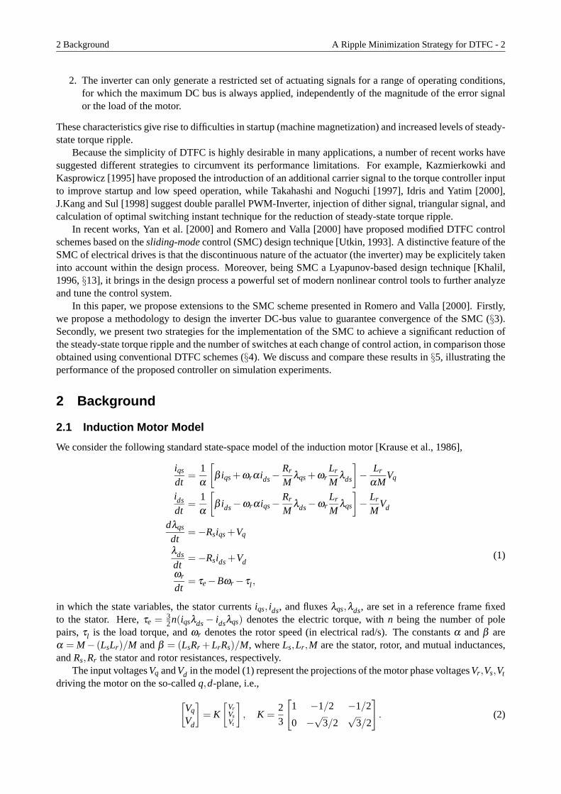
The phase voltagesVr ,Vs,Vt are generated by the inverter that drives the motor. Since there are eight admissiblecombinations of the three pairs of switches of the inverter, the resulting voltage vector driving the motor haseight possible positions (Figure 1). Two of these positions are null vectors, and correspond to the three upperswitches closed,V7 or the three lower switches closed,V0. The remaining six positions are the active (non null)values of the voltage vector, shown in theq,d-plane in Figure 2.
UDC
2
UDC
2
0A B C
N
Vr Vs Vt
Figure 1: Inverter scheme.
Since there is usually no neutral connection between the motor and the inverter, the inverter leg voltagesVA0,VB0,VC0 are not directly applied to the motor phases, but are related to them through the transformationVr
Vs
Vt
=13
2 −1 −1−1 2 −1−1 −1 2
VA0VB0VC0
. (3)
Each of these leg voltages can only have two possible values,±UDC2 , i.e., half of theDC bus UDC (Figure 1).
2.2 DTFC control
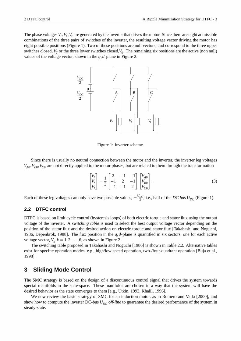
DTFC is based on limit cycle control (hysteresis loops) of both electric torque and stator flux using the outputvoltage of the inverter. Aswitching tableis used to select the best output voltage vector depending on theposition of the stator flux and the desired action on electric torque and stator flux [Takahashi and Noguchi,1986, Depenbrok, 1988]. The flux position in theq,d-plane is quantified in six sectors, one for each activevoltage vector,Vk,k = 1,2, . . . ,6, as shown in Figure 2.
The switching table proposed in Takahashi and Noguchi [1986] is shown in Table 2.2. Alternative tablesexist for specific operation modes, e.g., high/low speed operation, two-/four-quadrant operation [Buja et al.,1998].
3 Sliding Mode Control
The SMC strategy is based on the design of a discontinuous control signal that drives the system towardsspecial manifolds in the state-space. These manifolds are chosen in a way that the system will have thedesired behavior as the state converges to them [e.g., Utkin, 1993, Khalil, 1996].
We now review the basic strategy of SMC for an induction motor, as in Romero and Valla [2000], andshow how to compute the inverter DC-busUDC off-line to guarantee the desired performance of the system insteady-state.

3 Sliding Mode Control A Ripple Minimization Strategy for DTFC - 4
sector 1
V1
V6V5
V2V3
V4
λs
∆λs
Figure 2: Active voltage vectors, stator flux vector, and sectors on theq,d-plane.
Desired Voltage vector depending on sectorEffect 1 2 3 4 5 6
λs ↑τe ↑ V2 V3 V4 V5 V6 V1
τe− V7 V0 V7 V0 V7 V0
τe ↓ V6 V1 V2 V3 V4 V5
λs ↓τe ↑ V3 V4 V5 V6 V1 V2
τe− V0 V7 V0 V7 V0 V7
τe ↓ V5 V6 V1 V2 V3 V4
Table 1: DTFC Table;x ↑: increase inx, x ↓: decrease inx, andx−: x remains invariant.
3 Basic Strategy A Ripple Minimization Strategy for DTFC - 5
3.1 Basic Strategy
As in Romero and Valla [2000], we neglect the rotor speed dynamics as compared to the machine electricaldynamics, and considerωr in (1) constant for the synthesis process. On writingVq,Vd in terms ofVA0,VB0,VC0using (2) and (3), system (1) may be represented in the form
dxdt
= Ax+Bv, where x =[λqs λds iqs ids
]Tand
v =[VA0 VB0 VC0
]T. (4)
We postulate the SMC manifolds
S,
S1(x)S2(x)S3(v)
=
(λ2qs+ λ
2ds)/λ
2ref−1
32n(iqsλds− idsλqs)/τref−1∫
(VA0(t)+VB0 +VC0(t))dt
= 0,
whereλref andτref are the references for the flux magnitude and the torque. The manifoldS1(x) = 0 representsthe tracking of the flux magnitude, the manifoldS2(x) = 0 represents the torque regulation, and the manifoldS3(v) = 0 represents a voltage balance condition for the inverter.
In Romero and Valla [2000] the candidate Lyapunov functionW = 12STS≥ 0 is proposed to achieve
convergence to the manifoldsS= 0. The time derivative ofW along the system trajectories can be written as
dWdt
= ST dSdt
= ST(H +Dv), (5)
where
H ,∂S∂x
Ax+
[∂S1∂ t
∂S2∂ t0
]andD,
∂S∂x
B+[
00
∂S3∂ t
]. (6)
To guarantee the convergence of the system states to the manifoldsS= 0, an appropriate discontinuous controlsignal has to be chosen to makedW/dt < 0.
Because the inverter produces the three independent voltagesVA0,VB0,VC0, each of which, in turn, canonly take the values±UDC/2, it is natural to propose the discontinuous control signalv from (4) as
v =−U0sign(S∗), with S∗ , DTS. (7)
Now, on replacing (7) in (5) and rearranging terms,U0 appears as the design parameter in
dWdt
= STDD−1H−STDU0sign(S∗)
= (S∗)TH∗−U0|S∗|, (8)
whereH∗T , (D−1H)T = [h∗1 h∗2 h∗3 ] and|S∗|= |S∗1|+ |S∗2|+ |S∗3|. Hence, from (8), by selectingU0 such that
U0 > |h∗i |, ∀i = 1,2,3, (9)
convergence to the manifoldsS= 0 is guaranteed [Utkin, 1993].
3 DC-Bus Design A Ripple Minimization Strategy for DTFC - 6
3.2 DC-Bus Design
We need to satisfy (9), whereh∗i is a time-varying function, with U0 provided by theconstantDC-busUDC/2.Hence, we propose to selectU0 as the worst-case value under steady-state conditions. To this purpose, wenow determine a steady-state expression ofH∗ = D−1H.
Let the reference valuesλref andτref be constant. By neglecting ripple, the flux and currents in (1) maybe assumed as sinusoidal with phase, sayθ(t). Furthermore, by neglecting leakage flux, the fluxλds and thecurrentids may be considered to be in phase, and the same occurs withλqs andiqs. Under these hypotheses,H = [h1 h2 h3 ]T in (6) turns out to be a constant vector given by
h1 =−2Rr(idsλds+ iqsλqs)/λref
=−2Rr
λref(imaxsinθλmaxsinθ + imaxcosθ λmaxcosθ)
=−2Rr imaxλmax/λref,
h2 =β
α
(iqsλds− idsλqs)+ ωr(idsλds+ iqsλqs)
+ωrLr
αM(λ
2ds+ λ
2qs)
=β
αγ
τref + ωr imaxλmax+ωrLr
αMλ
2ref,
h3 = 0.
On the other handD in (6) can be shown to be
D = Λ∗K (10)
whereK is given in (2), and
Λ =
2λqs 2λds 0−γ[ids+ Lr
αLsrλds] γ[iqs+ Lr
αLsrλqs] 0
0 0 2
.Because, as mentioned before,λds andids are sines, andλqs andiqs cosines, the (periodically time-varying)
matrixΛ performs a rotation, i.e., a change of coordinates from a fixed(q,d)-frame to a(q,d)ω -frame rotatingat the synchronous frequencyω = dθ/dt. Thenthe matrix D= Λ∗K transforms the three phase magnitudesin the (R,S,T) frame, to a rotating frame oriented withλs = [λqs λds]T . Notice thatD is orthogonal, i.e.,DT = D−1.
In summary, under steady-state conditions, the components ofD−1H are three identical sinusoids shifted2/3π rad each. We can then selectUDC = 2U0 from
U0 = maxt‖D−1H‖∞, (11)
which may be easily computedoff-line.
4 Implementations for Torque Ripple Reduction
This section presents the main contributions of the paper, namely, two techniques to implement theon-linecomputation of the control signal to achieve reduction of the steady-state torque ripple.
4 Lyapunov-Based Softening of the Control Action A Ripple Minimization Strategy for DTFC - 7
4.1 Lyapunov-Based Softening of the Control Action
The proposed constant value ofU0 in (11) has been shown to guarantee, in steady-state, the Lyapunov con-dition dW/dt < 0 required by SMC. However, notice from (8) that when(S∗)TH∗ < 0, this condition wouldstill be guaranteed withU0 = 0. This observation suggests the possibility of making the control voltagev anull voltage vector,V0 or V7, in that case, i.e.,
v =
−U0sign(S∗) if (S∗)TH∗ ≥ 0,
V0,V7 otherwise.(12)
Such a design for the output of inverter requires theon-line computation of the value(S∗)TH∗ = SH. Thiscomputation, however, is not exceedingly complex and produces a significant reduction of torque ripple withrespect to the basic SMC strategy of§3 or other conventional DTFC strategies. We further discuss and illus-trate this point with simulations in§5.2.
4.2 Periodic Intersample Modulation by Averaging
When the control voltagev in (12) does need to be an active voltage vector,Vk,k = 1, . . . ,6, the proposedSMC strategy applies the fullU0, which we have designed in§3.2 as a worst-case value to satisfy (9) understeady-state conditions. This worst-case value turns out to be particularly conservative at low frequencies,producing a growth of torque ripple.
Since the implementation of the controller is in discrete time,t = NTs,N = 0,1,2, . . . , with a control updatetime Ts, we propose to perform aperiodic modulationof the applied voltage vector during the intersampleperiod[NTs,(N + 1)Ts) to further reduce the torque ripple whenU0 is too large. This modulation consists inapplying the computed active voltage vector only on the first fraction of the intersample period[NTs,NTs +Tav), while assigning a null voltage vectorV0 or V7 for the rest of the period[NTs + Tav,(N + 1)Ts). Thetime Tav, which varies at each sampling time, is computed following an averaging procedure similar to thatproposed in J.Kang and Sul [1998], as we see next.
We start by computing a virtual “necessary” voltage vector, sayU0n, to satisfy (9). At the sampling timet = NTs, the valueU0n is obtained computing the “necessary” column voltages as[
U0nA(NTs) U0nB(NTs) U0nC(NTs)]T = H∗(NTs). (13)
Then, from (13) we obtain the magnitude of the voltage vector as (for simplicity we omit the argument(NTs))
‖U0n‖2 =√
U20nq+U2
0nd, with
where
U0nq =23
(U0nA−U0nB/2−U0nC/2),
U0nd =√
33
(U0nC−U0nB).
The implementation ofU0n is carried out by “averaging” active and null vectors, which may be representedby the expression
U0n =TavVk +(Ts−Tav)V0(V7)
Ts,
whereTav is defined as
Tav =‖U0n‖223UDC
Ts.

5 Discussion and Simulation Results A Ripple Minimization Strategy for DTFC - 8
The active vectorVk,k = 1,2, . . . ,6 is provided by the control law (7), and the selection of the null vectorV0or V7 depends on the applied active vector in order to produce the least number of switch commutations. Thequantity 2
3UDC is the maximum magnitude of the voltage vector when an active vector is applied during thecomplete intersample interval[NTs,(N +1)Ts).
In summary, the proposed modulated control lawv is given by
v(t) = −U0sign(S∗) if SH≥ 0 andNTs≤ t < NTs+Tav),V0,V7 otherwise,
for t ∈ [NTs,(N +1)Ts). (14)
5 Discussion and Simulation Results
This section discusses the performance of the proposed control (14), showing its advantages with respect tothe basic scheme of§3.1 and conventional DTFC. We present simulation results that illustrate performance on
• Machine magnetization.
• Steady-state torque ripple.
• Switch commutations at control updates.
5.1 Machine Magnetization
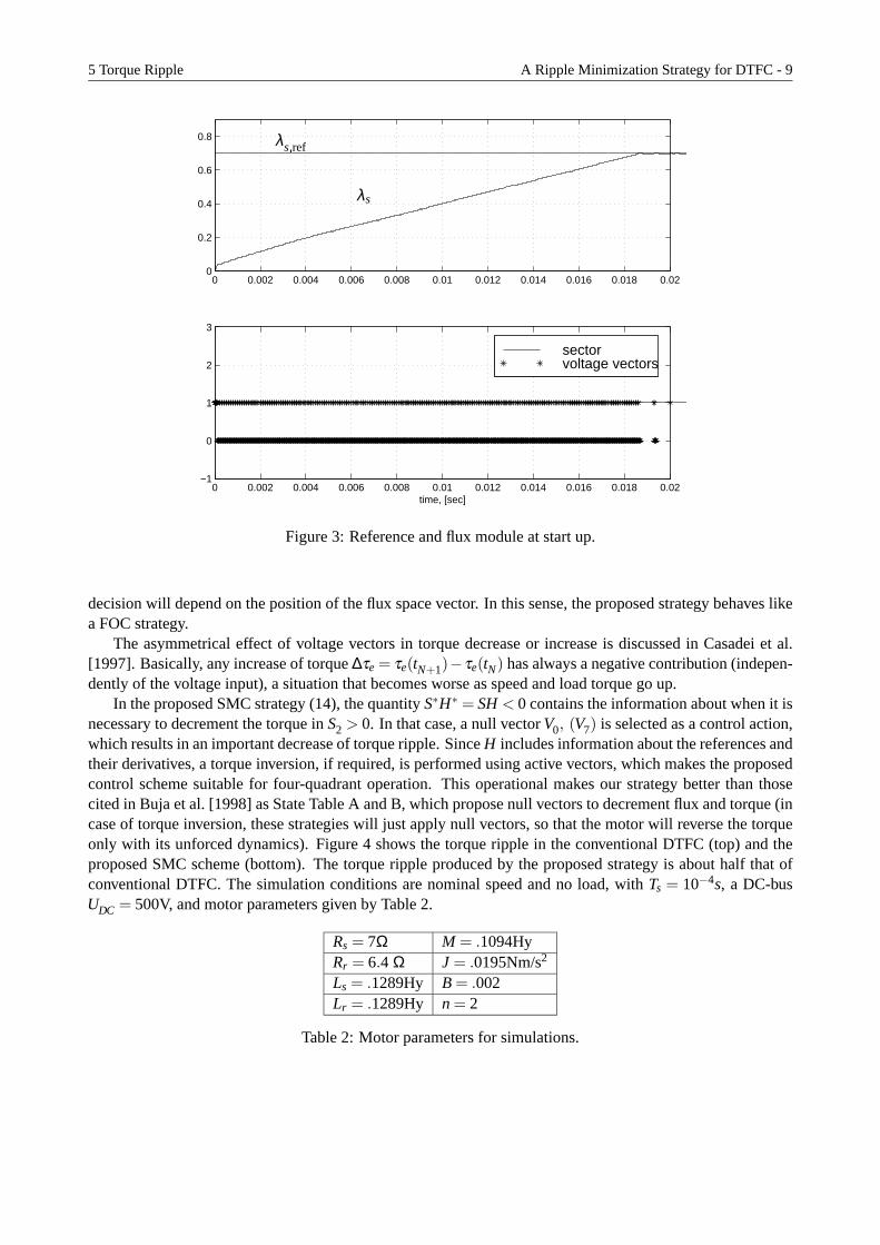
The proposed control scheme (14) permits the machine magnetization without a torque reference signal, afeature that is not possible with a conventional DTFC scheme. This feature is possible because the proposedscheme can use all eight voltage vectors instead of the five admissible in conventional DTFC. The best choicefor machine magnetization is the voltage vector which is collinear to the flux vector in each sector, namely, ifthe flux vector is in sectork, the best choice isVk. This situation is not contemplated in conventional DTFC.Figure 3 shows the response of the proposed SMC scheme at start up. Because the proposed control law isnot defined at the origin, however, it does require non zero initial conditions for start-up, which were set in[λqs λds] = [10−5 0] , i.e., the flux vector is in sectork = 1, and vectorV1 is selected to magnetize the machine.
5.2 Torque Ripple
By implementation of the softening of the control action of§ 4.1 and the periodic modulation of§ 4.2, theproposed control scheme achieves significant reduction of the steady-state torque ripple, as compared with thebasic SMC and conventional DTFC schemes.
The ripple phenomenon in DTFC is mainly generated by two factors: (i) conventional DTFC assigns asingle voltage vector for the whole sector, and (ii) voltage vectors producing torque decrease have a strongeraction than those that produce torque increase.
The assignment of a single voltage vector to a whole sector in DTFC amounts to computing the controlaction based on an error measurement that isquantized by sectors. This quantization of the error by sectorsmay produce undesirable effects depending on whether the flux vector is at the beginning, in the middle, or atthe end of the sector [Bertoluzzo et al., 1999]. A control action suitable when the flux vector is, for example,in the middle of the sector, could be inappropriate at the beginning.
A more appropriate strategy would take into account the position of the flux vector disregarding such aquantization by sectors. The proposed SMC naturally fulfills this requirement. Indeed, we can see from theexpression of the control signal (7) that the information contained inS∗ = DTS is the flux and torque error perphase, explicitely parameterized by the position of the stator flux vector. Because the matrixDT performs arotation from the(q,d)ω coordinates to the(R,S,T) coordinates, we see that for a given value ofS, the control
5 Torque Ripple A Ripple Minimization Strategy for DTFC - 9
0 0.002 0.004 0.006 0.008 0.01 0.012 0.014 0.016 0.018 0.020
0.2
0.4
0.6
0.8
0 0.002 0.004 0.006 0.008 0.01 0.012 0.014 0.016 0.018 0.02−1
0
1
2
3
time, [sec]
sector voltage vectors
λs ref
λs
Figure 3: Reference and flux module at start up.
decision will depend on the position of the flux space vector. In this sense, the proposed strategy behaves likea FOC strategy.
The asymmetrical effect of voltage vectors in torque decrease or increase is discussed in Casadei et al.[1997]. Basically, any increase of torque∆τe = τe(tN+1)−τe(tN) has always a negative contribution (indepen-dently of the voltage input), a situation that becomes worse as speed and load torque go up.
In the proposed SMC strategy (14), the quantityS∗H∗ = SH< 0 contains the information about when it isnecessary to decrement the torque inS2 > 0. In that case, a null vectorV0, (V7) is selected as a control action,which results in an important decrease of torque ripple. SinceH includes information about the references andtheir derivatives, a torque inversion, if required, is performed using active vectors, which makes the proposedcontrol scheme suitable for four-quadrant operation. This operational makes our strategy better than thosecited in Buja et al. [1998] as State Table A and B, which propose null vectors to decrement flux and torque (incase of torque inversion, these strategies will just apply null vectors, so that the motor will reverse the torqueonly with its unforced dynamics). Figure 4 shows the torque ripple in the conventional DTFC (top) and theproposed SMC scheme (bottom). The torque ripple produced by the proposed strategy is about half that ofconventional DTFC. The simulation conditions are nominal speed and no load, withTs = 10−4s, a DC-busUDC = 500V, and motor parameters given by Table 2.
Rs = 7Ω M = .1094HyRr = 6.4 Ω J = .0195Nm/s2
Ls = .1289Hy B = .002Lr = .1289Hy n = 2
Table 2: Motor parameters for simulations.

5 Switch Conmutations at Control Updates A Ripple Minimization Strategy for DTFC - 10
0.95 0.955 0.96 0.965 0.97 0.975 0.98 0.985 0.99 0.995 1−4
−3
−2
−1
0
1
2
3Conventional DTFC
0.95 0.955 0.96 0.965 0.97 0.975 0.98 0.985 0.99 0.995 1−4
−3
−2
−1
0
1
2
3SMC
time, [sec]
Figure 4: Torque ripple for conventional DTFC and SMC.
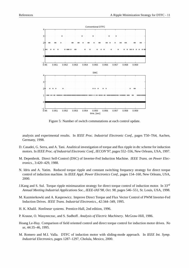
5.3 Switch Conmutations at Control Updates
The proposed control squeme (14) improves the inverter operation, because less number of switch conmuta-tion are produced at each control update step. This improvement is achieved because the controller providesthe switch configuration and the magnitud of the voltage vector necessary to drive the motor toS= 0, whichis implemented by averaging technique of§ 4.2. The resulting effect is that the deviations fromS= 0 be-come smaller than those produces when the full DC-bus is applied during the complete intersample interval.Moreover, the correction actions can be done with voltage vectors that involve only one switch conmutationfrom one configuration to another (i.e., no oposite voltage vectors are selected). Figure 5 shows the numberof switch conmutation at each control update step in the same simulation experiment of Figure 4.
6 Conclusions
We have presented a DTFC strategy using the SMC approach implementation for torque ripple reduction,namely, the use of null vectors to correct special error conditions, and a periodic modulation tecnique toapply the correct magnitud of the control signal. This methodology presents substantial advantages overconventional DTFC, namely, fixed frequency inverter operation, the possibility of machine magnetizationwithout a torque reference signal, more control degrees of freedom, and use of (non quantized) flux spacevector information in the control computation.
References
M. Bertoluzzo, G. Buja, and R. Menis. Analytical formulation of the direct control of induction motor drives.In IEEE-Int. Symp. Industrial Electronics, pages Ps14–Ps20, Bled, Slovenia, 1999.
G. Buja, D. Casadei, and G. Serra. Direct stator flux and torque control of an induction motor: theorethical
References A Ripple Minimization Strategy for DTFC - 11
0.95 0.951 0.952 0.953 0.954 0.955 0.956 0.957 0.958 0.959−1
0
1
2
3
4Conventional DTFC
0.95 0.951 0.952 0.953 0.954 0.955 0.956 0.957 0.958 0.959−1
0
1
2
3
4SMC
time, [sec]
Figure 5: Number of switch commutations at each control update.
analysis and experimental results. InIEEE Proc. Industrial Electronic Conf., pages T50–T64, Aachen,Germany, 1998.
D. Casadei, G. Serra, and A. Tani. Analitical investigation of torque and flux ripple in dtc scheme for inductionmotors. InIEEE Proc. of Industrial Electronic Conf., IECON’97, pages 552–556, New Orleans, USA, 1997.
M. Depenbrok. Direct Self-Control (DSC) of Inverter-Fed Induction Machine.IEEE Trans. on Power Elec-tronics., 3:420–429, 1988.
N. Idris and A. Yatim. Reduced torque ripple and constant switching frequency strategy for direct torquecontrol of induction machine. InIEEE Appl. Power Electronics Conf., pages 154–160, New Orleans, USA,2000.
J.Kang and S. Sul. Torque ripple minimazation strategy for direct torque control of induction motor. In 33rd
Annual Meeting Industrial Applications Soc., IEEE-IAS’98, Oct. 98, pages 546–551, St. Louis, USA, 1998.
M. Kazmierkowki and A. Kasprowicz. Improve Direct Torque and Flux Vector Control of PWM Inverter-FedInduction Drives.IEEE Trans. Industrial Electronics., 42:344–349, 1995.
H. K. Khalil. Nonlinear systems. Prentice-Hall, 2nd edition, 1996.
P. Krause, O. Wasynnczuc, and S. Sudhoff.Analysis of Electric Machinery. McGraw-Hill, 1986.
Hoang Le-Huy. Comparison of field oriented control and direct torque control for induction motor drives.Nose, 44:35–46, 1995.
M. Romero and M.I. Valla. DTFC of induction motor with sliding-mode approach. InIEEE Int. Symp.Industrial Electronics, pages 1287–1297, Cholula, Mexico, 2000.

References A Ripple Minimization Strategy for DTFC - 12
I. Takahashi and T. Noguchi. A New Quick response and High -Efficiency Control Strategy of an InductionMotor. IEEE Trans. Industry Appl., 22:820–827, 1986.
I. Takahashi and T. Noguchi. Take a look back upon the past decade of direct torque control. InIEEE Proc.of Industrial Electronic Conf., pages 546–551, New Orleans, USA, 1997.
Vadim Utkin. Sliding mode control design principles and application to electrical drives.IEEE Trans. Ind.Electron., 40:23–36, 1993.
Peter Vas.Sensorless Vector Control and Direct Torque Control. Oxford University Press, 1998.
Z. Yan, C. Jin, and V. Utkin. Sensorless Sliding-Mode Control of Induction Motors.IEEE Trans. Ind.Electron., 47:1287–1297, 2000.