WR SS02 E1 1 ZXSDR Base Station Structure and Principle 65p
64
ZXSDR Base Station Structure and Principle ZTE University
Transcript of WR SS02 E1 1 ZXSDR Base Station Structure and Principle 65p

ZXSDR Base Station Structure and Principle
ZTE University

Content
ZXSDR Base Station Family Overview ZXSDR Base Station IntroductionZXSDR Base Station Highlights

Evolution of Multi-Mode Base Station
ZTE macro-Base Station, IP architecture, 18TRX
cabinet
Different Base Station systems overlappedTDM/ATM platformNarrowband architectureLow integration and high consumption G1 Multimode Base Station
Different Base Station Systems Interchanged3G BBU/RRU Interchangeable IP/ATM architectureIncreasing integration
G2 Multimode Base Station
Shared broadband multi-carrier moduleShared uTCA BBUFull-IP architecture and unified platformMulti-system conversion for same frequency softwareUltra-high integration and low consumption
G3 Multimode Base Station - SDR
Unified Radio Resource ManagementSystem conversion for adjacent frequency softwareIntegrated BSC functionMESH network Architecture
G4 Multimode Base Station - Flat SDR
ZTE SDR, 36TRX cabinet
Traditional macro-Base Station, ATM
architecture, 12TRX cabinet

Future Oriented SDR Technology —— Ensuring Multi-Mode Network Convergence
W
HH+G
L
Convergence
SDR
Based on unified IP platform with MCPA
New generation multi mode base station
Convergence, revolution for traditional base station•Smart software
supports LTE evolution•Smart configuration supports different systems
•Same base station supports different systems•Software upgrade supports different evolutions
•Multi-mode•Multi-band•Flat network•Smooth evolution
Software Solution
Define Designed
Radio Refarming

Innovative Base Station Platform Unified multi-mode and multi-
frequency band Base Station hardware platform
μTCA –based BBU baseband processing unit
Platform structure with separated baseband and RF units
RF unit based on MCPA
中中中中 SDR 中中中中 中中中中中中中中中中中中中中中中中中中中Spectrum resource optimization utilization
Network resource optimization integration
Smooth wireless network evolution Optimal TCO solution
CDMA2000 WCDMA
LTEGSM TD-SCDMA
ATCA/mTCA
ATCA (Advanced Telecommunication Computer Architecture): adopted by PICMG in 2003
Micro TCA (u TCA): ATCA, be fit for accessing network

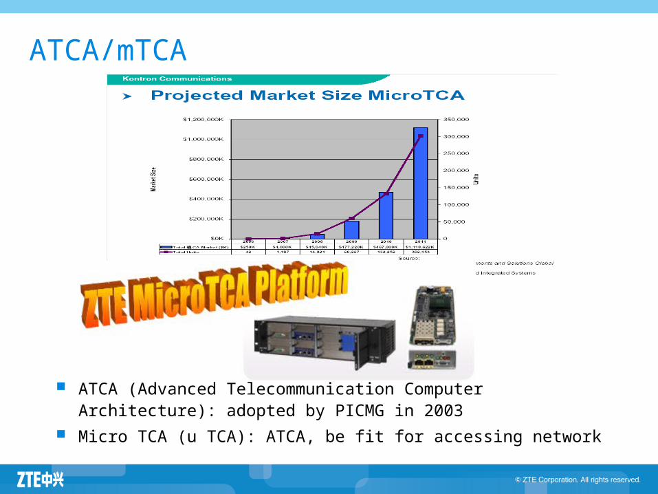
Broadband MCPA Single-Carrier
PA Multi-Carrier PA
Combiner & Antenna
Interface
Digital IF Process
BBU
PA1
TRX1
PA2
TRX2
PA3
TRX3
PA4
TRX4f1 f2 f3 f4
Duplex & Antenna
MCPA
MTRX
Interface
BBU
Digital IF Process
( f1~f6)
( f1~f6)
SDR design is based on MCPA at the same frequency; MCPA provides flexible frequency optimization technology and better equipment integrity.

SDR Based Uni-RAN Solution Highlights
Common Components Shared
•Different BP boardsSDR RRU Spectrum Refarming CapableMulti-band Supported
Multi-Mode Base Station and Convergent Radio Network Controller
Multi-band Support Smooth EvolutionEDGE EvolutionGSM->UMTS->LTE
Full Speed HSPA64QAM HSPA+MIMO HSPA+DC+64QAM HSPA+
50% PA EfficiencyD-PT Technology3 Sector RRU SolutionGreen Energy
Outdoor InstallationZero FootprintSmaller SizeLighter Weight
High Quality Base Station ProductHigh Reliability NetworkingUnified O&M SystemPowerful Network Optimization Tools
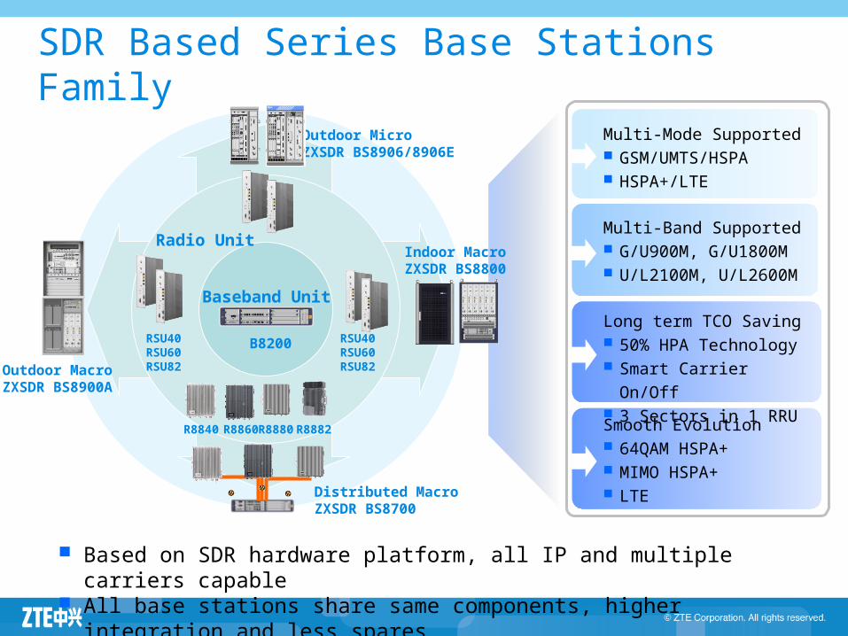
SDR Based Series Base Stations Family
Multi-Mode Supported GSM/UMTS/HSPA HSPA+/LTE
Multi-Band Supported G/U900M, G/U1800M U/L2100M, U/L2600M
Long term TCO Saving 50% HPA Technology Smart Carrier On/Off
3 Sectors in 1 RRUSmooth Evolution 64QAM HSPA+ MIMO HSPA+ LTE
Based on SDR hardware platform, all IP and multiple carriers capable
All base stations share same components, higher integration and less spares
Baseband Unit
B8200
R8860R8840
Indoor MacroZXSDR BS8800
Outdoor MicroZXSDR BS8906/8906E
Distributed MacroZXSDR BS8700
RSU40RSU60RSU82Outdoor Macro
ZXSDR BS8900A
Radio Unit
RSU40RSU60RSU82
R8880 R8882

RRUBBU
Indoor Macro
OutdoorMacro
MCPA-based broadband Radio Unit with multi-mode supported.
Sufficient output power of HPA with lower power consumption.
MicroTCA structure Base Band Unit with high reliability and easy expansion.
High integrity & processing capability; upgrade to HSPA+ via software; minimum upgrade cost to support LTE.
ZTE SDR 4 Key Features
SDR Base Station Key Features
Content
ZXSDR Base Station Family Overview ZXSDR Base Station IntroductionZXSDR Base Station Highlights

SDR Base Station IntroductionSDR Base Station Introduction
Baseband Unit and Radio Unit Distributed Base Station: ZXSDR BS8700 Introduction
BBU: B8200 RRU series
Macro Indoor : ZXSDR BS8800 Macro Outdoor : ZXSDR BS8900A Micro Outdoor: ZXSDR BS8906

Base Band Unit — SDR B8200
Volume:88.4×482.6×197mm( H×W×D) Weight: 8.75kg (full configuration) Typical Power Consumption : UMTS: 80W(1BPC), 115W(2BPC)
GSM: 60W(12TRX), 75W(24TRX) Power Supply: -48V DC Temperature Range: -20℃ ~ 55℃ Humidity Range: 5%~ 95%
Based on Unified MicroTCA Platform
2U
482.6mm
88.4mm
Uplink: 192CEDownlink: 192CEDownlink: 43.2MbpsUplink: 15Mbps
BPC ProcessingCapability
Processing Capability: UMTS: 30CS ( 6CS *5 BPCs) GSM: 60TRX
Base Band Processing Capability: Uplink/ Downlink: 960CE
Data Processing Capability: Downlink: 216Mbps Uplink: 75Mbps
Abis/Iub Interface: 2*STM-1; 16*E1/T1; 1*FE/GE
Electric/Optical(8 VLAN) To RRU: 12*1.25Gbps CPRI optical
interface
Performance IndexPerformance Index
Physical IndexPhysical Index
Interface IndexInterface Index
19 inch

CC Board Introduction
GPS system clock & RF reference clock;Abis Iub interface function;Ethernet switch function, providing switch plan for signaling and media stream;Rack management
Control & Clock Board

Board LED Color Meaning Description
CC
HS BluePlugging/Unplugging Indicator
On: The board can be unplugged.Flashing: The board is being activated or deactivated.Off: The board cannot be unplugged.
RUN Green Running Indicator
Always on: The board is in reset state.Flashing at 1Hz: The board is normally running.Off: Self test fails.
Alarm Red Alarm Indicator
On: The board has an alarm.Off: The board has no alarm.
E0S GreenE1/T1 status indicator (link 0–3)
Alternate flash for different links; the max 4 flashes per second; flashing at frequency of 5 Hz.The first second: one flash means Link 0 is normal and OFF means Link 0 is not in use.The third second: two flashes means Link 1 is normal and OFF means Link 1 is not in use.The fifth second: three flashes means Link 2 is normal and OFF means Link 2 is not in use.The seventh second: four flashes means Link 3 is normal.and OFF means Link 3 is not in use.Recycle. Each cycle lasts for eight seconds.
CC Indicators

Board LED Color Meaning Description
CC
E1S GreenE1/T1 status indicator (link 4–7)
The same as E0S.
E2S GreenE1/T1 status indicator (link 8–11)
The same as E0S.
E3S GreenE1/T1 status indicator (link 12–15)
The same as E0S.
MS GreenActive/Standby status indicator
On: The board is in active statusOff: The board is in standby status
REF Green
GPS antenna state or 2 MHz state, connection state of SMA Interface on corresponding panel GPS
Always on: The antenna feeder is normal.
Always off: The antenna feeder and satellite are normal, in initialization state.Slow Flash (flashing at 1 Hz)): The antenna feeder is broken.Fast Flash (flashing at 2 Hz): The antenna feeder is normal but cannot receive satellite signal.Slowest Flash (flashing at 0.5 Hz): Antenna short circuitQuickest Flash (flashing at 5 Hz): No message is received at the initialization stage.
CC Indicators
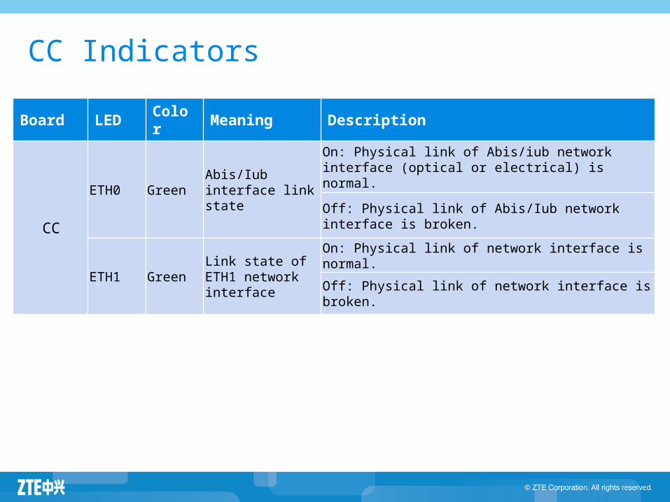
Board LED Color Meaning Description
CC
ETH0 GreenAbis/Iub interface link state
On: Physical link of Abis/iub network interface (optical or electrical) is normal.Off: Physical link of Abis/Iub network interface is broken.
ETH1 GreenLink state of ETH1 network interface
On: Physical link of network interface is normal.Off: Physical link of network interface is broken.
CC Indicators

PM Board Introduction
Power Module16 internal interface for +12V load power16 internal interface for +3.3V management powerMeasurement and protection of input over-voltage/under-voltage;Output over-current protection and load power management
Power Module

SA/SE Board Introduction
Site Alarm Board
Site Alarm Board/Site Alarm Extender Board(optional)Alarm monitor and rev control of no more than 9 fans;Signal monitor and interface lightning protection for the rack;Providing 6 input dry contact interfaces, 2 input /output dry contact interface;Providing 8 lines of E1/T1 interface
Site Alarm Extender

Jumper X5 is used to set E1/T1 transmission mode.TWO LSB POSITIONS OF X5
TWO MSB POSITIONS OF X5
SA Jumpers
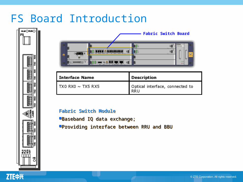
FS Board IntroductionFabric Switch Board
Fabric Switch ModuleBaseband IQ data exchange;Providing interface between RRU and BBU

Baseband Board Introduction
Universal Baseband Processing Board for GSM
Baseband modulation, maximum processing capacity is 12 carriers;
Supporting baseband frequency hopping; Supporting static and dynamic power control;
Baseband Processing Board Type C maximum processing capacity is 6 carrier-sectors;
maximum CE for UL/DL is 192/192 CE; maximum HSDPA throughput is 43.2Mbps maximum HSUPA throughput is 15Mbps
Baseband Board
Board LED Color Meaning Description
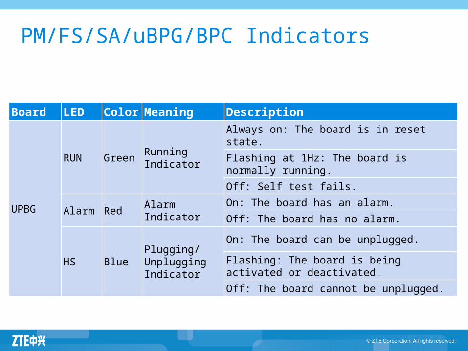
UPBG
RUN Green Running Indicator
Always on: The board is in reset state.Flashing at 1Hz: The board is normally running.Off: Self test fails.
Alarm Red Alarm Indicator
On: The board has an alarm.Off: The board has no alarm.
HS BluePlugging/Unplugging Indicator
On: The board can be unplugged.Flashing: The board is being activated or deactivated.Off: The board cannot be unplugged.
PM/FS/SA/uBPG/BPC Indicators

Cable Connection of B8200
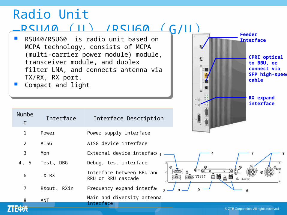
Radio Unit —RSU40( U) /RSU60( G/U)
Number Interface Interface Description
1 Power Power supply interface
2 AISG AISG device interface3 Mon External device interface
4、 5 Test、 DBG Debug, test interface
6 TX RX Interface between BBU and RRU or RRU cascade
7 RXout、 RXin Frequency expand interface
8 ANT Main and diversity antenna interface
RSU40/RSU60 is radio unit based on MCPA technology, consists of MCPA (multi-carrier power module) module, transceiver module, and duplex filter LNA, and connects antenna via TX/RX, RX port.
Compact and light
Feeder Interface
CPRI optical to BBU, or connect via SFP high-speed cable
RX expand interface

Radio Unit —RSU82(G/U)
Number Interface Interface Description
1 ANT Main and diversity antenna interface
2 Mon External device interface
3 TX RX Interface between BBU and RRU or RRU cascade
4 Mon External device interface
5 Power Power supply interface15
4
2
31
RSU 82 is for both GSM and UMTS; 2 PA: 2T4R; Weight: 15Kg Dimension: 482mm x 72mmx360mm Max TOC:
GSM: 2×80W (GMSK)/2×50W(8PSK) UMTS: 2×80W(900M), 2×60W(2100M)
Sensitivity: GSM: -113dBM UMTS: -126.5dBm@ single antenna
-129.2dBm@ Dual antenna Frequency band: 900M, 1800M, 2100M

SDR Base Station IntroductionSDR Base Station Introduction
Baseband Unit and Radio Unit Distributed Base Station: ZXSDR BS8700 Introduction
BBU: B8200 RRU series
Macro Indoor : ZXSDR BS8800 Macro Outdoor : ZXSDR BS8900A Micro Outdoor: ZXSDR BS8906

Hardware Architecture of BS8700
B8200+
=
RRU
BS8700
Fiber
BBU
Radio UnitRadio UnitSA/
SE/NIS CC
BBFS RRU
E1
GE/FE
Clock Data
Control Signaling
Antenna
STM-1
CPRI
The structure of BS8700 is BBU plus RRU, with separated modules as Base band unit and RF unit.

Remote Radio Unit – R8840Performance IndexPerformance Index Support maximal 4 carriers Support 1C1S ~ 4C1S Output Power: 60W Receive Sensitivity: -126.5dBm@sigle antenna -129.2dBm@dual antennaFrequency: 2100MHz
Physical IndexPhysical Index Volume: 370×320×160mm ( H×W×D) Weight: 16.5kg Typical Power Consumption:
100W(1C)/125W(2C)/160W (3C) Power Supply: -48V DC Temperature Range: -40℃~ +55℃ Protection Class: IP65
Interface IndexInterface Index 2 * 1.25G CPRI Optical Interface
SDR R8840 320mm 160mm
370mm

Remote Radio Unit —— ZXSDR R8860
ZXSDR R8860 ( 1T2R)
Carrier Configuration: Support maximal: 6TRX or 4 carriers Support maximal: 4G1U
Output Power: 80W Receive Sensitivity: -113dBm[GSM]
-126.5dBm@sigle antenna[UMTS] -129.2dBm@dual antenna[UMTS] Frequency: 850MHz, 900MHz, 1800MHz, 1900MHz
Performance IndexPerformance Index
2*1.25G CPRI Optical interface
Interface IndexInterface Index
Volume: 370×320×197mm ( H×W×D) Weight: 20Kg TPC: UMTS:1C: 155W/2C: 185W/3C: 210W/4C: 230W GSM: 200W(900M) /210W(1800M) GU: 4G1U 215 W Power Supply: -48V DC Temperature Range:-40℃~ +55℃ Protection Class: IP65
Physical IndexPhysical Index
370mm
320mm
197mm
• Support GSM and UMTS.

R8860 Structure

R8860 Structure ADTR: Completes the function of transmitter by one
path and receiver by two paths, providing interface and control function.
PA: Provides amplification function during transmission for RF signal.
DFL: Provides receiving & transmitting combination and division function for RF signal, and provides low noise amplification function for signal. It includes duplexer by one path and receiving filter by one path.
RIE: Mainly completes the transition between PIB board test and monitoring interface signal.
PIB: Mainly completes electrically tuned antenna and tower amplifier AISG interface protection and DTR board interface signal transition.
RPDC: Supplied by DC power conversion.

R8860 InterfaceNo Label Interface
1 LC1Interface betweenBBU and RRU/RRU cascading interface
2 LC2Interface betweenBBU and RRU/RRU cascading interface
3 AISG AISG device interface
4 MonExternal equipment interface (monitoring,LMT, etc.)
5 DC IN Power interface
6 RX Interface to receive diversity RF cable
7 RX/TX Interface to transmit / receive main diversity RF cable
8 RXout Frequency expansion interface
9 RXin Frequency expansion interface
10 GND Machine Grounding
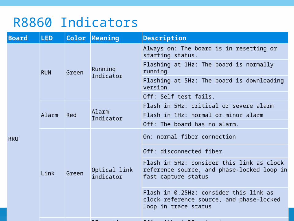
Board LED Color Meaning Description
RRU
RUN Green Running Indicator
Always on: The board is in resetting or starting status.Flashing at 1Hz: The board is normally running.Flashing at 5Hz: The board is downloading version.Off: Self test fails.
Alarm Red Alarm Indicator
Flash in 5Hz: critical or severe alarmFlash in 1Hz: normal or minor alarmOff: The board has no alarm.
Link Green Optical link indicator
On: normal fiber connection
Off: disconnected fiberFlash in 5Hz: consider this link as clock reference source, and phase-locked loop in fast capture status
Flash in 0.25Hz: consider this link as clock reference source, and phase-locked loop in trace status
RF OrangeRF working status indicator
Off: without RF out putOn: with RF out put
R8860 Indicators

Remote Radio Unit – R8880A
Performance IndexPerformance Index Support maximal 2 X 3 C Output Power: 2 X 60W Receive Sensitivity: -126.5dBm@sigle antenna -129.2dBm@dual antennaTransmitter Frequency: 2110MHz~2170MHZReceiver Frequency: 1920MHz~1980MHZ
Physical IndexPhysical Index Volume: 420×340×140mm ( H×W×D) Weight: < 20kg Typical Power Consumption:
S1:135W(Single PA), 215W(double PA)S2:195W(Single PA), 330W(double PA)S3:240W(Single PA), 420W(double PA)
Power Supply: -48V DC Temperature Range: -40℃~ +55℃ Protection Class: IP65
Interface IndexInterface Index 2 * 1.2288G Optical Interface
SDR R8880A420mm 140mm
340mm

Remote Radio Unit —— ZXSDR R8882
320mm
140mm
450mm
Carrier Configuration: Support maximal [UMTS]: 2×3C carriers Support maximal [GSM]: 2×4 TRX Support maximal [GU]: 2×4G1U or 2×2G2U
Output Power: 2×60W Receive Sensitivity: -113.5dBm[GSM]
-113.5dBm@sigle antenna[UMTS] -129.2dBm@dual antenna[UMTS]
Frequency: 900M/1800M/2100MHz
Performance IndexPerformance Index
Volume: 450×320×140mm ( H×W×D ) Weight: 20Kg TPC : 684W( S3/3/3)Power Supply: -48V DC, 110V AC, 220V ACTemperature Range: -40℃~ +55℃Protection Class: IP65
Physical IndexPhysical Index
ZXSDR R8882 (2T4R)
2*1.25G CPRI Optical interface (2.5G and 3.072G are also applicable)
Interface IndexInterface Index
• Support GSM & UMTS

R8882 Structure

R8882 Structure TRM: Finish the function of transmitter and receiver, which can provide the interface and control function.
PAD: Provide the amplification function of RF signals on two channels.
FLD: Provide the function of reception, transmitting, combination, and division of RF signals. It comprises of two duplexers and two receiving filters.
EPB : EMC protection at power, monitor interface, and AISG interface.

R8882 InterfaceNo Label Interface
1 PWR Power jack
2 EAM External monitor interface
3 AISG AISG device interface
4 OTP1 BBU-RRU interface / RRU cascading interface
5 OTP2 BBU-RRU interface / RRU cascading interface
6 ANT1TX/RX Antenna tx/rx interface on channel 1
7 ANT2RX Diversity receiving antenna interface on channel 1
8 ANT3RX Diversity receiving antenna interface on channel 2
9 ANT4TX/RX Antenna tx/rx interface on channel 2
10 - PE interface
1 2 3 4 5
9876
10

Board LED Color Meaning Description
R8882
RUN Green Running indication
Always on: The board is in resetting or starting status.Flashing at 1Hz: The board is normally running.Flashing at 5Hz: The board is downloading version.Off: Self test fails.
Alarm Red Alarm Indicator
Flash in 5Hz: major or critical alarmFlash in 1Hz: warning or minor alarmOff: indicates no fault or resetting, starting or downloading the version.
LINK1 GreenStatus indication at optical interface 0
ON: connection is ok at optical interface 0Off: disconnected fiberFlash in 5Hz: consider this link as clock reference source, and phase-locked loop in fast capture statusFlash in 0.25Hz: consider this link as clock reference source, and phase-locked loop in trace status
LINK2 GreenStatus indication at optical interface 1
The same meaning as LINK1
VSWR1 Green TX0 standing wave indication
ON: TX0 standing wave is okOFF: TX0 standing wave is improper
VSWR2 Green TX0 standing wave indication The same meaning as VSWR1
R8882 Indicators
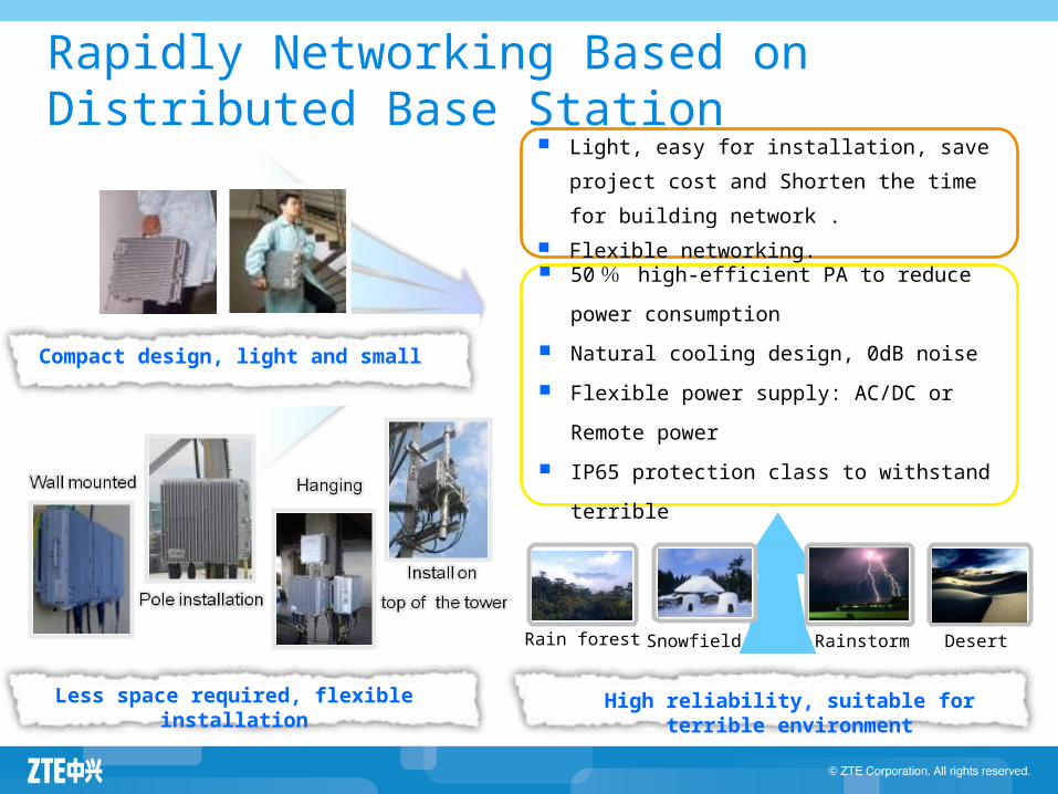
Rapidly Networking Based on Distributed Base Station
DesertSnowfield RainstormRain forest
Less space required, flexible installation
Compact design, light and small
High reliability, suitable for terrible environment
Light, easy for installation, save project cost and Shorten the time for building network .
Flexible networking. 50 % high-efficient PA to reduce
power consumption Natural cooling design, 0dB noise Flexible power supply: AC/DC or
Remote power IP65 protection class to withstand
terrible

Networking Topology of RRU
ZTE provides flexible networking for distributed site such as star, chain, loop and mix topology to meet demands for customers.

SDR Base Station IntroductionSDR Base Station Introduction
Baseband Unit and Radio Unit Distributed Base Station: ZXSDR BS8700 Introduction
BBU: B8200 RRU series
Macro Indoor : ZXSDR BS8800 Macro Outdoor : ZXSDR BS8900A Micro Outdoor: ZXSDR BS8906

Integrated Indoor Macro Site — ZXSDR BS8800
Radio Unit
BasebandUnit
Radio Unit: RSU40/ RSU60/RSU82
Physical IndexPhysical Index Volume: 950×600×450mm ( H×W×D) (Main Cabinet) Weight: main cabinet<135 KG, Auxiliary Cabinet <115KG[with RSU40/RSU60] TPC:
RSU82 (850/900M): 1110W[S444] RSU40 (2100M): 780W[S222]
Power Supply: -48V DC (-40~-57V DC)
Performance IndexPerformance Index Processing Capability(with Auxiliary Cabinet):
GSM 36TRX + UMTS12CS Base Band Processing Capability:
Uplink: 960CE (192CE*5BPC)Downlink: 960CE (192CE*5BPC)
Output Power: 60W/80W/2*80W(900/1800M), 2*60W(2100M) Receive Sensitivity:
GSM -113dBm@single antennaUMTS -126.5dBm@single antenna
-129.2dBm@dual antenna
Interface IndexInterface IndexAibs/Iub Interface:
8*E1/T1(Can expand to 16)1*GE/FE Optical or 1*GE/FE Electrical
To remote RRU: 12 *1.25Gbps CPRI Optical Interface
SDR BS8800
BU: B8200
Main Cabinet

BS8800 Hardware Structure Radio Unit:
RSU40, RSU60,RSU82 Wiring Duct:
Used to walk wiring in rack, such as fiber or SFP cable between BBU and RSU40/60/82.
Power Distribution Module: Passive power
distribution unit Transmission Device:
1U slot, it can provide built-in transmission or microwave devices to save operators’ investment.
FAN Used to perform heat
dissipation for RSU modules, 6 fans in total
950mm
600mm
450 mm
Radio Unit
Power Distribution Module
WiringDuct
TransmissionDevice Ventilation
Base Band
Fan
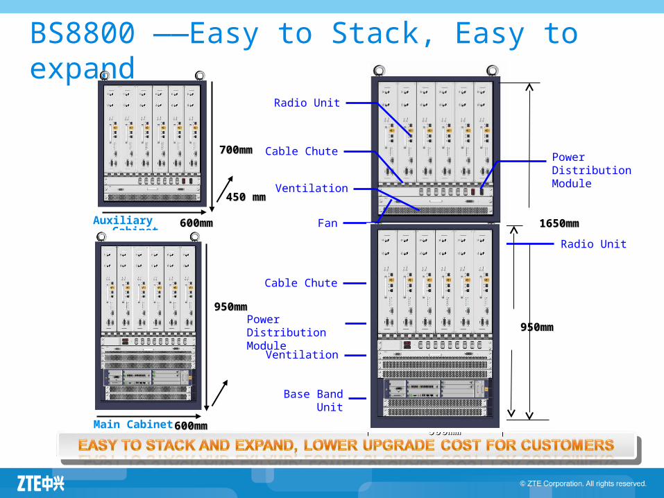
BS8800 ——Easy to Stack, Easy to expand
1650mm1650mm
600mm600mm
Power DistributionModule
Cable Chute
Base Band Unit
950mm950mmPower DistributionModule
Cable Chute
Radio Unit
Auxiliary Cabinet Fan
Radio Unit
Ventilation
Main Cabinet
950mm950mm
600mm600mm
600mm600mm
450 mm450 mm
700mm700mm
Ventilation

48
SDR Base Station IntroductionSDR Base Station Introduction
Baseband Unit and Radio Unit Distributed Base Station: ZXSDR BS8700 Introduction
BBU: B8200 RRU series
Macro Indoor : ZXSDR BS8800 Macro Outdoor : ZXSDR BS8900A Micro Outdoor: ZXSDR BS8906

Integrated Outdoor Macro Site – ZXSDR BS8900A
Radio Unit:RSU40/60/82
Physical IndexPhysical Index Volume: 1600×600×600mm ( H×W×D)
(Standard Configuration) Weight: 185kg (BC8910A+RC8911A)TPC:
RSU82 (900M): 1285W[S444] RSU40 (2100M): 865W[S222]
Power Supply: -48V DC, 220V AC, 380V AC
Performance IndexPerformance Index Processing Capability:
GSM 36TRX + UMTS12CSOutput Power:
60W/80W Receive Sensitivity:
GSM -113dBm@single antennaUMTS -126.5dBm@single antenna
-129.2dBm@dual antenna
Interface IndexInterface Index Abis/Iub interface:
8*E1/T1(Can expand to 16)1*GE Optical or 1*GE/FE Electrical2*STM-1
To RRU: 12 *1.25Gbps CPRI Optical interface
ZXSDR BS8900ABase Band Unit:B8200
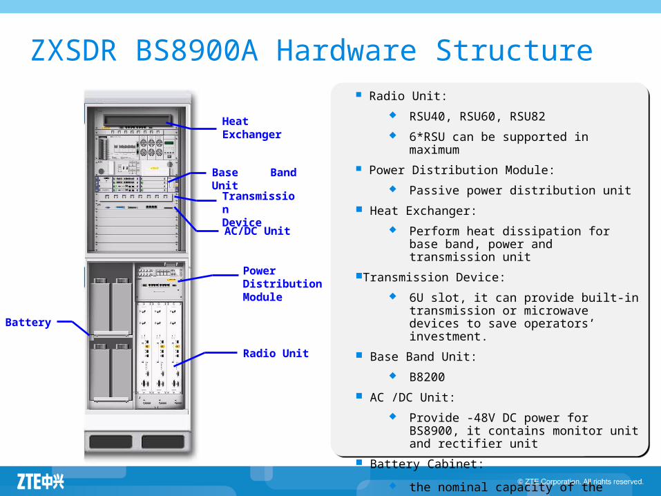
ZXSDR BS8900A Hardware Structure Radio Unit:
RSU40, RSU60, RSU82 6*RSU can be supported in
maximum Power Distribution Module:
Passive power distribution unit Heat Exchanger:
Perform heat dissipation for base band, power and transmission unit
Transmission Device: 6U slot, it can provide built-in
transmission or microwave devices to save operators’ investment.
Base Band Unit: B8200
AC /DC Unit: Provide -48V DC power for
BS8900, it contains monitor unit and rectifier unit
Battery Cabinet: the nominal capacity of the
built-in batteries is 300Ah
Heat Exchanger
TransmissionDevice
Base Band Unit
AC/DC Unit
Battery
Power Distribution Module
Radio Unit
BS8900A Sub-Rack Introduction
BC8910A RC8910A RC8911A PC8910A
BasebandCabinet
RadioCabinet
BatteryCabinet
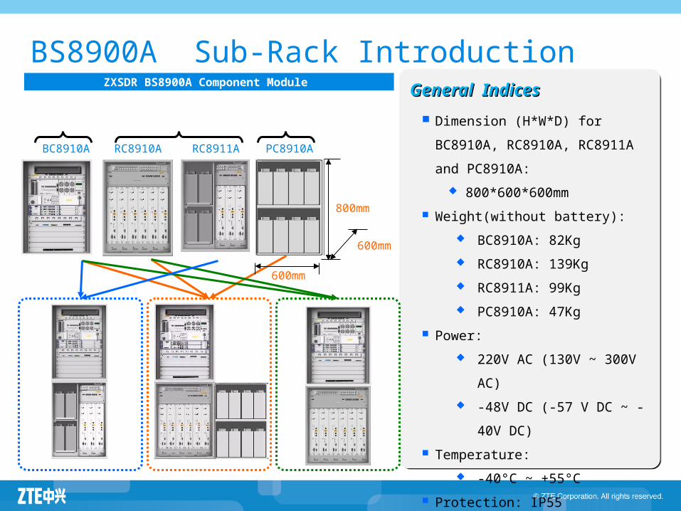
ZXSDR BS8900A Component Module
Dimension (H*W*D) for BC8910A, RC8910A, RC8911A and PC8910A:
800*600*600mm Weight(without battery):
BC8910A: 82Kg RC8910A: 139Kg RC8911A: 99Kg PC8910A: 47Kg
Power: 220V AC (130V ~ 300V
AC) -48V DC (-57 V DC ~ -
40V DC) Temperature:
-40°C ~ +55°C Protection: IP55
800mm
600mm
600mm
General IndicesGeneral Indices
52
SDR Base Station IntroductionSDR Base Station Introduction
Baseband Unit and Radio Unit Distributed Base Station: ZXSDR BS8700 Introduction
BBU: B8200 RRU series
Macro Indoor : ZXSDR BS8800 Macro Outdoor : ZXSDR BS8900A Micro Outdoor: ZXSDR BS8906

Integrated Micro Outdoor — SDR BS8906
Radio Unit:RSU40/60
Physical IndexPhysical Index Volume: 650 × 320 × 480 mm ( H×W×D) Weight: 52kg TPC:RSU60(DC): 445W/900M; 460W/1800M(S4)Power Supply: -48V DC, 110~240V AC
Performance IndexPerformance IndexProcessing Capability:
GSM: 60 carriers; UMTS: 30CS (with outdoor RRU); GU: 4 TRX + 1 C or 2 TRX + 2 C
Base Band Processing Capability:Same as B8200
Output Power: RSU60: GMSK 80W / 8PSK 50W/UMTS 80W RSU40: 60W
Receive Sensitivity:GSM: -113dBm @ single antennaUMTS: -126.5dBm @ single antenna
-129.2dBm @ dual antenna
Interface IndexInterface IndexAbis/Iub Interface:
8*E1/T1(Can expand to 16)1*GE/FE Optical or 1*GE/FE Electrical
To RRU: 12 *1.25Gbps CPRI Optical Interface
SDR BS8906
B8200
BS8906 can be connected with RRU for outdoor BBU solution.

BS8906 Hardware Structure FCE: Fan Control Element
LPU : Line Lightning Protection Unit
PSU: Power System Unit
APM: AC Protection Module
DPM: DC Protection Module
PM
SA
CC
BPC
FS
FAN
APM/DPM
LPU/SDH
/微微IDU
FCEPSU
RSU

Content
ZXSDR Base Station Family Overview ZXSDR Base Station IntroductionZXSDR Base Station Highlights

GU Convergence Network Architecture
GSM Base Station
GSM BSC
UMTS RNC
UMTS Node B
IP/SDH Backbone
IP/SDH Backbone
Independent GSM RAN
Independent UMTS RAN
GSM NMS
UMTS NMS
Dual-mode base staion controller
IP/SDH Backbone
Convergence RAN
G/U unified NMS
NetNumen unified NMS
Multi-mode RRUMulti dual mode BBUs form baseband group
Remote RRU
Optical fiber transmission is adopted unifiedly
Multi-mode base station
Multi-mode RRU

Convergence Network Evolving to LTEGSM Working Mode
GSM
BBU in SDR platform BBU in SDR platform
Same architecture for GSM/LTE, universal hardware
BBU supports LTE by adding baseband board
GSM/LTE dual-mode RRU evolution
Lower TCO Higher reliability Faster deployment
GSM RRU
GSM /LTE RRU
(Same Frequency band)
LTE RRU(Different Frequency band)
异异异异异 RRU异异异异异 RRU
GSM LTE
Co-shelf, co-rear board, co-power Co-clock, co-transmission GSM/LTE BBU can be flexibly configured as per requirements
Co-Platform for Multi-Mode
Co-platform for multi-mode
Feature Advantage
G/L Working ModeLTE RRU(Different Frequency band)
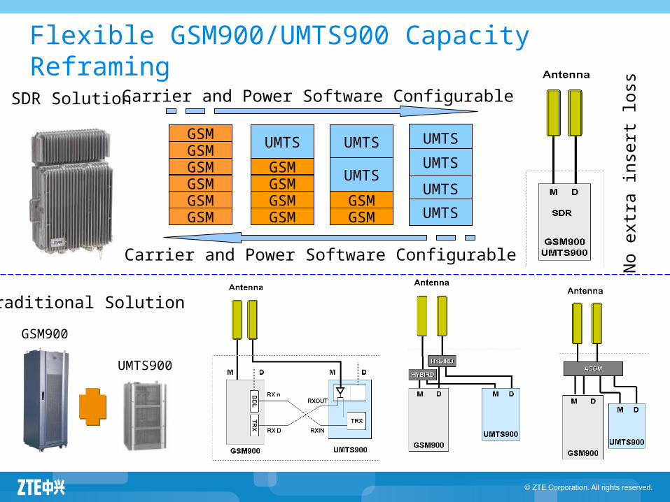
GSMGSMGSMGSMGSMGSM
GSMGSMGSMGSM
GSMGSM
UMTS UMTS
UMTS
UMTS
Carrier and Power Software Configurable
UMTSUMTSUMTS
Carrier and Power Software Configurable No e
xtra i
nser
t loss
GSM900
UMTS900
Traditional Solution
SDR Solution
Flexible GSM900/UMTS900 Capacity Reframing

The sum of each TRX configured maximum output power is bigger than PA maximum output power. In the area with little traffic, BCCH carrier power configuration can be appropriately added by taking use of dynamic power, and the remaining power is dynamically real-time shared among all TCH carriers to enlarge coverage and reduce site quantity.
Dynamic Power Sharing Enlarging Site Coverage
30w
20w
30w
15w
20w
BCCH carrierTCH carrier ATCH carrier B
30w
30w
40w
5w
30w
BCCH carrierTCH carrier ATCH carrier B
The sum of each TRX maximum transmission power is no bigger than PA maximum output power
User A
User B
The sum of each TRX maximum transmission power(100W) is bigger than PA maximum output power (80W).
User A
User B As user moves, each TRX transmission power dynamically adjusts.
Dynamic Power Sharing
30w
30w
40w
15w
20w
BCCH carrierTCH carrier ATCH carrier B
Static Power Configuration

All IP-based Network Improving Transmission Efficiency
iBSC
SDR Base Station
MGW1
SGSN2SGSN1
MSC Server
GGSN
TC Pool
IP Ater
MGW2
IP AFlex A
IP GbFlex Gb
IP Abis
All IP baseband processing unit
All IP-based network is the All IP-based network is the trend for mobile communication. trend for mobile communication.
SDR Base
Station
All IP-based network has better transmission efficiency.
Transmission efficiency increases by
87%
TDM E1
IP over E1
15 TRX/E1
23 TRX/2MbpsIP over FE
28 TRX/2Mbps
GE or IP over E1 transmission Mute frame and IP head compression

One Logical Cell with Multi RRU TechnologyBBU + RRU remote networking suits coverage scenes such as roads, bridges, villages along the river and so on.
Split cabinet, only BBU installed
Multi-RRU co-cell, improving wireless utilization
Cell A Cell ACell A Cell A
Cell ACell A
One logical Cell with Multi RRU dramatically reduces inter-cell switch, and improves wireless utilization. Cell A Cell A
•BCCH carrier power unchanged•Increasing TCH carrier, using reserved frequency point to absorb traffic•Not changing existing network frequency planning
110
12.5 0 029.8
0 0
110
35.712.8
0
73.2 72.8 63.9
0
50
100
0km ph 400km ph 600kmph 800km ph
Remote expansionSoftware
configurationMeasured UL datarate (Kpbs) of high speed railway scenario
Multi RRU and AFC disableOnly AFC enable
Only Multi RRU enable
Multi RRU and AFC enable

SDR-Based Network Effectively Reducing Energy Consumption
Typical consumption for S444
725W
RRURRU
BBU
Multi-carrier PA
TRX1
TRX2
TRX3
TRX4
TRX5
Highly Efficient PA Improving Overall Efficiency
Antenna-Close Installation Avoiding Feeder Loss
Intelligent Software Power Saving Technology
Networking Mode Saving Energy Consumption
PA module adoptes Doherty, DPD and multi-carrier PA, increasing overall efficiency to over 20%.
RRU is installed close to antenna, saving feeder loss. For the same coverage requirement, it reduces RF output power, hence lowering power consumption.
It supports some latest energy saving technologies such as intelligent voltage adjustment, carrier priority control and RRU module shutdown.
RRU adopts natual cooling system, BBU features in low power consumption and concentration which requires less equipment room and greatly reduces corollary equipments and air-conditioner’s power consumption.
Constructing network by using SDR-based Base Station averagely saves single site’s energy by over 40%.
1250W
Traditional Base Station
Multi-carrier Base Station
Power consumption descreased by 42%
TRX6
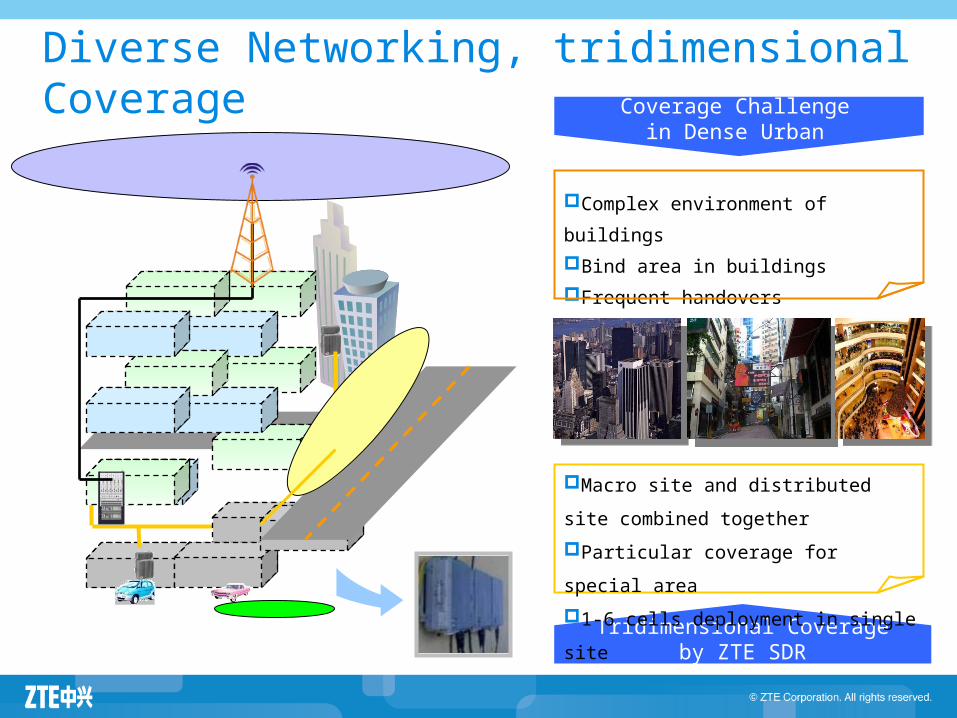
Diverse Networking, tridimensional Coverage Coverage Challenge
in Dense Urban
Complex environment of buildingsBind area in buildingsFrequent handovers
Tridimensional Coverage by ZTE SDR
Macro site and distributed site combined togetherParticular coverage for special area1-6 cells deployment in single site

Rapid Installation and Simple Maintenance
RRU flexible installationMacro base station without back board
On the pole
One person
on the wall Installation by the wall
All modules
operation at front,
easy maintenance
BBU saves space greatly Modularized designation for many application
19 inch width, 2U
height.
On transmission
rack or macro base
station
Directly on the
wall
BS8900 modularized
designation, flexible
subcabinet configuration Integrated cabinet in
suburb Horizontal
installation in
weight limited
area