e1 trnve1v th at !ivr.
141
T}v ter bizist thr.t shcttered Flood Rook 1n TTm11 Gtr fl October 10, 1885, and oloarAd tha y f'or iepdrnuht e1 trnve1v th at !ivr. (Tngnro11_Rnnd flo.)
-
Upload
khangminh22 -
Category
Documents
-
view
1 -
download
0
Transcript of e1 trnve1v th at !ivr.
T}v ter bizist thr.t shcttered Flood Rook 1n TTm11 Gtr fl
October 10, 1885, and oloarAd tha y f'or iepdrnuhte1 trnve1v th at !ivr. (Tngnro11_Rnnd flo.)

A &TUt! OF XCAVA?ION OFWI?fl 8PB(!*L
COLtJ7!A fl
n p*rtisl rnument ofthe z'equ.tremerite for the
degree ofMA3TER OV SCIENCE
by
C1CIL J. srt JR.
A THESIS
attbirittted to the
OROON 8TA!E AORICtUA'tIRAL CQLLX
uue 1056
OEROCK


PREFACE
A review or he svai].obls literatui'e on the aubtoct atsubaqueous rock removal has made possible the develai*ent
of an outline of the prori'eas tn thin branch of engineering.With this baek;round Part II is devoted to a proposed methodof removtn& rock from the Columbia River,
should be nentionod that the subject is contithe breaking and excavation of solid rook. Since much is
own of the methods of excavation of loose matepisi, asupplerent to the eztsneive literature on dredging w
of little value. For this reason, particular attention willbe d1rected to the drilling and blasting While the subae'
quent dredging will be treated moderatelyAcknowledgment is cie particularly to r. .L, . Peacock
of Stems.elmere, Inc. for the useful infortastion pertaintn to their 0 orations on the oluiibia iver. Valuable
data were received from .r, Chas, C, I*nsen., Eztner,Ingereolland Co. and esrs, Gordon end inkbiner, Port-land Salon Agents fur the Ingereollfland Co. Ac1oowl.d
ment te also dtiø to r, T. 0. Wier of the Worthington Co.,to az'. . 0. 0ro.hon, and to thoes o have contributed
of their time in correcting the test.Special credit is given to Dx. C. A. Mocknore, Read
of the Department of Civil Engineering, uzder hoae zsupervision and guidance this paper was writtn.

INTh)Dt1OTION
The removal of eubaqneotzs rock is a phase of conetruo*
tion which has perplexed ençineez's etnoe the first arttficial channel or subaqueous fowation was viauelizec1Ieverthlee, many million yards of submerged rook have
been removed t1u'ouh the ingenuity! of men confronted with
the problems of improvement.
Although thIs work is betri; carried on to an increaseing extent, it is unfortunate that the eubect ha been on.ly moderately ttetet. by entneering writers. any art talesof a vey general nature have boon written in recent years,but only a few writers have described theIr experiences co.cuately and in detail, Th limited material treatingthis work is so scattered and incomplete that it is difficult or a preotising en-theer to profit b he records ofhis prodecrtsaar*. 1s.ny mistakes result which, s3.though ez..
cusable to a pioneer in this field, coult be avoided withsome knowlede of previous experience.
Excsvstinc a ship chanol in the upper Colwbia Riverpresents itseir as a einI1'tosnt probler. vn with the mo&am equipnent in ottri'ent use, the eati factOry removal ofsolId rock to form a chanol In a river of this magnitudeard velocity Ii challenge to the ertneerin, pr&ezton.
It is with the thought that the available literature onIs subject or value in perfomminc simisir work in the C
lwbIa hivsr1 that the a.thor compiles this treattee.

PMT I . iVATION 01" hOCK
Fits tori1 Development
Surt*oe k3issting
Pioneering In Europe
¶L'A13Lg OP CQWEWLS
The Stewn PunohTb Chisel BoatThs Drill BoatTh. Drill tee
The anube River
Submarine Ulasting
Ort*nigat ion and Peraonel
Dredges and Dredging
The Drill
Modern 4ethod
floneyaoinb ing 24
Cofferdam 26
Ceie eon 27
The loating 3are 28The Lobnitz kock Cutter 2gThe Platform 29The Drill oat 30
Th. Drill Tower 37The DrillThe '!ater JetXntll 3teel
4
Th Jumper DrillPowder 3The Rook 3z'eeker 4The Dismond Drill 10The 5cott & Oristr Cutter 1
Procress in /4nterto* 11

eo
;°ti tt;itt OTZ
UO$flt3UO3tQ*Y O øpOt4ø*4
.ZTLpGJJ
UOTIJO XZ* UOZU14O$1IpiZa
%*OEoM
tL1p).b!1TtTuyuo;stouo3
£44O j:o x*uøOUO4JSj .;LGAOL tIIX1 $T4BtU7, taflt St(
£*j*;or UIt$O! sq
at pvdGqpndSXDOtX! G'LT
9eu2tjoou t toc' U!T4
3
.tt'LpøuodoGU
CUOT I1PUO3UG
qZAHIBtO) øt
AIX YIL'IOO ZII.LI )Ci oIirva
4QPPI 041;.addt eq1j,
qk 4ai

ture 1, The Lobnttz Rock3rsaking Dredge
Figure
re 12.
Lxsr or' ILLUSAIO3
)enerel Arrn.ement of Rock BreakersUsed in 3lack Rock harbor, i3uf*1o,New York, 1910.
The Lobnitz Rookeutter with CenterWell,
gure 4. A twenty ton mild steel ram with removable potnt
Figure The Ingersoll Drilling Scow.Figure i3uffalo Boat No. I used on Livin
atone Improvement in 1909. 34
Figure 7. npire Englneertng Corporation Boatin 31aok Rook Harbor, i3uZtalo, ewYork, 1913.. 17
A drUl boat htoh lifts itself clearof the water operattnr at Port Ve11er,Ontario on the ie13and Ship Canal,1914.
A Stemew.ielmers, Inc., drill boat atwork in &an Francisco }larbor showingthe spud and anchor engines.
A modern hmier rt1l an theEngineer drill boat "No. 426" work.ing in hook island apids.
PAGE
55
Ande. Corporation drill boat "EasthIver' drilling a 42 foot ohannal inNew York harbor,
0. Government drill boot "Terrier No. 2"engaged. in testing a hwze typedrill nd tower. 55
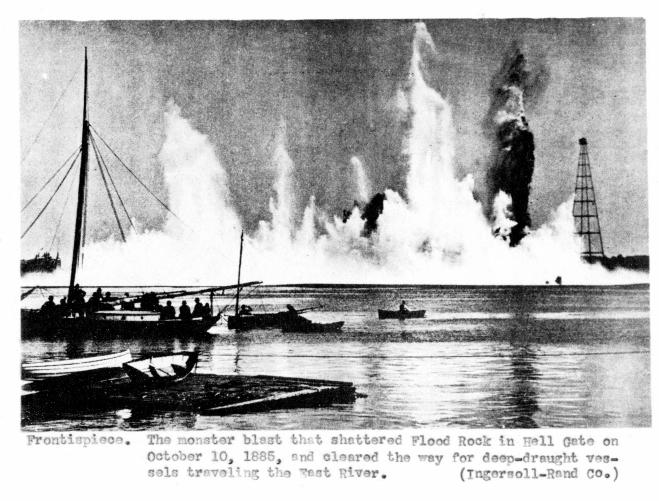
Front apieoe. The monster blast that shattered FRock in Hell Gate on October 10, 3885end cleared the way for deep-dravessels traveling the East River.
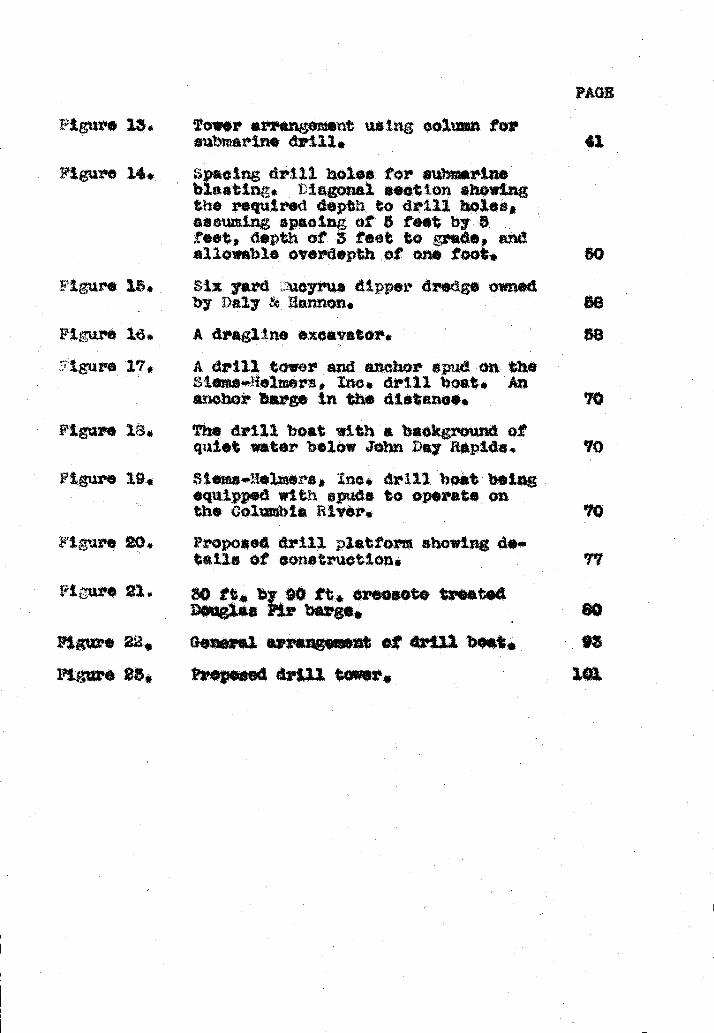
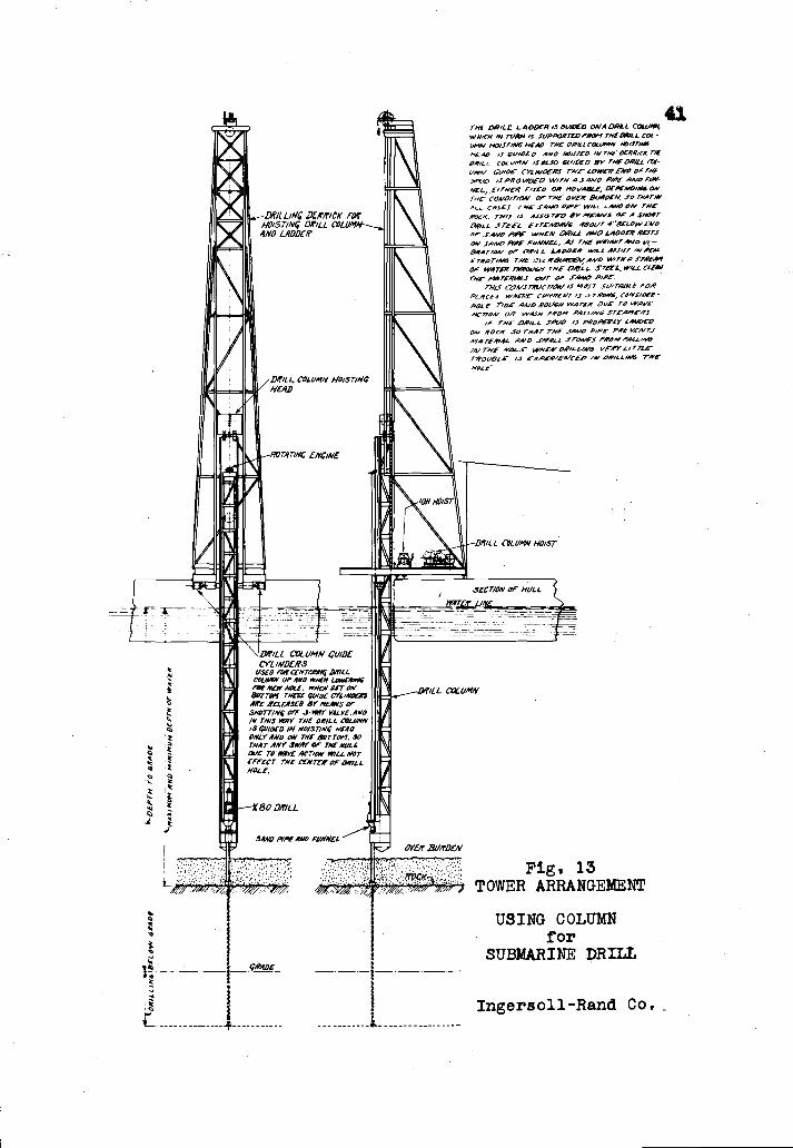
igure 13. Tower srrnngeiient using column forsubmarine drill.
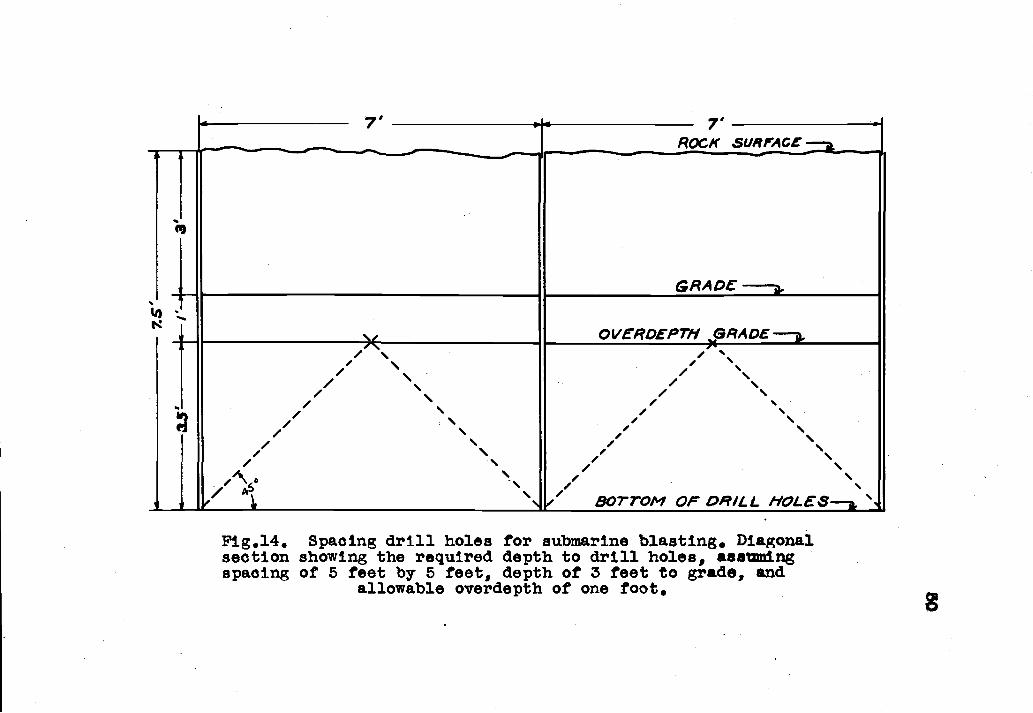
figure 14. spacing drill holes for submarineblastinr. Diagonal seat on showingthe required depth to drill holes,
sum.ing spacing of 5 f..t by. 5feet, depth of 3 feet to rede, andallowable overdepth of one foot.
ure 15. Six yard ucyrus dipper dredge ownedby Daly &. flcrnnon,
A dra1ine excavator.A drill tower and. anchor spud a theSime..'lelmers., mo. drill boat, Ananchor barge in the distance.The drill bot with a background ofquiet water ielów John Day Rapids.
ro 19. Stemai!elmers, c, drill bolt beingequipped wttF spud. to operats onthe Columble lvór,
Figure
Yigure
Fl u
gure 1L3.
cure 21.
?ropoaed drill platform showing di.tails of construction.
30 ft, by 90 ft. creosote treatedDouglas Fir bergs,
Figure 22, Ger*rsl errangewent
Figure 23, PrOposed drill tower
PAGE
43.
70

WOPSIS
The pi 'ose t this paper iti to present a. stuci at themethods empleled in revin solid rook troa blow a. w*titrsurface, applyinr; t principles to th constxct ion of a.ctiannel in the Calizbia. iver. A description of thodo and sohinery onplayed in iu"ope and Morica, bsginnm'
in with the first aride tools used earlr in the ninetsa.nthcertury, t presented as a ba.ckround fez' current oOra.tione, aie devices which havu been uied in the erwasof the world a.z'o discussed arid classified in the ordtheir tiportance as patterns for modern tnaoliinaa.
ny devices in current use are da.,oribd, xpandiupon those which si'. allied with excavation perforvod* floatirwj baz'e. The dr11 boat which is now .*itplo7ed
tsnsivel le analyzed in detail in order that its ta.turesu* be understood arid modif ted to ftt apoct'ic oonditionsubarjne blastin,; technique leads to the c3bvlos*rLt a
method of pc8 and loading drtU holes in order torealize iiva ,eiiottt fpolft the explosive eznplored.ioderate treatment of dredes and dedin methodseludes the dtecuasi.on of genel pz'acttoos.
Attention is thea devoted to the iuprovasnt or thenatural ch*rrnal in the upper eolumbia River. A descriptionof the adverse conditions and the ohannel zoquiz'ents -equ1sthe reader with a concept of the problem. ?wo tTpea of
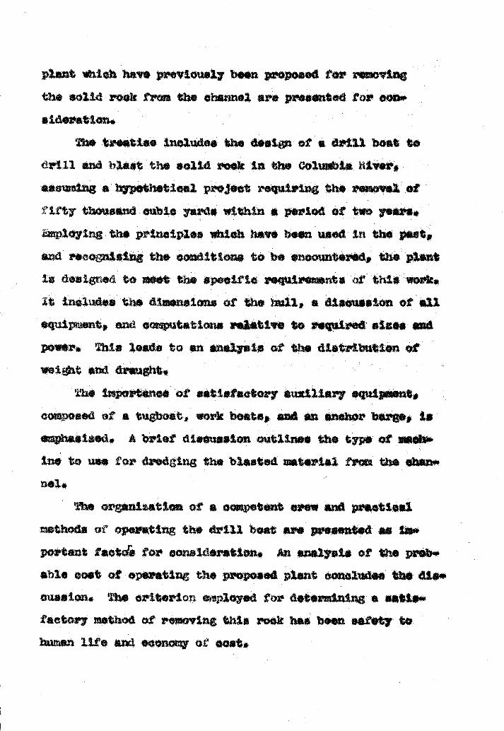
power. This leads to anig)it and trawz
yata of the cUetribution of
he iznpc*tance of satisfactory auxiliary .quip.snt,composed of a tugboat, work boats, and en anchor barge, isahastzed. A brief diaeuaaion outlines the type at sachoins to use for th'eding the blasted matsrts trc thO &*nø
.1.The orgsni24t Ion of a oompetent crew and preetleil
thods ot operating the drill boat are presentedrtent taotd for consideration. An analysis of the prObiu
able coat of op.ratin the proposed plant oonoludee the dLs.a ton, The criterion eiploy.d for determining a satta*£actor nethod of removing this rock baa boen safety tohuman life and economy ci' coat.
plant wio have previous I ben propos orthe solid rook from the channel are prented to? OOD'.sideratton.
treatise includes the d*ein of a dz'ill boat todrill end blast the solid rook in the Coluii. iiiver,assuming a hypothetical pro3ect requtriig the removal
fty thousand cubic *rds within * period of two yeJxploytng the pi'incipiea whieh have ben used in the pant,and recognizing the aoit lone to be noounteed, the plantis designed to moot the speoif to zequires*nte of this work.It inol,.dee the dimensions at the hull, a discussion of *1equipuient, and eovrputattons relative to quired

A STIDY OF 1X(AVATIO OF Q'J1o;s ROC1WITH 1CIAL F1th'TCE TO ¶U
GOLUW A XVI
PAT I
J .. h
ISTO1LCAL 'LOPENi
1h1AcJ LATI:G. ?e earliest knom method of loosen'.in ibaqtaeotu rock ws to place explosives n the surfaceor the atertal to be removed. Thin scheme wan used yearseo on the fthtna and 3evorn Rivera in &trop.. One method
'a? r o*tn the rock fron tho aoua Riverto place bundles of powder on the bottom of nrmotu'ed epud
and lower them to the surface of the rook whore theyexploded Uvtortrnctely the axtds wei'e usually daina,d more
than the roch, it wan found that the tirat ahot was eftc-tive to a depth of one or two feet but that the subsequentup1os tone in the ewio place were sborbed by the cushionof broIen rook.
This procedure h*n had a varied history and is usedoccactonll even today where oondttons at's favorable. The
iami :tp c nnel,68a soft porous limestone formation,wan recently deepened at a nominal coat by this metiod of"dobyin 'p or blasttn0, o 11 packets of 60%eiatin were weighted and. lowered to the rock surface. All
conditions boin favorable, no wind or fast currents exist'.irip, this method. proved max's economical than drilling. Th

reiaoval of boulders and pinnacles under the water nn'faceoften perfarraod in this itannor, but in snezal it nigh
be said that surface blnstln has been very unsatisfactoryin foranat tons Where ledge. and large areas of flat botto!npredominate. oat of the rook which has been dealt with inthe past faUs into this classification9 therefore, it hssbeen found advisable and iznportn.nt to resort to a rore praotj1l st'tod of renoval,
PoneerL in Juro
Witi attention centered about Europe thirtn thcs*ploneerin. rnany sehenes 'or rertoving. rock were ettenpto4,
The Liret method o which records are available was natu?"ally that of drilling holes in rook by hand' 'and the us.of black powder, The wrttin-a relate that the en stoo?,
on rafts and drilled through a pipe, one holding am! rot*t.rip the steel, while others struck with oleds. In this
ly development ot the hand nethod a e*ion or dtvinbell was often employed. As lon no as 1814 en descendidto tte botton cf the iowth harbor and drilled holes th*rock by hand nd loaded with black powd, The diving bellend oaeeon ha been used eVe2' since but With ma reftn.monte.
Th J<7M ?J i)ttL1. Probably the first inprovement sthe use of the jumper drill in rernovin.p, the *rl beda along
Note: wber* i* teat z,sfsr te bibUsp!.y.

The Uvr Severn" 'in 1860. Th B
was more satisfactory than striking the steel withhaLers, especially in soft lock formations. It was a hoesteel bar weighing about fifty pounds and equipped with a
fored bit. As it was raised and dropped it was guided inon iron pipe so that it continued t penetrate in one pl*ce,The first combined unit was composed of a shaft on hich anumber of slip ropes were w pedBh slip rope wasattaahsd to one of the twup.r drillø sa the shaft wasrotatod by hard, the bare were raised and dz'o b7 pullingand releasing the ropes,
The first machine used for' roek in was
invented by r, llipp in l865.'49'This consisted of a heavybar wMoli, like the jumper dxiii, was raised arid la ata atnle point of contact, The inprovennt restedtact that rather than using hand labor the shaft was rotatadby steam power. This msththe v ahort lived but e a valusbie contribution to prog,r'eas in subaqueous drtlltnj, !any
other tmproveente were nae during this period. A1thouh
they were einttic*nt at the time, the advent of rw esti*.factory r3achtnes soon put then into obscurity.
POWDER. iners at that time were not only con.fronted with dtffteulttoe in drilling holes, but the bleakpowder in ue was in*dsçuate for under water service. l3lask
powder had long besn known and used in firearms, but it we.Just beginning to find .nploymert as a methnd of braking
rook.
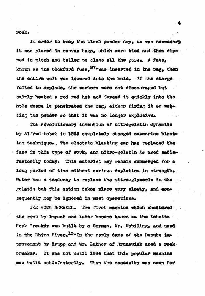
n order to keop the black powder d neceaaar
it wat placed in cavae haga, Whtôh were tied and then dip*pod in pitch and tallow to cloec all the porei. A tue
known re the I3iokford ae'was innertad in the bag, thenthe entire unit was lowered into the bole. It the chargetailed to explode, the rkere were not diacouraged hut
cablr heated a rod red hot and foz'oed it qtaickl into thehole where it penetrated the bag, olthcr firing it or wettr; the powder so that it wa no longer exploaie.
The revoluttozrnr7 invention of nitiogelatin dyna'lteb Alfred Nobel in 1863 oornpletely ohana.d submarine blast.in te The electric hlmwttng cap baa replaced theIuee in thie type of m!'k, and nitz'o.e1atth is uaed eatlsfactorily toda. This ztmtarlal may remain submerged. for *3.or, period of tte without eeriow deletton In strength.nter has a tendency to replica the nitro Irco'in Ielatin but this aetlon takes place very slowly, and on*
sequently nwy be inered in iost 'perat ions.OCJ BBIJUER. The riret miohine which shattered
the rock by Iupaet and later becme known as the Lobn.ttzflock reek4v was built a Oerncn, 4r, Tobillrxg, end. need
mime River,13' in the early days of the t tihe Imu'
provenent Irupp end tr. Luther of Hrunewick used a rookbreaker, It wee not until 1384 that this popular rnnchin*was ,utlt øatftitor1ly. 7hen the necessIty was eoen for

D---!
qwi)II IIIIII II Ii .1 I ijI -
Fig. 1. The Lobnitz Rock-Breaking Dredge 'Derocheuae".(Engineering News)

tmproviftg and deepenine; the 3uoz Canal, ..srs, LObnitL end
Coznpanj of Retifrow, eotl '2'aonstruoted a plant sftich
coribinod the featiwes of o leader dredge and a rock bker.
10 'e 05u3G'1 a eei.oin dredge was ch?..'is*
toned, was eqpped with a batterr of five r*ra arrenod in
a row on .aoh side of th ladder as shown in ure 1.
ty1ose otr ton rams wore ried and dropped, ttering theO bekot ladder iodiately re!nored the lGt>e zter
tal, leav1nj a clean surface on shih the rane oontinuousi
operat.ed B uein a sput! at the etern of the boat as a
± was possible to 000l the area of operation and
then to advance upon the oozn;lettoi of each arc nade b t
A1thoh the Dorohe'zee seoessAillr eoinp3.eted the wer
or toi it i*s deatrned, it was too large and cwereoie
in a confined area. The opeat ion of the entire plant weedependent upon each unit, therefore or one et the rams
failed to function properly- the rroress ceased, 1or thiareason it wee found iore satietaotoz7 to separate the rookbreakinr from the edin, Mle breekin, soft material
roes often penetrated and stuck fa*t resulting in atreat loss of time,
The later rock breakers were mounted on separate baresand per*tod independentl of the dredge. Thae usual
17 x'aned in
the rese
ight from four to t went tone, depending upon
nd depth of rook to be romoved.8'49'Wh.n

I1,k ,,'- t1is,,gR'p
Split Cap Rope Socket
Cap and Socket for Attaching the Rope to the/Rain.
Fig. 2. General Arrangement of Rock Breakers Used inBlack Rock Harbor, Buffalo, New York, 1910.
(Engineering Record)
NNN
N
heevy rams it w iore eonomic*1 to place only OflO or
on a ørn1l bar,e ihtch could be manoiaverad easily, as shownin 'ttire 3 These manoth chisels mounted on bargn aro 1w'tereetthg from a historical standpoint since they have bean
extensively in bre*kthG rock in all puts of the world.ivsri today thej rar be found operating in urope
hero covd1ti are favorable. The ru!i was long an!t 1
drical ape, usua1l; tape'ed slightly at both sndamain bod of thta raansive cclum2 was eo1ic mild steel equ
d with ecta1ly tomporeL. rerriovable points. The points
were oIval in shape, iure 4, and harder at the centertha: near the e32ones!'entl, were selr sherpening.
These res were rained and dz'opod in guides in muchthe za* w57 as the pile driver is operated, the dtstenasdopodth upon the con(11t5.ons and the ability ? the equip.ment to rociat the shack. The lIfe of the wire rope u.sddto I3G the ran very ho't, owin; to the continubendIn, at the point where It wee atteehed to the ramled to thi deveiopctent of a ral3.ow socket in the head
pernitted the line to fol1o' into the rum *bout three feetafter 1 etruc1 the bottom. ThIs tnprovement wa ftat u*e6in rernovinr, rook from 1sok }ock iarbor us shown in
2 and was 'ound vez'y successui'P' Anchor .sp'ids
iianly used to etabalizo the barge while in eperettotheaø wore not always necean*r a omittd when moon.yen lent
ma

j.' , f}jc Lobiitz kookoutt,r 'ith Contr !i1.(John Wiley & 3on' oundat&on&')
F'tg. 4. A bventy ton mfl(i ti rt th rnblpoint3 (ntneerin fl.øorc)
9

The rock breaker wee economical tri that tt eliminatedthe use of po*er, but it operated very slowly. Bsesusi ofthe great wei.t of tluseldom exceeded one hundred fifty per hour and the *ftsotivedept' to which the razn broke the røck doreased Very rapidlyas the ram penetrated the bottom. This was due to thetori of broken rock formd on the aurfacø which absorbed theforce of impact. Al a result the rock was broken and dredgain layers about two test in depth. Zn soft rock the s*chinwee vorj unsatiafaetoy because the rain failed to tracturthe rook but simply penetrated and atuek firmly. This moh-the has had a very interesting hIstory nd is practicablewhere labor coats are 1.0w and time is of little importance.
!E DIAJt4: tIULL. At approximately the same time that
the Lobntt rock cutter was first used the diamond drill,which is a rotating machine, equipped with diamonds or soma
other hard material as a ctitttn agent, was introduced by1. Th. Jonea and 3. H, Wild of Leeds, nglan6.'Thsee diernoid drills were freely attepended from floating barges andpermitted to operate in rxuch the ssxme manner as they do on
land today, These were later used by ?ontaine *nd Tedeaooon the Danube itver and the Panama diamond
drill has never been thoroughly successful in this type orwork since it operates very slowly end xmzst be carefullyheld in position. It has gIven wtr to the more popular pieton or h*r drill which cuts by impact rather than boring,
the averei number of blows

I
baft which dropped and struck the submerged rook with
1
TH SCOTT I (OI)SIR CUTTEh Thi scott and Gods tr.er was d*sijned by ressre E. M. Scott and A. Oodsir at
New South Wales in 1891, Thu maohine incorpors
ates a combination of the principles of the rock cutterand the steam drill. A very heavy rod 'as directly cted to a steam piston. The reciprocating rtotion osusadrod equipped with a bit to strike the rock bringing sbouits fracture end pulveriat ion, This machine operated fsmt*
than the Lobnitz rock broker but usually struck the Ughtarblow since the wal. t of the moving parts rarely sZsao4ac1three and one half tone. The number of blows was approzt
matal; fifty per minute when operating under full steam.This type of plant was used for a few years in lurorsdtzal1y disappeared with the new improvements in othe
machines,
in Atieries
At the ssxns time that European engineers ware
with improving navigation, similar problems war. present hsvsn the United States, Th first attempts made in this cOQfl'
try to remove solid rock ware quite naturally the methods ofhsnd drilling and b]aatin with black powder,
?HE svAr PW4CH, The first improvement upon thistics was Mx'. Chas. ¶1?. iIarv.y*s "t Punch"
used successfully in breaking a ledge of rock in the St.srya Fall 8tp Canal in 1854. Thu mach consisted of a.

e*ttmated force of twenty tone par square tnoh, This zø*ft
consisted of a heavy wrow',bt iron base which tapered dO
to a stel bit one inch square, To the tapper end of
bess was attached a heavy oak timber operating in guides.This nuoth chisel or pur4ob, as it wee called, thn droptz'or the tOP of the guides struck with terrific foro*,
T: E CHISEL !3OA. Upon this saute principle Major J.Floyd of the U. S. moors designed and built what was
called a 'chisel boats in the Dee Moines Iapids the fdlloIIZEwas cQ!nposod of a heavy steel cap tied with
rawhide to an oak timber studded with rails which woz4ced in
uidea, Thia boat cud not oporats very well on the Dciotnes aptds where it was necessary to reutove large boul
ders. It was later used nore suocesafuLty to remove a thinsyar of ledge forntion in the sock Island iapids of theiseiseipni River where naviat.ion was hazardeus. This
chIsel boat was improved upon and used continously until133G when it va discarded and replaced by more mod
me
An tnterestin observatin in that slthou, the Lobx4ts
sock cutter is generally consIdered a u'opean inventions inre ity the same principle was used at bat three pl*o*s inthe Trtec1 3tates many years f ox's the birth of the 5D*chcus&
TiE DLtILL OAT, As river and harbor improvements buø
ceme more Imperative in the Tnited States, Mr, C I, Dunbap,
aaaotivly ennged in this type of work, was
2

brCe, r4 Dunbsr wee
renova rock froi Port Co1bo:'rie
rock uias so hard that three ioa:V
per daj br hand thode,
end equipped it with two atetwveble towers placed or.i. tre&t
team piston drills hail just be.holo8 in rock quarries an ot
The bergs s moved. and eld
.i,. e:t ifl. t)o
"
ici
13
ieav7 breasting chaine ettachoc o .
installed on the bex'ge .t n1e!ii 1 t .
the drwnn ithi.ch controlled th 1:c ',, J)Ofl
in the driUin operatioz.desired beat Ion ero .or3d dw
above its nornal buoyancy 1iri 2.
the wsiht at the scow to itc ioeden towers upc w
csrring on drtllin aperat10hand steel, and orowbers, ; n
rafta, coupled with eorit it . . oc
me for 'i11in on 1 id t . oi
proved to be the prototype fo:t o c1ci.
478
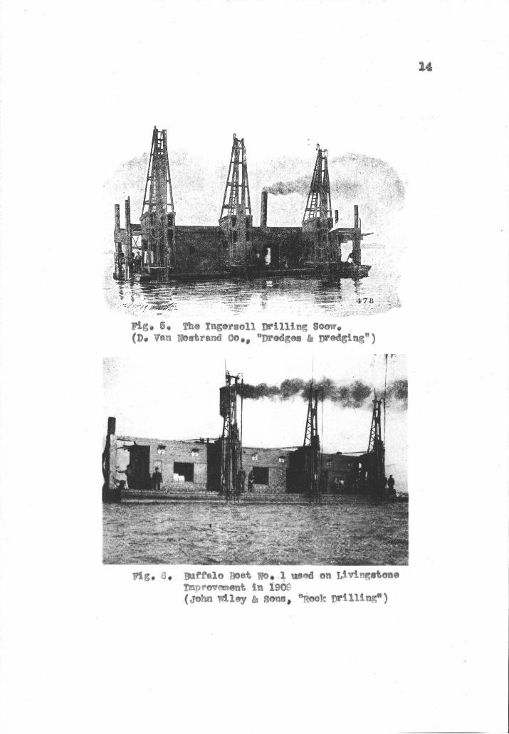
Ftc, 5 Th Tngrm11 flrL11Lnr Soow(P. yen j7otrand cOa, "predø & prdg1n")
Pig. I3u'fe10 T)Ont No 1 w'd on t1VInPton!moiovnt j 19O(john ii1y & Ron1, "PoCi tn'(11tn")
14

were designed to iove along the full Length of the fift7foot barged skidding these towera along the track withCrowbai'a elevsn holes spaced at five toot intervals couldbe drilled without moving the best, The drills were mvunte4
on the towers in vertical guide. overhanging the side of thebarge. They were controUed by hand winches and saud opu
ate for a vertical distsncO of n.m. feet before it was neassary to exchanje the bit for a longer one, The drill stedwas conneotad directly to the piston rod by means of abolt chn*k and moved the xl). length of the atx'ok wisb wasabout seven inches, These drills struck at a rete of 280blows per minute, which iwaa a great increase over the hand
operation,
Upon the a 4lettin of each hole, it was loadedblasted without moving the bar a raw of holes was
Iiniehed, the barge wee moved feat troa the rangeoperation was repeated. After a Zergs area of the reek
wee broken i * removed by Or'dinal7 dredging method
4thtn the following few iears r. )unbar installeddx'aulic rams to move the tower. and to f# and hoist thedrill in the gnides. In order to kep the overtur'denthe loose uttins fron falling into th. drill hole a easingor "tmid pipe" was used. to penetrate the overburden and rest
or the surfaee of the solid reek. This also aervd asgi6e when loading the hale with po
A w$ter jet was latex' inserted in thó hole either dii

tug the dz'tUin oi' when the bt was withdrawn for the purpose of waahin; out the cuttings end fine particles front thebottom of the hole. The successful removal of euttiuge
creased the speed of drilling end alleviated the difficultof etickin6 the bit due to "sandXn in" as it is called,This was one of the major improver*nta in drilling history,
The drill boet was so successful that many rew ones
re built n the region of the (ireat Lakes ahor'tlT after.The Ingersoll drill scow1 Fin, 5, and th Rand
drIll boat soon iade their xtppeexuno. The tudted States
Ax.y inineers built one to inprove the channel in RookIsland Repids, !?igs. 6 7 show more recent boats used
the Livtheton Improvement of the Detroit flyer and in BlackRock Uarbor, reepotively.
T DRILL The drill etaL. aundera *nd used successfully in the rexoval of Bliekiorn eef in New Yor,49'lneorporated the s principlebut the anchor epiite were designed to lift a light stagecl,ax' ot the water in order to avoid high tides and wave so.tton. Upon this platform wars unted oMinary trI.poddrIlls coml seen on land. The drills were ved about
the platform and the drillint, wee done through holes in th5deck, ?he steam boiler nd all appurtancOs we
a tender berg. moored alongside in order toimoh weight the etage as possible.. This meth
r. W.
ed

Pt 7. nptre ng1.nr Córprretn Bortin Bittok Rook Rtrbor, Buff1o, rYork, 111.(John i1ey Sonz9 "oek Drillthg")
Fig. 8. A drtfl bont wMoh Ufti t-ao1' o1r 0e thø wutr op'reti ttport V11rr, flntaro onShip Cann? i14. (rineering -8)
1'7
used extencively in many place. where tides and vindedrilltn from a 1i.osting barge inipr*oticable This typeplant shown in Ftc. 3, ha touM. current use where she].water is enoozntered.
The Danbe River
Thin t.h:ts time progress in druhin in the UnitedStates and Europe had ben separately and independanly. cn it bc*e necessary to remove the lron Jatee"tr,rn the 1iver nibe,9the work on this tteseherousrivet' was of sutrioi.nt ehsracter to enlist world wids Itereet. As a result p'actioelly every known type of rxtaoh*inc for 1llIn and breaking rook yes used, Although o
dit ions were very unfavorable with the swift current. sadan tni'ezlar bottom the engineers 5.5 to be coendsd. forthe calibre of wo'k done In removing rook from this sectionof the Danube, With the crude devices in usa at that tiz*the European Cossdseton of the Danube removed 200,000 eubiø
751'da of rock from Stenka iapida, the Greben action, Co].$irojke itapids and the "Iron Gsto&'. It is doubtful itproject as difficult a this one has been performed sinci
This ezte!Lafve work brouz,ht topether all of theadvanced details of sttbequeoua rock removal where it
possible to compare the equipment in use at that tt,the results obtained it was found that the Lobnibs rock out.,ton snd the Azueric*i drIll boat ware the two moat eatisfac*

9
to7 tfpee of' nachtnoe. Althouh tch grief was experienced
wIth both of these, it was found that ench one poaesaeed ad.vsntgeou features not found in the other.
The rook breaker was not satisfactory in shatteringre than two feet at tine. As the surface rock hecarae
pulverized it forne4 a ushion whióh protected the rook be-low, hi essitatsid dredging after two test of rock
re broken and then a repetit;ton of the sane process.th t a re eon the &rtll bsz'o was used in areas where morethn two feet were to be removed, and use of the rook br*k.'er confined to shallow a rule was
quIte generally observed for years afterward wher betyree of plant were used on the same project.
T2e drill baze was difficult to hold in position inthe swift current shile in operation. The slight shitttngoftefl caused the bit to stick in the bottom of the hole re.suiting in a treat loss of time and equipztent. Its operation in the Techtelts and Juca Rapids of theeratoly successful and introduced the drtU scow to theEuropeans.
e 'en*rsi onteome of this taous project was the ellanet ton of nearly all equipment in favor of the rock break.
or nd the th'ili boat. The Lobnits rock cutter has contin.ed to be popular in Europe where labor coats are not pro.
hibitive and tie slow operation concurs with European
chology. it has also ben used in the Panama

Liack iok *rbor' in k3uffalo, ow or'k' and in Caadprovemnta44' An accurate reoord of its ope'st ton and coetein th 4arbox'u of Ailoa, ..an ataban de ?r'svia and Port 4,ilbao in spain le available,
drill boat has continued to be nicre populcz in thetnited k.tA6iØ In the last fifty eara zdllione of cubicyards of rock have been røied from harbors and channelshio,hout the world 7A great majority of the vo*
has been performed in the region of the Orast Lcke#. and inEact Uvez' in Ntw lork uhore drill ecows hsve operated con.tinuouly thee the nineteenth century It is *n expensiveplant to operate and therefore mast tunct ion rapid3.y and ooa
tinwuly in order to avoId *xoessXre unit coat. In
this fact many nochantoal rttnsreente have been addedãex' to tncreaee the speed of operation.
The Drilldieucsatn the evolution of the drill scow, the
interest has centered about the drill itself. In $nersl t)adeveloprent of the drill ucod in subaqueous work has follow.ed the improvsents made on the land d.rt3.l.55As the ehannelepth requirements increased to forty feet it ii
necessary to improve the drtfl weohsntem in order tothe lonsr steel and greater weiht. With these thedrill b*en to differ somithat tram the l*nduopsratad
The inertia of the recipoeattn atel neeoeaitat*d a

21
very heay 1515b.bse)c an which the drill was mounted in ordSr
to nvoid vibration as much a possible. The orew feed was
slow and inconvenient1 riecoesitatinp steel thsnoa .ery fewfeit. This inadequate device was replaced by a brdraultocylinder and later the drill was hoisted and fed into the
d iirs pai/hole by a atesii wtrhA over a aherve at the top of the towsand down to the drill. :rsllw winches nd capstans realso nounted n the tower to handle the steel and sand pipdx the chanee The full tower' was not always used but
colunn was eloyed wer'e the rsno in tide was afeet, This column wa stiiiler in...can ton to the
chor spuds and rested on the bottos where it worked freelyin vertical guides on the barge. The drill with the Ged
rsii and sand pipe sas riiounted on the outboaM el4s OftLia spud. !Jpon the completion ot each bole the oolt*ri wa
raised and moved s1on the barge to the next position, The
advantage of this desi1n wee that it operated tndepend*ntlyof the barge and was not affected by surge. Tha rthodwas not too satisfactory because the long screw feedvery slow, and the posit to of the operator in * az*lat the top of the spud wee coveted by no
ie two most concn types of piston drIll in urns werethe tappet.valve end the eteam.4hrown&vele deet&ne.tappet.'vwve d*sIn the 4aton had to strike the valve inorder to reverse the port opening to the piston, A full
stroke of the piston was n G.nuarr to operate this machiUbviouil vibrstio difficulties were experienced tien thedrill uas runntn wid*r U speed and whn it was crowdedelose to the rock. hc ateam.trown'.vslve d.ainthe 'Ic1pa&' operated on the principle of unbainnoed prap.sure1 It WuU nQt useossary for the piston to strike Uvalve, therefore, any lonth of stroke would operate thevelvo noohai m. This fatu.re afforded the operator the
rtznIt of x*epltin the length of stroke and thet of the blow b proper eoUng of the drill,Durmn the period thet these izuproveitients were being
nado, the dri1l wore also being built with a lsrr bo:d stroke. Th first subnar1ne drtlls were of only a ttv.nch bore. As the driUir depth increased aazd the drill
stool "as loer and heavier the drills ere increasedt 1 the longest of the piston drills was *de with a pistonG inches in diameter. This increas, is reasonable sines *2 inch drill øteel sizti feet long used to rezove roo*t toa depth of fortytwo feet at low tide weighe eight hundrcd
OUndL
The mast recent developmrnt in subatueous drillthe zxlopt ton f the air'-drtven hsrier drill1 et1oh has en.tire1r replaced the piston drill on all land work. Although
the old ?iston ri11 is fs8t becoming obailete it has serveda valunb3.e purpose. Throtji its use waterways in all
s of the world are now avenues of o eras where p.
pt iithout dagez' of atrikLi blddGn obtzuation8.Itoigh tIiwe i no writt*n xeoozd of ioms of the
prttue whia hive böin wied n abao rock reaovul,t:.e i'enuity o rins' com'ronted with thee. prob1csias ont1bted i'eat1 to the dsve1oprnet of mocloim reth'.oit. The riodori d.t11 beat with Lte &nbzex'ed 11atme2 drills
and diesel powered aix1 c;eseozs 'trare a vivid past aMoats an intar.estii tituzc.

XCAV4IU4 OF
Rook has been removed from bsn*sth the water surfeo.in many ways. A thorough dtaøusoion of the methods employedb engineers would involvi a very extensive discourse in thefield of ,ndnoering. It is the purpose of this paper toemphasize only that type of work which is allied with theimprovement of water'.way. where the rook is in such a pOSi4u
tion that it is not feasible to remove the water, To clear.17 define the relative posit ton of the drill boat anti therook cutter an outline of the common methods will be in.'oluded but only the pr*et toes rssltive to the drill boawill be expanded,
The most logical procsdurs .tn *''izg methgeneral use would be to divide them into foir !laesifia*tions. These are honeycombing, employing the eofferdaa,
working in saiseone and operating train a floating bsi'gs
Iona7ooin
The honeycosabing method of rock removal ii favorable
only when a large body of rock can be approached from above
the surface of the water through either a. shaft ox' ondined tinnel. The procedure is very aiai]ar to that ofquarrying or removing large menses of rock commonly en
counterd in land imp ovements The only essential dIffer"
MODERN TIODS

snoc in workir under the surface of thø water is the tt'ow.ble encountered in eeeps due to the presence of a water
head at en elevation ezceedtn that of the operation. In
this type of work the rock is perforated with a network oftmnels and shafts eomnonly known as coyot. holes.
holes are subsequently loaded with powder and blasted
ing an electric cap system which is often 5U3)plOm*fltcd with
cozdoaM to insure proper detonation. After the obstruot ton
has been broken into frarnentm it is removed by ordinary
dedtn, rithoda, 11010 ioeks In the Bhino River, part o
be ?lIron te&' of the 'and many other lodges h*sb rmoved by this process. Probably the most widely
kno'an instanee was the blasttnr of Flood Rock in U.3.1
n flew York flarbor by Qenaral John I4ewton of the U, S.
Ai'niy Engineers.''866'Fortunat.ely a good picture was takes
at the time and a replic, is used as a frontispiece.This famous rook had obstructed traffi. in the nerrow
end crooked watez''way where the 1ast River passes b.twen
lackwell Island end ''/erde Island, Th channel was so d*m.
med by tha obstruction that a difference of water l.v.l ofalmost two fast was often observed at high tide, The con'
sequent currents plus uxtsvorable weather cnusa4 en average
of one out of fifty boats to bO damaged by atiking thisrock4 The work proved to b* ti martsnoth undertsktng nd the
United states Army Engineers met with no little ditttcuThe fanos blast on October 10, 1883 1. heralded as the
larjest subaqueous blast in history, tsny methods
vtoely attempted in remo'tn this rock but it was tozatthat honeyoombtngwse the most a*titstsotoz7 economical at
the time. ir that work were to be done toda It is probablethat a different method would be uad due to ie rapid ad.vance In the stficienoy of the drill barge.
Cotfardem
A coiwnon practice in reino'itn aubaquecus rook in can.
nection with dmn cànstruction tind the preperation of fdations is the use or the cofterdam. The ares to be av*ted is surrounded hT some form of temporary' dam and is
then unwatered. En realtt the area is converted to dryexcavation end from this point the work Is conducted in theseine W57 tie on land, One of the tsroua projects Szcutadin the inannor wee the removal of the large rook at ilendir.eon's Point in Portsmouth Rarbor.'Althouh many aatlarjobs have bsn performed .ince,this is outatsndtn inhistory of the cotfordeni beoause of its great eisa and natwal difficulties encountered, A circular wooden cofX.r.
dam was built to an elevation above the water surface andthe interior was piunped dry, then excavated to th requtdepth below the mean water level. Lone drift holes wethen drilled horteontal].y under the baaø of the cotterd.Those were loaded and the entire volume easd of 38,000cubic arde of rock plus the coffordam was lifted bysingle blast, The wrsekad coffardem was pulled swsy and

oose rock wee exCavated with dreds
seom iocc in san snetaco F 1055wee removed by
costination of the oofferdsrn and honsycoinbing 3inoa throck dId not project above the water &nu'face * small 0i3'*cular dau was built. As soon as a shaft was sunk in thorock, tunnels were run i all directions. They were loadid
with black powder and the ch.rn was detonated by elsatrie.tt from a boat.
An interestIng piece of work of this trp. was recentllperformed in the Tangtas River in Chin*'where it was tounecessary to remove two larije rocks from the channel. Us.
n Chinese labor exclusively, tar. R, G Ivereat of theCinsee aritime Custo!a built two small eoffssdsmsh*tta into the rooks. Many canals have been taproved and
deepened in this annr by placing enporaz7 dams at theends of the operations. The WSllsi%t Cen*l'wae reeent
desponed using methods ocmtpar'sble to those on
ootferdam has been used extensively in canjict.ton with dewconstruction within the last few years. A notable sxlis the manmioth strttoturs employed on the i3onneviUe Dam.
This msthod is precttcth1e only whex'e a large mass of materlal may economically be isolated by comparatively cheap astruction.
The osiseon method vat ton is extensively used whe

28
acc'u'scy is essential over a oonpar*ztive3.y small area. Its15e 18 Cofl!nonly *esociated with the preparation of foundationa. Tht8 device incorporates the principle of a stelshell open at the bkttO h1Oh descends to the surtece atthe rock. The water is prevented from entering the caissonb the use of air presmue on the inside equal to the prostire of the water. This tethod end th dlv bell. *lis olosely zelated, tro not confinad alone 0 the iiiti(,ned abovø bu
rocks have b.n
bloatin barge
ment of the use of eaisaons is found in Mr. Chee, E,"Treatise on Sub.'Aqusous Foundationst?,2h1
The i'loating i*rga
Of all the nethode used to rvs eubequethe most popular in channel bupx'ovament
hr. are a number of types at floating plant which shouldbe discussed separately with special sttntton directed tothe drill bost which is speedily usurping nearly all work
have been uad in channel 1nprovin. Many
ved. in the hhiue River under Gernia
eupervis ion. The diving bell was used in excsvetin. rap aQuay wall at iante, Frsnce.78'Colonel Newton attmjtedthe uae of the caisson in the zeaoval of Elood Rook but oon
clu4ed that honeyeombing was more satisfactory. Probably
the rnost not*blo onployment of the calgion haS been its usein preparing the rook for the piers of the two bridges !wbeing built in the San 1ranoisco liay An eztenelvó treat*

LOiTZ )C TT1Fc The Lobnitz rook cutter is stillfor ocoas tonally in the rivers and harbors of Euopø, butte dertae is predicted tthin a short ttte, This machin
was described in the historical development as a valuabletool *hare conditions are favorable for its operation,Practically no revisions have been nade in its constructionother th*n the ninor ref tnetnots in uaohinery. To smaar'to its advantegea'69'the rock breaker is economicsoperate and it breaks the rook into small tranexite wdehn many cases sids materially in lessening the cost ot
dredtng. Its disadvantages rest in the tact that it isnot etfeottys to a depth of more thai t feet without re.moval of the broken rook. The rock breaker is unsatisfacutory in soft rook and it operates very slowly causing thelabor cost to be excessive where the wags rates are ecprwable to those in the United states.
THE PLATFORM, The platform which is óleaeified as afloat tn bergs beoauee it is usually floated Xnt p1*
is cononly uscd wre the water is too shallow for the reg-ular floating bare and where wave action and em'rsnts sri'so excessive iw to make drilling from a floatiprsctioable.5''70Thie plant inooa'poratee the some principle as the barge and is held in position by legs at eachcorner which rest on the bottom. 13y thrusting the legs
down as shown In Ftc. 8, the plattort is raised ewater where it is maintained in a stable position b nesna
of lines. Drilling operations are carried on throu,h holesox slota in the deck where teLporary sand pipes are placedand held in position. Oz'dinal7 land drills are used, rnoun
ted either on a tripod or with the recent wagon iomtingwhich *a been used successfully on land projects. In vex
shztiiow work the ordinai7 jackhnr.rmsr may be ployed
of tho larger drill,. A tenderibarge carrying the shop en1the compressors 18 moored alongside. In the event that thework is near shore the air lY.n ray be carried out frombank.
T1U LR ':LL 3)AT. The drill boat is cammouly used inall parto of the world today. The davelopmenta sine.
Dunbarta Invention have not been drastic, but are eaapriae6of ref tnemonta end improvements. Pig, 9 zthos a *ddrill boat used in ew York !arbo?. ProreasIv chanes *1*steadily taking place with the construction of each nepla:;t, which rsnez in size and in order to fit thconditions for which it is dee barge is Of wood
or steel construct ton and built rigidly' in ordar to realis.o*xtm stability, The steel is cononly adopted there the
work 13 aontthIs end a longer lit, is desirable, Anchor
epuds are usually placed at the tow' 3ornere and designedto move vert1ctlly in the spud wells. These are steel orwood with srntourcd points *nd studded with angles on th

r1
jj4p
It
Aru
ndel
aor
porr
tlor!
dri
ll. b
ot "
t ivr
r dr
l1in
42 f
rot e
hnn1
in o
w Y
ork
TIr
bor.
(tnr
11nn
d co
o)

coner. A1thogh the rack an pinion re still seen inthe older boats on *13. of the new barges, the pudø rzre
hoisted iid 1owoed with 1iies attached to wirohee powby tca, air or internal cobw3tion øn$tes. In ordr todvclop uftieIent force on the spud the line ratto. isuz11y *bout tur to one, thus producinij $ ve2'tIcal loadequal to fo times the pulltng force of the winch, minusthe loss due to friction. These winches are ordtniu'ilback seared and oonsequent1 develop a re*t pulling torc,at the ezpense of speed.
The lines used to moe the barge and to hold it in atIte lateral poiition dur5.n operation are also handiedwith cIz'un powered in the anis manner. 1be nwiber of linesomp1ced depends upon the conditions end usualli vantram tour to &x. The drums are arrsrqed in two general
syeterie depend.tng upon the type of power whioh is used toactuate them, Then they are rotated by direct drivetn engine they re designed In two or three drum units andplaced with their axes of rotation perpendicular to thelonItdin&l center line of the barge. str leadssheaves are employed to ohane the direction of the linesin order that they ay be ted out at the required anglewith respect to the crart.
Zr steam or ir is eniploed the lines aresingle dx'tn unite, which are coiron1y placed in auch paLions that the cables otend in a straight line trots the

anchors to the drums. This eltee sheaves and fairleads, except those which are uttlised a gddss and pZftcodat the unwg1e tar the breast lines and on the transoms tot'the bow lines. Tht set.up is advantageous in that it reduces frIction loss and increases the life of the rope whsnthe bending eteaaes are avoided. Steam or air driven win'.chee are especially satisfactory in that they are more flex.ibis and e*sier to handle under varying line piUs than adrr 3irotly connected to a heavy duty engine. This sys
is enerally adopted on the plants employed in the rtv*ore and harbors today.
In ordei' to fcil1tiate movement of the bergs a cen.tralied control of all dt'ma is incorporat*d into the mod.
design, The pilot house or lever rooms, rig, .:
usually loc*ted about amidships at a point wh*re the opirea.tor can observe the ranges himself or can receive signalsfrom another who is directing the moving operation. %/ith
this centralization one man is able to handle *11 of thewinches necessary to move the barge without the sim4tsn.eous cooperation of others.
The cables commonly used to bold the boat in pleos andto move the spuds are 6 x l "regular lay" plow steel wireropes with wire centers. These are adaptable since they arespecially designed to withstand huvy loads under staticconditions, fte wire strand center increases the etitfnees

but adds to the strength of the rope and *ide in maintain*ing a uniform cross section when under stress. This tip.o rope is not used on moving lines here flexibility isdesirable but serves very well in holding nd ooeasiona31moving the drill scow. A stiff rope of thi.s type dedethe use of large diameter drui and sheaves in order torealize fufl value in the life of the rope. Tht& faet isoften tnored in practice end fair leads which aresmell sic employed to guide the lines.
Until a few years wo atean power was most
utilized on all drill bosta Although these barge
the steam piston drill are still in use the modern trend hasbeen toward dtesl.driven air copresaoz's which providepower to the winches and the drt1.a. In aous oaaee the eoapreseors have been powered by gasoline, e].cctrteity orsteam, but the modern boats are being equipped with diesel"powered compressors of suffiotent siss to provide air toall irnchinery. Fortunately the atsam winches nay be oper.eted by cii', so the change has been possible in some of thold drill boats. in 192'? II. L, ngtneera' drill boat "$o.426' used in Rock Island Rapids was converted to an air operated p1ant,and the old piston drills were supplanted bymodern he*er drtls, This new plant has proved tar morS
atisractori than its predec.esorTwo argument. supporting the use of air in preference
to steam are the convenience of handling without danger of

p1g. 10. Govrnieit t1r11l bot Pig. 11, A S Th, drill"Torrir 'o 2fl gd .n ttIng boot t rork i'i Sn proioo pirbrr,n hnzor type drUl and toer. h4ng th ipud ichir eng1ne.
(tro11Rnnd Co.)

bSin4 burned by the exhaust fr the drills, and the sl1a.instto of frozen machinery during cold heather. Than the
ork is tntez'isupted the sir piossux*e can be obtained in arelatively ert time s. to riz'ing the old steambol ),
In addition to the power plant, the modorn drill boatequiPped with a shop including a forge and sharpener' it
forged atel bite are used or a bit grinder it the detach.able bits axe employed. An adequate àhop eqitppsd to z'e*
pair nd replace. parts quickly La round to be economio*lover a period of time and is part of the equipment on allmodern bo*t3. The stock includes spare parts for the drillsand for any mechanism which is subjected to use and in costant danger of breaking or wsring 'beoM repir.
Th modern drill boat doss net contin* its activitthe hours of day light, so a lighting, plant is installedpoviered by a eaparat. unit or receiving *1,r train thepresser's Throughout the entire boat lights are mounted
oh a position that the work may be carried on uat *1ly at ni.t as durIng the day. It en electric mel
machIne 1. used, the generator may supply ourrsnt to thisduring the day when the lights are not burning.
A piston iimp dietged to supply water undasure of approximately two uindred pounds per square
at a rate of about fifty gallons a minute par drill is in.stalled on the barge. This equi.nt may be driven by a

separate motor.
An element of danger accompanies a drtUing and blast.
lug operation. Whan adverse weath*r conditions, fast cur.
rents and rocks are added to this danger, certain 8afetyprecautions mtist b* taken. A bilge pu2np, usually of the
eentrlfual type, is placed in such a position that it isn constant retdinoss to serve in the ease of mishap. The
design of the barge generally precludes the danger of sinkng unless it ta subjected to a terrific shook The a)dern
bare is divIded into a rnzz!b of oby solid bufltheade running the ftzIl
800
. Drt)l2o. Th drill tower on the current drillarge i a most inter.atin and complete mechanism, en e*s
pie of which is found in $ig. 12. It is this unit ttcb
distinguishes the drill boat as n'qus among all wata2'
craft. The number of towers on a boat is depndent upthe tip. of work for htob it ii d$i:4*5d, UAfl boat
one or two drills, while the tC0X,l.9X,,t a U mae,boat in Jaet River,49' is mounted with eight churn drills inafixad position on one end of the msamioth steel barge.
The towers are sometra placed on the bsge in a tix*dposltlonj they may be designed to operate in pairs, mcvialong with a constant distance bii*isee thea ci' they aaisingle units capable of rooving the full length of the bsrgaThe latter method is more popular allowing oE'tsin fiozi
sep.ratedand width of the

A nodern hrru,r drH on the TJ S0inegr drill bort "no 42" work..
ir in Roo1 !lrnd Rnpidi.(tngerol1..RBnd Co0)
38

blutty end perndte the nzxtimnn range of operation withou
movin the bnre. Thse towers have wheel or tki4 mounttns and operated on a track at the ed of the hull. A
rtversubls winch or hydraulic cylinder is eTployed to savethem. ifl lttit eonstructlon a s,nall air heist is very s*t*isfactory but the heavy towers with a skid mowit.tng aremore ecsily handled with the rain.
The details of construction of the tower are dependupon th depth of the water and th type of drill used,
e boat 'NO, 426" bicb was used in Rock Island Rapids
driflth was only a few feet below the surface hasshort towers, wtiile the work in New York Rarhor or Z35n
Francisco 3sy necessitates the use of derricks which ext.more than sixty ft above the deck, as shown in Fig, 10.The drill towers are of stel construct ton rigidly bracedto w.thstand the vibration aid force of currents ion th
1rU1 is operating. A heavy load is thrown on these towers
under some conditions and it is imperative that they holdthe drill in line directly above the hole.
The design of the tower depends some upon the
of drill employed. In the few surviving saces where thepiston drill is still in use, it is mounted firmly upon *heavy slabs'bsck which operates vertically in guides. De
cause of the erceeve vibration accompanying the operation
of this drill it nust be heavily weighted enthe qtziport

at be adapted to the handling of this unit. The tele"acopiri s*d pipe is mounted on a eparste frarns which oper.'
ctea he guides below the drill. Sheaves are placed atthe top of the tower, over 'heh the lines f'oz the drill.nd the casing pass trid return to the winches mounted. at
the base of the tower. An additional winch and line is aomettms employed to handle the steel during changes and to aidin loading the holes.
The a nary land type hsier drill is nometimee employed in shallow work This drill is mounted in the sameuanner hut upon a much lighter slsb'mbaok where the vibre'.
tion is relatively sailer. The sand pipe which serves as
a gUde iay be a atnle unit of csrbn steel casing equippedwith a tempered 3hoe for ponetrattn the overburden to thesurface of the rock.
The latest haer drill us*d for deep eub.qneoue drfll.lng Ia designed so that it may be submerged to the surfaceof the rook, This eliminates the use of lon steel and asand pipe extending fran the surface of the water to therock. On the other hand, steel of a length equal to the desired depth of the hole arid a sand pipe long enough to psne.trate the overburden are all that are nsesssary.
It beoomes obvious hat st,me or of extension must be
used on the tower tn orde? to hold the drill in posItion.a is accomplished by use of a drill ladder or oolusn
which t a long frame operating in the uidea of the tower.
t
t'a
0
1;
¼
DRYLL/A/Q DtRrIex ,/10/S T/N UK/il COLUM
1qND LADD(
DArII4 COLUMN go/sr/HG
,Oi?/LL CDLL/'411 GUIDECYL/NDER3
113(9 N? CEMTJRRç MILl.C11W4' UP 4119 WMCN LaW(RWQ'r,W1' hL(. WI/lW SET 04'DM-T TH1( QUIDE CVI 1,10173ARE K(LLZWD SY ME4v5 OF3NUTT14'j D? 3- WAY VALVE, 4110IN TN/i WAY fl/i rnr/LL 04104W/3 QU/OLi) IN 110/3 rING 11(40ONLYAND 04' 7/11 BOTTOM, SOTI/ArANY SWAY OP 771(1/OILCLII TO WAVE ACT/OW WILL HOTEPPECT 7W1 LYA'7Z? OP 047(1HOLE.
80D2,LL
THY P,Li LAGOiR 13 91//CEO 0.'/A ORLL COLtJI%WHIM 'N TI/RN '3 SI/PPORTEO FNO.1 THE DRILL CDL -tI/lW HO/Jr/MN/lEAD TIlE DRILL CILLOIN /0,11100
01/MED 4,10 4001(0 74' /lf D(RI/nN lItORILL (0(0/I/I IS 11(10 60/DEC BY (1110/111/ (17/Ill ELI/DC 1)70(06111 rIle- LOWIR 1/100f lt4N
LI PRO V/OlD WIT/-I N J600 P4O( 4410 FIlE(I (I/(I/ PIOPO OR .'aOV494-f, DEPE4'O,M6 ON
1,/C CU//Q,TIC4' OP 'WI OVIW S(4NDE4 $0 (1/4110ALL (43(5 rw11 $2/C 1/4C( WILL LA/-ID 0/V ratNbc-IC 7W/S Ii .415/S (tO Sb' VLSI/S OP A s/C-NTL)f (C 5TEEL ICTE.V0/4/6 I/BOOT 4"5EL0W4*/0IF $/WO ftaE 10//EN' 130101 /øilD L.4O0S .01175DV /4410 RIPE 04W11, .41 TIlE Wtl&1T.4VD I/I -BqAr.'cw O. MO/CL (.4BpS., WALL. A/JUT ,n pr/ALFI/HTIN'O P1/COO RN/B .44/0 W'T//A $FRF.*04 WRTER 1SRNoM THE 041/C Erm. WILL CL 1W(.00 ,lNrK.0140-J 04/7 DC J4/O p7.41
fl//.5 C047117111C/74tl /1 I/DIr 517/ THOIF roIlPL.qC/-5 WN17/C CL'41/IWT /5 $1WONG, CH/b'SAOPR-40T 7/01 .4410 1/0/INN 0(414W OLIJ TO 1041/6AICFON 0/P 10.4311 .1.Q/4 .41115.0(6 5rtW.AftRJ
IF 7//F 13//ILL .7.41/0 LI PROHOWLY 0.WorDDv ROCF .70 THAT 77/P .74/10 P/Pt p011/INTlMN 71914L .4410 .1RR/L. 5P0N1.$ P11011 FALL/SN/4/ .Vl 110CC WI/CL' DRILL/A/N VF.fV//P//IrI/ovate /3 £4.Ott/FA-/CE0 /4/ DRILL/MN FRif
Fig. 13TOWER ARRANGEMENT
USING COLUMNfor
SUBMARINE DRILL
Ingersoll-Rand Co. -

The drill Is mounted in a fixed position on the botton otthe reme and as the drill is lowered the entire column dSCiSndO ifl the guides. The oasng is handled with anotherdrum an line from a separate and lighter frame outside ofte dr'J.l ladder. A volume of word.s is expressed in the
s1nle drawing, Ftc, 18. This is the most recent develop.ment in submarine dri11ini nd the eneral principles withmod.tfioationa are used on current biprovemsuts where
predom stea.The hammer drill, wh:thb is seen in *1
land operations, is rapidly replacing the piston drill forbmarino work. The essential difference in design, z'ests
in the fact that the piston ¶s free runntni and does not
reciprocate the steel. On the other hand the air pressureovas the piston back and forth strtktn the stesl with te
rifte f ores on each stroke; thus It is properly named whsreferred to as a "iamer drill,
One of the masked Irprovementa is the period in which
t e blows are transmitted to the rock and te consequentdrIl1tn speed. Piston drI1l seldom exceed foiu' to six
hundred blows per minute while the hanar drill hits appoz.tmately two thousand, The eoznmon irffter used on land i.e
nut*ctured by a number of reputable companies and in oon
sequence a great variety ir. valve and piston ds*i isavailable. Thac may be used satisfactorily where it ispracticable to keep the drill above wster.
42

Rotation of the steel is noceeasr Uuriu the haneaction in order thcLt the cuttin, ede of the bit may
co1c in contact with the et Is area of the bottom of thehole. This rotation is nbsolutely essential ttnd the suocess of drillin without stickin&; the bit Is lare1y dspen..dent 'ipon the rott ton. ThIs Is ecconplished in twc ways
In nodor'n drIlls. ost of those used above water, itelud'.in the land rtlls, rotate the atsol by ieane of a rateh*t.This ratchet Ia actuste by the i'eciproc*ttn piston and ro.tates the cmck iiIch, through the use of lue on a hexaøonal th.ank, turns the steel. It is appsrent that this rc.
tat ion is dependent upon the hexztertng action end occur's
eimultuneowly.Two drlla are xos madi With independent rotation.
This l.a accomplished by means oi a separate air motot' whiøli
turns the steel and may he controlled and operated in theabsence of the rin action. This feature has beenfound verr coiwonient when operatinG under wster and indeep holes.
The Ineraoll*1and X CO suhmar.the drill Is specially.deetned so that it nay be aubmerged. It is equipped witha bell ethaust at the botton ct the drill which acts as anair seal excluding' the water train the moving parts of thedrill, An air rotation notor irs mounted at the top of theladder 'there It will not be euhmaez'ged. The botetlon La

44
trenantitted to the steel bl a hollow shaft equipped wtth adrivin pinion s1on the ladder which engages a sid geon the chuck. Th. speed of rotation of this shaft servesas an tndiotor to the operator fox the proper feedtn ofthe drill,
The orthtngton o. 321 ubuarino drill is e emall.tach1ne, but operates in rnzch the same manner. The rotation
motor on this maChine may he controlled independently but
the motor Itself is integrol with the drill and desoex4s tothe depths with the rest of the mechanism. It is situatedat the head of the chuck and employs a earn principle torotEte the steel. Both of those machines are designed
pecially for subaqueous work, while the more winmon drills
may be used in a variety of departments.¶L a er Je The water jet used in conjunetiozi with
drilling to remove the outtin;s at the bottom of the drillhole flows fron the side or the center of the bit, The
water is introduced at the top of the drill end passesthrou.:h a lone', tube into the center of the hollow steel.This tube is stationery wttb resect to the drill and passesthrough the piston whclh ta bored to acoosmodats it, Due
to the proeew'e of n :roximataly t we hundred pounds per
square inc:, it ta necessary to extend the tube some die.tence into the steel in orer to avoid $ great loss at apoint where the steel Is ohucked in the drill. Th. tubscannot be too long, however, beo*use it Is often broken

45
urin&' operation0 MUCh dif±tculty is encountered here,w!ich onet1mee leads to tho use of an improvised psckinjglsd. This is not altoother satisfactory since it zzuetbe loose enough to per'tit free rotation when tsedin the
drill aad t is ve ino:verient when steel chnn&ea arenecesasry,
U . The steel coionly employed in drtllinis a h1h c arbon steel especially tempered to resist fat
e?9'Dianeters between the limits of one inch and one
threø quarters inches, dop.rdin upon the depth endthe size of i2wmter, are eiployed. An entirely sattefactostoel 1i.s not been manufactured as yet, and rast loss issustained due to broakar'e. Proper care in forcing and ts.perth is one of the viejor aims of the modern operator.
ita, The bite in general use are of two types thefor: ed hit made t'rom the steel and the deteohable btt.'It has bsen only in recent ysara that the detachable bbaa beeoTo popular, so the tendency is to retain the oldercue t orie aa*d upon a lore service. The arguments presented
b the nufaeturere of the dtaohable bit to the effectthat loss steel is necessary, whtch is conducive to a fasteroperation, is well founded, The contention that the bitacan he itado of a special materIal which resists abrasion asan objective is also reasonable. The two types are atnga battle for e remacy which will probably continue for
many years.

The di'tll tower Ia often equippedatr,x wi',i A atlIn the drtl
vation even with the deo to ractittate
that r ian nsy opeete to onttre ch8niem, tthilø the
helpers are tsttonect t other points to handle the steel,the drill ad all appux'tonancea. It becomes appare;t that
t'o drill tower 13 a verj completa un.tt Lu itself, A suc.
cessul th'illtng operation I dependent upon the competent
operation of that iaøhinex'j dtoctlt ss;aoiated with thedrill,
SMARIE 13
Blast iu ro under wata is more difficult thanan other dnti of h sttn.' *eh hat been spOken and
written about the use of .ynamite in qai'riee, in mince wdin general e xerr7at ion, but the subject of submarine blast-
ha been pIven vey littl, attention. In connection
with xr an river triprovements thia has become a hi
important class f work where the coat exoesde that of a)...
moat *ni other icind of rock excavation. In water waja h.rshovr tides, wave action and currents are encountered thistype of york is extremely- difficult. Etnoc the work Is dons
loadt: the bolus. 3taina are nlo placed atd1terent levele In the tower with ladders runnin:; bet n
STI
tb an outboardclun at an ule-
n .tt'cA changes
NO
4..i .
L. All eontrrls ror the drill are centrally' located so

4?
in ob8urity one cannot afford to take any chances. Thx'i.fre, it has been found economically sound to make sure byallowing a big safety facto oi' ;rergin; oossquently, holesare i3rilled deepr and loaded heavier than tey would be inopen work. In oorneotion with the drilUng øf the holesthe thill boat is carefully lined up by shore ranen orfloat thr buoys in order that the proper spacing iy be real'.izod.
The epscin- and drilling of holes in connection withsubmaxie blastirg is extremely important when consideringthe efficiency of the use ot powder,491n *wtytn the con'.dit tons which exist many rules and forrailas have been woiked
out wIth reference to blaetin, but these era a. dome:value becaua the variables met with in excsv*ton arenumcrou that rulc will not hol. ...he practices foUoedin this kind of work era based for the most ra rt on expei.monte and precedent. For this reason it Xe oononl; statedthat the sucoeseful removal of z'ock Is 75% experience and
Intuition and only 25 theory.To advsn a few of the fwxtamantsl principles of blae
inr, rock an thtelligent di3ucseion of spacing and drillingis compatible. Most o the work done in river nd
improvenertt permits a dapth of one to two fast below gradsfor wMcli part or full pa" Xe reocived. This gives the eon'.tractor or engtreor some nergin within iubiGh to oparat. Itha been the general rule tollwed in deep water work to

drill t:rie holes about as ar below rude as thel are aart. in this the depth of hJe le depencent upon the
apac1n and the paotng becomes depeniient on the depth of
e,ccvat ion.
In tbeorr hen a ohnre explodoø in a d?IU hole thebreak in a homogeneous material follows approttt5li thesurface of a 45 deCree c,one, the oeter of which would beat the center of the ohar,o. it Ia upon this rule that theupnc1i; is t dame-tcilly bFIsed. However, it is also depGedent upon the type of rock, the current, the velocity ofthe powder and other factw's, £t is often foznd that a
e of spacing and drillin; holes iob is adequate on onejob tnay very often be nnsuccescfu1 in other work. Uooauae
of these vai'table conditions a mn'tn or safety factor isusually allowed che to the eosa and strata existin n therock. it is the 4S degree theorj :i3.us the safety factorthat has led to the practice f drilltn to the sane depthbelow ..rade a the apucIn..
To choose a hypothetical case for ex.iple, aszi.ate asoa1 three feet deep with allowable over depth of oie foot
whIch full pay will be received. If the holes werespaced fIve feet apart in both directions the diagonal die.t*ncs between them would be approximately even fee
Fin. 14, which is a diaConal cross section, it is seen thatwhen the holes ere spaced 'ivo feet apart the 45 degreelInes from the ceiter of each hole will intersect midwy be*

49
the holes and at a point erie foot below z'ade or t the U*'it Of the pay 3epth. As tJie cross section thaws It wouldthen he necesearj to dr1.11 the holes 7? feet eep. In
thco:rr tMa ,?oild be s'zfticiortt but for nest woik It isprobable that ore sat sfactorj results would ',o rea1iedIt these holes were drilled at least five feet belowor a total of e.tt feet.
study of the eonetry of solids clearly indicatesthat o'e lInear feet of holo per cubic yard of rock mustbe dfled when excavatIn; a. thin strata of rook than whenexcavattn a thick ono1. Likewise it is coirnnonly found thatnox powder Is neceesar per cubIc yard then removinr. a thinstrata of rocks 'or thIs reason it hst' cften been foundecononically cour to opae the bolc:. farther apart, drilldeeper and break the rock farther below rade, Although
the quantity of material blasted Xe renter the actual coatper py yard ay he less. cora ienerally show the eco*"vst ton of a thin strt.e and erall pinnacles to he the mostepeneive type of subaqueous rock renmval For this reasonit is desIrable to et full break to rsde upon the fI.rsts1ot because to return nn rertll, or to nendpapoi' with
a dredge is extremely exonstve with little value rsceivd.Tho type of poicn' coinly xed in submarine work is
a nItro..tolatth rentni; th ntreth 'ron 6O to 9O, Thishas been found more satisfactory than straIght d,amito etnøthe water he little effect upon Its d*tonation. Althoh
,,,,,
7,
OVE#?OEPT/1 GRAOEà.
/
/,/,,
7,ROC/( SURFACE -:--
GRADE
5.
S.
S..
.5.
Fig.l4. Spacing drill holes for submarine blasting. Diagonalsection showing the required depth to drill holes, aeanzningspacing of 5 feet by 5 feet, depth of 3 feet to grade, and
allowable overdepth of one foot.
,.5/ eol-roM OP DRILL HOLE8.

51
this r.atei'ial &fJ V617 3at$fatO!7 for wer wster work iths one disadvantage in that it does not readily explode.With all çclatir it has been found most practIcable to usea atron oap in a 60% straIght priar placed in each holebeca.tso it is alnmt Imposs:tble to firs nttro.relatin byropaat Ion. 3traiiht dynarite 1!a7 ho detonated by propa.
;atIor. when the bolos a'o spaced close toether ti a goodirm material but misfires and unsatisfactory breaks aroient1 consecuently It Is not recwe d by authori.
tIes. 'Il.e use of nitro..gelatiu wIth a cap in each hole ismore expensIze, hut the desirabIlity of beIng. assured thatthe shot has broken the rook to grade ororshadows the otherfoatarca. When gelatin diiaritte is emplojed a 60% straightprima;' is usually placed either in the center of t be chargeor near the bottom of the hole, 'Lhe )'dh strength powder
nes.'ly always used In this type of work because it isdesirable to place the xinim qusnity of powder in ,sini'.nun space. Tht permits the drilling of eamparetively ez*],lholes and the oorrvsnIent handling of equipment end powder.
The method of Inserting anr keeping the powder In thehole Is a unIque operation i; sbximrine drilliuc. In nearly sli modern plants each di'.11 Is equipped with a specialtharg.tng tube.46'60'This pipe is equipped with a slot inthe ide to provide for the wires end has an outside dia..meter slightly loss than that of the hole so that it might

52
eadIi inserted. In th h,ttoin of thIs tube is insertedfill ehse to be placed in the bole in zmioh the sav*n hell are placed In the aazine of a gun. These
hOI In po It ton with a sm*ll woodon wedge or a piec* of:aper used in packing the powder. This charCIn tube tot Inse'ted tht'ou the eand pipe to the bctt>i if thehole. Tirouh a much rialloz' pIpe which serves is a handfor this tube t}O$$0$ a lose wooden tarpin rod. ¶he tsnp.ifl. i'o9 holle the charge .n pOSItiofl while the tube is 'vtth'.trswri, thus fctn the w3dCe and the poder out of the tubsW-ere It emIr at the botti of the hole, The said p
n wi thdravrn an4 the wIrea az's eazried to a pin railox the bare wsre they ere later connected ln parallel to
e :rialn leads of the chtirer. V.hen last tn in feet cur.rent3 both ei amI a wooden plug are inserted in theholo to keep the powder iii pott:ton. in roet rtcttoes it
OYL1y necessary to 26 tho te!dn3 but under unusual con¶ t. ton the woculon i 'found tnvslu*ble,
most o' the reputable powder coIl?pantea haveservice en ho are well uulIicd to act .8 conaultants in
a t7e of work. It Is corrnon practIce for th vsnutacturtors to deliver a large orde of powder in utal oonttn.er o' the proer shape to adequntel neet eordItIona. With
these facilities anc thtz authortattve infornmntlon the snar often rel4.eved of the burden of worktn out the
etaIlz of bltu3tinj,

An outline o1 tht etizate quantitr of powder ueed .nth t'po o' work . difficult in that !t covers ct verywtdo 'ee,'3 Th .enor1 it nit be td that for oet sub.
rre ozcnvat4n bet'vue' two and st pourvls atm dy.
i-c'te ts noesary pox' c'th!c yard of x'o&c., ?h'3 qUttTGit7
c1eendeit upon th certh o the water otneruch of the 2trenth of the powder is oon'imed in ore1r th tnerta or the wuter itself. Ae oxpeesed evioui
cn exctttn' a very thi.n ledro of rocic rntzoh powderproortionztoly i alao c iuno in its x'ertvnl. "nderthese or t'onz it i ci'rion to uao froi 1ve to VhpourLd per cubic yrt. ¶iie nrount of owder riecesee.rj is
c crdent upon the r'e of the roek A ry t ft
hoev rutorinl such s grar'to will nturaily require morenn!..te than a oft rnestono foat.on. All of those oi
d'.ti,ne tnit he tt3COn Thto consideratto: 2en e Fti1natin
the quanttt of powder.
mploa o' mre of these variationn rizy ho expressedh7 obLor'vin sorie of the rcoo of projects weh have b*0uccescfullr cn,,loted. In teic T4vtnjston Chnnnel ,there the
nate t, lirestone of nodiuv hardness appoxtiatolypounc ? 6O olatn per cubia yard a requtred.19'lortdacanals, where crsl rock pi'odon4matoe, recure only oneof 6Q' ielat1n dyniuiite. In the days of the Rook a*rbor ox.cavatton an avere of nore thai five pouvds of elstin per
uh1 ni'd wao cont'uyod. In nr11 joba where it Ia neeeensiyto tove an otreely th.n stat tonpoed of si11 ptnnnesc.n 7TLzch at 10 ponf3a er cubic yarl ta oret!mee expended.
In arttn It I to he observed that the proper use ofpow.or In connection with thic work Is subject to tmn'Inbics, An economic oporatto Ic the result of exporieneand 1ro11 ent observation.
ANL ;PSOIUAL
The successful prforrance of a drillthp operation IsrLOt e;tirely dependet u,on the plant alone. Like all othartpe of wo proper orantzcton I.e far wore Important thane.7 of the eb.Inex'y no mattor how well d.einatL5Thiejthcee cannot be eve .enphaaized when dtsusaIng the subjectof suhaqueo,s rO& excavatIon. Covtpetent rsnt are ebno3ut
reeescarj and the coat of the work may be traced dteotto the ability of e*oh nonber of the crew to perforrtfuncton with speed and adeptness.
P drill boat rryirt two drill8 will empo aboutfourteen nen nd at least five of these hnv a definite rssponaVi!lity iieh t be 'erriec at all times In order toavot delaying the operation, The ope..tin eots Inclusiveor lahor are very Mh and only the period dm'In which tha'rll ax's operatIng I.e prduotive. The cycle of operationt crIlU and 1oadl.n one hole may be dirIded into aboutten different tepa of which the drIlltn. Is only one. I
is est1aate1 that the average th'llling period is only abouttort7 percent of the total time coneusted. It is thereforeconsistent to atud7 the other operat lone and properly equipthe boat with men and achtnerj capable of perThcycle with a minimum of lose, A study of this type ofa not complete WithOU
tion ond personnea careful analysis of the orgsnizs*
DIUDG AND DR1IXIING
The subsequent dredgln whIch toilowa the drtUtng endblasting of rock i often a vey expensive operationself. The dredin of loose material in river andImprovements has been carried on extensively for many years
and a wide knowledge of this work has been
Engineering writers have contributed iuch In desoribingtheir experience. throigh ny volumes which been pu
liehed eonei.tently as the meehanicel methods have evolved.or this raison the author feel, that an extsndsd discussion
wouli be of little value an a supplernnt to the already extatIng records,
The type of equipent In oomon use *nd the methodseriployed in reiovIng blasted rook will be presented In avery enera1 form. Throuhout the water ways of the worldfive types at dredges ire constantly opersttrg. These ii'.known as the hydrw 2110 dredCe, the grab bucket, the t pp.

de, the elevator or ladder dradosvatar,
T; tYDRAULIC DRDO. The hydraulic or auottor dredge
is operated in the ezoavatton of s*nd, rini4 or raval ith.largs quantities ar. to bø removed. A centrifugal pwnp
sueks the material tom the bed ed deposits it in acows,into a hopper, or forces it through a pipe line to its dew.tination. Thiz machine oprates very economically but has
definite limitations. It has been used successfully in theconatruct'on of large canals end artificial water wayajnotable are the Chicago Drs&ac* Canal, the New Tork Statø
LiarCe Canal, and the Panama Can*l, It is employed ind where millions ofimprovement of many rivers o:
yards are removed nrnu.ally.
Ti; ThA3 D1EflG. The arab buoket dredge is compos
of either the comion clam shell or the orange peel bucketsuspended on lines From * boom operatd by a stiff leg derich or a mechanical plant. This popular machin* has a
long and varied history and is used successfully where thematerial i& soft and not too compact, It has been employed
th* exo*vat ion of gravel and fine broke rook for many
a, but it has been found ry unsatisfactory where thematerial is large or when it is cementSd and keyed togethr.
TI LiPPR UDaL. The dipper dredge, ig. 15, is verycoimonly used in the excavation of blasted rock. It is theaquatic brother of the ordinary power ahoel used on land

operations and is designed in the same manner. A1thouh itis made in many sizes end with some modiftations for persttculax' work, the principles are much the same for al] macb'in,s. A stiff leg derrick I.e oo!anonly mounted on a barge
to which the boom is attached with heavy uy lines.power plant has followed the daveloa*ent of the land shovel,but steam is still oommonly used on the dr.dgs, The spud
mechanism which accompanies this machine is opireted in the
acre manner as those found on the drill berg*. 2he spud
placed at the stern t used as a pivot around which thedredge mayr rotate. In order to excavate to a depth of thir"ty or iorty feet these dredges are made very large and power
il with extremely heavy members used in their construction.E LAD E'Ri)(. The ledder dredga is the moe.t vs?.'
settle iachine which is coxmnonly used today. Becauee or itscomplex structw?s end expensive operation its activities arcconfined chiefly to the removal of tightly compacted matez'.is] or blasted rock. It te composed of a continuous chainequipped with buckets which serape the bottom and carry the
riaterial ta the surface where it is deposited in * scow orhopper. This iachino is very powerful and has been used inthe porous limestone toriation in Florida where it dug endremoved the rock withou lssting. Zt has been found very
sat!efactory where an even bottom I.e required, 3y virtue ofits design it is possible to drop the ladder to the desireddepth and excavate with a sivall tolerance. This is a very

yard acyru dtpr drAeoMidby flaly & nnnon, (The r3ucyrul Co.)
itg. 1C A dr"1ne(The Ln.e1t Co.)
58

expensive machine that can be used conaviie*ilya large qwrnt.ity ot material is to he removed. 3)uo to itsgreat size it is often difficult to tne.nouveur in a confinedaxes, noverthelese tt8 speed of excavation has revolutionsized the operation of removing rook from below the watersurf ace.
T DRAGLINE. To the abov group of dredges must beadded a type which twentyu.ttve years ago was unknown. The
dragline excavator, seen in 1ig. 16, is now recognised asbeing the beat fitted to meet the requiretents of many bigjobs of eoavstton,32' It is equa3.ly adaptable to work bisneath the surface of the water as well as to dry sosvstion.Its lon: reach enables it In many cases to deposit !natertfIdu into fill or waste hsnk in one operation. Revolving on
its base tlu'oupti a full cirole it cart dump anywhert withina radius determined by the length of its boomi.
P'ior to the tiie when the modern drsline ezcavatocemo into use nany construction men had made use of movable
stiff leg derricks equipped with drag buckets,. Even today
it is not uncommon to see such outfits pertorminç certainwork very eoonoriea13.y. The stiff leg derrick is veryadaptable to the installation of a dragline on a barge.?1ien thi3 neehanism is used the boom awtnpe with respect tothe body of the ba'ge. The ewing is usu*lly soctuated by
employing hat is comonly known as a bull wheel" This

60
hec1 is rotated at the base of the boc by two cables pass.
in around the periphery of the weel in opposite directton&The modern achtno is a compact unit of all steSi construe.tion. The boom does not ewin with respect to the bod ofthe machine but maintains the sane relative position endconsequently is alway corntubsl*nced. The neohine restson a large psd on the barge and rotates on thic pad by useof a rack and pinion. This method periits a oc%*ploto revo
1utior of the machIne any number of times in either direcotion.
One ofth most ocon tyea at bucket uod in oosine,tion with the dragline is the Pas bucket as illustratedT't'. 16. Thø bucket is hung so thai; when on the
being pulled toward the machine by the drag line it digs antiloads itself then when loaded the hoist line is put intoplay and lifts the bucket out of the ground. By means at *
short piece of cable running from the ball of the buoketover the he*ve at the hoist c,onneotion and out to the dragconnection, the huoket is hold in a hortsontei position aslonr as the drag line ta kept taught. lthen the bucket ishoisted and swung to the desired position the drag line isreleased and the bucket dumps. In the zo*v*tlon of a hardabrasive rock, manganese steam teeth are weed. tn some
cases It has been found economical to improve upon these
teeth by plan tn a special matrisl on t.tr surfaces with

61
an electric or an acetylene torch. Xt is posib1e in car..tam types of excavations to place a haul.'back line on thebucket .ic)i passes through a sheave at the f*i' snd of thereseat excavation and back to the machine, In this way
the bucket can be used effectively over a longer distnoethan the actual lngth of the boom. This is parttculer]adaptable under certain conditions of channel excavation,
In connection with this work a 6 by 19 lstproved plow
steel "Lang lay" wire rope h*a beon found very satisfactoryas a 1toieting line. The drag line is usually a 6plow steel with a wire center. It has always bn foundexcellent practice to use ood fair leads and sheavesconneet.on with this work. The additional expense of auztisry eqiiipnent is always equalized in saving on wire rope,In eunmartztng one mi}it say that the dragline has becomeectrernely popular for purp:isee of excavation in recentyears, since it is a imp1e and ls expensive ramay pertorn with very satisfactory results under diverseconditions.
An observat Ion of the many typos of equi4ent used forthe puroece of excavation discloses the fact that the led..der th'edg, the dipper dredge *nd the dragline excavatorare noet appUcablo to the reioval of blasted rock.unique featinee of each of these mach.tnes may make th
ticnlax'ly adaptable to a project dependtn upon the
ing conditions, Occasionally these nachinsa nay be

tsrohsngeahly or atdø by side on one job, but more often
the problem of exesyation in not no easily answered. The
ho Ioø of excavation machinery i dependent upon the amount
Of material to be rerovd and upon the conditions under
vhicb the equipment mustoperate.
In conclucIinj the study of subaqueous rock excavation
wary of the importart features of thIs work should berepeated, t is a difficult typ. of construction carriedon through an obscuring medium where exact ealoulations and
observations are impossible. The aere type of equipment isnot universal on *11 jobi but nuat be modified to fit theconditions of each lndtvtdual project. The proper choice
of equipment is no more inportant than the organtzston of* cotpetent crew. It is a field which permits the men incharge to eerciee unlimited injeziuity and reaourcefulnees.

XCAVATION op lOCI(
N 11
CQLtIUBXA RIVfl

PART ii:
KXCAVATIO M' ROCK IN TI1JCOLU3IA RIVEJ
ffI5T'JiY OF THE COLt7'3IA RIVER
A passe ewsy of fresh wstór in the vicinity of iatt.tiade forty"eix degrees north had long been aouht by allnations of the world without success, but on M*y 10, 1'792Robert Gray in eanstsnd at the Columbia ea.tl*1 alone the
western ocast of NOrth Arierice into a large river or trewater. Re bestowed the name of his ship upon his discoveryfor the TJntted ;3tetes
The Coiwubte has been navigated by bàsta of everycription, The hollow lo of the savage was the first wad.of travel and Wa followed by the batøaux of the trapper andflat boat of' the emmtgrant, 3ni1in ehipa of' every des.criptiort crowded to the RStivop gates of the river' and be.tore lone tIo "fIre canoe as the natives c*lled the firststeamers, put in an snpearanee. As early as 1888 a email1udeon 3ay Company steamer was sent frost jlsnd, and in1850 the first American steamship eroased the bar,same year river boat service was established between Port.land and Aetoris. The firet steamer t run between the
Cascades and The Lallea wis the Ecle. it was brought insections front th. east and was put together' above thesecades.

6$
In the next t* years many bo*ts sppard on the riverand at the elosø of the Indian ars in 1859 a well estab.'lished river service was running froi Portland to The 1411es.he steamers coneoted by means of portaea of five miles
at CasoSde kapids. In 1379 the Oregon Railroad and Nav3'
Cation Conpany came into bei::; end etetutiboatinG on the river
beca secondary. The teilos wao joined to tide water bythe opening of the COvOx'nxnont looks at the Cascades in lS96
and with the completion of the (efllo Canal the Inland i*piz'e was connected to the sea by a direct water route.
Although river boats have continuod to follow. th
famous weter coura, navigating the upper river has *1ways bøen a hasardous journey. The river captains who
every whin of the Colunbin and Snake live in constant tearof losing their boats and cargoes, The rivers have raemained true to their i'ears and old hulls can be found alathe banks, marking points where manmade craft ha. auoodto the natural forces.
The U. S. &icinssre have performed a few improvemsn
but tic traffic within the last thirty years has not warraxt-ed the vast expenditure necessary to build an artiftotelchannel. Pursuant upon the demand for the r.,aovsl of majorhazards, for many aurs the Ooverwent maintstn*d a smaldrill bsrFe above Celtic, The work was difficult and theequipment limited, so with the ezoav*tion of a few dangerous

rooks operation vr' d1aconttnxed.tearner8 still pnot'ats ss t*r as Lswiston0 Idahohth eater, bt*t hazirds are so nw4.row anil the
rtaltty of boats so h1i thnt an oxtenstvo conimerce tnever be established until program ot channel iniprove.
mont becomos effective.
66

PJ1E1T COZ1DIIIS
In order to provide t afa channel for river comesbove Cello Fells the ar Pepsrtent is consideringproraiti of river improvement ,xtandin from Cello to themouth of the Snake River, thence up the 6ntke to Lewieton,
Idaho. The initial step was taken in Auvt l93(, when bidslie advertised for the excavation of a channel 180 feet
wide end seven feet deep at low water between the upper rid
of Celilo Canal and Canoe Encamtnent kapitLs, a point stxtyufour ilea upetz'ssm,
This port to of the Columbia sLiver does not lend it.self to a simple description. Probably no other navigablertve in the world is oomp9rable to this turbulent cataractwith a mean anrnial flow or 210,000 cubic feet per second,
The f ow of many rivers of the world is temporarily ob"a true ad by chains of solid rock at a few points a1oni theircourses, but the Columbia is a continuous esiso of rapidsand pool. throui3hout Its entire navIgable length aboveCeltic.,
The solid z'oc2 ledges which project Into the ohsor extend from one bank to the other one are the result ofa lava tlow. This basalt rock is extremely herd and resistant to natux*l fore.. as well as to the concentrated aft orl*of man to effect it. removal. It i fractured in p.dicular pianes forzdn suiell cubes which are tightly Inter..
67

locked suggest ing the descriptive naae of "dtcd b*ult.ihrouhout the major part of it course the natural flowof the river has exacted a oharLnel of sufficient depthbetween the outcrops, thoref ore the problem of øhannel 1proveot is dirocted to the removal of rock in the treach.
rapids. x'avel ;uet be removed from b
.n the proposed channel but this work is not ooneidermajor difficulty'. The avorae elope of the river in thissection is approximately 1.4 feet per mile. Of course theme3or rail occurs at points doh total about one tenth ofthe entire distance. Obviously the elope is much increased
at these points productn. maximum vlooities of fiftamiles an hour during high water. It is hero that ther'ock is to be removed.
Records of the roadings on Umatilla gsa.
indicate that the river level is within four feet owater' thtumn approximatily nine, months of the ysaz'
advent of warmer weather in the upper reaches of theage area the snow begins to melt late in April and the water
aches its peak flow in June. It then begins to recedemd. in september the low water season is again in existance.
This section of the river does not froese every win.tsr but adequate proteioxu should be made in anticipationof ice. It is not uncoinon for the river to bsooms oovsrd'with flow los with only a few hours warning; a condition

xtreinely h*z*rdoue to any floating craft. The river may
reivain in this condition for a tow days or the period ofoeu.re ncy two months.
Prevailing winds b10 upstroai a greater part of theyear, and at tlmss with sufficient intensity to cause aU5!nall bo*ts to seek * cove. These are aoae of the conditions to cope with in ezoavating a ohennel in theColumbia River,
'i9U 3IEwHEL'LEi'S 3IULL i3OA!g SierneimJtelmers, Inc.
lers awardd the first contract to reraove a total of 1,000
cubic yards of solid rok end to ecavste 73,000 cubic yarof gravel. The plant whoh they propose to use in drillingthis rock La one of the most modern drill barges in theUnited $tats, Views of thIs barge are shown in Iigs, 17,18 and 19. It is a l's and powerful craft equipped withtwo moveable drill tower's.
Th* barge is of wood construction 310 feet long with
beam of approximately forty feet. Its draught in stillmater with the spuds up is five end one half test, Mountd
on the barge are three diesel.driven portable ooieprcesorswith a capacity of 9O cubic fe*t of air per minuto, These
furnish power to all machinery on the boat emplotnggallon receiver as a reservoir
The six lines are handled b7 separate beck.gearsdo arranged in such a way that the lines teed directly

ouo eu.xao o. cpnopoo&narq 'tp aouI
utc.t -tq¶frfleO
uoqiiJ
eotz ;T-PLw
uoq ttauI3q.uo puciIZQLjOU
JOttW?CLIJI1

without the use of sheaves, Four are used as breast linesand pass over the naalen noar the corners. The other two
extend directly over the orde of the barge from winohes 1*..osted o the bngitudinsl center line and shout 15 teat frowthe traneomi. hese lines are all oneinch regular layby 19 plow steel wire rope with a wire center, having abreakthg strength of about forty tone,
The anchor suda are each composed f two 24'4ncL Ibesn.s wtth the webs separated O inches by a plate equippedwith four angles. These mammoth spuds, seventy feet 1on,
weigh approximately sixteen tone each and are moved. vet'.'
ticiUy in the wells by individual winches and 14nch wireropes passing over sheaves at the top and bottom.
The drill towers extending ap ro:clmately fiftyabove the dock are mounted on skids w1*ioh slide along steelheaiin plaoed on the dt and separated nine feet, The tcwgare equipped with Zn erso11.snd X 80 drills mounted on cola.wane whioh move vertically in the guides. A fie foot sendpipe is moi.mted end controlled separately. Three hot
are employed on each tower to handle the equiptsent with the
large winch sttachot to the drill column and a smaller oneused to lift the semi pipe. A email capstan hoist is usedas an auxiliary to handle steel end perform mieoellsneouopersttone. oth the detachable and the forged bits withdiameters of three and one half inches equip the ends of the

72
inch hollow drill steel.A inique feature ot this drill barge ia a steel
ing fi'ams which rune the Full. length of the boat nd is etfrusted out.bOard of the boat proper, Thia frame is * catwalk protected with raili on both 3ids from which theholes will be charged. A range of holes viii be drilledand pipes will be inserted n each hole then the boat willbe withdrawn to the next range where the drills will. opar*ate at the aa,'o time that the first row of holes is loadedwith powder.
Aoros one end of the bar;e taaflt7 toot bridge, therailir. of whthh is rsduated in feet. At the other end isa row of vertical rods which will be used to line the boatfrom the bridge to the channel ranges placed on ahore.this way the barge will always be parallel to the channel,Two rows of tlar..a are pieced along the shore t Intervalsof 100 feet. 3tnoe the barge 10 110 feet long it in aiwaepoesible to deterr.ttine tt eaet position.
A fully equipped shop with a forge and drIllIs placed amidships. An uxiliary steam boiler maintainsa eontinow head or steam in the event that the ocipresnorsfail, A eall generator funinhe0 electricity to lightssituated at various points on the barge perTnitting the operattona to be carried on at ntht as well as durtn the day.A dtipiex operated by an air motor supplies water to th

er and. stability indicate definitely that the contractorviews the removal of thia rock as a job of no small propor.tione. It ie ught by 'any men associated with theColunfia that this plant ia too big and ewibersome to oper.ate stisfaetortly in the confired areas o tortuov waters
which will be encountered, The weight and draught preclude
the use of a tug boat in the rapids, oensequently all m*neuverin must be done by employtn the lines and winchesmount on the barge, 3009u50 of the many shoals, muoh of
the 'n'k can be done only when river is a ner of fastabove low water datum.
T..1E PflOPOSD DlaL PL?.FORM. in view of se of thesedifficulties, :r. Chas :, anssn of the Ing*reo]1.Eend Corn.
pany proposed a method based upon the principle of the drillatare which ha bean used aIzcoes8tully in the past. A draw.
tnp of the augeeted equipment has been reproducod and isincorporated in thie paper, tg. O, This plant is compidof a atiff'.lg derrick boit or a Whw'ley which handles agte*l drill platform equipped with a spud on eeoh of thefour corners. Upon the CLerrtck boat * well constructed wood
en hun of nominal size, ould be placed a ten ton derrickwith an eighty foot boom, oaps)1e of operating within a red.tue of 60 feet. Four lines and winches would be inetal].ed
drills.The drill boat is * composite of *11 he modern døtails
employ.t in the removal of subaqueous rock ts great pow.

to hold the boat in fixed position while it *cted as * tn*der to the drill stage. 73on the boat sotild be installda power plant of sufficient capacity to operate all macbin.ery and to funish air to the drill aperating from the plat.fo r,
The th'tll platform would be approximately Q2 feet
square and framed with epu wells at the fr corners asshown on the dwiflg. The de,ck would he of wood and per
foratod with holes at a des trod apscin thruh which thedrill could operate. The frnzre wotilcI be of stel construes
tion and braced so a to sist the bending noment exerted
on the 5p.ic1B '2he proposed apudo would be ten inch H eeo.
tioria equip;)ed itth steel shoes on the bottoms and chainsheaves in brackets on the tops The derrick would hold th
platform at the desired elovatio while the spuds wers dN.pod md chains were inserted in elarspe on the spud housing*
thus transrii.tting the weight of the platform through thechains to the anchor epuda. This may prove unsatisfactory
under certain conditions so the *ltrnative of controllingthe pude with hand winches and wire ropes is also mentton*d
n this design,After mooring the derrick bar;e e.ctnely the drill p1st
form would be removed from the deck of the berje, where it
is carried in tronstt, and pimood in the desired positionover the mica to he drilled, Upon the completion of this

area It could be rioved to two adjocen locations ore itwould be neeossarj to move the baro , The d?ill plattomis connected to the barge by a small gangplank with Woelson one en to pe'mit any relattv motion between tho we
a )ver tht gangplank the air and watel' line rsy be eonveyd ith proper val'ja and cormeetions convenient to thedrIll.
The drIll would be an ordinary land type drifter pl*csdon a wagon ttntinE'. In th !.s y It could be moved oonven.
Iertly over the wooden deck to a ne position a each hole
coplotcd, The ead pipe would be placed In the holeprevtot$ to the dr1flin operatIon and thou z'emowed upon the
coplet.'on of the loadln, ¶iu'oe such pipe*s would faoili*
tate speed of operation since one c<.uld be placed ahead ofthe dr11, Qtl$ used at the drill and the thi.rd employed asa uIdc while 1oedin the last hole drilled, As a resultthe drilling operation would be practically continuous with
Lme lost due to sand pipe changes.
The eTnall rolattve cost ot this plant in comparison to:be drIll boat tt uffiotent incentIve to view this t. Of
o'etrxetion with favor, The platform has been used aatie*frctorily where tide and wave action vzere encountered, andthe pririplc ha stood the teat of tir.e, bavtn been used
nco the removal of rock on the Danube. Undoubtedly the
T)lat.orm would be V517 ic*esatil in zoine locations on the

76
Goluinb where the is faIrly level and the current iinot too swift, In rock from the anake )?iver .iere
the low water flow is api.roximately 10,000 euhic feet persoor4d eontraat to the ¶'olulnbla' ?Q000 this rethodwould overchdow all others and wlU probably find extenatvuse,
In the Upper John iuy hpIda or Xndian Rapids where
depth chan;os abruptly from fie to more than thirty.'tivefeet r&nd the ttmw current may approaoh ten iiles per houreven at a mediun stae of the river, it would be extremelydtfficult to place this platform with a teolin of seourit
np tbo plsoin ope?ton the platform would be suspendedfrom the end of the boom on a lne, Even thoh aprini:thos were uod to gy It into poeiton, no litUe difficul.
would be encountered in setting its lee on terra tirv*tie appoInted tocat ion,
I]e large drIll boat nnd the platform represent a widediversity of opInion with regard to the proper nethod touo in rernovtng zk frm te tver depths. unfortunatelyno precedent has been eatabli3hed in operating under thevartous condttlon found here, Projects which may he eon
eldered comparable involve certain features which IIMtheir value as s. pattern for present operatlone. is ex'tenaive work on th Danube was carried on with e*tpsontwhioh ii now o'solete. To rou.venate that type of equip.

- . 4 'W 'AiA ':*:'
STIFF LEGD(RRICI
SPRING LINE &FLOAT
DEcTtON or CURALNT - - -
GANG PLANIHOSE COtINCCTIONS j
OERRICP BOAT
DRILL PLATFORMLANDED ON DECP OF
BOAT FOR MOVINGOR BLA8TING/
N
a -o
0 0
o 0 0 0
0 0
o 0 0 0
o 0 0
I
'Pu!
131. POSITIONFINISHED DRILLED,
& LOADED
2ND - POSITIONBEING DRILLED
3RD POSITIONTO BE DRILLED
X71 ONDWP-IEELMOUNTING
A
7I
IM OR
WATER LINE
4 SPUD CASINGSIISQ. INSIDE -S4STTrL.P%ATE - 1300 LB.
N
6 OIRDER -
FASTEN TO SPUD
SKETCh -a
IT
II '1
I-'LI___I' 4 -
_Z s: 04II I
4.. ,-I- I - I
P-1 iTf- ;.:--- -
-Ii
H-iLiRING 'M
'- /4 WIRE LIFTING.ROPrS-ONE ON iI/ EACH COftNER EOTT. LONG'
-AWT-Lb
4SETS or DMCINGS 18004 SPUD CASINGS IOO7 SETS or Trw4sáEe 3000
PLANI FLOOR 30004-I0X IO'-H- SECTIONEACH -49LB PER FOOTAND. 3 LONG 6Z7
TOTAL i57acon-eross 8 PER LB
A i;soo
tlOU SING
3/4 WIRE ROPE
4-LIFTING RORES EOFE LONGFOR PLATFORM DRILLING RIG
-e-- &-
05kETC1 -6
(su ALSO D*A*,N6 NO 115 Io)
10 I-I SECTION49 LB/FOOT
4 - RtQuREDANCHOR SPUDS - Oa-O LONG
FIG. 'O PROPOSED DPI L L PL A 7TOi9'Il51-lOkJ/N6 DETAILS OF CON3TPL/CT/ON
(INGER5OLL-flANO Co.)

78
ment d operate a s1oly and L'ie1ticient11 with the prisment ws,e eoale wuuld make the work extreiely oxpenrive.The two looation which are at all similar are UIG pro,in thlop npida on the Lawrence
193.0 end the work wt*h has been cari'ied on continucualy in
the ock Ie1&n apittb of the i.isateeippi hiver5"2''i,tie recent conatruetton ei a darn, In both oases the wor'
disimt1.r in man respects and only a few ideas can be bar.xowed &rid applied on the Colwnb
DESIGN A DRILL SOAP
Te proposed drill boat is not a new deein, but Ombodies the pri ipies which have been onipicyod for fif*
t years. The am I to p1ar a machino which will operiti
effIciently under the specific conditions encountered on;olixnbia liver, Thi incorporatei the ise of aeb.inoZ7 anti
oqitpmc'it Of porper size en strength so that it will beequate for the pwoee for which it is Intendid, The suo
cesaful funotion.tni of such a plant is measured in terms ofsafety to human life end cost of operation. These two fso
i'e the bests for the development of the design.efore pogrestn urther a few assumptions nnist be
made In order t justLf tho choice of equipment and the
coats entailed. To present a hpothetical project, Lotbe assied that a total of fity thousand aubi yards of e

79
4 rook are to be removed in a period of five hundred work.Ing Under noxia1 conditions this would be two eaz's,
since the working days arc copttta8 only when. the river isbelow the ten foot atae and froS trzL ice. The contractprovides for full to a depth of eighteen inches below tthe seven foot rsde, but it i8 only required that the rockbe rrrncvsd to grade. Approiinnte1y fifty percent of thisrook exists above the seven foot lsvetl)n. Since littlework of this nature I.e carx'ted on in the northwest a oon'aervative plan would be to &tttach no value to the drillboat upon the completion of the pliojoct. This is not accurate because iimch of the tnachthory y be used for otherpurposes, but the salvage value of thIs type of equi*nentIs often very sash. TikIn into consideration these spec,rtcnttow and the natural conditions to be encounteredis possible to outline a ncthod of attack.
BM'tGi. A ereosotetreetod )ougl*s fir barrig. td oonetriction would be satistsctor as a hull for thedrthl boat. This type of construction baa b*en used exten.aivoly in the northwest for all classes of work ithere barce' are enploysd. Wood is chosen in preference to steel b.cause the higher cost of 8 tool is not just ttiet t5
pOr'z9 plant. he average life of treated Dauglas fir hasbeen found to be approxiuiately ten years.
urawin of' the bare Is found in 1g. 21 showing a

3J"3(5) PIanith,5
.s.
3Jx //)" P/an,kfr,3
0 I'
'7
5Oo
90' 0"
7/'x 71" /3"x27'
GUNWALE GUARD PLANKS AND SHtETIN NOT SHOWN
INTERMEDIATE BULKHEADS
3 0"
S --
hY4 Ii'A
55' /3J#x 28'8" 51 9)k'
rA
ji/3Yz"xZ8'8 py1
I,
5i"x 1.3k
55x /.33z
5'O - 4'8'-- 48k-
- HALF SECTION 0 HALF SECTION S
5s0u
FIG. 21. 30 FT BY 90 FT
CREOSOTE- TREATED DOUGLAS FIR BARGE
ri 'A' A'

3
SdG olevatton, a lonitwitmi *ection, and two half croas5ectiona, The aoltd b1khend8 ODV9 to stiffen the bargea well a to divide it tnto water tight compartienta tiehal1vtate the dancer of ekii iu tho event of an acci..de.it. .h1s h.are has xot been deeiied upon a baste of theeo$wo&1 streaee bi.*t it feat'ea iava teen ho'rowed fromthe ru uted auceo illy in the northveat. The ij,
ineer have a maU awoeping bax'e of li&iter c1nu.trct!on oi the ivr at pi'oaent, whtch h.ae proved to be
q4te 8table i-ien zaoored fast water. A ha'Gc enallez'
than the proposed 'ne woul.i ho pre'erahle from he stand-point of oaao in neuvo'ii, iut the nohiner oann.ot be
dèincd oportionate3.7 azai1er, thGrefox'e the draughtwoul& be increased. The lea3t posoible Orauht is one ofthe oh:tof objectives in hl deei. A further discussionof thia liportant feature will be found accompanied by *lw
latom at the conclusIon of this t300tton. The lone. rake
on the huUrethze the iiox'tzontal force of the current.TU. L, £he ix Unea e:r.ploed to move this bsi'
c to h.1d it in positIon durtn the drifling operationare stIafactol operated 'j ainle drum units placed na'iown in 22 Flow steel wLe rope ooriposed of sixstxanc1 th nineteen wires to the strand and a wire centeris particularly adaptable, since it possesses a high strengthand will resist severe abraaion. its stiffness is not a

liabi1it because it is in a stattonar positton most ofthe ti"e, end the direct feed e:Lininatea aLl bendinl3 exceptat the dr
The disiioter of rope to use n this barge is deter.ned on a baai.s of the followinj considerations. The bere
should always be parallel to the direction of flow of thecurrent, but a mistake or an accident iiight permit the boatto swing until it receives the force of tue current full ontt3 bee. Asswaing these conditions end a ixinxur currentof tLtteen feet per second, the force would be
A wire rope L inches in diat5000 pounds and rhould be used for a].
conditions the stress in the lines
62,5 x 15 . 43? pour4s per aquaze.....(i)foot of area.
withstand about l35use. Under norma
be comparatively
g
Assume the drsuLht to be 3 feo then
Areas 60*.75x3,203Total Force * 203 x 43? a
It is apparent thst a con.inatton of any two lines ruwithstand this force, depending upon the direction in whichthe boat ewthgs, o employ a safety factor of thre under
these conditions the rope must have a breakin. strength of

8$
1 with a resu1tin factor of approxinatoly ten.A convenient length ;oul. he at least twelve hnndre
icet ..or eaoh. boW 1nO (fl fty toot tor eaohor tio fnu h'enet Ite. ti periiit the at to tioveover a lare wa without c:ni tie 11n03, an ope'atlonwhich conunos rnith tFe. tn 'iovin these ltn it I.e sm..
poile to avoid ipaot, A long, bite i lws's de3lrablei:co t:o wLht, the olo -atou and the force of the otu'
ront rn tho cable nU tei to absorb the onergArciors have bean unat18actox1y In th3.; fornm
t.ton nt theIr ue uho.ii- c iivoided ¶:' po ble. They' hold
tC.;0rE1ily but When uk1ffo1o1 :'orce Ia .&pplio' they re1oso wdon1' nd dra c' loi with no reaiatanoe other thant..e!r viol.tht i.ni toj t3 1]& obøtrict.on, ThIs is not
o i&tle othod o' o)r.Lr n 0X)Ofl31Vø plant In the
h is ott:io nocosary to use iuohore when theboct. :t ope?fatin;; t)1lt .0 of the rInbolto0 Iii thiscao anchori woih1n,', fIve thousand iound.a should be placed
7.
)L., Durthi; 1 water ring.'bolts tay be 4aoedth ojoottng T)3ck3 erie on tho banks of the river at ntre
otnt. ib1 worn my o perfoied b installing a$r11 orthble coprossor aná a ja th&uier on a wo'k boatwhIch cai iiuvi;ate in tho smal water. These r1nrholta,equppe ith a wede, Ahould he tnarted

line of the barge with the lines running through fair leadsat the canter of the transoms.
at least two in the rook and grouted in place with asmint or sulphur. If the location of the bolt is suoh thatit will be under zuter at a higher stage of the river, ashort rope with a thimble and a buoy should be attached.Vhen it is to be used the line from the barge may be hookedinto the thimble of the attachnent,
ANCII INGIN. The single drklm units operatingthe lines should have diameters of at li*st forty inches toobtain most eoonomioal rope service. A wire center rope re..quiree a larger diameter drum th*n an ordinary Iwap centerof equal size. These drums should be b*ok geared in order
to develop a pulling force of approximately 20,000 poundswith an air pressure of one hundred pounds per square inch.In order to obtain this line tension the engines must eitherbe very large or must operate slowly, aacrfioing speed fez'force. 1)ue to the tact that a minimzm draught is an oh.active the smaller unta are preferable, since moat of the
moves are short.
The breast line engines are installed with their axesof rotation about twenty.? ive degrees 'z'ou parallel to theside of the barge and the fir leads are placed at the gun.wales in such a position that the lines are uidod directlyto the drums e bwuline engines are plaoed on the centr

08
From the plan view of 22 it i. seen that the anch.or engines are placed at different distances from the pointof intersection of the three lines on each end of the bergs,These are installed in 3uch positions in order that thelines will not be in contact vhen drawn up. The variable
distances rsault in unequal elopes irom a common plane atthe deck of the bare, cànaequsntly the elev*tton of sath
us at the point of crossing is different.The fair leads ax'. a very important part of the I
mechanism and should conform to the specifications required
for a line of this siss, Although they are V17 expansivs
in large sizes, the proper diameters and. shapes will pr's"serve the life of the rope.
A centralized control for .11 drws is placed smtd-ships above the shops where the leverman may obser'v in *12
dIrect tone and may receive orders tron the bridge.small house inolude the controls for the anchor engines andthe spud hoists,
n ACHO PUts, The anchor spu& ni's d.signed to rssist column action due to the weight of the boat. The..02'S nOt of i3ft&CtSnt dimensions to withstand the bending
moment caused by lateral tor'oe of the current upon the hulland oonaequntly they are much smaller than the epuda com's
monly used on a barge of this size. The overall length ofthese coiunns is thirty.fXve feet with only twenty.threa
the
86
feet of effect ivi length below the surface. In some
locations on the river it will not be possible to rushbottom at all tour' corners of the bOat with legs twenty"three feet lone. Th this event the a aretivo viii be employed and the others withdra
apda have been øhosen for two definite reasons;the elimination of excessive weight, and the destrabt3.ttyof maintaining the center of gravity of the bsx'e as low asposathie when the apuds are up. The latter ooneidr*tionwill be diacussd more full7 upon the completion of thedes tn.
It Is * that of one toot above thenornal btioyancy line sill suffice to hold the b*rg stable1
granted that the lines are being utilized to mainta in it Ina lateral poe it ton, The unsupportid length of the 14 ineh* 12 inch"-78 pound H.seetion, which has been chosen to
serve as apuda, is appr'oxIxiate1y 21 feet when dropped toits lowest limit. The ares of this section is 2.94 squareInhes sid its ratio of slenderness becomes
o etuploi the American Institute of &t01 Construction for'

The total allowable stress will then be
22.94 x. 12950 29 on each spud.
The force necessary to lift the barge one toot may bedetermtned from the tact that the bergs is approximatsl.y75 feet long at a point 1/2 foot below the water line andis 30 feet wide1 thus displacing 75 x 50. 2250 cubic feetof ater for on. toot of depth, tia is equivalent to a
igzt of 62.5 x 2250 a 141,000 pounds. In order to raisethe bsre one foot each of the foiu' spuds would support awetht of
141,000 4
or approximately one eighth of the allowable load.Considering the column as a cantilever beam, the max.t
mum allowable b
8,000 z 121.1 : 2,180,000a
The maxtin force caused by the water impinging upon a ye
tical surface wee previously calculated to be 4'?square foot. This will create a bending monent of
43'? x 21 x 12 160,000 inch2 poun
t would be

or epproxiznatl one half of the sfloweble moment. The
total weight of ch spud, including the sheaves, will beabout 78 x 3 2730 + 10 * 3000 pounds.
TiU SE!I) ENGINiS. The eeglnee employed to operate the
legs are much smeller than those maneuvering the lines.
Fevereibie drums tw.ntyu'four inches in diameter with a pullof seventy.fiv* hundred pounds will suffice for this puz"pose. a lines are arranjed over the spud in a tour toone ratio thus producing tie necessary vertical force toraise the !oat, The line ratio is the unto on the bottoiof the spud for purposes of .ttMrawi it from the bottom.It is obvious that this is nyt neoesary in order to lifta three thousand pound spud, but i.n order to operate
in both directions with one winch the line must runout from the drum at the same rate that it fedealternative of employing a small hoist to raise the spudand a laz'or engine to roroe it doenward Is quite feasible.a 5/8'4noh wits rope of the same construct ion as those desoribod above will operate the spud with a sufficient margof safety. The sheaves at the top of tIie column are eightinches in diameter and those at the bottom are twelve.
The spud well is composed of thru structural stealekes connected and braced with angles as shown in the dr*w
ing. The two sheaves are placed in the yokes in mach $ way
that the lower lines till always be close to the web snd

is composed of two dtesel.drtven twe'u.stage portable comu.
preseors each capable of turnish.tng 315 cubic feet paute or actual air. 1e portable compressors are chosen inpreference to the stationary type because of thiti' greaterealvse 'value upon the completion or the job, Portable oom
preesor are used extensively in many typos of øonstrucwhile the stationary z!uIch.ine is adaptable only to thoa* *0w
tivities where it may 'oiain in one place for a px'otraetedlength of t ime. ti3.th the current improvement $ and increasid
capacity ot the portable machine it has supplanted its morecumbersome colleague on many opOr*tona.
The wheels az'e removed tx'om the two units and they
aced as ehown in tg, 22, 3oth machines are oonneoted
parallel and maintain a pressure of 100 pounds per squareinch in the 2000 gallon receiver and the distribution syi.ten. The email tanks on each unit plus the receiver andthe piping system foriu the reservoir necessary for the apex'.ating machinery.
A study of this arrangement discloses the fact that thecompressors perform three major funottoni They furnish
power to the anchor engine, to the srnd hoists and to thedrill towers resulting in continuou.a operation, The barge
plant mounted on the barge
bus protected by the flanges of the coI.uz, while the U per
lines passing over the eighteen inch ehavoe are outaie ofthe upper yoke.
TLE POW1 PLANT. Th
not encumbered with niachtnery tich to idlethe time, as would be true i separate power units were
e!nploed for each operet ton. The above functIons take pl*cø
niiependontl- and on at a time, therefore the eopr'eesorsye a distributed, load which never exceeds that of the lar'.et air consumer. The drill towers and the spud hoists
will not over"tax those units, but the lhie winches are oflarge eapactty Not xore than two winches will be operstingeIultcrooualy while novin the boat. t'flien one winch is
subjected to the rximum load of 20,000 pounds the two earn"pressors will develop a lIne of speed of spproxiaataly fit.ty feet per minute, ox' twenty.tive test per minute when twoengines are runntn. The nornal load will be approximately
one"fourth of this, therefore, the speed developed would or"dirarIly be mueh greater. from th.s standpoint a third ccii"prezsor would be deetrablo, but in view of the additional
ight and the infrequent use it is not justified. It t.apparent that the entire drill boat is dependent upon thesatisfactory operation of the compressor unite. These
machines should be the best quality available *nd should bemaintained in perfect co-dtion at all times,
TIrE JET PtJLP, The pump which furnishes water to thedrIlls is of the reetproattng piston type, either duplexor tipleic. The water is used only when the drills are
operating and ma be oontrollod at each drill tower. It is

theretoxe neoasaay to equip this pump with a by.psaa idiverts the water vhen a pressure of 250 pouxxa per squareinch is exceeded. In order to equalize the flow * smallooensating chsmbør is installed in the line. A flow of
'75 allons per minut to each drill would require the powerimput show below.
P in ft. lbs.
62.
Assuming the pump to be 80 efficient, tbe i*eesein hoz'ae power would be
ThE 3L9TY PtThlP, A safetr pump with a eapactt7 of 6000gallons per minute t placed amidships and equipped to pump
water from the bilge. This Xe a centritual typ*, powrodin the sammanner as the piston pump described *bovs, Aaaurn
ing that this pip operates against a tw.nt foot head withan efficient of 80% the required power imput would be
2.5 a '122,000 ft. lbs
This pump is connected b a small pipe with a valve to the
or35U,
hs/eu.tt. * head
piston ptuLtp for the purpose of pr.ai A suggested emeru.

genoy meseure would be to prints this pp every fe, hoxrsth OZ'dCZ' that it Tl*T be of txmiiediata service in the eventof an aeetdent, The motor should be in perfect conditionso that it could b started with the least difficulty, A
ten kilowatt lihtin plant ie installed to fuenish £lltwi.nation to all parts at the boat dui'tn the nit operations,
S:QP, The shop should be adequately equipped withall the naehtne neoessar to perform the ordinary repairs.This should include a work bench with a fuji set of toolsand a full tooic of spare parts, ioh erthodioa one om
plots drill and most o the ovin parts compristn3 a seconddrIll, Lotachablo biti ar's reccqended for thIs work inorder to eliminate th. weight of a force and sharpener andto preclude the nseeeity of h*ndlin lone steel In a eon'f'ned area. In this ease a hit sharpener bcones on, 0?
the 'most important tools in the shop.TE U3L TA.:.s. The fuel tanks are placed blow desks
on the opposite side of the barge fm the drill towers soahown in FIg, 22. In each of two ompartnts a 750 gallontank nay be placed with the Intakes on the deck of the bergsoutsite of the oovred area. This makes it possible fez'the work boat to delivep oil to the tanks thz'ouh a hoSewithout hIndering the drilling operation. A total of 1800gallon8 Is sufficient to supply the plant for a period of aweek of constant operation. The 500 gallon gasoline tank.

/8" SheaveS
/4i 12"-7e'H 5ecfion
Anchor
Engine
r!
? 4ork Bench
Stock Sheh,s
8' O
0
SHOP
P
58' 0.90' 0"
SlOE ELeVATION
-6' o-4---Door
Bit 6r1ndr
AN
II.,.. III Ill.uuuiuuuiuiiiiuuuiiiI.. IUU III III
0
5' 0"An&or
4 Ensn.
II.'.'.'..U.UI..UI'.....UI'.....
II' 6"
0CHART
R00-f
PIG.22 GCNfRAL ARRANOEtIf NTOf DRILL BOAT
83
U)
Do-0
IOUU)
0
0
0 L
0 'IU
§
OFFICE
5' 0" 50 2'S 0""

for the engines running the pumps may be pl*c.d in a thirdcompartment under the bit grinder. A small fuel pump pow
ered by sir is utilized to convey the oil. from the tanks bSi.low deck to the emsU t*nks at the compressors,
pools of wire rope, extra sheaves and other cumberao
equipment may be stowed in batches near the ends of thebarpe A r ack for auxiliary drill atoll may be tnstalled ata convenient point on the deck of the barge near one endthe treoke. Other minor details which s.re necessary in thecomplete design of a barge wifl be omitted in this discussiab
THE DIILL TOWR
for th13 boat, Tb
Two drill towers have been adopted
o he drilled in this project .rcfor the most part small and irgular in shape, composed ofsnail ledges, rocks and pinnacles, cofleequently it would ØfPten b impossible for more than two drill,s to operate a:tmultaneously. In a tw instances only on. drill may opsratiat oiw time while the other stands idle over dep water.Some proposals favor a smaller boat with one drill tower,but this inet;iod would be more expensIve because the capsc
ity of the plant would be reduced more than the boat andcrew. The two towers are Identical, therefore an exarnina-tion of on. will automatically include the details pertain.ing to both.
A disouse ton of the drill tower resolves itself intoan oxplanzit ton of i'ig., 23, In all of the diagrams the line
of the water surface is drawn at a point two and one halfeat above the bottom of the barge. Th.e is assumed to be
the average position of the water line when the boat isepudde3 up and in drilling position. The drill tower isbolted to shoes whth fit around the upper flanges of two3*jnch I-be*ms thus farming which ii1 *iotpermit the tower to leave the tracks. The towers are moved
along the tracks by mans of an endless cable passing froma reversible air hoist showr in 1g. 22 behind the spud,a aheavo at tl other end and back to the drum of the hoist.The cable is squipped with one or more hooks whi
attached to a ring in the base of the tower when it iisired to move it, Then not in use the rope rests on thed*ck between the tracks. As ahown in the ttgure the hois*;
employed to move the towers is in an inconvenient positionto operate. This condition may be improved by xtendtng thsthrottis so that it can be handled from the end of the trse.
The tower is eight feet wide and the clear distance bstweeii the epude is fffty..elght feet perrn1ttin a working
range of C 1tt feet. It oxtends thirty feet above its basor 30 feet 8 inches above the deok of the barge. he bassof the tower is used as the point from which all. measure.ments are taken and will servo as the datum in this disouts
e guides tend six test toui' inches below the basewhere another shoe slides along a vertical strap on the side

of the hull. Ft
tng the gutdwhen operat
23 Ate afronthe position o
a minimun depth
half feet is only six inches pore water than necessary tofloat the barge and will be encountered very rarely.
The sand pipes which serves to exclude overburden, and
acts as a 3utdo for the drill steel, and in loadt the b.ole*,
is a high carbon stool caein with an inside diameter offou' tncxiea. The walls of thib oaslng ire or an incht'- bk in order that it nay withstand the abuse it rocetv**.n service. It Is a single piece with trn over all length of
ten 'eet from tj bottom of the shoe to the top of the ccl..lar. It is clamped aoure].y in the upper croeshead which.
Is heal we1ghted and doeined to elide 'reely inu.dee. The bracket at the bottom of the guides is equipu
ped with a aleesre through which the pipe may slide. This
yoke le also moTablo in the guides but rests at the bottomur1es the ai-oe on the casing picks it when the pipe iswithdrawn. The sleeve meat toned abore is large enough to
periit the pipe to sUdo through it, but it will not passover the aho
An snalysis of the di ions shown on the figure dli.closes the fact that the pipe haa a range of five feet teninches between the w.Xntrium and inaxiim.un depth to the aur'
ace o the roe1, he ximum depth is, therefore, nineot foua' Inches below the surface of t he water, tr to grads
of the tower shew-
e*nd pipe and driter, Three arid one

9?
when the eator te 2.33 feet above low datum. L"aen the water
level exeeed this a lonsr pipe may be substituted. Ftg'ure 23:. ho the posit ion of the meohanlrnn when operating
at a xinirn depth. ¶Io the upper croehead ts attached aline which pasae over a sheave at the top of the tower anddown to a small hoist ,iounted on its hose, Thte ft' used
only ieri the pipe tL betn; withdrawn or lowered, While
drIilin., the pIpe on the urface of the rock ani.elides freel7 in the ,uies with the slIght motion of theboat. The dotted lines in each of the two th'iivtns tndIatste position of the drIll and ctaaIn when fully withdrawn
Tho drill i mount. in a freo eononly called aback" .I th also moves freely In the tdes The slab.'baok
I heavily woighte in order to absorb the roocil from themering. actIon of the drill and to keep the steel in con'
tact wtth the bttori of the hole. The limits of the rangethrou. th the slah*baek may travel are the collar ontop of the sand pipe and the top of the gtzld.ee. In orderto keep the drill alinod over the top of the steel *nd inthe d'retton of the hole t!,ø full length of tho slot.be*kIs five feet1
A th'Ul teel twenty.two feet In length is shown th th
drawtn. When it is neceaary to rtnovO the steel to changebta or load the hole, a minimum clearance of four Inches axIsts between tio collar nf the p2pe and the bit. In this
it !s possible to change the bit, or draw the .t..i toone side end load the hole without removing it from thechuck oI the crifl. It strap pith a hook may be t,laced out'.sIde oi one gutde to hold the steel away frori the casing.When dril1tnr in deeper water the clearance between the benc casing is increased. With this length of steel tt iipossible to drill a hole eleven teat deep, before the slab.back I resting on the collar of the send ptpe.
The guides are equipped with safety catches upon which
the 8lab.back and the cro3ehe*d rest when withdrawn, Thess
are designed to work automatically when the weehaniam is
raised shove them, removin; the hasar'd of dropping the pipeor the th'tll if one of the. hoists should let go. These
safety catches may he le*aed by lifting the weipht andwtthdriwing them with hemp ropes attached and extending dewn
to the deck.The coimon land type hastier drill or the small sub.i.
marine drill would be satisfactory for this shallow work.since the water is not deer enouth to demand e ubmergad
hr or extremely lonr steel the late drill would notbe practicable. Its comparative cost and sir consumption isjuatif'ed only where the work is of such a nature that noother drill would he satisfactory. It 1 not the purposeof thts reper to discuss the comparative merits of the
lis which are nuraSturad. Many different makes are
atlable and acid by reputable companies. The feet that

go
y are cant irv.ously on the rkct icatee that they areabe of wtthetvtndth:: the rpetitton of others. Any one
of nany c3rUls would e tifaotor'j for this arpointnOnt.Tbe drill steel should be linch hollow ron
in lent the fror twonty-two to thirtr feet. This steelis readU nva1l.ble and ehoul he prepared with luga aMupset thi'eadc before it is delivered to the job. ?uch
breskar,e should be ant 1cIted in connocton with this workto the very hard rock that is encoimtereñ, For this
reason ioet of the s4eel should be lonor then twenty'.twofeet hocause broken pIeces nn often be nalvaed and mdeinto 8h)rter steels w!thout weldIng, Welded steel has not
been t.our,hl, t ctor7 in hard rock, etnoe the ordin.flT hackar'i1th f-ns it difficult to properly heat treatthis cloy steel subsequent to the ldtng. A chrome venas
iut sleeve has been used to connect two sections of steel,hit this too hn been unatIsfector and is coupled with a
Creat cost. e'theieae one iiust resort to one of thesemethods when steels lonir than thtrtr feet are necessary.
')ctaehnble hIts arc rcoiwendett for this wwk, not bca'se they are unquestionably superior but because of theconventene ard the el1itnstion of the forge and sharpeneron the boat .tttt three inøhee in d1eneter and equippedwth a aide or ce.. tsr hole voulc be tlsfactory for thispurpose. 1 usIn. these hits vuch tire is saved in handlingthe steel, changes being, necessary only uhan It breaks or

.n umwunfl7 deep ioie Ia beIng dt1lei and an iz.-'essd lerwth in demnded.
do viow ot 10 O,.tll tower, Fir, C, diecloseete ,anjerent ha& o the dz'.i1 aicoe. One large ntnlotrn i' hot in cmp10 to handle the dI1l, and ae one o ei'aton the arind A emaIl canstan hoiBt is
o 3nvenIoflt a an lIi.7 to hen3.le drfll 'teel andt chaL'. tube. Th t,ttlee and the brakes on the
tr, t eThor with tho air and water controls should *1].in auch a poltirm that the ller vt 'it eonfor'tebl
md operat9 the ettre echrrtsr. The hoist attached tothe .irll ahoul bnve a verr aei tive throttle n order
3 fee! ow'ately ad with'avm quickly0a feature r, ,'tuch inportance in the '1lIn operation.
erploed. in loading theth the powder with the wires
ide through the slotlowered into the
I
hrle then Ithr,n ne the tmi.n rod. psenn througho pipe had10 hcl< the cha'e in p moe.
in the dsat.n ot a dr1l boot it YTu.8t be xonbez'edthat the efTtcio:uj r)t tho entiro plant is dependent uponthe -noehanii ttIltzed to dr.11 the holen and place theder, Trforo, rttcular attention should be devoted totho ear±'I id accr,tte co tritr'tton of a to WhiCh will
pt'lrn under aU working cct'dIton.
The ccn tibe, r.The harrel loe'ed
.!r'in the pr:txne' exte;d in:' out
wi ¶&]. eut e.
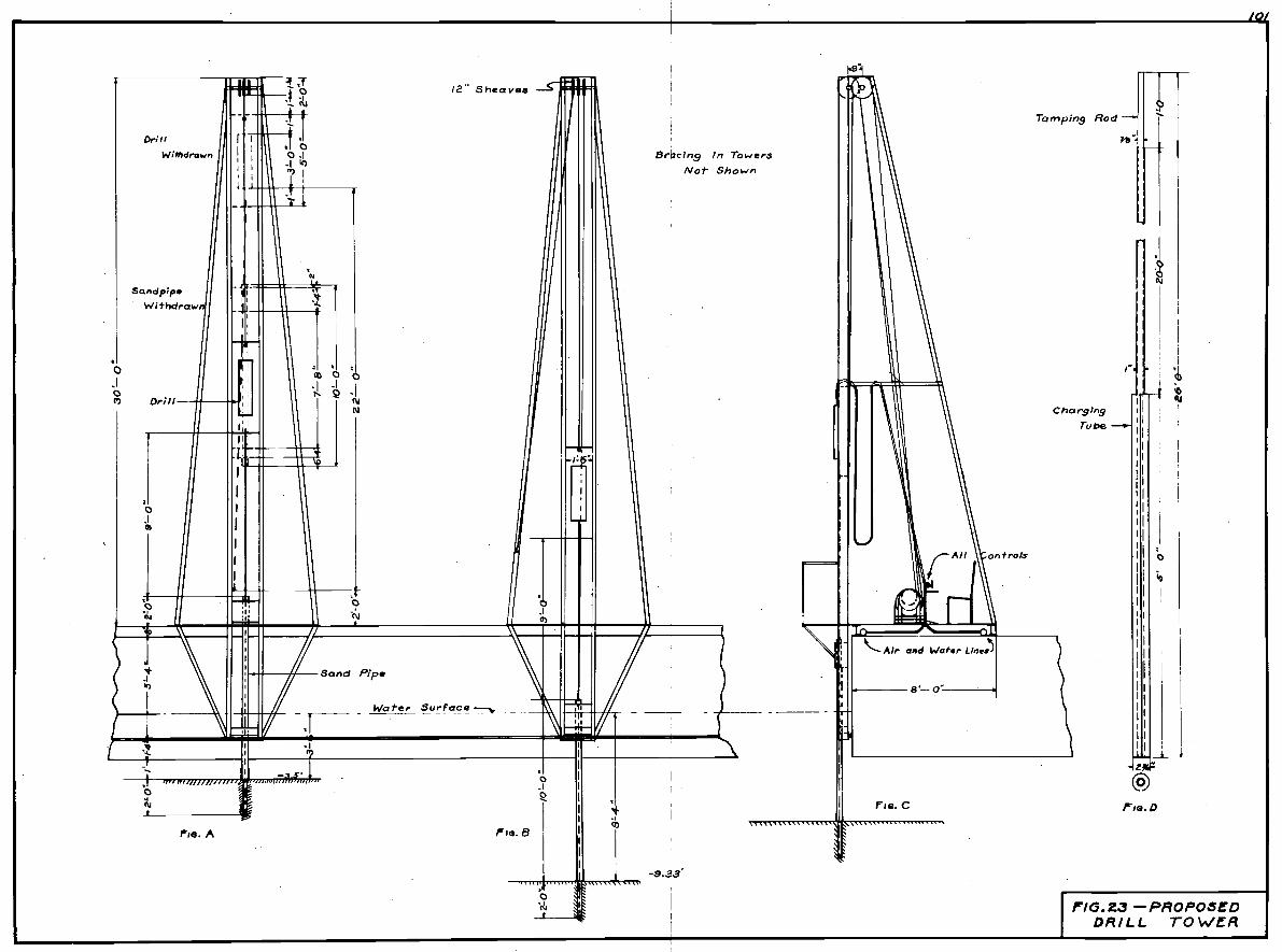
Sand pipeWithdraw
Pie. A
Br,c1ng n TowersNot Shown
Tarn ping Rod
ChargingTo be -S'-
zI
P16.23 -PROPOSEDDRILL TOWER
-
/0/
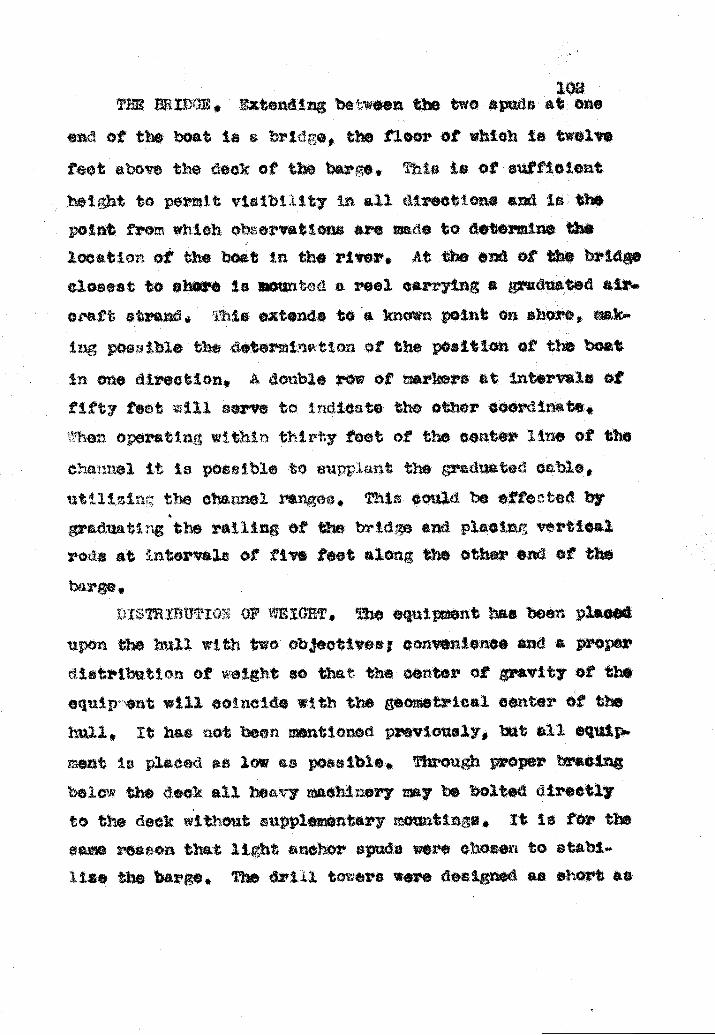
TflE IL1E, iztendin between the two epuda at oneof the boot 5 bridie, the floor at which is twelve
feet above the deck of the baz'e, This is of sufficIentheiht to peridt vtbLtity tn all directions and is thepoint from which observations are uue to determIne thelocation at the boat In the river. At the end of the bridclosest to shore is ouutcd a røol carrying a graduated air...ciaft strand. ;:j extends to a kno'n point on shore, mok..
posi ible the thternItton of the position of the boatone direction. A double row of markers ut Intervals of
f&ft7 feot ill serve to Indiote tho other coordinate.Then operatth wthtn thIrty foot of the center line of thechannel It i possible to surp.Lant the graduated cblo,uttlLIn:.: the channel rorios, ThIs could be effected bygrduat1. the railing of the hrIdre and plaolnr vrticslroth at thtorvalc of five feet along the other end of theb r ge,
tsnnuio:: or TIGHT The equl .nt has been placedupon the hull with two objectives; convenience and a prodintributj'n of eIgt o that the center of gravity of theequip orit Iwlil cotheide with the geometrical center of thehull, It has ot been nsntlon& previously, xt all equip..r.ant is placed as low as possible1 Through proper bracing
elo the deck all heavy machinery may be bolted directlyto the deck without supplementarr mountings, It is for thesa reason that light anchor spuda were chosen to stahl-use the barge., The diil towers were designed ss short as

are being used on some of t e lines. Just as the anchor
pose ible order to keep the centsr of gravity below thedeck.
To crest. a hypotbettoal situation, assume that thOboat was eqtpped with he*v spuds about sIxty feet longand op*rating tn s fast current. The barge has Just moved
into posit ton on * ledge adjacent to deep water and all ofthe apuds are up. hin bolts are thicoossible and snehors
spud over deep irater at the bow is dropped the bow Inc sfl.chor slip causing the inshore breast line anchor to gIveway also. The head of the barge would swing into the cur.rant aud start down stream broadside. The offshore breast
line at the bo* would slack and drop down under the barge.If the lowerd pud should strIke a rook or a subrner$sdledp'e In nfl probabIlity the boat would tip over with allthe crew. In a similar situation utilizing the email spudthe center of ravtty would be lower and the submerged col.
would not furnish as long a lever arm, then it struckbottom the l4inch I sectIon would probably crumple uplaavin the barge in upright position. In any event,
this would be a very da.izeroua pre4toaent and every effortshould be rnd to avoid such an accident.
oa]culat ion of the weight of this boaDi'i- to ceter!nine the craugIt nnd the approximate positionof the center of z'svtty in a verttoal plan Is computable

&L.reoeote treated £:ou
1n ir.3olt, e;ieetin, brao-Intl. tø.
tachtheryAnthor hnineMVIi'e rop L
tux.iiber
abie Q approdi:ate
Unit 'ioiht ots1Pound a
cu. £t. bO lbs. 2V1,500
16.090,
22,8W
6 3000 18,0005400 ft. 2.5
2,4(X)12,0006,0006,000
14,000150008,000
1,0001,000
10,000t,0008,000
126,400
Total teight of boat 371,gOO
At a poit ttree feet above t botton the hull iz ap*proxiiate3 79 feet lonr. Treating a seetion of the barge
trapezoid 1e £ol1wir cal laion will aptxtatethe depth to which the barge will aottle In utill tsr.
bota1 Disp1aoerent 37190C) a 6045 cubic feet.
Avez'Ee cubic 'eet pi rut de?th a('78+ 60 x 30 a 2070 CU. ft.
aIr 1eidn 6 4004 3(00
Spud 'efle 4 1800Spud eigtn.s 4 1500ctcro aor 2 1000riiJ. towe 2
2!ank, duel 500
Tar1 Air receiver 1000erirator rindez' 1(hX)
Stock t nrte 10000iptng zyatei 500()
Wood epors truotu re 5000iiecO1ie.neow3 10000
)i-it. eJ=at thi

Draut 4j a 2.92 or epprozivatal teat,
ER tRAVITY. Proa the table above wo1htof the hull le &pproxtnntoli twice that the nachinery,Vn the euds are elevated so that the points are evwIth the hotton of the harre, the center of gravity of' allt,n ment is about f,ur feet above the deck. The can.
tsr o' gravity 0r a13. the hull Ia three feet below the sametherefore, the hihe8t .IinIt in the locus of the
center of 'rnvity of the boat Is approximately etehtbelow the deck, or three feet above the water surface.
ry be coneidered coinpar.ttvel' sate with a thirtyfczt b5Th
aU provto acusetons the drautsidered only in t1l1 water, When moored ir shoal wete
trsvelin', at a hIgh velocity the barge Will squat or suok
down". The o,'tnt to wh1.oh t s henOrciLeflon wfll become
effe'tfve enrct be at'curately determined, but oheorv*.t1oni a smimilar btu"e under stmilnr conditions indtoitthe naxlr'um to be about one foot on the downstream end end
no chano at the bow. An oppostn, force exists here, sincernovtn water impIniIn u,on the rake posieases a verticalnortnonent o' fnre ihich tends to ratso the upstream end ofth oat.
coNcLus:t)N. in conclusion, a few general statementsconoerninç the capacity and the limitations of the (trillboat are in order. it is desiGned to operate under the
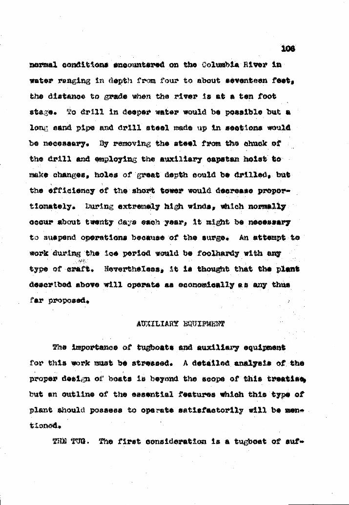
normal conditions encountered on the Columbia River in
water ranging in ttepth from four to about seventeen feet,the distance to rsde when the river is at * ten footatae. o drill in deeper water would be possible but alorz. sand pipe and drill steel made up in sections wouldbe necessary. Ly removing the steel from the chuck ofthe drill and employtn the euxtltai'y capstan hoistnake changes, holes of great de,th oould be drilled, butthe efficiency of the short tower would decrease propor'.tionstoly. burin extremely b1 winds, which normally
occur about twenty dada each year, it might be necessaryto suspenti operations bee*use of the surge. An: attempt to
work during the ice period would be ihardy with ally
type of craft. Nevertheless, it is thought that the plantdescribed above will operate as economically an any thusfar proposed.
ATXLLIARY EQUI??4INT
nportanoa of tuboats and auxiliary oq4for this work must be stressed. A detailed
proper desi. of boats Is beyond the scope of this treebut an outline of the essential features which this typeplant should possess to operate satisfaotorfly will be men.'tiOfl)d.
T)1] TtTO. The first consideration is a tugboat

10?
fio.ent power to aaneuvr the drill barge In awUt water.eoaae af tte hydro a:j enoowiteed it ehoulc he a
mn dzjt Li order to iavigate safely through the rapida.P bo..t hieh 1oas not hive a cruiaing epeed much greatert::ian t vslooitj o: ht w*ter wot1d 1)8 of no value.
.he twifl eorew t7p with propellora roxJjnatolr
tyour noh iii ixneter ad a power plant aspableof d8lpi t lea8t 400 . is wart o ona14eratton. I is neceaaary that thoas o high tipeed notor's
In or&i' to develop the required power, hut lar;s teelscQnhiot ued convc4entl i. th2. section of the river..tthei' hIth eed diesels tw ;aeole engines would be aa*
Iftctory .or the purpoa, ,he appixUate length of th.$boat iou1i rato betweon ortfivC and £ tttva feet,wi. th a dz'aght o' not more than four teat. in aoe placciit would etill be ary to resort to the use of linmt order to tako the bare upatren but the tug woXd beacequete under most conditIons. The United tstes ;rboat John Lay' is of thifl destgr but smaller, Us
1S5 ", f3aeol1nft i1iG8. ...t 18 tIe.ici 5*%tiaf*CtOt'tIy to
maneuver a ?5.sfoot !WOOpikAg barge i tghlng appr'oxivnately
one .hund-ud toxm, and i..zs oonaiderd one o. the best boa
f Its size on the river,The funetiona of this tugboat would be rather divorsi.
tied covering a L& vane of rtties. it could be employed

108
to oarr fuel to the UX11I boat from a convon.ont loaipOiit on the river. 1th a øial. eho' bare tied along'.t de it iiay eerve to iovo the awore or oa'ri the ithesto the rini.bolte. n tho tredgiru. operation ia binscarriwi OA it would 8erve to maneuver the dredge in the
W&j,
Uiifortu..at.ely vor few bovt poaaeøaIng thae feat-buree are available. he coat of builc.n4.; &uh a oraft'aod be prohibitive for a project of thie 8t wüeaafuture work a In te ofin or the builder C&L be aa&uredttat it would bo nrketalo ut a fair priee upon the ooi*plet..Lort o tie joo. thia z'eaeor one muat rooz to e
liojit iea.'eh tot' a at whioh esuo u fairi.y wU totlie eeiruLvl aoifiostione. o ret a t erate.intni eeotion of tie river ia a very epenatve enterpriee51501 Theretoe i3 anj eventbe carefully cons idcrod.
i)iT In ac1dItton, two aall.r work boats wouldbe neoessurj to oarrj pl#a and perform mcoilaneoueuutjee. Qie of these aould be about tiirt fe6t owra1land uld he equ1pecI to carry the crew to AZ £U1L the
drill barge. It may alsø he used to cariy powder and otherexpendab3o iter whiuh are constantly t'r*nsportec to thebarge. A twentyifoot upon hott powered with an out,boardmbtoz' wuuld uffioe fez' other pwosea.
the coat oJ: a tuboa

H
a shoal. The h1droraphy of
not uncomnon in many location
to the ledge ox' pinnacle to be removed. }ew places are
close enoug)i to the shore so that the broken rock may bedeposited abo;e the water. It is to be remembered that thisformation is diced basalt and most of it will brek up insmall fragments ithen blasted.
The quantity of material Is vary email when conaidex'.tug a dredging operation. This situation automaticallyeliminates a large end expensive plant, unless provision
made to remove addtt1on*l loose material. The
is is euch that it isad deep holes adjacent
A limited discussion of proposed dredges and dre ng
methods on this project will be presented to complete thepicture. From the general outline of the ooiinonly useddredges described in Part I of this paper it ta aeon thethree tpee of' plant ma be considered, Th ladder dredge,
the dipper dredge end the drag].no sxosvator are all cap.able of removin; blasted rook. The dipper dredge hea besa
the moat widely used of this group.To retain the assumptions made at the beginning of
ttte hypothet te*1 project and to add a few more, let itbe supposed that the rook is to he disposed of In eep
water or out of the channel where it will not i'etizrn to form

110
ladder drede is oon1dcred too euinbsrecnne for this partto*'lar work, and its capscty 2s not warranted in the r'eova1of email quentittes The dipper th'edge may be
mos the blasted rock, but it too Is a difficult draft tohandle in swift water and Its short boom confines Itsat ton from one position to a small area
The dragline excairato mounted on a barge should be tI.ost satisfactory plant to employ. inoe the r'ock Is fine]y
broken a small capacity but hea,,y bucket may be placed on along boom. This would permit the dredge to side cast intodeep atar tn instances.. A haul-back lIn* could alsobe used employtng a sheave attachod to anøhor ore rind.bolt beyond the area to be etc*vated. this manner thebarge could be noored. in deep water and the bucket could be
drared out to a distance much greater than the length of'the boom over the area o blasted rock. On Its return thebucket would load and then be picked up with the hoist linswhen it reached a point under the end of the boos.
7here the disposal area Xe a great dtetance fr'om thepoint o1 excavation, small scows could be loaded by thedraglIne and transported to the disposal area wt1i the tubct. iere they nay be unloaded with a small buildosercaterpillar or the dragline may follow and unload. In gsni.
he disposal areas a'e downstream C i'om the exeavstton,
would often be possible for' the dredge to drop downustn, her own lines, unload *nd return.

The dredge could remore the rock much more rapidly
than the drill hont coult prepare it for dredsjing. For'..
mately the eonstruot Ion of a channel in the ColnibtaRiver would tncludø the excavation of many yarda of loose
matérial in addition to the blasted rock. In thts casiit would be possible to operate the dredge * majority ofthe time at a nomthai unit cost.
ORGANI/ATION AND OP*t&TlON
The orginisat Ion of a competent crew to hsndls ar'ill boat on the Columbia River r.quree as careful study
the desi of the plant. An efficient end eats opera.on 18 more dependent upon the personnel and the organiza*
tion than upon the equipment which is employed to do thework. The trsintn of each member must be suah that he
fully capable of performing his duty accurately *nd in amanner which Inspires the confidence of the crew working
under the hazardous conditions4 The greatest burden inthis respect falls upon the captain of the boat.
T2i CR1W. The vpropoad crew Is composed of nine rnea.
bere, five of' which may be considered skilled laborer's,while the remainin four bilong to the aami'.ekilled group.E&oh drill requires * drill operator who controls the Sn.tire zeoh*idsi, and a helper who performs all the dutiesout near the drill undoi' the direction of the operator.One powdørman and a helper prepare the charges and load t!c

he )1t.)l
er . tt o: t.o oo iho:. ctI o1fat Or v:' L '.o
ooiiic nl.ko ary eYati.3w o
u till 1..o bt ocI re.i vctrt'.'
a to or:. the otcioly.Th i uvcc in' pos.t1oi, all lL arc traz
ti tite &r ooi dowboat ''. uin-
t ti th.iIl oior :1i 1e iaelc hia ;thte hulca iave p viuly 5oon d6tera1uec
tLO (.'Ulpg a i]uruteIi to et tho ncvlc tht
U2A JV( Lt OOXat8 tIiO
the trovir: ort1e it røa
&Lt148 ia oLi.
t, wiickt at't on a .tu1uated botrt1, ali ¶e1!e u, Lil L3yAte ta 13 1A
i.tB1blt ?.) t, _)fl O. L c;nr oxet the u'.t11:. ic hc iu1i u tall e1oj;* of
rai-rvtce n, ubor&1rrto to
iet }wncl o d to tharpenL::i aOLt te .lalit, .:ie .
rpt1n c1L t8 ety, ar t' ot1euu'&l ptrvido, ii.de till C dc
te wo'k.
MAL, :, Lo tri rieLh. of

3.
on hooks on the side of the house to direct the spaciithe holee.
Vihen e renio of holee is to he drilled, it is usus). Inioro catiofactory to place one tower ut each end of thetracks anc pei'idt thei both to procress toward the canter.In this w& the operatin of both towers iu continuousti]. the last hole is drilled. hen another arrenterneut isemployed, one drill ay be idle while the other Is ftni.sh*In the driliin eax' one end of the barge. Identicalspeed for both towers is only true in theory; in actualprcttce oe unit 13 always delayed due to ve.zioue eoudit5.ons of the rock.
he a tower i hi posItion to drill a hole, the oper.ator lowers the sand pipe to the surface of the rok. Ifoverhurdon Is encountered, which is very rare, the locz
ertal xurt be washed out of t casin&; with the water
fron the drU].. This is accomplIshed b, lowering thedrill s!!tt1tane'uely iith e sand pipe and th the bit afey Inches below the shoe of the pipe The water is ton arid the steel ! rotated slowly, If a separate rotationriotor is eiployed. hen the sand pipe reaches the surtacøof the rock and the loose m*tortal has aU been reTnoved,the 1tawier is put !.'i actions The drill is operated slowlyat first, and then the speed increased as the hole is start.ed. irin the th.Uinj; perat ion, the haimering action,

U'the rotation of the steel, and the flow of ter existimultaneouely. The water iaanin6 troa the bottoii of the
drIll hoi* is one of the zst important features of theoperation.
irequont bit ohanoa are flCCO5*Z7 when drilhtn thishard rook, arid it is probable thit at least tio bits willbe iioceeeary ror each hole, Nothtn is gained in the atttto use a dull bit, and when the drill begins to slow up it
be withth'wir.. tha bit replaced. it etplora4 toolong, the ae is worn of C the bit, and It is ruined fofuture use. It cannot be aharpenut 'tthout a great deoreasein diameter whIch leais to aertous trouble, A 4ncb bit isthe analiost whic2h oai ho used isfeotortly in this work,and t bate thou1d be p'eservod. If the bite are used pz'operi', thoy izay be sharpened at 1eut twice before they sired isoarclod, All driLl holon taper <htly' Cue to the wesrof the bit. ror this eaeon, the sharpened bits should begadod c,4 placed in z3epax'atc compartnents on the bsise of
the drill tower, so that the dr helper will not attertptto use a new bIt at the bet -.om of a hoic which has beendrilled by a slIj1itl aml one.
hon the hole is completed, the drill is wi thaen az
the eteel pulled to one tdo of the easing. )uring
drilling operation, the powdernan aid hi asaietst shouldpreparo the charge and place It in the chartu. tube, Upon

15
the re,ioval of the d.r.tll steel, the tube i tnerted to thebotti of the holø,. where the powder e held firmly in poetio wIth the tain roel, while the tube ti wthdru.n. The
wiree which ere ii de of the eia'd pipe ro arrIod up
age in the tower ad held in postton iile the pipe ierai3ed. ?2Cfl
g'asped below
e and carried
the cr.tlln slow, theboth uxtit aatIBracto'tly,
5: )5 5. s high onouh so that the wire o*n
t, the upper ends e.'e dropped th'ough theo a point n the etge o the barge '*iete
.5 oiplettcrn a rene o' holoe, the bargeved a tstence nornei to the rano eq'a1 to the desired
ard the eration s repeated, hen this move 2.
effetod, oa'o unt be ercised tc le.Re fIoient slackin the wiree o that they w11 1 rzit he broken. The barge
:ay he ved ovo the prey .owly ruled hole.e, or tt mnybc!ced away froi thei epe31cUnC UOfl the iotod in wW.oh
tIle area is hetn drUled. in the avent that it is backedej, the wI'ee r.ay e attorthO ;o the two bus wires, iichare equi!pod with nia1l, wooroi hlock as floats, and theentire astem, exeet the ods of the bus wires, iiar be
rown overboard, the wey the drill towore n.ty haved treely without oonttrnous1 cbanin the wroa.
t,rnan end holper can handle
p- 1.., tire t.O1 tporni'ily. The tower tr thea moved to thenext poaltion anti the cycle is repeated In t':te work ithere

method is not satisfactory when the barge is moved over theholes, because they ay become entangled around the epuds
or the dI'IIl casingo.When a number of rsnes have been drilled, the b
then hacked of I a safe distance, using a reel to let outthe two lead wires, The wtros si's then connected to * air'.cuit from the eneratoz'. and the ei' La detonated. !he
sate distance is variable, depending upon the size of theshot and the depth of the water. In general, the boatshould be farther sway Iron the blast in this work thanuoat submarine blasting because of the shallow water. When
the boat is in position to firs a shot, a check should bede to be sure that one of the maneuvering lines is not
too near the area to b e blasted it il1 be injured orbx'oken.
VAIOUS 1i!OD OF ATThCE. Zn csn.rel, the areas tobe removed are small and irregular in ebapo, Some may re's
quire two or three thousand drill holes while others aremerely pinnacles.. Obviously these variattàni require msnjmethods of attack. The harta of the areas should be care.fl1y studied and a plan outlined previoa to the work.The shape of the axes to bs drilled may be such that it
uld be more practicable to place the boat at an anwith the flow of tte current. This practice should be em-
ployd within limits, so that the force of the water on the
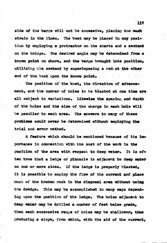
aide otth.e bsrç, will not be excessive, placingstrein th the Unea. The boat may be placed in a
tion by employing a protractor on the charts end a sextanton the bridge. The dsired angle ay be determined fross aknown point on ahor, and the bsre brought into position,utilizing ie sextant by superimposing * rodat' the otherend of the boat upon the known point
The position of the boat, the direction of *dvsnce.nt, and the nbsr of holes to he blasted at one time
sU inzbJot to 'variations, Likewisi the sp*ctn end depth
of the holes and the else of th charge in each hole wille peculiar to e8ch ares. The answers to many of thea
prObless could never be determined without *ploytng th*trial. r$ error method,
A teate which should be mentioned because of its im*portanee in connection with the coat of the work is theposition of the area with respect to deep water. It is of.ten true that a ledge or pinnacle is adjacent to deep wateron one or snore aides. It the ledge is prop4irly blastedt is possible to employ the flow of the current nd placeoh of the broken rook in the disposal area without using
the d this may be scc;*li.hed in many ways depending upon the position of the a holes sdjaosrt todsp water may be drilled a numbr of test below gradthen each suoCcssiv rare of holes may be shallower thus
producing a slope, croin which, with the aid of the current,

the loose rock y slide,Vhen a small pinnacle with steep sides is en
n deep water, its removal may be fføcted economie*lly bydrilling one or two deep holee, Larger bits may be n.e.esary in order to titeert sufficient porter to shatter *3
lose it Although the quantity of rock removed end th
powder used would be much z1eator thsn necessary, the tconeued may be sufftctnt to more than offset the othercost. becauo this rook is hard and brittli a h we.
locity powder is eteair*ble.CONCLUSIOW. In conclusion, a f*w of
stion may be of value in ezosating rook from the Colnmbi*kiver, An ample quantity of powder should be used to break
the rook into email fragments so that it can be dretlgsdeasily. Where the current will carry the rook to deepwater eittfieiont powder &iou3.d be oniployod to break aM
lift the rock from the ledge, A careful study of isshould be macis and the natural toreas employed to aid inthe work rathe than to hinder it, A well.trained and eoiapetont crew should be on board the drill boat. This is avery difficult type of work, 9V7 *se of which should
be approached 1ntel1iently.
T AALYSI
Little data are available upon which an estimate ofrobable costs can be made, Records of similar work may

be used to a ltn!it*d extent 'tzt these figures are sub3ectto so TMfll vaiables that ar approximation should be viewedcaution. The coat of op*rst ion of the proposed plant foa unit lentb. or t ins may be computed with a Za$.r degree
of scom'scy, but the speed of operation of the d*'U boais dI#tIOUlt to deteriirie prior to actual test.
The outline of probable costa preeented. herein willinclude obly the direct costs encountered in operating thdrill boat, These do not include the indireot oorte whiohare extensive in this t;pe of work, or the coat at dredgingthe rook subsequent to drilling end blasting. The propoe
list should not be considered accurate to a dgree ccipav*uble with an estimate upon many construction projects.
SPEL ci. OPERATION. The 1iret assumption pertains tothe speed of oprst ion of the drills, It will be asiumedthat the drills are capable of everaing fifteen linearfeet of drill hole per hour during operation. Represents.'
ttvea of drill manufacturers will cite many instances wheretheir drills liavi tar exos*ded this fittU'. but in aøtualPz'act lao under conditions where vez'y hard rook is eneounte.'
ed a conservative eat mats for the drifter trpo drtU us
a 3"inoh bit will approximate fitten feet pu' hour.Observations over a period of yearn indicate that a
ill is in operation about forty percent of the time,rodern improvements have increased thie figure slightly,

but the xtrse conditions on the Columbia River will e*uaa zestez' loss of tr than on many projects, consequentlythe "40" will be used without change.
An ideal situation would be to remove *13 the rook tothe ovnrdepth level, but this is not raSliaed in actualpractice, so the eatimae will be on a basis of receivingpay ro fifty percent of the rock between grade and on. footoverdapth. It was previously stated that half the entirequantity was betwsn theso limits, therefore the baut ofestimate will be
m% ot 50,000 37,500 cubic yards.
The avor*s depth of the existing surface o k
about 5 feet below low water ox' l test aboveith a drill hole spacing of five feet the necessary depth
to drill the holes would be 61 teet, spprximatoly.A summary of these assumptions will lead to th. toll
ing figIuu.
TABLE PERTAINING ¶L() S1ED C)? OPLATION
To adept one 24 ho day as ineawill be
t?ith a spacing of 5 feet in both directions and the rockretoved to 5/10 ft. below grad.e the total cubic contentof pay rook per hole would be
24.360 344 tt/dril3Jday144 x2 st per days

h
5*
* 3,5 ft, of bols per cubicThe rumber of cubic 'ard per day equals
.235 x g 82 cubic *rds per day.The time neceasary to cozimletthe proect would be
37500 2 8 : 457 days500 45'? * 45 d*yiz srgtn,
CO3TZ PR DAY. An eatim*t of the direct costs ofoperating the drill boat for a period of one twentymfour
hour day would involve the following considerations.
*in( iuprvisiokilledDrt].3. opratoLvsranPon
Sonzi..killsdDrill helpersPowder monkeyDeck hand
27 * 1,85 oubi y*rd/h.285 cubt yarte per foot
Total4 24man
242424
Materials end upplies. The engines driving the oopreesors will isob burn approximately six gallons of oilper hour. The gasoline engine driving the et pp willburn about two nd one half gallons per hour.,

Die
Gas
2x6 2& a11ons
'izoel1a*Ous. Large juantitiee of grease are usedills, and winches, .;t
Drill rts, hose couplingsLor 1uhricat1 the hoistbreakap i an expensive ite*s
8}OOtiflZ iY5 and hemp rope should be considered.
Plant, As previously stated, it is asid that theentire cost of the plant is absorbed by the job,, To this
cost should be added twenty per cent to include replacingthe raneuverin li;'es, major repairs, ard cotgeiciOB.
e cost per dsy would be
¶Lot1 itial cost z 120 4 45'l ,262 Initial-st dail7,
:1: i surm. ry of the Items upon vfhich a cost
eti ate for a ier5.od of one workthZ dty nay be derived,
122Gal hours
Powder and Cap..8 It aBsumed that this work will
co five pounds of 8CY' n.t tro-gelatth per cubic ya
of pay rock.ttroc1atin & z ; 410 poun
Caps (1 per hole) 6,5 4
BItG, Thø esti'ated life f each bit i thi'oe linear
toot eac1 t%te that. it i uso It may 'be sharpe;ed at
1ettt twice if carefully handle288

LaborSupervte ionSkilled laborSemiskilled Labor
aterIals and suppliesDiesel oilGasol IncPowderCaps3itsSteel, grease, oil, wire
Plant (initial oo*t)
The Itenc have been presented in units at' man
ex4 quantities in order that the unit coats which are ex.tstiri at any time ma' be applied. The unit costs havebeon subject to many vuriations recently and will probsblycontinue to change rapidly in the fsiture. It should brecautIoned that the auiisry above is not an. estimat at theenti'e cost o removtii the rock, but Includes only thedirect coats of opez'atin the drill boat. These costsapply only to a plant of the proposed size and S2'ø not
adspt*blo to all tee of craft.,ovIn solid rock tram below the water surface in
the Columbia )tiver is en extremely expensive operationThe nature o the work i such that an adequate plantcaxetul organizatIon are Imperative in order to effectthe work economically. e cost of operat5..on is continuous und pmctLcally constant whether the rook Xe satisfac.torly broken or not, therefore the unit east is controlledl.rely by the speed of operatior,
24 aen ho56
2Z
ho
072 g
410 pounds45

Dana, R. T. Rook drilling. John Wt107 : Sons, Nsweundez'a, W. L, York, ?iret dtt ton. 1912.
FowlOr, h*s. E. BubAqeous found*t ions.& Sons, New York. 1914.
The anarna Cana 4cGraNew York, Vo, 1917.
4, assey, George . Entneerin of axoavation,and sons, New York. 1923.
cIanle1, Allan 3. Exos atto chiner methods andcosts, c(paw.t{ll1 iook Co., Now York.irat 14iLton, 1919.
Paul, C, Li, Methods and plant for excavation andennett, C. S. bankment. Mc0rswfft11 Jook Co., New
York. irst idition, 192'?.
7. Prelird, ha
8, ion, F. Leit
omss, -3.Natt, ). A.
1O.Towneend, Curt
eston, E.
Btb1iograpq
Boks
iredgea and droding. 3). Van i4ostrandCo., ow York, 1911,
', Dredging engineering. NeGraw.1 l 113ook Go, New York. Firet Edition. 1920
The impoveaent of rivers. John WileySons, !ew York. 1913.
a MoD. Ftiver and harbor construction. The1.soil1an Co., ew York. 192,Ioek drills. McGraw iil1 Book Co.,York, 1910.
John Wt17
Hill Book
12.Bell, A. L. Dredging and th reva1 of aubii*arin.?ock at .1s1ta. rooecdings of the In.3titutlon of Civil Engineers, London.174 z289301. 1907.

blasting. Engineering and Contracting.47:380. Apr'11 18, 191'?.
.wn, 001, . I. zeavatinp the Chespeake and D.lawsrsCanal 19li.192. ingineering end Cona.trecting. 66:179.80. April 1927.
h. latching the rock drill to oon&ttions.Enineer1ng and Mining Journal. 131 :17.18. January 12, 1931.
28. Dion, E(
tixon,
Canadian wining Journal. AnNew Well,ind Canal, 50z245.u6, ax'th 1929.
19. Clarke, b, , Conparetive tents on drill steel brisk-ace, ininç end Aetallui'gy-, 14*493.5,Decernber 1935.
pressed Air Magazine. Color mstoh.tug. device controlsteinertn of drtU steel. 57:3870.July 1932.
21. Compreaaed Air dagasine, Cornonpleoa rock drill dignt-'fl.ett by Fssronet, 37*3870. July ,
22, Copreased Air Iigez1ne. Depth bombs cr blastingbridge foundation. 40:4th9. February
Conpreeed Air Magazine. )*ving money on en snergencydrilling job. 3t3s42'72. ovenber 1933.
24, Coirpressed Air dagazine. Type of fishing tool. 40:4667. 'ebruary 1956.
H, Removing Cointias Reef from the 1estRiver, iOW York iarbor', nrinoering News.77:112.43. January 18, 191?.A new ohannel in the Upper Ypressed EIt" aaztne. 53s423O-42. L)ebar 1933.
interesting blast in the
13. 3rriCçs i. The removal of sib2nar1ne 'ook. Prooengs of the Institution of Civil iiginra, Lordon. 174:502.18. 190?.
l4 owXe, C Life of drilling bite extended and oldones repaired by hardening edges. Oilend Gas Journal. 34:36,58,40. August29, 1935.
15, 'own, A. C. Method of eubmsrinrn rock drilling end

2?, Edwaxs,
23. Entn.eringOmi+
30. inineering
32.
37.
ErLI
nineoring News. A dr.0 boat h.ch 1tft itself deerof the water, 72:131.7. Deomber 51, 1914
ews. Mettods of ibaqueous rock excavation,ufta10 harbor, New York, 54:12, July
6, 1905.News. Rock oxcavation b meohenical power
thetead of explosives. 59t695i.6. June25) 193.
oring and Mininj Journaldrill erpertn,itheer1ng and tni Joir'nal
noiniec, 134:21.
ngineorin
Ert,tneertng
orgc. The application of gunpowder as an in..strument of engineering opei'at ions .zemputted by its use in blasting marl rooksin The rtivor 8evern. Proceedings of theInstitution of Civil gtheera, London,4z361'72. 1845.
London). I)eep eub!nartno borings in thsRiver Forth. 126:649. November 23, 1D28.
nd Contracting. laetLig a river obstruc.'tion, 65:231. May 3.9, 1926.
and Contracttn, Operating cost of 40 drag.line e:eavators on tT, . Reclamation Pro.'jects. 56:2'/U79. September 21, 1921.
Deve1opi*nts in rockX3:572, venber 192.Drill barge effects eooJanuary 1933.
ews. ;Ltbaqueous oxeavation at the HaOcean '. erminale 75:226. br.zsry3, 1916.
News. The reat blast ofPota,:r,uth Navy Yard,3, 1905.
e Point,August
En.'ineertng News, The Lohni.tz rook drodje. 2l*6970,January 26, 1889,
n1neertn News Record, i3ombtng out subaqQeous rockGolden (ate dridge Pier. 111:93-96.July 27, 1933.
41. z,nineering 24ews Hecord. DrIll derriok mounted on bergs107 :1033, Deceirer 31, 1931.

47. En
0. 0attmann, soar. The reova1 of the 'Iron Gates" of theRiver i)anubo. Proeeeding of the Thattution of Civil :;ineera, London. 119:209. 109495.
0. i3roakin:; eubaqueoue 1ete rook. iigin.esrin and Contracting. 67:154'?.usry 3.0?3,
S. Forz1az, for usin dynamite in canaexcavation. Civil igineertng. 3*iocombe 1933.
1ock dril1im 'Ln the Tennessee River,Einee'lrtg ecord, 68:480-9. ovsxnb.r1, 1913.
, G, A ibiu'ine rock excavator. Proceedinge of the Institution of Civil Engin..ears, Loidon. 159z231'3. 1906.
erriandez, Raton, r'ethod8 and eote of rook excavationin the H*rbor of Avilee, San 3!teban dePravia, arid Port do Bilbao, pin, En.gineerin and Contracting. 37s693'.B.Juno 10, 1q12,
I!ubboll, A. U. Drilli with a detachable bit, Entn.earing snd Mining Journal. 133 z582?.Novenber 1932,
42, Enginee eoord. outhhwpton' a at qtaa anddry dock, 111:622.4, Noventhor 23, 1955.
Ln2ine,rin News Record. Steel tower provtda rtgl.4bale for drill at Golden Gati 105:92.Ji17 17, 1930.
An4neerin Record. t.çiiizont and psz'toxtanos of theBritish Co1unbia Lredging fleet. 60:gO9I1. August 23, 1913.
Engineer cord.. Excavating subuezged rock with adrill boat. 6140. January 8, 1010.
1neering Record. :cow for BubIarine rock drilltng.68:600.1, November 29, 191$.
zg Record. ¶he operation of rook breakers at3lack Rock !nrbor. G3z46, Januer7 ?1911.

5 oUi.Rand Company. Drilling subaqueous rook. In.gersolluRand Co. Pori 1957, About3954 n, d.
66. 1nerso11and Company. 3ubmarine dri1113. IngersoEnd Co. Fo 1992, About 1934 n, d,
57, :enn.'i, John H. .Removin bsrtne 1edi.e in herbo!'improvement at k3everly, Ma*t. £nginseri.
Contracting. 65*268. November
oolt, Michael. A review o1 method.3 .3nX,1o.d for rv..tug aubaquocue rock. tneertng andContract 1n,. 3'1zGO2.3. May 29, 1912.
uerie,mers, niniertng and Contracting.Beov.nC submarine rock with Jack ham
60z1035.'37, Wovenber 14, 1923.
Levey, C, J, gethodu of 3ubnane rook drilling withdrill boSt8, with recordi of performance..Detroit ivor improvement, Engineeringand Contz'aci.in. 3:400.2. October 9,1912,
Lyland, A,. 3harpening ten thousand drill steels perday. ngtneertn snd Iining Joura1,153 sO]2. 'ebruery 1932,
Lohnit, Frederick. omova1 o rock under witcr withoutexplcn3ivoe, Frooedings of the Institu.
o Civil gtnoers, London. 77$369. lO8Ssii89.
65. cG1ash*n, Oso. i. Iemove1 of xbequeous rock at l3lyth.Prooebdtng3 o the Institution of Civilnt:ineors, London. 170 s331'42. 1907.
3Sfioisnt teohniqu.e for drilling andbleoting. igtneering and Ltnig Journa155*30-82. January 1932.,
eyetre, F, 3, Jr. Drill truck bottoa nineteen hundredboles per day. ineez'tn Iew Record.107 t103c), Deoenber 31, 1931.
Ntqlor, A. W, Method and genera]. cost of rook excavation1or the Inlet wnp Drainage iistrict,.tllinoc, inctneezing and Contracting,46z429-O. Novenibar 15, 1916.

i ho ipa, Chae.
Pialpe,
87, Oil and Gas Journal. Three methods offered for shoot"ing rivers. 30:48. Jirne 4, 1931.
O'Neill, C. 3. Submarine bleating in the Miami ShipChannel. Entheerin and Contracting.68:59-60. iebrusry 3929.
Subaqueous rook excavat ion.zig News. 74:908, 74:1020, 14*1062.4
Noembr 18,25, T)eoenber 2, 1915,
C, subaqueous rock excavated t'ron plats.form. ieeri News. 76:171-2. July27, 1916.
Polhenuas, 3. Ii, Subaqueou rock removal. i2ngin.ez'ingand Contracting. 68:340. August 1929w
Wh the block teat for drill steel, s.
gineering and Mining Journal, 129:506.'8. May 23, 3950.
R. Methods tind costs of subtaz'in blasting£.ine,1rin; and Contracting, 65 *20Q-12.ay 19, 1926.
L. Curz'ei.t iactico iii bIasing rook under water. ngine6ringContratin. 37:463-7. April 24, 1912.
fia American. i1aatin a chnel thri1z abottom, 127 s408-4Q9 )ecamber 192
75. RUseoll,
'74, tundexs,
75. Sciorit
tte Ocha.
76. wneend,
Trimbla,
Vidsi, I',
Vivian, C.
MeD. Ituprovement of Upper Missieippitver. i! astern Sccictl of Leore
Journal, 14s26s.71, 1909.
}ock excavation for ueentown.Ch.tpp*aa1, ntneering and ontr*otin. 68:
53.59, 1ebruaz'y VI, 1926.
Recent practios in subaqueous rock sxoavation in rano. En1neertn nd Cons.tracting. 3'? :599-600. ay 29, 1912.
Piers for super linerri. Conpreesed Airrazino, 38:4046..5$. ebruai7 1933.

Derrtok on poeta11f btLtlt bir le the3oiuttan of ctrUtng on bitatena t.P1OOtiOn3, Oil G* JOuzsnaa 52*40::*y lO 1934.
Vt1itason, . 13, othidu and coat of opevating Lob'nttz Hoak 3ro*kere and drill boats on thePtIna3na danal. Lngtne*Ptng and Cont'aet
$?:6Ol2. May 29, 19i2.
80. Wilhli