Width Measurement System. RF590 Series - Riftek
20
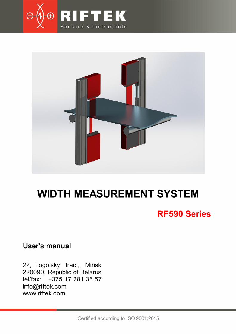
Certified according to ISO 9001:2015 WIDTH MEASUREMENT SYSTEM 22, Logoisky tract, Minsk 220090, Republic of Belarus tel/fax: +375 17 281 36 57 [email protected] User's manual www.riftek.com RF590 Series
-
Upload
khangminh22 -
Category
Documents
-
view
1 -
download
0
Transcript of Width Measurement System. RF590 Series - Riftek
Certified according to ISO 9001:2015
WIDTH MEASUREMENT SYSTEM
22, Logoisky tract, Minsk 220090, Republic of Belarus tel/fax: +375 17 281 36 [email protected]
User's manual
www.riftek.com
RF590 Series
2
Width Measurement System. RF590 Series
RF590 [Revision 1.0.0] 18.06.2018
Contents
.............................................................................................................................................31. Safety precautions
.............................................................................................................................................32. CE сompliance
.............................................................................................................................................33. Laser safety
.............................................................................................................................................34. General information
.............................................................................................................................................35. Structure and operating principle........................................................................................................................................... 4 5.1. Optical micrometers........................................................................................................................................... 4 5.2. System configuration........................................................................................................................................... 5 5.3. Indication device
.............................................................................................................................................66. Basic technical data
.............................................................................................................................................67. Example of item designation when ordering
.............................................................................................................................................68. Service program........................................................................................................................................... 7 8.1. Settings
................................................................................................................. 7 8.1.1. Device settings.............................................................................................................. 7 8.1.1.1. Language.............................................................................................................. 8 8.1.1.2. Password
................................................................................................................. 9 8.1.2. Parameters.............................................................................................................. 9 8.1.2.1. Input settings.............................................................................................................. 9 8.1.2.2. Output settings
.............................................................................................................. 10 8.1.2.3. Filter / Averaging
.............................................................................................................. 11 8.1.2.4. Parameters type........................................................................................................................................... 12 8.2. Measurement........................................................................................................................................... 13 8.3. Calibration........................................................................................................................................... 14 8.4. Database
.............................................................................................................................................159. Operating the system........................................................................................................................................... 16 9.1. Ethernet interface
................................................................................................................. 16 9.1.1. Factory parameters table
................................................................................................................. 16 9.1.2. Data packet format........................................................................................................................................... 16 9.2. Encoder input and Logical output
.............................................................................................................................................1710. Technical support
.............................................................................................................................................1711. Warranty policy
.............................................................................................................................................1712. Revisions
.............................................................................................................................................1713. Distributors
RF590 [Revision 1.0.0] 18.06.2018
Width Measurement System. RF590 Series
3
1. Safety precautions· Use supply voltage and interfaces indicated in the system specifications.· In connection/disconnection of cables, the system power must be switched off.· Do not use the system in locations close to powerful light sources.· To obtain stable results, wait about 20 minutes after sensor activation to achieve
uniform sensor warm-up.· The indication device must be grounded and connected to the grounding bus by a
separate branch.
2. CE сomplianceThe system has been developed for use in industry and meets the requirements of
the following Directives:· EU directive 2014/30/EU. Electromagnetic compatibility (EMC).· EU directive 2011/65/EU, “RoHS“ category 9.
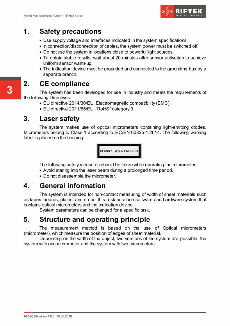
3. Laser safetyThe system makes use of optical micrometers containing light-emitting diodes.
Micrometers belong to Class 1 according to IEC/EN 60825-1:2014. The following warninglabel is placed on the housing:
The following safety measures should be taken while operating the micrometer: Avoid staring into the laser beam during a prolonged time period. Do not disassemble the micrometer.
4. General informationThe system is intended for non-contact measuring of width of sheet materials such
as tapes, boards, plates, and so on. It is a stand-alone software and hardware system thatcontains optical micrometers and the indication device.
System parameters can be changed for a specific task.
5. Structure and operating principleThe measurement method is based on the use of Optical micrometers
(micrometer), which measure the position of edges of sheet material.Depending on the width of the object, two versions of the system are possible: the
system with one micrometer and the system with two micrometers.
4
Width Measurement System. RF590 Series
RF590 [Revision 1.0.0] 18.06.2018
5.1. Optical micrometers
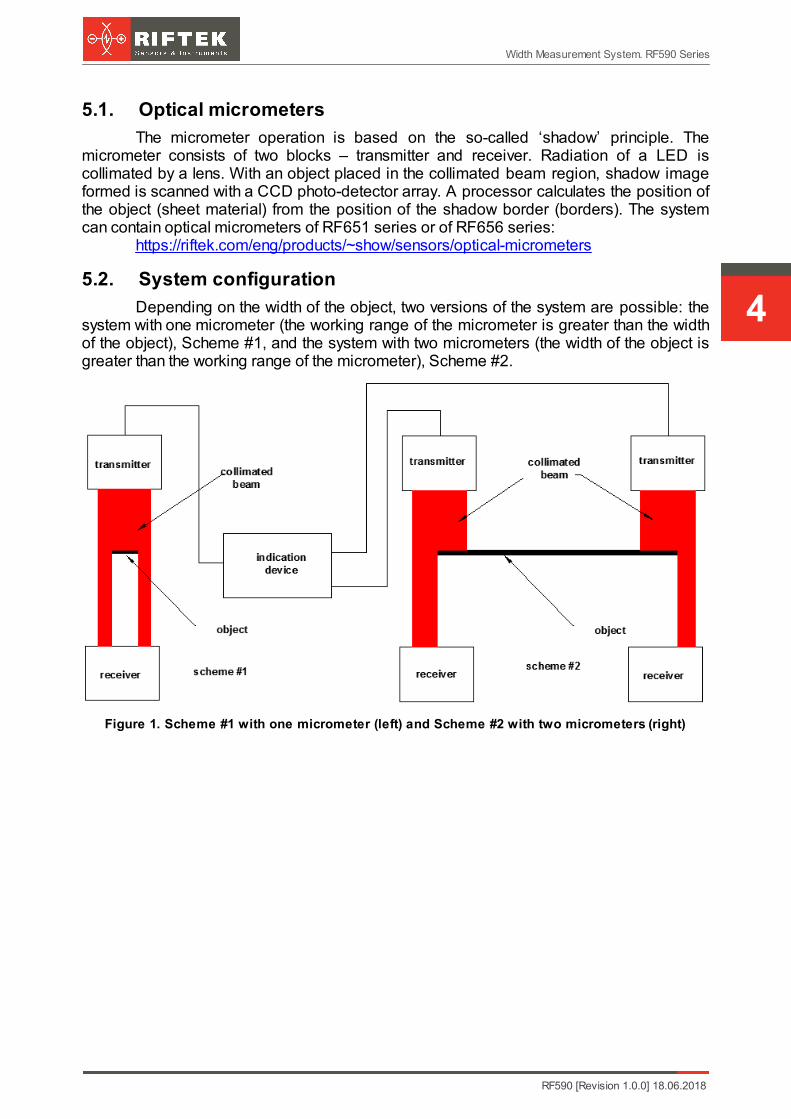
The micrometer operation is based on the so-called ‘shadow’ principle. Themicrometer consists of two blocks – transmitter and receiver. Radiation of a LED iscollimated by a lens. With an object placed in the collimated beam region, shadow imageformed is scanned with a CCD photo-detector array. A processor calculates the position ofthe object (sheet material) from the position of the shadow border (borders). The systemcan contain optical micrometers of RF651 series or of RF656 series:
https://riftek.com/eng/products/~show/sensors/optical-micrometers
5.2. System configuration
Depending on the width of the object, two versions of the system are possible: thesystem with one micrometer (the working range of the micrometer is greater than the widthof the object), Scheme #1, and the system with two micrometers (the width of the object isgreater than the working range of the micrometer), Scheme #2.
Figure 1. Scheme #1 with one micrometer (left) and Scheme #2 with two micrometers (right)
RF590 [Revision 1.0.0] 18.06.2018
Width Measurement System. RF590 Series
5
5.3. Indication device
The indication device is intended to receive information from micrometers, analyzeand display the measurement results.
Micrometers must be connected via the special connectors mounted on the housingof the indication device. The LCD display with the touch screen shows information. Whenthe width value exceeds the tolerances, the operator will be notified by an audible alarm.The width value output is based on the analysis of values received from the micrometer(micrometers) and calculated for the given averaging time, and is repeated with periodicityequal to the averaging time.
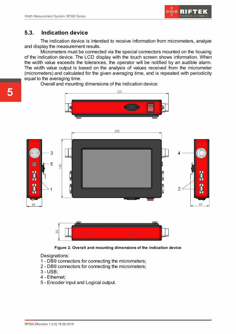
Overall and mounting dimensions of the indication device:
Figure 2. Overall and mounting dimensions of the indication device
Designations:1 - DB9 connectors for connecting the micrometers;2 - DB9 connectors for connecting the micrometers;3 - USB;4 - Ethernet;5 - Encoder input and Logical output.
6
Width Measurement System. RF590 Series
RF590 [Revision 1.0.0] 18.06.2018
6. Basic technical data
Parameter Value
Width measurement range, mm by request
Width measurement accuracy, µm up to +\-1 µm, depending on the accuracy of themicrometer used in the system
Input interface (micrometers connection) RS485
Output interface (result transfer) Ethernet
Logical output (OK/NOK) Open collector
Encoder input TTL
Software update, data transfer USB
Measurement speed, measurements/second up to 10000
Power supply, V 220 V (±10 %) AC, with frequency of 50 (±1) Hz
Power consumption, W 10
Operatingconditions
Ambient temperature, °С +1..+35
Relative humidity, % 65 (at 25°С)
Note: System parameters can be changed for a specific task.
7. Example of item designation when orderingRF590-MIN/MAX-SERIAL-N
Symbol Description
MIN Minimum width of the controlled object.
MAX Maximum width of the controlled object.
SERIAL Type of the micrometer serial interface: RS485 - 485, or Ethernet - ET.
N Number of logic outputs.
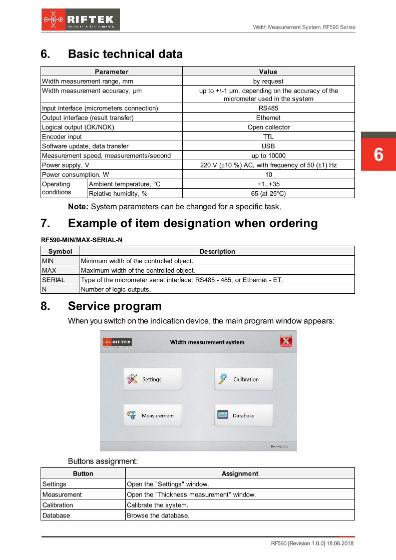
8. Service programWhen you switch on the indication device, the main program window appears:
Buttons assignment:
Button Assignment
Settings Open the "Settings" window.
Measurement Open the "Thickness measurement" window.
Calibration Calibrate the system.
Database Browse the database.
RF590 [Revision 1.0.0] 18.06.2018
Width Measurement System. RF590 Series
7
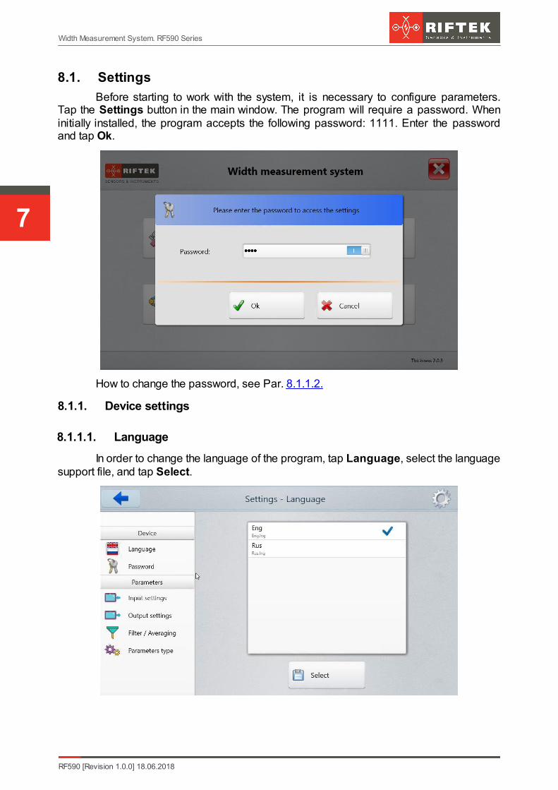
8.1. Settings
Before starting to work with the system, it is necessary to configure parameters.Tap the Settings button in the main window. The program will require a password. Wheninitially installed, the program accepts the following password: 1111. Enter the passwordand tap Ok.
How to change the password, see Par. 8.1.1.2.
8.1.1. Device settings
8.1.1.1. Language
In order to change the language of the program, tap Language, select the languagesupport file, and tap Select.

8
Width Measurement System. RF590 Series
RF590 [Revision 1.0.0] 18.06.2018
8.1.1.2. Password
To change the password, tap Password. Then enter a new password, confirm it,and tap Save.
The program will prompt you to confirm the action:
Select "Yes" to save a new password, or select "No" to cancel the action.
RF590 [Revision 1.0.0] 18.06.2018
Width Measurement System. RF590 Series
9
8.1.2. Parameters
8.1.2.1. Input settings
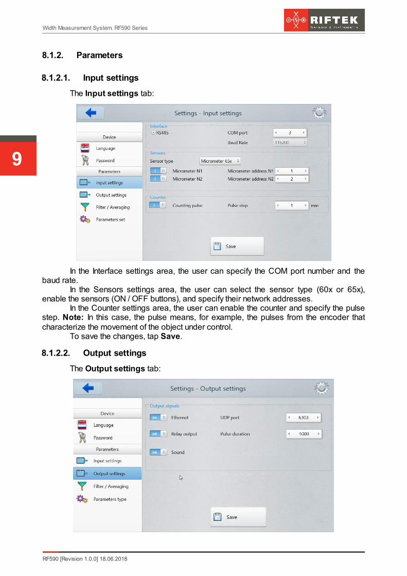
The Input settings tab:
In the Interface settings area, the user can specify the COM port number and thebaud rate.
In the Sensors settings area, the user can select the sensor type (60x or 65x),enable the sensors (ON / OFF buttons), and specify their network addresses.
In the Counter settings area, the user can enable the counter and specify the pulsestep. Note: In this case, the pulse means, for example, the pulses from the encoder thatcharacterize the movement of the object under control.
To save the changes, tap Save.
8.1.2.2. Output settings
The Output settings tab:
10
Width Measurement System. RF590 Series
RF590 [Revision 1.0.0] 18.06.2018
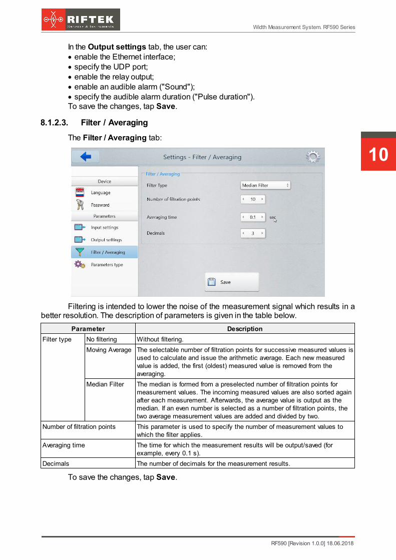
In the Output settings tab, the user can:· enable the Ethernet interface;· specify the UDP port;· enable the relay output;· enable an audible alarm ("Sound");· specify the audible alarm duration ("Pulse duration").To save the changes, tap Save.
8.1.2.3. Filter / Averaging
The Filter / Averaging tab:
Filtering is intended to lower the noise of the measurement signal which results in abetter resolution. The description of parameters is given in the table below.
Parameter Description
Filter type No filtering Without filtering.
Moving Average The selectable number of filtration points for successive measured values isused to calculate and issue the arithmetic average. Each new measuredvalue is added, the first (oldest) measured value is removed from theaveraging.
Median Filter The median is formed from a preselected number of filtration points formeasurement values. The incoming measured values are also sorted againafter each measurement. Afterwards, the average value is output as themedian. If an even number is selected as a number of filtration points, thetwo average measurement values are added and divided by two.
Number of filtration points This parameter is used to specify the number of measurement values towhich the filter applies.
Averaging time The time for which the measurement results will be output/saved (forexample, every 0.1 s).
Decimals The number of decimals for the measurement results.
To save the changes, tap Save.
RF590 [Revision 1.0.0] 18.06.2018
Width Measurement System. RF590 Series
11
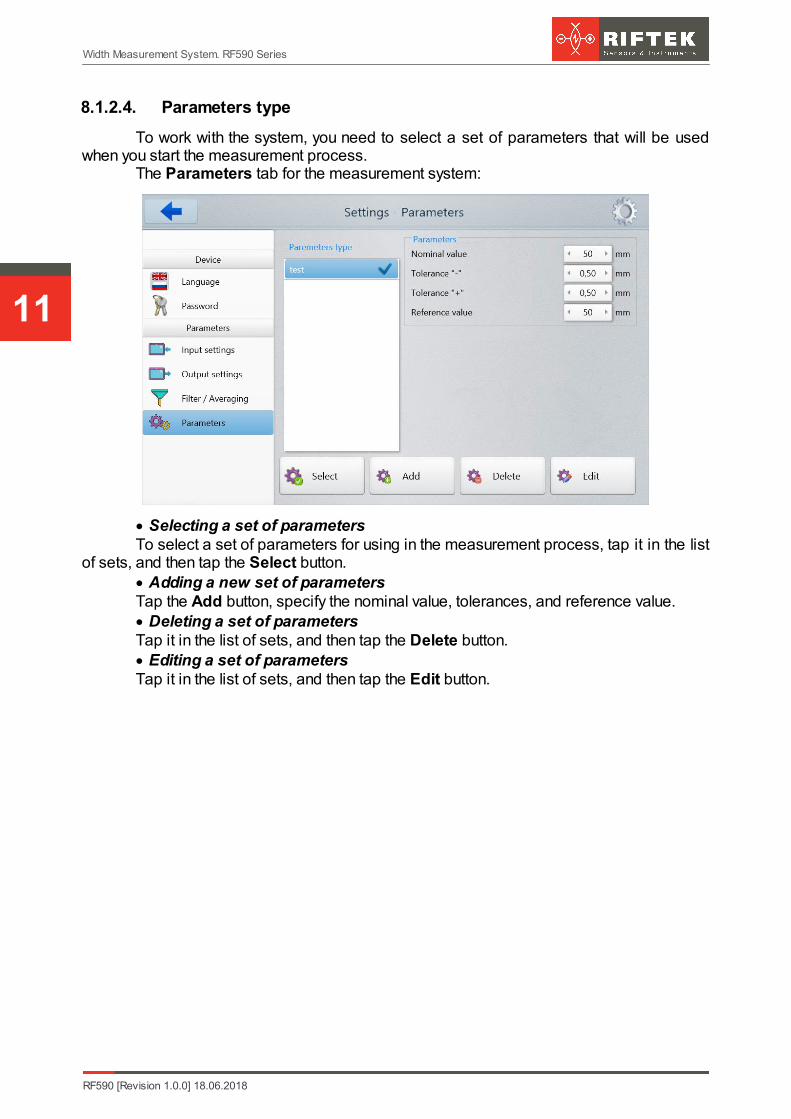
8.1.2.4. Parameters type
To work with the system, you need to select a set of parameters that will be usedwhen you start the measurement process.
The Parameters tab for the measurement system:
· Selecting a set of parametersTo select a set of parameters for using in the measurement process, tap it in the list
of sets, and then tap the Select button.· Adding a new set of parametersTap the Add button, specify the nominal value, tolerances, and reference value. · Deleting a set of parametersTap it in the list of sets, and then tap the Delete button.· Editing a set of parametersTap it in the list of sets, and then tap the Edit button.
12
Width Measurement System. RF590 Series
RF590 [Revision 1.0.0] 18.06.2018
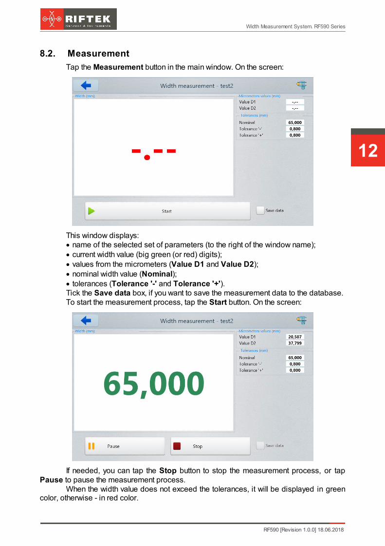
8.2. Measurement
Tap the Measurement button in the main window. On the screen:
This window displays:· name of the selected set of parameters (to the right of the window name);· current width value (big green (or red) digits);· values from the micrometers (Value D1 and Value D2);· nominal width value (Nominal);· tolerances (Tolerance '-' and Tolerance '+').Tick the Save data box, if you want to save the measurement data to the database.To start the measurement process, tap the Start button. On the screen:
If needed, you can tap the Stop button to stop the measurement process, or tapPause to pause the measurement process.
When the width value does not exceed the tolerances, it will be displayed in greencolor, otherwise - in red color.
RF590 [Revision 1.0.0] 18.06.2018
Width Measurement System. RF590 Series
13
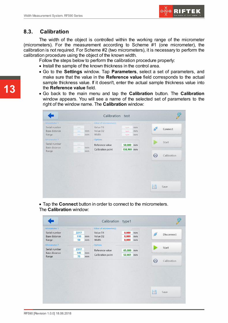
8.3. Calibration
The width of the object is controlled within the working range of the micrometer(micrometers). For the measurement according to Scheme #1 (one micrometer), thecalibration is not required. For Scheme #2 (two micrometers), it is necessary to perform thecalibration procedure using the object of the known width.
Follow the steps below to perform the calibration procedure properly:· Install the sample of the known thickness in the control area. · Go to the Settings window. Tap Parameters, select a set of parameters, and
make sure that the value in the Reference value field corresponds to the actualsample thickness value. If it doesn't, enter the actual sample thickness value intothe Reference value field.
· Go back to the main menu and tap the Calibration button. The Calibrationwindow appears. You will see a name of the selected set of parameters to theright of the window name. The Calibration window:
· Tap the Connect button in order to connect to the micrometers.The Calibration window:
14
Width Measurement System. RF590 Series
RF590 [Revision 1.0.0] 18.06.2018
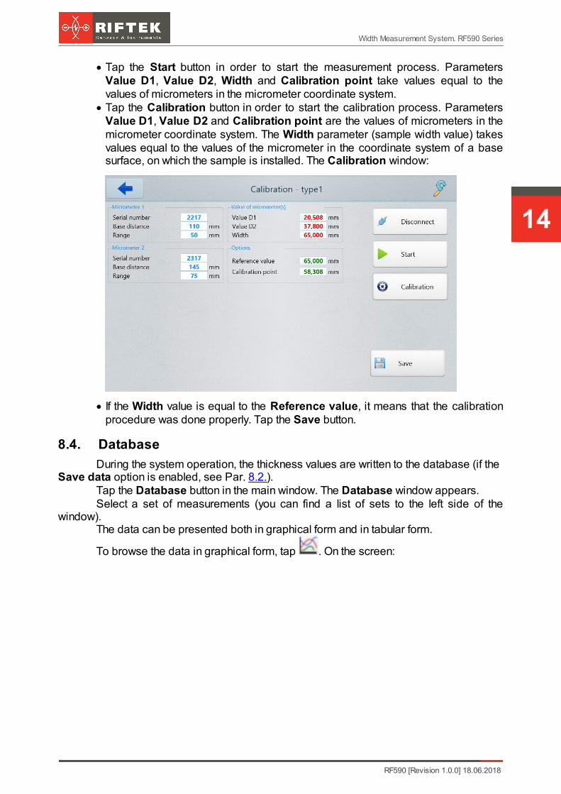
· Tap the Start button in order to start the measurement process. ParametersValue D1, Value D2, Width and Calibration point take values equal to thevalues of micrometers in the micrometer coordinate system.
· Tap the Calibration button in order to start the calibration process. ParametersValue D1, Value D2 and Calibration point are the values of micrometers in themicrometer coordinate system. The Width parameter (sample width value) takesvalues equal to the values of the micrometer in the coordinate system of a basesurface, on which the sample is installed. The Calibration window:
· If the Width value is equal to the Reference value, it means that the calibrationprocedure was done properly. Tap the Save button.
8.4. Database
During the system operation, the thickness values are written to the database (if the Save data option is enabled, see Par. 8.2.).
Tap the Database button in the main window. The Database window appears.Select a set of measurements (you can find a list of sets to the left side of the
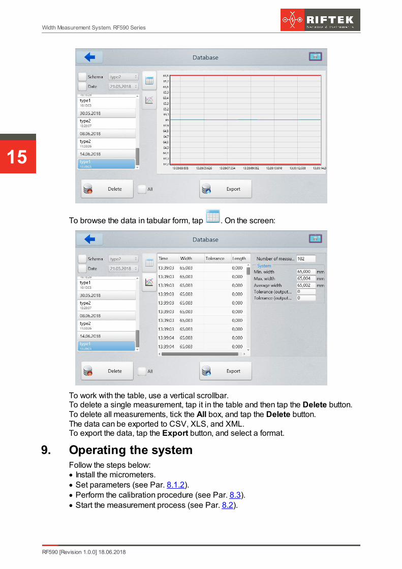
window).The data can be presented both in graphical form and in tabular form.
To browse the data in graphical form, tap . On the screen:
RF590 [Revision 1.0.0] 18.06.2018
Width Measurement System. RF590 Series
15
To browse the data in tabular form, tap . On the screen:
To work with the table, use a vertical scrollbar. To delete a single measurement, tap it in the table and then tap the Delete button.To delete all measurements, tick the All box, and tap the Delete button.The data can be exported to CSV, XLS, and XML.To export the data, tap the Export button, and select a format.
9. Operating the systemFollow the steps below:· Install the micrometers.· Set parameters (see Par. 8.1.2).· Perform the calibration procedure (see Par. 8.3).· Start the measurement process (see Par. 8.2).

16
Width Measurement System. RF590 Series
RF590 [Revision 1.0.0] 18.06.2018
9.1. Ethernet interface
The Ethernet interface is used only to transmit the width value.
9.1.1. Factory parameters table
Parameter Value
Destination IP address 192.168.1.200
Gateway IP address 192.168.1.1
Subnet mask 255.255.255.0
9.1.2. Data packet format
The sensor transmits the UDP packet to destination port 6303.The packet consists of a header field (8 bytes) and a data field (4 bytes). Data field:- byte 0, byte 1 : beginning of the packet - [0x55,0xAA]- byte 2, byte 3 : device serial number- byte 4, byte 5 : packet number- byte 6, byte 7 : data size - [4 bytes]- byte 8, byte 9, byte 10, byte 11: measurement resultExample of data packet:55h, AAh, 6Dh, 5Dh, 79h, 02h, 04h, 00h, 8Ah, C0h, 08h, 00h55h, AAh - beginning of the packet6Dh,5Dh - device serial number [s\n 23917]79h, 02h - packet number [cnt = 633]04h, 00h - data size [4 bytes]8Ah, C0h, 08h, 00h - data [D = 0008C08Ah = 573578]The result (in mm) is calculated by the following formula:X=D/10000 = 573578/10000 = 57,3578 mm
9.2. Encoder input and Logical output
The open collector is triggered when the width value exceeds the tolerance. View from the side of connector contacts used in the system is shown below.
RF590 [Revision 1.0.0] 18.06.2018
Width Measurement System. RF590 Series
17
10. Technical supportTechnical assistance related to incorrect work of the system and to problems with a
service program is free. Requests for technical assistance should be addressed to [email protected], or
by phone +375-17-2813513.
11. Warranty policyWarranty assurance for the Width Measurement System RF590 Series - 24 months
from the date of putting in operation; warranty shelf-life - 12 months.
12. Revisions
Date Revision Description
18.06.2018 1.0.0 Starting document.
13. Distributors
AUSTRIA
MBM Industry & Rail TechGmbH RAILWAY INSTRUMENTS ONLYTullnerbachstraße 36, A-3002 Purkersdorf, AustriaTel: +43 2231 66000Fax: +43 2231 66000 [email protected] www.mbm-tech.at
AUSTRALIA
Applied MeasurementAustralia Pty LtdRAILWAY INSTRUMENTS ONLYThornton Plaza, Unit 5, 27 Thornton Crescent, Mitcham VIC 3132, AustraliaTel: +61 39874 5777Fax: +61 39874 [email protected]
BENELUX
Altheris B.V.Vlietweg 17a2266KA LeidschendamThe NetherlandsTel: +31 70 3924421Fax: +31 70 [email protected]
BULGARIA, HUNGARY
RMT Ltd.R Zahradni 224739 21 Paskov, Czech RepublicTel: +420 558640211Fax: +420 [email protected]
BRAZIL
CAPI Controlee Automaçã o LtdaRua Itororó, 121, CEP 13466-240 Americana-SP, BrazilTel: +55 19 36047068Fax: +55 19 [email protected] www.capicontrole.com.br
CHILE
Verne SpAApoquindo 2818, oficina 31, Las Condes, Santiago, ChileTel: +56 2 [email protected]@verne.clwww.verne.cl
CHINA
Zhenshangyou TechnologiesCo.,Ltd.Rm 2205-2210, Zhongyou Hotel1110 Nanshan Road, NanshanDistrict 518054 Shenzhen, ChinaTel: +86 755-26528100/8011/8012Fax: +86 755-26528210/[email protected]
CHINA
Shanghai micron-metrologycom., Ltd.Room 602 unit 4, lane 399,Mudan road, Pudong New districtShanghai, ChinaTel: [email protected] www.micron-metrology.cn
CHINA
JRKtech Co., Ltd.1F, Building 9, 100 Xianlie Rd.,Guangzhou, ChinaTel: +86 755 85267190/+86 15989362481Fax: + 86 755 [email protected] www.jrktech.com
18
Width Measurement System. RF590 Series
RF590 [Revision 1.0.0] 18.06.2018
CZECH REPUBLIC
RMT Ltd.Zahradni 224739 21 Paskov, Czech RepublicTel: +420 558640211Fax: +420 [email protected]
FINLAND
TERÄSPYÖRÄ-STEELWHEELOYRAILWAY INSTRUMENTS ONLYJuvan teollisuuskatu 28FI-02920 ESPOO, FinlandTel: +358 400 422 900Fax: +358 9 2511 [email protected] www.teraspyora.fi
FRANCE
DB Innovation (ALTHERISFrance)26, avenue de la Mediterranee34110 Frontignan FranceTel: +33-467786166Fax: [email protected] www.altheris.fr
GERMANY
Disynet GmbHBreyeller Str. 241379, BrueggenTel: +49 2157 8799-0Fax: +49 2157 [email protected]
GERMANY
BIP-Industrietechnik GmbHRAILWAY INSTRUMENTS ONLY Am Elisabethhof 22,D-14772 BrandenburgD-41379 Brueggen, GermanyTel: +49 (0) 33 81 75 90 0Fax: +49 (0) 33 81 75 90 [email protected] www.bip-industrietechnik.de
GERMANY
Finger GmbH & Co. KGOPTICAL MICROMETERS ONLYSapelloh 172,31606 Warmsen, GermanyTel: +49 5767 96020Fax: +49 5767 [email protected] www.finger-kg.de
GERMANY
Hylewicz CNC-TechnikSHTRIKH-2 ONLYSiemensstrasse 13-15,47608 Geldern, GermanyTel: +49 2831 91021-20Fax: +49 2831 [email protected] www.cnc-step.de
INDIA
Pragathi Solutions#698, 5th Main, 8th Cross,HAL 3rd Stage,New Tippasandra Road,Bangalore, 560075, IndiaTel: +91 80 32973388Tel/fax: +91 80 25293985Mobile: +91 9448030426/[email protected]@pragathisolutions.inwww.pragathisolutions.in
INDIA
Paragon InstrumentationEngineers Pvt. Ltd.RAILWAY INSTRUMENTS ONLY200, Station Road,Roorkee, 247 667, IndiaTel: +91-1332-272394tanuj@paragoninstruments.comwww.paragoninstruments.com
INDONESIA
PT. DHAYA BASWARASANIYASABotanic Junction Blok H-9 NO. 7Mega Kebon Jeruk, JogloJakarta 11640, IndonesiaTel: + 62 21 [email protected]
IRAN
Novin IndustrialDevelopment Grp.Tel: +98 21 44022093-6Fax: +98 21 43858794Mobile: +98 [email protected]
ISRAEL
Nisso Dekalo ImportExport LTD1 David Hamelech StreetHerzlia 46661 IsraelTel: +972-99577888Fax: [email protected] www.fly-supply.net www.aircraft-partsupply.com
ITALY
FAE s.r.l.Via Tertulliano, 4120137 Milano, ItalyTel: +39-02-55187133Fax: [email protected]
LATVIA, ESTONIA
SIA "SOLARTEX"RAILWAY INSTRUMENTS ONLYDuntes 15a, 5th floor, office B7Riga, LatviaTel.: +371 67 130 [email protected]
MALAYSIA
OptoCom InstruVenturesH-49-2, Jalan 5, CosmoplexIndustrial Park, Bandar Baru Salak Tinggi, Sepang, MalaysiaTel: 603 8706 6806Fax: 603 8706 [email protected]
RF590 [Revision 1.0.0] 18.06.2018
Width Measurement System. RF590 Series
19
NORWAY
Salitec ASPB 468,N-1327 LysakerTel.: +47 23 891015Fax: +47 [email protected] www.salitec.no
PERU
Verne Perú S.A.C.Las Codornices 104, Surquillo, Lima, PeruTel/fax: +51 [email protected]
POLAND
MTL ASCO Sp. z o.o.RAILWAY INSTRUMENTS ONLYul. Wielowiejska 53 44-120PYSKOWICE (k/ GLIWIC),PolandTel: + 48 32 230 45 70Fax: + 48 32 332 70 [email protected]
PORTUGAL
UltraSensQt. da Portela, Lt. 22.1, Ap. 1523030 - 502 Coimbra, PortugalPhone +351 239 796 277Fax: +351 239 918 [email protected]
RUSSIA
Sensorika-M LLCDmitrovskoye shosse 64-4127474, Moscow, RussiaTel: +7 499 487 0363Fax: +7 499 487 [email protected]
RUSSIA
Diesel-test-Komplekt LLC620030, Karjernaya St, 16 Ekaterinburg, RussiaTel/fax: +7 343 2227565Tel/fax: +7 343 [email protected]
SERBIA, SLOVAKIA
RMT Ltd.Zahradni 224739 21 Paskov, Czech RepublicTel: +420 558640211Fax: +420 [email protected]
SOUTH AFRICA
Ratcom Enterprise Pty LtdCSIR BUILDING 35, Office 78Meiring Naude Road, Brummeria Pretoria, 0084 South AfricaTel: + 27 12 841 2032Fax: + 27 86 225 [email protected]
SOUTH KOREA
PROSEN. CO., LTDM-1001, Songdo techno park ITcenter, 32, Songdogwahak-ro,Yeonsu-gu, Incheon, 21984,Republic of KoreaTel: +82-32-811-3457Fax: [email protected]
SPAIN
Iberfluid Instruments S.A.C/ Botanica, 12208908 L'Hospitalet de Llobregat,BarcelonaTel: +34 93 447 10 65Fax: +34 93 334 05 [email protected]
SWITZERLAND
ID&T GmbHGewerbestrasse 12/a8132 Egg (Zurich), SwitzerlandTel: + 41 44 994 92 32Fax: + 41 44 994 92 [email protected]
SWEDEN, DENMARK
BLConsultRyssbält 294,95 291 KALIX, SwedenMobile: +46 70 663 19 25
SWEDEN, DENMARK
Latronix ABPropellervagen 10,183 62 Täby, SwedenTel.: +46 08-446 48 30Fax: +46 08-446 48 [email protected]
THAILAND
Advantech Solution Co.,Ltd.20/170 Motorway Rd.,Kwang Pravet, Khet Pravet,Bangkok, Thailand 10250Tel: +662-1848705Fax: [email protected]
TURKEY
TEKMA Mühendislik A.S.Cevizli Mh. M. Kemal Cd., Hukukçular Towers, A-Blok, No: 66-A/39Kartal – IstanbulTel: +90 216 970 1318Tel: +90 850 840 [email protected]

20
Width Measurement System. RF590 Series
RF590 [Revision 1.0.0] 18.06.2018
UKRAINE
KODAFrunze st 2261002, Harkov, UkraineTel/fax: +38 057 714 26 [email protected]
UNITED KINGDOM,IRELAND
Ix thus Instrumentation LtdThe Stables, Williams' BarnsTiffield road, Towcester, NorthentsTel: +44 1327 353437Fax: +44 1327 [email protected]
USA, CANADA, MEXICO
International ElectronicMachines CorporationRAILWAY INSTRUMENTS ONLY850 River Street, Troy,New York, USATel: +1 518 268-1636Fax: +1 518 [email protected]
USA, CANADA, MEXICO
Acuity Products of SchmittIndustries, Inc.2765 NW Nicolai StreetPortland, OR, 97210, USA Tel: +1 503 227 7908Fax: +1 503 223 [email protected] www.acuitylaser.com