Study on Multilayer Scanning Array Units Performance Using Ultrasonic Transducer
Upload
khangminh22Category
view
4download
0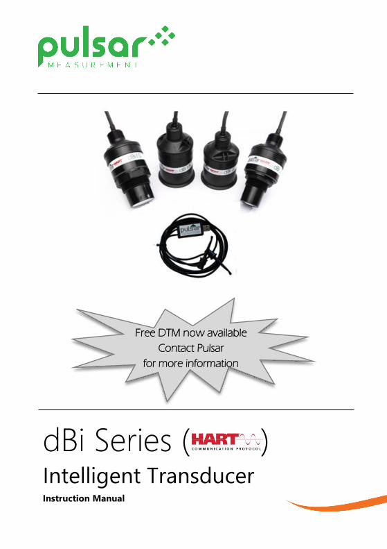
dBi Series ( ) Intelligent Transducer
Instruction Manual
Free DTM now available
Contact Pulsar
for more information

2
PULSAR MEASUREMENT
3
dBi SERIES (HART) (THIRD EDITION REV 2)
August 2021
Part Number M-560-0-003-2P
COPYRIGHT
© Pulsar Measurement, 2012-21. All rights reserved. No part of this publication may be
reproduced, transmitted, transcribed, stored in a retrieval system, or translated into any
language in any form without the written permission of Pulsar Measurement.
WARRANTY AND LIABILITY
Pulsar Measurement guarantee for a period of 2 years from the date of delivery that it will
either exchange or repair any part of this product returned to Pulsar Process Measurement
Limited if it is found to be defective in material or workmanship, subject to the defect not being
due to unfair wear and tear, misuse, modification or alteration, accident, misapplication, or
negligence.
DISCLAIMER
Pulsar Measurement neither gives nor implies any process guarantee for this product and shall
have no liability in respect of any loss, injury or damage whatsoever arising out of the
application or use of any product or circuit described herein.
Every effort has been made to ensure accuracy of this documentation, but Pulsar Measurement
cannot be held liable for any errors.
Pulsar Measurement operates a policy of constant development and improvement and reserves
the right to amend technical details, as necessary.
The dBi shown on the cover of this manual is used for illustrative purposes only and may not be
representative of the actual dBi supplied.
CONTACT
For technical support, please contact:
Europe: [email protected]
Outside Europe: [email protected]
If you have any comments or suggestions about this product, please contact:
Europe: [email protected]
Outside Europe: [email protected]
Pulsar Measurement website: www.pulsarmeasurement.com
United States
11451 Belcher Road South
Largo,
FL 33773
888-473-9546
Canada
16456 Sixsmith Drive
Long Sault, Ont.
K0C 1P0
855-300-9151
United Kingdom
Cardinal Building, Enigma
Commercial Centre
Sandy’s Road, Malvern
WR14 1JJ
00 44 (0)1684 891371
4
CONTENTS
Chapter 1: Start Here… ........................................................................................................... 6
About this Manual ............................................................................................................... 6
About the dBi Series (HART) Intelligent Transducer .............................................. 7
Functional Description ....................................................................................................... 7
Product Specification .......................................................................................................... 9
EU Declaration of Conformity ...................................................................................... 11
Chapter 2 Installation ........................................................................................................... 12
Unpacking ............................................................................................................................ 12
Power Supply Requirements......................................................................................... 12
Dimensions .......................................................................................................................... 13
Outdoor and Open Vessel Installation ..................................................................... 15
Closed Vessel Installation .............................................................................................. 16
Cable ...................................................................................................................................... 17
Typical wiring for a Non-Hazardous location ........................................................ 18
Preparation for Operation ............................................................................................. 19
Maintenance ....................................................................................................................... 20
Hazardous Area Installation .......................................................................................... 20
Chapter 3 How To Use Your dBi Sensor ....................................................................... 25
4-20 mA Device ................................................................................................................. 25
Accessing Parameters ...................................................................................................... 26
Hart Commands................................................................................................................. 26
dBi Hart PC Lite .................................................................................................................. 26
Parameter Defaults ........................................................................................................... 31
Chapter 4 Getting Results From Your dBi Sensor ..................................................... 32
Setting up Your Application.......................................................................................... 32
Setting Security Passcodes ............................................................................................ 33
Resetting Factory Defaults............................................................................................. 33
Checking the Information Specific to your dBi Intelligent Transducer ........ 34
Chapter 5 Parameter Listing and Description ............................................................ 35

PULSAR MEASUREMENT
5
Application ........................................................................................................................... 35
Operation ............................................................................................................................. 35
Distances .............................................................................................................................. 35
Data Logs ............................................................................................................................. 37
Volume .................................................................................................................................. 39
Conversion ........................................................................................................................... 39
Conversion ........................................................................................................................... 39
Breakpoints .......................................................................................................................... 44
Tables ..................................................................................................................................... 45
mA Output ........................................................................................................................... 46
Stability .................................................................................................................................. 49
System ................................................................................................................................... 49
DATEM ................................................................................................................................... 51
Chapter 6 Troubleshooting ................................................................................................ 53
Chapter 7 Disposal ................................................................................................................ 54
Transducers ......................................................................................................................... 54
Controllers............................................................................................................................ 54
DBI (HART) INSTRUCTION MANUAL
6
CHAPTER 1: START HERE…
Congratulations on your purchase of a Pulsar dBi Series Intelligent
Transducer Level Monitoring System. This quality system has been
developed over many years and represents the latest in high technology
ultrasonic level measurement and control. It has been designed to give you
years of trouble-free performance, and a few minutes spent reading this
operating manual will ensure that your installation is as simple as possible.
About this Manual
It is important that this manual is referred to for correct installation and
operation. There are various parts of the manual that offer additional help
or information as shown.
Tips
TIP: Look for this icon throughout your Pulsar Measurement manual to
f ind helpful information and answers to frequently asked questions .
Additional Information
Additional Information
At various parts of the manual, you will find sections
like this that explain specific things in more detail.
PULSAR MEASUREMENT
7
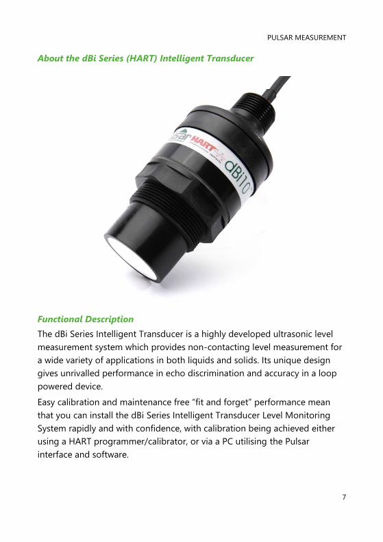
About the dBi Series (HART) Intelligent Transducer
Functional Description
The dBi Series Intelligent Transducer is a highly developed ultrasonic level
measurement system which provides non-contacting level measurement for
a wide variety of applications in both liquids and solids. Its unique design
gives unrivalled performance in echo discrimination and accuracy in a loop
powered device.
Easy calibration and maintenance free “fit and forget” performance mean
that you can install the dBi Series Intelligent Transducer Level Monitoring
System rapidly and with confidence, with calibration being achieved either
using a HART programmer/calibrator, or via a PC utilising the Pulsar
interface and software.

DBI (HART) INSTRUCTION MANUAL
8
The dBi Series Intelligent Transducer operates on the principle of timing the
echo received from a measured pulse of sound transmitted in air and utilises
“state of the art” echo extraction technology.
dBi Series Intelligent Transducer comes in four models:
1. dBi 3 with a range from 0.125m (0.41 feet) to 3.00m (9.84 feet).
2. dBi 6 with a range of 0.3m (0.98 feet) to 6.00m (19.69 feet).
3. dBi 10 with a range of 0.3m (0.98 feet) to 10.00m (32.81 feet).
4. dBi 15 with a range of 0.5m (1.64 feet) to 15.00m (49.213 feet).
All models can be mounted via a rear, 1” BSP/NPT, thread (Standard) with a
model with alternative front thread mounting being available, in addition to
this flange mount and PVDF options are also available. See Chapter 2
Installation for further details.
All model types are available for use in hazardous area installations with
either Ex mb or Ex ia ATEX certification.
The dBi Series Intelligent Transducer has a 4 to 20mA output which can be
programmed to give an output proportional to level, space, distance or
volume, dependant on the measurement mode selected and provides a
‘fault condition’ alarm of either 3.8mA or 22mA.
Boot time for the dBi Series intelligent Transducer from power up to stable
reading: cold boot = 9 seconds, warm boot = 4 seconds (if within 12hrs from
last start up). For 4 to 20ma set proportional to measured level/distance.
PULSAR MEASUREMENT
9
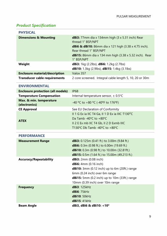
Product Specification
PHYSICAL
Dimensions & Mounting dBi3: 77mm dia x 134mm high (3 x 5.31 inch) Rear
thread 1” BSP/NPT
dBi6 & dBi10: 86mm dia x 121 high (3.38 x 4.75 inch).
Rear thread 1” BSP/NPT
dBi15: 86mm dia x 134 mm high (3.38 x 5.32 inch). Rear
1” BSP/NPT
Weight dBi3: 1kg (2.2lbs), dBi6: 1.2kg (2.7lbs)
dBi10: 1.3kg (2.9lbs), dBi15: 1.4kg (3.1lbs)
Enclosure material/description Valox 357
Transducer cable requirements 2 core screened. Integral cable length 5, 10, 20 or 30m
ENVIRONMENTAL
Enclosure protection (all models) IP68
Temperature Compensation Internal temperature sensor, ± 0.5oC
Max. & min. temperature
(electronics) -40 ºC to +80 ºC (-40ºF to 176ºF)
CE Approval See EU Declaration of Conformity
ATEX
II 1 G Ex ia IIC T4 Ga, II 1 D Ex ia IIIC T130OC
Da Tamb -40oC to +80oC
II 2 E Ex mb IIC T4 Gb, II 2 D Exmb IIIC
T130oC Db Tamb -40oC to +80oC
PERFORMANCE
Measurement Range dBi3: 0.125m (0.41 ft.) to 3.00m (9.84 ft.)
dBi6: 0.3m (0.98 ft.) to 6.00m (19.69 ft.)
dBi10: 0.3m (0.98 ft.) to 10.00m (32.81ft.)
dBi15: 0.5m (1.64 ft.) to 15.00m (49.213 ft.)
Accuracy/Repeatability dBi3: 2mm (0.08 inch)
dBi6: 4mm (0.16 inch)
dBi10: 3mm (0.12 inch) up to 6m (20ft.) range
6mm (0.24 inch) over 6m range
dBi15: 5mm (0.2 inch) up to 10m (33ft.) range
10mm (0.39 inch) over 10m range
Frequency dBi3: 125kHz
dBi6: 75kHz
dBi10: 50kHz
dBi15: 41kHz
Beam Angle dBi3, dBi6 & dBi10: <10o

DBI (HART) INSTRUCTION MANUAL
10
dBi15: <8o (all beam angles are inclusive, but give an
effective beam angle of <3o)
OUTPUTS
Digital Communications FSK (Frequency Shift Keying) modulation of 1200-
2400Hz
Communication Protocol HART 7, 4-20mA loop powered, output resolution 1µA
PROGRAMMING
PC programming (via HART
modem and 250 Ohm resistor)
HART PC Lite (setup only), Pulsar PC Suite-
and 250 Ohm resistor). HART PC (setup, installation,
echo profiles, cloning and troubleshooting).
Program security Via passcode
Programmed data integrity Via non-volatile RAM
PC Setup and monitoring Compatible with Win 7, Win 8 and Win 10
SUPPLY
Power supply 10 - 28V DC
Power Consumption Current consumption at start-up = 12mA, unit
powered every 15 minutes for 4 seconds the average
current = 53µA
Pulsar Measurement operates a policy of constant development and
improvement and reserve the right to amend technical details, as necessary.
PULSAR MEASUREMENT
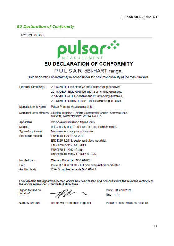
11
EU Declaration of Conformity
DBI (HART) INSTRUCTION MANUAL
12
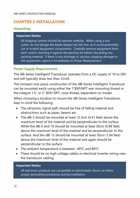
CHAPTER 2 INSTALLATION
Unpacking
Power Supply Requirements
The dBi Series Intelligent Transducer operates from a DC supply of 10 to 28V
and will typically draw less than 22mA.
The compact one-piece construction of the dBi Series Intelligent Transducer
can be mounted easily using either the 1″BSP/NPT rear mounting thread or
the integral 1.5" or 2" BSP/ NPT, nose thread, dependent on model.
When choosing a location to mount the dBi Series Intelligent Transducer,
bear in mind the following:
• The ultrasonic signal path should be free of falling material and
obstructions such as pipes, beams etc.
• The dBi 3 should be mounted at least 12.5cm (0.41 feet) above the
maximum level of the material and be perpendicular to the surface.
While the dBi 6 and 10 should be mounted at least 30cm (0.98 feet)
above the maximum level of the material and be perpendicular to the
surface. And the dBi 15 should be mounted at least 50cm (1.64 feet)
above the maximum level of the material and again should be
perpendicular to the surface.
• The ambient temperature is between -40ºC and 80ºC.
• There should be no high voltage cables or electrical inverter wiring near
the transducer cabling.
Important Notice
All shipping cartons should be opened carefully. When using a box
cutter, do not plunge the blade deeply into the box, as it could potentially
cut or scratch equipment components. Carefully remove equipment from
each carton, checking it against the packing list before discarding any
packing material. If there is any shortage or obvious shipping damage to
the equipment, report it immediately to Pulsar Measurement.
Important Notice
All electronic products are susceptible to electrostatic shock, so follow
proper grounding procedures during installation.
PULSAR MEASUREMENT
13
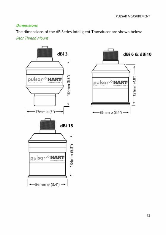
Dimensions
The dimensions of the dBiSeries Intelligent Transducer are shown below:
Rear Thread Mount
dBi 3 dBi 6 & dBi10
dBi 15
121m
m (
4.8
”)
86mm ø (3.4”)
134m
m (
5.3
”)
77mm ø (3”)
134m
m (
5.3
”)
86mm ø (3.4”)
DBI (HART) INSTRUCTION MANUAL
14
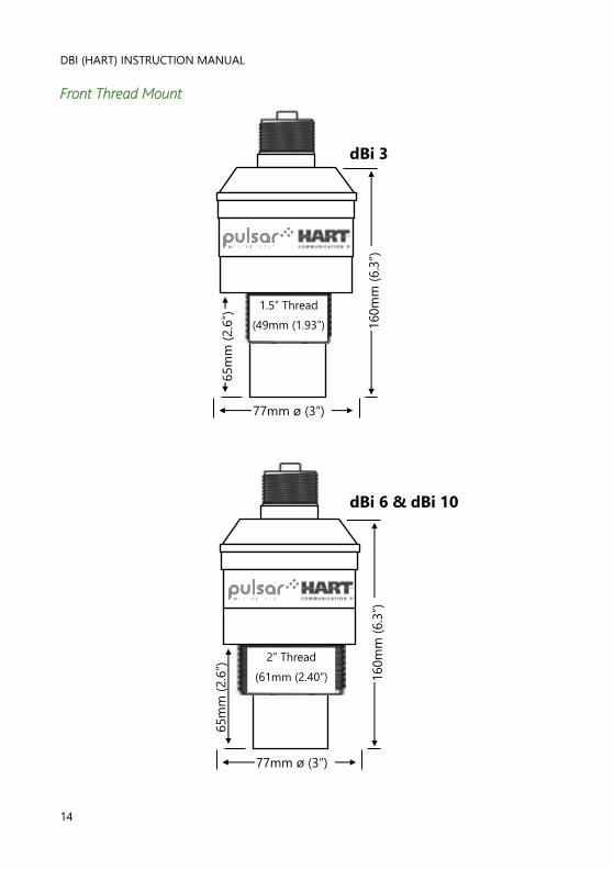
Front Thread Mount
dBi 3
dBi 6 & dBi 10
65m
m (
2.6
”)
160m
m (
6.3
”)
77mm ø (3”)
1.5” Thread
(49mm (1.93”)
Clearance
65m
m (
2.6
”)
160m
m (
6.3
”)
77mm ø (3”)
2” Thread
(61mm (2.40”)
Clearance hole)
PULSAR MEASUREMENT
15
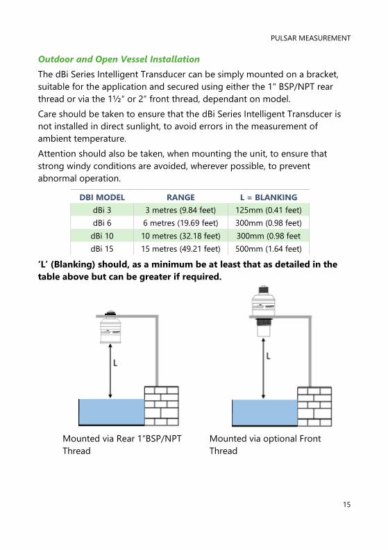
Outdoor and Open Vessel Installation
The dBi Series Intelligent Transducer can be simply mounted on a bracket,
suitable for the application and secured using either the 1" BSP/NPT rear
thread or via the 1½″ or 2″ front thread, dependant on model.
Care should be taken to ensure that the dBi Series Intelligent Transducer is
not installed in direct sunlight, to avoid errors in the measurement of
ambient temperature.
Attention should also be taken, when mounting the unit, to ensure that
strong windy conditions are avoided, wherever possible, to prevent
abnormal operation.
DBI MODEL RANGE L = BLANKING
dBi 3 3 metres (9.84 feet) 125mm (0.41 feet)
dBi 6 6 metres (19.69 feet) 300mm (0.98 feet)
dBi 10 10 metres (32.18 feet) 300mm (0.98 feet
dBi 15 15 metres (49.21 feet) 500mm (1.64 feet)
‘L’ (Blanking) should, as a minimum be at least that as detailed in the
table above but can be greater if required.
Mounted via Rear 1″BSP/NPT
Thread
Mounted via optional Front
Thread
DBI (HART) INSTRUCTION MANUAL
16
Closed Vessel Installation
“L” should as a minimum be at least that as detailed in the table above but
can be greater if required. The dBi Series Intelligent Transducer can be
simply screwed into a flange and secured using the rear 1" BSP/NPT rear
thread or via the 1½″ or 2″ front thread, dependant on model.
Where possible, use a flange made of a synthetic material such as PVC, in
cases where a metal flange is used it is advisable to fit a suitable gasket
between the flange of the dBi Series Intelligent Transducer and the
connection to the vessel.
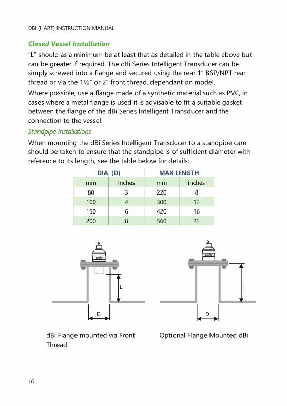
Standpipe Installations
When mounting the dBi Series Intelligent Transducer to a standpipe care
should be taken to ensure that the standpipe is of sufficient diameter with
reference to its length, see the table below for details:
DIA. (D) MAX LENGTH
mm inches mm inches
80 3 220 8
100 4 300 12
150 6 420 16
200 8 560 22
dBi Flange mounted via Front
Thread
Optional Flange Mounted dBi
PULSAR MEASUREMENT
17
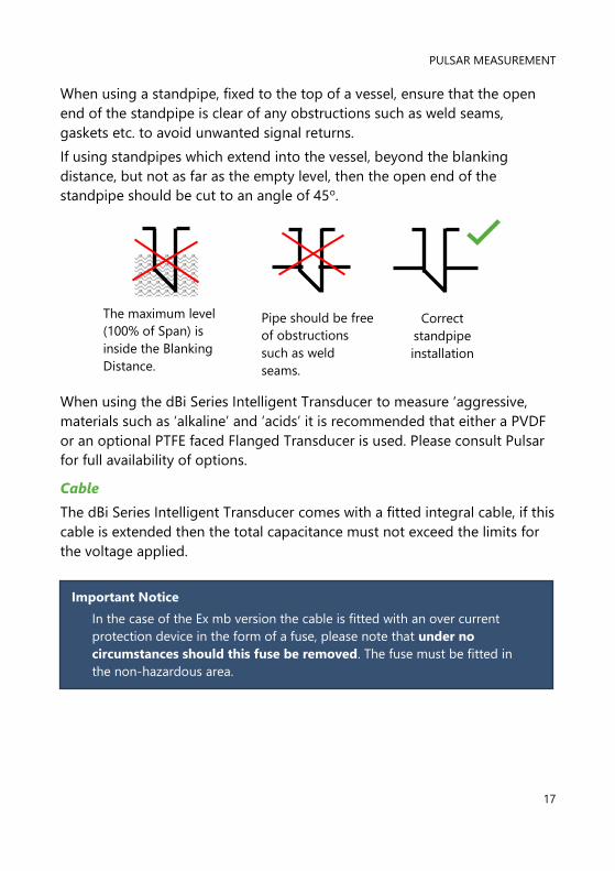
When using a standpipe, fixed to the top of a vessel, ensure that the open
end of the standpipe is clear of any obstructions such as weld seams,
gaskets etc. to avoid unwanted signal returns.
If using standpipes which extend into the vessel, beyond the blanking
distance, but not as far as the empty level, then the open end of the
standpipe should be cut to an angle of 45o.
When using the dBi Series Intelligent Transducer to measure ‘aggressive,
materials such as ‘alkaline’ and ‘acids’ it is recommended that either a PVDF
or an optional PTFE faced Flanged Transducer is used. Please consult Pulsar
for full availability of options.
Cable
The dBi Series Intelligent Transducer comes with a fitted integral cable, if this
cable is extended then the total capacitance must not exceed the limits for
the voltage applied.
Correct
standpipe
installation
Pipe should be free
of obstructions
such as weld
seams.
The maximum level
(100% of Span) is
inside the Blanking
Distance.
Important Notice
In the case of the Ex mb version the cable is fitted with an over current
protection device in the form of a fuse, please note that under no
circumstances should this fuse be removed. The fuse must be fitted in
the non-hazardous area.
DBI (HART) INSTRUCTION MANUAL
18
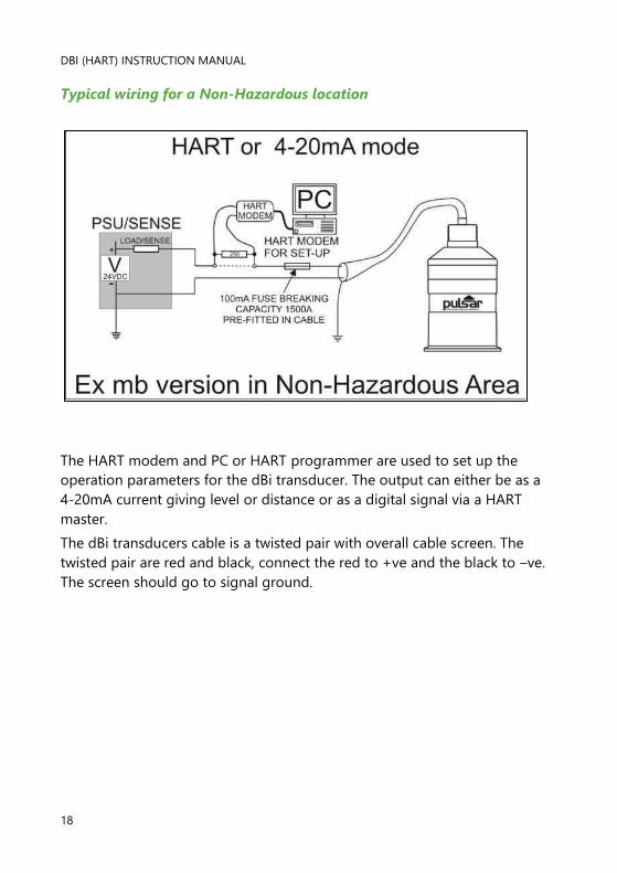
Typical wiring for a Non-Hazardous location
The HART modem and PC or HART programmer are used to set up the
operation parameters for the dBi transducer. The output can either be as a
4-20mA current giving level or distance or as a digital signal via a HART
master.
The dBi transducers cable is a twisted pair with overall cable screen. The
twisted pair are red and black, connect the red to +ve and the black to –ve.
The screen should go to signal ground.
PULSAR MEASUREMENT
19
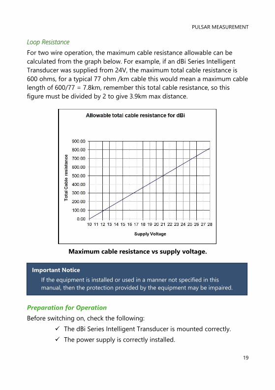
Loop Resistance
For two wire operation, the maximum cable resistance allowable can be
calculated from the graph below. For example, if an dBi Series Intelligent
Transducer was supplied from 24V, the maximum total cable resistance is
600 ohms, for a typical 77 ohm /km cable this would mean a maximum cable
length of 600/77 = 7.8km, remember this total cable resistance, so this
figure must be divided by 2 to give 3.9km max distance.
Maximum cable resistance vs supply voltage.
Preparation for Operation
Before switching on, check the following:
✓ The dBi Series Intelligent Transducer is mounted correctly.
✓ The power supply is correctly installed.
Important Notice
If the equipment is installed or used in a manner not specified in this
manual, then the protection provided by the equipment may be impaired.
DBI (HART) INSTRUCTION MANUAL
20
Maintenance
There are no user serviceable parts inside your dBi Series Intelligent
Transducer, if you experience any problems with the unit, then please
contact Pulsar Process Measurement for advice.
To clean the equipment, wipe with a damp cloth. Do not use any solvents on
the enclosure.
Hazardous Area Installation
Information specific to Hazardous Area Installation
(Reference European ATEX Directive 2014/34/EU, Annex II, 1.0.6.)
The following instructions apply to equipment covered by certificate number
TRAC 12ATEX0022X (Ex ia) & TRAC 12ATEX0023X (Ex mb)
1. The equipment may be used with flammable gases and vapours with
apparatus groups IIC, IIB, and IIA with temperature classes; T1, T2, T3, T4
maximum ambient temperature range -40oC to +80oC.
2. The equipment is only certified for use in ambient temperatures in the
range -40oC to +80oC and should not be used outside this range
3. Installation shall be carried out in accordance with the applicable code
of practice by suitably trained personnel
4. Repair of this equipment shall be carried out in accordance with the
applicable code of practice.
5. Certification marking as detailed in drawing number
D-804-0957-B (Ex ia) & D-804-0994-A (Ex mb).
6. If the equipment is likely to come into contact with aggressive
substances, then it is the responsibility of the user to take suitable
precautions that prevent it from being adversely affected, thus ensuring
that the type of protection is not compromised.
Aggressive Substances - e.g. acidic liquids or gases that may attack
metals or solvents that may affect polymeric materials.
Suitable Precautions - e.g. regular checks as part of routine inspections
or establishing from the material’s data sheet that it is resistant to
specific chemicals.
PULSAR MEASUREMENT
21
7. The certificate number has an ‘X’ suffix that indicates that the following
special condition of certification applies;
In the case of dBi transducer range, due to the housing and labels being
non-conductive plastic care needs to be taken with regards electrostatic
charge. The equipment shall not be installed if the conditions are
conducive to the build-up of electrostatic charge. Additionally, the
equipment should only be cleaned with a damp cloth.
With the dBi Ex mb version a 100mA, 1500A breaking capacity fuse must
be fitted in the positive lead of the cable. The product is shipped with
this fuse in the cable, visible through the heat shrink at the wire end of
the cable
8. The manufacturer should note that, on being put into service, the
equipment must be accompanied by a translation of the instructions in
the language or languages of the country in which the equipment is to
be used and by the instructions in the original language.
Hazardous Area Specific Power Supply and barrier Requirements
The dBi transducer operates from a DC supply of 10 –28V and will typically
draw less than 22mA.
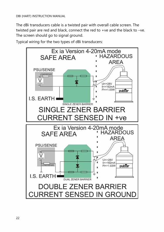
In the case of the Ex ia version the unit must be powered from an
approved I.S. safety barrier or approved I.S. Power supply with the
following limits:
Uo <= 28V, Io <=162mA, Po <= 1.03W
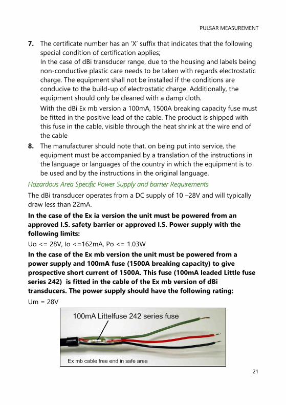
In the case of the Ex mb version the unit must be powered from a
power supply and 100mA fuse (1500A breaking capacity) to give
prospective short current of 1500A. This fuse (100mA leaded Little fuse
series 242) is fitted in the cable of the Ex mb version of dBi
transducers. The power supply should have the following rating:
Um = 28V
DBI (HART) INSTRUCTION MANUAL
22
The dBi transducers cable is a twisted pair with overall cable screen. The
twisted pair are red and black, connect the red to +ve and the black to –ve.
The screen should go to signal ground.
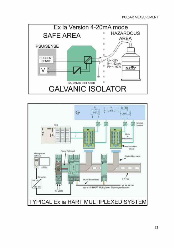
Typical wiring for the two types of dBi transducers:
PULSAR MEASUREMENT
23

DBI (HART) INSTRUCTION MANUAL
24

PULSAR MEASUREMENT
25
CHAPTER 3 HOW TO USE YOUR DBI SENSOR
4-20 mA Device
The dBi Hart Intelligent Transducer can be used as an ‘out of the box’ 4 –
20mA device if this is the case then by default, when you switch the dBi
Series Intelligent Transducer on, the 4 – 20mA output will be proportional to
the level being seen, with respect to the maximum range and span of the
dBi model being used as detailed in the table below.
DBI 3 DBI 6 DBI 10 DBI 15
4 mA (Empty) 0% of Span
Distance from dBi Face in
metres
3.000 6.000 10.000 15.000
20 mA (Full) 100% of Span
Distance from dBi Face in
metres 0.125 0.300 0.300 0.500
LOOP CURRENT DRAW
TYPE 3.8 4 5 6 7 8 9
dBi3 5.6 3.8 1.5 1 1 1 1
dBi6 7.5 4.8 2 1.2 1 1 1
dBi10 9.8 6.6 2.7 1.7 1.3 1.05 1
dBi15 10.9 7.5 3.2 2 1.4 1.1 1
Time in seconds between firing: For example – if using a dBi 6 and the
target is causing a current draw of 5mA then the cycle time (the time
between measurements is 2 seconds.
Important Notice
Customised factory calibration of Span is available; please contact Pulsar
for further details.
Important Notice
When the dBi Series Intelligent Transducer is operated below 8mA then
the speed of response will decrease. See the following table for cycle
times:

DBI (HART) INSTRUCTION MANUAL
26
Any transducer drawing 9mA or above will have a cycle time of 1 second.
Accessing Parameters
To view or change parameters values one of the following methods must be
used:
Hart Commands
If familiar with the use of HART protocol and the dBi Series Intelligent
Transducer is connected to a HART modem, then it can be programmed
following normal HART procedures.
Commands implemented by the dBi Series Intelligent Transducer are as
follows:
Universal
0, 1, 2, 3, 6, 7, 8, 9, 11, 12, 13, 14, 15, 16, 17, 18, 19, 20, 21, 22, 38 and 48.
Common practice
33, 34, 35, 40, 41, 42, 45, 46, 47, 83, 89, 90, 111, 112 and 122.
dBi Hart PC Lite
Your dBi Series Intelligent Transducer comes complete with the dBi HART PC
Lite software contained on CD, which, when used with a HART Modem, see
Chapter 2 Installation for full details on how to connect the modem, can be
used to carry out the programming of the dBi Series Intelligent Transducer.
Insert the CD into the CD drive or download the software from the Pulsar
website (onto the PC intended to be used to carry out the programming of
the dBi Series Intelligent Transducer and install the software, following the
on-screen instructions.
Once the software is installed connect the computer via a convenient USB
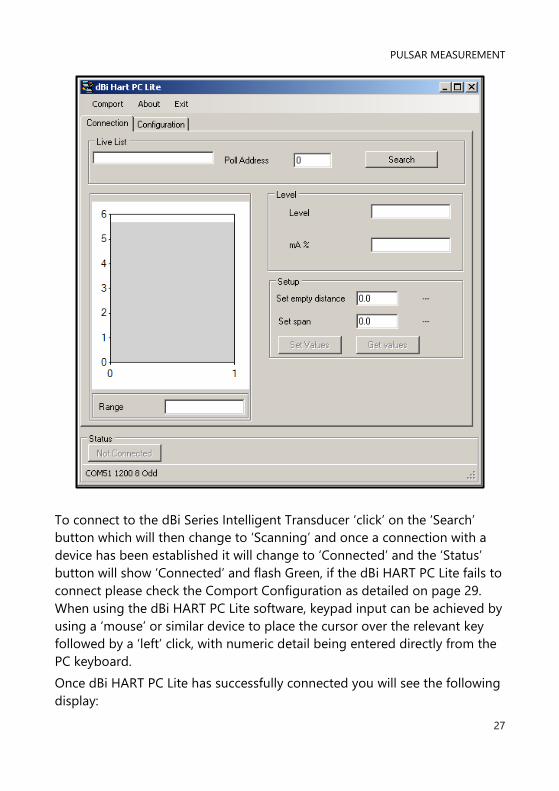
port to the HART Modem. Double click the ‘dBi HART PC Lite’ icon, installed
on your desktop and the programme will open and you will see the
following screen:
PULSAR MEASUREMENT
27
To connect to the dBi Series Intelligent Transducer ‘click’ on the ‘Search’
button which will then change to ‘Scanning’ and once a connection with a
device has been established it will change to ‘Connected’ and the ‘Status’
button will show ‘Connected’ and flash Green, if the dBi HART PC Lite fails to
connect please check the Comport Configuration as detailed on page 29.
When using the dBi HART PC Lite software, keypad input can be achieved by
using a ‘mouse’ or similar device to place the cursor over the relevant key
followed by a ‘left’ click, with numeric detail being entered directly from the
PC keyboard.
Once dBi HART PC Lite has successfully connected you will see the following
display:
DBI (HART) INSTRUCTION MANUAL
28
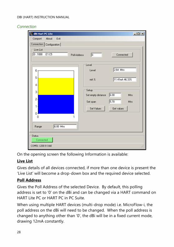
Connection
On the opening screen the following Information is available:
Live List
Gives details of all devices connected, if more than one device is present the
‘Live List’ will become a drop-down box and the required device selected.
Poll Address
Gives the Poll Address of the selected Device. By default, this polling
address is set to ‘0’ on the dBi and can be changed via a HART command on
HART Lite PC or HART PC in PC Suite.
When using multiple HART devices (multi-drop mode) i.e. MicroFlow-i, the
poll address on the dBi will need to be changed. When the poll address is
changed to anything other than ‘0’, the dBi will be in a fixed current mode,
drawing 12mA constantly.
PULSAR MEASUREMENT
29
Level
Gives value of the Level in the vessel in Measurement Units (P104)
mA %
Gives current value of the mA Output and how full the vessel is in
percentage.
Set Empty Distance
Allows the Empty Distance to be set.
Set Span
Allows the Span to be set which will determine the range of the 4 to 20mA
output, with 4mA representing 0% (empty) and 20mA representing 100%
(full).
Range
Shows the maximum range that can be measured, by the dBi Series
Intelligent Transducer, that is currently connected.
Bar Graph Display
Gives a graphical indication of the Empty Distance (P105) and Maximum
Span (P106) along with current level being measured.
DBI (HART) INSTRUCTION MANUAL
30
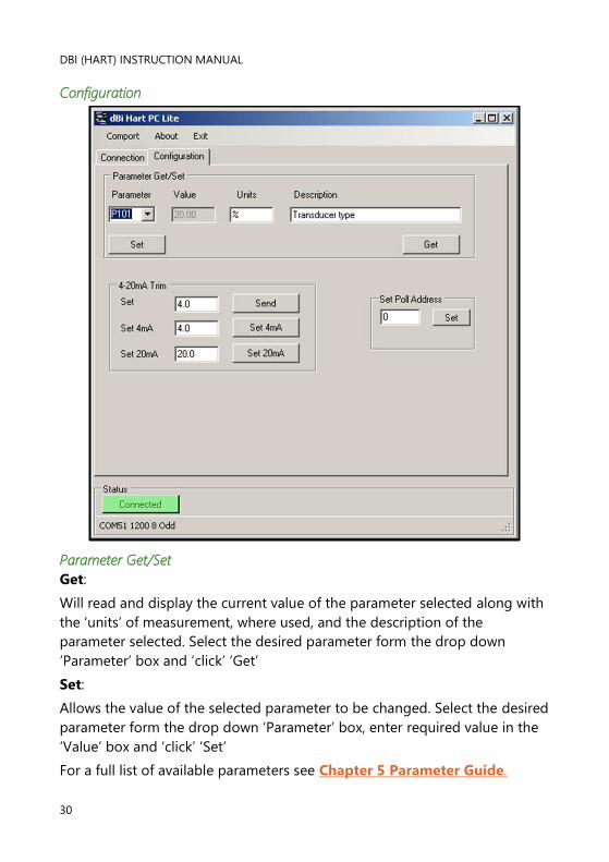
Configuration
Parameter Get/Set
Get:
Will read and display the current value of the parameter selected along with
the ‘units’ of measurement, where used, and the description of the
parameter selected. Select the desired parameter form the drop down
‘Parameter’ box and ‘click’ ‘Get’
Set:
Allows the value of the selected parameter to be changed. Select the desired
parameter form the drop down ‘Parameter’ box, enter required value in the
‘Value’ box and ‘click’ ‘Set’
For a full list of available parameters see Chapter 5 Parameter Guide.
PULSAR MEASUREMENT
31
4 – 20mA Trim
If the device connected to the mA output is out of calibration, and cannot be
calibrated, then the low and high current levels can be trimmed by altering
Set 4mA (P838Low Trim) and Set 20mA (P839 High Trim). To do this,
simply enter the value that ensures that 4 mA or 20 mA respectively are
shown on the remote device.
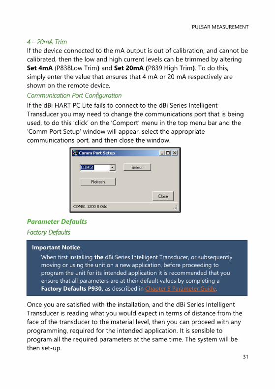
Communication Port Configuration
If the dBi HART PC Lite fails to connect to the dBi Series Intelligent
Transducer you may need to change the communications port that is being
used, to do this ‘click’ on the ‘Comport’ menu in the top menu bar and the
‘Comm Port Setup’ window will appear, select the appropriate
communications port, and then close the window.
Parameter Defaults
Factory Defaults
Once you are satisfied with the installation, and the dBi Series Intelligent
Transducer is reading what you would expect in terms of distance from the
face of the transducer to the material level, then you can proceed with any
programming, required for the intended application. It is sensible to
program all the required parameters at the same time. The system will be
then set-up.
Important Notice
When first installing the dBi Series Intelligent Transducer, or subsequently
moving or using the unit on a new application, before proceeding to
program the unit for its intended application it is recommended that you
ensure that all parameters are at their default values by completing a
Factory Defaults P930, as described in Chapter 5 Parameter Guide.
DBI (HART) INSTRUCTION MANUAL
32
CHAPTER 4 GETTING RESULTS FROM YOUR DBI SENSOR
This chapter explains how to undertake the various functions of your dBi
Series Intelligent Transducer. Where specific parameters are used, consult
Parameter Guide in Chapter 5.
Setting up Your Application
Empty Distance
Empty Distance (P105) is the distance from the face of the transducer to
the material at the bottom of the vessel.
Span
Span (P106) is the distance from the empty level (0% full) to span (100%
full).
Near and Far Blanking
Near blanking (P107) is the distance from the face of the transducer that
the dBi Series Intelligent Transducer will not record a level nearer than. A
typical reason to increase this from the default value would be if you wish to
ignore close in obstructions.
Far blanking (P108) is the distance (as a percentage of empty level) beyond
the empty level that the dBi Series Intelligent Transducer will read, the
default is plus 20% of empty level. If you wish to monitor further than the
empty level, then increase this figure, so that the empty level plus the far
blanking figure (as % of empty level) is greater than the surface being
measured, within the capability of the transducer being used.
Using the 4-20 mA Output
The mA output can be used to monitor remotely what the dBi Series
Intelligent Transducer is measuring, so it can be displayed remotely,
integrated into a PLC, or used to generate a record using a chart recorder or
similar.
By default, the dBi Series Intelligent Transducer will provide a 4-20 mA
output that is proportional to level and can be overwritten as follows.

PULSAR MEASUREMENT
33
By default, the 4-20 mA will represent the operational span of the dBi model
in use, with empty (0% full) = 4mA and full (100% of the operational span) =
20mA, but you may wish to only represent a section of the operational span.
For example, the application may have an operational span of 6 metres, but
you may only wish to represent empty level to 5 metres. If so, change P834
(Low Value) to 0, and P835 (High Value) to 5.0.
If the device connected to the mA output is out of calibration, and cannot be
calibrated, then the low and high current levels can be trimmed by altering
P838 (Low Trim) and P839 (High Trim). To do this, simply enter the value
that ensures that 4 mA or 20 mA respectively are shown on the remote
device. You can use the left/right menu keys to alter the value until the
correct reading is shown on the remote device, rather than typing in a value.
Setting Security Passcodes
A passcode is used to protect parameter entries and will be required when
accessing parameters with certain PC Software’s. You can set a new
passcode to prevent anyone changing any of your settings within your dBi
Series Intelligent Transducer. The default passcode is 1997, but this may be
changed as follows.
Changing the Passcode
You can set the passcode to any number from 0000 to 9999. To do this,
select P922 which is the Passcode parameter which can be changed as
required.
Resetting Factory Defaults
If you need to restore parameters to their original factory settings, then
access parameter P930, which is the factory defaults parameter, change the
value to 1 and ENTER, all parameters, except for the mA trims, will be
restored to the factory settings (including the DATEM trace) and on
completion.
Important Notice
The passcode is also used for remote access using certain PC Software’s,
so if this is being used, be sure to ensure any additional equipment using
this feature is changed accordingly.
DBI (HART) INSTRUCTION MANUAL
34
Checking the Information Specific to your dBi Intelligent Transducer
There are some parameters dedicated to each individual dBi Series
Intelligent Transducer, such as the software revision and the unit’s serial
number.
Checking the Software Revision and Serial Number
If you need to identify the serial number of the unit or the current level of
software in your dBi Series Intelligent Transducer, the following parameters
can be used. Select parameter P926 to view the identity of the current
software revision or P928 for the serial number of the unit.
PULSAR MEASUREMENT
35
CHAPTER 5 PARAMETER LISTING AND DESCRIPTION
Application
Operation
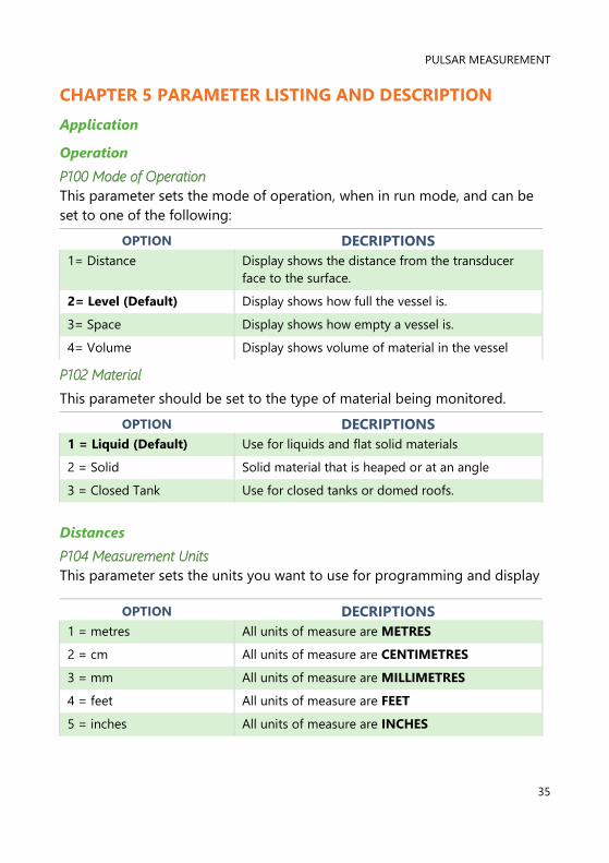
P100 Mode of Operation
This parameter sets the mode of operation, when in run mode, and can be
set to one of the following:
OPTION DECRIPTIONS
1= Distance Display shows the distance from the transducer
face to the surface.
2= Level (Default) Display shows how full the vessel is.
3= Space Display shows how empty a vessel is.
4= Volume Display shows volume of material in the vessel
P102 Material
This parameter should be set to the type of material being monitored.
OPTION DECRIPTIONS
1 = Liquid (Default) Use for liquids and flat solid materials
2 = Solid Solid material that is heaped or at an angle
3 = Closed Tank Use for closed tanks or domed roofs.
Distances
P104 Measurement Units
This parameter sets the units you want to use for programming and display
OPTION DECRIPTIONS
1 = metres All units of measure are METRES
2 = cm All units of measure are CENTIMETRES
3 = mm All units of measure are MILLIMETRES
4 = feet All units of measure are FEET
5 = inches All units of measure are INCHES
DBI (HART) INSTRUCTION MANUAL
36
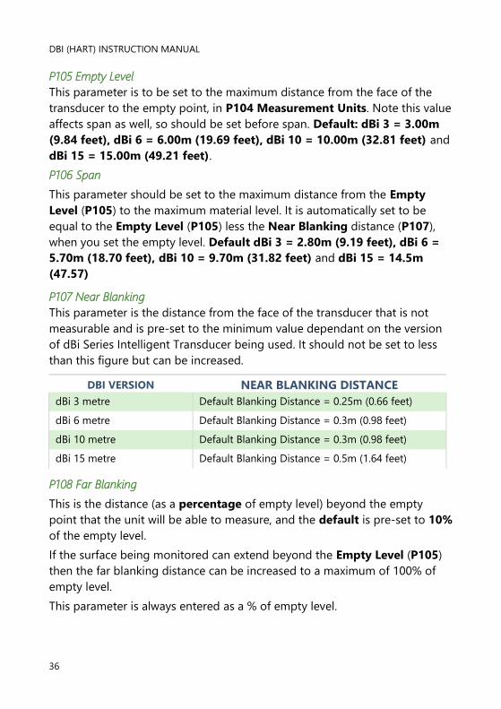
P105 Empty Level
This parameter is to be set to the maximum distance from the face of the
transducer to the empty point, in P104 Measurement Units. Note this value
affects span as well, so should be set before span. Default: dBi 3 = 3.00m
(9.84 feet), dBi 6 = 6.00m (19.69 feet), dBi 10 = 10.00m (32.81 feet) and
dBi 15 = 15.00m (49.21 feet).
P106 Span
This parameter should be set to the maximum distance from the Empty
Level (P105) to the maximum material level. It is automatically set to be
equal to the Empty Level (P105) less the Near Blanking distance (P107),
when you set the empty level. Default dBi 3 = 2.80m (9.19 feet), dBi 6 =
5.70m (18.70 feet), dBi 10 = 9.70m (31.82 feet) and dBi 15 = 14.5m
(47.57)
P107 Near Blanking
This parameter is the distance from the face of the transducer that is not
measurable and is pre-set to the minimum value dependant on the version
of dBi Series Intelligent Transducer being used. It should not be set to less
than this figure but can be increased.
DBI VERSION NEAR BLANKING DISTANCE
dBi 3 metre Default Blanking Distance = 0.25m (0.66 feet)
dBi 6 metre Default Blanking Distance = 0.3m (0.98 feet)
dBi 10 metre Default Blanking Distance = 0.3m (0.98 feet)
dBi 15 metre Default Blanking Distance = 0.5m (1.64 feet)
P108 Far Blanking
This is the distance (as a percentage of empty level) beyond the empty
point that the unit will be able to measure, and the default is pre-set to 10%
of the empty level.
If the surface being monitored can extend beyond the Empty Level (P105)
then the far blanking distance can be increased to a maximum of 100% of
empty level.
This parameter is always entered as a % of empty level.

PULSAR MEASUREMENT
37
Data Logs
The data log parameters contain the following information:
Temperature
The following parameters give information on temperature conditions seen
by the Temperature source (P852) in ºC. These parameters are read only
and cannot be changed, though if P852 is changed they will be reset.
P580 Minimum Temperature
This parameter displays the minimum temperature recorded.
P581 Minimum Temperature Date
This parameter displays the date when the minimum temperature was
recorded.
P582 Minimum Temperature Time
This parameter displays the time when the minimum temperature was
recorded.
P583 Maximum Temperature
This parameter displays the maximum temperature recorded.
P584 Maximum Temperature Date
This parameter displays the date when the maximum temperature was
recorded.
P585 Maximum Temperature Time
This parameter displays the time when the maximum temperature was
recorded.
P586 Current Temperature
This parameter displays the current temperature.
Transducer Power Information
The following parameters provide information on when the dBi Series
Intelligent Transducer was last powered down and how long it had run for.

DBI (HART) INSTRUCTION MANUAL
38
P940 Number of Starts
This parameter displays the number of times that the unit has been powered
since leaving the factory.
P941 Last Power Off Date
This parameter displays the last date on which the power was removed from
the unit.
P942 Last Power Off Time
This parameter displays the last time on which the power was removed from
the unit.
P943 Last Run Time (minutes)
This parameter displays how long the unit had been running, in minutes,
prior to the last power down.
P944 Last Run Time (hours)
This parameter displays how long the unit had been running, in hours, prior
to the last power down.
P945 Total Runtime (hours)
This parameter displays the accumulated total number of hours that the unit
has been in operation (powered up) since leaving the factory.
PULSAR MEASUREMENT
39
Volume
Conversion
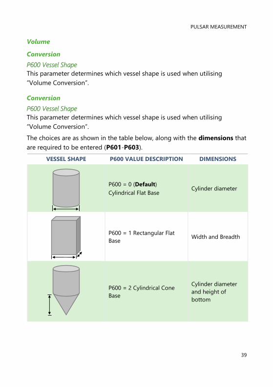
P600 Vessel Shape
This parameter determines which vessel shape is used when utilising
“Volume Conversion”.
Conversion
P600 Vessel Shape
This parameter determines which vessel shape is used when utilising
“Volume Conversion”.
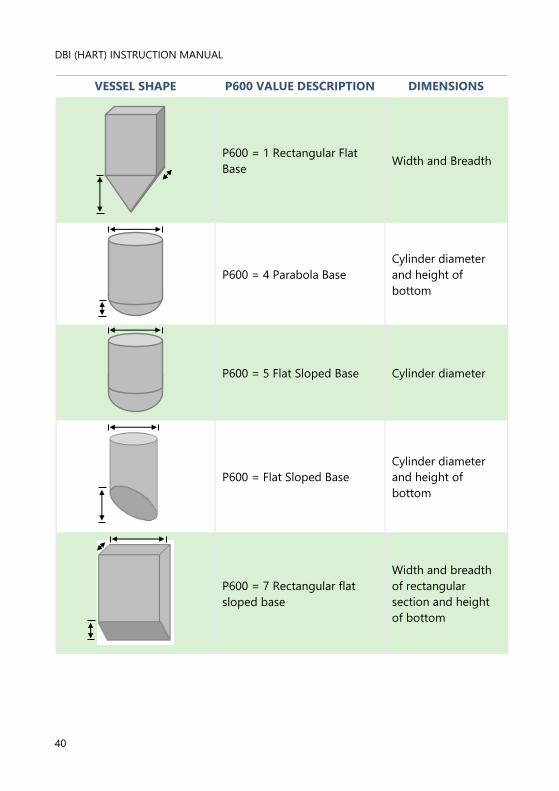
The choices are as shown in the table below, along with the dimensions that
are required to be entered (P601-P603).
VESSEL SHAPE P600 VALUE DESCRIPTION DIMENSIONS
P600 = 0 (Default)
Cylindrical Flat Base Cylinder diameter
P600 = 1 Rectangular Flat
Base Width and Breadth
P600 = 2 Cylindrical Cone
Base
Cylinder diameter
and height of
bottom
DBI (HART) INSTRUCTION MANUAL
40
VESSEL SHAPE P600 VALUE DESCRIPTION DIMENSIONS
P600 = 1 Rectangular Flat
Base Width and Breadth
P600 = 4 Parabola Base
Cylinder diameter
and height of
bottom
P600 = 5 Flat Sloped Base Cylinder diameter
P600 = Flat Sloped Base
Cylinder diameter
and height of
bottom
P600 = 7 Rectangular flat
sloped base
Width and breadth
of rectangular
section and height
of bottom
PULSAR MEASUREMENT
41
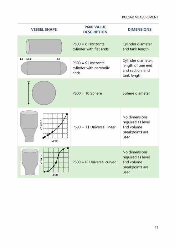
VESSEL SHAPE P600 VALUE
DESCRIPTION DIMENSIONS
P600 = 8 Horizontal
cylinder with flat ends
Cylinder diameter
and tank length
P600 = 9 Horizontal
cylinder with parabolic
ends
Cylinder diameter,
length of one end
and section, and
tank length
P600 = 10 Sphere Sphere diameter
P600 = 11 Universal linear
No dimensions
required as level,
and volume
breakpoints are
used
P600 =12 Universal curved
No dimensions
required as level,
and volume
breakpoints are
used

DBI (HART) INSTRUCTION MANUAL
42
P601-P603 Vessel Dimensions
These three parameters are used to enter the dimension required to
calculate the volume. The dimensions required are as shown below and are
entered Measurements Units (P104).
VESSEL SHAPE P601 P602 P603
P600 = 0
Cylindrical flat base
Cylinder
Diameter Not required Not required
P600 = 1
Rectangular flat base Not required
Width of
rectangle
Breadth of
rectangle
P600 = 2
Cylindrical cone base
Height of
base
Width of
rectangle Not required
P600 =3
Rectangular pyramid base
Height of
base
Width of
rectangle
Breadth of
rectangle
P600 = 4
Cylindrical parabola base
Height of
base
Cylinder
diameter Not required
P600 = 5
Cylindrical half sphere base
Cylinder
diameter Not required Not required
P600 = 6
Cylindrical flat sloped base
Height of
base
Cylinder
diameter Not required
P600 = 7
Rectangular flat sloped base
Height of
base
Width of
rectangle
Breadth of
rectangle
P600 = 8
Horizontal cylinder flat ends
Length of
cylinder
Cylinder
diameter Not required
P600 = 9
Horizontal cylinder parabolic
ends
Length of
cylinder
Cylinder
diameter
Length of
one end
P600 = 10
Sphere
Sphere
diameter Not required Not required
P604 Calculated Volume
This parameter displays the maximum volume that has been calculated by
the dBi and is a Read Only parameter. The volume displayed will be shown in
cubic meters and is the total volume available between empty level (P105)
and 100% of span (P106).
PULSAR MEASUREMENT
43
P605 Volume Units
This parameter determines the units that you wish to display, for volume
conversion. It is used in conjunction with P607 (maximum volume), and the
units are shown on the display (subject to P810). The choices are:
OPTION DESCRIPTION
0 = No units Volume will be totalised with no units
1 = Tons Volume will be totalised in Tons
2 = Tonnes Volume will be totalised in Tonnes
3 = Cubic metres (Default) Volume will be totalised in Cubic metres
4 = Litres Volume will be totalised in Litres
5 = UK Gallons Volume will be totalised in UK Gallons
6 = US Gallons Volume will be totalised in US Gallons
7 = Cubic Feet Volume will be totalised in Cubic Feet
8 = Barrels Volume will be totalised in Barrels
9 = lbs (pounds) Volume will be totalised in lbs (pounds)
P606 Correction Factor
This parameter is used to enter a correction factor, when required, such as
the specific gravity of the material so that the volume calculated is relative to
the actual amount of material that can be contained between empty level
(P105) and 100% of span (P106). Default = 1
P607 Max Volume
This parameter displays the actual maximum volume that has been
calculated by the dBi 5, i.e., P604 Calculated Volume x P606 Correction
Factor, and is a Read Only parameter. The volume displayed will be shown
in P605 Volume Units and is the total volume available between empty
level (P105) and 100% of span (P106).
DBI (HART) INSTRUCTION MANUAL
44
Breakpoints
P610-P641 Level/Volume Breakpoints
These parameters are used to create a profile of the vessel when P600=11
(universal linear) or P600=12 (universal curved). You should enter
breakpoints in pairs, a reading for level and its corresponding volume. The
more pairs you enter, the more accurate the profile will be. In the case of
universal linear, then enter the level/volume at each of the points where the
vessel changes shape. In the case of the universal curved, enter values
around each arc tangent, as well as at the top and bottom.
You must enter at least two pairs, and you can enter up to 32 pairs.
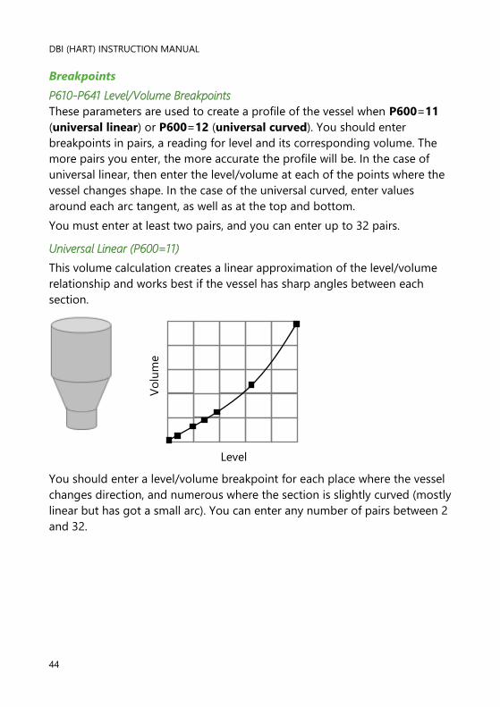
Universal Linear (P600=11)
This volume calculation creates a linear approximation of the level/volume
relationship and works best if the vessel has sharp angles between each
section.
You should enter a level/volume breakpoint for each place where the vessel
changes direction, and numerous where the section is slightly curved (mostly
linear but has got a small arc). You can enter any number of pairs between 2
and 32.
Vo
lum
e
Level
PULSAR MEASUREMENT
45
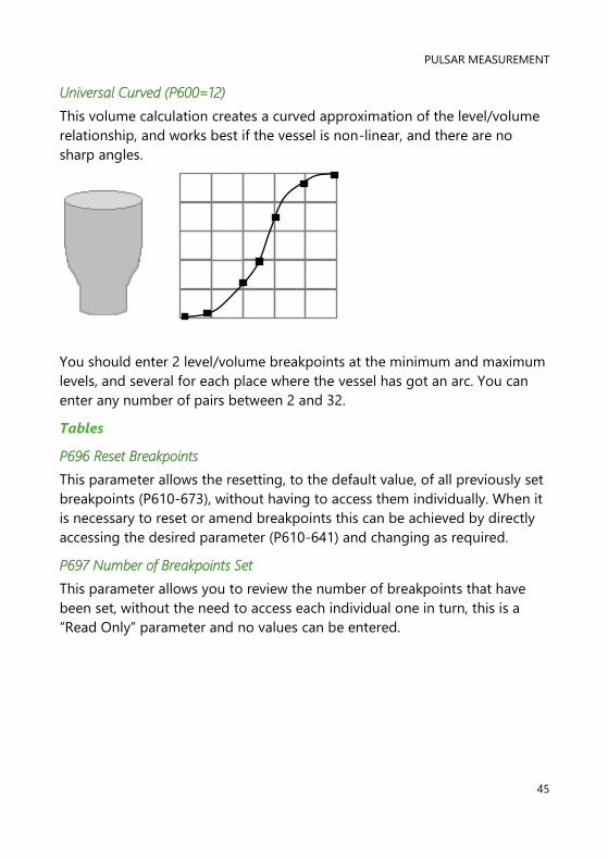
Universal Curved (P600=12)
This volume calculation creates a curved approximation of the level/volume
relationship, and works best if the vessel is non-linear, and there are no
sharp angles.
You should enter 2 level/volume breakpoints at the minimum and maximum
levels, and several for each place where the vessel has got an arc. You can
enter any number of pairs between 2 and 32.
Tables
P696 Reset Breakpoints
This parameter allows the resetting, to the default value, of all previously set
breakpoints (P610-673), without having to access them individually. When it
is necessary to reset or amend breakpoints this can be achieved by directly
accessing the desired parameter (P610-641) and changing as required.
P697 Number of Breakpoints Set
This parameter allows you to review the number of breakpoints that have
been set, without the need to access each individual one in turn, this is a
“Read Only” parameter and no values can be entered.
DBI (HART) INSTRUCTION MANUAL
46
mA Output
P834 mA Low Level
This parameter sets, in Measurement Units (P104), the value of ‘level’,
‘distance’ or ‘space’, depending on the selected Mode of Operation (P100),
at which 4mA will occur.
P835 mA High Level
This parameter sets, in Measurement Units (P104), the value of ‘level’,
‘distance’ or ‘space’, depending on the selected Mode of Operation (P100),
at which 20 mA output will occur.
P838 mA Low Trim
If the device you are connected to is not calibrated, and not showing the low
value, then you can trim it using this parameter. You can either type in the
offset directly or use the arrow keys to move the output up and down until
you get the expected result on the device that is connected.
P839 mA High Trim
If the device you are connected to is not calibrated, and not showing the
high value, then you can trim it using this parameter. You can either type in
the offset directly or use the arrow keys to move the output up and down
until you get the expected result on the device that is connected.
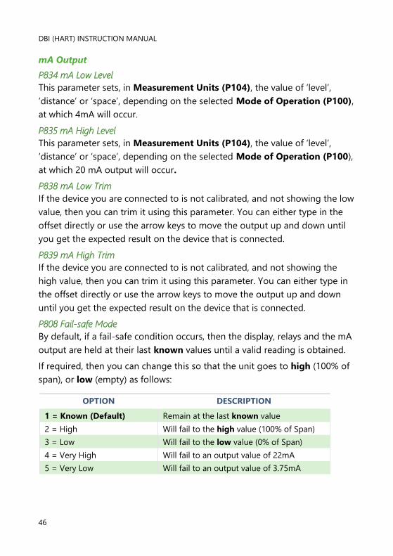
P808 Fail-safe Mode
By default, if a fail-safe condition occurs, then the display, relays and the mA
output are held at their last known values until a valid reading is obtained.
If required, then you can change this so that the unit goes to high (100% of
span), or low (empty) as follows:
OPTION DESCRIPTION
1 = Known (Default) Remain at the last known value
2 = High Will fail to the high value (100% of Span)
3 = Low Will fail to the low value (0% of Span)
4 = Very High Will fail to an output value of 22mA
5 = Very Low Will fail to an output value of 3.75mA

PULSAR MEASUREMENT
47
P809 Fail-safe Time
In the event of a fail-safe condition occurring the failsafe timer determines
the time before fail-safe mode is activated. Default = 2.00 mins
If the timer activates, the unit goes into fail-safe, as determined by P808,
(Display and P840 (mA Output). When this happens, you will see the
message “LOE!” on the display.
When a valid measurement is obtained then the display, relays and mA
output will be restored, and the timer is reset.
Compensation
P851 Measurement Offset
The value of this parameter is added to the measured distance, in
Measurement Units (P104).
This Offset will be added to the level, as derived from the transducer, and
will affect everything including the reading on the display, the relay
setpoints and the mA output.
P852 Temperature Source
This parameter determines the source of the temperature measurement. By
default, it is set to internal (transducer) (P852=1), which will automatically
detect the temperature from the transducer. If for any reason, no
temperature input is received, then the Fixed Temp value is used, as set by
P854.
The temperature source can be specifically set as follows:
OPTION DESCRIPTION
1 = Internal (Default) Always uses temperature reading from
transducer.
3 = Fixed Always uses fixed temperature (P854)
P854 Fixed Temperature
This parameter sets the temperature, in degrees centigrade to be used if
P852 (Temperature Source) =3. Default = 20oC
DBI (HART) INSTRUCTION MANUAL
48
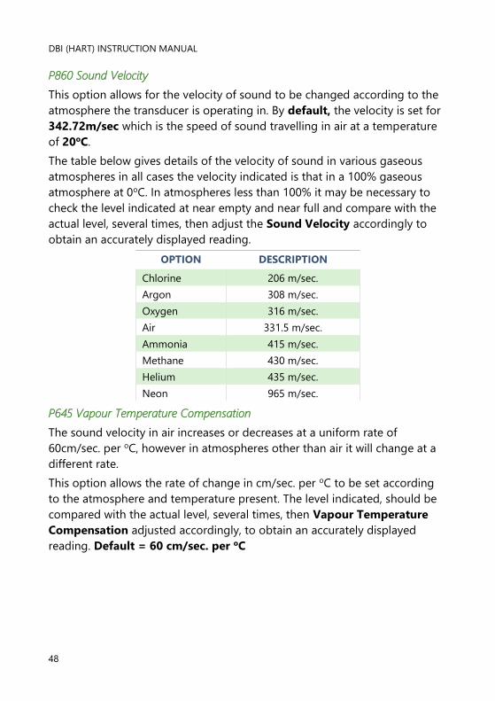
P860 Sound Velocity
This option allows for the velocity of sound to be changed according to the
atmosphere the transducer is operating in. By default, the velocity is set for
342.72m/sec which is the speed of sound travelling in air at a temperature
of 20oC.
The table below gives details of the velocity of sound in various gaseous
atmospheres in all cases the velocity indicated is that in a 100% gaseous
atmosphere at 0oC. In atmospheres less than 100% it may be necessary to
check the level indicated at near empty and near full and compare with the
actual level, several times, then adjust the Sound Velocity accordingly to
obtain an accurately displayed reading.
OPTION DESCRIPTION
Chlorine 206 m/sec.
Argon 308 m/sec.
Oxygen 316 m/sec.
Air 331.5 m/sec.
Ammonia 415 m/sec.
Methane 430 m/sec.
Helium 435 m/sec.
Neon 965 m/sec.
P645 Vapour Temperature Compensation
The sound velocity in air increases or decreases at a uniform rate of
60cm/sec. per oC, however in atmospheres other than air it will change at a
different rate.
This option allows the rate of change in cm/sec. per oC to be set according
to the atmosphere and temperature present. The level indicated, should be
compared with the actual level, several times, then Vapour Temperature
Compensation adjusted accordingly, to obtain an accurately displayed
reading. Default = 60 cm/sec. per oC
PULSAR MEASUREMENT
49
Stability
Damping
Damping is used to damp the display, to enable it to keep up with the
process but ignore minor surface fluctuations.
P870 Fill Damping
This parameter determines the maximum rate at which the unit will respond
to an increase in level. It should be set slightly higher than the maximum
vessel fill rate. Default = 10.000 metres/minute (32.81 feet/minute)
P871 Empty Damping
This parameter determines the maximum rate at which the unit will respond
to a decrease in level. It should be set slightly higher than the maximum
vessel empty rate. Default = 10.000 metres/minute (32.81 feet/minute)
Filters
P881 Fixed Distance
This parameter determines the width of gate to be used in tracking an echo
and under normal circumstances will not require changing, but it can be
increased in the cases where the surface is moving extremely fast (in excess
of 10m/min) to ensure smooth processing of the changing level.
P884 Peak Percentage
When P102 = 2 (Solids), this parameter can be used to determine the point
at which the measurement is taken, within the established gate of the
selected echo, to compensate for any error that maybe caused by “angles of
repose” presented by the way the material settles. Please consult Pulsar, for
further information and assistance on changing the value of this parameter.
System
Important Notice
Parameters 926, 927 and 928 do not affect how the unit performs, but
details contained in them may be required, by Pulsar, when making
technical enquiries.
DBI (HART) INSTRUCTION MANUAL
50
Password
P921 Enable Code
Enables the passcode (P922), which means the passcode must be entered
to go into program mode. If disabled (set to 0), then no passcode is
required, and pressing ESC and ENTER button simultaneously will allow entry
into the program mode.
P922 Passcode
This is the passcode that must be used to enter program mode. The default
is 1997, but this can be changed to another value.
System Information
P926 Software Revision
This parameter will display the current software revision.
P927 Hardware Revision
This parameter will display the current hardware revision. It is read only and
cannot be changed.
P928 Serial Number
This parameter will display the serial number of the unit.
P930 Factory Defaults
This parameter resets all parameter values to the original Factory Set values
that were installed when the unit was tested, before despatch to you.
To reset parameters, Set P930 to 1.
Date & Time
The date and time are used, to control specific relay functions and date
stamp certain events that are contained in the Data Logs. It is also used in
conjunction with the system watchdog that keeps an eye on the times the
unit has started.
P931 Date
This parameter displays the current date, in the format as set by P933 (Date
Format), and can be reset if required.
P932 Time
This parameter displays the current time and can be reset if required, in the
format HH:MM (24-hour format). This is set initially at the factory for UK
time.

PULSAR MEASUREMENT
51
LOE Save Trace
P950 Save DATEM Trace on LOE
When enabled this parameter will ensure that in the event of the unit going
into a LOE situation a trace at the time of the LOE occurrence is saved for
future reference.
OPTION DESCRIPTION
0 = Off Feature is disabled and in the event of LOE
echo trace will NOT be saved.
1 = Enable (Single Trace)
In the event of a LOE situation an echo trace
WILL be saved and stored for future reference.
Once a LOE trace has been saved no further
traces will be taken
2 = Enable Overwrite
(Default)
In the event of an LOE event occurring any
previous trace will be overwritten and the last
LOE trace saved.
DATEM
P020 Set DATEM
This parameter allows DATEM to be reset to its default value. To reset
DATEM to its default value set parameter value to 1, the trace will then be
set to its default value and then update as normal.
P021 Set Dist.
Allows the user or service personnel to determine which echo is to be
displayed. On start-up, if the unit displays an incorrect reading then simply
enter the distance from the transducer to the required level and, if an echo is
present at this point, the Gate will establish itself around the chosen echo,
DATEM will update in front of the Gate and reference out any other
unwanted echoes.
It should be noted that DATEM will reset to default values whilst performing
this function, and reform itself once it has selected an echo.
Enter distance from the face of transducer to the target in units of
measurement P104
Values: Min. 0.000, Max. 99.00

DBI (HART) INSTRUCTION MANUAL
52
P905 Peak Clearance
This parameter is used to set the “height” above which the DATEM trace will
“stand-off” from around unwanted echoes such as obstructions. Please
consult Pulsar for further information and assistance on changing the value
of this parameter.
P906 Side Clearance
This parameter is used to set the “distance” by which the DATEM trace will
“stand-off” from around unwanted echoes such as obstructions. Please
consult Pulsar for further information and assistance on changing the value
of this parameter.
PULSAR MEASUREMENT
53
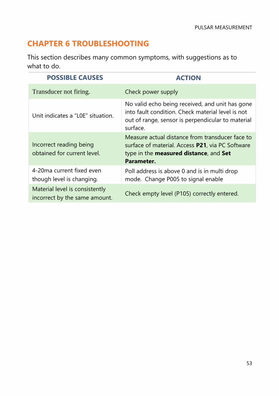
CHAPTER 6 TROUBLESHOOTING
This section describes many common symptoms, with suggestions as to
what to do.
POSSIBLE CAUSES ACTION
Transducer not firing. Check power supply
Unit indicates a “L0E” situation.
No valid echo being received, and unit has gone
into fault condition. Check material level is not
out of range, sensor is perpendicular to material
surface.
Incorrect reading being
obtained for current level.
Measure actual distance from transducer face to
surface of material. Access P21, via PC Software
type in the measured distance, and Set
Parameter.
4-20ma current fixed even
though level is changing.
Poll address is above 0 and is in multi drop
mode. Change P005 to signal enable
Material level is consistently
incorrect by the same amount. Check empty level (P105) correctly entered.

DBI (HART) INSTRUCTION MANUAL
54
CHAPTER 7 DISPOSAL
Incorrect disposal can cause adverse effects to the environment.
Dispose of the device components and packaging material in accordance
with regional environmental regulations including regulations for electrical \
electronic products.
Transducers
Remove power, disconnect the Transducer, cut off the electrical cable and
dispose of cable and Transducer in accordance with regional environmental
regulations for electrical \ electronic products.
Controllers
Remove power, disconnect the Controller, and remove battery (if fitted).
Dispose of Controller in accordance with regional environmental regulations
for electrical \ electronic products.
Dispose of batteries in accordance with regional environmental regulations
for batteries.
EU WEEE Directive Logo
This symbol indicates the requirements of Directive 2012/19/EU regarding
the treatment and disposal of waste from electric and electronic equipment.

PULSAR MEASUREMENT
55
www.pulsarmeasurement.com
S U P P O R T @ P U L S A R M E A S U R E M E N T . C O M
Copyright © 2020 Pulsar Measurement Ltd.
Registered Address: 1 Chamberlain Square CS, Birmingham B3 3AX
Registered No.: 3345604 England & Wales
Rev 1.0
Copyright © 2022 FDOKUMEN