ARECIBO PULSAR SURVEY USING ALFA: PROBING RADIO PULSAR INTERMITTENCY AND TRANSIENTS
Upload
khangminh22Category
view
0download
0
The Pulsar Project for Very High Speed Computer Networking
�
Gary J. Murakami, Roy H. Campbell, and Michael Faiman
University of Illinois at Urbana-Champaign
Department of Computer Science
1304 W. Spring�eld Avenue
Urbana, Illinois 61801{2987 USA
Abstract
We are investigating very high-speed computer networking at gigabit rates. We present the
Pulsar switch, a non-blocking design based on a high-spin-rate, port-dedicated, word-parallel,
shift-register ring. The Pulsar switch can also be used as a high-throughput system bus re-
placement to interconnect computer system components. The design can be implemented with
existing high-speed circuit technology.
�
This work was supported in part by AT&T
1

1 Introduction
As improvements in �ber-optic transmission technology scale up the speed and distance of computer
networks, the need for innovative high-speed and high-throughput packet switch design increases.
Since high speeds combined with long-distance propagation delay already incur large bu�ering
requirements, packet-based networks running at gigabit rates require improved packet switching
techniques to minimize blocking, routing, queueing, protocol processing, and switching overhead.
Slow, complex, traditional software switching methods must be replaced. The new networks require
extremely fast switches with design simplicity for e�ciency and hardware assistance for routing,
queueing, and protocol processing.
We have developed a high-speed packet switch named \Pulsar ". The Pulsar switch design
endeavors to minimize complexity while providing non-blocking throughput and self-switching logic.
High-speed circuitry implements a fast, slot-dedicated, shift-register ring. A non-blocking switch
with 16 or more ports and gigabit per second transmission links can be realized using current
technology
1
. The Pulsar switch design can also function as a high-throughput system interconnect
backplane which replaces the system bus in computer systems. This report presents the basic switch
design, major design alternatives, and directions for future research in the simulation and analysis
of the Pulsar switch design.
2 Related Work
Research on the Pulsar switch design is related to several current and proposed projects at the
University of Illinois.
XUNET: We are part of the Experimental University Network (XUNET) project sponsored by
AT&T Bell Laboratories. XUNET interconnects AT&T Bell Laboratories at Murray Hill with
the University of California at Berkeley, the University of Illinois at Urbana-Champaign, and the
University of Wisconsin at Madison. The network is currently implemented with T1 1.544 Mbps
lines and Datakit VCS
2
switches [6] [7]. Future plans include upgrading the network to T3 45 Mbps
lines and faster switches with the possibility of link speeds in the gigabit range for experimental
purposes
3
.
XUNET provides a prototype network for investigating high-speed long-distance networking
which spans the nation. A network architecture named \GNET" presents a plan for a national
network and outlines the functional components of the network [17]. The short-term GNET-IP plan
proposes IP (Internet Protocol) support coupled with a smooth transition to a the long term GNET-
PSP plan with PSP (Packet Stream Protocol)
4
as the primary protocol. With this approach, new
high-speed networking hardware can be introduced immediately into the Internet with a smooth
migration path toward newer protocol suites to take full advantage of very high-speed transmission
and switching technology operating at gigabit rates. The Pulsar switch design is compatible with
the GNET network architecture.
1
Pulsar capitalizes on high-speed electronic technology and does not depend on further improvements in optical
switch components.
2
Datakit VCS is a registered trademark of AT&T
3
FTG 1.7 Gbps = 36 x T3 45 Mbps + overhead
4
PSP has been superceded by MSP (Message Stream Protocol).
1
NRI: The Corporation for National Research Initiatives (NRI) is sponsoring research toward the
development of a high-speed national research network. We have applied for a grant to support
our research in very high-speed networking.
Tapestry: The Tapestry project at UIUC sponsored by the NSF is investigating the intercon-
nection of shared-memory and networked multiprocessors into a cohesive environment for parallel
processing applications [3]. The Choices [23] object-oriented operating system provides a portable
software environment for Tapestry.
Complementary Projects: The Pulsar , XUNET, NRI, and Tapestry projects complement
each other. The Pulsar switch can be integrated into to the XUNET and NRI research and can
be explored as a very high-speed local-area networking fabric for the Tapestry project. XUNET
provides long-distance trunks for experiments with long-haul networking and long-haul distributed
systems. Choices is attractive a foundation for switch controllers and network controllers.
3 Switch Architectures
Switching is the transfer of packets from the input port to the output port. Given a packet marked
for an output port, how is the packet switched or transferred from the input port to the output
port? This overview compares the features of major switch structures and provides a frame of
reference for the Pulsar switch.
3.1 Blocking Switches
Traditional packet switches are blocking since a shared resource is used for switching. A packet
being switched occupies the shared resource and blocks other packets from being switched even if
there is no contention for the output port.
Buses: The bus architecture is used for both computer systems (e.g., VME bus) and computer
networks (e.g., Ethernet). The bus structure is a broadcast medium with full connectivity. Com-
puter system buses use parallel lines for high bandwidth, and the physical backplane con�guration
enables pluggable modules for CPUs, memory, and I/O devices.
However, the bus is a shared resource which limits throughput. In computer systems, CPUs
and I/O contend for the bus and block each other. In order to reduce contention, multiple buses are
often arranged in a segmented or hierarchical structure. For example, several graphics workstations
have separate \pixel" buses for graphics processors and display memory. However, a transfer of
an image from disk to display memory still blocks the pixel bus, the system bus, and the bridge
between the buses. Multiprocessors based on a shared-bus architecture are bandwidth limited to
around 32 nodes [8].
Token Rings: Token rings are used primarily for computer networks (e.g., FDDI, ProNET-80
5
,
IEEE 802.4) but also have been used as a multiprocessor interconnect structure [10] [4]. The ring
is fully connected and can provide a broadcast medium. Token logic is a simple mechanism for
5
ProNET is a registered trademark of Proteon, Inc.
2
arbitrating access to the medium
6
. However in most implementations, the token ring is a shared
resource which limits throughput. Most token rings have higher delay than buses due to ring transit
time.
3.2 Non-blocking Switches
In non-blocking switches, the switch has su�cient capacity to support switching to all output ports
simultaneously. A packet destined to an output port does not block other packets destined to
di�erent output ports. The term \non-blocking" applies to the switch fabric and does not include
the unavoidable problem of blocking due to contention for the same output port.
Crossbars: The crossbar is a matrix switch used in telephone systems, computer networks, and in
computer systems [18]. Crossbar switches have been implemented optically [16] and electrically in
silicon (e.g., 16x16x4bits) [20]. The crossbar is non-blocking and can support broadcast capability.
A major drawback to the crossbar is the requirement for switch setup via external control for each
packet or set of synchronous bounded size packets. A coordination mechanism must be used to
provide fairness for crossbar setup. Scaling of a crossbar requires N
2
components.
Sort-Sift Networks: In contrast to crossbar switches, sort-sift switches are self-switching: the
destination port address for a packet is used to switch through a binary sorting network bit by
bit. Batcher-Banyan switches use a Batcher sorting network and an associated mechanism to
resolve output con icts before delivery to the Banyan network. Copy networks have been added to
Batcher-Banyan switches to provide multicast capability [15].
A major problem for Batcher-Banyan networks is resolving contention for output ports. The
Starlight
7
[11] switch adds a purge-skew-concentrate stage before the Banyan network. Packets
which have lost the contention are recirculated and reentered into the Batcher network. Packets can
be lost due to blocking within the reentry network, and packets may be delivered out of sequence.
An alternative to the Starlight contention resolution is a three phase algorithm: (I) send and resolve
request, (II) acknowledge winning port, and (III) send packet [1].
3.3 Other Topologies
Several projects researching optical interconnection use variations of the perfect shu�e connection
pattern [13] [24].
Mesh networks are another interesting structure. The Manhattan Street Network is a planar
network fabric readily implemented in VLSI [27], but it su�ers from less predictable delays and
out-of-sequence packet delivery. The mesh can be dedicated to switching, or a computation site
can be associated with each node.
Hypergraphs are a similar topology where the longest path between any two nodes is O(log
d
N)
where d is the degree of a node. An example of a hypergraph with a computation site at each node
is the Hypercube (e.g., Intel iPSC/2).
Many di�erent di�erent topologies can be used for constructing a larger switching fabric from
smaller switch components. Note that most of the common topologies su�er from blocking.
6
Token replacement policy a�ects fairness and ring occupancy
7
Starlight is a registered trademark of AT&T
3
-
�
?
?
-
?
?
A
A
A�
�
�
H
H
H
H
H
�
�
�
�
�
H
H
H
H
H
�
�
�
�
�
Fiber:
bit-serialword-parallel
GaAs|FastSi:
Register
ring stage
from previous
ring stage
to next
Out
In
Mux
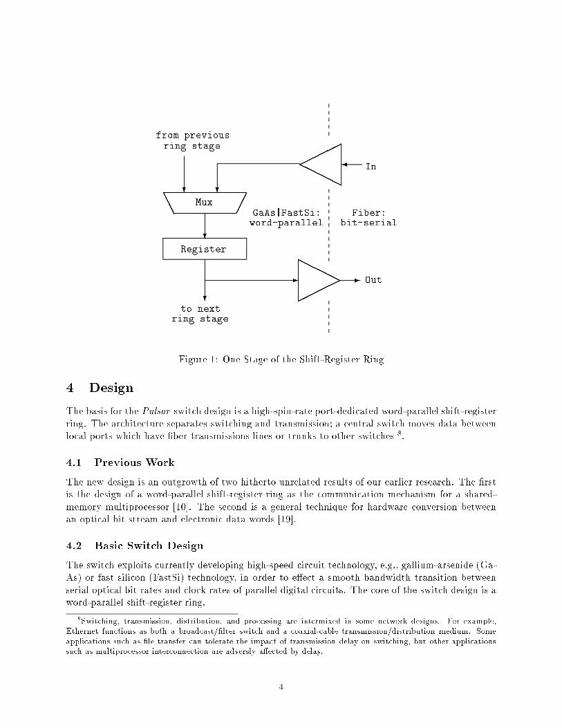
Figure 1: One Stage of the Shift-Register Ring
4 Design
The basis for the Pulsar switch design is a high-spin-rate port-dedicated word-parallel shift-register
ring. The architecture separates switching and transmission; a central switch moves data between
local ports which have �ber transmissions lines or trunks to other switches
8
.
4.1 Previous Work
The new design is an outgrowth of two hitherto unrelated results of our earlier research. The �rst
is the design of a word-parallel shift-register ring as the communication mechanism for a shared-
memory multiprocessor [10]. The second is a general technique for hardware conversion between
an optical bit stream and electronic data words [19].
4.2 Basic Switch Design
The switch exploits currently developing high-speed circuit technology, e.g., gallium-arsenide (Ga-
As) or fast silicon (FastSi) technology, in order to e�ect a smooth bandwidth transition between
serial optical bit rates and clock rates of parallel digital circuits. The core of the switch design is a
word-parallel shift-register ring.
8
Switching, transmission, distribution, and processing are intermixed in some network designs. For example,
Ethernet functions as both a broadcast/�lter switch and a coaxial-cable transmission/distribution medium. Some
applications such as �le transfer can tolerate the impact of transmission delay on switching, but other applications
such as multiprocessor interconnection are adversly a�ected by delay.
4
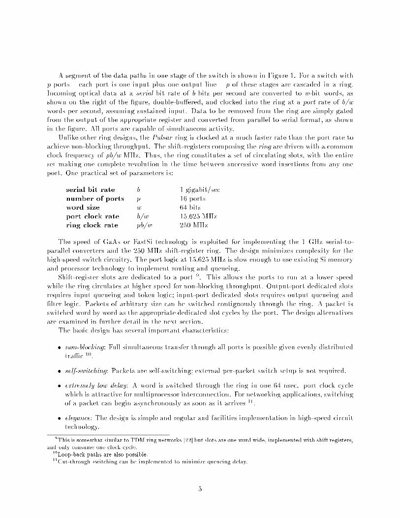
A segment of the data paths in one stage of the switch is shown in Figure 1. For a switch with
p ports { each port is one input plus one output line { p of these stages are cascaded in a ring.
Incoming optical data at a serial bit rate of b bits per second are converted to w-bit words, as
shown on the right of the �gure, double-bu�ered, and clocked into the ring at a port rate of b/w
words per second, assuming sustained input. Data to be removed from the ring are simply gated
from the output of the appropriate register and converted from parallel to serial format, as shown
in the �gure. All ports are capable of simultaneous activity.
Unlike other ring designs, the Pulsar ring is clocked at a much faster rate than the port rate to
achieve non-blocking throughput. The shift-registers composing the ring are driven with a common
clock frequency of pb/w MHz. Thus, the ring constitutes a set of circulating slots, with the entire
set making one complete revolution in the time between successive word insertions from any one
port. One practical set of parameters is:
serial bit rate b 1 gigabit/sec
number of ports p 16 ports
word size w 64 bits
port clock rate b/w 15.625 MHz
ring clock rate pb/w 250 MHz
The speed of GaAs or FastSi technology is exploited for implementing the 1 GHz serial-to-
parallel converters and the 250 MHz shift-register ring. The design minimizes complexity for the
high-speed switch circuitry. The port logic at 15.625 MHz is slow enough to use existing Si memory
and processor technology to implement routing and queueing.
Shift-register slots are dedicated to a port
9
. This allows the ports to run at a lower speed
while the ring circulates at higher speed for non-blocking throughput. Output-port dedicated slots
requires input queueing and token logic; input-port dedicated slots requires output queueing and
�lter logic. Packets of arbitrary size can be switched contiguously through the ring. A packet is
switched word by word as the appropriate dedicated slot cycles by the port. The design alternatives
are examined in further detail in the next section.
The basic design has several important characteristics:
� non-blocking: Full simultaneous transfer through all ports is possible given evenly distributed
tra�c
10
.
� self-switching: Packets are self-switching; external per-packet switch setup is not required.
� extremely low delay: A word is switched through the ring in one 64 nsec. port clock cycle
which is attractive for multiprocessor interconnection. For networking applications, switching
of a packet can begin asynchronously as soon as it arrives
11
.
� elegance: The design is simple and regular and facilities implementation in high-speed circuit
technology.
9
This is somewhat similar to TDM ring networks [22] but slots are one word wide, implemented with shift registers,
and only consume one clock cycle.
10
Loop-back paths are also possible.
11
Cut-through switching can be implemented to minimize queueing delay.
5
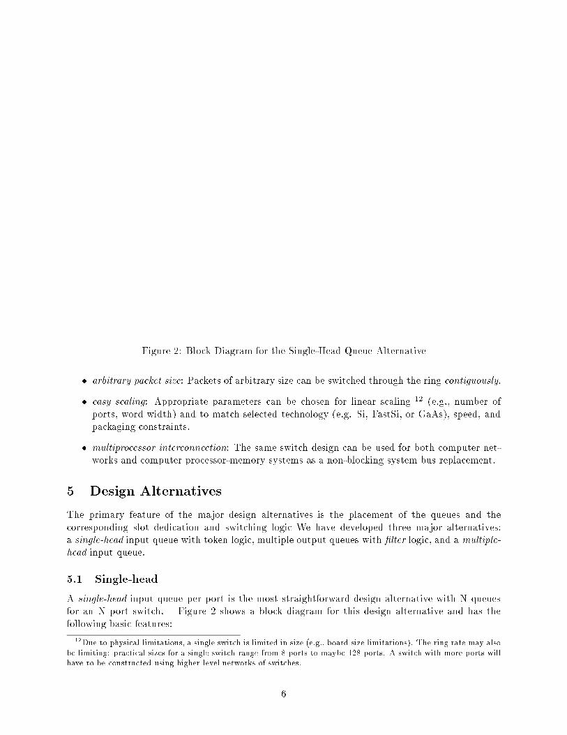
Figure 2: Block Diagram for the Single-Head Queue Alternative
� arbitrary packet size: Packets of arbitrary size can be switched through the ring contiguously.
� easy scaling: Appropriate parameters can be chosen for linear scaling
12
(e.g., number of
ports, word width) and to match selected technology (e.g. Si, FastSi, or GaAs), speed, and
packaging constraints.
� multiprocessor interconnection: The same switch design can be used for both computer net-
works and computer processor-memory systems as a non-blocking system bus replacement.
5 Design Alternatives
The primary feature of the major design alternatives is the placement of the queues and the
corresponding slot dedication and switching logic We have developed three major alternatives:
a single-head input queue with token logic, multiple output queues with �lter logic, and a multiple-
head input queue.
5.1 Single-head
A single-head input queue per port is the most straightforward design alternative with N queues
for an N port switch. Figure 2 shows a block diagram for this design alternative and has the
following basic features:
12
Due to physical limitations, a single switch is limited in size (e.g., board size limitations). The ring rate may also
be limiting: practical sizes for a single switch range from 8 ports to maybe 128 ports. A switch with more ports will
have to be constructed using higher level networks of switches.
6

� queueing occurs at the input port
� a slot is dedicated to each output port
� token logic is used for ring access
13
� ring access via token logic is packet-per-port fair
14
� Head-of-Line blocking lowers throughput
The following sequence lists the major events for switching a packet.
Input port packet arrival A packet arrives at the input port. The routing module determines
the output port for the packet. The input port has a single queue with space for one or more
packets
15
.
Wait for output port token: The input port waits for an empty slot for the output port.
Input port transmission The input port transmits the packet word-by-word through the output
slot. At the end of the packet, the token is put back on the ring.
Output port reception The output port accepts data from its slot and transmits it directly on
the �ber.
The single-head input queue design su�ers Head-Of-Line (HOL) blocking. If an input port has
a packet destined to an output port that is busy with a packet from a di�erent input port, then
packets that arrive at the input port are blocked even if they are destined to an output port that
is not busy. Simulation results and analysis show that HOL blocking lowers throughput to 59%
(2�
p
2) [1] [9] for the saturated-switch worst-case.
5.2 Filter
A multiple output queue design eliminates HOL blocking but has M*N queues for an N port switch
with M queues per port. Figure 3 shows a block diagram for this design alternative and has the
following basic features:
� queueing occurs at the output port
� slots are dedicated to input ports
� �lter logic is used for ring exit
16
� proper bu�er selection can provide fairness
17
13
Additional token bits are needed for each port-bit-slice chip
14
Input queueing is not word/byte/bit fair if packet size varies.
15
Both FCFS and FQ (Fair Queueing) queue disciplines are under investigation.
16
Address bits are needed to specify the destination port
17
Output queue combined with Fair Queueing provides approximate word/byte/bit fairness. The Input queue
alternatives are packet fair which is unfair if packet size varies.
7
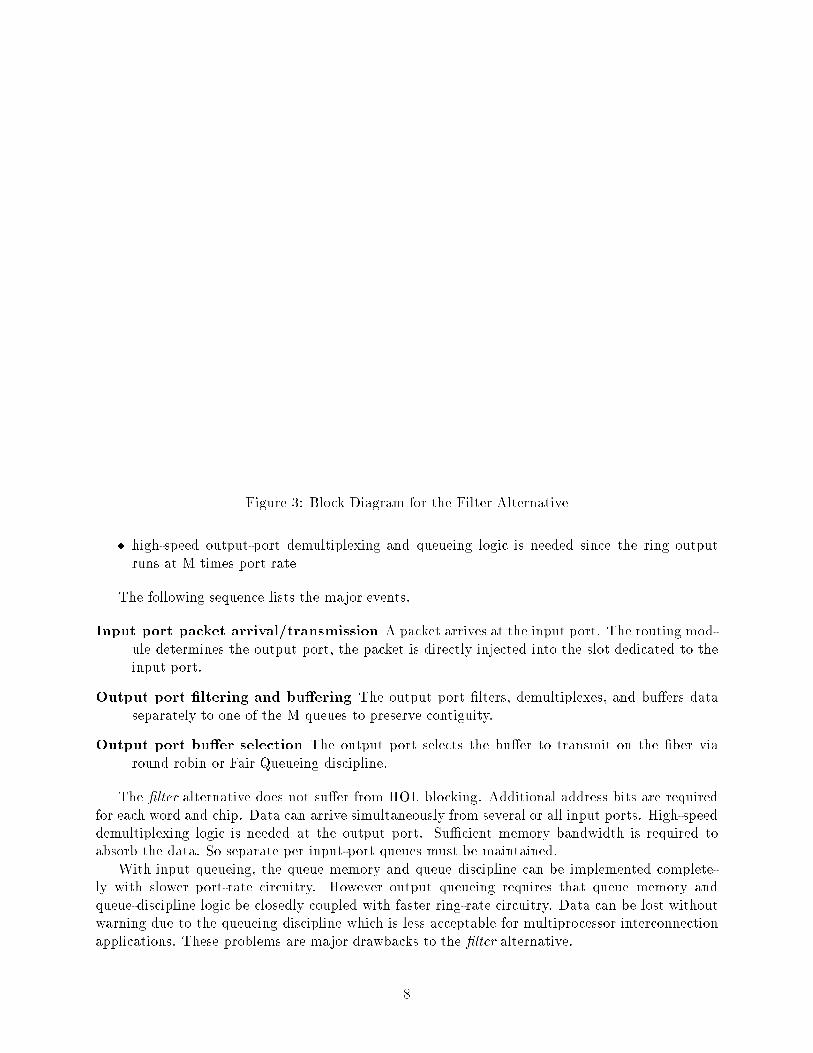
Figure 3: Block Diagram for the Filter Alternative
� high-speed output-port demultiplexing and queueing logic is needed since the ring output
runs at M times port rate
The following sequence lists the major events.
Input port packet arrival/transmission A packet arrives at the input port. The routing mod-
ule determines the output port, the packet is directly injected into the slot dedicated to the
input port.
Output port �ltering and bu�ering The output port �lters, demultiplexes, and bu�ers data
separately to one of the M queues to preserve contiguity.
Output port bu�er selection The output port selects the bu�er to transmit on the �ber via
round robin or Fair Queueing discipline.
The �lter alternative does not su�er from HOL blocking. Additional address bits are required
for each word and chip. Data can arrive simultaneously from several or all input ports. High-speed
demultiplexing logic is needed at the output port. Su�cient memory bandwidth is required to
absorb the data. So separate per input-port queues must be maintained.
With input queueing, the queue memory and queue discipline can be implemented complete-
ly with slower port-rate circuitry. However output queueing requires that queue memory and
queue-discipline logic be closedly coupled with faster ring-rate circuitry. Data can be lost without
warning due to the queueing discipline which is less acceptable for multiprocessor interconnection
applications. These problems are major drawbacks to the �lter alternative.
8

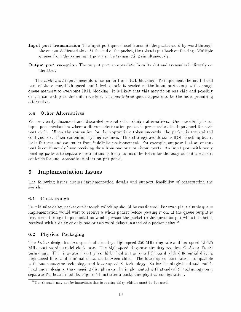
Figure 4: Block Diagram for the Multi-Head Queue Alternative
5.3 Multi-head
The next alternative is a multi-head input queue with N M-head queues for an N port switch.
Figure 4 shows a block diagram for this design alternative and has the following basic features:
� queueing occurs at the input port
� slots are dedicated to output ports
� token logic is used for ring access
18
� ring access via token logic is packet-per-port fair
19
� high-speed queue head and input-port multiplexing logic is needed
The following sequence lists the major events.
Input port packet arrival A packet arrives at the input port. The routing module determines
the destination port for the packet and enqueues the packet in the large slow-speed main
queue on the line card. If the high-speed queue head memory on the backplane is not full,
the packet is transferred and inserted into the queue head for the appropriate destination.
Wait for output port token As each output designated slot is presented to the input port, token
logic is run using the corresponding queue head. In e�ect, the input port is simultaneously
waiting for the output port tokens for each of the multiple queue heads.
18
Additional token bits are needed for each port-bit-slice chip
19
Input queueing is not word/byte/bit fair if packet size varies.
9
Input port transmission The input port queue head transmits the packet word-by-word through
the output-dedicated slot. At the end of the packet, the token is put back on the ring. Multiple
queues from the same input port can be transmitting simultaneously.
Output port reception The output port accepts data from its slot and transmits it directly on
the �ber.
The multi-head input queue does not su�er from HOL blocking. To implement the multi-head
part of the queue, high speed multiplexing logic is needed at the input port along with enough
queue memory to overcome HOL blocking. It is likely that this may �t on one chip and possibly
on the same chip as the shift registers. The multi-head queue appears to be the most promising
alternative.
5.4 Other Alternatives
We previously discussed and discarded several other design alternatives. One possibility is an
input port mechanism where a di�erent-destination packet is presented at the input port for each
port cycle. When the contention for the appropriate token succeeds, the packet is transmitted
contiguously. Then contention cycling resumes. This strategy avoids some HOL blocking but it
lacks fairness and can su�er from inde�nite postponement. For example, suppose that an output
port is continuously busy receiving data from one or more input ports. An input port with many
pending packets to separate destinations is likely to miss the token for the busy output port as it
contends for and transmits to other output ports.
6 Implementation Issues
The following issues discuss implementation details and support feasibility of constructing the
switch.
6.1 Cut-through
To minimize delay, packet cut-through switching should be considered. For example, a simple queue
implementation would wait to receive a whole packet before passing it on. If the queue output is
free, a cut-through implementation would present the packet to the queue output while it is being
received with a delay of only one or two word delays instead of a packet delay
20
.
6.2 Physical Packaging
The Pulsar design has two speeds of circuitry: high-speed 250 MHz ring rate and low-speed 15.625
MHz port word parallel clock rate. The high-speed ring-rate circuitry requires GaAs or FastSi
technology. The ring-rate circuitry would be laid out on one PC board with di�erential drivers
high-speed lines and minimal distances between chips. The lower-speed port rate is compatible
with bus connector technology and lower-speed Si technology. So for the single-head and multi-
head queue designs, the queueing discipline can be implemented with standard Si technology on a
separate PC board module. Figure 5 illustrates a backplane physical con�guration.
20
Cut-through may not be immediate due to routing delay which cannot be bypassed.
10
Figure 5: Pulsar Backplane Physical Con�guration
11
6.3 Chip Packaging
We currently favor a port-bit-slice chip packaging for the ring. The ring is divided into chips via
port and bit slice. Current chip packages of 256 pins are adequate for a 32-bit slice. So a 64-bit
word 16-port switch would require 32 chips. The port-bit-slice approach permits the construction
of rings with an arbitrary number of ports and a word size that is a multiple of the 32-bit slice size.
The example ring rate of 250 MHz can be implemented in FastSi as well as GaAs technology.
Faster clock rates can be chosen, but the 250 MHz rate can be implemented on PC boards with
balanced lines without resorting to micro-coax.
Port interface logic for the multi-head queue alternative can be implemented on a separate chip
or integrated into the ring chip
21
.
A common chip or chip-set subset for both computer network switching and computer system
interconnection is an attractive idea. However the di�ering applications may require su�ciently
di�erent circuitry support which may not be feasible with a common chip.
6.4 Network Switch
Routing and queueing mechanisms are needed to complete the network switch design.
6.4.1 Routing
Routing is determining the output port for a packet. The resulting local destination port is used
to switch the packet. There are three standard routing methods.
Source routing attaches an explicit path to each packet at the source. At the source, a symbolic
name must be resolved to a path, typically via a complete address routing database, and that
path is prepended to each packet. At each switch the output port is determined by simple
header stripping or indexing into the explicit path. A major drawback is that source routing
requires either headers of arbitrary length in order to span a network of arbitrary width, or
else a path length limit, which places restrictions on network width.
Destination routing is typical of many networks including the ARPANET. At the source a
symbolic name is resolved into a numeric address via a host table or name server. For every
packet at each switch, the address requires a relatively expensive translation lookup in a
database to determine the destination output port.
22
Virtual Circuit routing isolates expensive destination symbolic name or address translation to
a circuit setup phase. Subsequent packets follow the existing virtual circuit, with minimal
cost, by using a virtual circuit identi�er to index into a relatively small table, which can
be viewed as a small or �xed size explicit cache of active routes. Only a partial routing
database is needed at each node, and the database can be distributed by module
23
. The
major drawback is circuit setup overhead and delay.
21
Note that this may place size restrictions on the ring
22
Destination address translation has been too expensive for high-speed routing even using sophisticated software
searching techniques. We are investigating VM (Virtual Memory) mapping which capitalizes on MMU (Memory
Management Unit) hardware to manage a sparse cache of destination addresses.
23
Unlike the destination routing tables, the VC switch memory can be distributed with each module storing only
the mappings for its own circuits.
12
If packet cut-through is implemented, routing delay is critical, since the packet must be delayed
until the target output port is determined. The routing methods in order of increasing delay are
source routing, virtual circuit routing, and destination routing. With dedicated processing, we
expect the routing delay to be the time for a few memory accesses.
Destination routing can also result in blocking or excessive packet loss. If a route is not known for
a destination, the packet and any immediately following packets with the same destination must be
either discarded or else stored until the destination address address is resolved. In contrast, source
routing has no address translation, and virtual circuit routing establishes the circuit externally
before data packets are transmitted
24
. Besides performance, virtual circuits also facilitate network
administration, billing, authentication, security, and management
25
.
The Pulsar switch design is compatible with all three routing methods. The routing mod-
ule could support more than one routing method; it is possible that all three methods could be
supported simultaneously.
6.4.2 Queueing
The queueing discipline determines how the bandwidth is utilized. If dedicated bandwidth and
tra�c priorities are to be implemented, the queueing mechanism must incorporate those features.
We currently favor the implementation of Fair Queueing [5] which approximates bit-by-bit round
robin queueing. As mentioned previously, the single-head and multi-head queue alternatives are
only packet fair per port. This is �ne for �xed packet sizes or ATM cells but unfair for varying
packet sizes. However, the output-queue �lter alternative can be word fair regardless of varying
packet sizes.
6.5 System Interconnect
The Pulsar switch can be used to replace the system bus for interconnecting computer system
components. This provides non-blocking throughput and removes the bus bottleneck. The Pulsar
ring can be physically laid out like a backplane to preserve the modular circuit-board packaging.
For system interconnection, physical addresses and simple bu�ers su�ce for routing and queue-
ing. Modules submit requests and wait for responses. This eliminates the need for sophisticated
queueing. Request are short, usually one memory word with address overhead for every request
26
. The round trip request-response delay must be fast enough to minimize processor wait states.
With token logic,
27
the token is released for fairness, so a continuous conversation between two
ports is limited to every other request. Filter logic does not su�er from this restriction.
While system interconnection is simpler than packet switching, there are several design issues
that need to be resolved. However, the Pulsar switch appears to be extremely attractive as a
non-blocking backplane for system interconnection.
24
The relative e�ciency of destination routing versus virtual circuit routing is a factor of the packet size. Very
high speed transmission suggests the use of larger packets due to the reduced bit times. Small packets would favor
virtual circuit implementation for e�ciency, while larger packets reduce the routing overhead. The ATM standard
proposes small \cells" of 48 data octets.
25
Memory is needed to store packet counts for these purposes. For destination or VC routing, each conversation
requires one address word, one packet count word, and an optional status word. So a switch supporting 1,000,000
simultaneous conversations needs at least 2 M words of switch memory.
26
Some buses support short messages of several words for e�ciency
27
Note that a token logic failure is more likely to a�ect other ports and not just the port that caused the failure.
13
Figure 6: Snooping Cache Location Alternatives
6.6 Snooping Caches and Broadcast Capability
Snooping caches are very popular for shared-memory multiprocessor designs. In all three Pulsar
design alternatives, each word injected into the ring passes by each port in the ring. So it is
possible to implement snooping caches and broadcast capability. If the snooping cache is placed on
the backplane side rather that the module side, processor-to-cache bandwidth is limited to the port
rate. If the snooping cache is place completely on the module side, it looses synchronization with
the ring since cache updates can only be fed to it at port rate. Figure 6 shows the alternatives
for placement of the snooping cache and the associated rates for the data paths. The cacheing
capability must be weighed against the added complexity.
7 Simulation and Analysis
The crossbar switch is a simple example of a non-blocking switch and is a useful model for under-
standing simultaneous tra�c through a switch. Data ow in input queueing alternatives of Pulsar
is logically similar to a crossbar with switch setup that cyclically and non-exhaustively serves each
port one packet at a time.
Traditional simple queueing models do not match the cyclic service nature of token rings.
However, polling models can accurately model token rings. There is a substantial amount of
literature which includes the analysis of token rings based on polling models [9] [25] [12] [21] [14]
[26].
Simulations have been run for the single-head and multi-head queue design alternatives
28
. For
28
Further simulation is in progress for the �lter design alternative.
14
0.6
0.7
0.8
0.9
1
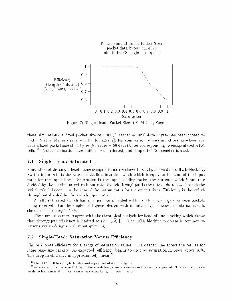
Pulsar Simulation for Packet Sizes
packet data bytes: 64, 4096
in�nite FCFS single-head queue
E�ciency
(length 64 dotted)
(length 4096 dashed)
Saturation
0 0.1 0.2 0.3 0.4 0.5 0.6 0.7 0.8 0.9 1
Figure 7: Single-Head: Packet Sizes (ATM Cell, Page)
these simulations, a �xed packet size of 4104 (8 header + 4096 data) bytes has been chosen to
match Virtual Memory service with 4K pages [2]. For comparison, some simulations have been run
with a �xed packet size of 64 bytes (8 header + 56 data) bytes corresponding to encapsulated ATM
cells
29
Packet destinations are uniformly distributed, and simple FCFS queueing is used.
7.1 Single-Head: Saturated
Simulation of the single-head queue design alternative shows throughput loss due to HOL-blocking.
Switch input rate is the rate of data ow into the switch which is equal to the sum of the input
rates for the input lines. Saturation is the input loading ratio: the current switch input rate
divided by the maximum switch input rate. Switch throughput is the rate of data ow through the
switch which is equal to the sum of the output rates for the output lines. E�ciency is the switch
throughput divided by the switch input rate.
A fully saturated switch has all input ports loaded with no inter-packet gap between packets
being received. For the single-head queue design with in�nite length queues, simulation results
show that e�ciency is 59%.
The simulation results agree with the theoretical analysis for head-of-line blocking which shows
that throughput e�ciency is limited to (2 �
p
2) [1]. The HOL blocking problem is common to
various switch designs with input queueing.
7.2 Single-Head: Saturation Versus E�ciency
Figure 7 plots e�ciency for a range of saturation values. The dashed line shows the results for
large page size packets. As expected, e�ciency begins to drop as saturation increase above 50%.
The drop in e�ciency is approximately linear
30
.
29
The ATM cell has 5 byte header and a payload of 48 data bytes.
30
As saturation approached 100% in the simulation, some anomalies in the results appeared. The simulator code
needs to be examined for correctness as the packet gap drops to zero.
15
0.2
0.4
0.6
0.8
1
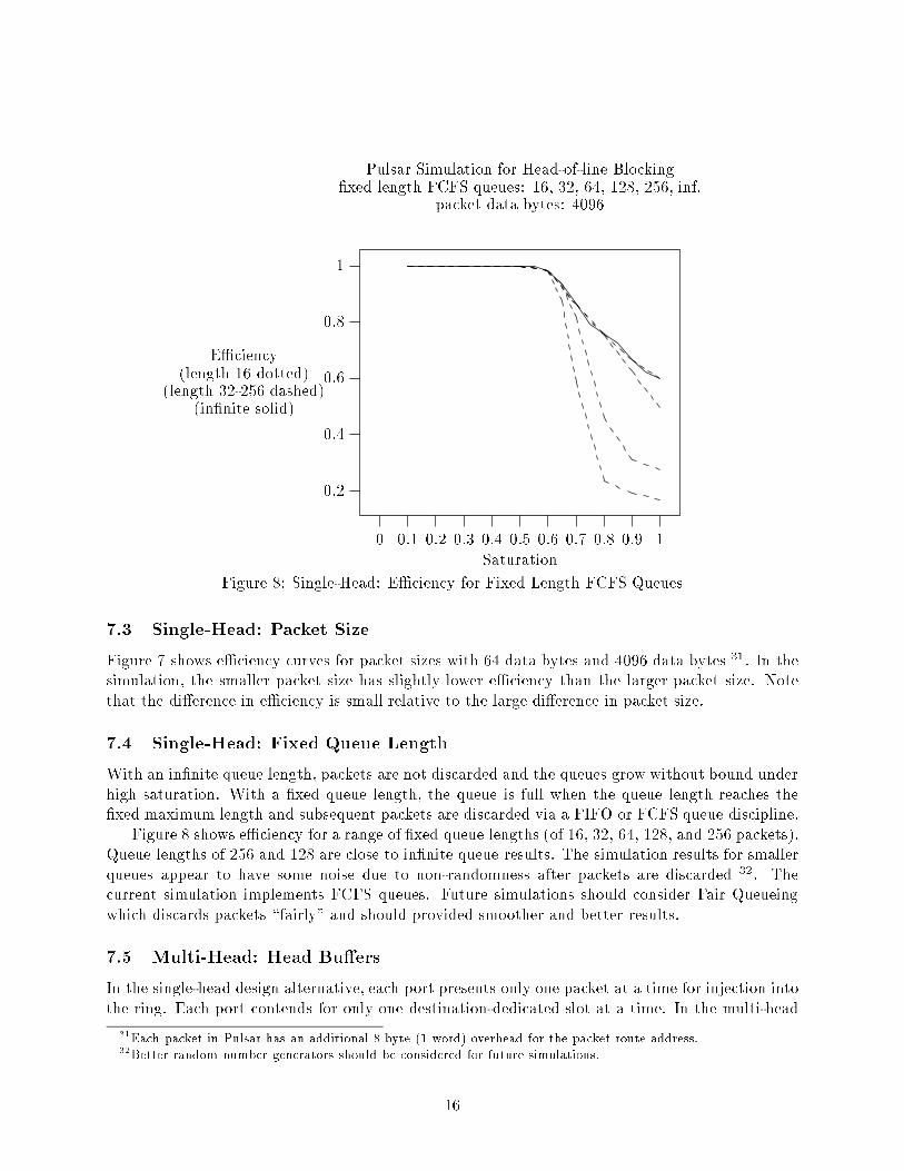
Pulsar Simulation for Head-of-line Blocking
�xed length FCFS queues: 16, 32, 64, 128, 256, inf.
packet data bytes: 4096
E�ciency
(length 16 dotted)
(length 32-256 dashed)
(in�nite solid)
Saturation
0 0.1 0.2 0.3 0.4 0.5 0.6 0.7 0.8 0.9 1
Figure 8: Single-Head: E�ciency for Fixed Length FCFS Queues
7.3 Single-Head: Packet Size
Figure 7 shows e�ciency curves for packet sizes with 64 data bytes and 4096 data bytes
31
. In the
simulation, the smaller packet size has slightly lower e�ciency than the larger packet size. Note
that the di�erence in e�ciency is small relative to the large di�erence in packet size.
7.4 Single-Head: Fixed Queue Length
With an in�nite queue length, packets are not discarded and the queues grow without bound under
high saturation. With a �xed queue length, the queue is full when the queue length reaches the
�xed maximum length and subsequent packets are discarded via a FIFO or FCFS queue discipline.
Figure 8 shows e�ciency for a range of �xed queue lengths (of 16, 32, 64, 128, and 256 packets).
Queue lengths of 256 and 128 are close to in�nite queue results. The simulation results for smaller
queues appear to have some noise due to non-randomness after packets are discarded
32
. The
current simulation implements FCFS queues. Future simulations should consider Fair Queueing
which discards packets \fairly" and should provided smoother and better results.
7.5 Multi-Head: Head Bu�ers
In the single-head design alternative, each port presents only one packet at a time for injection into
the ring. Each port contends for only one destination-dedicated slot at a time. In the multi-head
31
Each packet in Pulsar has an additional 8 byte (1 word) overhead for the packet route address.
32
Better random number generators should be considered for future simulations.
16

0.6
0.7
0.8
0.9
1
Pulsar Simulation for Multi-Head Queue
head bu�ers: 1, 2, 4, 8, 16, 32, inf.
in�nite FCFS queues, packet data bytes: 4096
E�ciency
(1 bu�er: dotted)
(2-32 bu�ers: dashed)
(inf. bu�ers: solid)
Saturation
0 0.1 0.2 0.3 0.4 0.5 0.6 0.7 0.8 0.9 1
1 1
1
1
1
1
1
1
1
1
1
1
1
2 2 22
2
2
2
2
4 4 44 4
4
4
4
Figure 9: Multi-Head: E�ciency for selected head bu�er limits
queue design, this limitation is overcome with additional high-speed ring rate circuitry. For each
port, the \multi-head" is really a set of simple FCFS queues, one for every destination port. As a
slot is presented to the port, the corresponding queue is used to contend for or transmit into the
slot. So each port can contend for every destination-dedicated slot. Words from multiple packets
can be injected into the ring in a single ring revolution.
The logic for the multi-head queue mechanism runs at the high-speed ring rate, so the queues
must be simple and bu�er memory is limited, since it must �t onto the single \ring" chip. Note
that the main queue is low speed, implemented with multiple chips, and located on the separate
PC board module. The main queue feeds into the ring chip in FCFS order. As a packet arrives in
the ring chip, a bu�er for the packet is allocated and enqueued into the proper destination queue.
Each non-empty queue contends to transmit a packet into the corresponding slot. If all bu�ers are
allocated, the multi-head is busy and additional packets are not fed to the ring chip.
Figure 9 shows e�ciency for head bu�er limits of 1, 2, 4, 8, 16, and 32. Additional bu�ers
improve e�ciency with diminishing returns, and the measurements for 32 bu�ers and in�nite bu�ers
are essentially identical. For a 90% saturated switch, 8 bu�ers are su�cient for 99% non-blocking
e�ciency. Note that the saturation point for non-blocking e�ciency shifts up as more bu�ers are
used.
8 Directions
Extensive research on the Pulsar switch and the design alternatives is planned, along with research
into related higher-level issues.
8.1 Pulsar Switch
Further simulation and analysis of the design alternative is in progress. Theoretical analysis of the
alternatives should verify our simulation results. We expect that the �lter simulation will show that
17
queue lengths are small under uniform tra�c distribution. However the requirement for high-speed
demultiplexing and queueing is a major drawback.
The current simulations use simple FCFS queueing. We plan to incorporate Fair Queueing into
our studies and expect to �nd improvements in throughput and reduced queue lengths. Fair Queue-
ing also enables the calculation of delay bounds so that we can evaluate real-time characteristics
for the switch.
8.2 Choices -based Multiprocessor Controller
Research on controllers for virtual circuit networks is also in progress. The switch controller re-
quires a \software-backplane" for the dynamic addition of new software modules, a high-degree of
multiprogramming for handling many simultaneous call requests, and scalability for matching a
range of switch sizes. The network controller requires comprehensive database and user interface
software. We plan to use Choices as an environment for controller software. Choices is written in
C
++
33
, provides lightweight threads, multiprocessor support, and a UNIX
34
compatibility library.
8.3 Network Virtual Memory
Choices implements an object-oriented approach to operating systems. Network VM naturally
extends the memory-model over networks to network multiprocessors or a network of processors.
Choices implements network VM. The Pulsar switch provides a low-latency and high-throughput
interconnection that is ideal for further experiments with network VM.
8.4 Implementation
We plan to investigate the implementation for our switch design. The Pulsar switch design can be
realized using existing technology. Implementation of a scaled down Pulsar chip set in standard
CMOS technology is straightforward. This prototype would also provide valuable experience and
would work out logic details with minimal expense.
9 Conclusion
The Pulsar switch design is a high-spin-rate port-dedicated word-parallel shift-register ring with
the following features.
� non-blocking throughput
� self-switching
� extremely low delay
� elegant regular structure
� arbitrary packet size
� easy scaling
33
Dynamic, loadable \meta" objects have been implemented in C
++
.
34
UNIX is a registered trademark of AT&T.
18
� system interconnection
Preliminary simulation and analysis show that the simple-head queue alternative su�ers from
head-of-line blocking. The �lter alternative has merit for fairness and robustness but requires high-
speed demultiplexing and queueing circuitry with a large bu�er memory to avoid packet losses. The
multi-head queue alternative appears to be the most attractive design since it achieves non-blocking
throughput with a modest amount of high-speed circuitry for the multi-head queue.
The Pulsar switch is an elegant and promising non-blocking switch design which can be easily
implemented with existing technology. We will continue our research and will investigate the
possibilities for implementation of the design.
References
[1] Arthurs and Hui. A Broadband Packet Switch for Integrated Packet Transport. IEEE Journal
on Selected Areas in Communications, 5.8:1264{1273, October 1987.
[2] Roy Campbell, Vincent Russo, and Gary Johnston. A Class Hierarchical, Object-Oriented Ap-
proach to Virtual Memory Management in Multiprocessor Operating Systems. Technical Report
UIUCDCS{R{88{1459, Department of Computer Science, University of Illinois at Urbana-
Champaign, 1988.
[3] Roy H. Campbell and Daniel A. Reed. TAPESTRY: Unifying Shared and Distributed Memory
Parallel Systems. Technical Report UIUCDCS{R{88{1449, Department of Computer Science,
University of Illinois at Urbana-Champaign, August 1988. also Tapestry Technical Report No.
TTR88{1.
[4] Gary S. Delp, Adarshpal S. Sethi, and David J. Farber. An Analysis of Memnet: An Experiment
in High-Speed Shared-Memroy Local Networking. Computer Communications Review, 18.4:165{
174, August 1988. SIGCOMM "88 Conference Proceedings.
[5] Alan Demers, Srinivasan Keshav, and Scott Schenker. Analysis and Simulation of a Fair Queueing
Algorithm. Computer Communications Review, 19.4:1{12, September 1989. SIGCOMM "89
Conference Proceedings.
[6] A. G. Fraser. Towards a Universal Data Transport System. IEEE Journal on Selected Areas in
Communications, 1.5:803{815, November 1983.
[7] A. G. Fraser and W. T. Marshall. Data Transport in a Byte Stream Network. Technical report,
AT&T Bell Laboratories, April 1987.
[8] Edward F. Gehringer, Janne Abullarde, and Michael H. Gulyn. A Survey of Commercial Parallel
Processors. Computer Architecture News, 16.4:75{107, September 1988.
[9] Michael G. Hluchyj. Queueing in High-Performance Packet Switching. IEEE Journal on Selected
Areas in Communications, 6.9:1587{1597, December 1988.
[10] Kurt H. Horton. Multicomputer Interconnection Using Word-Parallel Shift-Register Ring
Networks. Ph.d. thesis, Department of Computer Science, University of Illinois at Urbana-
Champaign, 1984. also Technical Report No. UIUCDCS{R{84{1164.
19
[11] A. Huang and S. Knauer. Starlite: A Wideband Digital Awitch. In Proceedings of the IEEE
Globecom "84, pages 121{125, 1984.
[12] Ahmed E. Kamal and V. Carl Hamacher. Approximate Analysis of Non-exhaustive Multiserv-
er Polling Systems with Applications to Local Area Networks. Computer Networks and ISDN
Systems, 17, 1989.
[13] Mark J. Karol. Optical Interconnection Using Shu�eNet Multihop Networks In Multi-Connected
Ring Topologies. Computer Communications Review, 18.4:25{34, August 1988. SIGCOMM
"88 Conference Proceedings.
[14] George Kimura and Yoshitaka Takahashi. Di�usion Approximation for a Token Ring System
with Nonexhaustive Service. IEEE Journal on Selected Areas in Communications, 4.6:794{801,
September 1986.
[15] Tony T. Lee. Nonblocking Copy Networks for Multicast Packet Switching. IEEE Journal on
Selected Areas in Communications, 6.9:1455{1467, December 1988.
[16] R. Ian MacDonald. Terminology for Photonic Matrix Switches. IEEE Journal on Selected Areas
in Communications, 6.7:1141{1151, August 1988.
[17] Gary J. Murakami. An Overview of GNET. Technical report, AT&T Bell Laboratories, Murray
Hill, NJ, January 1989. Center 1127.
[18] Kazuaki Murakami, Akira Fukuda, Toshinori Sueyoshi, and Shinji Tomita. An Overview of the
Kyushu University Recon�gurable Parallel Processor. Computer Architecture News, 16.4:130{137,
September 1988.
[19] Yoram Ofek. Design and Analysis of a Fiber-Optic Hypergraph Network. Technical Report
UIUCDCS{R{87{1343, Department of Electrical and Computer Engineering, University of
Illinois at Urbana-Champaign, 1987. also PhD Thesis.
[20] I. Page and J. Niehaus. The Flex Architecture, A High Speed Graphics Processor. Computer
Architecture News, 16.4:117{129, September 1988.
[21] Joseph W. M. Pang and Robert W. Donaldson. Approximate Delay Analysis and Results for
Asymmetric Token-Passing and Polling Networks. IEEE Journal on Selected Areas in Commu-
nications, 4.6:783{793, September 1986.
[22] Je�rey W. Reedy. The TDM Ring | A Fiber Optic Transport System for Campus or Metropolitan
Networks. IEEE Journal on Selected Areas in Communications, 4.9:1474{1483, December 1986.
[23] Vincent Russo, Gary Johnston, and Roy Campbell. Process Management and Exception Han-
dling in Multiprocessor Operating Systems Using Object-Oriented Design Techniques. In Proceed-
ings of the Conference on Object-Oriented Programming Systems, Languages and Applications,
1988.
[24] Jon Sauer. An Optoelectronic Multi-Gb/s Packet Switching Network, February 1989. Seminar
notes.
20

[25] Hideaki Takagi. Queuing Analysis of Polling Models. ACM Computing Surveys, 20.1:5{28,
March 1988.
[26] Tetsuya Takine, Yutaka Takahashi, and Toshiharu Hasegawa. Performance Analysis of a Polling
System with Single Bu�ers and Its Application to Interconnected Networks. IEEE Journal on
Selected Areas in Communications, 4.6:802{812, September 1986.
[27] Stuart K. Tewksbury and L. A. Hornak. Communication Network Issues and High-Density
Interconnects in Large-Scale Distributed Computing Systems. IEEE Journal on Selected Areas
in Communications, 6.3:587{609, April 1988.
21
Copyright © 2022 FDOKUMEN