sludge-finder-2-manual.pdf - Pulsar Measurement
131
SludgeFinder 2 Instruction Manual
-
Upload
khangminh22 -
Category
Documents
-
view
3 -
download
0
Transcript of sludge-finder-2-manual.pdf - Pulsar Measurement

SludgeFinder 2 Instruction Manual

2

PULSAR MEASUREMENT
3
SludgeFinder 2 (SIXTH EDITION REV 1)
February 2021
Part Number M-920-0-006-1P
COPYRIGHT
© Pulsar Measurement, 2009 -21. All rights reserved. No part of this publication may be
reproduced, transmitted, transcribed, stored in a retrieval system, or translated into any
language in any form without the written permission of Pulsar Process Measurement Limited.
WARRANTY AND LIABILITY
Pulsar Measurement guarantee for a period of 2 years from the date of delivery that it will
either exchange or repair any part of this product returned to Pulsar Process Measurement
Limited if it is found to be defective in material or workmanship, subject to the defect not being
due to unfair wear and tear, misuse, modification or alteration, accident, misapplication, or
negligence. Note: For a VT10 or ST10 transducer the period of time is 1 year from date of
delivery.
DISCLAIMER
Pulsar Measurement neither gives nor implies any process guarantee for this product and shall
have no liability in respect of any loss, injury or damage whatsoever arising out of the
application or use of any product or circuit described herein.
Every effort has been made to ensure accuracy of this documentation, but Pulsar Measurement
cannot be held liable for any errors.
Pulsar Measurement operates a policy of constant development and improvement and reserves
the right to amend technical details, as necessary.
The SludgeFinder 2 shown on the cover of this manual is used for illustrative purposes only and
may not be representative of the actual SludgeFinder 2 supplied.
CONTACT
For technical support, please contact:
Europe: [email protected]
Outside Europe: [email protected]
If you have any comments or suggestions about this product, please contact:
Europe: [email protected]
Outside Europe: [email protected]
Pulsar Measurement website: www.pulsarmeasurement.com
United States
11451 Belcher Road South
Largo,
FL 33773
888-473-9546
Canada
16456 Sixsmith Drive
Long Sault, Ont.
K0C 1P0
855-300-9151
United Kingdom
Cardinal Building, Enigma
Commercial Centre
Sandy’s Road, Malvern
WR14 1JJ
00 44 (0)1684 891371
4
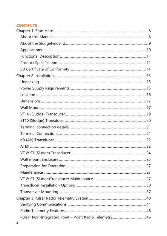
CONTENTS
Chapter 1: Start Here… ........................................................................................................... 8
About this Manual ............................................................................................................... 8
About the SludgeFinder 2................................................................................................. 9
Applications ......................................................................................................................... 10
Functional Description .................................................................................................... 11
Product Specification ....................................................................................................... 12
EU Certificate of Conformity ......................................................................................... 14
Chapter 2 Installation ........................................................................................................... 15
Unpacking ............................................................................................................................ 15
Power Supply Requirements......................................................................................... 15
Location ................................................................................................................................ 16
Dimensions .......................................................................................................................... 17
Wall Mount .......................................................................................................................... 17
VT10 (Sludge) Transducer .............................................................................................. 19
ST10 (Sludge) Transducer .............................................................................................. 20
Terminal connection details .......................................................................................... 21
Terminal Connections ...................................................................................................... 21
dB (Air) Transducer ........................................................................................................... 22
ATEX ....................................................................................................................................... 22
VT & ST (Sludge) Transducer........................................................................................ 24
Wall mount Enclosure ..................................................................................................... 25
Preparation for Operation ............................................................................................. 27
Maintenance ....................................................................................................................... 27
VT & ST (Sludge)Transducer Maintenance. ............................................................ 27
Transducer Installation Options .................................................................................. 30
Transceiver Mounting...................................................................................................... 37
Chapter 3 Pulsar Radio Telemetry System ................................................................... 40
Verifying Communications. ........................................................................................... 44
Radio Telemetry Features. ............................................................................................. 46
Pulsar Non-Integrated Point – Point Radio Telemetry. ...................................... 46
PULSAR MEASUREMENT
5
Receiver and Transmitter Dimensional Details. ..................................................... 47
Gateway and Node wiring details .............................................................................. 48
Analogue and Digital I/O ............................................................................................... 49
Installation Tips .................................................................................................................. 50
Bridge Integrator-Radio Schematic ........................................................................... 53
Specifications ...................................................................................................................... 54
How To Use Your SludgeFinder 2 ................................................................................... 55
Operating the Controls ................................................................................................... 55
Run Mode ............................................................................................................................. 56
Program Mode ................................................................................................................... 59
How to Access Program Mode .................................................................................... 59
Hot Keys ................................................................................................................................ 61
Menu Keys ........................................................................................................................... 62
Numeric Keys ...................................................................................................................... 63
Using the Menu System ................................................................................................. 64
Directly Editing Parameters ........................................................................................... 65
Test Mode ............................................................................................................................ 66
Using the Serial Interface ............................................................................................... 67
Parameter Defaults ........................................................................................................... 69
Chapter 4 Programming Guide ........................................................................................ 70
Measurements needed for Interface monitoring ................................................. 70
Example 1: Primary Settlement Sludge Interface monitoring ......................... 71
Example 2: Level Monitoring with High and Low Alarms on Point 2 ........... 73
Example 3: Using a Single Viper Transducer to Measure 2 Different
Interface Levels. ................................................................................................................. 76
Example 4: Setting the Unit to Alarm on Hi-Floc Levels .................................... 77
High Floc Alarm ................................................................................................................. 77
Chapter 6 Menu System and Parameter Guide ......................................................... 79
Top Level Menu ................................................................................................................. 79
Application Menu .............................................................................................................. 79
SLUDGEFINDER 2 INSTRUCTION MANUAL
6
Relays Menu ........................................................................................................................ 81
Floc Alarm Menu ............................................................................................................... 82
Data Logs Menu ................................................................................................................ 83
Display Menu ...................................................................................................................... 84
mA Output Menu .............................................................................................................. 85
Compensation Menu ....................................................................................................... 86
Stability Menu .................................................................................................................... 86
Echo Processing Menu .................................................................................................... 87
System Menu ...................................................................................................................... 88
Device Comm Menu ........................................................................................................ 90
Test Menu ............................................................................................................................ 91
Chapter 7 Parameter Listing and Description ............................................................ 92
Application Parameters................................................................................................... 92
Global ..................................................................................................................................... 95
Relay Parameters ............................................................................................................... 96
Alarms .................................................................................................................................... 98
Control ................................................................................................................................. 101
Miscellaneous ................................................................................................................... 103
Common Parameters ..................................................................................................... 104
Floc Alarm Parameters .................................................................................................. 105
Service Interval Alarm Parameters............................................................................ 106
Data Log Parameters ..................................................................................................... 106
Display Parameters ......................................................................................................... 107
Failsafe ................................................................................................................................. 108
mA Out 1 / mA Out 2 Parameters ............................................................................ 109
Setpoint ............................................................................................................................... 110
Compensation Parameters .......................................................................................... 112
Offset.................................................................................................................................... 112
Temperature ...................................................................................................................... 112
Stability Parameters ....................................................................................................... 113
Damping ............................................................................................................................. 113

PULSAR MEASUREMENT
7
Filters .................................................................................................................................... 113
Echo Processing Parameters ....................................................................................... 114
Transducer 1 Status ........................................................................................................ 114
Transducer 2 Status ........................................................................................................ 115
System Parameters ......................................................................................................... 116
Passcode ............................................................................................................................. 116
Backup ................................................................................................................................. 116
System Information ........................................................................................................ 117
Date & Time ...................................................................................................................... 118
LED Colour ......................................................................................................................... 118
Watchdog ........................................................................................................................... 119
Daylight Saving Time ..................................................................................................... 120
Device Comm. .................................................................................................................. 124
RS232 Set Up .................................................................................................................... 124
RS 485 Set Up ................................................................................................................... 124
Test Parameters ............................................................................................................... 125
Simulation .......................................................................................................................... 125
Hardware ............................................................................................................................ 126
Chapter 8 Troubleshooting .............................................................................................. 128
Chapter 9 Disposal .............................................................................................................. 129
Notes ........................................................................................................................................ 130

SLUDGEFINDER 2 INSTRUCTION MANUAL
8
CHAPTER 1: START HERE…
Congratulations on your purchase of a Pulsar Sludge Finder 2. This quality
system has been developed over many years and represents the latest in
high technology ultrasonic sludge monitoring.
It has been designed to give you years of trouble free performance, and a
few minutes spent reading this operating manual will ensure that your
installation is as simple as possible
About this Manual
It is important that this manual is referred to for correct installation and
operation. There are various parts of the manual that offer additional help
or information as shown.
Tips
TIP: Look for this icon throughout your Pulsar Measurement manual
to find helpful information and answers to frequently asked
questions.
Additional Information
References
See Also
References to other parts of the manual.
Additional Information
At various parts of the manual, you will find sections
like this that explain specific things in more detail.

PULSAR MEASUREMENT
9
About the SludgeFinder 2
The single Sludge Finder 2 unit provides dual point level sensing in liquids
and/or air. It is easily installed, with conduit entry on the unit via 5 x 20mm
Knockouts and 1 x 16mm knockout.
Outstanding stability, accuracy, and repeatability. Sophisticated algorithms
for echo extraction utilizing powerful Digital Signal Processing (DSP)
microprocessors.
The system has superior performance based on current leading-edge
technology and modern design procedures.
Two independent transducer channels with the option of combining
submersible and air transducers.
Two fully adjustable 4-20 mA outputs, six fully programmable SPDT status
relays.
RS232 and RS485 communications ports for multiple unit installations.
Radio communications for remote 4-20mA Indication (optional).
All these features and more plus the ease of programming, make this
instrument the number one choice for interface level measurement in
liquids.

SLUDGEFINDER 2 INSTRUCTION MANUAL
10
Applications
The Sludge Finder 2 is designed to monitor the levels of materials in various
processes and to regulate the control loops, start and stop motors, and
initiate events based on measured process conditions.
Some applications for the units are listed below:
• Water & Wastewater Treatment Clarifiers
• Water & Wastewater Gravity & DAF Thickeners
• Raw Water Clarifiers
• Sumps, lagoons, settling ponds.
• Industrial Process Thickeners
• Salt Brine Tanks
• Material Inventory Tanks
• Process Thickeners
• Dewatering/Hydro Bins
• Pyrite Holding/Transfer Tanks
• FGD Thickeners
• Surge & Settling Tanks
• Oil/Water separators
• SBR Tanks

PULSAR MEASUREMENT
11
Functional Description
Sludge Finder 2 sends a transmit pulse to the transducer, which then emits a
high frequency ultrasonic sound wave perpendicular to the transducer face,
the returned echo is received by the Sludge Finder 2. The time taken to
receive the echo is measured and the distance from the transducer face to
the sludge interface is calculated.
The relays can be programmed to activate alarms, pump starters, or other
control equipment. There is an isolated 4-20 mA output for each of two
transducer channels that can be connected to a recorder or PLC to monitor
the sludge interface independently from that shown on the display. Finally,
there is an RS232 port, so that the Sludge Finder 2 can be operated remotely
by a PC or other equipment to download/upload parameters or view real
time echo traces.
Sludge Finder 2 can be programmed either by the built-in keypad, or by PC
via the RS 232 Serial Interface. All parameters are stored in non-volatile
memory, so are retained in the event of power interruption. A second
backup copy of all parameters can also be retained in the Sludge Finder 2
memory, in case an alternative set of parameters needs to be stored.
Six user definable control relays with individual setpoints and intelligent
performance logging software features ensure maximum control versatility.
The Pulsar Sludge Finder 2 ultrasonic sludge detector has been designed to
provide maintenance-free fit and forget performance.

SLUDGEFINDER 2 INSTRUCTION MANUAL
12
Product Specification
PHYSICAL
Wall Mount outside Dimensions 235 x 184 x 120mm (9.25 x 7.24 x 4.72”)
Weight Nominal 1 kg (2.2lbs)
Enclosure Material/Description Polycarbonate, flame resistant to UL94-5V
Cable entry detail 10 cable entry knockouts, 1 x M16 underside, 5 x M20,
4 PG11 at rear.
Transducer Cable Extensions 3-conductor 20AWG screened
dB series (Air)
Maximum Separation 3,280 ft (1,000m)
ENVIRONMENTAL
IP Rating (Fascia) IP65, IP20 when open
Altitude 2000m maximum
Max. & min. temperature
(electronics) -20 ºC to +50 ºC (-4ºF to 122ºF)
Flammable atmosphere approval Safe area: compatible with approved dB transducers
(see transducer spec' sheet)
CE approval See EU Declaration of Conformity
PERFORMANCE (WITH SLUDGE)
Accuracy 0.25% of the measured range or 1.181" (30 mm)
(whichever is greater)
Resolution 0.25% of the measured range or 0.394" (10 mm)
(whichever is greater)
Max. Range 32.808ft (10m)
Min. Range 0.984ft (0.3m)
Rate Response Fully adjustable
OUTPUTS
Analogue Output
2 off Isolated (to 150V floating) output of 4-20 mA or
0-20 mA into 1k (user programmable and
adjustable) 0.1% resolution.
Digital Output Half Duplex RS232
Volt free contacts, number, and
rating 6 form "C" (SPDT) rated at 5A at 115V AC
Display
192 x 128 pixel illuminated graphical display
Fully programmable display options Integral keypad
with menu navigation keys
Radio Modem (optional) 4 – 20mA using wireless exempt frequencies
Maximum range 1640ft (500m) line of site
Communication bus (optional) RS485 Modbus RTU/ASCII or Profibus DPV1 (slave device)
PULSAR MEASUREMENT
13
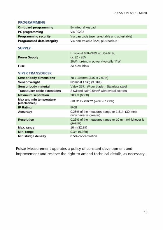
PROGRAMMING
On-board programming By integral keypad
PC programming Via RS232
Programming security Via passcode (user selectable and adjustable)
Programmed data integrity Via non-volatile RAM, plus backup
SUPPLY
Power Supply
Universal 100-240V ac 50-60 Hz,
dc 22 - 28V
20W maximum power (typically 11W)
Fuse 2A Slow blow
VIPER TRANSDUCER Sensor body dimensions 78 x 195mm (3.07 x 7.67in)
Sensor Weight Nominal 1.5kg (3.3lbs)
Sensor body material Valox 357. Wiper blade – Stainless steel
Transducer cable extensions 2 twisted pair 0.5mm2 with overall screen
Maximum separation 200 m (656ft)
Max and min temperature (electronics)
-20 ºC to +50 ºC (-4ºF to 122ºF)
IP Rating IP68
Accuracy 0.25% of the measured range or 1.81in (30 mm) (whichever is greater)
Resolution 0.25% of the measured range or 10 mm (whichever is greater)
Max. range 10m (32.8ft)
Min. range 0.3m (0.98ft)
Min sludge density 0.5% concentration
Pulsar Measurement operates a policy of constant development and
improvement and reserve the right to amend technical details, as necessary.
SLUDGEFINDER 2 INSTRUCTION MANUAL
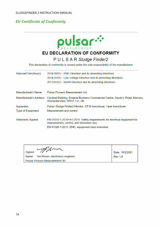
14
EU Certificate of Conformity

PULSAR MEASUREMENT
15
CHAPTER 2 INSTALLATION
Unpacking
Power Supply Requirements
Sludge Finder 2 can operate from AC supply or from a DC battery. The AC is
supplied via a universal 100-200VAC transformer. The DC is 22-28V. In all
cases the Sludge Finder 2 will typically consume 11W of power, with a
maximum of 20W.
Important Information
All shipping cartons should be opened carefully. When using a box cutter, do not
plunge the blade deeply into the box, as it could potentially cut or scratch
equipment components. Carefully remove equipment from each carton,
checking it against the packing list before discarding any packing material. If
there is any shortage or obvious shipping damage to the equipment, report it
immediately to Pulsar Process Measurement Limited.

SLUDGEFINDER 2 INSTRUCTION MANUAL
16
Location
The SludgeFinder 2 must be mounted in a non-hazardous (safe) area, and
the transducer fitted in the hazardous area.
When choosing a location to mount the enclosure, bear in mind the
following:
• Ensure that the SludgeFinder 2 is installed in a “Safe”, non-
hazardous area.
• For a clear view of the LCD display, it is recommended that it is
mounted at eye level.
• The mounting surface is to be vibration free.
• The ambient temperature is between -20°C and 50°C.
• There should be no high voltage cables or inverters nearby,
Important Information
All electronic products are susceptible to electrostatic shock, so follow proper
grounding procedures during installation.

PULSAR MEASUREMENT
17
Dimensions
Wall Mount
The dimensions of the wall fixing holes are as shown below:
The Sludge Finder 2 should be mounted by drilling three holes suitable for
size 8 screws (length to suit your application) and fixing the top screw in
place. Hang the unit on this and fix the two remaining screws by removing
the terminals access cover to access the pre-drilled holes.

SLUDGEFINDER 2 INSTRUCTION MANUAL
18
The full dimensions of the enclosure are as shown below:

PULSAR MEASUREMENT
19
Cable entry
There are 6 cable gland knockouts on the base of the Sludge Finder 2 (5 x
M20, 1 x M16) and 4 on the rear (4 x PG11). Select which ones you wish to
take out, and remove them by using a circular cutter, such as a tank cutter.
Take care not to damage the circuit board inside whilst undertaking this. Do
not use a hammer, as this may cause damage to the enclosure.
It is recommended that you use suitable cable glands to ensure that the
ingress rating is maintained.
VT10 (Sludge) Transducer
Important Information
Please note that the VT10 has a 1 year warranty period from the date of delivery
from Pulsar, if an issue arises with the item please contact your local Pulsar
distributor and return it to Pulsar within its warranty period.

SLUDGEFINDER 2 INSTRUCTION MANUAL
20
ST10 (Sludge) Transducer
1.5” BSP BOTTOM
41 mm
1” BSP 78 mm
25 mm
65 mm
Important Information
Please note that the ST10 has a 1 year warranty period from the date of delivery
from Pulsar, if an issue arises with the item please contact your local Pulsar
distributor and return it to Pulsar within its warranty period.
PULSAR MEASUREMENT
21
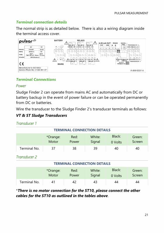
Terminal connection details
The normal strip is as detailed below. There is also a wiring diagram inside
the terminal access cover.
Terminal Connections
Power
Sludge Finder 2 can operate from mains AC and automatically from DC or
battery backup in the event of power failure or can be operated permanently
from DC or batteries.
Wire the transducer to the Sludge Finder 2’s transducer terminals as follows:
VT & ST Sludge Transducers
Transducer 1
TERMINAL CONNECTION DETAILS
*Orange:
Motor
Red:
Power
White:
Signal
Black:
0 Volts
Green:
Screen
Terminal No. 37 38 39 40 40
Transducer 2
TERMINAL CONNECTION DETAILS
*Orange:
Motor
Red:
Power
White:
Signal
Black:
0 Volts
Green:
Screen
Terminal No. 41 42 43 44 44
*There is no motor connection for the ST10, please connect the other
cables for the ST10 as outlined in the tables above.

SLUDGEFINDER 2 INSTRUCTION MANUAL
22
dB (Air) Transducer
Transducer 1
TERMINAL CONNECTION DETAILS
Not
required
Red:
Power
White:
Signal
Black:
0 Volts
Green:
Screen
Terminal No. N/A 38 39 40 40
Transducer 2
TERMINAL CONNECTION DETAILS
Not
required
Red:
Power
White:
Signal
Black:
0 Volts
Green:
Screen
Terminal No. N/A 42 43 44 44
When installing a transducer in a hazardous area use an approved
transducer, from the Pulsar dB range, suitable for the proposed application.
ATEX
For EEx m (Zone 1) applications a transducer certified to Sira
02ATEX5104X is used, and must be supplied via a 4000A breaking fuse,
which is fitted as standard to the Sludge Finder 2 controller.
For EEx ia (Zone 0) a transducer certified to Sira 02ATEX2103X is used,
which must be connected to the Sludge Finder 2 via an external Zener
barrier.
See transducer label for certification details.
Important Information
Please note that if the output of the ultrasonic transducers used with the Sludge
Finder 2 are capable of emitting sound pressure levels in excess of 85dBA (above
a reference sound pressure level of 20µPA), then the Sludge Finder 2 must be
located remote from the transducer such that a sound pressure level of 85dBA is
not exceeded when standing at the Sludge Finder 2 in the operator’s position.

PULSAR MEASUREMENT
23
Relay Outputs
The six relays can be programmed for a variety of alarms or process control
functions. The relay contacts are all rated at 5A at 115V AC. All connections
should be such that the short circuit capacity of the circuits to which they are
connected, is limited by fuses rated such that they do not exceed the relay
rating.
Current Output
This is an isolated (floating) mA output (to 150 V), of 4 - 20mA or 0 - 20mA,
and the load should not exceed 500 .
RS2323 Serial Interface
If required, you can connect to the serial interface to operate your Sludge
Finder 2 remotely.
Important Information
Never operate the Sludge Finder 2 with terminal access exposed.
An external switch or circuit breaker should be installed near to the Sludge
Finder 2 to allow the supply to be removed during installation and maintenance.
In installations where the relay contacts have mains power connected, there
should be a means of isolating them from the Sludge Finder 2.
Interconnecting cables must be adequately insulated for IEC 664 Category II
installations. Strip back 30 mm of the outer insulation of the cable. Strip 5 mm of
insulation from the end of each conductor. Twist all exposed strands of the
conductor together. Insert the stripped conductor into the terminal block as far
as it will go and tighten the terminal block screw. Ensure that all strands are
firmly clamped in the terminal block and that there is no excess bare conductor
showing, and no stray strands.
Important Information
If the equipment is installed or used in a manner not specified in this manual,
then the protection provided by the equipment may be impaired.

SLUDGEFINDER 2 INSTRUCTION MANUAL
24
VT & ST (Sludge) Transducer
Locating the Sludge Transducer
• Position the transducer at a height within the tank such that it is fully
submerged at all times that measurements are required, typically the
face of the transducer should be 150mm below the normal water level.
Liquid temperature compensation will only function correctly if the
transducer is submerged at this level or below.
• Ensure an unobstructed path between the transducer and the bottom of
the tank. N.B. Rotating sub-surface rakes and scrapers, that pass beneath
the transducer, do not interfere with normal operation.
• Select a location that minimizes the presence of gas bubbles, high flow
and heavy solid concentration dynamics in the process liquid near or the
transducer.
• Typical installation in a round clarifier or thickener is 1/3 to 2/3 the
distance from the sidewall to the centre of the tank with transducer
mounted from the walkway safety railing.
• Typical installation in a rectangular clarifier or thickener is along the
length of the clarifier in the third of the tank nearest the sludge
discharge sump.
Installing the Transducer
• The transducer housing is designed to accept a 1-inch BSP female
threaded coupler for pipe or conduit. Feed the integral transducer cable
through the mounting pipe and tighten by hand until snug. CAUTION:
extreme over-tightening may crack the transducer housing.
• Position the transducer such that it is 150mm below the water surface
and the mounting pipe is perpendicular to the water surface. Secure the
mounting pipe in place with clamps to ensure that it is rigid.
• Flexible arm transducers assemblies are available and are required where
there is surface skimming equipment that passes the location of the
transducer. Rotate the transducer mounting pipe so that the integral
transducer shield contacts the skimmer arm squarely. Ensure that the
transducer moves freely away from the passing skimmer equipment.
• Optional transducer mounting brackets are available to extend the
mounting pipe away from its connection point at the handrail to provide
clearance from obstructions.

PULSAR MEASUREMENT
25
• If desired, the transducer cable may be extended up to 200m. Install
transducer cables in grounded metal conduit. Do not run-in cable trays
or duct banks with variable frequency drives or other high voltage
sources.
• Air (dB) transducers should be installed and connected in accordance
with the installation instructions contained in the dB Transducer User
Guide.
Wall mount Enclosure
Locating the Sludge Finder 2 unit
• The unit may be located inside a building or it may be field-mounted.
• Locate the unit so that the maximum cable length to any transducer
does not exceed 200m.
• Avoid locating the processor near variable frequency drives or other
high voltage equipment or cables.
• Ensure that the Sludge Finder 2 controller is installed in a “Safe”, non-
hazardous, area.
• For a clear view of the LCD display it is recommended that it is mounted
at eye level.
• Ensure the mounting surface is vibration-free and the ambient
temperature is between -20ºC and 50ºC.
Installing the controller
• Mount the unit at a convenient height for viewing the control panel and
displays. Allow sufficient clearance around the unit for the door to swing
fully open for instrument service.
• Secure to a wall or panel using the mounting holes. Alternatively, attach
to a local handrail using the optional Integrator Mounting Assembly.

SLUDGEFINDER 2 INSTRUCTION MANUAL
26

PULSAR MEASUREMENT
27
Preparation for Operation
Before switching on, check the following:
✓ The Sludge Finder 2 is mounted correctly and is in a ‘safe’ area.
✓ The power supply is correctly installed.
✓ The relays are connected correctly.
Maintenance
There are no user serviceable parts inside Sludge Finder 2, except the mains
fuse. If you experience any problems with the unit, then please contact
Pulsar Measurement for advice.
To clean the equipment, wipe with a damp cloth. Do not use any solvents on
the enclosure.
VT & ST (Sludge)Transducer Maintenance.
Procedure for the Removal of Transducers
From time to time, it may be necessary to remove the transducer for
cleaning or maintenance purposes, the following procedure is to ensure that
this is done carefully with regard for the health and safety of the operator
involved, and without damage to the transducer.
The transducer mounting bracket (option 1) is designed such that the
transducer can be removed without any parts being available to fall into the
application. Before attempting to remove the transducer for cleaning or
maintenance, the power to the unit should be disconnected.
The correct PPE should be worn to ensure you do not come into direct
contact with the wetted parts of the Sludge Finder 2 system, if in doubt
contact your site Health and Safety Officer. To remove the transducer,
loosen the retaining bolts on the end of the mounting brackets as shown in
fig.1 and lift the transducer conduit assembly onto the walkway. The conduit
is attached to the mounting assembly plate by means of a security chain so
that it cannot be dropped and lost into the application.
The transducer can then be safely inspected for damage or material fouling
and can be carefully cleaned with a damp cloth to remove any foreign
debris. Care should be taken not to move the wiper by hand as any
movement not under the power of the motor may damage the unit.

SLUDGEFINDER 2 INSTRUCTION MANUAL
28
IMPORTANT WARRANTY NOTICE:
THE ONE YEAR TRANSDUCER WARRANTY IS VOID IF
THE WIPER BLADE IS ROTATED BY HAND. THIS IS
DETRIMENTAL TO THE MOTOR GEAR DRIVE AND WILL
DAMAGE THE UNIT.

PULSAR MEASUREMENT
29
The wiper arm on the VT10 will move twice every 20 mins as a default
setting, if the face of the transducer is dirty and you are unsure as to
whether or not the wiper is cleaning then place the transducer such that the
wiper movement will not foul on anything and use the appropriate function
key ( ) to force a wipe (see note below).
If it is necessary to replace the transducer, the following procedure should
be followed.
Disconnect the transducer wiring from the electronics as shown on page 15
and remove the transducer cable from the electronics enclosure.
The transducer is mounted onto the end of the conduit via its process fitting,
this should be carefully unscrewed in an anticlockwise direction. Make sure
the transducer is not dropped or knocked as this can damage the unit.
When replacing the transducer care must be taken not to over tighten the
unit as this can result in the transducer ‘ringing’. Hand tight is sufficient.
When the transducer is replaced into the application and the power re-
applied the unit will re-initialise and after a short period of time depending
on the process conditions show the correct blanket reading.
Important Information
The function key will only initiate a wiper sweep on a VT transducer
related to the currently viewed point and will only operate in run mode on
the “Main” display. The function key will not initiate a wiper sweep if the
dual point view is displayed.

SLUDGEFINDER 2 INSTRUCTION MANUAL
30
Transducer Installation Options
1. Stainless steel mounting plate.

PULSAR MEASUREMENT
31
The mounting system shown above including the conduit is made from
stainless steel.
The mounting plate is attached to the (normally galvanised) handrail via two
hot dipped galvanised U-bolts, the U-bolts are then separated from the
mounting plate via robust cast plastic spacers.
This system ensures that there are no problems with dissimilar metal
reactions, and the entire mounting system should not suffer from
oxidisation/corrosion issues which can cause problems when performing
maintenance.
The above system is also available with an optional 2.3m length of Stainless
¾” conduit, with other lengths being available on request. The conduit can
be secured to the mounting bracket or the chain can be supplied welded to
the conduit for the customer to attached at a suitable point.

SLUDGEFINDER 2 INSTRUCTION MANUAL
32
Mounting Plate Dimensions

PULSAR MEASUREMENT
33
Mounting Bracket (exploded view)
Note: the two arms holding the hinged conduit retainers are welded to the
mounting plate.

SLUDGEFINDER 2 INSTRUCTION MANUAL
34
Part Numbers
Stainless transducer mounting bracket assembly complete with security
chain and 2.5m ¾" stainless conduit.
Part Number 9200A0007
Stainless transducer mounting bracket assembly without chain or conduit.
Part Number 9200A0008
Flexible Arm Assembly
Part Number 9200A0001

PULSAR MEASUREMENT
35
2. Budget Mounting Option.
This mounting system has galvanised parts and is designed to be a budget
option for transducer mounting.
In the picture shown above the security chain and flexible arm assembly are
optional.

SLUDGEFINDER 2 INSTRUCTION MANUAL
36
Mounting option 2, arm assembly
Part Numbers
Budget galvanised transducer mounting bracket complete with
security chain and 2.5m ¾" galvanized conduit.
Part Number 9200A0009
Budget galvanised transducer mounting bracket.
Part Number 9200A0010
Flexible Arm Assembly
Part Number 9200A0001

PULSAR MEASUREMENT
37
Transceiver Mounting
The Sludge Finder 2 transceiver is mounted in an IP65 rated enclosure.
These enclosures are often situated out in the open on the walkways or
bridges of settlement tanks and are therefore very exposed to the elements.
We offer a metal enclosure like the one below to ensure that, if required, the
unit is not mounted in direct sunlight and is sheltered from any potential
exposure to water ingress via precipitation or the application itself.
A steel enclosure with optional mounting plate and brackets is
recommended as a suitable enclosure.
Dimensions: W x H x D: 400 mm x 400 mm x 200 mm are adequate.
Requirements: General protection of electrical and other equipment against
impact and the ingress of dust and liquids.
Example Spec
• Overall sheet steel construction.
• Epoxy powder coated to RAL7032.
• Earth points on enclosure body & door.
• IP55 protection as standard.
• Polyurethane gasket.
Note: Enclosure mounting equipment supplied and fitted by others to suit
local site conditions.
SLUDGEFINDER 2 INSTRUCTION MANUAL
38
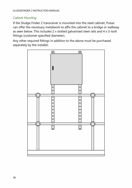
Cabinet Mounting
If the Sludge Finder 2 transceiver is mounted into the steel cabinet, Pulsar
can offer the necessary metalwork to affix the cabinet to a bridge or walkway
as seen below. This includes 2 x slotted galvanised steel rails and 4 x U-bolt
fittings (customer specified diameter).
Any other required fittings in addition to the above must be purchased
separately by the installer.
PULSAR MEASUREMENT
39
Part Numbers for Cabinet Assembly.
Sludge Finder 2 integrator enclosure complete with chassis plate and
mounting bracket.
Part Number 9200A0004
Sludge Finder 2 integrator enclosure complete with 5 x cable glands
installed, integrator fixed to the internally mounted chassis plate and
mounting brackets.
Part Number 9200A0005
Handrail installation kit for Sludge Finder 2 enclosure. Includes 2 x 2m
mounting rails and 4 x U-bolts (diameter to be customer specified)
Part Number 9200A0006

SLUDGEFINDER 2 INSTRUCTION MANUAL
40
CHAPTER 3 PULSAR RADIO TELEMETRY SYSTEM
Some Pulsar units may be fitted with an optional Radio Telemetry System.
This system cannot be retro fitted and must be purchased at the time of
ordering.
The system consists of a small transmitter board or ‘Node’ that is integrated
into the SF2 housing and a receiver or ‘Gateway’ that is placed in a suitable
location. The transmitter is pre-wired into the analogue output terminals
and three of the digital outputs as shown below.
TRANSMITTER (node) WIRING
The transmitter unit has two analogue outputs and two digital outputs.
Channel 1 is mA OUT 1. Channel 2 is mA OUT 2.
Relay 4 is DIG OUT 1. Relays 5 and 6 are DIG OUT 2
The mA output will be set by the user in the Application section of the
parameters to reflect the operational 4-20 mA output span of the
instrument.
The Relays should be programmed as follows.
Relay 5 should be set to be a Loss of Echo alarm, Relay 6 should be set to be
a Wiper fail. These outputs are wired in series to DIG 2 and are used to give
a Failure Output.
Relay 4 can be programmed as a customer preference for Hi or Lo alarm
output.

PULSAR MEASUREMENT
41
RECEIVER (gateway) DX80
The Receiver unit is shown below.
The Receiver unit needs to be supplied with 10-30vdc.

SLUDGEFINDER 2 INSTRUCTION MANUAL
42
The Power Supply and output terminals are shown below.
The Power can be connected to either of the PWR and GND terminals.
10-30VDC
The Digital Output for Relay 4 (Hi or Lo level) is connected to DO1
The Digital Output for Relays 5 & 6 (Wiper Fail and LOE) is connected to
DO2
The Analogue Output for Channel 1 is connected to AO1
The Analogue Output for Channel 2 is connected to AO2

PULSAR MEASUREMENT
43
The systems supplied by Pulsar are ‘paired’ and care should be taken to
ensure the right Receiver is installed with the appropriate Transmitter if
more than one system is in operation on the same site.
The receiver unit should be pre-set to 11 or greater, the transmitters are set
to 1 or greater, so for a transmitter address of, for example, 4 the receiver
will be 14 and so on. These are pre-set as the transmitter rotary dial are
difficult to access.
Receiver Specifications
Max distance between Transmitter & Receiver with a clear line of sight is
3km.
Frequency. 2.4 GHz
Enclosure. Polycarbonate IP67, NEMA 6.
Power. 10-30vdc consumption less than 1.4W at 24VDC
Temp. (electronics) -20 to +80 C
The left dial represents
the units of the device.
The right dial represents
the tens of the device.

SLUDGEFINDER 2 INSTRUCTION MANUAL
44
Verifying Communications.
After powering up, verify the device is communicating properly.
When testing the Gateway and Node, ensure all radios and antenna are at
least two metres apart or communications may fail.

PULSAR MEASUREMENT
45
Enclosure Dimensions

SLUDGEFINDER 2 INSTRUCTION MANUAL
46
Radio Telemetry Features.
• Up to 48 repeaters can be used by upgrading to a ‘MULTIHOP’ receiver
vastly increasing the distance between transmitter and receiver.
• Transmissions are always secure due to ‘Frequency Hopping’
technology.
• Unlimited pairs can be used in the same location.
• Light, strong, compact, and easily fitted enclosure.
• Other options are available on request such as RS485 comms and Solar
Powered capability.
• 3km distance between Transmitter and Receiver, with clear line of sight.
Pulsar Non-Integrated Point – Point Radio Telemetry.
Pulsar also offer a non-integrated Radio Telemetry System that is available
to be retro fitted.
The unit offers 2 x 4-20 Analogue Output and 4 x Digital Output re-
transmission over 3km line of sight.

PULSAR MEASUREMENT
47
Receiver and Transmitter Dimensional Details.

SLUDGEFINDER 2 INSTRUCTION MANUAL
48
Gateway and Node wiring details
Applying power to the DX70 Radio Devices.
Connect power to the Gateway and Node by connecting 10-30VDC directly
to the terminal block as shown below.
1 = 10-30VDC
2 = Ground

PULSAR MEASUREMENT
49
Analogue and Digital I/O
The Pulsar units will be supplied already ‘bound’ and correctly addressed this
means they will only talk to each other and cannot be externally
interrogated.
When power is applied the units will show a solid green led and a flashing
yellow led that will indicate they are communicating and all is normal, as
shown below the speed of the flashing yellow led indicates the strength of
the signal between the devices.
TERMINATION NODE GATEWAY TERMINATION
AI1 Analogue Input 1 Analogue Output 1 AO1
AI2 Analogue Input 2 Analogue Output 2 AO2
DI1 Digital Input 1 Digital Output 1 DO1
DI2 Digital Input 2 Digital Output 2 DO2
DI3 Digital Input 3 Digital Output 3 DO3
DI4 Digital Input 4 Digital Output 4 DO4
AI1 Analogue Input 1 Analogue Output 1 AO1
AI2 Analogue Input 2 Analogue Output 2 AO2

SLUDGEFINDER 2 INSTRUCTION MANUAL
50
Installation Tips
It is important to create a clear communication path.
Wireless comms can be hindered by radio interference and obstructions in
the path between the radio and receiver. To achieve the best performance
carefully consider the installation locations for the Gateways and Nodes,
select locations without obstructions in the pathway between them.
Increase the height of the Antenna.
Position the antenna vertically for optimal RF communication, if necessary,
change the height of the radio or antenna to improve reception. For outdoor
applications mounting the antenna on top of a pole or building may help to
achieve line of sight radio link.
Line of sight
No line of sight Gateway
Node

PULSAR MEASUREMENT
51
Be Aware of Seasonal Changes.
Seasonal changes may affect signal strength, leaves on trees that were
absent during a site survey can become a problem later in the year.
Gateway
Gateway
Node
Node
A good signal strength in winter does
not always mean you will get the same
signal strength the rest of the year.
During spring and summer, leaves may
block more of the radio signal.

SLUDGEFINDER 2 INSTRUCTION MANUAL
52
Further Antenna Installation Information.
It is very important that the Radio Antenna is installed correctly for the Radio
Communication to be reliable under all conditions.
Pulsar only supply External Antenna; these Antenna are weatherproof if
installed correctly.
Pulsar also supply 4m extensions for both the receiver and transmitter end
to ensure there is sufficient flexibility for Antenna positioning.
The Antenna always need a CLEAR LINE OF SIGHT to each other to
maintain reliable communication, care should be taken if either the
transmitter or receiver end is installed on moving machinery. Or, the
installation takes place in winter and foliage growth during the summer
months could block signal.
Radio signal does not penetrate metalwork or water so special care should
be taken avoiding these objects within line of sight.
The 4m length of cable at each end should not be tightly coiled, care should
be taken during the installation to ensure, if possible, the extension cable is
run in such a way as to make extensive or tight coiling of the remainder
unnecessary.

PULSAR MEASUREMENT
53
Bridge Integrator-Radio Schematic
The Integrator on the Bridge should be protected from the elements inside
an enclosure, the Antenna extension cable should be installed through a
cable gland in the base of the enclosure and out to a suitable position so
that the Antenna is above the enclosure.
If the installation position at either end is thought to be susceptible to a
lightning strike then a surge suppressor can be installed in place of the cable
gland, this installation would require an additional small extension cable
from the integrator to the surge suppressor which is a bulkhead fitting.
Please contact Pulsar for details.

SLUDGEFINDER 2 INSTRUCTION MANUAL
54
Specifications
Radio Range 2.4 GHz up to 3km.
Radio Transmit Power 18dn conducted, less than or equal to 20dbm EIRP.
Radio Compliance
FCC ID UE300DX80-2400 This device complies with
FCC Part 15 Subpart C 15.247
ETSI/EN In accordance with EN 300 328: V1.7.1 (2006-
05). IC 7044A-DX8024
dB series (Air)
Maximum Separation 3,280 ft (1,000m)
Spread Spectrum Technology FSSS (Frequency Hopping Spread Spectrum)
Link Time Out Adjustable
Power +10 to 30VDC Consumption less than 1.4W (60ma) at
24vdc
Housing Polycarbonate housing, nitrile rubber button covers.
Mounting M5, Weight 0.26kg
Antenna Connection External reverse polarity SMA 50 Ohms, max
tightening torque 0.45Nm
Interface Red/Green Power LED, Red/Yellow Signal LED
Wiring Access ½” NPT
Inputs
Discrete I/P OFF condition, PNP Less than 5V, NPN
Greater than 2V or Open. Analogue I/P Rating 24ma,
Impedance 100 ohms, Sample Rate 1 second or 1%,
Resolution 12bit
Outputs
OFF State Leakage Less than 10 micro amps, Max End
to End Latency 300 milliseconds. Analogue Outputs.
Update Rate 125ms Accuracy 0.1%, Resolution 12bit
Environmental
Rating IEC IP67, NEMA 6. Operating temp -40 to 85ºC.
Operating Humidity 95%. Radiated Immunity 10v/m,
80-2700MHz (EN61000-6-2)
Shock and Vibration IEC 68-2-6 and IEC68-2-7, Shock 30g 11ms half sine
wave, 18 shocks, Vibration 0.5mm p-p 10 to 60 Hz.

PULSAR MEASUREMENT
55
HOW TO USE YOUR SLUDGEFINDER 2
Operating the Controls
Display
The graphical display provides four levels of runtime information and a
sophisticated, progressive menu system in program mode.
While in Run Mode, the ‘Main’ screen displays the current level reading and
its units of measure, with a graphical representation of level for point 1
and/or point 2 along with status information with regards to the Transducer,
Echo reception, Wiper status and Fail Safe Mode via the hotkeys. To scroll
between run mode screens, use the left and right arrow keys (see diagrams
below). To switch between points, use the up and down arrow keys.
The ‘Echo’ screen shows the live echo trace of point 1, point 2 or both on
the same screen, with various viewing options described later in this chapter.
The ‘Range’ screen gives details of the empty level, span and blanking for
point 1 or point 2.
The ‘Relays’ screen gives live information on relay type and current state, a
graphical representation of on and off setpoints and the current level for
point 1 or point 2.
When in Program mode, the display is used to read information on the
menu system, parameter details and the values that can be entered.
During Test Mode the display is used to monitor the simulated level with a
screen like the ‘Main’ screen in Run Mode. The current test mode
(auto/manual hard/soft) will also be shown at the bottom of the screen.
There are two main operating modes for your Sludge Finder 2, Run Mode
and Program Mode. There is also a Test Mode, used for checking the set-
up. All modes are now described.

SLUDGEFINDER 2 INSTRUCTION MANUAL
56
Run Mode
This mode is used once the Sludge Finder 2 has been set up in program
mode. It is also the default mode that the unit reverts to when it resumes
operation after a power failure.
When Sludge Finder 2 is switched on for the first time, it will display, in
metres, a level measurement relating to the default tank dimensions. All
relays by default are switched off.
After programming is complete, any relays that are set will operate when the
level reaches the relevant setpoint, and the LED’s will change colour (unless
specifically switched off).
Main
This group of screens provides information on Point 1, Point 2 or an
overview of both Points. Use the up and down arrows to scroll between
points 1, 2 or both. Below is an example of point 1, this is the screen that will
be displayed when the Sludge Finder 2 is switched on for the first time.
Error messages, such as “Wiper Fault”, “Status = LOE” or “Status = Failed”
will be displayed on this screen, relating to the point of measure currently
being viewed, when a fault condition occurs.
Tank overview
showing a graphical
representation of
the sludge level in
percentage of span.
Sludge level in
percentage of
span
Current sludge
interface level in
measurement units
Clock
Display modes - current
mode is highlighted.

PULSAR MEASUREMENT
57
Echo
The echo screen displays the echo data. Below is an annotated example of a
typical secondary settlement tank sludge interface.
Range
This screen gives details of the current interface level and the range settings
held in the Sludge Finder 2.
P107 = Near Blanking Distance
P106 = Span
P105 = Empty Distance
Sludge Interface measurement
Gate
Tank
Bottom
Distance in
measurement
units
Wiper Status Transducer Status
Echo Strength
in dB
Sludge Interface
indicator
SLUDGEFINDER 2 INSTRUCTION MANUAL
58
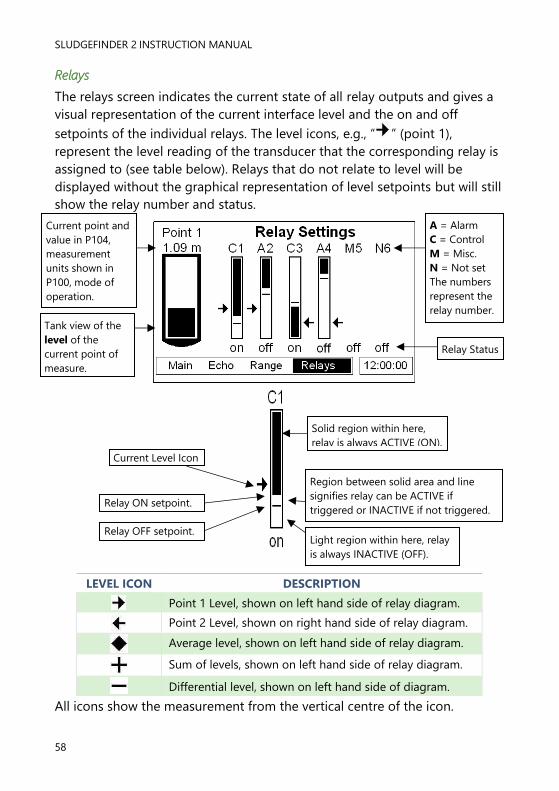
Relays
The relays screen indicates the current state of all relay outputs and gives a
visual representation of the current interface level and the on and off
setpoints of the individual relays. The level icons, e.g., “ ” (point 1),
represent the level reading of the transducer that the corresponding relay is
assigned to (see table below). Relays that do not relate to level will be
displayed without the graphical representation of level setpoints but will still
show the relay number and status.
All icons show the measurement from the vertical centre of the icon.
LEVEL ICON DESCRIPTION
Point 1 Level, shown on left hand side of relay diagram.
Point 2 Level, shown on right hand side of relay diagram.
Average level, shown on left hand side of relay diagram.
Sum of levels, shown on left hand side of relay diagram.
Differential level, shown on left hand side of diagram.
Solid region within here,
relay is always ACTIVE (ON).
Region between solid area and line
signifies relay can be ACTIVE if
triggered or INACTIVE if not triggered.
Light region within here, relay
is always INACTIVE (OFF).
Current Level Icon
Relay ON setpoint.
Relay OFF setpoint.
A = Alarm
C = Control
M = Misc.
N = Not set
The numbers
represent the
relay number.
Relay Status
Current point and
value in P104,
measurement
units shown in
P100, mode of
operation.
Tank view of the
level of the
current point of
measure.

PULSAR MEASUREMENT
59
Program Mode
This mode is used to set up the Sludge Finder 2 or change information
already set. You must use the built-in keypad to access program mode.
Alternatively, the unit can be set up with a PC via the RS 232 Serial Interface.
Entering a value for each of the parameters that are relevant to your
application provides all of the programming information.
How to Access Program Mode
With Sludge Finder 2, to enter program mode, you simply enter the
passcode, via the keypad, followed by the ENTER key. The default passcode
is 1997, so you would press the following:
Screenshots of program mode
Important Information
There is a time-out period of 15 minutes when in program mode.
After which time the run mode will resumed if you do not press any
key.
ENTER 1 9 9 7
Main Menu
Sub Menu

SLUDGEFINDER 2 INSTRUCTION MANUAL
60
Information screen
The information screen can be used to view system details such as Software
revision, serial number etc. but can also be used to view a summary of the
application settings. To access the information screen, press the button
when the Sludge Finder 2 is in run mode. There are 4 pages within the
information screen, preceded by the pulsar logo, showing the current page
number at the bottom centre of the information screen. The screens will
automatically scroll but can also use the left and right arrow keys to toggle
between pages an example of page 1 is shown below:
PAGE DESCRIPTION
1 General information on the system. See example above
2 Information on communications set up: RS232 and RS485 (if available)
3 Information on application set up, such as; transducer type, mode,
empty level etc.
4 Information on mA output setup such as; allocation etc.
Sub menu
heading
Parameter
list
Current value
Units (none in
this case)
System : SludgeFinder
Version : 2.2
Boot : Loader 1.2
Date : 12/03/21
Time : 16:45
Customer : Pulsar
Serial : 12345
Site ID : 12345 1/4

PULSAR MEASUREMENT
61
Hot Keys
There are five hot keys on the keypad that can be used to quickly access
common parameters for viewing only, while in Run Mode. Pressing the hot
key once will initiate or toggle the function assigned to that key, then the
Sludge Finder 2 reverts to the Run Mode display, if applicable. In program
mode, they have different functions. Information displayed by the function
keys in the “Main” screen will timeout and disappear after 20secs. The
functions are shown below:
HOT KEY RUN MODE PROGRAM MODE
Toggle status, echo strength, wiper
status and temperature display in the
“Main” screen.
Toggle the Gate display in the “Echo”
screen.
Clear the current value
Toggle distance, level, and space
display in “Main” screen.
Toggle the DATEM trace in “Echo”
screen.
Not used with Sludge Finder 2
Toggle mA output display in the ‘Main’
screen
Toggle the the Raw echo in the “Echo”
screen
Reset parameter to default
setting
Not used with Sludge Finder 2 Not used with Sludge Finder 2
Initiates a wiper sweep on the sludge
transducer face (VT transducers on
single point main display only).
Not used with SludgeFinder 2
Not used with SludgeFinder 2 Toggle negative values
Displays the information screen,
timeout 20 seconds. Enter decimal point.
F1
F2
F3
F4
F5

SLUDGEFINDER 2 INSTRUCTION MANUAL
62
Menu Keys
The menu keys have the following functions:
HOT KEY FUNCTION
1) Arrow keys for moving left and right around the menu
system and used as a backspace when editing the value of
a parameter.
2) Used for changing display modes in Run Mode.
3) Used in test mode to simulate the level moving up and
down (Right = up, Left = down)
1) Used to for moving up and down through the menu
system)
2) Used for changing displayed point of measurement in Run
Mode.
1) Used to confirm each action (for example, select a menu
option or accept a parameter number or value).
2) Used to confirm questions asked by your Sludge Finder 2
such as before restoring factory defaults.
When in ‘program mode’ used to navigate back a level in the
menu system or back to run mode. Cancel a value entered in
error. When in ‘run mode’ used to re-initialise the SF2 echo
trace if the unit is thought to be reading the incorrect value. This
function should only be used by experienced users, see Service
Manual for further details.
CANCEL
ENTER

PULSAR MEASUREMENT
63
Numeric Keys
These keys are used for entering numerical information during
programming.
1 2 3
4 5 6
7 8 9
0 . + -
SLUDGEFINDER 2 INSTRUCTION MANUAL
64
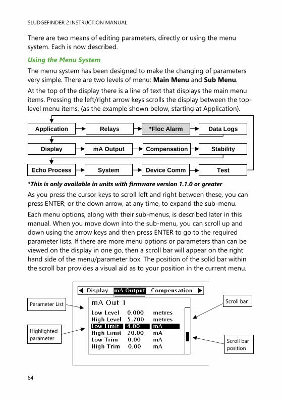
There are two means of editing parameters, directly or using the menu
system. Each is now described.
Using the Menu System
The menu system has been designed to make the changing of parameters
very simple. There are two levels of menu: Main Menu and Sub Menu.
At the top of the display there is a line of text that displays the main menu
items. Pressing the left/right arrow keys scrolls the display between the top-
level menu items, (as the example shown below, starting at Application).
*This is only available in units with firmware version 1.1.0 or greater
As you press the cursor keys to scroll left and right between these, you can
press ENTER, or the down arrow, at any time, to expand the sub-menu.
Each menu options, along with their sub-menus, is described later in this
manual. When you move down into the sub-menu, you can scroll up and
down using the arrow keys and then press ENTER to go to the required
parameter lists. If there are more menu options or parameters than can be
viewed on the display in one go, then a scroll bar will appear on the right
hand side of the menu/parameter box. The position of the solid bar within
the scroll bar provides a visual aid as to your position in the current menu.
Parameter List
Highlighted
parameter
Scroll bar
Scroll bar
position
Application *Floc Alarm
Compensation
Data Logs
Stability Display
Echo Process
Relays
mA Output
System Device Comm Test

PULSAR MEASUREMENT
65
Once you have reached the relevant section, scroll down the parameter list
to highlight the parameter you wish to edit, and press ENTER to access the
parameter options. When you are at parameter level, the options for that
parameter will be displayed on the screen. If the parameter has pre-set
options then scroll up or down, with the up/down arrow keys, or press the
designated number key (displayed on the left hand side) to highlight the
option, then press ENTER to save. If the parameter requires you to enter a
value within a particular range, the range options will be displayed with a
box to enter the value. Use the numeric keypad to enter the required value
following the onscreen prompts and press ENTER to save.
When you have finished, press CANCEL to go back to the previous menu
level. When you have reached the top level, press the CANCEL button again,
the Sludge Finder 2 will ask for confirmation before allowing you return to
run mode. This is done by pressing ENTER at the display prompt.
Directly Editing Parameters
If you already know the number of the parameter, that you wish to look at or
edit, simply type the number in at any time while you are in the menu
system. Thus, if you are in either the menu or sub-menu level by pressing a
numeric key, you can enter the parameter number directly and jump straight
there. You cannot type a parameter number whilst at parameter level, only at
one of the two menu levels.
When you are at a parameter, the text line rotates automatically displaying
the parameter name, number, the applicable units, and the maximum and
minimum figure you can enter. The top line shows the value you are setting.
Once you have accessed a parameter, you can either just look at it, or
change it.
Once a parameter has been changed, press ENTER and you will see the
parameter value changed in the parameter list. If you press CANCEL then
you will be returned to the parameter list with no change to the values.

SLUDGEFINDER 2 INSTRUCTION MANUAL
66
Test Mode
Test mode is used to simulate the application and confirm that all
parameters and relay setpoints have been entered as expected. During
simulation, there is a choice of whether the relays will change state (hard
simulation) or not (soft simulation), but the LED’s will always change colour
as programmed, and the mA outputs will change in accordance with the
chosen mode of operation. If you wish to test the logic of the system that
the relays are connected to then select hard simulation, but if you don’t
wish to change the relay state, then select a soft simulation.
There are two modes of simulation for each point of measurement,
automatic and manual. Automatic simulation will move the level up and
down between empty level or the pre-determined Start Level (P983) and
the span, if you wish to change the direction of the level movement, this can
be done by using the left/right arrow keys. In manual simulation, using the
up/down arrow keys will allow you to move the level up and down as
required.
To enter simulation, first go to program mode. Using the menu system,
select menu item ‘Test’, then sub-menu item ‘Simulation’. Select the point
of measure you wish to simulate and press enter to access the simulation
options. You can change the value of the parameter to one of the following:
1= Manual soft simulation
2= Automatic soft simulation
3= Manual hard simulation
4= Automatic hard simulation
When in test mode, the display will show the graphical level indicator with
the current mode of operation value in measurement units. Also shown will
be the relay setpoint indicators, for each relay, with an arrow showing the
current level relevant to that relay allocation e.g. if you are simulating point
1 then the level indicator will move up and down along with the arrows next
to any relay allocated to point 1. If a relay is allocated to sum, average or
differential, then the Sludge Finder 2 will span the relay diagram to the sum,
average or differential of point 1 and 2. The level of point 2 (or point 1 if
simulating point 2) will always remain at 0.
To return to program mode, press CANCEL and test mode will end.

PULSAR MEASUREMENT
67
When in manual simulation, by default test mode will move the level by
0.1m steps. Altering the increment (P981) will change this value.
In automatic mode, the rate at which the level moves up and down is set by
the increment (P981 in metres, the rate (P982) in minutes, which can be
changed to make the level move up and down faster. E.g., if increment
(P981) is set for 0.1m and rate (P982) is set to 1 min then the level will
increase or decrease at a rate of 0.1m/min. To make the simulated level
move slower, decrease the value in increment (P981) or increase the value
in rate (P982). To make the simulated level move faster, increase the value
in increment (P981) or decrease the value in rate (P982).
Using the Serial Interface
The RS232 serial interface is used to communicate between the Sludge
Finder 2 and a PC using the optional Sludge Finder PC software and other
associated Pulsar software packages. To obtain information such as data
logging and view echo traces, upload, download and save parameter files. In
addition it can also be used to control or obtain information using a
standard PC or other computer base equipment. To do so, the default
settings for communications port are as follows: baud rate 19,200, 8 data
bits, no parity, 1 stop bit.
The device should be connected as shown in Chapter 2 Installation.
To use the device remotely, you need to log on to start, and log off when
finished. When logged on, Sludge Finder 2 will show “Remote” on the
display in place of the clock. When logged off, the display will return to
normal (clock will be displayed).
All commands should be followed by a carriage return.
The unit will respond either OK or a value if the command is accepted, or
NO if the command is not recognised or is not available.
To log on, send the command
/ACCESS:pppp where pppp is the passcode (P922).
To log off, send the command
/ACCESS:OFF
To set a parameter, send the command
/Pxxx:yy where xxx is the parameter number, and yy is the value you wish to
set it to.

SLUDGEFINDER 2 INSTRUCTION MANUAL
68
Other commands you can use are:
/DISTANCE 1 (shows current distance of point 1)
/DISTANCE 2 (shows current distance of point 2)
/LEVEL 1 (shows current level of point 1l)
/LEVEL (shows current level of point 2)
/TEMP1 (shows current temperature of point 1)
/TEMP2 (shows current temperature of point 2)
/CURRENTOUT1 (shows the mA output value for mA output 1)
/CURRENTOUT2 (shows the mA output value for mA output 2)
Please consult Pulsar Measurement or contact your local Pulsar
representative for further details and a full list of available commands.
PULSAR MEASUREMENT
69
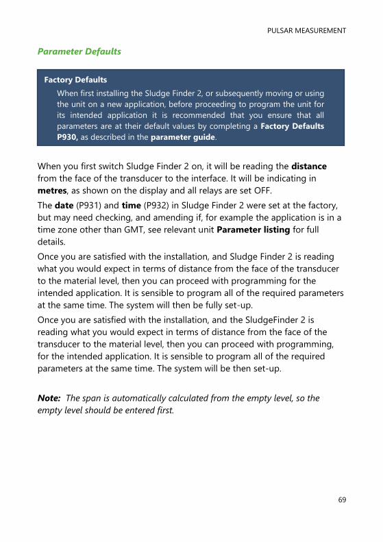
Parameter Defaults
When you first switch Sludge Finder 2 on, it will be reading the distance
from the face of the transducer to the interface. It will be indicating in
metres, as shown on the display and all relays are set OFF.
The date (P931) and time (P932) in Sludge Finder 2 were set at the factory,
but may need checking, and amending if, for example the application is in a
time zone other than GMT, see relevant unit Parameter listing for full
details.
Once you are satisfied with the installation, and Sludge Finder 2 is reading
what you would expect in terms of distance from the face of the transducer
to the material level, then you can proceed with programming for the
intended application. It is sensible to program all of the required parameters
at the same time. The system will then be fully set-up.
Once you are satisfied with the installation, and the SludgeFinder 2 is
reading what you would expect in terms of distance from the face of the
transducer to the material level, then you can proceed with programming,
for the intended application. It is sensible to program all of the required
parameters at the same time. The system will be then set-up.
Note: The span is automatically calculated from the empty level, so the
empty level should be entered first.
Factory Defaults
When first installing the Sludge Finder 2, or subsequently moving or using
the unit on a new application, before proceeding to program the unit for
its intended application it is recommended that you ensure that all
parameters are at their default values by completing a Factory Defaults
P930, as described in the parameter guide.
SLUDGEFINDER 2 INSTRUCTION MANUAL
70
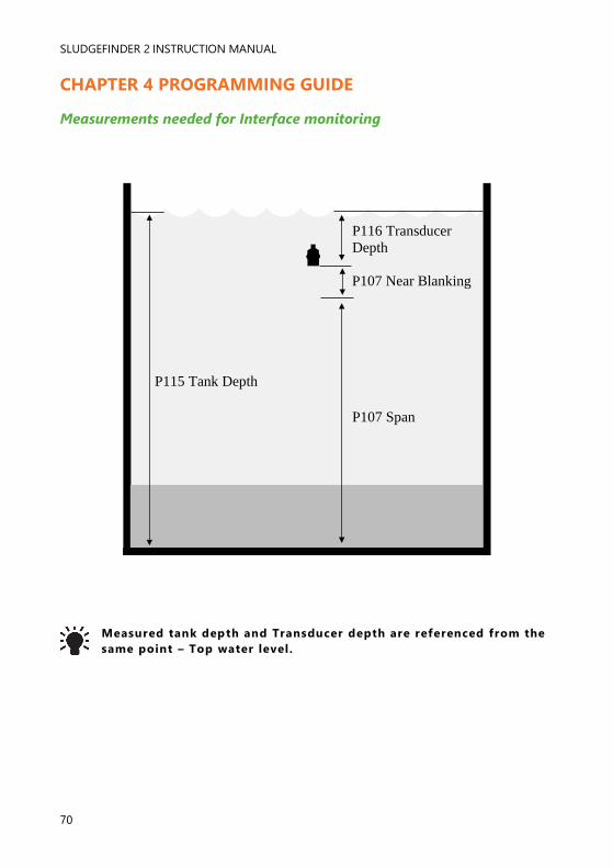
CHAPTER 4 PROGRAMMING GUIDE
Measurements needed for Interface monitoring
Measured tank depth and Transducer depth are referenced from the
same point – Top water level.
P115 Tank Depth
P116 Transducer
Depth
P107 Near Blanking
P107 Span

PULSAR MEASUREMENT
71
Example 1: Primary Settlement Sludge Interface monitoring
Tank Depth (P115) 2.8m
Span (P106) 2.3m
High alarm off (P214) 1.85m
Transducer Depth (P116) 0.2m
Interface level
High Alarm on (P213) 1.95m
Empty level
Near Blanking (P107) 0.3m
In this example, when the sludge interface level rises to 1.95 m, relay 1 will
come on until the level drops to 1.85 m when it will turn off.
The display for point 1 will show the sludge interface level in the tank.
The mA output will be representative of sludge interface level where 4mA =
empty level (0%) and 20mA = 2.3m (100%).
To program the unit for Example 1 Primary Settlement Sludge Interface
Monitoring, proceed as follows.
If required access the Program Mode.
Key in the passcode 1997 and press ENTER.

SLUDGEFINDER 2 INSTRUCTION MANUAL
72
Use the arrow keys to scroll to the following menus and parameters and
press ENTER to access them. Select the relevant option using the up and
down arrows or type in the required value using the keypad and press
ENTER to accept.
All other parameters should remain at default values.
If combining the sludge interface monitoring with a tank liquid level monitor
then proceed to Example 1b Level Monitoring with Alarms on Point 2
otherwise, programming is now complete and the unit can be returned to
the run mode, press CANCEL until Run Mode? Is displayed on the LCD
press ENTER, and the Sludge Finder 2 will return to the Run Mode.
MENU SUB MENU PARAMETER VALUE/OPTION
Application Point 1
Global
Mode P100
Xducer P101
Material P102
Tank Depth P115
Xducer Depth P116
Span P106
Meast Units P104
2 = Level
7 = VT10
2 = Primary
2.8 (metres)
0.2 (metres)
2.3 (metres)
1 = metres
Application
Relay 1
Type P210
Function P211
Ident P212
Setpoint 1 P213
Setpoint 2 P214
Allocation P216
1 = Alarm
1 = Level
2 = High
1.95 (metres)
1.85 (metres)
1 = Xducer 1

PULSAR MEASUREMENT
73
Setting Up Point 2 with as an Ultrasonic Point of Measurement
If it is required that point two is to be set up as an ultrasonic transducer to
measure level in air, follow the procedure as per the example below.
Example 2: Level Monitoring with High and Low Alarms on Point 2
A vessel, containing a liquid that has a variation in level that is to be
monitored, with a high level alarm set on Relay 1, and low level alarm set on
Relay 2. The following method uses an air transducer from the dB range,
example shown is a dB6 on channel 2.
In this example, when the level rises to 2.38 m, relay 2 will come on until the
level drops to 2.24 m when it will turn off. If the level drops to 0.28 m, then
relay 3 will come on until it rises 0.42 m when it will turn off.
The display for point 2 will show the level in the tank.
The mA output will be representative of level where 4mA = empty level (0%)
and 20mA = 2.8m (100%).
Empty Distance (P1105), 3.5m
100%. Span (P1106), 2.8m
85%. High alarm on (P223), 8.5 2.38m
80%. High alarm off (P224), 2.24m
0%, Empty level
10%. Low alarm on (P233), 0.28m
15%, Low alarm off (P234), 0.42m
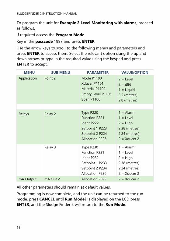
SLUDGEFINDER 2 INSTRUCTION MANUAL
74
To program the unit for Example 2 Level Monitoring with alarms, proceed
as follows.
If required access the Program Mode
Key in the passcode 1997 and press ENTER
Use the arrow keys to scroll to the following menus and parameters and
press ENTER to access them. Select the relevant option using the up and
down arrows or type in the required value using the keypad and press
ENTER to accept.
All other parameters should remain at default values.
Programming is now complete, and the unit can be returned to the run
mode, press CANCEL until Run Mode? Is displayed on the LCD press
ENTER, and the Sludge Finder 2 will return to the Run Mode.
MENU SUB MENU PARAMETER VALUE/OPTION
Application Point 2
Mode P1100
Xducer P1101
Material P1102
Empty Level P1105
Span P1106
2 = Level
2 = dB6
1 = Liquid
3.5 (metres)
2.8 (metres)
Relays
Relay 2
Type P220
Function P221
Ident P222
Setpoint 1 P223
Setpoint 2 P224
Allocation P226
1 = Alarm
1 = Level
2 = High
2.38 (metres)
2.24 (metres)
2 = Xducer 2
Relay 3 Type P230
Function P231
Ident P232
Setpoint 1 P233
Setpoint 2 P234
Allocation P236
1 = Alarm
1 = Level
2 = High
2.38 (metres)
2.24 (metres)
2 = Xducer 2
mA Output mA Out 2 Allocation P899 2 = Xducer 2

PULSAR MEASUREMENT
75
Example Echo Screen for Ultrasonic Transducer
Status Indicator
Empty Distance
Indicator

SLUDGEFINDER 2 INSTRUCTION MANUAL
76
Example 3: Using a Single Viper Transducer to Measure 2 Different
Interface Levels.
The Pulsar SF2 Integrator can be used to monitor both the Rag or FLOC
levels and the Settled Sludge or RAS levels simultaneously using only one
Viper Transducer.
This feature gives the user the ability to monitor and control the RAS level
application by monitoring the settled sludge, but also prevent damaging
FLOC spillage to the local water course by monitoring the less dense Rag
levels.
To achieve this, we utilise Point number 2 in addition to Point number 1.
Both points will display the same profile, but different service parameters
can be applied thus setting Point 1 to monitor the RAS layer and Point 2 the
FLOC layer.
It is required to set Point 2 Allocation in the Application menu (P1103) To 0
= Transducer 1.
The above profiles show the unit differentiating between the two echoes. In
this instance point one is set to pick the largest echo and point two is set to
pick the first echo (see SF2 Service Manual for details).
Each 4-20ma can be independently set to track both interfaces.
All relays can be independently set to give control or alarms on both points.

PULSAR MEASUREMENT
77
Example 4: Setting the Unit to Alarm on Hi-Floc Levels
High Floc Alarm
The unit is now able to pick up on high level of floc readings, to do this it
reacts to the raw echo trace rather than the processed echo. You are then
able to set an alarm that is only reacting to the raw floc levels which will
activate if the % of intrusion (P163) is reached between the distances set
(in measurement units) in P160 Start distance and P161 End Distance. So
if the reading is low and sat near the bottom of the tank the processed echo
is low but the raw echo can be high.
The unit will pick up hi levels of floc near the surface which it can only do by
looking at the raw trace. The alarm On Delay P164 and Off Delay P165 can
be set to prevent passing ‘clouds’ of material in flight from nuisance
alarming.
With the introduction of the High Floc Alarm feature, several different
parameters and features now need to be included into the manual. Below
are the illustrations, parameters and their descriptions which require adding
to the new release of manuals due to be compiled indicating how to
program a high floc alarm.
Top Level Menu
*This is only available in units with firmware version 1.1.0 or greater.
Compensation mA Output Display Stability
Device Comm System Echo Process Test
Relays Application Floc Alarm* Data Logs

SLUDGEFINDER 2 INSTRUCTION MANUAL
78
Setting up a High Floc alarm:
Note: When setting a High Floc Alarm, it is necessary to access two menu
systems the RELAYS menu to set up the relay and the FLOC ALARM menu
to set the alarm parameters.
Enter program mode by keying in 1997 and pressing ENTER. Once in
program mode you will need to program both a High Floc alarm relay and
set up the parameters in the new Floc alarm menu option. Assigning an
alarm relay to this new feature to alert you of a high floc presence, also
allows you to view on the units trace screen the area box monitored by the
Floc alarm parameters. How to set this alarm relay feature is explained in
Relay parameters. The parameters required to setup a High Floc alarm are
detailed in the Chapter 6 Menu system and parameter guide - Floc Alarm
section.
The ‘Intrusion Window’ appears in the top let hand side of the echo profile
display when the ‘Gate’ hot key is pressed.
The ‘Raw Echo’ (F3) should also be pressed to see if th e Raw Echo
profile is in the display is intruding into the window .

PULSAR MEASUREMENT
79
CHAPTER 6 MENU SYSTEM AND PARAMETER GUIDE
This section outlines all parameters available in the Sludge Finder 2, as they
appear in the menu system.
Shown below is a set of charts to show you how all the various parts can be
found using the menu system.
For further details and a full description of all parameters refer to Chapter 7
Parameter Listings and Descriptions.
Top Level Menu
Compensation mA Output Display Stability
Device Comm System Echo Process Test
Relays Application Floc Alarm* Data Logs

SLUDGEFINDER 2 INSTRUCTION MANUAL
80
Application Menu
Global
P104 Measurement Units
Point 1 Point 2 Global
* only available with VT transducers + only available with dB transducers
Point 1
P100 Mode
P101 Transducer
P115* Tank Depth
P116* Transducer Depth
P105+ Empty Level
P106 Span
P107 Near Blanking
P108+ Far Blanking
P102 Material
Point 2
P1100 Mode
P1101 Transducer
P1115* Tank Depth
P1116* Transducer Depth
P1105+ Empty Level
P1106 Span
P1107 Near Blanking
P1108+ Far Blanking
P1102 Material
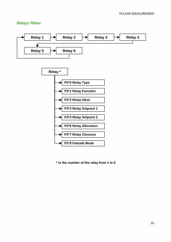
PULSAR MEASUREMENT
81
Relays Menu
Relay 1 Relay 2 Relay 3 Relay 4
Relay 5 Relay 6
* is the number of the relay from 1 to 6
P2*0 Relay Type
P2*1 Relay Function
P2*2 Relay Ident.
P2*3 Relay Setpoint 1
P2*4 Relay Setpoint 2
P2*6 Relay Allocation
Relay *
P2*7 Relay Closures
P2*8 Failsafe Mode

SLUDGEFINDER 2 INSTRUCTION MANUAL
82
Floc Alarm Menu
Point 2 Point 1
P161 End Distance
P160 Start Distance
P162 Level
P163 % of Intrusion
P164 On Delay
P165 Off Delay
Point 1
P1161 End Distance
P1160 Start Distance
P1162 Level
P1163 % of Intrusion
P1164 On Delay
P1165 Off Delay
Point 2

PULSAR MEASUREMENT
83
Data Logs Menu
Point 1 Point 2
Point 1
P580 Min. Temperature
P581 Min. Temp. Date
P582 Min. Temp. Time
P583 Max. Temperature
P584 Max. Temp. Date
P585 Max. Temp. Time
P586 Current Temp.
Point 2
P1580 Min. Temperature
P1581 Min. Temp. Date
P1582 Min. Temp. Time
P1583 Max. Temperature
P1584 Max. Temp. Date
P1585 Max. Temp. Time
P1586 Current Temp.

SLUDGEFINDER 2 INSTRUCTION MANUAL
84
Display Menu
Point 1 Point 2
Point 1
P802 Display Offset
P804 Display Conversion
P808 Failsafe Mode
P809 Failsafe Time
P801 Decimal Places
P800 Display Units
Point 2
P1802 Display Offset
P1804 Display Conv.
P1808 Failsafe Mode
P1809 Failsafe Time
P1801 Decimal Places
P1800 Display Units

PULSAR MEASUREMENT
85
mA Output Menu
mA Out 1 mA Out 2
mA Out 1
P831 mA Mode
P841 mA Allocation
P830 mA Range
P840 mA Fail Mode
P834 mA Low Level
P835 mA High Level
P836 mA Low Limit
P837 mA High Limit
P838 mA Low Trim
P839 mA High Trim
mA Out 2
P891 mA Mode
P899 mA Allocation
P890 mA Range
P898 mA Fail Mode
P892 mA Low Level
P893 mA High Level
P894 mA Low Limit
P895 mA High Limit
P896 mA Low Trim
P897 mA High Trim
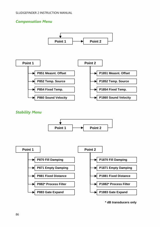
SLUDGEFINDER 2 INSTRUCTION MANUAL
86
Compensation Menu
Stability Menu
Point 1 Point 2
Point 1
P851 Measnt. Offset
P852 Temp. Source
P854 Fixed Temp.
P860 Sound Velocity
Point 2
P1851 Measnt. Offset
P1852 Temp. Source
P1854 Fixed Temp.
P1860 Sound Velocity
Point 1 Point 2
* dB transducers only
Point 1
P870 Fill Damping
P871 Empty Damping
P881 Fixed Distance
P882* Process Filter
P883 Gate Expand
Point 2
P1870 Fill Damping
P1871 Empty Damping
P1881 Fixed Distance
P1882* Process Filter
P1883 Gate Expand

PULSAR MEASUREMENT
87
Echo Processing Menu
Point 1 Point 2
* dB transducers only
Point 1
P900 Transducer Status
P901 Echo Confidence
P902 Echo Strength
P903 Average Noise
P904 Peak Noise
P905* Sensitivity
P906* Side Clearance
Point 2
P910 Transducer Status
P911 Echo Confidence
P912 Echo Strength
P913 Average Noise
P914 Peak Noise
P915* Sensitivity
P916* Side Clearance
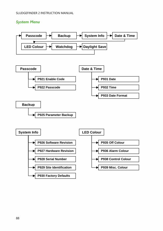
SLUDGEFINDER 2 INSTRUCTION MANUAL
88
System Menu
Passcode
P921 Enable Code
P922 Passcode
Backup
P925 Parameter Backup
System Info
P926 Software Revision
P927 Hardware Revision
P928 Serial Number
P929 Site Identification
P930 Factory Defaults
Date & Time
P931 Date
P932 Time
P933 Date Format
LED Colour
P935 Off Colour
P936 Alarm Colour
P938 Control Colour
P939 Misc. Colour
Passcode
Daylight Save
Backup System Info Date & Time
LED Colour Watchdog

PULSAR MEASUREMENT
89
Daylight Save
P970 DST Enable
P971 Difference
P972 Start Time
P973 Start Day
P974 Start Week
P975 Start Month
P976 End Time
P977 End Day
P978 End Week
P979 End Month
Watchdog
P940 Number of Starts
P941 Start Date
P942 Start Time
P943 Start Date 1
P944 Start Time 1
P945 Start Date 2
P946 Start Time 2
P947 Start Date 3
P948 Start Time 3
P949 Start Date 4
P950 Start Time 4
P951 Start Date 5
P952 Start Time 5
P953 Start Date 6
P954 Start Time 6
P955 Start Date 7
P956 Start Time 7
P957 Start Date 8
P958 Start Time 8
P959 Start Date 9
P960 Start Time 9

SLUDGEFINDER 2 INSTRUCTION MANUAL
90
Device Comm Menu
RS232 Setup Modbus
Profibus
Comm. option dependent
RS232 Setup
P061 Comms Baudrate
Optional
Profibus
P132 Device Address
P143 Address Locked
Optional
Modbus
P130 Device Mode
P131 Protocol
P132 Device Address
P133 Device Baud rate
P134 Parity
P135 Stop Bits
P136 Data Format
P137 Delay in ms

PULSAR MEASUREMENT
91
Test Menu
Simulate Pt 1 Hardware Simulate Pt 2 Setup
Simulate Pt 1
P980 Simulate
Simulate Pt 2
P1980 Simulate
Setup
P981 Increment
P982 Rate
P983 Start Level
Hardware
P990 Self Test
P991 Hardware Test
P992 mA Output Test
P994 Transducer Test
P995 Keypad Test
P996 Relay Test

SLUDGEFINDER 2 INSTRUCTION MANUAL
92
CHAPTER 7 PARAMETER LISTING AND DESCRIPTION
Application Parameters
Point 1 / Point 2
P1-100, P2-1100 Mode of Operation
This parameter sets the mode of operation, when in run mode, and can be
set to one of the following:
OPTION DESCRIPTION
1 = Distance (Default) Display shows the distance from the transducer face
to the surface of the material measured.
2 = Level Shows how full a vessel is.
3 = Space Shows how empty a vessel is.
4* = Average Level P1 & P2 Display shows the average level of point 1 & point 2
5* = Differential P1 & P2 Display shows the differential between point 1 &
point 2
*If transducer 2 is enabled
P1-101, P2-1101 Xducer (Transducer)
This parameter should be set to the transducer being used with the unit, and
can be set to one of the following:
OPTION DESCRIPTION
0 = None For point 2 only. Disables point 2 (Default)
1 = dB3 Transducer is a dB3. Range = 0.125 to 3 metres
2 = dB6 Transducer is a dB6. Range = 0.3 to 6 metres
3 = dB10 Transducer is a dB10. Range = 0.3 to 10 metres
4 = dB15 Transducer is a dB15. Range = 0.5 to 15 metres
5 = dB25 Transducer is a dB25. Range = 0.6 to 25 metres
6 = dB40 Transducer is a dB40. Range = 1.2 to 40 metres
7 = VT10 (Default) Transducer is a VT10. Range = 0.3 to 10 metres
*8 = ST10 Transducer is a ST10. Range = 0.3 to 10 metres
*This option is only available in firmware versions 2.2.0 and greater
PULSAR MEASUREMENT
93
P1-102, P2-102 Material
This parameter should be set to the type of site being monitored for Sludge
or the material being monitored with air transducers. The options are:
VT/ST Transducer
OPTION DESCRIPTION
1 = Industrial Use for the majority of non-sludge sites
2 = Primary (Default) Use for primary settlement tanks
3 = Secondary Use for secondary settlement tanks
4 = SBR Use for SBR (Sequencing Batch Reactor) tanks
dB Transducers
OPTION DESCRIPTION
1 = Industrial Use for the majority of non-sludge sites
2 = Primary (Default) Use for primary settlement tanks
P1-P105, P2-P1105 Empty Level (dB transducers only)
This parameter is to be set to the maximum distance from the face of a dB
transducer to the empty point (bottom of tank), in P104 Measurement
Units. This value also affects span, (see important information below), so
should be set before span. With sludge transducers, the empty level is
automatically calculated from P115 Tank Depth and P116 Transducer
Depth.
P1-P106, P2-P1106 Span
This parameter should be set to the maximum distance from the Tank
Depth (P115/P1115) or Empty Level (P105/P1105) to the maximum
material level. It is automatically set to be equal to the Tank Depth
(P115/P1115) or Empty Level (P105/P1105) less the Near Blanking
distance (P107/P1107) when you set the tank depth or empty level.

SLUDGEFINDER 2 INSTRUCTION MANUAL
94
P1-107, P2-1107 Near Blanking
This parameter is the distance from the face of the transducer that is not
measurable and is pre-set to the minimum value dependant on the
Transducer (P101) selected. It should not be set to less than this figure, but
can be increased, typically to ignore close in obstructions.
TRANSDUCER NEAR BLANKING DISTANCE
P101/P1101 = dB3 Default blanking distance = 0.125 metres
P101/P1101 = dB6 Default blanking distance = 0.30 metres
P101/P1101 = dB10 Default blanking distance = 0.30 metres
P101/P1101 = dB15 Default blanking distance = 0.50 metres
P101/P1101 = dB25 Default blanking distance = 0.60 metres
P101/P1101 = dB40 Default blanking distance = 1.20 metres
P101/P1101 = VT10 Default blanking distance = 0.30 metres
*P101/P1101 = ST10 Default blanking distance = 0.30 metres
*This option is only available in firmware versions 2.2.0 and greater.
P1-108, P2-1108 Far Blanking Distance
This is the distance (as a percentage of empty level P105) beyond the
empty point that the unit will be able to measure, and by default is pre-set
to 20% of the empty level.
If the surface being monitored can extend beyond the Empty Level (P105)
then the far blanking distance can be increased to a maximum of 100% of
empty level.
This parameter is always entered as a % of empty level.
Important Notice
When changing the Tank Depth (P115) or Empty Distance (P105) you can also
recalculate the values for the Span and the Relay Setpoints to take in to account
the near blanking (P107) and transducer depth (P116) where applicable, so that
they remain at the same percentage values of the empty distance as they were
before they were changed. The question “Recalculate Span?” will be asked, if you
choose yes (enter), then the span will be recalculated, any other answer will leave
the span at its original value. You will then be asked if you want to “Recalculate
Setpoints?”, if you choose yes (enter), then all Relay Setpoints will be
recalculated as a percentage of the new empty distance, any other answer will
leave the setpoints at their original values.

PULSAR MEASUREMENT
95
P1-115, P2-P1115 Tank Depth
This is the distance from the top of the tank (or the surface of the liquid
when full) to the bottom of the tank in P104 Measurement Units. This
parameter will only become available when a sludge transducer (prefixed
‘VT’) is selected in P101 Transducer Type.
P1-116, P2-P1116 Transducer Depth
This is the distance from the top of the tank (or the surface of the liquid
when full) to the face of the sludge transducer in P104 Measurement Units.
This parameter will only become available when a sludge transducer
(prefixed ‘VT’) is selected in P101 Transducer Type.
Global
P104 Measurement Units
This parameter sets the units you want to use for programming and display.
OPTION DESCRIPTION
1 = metres (Default) All units of measurement are Metres
2 = cm All units of measurement are Centimetres
3 = mm All units of measurement are Millimetres
4 = feet All units of measurement are Feet
5 = inches All units of measurement are Inches

SLUDGEFINDER 2 INSTRUCTION MANUAL
96
Relay Parameters
All relay related parameters are prefixed with a 2**.
The second digit of the three-figure parameter number denotes the relay
number as follows:
21* parameters for Relay 1
22* parameters for Relay 2
23* parameters for Relay 3
24* parameters for Relay 4
25* parameters for Relay 5
26* parameters for Relay 6
The third digit selects specific parameter for the setting of the relays, which
can be selected individually and results in the following parameter numbers
for each relay:
Relay 1 210 to 218
Relay 2 220 to 228
Relay 3 230 to 238
Relay 4 240 to 248
Relay 5 250 to 258
Relay 6 260 to 268

PULSAR MEASUREMENT
97
P210, 220, 230, 240, 250, 260 - Relay Type
This parameter defines what type each relay should be, see the table below
for available options:
OPTION DESCRIPTION
1 = Alarm
Relay is programmed as an alarm relay, which will de-
energise ON, and energise OFF. This will ensure an
alarm is raised if the power fails to the unit.
2 = Control Relay is programmed as a control relay, which will
energise ON, and de-energise OFF.
3 = Miscellaneous Relay is programmed as a miscellaneous relay, which will
energise ON, and de-energise OFF.

SLUDGEFINDER 2 INSTRUCTION MANUAL
98
Alarms
P210, 220, 230, 240, 250, 260 = 1 (Alarm)
The second parameter for each relay determines the function of the alarm.
P211, 221, 231, 241, 251, 261 – Relay Function
*This is only available in units with firmware version 1.1.0 or greater.
**This is only available in units with firmware version 1.1.1 or greater.
The third parameter for each relay determines the alarm ID for the relay
you wish to set.
P212, P222, P232, P242, P252, P262 - Relay Alarm ID
When P211, 221, 231, 241, 251, 261 = 3 (Loss of Echo), 4 (Loss of Clock)
or 5 (Wiper Fault)
This parameter has no function and will not be displayed.
OPTION DESCRIPTION
0 = Off (Default) Relay will not operate.
1 = Level
Alarm is based on the level in the vessel, and the type of level
alarm (P212, 222, 232, 233, 243, 253) and two setpoints must
be set (P223, 223, 233 & 214, 224, 234, 244, 254). Setpoints
are entered in display units or % of span as referenced to
empty level.
3 = Temperature
Alarm is based on the temperature, and the type of
temperature alarm (P212, 222, 232, 242, 252) and two
setpoints must be set (P213, 223, 233 & P214, 224, 234, 244,
254). The temperature used depends on the temperature
source selected (P852). Setpoints are entered in oC.
4 = Loss of Echo Alarm is raised if the Failsafe Timer (P809) expires. No
setpoints required.
5 = Loss of Clock Alarm is raised if the expires. No setpoints required.
*6 = High Floc Alarm An alarm is raised if the floc level reaches the level of intrusion
as set in % intrusion P1-163.
**7 = Service Alarm An alarm is raised when the unit has reached its service
interval (see service manual for details)

PULSAR MEASUREMENT
99
When P211, 221, 231, 241, 251, 261 = 1 (Level) or 2 (Temperature). This
parameter has no function and will not be displayed.
P211, 221, 231, 241, 251 = 1 (Level), 2 = Rate of Change or 3 (Temp)
This parameter defines which alarm type, or identification, the relay should
respond to, as follows:
OPTION DESCRIPTION SETPOINTS
1 = General
(Default)
Relay goes “ON” when the
value reaches the ON
setpoint and goes “OFF”
when the value reaches the
OFF setpoint.
P213, 223, 233, 243, 253,
263 is ON Setpoint; P214,
224, 234, 244, 254, 264 is
OFF Setpoint.
2 = High
Relay goes “ON” when the
value rises to the ON
setpoint and goes “OFF”
when the value lowers to the
OFF setpoint.
ON> OFF Relay Setpoints
P213, 223, 233, 243, 253,
263 and P214, 224, 234,
244, 254, 264. Setpoints
can be set in any order as
the unit ‘knows’ that you
are setting a high level
alarm.
3 = HiHi Same as 2 = High, but different identifier
4 = Low
Relay goes “ON” when the
value lowers to the ON
setpoint and goes “OFF”
when the value rises to the
OFF setpoint.
ON<OFF Relay Setpoints
P213, 223, 233, 243, 253,
263 and P214, 224, 234,
244, 254, 264. Setpoints
can be set in any order as
the unit ‘knows’ that you
are setting a low-level
alarm.
5 = LoLo Same as 4 = Lo, but different
identifier
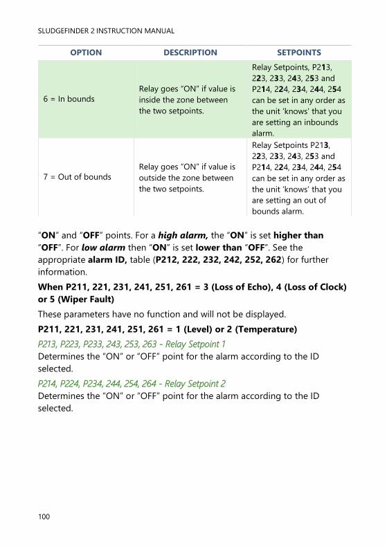
SLUDGEFINDER 2 INSTRUCTION MANUAL
100
OPTION DESCRIPTION SETPOINTS
6 = In bounds
Relay goes “ON” if value is
inside the zone between
the two setpoints.
Relay Setpoints, P213,
223, 233, 243, 253 and
P214, 224, 234, 244, 254
can be set in any order as
the unit ‘knows’ that you
are setting an inbounds
alarm.
7 = Out of bounds
Relay goes “ON” if value is
outside the zone between
the two setpoints.
Relay Setpoints P213,
223, 233, 243, 253 and
P214, 224, 234, 244, 254
can be set in any order as
the unit ‘knows’ that you
are setting an out of
bounds alarm.
“ON” and “OFF” points. For a high alarm, the “ON” is set higher than
“OFF”. For low alarm then “ON” is set lower than “OFF”. See the
appropriate alarm ID, table (P212, 222, 232, 242, 252, 262) for further
information.
When P211, 221, 231, 241, 251, 261 = 3 (Loss of Echo), 4 (Loss of Clock)
or 5 (Wiper Fault)
These parameters have no function and will not be displayed.
P211, 221, 231, 241, 251, 261 = 1 (Level) or 2 (Temperature)
P213, P223, P233, 243, 253, 263 - Relay Setpoint 1
Determines the “ON” or “OFF” point for the alarm according to the ID
selected.
P214, P224, P234, 244, 254, 264 - Relay Setpoint 2
Determines the “ON” or “OFF” point for the alarm according to the ID
selected.

PULSAR MEASUREMENT
101
Control
P210, 220, 230, 240, 250, 260 = 2 (Control)
When a relay is being set up as a control relay, the second parameter that
will be displayed in the menu determines its function.
P211, 221, 231, 241, 251, 261 – Relay Function
This function allows the relay to be assigned to specific control functions
(other than alarms).
This can be used to activate devices based on elapsed time or running
cycles, such as a timed rake control to keep a ram lubricated if idle for long
periods.
OPTIONS DESCRIPTION
0 = Off (Default) Relay is always de-energised
1 = Time
Relay will energise “ON” after the Cycle time that is set in
Relay Setpoint 2 (P214, 224, 234, 244, 254, 264). And turns
“OFF”, de-energises, after the On Time Period that is set in
Relay Setpoint 1 (P213, 223, 233, 243, 253, 263)
2 = General
Control is based on the level in the vessel. All general
controls are used to assist each other (run at the same time)
and each general control has its own “ON” and “OFF”
setpoints.
Important Notice
Setpoints are entered in values according to the function selected.
Level - entered in Display Units or % of span as referenced to Empty
Level. Rate
of Change - entered in Display Units per minute or % of span per minute.
For an alarm on an increasing level enter setpoints as a positive value, for
an alarm on a decreasing level enter setpoints as a negative value.
Temperature - entered in ºC.
See the appropriate alarm function, table (P211, 221, 231, 241 and
251) for further information.

SLUDGEFINDER 2 INSTRUCTION MANUAL
102
The third parameter has no function when control relays are chosen and
will not be displayed.
The fourth parameter and fifth parameter are set to determine the switch
points, “ON” and “OFF” for the relay. See control function, table (P211,
221, 231, 241, 251, 261) for further information.
P213, P223, P233, 243, 253, 263 - Relay Setpoint 1
P211, 221, 231, 241, 251, 261 =1 (Time)
This parameter determines the “Time Period” that the relay will remain
“ON”. Relay Setpoints are entered in Minutes.
See the appropriate relay Function tables (P211, 221, 231, 241, 251, 261)
for further information.
P211, 221, 231, 241, 251, 261 =2 (General)
This parameter is the “ON” point for the general control relay. Relay
setpoints are entered in values of Measurement Units (P104).
P214, P224, P234, 244, 254, 264 - Relay Setpoint 2
P211, 221, 231, 241, 251, 261 =1 (Time)
This parameter determines the “Cycle Time” for the operation of the relay.
See the appropriate relay Function tables (P211, 221, 231, 241, 251, 261)
for further information.
P211, 221, 231, 241, 251, 261 =2 (General)
This parameter is the “OFF” point for the general control relay. Relay
setpoints are entered in values of Measurement Units (P104).

PULSAR MEASUREMENT
103
Miscellaneous
P210, 220, 230, 240, 250, 260 = 3 (Miscellaneous)
When a relay is set to be a miscellaneous relay, the second parameter
determines its function.
P211, 221, 231, 241, 251, 261 – Relay Function
This function allows the relay to work in relation to a clock or a specific event
and will be set to activate in relation to Real Time.
OPTIONS DESCRIPTION
0 = Off (Default) Relay is always de-energised
1 = Clock
Relay will energise ON at a specified time each day as set
in Relay Setpoint 1 (P213, 223, 233, 243, 253). And turns
OFF, de-energises, after the specified-On Time period as
set in Relay Setpoint 2 (P214, 224, 234, 244, 254)
The third parameter has no function when miscellaneous relay is chosen
and will not be displayed.
The fourth parameter, and fifth parameter, are set to determine the switch
points, “ON” and “OFF” for the relay. See miscellaneous function table
(P211, 221, 231, 241, 251, 261) for further information.
P210, 220, 230, 240, 250, 260 = 1 (Clock)
P213, 223, 233, 243, 253, 263 – Relay Setpoint 1
Relay Setpoints are entered in Hours & Minutes (HH:MM) to set Time at
which relay will energise. Default = 00:00 (HH:MM)
P214, 224, 234, 244, 254, 264 – Relay Setpoint 2
Relay Setpoints are entered in seconds to set the Time Period that the relay
will remain ‘ON’. Default = 0.00 mins.
Important Notice
When using a Relay to control a device at a specified time of day ensure
that the Time P932 is set correctly. And if required, enable Daylight
Saving for the appropriate time difference P970 – P979.

SLUDGEFINDER 2 INSTRUCTION MANUAL
104
Common Parameters
P216, 226, 236, 246, 256, 266 – Relay Allocation
This parameter determines which input the relay will act on. You can set it to
the transducer1 (default), transducer 2 or an average, sum, or differential of
the two when available.
OPTIONS DESCRIPTION
1 = Xducer 1 (Default) Relay acts on Xducer 1 calculated values
2 = Xducer 2 Relay acts on Xducer 2 calculated values
3 = Average of 1 & 2 Relay acts on the resulting average levels of two
signal inputs.
4 = Differential of 1 & 2 Relay acts on the resulting differential level of two
signal inputs
P217, P227, P 237, P247, P257, 267 - Relay Closures
The SludgeFinder 2 will record how many times each relay is closed, this
parameter displays the number of times the relay has activated since the
relay has been in use. It can be reset with any value.
P218, P228, P238, P248, P258, 268 - Relay Fail Safe
Your SludgeFinder 2 has a general fail-safe parameter P808. However, this
can be overridden so that each individual relay has its own independent
failsafe mode.
This parameter determines what the relay will do in the event of the Failsafe
Time (P809) expiring.
OPTIONS DESCRIPTION
0 = Default Relay assumes system default mode P808
1 = Hold Relay remains in its current state
2 = De-energise Relay will De-energise
3 = Energise Relay will energise

PULSAR MEASUREMENT
105
Floc Alarm Parameters
P1-160, P2-1160 Start Distance
This parameter determines in measurement units (P104) the distance from
the transducer at which the Floc Density monitoring starts.
Minimum = 0, Maximum = 10. Default = 0m
P1-161, P2-1161 End Distance
This parameter determines in measurement units (P104) the distance from
the transducer at which the Floc Density monitoring ends.
Minimum = 0, Maximum = 10. Default = 0m
P1-162, P2-1162 Level
This sets the level above which the Floc Density is considered too high. The
level is in dB (decibels) as on the trace display of the unit.
Minimum = 0, Maximum = 99.9. Default = 50dB
P1-163, P2-1163 % of intrusion
Use this parameter to set the percentage of the distance between the Start
distance and the End distance that must have a trace above Level to trigger
an alarm.
Minimum =0, Maximum = 100. Default = 100%
P1-164, P2-1164 On Delay
This parameter sets the time, in minutes, from when the Floc Density
becomes too high until the alarm is activated.
Minimum = 0, Maximum 10. Default = 0mins
P1-165, P2-1165 Off Delay
This parameter sets the time, in minutes, from when the Floc Density
becomes low again until the alarm is deactivated.
Minimum = 0, Maximum = 10. Default = 0mins

SLUDGEFINDER 2 INSTRUCTION MANUAL
106
Service Interval Alarm Parameters
Please contact Pulsar for further information.
Data Log Parameters
The data log parameters contain the following information.
Point 1 / Point 2
The following parameters give information on temperature conditions seen
by the Temperature source (P852/P1852) in ºC. All these parameters are
read only and cannot be changed, though if P852/P1852 is changed they
will be reset.
P1-P580, P2-P1580 Minimum Temperature
This parameter displays the minimum temperature recorded.
P1-P581, P2-P1581 Minimum Temperature Date
This parameter displays the date when the minimum temperature was
recorded.
P1-P582, P2-P1582 Minimum Temperature Time
This parameter displays the time when the minimum temperature was
recorded.
P1-P583, P2-P1583 Maximum Temperature
This parameter displays the maximum temperature recorded.
P1-P584, P2-P1584 Maximum Temperature Date
This parameter displays the date when the maximum temperature was
recorded.
P1-P585, P2-P1585 Maximum Temperature Time
This parameter displays the time when the maximum temperature was
recorded.
P1-P586, P2-P1586 Current Temperature
This parameter displays the current temperature.

PULSAR MEASUREMENT
107
Display Parameters
Point 1 / Point 2
P1-800, P2-1800 Display Units
This parameter determines whether the reading displayed is in
Measurement Units (P104), or as a percentage of span.
OPTION DESCRIPTION
1 = Measured (Default) Display is in selected unit’s dependent in Mode
(P100/P1100)
2 = Percentage Display is in percentage of span dependent in Mode
(P100/P1100)
P1-801, P2-1801 Decimal Places
This parameter determines the number of decimal places on the reading
during run mode. Minimum = 0 (No decimal places), Maximum 3 = (3
decimal Places). Default = 2 (2 decimal Places).
P1-802, P2-1802 Display Offset
The value of this parameter is added to the reading before it is displayed, in
Measurement Units (P104). It does not affect the relay setpoints or the mA
output, only the reading on the display.
You could use this feature if for example you wanted to reference the
reading to sea level, where you would enter the distance between Empty
Level (P105) and sea level. If the empty level point is below sea level, then
enter a negative value.
P1-804, P2-1804 Display Conversion
The reading is multiplied by the value of this parameter before being
displayed. The default is 1.0, but if for example you wanted to display the
reading in yards, then set the Measurement Units (P104) to feet and set
P804 to 3.
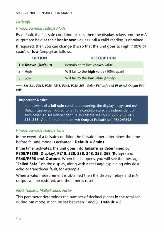
SLUDGEFINDER 2 INSTRUCTION MANUAL
108
Failsafe
P1-808, P2-1808 Failsafe Mode
By default, if a fail-safe condition occurs, then the display, relays and the mA
output are held at their last known values until a valid reading is obtained.
If required, then you can change this so that the unit goes to high (100% of
span), or low (empty) as follows:
OPTION DESCRIPTION
1 = Known (Default) Remain at its last known value
2 = High Will fail to the high value (100% span)
3 = Low Will fail to the low value (empty)
See Also P218, P228, P238, P248, P258, 268 - Relay Fail-safe and P840 mA Output Fail-
safe
P1-809, P2-1809 Failsafe Time
In the event of a failsafe condition the failsafe timer determines the time
before failsafe mode is activated. Default = 2mins
If the timer activates, the unit goes into failsafe, as determined by
P808/P1808 (Display), P218, 228, 238, 248, 258, 268 (Relays) and
P840/P898 (mA Output). When this happens, you will see the message
“Failed Safe!” on the display, along with a message explaining why (lost
echo or transducer fault, for example).
When a valid measurement is obtained then the display, relays and mA
output will be restored, and the timer is reset.
P823 Totaliser Multiplication Factor
This parameter determines the number of decimal places in the totaliser
during run mode. It can be set between 1 and 3. Default = 2
Important Notice
In the event of a fail-safe condition occurring, the display, relays and mA
Output can be configured to fail to a condition which is independent of
each other. To set independent Relay Failsafe see P218, 228, 238, 248,
258, 268. And for independent mA Output Failsafe see P840/P898.

PULSAR MEASUREMENT
109
mA Out 1 / mA Out 2 Parameters
P1-830, P2-1830 mA Range
This parameter determines the range of the mA output, from the following:
OPTION DESCRIPTION
0 = Off mA output disabled
1 = 0 to 20 mA
mA output directly proportional to the mA mode
(P831,891), so if the reading is 0% the output is 0
mA. If the reading is 100% the output is 20 mA.
2 = 4to 20 mA
(Default)
mA output directly proportional to the mA mode
(P831,891), so if the reading is 0% the output is 4
mA. If the reading is 100% the output is 20 mA.
3 = 20 to 0 mA
mA output inversely proportional to the mA mode
(P831,891), so if the reading is 0% the output is 20
mA. If the reading is 100% the output is 0 mA.
4 = 20 to 4 mA
mA output inversely proportional to the mA mode
(P831,891), so if the reading is 0% the output is 20
mA. If the reading is 100% the output is 4 mA.
P1-831, P2-1891 mA Mode
This parameter determines how the mA Output relates to what is measured.
By default, it operates the same as the display (P100/P1100), but it can be
set to operate as follows:
OPTION DESCRIPTION
0 = Default mA output relative to Mode P100/P1100
1 = Distance mA output relative to Distance.
2 = Level mA output relative to Level.
3 = Space mA output is relative to Space.
4* = Average Level mA output is relative to the Average level.
5* = Differential mA output is relative to Differential level

SLUDGEFINDER 2 INSTRUCTION MANUAL
110
Setpoint
By default, the mA Output will represent the empty (0 or 4mA dependant
on (P830/P890) mA Range) and 100% of the operational span (20mA), but
you may wish to have the output represent a section of the operational
span. For example, the application has an operational span of 6 metres, but
output is to represent empty (0 or 4mA dependant on (P830/P890) mA
Range) to a level of 5 metres (20mA). If so P834 (Low Level) should be set
to 0.00 metres and P835 (High Level) should be set to 5 metres.
P1-834, P2-892 mA Low Level
This parameter sets the level, distance, or space, depending on the selected
mA Out Mode (P831/891) at which the low mA output will occur (0 or 4mA
dependant on (P830/890) mA Range). Default = 0.000m
P1-835, P2-893 mA High Level
This parameter sets the level, distance or space, depending on the selected
mA Out Mode (P831/891) at which the high mA output will occur (20mA).
Default = 6.00m
P1-836, P2-894 mA Low Limit
This parameter sets the lowest level that the mA output will drop to, the
default is 0mA, but you can override this if the device you connect to cannot
for example accept less than 2mA, yet you want to use the 0-20mA range.
Default = 0.00mA
P1-837, P2-895 mA High Limit
This parameter sets the highest level that the mA output will rise to, the
default is 20 mA, but you can override this if the device you connect to
cannot for example accept more than 18 mA, yet you want to use the 0-20
mA range. Default = 20.00mA
1-P838, P2-896 mA Low Trim
If the device you are connected to is not calibrated, and not showing the
correct low value (reading), then you can trim it using this parameter. You
can either type in the offset directly or use the arrow keys to move the
output up and down until you get the expected result (reading) on the
device that is connected.
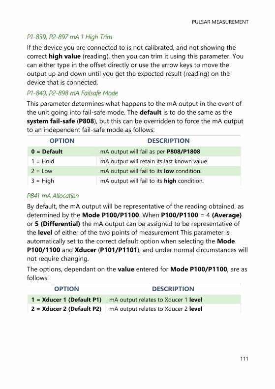
PULSAR MEASUREMENT
111
P1-839, P2-897 mA 1 High Trim
If the device you are connected to is not calibrated, and not showing the
correct high value (reading), then you can trim it using this parameter. You
can either type in the offset directly or use the arrow keys to move the
output up and down until you get the expected result (reading) on the
device that is connected.
P1-840, P2-898 mA Failsafe Mode
This parameter determines what happens to the mA output in the event of
the unit going into fail-safe mode. The default is to do the same as the
system fail-safe (P808), but this can be overridden to force the mA output
to an independent fail-safe mode as follows:
OPTION DESCRIPTION
0 = Default mA output will fail as per P808/P1808
1 = Hold mA output will retain its last known value.
2 = Low mA output will fail to its low condition.
3 = High mA output will fail to its high condition.
P841 mA Allocation
By default, the mA output will be representative of the reading obtained, as
determined by the Mode P100/P1100. When P100/P1100 = 4 (Average)
or 5 (Differential) the mA output can be assigned to be representative of
the level of either of the two points of measurement This parameter is
automatically set to the correct default option when selecting the Mode
P100/1100 and Xducer (P101/P1101), and under normal circumstances will
not require changing.
The options, dependant on the value entered for Mode P100/P1100, are as
follows:
OPTION DESCRIPTION
1 = Xducer 1 (Default P1) mA output relates to Xducer 1 level
2 = Xducer 2 (Default P2) mA output relates to Xducer 2 level

SLUDGEFINDER 2 INSTRUCTION MANUAL
112
Compensation Parameters
Offset
P1-851, P2-851 Measurement Offset
The value of this parameter is added to the measured distance, in
Measurement Units (P104).
This Offset will be added to the level, as derived from the transducer, and
will affect everything including the reading on the display, the relay
setpoints and the mA output.
Temperature
P1-852, P2-1851 Temperature Source
This parameter determines the source of the temperature measurement. By
default, it is set to automatic (P852/P1852=1), which will automatically
detect if a temperature sensor is available from the transducer. If for any
reason, no temperature input is received, then the Fixed Temp value is used,
as set by P854/P1854.
The temperature source can be specifically set as follows:
OPTION DESCRIPTION
1 = Automatic (Default) Will automatically select transducer temperature
sensor, if available, or fixed temperature (P854) if no
temperature sensor found.
2 = Xducer 1 Always uses temperature reading from transducer 1.
3 = Xducer 2 Always uses temperature reading from transducer 2.
4 = Fixed Always uses fixed temperature (P854/P1854)
P1-P854, P2-P1854 Fixed Temperature
This parameter sets the temperature, in degrees Celsius, to be used if
P852/P1852 (Temperature Source) =3. Default = 20oC
P1-P860, P2-P1860 Sound Velocity
This parameter allows for the velocity of sound to be changed according to
the atmosphere the transducer is operating in. By default, the velocity is set
for sound travelling in air/water at an ambient temperature of 20 degrees
centigrade. Default = 342.72m/s (velocity in air for dB transducer)
Default = 1482.32m/s (velocity in water for VT transducer)

PULSAR MEASUREMENT
113
Stability Parameters
Point 1 / Point 2
Damping
Damping is used to damp the display, to enable it to keep up with the
process but ignore minor surface fluctuations.
P1-870, P1870 Fill Damping
This parameter determines the maximum rate at which the unit will
respond to an increase in level. It should be set slightly higher than the
maximum vessel fill rate. Default = 10m/min.
P1-871, P2-1871 Empty Damping
This parameter determines the maximum rate at which the unit will
respond to a decrease in level. It should be set slightly higher than the
maximum vessel empty rate. Default = 10m/min.
Filters
The following three parameters can be used to filter out unwanted changes
of level caused by a ‘rippled’ or agitated surface.
P1-881, P2-1881 Fixed Distance
This parameter determines the width of gate to be used in tracking an echo
and under normal circumstances will not require changing, but it can be
increased in the cases where the surface is moving extremely fast (in excess
of 10m/min) to ensure smooth processing of the changing level.
P1-882, P2-1882 Process Filter (dB Transducers)
This parameter determines the number of ‘cycles’ that will be taken before a
change in level is processed and the display updated.
OPTION DESCRIPTION
1 = Fast level will be updated every cycle
2 = Medium level will be updated every 8 cycles
3 = Slow (Default) level will be updated every 16 cycles

SLUDGEFINDER 2 INSTRUCTION MANUAL
114
P1-883, P2-1883 Gate Expand
This parameter determines the size of the increment by which the gate
expands per cycle when an echo is detected outside of the gate.
Default = 0.1m
Echo Processing Parameters
Point 1 / Point 2
Transducer 1 Status
P1-900, P2-910 Transducer Status
This parameter shows the current state of the transducer. The value means
the following:
OPTION DESCRIPTION
0= OK Transducer working correctly.
1= Disabled Transducer is not being used (mA input is being
used instead, so P101=1)
2= Stuck High
Indicates that the power and signal lines on the
transducer terminals are crossed over, or the signal
line is shorted to earth.
3= Not Found No transducer is detected.
P1-901, P2-911 Echo Confidence 1/2
This parameter displays the most recent echo confidence from the
transducer. It is useful to help find the best mounting location for the
transducer, where you should aim to get the highest figure. It is a
percentage of confidence that the echo reporting the level is the correct
one.
P1-902, P2-912 Echo Strength 1/2
This parameter displays the most recent echo strength figure for the
transducer, where a higher figure indicates a better returned echo.
P1-903, P2-913 Average Noise 1/2
This is the mean noise reading for the transducer. It is measured while the
transducer is not firing and gives an indication of the average amount of
electrical noise present on the cabling.

PULSAR MEASUREMENT
115
P1-904, P2-914 Peak Noise 1/2
This is the peak noise reading for the transducer. It is measured while the
transducer is not firing and gives an indication of the maximum amount of
electrical noise present on the cabling.
P1-905, P2-915 Sensitivity (dB Transducers only)
This parameter determines the sensitivity of the unit. Please consult Pulsar
for further information and assistance on changing the value of this
parameter.
P1-906, P2-916 Side Clearance (dB Transducers only)
This parameter is used to set the distance by which the DATEM trace will
“stand-off” from around unwanted echoes such as obstructions. Please
consult Pulsar for further information and assistance on changing the value
of this parameter. Default 5dB (50mV)
Transducer 2 Status
When Ultra Wizard = 1 Level/Volume or 2 Pump/Differential
P910 - 916 Transducer 2
These parameters contain the same information as detailed in Transducer 1
Status, for Transducer 2.

SLUDGEFINDER 2 INSTRUCTION MANUAL
116
System Parameters
Passcode
P921 Enable Code
Enables the passcode (P922), which means the passcode must be entered
to go into program mode. If disabled (set to 0), then no passcode is
required, and ENTER is used to enter program mode. Default =1 (Enabled)
P922 Passcode
This is the passcode that must be used to enter program mode. The default
is 1997, but this can be changed to another value from 0 to 9999.
Backup
P925 Parameter Backup & Restore
This parameter is used to make a backup of all parameters, for example to
ensure a default set is maintained within the unit. If alterations are made to
the parameters that do not work as intended, then the backup set can be
restored into the unit.
You can make two separate backup copies if you wish, called backup 1 and
backup 2, and restore from either. The options are:
OPTION DESCRIPTION
1= Backup 1 Make backup to area 1 of all parameters
2= Backup 2 Make backup to area 2 of all parameters
3= Restore 1 Restore all parameters from area 1
4= Restore 2 Restore all parameters from area 2

PULSAR MEASUREMENT
117
System Information
The following three parameters do not affect how the unit performs, but
details, contained in them, may be required, by Pulsar, when making technical
enquiries.
P926 Software Revision
This parameter will display the current software revision. It is read only and
cannot be changed.
P927 Hardware Revision
This parameter will display the current hardware revision. It is read only and
cannot be changed.
P928 Serial Number
This parameter will display the serial number of the unit. It is read only and
cannot be changed.
P929 Site Identification
This parameter allows you to give each unit an individual reference number,
for identification purposes. You can set any number between 1 and 99999.
P930 Factory Defaults
This parameter resets all parameter values to the original Factory Set values
that were installed when the unit was tested before despatch to you.
To reset parameters, enter 1 (Yes), and press ENTER, then you will see a
message “Entr if sure”, you should press ENTER again. If you press any other
key at this point, the parameters will not be reset, and you will see a
message confirming this.
Once you have done this, program the unit, to the desired application.
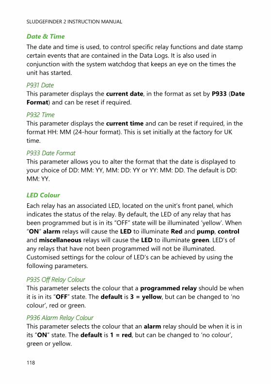
SLUDGEFINDER 2 INSTRUCTION MANUAL
118
Date & Time
The date and time is used, to control specific relay functions and date stamp
certain events that are contained in the Data Logs. It is also used in
conjunction with the system watchdog that keeps an eye on the times the
unit has started.
P931 Date
This parameter displays the current date, in the format as set by P933 (Date
Format) and can be reset if required.
P932 Time
This parameter displays the current time and can be reset if required, in the
format HH: MM (24-hour format). This is set initially at the factory for UK
time.
P933 Date Format
This parameter allows you to alter the format that the date is displayed to
your choice of DD: MM: YY, MM: DD: YY or YY: MM: DD. The default is DD:
MM: YY.
LED Colour
Each relay has an associated LED, located on the unit’s front panel, which
indicates the status of the relay. By default, the LED of any relay that has
been programmed but is in its “OFF” state will be illuminated ‘yellow’. When
“ON” alarm relays will cause the LED to illuminate Red and pump, control
and miscellaneous relays will cause the LED to illuminate green. LED’s of
any relays that have not been programmed will not be illuminated.
Customised settings for the colour of LED’s can be achieved by using the
following parameters.
P935 Off Relay Colour
This parameter selects the colour that a programmed relay should be when
it is in its “OFF” state. The default is 3 = yellow, but can be changed to ‘no
colour’, red or green.
P936 Alarm Relay Colour
This parameter selects the colour that an alarm relay should be when it is in
its “ON” state. The default is 1 = red, but can be changed to ‘no colour’,
green or yellow.

PULSAR MEASUREMENT
119
P937 Pump Relay Colour
This parameter selects the colour that a pump relay should be when it is in
its “ON” state. The default is 2 = green, but can be changed to ‘no colour’,
red or yellow.
P938 Control Relay Colour
This parameter selects the colour that a control relay should be when it is in
its “ON” state. The default is 2 = green, but can be changed to ‘no colour’,
red or yellow.
P939 Miscellaneous Relay Colour
This parameter selects the colour that a miscellaneous relay should be
when it is in its “ON” state. The default is 2 = green, but can be changed to
‘no colour’, red or yellow.
All relays that are not programmed will show, ‘no colour’, i.e. they are off.
Watchdog
You can check how many times the unit has been switched on, and look at
the date and time of the last ten starts. This can be useful if there have been
power failures or if for any reason the Sludge Finder 2 restarts due to a fault
condition. The Sludge Finder 2 can be backed up from a battery which
automatically cuts in during power failure. Battery backed up units will
continue uninterrupted operation and therefore will not register a loss of
mains power. If, however, the battery was to fail during a mains power
interruption, a start up would be recorded once power has been restored.
P940 Number of Starts
This parameter shows how many times the unit has been powered up.
P941-P960 Start Date & Time
Parameters P941 and P942 show the date and time that the unit was last
started. There are ten start dates & times recorded, which are parameters
P943-P960. The first on the list are the most recent, and the last ones are
the oldest. These are read only and cannot be changed.

SLUDGEFINDER 2 INSTRUCTION MANUAL
120
Daylight Saving Time
P970 DST Enable
When Enabled (set to 1) the internal clock will be automatically adjusted to
compensate for the difference between standard time and Daylight-Saving
Time. Default = 1 (Yes)
P971 DST Difference
This parameter sets the time difference between standard time and
Daylight-Saving Time. The time difference is entered in HH:MM.
Default = 01:00
P972 DST Start Time
This parameter is used to set the time of day at which Daylight-Saving
Time will start, the time is entered in the format HH: MM (24-hour format).
Default = 02:00
Important Notice
To ensure the correct operation of Daylight-Saving Time P932 Time
should be checked, and adjusted if necessary, to ensure that it is set for
the current valid time.

PULSAR MEASUREMENT
121
P973 Start Day
Use this parameter to enter the day of the week (P974) that Daylight
Saving Time is to start.
OPTION DESCRIPTION
2= Monday DST will start on a Monday
3= Tuesday DST will start on a Tuesday
4= Wednesday DST will start on a Wednesday
5= Thursday DST will start on a Thursday
6= Friday DST will start on a Friday
7= Saturday DST will start on a Saturday
8= Sunday (Default) DST will start on a Sunday
P974 Start Week
This parameter will determine the week of the month (P975) in which
Daylight-Saving Time is to start.
OPTION DESCRIPTION
1= Week 1 DST will start on day (P973) in the first week
(P974) of the month (P975).
2= Week 2 DST will start on day (P973) in the second week
(P974) of the month (P975).
3= Week 3 DST will start on day (P973) in the third week
(P974) of the month (P975).
4= Week 4 DST will start on day (P973) in the fourth week
(P974) of the month (P975).
5= Last (Default) DST will start on day (P973) in the last week
(P974) of the month (P975).
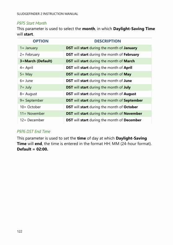
SLUDGEFINDER 2 INSTRUCTION MANUAL
122
P975 Start Month
This parameter is used to select the month, in which Daylight-Saving Time
will start.
OPTION DESCRIPTION
1= January DST will start during the month of January
2= February DST will start during the month of February
3=March (Default) DST will start during the month of March
4= April DST will start during the month of April
5= May DST will start during the month of May
6= June DST will start during the month of June
7= July DST will start during the month of July
8= August DST will start during the month of August
9= September DST will start during the month of September
10= October DST will start during the month of October
11= November DST will start during the month of November
12= December DST will start during the month of December
P976 DST End Time
This parameter is used to set the time of day at which Daylight-Saving
Time will end, the time is entered in the format HH: MM (24-hour format).
Default = 02:00.
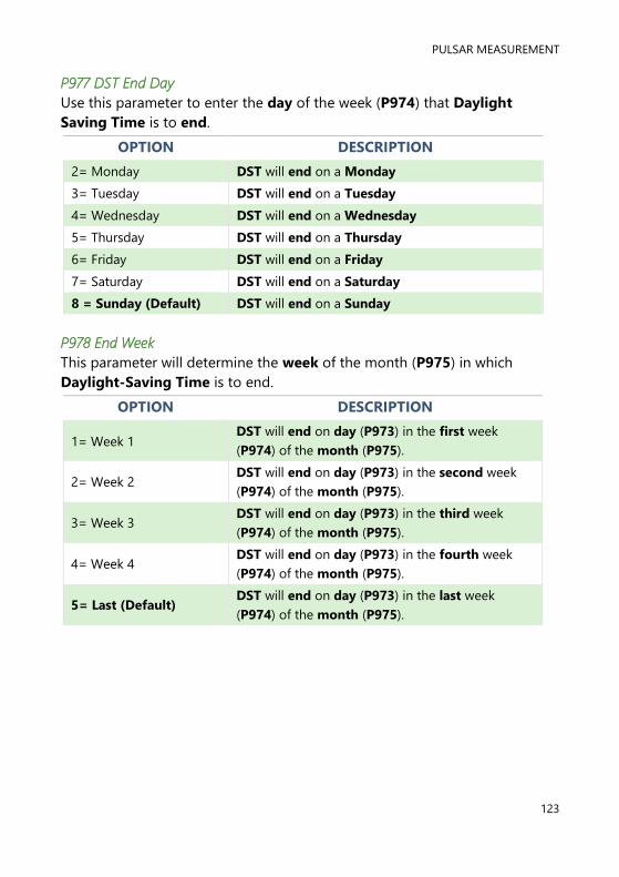
PULSAR MEASUREMENT
123
P977 DST End Day
Use this parameter to enter the day of the week (P974) that Daylight
Saving Time is to end.
OPTION DESCRIPTION
2= Monday DST will end on a Monday
3= Tuesday DST will end on a Tuesday
4= Wednesday DST will end on a Wednesday
5= Thursday DST will end on a Thursday
6= Friday DST will end on a Friday
7= Saturday DST will end on a Saturday
8 = Sunday (Default) DST will end on a Sunday
P978 End Week
This parameter will determine the week of the month (P975) in which
Daylight-Saving Time is to end.
OPTION DESCRIPTION
1= Week 1 DST will end on day (P973) in the first week
(P974) of the month (P975).
2= Week 2 DST will end on day (P973) in the second week
(P974) of the month (P975).
3= Week 3 DST will end on day (P973) in the third week
(P974) of the month (P975).
4= Week 4 DST will end on day (P973) in the fourth week
(P974) of the month (P975).
5= Last (Default) DST will end on day (P973) in the last week
(P974) of the month (P975).

SLUDGEFINDER 2 INSTRUCTION MANUAL
124
P979 End Month
This parameter is used to select the month, in which Daylight-Saving Time
will end.
OPTION DESCRIPTION
1= January DST will end during the month of January
2= February DST will end during the month of February
3=March DST will end during the month of March
4= April DST will end during the month of April
5= May DST will end during the month of May
6= June DST will end during the month of June
7= July DST will end during the month of July
8= August DST will end during the month of August
9= September DST will end during the month of September
10= October (Default) DST will end during the month of October
11= November DST will end during the month of November
12= December DST will end during the month of December
Device Comm.
RS232 Set Up
P061 Comms Baud
This parameter is used to set the speed (Baud Rate) of the RS232
communications and can be changed to suit the connecting device.
Default = 19200
RS 485 Set Up
Please refer to the RS485 communications manual for availability of
parameters and details of their options. This can be found in the downloads
section of the Pulsar website:
https://pulsarmeasurement.com/downloads/instruction-manuals/

PULSAR MEASUREMENT
125
Test Parameters
Simulation
P980 Simulate
Test mode is used to simulate the application and confirm that all
parameters and relay setpoints have been entered as expected. During
simulation, there is a choice of whether the relays will change state (hard
simulation) or not (soft simulation), but the LED’s will always change colour
as programmed, and the current output will change. If you want to test the
logic of the system that the relays are connected to then select a hard
simulation, but if you do not want to change the relay state, then select a
soft simulation.
There are two simulation modes, automatic and manual. Automatic
simulation will move the level up and down between empty level or the pre-
determined Start Level (P983) and Pump/Control relay switch points, if you
wish to change the direction of the level movement e.g. to go beyond relay
setpoints, this can be done by using the arrow keys. In manual simulation,
using the arrow keys will allow you to move the level up and down as
required.
The choices for you to enter are as follows.
1= Manual soft simulation
2= Automatic soft simulation
3= Manual hard simulation
4= Automatic hard simulation
Whilst in Automatic hard simulation (P980 = 4) the switching of digital
inputs can be simulated by pressing the corresponding numeric key to the
input to be switched, each time the numeric key is pressed it will toggle the
input between On and Off.
To return to program mode, press ‘CANCEL’ and test mode will end.
P981 Increment
By default, simulation mode will move by 0.1m steps in manual simulation
and by 0.1m/min in automatic simulation. Altering the increment can
change this value.

SLUDGEFINDER 2 INSTRUCTION MANUAL
126
P982 Rate
In automatic mode, the rate at which the level will move up and down, is
determined by distance, P981 Increment and the time, P982 Rate which by
default is set to 1min and can be changed as required. To increase the rate
at which the level moves increase the Increment (P981) or decrease the
Rate (P982). To decrease the rate at which the level moves decrease the
Increment (P981) or increase the Rate (P982).
P983 Start Level
When using automatic simulation this parameter can be used to pre-
determine the point at which the simulated level will start at and return to.
This can be used to simulate the lowest point to which the level would
normally operate.
Hardware
P990 Self Test
If you enter 1 for this parameter, then the unit will perform a self-test. This
will confirm that the various parts of the circuitry are working correctly. You
will see confirmation messages that the clock and the EEPROM are working
correctly, and error messages for any parts that fail.

PULSAR MEASUREMENT
127
P991 Hard Test
When this parameter is selected, the unit will test the following in turn.
• LED’s. Watch them change colour as shown on the display, and
press, ENTER, if they operated as shown.
• Relays. Press a numeric key corresponding to the number of the
relay you wish to test, and the relay will change state each time the
key is pressed. If you press any other key, other than a valid relay
number, then the test will end.
• Segments. All the segments on the LCD are lit up, so you can see if
they all work. Press, ENTER, to end the test. The LED’s all go green at
the same time.
• Keys. You should press each key, to confirm it works, with a counter
showing how many more keys you have to press. Be sure to press
the CANCEL key last, as this will show if all keys were pressed or not.
If they were not, then an error message is displayed.
P992/P993 mA Out 1/2 Test
This parameter will allow you to force a specified current on the mA output,
to test the equipment that it is connected to, and to make sure the unit is
working correctly. The figure you enter will be generated by the mA output.
P995/P996 Transducer 1/2 Test
If you enter 1 for this parameter it will continually fire the transducer, so you
can check the wiring, until you press any key to cancel.
P997 Keys Test
You should press each key, to confirm it works, with a counter showing how
many more keys you have to press. Press the CANCEL key last, as this will
confirm if all keys were pressed or not. If they were not, then an error
message is displayed.
P998 Relay Test
Press a numeric key corresponding to the number of the relay you wish to
test, and the relay will change state each time the key is pressed. If you press
any other key, other than a valid relay number, then the test will end.
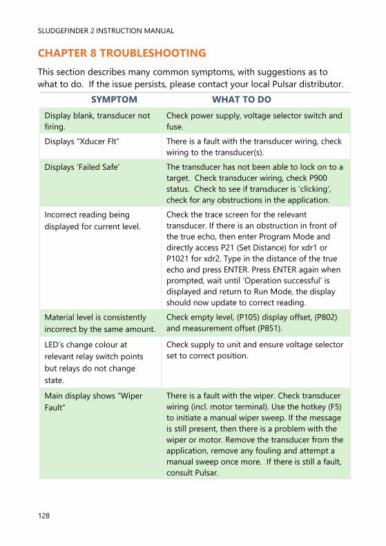
SLUDGEFINDER 2 INSTRUCTION MANUAL
128
CHAPTER 8 TROUBLESHOOTING
This section describes many common symptoms, with suggestions as to
what to do. If the issue persists, please contact your local Pulsar distributor.
SYMPTOM WHAT TO DO
Display blank, transducer not
firing.
Check power supply, voltage selector switch and
fuse.
Displays “Xducer Flt” There is a fault with the transducer wiring, check
wiring to the transducer(s).
Displays ‘Failed Safe’ The transducer has not been able to lock on to a
target. Check transducer wiring, check P900
status. Check to see if transducer is ‘clicking’,
check for any obstructions in the application.
Incorrect reading being
displayed for current level.
Check the trace screen for the relevant
transducer. If there is an obstruction in front of
the true echo, then enter Program Mode and
directly access P21 (Set Distance) for xdr1 or
P1021 for xdr2. Type in the distance of the true
echo and press ENTER. Press ENTER again when
prompted, wait until ‘Operation successful’ is
displayed and return to Run Mode, the display
should now update to correct reading.
Material level is consistently
incorrect by the same amount.
Check empty level, (P105) display offset, (P802)
and measurement offset (P851).
LED’s change colour at
relevant relay switch points
but relays do not change
state.
Check supply to unit and ensure voltage selector
set to correct position.
Main display shows “Wiper
Fault”
There is a fault with the wiper. Check transducer
wiring (incl. motor terminal). Use the hotkey (F5)
to initiate a manual wiper sweep. If the message
is still present, then there is a problem with the
wiper or motor. Remove the transducer from the
application, remove any fouling and attempt a
manual sweep once more. If there is still a fault,
consult Pulsar.

PULSAR MEASUREMENT
129
CHAPTER 9 DISPOSAL
Incorrect disposal can cause adverse effects to the environment.
Dispose of the device components and packaging material in accordance
with regional environmental regulations including regulations for electrical \
electronic products.
Transducers
Remove power, disconnect the Transducer, cut off the electrical cable and
dispose of cable and Transducer in accordance with regional environmental
regulations for electrical \ electronic products.
Controllers
Remove power, disconnect the Controller, and remove battery (if fitted).
Dispose of Controller in accordance with regional environmental regulations
for electrical \ electronic products.
Dispose of batteries in accordance with regional environmental regulations
for batteries.
EU WEEE Directive Logo
This symbol indicates the requirements of Directive 2012/19/EU regarding
the treatment and disposal of waste from electric and electronic equipment.

SLUDGEFINDER 2 INSTRUCTION MANUAL
130
NOTES

PULSAR MEASUREMENT
131
www.pulsarmeasurement.com
S U P P O R T @ P U L S A R M E A S U R E M E N T . C O M
Copyright © 2020 Pulsar Measurement Ltd.
Registered Address: 1 Chamberlain Square CS, Birmingham B3 3AX
Registered No.: 3345604 England & Wales
Rev 1.0