posco-sludge-presentation.pdf - CSU, Chico
29
Sl d H dli At ti Sl d H dli At ti Sludge Handling Automation Sludge Handling Automation MECH/MECA 440 B– Senior Project Spring 2010 Final Design Presentation Tuesday, May 11 th , 2010
-
Upload
khangminh22 -
Category
Documents
-
view
1 -
download
0
Transcript of posco-sludge-presentation.pdf - CSU, Chico

Sl d H dli A t tiSl d H dli A t tiSludge Handling AutomationSludge Handling Automation
MECH/MECA 440 B– Senior ProjectSpring 2010
Final Design Presentation
Tuesday, May 11th, 2010y, y ,

Design Team MembersDesign Team MembersMechatronicEngineering
MechanicalEngineering
Ahmad Aladdasi Carlos CabreraAhmad Aladdasi Carlos Cabrera
MechatronicEngineering
MechatronicEngineering
Nik TkachenkoKeith Lindauer
Faculty Advisor : Dr. Ramesh Varahamurti

Industry SponsorIndustry Sponsor
USS POSCO INDUSTRIES
“ T d t b i i th t id“…To conduct business in a manner that provides maximum value to our customers, owners, and employees. To be the Safest, Most Competitive Flat Rolled Steel Company”Flat Rolled Steel Company
Project BackgroundProject BackgroundWater Water utilized at the facility is utilized at the facility is treated and treated and ret rned to San Joaq inret rned to San Joaq in ri er/ Ne Yorkri er/ Ne Yorkreturned to San Joaquin returned to San Joaquin river/ New York river/ New York Slough.Slough.
Alum is introduced in the process to meet Alum is introduced in the process to meet state clarity state clarity requirements, creating sludge.requirements, creating sludge.
Sludge is sent to an Oil Separation Unit Sludge is sent to an Oil Separation Unit (OSU)(OSU)(OSU).(OSU).

OSU
Clarifiers

Project BackgroundProject BackgroundProject BackgroundProject Background
S l t V l
Clarifier Valve
Selector Valve
Flush ValveFlush Valve
Pump
Current Pumping System
Project NeedProject Need
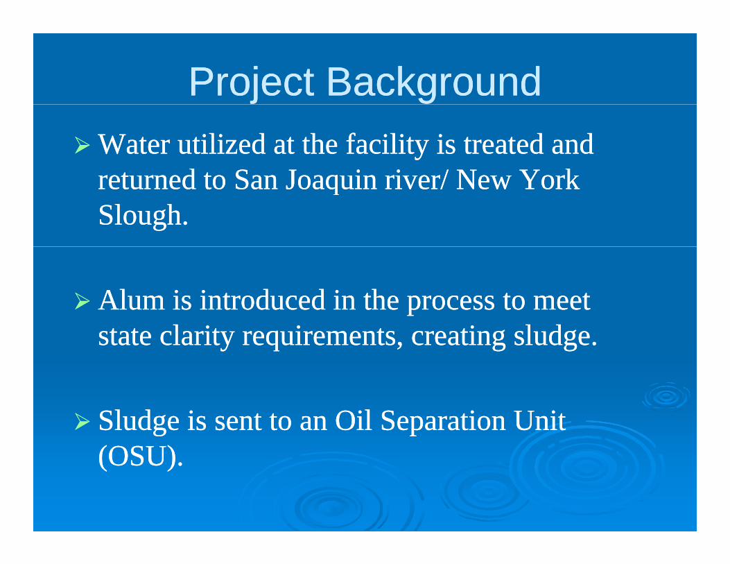
Pump the sludge from thePump the sludge from the clarifiersclarifiers to theto thePump the sludge from the Pump the sludge from the clarifiers clarifiers to the to the Oil Separation Unit without human assistanceOil Separation Unit without human assistance
Clarifiers OSU

Goal StatementGoal Statement
A t t th i ti d t thA t t th i ti d t thAutomate the existing procedure to pump the Automate the existing procedure to pump the correct consistency of sludge from the correct consistency of sludge from the Cl ifi t th Oil S ti U it (OSU)Cl ifi t th Oil S ti U it (OSU)Clarifiers to the Oil Separation Unit (OSU). Clarifiers to the Oil Separation Unit (OSU).
Pneumatic Actuator PLC
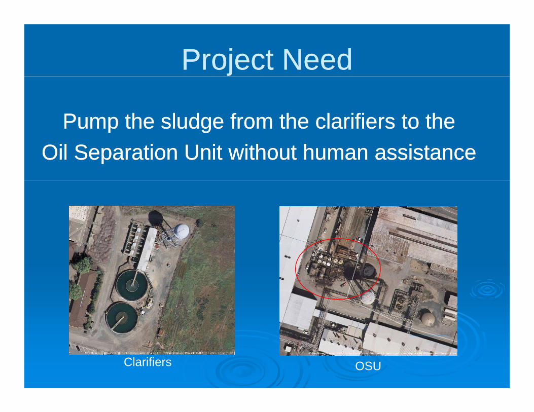
Customer RequirementsCustomer RequirementsCustomer RequirementsCustomer Requirements• The Design Solution Must :
• Automate the sludge pumping system• Automate the sludge pumping system• Switch between clarifiers• Utilize Emergency Switch• Back flushBack flush
• The Design Solution Should :•Human Machine Interface
• Would be Nice : Would be Nice :• Positive displacement pump analysis

Engineering Specifications & Engineering Specifications & TargetsTargets
Requirements Specification Metric Method/Device Target Range Conditions
Pump Sludge Flow Rate GPM Flow meter50 ± 10 GPM Minimum
100 ± 10 GPM Maximum
Regulate Sludge% Solids in Water
SolutionPPM Turbidity Meter
20% ± 5% solids Minimum
60% ± 5% solids Maximum
Pressure in Pipes Pressure PSI Pressure Gauge < 150 PSI Maximum

Design SolutionDesign Solution
PLC
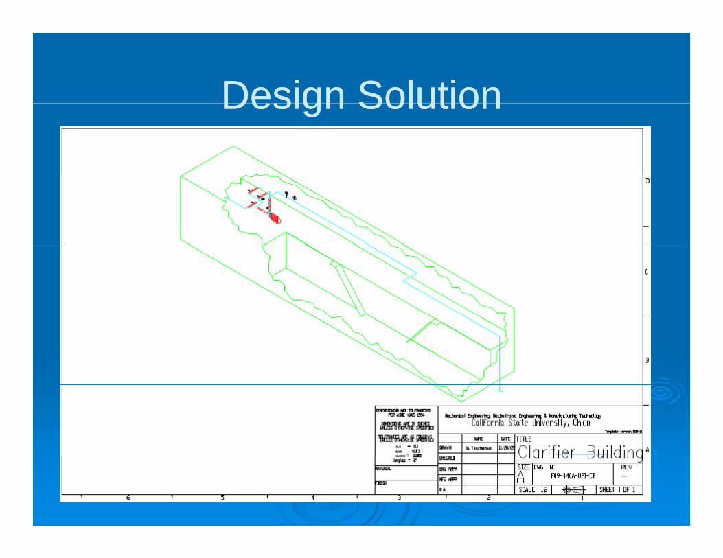
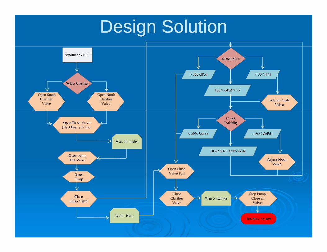
Design SolutionDesign SolutionDesign SolutionDesign Solution

Design SolutionDesign SolutionDesign SolutionDesign Solution

Design SolutionDesign SolutionDesign SolutionDesign Solution

Design SolutionDesign SolutionNusonics Flow meter
PLC Interface With the System
Series 90 G.E ProgrammableLogic Controller
115 VACPower Supply
Optical TurbidityMeter
Centrifugal PumpRugged Pressure
Sensor
Electro-MechanicalActuator

Design SolutionDesign SolutionDesign SolutionDesign Solution
PLC PLC Genius Blocks
Design SolutionDesign Solution
Open South Clarifier Valve
Open North Clarifier Valve
Open Flush Valve FullValve Full
Close Clarifier Valve
Stop Pump, Close all Valves

Design SolutionDesign Solution
Close Flush Valve
Close Clarifier Valve
Stop Pump, Close all Valves

Design SolutionDesign Solution
Stop Pump, Close all V lValves

Fabrication ChangesFabrication ChangesFabrication ChangesFabrication Changes
Design ChangesDesign ChangesDesign ChangesDesign ChangesActuators Actuators –– Now PneumaticNow PneumaticValvesValves Now ButterflyNow ButterflyValves Valves –– Now ButterflyNow ButterflyPump Pump –– Only 1 RequiredOnly 1 Required
Si l ti f T bidit M tSi l ti f T bidit M tSimulation of Turbidity MeterSimulation of Turbidity Meter
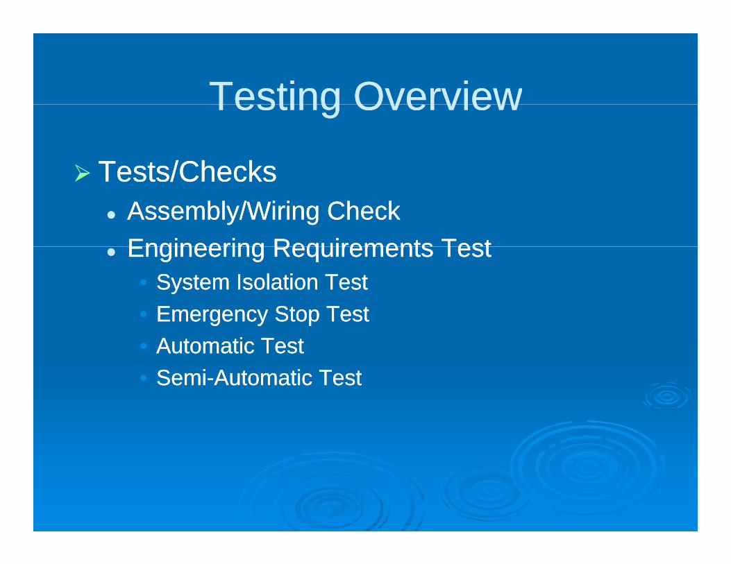
Testing OverviewTesting OverviewTesting OverviewTesting Overview
Tests/ChecksTests/ChecksTests/ChecksTests/ChecksAssembly/Wiring CheckAssembly/Wiring CheckEngineering Requirements TestEngineering Requirements TestEngineering Requirements TestEngineering Requirements Test
•• System Isolation TestSystem Isolation Test•• Emergency Stop TestEmergency Stop TestEmergency Stop TestEmergency Stop Test•• Automatic TestAutomatic Test•• SemiSemi--Automatic TestAutomatic Test

Test ResultsTest ResultsTest ResultsTest Results
Assembly/WiringAssembly/WiringAssembly/WiringAssembly/WiringPASSPASS
System IsolationSystem IsolationSystem IsolationSystem IsolationPASSPASS
Emergency StopEmergency StopPASSPASS

Test ResultsTest ResultsTest ResultsTest Results
Requirements Specification Metric Method/DeviceTest Results(Automatic)
Test Results (Semi-
Automatic)Conditions
18 G 16 G Mi i
Target RangePump Sludge Flow Rate GPM Flow meter
18 GPM 16 GPM Minimum65 GPM 49 GPM Maximum
Regulate Sludge% Solids in
Water SolutionPPM Turbidity Meter
N/A N/A Minimum
N/A N/A Maximum
Pressure in Pipes Pressure PSI Pressure Gauge 60 PSI 53 PSI Maximum

Discussion of ResultsDiscussion of ResultsDiscussion of ResultsDiscussion of Results
Requirements Specification MetricMethod/Device
Target RangeTest Results(Automatic)
Test Results (Semi-
Automatic)Conditions
Fl 50 10 GPM 18 G 16 G Mi iPump Sludge Flow Rate GPM
Flow meter
50 ± 10 GPM 18 GPM 16 GPM Minimum100 ± 10 GPM 65 GPM 49 GPM Maximum
Regulate Sludge
% Solids in Water Solution
PPMTurbidity Meter
20% ± 5% solids N/A N/A Minimum
60% ± 5% solids N/A N/A MaximumPressure in
PipesPressure PSI
Pressure Gauge
< 150 PSI 60 PSI 53 PSI Maximum

BudgetBudgetUnit Price Quantity
Final Unit Price Quantity
Price
Centrifugal Pumps $1,125 2 $2,500
4” - #150 Pipe $5/ft 100 $500
Available to Use, (Already
Purchased Parts)
G.E. PLC + 2 Blocks $5,000 1 $5,000
2” Actuated butterfly flow screw $2301 1 $2,301
4” pneumatic Actuated Butterfly valve $2301 3 $6,903
2” Gate valve $1000 2 $2,000
4” WCB check Gate $500 3 $1,5004 WCB check Gate $ $ ,
Nusonics inc. Flow meter $10,000 1 $10,000
4” Butterfly gate valve $500 2 $1000
4” Garloc expansion joints $550 1 $550
Parts Needed Viatran 548 Pressure Gauge $200 1 $200
Turbidity Meter and Assembly $8,000 1 $8,000
Labor
DesignMech. Eng. $ 34.97/hour 100 $ 3,497
Design Meca. Eng. $ 36.8/hour 400 $ 14,720
Manufacturing $ 50/hour 25 $1,250
Overhead @ 40% per labor hour $8,980
Benefits @ 37% per labor hour $8,307
Total Cost = $77,208
Parts on Hand = $32,254Donated Labor + Expenses = $21,200 + 17,287 = $36,754
Final Cost = $77,208 – $69,008 = $ 8,200

Additional ContentAdditional ContentAdditional ContentAdditional Content
Unique problems encounteredUnique problems encounteredUnique problems encounteredUnique problems encounteredTurbidity Meter(Shipping Times)Turbidity Meter(Shipping Times)
•• Simulate using current supplySimulate using current supply•• Simulate using current supplySimulate using current supply
Suggestions for the futureSuggestions for the futureChange injection valve to variable positionChange injection valve to variable positionChange injection valve to variable positionChange injection valve to variable position
Revise SpecificationsRevise SpecificationsRefine % Solids once turbidity meter is Refine % Solids once turbidity meter is installedinstalled

ConclusionConclusionConclusionConclusion
All the design specifications are metAll the design specifications are metAll the design specifications are metAll the design specifications are met

AcknowledgementsAcknowledgements
USSUSS--PoscoPoscoUSSUSS PoscoPoscoFrank Frank MartucciMartucciMike AtwoodMike AtwoodMike AtwoodMike AtwoodNatalie Natalie TkachenkoTkachenkoTodd McHughTodd McHughTodd McHughTodd McHughRon HatchelRon Hatchel

QUESTIONS ?QUESTIONS ?QUESTIONS ?QUESTIONS ?
OSU
Clarifiers