Installation Manual NETWORK FISH FINDER Model DFF3-UHD
16
www.furuno.com All brand and product names are trademarks, registered trademarks or service marks of their respective holders. Installation Manual NETWORK FISH FINDER Model DFF3-UHD A Word to the Owner of the DFF3-UHD Congratulations on your choice of the FURUNO DFF3-UHD Network Fish Finder. The DFF3-UHD is a net- work fish finder designed for use with the NavNet TZtouch3 (TZT9F/12F/16F/19F, Ver. 3.01 or higher) and NavNet TZtouch2 (TZT2BB only, Ver.9.01 or higher). Please carefully read and follow the recommended procedures for installation and maintenance. Thank you for considering and purchasing FURUNO. Operational Cautions • A separate power supply is required. Take the power from the ship's mains via the ship's switchboard. • The DFF3-UHD is not turned off when the multi function display is powered off. The DFF3-UHD's standby power is 6.2 W, so turn it off from the ship’s switchboard when it is not in use. • DFF3-UHD does not support the Bottom Discrimination, RezBoost, or ACCU-FISH. • Do not transmit with the transducer out of water, to prevent damage to the transducer. • Use the multi function display to change the program version of the power amp. Contact FURUNO for information on how to upgrade program version. • When using two types of transducers, set them from [Fishfinder]-[Transducer Setup]-[Transducer Setup]- [Type] of the NavNet TZtouch3 and NavNet TZtouch2. Because the equipment has only one TDID port, two TDIDs cannot be read. • The following concern acts as our importer in Europe, as defined in DECISION No 768/2008/EC. - Name: FURUNO EUROPE B.V. - Address: Ridderhaven 19B, 2984 BT Ridderkerk, The Netherlands • The following concern acts as our importer in UK, as defined in SI 2016/1025 as amended SI 2019/470. - Name: FURUNO (UK) LTD. - Address: West Building Penner Road Havant Hampshire PO9 1QY, U.K. Safety Instructions The installer must read the safety instructions before attempting to install the equipment. CAUTION Observe the following compass safe distance to prevent interference to a magnetic compass: Standard compass Steering compass 0.35 m 0.3 m Do not disassemble or modify the equipment. Fire, electrical shock or serious injury can result. Use the proper fuse. Use of a wrong fuse can damage the equipment and may cause fire. WARNING WARNING Warning, Caution Indicates a potentially hazardous situation which, if not avoided, could result in death or serious injury. Indicates a potentially hazardous situation which, if not avoided, could result in minor or moderate injury. CAUTION Prohibitive Action Mandatory Action 12VDC 24VDC 7.5 A 7.5 A
-
Upload
khangminh22 -
Category
Documents
-
view
0 -
download
0
Transcript of Installation Manual NETWORK FISH FINDER Model DFF3-UHD

Installation ManualNETWORK FISH FINDER
Model DFF3-UHD
A Word to the Owner of the DFF3-UHDCongratulations on your choice of the FURUNO DFF3-UHD Network Fish Finder. The DFF3-UHD is a net-work fish finder designed for use with the NavNet TZtouch3 (TZT9F/12F/16F/19F, Ver. 3.01 or higher) and NavNet TZtouch2 (TZT2BB only, Ver.9.01 or higher). Please carefully read and follow the recommended procedures for installation and maintenance. Thank you for considering and purchasing FURUNO.
Operational Cautions• A separate power supply is required. Take the power from the ship's mains via the ship's switchboard.• The DFF3-UHD is not turned off when the multi function display is powered off. The DFF3-UHD's standby
power is 6.2 W, so turn it off from the ship’s switchboard when it is not in use.• DFF3-UHD does not support the Bottom Discrimination, RezBoost, or ACCU-FISH.• Do not transmit with the transducer out of water, to prevent damage to the transducer.• Use the multi function display to change the program version of the power amp. Contact FURUNO for
information on how to upgrade program version.• When using two types of transducers, set them from [Fishfinder]-[Transducer Setup]-[Transducer Setup]-
[Type] of the NavNet TZtouch3 and NavNet TZtouch2. Because the equipment has only one TDID port, two TDIDs cannot be read.
• The following concern acts as our importer in Europe, as defined in DECISION No 768/2008/EC.- Name: FURUNO EUROPE B.V.- Address: Ridderhaven 19B, 2984 BT Ridderkerk, The Netherlands
• The following concern acts as our importer in UK, as defined in SI 2016/1025 as amended SI 2019/470.- Name: FURUNO (UK) LTD.- Address: West Building Penner Road Havant Hampshire PO9 1QY, U.K.
Safety InstructionsThe installer must read the safety instructions before attempting to install the equipment.
CAUTIONObserve the following compass safe distance to prevent interference to a magnetic compass:
Standard compass Steering compass0.35 m 0.3 m
Do not disassemble or modify the equipment.
Fire, electrical shock or serious injury can result.
Use the proper fuse.
Use of a wrong fuse can damage the equipment and may cause fire.
WARNING
WARNING
Warning, Caution
Indicates a potentially hazardous situation which, if not avoided, could result in death or serious injury.
Indicates a potentially hazardous situation which, if not avoided, could result in minor or moderate injury.CAUTION
Prohibitive Action Mandatory Action
12VDC 24VDC7.5 A 7.5 A
www.furuno.comAll brand and product names are trademarks, registered trademarks or service marks of their respective holders.

Equipment List
Option
CE/UKCA DeclarationWith regards to CE/UKCA declarations, please refer to our website (www.furuno.com) for further information about RoHS conformity declarations.
Disclosure of Information about China RoHSWith regards to China RoHS information for our products, please refer to our website (www.furuno.com).
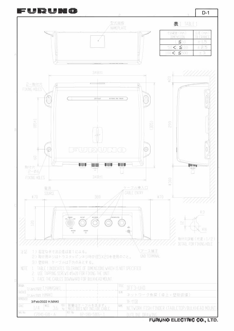
InstallationSelect the mounting location considering the following points.• Locate the unit away from areas subject to water splash.• Select a location that is well ventilated.• Observe the compass safe distances shown on page 1. • Leave the sufficient service clearance around the unit.
Name Type Code No. Qty RemarkNetwork Fish Finder DFF3-UHD - 1Installation Materials CP02-09900 000-038-530 1 - FRU-3P-FF-A002M-001
(Cable assembly, 001-197-092-10)- MOD-Z071-050+ (LAN ca-ble, 001-167-890-10)- CP02-09901 (EMI core and Self-tapping screw, 001-621-550)
Name Type Code No. Qty RemarkExtension Cable C44-02 30M 000-190-455 1 For tank w/transducer
(CM265LH, CM265LM, CM599LH, CM599LM, PM111LH, PM111LM, CM275LH-W)
C44-02 50M 000-190-454 1
C334 30M 000-190-456 1 For thru-hull transducer.LAN Cable MOD-Z072-020+ 000-167-175 1 2 m
MOD-Z072-100+ 000-167-177 1 10 mTransducer PM111LHG 000-027-404 1 2 kW 38-75/130-210 kHz
CM599LHG 000-027-406 1 2 kW 28-60/130-210 kHzThru-Hull Pipe TFB-7000(1) 000-022-532 1AC/DC Power Supply Unit PR-241 - 1Ferrite Core OP86-11 001-594-450 1 For PR-241
2
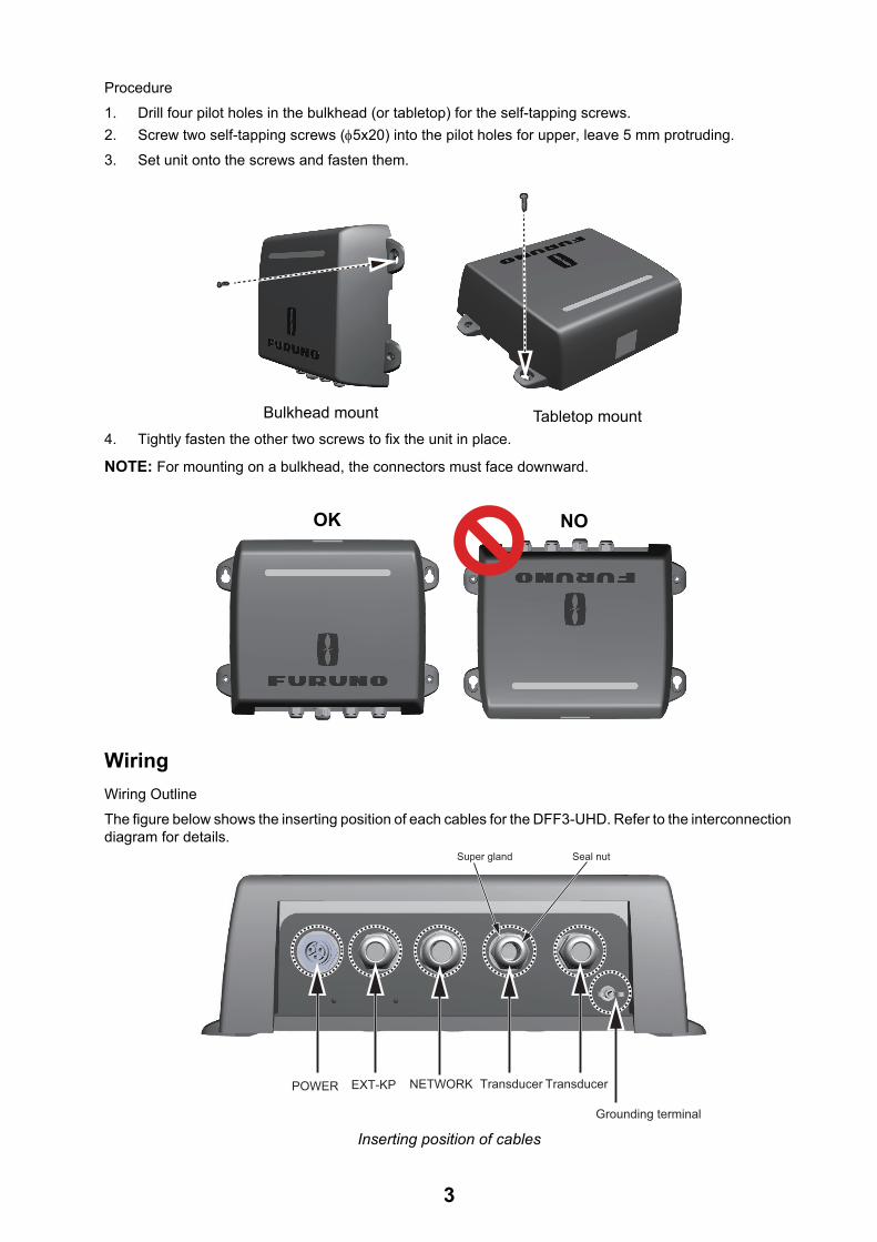
Procedure1. Drill four pilot holes in the bulkhead (or tabletop) for the self-tapping screws.2. Screw two self-tapping screws (5x20) into the pilot holes for upper, leave 5 mm protruding.3. Set unit onto the screws and fasten them.
4. Tightly fasten the other two screws to fix the unit in place.
NOTE: For mounting on a bulkhead, the connectors must face downward.
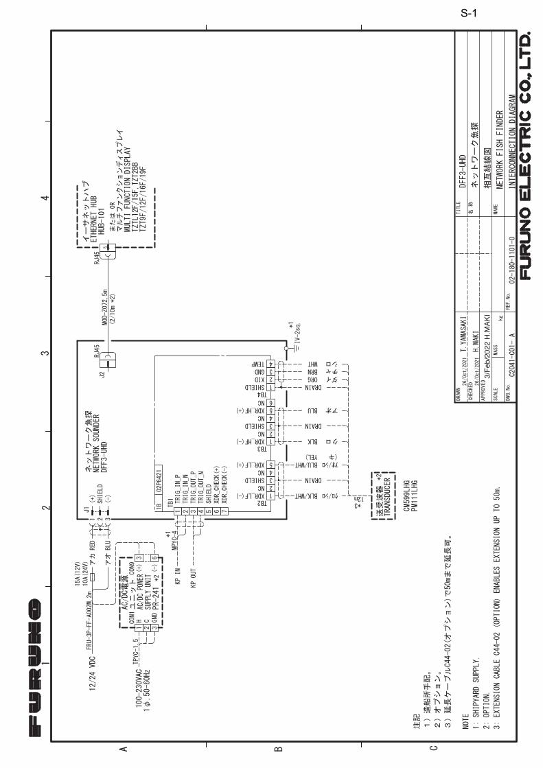
WiringWiring OutlineThe figure below shows the inserting position of each cables for the DFF3-UHD. Refer to the interconnection diagram for details.
Inserting position of cables
Tabletop mountBulkhead mount
OK NO
POWER EXT-KP NETWORK Transducer
Grounding terminal
Transducer
Seal nutSuper gland
3

Procedure1. Remove the cover.2. Unfasten four screws to remove the chassis cover.
[Transducer cable wiring] 3. Fabricate the transducer cable(s) as shown below.
Fabricate the cables for both the high and low frequencies. For a CHIRP transducer, fabricate the ID signal cores for both the high and low frequencies.
4. Unfasten the seal nut on the cable entry for transducer cable.5. Pass the seal nut, claw and seal onto the transducer cable, in that order.
6. Push the seal assembly into the seal nut, then tighten the super gland.7. Remove the WAGO connectors from the PCB, then attach the transducer cable to the connector.
8. Clamp the braided shield with a cable clamp.
6
6150150
150150
30303030
Braided shieldBraided shield
Drain w
CHIRP transducer cableSingle frequency transducer cable
CoSheath
Wrap the shield onto the sheath.
Vinyl tape(10 mm)
Clamp here (on step 10).
Vinyl tape(10 mm)
Clamp here (on step 10).
Seal assemblySeal assembly
SealSeal
ClawClaw
Seal nutSeal nut
Procedure1. Twist core.2. Insert terminal opener and push.3. Insert a core into hole.4. Release the terminal opener.5. Pull the core to confirm it is
correctly inserted.
Push
Terminal opener
WAGO Connector
CoreTwist
4

9. Attach the WAGO connector to the PCB.
[LAN cable and external KP signal cable wiring]10. Connect the LAN cable to the LAN connector.
As shown in the above figure, make a loop in the cable (approx. 10mm diameter), then connect the cable.
11. Fasten the seal nut to fix the transducer cable.The torque shall be 2.0 Nm and the gap between the seal nut and the super gland shall be approx. 3 mm.
12. Fabricate the external KP signal cable as shown below. (core size 0.75 sq, outer dia 7.6 approx.)
13. Pass the cable through the seal nut and seal assembly, like you did with the transducer cable.
14. Push the seal assembly into the seal nut, then tighten the super gland.15. Remove the WAGO connector from the PCB and connect it to the external KP signal cable.16. Connect WAGO connector to the PCB.
17. Tighten the seal nut to fasten the cable. 18. Attach the EMI core (GRFC-8, supplied) to the power cable near the super gland to prevent noise (see
figure below).
19. Attach the ground wire (IV-1.25sq, local supply) to the ground terminal with a crimp-on lug (M3, local supply) to prevent interference.
20. Reattach the chassis cover.
21. Reattach the cover.
Clamp the shield
LF HF LF HF TDID
KPKP
Source Source
Transducer cable
LF HFExternal KP signal cable
CHIRP transducer
Clamp the shield
LAN
LANCable
LAN
LANCable
Make loopMake loop
TDID
For two sets of single frequency transducers
For CHIRP transducer
External KP signal cable
External KP signal cable (local supply)VCTF0.75x4C
6150150
Sheathφ6.5φ12.5
External KP signal cable
EMI core
10 mm
5

Operation CheckFor NavNet TZtouch3 and NavNet TZtouch2, the DFF3-UHD is powered on/off from the ship’s switchboard. The STATUS LED and ERROR LED on the bottom of the DFF3-UHD lights or blinks according to equipment state, as described in the table below.
LED Position
TroubleshootingThe table below provides basic troubleshooting procedures which the user may follow to restore normal op-eration. If you cannot restore normal operation, do not check inside unit. Have a FURUNO dealer check the equipment.
LED Type STATUS ERROR Meaning
LED State Blinking every two seconds Off Normal operation
Blinking every 0.4 seconds Off Transducer settings at NavNet device not properly set.
Off Lit continuously Communication error with NavNet device or internal fan error (see “Troubleshooting” about how to solve the prob-lem).
Problem Reason
Cannot turn on power. • The power cable is disconnected or damaged. Check the power cable and if it damaged, replace it.
• Check the ship’s mains and check if the switchboard is turned on.
• Check the fuse on the power cable. If the fuse has blown, find the cause then replace it.
No echo appears but fixed range scale appears.
• The sensor cable is disconnected or damaged. Check the cable and reconnect or replace it as necessary.
Sensitivity is low. • Gain setting is too low. Raise the gain.• Marine life is adhering to the transducer face. Clean the
transducer face.• Vessel is in heavily sedimented water.
ERROR LED turns on. • Disconnect the Power cable and LAN cable.• Connect the Power cable and LAN cable.• Contact your local dealer for advice when the problem
cannot be solved.
6

SpecificationsFrequency 25 to 242 kHzNumber of channels 2 chOutput power 3 kW
Power supply 12-24 VDC: 3.0-1.6 AEnvironmental conditions Ambient temperature -15°C to +55°C
Degree of protection IP55 Vibration IEC60945 Ed.4External KP Input 5-12 VDC, Positive
External KP Output 12 VDC, Positive
Transducer List The below shows the transducers that can be connected.• R109LM*
• R109LHW*
• R111LH*
• PM111LM• PM111LH/PM111LHG• PM111LHW*
• PM411LWM*
• CM599LM• CM599LH/CM599LHG• CM599LHW*
• R509LM*
• R509LHW*
• R599LM*
• 165T-PM542LM*• 165T-PM542LHW**: Local Supply
Licensed SoftwareThis product includes software licensed under BSD-3-Clause and others. Please refer to the following for details on the terms of the software.Intel-socfpga-hwlib
Copyright 2013-2020 Intel Corporation. All Rights Reserved.
Redistribution and use in source and binary forms, with or without modification, are permitted provided thatthe following conditions are met:
1. Redistributions of source code must retain the above copyright notice, this list of conditions and the following disclaimer.
2. Redistributions in binary form must reproduce the above copyright notice, this list of conditions and the following disclaimer in the documentation and/or other materials provided with the distribution.
3. Neither the name of the copyright holder nor the names of its contributors may be used to endorse or promote products derived from this software without specific prior written permission.
7

THIS SOFTWARE IS PROVIDED BY THE COPYRIGHT HOLDERS AND CONTRIBUTORS "AS IS"AND ANY EXPRESS OR IMPLIED WARRANTIES, INCLUDING, BUT NOT LIMITED TO, THE IMPLIED WARRANTIES OF MERCHANTABILITY AND FITNESS FOR A PARTICULAR PURPOSE ARE DISCLAIMED. IN NO EVENT SHALL THE COPYRIGHT HOLDER OR CONTRIBUTORS BE LIABLE FOR ANY DIRECT, INDIRECT, INCIDENTAL, SPECIAL, EXEMPLARY, OR CONSEQUENTIAL DAMAGES (INCLUDING, BUT NOT LIMITED TO, PROCUREMENT OF SUBSTITUTE GOODS OR SERVICES; LOSS OF USE, DATA, OR PROFITS; OR BUSINESS INTERRUPTION) HOWEVER CAUSED AND ON ANY THEORY OF LIABILITY, WHETHER IN CONTRACT, STRICT LIABILITY, OR TORT (INCLUDING NEGLIGENCE OR OTHERWISE) ARISING IN ANY WAY OUT OF THE USE OF THIS SOFTWARE, EVEN IF ADVISED OF THE POSSIBILITY OF SUCH DAMAGE.
Altera-SoCFPGA-HardwareLib-MPLAltera MPL preloader, configured for use with SDMMC/Connectal. (The initial commit is the unmodified sourcecode from Altera)The original source was extracted from: altera/14.1/embedded/examples/software/Altera-SoCFPGA-HardwareLib-MPL.tar.gz and has BSD copyright with the additional restriction: "This software may only be used to run on Altera products, or to program Altera devices."All subsequent edits by Cambridgehackers are under the same copyright.
8
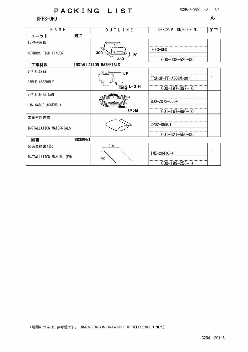
PACKING LIST 02HA-X-9851 -0
DFF3-UHD
N A M E O U T L I N E DESCRIPTION/CODE № Q'TY
1/1
ユニット UNIT
ネットワーク魚探
NETWORK FISH FINDERDFF3-UHD
000-038-529-00
1
工事材料 INSTALLATION MATERIALS
ケーブル(組品)
CABLE ASSEMBLYFRU-3P-FF-A002M-001
000-197-092-10
1
ケーブル(組品)LAN
LAN CABLE ASSEMBLYMOD-Z072-050+
001-167-890-10
1
工事材料袋詰
INSTALLATION MATERRIALSCP02-09901
001-621-550-00
1
図書 DOCUMENT
装備要領書(英)
INSTALLATION MANUAL (EN)IME-20410-*
000-199-256-1*
1
(略図の寸法は、参考値です。 DIMENSIONS IN DRAWING FOR REFERENCE ONLY.)
C2041-Z01-A
A-1
3/Feb/2022 H.MAKI
D-1
3/Feb/2022H.MAKI
S-1


The paper used in this manual
is elemental chlorine free.
・FURUNO Authorized Distributor/Dealer
9-52 Ashihara-cho,
Nishinomiya, 662-8580, JAPAN
A : FEB 2022.Printed in JapanAll rights reserved.
B : JUN . 08, 2022
Pub. No. IME-20410-B
(REFU ) DFF3-UHD
0 0 0 1 9 9 2 5 6 1 2