Zenith 140 - Pulsar Measurement
161
Zenith 140 Instruction Manual
-
Upload
khangminh22 -
Category
Documents
-
view
0 -
download
0
Transcript of Zenith 140 - Pulsar Measurement

Zenith 140 Instruction Manual

2

PULSAR MEASUREMENT
3
Zenith 140 (SIXTH EDITION REV 1)
February 2021
Part Number M-140-0-006-1P
COPYRIGHT
© Pulsar Measurement, 2005 -21. All rights reserved. No part of this publication may be
reproduced, transmitted, transcribed, stored in a retrieval system, or translated into any
language in any form without the written permission of Pulsar Process Measurement Limited.
WARRANTY AND LIABILITY
Pulsar Measurement guarantee for a period of 2 years from the date of delivery that it will
either exchange or repair any part of this product returned to Pulsar Process Measurement
Limited if it is found to be defective in material or workmanship, subject to the defect not being
due to unfair wear and tear, misuse, modification or alteration, accident, misapplication or
negligence.
DISCLAIMER
Pulsar Measurement neither gives nor implies any process guarantee for this product and shall
have no liability in respect of any loss, injury or damage whatsoever arising out of the
application or use of any product or circuit described herein.
Every effort has been made to ensure accuracy of this documentation, but Pulsar Measurement
cannot be held liable for any errors.
Pulsar Measurement operates a policy of constant development and improvement and reserves
the right to amend technical details, as necessary.
The Zenith shown on the cover of this manual is used for illustrative purposes only and may not
be representative of the actual Zenith supplied.
CONTACT
For technical support, please contact:
Europe: [email protected]
Outside Europe: [email protected]
If you have any comments or suggestions about this product, please contact:
Europe: [email protected]
Outside Europe: [email protected]
Pulsar Measurement website: www.pulsarmeasurement.com
United States
11451 Belcher Road South
Largo,
FL 33773
888-473-9546
Canada
16456 Sixsmith Drive
Long Sault, Ont.
K0C 1P0
855-300-9151
United Kingdom
Cardinal Building, Enigma
Commercial Centre
Sandy’s Road, Malvern
WR14 1JJ
00 44 (0)1684 891371

4
CONTENTS
Chapter 1: Start Here… ........................................................................................................... 9
About this Manual ............................................................................................................... 9
About the Zenith 140 ...................................................................................................... 10
Functional Description .................................................................................................... 10
Product Specification ....................................................................................................... 12
EU Certificate of Conformity ......................................................................................... 14
Fascia Mount ............................................................ Error! Bookmark not defined.
Chapter 2 Zenith 140 Installation .................................................................................... 15
Unpacking ............................................................................................................................ 15
Power Supply Requirements......................................................................................... 15
Location ................................................................................................................................ 16
Dimensions .......................................................................................................................... 17
Fascia Mount ....................................................................................................................... 17
Terminal connection details .......................................................................................... 19
Power ..................................................................................................................................... 20
Transducer ........................................................................................................................... 20
Voltage selector and fuse location............................................................................. 23
Preparation for Operation ............................................................................................. 25
Maintenance ....................................................................................................................... 25
Chapter 3 How To Use Your Zenith 140 ....................................................................... 26
Operating the Controls ................................................................................................... 26
Run Mode ............................................................................................................................. 27
Program Mode ................................................................................................................... 28
How to Access Program Mode .................................................................................... 28
Hot Keys ................................................................................................................................ 29
Menu Keys ........................................................................................................................... 30
Numeric Keys ...................................................................................................................... 30
Using the Menu System ................................................................................................. 31
Directly Editing Parameters ........................................................................................... 32
Test Mode ............................................................................................................................ 33
Using the Serial Interface ............................................................................................... 34

PULSAR MEASUREMENT
5
Parameter Defaults ........................................................................................................... 36
Chapter 4 Quick Setup Guide ........................................................................................... 37
Enter Program Mode ....................................................................................................... 37
Choose Quick Setup ......................................................................................................... 37
Quick Setup ......................................................................................................................... 39
Example 1 Level Monitoring with Alarms ................................................................ 44
Example 2 Sump Control (pump down) ................................................................... 46
Chapter 5 Parameter Guide ............................................................................................... 48
Menu System ...................................................................................................................... 48
Top Level Menu ................................................................................................................. 48
Application Menu .............................................................................................................. 48
Relays Menu ........................................................................................................................ 50
Pump “Advanced” Menu ................................................................................................ 51
Digital Inputs Menu.......................................................................................................... 52
Float Switch Menu ............................................................................................................ 53
Tariff Guard Menu ............................................................................................................. 54
Data Logs Menu ................................................................................................................ 55
Pumped Volume Menu ................................................................................................... 56
Efficiency Menu .................................................................................................................. 57
Display Menu ...................................................................................................................... 58
mA Output Menu .............................................................................................................. 59
Compensation Menu ....................................................................................................... 59
Stability Menu .................................................................................................................... 60
Echo Processing Menu .................................................................................................... 60
System Menu ...................................................................................................................... 61
Device Comm Menu ........................................................................................................ 62
Test Menu ............................................................................................................................ 63
Application Parameters................................................................................................... 64
Operation ............................................................................................................................. 64
Dimensions .......................................................................................................................... 66

ZENITH 140 INSTRUCTION MANUAL
6
mA Input ............................................................................................................................... 68
Relay Parameters ............................................................................................................... 70
Alarms .................................................................................................................................... 72
Pumps .................................................................................................................................... 79
Control ................................................................................................................................... 83
Miscellaneous ..................................................................................................................... 88
Pump by Time .................................................................................................................... 89
Common Relay parameters........................................................................................... 92
Pump “Advanced” Parameters ..................................................................................... 94
Pump Run On ..................................................................................................................... 94
Starting .................................................................................................................................. 94
Stopping ............................................................................................................................... 95
Pump Exercising ................................................................................................................ 95
Wall Cling ............................................................................................................................. 96
Storm...................................................................................................................................... 96
Digital Inputs ....................................................................................................................... 97
Digital Input Parameters .............................................................................................. 103
Digital Input ....................................................................................................................... 105
Float Switch (FS) Backup .............................................................................................. 107
Digital Input ....................................................................................................................... 108
Tariff Guard ........................................................................................................................ 109
Data Log parameters ..................................................................................................... 112
Totaliser Audits ................................................................................................................ 112
Temperature ...................................................................................................................... 112
Pump Logs ......................................................................................................................... 113
Pumped Volume .............................................................................................................. 114
Volume ................................................................................................................................ 116
Conversion ......................................................................................................................... 116
Breakpoints ........................................................................................................................ 121
Tables ................................................................................................................................... 122
Pump Efficiency ................................................................................................................ 123

PULSAR MEASUREMENT
7
Display Parameters ......................................................................................................... 126
Options ................................................................................................................................ 126
Failsafe ................................................................................................................................. 127
Auxiliary ............................................................................................................................... 128
Totaliser ............................................................................................................................... 130
mA Output Parameters ................................................................................................. 133
Range ................................................................................................................................... 133
Operation ........................................................................................................................... 134
Setpoint ............................................................................................................................... 134
mA Limits ............................................................................................................................ 135
mA Trim .............................................................................................................................. 135
mA Failsafe ......................................................................................................................... 136
Compensation Parameters .......................................................................................... 137
Offset.................................................................................................................................... 137
Temperature ...................................................................................................................... 137
Velocity ................................................................................................................................ 138
Stability Parameters ....................................................................................................... 139
Damping ............................................................................................................................. 139
Indicator .............................................................................................................................. 139
Rate ....................................................................................................................................... 139
Filters .................................................................................................................................... 140
Echo Processing Parameters ....................................................................................... 141
Transducer 1 Status ........................................................................................................ 141
Transducer 2 Status ........................................................................................................ 142
DATEM Parameters......................................................................................................... 143
System Parameters ......................................................................................................... 144
Passcode ............................................................................................................................. 144
Backup ................................................................................................................................. 144
System Information ........................................................................................................ 145
Date & Time ...................................................................................................................... 146

ZENITH 140 INSTRUCTION MANUAL
8
LED Colour ......................................................................................................................... 146
Watchdog ........................................................................................................................... 147
Daylight Saving Time ..................................................................................................... 148
Device Comm. .................................................................................................................. 152
RS232 Set Up .................................................................................................................... 152
RS 485 Set Up ................................................................................................................... 152
Remote Alarm ................................................................................................................... 153
Test Parameters ............................................................................................................... 155
Simulation .......................................................................................................................... 155
Hardware ............................................................................................................................ 156
Chapter 6 Troubleshooting .............................................................................................. 158
Chapter 7 Disposal .............................................................................................................. 159
Notes ........................................................................................................................................ 160

PULSAR MEASUREMENT
9
CHAPTER 1: START HERE…
Congratulations on your purchase of a Pulsar Zenith 140. This quality system
has been developed over many years and represents the latest in high
technology ultrasonic level measurement and control.
It has been designed to give you years of trouble-free performance, and a
few minutes spent reading this operating manual will ensure that your
installation is as simple as possible.
About this Manual
It is important that this manual is referred to for correct installation and
operation. There are various parts of the manual that offer additional help
or information as shown.
Tips
TIP: Look for this icon throughout your Pulsar Measurement manual to
f ind helpful information and answers to frequently asked questions .
Additional Information
References
See Also
References to other parts of the manual.
Additional Information
At various parts of the manual, you will find sections
like this that explain specific things in more detail.
ZENITH 140 INSTRUCTION MANUAL
10
About the Zenith 140
The Zenith 140 is a state-of-the-art pump, and level controller, that provides
advanced operating routines suitable for an extremely wide variety of
applications. The system combines premium specification with high
performance even in the most arduous applications where high turbulence
and foam or froth is present.
Functional Description
The Zenith 140 level and pump controller is a highly developed ultrasonic
level measurement system which provides non-contacting sophisticated
pump and level control routines suitable for an extremely wide variety of
applications.
Easy calibration and maintenance free “fit and forget” performance mean
that you can install the Zenith 140 pump controller rapidly and with
confidence. Six user-definable relays with adjustable, individual on and off
points, seven user-definable digital inputs, isolated mA output, RS 232 and
intelligent performance logging software features provide the user with a
superior pump management system and comprehensive level measurement
information.
The Zenith 140 operates on the principle of timing the echo received from a
measured pulse of sound transmitted in air and utilises the unique DATEM
software (Digital Adaptive Tracking of Echo Movement). This is an entirely
new digital mapping technique developed especially for the Pulsar Ultra
range.
PULSAR MEASUREMENT
11
It gives the system the edge when identifying the “true target level” in the
face of competing echoes from pipes, pumps or other obstructions. When
coupled with the powerful, long range abilities of a dB transducer and radar
range, the Zenith 140 level and pump controller has no equal.
The Zenith 140 can measure from 0.077m to 25m from the face of the
transducer to the surface being monitored, dependent on the transducer
used.
The Zenith 140 can show level, space, distance, on the display. The relays
can be programmed to activate alarms, pump starters, or other control
equipment. In addition, the digital inputs can be used to modify pump and
control regimes to optimise performance. There is an isolated 4-20 mA
output that can be connected to a chart recorder or PLC, to monitor level,
space or distance, independently from that shown on the display. There is an
RS232 port, so that the Zenith 140 can be operated remotely by a PC or
other equipment.
The Zenith 140 is programmed by the built-in keypad or by PC via the RS
232 Serial Interface (optional). All the parameters are stored in non-volatile
memory, so are retained in the event of power interruption. A second
backup copy of all parameters can also be retained in the Zenith 140, in case
a previous set of parameters needs to be restored.
ZENITH 140 INSTRUCTION MANUAL
12
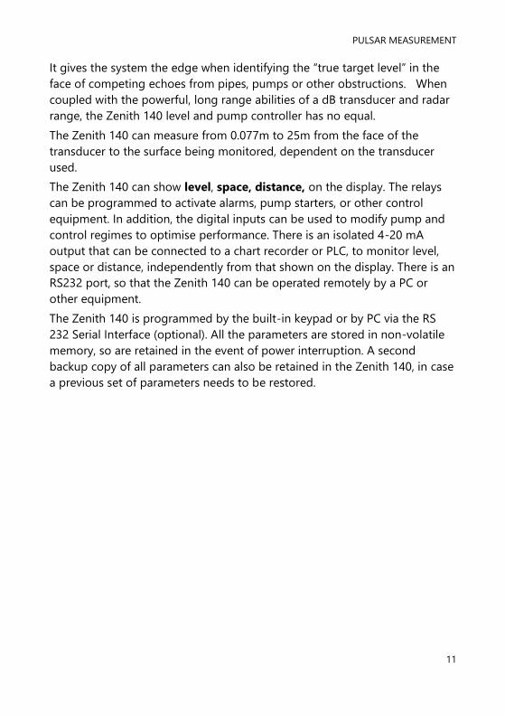
Product Specification
PHYSICAL
Fascia Mount dimensions 200 x 112 x 108mm
Weight 1.3kg
Enclosure material/description Stainless steel back, ABS front and bezel
Transducer Cable Extensions 2-core screened
Maximum Separation 1000m (3,280 ft), 500m (1,640 ft) for mmWave
ENVIRONMENTAL
IP Rating IP64
Max. & min. temperature
(electronics)
-20 ºC to +50 ºC
Flammable atmosphere approval Safe area: compatible with approved dB transducers
(see transducer spec' sheet)
CE Approval See EU Declaration of Conformity
PERFORMANCE
Accuracy 0.25% of the measured range or 6 mm (whichever is
greater). mmWAVE ± 2mm.
Resolution 0.1% of the measured range or 2 mm (whichever is
greater)
Max. Range Dependant on transducer (maximum 40m dB40)
Min. Range Dependent upon application and transducer
(minimum zero dB Mach3)
Rate Response Fully adjustable
ECHO PROCESSING
Description DATEM (Digital Adaptive Tracking of Echo Movement)
OUTPUTS
Analogue I/O
Isolated (floating) output (to 150V) of 4-20 mA or 0-20
mA into 500 (user programmable and adjustable)
0.1% resolution
Digital output Full Duplex RS232
Volt free contacts, number, and
rating 6 form "C" (SPDT) rated at 5A at 240V AC
Display
6 digits plus 12-character text, plus bar graph with
direction indicators, remote communicator identifier,
and program/run/test mode indicators
PULSAR MEASUREMENT
13
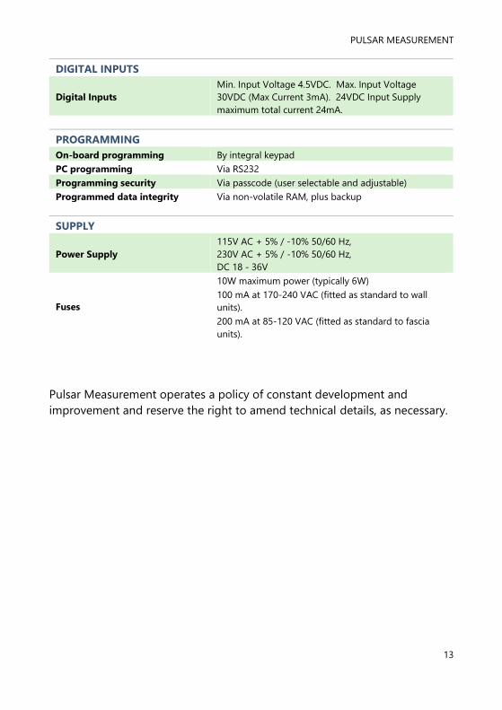
DIGITAL INPUTS
Digital Inputs
Min. Input Voltage 4.5VDC. Max. Input Voltage
30VDC (Max Current 3mA). 24VDC Input Supply
maximum total current 24mA.
PROGRAMMING
On-board programming By integral keypad
PC programming Via RS232
Programming security Via passcode (user selectable and adjustable)
Programmed data integrity Via non-volatile RAM, plus backup
SUPPLY
Power Supply
115V AC + 5% / -10% 50/60 Hz,
230V AC + 5% / -10% 50/60 Hz,
DC 18 - 36V
Fuses
10W maximum power (typically 6W)
100 mA at 170-240 VAC (fitted as standard to wall
units).
200 mA at 85-120 VAC (fitted as standard to fascia
units).
Pulsar Measurement operates a policy of constant development and
improvement and reserve the right to amend technical details, as necessary.

ZENITH 140 INSTRUCTION MANUAL
14
EU Certificate of Conformity

PULSAR MEASUREMENT
15
CHAPTER 2 ZENITH 140 INSTALLATION
Unpacking
Power Supply Requirements
The Zenith 140 can operate from AC supply or from a DC battery. The AC is
either 85-120V 50/60Hz or 170-240V 50/60Hz, depending on the position
of the selector switch. The DC is 18-36V. In all cases the Zenith 140 will
typically consume 6W of power, with a maximum of 10W.
Important Information
All shipping cartons should be opened carefully. When using a box cutter, do not
plunge the blade deeply into the box, as it could potentially cut or scratch
equipment components. Carefully remove equipment from each carton,
checking it against the packing list before discarding any packing material. If
there is any shortage or obvious shipping damage to the equipment, report it
immediately to Pulsar Process Measurement Limited.

ZENITH 140 INSTRUCTION MANUAL
16
Location
The Zenith must be mounted in a non-hazardous (safe) area, and the
transducer fitted in the hazardous area.
When choosing a location to mount the enclosure, bear in mind the
following:
• Ensure that the Zenith 140 is installed in a “Safe”, non-hazardous
area.
• For a clear view of the LCD display, it is recommended that it is
mounted at eye level.
• The mounting surface is to be vibration free.
• The ambient temperature is between -20°C and 50°C.
• There should be no high voltage cables or inverters nearby,
Important Information
All electronic products are susceptible to electrostatic shock, so follow proper
grounding procedures during installation.

PULSAR MEASUREMENT
17
Dimensions
Fascia Mount
The dimensions of the wall fixing holes are as shown below:
ZENITH 140 INSTRUCTION MANUAL
18
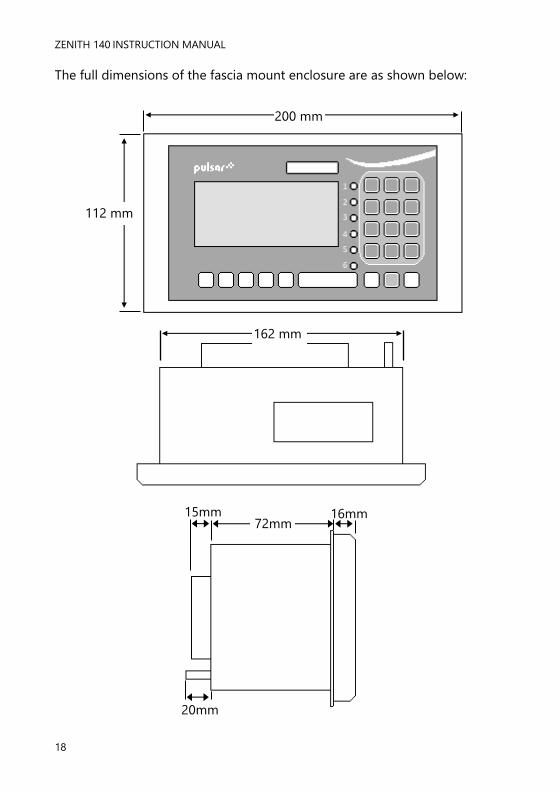
The full dimensions of the fascia mount enclosure are as shown below:
162 mm
20mm
72mm 15mm 16mm
200 mm
112 mm

PULSAR MEASUREMENT
19
Terminal connection details
Fascia Mount
The terminal details are as illustrated below:

ZENITH 140 INSTRUCTION MANUAL
20
Power
The Zenith 140 can operate from mains AC and automatically from DC or
battery backup in the event of power failure or can be operated permanently
from DC or batteries.
Transducer
The transducer should be installed, and connected, in accordance with the
installation instructions contained in the Transducer User Guide. Wire the
transducer to the Zenith 140’s transducer terminals, as follows:
Transducer 1
TERMINAL CONNECTION DETAILS
Red:
Power
White:
Signal
Black:
0Volts
Green:
Screen
32 31 30 30
Transducer 2
TERMINAL CONNECTION DETAILS
Red:
Power
White:
Signal
Black:
0Volts
Green:
Screen
35 34 33 33
When using 2-core screened extension cable, the Black and Green wires of
the transducer should be connected to the screen of the extension cable.
For Zone 1 applications a transducer certified to Sira 02ATEX5104X is used,
and must be supplied via a 4000A breaking fuse, which is fitted as standard
to the Zenith.
For Zone 0 a transducer certified to Sira 02ATEX2103X is used, which must
be connected to the Zenith controller via an external Zener barrier.
See transducer label for certification details.
When using the Zenith 140 in a single transducer mode, to measure space,
level or distance, the transducer should be connected to Transducer 1
input terminals. In applications where it is required to measure Differential,
then the upstream transducer should be connected to Transducer 1 input
terminals and the downstream transducer to Transducer 2 input terminals.
In cases where the Zenith 140 is required to measure Average, transducers
can be connected as required.

PULSAR MEASUREMENT
21
Relay Outputs
The five relays can be programmed for a variety of alarms, pump control, or
other process functions. The relay contacts are all rated at 5A at 240V AC. All
connections should be such that the short circuit capacity of the circuits to
which they are connected, is limited by fuses rated so that they do not
exceed the relay rating.
Current Output
This is an isolated (floating) mA output (to 150 V), of 4 - 20mA or 0 - 20mA,
and the load should not exceed 500 .
Current Input (Optional)
This feature is available as an option only. Please consult Pulsar for further
details. The current input is an isolated (floating) mA input (to 150 V), 4 -
20mA or 0 -20mA.
Temperature Input (Optional)
The external temperature sensor allows more localised compensation of the
measured distance due to changes in temperature.
There are two models, Type A and Type B as follows:
TYPE RANGE
A -25° to 50°C
B -25° to 125°C
The temperature sensor should be placed close to the point of
measurement.

ZENITH 140 INSTRUCTION MANUAL
22
The Temperature sensor connections are as follows:
DESCRIPTION TEMPERATURE
SENSOR
ZENITH
FASCIA
Power Supply Terminal 1 Terminal 25
Return Terminal 2 Terminal 24
Temp Source (P852), should be set to option 4 or 5 depending on the
sensor range, set 4 for type A and 5 for type B (see above), the range is
specified on the label of the sensor.
This feature is available as an option only, please consult Pulsar for further
details.
Digital Inputs
Where the Zenith is required to provide power for a Device Input the
appropriate Digital Input should be wired between the 24VDC supply
terminal and the IN terminal. (TOTAL maximum current available, for all
seven digital inputs, from the 24VDC supply is 24mA). When Device Inputs
are self-powered, connection of the device should be made between the
Common terminal and the IN terminal. (Min Input voltage 4.5VDC, and
Maximum Input voltage 30VDC with a maximum current of 3mA).
92mm 182m
m
100mm
M20 ENTRY
IP67 ABS HOUSING
316 STAINLESS STEEL
6mm
PULSAR MEASUREMENT
23
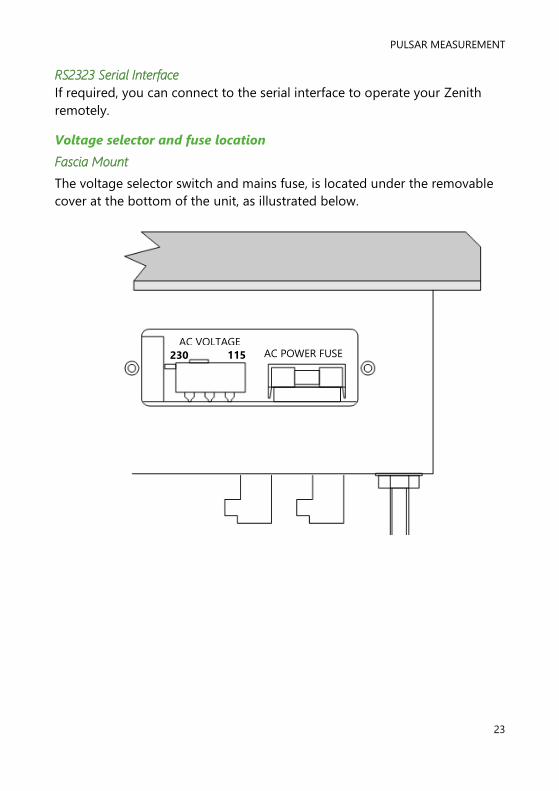
RS2323 Serial Interface
If required, you can connect to the serial interface to operate your Zenith
remotely.
Voltage selector and fuse location
Fascia Mount
The voltage selector switch and mains fuse, is located under the removable
cover at the bottom of the unit, as illustrated below.
AC VOLTAGE
SELECTOR 230 115 AC POWER FUSE

ZENITH 140 INSTRUCTION MANUAL
24
DON’T FORGET
Make sure you move the voltage selector switch to the correct position for your
power supply.
Important Information
If the equipment is installed or used in a manner not specified in this
manual, then the protection provided by the equipment may be impaired.
Important Information
Before applying AC power (mains), make sure you have correctly selected
the voltage selector switch. In the case of the Fascia mount model this is
located under the removable cover at the bottom of the unit, as detailed
in the preceding pages.
Please note that all Fascia units are set to 115 volts AC with a 200mA fuse
fitted, and all Wall units are supplied set to 230 volts AC for safety
reasons, and a 100mA fuse fitted as standard.
Never operate the Zenith 140 with the terminals access cover removed.
An external switch or circuit breaker should be installed near to the Zenith
140 to allow the supply to be removed during installation and
maintenance. In addition, the relay contacts should also have a means of
isolating them from the unit.
Interconnecting cables must be adequately insulated for IEC 664 Category
II installations. Strip back 30 mm of the outer insulation of the cable. Strip
5 mm of insulation from the end of each conductor. Twist all exposed
strands of the conductor together. Insert the stripped conductor into the
terminal block as far as it will go and tighten the terminal block screw.
Ensure that all strands are firmly clamped in the terminal block and that
there is no excess bare conductor showing, and no stray strands.

PULSAR MEASUREMENT
25
Preparation for Operation
Before switching on, check the following:
✓ The Zenith 140 is mounted correctly and is in a ‘safe’ area.
✓ The power supply is correctly installed.
✓ The voltage selector switch is in the correct position.
✓ The relays are connected correctly.
Maintenance
There are no user serviceable parts inside Zenith, except the mains fuse. If
you experience any problems with the unit, then please contact Pulsar
Measurement for advice.
To clean the equipment, wipe with a damp cloth. Do not use any solvents on
the enclosure.
Important Information
The unique DATEM software comes into operation as soon as power is
applied and is designed to monitor a moving level or target with the
transducer in a fixed position.
If, after any period of use, it should become necessary to move the
transducer, for any reason, from its original operating position, switch off
the Zenith, before proceeding, in order to prevent any undesirable updates
to the DATEM trace. If after moving the transducer the reading is not as
expected, please refer to Chapter 6 Troubleshooting.

ZENITH 140 INSTRUCTION MANUAL
26
CHAPTER 3 HOW TO USE YOUR ZENITH 140
Operating the Controls
Display
The display provides information on the current mode of operation, and
status of the remote communication. Whilst in the Run Mode it will display
the current level reading and its units of measure, along with status
messages with regards to the Transducer, Echo reception and Fail-Safe
Mode. Additionally, it can be programmed to provide status messages on
alarms, pumps etc. When in the Program mode the display is used to read
information on the Menu System, Parameter Number and parameter details
and values, which can be entered. During Test Mode, the display is used to
monitor the simulated level. A bar graph is also provided which will provide
a visual reading of the level, in percentage of span.
1. Displays the current mode of operation.
2. Main 6-digit display:
Run Mode; current measurement displayed, dependent on mode
and measurement units chosen, and value of hotkey selected.
Program Mode; displays parameter number and values entered for
parameters.
Test Mode; displays simulated level.
1
2
3
4
0%
5
6
Run Mode Program Mode Test Mode 100%
REMOTE COMMUNICATOR OFF
XXXXXXXXXXXX 000.000

PULSAR MEASUREMENT
27
3. Auxiliary Display, scrolling twelve-digit display.
Run Mode; displays measurement units, status messages on signal
and transducer, details of Hot Key function selected. It can be also
programmed to provide notification messages on alarms and
pumps etc. For full details please refer to Display Parameters in the
relevant parameter listing.
Program Mode; displays menu and sub menu headings, parameter
details and options.
4. Communicator status, this displays the status of remote PC
connection and velocity sensor operation.
5. Bar graph display, this gives visual indication of measurement in %
of span.
6. Level indicators:
Run Mode; indicates in which direction the level is moving.
Program Mode: indicates at which level of the menu system you are
at.
There are two main operating modes for your Zenith 140, Run Mode and
Program Mode. There is also a Test Mode, used for checking the set-up.
All modes are now described.
Run Mode
This mode is used once the Zenith 140 has been set up in program mode. It
is also the default mode that the unit reverts to when it resumes operation
after a power failure.
When the Zenith 140 is switched on for the first time, it will display, in
metres, the distance from the transducer face to the target. All relays by
default are switched off.
After programming is complete, any relays that are set will operate when the
level reaches the relevant setpoint, and the LED’s will change colour (unless
specifically switched off).

ZENITH 140 INSTRUCTION MANUAL
28
Program Mode
This mode is used to set up the Zenith 140 or change information already
set. You must use either the built-in keypad (standard) or, alternatively the
unit can be set up with a PC via the RS232 Serial Interface.
Entering a value for each of the parameters that are relevant to your
application provides all the programming information.
How to Access Program Mode
To enter program mode on the Zenith 140, you simply enter the passcode,
via the keypad, followed by the ENTER key. The default passcode is 1997,
so you would press the following:
Important Information
There is a time-out period of 15 minutes when in program mode.
After which time the run mode will resumed if you do not press any
key.
ENTER 1 9 9 7

PULSAR MEASUREMENT
29
Hot Keys
There are five hot keys on the keypad, which can be used to quickly access
common parameters for viewing only, while in Run Mode. Pressing the hot
key once will display the first parameter, then repeated pressing will display
the others, then the Zenith reverts to Run Mode. In program mode, they
have different functions, the functions are shown below.
HOT KEY RUN MODE PROGRAM MODE
Total pump running hours and
individual pump running hours. Not used with Zenith 140
Displays echo confidence, echo
strength, height above loss limit (HALL),
average noise, peak noise, and
temperature
Not used with Zenith 140
Total number of pump starts, and
individual pump starts.
Reset parameter to default
setting
Instantaneous mA output Not used with Zenith 140
Dependent on application. Displays
distance, level, space, volume or rate of
change of level.
Toggle relay setpoints
between units of measure and
% of span.
Reset for digital inputs
Takes you to the last
parameter edited when you
first enter program mode.
Shows details of function type, firmware
revision and serial number Enter decimal point.
∑
mA
n

ZENITH 140 INSTRUCTION MANUAL
30
Menu Keys
The menu keys have the following functions:
HOT KEY FUNCTION
1) Arrow keys for moving left and right around the menu
system.
2) Used in test mode to simulate the level moving up and
down.
1) Used to confirm each action (e.g. select a menu option)
2) Used to confirm questions asked by the Zenith, such as
before restring factory defaults.
Used to navigate up a level in the menu system, and back to run
mode.
Used to cancel a value entered in error
Numeric Keys
These keys are used for entering numerical information during
programming.
CANCEL
ENTER
1 2 3
4 5 6
7 8 9
0 . + -

PULSAR MEASUREMENT
31
There are two means of editing parameters, directly or using the menu
system. Each is now described.
Using the Menu System
The menu system has been designed to make the changing of parameters
very simple. There are two levels of menu: Main Menu and Sub Menu.
On the display, there is a line of text that displays the menu system. Pressing
the arrow keys scrolls the display between the top-level menu items, (as the
example shown below, starting at Quick Setup).
As you press the cursor keys to scroll left and right between these, you can
press ENTER at any time, to select the desired menu heading, and take you
to the sub-menu.
Each of these options, along with their sub-menus, are described later in this
manual. When you move down into the sub-menu, you can scroll round
using the arrow keys, press ENTER to go to the required section of
parameters.
Once you have reached the relevant section, scroll through the parameters,
and enter the necessary information. To enter the information, use the
numeric keys and then press ENTER, you will then see the message “Saved!”
If you press CANCEL, then the change you made will not be saved, and the
message “Unchanged!!” will be displayed.
When you have finished, press CANCEL to go back to the previous level.
When you have reached the top level, then the Zenith will ask for
confirmation before allowing you to go back into run mode. This is done by
pressing ENTER at the display prompt.
Quick Setup Application Relays Pump Advanced
Digital Inputs
FS Backup
Tariff Guard Display mA Output
Pump Efficiency
Pump Volume
Compensation Stability System Test Device Comm
Echo Processing
Data Logs
ZENITH 140 INSTRUCTION MANUAL
32
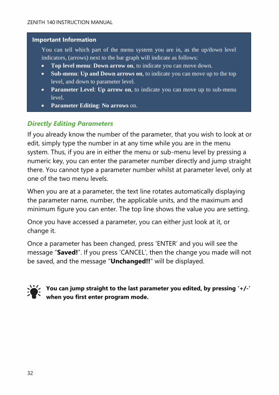
Directly Editing Parameters
If you already know the number of the parameter, that you wish to look at or
edit, simply type the number in at any time while you are in the menu
system. Thus, if you are in either the menu or sub-menu level by pressing a
numeric key, you can enter the parameter number directly and jump straight
there. You cannot type a parameter number whilst at parameter level, only at
one of the two menu levels.
When you are at a parameter, the text line rotates automatically displaying
the parameter name, number, the applicable units, and the maximum and
minimum figure you can enter. The top line shows the value you are setting.
Once you have accessed a parameter, you can either just look at it, or
change it.
Once a parameter has been changed, press ‘ENTER’ and you will see the
message “Saved!”. If you press ‘CANCEL’, then the change you made will not
be saved, and the message “Unchanged!!” will be displayed.
You can jump straight to the last parameter you edited, by pressing ‘+/-’
when you first enter program mode.
Important Information
You can tell which part of the menu system you are in, as the up/down level
indicators, (arrows) next to the bar graph will indicate as follows:
• Top level menu: Down arrow on, to indicate you can move down.
• Sub-menu: Up and Down arrows on, to indicate you can move up to the top
level, and down to parameter level.
• Parameter Level: Up arrow on, to indicate you can move up to sub-menu
level.
• Parameter Editing: No arrows on.
PULSAR MEASUREMENT
33
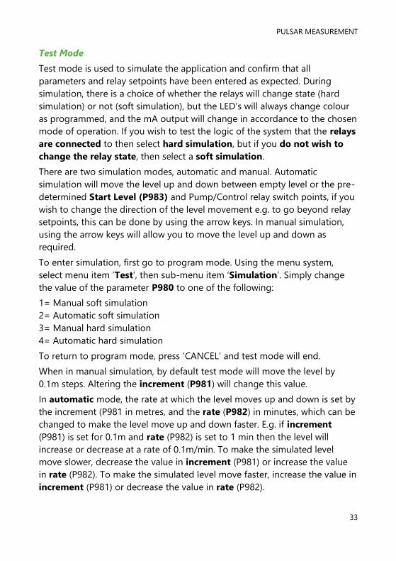
Test Mode
Test mode is used to simulate the application and confirm that all
parameters and relay setpoints have been entered as expected. During
simulation, there is a choice of whether the relays will change state (hard
simulation) or not (soft simulation), but the LED’s will always change colour
as programmed, and the mA output will change in accordance to the chosen
mode of operation. If you wish to test the logic of the system that the relays
are connected to then select hard simulation, but if you do not wish to
change the relay state, then select a soft simulation.
There are two simulation modes, automatic and manual. Automatic
simulation will move the level up and down between empty level or the pre-
determined Start Level (P983) and Pump/Control relay switch points, if you
wish to change the direction of the level movement e.g. to go beyond relay
setpoints, this can be done by using the arrow keys. In manual simulation,
using the arrow keys will allow you to move the level up and down as
required.
To enter simulation, first go to program mode. Using the menu system,
select menu item ‘Test’, then sub-menu item ‘Simulation’. Simply change
the value of the parameter P980 to one of the following:
1= Manual soft simulation
2= Automatic soft simulation
3= Manual hard simulation
4= Automatic hard simulation
To return to program mode, press ‘CANCEL’ and test mode will end.
When in manual simulation, by default test mode will move the level by
0.1m steps. Altering the increment (P981) will change this value.
In automatic mode, the rate at which the level moves up and down is set by
the increment (P981 in metres, and the rate (P982) in minutes, which can be
changed to make the level move up and down faster. E.g. if increment
(P981) is set for 0.1m and rate (P982) is set to 1 min then the level will
increase or decrease at a rate of 0.1m/min. To make the simulated level
move slower, decrease the value in increment (P981) or increase the value
in rate (P982). To make the simulated level move faster, increase the value in
increment (P981) or decrease the value in rate (P982).

ZENITH 140 INSTRUCTION MANUAL
34
Using the Serial Interface
The RS232 serial interface is used to communicate between the Zenith and a
PC using the optional Ultra PC and other associated Pulsar software
packages, to obtain information such as data logging and view echo traces
upload, download and save parameter files. In addition, it can also be used
to control or obtain information using a standard PC or other computer base
equipment. To do so, the settings for control are as follows: baud rate
19,200, 8 data bits, no parity, 1 stop bit.
The device should be connected as shown in Chapter 2 Zenith
140 Installation.
To use the device remotely, you need to log on to start, and log off when
finished. When logged on, the Zenith will show ‘Remote ON’ on the display,
and “Communicator OFF” when logged off.
All commands should be followed by a carriage return. When logged on, the
unit will respond either OK (or a value) if the command is accepted, or NO if
it is not.
To log on, send the command
/ACCESS:pppp where pppp is the passcode (P922).
To log off, send the command
/ACCESS:OFF
To read a parameter value, send the command
/Pxxx where xxx is the parameter you wish to read, and the Zenith 140 will
respond with the parameter value.
To set a parameter, send the command
/Pxxx:yy where xxx is the parameter number, and yy is the value you wish to
set it to.
PULSAR MEASUREMENT
35
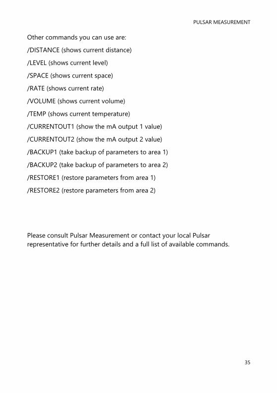
Other commands you can use are:
/DISTANCE (shows current distance)
/LEVEL (shows current level)
/SPACE (shows current space)
/RATE (shows current rate)
/VOLUME (shows current volume)
/TEMP (shows current temperature)
/CURRENTOUT1 (show the mA output 1 value)
/CURRENTOUT2 (show the mA output 2 value)
/BACKUP1 (take backup of parameters to area 1)
/BACKUP2 (take backup of parameters to area 2)
/RESTORE1 (restore parameters from area 1)
/RESTORE2 (restore parameters from area 2)
Please consult Pulsar Measurement or contact your local Pulsar
representative for further details and a full list of available commands.

ZENITH 140 INSTRUCTION MANUAL
36
Parameter Defaults
When you first switch the Zenith 140 on, it will be reading the distance from
the face of the transducer to the surface. It will be indicating in metres, as
shown on the display. All relays are set OFF.
The date (P931) and time (P932) in the Zenith 140 were set at the factory,
but may need checking, and amending if, for example the application is in a
time zone other than GMT, see relevant parameter listing for full details.
In some applications, it is easier to empty the vessel, take a reading from the
Zenith 140 for distance and then setup the empty level to this figure.
Once you are satisfied with the installation, and Zenith 140 is reading what
you would expect in terms of distance from the face of the transducer to the
material level, then you can proceed with programming, for the intended
application. It is sensible to program all the required parameters at the same
time. The system will be then set-up.
Note: The span is automatically calculated from the empty level, so the
empty level should be entered first.
Factory Defaults
When first installing the Zenith, or subsequently moving or using the unit on a
new application, before proceeding to program the unit for its intended application
it is recommended that you ensure that all parameters are at their default values by
completing a Factory Default P930, as described in the relevant unit type
parameter guide.

PULSAR MEASUREMENT
37
CHAPTER 4 QUICK SETUP GUIDE
This quick set-up guide shows you how to get up and running in a few
minutes in just four easy steps after installing your Zenith 140.
Enter Program Mode
First you need to go from run mode into program mode. Assuming the
passcode is the default 1997, then you should enter the following on the
keypad:
Choose Quick Setup
Now you need to go into the quick setup. You will see on the menu the
words ‘Quick Setup’, which is the first item on the menu system. Try pressing
the two arrow keys to see some more menu options, but return to Quick
Setup, and press
ENTER 1 9 9 7
ENTER This takes you to the common
applications parameter (P200).
ENTER This takes you to the common
applications parameters, and you will see
some options appearing on the display.
Factory Defaults
If you have already setup a common application, then there will be a
number shown other than 0, and you will see messages showing what the
current setup is. If you want to reset this and start again, press 0 (which will
reset all the quick setup parameters), otherwise pressing ENTER will allow
you to edit the parameters that have been set.

ZENITH 140 INSTRUCTION MANUAL
38
Choose Your Application
There are four categories of application, which are all described at the end of
this chapter. They are level, pump down (sump control), pump up
(reservoir control) or customised, all with the choice of alarms and a number
of pumps, dependant on application.
If you want to set-up a basic level monitoring application, as described in
the following example 1, then choose 1. You then need to decide the
number of alarms required and their function and choose the appropriate
options.
If you want to set-up a pump down (sump control) application, as described
in the following example 2, then choose 2. You then need to decide the
number of pumps required the pump duty and any requirement for
alarms and choose the appropriate options.
If you want to set-up a pump up (reservoir control) application, then choose
3. You then need to decide the number of pumps required the pump duty,
and any requirement for alarms, and choose the appropriate options.
In certain cases, the Quick Setup Menu has been customised for customer
specific applications, to choose one of these options press 4 and select the
appropriate customised application and enter the details required as
prompted.
Once you have chosen your application you will be asked a series of
questions which are answered by choosing the appropriate option as
detailed in the flow charts that follow. Once all the questions have been
answered you will be prompted to provide further information, as detailed in
the tables that follow, to complete the programming of the unit.

PULSAR MEASUREMENT
39
Quick Setup
Quick Setup
For Each Alarm
1 = High Alarm 2 = Low alarm 3 = Hi Hi Alarm 4 = Lo Lo alarm 5 = Loss of Echo
1 = Level 2 = Pump Down 3 = Pump Up
How Many Pumps
1 = One Pump 2 = Two Pumps 3 = Three Pumps 4 = Four Pumps 5 = Five Pumps
For each Pump Relay
1 = Set to Relay 1 2 = Set to Relay 2 3 = Set to Relay 3 4 = Set to Relay 4 5 = Set to Relay 5
How Many Alarms
0 = No Alarms 1 = One Alarm 2 = Two Alarms 3 = Three Alarms 4 = Four Alarms 5 = Five Alarms List will be truncated according to the number of Control relays selected
Pump Duty
1 = Fixed Duty Assis 2 = Fixed Duty Backup 3 = Alt Duty Assist 4 = Alt Duty Backup 5 = Duty Backup & Ass 6 = Ser Ratio Duty Ass 7 = Ser Ratio Duty B’up 8 = FOFO Alt Duty Ass 9 = Ser Ratio Stby 10 = 2 Pump Set
4 = Customised
Select the option
specific to your
application
For each Alarm
1 = Set to Relay 1 2 = Set to Relay 2 3 = Set to Relay 3 4 = Set to Relay 4 5 = Set to Relay 5 6 = Set to Relay 6

ZENITH 140 INSTRUCTION MANUAL
40
Set-up Your Application
Once you have chosen the application, you will see a ‘Wait…’ message while
the parameters are all calculated and stored. Next you will see the
parameters needed to finalise your application, in turn, as shown below. If
you know you don’t need to change from the default, you can use the right
arrow key to scroll through them, but if you want to view or change each
one, just press ENTER.
PARAMETER DEFAULT DESCRIPTION
P101 Transducer 2 = dB6 Type of transducer being used.
P102 Material 1 = Liquid
Material in the vessel, either liquid or
solid. If the solid lays flat, then it can be
programmed as liquid.
P104 Measurement
Units 1 = metres
Select units to be used for programming
measurement information.
P105 Empty Level 6m
Distance from the face of the transducer
to the material at the bottom of the
vessel.
P106 Span 5.7m Distance from the empty level (0% full) to
span (100% full).
For More Options Hit Enter
Now you will see a scrolling message that says, ‘For more Options Hit
Enter’. If you press ENTER, you will then see more parameters, specific to the
application you have chosen, these are all factory pre-set. If you press any
other key you will return to the Quick Setup menu, where you can press
CANCEL to return to run mode.

PULSAR MEASUREMENT
41
PARAMETER DEFAULT DESCRIPTION
P213 / P214
Relay 1 ON/OFF
setpoints
Factory preset as a % to
appropriate level according
to the span already
entered. See tables below
Either Alarm or Level control.
Depends on application.
P223 / P224
Relay 2 ON/OFF
setpoints
Factory preset as a % to
appropriate level according
to the span already
entered. See tables below
Either Alarm or Level control.
Depends on application.
P233 / P234
Relay 3 ON/OFF
setpoints
Factory preset as a % to
appropriate level according
to the span already
entered. See tables below
Either Alarm or Level control.
Depends on application.
P243 / P244
Relay 4 ON/OFF
setpoints
Factory preset as a % to
appropriate level according
to the span already
entered. See tables below
Either Alarm or Level control.
Depends on application.
P253 / P254
Relay 5 ON/OFF
setpoints
Factory preset as a % to
appropriate level according
to the span already
entered. See tables below
Either Alarm or Level control.
Depends on application.
P263 / P264
Relay 5 ON/OFF
setpoints
Factory preset as a % to
appropriate level according
to the span already
entered. See tables below
Either Alarm or Level control.
Depends on application.
P830 mA Out Range 2 = 4 to 20mA
Determines the mA output
range.
0 = Off, 1 = 0 to 20mA, 2 = 4
to 20mA, 3 = 20 to 0mA, 4 =
20 to 4mA.
P870 Fill Damping 10m/min
Rate of maximum fill rate (set
above the actual fill rate of the
vessel).
P871 Empty
Damping 10m/min
Rate of maximum empty rate
(set above the actual rate of
the vessel).
ZENITH 140 INSTRUCTION MANUAL
42
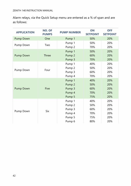
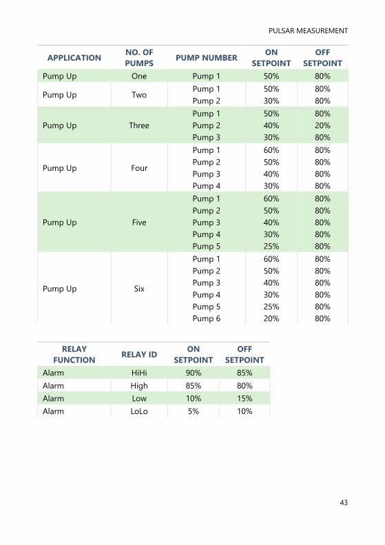
Alarm relays, via the Quick Setup menu are entered as a % of span and are
as follows:
APPLICATION NO. OF
PUMPS PUMP NUMBER
ON
SETPOINT
OFF
SETPOINT
Pump Down One Pump 1 50% 20%
Pump Down Two Pump 1
Pump 2
50%
70%
20%
20%
Pump Down Three
Pump 1
Pump 2
Pump 3
50%
60%
70%
20%
20%
20%
Pump Down Four
Pump 1
Pump 2
Pump 3
Pump 4
40%
50%
60%
70%
20%
20%
20%
20%
Pump Down Five
Pump 1
Pump 2
Pump 3
Pump 4
Pump 5
40%
50%
60%
70%
75%
20%
20%
20%
20%
20%
Pump Down Six
Pump 1
Pump 2
Pump 3
Pump 4
Pump 5
Pump 6
40%
50%
60%
70%
75%
80%
20%
20%
20%
20%
20%
20%
PULSAR MEASUREMENT
43
APPLICATION NO. OF
PUMPS PUMP NUMBER
ON
SETPOINT
OFF
SETPOINT
Pump Up One Pump 1 50% 80%
Pump Up Two Pump 1
Pump 2
50%
30%
80%
80%
Pump Up Three
Pump 1
Pump 2
Pump 3
50%
40%
30%
80%
20%
80%
Pump Up Four
Pump 1
Pump 2
Pump 3
Pump 4
60%
50%
40%
30%
80%
80%
80%
80%
Pump Up Five
Pump 1
Pump 2
Pump 3
Pump 4
Pump 5
60%
50%
40%
30%
25%
80%
80%
80%
80%
80%
Pump Up Six
Pump 1
Pump 2
Pump 3
Pump 4
Pump 5
Pump 6
60%
50%
40%
30%
25%
20%
80%
80%
80%
80%
80%
80%
RELAY
FUNCTION RELAY ID
ON
SETPOINT
OFF
SETPOINT
Alarm HiHi 90% 85%
Alarm High 85% 80%
Alarm Low 10% 15%
Alarm LoLo 5% 10%

ZENITH 140 INSTRUCTION MANUAL
44
Example 1 Level Monitoring with Alarms
A vessel, containing liquid that has a variation in level that is to be
monitored, with a high-level alarm set on Relay 1 and low-level alarm set on
Relay 2.
In this example, when the level rises to 2.38 m, relay 1 will come on until the
level drops to 2.24 m when it will turn off. If the level drops to 0.28 m, then
relay 2 will come on until it rises 0.42 m when it will turn off.
The display will show the level in the tank.
The mA output will be representative of level where 4mA = empty level (0%)
and 20mA = 2.8m (100%).
Empty Distance (P105), 3.5m
100%. Span (P106), 2.8m
85%. High alarm on (P213), 2.38m
80%. High alarm off (P214), 2.24m
0%, Empty level
10%. Low alarm on (P223), 0.28m
15%, Low alarm off (P224), 0.42m

PULSAR MEASUREMENT
45
To program the Zenith 140 for Example 1 Level Monitoring with Alarms
by using the Quick Setup menu proceed as follows. If required to access
Program Mode, key in the passcode 1997 and press ENTER
At the Quick Setup menu press ENTER and as prompted, by the questions,
select the relevant option and ENTER.
QUESTION OPTION
Level/Volume 1 = Level App.
No. of alarms 2 = 2 Alarms
Type alarm 1 1 = High
Alarm no.1 1 = Set to relay 1
Type alarm 2 2 = Low
Alarm no.2 2 = Set relay 2
Xducer (P101) 2 = dB6
Material (P102) 1 = Liquid
Measurement units (P104) 1 = Metres
Empty Level (P105) 3.5m
Span (P106) 2.8m
Programming is now complete, and the unit can be returned to the run
mode, press CANCEL until Run Mode? Is displayed on the LCD press
ENTER, and the Zenith 140 will return to the Run Mode.
Important Notice
If relay setpoints do not meet the exact requirements of the application,
they can be modified to suit by pressing ENTER when, “For More Options
Hit Enter”, is displayed, and entering new values to relay setpoints as
required. Alternatively, the relevant relay setpoint can be accessed either
by the main menu system or directly via parameter number and changed
as necessary.
ZENITH 140 INSTRUCTION MANUAL
46
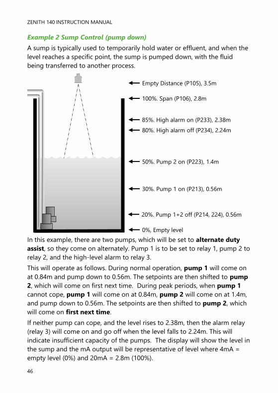
Example 2 Sump Control (pump down)
A sump is typically used to temporarily hold water or effluent, and when the
level reaches a specific point, the sump is pumped down, with the fluid
being transferred to another process.
In this example, there are two pumps, which will be set to alternate duty
assist, so they come on alternately. Pump 1 is to be set to relay 1, pump 2 to
relay 2, and the high-level alarm to relay 3.
This will operate as follows. During normal operation, pump 1 will come on
at 0.84m and pump down to 0.56m. The setpoints are then shifted to pump
2, which will come on first next time. During peak periods, when pump 1
cannot cope, pump 1 will come on at 0.84m, pump 2 will come on at 1.4m,
and pump down to 0.56m. The setpoints are then shifted to pump 2, which
will come on first next time.
If neither pump can cope, and the level rises to 2.38m, then the alarm relay
(relay 3) will come on and go off when the level falls to 2.24m. This will
indicate insufficient capacity of the pumps. The display will show the level in
the sump and the mA output will be representative of level where 4mA =
empty level (0%) and 20mA = 2.8m (100%).
Empty Distance (P105), 3.5m
100%. Span (P106), 2.8m
85%. High alarm on (P233), 2.38m
80%. High alarm off (P234), 2.24m
0%, Empty level
20%. Pump 1+2 off (P214, 224), 0.56m
30%. Pump 1 on (P213), 0.56m
50%. Pump 2 on (P223), 1.4m
PULSAR MEASUREMENT
47
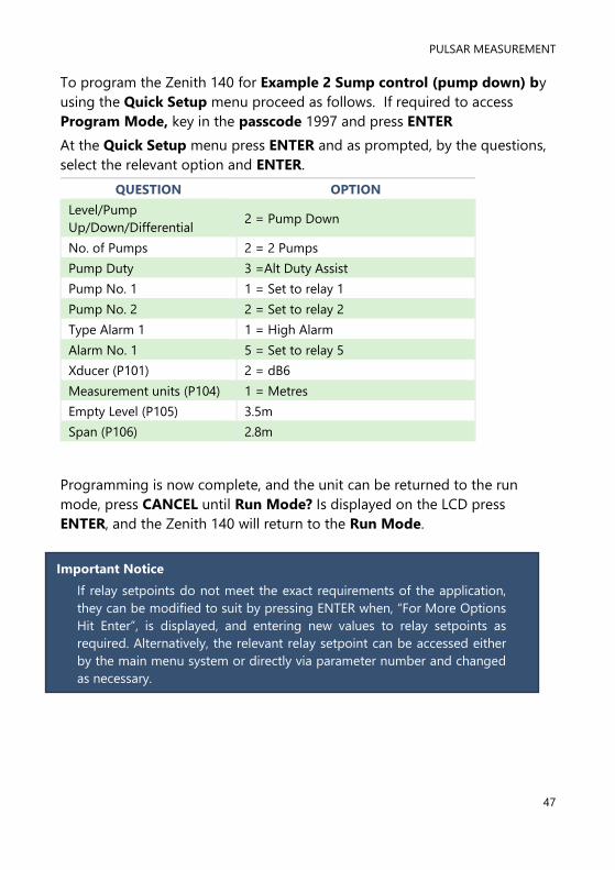
To program the Zenith 140 for Example 2 Sump control (pump down) by
using the Quick Setup menu proceed as follows. If required to access
Program Mode, key in the passcode 1997 and press ENTER
At the Quick Setup menu press ENTER and as prompted, by the questions,
select the relevant option and ENTER.
QUESTION OPTION
Level/Pump
Up/Down/Differential 2 = Pump Down
No. of Pumps 2 = 2 Pumps
Pump Duty 3 =Alt Duty Assist
Pump No. 1 1 = Set to relay 1
Pump No. 2 2 = Set to relay 2
Type Alarm 1 1 = High Alarm
Alarm No. 1 5 = Set to relay 5
Xducer (P101) 2 = dB6
Measurement units (P104) 1 = Metres
Empty Level (P105) 3.5m
Span (P106) 2.8m
Programming is now complete, and the unit can be returned to the run
mode, press CANCEL until Run Mode? Is displayed on the LCD press
ENTER, and the Zenith 140 will return to the Run Mode.
Important Notice
If relay setpoints do not meet the exact requirements of the application,
they can be modified to suit by pressing ENTER when, “For More Options
Hit Enter”, is displayed, and entering new values to relay setpoints as
required. Alternatively, the relevant relay setpoint can be accessed either
by the main menu system or directly via parameter number and changed
as necessary.
ZENITH 140 INSTRUCTION MANUAL
48
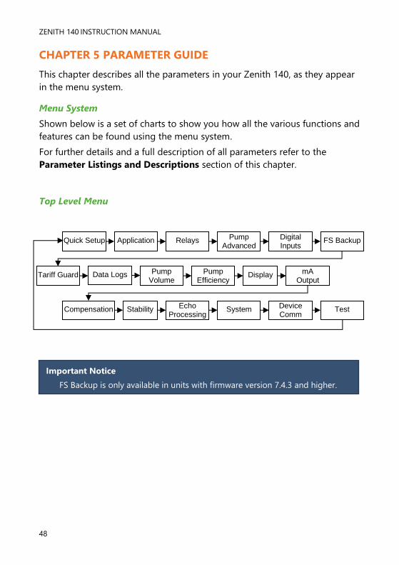
CHAPTER 5 PARAMETER GUIDE
This chapter describes all the parameters in your Zenith 140, as they appear
in the menu system.
Menu System
Shown below is a set of charts to show you how all the various functions and
features can be found using the menu system.
For further details and a full description of all parameters refer to the
Parameter Listings and Descriptions section of this chapter.
Top Level Menu
Quick Setup Application Relays Pump Advanced
Digital Inputs
FS Backup
Tariff Guard Display mA Output
Pump Efficiency
Pump Volume
Compensation Stability System Test Device Comm
Echo Processing
Data Logs
Important Notice
FS Backup is only available in units with firmware version 7.4.3 and higher.
PULSAR MEASUREMENT
49
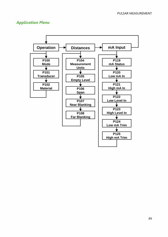
Application Menu
Operation Distances mA Input
P100 Mode
P101 Transducer
P119 mA Status
P104 Measurement
Units
P102 Material
P105 Empty Level
P106 Span
P107 Near Blanking
P108 Far Blanking
P120 Low mA In
P121 High mA In
P122 Low Level In
P123 High Level In
P124 Low mA Trim
P125 High mA Trim

ZENITH 140 INSTRUCTION MANUAL
50
Relays Menu
Relay 1
P210 Type
P211 Function
P212 Alarm ID
or Pump Group
P214 Set 2
P213 Set 1
P215 Set 3
As Required
P216 Allocat.
P217 Closures
P218 Fail Safe
P219 R1
Max.Rate If
P210=2
Relay 2 Relay 3 Relay 4 Relay 5 Relay 6
P220 Type
P230 Type
P240 Type
P250 Type
P260 Type
P221 Function
P231 Function
P241 Function
P251 Function
P261 Function
P222 Alarm ID
or Pump Group
P232 Alarm ID
or Pump Group
P242 Alarm ID
or Pump Group
P252 Alarm ID
or Pump Group
P262 Alarm ID
or Pump Group
P223 Set 1
P233 Set 1
P243 Set 1
P253 Set 1
P263 Set 1
P224 Set 2
P234 Set 2
P244 Set 2
P254 Set 2
P264 Set 2
P225 Set 3
As Required
P235 Set 3
As Required
P245 Set 3
As Required
P255 Set 3
As Required
P265 Set 3
As Required
P226 Allocat.
P236 Allocat.
P246 Allocat.
P256 Allocat.
P266 Allocat.
P227 Closures
P237 Closures
P247 Closures
P257 Closures
P267 Closures
P228 Fail Safe
P238 Fail Safe
P248 Fail Safe
P258 Fail Safe
P268 Fail Safe
P249 R4
Max.Rate If
P240=2
P259 R5
Max.Rate If
P250=2
P269 R6
Max.Rate If
P260=2
P229 R2
Max.Rate If
P220=2
P239 R3
Max.Rate If
P230=2

PULSAR MEASUREMENT
51
Pump “Advanced” Menu
Run On Starting Stopping Exercise Wall Cling Storm
P349 Prime Level
P352 Start Delay
P348 Stop Delay
P354 Exercise Enable
P360 Wall Cling
P370 Pump
Disable
P350 Run
Interval
P351 Run
Duration
P353 Power Delay
P355 Idle Time
P356 Exercise
Time
P357 Minimum
Head
P371 Disable
Time

ZENITH 140 INSTRUCTION MANUAL
52
Digital Inputs Menu
Common Par
Digital Input 1
P300 Maximum Attempts
P301 Switch Mode
P302 Override
Delay
P303 Minimum Override
P304 Input Delay
P305 Input Filter
P306 Override
Level
P372 Type
P373 Function
P374 Assign.
Input 2 – P375, Input 3 – P378 Input 4 – P381, Input 5 – P384
Input 6 – P387
Digital Input 2 to
Digital Input 6
Input 2 – P376, Input 3 – P379 Input 4 – P382, Input 5 – P385
Input 6 – P388
Input 2 – P377, Input 3 – P380 Input 4 – P383, Input 5 – P386
Input 6 – P389
Digital Input 7
P390 Type
P391 Function
P392 Assign.

PULSAR MEASUREMENT
53
Float Switch Menu
Common Par
Digital Input 1
P330 Mode
P331 Input Filter
P332 Pump Run
Time
P333 Type
P334 Function
P335 Forced Level
Input 2 – P336, Input 3 – P339 Input 4 – P342, Input 5 – P345
(Type)
Digital Input 2 to
Digital Input 5
Input 2 – P337, Input 3 – P340 Input 4 – P343, Input 5 – P346
(Function)
Input 2 – P338, Input 3 – P341 Input 4 – P344, Input 5 – P347
(Forced Level)
Digital Input 6
P363 Type
P364 Function
P365 Forced Level
ZENITH 140 INSTRUCTION MANUAL
54
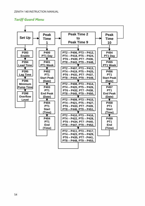
Tariff Guard Menu
Set Up Peak Time
1
Peak Time 2 to
Peak Time 9
PT2 – P406, PT3 – P412, PT4 – P418, PT5 – P424, PT6 – P430, PT7 - P436, PT8 – P443, PT9 – P448,
Peak Time
10
PT2 – P407, PT3 – P413, PT4 – P419, PT5 – P425, PT6 – P431, PT7 - P437, PT8 – P444, PT9 – P449,
PT2 – P408, PT3 – P414, PT4 – P420, PT5 – P426, PT6 – P432, PT7 - P438, PT8 – P445, PT9 – P450,
PT2 – P409, PT3 – P415, PT4 – P421, PT5 – P427, PT6 – P433, PT7 - P439, PT8 – P446, PT9 – P451,
PT2 – P410, PT3 – P416, PT4 – P422, PT5 – P428, PT6 – P434, PT7 - P440, PT8 – P447, PT9 – P452,
PT2 – P411, PT3 – P417, PT4 – P423, PT5 – P429, PT6 – P435, PT7 - P441, PT8 – P448, PT9 – P453,
P393 Enable
P394 Lead Time
P395 Lag Time
P396 Minimum
Pump Time
P398 Overflow
Level
P400 PT1 Day
P401 PT1 Week
P402 PT1
Start Peak (Date)
P403 PT1
End Peak (Date)
P404 PT1 Start
(Time)
P404 PT1 End
(Time)
P454 PT1 Day
P455 PT1 Week
P456 PT1
Start Peak (Date)
P457 PT1
End Peak (Date)
P458 PT1 Start
(Time)
P459 PT1 End
(Time)

PULSAR MEASUREMENT
55
Data Logs Menu
Tot. Audit Temperature Pump 1 Pump 2 to 5 Pump 6
P521, P531 P541, P551
Pump Hours
P522, P532 P542, P552
Pump Starts
P523, P533 P543, P553
Pump Starts per
Hour
P524, P534 P544, P554
Pump Run On
P460 Vol. Date 1
P461 Volume 1
P462, 464, 466, 468, 470, 472, 474, 476 Total Dates
2 to 9 P463, 465,
467, 469, 471, 473, 475, 477
Totals 2 to 9
P478 Vol. Date 10
P580 Min. Temp
P478 Volume 10
P581 Min. Temp.
Date
P582 Min. Temp.
Time
P583 Max. Temp.
P584 Max. Temp.
Date
P585 Max. Temp.
Time
P586 Current
Temperature
P511 Pump 1 Hours
P512 Pump 1 Starts
P513 Pump 1 Starts
per Hour
P514 Pump 1 Run On
P561 Pump 6 Hours
P562 Pump 6 Starts
P563 Pump 6 Starts
per Hour
P564 Pump 6 Run On
P515 Pump 1
Draw
P516 Pump 1
Effic.
P525, P535 P545, P555 Pump Draw
P526, P536 P546, P556 Pump Effic.
P565 Pump 6
Draw
P566 Pump 6
Effic.
ZENITH 140 INSTRUCTION MANUAL
56
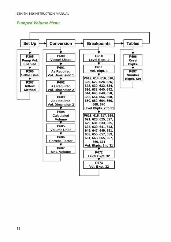
Pumped Volume Menu
Set Up
P205 Pump Vol. Enabled
P206 Settle Time
P207 Inflow
Method
Conversion
P600 Vessel Shape
P601 As Required
Vol. Dimension 1
P602 As Required
Vol. Dimension 2
P603 As Required
Vol. Dimension 3
P604 Calculated
Volume
P605 Volume Units
P606 Correct. Factor
P607 Max. Volume
P612, 614, 616, 618, 620, 622, 624, 626, 628, 630, 632, 634, 636, 638, 640, 642, 644, 646, 648, 650, 652, 654, 656, 658, 660, 662, 664, 666,
668, 670 Level Bkpts. 2 to 31
Breakpoints
P610 Level Bkpt. 1
P611 Vol. Bkpt. 1
P613, 615, 617, 619, 621, 623, 625, 627, 629, 631, 633, 635, 637, 639, 641, 643, 645, 647, 649, 651, 653, 655, 657, 659, 661, 663, 665, 667,
669, 671 Vol. Bkpts. 2 to 31
P672 Level Bkpt. 32
P673 Vol. Bkpt. 32
Tables
P696 Reset Bkpts.
P697 Number
Bkpts. Set
PULSAR MEASUREMENT
57
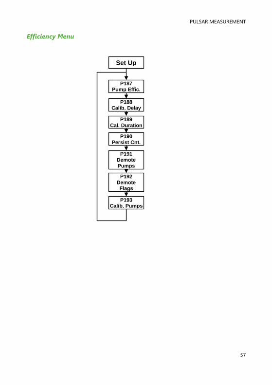
Efficiency Menu
Set Up
P187 Pump Effic.
P188 Calib. Delay
P189 Cal. Duration
P190 Persist Cnt.
P191 Demote Pumps
P192 Demote Flags
P193 Calib. Pumps

ZENITH 140 INSTRUCTION MANUAL
58
Display Menu
Options Fail Safe Auxiliary Bargraph
P802 Display Offset
P801 Decimal Places
P804 Display
Conversion
P805 Display Source
P808 Fail Mode
P809 Fail Time
P810 Units
P811 Alarms
P812 Pumps
P813 Control
P814 Misc.
P815 Auxiliary Source
P816 Totaliser
(R)
P817 Auxiliary
Offset
Totaliser
P829 Bargraph
P820 Totaliser
P821 Totaliser (R)
P822 Totaliser Decimal
P823 Totaliser Multiplier
P800 Display Units
PULSAR MEASUREMENT
59
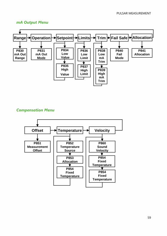
mA Output Menu
Compensation Menu
Offset Temperature Velocity
P851 Measurement
Offset
P852 Temperature
Source
P854 Fixed
Temperature
P860 Sound
Velocity
P854 Fixed
Temperature
Range Operation Setpoint Limits Trim Fail Safe Allocation
P830 mA Out Range
P831 mA Out Mode
P834 Low
Value
P836 Low Limit
P835 High
Value
P838 Low mA Trim
P840 Fail
Mode
P841 Allocation
P837 High Limit
P839 High mA Trim
P854 Fixed
Temperature
P853 Allocation

ZENITH 140 INSTRUCTION MANUAL
60
Stability Menu
Echo Processing Menu
Damping Indicator Rate Filters
P870 Fill
Damping
P871 Empty
Damping
P872 Fill
Indicator
P873 Empty
Indicator
P874 Rate Update
P875 Rate Time
P876 Rate Distance
P877 Rate Value
P878 Lower Cutoff
P880 Gate Mode
P881 Fixed Distance
P882 Process Filter
P884 Peak Percent
Xdr. 1 Status Xdr. 2 Status
P900 Xdr. 1 Status
P901 Echo
Confidence 1
P902 Echo Strength 1
P903 Average Noise 1
P904 Peak Noise 1
P905 Sensitivity 1
P906 Side Clearance 1
P910 Xdr. 2 Status
P916 Side Clearance 2
P915 Sensitivity 2
P914 Peak Noise 2
P913 Average Noise 2
P912 Echo Strength 2
P911 Echo
Confidence 2

PULSAR MEASUREMENT
61
System Menu
Passcode Backup System Info
Date &
Time
LED Colour
Daylight Saving
P921 Enable Code
P925 Parameter
Backup
P926 Software Revision
P931 Date
P935 Off
Colour
P970 DST
Enable P922
Passcode P927 Hardware Revision
P928 Serial
Number
P929 Site
Ident.
P930 Factory Default
P931 Time
P932 Date
Format
P936 Alarm Colour
P937 Pump Colour
P938 Control Colour
P939 Misc.
Colour
P971 DST
Difference
P972 DST
Start Time
P973 Start Day
P974 Start Week
P975 Start
Month
P976 DST
End Time
P977 End Day
P978 End Week
P979 End Month
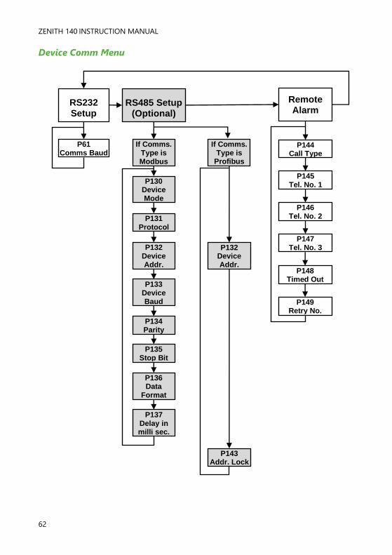
ZENITH 140 INSTRUCTION MANUAL
62
Device Comm Menu
RS485 Setup (Optional)
If Comms. Type is Modbus
P130 Device Mode
P131 Protocol
P132 Device Addr.
P133 Device Baud
RS232 Setup
P61 Comms Baud
Remote Alarm
P144 Call Type
P145 Tel. No. 1
P146 Tel. No. 2
P147 Tel. No. 3
P134 Parity
P135 Stop Bit
P136 Data
Format
P137 Delay in milli sec.
If Comms. Type is
Profibus
P132 Device Addr.
P143 Addr. Lock
P148 Timed Out
P149 Retry No.

PULSAR MEASUREMENT
63
Test Menu
Simulation Hardware
P980 Simulate
P981 Increment
P982 Rate
P983 Start Level
P984 Incremental
Change
P990 Self Test
P991 Hardware Test
P992 mA Out Test
P993 mA In Test
P994 Transducer Test
P995 Keys Test
P996 Relay Test

ZENITH 140 INSTRUCTION MANUAL
64
Application Parameters
Operation
P100 Mode of Operation
This parameter sets the mode of operation, when in run mode, and can be
set to one of the following:
OPTION DESCRIPTION
1 = Distance (Default) Display shows the distance from the transducer face
to the surface of the material measured.
2 = Level Shows how full a vessel is.
3 = Space Shows how empty a vessel is.
4 = Average Level Display shows the average level of two points of
measurement.
5 - Differential Display shows the Differential level between 2 points
of measure.
P101 Xducer (Transducer)
This parameter should be set to the transducer being used with the unit, and
can be set to one of the following:
OPTION DESCRIPTION
0 = Auxiliary Use a mA input
1 = dB3 Transducer is a dB3. Range = 0 to 3 metres
2 = dB6 (default) Transducer is a dB6. Range = 0.3 to 6 metres
3 = dB10 Transducer is a dB10. Range = 0.3 to 10 metres
4 = dB15 Transducer is a dB15. Range = 0.5 to 15 metres
5 = dB25 Transducer is a dB25. Range = 0.6 to 25 metres
6 = dB40 Transducer is a dB40. Range = 1.2 to 40 metres
7 = dBS6 Transducer is a dBS6. Range = 0.2 to 6 metres
8 = dBMach3 Transducer is a dBMach3. Range 0.3 to 2.425 metres
*11 = dBR16 Transducer is a mmWave radar. Range 0.077 to 16 metres
*12 = dBR8 Transducer is a mmWave radar. Range 0.077 to 8 metres
P102 Material
This parameter should be set to the type of material being monitored.
Important Notice
*Please consult your local Pulsar distributor for the versions of firmware that the
mmWAVE radars are available in.
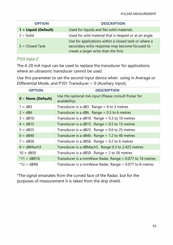
PULSAR MEASUREMENT
65
OPTION DESCRIPTION
1 = Liquid (Default) Used for liquids and flat solid materials.
2 = Solid Used for sold material that is heaped or at an angle.
3 = Closed Tank
Use for applications within a closed tank or where a
secondary echo response may become focused to
create a larger echo than the first.
P103 Input 2
The 4-20 mA input can be used to replace the transducer for applications
where an ultrasonic transducer cannot be used.
Use this parameter to set the second input device when using in Average or
Differential Mode, and P101 Transducer = 0 (Auxiliary Input).
OPTION DESCRIPTION
0 = None (Default) Use the optional mA input (Please consult Pulsar for
availability).
1 = dB3 Transducer is a dB3. Range = 0 to 3 metres
2 = dB6 Transducer is a dB6. Range = 0.3 to 6 metres
3 = dB10 Transducer is a dB10. Range = 0.3 to 10 metres
4 = dB15 Transducer is a dB15. Range = 0.5 to 15 metres
5 = dB25 Transducer is a dB25. Range = 0.6 to 25 metres
6 = dB40 Transducer is a dB40. Range = 1.2 to 40 metres
7 = dBS6 Transducer is a dBS6. Range = 0.2 to 6 metres
8 = dBMach3 Transducer is a dBMach3. Range 0.3 to 2.425 metres
10 = dB50 Transducer is a dB50. Range = 2 to 50 metres
*11 = dBR16 Transducer is a mmWave Radar. Range = 0.077 to 16 metres
*12 = dBR8 Transducer is a mmWave Radar. Range = 0.077 to 8 metres
*The signal emanates from the curved face of the Radar, but for the
purposes of measurement it is taken from the drip shield.

ZENITH 140 INSTRUCTION MANUAL
66
Dimensions
P104 Measurement Units
This parameter sets the units you want to use for programming and display.
OPTION DESCRIPTION
1 = metres (Default) All units of measurement are Metres
2 = cm All units of measurement are Centimetres
3 = mm All units of measurement are Millimetres
4 = feet All units of measurement are Feet
5 = inches All units of measurement are Inches
P105 Empty Level
This parameter is to be set to the maximum distance from the face of the
transducer to the empty point, in P104 Measurement Units. Note this
value affects span as well, (see the following important information notices),
so should be set before span.
P106 Span
This parameter should be set to the maximum distance from the Empty
Level (P105) to the maximum material level. It is automatically set to be
equal to the Empty Level (P105) less the Near Blanking distance (P107)
when you set the empty level.
Important Notice
When changing the Empty Distance (P105) you can also recalculate the
values for the Span so that it equals the empty distance (P105) minus
Near Blanking (P107) and the Relay Setpoints, so that they remain at the
same percentage values of the empty distance as they were before you
changed the empty distance (P105). You will be asked the question
“Recalculate Span?” if you choose yes (enter 1), then the span will be
recalculated. Any other answer will leave the span at its original value.
You will then be asked if you want to “Recalculate Setpoints?”, if you
choose yes (enter 1), then all Relay Setpoints will be recalculated as a
percentage of the new empty distance. Any other answer will leave the
setpoints at their original values.
Important Notice
When using the dB Mach 3 the empty distance is measured from the end of the
horn to the empty point in P104 Measurement Units.

PULSAR MEASUREMENT
67
P107 Span
This parameter is the distance from the face of the transducer that is not
measurable and is pre-set to the minimum value dependant on the
Transducer (P101) selected. It should not be set to less than this figure, but
can be increased, typically to ignore close in obstructions.
TRANSDUCER NEAR BLANKING DISTANCE
P101 = dBMach3 Default blanking distance = 0.00 metres
P101 = dB3 Default blanking distance = 0.125 metres
P101 = dB6 Default blanking distance = 0.30 metres
P101 = dB10 Default blanking distance = 0.30 metres
P101 = dB15 Default blanking distance = 0.50 metres
P101 = dB25 Default blanking distance = 0.60 metres
P101 = dB40 Default blanking distance = 1.20 metres
P101 = dBS6 Default blanking distance = 0.20 metres
P101 = dBR16 Default blanking distance = *0.077 metres
P101 = dBR8 Default blanking distance = *0.077 metres
*The signal emanates from the curved face of the radar, but for the purposes
of measurement it is taken from the drip shield.
P108 Far Blanking Distance
This is the distance (as a percentage of the empty level P105) beyond the
empty point that the unit will be able to measure, and by default is pre-set
to 20% of the empty level.
If the surface being monitored can be extended beyond the empty level
(P105) then the far blanking distance can be increased to a max. of 100% of
the empty level, provided it does not exceed the max range of the
transducer being used. This parameter is always entered as a % of the
empty level.

ZENITH 140 INSTRUCTION MANUAL
68
mA Input
The 4-20 mA (Auxiliary) input is available as an option (Consult Pulsar for
details of availability), and can be used to replace the transducer for
applications where an ultrasonic transducer cannot be used.
P119 mA Status
If P101 (Xducer) = 1 (Auxiliary)
This indicates the status of the Auxiliary input if selected
OPTION DESCRIPTION
1 = mA OK (Default) mA Input present and functioning correctly
1 = mA Open No input (device) is being detected
2 = mA Short Input is indicating a fault condition
P120 Low mA in
This parameter sets the current input figure that is used to represent empty
when using the optional current input, instead of an ultrasonic transducer.
Default = 4ma
P121 High mA in
This parameter sets the current input figure that is used to represent span
when using the optional current input, instead of an ultrasonic transducer.
Default= 20mA
P122 Low Level in.
This parameter sets the distance to empty point when using the optional
current input, (Aux. input) instead of an ultrasonic transducer.
P123 High Level in
This parameter sets the distance that is full (span) when using the optional
current input, (Aux. input) instead of an ultrasonic transducer.
P124 Low mA Trim
This parameter allows you to “calibrate” the Zenith to the Low mA Input
from the device being used. If the expected low value, from the device
connected to the mA Input, is not displayed, then you can trim it using this
parameter.

PULSAR MEASUREMENT
69
P125 High mA Trim
This parameter allows you to “calibrate” the Zenith to the High mA Input
from the device being used. If the expected high value, from the device
connected to the mA Input, is not displayed, then you can trim it using this
parameter.
Important Notice
When using the auxiliary input, all settings relating to measurement should be
entered in relation to level i.e., zero (empty) to 100% (full) and not distance. This also
means that the device you are connecting should provide an input that will change
with level.

ZENITH 140 INSTRUCTION MANUAL
70
Relay Parameters
All relay related parameters are prefixed with a 2**.
The second digit of the three-figure parameter number denotes the relay
number as follows:
21* parameters for Relay 1
22* parameters for Relay 2
23* parameters for Relay 3
24* parameters for Relay 4
25* parameters for Relay 5
26* parameters for Relay 6
The third digit selects specific parameter for the setting of the relays, which
can be selected individually and results in the following parameter numbers
for each relay:
Relay 1 210 to 219
Relay 2 220 to 229
Relay 3 230 to 239
Relay 4 240 to 249
Relay 5 250 to 259
Relay 6 260 to 269

PULSAR MEASUREMENT
71
P210, 220, 230, 240, 250, 260 - Relay Type
This parameter defines what type each relay should be, see the table below
for available options:
OPTION DESCRIPTION
0 = Not in use (Default) Relay is not in use or programmed and the LED will
always be off.
1 = Alarm
Relay is programmed as an alarm relay, which will de-
energise ON, and energise OFF. This will ensure an
alarm is raised if the power fails to the unit.
2 = Pump Relay is programmed as a pump relay, which will
energise ON, and de-energise OFF.
3 = Control Relay is programmed as a control relay, which will
energise ON, and de-energise OFF.
4 = Miscellaneous Relay is programmed as a miscellaneous relay, which will
energise ON, and de-energise OFF.
5 = Pump by time
Relay is programmed as a pump relay, which will
energise at its ON level setpoint, and de-energise at its
OFF level setpoint or after a predetermined time period,
whichever occurs first.
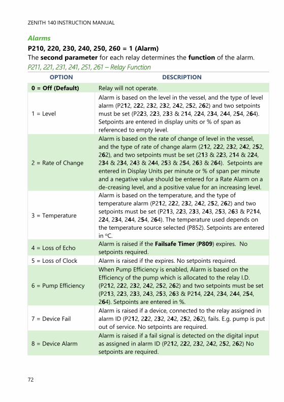
ZENITH 140 INSTRUCTION MANUAL
72
Alarms
P210, 220, 230, 240, 250, 260 = 1 (Alarm)
The second parameter for each relay determines the function of the alarm.
P211, 221, 231, 241, 251, 261 – Relay Function
OPTION DESCRIPTION
0 = Off (Default) Relay will not operate.
1 = Level
Alarm is based on the level in the vessel, and the type of level
alarm (P212, 222, 232, 232, 242, 252, 262) and two setpoints
must be set (P223, 223, 233 & 214, 224, 234, 244, 254, 264).
Setpoints are entered in display units or % of span as
referenced to empty level.
2 = Rate of Change
Alarm is based on the rate of change of level in the vessel,
and the type of rate of change alarm (212, 222, 232, 242, 252,
262), and two setpoints must be set (213 & 223, 214 & 224,
234 & 234, 243 & 244, 253 & 254, 263 & 264). Setpoints are
entered in Display Units per minute or % of span per minute
and a negative value should be entered for a Rate Alarm on a
de-creasing level, and a positive value for an increasing level.
3 = Temperature
Alarm is based on the temperature, and the type of
temperature alarm (P212, 222, 232, 242, 252, 262) and two
setpoints must be set (P213, 223, 233, 243, 253, 263 & P214,
224, 234, 244, 254, 264). The temperature used depends on
the temperature source selected (P852). Setpoints are entered
in oC.
4 = Loss of Echo Alarm is raised if the Failsafe Timer (P809) expires. No
setpoints required.
5 = Loss of Clock Alarm is raised if the expires. No setpoints required.
6 = Pump Efficiency
When Pump Efficiency is enabled, Alarm is based on the
Efficiency of the pump which is allocated to the relay I.D.
(P212, 222, 232, 242, 252, 262) and two setpoints must be set
(P213, 223, 233, 243, 253, 263 & P214, 224, 234, 244, 254,
264). Setpoints are entered in %.
7 = Device Fail
Alarm is raised if a device, connected to the relay assigned in
alarm ID (P212, 222, 232, 242, 252, 262), fails. E.g. pump is put
out of service. No setpoints are required.
8 = Device Alarm
Alarm is raised if a fail signal is detected on the digital input
as assigned in alarm ID (P212, 222, 232, 242, 252, 262) No
setpoints are required.
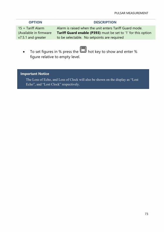
PULSAR MEASUREMENT
73
OPTION DESCRIPTION
15 = Tariff Alarm
(Available in firmware
v7.5.1 and greater
Alarm is raised when the unit enters Tariff Guard mode.
Tariff Guard enable (P393) must be set to ‘1’ for this option
to be selectable. No setpoints are required
• To set figures in % press the hot key to show and enter %
figure relative to empty level.
Important Notice
The Loss of Echo, and Loss of Clock will also be shown on the display as “Lost
Echo”, and “Lost Clock” respectively.

ZENITH 140 INSTRUCTION MANUAL
74
The third parameter for each relay determines the Alarm ID for the relay
you wish to set.
P212, 222, 232, 242, 252, 262 – Relay Alarm ID
When P211, 221, 231, 241, 251, 261 = 4 (Loss of Echo) or 5 (Loss of
Clock). This parameter has no function and will not be displayed.
P211, 221, 231, 241, 251, 261 = 1 (Level), 2 = Rate of Change or 3
(Temp)
This parameter defines which alarm type, or identification, the relay should
respond to, as follows:
OPTION DESCRIPTION SETPOINTS
1 = General
(Default)
Relay goes “ON” when the
value reaches the ON
setpoint and goes “OFF”
when the value reaches the
OFF setpoint.
P213, 223, 233, 243, 253,
263 is ON Setpoint; P214,
224, 234, 244, 254, 264 is
OFF Setpoint
2 = High
Relay goes “ON” when the
value rises to the ON
setpoint and goes “OFF”
when the value lowers to the
OFF setpoint.
ON>OFF Relay Setpoints
P213, 223, 233, 243, 253,
263 and P214, 224, 234,
244, 254, 264. Setpoints
can be set in any order as
the unit ‘knows’ that you
are setting a high-level
alarm.
3 = HiHi Same as 2 = High, but different identifier
4 = Low
Relay goes “ON” when the
value lowers to the ON
setpoint and goes “OFF”
when the value rises to the
OFF setpoint.
ON<OFF Relay
Setpoints P213, 223, 233,
243, 253, 263 and P214,
224, 234, 244, 254, 264.
Setpoints can be set in any
order as the unit ‘knows’
that you are setting a low-
level alarm.
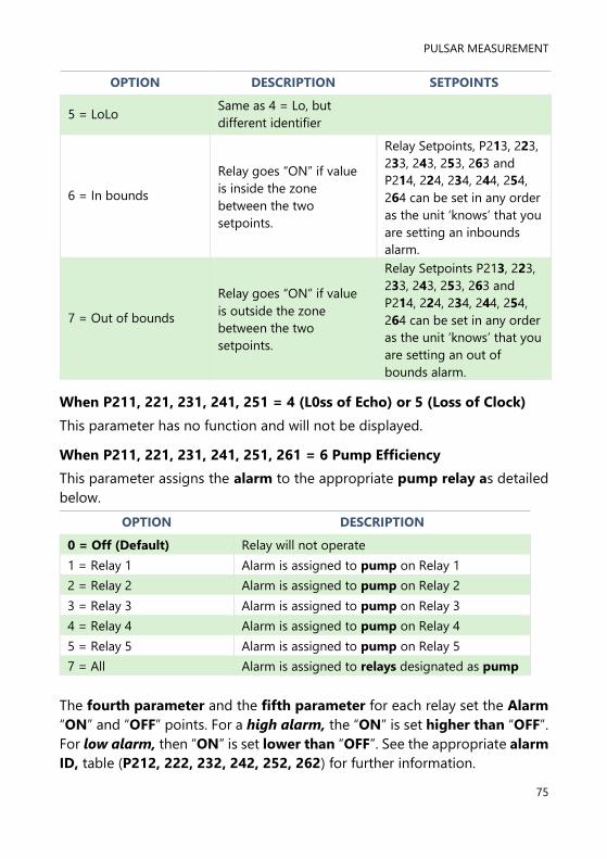
PULSAR MEASUREMENT
75
OPTION DESCRIPTION SETPOINTS
5 = LoLo Same as 4 = Lo, but
different identifier
6 = In bounds
Relay goes “ON” if value
is inside the zone
between the two
setpoints.
Relay Setpoints, P213, 223,
233, 243, 253, 263 and
P214, 224, 234, 244, 254,
264 can be set in any order
as the unit ‘knows’ that you
are setting an inbounds
alarm.
7 = Out of bounds
Relay goes “ON” if value
is outside the zone
between the two
setpoints.
Relay Setpoints P213, 223,
233, 243, 253, 263 and
P214, 224, 234, 244, 254,
264 can be set in any order
as the unit ‘knows’ that you
are setting an out of
bounds alarm.
When P211, 221, 231, 241, 251 = 4 (L0ss of Echo) or 5 (Loss of Clock)
This parameter has no function and will not be displayed.
When P211, 221, 231, 241, 251, 261 = 6 Pump Efficiency
This parameter assigns the alarm to the appropriate pump relay as detailed
below.
OPTION DESCRIPTION
0 = Off (Default) Relay will not operate
1 = Relay 1 Alarm is assigned to pump on Relay 1
2 = Relay 2 Alarm is assigned to pump on Relay 2
3 = Relay 3 Alarm is assigned to pump on Relay 3
4 = Relay 4 Alarm is assigned to pump on Relay 4
5 = Relay 5 Alarm is assigned to pump on Relay 5
7 = All Alarm is assigned to relays designated as pump
The fourth parameter and the fifth parameter for each relay set the Alarm
“ON” and “OFF” points. For a high alarm, the “ON” is set higher than “OFF”.
For low alarm, then “ON” is set lower than “OFF”. See the appropriate alarm
ID, table (P212, 222, 232, 242, 252, 262) for further information.

ZENITH 140 INSTRUCTION MANUAL
76
P212, 222, 232, 242, 252, 262 Relay Alarm ID
When P211, 221, 231, 241, 251, 261 = 7 (Device Fail)
This parameter defines which failed device relay, the alarm should respond
to, as follows.
OPTION DESCRIPTION SETPOINTS
1 = Fail Relay 1 (Default) Relay goes “ON” when a device
failure is detected on relay 1. None
2 = Fail Relay 2 Relay goes “ON” when a device
failure is detected on relay 2. None
3 = Fail Relay 3 Relay goes “ON” when a device
failure is detected on relay 3. None
4 = Fail Relay 4 Relay goes “ON” when a device
failure is detected on relay 4. None
5 = Fail Relay 5 Relay goes “ON” when a device
failure is detected on relay 5. None
6 = Fail Relay 6 Relay goes “ON” when a device
failure is detected on relay 6. None
7 = Any 1 Fail
Relay goes “ON” when a device
failure is detected on any 1
relay.
None
8 = Any 2 Fail
Relay goes “ON” when a device
failure is detected on any 2
relays.
None

PULSAR MEASUREMENT
77
P212, 222, 232, 242, 252, 262 Relay Alarm ID
When P211, 221, 231, 241, 251, 261 = 8 (Device Alarm)
This parameter defines which digital input, the alarm should respond to, as
follows.
OPTION DESCRIPTION SETPOINTS
1 = Fail Input 1 (Default)
Relay goes “ON” when a device
fail signal is detected on digital
input 1.
None
2 = Fail Input 2
Relay goes “ON” when a device
fail signal is detected on digital
input 2.
None
3 = Fail Input 3
Relay goes “ON” when a device
fail signal is detected on digital
input 3.
None
4 = Fail Input 4
Relay goes “ON” when a device
fail signal is detected on digital
input 4.
None
5 = Fail Input 5
Relay goes “ON” when a device
fail signal is detected on digital
input 5.
None
6 = Fail Input 6
Relay goes “ON” when a device
fail signal is detected on digital
input 6.
None
7 = Fail Input 7
Relay goes “ON” when a device
fail signal is detected on digital
input 7.
None

ZENITH 140 INSTRUCTION MANUAL
78
When P211, 221, 231, 241, 251, 261 = 1 (Level), 2 (Rate of Change) or 3
(Temperature) or 6 (Efficiency)
P213, P223, P233, 243, 253, 263 - Relay Setpoint 1
Determines the “ON” or “OFF” point for the alarm according to the ID
selected.
P214, P224, P234, 244, 254, 264 - Relay Setpoint 2
Determines the “ON” or “OFF” point for the alarm according to the ID
selected.
To set figures in % press the hotkey to show and enter % figure,
relative to empty level.
When P211, 221, 231, 241, 251, 261 = 4 (Loss of Echo), 5 (Loss of
Clock), 7 (Device Fail) or 8 (Device Alarm)
This parameter has no function and will not be displayed.
Important Notice
Setpoints are entered in values according to the function selected.
Level - entered in Display Units or % of span as referenced to Empty Level.
Rate of Change - entered in Display Units per minute or % of span per minute.
For an alarm on an increasing level enter setpoints as a positive value, for an
alarm on a decreasing level enter setpoints as a negative value.
Temperature - entered in ºC.
See the appropriate alarm function, table (P211, 221, 231, 241, 251 and 261)
for further information.

PULSAR MEASUREMENT
79
Pumps
P210, 220, 230, 240, 250, 260= 2 (Pump)
When a relay is being used for a pump function, the second parameter
determines the pump duty that will be used to determine the operating
cycle.
P211, 221, 231, 241, 251, 261 – Relay Function
This parameter defines which pump duty the relay should respond to as
follows:
PUMP DUTY DESCRIPTION
0 = Off (Default) Relay is always de-energised
1 = Fixed duty assist
All pumps are used to assist each other (run at the
same time) and each pump has its own setpoints.
(P213, 223, 233, 243, 253, 263 & P214, 224, 234,
244, 254, 264).
2 = Fixed duty backup
If a pump fails to meet the demand (due to
malfunction, intake blockage etc.), then it is
stopped, and another pump shall take over. Each
pump has its own setpoints. (P213, 223, 233, 243,
253, 263 & P214, 224, 234, 244, 254, 264).
3 = Alternate duty assist
All pumps are used to assist each other (run at the
same time) and each pump has its own setpoints,
(P213, 223, 233, 243, 253, 263 & P214, 224, 234,
244, 254, 264). but each time all pumps have
stopped, then the setpoints are sequentially rotated
between the pumps to ensure equal pump use.
4 = Alternate duty backup
If a pump fails to meet the demand (due to
malfunction, intake blockage etc.), then it is
stopped, and another pump shall take over. Each
pump has its own setpoints, (P213, 223, 233, 243,
253, 263 & P214, 224, 234, 244, 254, 264). but each
time all pumps have stopped, then the setpoints are
sequentially rotated between the pumps to ensure
equal pump use.

ZENITH 140 INSTRUCTION MANUAL
80
PUMP DUTY DESCRIPTION
5 = Duty backup and assist
First pump comes on, if it cannot cope, it goes
off and next pump comes on (duty backup). This
continues until the last pump comes on and if it
cannot cope the first pump comes back on to
assist the last pump (duty assist) if the level
continues to rise all other pumps will come on
(assist) in turn until the level decreases to the
pump off points. Each pump has its own
setpoints, (P213, 223, 233, 243, 253 & P214, 224,
234, 244, 254, 264).
6 = Service ratio duty assist
All pumps are used to assist each other (run at
the same time) and each pump has its own
setpoints (P213, 223, 233, 243, 253, 263 & P214,
224, 234, 244, 254, 264). And a service ratio
setting. The third setpoint (P215, 225, 235, 245,
255, 265) is used to set the service ratio. Each
time a pump is required to start then the pump
with the least running hours (with respect to the
service ratio) is started (i.e. the setpoints are re-
assigned accordingly). For example, if two
pumps A and B have the service ratio set to 2
and 1 respectively, then pump A will operate for
twice as many hours as pump B.

PULSAR MEASUREMENT
81
PUMP DUTY DESCRIPTION
7 = Service ratio duty
backup
The first pump switched on is the first pump to
be switched off, regardless of the set points, so
the setpoints are dynamically changed to enable
this. If a pump fails to meet the demand (due to
malfunction, intake blockage and so on), then it
is stopped, and another pump shall take over.
Each time a pump is required to start then the
pump with the least running hours (with respect
to the service ratio) is started (i.e. the setpoints
are re-assigned accordingly). Each pump has its
own setpoints (P213, 223, 233, 243, 253, 263 &
P214, 224, 234, 244, 254, 264). The third setpoint
(P215, 225, 235, 245, 255, 265) is used to set the
service ratio. E.g., if two pumps A and B have the
service ratio set to 2 and 1 respectively, then
pump A will operate for twice as many hours as
pump B.
8 = First On First Off
Alternate duty assist
The first pump switched on is the first pump to
be switched off, etc. regardless of the set points,
so the setpoints are dynamically changed to
enable this.
9 = Service Ratio Standby
When a service ratio duty is being used, on all
other pumps in use, the standby pump can be
started on a ratio basis only, when it will assume
the setpoints of the next pump to start. The third
setpoint (P215, 225, 235, 245, 255, 265) is used
to set the service ratio.
10 = Two Pump Sets
There are four pumps. Two rotate their start-up
sequence with each other. If the two pumps
cannot keep up, the level rise to the setpoints of
the other two pumps which take over and rotate
their sequence with each other.
Important Notice
The pumps are started and stopped at the “ON” and “OFF” setpoints. To
pump down (reduce level) then set “ON” higher than “OFF”. To pump up
(increase level) then set “ON” lower than “OFF”.

ZENITH 140 INSTRUCTION MANUAL
82
The third parameter for each relay determines the pump group. You can
have two groups of pumps, and all similar duties within that group will
operate together.
P212, 222, 232, 242, 252, 262 – Relay Pump Group
By default, all pump groups are set to 1, but if you want to have another
group, then set this parameter to 2, for each pump relay that should operate
together as part of a second group.
The fourth parameter and the fifth parameter for each relay set the pump
“ON” and “OFF” points, which are entered in Measurement units P104. For
pump down the “ON” is set higher than “OFF”. For pump up then “ON” is
set lower than “OFF”. See the appropriate pump duty, function table
(P212, 222, 232, 242, 252, 262) for further information.
P213, 223, 233, 243, 253, 263 – Relay Setpoint 1
This parameter determines the ‘ON’ point of the pump.
P214, 224, 234, 244, 254, 264 – Relay Setpoint 2
This parameter determines the ‘OFF’ point of the pump.
The sixth parameter will determine the service ratio that will be used to
switch the pump, when pump duty selected is a Service Ratio duty.
P210, 220, 230, 240, 250 = 6, 7 or 9 (Service ratio)
P215, 225, 235, 245, 255, 265 – Relay Setpoint 3
This parameter determines the Service Ratio in values of %. See the
appropriate pump duty function, table (P211, 221, 231, 241, 251, 261), for
further information.
P219, 229, 239, 249, 259, 269 – Relay Max Rate
This parameter will allow a pump to be switched at a pre-determined Rate
of change of Level, irrespective of the “ON” level setpoint P213, 223, 233,
243, 253, 263. Once a pump relay has been switched “ON” by the pre-
determined Rate of Change, it will remain energised until the level reaches
the “OFF” level setpoint P214, 224, 234, 244, 254, 264.
Max. Rate is entered in Measurement Units (P104) per minute and can be
entered as either positive (increasing level) or negative (decreasing level)
values.

PULSAR MEASUREMENT
83
Control
P210, 220, 230, 240, 250, 260 = 3 (Control)
When a relay is being set as a control relay, the second parameter that will
be displayed in the menu determines its function.
P211, P221, P231, 241, 251, 261 - Relay Function,
This function allows the relay to be assigned to specific control functions
and mainly work in relation to time.
OPTIONS DESCRIPTION
0 = Off (Default) Relay is always de-energised
1 = Time
Relay will energise “ON” after the Cycle time that is set in
Relay Setpoint 2 (P214, 224, 234). And turns “OFF”, de-
energises, after the On-Time Period that is set in Relay
Setpoint 1 (P213, 223, 233, 243, 253)
2 = Storm
Relay will energise “ON” when storm conditions are in effect
and, de-energise “OFF” when storm conditions cease. Two
setpoints are required, Upper Storm “ON”, (P213, 223, 233,
243, 253, 263) and Lower Storm, “OFF” (P214, 224, 234, 244,
254, 264). This allows the relay to be used to activate a
device as a result of high levels such as a storm condition e.g.
opening a gate valve to divert storm overflow into a holding
vessel.
3 = Aeration
Relay will energise “ON” after each Cycle time as set in
Relay Setpoint 2 (P214, 224, 234, 244, 254, 264). And turns
“OFF”, de-energises, after the set On Time Period as set in
Relay Setpoint 1 (P213, 223, 233, 243,253, 263).
This can be used to activate a device based upon elapsed
time since All Pumps have been “OFF”, such as the
introduction of fresh air to reduce gas concentration.

ZENITH 140 INSTRUCTION MANUAL
84
OPTIONS DESCRIPTION
4 = Flush Valve
Relay will energise “ON” when Flush condition is in effect
and goes off when Flush condition is cleared. A relay being
used for Flush Valve/Pump must be assigned to one of the
main pumps in use. Flush relay Alarm ID (P212, 222, 232,
242, 252, 262) is used to enter the relay number, to which
the assigned pump is connected.
Flush Valve/Pump relay requires three setpoints. The first set
point (P213, 223, 233, 243, 253, 263) determines the Flush
Interval, which is the number of main pump cycles that
should occur before the Flush Valve/Pump operates. The
second setpoint (P214, 224, 234, 244, 254, 264), sets the
number of Flush cycles the Flush Valve/Pump will operate
for. This means that the Flush Valve will be operated for
several main pump starts (Flush Cycles) after which the Flush
Valve activity will cease until the Flush Interval comes
around again. Setpoint three of the Flush Valve/Pump relay
sets the Flush Duration, (P215, 225, 235, 245, 235, 236) this
is the duration for Flush
5 = Step Time
Step Time Control allows relays to be used to control a
device, such as a motorised valve or gate, in order to
maintain the level within two predetermined points. Relays
will energise “ON” when Step Time condition is in effect and
de-energises “OFF” when Step Time goes off. One relay will
be required to control an increase in level, (‘open’ the device)
and a second relay is required to control a decrease in level,
(‘close’ the device). Alarm ID (P212, 222, 232, 242, 252, 262)
is used to assign the relay to control either the open or close
condition. Step Time Control relay requires three setpoints.
The first set point (P213, 223, 233, 243, 253, 263) determines
the level, at which the relay is to be activated, (N.B. level
setpoint for open relay, increase the level, must be lower
than the setpoint for the close relay, decrease the level). The
relay will energise “ON” after the Limit time that is set in
Relay Setpoint 3 (P215, 225, 235, 245, 255, 265). And turns
“OFF”, de-energises, after the Drive Period that is set in
Relay Setpoint 2 (P214, 224, 234, 244, 254, 264).

PULSAR MEASUREMENT
85
OPTIONS DESCRIPTION
6 = Differential
Control
Relay will energise “ON” when a differential condition is in
effect and, de-energise “OFF” when the differential
conditions cease. Two setpoints are required, Differential
control “ON”, (P213, 223, 233, 243, 253, 263) and
Differential control, “OFF” (P214, 224, 234, 244, 254, 264).
This allows the relay to be used to activate a device because
of a differential level, between two points e.g. operate a rake
on a screen.
The third parameter for each relay determines the assignment or
condition of the relay, where required.
P212, P222, P232, P242, P252, 262 - Relay Alarm ID/Pump Group,
P211, 221, 231, 241, 251, 261 = 1, 2, 3 or 6
This parameter has no function and will not be displayed.
P211, 221, 231, 241, 251, 261 = 4 (Flush Valve)
If the relay is selected for Flush Valve/Pump, then this parameter is used to
determine to which pump the Flush function is assigned. Enter the relay
number to which the assigned pump is connected.
P211, 221, 231, 241, 251, 261 = 5 (Step Time)
If the relay is selected for Step Time, then this parameter is used to assign
the relay to the 0 = Open condition (increase level) or 1 = Close condition
(decrease level).
The fourth parameter, fifth parameter and sixth parameter are set to
determine the switch points, “ON” and “OFF” for the relay and where
required the order of start. See control function, table (P211, 221, 231) for
further information.
P213, P223, P233, P243, P253 Relay Setpoint 1
P211, 221, 231, 241, 251, 261 =1 (Time)
This parameter determines the “Time Period” that the relay will remain “ON”.
Relay Setpoints are entered in Minutes.
See the appropriate relay Function tables (P211, 221, 231, 241, 251, 261)
for further information.

ZENITH 140 INSTRUCTION MANUAL
86
P211, 221, 231, 241, 251, 261 =2 (Storm)
Relay Setpoint 1 is entered in values of Measurement Units (P104)
See the appropriate relay function tables (P211, 221, 231, 241, 251, 261)
for further information.
P211, 221, 231, 241, 251, 261 =3 (Aeration)
Relay Setpoint 1 is entered in Minutes to set Cycle Time
See the appropriate relay Function tables (P211, 221, 231, 241, 251, 261)
for further information.
P211, 221, 231, 241, 251, 261 =4 (Flush Valve)
Relay Setpoint 1 is entered in Pump cycles to set Flush Interval.
See the appropriate relay Function tables (P211, 221, 231, 241, 251, 261)
for further information.
P211, 221, 231, 241, 251, 261 =5 (Step Time)
Relay Setpoint 1 is entered in values of Measurement Units (P104)
See the appropriate relay function tables (P211, 221, 231, 241, 251, 261)
for further information.
P211, 221, 231, 241, 251, 261 =6 (Differential)
Relay Setpoint 1 is entered in values of Measurement Units (P104)
See the appropriate relay function tables (P211, 221, 231, 241, 251, 261)
for further information.
P214, P224, P234, P244, P254 Relay Setpoint 2
P211, 221, 231, 241, 251, 261 =1 (Time)
This parameter determines the “Cycle Time” for the operation of the relay.
See the appropriate relay Function tables (P211, 221, 231, 241, 251, 261)
for further information.
P211, 221, 231, 241, 251, 261 =2 (Storm)
Relay Setpoints are entered in values of Measurement Units (P104)
See the appropriate relay Function tables (P211, 221, 231, 241, 251, 261)
for further information.
PULSAR MEASUREMENT
87
P211, 221, 231, 241, 251, 261 =3 (Aeration)
Relay Setpoints are entered in Minutes to set Time Period that the relay will
remain ON.
See the appropriate relay Function tables (P211, 221, 231, 241, 251, 261)
for further information.
P211, 221, 231, 241, 251, 261 =4 (Flush Valve)
Relay Setpoints are entered in cycles to set the number of Flush cycles.
See the appropriate relay Function tables (P211, 221, 231, 241, 251, 261)
for further information.
P211, 221, 231, 241, 251, 261 =5 (Step Time)
Relay Setpoints are entered in Seconds to set Drive Period, the time that
the relay will remain ON
See the appropriate relay Function tables (P211, 221, 231, 241, 251, 261)
for further information.
P211, 221, 231, 241, 251, 261 =6 (Differential)
Relay Setpoints are entered in values of Measurement Units (P104).
See the appropriate relay Function tables (P211, 221, 231, 241, 251, 261)
for further information.
P215, P225, P235, P245, P255, 265 Relay Setpoint 3
P211, 221, 231, 241, 251, 261 = 4 (Flush Valve)
Enter desired Flush duration in seconds.
See the appropriate relay Function tables (P211, 221, 231, 241, 251) for
further information.
P211, 221, 231, 241, 251, 261 = 5 (Step Time)
This parameter is used to determine the Limit Time between each Drive
Period. Relay Setpoints are entered in Minutes, during which time the relay
will remain OFF.
See the appropriate relay Function tables (P211, 221, 231, 241, 251, 261)
for further information.

ZENITH 140 INSTRUCTION MANUAL
88
Miscellaneous
P210, 220, 230, 240, 250 = 4 (Miscellaneous)
When a relay is set to be a miscellaneous relay, the second parameter
determines its function.
P211, 221, 231, 241, 251, 261 – Relay Function
This function allows the relay to work in relation to a clock or a specific event
and will be set to activate in relation to Real Time.
OPTIONS DESCRIPTION
0 = Off (Default) Relay is always de-energised
1 = Clock
Relay will energise ON at a specified time each day as set
in Relay Setpoint 1 (P213, 223, 233, 243, 253, 263). And
turns OFF, de-energises, after the specified “On Time”
period as set in Relay Setpoint 2 (P214, 224, 234, 244,
254, 264)
2 = Totaliser
Relay will energise ON momentarily each time the
specified flow has passed as set in Relay setpoint 1 (P213,
223, 233, 243, 253, 263), this parameter sets the
multiplication factor which will be applied to the on-
board totaliser (P820) to determine the switch point of
the relay. E.g., if the totaliser is set to totalise in cubic
metres and the relay is required to provide a closure
every 10,000 litres Relay setpoint 1 would be set to 10.
Relay setpoint 2 (P214, 224, 234, 244, 254, 264) can be
used to select the time the relay will remain closed in
seconds.
Important Notice
When using a Relay to control a device at a specified time of day ensure
that the Time P932 is set correctly. And if required, enable Daylight
Saving for the appropriate time difference P970 – P979.
PULSAR MEASUREMENT
89
The third parameter has no function when miscellaneous relay is chosen
and will not be displayed.
The fourth parameter, and fifth parameter, are set to determine the switch
points, “ON” and “OFF” for the relay. See miscellaneous function table
(P211, 221, 231, 241, 251, 261) for further information.
P211, 221, 231, 241, 251, 261 = 1 (Clock)
P213, 223, 233, 243, 253, 263 – Relay Setpoint 1
Relay Setpoints are entered in Hours & Minutes (HH:MM) to set Time at
which relay will energise. Default = 00:00 (HH:MM)
P214, 224, 234, 244, 254, 264 – Relay Setpoint 2
Relay Setpoints are entered in seconds to set the Time Period that the relay
will remain ‘ON’. Default = 0.00 mins.
P210, 220, 230= 2 (Totaliser)
P213, 223, 233, 243, 253, 263 – Relay Setpoint 1
Relay Setpoints are entered as a factor by which the on-board totaliser
(P820) should be multiplied by to provide a relay closure. Default = 0.00
P214, 224, 234, 244, 254, 264 – Relay Setpoint 2
Relay Setpoints are entered in seconds to set the Time Period that the relay
will remain ‘ON’. Default = 0.00 secs.
Pump by Time
When a relay is assigned to Pump by Time the pump will come on (energise)
at its normal “ON” level setpoint, and de-energise at its OFF level setpoint
or after a predetermined time period, whichever occurs first.
P210, 220, 230, 240, 250, 260 = 5 (Pump by Time)
When a relay is being used for a pump by time function, the second
parameter determines the pump duty that will be used to determine the
operating cycle.

ZENITH 140 INSTRUCTION MANUAL
90
P211, P221, P231, P241, P25, 2611 - Relay Function,
This parameter defines which pump duty the relay should respond to as
follows.
PUMP DUTY DESCRIPTION
0 = Off (Default) Relay is always de-energised
1 = Fixed duty assist
All pumps are used to assist each other (run at the
same time) and each pump has its own setpoints.
(P213, 223, 233, 243, 253, 263 & P214, 224, 234,
244, 254, 264).
2 = Fixed duty backup
If a pump fails to meet the demand (due to
malfunction, intake blockage etc.), then it is
stopped, and another pump shall take over. Each
pump has its own setpoints. (P213, 223, 233, 243,
253, 263 & P214, 224, 234, 244, 254, 264).
3 = Alternate duty assist
All pumps are used to assist each other (run at the
same time) and each pump has its own setpoints,
(P213, 223, 233, 243, 253, 263 & P214, 224, 234,
244, 254, 264). but each time all pumps have
stopped, then the setpoints are sequentially rotated
between the pumps to ensure equal pump use.
4= Alternate duty backup If a pump fails to meet the demand (due to
malfunction, intake blockage etc.), then it is
stopped, and another pump shall take over. Each
pump has its own setpoints, (P213, 223, 233, 243,
253, 263 & P214, 224, 234, 244, 254, 264) but each
time all pumps have stopped, then the setpoints are
sequentially rotated between the pumps to ensure
equal pump use.

PULSAR MEASUREMENT
91
PUMP DUTY DESCRIPTION
5= Duty backup and assist First pump comes on, if it cannot cope, it goes off
and next pump comes on (duty backup). This
continues until the last pump comes on and if it
cannot cope the first pump comes back on to assist
the last pump (duty assist) if the level continues to
rise all other pumps will come on (assist) in turn
until the level decreases to the pump off points.
Each pump has its own setpoints, (P213, 223, 233,
243, 253, 263 & P214, 224, 234, 244, 254, 264).
The third parameter for each relay determines the pump group. You can
have two groups of pumps, and all similar duties within that group will
operate together.
P212, P222, P232, P242, P252, 262 - Relay Pump Group
By default, all pump groups are set to 1, but if you want to have another
group, then set this parameter to 2, for each pump relay that should operate
together as part of a second group.
The fourth parameter, and the fifth parameter for each relay set the
pump “ON” and “OFF” points, which are entered in Measurement units
P104. For pump down the “ON” is set higher than “OFF”. For pump up
then “ON” is set lower than “OFF”. See the appropriate pump duty,
function table (P212, 222, 232, 242, 252, 262) for further information.
P213, P223, P233, P243, P253, 263 - Relay Setpoint 1
This parameter determines the “ON” point of the pump.
P214, P224, P234, P244, P254, 264 - Relay Setpoint 2
This parameter determines the “OFF” point for the pump.
Important Notice
The pumps are started and stopped at the “ON” and “OFF” setpoints. To
pump down (reduce level) then set “ON” higher than “OFF”. To pump up
(increase level) then set “ON” lower than “OFF”.
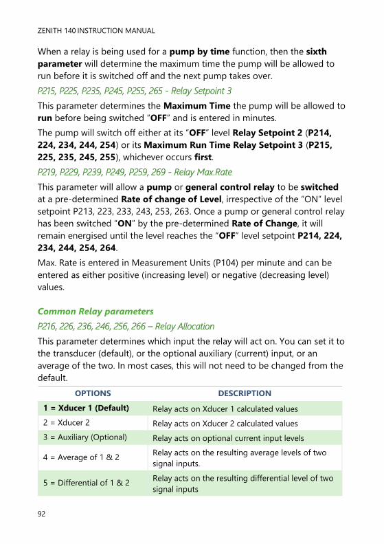
ZENITH 140 INSTRUCTION MANUAL
92
When a relay is being used for a pump by time function, then the sixth
parameter will determine the maximum time the pump will be allowed to
run before it is switched off and the next pump takes over.
P215, P225, P235, P245, P255, 265 - Relay Setpoint 3
This parameter determines the Maximum Time the pump will be allowed to
run before being switched “OFF” and is entered in minutes.
The pump will switch off either at its “OFF” level Relay Setpoint 2 (P214,
224, 234, 244, 254) or its Maximum Run Time Relay Setpoint 3 (P215,
225, 235, 245, 255), whichever occurs first.
P219, P229, P239, P249, P259, 269 - Relay Max.Rate
This parameter will allow a pump or general control relay to be switched
at a pre-determined Rate of change of Level, irrespective of the “ON” level
setpoint P213, 223, 233, 243, 253, 263. Once a pump or general control relay
has been switched “ON” by the pre-determined Rate of Change, it will
remain energised until the level reaches the “OFF” level setpoint P214, 224,
234, 244, 254, 264.
Max. Rate is entered in Measurement Units (P104) per minute and can be
entered as either positive (increasing level) or negative (decreasing level)
values.
Common Relay parameters
P216, 226, 236, 246, 256, 266 – Relay Allocation
This parameter determines which input the relay will act on. You can set it to
the transducer (default), or the optional auxiliary (current) input, or an
average of the two. In most cases, this will not need to be changed from the
default.
OPTIONS DESCRIPTION
1 = Xducer 1 (Default) Relay acts on Xducer 1 calculated values
2 = Xducer 2 Relay acts on Xducer 2 calculated values
3 = Auxiliary (Optional) Relay acts on optional current input levels
4 = Average of 1 & 2 Relay acts on the resulting average levels of two
signal inputs.
5 = Differential of 1 & 2 Relay acts on the resulting differential level of two
signal inputs

PULSAR MEASUREMENT
93
P217, P227, P 237, P247, P257, 267 - Relay Closures
The Zenith will record how many times each relay is closed, this parameter
displays the number of times the relay has activated since the relay has been
in use. It can be reset with any value.
P218, P228, P238, P248, P258, 268 - Relay Fail Safe
Your Zenith has a general fail-safe parameter P808. However, this can be
overridden so that each individual relay has its own independent failsafe
mode.
This parameter determines what the relay will do in the event of the Failsafe
Time (P809) expiring.
OPTIONS DESCRIPTION
0 = Default Relay assumes system default mode P808
1 = Hold Relay remains in its current state
2 = De-energise Relay will De-energise
3 = Energise Relay will energise

ZENITH 140 INSTRUCTION MANUAL
94
Pump “Advanced” Parameters
The following parameters are used to set the “Advanced” Pump features.
Pump Run On
This feature is used to periodically allow the pumps to continue operating
below their normal “OFF” point, to discharge any sediment that may have
settled at the bottom of the vessel.
P349 Prime Level
Sets the required level to ensure pumps are fully primed after a pump run
on has occurred. Following a pump run on, any pump, whose “ON” point is
below the Prime Level will be held “OFF” until the Prime Level has been
exceeded.
P350 Run Interval
Set required time period, in hours, at which pump run on should occur.
P351 Run Duration
This parameter sets the length of time, in seconds, that pumps will run on
for, it should be noted that only one run on is allowed per Run Interval.
Starting
This feature is used to reduce the effects of power surges, caused by
switching of pumps, in the following instances, (P352) Power surge (mains
or hydraulic) that is generated when multiple pumps are started
simultaneously, (P353) Power resumption following a power failure.
P352 Start Delay
Set the required time period, in seconds, that should elapse between pumps
starting. Default = 10 seconds.
P353 Power Delay
Set the required time period, in seconds, that should elapse before pumps
are allowed to start following a power failure. Default = 10 seconds.

PULSAR MEASUREMENT
95
Stopping
If required, this feature will prevent pumps, with a common “OFF” point
being switched off all at the same time pumps will be switched “OFF” in turn
as determined by the delay set in P348 Stop Delay.
P348 Stop Delay
Set the required time period, in seconds, that should elapse between pumps
stopping. Default = 0.0 seconds.
Pump Exercising
This feature is used to reduce idle pump corrosion and sediment build up.
Pumps can run after a specified Idle Time (P355) for a determined period of
Exercise time (P356), providing a Minimum head /level (P357) is present
and all other pumps are switched off.
P354 Exercise Enable
This parameter determines if Pump Exercising is enabled or disabled.
OPTIONS DESCRIPTION
0 = No (Default) Pump exercising disabled
1 = Yes Pump exercising enabled
P355 Idle Time
Sets the Idle Time to elapse before Pump Exercising is to be activated. Set
the required time period in minutes. Default = 720 minutes.
P356 Exercise Time
Set the required Exercise Time in seconds. Default = 30 seconds
P357 Minimum Head
To prevent the dry running and the possibility of cavitation, of the pump,
enter the minimum level (head) of material, in metres, that is to be present
before permitting pump exercising to take place.

ZENITH 140 INSTRUCTION MANUAL
96
Wall Cling
To reduce material build up, (such as fat), on the wall of the sump or vessel,
at the “normal” material level the pump setpoints can be varied within a
specified band.
For Pump Down applications the relay setpoints for the pumps will be
randomly varied within the band specified, somewhere below ON, but to a
maximum of the setting, and somewhere higher than OFF, but to a
maximum of the setting.
For Pump Up applications the relay setpoints for the pumps will be
randomly varied within the band specified somewhere higher than ON, but
to a maximum of the setting, and somewhere lower than OFF, but to a
maximum of the setting.
P360 Wall Cling
Enter the maximum band, of variation, required in measurement units
P104.
Storm
This facility enables all pumps to be disabled (P370) during a storm
condition to prevent the futile running or potential damage due to the
continued use of pumps during flood conditions. Provision is also made to
allow a maximum time period (P371) for which pumps will remain disabled
during such conditions. For this function to operate a relay must have been
assigned to Storm and have Upper and Lower storm setpoints set. See P210,
220, 230, 240, 250 = 3 (Control) P211, 221, 231, 241, 251, Relay
Function =2 (Storm) for further details.
P370 Pump Disable
This parameter sets the action required during a flood condition.
OPTIONS DESCRIPTION
0 = Disabled Pumps disabled during storm condition.
1 = Normal (Default) Normal pump operation during storm condition
P371 Disable Time
This parameter will set the maximum time pumps will remain disabled if
P370 = 0 Enter desired time in minutes. Default = 30 minutes

PULSAR MEASUREMENT
97
Digital Inputs
About Digital Inputs
The digital inputs are used to provide the Zenith with information on the
operational status and condition of pumps, valves, and other process control
devices. Based on the information supplied, by the inputs, the Zenith, will
make intelligent decisions and modify its control regime to meet the
demand of the prevailing operational requirements.
The parameters used to program the Digital inputs are as follows:
Common Parameters P300 to P306
Digital Input 1 P372 to 374 Digital Input 2 P375 to 377
Digital Input 3 P378 to 380 Digital Input 4 P381 to 383
Digital Input 5 P384 to 386 Digital Input 6 P387 to 389
Digital Input 7 P390 to 392
Common Parameters Set-up
These parameters determine specific operational criteria for particular digital
input functions and are common to each digital input.
Input Type
The digital inputs can be either voltage source, where Zenith will supply the
switching voltage, or voltage synch, where the switching voltage is supplied
by the input from the device, for full details see Chapter 2 Installation. Both
voltage source and voltage synch. inputs can be configured for N.O. or N.C.
operation as determined by the digital input Type P372, 375, 378, 381,
384, 387, 390 when set to 1= Input N.C., Zenith will recognise a closed
condition, D.C. signal voltage present at input, as a healthy condition,
alternatively, an open condition, D.C. signal voltage isn’t present at input,
indicating a healthy condition, can be chosen as a valid input by selecting
2=Input N.O.
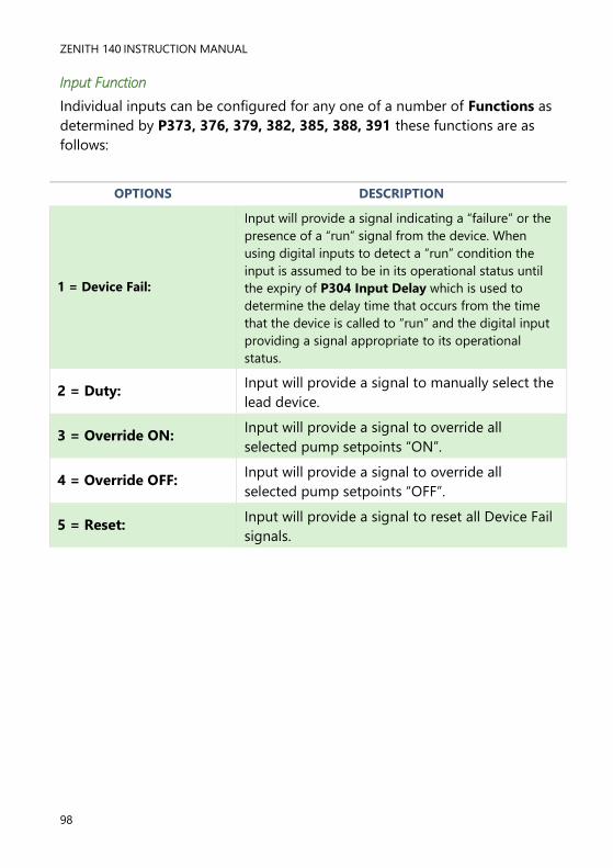
ZENITH 140 INSTRUCTION MANUAL
98
Input Function
Individual inputs can be configured for any one of a number of Functions as
determined by P373, 376, 379, 382, 385, 388, 391 these functions are as
follows:
OPTIONS DESCRIPTION
1 = Device Fail:
Input will provide a signal indicating a “failure” or the
presence of a “run” signal from the device. When
using digital inputs to detect a “run” condition the
input is assumed to be in its operational status until
the expiry of P304 Input Delay which is used to
determine the delay time that occurs from the time
that the device is called to “run” and the digital input
providing a signal appropriate to its operational
status.
2 = Duty: Input will provide a signal to manually select the
lead device.
3 = Override ON: Input will provide a signal to override all
selected pump setpoints “ON”.
4 = Override OFF: Input will provide a signal to override all
selected pump setpoints “OFF”.
5 = Reset: Input will provide a signal to reset all Device Fail
signals.

PULSAR MEASUREMENT
99
Device Fail
The digital inputs are used to indicate a ‘fail’ situation which effect devices,
which are connected to the relay outputs of the Zenith, e.g. failure of a
pump, screen, valve, etc. This information is then used to initiate changes to
the Zeniths control regime to meet the demands of the situation.
Let us consider the example of an application using 2 pumps, each pump
has the capability to provide a signal indicating its ‘run’ status. Each pump is
connected and controlled by one of the Zenith relay outputs, the duty and
setpoints have been programmed as detailed in Using the Relays, earlier in
this chapter. The signals providing details on the pumps ‘run status’ are
connected to the digital inputs as described in Chapter 2 Installation, and
the input Type P372, 375, 378, 381, 384, 387, 390 is configured as
detailed in Input Type, earlier in this chapter.
Pump 1 is connected and programmed to operate on Relay 1
Pump 2 is connected and programmed to operate on Relay 2
Pump 1 Fail signal is connected to Digital Input 1
Pump 2 Fail signal is connected to Digital Input 2
Each digital input must be assigned to the device relay output that it relates
to, this is determined by Assignment P374, 377, 380, 383, 386, 389, 392.
In the case of our example Digital Input 1 will be assigned to Relay 1 (P374
= 1) and Digital Input 2 will be assigned to Relay 2 (P377 = 2).
When the level rises to the ON Setpoint of Relay 1, the relay will energise,
and Pump 1 will ‘start’, in the normal manner. If the pump starts and
correctly runs and no change of ‘run’ status will be seen on the digital input
and the pump(s) will be allowed to operate as programmed.
Should a pump fail, a change of ‘run’ status would be seen and a Device
Fail, condition would be detected on the corresponding digital input, this
will result in the relay for the ‘failed’ pump being de-energised, and the
pump being switched OFF. The setpoints of the ‘failed’ pump will then be
passed to the second pump, which will take over to complete the pumping
operation.

ZENITH 140 INSTRUCTION MANUAL
100
The decision on whether or not to attempt to start the failed pump on
subsequent pump cycles will be determined by P300 Max. Attempts. Once
the number of attempts stipulated have been made the pump will be put
out of service until such time the Device Fail input is cleared by a Reset
(P391 = 4) on Digital Input 7. Alternatively, the +/- key can be used as a as
a Hot Key, which when pressed, whilst the unit is in RUN, will give details of
any Device Fail and provides prompts to Reset any failures to the no fault
condition.
Duty
When this function is selected, the digital inputs are used to determine, via
an ‘auto/manual’ switch, which one of the devices, connected to the relay
outputs of the Zenith, will be the “lead” or “duty” device.
Consider the example of an application using 2 pumps. Each pump is
connected and controlled by one of the Zenith relay outputs, the pump duty
and setpoints have been programmed as detailed in Using the Relays,
earlier in this chapter. The signals providing details on the “lead” or “duty”
pump ‘status’ are connected to the digital inputs as described in Chapter 2
Installation, and the input Type P372, 375, 378, 381, 384, 387, 390 is
configured as detailed in Input Type, earlier in this chapter.
Pump 1 is connected and programmed to operate on Relay 1
Pump 2 is connected and programmed to operate on Relay 2
Pump 1 Duty signal is connected to Digital Input 3
Pump 2 Duty signal is connected to Digital Input 4
The type of switch to be used to determine the duty is selected and
configured as detailed in P301 Switch Mode.
Standard Switch Mode (P301 = 0 Standard)
When a standard rotary type switch is used, to determine auto/manual duty
one input per device is required, with each input being assigned to the
appropriate device relay output that it relates to, this is determined by
Assignment P374, 377, 380, 383, 386, 389, 392. In the case of our
example Digital Input 3 will be assigned to Relay 1 (P380 = 1) and Digital
Input 4 will be assigned to Relay 2 (P383 = 2).

PULSAR MEASUREMENT
101
When the duty switch is in the “auto” position, no signals are present on
either Digital Input 3 or Digital Input 4 and devices will run in the “auto”
mode, as determined by the Zenith, in accordance with its programmed
settings. If a signal is seen on Digital Input 3, duty switch selected for Pump
1, then the pump connected to Relay 1 will assume the role of “lead”/ “duty”
pump, regardless of the settings programmed in the Zenith.
When the level rises to the ON Setpoint, for the first pump, relay 1 will
energise and Pump 1 will ‘start’, in the normal manner. If the level continues
to rise, then relay 2 will energise and Pump 2 will start in accordance with
the settings programmed for pump 2.
If a signal is seen on Digital Input 4, duty switch selected for Pump 2, then
the pump connected to Relay 2 will assume the role of “lead”/ “duty” pump,
regardless of the settings programmed in the Zenith. When the level rises to
the ON Setpoint, for the first pump, the relay 2 will energise and Pump 2
will ‘start’, in the normal manner. If the level continues to rise, then relay 1
will energise and Pump 1 will start in accordance with the settings
programmed for pump 2.
Binary Switch Mode (P301 = 1Binary)
When a binary switch is used, to determine auto/manual duty, the number
of inputs required will be dependent on the number of devices to be
included in the duty selection. In this mode the duty device will be selected
according to the binary input present on the appropriate inputs and there is
therefore no requirement to assign the duty switch inputs to specific device
relay. The selection of the Lead/Duty device is determined by the presence
of an input as detailed in the table below, where 0 = no input present and 1
= input present
DUTY
INPUT 1
DUTY
INPUT 2
DUTY
INPUT 3
LEAD/DUTY
DEVICE
0 0 0 Auto
1 0 0 Relay 1
0 1 0 Relay 2
1 1 0 Relay 3
0 0 1 Relay 4
1 0 1 Relay 5
0 1 1 Relay 6

ZENITH 140 INSTRUCTION MANUAL
102
Consider the example of an application using 2 pumps. Each pump is
connected and controlled by one of the Zenith relay outputs, the pump duty
and setpoints have been programmed as detailed in Using the Relays,
earlier in this chapter. The signals providing details on the “lead” or “duty”
pump ‘status’ are connected to the digital inputs as described in Chapter 2
Installation, and the input Type P372, 375, 378, 381, 384, 387, 390 is
configured as detailed in Input Type, earlier in this chapter.
Pump 1 is connected and programmed to operate on Relay 1
Pump 2 is connected and programmed to operate on Relay 2
Duty Input 1 signal is connected to Digital Input 3
Duty Input 2 signal is connected to Digital Input 4
When no signals are present on either Digital Input 3 or Digital Input 4 then
devices will run in the “auto” mode, as determined by the Zenith, in
accordance with its programmed settings. If a signal is seen on Digital Input
3, duty selected for Pump 1, then the pump connected to Relay 1 will
assume the role of “lead”/duty” pump, regardless of the settings
programmed in the Zenith. When the level rises to the ON Setpoint, for the
first pump, relay 1 will energise and Pump 1 will ‘start’, in the normal
manner. If the level continues to rise, then relay 2 will energise and Pump 2
will start in accordance with the settings programmed for pump 2.
If a signal is seen on Digital Input 4, duty selected for Pump 2, then the
pump connected to Relay 2 will assume the role of “lead”/duty” pump,
regardless of the settings programmed in the Zenith. When the level rises to
the ON Setpoint, for the first pump, the relay 2 will energise and Pump 2
will ‘start’, in the normal manner. If the level continues to rise, then relay 1
will energise and Pump 1 will start in accordance with the settings
programmed for pump 2.
PULSAR MEASUREMENT
103
Override
A digital input can be assigned to receive an input, which will override the
setpoints of the pumps and start them, as determined by the Override
Level (P306) and providing the level is above the Min. Override (P303),
immediately after the expiry of the Override Delay (P302). A digital input
can also be assigned to receive an input, which will override the setpoints of
the pumps and stop them immediately after the expiry of the Override
Delay (P302).
Reset
This option is only available on Digital Input 7 P391 = 5 when selected a
valid signal received on this input will Reset all Device Fail signals to the no
fault condition. When using this function, the unit will check all inputs for
such conditions so there is no requirement to assign the input to a specific
relay output. Alternatively, the +/- key has been allocated as a Hot Key,
which when pressed will give details of any Device Fail and provides
prompts to Reset any failures to the no fault condition.
Digital Input Parameters
Common Par.
These parameters are common to each of the seven digital inputs and set
specific operational criteria for particular functions.
P300 Max. Attempts
When digital inputs are used to detect device failure this parameter
determines the number of attempts that will be made before failing the
device and putting it out of service. When the number of attempts is set to
‘0’, there is no restriction on the number of starts. The digital inputs will
provide a fail signal in the normal manner and initiate any action as required,
but the device will not be put out of service. Any figure other than 0 will
determine the number of attempts that will be made to start the device
before putting it out of service until such time that the input is reset.
Set the number of attempts Min. 0, Max 99.

ZENITH 140 INSTRUCTION MANUAL
104
P301 Switch Mode
When an external duty switch is used this can be connected via the digital
inputs and facilitate the selection of the duty device manually, thereby
overriding the duty programmed within the unit.
This parameter determines the type of switch in use.
OPTIONS DESCRIPTION
0 = Standard (Default)
A standard switch, e.g., rotary switch, can be used
with one switch position and a digital input
required for each pump.
1 = Normal
To reduce the number of digital inputs used, for
manual duty selection, a binary switch can be
supplied. Max. No. of digital inputs required being
three.
P302 Override Delay
A digital input can be assigned to receive an input, which will override the
setpoints of the pumps and start or stop them, immediately after the expiry
of the Override Delay, dependent on the selected Digital Input Function
P373, 376, 379, 382, 385, 388, 391 = 3 (Override “ON”) or 4 (Override
“OFF”) and providing the level is above the Min. Override (P303), when
Override “ON” is selected.
Enter the required delay time in minutes.
P303 Min Override
Determines the minimum level required before an Override Delay (P302)
will be in effect when Digital Input Function P373, 376, 379, 382, 385, 388,
391 = 3 (Override “ON”).
Enter the required level in Measurement Units (P104).
P304 Input Delay
This parameter determines the delay applied, from the time a device (relay)
is called to “run” and when the status of the digital input is recognised as a
valid input. If the digital input is used to detect a “running” signal this
parameter should be set to reflect the time it takes from the device being
called to “run” to the input being in its operational status.
Enter the required time in seconds.

PULSAR MEASUREMENT
105
P305 Input Filter
This parameter is used to ignore spurious changes of state on the digital
inputs and determines the time that a change of state has to be present
before it is recognised as a valid input.
Enter the required time in seconds.
P306 Override Level
This parameter will determine which pumps setpoints will be overridden
when Digital Input Function P373, 376, 379, 382, 385, 388, 391 = 3
(Override “ON”). Only pumps with, normal “ON”, setpoints below the
Override Level will be activated when an Override “ON” condition exists
and that the Override Delay (P302) and Min Override (P303), where
required, have been satisfied.
Enter the required level in Measurement Units (P104).
Digital Input
The following parameters are used to configure the use of the digital inputs.
P372, 375, 378, 381, 384, 387, 390 Type
Determines the way digital inputs will be recognised by the Zenith.
OPTIONS DESCRIPTION
1 = Input N.C.
(Default Input 1 to 6)
Zenith recognises a closed condition, D.C. signal
voltage present at the input, as a healthy/run
condition.
2 = Input N.O.
(Default Input 7)
Zenith recognises an open condition, D.C. signal
voltage not present at the input, as a healthy/run
condition.

ZENITH 140 INSTRUCTION MANUAL
106
P373, 376, 379, 382, 385, 388, 391 Function
This parameter will set the function of the digital Input.
OPTIONS DESCRIPTION
1 = Device Fail
(Default Input 1 to 6)
Digital input is used to Fail, (put out of service), a
device connected to the relay specified in P374,
377, 380, 383, 386, 389, 392 Assignment
2 = Duty
Digital input is used to select the device, (pump),
connected to the relay specified in P374, 377,
380, 383, 386, 389, 392 Assignment as the
current duty device (pump).
3 = Override “ON”
Digital input is used to provide a signal to activate
an Override “ON” condition of pumps as
determined by P302 Override Delay, P303 Min.
Override and P306 Override Level.
4 = Override “OFF”
Digital input is used to provide a signal to activate
an Override “OFF” condition of pumps after the
expiry of the delay time as determined by P302
Override Delay.
5 = Reset.
Digital Input 7 only.
(Default Input 7)
Input is used to Reset all Device Fail conditions.
Alternatively, the +/- key can be used, whilst in
RUN, to Reset any Device Fail.
P373, 376, 379, 382, 385, 388, 391 Function
This parameter will set the function of the digital Input.
OPTIONS DESCRIPTION
0 = None (Default) Digital Input is not assigned to any relay
1 = Relay 1 Digital input is assigned to Device connected to Relay 1.
2 = Relay 2 Digital input is assigned to Device connected to Relay 2.
3 = Relay 3 Digital input is assigned to Device connected to Relay 3.
4 = Relay 4 Digital input is assigned to Device connected to Relay 4.
5 = Relay 5 Digital input is assigned to Device connected to Relay 5.
6 = Relay 6 Digital input is assigned to Device connected to Relay 6.
7 = All Digital input is assigned to All relays with a device
connected.

PULSAR MEASUREMENT
107
Float Switch (FS) Backup
About Float Switch Backup
This digital feature is used with a float switch, where it can be used alongside
a transducer or as a backup method for when a transducer goes into failsafe.
The high input will have a timer and a level set point, which will allow for the
unit to power on every pump below the set point for the specified amount
of time as set in P332 Pump Run Time.
The low input will simply switch off all the pumps that have been set on the
controller.
Common Par
P330 Mode of Operation
OPTIONS DESCRIPTION
0 = Off (Default) Float Switch Backup is not used
1 = Always Backup will be active continuously and will always
respond to an input from a Backup device, always.
2 = On Xdr Fail Backup will only be active at times when the unit
has gone into a Failsafe mode.
P330 Input Filter
This parameter can be used to ignore spurious changes of state on the
digital inputs and determines the time that a change of state must be
present before it is recognised as a valid input.
Enter a value in seconds: Min = 1 (Default), Max = 999.
P330 Pump Run Time
This parameter tells the unit to switch the pumps off after the specified
amount of time, if the level of the float switch has not been reached.
Enter a value in minutes: Min = 0.1 (Default), Max = 9999.
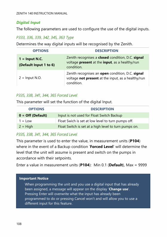
ZENITH 140 INSTRUCTION MANUAL
108
Digital Input
The following parameters are used to configure the use of the digital inputs.
P333, 336, 339, 342, 345, 363 Type
Determines the way digital inputs will be recognised by the Zenith.
OPTIONS DESCRIPTION
1 = Input N.C.
(Default Input 1 to 6)
Zenith recognises a closed condition, D.C. signal
voltage present at the input, as a healthy/run
condition.
2 = Input N.O.
Zenith recognises an open condition, D.C. signal
voltage not present at the input, as a healthy/run
condition.
P335, 338, 341, 344, 365 Forced Level
This parameter will set the function of the digital Input.
OPTIONS DESCRIPTION
0 = Off (Default) Input is not used for Float Switch Backup
1 = Low Float Swich is set at low level to turn pumps off.
2 = High Float Switch is set at a high level to turn pumps on.
P335, 338, 341, 344, 365 Forced Level
This parameter is used to enter the value, in measurement units (P104)
where in the event of a Backup condition ‘Forced Level’ will determine the
level that the unit will assume is present and switch on the pumps in
accordance with their setpoints.
Enter a value in measurement units (P104): Min 0.1 (Default), Max = 9999
Important Notice
When programming the unit and you use a digital input that has already
been assigned, a message will appear on the display ‘Change use’.
Pressing Enter will overwrite what the input has already been
programmed to do or pressing Cancel won’t and will allow you to use a
different input for this feature.

PULSAR MEASUREMENT
109
Tariff Guard
Set Up
P393 Enable
This parameter determines if Energy Saving is in use or not.
OPTIONS DESCRIPTION
0 = Off (Default) Energy saving is switched Off
1 = On Energy saving is switched On
‘Tariff active’ will appear on the Aux display of the unit when unit is in Tariff
Guard mode. This feature is available from firmware version 7.5.1 and
onwards.
P394 Lead Time
This parameter determines the time, prior to a High Tariff period, at which
the vessel will be pumped down to the lowest pump OFF level.
Enter desired time in minutes.
P395 Lag Time
This parameter determines the time, after a High Tariff period, that the
vessel will be pumped down, (if required), by the first duty pump to the
lowest pump Off level. If after the Lag Time has expired the pump has not
reached its Off point it will continue to pump until the Off point is reached.
On expiry of the Lag Time all pumps will assume their normal operation and
will be switched On and Off according to their respective setpoints.
Enter desired time in minutes.
P396 Min. Pump Run
This parameter determines the minimum amount of time that a pump will
be allowed to run during a High Tariff period, if required, and is used to
prevent excessive wear or damage to the pump.
Enter desired time in seconds.
P397 Minimum Head
This parameter determines the minimum head (level) of material required to
be present before a pump will be allowed to run, if required, during a High
Tariff period and is used to ensure that a prime level for the pumps is
maintained. Enter desired level in Measurement Units (P104).
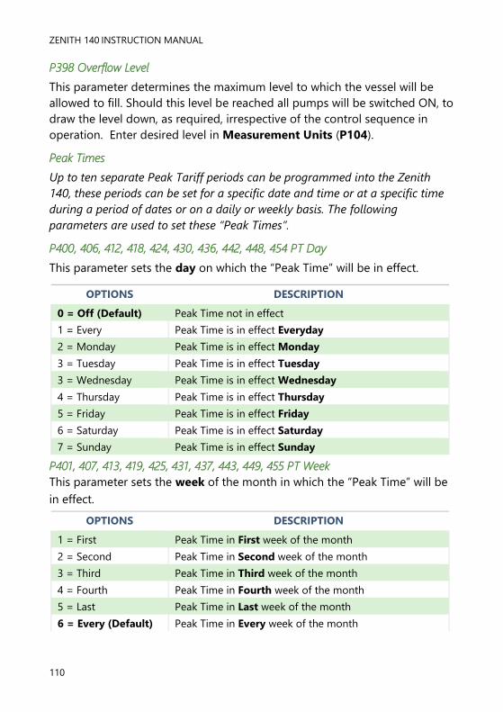
ZENITH 140 INSTRUCTION MANUAL
110
P398 Overflow Level
This parameter determines the maximum level to which the vessel will be
allowed to fill. Should this level be reached all pumps will be switched ON, to
draw the level down, as required, irrespective of the control sequence in
operation. Enter desired level in Measurement Units (P104).
Peak Times
Up to ten separate Peak Tariff periods can be programmed into the Zenith
140, these periods can be set for a specific date and time or at a specific time
during a period of dates or on a daily or weekly basis. The following
parameters are used to set these “Peak Times”.
P400, 406, 412, 418, 424, 430, 436, 442, 448, 454 PT Day
This parameter sets the day on which the “Peak Time” will be in effect.
OPTIONS DESCRIPTION
0 = Off (Default) Peak Time not in effect
1 = Every Peak Time is in effect Everyday
2 = Monday Peak Time is in effect Monday
3 = Tuesday Peak Time is in effect Tuesday
3 = Wednesday Peak Time is in effect Wednesday
4 = Thursday Peak Time is in effect Thursday
5 = Friday Peak Time is in effect Friday
6 = Saturday Peak Time is in effect Saturday
7 = Sunday Peak Time is in effect Sunday
P401, 407, 413, 419, 425, 431, 437, 443, 449, 455 PT Week
This parameter sets the week of the month in which the “Peak Time” will be
in effect.
OPTIONS DESCRIPTION
1 = First Peak Time in First week of the month
2 = Second Peak Time in Second week of the month
3 = Third Peak Time in Third week of the month
4 = Fourth Peak Time in Fourth week of the month
5 = Last Peak Time in Last week of the month
6 = Every (Default) Peak Time in Every week of the month

PULSAR MEASUREMENT
111
P402, 408, 414, 420, 426, 432, 438, 444, 450, 456 PT Start Pk.
This parameter sets the date on which the “Peak Time” will start.
Enter the desired Start Date in DD:MM format.
P403, 409, 415, 421, 427, 433, 439, 445, 451, 457 PT End Pk.
This parameter sets the date on which the “Peak Time” will end.
Enter the desired End Date in DD:MM format.
P404, 410, 416, 422, 428, 434, 440, 446, 452, 458 PT1 Start.
This parameter sets the time at which the “Peak Time” will start.
Enter the desired Start Time in HH:MM format.
P405, 411, 417, 423, 429, 435, 441, 447, 453, 459 PT1 End
This parameter sets the time at which the “Peak Time” will end.
Enter the desired End Time in HH:MM format.
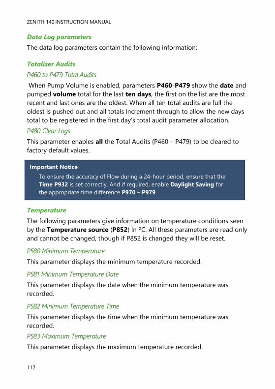
ZENITH 140 INSTRUCTION MANUAL
112
Data Log parameters
The data log parameters contain the following information:
Totaliser Audits
P460 to P479 Total Audits
When Pump Volume is enabled, parameters P460-P479 show the date and
pumped volume total for the last ten days, the first on the list are the most
recent and last ones are the oldest. When all ten total audits are full the
oldest is pushed out and all totals increment through to allow the new days
total to be registered in the first day’s total audit parameter allocation.
P480 Clear Logs
This parameter enables all the Total Audits (P460 – P479) to be cleared to
factory default values.
Temperature
The following parameters give information on temperature conditions seen
by the Temperature source (P852) in ºC. All these parameters are read only
and cannot be changed, though if P852 is changed they will be reset.
P580 Minimum Temperature
This parameter displays the minimum temperature recorded.
P581 Minimum Temperature Date
This parameter displays the date when the minimum temperature was
recorded.
P582 Minimum Temperature Time
This parameter displays the time when the minimum temperature was
recorded.
P583 Maximum Temperature
This parameter displays the maximum temperature recorded.
Important Notice
To ensure the accuracy of Flow during a 24-hour period, ensure that the
Time P932 is set correctly. And if required, enable Daylight Saving for
the appropriate time difference P970 – P979.

PULSAR MEASUREMENT
113
P584 Maximum Temperature Date
This parameter displays the date when the maximum temperature was
recorded.
P585 Maximum Temperature Time
This parameter displays the time when the maximum temperature was
recorded.
P586 Current Temperature
This parameter displays the current temperature.
Pump Logs
P510 Pump 1 Hours
This parameter displays the current total running hours for Pump 1. Any
value from 0 - 9999 can be entered to facilitate any update to the stored
total for any reason e.g. a replacement pump being fitted.
P511 Pump 1 Starts
This parameter displays the current total pump starts for Pump 1. Any value
from 0 - 9999 can be entered to facilitate any update to the stored total for
any reason e.g. a replacement pump being fitted.
P512 Pump 1 Starts/Hour
This parameter displays the current pump Starts/Hour for Pump 1. Any value
from 0 - 9999 can be entered to facilitate any update to the stored total for
any reason e.g. a replacement pump being fitted.
P513 Pump 1 Run On
This parameter displays the current number of Pump Run On’s, which have
occurred, for Pump 1. Any value from 0 - 9999 can be entered to facilitate
any update to the stored total for any reason e.g. a replacement pump being
fitted.
P514 Pump 1 Draw
This parameter displays the current Draw Rate for Pump 1, which is used to
calculate the pump efficiency. Any value from 0 - 9999 can be entered to
facilitate any update to the stored total for any reason e.g. a replacement
pump being fitted.
ZENITH 140 INSTRUCTION MANUAL
114
P515 Pump 1 Efficiency
This parameter displays the current value for Pump 1 Efficiency, which is
used to calculate the pump efficiency and will update with any change to the
Pump Draw Rate (P514).
P516 - P521 Pump 2
These parameters contain the same information as above for Pump 2.
P522 - P527 Pump 3
These parameters contain the same information as above for Pump 3.
P528 - P533 Pump 4
These parameters contain the same information as above for Pump 4.
P534 - P539 Pump 5
These parameters contain the same information as above for Pump 5.
Pumped Volume
Set Up
P205 Pump Vol. Enable
This parameter determines if Pumped Volume is in use or not.
OPTIONS DESCRIPTION
0 = Off (Default) Pumped volume calculation is switched Off
1 = On Pumped volume calculation is switched On
P206 Settle Time
This parameter determines the time allowed for the level to settle after all
pumps have switched Off, to avoid any effects of flow back or turbulence,
before calculating the Inflow Rate. Enter desired time in minutes. Default =
1 minute

PULSAR MEASUREMENT
115
P207 Inflow Method
This parameter determines which method is used to calculate the inflow of
material during a pump down cycle.
OPTIONS DESCRIPTION
0 = No Inflow Inflow during pumping is not calculated
1 = Average Inflow
(Default)
Average between Inflow at time pump started and
Inflow after Settle Time used to calculate Inflow
during pumping.

ZENITH 140 INSTRUCTION MANUAL
116
Volume
Your Zenith provides a variety of volume calculation features, with 11 pre-
programmed vessel shapes. See Vessel Shape (P600) for more information.
For each vessel you will need to know the dimensions (P601-603) in
Measurement Units (P104) which are required to calculate the volume
(P604) which will be displayed in the selected Volume Units (P605).
If your vessel shape does not correspond with any of the pre-programmed
vessel shapes, then you can use the universal calculations. For this you will
need a level/volume graph or chart provided by the vessel manufacturer or
you can create one based on the dimensions of the vessel. You can enter up
to 32 pairs of breakpoints, and the more you enter, the greater accuracy of
the volume calculation will be.
Conversion
P600 Vessel Shape
This parameter determines which vessel shape is used when utilising
“Volume Conversion”.
The choices are as shown in the table below, along with the dimensions that
are required to be entered (P601-P603).
VESSEL SHAPE P600 VALUE DESCRIPTION DIMENSIONS
P600 = 0 (Default)
Cylindrical Flat Base Cylinder diameter
P600 = 1 Rectangular Flat
Base Width and Breadth
VESSEL SHAPE P600 VALUE DESCRIPTION DIMENSIONS

PULSAR MEASUREMENT
117
P600 = 2 Cylindrical Cone
Base
Cylinder diameter
and height of
bottom
P600 = 1 Rectangular Flat
Base Width and Breadth
P600 = 4 Parabola Base
Cylinder diameter
and height of
bottom
P600 = 5 Flat Sloped Base Cylinder diameter
P600 = Flat Sloped Base
Cylinder diameter
and height of
bottom
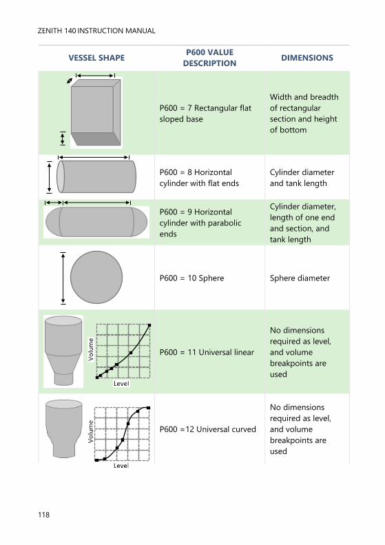
ZENITH 140 INSTRUCTION MANUAL
118
VESSEL SHAPE P600 VALUE
DESCRIPTION DIMENSIONS
P600 = 7 Rectangular flat
sloped base
Width and breadth
of rectangular
section and height
of bottom
P600 = 8 Horizontal
cylinder with flat ends
Cylinder diameter
and tank length
P600 = 9 Horizontal
cylinder with parabolic
ends
Cylinder diameter,
length of one end
and section, and
tank length
P600 = 10 Sphere Sphere diameter
P600 = 11 Universal linear
No dimensions
required as level,
and volume
breakpoints are
used
P600 =12 Universal curved
No dimensions
required as level,
and volume
breakpoints are
used

PULSAR MEASUREMENT
119
P601-P603 Vessel Dimensions
These three parameters are used to enter the dimension required to
calculate the volume. The dimensions required are as shown below and are
entered Measurements Units (P104).
VESSEL SHAPE P601 P602 P603
P600 = 0
Cylindrical flat base
Cylinder
Diameter Not required Not required
P600 = 1
Rectangular flat base Not required
Width of
rectangle
Breadth of
rectangle
P600 = 2
Cylindrical cone base
Height of
base
Width of
rectangle Not required
P600 =3
Rectangular pyramid base
Height of
base
Width of
rectangle
Breadth of
rectangle
P600 = 4
Cylindrical parabola base
Height of
base
Cylinder
diameter Not required
P600 = 5
Cylindrical half sphere base
Cylinder
diameter Not required Not required
P600 = 6
Cylindrical flat sloped base
Height of
base
Cylinder
diameter Not required
P600 = 7
Rectangular flat sloped base
Height of
base
Width of
rectangle
Breadth of
rectangle
P600 = 8
Horizontal cylinder flat ends
Length of
cylinder
Cylinder
diameter Not required
P600 = 9
Horizontal cylinder parabolic
ends
Length of
cylinder
Cylinder
diameter
Length of
one end
P600 = 10
Sphere
Sphere
diameter Not required Not required
P604 Calculated Volume
This parameter displays the maximum volume that has been calculated by
the Zenith and is a Read Only parameter. The volume displayed will be
shown in cubic meters and is the total volume available between empty
level (P105) and 100% of span (P106).

ZENITH 140 INSTRUCTION MANUAL
120
P605 Volume Units
This parameter determines the units that you wish to display, for volume
conversion. It is used in conjunction with P607 (maximum volume), and the
units are shown on the display (subject to P810). The choices are:
OPTION DESCRIPTION
0 = No units Volume will be totalised with no units
1 = Tons Volume will be totalised in Tons
2 = Tonnes Volume will be totalised in Tonnes
3 = Cubic metres (Default) Volume will be totalised in Cubic metres
4 = Litres Volume will be totalised in Litres
5 = UK Gallons Volume will be totalised in UK Gallons
6 = US Gallons Volume will be totalised in US Gallons
7 = Cubic Feet Volume will be totalised in Cubic Feet
8 = Barrels Volume will be totalised in Barrels
9 = lbs (pounds) Volume will be totalised in lbs (pounds)
P606 Correction Factor
This parameter is used to enter a correction factor, when required, such as
the specific gravity of the material so that the volume calculated is relative to
the actual amount of material that can be contained between empty level
(P105) and 100% of span (P106). Default = 1
P607 Max Volume
This parameter displays the actual maximum volume that has been
calculated by the Zenith, i.e. P604 Calculated Volume x P606 Correction
Factor, and is a Read Only parameter. The volume displayed will be shown
in P605 Volume Units and is the total volume available between empty
level (P105) and 100% of span (P106).

PULSAR MEASUREMENT
121
Breakpoints
P610-P673 Level/Volume Breakpoints
These parameters are used to create a profile of the vessel when P600=11
(universal linear) or P600=12 (universal curved). You should enter
breakpoints in pairs, a reading for level and its corresponding volume. The
more pairs you enter, the more accurate the profile will be. In the case of
universal linear, then enter the level/volume at each of the points where the
vessel changes shape. In the case of the universal curved, enter values
around each arc tangent, as well as at the top and bottom.
You must enter at least two pairs, and you can enter up to 32 pairs.
Universal Linear (P600=11)
This volume calculation creates a linear approximation of the level/volume
relationship and works best if the vessel has sharp angles between each
section.
You should enter a level/volume breakpoint for each place where the vessel
changes direction, and numerous where the section is slightly curved (mostly
linear but has got a small arc). You can enter any number of pairs between 2
and 32.
Vo
lum
e
Level

ZENITH 140 INSTRUCTION MANUAL
122
Universal Curved (P600=12)
This volume calculation creates a curved approximation of the level/volume
relationship, and works best if the vessel is non-linear, and there are no
sharp angles.
You should enter 2 level/volume breakpoints at the minimum and maximum
levels, and several for each place where the vessel has got an arc. You can
enter any number of pairs between 2 and 32.
Tables
P696 Reset Breakpoints
This parameter allows the resetting, to the default value, of all previously set
breakpoints (P610-673), without having to access them individually. When it
is necessary to reset or amend breakpoints this can be achieved by directly
accessing the desired parameter (P610-673) and changing as required.
P697 Number of Breakpoints Set
This parameter allows you to review the number of breakpoints that have
been set, without the need to access each individual one in turn, this is a
“Read Only” parameter and no values can be entered.

PULSAR MEASUREMENT
123
Pump Efficiency
Set Up
P187 Pump Efficiency
This parameter determines whether pump efficiency is enabled or disabled.
OPTIONS DESCRIPTION
0 = Off (Default) Pump efficiency is disabled
1 = On Pump efficiency is enabled
P188 Calib. Delay
This parameter is used to set a delay, after all pumps have stopped, to allow
for any turbulence of the material surface to settle prior to monitoring the
level in the vessel and determining the inflow before the next pump cycle
commences. The delay time is entered in seconds. Default = 45 seconds.
P189 Cal. Duration
This parameter sets the time duration over which the pumps performance
will be monitored, and the resulting efficiency is calculated.
P190 Persist Cnt.
If an alarm is to be used to indicate when the Pump efficiency falls below a
predetermined level, this parameter determines the number of consecutive
times the pump will be allowed to run, at the reduced efficiency, before the
alarm will be activated. The Persist Count can be set to Min. 0, Max 99.
Default = 6
Important Notice
When setting the time period for the Calibration Delay (P188) it is
important that it does not exceed the time from when all pumps switch
Off to the first pump Start during normal operation as it will prevent
determining the Inflow and any subsequent calculation of Efficiency.
Important Notice
When setting the time period for the Calibration Duration (P189) it is
important that it does not exceed the time from one pump Start to the
next pump Start during normal operation as it will abort any
subsequent calculation of Efficiency.

ZENITH 140 INSTRUCTION MANUAL
124
P191 Demote Pumps.
When an efficiency alarm is being used, this parameter will determine if a
pump is to be demoted to the last pump in the duty cycle on activation of
the alarm. When Demote Pump is enabled and the efficiency alarm is
activated after the predetermined Persist Count (P190) the pump duty will
default to a fixed duty regime with the inefficient pump being set to the last
pump in the cycle which will be called to start if the level reaches the on
point for that pump. A pump which has been demoted will be indicated by
the relevant “pump” relay LED “flashing” RED.
OPTIONS DESCRIPTION
0 = Off (Default) Demote pump is disabled
1 = On Demote pump is enabled

PULSAR MEASUREMENT
125
P192 Demote Flags
This parameter will indicate, in a binary number format as detailed below,
which pumps, if any, have been demoted. Any demoted pump(s) can be
reset by entering “0”.
0 = None 16 = Pump 5
1 = Pump 1 17 = Pump 1 + 5 2 = Pump 2 18 = Pump 2 + 5
3 = Pump 1 + 2 19 = Pump 1 + 2 + 5 4 = Pump 3 20 = Pump 3 + 5
5 = Pump 1 + 3 21 = Pump 1 + 3 + 5
6 = Pump 2 + 3 22 = Pump 2 + 3 +5 7 = Pump 1 + 2 + 3 23 = Pump 1 + 2 + 3 + 5
8 = Pump 4 24 = Pump 4 + 5 9 = Pump 1 + 4 25 = Pump 1 + 4 + 5
10 = Pump 2 + 4 26 = Pump 2 + 4 + 5
11 = Pump 1 + 2 + 4 27 = Pump 1 + 2 + 4 + 5 12 = Pump 3 + 4 28 = Pump 3 + 4 + 5
13 = Pump 1 + 3 + 4 29 = Pump 1 + 3 + 4 + 5 14 = Pump 2 + 3+ 4 30 = Pump 2 + 3 + 4 + 5
15 = Pump 1 + 2 + 3 + 4 31 = Pump 1 + 2 + 3 + 4 + 5
P193 Calib. Pumps
This parameter is used to calibrate the pumps and determine the optimum
(100%) efficiency of the pump from which all subsequent efficiency
calculations will be derived. You can either choose to “calibrate” an
individual pump or alternatively have each pump “calibrated” in turn
automatically. When selecting pumps to be calibrated individually (Option 1
to 5), it is essential that the level in the vessel is above the relevant pump
start point to ensure correct calibration. Once you have selected the pump
to be “calibrated” you will be prompted to return to the RUN mode, there
will then be a delay before the pump starts which is equal to the Calib.
Delay (P188) the display will show the time being counted down time to the
pump start. Once the pump has started the display will show a countdown
time equal to the Cal. Duration (P189), calculation of pump efficiency will
be completed on the expiry of the count and the unit will return to normal
operation. If you choose to “calibrate” the pumps automatically (Option 7)
then when the unit is returned to the RUN mode each pump will be
“calibrated” in turn as and when it is next called to run.

ZENITH 140 INSTRUCTION MANUAL
126
Display Parameters
Options
P800 Display Units
This parameter determines whether the reading displayed is in
Measurement Units (P104), or as a percentage of span.
OPTION DESCRIPTION
1 = Measured (Default) Display is in selected unit’s dependent in Mode (P100)
2 = Percentage Display is in percentage of span dependent in Mode
(P100)
P801 Decimal Places
This parameter determines the number of decimal places on the reading
during run mode. Minimum = 0 (No decimal places), Maximum 3 = (3
decimal Places). Default = 2 (2 decimal Places).
P802 Display Offset
The value of this parameter is added to the reading before it is displayed, in
Measurement Units (P104). It does not affect the relay setpoints or the mA
output, only the reading on the display.
You could use this feature if for example you wanted to reference the
reading to sea level, where you would enter the distance between Empty
Level (P105) and sea level. If the empty level point is below sea level, then
enter a negative value.
P804 Display Conversion
The reading is multiplied by the value of this parameter before being
displayed. The default is 1.0, but if for example you wanted to display the
reading in yards, then set the Measurement Units (P104) to feet and set
P804 to 3.
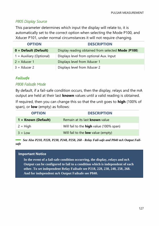
PULSAR MEASUREMENT
127
P805 Display Source
This parameter determines which input the display will relate to, it is
automatically set to the correct option when selecting the Mode P100, and
Xducer P101, under normal circumstances it will not require changing.
OPTION DESCRIPTION
0 = Default (Default) Display reading obtained from selected Mode (P100)
1 = Auxiliary (Optional) Displays level from optional Aux. Input
2 = Xducer 1 Displays level from Xducer 1
3 = Xducer 2 Displays level from Xducer 2
Failsafe
P808 Failsafe Mode
By default, if a fail-safe condition occurs, then the display, relays and the mA
output are held at their last known values until a valid reading is obtained.
If required, then you can change this so that the unit goes to high (100% of
span), or low (empty) as follows:
OPTION DESCRIPTION
1 = Known (Default) Remain at its last known value
2 = High Will fail to the high value (100% span)
3 = Low Will fail to the low value (empty)
See Also P218, P228, P238, P248, P258, 268 - Relay Fail-safe and P840 mA Output Fail-
safe
Important Notice
In the event of a fail-safe condition occurring, the display, relays and mA
Output can be configured to fail to a condition which is independent of each
other. To set independent Relay Failsafe see P218, 228, 238, 248, 258, 268.
And for independent mA Output Failsafe see P840.
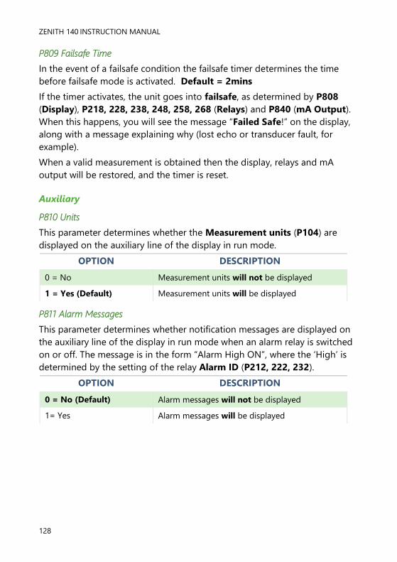
ZENITH 140 INSTRUCTION MANUAL
128
P809 Failsafe Time
In the event of a failsafe condition the failsafe timer determines the time
before failsafe mode is activated. Default = 2mins
If the timer activates, the unit goes into failsafe, as determined by P808
(Display), P218, 228, 238, 248, 258, 268 (Relays) and P840 (mA Output).
When this happens, you will see the message “Failed Safe!” on the display,
along with a message explaining why (lost echo or transducer fault, for
example).
When a valid measurement is obtained then the display, relays and mA
output will be restored, and the timer is reset.
Auxiliary
P810 Units
This parameter determines whether the Measurement units (P104) are
displayed on the auxiliary line of the display in run mode.
OPTION DESCRIPTION
0 = No Measurement units will not be displayed
1 = Yes (Default) Measurement units will be displayed
P811 Alarm Messages
This parameter determines whether notification messages are displayed on
the auxiliary line of the display in run mode when an alarm relay is switched
on or off. The message is in the form “Alarm High ON”, where the ‘High’ is
determined by the setting of the relay Alarm ID (P212, 222, 232).
OPTION DESCRIPTION
0 = No (Default) Alarm messages will not be displayed
1= Yes Alarm messages will be displayed

PULSAR MEASUREMENT
129
P812 Pump Messages
This parameter determines whether notification messages are displayed on
the auxiliary line of the display in run mode when a pump or general control
relay is switched on or off. The message is in the form “General 1 ON”, where
the number displayed is the number of the relay.
OPTION DESCRIPTION
0 = No (Default) Pump messages will not be displayed
1= Yes Pump messages will be displayed
P813 Control Messages
This parameter determines whether notification messages are displayed on
the auxiliary line of the display in run mode when a control relay is switched
on or off. The message is in the form “Time ON”.
OPTION DESCRIPTION
0 = No (Default) Control messages will not be displayed
1= Yes Control messages will be displayed
P814 Miscellaneous Messages
This parameter determines whether notification messages are displayed on
the auxiliary line of the display in run mode when a miscellaneous relay is
switched on or off. The message is in the form “Clock ON”.
OPTION DESCRIPTION
0 = No (Default) Miscellaneous messages will not be displayed
1= Yes Miscellaneous messages will be displayed
P815 Auxiliary Source
When P100 = 4 (Average) or 5 (Differential) the auxiliary display line can
be used to display the level on any of the two points of measurement.
OPTION DESCRIPTION
0 = Off (Default) Auxiliary display not used to display
measurement readings.
1 = Auxiliary Displays level from optional Aux input.
2 = Xducer 1 Displays level from transducer 1
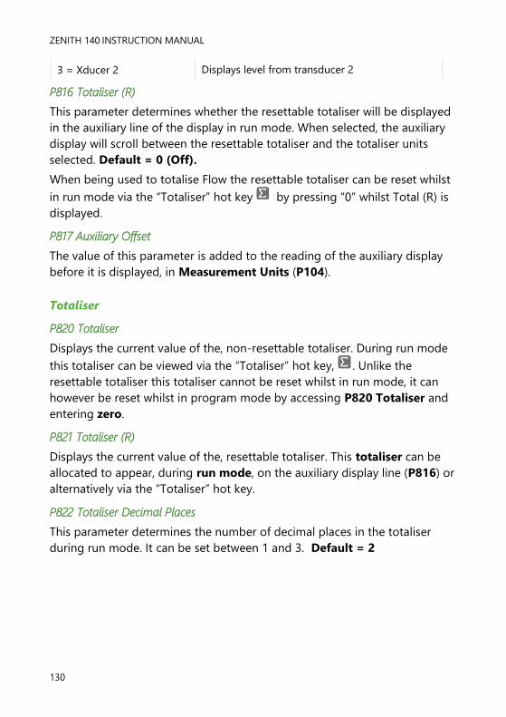
ZENITH 140 INSTRUCTION MANUAL
130
3 = Xducer 2 Displays level from transducer 2
P816 Totaliser (R)
This parameter determines whether the resettable totaliser will be displayed
in the auxiliary line of the display in run mode. When selected, the auxiliary
display will scroll between the resettable totaliser and the totaliser units
selected. Default = 0 (Off).
When being used to totalise Flow the resettable totaliser can be reset whilst
in run mode via the “Totaliser” hot key by pressing “0” whilst Total (R) is
displayed.
P817 Auxiliary Offset
The value of this parameter is added to the reading of the auxiliary display
before it is displayed, in Measurement Units (P104).
Totaliser
P820 Totaliser
Displays the current value of the, non-resettable totaliser. During run mode
this totaliser can be viewed via the “Totaliser” hot key, . Unlike the
resettable totaliser this totaliser cannot be reset whilst in run mode, it can
however be reset whilst in program mode by accessing P820 Totaliser and
entering zero.
P821 Totaliser (R)
Displays the current value of the, resettable totaliser. This totaliser can be
allocated to appear, during run mode, on the auxiliary display line (P816) or
alternatively via the “Totaliser” hot key.
P822 Totaliser Decimal Places
This parameter determines the number of decimal places in the totaliser
during run mode. It can be set between 1 and 3. Default = 2

PULSAR MEASUREMENT
131
P823 Totaliser Multiplication Factor
This parameter determines the number of decimal places in the totaliser
during run mode. It can be set between 1 and 3. Default = 2
Use this parameter if the totaliser increments by to large or small amount,
enter the factor by which the actual flow rate is multiplied by before
incrementing the totaliser.
Example: If flowrate is being calculated and displayed in ltrs/second and it is
desired to increment the totaliser in cubic metres select 7 = *1000.
When viewing, the totaliser display will state, “Units are: L*1000”, and the
totaliser will be incremented every 1000 litres. The options are:
OPTION DESCRIPTION
1 = 1/1000 Totaliser will increment every 1/1000th units of flow
2 = 1/100 Totaliser will increment every 1/100th units of flow
3 = 1/10 Totaliser will increment every 1/10th units of flow
4 = *1 (Default) Totaliser will increment every 1 units of flow
5 = 10 Totaliser will increment every 10 units of flow
6 = 100 Totaliser will increment every 100 units of flow
7 = 1,000 Totaliser will increment every 1000 units of flow
8 = 10,000 Totaliser will increment every 10,000 units of flow
9 = 100,000 Totaliser will increment every 100,000 units of flow
10 = 1,000,000 Totaliser will increment every 1,000,000 units of flow
P824 Totaliser Enable
This parameter determines if the totaliser is enabled or not, the options are
as follows:
OPTION DESCRIPTION
0 = Off Totaliser will be disabled
1 = On (default) Totaliser will be enabled

ZENITH 140 INSTRUCTION MANUAL
132
Bargraph
P829 Bargraph
By default, the bar graph will be representative of the reading obtained, as
determined by the Mode P100. When P100 = 4 (Average) or 5
(Differential) the bar graph can be assigned to be representative of the
level on any of the two points of measurement. This parameter is
automatically set to the correct default option when selecting the Mode
P100 and Xducer (P101), and under normal circumstances will not require
changing. The options, dependant on the value entered for Mode P100,
are as follows:
OPTION DESCRIPTION
1 = Auxiliary (Optional) Bargraph will be representative of levels obtained
from optional Aux. Input.
2 = Xducer 1 (Default) Bargraph will be representative of levels obtained
from Xducer 1
3 = Xducer 2 Bargraph will be representative of levels obtained
from Xducer 2
4 = Avg. Level or Diff Bargraph will be representative of levels obtained
from optional Xducer 1

PULSAR MEASUREMENT
133
mA Output Parameters
Range
P830 mA Range
This parameter determines the range of the mA output, from the following:
OPTION DESCRIPTION
0 = Off mA output disabled
1 = 0 to 20 mA
mA output directly proportional to the mA mode
(P831), so if the reading is 0% the output is 0 mA. If
the reading is 100% the output is 20 mA.
2 = 4to 20 mA
(Default)
mA output directly proportional to the mA mode
(P831), so if the reading is 0% the output is 4 mA. If
the reading is 100% the output is 20 mA.
3 = 20 to 0 mA
mA output inversely proportional to the mA mode
(P831), so if the reading is 0% the output is 20 mA.
If the reading is 100% the output is 0 mA.
4 = 20 to 4 mA
mA output inversely proportional to the mA mode
(P831), so if the reading is 0% the output is 20 mA.
If the reading is 100% the output is 4 mA.

ZENITH 140 INSTRUCTION MANUAL
134
Operation
P831 mA Mode
This parameter determines how the mA Output relates to what is measured.
By default, it operates the same as the display (P100), but it can be set to
operate as follows:
OPTION DESCRIPTION
0 = Default mA output relative to Mode P100
1 = Distance mA output relative to Distance.
2 = Level mA output relative to Level.
3 = Space mA output is relative to Space.
4 = Average Level mA output is relative to the average level of two
points of measurement P100 = 4
5 = Differential mA output is relative to the differential between two
points o measurement. P100 = 5
Setpoint
By default, the mA Output will represent the empty (0 or 4mA dependant
on (P830) mA Range) and 100% of the operational span (20mA), but you
may wish to have the output represent a section of the operational span. For
example, the application has an operational span of 6 metres, but output is
to represent empty (0 or 4mA dependant on (P830) mA Range) to a level
of 5 metres (20mA). If so P834 (Low Level) should be set to 0.00 metres and
P835 (High Level) should be set to 5 metres.
P834 mA Low Level
This parameter sets the level, distance, or space, depending on the selected
mA Out Mode (P831) at which the low mA output will occur (0 or 4mA
dependant on (P830) mA Range). Default = 0.000m
P835 mA High Level
This parameter sets the level, distance or space, depending on the selected
mA Out Mode (P831) at which the high mA output will occur (20mA).
Default = 6.00m
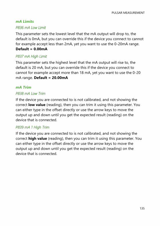
PULSAR MEASUREMENT
135
mA Limits
P836 mA Low Limit
This parameter sets the lowest level that the mA output will drop to, the
default is 0mA, but you can override this if the device you connect to cannot
for example accept less than 2mA, yet you want to use the 0-20mA range.
Default = 0.00mA
P837 mA High Limit
This parameter sets the highest level that the mA output will rise to, the
default is 20 mA, but you can override this if the device you connect to
cannot for example accept more than 18 mA, yet you want to use the 0-20
mA range. Default = 20.00mA
mA Trim
P838 mA Low Trim
If the device you are connected to is not calibrated, and not showing the
correct low value (reading), then you can trim it using this parameter. You
can either type in the offset directly or use the arrow keys to move the
output up and down until you get the expected result (reading) on the
device that is connected.
P839 mA 1 High Trim
If the device you are connected to is not calibrated, and not showing the
correct high value (reading), then you can trim it using this parameter. You
can either type in the offset directly or use the arrow keys to move the
output up and down until you get the expected result (reading) on the
device that is connected.

ZENITH 140 INSTRUCTION MANUAL
136
mA Failsafe
P840 mA Failsafe Mode
This parameter determines what happens to the mA output in the event of
the unit going into fail-safe mode. The default is to do the same as the
system fail-safe (P808), but this can be overridden to force the mA output
to an independent fail-safe mode as follows:
OPTION DESCRIPTION
0 = Default mA output will fail as per P808
1 = Hold mA output will retain its last known value.
2 = Low mA output will fail to its low condition.
3 = High mA output will fail to its high condition.
P841 mA Allocation
By default, the mA output will be representative of the reading obtained, as
determined by the Mode P100. When P100 = 5 (Volume) the output can
be assigned to be representative of the level. This parameter is
automatically set to the correct default option when selecting the Mode
P100 and under normal circumstances will not require changing.
The options, dependant on the value entered for Mode P100, are as
follows:
OPTION DESCRIPTION
1 = Auxiliary (Optional) mA output relates to the optional auxiliary input
level
2 = Xducer 1 (Default) mA output relates to Xducer 1 level
3 = Xducer 2 mA output relates to ducer 2 level
4 = Average level mA output relates to the average level of two
points of measurement. P100 = 4
5 – Differential mA output relates to the differential level of
two points of measurement. P100 = 5

PULSAR MEASUREMENT
137
Compensation Parameters
Offset
P851 Measurement Offset
The value of this parameter is added to the measured distance, in
Measurement Units (P104).
This Offset will be added to the level, as derived from the transducer, and
will affect everything including the reading on the display, the relay
setpoints and the mA output.
Temperature
P852 Temperature Source
This parameter determines the source of the temperature measurement. By
default, it is set to automatic (P852=1), which will automatically detect if a
temperature sensor is available from the transducer. If for any reason, no
temperature input is received, then the Fixed Temp value is used, as set by
P854.
The temperature source can be specifically set as follows:
OPTION DESCRIPTION
1 = Automatic (Default) Will automatically select transducer temperature
sensor, if available, or fixed temperature (P854) if
no temperature sensor found.
2 = Xducer Always uses temperature reading from transducer.
3 = Fixed Always uses fixed temperature (P854)
4 = Ext Range “A” Uses an optional external temperature sensor with
an operating range of -25oC to 50oC.
5 = Ext Range “B” Uses an optional external temperature sensor with
an operating range of -25oC to 125oC.

ZENITH 140 INSTRUCTION MANUAL
138
P853 Allocation
This parameter indicates which transducer is being used to obtain the
temperature, in the case of the Zenith this can be viewed but cannot be
changed.
OPTION DESCRIPTION
0 = Xducer 1 (Default) Temperature obtained from Xducer 1
1 = Xducer 2 Temperature obtained from Xducer 2
P854 Fixed Temperature
This parameter sets the temperature, in degrees centigrade to be used if
P852 (Temperature Source) =3. Default = 20oC.
Velocity
P860 Sound Velocity
This parameter allows for the velocity of sound to be changed according to
the atmosphere the transducer is operating in. By default, the velocity is set
for sound travelling in air at an ambient temperature of 20 degrees
centigrade (at 1bar, atmospheric pressure). Default = 342.72 m/sec.
P861 Cal. Dist 1
This parameter is used to re-calibrate the speed of sound for Xducer 1
P861 Cal. Dist 1
This parameter is used to re-calibrate the speed of sound for Xducer 2, when
P100 4 (Avg. Level), 5 (Differential Level) or 6 (Volume Average)
To obtain best results calibration should be carried out when the level is as
near empty as possible and when any vapour present has stabilized.
With the material at a steady level, view the value of P861, which will
indicate the current distance as calculated by Zenith with respect to the
current value of P860. Physically measure the distance from the face of the
transducer to the surface of the material level and enter this value, in
Measurement Units P104 and P860 will be automatically updated to
compensate for any difference between the displayed and entered values.
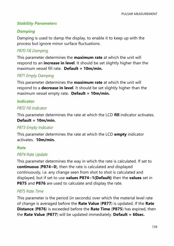
PULSAR MEASUREMENT
139
Stability Parameters
Damping
Damping is used to damp the display, to enable it to keep up with the
process but ignore minor surface fluctuations.
P870 Fill Damping
This parameter determines the maximum rate at which the unit will
respond to an increase in level. It should be set slightly higher than the
maximum vessel fill rate. Default = 10m/min.
P871 Empty Damping
This parameter determines the maximum rate at which the unit will
respond to a decrease in level. It should be set slightly higher than the
maximum vessel empty rate. Default = 10m/min.
Indicator
P872 Fill Indicator
This parameter determines the rate at which the LCD fill indicator activates.
Default = 10m/min.
P873 Empty Indicator
This parameter determines the rate at which the LCD empty indicator
activates. 10m/min.
Rate
P874 Rate Update
This parameter determines the way in which the rate is calculated. If set to
continuous (P874=0), then the rate is calculated and displayed
continuously, i.e. any change seen from shot to shot is calculated and
displayed, but if set to use values P874=1(Default) then the values set in
P875 and P876 are used to calculate and display the rate.
P875 Rate Time
This parameter is the period (in seconds) over which the material level rate
of change is averaged before the Rate Value (P877) is updated. If the Rate
Distance (P876) is exceeded before the Rate Time (P875) has expired, then
the Rate Value (P877) will be updated immediately. Default = 60sec.

ZENITH 140 INSTRUCTION MANUAL
140
P876 Rate Distance
This parameter is the rate Measurement Units (P104) over which the
material level must change before the Rate Value (P877) is updated. If the
Rate Time (P875) expires before the Rate Distance (P876) is exceeded,
then the Rate Value (P877) will be updated immediately. Default = 0.05m
P877 Rate Value
This parameter displays the current rate of change of material level, in
Measurement Units (P104) per minute. It is read only.
P878 Lower Cutoff
This parameter is used to select the minimum Rate to be calculated and can
be used to eliminate unwanted updates from effects of ripples/waves on the
surface of the material.
Filters
The following three parameters can be used to filter out unwanted changes
of level caused by a ‘rippled’ or agitated surface.
P880 Gate Mode
This parameter determines the operation of the gate, which is established
around the processed echo and is used to track the echoes movement and
update the display. If set to Fixed, P880 = 0 (Default) then the width of the
gate is determined by the value of P881 Fixed Distance. When set to
Calculated, P880=1 then the gate width is automatically calculated and
updated according to the values of P870, P871, P874, P875 and P876.
Please consult Pulsar for further information and assistance on changing the
value of this parameter.
P881 Fixed Distance
This parameter determines the width of gate to be used in tracking an echo
and under normal circumstances will not require changing, but it can be
increased in the cases where the surface is moving extremely fast (in excess
of 10m/min) to ensure smooth processing of the changing level.
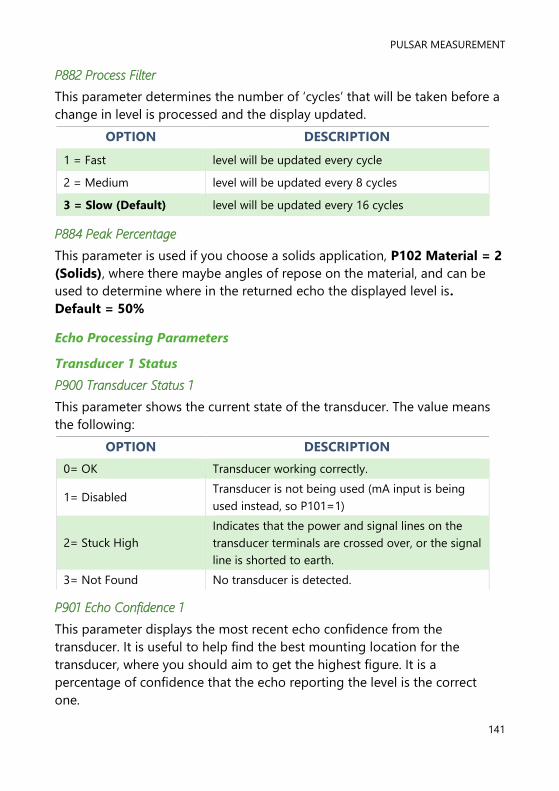
PULSAR MEASUREMENT
141
P882 Process Filter
This parameter determines the number of ‘cycles’ that will be taken before a
change in level is processed and the display updated.
OPTION DESCRIPTION
1 = Fast level will be updated every cycle
2 = Medium level will be updated every 8 cycles
3 = Slow (Default) level will be updated every 16 cycles
P884 Peak Percentage
This parameter is used if you choose a solids application, P102 Material = 2
(Solids), where there maybe angles of repose on the material, and can be
used to determine where in the returned echo the displayed level is.
Default = 50%
Echo Processing Parameters
Transducer 1 Status
P900 Transducer Status 1
This parameter shows the current state of the transducer. The value means
the following:
OPTION DESCRIPTION
0= OK Transducer working correctly.
1= Disabled Transducer is not being used (mA input is being
used instead, so P101=1)
2= Stuck High
Indicates that the power and signal lines on the
transducer terminals are crossed over, or the signal
line is shorted to earth.
3= Not Found No transducer is detected.
P901 Echo Confidence 1
This parameter displays the most recent echo confidence from the
transducer. It is useful to help find the best mounting location for the
transducer, where you should aim to get the highest figure. It is a
percentage of confidence that the echo reporting the level is the correct
one.

ZENITH 140 INSTRUCTION MANUAL
142
P902 Echo Strength 1
This parameter displays the most recent echo strength figure for the
transducer, where a higher figure indicates a better returned echo.
P903 Average Noise 1
This is the mean noise reading for the transducer. It is measured while the
transducer is not firing and gives an indication of the average amount of
electrical noise present on the cabling.
P904 Peak Noise 1
This is the peak noise reading for the transducer. It is measured while the
transducer is not firing and gives an indication of the maximum amount of
electrical noise present on the cabling.
P905 Sensitivity 1
This parameter determines the sensitivity of the unit. Please consult Pulsar
for further information and assistance on changing the value of this
parameter.
P906 Side Clearance 1
This parameter is used to set the distance by which the DATEM trace will
“stand-off” from around unwanted echoes such as obstructions. Please
consult Pulsar for further information and assistance on changing the value
of this parameter.
Transducer 2 Status
P910 - 916 Transducer 2
These parameters contain the same information as detailed in Transducer 1
Status, for Transducer 2.
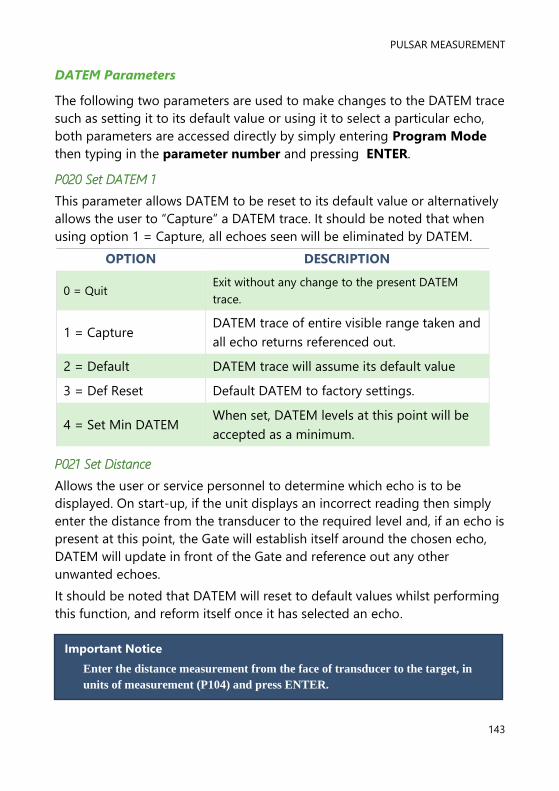
PULSAR MEASUREMENT
143
DATEM Parameters
The following two parameters are used to make changes to the DATEM trace
such as setting it to its default value or using it to select a particular echo,
both parameters are accessed directly by simply entering Program Mode
then typing in the parameter number and pressing ENTER.
P020 Set DATEM 1
This parameter allows DATEM to be reset to its default value or alternatively
allows the user to “Capture” a DATEM trace. It should be noted that when
using option 1 = Capture, all echoes seen will be eliminated by DATEM.
OPTION DESCRIPTION
0 = Quit Exit without any change to the present DATEM
trace.
1 = Capture DATEM trace of entire visible range taken and
all echo returns referenced out.
2 = Default DATEM trace will assume its default value
3 = Def Reset Default DATEM to factory settings.
4 = Set Min DATEM When set, DATEM levels at this point will be
accepted as a minimum.
P021 Set Distance
Allows the user or service personnel to determine which echo is to be
displayed. On start-up, if the unit displays an incorrect reading then simply
enter the distance from the transducer to the required level and, if an echo is
present at this point, the Gate will establish itself around the chosen echo,
DATEM will update in front of the Gate and reference out any other
unwanted echoes.
It should be noted that DATEM will reset to default values whilst performing
this function, and reform itself once it has selected an echo.
Important Notice
Enter the distance measurement from the face of transducer to the target, in
units of measurement (P104) and press ENTER.

ZENITH 140 INSTRUCTION MANUAL
144
System Parameters
Passcode
P921 Enable Code
Enables the passcode (P922), which means the passcode must be entered
to go into program mode. If disabled (set to 0), then no passcode is
required, and ENTER is used to enter program mode. Default =1 (Enabled)
P922 Passcode
This is the passcode that must be used to enter program mode. The default
is 1997, but this can be changed to another value from 0 to 9999.
Backup
P925 Parameter Backup & Restore
This parameter is used to make a backup of all parameters, for example to
ensure a default set is maintained within the unit. If alterations are made to
the parameters that do not work as intended, then the backup set can be
restored into the unit.
You can make two separate backup copies if you wish, called backup 1 and
backup 2, and restore from either. The options are:
OPTION DESCRIPTION
1= Backup 1 Make backup to area 1 of all parameters
2= Backup 2 Make backup to area 2 of all parameters
3= Restore 1 Restore all parameters from area 1
4= Restore 2 Restore all parameters from area 2
PULSAR MEASUREMENT
145
System Information
The following three parameters do not affect how the unit performs, but
details, contained in them, may be required, by Pulsar, when making technical
enquiries.
P926 Software Revision
This parameter will display the current software revision. It is read only and
cannot be changed.
P927 Hardware Revision
This parameter will display the current hardware revision. It is read only and
cannot be changed.
P928 Serial Number
This parameter will display the serial number of the unit. It is read only and
cannot be changed.
P929 Site Identification
This parameter allows you to give each unit an individual reference number,
for identification purposes. You can set any number between 1 and 99999.
P930 Factory Defaults
This parameter resets all parameter values to the original Factory Set values
that were installed when the unit was tested before despatch to you.
To reset parameters, enter 1 (Yes), and press ENTER, then you will see a
message “Entr if sure”, you should press ENTER again. If you press any other
key at this point, the parameters will not be reset, and you will see a
message confirming this.
Once you have done this, program the unit, to the desired application.
ZENITH 140 INSTRUCTION MANUAL
146
Date & Time
The date and time is used, to control specific relay functions and date stamp
certain events that are contained in the Data Logs. It is also used in
conjunction with the system watchdog that keeps an eye on the times the
unit has started.
P931 Date
This parameter displays the current date, in the format as set by P933 (Date
Format) and can be reset if required.
P932 Time
This parameter displays the current time and can be reset if required, in the
format HH: MM (24-hour format). This is set initially at the factory for UK
time.
P933 Date Format
This parameter allows you to alter the format that the date is displayed to
your choice of DD: MM: YY, MM: DD: YY or YY: MM: DD. The default is DD:
MM: YY.
LED Colour
Each relay has an associated LED, located on the unit’s front panel, which
indicates the status of the relay. By default, the LED of any relay that has
been programmed but is in its “OFF” state will be illuminated ‘yellow’. When
“ON” alarm relays will cause the LED to illuminate Red and pump, control
and miscellaneous relays will cause the LED to illuminate green. LED’s of
any relays that have not been programmed will not be illuminated.
Customised settings for the colour of LED’s can be achieved by using the
following parameters.
P935 Off Relay Colour
This parameter selects the colour that a programmed relay should be when
it is in its “OFF” state. The default is 3 = yellow, but can be changed to ‘no
colour’, red or green.
P936 Alarm Relay Colour
This parameter selects the colour that an alarm relay should be when it is in
its “ON” state. The default is 1 = red, but can be changed to ‘no colour’,
green or yellow.

PULSAR MEASUREMENT
147
P937 Pump Relay Colour
This parameter selects the colour that a pump relay should be when it is in
its “ON” state. The default is 2 = green, but can be changed to ‘no colour’,
red or yellow.
P938 Control Relay Colour
This parameter selects the colour that a control relay should be when it is in
its “ON” state. The default is 2 = green, but can be changed to ‘no colour’,
red or yellow.
P939 Miscellaneous Relay Colour
This parameter selects the colour that a miscellaneous relay should be
when it is in its “ON” state. The default is 2 = green, but can be changed to
‘no colour’, red or yellow.
All relays that are not programmed will show, ‘no colour’, i.e. they are off.
Watchdog
You can check how many times the unit has been switched on and look at
the date and time of the last ten starts. This can be useful if there have been
power failures or if for any reason the Zenith restarts due to a fault
condition. The Zenith can be backed up from a battery which automatically
cuts in during power failure, battery backed up units will continue
uninterrupted operation and therefore will not register a loss of mains
power. If, however the battery was to fail during a mains power interruption,
a start-up would be recorded once power has been restored.
The following parameters can be accessed by directly entering the
parameter number. To do this, enter the program mode and then type in
the appropriate parameter number.
Important Notice
When a relay has been failed, due to a fail signal having been received on its
associated digital input, the relay LED will flash on and off, between yellow
and red, to indicate that the relay has been failed but not put out of service.
After the maximum attempts P300 have been made to start the device relay
and it is put out of service then the relay LED will remain lit on red until
such time that the input is reset.

ZENITH 140 INSTRUCTION MANUAL
148
P940 Number of Starts
This parameter shows how many times the unit has been powered up.
P941-P960 Start Date & Time
Parameters P941 and P942 show the date and time that the unit was last
started. There are ten start dates & times recorded, which are parameters
P943-P960. The first on the list are the most recent, and the last ones are
the oldest. These are read only and cannot be changed.
Daylight Saving Time
P970 DST Enable
When Enabled (set to 1) the internal clock will be automatically adjusted to
compensate for the difference between standard time and Daylight-Saving
Time. Default = 1 (Yes)
P971 DST Difference
This parameter sets the time difference between standard time and
Daylight-Saving Time. The time difference is entered in HH:MM.
Default = 01:00
P972 DST Start Time
This parameter is used to set the time of day at which Daylight-Saving
Time will start, the time is entered in the format HH: MM (24-hour format).
Default = 02:00
Important Notice
In order to ensure the correct operation of Daylight-Saving Time P932 Time
should be checked, and adjusted if necessary, to ensure that it is set for the
current valid time.

PULSAR MEASUREMENT
149
P973 Start Day
Use this parameter to enter the day of the week (P974) that Daylight
Saving Time is to start.
OPTION DESCRIPTION
2= Monday DST will start on a Monday
3= Tuesday DST will start on a Tuesday
4= Wednesday DST will start on a Wednesday
5= Thursday DST will start on a Thursday
6= Friday DST will start on a Friday
7= Saturday DST will start on a Saturday
8= Sunday (Default) DST will start on a Sunday
P974 Start Week
This parameter will determine the week of the month (P975) in which
Daylight-Saving Time is to start.
OPTION DESCRIPTION
1= Week 1 DST will start on day (P973) in the first week
(P974) of the month (P975).
2= Week 2 DST will start on day (P973) in the second week
(P974) of the month (P975).
3= Week 3 DST will start on day (P973) in the third week
(P974) of the month (P975).
4= Week 4 DST will start on day (P973) in the fourth week
(P974) of the month (P975).
5= Last (Default) DST will start on day (P973) in the last week
(P974) of the month (P975).

ZENITH 140 INSTRUCTION MANUAL
150
P975 Start Month
This parameter is used to select the month, in which Daylight-Saving Time
will start.
OPTION DESCRIPTION
1= January DST will start during the month of January
2= February DST will start during the month of February
3=March (Default) DST will start during the month of March
4= April DST will start during the month of April
5= May DST will start during the month of May
6= June DST will start during the month of June
7= July DST will start during the month of July
8= August DST will start during the month of August
9= September DST will start during the month of September
10= October DST will start during the month of October
11= November DST will start during the month of November
12= December DST will start during the month of December
P976 DST End Time
This parameter is used to set the time of day at which Daylight-Saving
Time will end, the time is entered in the format HH: MM (24-hour format).
Default = 02:00.

PULSAR MEASUREMENT
151
P977 DST End Day
Use this parameter to enter the day of the week (P974) that Daylight
Saving Time is to end.
OPTION DESCRIPTION
2= Monday DST will end on a Monday
3= Tuesday DST will end on a Tuesday
4= Wednesday DST will end on a Wednesday
5= Thursday DST will end on a Thursday
6= Friday DST will end on a Friday
7= Saturday DST will end on a Saturday
8 = Sunday (Default) DST will end on a Sunday
P978 End Week
This parameter will determine the week of the month (P975) in which
Daylight-Saving Time is to end.
OPTION DESCRIPTION
1= Week 1 DST will end on day (P973) in the first week
(P974) of the month (P975).
2= Week 2 DST will end on day (P973) in the second week
(P974) of the month (P975).
3= Week 3 DST will end on day (P973) in the third week
(P974) of the month (P975).
4= Week 4 DST will end on day (P973) in the fourth week
(P974) of the month (P975).
5= Last (Default) DST will end on day (P973) in the last week
(P974) of the month (P975).

ZENITH 140 INSTRUCTION MANUAL
152
P979 End Month
This parameter is used to select the month, in which Daylight-Saving Time
will end.
OPTION DESCRIPTION
1= January DST will end during the month of January
2= February DST will end during the month of February
3=March DST will end during the month of March
4= April DST will end during the month of April
5= May DST will end during the month of May
6= June DST will end during the month of June
7= July DST will end during the month of July
8= August DST will end during the month of August
9= September DST will end during the month of September
10= October (Default) DST will end during the month of October
11= November DST will end during the month of November
12= December DST will end during the month of December
Device Comm.
RS232 Set Up
P061 Comms Baud
This parameter is used to set the speed (Baud Rate) of the RS232
communications and can be changed to suit the connecting device.
Default = 19200
RS 485 Set Up
Please refer to the RS485 communications manual for availability of
parameters and details of their options. This can be found in the downloads
section of the Pulsar website:
https://pulsarmeasurement.com/downloads/instruction-manuals/

PULSAR MEASUREMENT
153
Remote Alarm
When a Modem is connected, via the RS232 port, (Consult Pulsar or your
local distributor for further details), the following parameters are used to set
up the Zenith so that when the level reaches a specific alarm point, as
determined by the setting of the relay(s) the unit will dial and connect to a
remote telephone number to provide details of the event.
P144 Call Type
This parameter determines what type of connection is made via the modem.
OPTION DESCRIPTION
0 = Off (Default) Remote alarm function is disabled
1 = Ring
This option initiates a connection to a remote
modem/computer which will then allow remote
communication with the unit. Please consult Pulsar or
your local distributor for further details.
2 = SMS
This option initiates a predetermined message which is
sent to the remote telephone number detailing date and
time the alarm was initiated, the site ID, alarm condition
and level at the time the alarm was initiated.
P145 Tel. No.1
This parameter is used to enter the number of ‘0’s that appear at the
beginning of the telephone number to be dialled to receive the message.
OPTION DESCRIPTION
0= None No ‘0’s present at the beginning of the telephone number
to be dialled.
1 = Add 0 (Default) 1 ‘0’ present at the beginning of the telephone number to
be dialled.
2= Add 00 2 ‘0’s present at the beginning of the telephone number
to be dialled.

ZENITH 140 INSTRUCTION MANUAL
154
P146 Tel. No2
This parameter is used to enter the next 6 digits, following the ‘0’s, of the
telephone number to be dialled. If there are less than 6 digits following the
‘0’s, then just enter the digits required, if there are more than 6 digits
following the ‘0’s then enter the first 6 digits and then proceed to P147 to
enter the remainder.
P147 Tel. No3
This parameter is used to enter any remaining digits of the telephone
number to be dialled after completion of P145 and P146 above.
Example
Telephone number to be dialled is: 0 1234 123456
P145 Tel. No. 1 = 1 (One ‘0’ at the beginning of the telephone number)
P146 Tel. No. 2 = 123412 (The next 6 digits following the ‘0’s).
P147 Tel. No. 3 = 3456 (Remaining digits of telephone number).
P148 Timed Out
This parameter will set the time period that the unit will wait for a reply
before disconnecting.
Default = 90 seconds
P149 Retry No.
This parameter will set the number of times the telephone number will be
re-dialled if no reply is received. If set to ‘0’ then the number will be re-
dialled continually until a reply is received, if set to ‘-1’ then the number will
not be re-dialled at all. Any other value entered between 1 and 99 will
determine the number of re-dials to be attempted.
Default = 0

PULSAR MEASUREMENT
155
Test Parameters
Simulation
P980 Simulate
Test mode is used to simulate the application and confirm that all
parameters and relay setpoints have been entered as expected. During
simulation, there is a choice of whether the relays will change state (hard
simulation) or not (soft simulation), but the LED’s will always change colour
as programmed, and the current output will change. If you want to test the
logic of the system that the relays are connected to then select a hard
simulation, but if you do not want to change the relay state, then select a
soft simulation.
There are two simulation modes, automatic and manual. Automatic
simulation will move the level up and down between empty level or the pre-
determined Start Level (P983) and Pump/Control relay switch points, if you
wish to change the direction of the level movement e.g. to go beyond relay
setpoints, this can be done by using the arrow keys. In manual simulation,
using the arrow keys will allow you to move the level up and down as
required.
The choices for you to enter are as follows.
1= Manual soft simulation
2= Automatic soft simulation
3= Manual hard simulation
4= Automatic hard simulation
Whilst in Automatic hard simulation (P980 = 4) the switching of digital
inputs can be simulated by pressing the corresponding numeric key to the
input to be switched, each time the numeric key is pressed it will toggle the
input between On and Off.
To return to program mode, press ‘CANCEL’ and test mode will end.
Important Notice
Pump start delay (which by default is 10 seconds) is set to 0 during
simulation.

ZENITH 140 INSTRUCTION MANUAL
156
P981 Increment
By default, simulation mode will move by 0.1m steps in manual simulation
and by 0.1m/min in automatic simulation. Altering the increment can
change this value.
P982 Rate
In automatic mode, the rate at which the level will move up and down, is
determined by distance, P981 Increment and the time, P982 Rate which by
default is set to 1min and can be changed as required. To increase the rate
at which the level moves increase the Increment (P981) or decrease the
Rate (P982). To decrease the rate at which the level moves decrease the
Increment (P981) or increase the Rate (P982).
P983 Start Level
When using automatic simulation this parameter can be used to pre-
determine the point at which the simulated level will start at and return to.
This can be used to simulate the lowest point to which the level would
normally operate.
P984 Inc. Change
When using automatic simulation, you can incrementally increase or
decrease the rate whilst running simulation. The rate is increased /decreased
incrementally by the value P984 (Incremental Change) by using the
“decimal point” key to increase and the “plus/minus” key to decrease the
rate of change.
Default = 0.1m
Hardware
P990 Self Test
If you enter 1 for this parameter, then the unit will perform a self-test. This
will confirm that the various parts of the circuitry are working correctly. You
will see confirmation messages that the clock and the EEPROM are working
correctly, and error messages for any parts that fail.

PULSAR MEASUREMENT
157
P991 Hard Test
When this parameter is selected, the unit will test the following in turn.
• LED’s. Watch them change colour as shown on the display, and
press, ENTER, if they operated as shown.
• Relays. Press a numeric key corresponding to the number of the
relay you wish to test, and the relay will change state each time the
key is pressed. If you press any other key, other than a valid relay
number, then the test will end.
• Segments. All the segments on the LCD are lit up, so you can see if
they all work. Press, ENTER, to end the test. The LED’s all go green at
the same time.
• Keys. You should press each key, to confirm it works, with a counter
showing how many more keys you have to press. Be sure to press
the CANCEL key last, as this will show if all keys were pressed or not.
If they were not, then an error message is displayed.
P992 mA Out Test
This parameter will allow you to force a specified current on the mA output,
to test the equipment that it is connected to, and to make sure the unit is
working correctly. The figure you enter will be generated by the mA output.
P993 mA In Test
This parameter will allow you to test the mA input, by injecting a known mA
signal from an external source you can check the unit is working correctly
and as expected.
P994 Transducer Test
If you enter 1 for this parameter it will continually fire the transducer, so you
can check the wiring, until you press any key to cancel.
P995 Keys Test
You should press each key, to confirm it works, with a counter showing how
many more keys you have to press. Press the CANCEL key last, as this will
confirm if all keys were pressed or not. If they were not, then an error
message is displayed.

ZENITH 140 INSTRUCTION MANUAL
158
P996 Relay Test
Press a numeric key corresponding to the number of the relay you wish to
test, and the relay will change state each time the key is pressed. If you press
any other key, other than a valid relay number, then the test will end.
CHAPTER 6 TROUBLESHOOTING
This section describes many common symptoms, with suggestions as to
what to do. If the issue persists, please contact your local Pulsar distributor.
SYMPTOM WHAT TO DO
Display blank, transducer not firing. Check power supply, voltage selector
switch and fuse.
Displays “No Xducer” Check wiring to transducer.
Displays “Xducer Flt” There is a fault with the transducer wiring,
so check wiring to transducer.
Displays ‘Failed Safe’ The transducer has not been able to lock
on to a target. Check transducer wiring,
check P900 status. Check to see if
transducer is ‘clicking’, check for any
obstructions in the application.
Incorrect reading being displayed
for current level.
Measure actual distance from transducer
head to surface of material. Enter Program
Mode and directly access P21 (Set
Distance) type in the measured distance,
ENTER, ENTER again when prompted, wait
until SET displayed and return to Run
Mode, display should now update to
correct reading.
Material level is consistently
incorrect by the same amount.
Check empty level, (P105) display offset,
(P802) and measurement offset (P851).
LED’s change colour at relevant
relay switch points but relays do
not change state.
Check supply to unit and ensure voltage
selector set to correct position.

PULSAR MEASUREMENT
159
CHAPTER 7 DISPOSAL
Incorrect disposal can cause adverse effects to the environment.
Dispose of the device components and packaging material in accordance
with regional environmental regulations including regulations for electrical \
electronic products.
Transducers
Remove power, disconnect the Transducer, cut off the electrical cable and
dispose of cable and Transducer in accordance with regional environmental
regulations for electrical \ electronic products.
Controllers
Remove power, disconnect the Controller, and remove battery (if fitted).
Dispose of Controller in accordance with regional environmental regulations
for electrical \ electronic products.
Dispose of batteries in accordance with regional environmental regulations
for batteries.
EU WEEE Directive Logo
This symbol indicates the requirements of Directive 2012/19/EU regarding
the treatment and disposal of waste from electric and electronic equipment.

ZENITH 140 INSTRUCTION MANUAL
160
NOTES

PULSAR MEASUREMENT
161
www.pulsarmeasurement.com
S U P P O R T @ P U L S A R M E A S U R E M E N T . C O M
Copyright © 2020 Pulsar Measurement Ltd.
Registered Address: 1 Chamberlain Square CS, Birmingham B3 3AX
Registered No.: 3345604 England & Wales
Rev 1.0