
Multi-transducer, MTR-4
49
QUICK START GUIDE INSTALLATION INSTRUCTIONS Document no.: 4189300027A SW version 3.0X.X or later Multi-transducer, MTR-4
-
Upload
khangminh22 -
Category
Documents
-
view
0 -
download
0
Transcript of Multi-transducer, MTR-4

QUICK START GUIDE
INSTALLATION INSTRUCTIONS
Document no.: 4189300027A SW version 3.0X.X or later
Multi-transducer, MTR-4
MTR-4 Installation Instructions
DEIF A/S Page 2 of 49
Table of contents
1. ABOUT THIS DOCUMENT ................................................................................................... 3
GENERAL PURPOSE ...................................................................................................................... 3 CONTENTS/OVERALL STRUCTURE .................................................................................................. 3
2. WARNINGS AND LEGAL INFORMATION ........................................................................... 4
LEGAL INFORMATION AND DISCLAIMER ........................................................................................... 4 ELECTROSTATIC DISCHARGE AWARENESS ..................................................................................... 4 SAFETY ISSUES ............................................................................................................................ 4 DEFINITIONS ................................................................................................................................ 4 SAFETY WARNINGS AND INSTRUCTIONS FOR USE ........................................................................... 5 WASTE ........................................................................................................................................ 5
3. BASIC DESCRIPTION AND OPERATION OF THE MTR-4 ................................................. 6
INTRODUCTION ............................................................................................................................. 6 USER INFORMATION ..................................................................................................................... 7 DESCRIPTION OF THE PRODUCT .................................................................................................... 7 PURPOSE AND USE OF MEASURING TRANSDUCER ........................................................................... 8
4. CONNECTION ..................................................................................................................... 10
INTRODUCTION ........................................................................................................................... 10 MOUNTING ................................................................................................................................. 10 CONNECTION OF INPUT/OUTPUT MODULES ................................................................................... 12 COMMUNICATION CONNECTION ................................................................................................... 13 CONNECTION OF AUXILIARY POWER SUPPLY ................................................................................ 14
5. SETTINGS ........................................................................................................................... 15
INTRODUCTION ........................................................................................................................... 15 M-SET SOFTWARE...................................................................................................................... 15 SETTING PROCEDURE ................................................................................................................. 16 GENERAL SETTINGS ................................................................................................................... 16 CONNECTION ............................................................................................................................. 18 COMMUNICATION ....................................................................................................................... 18 SECURITY .................................................................................................................................. 19 ENERGY .................................................................................................................................... 19 ANALOGUE OUTPUTS .................................................................................................................. 20 ALARMS ..................................................................................................................................... 23 RESET OPERATIONS ................................................................................................................... 23
6. MEASUREMENTS ............................................................................................................... 24
INTRODUCTION ........................................................................................................................... 24 SUPPORTED MEASUREMENTS ..................................................................................................... 24 AVAILABLE CONNECTIONS ........................................................................................................... 24 EXPLANATION OF BASIC CONCEPTS ............................................................................................. 26 CALCULATION AND DISPLAY OF MEASUREMENTS .......................................................................... 26 PRESENT VALUES ....................................................................................................................... 27
7. APPENDIX A: MODBUS PROTOCOL ............................................................................... 29
MODBUS COMMUNICATION PROTOCOL ......................................................................................... 29 8. APPENDIX B: CALCULATIONS AND EQUATIONS ......................................................... 47
CALCULATIONS .......................................................................................................................... 47
MTR-4 Installation Instructions
DEIF A/S Page 3 of 49
1. About this document
General purpose This document is the Installation Instructions for the Multi-configurable AC Transducer, the MTR-4. The general purpose of the document is to help the user with the first steps of installing and using the unit. It contains instructions for installations and use of the MTR-4.
Contents/overall structure This document is divided into chapters, and in order to make the structure simple and easy to use, each chapter will begin from the top of a new page.
Please make sure that you read this document before starting to work with the MTR-4. Failure to do this could result in human injury or damage to the equipment.

MTR-4 Installation Instructions
DEIF A/S Page 4 of 49
2. Warnings and legal information This chapter includes important information about general legal issues relevant in the handling of DEIF products. Furthermore, some overall safety precautions will be introduced and recommended. Finally, the highlighted notes and warnings, which will be used throughout this document, are presented.
Legal information and disclaimer DEIF takes no responsibility for installation or operation of the MTR-4. If there is any doubt regarding installation and use of the system in which the instrument is used for measuring or supervision, please contact the person or company responsible for the installation of such system.
Disclaimer DEIF A/S reserves the right to change any of the contents of this document without prior notice.
The English version of this document always contains the most recent and up-to-date information about the product. DEIF does not take responsibility for the accuracy of translations, and translations might not be updated at the same time as the English document. If there is any discrepancy, the English version prevails.
Electrostatic discharge awareness Sufficient care must be taken to protect the terminals against static discharges during the installation. Once the unit is installed and connected, these precautions are no longer necessary.
Safety issues Installing the unit implies work with dangerous currents and voltages. Therefore, the installation of the unit should only be carried out by authorised personnel who understand the risks involved in the working with live electrical equipment.
Definitions Throughout this document, a number of notes with helpful user information will be presented. To ensure that these are noticed, they will be highlighted in order to separate them from the general text.
Note symbol
Warnings
Be aware of the hazardous live currents and voltages. Do not touch any AC measurement inputs as this could lead to injury or death.
The notes provide general information which will be helpful for the reader to bear in mind.
The warnings indicate a potentially dangerous situation which could result in death, personal injury or damaged equipment if certain guidelines are not followed.
The units are not to be opened by unauthorised personnel. If opened anyway, the warranty will be lost.
MTR-4 Installation Instructions
DEIF A/S Page 5 of 49
Safety warnings and instructions for use
Check the following before switching on the device: • Nominal voltage • Proper connection of auxiliary supply • Nominal frequency • Voltage ratio and phase sequence • Current transformer ratio and terminals’ integrity • Protection fuse – recommended maximal external fuse size is 6 A • Proper connection of I/O modules
Waste It is forbidden to deposit electrical and electronic equipment as municipal waste. The manufacturer or provider shall take waste electrical and electronic equipment free of charge. The complete procedure after lifetime should comply with the Directive EZ 2002/96/EG about restriction on the use of certain hazardous substances in electrical and electronic equipment or a corresponding Url 118/04.
The secondary output of the current transformer should be short-circuited before connecting the transducer.
MTR-4 Installation Instructions
DEIF A/S Page 6 of 49
3. Basic description and operation of the MTR-4
Introduction
What is in the delivery? The consignment includes:
• Multi-transducer MTR-4 • Label for I/O functionality description • Quick start guide
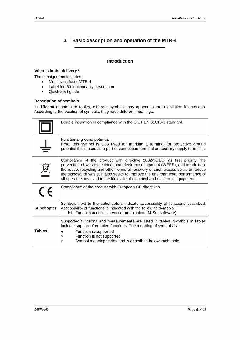
Description of symbols In different chapters or tables, different symbols may appear in the installation instructions. According to the position of symbols, they have different meanings.
Double insulation in compliance with the SIST EN 61010-1 standard.
Functional ground potential. Note: this symbol is also used for marking a terminal for protective ground potential if it is used as a part of connection terminal or auxiliary supply terminals.
Compliance of the product with directive 2002/96/EC, as first priority, the prevention of waste electrical and electronic equipment (WEEE), and in addition, the reuse, recycling and other forms of recovery of such wastes so as to reduce the disposal of waste. It also seeks to improve the environmental performance of all operators involved in the life cycle of electrical and electronic equipment.
Compliance of the product with European CE directives.
Subchapter Symbols next to the subchapters indicate accessibility of functions described. Accessibility of functions is indicated with the following symbols:
Function accessible via communication (M-Set software)
Tables
Supported functions and measurements are listed in tables. Symbols in tables indicate support of enabled functions. The meaning of symbols is: Function is supported × Function is not supported Symbol meaning varies and is described below each table
MTR-4 Installation Instructions
DEIF A/S Page 7 of 49
User information For unknown technical terms, please refer to the below glossary.
Glossary
Term Explanation
RMS Root Mean Square value Modbus Industrial protocol for data transmission M-Set Software for MTR-4 AC Alternating voltage and current PA total Angle calculated from total active and apparent power PA1, PA2, PA3 Angle between fundamental phase voltage and phase current PF Power factor THD Total Harmonic Distortion MD Measurement of average values in time interval Hand-over place Connection spot of consumer installation in public network Mv − Sample factor Defines a number of periods for measuring calculation on the basis of
measured frequency Mp − Average interval
Defines frequency of refreshing displayed measurements on the basis of a sample factor
Hysteresis expressed as percentage [%]
Percentage specifies increase or decrease of a measurement from a certain limit after exceeding it.
Description of the product The measuring transducer is intended for measuring, analysing and monitoring single-phase or three-phase electrical power network. It measures RMS values by means of fast sampling of voltage and current signals, which makes the instrument suitable for acquisition of transient events. A built-in micro controller calculates measurements (voltage, current, frequency, energy, power, power factor, THD phase angles, and so on) from the measured signals.
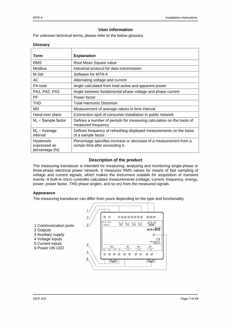
Appearance The measuring transducer can differ from yours depending on the type and functionality.
1 Communication ports 2 Outputs 3 Auxiliary supply 4 Voltage inputs 5 Current inputs 6 Power ON LED
MTR-4 Installation Instructions
DEIF A/S Page 8 of 49
Communication ports and LED indicators Serial communication can be connected by using screw-in connector (RS-485). A USB can be connected through a USB-mini type connector at the bottom of the transducer. LED indicator is intended for POWER ON signalling (red LED).
Universal auxiliary supply Auxiliary supply is connected by two screw-in connectors. For safety purposes, it is important that all wires are firmly fastened. Auxiliary supply is wide range (24 V DC to 300 V DC; 40 V AC to 276 V AC).
Voltage inputs Each voltage input is connected to a measuring circuit through an input resistor chain (3.3 MΩ per phase). Maximum value of input voltage is 600 VL-N (1000 VL-L).
Current inputs Each current input is connected to a measuring circuit through a current transformer (0.01 Ω per phase). Maximum allowed thermal value of input current is 15 A (cont.).
Purpose and use of measuring transducer The instrument is used for monitoring and measuring electric quantities of three-phase electrical power distribution system. The meter is provided with 32 programme-adjustable alarms and communication. With the RS-485 and USB communication, the transducer can be configured and by RS-485 also measurements can be read. The transducer also functions as an energy counter (up to four energy counters).
The USB communication port is NOT galvanically insulated and can be used ONLY UN-connected to auxiliary supply and power inputs!
MTR-4 Installation Instructions
DEIF A/S Page 9 of 49
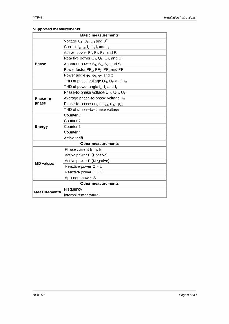
Supported measurements Basic measurements
Phase
Voltage U1, U2, U3 and U~ Current I1, I2, I3, In, It and Ia
Active power P1, P2, P3, and Pt Reactive power Q1, Q2, Q3, and Qt Apparent power S1, S2, S3, and St Power factor PF1, PF2, PF3 and PF~ Power angle φ1, φ2, φ3 and φ~ THD of phase voltage Uf1, Uf2 and Uf3 THD of power angle I1, I2 and I3
Phase-to-phase
Phase-to-phase voltage U12, U23, U31 Average phase-to-phase voltage Uff Phase-to-phase angle φ12, φ23, φ31 THD of phase−to−phase voltage
Energy
Counter 1 Counter 2 Counter 3 Counter 4 Active tariff
Other measurements
MD values
Phase current I1, I2, I3 Active power P (Positive) Active power P (Negative) Reactive power Q − L Reactive power Q − C Apparent power S
Other measurements
Measurements Frequency Internal temperature
MTR-4 Installation Instructions
DEIF A/S Page 10 of 49
4. Connection
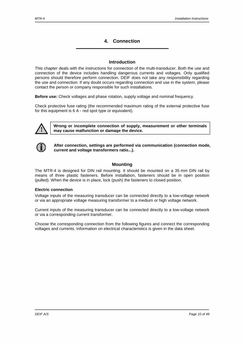
Introduction This chapter deals with the instructions for connection of the multi-transducer. Both the use and connection of the device includes handling dangerous currents and voltages. Only qualified persons should therefore perform connection. DEIF does not take any responsibility regarding the use and connection. If any doubt occurs regarding connection and use in the system, please contact the person or company responsible for such installations. Before use: Check voltages and phase rotation, supply voltage and nominal frequency. Check protective fuse rating (the recommended maximum rating of the external protective fuse for this equipment is 6 A - red spot type or equivalent).
Mounting The MTR-4 is designed for DIN rail mounting. It should be mounted on a 35 mm DIN rail by means of three plastic fasteners. Before installation, fasteners should be in open position (pulled). When the device is in place, lock (push) the fasteners to closed position.
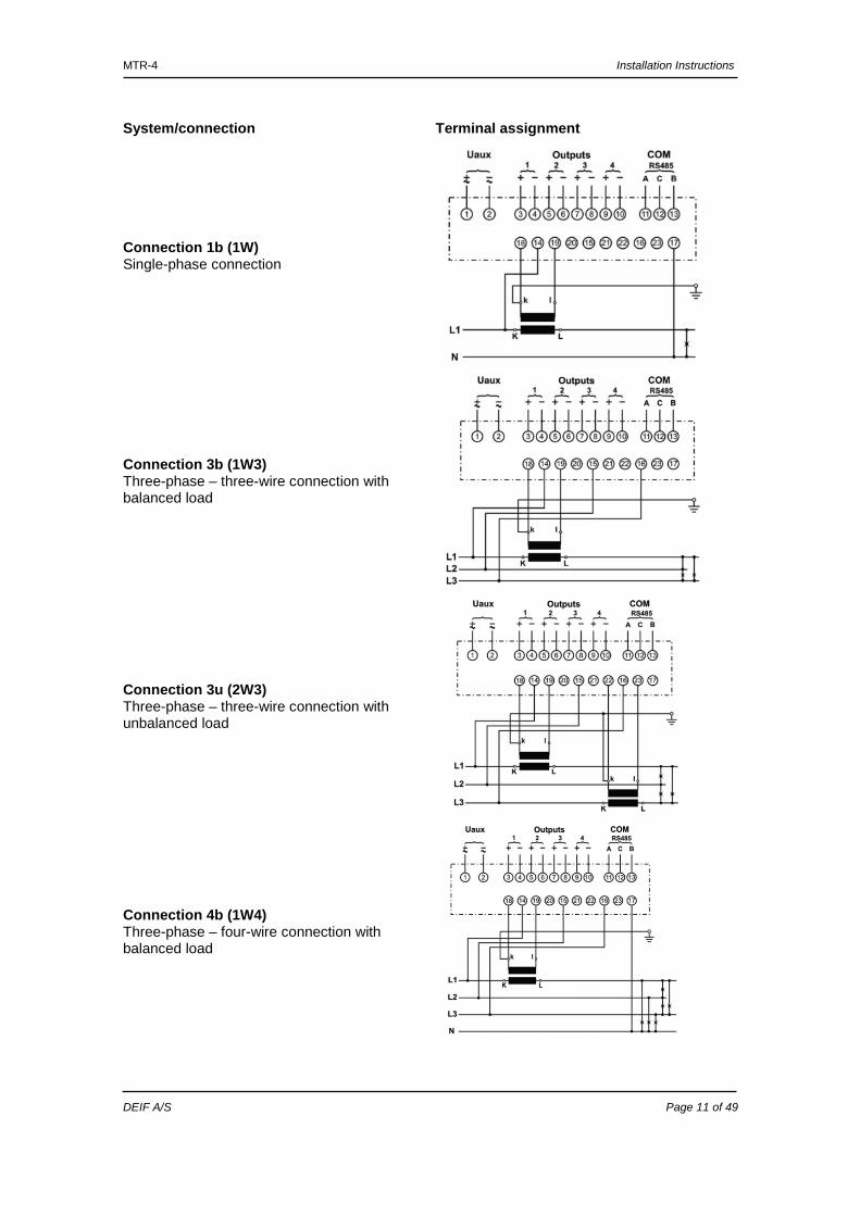
Electric connection Voltage inputs of the measuring transducer can be connected directly to a low-voltage network or via an appropriate voltage measuring transformer to a medium or high voltage network. Current inputs of the measuring transducer can be connected directly to a low-voltage network or via a corresponding current transformer. Choose the corresponding connection from the following figures and connect the corresponding voltages and currents. Information on electrical characteristics is given in the data sheet.
Wrong or incomplete connection of supply, measurement or other terminals may cause malfunction or damage the device.
After connection, settings are performed via communication (connection mode, current and voltage transformers ratio...).
MTR-4 Installation Instructions
DEIF A/S Page 11 of 49
System/connection Terminal assignment
Connection 1b (1W) Single-phase connection
Connection 3b (1W3) Three-phase – three-wire connection with balanced load
Connection 3u (2W3) Three-phase – three-wire connection with unbalanced load
Connection 4b (1W4) Three-phase – four-wire connection with balanced load
MTR-4 Installation Instructions
DEIF A/S Page 12 of 49
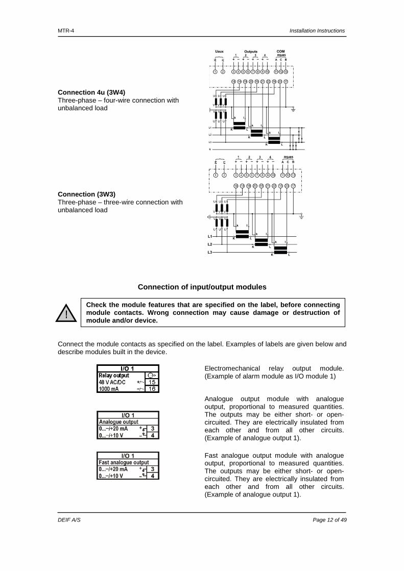
Connection 4u (3W4) Three-phase – four-wire connection with unbalanced load
Connection (3W3) Three-phase – three-wire connection with unbalanced load
Connection of input/output modules Connect the module contacts as specified on the label. Examples of labels are given below and describe modules built in the device.
Electromechanical relay output module. (Example of alarm module as I/O module 1)
Analogue output module with analogue output, proportional to measured quantities. The outputs may be either short- or open-circuited. They are electrically insulated from each other and from all other circuits. (Example of analogue output 1).
Fast analogue output module with analogue output, proportional to measured quantities. The outputs may be either short- or open-circuited. They are electrically insulated from each other and from all other circuits. (Example of analogue output 1).
Check the module features that are specified on the label, before connecting module contacts. Wrong connection may cause damage or destruction of module and/or device.
MTR-4 Installation Instructions
DEIF A/S Page 13 of 49
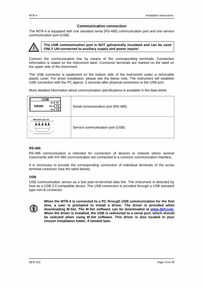
Communication connection The MTR-4 is equipped with one standard serial (RS-485) communication port and one service communication port (USB). Connect the communication line by means of the corresponding terminals. Connection information is stated on the instrument label. Connector terminals are marked on the label on the upper side of the instrument. The USB connector is positioned on the bottom side of the instrument under a removable plastic cover. For driver installation, please see the below note. The instrument will establish USB connection with the PC approx. 5 seconds after physical connection to the USB port. More detailed information about communication specifications is available in the data sheet.
Serial communication port (RS-485)
Service communication port (USB)
RS-485 RS-485 communication is intended for connection of devices to network where several instruments with RS-485 communication are connected to a common communication interface. It is necessary to provide the corresponding connection of individual terminals of the screw terminal connector (see the table below).
USB USB communication serves as a fast peer-to-terminal data link. The instrument is detected by host as a USB 2.0 compatible device. The USB connection is provided through a USB standard type mini B connector.
The USB communication port is NOT galvanically insulated and can be used ONLY UN-connected to auxiliary supply and power inputs!
When the MTR-4 is connected to a PC through USB communication for the first time, a user is prompted to install a driver. The driver is provided when downloading M-Set. The M-Set software can be downloaded at www.deif.com. When the driver is installed, the USB is redirected to a serial port, which should be selected when using M-Set software. This driver is also located in your chosen installation folder, if needed later.
MTR-4 Installation Instructions
DEIF A/S Page 14 of 49
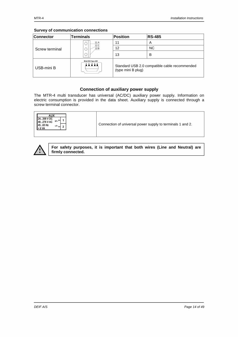
Survey of communication connections Connector Terminals Position RS-485
Screw terminal
11 A12 C13 B
11 A 12 NC
13 B
USB-mini B
Standard USB 2.0 compatible cable recommended (type mini B plug)
Connection of auxiliary power supply The MTR-4 multi transducer has universal (AC/DC) auxiliary power supply. Information on electric consumption is provided in the data sheet. Auxiliary supply is connected through a screw terminal connector.
Connection of universal power supply to terminals 1 and 2.
For safety purposes, it is important that both wires (Line and Neutral) are firmly connected.
MTR-4 Installation Instructions
DEIF A/S Page 15 of 49
5. Settings
Introduction Instrument settings can be remotely modified with communication (RS-485 or USB) and M-Set software when connected to a PC.
M-Set software M-Set is a software tool for complete monitoring of measuring instruments, connected to a PC via serial or USB communication. A user-friendly interface consists of four segments: device management, instrument settings, real-time measurements and software upgrading.
Device management Select the instrument in a favourite’s line. Use the network explorer to set and explore the device’s network. Communication parameters of all devices and their addresses in the network can be easily set.
Instrument settings Multi-register edit technology assures a simple modification of settings that are organised in a tree structure. Besides transferring settings into the instrument, storing and reading from the setting files are also available.
Real-time measurements All supported measurements can be captured in real time in a table form. For further processing of the results of measurements, copying via a clipboard into standard Windows formats is supported.
Software upgrading Always use the latest version of software, both M-Set and software in the instrument. The programme automatically informs you on available upgrades that can be transferred from the website and used for upgrading.
More information about the M-Set software can be found in the M-Set help system.

MTR-4 Installation Instructions
DEIF A/S Page 16 of 49
M-Set user interface
Setting procedure In order to modify instrument settings with M-Set, current parameters must be loaded first. Instrument settings can be acquired via a communication link (serial or USB) or can be loaded off-line from a file on a local disk. Settings are displayed in the M-Set setting window - the left part displays a hierarchical tree structure of settings, the right part displays parameter values of the chosen setting group.
General settings General settings are essential for the transducer. They are divided into four additional sub-levels (Connection, Communication, Display and Security).
Description and location Two parameters that are intended for easier recognition of a certain unit. They are especially used for identification of the device or location on which measurements are performed.
Average interval The averaging interval defines the refresh rate of measurements on communication and remote display.
Temperature unit Choose a unit for temperature display.
Maximum demand calculation (MD mode) The instrument provides maximum demand values using thermal function. A thermal function assures exponent thermal characteristic based on simulation of bimetal meters. Maximum values and time of their occurrence are stored in the device. A time constant (t. c.) can be set from 1 to 255 minutes and is 6 times the thermal time constant (t. c. = 6 * thermal time constant).
You can download freeware M-Set from www.deif.com.

MTR-4 Installation Instructions
DEIF A/S Page 17 of 49
Example: Mode: thermal function Time constant: 8 min. Current MD and maximal MD: reset at 0 min.
Starting current for PF and PA (mA) At all measuring inputs, noise is usually present. It is constant, and its influence on the accuracy is increased by decreasing measuring signals. It is present also when measuring signals are not connected, and it occurs at all further calculations as very sporadic measurements. By setting a common starting current, a limit of input signal is defined where measurements and all other calculations are still performed.
Starting current for all powers (mA) Noise is limited with a starting current also at measurements and calculations of powers.
Minimum synchronisation voltage If all phase voltages are smaller than this (noise limit) setting, the instrument uses current inputs for synchronisation. If also all phase currents are smaller than Starting current for PF and PA setting, synchronisation is not possible and frequency displayed is 0.
Reactive power and energy calculation Two different principles of reactive power and energy calculation are used: Standard method: With this method, a reactive power and energy is calculated, based on the assumption that all power (energy), which is not active, is reactive. Q2 = S2 – P2 This also means that all higher harmonics will be measured as reactive power (energy). Delayed current method: With this method, reactive power (energy) is calculated by multiplication of voltage samples and delayed current samples (see chapter 8, “Appendix B: Calculations and equations” on page 47): Q = U × I|+90° With this method, reactive power (energy) only represents the true reactive component of apparent power (energy).
Thermal function
0 1 2 3 4 5 6 7 8 9 10 11 12 13 14 15 16 17 18 19 20
Time [min.]
Mea
sure
d va
lue
Present MD MD peak Input
MTR-4 Installation Instructions
DEIF A/S Page 18 of 49
Connection
Connection When connection is selected, load connection and the supported measurements are defined (see chapter 6, “Measurements” regarding connection mode, on page 24).
Setting of current and voltage ratios Before setting current and voltage ratios, it is necessary to be familiar with the conditions in which the device is to be used. All other measurements and calculations depend on these settings. Up to five decimal places can be set. Settings range VT primary VT secondary CT primary CT secondary Maximum value 1638.3 kV 13383 V 1638.3 kA 13383 A Minimum value 0.1 V 1 mV 0.1 A 1 mA
Used voltage and current range Setting of the range is connected with all settings of alarms, analogue outputs and a display (calculation) of energy and measurements recording, where 100 % represents 500 V 5 A. In case of subsequent change of the range, alarm settings must be correspondingly changed, as well.
Nominal frequency A valid frequency measurement is within the range of nominal frequency ±32 Hz. This setting is used for alarms.
Energy flow direction This setting allows manual change of energy flow direction (IMPORT to EXPORT or vice versa) in the readings tab. It has no influence on readings sent by communication.
CT connection If this setting is set to “Reversed”, it has the same influence as if CTs would be reversely connected. All power readings will also change their sign.
Communication
Serial Communication Define parameters that are important for the operation in the RS-485 network. Factory settings of communication are #33\115200,n,8,2 (address 1 to 247\baud rate 2400 to 115200 b/s, parity, data bits, stop bit). Modbus table: with this setting, a Modbus table for measurements and settings is defined. Modbus addresses for measurements and settings can be compatible with the previous family of transducers (MTR-2). For a more detailed description, see chapter 7, “Appendix A: Modbus protocol”, on page 29.
USB Communication For description of all settings, see Chapter 7 Appendix A: Modbus protocol. For driver installation, see the note on page 13. The instrument will establish a USB connection with the PC approx. 5 seconds after physical connection to the USB port.
Settings of connections must reflect actual state; otherwise measurements are not valid.
MTR-4 Installation Instructions
DEIF A/S Page 19 of 49
Security Parameter settings are divided into three groups regarding security level:
1. At the first level (PL1), settings of a real time clock can be changed, and energy meters and MD can be reset.
2. At the second level (PL2), the access to all data that are protected with the first level (PL1) and setting of all other parameters in the ”Settings” menu is available.
3. A backup password (BP) is used if passwords at levels 1 (PL1) and 2 (PL2) have been forgotten, and it is different for each device (depending on a serial number of the meter). The BP password is available in the support department at DEIF, and is entered instead of the password PL1 or/and PL2. Do not forget to state the meter serial number when contacting the personnel at DEIF.
User information
Password setting A password consists of four letters taken from the British alphabet from A to Z. When setting a password, only the letter being set is visible while the others are covered with *. Two passwords (PL1, PL2) and the time of automatic activation could be set.
Password modification A password can be modified; however, only that password can be modified to which the access is unlocked at the moment.
Password disabling A password is disabled by setting the "AAAA" password.
Energy
Active tariff When active tariff is set, one of the tariffs (up to four) is defined as active.
Common energy exponent Common energy exponent defines minimal energy that can be displayed on the energy counter. On the basis of this and a counter divider, a basic calculation prefix for energy is defined (−3 is 10−3Wh = mWh, 4 is 104Wh = 10 kWh). A common energy exponent also influences in setting a number of impulses for energy of pulse output or alarm output functioning as an energy meter. Define the common energy exponent as recommended in the table below, where counter divider is value 10 as default. Values of primary voltage and current determine a proper common energy exponent.
A serial number of device is stated on the label and also accessible with the M-Set software.
A factory-set password is “AAAA” at both access levels (L1 and L2). This password does not limit access.
After modification of energy parameters, the energy meters must be reset. Otherwise, all further energy measurements could be incorrect.
MTR-4 Installation Instructions
DEIF A/S Page 20 of 49
Current Voltage
1 A 5 A 50 A 100 A 1000 A
110 V -1 0 1 1 2 230 V 0 0 1 2 3 1000 V 0 1 2 3 4 30 kV 2 2 3 4 4* * Counter divider should be at least 100
Counter divider Additionally, the counter divider defines precision of a certain counter, according to settings of a common energy exponent. This is done to prevent the counter from having an early energy overflow. An example for 23.331 kWh of consumed active energy: Divider Exponent Resolution Displayed 1 0 1 x 10^0 = 1 W 23.331 kW 10 0 10 x 10^0 = 10 W 23.33 kW 100 0 100 x 10^0 = 100 W 0.0233 MW 1000 0 1000 x 10^0 = 1 kW 0.023 MW 1 1 1 x 10^1 = 10 W 23.33 kW 1 2 1 x 10^2 = 100 W 0.0233 MW 1 3 1 x 10^3 = 1 kW 0.023 MW 1 4 1 x 10^4 = 10 kW 0.02 MW 10 2 10 x 10^2 = 1 kW 0.023 MW
Analogue outputs Number of analogue outputs depends on the version of MTR-4.
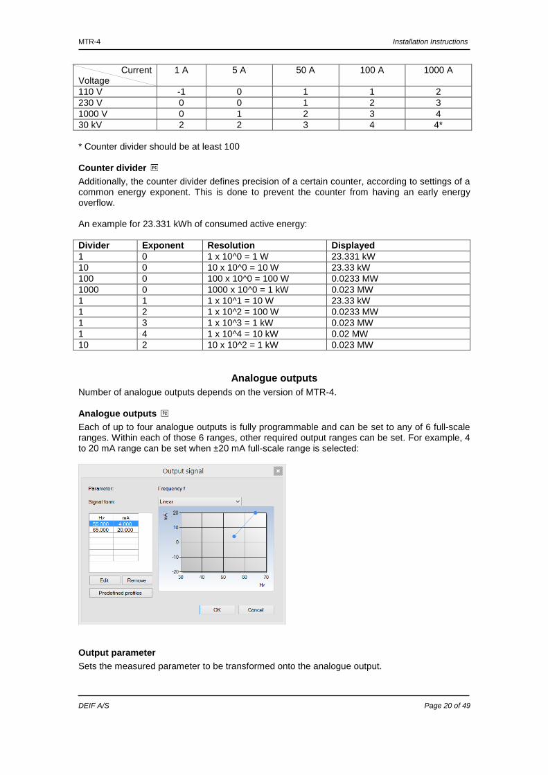
Analogue outputs Each of up to four analogue outputs is fully programmable and can be set to any of 6 full-scale ranges. Within each of those 6 ranges, other required output ranges can be set. For example, 4 to 20 mA range can be set when ±20 mA full-scale range is selected:
Output parameter Sets the measured parameter to be transformed onto the analogue output.
MTR-4 Installation Instructions
DEIF A/S Page 21 of 49
Output range Defines analogue output full-scale ranges: DC current output DC voltage output -1 to 0 to 1 mA -1 to 0 to 1 V -5 to 0 to 5 mA -10 to 0 to 10 mA -10 to 0 to 10 V -20 to 0 to 20 mA
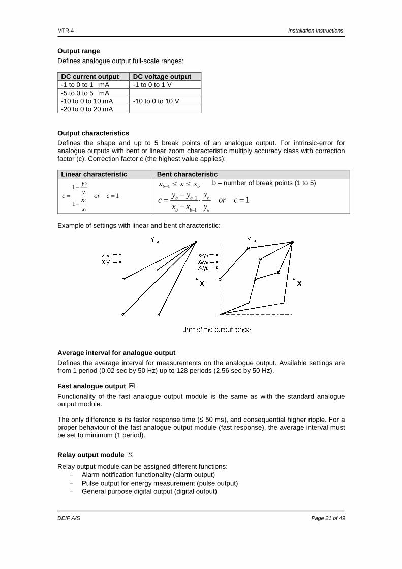
Output characteristics Defines the shape and up to 5 break points of an analogue output. For intrinsic-error for analogue outputs with bent or linear zoom characteristic multiply accuracy class with correction factor (c). Correction factor c (the highest value applies): Linear characteristic Bent characteristic
11
1
0
0
=−
−= cor
xxyy
c
e
e bb xxx ≤≤−1 b – number of break points (1 to 5)
11
1 =⋅−−
=−
− coryx
xxyyc
e
e
bb
bb
Example of settings with linear and bent characteristic:
Average interval for analogue output Defines the average interval for measurements on the analogue output. Available settings are from 1 period (0.02 sec by 50 Hz) up to 128 periods (2.56 sec by 50 Hz).
Fast analogue output Functionality of the fast analogue output module is the same as with the standard analogue output module. The only difference is its faster response time (≤ 50 ms), and consequential higher ripple. For a proper behaviour of the fast analogue output module (fast response), the average interval must be set to minimum (1 period).
Relay output module Relay output module can be assigned different functions:
− Alarm notification functionality (alarm output) − Pulse output for energy measurement (pulse output) − General purpose digital output (digital output)
MTR-4 Installation Instructions
DEIF A/S Page 22 of 49
Pulse output functionality A corresponding energy counter (up to 4) can be assigned to a pulse output. A number of pulses per energy unit, pulse length, and a tariff in which output is active are set.
Calculation of recommended pulse parameters Number of pulses per energy unit should be in certain limits according to expected power. If not so, the measurement from pulse output can be incorrect. Settings of current and voltage transformers can help in estimation of expected power. Principle described below for pulse setting, where e is prefix, satisfies SIST EN 62053−31: 2001 standards pulse specifications:
eWhpeW 1100155.1 →
Examples:
Expected power → Pulse output settings 150 to 1500 kW → 1 p/1kWh 1.5 to 15 MW → 100 p/1MWh 15 to 150 MW → 10 p/1MWh
150 to 1500 MW → 1 p/1MWh
Alarm notification functionality An alarm notification function can also be assigned to output. In case of any alarm occurrence, alarm output will trigger passive electromechanical relay or passive solid-state relay. Two parameters should be defined for each alarm output:
− The source for assigned alarm (alarm group 1, 2 or both) − Type of output signal when alarm is detected.
General purpose digital output This functionality allows user to enable/disable output relay by software settings (when appropriate values are set in Modbus table).
Module number Modbus register Register value Module 1 (if installed) 40722 3 - ON 4 - OFF Module 2 (if installed) 40725 3 - ON 4 - OFF Module 3 (if installed) 40728 3 - ON 4 - OFF Module 4 (if installed) 40731 3 - ON 4 - OFF
Pulse parameters are defined by SIST EN 62053−31 standard. In the section “Calculation of recommended pulse parameters” below, a simplified rule is described to assist you in setting the pulse output parameters.
MTR-4 Installation Instructions
DEIF A/S Page 23 of 49
Alarms Alarms are used for alarming exceeded set values of the measured quantities.
Alarm setting MTR-4 supports recording and storage of 16 alarms in two groups. For each group of alarms, a time constant of maximal values in thermal mode, a delay time and alarm deactivation hysteresis can be defined. Quantity, value (a current value or an MD – thermal function) are defined for every individual alarm.
Reset operations
Reset energy counters (E1, E2, E3, E4) All or individual energy meters are reset.
Reset MD values Current and stored MDs are reset.
Reset the last MD period Current MD value is reset.
Reset alarm output All alarms are reset.
New values of alarms are calculated in percentage at the modification of the connection settings. If used voltage, current range is changed, the limit values of alarms will change proportionally.
MTR-4 Installation Instructions
DEIF A/S Page 24 of 49
6. Measurements
Introduction In the following chapters, the device operation is explained in more details.
Supported measurements Selection of supported measurements is changed with the connection settings. All supported measurements can be read via communication (M-Set and Modbus).
Available connections Different electric connections are described in more details in in chapter 4 “Connection”. Connections are marked as follows:
• Connection 1b (1W) − single phase connection • Connection 3b (1W3) − three-phase – three-wire connection with balanced load • Connection 4b (1W4) − three-phase – four-wire connection with balanced load • Connection 3u (2W3) − three-phase – three-wire connection with unbalanced load • Connection 4u (3W4) − three-phase – four-wire connection with unbalanced load
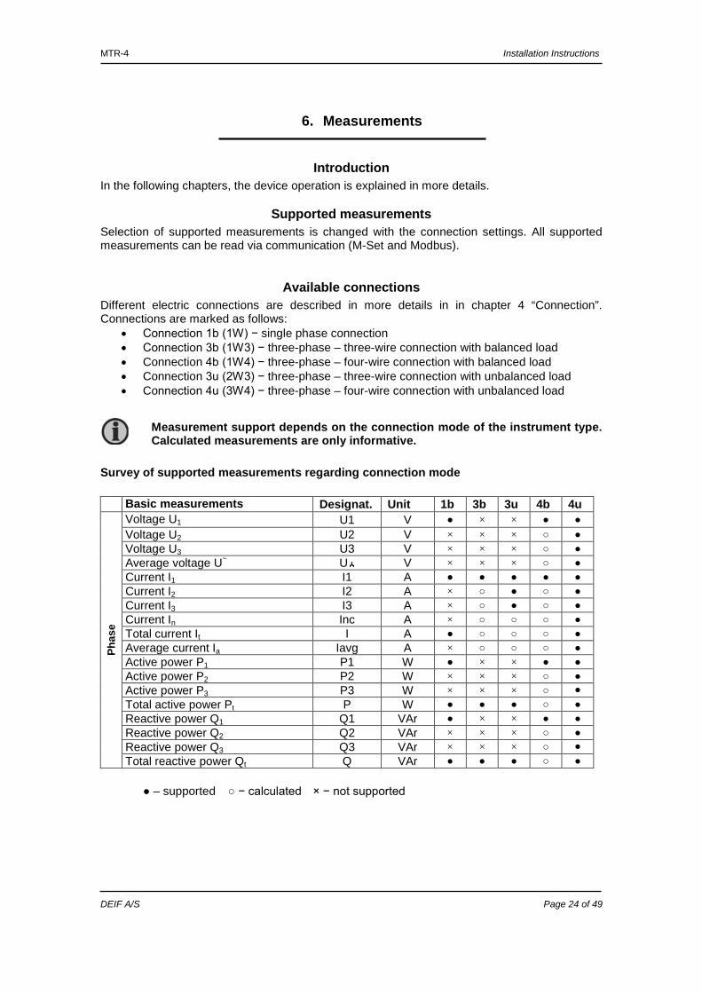
Survey of supported measurements regarding connection mode Basic measurements Designat. Unit 1b 3b 3u 4b 4u
Phas
e
Voltage U1 U1 V × × Voltage U2 U2 V × × × Voltage U3 U3 V × × × Average voltage U~ U V × × × Current I1 I1 A Current I2 I2 A × Current I3 I3 A × Current In Inc A × Total current It I A Average current Ia Iavg A × Active power P1 P1 W × × Active power P2 P2 W × × × Active power P3 P3 W × × × Total active power Pt P W Reactive power Q1 Q1 VAr × × Reactive power Q2 Q2 VAr × × × Reactive power Q3 Q3 VAr × × × Total reactive power Qt Q VAr
– supported − calculated × − not supported
Measurement support depends on the connection mode of the instrument type. Calculated measurements are only informative.
MTR-4 Installation Instructions
DEIF A/S Page 25 of 49
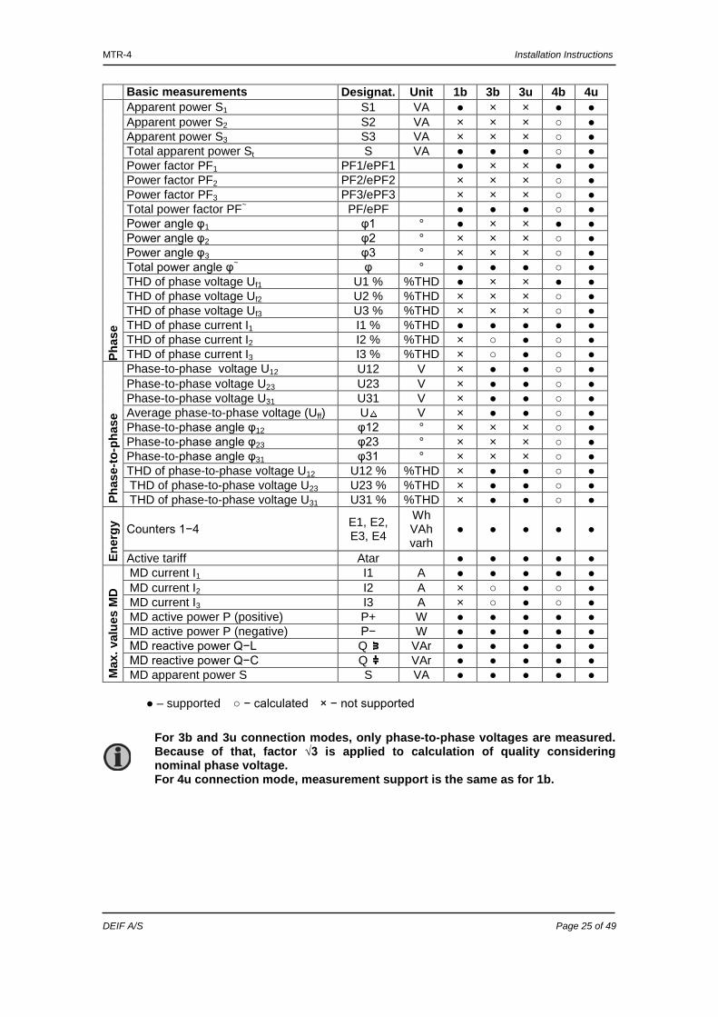
Basic measurements Designat. Unit 1b 3b 3u 4b 4u Ph
ase
Apparent power S1 S1 VA × × Apparent power S2 S2 VA × × × Apparent power S3 S3 VA × × × Total apparent power St S VA Power factor PF1 PF1/ePF1 × × Power factor PF2 PF2/ePF2 × × × Power factor PF3 PF3/ePF3 × × × Total power factor PF~ PF/ePF Power angle φ1 φ1 ° × × Power angle φ2 φ2 ° × × × Power angle φ3 φ3 ° × × × Total power angle φ~ φ ° THD of phase voltage Uf1 U1 % %THD × × THD of phase voltage Uf2 U2 % %THD × × × THD of phase voltage Uf3 U3 % %THD × × × THD of phase current I1 I1 % %THD THD of phase current I2 I2 % %THD × THD of phase current I3 I3 % %THD ×
Pha
se-to
-pha
se
Phase-to-phase voltage U12 U12 V × Phase-to-phase voltage U23 U23 V × Phase-to-phase voltage U31 U31 V × Average phase-to-phase voltage (Uff) U V × Phase-to-phase angle φ12 φ12 ° × × × Phase-to-phase angle φ23 φ23 ° × × × Phase-to-phase angle φ31 φ31 ° × × × THD of phase-to-phase voltage U12 U12 % %THD × THD of phase-to-phase voltage U23 U23 % %THD × THD of phase-to-phase voltage U31 U31 % %THD ×
Ene
rgy Counters 1−4 E1, E2,
E3, E4
Wh VAh varh
Active tariff Atar
Max
. val
ues
MD
MD current I1 I1 A MD current I2 I2 A × MD current I3 I3 A × MD active power P (positive) P+ W MD active power P (negative) P− W MD reactive power Q−L Q VAr MD reactive power Q−C Q VAr MD apparent power S S VA
– supported − calculated × − not supported
For 3b and 3u connection modes, only phase-to-phase voltages are measured. Because of that, factor √3 is applied to calculation of quality considering nominal phase voltage. For 4u connection mode, measurement support is the same as for 1b.
MTR-4 Installation Instructions
DEIF A/S Page 26 of 49
Explanation of basic concepts
Sample factor − MV A meter measures all primary quantities with sample frequency which cannot exceed a certain number of samples in a time period. Based on these limitations (65 Hz·128 samples), a sample factor is calculated. A sample factor (MV), depending on frequency of a measured signal, defines a number of periods for a measurement calculation and thus a number of harmonics considered in THD calculations.
Average interval − MP Due to readability of measurements from communication, an average interval (MP) is calculated with regard to the measured signal frequency. The average interval (see “Average interval” on page 16) defines the refresh rate of displayed measurements based on a sampling factor.
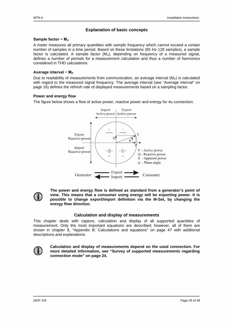
Power and energy flow The figure below shows a flow of active power, reactive power and energy for 4u connection.
Calculation and display of measurements This chapter deals with capture, calculation and display of all supported quantities of measurement. Only the most important equations are described; however, all of them are shown in chapter 8, “Appendix B: Calculations and equations” on page 47 with additional descriptions and explanations.
The power and energy flow is defined as standard from a generator’s point of view. This means that a consumer using energy will be exporting power. It is possible to change export/import definition via the M-Set, by changing the energy flow direction.
Calculation and display of measurements depend on the used connection. For more detailed information, see “Survey of supported measurements regarding connection mode” on page 24.

MTR-4 Installation Instructions
DEIF A/S Page 27 of 49
Present values All values are calculated as an average of number of periods set in general settings/average interval.
Voltage The instrument measures true RMS values of all phase voltages (U1, U2, U3), connected to the transducer. Phase-to-phase voltages (U12, U23, U31), average phase voltage (Uf) and average phase-to-phase voltage (Ua) are calculated from measured phase voltages (U1, U2, U3).
N
u = U
2n
N
1=nf
∑
( )
N
2ynxn
N
1=nxy
uu = U
−∑
All voltage measurements are available via communication.
Current The instrument measures true RMS values of phase currents, connected to current inputs. Neutral current (In), average current (Ia) and a sum of all phase currents (It) are calculated from phase currents.
N
i =
2n
I
N
1=nRMS
∑
All current measurements are available via communication.
Active, reactive and apparent power Active power is calculated from instantaneous phase voltages and currents. Two different principles of reactive power calculation are used: Standard method: With this method, a reactive power is calculated based on the assumption that all power, which is not active, is reactive. Q2 = S2 – P2 This also means that all higher harmonics will be measured as reactive power. Delayed current method: With this method, reactive power (energy) is calculated by multiplication of voltage samples and delayed current samples (see chapter 8, “Appendix B: Calculations and equations” on page 47: Q = U × I|+90° With this method, reactive power (energy) only represents the true reactive component of apparent power (energy). All measurements are seen via communication. For more detailed information about calculation, see chapter 8, “Appendix B: Calculations and equations” on page 47.
MTR-4 Installation Instructions
DEIF A/S Page 28 of 49
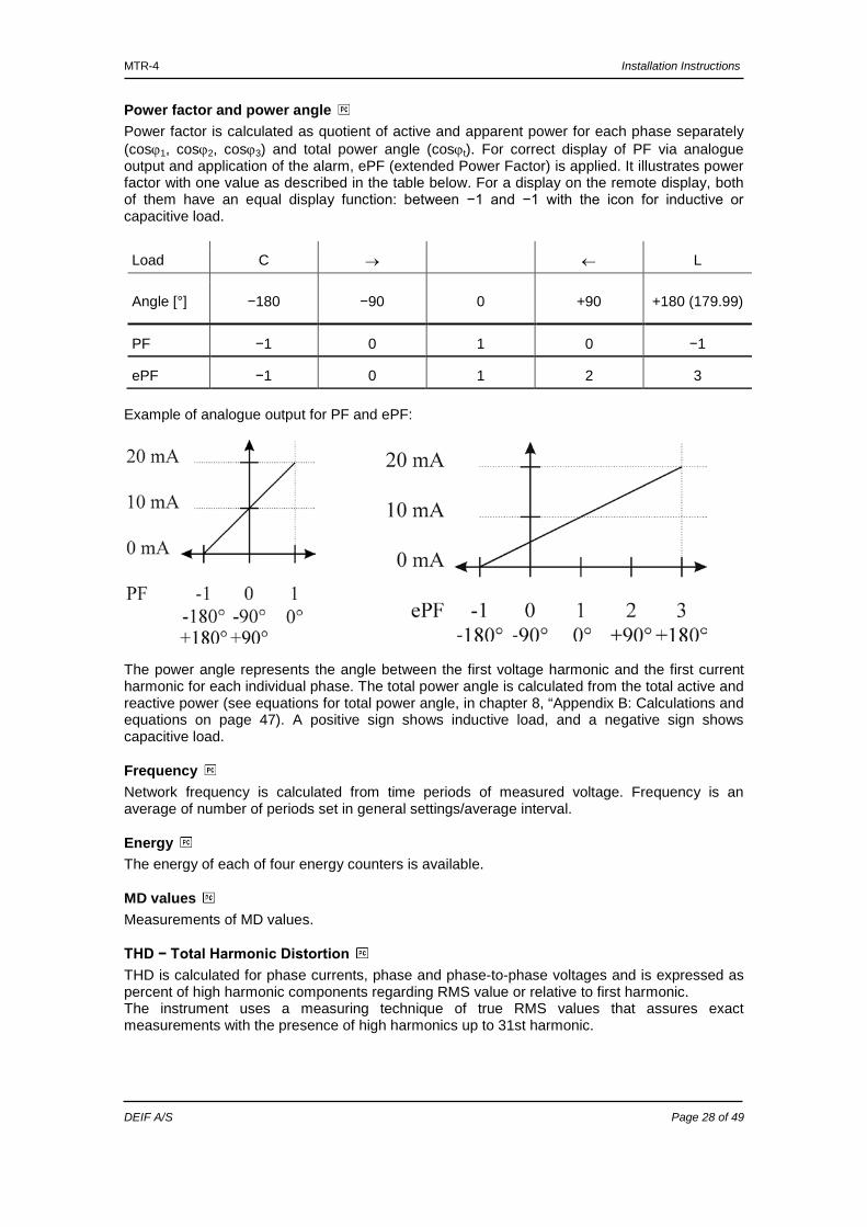
Power factor and power angle Power factor is calculated as quotient of active and apparent power for each phase separately (cosϕ1, cosϕ2, cosϕ3) and total power angle (cosϕt). For correct display of PF via analogue output and application of the alarm, ePF (extended Power Factor) is applied. It illustrates power factor with one value as described in the table below. For a display on the remote display, both of them have an equal display function: between −1 and −1 with the icon for inductive or capacitive load.
Load C → ← L
Angle [°] −180 −90 0 +90 +180 (179.99)
PF −1 0 1 0 −1
ePF −1 0 1 2 3 Example of analogue output for PF and ePF:
The power angle represents the angle between the first voltage harmonic and the first current harmonic for each individual phase. The total power angle is calculated from the total active and reactive power (see equations for total power angle, in chapter 8, “Appendix B: Calculations and equations on page 47). A positive sign shows inductive load, and a negative sign shows capacitive load.
Frequency Network frequency is calculated from time periods of measured voltage. Frequency is an average of number of periods set in general settings/average interval.
Energy The energy of each of four energy counters is available.
MD values Measurements of MD values.
THD − Total Harmonic Distortion THD is calculated for phase currents, phase and phase-to-phase voltages and is expressed as percent of high harmonic components regarding RMS value or relative to first harmonic. The instrument uses a measuring technique of true RMS values that assures exact measurements with the presence of high harmonics up to 31st harmonic.
MTR-4 Installation Instructions
DEIF A/S Page 29 of 49
7. Appendix A: Modbus protocol
Modbus communication protocol Modbus is enabled via RS-485 or USB. The response is the same type as the request. Two versions of Modbus register tables are available:
• VERSION 1: MTR-4/MTR-3 Modbus registers • VERSION 2: Compatibility with previous version of the product, the MTR-2
Please note that VERSION 1 has both the IEEE 754 formatted float tags available and special formatted tags. The type of the special formatted tags is to be translated with the provided table shown on the last page in Appendix A, page 46.
Modbus Modbus protocol enables operation of device on Modbus networks. For device with serial communication, the Modbus protocol enables point-to-point (for example device to PC) multi-drop communication via RS-485 communication. Modbus protocol is a widely supported open interconnect originally designed by Modicon. The memory reference for input and holding registers is 300001 and 400001 respectively. The register tables on the next pages show both the PLC address and Modbus address to read from the desired register. Example for reading frequency parameter: PLC: Read address 300106-300107 Modbus: Read address 105-106 with function 4 The Modbus address will always be 1 lower than the PLC address because PLC addresses start with 1 where Modbus addresses start with 0.
MTR-4 Installation Instructions
DEIF A/S Page 30 of 49
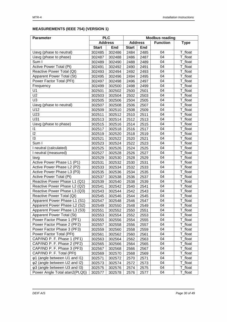
MEASUREMENTS (IEEE 754) (VERSION 1) Parameter PLC Modbus reading
Address Address Function Type Start End Start End
Uavg (phase to neutral) 302485 302486 2484 2485 04 T_float Uavg (phase to phase) 302487 302488 2486 2487 04 T_float Sum I 302489 302490 2488 2489 04 T_float Active Power Total (Pt) 302491 302492 2490 2491 04 T_float Reactive Power Total (Qt) 302493 302494 2492 2493 04 T_float Apparent Power Total (St) 302495 302496 2494 2495 04 T_float Power Factor Total (PFt) 302497 302498 2496 2497 04 T_float Frequency 302499 302500 2498 2499 04 T_float U1 302501 302502 2500 2501 04 T_float U2 302503 302504 2502 2503 04 T_float U3 302505 302506 2504 2505 04 T_float Uavg (phase to neutral) 302507 302508 2506 2507 04 T_float U12 302509 302510 2508 2509 04 T_float U23 302511 302512 2510 2511 04 T_float U31 302513 302514 2512 2513 04 T_float Uavg (phase to phase) 302515 302516 2514 2515 04 T_float I1 302517 302518 2516 2517 04 T_float I2 302519 302520 2518 2519 04 T_float I3 302521 302522 2520 2521 04 T_float Sum I 302523 302524 2522 2523 04 T_float I neutral (calculated) 302525 302526 2524 2525 04 T_float I neutral (measured) 302527 302528 2526 2527 04 T_float Iavg 302529 302530 2528 2529 04 T_float Active Power Phase L1 (P1) 302531 302532 2530 2531 04 T_float Active Power Phase L2 (P2) 302533 302534 2532 2533 04 T_float Active Power Phase L3 (P3) 302535 302536 2534 2535 04 T_float Active Power Total (Pt) 302537 302538 2536 2537 04 T_float Reactive Power Phase L1 (Q1) 302539 302540 2538 2539 04 T_float Reactive Power Phase L2 (Q2) 302541 302542 2540 2541 04 T_float Reactive Power Phase L3 (Q3) 302543 302544 2542 2543 04 T_float Reactive Power Total (Qt) 302545 302546 2544 2545 04 T_float Apparent Power Phase L1 (S1) 302547 302548 2546 2547 04 T_float Apparent Power Phase L2 (S2) 302549 302550 2548 2549 04 T_float Apparent Power Phase L3 (S3) 302551 302552 2550 2551 04 T_float Apparent Power Total (St) 302553 302554 2552 2553 04 T_float Power Factor Phase 1 (PF1) 302555 302556 2554 2555 04 T_float Power Factor Phase 2 (PF2) 302557 302558 2556 2557 04 T_float Power Factor Phase 3 (PF3) 302559 302560 2558 2559 04 T_float Power Factor Total (PFt) 302561 302562 2560 2561 04 T_float CAP/IND P. F. Phase 1 (PF1) 302563 302564 2562 2563 04 T_float CAP/IND P. F. Phase 2 (PF2) 302565 302566 2564 2565 04 T_float CAP/IND P. F. Phase 3 (PF3) 302567 302568 2566 2567 04 T_float CAP/IND P. F. Total (PFt) 302569 302570 2568 2569 04 T_float φ1 (angle between U1 and I1) 302571 302572 2570 2571 04 T_float φ2 (angle between U2 and I2) 302573 302574 2572 2573 04 T_float φ3 (angle between U3 and I3) 302575 302576 2574 2575 04 T_float Power Angle Total atan2(Pt,Qt)) 302577 302578 2576 2577 04 T_float
MTR-4 Installation Instructions
DEIF A/S Page 31 of 49
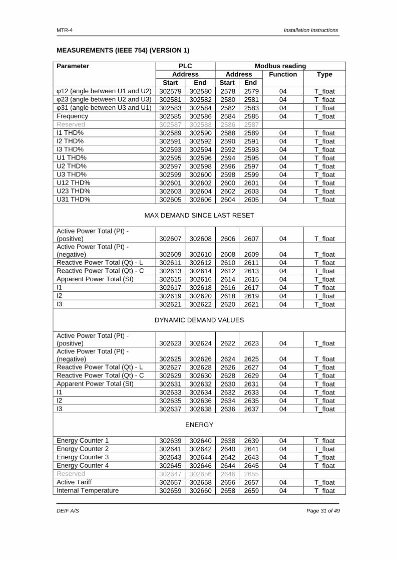
MEASUREMENTS (IEEE 754) (VERSION 1) Parameter PLC Modbus reading
Address Address Function Type Start End Start End
φ12 (angle between U1 and U2) 302579 302580 2578 2579 04 T_float φ23 (angle between U2 and U3) 302581 302582 2580 2581 04 T_float φ31 (angle between U3 and U1) 302583 302584 2582 2583 04 T_float Frequency 302585 302586 2584 2585 04 T_float Reserved 302587 302588 2586 2587 I1 THD% 302589 302590 2588 2589 04 T_float I2 THD% 302591 302592 2590 2591 04 T_float I3 THD% 302593 302594 2592 2593 04 T_float U1 THD% 302595 302596 2594 2595 04 T_float U2 THD% 302597 302598 2596 2597 04 T_float U3 THD% 302599 302600 2598 2599 04 T_float U12 THD% 302601 302602 2600 2601 04 T_float U23 THD% 302603 302604 2602 2603 04 T_float U31 THD% 302605 302606 2604 2605 04 T_float
MAX DEMAND SINCE LAST RESET
Active Power Total (Pt) - (positive) 302607 302608 2606 2607 04 T_float Active Power Total (Pt) - (negative) 302609 302610 2608 2609 04 T_float Reactive Power Total (Qt) - L 302611 302612 2610 2611 04 T_float Reactive Power Total (Qt) - C 302613 302614 2612 2613 04 T_float Apparent Power Total (St) 302615 302616 2614 2615 04 T_float I1 302617 302618 2616 2617 04 T_float I2 302619 302620 2618 2619 04 T_float I3 302621 302622 2620 2621 04 T_float
DYNAMIC DEMAND VALUES
Active Power Total (Pt) - (positive) 302623 302624 2622 2623 04 T_float Active Power Total (Pt) - (negative) 302625 302626 2624 2625 04 T_float Reactive Power Total (Qt) - L 302627 302628 2626 2627 04 T_float Reactive Power Total (Qt) - C 302629 302630 2628 2629 04 T_float Apparent Power Total (St) 302631 302632 2630 2631 04 T_float I1 302633 302634 2632 2633 04 T_float I2 302635 302636 2634 2635 04 T_float I3 302637 302638 2636 2637 04 T_float
ENERGY
Energy Counter 1 302639 302640 2638 2639 04 T_float Energy Counter 2 302641 302642 2640 2641 04 T_float Energy Counter 3 302643 302644 2642 2643 04 T_float Energy Counter 4 302645 302646 2644 2645 04 T_float Reserved 302647 302656 2646 2655 Active Tariff 302657 302658 2656 2657 04 T_float Internal Temperature 302659 302660 2658 2659 04 T_float
MTR-4 Installation Instructions
DEIF A/S Page 32 of 49
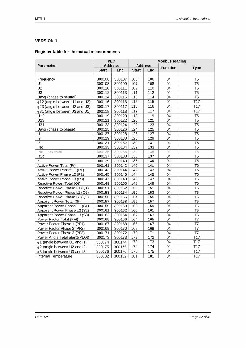
VERSION 1: Register table for the actual measurements
Parameter PLC Modbus reading
Address Address Function Type Start End Start End Frequency 300106 300107 105 106 04 T5 U1 300108 300109 107 108 04 T5 U2 300110 300111 109 110 04 T5 U3 300112 300113 111 112 04 T5 Uavg (phase to neutral) 300114 300115 113 114 04 T5 ϕ12 (angle between U1 and U2) 300116 300116 115 115 04 T17 ϕ23 (angle between U2 and U3) 300117 300117 116 116 04 T17 ϕ31 (angle between U3 and U1) 300118 300118 117 117 04 T17 U12 300119 300120 118 119 04 T5 U23 300121 300122 120 121 04 T5 U31 300123 300124 122 123 04 T5 Uavg (phase to phase) 300125 300126 124 125 04 T5 I1 300127 300128 126 127 04 T5 I2 300129 300130 128 129 04 T5 I3 300131 300132 130 131 04 T5 INc 300133 300134 132 133 04 T5 INm - reserved 300135 300136 134 135 04 T5 Iavg 300137 300138 136 137 04 T5 Σ I 300139 300140 138 139 04 T5 Active Power Total (Pt) 300141 300142 140 141 04 T6 Active Power Phase L1 (P1) 300143 300144 142 143 04 T6 Active Power Phase L2 (P2) 300145 300146 144 145 04 T6 Active Power Phase L3 (P3) 300147 300148 146 147 04 T6 Reactive Power Total (Qt) 300149 300150 148 149 04 T6 Reactive Power Phase L1 (Q1) 300151 300152 150 151 04 T6 Reactive Power Phase L2 (Q2) 300153 300154 152 153 04 T6 Reactive Power Phase L3 (Q3) 300155 300156 154 155 04 T6 Apparent Power Total (St) 300157 300158 156 157 04 T5 Apparent Power Phase L1 (S1) 300159 300160 158 159 04 T5 Apparent Power Phase L2 (S2) 300161 300162 160 161 04 T5 Apparent Power Phase L3 (S3) 300163 300164 162 163 04 T5 Power Factor Total (PFt) 300165 300166 164 165 04 T7 Power Factor Phase 1 (PF1) 300167 300168 166 167 04 T7 Power Factor Phase 2 (PF2) 300169 300170 168 169 04 T7 Power Factor Phase 3 (PF3) 300171 300172 170 171 04 T7 Power Angle Total atan2(Pt,Qt)) 300173 300173 172 172 04 T17 ϕ1 (angle between U1 and I1) 300174 300174 173 173 04 T17 ϕ2 (angle between U2 and I2) 300175 300175 174 174 04 T17 ϕ3 (angle between U3 and I3) 300176 300176 175 175 04 T17 Internal Temperature 300182 300182 181 181 04 T17
MTR-4 Installation Instructions
DEIF A/S Page 33 of 49
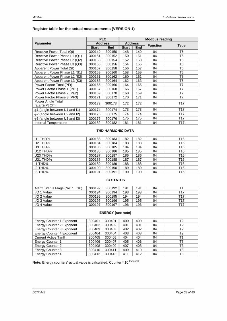
Register table for the actual measurements (VERSION 1)
Parameter PLC Modbus reading
Address Address Function Type Start End Start End Reactive Power Total (Qt) 300149 300150 148 149 04 T6 Reactive Power Phase L1 (Q1) 300151 300152 150 151 04 T6 Reactive Power Phase L2 (Q2) 300153 300154 152 153 04 T6 Reactive Power Phase L3 (Q3) 300155 300156 154 155 04 T6 Apparent Power Total (St) 300157 300158 156 157 04 T5 Apparent Power Phase L1 (S1) 300159 300160 158 159 04 T5 Apparent Power Phase L2 (S2) 300161 300162 160 161 04 T5 Apparent Power Phase L3 (S3) 300163 300164 162 163 04 T5 Power Factor Total (PFt) 300165 300166 164 165 04 T7 Power Factor Phase 1 (PF1) 300167 300168 166 167 04 T7 Power Factor Phase 2 (PF2) 300169 300170 168 169 04 T7 Power Factor Phase 3 (PF3) 300171 300172 170 171 04 T7 Power Angle Total (atan2(Pt,Qt)) 300173 300173 172 172 04 T17
ϕ1 (angle between U1 and I1) 300174 300174 173 173 04 T17 ϕ2 (angle between U2 and I2) 300175 300175 174 174 04 T17 ϕ3 (angle between U3 and I3) 300176 300176 175 175 04 T17 Internal Temperature 300182 300182 181 181 04 T17
THD HARMONIC DATA
U1 THD% 300183 300183 182 182 04 T16 U2 THD% 300184 300184 183 183 04 T16 U3 THD% 300185 300185 184 184 04 T16 U12 THD% 300186 300186 185 185 04 T16 U23 THD% 300187 300187 186 186 04 T16 U31 THD% 300188 300188 187 187 04 T16 I1 THD% 300189 300189 188 188 04 T16 I2 THD% 300190 300190 189 189 04 T16 I3 THD% 300191 300191 190 190 04 T16
I/O STATUS
Alarm Status Flags (No. 1…16) 300192 300192 191 191 04 T1 I/O 1 Value 300194 300194 193 193 04 T17 I/O 2 Value 300195 300195 194 194 04 T17 I/O 3 Value 300196 300196 195 195 04 T17 I/O 4 Value 300197 300197 196 196 04 T17
ENERGY (see note)
Energy Counter 1 Exponent 300401 300401 400 400 04 T2 Energy Counter 2 Exponent 300402 300402 401 401 04 T2 Energy Counter 3 Exponent 300403 300403 402 402 04 T2 Energy Counter 4 Exponent 300404 300404 403 403 04 T2 Current Active Tariff 300405 300405 404 404 04 T1 Energy Counter 1 300406 300407 405 406 04 T3 Energy Counter 2 300408 300409 407 408 04 T3 Energy Counter 3 300410 300411 409 410 04 T3 Energy Counter 4 300412 300413 411 412 04 T3
Note: Energy counters’ actual value is calculated: Counter * 10 Exponent
MTR-4 Installation Instructions
DEIF A/S Page 34 of 49
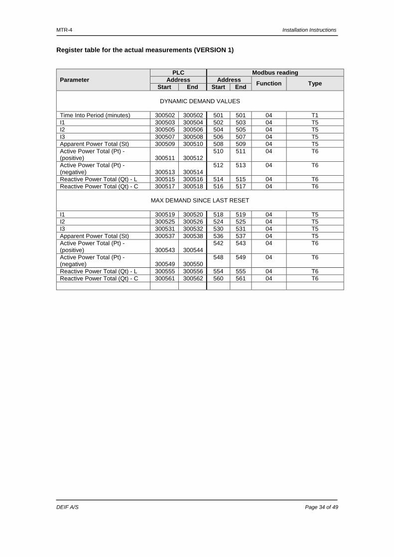
Register table for the actual measurements (VERSION 1)
Parameter PLC Modbus reading
Address Address Function Type Start End Start End
DYNAMIC DEMAND VALUES
Time Into Period (minutes) 300502 300502 501 501 04 T1 I1 300503 300504 502 503 04 T5 I2 300505 300506 504 505 04 T5 I3 300507 300508 506 507 04 T5 Apparent Power Total (St) 300509 300510 508 509 04 T5 Active Power Total (Pt) - (positive) 300511 300512
510 511 04 T6
Active Power Total (Pt) - (negative) 300513 300514
512 513 04 T6
Reactive Power Total (Qt) - L 300515 300516 514 515 04 T6 Reactive Power Total (Qt) - C 300517 300518 516 517 04 T6
MAX DEMAND SINCE LAST RESET
I1 300519 300520 518 519 04 T5 I2 300525 300526 524 525 04 T5 I3 300531 300532 530 531 04 T5 Apparent Power Total (St) 300537 300538 536 537 04 T5 Active Power Total (Pt) - (positive) 300543 300544
542 543 04 T6
Active Power Total (Pt) - (negative) 300549 300550
548 549 04 T6
Reactive Power Total (Qt) - L 300555 300556 554 555 04 T6 Reactive Power Total (Qt) - C 300561 300562 560 561 04 T6
MTR-4 Installation Instructions
DEIF A/S Page 35 of 49
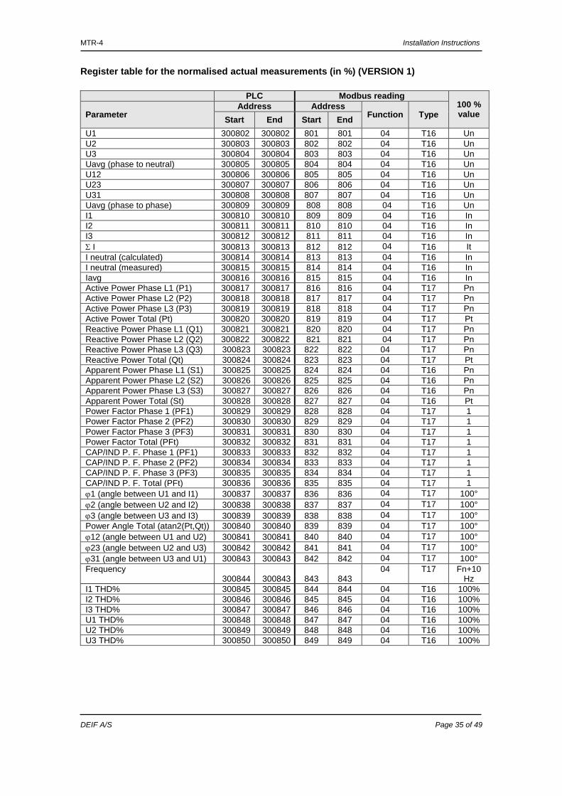
Register table for the normalised actual measurements (in %) (VERSION 1)
PLC Modbus reading 100 % value Parameter
Address Address Function Type Start End Start End
U1 300802 300802 801 801 04 T16 Un U2 300803 300803 802 802 04 T16 Un U3 300804 300804 803 803 04 T16 Un Uavg (phase to neutral) 300805 300805 804 804 04 T16 Un U12 300806 300806 805 805 04 T16 Un U23 300807 300807 806 806 04 T16 Un U31 300808 300808 807 807 04 T16 Un Uavg (phase to phase) 300809 300809 808 808 04 T16 Un I1 300810 300810 809 809 04 T16 In I2 300811 300811 810 810 04 T16 In I3 300812 300812 811 811 04 T16 In Σ I 300813 300813 812 812 04 T16 It I neutral (calculated) 300814 300814 813 813 04 T16 In I neutral (measured) 300815 300815 814 814 04 T16 In Iavg 300816 300816 815 815 04 T16 In Active Power Phase L1 (P1) 300817 300817 816 816 04 T17 Pn Active Power Phase L2 (P2) 300818 300818 817 817 04 T17 Pn Active Power Phase L3 (P3) 300819 300819 818 818 04 T17 Pn Active Power Total (Pt) 300820 300820 819 819 04 T17 Pt Reactive Power Phase L1 (Q1) 300821 300821 820 820 04 T17 Pn Reactive Power Phase L2 (Q2) 300822 300822 821 821 04 T17 Pn Reactive Power Phase L3 (Q3) 300823 300823 822 822 04 T17 Pn Reactive Power Total (Qt) 300824 300824 823 823 04 T17 Pt Apparent Power Phase L1 (S1) 300825 300825 824 824 04 T16 Pn Apparent Power Phase L2 (S2) 300826 300826 825 825 04 T16 Pn Apparent Power Phase L3 (S3) 300827 300827 826 826 04 T16 Pn Apparent Power Total (St) 300828 300828 827 827 04 T16 Pt Power Factor Phase 1 (PF1) 300829 300829 828 828 04 T17 1 Power Factor Phase 2 (PF2) 300830 300830 829 829 04 T17 1 Power Factor Phase 3 (PF3) 300831 300831 830 830 04 T17 1 Power Factor Total (PFt) 300832 300832 831 831 04 T17 1 CAP/IND P. F. Phase 1 (PF1) 300833 300833 832 832 04 T17 1 CAP/IND P. F. Phase 2 (PF2) 300834 300834 833 833 04 T17 1 CAP/IND P. F. Phase 3 (PF3) 300835 300835 834 834 04 T17 1 CAP/IND P. F. Total (PFt) 300836 300836 835 835 04 T17 1 ϕ1 (angle between U1 and I1) 300837 300837 836 836 04 T17 100° ϕ2 (angle between U2 and I2) 300838 300838 837 837 04 T17 100° ϕ3 (angle between U3 and I3) 300839 300839 838 838 04 T17 100° Power Angle Total (atan2(Pt,Qt)) 300840 300840 839 839 04 T17 100° ϕ12 (angle between U1 and U2) 300841 300841 840 840 04 T17 100° ϕ23 (angle between U2 and U3) 300842 300842 841 841 04 T17 100° ϕ31 (angle between U3 and U1) 300843 300843 842 842 04 T17 100° Frequency
300844 300843 843 843 04 T17 Fn+10
Hz I1 THD% 300845 300845 844 844 04 T16 100% I2 THD% 300846 300846 845 845 04 T16 100% I3 THD% 300847 300847 846 846 04 T16 100% U1 THD% 300848 300848 847 847 04 T16 100% U2 THD% 300849 300849 848 848 04 T16 100% U3 THD% 300850 300850 849 849 04 T16 100%
MTR-4 Installation Instructions
DEIF A/S Page 36 of 49
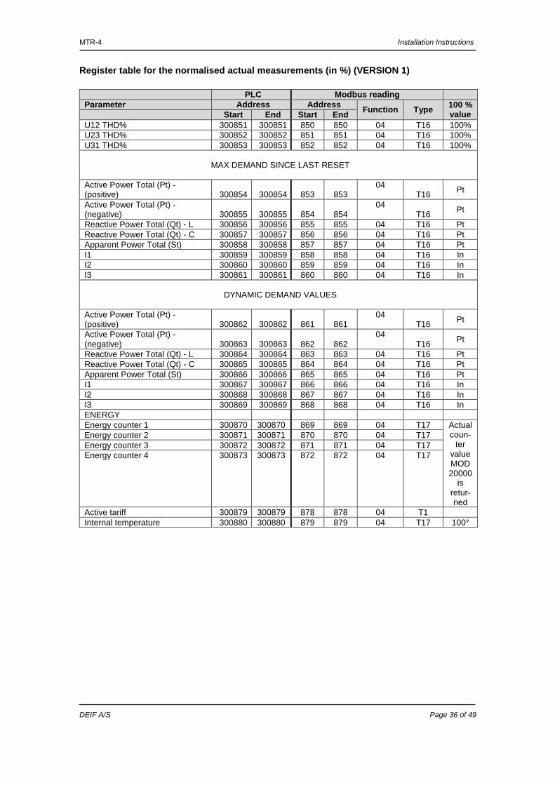
Register table for the normalised actual measurements (in %) (VERSION 1)
PLC Modbus reading Parameter Address Address Function Type 100 %
value Start End Start End U12 THD% 300851 300851 850 850 04 T16 100% U23 THD% 300852 300852 851 851 04 T16 100% U31 THD% 300853 300853 852 852 04 T16 100%
MAX DEMAND SINCE LAST RESET
Active Power Total (Pt) - (positive) 300854 300854 853 853
04 T16 Pt
Active Power Total (Pt) - (negative) 300855 300855 854 854
04 T16 Pt
Reactive Power Total (Qt) - L 300856 300856 855 855 04 T16 Pt Reactive Power Total (Qt) - C 300857 300857 856 856 04 T16 Pt Apparent Power Total (St) 300858 300858 857 857 04 T16 Pt I1 300859 300859 858 858 04 T16 In I2 300860 300860 859 859 04 T16 In I3 300861 300861 860 860 04 T16 In
DYNAMIC DEMAND VALUES
Active Power Total (Pt) - (positive) 300862 300862 861 861
04 T16 Pt
Active Power Total (Pt) - (negative) 300863 300863 862 862
04 T16 Pt
Reactive Power Total (Qt) - L 300864 300864 863 863 04 T16 Pt Reactive Power Total (Qt) - C 300865 300865 864 864 04 T16 Pt Apparent Power Total (St) 300866 300866 865 865 04 T16 Pt I1 300867 300867 866 866 04 T16 In I2 300868 300868 867 867 04 T16 In I3 300869 300869 868 868 04 T16 In ENERGY Energy counter 1 300870 300870 869 869 04 T17 Actual
coun-ter
value MOD 20000
is retur-ned
Energy counter 2 300871 300871 870 870 04 T17 Energy counter 3 300872 300872 871 871 04 T17 Energy counter 4 300873 300873 872 872 04 T17
Active tariff 300879 300879 878 878 04 T1 Internal temperature 300880 300880 879 879 04 T17 100°
MTR-4 Installation Instructions
DEIF A/S Page 37 of 49
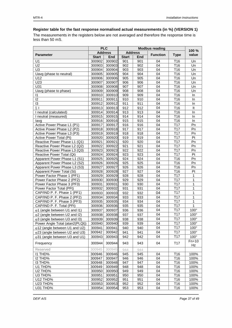
Register table for the fast response normalised actual measurements (in %) (VERSION 1) The measurements in the registers below are not averaged and therefore the response time is less than 50 mS.
PLC Modbus reading 100 % value Parameter Address Address Function Type Start End Start End
U1 300902 300902 901 901 04 T16 Un U2 300903 300903 902 902 04 T16 Un U3 300904 300904 903 903 04 T16 Un Uavg (phase to neutral) 300905 300905 904 904 04 T16 Un U12 300906 300906 905 905 04 T16 Un U23 300907 300907 906 906 04 T16 Un U31 300908 300908 907 907 04 T16 Un Uavg (phase to phase) 300909 300909 908 908 04 T16 Un I1 300910 300910 909 909 04 T16 In I2 300911 300911 910 910 04 T16 In I3 300912 300912 911 911 04 T16 In Σ I 300913 300913 912 912 04 T16 It I neutral (calculated) 300914 300914 913 913 04 T16 In I neutral (measured) 300915 300915 914 914 04 T16 In Iavg 300916 300916 915 915 04 T16 In Active Power Phase L1 (P1) 300917 300917 916 916 04 T17 Pn Active Power Phase L2 (P2) 300918 300918 917 917 04 T17 Pn Active Power Phase L3 (P3) 300919 300919 918 918 04 T17 Pn Active Power Total (Pt) 300920 300920 919 919 04 T17 Pt Reactive Power Phase L1 (Q1) 300921 300921 920 920 04 T17 Pn Reactive Power Phase L2 (Q2) 300922 300922 921 921 04 T17 Pn Reactive Power Phase L3 (Q3) 300923 300923 922 922 04 T17 Pn Reactive Power Total (Qt) 300924 300924 923 923 04 T17 Pt Apparent Power Phase L1 (S1) 300925 300925 924 924 04 T16 Pn Apparent Power Phase L2 (S2) 300926 300926 925 925 04 T16 Pn Apparent Power Phase L3 (S3) 300927 300927 926 926 04 T16 Pn Apparent Power Total (St) 300928 300928 927 927 04 T16 Pt Power Factor Phase 1 (PF1) 300929 300929 928 928 04 T17 1 Power Factor Phase 2 (PF2) 300930 300930 929 929 04 T17 1 Power Factor Phase 3 (PF3) 300931 300931 930 930 04 T17 1 Power Factor Total (PFt) 300932 300932 931 931 04 T17 1 CAP/IND P. F. Phase 1 (PF1) 300933 300933 932 932 04 T17 1 CAP/IND P. F. Phase 2 (PF2) 300934 300934 933 933 04 T17 1 CAP/IND P. F. Phase 3 (PF3) 300935 300935 934 934 04 T17 1 CAP/IND P. F. Total (PFt) 300936 300936 935 935 04 T17 1 ϕ1 (angle between U1 and I1) 300937 300937 936 936 04 T17 100° ϕ2 (angle between U2 and I2) 300938 300938 937 937 04 T17 100° ϕ3 (angle between U3 and I3) 300939 300939 938 938 04 T17 100° Power Angle Total (atan2(Pt,Qt)) 300940 300940 939 939 04 T17 100° ϕ12 (angle between U1 and U2) 300941 300941 940 940 04 T17 100° ϕ23 (angle between U2 and U3) 300942 300942 941 941 04 T17 100° ϕ31 (angle between U3 and U1) 300943 300943 942 942 04 T17 100°
Frequency 300944 300944 943 943 04 T17 Fn+10 Hz
Reserved 300945 300945 944 944 I1 THD% 300946 300946 945 945 04 T16 100% I2 THD% 300947 300947 946 946 04 T16 100% I3 THD% 300948 300948 947 947 04 T16 100% U1 THD% 300949 300949 948 948 04 T16 100% U2 THD% 300950 300950 949 949 04 T16 100% U3 THD% 300951 300951 950 950 04 T16 100% U12 THD% 300952 300952 951 951 04 T16 100% U23 THD% 300953 300953 952 952 04 T16 100% U31 THD% 300954 300954 953 953 04 T16 100%
MTR-4 Installation Instructions
DEIF A/S Page 38 of 49
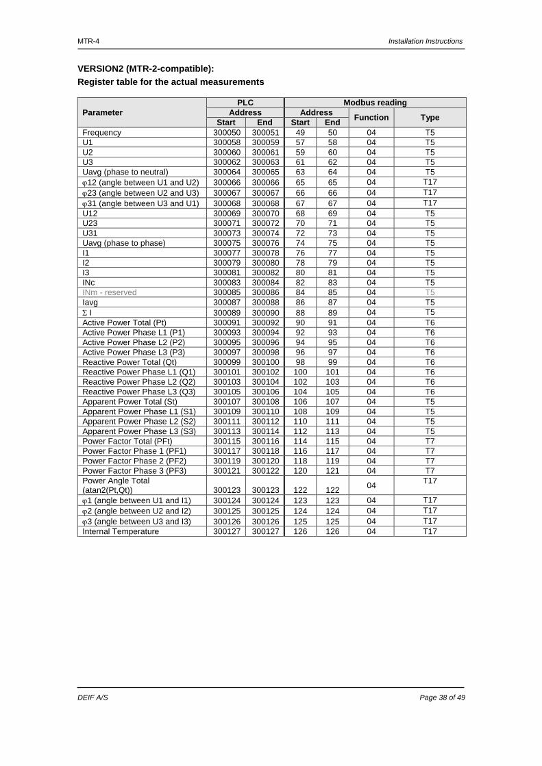
VERSION2 (MTR-2-compatible): Register table for the actual measurements
Parameter PLC Modbus reading
Address Address Function Type Start End Start End Frequency 300050 300051 49 50 04 T5 U1 300058 300059 57 58 04 T5 U2 300060 300061 59 60 04 T5 U3 300062 300063 61 62 04 T5 Uavg (phase to neutral) 300064 300065 63 64 04 T5 ϕ12 (angle between U1 and U2) 300066 300066 65 65 04 T17 ϕ23 (angle between U2 and U3) 300067 300067 66 66 04 T17 ϕ31 (angle between U3 and U1) 300068 300068 67 67 04 T17 U12 300069 300070 68 69 04 T5 U23 300071 300072 70 71 04 T5 U31 300073 300074 72 73 04 T5 Uavg (phase to phase) 300075 300076 74 75 04 T5 I1 300077 300078 76 77 04 T5 I2 300079 300080 78 79 04 T5 I3 300081 300082 80 81 04 T5 INc 300083 300084 82 83 04 T5 INm - reserved 300085 300086 84 85 04 T5 Iavg 300087 300088 86 87 04 T5 Σ I 300089 300090 88 89 04 T5 Active Power Total (Pt) 300091 300092 90 91 04 T6 Active Power Phase L1 (P1) 300093 300094 92 93 04 T6 Active Power Phase L2 (P2) 300095 300096 94 95 04 T6 Active Power Phase L3 (P3) 300097 300098 96 97 04 T6 Reactive Power Total (Qt) 300099 300100 98 99 04 T6 Reactive Power Phase L1 (Q1) 300101 300102 100 101 04 T6 Reactive Power Phase L2 (Q2) 300103 300104 102 103 04 T6 Reactive Power Phase L3 (Q3) 300105 300106 104 105 04 T6 Apparent Power Total (St) 300107 300108 106 107 04 T5 Apparent Power Phase L1 (S1) 300109 300110 108 109 04 T5 Apparent Power Phase L2 (S2) 300111 300112 110 111 04 T5 Apparent Power Phase L3 (S3) 300113 300114 112 113 04 T5 Power Factor Total (PFt) 300115 300116 114 115 04 T7 Power Factor Phase 1 (PF1) 300117 300118 116 117 04 T7 Power Factor Phase 2 (PF2) 300119 300120 118 119 04 T7 Power Factor Phase 3 (PF3) 300121 300122 120 121 04 T7 Power Angle Total (atan2(Pt,Qt)) 300123 300123 122 122 04 T17
ϕ1 (angle between U1 and I1) 300124 300124 123 123 04 T17 ϕ2 (angle between U2 and I2) 300125 300125 124 124 04 T17 ϕ3 (angle between U3 and I3) 300126 300126 125 125 04 T17 Internal Temperature 300127 300127 126 126 04 T17
MTR-4 Installation Instructions
DEIF A/S Page 39 of 49
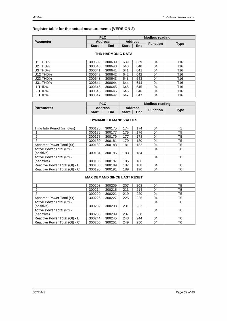
Register table for the actual measurements (VERSION 2)
Parameter PLC Modbus reading
Address Address Function Type Start End Start End
THD HARMONIC DATA
U1 THD% 300639 300639 639 639 04 T16 U2 THD% 300640 300640 640 640 04 T16 U3 THD% 300641 300641 641 641 04 T16 U12 THD% 300642 300642 642 642 04 T16 U23 THD% 300643 300643 643 643 04 T16 U31 THD% 300644 300644 644 644 04 T16 I1 THD% 300645 300645 645 645 04 T16 I2 THD% 300646 300646 646 646 04 T16 I3 THD% 300647 300647 647 647 04 T16
Parameter PLC Modbus reading
Address Address Function Type Start End Start End
DYNAMIC DEMAND VALUES
Time Into Period (minutes) 300175 300175 174 174 04 T1 I1 300176 300177 175 176 04 T5 I2 300178 300179 177 178 04 T5 I3 300180 300181 179 180 04 T5 Apparent Power Total (St) 300182 300183 181 182 04 T5 Active Power Total (Pt) - (positive) 300184 300185 183 184
04 T6
Active Power Total (Pt) - (negative) 300186 300187 185 186
04 T6
Reactive Power Total (Qt) - L 300188 300189 187 188 04 T6 Reactive Power Total (Qt) - C 300190 300191 189 190 04 T6
MAX DEMAND SINCE LAST RESET
I1 300208 300209 207 208 04 T5 I2 300214 300215 213 214 04 T5 I3 300220 300221 219 220 04 T5 Apparent Power Total (St) 300226 300227 225 226 04 T5 Active Power Total (Pt) - (positive) 300232 300233 231 232
04 T6
Active Power Total (Pt) - (negative) 300238 300239 237 238
04 T6
Reactive Power Total (Qt) - L 300244 300245 243 244 04 T6 Reactive Power Total (Qt) - C 300250 300251 249 250 04 T6
MTR-4 Installation Instructions
DEIF A/S Page 40 of 49
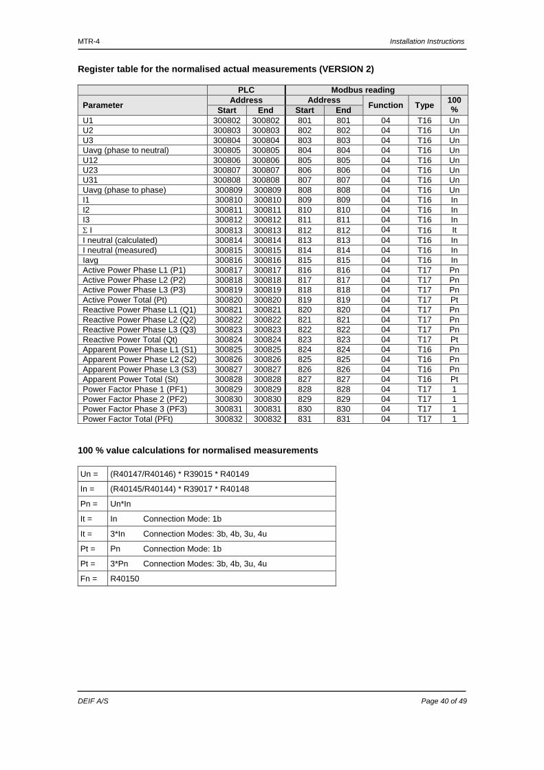
Register table for the normalised actual measurements (VERSION 2)
PLC Modbus reading
Parameter Address Address Function Type 100 %
Start End Start End U1 300802 300802 801 801 04 T16 Un U2 300803 300803 802 802 04 T16 Un U3 300804 300804 803 803 04 T16 Un Uavg (phase to neutral) 300805 300805 804 804 04 T16 Un U12 300806 300806 805 805 04 T16 Un U23 300807 300807 806 806 04 T16 Un U31 300808 300808 807 807 04 T16 Un Uavg (phase to phase) 300809 300809 808 808 04 T16 Un I1 300810 300810 809 809 04 T16 In I2 300811 300811 810 810 04 T16 In I3 300812 300812 811 811 04 T16 In Σ I 300813 300813 812 812 04 T16 It I neutral (calculated) 300814 300814 813 813 04 T16 In I neutral (measured) 300815 300815 814 814 04 T16 In Iavg 300816 300816 815 815 04 T16 In Active Power Phase L1 (P1) 300817 300817 816 816 04 T17 Pn Active Power Phase L2 (P2) 300818 300818 817 817 04 T17 Pn Active Power Phase L3 (P3) 300819 300819 818 818 04 T17 Pn Active Power Total (Pt) 300820 300820 819 819 04 T17 Pt Reactive Power Phase L1 (Q1) 300821 300821 820 820 04 T17 Pn Reactive Power Phase L2 (Q2) 300822 300822 821 821 04 T17 Pn Reactive Power Phase L3 (Q3) 300823 300823 822 822 04 T17 Pn Reactive Power Total (Qt) 300824 300824 823 823 04 T17 Pt Apparent Power Phase L1 (S1) 300825 300825 824 824 04 T16 Pn Apparent Power Phase L2 (S2) 300826 300826 825 825 04 T16 Pn Apparent Power Phase L3 (S3) 300827 300827 826 826 04 T16 Pn Apparent Power Total (St) 300828 300828 827 827 04 T16 Pt Power Factor Phase 1 (PF1) 300829 300829 828 828 04 T17 1 Power Factor Phase 2 (PF2) 300830 300830 829 829 04 T17 1 Power Factor Phase 3 (PF3) 300831 300831 830 830 04 T17 1 Power Factor Total (PFt) 300832 300832 831 831 04 T17 1
100 % value calculations for normalised measurements Un = (R40147/R40146) * R39015 * R40149
In = (R40145/R40144) * R39017 * R40148
Pn = Un*In
It = In Connection Mode: 1b
It = 3*In Connection Modes: 3b, 4b, 3u, 4u
Pt = Pn Connection Mode: 1b
Pt = 3*Pn Connection Modes: 3b, 4b, 3u, 4u
Fn = R40150
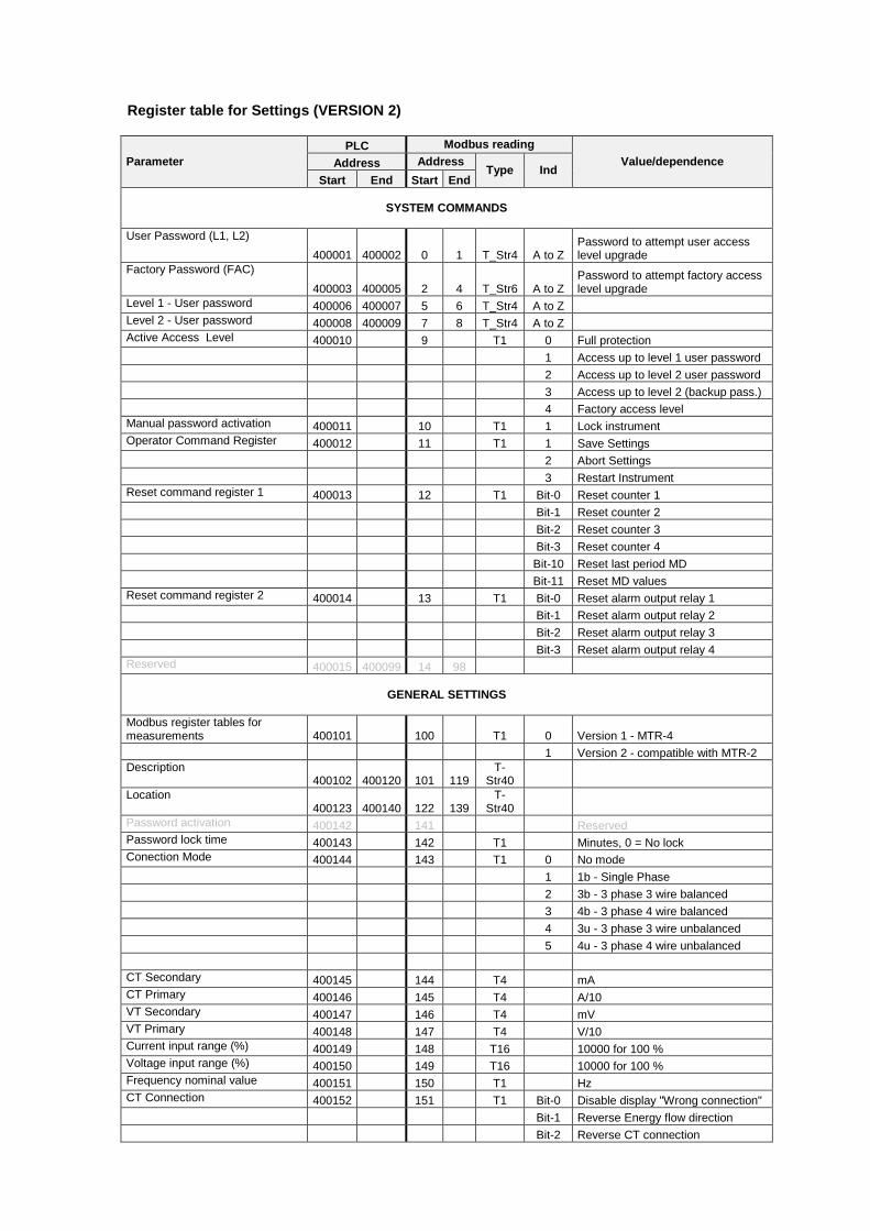
Register table for Settings (VERSION 2)
Parameter PLC Modbus reading
Value/dependence Address Address Type Ind
Start End Start End
SYSTEM COMMANDS
User Password (L1, L2) 400001 400002 0 1 T_Str4 A to Z
Password to attempt user access level upgrade
Factory Password (FAC) 400003 400005 2 4 T_Str6 A to Z
Password to attempt factory access level upgrade
Level 1 - User password 400006 400007 5 6 T_Str4 A to Z Level 2 - User password 400008 400009 7 8 T_Str4 A to Z Active Access Level 400010 9 T1 0 Full protection 1 Access up to level 1 user password 2 Access up to level 2 user password 3 Access up to level 2 (backup pass.) 4 Factory access level Manual password activation 400011 10 T1 1 Lock instrument Operator Command Register 400012 11 T1 1 Save Settings 2 Abort Settings 3 Restart Instrument Reset command register 1 400013 12 T1 Bit-0 Reset counter 1 Bit-1 Reset counter 2 Bit-2 Reset counter 3 Bit-3 Reset counter 4 Bit-10 Reset last period MD Bit-11 Reset MD values Reset command register 2 400014 13 T1 Bit-0 Reset alarm output relay 1 Bit-1 Reset alarm output relay 2 Bit-2 Reset alarm output relay 3 Bit-3 Reset alarm output relay 4 Reserved 400015 400099 14 98
GENERAL SETTINGS
Modbus register tables for measurements 400101 100 T1 0 Version 1 - MTR-4 1 Version 2 - compatible with MTR-2 Description
400102 400120 101 119 T-
Str40 Location
400123 400140 122 139 T-
Str40 Password activation 400142 141 Reserved Password lock time 400143 142 T1 Minutes, 0 = No lock Conection Mode 400144 143 T1 0 No mode 1 1b - Single Phase 2 3b - 3 phase 3 wire balanced 3 4b - 3 phase 4 wire balanced 4 3u - 3 phase 3 wire unbalanced 5 4u - 3 phase 4 wire unbalanced CT Secondary 400145 144 T4 mA CT Primary 400146 145 T4 A/10 VT Secondary 400147 146 T4 mV VT Primary 400148 147 T4 V/10 Current input range (%) 400149 148 T16 10000 for 100 % Voltage input range (%) 400150 149 T16 10000 for 100 % Frequency nominal value 400151 150 T1 Hz CT Connection 400152 151 T1 Bit-0 Disable display "Wrong connection" Bit-1 Reverse Energy flow direction Bit-2 Reverse CT connection
MTR-4 Installation Instructions
DEIF A/S Page 42 of 49
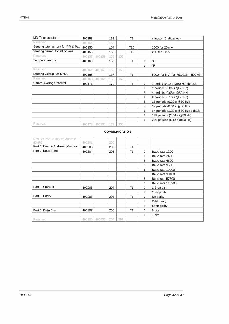
MD Time constant 400153 152 T1 minutes (0=disabled) Reserved 400154 153 Starting total current for PFt & Pat 400155 154 T16 2000 for 20 mA Starting current for all powers 400156 155 T16 200 for 2 mA Reserved 400157 400159 156 158 Temperature unit 400160 159 T1 0 °C 1 °F Reserved 400161 400167 160 166 Starting voltage for SYNC. 400168 167 T1 5000 for 5 V (for R30015 = 500 V) Reserved 400168 400169 168 169 Comm. average interval 400171 170 T1 0 1 period (0.02 s @50 Hz) default 1 2 periods (0.04 s @50 Hz) 2 4 periods (0.08 s @50 Hz) 3 8 periods (0.16 s @50 Hz) 4 16 periods (0.32 s @50 Hz) 5 32 periods (0.64 s @50 Hz) 6 64 periods (1.28 s @50 Hz) default 7 128 periods (2.56 s @50 Hz) 8 256 periods (5.12 s @50 Hz) Reserved 400172 400201 171 200
COMMUNICATION
Res. for Port 1: Device Address (DNP3) 400201 200 Port 1: Device Address (Modbus) 400203 202 T1 Port 1: Baud Rate 400204 203 T1 0 Baud rate 1200 1 Baud rate 2400 2 Baud rate 4800 3 Baud rate 9600 4 Baud rate 19200 5 Baud rate 38400 6 Baud rate 57600 7 Baud rate 115200 Port 1: Stop Bit 400205 204 T1 0 1 Stop bit 1 2 Stop bits Port 1: Parity 400206 205 T1 0 No parity 1 Odd parity 2 Even parity Port 1: Data Bits 400207 206 T1 0 8 bits 1 7 bits Reserved 400208 400400 207 399
MTR-4 Installation Instructions
DEIF A/S Page 43 of 49
Register table for Settings (VERSION 2)
Parameter PLC Modbus reading
Value/dependence Address Address Type Ind
Start End Start End
ENERGY
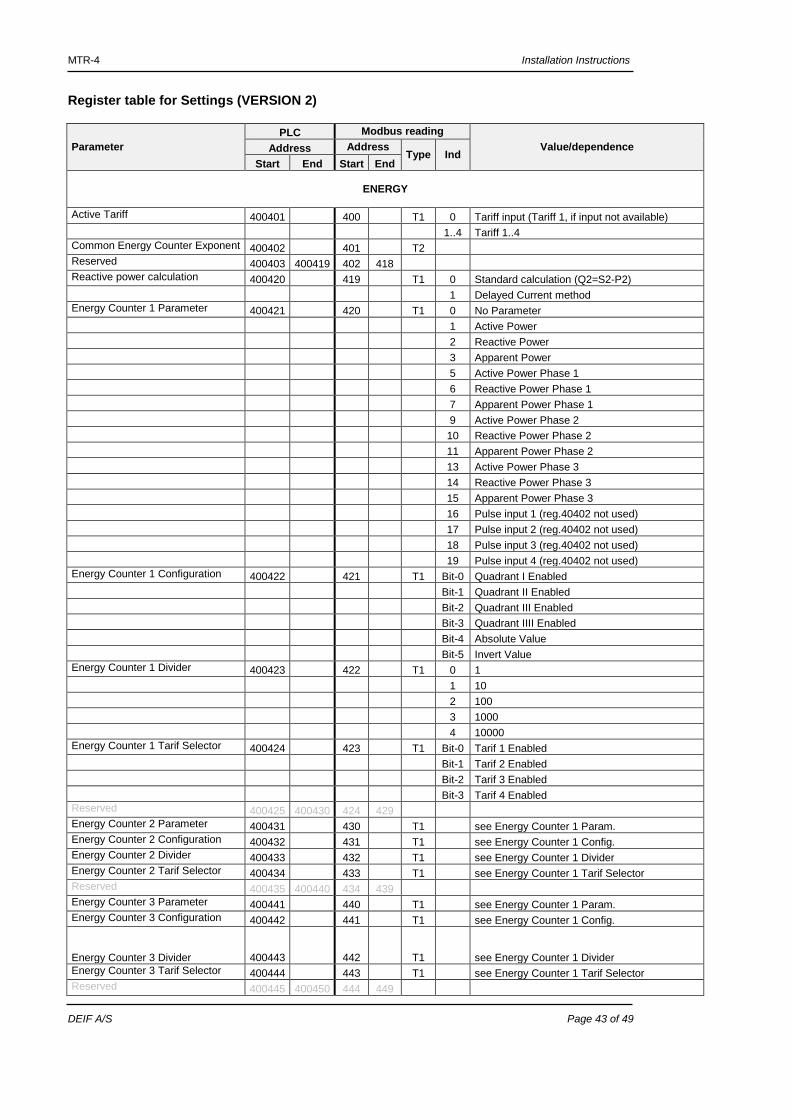
Active Tariff 400401 400 T1 0 Tariff input (Tariff 1, if input not available) 1..4 Tariff 1..4 Common Energy Counter Exponent 400402 401 T2 Reserved 400403 400419 402 418 Reactive power calculation 400420 419 T1 0 Standard calculation (Q2=S2-P2) 1 Delayed Current method Energy Counter 1 Parameter 400421 420 T1 0 No Parameter 1 Active Power 2 Reactive Power 3 Apparent Power 5 Active Power Phase 1 6 Reactive Power Phase 1 7 Apparent Power Phase 1 9 Active Power Phase 2 10 Reactive Power Phase 2 11 Apparent Power Phase 2 13 Active Power Phase 3 14 Reactive Power Phase 3 15 Apparent Power Phase 3 16 Pulse input 1 (reg.40402 not used) 17 Pulse input 2 (reg.40402 not used) 18 Pulse input 3 (reg.40402 not used) 19 Pulse input 4 (reg.40402 not used) Energy Counter 1 Configuration 400422 421 T1 Bit-0 Quadrant I Enabled Bit-1 Quadrant II Enabled Bit-2 Quadrant III Enabled Bit-3 Quadrant IIII Enabled Bit-4 Absolute Value Bit-5 Invert Value Energy Counter 1 Divider 400423 422 T1 0 1 1 10 2 100 3 1000 4 10000 Energy Counter 1 Tarif Selector 400424 423 T1 Bit-0 Tarif 1 Enabled Bit-1 Tarif 2 Enabled Bit-2 Tarif 3 Enabled Bit-3 Tarif 4 Enabled Reserved 400425 400430 424 429 Energy Counter 2 Parameter 400431 430 T1 see Energy Counter 1 Param. Energy Counter 2 Configuration 400432 431 T1 see Energy Counter 1 Config. Energy Counter 2 Divider 400433 432 T1 see Energy Counter 1 Divider Energy Counter 2 Tarif Selector 400434 433 T1 see Energy Counter 1 Tarif Selector Reserved 400435 400440 434 439 Energy Counter 3 Parameter 400441 440 T1 see Energy Counter 1 Param. Energy Counter 3 Configuration 400442 441 T1 see Energy Counter 1 Config. Energy Counter 3 Divider 400443 442 T1 see Energy Counter 1 Divider Energy Counter 3 Tarif Selector 400444 443 T1 see Energy Counter 1 Tarif Selector Reserved 400445 400450 444 449
MTR-4 Installation Instructions
DEIF A/S Page 44 of 49
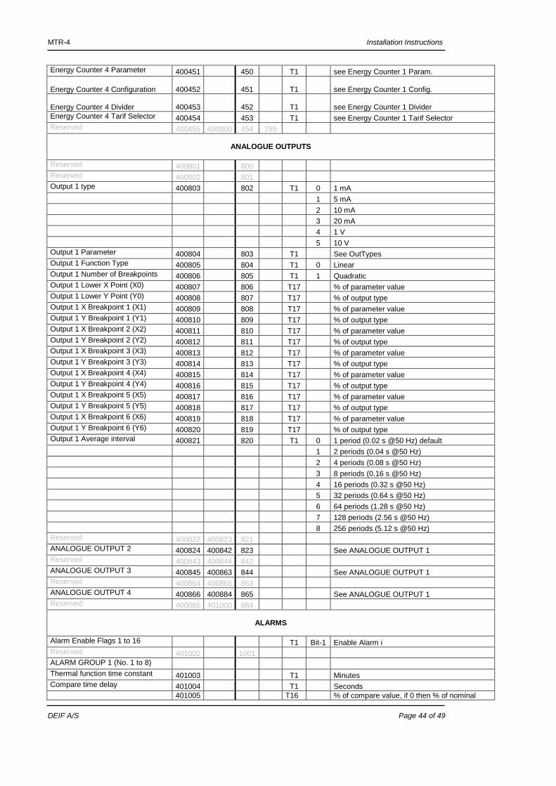
Energy Counter 4 Parameter 400451 450 T1 see Energy Counter 1 Param. Energy Counter 4 Configuration 400452 451 T1 see Energy Counter 1 Config. Energy Counter 4 Divider 400453 452 T1 see Energy Counter 1 Divider Energy Counter 4 Tarif Selector 400454 453 T1 see Energy Counter 1 Tarif Selector Reserved 400455 400800 454 799
ANALOGUE OUTPUTS
Reserved 400801 800 Reserved 400802 801 Output 1 type 400803 802 T1 0 1 mA 1 5 mA 2 10 mA 3 20 mA 4 1 V 5 10 V Output 1 Parameter 400804 803 T1 See OutTypes Output 1 Function Type 400805 804 T1 0 Linear Output 1 Number of Breakpoints 400806 805 T1 1 Quadratic Output 1 Lower X Point (X0) 400807 806 T17 % of parameter value Output 1 Lower Y Point (Y0) 400808 807 T17 % of output type Output 1 X Breakpoint 1 (X1) 400809 808 T17 % of parameter value Output 1 Y Breakpoint 1 (Y1) 400810 809 T17 % of output type Output 1 X Breakpoint 2 (X2) 400811 810 T17 % of parameter value Output 1 Y Breakpoint 2 (Y2) 400812 811 T17 % of output type Output 1 X Breakpoint 3 (X3) 400813 812 T17 % of parameter value Output 1 Y Breakpoint 3 (Y3) 400814 813 T17 % of output type Output 1 X Breakpoint 4 (X4) 400815 814 T17 % of parameter value Output 1 Y Breakpoint 4 (Y4) 400816 815 T17 % of output type Output 1 X Breakpoint 5 (X5) 400817 816 T17 % of parameter value Output 1 Y Breakpoint 5 (Y5) 400818 817 T17 % of output type Output 1 X Breakpoint 6 (X6) 400819 818 T17 % of parameter value Output 1 Y Breakpoint 6 (Y6) 400820 819 T17 % of output type Output 1 Average interval 400821 820 T1 0 1 period (0.02 s @50 Hz) default 1 2 periods (0.04 s @50 Hz) 2 4 periods (0.08 s @50 Hz) 3 8 periods (0.16 s @50 Hz) 4 16 periods (0.32 s @50 Hz) 5 32 periods (0.64 s @50 Hz) 6 64 periods (1.28 s @50 Hz) 7 128 periods (2.56 s @50 Hz) 8 256 periods (5.12 s @50 Hz) Reserved 400822 400823 821 ANALOGUE OUTPUT 2 400824 400842 823 See ANALOGUE OUTPUT 1 Reserved 400843 400844 842 ANALOGUE OUTPUT 3 400845 400863 844 See ANALOGUE OUTPUT 1 Reserved 400864 400865 863 ANALOGUE OUTPUT 4 400866 400884 865 See ANALOGUE OUTPUT 1 Reserved 400885 401000 884
ALARMS
Alarm Enable Flags 1 to 16 T1 Bit-1 Enable Alarm i Reserved 401002 1001 ALARM GROUP 1 (No. 1 to 8) Thermal function time constant 401003 T1 Minutes Compare time delay 401004 T1 Seconds 401005
T16
% of compare value, if 0 then % of nominal
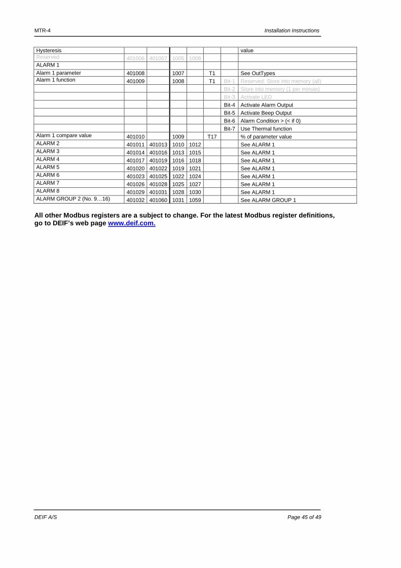
MTR-4 Installation Instructions
DEIF A/S Page 45 of 49
Hysteresis value Reserved 401006 401007 1005 1006
ALARM 1 Alarm 1 parameter 401008 1007
T1 See OutTypes
Alarm 1 function 401009 1008 T1 Bit-1 Reserved: Store into memory (all) Bit-2 Store into memory (1 per minute) Bit-3 Activate LED Bit-4 Activate Alarm Output Bit-5 Activate Beep Output Bit-6 Alarm Condition > (< if 0) Bit-7 Use Thermal function Alarm 1 compare value 401010 1009 T17 % of parameter value ALARM 2 401011 401013 1010 1012 See ALARM 1 ALARM 3 401014 401016 1013 1015 See ALARM 1 ALARM 4 401017 401019 1016 1018 See ALARM 1 ALARM 5 401020 401022 1019 1021 See ALARM 1 ALARM 6 401023 401025 1022 1024 See ALARM 1 ALARM 7 401026 401028 1025 1027 See ALARM 1 ALARM 8 401029 401031 1028 1030 See ALARM 1 ALARM GROUP 2 (No. 9…16) 401032 401060 1031 1059 See ALARM GROUP 1 All other Modbus registers are a subject to change. For the latest Modbus register definitions, go to DEIF’s web page www.deif.com.
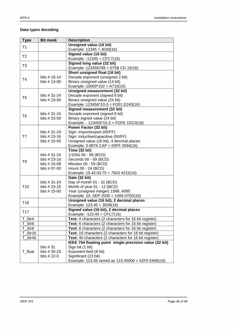
MTR-4 Installation Instructions
DEIF A/S Page 46 of 49
Data types decoding Type Bit mask Description
T1 Unsigned value (16 bit) Example: 12345 = 3039(16)
T2 Signed value (16 bit) Example: -12345 = CFC7(16)
T3 Signed long value (32 bit) Example: 123456789 = 075B CD 15(16)
T4 bits # 15-14 bits # 13-00
Short unsigned float (16 bit) Decade exponent (unsigned 2 bit) Binary unsigned value (14 bit) Example: 10000*102 = A710(16)
T5 bits # 31-24 bits # 23-00
Unsigned measurement (32 bit) Decade exponent (signed 8 bit) Binary unsigned value (24 bit) Example: 123456*10-3 = FD01 E240(16)
T6 bits # 31-24 bits # 23-00
Signed measurement (32 bit) Decade exponent (signed 8 bit) Binary signed value (24 bit) Example: - 123456*10-3 = FDFE 1DC0(16)
T7 bits # 31-24 bits # 23-16 bits # 15-00
Power Factor (32 bit) Sign: import/export (00/FF) Sign: inductive/capacitive (00/FF) Unsigned value (16 bit), 4 decimal places Example: 0.9876 CAP = 00FF 2694(16)
T9
bits # 31-24 bits # 23-16 bits # 15-08 bits # 07-00
Time (32 bit) 1/100s 00 - 99 (BCD) Seconds 00 - 59 (BCD) Minutes 00 - 59 (BCD) Hours 00 - 24 (BCD) Example: 15:42:03.75 = 7503 4215(16)
T10 bits # 31-24 bits # 23-16 bits # 15-00
Date (32 bit) Day of month 01 - 31 (BCD) Month of year 01 - 12 (BCD) Year (unsigned integer) 1998..4095 Example: 10, SEP 2000 = 1009 07D0(16)
T16 Unsigned value (16 bit), 2 decimal places Example: 123.45 = 3039(16)
T17 Signed value (16 bit), 2 decimal places Example: -123.45 = CFC7(16)
T_Str4 Text: 4 characters (2 characters for 16 bit register) T_Str6 Text: 6 characters (2 characters for 16 bit register) T_Str8 Text: 8 characters (2 characters for 16 bit register) T_Str16 Text: 16 characters (2 characters for 16 bit register) T_Str40 Text: 40 characters (2 characters for 16 bit register)
T_float
bits # 31 bits # 30-23 bits # 22-0
IEEE 754 floating point single precision value (32 bit) Sign bit (1 bit) Exponent field (8 bit) Significant (23 bit) Example: 123.45 stored as 123.45000 = 42F6 E666(16)
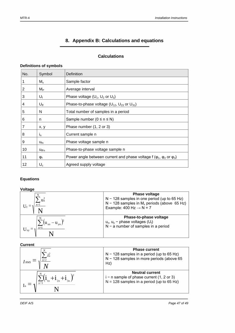
MTR-4 Installation Instructions
DEIF A/S Page 47 of 49
8. Appendix B: Calculations and equations
Calculations
Definitions of symbols
No. Symbol Definition
1 Mv Sample factor
2 MP Average interval
3 Uf Phase voltage (U1, U2 or U3)
4 Uff Phase-to-phase voltage (U12, U23 or U31)
5 N Total number of samples in a period
6 n Sample number (0 ≤ n ≤ N)
7 x, y Phase number (1, 2 or 3)
8 in Current sample n
9 ufn Phase voltage sample n
10 ufFn Phase-to-phase voltage sample n
11 φf Power angle between current and phase voltage f (φ1, φ2 or φ3)
12 Uc Agreed supply voltage
Equations Voltage
N
u = U
2n
N
1=nf
∑
Phase voltage N − 128 samples in one period (up to 65 Hz) N − 128 samples in Mv periods (above 65 Hz) Example: 400 Hz → N = 7
( )
N
2ynxn
N
1=nxy
uu = U
−∑
Phase-to-phase voltage ux, uy − phase voltages (Uf) N − a number of samples in a period
Current
N
= i
I
2n
N
1=nRMS
∑
Phase current N − 128 samples in a period (up to 65 Hz) N − 128 samples in more periods (above 65 Hz)
( )N
iii =
2
n3n2n1
N
1=nnI
++∑
Neutral current i − n sample of phase current (1, 2 or 3) N = 128 samples in a period (up to 65 Hz)
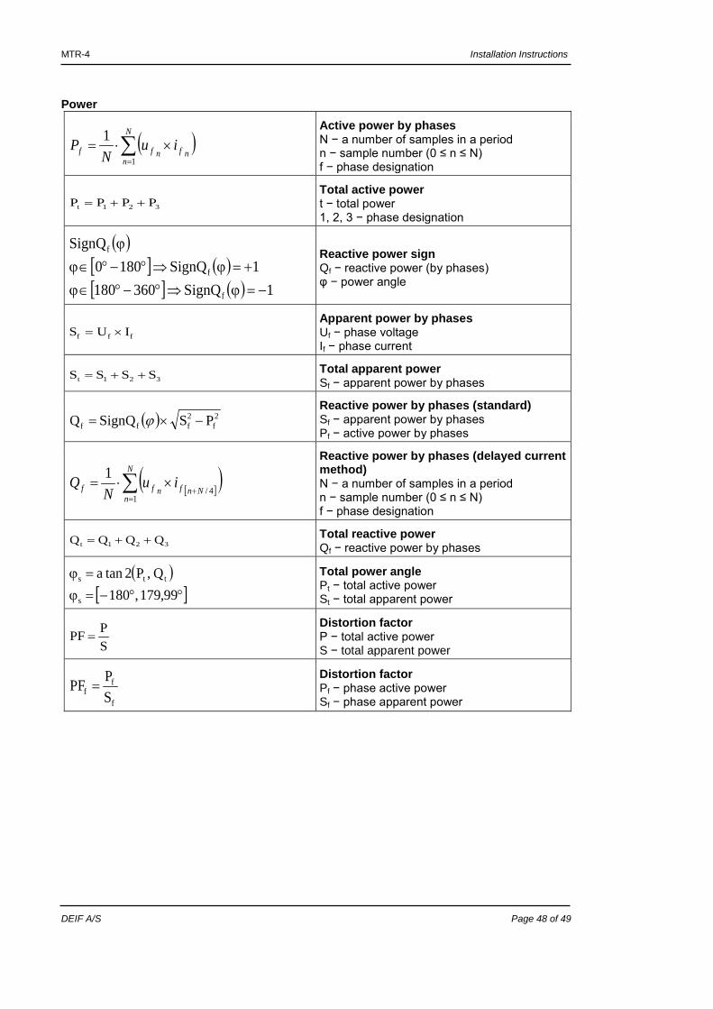
MTR-4 Installation Instructions
DEIF A/S Page 48 of 49
Power
( )∑=
×⋅=N
nnfnff iu
NP
1
1
Active power by phases N − a number of samples in a period n − sample number (0 ≤ n ≤ N) f − phase designation
321t PPPP ++= Total active power t − total power 1, 2, 3 − phase designation
( )[ ] ( )[ ] ( ) 1SignQ360801
1SignQ1800SignQ
f
f
f
−=ϕ⇒°−°∈ϕ+=ϕ⇒°−°∈ϕ
ϕ
Reactive power sign Qf − reactive power (by phases) φ − power angle
fff IUS ×= Apparent power by phases Uf − phase voltage If − phase current
321t SSSS ++= Total apparent power Sf − apparent power by phases
( ) 2f
2fff PSSignQQ −×= ϕ
Reactive power by phases (standard) Sf − apparent power by phases Pf − active power by phases
[ ]( )∑=
+×⋅=
N
nNnfnff iu
NQ
14/
1
Reactive power by phases (delayed current method) N − a number of samples in a period n − sample number (0 ≤ n ≤ N) f − phase designation
321t QQQQ ++= Total reactive power Qf − reactive power by phases
( )[ ]°°−=ϕ
=ϕ99,179,180
Q,P2tana
s
tts
Total power angle Pt − total active power St − total apparent power
SPPF =
Distortion factor P − total active power S − total apparent power
f
ff S
PPF = Distortion factor Pf − phase active power Sf − phase apparent power
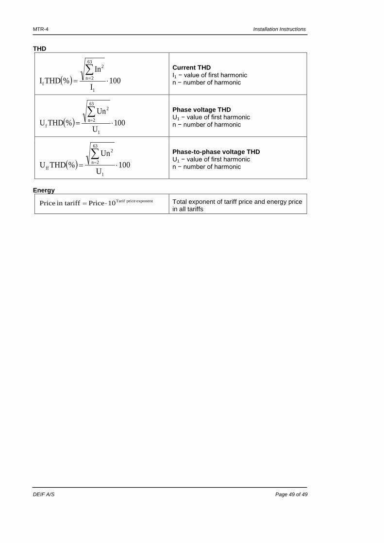
MTR-4 Installation Instructions
DEIF A/S Page 49 of 49
THD
( ) 100I
In%THDI
1
63
2n
2
f ⋅=∑
=
Current THD I1 − value of first harmonic n − number of harmonic
( ) 100U
Un%THDU
1
63
2n
2
f ⋅=∑
=
Phase voltage THD U1 − value of first harmonic n − number of harmonic
( ) 100U
Un%THDU
1
63
2n
2
ff ⋅=∑
=
Phase-to-phase voltage THD U1 − value of first harmonic n − number of harmonic
Energy
exponent price Tarif10 Price in tariff Price ⋅= Total exponent of tariff price and energy price in all tariffs