A Generic Model of Multi-Interface and Multi- Channel for Multi-hop ...
7
A Generic Model of Multi-Interface and Multi- Channel for Multi-hop Wireless Networks Xinhua Liu, YangFan Li, HaiLan Kuang, Fangmin Li School of Information Engineering, Wuhan University of Technology, Wuhan, Hubei, China {liuxinhua, liyangfan, kuanghailan, lifangmin}@whut.edu.cn Abstract—The performance of multi-hop wireless networks can be improved through using multi-interface and multi- channel (MIMC). In this paper, a generic model of MIMC (abbreviated as GMM) for multi-hop wireless networks is proposed for NS2. The architecture of GMM consists of an MIMC control sublayer, separated interfaces, and dynamic channels. The MIMC control sublayer manages all interfaces and channels, and provides MIMC services to upper layers. Each separated interface has its own physical layer, MAC layer, link layer, and propagation model so that it can support heterogeneous interfaces. The dynamic channels are shared by all the interfaces, and each interface can be assigned to one or more channels by a preset channel assignment algorithm. Compared with other existing MIMC models, the proposed GMM is more generic and more flexible. The proposed GMM is validated through experiments, and network performances are discussed as well. Keywords-Model, Multi-Interface and Multi-Channel, Multi- hop Wireless Networks, NS2 I. INTRODUCTION Recently, multi-hop wireless networks, such as wireless sensor networks (WSNs), mobile ad hoc networks (MANETs) and wireless mesh networks (WMNs), become popular and important for various wireless applications. As one of the most promising technologies to improve performance of multi-hop wireless networks, multi-interface and multi-channel (MIMC) schemes have received great attention [1-3]. The reason is that in multi-hop wireless networks, interferences from adjacent hops on the same path as well as interferences from neighboring paths can be severe [4]; and the optimal approach to solve this problem is to use multiple non-overlapped frequency channels and multiple interfaces simultaneously. With advances in hardware technologies (especially in embedded microprocessor technologies), small devices and systems can be manufactured at low cost, making hardware integration of multiple interfaces possible. As a result, a multi- hop wireless network implemented with multi-interface hardware will become commercially available in the near future. Investigation of multi-hop wireless networks with multi-channels and multi-interfaces then becomes very much desirable. The network simulator 2 (NS2) is widely used as a generic and powerful network simulator with open source code, and simulation results from NS2 are generally considered credible, realizable and acceptable [5]. NS2 has the capability of simulating not only wired networks but also wireless networks with a single frequency channel. In the past few years, many extensions of NS2 for wireless networks have been developed, but they are still inadequate for MIMC systems. Although there have been some previous research efforts that aimed to make NS2 support multiple channels for simulation of multi-hop wireless networks [6-12], most of those efforts, either are complicated or is not very generic. Particularly, flexibility of channel assignment, support for upper layers employing MIMC schemes, and support for heterogeneous interfaces are still underdeveloped. In this paper, we proposed a generic architecture of MIMC (abbreviated as GMM) for multi-hop wireless networks in NS2. The proposed GMM architecture is made up of a MIMC control sublayer, separated interfaces and dynamic channels. The MIMC control sublayer, which is a new sublayer located between link layer (LL) and routing agent (RA), manages all interfaces and channels, and provides the MIMC services to upper layers. Each separated interface has its own physical layer, MAC layer, link layer and propagation model so that it can support heterogeneous interfaces; this means that different physical layers and MAC protocols can be integrated. The dynamic channels are shared by all the interfaces, and each interface is assigned to one or more channels by a preset channel assignment algorithm. Compared with the existing models of MIMC schemes [6-12], the proposed GMM architecture is more generic, flexible and powerful; the simulation results presented later will validate this. The remainder of this paper is organized as follows. Section II describes the existing works on MIMC extension to NS2. Section III presents the proposed GMM architecture for multi- hop wireless networks in NS2, and describes the implementation of GMM in Section IV. Section V presents validation of the GMM through experiments, and discusses the results for evaluating the MIMC’s effect on network performance. Finally, the summary of this paper is given in Section Ⅵ. II. THE EXISTING WORK Due to its complexity, performances of multi-hop wireless networks are often assessed through simulations. As mentioned before, NS2 is a good candidate for the simulations. However, to use NS2 to simulate MIMC-based protocols for multi-hop wireless network, NS2 needs to be expanded. To this end, various MIMC schemes and models have been developed in NS2 [6-12]. 1083 2015 4th International Conference on Computer Science and Network Technology (ICCSNT 2015) 978-1-4673-8173-4/15/$31.00 ©2015 IEEE Harbin, China
-
Upload
khangminh22 -
Category
Documents
-
view
1 -
download
0
Transcript of A Generic Model of Multi-Interface and Multi- Channel for Multi-hop ...
A Generic Model of Multi-Interface and Multi-Channel for Multi-hop Wireless Networks
Xinhua Liu, YangFan Li, HaiLan Kuang, Fangmin Li School of Information Engineering, Wuhan University of Technology, Wuhan, Hubei, China
{liuxinhua, liyangfan, kuanghailan, lifangmin}@whut.edu.cn
Abstract—The performance of multi-hop wireless networks can be improved through using multi-interface and multi-channel (MIMC). In this paper, a generic model of MIMC (abbreviated as GMM) for multi-hop wireless networks is proposed for NS2. The architecture of GMM consists of an MIMC control sublayer, separated interfaces, and dynamic channels. The MIMC control sublayer manages all interfaces and channels, and provides MIMC services to upper layers. Each separated interface has its own physical layer, MAC layer, link layer, and propagation model so that it can support heterogeneous interfaces. The dynamic channels are shared by all the interfaces, and each interface can be assigned to one or more channels by a preset channel assignment algorithm. Compared with other existing MIMC models, the proposed GMM is more generic and more flexible. The proposed GMM is validated through experiments, and network performances are discussed as well.
Keywords-Model, Multi-Interface and Multi-Channel, Multi-hop Wireless Networks, NS2
I. INTRODUCTION
Recently, multi-hop wireless networks, such as wireless sensor networks (WSNs), mobile ad hoc networks (MANETs) and wireless mesh networks (WMNs), become popular and important for various wireless applications. As one of the most promising technologies to improve performance of multi-hop wireless networks, multi-interface and multi-channel (MIMC) schemes have received great attention [1-3]. The reason is that in multi-hop wireless networks, interferences from adjacent hops on the same path as well as interferences from neighboring paths can be severe [4]; and the optimal approach to solve this problem is to use multiple non-overlapped frequency channels and multiple interfaces simultaneously. With advances in hardware technologies (especially in embedded microprocessor technologies), small devices and systems can be manufactured at low cost, making hardware integration of multiple interfaces possible. As a result, a multi-hop wireless network implemented with multi-interface hardware will become commercially available in the near future. Investigation of multi-hop wireless networks with multi-channels and multi-interfaces then becomes very much desirable.
The network simulator 2 (NS2) is widely used as a generic and powerful network simulator with open source code, and simulation results from NS2 are generally considered credible, realizable and acceptable [5]. NS2 has the capability of simulating not only wired networks but also wireless networks
with a single frequency channel. In the past few years, many extensions of NS2 for wireless networks have been developed, but they are still inadequate for MIMC systems. Although there have been some previous research efforts that aimed to make NS2 support multiple channels for simulation of multi-hop wireless networks [6-12], most of those efforts, either are complicated or is not very generic. Particularly, flexibility of channel assignment, support for upper layers employing MIMC schemes, and support for heterogeneous interfaces are still underdeveloped.
In this paper, we proposed a generic architecture of MIMC (abbreviated as GMM) for multi-hop wireless networks in NS2. The proposed GMM architecture is made up of a MIMC control sublayer, separated interfaces and dynamic channels. The MIMC control sublayer, which is a new sublayer located between link layer (LL) and routing agent (RA), manages all interfaces and channels, and provides the MIMC services to upper layers. Each separated interface has its own physical layer, MAC layer, link layer and propagation model so that it can support heterogeneous interfaces; this means that different physical layers and MAC protocols can be integrated. The dynamic channels are shared by all the interfaces, and each interface is assigned to one or more channels by a preset channel assignment algorithm. Compared with the existing models of MIMC schemes [6-12], the proposed GMM architecture is more generic, flexible and powerful; the simulation results presented later will validate this.
The remainder of this paper is organized as follows. Section II describes the existing works on MIMC extension to NS2. Section III presents the proposed GMM architecture for multi-hop wireless networks in NS2, and describes the implementation of GMM in Section IV. Section V presents validation of the GMM through experiments, and discusses the results for evaluating the MIMC’s effect on network performance. Finally, the summary of this paper is given in Section Ⅵ.
II. THE EXISTING WORK
Due to its complexity, performances of multi-hop wireless networks are often assessed through simulations. As mentioned before, NS2 is a good candidate for the simulations. However, to use NS2 to simulate MIMC-based protocols for multi-hop wireless network, NS2 needs to be expanded. To this end, various MIMC schemes and models have been developed in NS2 [6-12].
1083
2015 4th International Conference on Computer Science and Network Technology (ICCSNT 2015)
978-1-4673-8173-4/15/$31.00 ©2015 IEEE Harbin, China
In [6,7], Raniwala et. al. proposed the Hyacinth model for multi-channel WMNs simulation. The aim of the model is to exploit the aggregate bandwidth available in the radio spectrum provided by the wireless MAC standards such as IEEE802.11 and IEEE802.16. In the model, MAC protocol and routing algorithm are bound together. As a result, it lacks of flexibility and generality; i.e., other existing MACs and routing protocols are difficult to run in such model.
In [8,9], a module-based MIMC extension model is proposed. In this model, a new node architecture, named NW-Node, is derived from the standard node of NS2, and all the new objects are integrated in the NW-Node. By providing a generic network layer architecture and framework, routing and forwarding protocols can be run over one or more than one interface regardless of their types. Compared with the Hyacinth’ model, this model is more flexible and generic. However, the architecture of the NW-Node is not only relatively complicated but also very different from the conventional architecture of the standard mobile nodes widely used in wireless network simulation. Routing agents cannot be used directly with the MW-Node and need to be converted, even in the case of a node with a single interface.
In [10], Aguero et. al. proposed a layer-copied model that aims to provide a generic solution to MIMC in NS2 (the model is called Ramon’s model hereafter). In this model, there are more than one copies of a data link below a single routing agent. All of these data link copies are identical, including the same PHY, MAC, IFQ, LL and propagation model. The routing agents need to be modified to handle these data links. The architecture of Ramon’s model is based on the standard mobile node of NS2, and the layers of the architecture are very clear. From the routing agent’s point of view, this model has a good flexibility and low complexity, although the routing agents still have to be much modified. However, its flexibility of channel assignment and support for heterogeneous interfaces are not adequate.
In order to realize a MAC protocol over multiple interfaces, a multi-channel MAC simulation model (MMSM) is proposed in [11]. Instead of copying data link in Ramon’s model, the MMSM model duplicates more than one copy of interfaces (PHYs) between channel and MAC layer. It provides the support for simulating multi-channel MAC protocols which are over multiple-input multiple-output (MIMO) or MIMO-like mechanisms. It is a design specifically for simulating multi-channel MAC protocols; any present MAC protocols need to be modified. So it can be considered as a model complementary to Ramon’s model but they are compatible with each other.
[12] proposed a versatile model architecture (VMA) for simulating home gateway in NS2. The home gateway is requested to support various MACs and multi-channel MACs. The VMA model is designed to combine multiple MACs and multi-channel MACs in the same home gateway.
Although there have been other models developed, to the authors’ best knowledge, they either are relatively complicated or have poor compatibility with others. Furthermore, the flexibility of channel assignment, the support for upper layers
employing MIMC, and the support for heterogeneous interfaces are still inadequate.
III. THE ARCHETETURE OF THE PROPOSED GMM
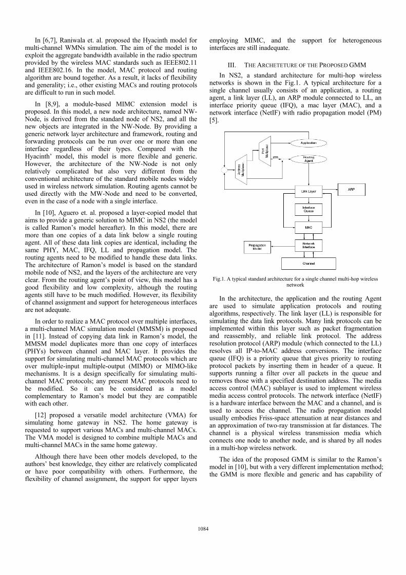
In NS2, a standard architecture for multi-hop wireless networks is shown in the Fig.1. A typical architecture for a single channel usually consists of an application, a routing agent, a link layer (LL), an ARP module connected to LL, an interface priority queue (IFQ), a mac layer (MAC), and a network interface (NetIF) with radio propagation model (PM) [5].
Fig.1. A typical standard architecture for a single channel multi-hop wireless
network
In the architecture, the application and the routing Agent are used to simulate application protocols and routing algorithms, respectively. The link layer (LL) is responsible for simulating the data link protocols. Many link protocols can be implemented within this layer such as packet fragmentation and reassembly, and reliable link protocol. The address resolution protocol (ARP) module (which connected to the LL) resolves all IP-to-MAC address conversions. The interface queue (IFQ) is a priority queue that gives priority to routing protocol packets by inserting them in header of a queue. It supports running a filter over all packets in the queue and removes those with a specified destination address. The media access control (MAC) sublayer is used to implement wireless media access control protocols. The network interface (NetIF) is a hardware interface between the MAC and a channel, and is used to access the channel. The radio propagation model usually embodies Friss-space attenuation at near distances and an approximation of two-ray transmission at far distances. The channel is a physical wireless transmission media which connects one node to another node, and is shared by all nodes in a multi-hop wireless network.
The idea of the proposed GMM is similar to the Ramon’s model in [10], but with a very different implementation method; the GMM is more flexible and generic and has capability of
1084
simulating both MIMC-based MAC protocols and MIMC-based routing protocols.
A. The Architecutre of the Proposed GMM
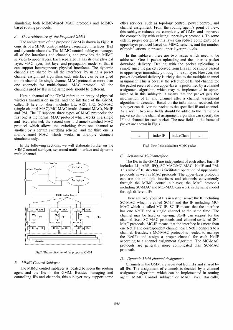
The architecture of the proposed GMM is shown in Fig.2. It consists of a MIMC control sublayer, separated interfaces (IFs) and dynamic channels. The MIMC control sublayer manages all of the interfaces and channels, and provides the MIMC services to upper layers. Each separated IF has its own physical layer, MAC layer, link layer and propagation model so that it can support heterogeneous physical interfaces. The dynamic channels are shared by all the interfaces; by using a preset channel assignment algorithm, each interface can be assigned to one channel for single channel MAC protocol, or more than one channels for multi-channel MAC protocol. All the channels used by IFs in the same node should be different.
Here a channel of the GMM refers to an entity of physical wireless transmission media, and the interface of the GMM, called IF here for short, includes LL, ARP, IFQ, SC-MAC (single-channel MAC)/MC-MAC (multi-channel MAC), NetIF and PM. The IF supports three types of MAC protocols: the first one is the normal MAC protocol which works in a single and fixed channel; the second one is channel-switched MAC protocol which allows the switching from one channel to another by a certain switching scheme; and the third one is multi-channel MAC which works in multiple channels simultaneously.
In the following sections, we will elaborate further on the MIMC control sublayer, separated multi-interface and dynamic multi-channel.
Fig.2. The architecture of the proposed GMM
B. MIMC Control Sublayer
The MIMC control sublayer is located between the routing agent and the IFs in the GMM. Besides managing and controlling IFs and channels, this sublayer may support some
other services, such as topology control, power control, and channel assignment. From the routing agent’s point of view, this sublayer reduces the complexity of GMM and improves the compatibility with existing upper-layer protocols. To some extent, proper design of this layer can reduce complexity of a upper-layer protocol based on MIMC scheme, and the number of modifications on present upper-layer protocols.
In this sublayer, there are two issues which need to be addressed. One is packet uploading and the other is packet download delivery. Dealing with the packet uploading is simple since the packet received from IFs can be simply passed to upper-layer immediately through this sublayer. However, the packet download delivery is tricky due to the multiple channel assignment. This is because the selection of IF and channel for the packet received from upper-layer is performed by a channel assignment algorithm, which may be implemented in upper-layer or in this sublayer. It means that the packet gets the information of IF and channel after a channel assignment algorithm is executed. Based on the information received, the sublayer can deliver the packet to the specified IF and channel. As a result, two new fields should be added to the frame of a packet so that the channel assignment algorithm can specify the IF and channel for each packet. The new fields in the frame of packet are shown in Fig.3.
Fig.3. New fields added in a MIMC packet
C. Separated Multi-interface
The IFs in the GMM are independent of each other. Each IF includes LL, ARP, IFQ, SC-MAC/MC-MAC, NetIF and PM. This kind of IF structure is facilitated operation of upper-layer protocols as well as MAC protocols. The upper-layer protocols can use the multiple interfaces and channels conveniently through the MIMC control sublayer; the MAC protocols including SC-MAC and MC-MAC can work in the same model through different IFs.
There are two types of IFs in a strict sense: the IF including SC-MAC which is called SC-IF and the IF including MC-MAC which is called MC-IF. SC-IF means that the interface has one NetIF and a single channel at the same time. The channel may be fixed or varying. SC-IF can support for the channel-fixed SC-MAC protocols and channel-switched SC-MAC protocols. MC-IF means that the interface has more than one NetIF and correspondent channel; each NetIF connects to a channel. Besides, a MC-MAC protocol is needed to manage the NetIFs and assign a proper channel for each NetIF according to a channel assignment algorithm. The MC-MAC protocols are generally more complicated than SC-MAC protocols.
D. Dynamic Multi-channel Assignment
Channels in the GMM are separated from IFs and shared by all IFs. The assignment of channels is decided by a channel assignment algorithm, which can be implemented in routing agent, MIMC Control sublayer or MAC layer. Basically,
indexIF indexChan … …
1085
channel assignments can be classified into two categories: 1) fixed channel assignment (FCA), where channels are permanently allocated to each IF; and 2) dynamic channel assignment (DCA), where all channels, available for every IF, are allocated dynamically.
Such a design of dynamic multi-channels provides the convenience of evaluating FCA and DCA algorithms through the GMM in NS2.
IV. IMPEMENTATION OF THE GMM IN NS2
The implementation of the GMM is described in this section. NS2 is a discrete event simulator written in C++, with an OTcl interpreter shell as the user interface that allows the input model files (Tcl scripts) to be executed. Most network elements in the NS2 simulator are developed as classes, in an object-oriented fashion. The simulator supports a class hierarchy in C++ and a very similar class hierarchy in OTcl. Therefore, implementation of the GMM architecture is built on the standard mobile node class in NS2. Most of the required addtions and modifications are carried out with Otcl scripts and C++ codes in NS2.31. Elaborations on the implementation are given as follows.
A. Extending the Packet Header
Based on the packet flowing in the GMM, the IF and channel is specified for each packet. Two member variables are given to identify the IF and channel, and they are added into the packet header defined in the file packet.h.
B. Adding MIMC Control Sublayer
The MIMC Control Sublayer is added with creation of new classes and modifications of OTcl and Tcl scripts as described below.
1) new classes in C++
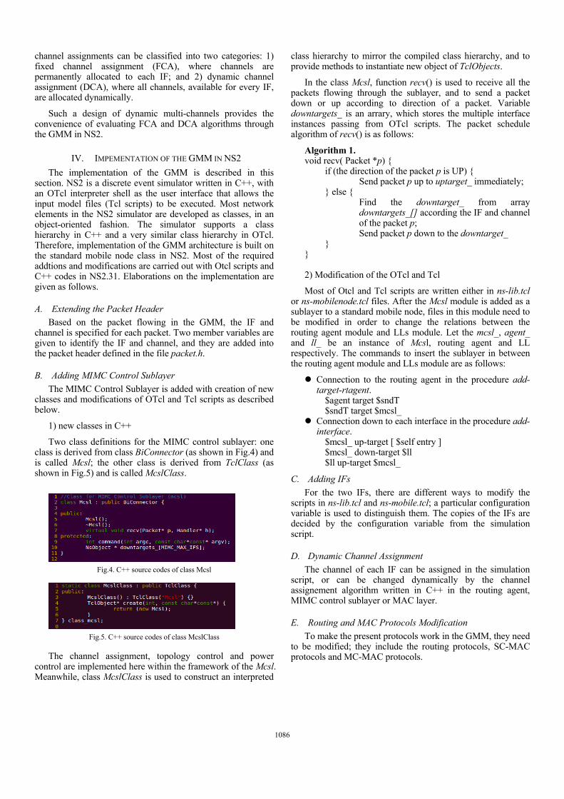
Two class definitions for the MIMC control sublayer: one class is derived from class BiConnector (as shown in Fig.4) and is called Mcsl; the other class is derived from TclClass (as shown in Fig.5) and is called McslClass.
Fig.4. C++ source codes of class Mcsl
Fig.5. C++ source codes of class McslClass
The channel assignment, topology control and power control are implemented here within the framework of the Mcsl. Meanwhile, class McslClass is used to construct an interpreted
class hierarchy to mirror the compiled class hierarchy, and to provide methods to instantiate new object of TclObjects.
In the class Mcsl, function recv() is used to receive all the packets flowing through the sublayer, and to send a packet down or up according to direction of a packet. Variable downtargets_ is an arrary, which stores the multiple interface instances passing from OTcl scripts. The packet schedule algorithm of recv() is as follows:
Algorithm 1. void recv( Packet *p) { if (the direction of the packet p is UP) { Send packet p up to uptarget_ immediately; } else { Find the downtarget_ from array
downtargets_[] according the IF and channel of the packet p;
Send packet p down to the downtarget_ } } 2) Modification of the OTcl and Tcl
Most of Otcl and Tcl scripts are written either in ns-lib.tcl or ns-mobilenode.tcl files. After the Mcsl module is added as a sublayer to a standard mobile node, files in this module need to be modified in order to change the relations between the routing agent module and LLs module. Let the mcsl_, agent_ and ll_ be an instance of Mcsl, routing agent and LL respectively. The commands to insert the sublayer in between the routing agent module and LLs module are as follows:
Connection to the routing agent in the procedure add-target-rtagent.
$agent target $sndT $sndT target $mcsl_ Connection down to each interface in the procedure add-
interface. $mcsl_ up-target [ $self entry ] $mcsl_ down-target $ll $ll up-target $mcsl_
C. Adding IFs
For the two IFs, there are different ways to modify the scripts in ns-lib.tcl and ns-mobile.tcl; a particular configuration variable is used to distinguish them. The copies of the IFs are decided by the configuration variable from the simulation script.
D. Dynamic Channel Assignment
The channel of each IF can be assigned in the simulation script, or can be changed dynamically by the channel assignement algorithm written in C++ in the routing agent, MIMC control sublayer or MAC layer.
E. Routing and MAC Protocols Modification
To make the present protocols work in the GMM, they need to be modified; they include the routing protocols, SC-MAC protocols and MC-MAC protocols.
1086
V. ANALYSIS AND EVALUATIONS
A. Analysis of the GMM
The characteristics of the GMM are summarized as follows.
1) Protocol compatibility. Protocols with the standard model are still able to work with the GMM with a few modifications. These protocols including routing and MAC protocols are single-channel protocols, and they can work in the GMM by configuring the single SC-IF. Furthermore, the multi-channel protocols can be transplanted easily across different models.
2) Heterogeneous interfaces. The GMM provides two kinds of interfaces for simulating heterogeneous interfaces. The different interfaces such as SC-IF and MC-IF can meet the requirements of many applications.
3) Configuration flexibility. As a generic model for MIMC, the GMM provides a set of configuration scripts for simulating various protocols. Through the Tcl scripts, whether single-channel or multi-channel protocols can be simulated with this model.
4) Expandability. The GMM is based on the standard model of a mobile node in NS2, and the implementation of this model is not difficult. The GMM can be further expanded by users for simulating a more complex system.
B. Validation and Discussion
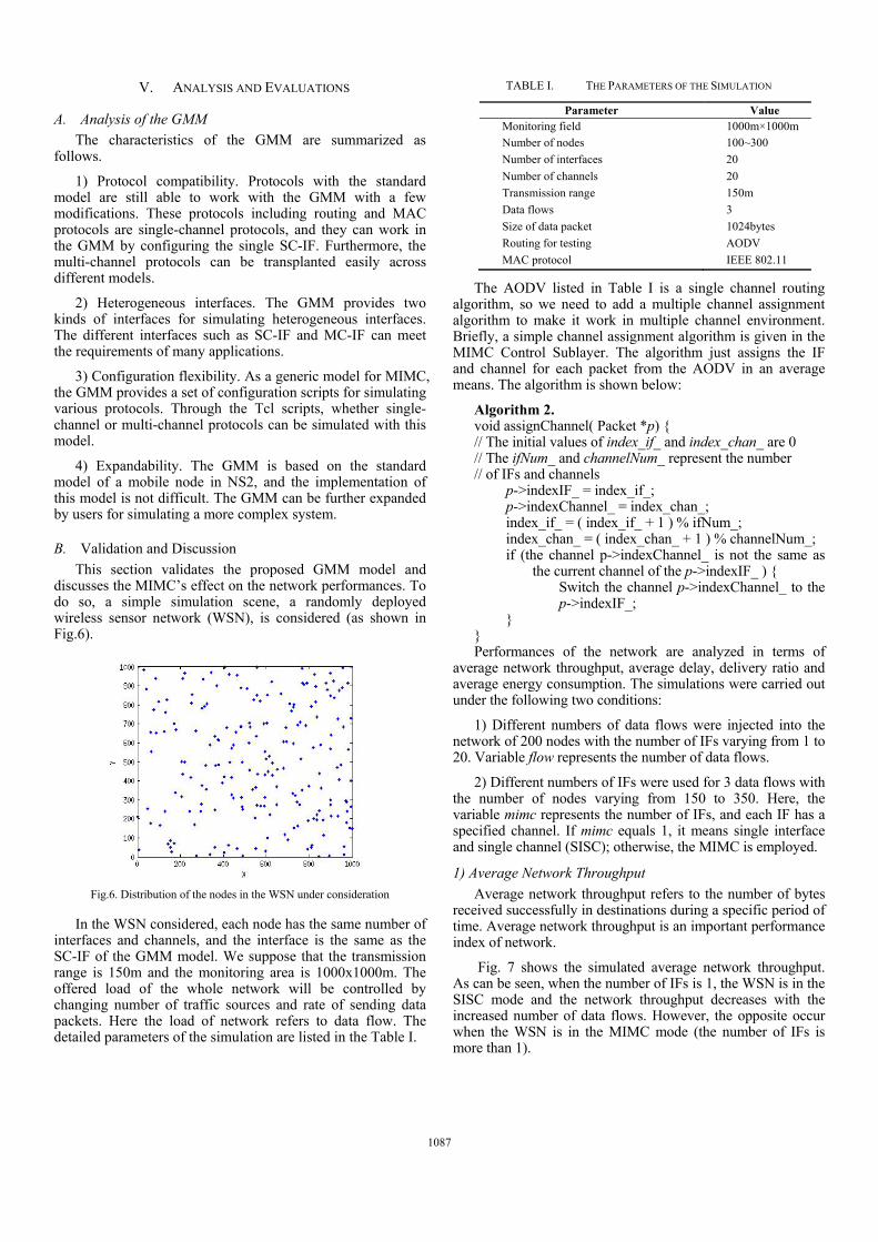
This section validates the proposed GMM model and discusses the MIMC’s effect on the network performances. To do so, a simple simulation scene, a randomly deployed wireless sensor network (WSN), is considered (as shown in Fig.6).
Fig.6. Distribution of the nodes in the WSN under consideration
In the WSN considered, each node has the same number of interfaces and channels, and the interface is the same as the SC-IF of the GMM model. We suppose that the transmission range is 150m and the monitoring area is 1000x1000m. The offered load of the whole network will be controlled by changing number of traffic sources and rate of sending data packets. Here the load of network refers to data flow. The detailed parameters of the simulation are listed in the Table I.
TABLE I. THE PARAMETERS OF THE SIMULATION
Parameter Value Monitoring field 1000m×1000m
Number of nodes 100~300
Number of interfaces 20
Number of channels 20
Transmission range 150m
Data flows 3
Size of data packet 1024bytes
Routing for testing AODV
MAC protocol IEEE 802.11
The AODV listed in Table I is a single channel routing algorithm, so we need to add a multiple channel assignment algorithm to make it work in multiple channel environment. Briefly, a simple channel assignment algorithm is given in the MIMC Control Sublayer. The algorithm just assigns the IF and channel for each packet from the AODV in an average means. The algorithm is shown below:
Algorithm 2. void assignChannel( Packet *p) { // The initial values of index_if_ and index_chan_ are 0 // The ifNum_ and channelNum_ represent the number // of IFs and channels p->indexIF_ = index_if_; p->indexChannel_ = index_chan_; index_if_ = ( index_if_ + 1 ) % ifNum_; index_chan_ = ( index_chan_ + 1 ) % channelNum_; if (the channel p->indexChannel_ is not the same as
the current channel of the p->indexIF_ ) { Switch the channel p->indexChannel_ to the
p->indexIF_; } } Performances of the network are analyzed in terms of
average network throughput, average delay, delivery ratio and average energy consumption. The simulations were carried out under the following two conditions:
1) Different numbers of data flows were injected into the network of 200 nodes with the number of IFs varying from 1 to 20. Variable flow represents the number of data flows.
2) Different numbers of IFs were used for 3 data flows with the number of nodes varying from 150 to 350. Here, the variable mimc represents the number of IFs, and each IF has a specified channel. If mimc equals 1, it means single interface and single channel (SISC); otherwise, the MIMC is employed.
1) Average Network Throughput
Average network throughput refers to the number of bytes received successfully in destinations during a specific period of time. Average network throughput is an important performance index of network.
Fig. 7 shows the simulated average network throughput. As can be seen, when the number of IFs is 1, the WSN is in the SISC mode and the network throughput decreases with the increased number of data flows. However, the opposite occur when the WSN is in the MIMC mode (the number of IFs is more than 1).
1087
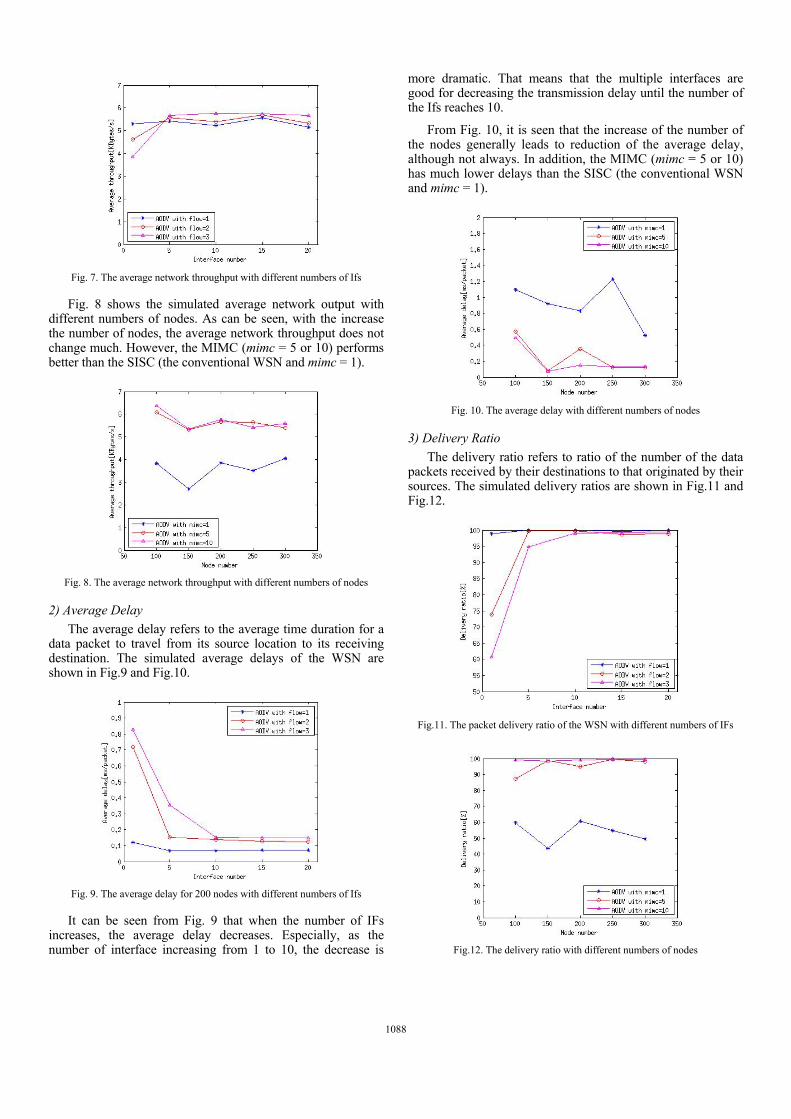
Fig. 7. The average network throughput with different numbers of Ifs
Fig. 8 shows the simulated average network output with different numbers of nodes. As can be seen, with the increase the number of nodes, the average network throughput does not change much. However, the MIMC (mimc = 5 or 10) performs better than the SISC (the conventional WSN and mimc = 1).
Fig. 8. The average network throughput with different numbers of nodes
2) Average Delay
The average delay refers to the average time duration for a data packet to travel from its source location to its receiving destination. The simulated average delays of the WSN are shown in Fig.9 and Fig.10.
Fig. 9. The average delay for 200 nodes with different numbers of Ifs
It can be seen from Fig. 9 that when the number of IFs increases, the average delay decreases. Especially, as the number of interface increasing from 1 to 10, the decrease is
more dramatic. That means that the multiple interfaces are good for decreasing the transmission delay until the number of the Ifs reaches 10.
From Fig. 10, it is seen that the increase of the number of the nodes generally leads to reduction of the average delay, although not always. In addition, the MIMC (mimc = 5 or 10) has much lower delays than the SISC (the conventional WSN and mimc = 1).
Fig. 10. The average delay with different numbers of nodes
3) Delivery Ratio
The delivery ratio refers to ratio of the number of the data packets received by their destinations to that originated by their sources. The simulated delivery ratios are shown in Fig.11 and Fig.12.
Fig.11. The packet delivery ratio of the WSN with different numbers of IFs
Fig.12. The delivery ratio with different numbers of nodes
1088
As seen from Fig.11, as the number of the data packets increases, the delivery ratio decreases. However, as the number of IFs increases, the delivery ratio increases. When the number of IFs reaches beyond 10, the packet delivery ratio levels off but remains at a high value of above 95%. From Fig.12, it is seen that the delivery ratio moves between 40% and 60% with the SISC (mimc=1); but it reaches up to 99% with the MIMC (mimc = 5 or 10). That is the MIMC scheme can increase the delivery ratio dramatically.
4) Average Energy Consumption
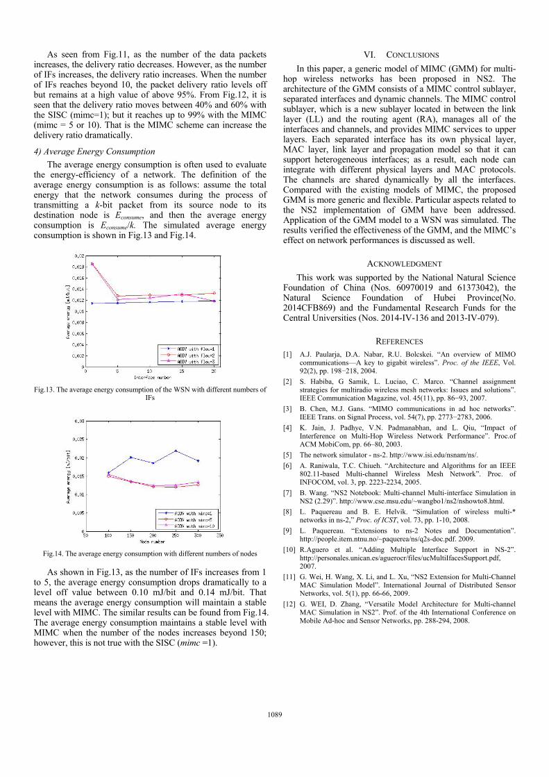
The average energy consumption is often used to evaluate the energy-efficiency of a network. The definition of the average energy consumption is as follows: assume the total energy that the network consumes during the process of transmitting a k-bit packet from its source node to its destination node is Econsume, and then the average energy consumption is Econsume/k. The simulated average energy consumption is shown in Fig.13 and Fig.14.
Fig.13. The average energy consumption of the WSN with different numbers of
IFs
Fig.14. The average energy consumption with different numbers of nodes
As shown in Fig.13, as the number of IFs increases from 1 to 5, the average energy consumption drops dramatically to a level off value between 0.10 mJ/bit and 0.14 mJ/bit. That means the average energy consumption will maintain a stable level with MIMC. The similar results can be found from Fig.14. The average energy consumption maintains a stable level with MIMC when the number of the nodes increases beyond 150; however, this is not true with the SISC (mimc =1).
VI. CONCLUSIONS
In this paper, a generic model of MIMC (GMM) for multi-hop wireless networks has been proposed in NS2. The architecture of the GMM consists of a MIMC control sublayer, separated interfaces and dynamic channels. The MIMC control sublayer, which is a new sublayer located in between the link layer (LL) and the routing agent (RA), manages all of the interfaces and channels, and provides MIMC services to upper layers. Each separated interface has its own physical layer, MAC layer, link layer and propagation model so that it can support heterogeneous interfaces; as a result, each node can integrate with different physical layers and MAC protocols. The channels are shared dynamically by all the interfaces. Compared with the existing models of MIMC, the proposed GMM is more generic and flexible. Particular aspects related to the NS2 implementation of GMM have been addressed. Application of the GMM model to a WSN was simulated. The results verified the effectiveness of the GMM, and the MIMC’s effect on network performances is discussed as well.
ACKNOWLEDGMENT
This work was supported by the National Natural Science Foundation of China (Nos. 60970019 and 61373042), the Natural Science Foundation of Hubei Province(No. 2014CFB869) and the Fundamental Research Funds for the Central Universities (Nos. 2014-IV-136 and 2013-IV-079).
REFERENCES [1] A.J. Paularja, D.A. Nabar, R.U. Bolcskei. “An overview of MIMO
communications—A key to gigabit wireless”. Proc. of the IEEE, Vol. 92(2), pp. 198−218, 2004.
[2] S. Habiba, G Samik, L. Luciao, C. Marco. “Channel assignment strategies for multiradio wireless mesh networks: Issues and solutions”. IEEE Communication Magazine, vol. 45(11), pp. 86−93, 2007.
[3] B. Chen, M.J. Gans. “MIMO communications in ad hoc networks”. IEEE Trans. on Signal Process, vol. 54(7), pp. 2773−2783, 2006.
[4] K. Jain, J. Padhye, V.N. Padmanabhan, and L. Qiu, “Impact of Interference on Multi-Hop Wireless Network Performance”. Proc.of ACM MobiCom, pp. 66–80, 2003.
[5] The network simulator - ns-2. http://www.isi.edu/nsnam/ns/.
[6] A. Raniwala, T.C. Chiueh. “Architecture and Algorithms for an IEEE 802.11-based Multi-channel Wireless Mesh Network”. Proc. of INFOCOM, vol. 3, pp. 2223-2234, 2005.
[7] B. Wang. “NS2 Notebook: Multi-channel Multi-interface Simulation in NS2 (2.29)”. http://www.cse.msu.edu/~wangbo1/ns2/nshowto8.html.
[8] L. Paquereau and B. E. Helvik. “Simulation of wireless multi-* networks in ns-2,” Proc. of ICST, vol. 73, pp. 1-10, 2008.
[9] L. Paquereau. “Extensions to ns-2 Notes and Documentation”. http://people.item.ntnu.no/~paquerea/ns/q2s-doc.pdf. 2009.
[10] R.Aguero et al. “Adding Multiple Interface Support in NS-2”. http://personales.unican.es/aguerocr/files/ucMultiIfacesSupport.pdf, 2007.
[11] G. Wei, H. Wang, X. Li, and L. Xu, “NS2 Extension for Multi-Channel MAC Simulation Model”. International Journal of Distributed Sensor Networks, vol. 5(1), pp. 66-66, 2009.
[12] G. WEI, D. Zhang, “Versatile Model Architecture for Multi-channel MAC Simulation in NS2”. Prof. of the 4th International Conference on Mobile Ad-hoc and Sensor Networks, pp. 288-294, 2008.
1089