HW/SW for an intelligent transducer network based on IEEE 1451 standard
13
HW/SW for an intelligent transducer network based on IEEE 1451 standard E.A. Batista a, ⁎, L. Gonda b, ⁎, A.C.R. da Silva c , S.R. Rossi d , M.C. Pereira e , A.A. de Carvalho c , C.E. Cugnasca f a Federal University of Mato Grosso do Sul, Dept. of Electrical Engineering, Campo Grande-MS, Brazil b Federal University of Mato Grosso do Sul, College of Computing, Campo Grande-MS, Brazil c University of São Paulo State, Dept. of Electrical Engineering, Ilha Solteira-SP, Brazil d Center of Buenos Aires Province National University, Dept. of Electro-Mechanical Engineering, Argentina e Dom Bosco Catholic University, Computer and Engineering Research Group, Campo Grande-MS, Brazil f Polytechnic School, University of São Paulo, São Paulo-SP, Brazil abstract article info Article history: Received 30 April 2009 Accepted 20 May 2011 Available online 12 June 2011 Keywords: IEEE 1451 standard NIOS II processor FPGA Intelligent transducers This work describes a hardware/software co-design system development, named IEEE 1451 platform, to be used in process automation. This platform intends to make easier the implementation of IEEE standards 1451.0, 1451.1, 1451.2 and 1451.5. The hardware was built using NIOS II processor resources on Alteras Cyclone II FPGA. The software was done using Java technology and C/C++ for the processors programming. This HW/SW system implements the IEEE 1451 based on a control module and supervisory software for industrial automation. © 2011 Elsevier B.V. All rights reserved. Contents 1. Introduction . . . . . . . . . . . . . . . . . . . . . . . . . . . . . . . . . . . . . . . . . . . . . . . . . . . . . . . . . . . . . . . 1 1.1. IEEE 1451.0 — TEDS . . . . . . . . . . . . . . . . . . . . . . . . . . . . . . . . . . . . . . . . . . . . . . . . . . . . . . . . 3 1.2. IEEE 1451.2 . . . . . . . . . . . . . . . . . . . . . . . . . . . . . . . . . . . . . . . . . . . . . . . . . . . . . . . . . . . . 4 1.3. IEEE 1451.5 — WTIM . . . . . . . . . . . . . . . . . . . . . . . . . . . . . . . . . . . . . . . . . . . . . . . . . . . . . . . 4 1.4. IDE and CAD tools used to develop the IEEE 1451 platform . . . . . . . . . . . . . . . . . . . . . . . . . . . . . . . . . . . . . 4 1.5. Quartus II and SOPC Builder . . . . . . . . . . . . . . . . . . . . . . . . . . . . . . . . . . . . . . . . . . . . . . . . . . . . 4 2. Implemented IEEE 1451 platform . . . . . . . . . . . . . . . . . . . . . . . . . . . . . . . . . . . . . . . . . . . . . . . . . . . . . 5 2.1. NCAP — IEEE 1451 platform . . . . . . . . . . . . . . . . . . . . . . . . . . . . . . . . . . . . . . . . . . . . . . . . . . . . 6 2.2. TIM IEEE 1451 platform . . . . . . . . . . . . . . . . . . . . . . . . . . . . . . . . . . . . . . . . . . . . . . . . . . . . . . 6 2.3. TIM configuration for Cyclone II FPGA . . . . . . . . . . . . . . . . . . . . . . . . . . . . . . . . . . . . . . . . . . . . . . . 7 2.4. NIOS II IDE . . . . . . . . . . . . . . . . . . . . . . . . . . . . . . . . . . . . . . . . . . . . . . . . . . . . . . . . . . . . 7 3. IEEE 1451 platform test . . . . . . . . . . . . . . . . . . . . . . . . . . . . . . . . . . . . . . . . . . . . . . . . . . . . . . . . . 9 3.1. Hydraulic automation kit . . . . . . . . . . . . . . . . . . . . . . . . . . . . . . . . . . . . . . . . . . . . . . . . . . . . . 9 3.2. Flow and pressure compressor automation . . . . . . . . . . . . . . . . . . . . . . . . . . . . . . . . . . . . . . . . . . . . . 11 3.3. Analysis of results . . . . . . . . . . . . . . . . . . . . . . . . . . . . . . . . . . . . . . . . . . . . . . . . . . . . . . . . . 12 4. Conclusions and future work . . . . . . . . . . . . . . . . . . . . . . . . . . . . . . . . . . . . . . . . . . . . . . . . . . . . . . . 12 References . . . . . . . . . . . . . . . . . . . . . . . . . . . . . . . . . . . . . . . . . . . . . . . . . . . . . . . . . . . . . . . . . . 13 1. Introduction Transducer networks built using standard interfaces provide better flexibility for maintenance and expansion design of industrial plants. This kind of networks is common on various instrumentation applications like production lines, agricultural and home automations, biomedical engineering, robotics and safety, among others. Proprie- tary solutions are still dominant, which protects companies' research and development, but jeopardizes scalable project distributed instrumentation. Since the 1990s NIST (National Institute of Standards and Technology) and IEEE (Institute of Electrical and Electronics Engi- neers) have been developing a set of transducer networks standards, called IEEE 1451 [1]. It establishes a set of rules for different interfaces Computer Standards & Interfaces 34 (2012) 1–13 ⁎ Corresponding authors. E-mail addresses: [email protected] (E.A. Batista), [email protected] (L. Gonda), [email protected] (A.C.R. da Silva), srossi@fio.unicen.edu.ar (S.R. Rossi), [email protected] (M.C. Pereira), [email protected] (A.A. de Carvalho), [email protected] (C.E. Cugnasca). 0920-5489/$ – see front matter © 2011 Elsevier B.V. All rights reserved. doi:10.1016/j.csi.2011.05.009 Contents lists available at ScienceDirect Computer Standards & Interfaces journal homepage: www.elsevier.com/locate/csi
-
Upload
independent -
Category
Documents
-
view
1 -
download
0
Transcript of HW/SW for an intelligent transducer network based on IEEE 1451 standard
Computer Standards & Interfaces 34 (2012) 1–13
Contents lists available at ScienceDirect
Computer Standards & Interfaces
j ourna l homepage: www.e lsev ie r.com/ locate /cs i
HW/SW for an intelligent transducer network based on IEEE 1451 standard
E.A. Batista a,⁎, L. Gonda b,⁎, A.C.R. da Silva c, S.R. Rossi d, M.C. Pereira e, A.A. de Carvalho c, C.E. Cugnasca f
a Federal University of Mato Grosso do Sul, Dept. of Electrical Engineering, Campo Grande-MS, Brazilb Federal University of Mato Grosso do Sul, College of Computing, Campo Grande-MS, Brazilc University of São Paulo State, Dept. of Electrical Engineering, Ilha Solteira-SP, Brazild Center of Buenos Aires Province National University, Dept. of Electro-Mechanical Engineering, Argentinae Dom Bosco Catholic University, Computer and Engineering Research Group, Campo Grande-MS, Brazilf Polytechnic School, University of São Paulo, São Paulo-SP, Brazil
⁎ Corresponding authors.E-mail addresses: [email protected] (E.A. Batista), g
(L. Gonda), [email protected] (A.C.R. da Silva),(S.R. Rossi), [email protected] (M.C. Pereira), [email protected]@poli.usp.br (C.E. Cugnasca).
0920-5489/$ – see front matter © 2011 Elsevier B.V. Aldoi:10.1016/j.csi.2011.05.009
a b s t r a c t
a r t i c l e i n f oArticle history:Received 30 April 2009Accepted 20 May 2011Available online 12 June 2011
Keywords:IEEE 1451 standardNIOS II processorFPGAIntelligent transducers
This work describes a hardware/software co-design system development, named IEEE 1451 platform, to beused in process automation. This platform intends to make easier the implementation of IEEE standards1451.0, 1451.1, 1451.2 and 1451.5. The hardware was built using NIOS II processor resources on AlterasCyclone II FPGA. The software was done using Java technology and C/C++ for the processors programming.This HW/SW system implements the IEEE 1451 based on a control module and supervisory software forindustrial automation.
[email protected]@fio.unicen.edu.ar.unesp.br (A.A. de Carvalho),
l rights reserved.
© 2011 Elsevier B.V. All rights reserved.
Contents
1. Introduction . . . . . . . . . . . . . . . . . . . . . . . . . . . . . . . . . . . . . . . . . . . . . . . . . . . . . . . . . . . . . . . 11.1. IEEE 1451.0 — TEDS . . . . . . . . . . . . . . . . . . . . . . . . . . . . . . . . . . . . . . . . . . . . . . . . . . . . . . . . 31.2. IEEE 1451.2 . . . . . . . . . . . . . . . . . . . . . . . . . . . . . . . . . . . . . . . . . . . . . . . . . . . . . . . . . . . . 41.3. IEEE 1451.5 — WTIM . . . . . . . . . . . . . . . . . . . . . . . . . . . . . . . . . . . . . . . . . . . . . . . . . . . . . . . 41.4. IDE and CAD tools used to develop the IEEE 1451 platform . . . . . . . . . . . . . . . . . . . . . . . . . . . . . . . . . . . . . 41.5. Quartus II and SOPC Builder . . . . . . . . . . . . . . . . . . . . . . . . . . . . . . . . . . . . . . . . . . . . . . . . . . . . 4
2. Implemented IEEE 1451 platform . . . . . . . . . . . . . . . . . . . . . . . . . . . . . . . . . . . . . . . . . . . . . . . . . . . . . 52.1. NCAP — IEEE 1451 platform . . . . . . . . . . . . . . . . . . . . . . . . . . . . . . . . . . . . . . . . . . . . . . . . . . . . 62.2. TIM IEEE 1451 platform . . . . . . . . . . . . . . . . . . . . . . . . . . . . . . . . . . . . . . . . . . . . . . . . . . . . . . 62.3. TIM configuration for Cyclone II FPGA . . . . . . . . . . . . . . . . . . . . . . . . . . . . . . . . . . . . . . . . . . . . . . . 72.4. NIOS II IDE . . . . . . . . . . . . . . . . . . . . . . . . . . . . . . . . . . . . . . . . . . . . . . . . . . . . . . . . . . . . 7
3. IEEE 1451 platform test . . . . . . . . . . . . . . . . . . . . . . . . . . . . . . . . . . . . . . . . . . . . . . . . . . . . . . . . . 93.1. Hydraulic automation kit . . . . . . . . . . . . . . . . . . . . . . . . . . . . . . . . . . . . . . . . . . . . . . . . . . . . . 93.2. Flow and pressure compressor automation . . . . . . . . . . . . . . . . . . . . . . . . . . . . . . . . . . . . . . . . . . . . . 113.3. Analysis of results . . . . . . . . . . . . . . . . . . . . . . . . . . . . . . . . . . . . . . . . . . . . . . . . . . . . . . . . . 12
4. Conclusions and future work . . . . . . . . . . . . . . . . . . . . . . . . . . . . . . . . . . . . . . . . . . . . . . . . . . . . . . . 12References . . . . . . . . . . . . . . . . . . . . . . . . . . . . . . . . . . . . . . . . . . . . . . . . . . . . . . . . . . . . . . . . . . 13
1. Introduction
Transducer networks built using standard interfaces providebetter flexibility for maintenance and expansion design of industrial
plants. This kind of networks is common on various instrumentationapplications like production lines, agricultural and home automations,biomedical engineering, robotics and safety, among others. Proprie-tary solutions are still dominant, which protects companies' researchand development, but jeopardizes scalable project distributedinstrumentation.
Since the 1990s NIST (National Institute of Standards andTechnology) and IEEE (Institute of Electrical and Electronics Engi-neers) have been developing a set of transducer networks standards,called IEEE 1451 [1]. It establishes a set of rules for different interfaces
2 E.A. Batista et al. / Computer Standards & Interfaces 34 (2012) 1–13
to be used in a transducer network. The main idea is based on thedefinition that an intelligent transducer is a device capable ofidentifying itself and operating a communication network [2]. TheIEEE 1451 requires the use of open and standard tools, based on anarchitecture set up by a NCAP (Network Capable ApplicationProcessor) and the TIMs (Transducer Interface Module).
The connection mode between the NCAP and TIM and theirfunctions originated the following committees [3], formed byscientists and engineers from various institutions. These committeesare responsible for the elaboration and validation of standards details,such as:
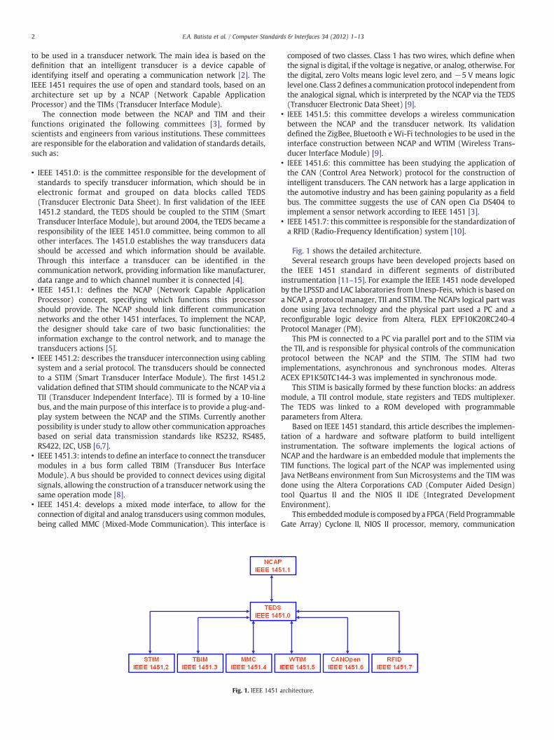
• IEEE 1451.0: is the committee responsible for the development ofstandards to specify transducer information, which should be inelectronic format and grouped on data blocks called TEDS(Transducer Electronic Data Sheet). In first validation of the IEEE1451.2 standard, the TEDS should be coupled to the STIM (SmartTransducer Interface Module), but around 2004, the TEDS became aresponsibility of the IEEE 1451.0 committee, being common to allother interfaces. The 1451.0 establishes the way transducers datashould be accessed and which information should be available.Through this interface a transducer can be identified in thecommunication network, providing information like manufacturer,data range and to which channel number it is connected [4].
• IEEE 1451.1: defines the NCAP (Network Capable ApplicationProcessor) concept, specifying which functions this processorshould provide. The NCAP should link different communicationnetworks and the other 1451 interfaces. To implement the NCAP,the designer should take care of two basic functionalities: theinformation exchange to the control network, and to manage thetransducers actions [5].
• IEEE 1451.2: describes the transducer interconnection using cablingsystem and a serial protocol. The transducers should be connectedto a STIM (Smart Transducer Interface Module). The first 1451.2validation defined that STIM should communicate to the NCAP via aTII (Transducer Independent Interface). TII is formed by a 10-linebus, and the main purpose of this interface is to provide a plug-and-play system between the NCAP and the STIMs. Currently anotherpossibility is under study to allow other communication approachesbased on serial data transmission standards like RS232, RS485,RS422, I2C, USB [6,7].
• IEEE 1451.3: intends to define an interface to connect the transducermodules in a bus form called TBIM (Transducer Bus InterfaceModule). A bus should be provided to connect devices using digitalsignals, allowing the construction of a transducer network using thesame operation mode [8].
• IEEE 1451.4: develops a mixed mode interface, to allow for theconnection of digital and analog transducers using commonmodules,being called MMC (Mixed-Mode Communication). This interface is
Fig. 1. IEEE 1451
composed of two classes. Class 1 has two wires, which define whenthe signal is digital, if the voltage is negative, or analog, otherwise. Forthe digital, zero Volts means logic level zero, and −5 V means logiclevel one. Class 2 defines a communication protocol independent fromthe analogical signal, which is interpreted by the NCAP via the TEDS(Transducer Electronic Data Sheet) [9].
• IEEE 1451.5: this committee develops a wireless communicationbetween the NCAP and the transducer network. Its validationdefined the ZigBee, Bluetooth e Wi-Fi technologies to be used in theinterface construction between NCAP and WTIM (Wireless Trans-ducer Interface Module) [9].
• IEEE 1451.6: this committee has been studying the application ofthe CAN (Control Area Network) protocol for the construction ofintelligent transducers. The CAN network has a large application inthe automotive industry and has been gaining popularity as a fieldbus. The committee suggests the use of CAN open Cia DS404 toimplement a sensor network according to IEEE 1451 [3].
• IEEE 1451.7: this committee is responsible for the standardization ofa RFID (Radio-Frequency Identification) system [10].
Fig. 1 shows the detailed architecture.Several research groups have been developed projects based on
the IEEE 1451 standard in different segments of distributedinstrumentation [11–15]. For example the IEEE 1451 node developedby the LPSSD and LAC laboratories from Unesp-Feis, which is based ona NCAP, a protocol manager, TII and STIM. The NCAPs logical part wasdone using Java technology and the physical part used a PC and areconfigurable logic device from Altera, FLEX EPF10K20RC240-4Protocol Manager (PM).
This PM is connected to a PC via parallel port and to the STIM viathe TII, and is responsible for physical controls of the communicationprotocol between the NCAP and the STIM. The STIM had twoimplementations, asynchronous and synchronous modes. AlterasACEX EP1K50TC144-3 was implemented in synchronous mode.
This STIM is basically formed by these function blocks: an addressmodule, a TII control module, state registers and TEDS multiplexer.The TEDS was linked to a ROM developed with programmableparameters from Altera.
Based on IEEE 1451 standard, this article describes the implemen-tation of a hardware and software platform to build intelligentinstrumentation. The software implements the logical actions ofNCAP and the hardware is an embedded module that implements theTIM functions. The logical part of the NCAP was implemented usingJava NetBeans environment from Sun Microsystems and the TIM wasdone using the Altera Corporations CAD (Computer Aided Design)tool Quartus II and the NIOS II IDE (Integrated DevelopmentEnvironment).
This embeddedmodule is composed by a FPGA (Field ProgrammableGate Array) Cyclone II, NIOS II processor, memory, communication
architecture.
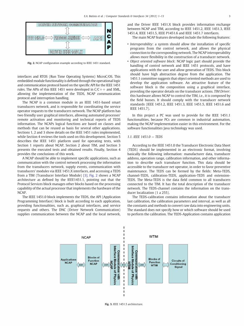
Fig. 2. NCAP configuration example according to IEEE 1451 standard.
3E.A. Batista et al. / Computer Standards & Interfaces 34 (2012) 1–13
interfaces and RTOS (Run Time Operating Systems) MicroC/OS. Thisembeddedmodule functionality is defined through theoperational logicand communication protocol based on the specific API for the IEEE 1451rules. The APIs of this IEEE 1451 were developed in C/C++ and XML,allowing the implementation of the TEDS, NCAP communicationprotocol and interruption handling.
The NCAP is a common module in an IEEE 1451-based smarttransducers network, and is responsible for coordinating the serviceoperator requests to the transducers network. The NCAP platform hastwo friendly user graphical interfaces, allowing automated processes'remote activation and monitoring and technical reports of TEDSinformation. The NCAPs logical functions are based on classes andmethods that can be reused as basis for several other applications.Sections 1, 2 and 3 show details on the IEEE 1451 rules implemented,while Section 4 reviews the tools used on this development. Section 5describes the IEEE 1451 platform used for operating tests, withSection 1 reports about NCAP, Section 2 about TIM, and Section 3presents the executed tests and obtained results. Finally, Section 4provides the conclusions of this work.
A NCAP should be able to implement specific applications, such ascommunication with the control network processing the informationfrom the transducers network, supply events, communication withtransducers' modules via IEEE 1451.X interfaces, and accessing a TEDSfrom a TIM (Transducer Interface Module) [3]. Fig. 2 shows a NCAParchitecture as defined by the IEEE1451.1, pointing out that theProtocol Services block manages other blocks based on the processingcapability of the actual processor that implements the hardware of theNCAP.
The IEEE 1451.0 block implements the TEDS, the API (ApplicationProgramming Interface) block is built according to each application,providing functionalities, such as, graphical interfaces, and servicerequests and others. The DNC (Driver Network Communication)supplies communication between the NCAP and the local network,
Fig. 3. IEEE 1451.5
and the Driver IEEE 1451.X block provides information exchangebetween NCAP and TIM, according to IEEE 1451.2, IEEE 1451.3, IEEE1451.4, IEEE 1451.5, IEEE P1451.6 and IEEE 1451.7 interfaces.
The main NCAP features developed include the following features:
• Interoperability: a system should allow the installation of specificprograms from the control network, and allows the physicalconnection to the correspondingnetwork. TheNCAP interoperabilityallows more flexibility in the construction of a transducer network.
• Object oriented software block: NCAP logic part should provide thehandling of control network and IEEE 1451 protocols, and haveapplications with the user and allow generation of TEDS. This blockshould have high abstraction degree from the application. The1451.1 committee suggests that object orientedmethods are used todevelop the application software. An attractive feature of thesoftware block is the composition using a graphical interface,providing the operator details on the transducer actions. TIM Driver:this hardware allows NCAP to control the TIM, i.e., it is composed bythe field busses. It should comply with the transducer networkstandards (IEEE 1451.2, IEEE 1451.3, IEEE 1451.5, IEEE 1451.6 andIEEE 1451.7).
In this project a PC was used to provide for the IEEE 1451.1functionalities, because PCs are common in industrial automation,making the NCAP implementation easier in this environment. For thesoftware functionalities Java technology was used.
1.1. IEEE 1451.0 — TEDS
According to the IEEE 1451.0 the Transducer Electronic Data Sheet(TEDS) should be implemented in an electronic format, involvingbasically the following information: manufacturer data, transduceraddress, operation range, calibration information, and other informa-tion to describe each transducer function. This data should beaccessible to the transducer net operator, in order to favor preventivemaintenance. The TEDS can be formed by the fields: Meta-TEDS,channel-TEDS, calibration-TEDS, application-TEDS and extension-TEDS. The Meta-TEDS is the data field common to all transducersconnected to the TIM. It has the total description of the transducernetwork. The TEDS-channel contains the information on the trans-ducer localization (1 a 255).
The TEDS-calibration contains information about the transducerlast calibration, the calibration parameters and interval, as well as allthe constants andmethods to convert raw data into engineering units.The standard does not specify how or which software should be usedto perform the calibration. The TEDS-Application contains application
architecture.

Table 1Physical layer addressing.
Address value Wireless technology
0 IEEE 802.11 (Wi-Fi)1 Bluetooth2 Zigbee
4 E.A. Batista et al. / Computer Standards & Interfaces 34 (2012) 1–13
specific information, according to the transducer use. It is reserved forfuture implementations and industrial expansion, according to theIEEE1451.X standards (IEEE 1451.2, IEEE 1451.3, IEEE 1451.5, IEEE1451.6 and IEEE 1451.7).
1.2. IEEE 1451.2
The IEEE 1451.2 standard specifies the STIM (Smart TransducerInterface Module) functionalities. The first STIM version was definedaround 1997, but it is being revised specially regarding the NCAP andSTIM connection [2]. In the first version of the standard the STIM isconnected to the NCAP, using a 10-wire serial data interface called TII(Transducer Independent Interface). The 10 well defined pins areused to establish the hardware communication protocol betweenSTIM and NCAP, enabling plug-and-play connection mode betweenNCAP and STIM. The STIM should include A/D and/or D/A convertersand address logic circuit, communication driver and direct relation tothe TEDS.
The STIM is the module in which the transducers are connectedand should allow information exchange between these devices andthe control network. Recently is under the discussion the possibility ofthis TII interface to be optional when plug-and-play can be achievedby other means. Interfaces like RS232, SPI and USB can replace the TII[1].
1.3. IEEE 1451.5 — WTIM
The IEEE 1451.5 standardwas defined inMarch of 2007, describingthe technologies which should be used to implement wirelesscommunication systems. It presents the functional configuration,the services data formats, and message types, for the differentestablished physical layers. Fig. 3 shows the functional configurationindependent from the wireless technology used, pointing out that theNCAP functionalities should comply with the descriptions of thesearticles. On WTIM part (Fig. 3), the Communication Module to thephysical interface should comply with one of the technologies definedby IEEE 1451.5, such as: Bluetooth, ZigBee and Wi-Fi. The WTIM
Fig. 4. Configuration o
function module involves the software and hardware required toimplement the communication protocol between the transducernetwork and the wireless technology, as well as communicationinterfaces like RS232 and USB.
The signal conditioning is based on electronic instrumentation toallow data acquisition and actuators activation.
Table 1 shows the physical layer addressing, according todefinitions described in IEEE 1451.5.
The use of the IEEE 1451.5 specification allows the communicationbetween a NCAP and WTIM by different ways, forcing the committeeto establish the following operation rules:
• A NCAP can register multiple WTIMs.• A WTIM should be registered by only one NCAP.• A WTIM should have interface to multiple transducers.• Allow the communication between WTIMs.
1.4. IDE and CAD tools used to develop the IEEE 1451 platform
To implement IEEE 1451 platform hardware, a tool from AlteraCorporation is used, the EDA (Electronic Design Automation) QuartusII. The functionalities of the hardware are implemented in the NIOS IIprocessor using its IDE. The embedded module is done with the NIOSII processor implemented in a Cyclone II FPGA, and along with theelectronic instrumentation it forms the TIM of this platform.
The NCAP logic functions are implemented using the Javatechnology in NetBeans IDE from Sun Microsystems. This technologyis object oriented and allows the portability of the final supervisorysystem among different operating systems. The tools used here canreduce the development time and provide greater flexibility inHardware/Software systems construction.
1.5. Quartus II and SOPC Builder
To develop a processor in a FPGA using the Quartus EDA requiredthe use of a tool called SOPC (System-On-a-Programmable-Chip)Builder. On SOPC Builder the designer configures each componentbefore connecting them in the Avalon internal bus. This componentsets a module containing a processor and the selected peripherals. Thedesigner needs to finalize the hardware structure in the Quartus IIenvironment.
To develop the hardware functionalities NIOS II processor shouldbe programmed in the NIOS II IDE environment, using C/C++language. The designer should take care of the connections betweenAvalon bus, selected peripherals and NIOS II processor.
f NCAP logic part.
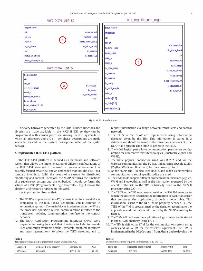
Fig. 5. RS 232 interface pins.
5E.A. Batista et al. / Computer Standards & Interfaces 34 (2012) 1–13
For every hardware generated by the SOPC Builder, functions andlibraries are made available in the NIOS II IDE, so they can beprogrammed with chosen processor. Among them is system.h, inwhich all addresses and C/C++ peripheral descriptions are madeavailable, located in the system description folder of the syslibpackage.
2. Implemented IEEE 1451 platform
The IEEE 1451 platform is defined as a hardware and softwaresystem that allows the implementation of different configurations ofthe IEEE 1451 standard, to be used in process automation. It isbasically formed by a NCAP and an embedded module. The IEEE 1451standard intends to fulfill the needs of a system for distributedmonitoring and control. Therefore, the NCAP performs the functionsof a supervisory system and the embedded module performs theactions of a PLC (Programmable Logic Controller). Fig. 4 shows theplatform architecture proposed in this work.
It is important to observe that:
1. The NCAP is implemented in a PC, because it has functional blockscompatible to the IEEE 1451.1 definitions, and is common inautomation systems. The main blocks implemented in the PC arethe processor, operating system, communication interface to thetransducer modules, communication interface to the controlnetwork.
2. The NCAP Application Programming Interfaces (APIs) wereimplemented using Java, and their functions include: to provideuser application working details (dynamic graphical interfacesand report generation); to allow the TEDS decoding, and to
Table 2Basic resources required to implement TIM in Cyclone II FPGA.
Logic cell Dedicated logic register Memory bit Pins
3359,10% 1931.60% 46720.10% 58.12%
request information exchange between transducers and controlnetwork.
3. The TEDS in the NCAP are implemented using informationdecoded, given by the TIM. This information is stored in adatabase and should be linked to the transducers network. So, theNCAP has a specific code table to generate the TEDS.
4. The NCAP logical part allows communication parameters config-uration for different wireless technologies (Bluetooth, ZigBee andWi-Fi).
5. The basic physical connection used was RS232, and for thewireless communication, the PC was linked using specific radios(ZigBee, Wi-Fi and Bluetooth) for the chosen protocol.
6. As the NCAP, the TIM also used RS232, and when using wirelesscommunication, a set of specific radios are used.
7. TheTIMshould support differentprotocol communications (ZigBee,Wi-Fi and Bluetooth), as well as the information requested by theoperator. The SPC in the TIM is basically done in the NIOS IIprocessor using C/C++.
8. The TEDS in the TIM was programmed in the SDRAM memory, inwhich the designer described the information of each transducerthat composes the application, through a code table. Thisinformation is sent to the NCAP to be properly decoded, i.e., theTEDS of the TIM is programmed by the designer according to theapplication, and this data is interpreted by the NCAP according toitem 3.
9. The TIMs API performs the applications logic control and is storedin the SDRAM memory using C/C++.
10. The TIM is defined as STIM for the communication system usingcables and as WTIM for the wireless equivalent. The TIM isimplemented in the DE2 Cyclone II fromAltera, and to develop the
Table 3Cyclone II resources required to implement a 32 I/O TIM.
Logic cell Dedicated logic register Memory bit Pins
3401,01% 1963.60% 46720.10% 90.19%
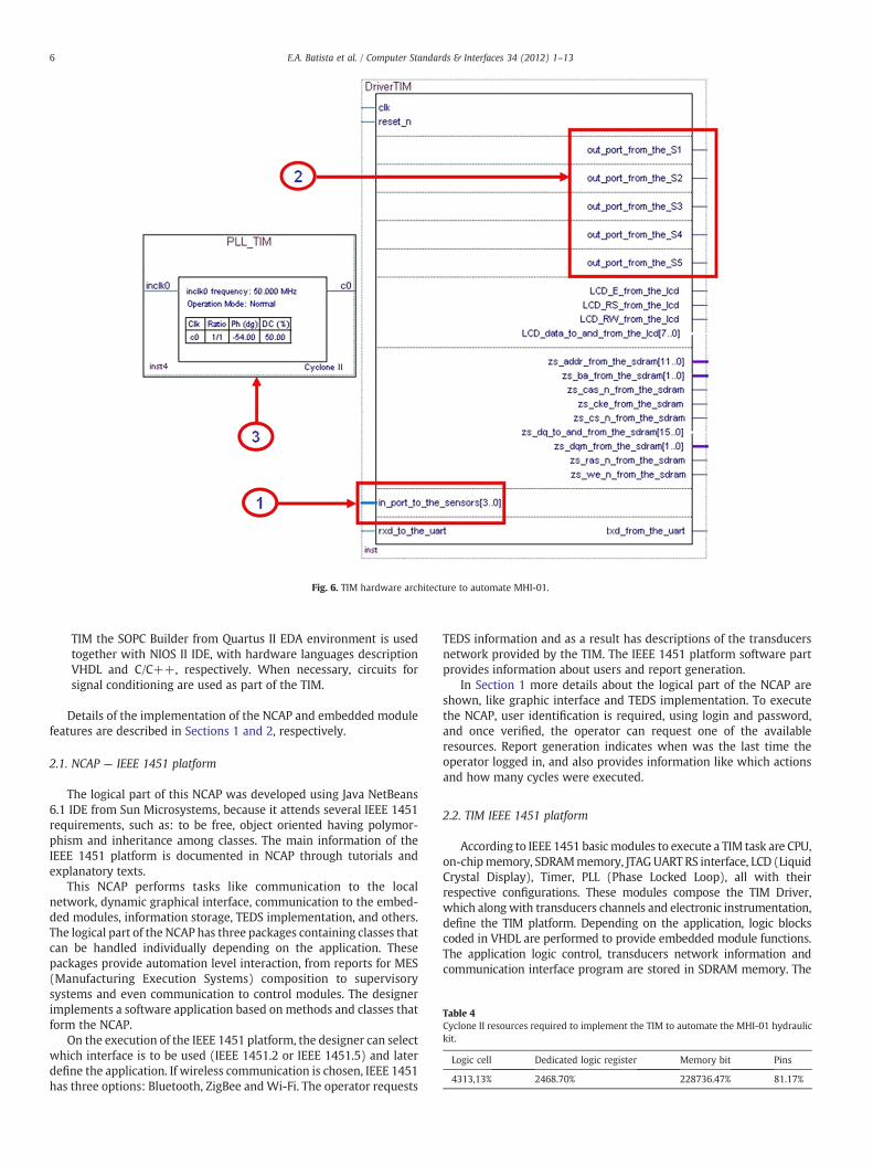
Fig. 6. TIM hardware architecture to automate MHI-01.
Table 4Cyclone II resources required to implement the TIM to automate the MHI-01 hydraulickit.
Logic cell Dedicated logic register Memory bit Pins
4313,13% 2468.70% 228736.47% 81.17%
6 E.A. Batista et al. / Computer Standards & Interfaces 34 (2012) 1–13
TIM the SOPC Builder from Quartus II EDA environment is usedtogether with NIOS II IDE, with hardware languages descriptionVHDL and C/C++, respectively. When necessary, circuits forsignal conditioning are used as part of the TIM.
Details of the implementation of the NCAP and embedded modulefeatures are described in Sections 1 and 2, respectively.
2.1. NCAP — IEEE 1451 platform
The logical part of this NCAP was developed using Java NetBeans6.1 IDE from Sun Microsystems, because it attends several IEEE 1451requirements, such as: to be free, object oriented having polymor-phism and inheritance among classes. The main information of theIEEE 1451 platform is documented in NCAP through tutorials andexplanatory texts.
This NCAP performs tasks like communication to the localnetwork, dynamic graphical interface, communication to the embed-ded modules, information storage, TEDS implementation, and others.The logical part of the NCAP has three packages containing classes thatcan be handled individually depending on the application. Thesepackages provide automation level interaction, from reports for MES(Manufacturing Execution Systems) composition to supervisorysystems and even communication to control modules. The designerimplements a software application based on methods and classes thatform the NCAP.
On the execution of the IEEE 1451 platform, the designer can selectwhich interface is to be used (IEEE 1451.2 or IEEE 1451.5) and laterdefine the application. If wireless communication is chosen, IEEE 1451has three options: Bluetooth, ZigBee andWi-Fi. The operator requests
TEDS information and as a result has descriptions of the transducersnetwork provided by the TIM. The IEEE 1451 platform software partprovides information about users and report generation.
In Section 1 more details about the logical part of the NCAP areshown, like graphic interface and TEDS implementation. To executethe NCAP, user identification is required, using login and password,and once verified, the operator can request one of the availableresources. Report generation indicates when was the last time theoperator logged in, and also provides information like which actionsand how many cycles were executed.
2.2. TIM IEEE 1451 platform
According to IEEE 1451 basicmodules to execute a TIM task are CPU,on-chipmemory, SDRAMmemory, JTAGUART RS interface, LCD (LiquidCrystal Display), Timer, PLL (Phase Locked Loop), all with theirrespective configurations. These modules compose the TIM Driver,which along with transducers channels and electronic instrumentation,define the TIM platform. Depending on the application, logic blockscoded in VHDL are performed to provide embedded module functions.The application logic control, transducers network information andcommunication interface program are stored in SDRAM memory. The
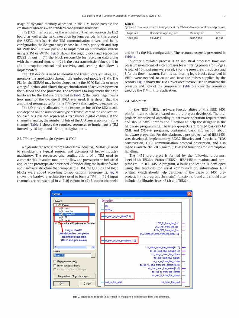
Table 5Cyclone II resources required to implement the TIM used to monitor flow and pressure.
Logic cell Dedicated logic register Memory bit Pins
3467,10% 1946.60% 46720.10% 88.19%
7E.A. Batista et al. / Computer Standards & Interfaces 34 (2012) 1–13
usage of dynamic memory allocation in the TIM made possible thecreation of libraries with standard configurable functions.
The JTAG interface allows the synthesis of the hardware on the DE2board, as well as the tasks execution for long periods. In this projectthe RS232 interface is the TIM communication driver, and in itsconfiguration the designer may choose baud rate, parity bit and stopbit. With RS232 it was possible to implement an automation systemusing STIM or WTIM. Fig. 5 shows the logic blocks and respectiveRS232 pinout in (1) the block responsible for receiving data alongwith their control signals in (2) is the data transmission block, and in(3) interruption control and receiving and sending data flow isimplemented.
The LCD device is used to monitor the transducers activities, i.e.,monitors the application through the embedded module (TIM). ThePLL for the SDRAMmay be developed using the SOPC Builder or usinga Megafunction, and allows the synchronization of activities betweenthe SDRAM and the processor. The resources to implement the basichardware for the TIM are presented in Table 2; the percentage meanshow much of the Cyclone II FPGA was used. It is shown that theamount of resources to form the TIM favors this hardware expansion.
The I/O pins are allocated in the expansion bus of the DE2 board,and depend on the number and type of transducers of the application.So, each bus pin can represent a transducer digital channel. If thechannel is analog, the number of bits of the A/D conversion forms onechannel. Table 3 shows the required resources to implement a TIMformed by 16 input and 16 output digital ports.
2.3. TIM configuration for Cyclone II FPGA
Ahydraulic didactic kit fromHidroEletro Industrial,MHI-01, is usedto simulate the typical sensors and actuators of heavy industrymachinery. The resources and configurations of a TIM used toautomate this kit and tomonitor the flow and pressure in an industrialapplication prototype are described. After deciding the basic softwareand hardware structure that compose the TIM, the I/O pins and logicblocks were added according to applications requirements. Fig. 6shows the hardware architecture used to form a TIM. In (1) 4 inputchannels are represented in a [3..0] vector; in (2) 5 output channels,
Fig. 7. Embedded module (TIM) used to me
and in (3) the PLL configuration. The resource usage is presented inTable 4.
Another simulated process is an industrial processes flow andpressure monitoring of a compressor for a filtering process for Biogas.A total of 16 input pins were used, 8 for the pressure transducers and8 for the flow measurer. For this monitoring logic blocks described inVHDL were needed, to count and treat the pulses supplied by thesensors. Fig. 7 shows the TIM Driver architecture used to monitor thepressure and flow of the compressor. Table 5 shows the resourcesused by the TIM in this application.
2.4. NIOS II IDE
In the NIOS II IDE, hardware functionalities of this IEEE 1451platform can be chosen, based on a pre-project developed. The pre-projects are selected according to hardware operation requirementsand should have libraries and functions to help the designer in thehardware programming. These pre-projects are formed basically byXML and C/C++ programs, containing basic information abouthardware properties. For this platform, a pre-project called IEEE1451was developed, implementing RS232 libraries and functions, TEDSconstruction, TEDS communication protocol description, and alsomade available the RTOS microC/OS-II and functions for interruptionhandling.
The 1451 pre-project is formed by the following programs:ieee1451.h TEDS.h, ProtocolTEDS.h, IEEE1451.c, readme and tem-plate.xml. In IEEE1451.c program, a basic application is developedusing the functions for serial communication, information LCDwriting, which should help designers in the usage of 1451 pre-project. In this program, the main() function is found and should alsoinclude the libraries ieee1451.h and TEDS.h.
asure a compressor flow and pressure.
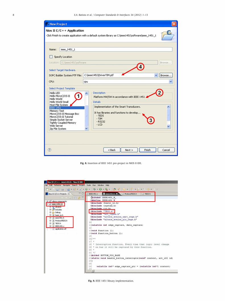
Fig. 8. Insertion of IEEE 1451 pre-project in NIOS II IDE.
Fig. 9. IEEE 1451 library implementation.
8 E.A. Batista et al. / Computer Standards & Interfaces 34 (2012) 1–13
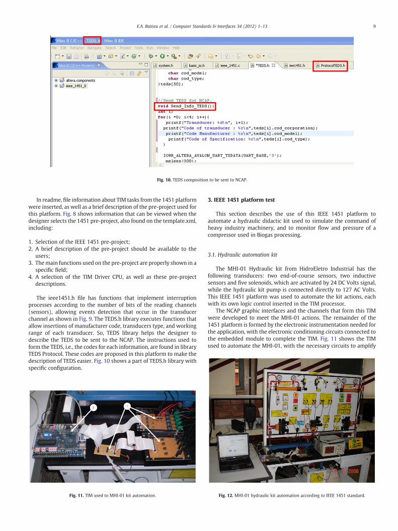
Fig. 10. TEDS composition to be sent to NCAP.
9E.A. Batista et al. / Computer Standards & Interfaces 34 (2012) 1–13
In readme, file information about TIM tasks from the 1451 platformwere inserted, as well as a brief description of the pre-project used forthis platform. Fig. 8 shows information that can be viewed when thedesigner selects the 1451 pre-project, also found on the template.xml,including:
1. Selection of the IEEE 1451 pre-project;2. A brief description of the pre-project should be available to the
users;3. Themain functions used on the pre-project are properly shown in a
specific field;4. A selection of the TIM Driver CPU, as well as these pre-project
descriptions.
The ieee1451.h file has functions that implement interruptionprocesses according to the number of bits of the reading channels(sensors), allowing events detection that occur in the transducerchannel as shown in Fig. 9. The TEDS.h library executes functions thatallow insertions of manufacturer code, transducers type, and workingrange of each transducer. So, TEDS library helps the designer todescribe the TEDS to be sent to the NCAP. The instructions used toform the TEDS, i.e., the codes for each information, are found in libraryTEDS Protocol. These codes are proposed in this platform to make thedescription of TEDS easier. Fig. 10 shows a part of TEDS.h library withspecific configuration.
Fig. 11. TIM used to MHI-01 kit automation.
3. IEEE 1451 platform test
This section describes the use of this IEEE 1451 platform toautomate a hydraulic didactic kit used to simulate the command ofheavy industry machinery, and to monitor flow and pressure of acompressor used in Biogas processing.
3.1. Hydraulic automation kit
The MHI-01 Hydraulic kit from HidroEletro Industrial has thefollowing transducers: two end-of-course sensors, two inductivesensors and five solenoids, which are activated by 24 DC Volts signal,while the hydraulic kit pump is connected directly to 127 AC Volts.This IEEE 1451 platform was used to automate the kit actions, eachwith its own logic control inserted in the TIM processor.
The NCAP graphic interfaces and the channels that form this TIMwere developed to meet the MHI-01 actions. The remainder of the1451 platform is formed by the electronic instrumentation needed forthe application, with the electronic conditioning circuits connected tothe embedded module to complete the TIM. Fig. 11 shows the TIMused to automate the MHI-01, with the necessary circuits to amplify
Fig. 12. MHI-01 hydraulic kit automation according to IEEE 1451 standard.

Fig. 13. TEDS description for MHI-01 hydraulic system. Fig. 15. Monitoring of MHI-01 transducers using TIM.
10 E.A. Batista et al. / Computer Standards & Interfaces 34 (2012) 1–13
the signal to activate the solenoids and to condition the signal fromthe sensors (1), and shows the embedded module (2). The structureused to automate the hydraulic kit and the IEEE 1451 platform isshown in Fig. 12.
On the NCAP the operator should select which 1451 interface touse (1451.2 or 1451.5), and also should define which action and howmany cycles will be performed. On the TEDS menu, the operatorrequests information from transducer network where the MHI-01 isinserted. These data are stored in a database, forming the TEDS. Whenan operator requests a report, the following information are shown:TEDS description, operator name, job execution date, action identi-fication, and how many cycles were performed by that operator.
In TEDS assembly on the NCAP occurs the decoding of the data sentfrom the TIM, i.e., the codes are defined by the designer in theinfoTEDS.h library. Fig. 13 shows a TEDS generation screen, according
Fig. 14. NCAP main screen f
to the transducer network of theMHI-01. During the action execution,the operator observes in real time the movement of hydraulic pistons,according to the control logic.
A green color indicates that the actuator is activated, while redindicates not activated. The panel presented in Fig. 14 shows themonitoring of the sensor actions; likewise, green indicates an activesensor, while red indicates not active. Fig. 14 shows some screensproduced during the MHI-01 automation. The graphic showsexperiments and number of cycles executed.
The operator can also monitor the actions taken in the MHI-01 kitthrough the LCD screen, as shown in Fig. 15.
TheMHI-01 automationwas conducted bothwithwireless andwiredchannels. The first option used RS232/RS485 converters to expand thereach between the NCAP and the TIM. For the wireless option threeoptions were tested, ZigBee (Xbee) [16], Bluetooth (BTS1009C) [17] andWi-Fi (INT550 RS232) [18]. Both configurations are shown in Fig. 16.
or MHI-01 automation.
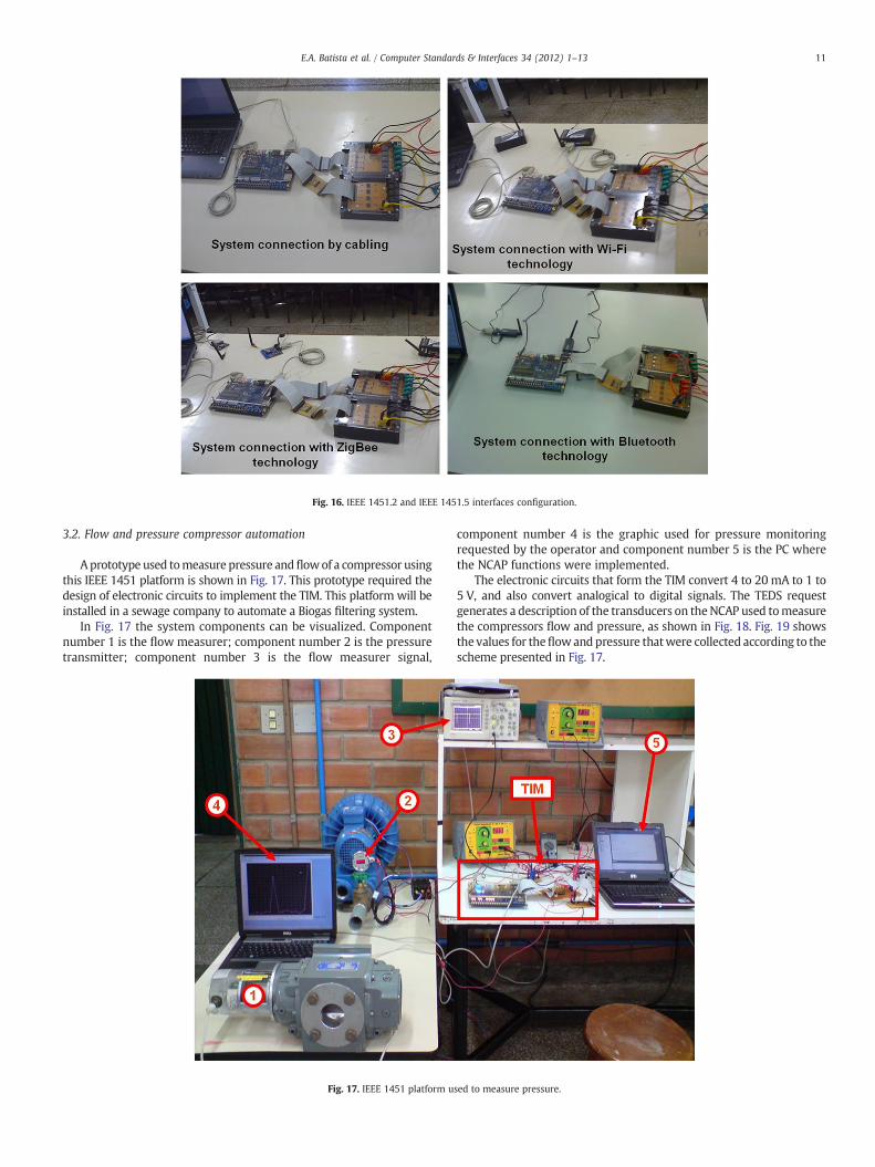
Fig. 16. IEEE 1451.2 and IEEE 1451.5 interfaces configuration.
11E.A. Batista et al. / Computer Standards & Interfaces 34 (2012) 1–13
3.2. Flow and pressure compressor automation
Aprototype used tomeasure pressure andflowof a compressor usingthis IEEE 1451 platform is shown in Fig. 17. This prototype required thedesign of electronic circuits to implement the TIM. This platform will beinstalled in a sewage company to automate a Biogas filtering system.
In Fig. 17 the system components can be visualized. Componentnumber 1 is the flow measurer; component number 2 is the pressuretransmitter; component number 3 is the flow measurer signal,
Fig. 17. IEEE 1451 platform u
component number 4 is the graphic used for pressure monitoringrequested by the operator and component number 5 is the PC wherethe NCAP functions were implemented.
The electronic circuits that form the TIM convert 4 to 20 mA to 1 to5 V, and also convert analogical to digital signals. The TEDS requestgenerates a description of the transducers on theNCAP used tomeasurethe compressors flow and pressure, as shown in Fig. 18. Fig. 19 showsthe values for theflowand pressure thatwere collected according to thescheme presented in Fig. 17.
sed to measure pressure.

Fig. 18. TEDS request results.
12 E.A. Batista et al. / Computer Standards & Interfaces 34 (2012) 1–13
3.3. Analysis of results
The IEEE 1451 platform is formed by the NCAP logic and anembeddedmodule that implements the process automation accordingto the IEEE 1451 standard. The implementation of the embeddedmodule using Quartus II and SOPC Builder makes easier thedevelopment of complex hardware. The insertion of I/O channels inthe embeddedmodule (TIM Driver) is flexible and easily configurable.The resources used from the Cyclone II FPGA to implement the TIMwere relatively low, proving the possibility for this type of devices to beused in control and automation.
The embedded module was formed by a NIOS II processor, toperform tasks like: TEDS implementation, control logic programmingin C/C++, insertion of a RTOS (Real Time Operating System),interrupt handling and RS232 serial interface communication. TheNIOS II processor has resources that provide good performance on
Fig. 19. Real-time
complex activities, making the use of FPGA in industrial applicationsattractive to design an intelligent instrumentation system. Theelectronic instrumentation was developed according to each applica-tion, and is part of the TIM in the general architecture of the IEEE 1451standard. The platform developed here has been used by this researchgroup to automate several different processes, such as home(domotics), greenhouse model and Biogas filtering, and is continuallyupdated and improved [19].
4. Conclusions and future work
The implementation of the IEEE 1451 platform using reconfigurablelogic and Java technology meets fundamental requirements of the IEEE1451 standard. TheNCAP from the implemented IEEE 1451platformhascharacteristics of a SCADAsoftware and thehardware (TIM)withNIOS IIprocessor has the functionalities of a controlmodule. This systemcan beused as basis for automating different processes, either with wired orwireless communication. The TIM is formed by an embedded moduledeveloped using EDA tool, allowing a rapid and flexible prototyping.Specifically for this IEEE 1451 platform, the interfaces IEEE 1451.0, IEEE1451.1, IEEE 1451.2 and IEEE 1451.5 were implemented.
The applicability of the NIOS II processor to form the TIM madepossible a high level logic control development, interruption handlingand the TEDS coding, and in all the cases specific C language functionsand libraries were implemented. The TEDS was coded in NIOS II IDE,and through a request in NCAP, the operator can obtain informationfrom the transducers network. To provide TEDS flexibility, a set ofcodes were created for manufacturers, working range, and transducertype. Later the NCAP decodes this information from the TEDS andmakes it available in a database.
In current version of this platform, the standards IEEE 1451.0, IEEE1451.1 IEEE 1451.2 and IEEE 1451.5 were implemented. For the nextversions also the interfaces IEEE 1451.3 and IEEE 1451.6 will beimplemented. The embeddedmodulewas tested alsowith supervisorysoftware Elipse SCADA, proving TIM flexibility, and for the next test,the communication of this TIM to other supervisory programs will be
collected data.
13E.A. Batista et al. / Computer Standards & Interfaces 34 (2012) 1–13
tested. The resources used to implement the TIM in the Cyclone II FPGAallow the insertion of logic blocks to turn this embeddedmodulemoreapplicable. Thisway, it will be possible to supply for this 1451 platformlibraries to implement control algorithms, such as PID (ProportionalDerivative Integrative), PID Fuzzy, image processing, FFT, Field busprotocols and others. With this platform, this research group intendsto supply aflexible system, formedby attractive technologies and toolsto implement an intelligent transducer network, with a standardizedinterface, according to IEEE 1451 Specifications.
References
[1] E.Y. Song, K. Lee, Understanding IEEE 1451-networked smart transducer interfacestandard — what is a smart transducer? IEEE Instrumentation and MeasurementMagazine 11 (2008) 11–17.
[2] K. Lee, IEEE 1451: a standard in support of smart transducer networking,Proceedings of 17th Instrumentation and Measurement Technology Conference,Vol. 2, IEEE, Baltimore, USA, 2000, pp. 525–528.
[3] NIST, The proposed IEEE 1451.6 standard, http://grouper.ieee.org/groups/1451/62010 accessed in August, 2010.
[4] NIST, Draft standard for a smart transducer interface for sensors and actuators —common functions, communications protocols and transducer electronic datasheets (teds) formats, http://grouper.ieee.org/groups/1451/0 2010 accessed inAugust, 2010.
[5] K. Lee, E.Y. Song, UML model for the IEEE 1451.1 standard, Proceedings of 20thInstrumentation andMeasurement Technology Conference, Vol. 2, IEEE, Vail, USA,2003, pp. 1587–1592.
[6] D. Wobschall, W.S. Port, A smart RTD temperature sensor with a prototype IEEE1451.2 internet interface, Proceedings of Sensors for Industry Conference, IEEE,New Orleans, USA, 2004, pp. 183–186.
[7] L. Bissi, A. Scorzoni, P. Placidi, L. Marrocchi, M. Bennati, S. Zampolli, L. Masini, I.Elmi, G. Cardinali, A low-cost distributedmeasurement system based on gas smartsensors for environmental monitoring, Proceedings of International Conferenceon Sensing Technology, IEEE, Palmerston North, New Zealand, 2005, pp. 301–306.
[8] NIST, P1451.3 working group, http://www.nist.gov/el/isd/ieee/1451group3.cfmAug. 2010 accessed in August, 2010.
[9] E.Y. Song, K. Lee, An implementation of the proposed IEEE 1451.0 and 1451.5standards, Proceedings of Sensor Application Symposium, IEEE, Houston, Texas,USA, 2006, pp. 72–77.
[10] Sensors Portal, IEEE 1451.7 transducers to radio frequency identification (RFID)systems communication protocols and transducer electronic data sheet formats,http://www.sensorsportal.com/HTML/standard_7.htm 2010 accessed in August,2010.
[11] M. Sveda, R. Vrba, Sensor networking, Proceedings of Engineering of ComputerBased Systems, IEEE, Washington D. C., USA, 2001, pp. 262–268.
[12] V. Randal, Software development environment for prototyping ieee 1451 smartsensors, Proceedings of Sensors Applications Symposium, IEEE, San Diego,California, USA, 2007, pp. 1–5.
[13] R.L. Oostdyk, C.T. Mata, J.M. Perotti, A kennedy space center implementation ofieee 1451 networked smart sensors and lessons learned, Proceedings ofAerospace Conference, IEEE, Big Sky, Montana, USA, 2006.
[14] F. Tani, Proposta de desenvolvimento de transdutores inteligentes baseados nanorma IEEE 1451 aplicados a redes LonWorks, Master's thesis, Polytechnic School,University of Sao Paulo, Sao Paulo, Brazil (2007).
[15] S.R. Rossi, E.A. Batista, A.A. de Carvalho, A.C.R. da Silva, C. Kitano, T.A.S. Filho, L.Guardalben, T.A. Prado, R.P. Ferraz, L.A.P. Marçal, Open and standardized toolsfor smart transducer networking, Proceedings of Instrumentation and Measure-ment Technology Conference, Vol. 6, IEEE, Ottawa, Canada, 2005, pp. 1792–1796.
[16] Zigbee Alliance, Zigbee standards overview, http://www.zigbee.org/Standards/Overview.aspx 2010 accessed in December, 2010.
[17] Bluetooth SIG, Bluetooth overview, http://www.bluetooth.org 2010 accessed inDecember, 2010.
[18] Wi-Fi Alliance, Wi-fi articles, http://www.wi-fi.org/knowledge_center_overview.php?type=7 2010 accessed in December, 2010.
[19] E.A. Batista, A.C.R. da Silva, L. Gonda, M.C. Pereira, I. da Silva, W.M. Ferreira, F.D'Elia, IEEE 1451 based multi-interface module (i2m) for industrial automation,Proceedings of Sensors Applications Symposium, IEEE, Atlanta, GA, USA, 2008,pp. 12–14.
Edson A. Batista is an undergraduate of ElectricalEngineering at University of Sao Paulo State (UNESP),Brazil and obtained his Ph.D. degree from University of SaoPaulo State (UNESP) (2009). He is currently a professor atElectrical Engineering Department of UFMS and hisresearch area of interest includes: development of em-bedded systems using FPGA, industrialautomation inaccordance with IEEE 1451 standard and eletronic drivingof electric machinery. He has an experience in applicationsusing FPGA, NIOS IIprocessor, electronic instrumentationand development of monitoring software.
Luciano Gonda received his B.S. and M.S. degrees inComputer Science from Federal University of MatoGrossodo Sul(UFMS), Campo Grande-MS, Brazil, in 1999 and2004, respectively. In 2010, he received his Ph.D. degree inElectrical Engineering from University of Sao Paulo (USP),Sao Paulo, Brazil. He is currently a professor at Collegeof Computing in UFMS. His research interests includeWireless Sensor Networks, Parallel Algorithms and Dis-tributed Systems.
Alexandre C. R. da Silva received the degree in ElectricalEngineering from the University ofMogi das Cruzes (UMC),Brazil, in 1984, and the M.Sc. and Ph.D. degrees in ElectricalEngineering from the University of Campinas (UNICAMP),Brazil, in 1989 and 2003, respectively. In 2003, he receivedthe degree of Free Lecture from the University of São PauloState (UNESP) and in 2007 developed a post-graduatestage at University of Limerick, Ireland. He is currentlyinvolved with synthesis tools for mixed-signal circuits,embedded systems and IEEE 1451 Standard applications.He is an Associate Professor and researcher within theDepartment of Electrical Engineering of the College ofEngineering (FEIS) at the University of São Paulo State(UNESP). His research interests include analysis andsynthesis of mixed-signal circuits, embedded systems,smart transducer networks, hardware description lan-guages and Petri Net.
Silvano R. Rossi received the B.Sc. in Electro-MechanicalEngineering from the Center of Buenos Aires ProvinceNational University (UNCPBA), Argentine, in 1999, and thePh.D. degree in Electrical Engineering from the Universityof São Paulo State (UNESP), Brazil, in 2005. He is currentlyinvolved with instrumentation systems and IEEE 1451Standard applications. He is a professor at the Departmentof Electro-Mechanical Engineering in the Center of BuenosAires Province National University, and researcher memberof the INTELYMEC group in the same university. Hisresearch interests include instrumentation systems andmeasurements, smart transducer networks, autonomousvehicles and digital systems.
Aparecido A. de Carvalho was born in Bebedouro, SP,Brazil. He received the B.Sc. in Electrical Engineering in1976 from the University of São Paulo, the M.Sc. degree inBiomedical Engineering in 1979 from the Federal Uni-versity of Rio deJaneiro, and the Ph.D. in Applied Physicsfrom the University of São Paulo (USP). In 1993 and 1994he was an honorary fellow at the Department of Computerand Electrical Engineering of the University of Wisconsin-Madison, granted by FAPESP (Brazil). He is now a professorat the São Paulo State University (UNESP), Campus of IlhaSolteira, Brazil. His research interests include sensors andelectronic instrumentation.
Carlos E. Cugnasca received his B.S., M.S., and Ph.D.degrees in electrical engineering from the University ofSão Paulo (USP), São Paulo, Brazil, in 1980, 1988, and 1992,respectively. In October 2002, he received his habilitationdegree ("Livre-Docência") from USP. He is currently anAssociate Professor at the Computing Engineering andDigital Systems Department of Escola Politécnica, Univer-sity of São Paulo. He has been a researcher at theAgricultural Automation Laboratory, USP, São Paulo, Brazil,since 1989. He is the editor-in-chief of "Revista Brasileirade Agroinformática", Journal of the Brazilian Society ofAgroinformatics, and a member of ISOBUS Brazilian TaskForce. His research interests include network control,wireless sensor networks, pervasive computing, environ-ment monitoring, and agricultural automation. He hasauthored/coauthored over 200 publications in these areas.