HT21RT PRO SW - Haulotte
214
Training manual HT21RT O - HT21RT O SW - HT61RT O - HT21 RT PRO - HT21RT PRO SW - HT61RT PRO - HT23RTJ O - HT23RTJ O SW - HT67RTJ O - HT23RTJ PRO - HT23RTJ PRO SW - HT67RTJ PRO 4000595930 E 10.16 USA / GB Training manual HT21RT O - HT21RT O SW - HT61RT O - HT21 RT PRO - HT21RT PRO SW - HT61RT PRO - HT23RTJ O - HT23RTJ O SW - HT67RTJ O - HT23RTJ PRO - HT23RTJ PRO SW - HT67RTJ PRO
-
Upload
khangminh22 -
Category
Documents
-
view
4 -
download
0
Transcript of HT21RT PRO SW - Haulotte

Training manual
HT2
1RT
O -
HT2
1RT
O S
W -
HT6
1RT
O -
HT2
1 R
T P
RO
- H
T21R
T P
RO
SW
- H
T61R
T P
RO
- H
T23R
TJ O
- H
T23R
TJ O
SW
- H
T67R
TJ O
- H
T23R
TJ P
RO
- H
T23R
TJ P
RO
SW
- H
T67R
TJ P
RO
4000595930 E 10.16 USA / GB
Training manual
HT21RT O - HT21RT O SW - HT61RT O - HT21 RT PRO - HT21RT PRO SW - HT61RT
PRO - HT23RTJ O - HT23RTJ O SW - HT67RTJ O - HT23RTJ PRO - HT23RTJ
PRO SW - HT67RTJ PRO

2 4000595930 E 10.16 USA / GB
HT21RT O - HT21RT O SW - HT61RT O - HT21 RT PRO - HT21RT PRO SW - HT61RT PRO - HT23RTJ O - HT23RTJ O SW - HT67RTJ O - HT23RTJ PRO - HT23RTJ PRO SW - HT67RTJ PRO
USA

3
CONT
ENTS
Training manual
CONTENTS
AFOREWORD1 - Revision. . . . . . . . . . . . . . . . . . . . . . . . . . . . . . . .8
BMAIN FEATURES AND FUNCTIONS1 - Models description. . . . . . . . . . . . . . . . . . . . . . .92 - Primary machine components . . . . . . . . . . . . 10
2.1 - Working area / Range of motion . . . . . . . . . . . . . . . . . . . . . . . . . . . . . . . . 10 2.2 - Transportation . . . . . . . . . . . . . . . . . . . . . . . . . . . . . . . . . . . . . . . . . . . . . . . . 12 2.2.1 - Machine layout . . . . . . . . . . . . . . . . . . . . . . . . . . . . . . . . . . . . . . 12 2.3 - Ground control box . . . . . . . . . . . . . . . . . . . . . . . . . . . . . . . . . . . . . . . . . . . . 14 2.3.1 - Layout . . . . . . . . . . . . . . . . . . . . . . . . . . . . . . . . . . . . . . . . . . . . 14 2.3.2 - HAULOTTE Activ'Screen 2 . . . . . . . . . . . . . . . . . . . . . . . . . . . . 17 2.4 - Platform control box . . . . . . . . . . . . . . . . . . . . . . . . . . . . . . . . . . . . . . . . . . . 27 2.4.1 - Layout . . . . . . . . . . . . . . . . . . . . . . . . . . . . . . . . . . . . . . . . . . . . 27 2.4.2 - Display Panel (LED'S 101 - 117). . . . . . . . . . . . . . . . . . . . . . . . 29
CSTUDY OF THE ELECTRIC SCHEMATICS1 - System architecture . . . . . . . . . . . . . . . . . . . . . 33
1.1 - The ECU modules. . . . . . . . . . . . . . . . . . . . . . . . . . . . . . . . . . . . . . . . . . . . 34 1.1.1 - U106 SPU 7066 . . . . . . . . . . . . . . . . . . . . . . . . . . . . . . . . . . . . . 34 1.1.2 - U104 node B2 slave. . . . . . . . . . . . . . . . . . . . . . . . . . . . . . . . . 43 1.1.3 - EGV Kubota module . . . . . . . . . . . . . . . . . . . . . . . . . . . . . . . . . 44 1.1.4 - Printed circuit board . . . . . . . . . . . . . . . . . . . . . . . . . . . . . . . . . . 45

4
Training manual
2 - List of actuators and sensors . . . . . . . . . . . . . 48
2.1 - Sensors and actuators. . . . . . . . . . . . . . . . . . . . . . . . . . . . . . . . . . . . . . . . . 48 2.2 - Sensors detail. . . . . . . . . . . . . . . . . . . . . . . . . . . . . . . . . . . . . . . . . . . . . . . . . 50 2.3 - Actuators and their location. . . . . . . . . . . . . . . . . . . . . . . . . . . . . . . . . . . . . 59 2.3.1 - List of actuators . . . . . . . . . . . . . . . . . . . . . . . . . . . . . . . . . . . . . 59 2.3.2 - Modules . . . . . . . . . . . . . . . . . . . . . . . . . . . . . . . . . . . . . . . . . . . 59 2.3.3 - Fuses . . . . . . . . . . . . . . . . . . . . . . . . . . . . . . . . . . . . . . . . . . . . . 60 2.3.4 - Inputs . . . . . . . . . . . . . . . . . . . . . . . . . . . . . . . . . . . . . . . . . . . . . 61 2.3.5 - Outputs . . . . . . . . . . . . . . . . . . . . . . . . . . . . . . . . . . . . . . . . . . . 63 2.4 - The working zone control. . . . . . . . . . . . . . . . . . . . . . . . . . . . . . . . . . . . . . . 66 2.4.1 - Machine positions. . . . . . . . . . . . . . . . . . . . . . . . . . . . . . . . . . . . 66 2.5 - Cut out conditions of every function. . . . . . . . . . . . . . . . . . . . . . . . . . . . . . 77 2.5.1 - Glossary . . . . . . . . . . . . . . . . . . . . . . . . . . . . . . . . . . . . . . . . . . . 77 2.5.2 - Power supply/commands . . . . . . . . . . . . . . . . . . . . . . . . . . . . . . .81 2.5.3 - Drive . . . . . . . . . . . . . . . . . . . . . . . . . . . . . . . . . . . . . . . . . . . . . . .83 2.5.3.1 - Validation . . . . . . . . . . . . . . . . . . . . . . . . . . . . . . . . . . . . . . . . . . 83 2.5.3.2 - Actuators . . . . . . . . . . . . . . . . . . . . . . . . . . . . . . . . . . . . . . . . . . 86 2.5.4 - Steering . . . . . . . . . . . . . . . . . . . . . . . . . . . . . . . . . . . . . . . . . . . .87 2.5.4.1 - Validation . . . . . . . . . . . . . . . . . . . . . . . . . . . . . . . . . . . . . . . . . . 87 2.5.4.2 - Actuators . . . . . . . . . . . . . . . . . . . . . . . . . . . . . . . . . . . . . . . . . . 89 2.5.5 - Orientation . . . . . . . . . . . . . . . . . . . . . . . . . . . . . . . . . . . . . . . . . .90 2.5.5.1 - Validation . . . . . . . . . . . . . . . . . . . . . . . . . . . . . . . . . . . . . . . . . . 90 2.5.5.2 - Actuators . . . . . . . . . . . . . . . . . . . . . . . . . . . . . . . . . . . . . . . . . . 93 2.5.6 - Boom . . . . . . . . . . . . . . . . . . . . . . . . . . . . . . . . . . . . . . . . . . . . . .94 2.5.6.1 - Validation . . . . . . . . . . . . . . . . . . . . . . . . . . . . . . . . . . . . . . . . . . 94 2.5.6.2 - Actuators . . . . . . . . . . . . . . . . . . . . . . . . . . . . . . . . . . . . . . . . . . 97 2.5.7 - Telescope. . . . . . . . . . . . . . . . . . . . . . . . . . . . . . . . . . . . . . . . . . .98 2.5.7.1 - Validation . . . . . . . . . . . . . . . . . . . . . . . . . . . . . . . . . . . . . . . . . . 98 2.5.7.2 - Actuators . . . . . . . . . . . . . . . . . . . . . . . . . . . . . . . . . . . . . . . . . 101 2.5.8 - Jib. . . . . . . . . . . . . . . . . . . . . . . . . . . . . . . . . . . . . . . . . . . . . . . .102 2.5.8.1 - Validation . . . . . . . . . . . . . . . . . . . . . . . . . . . . . . . . . . . . . . . . . 102 2.5.8.2 - Actuators . . . . . . . . . . . . . . . . . . . . . . . . . . . . . . . . . . . . . . . . . 105 2.5.9 - Basket rotation . . . . . . . . . . . . . . . . . . . . . . . . . . . . . . . . . . . . . .106 2.5.9.1 - Validation . . . . . . . . . . . . . . . . . . . . . . . . . . . . . . . . . . . . . . . . . 106 2.5.9.2 - Actuators . . . . . . . . . . . . . . . . . . . . . . . . . . . . . . . . . . . . . . . . . 108 2.5.10 - Basket compensation . . . . . . . . . . . . . . . . . . . . . . . . . . . . . . . . .109 2.5.10.1 - Validation . . . . . . . . . . . . . . . . . . . . . . . . . . . . . . . . . . . . . . . . . 109 2.5.10.2 - Actuators . . . . . . . . . . . . . . . . . . . . . . . . . . . . . . . . . . . . . . . . . 111 2.5.11 - Brake release . . . . . . . . . . . . . . . . . . . . . . . . . . . . . . . . . . . . . . .112 2.5.11.1 - Validation . . . . . . . . . . . . . . . . . . . . . . . . . . . . . . . . . . . . . . . . . 112 2.5.11.2 - Actuators . . . . . . . . . . . . . . . . . . . . . . . . . . . . . . . . . . . . . . . . . 113 2.5.12 - Oscillating axles . . . . . . . . . . . . . . . . . . . . . . . . . . . . . . . . . . . . .114 2.5.12.1 - Validation . . . . . . . . . . . . . . . . . . . . . . . . . . . . . . . . . . . . . . . . . 114 2.5.12.2 - Actuators . . . . . . . . . . . . . . . . . . . . . . . . . . . . . . . . . . . . . . . . . 115 2.5.13 - Activ' Shield Bar . . . . . . . . . . . . . . . . . . . . . . . . . . . . . . . . . . . . .116 2.5.13.1 - Activ' Shield Bar - SECONDARY GUARDING SYSTEM . . . . 116

5
CONT
ENTS
Training manual
DSTUDY OF THE HYDRAULIC SCHEMA1 - Hydraulic units . . . . . . . . . . . . . . . . . . . . . . . . 117
1.1 - General overview . . . . . . . . . . . . . . . . . . . . . . . . . . . . . . . . . . . . . . . . . . . . 117 1.2 - EDC block . . . . . . . . . . . . . . . . . . . . . . . . . . . . . . . . . . . . . . . . . . . . . . . . . . 118 1.3 - ON/OFF block. . . . . . . . . . . . . . . . . . . . . . . . . . . . . . . . . . . . . . . . . . . . . . . 119 1.4 - Drive block. . . . . . . . . . . . . . . . . . . . . . . . . . . . . . . . . . . . . . . . . . . . . . . . . . . 121 1.5 - Steering block 2WS. . . . . . . . . . . . . . . . . . . . . . . . . . . . . . . . . . . . . . . . . . 124 1.6 - Steering block 4WS. . . . . . . . . . . . . . . . . . . . . . . . . . . . . . . . . . . . . . . . . . 125
EADJUSTMENTS1 - Adjustments . . . . . . . . . . . . . . . . . . . . . . . . . . 127
1.1 - Activ screen. . . . . . . . . . . . . . . . . . . . . . . . . . . . . . . . . . . . . . . . . . . . . . . . . . 127 1.2 - Access to advanced menus. . . . . . . . . . . . . . . . . . . . . . . . . . . . . . . . . . . 131 1.3 - Console diag. . . . . . . . . . . . . . . . . . . . . . . . . . . . . . . . . . . . . . . . . . . . . . . . . 132
2 - List of menus . . . . . . . . . . . . . . . . . . . . . . . . . 133
2.1 - Machine settings . . . . . . . . . . . . . . . . . . . . . . . . . . . . . . . . . . . . . . . . . . . . . 133 2.1.1 - Speeds and ramps . . . . . . . . . . . . . . . . . . . . . . . . . . . . . . . . . . 133 2.1.2 - Options. . . . . . . . . . . . . . . . . . . . . . . . . . . . . . . . . . . . . . . . . . . 133 2.1.3 - Configurations . . . . . . . . . . . . . . . . . . . . . . . . . . . . . . . . . . . . . 133 2.1.4 - Securities . . . . . . . . . . . . . . . . . . . . . . . . . . . . . . . . . . . . . . . . . 133 2.2 - Diagnostic . . . . . . . . . . . . . . . . . . . . . . . . . . . . . . . . . . . . . . . . . . . . . . . . . . . 133 2.2.1 - Inputs/Outputs . . . . . . . . . . . . . . . . . . . . . . . . . . . . . . . . . . . . . 133 2.2.2 - States . . . . . . . . . . . . . . . . . . . . . . . . . . . . . . . . . . . . . . . . . . . . 133
3 - Failures list . . . . . . . . . . . . . . . . . . . . . . . . . . . 134
3.1 - List of failures per category . . . . . . . . . . . . . . . . . . . . . . . . . . . . . . . . . . . . 135
4 - Load management system . . . . . . . . . . . . . . 148
4.1 - Offset calibration. . . . . . . . . . . . . . . . . . . . . . . . . . . . . . . . . . . . . . . . . . . . . . 148 4.2 - Gain of load management system with fixed weight. . . . . . . . . . . . . . 149 4.3 - Gain of load management system with adjustable weight . . . . . . . . 150
5 - Adjustment of pressures . . . . . . . . . . . . . . . . 151
5.1 - Port plug for pressures control . . . . . . . . . . . . . . . . . . . . . . . . . . . . . . . . . 151 5.2 - Pressure adjustments on pump. . . . . . . . . . . . . . . . . . . . . . . . . . . . . . . . 152

6
Training manual
FSIMPLIFIED BREAKDOWN GUIDE1 - Quick checkings on drive . . . . . . . . . . . . . . . 153
2 - Quick checkings on movements. . . . . . . . . . 154
3 - Quick checkings on engine . . . . . . . . . . . . . . 155
4 - No engine start . . . . . . . . . . . . . . . . . . . . . . . . 157
5 - No movement . . . . . . . . . . . . . . . . . . . . . . . . . 157
6 - No boom . . . . . . . . . . . . . . . . . . . . . . . . . . . . . 157
7 - No telescopic boom . . . . . . . . . . . . . . . . . . . . 158
8 - No turret rotation . . . . . . . . . . . . . . . . . . . . . . 158
9 - No jib . . . . . . . . . . . . . . . . . . . . . . . . . . . . . . . . 158
10 - No basket rotation . . . . . . . . . . . . . . . . . . . . 158
11 - No basket compensation . . . . . . . . . . . . . . . 158
12 - No drive . . . . . . . . . . . . . . . . . . . . . . . . . . . . . 159
13 - Low speed only. . . . . . . . . . . . . . . . . . . . . . . 159
14 - No steering . . . . . . . . . . . . . . . . . . . . . . . . . . 159
15 - No oscillating axle . . . . . . . . . . . . . . . . . . . . 159
GVERSION SUMMARY1 - Version summary . . . . . . . . . . . . . . . . . . . . . . 161
2 - List of schematics . . . . . . . . . . . . . . . . . . . . . 161
3 - List of wiring harnesses . . . . . . . . . . . . . . . . 161

A
B
C
D
E
F
G
H
I
7 4000595930 E 10.16 USA / GB
HT21RT O - HT21RT O SW - HT61RT O - HT21 RT PRO - HT21RT PRO SW - HT61RT PRO - HT23RTJ O - HT23RTJ O SW - HT67RTJ O - HT23RTJ PRO - HT23RTJ PRO SW - HT67RTJ PRO
A- Foreword
Foreword
You are in possession of the summary document provided during the HAULOTTE® technical trainingprogramme. It will allow you to find the information necessary for performing maintenance and repairs onyour HAULOTTE® machine.
The following guide will help you to rapidly access the required chapter.
Section A : Foreword
You will find there the elements as following :
• A resume of any update made since the creation of the manual.
Section B : Main characteristics and functions
You will find there the elements as following :
• The list of the models.
• Their main datas.
• Their overall dimensions.
• Their working envelop.
• Controls boxes.
• Some maintenance topics on specific components (charger, engine ..).
Section C : Study of the wiring diagram
It will include the following elements: :
• Structure of the system.
• Localization/photo of each safety components.
• The location/function of each component in schematics.
• Cut out conditions of every function.
Section D : Study of the hydraulic diagram
It will include the following elements: :
• The localization of every manifolds.
• The location/function of each component on block.
How to use this document ?
MAINTENANCE AND REPAIR OPERATIONS ON YOUR HAULOTTE® MACHINE MAY ONLY BE PERFORMED BY TRAINED AND EXPERIENCED TECHNICIANS

8 4000595930 E 10.16 USA / GB
HT21RT O - HT21RT O SW - HT61RT O - HT21 RT PRO - HT21RT PRO SW - HT61RT PRO - HT23RTJ O - HT23RTJ O SW - HT67RTJ O - HT23RTJ PRO - HT23RTJ PRO SW - HT67RTJ PRO
A- Foreword
Section E : The adjustments
It will include the following elements: :
• The way to use/connect the console of diagnostic.
• The list of main menus and its architecture.
• The list of alarms with their explanation.
• Any calibration/settings required for the model of the machine.
• The way to check/adjust the pressures for the model.
Section F : Repair guide
It will include the following elements: :
• A summary of every function and items to be checked in case of breakdowns.
Section G : Summary of the versions
It will include the following elements: :
• A summary of the different versions made per model.
• Any schematics (electric /hydraulic) linked to the models studied.
• Coloured schematics (electric/hydraulic) per function.
• List of main harnesses in the models studied.
1 - Revision
REVISION EDITION SUBJECTCREATED
BYVALIDATED
BYMODIFIED
BYTRANSLATED
BYLANGUAGE
00 10.16 Creation ASA MGD ASA ITC USA / GB
A
B
C
D
E
F
G
H
I
9 4000595930 E 10.16 USA / GB
HT21RT O - HT21RT O SW - HT61RT O - HT21 RT PRO - HT21RT PRO SW - HT61RT PRO - HT23RTJ O - HT23RTJ O SW - HT67RTJ O - HT23RTJ PRO - HT23RTJ PRO SW - HT67RTJ PRO
B- Main features and functions
Main features and functions1 - Models description
REGULATION MODELS
ANSI and CSA standards
HT61 RT O
HT61 RT PRO
HT67 RTJ O
HT67 RTJ PRO
CE, AS and EAC standards
HT 21 RT O
HT 21 RT PRO
HT 21 O SW
HT 21 RT PRO SW
HT23 RTJ O
HT23 RTJ PRO
HT23 RTJ O SW
HT23 RTJ PRO SW
10 4000595930 E 10.16 USA / GB
HT21RT O - HT21RT O SW - HT61RT O - HT21 RT PRO - HT21RT PRO SW - HT61RT PRO - HT23RTJ O - HT23RTJ O SW - HT67RTJ O - HT23RTJ PRO - HT23RTJ PRO SW - HT67RTJ PRO
B- Main features and functions
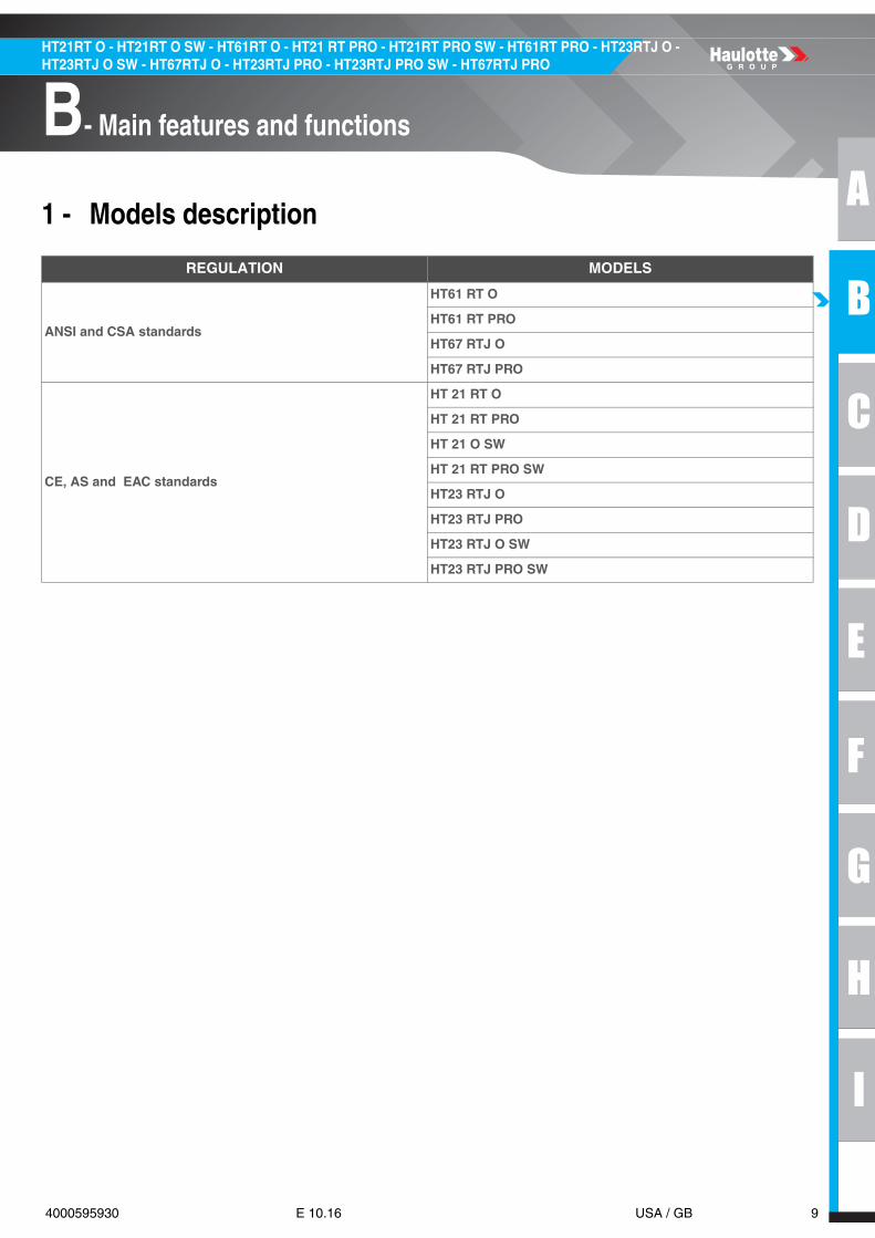
2 - Primary machine components
2.1 - WORKING AREA / RANGE OF MOTION
HT21RT O - HT21RT O SW - HT61RT O - HT21RT PRO - HT21RT PRO SW - HT61RT PRO
230 Kg
500 lbs
450 Kg
1000 lbs
ft in
m
-6ft 6in
-6ft 6in
0
0 6ft 6in 13ft 10in 19ft 8in 26ft 2in 32ft 9in 39ft 4in 45ft 11in 52ft 5in 59ft 67ft 5 in
6ft 6in
13ft 10in
19ft 8in
26ft 2in
32ft 9in
39ft 4in
45ft 11in
52ft 5in
59ft
67ft 5 in
72ft 2in22
20
18
16
14
12
10
8
6
4
2
0
0-2 2 4 6 8 10 12 14 16 18
-2
-4

A
B
C
D
E
F
G
H
I
11 4000595930 E 10.16 USA / GB
HT21RT O - HT21RT O SW - HT61RT O - HT21 RT PRO - HT21RT PRO SW - HT61RT PRO - HT23RTJ O - HT23RTJ O SW - HT67RTJ O - HT23RTJ PRO - HT23RTJ PRO SW - HT67RTJ PRO
B- Main features and functions
HT23RTJ O - HT23RTJ O SW - HT67RTJ O - HT23RTJ PRO - HT23RTJ PRO SW - HT67RTJ PRO
230 Kg
500 lbs
450 Kg
1000 lbs
ft in-6ft 6in
-6ft 6in
0
0 6ft 6in 13ft 10in 19ft 8in 26ft 2in 32ft 9in 39ft 4in 45ft 11in 52ft 5in 59ft 65ft 7 in
6ft 6in
13ft 10in
-13ft 10in
19ft 8in
26ft 2in
32ft 9in
39ft 4in
45ft 11in
52ft 5in
59ft
67ft 5 in
72ft 2in22
20
18
16
14
12
10
8
6
4
2
0
0-2 2 4 6 8 10 12 14 16 18 20
-2
-4
m
m
12 4000595930 E 10.16 USA / GB
HT21RT O - HT21RT O SW - HT61RT O - HT21 RT PRO - HT21RT PRO SW - HT61RT PRO - HT23RTJ O - HT23RTJ O SW - HT67RTJ O - HT23RTJ PRO - HT23RTJ PRO SW - HT67RTJ PRO
B- Main features and functions
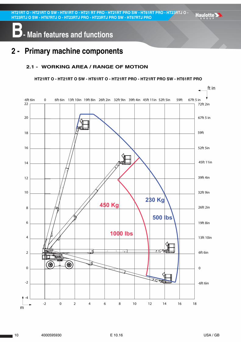
2.2 - TRANSPORTATION
2.2.1 - Machine layout
Machine stowing
N.B.-:-SECURE TURNTABLE WITH THE TURNTABLE LOCKING PIN BEFORE TRAVELING LONG DISTANCES ORHAULING MACHINE ON A TRUCK.
AVANTFRONT
ARRIEREREAR
A
B
C
D
E
F
G
H
I
13 4000595930 E 10.16 USA / GB
HT21RT O - HT21RT O SW - HT61RT O - HT21 RT PRO - HT21RT PRO SW - HT61RT PRO - HT23RTJ O - HT23RTJ O SW - HT67RTJ O - HT23RTJ PRO - HT23RTJ PRO SW - HT67RTJ PRO
B- Main features and functions
Notes
14 4000595930 E 10.16 USA / GB
HT21RT O - HT21RT O SW - HT61RT O - HT21 RT PRO - HT21RT PRO SW - HT61RT PRO - HT23RTJ O - HT23RTJ O SW - HT67RTJ O - HT23RTJ PRO - HT23RTJ PRO SW - HT67RTJ PRO
B- Main features and functions
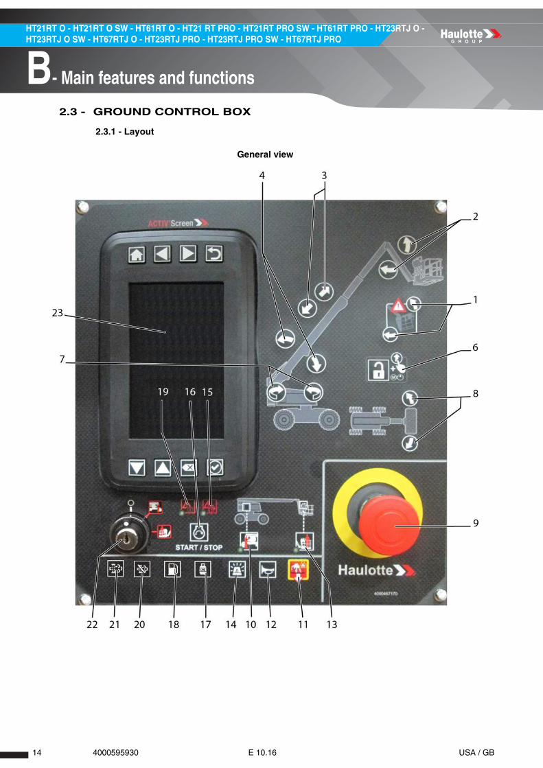
2.3 - GROUND CONTROL BOX
2.3.1 - Layout
General view
A
B
C
D
E
F
G
H
I
15 4000595930 E 10.16 USA / GB
HT21RT O - HT21RT O SW - HT61RT O - HT21 RT PRO - HT21RT PRO SW - HT61RT PRO - HT23RTJ O - HT23RTJ O SW - HT67RTJ O - HT23RTJ PRO - HT23RTJ PRO SW - HT67RTJ PRO
B- Main features and functions
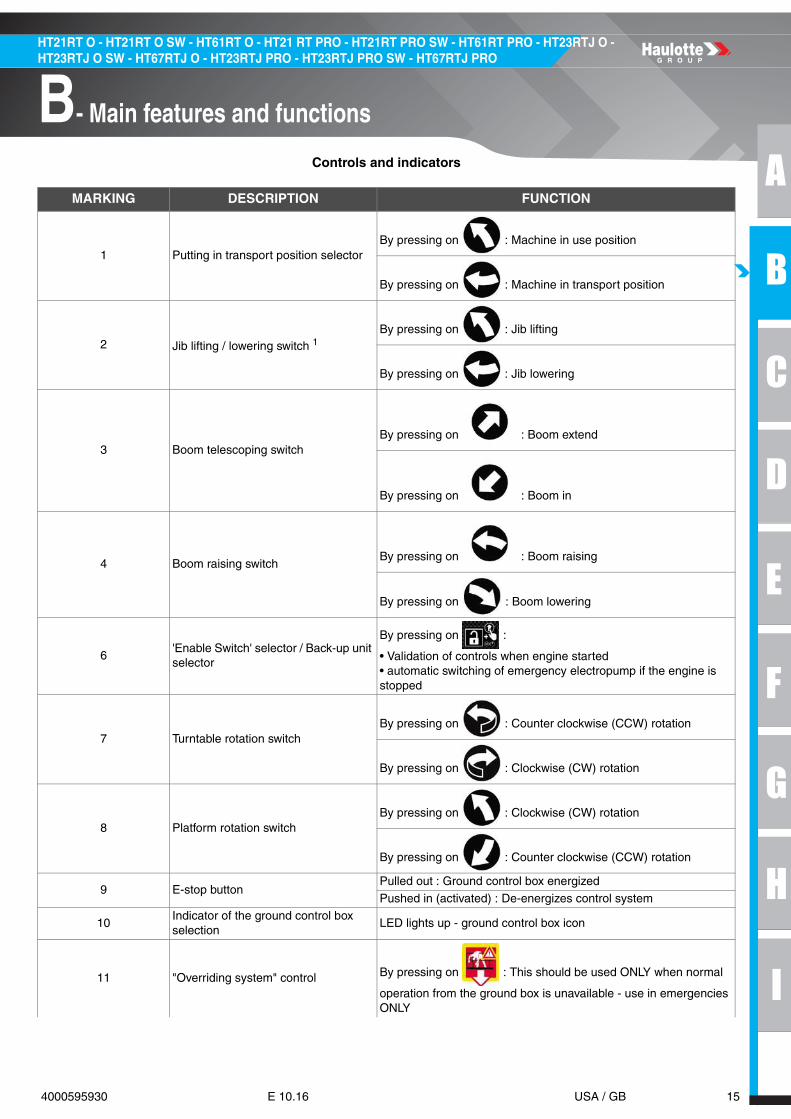
Controls and indicators
MARKING DESCRIPTION FUNCTION
1 Putting in transport position selectorBy pressing on : Machine in use position
By pressing on : Machine in transport position
2 Jib lifting / lowering switch 1By pressing on : Jib lifting
By pressing on : Jib lowering
3 Boom telescoping switchBy pressing on : Boom extend
By pressing on : Boom in
4 Boom raising switchBy pressing on : Boom raising
By pressing on : Boom lowering
6'Enable Switch' selector / Back-up unit selector
By pressing on :
• Validation of controls when engine started• automatic switching of emergency electropump if the engine is stopped
7 Turntable rotation switchBy pressing on : Counter clockwise (CCW) rotation
By pressing on : Clockwise (CW) rotation
8 Platform rotation switchBy pressing on : Clockwise (CW) rotation
By pressing on : Counter clockwise (CCW) rotation
9 E-stop buttonPulled out : Ground control box energized
Pushed in (activated) : De-energizes control system
10Indicator of the ground control box selection
LED lights up - ground control box icon
11 "Overriding system" control By pressing on : This should be used ONLY when normal
operation from the ground box is unavailable - use in emergencies ONLY

16 4000595930 E 10.16 USA / GB
HT21RT O - HT21RT O SW - HT61RT O - HT21 RT PRO - HT21RT PRO SW - HT61RT PRO - HT23RTJ O - HT23RTJ O SW - HT67RTJ O - HT23RTJ PRO - HT23RTJ PRO SW - HT67RTJ PRO
B- Main features and functions
12 Horn button By pressing on : Horn activation
13Indicator of the platform control box selection
LED lights up - platform control box icon
14 Beacon light on/off By pressing on : Beacon light ON / OFF
15 Overload indicator / Fault
Alarm icon :
Is ON at power up of the machine, at the same time as the icon ( 19 )Is blinking if overriding is active Alarm icon is ON if : An active or detected failure is displayed on on-board screenOr Hydraulic oil temperature icon is active on on-board screenOr Engine pressure icon is active on on-board screenOr Engine stop icon is active on on-board screenOr Overload machine status is active on on-board screen
16 Engine start-up selector By pressing on : Engine start / stop
17 Propane Gas supply2By pressing on : Propane Gas supply selection
18 Petrol/Gasoline or diesel supply3By pressing on : Fuel supply selection
19Engine warning indicator / Engine pre-heating
Alarm icon :
• Is ON at power up of the machine at the same time as the icon ( 15 )Is blinking if overriding is active Warning icon is ON if : • Engine warning icon is active on on-board screen• Or Tilt machine status is active on on-board screen• Or Engine is pre-heating
20 DPF regeneration inhibited4By pressing on : Refusal of the request for regeneration
21 DPF regeneration required5By pressing on : Regeneration start-up
22 Control box activation key selector
: De-energizes control system
: Platform control box energized
: Ground control box energized
23 Activ'Screen 2
1. For machines fitted with2. For machines fitted with3. For machines fitted with4. For machines fitted with5. For machines fitted with
MARKING DESCRIPTION FUNCTION

A
B
C
D
E
F
G
H
I
17 4000595930 E 10.16 USA / GB
HT21RT O - HT21RT O SW - HT61RT O - HT21 RT PRO - HT21RT PRO SW - HT61RT PRO - HT23RTJ O - HT23RTJ O SW - HT67RTJ O - HT23RTJ PRO - HT23RTJ PRO SW - HT67RTJ PRO
B- Main features and functions
2.3.2 - HAULOTTE Activ'Screen 2
Upon starting and during operation of the machine, the LCD screen "Activ'Screen" located on theground control box displays in real time the machine operating status.
Controls and indicators
ICON DESCRIPTION FUNCTION
Machine power up (Start-up screen)
Navigation buttons - Above Activ'Screen display
Home Button Allows return to the home screen at any time
Left navigation Permits navigation to screens to the left (if present)
Right NavigationPermits navigation to screens to the right of the current screen (if present )
Back button Returns the user to the previous screen

18 4000595930 E 10.16 USA / GB
HT21RT O - HT21RT O SW - HT61RT O - HT21 RT PRO - HT21RT PRO SW - HT61RT PRO - HT23RTJ O - HT23RTJ O SW - HT67RTJ O - HT23RTJ PRO - HT23RTJ PRO SW - HT67RTJ PRO
B- Main features and functions
Navigation buttons - Below Activ'Screen display
Up Navigation Permits scrolling up through the screen (if present)
Down NavigationPermits allows scrolling down through the screen and onto the following screen (if present)
Cancel Button Used to refuse or cancel a selection within the menu
Validation Button Used to confirm selection within the menus
Home screen (dashboard)(Will be visible - depending on the machine)
ICON DESCRIPTION FUNCTION

A
B
C
D
E
F
G
H
I
19 4000595930 E 10.16 USA / GB
HT21RT O - HT21RT O SW - HT61RT O - HT21 RT PRO - HT21RT PRO SW - HT61RT PRO - HT23RTJ O - HT23RTJ O SW - HT67RTJ O - HT23RTJ PRO - HT23RTJ PRO SW - HT67RTJ PRO
B- Main features and functions
Icons top of display (All alert icons will be blinking if the machine configuration is not set)
Battery State
• Icon is ON if there is no charge output detected from the alternator• Icon is flashing if a failure code for the alternator is detected (code F09.10)
Hydraulic oil temperatureIcon is ON when the temperature in the hydraulic reservoir has exceeded the maximum required temperature. Stop using the machine and allow the oil to cool down.
Engine oil pressureIcon is ON if engine oil pressure is lower than required limit while engine is running. The Engine must be switched OFF immediately to avoid damaging the motor.
Engine warning• Icon is ON if Engine warning is detected. Or one of the engine maintenance schedules has been exceeded.
Stop motor
• Icon is ON if an engine failure is detected (coolant, pressure, alternator etc)• Or if the Engine shuts down after 3 seconds of running. • Or after 1 second when engine fails to start.
Displays at machine startup for 5 seconds and displays when the next maintenance has to be done. Maintenance Tool icon blinks; if maintenance is due. Alternatively, also displays the hours in RED if next scheduled maintenance is to be done within 25 hours.
Hourmeter
• Flashes when the engine is running and the hourmeter increments. • Alternatively, also displays the hours in RED if next scheduled maintenance is to be done within 25 hours.
Displays Machine Model Number(Will be visible - depending on the machine)
ICON DESCRIPTION FUNCTION

20 4000595930 E 10.16 USA / GB
HT21RT O - HT21RT O SW - HT61RT O - HT21 RT PRO - HT21RT PRO SW - HT61RT PRO - HT23RTJ O - HT23RTJ O SW - HT67RTJ O - HT23RTJ PRO - HT23RTJ PRO SW - HT67RTJ PRO
B- Main features and functions
Beacon option Icon is illuminated when the Beacon function is activated
Bar graphs
Fuel level indicator (ON/OFF)The indicator changes from GREEN to RED when the fuel level is low and indicator is activated
Charge BatteryDisplays the machine battery voltage. Indicator will display in RED if voltage is lower than 10V.
Engine Speed (rpm) Displays the Engine speed from 0 to 3250 RPM
Temperature motorDisplays Engine coolant temperature. Display's engine coolant temperature. Indicator changes from GREEN to RED when the engine is overheating (coolant temperature is higher than 110° C)
Displays machine Information(Will be visible - depending on the machine)
Displays the applicable number & software version installed. Also, displays the date & hour within the engine ECU
Icons - Central zone of display
ReadyMachine ready, displayed when no failures and no other machine state icons is active
Alarm
Alarm icon is flashing slowly If there is either an active or detected machine failure, or if the machine is in an overload or tilt is active. When the Alarm symbol is displayed, there will also be a symbol displayed to show tither the type of machine state, or machine failure that corresponds.
ICON DESCRIPTION FUNCTION

A
B
C
D
E
F
G
H
I
21 4000595930 E 10.16 USA / GB
HT21RT O - HT21RT O SW - HT61RT O - HT21 RT PRO - HT21RT PRO SW - HT61RT PRO - HT23RTJ O - HT23RTJ O SW - HT67RTJ O - HT23RTJ PRO - HT23RTJ PRO SW - HT67RTJ PRO
B- Main features and functions
Platform control selected Selector switch is in platform control box position
Ground control elected Selector switch is in ground control box position
Machine status Icons
Pre-heatingEngine’s automatic preheat system is active. The time to pre-heat will vary according to engine and ambient temperature. Wait before starting the machine
Tilt(Will be visible - depending on the machine)
The machine is elevated , and is on a slope greater than the permitted slope. Depending on the machine configuration, machine raise and extend functions may be slowed or prevented.
OverloadThe platform is overloaded. Remove the excessive load to or below the rated capacity, to restore functions. In case of an emergency, to rescue the operator in platform, use the Overriding system.
Low fuel levelThe fuel level is on reserve level. Refill the fuel tank to the marked level. Attention: Lack of fuel may damage the motor/engine and will not be covered under warranty.
Platform emergency stopThe platform E-Stop has been activated (pushed in). The machine will switch OFF in few seconds. In case of emergency, to lower the platform, use the Overriding system.
ICON DESCRIPTION FUNCTION

22 4000595930 E 10.16 USA / GB
HT21RT O - HT21RT O SW - HT61RT O - HT21 RT PRO - HT21RT PRO SW - HT61RT PRO - HT23RTJ O - HT23RTJ O SW - HT67RTJ O - HT23RTJ PRO - HT23RTJ PRO SW - HT67RTJ PRO
B- Main features and functions
Machine fault(Will be visible - depending on the machine)
Machine fault icons
Failure code F02.xx Fault - power contactor
Failure code F03.xx Fault - command relay
ICON DESCRIPTION FUNCTION

A
B
C
D
E
F
G
H
I
23 4000595930 E 10.16 USA / GB
HT21RT O - HT21RT O SW - HT61RT O - HT21 RT PRO - HT21RT PRO SW - HT61RT PRO - HT23RTJ O - HT23RTJ O SW - HT67RTJ O - HT23RTJ PRO - HT23RTJ PRO SW - HT67RTJ PRO
B- Main features and functions
Failure code F04.xx Fault - electro-valve
Failure code F05.xx Fault - joystick
Failure code F06.xx Fault - weight management system
Failure code F07.xx Fault - limit switch or sensor
Failure code F08.xx Fault - electrical circuit
Failure code F09.xx Fault - IC Engine
ICON DESCRIPTION FUNCTION

24 4000595930 E 10.16 USA / GB
HT21RT O - HT21RT O SW - HT61RT O - HT21 RT PRO - HT21RT PRO SW - HT61RT PRO - HT23RTJ O - HT23RTJ O SW - HT67RTJ O - HT23RTJ PRO - HT23RTJ PRO SW - HT67RTJ PRO
B- Main features and functions
Failure code F11.xx Fault - machine safety
Failure code F12.xx Fault - electronic control unit ECU
Failure code F15.xx Fault - data communication system CAN
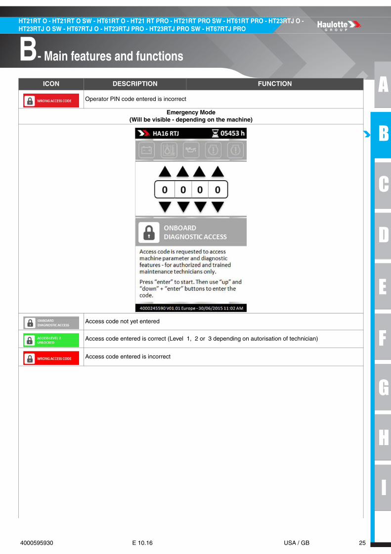
Operator PIN code(Will be visible - depending on the machine)
Operator PIN code not yet entered
Operator PIN code entered is correct
ICON DESCRIPTION FUNCTION
A
B
C
D
E
F
G
H
I
25 4000595930 E 10.16 USA / GB
HT21RT O - HT21RT O SW - HT61RT O - HT21 RT PRO - HT21RT PRO SW - HT61RT PRO - HT23RTJ O - HT23RTJ O SW - HT67RTJ O - HT23RTJ PRO - HT23RTJ PRO SW - HT67RTJ PRO
B- Main features and functions
Operator PIN code entered is incorrect
Emergency Mode(Will be visible - depending on the machine)
Access code not yet entered
Access code entered is correct (Level 1, 2 or 3 depending on autorisation of technician)
Access code entered is incorrect
ICON DESCRIPTION FUNCTION

26 4000595930 E 10.16 USA / GB
HT21RT O - HT21RT O SW - HT61RT O - HT21 RT PRO - HT21RT PRO SW - HT61RT PRO - HT23RTJ O - HT23RTJ O SW - HT67RTJ O - HT23RTJ PRO - HT23RTJ PRO SW - HT67RTJ PRO
B- Main features and functions
Access code(Will be visible - depending on the machine)
E-Stop at platform control box has been pushed in (de-energized). The machine will switch OFF in 5 seconds. In case of emergency, use Emergency Overriding system.
The Overriding function is Enabled when : • The E-Stop at platform control box is pushed in (de-energized). • The machine is in overload state. • Ground control box is selected/energized. • The emergency overriding button is activated.
The Overriding function is Dis-abled when : • The E-Stop at platform control box is pulled out (energized). • The machine is NOT in overload state. • Ground control box is NOT selected/energized.
The Emergency mode is out of service/non-functional
The Overriding circuit is activated, and it's use is recorded in the machine ECU. A HAULOTTE® Qualified technician is required to reset the Overriding system.
ICON DESCRIPTION FUNCTION

A
B
C
D
E
F
G
H
I
27 4000595930 E 10.16 USA / GB
HT21RT O - HT21RT O SW - HT61RT O - HT21 RT PRO - HT21RT PRO SW - HT61RT PRO - HT23RTJ O - HT23RTJ O SW - HT67RTJ O - HT23RTJ PRO - HT23RTJ PRO SW - HT67RTJ PRO
B- Main features and functions
2.4 - PLATFORM CONTROL BOX
2.4.1 - Layout
General view
Controls and indicators
MARKING NAME DESCRIPTION FUNCTION
33 SM902
Drive joystickMove forward : Forward drive
Move backwards : Reverse drive
Steering thumb / rocker switch
Press right side of button : Steer right - According to selected mode ( 201 )
Press left side of button : Steer left - According to selected mode ( 201 )
38 SA751 Platform rotation switch
Move to the right : Counter clockwise (CCW) rotation
Move to the left : Clockwise (CW) rotation
40 SA721 Platform leveling switchMove upwards : Raise platform
Move downwards : Platform lowers
41 SA800 Auxiliary power switchToggle and hold : Back-up unit activated
Release : Back-up unit deactivated
43 SA907 Horn button Horn
44 SA304 Fuel selector1LPG : Propane Gas supply
G : Petrol/Liquid propane gas or diesel supply

28 4000595930 E 10.16 USA / GB
HT21RT O - HT21RT O SW - HT61RT O - HT21 RT PRO - HT21RT PRO SW - HT61RT PRO - HT23RTJ O - HT23RTJ O SW - HT67RTJ O - HT23RTJ PRO - HT23RTJ PRO SW - HT67RTJ PRO
B- Main features and functions
45 SA110 Drive speed selector
High-speed drivie
Low-speed drive
46 SB802 E-stop button
Pulled out : Platform control box energized
Pressed in : De-energizes control system (Engine stopped)
78 Not used
79 SA906 Generator selector2Move to the left : Generator deactivated
Move to the right : Generator activated
823For CE : 230 kg (500 lbs) or 450 kg (1000 lbs) load selector
Move to the left : 230 kg (500 lbs) load selected
Move to the right : 450 kg (1000 lbs) load selected
824For ANSI : 230 kg (500 lbs) confirmation selector
Load confirmation : Shift the momentary switch
129 SA621Jib lifting/lowering switch5
Toggle and hold : Jib lifting/lowering
Release : No movement
201 SA101 Steering mode selector6
Synchronised axle : 4 wheel steering mode
2 front steering wheels from axle
Crab mode axle
230 SA303Engine start-up / stop selector
Start or stop the engine (depending on the machine's operating status) by pressing the push-button
232 SM900
Turntable rotation joystick
Move to the right : Counter clockwise (CCW) rotation
Move to the left : Clockwise (CW) rotation
Boom lift joystick Move forward : Boom up
Move backwards : Lower boom
233 SM901 Boom telescope joystickMove forward : Retract boom Upper boom
Move backwards : Extend boom Upper boom
1. For machines fitted with2. For machines fitted with3. If machine equipped with dual load4. If machine equipped with dual load5. For machines fitted with6. For machines fitted with
MARKING NAME DESCRIPTION FUNCTION
230 kg500 lbs
450 kg1000 lbs
230 kg500 lbs

A
B
C
D
E
F
G
H
I
29 4000595930 E 10.16 USA / GB
HT21RT O - HT21RT O SW - HT61RT O - HT21 RT PRO - HT21RT PRO SW - HT61RT PRO - HT23RTJ O - HT23RTJ O SW - HT67RTJ O - HT23RTJ PRO - HT23RTJ PRO SW - HT67RTJ PRO
B- Main features and functions
2.4.2 - Display Panel (LED'S 101 - 117)
Platform control box display
MARKING SYMBOL FUNCTION MARKING SYMBOL FUNCTION
LED 101 Power ON LED 110 Foot pedal switch
LED 102Combustion engine pre-heating
LED 111 Fault
LED 103 Low fuel level LED 112 Tilt
LED 104 Engine warning LED 113 Radius limit
LED 105 Engine shutdown LED 114 Overload
LED 106 DPF disable LED 115 Turret at 180°
LED 107 DPF disable LED 116Platform compensation
LED 108 DPF disable LED 1171
1. If machine equipped with dual load
Load selection 450 kg (1000 lbs)
LED 1092
2. If machine equipped with dual load
Load selection 230 kg (500 lbs)
LED 101 LED 102 LED 103 LED 104 LED 105 LED 106 LED 107 LED 108 LED 109
LED 110 LED 111 LED 112 LED 113 LED 114 LED 115 LED 116 LED 117
0°
0°
450 kg1000 lbs
230 kg500 lbs

30 4000595930 E 10.16 USA / GB
HT21RT O - HT21RT O SW - HT61RT O - HT21 RT PRO - HT21RT PRO SW - HT61RT PRO - HT23RTJ O - HT23RTJ O SW - HT67RTJ O - HT23RTJ PRO - HT23RTJ PRO SW - HT67RTJ PRO
B- Main features and functions
SYMBOL DESCRIPTION
Machine switched on : • Rapid flashing : Machine is ON, but platform control panel is not active but the ground control panel is ON• Illuminated : Machine is turned on and platform control panel is active
Foot pedal switch : • Illuminated when foot pedal activated
Faults : • Rapid flashing : If a fault is active (current fault)
Overload (If machine equipped with weighing system) : • Rapid flashing : Faulty weighing / overload system• Illuminated in case of overload
Tilt sensor (if fitted) : • Permanently on in case of tilting, machine folded or unfolded
Radius limitation : • Rapid flashing : Reach limitation system fault• Slow flashing : The machine is in the 230 kg (500 lbs) low load zone, the low load is validated and 450 kg (1000 lbs) heavy load is selected by the selector ( 82 )• Permanently lighted : Limit of work zone with movement cut-off or machine in 230 kg (500 lbs) low load zone and load not validated
Europe - Australia : • 230 kg load selected : Permanently lighted whatever the position of the machine when the 230 kg load is validated, otherwise off• 450 kg load selected : Permanently lighted, machine in the 450 kg zone and the 450 kg load is validated, otherwise off1
1. If machine equipped with dual load
United States - Canada : • 500 lbs load selected• Permanently lighted, position of the machine in 500 lbs zone with the 500 lbs load validated• Flashes, the machine is in the 500 lbs zone, the low load is not validated and a telescope extension or boom lowering movement control is activated• 1000 lbs load selected• Permanently lighted if the machine is in the 1000 lbs zone• Permanently lighted if the position of the machine is in the 1000 lbs zone and low load is not validated2
2. If machine equipped with dual load
Platform compensation +/- 10° : • Illuminated if the angle of the platform reaches +/- 10° in relation to the horizontal and movement control
Low fuel level
Combustion engine pre-heating : • Illuminated while engine is pre-heating• Off if engine started and if post-heating
Engine warning : • Lighted in case of minor engine fault (e;g. water in the diesel, clogged air filter, etc.)• Lighted or flashing in case of fault managed by the engine ECU
Engine shutdown : • Lighted in case of major engine fault (e.g. engine overheating, oil pressure, alternator fault, etc.)• Lighted in case of faults managed by the engine ECU
DPF regeneration required : • Permanently lighted if the particle filter requires regeneration with a high clogging level3
3. If engine quipped with Particulate Filter Regeneration
DPF regeneration in progress, high temperature in the exhaust system ( HEST )4
4. If engine quipped with Particulate Filter Regeneration
DPF regeneration inhibited5
5. If engine quipped with Particulate Filter Regeneration
230 kg500 lbs
450 kg1000 lbs
230 kg500 lbs
450 kg1000 lbs
0°
0°

A
B
C
D
E
F
G
H
I
31 4000595930 E 10.16 USA / GB
HT21RT O - HT21RT O SW - HT61RT O - HT21 RT PRO - HT21RT PRO SW - HT61RT PRO - HT23RTJ O - HT23RTJ O SW - HT67RTJ O - HT23RTJ PRO - HT23RTJ PRO SW - HT67RTJ PRO
B- Main features and functions
FILTER STATUS LEVEL OF CLOGGING
DPF cannot be recovered > 250% ON ON
Manual regeneration required (high level) 250% - 180% ON OFF
Automatic or manual regeneration required (medium level -> regeneration deactivation must not be engaged
180% - 130% ON OFF OFF
Automatic regeneration possible (low level) 130% - 90% OFF OFF OFF
Passive regeneration < 90% OFF OFF OFF
regeneration inhibited ON
Active regeneration (automatic or forced) ON

32 4000595930 E 10.16 USA / GB
HT21RT O - HT21RT O SW - HT61RT O - HT21 RT PRO - HT21RT PRO SW - HT61RT PRO - HT23RTJ O - HT23RTJ O SW - HT67RTJ O - HT23RTJ PRO - HT23RTJ PRO SW - HT67RTJ PRO
B- Main features and functions
Notes

A
B
C
D
E
F
G
H
I
33 4000595930 E 10.16 USA / GB
C- Study of the electric schematics
HT21RT O - HT21RT O SW - HT61RT O - HT21 RT PRO - HT21RT PRO SW - HT61RT PRO - HT23RTJ O - HT23RTJ O SW - HT67RTJ O - HT23RTJ PRO - HT23RTJ PRO SW - HT67RTJ PRO
Study of the electric schematics1 - System architecture
The system has different ECU modules linked by 2 can bus (HG and standard J1939) as shown below.
The ECU module master SPU7066 controls the whole system.
The ECU module slave node B2 controls all functions linked to upper controls.

34 4000595930 E 10.16 USA / GB
HT21RT O - HT21RT O SW - HT61RT O - HT21 RT PRO - HT21RT PRO SW - HT61RT PRO - HT23RTJ O - HT23RTJ O SW - HT67RTJ O - HT23RTJ PRO - HT23RTJ PRO SW - HT67RTJ PRO
C- Study of the electric schematics
1.1 - THE ECU MODULES
1.1.1 - U106 SPU 7066
This module master is located in turret near the lower control box.
Details on connectors
SPU 7066 external view
A
B
C
D
E
F
G
H
I
35 4000595930 E 10.16 USA / GB
C- Study of the electric schematics
HT21RT O - HT21RT O SW - HT61RT O - HT21 RT PRO - HT21RT PRO SW - HT61RT PRO - HT23RTJ O - HT23RTJ O SW - HT67RTJ O - HT23RTJ PRO - HT23RTJ PRO SW - HT67RTJ PRO
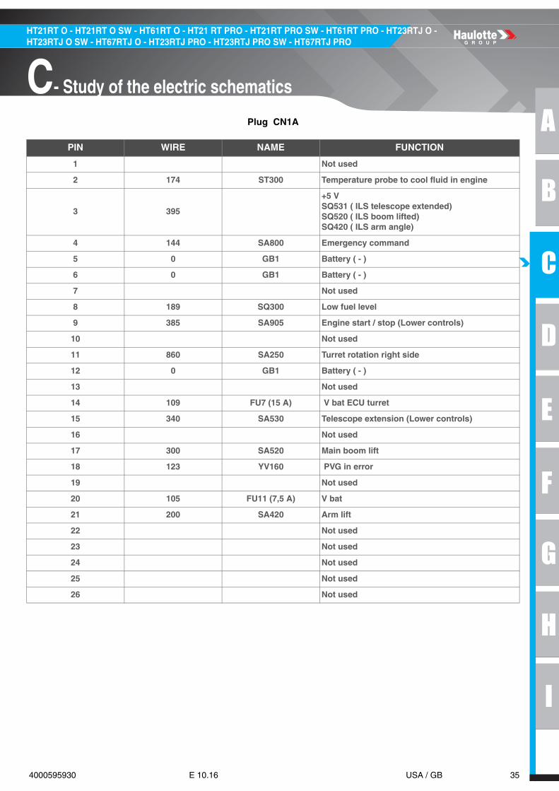
Plug CN1A
PIN WIRE NAME FUNCTION
1 Not used
2 174 ST300 Temperature probe to cool fluid in engine
3 395
+5 VSQ531 ( ILS telescope extended)SQ520 ( ILS boom lifted)SQ420 ( ILS arm angle)
4 144 SA800 Emergency command
5 0 GB1 Battery ( - )
6 0 GB1 Battery ( - )
7 Not used
8 189 SQ300 Low fuel level
9 385 SA905 Engine start / stop (Lower controls)
10 Not used
11 860 SA250 Turret rotation right side
12 0 GB1 Battery ( - )
13 Not used
14 109 FU7 (15 A) V bat ECU turret
15 340 SA530 Telescope extension (Lower controls)
16 Not used
17 300 SA520 Main boom lift
18 123 YV160 PVG in error
19 Not used
20 105 FU11 (7,5 A) V bat
21 200 SA420 Arm lift
22 Not used
23 Not used
24 Not used
25 Not used
26 Not used

36 4000595930 E 10.16 USA / GB
HT21RT O - HT21RT O SW - HT61RT O - HT21 RT PRO - HT21RT PRO SW - HT61RT PRO - HT23RTJ O - HT23RTJ O SW - HT67RTJ O - HT23RTJ PRO - HT23RTJ PRO SW - HT67RTJ PRO
C- Study of the electric schematics
Plug CN1B
PIN WIRE NAME FUNCTION
1 120 Command load sensing valve YV800 (+)
2 187 Command horn relay KA9
3 686High speed drive supply on valves YV110 / YV111
4 192 Command generator relay KA2
5 0 Battery (-)
6 620Command YV900, movements ON/OFF and steering
7 170 Command stop engine relay KA3
8 121 Command load sensing valve YV800 (-)
9 Not used
10 201 Command arm lift YV420U
11 600 SA300 Regeneration engine Tier IV (option)
12 481 SA720 Basket compensation descent (Lower controls)
13 500 SA620 Jib lifting (Lower controls)
14 610 SA300 Regeneration engine Tier IV inhibited (option)
15 510 SA620 Jib descent (Lower controls)
16 1003 CAN
17 1003 CAN
18 103 V power from fuse FU13
19 Not used
20 114 SA901 Information selection basket from SA901
21 150 SQ800 Tilt sensor
22 386 SA905 Enable switch (Lower controls)
23 480 SA720 Basket compensation lift (Lower controls)
24 Not used
25 1001 CAN HG L
26 Not used
27 621 Command crab mode steering YV607
28 188 Command EL901, option flashing light
29 186 Buzzer HA901
30 162 Command preheating relay KM160
31 880 Command turret rotation YV250
32 103 V power from fuse FU13
33 Not used
34 1002 CAN HG H

A
B
C
D
E
F
G
H
I
37 4000595930 E 10.16 USA / GB
C- Study of the electric schematics
HT21RT O - HT21RT O SW - HT61RT O - HT21 RT PRO - HT21RT PRO SW - HT61RT PRO - HT23RTJ O - HT23RTJ O SW - HT67RTJ O - HT23RTJ PRO - HT23RTJ PRO SW - HT67RTJ PRO
Plug CN2A
PIN WIRE NAME FUNCTION
1 122 Fault monitoring on PVG drive coil YV160
2 783 Command crab/synchro brake release YV105
3 387 Command telescopic boom YV530
4 381 Command boom lift YV520
5 689 Command differential lock YV100
6 145 Command emergency pump relay KM160
7 103 V power from fuse FU13
8 103 V power from fuse FU13
9 Not used
10 320 SA520 Command boom descent (Lower controls)
11 840 SA250 Command turret rotation (Lower controls)
12 220 SA420 Command arm lift (Lower controls)
13 Not used
14 Not used
15 Not used
16 Not used
17 360 SA530Command telescopic boom retraction (Lower controls)
18 2003 CAN
19 780 Command oscillating axle unlocking YV101
20 282 Command arm lift YV420 (Lower controls)
21 Not used
22 0 Battery (-)
23 169 Command start relay KA4
24 622 Command synchro steering mode YV108
25 Not used
26 782 Command brake release YV102

38 4000595930 E 10.16 USA / GB
HT21RT O - HT21RT O SW - HT61RT O - HT21 RT PRO - HT21RT PRO SW - HT61RT PRO - HT23RTJ O - HT23RTJ O SW - HT67RTJ O - HT23RTJ PRO - HT23RTJ PRO SW - HT67RTJ PRO
C- Study of the electric schematics
Plug CN2B
PIN WIRE NAME FUNCTION
1 2002 CAN 2.0 H
2 103 V power from fuse FU13
3 Not used
4 Not used
5 301 Command boom lift YV520U
6 Not used
7 221 Command arm descent YV420D
8 841 Command turret rotation left side YV250L
9 103 V power from fuse FU13
10 2001 CAN 2.0 L
11 Not used
12 384 SQ520 ILS detection boom lifted
13 380 SQ531 ILS detection telescope extended
14 281 SQ420 ILS detection arm angle
15 Not used
16 Not used
17 Not used
18 Not used
19 2003 CAN
20 Not used
21 Not used
22 Not used
23 Not used
24 Not used
25 861 Command turret rotation right side YV250R
26 687Command medium speed drive valves YV113 / YV115
27 Not used
28 687Command medium speed drive valves YV113 / YV115
29 Not used
30 0 Battery (-)
31 Not used
32 Not used
33 Not used
34 321 Command boom descent YV520D

A
B
C
D
E
F
G
H
I
39 4000595930 E 10.16 USA / GB
C- Study of the electric schematics
HT21RT O - HT21RT O SW - HT61RT O - HT21 RT PRO - HT21RT PRO SW - HT61RT PRO - HT23RTJ O - HT23RTJ O SW - HT67RTJ O - HT23RTJ PRO - HT23RTJ PRO SW - HT67RTJ PRO
Plug CN3A
PIN WIRE NAME FUNCTION
1 103 V power from fuse FU13
2 601 Command FL steering YV150L
3 Not used
4 Not used
5 Not used
6 Not used
7 103 V power from fuse FU13
8 Not used
9 124 PVG drive setpoint on PVG
10 Not used
11 222 SQ900 ILS arm/boom exit if option oscillating axle
12 Not used
13 Not used
14 602 Command FR steering YV150R
15 Not used
16 Not used
17 332 SQ532 ILS telescope if option oscillating axle
18 Not used
19 Not used
20 341 Command telescopic boom extension YV530O
21 361 Command telescopic boom retraction YV530I
22 Not used
23 0 Battery (-)
24 Not used
25 690 Command MS/HS drive mode YV112 / YV114
26 Not used

40 4000595930 E 10.16 USA / GB
HT21RT O - HT21RT O SW - HT61RT O - HT21 RT PRO - HT21RT PRO SW - HT61RT PRO - HT23RTJ O - HT23RTJ O SW - HT67RTJ O - HT23RTJ PRO - HT23RTJ PRO SW - HT67RTJ PRO
C- Study of the electric schematics
Plug CN3B
PIN WIRE NAME FUNCTION
1 690 Command MS/HS drive mode YV112 / YV114
2 Not used
3 Not used
4 686 HS drive supply on valves YV110 / YV111
5 Not used
6 Not used
7 Not used
8 103 V power from fuse FU13
9 Not used
10 Not used
11 Not used
12 Not used
13 115 SA901 Information turret selection from SA901
14 102 Alternator (D+)
15 142 SB801 Emergency stop (Lower controls)
16 Not used
17 Not used
18 Not used
19 Not used
20 Not used
21 173 SP300 Pressure switch oil engine
22 0 Battery (-)
23 125 ST900 Hydraulic oil overheating
24 Not used
25 Not used
26 Not used
27 Not used
28 Not used
29 Not used
30 212 SP109 Pressure switch oscillating axle
31 Not used
32 Not used
33 4002 CAN H 3
34 4001 CAN L 3

A
B
C
D
E
F
G
H
I
41 4000595930 E 10.16 USA / GB
C- Study of the electric schematics
HT21RT O - HT21RT O SW - HT61RT O - HT21 RT PRO - HT21RT PRO SW - HT61RT PRO - HT23RTJ O - HT23RTJ O SW - HT67RTJ O - HT23RTJ PRO - HT23RTJ PRO SW - HT67RTJ PRO
N.B.-:-ON SPU MODULE, THERE ARE TWO TYPES OF DIGITAL OUTPUTS : LS (LOW SIDE) AND HS (HIGHSIDE).
High side digital output
Low side digital output
• At state OFF, we detect a possible open circuit.
• At state ON, we detect a possible short circuit.
• In case of failure, the output is deactivated.
Charge must be connected to mass.
Charge must be connected to power supply.
42 4000595930 E 10.16 USA / GB
HT21RT O - HT21RT O SW - HT61RT O - HT21 RT PRO - HT21RT PRO SW - HT61RT PRO - HT23RTJ O - HT23RTJ O SW - HT67RTJ O - HT23RTJ PRO - HT23RTJ PRO SW - HT67RTJ PRO
C- Study of the electric schematics
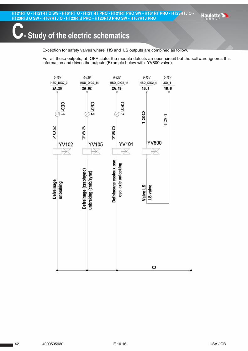
Exception for safety valves where HS and LS outputs are combined as follow.
For all these outputs, at OFF state, the module detects an open circuit but the software ignores thisinformation and drives the outputs (Example below with YV800 valve).

A
B
C
D
E
F
G
H
I
43 4000595930 E 10.16 USA / GB
C- Study of the electric schematics
HT21RT O - HT21RT O SW - HT61RT O - HT21 RT PRO - HT21RT PRO SW - HT61RT PRO - HT23RTJ O - HT23RTJ O SW - HT67RTJ O - HT23RTJ PRO - HT23RTJ PRO SW - HT67RTJ PRO
1.1.2 - U104 node B2 slave
This slave module is located inside the upper control box.

44 4000595930 E 10.16 USA / GB
HT21RT O - HT21RT O SW - HT61RT O - HT21 RT PRO - HT21RT PRO SW - HT61RT PRO - HT23RTJ O - HT23RTJ O SW - HT67RTJ O - HT23RTJ PRO - HT23RTJ PRO SW - HT67RTJ PRO
C- Study of the electric schematics
1.1.3 - EGV Kubota module
This module called EGV (Electronic Governor) is located behind the Kubota engine and controls allengine actuators (rpm/temperature).

A
B
C
D
E
F
G
H
I
45 4000595930 E 10.16 USA / GB
C- Study of the electric schematics
HT21RT O - HT21RT O SW - HT61RT O - HT21 RT PRO - HT21RT PRO SW - HT61RT PRO - HT23RTJ O - HT23RTJ O SW - HT67RTJ O - HT23RTJ PRO - HT23RTJ PRO SW - HT67RTJ PRO
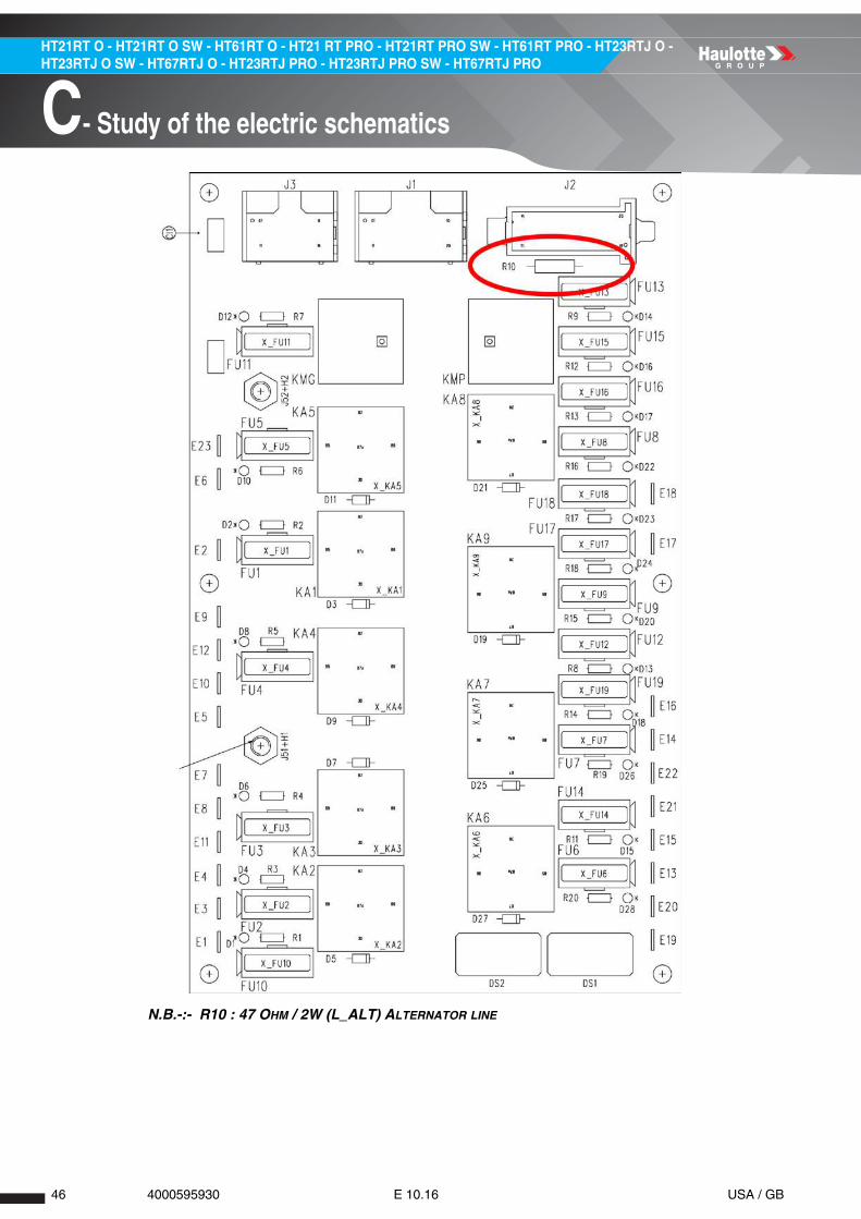
1.1.4 - Printed circuit board
The printed circuit board is located inside the lower control box.
All main fuses and relays are located in this printed circuit board.
46 4000595930 E 10.16 USA / GB
HT21RT O - HT21RT O SW - HT61RT O - HT21 RT PRO - HT21RT PRO SW - HT61RT PRO - HT23RTJ O - HT23RTJ O SW - HT67RTJ O - HT23RTJ PRO - HT23RTJ PRO SW - HT67RTJ PRO
C- Study of the electric schematics
N.B.-:- R10 : 47 OHM / 2W (L_ALT) ALTERNATOR LINE
A
B
C
D
E
F
G
H
I
47 4000595930 E 10.16 USA / GB
C- Study of the electric schematics
HT21RT O - HT21RT O SW - HT61RT O - HT21 RT PRO - HT21RT PRO SW - HT61RT PRO - HT23RTJ O - HT23RTJ O SW - HT67RTJ O - HT23RTJ PRO - HT23RTJ PRO SW - HT67RTJ PRO
Notes

48 4000595930 E 10.16 USA / GB
HT21RT O - HT21RT O SW - HT61RT O - HT21 RT PRO - HT21RT PRO SW - HT61RT PRO - HT23RTJ O - HT23RTJ O SW - HT67RTJ O - HT23RTJ PRO - HT23RTJ PRO SW - HT67RTJ PRO
C- Study of the electric schematics
2 - List of actuators and sensors
2.1 - SENSORS AND ACTUATORS
Sensors and actuators

A
B
C
D
E
F
G
H
I
49 4000595930 E 10.16 USA / GB
C- Study of the electric schematics
HT21RT O - HT21RT O SW - HT61RT O - HT21 RT PRO - HT21RT PRO SW - HT61RT PRO - HT23RTJ O - HT23RTJ O SW - HT67RTJ O - HT23RTJ PRO - HT23RTJ PRO SW - HT67RTJ PRO
NAME DESCRIPTION
SR721 Detector - Tilt + 10°
SR720 Detector - Tilt - 10°SP800 Sensor - Strain gauges
SP801 Sensor - Strain gauges
YV720U Valve - Platform level up
YV720D Valve - Platform level downYV620U Valve - Jib raise
YV620D Valve - Jib descent
YV750L Valve - Platform rotation leftYV750R Valve - Platform rotation right
SQ531 Detector - ILS Boom length
SQ533 Detector - Boom 1000 lbs length limit zoneSQ591 Detector - Boom retracted / down
SQ590 Detector - Boom retracted / down
SQ802 Detector - Cable break 2YV390 Detector - Boom safety up / down
YV521 Detector - ILS boom angle
SQ523 Detector - Boom 1000 lbs angle limit zoneSQ990 Detector - Cable break 1
ST300 Detector(Tier III) - Engine overheating
SP300 Detector(Tier III) - Engine oil pressureKA2 Relay - Generator control
YV160F Valve - Drive Forward
YV160B Valve - Drive reverseYV800 Valve - LS valve
YV900 Valve - Platform movements / steering
YV520 Valve - Boom movementsYV250 Valve - Turntable movements
YV530 Valve - Boom's telescope movements
YV807 Valve - Boom descent safetyYV801 Valve - Boom telescope extend safety
YV805 Valve - Turntable orientation safety
SQ800 Detector - Tilt sensorSQ300 Detector - Fuel low level
ST900 Detector - Hydraulic oil overheating
YV110 Valve - High speed translationYV102 Valve - Unbreaking front and rear
YV101 Valve - Axle unlocking
YV104 Valve - Axle unlockingSP100 Detector - High speed pressure
YV107 Valve(4WS only) - Crab / synchro steering
YV108 Valve(4WS only) - Crab / synchro steering
YV150R Valve - Right forwards steeringYV150L Valve - Left forwards steering

50 4000595930 E 10.16 USA / GB
HT21RT O - HT21RT O SW - HT61RT O - HT21 RT PRO - HT21RT PRO SW - HT61RT PRO - HT23RTJ O - HT23RTJ O SW - HT67RTJ O - HT23RTJ PRO - HT23RTJ PRO SW - HT67RTJ PRO
C- Study of the electric schematics
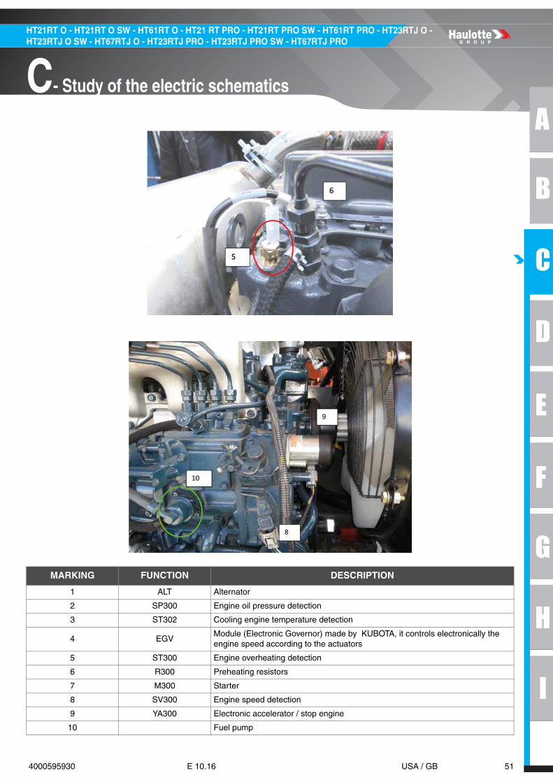
2.2 - SENSORS DETAIL
Engine
A
B
C
D
E
F
G
H
I
51 4000595930 E 10.16 USA / GB
C- Study of the electric schematics
HT21RT O - HT21RT O SW - HT61RT O - HT21 RT PRO - HT21RT PRO SW - HT61RT PRO - HT23RTJ O - HT23RTJ O SW - HT67RTJ O - HT23RTJ PRO - HT23RTJ PRO SW - HT67RTJ PRO
MARKING FUNCTION DESCRIPTION
1 ALT Alternator
2 SP300 Engine oil pressure detection
3 ST302 Cooling engine temperature detection
4 EGVModule (Electronic Governor) made by KUBOTA, it controls electronically the engine speed according to the actuators
5 ST300 Engine overheating detection
6 R300 Preheating resistors
7 M300 Starter
8 SV300 Engine speed detection
9 YA300 Electronic accelerator / stop engine
10 Fuel pump

52 4000595930 E 10.16 USA / GB
HT21RT O - HT21RT O SW - HT61RT O - HT21 RT PRO - HT21RT PRO SW - HT61RT PRO - HT23RTJ O - HT23RTJ O SW - HT67RTJ O - HT23RTJ PRO - HT23RTJ PRO SW - HT67RTJ PRO
C- Study of the electric schematics
Drive pump
MARKING FUNCTION DESCRIPTION
1 SP160F Pressure switch for FWD drive mode
2 SP160B Pressure switch for REV drive mode
3 YV160F FWD drive valve
4 YV160B REV drive valve

A
B
C
D
E
F
G
H
I
53 4000595930 E 10.16 USA / GB
C- Study of the electric schematics
HT21RT O - HT21RT O SW - HT61RT O - HT21 RT PRO - HT21RT PRO SW - HT61RT PRO - HT23RTJ O - HT23RTJ O SW - HT67RTJ O - HT23RTJ PRO - HT23RTJ PRO SW - HT67RTJ PRO
Boom
MARKING FUNCTION DESCRIPTION
1 SQ521 Proximity sensor for boom angle detection( =1 if > 50°)
2 SQ523 ILS sensor in redundancy for boom angle detection( =1 if > 50°)
54 4000595930 E 10.16 USA / GB
HT21RT O - HT21RT O SW - HT61RT O - HT21 RT PRO - HT21RT PRO SW - HT61RT PRO - HT23RTJ O - HT23RTJ O SW - HT67RTJ O - HT23RTJ PRO - HT23RTJ PRO SW - HT67RTJ PRO
C- Study of the electric schematics
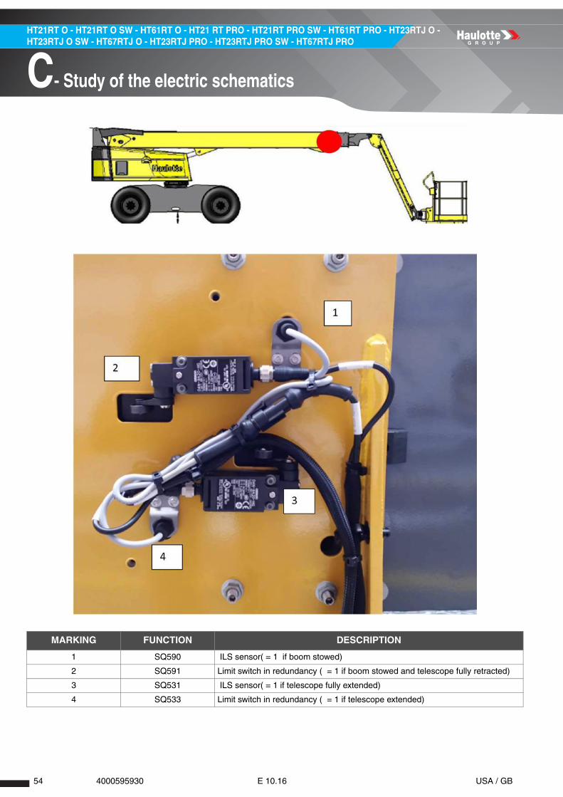
MARKING FUNCTION DESCRIPTION
1 SQ590 ILS sensor( = 1 if boom stowed)
2 SQ591 Limit switch in redundancy ( = 1 if boom stowed and telescope fully retracted)
3 SQ531 ILS sensor( = 1 if telescope fully extended)
4 SQ533 Limit switch in redundancy ( = 1 if telescope extended)

A
B
C
D
E
F
G
H
I
55 4000595930 E 10.16 USA / GB
C- Study of the electric schematics
HT21RT O - HT21RT O SW - HT61RT O - HT21 RT PRO - HT21RT PRO SW - HT61RT PRO - HT23RTJ O - HT23RTJ O SW - HT67RTJ O - HT23RTJ PRO - HT23RTJ PRO SW - HT67RTJ PRO
MARKING FUNCTION DESCRIPTION
1 SQ801 Detection chain broken on main boom
2 SQ802 Detection chain broken on main boom

56 4000595930 E 10.16 USA / GB
HT21RT O - HT21RT O SW - HT61RT O - HT21 RT PRO - HT21RT PRO SW - HT61RT PRO - HT23RTJ O - HT23RTJ O SW - HT67RTJ O - HT23RTJ PRO - HT23RTJ PRO SW - HT67RTJ PRO
C- Study of the electric schematics
Turret
MARKING FUNCTION DESCRIPTION
1 HA901 Buzzer
2 HA907 Horn
3 SQ800 Tilt sensor (wire 150 = 1 if machine on flat ground)
4 KM120 Command emergency pump
5 CN03 External connector for VCI adapter (used for Haulotte Diag connection)
6 SQ300 Detection of low level of fuel

A
B
C
D
E
F
G
H
I
57 4000595930 E 10.16 USA / GB
C- Study of the electric schematics
HT21RT O - HT21RT O SW - HT61RT O - HT21 RT PRO - HT21RT PRO SW - HT61RT PRO - HT23RTJ O - HT23RTJ O SW - HT67RTJ O - HT23RTJ PRO - HT23RTJ PRO SW - HT67RTJ PRO
Upper controls
N.B.-:-THE STRAIN GAUGES IS PROTECTED BY A FUSE ( FU34 = 1A) LOCATED INSIDE THE UPPER CONTROLBOX
MARKING FUNCTION DESCRIPTION
1 SP800 Strain gauges for load detection on basket
2 SP801 Strain gauges for load detection on basket

58 4000595930 E 10.16 USA / GB
HT21RT O - HT21RT O SW - HT61RT O - HT21 RT PRO - HT21RT PRO SW - HT61RT PRO - HT23RTJ O - HT23RTJ O SW - HT67RTJ O - HT23RTJ PRO - HT23RTJ PRO SW - HT67RTJ PRO
C- Study of the electric schematics
Upper controls
MARKING FUNCTION DESCRIPTION
1 SR720Detection basket angle ( +10°) must be adjusted in parallel to the side of the metal sheet
2 SR721 Detection basket angle ( -10°) must be adjusted fully at the bottom of the hole

A
B
C
D
E
F
G
H
I
59 4000595930 E 10.16 USA / GB
C- Study of the electric schematics
HT21RT O - HT21RT O SW - HT61RT O - HT21 RT PRO - HT21RT PRO SW - HT61RT PRO - HT23RTJ O - HT23RTJ O SW - HT67RTJ O - HT23RTJ PRO - HT23RTJ PRO SW - HT67RTJ PRO
2.3 - ACTUATORS AND THEIR LOCATION
2.3.1 - List of actuators
In the following tables : • The column n°2 indicates the position on the connector on modules (if required).
• The state noted "0" corresponds to 0 V, opened contact or not activated.
• The state noted "1" corresponds to the tension of the circuit, closed or activated contact.
Glossary
2.3.2 - Modules
MARKING DESCRIPTION
FWD Forward drive
REV Reverse drive
FL Front left
FR Front right
RL Rear left
RR Rear right
PF Platform
LS Low speed drive
LS valve/adj Load sensing valve/adjustment
MS Medium speed drive
HS High speed drive
ILS Magnet reed sensor
UCB Upper control box
LCB Lower control box
ECU Electronic Control Unit
PWM Pulse Width Modulation
PCB Printed circuit board
MODULES
NAME LOCATION FUNCTION
U101 04 Multi function CAN display
U104 ECU module node B2 upper controls (slave)
U106 ECU module SPU7066 (master)
U107 04 Sensitive keyboard plate
EGV 02 Electronic Governor( Kubota module)

60 4000595930 E 10.16 USA / GB
HT21RT O - HT21RT O SW - HT61RT O - HT21 RT PRO - HT21RT PRO SW - HT61RT PRO - HT23RTJ O - HT23RTJ O SW - HT67RTJ O - HT23RTJ PRO - HT23RTJ PRO SW - HT67RTJ PRO
C- Study of the electric schematics
2.3.3 - Fuses
N.B.-:-THE STRAIN GAUGES ARE PROTECTED BY A FUSE (FU34 = 1 A) LOCATED INSIDE THE UPPER CONTROLBOX.
FUSES
NAME LOCATION FUNCTION
FU2 03 - 02 Generator (20 A)
FU3 03 - 03 Start / stop engine (15 A)
FU4 03 - 04 Engine start (25 A)
FU5 03 - 08 Main supply + Vbat (30 A)
FU6 03 - 08 Overspeed option (20 A)
FU7 03 - 15 Supply V ECU node B2 upper controls (15 A)
FU8 03 - 10 Option flashing light (20 A)
FU9 03 - 12 Supply accessories (20 A)
FU11 03 - 09 Main power supply V bat permanent (7.5 A)
FU13 03 - 11 Supply V power SPU (20 A)
FU17 04 - 14 Selection ground / upper controls (5 A)
FU23 02 - 19 Overspeed relay option (40 A)
FU34 08 - 10 Supply strain gauges (1 A)
FU122 02 - 03 Emergency pump (250 A)
FU161 02 - 05 Preheating (100 A)
FU180 02 - 02 Cooler option (30 A)
A
B
C
D
E
F
G
H
I
61 4000595930 E 10.16 USA / GB
C- Study of the electric schematics
HT21RT O - HT21RT O SW - HT61RT O - HT21 RT PRO - HT21RT PRO SW - HT61RT PRO - HT23RTJ O - HT23RTJ O SW - HT67RTJ O - HT23RTJ PRO - HT23RTJ PRO SW - HT67RTJ PRO
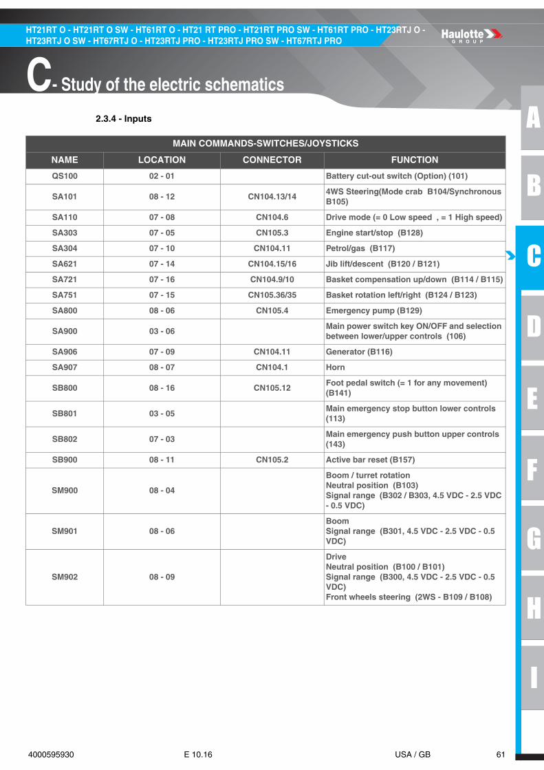
2.3.4 - Inputs
MAIN COMMANDS-SWITCHES/JOYSTICKS
NAME LOCATION CONNECTOR FUNCTION
QS100 02 - 01 Battery cut-out switch (Option) (101)
SA101 08 - 12 CN104.13/144WS Steering(Mode crab B104/Synchronous B105)
SA110 07 - 08 CN104.6 Drive mode (= 0 Low speed , = 1 High speed)
SA303 07 - 05 CN105.3 Engine start/stop (B128)
SA304 07 - 10 CN104.11 Petrol/gas (B117)
SA621 07 - 14 CN104.15/16 Jib lift/descent (B120 / B121)
SA721 07 - 16 CN104.9/10 Basket compensation up/down (B114 / B115)
SA751 07 - 15 CN105.36/35 Basket rotation left/right (B124 / B123)
SA800 08 - 06 CN105.4 Emergency pump (B129)
SA900 03 - 06Main power switch key ON/OFF and selection between lower/upper controls (106)
SA906 07 - 09 CN104.11 Generator (B116)
SA907 08 - 07 CN104.1 Horn
SB800 08 - 16 CN105.12Foot pedal switch (= 1 for any movement) (B141)
SB801 03 - 05Main emergency stop button lower controls (113)
SB802 07 - 03Main emergency push button upper controls (143)
SB900 08 - 11 CN105.2 Active bar reset (B157)
SM900 08 - 04
Boom / turret rotationNeutral position (B103)Signal range (B302 / B303, 4.5 VDC - 2.5 VDC - 0.5 VDC)
SM901 08 - 06BoomSignal range (B301, 4.5 VDC - 2.5 VDC - 0.5 VDC)
SM902 08 - 09
DriveNeutral position (B100 / B101)Signal range (B300, 4.5 VDC - 2.5 VDC - 0.5 VDC)Front wheels steering (2WS - B109 / B108)

62 4000595930 E 10.16 USA / GB
HT21RT O - HT21RT O SW - HT61RT O - HT21 RT PRO - HT21RT PRO SW - HT61RT PRO - HT23RTJ O - HT23RTJ O SW - HT67RTJ O - HT23RTJ PRO - HT23RTJ PRO SW - HT67RTJ PRO
C- Study of the electric schematics
SENSORS
NAME LOCATION CONNECTOR FUNCTION
SP100 06 - 14 3B.28 High speed drive detection (212)
SP160B 07 - 05 1A.02Detection of pressure in drive pump in stand-by mode in REV drive (above charge pressure) (512)
SP160F 07 - 06 1A.4Detection of pressure in drive pump in stand-by mode in FWD drive (above charge pressure) (506)
SP300 02 - 15Engine oil pressure detection ( ON if P < 3 b) (173)
SP800 / SP801 09 - 18 CN106.4/5Strain gauges for basket load detection (B310 / B311)
SQ300 06 - 02 1A.8 Low fuel level detection ( = 1 if low) (189)
SQ521 06 - 08 2B.12Proximity sensor for boom position( = 1 if > 50°) (384)
SQ523 06 - 10 3A.17 ILS detection for boom position( = 1 in front of magnet) (380)
SQ531 06 - 11 3A.11Telescope detection ( ILS in front of magnet = 1 if retracted) (332)
SQ533 06 - 09 3B.23Detection telescopic boom position ( = 1 if extended)(383)
SQ590 06 - 15 2B.14Detection boom position ( = 1 if in stowed position)(281)
SQ591 06 - 16 2B.13 ILS detection for boom position( = 1 in front of magnet) (222)
SQ800 06 - 04 1B.21Slope detection (Signal wire 150 = 1 if machine levelled)
SQ801 06 - 17 1A.21 Chain 1 detection ( = 0 if broken) (990)
SQ802 06 - 18 2A.12 Chain 2 detection ( = 0 if broken) (991)
SQ902 08 - 12 CN105.5 Active bar detection ( = 1 if detected) (B150)
SR720 08 - 14 CN105.14 Basket inclination ( = 1 if at -10°) (B146)
SR721 08 - 13 CN105.13 Basket inclination ( = 1 if at +10°) (B145)
ST300 02 - 16Engine oil overheating detection ( = 1 if overheat) (174)
ST302 02 - 11 Cooler temperature detection in engine(130)
ST900 06 - 13 3B.15Hydraulic oil overheating detection ( = 1 if OK) (125)
ST902 02 - 02Temperature switch detection (oil cooler) (190)
SV300 02 - 13 Engine speed detection (133)

A
B
C
D
E
F
G
H
I
63 4000595930 E 10.16 USA / GB
C- Study of the electric schematics
HT21RT O - HT21RT O SW - HT61RT O - HT21 RT PRO - HT21RT PRO SW - HT61RT PRO - HT23RTJ O - HT23RTJ O SW - HT67RTJ O - HT23RTJ PRO - HT23RTJ PRO SW - HT67RTJ PRO
2.3.5 - Outputs
RELAYS-CONTACTORS
NAME LOCATION CONNECTOR FUNCTION
KA2 05 - 16 1B.3 Option generator command (192)
KA3 05 - 18 1A.23 Engine start/stop command (170)
KA4 05 - 19 2A.6 Engine start command (169)
KA6 03 - 14 Overriding command (188)
KA7 03 - 03 For engine start (For engine tiers 4 only)
KA8 05 - 13 2A.25 Option beacon/flashing light (194)
KA9 05 - 14 1B.2 Horn command (187)
KAC 08 - 12 CN105.30 Active bar command (B510)
KMG 03 - 14 Main contactor (143)
KMP 03 - 15Power relay (Keeps power a few seconds after KMG) (143)
SD85 02 - 19 Option overspeed relay
KM120 02 - 04 Emergency pump (145)
KM160 02 - 07 Preheating (162)
KM300 02 - 08 Starter (165)

64 4000595930 E 10.16 USA / GB
HT21RT O - HT21RT O SW - HT61RT O - HT21 RT PRO - HT21RT PRO SW - HT61RT PRO - HT23RTJ O - HT23RTJ O SW - HT67RTJ O - HT23RTJ PRO - HT23RTJ PRO SW - HT67RTJ PRO
C- Study of the electric schematics
VALVES
NAME LOCATION CONNECTOR FUNCTION
YA300 02 - 14 Electronic engine speed control coil (135)
YV101 06 - 06 2B.25 Oscillating axle unlocking (781)
YV102 06 - 04 2B.8 Brake release (782)
YV104 06 - 05 3A.26 Oscillating axle unlocking (780)
YV107 06 - 08 2B.28 Crab steering mode ( YV108 = 1 if right) (621)
YV108 06 - 09 2B.26 Synchro steering mode ( YV107 = 1 if left) (622)
YV110 06 - 04 2B.7 Valve for drive mode (In high speed) (686)
YV150L 06 - 02 2B.29 Front left steering (601)
YV150R 06 - 03 2B.27 Front right steering (602)
YV160F 06 - 06 1B.31 PWM FWD drive valve (687)
YV160B 06 - 07 1B.9 PWM REV drive valve (688)
YV250L 06 - 18 2A.5Flow sharing valve for turret rotation left side (907)
YV250R 06 - 19 2A.4Flow sharing valve for turret rotation right side (906)
YV520D 07 - 12 1B.10 Flow sharing valve for boom descent (903)
YV520U 06 - 13 1B.6 Flow sharing valve for boom lift (902)
YV530I 06 - 16 2A.20Flow sharing valve for telescopic boom retraction (905)
YV530O 06 - 15 2A.3Flow sharing valve for telescopic boom extension (904)
YV620D 08 - 13 CN105.32 Jib descent (B604)
YV620U 08 - 14 CN105.31 Jib lift (B603)
YV720D 08 - 17 CN105.28 Basket compensation down (B600)
YV720U 08 - 18 CN105.27 Basket compensation up (B607)
YV750L 08 - 16 CN105.33 Basket rotation left side (B605)
YV750R 08 - 15 CN105.34 Basket rotation right side (B606)
YV800 05 - 08 1B.4 Load sensing valve ( = 1 for any movement) (120)
YV801 05 - 05 2A.26 Safety valve for telescopic boom (392/890)
YV802 05 - 06 1B.29 Safety valve for boom lift (390/890)
YV805 05 - 09 2A.19 Safety valve for turret orientation (783/393)
YV807 05 - 11 2A.24 Safety valve for boom descent (391/393)
YV901 06 - 10 2B.5Flow sharing valve for ON/OFF movements block (900)
YV902 06 - 11 2B.34Flow sharing valve for steering block(2WS/4WS) (901)

A
B
C
D
E
F
G
H
I
65 4000595930 E 10.16 USA / GB
C- Study of the electric schematics
HT21RT O - HT21RT O SW - HT61RT O - HT21 RT PRO - HT21RT PRO SW - HT61RT PRO - HT23RTJ O - HT23RTJ O SW - HT67RTJ O - HT23RTJ PRO - HT23RTJ PRO SW - HT67RTJ PRO
BUZZER-INDICATORS-RECEPTORS
NAME LOCATION CONNECTOR FUNCTION
R10 03 - 15Receptor for alternator command (47ȵ, 2W) (102)
HA901 05 - 13 1B.30 Buzzer (186)
HA902 07 - 08 CN106.16 Buzzer (B508)
HA907 03 - 13 Horn (184)
EL901 06 - 05 1B.28 Option flashing light (188)
EL903 03 - 09 Option flashing light (185)
EL904 09 - 19 Option working light (183)
EL905 09 - 11 CN105.29 Active bar detection (B608)
HL901 08 - 09 CN106.19 Active bar activated (B609)
HL902 09 - 10 CN105.29 Active bar detection (B608)
HLXX 07Upper controls PCB with 16 leds for indication/alarms
66 4000595930 E 10.16 USA / GB
HT21RT O - HT21RT O SW - HT61RT O - HT21 RT PRO - HT21RT PRO SW - HT61RT PRO - HT23RTJ O - HT23RTJ O SW - HT67RTJ O - HT23RTJ PRO - HT23RTJ PRO SW - HT67RTJ PRO
C- Study of the electric schematics
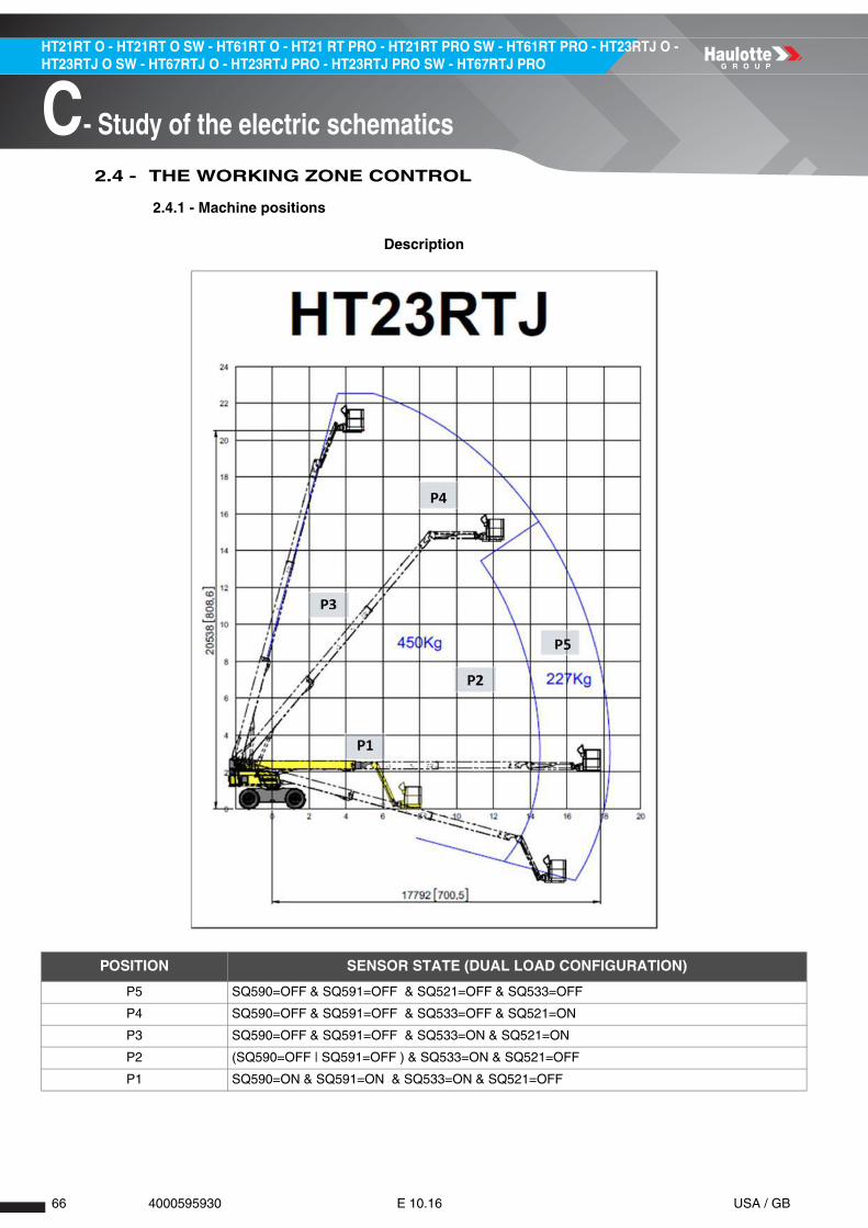
2.4 - THE WORKING ZONE CONTROL
2.4.1 - Machine positions
Description
POSITION SENSOR STATE (DUAL LOAD CONFIGURATION)
P5 SQ590=OFF & SQ591=OFF & SQ521=OFF & SQ533=OFF
P4 SQ590=OFF & SQ591=OFF & SQ533=OFF & SQ521=ON
P3 SQ590=OFF & SQ591=OFF & SQ533=ON & SQ521=ON
P2 (SQ590=OFF | SQ591=OFF ) & SQ533=ON & SQ521=OFF
P1 SQ590=ON & SQ591=ON & SQ533=ON & SQ521=OFF

A
B
C
D
E
F
G
H
I
67 4000595930 E 10.16 USA / GB
C- Study of the electric schematics
HT21RT O - HT21RT O SW - HT61RT O - HT21 RT PRO - HT21RT PRO SW - HT61RT PRO - HT23RTJ O - HT23RTJ O SW - HT67RTJ O - HT23RTJ PRO - HT23RTJ PRO SW - HT67RTJ PRO
POSITION CHANGES SENSOR STATE (DUAL LOAD CONFIGURATION)
P1-->P2 SQ590=ON-->OFF | SQ591=ON-->OFF & SQ521=OFF & SQ533=OFF
P2-->P3 SQ590=OFF & SQ591=OFF & SQ533=OFF & SQ521=OFF-->ON & SQ521=ON
P3-->P4 SQ590=OFF & SQ591=OFF & SQ533=ON-->OFF & SQ531=ON & SQ521=ON
P4-->P5 SQ590=OFF & SQ591=OFF & SQ533=ON & SQ521=ON-->OFF & SQ521=ON
P2-->P5 SQ590=OFF & SQ591=OFF & SQ533=ON-->OFF & SQ531=ON & SQ521=OFF
POSITION SENSOR STATE (SINGLE LOAD CONFIGURATION)
P2 SQ590=OFF | SQ591=OFF
P1 SQ590=ON & SQ591=ON
POSITION CHANGES SENSOR STATE (SINGLE LOAD CONFIGURATION)
P1-->P2 SQ590=ON-->OFF | SQ591=ON-->OFF
REQUIREMENTS DEFINITION
POSDL01
The machine positions are defined and checked by the following sensors when machine is dual load enabled : • SQ590 : Mechanical switch to set the position telescope in and boom down, pull down input (active state ON=12V, telescope in and boom above 10°). • SQ591 : Magnet detector to set the position telescope in and boom down, SQ590 redundancy, pull down input (active state ON=12V). • SQ533 : Mechanical switch to set the length of telescope, pull down input (active state ON=12V, telescope below 10m). • SQ531 : Magnet detector to set the zone of accepted change in SQ533 sensor state, pull down input (active state ON=12V). • SQ521 : Inductive switch to set the angle of boom, pull down input (active state ON=12V, boom above 52°). • SQ523 : Magnet detector to set the zone of accepted change in SQ521 sensor state, pull down input (active state ON=12V).

68 4000595930 E 10.16 USA / GB
HT21RT O - HT21RT O SW - HT61RT O - HT21 RT PRO - HT21RT PRO SW - HT61RT PRO - HT23RTJ O - HT23RTJ O SW - HT67RTJ O - HT23RTJ PRO - HT23RTJ PRO SW - HT67RTJ PRO
C- Study of the electric schematics
REQUIREMENTS DEFINITION
POSDL02
The telescope length is secured with the redundancy between SQ531 magnet detector and SQ533 mechanical switch: mutual survey of raising or falling edges on both sensors. • SQ531 magnet detector secures the zone of change in SQ533 mechanical switch permanently. • SQ533 secures the zone of change of SQ531 magnet detector considering the running movement.
SQ533 MECHANICAL
SWITCH TELESCOPE
SQ531 MAGNET DETECTOR TELESCOPE
RUNNING MOVEMENT
ON OFF All (Including no movement)
ON ON All (Including no movement)
OFF ON All (Including no movement)
OFF OFF All (Including no movement)
↓ OFF All (Including no movement)
↓ OFF All (Including no movement)
OFF ↓ Boom raise or Telescope extended
ON ↓ Boom raise or Telescope extended
Typical failure cases (not exhaustive). • IC = 1 | 2: Could be open circuit on SQ531 sensor. • IC = 4: Could be open circuit on SQ533 sensor. • IC = 8: Could be open circuit on SQ533 sensor.

A
B
C
D
E
F
G
H
I
69 4000595930 E 10.16 USA / GB
C- Study of the electric schematics
HT21RT O - HT21RT O SW - HT61RT O - HT21 RT PRO - HT21RT PRO SW - HT61RT PRO - HT23RTJ O - HT23RTJ O SW - HT67RTJ O - HT23RTJ PRO - HT23RTJ PRO SW - HT67RTJ PRO
REQUIREMENTS DEFINITION
POSDL03
The telescope length is also secured with the redundancy between SQ531 magnet detector and SQ590 mechanical switch + SQ591 magnet detector : Comparison between the SQ531 detector state and the states of SQ591 and SQ590 sensor value. • SQ590 mechanical switch and SQ591 magnet detector secure the state of SQ531 magnet detector.
SQ590 MECHANICAL
SWITCH TELESCOPE AND
BOOM
SQ591 MAGNET DETECTOR
TELESCOPE AND BOOM
SQ531 MAGNET DETECTOR TELESCOPE
RUNNING MOVEMENT
ON ON OFF All (Including no movement)
OFF OFF OFF All (Including no movement)
OFF ON OFF All (Including no movement)
ON OFF OFF All (Including no movement)
OFF OFF ON All (Including no movement)
ON ON ON All (Including no movement)
Typical failure cases (not exhaustive) : IC=16: could be short circuit on SQ531 sensor. Others failure cases: see POSDL021( SQ590 or SQ591 inactive and SQ531 active).
REQUIREMENTS DEFINITION
POSDL04
A system failure is activated if position error is detected. Until the SQ590 sensor combination is not detected, the failure is kept active and reactivated at each machine power on=1 & SQ591=1 & SQ533=1 & SQ521=0.
MARKING BEHAVIOR
1 No error or erased error
2 To activate the failure
3 To reset the error
4 To erase the failure with emergency stop
5 To keep the failure detected after power on if still active at power off
IC = Mem: EEPROM memorized detailed code A: currently active, D: detected once at least since power on, M: EEPROM memorized
70 4000595930 E 10.16 USA / GB
HT21RT O - HT21RT O SW - HT61RT O - HT21 RT PRO - HT21RT PRO SW - HT61RT PRO - HT23RTJ O - HT23RTJ O SW - HT67RTJ O - HT23RTJ PRO - HT23RTJ PRO SW - HT67RTJ PRO
C- Study of the electric schematics
REQUIREMENTS DEFINITION
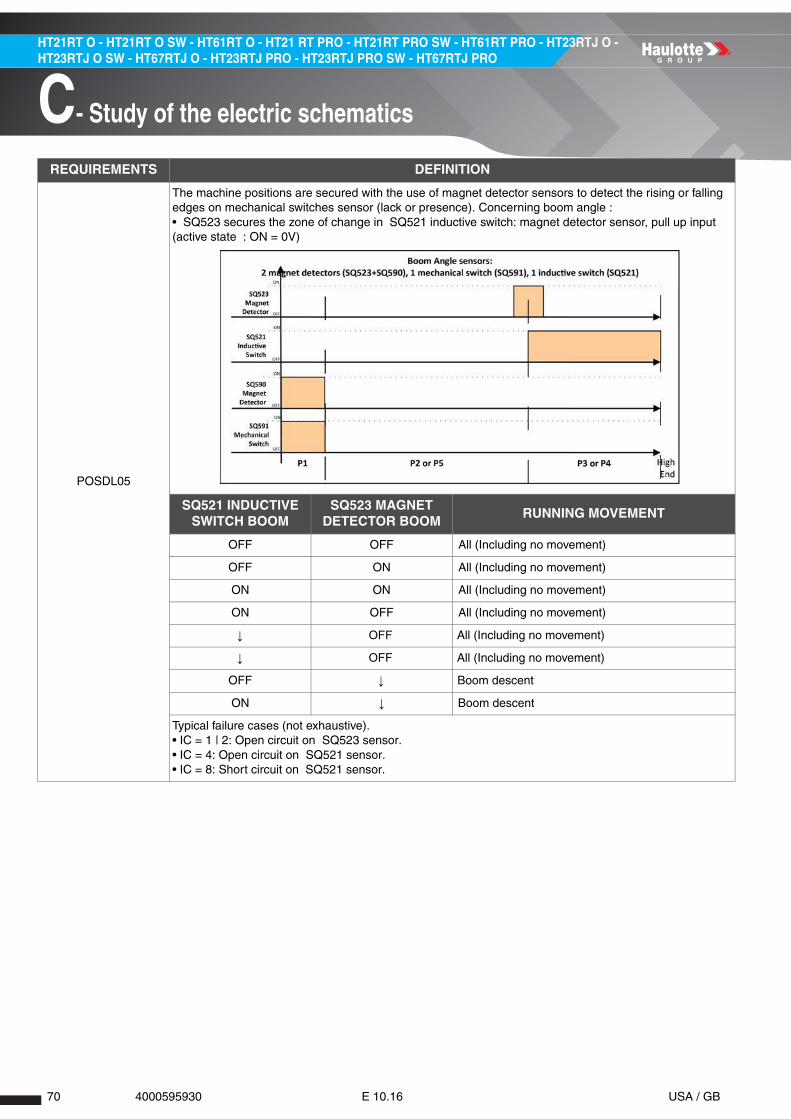
POSDL05
The machine positions are secured with the use of magnet detector sensors to detect the rising or falling edges on mechanical switches sensor (lack or presence). Concerning boom angle : • SQ523 secures the zone of change in SQ521 inductive switch: magnet detector sensor, pull up input (active state : ON = 0V)
SQ521 INDUCTIVE SWITCH BOOM
SQ523 MAGNET DETECTOR BOOM
RUNNING MOVEMENT
OFF OFF All (Including no movement)
OFF ON All (Including no movement)
ON ON All (Including no movement)
ON OFF All (Including no movement)
↓ OFF All (Including no movement)
↓ OFF All (Including no movement)
OFF ↓ Boom descent
ON ↓ Boom descent
Typical failure cases (not exhaustive). • IC = 1 | 2: Open circuit on SQ523 sensor. • IC = 4: Open circuit on SQ521 sensor. • IC = 8: Short circuit on SQ521 sensor.

A
B
C
D
E
F
G
H
I
71 4000595930 E 10.16 USA / GB
C- Study of the electric schematics
HT21RT O - HT21RT O SW - HT61RT O - HT21 RT PRO - HT21RT PRO SW - HT61RT PRO - HT23RTJ O - HT23RTJ O SW - HT67RTJ O - HT23RTJ PRO - HT23RTJ PRO SW - HT67RTJ PRO
REQUIREMENTS DEFINITION
POSDL06
The boom angle is also secured with the redundancy between SQ523 magnet detector and SQ590 mechanical switch and SQ591 magnet detector : Comparison between the SQ523 detector state and the states of SQ591 and SQ590 sensor value. • SQ590 mechanical switch and SQ591 magnet detector secure the state of SQ523 magnet detector
SQ590 MECHANICAL
SWITCH TELESCOPE AND BOOM
SQ591 MAGNET DETECTOR TELESCOPE AND BOOM
SQ523 MAGNET DETECTOR
BOOMRUNNING MOVEMENT
ON ON OFF All (Including no movement)
OFF OFF OFF All (Including no movement)
OFF ON OFF All (Including no movement)
ON OFF OFF All (Including no movement)
OFF OFF ON All (Including no movement)
ON ON ON All (Including no movement)
Typical error cases (not exhaustive). • IC = 16: Could be short circuit on SQ523 sensor. Others failure cases: see POS_*_021( SQ590 or SQ591 inactive and SQ523 active)
REQUIREMENTS DEFINITION
POSDL07
A system failure is activated if position error is detected. Until the SQ590 sensor combination is not detected, the failure is kept active and reactivated at each machine power on=1 & SQ591=1 & SQ533=1 & SQ521=0.
MARKING BEHAVIOR
1 No error or erased error
2 To activate the failure
3 To reset the error
4 To erase the failure with emergency stop
5 To keep the failure detected after power on if still active at power off
IC = Mem: EEPROM memorized detailed code A: currently active, D: detected once at least since power on, M: EEPROM memorized

72 4000595930 E 10.16 USA / GB
HT21RT O - HT21RT O SW - HT61RT O - HT21 RT PRO - HT21RT PRO SW - HT61RT PRO - HT23RTJ O - HT23RTJ O SW - HT67RTJ O - HT23RTJ PRO - HT23RTJ PRO SW - HT67RTJ PRO
C- Study of the electric schematics
REQUIREMENTS DEFINITION
POSDL08
If no error is previously detected on boom angle or telescope length (VAR[AngleErr]=No Error & VAR[LengthErr]=No Error). The state of SQ590 mechanical switch is checked with the SQ533 and SQ521 mechanical switches’ state :
SQ590 MECHANICAL SWITCH TELESCOPE AND
BOOM
SQ533 MECHANICAL SWITCH TELESCOPE
SQ521 INDUCTIVE SWITCH BOOM
ON ON OFF
OFF ON OFF
OFF ON ON
OFF OFF ON
OFF OFF OFF
ON ON ON
ON OFF ON
ON OFF OFF
Typical failure cases (not exhaustive). • IC = 1: Could be short circuit on SQ590 sensor. • IC = 2: Could be short circuit on SQ590 or SQ521 sensor. • IC = 4: Could be short circuit on SQ590 or open circuit on SQ533 sensor.

A
B
C
D
E
F
G
H
I
73 4000595930 E 10.16 USA / GB
C- Study of the electric schematics
HT21RT O - HT21RT O SW - HT61RT O - HT21 RT PRO - HT21RT PRO SW - HT61RT PRO - HT23RTJ O - HT23RTJ O SW - HT67RTJ O - HT23RTJ PRO - HT23RTJ PRO SW - HT67RTJ PRO
REQUIREMENTS DEFINITION
POSDL09
If no error of boom or telescope is previously detected (VAR[AngleErr]=No Error & VAR[LengthErr]=No Error). The states of SQ590 and SQ591 sensors are checked with the states of SQ523 and SQ531 sensors
SQ590 MECHANICAL
SWITCH TELESCOPE AND
BOOM
SQ591 MAGNET DETECTOR
TELESCOPE AND BOOM
SQ531 MAGNET DETECTOR TELESCOPE
SQ523 MAGNET DETECTOR BOOM
ON ON OFF OFF
ON OFF OFF OFF
OFF ON OFF OFF
OFF OFF OFF OFF
OFF OFF OFF ON
OFF OFF ON OFF
OFF ON ON OFF
ON OFF ON OFF
OFF ON OFF ON
ON OFF OFF ON
OFF ON ON ON
ON OFF ON ON
Typical error cases (not exhaustive). • IC = 8: Could be short circuit on SQ591 or SQ531 sensor. • IC = 16: Could be short circuit on SQ590 or SQ531 sensor. • IC = 32: Could be short circuit on SQ591 or SQ523 sensor. • IC = 64: Could be short circuit on SQ590 or SQ523 sensor. • IC = 128: Could be short circuit on SQ591 sensor. • IC = 256: Could be short circuit on SQ590 sensor.
REQUIREMENTS DEFINITION
POSDL10
A system failure is activated if position error is detected. Until the SQ590 sensor combination is not detected, the failure is kept active and reactivated at each machine power on=1 & SQ591=1 & SQ533=1 & SQ521=0.
MARKING BEHAVIOR
1 No error or erased error
2 To activate the failure
3 To reset the error
4 To erase the failure with emergency stop
5 To keep the failure detected after power on if still active at power off
IC = Mem: EEPROM memorized detailed code A: currently active, D: detected once at least since power on, M: EEPROM memorized
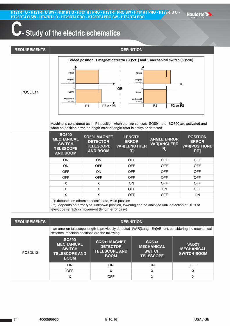
74 4000595930 E 10.16 USA / GB
HT21RT O - HT21RT O SW - HT61RT O - HT21 RT PRO - HT21RT PRO SW - HT61RT PRO - HT23RTJ O - HT23RTJ O SW - HT67RTJ O - HT23RTJ PRO - HT23RTJ PRO SW - HT67RTJ PRO
C- Study of the electric schematics
REQUIREMENTS DEFINITION
POSDL11
Machine is considered as in P1 position when the two sensors SQ591 and SQ590 are activated and when no position error, or length error or angle error is active or detected
SQ590 MECHANICAL
SWITCH TELESCOPE AND BOOM
SQ591 MAGNET DETECTOR TELESCOPE AND BOOM
LENGTH ERROR
VAR[LENGTHERR]
ANGLE ERROR VAR[ANGLEER
R]
POSITION ERROR
VAR[POSITIONERR]
ON ON OFF OFF OFF
ON OFF OFF OFF OFF
OFF ON OFF OFF OFF
OFF OFF OFF OFF OFF
X X ON OFF OFF
X X OFF ON OFF
X X OFF OFF ON
(*): depends on others sensors’ state, valid position (**): depends on error type, unknown position, lowering can be inhibited until detection of 10 s of telescope retraction movement (length error case)
REQUIREMENTS DEFINITION
POSDL12
If an error on telescope length is previously detected (VAR[LengthErr]=Error), considering the mechanical switches, machine positions are the following
SQ590 MECHANICAL
SWITCH TELESCOPE AND
BOOM
SQ591 MAGNET DETECTOR
TELESCOPE AND BOOM
SQ533 MECHANICAL
SWITCH TELESCOPE
SQ521 MECHANICAL
SWITCH BOOM
ON ON ON OFF
OFF X X X
X OFF X X

A
B
C
D
E
F
G
H
I
75 4000595930 E 10.16 USA / GB
C- Study of the electric schematics
HT21RT O - HT21RT O SW - HT61RT O - HT21 RT PRO - HT21RT PRO SW - HT61RT PRO - HT23RTJ O - HT23RTJ O SW - HT67RTJ O - HT23RTJ PRO - HT23RTJ PRO SW - HT67RTJ PRO
REQUIREMENTS DEFINITION
POSDL13
If an error on boom angle is previously detected (VAR[AngleErr]=Error), considering the mechanical switches, machine positions are the following
SQ590 MECHANICAL
SWITCH TELESCOPE AND
BOOM
SQ591 MAGNET DETECTOR
TELESCOPE AND BOOM
SQ533 MECHANICAL
SWITCH TELESCOPE
SQ521 INDUCTIVE SWITCH BOOM
ON ON ON OFF
OFF X ON X
X OFF ON X
OFF OFF OFF X
REQUIREMENTS DEFINITION
POSDL14
If no error on position, boom angle or telescope length is previously detected ((VAR[ErrorPosition]=No Error & VAR[AngleErr]=No Error & VAR[LengthErr]=No Error)). Considering the mechanical switches, machine positions are the following :
SQ590 MECHANICAL
SWITCH TELESCOPE AND
BOOM
SQ591 MAGNET DETECTOR
TELESCOPE AND BOOM
SQ533 MECHANICAL
SWITCH TELESCOPE
SQ521 INDUCTIVE SWITCH BOOM
ON ON ON OFF
OFF X ON OFF
X OFF ON OFF
OFF X ON ON
OFF X OFF ON
OFF X OFF OFF
(*): depends on machine, SQ591 switches ON before or after SQ590 (depending on machine sensors adjustment)
REQUIREMENTS DEFINITION
POSDL15
If position error is detected (VAR[ErrorPosition]!=No Error), considering the mechanical switches SQ533 and SQ521, machine positions are the following
SQ590 MECHANICAL
SWITCH TELESCOPE AND
BOOM
SQ591 MAGNET DETECTOR
TELESCOPE AND BOOM
SQ533 MECHANICAL
SWITCH TELESCOPE
SQ521 INDUCTIVE SWITCH BOOM
X X ON OFF
X X ON ON
X X OFF ON
X X OFF OFF

76 4000595930 E 10.16 USA / GB
HT21RT O - HT21RT O SW - HT61RT O - HT21 RT PRO - HT21RT PRO SW - HT61RT PRO - HT23RTJ O - HT23RTJ O SW - HT67RTJ O - HT23RTJ PRO - HT23RTJ PRO SW - HT67RTJ PRO
C- Study of the electric schematics
REQUIREMENTS DEFINITION
POSDL16When length error is active or detected : • Telescope extension movement is prohibited. • Telescope retraction movement is authorized.
REQUIREMENTS DEFINITION
POSDL17When length error is active : • From upper command console, the boom retraction movement is controlled at a fixed set point (no proportionality).
REQUIREMENTS DEFINITION
POSDL18
When length error is active or detected : • Boom lowering movement is prohibited until 10s of telescope retraction has been detected. • Boom lowering movement is authorized after the detection of 10s of telescope retraction movement. • Boom lifting is authorized.
REQUIREMENTS DEFINITION
POSDL19
When angle error is active or detected : • Telescope extension movement is prohibited if SQ533 mechanical switch is inactive. • Telescope extension movement is authorized if SQ533 mechanical switch is active. • Telescope retraction movement is authorized.
REQUIREMENTS DEFINITION
POSDL20
When angle error is active or detected : • Boom lowering movement is prohibited if SQ533 mechanical switch is inactive. • Boom lowering movement is authorized if SQ533 mechanical switch is active. • Boom lifting is authorized.
REQUIREMENTS DEFINITION
POSDL21
When position error is active or detected : • Drive movement happens in micro speed (with movement cuttings corresponding to this speed, tilt cuttings or simultaneous movements cuttings). • Boom raise and descent, telescope retraction and extension are authorized (telescope length and boom angle are known and considered as valid).
REQUIREMENTS DEFINITION
POSDL22When powering off the machine, the errors’ detection is inhibited(Case : No failure activation during engine immobilizing time)

A
B
C
D
E
F
G
H
I
77 4000595930 E 10.16 USA / GB
C- Study of the electric schematics
HT21RT O - HT21RT O SW - HT61RT O - HT21 RT PRO - HT21RT PRO SW - HT61RT PRO - HT23RTJ O - HT23RTJ O SW - HT67RTJ O - HT23RTJ PRO - HT23RTJ PRO SW - HT67RTJ PRO
2.5 - CUT OUT CONDITIONS OF EVERY FUNCTION
2.5.1 - Glossary
MARKING DESIGNATION
U UpD Down
L Left
R Right
F/FWD ForwardREV/B Reverse/backward
SETP Setpoint
A IN Analogic inputD IN Digital input
D OUT Digital output
A OUT Analogic outputPWM Pulse Width Modulation (Proportionnal valve in current square modulated signal)
VAR Internal variable in the module (not accessible with the console)
I/O Inputs/OutputsI Input
O Output
µS Micro speed driveMS Medium speed drive
HS High speed drive
2WS 2 wheels steering4WS 4 wheels steering

78 4000595930 E 10.16 USA / GB
HT21RT O - HT21RT O SW - HT61RT O - HT21 RT PRO - HT21RT PRO SW - HT61RT PRO - HT23RTJ O - HT23RTJ O SW - HT67RTJ O - HT23RTJ PRO - HT23RTJ PRO SW - HT67RTJ PRO
C- Study of the electric schematics
EC standards
STANDARDSIMULTANEOUS MOVEMENTS
VAR[AUTHORIZEDMVT]=1
1 2 3 4 5 6 7 8 9
DRIVESTEERING
( 2WS OR 4WS)
TUR
RE
T R
OT
AT
ION
AR
M
BO
OM
TEL
ES
CO
PE
JIB
PL
AT
FOR
M R
OT
AT
ION
PL
AT
FOR
M L
EV
EL
µS LS MS-HS µS LS MS-HS
1 Drive
µS
1
0 0 0 0 0 0 0
LS 1 1 1 1 1 1 0
MS-HS 1 0 0 0 1 1 0
2Steering( 2WS or 4WS)
µS 0 0 0 0
0LS 1 1 1 1
MS-HS 1 0 0 0
3 Turret rotation 1 1 1 1 1 0
4 Arm 1 1 1 0 0
5 Boom 1 1 0 0
6 Telescope 1 0 0
7 Jib 0 0
8 Platform rotation 0
9 Platform level
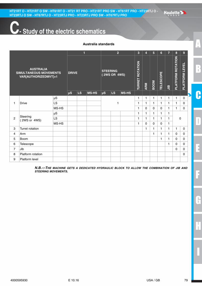
A
B
C
D
E
F
G
H
I
79 4000595930 E 10.16 USA / GB
C- Study of the electric schematics
HT21RT O - HT21RT O SW - HT61RT O - HT21 RT PRO - HT21RT PRO SW - HT61RT PRO - HT23RTJ O - HT23RTJ O SW - HT67RTJ O - HT23RTJ PRO - HT23RTJ PRO SW - HT67RTJ PRO
Australia standards
N.B.-:-THE MACHINE GETS A DEDICATED HYDRAULIC BLOCK TO ALLOW THE COMBINATION OF JIB ANDSTEERING MOVEMENTS.
AUSTRALIASIMULTANEOUS MOVEMENTS
VAR[AUTHORIZEDMVT]=1
1 2 3 4 5 6 7 8 9
DRIVESTEERING( 2WS OR 4WS)
TUR
RE
T R
OT
AT
ION
AR
M
BO
OM
TEL
ES
CO
PE
JIB
PL
AT
FOR
M R
OT
AT
ION
PL
AT
FOR
M L
EV
EL
µS LS MS-HS µS LS MS-HS
1 Drive
µS
1
1 1 1 1 1 1 0
LS 1 1 1 1 1 1 0
MS-HS 1 0 0 0 1 1 0
2Steering( 2WS or 4WS)
µS 1 1 1 1 1
0LS 1 1 1 1 1
MS-HS 1 0 0 0 1
3 Turret rotation 1 1 1 1 1 0
4 Arm 1 1 1 0 0
5 Boom 1 1 0 0
6 Telescope 1 0 0
7 Jib 0 0
8 Platform rotation 0
9 Platform level
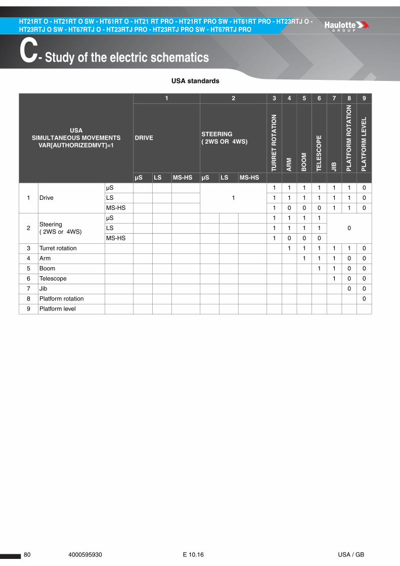
80 4000595930 E 10.16 USA / GB
HT21RT O - HT21RT O SW - HT61RT O - HT21 RT PRO - HT21RT PRO SW - HT61RT PRO - HT23RTJ O - HT23RTJ O SW - HT67RTJ O - HT23RTJ PRO - HT23RTJ PRO SW - HT67RTJ PRO
C- Study of the electric schematics
USA standards
USASIMULTANEOUS MOVEMENTS
VAR[AUTHORIZEDMVT]=1
1 2 3 4 5 6 7 8 9
DRIVESTEERING( 2WS OR 4WS)
TUR
RE
T R
OT
AT
ION
AR
M
BO
OM
TEL
ES
CO
PE
JIB
PL
AT
FOR
M R
OT
AT
ION
PL
AT
FOR
M L
EV
EL
µS LS MS-HS µS LS MS-HS
1 Drive
µS
1
1 1 1 1 1 1 0
LS 1 1 1 1 1 1 0
MS-HS 1 0 0 0 1 1 0
2Steering( 2WS or 4WS)
µS 1 1 1 1
0LS 1 1 1 1
MS-HS 1 0 0 0
3 Turret rotation 1 1 1 1 1 0
4 Arm 1 1 1 0 0
5 Boom 1 1 0 0
6 Telescope 1 0 0
7 Jib 0 0
8 Platform rotation 0
9 Platform level

A
B
C
D
E
F
G
H
I
81 4000595930 E 10.16 USA / GB
C- Study of the electric schematics
HT21RT O - HT21RT O SW - HT61RT O - HT21 RT PRO - HT21RT PRO SW - HT61RT PRO - HT23RTJ O - HT23RTJ O SW - HT67RTJ O - HT23RTJ PRO - HT23RTJ PRO SW - HT67RTJ PRO
2.5.2 - Power supply/commands
N.B.-:-
• The diagnostic menu is very important on this model as it will permit to the technician to focuse only on thedysfunction encountered and then save time to repair the machine.
• The explanation done below is built on the same basis for all movements.
Explanation of the cinematic
Explanation of the Cuttings function
This is valid for every movement including drive mode.
COMMANDS ALL COMMANDS COMING FROM LOWER/UPPER CONTROLS
Inputs Digitals or analogic inputs (ETOR-EANA)
Setpoint(0-100%)In Diagnostic menu, it's the parameter Internal setpoint for the function described Neutral to Fwd/up/left or Rev/down/Right (0-1000pts)This setpoint is null when no movement is performed or there is a failure on the josytick
CuttingsConditions for cutting the movements : • Null movement is authorized• 1 movement is inhibited
Validation and formatting the command
Conditions for validation of the movement
Slow down Condtions for slowing down the movement (from 0 to 100%)
Control(0-100%)In Diagnostic menu, it’s the parameter Internal control for the internal command of the function(0-1000pts)
Outputs Digitals or Analogic outputs (STOR-SPWM-SANA)
Actuator Any device like valves/cylinders/motors/relays
BIT CUT-OFF CONDITIONS DESCRIPTION
0 Enable General movement deactivation
1 General General Inhibition
2 Simultaneous movements Inhibition due to numerous movements activated at the same time
3 Overload Inhibition due to machine is in overload mode
4 Tilt Inhibition due to machine is in tilt/slope
5 Reach limit Inhibition due to machine is in outreach limitation mode
6 Failure Inhibition due to Faliures
7 Specific Inhibition due to specific conditions /options

82 4000595930 E 10.16 USA / GB
HT21RT O - HT21RT O SW - HT61RT O - HT21 RT PRO - HT21RT PRO SW - HT61RT PRO - HT23RTJ O - HT23RTJ O SW - HT67RTJ O - HT23RTJ PRO - HT23RTJ PRO SW - HT67RTJ PRO
C- Study of the electric schematics
REQUIREMENTS DEFINITION
PS001
The principal supply of master ECU (SPU 7066) is always powered with a permanent 12 V (12VP). The ECU handles its start and stop sequence with an internal control.
The start sequence is controlled when wake-up input is powered : • --> WUI1 = ONThe stop sequence is controlled when : • Wake-up input is in low state ( ON/OFF key, emergency stopper) : WUI1 = OFF. • No EEPROM request pending (no write or read request) : EEPROM = NOREQUEST. • Engine not in immobilizing state : CTRL[Engine]ÍSTOP.
Wake-up input WUI1 is provided by the ON/OFF key and depends on the state of emergency stoppers and overriding switch : • When the upper control box's emergency stopper is pushed and overriding switch SA801 is not activated, the wake-up input WUI1 is seen as OFF. • When the lower control box's emergency stopper is pushed, the wake-up input WUI1 is seen as OFF. • When ON/OFF key SA900 is on OFF position, the wake-up input WUI1 is seen as OFF.
PS002
The machine is powered on by switching the ON/OFF key SA900 to ON position : KMG relay is closed the the following signals raise to battery voltage : • WUI1 : Wake-up signal for SPU controller, power line for sensors. • 12VD1 : ECU outputs' supply rail. • 12VD2 : ECU outputs' supply rail. • 12VD4 : ECU outputs' supply rail. • 12VD5 : ECU outputs' supply rail. • 12VF1 : ECU outputs' supply rail. • 12VF2 : ECU outputs' supply rail. • 12VF3 : ECU outputs' supply rail. • 12VF4 : ECU outputs' supply rail. • Node B2 controller supply (platform slave, via KMP and FU7 fuse). • Sensors' supply voltage (via KMP and FU7 fuse). • Engine's relays supply voltage (via KMP and FU7 fuse). • Actuators' supply voltage (Ground).
PS003 When the SPU controller is powered on, and its status is OK, the status LED blinks (1s ON/1s OFF)
PS004
At each power on, a check between the current software identifier and the EEPROM saved software identifier is made, should the identifiers be different, the default value for all settings are reloaded : • SPEEDS/RAMPS/OPTIONS/MACHINE CONFIG, failure F12.04. • Overload system values, failure F06.01. • Hours counter is forced to null value (0).
PS005 When the emergency stoppers (turret and platform) are pulled : SB801 = ON (12V)
PS006When one at least of the emergency stops (turret and/or platform) is pushed : SB801 = OFF (0V)When only platform emergency stop is pushed : SB802 = ON (12V)
PS007
To secure the stuck of KMP power relay, the power supply of outputs' supply rail is monitored. In case of an emergency, stopper is pushed and the output's supply is still on for 2s, a failure is activated. D2s(EMSTOP=OFF & (12VD1 > 8V | 12VD2 > 8V | 12VD3 > 8V | 12VD4 > 8V | 12VD5 > 8V | 12VF1 > 8V | 12VF2 > 8V | 12VF3 > 8V | 12VF4 > 8V) --> F02.04(A)=1
PS008The overriding switch SA801 allows to bypass electrically the state of the upper control box emergency stop and then to put power back to following power supplies : WUI1, 12VD1, 12VD2, 12VD3, 12VD4, 12VD5, 12VF1, 12VF2, 12VF3, 12VF4

A
B
C
D
E
F
G
H
I
83 4000595930 E 10.16 USA / GB
C- Study of the electric schematics
HT21RT O - HT21RT O SW - HT61RT O - HT21 RT PRO - HT21RT PRO SW - HT61RT PRO - HT23RTJ O - HT23RTJ O SW - HT67RTJ O - HT23RTJ PRO - HT23RTJ PRO SW - HT67RTJ PRO
2.5.3 - Drive
2.5.3.1 - Validation
REQUIREMENTS DEFINITION
DSV01The drive movement happens in the specified direction and set point and regarding to validation and slow down conditions : SETP[Drive] = FWD | N | REV : [0-100]%Drive movement is available only from platform control box
REQUIREMENTS DEFINITION
DSV02
Forward (F) and/or reverse (R) drive movement is allowed if all validation conditions are satisfied and none of cut-offs condition is true (see DSV03)
VALIDATION F R ENABLE CONDITIONS
0 Enable1 1 1 Machine powered on for more than 3s
2 1 1 Engine is running
REQUIREMENTS DEFINITION
DSV03
Forward (F) and/or reverse (R) drive motion is/are inhibited if at least one of the all cut-off condition is activated
CUT-OFF F R GENERAL CUT-OFF CONDITIONS
1 General
1 1 1 Generator is running
2 1 1 Maximum number of running movements is reached
3 1 1 Safety valves tool is active
4 1 1Platform emergency stop pushed and overriding not used
REQUIREMENTS DEFINITION
DSV03CUT-OFF F R
SIMULTANEOUS MOVEMENTS CUT-OFF CONDITIONS
2Simultaneous movements
1..10 1 1Requirements SM_CE_03 | SM_AU_02 | SM_ANSI_02
REQUIREMENTS DEFINITION
DSV03CUT-OFF F R OVERLOAD CUT-OFF CONDITIONS
3 Overload 1 1 1 Overload alarm is active

84 4000595930 E 10.16 USA / GB
HT21RT O - HT21RT O SW - HT61RT O - HT21 RT PRO - HT21RT PRO SW - HT61RT PRO - HT23RTJ O - HT23RTJ O SW - HT67RTJ O - HT23RTJ PRO - HT23RTJ PRO SW - HT67RTJ PRO
C- Study of the electric schematics
REQUIREMENTS DEFINITION
DSV03CUT-OFF F R TILT CUT-OFF CONDITIONS
4 Tilt 1 1 1Tilt activated with unfolded machine and drive's safety tilt
REQUIREMENTS DEFINITION
DSV03CUT-OFF F R REACH LIMIT CUT-OFF CONDITIONS
5 Reach limit N/A N/A N/A N/A
REQUIREMENTS DEFINITION
DSV03
CUT-OFF F R FAILURE CUT-OFF CONDITIONS
6 Failure
1 1 1 KMP relay stuck
2 1 1 Active failure on steering valve
3 1 1 Active failure on drive proportional electrovalve
4 1 1 Active failure on LS valve
5 1 1 Weight system not calibrated and machine unfolded
6 1 1Brake releasing valve detected failure and machine unfolded
7 1 1Load management system not calibrated and machine unfolded
8 1 1Load management sensors out of range and machine unfolded
9 1 1Load management sensors incoherence and machine unfolded
10 1 1Load management sensors low powered and machine unfolded
11 1 1Load management sensors electrical failure and machine unfolded
12 1 1Load management sensors logical failure and machine unfolded
13 1 1 Drive circuit pressure sensors failure
14 1 1 Drive current too high with unfolded machine
15 1 1Drive circuit pressure incoherence and unfolded machine
16 1 1Engine RPM is too high (detected) while driving and machine is unfolded(>2550RPM for 2.5s)
17 1 1 Drive circuit pressure incoherence
18 1 1 Failure F12.01.b0 is active

A
B
C
D
E
F
G
H
I
85 4000595930 E 10.16 USA / GB
C- Study of the electric schematics
HT21RT O - HT21RT O SW - HT61RT O - HT21 RT PRO - HT21RT PRO SW - HT61RT PRO - HT23RTJ O - HT23RTJ O SW - HT67RTJ O - HT23RTJ PRO - HT23RTJ PRO SW - HT67RTJ PRO
REQUIREMENTS DEFINITION
DSV03
CUT-OFF F R SPECIFIC CUT-OFF CONDITIONS
7 Specific
1 1 N/A ASB safety active for forward direction
2 N/A 1 ASB safety active for reverse direction
3 1 1Extreme ambient temperature is detected and machine is unfolded
REQUIREMENTS DEFINITION
Following limits are applied on the set point (SETP[Drive]) if engine is running(CTRL[Engine]=RUNNING)
DSV04
LIMITS (%) CORRESPONDING TO DIRECTIONS
MOVEMENT SET POINT LIMIT CONDITIONS IF ENGINE IS
RUNNING(CTRL[ENGINE]=RUNNING)F R
SPEED[uS Drive Fwd] SPEED[uS Drive Rev] 1 Unfolded machine(Micro speed)
Lower value is applied if several limits are active(100% = max speed)-No slow down with emergency pump
REQUIREMENTS DEFINITION
DSV05
Pressures in forward and reverse drive circuit are given by analogue sensors SP160F(MB) and SP160B (MA), if drive pump safety is active : [0.5 – 4.5]V –>[0 – 400]barCONFIG[DrivePumpSafety] = 1:• VAR[DrivePressureFWD] = 400 x (SP160F – 0.5) / 4 (bar)• VAR[DrivePressureREV] = 400 x (SP160B – 0.5) / 4 (bar)• VAR[DrivePressureDiff] = (VAR[DrivePressureFWD] – VAR[DrivePressureREV])CONFIG[DrivePumpSafety] = 0:• VAR[DrivePressureFWD] = 0• VAR[DrivePressureREV] = 0• VAR[DrivePressureDiff] = 0
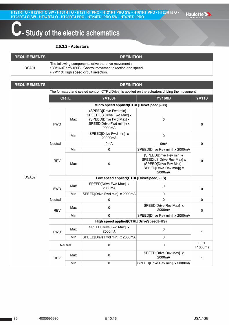
86 4000595930 E 10.16 USA / GB
HT21RT O - HT21RT O SW - HT61RT O - HT21 RT PRO - HT21RT PRO SW - HT61RT PRO - HT23RTJ O - HT23RTJ O SW - HT67RTJ O - HT23RTJ PRO - HT23RTJ PRO SW - HT67RTJ PRO
C- Study of the electric schematics
2.5.3.2 - Actuators
REQUIREMENTS DEFINITION
DSA01The following components drive the drive movement : • YV160F / YV160B : Control movement direction and speed. • YV110: High speed circuit selection.
REQUIREMENTS DEFINITION
DSA02
The formated and scaled control CTRL[Drive] is applied on the actuators driving the movement
CRTL YV160F YV160B YV110
Micro speed applied(CTRL[DriveSpeed]=uS)
FWD
Max
(SPEED[Drive Fwd min] + SPEED[uS Drive Fwd Max] x
(SPEED[Drive Fwd Max] - SPEED[Drive Fwd min])) x
2000mA
0
0
MinSPEED[Drive Fwd min] x
20000mA0
Neutral 0mA 0mA 0
REV
Min 0 SPEED[Drive Rev min] x 2000mA
0Max 0
(SPEED[Drive Rev min] + SPEED[uS Drive Rev Max] x
(SPEED[Drive Rev Max] - SPEED[Drive Rev min])) x
2000mA
Low speed applied(CTRL[DriveSpeed]=LS)
FWDMax
SPEED[Drive Fwd Max] x 2000mA
00
Min SPEED[Drive Fwd min] x 2000mA 0
Neutral 0 0 0
REVMax 0
SPEED[Drive Rev Max] x 2000mA 0
Min 0 SPEED[Drive Rev min] x 2000mA
High speed applied(CTRL[DriveSpeed]=HS)
FWDMax
SPEED[Drive Fwd Max] x 2000mA
01
Min SPEED[Drive Fwd min] x 2000mA 0
Neutral 0 00 | 1
T1000ms
REVMax 0
SPEED[Drive Rev Max] x 2000mA 1
Min 0 SPEED[Drive Rev min] x 2000mA

A
B
C
D
E
F
G
H
I
87 4000595930 E 10.16 USA / GB
C- Study of the electric schematics
HT21RT O - HT21RT O SW - HT61RT O - HT21 RT PRO - HT21RT PRO SW - HT61RT PRO - HT23RTJ O - HT23RTJ O SW - HT67RTJ O - HT23RTJ PRO - HT23RTJ PRO SW - HT67RTJ PRO
2.5.4 - Steering
2.5.4.1 - Validation
REQUIREMENTS DEFINITION
STV01The steering movement happens in the specified direction and set point, regarding to validation and slow down conditions : SETP[Steering] = LEFT|N|RIGHT : [0-100]%Steering movement is available only from platform control box
REQUIREMENTS DEFINITION
STV02
Steering (both directions, each mode) is allowed if all validation conditions are satisfied and none of cut-off conditions is true (see STV03)
VALIDATION L R ENABLE CONDITIONS
0 Enable1 1 1 Machine powered on for more than 3s
2 1 1 Engine is running
REQUIREMENTS DEFINITION
STV03
Steering for left (L) or right (R) directions and for each mode is inhibited if at least one of the all cut-off conditions is activated
CUT-OFF L R GENERAL CUT-OFF CONDITIONS
1 General
1 1 1 Generator is running
2 1 1 Maximum number of running movements is reached
3 1 1 Safety valves tool is active
4 1 1Platform emergency stop pushed and overriding not used
REQUIREMENTS DEFINITION
STV03CUT-OFF L R
SIMULTANEOUS MOVEMENTS CUT-OFF CONDITIONS
2Simultaneous movements
1..10 1 1Requirements SM_CE_03 | SM_AU_02 | SM_ANSI_02
REQUIREMENTS DEFINITION
STV03CUT-OFF L R OVERLOAD CUT-OFF CONDITIONS
3 Overload 1 1 1 Overload alarm is active
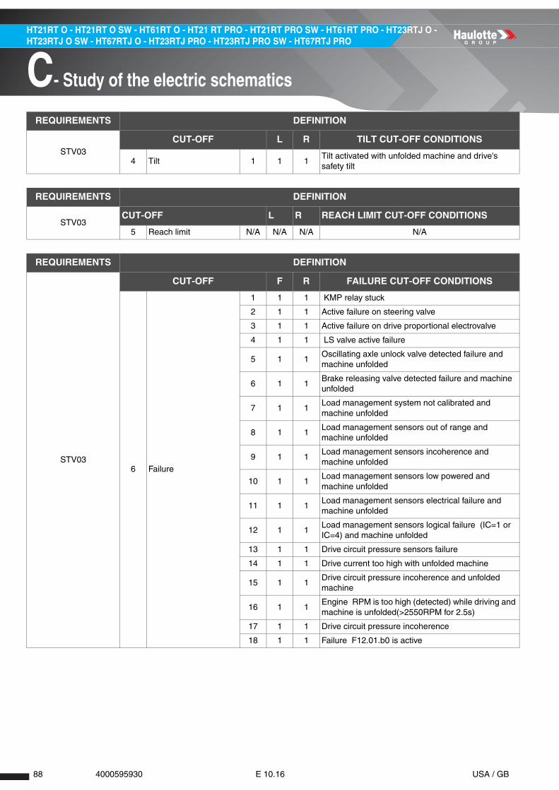
88 4000595930 E 10.16 USA / GB
HT21RT O - HT21RT O SW - HT61RT O - HT21 RT PRO - HT21RT PRO SW - HT61RT PRO - HT23RTJ O - HT23RTJ O SW - HT67RTJ O - HT23RTJ PRO - HT23RTJ PRO SW - HT67RTJ PRO
C- Study of the electric schematics
REQUIREMENTS DEFINITION
STV03CUT-OFF L R TILT CUT-OFF CONDITIONS
4 Tilt 1 1 1Tilt activated with unfolded machine and drive's safety tilt
REQUIREMENTS DEFINITION
STV03CUT-OFF L R REACH LIMIT CUT-OFF CONDITIONS
5 Reach limit N/A N/A N/A N/A
REQUIREMENTS DEFINITION
STV03
CUT-OFF F R FAILURE CUT-OFF CONDITIONS
6 Failure
1 1 1 KMP relay stuck
2 1 1 Active failure on steering valve
3 1 1 Active failure on drive proportional electrovalve
4 1 1 LS valve active failure
5 1 1Oscillating axle unlock valve detected failure and machine unfolded
6 1 1Brake releasing valve detected failure and machine unfolded
7 1 1Load management system not calibrated and machine unfolded
8 1 1Load management sensors out of range and machine unfolded
9 1 1Load management sensors incoherence and machine unfolded
10 1 1Load management sensors low powered and machine unfolded
11 1 1Load management sensors electrical failure and machine unfolded
12 1 1Load management sensors logical failure (IC=1 or IC=4) and machine unfolded
13 1 1 Drive circuit pressure sensors failure
14 1 1 Drive current too high with unfolded machine
15 1 1Drive circuit pressure incoherence and unfolded machine
16 1 1Engine RPM is too high (detected) while driving and machine is unfolded(>2550RPM for 2.5s)
17 1 1 Drive circuit pressure incoherence
18 1 1 Failure F12.01.b0 is active

A
B
C
D
E
F
G
H
I
89 4000595930 E 10.16 USA / GB
C- Study of the electric schematics
HT21RT O - HT21RT O SW - HT61RT O - HT21 RT PRO - HT21RT PRO SW - HT61RT PRO - HT23RTJ O - HT23RTJ O SW - HT67RTJ O - HT23RTJ PRO - HT23RTJ PRO SW - HT67RTJ PRO
2.5.4.2 - Actuators
REQUIREMENTS DEFINITION
STV03
CUT-OFF L R SPECIFIC CUT-OFF CONDITIONS
7 Specific
1 1 1 Activ'Shield Bar active for steering motion
2 1 1Extreme temperature detected and machine unfolded
REQUIREMENTS DEFINITION
STV04 There is not limitation of steering movement set point
REQUIREMENTS DEFINITION
STA01
The following components drive the drive movement : • YV902 : Control movement speed. • YV150L : Steering left. • YV150R : Steering right. • YV107 / YV108 : Crab / Synchronized mode.
REQUIREMENTS DEFINITION
STA02
The formated control (CTRL[Steering]) is applied on the actuators driving the steering movement depending on the chosen mode
MOVEMENT DIRECTION
STEERING MODE SELECTION
YV902
YV
150L
YV
150R
YV
107
YV
108
Left
2WS
Acc min 0 mA
1 0 0 0Max SPEED[Steering Max] x 2000mA
Dec min 0 mA
CRAB
Acc min 0 mA
1 0 1 0Max SPEED[Steering Max] x 2000mA
Dec min 0 mA
SYNC
Acc min 0 mA
1 0 0 1Max SPEED[Steering Max] x 2000mA
Dec min 0 mA
Neutral 0 mA 0 0 0 0
Right
2WS
Acc min 0 mA
0 1 0 0Max SPEED[Steering Max] x 2000mA
Dec min 0 mA
CRAB
Acc min 0 mA
0 1 0 1Max SPEED[Steering Max] x 2000mA
Dec min 0 mA
SYNC
Acc min 0 mA
0 1 1 0Max SPEED[Steering Max]% 2000mA
Dec min 0 mA

90 4000595930 E 10.16 USA / GB
HT21RT O - HT21RT O SW - HT61RT O - HT21 RT PRO - HT21RT PRO SW - HT61RT PRO - HT23RTJ O - HT23RTJ O SW - HT67RTJ O - HT23RTJ PRO - HT23RTJ PRO SW - HT67RTJ PRO
C- Study of the electric schematics
2.5.5 - Orientation
2.5.5.1 - Validation
REQUIREMENTS DEFINITION
TRV01The turret rotation movement happens in the specified direction and set point, regarding to validation and slow down conditions : SETP[Turntable] = LEFT|N|RIGHT: [0-100]%
REQUIREMENTS DEFINITION
TRV02
Turntable orientation for left (L) or right (R) directions is allowed if all validation conditions are satisfied and none of cut-offs condition is true (see STV03)
VALIDATION L R ENABLE CONDITIONS
0 Enable1 1 1 Machine powered on for more than 3s
2 1 1 Engine is running or emergency pump is running
REQUIREMENTS DEFINITION
TRV03
Turntable rotate for left (L) and/or right (R) directions is inhibited if at least one of the all cut-off conditions is activated
CUT-OFF L R GENERAL CUT-OFF CONDITIONS
1 General
1 1 1 Generator is running
2 1 1 Maximum number of running movements is reached
3 1 1 Safety valves tool is active
4 1 1Platform emergency stop pushed and overriding not used
REQUIREMENTS DEFINITION
TRV03CUT-OFF L R
SIMULTANEOUS MOVEMENTS CUT-OFF CONDITIONS
2Simultaneous movements
1..10 1 1Requirements SM_CE_03 | SM_AU_02 | SM_ANSI_02
REQUIREMENTS DEFINITION
TRV03CUT-OFF L R OVERLOAD CUT-OFF CONDITIONS
3 Overload 1 1 1 Overload alarm is active and not overriding mode

A
B
C
D
E
F
G
H
I
91 4000595930 E 10.16 USA / GB
C- Study of the electric schematics
HT21RT O - HT21RT O SW - HT61RT O - HT21 RT PRO - HT21RT PRO SW - HT61RT PRO - HT23RTJ O - HT23RTJ O SW - HT67RTJ O - HT23RTJ PRO - HT23RTJ PRO SW - HT67RTJ PRO
REQUIREMENTS DEFINITION
TRV03CUT-OFF L R TILT CUT-OFF CONDITIONS
4 Tilt N/A N/A N/A N/A
REQUIREMENTS DEFINITION
TRV03CUT-OFF L R REACH LIMIT CUT-OFF CONDITIONS
5 Reach limit N/A N/A N/A N/A
REQUIREMENTS DEFINITION
TRV03
CUT-OFF L R FAILURE CUT-OFF CONDITIONS
6 Failure
1 1 1 KMP relay stuck
2 1 1Turntable orientation active valves failure and engine is running
3 1 1 Active failure on LS valve and engine is running
4 1 1Load management system not calibrated and machine unfolded and not overriding control box
5 1 1LMS gauges out of range and machine unfolded and not overriding control box
6 1 1LMS gauges incoherence and machine unfolded and not overriding control box
7 1 1LMS gauges low power and machine unfolded and not overriding control box
8 1 1Load management sensors electrical failure and machine unfolded and not overriding control box
9 1 1Load management sensors logical failure (IC=1 or IC=4) and machine unfolded and not overriding control box
10 1 1 CAN failure with platform ECU and platform control box

92 4000595930 E 10.16 USA / GB
HT21RT O - HT21RT O SW - HT61RT O - HT21 RT PRO - HT21RT PRO SW - HT61RT PRO - HT23RTJ O - HT23RTJ O SW - HT67RTJ O - HT23RTJ PRO - HT23RTJ PRO SW - HT67RTJ PRO
C- Study of the electric schematics
REQUIREMENTS DEFINITION
TRV03
CUT-OFF L R SPECIFIC CUT-OFF CONDITIONS
7 Specific1 1 N/A ASB safety active and upper controls
2 N/A 1 ASB safety active and upper controls
REQUIREMENTS DEFINITION
TRV04
Following limits are applied on the set point (SETP[Turntable]) if engine is running (CTRL[Engine]=RUNNING)
LIMITS (%) CORRESPONDING TO
DIRECTIONSMOVEMENT SET POINT LIMIT CONDITIONS IF ENGINE IS
RUNNING(CTRL[ENGINE]=RUNNING &)
L R
50 50 1 Active control box is overriding control box
80 80 2 Active control box is lower control box
50 50 3 Tilt is active and machine is unfolded
50 50 4Load management system failure or oscillating axle failure or brake release valve failure
Lower value is applied if several limits are active(100% = max speed)-No slow down with emergency pump

A
B
C
D
E
F
G
H
I
93 4000595930 E 10.16 USA / GB
C- Study of the electric schematics
HT21RT O - HT21RT O SW - HT61RT O - HT21 RT PRO - HT21RT PRO SW - HT61RT PRO - HT23RTJ O - HT23RTJ O SW - HT67RTJ O - HT23RTJ PRO - HT23RTJ PRO SW - HT67RTJ PRO
2.5.5.2 - Actuators
REQUIREMENTS DEFINITION
TRA01
The following components drive the turret rotation movements : • YV250R / YV250L: Control movement direction and speed. • YV805: Turntable rotate safety. • GND5: Turntable rotate safety ground supply.
REQUIREMENTS DEFINITION
TRA02
When activation or deactivation of safety valves are not active, the validated and scaled computed control CTRL[Turntable] is applied to actuators
CTRL YV250L YV250R YV805 GND5
Left
MaxSPEED[Turntable Left Max] x
2000mA0 mA
1 1
MinSPEED[Turntable Left Min] x
2000mA0 mA
Neutral 0 mA 0 mA 0 (*) 0 (*)
Right
Min 0 mASPEED[Turntable Right Min] x
2000mA1 1
Max 0 mASPEED[Turntable Right Max] x
2000mA
(*): Safety valve deactivation is delayed (500ms) after the end of deceleration ramp(**): Safety valve ground supply is used to supply ground also to YV807 (boom descent safety valve)

94 4000595930 E 10.16 USA / GB
HT21RT O - HT21RT O SW - HT61RT O - HT21 RT PRO - HT21RT PRO SW - HT61RT PRO - HT23RTJ O - HT23RTJ O SW - HT67RTJ O - HT23RTJ PRO - HT23RTJ PRO SW - HT67RTJ PRO
C- Study of the electric schematics
2.5.6 - Boom
2.5.6.1 - Validation
REQUIREMENTS DEFINITION
BMV01The boom's movement happens in the specified direction and set point regarding to validation and slow down conditions : SETP[Boom] = UP|N|DOWN: [0-100]%
REQUIREMENTS DEFINITION
BMV02
Raise (U: up) and/or descent (D: down) of boom is/are allowed if all validation conditions are satisfied and none of cut-offs condition is true (see BLV03)
VALIDATION U D ENABLE CONDITIONS
0 Enable1 1 1 Machine powered on for more than 3s
2 1 1 Engine is running or emergency pump is running
REQUIREMENTS DEFINITION
BMV03
Raise (U: up) or descent (D: down) of boom is enabled if at least one of the cut-off conditions is active(From General to Specific)
CUT-OFF U D GENERAL CUT-OFF CONDITIONS
1 General
1 1 1 Generator is running
2 1 1 Maximum number of running movements is reached
3 1 1 Safety valves ON tool is inactive
4 1 1Platform emergency stop pushed and overriding not used
REQUIREMENTS DEFINITION
BMV03CUT-OFF U D
SIMULTANEOUS MOVEMENTS CUT-OFF CONDITIONS
2Simultaneous movements
1..8 1 1Requirements SM_CE_03 | SM_AU_02 | SM_ANSI_02
REQUIREMENTS DEFINITION
BMV03
CUT-OFF U D OVERLOAD CUT-OFF CONDITIONS
3 Overload1 1 1
Overload alarm is active and overriding control box is inactive
2 1 N/AOverload alarm is active and machine in position "P5" (prevent from shunting reach limit system)

A
B
C
D
E
F
G
H
I
95 4000595930 E 10.16 USA / GB
C- Study of the electric schematics
HT21RT O - HT21RT O SW - HT61RT O - HT21 RT PRO - HT21RT PRO SW - HT61RT PRO - HT23RTJ O - HT23RTJ O SW - HT67RTJ O - HT23RTJ PRO - HT23RTJ PRO SW - HT67RTJ PRO
REQUIREMENTS DEFINITION
BMV03
CUT-OFF U D TILT CUT-OFF CONDITIONS
4 Tilt
1 1 N/ATilt active and option "movements restriction under tilt conditions" is active and machine is unfolded
2 N/A 1Tilt active and option "movements restriction under tilt conditions" is active and machine in P4 position (dual load machines only)
3 N/A 1Tilt active and option "movements restriction under tilt conditions" is active and machine in P5 position (dual load machines only)
REQUIREMENTS DEFINITION
BMV03CUT-OFF U D REACH LIMIT CUT-OFF CONDITIONS
5 Reach limit 1 N/A 1Machine in position "P5" and 450kg/1000lb applied load
REQUIREMENTS DEFINITION
BMV03
CUT-OFF U D FAILURE CUT-OFF CONDITIONS
6 Failure
1 1 1 KMP relay stuck
2 1 1 Boom valves active failure and engine is running
3 1 1 LS valve active failure and engine is running
4 1 N/A Oscillating axle valve and machine unfolded
5 1 N/A Brake release valve failure and machine unfolded
6 1 1Load management system not calibrated and machine unfolded and not overriding control box
7 1 1LMS gauges out of range and machine unfolded and not overriding control box
8 1 1LMS gauges incoherence and machine unfolded and not overriding control box
9 1 1LMS gauges low power and machine unfolded and not overriding control box
10 1 1Load management sensors electrical failure and machine unfolded and not overriding control box
11 1 1Load management sensors logical failure (IC=1 or IC=4) and machine unfolded and not overriding control box
12 1 N/A Cable break and machine unfolded
13 N/A 1Angle position failure under conditions (failure F07.04 and boom descent inhibited)
14 N/A 1Length position failure under conditions(failure F07.11 and boom descent inhibited)
15 1 1Active CAN failure witch platform ECU and upper controls
16 1 1 Overriding switch failure and machine is folded
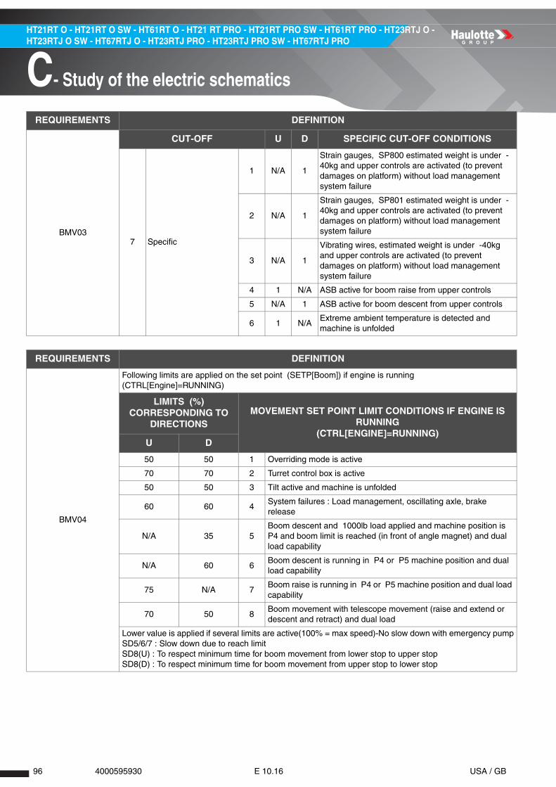
96 4000595930 E 10.16 USA / GB
HT21RT O - HT21RT O SW - HT61RT O - HT21 RT PRO - HT21RT PRO SW - HT61RT PRO - HT23RTJ O - HT23RTJ O SW - HT67RTJ O - HT23RTJ PRO - HT23RTJ PRO SW - HT67RTJ PRO
C- Study of the electric schematics
REQUIREMENTS DEFINITION
BMV03
CUT-OFF U D SPECIFIC CUT-OFF CONDITIONS
7 Specific
1 N/A 1
Strain gauges, SP800 estimated weight is under -40kg and upper controls are activated (to prevent damages on platform) without load management system failure
2 N/A 1
Strain gauges, SP801 estimated weight is under -40kg and upper controls are activated (to prevent damages on platform) without load management system failure
3 N/A 1
Vibrating wires, estimated weight is under -40kg and upper controls are activated (to prevent damages on platform) without load management system failure
4 1 N/A ASB active for boom raise from upper controls
5 N/A 1 ASB active for boom descent from upper controls
6 1 N/AExtreme ambient temperature is detected and machine is unfolded
REQUIREMENTS DEFINITION
BMV04
Following limits are applied on the set point (SETP[Boom]) if engine is running (CTRL[Engine]=RUNNING)
LIMITS (%) CORRESPONDING TO
DIRECTIONSMOVEMENT SET POINT LIMIT CONDITIONS IF ENGINE IS
RUNNING(CTRL[ENGINE]=RUNNING)
U D
50 50 1 Overriding mode is active
70 70 2 Turret control box is active
50 50 3 Tilt active and machine is unfolded
60 60 4System failures : Load management, oscillating axle, brake release
N/A 35 5Boom descent and 1000lb load applied and machine position is P4 and boom limit is reached (in front of angle magnet) and dual load capability
N/A 60 6Boom descent is running in P4 or P5 machine position and dual load capability
75 N/A 7Boom raise is running in P4 or P5 machine position and dual load capability
70 50 8Boom movement with telescope movement (raise and extend or descent and retract) and dual load
Lower value is applied if several limits are active(100% = max speed)-No slow down with emergency pumpSD5/6/7 : Slow down due to reach limitSD8(U) : To respect minimum time for boom movement from lower stop to upper stopSD8(D) : To respect minimum time for boom movement from upper stop to lower stop

A
B
C
D
E
F
G
H
I
97 4000595930 E 10.16 USA / GB
C- Study of the electric schematics
HT21RT O - HT21RT O SW - HT61RT O - HT21 RT PRO - HT21RT PRO SW - HT61RT PRO - HT23RTJ O - HT23RTJ O SW - HT67RTJ O - HT23RTJ PRO - HT23RTJ PRO SW - HT67RTJ PRO
2.5.6.2 - Actuators
REQUIREMENTS DEFINITION
BMA01
The following components drive the boom lifting movement : • YV520U/YV520D: Control movement direction and speed. • YV802: Boom raise and descent safety. • GND2: Boom raise and descent safety ground supply. • YV807: Boom descent safety. • GND5: Boom descent safety ground supply.
REQUIREMENTS DEFINITION
BMA02
When activation or deactivation of safety valves are not active, the validated and scaled computed control CTRL[Boom] is applied to actuators
CRTL YV520U YV520D
YV
802
GN
D2
YV
807
GN
D5
Up
MaxSPEED[Boom Raise Max] x
2000mA0 mA
1 1 0 0Min
SPEED[Boom Raise Min] x 2000mA
0 mA
Neutral 0 mA 0 mA 0 (*) 0 (**) 0 (*) 0 (***)
DownMin 0 mA
SPEED[Boom Descent Min] x 2000mA
1
Max 0 mASPEED[Boom Descent
Max] x 2000mA
(*): Safety valves and power supply deactivation ( YV802, YV807 with their ground supply) are delayed after the end of boom deceleration ramp. (**): Safety valve ground supply is used to supply ground also to YV801 (boom telescope extension safety valve). (***): Safety valve ground supply is used to supply ground also to YV805 (turntable orientation safety valve).

98 4000595930 E 10.16 USA / GB
HT21RT O - HT21RT O SW - HT61RT O - HT21 RT PRO - HT21RT PRO SW - HT61RT PRO - HT23RTJ O - HT23RTJ O SW - HT67RTJ O - HT23RTJ PRO - HT23RTJ PRO SW - HT67RTJ PRO
C- Study of the electric schematics
2.5.7 - Telescope
2.5.7.1 - Validation
REQUIREMENTS DEFINITION
BTV01The telescope's movement happens in the specified direction and set point regarding to validation and slow down condition : SETP[Telescope]=OUT|N|IN: [0-100]%
REQUIREMENTS DEFINITION
BTV02
Boom telescope extension (O: out) or retraction (I:in) is allowed if all validation conditions are satisfied and none of cut-offs condition is true (see STV03)
VALIDATION L R ENABLE CONDITIONS
0 Enable1 1 1 Machine powered on for more than 3s
2 1 1 Engine is running or emergency pump is running
REQUIREMENTS DEFINITION
BTV03
Extension (O:out) or retraction (I:in) of boom's telescope is inhibited if at least one of the following cut-off conditions is active
CUT-OFF O I GENERAL CUT-OFF CONDITIONS
1 General
1 1 1 Generator is running
2 1 1 Maximum number of running movements is reached
3 1 1 Safety valves tool is active
4 1 1Platform emergency stop pushed and overriding not used
REQUIREMENTS DEFINITION
BTV03CUT-OFF O I
SIMULTANEOUS MOVEMENTS CUT-OFF CONDITIONS
2Simultaneous movements
1..10 1 1Requirements SM_CE_03 | SM_AU_02 | SM_ANSI_02
REQUIREMENTS DEFINITION
BTV03
CUT-OFF O I OVERLOAD CUT-OFF CONDITIONS
3 Overload
1 1 1 Overload alarm is active and not overriding mode
2 1 N/AOverload alarm is active and machine in position "P5"
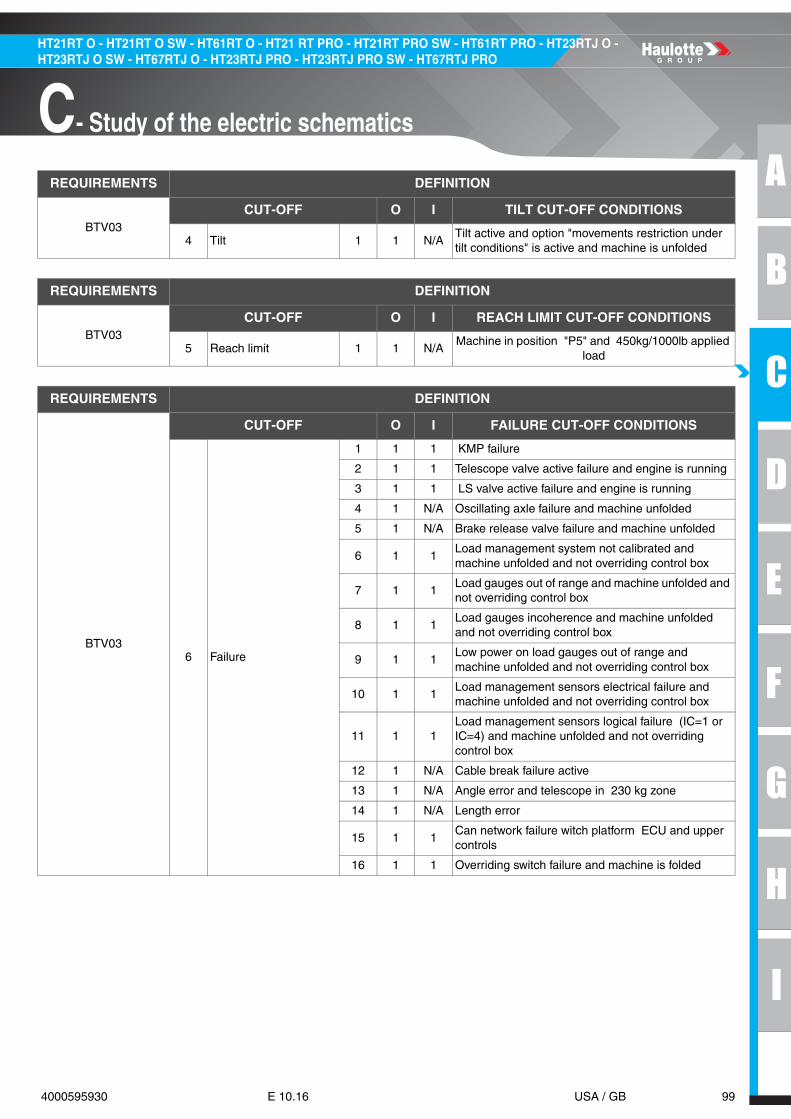
A
B
C
D
E
F
G
H
I
99 4000595930 E 10.16 USA / GB
C- Study of the electric schematics
HT21RT O - HT21RT O SW - HT61RT O - HT21 RT PRO - HT21RT PRO SW - HT61RT PRO - HT23RTJ O - HT23RTJ O SW - HT67RTJ O - HT23RTJ PRO - HT23RTJ PRO SW - HT67RTJ PRO
REQUIREMENTS DEFINITION
BTV03CUT-OFF O I TILT CUT-OFF CONDITIONS
4 Tilt 1 1 N/ATilt active and option "movements restriction under tilt conditions" is active and machine is unfolded
REQUIREMENTS DEFINITION
BTV03CUT-OFF O I REACH LIMIT CUT-OFF CONDITIONS
5 Reach limit 1 1 N/AMachine in position "P5" and 450kg/1000lb applied
load
REQUIREMENTS DEFINITION
BTV03
CUT-OFF O I FAILURE CUT-OFF CONDITIONS
6 Failure
1 1 1 KMP failure
2 1 1 Telescope valve active failure and engine is running
3 1 1 LS valve active failure and engine is running
4 1 N/A Oscillating axle failure and machine unfolded
5 1 N/A Brake release valve failure and machine unfolded
6 1 1Load management system not calibrated and machine unfolded and not overriding control box
7 1 1Load gauges out of range and machine unfolded and not overriding control box
8 1 1Load gauges incoherence and machine unfolded and not overriding control box
9 1 1Low power on load gauges out of range and machine unfolded and not overriding control box
10 1 1Load management sensors electrical failure and machine unfolded and not overriding control box
11 1 1Load management sensors logical failure (IC=1 or IC=4) and machine unfolded and not overriding control box
12 1 N/A Cable break failure active
13 1 N/A Angle error and telescope in 230 kg zone
14 1 N/A Length error
15 1 1Can network failure witch platform ECU and upper controls
16 1 1 Overriding switch failure and machine is folded

100 4000595930 E 10.16 USA / GB
HT21RT O - HT21RT O SW - HT61RT O - HT21 RT PRO - HT21RT PRO SW - HT61RT PRO - HT23RTJ O - HT23RTJ O SW - HT67RTJ O - HT23RTJ PRO - HT23RTJ PRO SW - HT67RTJ PRO
C- Study of the electric schematics
REQUIREMENTS DEFINITION
BTV03
CUT-OFF O I SPECIFIC CUT-OFF CONDITIONS
7 Specific
1 1 N/AASB active for telescope extension from upper controls
2 N/A 1ASB active for telescope retraction from upper controls
3 1 N/AExtreme ambient temperature is detected and machine is unfolded
REQUIREMENTS DEFINITION
BTV04
Following limits are applied on the set point (SETP[BoomTelescope]) if engine is running (CTRL[Engine]=RUNNING)
LIMITS (%) CORRESPONDING TO
DIRECTIONSMOVEMENT SET POINT LIMIT CONDITIONS IF ENGINE IS
RUNNING(CTRL[ENGINE]=RUNNING)
O I
50 80 1 Overriding control box is active
65 65 2 Turret control box is active
65 80 3 Tilt active and machine unfolded
65 65 4System failures : Load management, oscillating axle, brake release
N/A 45 5 Boom descent and telescope retract running simultaneously
N/A 80 6 Machine position is failing
60 N/A 7Boom raise and turntable rotation and telescope extend running simultaneously
40 N/A 8Telescope extend and 1000 lb load applied and machine position is P2 and telescope limit is reached (in front of magnet) and dual load capability
Lower value is applied if several limits are active(100% = max speed)-No slow down with emergency pump

A
B
C
D
E
F
G
H
I
101 4000595930 E 10.16 USA / GB
C- Study of the electric schematics
HT21RT O - HT21RT O SW - HT61RT O - HT21 RT PRO - HT21RT PRO SW - HT61RT PRO - HT23RTJ O - HT23RTJ O SW - HT67RTJ O - HT23RTJ PRO - HT23RTJ PRO SW - HT67RTJ PRO
2.5.7.2 - Actuators
REQUIREMENTS DEFINITION
BTA01
The following components drive the boom telescoping movement : • YV530O / YV530I : Control movement direction and speed. • YV801 : Telescope extension safety. • GND5 : Telescope extension safety ground supply.
REQUIREMENTS DEFINITION
BTA02
When activation or deactivation of safety valves are not active, the validated and scaled computed control CTRL[BoomTelescope] is applied to actuators
CTRL YV530O YV530I YV801 GND5
OUT
MaxSPEED[Boom Telescope Extend Max] x 2000mA
0mA
1 1(**)
MinSPEED[Boom Telescope Extend Min] x 2000mA
0mA
Neutral 0mA 0mA 0(*) 0(*)
IN
Max 0mASPEED[Boom Telescope Retract Min] x 2000mA
0 0Min 0mA
SPEED[Boom Telescope Retract Max] x 2000mA
(*) : Safety valves deactivation ( YV801 and YV801 ground supply) is delayed after the end of boom deceleration ramp. (**) : Safety valve ground supply is used to supply ground also to YV802 (boom raise and descent safety valve).

102 4000595930 E 10.16 USA / GB
HT21RT O - HT21RT O SW - HT61RT O - HT21 RT PRO - HT21RT PRO SW - HT61RT PRO - HT23RTJ O - HT23RTJ O SW - HT67RTJ O - HT23RTJ PRO - HT23RTJ PRO SW - HT67RTJ PRO
C- Study of the electric schematics
2.5.8 - Jib
2.5.8.1 - Validation
REQUIREMENTS DEFINITION
JMV01The boom telescope motion happens in the specified direction and set point and regarding to validation conditions : SETP[Jib] = UP|N|DOWN: [0-100]%
REQUIREMENTS DEFINITION
JMV02
Jib raise (U:up) or descent (D:Down) is allowed if all validation conditions are satisfied and none of cut-offs condition is true (see JLV03)
VALIDATION L R ENABLE CONDITIONS
0 Enable
1 1 1 Machine powered on for more than 3s
2 1 1 Engine is running or emergency pump is running
3 1 1 Engine is running or emergency pump is running
REQUIREMENTS DEFINITION
JMV03
Raise (U:up) or descent (D:down) of jib is inhibited if at least one of the following cut-off conditions is active
CUT-OFF U D GENERAL CUT-OFF CONDITIONS
1 General
1 1 1 Generator is running
2 1 1 Maximum number of running movements is reached
3 1 1 Safety valves tool is active
4 1 1Platform emergency stop pushed and overriding not used
REQUIREMENTS DEFINITION
JMV03CUT-OFF U D
SIMULTANEOUS MOVEMENTS CUT-OFF CONDITIONS
2Simultaneous movements
1..10 1 1Requirements SM_CE_03 | SM_AU_02 | SM_ANSI_02
REQUIREMENTS DEFINITION
JMV03CUT-OFF U D OVERLOAD CUT-OFF CONDITIONS
3 Overload 1 1 1 Overload alarm is active and not overriding mode

A
B
C
D
E
F
G
H
I
103 4000595930 E 10.16 USA / GB
C- Study of the electric schematics
HT21RT O - HT21RT O SW - HT61RT O - HT21 RT PRO - HT21RT PRO SW - HT61RT PRO - HT23RTJ O - HT23RTJ O SW - HT67RTJ O - HT23RTJ PRO - HT23RTJ PRO SW - HT67RTJ PRO
REQUIREMENTS DEFINITION
JMV03CUT-OFF O I TILT CUT-OFF CONDITIONS
4 Tilt N/A N/A N/A N/A
REQUIREMENTS DEFINITION
JMV03CUT-OFF U D REACH LIMIT CUT-OFF CONDITIONS
5 Reach limit N/A N/A N/A N/A
REQUIREMENTS DEFINITION
JMV03
CUT-OFF U D FAILURE CUT-OFF CONDITIONS
6 Failure
1 1 1 KMP failure
2 1 1 Jib valve active failure and engine is running
3 1 1 LS valve active failure and engine is running
4 1 1Load management system not calibrated and machine unfolded and not overriding control box
5 1 1Load gauges out of range and machine unfolded and not overriding control box
6 1 1Load gauges incoherence and machine unfolded and not overriding control box
7 1 1Low power on load gauges out of range and machine unfolded and not overriding control box
8 1 1Load management sensors electrical failure and machine unfolded and not overriding control box
9 1 1Load management sensors logical failure (IC=1 or IC=4) and machine unfolded and not overriding control box
10 1 1 CAN failure with platform ECU
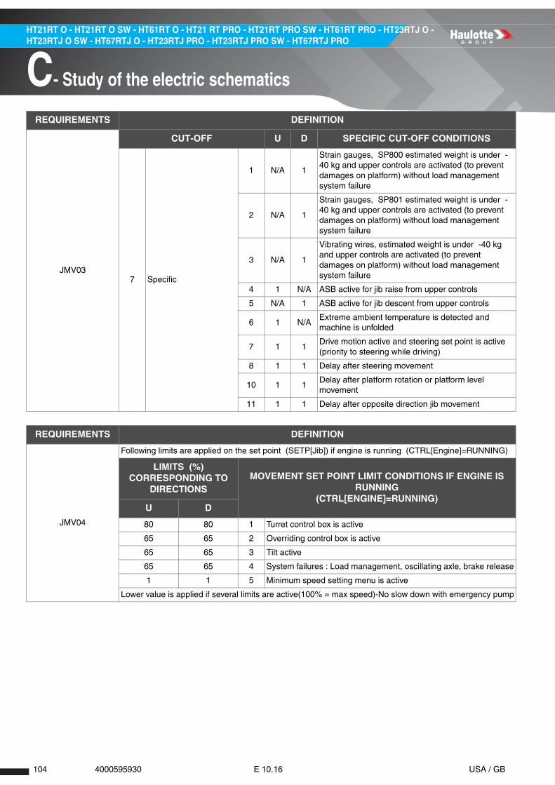
104 4000595930 E 10.16 USA / GB
HT21RT O - HT21RT O SW - HT61RT O - HT21 RT PRO - HT21RT PRO SW - HT61RT PRO - HT23RTJ O - HT23RTJ O SW - HT67RTJ O - HT23RTJ PRO - HT23RTJ PRO SW - HT67RTJ PRO
C- Study of the electric schematics
REQUIREMENTS DEFINITION
JMV03
CUT-OFF U D SPECIFIC CUT-OFF CONDITIONS
7 Specific
1 N/A 1
Strain gauges, SP800 estimated weight is under -40 kg and upper controls are activated (to prevent damages on platform) without load management system failure
2 N/A 1
Strain gauges, SP801 estimated weight is under -40 kg and upper controls are activated (to prevent damages on platform) without load management system failure
3 N/A 1
Vibrating wires, estimated weight is under -40 kg and upper controls are activated (to prevent damages on platform) without load management system failure
4 1 N/A ASB active for jib raise from upper controls
5 N/A 1 ASB active for jib descent from upper controls
6 1 N/AExtreme ambient temperature is detected and machine is unfolded
7 1 1Drive motion active and steering set point is active (priority to steering while driving)
8 1 1 Delay after steering movement
10 1 1Delay after platform rotation or platform level movement
11 1 1 Delay after opposite direction jib movement
REQUIREMENTS DEFINITION
JMV04
Following limits are applied on the set point (SETP[Jib]) if engine is running (CTRL[Engine]=RUNNING)
LIMITS (%) CORRESPONDING TO
DIRECTIONSMOVEMENT SET POINT LIMIT CONDITIONS IF ENGINE IS
RUNNING(CTRL[ENGINE]=RUNNING)
U D
80 80 1 Turret control box is active
65 65 2 Overriding control box is active
65 65 3 Tilt active
65 65 4 System failures : Load management, oscillating axle, brake release
1 1 5 Minimum speed setting menu is active
Lower value is applied if several limits are active(100% = max speed)-No slow down with emergency pump

A
B
C
D
E
F
G
H
I
105 4000595930 E 10.16 USA / GB
C- Study of the electric schematics
HT21RT O - HT21RT O SW - HT61RT O - HT21 RT PRO - HT21RT PRO SW - HT61RT PRO - HT23RTJ O - HT23RTJ O SW - HT67RTJ O - HT23RTJ PRO - HT23RTJ PRO SW - HT67RTJ PRO
2.5.8.2 - Actuators
REQUIREMENTS DEFINITION
JMA01
The following components drive the drive movement : • YV901 : Control movement speed. • YV620U : Jib raise. • YV620D : Jib raise.
REQUIREMENTS DEFINITION
JMA02
The validated and scaled computed control CTRL[Jib] is applied to actuators
CTRL YV901 YV620U YV620D
UPMax SPEED[Jib Raise Max] x 2000mA
1 0Min SPEED[Jib Raise Min] x 2000mA
Neutral 0 0(*) 0(*)
DOWNMax SPEED[Jib Descent Min] x 2000mA
0 1Min SPEED[Jib Descent Max] x 2000mA
(*) : Power supply deactivation (YV900S) is delayed after the end of jib deceleration ramp

106 4000595930 E 10.16 USA / GB
HT21RT O - HT21RT O SW - HT61RT O - HT21 RT PRO - HT21RT PRO SW - HT61RT PRO - HT23RTJ O - HT23RTJ O SW - HT67RTJ O - HT23RTJ PRO - HT23RTJ PRO SW - HT67RTJ PRO
C- Study of the electric schematics
2.5.9 - Basket rotation
2.5.9.1 - Validation
REQUIREMENTS DEFINITION
PRV01The platform rotation movement happens in the specified direction and set point, regarding to validation and slow down conditions : SETP[PlatformRotation]=LEFT|N|RIGHT:[0-100]%. Platform rotation function is available from platform control box only.
REQUIREMENTS DEFINITION
PRV02
Platform rotation for left (L) or right (R) direction is allowed if all validation conditions are satisfied and none of cut-offs condition is true (see PRV03)
VALIDATION L R ENABLE CONDITIONS
0 Enable1 1 1 Machine powered on for more than 3s
2 1 1 Engine is running or emergency pump is running
REQUIREMENTS DEFINITION
PRV03
Left (L) or right (R) platform rotation is inhibited if at least one of the following cut-off conditions is active
CUT-OFF L R GENERAL CUT-OFF CONDITIONS
1 General
1 1 1 Generator is running
2 1 1 Maximum number of running movements is reached
3 1 1 Safety valves tool is active
4 1 1Platform emergency stop pushed and overriding not used
REQUIREMENTS DEFINITION
PRV03CUT-OFF L R
SIMULTANEOUS MOVEMENTS CUT-OFF CONDITIONS
2Simultaneous movements
1..10 1 1Requirements SM_CE_03 | SM_AU_02 | SM_ANSI_02
REQUIREMENTS DEFINITION
PRV03CUT-OFF L R OVERLOAD CUT-OFF CONDITIONS
3 Overload 1 1 1 Overload alarm is active

A
B
C
D
E
F
G
H
I
107 4000595930 E 10.16 USA / GB
C- Study of the electric schematics
HT21RT O - HT21RT O SW - HT61RT O - HT21 RT PRO - HT21RT PRO SW - HT61RT PRO - HT23RTJ O - HT23RTJ O SW - HT67RTJ O - HT23RTJ PRO - HT23RTJ PRO SW - HT67RTJ PRO
REQUIREMENTS DEFINITION
PRV03CUT-OFF L R TILT CUT-OFF CONDITIONS
4 Tilt N/A N/A N/A N/A
REQUIREMENTS DEFINITION
PRV03CUT-OFF L R REACH LIMIT CUT-OFF CONDITIONS
5 Reach limit N/A N/A N/A N/A
REQUIREMENTS DEFINITION
PRV03
CUT-OFF L R FAILURE CUT-OFF CONDITIONS
6 Failure
1 1 1 KMP relay stuck
2 1 1Active failure on platform rotation valves and engine is running
3 1 1 Active failure on LS valve and engine is running
4 1 1Load management system not calibrated and machine unfolded and not overriding control box
5 1 1Load gauges out of range and machine unfolded and not overriding control box
6 1 1Load gauges incoherence and machine unfolded and not overriding control box
7 1 1Low power on load gauges out of range and machine unfolded and not overriding control box
8 1 1Load management sensors electrical failure and machine unfolded and not overriding control box
9 1 1Load management sensors logical failure (IC=1 or IC=4) and machine unfolded and not overriding control box
10 1 1 Active failure on CAN with platform ECU
11 1 1 Overriding switch failure and machine is folded
REQUIREMENTS DEFINITION
PRV03
CUT-OFF L R SPECIFIC CUT-OFF CONDITIONS
7 Specific
1 1 1ASB active for platform rotation and platform control box active
2 1 1Drive motion active and steering set point is active (priority to steering while driving)
3 1 1 Delay after steering movement
4 1 1 Delay after jib or platform level movement
5 1 1Delay after opposite direction platform rotation movement

108 4000595930 E 10.16 USA / GB
HT21RT O - HT21RT O SW - HT61RT O - HT21 RT PRO - HT21RT PRO SW - HT61RT PRO - HT23RTJ O - HT23RTJ O SW - HT67RTJ O - HT23RTJ PRO - HT23RTJ PRO SW - HT67RTJ PRO
C- Study of the electric schematics
2.5.9.2 - Actuators
REQUIREMENTS DEFINITION
PRV04
Following conditions slowdown the platform rotation left (L) or right (R) set point when engine is running. With emergency pump running, no slow down is applied
LIMITS (%) CORRESPONDING TO
DIRECTIONSMOVEMENT SET POINT LIMIT CONDITIONS IF ENGINE IS
RUNNING(CTRL[ENGINE]=RUNNING)
L R
60 60 1 Tilt is active and machine is unfolded
100 100 2 Turret control box
60 60 3 LMS failure or oscillating axle failure or brake release valve failure
1 1 4 Minimum speed setting menu is active
Lower value is applied if several limits are active(100% = max speed)-No slow down with emergency pump
REQUIREMENTS DEFINITION
PRA01
The following components drive the basket rotation movement : • YV901 : Control movement speed (common PWM valve to platform, jib and steering movements). • YV750L : Platform left rotation ON/OFF valves. • YV750R : Platform right rotation ON/OFF valves.
REQUIREMENTS DEFINITION
The formatted and scaled control (CTRL[PlatformRotation]) is applied to actuators driving the movement when engine is running
PRA02.D
CTRL YV901 YV750L YV750R
LEFTMax SPEED[PF Rotation Max] x 2000mA
1 0Min SPEED[PF Rotation Min] x 2000mA
NEUTRAL 0mA 0 0
RIGHTMin SPEED[PF Rotation Min] x 2000mA
0 1Max SPEED[PF Rotation Max] x 2000mA
REQUIREMENTS DEFINITION
The formatted and scaled control (CTRL[PlatformRotation]) is applied to actuators driving the movement when emergency pump is running : Platform rotation control is increased compared to control with engine.
PRA03
CTRL YV901 YV750L YV750R
LEFTMax (SPEED[PF Rotation Max] + 15.0) x 2000mA
1 0Min SPEED[PF Rotation Min] x 2000mA
NEUTRAL 0mA 0 0
RIGHTMin SPEED[PF Rotation Min] x 2000mA
0 1Max (SPEED[PF Rotation Max] + 15.0) x 2000mA

A
B
C
D
E
F
G
H
I
109 4000595930 E 10.16 USA / GB
C- Study of the electric schematics
HT21RT O - HT21RT O SW - HT61RT O - HT21 RT PRO - HT21RT PRO SW - HT61RT PRO - HT23RTJ O - HT23RTJ O SW - HT67RTJ O - HT23RTJ PRO - HT23RTJ PRO SW - HT67RTJ PRO
2.5.10 - Basket compensation
2.5.10.1 - Validation
REQUIREMENTS DEFINITION
PLV01The platform level movement happens in the specified direction and set point, regarding to validation and slow down conditions : SETP[PlatformLevel]=UP|N|DOWN:[0-100]%
REQUIREMENTS DEFINITION
PLV02
Platform level for raise (U:up) or descent (D:down) direction is allowed if all validation conditions are satisfied and none of cut-offs condition is true (see PRV03)
VALIDATION U D ENABLE CONDITIONS
0 Enable1 1 1 Machine powered on for more than 3s
2 1 1 Engine is running or emergency pump is running
REQUIREMENTS DEFINITION
PLV03
Platform level for up (U) and down (D) direction is inhibited if at least one of the following cut-off conditions is active
CUT-OFF U D GENERAL CUT-OFF CONDITIONS
1 General
1 1 1 Generator is running
2 1 1 Safety valves tool is active
3 1 1Platform emergency stop pushed and overriding not used
REQUIREMENTS DEFINITION
PLV03CUT-OFF U D
SIMULTANEOUS MOVEMENTS CUT-OFF CONDITIONS
2Simultaneous movements
1..8 1 1Requirements SM_CE_03 | SM_AU_02 | SM_ANSI_02
REQUIREMENTS DEFINITION
PLV03CUT-OFF U D OVERLOAD CUT-OFF CONDITIONS
3 Overload 1 1 1 Overload alarm is active

110 4000595930 E 10.16 USA / GB
HT21RT O - HT21RT O SW - HT61RT O - HT21 RT PRO - HT21RT PRO SW - HT61RT PRO - HT23RTJ O - HT23RTJ O SW - HT67RTJ O - HT23RTJ PRO - HT23RTJ PRO SW - HT67RTJ PRO
C- Study of the electric schematics
REQUIREMENTS DEFINITION
PLV03CUT-OFF U D TILT CUT-OFF CONDITIONS
4 Tilt N/A N/A N/A N/A
REQUIREMENTS DEFINITION
PLV03CUT-OFF U D REACH LIMIT CUT-OFF CONDITIONS
5 Reach limit N/A N/A N/A N/A
REQUIREMENTS DEFINITION
PLV03
CUT-OFF U D FAILURE CUT-OFF CONDITIONS
6 Failure
1 1 1 KMP relay stuck
2 1 1Active failure on platform level valves and engine is running
3 1 1 Active failure on LS valve and engine is running
4 1 1Load management system not calibrated and machine unfolded and not overriding control box
5 1 1Load gauges out of range and machine unfolded and not overriding control box
6 1 1Load gauges incoherence and machine unfolded and not overriding control box
7 1 1Low power on load gauges out of range and machine unfolded and not overriding control box
8 1 1Load management sensors electrical failure and machine unfolded and not overriding control box
9 1 1Load management sensors logical failure (IC=1 or IC=4) and machine unfolded and not overriding control box
10 1 1 Active failure on CAN with platform ECU
11 1 1 Overriding switch failure and machine is folded
REQUIREMENTS DEFINITION
PLV03
CUT-OFF U D SPECIFIC CUT-OFF CONDITIONS
7 Specific
1 1 1ASB active for platform level and platform control box active
2
1 N/APositive platform tilt detector (+10°) active and platform control box active
N/A 1Negative platform tilt detector (-10°) active and platform control box active
3 1 1 Time-out after steering motion
4 1 1 Time-out after platform rotation or jib

A
B
C
D
E
F
G
H
I
111 4000595930 E 10.16 USA / GB
C- Study of the electric schematics
HT21RT O - HT21RT O SW - HT61RT O - HT21 RT PRO - HT21RT PRO SW - HT61RT PRO - HT23RTJ O - HT23RTJ O SW - HT67RTJ O - HT23RTJ PRO - HT23RTJ PRO SW - HT67RTJ PRO
2.5.10.2 - Actuators
REQUIREMENTS DEFINITION
PLV04
Following conditions slow down the platform level for raise (U:up) or descent (D:Down) set point when engine is running. With emergency pump running, no slow down is applied.
LIMITS (%) CORRESPONDING TO
DIRECTIONSMOVEMENT SET POINT LIMIT CONDITIONS IF ENGINE IS
RUNNING(CTRL[ENGINE]=RUNNING)
U D
60 60 1 Overriding controls are active
60 60 2 Tilt is active and machine is unfolded
60 60 3 LMS failure or oscillating axle failure or brake release valve failure
1 1 4 Minimum speed setting menu is active
Lower value is applied if several limits are active(100% = max speed)-No slow down with emergency pump
REQUIREMENTS DEFINITION
PLA01
The following components drive the basket rotation movement : • YV901 : Control movement speed(Common electrovalve to platform, jib and steering movements). • YV720U : Platform level up ON/OFF valves. • YV720D : Platform level down ON/OFF valves.
REQUIREMENTS DEFINITION
The formated and scaled control (CTRL[PlatformLevel]) is applied on the actuators driving the movement
PLA02
CTRL YV900 YV720U YV720D
UPMax SPEED[Platform Level Raise Max] x 2000mA
1 0Min SPEED[Platform Level Raise Min] x 2000mA
NEUTRAL 0mA 0(*) 0(*)
DOWNMin SPEED[Platform Level Descent Min] x 2000mA
0 1Max SPEED[Platform Level Descent Max] x 2000mA

112 4000595930 E 10.16 USA / GB
HT21RT O - HT21RT O SW - HT61RT O - HT21 RT PRO - HT21RT PRO SW - HT61RT PRO - HT23RTJ O - HT23RTJ O SW - HT67RTJ O - HT23RTJ PRO - HT23RTJ PRO SW - HT67RTJ PRO
C- Study of the electric schematics
2.5.11 - Brake release
2.5.11.1 - Validation
REQUIREMENTS DEFINITION
BRV01
The drive brake is automatically released if the function is allowed, the inactivation is timed for 1 s (without tilt) or 100 ms (with tilt activated) after the function is disabled : CTRL[ReleaseBrake]=((M1600ms(BR_V_002) & VAR[Tilt]=0) | (M600ms(BR_V_002) & VAR[Tilt]=1)) & \BR_V_003
REQUIREMENTS DEFINITION
Drive brake releasing is allowed (A) if all the following conditions are satisfied
BRV02VALIDATION A ENABLE CONDITIONS
0 Enable 1 1 Drive or steering is running
REQUIREMENTS DEFINITION
BRV03
Brake release is inhibited (I) if the following condition is active
CUT-OFF I GENERAL CUT-OFF CONDITIONS
1 General 1 1 N/A
REQUIREMENTS DEFINITION
BRV03CUT-OFF U D
SIMULTANEOUS MOVEMENTS CUT-OFF CONDITIONS
2Simultaneous movements
N/A N/A N/A N/A
REQUIREMENTS DEFINITION
BRV03CUT-OFF U D OVERLOAD CUT-OFF CONDITIONS
3 Overload N/A N/A N/A N/A
REQUIREMENTS DEFINITION
BRV03CUT-OFF U D TILT CUT-OFF CONDITIONS
4 Tilt N/A N/A N/A N/A

A
B
C
D
E
F
G
H
I
113 4000595930 E 10.16 USA / GB
C- Study of the electric schematics
HT21RT O - HT21RT O SW - HT61RT O - HT21 RT PRO - HT21RT PRO SW - HT61RT PRO - HT23RTJ O - HT23RTJ O SW - HT67RTJ O - HT23RTJ PRO - HT23RTJ PRO SW - HT67RTJ PRO
2.5.11.2 - Actuators
REQUIREMENTS DEFINITION
BRV03CUT-OFF U D REACH LIMIT CUT-OFF CONDITIONS
5 Reach limit N/A N/A N/A N/A
REQUIREMENTS DEFINITION
BRV03CUT-OFF I FAILURE CUT-OFF CONDITIONS
6 Failure N/A N/A N/A
REQUIREMENTS DEFINITION
BRV03CUT-OFF I SPECIFIC CUT-OFF CONDITIONS
7 Specific N/A N/A N/A
REQUIREMENTS DEFINITION
BRA01The following components drive the brake releasing function : • YV102 : Brake release functionYV102=CTRL[BrakeRelease]

114 4000595930 E 10.16 USA / GB
HT21RT O - HT21RT O SW - HT61RT O - HT21 RT PRO - HT21RT PRO SW - HT61RT PRO - HT23RTJ O - HT23RTJ O SW - HT67RTJ O - HT23RTJ PRO - HT23RTJ PRO SW - HT67RTJ PRO
C- Study of the electric schematics
2.5.12 - Oscillating axles
2.5.12.1 - Validation
REQUIREMENTS DEFINITION
OAUV01The oscillation axle unlock is automatically activated if the function is allowed and not inhibited (all of models embed oscillating axle function) : CTRL[OscillatingAxleUnlock]=AU_V_002 & \AU_V_003
REQUIREMENTS DEFINITION
Oscillating axle unlocking is allowed (A) if all the following conditions are satisfied
OAUV02VALIDATION A ENABLE CONDITIONS
0 Enable 1 1 Drive motion is in progress
REQUIREMENTS DEFINITION
OAUV03
Brake release is inhibited (I) if the following condition is active
VALIDATION I GENERAL CUT-OFF CONDITIONS
1 General 1 1 Machine is unfolded
REQUIREMENTS DEFINITION
OAUV02VALIDATION I
SIMULTANEOUS MOVEMENTS CUT-OFF CONDITIONS
2Simultaneous movements
N/A N/A N/A
REQUIREMENTS DEFINITION
OAUV02VALIDATION I OVERLOAD CUT-OFF CONDITIONS
3 Overload N/A N/A N/A
REQUIREMENTS DEFINITION
OAUV02VALIDATION I TILT CUT-OFF CONDITIONS
4 Tilt N/A N/A N/A

A
B
C
D
E
F
G
H
I
115 4000595930 E 10.16 USA / GB
C- Study of the electric schematics
HT21RT O - HT21RT O SW - HT61RT O - HT21 RT PRO - HT21RT PRO SW - HT61RT PRO - HT23RTJ O - HT23RTJ O SW - HT67RTJ O - HT23RTJ PRO - HT23RTJ PRO SW - HT67RTJ PRO
2.5.12.2 - Actuators
REQUIREMENTS DEFINITION
OAUV02VALIDATION I REACH LIMIT CUT-OFF CONDITIONS
5 Reach limit N/A N/A N/A
REQUIREMENTS DEFINITION
OAUV02VALIDATION I FAILURE CUT-OFF CONDITIONS
6 Failure N/A N/A N/A
REQUIREMENTS DEFINITION
OAUV02VALIDATION I SPECIFIC CUT-OFF CONDITIONS
7 Specific N/A N/A N/A
REQUIREMENTS DEFINITION
OAUA01The following components drive the oscillating axle unlock function : • YV101 : Oscillating axle unlocking electrovalve(1/2). • YV104 : Oscillating axle unlocking electrovalve(2/2).
REQUIREMENTS DEFINITION
OAUA02YV101=CTRL[OscillatingAxle]YV104=CTRL[OscillatingAxle]

116 4000595930 E 10.16 USA / GB
HT21RT O - HT21RT O SW - HT61RT O - HT21 RT PRO - HT21RT PRO SW - HT61RT PRO - HT23RTJ O - HT23RTJ O SW - HT67RTJ O - HT23RTJ PRO - HT23RTJ PRO SW - HT67RTJ PRO
C- Study of the electric schematics
2.5.13 - Activ' Shield Bar
2.5.13.1 - Activ' Shield Bar - SECONDARY GUARDING SYSTEM
Operated movement when the bar is triggered
Driving Turntable rotation Lifting or telescope extension
Other movementForward Reverse Left Right
Yes
No
Yes
No
Yes
No
Yes
No
Yes
No
Yes
No
Platform control box
Forward
Reverse
Turntable left
Turntable right
Lifting or telescope extension
Telescope descent or retraction
Other movement
Ground control box All N/A N/A
Authorized
Prohibited
Authorized if all switches / joysticks of the Platform control box are in neutral position or, if the Enable switch has been released

A
B
C
D
E
F
G
H
I
117 4000595930 E 10.16 USA / GB
D- Study of the hydraulic schema
HT21RT O - HT21RT O SW - HT61RT O - HT21 RT PRO - HT21RT PRO SW - HT61RT PRO - HT23RTJ O - HT23RTJ O SW - HT67RTJ O - HT23RTJ PRO - HT23RTJ PRO SW - HT67RTJ PRO
Study of the hydraulic schema1 - Hydraulic units
1.1 - GENERAL OVERVIEW

118 4000595930 E 10.16 USA / GB
D- Study of the hydraulic schema
HT21RT O - HT21RT O SW - HT61RT O - HT21 RT PRO - HT21RT PRO SW - HT61RT PRO - HT23RTJ O - HT23RTJ O SW - HT67RTJ O - HT23RTJ PRO - HT23RTJ PRO SW - HT67RTJ PRO
1.2 - EDC BLOCK
This block is mounted with flow sharing proportional valve for all movements (except drive).
That's mean : It can achieve the simultaneous activation of different actuators by distributing theavailable flow proportionally to the speeds selected by the operator.
All simultaneous movements go on at the same reciprocal speed also in case of flow shortage.
MARKING FUNCTION DESCRIPTION
1 YV901 Flow sharing valve for ON/OFF block
2 YV902 Flow sharing valve for steering block3 YV250L Flow sharing valve for turret rotation left side
4 YV250R Flow sharing valve for turret rotation right side
5 YV530I Flow sharing valve for telescope retraction6 YV530O Flow sharing valve for telescope extension
7 YV520D Flow sharing valve for boom descent
8 YV520U Flow sharing valve for boom lift
9 M Minimess plug for pressure control ( 220 b)10 YV807 Safety valve for boom descent
11 YV805 Safety valve for turret orientation
12 YV801 Safety valve for telescope extension13 YV802 Safety valve for boom lift/descent
14 YV800 Load sensing valve ( = 1 for any movements)
15 Anti shock valve in order to avoid oscillation during boom descent ( 100 b)
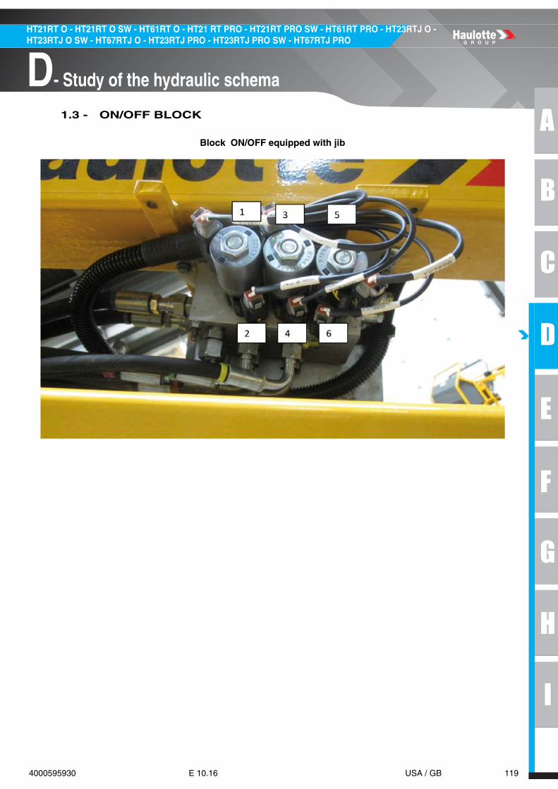
A
B
C
D
E
F
G
H
I
119 4000595930 E 10.16 USA / GB
D- Study of the hydraulic schema
HT21RT O - HT21RT O SW - HT61RT O - HT21 RT PRO - HT21RT PRO SW - HT61RT PRO - HT23RTJ O - HT23RTJ O SW - HT67RTJ O - HT23RTJ PRO - HT23RTJ PRO SW - HT67RTJ PRO
1.3 - ON/OFF BLOCK
Block ON/OFF equipped with jib

120 4000595930 E 10.16 USA / GB
D- Study of the hydraulic schema
HT21RT O - HT21RT O SW - HT61RT O - HT21 RT PRO - HT21RT PRO SW - HT61RT PRO - HT23RTJ O - HT23RTJ O SW - HT67RTJ O - HT23RTJ PRO - HT23RTJ PRO SW - HT67RTJ PRO
Block ON/OFF without jib
MARKING DESCRIPTION FUNCTION
1 YV750L Basket rotation towards left side
2 YV750R Basket rotation towards right side
3 YV620U Jib lift mode
4 YV620D Jib descent mode
5 YV720D Basket compensation lift mode
6 YV720U Basket compensation descent mode

A
B
C
D
E
F
G
H
I
121 4000595930 E 10.16 USA / GB
D- Study of the hydraulic schema
HT21RT O - HT21RT O SW - HT61RT O - HT21 RT PRO - HT21RT PRO SW - HT61RT PRO - HT23RTJ O - HT23RTJ O SW - HT67RTJ O - HT23RTJ PRO - HT23RTJ PRO SW - HT67RTJ PRO
1.4 - DRIVE BLOCK
MARKING FUNCTION DESCRIPTION
1 YV104 Alternator
2 YV102 Engine oil pressure detection
3 YV110 Cooling engine temperature detection
4 YV101Module (Electronic Governor) made by KUBOTA, it controls electronically the engine speed according to the actuators
5 SP100 Engine overheating detection
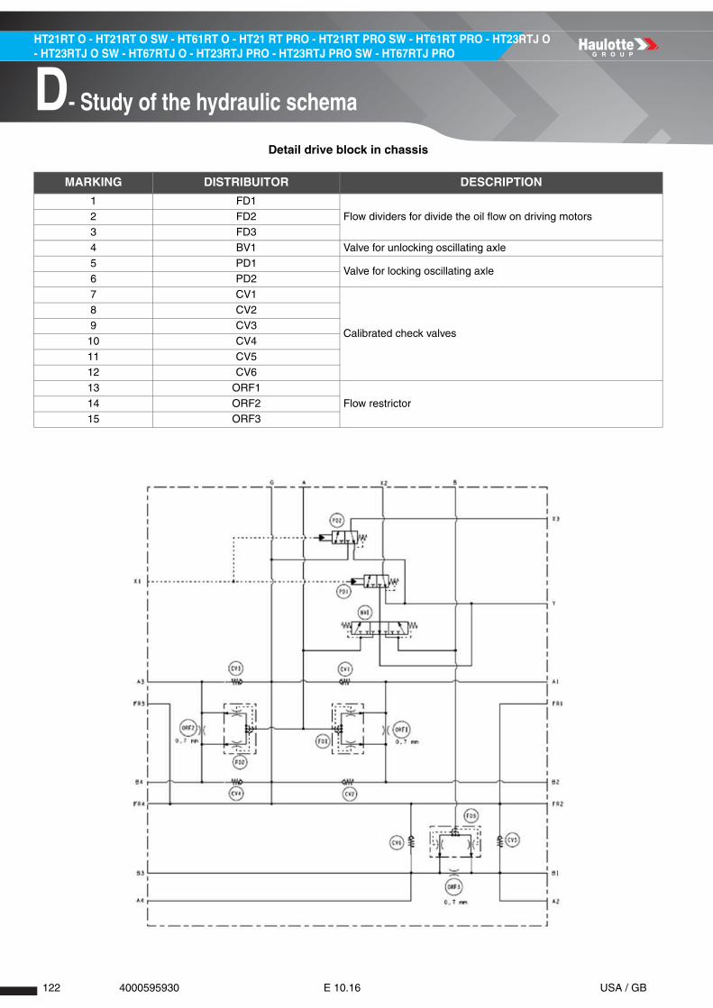
122 4000595930 E 10.16 USA / GB
D- Study of the hydraulic schema
HT21RT O - HT21RT O SW - HT61RT O - HT21 RT PRO - HT21RT PRO SW - HT61RT PRO - HT23RTJ O - HT23RTJ O SW - HT67RTJ O - HT23RTJ PRO - HT23RTJ PRO SW - HT67RTJ PRO
Detail drive block in chassis
MARKING DISTRIBUITOR DESCRIPTION
1 FD1
Flow dividers for divide the oil flow on driving motors2 FD23 FD3
4 BV1 Valve for unlocking oscillating axle
5 PD1Valve for locking oscillating axle
6 PD2
7 CV1
Calibrated check valves
8 CV29 CV3
10 CV4
11 CV512 CV6
13 ORF1
Flow restrictor14 ORF215 ORF3
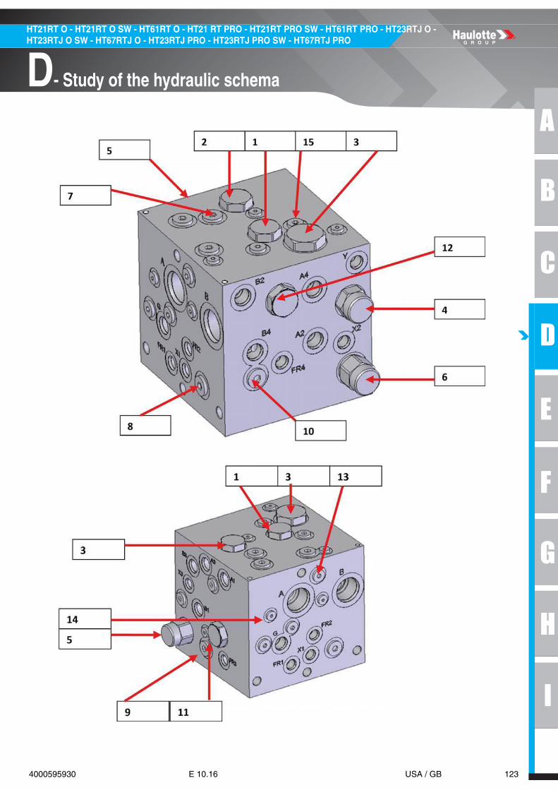
A
B
C
D
E
F
G
H
I
123 4000595930 E 10.16 USA / GB
D- Study of the hydraulic schema
HT21RT O - HT21RT O SW - HT61RT O - HT21 RT PRO - HT21RT PRO SW - HT61RT PRO - HT23RTJ O - HT23RTJ O SW - HT67RTJ O - HT23RTJ PRO - HT23RTJ PRO SW - HT67RTJ PRO

124 4000595930 E 10.16 USA / GB
D- Study of the hydraulic schema
HT21RT O - HT21RT O SW - HT61RT O - HT21 RT PRO - HT21RT PRO SW - HT61RT PRO - HT23RTJ O - HT23RTJ O SW - HT67RTJ O - HT23RTJ PRO - HT23RTJ PRO SW - HT67RTJ PRO
1.5 - STEERING BLOCK 2WS
MARKING DESCRIPTION FUNCTION
1 YV150L Left steering(Front axle)
2 YV150R Right steering(Front axle)
3 EDC block Flow sharing proportional hydraulic block
4 YV107 Crab steering mode(Rear axle)
5 YV108 Synchronous steering mode(Rear axle)

A
B
C
D
E
F
G
H
I
125 4000595930 E 10.16 USA / GB
D- Study of the hydraulic schema
HT21RT O - HT21RT O SW - HT61RT O - HT21 RT PRO - HT21RT PRO SW - HT61RT PRO - HT23RTJ O - HT23RTJ O SW - HT67RTJ O - HT23RTJ PRO - HT23RTJ PRO SW - HT67RTJ PRO
1.6 - STEERING BLOCK 4WS

126 4000595930 E 10.16 USA / GB
D- Study of the hydraulic schema
HT21RT O - HT21RT O SW - HT61RT O - HT21 RT PRO - HT21RT PRO SW - HT61RT PRO - HT23RTJ O - HT23RTJ O SW - HT67RTJ O - HT23RTJ PRO - HT23RTJ PRO SW - HT67RTJ PRO
Notes

A
B
C
D
E
F
G
H
I
127 4000595930 E 10.16 USA / GB
E- Adjustments
HT21RT O - HT21RT O SW - HT61RT O - HT21 RT PRO - HT21RT PRO SW - HT61RT PRO - HT23RTJ O - HT23RTJ O SW - HT67RTJ O - HT23RTJ PRO - HT23RTJ PRO SW - HT67RTJ PRO
Adjustments1 - Adjustments
1.1 - ACTIV SCREEN
This "on board" console (Activ screen) gives all informations to the user but also to the technician incase of problems.
Thanks to different access code levels, the technician is able to make a full diagnostic of the machine.
There is many languages available and this could be selected directly by the user.

128 4000595930 E 10.16 USA / GB
E- Adjustments
HT21RT O - HT21RT O SW - HT61RT O - HT21 RT PRO - HT21RT PRO SW - HT61RT PRO - HT23RTJ O - HT23RTJ O SW - HT67RTJ O - HT23RTJ PRO - HT23RTJ PRO SW - HT67RTJ PRO
The architecture of the menus is as follow :

A
B
C
D
E
F
G
H
I
129 4000595930 E 10.16 USA / GB
E- Adjustments
HT21RT O - HT21RT O SW - HT61RT O - HT21 RT PRO - HT21RT PRO SW - HT61RT PRO - HT23RTJ O - HT23RTJ O SW - HT67RTJ O - HT23RTJ PRO - HT23RTJ PRO SW - HT67RTJ PRO

130 4000595930 E 10.16 USA / GB
E- Adjustments
HT21RT O - HT21RT O SW - HT61RT O - HT21 RT PRO - HT21RT PRO SW - HT61RT PRO - HT23RTJ O - HT23RTJ O SW - HT67RTJ O - HT23RTJ PRO - HT23RTJ PRO SW - HT67RTJ PRO

A
B
C
D
E
F
G
H
I
131 4000595930 E 10.16 USA / GB
E- Adjustments
HT21RT O - HT21RT O SW - HT61RT O - HT21 RT PRO - HT21RT PRO SW - HT61RT PRO - HT23RTJ O - HT23RTJ O SW - HT67RTJ O - HT23RTJ PRO - HT23RTJ PRO SW - HT67RTJ PRO
1.2 - ACCESS TO ADVANCED MENUS
The diagnostic could be done very quickly thanks to ergonomic indication :
With Activ'Screen, maintenance technicians will have a direct access to machine parameters/diagnostic/calibration...(Protected by an access code). It's the same interface as Haulotte Diag and thesame features in the advanced diagnostic mode.
Example of diagnostic function SP300 : • It shows the way to check this sensor and its location on machine.

132 4000595930 E 10.16 USA / GB
E- Adjustments
HT21RT O - HT21RT O SW - HT61RT O - HT21 RT PRO - HT21RT PRO SW - HT61RT PRO - HT23RTJ O - HT23RTJ O SW - HT67RTJ O - HT23RTJ PRO - HT23RTJ PRO SW - HT67RTJ PRO
1.3 - CONSOLE DIAG
The adjustments, parameter settings and lists of alarms of the machine are accessible either throughthis console or either with the laptop version.
The VCI (Vehicle Computer Interface) adapter could be connected from any controls (turret or inplatform) using wireless or cable connection.
The full description of how to use that console and its menus is explained in a technical note PI144 (formore information refer to your nearest HAULOTTE Services® of your area)
VCI

A
B
C
D
E
F
G
H
I
133 4000595930 E 10.16 USA / GB
E- Adjustments
HT21RT O - HT21RT O SW - HT61RT O - HT21 RT PRO - HT21RT PRO SW - HT61RT PRO - HT23RTJ O - HT23RTJ O SW - HT67RTJ O - HT23RTJ PRO - HT23RTJ PRO SW - HT67RTJ PRO
2 - List of menusSee end of manual
2.1 - MACHINE SETTINGS
2.1.1 - Speeds and ramps
See end of manual : Annex 1
2.1.2 - Options
See end of manual : Annex 2
2.1.3 - Configurations
See end of manual : Annex 3
2.1.4 - Securities
See end of manual : Annex 4
2.2 - DIAGNOSTIC
2.2.1 - Inputs/Outputs
See end of manual : Annex 5
2.2.2 - States
See end of manual : Annex 6

134 4000595930 E 10.16 USA / GB
E- Adjustments
HT21RT O - HT21RT O SW - HT61RT O - HT21 RT PRO - HT21RT PRO SW - HT61RT PRO - HT23RTJ O - HT23RTJ O SW - HT67RTJ O - HT23RTJ PRO - HT23RTJ PRO SW - HT67RTJ PRO
3 - Failures list
• For any type A (ACTIVE) failure code, it will appear on display in lower control and the warning light will flickeron upper controls (see below).
• For any type D (DETECTED) failure code, it will also appear on display in lower control and the warning lightwill flicker on upper controls.
• For any type N failure code, it means that this alarm will never appear on display.
• An internal code (column C) with 5 digits, visible only on the console, allows specifying the trigger conditions ofthe failure.
Each trigger condition is associated with a single code number (16 possible single codes in decimal formatcorresponding to a single bit in binary format) :
• If several conditions are active at the same time, single codes are added to form the resulting code displayed.For example, il conditions 1 and 4 of single code are active, then the resulting code displayed will be 5 (1+4=5).
All alarms codes are gathered per category (ex F02xxx contactors)

A
B
C
D
E
F
G
H
I
135 4000595930 E 10.16 USA / GB
E- Adjustments
HT21RT O - HT21RT O SW - HT61RT O - HT21 RT PRO - HT21RT PRO SW - HT61RT PRO - HT23RTJ O - HT23RTJ O SW - HT67RTJ O - HT23RTJ PRO - HT23RTJ PRO SW - HT67RTJ PRO
3.1 - LIST OF FAILURES PER CATEGORY
FAILURES N DEC BIT DESCRIPTION
CONTACTORS
F02.02Emergency Pump
KM120D
• Digital output's failure : Emergency pump relay --> KM120• Check relay• Check connection to ground• Check connection to U106 ECU
F02.04Power Contactor
KMPD
• Incoherence between the emergency stop status and the presence of voltage on power line--> EMSTOP=0 & (12VD1>8.00V | 12VD2>8.00V | 12VD3>8.00V | 12VD4>8.00V | 12VD5>8.00V | 12VF1>8.00V | 12VF2>8.00V | 12VF3>8.00V | 12VF4>8.00V)• Check emergency stop• Check relay KMP• Check fuses• Check wiring
F02.05Heating Relay
KM160D
• Digital output's failure : Preheating relay and engine is not Tier IV--> KM160=FAIL & CFG[Engine]=TierIII• Check relay• Check connection to ground• Check connection to U106 ECU
FAILURES N DEC BIT DESCRIPTION
RELAYS
F03.06Horn Relay
KA9D
• Digital output's failure : Horn relay--> KA9=FAIL• Check relay• Check connection to ground• Check connection to U106 ECU
F03.07Relay failure
KA6D
• Platform emergency stop pushed while power is ON, overriding relay stuck (if not controlled) => overriding relay stuck--> SB802 = 1 & WUI = 1 & KA6 = 0• Check relay• Check connection to ground• Check connection to U106 ECU
F03.08Start Relay
KA4D
• Digital output's failure : Starter relay--> KA4=FAIL• Check relay• Check connection to ground• Check connection to U106 ECU
F03.09Supply/Key Switch Rel
KA3
D
• Digital output's failure : Engine supply relay--> KA3=FAIL• Check relay• Check connection to ground• Check connection to U106 ECU
F03.11Generator Relay
KA2D
• Digital output's failure : Generator relay failure while generator on(And failure is not low current)--> KA2=FAIL& SETP[Generator]=ON• Check relay• Check connection to ground• Check connection to U106 ECU
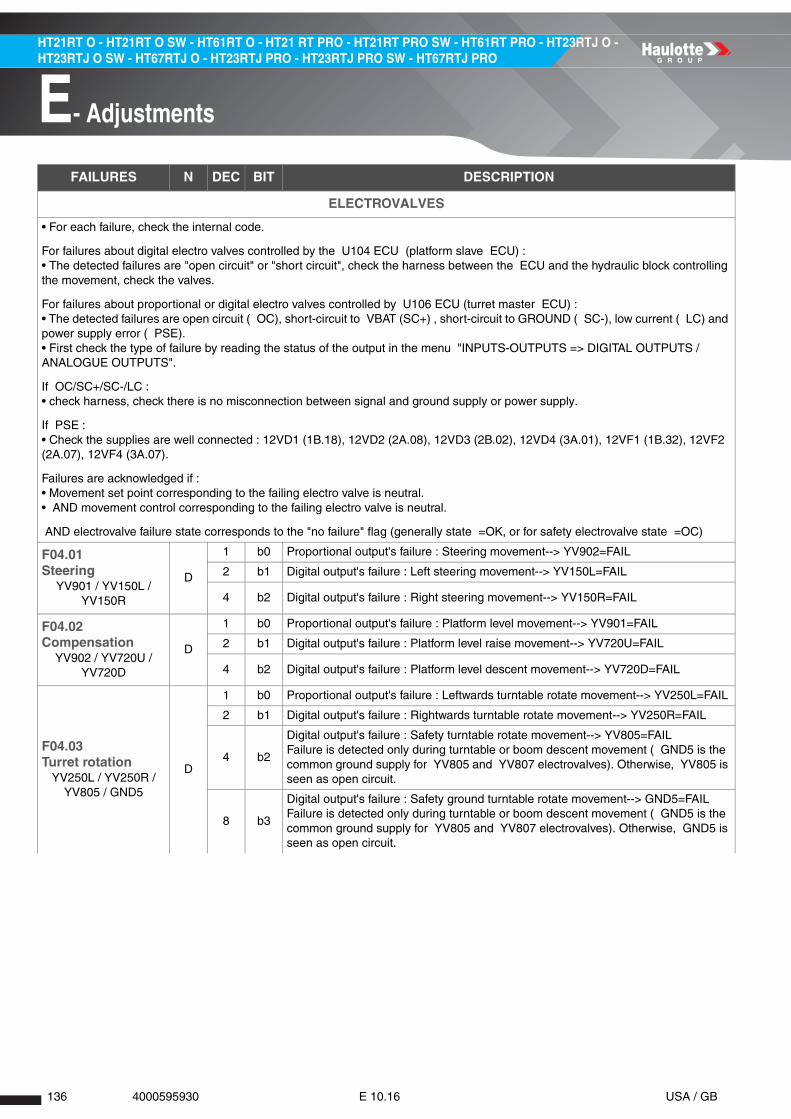
136 4000595930 E 10.16 USA / GB
E- Adjustments
HT21RT O - HT21RT O SW - HT61RT O - HT21 RT PRO - HT21RT PRO SW - HT61RT PRO - HT23RTJ O - HT23RTJ O SW - HT67RTJ O - HT23RTJ PRO - HT23RTJ PRO SW - HT67RTJ PRO
FAILURES N DEC BIT DESCRIPTION
ELECTROVALVES
• For each failure, check the internal code.
For failures about digital electro valves controlled by the U104 ECU (platform slave ECU) : • The detected failures are "open circuit" or "short circuit", check the harness between the ECU and the hydraulic block controlling the movement, check the valves.
For failures about proportional or digital electro valves controlled by U106 ECU (turret master ECU) : • The detected failures are open circuit ( OC), short-circuit to VBAT (SC+) , short-circuit to GROUND ( SC-), low current ( LC) and power supply error ( PSE).• First check the type of failure by reading the status of the output in the menu "INPUTS-OUTPUTS => DIGITAL OUTPUTS / ANALOGUE OUTPUTS".
If OC/SC+/SC-/LC : • check harness, check there is no misconnection between signal and ground supply or power supply.
If PSE : • Check the supplies are well connected : 12VD1 (1B.18), 12VD2 (2A.08), 12VD3 (2B.02), 12VD4 (3A.01), 12VF1 (1B.32), 12VF2 (2A.07), 12VF4 (3A.07).
Failures are acknowledged if : • Movement set point corresponding to the failing electro valve is neutral. • AND movement control corresponding to the failing electro valve is neutral.
AND electrovalve failure state corresponds to the "no failure" flag (generally state =OK, or for safety electrovalve state =OC)
F04.01Steering
YV901 / YV150L / YV150R
D
1 b0 Proportional output's failure : Steering movement--> YV902=FAIL
2 b1 Digital output's failure : Left steering movement--> YV150L=FAIL
4 b2 Digital output's failure : Right steering movement--> YV150R=FAIL
F04.02Compensation
YV902 / YV720U / YV720D
D
1 b0 Proportional output's failure : Platform level movement--> YV901=FAIL
2 b1 Digital output's failure : Platform level raise movement--> YV720U=FAIL
4 b2 Digital output's failure : Platform level descent movement--> YV720D=FAIL
F04.03Turret rotation
YV250L / YV250R / YV805 / GND5
D
1 b0 Proportional output's failure : Leftwards turntable rotate movement--> YV250L=FAIL
2 b1 Digital output's failure : Rightwards turntable rotate movement--> YV250R=FAIL
4 b2
Digital output's failure : Safety turntable rotate movement--> YV805=FAILFailure is detected only during turntable or boom descent movement ( GND5 is the common ground supply for YV805 and YV807 electrovalves). Otherwise, YV805 is seen as open circuit.
8 b3
Digital output's failure : Safety ground turntable rotate movement--> GND5=FAILFailure is detected only during turntable or boom descent movement ( GND5 is the common ground supply for YV805 and YV807 electrovalves). Otherwise, GND5 is seen as open circuit.

A
B
C
D
E
F
G
H
I
137 4000595930 E 10.16 USA / GB
E- Adjustments
HT21RT O - HT21RT O SW - HT61RT O - HT21 RT PRO - HT21RT PRO SW - HT61RT PRO - HT23RTJ O - HT23RTJ O SW - HT67RTJ O - HT23RTJ PRO - HT23RTJ PRO SW - HT67RTJ PRO
F04.05Boom
YV520U / YV520D / YV802 / GND2 / YV807
/ GND5
D
1 b0 Proportional output's failure : Upwards boom movement--> YV520U=FAIL
2 b1 Digital output's failure : Downwards boom movement--> YV520D=FAIL
4 b2
Digital output's failure : Safety boom movement--> YV802=FAILFailure is detected only during telescope extend or boom movement ( GND2 is the common ground supply for YV801 and YV802 electrovalves). Otherwise, YV802 is seen as open circuit.
8 b3
Digital output's failure : Safety ground boom movement--> GND2=FAILFailure is detected only during telescope extend or boom movement ( GND2 is the common ground supply for YV801 and YV802 electrovalves). Otherwise, GDN2 is seen as open circuit.
16 b4
Digital output's failure : Safety boom descent movement--> YV807=FAILFailure is detected only during turntable or boom descent movement ( GND5 is the common ground supply for YV805 and YV807 electrovalves). Otherwise, YV805 is seen as open circuit.
32 b5
Digital output's failure : Safety ground boom descent movement--> GND5=FAILFailure is detected only during turntable or boom descent movement ( GND5 is the common ground supply for YV805 and YV807 electrovalves). Otherwise, GDN5 is seen as open circuit.
F04.06Telescope
YV530O / YV530I / YV801 / GND2
D
1 b0 Proportional output's failure : Telescope movement--> YV530O=FAIL
2 b1 Digital output's failure : Telescope extension movement--> YV530I=FAIL
4 b2
Digital output's failure : Safety telescope extend movement--> YV801=FAILFailure is detected only during telescope extend or boom movement ( GND2 is the common ground supply for YV801 and YV802 electrovalves). Otherwise, GDN2 is seen as open circuit.
8 b3
Digital output's failure : Safety ground telescope extend movement--> GND2=FAILFailure is detected only during telescope extend or boom movement ( GND2 is the common ground supply for YV801 and YV802 electrovalves). Otherwise, GDN2 is seen as open circuit.
F04.07Jib
YV902 / YV620U / YV620D
D
1 b0 Proportional output's failure : Upper movements--> YV901=FAIL
2 b1 Digital output's failure : Jib raise movement--> YV620U=FAIL
4 b2 Digital output's failure : Jib descent movement--> YV620D=FAIL
F04.08Cage Rotation
YV902 / YV750R / YV750L
D
1 b0 Proportional output's failure : Platform rotation movement--> YV901=FAIL
2 b1 Digital output's failure : Platform rotation left movement--> YV750L=FAIL
4 b2 Digital output's failure : Platform rotation right movement--> YV750R=FAIL
F04.10Drive
YV160F / YV160BD
1 b0 Proportional output's failure : Drive movement, forward direction--> YV160F=FAIL
2 b1 Proportional output's failure : Drive movement, reverse direction--> YV160B=FAIL
F04.11Principal movements
Chk YV800
D 1 b0 Digital output's failure : LS valve (HSD) --> YV800=FAIL
F04.20Drive Speed
YV110D Digital output's failure : High speed drive --> YV110=FAIL
F04.33Steering mode
YV107 / YV108D
1 b0Digital output's failure : Steering mode with 4 wheels steering option activated--> YV107=FAIL & VAR[4WSEnable]
2 b1Digital output's failure : Steering mode with 4 wheels steering option activated--> YV108=FAIL & VAR[4WSEnable]
FAILURES N DEC BIT DESCRIPTION

138 4000595930 E 10.16 USA / GB
E- Adjustments
HT21RT O - HT21RT O SW - HT61RT O - HT21 RT PRO - HT21RT PRO SW - HT61RT PRO - HT23RTJ O - HT23RTJ O SW - HT67RTJ O - HT23RTJ PRO - HT23RTJ PRO SW - HT67RTJ PRO
F04.34Front Axle Unlocking
YV101 / YV104
D
1 b0 Digital output's failure : Oscillating axle unlocking--> YV101=FAIL
2 b1 Digital output's failure : Oscillating axle unlocking--> YV104=FAIL
F04.35Brake Releasing
YV102D 1 b0 Digital output's failure : Brake releasing--> YV102=FAIL
FAILURES N DEC BIT DESCRIPTION
JOYSTICKS
The following joysticks’ failures are relevant if failure F08.05 is not active (failure of 5 V supplying signal). First check the 5 V supplying the joysticks, then the harness between ECU and joysticks
F05.01Drive Joystick
SM902YD
1 b0Drive joystick failure : Out of range [0.2.4.8] V --> SM902Y<0.20V and SM902Y>4.80V
2 b1
Drive joystick failure : Analogue signal and out of neutral incoherence--> SM902F = 1 & SM902B = 1 & 2.45V<SM902Y<2.55V--> Or SM902F = 0 & SM902Y<2.00V--> Or SM902B = 0 & SM902Y>3.00V
F05.03Telescope Joystick
SM901YD
1 b0Telescope joystick failure : Out of range[0.2.4.8] V --> SM901Y<0.20V | SM901Y>4.80V
2 b1Telescope joystick failure : Analogue signal and out of neutral incoherence--> SM901N = 1 & 2.45V<SM901Y<2.55V--> Or SM901N=0 & SM901Y<2.00V | SM901Y>3.00V
F05.04Boom Joystick
SM900YD
1 b0 Boom joystick failure : Out of range[0.2.4.8] V --> SM900Y<0.20V & SM900Y>4.80V
2 b1
Boom joystick failure : Analogue signal and out of neutral incoherence--> SM900N = 1 & 2.45V<SM900Y<2.55V & 2.45V<SM900X<2.55V--> Or SM900N = 0 & SM900Y<2.00V & SM900Y>3.00V & SM900X<2.00V | SM900X>3.00V
F05.05Turret Joystick
SM900XD
1 b0Turret rotation joystick failure : Out of range[0.2.4.8] V --> SM900X<0.20V & SM900X>4.80V
2 b1
Turret rotation joystick failure : Analogue signal and out of neutral incoherence--> SM900N = 1 & 2.45V<SM900Y<2.55V & 2.45V<SM900X<2.55V--> Or SM900N = 0 & SM900Y<2.00V & SM900Y>3.00V & SM900X<2.00V & SM900X>3.00V
F05.11Joystick neutral
SM902YA
No detection of joystick's neutral position at machine's power-on--> SM902Y<2.35V | SM902Y>2.65VRelease joystick / Check joystick
F05.12Joystick neutral 2
SM901YA
No detection of joystick's neutral position at machine's power-on--> SM901Y<2.35V | SM901Y>2.65VRelease joystick / Check joystick
F05.13Joystick neutral 3
SM900X/YA
No detection of joystick's neutral position at machine's power-on--> SM900X<2.35V | SM900X>2.65V | SM900Y<2.35V | SM900Y>2.65VRelease joystick / Check joystick
FAILURES N DEC BIT DESCRIPTION

A
B
C
D
E
F
G
H
I
139 4000595930 E 10.16 USA / GB
E- Adjustments
HT21RT O - HT21RT O SW - HT61RT O - HT21 RT PRO - HT21RT PRO SW - HT61RT PRO - HT23RTJ O - HT23RTJ O SW - HT67RTJ O - HT23RTJ PRO - HT23RTJ PRO SW - HT67RTJ PRO
Failures N Dec Bit Description
LOAD MANAGEMENT SYSTEM
F06.01No Loading Cal
CalibrateA
No overload calibration, do/redo overload calibrationVAR[GaugesNotCalibrated]=1Complete calibration
F06.03Gauges out of Range
SP800/SP801
D
1 b0
Gauges out of range (load management system activated)--> SP800 Not in [1500; 20500]µAVAR[GaugesOutOfRange]=1Check SP800 connections to ground, to U104 ECU analog inputs
2 b1Gauges out of range (load management system activated)--> SP801 Not in [1500; 20500]µACheck SP801 connections to ground, to U104 ECU analog inputs
F06.04Incoh Gauges
SP800/SP801D
SP800 measured weight and SP801 measured weight are more than 50kg far (and gauges are not out of range and gauges are calibrated)VAR[GaugesIncoherent]=1Check SP800 and SP801 connections to ground, to U104 ECU analog inputsRedo calibration
F06.05Low Power
Gauges supplyD
Low power for strain gauges is detected low : VbattB2 basket is under 8500 VCheck gauge's power supply
F06.09Negative load
Gauges supplyA
1 b0 Negative load(<-40kg)Gauge 1 measures negative load below -40kg VAR[WeightSP800] < -40kgGauge 2 measures negative load below -40kg VAR[WeightSP801] < -40kg1. Check the platform does not lie on an obstacle
2. Check weighing system3. Check the integrity of the structure
2 b1
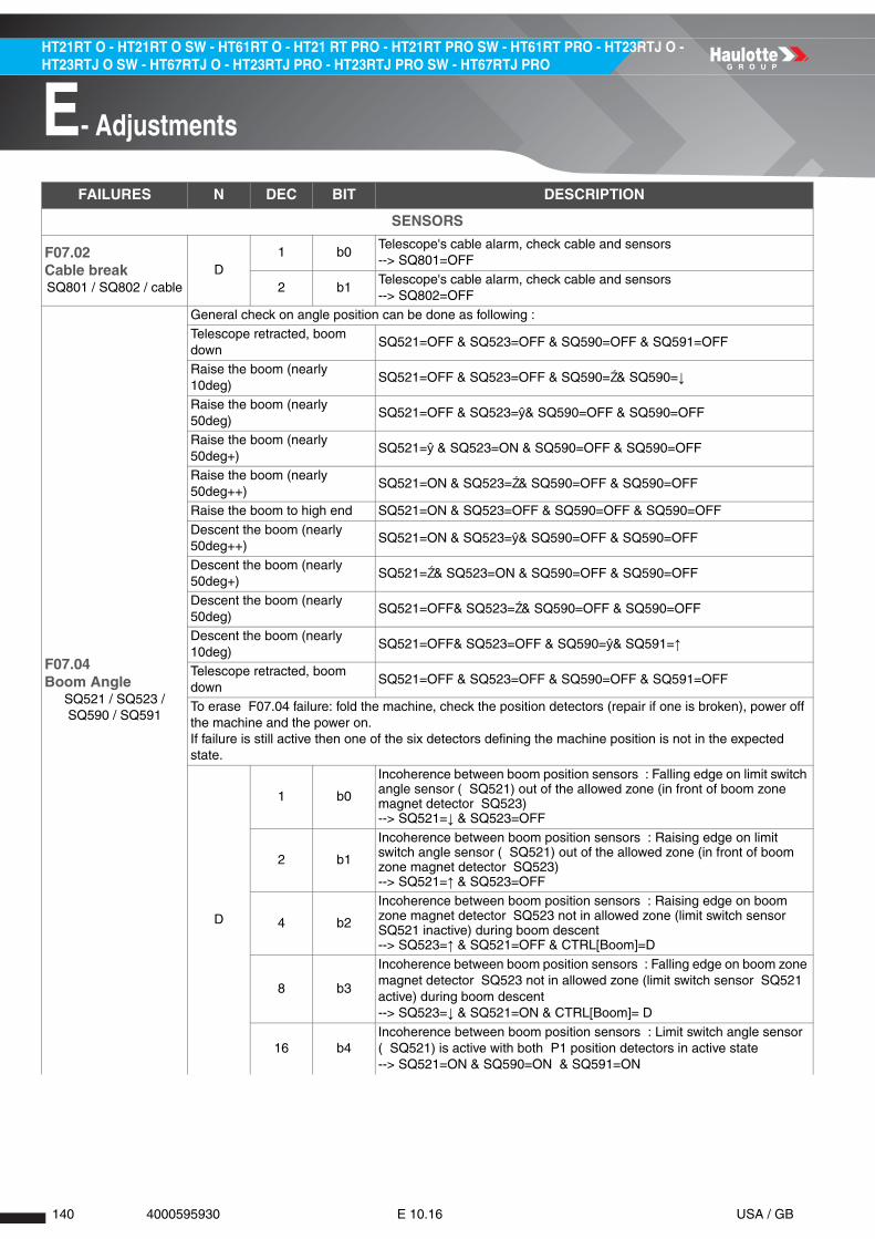
140 4000595930 E 10.16 USA / GB
E- Adjustments
HT21RT O - HT21RT O SW - HT61RT O - HT21 RT PRO - HT21RT PRO SW - HT61RT PRO - HT23RTJ O - HT23RTJ O SW - HT67RTJ O - HT23RTJ PRO - HT23RTJ PRO SW - HT67RTJ PRO
FAILURES N DEC BIT DESCRIPTION
SENSORS
F07.02Cable breakSQ801 / SQ802 / cable
D1 b0
Telescope's cable alarm, check cable and sensors--> SQ801=OFF
2 b1Telescope's cable alarm, check cable and sensors--> SQ802=OFF
F07.04Boom Angle
SQ521 / SQ523 / SQ590 / SQ591
General check on angle position can be done as following : Telescope retracted, boom down
SQ521=OFF & SQ523=OFF & SQ590=OFF & SQ591=OFF
Raise the boom (nearly 10deg)
SQ521=OFF & SQ523=OFF & SQ590=Ź& SQ590=↓
Raise the boom (nearly 50deg)
SQ521=OFF & SQ523=ŷ& SQ590=OFF & SQ590=OFF
Raise the boom (nearly 50deg+)
SQ521=ŷ & SQ523=ON & SQ590=OFF & SQ590=OFF
Raise the boom (nearly 50deg++)
SQ521=ON & SQ523=Ź& SQ590=OFF & SQ590=OFF
Raise the boom to high end SQ521=ON & SQ523=OFF & SQ590=OFF & SQ590=OFF
Descent the boom (nearly 50deg++)
SQ521=ON & SQ523=ŷ& SQ590=OFF & SQ590=OFF
Descent the boom (nearly 50deg+)
SQ521=Ź& SQ523=ON & SQ590=OFF & SQ590=OFF
Descent the boom (nearly 50deg)
SQ521=OFF& SQ523=Ź& SQ590=OFF & SQ590=OFF
Descent the boom (nearly 10deg)
SQ521=OFF& SQ523=OFF & SQ590=ŷ& SQ591=↑
Telescope retracted, boom down
SQ521=OFF & SQ523=OFF & SQ590=OFF & SQ591=OFF
To erase F07.04 failure: fold the machine, check the position detectors (repair if one is broken), power off the machine and the power on. If failure is still active then one of the six detectors defining the machine position is not in the expected state.
D
1 b0
Incoherence between boom position sensors : Falling edge on limit switch angle sensor ( SQ521) out of the allowed zone (in front of boom zone magnet detector SQ523)--> SQ521=↓ & SQ523=OFF
2 b1
Incoherence between boom position sensors : Raising edge on limit switch angle sensor ( SQ521) out of the allowed zone (in front of boom zone magnet detector SQ523)--> SQ521=↑ & SQ523=OFF
4 b2
Incoherence between boom position sensors : Raising edge on boom zone magnet detector SQ523 not in allowed zone (limit switch sensor SQ521 inactive) during boom descent--> SQ523=↑ & SQ521=OFF & CTRL[Boom]=D
8 b3
Incoherence between boom position sensors : Falling edge on boom zone magnet detector SQ523 not in allowed zone (limit switch sensor SQ521 active) during boom descent--> SQ523=↓ & SQ521=ON & CTRL[Boom]= D
16 b4Incoherence between boom position sensors : Limit switch angle sensor ( SQ521) is active with both P1 position detectors in active state--> SQ521=ON & SQ590=ON & SQ591=ON
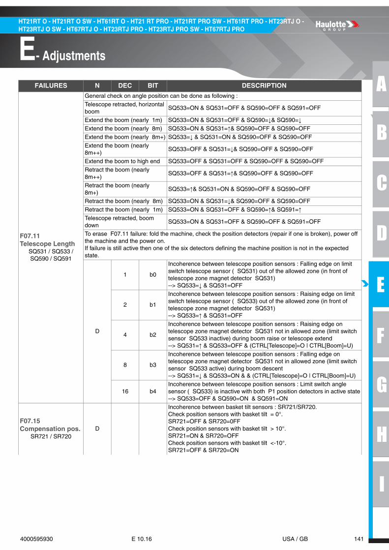
A
B
C
D
E
F
G
H
I
141 4000595930 E 10.16 USA / GB
E- Adjustments
HT21RT O - HT21RT O SW - HT61RT O - HT21 RT PRO - HT21RT PRO SW - HT61RT PRO - HT23RTJ O - HT23RTJ O SW - HT67RTJ O - HT23RTJ PRO - HT23RTJ PRO SW - HT67RTJ PRO
F07.11Telescope Length
SQ531 / SQ533 / SQ590 / SQ591
General check on angle position can be done as following :
Telescope retracted, horizontal boom
SQ533=ON & SQ531=OFF & SQ590=OFF & SQ591=OFF
Extend the boom (nearly 1m) SQ533=ON & SQ531=OFF & SQ590=↓& SQ590=↓Extend the boom (nearly 8m) SQ533=ON & SQ531=↑& SQ590=OFF & SQ590=OFF
Extend the boom (nearly 8m+) SQ533=↓ & SQ531=ON & SQ590=OFF & SQ590=OFF
Extend the boom (nearly 8m++)
SQ533=OFF & SQ531=↓& SQ590=OFF & SQ590=OFF
Extend the boom to high end SQ533=OFF & SQ531=OFF & SQ590=OFF & SQ590=OFFRetract the boom (nearly 8m++)
SQ533=OFF & SQ531=↑& SQ590=OFF & SQ590=OFF
Retract the boom (nearly 8m+)
SQ533=↑& SQ531=ON & SQ590=OFF & SQ590=OFF
Retract the boom (nearly 8m) SQ533=ON & SQ531=↓& SQ590=OFF & SQ590=OFF
Retract the boom (nearly 1m) SQ533=ON & SQ531=OFF & SQ590=↑& SQ591=↑Telescope retracted, boom down
SQ533=ON & SQ531=OFF & SQ590=OFF & SQ591=OFF
To erase F07.11 failure: fold the machine, check the position detectors (repair if one is broken), power off the machine and the power on. If failure is still active then one of the six detectors defining the machine position is not in the expected state.
D
1 b0
Incoherence between telescope position sensors : Falling edge on limit switch telescope sensor ( SQ531) out of the allowed zone (in front of telescope zone magnet detector SQ531)--> SQ533=↓ & SQ531=OFF
2 b1
Incoherence between telescope position sensors : Raising edge on limit switch telescope sensor ( SQ533) out of the allowed zone (in front of telescope zone magnet detector SQ531)--> SQ533=↑ & SQ531=OFF
4 b2
Incoherence between telescope position sensors : Raising edge on telescope zone magnet detector SQ531 not in allowed zone (limit switch sensor SQ533 inactive) during boom raise or telescope extend--> SQ531=↑ & SQ533=OFF & (CTRL[Telescope]=O | CTRL[Boom]=U)
8 b3
Incoherence between telescope position sensors : Falling edge on telescope zone magnet detector SQ531 not in allowed zone (limit switch sensor SQ533 active) during boom descent--> SQ531=↓ & SQ533=ON & & (CTRL[Telescope]=O | CTRL[Boom]=U)
16 b4Incoherence between telescope position sensors : Limit switch angle sensor ( SQ533) is inactive with both P1 position detectors in active state--> SQ533=OFF & SQ590=ON & SQ591=ON
F07.15Compensation pos.
SR721 / SR720D
Incoherence between basket tilt sensors : SR721/SR720. Check position sensors with basket tilt = 0°. SR721=OFF & SR720=0FFCheck position sensors with basket tilt > 10°. SR721=ON & SR720=OFFCheck position sensors with basket tilt <-10°. SR721=OFF & SR720=ON
FAILURES N DEC BIT DESCRIPTION
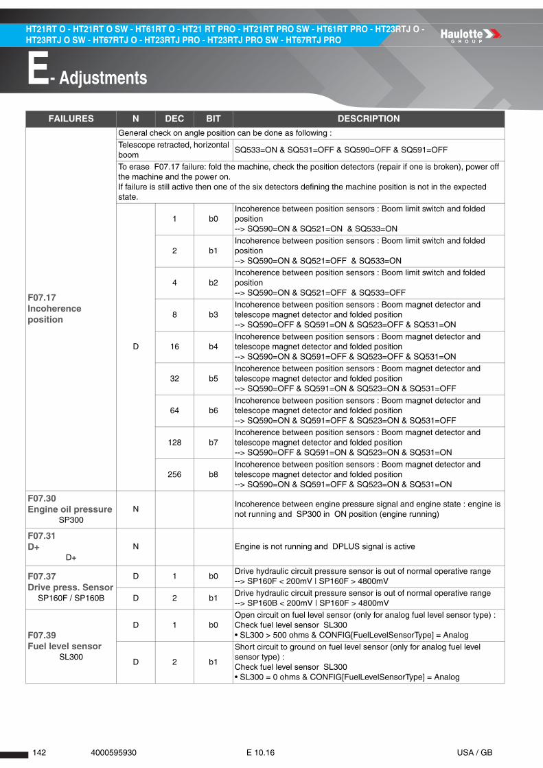
142 4000595930 E 10.16 USA / GB
E- Adjustments
HT21RT O - HT21RT O SW - HT61RT O - HT21 RT PRO - HT21RT PRO SW - HT61RT PRO - HT23RTJ O - HT23RTJ O SW - HT67RTJ O - HT23RTJ PRO - HT23RTJ PRO SW - HT67RTJ PRO
F07.17Incoherence position
General check on angle position can be done as following :
Telescope retracted, horizontal boom
SQ533=ON & SQ531=OFF & SQ590=OFF & SQ591=OFF
To erase F07.17 failure: fold the machine, check the position detectors (repair if one is broken), power off the machine and the power on. If failure is still active then one of the six detectors defining the machine position is not in the expected state.
D
1 b0Incoherence between position sensors : Boom limit switch and folded position--> SQ590=ON & SQ521=ON & SQ533=ON
2 b1Incoherence between position sensors : Boom limit switch and folded position--> SQ590=ON & SQ521=OFF & SQ533=ON
4 b2Incoherence between position sensors : Boom limit switch and folded position--> SQ590=ON & SQ521=OFF & SQ533=OFF
8 b3Incoherence between position sensors : Boom magnet detector and telescope magnet detector and folded position--> SQ590=OFF & SQ591=ON & SQ523=OFF & SQ531=ON
16 b4Incoherence between position sensors : Boom magnet detector and telescope magnet detector and folded position--> SQ590=ON & SQ591=OFF & SQ523=OFF & SQ531=ON
32 b5Incoherence between position sensors : Boom magnet detector and telescope magnet detector and folded position--> SQ590=OFF & SQ591=ON & SQ523=ON & SQ531=OFF
64 b6Incoherence between position sensors : Boom magnet detector and telescope magnet detector and folded position--> SQ590=ON & SQ591=OFF & SQ523=ON & SQ531=OFF
128 b7Incoherence between position sensors : Boom magnet detector and telescope magnet detector and folded position--> SQ590=OFF & SQ591=ON & SQ523=ON & SQ531=ON
256 b8Incoherence between position sensors : Boom magnet detector and telescope magnet detector and folded position--> SQ590=ON & SQ591=OFF & SQ523=ON & SQ531=ON
F07.30Engine oil pressure
SP300N
Incoherence between engine pressure signal and engine state : engine is not running and SP300 in ON position (engine running)
F07.31D+
D+N Engine is not running and DPLUS signal is active
F07.37Drive press. Sensor
SP160F / SP160B
D 1 b0Drive hydraulic circuit pressure sensor is out of normal operative range--> SP160F < 200mV | SP160F > 4800mV
D 2 b1Drive hydraulic circuit pressure sensor is out of normal operative range--> SP160B < 200mV | SP160F > 4800mV
F07.39Fuel level sensor
SL300
D 1 b0Open circuit on fuel level sensor (only for analog fuel level sensor type) : Check fuel level sensor SL300• SL300 > 500 ohms & CONFIG[FuelLevelSensorType] = Analog
D 2 b1
Short circuit to ground on fuel level sensor (only for analog fuel level sensor type) : Check fuel level sensor SL300• SL300 = 0 ohms & CONFIG[FuelLevelSensorType] = Analog
FAILURES N DEC BIT DESCRIPTION

A
B
C
D
E
F
G
H
I
143 4000595930 E 10.16 USA / GB
E- Adjustments
HT21RT O - HT21RT O SW - HT61RT O - HT21 RT PRO - HT21RT PRO SW - HT61RT PRO - HT23RTJ O - HT23RTJ O SW - HT67RTJ O - HT23RTJ PRO - HT23RTJ PRO SW - HT67RTJ PRO
FAILURES N DEC BIT DESCRIPTION
SUPPLIES
F08.04Calc. Input Supply
U104 / U106D
Detected ECU voltage difference --> Difference between U106 (SPU) and U104 (basket B2)Check U100, U104 and U106 supply voltageCheck fusesCheck supply voltage coherence between all ECU (more than 2000 V far during the first 4 seconds after start)
F08.05Calc. Input Supply
U106 5V regul
D 1 b0
Failure on regulated 5 V output of U104 ECU (basket slave node ) supplying the joysticks. --> 5 V output is measured out the range [4.5;5.5]V and 5 V output not failingCheck fusesCheck the harness (check short circuit to power supply, to ground supply, open circuit…)
D 2 b1
Failure on regulated 5 V output of U104 ECU (basket slave node ) supplying the joysticks. --> Detected failure on 5 V outputSwitch OFF/ON the machine, check the failure has gone (probable cause: internal failure of the ECU)
F08.08Unplugged connector
Connectors / Fuses
D
1 b0Supplies’ input detected as unplugged on connectors : Check the CN1.B connectors for U106 ECU : --> 12VD2<5.00V & 12VF2<5.00V
2 b1Supplies’ input detected as unplugged on connectors : Check the CN2.A connectors for U106 ECU : --> 12VD2<5.00V & 12VF2<5.00V
4 b2Supplies’ input detected as unplugged on connectors : Check the CN2.B connectors for U106 ECU : --> 12VD3<5.00V & 12VF3<5.00V
8 b3Supplies’ input detected as unplugged on connectors : Check the CN3.A connectors for U106 ECU : --> 12VD4<5.00V & 12VF4<5.00V
16 b4Supplies’ input detected as unplugged on connectors : Check the CN3.B connectors for U106 ECU : --> 12VD5<5.00V

144 4000595930 E 10.16 USA / GB
E- Adjustments
HT21RT O - HT21RT O SW - HT61RT O - HT21 RT PRO - HT21RT PRO SW - HT61RT PRO - HT23RTJ O - HT23RTJ O SW - HT67RTJ O - HT23RTJ PRO - HT23RTJ PRO SW - HT67RTJ PRO
FAILURES N DEC BIT DESCRIPTION
ENGINE
F09.01Water temperature
Engine overheatD
Engine overheat--> T2s(ST300 & T15s(VAR[Engine]=RUNNING))
F09.02Oil pressure
Engine pressureD
Engine oil pressure--> T6s(SP300 & T15s(VAR[Engine]=RUNNING))
F09.07Amber warning lamp
Check engine
DAvailable with Tier III variable RPM electronic engine and Tier III dual fuel engine, warning lamp received from engine ECUCheck DIAGNOSTIC => FUNCTIONS => Engine => Failure SPN
F09.08Red stop lamp
Check engineD
Available with Tier III variable RPM electronic engine and Tier III dual fuel engine, stop lamp code received from engine ECUCheck DIAGNOSTIC => FUNCTIONS => Engine => Failure SPN
F09.10D+
Engine alternatorD
Alternator failure (alternator not charging battery): only for future TIV versions/ Tier III variable ECU electronic enginesT2s(CTRL[Engine]=RUNNING & (DPLUS=OFF | 12VP<12.00V)
FAILURES N DEC BIT DESCRIPTION
FUNCTIONS
F10.01 DWhile driving in micro speed, measured current for YV160F or YV160B proportional electrovalves is too high : --> VAR[MachinePosition]≠P1 & (YV600[current]> xxx µA | YV620[current] > xxx µA)
F10.02 D
While driving in micro speed, pressure is detected in the hydraulic high speed circuit : Check high speed circuit (YV686), check SP692 sensor (15b) : --> VAR[MachinePosition]≠P1 & SP100=OFF --> VAR[MachinePosition]=P1 & CTRL[DriveSpeed]=High & CTRL[Drive]≠N & SP100=ON• Case 001 = probably hydraulic failure, or SP692 disconnected• Case 002 = probably SP692 failure (shunt, wrong calibration adjusting pressure)
F10.03 DEngine RPM is too high during driving in micro speed : --> VAR[EngineSpeed] > 2550RPM & CTRL[Drive]≠N & VAR[UnfoldedMachine] = 1

A
B
C
D
E
F
G
H
I
145 4000595930 E 10.16 USA / GB
E- Adjustments
HT21RT O - HT21RT O SW - HT61RT O - HT21 RT PRO - HT21RT PRO SW - HT61RT PRO - HT23RTJ O - HT23RTJ O SW - HT67RTJ O - HT23RTJ PRO - HT23RTJ PRO SW - HT67RTJ PRO
FAILURES N DEC BIT DESCRIPTION
FUNCTIONS
F11.08Drive press. Incoh.
SP160F / SP160B / Drive pump
D
Absolute pressure difference in drive circuit is greater than 20bar, except if machine is driving or steering is active (because they cause the pressure difference to raise) --> ABS(VAR[DrivePressureDiff]) > 20 bar & 5s(CTRL[Drive] = Neutral & CTRL[Steering] = Neutral)
FAILURES N DEC BIT DESCRIPTION
INTERNAL FAULTS
F12.01CAN Fault
Check wiresD
1 b0
CAN network failure detected with turret B2 ECU (U100)Machine not supplied, with multimeter, check the resistance between 1001 (CAN high) and 1002 (CAN low) is nearly 60 O (if 0 O or 120 O : failure, check RES TERM connection for all ECUs)Check ECU supplies lineCheck address connections for each B2 ECU (CN106.18/CN106.19/CN106.20)
2 b1 CAN network failure detected with keyboard switches ECU (U107)
4 b2 CAN network failure detected with onboard screen ECU (U101)
F12.02E2P Read/Write Error
Change U106 ECU
Internal failure of SPU: access to EEPROM (read or write)Restart machine
F12.04E2P Param Reset
Check SETTINGSD
1 b0 ID of software loaded into machine is different from the ID stored into EEPROM: all machine parameters have been reset and must then be set again (speeds, ramps, options, configs, access code level 2, failure counters and calibration data)
2 b1 Detected changes in machine speeds and ramps
4 b2 Detected changes in machine options
8 b3 Detected changes in machine configuration
16 b4 Detected changes in machine maintenances
32 b5 Detected changes in machine daily logs
64 b6 Detected changes in machine events counters
128 b7 Detected changes in machine events logs
F12.05Machine not set
D
1 b0Machine’s model is not setSet machine model (HT21RTO - HT21RTPRO - HT23RTJO - HT23RTJPRO)
2 b1Country not setSet country (USA/AUS/STD/RUS)
4 b2Serial number not setSet machine serial number
8 b3Some speed or ramp parameters are not setSet all speed and ramp parameter
16 b4Some options are not setSet machine options (Buzzer, Flashing light, Fleet management, Activ' Shield Bar)
32 b5Some configurations are not setSet all machine's options (Engine)

146 4000595930 E 10.16 USA / GB
E- Adjustments
HT21RT O - HT21RT O SW - HT61RT O - HT21 RT PRO - HT21RT PRO SW - HT61RT PRO - HT23RTJ O - HT23RTJ O SW - HT67RTJ O - HT23RTJ PRO - HT23RTJ PRO SW - HT67RTJ PRO
FAILURES N DEC BIT DESCRIPTION
SWITCHES
F13.02Platform switches
Sw:2 dir activeD
1 b0Detected failure on upper console switches : Two directions active at the same time for steering rocker switch--> SM902L=ON & SM902R=ON
2 b1Detected failure on upper console switches : Two directions active at the same time for jib switch--> SA621U=ON & SA621D=ON
4 b2Detected failure on upper console switches : Two directions active at the same time for platform rotation switch--> SA751U=ON & SA751D=ON
8 b3Detected failure on upper console switches : Two directions active at the same time for platform level switch--> SA721U=ON & SA721D=ON
16 b4Detected failure on upper console switches : Two directions active at the same time for steering mode switch--> SA101C=ON & SA101S=ON
F13.10Switches neutral
Sw: Lower boxA
1 b0Neutral detection failure at machine's power-on for lower console switches : Turntable rotate switch is active
2 b1Neutral detection failure at machine's power-on for lower console switches : Boom switch is active
4 b2Neutral detection failure at machine's power-on for lower console switches : Telescope switch is active
8 b3Neutral detection failure at machine's power-on for lower console switches : Jib switch is active
16 b4Neutral detection failure at machine's power-on for lower console switches : Platform level switch is active
32 b5Neutral detection failure at machine's power-on for lower console switches : Engine start/stop switch is active
64 b6Neutral detection failure at machine's power-on for lower console switches : Enable switch is active
128 b7Neutral detection failure at machine's power-on for lower console switches : DPF switch is active
256 b8Neutral detection failure at machine's power-on for lower console switches : Overriding switch is active
512 b9Neutral detection failure at machine's power-on for lower console switches : Platform rotation switch is active
1024 b10Neutral detection failure at machine's power-on for lower console switches : Horn switch is active
2048 b11Neutral detection failure at machine's power-on for lower console switches : Beacon switch is active

A
B
C
D
E
F
G
H
I
147 4000595930 E 10.16 USA / GB
E- Adjustments
HT21RT O - HT21RT O SW - HT61RT O - HT21 RT PRO - HT21RT PRO SW - HT61RT PRO - HT23RTJ O - HT23RTJ O SW - HT67RTJ O - HT23RTJ PRO - HT23RTJ PRO SW - HT67RTJ PRO
F13.11Switches neutral 2
Sw: Upper boxA
1 b0Neutral detection failure at machine's power-on for upper console switches : Jib switch is active
2 b1Neutral detection failure at machine's power-on for upper console switches : Platform rotation switch is active
4 b2Neutral detection failure at machine's power-on for upper console switches : Platform level switch is active
8 b3Neutral detection failure at machine's power-on for upper console switches : Steering rocker switch is active
16 b4Neutral detection failure at machine's power-on for upper console switches : Engine start/stop switch is active
32 b5Neutral detection failure at machine's power-on for upper console switches : Emergency pump switch is active
64 b6Neutral detection failure at machine's power-on for upper console switches : Horn switch is active
128 b7Neutral detection failure at machine's power-on for upper console switches : Enable pedal is active
FAILURES N DEC BIT DESCRIPTION
CAN J1939
F15.06CANBus Cycle Unit
D
Problem detected in J1939 CANMachine not supplied, with multimeter, check the resistance between 2001 (CAN high) and 2002 (CAN low) is nearly 60 O (if 0 O or 120 O : failure, check RES TERM connection for all ECUs)Check ECU supplies lineCheck CAN connection for Display and/or engine
FAILURES N DEC BIT DESCRIPTION

148 4000595930 E 10.16 USA / GB
E- Adjustments
HT21RT O - HT21RT O SW - HT61RT O - HT21 RT PRO - HT21RT PRO SW - HT61RT PRO - HT23RTJ O - HT23RTJ O SW - HT67RTJ O - HT23RTJ PRO - HT23RTJ PRO SW - HT67RTJ PRO
4 - Load management system
4.1 - OFFSET CALIBRATION
LOAD MANAGEMENT SYSTEM GAUGES
CALIBRATION VALID RANGE (mA)VALID RANGE (V)
(ESTIMATED)
SP800 Offset 7 ± 7 1,67 ± 1,67
SP801 Offset 7 ± 7 1,67 ± 1,67
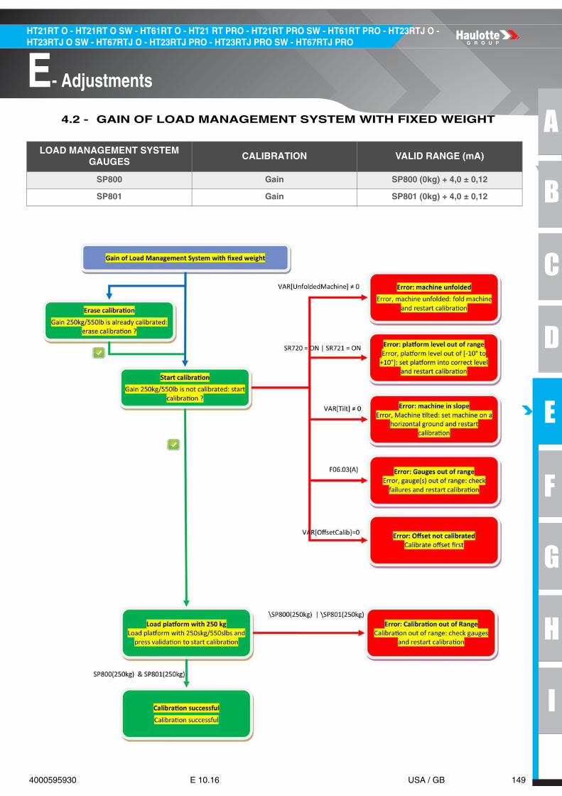
A
B
C
D
E
F
G
H
I
149 4000595930 E 10.16 USA / GB
E- Adjustments
HT21RT O - HT21RT O SW - HT61RT O - HT21 RT PRO - HT21RT PRO SW - HT61RT PRO - HT23RTJ O - HT23RTJ O SW - HT67RTJ O - HT23RTJ PRO - HT23RTJ PRO SW - HT67RTJ PRO
4.2 - GAIN OF LOAD MANAGEMENT SYSTEM WITH FIXED WEIGHT
LOAD MANAGEMENT SYSTEM GAUGES
CALIBRATION VALID RANGE (mA)
SP800 Gain SP800 (0kg) + 4,0 ± 0,12
SP801 Gain SP801 (0kg) + 4,0 ± 0,12

150 4000595930 E 10.16 USA / GB
E- Adjustments
HT21RT O - HT21RT O SW - HT61RT O - HT21 RT PRO - HT21RT PRO SW - HT61RT PRO - HT23RTJ O - HT23RTJ O SW - HT67RTJ O - HT23RTJ PRO - HT23RTJ PRO SW - HT67RTJ PRO
4.3 - GAIN OF LOAD MANAGEMENT SYSTEM WITH ADJUSTABLE WEIGHT
LOAD MANAGEMENT SYSTEM GAUGES
CALIBRATION VALID RANGE (mA)
SP800 Gain SP800 (0kg) + 4,0 x (ADJWEIGHT / 250) ± 0,12
SP801 Gain SP801 (0kg) + 4,0 x (ADJWEIGHT / 250) ± 0,12

A
B
C
D
E
F
G
H
I
151 4000595930 E 10.16 USA / GB
E- Adjustments
HT21RT O - HT21RT O SW - HT61RT O - HT21 RT PRO - HT21RT PRO SW - HT61RT PRO - HT23RTJ O - HT23RTJ O SW - HT67RTJ O - HT23RTJ PRO - HT23RTJ PRO SW - HT67RTJ PRO
5 - Adjustment of pressures
5.1 - PORT PLUG FOR PRESSURES CONTROL
All pressures could be ckecked by connecting a pressure gauge on port M as shown below

152 4000595930 E 10.16 USA / GB
E- Adjustments
HT21RT O - HT21RT O SW - HT61RT O - HT21 RT PRO - HT21RT PRO SW - HT61RT PRO - HT23RTJ O - HT23RTJ O SW - HT67RTJ O - HT23RTJ PRO - HT23RTJ PRO SW - HT67RTJ PRO
5.2 - PRESSURE ADJUSTMENTS ON PUMP
• Load Sensing.
• Main flow.
• The pump is preset at a load sensing pressure of 20b (+-2b)/290 psi.
• The pump is preset at a main pressure of 240b (+-5b)/3480 psi.
Settings
MARKING FUNCTION VALUE
1 Load Sensing 20b
2 Pmaxi 240b
Designation Pressure Adjustment port
Maxi pressure setting 240 +/-5b On equipment pump
Load sensing setting 22 +/-2b On equipment pump
Pressure turret orientation 120 +/-5b On ECD proportional block
Emergency pump 240 +/-5b On emergency pump

A
B
C
D
E
F
G
H
I
153 4000595930 E 10.16 USA / GB
F- Simplified breakdown guide
HT21RT O - HT21RT O SW - HT61RT O - HT21 RT PRO - HT21RT PRO SW - HT61RT PRO - HT23RTJ O - HT23RTJ O SW - HT67RTJ O - HT23RTJ PRO - HT23RTJ PRO SW - HT67RTJ PRO
Simplified breakdown guideThis guide does not replace the diagnostic functions described previously in this manual. It allows the technicianto have a logical step of breakdown service, detailing the successive steps to be followed starting from generaltips until the details. The checking of the electric part is carried out in priority because less sensitive to the externalparameters than the hydraulics part (Temperature, pollution, viscosity). The denomination of the movementsdescribes below implies both directions (Example not lifting, neither raise, nor descent from both controls, up anddown).
For a quicker diagnostic :
Do check the failures code on cluster display and refer to the alarms list before scrolling this breakdown guide.
Do check all fuses.
Beware as some options once activated might prohibit some movements (the option ASB, Active Shield Bardevice).
1 - Quick checkings on drive
Same as above
(Example for FWD drive in High speed mode YV160B+YV102+YV110+YV104+YV101=1)
YV XXX → 160B 160F 102 110 104 101
Drive low speed forward X X X X
Drive low speed rear X X X X
Drive high speed forward X X X X X
Drive high speed rear X X X X X
ON if machine retracted and turret in the axis

154 4000595930 E 10.16 USA / GB
F- Simplified breakdown guide
HT21RT O - HT21RT O SW - HT61RT O - HT21 RT PRO - HT21RT PRO SW - HT61RT PRO - HT23RTJ O - HT23RTJ O SW - HT67RTJ O - HT23RTJ PRO - HT23RTJ PRO SW - HT67RTJ PRO
2 - Quick checkings on movements
Thanks to this quick table, you could check for each movement, which valve must be activated(Example for jiblifting = YV800 + YV802 + YV520U = 1)
ITEMS DESCRIPTION
YV800+YV805+YV250R Turn table right hand rotation
YV800+YV805+YV250L Turn table left hand rotation
YV800+YV801+YV530O Boom extension
YV800+YV530I Boom retraction
YV800+YV901+YV750R Basket right hand rotation
YV800+YV901+YV750L Basket left hand rotation
YV800+YV802+YV520U Boom lifting
YV800+YV802+YV807+YV520D Boom lowering
YV800+YV901+YV620U Jib lifting
YV800+YV901+YV620D Jib lowering
YV800+YV901+YV720U Compensation lifting
YV800+YV901+YV720D Compensation lowering

A
B
C
D
E
F
G
H
I
155 4000595930 E 10.16 USA / GB
F- Simplified breakdown guide
HT21RT O - HT21RT O SW - HT61RT O - HT21 RT PRO - HT21RT PRO SW - HT61RT PRO - HT23RTJ O - HT23RTJ O SW - HT67RTJ O - HT23RTJ PRO - HT23RTJ PRO SW - HT67RTJ PRO
3 - Quick checkings on engine
PROBLEM PROBABLE CAUSE SOLUTION
When it is difficult to start the engine
Fuel is thick and doesn't flow
• Check the fuel tank and fuel filter. • Remove water, dirt and other impurities. • As all fuel will be filtered by the filter, if there should be water or other foreign matters on the filter, clean the filter with kerosene.
Air or water mixed in fuel system
• If air is in the fuel filter or injection lines, the fuel pump will not work properly. • To attain proper fuel injection pressure, check carefully for loosened fuel line coupling, loose cap nut, etc. • Loosen joint bolt stop fuel filter and air vent screws of fuel injection pump to eliminate all the air in the fuel system.
Battery is discharged and the engine will not crank
• Charge battery. • In winter, always remove battery from machine, charge fully and keep indoors. Install in machine at time of use.
Engine oil becomes thick in cold weather and engine cranks slow
• Change grade of oil according to the weather (temperature).
When output is insufficient
Fuel is insufficient • Check fuel system
Overheating of moving parts
• Check lubricating oil system• Check to see if lubricating oil filter is working properly. • Filter element deposited with impurities would cause poor lubrication. Change element.
When engine suddenly stops
Lack of fuel• Check the fuel tank and refill the fuel, if necessary• Also check the fuel system for air or leaks.
Bad nozzle • If necessary, replace with a new nozzle.
Moving parts are overheated due to shortage of lubrication oil or improper lubrication
• Check amount of engine oil with oil level gauge. • Check lubricating oil system. • At every 2 times of oil change, oil filter cartridge should be replaced.
When color of exhaust is especially bad
Fuel is of extremely poor quality• Select good quality fuel. Use no. 2-D diesel fuel only
Nozzle is bad • If necessary, replace with new nozzle.
When engine must be stopped immediately
Color of exhaust suddenly turns dark• Check the fuel injection system, especially the fuel injection nozzle.
Bearing parts are overheated • Check the lubricating system.
Oil lamp lights up during operation
• Check the lubricating system. • Check the function of the relieve valve in the lubricating system. • Check pressure switch. • Check filter base gasket.

156 4000595930 E 10.16 USA / GB
F- Simplified breakdown guide
HT21RT O - HT21RT O SW - HT61RT O - HT21 RT PRO - HT21RT PRO SW - HT61RT PRO - HT23RTJ O - HT23RTJ O SW - HT67RTJ O - HT23RTJ PRO - HT23RTJ PRO SW - HT67RTJ PRO
When engine overheats
Engine oil insufficient • Check oil level. Replenish oil as required.
Fan belt broken or elongated • Change belt or adjust belt tension.
Coolant insufficient • Replenish coolant.
Excessive concentration of antifreeze• Add water only or change to coolant with the specified mixing ratio.
Radiator net or radiator fin clogged with dust
• Clean net or fin carefully.
Inside of radiator or coolant flow route corroded
• Clean or replace radiator and parts.
Fan or radiator or radiator cap defective • Replace defective parts.
Thermostat defective • Check thermostat and replace if necessary.
Temperature gauge or sensor defective• Check temperature with thermometer and replace if necessary.
Overload running • Reduce load.
Head gasket defective or water leakage • Replace parts.
Unsuitable fuel used • Use the specified fuel.
PROBLEM PROBABLE CAUSE SOLUTION
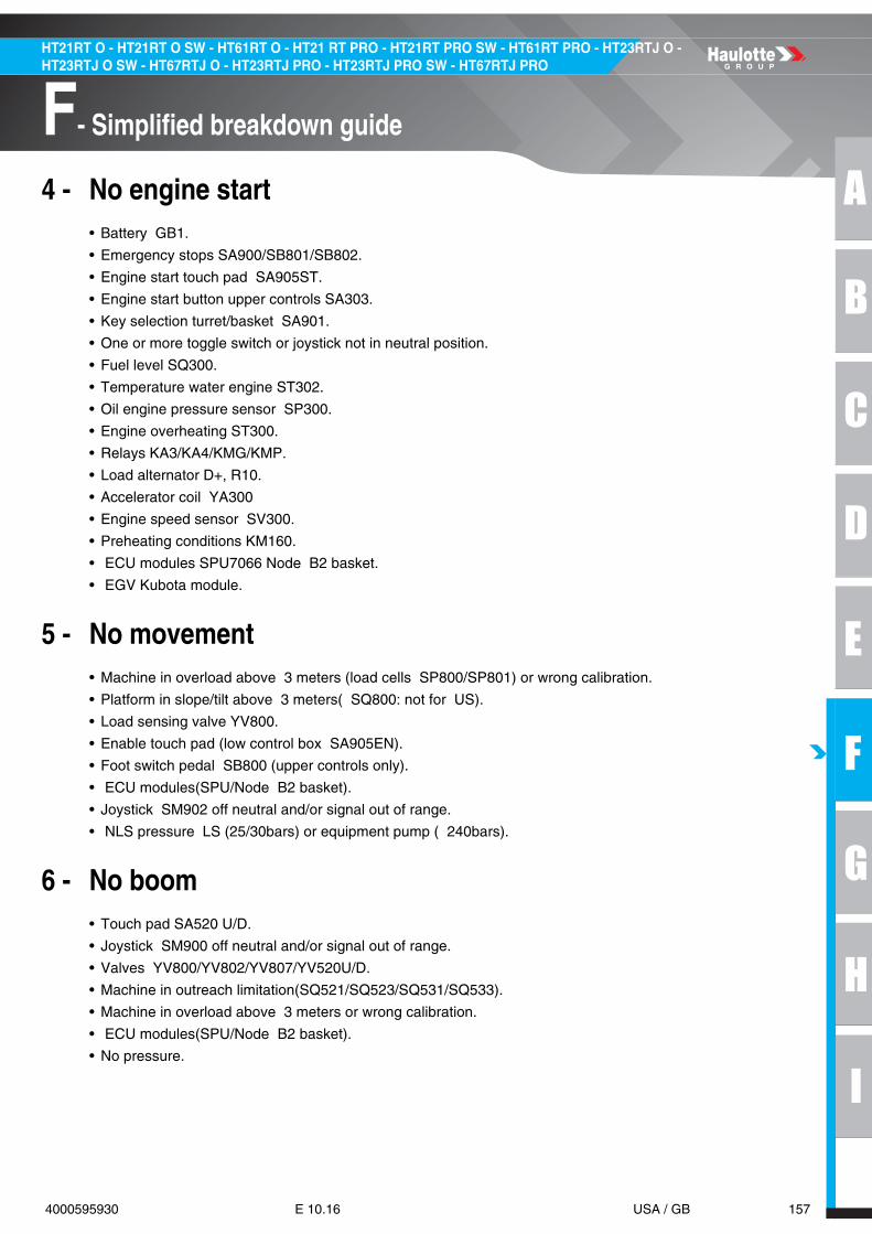
A
B
C
D
E
F
G
H
I
157 4000595930 E 10.16 USA / GB
F- Simplified breakdown guide
HT21RT O - HT21RT O SW - HT61RT O - HT21 RT PRO - HT21RT PRO SW - HT61RT PRO - HT23RTJ O - HT23RTJ O SW - HT67RTJ O - HT23RTJ PRO - HT23RTJ PRO SW - HT67RTJ PRO
4 - No engine start• Battery GB1.
• Emergency stops SA900/SB801/SB802.
• Engine start touch pad SA905ST.
• Engine start button upper controls SA303.
• Key selection turret/basket SA901.
• One or more toggle switch or joystick not in neutral position.
• Fuel level SQ300.
• Temperature water engine ST302.
• Oil engine pressure sensor SP300.
• Engine overheating ST300.
• Relays KA3/KA4/KMG/KMP.
• Load alternator D+, R10.
• Accelerator coil YA300
• Engine speed sensor SV300.
• Preheating conditions KM160.
• ECU modules SPU7066 Node B2 basket.
• EGV Kubota module.
5 - No movement• Machine in overload above 3 meters (load cells SP800/SP801) or wrong calibration.
• Platform in slope/tilt above 3 meters( SQ800: not for US).
• Load sensing valve YV800.
• Enable touch pad (low control box SA905EN).
• Foot switch pedal SB800 (upper controls only).
• ECU modules(SPU/Node B2 basket).
• Joystick SM902 off neutral and/or signal out of range.
• NLS pressure LS (25/30bars) or equipment pump ( 240bars).
6 - No boom• Touch pad SA520 U/D.
• Joystick SM900 off neutral and/or signal out of range.
• Valves YV800/YV802/YV807/YV520U/D.
• Machine in outreach limitation(SQ521/SQ523/SQ531/SQ533).
• Machine in overload above 3 meters or wrong calibration.
• ECU modules(SPU/Node B2 basket).
• No pressure.

158 4000595930 E 10.16 USA / GB
F- Simplified breakdown guide
HT21RT O - HT21RT O SW - HT61RT O - HT21 RT PRO - HT21RT PRO SW - HT61RT PRO - HT23RTJ O - HT23RTJ O SW - HT67RTJ O - HT23RTJ PRO - HT23RTJ PRO SW - HT67RTJ PRO
7 - No telescopic boom• Touch pad SA530I/O.
• Joystick SM901 off neutral and/or signal out of range.
• Valves YV800/YV801/YV530O/I.
• Machine in outreach limitation(SQ521/SQ523/SQ531/SQ533).
• Machine in overload above 3 meters or wrong calibration.
• ECU modules(SPU/Node B2 basket).
• No pressure.
8 - No turret rotation• Touch pad SA250L/R.
• Joystick SM900 off neutral and/or signal out of range.
• Valves YV800/YV805/YV250L/R.
• ECU modules(SPU/Node B2 basket).
• No pressure.
9 - No jib• Touch pad SA620U/D.
• Switch SA621.
• Valves YV800/YV901/YV620U/D.
• ECU modules(SPU/Node B2 basket).
• No pressure.
10 - No basket rotation• Switch SA751.
• Valves YV800/YV901/YV750R/L.
• ECU modules(SPU/Node B2 basket).
• No pressure.
11 - No basket compensation• Machine not in stowed position.
• Touch pad SA720U/D.
• Switch SA751.
• Valves YV80/YV901/YV720U/D.
• Other movement running.
• Tilt switches SR720/SR721.
• ECU modules(SPU/Node B2 basket).
• No pressure.
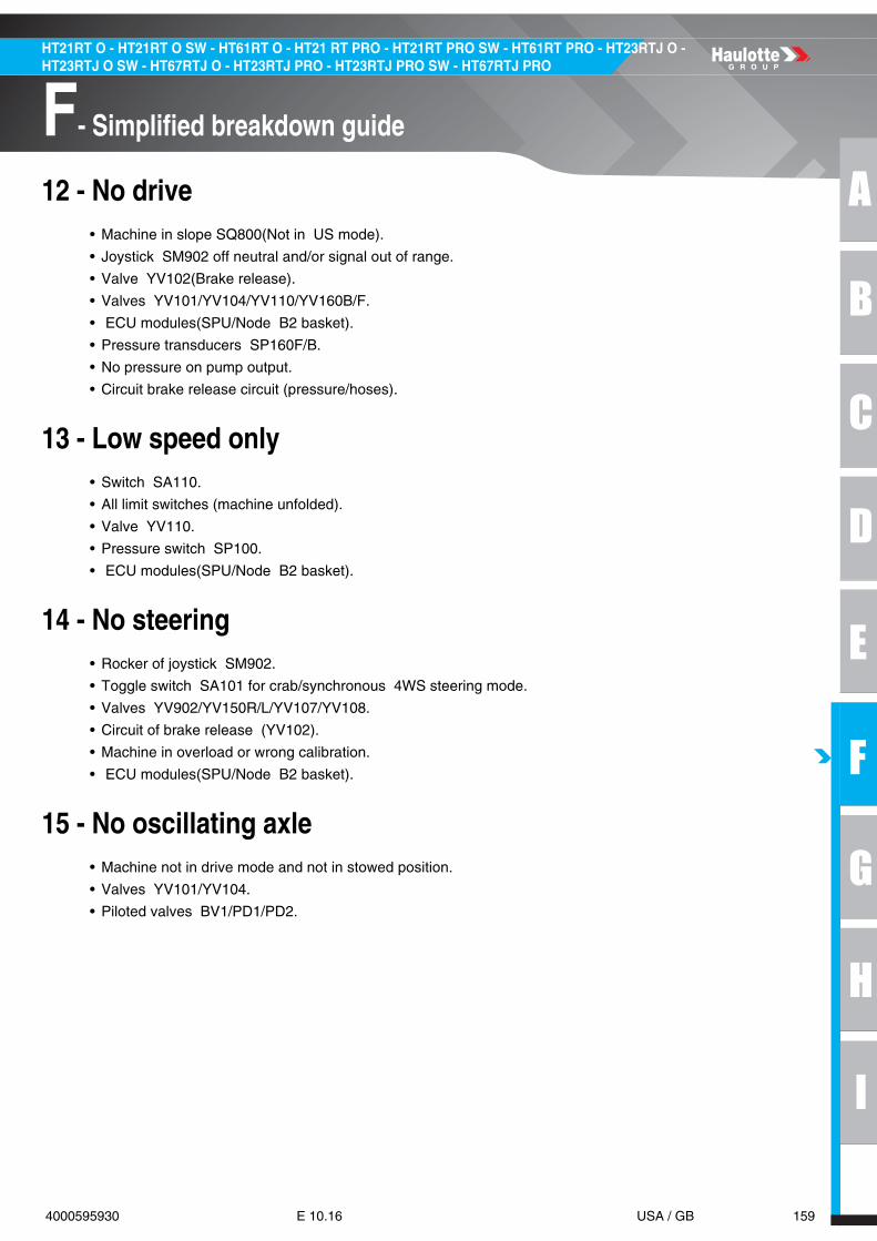
A
B
C
D
E
F
G
H
I
159 4000595930 E 10.16 USA / GB
F- Simplified breakdown guide
HT21RT O - HT21RT O SW - HT61RT O - HT21 RT PRO - HT21RT PRO SW - HT61RT PRO - HT23RTJ O - HT23RTJ O SW - HT67RTJ O - HT23RTJ PRO - HT23RTJ PRO SW - HT67RTJ PRO
12 - No drive• Machine in slope SQ800(Not in US mode).
• Joystick SM902 off neutral and/or signal out of range.
• Valve YV102(Brake release).
• Valves YV101/YV104/YV110/YV160B/F.
• ECU modules(SPU/Node B2 basket).
• Pressure transducers SP160F/B.
• No pressure on pump output.
• Circuit brake release circuit (pressure/hoses).
13 - Low speed only• Switch SA110.
• All limit switches (machine unfolded).
• Valve YV110.
• Pressure switch SP100.
• ECU modules(SPU/Node B2 basket).
14 - No steering• Rocker of joystick SM902.
• Toggle switch SA101 for crab/synchronous 4WS steering mode.
• Valves YV902/YV150R/L/YV107/YV108.
• Circuit of brake release (YV102).
• Machine in overload or wrong calibration.
• ECU modules(SPU/Node B2 basket).
15 - No oscillating axle• Machine not in drive mode and not in stowed position.
• Valves YV101/YV104.
• Piloted valves BV1/PD1/PD2.

160 4000595930 E 10.16 USA / GB
F- Simplified breakdown guide
HT21RT O - HT21RT O SW - HT61RT O - HT21 RT PRO - HT21RT PRO SW - HT61RT PRO - HT23RTJ O - HT23RTJ O SW - HT67RTJ O - HT23RTJ PRO - HT23RTJ PRO SW - HT67RTJ PRO
Notes

A
B
C
D
E
F
G
H
I
161 4000595930 E 10.16 USA / GB
G- Version summary
HT21RT O - HT21RT O SW - HT61RT O - HT21 RT PRO - HT21RT PRO SW - HT61RT PRO - HT23RTJ O - HT23RTJ O SW - HT67RTJ O - HT23RTJ PRO - HT23RTJ PRO SW - HT67RTJ PRO
Version summary1 - Version summary
2 - List of schematics
See end of manual
3 - List of wiring harnesses
See end of manual
HT21RTO/PRO - HT23RTJO/PRO (HT61RT/RTO/PRO - HT67RTJO/PRO)
STANDARDS WIRING DIAGRAMHYDRAULIC
DIAGRAM
All versions equipped with display on lower panel
All countries
166P328300 166P325080
All versions equipped with activ screen V2 on lower panel
4000421620 4000466740

162 4000595930 E 10.16 USA / GB
G- Version summary
HT21RT O - HT21RT O SW - HT61RT O - HT21 RT PRO - HT21RT PRO SW - HT61RT PRO - HT23RTJ O - HT23RTJ O SW - HT67RTJ O - HT23RTJ PRO - HT23RTJ PRO SW - HT67RTJ PRO
Notes

Mov
emen
tPa
ram
eter
[Tar
get]
Fact
ory
tole
ranc
eCo
nfig
urat
ion
Driv
e fo
rwar
dM
in sp
eed
[‐100
; +1
0]D
rive
forw
ard
Max sp
eed
[29.
0000
00 ;
33.0
0000
0][‐1
00 ;
+0]
High
spee
d se
lect
ed, d
rive
on 5
0m/1
64ft le
ngth
Driv
e fo
rwar
dM
ax sp
eed
mic
ro[7
0.00
0000
; 74
.000
000]
[‐100
; +0
]M
achi
ne u
nfol
ded, d
rive
on 1
0m/3
3ft l
engt
h. H
igh
spee
d se
t mus
t be
done
.D
rive
forw
ard
Acce
lera
tion
[‐1 ;
+3]
Driv
e fo
rwar
dDe
cele
ratio
n[‐3
; +1
]1.
7m/5
.6ft ± 0
.3m
/1ft in h
igh
spee
dD
rive
reve
rse
Min sp
eed
[‐100
; +1
0]D
rive
reve
rse
Max sp
eed
[29.
0000
00 ;
33.0
0000
0][‐1
00 ;
+0]
High
spee
d se
lect
ed, d
rive
on 5
0m/1
64ft le
ngth
Driv
e re
vers
eM
ax sp
eed
mic
ro[7
0.00
0000
; 74
.000
000]
[‐100
; +0
]M
achi
ne u
nfol
ded, d
rive
on 1
0m/3
3ft l
engt
h. H
igh
spee
d se
t mus
t be
done
.D
rive
reve
rse
Acce
lera
tion
[‐1 ;
+3]
Driv
e re
vers
eDe
cele
ratio
n[‐3
; +1
]1.
7m/5
.6ft ± 0
.3m
/1ft in h
igh
spee
dSt
eerin
gM
ax sp
eed
[3.0
0000
0 ; 5
.000
000]
[‐100
; +0
]2W
S se
lect
ed, f
rom lo
ck to
lock
Turn
tabl
e or
ient
atio
n le
ftM
in sp
eed
[‐100
; +1
0]Tu
rnta
ble
orie
ntat
ion
left
Max sp
eed
[30.
0000
00 ;
34.0
0000
0][‐1
00 ;
+0]
Turr
et ro
tatio
n to th
e le
ft fo
r ¼ tu
rn w
ith b
oom re
trac
ted
Turn
tabl
e or
ient
atio
n le
ftAc
cele
ratio
n[‐1
; +3
]Tu
rnta
ble
orie
ntat
ion
left
Dece
lera
tion
[‐3 ;
+1]
Turn
tabl
e or
ient
atio
n rig
htM
in sp
eed
[‐100
; +1
0]Tu
rnta
ble
orie
ntat
ion
right
Max sp
eed
[30.
0000
00 ;
34.0
0000
0][‐1
00 ;
+0]
Turr
et ro
tatio
n to th
e rig
ht fo
r ¼ tu
rn w
ith b
oom re
trac
ted
Turn
tabl
e or
ient
atio
n rig
htAc
cele
ratio
n[‐1
; +3
]Tu
rnta
ble
orie
ntat
ion
right
Dece
lera
tion
[‐3 ;
+1]
Boom
Rai
seM
in sp
eed
[‐100
; +1
0]Bo
om R
aise
Max sp
eed
[57.
0000
00 ;
63.0
0000
0][‐1
0 ; +
0]Pl
atfo
rm c
ontr
ols, si
ngle lo
ad c
onfig
urat
ion, fr
om lo
wer to
upp
er st
opBo
om R
aise
Max sp
eed
[40.
0000
00 ;
44.0
0000
0][‐1
00 ;
+0]
Plat
form
con
trol
s, d
ual l
oad
conf
igur
atio
n, fr
om u
pper to
low
er st
opBo
om R
aise
Acce
lera
tion
[‐1 ;
+3]
Boom
Rai
seDe
cele
ratio
n[‐3
; +1
]Bo
om D
esce
ntM
in sp
eed
[‐100
; +1
0]Bo
om D
esce
ntM
ax sp
eed
[67.
0000
00 ;
73.0
0000
0][‐1
00 ;
+0]
Plat
form
con
trol
s, si
ngle lo
ad c
onfig
urat
ion, fr
om u
pper to
low
er st
opBo
om D
esce
ntM
ax sp
eed
[40.
0000
00 ;
44.0
0000
0][‐1
0 ; +
0]Pl
atfo
rm c
ontr
ols, d
ual l
oad
conf
igur
atio
n, fr
om u
pper to
low
er st
opBo
om D
esce
ntAc
cele
ratio
n[‐1
; +3
]Bo
om D
esce
ntDe
cele
ratio
n[‐3
; +1
]Bo
om T
eles
cope
Ext
end
Min sp
eed
[‐100
; +1
0]Bo
om T
eles
cope
Ext
end
Max sp
eed
[25.
0000
00 ;
29.0
0000
0][‐1
00 ;
+0]
Boom
raise
d, fr
om lo
wer to
upp
er st
opBo
om T
eles
cope
Ext
end
Acce
lera
tion
[‐1 ;
+3]
Boom
Tel
esco
pe E
xten
dDe
cele
ratio
n[‐3
; +1
]Bo
om T
eles
cope
Ret
ract
Min sp
eed
[‐100
; +1
0]Bo
om T
eles
cope
Ret
ract
Max sp
eed
[25.
0000
00 ;
29.0
0000
0][‐1
00 ;
+0]
Boom
raise
d, fr
om u
pper to
low
er st
opBo
om T
eles
cope
Ret
ract
Acce
lera
tion
[‐1 ;
+3]
Boom
Tel
esco
pe R
etra
ctDe
cele
ratio
n[‐3
; +1
]Jib
Rai
seM
in sp
eed
[‐100
; +1
0]Jib
Rai
seM
ax sp
eed
[27.
0000
00 ;
31.0
0000
0][‐1
00 ;
+0]
Plat
form
con
trol
s, fr
om lo
wer to
upp
er st
opJib
Rai
seAc
cele
ratio
n[‐1
; +3
]Jib
Rai
seDe
cele
ratio
n[‐3
; +1
]Jib
Des
cent
Min sp
eed
[‐100
; +1
0]Jib
Des
cent
Max sp
eed
[26.
0000
00 ;
30.0
0000
0][‐1
00 ;
+0]
Plat
form
con
trol
s, fr
om lo
wer to
upp
er st
opJib
Des
cent
Acce
lera
tion
[‐1 ;
+3]
Jib D
esce
ntDe
cele
ratio
n[‐3
; +1
]Pl
atfo
rm L
evel R
aise
Min sp
eed
[‐100
; +1
0]Pl
atfo
rm L
evel R
aise
Max sp
eed
[13.
0000
00 ;
17.0
0000
0][‐1
00 ;
+0]
Plat
form
con
trol
s, fr
om u
pper to
low
er st
opPl
atfo
rm L
evel R
aise
Acce
lera
tion
[‐1 ;
+3]
Plat
form
Lev
el R
aise
Dece
lera
tion
[‐3 ;
+1]
Plat
form
Lev
el D
esce
ntM
in sp
eed
[‐100
; +1
0]Pl
atfo
rm L
evel D
esce
ntM
ax sp
eed
[13.
0000
00 ;
17.0
0000
0][‐1
00 ;
+0]
Plat
form
con
trol
s, fr
om lo
wer to
upp
er st
opPl
atfo
rm L
evel D
esce
ntAc
cele
ratio
n[‐1
; +3
]Pl
atfo
rm L
evel D
esce
ntDe
cele
ratio
n[‐3
; +1
]Pl
atfo
rm ro
tatio
nM
in sp
eed
[‐100
; +1
0]Pl
atfo
rm ro
tatio
nM
ax sp
eed
[13.
0000
00 ;
17.0
0000
0][‐1
00 ;
+0]
Plat
form
con
trol
s, fr
om lo
ck to
lock (l
eft o
r rig
ht)
Plat
form
rota
tion
Acce
lera
tion
[‐1 ;
+3]
Plat
form
rota
tion
Dece
lera
tion
[‐3 ;
+1]
ANN
EX 1

xxxxx.A
noitpircseDe
maN
& V
alue
sEn
gine
TIER
3 KU
BOTA
V24
03-M
TIER
4 KU
BOTA
V24
03-C
RLo
ad M
anag
emen
t Sys
tem
Choi
ce o
f the
type
of l
oad
syst
em se
nsor
sSt
rain
gau
ges
Vibrati
ng w
ires
Load
Selectio
nCh
oice
of t
he ty
pe o
f mac
hine
: du
al lo
ad se
lection
(230
kg-5
00lb
and
450
kg-1
000l
b lo
ads)
or s
ingl
e lo
ad se
lection
(230
kg-5
00lb
onl
y)Si
ngle
load
selecti
onDu
al lo
ad se
lecti
onDr
ive
pum
p sa
fety
inst
alle
dO
FFO
NFu
el le
vel s
enso
r typ
eCh
oice
of t
he ty
pe o
f fue
l lev
el se
nsor
: O
N/O
FF (l
ow fu
el le
vel detectio
n on
ly) o
r ana
logi
c (fu
el le
vel m
easu
re)
ON
/OFF
Anal
og
ANN
EX 3
noitpircseDe
maN
&
nim_leveL
seulaVBu
zzer
Choo
se fo
r whi
ch m
ovem
ents
the
buzz
er m
ust b
e activ
ated
1O
FFDe
scen
t / R
etra
ct M
ovem
ents
All M
ovem
ents
Driv
eDr
ive
+ Al
l Mov
emen
tsFl
ashi
ng li
ght
1O
FFAl
l Mov
emen
tsDr
ive
Driv
e +
All M
ovem
ents
ON
Activ
'Shield
Bar
2O
FFO
NTr
acki
ng sy
stem
1O
FFO
NM
ovem
ents
restric
tions
und
er tilt cond
ition
sIf op
tion
is O
N, i
t allo
ws t
o re
stric
t driv
e an
d ex
tens
ion
mov
emen
ts w
hen tilt i
s active
and
m
achi
ne is
unf
olde
d. If
opti
on is
OFF
, driv
e an
d ex
tens
ion
mov
emen
ts a
re a
llow
ed a
ccor
ding
to
coun
try selection
.
3
OFF
ON
Gene
rato
r with
eng
ine acceleratio
n1
OFF
ON
Emer
genc
y M
ode
not r
eset
Allo
ws t
o di
sabl
e w
arni
ng a
t mac
hine
star
tup
if em
erge
ncy
mod
e ha
s bee
n us
ed2
OFF
ON
Use
r Ide
ntificati
on in
hibi
ted
Allo
ws t
o in
hibi
t use
r ide
ntificati
on in
case
scre
en is
not
usa
ble
3O
FFO
N
ANN
EX 2
Nam
eDe
scrip
tion
& V
alue
sEn
gine
supp
lyAp
ply
engi
ne p
ower
supp
lyO
FFO
NTe
st V
alve
s ON
Forc
e al
l sec
urity
val
ves t
o O
NO
FFO
NTe
st V
alve
s OFF
Forc
e al
l sec
urity
val
ves t
o O
FFO
FFO
NANN
EX 4

Type
:N
ame
Dia
gnos
tic in
stru
ctio
ns:
ECU
:Re
fPi
nW
ireTy
pe:2
DIG
ITAL
INPU
TSSQ
800 ‐ T
ilt se
nsor
If til
t < 5
°, in
put m
ust b
e O
N (+
VBAT
). If
not:
‐ c
heck se
nsor a
djus
tmen
t ‐ c
heck se
nsor su
pply fu
se (F
U7/
15A)
‐ c
heck se
nsor su
pply (w
ires 0
=0V
and
109=
+VBA
T)‐c
heck
inpu
twire
cont
inui
ty
SPU
70‐6
6 ‐ T
urre
tAN
051B
.21
150
Digi
tal i
nput (H
S)
SQ59
0 ‐ B
oom d
own/
tele
scop
e re
trac
ted
dete
ctor 1
If bo
om is se
t on
turr
et a
nd te
lesc
ope
is re
trac
ted, in
put m
ust b
e O
N (+
VBAT
). If
not:
‐ c
heck se
nsor a
djus
tmen
t ‐ c
heck se
nsor su
pply fu
se (F
U7‐
15A)
‐ c
heck se
nsor su
pply (w
ire 1
09=+
VBAT
)‐c
heck
inpu
twire
cont
inui
ty
SPU
70‐6
6 ‐ T
urre
tU
N22
2B.1
322
2 (C
N02
.1)
Uni
vers
al in
put L
(0‐3
2V, H
S, L
S)
SQ59
1 ‐ B
oom d
own/
tele
scop
e re
trac
ted
dete
ctor 2
If bo
om is se
t on
turr
et a
nd te
lesc
ope
is re
trac
ted, in
put m
ust b
e O
N (+
VBAT
). If
not:
‐ c
heck se
nsor a
djus
tmen
t ‐ c
heck se
nsor su
pply fu
se (F
U7‐
15A)
‐ c
heck se
nsor su
pply (w
ire 1
09=+
VBAT
)‐c
heck
inpu
twire
cont
inui
ty
SPU
70‐6
6 ‐ T
urre
tU
N24
2B.1
428
1 (C
N02
.6)
Uni
vers
al in
put L
(0‐3
2V, H
S, L
S)
SQ53
3 ‐ B
oom te
lesc
ope
posi
tion
dete
ctor
If bo
om te
lesc
ope
leng
th is <
10m
, inp
ut m
ust b
e O
N (+
VBAT
). If
not:
‐ c
heck se
nsor a
djus
tmen
t ‐ c
heck se
nsor su
pply fu
se (F
U7‐
15A)
‐ c
heck se
nsor su
pply (w
ire 1
09=+
VBAT
)‐c
heck
inpu
twire
cont
inui
ty
SPU
70‐6
6 ‐ T
urre
tU
N31
3B.2
338
3 (C
N02
.13)
Uni
vers
al in
put N
(0‐3
2V, H
S, L
S)
SQ53
1 ‐ B
oom te
lesc
ope
zone
1If
boom
zone
1 d
etec
tor o
f tel
esco
pe is in
fron
t of a
mag
net,
inpu
t mus
t be
ON (+
VBAT
). If
not:
‐ c
heck se
nsor a
djus
tmen
t ‐ c
heck b
oom m
agne
t adj
ustm
ent
‐ c
heck se
nsor su
pply fu
se (F
U7‐
15A)
‐ c
heck se
nsor su
pply (w
ire 1
09=+
VBAT
) ‐ c
heck in
put w
ire c
ontin
uity
Itis
poss
ible
toch
eck
allo
ther
mag
nets
refe
rto
zone
coun
ting
inDi
agno
stic
/Sta
te
SPU
70‐6
6 ‐ T
urre
tU
N25
3A.1
133
2 (C
N02
.2)
Uni
vers
al in
put M
(0‐3
2V, H
S, L
S)
SQ52
1 ‐ B
oom h
igh
dete
ctor
If bo
om a
ngle >
52°,
inpu
t mus
t be
ON (+
VBAT
). If
not:
‐ c
heck se
nsor a
djus
tmen
t ‐ c
heck se
nsor su
pply fu
se (F
U7‐
15A)
‐ c
heck se
nsor su
pply (1
09=+
VBAT
)‐c
heck
inpu
twire
cont
inui
ty
SPU
70‐6
6 ‐ T
urre
tU
N23
2B.1
238
4 (C
N02
.4)
Uni
vers
al in
put L
(0‐3
2V, H
S, L
S)
SQ52
3 ‐ B
oom zo
ne m
agne
tIf
boom
zone
1 d
etec
tor o
f tel
esco
pe is in
fron
t of a
mag
net,
inpu
t mus
t be
ON (+
VBAT
). If
not:
‐ c
heck se
nsor a
djus
tmen
t ‐ c
heck b
oom m
agne
t adj
ustm
ent
‐ c
heck se
nsor su
pply fu
se (F
U7‐
15A)
‐ c
heck se
nsor su
pply (w
ire 1
09=+
VBAT
) ‐ c
heck in
put w
ire c
ontin
uity
Itis
poss
ible
toch
eck
allo
ther
mag
nets
refe
rto
zone
coun
ting
inDi
agno
stic
/Sta
te
SPU
70‐6
6 ‐ T
urre
tU
N26
3A.1
738
0 (C
N02
.3)
Uni
vers
al in
put M
(0‐3
2V, H
S, L
S)
SQ80
1 ‐ C
hain
/cab
le b
reak 1
If bo
om te
lesc
ope
chai
n/ca
ble
is no
t bro
ken, in
put m
ust b
e O
N (+
VBAT
). If
not:
‐ c
heck se
nsor a
djus
tmen
t ‐ c
heck se
nsor su
pply fu
se (F
U7‐
15A)
‐ c
heck se
nsor su
pply (w
ire 1
09=+
VBAT
)‐c
heck
inpu
twire
cont
inui
ty
SPU
70‐6
6 ‐ T
urre
tU
N08
1A.2
199
0U
nive
rsal in
put E
(0‐3
2V, H
S, L
S)
SQ80
2 ‐ C
hain
/cab
le b
reak 2
If bo
om te
lesc
ope
chai
n/ca
ble
is no
t bro
ken, in
put m
ust b
e O
N (+
VBAT
). If
not:
‐ c
heck se
nsor a
djus
tmen
t ‐ c
heck se
nsor su
pply fu
se (F
U7‐
15A)
‐ c
heck se
nsor su
pply (w
ire 1
09=+
VBAT
)‐c
heck
inpu
twire
cont
inui
ty
SPU
70‐6
6 ‐ T
urre
tU
N20
2A.1
299
1U
nive
rsal in
put K
(0‐3
2V, H
S, L
S)
SA90
1TU ‐
Cont
rol b
ox se
lect
or ‐
Turr
etIf
turr
et c
ontr
ol b
ox is se
lect
ed, i
nput m
ust b
e O
N (+
VBAT
). If
not:
‐ c
heck sw
itch
func
tion
‐ c
heck sw
itch
supp
ly fu
se (F
U17
/5A)
‐ c
heck sw
itch
supp
ly (w
ire 1
17=+
VBAT
)‐c
heck
inpu
twire
cont
inui
ty
SPU
70‐6
6 ‐ T
urre
tU
N28
3B.2
111
5 (C
N01
.39)
Uni
vers
al in
put M
(0‐3
2V, H
S, L
S)
SA90
1PF ‐ C
ontr
ol b
ox se
lect
or ‐
Plat
form
If pl
atfo
rm c
ontr
ol b
ox is se
lect
ed, i
nput m
ust b
e O
N (+
VBAT
). If
not:
‐ c
heck sw
itch
func
tion
‐ c
heck sw
itch
supp
ly fu
se (F
U17
/5A)
‐ c
heck sw
itch
supp
ly (w
ire 1
17=+
VBAT
)‐c
heck
inpu
twire
cont
inui
ty
SPU
70‐6
6 ‐ T
urre
tU
N09
1B.2
011
4 (C
N01
.38)
Uni
vers
al in
put F
(0‐3
2V, 0
‐5V, H
S, L
S, R
)
SB80
1 ‐ E
mer
genc
y st
op (t
urnt
able
/fra
me)
If bo
th e
mer
genc
y st
ops a
re p
ulle
d, in
put m
ust b
e O
N (+
VBAT
). If
not:
‐ c
heck fr
ame
emer
genc
y st
op fu
nctio
n (S
B801
) ‐ c
heck p
latf
orm e
mer
genc
y st
op fu
nctio
n (S
B802
) ‐ c
heck in
put w
ire c
ontin
uity
SPU
70‐6
6 ‐ T
urre
tU
N29
3B.1
314
2 (C
N01
.41)
Uni
vers
al in
put N
(0‐3
2V, H
S, L
S)
SQ30
0 ‐ L
ow fu
el le
vel d
etec
tor
If fu
el le
vel i
s OK, in
put m
ust b
e O
FF (>
6V)
. If s
igna
l is O
N (0
V):
‐ c
heck fu
el le
vel
‐ c
heck fu
el se
nsor
‐ c
heck in
put w
ire c
ontin
uity
SPU
70‐6
6 ‐ T
urre
tU
N01
1A.0
818
9U
nive
rsal in
put A
(0‐3
2V, 0
‐5V, H
S, L
S, R
)
DPL
US ‐ A
ltern
ator si
gnal
If al
tern
ator is c
harg
ing, in
put m
ust b
e O
N (>
12V)
. If n
ot:
‐ c
heck th
at e
ngin
e is
runn
ing
‐ c
heck re
sisto
r (R1
0/47
ohm
/2W
) ‐ c
heck in
put w
ire c
ontin
uity
SPU
70‐6
6 ‐ T
urre
tU
N21
2B.1
510
2 (C
N01
.3)
Uni
vers
al in
put K
(0‐3
2V, H
S, L
S)
SP30
0 ‐ L
ow e
ngin
e oi
l pre
ssur
e de
tect
orIf
engi
ne o
il pr
essu
re is a
bove m
inim
um, i
nput m
ust b
e O
FF (>
6V).
If no
t: ‐ c
heck th
at e
ngin
e is
runn
ing
‐ c
heck e
ngin
e oi
l lev
el
‐ c
heck in
put w
ire c
ontin
uity
SPU
70‐6
6 ‐ T
urre
tAN
082A
.18
173
(CN
04.1
0)Di
gita
l inp
ut (L
S)
ANN
EX 5A

Type
:N
ame
Dia
gnos
tic in
stru
ctio
ns:
ECU
:Re
fPi
nW
ireTy
pe:2
ANN
EX 5B
ST30
0 ‐ E
ngin
e ov
erhe
at d
etec
tor
If en
gine
coo
lant is n
ot o
verh
eatin
g, in
put m
ust b
e O
FF (>
6V).
If no
t: ‐ c
heck e
ngin
e fa
n ‐ c
heck e
ngin
e co
olan
t lev
el ‐ c
heck in
put w
ire c
ontin
uity
SPU
70‐6
6 ‐ T
urre
tAN
173B
.26
174
(CN
04.1
1)Di
gita
l inp
ut (L
S)
ST90
0 ‐ H
ydra
ulic o
il ov
erhe
at d
etec
tor
If hy
drau
lic o
il is
not o
verh
eatin
g, in
put m
ust b
e O
N (+
VBAT
). If
not:
‐ c
heck h
ydra
ulic o
il le
vel
‐ c
heck se
nsor su
pply fu
se (F
U7/
15A)
‐ c
heck se
nsor su
pply (w
ire 1
09=+
VBAT
)‐c
heck
inpu
twire
cont
inui
ty
SPU
70‐6
6 ‐ T
urre
tU
N30
3B.1
512
5U
nive
rsal in
put N
(0‐3
2V, H
S, L
S)
SP10
0 ‐ H
igh
spee
d pr
essu
re d
etec
tor
If m
achi
ne is n
ot d
rivin
g at h
igh
spee
d, in
put m
ust b
e O
N (+
VBAT
). If
not:
‐ c
heck se
nsor a
djus
tmen
t ‐ c
heck se
nsor su
pply fu
se (F
U7‐
15A)
‐ c
heck se
nsor su
pply (w
ires 1
09=+
VBAT
)‐c
heck
inpu
twire
cont
inui
ty
SPU
70‐6
6 ‐ T
urre
tAN
163B
.28
212
Digi
tal i
nput (H
S)
ST90
3 ‐ E
xtre
m a
mbi
ant t
empe
ratu
re s
enso
rIf
ambi
ent t
empe
ratu
re is in
side
norm
al w
orki
ng c
ondi
tions [‐
20 ;
+40]
°C, i
nput m
ust b
e O
N (+
VBAT
). If
not:
‐ c
heck se
nsor
‐ c
heck se
nsor su
pply fu
se (F
_OPT
/5A)
‐ c
heck se
nsor su
pply (w
ires 0
=0V
and
101B
=+VB
AT)
‐che
ckin
putw
ireco
ntin
uity
SPU
70‐6
6 ‐ T
urre
tU
N27
3B.3
020
5AU
nive
rsal in
put M
(0‐3
2V, H
S, L
S)
SA80
1 ‐ S
afet
y co
mm
and
switc
hIf
safe
ty c
omm
and
switc
h is
push
ed, i
nput m
ust b
e O
N. I
f not
: ‐
chec
k m
embr
ane
switc
hes c
ontr
olle
r sup
ply
fuse (F
U11
‐7.5
A) ‐
chec
k m
embr
ane
switc
hes c
ontr
olle
r sup
ply
(wire
105
=+VB
AT)
‐ ch
eck
switc
h fu
nctio
n
Keyb
oard ‐
Turr
etSW
077‐
Digi
tal i
nput
SA90
5ST ‐ S
tart
/Sto
p sw
itch
(tur
ret) ‐
Star
t/St
opIf
star
t/st
op sw
itch
is pu
shed
, inp
ut m
ust b
e O
N. I
f not
:
‐ ch
eck
mem
bran
e sw
itche
s con
trol
ler s
uppl
y fu
se (F
U7‐
15A)
‐ ch
eck
mem
bran
e sw
itche
s con
trol
ler s
uppl
y (w
ire 1
09=+
VBAT
)
‐ che
cksw
itch
func
tion
Keyb
oard ‐
Turr
etSW
088‐
Digi
tal i
nput
SA90
5EN ‐
Enab
le s
witc
h (t
urre
t) ‐
Enab
leIf
turr
et e
nabl
e sw
itch
is pu
shed
, inp
ut m
ust b
e O
N. I
f not
: ‐
chec
k m
embr
ane
switc
hes c
ontr
olle
r sup
ply
fuse (F
U7‐
15A)
‐ ch
eck
mem
bran
e sw
itche
s con
trol
ler s
uppl
y (w
ire 1
09=+
VBAT
) ‐
chec
k sw
itch
func
tion
Keyb
oard ‐
Turr
etSW
1212
‐Di
gita
l inp
ut
SA62
0U ‐
Jib sw
itch
(tur
ret) ‐
Rais
eIf
jib ra
ise fu
nctio
n is
activ
ated
from
turr
et c
ontr
ol b
ox, i
nput m
ust b
e O
N. I
f not
: ‐
chec
k m
embr
ane
switc
hes c
ontr
olle
r sup
ply
fuse (F
U7‐
15A)
‐ ch
eck
mem
bran
e sw
itche
s con
trol
ler s
uppl
y (w
ire 1
09=+
VBAT
) ‐
chec
k sw
itch
func
tion
Keyb
oard ‐
Turr
etSW
1313
‐Di
gita
l inp
ut
SA62
0D ‐
Jib s
witc
h (t
urre
t) ‐
Des
cent
If jib
des
cend
func
tion
is ac
tivat
ed fr
om tu
rret c
ontr
ol b
ox, i
nput m
ust b
e O
N. I
f not
: ‐
chec
k m
embr
ane
switc
hes c
ontr
olle
r sup
ply
fuse (F
U7‐
15A)
‐ ch
eck
mem
bran
e sw
itche
s con
trol
ler s
uppl
y (w
ire 1
09=+
VBAT
) ‐
chec
k sw
itch
func
tion
Keyb
oard ‐
Turr
etSW
1414
‐Di
gita
l inp
ut
SA53
0O ‐
Boom
tele
scop
e sw
itch
(tur
ret) ‐
Exte
ndIf
boom
tele
scop
e ex
tend
func
tion
is ac
tivat
ed fr
om tu
rret c
ontr
ol b
ox, i
nput m
ust b
e O
N. I
f not
: ‐
chec
k m
embr
ane
switc
hes c
ontr
olle
r sup
ply
fuse (F
U7‐
15A)
‐ ch
eck
mem
bran
e sw
itche
s con
trol
ler s
uppl
y (w
ire 1
09=+
VBAT
) ‐
chec
k sw
itch
func
tion
Keyb
oard ‐
Turr
etSW
1919
‐Di
gita
l inp
ut
SA53
0I ‐
Boom
tele
scop
e sw
itch
(tur
ret) ‐
Retr
act
If bo
om te
lesc
ope
retr
act f
unct
ion
is ac
tivat
ed fr
om tu
rret c
ontr
ol b
ox, i
nput m
ust b
e O
N. I
f not
: ‐
chec
k m
embr
ane
switc
hes c
ontr
olle
r sup
ply
fuse (F
U7‐
15A)
‐ ch
eck
mem
bran
e sw
itche
s con
trol
ler s
uppl
y (w
ire 1
09=+
VBAT
) ‐
chec
k sw
itch
func
tion
Keyb
oard ‐
Turr
etSW
2020
‐Di
gita
l inp
ut
SA52
0U ‐
Boom
switc
h (t
urre
t) ‐
Rais
eIf
boom
raise
func
tion
is ac
tivat
ed fr
om tu
rret c
ontr
ol b
ox, i
nput m
ust b
e O
N. I
f not
: ‐
chec
k m
embr
ane
switc
hes c
ontr
olle
r sup
ply
fuse (F
U7‐
15A)
‐ ch
eck
mem
bran
e sw
itche
s con
trol
ler s
uppl
y (w
ire 1
09=+
VBAT
) ‐
chec
k sw
itch
func
tion
Keyb
oard ‐
Turr
etSW
2222
‐Di
gita
l inp
ut
SA52
0D ‐
Boom
sw
itch
(tur
ret) ‐
Des
cent
If bo
om d
esce
nd fu
nctio
n is
activ
ated
from
turr
et c
ontr
ol b
ox, i
nput m
ust b
e O
N. I
f not
: ‐
chec
k m
embr
ane
switc
hes c
ontr
olle
r sup
ply
fuse (F
U7‐
15A)
‐ ch
eck
mem
bran
e sw
itche
s con
trol
ler s
uppl
y (w
ire 1
09=+
VBAT
) ‐
chec
k sw
itch
func
tion
Keyb
oard ‐
Turr
etSW
2323
‐Di
gita
l inp
ut
SA25
0L ‐
Turn
tabl
e or
ient
atio
n sw
itch
(tur
ret) ‐
Left
If tu
rnta
ble
orie
ntat
ion
left fu
nctio
n is
activ
ated
from
turr
et c
ontr
ol b
ox, i
nput m
ust b
e O
N. I
f not
: ‐
chec
k m
embr
ane
switc
hes c
ontr
olle
r sup
ply
fuse (F
U7‐
15A)
‐ ch
eck
mem
bran
e sw
itche
s con
trol
ler s
uppl
y (w
ire 1
09=+
VBAT
) ‐
chec
k sw
itch
func
tion
Keyb
oard ‐
Turr
etSW
2626
‐Di
gita
l inp
ut
SA25
0R ‐
Turn
tabl
e or
ient
atio
n sw
itch
(tur
ret) ‐
Righ
tIf
turn
tabl
e or
ient
atio
n rig
ht fu
nctio
n is
activ
ated
from
turr
et c
ontr
ol b
ox, i
nput m
ust b
e O
N. I
f not
: ‐
chec
k m
embr
ane
switc
hes c
ontr
olle
r sup
ply
fuse (F
U7‐
15A)
‐ ch
eck
mem
bran
e sw
itche
s con
trol
ler s
uppl
y (w
ire 1
09=+
VBAT
) ‐
chec
k sw
itch
func
tion
Keyb
oard ‐
Turr
etSW
2727
‐Di
gita
l inp
ut
SA72
0U ‐
Plat
form
leve
l sw
itch
(tur
ret) ‐
Rais
eIf
plat
form
leve
l rai
se fu
nctio
n is
activ
ated
from
turr
et c
ontr
ol b
ox, i
nput m
ust b
e O
N. I
f not
: ‐
chec
k m
embr
ane
switc
hes c
ontr
olle
r sup
ply
fuse (F
U7‐
15A)
‐ ch
eck
mem
bran
e sw
itche
s con
trol
ler s
uppl
y (w
ire 1
09=+
VBAT
) ‐
chec
k sw
itch
func
tion
Keyb
oard ‐
Turr
etSW
2828
‐Di
gita
l inp
ut
SA72
0D ‐
Plat
form
leve
l sw
itch
(tur
ret) ‐
Des
cent
If pl
atfo
rm le
vel d
esce
nd fu
nctio
n is
activ
ated
from
turr
et c
ontr
ol b
ox, i
nput m
ust b
e O
N. I
f not
: ‐
chec
k m
embr
ane
switc
hes c
ontr
olle
r sup
ply
fuse (F
U7‐
15A)
‐ ch
eck
mem
bran
e sw
itche
s con
trol
ler s
uppl
y (w
ire 1
09=+
VBAT
) ‐
chec
k sw
itch
func
tion
Keyb
oard ‐
Turr
etSW
2929
‐Di
gita
l inp
ut

Type
:N
ame
Dia
gnos
tic in
stru
ctio
ns:
ECU
:Re
fPi
nW
ireTy
pe:2
ANN
EX 5C
SA75
0R ‐
Plat
form
rota
tion
switc
h (t
urre
t) ‐
Righ
tIf
plat
form
rota
tion
right fu
nctio
n is
activ
ated
from
turr
et c
ontr
ol b
ox, i
nput m
ust b
e O
N. I
f not
: ‐
chec
k m
embr
ane
switc
hes c
ontr
olle
r sup
ply
fuse (F
U7‐
15A)
‐ ch
eck
mem
bran
e sw
itche
s con
trol
ler s
uppl
y (w
ire 1
09=+
VBAT
) ‐
chec
k sw
itch
func
tion
Keyb
oard ‐
Turr
etSW
3131
‐Di
gita
l inp
ut
SA75
0L ‐
Plat
form
rota
tion
switc
h (t
urre
t) ‐
Left
If pl
atfo
rm ro
tatio
n le
ft fu
nctio
n is
activ
ated
from
turr
et c
ontr
ol b
ox, i
nput m
ust b
e O
N. I
f not
: ‐
chec
k m
embr
ane
switc
hes c
ontr
olle
r sup
ply
fuse (F
U7‐
15A)
‐ ch
eck
mem
bran
e sw
itche
s con
trol
ler s
uppl
y (w
ire 1
09=+
VBAT
) ‐
chec
k sw
itch
func
tion
Keyb
oard ‐
Turr
etSW
3030
‐Di
gita
l inp
ut
SB90
7 ‐ H
orn
switc
h (t
urre
t)If
horn fu
nctio
n is
activ
ated
from
turr
et c
ontr
ol b
ox, i
nput m
ust b
e O
N. I
f not
: ‐
chec
k m
embr
ane
switc
hes c
ontr
olle
r sup
ply
fuse (F
U7‐
15A)
‐ ch
eck
mem
bran
e sw
itche
s con
trol
ler s
uppl
y (w
ire 1
09=+
VBAT
) ‐
chec
k sw
itch
func
tion
Keyb
oard ‐
Turr
etSW
066‐
Digi
tal i
nput
SA90
3 ‐ B
eaco
n sw
itch
If be
acon
func
tion
is re
ques
ted, o
utpu
t mus
t be
ON (>
0mA)
. If n
ot, c
heck F
unct
ion
Diag
nost
ic. I
f sta
tus i
s not O
K: ‐ c
heck b
eaco
n lig
ht ‐ c
heck p
ower su
pply fu
se (F
U8‐
20, F
U7‐
15A)
‐ c
heck p
ower su
pply (1
09=+
VBAT
)‐c
heck
outp
utw
ireco
ntin
uity
Keyb
oard ‐
Turr
etSW
055‐
Digi
tal i
nput
SA30
0FC ‐ R
egen
erat
ion
switc
h ‐ F
orce
If fo
rced
rege
nera
tion
func
tion
is ac
tivat
ed fr
om tu
rret c
ontr
ol b
ox, i
nput m
ust b
e O
N. I
f not
: ‐
chec
k m
embr
ane
switc
hes c
ontr
olle
r sup
ply
fuse (F
U7‐
15A)
‐ ch
eck
mem
bran
e sw
itche
s con
trol
ler s
uppl
y (w
ire 1
09=+
VBAT
) ‐
chec
k sw
itch
func
tion
Keyb
oard ‐
Turr
etSW
033‐
Digi
tal i
nput
SA30
0IB ‐ R
egen
erat
ion
switc
h ‐ I
nhib
itIf
inhi
bite
d re
gene
ratio
n fu
nctio
n is
activ
ated
from
turr
et c
ontr
ol b
ox, i
nput m
ust b
e O
N. I
f not
: ‐
chec
k m
embr
ane
switc
hes c
ontr
olle
r sup
ply
fuse (F
U7‐
15A)
‐ ch
eck
mem
bran
e sw
itche
s con
trol
ler s
uppl
y (w
ire 1
09=+
VBAT
) ‐
chec
k sw
itch
func
tion
Keyb
oard ‐
Turr
etSW
044‐
Digi
tal i
nput
SA62
1D ‐
Jib sw
itch
(pla
tfor
m) ‐ D
esce
ntIf
jib d
esce
nt fu
nctio
n is
activ
ated
from
pla
tfor
m c
ontr
ol b
ox, i
nput m
ust b
e O
N (+
VBAT
). If
not:
‐ c
heck sw
itch
func
tion
‐ c
heck sw
itch
supp
ly fu
se (F
U7‐
15A)
‐ c
heck sw
itch
supp
ly (w
ire 1
09=+
VBAT
)‐c
heck
inpu
twire
cont
inui
ty
Nod
e B ‐ P
latf
orm
CN10
4_16
104.
16B1
21Di
gita
l Inp
ut (H
S)
SA62
1U ‐
Jib sw
itch
(pla
tfor
m) ‐ R
aise
If jib
raise
func
tion
is ac
tivat
ed fr
om p
latf
orm c
ontr
ol b
ox, i
nput m
ust b
e O
N (+
VBAT
). If
not:
‐ c
heck sw
itch
func
tion
‐ c
heck sw
itch
supp
ly fu
se (F
U7‐
15A)
‐ c
heck sw
itch
supp
ly (w
ire 1
09=+
VBAT
)‐c
heck
inpu
twire
cont
inui
ty
Nod
e B ‐ P
latf
orm
CN10
4_15
104.
15B1
20Di
gita
l Inp
ut (H
S)
SA10
1CR ‐ S
teer
ing
mod
e sw
itch ‐ C
rab
If cr
ab st
eerin
g m
ode
func
tion
is ac
tivat
ed fr
om p
latf
orm c
ontr
ol b
ox, i
nput m
ust b
e O
N (+
VBAT
). If
not:
‐ c
heck sw
itch
func
tion
‐ c
heck sw
itch
supp
ly fu
se (F
U7‐
15A)
‐ c
heck sw
itch
supp
ly (w
ire 0
=0V
and
109=
+VBA
T)‐c
heck
inpu
twire
cont
inui
ty
Nod
e B ‐ P
latf
orm
CN10
4_14
104.
14B1
04Di
gita
l Inp
ut (H
S)
SA10
1SY ‐ S
teer
ing
mod
e sw
itch ‐ S
ynch
roIf
sync
hro
stee
ring
mod
e fu
nctio
n is
activ
ated
from
pla
tfor
m c
ontr
ol b
ox, i
nput m
ust b
e O
N (+
VBAT
). If
not:
‐ c
heck sw
itch
func
tion
‐ c
heck sw
itch
supp
ly fu
se (F
U7‐
15A)
‐ c
heck sw
itch
supp
ly (w
ire 1
09=+
VBAT
)‐c
heck
inpu
twire
cont
inui
ty
Nod
e B ‐ P
latf
orm
CN10
4_13
104.
13B1
05Di
gita
l Inp
ut (H
S)
SA90
6 ‐ G
ener
ator sw
itch
If ge
nera
tor f
unct
ion
is ac
tivat
ed fr
om p
latf
orm c
ontr
ol b
ox, i
nput m
ust b
e O
N (+
VBAT
). If
not:
‐ c
heck sw
itch
func
tion
‐ c
heck sw
itch
supp
ly fu
se (F
U7‐
15A)
‐ c
heck sw
itch
supp
ly (w
ire 1
09=+
VBAT
)‐c
heck
inpu
twire
cont
inui
ty
Nod
e B ‐ P
latf
orm
CN10
4_11
104.
11B1
16Di
gita
l Inp
ut (H
S)
SA72
1D ‐
Plat
form
leve
l sw
itch
(pla
tfor
m) ‐ D
esce
ntIf
plat
form
des
cent fu
nctio
n is
activ
ated
from
pla
tfor
m c
ontr
ol b
ox, i
nput m
ust b
e O
N (+
VBAT
). If
not:
‐ c
heck sw
itch
func
tion
‐ c
heck sw
itch
supp
ly fu
se (F
U7‐
15A)
‐ c
heck sw
itch
supp
ly (w
ire 1
09=+
VBAT
)‐c
heck
inpu
twire
cont
inui
ty
Nod
e B ‐ P
latf
orm
CN10
4_10
104.
10B1
15Di
gita
l Inp
ut (H
S)
SA72
1U ‐
Plat
form
leve
l sw
itch
(pla
tfor
m) ‐ R
aise
If pl
atfo
rm ra
ise fu
nctio
n is
activ
ated
from
pla
tfor
m c
ontr
ol b
ox, i
nput m
ust b
e O
N (+
VBAT
). If
not:
‐ c
heck sw
itch
func
tion
‐ c
heck sw
itch
supp
ly fu
se (F
U7‐
15A)
‐ c
heck sw
itch
supp
ly (w
ire 1
09=+
VBAT
)‐c
heck
inpu
twire
cont
inui
ty
Nod
e B ‐ P
latf
orm
CN10
4_09
104.
09B1
14Di
gita
l Inp
ut (H
S)
SA11
0 ‐ D
rive
spee
d se
lect
ion
If hi
gh sp
eed
func
tion
is ac
tivat
ed fr
om p
latf
orm c
ontr
ol b
ox, i
nput m
ust b
e O
N (+
VBAT
). If
not:
‐ c
heck sw
itch
func
tion
‐ c
heck sw
itch
supp
ly fu
se (F
U7‐
15A)
‐ c
heck sw
itch
supp
ly (w
ire 1
09=+
VBAT
)‐c
heck
inpu
twire
cont
inui
ty
Nod
e B ‐ P
latf
orm
CN10
4_06
104.
06B1
11Di
gita
l Inp
ut (H
S)
SM90
2L ‐
Joys
tick
stee
ring
rock
er ‐
Left
If st
eerin
g le
ft fu
nctio
n is
activ
ated
from
joys
tick
rock
er, i
nput m
ust b
e O
N. I
f not
: ‐ c
heck ro
cker fu
nctio
n ‐ c
heck ro
cker su
pply fu
se (F
U7‐
15A)
‐ c
heck ro
cker su
pply (w
ire 0
=0V
and
109=
+VBA
T)‐c
heck
inpu
twire
cont
inui
ty
Nod
e B ‐ P
latf
orm
CN10
4_04
104.
04B1
09Di
gita
l Inp
ut (H
S)
SM90
2R ‐
Joys
tick
stee
ring
rock
er ‐
Righ
tIf
stee
ring
right fu
nctio
n is
activ
ated
from
joys
tick
rock
er, i
nput m
ust b
e O
N. I
f not
: ‐ c
heck ro
cker fu
nctio
n ‐ c
heck ro
cker su
pply fu
se (F
U7‐
15A)
‐ c
heck ro
cker su
pply (w
ire 0
=0V
and
109=
+VBA
T)‐c
heck
inpu
twire
cont
inui
ty
Nod
e B ‐ P
latf
orm
CN10
4_03
104.
03B1
08Di
gita
l Inp
ut (H
S)

Type
:N
ame
Dia
gnos
tic in
stru
ctio
ns:
ECU
:Re
fPi
nW
ireTy
pe:2
ANN
EX 5D
SA90
7 ‐ H
orn
switc
hIf
horn fu
nctio
n is
activ
ated
from
pla
tfor
m c
ontr
ol b
ox, i
nput m
ust b
e O
N (+
VBAT
). If
not:
‐ c
heck sw
itch
func
tion
‐ c
heck sw
itch
supp
ly fu
se (F
U7‐
15A)
‐ c
heck sw
itch
supp
ly (w
ire 1
09=+
VBAT
)‐c
heck
inpu
twire
cont
inui
ty
Nod
e B ‐ P
latf
orm
CN10
4_01
104.
01B1
06Di
gita
l Inp
ut (H
S)
SB90
0 ‐ A
ctiv
' Shi
eld
Bar s
witc
hIf
Activ
' Shi
eld
Bar f
unct
ion
rese
t is a
ctiv
ated
from
pla
tfor
m c
ontr
ol b
ox, i
nput m
ust b
e O
N (+
VBAT
). If
not:
‐ c
heck sw
itch
func
tion
‐ c
heck sw
itch
supp
ly fu
se (F
U7‐
15A)
‐ c
heck sw
itch
supp
ly (w
ires 0
=0V
and
109=
+VBA
T)‐c
heck
inpu
twire
cont
inui
ty
Nod
e B ‐ P
latf
orm
CN10
5_02
105.
02B1
57 (A
C.1)
Digi
tal I
nput (H
S)
SA30
3 ‐ E
ngin
e st
art/
stop
sw
itch
If st
art/
stop
func
tion
is ac
tivat
ed fr
om p
latf
orm c
ontr
ol b
ox, i
nput m
ust b
e O
N (+
VBAT
). If
not:
‐ c
heck sw
itch
func
tion
‐ c
heck sw
itch
supp
ly fu
se (F
U7‐
15A)
‐ c
heck sw
itch
supp
ly (w
ire 1
09=+
VBAT
)‐c
heck
inpu
twire
cont
inui
ty
Nod
e B ‐ P
latf
orm
CN10
5_03
105.
03B1
28Di
gita
l Inp
ut (H
S)
SA80
0 ‐ E
mer
genc
y pu
mp
switc
hIf
emer
genc
y pu
mp
func
tion
is ac
tivat
ed fr
om p
latf
orm c
ontr
ol b
ox, i
nput m
ust b
e O
N (+
VBAT
). If
not:
‐ c
heck sw
itch
func
tion
‐ c
heck sw
itch
supp
ly fu
se (F
U7‐
15A)
‐ c
heck sw
itch
supp
ly (w
ire 1
09=+
VBAT
)‐c
heck
inpu
twire
cont
inui
ty
Nod
e B ‐ P
latf
orm
CN10
5_04
105.
04B1
29Di
gita
l Inp
ut (H
S)
SQ90
2 ‐ A
ctiv
' Shi
eld
Bar d
etec
tor
If Ac
tiv' S
hiel
d Ba
r fun
ctio
n is
not a
ctiv
ated
, inp
ut m
ust b
e O
N (+
VBAT
). If
not:
‐ c
heck se
nsor a
djus
tmen
t (re
fer t
o Ac
tiv' S
hiel
d Ba
r man
ual)
‐ c
heck se
nsor su
pply fu
se (F
U7‐
15A)
‐ c
heck se
nsor su
pply (0
=0V
and
109=
+VBA
T)‐c
heck
inpu
twire
cont
inui
ty
Nod
e B ‐ P
latf
orm
CN10
5_05
105.
05B1
50 (A
C.2)
Digi
tal I
nput (H
S)
SM90
2B ‐
Driv
e jo
ystic
k ‐ R
ever
seIf
driv
e jo
ystic
k is
pulle
d, o
ut o
f neu
tral in
put m
ust b
e O
N (+
VBAT
). If
not:
‐ c
heck jo
ystic
k fu
nctio
n ‐ c
heck jo
ystic
k su
pply fu
se (F
U7‐
15A)
‐ c
heck jo
ystic
k su
pply (w
ire 0
=0V
and
109=
+VBA
T)‐c
heck
inpu
twire
cont
inui
ty
Nod
e B ‐ P
latf
orm
CN10
5_06
105.
06B1
00 (1
3)Di
gita
l Inp
ut (H
S)
SM90
2F ‐
Driv
e jo
ystic
k ‐ F
orw
ard
If dr
ive
joys
tick
is pu
shed
, out o
f neu
tral in
put m
ust b
e O
N (+
VBAT
). If
not:
‐ c
heck jo
ystic
k fu
nctio
n ‐ c
heck jo
ystic
k su
pply fu
se (F
U7‐
15A)
‐ c
heck jo
ystic
k su
pply (w
ire 0
=0V
and
109=
+VBA
T)‐c
heck
inpu
twire
cont
inui
ty
Nod
e B ‐ P
latf
orm
CN10
5_07
105.
07B1
01 (1
1)Di
gita
l Inp
ut (H
S)
SM90
1N ‐
Boom
tele
scop
ing
joys
tick ‐ O
ut o
f Neu
tral
If bo
om te
lesc
opin
g jo
ystic
k is
activ
ated
, out o
f neu
tral in
put m
ust b
e O
N (+
VBAT
). If
not:
‐ c
heck jo
ystic
k fu
nctio
n ‐ c
heck jo
ystic
k su
pply fu
se (F
U7‐
15A)
‐ c
heck jo
ystic
k su
pply (w
ire 0
=0V
and
109=
+VBA
T)‐c
heck
inpu
twire
cont
inui
ty
Nod
e B ‐ P
latf
orm
CN10
5_08
105.
08B1
02 (6
)Di
gita
l Inp
ut (H
S)
SM90
0N ‐
Turn
tabl
e or
ient
atio
n /
boom
joys
tick ‐ O
ut o
f Neu
tral
If tu
rnta
ble
orie
ntat
ion
or b
oom jo
ystic
k is
activ
ated
, out o
f neu
tral in
put m
ust b
e O
N (+
VBAT
). If
not:
‐ c
heck jo
ystic
k fu
nctio
n ‐ c
heck jo
ystic
k su
pply fu
se (F
U7‐
15A)
‐ c
heck jo
ystic
k su
pply (w
ires 0
=0V
and
109=
+VBA
T)‐c
heck
inpu
twire
cont
inui
ty
Nod
e B ‐ P
latf
orm
CN10
5_09
105.
09B1
03 (6
)Di
gita
l Inp
ut (H
S)
SB80
0 ‐ E
nabl
e pe
dal
If pl
atfo
rm e
nabl
e pe
dal f
unct
ion
is ac
tivat
ed, i
nput m
ust b
e O
N (+
VBAT
). If
not:
‐ c
heck p
edal fu
nctio
n ‐ c
heck p
edal su
pply fu
se (F
U7‐
15A)
‐ c
heck p
edal su
pply (w
ire 1
09=+
VBAT
)‐c
heck
inpu
twire
cont
inui
ty
Nod
e B ‐ P
latf
orm
CN10
5_12
105.
12B1
41 (C
NB0
2.2)
Digi
tal I
nput (H
S)
SA80
2 ‐ L
oad
sele
ctio
nIf
load
sele
ctor sw
itch
is se
t on
230k
g/50
0lb
from
pla
tfor
m c
ontr
ol b
ox, i
nput m
ust b
e O
N (+
VBAT
). If
not:
‐ c
heck sw
itch
func
tion
‐ c
heck sw
itch
supp
ly fu
se (F
U7‐
15A)
‐ c
heck sw
itch
supp
ly (w
ire 1
09=+
VBAT
)‐c
heck
inpu
twire
cont
inui
ty
Nod
e B ‐ P
latf
orm
CN10
5_14
105.
14B1
43Di
gita
l Inp
ut (H
S)
SR72
1 ‐ P
latf
orm le
vel +
10° d
etec
tor
If pl
atfo
rm le
vel > 1
0° (u
p), i
nput m
ust b
e O
N (+
VBAT
). If
not:
‐ c
heck se
nsor a
djus
tmen
t ‐ c
heck se
nsor su
pply fu
se (F
U7‐
15A)
‐ c
heck se
nsor su
pply (w
ires 1
09=+
VBAT
)‐c
heck
inpu
twire
cont
inui
ty
Nod
e B ‐ P
latf
orm
CN10
5_16
105.
16B1
45Di
gita
l Inp
ut (H
S)
SR72
0 ‐ P
latf
orm le
vel ‐
10° d
etec
tor
If pl
atfo
rm le
vel < ‐1
0° (d
own)
, inp
ut m
ust b
e O
N (+
VBAT
). If
not:
‐ c
heck se
nsor a
djus
tmen
t ‐ c
heck se
nsor su
pply fu
se (F
U7‐
15A)
‐ c
heck se
nsor su
pply (w
ires 1
09=+
VBAT
)‐c
heck
inpu
twire
cont
inui
ty
Nod
e B ‐ P
latf
orm
CN10
5_17
105.
17B1
46Di
gita
l Inp
ut (H
S)
SA75
1L ‐
Plat
form
rota
tion
switc
h (p
latf
orm
) ‐ L
eft
If pl
atfo
rm ro
tatio
n to th
e le
ft fu
nctio
n is
activ
ated
from
pla
tfor
m c
ontr
ol b
ox, i
nput m
ust b
e O
N (+
VBAT
). If
not:
‐ c
heck sw
itch
func
tion
‐ c
heck sw
itch
supp
ly fu
se (F
U7‐
15A)
‐ c
heck sw
itch
supp
ly (w
ire 1
09=+
VBAT
)‐c
heck
inpu
twire
valu
ean
dco
ntin
uity
Nod
e B ‐ P
latf
orm
CN10
5_36
105.
36B1
24Di
gita
l Inp
ut (H
S)
SA75
1R ‐
Plat
form
rota
tion
switc
h (p
latf
orm
) ‐ R
ight
If pl
atfo
rm ro
tatio
n to th
e rig
ht fu
nctio
n is
activ
ated
from
pla
tfor
m c
ontr
ol b
ox, i
nput m
ust b
e O
N (+
VBAT
). If
not:
‐ c
heck sw
itch
func
tion
‐ c
heck sw
itch
supp
ly fu
se (F
U7‐
15A)
‐ c
heck sw
itch
supp
ly (w
ire 1
09=+
VBAT
)‐c
heck
inpu
twire
cont
inui
ty
Nod
e B ‐ P
latf
orm
CN10
5_35
105.
35B1
23Di
gita
l Inp
ut (H
S)
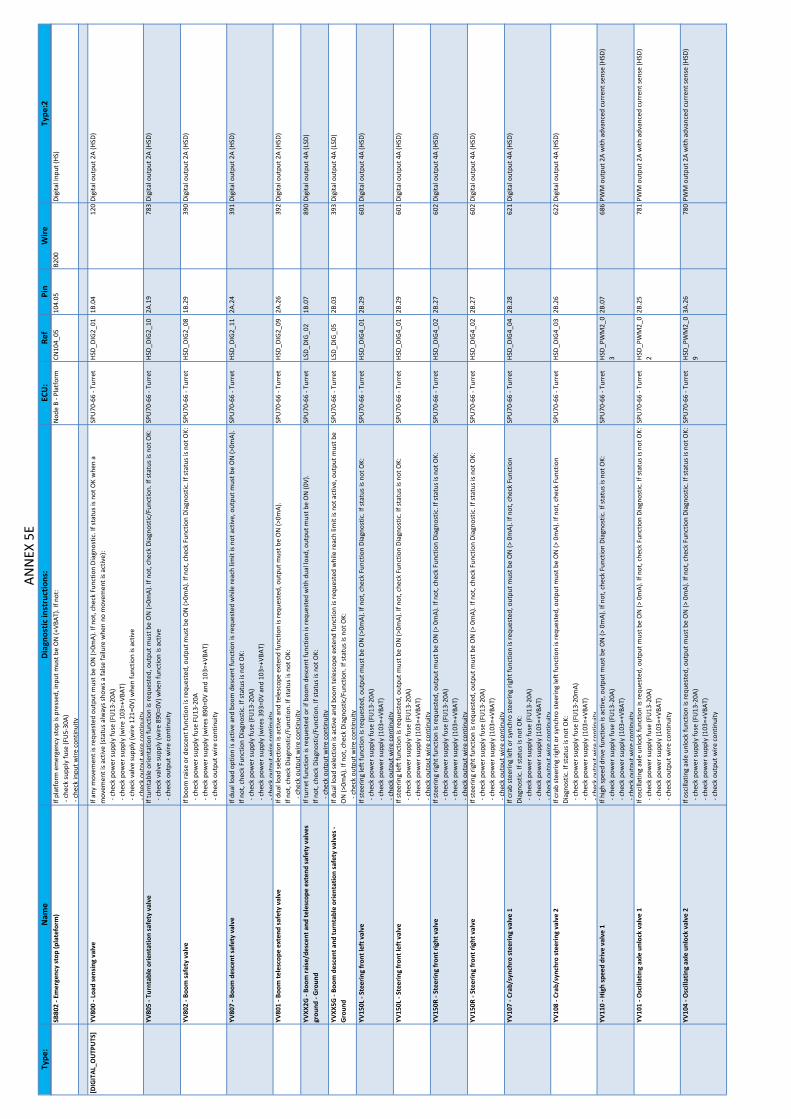
Type
:N
ame
Dia
gnos
tic in
stru
ctio
ns:
ECU
:Re
fPi
nW
ireTy
pe:2
ANN
EX 5E
SB80
2 ‐ E
mer
genc
y st
op (p
late
form
)If
plat
form
em
erge
ncy
stop
is p
ress
ed, i
nput m
ust b
e O
N (+
VBAT
). If
not:
‐ ch
eck
supp
ly fu
se (F
U5‐
30A)
‐ ch
eck
inpu
t wire
con
tinui
ty
Nod
e B ‐ P
latf
orm
CN10
4_05
104.
05B2
00Di
gita
l Inp
ut (H
S)
[DIG
ITAL
_OU
TPU
TS]
YV80
0 ‐ L
oad
sens
ing
valv
eIf
any
mov
emen
t is r
eque
sted
out
put m
ust b
e O
N (>
0mA)
. If n
ot, c
heck F
unct
ion
Diag
nost
ic. I
f sta
tus i
s not O
K w
hen
a m
ovem
ent i
s act
ive
(sta
tus a
lway
s sho
ws a
false
failu
re w
hen
no m
ovem
ent i
s act
ive)
: ‐ c
heck p
ower su
pply fu
se (F
U13
‐20A
) ‐ c
heck p
ower su
pply (w
ire 1
03=+
VBAT
) ‐ c
heck v
alve su
pply (w
ire 1
21=0
V) w
hen
func
tion
is ac
tive
‐che
ckou
tput
wire
cont
inui
ty
SPU
70‐6
6 ‐ T
urre
tHS
D_DI
G2_
011B
.04
120
Digi
tal o
utpu
t 2A
(HSD
)
YV80
5 ‐ T
urnt
able o
rient
atio
n sa
fety v
alve
If tu
rnta
ble
orie
ntat
ion
func
tion
is re
ques
ted, o
utpu
t mus
t be
ON (>
0mA)
. If n
ot, c
heck D
iagn
ostic
/Fun
ctio
n. If st
atus is n
ot O
K: ‐ c
heck v
alve su
pply (w
ire 8
90=0
V) w
hen
func
tion
is ac
tive
‐ c
heck o
utpu
t wire
con
tinui
ty
SPU
70‐6
6 ‐ T
urre
tHS
D_DI
G2_
102A
.19
783
Digi
tal o
utpu
t 2A
(HSD
)
YV80
2 ‐ B
oom s
afet
y va
lve
If bo
om ra
ise o
r des
cent fu
nctio
n is
requ
este
d, o
utpu
t mus
t be
ON (>
0mA)
. If n
ot, c
heck F
unct
ion
Diag
nost
ic. I
f sta
tus i
s not O
K: ‐ c
heck p
ower su
pply fu
se F
U13
‐20A
‐ c
heck p
ower su
pply (w
ires 8
90=0
V an
d 10
3=+V
BAT)
‐ c
heck o
utpu
t wire
con
tinui
ty
SPU
70‐6
6 ‐ T
urre
tHS
D_DI
G2_
081B
.29
390
Digi
tal o
utpu
t 2A
(HSD
)
YV80
7 ‐ B
oom d
esce
nt s
afet
y va
lve
If du
al lo
ad o
ptio
n is
activ
e an
d bo
om d
esce
nt fu
nctio
n is
requ
este
d w
hile re
ach
limit
is no
t act
ive, o
utpu
t mus
t be
ON (>
0mA)
. If
not,
chec
k Fu
nctio
n Di
agno
stic
. If s
tatu
s is n
ot O
K: ‐ c
heck p
ower su
pply fu
se (F
U13
‐20A
) ‐ c
heck p
ower su
pply (w
ires 3
93=0
V an
d 10
3=+V
BAT)
‐che
ckou
tput
wire
cont
inui
ty
SPU
70‐6
6 ‐ T
urre
tHS
D_DI
G2_
112A
.24
391
Digi
tal o
utpu
t 2A
(HSD
)
YV80
1 ‐ B
oom te
lesc
ope
exte
nd sa
fety v
alve
If du
al lo
ad se
lect
ion
is ac
tive
and
tele
scop
e ex
tend
func
tion
is re
ques
ted, o
utpu
t mus
t be
ON (>
0mA)
. If
not,
chec
k Di
agno
stic
/Fun
ctio
n. If st
atus is n
ot O
K: ‐ c
heck o
utpu
t wire
con
tinui
ty
SPU
70‐6
6 ‐ T
urre
tHS
D_DI
G2_
092A
.26
392
Digi
tal o
utpu
t 2A
(HSD
)
YVXX
2G ‐
Boom
rais
e/de
scen
t and
tele
scop
e ex
tend
saf
ety
valv
es
grou
nd ‐
Gro
und
If tu
rret fu
nctio
n is
requ
este
d or if b
oom d
esce
nt fu
nctio
n is
requ
este
d w
ith d
ual l
oad, o
utpu
t mus
t be
ON (0
V).
If no
t, ch
eck
Diag
nost
ic/F
unct
ion. If st
atus is n
ot O
K: ‐ c
heck o
utpu
t wire
con
tinui
ty
SPU
70‐6
6 ‐ T
urre
tLS
D_DI
G_0
21B
.07
890
Digi
tal o
utpu
t 4A
(LSD
)
YVXX
5G ‐
Boom
des
cent a
nd tu
rnta
ble
orie
ntat
ion
safe
ty v
alve
s ‐
Gro
und
If du
al lo
ad se
lect
ion
is ac
tive
and
boom
tele
scop
e ex
tend
func
tion
is re
ques
ted
whi
le re
ach
limit
is no
t act
ive, o
utpu
t mus
t be
ON (>
0mA)
. If n
ot, c
heck D
iagn
ostic
/Fun
ctio
n. If st
atus is n
ot O
K: ‐ c
heck o
utpu
t wire
con
tinui
ty
SPU
70‐6
6 ‐ T
urre
tLS
D_DI
G_0
52B
.03
393
Digi
tal o
utpu
t 4A
(LSD
)
YV15
0L ‐
Stee
ring
fron
t lef
t val
veIf
stee
ring
left fu
nctio
n is
requ
este
d, o
utpu
t mus
t be
ON (>
0mA)
. If n
ot, c
heck F
unct
ion
Diag
nost
ic. I
f sta
tus i
s not O
K: ‐ c
heck p
ower su
pply fu
se (F
U13
‐20A
) ‐ c
heck p
ower su
pply (1
03=+
VBAT
) ‐ c
heck o
utpu
t wire
con
tinui
ty
SPU
70‐6
6 ‐ T
urre
tHS
D_DI
G4_
012B
.29
601
Digi
tal o
utpu
t 4A
(HSD
)
YV15
0R ‐
Stee
ring
fron
t rig
ht v
alve
If st
eerin
g rig
ht fu
nctio
n is
requ
este
d, o
utpu
t mus
t be
ON (>
0m
A). I
f not
, che
ck F
unct
ion
Diag
nost
ic. I
f sta
tus i
s not O
K: ‐ c
heck p
ower su
pply fu
se (F
U13
‐20A
) ‐ c
heck p
ower su
pply (1
03=+
VBAT
) ‐ c
heck o
utpu
t wire
con
tinui
ty
SPU
70‐6
6 ‐ T
urre
tHS
D_DI
G4_
022B
.27
602
Digi
tal o
utpu
t 4A
(HSD
)
YV10
7 ‐ C
rab/
sync
hro
stee
ring
valv
e 1
If cr
ab st
eerin
g le
ft o
r syn
chro st
eerin
g rig
ht fu
nctio
n is
requ
este
d, o
utpu
t mus
t be
ON (>
0m
A). I
f not
, che
ck F
unct
ion
Diag
nost
ic. I
f sta
tus i
s not O
K: ‐ c
heck p
ower su
pply fu
se (F
U13
‐20A
) ‐ c
heck p
ower su
pply (1
03=+
VBAT
)‐c
heck
outp
utw
ireco
ntin
uity
SPU
70‐6
6 ‐ T
urre
tHS
D_DI
G4_
042B
.28
621
Digi
tal o
utpu
t 4A
(HSD
)
YV10
8 ‐ C
rab/
sync
hro
stee
ring
valv
e 2
If cr
ab st
eerin
g rig
ht o
r syn
chro st
eerin
g le
ft fu
nctio
n is
requ
este
d, o
utpu
t mus
t be
ON (>
0m
A). I
f not
, che
ck F
unct
ion
Diag
nost
ic. I
f sta
tus i
s not O
K: ‐ c
heck p
ower su
pply fu
se (F
U13
‐20m
A) ‐ c
heck p
ower su
pply (1
03=+
VBAT
)‐c
heck
outp
utw
ireco
ntin
uity
SPU
70‐6
6 ‐ T
urre
tHS
D_DI
G4_
032B
.26
622
Digi
tal o
utpu
t 4A
(HSD
)
YV11
0 ‐ H
igh
spee
d dr
ive
valv
e 1
If hi
gh sp
eed
driv
e fu
nctio
n is
activ
e, o
utpu
t mus
t be
ON (>
0m
A). I
f not
, che
ck F
unct
ion
Diag
nost
ic. I
f sta
tus i
s not O
K: ‐ c
heck p
ower su
pply fu
se (F
U13
‐20A
) ‐ c
heck p
ower su
pply (1
03=+
VBAT
) ‐ c
heck o
utpu
t wire
con
tinui
ty
SPU
70‐6
6 ‐ T
urre
tHS
D_PW
M2_
03
2B.0
768
6PW
M o
utpu
t 2A
with
adv
ance
d cu
rren
t sen
se (H
SD)
YV10
1 ‐ O
scill
atin
g ax
le u
nloc
k va
lve
1If
osci
llatin
g ax
le u
nloc
k fu
nctio
n is
requ
este
d, o
utpu
t mus
t be
ON (>
0m
A). I
f not
, che
ck F
unct
ion
Diag
nost
ic. I
f sta
tus i
s not O
K: ‐ c
heck p
ower su
pply fu
se (F
U13
‐20A
) ‐ c
heck p
ower su
pply (1
03=+
VBAT
) ‐ c
heck o
utpu
t wire
con
tinui
ty
SPU
70‐6
6 ‐ T
urre
tHS
D_PW
M2_
02
2B.2
578
1PW
M o
utpu
t 2A
with
adv
ance
d cu
rren
t sen
se (H
SD)
YV10
4 ‐ O
scill
atin
g ax
le u
nloc
k va
lve
2If
osci
llatin
g ax
le u
nloc
k fu
nctio
n is
requ
este
d, o
utpu
t mus
t be
ON (>
0m
A). I
f not
, che
ck F
unct
ion
Diag
nost
ic. I
f sta
tus i
s not O
K: ‐ c
heck p
ower su
pply fu
se (F
U13
‐20A
) ‐ c
heck p
ower su
pply (1
03=+
VBAT
) ‐ c
heck o
utpu
t wire
con
tinui
ty
SPU
70‐6
6 ‐ T
urre
tHS
D_PW
M2_
09
3A.2
678
0PW
M o
utpu
t 2A
with
adv
ance
d cu
rren
t sen
se (H
SD)

Type
:N
ame
Dia
gnos
tic in
stru
ctio
ns:
ECU
:Re
fPi
nW
ireTy
pe:2
ANN
EX 5F
YV10
2 ‐ B
rake
rele
ase
valv
e 1
If br
ake
rele
ase
func
tion
(driv
e on
ly) i
s req
uest
ed, o
utpu
t mus
t be
ON (>
0m
A). I
f not c
heck
, fun
ctio
n di
agno
stic
. If s
tatu
s is n
ot
OK:
‐ c
heck p
ower su
pply fu
se (F
U13
‐20A
) ‐ c
heck p
ower su
pply (1
03=+
VBAT
)‐c
heck
outp
utw
ireco
ntin
uity
SPU
70‐6
6 ‐ T
urre
tHS
D_PW
M2_
01
2B.0
878
2PW
M o
utpu
t 2A
with
adv
ance
d cu
rren
t sen
se (H
SD)
KA3 ‐ E
ngin
e su
pply re
lay
Whe
n en
gine
is st
artin
g or ru
nnin
g, o
utpu
t mus
t be
ON (0
V). I
f sta
tus i
s not O
K: ‐ c
heck re
lay
‐ c
heck o
utpu
t sup
ply
fuse (F
U7‐
15A)
‐ c
heck o
utpu
t sup
ply
(109
=+VB
AT)
‐che
ckou
tput
wire
cont
inui
ty
SPU
70‐6
6 ‐ T
urre
tLS
D_DI
G_0
32A
.23
170
(CN
01.2
9)Di
gita
l out
put 4
A (L
SD)
KM16
0 ‐ E
ngin
e pr
e‐he
atin
g co
ntac
tor
If en
gine
pre‐h
eat f
unct
ion
is ac
tive, o
utpu
t mus
t be
ON (>
0m
A). I
f not c
heck fu
nctio
n di
agno
stic
. If s
tatu
s is n
ot O
K: ‐ c
heck c
onta
ctor
‐ c
heck p
ower su
pply fu
se (F
U13
‐20A
) ‐ c
heck p
ower su
pply (1
03=+
VBAT
)‐c
heck
outp
utw
ireco
ntin
uity
SPU
70‐6
6 ‐ T
urre
tHS
D_DI
G2_
041B
.01
162
Digi
tal o
utpu
t 2A
(HSD
)
KA4 ‐ E
ngin
e st
art r
elay
If en
gine
star
t fun
ctio
n is
requ
este
d ou
tput m
ust b
e O
N (0
V). I
f not
, che
ck F
unct
ion
Diag
nost
ic. I
f sta
tus i
s not O
K: ‐ c
heck re
lay
‐ c
heck o
utpu
t sup
ply
fuse (F
U7‐
15A)
‐ c
heck o
utpu
t sup
ply
(109
=+VB
AT)
‐che
ckou
tput
wire
cont
inui
ty
SPU
70‐6
6 ‐ T
urre
tLS
D_DI
G_0
42A
.06
169
(CN
01.4
7)Di
gita
l out
put 4
A (L
SD)
KA9 ‐ H
orn
rela
yIf
horn fu
nctio
n is
requ
este
d, o
utpu
t mus
t be
ON (>
0m
A). I
f not
, che
ck F
unct
ion
Diag
nost
ic. I
f sta
tus i
s not O
K: ‐ c
heck re
lay
‐ c
heck p
ower su
pply fu
se (F
U13
‐20A
) ‐ c
heck p
ower su
pply (1
03=+
VBAT
)‐c
heck
outp
utw
ireco
ntin
uity
SPU
70‐6
6 ‐ T
urre
tHS
D_DI
G2_
031B
.02
187
(CN
01.2
6)Di
gita
l out
put 2
A (H
SD)
HA9
01 ‐
Buzz
er (t
urre
t)If
turr
et c
ontr
ol b
ox b
uzze
r fun
ctio
n is
requ
este
d ou
tput m
ust b
e O
N (>
0m
A). I
f not
, che
ck F
unct
ion
Diag
nost
ic. I
f sta
tus i
s not
OK:
‐ c
heck p
ower su
pply fu
se (F
U13
‐20A
) ‐ c
heck p
ower su
pply (1
03=+
VBAT
)‐c
heck
outp
utw
ireco
ntin
uity
SPU
70‐6
6 ‐ T
urre
tHS
D_DI
G2_
061B
.30
186
Digi
tal o
utpu
t 2A
(HSD
)
KM12
0 ‐ E
mer
genc
y pu
mp
cont
acto
rIf
emer
genc
y pu
mp
is re
ques
ted, o
utpu
t mus
t be
ON (0
V). I
f not c
heck fu
nctio
n di
agno
stic
. If s
tatu
s is n
ot O
K: ‐ c
heck c
onta
ctor
‐ c
heck o
utpu
t sup
ply
fuse (F
U7‐
15A)
‐ c
heck o
utpu
t sup
ply
(109
=+VB
AT)
‐che
ckou
tput
wire
cont
inui
ty
SPU
70‐6
6 ‐ T
urre
tLS
D_DI
G_0
11B
.08
145
Digi
tal o
utpu
t 4A
(LSD
)
KA8 ‐ R
elay B
eaco
n, fl
ashi
ng li
ght K
A8If
beac
on fu
nctio
n is
requ
este
d, o
utpu
t mus
t be
ON (>
0mA)
. If n
ot, c
heck F
unct
ion
Diag
nost
ic. I
f sta
tus i
s not O
K: ‐ c
heck b
eaco
n lig
ht ‐ c
heck p
ower su
pply fu
se (F
U8
20A)
‐ c
heck p
ower su
pply (1
09=+
VBAT
)‐c
heck
outp
utw
ireco
ntin
uity
SPU
70‐6
6 ‐ T
urre
tHS
D_DI
G2_
122A
.25
194
Digi
tal o
utpu
t 2A
(HSD
)
KA2 ‐ G
ener
ator re
lay
If ge
nera
tor f
unct
ion
is re
ques
ted, o
utpu
t mus
t be
ON (>
0m
A). I
f not c
heck fu
nctio
n di
agno
stic
. If s
tatu
s is n
ot O
K: ‐ c
heck re
lay
‐ c
heck p
ower su
pply fu
se (F
U13
‐20A
) ‐ c
heck p
ower su
pply (1
03=+
VBAT
)‐c
heck
outp
utw
ireco
ntin
uity
SPU
70‐6
6 ‐ T
urre
tHS
D_DI
G2_
021B
.03
192
(CN
01.2
8)Di
gita
l out
put 2
A (H
SD)
EL90
1 ‐ F
lash
ing
light
If fla
shin
g lig
ht fu
nctio
n is
requ
este
d, o
utpu
t mus
t be
ON (>
0m
A). I
f not
, che
ck F
unct
ion
Diag
nost
ic. I
f sta
tus i
s not O
K: ‐ c
heck fl
ashi
ng li
ght
‐ c
heck p
ower su
pply fu
se (F
U13
‐15A
) ‐ c
heck p
ower su
pply (1
03=+
VBAT
)‐c
heck
outp
utw
ireco
ntin
uity
SPU
70‐6
6 ‐ T
urre
tHS
D_DI
G2_
051B
.27
188
Digi
tal o
utpu
t 2A
(HSD
)
HL9
05 ‐
Turr
et c
ontr
ol b
ox se
lect
ed li
ght
If la
mp
is no
t act
ive
at p
ower O
N o
r if s
tatu
s is n
ot O
K: ‐ c
heck L
ED P
CB ‐ c
heck L
ED su
pply fu
se ()
‐ c
heck L
ED su
pply (w
ire =
+VBA
T)‐c
heck
outp
utw
ireco
ntin
uity
Keyb
oard ‐
Turr
etLE
D11‐
Out
put L
ED
HL9
06 ‐
Plat
form
con
trol b
ox s
elec
ted
light
If la
mp
is no
t act
ive
at p
ower O
N o
r if s
tatu
s is n
ot O
K: ‐ c
heck L
ED P
CB ‐ c
heck L
ED su
pply fu
se ()
‐ c
heck L
ED su
pply (w
ire =
+VBA
T)‐c
heck
outp
utw
ireco
ntin
uity
Keyb
oard ‐
Turr
etLE
D33‐
Out
put L
ED
HL9
08 ‐
War
ning
ligh
tIf
lam
p is
not a
ctiv
e at p
ower O
N o
r if s
tatu
s is n
ot O
K: ‐ c
heck L
ED P
CB ‐ c
heck L
ED su
pply fu
se ()
‐ c
heck L
ED su
pply (w
ire =
+VBA
T)‐c
heck
outp
utw
ireco
ntin
uity
Keyb
oard ‐
Turr
etLE
D44‐
Out
put L
ED
HL9
09 ‐
Erro
r lig
htIf
lam
p is
not a
ctiv
e at p
ower O
N o
r if s
tatu
s is n
ot O
K: ‐ c
heck L
ED P
CB ‐ c
heck L
ED su
pply fu
se ()
‐ c
heck L
ED su
pply (w
ire =
+VBA
T)‐c
heck
outp
utw
ireco
ntin
uity
Keyb
oard ‐
Turr
etLE
D55‐
Out
put L
ED
KA6 ‐ O
verr
idin
g co
ntro
l box
act
ivat
ion
rela
yIf
plat
form
em
erge
ncy
stop
is p
ushe
d an
d em
erge
ncy
mod
e is
activ
e, o
utpu
t mus
t be
ON
. If n
ot:
‐ c
heck re
lay
KA6
‐ c
heck m
embr
ane
switc
hes c
ontr
olle
r U10
7 su
pply fu
se (F
U7‐
15A)
‐ c
heck sw
itche
s con
trol
ler U
107
supp
ly (w
ires 0
=0V
and
109=
+VBA
T)‐c
heck
outp
utw
ireco
ntin
uity
Keyb
oard ‐
Turr
etO
UTP
UT3
00xx
.118
8Di
gita
l out
put 3
00m
A
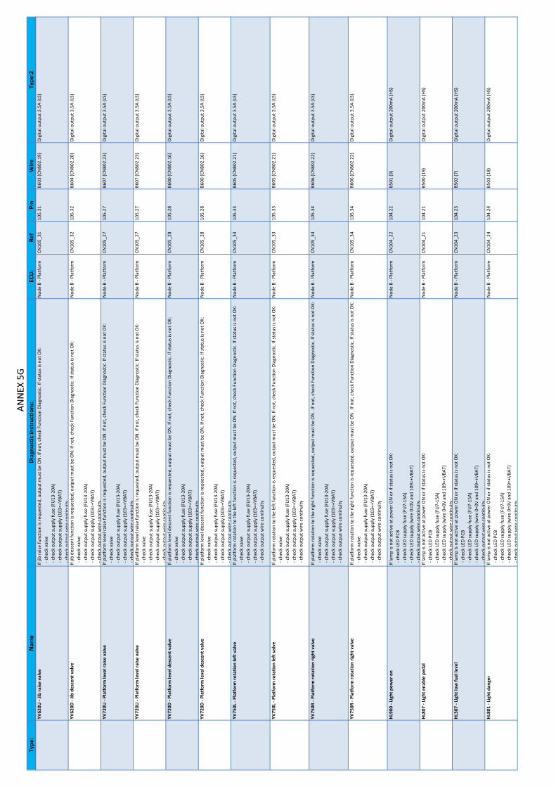
Type
:N
ame
Dia
gnos
tic in
stru
ctio
ns:
ECU
:Re
fPi
nW
ireTy
pe:2
ANN
EX 5G
YV62
0U ‐
Jib ra
ise
valv
eIf
jib ra
ise fu
nctio
n is
requ
este
d, o
utpu
t mus
t be
ON
. If n
ot, c
heck F
unct
ion
Diag
nost
ic. I
f sta
tus i
s not O
K: ‐ c
heck v
alve
‐ c
heck o
utpu
t sup
ply
fuse (F
U13
‐20A
) ‐ c
heck o
utpu
t sup
ply
(103
=+VB
AT)
‐che
ckou
tput
wire
cont
inui
ty
Nod
e B ‐ P
latf
orm
CN10
5_31
105.
31B6
03 (C
NB0
2.19
)Di
gita
l out
put 3
.5A
(LS)
YV62
0D ‐
Jib d
esce
nt v
alve
If jib
des
cent fu
nctio
n is
requ
este
d, o
utpu
t mus
t be
ON
. If n
ot, c
heck F
unct
ion
Diag
nost
ic. I
f sta
tus i
s not O
K: ‐ c
heck v
alve
‐ c
heck o
utpu
t sup
ply
fuse (F
U13
‐20A
) ‐ c
heck o
utpu
t sup
ply
(103
=+VB
AT)
‐che
ckou
tput
wire
cont
inui
ty
Nod
e B ‐ P
latf
orm
CN10
5_32
105.
32B6
04 (C
NB0
2.20
)Di
gita
l out
put 3
.5A
(LS)
YV72
0U ‐
Plat
form
leve
l rai
se v
alve
If pl
atfo
rm le
vel r
aise fu
nctio
n is
requ
este
d, o
utpu
t mus
t be
ON
. If n
ot, c
heck F
unct
ion
Diag
nost
ic. I
f sta
tus i
s not O
K: ‐ c
heck v
alve
‐ c
heck o
utpu
t sup
ply
fuse (F
U13
‐20A
) ‐ c
heck o
utpu
t sup
ply
(103
=+VB
AT)
‐che
ckou
tput
wire
cont
inui
ty
Nod
e B ‐ P
latf
orm
CN10
5_27
105.
27B6
07 (C
NB0
2.23
)Di
gita
l out
put 3
.5A
(LS)
YV72
0D ‐
Plat
form
leve
l des
cent v
alve
If pl
atfo
rm le
vel d
esce
nt fu
nctio
n is
requ
este
d, o
utpu
t mus
t be
ON
. If n
ot, c
heck F
unct
ion
Diag
nost
ic. I
f sta
tus i
s not O
K: ‐ c
heck v
alve
‐ c
heck o
utpu
t sup
ply
fuse (F
U13
‐20A
) ‐ c
heck o
utpu
t sup
ply
(103
=+VB
AT)
‐che
ckou
tput
wire
cont
inui
ty
Nod
e B ‐ P
latf
orm
CN10
5_28
105.
28B6
00 (C
NB0
2.16
)Di
gita
l out
put 3
.5A
(LS)
YV75
0L ‐
Plat
form
rota
tion
left v
alve
If pl
atfo
rm ro
tatio
n to th
e le
ft fu
nctio
n is
requ
este
d, o
utpu
t mus
t be
ON
. If n
ot, c
heck F
unct
ion
Diag
nost
ic. I
f sta
tus i
s not O
K: ‐ c
heck v
alve
‐ c
heck o
utpu
t sup
ply
fuse (F
U13
‐20A
) ‐ c
heck o
utpu
t sup
ply
(103
=+VB
AT)
‐ c
heck o
utpu
t wire
con
tinui
ty
Nod
e B ‐ P
latf
orm
CN10
5_33
105.
33B6
05 (C
NB0
2.21
)Di
gita
l out
put 3
.5A
(LS)
YV75
0R ‐
Plat
form
rota
tion
right v
alve
If pl
atfo
rm ro
tatio
n to th
e rig
ht fu
nctio
n is
requ
este
d, o
utpu
t mus
t be
ON .
If no
t, ch
eck
Func
tion
Diag
nost
ic. I
f sta
tus i
s not O
K: ‐ c
heck v
alve
‐ c
heck o
utpu
t sup
ply
fuse (F
U13
‐20A
) ‐ c
heck o
utpu
t sup
ply
(103
=+VB
AT)
‐ c
heck o
utpu
t wire
con
tinui
ty
Nod
e B ‐ P
latf
orm
CN10
5_34
105.
34B6
06 (C
NB0
2.22
)Di
gita
l out
put 3
.5A
(LS)
HL9
00 ‐
Ligh
t pow
er o
nIf
lam
p is
not a
ctiv
e at p
ower O
N o
r if s
tatu
s is n
ot O
K: ‐ c
heck L
ED P
CB ‐ c
heck L
ED su
pply fu
se (F
U7‐
15A)
‐ c
heck L
ED su
pply (w
ire 0
=0V
and
109=
+VBA
T)‐c
heck
outp
utw
ireco
ntin
uity
Nod
e B ‐ P
latf
orm
CN10
4_22
104.
22B5
01 (9
)Di
gita
l out
put 2
00m
A (H
S)
HL8
07 ‐
Ligh
t ena
ble
peda
lIf
lam
p is
not a
ctiv
e at p
ower O
N o
r if s
tatu
s is n
ot O
K: ‐ c
heck L
ED P
CB ‐ c
heck L
ED su
pply fu
se (F
U7‐
15A)
‐ c
heck L
ED su
pply (w
ire 0
=0V
and
109=
+VBA
T)‐c
heck
outp
utw
ireco
ntin
uity
Nod
e B ‐ P
latf
orm
CN10
4_21
104.
21B5
00 (1
9)Di
gita
l out
put 2
00m
A (H
S)
HL3
07 ‐
Ligh
t low
fuel le
vel
If la
mp
is no
t act
ive
at p
ower O
N o
r if s
tatu
s is n
ot O
K: ‐ c
heck L
ED P
CB ‐ c
heck L
ED su
pply fu
se (F
U7‐
15A)
‐ c
heck L
ED su
pply (w
ire 0
=0V
and
109=
+VBA
T)‐c
heck
outp
utw
ireco
ntin
uity
Nod
e B ‐ P
latf
orm
CN10
4_23
104.
23B5
02 (7
)Di
gita
l out
put 2
00m
A (H
S)
HL8
01 ‐
Ligh
t dan
ger
If la
mp
is no
t act
ive
at p
ower O
N o
r if s
tatu
s is n
ot O
K: ‐ c
heck L
ED P
CB ‐ c
heck L
ED su
pply fu
se (F
U7‐
15A)
‐ c
heck L
ED su
pply (w
ire 0
=0V
and
109=
+VBA
T)‐c
heck
outp
utw
ireco
ntin
uity
Nod
e B ‐ P
latf
orm
CN10
4_24
104.
24B5
03 (1
8)Di
gita
l out
put 2
00m
A (H
S)

Type
:N
ame
Dia
gnos
tic in
stru
ctio
ns:
ECU
:Re
fPi
nW
ireTy
pe:2
ANN
EX 5H
HL8
00 ‐
Ligh
t tilt
If la
mp
is no
t act
ive
at p
ower O
N o
r if s
tatu
s is n
ot O
K: ‐ c
heck L
ED P
CB ‐ c
heck L
ED su
pply fu
se (F
U7‐
15A)
‐ c
heck L
ED su
pply (w
ire 0
=0V
and
109=
+VBA
T)‐c
heck
outp
utw
ireco
ntin
uity
Nod
e B ‐ P
latf
orm
CN10
4_25
104.
25B5
04 (1
7)Di
gita
l out
put 2
00m
A (H
S)
HL8
02 ‐
Ligh
t ove
rload
‐ pl
atfo
rmIf
lam
p is
not a
ctiv
e at p
ower O
N o
r if s
tatu
s is n
ot O
K: ‐ c
heck L
ED P
CB ‐ c
heck L
ED su
pply fu
se (F
U7‐
15A)
‐ c
heck L
ED su
pply (w
ire 0
=0V
and
109=
+VBA
T)‐c
heck
outp
utw
ireco
ntin
uity
Nod
e B ‐ P
latf
orm
CN10
4_26
104.
26B5
05 (1
5)Di
gita
l out
put 2
00m
A (H
S)
HL8
04 ‐
Ligh
t rea
ch li
mita
tion
If la
mp
is no
t act
ive
at p
ower O
N o
r if s
tatu
s is n
ot O
K: ‐ c
heck L
ED P
CB ‐ c
heck L
ED su
pply fu
se (F
U7‐
15A)
‐ c
heck L
ED su
pply (w
ire 0
=0V
and
109=
+VBA
T)‐c
heck
outp
utw
ireco
ntin
uity
Nod
e B ‐ P
latf
orm
CN10
4_27
104.
27B5
06 (1
6)Di
gita
l out
put 2
00m
A (H
S)
HL8
06 ‐
Ligh
t loa
d 45
0If
lam
p is
not a
ctiv
e at p
ower O
N o
r if s
tatu
s is n
ot O
K: ‐ c
heck L
ED P
CB ‐ c
heck L
ED su
pply fu
se (F
U7‐
15A)
‐ c
heck L
ED su
pply (w
ire 0
=0V
and
109=
+VBA
T)‐c
heck
outp
utw
ireco
ntin
uity
Nod
e B ‐ P
latf
orm
CN10
4_28
104.
28B5
59Di
gita
l out
put 2
00m
A (H
S)
HL8
05 ‐
Ligh
t loa
d 23
0If
lam
p is
not a
ctiv
e at p
ower O
N o
r if s
tatu
s is n
ot O
K: ‐ c
heck L
ED P
CB ‐ c
heck L
ED su
pply fu
se (F
U7‐
15A)
‐ c
heck L
ED su
pply (w
ire 0
=0V
and
109=
+VBA
T)‐c
heck
outp
utw
ireco
ntin
uity
Nod
e B ‐ P
latf
orm
CN10
4_29
104.
29B5
58Di
gita
l out
put 2
00m
A (H
S)
HL7
20 ‐
Ligh
t pla
tfor
m le
vel
If la
mp
is no
t act
ive
at p
ower O
N o
r if s
tatu
s is n
ot O
K: ‐ c
heck L
ED P
CB ‐ c
heck L
ED su
pply fu
se (F
U7‐
15A)
‐ c
heck L
ED su
pply (w
ire 0
=0V
and
109=
+VBA
T)‐c
heck
outp
utw
ireco
ntin
uity
Nod
e B ‐ P
latf
orm
CN10
4_31
104.
31B5
11 (1
3)Di
gita
l out
put 2
00m
A (H
S)
HL3
00 ‐
Ligh
t pre
heat
If la
mp
is no
t act
ive
at p
ower O
N o
r if s
tatu
s is n
ot O
K: ‐ c
heck L
ED P
CB ‐ c
heck L
ED su
pply fu
se (F
U7‐
15A)
‐ c
heck L
ED su
pply (w
ire 0
=0V
and
109=
+VBA
T)‐c
heck
outp
utw
ireco
ntin
uity
Nod
e B ‐ P
latf
orm
CN10
4_30
104.
30B5
09 (8
)Di
gita
l out
put 2
00m
A (H
S)
HL3
04 ‐
Ligh
t eng
ine
war
ning
If la
mp
is no
t act
ive
at p
ower O
N o
r if s
tatu
s is n
ot O
K: ‐ c
heck L
ED P
CB ‐ c
heck L
ED su
pply fu
se (F
U7‐
15A)
‐ c
heck L
ED su
pply (w
ire 0
=0V
and
109=
+VBA
T)‐c
heck
outp
utw
ireco
ntin
uity
Nod
e B ‐ P
latf
orm
CN10
4_32
104.
32B5
23 (5
)Di
gita
l out
put 2
00m
A (H
S)
HL3
05 ‐
Ligh
t eng
ine
stop
If la
mp
is no
t act
ive
at p
ower O
N o
r if s
tatu
s is n
ot O
K: ‐ c
heck L
ED P
CB ‐ c
heck L
ED su
pply fu
se (F
U7‐
15A)
‐ c
heck L
ED su
pply (w
ire 0
=0V
and
109=
+VBA
T)‐c
heck
outp
utw
ireco
ntin
uity
Nod
e B ‐ P
latf
orm
CN10
4_33
104.
33B5
24 (6
)Di
gita
l out
put 2
00m
A (H
S)
HL3
02 ‐
HES
T (H
igh
Exha
ust S
yste
m T
empe
ratu
re)
If la
mp
is no
t act
ive
at p
ower O
N o
r if s
tatu
s is n
ot O
K: ‐ c
heck L
ED P
CB ‐ c
heck L
ED su
pply fu
se (F
U7‐
15A)
‐ c
heck L
ED su
pply (w
ire 0
=0V
and
109=
+VBA
T)‐c
heck
outp
utw
ireco
ntin
uity
Nod
e B ‐ P
latf
orm
CN10
4_35
104.
35B5
21 (2
)Di
gita
l out
put 2
00m
A (H
S)
HL3
03 ‐
Ligh
t reg
ener
atio
n in
hibi
ted
If la
mp
is no
t act
ive
at p
ower O
N o
r if s
tatu
s is n
ot O
K: ‐ c
heck L
ED P
CB ‐ c
heck L
ED su
pply fu
se (F
U7‐
15A)
‐ c
heck L
ED su
pply (w
ire 0
=0V
and
109=
+VBA
T)‐c
heck
outp
utw
ireco
ntin
uity
Nod
e B ‐ P
latf
orm
CN10
4_36
104.
36B5
20 (3
)Di
gita
l out
put 2
00m
A (H
S)
HL9
01 ‐
Ligh
t Act
iv' s
hiel
d ba
r act
ivat
edIf
lam
p is
not a
ctiv
e or if st
atus is n
ot O
K: ‐
chec
k la
mp
‐ ch
eck
lam
p su
pply fu
se (F
U7‐
15A)
‐ ch
eck
lam
p su
pply re
lay
(KAC
) ‐
chec
k la
mp
supp
ly (w
ire 0
=0V
and
109=
+VBA
T)‐c
heck
outp
utw
ireco
ntin
uity
Nod
e B ‐ P
latf
orm
CN10
5_30
105.
30B5
10Di
gita
l out
put 3
.5A
(LS)
EL90
5 ‐ F
lash
ing
light A
ctiv
' shi
eld
bar
If la
mps a
re n
ot a
ctiv
e w
hen
activ
e ba
r is a
ctiv
e or if o
utpu
t sta
tus i
s not O
K: ‐ c
heck la
mps
‐ c
heck la
mps su
pply fu
se (F
U7‐
15A)
‐ c
heck la
mps su
pply (w
ire 0
=0V
and
109=
+VBA
T)‐c
heck
outp
utw
ireco
ntin
uity
Nod
e B ‐ P
latf
orm
CN10
5_29
105.
29B6
01 (A
C.4)
Digi
tal o
utpu
t 3.5
A (L
S)
HL3
01 ‐
DPF
(Die
sel P
artic
ulat
e Fi
lter)
If la
mp
is no
t act
ive
at p
ower O
N o
r if s
tatu
s is n
ot O
K: ‐ c
heck L
ED P
CB ‐ c
heck L
ED su
pply fu
se (F
U7‐
15A)
‐ c
heck L
ED su
pply (w
ire 0
=0V
and
109=
+VBA
T)‐c
heck
outp
utw
ireco
ntin
uity
Nod
e B ‐ P
latf
orm
CN10
4_34
104.
34B5
22 (1
)Di
gita
l out
put 2
00m
A (H
S)
ANAL
OG IN
PUTS
WU
I ‐ 1
2V E
CU W
ake
Up
Inpu
tIf
mac
hine
is p
ower
ed a
nd e
mer
genc
y st
ops a
re n
ot p
ushe
d, in
put m
ust b
e eq
ual t
o O
N (+
VBAT
). If
not:
‐ c
heck O
N/O
FF k
ey (S
A900
) ‐ c
heck m
ain
rela
y (K
MG
) ‐ c
heck in
put s
uppl
y fu
se (F
U7‐
15A)
‐che
ckin
putw
ireco
ntin
uity
SPU
70‐6
6 ‐ T
urre
tW
UI1
1A.1
410
9W
ake‐
up in
put (
on h
igh
leve
l)

Type
:N
ame
Dia
gnos
tic in
stru
ctio
ns:
ECU
:Re
fPi
nW
ireTy
pe:2
ANN
EX 5I
12VP
‐ 12
V EC
U p
erm
anen
tIn
put m
ust a
lway
s be
equa
l to
VBAT
. If n
ot:
‐ c
heck in
put s
uppl
y fu
se (F
U5‐
30A
/ FU
11‐7
.5A)
‐ c
heck in
put w
ire c
ontin
uity to
bat
tery
SPU
70‐6
6 ‐ T
urre
tVB
ATP
1A.2
010
5 (C
N01
.32)
Supp
ly 1
2V p
erm
anen
t (LS
D_DI
G, P
VG, V
REF)
12VD
1 ‐ 1
2V p
ower
If m
achi
ne is p
ower
ed a
nd e
mer
genc
y st
ops a
re n
ot p
ushe
d, in
put m
ust b
e eq
ual t
o +V
BAT. If n
ot:
‐ c
heck O
N/O
FF k
ey (S
A900
) ‐ c
heck m
ain
(KM
G) a
nd p
ower (K
MP) re
lays
‐ c
heck in
put s
uppl
y fu
se (F
U13
‐20A
)‐c
heck
inpu
twire
cont
inui
ty
SPU
70‐6
6 ‐ T
urre
tVB
ATD1
1B.1
8/26
103
Supp
ly 1
2V (H
SD_D
IG2_
01‐0
8)
12VD
2 ‐ 1
2V p
ower
If m
achi
ne is p
ower
ed a
nd e
mer
genc
y st
ops a
re n
ot p
ushe
d, in
put m
ust b
e eq
ual t
o +V
BAT. If n
ot:
‐ c
heck O
N/O
FF k
ey (S
A900
) ‐ c
heck m
ain
(KM
G) a
nd p
ower (K
MP) re
lays
‐ c
heck in
put s
uppl
y fu
se (F
U13
‐20A
)‐c
heck
inpu
twire
cont
inui
ty
SPU
70‐6
6 ‐ T
urre
tVB
ATD2
2A.0
8/14
103
Supp
ly 1
2V (H
SD_D
IG2_
09‐1
4)
12VD
3 ‐ 1
2V p
ower
If m
achi
ne is p
ower
ed a
nd e
mer
genc
y st
ops a
re n
ot p
ushe
d, in
put m
ust b
e eq
ual t
o +V
BAT. If n
ot:
‐ c
heck O
N/O
FF k
ey (S
A900
) ‐ c
heck m
ain
(KM
G) a
nd p
ower (K
MP) re
lays
‐ c
heck in
put s
uppl
y fu
se (F
U13
‐20A
)‐c
heck
inpu
twire
cont
inui
ty
SPU
70‐6
6 ‐ T
urre
tVB
ATD3
2B.2
/11
103
Supp
ly 1
2V (H
SD_D
IG4_
01‐0
4)
12VD
4 ‐ 1
2V p
ower
If m
achi
ne is p
ower
ed a
nd e
mer
genc
y st
ops a
re n
ot p
ushe
d, in
put m
ust b
e eq
ual t
o +V
BAT. If n
ot:
‐ c
heck O
N/O
FF k
ey (S
A900
) ‐ c
heck m
ain
(KM
G) a
nd p
ower (K
MP) re
lays
‐ c
heck in
put s
uppl
y fu
se (F
U13
‐20A
)‐c
heck
inpu
twire
cont
inui
ty
SPU
70‐6
6 ‐ T
urre
tVB
ATD4
3A.0
1/08
103
Supp
ly 1
2V (H
SD_D
IG4_
05‐0
8)
12VF
1 ‐ 1
2V p
ower
If m
achi
ne is p
ower
ed a
nd e
mer
genc
y st
ops a
re n
ot p
ushe
d, in
put m
ust b
e eq
ual t
o +V
BAT. If n
ot:
‐ c
heck O
N/O
FF k
ey (S
A900
) ‐ c
heck m
ain
(KM
G) a
nd p
ower (K
MP) re
lays
‐ c
heck in
put s
uppl
y fu
se (F
U13
‐20A
)‐c
heck
inpu
twire
cont
inui
ty
SPU
70‐6
6 ‐ T
urre
tVB
ATF1
1A.3
2/33
103
Supp
ly 1
2V (P
WM
2_1/
2, P
WM
4_1/
2)
12VF
2 ‐ 1
2V p
ower
If m
achi
ne is p
ower
ed a
nd e
mer
genc
y st
ops a
re n
ot p
ushe
d, in
put m
ust b
e eq
ual t
o +V
BAT. If n
ot:
‐ c
heck O
N/O
FF k
ey (S
A900
) ‐ c
heck m
ain
(KM
G) a
nd p
ower (K
MP) re
lays
‐ c
heck in
put s
uppl
y fu
se (F
U13
‐20A
)‐c
heck
inpu
twire
cont
inui
ty
SPU
70‐6
6 ‐ T
urre
tVB
ATF2
2A.0
7/13
103
Supp
ly 1
2V (P
WM
2_3/
4, P
WM
4_3/
4)
12VF
3 ‐ 1
2V p
ower
If m
achi
ne is p
ower
ed a
nd e
mer
genc
y st
ops a
re n
ot p
ushe
d, in
put m
ust b
e eq
ual t
o +V
BAT. If n
ot:
‐ c
heck O
N/O
FF k
ey (S
A900
) ‐ c
heck m
ain
(KM
G) a
nd p
ower (K
MP) re
lays
‐ c
heck in
put s
uppl
y fu
se (F
U13
‐20A
)‐c
heck
inpu
twire
cont
inui
ty
SPU
70‐6
6 ‐ T
urre
tVB
ATF3
2D.0
9/17
103
Supp
ly 1
2V (P
WM
2_5/
6/9/
10, P
WM
4_5/
6)
12VF
4 ‐ 1
2V p
ower
If m
achi
ne is p
ower
ed a
nd e
mer
genc
y st
ops a
re n
ot p
ushe
d, in
put m
ust b
e eq
ual t
o +V
BAT. If n
ot:
‐ c
heck O
N/O
FF k
ey (S
A900
) ‐ c
heck m
ain
(KM
G) a
nd p
ower (K
MP) re
lays
‐ c
heck in
put s
uppl
y fu
se (F
U13
‐20A
)‐c
heck
inpu
twire
cont
inui
ty
SPU
70‐6
6 ‐ T
urre
tVB
ATF4
3A.0
7/13
103
Supp
ly 1
2V (P
WM
2_7/
8/11
/12, P
WM
4_11
/12)
SP16
0F ‐
Driv
e ci
rcui
t pre
ssur
e se
nsor ‐
Forw
ard
The
inpu
t fro
m th
e fo
rwar
d pr
essu
re se
nsor sh
all b
e in th
e ra
nge
[200
mV ; 4
800m
V ],
and
the
valu
e of th
e sig
nal s
hall
incr
ease
durin
g th
e fo
rwar
d dr
ive.
Oth
erw
ise:
‐ Che
ck if th
e se
nsor is c
orre
ctly p
lugg
ed (r
ef :
trai
ning
man
ual)
‐ Che
ck th
e po
wer su
pply o
f the
sens
or (w
ires : 0 =
0V a
nd 1
09=+
VBAT
V)
‐Che
ckth
eco
ntin
uity
ofth
ein
puts
igna
l
SPU
70‐6
6 ‐ T
urre
tU
N02
1A.0
450
6 (C
N04
B.5)
Uni
vers
al in
put B
(0‐3
2V, 0
‐5V, H
S, L
S, R
)
SP16
0B ‐
Driv
e ci
rcui
t pre
ssur
e se
nsor ‐
Reve
rse
The
inpu
t fro
m th
e re
vers
e pr
essu
re se
nsor sh
all b
e in th
e ra
nge
[200
mV ; 4
800m
V ],
and
the
valu
e of th
e sig
nal s
hall
incr
ease
durin
g th
e re
vers
e dr
ive.
Oth
erw
ise:
‐ Che
ck if th
e se
nsor is c
orre
ctly p
lugg
ed (r
ef :
trai
ning
man
ual)
‐ Che
ck th
e po
wer su
pply o
f the
sens
or (w
ires : 0 =
0V a
nd 1
09=+
VBAT
V)
‐Che
ckth
eco
ntin
uity
ofth
ein
puts
igna
l
SPU
70‐6
6 ‐ T
urre
tU
N03
1A.0
251
2 (C
N04
B.6)
Uni
vers
al in
put C
(0‐3
2V, 0
‐5V, H
S, L
S, R
)
SL30
0 ‐ F
uel l
evel se
nsor
Inpu
t sig
nal r
esist
ance m
ust i
ncre
ase
from
20o
hms (
tank
full) to
200
ohm
s (ta
nk lo
w) w
hen
fuel le
vel d
ecre
ase.
SPU
70‐6
6 ‐ T
urre
tU
N01
1A.0
818
9U
nive
rsal in
put A
(0‐3
2V, 0
‐5V, H
S, L
S, R
)SM
902Y
‐ D
rive
joys
tick ‐ A
xis Y
If dr
ive
joys
tick
is O
K, in
put i
s var
iabl
e be
twee
n [0
.5 ‐
4.5]
V. If n
ot:
‐ c
heck jo
ystic
k fu
nctio
n ‐ c
heck jo
ystic
k 5V
supp
ly (w
ire B
400, in
put 5
V U
104)
‐ c
heck jo
ystic
k ce
nter p
ositi
on (a
ppro
x. 2
.5V)
‐che
ckin
putw
ireco
ntin
uity
Nod
e B ‐ P
latf
orm
CN10
6_10
106.
10B3
00 (9
)An
alog
ue in
put 0
‐5V
SM90
1Y ‐
Boom
tele
scop
ing
joys
tick ‐ A
xis
YIf
arm li
ftin
g jo
ystic
k is
OK, in
put i
s var
iabl
e be
twee
n [0
.5 ‐
4.5]
V. If n
ot:
‐ c
heck jo
ystic
k fu
nctio
n ‐ c
heck jo
ystic
k 5V
supp
ly (w
ire B
400, in
put 5
V U
104)
‐ c
heck jo
ystic
k ce
nter p
ositi
on (a
ppro
x. 2
.5V)
‐che
ckin
putw
ireco
ntin
uity
Nod
e B ‐ P
latf
orm
CN10
6_11
106.
11B3
01 (1
2)An
alog
ue in
put 0
‐5V
SM90
0X ‐
Turn
tabl
e jo
ystic
k ‐ A
xis
XIf
turn
tabl
e or
ient
atio
n jo
ystic
k is
OK, in
put i
s var
iabl
e be
twee
n [0
.5 ‐
4.5]
V. If n
ot:
‐ c
heck jo
ystic
k fu
nctio
n ‐ c
heck jo
ystic
k 5V
supp
ly (w
ire B
400, in
put 5
V U
104)
‐ c
heck jo
ystic
k ce
nter p
ositi
on (a
ppro
x. 2
.5V)
‐che
ckin
putw
ireco
ntin
uity
Nod
e B ‐ P
latf
orm
CN10
6_13
106.
13B3
03 (1
2)An
alog
ue in
put 0
‐5V
SM90
0Y ‐
Boom
joys
tick ‐ A
xis
YIf
boom
lift
ing
joys
tick
is O
K, in
put i
s var
iabl
e be
twee
n [0
.5 ‐
4.5]
V. If n
ot:
‐ c
heck jo
ystic
k fu
nctio
n ‐ c
heck jo
ystic
k 5V
supp
ly (w
ire B
400, in
put 5
V U
104)
‐ c
heck jo
ystic
k ce
nter p
ositi
on (a
ppro
x. 2
.5V)
‐che
ckin
putw
ireco
ntin
uity
Nod
e B ‐ P
latf
orm
CN10
6_12
106.
12B3
02 (9
)An
alog
ue in
put 0
‐5V

Type
:N
ame
Dia
gnos
tic in
stru
ctio
ns:
ECU
:Re
fPi
nW
ireTy
pe:2
ANN
EX 5J
SP80
0 ‐ L
oad
sens
or si
gnal 1
If pl
atfo
rm is e
mpt
y in
put m
ust b
e be
twee
n [5 ‐
8]m
A. If n
ot:
‐ c
heck se
nsor m
ount
ing
(ref
. ins
truc
tions
) ‐ c
heck se
nsor su
pply fu
se (F
U34
‐1A)
‐ c
heck se
nsor su
pply (w
ires 0
=0V
and
B401
=+VB
AT)
‐che
ckin
putw
ireco
ntin
uity
Nod
e B ‐ P
latf
orm
CN10
6_04
106.
04B3
10 (C
NB0
2.9)
Anal
ogue
inpu
t 4‐
20m
A
SP80
1 ‐ L
oad
sens
or si
gnal 2
If pl
atfo
rm is e
mpt
y in
put m
ust b
e be
twee
n [5 ‐
8]m
A. If n
ot:
‐ c
heck se
nsor m
ount
ing
(ref
. ins
truc
tions
) ‐ c
heck se
nsor su
pply fu
se (F
U34
‐1A)
‐ c
heck se
nsor su
pply (w
ires 0
=0V
and
B401
=+VB
AT)
‐che
ckin
putw
ireco
ntin
uity
Nod
e B ‐ P
latf
orm
CN10
6_05
106.
05B3
11 (C
NB0
2.10
)An
alog
ue in
put
4‐20
mA
12V ‐ 1
2V E
CU (U
104)
If m
achi
ne is p
ower
ed a
nd e
mer
genc
y st
ops a
re n
ot p
ushe
d, in
put m
ust b
e eq
ual t
o +V
BAT. If n
ot:
‐ ch
eck
inpu
t sup
ply
fuse (F
U7‐
15A)
‐ ch
eck
inpu
t sup
ply
(wire
109
) ‐
chec
k in
put d
iode
(D20
0)‐c
heck
inpu
twire
cont
inui
ty
Nod
e B ‐ P
latf
orm
VBAT
_B10
7.02
109B
Supp
ly 1
2V
5V E
CU R
EAD ‐
5V E
CU re
adIf
ECU (U
104) is p
ower
ed, i
nput m
ust b
e eq
ual t
o +5
V. If n
ot:
‐ c
heck E
CU su
pply fu
se(F
U7‐
15A)
‐ c
heck E
CU su
pply (w
ire 1
09B)
‐ c
heck in
put w
ire c
ontin
uity
Nod
e B ‐ P
latf
orm
CN10
6_15
106.
15B4
00PV
G o
utpu
t
ANAL
OG O
UTP
UTS
YV16
0F ‐
Driv
e fo
rwar
d va
lve
If dr
ive
forw
ard
func
tion
is re
ques
ted
outp
ut m
ust b
e >0
mA. If n
ot, c
heck F
unct
ion
Diag
nost
ic. I
f sta
tus i
s not O
K: ‐ c
heck P
WM c
oil r
esist
ance
‐ c
heck o
utpu
t wire
con
tinui
t ‐ c
heck v
alve su
pply 6
87, 1
03 (F
U13
‐20A
)
SPU
70‐6
6 ‐ T
urre
tHS
D_PW
M4_
01
1B.3
168
7PW
M 4
A ou
tput w
ith a
dvan
ced
curr
ent s
ense (H
SD)
YV16
0B ‐
Driv
e re
vers
e va
lve
If dr
ive
reve
rse
func
tion
is re
ques
ted
outp
ut m
ust b
e >0
mA. If n
ot, c
heck F
unct
ion
Diag
nost
ic. I
f sta
tus i
s not O
K: ‐ c
heck P
WM c
oil r
esist
ance
‐ c
heck o
utpu
t wire
con
tinui
t ‐ c
heck v
alve su
pply 0
SPU
70‐6
6 ‐ T
urre
tHS
D_PW
M4_
02
1B.0
968
8PW
M 4
A ou
tput w
ith a
dvan
ced
curr
ent s
ense (H
SD)
YV90
2 ‐ P
ropo
rtio
nal v
alve
1 (s
teer
ing)
If st
eerin
g fu
nctio
n is
requ
este
d ou
tput m
ust b
e >0
mA. If n
ot, c
heck F
unct
ion
Diag
nost
ic. I
f sta
tus i
s not O
K: ‐ c
heck P
WM c
oil r
esist
ance
‐ c
heck o
utpu
t wire
con
tinui
ty ‐ c
heck v
alve su
pply 9
01, 1
03 (F
U13
‐20A
)
SPU
70‐6
6 ‐ T
urre
tHS
D_PW
M2_
06
2B.3
490
1PW
M o
utpu
t 2A
with
adv
ance
d cu
rren
t sen
se (H
SD)
YV90
1 ‐ P
ropo
rtio
nal v
alve
2 (j
ib, p
latf
orm le
vel,
plat
form
rota
tion)
If jib
, pla
tfor
m le
vel o
r pla
tfor
m ro
tatio
n fu
nctio
n is
requ
este
d ou
tput m
ust b
e >0
mA. If n
ot, c
heck F
unct
ion
Diag
nost
ic. I
f sta
tus
is no
t OK:
‐ c
heck P
WM c
oil r
esist
ance
‐ c
heck o
utpu
t wire
con
tinui
ty‐c
heck
valv
esu
pply
900,
103
(FU
13‐2
0)
SPU
70‐6
6 ‐ T
urre
tHS
D_PW
M2_
05
2B.0
590
0PW
M o
utpu
t 2A
with
adv
ance
d cu
rren
t sen
se (H
SD)
YV25
0L ‐
Turn
tabl
e or
ient
atio
n va
lve ‐ L
eft
If tu
rnta
ble
orie
ntat
ion
func
tion
is re
ques
ted
outp
ut m
ust b
e >
0A. I
f not
, che
ck F
unct
ion
Diag
nost
ic. I
f sta
tus i
s not O
K: ‐ c
heck P
WM c
oil r
esist
ance
‐ c
heck o
utpu
t wire
con
tinui
ty
SPU
70‐6
6 ‐ T
urre
tHS
D_PW
M4_
07
2A.0
590
7PW
M 4
A ou
tput w
ith a
dvan
ced
curr
ent s
ense (H
SD)
YV25
0R ‐
Turn
tabl
e or
ient
atio
n va
lve ‐ R
ight
If tu
rnta
ble
orie
ntat
ion
func
tion
is re
ques
ted
outp
ut m
ust b
e >
0A. I
f not
, che
ck F
unct
ion
Diag
nost
ic. I
f sta
tus i
s not O
K: ‐ c
heck P
WM c
oil r
esist
ance
‐ c
heck o
utpu
t wire
con
tinui
ty
SPU
70‐6
6 ‐ T
urre
tHS
D_PW
M4_
08
2A.0
490
6PW
M 4
A ou
tput w
ith a
dvan
ced
curr
ent s
ense (H
SD)
YV52
0U ‐
Boom
val
ve ‐
Rais
eIf
boom
lift
ing
func
tion
is re
ques
ted
outp
ut m
ust b
e >
0A. I
f not
, che
ck F
unct
ion
Diag
nost
ic. I
f sta
tus i
s not O
K: ‐ c
heck P
WM c
oil r
esist
ance
‐ c
heck o
utpu
t wire
con
tinui
ty
SPU
70‐6
6 ‐ T
urre
tHS
D_PW
M4_
03
1B.0
690
2PW
M 4
A ou
tput w
ith a
dvan
ced
curr
ent s
ense (H
SD)
YV52
0D ‐
Boom
val
ve ‐
Des
cent
If bo
om li
ftin
g fu
nctio
n is
requ
este
d ou
tput m
ust b
e >
0A. I
f not
, che
ck F
unct
ion
Diag
nost
ic. I
f sta
tus i
s not O
K: ‐ c
heck P
WM c
oil r
esist
ance
‐ c
heck o
utpu
t wire
con
tinui
ty
SPU
70‐6
6 ‐ T
urre
tHS
D_PW
M4_
04
1B.1
090
3PW
M 4
A ou
tput w
ith a
dvan
ced
curr
ent s
ense (H
SD)
YV53
0O ‐
Boom
tele
scop
e va
lve ‐ E
xten
dIf
boom
tele
scop
e ex
tend
func
tion
is re
ques
ted, o
utpu
t mus
t be
ON (>
0 m
A). I
f not
, che
ck D
iagn
ostic
/Fun
ctio
n. If st
atus is n
ot
OK:
‐ c
heck p
ower su
pply fu
se (F
13‐2
0A)
‐ c
heck p
ower su
pply (1
03=+
VBAT
)‐c
heck
outp
utw
ireco
ntin
uity
SPU
70‐6
6 ‐ T
urre
tHS
D_PW
M4_
05
2A.0
390
4PW
M 4
A ou
tput w
ith a
dvan
ced
curr
ent s
ense (H
SD)
YV53
0I ‐
Boom
tele
scop
e va
lve ‐ R
etra
ctIf
boom
tele
scop
e ex
tend
func
tion
is re
ques
ted, o
utpu
t mus
t be
ON (>
0 m
A). I
f not
, che
ck D
iagn
ostic
/Fun
ctio
n. If st
atus is n
ot
OK:
‐ c
heck p
ower su
pply fu
se (F
13‐2
0A)
‐ c
heck p
ower su
pply (1
03=+
VBAT
)‐c
heck
outp
utw
ireco
ntin
uity
SPU
70‐6
6 ‐ T
urre
tHS
D_PW
M4_
06
2A.2
090
5PW
M 4
A ou
tput w
ith a
dvan
ced
curr
ent s
ense (H
SD)
HA9
02 ‐
Buzz
er (p
latf
orm
)If
buzz
er is n
ot a
ctiv
e at p
ower O
N o
r if s
tatu
s is n
ot O
K: ‐ c
heck b
uzze
r ‐ c
heck o
utpu
t wire
con
tinui
ty
Nod
e B ‐ P
latf
orm
CN10
6_16
106.
16B5
08PV
G o
utpu
t

Cate
gory
Nam
eIte
mVa
lues
Uni
tD
escr
iptio
n & R
efer
ence
sIN
TERN
ALYV
160F % m
axim
um c
urre
nt10
0 x
YV16
0F /
1500
[REF
_IO
_MAI
N] Y
V160
F ‐ D
rive
forw
ard
valv
eYV
160B
% m
axim
um c
urre
nt10
0 x
YV16
0F /
1500
[REF
_IO
_MAI
N] Y
V160
B ‐ D
rive
reve
rse
valv
eYV
901
% m
axim
um c
urre
nt%
100
* YV
901
/ 200
0[R
EF_I
O_M
AIN
] YV9
01 ‐
Prop
ortio
nal v
alve 1 (s
teer
ing)
YV25
0L % m
axim
um c
urre
nt%
100
* YV
250L /
2000
[REF
_IO
_MAI
N] Y
V250
L ‐ T
urnt
able o
rient
atio
n va
lve ‐ L
eft
YV25
0R % m
axim
um c
urre
nt%
100
* 25
0R /
12VD
2[R
EF_I
O_M
AIN
] YV2
50R ‐ T
urnt
able o
rient
atio
n va
lve ‐ R
ight
Y520
U % m
axim
um c
urre
nt%
100
* YV
520U
/ 20
00[R
EF_I
O_M
AIN
] YV5
20U ‐
Boom
val
ve ‐
Raise
Y520
D % m
axim
um c
urre
nt%
100
* YV
520D
/ 20
00[R
EF_I
O_M
AIN
] YV5
20D ‐ B
oom v
alve ‐
Desc
ent
Y530
O % m
axim
um c
urre
nt%
100
* YV
530O
/ 20
00[R
EF_I
O_M
AIN
] YV5
30O ‐
Boom
tele
scop
e va
lve ‐ E
xten
dY5
30I %
max
imum
cur
rent
%10
0 *
YV53
0I /
2000
[REF
_IO
_MAI
N] Y
V530
I ‐ B
oom te
lesc
ope
valv
e ‐ R
etra
ctYV
902
% m
axim
um c
urre
nt%
100
* YV
902
/ 200
0[R
EF_I
O_M
AIN
] YV9
02 ‐
Elec
trov
anne
pro
port
ionn
elle 2 (j
ib, p
latf
orm le
vel,
plat
form
ro
tatio
n)FT
1 pa
ram
eter (u
ser c
alib
ratio
n)Hz
FT2
para
met
er (u
ser c
alib
ratio
n)Hz
Alph
a pa
ram
eter (u
ser c
alib
ratio
n)Hz
Beta p
aram
eter (u
ser c
alib
ratio
n)Hz
FT1
para
met
er (b
ench c
alib
ratio
n)Hz
FT2
para
met
er (b
ench c
alib
ratio
n)Hz
Batt
ery
volta
geV
Load
man
agem
ent s
yste
m c
alib
ratio
n fa
ilure fl
ags
Offs
et p
aram
eter c
alib
ratio
n er
ror
OFF
/ON
Alph
a pa
ram
eter c
alib
ratio
n er
ror
OFF
/ON
[REF
_VAR
IABL
E] A
lpha
par
amet
er (u
ser c
alib
ratio
n)
Beta p
aram
eter c
alib
ratio
n er
ror
OFF
/ON
[REF
_VAR
IABL
E] B
eta
para
met
er (u
ser c
alib
ratio
n)
FT1
para
met
er c
alib
ratio
n er
ror
OFF
/ON
[REF
_VAR
IABL
E] F
T1 p
aram
eter (u
ser c
alib
ratio
n)
FT2
para
met
er c
alib
ratio
n er
ror
OFF
/ON
[REF
_VAR
IABL
E] F
T2 p
aram
eter (u
ser c
alib
ratio
n)
Delta
par
amet
er c
alib
ratio
n er
ror
OFF
/ON
[REF
_VAR
IABL
E] F
T1 p
aram
eter (b
ench c
alib
ratio
n)
[REF
_VAR
IABL
E] F
T2 p
aram
eter (b
ench c
alib
ratio
n)O
verlo
ad (s
trai
n ga
uges
)Es
timat
ed L
oad
kgEs
timat
ed lo
ad in
to th
e pl
atfo
rm, c
ompu
ted
from
SP8
00 a
nd S
P801
gau
ges s
igna
l va
lues c
orre
cted
with
cal
ibra
tion
offs
et a
nd g
ain
[REF
_IO
] SP8
00 ‐
Load
sens
or si
gnal 1
[REF
_IO
] SP8
01 ‐
Load
sens
or si
gnal 2
Ove
rload
Ala
rmO
verlo
ad a
larm
is a
ctiv
ated
if e
stim
ated
load
into th
e pl
atfo
rm is g
reat
er th
an 2
50kg
for m
ore
than
1s. It is th
en d
eact
ivat
ed if e
stim
ated
load
into th
e pl
atfo
rm is lo
wer
than
240
kg fo
r mor
e th
an 1
s.[R
EF_V
ARIA
BLE] E
stim
ated
Loa
dLo
ad m
anag
emen
t Sys
tem c
alib
rate
dN
oYe
sG
auge
s Inc
oher
ence
Diffe
renc
e be
twee
n th
e es
timat
ed lo
ad fr
om S
P800
and
SP8
01 is g
reat
er th
an 8
0kg
[REF
_IO
] SP8
00 ‐
Load
sens
or si
gnal 1
[REF
_IO
] SP8
01 ‐
Load
sens
or si
gnal 2
Gau
ge S
P800
out o
f ran
geSi
gnal fr
om S
P800
gau
ge is o
ut o
f ran
ge [1
.5m
A ‐ 2
0.5m
A][R
EF_I
O] S
P800
‐ Lo
ad se
nsor si
gnal 1
Gau
ge S
P801
out o
f ran
geSi
gnal fr
om S
P801
gau
ge is o
ut o
f ran
ge [1
.5m
A ‐ 2
0.5m
A][R
EF_I
O] S
P801
‐ Lo
ad se
nsor si
gnal 2
Gau
ge S
P800
est
imat
ed lo
adkg
Estim
ated
load
into th
e pl
atfo
rm, c
ompu
ted
from
SP8
00 g
auge si
gnal v
alue
cor
rect
ed
with
cal
ibra
tion
offs
et a
nd g
ain
[REF
_IO
] SP8
00 ‐
Load
sens
or si
gnal 1
Gau
ge S
P801
est
imat
ed lo
adkg
Estim
ated
load
into th
e pl
atfo
rm, c
ompu
ted
from
SP8
01 g
auge si
gnal v
alue
cor
rect
ed
with
cal
ibra
tion
offs
et a
nd g
ain
[REF
_IO
] SP8
01 ‐
Load
sens
or si
gnal 2
Gau
ge S
P800
off
set (
plat
form
em
pty)
uACa
libra
tion
offs
et fo
r SP8
00 g
auge (p
latf
orm e
mpt
y)
ANN
EX 6A
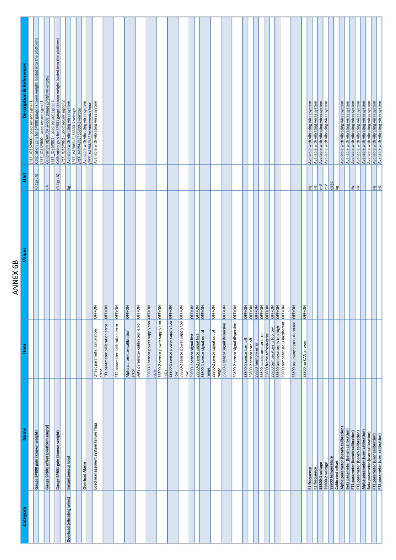
Cate
gory
Nam
eIte
mVa
lues
Uni
tD
escr
iptio
n & R
efer
ence
sAN
NEX
6B
[REF
_IO
] SP8
00 ‐
Load
sens
or si
gnal 1
Gau
ge S
P800
gai
n (k
now
n w
eigh
t)(0
.1g/
uA)
Calib
ratio
n ga
in fo
r SP8
00 g
auge (k
now
n w
eigh
t loa
ded
into th
e pl
atfo
rm)
[REF
_IO
] SP8
00 ‐
Load
sens
or si
gnal 1
Gau
ge S
P801
off
set (
plat
form
em
pty)
uACa
libra
tion
offs
et fo
r SP8
01 g
auge
(pla
tfor
m e
mpt
y)[R
EF_I
O] S
P801
‐ Lo
ad se
nsor si
gnal 2
Gau
ge S
P801
gai
n (k
now
n w
eigh
t)(0
.1g/
uA)
Calib
ratio
n ga
in fo
r SP8
01 g
auge (k
now
n w
eigh
t loa
ded
into th
e pl
atfo
rm)
[REF
_IO
] SP8
01 ‐
Load
sens
or si
gnal 2
Ove
rload
(vib
ratin
g w
ires)
Inst
anta
neou
s loa
dkg
Avai
labl
e w
ith v
ibra
ting
wire
s sys
tem
[REF
_VAR
IABL
E] S
S800
‐1 v
olta
ge[R
EF_V
ARIA
BLE] S
S800
‐2 v
olta
g eO
verlo
ad A
larm
Avai
labl
e w
ith v
ibra
ting
wire
s sys
tem
[REF
_VAR
IABL
E] In
stan
tane
ous l
oad
Load
man
agem
ent s
yste
m fa
ilure fl
ags
Offs
et p
aram
eter c
alib
ratio
n er
ror
OFF
/ON
Avai
labl
e w
ith v
ibra
ting
wire
s sys
tem
FT1
para
met
er c
alib
ratio
n er
ror
OFF
/ON
FT2
para
met
er c
alib
ratio
n er
ror
OFF
/ON
Alph
a pa
ram
eter c
alib
ratio
n er
ror
OFF
/ON
Beta p
aram
eter c
alib
ratio
n er
ror
OFF
/ON
SS80
0‐1
sens
or p
ower su
pply to
o hi
ghO
FF/O
N
SS80
0‐2
sens
or p
ower su
pply to
o hi
ghO
FF/O
N
SS80
0‐1
sens
or p
ower su
pply to
o lo
wO
FF/O
N
SS80
0‐2
sens
or p
ower su
pply to
o lo
wO
FF/O
N
SS80
0‐1
sens
or si
gnal lo
stO
FF/O
NSS
800‐
2 se
nsor si
gnal lo
stO
FF/O
NSS
800‐
1 se
nsor si
gnal o
ut o
f ra
n ge
OFF
/ON
SS80
0‐2
sens
or si
gnal o
ut o
f ra
nge
OFF
/ON
SS80
0‐1
sens
or si
gnal d
isper
sive
OFF
/ON
SS80
0‐2
sens
or si
gnal d
isper
sive
OFF
/ON
SS80
0‐1
sens
or to
rn o
ffO
FF/O
NSS
800‐
2 se
nsor to
rn o
f fO
FF/O
NSS
800
mem
ory
erro
rO
FF/O
NSS
800
acce
lero
met
er e
rro r
OFF
/ON
SS80
0 fr
ame
refr
esh
erro
rO
FF/O
NSS
800
tem
pera
ture is to
o lo
wO
FF/O
NSS
800
tem
pera
ture is to
o hi
ghO
FF/O
NSS
800
tem
pera
ture is in
cohe
rent
OFF
/ON
SS80
0 to
o m
any
shoc
ks d
etec
ted
OFF
/ON
SS80
0 no
CAN
ans
wer
OFF
/ON
F1 fr
eque
ncy
HzAv
aila
ble
with
vib
ratin
g w
ires s
yste
mF2 fr
eque
ncy
HzAv
aila
ble
with
vib
ratin
g w
ires s
yste
mSS
800‐
1 vo
ltage
mV
Avai
labl
e w
ith v
ibra
ting
wire
s sys
tem
SS80
0‐2
volta
gem
VAv
aila
ble
with
vib
ratin
g w
ires s
yste
mSS
800
tem
pera
ture
degC
Calib
rate
d of
fset
kgAl
pha
para
met
er (b
ench c
alib
ratio
n)Av
aila
ble
with
vib
ratin
g w
ires s
yste
mBe
ta p
aram
eter (b
ench c
alib
ratio
n)Av
aila
ble
with
vib
ratin
g w
ires s
yste
mFT
1 pa
ram
eter (b
ench c
alib
ratio
n)Hz
Avai
labl
e w
ith v
ibra
ting
wire
s sys
tem
FT2
para
met
er (b
ench c
alib
ratio
n)Hz
Avai
labl
e w
ith v
ibra
ting
wire
s sys
tem
Alph
a pa
ram
eter (u
ser c
alib
ratio
n)Av
aila
ble
with
vib
ratin
g w
ires s
yste
mBe
ta p
aram
eter (u
ser c
alib
ratio
n)Av
aila
ble
with
vib
ratin
g w
ires s
yste
mFT
1 pa
ram
eter (u
ser c
alib
ratio
n)Hz
Avai
labl
e w
ith v
ibra
ting
wire
s sys
tem
FT2
para
met
er (u
ser c
alib
ratio
n)Hz
Avai
labl
e w
ith v
ibra
ting
wire
s sys
tem

Cate
gory
Nam
eIte
mVa
lues
Uni
tD
escr
iptio
n & R
efer
ence
sAN
NEX
6C
Mac
hine
Activ
e co
ntro
l box
Turr
etPl
atfo
rm[R
EF_I
O] W
UI ‐ 1
2V E
CU W
ake
Up
Inpu
tN
one
[REF
_IO
] SA9
01TU
‐ Co
ntro
l box se
lect
or ‐
Turr
et[R
EF_I
O] S
A901
PF ‐
Cont
rol b
ox se
lect
or ‐
Plat
form
[REF
_IO
] SA8
01 ‐
Safe
ty c
omm
and
switc
h[R
EF_O
PTIO
N] T
rack
ing
syst
em[R
EF_F
AIL] F
02.0
2 ‐ E
mer
genc
y pu
mp
cont
acto
r[R
EF_F
AIL] F
12.0
1 ‐ C
AN F
ault
Turr
et / o
verr
idin
g co
ntro
l bo x
Inac
tive
Activ
e[R
EF_I
O] S
A801
‐ Sa
fety c
omm
and
switc
h[R
EF_I
O] S
A905
EN ‐
Enab
le sw
itch
(tur
ret) ‐
Enab
le[R
EF_I
O] S
A905
ST ‐
Star
t/St
op sw
itch
(tur
ret) ‐
Star
t/St
op[R
EF_I
O] S
A250
L ‐ T
urnt
able o
rient
atio
n sw
itch
(tur
ret) ‐
Lef t
[REF
_IO
] SA2
50R ‐ T
urnt
able o
rient
atio
n sw
itch
(tur
ret) ‐
Righ
t[R
EF_I
O] S
A420
U ‐
Arm sw
itch
(tur
ret) ‐
Raise
[REF
_IO
] SA4
20D ‐ A
rm sw
itch
(tur
ret) ‐
Desc
ent
[REF
_IO
] SA5
20U ‐
Boom
switc
h (t
urre
t) ‐
Raise
[REF
_IO
] SA5
20D ‐ B
oom sw
itch
(tur
ret) ‐
Desc
ent
[REF
_IO
] SA5
30O ‐
Boom
tele
scop
e sw
itch
(tur
ret) ‐
Exte
nd[R
EF_I
O] S
A530
I ‐ B
oom te
lesc
ope
switc
h (t
urre
t) ‐
Retr
act
[REF
_IO
] SA6
20U ‐
Jib sw
itch
(tur
ret) ‐
Raise
[REF
_IO
] SA6
20D ‐ J
ib sw
itch
(tur
ret) ‐
Desc
ent
[REF
_IO
] SA7
20U ‐
Plat
form
leve
l sw
itch
(tur
ret) ‐
Raise
[REF
_IO
] SA7
20D ‐ P
latf
orm le
vel s
witc
h (t
urre
t) ‐
Desc
ent
[REF
_FAI
L] F
12.0
1 ‐ C
AN F
ault
Plat
form
con
trol b
o xIn
activ
eAc
tive
[REF
_IO
] SB8
00 ‐
Enab
le p
edal
[REF
_IO
] SA3
03 ‐
Engi
ne st
art/
stop
switc
h[R
EF_I
O] S
A906
‐ G
ener
ator sw
itch
[REF
_IO
] SA8
00 ‐
Emer
genc
y pu
mp
switc
h[R
EF_I
O] S
A907
‐ Ho
rn sw
itch
[REF
_IO
] SM
900X
‐ Tu
rnta
ble
joys
tick ‐ A
xis X
[REF
_IO
] SM
900Y
‐ Bo
om jo
ystic
k ‐ A
xis Y
[REF
_IO
] SM
900N
‐ Tu
rnta
ble
orie
ntat
ion
/ boo
m jo
ystic
k ‐ O
ut o
f Neu
tral
[REF
_IO
] SM
901Y
‐ Bo
om te
lesc
opin
g jo
ystic
k ‐ A
xis Y
[REF
_IO
] SM
901N
‐ Bo
om te
lesc
opin
g jo
ystic
k ‐ O
ut o
f Neu
tral
[REF
_IO
] SM
902Y
‐ Dr
ive
joys
tick ‐ A
xis Y
[REF
_IO
] SM
902F ‐
Driv
e jo
ystic
k ‐ F
orw
ard
[REF
_IO
] SM
902B
‐ Dr
ive
joys
tick ‐ R
ever
se[R
EF_I
O] S
M90
2L ‐
Joys
tick
stee
ring
rock
er ‐
Left
[REF
_IO
] SM
902R
‐ Jo
ystic
k st
eerin
g ro
cker ‐
Righ
t[R
EF_I
O] S
A101
CR ‐
Stee
ring
mod
e sw
itch ‐ C
rab
[REF
_IO
] SA1
01SY ‐
Stee
ring
mod
e sw
itch ‐ S
ynch
ro[R
EF_I
O] S
A110
HS ‐
Driv
e sp
eed
sele
ctio
n ‐ H
igh
Spee
d[R
EF_I
O] S
A110
LS ‐
Driv
e sp
eed
sele
ctio
n ‐ L
ow S
peed
[REF
_IO
] SA1
00 ‐
Diffe
rent
ial l
ock
switc
h[R
EF_I
O] S
A531
O ‐
Boom
tele
scop
e sw
itch
(pla
tfor
m) ‐ E
xten
d[R
EF_I
O] S
A531
I ‐ B
oom te
lesc
ope
switc
h (p
latf
orm
) ‐ R
etra
c t[R
EF_I
O] S
A621
U ‐
Jib sw
itch
(pla
tfor
m) ‐ R
aise
[REF
_IO
] SA6
21D ‐ J
ib sw
itch
(pla
tfor
m) ‐ D
esce
nt[R
EF_I
O] S
A721
U ‐
Plat
form
leve
l sw
itch
(pla
tfor
m) ‐ R
aise
[REF
_IO
] SA7
21D ‐ P
latf
orm le
vel s
witc
h (p
latf
orm
) ‐ D
esce
n t[R
EF_I
O] S
A751
L ‐ P
latf
orm ro
tatio
n sw
itch
(pla
tfor
m) ‐ L
eft
[REF
_IO
] SA7
51R ‐ P
latf
orm ro
tatio
n sw
itch
(pla
tfor
m) ‐ R
ight
Mac
hine
unf
olde
d[R
EF_I
O] S
Q59
0 ‐ B
oom d
own/
tele
scop
e re
trac
ted
dete
ctor 1
[REF
_IO
] SQ
591 ‐ B
oom d
own/
tele
scop
e re
trac
ted
dete
ctor 2
[REF
_IO
] SQ
521 ‐ B
oom h
igh
dete
cto r
[REF
_IO
] SQ
523 ‐ B
oom zo
ne m
agne
t[R
EF_I
O] S
Q53
3 ‐ B
oom te
lesc
ope
posit
ion
dete
ctor
[REF
_IO
] SQ
531 ‐ B
oom te
lesc
ope
zone
1

Cate
gory
Nam
eIte
mVa
lues
Uni
tD
escr
iptio
n & R
efer
ence
sAN
NEX
6D
Mac
hine
Pos
ition
Init
P1, P
2, P
3, P
4 : 0
..450
kg/1
000l
b po
sitio
n w
ith d
ual l
oad
optio
n (P
5 ca
n be
reac
hed
but
tele
scop
e ex
tend
and
boo
m d
esce
nt a
re th
en c
ut)
P1, P
2, P
3, P
4, P
5 : 0
..230
kg/5
00lb p
ositi
on w
ith d
ual l
oad
optio
n an
d 23
0kg
sele
cted
, an
d sin
gle
load
cap
abili
ty (P
3/P4
/P5
are
cons
ider
ed a
s P2
zone
)P1
: SQ
590=
ON & S
Q59
1=O
N & S
Q53
3=O
N & S
Q52
1=O
FFP2
: (SQ
590=
OFF o
r SQ
591=
OFF )
& S
Q53
3=O
N & S
Q52
1=O
FFP3
: SQ
590=
OFF & S
Q59
1=O
FF & S
Q53
3=O
N & S
Q52
1=O
NP4
: SQ
590=
OFF & S
Q59
1=O
FF & S
Q53
3=O
FF & S
Q52
1=O
NP5
:SQ
590=
OFF
&SQ
591=
OFF
&SQ
521=
OFF
&SQ
533=
OFF
P1 p
ositi
on (f
olde
d)[R
EF_I
O] S
Q59
0 ‐ B
oom d
own/
tele
scop
e re
trac
ted
dete
ctor 1
P2 p
ositi
on (u
nfol
ded)
[REF
_IO
] SQ
591 ‐ B
oom d
own/
tele
scop
e re
trac
ted
dete
ctor 2
P3 p
ositi
on (u
nfol
ded)
[REF
_IO
] SQ
521 ‐ B
oom h
igh
dete
cto r
P4 p
ositi
on (u
nfol
ded)
[REF
_IO
] SQ
523 ‐ B
oom zo
ne m
agne
tP5
pos
ition
(unf
olde
d)[R
EF_I
O] S
Q53
3 ‐ B
oom te
lesc
ope
posit
ion
dete
ctor
Fold
ed p
ositi
on e
rror
[REF
_IO
] SQ
531 ‐ B
oom te
lesc
ope
zone
1Po
sitio
n er
ror : b
oom lo
wer
ing
not a
llow
ed[R
EF_C
ON
FIG
] Loa
d Se
lect
ion
Posit
ion
erro
r : b
oom lo
wer
ing
allo
wed
Tilt
[REF
_IO
] SQ
800 ‐ T
ilt se
nso r
Ove
rload
Ala
rm[R
EF_V
ARIA
BLE] In
stan
tane
ous l
oad
[REF
_VAR
IABL
E] O
verlo
ad A
larm
[REF
_VAR
IABL
E] O
verlo
ad A
larm
Inst
anta
neou
s loa
dkg
[REF
_VAR
IABL
E] In
stan
tane
ous l
oad
[REF
_VAR
IABL
E] E
stim
ated
Loa
dEn
gine
runn
ing
Emer
genc
y pu
mp
runn
ing
Num
ber o
f run
ning
mov
emen
tsN
umbe
r of m
ovem
ents c
urre
ntly a
ctiv
e, in
clud
ing
driv
e an
d st
eerin
gH
ourm
eter
hAc
tiv' S
hiel
d Ba
r fun
ctio
nSt
ate
Inac
tive
Activ
e' S
hiel
d Ba
r fun
ctio
n is
activ
e w
hen
anti‐
crus
hing
bar is p
ushe
d (S
Q90
2 =
OFF
) w
hile m
achi
ne is u
nfol
ded. A
ll m
ovem
ents fr
om p
latf
orm c
ontr
ol b
ox a
re th
en
imm
edia
tely c
ut o
ff.W
hen
all j
oyst
icks a
nd sw
itche
s of p
latf
orm c
ontr
ol b
ox a
re re
leas
ed to
neu
tral
posit
ion, m
ovem
ents w
hich a
llow to
fold th
e m
achi
ne b
ecom
e av
aila
ble
agai
n, a
nd
the
func
tion
is w
aitin
g fo
r res
et sw
itch
(SB9
00=O
N) t
o be
pus
hed.
The
func
tion
retu
rn to
inac
tive
stat
e w
hen
rese
t sw
itch
is pu
shed
(SB9
00=O
N) a
nd
anti‐
crus
hing
bari
srel
ease
d(S
Q90
2=O
N)
Activ
e[R
EF_O
PTIO
N] A
ctiv
'Shi
eld
bar
Wai
ting
for r
eset
[REF
_IO
] SQ
902 ‐ A
ctiv
' Shi
eld
Bar d
etec
tor
Driv
e fo
rwar
d cu
ttin
gO
FF/O
N[R
EF_I
O] S
B900
‐ Ac
tiv' S
hiel
d Ba
r sw
itch
Driv
e re
vers
e cu
ttin
gO
FF/O
NSt
eerin
g cu
ttin
gO
FF/O
NTu
rnta
ble
orie
ntat
ion
left c
uttin
gO
FF/O
N
Turn
tabl
e or
ient
atio
n rig
ht
cutt
ing
OFF
/ON
Boom
raise
cut
ting
OFF
/ON
Boom
des
cent c
uttin
gO
FF/O
NTe
lesc
ope
exte
nd c
uttin
gO
FF/O
NTe
lesc
ope
retr
act c
uttin
gO
FF/O
NJib
raise
cut
ting
OFF
/ON
Jib d
esce
nt c
uttin
gO
FF/O
NPl
atfo
rm ro
tatio
n cu
ttin
gO
FF/O
NPl
atfo
rm le
vel c
uttin
gO
FF/O
NTu
rret e
nabl
e sw
itch
stat
eIn
activ
eAc
tive
but n
ot v
alid (>
8s)
[REF
_IO
_MAI
N] S
A905
EN ‐
Enab
le sw
itch
(tur
ret) ‐
Enab
leAc
tive
and
valid
Plat
form
ena
ble
peda
l sta
teIn
activ
eAc
tive
but n
ot v
alid (>
8s)
[REF
_IO
_MAI
N] S
B800
‐ En
able p
edal
Activ
e an
d va
lidD
rive
and
stee
ring
safe
ty in
tilt
cond
ition
sSa
fety is a
ctiv
e fo
r cou
ntrie
s Sta
ndar
d, A
ustr
alia a
nd R
ussia
/Ukr
aine
, or i
f co
nfig
urat
ion
"Res
tric
tion
of m
ovem
ents in
tilt
cond
ition
s" is a
ctiv
ated
.In th
is ca
se, d
rive
and
stee
ring
are
not a
llow
ed w
hen
mac
hine
is u
nfol
ded
and
tilt i
s ac
tive.
[REF
_OPT
ION
] Mov
emen
ts re
stric
tions u
nder ti
lt co
nditi
ons

Cate
gory
Nam
eIte
mVa
lues
Uni
tD
escr
iptio
n & R
efer
ence
sAN
NEX
6E
[REF
_CO
UN
TRY] S
tand
ard
Exte
nsib
le st
ruct
ure'
s m
ovem
ent s
afet
y in ti
lt co
nditi
ons
Safe
ty is a
ctiv
e fo
r cou
ntrie
s Rus
sia/U
krai
ne, o
r if c
onfig
urat
ion
"Res
tric
tion
of
mov
emen
ts in
tilt
cond
ition
s" is a
ctiv
ated
. In
this
case
, fol
low
ing
mov
emen
ts a
re n
ot
allo
wed
whe
n m
achi
ne is u
nfol
ded
and
tilt i
s act
ive:
‐ te
lesc
ope
exte
nd ‐ d
ual l
oad
mac
hine
s : b
oom e
xten
d an
d bo
om ra
ise w
hen
tele
scop
e is
exte
nded
in
P4or
P5po
sitio
n[R
EF_O
PTIO
N] M
ovem
ents re
stric
tions u
nder ti
lt co
nditi
ons
[REF
_CO
UN
TRY] S
tand
ard
Use
r ide
ntifi
catio
nM
ode
Disa
bled
Activ
ated
Stat
eLo
cked
Unl
ocke
dO
verr
idin
g m
ode
Inac
tive
#NAM
E?Ac
tive
[REF
_IO
] SA8
01 ‐
Safe
ty c
omm
and
switc
hN
ot a
vaila
ble
[REF
_VAR
IABL
E] O
verlo
ad A
larm
Not e
nabl
ed[R
EF_I
O] S
B802
‐ Em
erge
ncy
stop
(pla
tefo
rm)
Not o
pera
tiona
l[R
EF_V
ARIA
BLE] A
ctiv
e co
ntro
l box
[REF
_FAI
L] F
13.1
0 ‐ N
eutr
al sw
itch
[REF
_FAI
L] F
06.0
1 ‐ L
oad
Man
agem
ent S
yste
m n
ot c
alib
rate
d[R
EF_F
AIL] F
06.0
3 ‐ L
oad
Cells o
ut o
f Ran
ge[R
EF_F
AIL] F
06.0
4 ‐ L
oad
Cells in
cohe
renc
e[R
EF_F
AIL] F
06.0
5 ‐ O
verlo
ad L
ow P
owe r
[REF
_FAI
L] F
06.0
9 ‐ N
egat
ive
load
Engi
neEn
gine
star
t set
poin
t[R
EF_I
O] S
A905
ST ‐
Star
t/St
op sw
itch
(tur
ret) ‐
Star
t/St
op[R
EF_I
O] S
A303
‐ En
gine
star
t/st
op sw
itch
[REF
_CO
NFI
G] E
ngin
eEn
gine
con
trol st
ate
Init
Pre‐
heat
ing
[REF
_VAR
IABL
E] T
urre
t / o
verr
idin
g co
ntro
l box
Read
y to st
art
[REF
_VAR
IABL
E] P
latf
orm c
ontr
ol b
o xSt
artin
gPo
st‐h
eatin
gRu
nnin
gSt
oppi
ngEn
gine
runn
ing
[REF
_IO
] DPL
US ‐ A
ltern
ator si
gna l
[REF
_VAR
IABL
E] E
ngin
e sp
eed
mea
sure
dEn
gine
coo
lant te
mpe
ratu
re°C
Engi
ne c
oola
nt te
mpe
ratu
re c
alcu
late
d fr
om a
nalo
g se
nsor (T
IER
III fi
xed
spee
d) o
r ge
t dire
ctly fr
om e
lect
roni
c en
gine
[REF
_IO
] ST3
02 ‐
Mot
or te
mpe
ratu
re se
nsor 1
[REF
_CO
NFI
G] E
ngin
eEn
gine
pre‐h
eatin
g tim
em
sEn
gine
pre‐h
eatin
g tim
e ca
lcul
ated
from
eng
ine
cool
ant t
empe
ratu
r e[R
EF_V
ARIA
BLE] E
ngin
e co
olan
t tem
pera
ture
Engi
ne sp
eed
requ
este
drp
mEn
gine
spee
d m
easu
red
rpm
Engi
ne su
pply v
olta
geV
Mea
sure
d en
gine
supp
ly v
olta
ge se
nd b
y EC
U e
ngin
e (T
IER
III v
aria
ble
spee
d an
d TI
ER
IV e
n gin
e on
ly)
[REF
_IO
] 12V
P ‐ 1
2V E
CU p
erm
anen
tAc
tive
diag
nost
ic tr
oubl
e co
des f
ram
e (D
M1)
Prot
ect l
amp
OFF
/ON
War
ning
lam
pO
FF/O
NSt
op la
mp
OFF
/ON
Mal
func
tion
lam
pO
FF/O
NFl
ash
prot
ect l
amp
SLO
WFA
STN
/AO
NFl
ash
war
ning
lam
pSL
OW
FAST
N/A
ON
Flas
h st
op la
mp
SLO
WFA
STN
/AO
NFl
ash
mal
func
tion
lam
pSL
OW

Cate
gory
Nam
eIte
mVa
lues
Uni
tD
escr
iptio
n & R
efer
ence
sAN
NEX
6F
FAST
N/A
ON
Activ
e di
agno
stic tr
oubl
e co
des c
ount (D
M1)
Dia
gnos
tic tr
oubl
e co
de 1 (D
M1)
SPN
Failu
re M
ode
Iden
tifie
r (FM
I)O
ccur
renc
e Co
unt (
OC)
Dia
gnos
tic tr
oubl
e co
de 2 (D
M1)
SPN
Failu
re M
ode
Iden
tifie
r (FM
I)O
ccur
renc
e Co
unt (
OC)
Dia
gnos
tic tr
oubl
e co
de 3 (D
M1)
SPN
Failu
re M
ode
Iden
tifie
r (FM
I)O
ccur
renc
e Co
unt (
OC)
Dia
gnos
tic tr
oubl
e co
de 4 (D
M1)
SPN
Failu
re M
ode
Iden
tifie
r (FM
I)O
ccur
renc
e Co
unt (
OC)
Dia
gnos
tic tr
oubl
e co
de 5 (D
M1)
SPN
Failu
re M
ode
Iden
tifie
r (FM
I)O
ccur
renc
e Co
unt (
OC)
Fuel le
vel (
filte
red)
[REF
_CO
NFI
G] F
uel l
evel se
nsor ty
pe[R
EF_I
O] S
Q30
0 ‐ L
ow fu
el le
vel d
etec
tor
[REF
_IO
] SL3
00 ‐
Fuel le
vel s
enso
rEn
gine
Oil
Pres
sure
kPa
[REF
_CO
NFI
G] E
ngin
eD
PF R
egen
erat
ion
DPF
leve
l (en
gine
man
ufac
ture
r de
finiti
on)
DPF
Stat
usN
ot a
ctiv
eAc
tive
Nee
ded
DPF: in
hibi
ted
rege
nera
tion
requ
est
OFF
/ON
DPF: in
hibi
ted
rege
nera
tion
stat
usO
FF/O
N
DPF: p
arke
d re
gene
ratio
n re
ques
tO
FF/O
N
DPF: p
arke
d re
gene
ratio
n st
atus
OFF
/ON
DPF: a
utom
atic re
gene
ratio
n st
atus
OFF
/ON
DPF
Soot L
oad
Perc
ent
Engi
ne D
PF re
gene
ratio
n st
ate
char
tCh
oice
Conf
irm in
hibi
tion
Inhi
bitio
n re
leas
eIn
hibi
tion
Conf
irm d
esin
hibi
tion
Rele
ase
befo
re c
hoic
eCo
nfirm
act
ivat
ion
Activ
atio
nCo
nfirm
rege
nera
tion
stop
DPF
inhi
bit c
ause
SWO
FF/O
NAc
cele
rato
r Off
Iddl
eO
FF/O
NO
ut o
f neu
tral
OFF
/ON
Park b
rake
OFF
/ON
Low e
xhau
st g
az te
mp
OFF
/ON
Syst
em fa
ult
OFF
/ON
Syst
em ti
meo
utO
FF/O
NSy
stem
lock
OFF
/ON
Engi
ne n
ot w
arm
ed u
pO
FF/O
NEC
UPl
atfo
rm E
CU st
atus (U
104)
Stat
usW
AIT
NO
RMAL
SETT
ING
DEG
RADE
DSt
atus O
KO
FF/O
NM
ax n
umbe
r of E
EPRO
M q
uerie
s (R/
W) i
nto
the
stac
kCu
rren
t num
ber o
f EEP
ROM q
uerie
s (R/
W) i
nto
the
stac
k

Cate
gory
Nam
eIte
mVa
lues
Uni
tD
escr
iptio
n & R
efer
ence
sAN
NEX
6G
Curr
ent E
EPRO
M st
atus
READ
YBU
SYN
umbe
r of E
EPRO
M st
ack
erro
rsN
umbe
r of E
EPRO
M st
atus e
rror
sEx
ecut
ion
time
of 1
0ms t
ask
ms
Exec
utio
n tim
e of 2
0ms t
ask
ms
Exec
utio
n tim
e of 4
0ms t
ask
ms
Last J1
939
failu
reIn
stan
ce n
umbe
rCA
N_H
G (1
001/
1002
)CA
N 2
.0 (2
001/
2002
)Er
ror
Non
eN
o fr
ee E
ntry in
the
Tx Q
ueue
of t
he T
PL a
vaila
ble
Too
man
y PG
Ns t
ried
to re
gist
er in
the
conf
ig fi
lter
Une
xpec
ted
BAM fr
ame
rece
ived
Une
xpec
ted
RTS
fram
e re
ceiv
edU
nexp
ecte
d CT
S fr
ame
rece
ived
Une
xpec
ted
EOM fr
ame
rece
ived
Une
xpec
ted
CA fr
ame
rece
ived
Une
xpec
ted
DT fr
ame
rece
ived
No
free
Rx
Msg B
uffe
r in
the
TPL
for a
glo
bal m
essa
ge a
vaila
ble
Tim
er o
verr
un fo
r Tx
Tim
eout T
0Ti
mer o
verr
un fo
r Tx
Tim
eout T
2Ti
mer o
verr
un fo
r Rx
Tim
eout T
0Ti
mer o
verr
un fo
r Rx
Tim
eout T
1Ti
mer o
verr
un fo
r Rx
Tim
eout T
2Th
e le
ngth o
f the
rece
ived
mes
sage is to
o lo
ng fo
r a se
g m
s gEr
ror b
y Se
ndin
g: C
an't
send
a se
gmen
ted
mes
sage
Send
ing
a %
s mes
sage fa
iled
Send
ing
a N
ACK
mes
sage fa
iled
The
devi
ce is a
lread
y re
gist
ered
in th
e de
vice li
s tTh
e de
vice h
andl
e is
inva
lidTh
e de
vice a
ddre
ss is in
valid
The
devi
ce c
an't
clai
m a fr
ee a
ddre
ssTh
e m
axim
um n
umbe
r of n
odes in
the
netw
ork
is ex
ceed
edAd
dres
s cla
im w
ith in
valid
add
ress re
ceiv
edM
ain
Man
ager T
ask
was n
ot c
alle
d in th
e re
quire
d se
quen
ceTh
e da
ta fi
eld
of th
e tr
ansm
it m
essa
ge is to
o lo
n gN
o m
emor
y fo
r the
dat
a fie
ld o
f the
tran
smit
mes
sage a
lloca
ted
An e
rror o
ccur
red
durin
g re
gist
ratio
n of a re
ques
t PG
NDe
vice h
as n
o ad
dres
s cla
imed
Devi
ce li
st is d
isabl
edTh
e m
axim
al n
umbe
r of r
ecei
ve m
essa
ges i
s exc
eede
d.Th
e m
axim
al n
umbe
r of t
rans
mit
mes
sage
s is e
xcee
ded.
A re
gist
ered
mes
sage w
asn'
t rec
eive
d in th
e gi
ven
time
Allo
cate m
emor
y fa
iled
Free
mem
ory
faile
dEr
ror c
lass
War
ning
Erro
rFa
tal
Turr
et E
CU st
atus (U
106)
Ove
r tem
pera
ture (>
110°
C)
dete
cted
dur
ing
mor
e th
an 3
0 se
cond
s
OFF
/ON
Ove
r cur
rent d
etec
ted
durin
g m
ore
than
5 se
cond
sO
FF/O
N
Inte
rnal v
olta
ge o
ut o
f ran
geO
FF/O
NAD
C re
fere
nce
volta
ge o
ut o
f ra
n ge
or A
DC b
lock
edO
FF/O
N
Gro
und
lost d
etec
ted
OFF
/ON
One
of S
PI d
aisy c
hain
s fai
led
OFF
/ON
Ove
r pow
er d
etec
ted
OFF
/ON
Dat
a sa
ved
into E
EPRO
MDa
ta re
set
Wro
ng c
heck
sum
Data o
verf
low
Soft
war
e bu
ild n
umbe
rD
rive
Driv
e m
ovem
ent s
etpo
int
Valu
e%
Inte
rnal se
tpoi
nt se
cure
d co
min
g fr
om a
ctiv
e co
ntro
l box a
nd fo
rmat
ted
from
0 to
10
0% fo
r a g
iven
dire
ctio
n
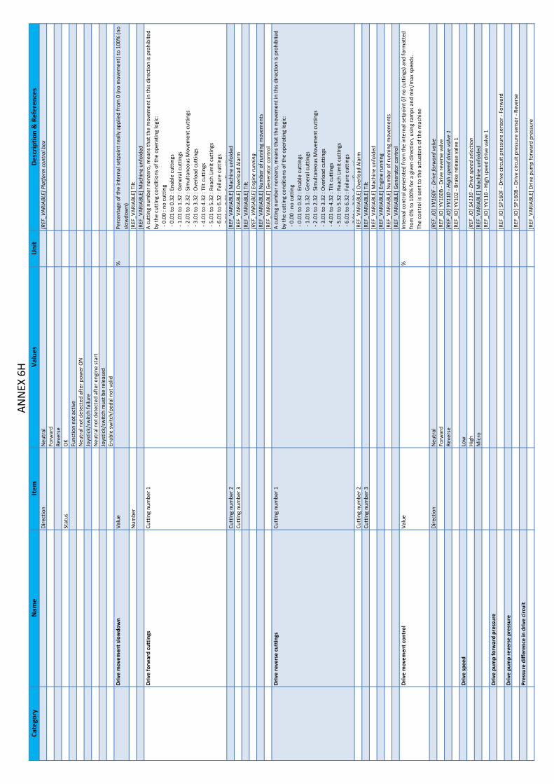
Cate
gory
Nam
eIte
mVa
lues
Uni
tD
escr
iptio
n & R
efer
ence
sAN
NEX
6H
Dire
ctio
nN
eutr
al[R
EF_V
ARIA
BLE] P
latf
orm c
ontr
ol b
oxFo
rwar
dRe
vers
eSt
atus
OK
Func
tion
not a
ctiv
eN
eutr
al n
ot d
etec
ted
afte
r pow
er O
NJo
ystic
k/sw
itch
failu
reN
eutr
al n
ot d
etec
ted
afte
r eng
ine
star
tJo
ystic
k/sw
itch
mus
t be
rele
ased
Enab
le sw
itch/
peda
l not v
alid
Driv
e m
ovem
ent s
low
dow
nVa
lue
%Pe
rcen
tage o
f the
inte
rnal se
tpoi
nt re
ally a
pplie
d fr
om 0 (n
o m
ovem
ent) to
100
% (n
o slo
wdo
wn )
Num
ber
[REF
_VAR
IABL
E] T
ilt[R
EF_V
ARIA
BLE] M
achi
ne u
nfol
ded
Driv
e fo
rwar
d cu
ttin
gsCu
ttin
g nu
mbe
r 1A
cutt
ing
num
ber n
onze
ro, m
eans th
at th
e m
ovem
ent i
n th
is di
rect
ion
is pr
ohib
ited
by th
e cu
ttin
g co
nditi
ons o
f the
ope
ratin
g lo
gic:
‐ 0
.00
: no
cutt
ing
‐ 0
.01
to 0
.32
: Ena
ble
cutt
ings
‐ 1
.01
to 1
.32
: Gen
eral c
uttin
gs ‐ 2
.01
to 2
.32
: Sim
ulta
neou
s Mov
emen
t cut
tings
‐ 3
.01
to 3
.32
: Ove
rload
cut
tings
‐ 4
.01
to 4
.32
: Tilt c
uttin
gs ‐ 5
.01
to 5
.32
: Rea
ch L
imit
cutt
ings
‐ 6
.01
to 6
.32
: Fai
lure c
uttin
gs7
01to
732
:Spe
cific
cutt
ings
Cutt
ing
num
ber 2
[REF
_VAR
IABL
E] M
achi
ne u
nfol
ded
Cutt
ing
num
ber 3
[REF
_VAR
IABL
E] O
verlo
ad A
larm
[REF
_VAR
IABL
E] T
ilt[R
EF_V
ARIA
BLE] E
ngin
e ru
nnin
g[R
EF_V
ARIA
BLE] N
umbe
r of r
unni
ng m
ovem
ents
[REF
_VAR
IABL
E] G
ener
ator c
ontr
olD
rive
reve
rse
cutt
ings
Cutt
ing
num
ber 1
A cu
ttin
g nu
mbe
r non
zero
, mea
ns th
at th
e m
ovem
ent i
n th
is di
rect
ion
is pr
ohib
ited
by th
e cu
ttin
g co
nditi
ons o
f the
ope
ratin
g lo
gic:
‐ 0
.00
: no
cutt
ing
‐ 0
.01
to 0
.32
: Ena
ble
cutt
ings
‐ 1
.01
to 1
.32
: Gen
eral c
uttin
gs ‐ 2
.01
to 2
.32
: Sim
ulta
neou
s Mov
emen
t cut
tings
‐ 3
.01
to 3
.32
: Ove
rload
cut
tings
‐ 4
.01
to 4
.32
: Tilt c
uttin
gs ‐ 5
.01
to 5
.32
: Rea
ch L
imit
cutt
ings
‐ 6
.01
to 6
.32
: Fai
lure c
uttin
gs7
01to
732
:Spe
cific
cutt
ings
Cutt
ing
num
ber 2
[REF
_VAR
IABL
E] O
verlo
ad A
larm
Cutt
ing
num
ber 3
[REF
_VAR
IABL
E] T
ilt[R
EF_V
ARIA
BLE] M
achi
ne u
nfol
ded
[REF
_VAR
IABL
E] E
ngin
e ru
nnin
g[R
EF_V
ARIA
BLE] N
umbe
r of r
unni
ng m
ovem
ents
[REF
_VAR
IABL
E] G
ener
ator c
ontr
olD
rive
mov
emen
t con
trol
Valu
e%
Inte
rnal c
ontr
ol g
ener
ated
from
the
inte
rnal se
tpoi
nt (i
f no
cutt
ings
) and
form
atte
d fr
om 0
% to
100
% fo
r a g
iven
dire
ctio
n, u
sing
ram
ps a
nd m
in/m
ax sp
eeds
.Th
e co
ntro
l is s
ent t
o th
e ac
tuat
ors o
f the
mac
hine
Dire
ctio
nN
eutr
al[R
EF_I
O] Y
V160
F ‐ D
rive
forw
ard
valv
eFo
rwar
d[R
EF_I
O] Y
V160
B ‐ D
rive
reve
rse
valv
eRe
vers
e[R
EF_I
O] Y
V110
‐ Hi
gh sp
eed
driv
e va
lve
1[R
EF_I
O] Y
V102
‐ Br
ake
rele
ase
valv
e 1
Driv
e sp
eed
Low
High
[REF
_IO
] SA1
10 ‐
Driv
e sp
eed
sele
ctio
nM
icro
[REF
_VAR
IABL
E] M
achi
ne u
nfol
ded
[REF
_IO
] YV1
10 ‐
High
spee
d dr
ive
valv
e 1
Driv
e pu
mp
forw
ard
pres
sure
[REF
_IO
] SP1
60F ‐ D
rive
circ
uit p
ress
ure
sens
or ‐
Forw
ard
Driv
e pu
mp
reve
rse
pres
sure
[REF
_IO
] SP1
60B ‐ D
rive
circ
uit p
ress
ure
sens
or ‐
Reve
rse
Pres
sure d
iffer
ence in
driv
e ci
rcui
t[R
EF_V
ARIA
BLE] D
rive
pum
p fo
rwar
d pr
essu
re

Cate
gory
Nam
eIte
mVa
lues
Uni
tD
escr
iptio
n & R
efer
ence
sAN
NEX
6I
[REF
_VAR
IABL
E] D
rive
pum
p re
vers
e pr
essu
reSt
eerin
gSt
eerin
g m
ovem
ent s
etpo
int
Valu
e%
Inte
rnal se
tpoi
nt se
cure
d co
min
g fr
om a
ctiv
e co
ntro
l box a
nd fo
rmat
ted
from
0 to
10
0% fo
r a g
iven
dire
ctio
nDi
rect
ion
Neu
tral
[REF
_VAR
IABL
E] P
latf
orm c
ontr
ol b
o xLe
ftRi
ght
Stat
usO
KFu
nctio
n no
t act
ive
Neu
tral n
ot d
etec
ted
afte
r pow
er O
NJo
ystic
k/sw
itch
failu
reN
eutr
al n
ot d
etec
ted
afte
r eng
ine
star
tJo
ystic
k/sw
itch
mus
t be
rele
ased
Enab
le sw
itch/
peda
l not v
alid
Stee
ring
mov
emen
t slo
wdo
wn
Valu
e%
Perc
enta
ge o
f the
inte
rnal se
tpoi
nt re
ally a
pplie
d fr
om 0 (n
o m
ovem
ent) to
100
% (n
o slo
wdo
wn )
Num
ber
Stee
ring
left c
uttin
gsCu
ttin
g nu
mbe
r 1A
cutt
ing
num
ber n
onze
ro, m
eans th
at th
e m
ovem
ent i
n th
is di
rect
ion
is pr
ohib
ited
by
the
cutt
ing
cond
ition
s of t
he o
pera
ting
logi
c: ‐ 0
.00
: no
cutt
ing
‐ 0
.01
to 0
.32
: Ena
ble
cutt
ings
‐ 1
.01
to 1
.32
: Gen
eral c
uttin
gs ‐ 2
.01
to 2
.32
: Sim
ulta
neou
s Mov
emen
t cut
tings
‐ 3
.01
to 3
.32
: Ove
rload
cut
tings
‐ 4
.01
to 4
.32
: Tilt c
uttin
gs ‐ 5
.01
to 5
.32
: Rea
ch L
imit
cutt
ings
‐ 6
.01
to 6
.32
: Fai
lure c
uttin
gs7
01to
732
:Spe
cific
cutt
ings
Cutt
ing
num
ber 2
[REF
_VAR
IABL
E] E
ngin
e ru
nnin
gCu
ttin
g nu
mbe
r 3[R
EF_V
ARIA
BLE] O
verlo
ad A
larm
[REF
_VAR
IABL
E] M
achi
ne u
nfol
ded
[REF
_VAR
IABL
E] N
umbe
r of r
unni
ng m
ovem
ents
[REF
_VAR
IABL
E] G
ener
ator c
ontr
olSt
eerin
g rig
ht c
uttin
gsCu
ttin
g nu
mbe
r 1A
cutt
ing
num
ber n
onze
ro, m
eans th
at th
e m
ovem
ent i
n th
is di
rect
ion
is pr
ohib
ited
by th
e cu
ttin
g co
nditi
ons o
f the
ope
ratin
g lo
gic:
‐ 0
.00
: no
cutt
ing
‐ 0
.01
to 0
.32
: Ena
ble
cutt
ings
‐ 1
.01
to 1
.32
: Gen
eral c
uttin
gs ‐ 2
.01
to 2
.32
: Sim
ulta
neou
s Mov
emen
t cut
tings
‐ 3
.01
to 3
.32
: Ove
rload
cut
tings
‐ 4
.01
to 4
.32
: Tilt c
uttin
gs ‐ 5
.01
to 5
.32
: Rea
ch L
imit
cutt
ings
‐ 6
.01
to 6
.32
: Fai
lure c
uttin
gs7
01to
732
:Spe
cific
cutt
ings
Cutt
ing
num
ber 2
[REF
_VAR
IABL
E] O
verlo
ad A
larm
Cutt
ing
num
ber 3
[REF
_VAR
IABL
E] M
achi
ne u
nfol
ded
[REF
_VAR
IABL
E] E
ngin
e ru
nnin
g[R
EF_V
ARIA
BLE] N
umbe
r of r
unni
ng m
ovem
ents
[REF
_VAR
IABL
E] G
ener
ator c
ontr
olSt
eerin
g m
ovem
ent c
ontr
olVa
lue
%In
tern
al c
ontr
ol g
ener
ated
from
the
inte
rnal se
tpoi
nt (i
f no
cutt
ings
) and
form
atte
d fr
om 0
% to
100
% fo
r a g
iven
dire
ctio
n, u
sing
ram
ps a
nd m
in/m
ax sp
eeds
.Th
e co
ntro
l is s
ent t
o th
e ac
tuat
ors o
f the
mac
hine
Dire
ctio
nN
eutr
al[R
EF_I
O] Y
V901
‐ Pr
opor
tiona
l val
ve 1 (s
teer
ing)
Left
[REF
_IO
] YV1
50L ‐ S
teer
ing
fron
t lef
t val
veRi
ght
[REF
_IO
] YV1
50R ‐ S
teer
ing
fron
t rig
ht v
alve
[REF
_IO
] YV1
07 ‐
Crab
/syn
chro st
eerin
g va
lve
1[R
EF_I
O] Y
V108
‐ Cr
ab/s
ynch
ro st
eerin
g va
lve
2[R
EF_I
O] Y
V800
‐ Lo
ad se
nsin
g va
lve
Stee
ring
mod
eFr
ont
Crab
[REF
_IO
] SA1
01CR
‐ St
eerin
g m
ode
switc
h ‐ C
rab
Sync
hro
[REF
_IO
] SA1
01SY ‐
Stee
ring
mod
e sw
itch ‐ S
ynch
ro[R
EF_I
O] Y
V902
‐ El
ectr
ovan
ne p
ropo
rtio
nnel
le 2 (j
ib, p
latf
orm le
vel,
plat
form
ro
tatio
n )[R
EF_I
O] Y
V150
L ‐ S
teer
ing
fron
t lef
t val
ve[R
EF_I
O] Y
V150
R ‐ S
teer
ing
fron
t rig
ht v
alve
[REF
_IO
] YV1
07 ‐
Crab
/syn
chro st
eerin
g va
lve
1

Cate
gory
Nam
eIte
mVa
lues
Uni
tD
escr
iptio
n & R
efer
ence
sAN
NEX
6J
[REF
_IO
] YV1
08 ‐
Crab
/syn
chro st
eerin
g va
lve
2[R
EF_I
O] Y
V800
‐ Lo
ad se
nsin
g va
lve
Turn
tabl
e or
ient
atio
nTu
rnta
ble
orie
ntat
ion
mov
emen
t set
poin
tVa
lue
%In
tern
al se
tpoi
nt se
cure
d co
min
g fr
om a
ctiv
e co
ntro
l box a
nd fo
rmat
ted
from
0 to
10
0% fo
r a g
iven
dire
ctio
nDi
rect
ion
Neu
tral
[REF
_VAR
IABL
E] T
urre
t / o
verr
idin
g co
ntro
l bo x
Left
[REF
_VAR
IABL
E] P
latf
orm c
ontr
ol b
oxRi
ght
Stat
usO
KFu
nctio
n no
t act
ive
Neu
tral n
ot d
etec
ted
afte
r pow
er O
NJo
ystic
k/sw
itch
failu
reN
eutr
al n
ot d
etec
ted
afte
r eng
ine
star
tJo
ystic
k/sw
itch
mus
t be
rele
ased
Enab
le sw
itch/
peda
l not v
alid
Turn
tabl
e or
ient
atio
n m
ovem
ent s
low
dow
nVa
lue
%Pe
rcen
tage o
f the
inte
rnal se
tpoi
nt re
ally a
pplie
d fr
om 0 (n
o m
ovem
ent) to
100
% (n
o slo
wdo
wn )
Num
ber
[REF
_VAR
IABL
E] T
urre
t / o
verr
idin
g co
ntro
l box
[REF
_VAR
IABL
E] T
ilt[R
EF_V
ARIA
BLE] M
achi
ne u
nfol
ded
Turn
tabl
e or
ient
atio
n le
ft c
uttin
gsCu
ttin
g nu
mbe
r 1A
cutt
ing
num
ber n
onze
ro, m
eans th
at th
e m
ovem
ent i
n th
is di
rect
ion
is pr
ohib
ited
by th
e cu
ttin
g co
nditi
ons o
f the
ope
ratin
g lo
gic:
‐ 0
.00
: no
cutt
ing
‐ 0
.01
to 0
.32
: Ena
ble
cutt
ings
‐ 1
.01
to 1
.32
: Gen
eral c
uttin
gs ‐ 2
.01
to 2
.32
: Sim
ulta
neou
s Mov
emen
t cut
tings
‐ 3
.01
to 3
.32
: Ove
rload
cut
tings
‐ 4
.01
to 4
.32
: Tilt c
uttin
gs ‐ 5
.01
to 5
.32
: Rea
ch L
imit
cutt
ings
‐ 6
.01
to 6
.32
: Fai
lure c
uttin
gs7
01to
732
:Spe
cific
cutt
ings
Cutt
ing
num
ber 2
[REF
_VAR
IABL
E] E
ngin
e ru
nnin
gCu
ttin
g nu
mbe
r 3[R
EF_V
ARIA
BLE] O
verlo
ad A
larm
[REF
_VAR
IABL
E] M
achi
ne u
nfol
ded
[REF
_VAR
IABL
E] N
umbe
r of r
unni
ng m
ovem
ents
[REF
_VAR
IABL
E] G
ener
ator c
ontr
o lTu
rnta
ble
orie
ntat
ion
right c
uttin
gsCu
ttin
g nu
mbe
r 1A
cutt
ing
num
ber n
onze
ro, m
eans th
at th
e m
ovem
ent i
n th
is di
rect
ion
is pr
ohib
ited
by th
e cu
ttin
g co
nditi
ons o
f the
ope
ratin
g lo
gic:
‐ 0
.00
: no
cutt
ing
‐ 0
.01
to 0
.32
: Ena
ble
cutt
ings
‐ 1
.01
to 1
.32
: Gen
eral c
uttin
gs ‐ 2
.01
to 2
.32
: Sim
ulta
neou
s Mov
emen
t cut
tings
‐ 3
.01
to 3
.32
: Ove
rload
cut
tings
‐ 4
.01
to 4
.32
: Tilt c
uttin
gs ‐ 5
.01
to 5
.32
: Rea
ch L
imit
cutt
ings
‐ 6
.01
to 6
.32
: Fai
lure c
uttin
gs7
01to
732
:Spe
cific
cutt
ings
Cutt
ing
num
ber 2
[REF
_VAR
IABL
E] O
verlo
ad A
larm
Cutt
ing
num
ber 3
[REF
_VAR
IABL
E] M
achi
ne u
nfol
ded
[REF
_VAR
IABL
E] E
ngin
e ru
nnin
g[R
EF_V
ARIA
BLE] N
umbe
r of r
unni
ng m
ovem
ents
[REF
_VAR
IABL
E] G
ener
ator c
ontr
olTu
rnta
ble
orie
ntat
ion
mov
emen
t con
trol
Valu
e%
Inte
rnal c
ontr
ol g
ener
ated
from
the
inte
rnal se
tpoi
nt (i
f no
cutt
ings
) and
form
atte
d fr
om 0
% to
100
% fo
r a g
iven
dire
ctio
n, u
sing
ram
ps a
nd m
in/m
ax sp
eeds
.Th
e co
ntro
l is s
ent t
o th
e ac
tuat
ors o
f the
mac
hine
Dire
ctio
nN
eutr
al[R
EF_I
O] Y
V250
L ‐ T
urnt
able o
rient
atio
n va
lve ‐ L
eft
Left
[REF
_IO
] YV2
50R ‐ T
urnt
able o
rient
atio
n va
lve ‐ R
ight
Righ
t[R
EF_I
O] Y
V805
‐ Tu
rnta
ble
orie
ntat
ion
safe
ty v
alve
[REF
_IO
] YV8
00 ‐
Load
sens
ing
valv
eBo
omBo
om m
ovem
ent s
etpo
int
Valu
e%
Inte
rnal se
tpoi
nt se
cure
d co
min
g fr
om a
ctiv
e co
ntro
l box a
nd fo
rmat
ted
from
0 to
10
0% fo
r a g
iven
dire
ctio
nDi
rect
ion
Neu
tral
[REF
_VAR
IABL
E] T
urre
t / o
verr
idin
g co
ntro
l bo x
Raise
[REF
_VAR
IABL
E] P
latf
orm c
ontr
ol b
oxDe
scen
tSt
atus
OK
Func
tion
not a
ctiv
e

Cate
gory
Nam
eIte
mVa
lues
Uni
tD
escr
iptio
n & R
efer
ence
sAN
NEX
6K
Neu
tral n
ot d
etec
ted
afte
r pow
er O
NJo
ystic
k/sw
itch
failu
reN
eutr
al n
ot d
etec
ted
afte
r eng
ine
star
tJo
ystic
k/sw
itch
mus
t be
rele
ased
Enab
le sw
itch/
peda
l not v
alid
Boom
mov
emen
t slo
wdo
wn
Valu
e%
Perc
enta
ge o
f the
inte
rnal se
tpoi
nt re
ally a
pplie
d fr
om 0 (n
o m
ovem
ent) to
100
% (n
o slo
wdo
wn )
Num
ber
[REF
_VAR
IABL
E] T
urre
t / o
verr
idin
g co
ntro
l box
[REF
_VAR
IABL
E] T
ilt[R
EF_V
ARIA
BLE] M
achi
ne u
nfol
ded
Boom
rais
e cu
ttin
gsCu
ttin
g nu
mbe
r 1A
cutt
ing
num
ber n
onze
ro, m
eans th
at th
e m
ovem
ent i
n th
is di
rect
ion
is pr
ohib
ited
by th
e cu
ttin
g co
nditi
ons o
f the
ope
ratin
g lo
gic:
‐ 0
.00
: no
cutt
ing
‐ 0
.01
to 0
.32
: Ena
ble
cutt
ings
‐ 1
.01
to 1
.32
: Gen
eral c
uttin
gs ‐ 2
.01
to 2
.32
: Sim
ulta
neou
s Mov
emen
t cut
tings
‐ 3
.01
to 3
.32
: Ove
rload
cut
tings
‐ 4
.01
to 4
.32
: Tilt c
uttin
gs ‐ 5
.01
to 5
.32
: Rea
ch L
imit
cutt
ings
‐ 6
.01
to 6
.32
: Fai
lure c
uttin
gs7
01to
732
:Spe
cific
cutt
ings
Cutt
ing
num
ber 2
[REF
_VAR
IABL
E] E
ngin
e ru
nnin
gCu
ttin
g nu
mbe
r 3[R
EF_V
ARIA
BLE] O
verlo
ad A
larm
[REF
_VAR
IABL
E] M
achi
ne u
nfol
ded
[REF
_VAR
IABL
E] N
umbe
r of r
unni
ng m
ovem
ents
[REF
_VAR
IABL
E] G
ener
ator c
ontr
olBo
om d
esce
nt c
uttin
gsCu
ttin
g nu
mbe
r 1A
cutt
ing
num
ber n
onze
ro, m
eans th
at th
e m
ovem
ent i
n th
is di
rect
ion
is pr
ohib
ited
by th
e cu
ttin
g co
nditi
ons o
f the
ope
ratin
g lo
gic:
‐ 0
.00
: no
cutt
ing
‐ 0
.01
to 0
.32
: Ena
ble
cutt
ings
‐ 1
.01
to 1
.32
: Gen
eral c
uttin
gs ‐ 2
.01
to 2
.32
: Sim
ulta
neou
s Mov
emen
t cut
tings
‐ 3
.01
to 3
.32
: Ove
rload
cut
tings
‐ 4
.01
to 4
.32
: Tilt c
uttin
gs ‐ 5
.01
to 5
.32
: Rea
ch L
imit
cutt
ings
‐ 6
.01
to 6
.32
: Fai
lure c
uttin
gs7
01to
732
:Spe
cific
cutt
ings
Cutt
ing
num
ber 2
[REF
_VAR
IABL
E] O
verlo
ad A
larm
Cutt
ing
num
ber 3
[REF
_VAR
IABL
E] M
achi
ne u
nfol
ded
[REF
_VAR
IABL
E] E
ngin
e ru
nnin
g[R
EF_V
ARIA
BLE] G
auge
SP8
00 e
stim
ated
loa d
[REF
_VAR
IABL
E] G
auge S
P801
est
imat
ed lo
ad[R
EF_V
ARIA
BLE] N
umbe
r of r
unni
ng m
ovem
ents
[REF
_VAR
IABL
E] G
ener
ator c
ontr
o lBo
om m
ovem
ent c
ontr
olVa
lue
%In
tern
al c
ontr
ol g
ener
ated
from
the
inte
rnal se
tpoi
nt (i
f no
cutt
ings
) and
form
atte
d fr
om 0
% to
100
% fo
r a g
iven
dire
ctio
n, u
sing
ram
ps a
nd m
in/m
ax sp
eeds
.Th
e co
ntro
l is s
ent t
o th
e ac
tuat
ors o
f the
mac
hine
Dire
ctio
nN
eutr
al[R
EF_I
O] Y
V520
U ‐
Boom
val
ve ‐
Raise
Raise
[REF
_IO
] YV5
20D ‐ B
oom v
alve ‐
Desc
ent
Desc
ent
[REF
_IO
] YV8
02 ‐
Boom
safe
ty v
alve
[REF
_IO
] YV8
07 ‐
Boom
des
cent sa
fety v
alve
[REF
_IO
] YV8
00 ‐
Load
sens
ing
valv
eBo
om te
lesc
ope
Boom
tele
scop
e m
ovem
ent s
etpo
int
Valu
e%
Inte
rnal se
tpoi
nt se
cure
d co
min
g fr
om a
ctiv
e co
ntro
l box a
nd fo
rmat
ted
from
0 to
10
0% fo
r a g
iven
dire
ctio
nDi
rect
ion
Neu
tral
[REF
_VAR
IABL
E] T
urre
t / o
verr
idin
g co
ntro
l bo x
Exte
nd[R
EF_V
ARIA
BLE] P
latf
orm c
ontr
ol b
oxRe
trac
tSt
atus
OK
Func
tion
not a
ctiv
eN
eutr
al n
ot d
etec
ted
afte
r pow
er O
NJo
ystic
k/sw
itch
failu
reN
eutr
al n
ot d
etec
ted
afte
r eng
ine
star
tJo
ystic
k/sw
itch
mus
t be
rele
ased
Enab
le sw
itch/
peda
l not v
alid

Cate
gory
Nam
eIte
mVa
lues
Uni
tD
escr
iptio
n & R
efer
ence
sAN
NEX
6L
Boom
tele
scop
e m
ovem
ent s
low
dow
nVa
lue
%Pe
rcen
tage o
f the
inte
rnal se
tpoi
nt re
ally a
pplie
d fr
om 0 (n
o m
ovem
ent) to
100
% (n
o slo
wdo
wn)
Num
ber
[REF
_VAR
IABL
E] T
urre
t / o
verr
idin
g co
ntro
l box
[REF
_VAR
IABL
E] T
ilt[R
EF_V
ARIA
BLE] M
achi
ne u
nfol
ded
Boom
tele
scop
e ex
trac
t cut
tings
Cutt
ing
num
ber 1
A cu
ttin
g nu
mbe
r non
zero
, mea
ns th
at th
e m
ovem
ent i
n th
is di
rect
ion
is pr
ohib
ited
by th
e cu
ttin
g co
nditi
ons o
f the
ope
ratin
g lo
gic:
‐ 0
.00
: no
cutt
ing
‐ 0
.01
to 0
.32
: Ena
ble
cutt
ings
‐ 1
.01
to 1
.32
: Gen
eral c
uttin
gs ‐ 2
.01
to 2
.32
: Sim
ulta
neou
s Mov
emen
t cut
tings
‐ 3
.01
to 3
.32
: Ove
rload
cut
tings
‐ 4
.01
to 4
.32
: Tilt c
uttin
gs ‐ 5
.01
to 5
.32
: Rea
ch L
imit
cutt
ings
‐ 6
.01
to 6
.32
: Fai
lure c
uttin
gs7
01to
732
:Spe
cific
cutt
ings
Cutt
ing
num
ber 2
[REF
_VAR
IABL
E] E
ngin
e ru
nnin
gCu
ttin
g nu
mbe
r 3[R
EF_V
ARIA
BLE] O
verlo
ad A
larm
[REF
_VAR
IABL
E] M
achi
ne u
nfol
ded
[REF
_VAR
IABL
E] N
umbe
r of r
unni
ng m
ovem
ents
[REF
_VAR
IABL
E] G
ener
ator c
ontr
o lBo
om te
lesc
ope
retr
act c
uttin
gsCu
ttin
g nu
mbe
r 1A
cutt
ing
num
ber n
onze
ro, m
eans th
at th
e m
ovem
ent i
n th
is di
rect
ion
is pr
ohib
ited
by th
e cu
ttin
g co
nditi
ons o
f the
ope
ratin
g lo
gic:
‐ 0
.00
: no
cutt
ing
‐ 0
.01
to 0
.32
: Ena
ble
cutt
ings
‐ 1
.01
to 1
.32
: Gen
eral c
uttin
gs ‐ 2
.01
to 2
.32
: Sim
ulta
neou
s Mov
emen
t cut
tings
‐ 3
.01
to 3
.32
: Ove
rload
cut
tings
‐ 4
.01
to 4
.32
: Tilt c
uttin
gs ‐ 5
.01
to 5
.32
: Rea
ch L
imit
cutt
ings
‐ 6
.01
to 6
.32
: Fai
lure c
uttin
gs7
01to
732
:Spe
cific
cutt
ings
Cutt
ing
num
ber 2
[REF
_VAR
IABL
E] O
verlo
ad A
larm
Cutt
ing
num
ber 3
[REF
_VAR
IABL
E] M
achi
ne u
nfol
ded
[REF
_VAR
IABL
E] E
ngin
e ru
nnin
g[R
EF_V
ARIA
BLE] G
auge
SP8
00 e
stim
ated
loa d
[REF
_VAR
IABL
E] G
auge S
P801
est
imat
ed lo
ad[R
EF_V
ARIA
BLE] N
umbe
r of r
unni
ng m
ovem
ents
[REF
_VAR
IABL
E] G
ener
ator c
ontr
o lBo
om te
lesc
ope
mov
emen
t con
trol
Valu
e%
Inte
rnal c
ontr
ol g
ener
ated
from
the
inte
rnal se
tpoi
nt (i
f no
cutt
ings
) and
form
atte
d fr
om 0
% to
100
% fo
r a g
iven
dire
ctio
n, u
sing
ram
ps a
nd m
in/m
ax sp
eeds
.Th
e co
ntro
l is s
ent t
o th
e ac
tuat
ors o
f the
mac
hine
Dire
ctio
nN
eutr
al[R
EF_I
O] Y
V530
O ‐
Boom
tele
scop
e va
lve ‐ E
xten
dEx
tend
[REF
_IO
] YV5
30I ‐ B
oom te
lesc
ope
valv
e ‐ R
etra
ctRe
trac
t[R
EF_I
O] Y
V801
‐ Bo
om te
lesc
ope
exte
nd sa
fety v
alv e
[REF
_IO
] YV8
00 ‐
Load
sens
ing
valv
eJib
Jib m
ovem
ent s
etpo
int
Valu
e%
Inte
rnal se
tpoi
nt se
cure
d co
min
g fr
om a
ctiv
e co
ntro
l box a
nd fo
rmat
ted
from
0 to
10
0% fo
r a g
iven
dire
ctio
nDi
rect
ion
Neu
tral
[REF
_VAR
IABL
E] T
urre
t / o
verr
idin
g co
ntro
l bo x
Raise
[REF
_VAR
IABL
E] P
latf
orm c
ontr
ol b
oxDe
scen
tSt
atus
OK
Func
tion
not a
ctiv
eN
eutr
al n
ot d
etec
ted
afte
r pow
er O
NJo
ystic
k/sw
itch
failu
reN
eutr
al n
ot d
etec
ted
afte
r eng
ine
star
tJo
ystic
k/sw
itch
mus
t be
rele
ased
Enab
le sw
itch/
peda
l not v
alid
Jib m
ovem
ent s
low
dow
nVa
lue
%Pe
rcen
tage o
f the
inte
rnal se
tpoi
nt re
ally a
pplie
d fr
om 0 (n
o m
ovem
ent) to
100
% (n
o slo
wdo
wn )
Num
ber
[REF
_VAR
IABL
E] T
urre
t / o
verr
idin
g co
ntro
l box
[REF
_VAR
IABL
E] T
ilt[R
EF_V
ARIA
BLE] M
achi
ne u
nfol
ded
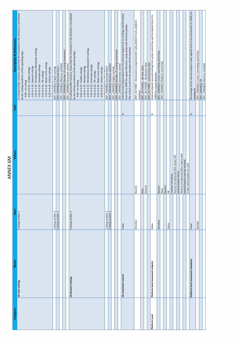
Cate
gory
Nam
eIte
mVa
lues
Uni
tD
escr
iptio
n & R
efer
ence
sAN
NEX
6M
Jib ra
ise
cutt
ings
Cutt
ing
num
ber 1
A cu
ttin
g nu
mbe
r non
zero
, mea
ns th
at th
e m
ovem
ent i
n th
is di
rect
ion
is pr
ohib
ited
by th
e cu
ttin
g co
nditi
ons o
f the
ope
ratin
g lo
gic:
‐ 0
.00
: no
cutt
ing
‐ 0
.01
to 0
.32
: Ena
ble
cutt
ings
‐ 1
.01
to 1
.32
: Gen
eral c
uttin
gs ‐ 2
.01
to 2
.32
: Sim
ulta
neou
s Mov
emen
t cut
tings
‐ 3
.01
to 3
.32
: Ove
rload
cut
tings
‐ 4
.01
to 4
.32
: Tilt c
uttin
gs ‐ 5
.01
to 5
.32
: Rea
ch L
imit
cutt
ings
‐ 6
.01
to 6
.32
: Fai
lure c
uttin
gs7
01to
732
:Spe
cific
cutt
ings
Cutt
ing
num
ber 2
[REF
_VAR
IABL
E] E
ngin
e ru
nnin
gCu
ttin
g nu
mbe
r 3[R
EF_V
ARIA
BLE] O
verlo
ad A
larm
[REF
_VAR
IABL
E] M
achi
ne u
nfol
ded
[REF
_VAR
IABL
E] N
umbe
r of r
unni
ng m
ovem
ents
[REF
_VAR
IABL
E] G
ener
ator c
ontr
olJib
des
cent c
uttin
gsCu
ttin
g nu
mbe
r 1A
cutt
ing
num
ber n
onze
ro, m
eans th
at th
e m
ovem
ent i
n th
is di
rect
ion
is pr
ohib
ited
by th
e cu
ttin
g co
nditi
ons o
f the
ope
ratin
g lo
gic:
‐ 0
.00
: no
cutt
ing
‐ 0
.01
to 0
.32
: Ena
ble
cutt
ings
‐ 1
.01
to 1
.32
: Gen
eral c
uttin
gs ‐ 2
.01
to 2
.32
: Sim
ulta
neou
s Mov
emen
t cut
tings
‐ 3
.01
to 3
.32
: Ove
rload
cut
tings
‐ 4
.01
to 4
.32
: Tilt c
uttin
gs ‐ 5
.01
to 5
.32
: Rea
ch L
imit
cutt
ings
‐ 6
.01
to 6
.32
: Fai
lure c
uttin
gs7
01to
732
:Spe
cific
cutt
ings
Cutt
ing
num
ber 2
[REF
_VAR
IABL
E] O
verlo
ad A
larm
Cutt
ing
num
ber 3
[REF
_VAR
IABL
E] M
achi
ne u
nfol
ded
[REF
_VAR
IABL
E] E
ngin
e ru
nnin
g[R
EF_V
ARIA
BLE] N
umbe
r of r
unni
ng m
ovem
ents
[REF
_VAR
IABL
E] G
ener
ator c
ontr
olJib
mov
emen
t con
trol
Valu
e%
Inte
rnal c
ontr
ol g
ener
ated
from
the
inte
rnal se
tpoi
nt (i
f no
cutt
ings
) and
form
atte
d fr
om 0
% to
100
% fo
r a g
iven
dire
ctio
n, u
sing
ram
ps a
nd m
in/m
ax sp
eeds
.Th
e co
ntro
l is s
ent t
o th
e ac
tuat
ors o
f the
mac
hine
Dire
ctio
nN
eutr
al[R
EF_I
O] Y
V902
‐ El
ectr
ovan
ne p
ropo
rtio
nnel
le 2 (j
ib, p
latf
orm le
vel,
plat
form
ro
tatio
n )Ra
ise[R
EF_I
O] Y
V620
U ‐
Jib ra
ise v
alve
Desc
ent
[REF
_IO
] YV6
20D ‐ J
ib d
esce
nt v
alve
[REF
_IO
] YV8
00 ‐
Load
sens
ing
valv
ePl
atfo
rm L
evel
Plat
form
leve
l mov
emen
t set
poin
tVa
lue
%In
tern
al se
tpoi
nt se
cure
d co
min
g fr
om a
ctiv
e co
ntro
l box a
nd fo
rmat
ted
from
0 to
10
0% fo
r a g
iven
dire
ctio
nDi
rect
ion
Neu
tral
[REF
_VAR
IABL
E] T
urre
t / o
verr
idin
g co
ntro
l bo x
Raise
[REF
_VAR
IABL
E] P
latf
orm c
ontr
ol b
oxDe
scen
tSt
atus
OK
Func
tion
not a
ctiv
eN
eutr
al n
ot d
etec
ted
afte
r pow
er O
NJo
ystic
k/sw
itch
failu
reN
eutr
al n
ot d
etec
ted
afte
r eng
ine
star
tJo
ystic
k/sw
itch
mus
t be
rele
ased
Enab
le sw
itch/
peda
l not v
alid
Plat
form
leve
l mov
emen
t slo
wdo
wn
Valu
e%
Perc
enta
ge o
f the
inte
rnal se
tpoi
nt re
ally a
pplie
d fr
om 0 (n
o m
ovem
ent) to
100
% (n
o slo
wdo
wn )
Num
ber
[REF
_VAR
IABL
E] T
urre
t / o
verr
idin
g co
ntro
l box
[REF
_VAR
IABL
E] T
ilt[R
EF_V
ARIA
BLE] M
achi
ne u
nfol
ded

Cate
gory
Nam
eIte
mVa
lues
Uni
tD
escr
iptio
n & R
efer
ence
sAN
NEX
6N
Plat
form
leve
l rai
se c
uttin
gsCu
ttin
g nu
mbe
r 1A
cutt
ing
num
ber n
onze
ro, m
eans th
at th
e m
ovem
ent i
n th
is di
rect
ion
is pr
ohib
ited
by
the
cutt
ing
cond
ition
s of t
he o
pera
ting
logi
c: ‐ 0
.00
: no
cutt
ing
‐ 0
.01
to 0
.32
: Ena
ble
cutt
ings
‐ 1
.01
to 1
.32
: Gen
eral c
uttin
gs ‐ 2
.01
to 2
.32
: Sim
ulta
neou
s Mov
emen
t cut
tings
‐ 3
.01
to 3
.32
: Ove
rload
cut
tings
‐ 4
.01
to 4
.32
: Tilt c
uttin
gs ‐ 5
.01
to 5
.32
: Rea
ch L
imit
cutt
ings
‐ 6
.01
to 6
.32
: Fai
lure c
uttin
gs7
01to
732
:Spe
cific
cutt
ings
Cutt
ing
num
ber 2
[REF
_VAR
IABL
E] E
ngin
e ru
nnin
gCu
ttin
g nu
mbe
r 3[R
EF_V
ARIA
BLE] O
verlo
ad A
larm
[REF
_VAR
IABL
E] M
achi
ne u
nfol
ded
[REF
_VAR
IABL
E] N
umbe
r of r
unni
ng m
ovem
ents
[REF
_VAR
IABL
E] G
ener
ator c
ontr
ol[R
EF_I
O] S
R721
‐ Pl
atfo
rm le
vel +
10° d
etec
tor
Plat
form
leve
l des
cent c
uttin
gsCu
ttin
g nu
mbe
r 1A
cutt
ing
num
ber n
onze
ro, m
eans th
at th
e m
ovem
ent i
n th
is di
rect
ion
is pr
ohib
ited
by th
e cu
ttin
g co
nditi
ons o
f the
ope
ratin
g lo
gic:
‐ 0
.00
: no
cutt
ing
‐ 0
.01
to 0
.32
: Ena
ble
cutt
ings
‐ 1
.01
to 1
.32
: Gen
eral c
uttin
gs ‐ 2
.01
to 2
.32
: Sim
ulta
neou
s Mov
emen
t cut
tings
‐ 3
.01
to 3
.32
: Ove
rload
cut
tings
‐ 4
.01
to 4
.32
: Tilt c
uttin
gs ‐ 5
.01
to 5
.32
: Rea
ch L
imit
cutt
ings
‐ 6
.01
to 6
.32
: Fai
lure c
uttin
gs7
01to
732
:Spe
cific
cutt
ings
Cutt
ing
num
ber 2
[REF
_VAR
IABL
E] M
achi
ne u
nfol
ded
Cutt
ing
num
ber 3
[REF
_VAR
IABL
E] E
ngin
e ru
nnin
g[R
EF_V
ARIA
BLE] N
umbe
r of r
unni
ng m
ovem
ents
[REF
_VAR
IABL
E] G
ener
ator c
ontr
o l[R
EF_I
O] S
R720
‐ Pl
atfo
rm le
vel ‐
10° d
etec
tor
Plat
form
leve
l mov
emen
t con
trol
Valu
e%
Inte
rnal c
ontr
ol g
ener
ated
from
the
inte
rnal se
tpoi
nt (i
f no
cutt
ings
) and
form
atte
d fr
om 0
% to
100
% fo
r a g
iven
dire
ctio
n, u
sing
ram
ps a
nd m
in/m
ax sp
eeds
.Th
e co
ntro
l is s
ent t
o th
e ac
tuat
ors o
f the
mac
hine
Dire
ctio
nN
eutr
al[R
EF_I
O] Y
V902
‐ El
ectr
ovan
ne p
ropo
rtio
nnel
le 2 (j
ib, p
latf
orm le
vel,
plat
form
ro
tatio
n)Ra
ise[R
EF_I
O] Y
V720
U ‐
Plat
form
leve
l rai
se v
alve
Desc
ent
[REF
_IO
] YV7
20D ‐ P
latf
orm le
vel d
esce
nt v
alve
[REF
_IO
] YV8
00 ‐
Load
sens
ing
valv
ePl
atfo
rm R
otat
ion
Plat
form
rota
tion
mov
emen
t set
poin
tVa
lue
%In
tern
al se
tpoi
nt se
cure
d co
min
g fr
om a
ctiv
e co
ntro
l box a
nd fo
rmat
ted
from
0 to
10
0% fo
r a g
iven
dire
ctio
nDi
rect
ion
Neu
tral
[REF
_VAR
IABL
E] P
latf
orm c
ontr
ol b
o xLe
ftRi
ght
Stat
usO
KFu
nctio
n no
t act
ive
Neu
tral n
ot d
etec
ted
afte
r pow
er O
NJo
ystic
k/sw
itch
failu
reN
eutr
al n
ot d
etec
ted
afte
r eng
ine
star
tJo
ystic
k/sw
itch
mus
t be
rele
ased
Enab
le sw
itch/
peda
l not v
alid
Plat
form
rota
tion
mov
emen
t slo
wdo
wn
Valu
e%
Perc
enta
ge o
f the
inte
rnal se
tpoi
nt re
ally a
pplie
d fr
om 0 (n
o m
ovem
ent) to
100
% (n
o slo
wdo
wn )
Num
ber
[REF
_VAR
IABL
E] T
urre
t / o
verr
idin
g co
ntro
l box
[REF
_VAR
IABL
E] T
ilt[R
EF_V
ARIA
BLE] M
achi
ne u
nfol
ded
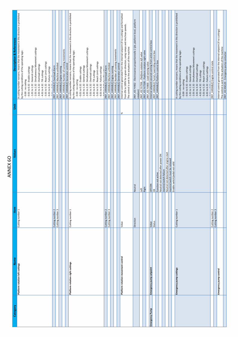
Cate
gory
Nam
eIte
mVa
lues
Uni
tD
escr
iptio
n & R
efer
ence
sAN
NEX
6O
Plat
form
rota
tion
left c
uttin
gsCu
ttin
g nu
mbe
r 1A
cutt
ing
num
ber n
onze
ro, m
eans th
at th
e m
ovem
ent i
n th
is di
rect
ion
is pr
ohib
ited
by th
e cu
ttin
g co
nditi
ons o
f the
ope
ratin
g lo
gic:
‐ 0
.00
: no
cutt
ing
‐ 0
.01
to 0
.32
: Ena
ble
cutt
ings
‐ 1
.01
to 1
.32
: Gen
eral c
uttin
gs ‐ 2
.01
to 2
.32
: Sim
ulta
neou
s Mov
emen
t cut
tings
‐ 3
.01
to 3
.32
: Ove
rload
cut
tings
‐ 4
.01
to 4
.32
: Tilt c
uttin
gs ‐ 5
.01
to 5
.32
: Rea
ch L
imit
cutt
ings
‐ 6
.01
to 6
.32
: Fai
lure c
uttin
gs7
01to
732
:Spe
cific
cutt
ings
Cutt
ing
num
ber 2
[REF
_VAR
IABL
E] O
verlo
ad A
larm
Cutt
ing
num
ber 3
[REF
_VAR
IABL
E] M
achi
ne u
nfol
ded
[REF
_VAR
IABL
E] E
ngin
e ru
nnin
g[R
EF_V
ARIA
BLE] N
umbe
r of r
unni
ng m
ovem
ents
[REF
_VAR
IABL
E] G
ener
ator c
ontr
olPl
atfo
rm ro
tatio
n rig
ht c
uttin
gsCu
ttin
g nu
mbe
r 1A
cutt
ing
num
ber n
onze
ro, m
eans th
at th
e m
ovem
ent i
n th
is di
rect
ion
is pr
ohib
ited
by th
e cu
ttin
g co
nditi
ons o
f the
ope
ratin
g lo
gic:
‐ 0
.00
: no
cutt
ing
‐ 0
.01
to 0
.32
: Ena
ble
cutt
ings
‐ 1
.01
to 1
.32
: Gen
eral c
uttin
gs ‐ 2
.01
to 2
.32
: Sim
ulta
neou
s Mov
emen
t cut
tings
‐ 3
.01
to 3
.32
: Ove
rload
cut
tings
‐ 4
.01
to 4
.32
: Tilt c
uttin
gs ‐ 5
.01
to 5
.32
: Rea
ch L
imit
cutt
ings
‐ 6
.01
to 6
.32
: Fai
lure c
uttin
gs7
01to
732
:Spe
cific
cutt
ings
Cutt
ing
num
ber 2
[REF
_VAR
IABL
E] O
verlo
ad A
larm
Cutt
ing
num
ber 3
[REF
_VAR
IABL
E] M
achi
ne u
nfol
ded
[REF
_VAR
IABL
E] E
ngin
e ru
nnin
g[R
EF_V
ARIA
BLE] N
umbe
r of r
unni
ng m
ovem
ents
[REF
_VAR
IABL
E] G
ener
ator c
ontr
olPl
atfo
rm ro
tatio
n m
ovem
ent c
ontr
olVa
lue
%In
tern
al c
ontr
ol g
ener
ated
from
the
inte
rnal se
tpoi
nt (i
f no
cutt
ings
) and
form
atte
d fr
om 0
% to
100
% fo
r a g
iven
dire
ctio
n, u
sing
ram
ps a
nd m
in/m
ax sp
eeds
.Th
e co
ntro
l is s
ent t
o th
e ac
tuat
ors o
f the
mac
hine
Dire
ctio
nN
eutr
al[R
EF_I
O] Y
V902
‐ El
ectr
ovan
ne p
ropo
rtio
nnel
le 2 (j
ib, p
latf
orm le
vel,
plat
form
ro
tatio
n)Le
ft[R
EF_I
O] Y
V750
L ‐ P
latf
orm ro
tatio
n le
ft v
alve
Righ
t[R
EF_I
O] Y
V750
R ‐ P
latf
orm ro
tatio
n rig
ht v
alve
[REF
_IO
] YV8
00 ‐
Load
sens
ing
valv
eEm
erge
ncy
Pum
pEm
erge
ncy
pum
p se
tpoi
n tVa
lue
OFF
/ON
Inte
rnal se
tpoi
nt se
cure
d co
min
g fr
om a
ctiv
e co
ntro
l box
Stat
usO
K[R
EF_V
ARIA
BLE] T
urre
t / o
verr
idin
g co
ntro
l box
Func
tion
not a
ctiv
e[R
EF_V
ARIA
BLE] P
latf
orm c
ontr
ol b
o xN
eutr
al n
ot d
etec
ted
afte
r pow
er O
NJo
ystic
k/sw
itch
failu
reN
eutr
al n
ot d
etec
ted
afte
r eng
ine
star
tJo
ystic
k/sw
itch
mus
t be
rele
ased
Enab
le sw
itch/
peda
l not v
alid
Emer
genc
y pu
mp
cutt
ings
Cutt
ing
num
ber 1
A cu
ttin
g nu
mbe
r non
zero
, mea
ns th
at th
e m
ovem
ent i
n th
is di
rect
ion
is pr
ohib
ited
by th
e cu
ttin
g co
nditi
ons o
f the
ope
ratin
g lo
gic:
‐ 0
.00
: no
cutt
ing
‐ 0
.01
to 0
.32
: Ena
ble
cutt
ings
‐ 1
.01
to 1
.32
: Gen
eral c
uttin
gs ‐ 2
.01
to 2
.32
: Sim
ulta
neou
s Mov
emen
t cut
tings
‐ 3
.01
to 3
.32
: Ove
rload
cut
tings
‐ 4
.01
to 4
.32
: Tilt c
uttin
gs ‐ 5
.01
to 5
.32
: Rea
ch L
imit
cutt
ings
‐ 6
.01
to 6
.32
: Fai
lure c
uttin
gs7
01to
732
:Spe
cific
cutt
ings
Cutt
ing
num
ber 2
[REF
_VAR
IABL
E] E
ngin
e co
ntro
l sta
teCu
ttin
g nu
mbe
r 3Em
erge
ncy
pum
p co
ntro
lIn
tern
al c
ontr
ol g
ener
ated
from
the
inte
rnal se
tpoi
nt (i
f no
cutt
ings
)Th
e co
ntro
l is s
ent t
o th
e ac
tuat
ors o
f the
mac
hin e
[REF
_IO
] KM
120 ‐ E
mer
genc
y pu
mp
cont
acto
r

Cate
gory
Nam
eIte
mVa
lues
Uni
tD
escr
iptio
n & R
efer
ence
sAN
NEX
6P
LS V
alve
LS V
alve
cut
tings
Cutt
ing
num
ber 1
A cu
ttin
g nu
mbe
r non
zero
, mea
ns th
at th
e m
ovem
ent i
n th
is di
rect
ion
is pr
ohib
ited
by th
e cu
ttin
g co
nditi
ons o
f the
ope
ratin
g lo
gic:
‐ 0
.00
: no
cutt
ing
‐ 0
.01
to 0
.32
: Ena
ble
cutt
ings
‐ 1
.01
to 1
.32
: Gen
eral c
uttin
gs ‐ 2
.01
to 2
.32
: Sim
ulta
neou
s Mov
emen
t cut
tings
‐ 3
.01
to 3
.32
: Ove
rload
cut
tings
‐ 4
.01
to 4
.32
: Tilt c
uttin
gs ‐ 5
.01
to 5
.32
: Rea
ch L
imit
cutt
ings
‐ 6
.01
to 6
.32
: Fai
lure c
uttin
gs7
01to
732
:Spe
cific
cutt
ings
Cutt
ing
num
ber 2
[REF
_VAR
IABL
E] N
umbe
r of r
unni
ng m
ovem
ents
Cutt
ing
num
ber 3
LS V
alve
con
trol
Inte
rnal c
ontr
ol g
ener
ated
from
the
inte
rnal se
tpoi
nt (i
f no
cutt
ings
)Th
e co
ntro
l is s
ent t
o th
e ac
tuat
ors o
f the
mac
hin e
[REF
_IO
] YV8
00 ‐
Load
sens
ing
valv
eBr
ake
Rele
ase
Brak
e re
leas
e cu
ttin
gs (d
rive)
Cutt
ing
num
ber 1
A cu
ttin
g nu
mbe
r non
zero
, mea
ns th
at th
e m
ovem
ent i
n th
is di
rect
ion
is pr
ohib
ited
by th
e cu
ttin
g co
nditi
ons o
f the
ope
ratin
g lo
gic:
‐ 0
.00
: no
cutt
ing
‐ 0
.01
to 0
.32
: Ena
ble
cutt
ings
‐ 1
.01
to 1
.32
: Gen
eral c
uttin
gs ‐ 2
.01
to 2
.32
: Sim
ulta
neou
s Mov
emen
t cut
tings
‐ 3
.01
to 3
.32
: Ove
rload
cut
tings
‐ 4
.01
to 4
.32
: Tilt c
uttin
gs ‐ 5
.01
to 5
.32
: Rea
ch L
imit
cutt
ings
‐ 6
.01
to 6
.32
: Fai
lure c
uttin
gs7
01to
732
:Spe
cific
cutt
ings
Cutt
ing
num
ber 2
[REF
_VAR
IABL
E] D
rive
mov
emen
t con
trol
Cutt
ing
num
ber 3
Brak
e re
leas
e co
ntro
l (dr
ive)
Inte
rnal c
ontr
ol g
ener
ated
from
the
inte
rnal se
tpoi
nt (i
f no
cutt
ings
), fo
r driv
e m
ovem
ent o
nly.
The
cont
rol i
s sen
t to
the
actu
ator
s of t
he m
achi
n e[R
EF_I
O] Y
V102
‐ Br
ake
rele
ase
valv
e 1
Osc
illat
ing
Axle U
nloc
king
Osc
illat
ing
axle u
nloc
king
cut
tings
Cutt
ing
num
ber 1
A cu
ttin
g nu
mbe
r non
zero
, mea
ns th
at th
e m
ovem
ent i
n th
is di
rect
ion
is pr
ohib
ited
by th
e cu
ttin
g co
nditi
ons o
f the
ope
ratin
g lo
gic:
‐ 0
.00
: no
cutt
ing
‐ 0
.01
to 0
.32
: Ena
ble
cutt
ings
‐ 1
.01
to 1
.32
: Gen
eral c
uttin
gs ‐ 2
.01
to 2
.32
: Sim
ulta
neou
s Mov
emen
t cut
tings
‐ 3
.01
to 3
.32
: Ove
rload
cut
tings
‐ 4
.01
to 4
.32
: Tilt c
uttin
gs ‐ 5
.01
to 5
.32
: Rea
ch L
imit
cutt
ings
‐ 6
.01
to 6
.32
: Fai
lure c
uttin
gs7
01to
732
:Spe
cific
cutt
ings
Cutt
ing
num
ber 2
[REF
_VAR
IABL
E] M
achi
ne u
nfol
ded
Cutt
ing
num
ber 3
[REF
_VAR
IABL
E] D
rive
mov
emen
t con
trol
Osc
illat
ing
axle u
nloc
king
con
trol
Inte
rnal c
ontr
ol g
ener
ated
from
the
inte
rnal se
tpoi
nt (i
f no
cutt
ings
)Th
e co
ntro
l is s
ent t
o th
e ac
tuat
ors o
f the
mac
hin e
[REF
_IO
] YV1
01 ‐
Osc
illat
ing
axle u
nloc
k va
lve
1[R
EF_I
O] Y
V104
‐ O
scill
atin
g ax
le u
nloc
k va
lve
2G
ener
ator
Gen
erat
or se
tpoi
ntVa
lue
OFF
/ON
Inte
rnal se
tpoi
nt se
cure
d co
min
g fr
om a
ctiv
e co
ntro
l bo x
Stat
usO
K[R
EF_V
ARIA
BLE] P
latf
orm c
ontr
ol b
oxFu
nctio
n no
t act
ive
Neu
tral n
ot d
etec
ted
afte
r pow
er O
NJo
ystic
k/sw
itch
failu
reN
eutr
al n
ot d
etec
ted
afte
r eng
ine
star
tJo
ystic
k/sw
itch
mus
t be
rele
ased
Enab
le sw
itch/
peda
l not v
alid

Cate
gory
Nam
eIte
mVa
lues
Uni
tD
escr
iptio
n & R
efer
ence
sAN
NEX
6Q
Gen
erat
or c
uttin
gsCu
ttin
g nu
mbe
r 1A
cutt
ing
num
ber n
onze
ro, m
eans th
at th
e m
ovem
ent i
n th
is di
rect
ion
is pr
ohib
ited
by th
e cu
ttin
g co
nditi
ons o
f the
ope
ratin
g lo
gic:
‐ 0
.00
: no
cutt
ing
‐ 0
.01
to 0
.32
: Ena
ble
cutt
ings
‐ 1
.01
to 1
.32
: Gen
eral c
uttin
gs ‐ 2
.01
to 2
.32
: Sim
ulta
neou
s Mov
emen
t cut
tings
‐ 3
.01
to 3
.32
: Ove
rload
cut
tings
‐ 4
.01
to 4
.32
: Tilt c
uttin
gs ‐ 5
.01
to 5
.32
: Rea
ch L
imit
cutt
ings
‐ 6
.01
to 6
.32
: Fai
lure c
uttin
gs7
01to
732
:Spe
cific
cutt
ings
Cutt
ing
num
ber 2
[REF
_VAR
IABL
E] N
umbe
r of r
unni
ng m
ovem
ents
Cutt
ing
num
ber 3
Gen
erat
or c
ontr
olIn
tern
al c
ontr
ol g
ener
ated
from
the
inte
rnal se
tpoi
nt (i
f no
cutt
ings
)Th
e co
ntro
l is s
ent t
o th
e ac
tuat
ors o
f the
mac
hin e
[REF
_IO
] KA2
‐ G
ener
ator re
lay
[REF
_IO
] YV8
00 ‐
Load
sens
ing
valv
e[R
EF_I
O] Y
V800
G ‐
Load
sens
ing
valv
e ‐ G
roun
dEm
erge
ncy
Pum
pEm
erge
ncy
pum
p se
tpoi
n tVa
lue
OFF
/ON
Inte
rnal se
tpoi
nt se
cure
d co
min
g fr
om a
ctiv
e co
ntro
l box
Stat
usO
K[R
EF_V
ARIA
BLE] T
urre
t con
trol b
oxFu
nctio
n no
t act
ive
[REF
_VAR
IABL
E] P
latf
orm c
ontr
ol b
oxN
eutr
al n
ot d
etec
ted
afte
r pow
er O
NJo
ystic
k/sw
itch
failu
reN
eutr
al n
ot d
etec
ted
afte
r eng
ine
star
tJo
ystic
k/sw
itch
mus
t be
rele
ased
Enab
le sw
itch/
peda
l not v
alid
Emer
genc
y pu
mp
cutt
ings
Cutt
ing
num
ber 1
A cu
ttin
g nu
mbe
r non
zero
, mea
ns th
at th
e m
ovem
ent i
n th
is di
rect
ion
is pr
ohib
ited
by th
e cu
ttin
g co
nditi
ons o
f the
ope
ratin
g lo
gic:
‐ 0
.00
: no
cutt
ing
‐ 0
.01
to 0
.32
: Ena
ble
cutt
ings
‐ 1
.01
to 1
.32
: Gen
eral c
uttin
gs ‐ 2
.01
to 2
.32
: Sim
ulta
neou
s Mov
emen
t cut
tings
‐ 3
.01
to 3
.32
: Ove
rload
cut
tings
‐ 4
.01
to 4
.32
: Tilt c
uttin
gs ‐ 5
.01
to 5
.32
: Rea
ch L
imit
cutt
ings
‐ 6
.01
to 6
.32
: Fai
lure c
uttin
gs7
01to
732
:Spe
cific
cutt
ings
Cutt
ing
num
ber 2
[REF
_VAR
IABL
E] E
ngin
e co
ntro
l sta
teCu
ttin
g nu
mbe
r 3Em
erge
ncy
pum
p co
ntro
lIn
tern
al c
ontr
ol g
ener
ated
from
the
inte
rnal se
tpoi
nt (i
f no
cutt
ings
)Th
e co
ntro
l is s
ent t
o th
e ac
tuat
ors o
f the
mac
hin e
[REF
_IO
] KM
120 ‐ E
mer
genc
y pu
mp
cont
acto
rLS V
alve
LS V
alve
cut
tings
Cutt
ing
num
ber 1
A cu
ttin
g nu
mbe
r non
zero
, mea
ns th
at th
e m
ovem
ent i
n th
is di
rect
ion
is pr
ohib
ited
by
the
cutt
ing
cond
ition
s of t
he o
pera
ting
logi
c: ‐ 0
.00
: no
cutt
ing
‐ 0
.01
to 0
.32
: Ena
ble
cutt
ings
‐ 1
.01
to 1
.32
: Gen
eral c
uttin
gs ‐ 2
.01
to 2
.32
: Sim
ulta
neou
s Mov
emen
t cut
tings
‐ 3
.01
to 3
.32
: Ove
rload
cut
tings
‐ 4
.01
to 4
.32
: Tilt c
uttin
gs ‐ 5
.01
to 5
.32
: Rea
ch L
imit
cutt
ings
‐ 6
.01
to 6
.32
: Fai
lure c
uttin
gs7
01to
732
:Spe
cific
cutt
ings
Cutt
ing
num
ber 2
[REF
_VAR
IABL
E] N
umbe
r of r
unni
ng m
ovem
ents
Cutt
ing
num
ber 3
LS V
alve
con
trol
Inte
rnal c
ontr
ol g
ener
ated
from
the
inte
rnal se
tpoi
nt (i
f no
cutt
ings
)Th
e co
ntro
l is s
ent t
o th
e ac
tuat
ors o
f the
mac
hine
[REF
_IO
] YV8
00 ‐
Load
sens
ing
valv
e[R
EF_I
O] Y
V800
G ‐
Load
sens
ing
valv
e ‐ G
roun
d

Cate
gory
Nam
eIte
mVa
lues
Uni
tD
escr
iptio
n & R
efer
ence
sAN
NEX
6R
Brak
e Re
leas
eBr
ake
rele
ase
cutt
ings (d
rive)
Cutt
ing
num
ber 1
A cu
ttin
g nu
mbe
r non
zero
, mea
ns th
at th
e m
ovem
ent i
n th
is di
rect
ion
is pr
ohib
ited
by th
e cu
ttin
g co
nditi
ons o
f the
ope
ratin
g lo
gic:
‐ 0
.00
: no
cutt
ing
‐ 0
.01
to 0
.32
: Ena
ble
cutt
ings
‐ 1
.01
to 1
.32
: Gen
eral c
uttin
gs ‐ 2
.01
to 2
.32
: Sim
ulta
neou
s Mov
emen
t cut
tings
‐ 3
.01
to 3
.32
: Ove
rload
cut
tings
‐ 4
.01
to 4
.32
: Tilt c
uttin
gs ‐ 5
.01
to 5
.32
: Rea
ch L
imit
cutt
ings
‐ 6
.01
to 6
.32
: Fai
lure c
uttin
gs7
01to
732
:Spe
cific
cutt
ings
Cutt
ing
num
ber 2
[REF
_VAR
IABL
E] D
rive
mov
emen
t con
trol
Cutt
ing
num
ber 3
Brak
e re
leas
e co
ntro
l (dr
ive)
Inte
rnal c
ontr
ol g
ener
ated
from
the
inte
rnal se
tpoi
nt (i
f no
cutt
ings
), fo
r driv
e m
ovem
ent o
nly.
The
cont
rol i
s sen
t to
the
actu
ator
s of t
he m
achi
n e[R
EF_I
O] Y
V102
‐ Br
ake
rele
ase
valv
e 1
Brak
e re
leas
e cu
ttin
gs (4
WS)
Cutt
ing
num
ber 1
A cu
ttin
g nu
mbe
r non
zero
, mea
ns th
at th
e m
ovem
ent i
n th
is di
rect
ion
is pr
ohib
ited
by th
e cu
ttin
g co
nditi
ons o
f the
ope
ratin
g lo
gic:
‐ 0
.00
: no
cutt
ing
‐ 0
.01
to 0
.32
: Ena
ble
cutt
ings
‐ 1
.01
to 1
.32
: Gen
eral c
uttin
gs ‐ 2
.01
to 2
.32
: Sim
ulta
neou
s Mov
emen
t cut
tings
‐ 3
.01
to 3
.32
: Ove
rload
cut
tings
‐ 4
.01
to 4
.32
: Tilt c
uttin
gs ‐ 5
.01
to 5
.32
: Rea
ch L
imit
cutt
ings
‐ 6
.01
to 6
.32
: Fai
lure c
uttin
gs7
01to
732
:Spe
cific
cutt
ings
Cutt
ing
num
ber 2
[REF
_VAR
IABL
E] S
teer
ing
mov
emen
t con
trol
Cutt
ing
num
ber 3
[REF
_VAR
IABL
E] S
teer
ing
mod
e[R
EF_V
ARIA
BLE] D
rive
mov
emen
t con
trol
[REF
_VAR
IABL
E] T
iltBr
ake
rele
ase
cont
rol (
4WS)
Inte
rnal c
ontr
ol g
ener
ated
from
the
inte
rnal se
tpoi
nt (i
f no
cutt
ings
), fo
r ste
erin
g m
ovem
ent o
nly
(with
out d
rivin
g) if c
rab
or st
eerin
g m
ode
is se
lect
ed a
nd ti
lt is
activ
e.Th
e co
ntro
l is s
ent t
o th
e ac
tuat
ors o
f the
mac
hine
[REF
_IO
] YV1
05 ‐
Brak
e re
leas
e va
lve
2D
iffer
entia
l Loc
kD
iffer
entia
l loc
k se
tpoi
ntVa
lue
OFF
/ON
Inte
rnal se
tpoi
nt se
cure
d co
min
g fr
om a
ctiv
e co
ntro
l box
Stat
usO
K[R
EF_V
ARIA
BLE] P
latf
orm c
ontr
ol b
o xFu
nctio
n no
t act
ive
Neu
tral n
ot d
etec
ted
afte
r pow
er O
NJo
ystic
k/sw
itch
failu
reN
eutr
al n
ot d
etec
ted
afte
r eng
ine
star
tJo
ystic
k/sw
itch
mus
t be
rele
ased
Enab
le sw
itch/
peda
l not v
alid
Diff
eren
tial l
ock
cutt
ings
Cutt
ing
num
ber 1
A cu
ttin
g nu
mbe
r non
zero
, mea
ns th
at th
e m
ovem
ent i
n th
is di
rect
ion
is pr
ohib
ited
by
the
cutt
ing
cond
ition
s of t
he o
pera
ting
logi
c: ‐ 0
.00
: no
cutt
ing
‐ 0
.01
to 0
.32
: Ena
ble
cutt
ings
‐ 1
.01
to 1
.32
: Gen
eral c
uttin
gs ‐ 2
.01
to 2
.32
: Sim
ulta
neou
s Mov
emen
t cut
tings
‐ 3
.01
to 3
.32
: Ove
rload
cut
tings
‐ 4
.01
to 4
.32
: Tilt c
uttin
gs ‐ 5
.01
to 5
.32
: Rea
ch L
imit
cutt
ings
‐ 6
.01
to 6
.32
: Fai
lure c
uttin
gs7
01to
732
:Spe
cific
cutt
ings
Cutt
ing
num
ber 2
[REF
_VAR
IABL
E] D
rive
mov
emen
t con
trol
Cutt
ing
num
ber 3
[REF
_VAR
IABL
E] D
rive
spee
dD
iffer
entia
l loc
k co
ntro
lIn
tern
al c
ontr
ol g
ener
ated
from
the
inte
rnal se
tpoi
nt (i
f no
cutt
ings
)Th
e co
ntro
l is s
ent t
o th
e ac
tuat
ors o
f the
mac
hine
[REF
_IO
] YV1
00 ‐
Diffe
rent
ial l
ock
valv
e

Cate
gory
Nam
eIte
mVa
lues
Uni
tD
escr
iptio
n & R
efer
ence
sAN
NEX
6S
Osc
illat
ing
Axle U
nloc
king
Osc
illat
ing
axle u
nloc
king
cut
tings
Cutt
ing
num
ber 1
A cu
ttin
g nu
mbe
r non
zero
, mea
ns th
at th
e m
ovem
ent i
n th
is di
rect
ion
is pr
ohib
ited
by th
e cu
ttin
g co
nditi
ons o
f the
ope
ratin
g lo
gic:
‐ 0
.00
: no
cutt
ing
‐ 0
.01
to 0
.32
: Ena
ble
cutt
ings
‐ 1
.01
to 1
.32
: Gen
eral c
uttin
gs ‐ 2
.01
to 2
.32
: Sim
ulta
neou
s Mov
emen
t cut
tings
‐ 3
.01
to 3
.32
: Ove
rload
cut
tings
‐ 4
.01
to 4
.32
: Tilt c
uttin
gs ‐ 5
.01
to 5
.32
: Rea
ch L
imit
cutt
ings
‐ 6
.01
to 6
.32
: Fai
lure c
uttin
gs7
01to
732
:Spe
cific
cutt
ings
Cutt
ing
num
ber 2
[REF
_VAR
IABL
E] M
achi
ne u
nfol
ded
Cutt
ing
num
ber 3
[REF
_VAR
IABL
E] D
rive
mov
emen
t con
trol
Osc
illat
ing
axle u
nloc
king
con
trol
Inte
rnal c
ontr
ol g
ener
ated
from
the
inte
rnal se
tpoi
nt (i
f no
cutt
ings
)Th
e co
ntro
l is s
ent t
o th
e ac
tuat
ors o
f the
mac
hin e
[REF
_IO
] YV1
01 ‐
Osc
illat
ing
axle u
nloc
k va
lve
1G
ener
ator
Gen
erat
or se
tpoi
ntVa
lue
OFF
/ON
Inte
rnal se
tpoi
nt se
cure
d co
min
g fr
om a
ctiv
e co
ntro
l bo x
Stat
usO
K[R
EF_V
ARIA
BLE] P
latf
orm c
ontr
ol b
oxFu
nctio
n no
t act
ive
Neu
tral n
ot d
etec
ted
afte
r pow
er O
NJo
ystic
k/sw
itch
failu
reN
eutr
al n
ot d
etec
ted
afte
r eng
ine
star
tJo
ystic
k/sw
itch
mus
t be
rele
ased
Enab
le sw
itch/
peda
l not v
alid
Gen
erat
or c
uttin
gsCu
ttin
g nu
mbe
r 1A
cutt
ing
num
ber n
onze
ro, m
eans th
at th
e m
ovem
ent i
n th
is di
rect
ion
is pr
ohib
ited
by th
e cu
ttin
g co
nditi
ons o
f the
ope
ratin
g lo
gic:
‐ 0
.00
: no
cutt
ing
‐ 0
.01
to 0
.32
: Ena
ble
cutt
ings
‐ 1
.01
to 1
.32
: Gen
eral c
uttin
gs ‐ 2
.01
to 2
.32
: Sim
ulta
neou
s Mov
emen
t cut
tings
‐ 3
.01
to 3
.32
: Ove
rload
cut
tings
‐ 4
.01
to 4
.32
: Tilt c
uttin
gs ‐ 5
.01
to 5
.32
: Rea
ch L
imit
cutt
ings
‐ 6
.01
to 6
.32
: Fai
lure c
uttin
gs7
01to
732
:Spe
cific
cutt
ings
Cutt
ing
num
ber 2
[REF
_VAR
IABL
E] N
umbe
r of r
unni
ng m
ovem
ents
Cutt
ing
num
ber 3
Gen
erat
or c
ontr
olIn
tern
al c
ontr
ol g
ener
ated
from
the
inte
rnal se
tpoi
nt (i
f no
cutt
ings
)Th
e co
ntro
l is s
ent t
o th
e ac
tuat
ors o
f the
mac
hin e
[REF
_IO
] KA2
‐ G
ener
ator re
lay

XXXXXX.A

XXXXXX.A

XXXXXX.A

XXXXXX.A

XXXXXX.A

XXXXXX.A

XXXXXX.A

XXXXXX.A

XXXXXX.A

XXXXXX.A
12V P
LUG
TEMP
SENS
RUSS
IAHO
RN LC
B
ST90
3
ANEN
OMET
ER

XXXXXX.A

4000466740.B
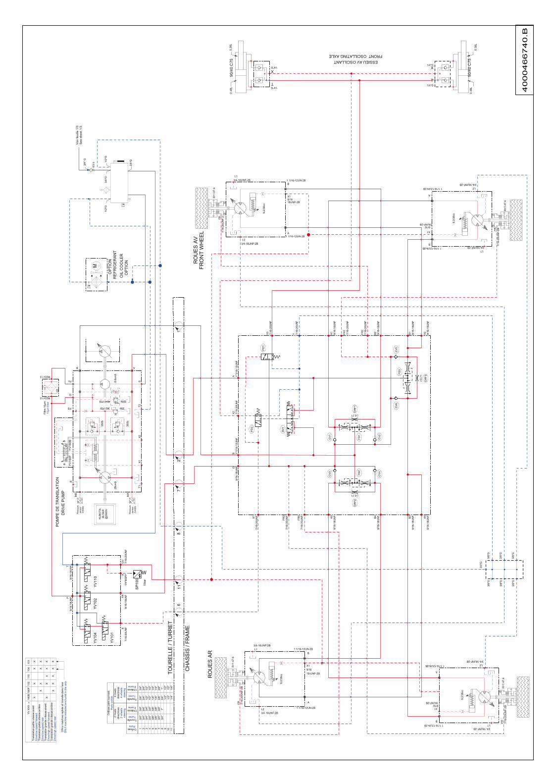
4000466740.B
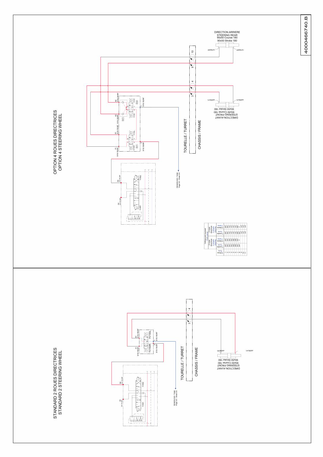
4000466740.B

4000016450.H

4000173930.D
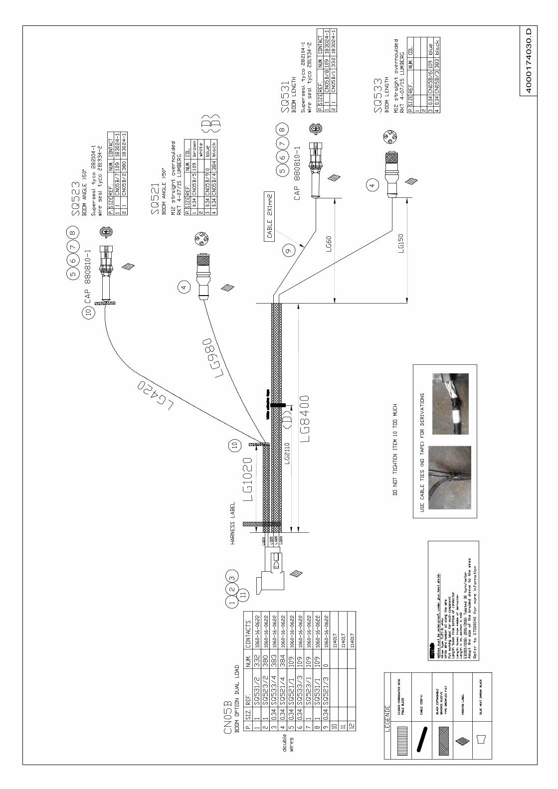
4000174030.D

4000203930.G
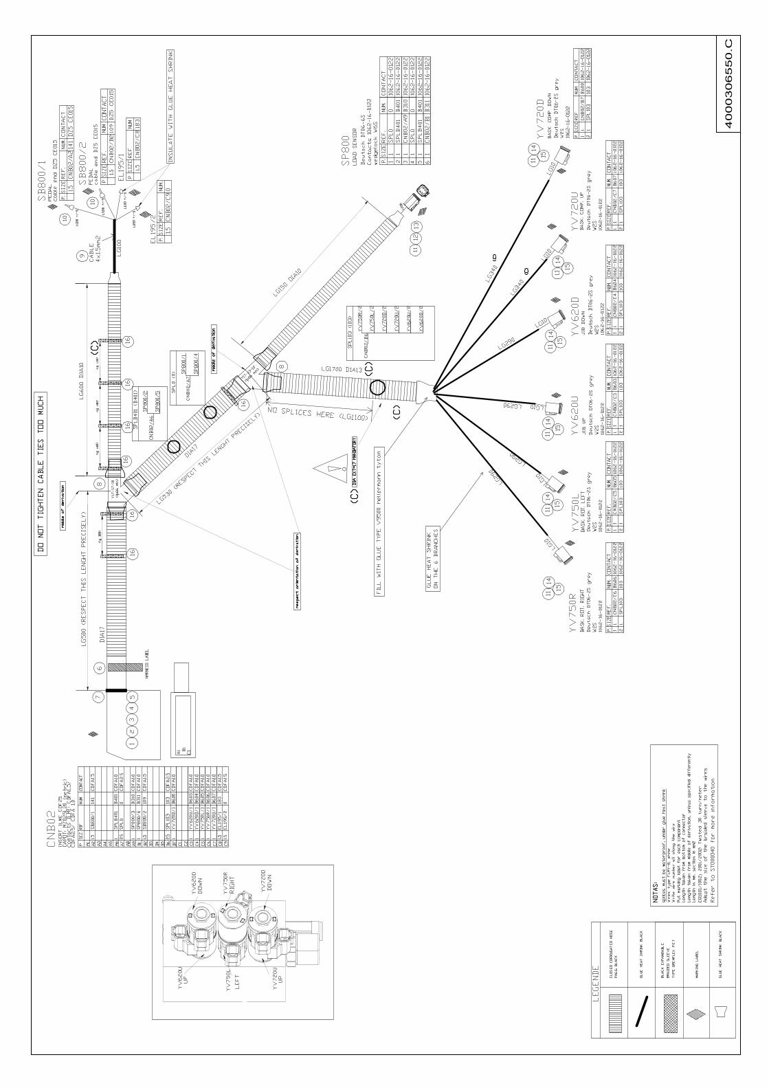
4000306550.C

4000473770.B

4000016450.H