ESK HW Paper
8
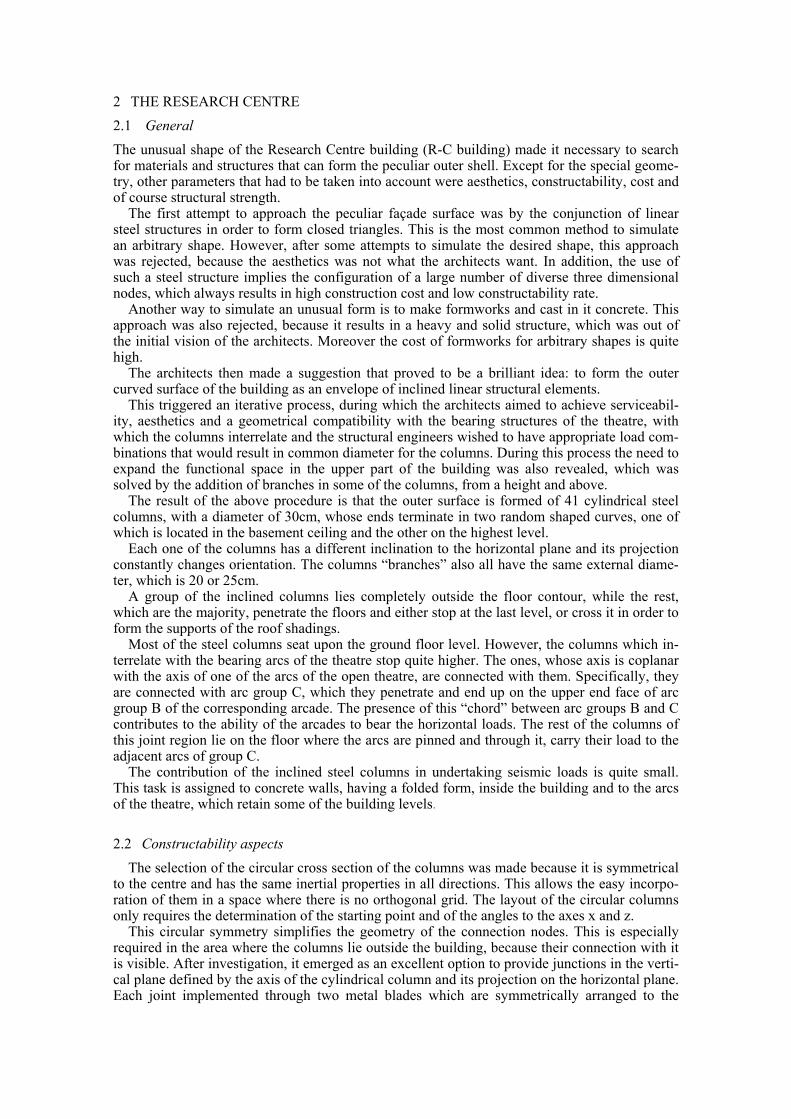
1 INTRODUCTION The Cultural Centre “Hellenic World” was envisioned by the Administration of the Foundation of the Hellenic World and was designed by the architectural office “Anamorphosis”. The design philosophy of the total complex is inspired by the Greek History and Mythology. Thematic forms based on the human scale and the Greek landscape, that is characterized by its slops, cav- erns, lakes, gorges, the sea and its flora, are planned. All these forms have an arbitrary geometry, which differs significantly from the usual rectan- gular-grid geometry of the majority of buildings. It’s obvious that, in order to support this ran- dom geometric arrangement, a non-conventional grid of structural bearing elements is required. The structural engineer’s task becomes even more challenging due to the architects’ wish for the structural elements to be visible and to contribute to the overall aesthetics of the building structures. In the framework of this design philosophy, the Research Centre building resembles a volume of a geological formation. The western side gives the impression of a reverse geological fault, while the eastern is a smooth slope, covered with plants and trees, which can be approached from the surroundings. Finally, the southern side takes a concave shape, in which the open-air theatre is formed. (pic.1). ‘Picture 1. The initial architectural approach’ The interaction of architects & str. engineers for the Hellenic World complex in Athens E. S. Kyriazis E.S.K. Str. Engineering Technical Office, Athens, Greece
-
Upload
independent -
Category
Documents
-
view
0 -
download
0
Transcript of ESK HW Paper
1 INTRODUCTION
The Cultural Centre “Hellenic World” was envisioned by the Administration of the Foundation of the Hellenic World and was designed by the architectural office “Anamorphosis”. The design philosophy of the total complex is inspired by the Greek History and Mythology. Thematic forms based on the human scale and the Greek landscape, that is characterized by its slops, cav-erns, lakes, gorges, the sea and its flora, are planned.
All these forms have an arbitrary geometry, which differs significantly from the usual rectan-gular-grid geometry of the majority of buildings. It’s obvious that, in order to support this ran-dom geometric arrangement, a non-conventional grid of structural bearing elements is required.
The structural engineer’s task becomes even more challenging due to the architects’ wish for the structural elements to be visible and to contribute to the overall aesthetics of the building structures.
In the framework of this design philosophy, the Research Centre building resembles a volume of a geological formation. The western side gives the impression of a reverse geological fault, while the eastern is a smooth slope, covered with plants and trees, which can be approached from the surroundings. Finally, the southern side takes a concave shape, in which the open-air theatre is formed. (pic.1).
‘Picture 1. The initial architectural approach’
The interaction of architects & str. engineersfor the Hellenic World complex in Athens E. S. Kyriazis E.S.K. Str. Engineering Technical Office, Athens, Greece
2 THE RESEARCH CENTRE 2.1 General The unusual shape of the Research Centre building (R-C building) made it necessary to search for materials and structures that can form the peculiar outer shell. Except for the special geome-try, other parameters that had to be taken into account were aesthetics, constructability, cost and of course structural strength.
The first attempt to approach the peculiar façade surface was by the conjunction of linear steel structures in order to form closed triangles. This is the most common method to simulate an arbitrary shape. However, after some attempts to simulate the desired shape, this approach was rejected, because the aesthetics was not what the architects want. In addition, the use of such a steel structure implies the configuration of a large number of diverse three dimensional nodes, which always results in high construction cost and low constructability rate.
Another way to simulate an unusual form is to make formworks and cast in it concrete. This approach was also rejected, because it results in a heavy and solid structure, which was out of the initial vision of the architects. Moreover the cost of formworks for arbitrary shapes is quite high.
The architects then made a suggestion that proved to be a brilliant idea: to form the outer curved surface of the building as an envelope of inclined linear structural elements.
This triggered an iterative process, during which the architects aimed to achieve serviceabil-ity, aesthetics and a geometrical compatibility with the bearing structures of the theatre, with which the columns interrelate and the structural engineers wished to have appropriate load com-binations that would result in common diameter for the columns. During this process the need to expand the functional space in the upper part of the building was also revealed, which was solved by the addition of branches in some of the columns, from a height and above.
The result of the above procedure is that the outer surface is formed of 41 cylindrical steel columns, with a diameter of 30cm, whose ends terminate in two random shaped curves, one of which is located in the basement ceiling and the other on the highest level.
Each one of the columns has a different inclination to the horizontal plane and its projection constantly changes orientation. The columns “branches” also all have the same external diame-ter, which is 20 or 25cm.
A group of the inclined columns lies completely outside the floor contour, while the rest, which are the majority, penetrate the floors and either stop at the last level, or cross it in order to form the supports of the roof shadings.
Most of the steel columns seat upon the ground floor level. However, the columns which in-terrelate with the bearing arcs of the theatre stop quite higher. The ones, whose axis is coplanar with the axis of one of the arcs of the open theatre, are connected with them. Specifically, they are connected with arc group C, which they penetrate and end up on the upper end face of arc group B of the corresponding arcade. The presence of this “chord” between arc groups B and C contributes to the ability of the arcades to bear the horizontal loads. The rest of the columns of this joint region lie on the floor where the arcs are pinned and through it, carry their load to the adjacent arcs of group C.
The contribution of the inclined steel columns in undertaking seismic loads is quite small. This task is assigned to concrete walls, having a folded form, inside the building and to the arcs of the theatre, which retain some of the building levels.
2.2 Constructability aspects The selection of the circular cross section of the columns was made because it is symmetrical
to the centre and has the same inertial properties in all directions. This allows the easy incorpo-ration of them in a space where there is no orthogonal grid. The layout of the circular columns only requires the determination of the starting point and of the angles to the axes x and z.
This circular symmetry simplifies the geometry of the connection nodes. This is especially required in the area where the columns lie outside the building, because their connection with it is visible. After investigation, it emerged as an excellent option to provide junctions in the verti-cal plane defined by the axis of the cylindrical column and its projection on the horizontal plane. Each joint implemented through two metal blades which are symmetrically arranged to the
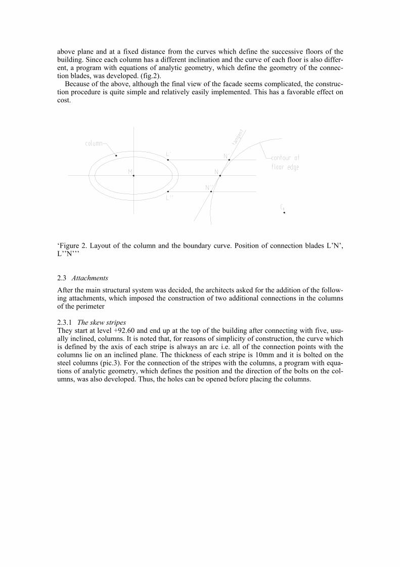
above plane and at a fixed distance from the curves which define the successive floors of the building. Since each column has a different inclination and the curve of each floor is also differ-ent, a program with equations of analytic geometry, which define the geometry of the connec-tion blades, was developed. (fig.2).
Because of the above, although the final view of the facade seems complicated, the construc-tion procedure is quite simple and relatively easily implemented. This has a favorable effect on cost.
‘Figure 2. Layout of the column and the boundary curve. Position of connection blades L’Ν’, L’’Ν’’’
2.3 Attachments After the main structural system was decided, the architects asked for the addition of the follow-ing attachments, which imposed the construction of two additional connections in the columns of the perimeter
2.3.1 The skew stripes They start at level +92.60 and end up at the top of the building after connecting with five, usu-ally inclined, columns. It is noted that, for reasons of simplicity of construction, the curve which is defined by the axis of each stripe is always an arc i.e. all of the connection points with the columns lie on an inclined plane. The thickness of each stripe is 10mm and it is bolted on the steel columns (pic.3). For the connection of the stripes with the columns, a program with equa-tions of analytic geometry, which defines the position and the direction of the bolts on the col-umns, was also developed. Thus, the holes can be opened before placing the columns.
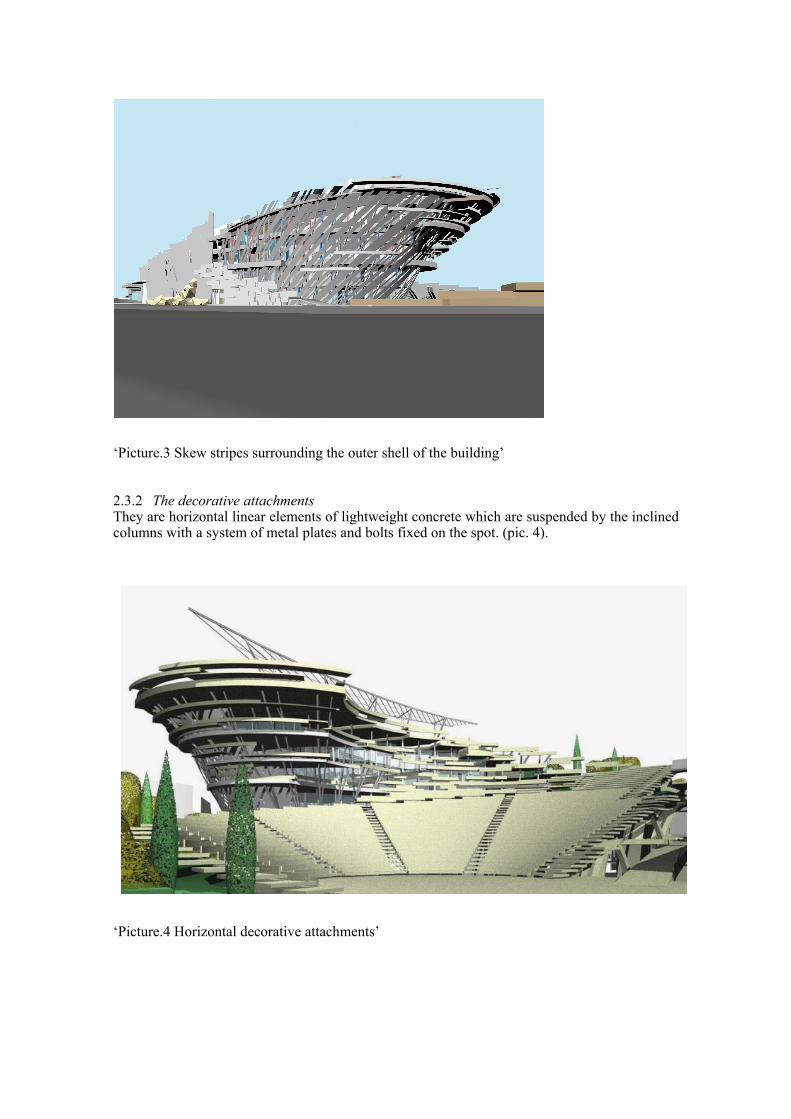
‘Picture.3 Skew stripes surrounding the outer shell of the building’
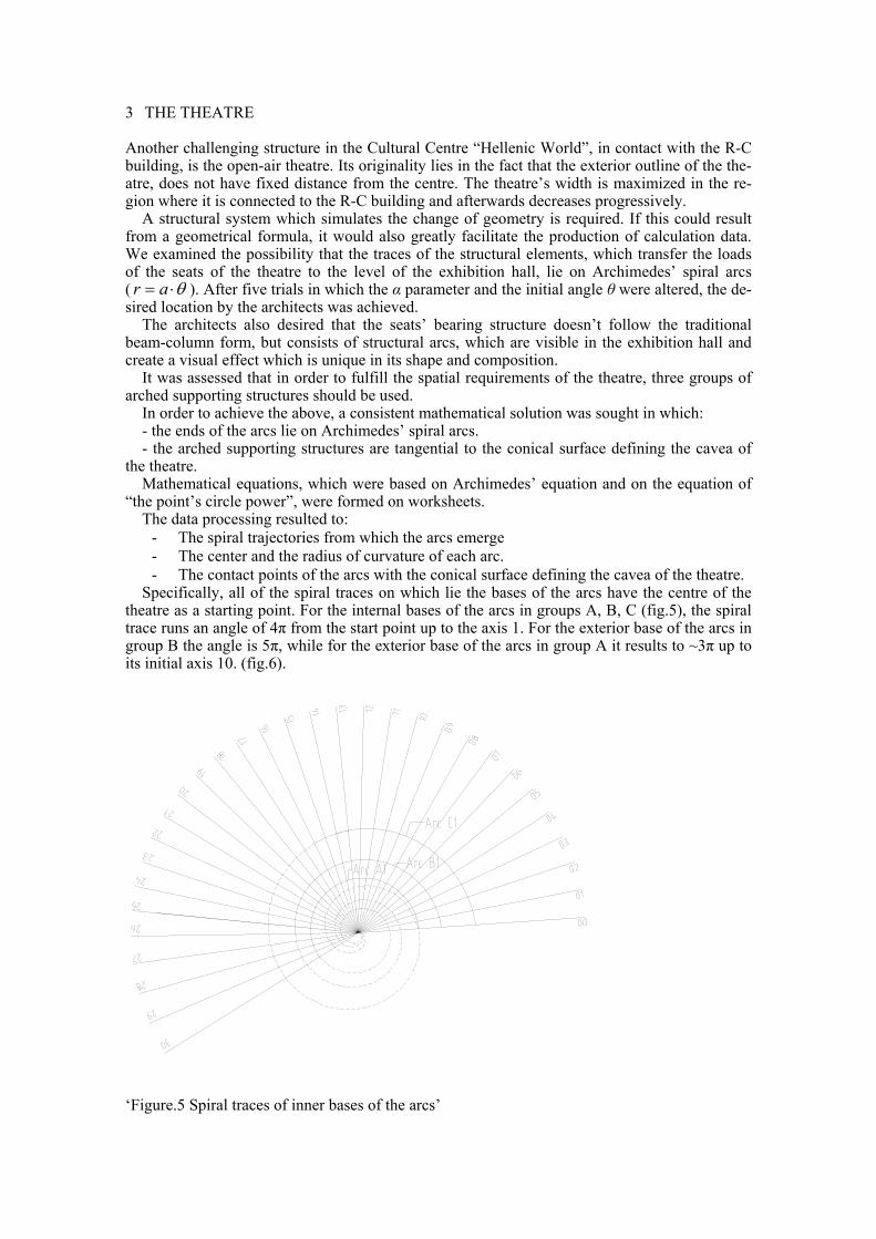
2.3.2 The decorative attachments They are horizontal linear elements of lightweight concrete which are suspended by the inclined columns with a system of metal plates and bolts fixed on the spot. (pic. 4). ‘Picture.4 Horizontal decorative attachments’
3 THE THEATRE
Another challenging structure in the Cultural Centre “Hellenic World”, in contact with the R-C building, is the open-air theatre. Its originality lies in the fact that the exterior outline of the the-atre, does not have fixed distance from the centre. The theatre’s width is maximized in the re-gion where it is connected to the R-C building and afterwards decreases progressively.
A structural system which simulates the change of geometry is required. If this could result from a geometrical formula, it would also greatly facilitate the production of calculation data. We examined the possibility that the traces of the structural elements, which transfer the loads of the seats of the theatre to the level of the exhibition hall, lie on Archimedes’ spiral arcs ( θ⋅= ar ). After five trials in which the α parameter and the initial angle θ were altered, the de-sired location by the architects was achieved.
The architects also desired that the seats’ bearing structure doesn’t follow the traditional beam-column form, but consists of structural arcs, which are visible in the exhibition hall and create a visual effect which is unique in its shape and composition.
It was assessed that in order to fulfill the spatial requirements of the theatre, three groups of arched supporting structures should be used.
In order to achieve the above, a consistent mathematical solution was sought in which: - the ends of the arcs lie on Archimedes’ spiral arcs. - the arched supporting structures are tangential to the conical surface defining the cavea of
the theatre. Mathematical equations, which were based on Archimedes’ equation and on the equation of
“the point’s circle power”, were formed on worksheets. The data processing resulted to:
- The spiral trajectories from which the arcs emerge - The center and the radius of curvature of each arc. - The contact points of the arcs with the conical surface defining the cavea of the theatre.
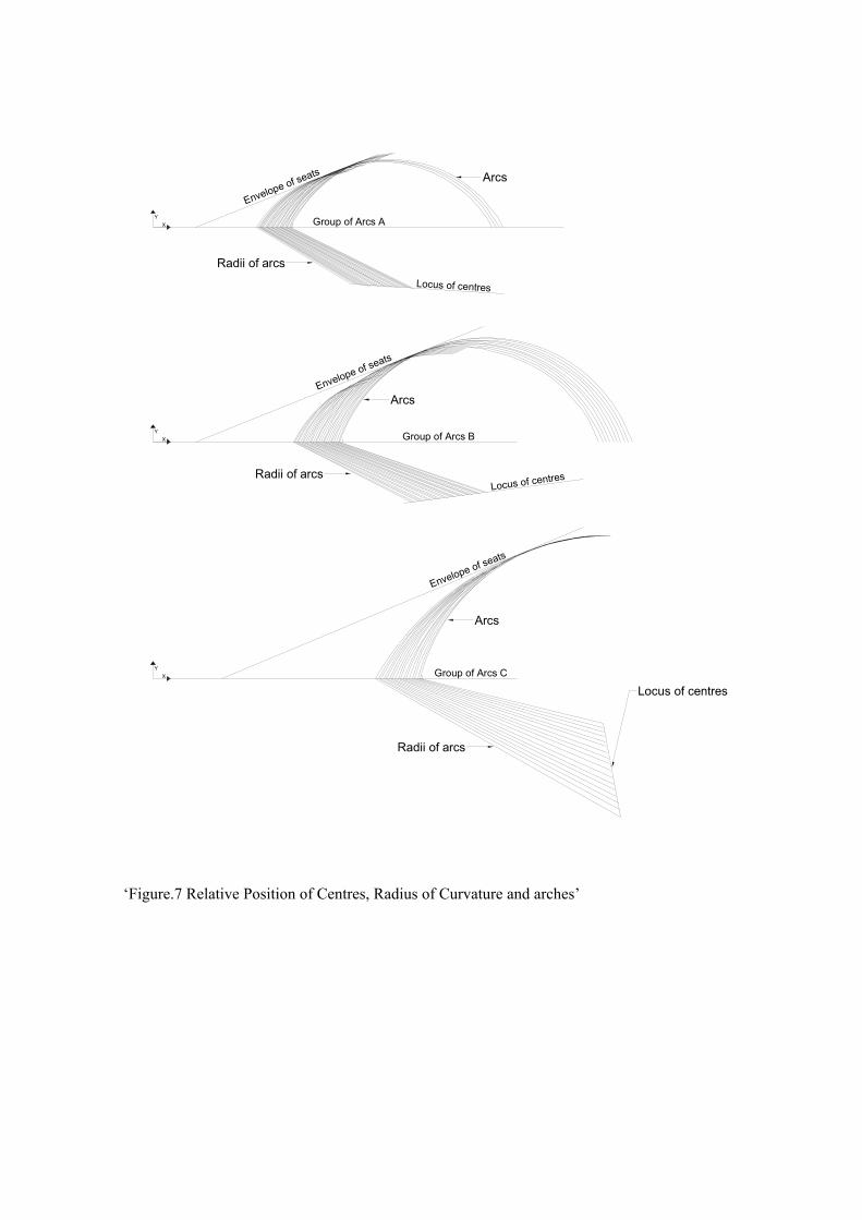
Specifically, all of the spiral traces on which lie the bases of the arcs have the centre of the theatre as a starting point. For the internal bases of the arcs in groups A, B, C (fig.5), the spiral trace runs an angle of 4π from the start point up to the axis 1. For the exterior base of the arcs in group B the angle is 5π, while for the exterior base of the arcs in group A it results to ~3π up to its initial axis 10. (fig.6).
‘Figure.5 Spiral traces of inner bases of the arcs’

‘Figure.6 Spiral traces of outer bases of the arcs’ By using the above mathematical processing not only the initial objectives were achieved, but
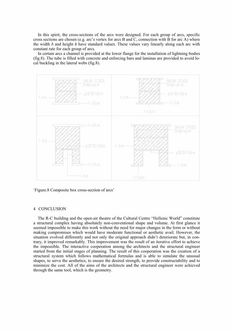
also resulted in linearly or evenly varied values for the following geometrical entities: - The radius of curvature - The vertex of the arcs - The distances of the centers of the arcs from the starting point of the spirals - The tangents of the arcs at the points of emersion at the exhibition hall level. The smooth change of all of the above entities appears in fig.7. It is obvious that the results of the aforementioned mathematical processing not only met with
the architects’ wishes, but were also an easy method of producing data for the calculation of the bearing structure.
Apart from aesthetics and special geometry, other parameters had to be taken into account. As far as serviceability is concerned, the space below the arcs have to be wide and tall enough in order to be able to function as an exhibition hall. Another very important parameter is con-structability. The arcs should be easily constructed, in order to keep the construction cost low. Finally, from the structural point of view, the bearing structure of the arcs should contribute to the stiffness of the R-C building in the parts where they are tangential to it.
‘Figure.7 Relative Position of Centres, Radius of Curvature and arches’
YX Group of Arcs B
Envelope of seats
Group of Arcs C
Envelope of seats
YX
Envelope of seats
Group of Arcs AYX
Locus of centresRadii of arcs
Arcs
Locus of centres
Radii of arcs
Arcs
Radii of arcs
Arcs
Locus of centres
In this spirit, the cross-sections of the arcs were designed. For each group of arcs, specific
cross sections are chosen (e.g. arc’s vertex for arcs B and C, connection with B for arc A) where the width b and height h have standard values. These values vary linearly along each arc with constant rate for each group of arcs.
In certain arcs a channel is provided at the lower flange for the installation of lightning bodies (fig.8). The tube is filled with concrete and enforcing bars and laminas are provided to avoid lo-cal buckling in the lateral webs (fig.8).
‘Figure.8 Composite box cross-section of arcs’
4 CONCLUSION
The R-C building and the open-air theatre of the Cultural Centre “Hellenic World” constitute a structural complex having absolutely non-conventional shape and volume. At first glance it seemed impossible to make this work without the need for major changes in the form or without making compromises which would have moderate functional or aesthetic avail. However, the situation evolved differently and not only the original approach didn’t deteriorate but, in con-trary, it improved remarkably. This improvement was the result of an iterative effort to achieve the impossible. The interactive cooperation among the architects and the structural engineer started from the initial stages of planning. The result of this cooperation was the creation of a structural system which follows mathematical formulas and is able to simulate the unusual shapes, to serve the aesthetics, to ensure the desired strength, to provide constructability and to minimize the cost. All of the aims of the architects and the structural engineer were achieved through the same tool, which is the geometry.