ø22mm HW Series Control Units
60
ø22mm HW Series Control Units (0901211)
-
Upload
khangminh22 -
Category
Documents
-
view
8 -
download
0
Transcript of ø22mm HW Series Control Units

ø22mmHW Series Control Units
(0901211)

2
HW Series Control Units (Selection Guide)ø22
Function Emergency Stop Switch (Unibody Type) Emergency Stop Switch (Separate Type)
CategoryPushlock Turn Reset
ø40mm Mushroom ø40mm Mushroom(Illuminated) ø29mm Mushroom ø40mm Mushroom ø60mm Mushroom
Shape
Type HW1E-BV4 HW1E-LV4 HW1B-V3 HW1B-V4 HW1B-V5Page 9 9 11 11 11
Function Emergency Stop Switch Pushbutton
Category Pushlock Key Reset Push Pull Pushlock Turn Reset Flush Extendedø40mm Mushroom ø40mm Mushroom ø40mm EMO Momentary/Maintained
Shape
Type HW1B-X4 HW1B-Y2 HW1B-V**R-EMO HW1B-M1HW1B-A1
HW1B-M2HW1B-A2
Page 12 12 14 16 16
Function Pushbutton
Category ø29mm Mushroom ø40 Mushroom ø60 Mushroom Square Flush Square ExtendedMomentary/Maintained Momentary Momentary/Maintained
Shape
Type HW1B-M3HW1B-A3
HW1B-M4HW1B-A4 HW1B-M5 HW2B-M1
HW2B-A1HW2B-M2HW2B-A2
Page 16 16 16 17 17
Function Pushbutton
CategoryRound Flush
w/Square BezelRound Extendedw/Square Bezel
ø29mm Mushroomw/Square Bezel
Momentary/Maintained
Shape
Type HW3B-M1HW3B-A1
HW3B-M2HW3B-A2
HW3B-M3HW3B-A3
Page 18 18 18
Function Pilot Light (LED/Incandescent)Category Flush (Marking) Extended (Dome) Square Flush (Marking) Jumbo Dome
Shape
Type HW1P-1 HW1P-2 HW2P-1 HW1P-5Page 19 19 19 19
(091211)

3
ø22HW Series Control Units (Selection Guide)
Function Illuminated Pushbutton (LED/Incandescent)
Category Flush Extended Extended w/Full Shroud Square Flush Flush w/Square Bezel
Shape
Type HW1L-M1HW1L-A1
HW1L-M2HW1L-A2
HW1L-MF2HW1L-AF2
HW2L-M1HW2L-A1
HW3L-M1HW3L-A1
Page 21 22 23 24 25
Function Illuminated Pushbutton (LED/Incandescent) Dual Pushbutton
Category ø29mm Mushroom ø29mm Mushroomw/ Square Bezel ø40mm Mushroom
w/o Pilot LightFlush (top)
Flush (bottom)Flush (top)
Extended (bottom)
Shape
Type HW1L-M3HW1L-A3
HW3L-M3HW3L-A3
HW1L-M4HW1L-A4
HW7D-B11HW7D-B21
HW7D-B12HW7D-B22
Page 26 27 28 30 30
Function Dual Pushbutton Selector SwitchIlluminated Selector
Switch(LED/Incandescent)Category
w/Pilot Light (LED/Incandescent)Selector KeyFlush (top)
Flush (bottom)Flush (top)
Extended (bottom)
Shape
Type HW7D-L11HW7D-L21
HW7D-L12HW7D-L22 HW1S HW1K HW1F
Page 31 31 35 36 37
Function Pushbutton Selector Mono-Lever SwitchCategory Standard Interlocking
Shape
Type HW1R HW1M HW1M-LPage 44 45 45
Function Control Station Emergency Stop Control Station
Category w/Pushbutton w/Selector Switch w/Pushlock TurnReset Switch
w/Pushlock KeyReset Switch
Shape
Type HW1X-BM HW1X-S HW1X-BV HW1X-BXPage 57 57 57 57
(0901211)

4
HW Series Control Unitsø22Complete with finger-safe contact blocksEnsure safety and save wiring time
Locking lever removable contact blocks•Spring-upscrewandfinger-safe(IP20)contactblocksare•available.Self-cleaningrollingactioncontactshavearakedcontact•surface.Degreeofprotection:IP65(exceptdualpushbutton:IP40)•Dual pushbutton switches available with two pushbuttons and •a pilot light integrated into one space-saving control unit.Awiderangeofoperatingvoltagesforworldwideapplication•UL, CSA rated, and EN compliant.•
Application for dual pushbuttons:Idealforuseaspowerswitchesandstart/stopswitches(availablewith I/ON and O/OFF markings on the buttons and a pilot light in the center).Interlocktypepreventstwopushbuttonsfrombeingpressedatthesametime,providingthebestsolutionforup/downswitches.
Applicable Standard Marking File No. or Organization
UL508 UL/c-UL File No. E68961
CSA C22.2 No.14CSA166730 (LR92374)(jumbodomepilotlight:LR21451)
EN60947-5-1TÜV Rheinland R50054316(jumbodomepilotlight:R50051481)
Specifications and RatingsContact Ratings
PushbuttonsIlluminated PushbuttonsDual PushbuttonsSelector SwitchesIlluminated Selector SwitchesPushbutton Selectors
Contact Block Type HW-G / HW-FRated Insulation Voltage 600VRated Thermal Current 10A
Contact Ratings by Utilization CategoryIEC 60947-5-1
AC-15 (A600)DC-13 (P600)
CharacteristicsContact Ratings by Utilization Category•
Operational Voltage 24V 48V 50V 110V 220V 440V
Operational Current
AC50/60 Hz
AC-12 Controlofresistiveloadsandsolidstateloads 10A — 10A 10A 6A 2AAC-15 Controlofelectromagneticloads(>72VA) 10A — 7A 5A 3A 1A
DC DC-12 Controlofresistiveloadsandsolidstateloads 8A 4A — 2.2A 1.1A —DC-13 Controlofelectromagnets 4A 2A — 1.1A 0.6A —
Note:Theoperationalcurrentrepresentstheclassificationbymakingandbreakingcurrents(IEC60947-5-1).Minimumapplicableload:3VAC/DC,5mA(applicablerangemayvarywithoperatingconditionsandloadtypes)•
Forthecontrolunitslistedbelow,theratedcurrent(loadswitchingcurrent)isreducedtoahalfoftheratedoperationalcurrentofthecon-tact block. The rated insulation voltage (600V) and the rated thermal current (10A) remain unchanged.3-positionselectorswitcheswhichcontainJorSfollowing3intheTypeNo.andwhichhavecamcodeJorS.Example:HW1S-3JT21N1•All 4-position and 5-position selector switches•All mono-lever switches•All pushbutton selectors (circuit symbols E, F, N)•
Dual Pushbuttons
(091211)

5
HW Series Control Units ø22
Snap-fitlatch•Snap-fitlatch•
Double-break rolling •action silver contacts withrakedsurface
Double-break rolling •action silver contacts withrakedsurface
Housingindifferentcolorsfor•NO and NC contact.
Housingindifferent•colorsforNOandNC contact.
Insertionfromtwodirections•Ringorforkconnectorscan•also be used. Finger-safe(IP20)terminal•
Push rod •Color-codedfordifferentcontacts
Push rod •Color-codedfordifferentcontacts
Spring-up screw terminal •isreadyforwiring.Screwis held captive.
Contact Blocks
HW-F (IP20 Finger-Safe Screw Terminal)•HW-G (Spring-up Screw Terminal)•
Contact Block Types•Type No. HW-G10
HW-F10HW-G01HW-F01
HW-G10RHW-F10R
HW-G01RHW-F01R
Contact NO NC NO (early make) NC (late break)Housing Blue Purple red Blue Purple redPush Rod Green Red Black WhiteUp to 2 layers (4 blocks) can be attached. •
LEDIlluminatedUnitSpecificationsUnit Color Code ➁ Input Type Operating
VoltageLED Lamp
Lamp Base Type No. Voltage
Pilot LightIlluminated PushbuttonIlluminated Selector Switch
A: amberG: greenPW:purewhiteR: redS: blueW: whiteY: yellow
Full Voltage6V AC/DC
BA9S/13
LSTD-6➁ 6V AC/DC±10%12V AC/DC LSTD-1➁ 12V AC/DC±10%24V AC/DC LSTD-2➁ 24V AC/DC±10%
Transformer
100/110V AC115/120V AC200/220V AC230/240V AC380V AC400/440V AC480V AC(50/60 Hz)
LSTD-6➁ 6V AC/DC±10%
DC-DC Converter 110V DC LSTD-6➁ 6V AC/DC±10%UseapurewhiteLEDforyellowillumination.•Yellow cannot be used with dual pushbuttons.•
IncandescentIlluminatedUnitSpecificationsUnit Color Code ➁ Input Type Operating
VoltageLED Lamp
Lamp Base Type No. Voltage
Pilot LightIlluminated PushbuttonIlluminated Selector Switch
A: amberG: greenR: redS: blueW: white
Full Voltage6V AC/DC
BA9S/13
LS-6 1W (6.3V)12V AC/DC LS-8 1W (18V)24V AC/DC LS-3 1W (30V)
Transformer
100/110V AC115/120V AC200/220V AC230/240V AC380V AC400/440V AC480V AC(50/60 Hz)
LS-6 1W (6.3V)
ForLEDandincandescentunitspecificationsofjumbodomepilotlights,seepage6.•
Note:HW-GandHW-Fcontactblockshavedifferentdimensions.Fordimensions,seepage49.
(0901211)

6
HW Series Control Unitsø22
LED Lamp Ratings (LSTD Type)(Except Jumbo Dome Pilot Lights)
Type No. LSTD-6➁ LSTD-1➁ LSTD-2➁
Lamp Base BA9S/13Rated Voltage 6V AC/DC 12V AC/DC 24V AC/DC
Voltage Range 6V AC/DC ±10% 12V AC/DC ±10%
24V AC/DC ±10%
Current Draw
AC 8 mA 11 mA 11 mA
DC A,R,W: 7mAG,PW,S:5.5mA 10 mA 10 mA
Color Code A (amber), G (green), PW (pure white), R (red), S (blue), W (white)
Lamp Base Color Same as illumination colorVoltage Marking Die stamped on the base
Life (referencevalue)
Approx. 50,000 hours (until the brightness reduces to 50% the initial valuewhenlitatcompletedirectcurrentoftherated voltage under 25ºC environment.)
Internal Circuit
X1
X2
LED Chip
Symbols
RecitificationDiode
Zener Diode
Resistor
Incandescent Lamp Ratings (LS Type)(Except Jumbo Dome Pilot Lights)
Type No. LS-6 LS-8 LS-2 LS-3Lamp Base BA9S/13Rated Voltage 6V AC/DC 12V AC/DC 18V AC/DC 24V AC/DCWattage 1W (6.3V) 1W (18V) 1W (24V) 1W (30V)Voltage Marking Die stamped on the baseLife (referencevalue)
Approx. 1,000 hours minimum (mean value when used on the rated voltage)
SpecificationsOperating Temperature –25to+60ºC(nofreezing)
Illuminatedunits:–25to+50ºCJumbodomepilotlights:–25to+55ºCStorage Temperature –40 to +80ºCOperating Humidity 45 to 85% RH (no condensation)Contact Resistance 50mΩmaximum(initialvalue)Insulation Resistance 100MΩminimum(500VDCmegger)Dielectric Strength (Note)
Betweenliveanddeadmetalparts: 2,500VAC,1minute(Fullvoltagetypeilluminatedunits: 2,000VAC,1minute)
Vibration Resistance Operatingextremes: 5to55Hz,amplitude0.5mm
Shock Resistance Damagelimits: 1,000m/s2
Operatingextremes: 100m/s2
MechanicalLife(minimum operations)
Pushbuttons, Illuminated pushbuttons Momentary: 5,000,000 Maintained: 500,000Dualpushbuttons: 500,000Selectorswitches: 500,000
Keyselectorswitches: 500,000Illuminatedselectorswitches: 500,000Pushbuttonselectors: 250,000Mono-leverswitches: 250,000
ElectricalLife(minimum operations)
Pushbuttons,Illuminatedpushbuttons: 500,000*1Dualpushbuttons: 500,000*1Selectorswitches: 500,000*2Keyselectorswitches: 500,000*2
Illuminatedselectorswitches: 500,000*2Pushbuttonselectors: 250,000*2Mono-leverswitches: 250,000*3
*1Switchingfrequency1,800operations/h,dutyratio40%*2Switchingfrequency1,200operations/h,dutyratio40%*3Switchingfrequency900operations/h,dutyratio40%
Weight 66g (HW1B-M122 ), 20g (HW1P-1Q4), 84g (HW1L-M122Q4), 66g (HW1S-2T22), 94g (HW1K-2A22),84g (HW1F-222Q4), 71g (HW1R-2A22), 82g (HW1M-2222-22N9), 72g (HW7D-B111111), 90g (HW7D-L111111Q4)
Note: Dielectricstrengthfordualpushbuttonsareasfollows: Withoutpilotlight: 2,500VAC,1minute(betweenliveanddeadmetalparts)
Withpilotlight: Fullvoltagetype: 1,000VAC,1minute(betweenliveanddeadmetalparts) TransformerandDC-DCconvertertypes: 2,000VAC,1minute(betweenliveanddeadmetalparts)
LED Lamp Ratings (LSTDB Type)(For Jumbo Dome Pilot Lights Only)
Type No. LSTDB-2➁
Rated Voltage 24V AC/DCVoltage Range 24V AC/DC ±10%Current Draw 15 mA
Color Code A (amber), G (green), PW (pure white),R (red), S (blue), W (white)
Life (referencevalue)
Approx. 20,000 hours (until the brightness reduces to 50% the initial value when lit at complete direct cur-rentoftheratedvoltageunder25ºCenviron-ment.)
Internal Circuit
A, R, W
LED Chip
RecitificationDiode
Zener Diode
Resistor
X1
X2
G, PW, SX1
X2
UseapurewhiteLEDforyellowillumination.•
Incandescent Lamp Ratings (LSB Type)(For Jumbo Dome Pilot Lights Only)
Type No. LSB-2Rated Voltage 24V AC/DCWattage 3.6WLamp Rating 28V, 0.17A
Life(referencevalue) Approx. 1,000 hours (Mean value at the rated voltage.)
Useincandescentlamptypesfordisplayingthemutingstatus•(temporaryautomaticsuspensionofasafetyfunction,requiredbyIEC61496-1)ofequipmentsuchaslightcurtains.
(091211)

7
HW Series Control Units ø22
Note:Full voltage type is not supplied with a lamp.TransformerandDC-DCconvertertypescontainanLEDlamp(LSTD-6➁) or incandescent lamp (LS-6).TransformerandDC-DCconvertertypescanhavetwoorfourcontact blocks only.
Degree of ProtectionUnit NEMA ICS 6-110 IEC 60529
All units except dual pushbutton switches Type1, 2, 3, 3R, (3S), 4, 5, 12,13 IP65 (Note 1)
Dual pushbutton switches IP40 (Note 2)Note1:When using a nameplate with the control unit, IP65 protection degree is achieved only when nameplates shown on page 46 are used.Note2:IP65protectiondegreewhenHW9Z-D7Dbuttoncoverisused.
Mounting Hole Layout
Ordering InformationTheTypeNo.developmentchartsshownbelowcanbeusedtospecifycontrolunitsotherthanthoselistedonthefollowingpages.Gold-plated silver contacts are also available.
The minimum mounting centers are applicable to switches with onelayerofcontactblocks(twocontactblocks).Whentwolayersofcontactblocksaremounted,determinetheminimummountingcentersinconsiderationofconvenienceforwiring.Minimum Mounting Centers•
Unit A Bø40mm mushroom button 50 mm 40 mmPilot light 30 mm 30 mmPushbutton selector 50 mm 50 mmMono-lever switch 72 mm 72 mmJumbo dome pilot 85 mm 85 mmDual pushbutton switches 55 mm 30 mmNote: Whenusingthesafetyleverlock,determinethevertical
spacing(A)inconsiderationofconvenienceforinstallingandremovingthesafetyleverlock. Recommendedverticalspacing:100mm
R0.8 max.
30
0+0.4
+0.4
0
+0.20ø22.3
*3.2
24.1
50 (4
5 m
in.)
A B
*The3.2mmrecessisforpreventingrotationandisnotnecessarywhen the nameplate or anti-rotation ring is not used.
Emergency Stop Switches (Separate Type)For emergency stop purposes, these switches must contain at least one NC contact block.HW1B-V4 F 11 R -MAU
Illuminated PushbuttonsHW1L-M1 F 11 H 2 R -MAU
Optional contact MAU:Gold-platedsilvercontactButton/lens color codeContact arrangement code 01: 1NC 11: 1NO-1NC 02: 2NC 21: 2NO-1NC 12: 1NO-2NC 03: 3NC 31: 3NO-1NC 22: 2NO-2NC 13: 1NO-3NC 04: 4NCTerminals F: Finger-safe(IP20) blank: Spring-upscrew
PushbuttonsHW1B-M1 F 11 R -MAU
Optional contact MAU:Gold-platedsilvercontactButton/lens color codeContact arrangement code 10: 1NO 01: 1NC 11: 1NO-1NC 20: 2NO 02: 2NC 21: 2NO-1NC 12: 1NO-2NC 30: 3NO 03: 3NC 31: 3NO-1NC 22: 2NO-2NC 13: 1NO-3NC 40: 4NO 04: 4NCTerminals F: Finger-safe(IP20) blank: Spring-upscrew
Note:Push-pulltypeHW1B-Y2canhaveamaximumoftwocontactblocks.
Optional contact MAU:Gold-platedsilvercontactLens color codeLamp code 0: Withoutlamp 2: LED(6V:LSTD) 3: LED(12V:LSTD) 4: LED(24V:LSTD) 5: Incandescent(6V:LS-6) 6: Incandescent(12V:LS-8) 7: Incandescent(24V:LS-3)Operating voltage code Q: Fullvoltage H: Transformer(100/110VAC) H2: Transformer(115/120VAC) M: Transformer(200/220VAC) M4: Transformer(230/240VAC) S: Transformer(380VAC) T: Transformer(400/440VAC) T8: Transformer(480VAC) D: DC-DCconverter(110VDC)Contact arrangement code 10: 1NO 01: 1NC 11: 1NO-1NC 20: 2NO 02: 2NC 21: 2NO-1NC 12: 1NO-2NC 30: 3NO 03: 3NC 31: 3NO-1NC 22: 2NO-2NC 13: 1NO-3NC 40: 4NO 04: 4NCTerminals F: Finger-safe(IP20) blank:Spring-upscrew
(0901211)

8
ø22
Selector Switches HW1S-3 S T F 22N9 -MAU
Dual Pushbutton Switches w/o Pilot Light HW7D-B 1 1 F 10 02 GR 1 -MAU HW7D-L 1 1 F 11 20 H 2 R -GR 1 -MAU
Dual Pushbutton Switches with Pilot Light
Optional contact MAU: Gold-platedsilver contactButton legends Blank:Withoutlegend 1: I/ON+O/OFFButton color code GR: Green(top) Red (bottom) WB: White(top) Black (bottom)Contact arrangement code(bottom button) 10:1NO 01:1NC 11: 1NO-1NC 20:2NO 02:2NCContact arrangement code(top button) 10:1NO 01:1NC 11: 1NO-1NC 20:2NO 02:2NCTerminals F: Finger-safe(IP20) blank:Spring-upscrewButton style 1: Flush+Flush 2: Flush+ExtendedOperating type 1: Momentary 2: Interlock
Optional contact MAU:Gold-platedsilver contactButton legends Blank: Withoutlegend 1: I/ON+O/OFFButton color code GR: Green(top) Red (bottom) WB: White(top) Black (bottom)Lamp color code A: Amber(LEDonly) G: Green(LEDonly) PW: Purewhite (LED only) R: Red(LEDonly) S: Blue(LEDonly) W: White (LED/incandescent)Lamp code 0: Withoutlamp 2: LED(6V:LSTD-6) 3: LED(12V:LSTD-1) 4: LED(24V:LSTD-2) 5: Incandescent(6V:LS-6) 6: Incandescent(12V:LS-8) 7: Incandescent(24V:LS-3)
Operating type 1:Momentary 2:InterlockButton style 1:Flush+Flush 2:Flush+ExtendedTerminals F:Finger-safe(IP20) blank:Spring-up screwContact arrangement code (top button) 10:1NO 01:1NC 11: 1NO-1NC 20:2NO 02:2NCContact arrangement code (bottom button) 10:1NO 01:1NC 11: 1NO-1NC 20:2NO 02:2NCOperating voltage code Q: Fullvoltage H: Transformer(100/110VAC) H2:Transformer(115/120VAC) M: Transformer(200/220VAC) M4:Transformer(230/240VAC) S: Transformer(380VAC) T: Transformer(400/440VAC) T8:Transformer(480VAC) D: DC-DCconverter(110VDC)
Note:Full voltage type is not supplied with a lamp.TransformerandDC-DCconvertertypescontainanLEDlamp(LSTD-6➁) or incandescent lamp (LS-6).TransformerandDC-DCconvertertypescanhavetwoorfourcontactblocksonly.
Pushbutton Selectors HW1R-2 D F 22N1 B -MAU
Key Selector Switches HW1K-2 A F 11 - 1H -MAU
HW1F-2 F 11 H 2 R -MAUIlluminated Selector Switches
Optional contact MAU: Gold-plated silver contactContact codeTerminals F: Finger-safe(IP20) blank:Spring-upscrew
Terminals F: Finger-safe(IP20) blank:Spring-upscrew
Cam code J / S / (none)Knob operator
Optional contact MAU:Gold-platedsilvercontactButton color codeContact code
Circuit categoryTerminals F: Finger-safe(IP20) blank: Spring-upscrew
Optional contact MAU:Gold-platedsilvercontactDifferentkeynumber 1H / 2H / 3HTerminals F: Finger-safe(IP20) blank:Spring-upscrew
Key removal position code 2-position A: Removableinallpositions B: Removableinleftonly C: Removableinrightonly 3-position A: Removableinallpositions B: Removableinleftandcenter C: Removableinrightandcenter D: Removableincenteronly E: Removableinrightandleft G: Removableinleftonly H: Removableinrightonly
Optional contact MAU:Gold-platedsilvercontactLens color codeLamp code 0: Withoutlamp 2: LED(6V:LSTD) 3: LED(12V:LSTD) 4: LED(24V:LSTD) 5: Incandescent(6V:LS-6) 6: Incandescent(12V:LS-8) 7: Incandescent(24V:LS-3)Operating voltage code Q: Fullvoltage H: Transformer(100/110VAC) H2:Transformer(115/120VAC) M: Transformer(200/220VAC) M4:Transformer(230/240VAC) S: Transformer(380VAC) T: Transformer(400/440VAC) T8: Transformer(480VAC)
Note:Full voltage type is not supplied with a lamp.TransformertypecontainsanLEDlamp(LSTD-6➁) or incandescent lamp (LS-6).
Note:Keyisnotremovablefromspring-returnpositions.
HW Series Control Units
(091211)

9
ø22
Emergency Stop Switches (Unibody Type) Specifications
Pushlock Turn Reset Switches (Unibody Type)Shape Contact Type No. Button Color
ø40mm Mushroom Pushlock Turn ResetHW1E-BV4 1NO-1NC HW1E-BV4F11R
Red only
2NC HW1E-BV4F02R
When pressed, the button is held depressed. The button is released by turning clockwise.•Finger-safe(IP20)terminal.•
Illuminated Pushlock Turn Reset Switches (Unibody Type)Shape Contact Type No. Button Color
ø40mm Mushroom Pushlock Turn ResetHW1E-LV4
1NO-1NC HW1E-LV4F11Q0R
Red only
2NC HW1E-LV4F02Q0R
When pressed, the button is held depressed. The button is released by turning clockwise.•The illuminated pushlock turn reset switch does not contain a lamp. Order LED or incandescent lamps separately. For lamps, see page 51.•Finger-safe(IP20)terminal.•
LED Lamp RatingsUnit Rated
Operating VoltageLED Lamp
Type No. Rated Voltage Rated Current6V AC/DC LSTD-6R 6V AC/DC ±10% 7 mA12V AC/DC LSTD-1R 12V AC/DC ±10% 10 mA24V AC/DC LSTD-2R 24V AC/DC ±10% 10 mA
Incandescent Lamp RatingsUnit Rated
Operating VoltageLED Lamp
Type No. Wattage6V AC/DC LS-6 1W (6.3V)12V AC/DC LS-8 1W (18V)24V AC/DC LS-3 1W (30V)
SpecificationsOperatingTemperature
–25to+60ºC(nofreezing)Illuminatedunits: –25to+55ºC
Storage Temperature –40 to +80ºCOperating Humidity 45 to 85% RH (no condensation)Contact Resistance 50mΩmaximum(initialvalue)Insulation Resistance 100MΩminimum(500VDCmegger)
Dielectric StrengthBetweenliveanddeadmetalparts:Contacts: 2,500VAC,1minuteIlluminatedparts:1,000VAC,1minute
Vibration ResistanceDamagelimits: 60m/s2
Operatingextremes:5 to 55 Hz, amplitude 0.5 mm
Shock Resistance Damagelimits: 1,000m/s2
Operatingextremes:100m/s2
Operating Frequency 900 operations/h
LifeMechanical:250,000operationsminimumElectrical: 100,000operationsminimum(at 900 operations/h, duty ratio 40%)
DegreeofProtection IP65Terminal Style M3.5 screw
Weight 49g (HW1E-BV402R)56g (HW1E-LV402Q4R)
Applicable Standards and ApprovalsSafety Standards Marking File No. or Organization
UL508CSA C22.2 No. 14 UL Listing File No. E55996
EN60947-5-5DEMKO approved
Selfdeclaration(EC Low Voltage Directive)
GB14048.5 CCC No.2004010305132908
HW Series Emergency Stop Switches
Contact RatingsRated Insulation Voltage (Ui) 250VRated Thermal Current (Ith) 10ARated Operational Voltage (Ue) 24V 110V 220V
Rated Operational Current
AC50/60 Hz
Resistive Load (AC-12) 6A 3A 3AInductive Load (AC-15) 6A 3A 3A
DCResistive Load (DC-12) 6A 2A 1AInductive Load (DC-13) 1.5A 0.3A 0.15A
Minimumapplicableload(referencevalue):3VAC/DC,5mA •(Applicable range may vary with operating conditions and load types.)Theoperationalcurrentrepresentstheclassificationbymaking•and breaking currents (IEC 60947-5-1).
(0901211)

10
ø22
DimensionsHW1E-BV4•
0.5
ø40
4811.5
32
TOP
Panel Thickness 0.8 to 6Gasket
M3.5 Terminal ScrewLocking Ring
HW1E-LV4•
0.5
ø40
6323.5
3214
TOP
Panel Thickness 0.8 to 6
Locking RingLamp TerminalM3.5 Terminal Screw
M3.5 Terminal Screw
Gasket
Mounting HoleR0.8 max.
0+0.4
+0.4 0
+0.20ø22.3
3.2
24.1
Determine the minimum mounting hole centers inconsiderationofconvenienceforwiring.
HW1E-BV4•
(1NO-1NC)
TOP
.2 (NC) .3 (NO)
.4 (NO).1 (NC)
Terminal Arrangement (Bottom View)HW1E-LV4•
(1NO-1NC)
LAMP
X1
X2
TOP
.2 (NC) .3 (NO)
.4 (NO).1 (NC)
All dimensions in mm.
HW Series Emergency Stop Switches
(091211)

11
ø22
Contact Ratings
Contact Block
Rated Insulation Voltage 600VRated Thermal Current 10AContact Ratings by Utilization CategoryIEC 60947-5-1
AC-15 (A600)DC-13 (P600)
CharacteristicsContact Ratings by Utilization Category•Operational Voltage 24V 48V 50V 110V 220V 440V
Ope
ratio
nal C
urre
nt AC50/60 Hz
AC-12 Controlofresistive loads and solid state loads
10A — 10A 10A 6A 2A
AC-15 Controlofelectromagnetic loads(>72VA)
10A — 7A 5A 3A 1A
DC
DC-12 Controlofresistive loads and solid state loads
8A 4A — 2.2A 1.1A —
DC-13 Controlofelectromagnets 4A 2A — 1.1A 0.6A —
Emergency Stop Switches (Separate Type) SpecificationsSpecificationsOperating Temperature –25to+60ºC(nofreezing)Storage Temperature –40 to +80ºCOperating Humidity 45 to 85% RH (no condensation)Contact Resistance 50mΩmaximum(initialvalue)Insulation Resistance 100MΩminimum(500VDCmegger)
Dielectric StrengthBetween live and dead metal partsBetweenterminalsofdifferentpolesBetweenterminalsofthesamepole2,500V AC, 1 minute
Vibration ResistanceDamagelimits: 60m/s2
Operatingextremes:5to55Hz, amplitude 0.5 mm
Shock Resistance Damagelimits: 1,000m/s2
Operatingextremes:100m/s2
Operating Frequency 900 operations/h
Life
Mechanical: 500,000 operations minimum (push-pull:250,000operations)Electrical: 500,000 operations minimum (push-pull:250,000operations) (at 900 operations/h, duty ratio 40%)
DegreeofProtection IP65Terminal Style M3.5 screw
Weight76g (HW1B-V322)99g (HW1B-X422R)54g (HW1B-Y202)79g (HW1B-V422R-EMO)
Applicable Standards and ApprovalsSafetyStandards Marking File No. or Organization
UL508 UL Listing File No. E68961
CSA C22.2 No. 14 File No. LR92374
EN60947-5-5DEMKO approved
Selfdeclaration(EC Low Voltage Directive)
GB14048.5 CCC No.2005103050145656
Pushlock Turn Reset Switches (Separate Type)Shape Contact Type No. Button Color
ø29mm Mushroom Pushlock Turn ResetHW1B-V3 1NC HW1B-V3➅01➀
Specifyabuttoncolorcodeinplaceof➀ in the Type No.
R: redY: yellow
1NO-1NC HW1B-V3➅11➀
2NC HW1B-V3➅02➀
2NO-2NC HW1B-V3➅22➀
ø40mm Mushroom Pushlock Turn ResetHW1B-V4 1NC HW1B-V4➅01➀
1NO-1NC HW1B-V4➅11➀
2NC HW1B-V4➅02➀
2NO-2NC HW1B-V4➅22➀
ø60mm Mushroom Pushlock Turn ResetHW1B-V5 1NC HW1B-V5➅01➀
1NO-1NC HW1B-V5➅11➀
2NC HW1B-V5➅02➀
2NO-2NC HW1B-V5➅22➀
Specifyaterminalstylecodeinplaceof• ➅ intheTypeNo. F:Finger-safe(IP20),blank:Spring-upscrewYellow buttons cannot be used as emergency stop switches in compliance with EN standards.•When pressed, the button is held depressed. The button is released by turning clockwise.•Pushlock turn reset switches with one or three contact blocks contain a dummy block.•SafetyleverlockHW9Z-LSissuppliedwiththeswitch.•Other contact arrangements and gold-plated silver contacts are also available. See page • 7.
HW Series Emergency Stop Switches
(0901211)

12
ø22
Pushlock Key Reset Switches (Separate Type)Shape Contact Type No. Button Color
ø40mm Mushroom Pushlock Key ResetHW1B-X4 1NC HW1B-X4➅01R
Red only1NO-1NC HW1B-X4➅11R
2NC HW1B-X4➅02R
2NO-2NC HW1B-X4➅22R
Specifyaterminalstylecodeinplaceof• ➅ intheTypeNo. F:Finger-safe(IP20),blank:Spring-upscrewWhen pressed, the button is held depressed. The button is released by turning the key clockwise.•Pushlock key reset switches with one or three contact blocks contain a dummy block.•TwoidenticalkeysandsafetyleverlockHW9Z-LSaresuppliedwiththeswitch.•Other contact arrangements and gold-plated silver contacts are also available. See page 7.•
Push-Pull Switches (Separate Type)Shape Contact Type No. Button Color
ø40mm Mushroom Push-Pull (2-position) HW1B-Y2 1NC HW1B-Y2➅01➀
Specifyabuttoncolorcodeinplaceof➀ in the Type No.
R: redY: yellow
1NO-1NC HW1B-Y2➅11➀
2NC HW1B-Y2➅02➀
Specifyaterminalstylecodeinplaceof• ➅ intheTypeNo. F:Finger-safe(IP20),blank:Spring-upscrewThe button is maintained at either pulled or depressed position.•Push-pull switches are available with one or two contact blocks.•Push-pull switches with one contact block contain a dummy block.•SafetyleverlockHW9Z-LSissuppliedwiththeswitch.•
AccessoryNameplate
Shape Name Type No. Legend Package Quantity Remarks
EMERGENCY
STOP
ø60
ø22
0.91.5
NameplateforEmergency Stop Switch(See page 13 forpanelcut-out.)
HWAV-0-Y (blank)
1
Background:YellowLegend: BlackApplicablepanelthickness:0.8to4.5mmMaterial: PolyamideNotapplicableforø60mmmushroombuttons. Legend "EMERGENCY STOP" is indi-cated outside a ø44mm circle.
HWAV-27-Y EMERGENCYSTOP
HW Series Emergency Stop Switches
(091211)

13
ø22
Dimensionsø29mm Pushlock Turn Reset •HW1B-V3
LOCK
ø29
3229.4
41.4
25
13
26.5
Terminal Screw M3.5
Panel Thickness 0.8 to 6Locking Ring
SafetyLeverLock
Gasket
49.4 (1 or 2 blocks)69.4 (4 blocks)
1 contact block 2 contact blocks4 contact blocks
ø40mm Pushlock Turn Reset •HW1B-V4
LOCK
29.4
41.4
32
ø40
13
SafetyLeverLock
2526.5
ø60mm Pushlock Turn Reset •HW1B-V5
34.515
ø60
Safety Lever Lock
ø40mm Pushlock Key Reset •HW1B-X4
LOCK
29.4
41.4
32
ø40
13
49.4
Safety Lever Lock
2526.5
ø40mm Push-Pull •HW1B-Y2
LOCK
29.4
41.4
32
ø40
13
SafetyLeverLock
2526.5
R0.8 max.
0+0.4
+0.4 0
+0.20ø22.3
3.2
24.1
The minimum mounting centers shown below are applicable to emergency stop switcheswithonelayerofcontactblocks(twocontactblocks).Whentwolayersofcontact blocks are mounted, determine the minimum mounting centers in consider-ationofconvenienceforwiring.Minimum Mounting Centers for Emergency Stop Switches•
Unit Vertical Spacing Horizontal SpacingHW1B-V3HW1B-V4HW1B-X4HW1B-Y2
50 mm 50 mm
HW1B-V5 60 mm 60 mmNote:Whenusingthesafetyleverlock,determinetheverticalspacinginconsider-
ationofconvenienceforinstallingandremovingthesafetyleverlock. Recommendedverticalspacing:100mm
Panel Cut-Out
For emergency stop control stations, see page 57.
HW Series Emergency Stop Switches
All dimensions in mm.
Theabovefigureillustratesthespring-upscrewtype. Alldimensionsinmm.Thedepthofeachfinger-safe(IP20)contactblockis0.9mmlongerthanthatofaspring-upscrewcontactblock.
(0901211)

14
ø22
EMO Pushbuttons EMOisanabbreviationofEmergencyOff.UsedforemergencystopaccordingtoSEMIstandards.
Shape Contact Type No. Button Colorø40mm Mushroom Pushlock Turn ResetHW1E-BV4 1NC HW1B-V4➅01R-EMO
Red only(Legend:White)
1NO-1NC HW1B-V4➅11R-EMO
2NC HW1B-V4➅02R-EMO
2NO-2NC HW1B-V4➅22R-EMO
Specifyaterminalstylecodeinplaceof• ➅ intheTypeNo. F:Finger-safe(IP20),blank:Spring-upscrew Dimensions
1349.4(1 or 2 blocks)
69.4 (4 blocks) 32
Locking Ring
41.4
29.4
20
26.5
25
Lock Lever
ø40LOCK
2 contact blocks4 contact blocks
1 contact block
SEMI Standard Compliant Switch Guards (For ø22mm mounting hole)SEMI S2-0200 12.5.1 Compliant•
Description & Appearance Type No. Applicable Emergency Stop Switches Dimensions
EMO Switch GuardSEMI S2 compliant (Note 1)
HW9Z-KG1
HW1B-V3HW1B-V4HW1B-X4HW1B-Y2HW1E-BV4HW1E-LV4XW1E-BV4XW1E-LV4XW1E-TV4
32
2238
ø80
ø66.
8
6447
ø22
EMO Switch GuardSEMI S2 compliant (Note 1)SEMATECH compliant (Note 2)
HW9Z-KG2
HW1B-V3HW1B-V4HW1B-X4HW1B-Y2HW1E-BV4HW1E-LV4XW1E-BV4XW1E-LV4XW1E-TV4
ø22.2
36.5
ø76.
1
ø90
EMO Switch GuardSEMI S2 compliant (Note 3)
HW9Z-KG3
HW1B-V3HW1B-V4HW1B-X4HW1B-Y2XW1E-BV4XW1E-LV4XW1E-TV4
52 ø74
42
3525
ø22
ø66
EMO Switch GuardSEMI S2 compliant (Note 3)SEMATECH compliant (Note 2)
HW9Z-KG4
HW1B-V3HW1B-V4HW1B-X4HW1B-Y2HW1E-BV4HW1E-LV4XW1E-BV4XW1E-LV4XW1E-TV4
67 ø90
50
3525
ø22
ø75
All dimensions in mm.
HW Series Emergency Stop Switches
Theabovefigureillustratesthespring-upscrewtype.Thedepthofeachfinger-safe(IP20)contactblockis0.9mmlongerthanthatofaspring-upscrewcontactblock.
(091211)

15
ø22
When anti-rotation is not required or when the panel cut-out does not have anti-rotation recess, remove the projection using pliers.
Projection
24.1
∗3.2
ø22.3
R0.8 maximum
The ∗3.2 recess is for preventing rotation and not necessary when anti-rotation is not used.+0.20
+0.20
+0.4 0
+0.40
Panel Cut-out
Installation
EMO Sticker
TOP Marking
Panel Thickness: 1.2 to 4
TOP Marking
Locking Ring
Operator Button
50
20 EMO
TypeNo.: HW9Z-EMO-NPP•Color: Yellow(redlegend)•PackageQuantity:10•
Note:EMOswitchguardshavebeendesignedforapplicationsinsemiconductormanufacturingequipmentonly.DonotusetheEMOswitch-guardswithemergencystopswitcheswhichareinstalledonmachinetoolsorfoodprocessingmachines.(MachineryDirectiveoftheEuropean Commission and IEC 60204-1 require that emergency stop switches be installed in a readily accessible area, and the usage ofswitchguardsisnotpermitted.)
To tighten the locking ring, use locking ring wrench MW9Z-T1.Tightenthelockingringtoatorqueof2.0N·m.
HW Series Emergency Stop Switches
Description & Appearance Type No. Applicable Emergency Stop Switches Dimensions
EMO Switch GuardSEMI S2 compliant (Note 3)SEMATECH compliant (Note 2)
HW9Z-KG5
HW1B-V3HW1B-V4HW1B-X4HW1B-Y2HW1E-BV4HW1E-LV4XW1E-BV4XW1E-LV4XW1E-TV4XW1E-BV5
75ø22
76
27
ø903340
34.436.2
Note1: SEMIS2-0703,12.5.1compliant.Note2: SEMATECHApplicationGuideforSEMIS2-93,12.4.compliant.Note3: ThecombinationofIDEC'semergencystopswitchesandEMOswitchguardsareapprovedbyTÜVRheinlandforcompliancewith
SEMI S2 standard.DegreeofprotectionIP65appliestothecombinationofanemergencystopswitchandanEMOswitchguard.•HW9Z-KG1, HW9Z-KG2, and HW9Z-KG3 can be used with ø29mm or ø40mm mushroom buttons. ø60mm jumbo mushroom buttons can-•not be installed.
(0901211)

16
ø22
Flush / Extended / Mushroom Types
Shape Operation Type Contact Type No. ➀ Button
Color CodeDimensions
(Spring-up screw type)FlushHW1B-M1HW1B-A1
Momentary
1NO HW1B-M1➅10➀
Specifyabutton color code in place of➀ in the Type No.
B: blackG: greenR: redS: blueW:whiteY: yellow
69.4 (4 blocks)49.4 (1 or 2 blocks)
Panel Thickness 0.8 to 6Locking Ring
M3.5Terminal Screw
13 29.4
41.4
25
ø23.6
ø29
LOCK
1NC HW1B-M1➅01➀
1NO-1NC HW1B-M1➅11➀
2NO HW1B-M1➅20➀
2NC HW1B-M1➅02➀
2NO-2NC HW1B-M1➅22➀
Maintained
1NO HW1B-A1➅10➀
1NC HW1B-A1➅01➀
1NO-1NC HW1B-A1➅11➀
2NO HW1B-A1➅20➀
2NC HW1B-A1➅02➀
2NO-2NC HW1B-A1➅22➀
ExtendedHW1B-M2HW1B-A2
Momentary
1NO HW1B-M2➅10➀
13
1929.4
25
41.4
LOCK
ø29
ø23.
6
M3.5Terminal Screw
Locking Ring Panel Thickness 0.8 to 6
49.4 (1 or 2 blocks)69.4 (4 blocks)
1NC HW1B-M2➅01➀
1NO-1NC HW1B-M2➅11➀
2NO HW1B-M2➅20➀
2NC HW1B-M2➅02➀
2NO-2NC HW1B-M2➅22➀
Maintained
1NO HW1B-A2➅10➀
1NC HW1B-A2➅01➀
1NO-1NC HW1B-A2➅11➀
2NO HW1B-A2➅20➀
2NC HW1B-A2➅02➀
2NO-2NC HW1B-A2➅22➀
ø29mm MushroomHW1B-M3HW1B-A3
Momentary
1NO HW1B-M3➅10➀
13
23.229.4
25
41.4
ø29
LOCK
M3.5Terminal Screw
Locking Ring Panel Thickness 0.8 to 6
49.4 (1 or 2 blocks)69.4 (4 blocks)
1NC HW1B-M3➅01➀
1NO-1NC HW1B-M3➅11➀
2NO HW1B-M3➅20➀
2NC HW1B-M3➅02➀
2NO-2NC HW1B-M3➅22➀
Maintained
1NO HW1B-A3➅10➀
1NC HW1B-A3➅01➀
1NO-1NC HW1B-A3➅11➀
2NO HW1B-A3➅20➀
2NC HW1B-A3➅02➀
2NO-2NC HW1B-A3➅22➀
ø40mm MushroomHW1B-M4HW1B-A4
Momentary
1NO HW1B-M4➅10➀
29.423.2
13
25
41.4
LOCK
ø40
M3.5Terminal Screw
Locking Ring Panel Thickness 0.8 to 6
49.4 (1 or 2 blocks)69.4 (4 blocks)
1NC HW1B-M4➅01➀
1NO-1NC HW1B-M4➅11➀
2NO HW1B-M4➅20➀
2NC HW1B-M4➅02➀
2NO-2NC HW1B-M4➅22➀
Maintained
1NO HW1B-A4➅10➀
1NC HW1B-A4➅01➀
1NO-1NC HW1B-A4➅11➀
2NO HW1B-A4➅20➀
2NC HW1B-A4➅02➀
2NO-2NC HW1B-A4➅22➀
ø60mm MushroomHW1B-M5
Momentary
1NO HW1B-M➄➅10➀
Specifyabutton color code in place of➀ in the Type No.
B: blackG:greenR:red
M3.5 Terminal ScrewLocking Ring Panel Thickness 0.8 to 6
49.4 (1 or 2 blocks)69.4 (4 blocks)
15
30
ø60
1NC HW1B-M➄➅01➀
1NO-1NC HW1B-M➄➅11➀
2NO HW1B-M➄➅20➀
2NC HW1B-M➄➅02➀
2NO-2NC HW1B-M➄➅22➀
Specifyaterminalstylecodeinplaceof• ➅ intheTypeNo. F:Finger-safe(IP20),blank:Spring-upscrewPushbuttons with one or three contact blocks contain a dummy block.•Other contact arrangements and gold-plated silver contacts are also available. See page 7.•Thedepthofeachfinger-safe(IP20)contactblockis0.9mmlongerthanthatofaspring-upscrewcontactblock.•
HW Series Pushbuttons
(091211)

17
ø22
Square Flush / Square Extended Types
Shape Operation Type Contact Type No. ➀ Button
Color CodeDimensions
(Spring-up screw type)Square FlushHW2B-M1HW2B-A1
Momentary
1NO HW2B-M1➅10➀
Specifyabutton color code in place of➀ in the Type No.
B: blackG: greenR: redS: blueW:whiteY: yellow
13
29.4
LOCK
25
41.4
24.8
29.6
M3.5Terminal Screw
Locking Ring Panel Thickness 0.8 to 6
49.4 (1 or 2 blocks)69.4 (4 blocks)
1NC HW2B-M1➅01➀
1NO-1NC HW2B-M1➅11➀
2NO HW2B-M1➅20➀
2NC HW2B-M1➅02➀
2NO-2NC HW2B-M1➅22➀
Maintained
1NO HW2B-A1➅10➀
1NC HW2B-A1➅01➀
1NO-1NC HW2B-A1➅11➀
2NO HW2B-A1➅20➀
2NC HW2B-A1➅02➀
2NO-2NC HW2B-A1➅22➀
Square ExtendedHW2B-M2HW2B-A2
Momentary
1NO HW2B-M2➅10➀
13
1929.4
LOCK
25
41.4
29.6
24.8
M3.5Terminal Screw
Locking Ring Panel Thickness 0.8 to 6
49.4 (1 or 2 blocks)69.4 (4 blocks)
1NC HW2B-M2➅01➀
1NO-1NC HW2B-M2➅11➀
2NO HW2B-M2➅20➀
2NC HW2B-M2➅02➀
2NO-2NC HW2B-M2➅22➀
Maintained
1NO HW2B-A2➅10➀
1NC HW2B-A2➅01➀
1NO-1NC HW2B-A2➅11➀
2NO HW2B-A2➅20➀
2NC HW2B-A2➅02➀
2NO-2NC HW2B-A2➅22➀
Specifyaterminalstylecodeinplaceof• ➅ intheTypeNo. F:Finger-safe(IP20),blank:Spring-upscrewPushbuttons with one or three contact blocks contain a dummy block.•Other contact arrangements and gold-plated silver contacts are also available. See page 7.•Thedepthofeachfinger-safe(IP20)contactblockis0.9mmlongerthanthatofaspring-upscrewcontactblock.•
Contact Block (Bottom View)Spring-up screw type
1 contact block 2 contact blocks 4 contact blocks
Terminal WiringArrowsindicateaccessdirectionsforwiring.
HW Series Pushbuttons
*Spring-up screw type only.
*
**
*
(0901211)

18
ø22
Round Button with Square Bezel Type
Shape Operation Type Contact Type No. ➀ Button
Color CodeDimensions
(Spring-up screw type)Round Flushwith Square BezelHW3B-M1HW3B-A1 Momentary
1NO HW3B-M1➅10➀
Specifyabutton color code in place of➀ in the Type No.
B: blackG: greenR: redS: blueW:whiteY: yellow
13 29.4
LOCK
25
41.4
ø23.6
29.6
M3.5Terminal Screw
Locking Ring
49.4 (1 or 2 blocks)69.4 (4 blocks)
Panel Thickness 0.8 to 6
1NC HW3B-M1➅01➀
1NO-1NC HW3B-M1➅11➀
2NO HW3B-M1➅20➀
2NC HW3B-M1➅02➀
2NO-2NC HW3B-M1➅22➀
Maintained
1NO HW3B-A1➅10➀
1NC HW3B-A1➅01➀
1NO-1NC HW3B-A1➅11➀
2NO HW3B-A1➅20➀
2NC HW3B-A1➅02➀
2NO-2NC HW3B-A1➅22➀
Round Extendedwith Square BezelHW3B-M2 HW3B-A2 Momentary
1NO HW3B-M2➅10➀
19
13
25
41.4
29.4
LOCK
ø23.
6
29.6
M3.5Terminal Screw
Locking Ring Panel Thickness 0.8 to 6
49.4 (1 or 2 blocks)69.4 (4 blocks)
1NC HW3B-M2➅01➀
1NO-1NC HW3B-M2➅11➀
2NO HW3B-M2➅20➀
2NC HW3B-M2➅02➀
2NO-2NC HW3B-M2➅22➀
Maintained
1NO HW3B-A2➅10➀
1NC HW3B-A2➅01➀
1NO-1NC HW3B-A2➅11➀
2NO HW3B-A2➅20➀
2NC HW3B-A2➅02➀
2NO-2NC HW3B-A2➅22➀
ø29mm Mushroomwith Square BezelHW3B-M3HW3B-A3 Momentary
1NO HW3B-M3➅10➀
13
23.229.4
LOCK
25
41.4
29.6
ø29
M3.5Terminal Screw
Locking Ring Panel Thickness 0.8 to 6
49.4 (1 or 2 blocks)
69.4 (4 blocks)
1NC HW3B-M3➅01➀
1NO-1NC HW3B-M3➅11➀
2NO HW3B-M3➅20➀
2NC HW3B-M3➅02➀
2NO-2NC HW3B-M3➅22➀
Maintained
1NO HW3B-A3➅10➀
1NC HW3B-A3➅01➀
1NO-1NC HW3B-A3➅11➀
2NO HW3B-A3➅20➀
2NC HW3B-A3➅02➀
2NO-2NC HW3B-A3➅22➀
Specifyaterminalstylecodeinplaceof• ➅ intheTypeNo.F:Finger-safe(IP20),blank:Spring-upscrewPushbuttons with one or three contact blocks contain a dummy block.•Other contact arrangements and gold-plated silver contacts are also available. See page 7.•Thedepthofeachfinger-safe(IP20)contactblockis0.9mmlongerthanthatofaspring-upscrewcontactblock.•
Contact Block (Bottom View)Spring-up screw type
1 contact block 2 contact blocks 4 contact blocks
Terminal WiringArrowsindicateaccessdirectionsforwiring.
HW Series Pushbuttons
*Spring-up screw type only.
*
**
*
(091211)

19
ø22
Round Flush / Dome / Square Flush / Jumbo Dome Types
Shape Lamp Input Type Type No. ➁ Lens/LED Color Code
➂ Operating Voltage Code
Round FlushHW1P-1
(Photo:FullVoltageType)
Without Lamp Full Voltage HW1P-1➅Q0➁ A: amberG: greenPW:purewhiteR: redS: blueW: whiteY: yellow
Specifyanoperatingvoltage code in place of➂ in the Type No.
H: 100/110VACH2: 115/120VACM: 200/220VACM4: 230/240VACS: 380VACT: 400/440VACT8: 480VAC
LEDTransformer HW1P-1➅➂2➁
DC-DC Converter* HW1P-1D2➁
Incandescent Transformer HW1P-1➅➂5➁
A: amberG: greenR: redS: blueW: white
DomeHW1P-2
(Photo:FullVoltageType)
Without Lamp Full Voltage HW1P-2➅Q0➁ A: amberG: greenPW:purewhiteR: redS: blueW: whiteY: yellow
LEDTransformer HW1P-2➅➂2➁
DC-DC Converter* HW1P-2D2➁
Incandescent Transformer HW1P-2➅➂5➁
A: amberG: greenR: redS: blueW: white
Square FlushHW2P-1
(Photo:TransformerType)
Without Lamp Full Voltage HW2P-1➅Q0➁ A: amberG: greenPW:purewhiteR: redS: blueW: whiteY: yellow
LEDTransformer HW2P-1➂2➁
DC-DC Converter* HW2P-1D2➁
Incandescent Transformer HW2P-1➅➂5➁
A: amberG: greenR: redS: blueW: white
Jumbo Dome Pilot LightHW1P-5
LED
Full Voltage
HW1P-5Q4➁ A: amberG: greenR: redS: blueW: whiteY: yellow
Operatingvoltage: 24V AC/DC
Incandescent HW1P-5Q7➁
Specifyalens/LEDcolorcodeinplaceof• ➁intheTypeNo.UseapurewhiteLEDlampforyellowillumination.Specifyaterminalstylecodeinplaceof• ➅ intheTypeNo.F:Finger-safe(IP20),blank:Spring-upscrewOnly spring-up screw terminals are available on DC-DC converter types. •Full voltage types do not contain a lamp. Order LED or incandescent lamps separately. For lamps, see page 51.•LEDilluminatedtransformerandDC-DCconvertertypescontainanLEDlamp(LSTD-6• ➁, rated voltage 6V AC/DC).Incandescentilluminatedtransformertypescontainanincandescentlamp(LS-6,ratedvoltage6VAC/DC).•*• DC-DC converter types are not approved by UL, CSA, and TÜV, and not CE compliant (operating voltage 90 to 140V DC)Jumbo dome pilot lights contain an exclusive LED and incandescent lamps. See page 51. •
HW Series Pilot Lights
(0901211)

20
ø22
Jumbo Dome Pilot Light•
Mounting Hole LayoutPilot Light (except jumbo dome pilot light)•
Close mounting on 30mm centers Degreeofprotection:IP65
WhenmountingtransformerorDC-DCconvertertypeunits on 30mm centers vertically and horizontally, keep the ambient temperature below 40ºC.
Jumbo Dome Pilot Light•
ø66
M3.5 Terminal Screw
Rubber GasketLocking Ring
Panel Thickness 1 to 5
50.50.5
34.4
+0.203.2
85
+0.4
R0.8 max.ø22.3+0.4
0
24.1
0
8530 m
in.
30 min.
ø22.3 0+0.4
HW Series Pilot Lights
Theabovefiguresillustratethespring-upscrewtypes. Alldimensionsinmm.*Thedepthsoffinger-safe(IP20)typesareasfollows:
[Full Voltage Type] 44.7 mm [TransformerType] 72.1mm
Dimensions Pilot Light (except jumbo dome pilot light)•
X2
X1
GasketLocking Ring
Panel Thickness 0.8 to 6
0.5743.3∗
17.5
ø29Flush Dome Round/Dome Square FlushM3.5 Terminal Screw
29.6
FlushM3.5 Terminal Screw
X1
X2
760.8∗
24
29.6
Dome Round/Dome
17.5
ø29Square Flush
29.6
X1
X2
776.2
24
29.6 17.5
ø29
29.6
Flush Dome Round/Dome Square FlushM3.5 Terminal Screw
[Full Voltage Type]
[TransformerType]
[DC-DC Converter Type]
(091211)

21
ø22
Round Flush Illuminated PushbuttonShape Operation Type Lamp Input Type Contact Type No.
Round FlushHW1L-M1HW1L-A1
Momentary
Without Lamp Full Voltage
1NO HW1L-M1➅10Q0➁
1NC HW1L-M1➅01Q0➁
1NO-1NC HW1L-M1➅11Q0➁
2NO HW1L-M1➅20Q0➁
2NC HW1L-M1➅02Q0➁
2NO-2NC HW1L-M1➅22Q0➁
LED
Transformer
1NO-1NC HW1L-M1➅11➂2➁
2NO HW1L-M1➅20➂2➁
2NC HW1L-M1➅02➂2➁
2NO-2NC HW1L-M1➅22➂2➁
DC-DC Converter*
1NO-1NC HW1L-M111D2➁
2NO HW1L-M120D2➁
2NC HW1L-M102D2➁
2NO-2NC HW1L-M122D2➁
Incandescent Transformer
1NO-1NC HW1L-M1➅11➂5➁
2NO HW1L-M1➅20➂5➁
2NC HW1L-M1➅02➂5➁
2NO-2NC HW1L-M1➅22➂5➁
Maintained
Without Lamp Full Voltage
1NO HW1L-A1➅10Q0➁
1NC HW1L-A1➅01Q0➁
1NO-1NC HW1L-A1➅11Q0➁
2NO HW1L-A1➅20Q0➁
2NC HW1L-A1➅02Q0➁
2NO-2NC HW1L-A1➅22Q0➁
LED
Transformer
1NO-1NC HW1L-A1➅11➂2➁
2NO HW1L-A1➅20➂2➁
2NC HW1L-A1➅02➂2➁
2NO-2NC HW1L-A1➅22➂2➁
DC-DC Converter*
1NO-1NC HW1L-A111D2➁
2NO HW1L-A120D2➁
2NC HW1L-A102D2➁
2NO-2NC HW1L-A122D2➁
Incandescent Transformer
1NO-1NC HW1L-A1➅11➂5➁
2NO HW1L-A1➅20➂5➁
2NC HW1L-A1➅02➂5➁
2NO-2NC HW1L-A1➅22➂5➁
Designation Code •Specifydesignationcodes➁, ➂, and ➅ in the Type No.
LED Illuminated Type Incandescent Illuminated Type➂ Operating Voltage Code ➅ Terminal Style Code
➁ Lens/LED Color Code ➁ Lens Color CodeSpecifyalens/LEDcolorcodeinplaceof➁ in the Type No.
A: amberG: greenPW: purewhiteR: redS: blueW: whiteY: yellow
UseapurewhiteLEDlampforyellow illumination.
Specifyalenscolorcodeinplaceof➁ in the Type No.
A: amberG: greenR: redS: blueW: white
Specifyanoperatingvoltagecodeinplaceof➂ in the Type No.
H: 100/110VACH2: 115/120VACM: 200/220VACM4: 230/240VACS: 380VACT: 400/440VACT8: 480VAC
Specifyaterminalstylecodeinplaceof➅ in the Type No.
F: Finger-safe(IP20)blank:Spring-upscrew
Only spring-up screw terminals are available on DC-DC con-verter types.
Note:Fullvoltagetypesdonotcontainalamp.OrderLEDorincandescentlampsseparately.Forlamps,seepage51. LEDilluminatedtransformerandDC-DCconvertertypescontainanLEDlamp(LSTD-6➁, rated voltage 6V AC/DC). Incandescentilluminatedtransformertypescontainanincandescentlamp(LS-6,ratedvoltage6VAC/DC). * DC-DC converter types are not approved by UL, CSA, and TÜV, and not CE compliant (operating voltage 90 to 140V DC).
HW Series Illuminated Pushbuttons
(0901211)
22
ø22
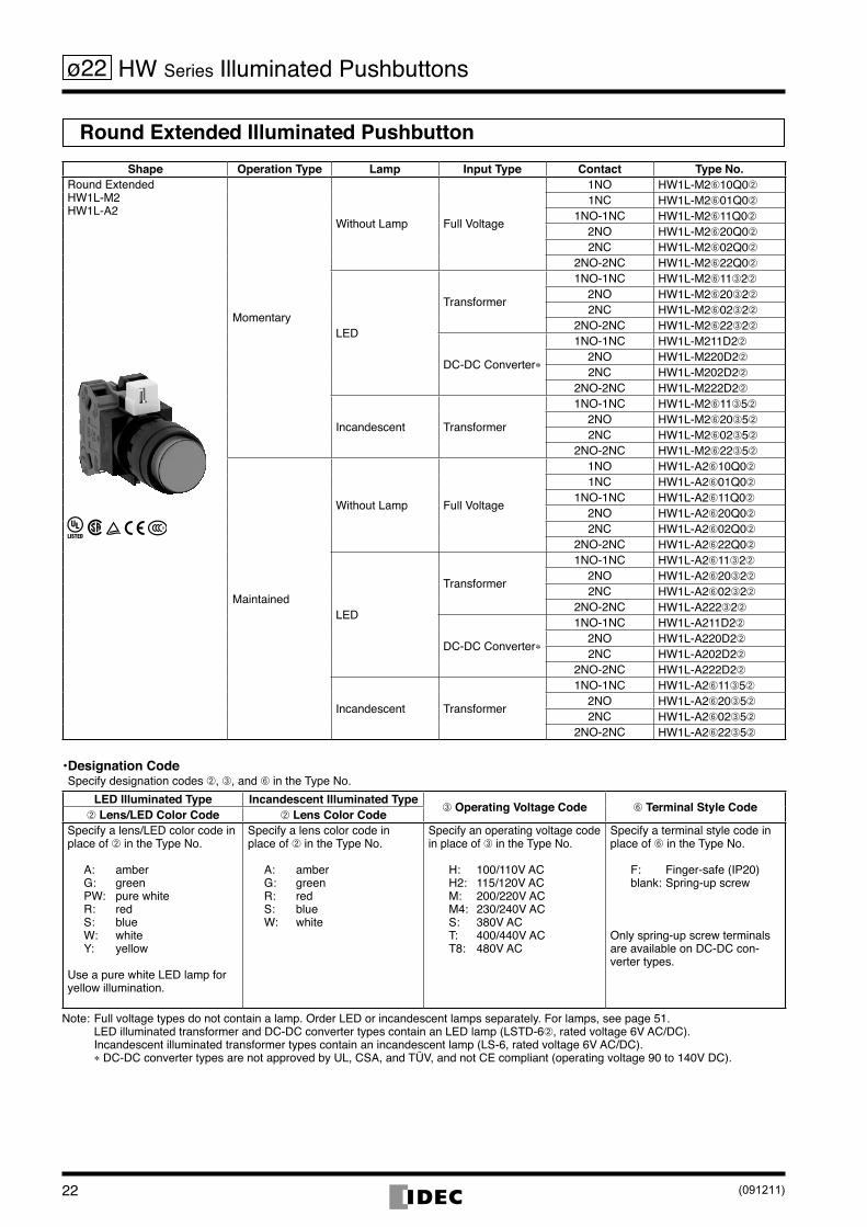
Round Extended Illuminated PushbuttonShape Operation Type Lamp Input Type Contact Type No.
Round ExtendedHW1L-M2HW1L-A2
Momentary
Without Lamp Full Voltage
1NO HW1L-M2➅10Q0➁
1NC HW1L-M2➅01Q0➁
1NO-1NC HW1L-M2➅11Q0➁
2NO HW1L-M2➅20Q0➁
2NC HW1L-M2➅02Q0➁
2NO-2NC HW1L-M2➅22Q0➁
LED
Transformer
1NO-1NC HW1L-M2➅11➂2➁
2NO HW1L-M2➅20➂2➁
2NC HW1L-M2➅02➂2➁
2NO-2NC HW1L-M2➅22➂2➁
DC-DC Converter*
1NO-1NC HW1L-M211D2➁
2NO HW1L-M220D2➁
2NC HW1L-M202D2➁
2NO-2NC HW1L-M222D2➁
Incandescent Transformer
1NO-1NC HW1L-M2➅11➂5➁
2NO HW1L-M2➅20➂5➁
2NC HW1L-M2➅02➂5➁
2NO-2NC HW1L-M2➅22➂5➁
Maintained
Without Lamp Full Voltage
1NO HW1L-A2➅10Q0➁
1NC HW1L-A2➅01Q0➁
1NO-1NC HW1L-A2➅11Q0➁
2NO HW1L-A2➅20Q0➁
2NC HW1L-A2➅02Q0➁
2NO-2NC HW1L-A2➅22Q0➁
LED
Transformer
1NO-1NC HW1L-A2➅11➂2➁
2NO HW1L-A2➅20➂2➁
2NC HW1L-A2➅02➂2➁
2NO-2NC HW1L-A222➂2➁
DC-DC Converter*
1NO-1NC HW1L-A211D2➁
2NO HW1L-A220D2➁
2NC HW1L-A202D2➁
2NO-2NC HW1L-A222D2➁
Incandescent Transformer
1NO-1NC HW1L-A2➅11➂5➁
2NO HW1L-A2➅20➂5➁
2NC HW1L-A2➅02➂5➁
2NO-2NC HW1L-A2➅22➂5➁
Designation Code •Specifydesignationcodes➁, ➂, and ➅ in the Type No.
LED Illuminated Type Incandescent Illuminated Type➂ Operating Voltage Code ➅ Terminal Style Code
➁ Lens/LED Color Code ➁ Lens Color CodeSpecifyalens/LEDcolorcodeinplaceof➁ in the Type No.
A: amberG: greenPW: purewhiteR: redS: blueW: whiteY: yellow
UseapurewhiteLEDlampforyellow illumination.
Specifyalenscolorcodeinplaceof➁ in the Type No.
A: amberG: greenR: redS: blueW: white
Specifyanoperatingvoltagecodeinplaceof➂ in the Type No.
H: 100/110VACH2: 115/120VACM: 200/220VACM4: 230/240VACS: 380VACT: 400/440VACT8: 480VAC
Specifyaterminalstylecodeinplaceof➅ in the Type No.
F: Finger-safe(IP20)blank:Spring-upscrew
Only spring-up screw terminals are available on DC-DC con-verter types.
Note:Fullvoltagetypesdonotcontainalamp.OrderLEDorincandescentlampsseparately.Forlamps,seepage51. LEDilluminatedtransformerandDC-DCconvertertypescontainanLEDlamp(LSTD-6➁, rated voltage 6V AC/DC). Incandescentilluminatedtransformertypescontainanincandescentlamp(LS-6,ratedvoltage6VAC/DC). * DC-DC converter types are not approved by UL, CSA, and TÜV, and not CE compliant (operating voltage 90 to 140V DC).
HW Series Illuminated Pushbuttons
(091211)

23
ø22
Round Extended with Full Shroud Illuminated PushbuttonShape Operation Type Lamp Input Type Contact Type No.
Round Extended with Full ShroudHW1L-MF2HW1L-AF2
Momentary
Without Lamp Full Voltage
1NO HW1L-MF2➅10Q0➁
1NC HW1L-MF2➅01Q0➁
1NO-1NC HW1L-MF2➅11Q0➁
2NO HW1L-MF2➅20Q0➁
2NC HW1L-MF2➅02Q0➁
2NO-2NC HW1L-MF2➅22Q0➁
LED
Transformer
1NO-1NC HW1L-MF2➅11➂2➁
2NO HW1L-MF2➅20➂2➁
2NC HW1L-MF2➅02➂2➁
2NO-2NC HW1L-MF2➅22➂2➁
DC-DC Converter*
1NO-1NC HW1L-MF211D2➁
2NO HW1L-MF220D2➁
2NC HW1L-MF202D2➁
2NO-2NC HW1L-MF222D2➁
Incandescent Transformer
1NO-1NC HW1L-MF2➅11➂5➁
2NO HW1L-MF2➅20➂5➁
2NC HW1L-MF2➅02➂5➁
2NO-2NC HW1L-MF2➅22➂5➁
Maintained
Without Lamp Full Voltage
1NO HW1L-AF2➅10Q0➁
1NC HW1L-AF2➅01Q0➁
1NO-1NC HW1L-AF2➅11Q0➁
2NO HW1L-AF2➅20Q0➁
2NC HW1L-AF2➅02Q0➁
2NO-2NC HW1L-AF2➅22Q0➁
LED
Transformer
1NO-1NC HW1L-AF2➅11➂2➁
2NO HW1L-AF2➅20➂2➁
2NC HW1L-AF2➅02➂2➁
2NO-2NC HW1L-AF2➅22➂2➁
DC-DC Converter*
1NO-1NC HW1L-AF211D2➁
2NO HW1L-AF220D2➁
2NC HW1L-AF202D2➁
2NO-2NC HW1L-AF222D2➁
Incandescent Transformer
1NO-1NC HW1L-AF2➅11➂5➁
2NO HW1L-AF2➅20➂5➁
2NC HW1L-AF2➅02➂5➁
2NO-2NC HW1L-AF2➅22➂5➁
Designation Code •Specifydesignationcodes➁, ➂, and ➅ in the Type No.
LED Illuminated Type Incandescent Illuminated Type➂ Operating Voltage Code ➅ Terminal Style Code
➁ Lens/LED Color Code ➁ Lens Color CodeSpecifyalens/LEDcolorcodeinplaceof➁ in the Type No.
A: amberG: greenPW: purewhiteR: redS: blueW: whiteY: yellow
UseapurewhiteLEDlampforyellow illumination.
Specifyalenscolorcodeinplaceof➁ in the Type No.
A: amberG: greenR: redS: blueW: white
Specifyanoperatingvoltagecodeinplaceof➂ in the Type No.
H: 100/110VACH2: 115/120VACM: 200/220VACM4: 230/240VACS: 380VACT: 400/440VACT8: 480VAC
Specifyaterminalstylecodeinplaceof➅ in the Type No.
F: Finger-safe(IP20)blank:Spring-upscrew
Only spring-up screw terminals are available on DC-DC con-verter types.
Note:Fullvoltagetypesdonotcontainalamp.OrderLEDorincandescentlampsseparately.Forlamps,seepage51. LEDilluminatedtransformerandDC-DCconvertertypescontainanLEDlamp(LSTD-6➁, rated voltage 6V AC/DC). Incandescentilluminatedtransformertypescontainanincandescentlamp(LS-6,ratedvoltage6VAC/DC). * DC-DC converter types are not approved by UL, CSA, and TÜV, and not CE compliant (operating voltage 90 to 140V DC).
HW Series Illuminated Pushbuttons
(0901211)

24
ø22
Square Flush Illuminated PushbuttonShape Operation Type Lamp Input Type Contact Type No.
Square FlushHW2L-M1HW2L-A1
Momentary
Without Lamp Full Voltage
1NO HW2L-M1➅10Q0➁
1NC HW2L-M1➅01Q0➁
1NO-1NC HW2L-M1➅11Q0➁
2NO HW2L-M1➅20Q0➁
2NC HW2L-M1➅02Q0➁
2NO-2NC HW2L-M1➅22Q0➁
LED
Transformer
1NO-1NC HW2L-M1➅11➂2➁
2NO HW2L-M1➅20➂2➁
2NC HW2L-M1➅02➂2➁
2NO-2NC HW2L-M1➅22➂2➁
DC-DC Converter*
1NO-1NC HW2L-M111D2➁
2NO HW2L-M120D2➁
2NC HW2L-M102D2➁
2NO-2NC HW2L-M122D2➁
Incandescent Transformer
1NO-1NC HW2L-M1➅11➂5➁
2NO HW2L-M1➅20➂5➁
2NC HW2L-M1➅02➂5➁
2NO-2NC HW2L-M1➅22➂5➁
Maintained
Without Lamp Full Voltage
1NO HW2L-A1➅10Q0➁
1NC HW2L-A1➅01Q0➁
1NO-1NC HW2L-A1➅11Q0➁
2NO HW2L-A1➅20Q0➁
2NC HW2L-A1➅02Q0➁
2NO-2NC HW2L-A1➅22Q0➁
LED
Transformer
1NO-1NC HW2L-A1➅11➂2➁
2NO HW2L-A1➅20➂2➁
2NC HW2L-A1➅02➂2➁
2NO-2NC HW2L-A1➅22➂2➁
DC-DC Converter*
1NO-1NC HW2L-A111D2➁
2NO HW2L-A120D2➁
2NC HW2L-A102D2➁
2NO-2NC HW2L-A122D2➁
Incandescent Transformer
1NO-1NC HW2L-A1➅11➂5➁
2NO HW2L-A1➅20➂5➁
2NC HW2L-A1➅02➂5➁
2NO-2NC HW2L-A1➅22➂5➁
Designation Code •Specifydesignationcodes➁, ➂, and ➅ in the Type No.
LED Illuminated Type Incandescent Illuminated Type➂ Operating Voltage Code ➅ Terminal Style Code
➁ Lens/LED Color Code ➁ Lens Color CodeSpecifyalens/LEDcolorcodeinplaceof➁ in the Type No.
A: amberG: greenPW: purewhiteR: redS: blueW: whiteY: yellow
UseapurewhiteLEDlampforyellow illumination.
Specifyalenscolorcodeinplaceof➁ in the Type No.
A: amberG: greenR: redS: blueW: white
Specifyanoperatingvoltagecodeinplaceof➂ in the Type No.
H: 100/110VACH2: 115/120VACM: 200/220VACM4: 230/240VACS: 380VACT: 400/440VACT8: 480VAC
Specifyaterminalstylecodeinplaceof➅ in the Type No.
F: Finger-safe(IP20)blank:Spring-upscrew
Only spring-up screw terminals are available on DC-DC con-verter types.
Note:Fullvoltagetypesdonotcontainalamp.OrderLEDorincandescentlampsseparately.Forlamps,seepage51. LEDilluminatedtransformerandDC-DCconvertertypescontainanLEDlamp(LSTD-6➁, rated voltage 6V AC/DC). Incandescentilluminatedtransformertypescontainanincandescentlamp(LS-6,ratedvoltage6VAC/DC). * DC-DC converter types are not approved by UL, CSA, and TÜV, and not CE compliant (operating voltage 90 to 140V DC).
HW Series Illuminated Pushbuttons
(091211)

25
ø22
Round Flush with Square Bezel Illuminated PushbuttonShape Operation Type Lamp Input Type Contact Type No.
Round Flush with Square BezelHW3L-M1HW3L-A1
Momentary
Without Lamp Full Voltage
1NO HW3L-M1➅10Q0➁
1NC HW3L-M1➅01Q0➁
1NO-1NC HW3L-M1➅11Q0➁
2NO HW3L-M1➅20Q0➁
2NC HW3L-M1➅02Q0➁
2NO-2NC HW3L-M1➅22Q0➁
LED
Transformer
1NO-1NC HW3L-M1➅11➂2➁
2NO HW3L-M1➅20➂2➁
2NC HW3L-M1➅02➂2➁
2NO-2NC HW3L-M1➅22➂2➁
DC-DC Converter*
1NO-1NC HW3L-M111D2➁
2NO HW3L-M120D2➁
2NC HW3L-M102D2➁
2NO-2NC HW3L-M122D2➁
Incandescent Transformer
1NO-1NC HW3L-M1➅11➂5➁
2NO HW3L-M1➅20➂5➁
2NC HW3L-M1➅02➂5➁
2NO-2NC HW3L-M1➅22➂5➁
Maintained
Without Lamp Full Voltage
1NO HW3L-A1➅10Q0➁
1NC HW3L-A1➅01Q0➁
1NO-1NC HW3L-A1➅11Q0➁
2NO HW3L-A1➅20Q0➁
2NC HW3L-A1➅02Q0➁
2NO-2NC HW3L-A1➅22Q0➁
LED
Transformer
1NO-1NC HW3L-A1➅11➂2➁
2NO HW3L-A1➅20➂2➁
2NC HW3L-A1➅02➂2➁
2NO-2NC HW3L-A1➅22➂2➁
DC-DC Converter*
1NO-1NC HW3L-A111D2➁
2NO HW3L-A120D2➁
2NC HW3L-A102D2➁
2NO-2NC HW3L-A122D2➁
Incandescent Transformer
1NO-1NC HW3L-A1➅11➂5➁
2NO HW3L-A1➅20➂5➁
2NC HW3L-A1➅02➂5➁
2NO-2NC HW3L-A1➅22➂5➁
Designation Code •Specifydesignationcodes➁, ➂, and ➅ in the Type No.
LED Illuminated Type Incandescent Illuminated Type➂ Operating Voltage Code ➅ Terminal Style Code
➁ Lens/LED Color Code ➁ Lens Color CodeSpecifyalens/LEDcolorcodeinplaceof➁ in the Type No.
A: amberG: greenPW: purewhiteR: redS: blueW: whiteY: yellow
UseapurewhiteLEDlampforyellow illumination.
Specifyalenscolorcodeinplaceof➁ in the Type No.
A: amberG: greenR: redS: blueW: white
Specifyanoperatingvoltagecodeinplaceof➂ in the Type No.
H: 100/110VACH2: 115/120VACM: 200/220VACM4: 230/240VACS: 380VACT: 400/440VACT8: 480VAC
Specifyaterminalstylecodeinplaceof➅ in the Type No.
F: Finger-safe(IP20)blank:Spring-upscrew
Only spring-up screw terminals are available on DC-DC con-verter types.
Note:Fullvoltagetypesdonotcontainalamp.OrderLEDorincandescentlampsseparately.Forlamps,seepage51. LEDilluminatedtransformerandDC-DCconvertertypescontainanLEDlamp(LSTD-6➁, rated voltage 6V AC/DC). Incandescentilluminatedtransformertypescontainanincandescentlamp(LS-6,ratedvoltage6VAC/DC). * DC-DC converter types are not approved by UL, CSA, and TÜV, and not CE compliant (operating voltage 90 to 140V DC).
HW Series Illuminated Pushbuttons
(0901211)

26
ø22
Mushroom (ø29mm) Illuminated PushbuttonShape Operation Type Lamp Input Type Contact Type No.
ø29mm MushroomHW1L-M3HW1L-A3
Momentary
Without Lamp Full Voltage
1NO HW1L-M3➅10Q0➁
1NC HW1L-M3➅01Q0➁
1NO-1NC HW1L-M3➅11Q0➁
2NO HW1L-M3➅20Q0➁
2NC HW1L-M3➅02Q0➁
2NO-2NC HW1L-M3➅22Q0➁
LED
Transformer
1NO-1NC HW1L-M3➅11➂2➁
2NO HW1L-M3➅20➂2➁
2NC HW1L-M3➅02➂2➁
2NO-2NC HW1L-M3➅22➂2➁
DC-DC Converter*
1NO-1NC HW1L-M311D2➁
2NO HW1L-M320D2➁
2NC HW1L-M302D2➁
2NO-2NC HW1L-M322D2➁
Incandescent Transformer
1NO-1NC HW1L-M3➅11➂5➁
2NO HW1L-M3➅20➂5➁
2NC HW1L-M3➅02➂5➁
2NO-2NC HW1L-M3➅22➂5➁
Maintained
Without Lamp Full Voltage
1NO HW1L-A3➅10Q0➁
1NC HW1L-A3➅01Q0➁
1NO-1NC HW1L-A3➅11Q0➁
2NO HW1L-A3➅20Q0➁
2NC HW1L-A3➅02Q0➁
2NO-2NC HW1L-A3➅22Q0➁
LED
Transformer
1NO-1NC HW1L-A3➅11➂2➁
2NO HW1L-A3➅20➂2➁
2NC HW1L-A3➅02➂2➁
2NO-2NC HW1L-A3➅22➂2➁
DC-DC Converter*
1NO-1NC HW1L-A311D2➁
2NO HW1L-A320D2➁
2NC HW1L-A302D2➁
2NO-2NC HW1L-A322D2➁
Incandescent Transformer
1NO-1NC HW1L-A3➅11➂5➁
2NO HW1L-A3➅20➂5➁
2NC HW1L-A3➅02➂5➁
2NO-2NC HW1L-A3➅22➂5➁
Designation Code •Specifydesignationcodes➁, ➂, and ➅ in the Type No.
LED Illuminated Type Incandescent Illuminated Type➂ Operating Voltage Code ➅ Terminal Style Code
➁ Lens/LED Color Code ➁ Lens Color CodeSpecifyalens/LEDcolorcodeinplaceof➁ in the Type No.
A: amberG: greenPW: purewhiteR: redS: blueW: whiteY: yellow
UseapurewhiteLEDlampforyellow illumination.
Specifyalenscolorcodeinplaceof➁ in the Type No.
A: amberG: greenR: redS: blueW: white
Specifyanoperatingvoltagecodeinplaceof➂ in the Type No.
H: 100/110VACH2: 115/120VACM: 200/220VACM4: 230/240VACS: 380VACT: 400/440VACT8: 480VAC
Specifyaterminalstylecodeinplaceof➅ in the Type No.
F: Finger-safe(IP20)blank:Spring-upscrew
Only spring-up screw terminals are available on DC-DC con-verter types.
Note:Fullvoltagetypesdonotcontainalamp.OrderLEDorincandescentlampsseparately.Forlamps,seepage51. LEDilluminatedtransformerandDC-DCconvertertypescontainanLEDlamp(LSTD-6➁, rated voltage 6V AC/DC). Incandescentilluminatedtransformertypescontainanincandescentlamp(LS-6,ratedvoltage6VAC/DC). * DC-DC converter types are not approved by UL, CSA, and TÜV, and not CE compliant (operating voltage 90 to 140V DC).
HW Series Illuminated Pushbuttons
(091211)

27
ø22
Mushroom (ø29mm) with Square Bezel Illuminated PushbuttonShape Operation Type Lamp Input Type Contact Type No.
ø29mm Mushroom with Square BezelHW3L-M3HW3L-A3
Momentary
Without Lamp Full Voltage
1NO HW3L-M3➅10Q0➁
1NC HW3L-M3➅01Q0➁
1NO-1NC HW3L-M3➅11Q0➁
2NO HW3L-M3➅20Q0➁
2NC HW3L-M3➅02Q0➁
2NO-2NC HW3L-M3➅22Q0➁
LED
Transformer
1NO-1NC HW3L-M3➅11➂2➁
2NO HW3L-M3➅20➂2➁
2NC HW3L-M3➅02➂2➁
2NO-2NC HW3L-M3➅22➂2➁
DC-DC Converter*
1NO-1NC HW3L-M311D2➁
2NO HW3L-M320D2➁
2NC HW3L-M302D2➁
2NO-2NC HW3L-M322D2➁
Incandescent Transformer
1NO-1NC HW3L-M3➅11➂5➁
2NO HW3L-M3➅20➂5➁
2NC HW3L-M3➅02➂5➁
2NO-2NC HW3L-M3➅22➂5➁
Maintained
Without Lamp Full Voltage
1NO HW3L-A3➅10Q0➁
1NC HW3L-A3➅01Q0➁
1NO-1NC HW3L-A3➅11Q0➁
2NO HW3L-A3➅20Q0➁
2NC HW3L-A3➅02Q0➁
2NO-2NC HW3L-A3➅22Q0➁
LED
Transformer
1NO-1NC HW3L-A3➅11➂2➁
2NO HW3L-A3➅20➂2➁
2NC HW3L-A3➅02➂2➁
2NO-2NC HW3L-A3➅22➂2➁
DC-DC Converter*
1NO-1NC HW3L-A311D2➁
2NO HW3L-A320D2➁
2NC HW3L-A302D2➁
2NO-2NC HW3L-A322D2➁
Incandescent Transformer
1NO-1NC HW3L-A3➅11➂5➁
2NO HW3L-A3➅20➂5➁
2NC HW3L-A3➅02➂5➁
2NO-2NC HW3L-A3➅22➂5➁
Designation Code •Specifydesignationcodes➁, ➂, and ➅ in the Type No.
LED Illuminated Type Incandescent Illuminated Type➂ Operating Voltage Code ➅ Terminal Style Code
➁ Lens/LED Color Code ➁ Lens Color CodeSpecifyalens/LEDcolorcodeinplaceof➁ in the Type No.
A: amberG: greenPW: purewhiteR: redS: blueW: whiteY: yellow
UseapurewhiteLEDlampforyellow illumination.
Specifyalenscolorcodeinplaceof➁ in the Type No.
A: amberG: greenR: redS: blueW: white
Specifyanoperatingvoltagecodeinplaceof➂ in the Type No.
H: 100/110VACH2: 115/120VACM: 200/220VACM4: 230/240VACS: 380VACT: 400/440VACT8: 480VAC
Specifyaterminalstylecodeinplaceof➅ in the Type No.
F: Finger-safe(IP20)blank:Spring-upscrew
Only spring-up screw terminals are available on DC-DC con-verter types.
Note:Fullvoltagetypesdonotcontainalamp.OrderLEDorincandescentlampsseparately.Forlamps,seepage51. LEDilluminatedtransformerandDC-DCconvertertypescontainanLEDlamp(LSTD-6➁, rated voltage 6V AC/DC). Incandescentilluminatedtransformertypescontainanincandescentlamp(LS-6,ratedvoltage6VAC/DC). * DC-DC converter types are not approved by UL, CSA, and TÜV, and not CE compliant (operating voltage 90 to 140V DC).
HW Series Illuminated Pushbuttons
(0901211)

28
ø22
Mushroom (ø40mm) Illuminated PushbuttonShape Operation Type Lamp Input Type Contact Type No.
ø40mm MushroomHW1L-M4HW1L-A4
Momentary
Without Lamp Full Voltage
1NO HW1L-M4➅10Q0➁
1NC HW1L-M4➅01Q0➁
1NO-1NC HW1L-M4➅11Q0➁
2NO HW1L-M4➅20Q0➁
2NC HW1L-M4➅02Q0➁
2NO-2NC HW1L-M4➅22Q0➁
LED
Transformer
1NO-1NC HW1L-M4➅11➂2➁
2NO HW1L-M4➅20➂2➁
2NC HW1L-M4➅02➂2➁
2NO-2NC HW1L-M4➅22➂2➁
DC-DC Converter*
1NO-1NC HW1L-M411D2➁
2NO HW1L-M420D2➁
2NC HW1L-M402D2➁
2NO-2NC HW1L-M422D2➁
Incandescent Transformer
1NO-1NC HW1L-M4➅11➂5➁
2NO HW1L-M4➅20➂5➁
2NC HW1L-M4➅02➂5➁
2NO-2NC HW1L-M4➅22➂5➁
Maintained
Without Lamp Full Voltage
1NO HW1L-A4➅10Q0➁
1NC HW1L-A4➅01Q0➁
1NO-1NC HW1L-A4➅11Q0➁
2NO HW1L-A4➅20Q0➁
2NC HW1L-A4➅02Q0➁
2NO-2NC HW1L-A4➅22Q0➁
LED
Transformer
1NO-1NC HW1L-A4➅11➂2➁
2NO HW1L-A4➅20➂2➁
2NC HW1L-A4➅02➂2➁
2NO-2NC HW1L-A4➅22➂2➁
DC-DC Converter*
1NO-1NC HW1L-A411D2➁
2NO HW1L-A420D2➁
2NC HW1L-A402D2➁
2NO-2NC HW1L-A422D2➁
Incandescent Transformer
1NO-1NC HW1L-A4➅11➂5➁
2NO HW1L-A4➅20➂5➁
2NC HW1L-A4➅02➂5➁
2NO-2NC HW1L-A4➅22➂5➁
Designation Code •Specifydesignationcodes➁, ➂, and ➅ in the Type No.
LED Illuminated Type Incandescent Illuminated Type➂ Operating Voltage Code ➅ Terminal Style Code
➁ Lens/LED Color Code ➁ Lens Color CodeSpecifyalens/LEDcolorcodeinplaceof➁ in the Type No.
A: amberG: greenPW: purewhiteR: redS: blueW: whiteY: yellow
UseapurewhiteLEDlampforyellow illumination.
Specifyalenscolorcodeinplaceof➁ in the Type No.
A: amberG: greenR: redS: blueW: white
Specifyanoperatingvoltagecodeinplaceof➂ in the Type No.
H: 100/110VACH2: 115/120VACM: 200/220VACM4: 230/240VACS: 380VACT: 400/440VACT8: 480VAC
Specifyaterminalstylecodeinplaceof➅ in the Type No.
F: Finger-safe(IP20)blank:Spring-upscrew
Only spring-up screw terminals are available on DC-DC con-verter types.
Note:Fullvoltagetypesdonotcontainalamp.OrderLEDorincandescentlampsseparately.Forlamps,seepage51. LEDilluminatedtransformerandDC-DCconvertertypescontainanLEDlamp(LSTD-6➁, rated voltage 6V AC/DC). Incandescentilluminatedtransformertypescontainanincandescentlamp(LS-6,ratedvoltage6VAC/DC). * DC-DC converter types are not approved by UL, CSA, and TÜV, and not CE compliant (operating voltage 90 to 140V DC).
HW Series Illuminated Pushbuttons
(091211)

29
ø22
Dimensions
X1X2
49.4 (1 block)
Locking Ring Panel Thickness 0.8 to 6
Full Voltage Adapter
M3.5 Terminal ScrewContact Block
1 contact block
1 contact block
3 contact blocks
3 contact blocks
X1X2
Full Voltage Adapter
M3.5 Terminal ScrewContact Block
Locking Ring Panel Thickness 0.8 to 6
69.4 (3 blocks)
Full Voltage Adapter
2 contact blocks
Panel Thickness 0.8 to 6Locking Ring
2 contact blocks69.4 (2 blocks)
M3.5 Terminal ScrewContact Block
Full Voltage Adapter
M3.5 Terminal ScrewContact Block Locking Ring Panel Thickness 0.8 to 6
89.4 (4 blocks)
4 contact blocks
4 contact blocks
Round SquareRound withSquare Bezel
LOCK
ø23.6
29.4
25
LOCK
41.4
29.4
29.6
13
Panel Thickness0.8 to 6
41.4
LOCK
25
41.4
29.424.8
29.6
ø23.6
25
Extended with Full Shroud
Extended
Mushroom (ø29)
LOCK
LOCK
ø23.6
18.5
ø29.
5
1323.2
ø29
Mushroom (ø40)
1323.2
ø40
29.441
.4
25
LOCK
29.4
41.4
25
1318.5
ø23.
5
ø23.6
29.4
41.4
25
LOCK
29.4
41.4
25
Transformer Type (240V AC maximum)•
Transformer Type (380V AC minimum)•DC-DC Converter Type•
Full Voltage Type• Operator•
X2X1
34
M3.5 Terminal Screws79.5 (2 blocks)*99.5 (4 blocks)*
Locking RingSafetyLeverLock
X2
X1
M3.5 Terminal Screw89.5 (2 blocks)109.5 (4 blocks)
SafetyLeverLock Locking Ring
Terminal Wiring Arrowsindicateaccessdirectionsforwiring.Spring-up screw type
X2X1
Contact BlockFull Voltage Adapter
Transformer
X1: PositiveterminalX2: Negativeterminal
HW Series Illuminated Pushbuttons
*Spring-up screw type only
Theabovefiguresillustratethespring-upscrewtypes.
All dimensions in mm.
Thedepthofeachfinger-safe(IP20)contactblockis0.9mmlongerthanthatofaspring-up screw contact block.*Thedepthsoffinger-safe(IP20)typesareasfollows: TransformerType (240VACmaximum): 89.5(2blocks) 109.5 (4 blocks)
* *
**
* *
(0901211)

30
ø22
Dual PushbuttonsWithout Pilot Light•
Operation Type Button Style
Contact ArrangementType No. ➃ Button
Color Code ➄ Legend CodeTopButton
BottomButton
Momentary
Flush (top)Flush (bottom) 1NO 1NC HW7D-B11➅1001➃➄
GR:Green(top) Red (bottom)
WB:White(top) Black (bottom)
Blank:Withoutlegend
1: I/ON(top) O/OFF (bottom)
1NO 1NO HW7D-B11➅1010➃➄
1NO-1NC 1NO-1NC HW7D-B11➅1111➃➄
2NO 2NC HW7D-B11➅2002➃➄
2NO 2NO HW7D-B11➅2020➃➄
Flush (top)Extended (bottom) 1NO 1NC HW7D-B12➅1001➃➄
1NO 1NO HW7D-B12➅1010➃➄
1NO-1NC 1NO-1NC HW7D-B12➅1111➃➄
2NO 2NC HW7D-B12➅2002➃➄
2NO 2NO HW7D-B12➅2020➃➄
Interlock
Flush (top)Flush (bottom) 1NO 1NC HW7D-B21➅1001➃➄
1NO 1NO HW7D-B21➅1010➃➄
1NO-1NC 1NO-1NC HW7D-B21➅1111➃➄
2NO 2NC HW7D-B21➅2002➃➄
2NO 2NO HW7D-B21➅2020➃➄
Flush (top)Extended (bottom) 1NO 1NC HW7D-B22➅1001➃➄
1NO 1NO HW7D-B22➅1010➃➄
1NO-1NC 1NO-1NC HW7D-B22➅1111➃➄
2NO 2NC HW7D-B22➅2002➃➄
2NO 2NO HW7D-B22➅2020➃➄
Specifyaterminalstylecodeinplaceof• ➅ intheTypeNo.F:Finger-safe(IP20),blank:Spring-upscrewMomentary:Twoindependentmomentaryswitchesarecontainedinoneunit. The contact operates when the button is pressed. When the button is released, the contact goes back to the original position.Interlock: Momentaryoperation.Whenoneofthebuttonsarepressed,theotherbuttoncannotbeoperated. Donotoperatetopandbottombuttonsatthesametime.Operatingthebuttonsatthesametimemayleadtomalfunctions.Other contact arrangements and gold-plated silver contacts are also available. See page 8.
HW Series Dual Pushbuttons
(091211)

31
ø22
Dual PushbuttonsWith Pilot Light•
Operation Type Lamp Input Type Contact Arrangement Type No.Top Button Bottom Button
Momentary
Without Lamp Full Voltage
1NO 1NC HW7D-L1➀➅1001Q0W➃➄
1NO 1NO HW7D-L1➀➅1010Q0W➃➄
1NO-1NC 1NO-1NC HW7D-L1➀➅1111Q0W➃➄
2NO 2NC HW7D-L1➀➅2002Q0W➃➄
2NO 2NO HW7D-L1➀➅2020Q0W➃➄
LED
Transformer
1NO 1NC HW7D-L1➀➅1001➁2➂➃➄
1NO 1NO HW7D-L1➀➅1010➁2➂➃➄
1NO-1NC 1NO-1NC HW7D-L1➀➅1111➁2➂➃➄
2NO 2NC HW7D-L1➀➅2002➁2➂➃➄
2NO 2NO HW7D-L1➀➅2020➁2➂➃➄
DC-DC Converter
1NO 1NC HW7D-L1➀1001D2➂➃➄
1NO 1NO HW7D-L1➀1010D2➂➃➄
1NO-1NC 1NO-1NC HW7D-L1➀1111D2➂➃➄
2NO 2NC HW7D-L1➀2002D2➂➃➄
2NO 2NO HW7D-L1➀2020D2➂➂➄
Incandescent Transformer
1NO 1NC HW7D-L1➀➅1001➁5W➃➄
1NO 1NO HW7D-L1➀➅1010➁5W➃➄
1NO-1NC 1NO-1NC HW7D-L1➀➅1111➁5W➃➄
2NO 2NC HW7D-L1➀➅2002➁5W➃➄
2NO 2NO HW7D-L1➀➅2020➁5W➃➄
Interlock
Without Lamp Full Voltage
1NO 1NC HW7D-L2➀➅1001Q0W➃➄
1NO 1NO HW7D-L2➀➅1010Q0W➃➄
1NO-1NC 1NO-1NC HW7D-L2➀➅1111Q0W➃➄
2NO 2NC HW7D-L2➀➅2002Q0W➃➄
2NO 2NO HW7D-L2➀➅2020Q0W➃➄
LED
Transformer
1NO 1NC HW7D-L2➀➅1001➁2➂➃➄
1NO 1NO HW7D-L2➀➅1010➁2➂➃➄
1NO-1NC 1NO-1NC HW7D-L2➀➅1111➁2➂➃➄
2NO 2NC HW7D-L2➀➅2002➁2➂➃➄
2NO 2NO HW7D-L2➀➅2020➁2➂➃➄
DC-DC Converter
1NO 1NC HW7D-L2➀1001D2➂➃➄
1NO 1NO HW7D-L2➀1010D2➂➃➄
1NO-1NC 1NO-1NC HW7D-L2➀1111D2➂➃➄
2NO 2NC HW7D-L2➀2002D2➂➃➄
2NO 2NO HW7D-L2➀2020D2➂➃➄
Incandescent Transformer
1NO 1NC HW7D-L2➀➅1001➁5W➃➄
1NO 1NO HW7D-L2➀➅1010➁5W➃➄
1NO-1NC 1NO-1NC HW7D-L2➀➅1111➁5W➃➄
2NO 2NC HW7D-L2➀➅2002➁5W➃➄
2NO 2NO HW7D-L2➀➅2020➁5W➃➄
Designation Codes •Specifydesignationcodes➀ to ➅ in the Type No.
➀ Button Style Code ➁ Operating Voltage Code
➂ Lamp Color Code
➃ Button Color Code ➄ Legend Code ➅ Terminal Style
Code
1: Flush(top) Flush (bottom) H: 100/110VAC
H2:115/120VACM: 200/220VACM4:230/240VACS: 380VACT: 400/440VACT8: 480VAC
A: amberG: greenR: redS: blueW:white
The lens is white only.
GR:Green(top) Red (bottom)
WB:White(top) Black (bottom)
Blank:Without legend
1: I/ON(top) O/OFF (bottom)
F:Finger-safe(IP20)blank:Spring-up screw
Only spring-up screw terminals are available on DC-DC converter types.2: Flush(top)
Extended (bottom)
Note:Fullvoltagetypesdonotcontainalamp.OrderLEDorincandescentlampsseparately.Forlamps,seepage51. LEDilluminatedtransformerandDC-DCconvertertypescontainanLEDlamp(LSTD-6➂, rated voltage 6V AC/DC). Incandescentilluminatedtransformertypescontainanincandescentlamp(LS-6,ratedvoltage6VAC/DC).
HW Series Dual Pushbuttons
(0901211)

32
ø22
0.5
Without ButtonMarkings
With Button Markings(I/ON and O/OFF)
Panel Thickness 0.8 to 6
14.520
49.4 (2 contacts)69.4 (3 or 4 contacts)
54.8
29.8
54.8
29.8
41.4
Rubber Gasket
Locking RingSafety Lever Lock
HW
ON
OFF
DimensionsWithout Pilot Light
With Pilot LightFull Voltage•
Transformer (240V AC maximum)•
Transformer (380V AC minimum)•DC-DC Converter•
Full Voltage Adapter
(Bottom Button)
(Top Button)
69.4 (2 contacts), 89.4 (4 contacts)(Note)
HW
79.5 (2 contacts)∗, 99.5 (4 contacts)∗
Transformer
HW
89.5 (2 contacts), 109.5 (4 contacts)
Transformer, DC-DC Converter
HW
Note: Thedepthof3-contacttypedependsonthecombinationofcontactblocksattopandbottompushbuttonsTop Button 1 contact block 2 contact blocksBottom Button 2 contact blocks 1 contact blockDepth 89.4 mm 69.4 mm
HW Series Dual Pushbuttons
All dimensions in mm.
Theabovefiguresillustratethespring-upscrewtypes.Thedepthofeachfinger-safe(IP20)contactblockis0.9mmlongerthanthatofaspring-upscrewcontactblock.*Thedepthsoffinger-safe(IP20)typesareasfollows: TransformerType (240VACmaximum):89.5(2blocks) 109.5 (4 blocks)
(091211)

33
ø22
Contact Arrangement ChartContact Arrangement Contact Block Top Button Bottom Button
Top Button Bottom Button Contact Code Mounting Position Type Normal Push Normal Push
1NO 1NO 1010 1 NO ●
2 NO ●
1NO 1NC 1001 1 NO ●
2 NC ●
1NC 1NO 0110 1 NC ●
2 NO ●
1NC 1NC 0101 1 NC ●
2 NC ●
1NO 2NO 1020
1 NO ●
2 NO ●
3 Dummy4 NO ●
1NO 1NO-1NC 1011
1 NO ●
2 NO ●
3 Dummy4 NC ●
1NO 2NC 1002
1 NO ●
2 NC ●
3 Dummy4 NC ●
1NC 2NO 0120
1 NC ●
2 NO ●
3 Dummy4 NO ●
1NC 1NO-1NC 0111
1 NC ●
2 NO ●
3 Dummy4 NC ●
1NC 2NC 0102
1 NC ●
2 NC ●
3 Dummy4 NC ●
2NO 1NO 2010
1 NO ●
2 NO ●
3 NO ●
4 Dummy
2NO 1NC 2001
1 NO ●
2 NC ●
3 NO ●
4 Dummy
1NO-1NC 1NO 1110
1 NO ●
2 NO ●
3 NC ●
4 Dummy
1NO-1NC 1NC 1101
1 NO ●
2 NC ●
3 NC ●
4 DummyTransformerandDC-DCconvertertypescanhavetwoorfourcontactblocksonly.•Contact blocks 1 and 3 are actuated by the top button. Contact blocks 2 and 4 are actuated by the bottom button.•
Contact Block Mounting Position and Contact Arrangement Chart•
4 2
31
4 2 Full Voltage Adapter
31
Contact Block Top Button Bottom ButtonNormal Push Normal Push
1 NO ●
2 NO ●
3 NC ●
4 NC ●
Type No. Development• HW7D - B 12 11 11 GR
Contactcode(1NO-1NC)ofbottombuttonContactcode(1NO-1NC)oftopbutton
Without Pilot LightWith Pilot Light (transformertype)
With Pilot Light(fullvoltagetype)
HW Series Dual Pushbuttons
(0901211)

34
ø22
Contact Arrangement ChartContact Arrangement Contact Block Top Button Bottom Button
Top Button Bottom Button Contact Code Mounting Position Type Normal Push Normal Push
2NC 1NO 0210
1 NC ●
2 NO ●
3 NC ●
4 Dummy
2NC 1NC 0201
1 NC ●
2 NC ●
3 NC ●
4 Dummy
2NO 2NO 2020
1 NO ●
2 NO ●
3 NO ●
4 NO ●
2NO 1NO-1NC 2011
1 NO ●
2 NO ●
3 NO ●
4 NC ●
2NO 2NC 2002
1 NO ●
2 NC ●
3 NO ●
4 NC ●
1NO-1NC 2NO 1120
1 NO ●
2 NO ●
3 NC ●
4 NO ●
1NO-1NC 1NO-1NC 1111
1 NO ●
2 NO ●
3 NC ●
4 NC ●
1NO-1NC 2NC 1102
1 NO ●
2 NC ●
3 NC ●
4 NC ●
2NC 2NO 0220
1 NC ●
2 NO ●
3 NC ●
4 NO ●
2NC 1NO-1NC 0211
1 NC ●
2 NO ●
3 NC ●
4 NC ●
2NC 2NC 0202
1 NC ●
2 NC ●
3 NC ●
4 NC ●
HW Series Dual Pushbuttons
(091211)

35
ø22
L C R1 NO ●
2 NO ●
3 NC4 NC
CenterLeft Right
OperatorPosition
Contact Block Mounting Position •and Contact Arrangement Chart
4 2
31
HW Series Selector Switches
Selector Switches
No.
of P
ositi
ons Shape
Contact Arrangement Chart
HW1S
Dimensions on page 39.
90º 2
-pos
ition
/ 60
º 2-p
ositi
on
ContactCode
Contact Block Operator Position Maintained (90º)
L R
SpringReturnfromRight (60º)
L R — —Mounting Position Type L R
10(1NO)
1 NO ● HW1S-2T➅10 HW1S-21T➅10
— —
2 Dummy11
(1NO-1NC)1 NO ● HW1S-2T➅11 HW1S-21T➅112 NC ●
20(2NO)
1 NO ● HW1S-2T➅20 HW1S-21T➅202 NO ●
22(2NO-2NC)
1 NO ●
HW1S-2T➅22 HW1S-21T➅222 NC ●3 NO ●4 NC ●
45º 3
-pos
ition
ContactCode
Contact Block Operator Position Maintained
LC
R
Spring Return fromRight
LC
R
Spring Return fromLeft
RLC
Spring Return Two-wayL
CRMounting
Position Type L C R
20(2NO)
1 NO ● HW1S-3T➅20 HW1S-31T➅20 HW1S-32T➅20 HW1S-33T➅202 NO ●
02(2NC)
1 NC HW1S-3T➅02 HW1S-31T➅02 HW1S-32T➅02 HW1S-33T➅022 NC
22N1(2NO-2NC)
1 NO ●
HW1S-3T➅22N1 HW1S-31T➅22N1 HW1S-32T➅22N1 HW1S-33T➅22N12 NO ●3 NC4 NC
22N9 H(2NO-2NC)
1 NC ●
HW1S-3ST➅22N9 — — —2 NC ●3 NO4 NO ●
40(4NO)
1 NO ●
HW1S-3T➅40 HW1S-31T➅40 HW1S-32T➅40 HW1S-33T➅402 NO ●3 NO ●4 NO ●
40N2 H(4NO)
1 NO ●
HW1S-3ST➅40N2 — — —2 NO3 NO ●4 NO ●
04(4NC)
1 NC
HW1S-3T➅04 HW1S-31T➅04 HW1S-32T➅04 HW1S-33T➅042 NC3 NC4 NC
21N1 H(2NO-1NC)
1 NO ●
HW1S-3JT➅21N1 — — —2 NO ●3 NC ●4 Dummy
30º 5
-pos
ition
/ 45
º 4-p
ositi
on
ContactCode
Contact Block Operator Position Maintained
14
2 3
Maintained
14
52 3Mounting
Position Type 1 2 3 4 5
13N6 H(1NO-3NC)
1 NCHW1S-4T➅13N6 —2 NC ●
3 NC ●
4 NO ●
22N3 H(2NO-2NC)
1 NO ●
HW1S-4T➅22N3 —2 NC ●
3 NC ●
4 NO ●
12 H(1NO-2NC)
1 NO ●
HW1S-4T➅12 —2 NC ●
3 NC ●
4 Dummy
22N3 H(2NO-2NC)
1 NO ●
— HW1S-5T➅22N32 NC ●
3 NC ●
4 NO ●
Specifyaterminalstylecodeinplaceof• ➅ intheTypeNo.F:Finger-safe(IP20),blank:Spring-upscrewOn the contact arrangement marked with • Hinthetableabove,theratedcurrent(loadswitchingcurrent)isreducedtoahalfoftheratedcurrentofthecontactblock.Theratedinsulationvoltageandtheratedthermalcurrentremainunchanged.Selectorswitcheswithoneorthreecontactblockscontainadummyblock.Knoboperator:Whiteindicatoronblackbody•Other contact arrangements are also available. See pages 40 through 43.•
(0901211)

36
ø22
Key Selector Switches
No.
of P
ositi
ons Shape
Contact Arrangement Chart
HW1K
Dimensions on page 39.
90º 2
-pos
ition
/ 60
º 2-p
ositi
on
Contact Code
Contact Block Operator Position Maintained (90º)
L R
SpringReturnfromRight (60º)
L R — —Mounting Position Type L R
10(1NO)
1 NO ● HW1K-2A➅10 HW1K-21B➅10
— —
2 Dummy11
(1NO-1NC)1 NO ● HW1K-2A➅11 HW1K-21B➅112 NC ●
20(2NO)
1 NO ● HW1K-2A➅20 HW1K-21B➅202 NO ●
22(2NO-2NC)
1 NO ●
HW1K-2A➅22 HW1K-21B➅222 NC ●
3 NO ●
4 NC ●
45º 3
-pos
ition
Contact Code
Contact Block Operator Position Maintained
LC
R
Spring Return fromRight
LC
R
Spring Return fromLeft
RLC
Spring Return Two-wayL
CRMounting
Position Type L C R
20(2NO)
1 NO ● HW1K-3A➅20 HW1K-31B➅20 HW1K-32C➅20 HW1K-33D➅202 NO ●
02(2NC)
1 NC HW1K-3A➅02 HW1K-31B➅02 HW1K-32C➅02 HW1K-33D➅022 NC
22N1(2NO-2NC)
1 NO ●
HW1K-3A➅22N1 HW1K-31B➅22N1 HW1K-32C➅22N1 HW1K-33D➅22N12 NO ●
3 NC4 NC
22N9 H(2NO-2NC)
1 NC ●
HW1K-3SA➅22N9 — — —2 NC ●
3 NO4 NO ●
40(4NO)
1 NO ●
HW1K-3A➅40 HW1K-31B➅40 HW1K-32C➅40 HW1K-33D➅402 NO ●
3 NO ●
4 NO ●
40N2 H(4NO)
1 NO ●
HW1K-3SA➅40N2 — — —2 NO3 NO ●
4 NO ●
04(4NC)
1 NC
HW1K-3A➅04 HW1K-31B➅04 HW1K-32C➅04 HW1K-33D➅042 NC3 NC4 NC
21N1 H(2NO-1NC)
1 NO ●
HW1K-3JA➅21N1 — — —2 NO ●
3 NC ●
4 Dummy
Specifyaterminalstylecodeinplaceof• ➅ intheTypeNo.F:Finger-safe(IP20),blank:Spring-upscrewOnthespring-returnedtypes,thekeycanbereleasedonlyfromthemaintainedposition.Onthemaintainedtypes,thekeycanbereleased•fromeveryposition.Keyretainedpositionsarealsoavailable.Seepage8.Eachkeyselectorswitchissuppliedwithtwoidenticalkeys.Threedifferentkeysarealsoavailable.Seepage8.•On the contact arrangement marked with • Hinthetableabove,theratedcurrent(loadswitchingcurrent)isreducedtoahalfoftheratedcurrentofthecontactblock.Theratedinsulationvoltageandtheratedthermalcurrentremainunchanged.Key selector switches with one or three contact blocks contain a dummy block.•Cylindercover:black,Cylinder:metal•Other contact arrangements are also available. See pages 40 through 43.•
Contact Block Mounting Position and Contact Arrangement Chart•
L C R1 NO ●
2 NO ●
3 NC4 NC
CenterLeft Right
OperatorPosition
4 2
31
HW Series Selector Switches
(091211)

37
ø22
42
31
Illuminated Selector Switches90º 2-position / 60º 2-positionShape
Contact Arrangement Chart
HW1F
Dimensions on page 39.
Contact Code
Contact Block Operator Position
Lamp Input Type
Maintained (90º)
L R
SpringReturnfromRight(60º)L RMounting
Position Type L R
11(1NO-1NC)
1 NO ● Without Lamp Full Voltage HW1F-2➅11Q0➁ HW1F-21➅11Q0➁
2 NC ● LEDTransformer HW1F-2➅11➂2➁ HW1F-21➅11➂2➁
DC-DC Converter HW1F-211D2➁ HW1F-2111D2➁
Incandescent Transformer HW1F-2➅11➂5➁ HW1F-21➅11➂5➁
20(2NO)
1 NO ● Without Lamp Full Voltage HW1F-2➅20Q0➁ HW1F-21➅20Q0➁
2 NO ● LEDTransformer HW1F-2➅20➂2➁ HW1F-21➅20➂2➁
DC-DC Converter HW1F-220D2➁ HW1F-2120D2➁
Incandescent Transformer HW1F-2➅20➂5➁ HW1F-21➅20➂5➁
22(2NO-2NC)
1 NO ● Without Lamp Full Voltage HW1F-2➅22Q0➁ HW1F-21➅22Q0➁2 NC ●
3 NO ●LED
Transformer HW1F-2➅22➂2➁ HW1F-21➅22➂2➁
4 NC ● DC-DC Converter HW1F-222D2➁ HW1F-2122D2➁
Incandescent Transformer HW1F-2➅22➂5➁ HW1F-21➅22➂5➁
Designation Codes•LED Illuminated Type Incandescent Illuminated Type
➂ Operating Voltage Code ➅ Terminal Style Code➁ Lens/LED Color Code ➁ Lens Color Code
Specifyalens/LEDcolorcodeinplaceof➁ in the Type No.
A: amberG: greenR: redS: blueW: whiteY: yellow
UseapurewhiteLEDlampforyellow illumination.
Specifyalenscolorcodeinplaceof➁ in the Type No.
A: amberG: greenR: redS: blueW: white
Specifyanoperatingvoltagecodeinplaceof➂ in the Type No.
H: 100/110VACH2: 115/120VACM: 200/220VACM4: 230/240VACS: 380VACT: 400/440VACT8: 480VAC
Specifyaterminalstylecodeinplaceof➅ in the Type No.
F: Finger-safe(IP20)blank:Spring-upscrew
Only spring-up screw termi-nals are available on DC-DC converter types.
Full voltage types do not contain a lamp. Order LED or incandescent lamps separately. For lamps, see page 51.•LEDilluminatedtransformerandDC-DCconvertertypescontainanLEDlamp(LSTD-6• ➁, rated voltage 6V AC/DC).Incandescentilluminatedtransformertypescontainanincandescentlamp(LS-6,ratedvoltage6VAC/DC).•
Contact Block Mounting Position and Contact Arrangement Chart•
4 2
31
Transformer Type For more contact arrangement chart, see pages 41 and 42.
Full Voltage Type
Full Voltage Adapter Transformer
L R1 NO ●
2 NO ●
3 NC4 NC
Left Right
OperatorPosition
HW Series Selector Switches
(0901211)

38
ø22
45º 3-position
Contact Code
Contact Block Operator Position
Input Type
Maintained
LC
R
Spring Return fromRight
LC
R
Spring Return fromLeft
RLC
Spring Return Two-wayL
CRMounting
Position Type L C R
20(2NO)
1 NO ●Without LampFull Voltage HW1F-3➅20Q0➁ HW1F-31➅20Q0➁ HW1F-32➅20Q0➁ HW1F-33➅20Q0➁
2 NO ● LED Transformer HW1F-3➅20➂2➁ HW1F-31➅20➂2➁ HW1F-32➅20➂2➁ HW1F-33➅20➂2➁
DC-DC Converter HW1F-320D2➁ HW1F-3120D2➁ HW1F-3220D2➁ HW1F-3320D2➁
IncandescentTransformer HW1F-3➅20➂5➁ HW1F-31➅20➂5➁ HW1F-32➅20➂5➁ HW1F-33➅20➂5➁
02(2NC)
1 NC Without LampFull Voltage HW1F-3➅02Q0➁ HW1F-31➅02Q0➁ HW1F-32➅02Q0➁ HW1F-33➅02Q0➁
2 NC LED Transformer HW1F-3➅02➂2➁ HW1F-31➅02➂2➁ HW1F-32➅02➂2➁ HW1F-33➅02➂2➁
DC-DC Converter HW1F-302D2➁ HW1F-3102D2➁ HW1F-3202D2➁ HW1F-3302D2➁
IncandescentTransformer HW1F-3➅02➂5➁ HW1F-31➅02➂5➁ HW1F-32➅02➂5➁ HW1F-33➅02➂5➁
22N1(2NO-2NC)
1 NO ● Without LampFull Voltage HW1F-3➅22N1Q0➁ HW1F-31➅22N1Q0➁ HW1F-32➅22N1Q0➁ HW1F-33➅22N1Q0➁2 NO ●
3 NC LED Transformer HW1F-3➅22N1➂2➁ HW1F-31➅22N1➂2➁ HW1F-32➅22N1➂2➁ HW1F-33➅22N1➂2➁
4 NC DC-DC Converter HW1F-322N1D2➁ HW1F-3122N1D2➁ HW1F-3222N1D2➁ HW1F-3322N1D2➁
IncandescentTransformer HW1F-3➅22N1➂5➁ HW1F-31➅22N1➂5➁ HW1F-32➅22N1➂5➁ HW1F-33➅22N1➂5➁
40(4NO)
1 NO ● Without LampFull Voltage HW1F-3➅40Q0➁ HW1F-31➅40Q0➁ HW1F-32➅40Q0➁ HW1F-33➅40Q0➁2 NO ●
3 NO ● LED Transformer HW1F-3➅40➂2➁ HW1F-31➅40➂2➁ HW1F-32➅40➂2➁ HW1F-33➅40➂2➁
4 NO ● DC-DC Converter HW1F-340D2➁ HW1F-3140D2➁ HW1F-3240D2➁ HW1F-3340D2➁
IncandescentTransformer HW1F-3➅40➂5➁ HW1F-31➅40➂5➁ HW1F-32➅40➂5➁ HW1F-33➅40➂5➁
04(4NC)
1 NC Without LampFull Voltage HW1F-3➅04Q0➁ HW1F-31➅04Q0➁ HW1F-32➅04Q0➁ HW1F-33➅04Q0➁2 NC
3 NC LED Transformer HW1F-3➅04➂2➁ HW1F-31➅04➂2➁ HW1F-32➅04➂2➁ HW1F-33➅04➂2➁
4 NC DC-DC Converter HW1F-304D2➁ HW1F-3104D2➁ HW1F-3204D2➁ HW1F-3304D2➁
IncandescentTransformer HW1F-3➅04➂5➁ HW1F-31➅04➂5➁ HW1F-32➅04➂5➁ HW1F-33➅04➂5➁
Designation Codes•LED Illuminated Type Incandescent Illuminated Type
➂ Operating Voltage Code ➅ Terminal Style Code➁ Lens/LED Color Code ➁ Lens Color Code
Specifyalens/LEDcolorcodeinplaceof➁in the Type No.
A: amberG: greenR: redS: blueW: whiteY: yellow
UseapurewhiteLEDlampforyellow illumination.
Specifyalenscolorcodeinplaceof➁ in the Type No.
A: amberG: greenR: redS: blueW: white
Specifyanoperatingvoltagecodeinplaceof➂ in the Type No.
H: 100/110VACH2: 115/120VACM: 200/220VACM4: 230/240VACS: 380VACT: 400/440VACT8: 480VAC
Specifyacontactblockcodeinplaceof➅ in the Type No.
F: Finger-safe(IP20)blank:Spring-upscrew
Only spring-up screw termi-nals are available on DC-DC converter types.
Full voltage types do not contain a lamp. Order LED or incandescent lamps separately. For lamps, see page 51.•LEDilluminatedtransformerandDC-DCconvertertypescontainanLEDlamp(LSTD-6• ➁, rated voltage 6V AC/DC).Incandescentilluminatedtransformertypescontainanincandescentlamp(LS-6,ratedvoltage6VAC/DC).•
Contact Block Mounting Position and Contact Arrangement Chart•
42
31
L C R1 NO ●
2 NO ●
3 NC4 NC
CenterLeft Right
OperatorPosition
For more contact arrangement chart, see pages 41 and 42.
Full Voltage Type
Full Voltage Adapter
HW Series Selector Switches
4 2
31
Transformer Type
Transformer
(091211)

39
ø22
Knob Operator•
Full Voltage Type•
Key Operator•
Arrowsindicateaccessdirectionsforwiring.
All dimensions in mm.
Dimensions: Selector Switches
Dimensions: Illuminated Selector Switches
Terminal Wiring
721
ø28.
8
LOCK
29.4
41.4
25
ø29
1 contact block 2 contact blocks4 contact blocks
M3.5 Terminal ScrewPanel Thickness 0.8 to 6
Gasket
Locking Ring
49.4 (1 or 2 blocks)
69.4 (3 or 4 blocks)
LOCK
29.4
41.4
25
ø29
721
M3.5 Terminal Screw
69.4 (2 blocks)
89.4 (4 blocks)
1330.5
17
LOCK
29.4
41.4
25
ø29.4
X2X1
LOCK
34
721 29.4
41.4
25
ø29
M.3.5 Terminal Screw 79.5 (2 blocks)∗99.5 (4 blocks)∗
HW Series Selector Switches
Theabovefiguresillustratethespring-upscrewtypes.
Theabovefiguresillustratesthespring-upscrewtypes.All dimensions in mm.
X2X1
Contact BlockFull Voltage Adapter
Transformer*Spring-up screw type only.
Spring-up screw type
* *
**
* *
Thedepthofeachfinger-safe(IP20)contactblockis0.9mmlongerthanthatofaspring-upscrewcontactblock.
Thedepthofeachfinger-safe(IP20)contactblockis0.9mmlongerthanthatofaspring-upscrewcontactblock.*Thedepthoffinger-safe(IP20)typesareasfollows: TransformerType: 89.5(2blocks) 109.5 (4 blocks) Fordimensionsoftransformertypes(380VACminimum)andDC-DCconvertertypes,seepage29.
Transformer Type (240V AC maximum)•
(0901211)

40
ø22
90º 2-position (Maintained) / 60º 2-position (Spring Return)
Contact Code
Contact Block
Operator Position
Operator Availability
Cam
Cod
e
Remarks
L R L R
Knob
Key
Illum
inat
ed
Knob
Key
Illum
inat
ed
Mounting Position Type L R
10(1NO)
1 NO ● × × × × × × — Standard2 Dummy01
(1NC)1 NC ● × × × × — × —2 Dummy
11(1NO-1NC)
1 NO ● × × × × × × — Standard2 NC ●
11N1(2NO-2NC)
1 NC ● × × × × — × —2 NO ●
20(2NO)
1 NO ● × × × × × × — Standard2 NO ●
02(2NC)
1 NC ● × × × × — × —2 NC ●
22(2NO-2NC)
1 NO ●
× × × × — × – Standard2 NC ●
3 NO ●
4 NC ●
22N2(2NO-2NC)
1 NC ●
× × × × — × —2 NO ●
3 NC ●
4 NO ●
22N1(2NO-2NC)
1 NO ●
× × × × — × —2 NO ●
3 NC ●
4 NC ●
22N4(2NO-2NC)
1 NC ●
× × × × — × —2 NO ●
3 NO ●
4 NC ●
31N1(3NO-1NC)
1 NC ●
× × × × — × —2 NO ●
3 NO ●
4 NO ●
40(4NO)
1 NO ●
× × × × — × —2 NO ●
3 NO ●
4 NO ●
7S H(1NO-1NC)
1 NO × × × × — × —2 NC
8S H(2NO-2NC)
1 NO
× × × × — × —2 NC3 NO4 NC
22N7 H(2NO-2NC)
1 NC
× × × × — × —2 NO3 NC4 NO
On the contact arrangement marked with • H in the table above, the rated current (load switchingcurrent)isreducedtoahalfoftheratedcurrentofthecontactblock.Theratedinsulation voltage and the rated thermal current remain unchanged.
Remarks: Whenorderingthecontactarrangementindicatedwith“Standard”inthetableabove,specifytheTypeNo.showninthestandardTypeNo.onprecedingpages.Forothercontactarrangements,seepage43tospecifytheTypeNo.andcontactcode.
HW Series Selector Switch Contact Arrangement Charts
(091211)

41
ø22
45º 3-position
Contact Code
Contact BlockOperator Position
Operator Availability
Cam
Cod
e
Remarks
LC
R LC
R RLC L
CR
Knob
Key
Illum
inat
ed
Knob
Key
Illum
inat
ed
Knob
Key
Illum
inat
ed
Knob
Key
Illum
inat
ed
Mounting Position Type L C R
11(1NO-1NC)
1 NO ● × × × × × × × × × × × × —2 NC11N1
(1NO-1NC)1 NC × × × × × × × × × × × × —2 NO ●
7S H(1NO-1NC)
1 NO ● ● × × × — — — — — — — — — J2 NC11N1 H
(1NO-1NC)1 NC ● × × × — — — — — — — — — J2 NO ●
20(2NO)
1 NO ● × × × × × × × × × × × × — Standard2 NO ●
1S H(2NO)
1 NO ● ● × × × — — — — — — — — — J2 NO ●
2S H(2NC)
1 NC ● × × × — — — — — — — — — J2 NO02
(2NC)3 NC × × × × × × × × × × × × — Standard4 NC
22N1(2NO-2NC)
1 NO ●
× × × × × × × × × × × × — Standard2 NO ●
3 NC4 NC
22N2(2NO-2NC)
1 NC
× × × × × × × × × × × × —2 NO ●
3 NC4 NO ●
8S H(2NO-2NC)
1 NO ● ●
× × × — — — — — — — — — J2 NC3 NO ● ●
4 NC
22N8 H(2NO-2NC)
1 NO ● ●
× × × — — — — — — — — — J2 NC3 NC ●
4 NO ●
22N2 H(2NO-2NC)
1 NC ●
× × × — — — — — — — — — J2 NO ●
3 NC ●
4 NO ●
31(3NO-1NC)
1 NO ●
× × × × × × × × × × × × —2 NC3 NO ●
4 NO ●
31N1(3NO-1NC)
1 NC
× × × × × × × × × × × × —2 NO ●
3 NO ●
4 NO ●
13(1NO-3NC)
1 NO ●
× × × × × × × × × × × × —2 NC3 NC4 NC
13N3 H(1NO-3NC)
1 NC ●
× × × — — — — — — — — — J2 NO ●
3 NC ●
4 NCRemarks: Whenorderingthecontactarrangementindicatedwith“Standard”inthetableabove,specifytheTypeNo.showninthe
standardTypeNo.onprecedingpages.Forothercontactarrangements,seepage43tospecifytheTypeNo.andcontactcode.
HW Series Selector Switch Contact Arrangement Charts
(0901211)

42
ø22 HW Series Selector Switch Contact Arrangement Charts
45º 3-position
Contact Code
Contact BlockOperator Position
Operator Availability
Cam
Cod
e
Remarks
LC
R LC
R RLC L
CR
Knob
Key
Illum
inat
ed
Knob
Key
Illum
inat
ed
Knob
Key
Illum
inat
ed
Knob
Key
Illum
inat
ed
Mounting Position Type L C R
40(4NO)
1 NO ●
× × × × × × × × × × × × — Standard2 NO ●
3 NO ●
4 NO ●
40N1 H(4NO)
1 NO ● ●
× × × — — — — — — — — — J2 NO ●
3 NO ● ●
4 NO ●
04(4NC)
1 NC
× × × × × × × × × × × × — Standard2 NC3 NC4 NC
04N2 H(4NC)
1 NC ●
× × × — — — — — — — — — J2 NC3 NC ●
4 NC
22 H(2NO-2NC)
1 NO ●
× × × — — — — — — — — — J2 NC ●
3 NO ●
4 NC ●
21N1 H(2NO-1NC)
1 NO ●
× × × — — — — — — — — — S Standard2 NO ●
3 NC ●
4 Dummy
40N2 H(4NO))
1 NO ●
× × × — — — — — — — — — S Standard2 NO3 NO ●
4 NO ●
22N9 H(2NO-2NC)
1 NC ●
× × × — — — — — — — — — J Standard2 NC ●
3 NO4 NO ●
31N4 H(3NO-1NC)
1 NO ●
× × × — — — — — — — — — J2 NC3 NO ● ●
4 NO ●
13N1 H(1NO-3NC)
1 NO ●
× × × — — — — — — — — — J2 NC3 NC ●
4 NC
22N5 H(2NO-2NC)
1 NC
× × × — — — — — — — — — J2 NO ●
3 NC ●
4 NO ●
31N2 H(3NO-1NC)
1 NO ●
× × × — — — — — — — — — J2 NO ●
3 NC ●
4 NO ●
13N2 H(1NO-3NC)
1 NC
× × × — — — — — — — — — J2 NC3 NC ●
4 NO ●
Remarks: Whenorderingthecontactarrangementindicatedwith“Standard”inthetableabove,specifytheTypeNo.showninthestandardTypeNo.onprecedingpages.Forothercontactarrangements,seepage43tospecifytheTypeNo.andcontactcode.
(091211)

43
ø22
45º 4-position
Contact Code
Contact Block
Operator Position OperatorAvailability
Cam
Cod
e
Remarks1
4
2 3
Mounting Position Type 1 2 3 4 Knob
12 H(1NO-2NC)
1 NO ●
× — Standard2 NC ●
3 NC ●
4 Dummy
04N3 H(4NC)
1 NC
× —2 NC ●
3 NC ●
4 NC
13N6 H(1NO-3NC)
1 NC
× — Standard2 NC ●
3 NC ●
4 NO ●
13N5 H(1NO-3NC)
1 NO ●
× —2 NC ●
3 NC ●
4 NC
22N3 H(2NO-2NC)
1 NO ●
× — Standard2 NC ●
3 NC ●
4 NO ●
30º 5-position
Contact Code
Contact Block
Operator Position OperatorAvailability
Cam
Cod
e
Remarks14
52 3
Mounting Position Type 1 2 3 4 5 Knob
22N3 H(2NO-2NC)
1 NO ●
× — Standard2 NC ●
3 NC ●
4 NO ●
Contact Block Mounting Position and Contact Arrangement Chart•
L C R1 NO ●
2 NO ●
3 NC4 NC
CenterLeft Right
OperatorPosition
Non-illuminated SelectorIlluminated Selector(Transformer Type)
2
13
4
Illuminated Selector(Full Voltage Type)
2
13
4
Type No. DevelopmentWhen cam code is not required• When cam code is required•
HW1S - 2 T F 11Contact code (1NO-1NC)
Full Voltage Adapter
“T”forknoboperator2-position
HW1K - 3 J A F 22N2 Contact code (2NO-2NC)Key removal option codeCam code (J, S, or none)3-position
HW Series Selector Switch Contact Arrangement Charts
(0901211)

44
ø22
Pushbutton Selectors
Shape Circuit Category
Contact Code
Contact BlockType No. ➀ Button
Color CodeMounting Position Type Normal Depressed Normal Depressed
HW1R
A
11(1NO-1NC)
1 NO ● ● HW1R-2A➅11➀
Specifyabutton color code in place of➀ in the Type No.
B: blackG: greenR: redS: blueW:whiteY: yellow
2 NC ●
20(2NO)
1 NO ● ● HW1R-2A➅20➀2 NO ●
22(2NO-2NC)
1 NO ● ●
HW1R-2A➅22➀2 NC ●
3 NO ● ●
4 NC ●
D
20(2NO)
1 NO ● HW1R-2D➅20➀2 NO ●
22N1(2NO-2NC)
1 NO ●
HW1R-2D➅22N1➀2 NO ●
3 NC ●
4 NC ●
E 22N1 H(2NO-2NC)
1 NO ●
HW1R-2E➅22N1➀2 NO ●
3 NC4 NC
F 22N1 H(2NO-2NC)
1 NO ●
HW1R-2F➅22N1➀2 NO ●
3 NC ●
4 NC ●
N 22N2 H(2NO-2NC)
1 NC ●
HW1R-2N➅22N2➀2 NO ● ●
3 NC ●
4 NO ● ●
T 22N1 H(2NO-2NC)
1 NO ● ●
Blocked HW1R-2T➅22N1➀2 NO ● ●
3 NC ●
4 NC ●
On the contact arrangement marked with • Hinthetableabove,theratedcurrent(loadswitchingcurrent)isreducedtoahalfoftheratedcurrentofthecontactblock.Theratedinsulationvoltageandtheratedthermalcurrentremainunchanged.Specifyaterminalstylecodeinplaceof• ➅ intheTypeNo.F:Finger-safe(IP20),blank:Spring-upscrewWhen operating the pushbutton selector, do not turn the operator ring or the lock lever while the button is depressed. Otherwise the push-•button selector may be damaged.Other contact arrangements are also available upon request.•
LOCK
29.4
41.4
25
Gasket
Locking Ring
M3.5 TerminalScrew
Panel Thickness 0.8 to 6
49.4 (2 blocks)69.4 (4 blocks) 23.5
ø29.
4ø2
8
Dimensions
Contact Block
Left RightNormal Depressed Normal Depressed
1 NO ●
2 NO ●
3 NC ●
4 NC ●
Button
RingPosition
Contact Block Mounting Position and •Contact Arrangement Chart
4 2
31
All dimensions in mm.
HW Series Pushbuttons Selectors
Theabovefigureillustratesthespring-upscrewtype.Thedepthofeachfinger-safe(IP20)contactblockis0.9mmlongerthanthatofaspring-upscrewcontactblock.
(091211)

45
ø22
Mono-Lever SwitchesShape Positions Type No.
HW1MStandard Lever
2-position
HW1M-1010-➅20HW1M-2020-➅20HW1M-0101-➅20HW1M-0202-➅20HW1M-0101-➅40HW1M-0202-➅40
4-position HW1M-1111-➅22N9HW1M-2222-➅22N9
HW1M-LInterlocking Lever
2-position
HW1M-L1010-➅20HW1M-L2020-➅20HW1M-L0101-➅20HW1M-L0202-➅20HW1M-L0101-➅40HW1M-L0202-➅40
4-position HW1M-L1111-➅22N9HW1M-L2222-➅22N9
Onallmono-leverswitches,theratedcurrent(loadswitchingcurrent)isreducedtoahalfoftheratedcurrentofthecontactblock.The•rated insulation voltage and the rated thermal current remain unchanged.Specifyaterminalstylecodeinplaceof• ➅ intheTypeNo.F:Finger-safe(IP20),blank:Spring-upscrew
Contact Arrangement Chart•2-position (Right/Left)•
Contact Code
Contact Block Lever Operator Position
Mounting Position Type Left Center Right
20 1 NO ●
2 NO ●
40
1 NO ●
2 NO ●
3 NO ●
4 NO ●
TypeHW1M: StandardHW1M-L: Interlocking
Terminal Style CodeF: Finger-safe(IP20)blank: Spring-upscrew
Lever Operation ModeOrderofEntryUp → Right → Down →Left1: Maintained2: Springreturned0: Blocked
Contact CodeSelect a required contact operation at each lever operatorpositionfromthecontact arrangement charts aboveandspecifytheContact Code.
2-position (Up/Down)•
Contact Code
Contact Block Lever Operator Position
Mounting Position Type Down Center Up
20 1 NO ●
2 NO ●
40
1 NO ●
2 NO ●
3 NO ●
4 NO ●
4-position•Contact Code
Contact Block Lever Operator PositionMounting Position Type Down Left Center Up Right
22N9
1 NC ●
2 NC ●
3 NO ●
4 NO ●
Ordering Information
HW1M-L 22N91 1 1 1
Contact Block Mounting Position and •Lever Operator Position
Dimensions
24
31
Right
Lever OperatorPosition
Up
Left
Down
Contact BlockMounting Position
All dimensions in mm.
LOCK
24º
24º
36 m
ax.
36 m
ax.
29.4
41.4
25
ø34.2
72
8
45.5
M3.5 TerminalScrew
Locking RingPanel Thickness 0.8 to 6
49.4 (2 blocks)*
69.4 (4 blocks)*
FUp R Dn L
HW Series Mono-Lever Switches
Theabovefigureillustratesthespring-upscrewtype.
Thedepthofeachfinger-safe(IP20)contactblockis0.9mmlongerthanthatofaspring-upscrew contact block.
(0901211)

46
ø22
AccessoriesNameplates•HWAM,HWAQ,HWAS,andHWAVDescription Legend Material Type No. Ordering
Type No.PackageQuantity Dimensions (mm)
HWAM Order marking plate separately.
Plastic (black)1.5 mm thick HWAM
HWAM 1
Marking Plate
11.5
2.7
30
12.1
14.9
14.5
2729
ø22
R14.9
HWAMPN10 10
HWAQ Order marking plate separately.
Plastic (black)1.5 mm thick HWAQ
HWAQ 129
2.7
11.9
14.5
14.9
ø22
30
12.1
27
R14.9
Marking Plate
HWAQPN10 10
HWAS Blank Plastic (black)1.5 mm thick HWAS-0
HWAS-0 10.91.645
ø22HWAS-0PN10 10
HWAV
Blank
Plastic (yellow)1.5 mm thick
HWAV-0-Y HWAV-0-Y 1EMERGENCY
STOP
ø60
ø22
0.91.6
Legend“EmergencyStop”isindicated•outside a ø44mm circle.
EMERGENCY STOP HWAV-27-Y HWAV-27-Y 1
Making Plate•
Description Material Type No. OrderingType No. Package Quantity Dimensions (mm)
HWNP Aluminum (black)1.0 mm thick HWNP-*
HWNP* 1White legend on black background.
27
12HWNP-*PN10 10
Specifyalegendcodeinplaceof• * in the Ordering Type No.
Legends•Code Legend
0 (blank)1 ON2 OFF3 START4 STOP31 OFF-ON33 HAND-AUTO53 HAND-OFF-AUTO
Installing the marking plate •on a nameplate
Toremovethemarkingplate,inserttheflatscrewdriver•beween the marking plate and nameplate.
Note:Whenusingannameplate,themountingpanelthicknessisdecreasedby1.5mm.
Nameplate
When requring no anti-rotation, remove the projection using pliers.
Marking Plate
Flat ScrewdriverNameplate
Mar
king
Pla
te
�
�
HW Series Accessories and Replacement Parts
(091211)

47
ø22
GasketLocking Ring
ø25.8
123
Accessories
Shape Material Type No. OrderingType No.
PackageQuantity Dimensions (mm)
Locking Ring Wrench
Metal(weight:approx. 150g
MW9Z-T1 MW9Z-T1 1
Used to tighten the locking ring when installing •the HW switch onto a panel.Tightenthelockingringtoatorqueof2.0N·m.•
Lamp Holder Tool
Rubber OR-55 OR-55 1
Used to install and remove the LED/•incandescent lamps.
59
ø11.
6
ø14
Contact Block Removal Tool
Metal/Rubber TW-KC1 TW-KC1 1
Used to remove the contact block and •transformer,andalsotoinstall/removethepilot light and illuminated pushbutton lens.
23
ø19
39
130
Anti-rotation Ring
Plastic HW9Z-RL HW9Z-RLPN10 10
Usedtopreventtheoperatorfromturning. •Generally used when using no nameplates on selector switches and pushbutton selectors.
TOP
ø22
1.5
ø29
Rubber Mounting Hole Plug
Rubber (black) OB-31 OB-31PN05 5
Used to plug the unused ø22.2mm mounting •holes.
ø25
ø29
3.5
3.5
Metallic Mounting Hole Plug
Diecast Metal(lockingring:plastic)
LW9Z-BM LW9Z-BM 1
Used to plug the unused ø22.2mm mounting •holes.Tightenthelockingringtoatorqueof1.2N·m.•IP66Mountingpanelthickness: •0.8 to 6 mm
Plastic Mounting Hole Plug
Plastic (nylon)
LW9Z-BP1 LW9Z-BP1 1
Used to plug the unused ø22.2mm mounting •holes.Tightenthelockingringtoatorqueof2.0N·m.•IP65Mountingpanelthickness:0.8to6mm•
Barrier
Plastic HW-VG1 HW-VG1PN10 10
Used to prevent •contact between adjacent lead wires when units are mounted closely. Barriers should always be used in close mounting. 20 1.5
45
ø28110
HW Series Accessories and Replacement Parts
(0901211)

48
ø22
Accessories
Shape Material Type No. OrderingType No.
PackageQuantity Dimensions (mm)
Switch Guard
SpringReturn
Plastic
HW9Z-K1 HW9Z-K1 1
Used to prevent inadvertent operation •forflushpushbuttonsandilluminatedpushbuttons.IP65•Maintained type stops at 90º and 180º.•
Spring Return49.4
0.4
Panel Thickness:0.8 to 5
R33.7 51.2
17.4 48.3
Maintained HW9Z-K11 HW9Z-K11 1
Button Clear BootForflushpushbuttons
Rubber (EPDM)
OC-31 OC-31 1
Used to cover •and protect pushbuttons where units are subject to watersplash. Not suitableforoutdooruse or where the units are subject to oil splash. 22 (OC-32)
18 (OC-31)
ø32.
6
For extendedpushbuttons OC-32 OC-32 1
Padlock Cover
Polyarylate(gasket:nitrylrubber)
HW9Z-KL1 HW9Z-KL1 1
Used to protect pushbuttons, •illuminated pushbuttons, selector switches, and key selector switches.
Key Hole ø8
30
70
93
29.530
R66.5
82.5
ø22.2
24
Waterproof RubberGasket 0.5t
Panel Thickness0.8 to 3.2
ø50
(ID: ø
44.4)
RubberBootforDualPushbuttonSwitches
Clear Silicon Rubber HW9Z-D7D HW9Z-D7D 1
Degreeofproctection:IP65•33
58
22.5
Ring Adapter
Rubber HW9Z-A25 HW9Z-A25PN05 5
Used to install the HW/TW units into •ø25 mm mounting holes.IP65•Cannot be used with anti-rotation ring •and nameplate.Mountingpanelthickness:1.2to6.0mm•
Ring Adapter
Gasket:NylonWasher:Metal (brass)
HW9Z-A30 HW9Z-A30PN02 2
Used to install the HW units into ø30 •mmmountingholes(exceptforHW1E,HW1B-M5/V5, and HW7D).IP65•Cannot be used with anti-rotation ring, •nameplate,full-shroudilluminatedpushbuttons, pushbutton selectors, and mono-lever switches.Mountingpanelthickness:1.6to4.0mm•
68 m
in.
31 min.
HW Series Accessories and Replacement Parts
(091211)

49
ø22
Maintenance Parts
Shape Specification Type No. OrderingType No.
PackageQuantity Remarks
Contact BlockSpring-up screw NO contact HW-G10 HW-G10 1
20.9
11.5
41.4
14.7
Fixed Terminal Plate(Brass)
M3.5 Terminal Screw
Push Rod
1NC contact HW-G01 HW-G01 1
EM (early make) contact HW-G10R HW-G10R 1
LB (late break) contact HW-G01R HW-G01R 1
Contact BlockFinger-safe(IP20) 1NO contact HW-F10 HW-F10 1
21.8
11.5
40.4
Push Rod
1NC contact HW-F01 HW-F01 1
EM (early make) contact HW-F10R HW-F10R 1
LB (late break) contact HW-F01R HW-F01R 1
Dummy Block
Nylon TW-DB TW-DBPN10 10
Full Voltage Adapter
(Photo:Spring-upscrew)
Spring-up screw HW-GA1 HW-GA1PN02 2
Finger-safe(IP20) HW-DA1FB HW-DA1FB 1
Transformer
(Photo:Spring-upscrew)
100/110V AC Spring-up screw HW-T16 HW-T16 1
For illuminated pushbuttons •and illuminated selector switches.
Finger-safe(IP20) TW-F16B TW-F16B 1
115/120V AC Spring-up screw HW-T126 HW-T126 1Finger-safe(IP20) TW-F126B TW-F126B 1
200/220V AC Spring-up screw HW-T26 HW-T26 1Finger-safe(IP20) TW-F26B TW-F26B 1
230/240V AC Spring-up screw HW-T246 HW-T246 1Finger-safe(IP20) TW-F246B TW-F246B 1
380V AC Spring-up screw — — —Finger-safe(IP20) TW-F386B TW-F386B 1
400/440V AC Spring-up screw HW-L46 HW-L46 1Finger-safe(IP20) TW-F46B TW-F46B 1
480V AC Spring-up screw HW-L486 HW-L486 1Finger-safe(IP20) TW-F486B TW-F486B 1
DC-DC Converter
110V DC Spring-up screw HW-L16D HW-L16D 1
DomeLensforPilotLight
AS resin HW1A-P2➁ HW1A-P2➁PN05 5
Specifyacolorcodeinplace•of➁. A (amber), G (green), R (red), S (blue), W (white), Y (yellow)
Button Roundflushwith round or square bezel
Polyacetal
HW1A-B1➀ HW1A-B1➀PN05 5 Specifyabuttoncolorcodein•placeof➀. B (black) G (green) R (red) S (blue) W (white) Y (yellow)
Round extended withround or square bezel HW1A-B2➀ HW1A-B2➀PN05 5
Squareflush HW2A-B1➀ HW2A-B1➀PN05 5Square extended HW2A-B2➀ HW2A-B2➀PN05 5ø29mm mushroom HW1A-B3➀ HW1A-B3➀PN02 2ø40mm mushroom HW1A-B4➀ HW1A-B4➀PN02 2
HW Series Accessories and Replacement Parts
(0901211)

50
ø22
Maintenance Parts
Shape Specification Type No. OrderingType No.
PackageQuantity Color Code
Lens(forpilotlightsandilluminated pushbuttons) Roundflush
Polyarylate
HW9Z-L11➁ HW9Z-L11➁PN05 5 A (amber), C (clear), G (green), R (red), S (blue),Y (yellow)Useaclearlensforpurewhite and white illumination.
Squareflush HW9Z-L21➁ HW9Z-L21➁PN05 5
Round extended HW9Z-L12➁ HW9Z-L12➁PN05 5
Lens(forilluminatedpushbuttons) ø29mm
mushroomAS, Markingtype
ALW31L-➁ ALW31L-➁PN02 2 C (clear), G (green), R (red), S (blue)
ALW31LD-➁ ALW31LD-➁PN02 2 A (amber), Y (yellow)
ø40mm mushroom
ALW41L-➁ ALW41L-➁ 1 C (clear), G (green), R (red), S (blue)
ALW41LD-➁ ALW41LD-➁ 1 A (amber), Y (yellow)DomeLensforPilotLight
AS resin HW1A-P2➁ HW1A-P2➁PN05 5
Specifyacolorcodeinplaceof➁.A (amber), G (green), R (red), S (blue), W (white), and Y (yellow)
Jumbo Dome Lens
Polycarbonate HW1A-P5➁ HW1A-P5➁ 1Specifyalenscolorcodeinplaceof➁.A:amber,G:green,R:red,S:blue,W:white,Y:yellow
Marking Plate Roundflush
Acrylic
HW9Z-P11 HW9Z-P11PN05 5
•WhiteRound extended HW9Z-P12 HW9Z-P12PN05 5Squareflush HW9Z-P21 HW9Z-P21PN05 5ø29/40mm mushroom ALW3B ALW3BPN05 5
OperatorKnobforIlluminatedSelector Switch
Polyarylate HW9Z-FDY➁ HW9Z-FDY➁ 1A (amber), G (green),R (red), S (blue),W (white), Y (yellow)
Replacement key
Key selector switch Metal HW9Z-SK-231 HW9Z-SK-231PN02 2
Locking Ring
Plastic HW9Z-LN HW9Z-LNPN05 5 •Black
CapforMono-LeverSwitch
Standard Rubber
HW9Z-CPM HW9Z-CPM 1
BootforMono-LeverSwitch
HW9Z-BLM HW9Z-BLM 1
DiffusingLens
Polycarbonate HW9Z-PP5C HW9Z-PP5C 1DiffusinglensisusedforLED type jumbo dome pilot lights only.
SafetyLeverLock
Plastic HW9Z-LS HW9Z-LSPN10 10 •Yellow
Gasket
Rubber HW9Z-WM HW9Z-WMP10 10
Note:Specifyabuttoncolorcodeorlenscolorcodeinplaceof➀ or ➁ in the Ordering Type No.
HW Series Accessories and Replacement Parts
(091211)

51
ø22
Maintenance Parts
LED Lamps (LSTD) [except for HW Jumbo Dome pilot lights]Operating Voltage Current Draw Type No. Ordering
Type No.IlluminationColor Code
PackageQuantity BaseAC DC
6V AC/DC ±5%
8 mA 7 mA (A, R, W,)5.5 mA (G, PW, S) LSTD-6➁
LSTD-6➁ Specifyacolorcodeinplaceof➁ in the Ordering Type No.
A: amberG: greenPW:purewhiteR: redS: blueW: white
Use a pure white (PW) LED lamp with yellow (Y) lens.
1
BA9S/13
LSTD-6➁PN10 10
12V AC/DC ±10%
11 mA 10 mA LSTD-1➁
LSTD-1➁ 1
LSTD-1➁PN10 10
24V AC/DC ±10%
11 mA 10 mA LSTD-2➁
LSTD-2➁ 1
LSTD-2➁PN10 10
LED Lamps (LSTDB) [used for HW Jumbo Dome pilot lights only]Operating Voltage Current Draw Type No.
(Ordering Type No.)IlluminationColor Code
PackageQuantity DimensionsAC DC
24V AC/DC ±10%
15 mA 15 mA LSTDB-2➁
Specifyacolorcodeinplaceof➁ in the Ordering Type No.
A: amberG: greenPW:purewhiteR: redS: blueW: white
Use a pure white (PW) LED lamp with yellow (Y) lens.
1
Base BA9S/13Lightblue:LSTDB
Illumination Color
20.4�
ø10.
6
Incandescent Lamps (LS) [except for HW Jumbo Dome pilot lights]Rated Operating Voltage Lamp Ratings Type No.
(Ordering Type No.) Package Quantity Dimensions
6V AC/DC
1W (6.3V) LS-6
1
Base BA9S/13
±1±1.522.5
ø11
12V AC/DC
1W (18V) LS-8
18V AC/DC
1W (24V) LS-2
24V AC/DC
1W (30V) LS-3
Incandescent Lamps (LSB) [used for HW Jumbo Dome pilot lights only]Rated Operating Voltage Lamp Ratings Type No Ordering Type No. Package Quantity Dimensions
24V AC/DC
28V, 0.17A LSB-2 LSB-2PN02 2±2
±1
Base BA9S/13
27
ø10
HW Series Accessories and Replacement Parts
(0901211)

52
ø22
Separate Mounting Type Transformer
Shape Primary Voltage Secondary Voltage
Type No. (Ordering Type No.) Applicable Load
For 6V 100/110V AC
5.5V AC, 1W
TWR516
LSTD-6 LED lamp (6V AC/DC) or LS-6 incandescent lamp (6V AC/DC, 1W)
115/120V AC TWR5126200/220V AC TWR526230/240V AC TWR5246380V AC TWR5386400/440V AC TWR546480V AC TWR5486
Specifications
Operating Voltage100/110V AC, 115/120V AC, 200/220V AC, 230/240V AC, 380V AC, 400/440V AC, 480V AC (50/60Hz)
Current Draw 2.4 VARated Insulation Voltage 600V
Insulation Resistance 100MΩminimum(500VDCmegger)Operating Temperature –30to+60ºC(nofreezing)Operating Humidity 35 to 85% RH (no condensation)Vibration Resistance Operatingextremes:5to55Hz,amplitude0.5mmShock Resistance Damagelimits:1,000m/s2
Dielectric Strength 2,500V AC, 1 minuteTerminal Screw M3.5Applicable Wire 2 mm2 maximum, 2 wires maximum
AccessoriesDIN Rail•
Type No. Ordering Type No. Length Weight (approx.) Material Package QuantityBAA1000 BAA1000PN10 1000 mm 200g Aluminum 10BAP1000 BAP1000PN10 1000 mm 320g Steel 10
End Clip•
Type No. Ordering Type No. Applicable DIN Rail Weight (approx.) Material Package Quantity Dimensions
BNL6 BNL6PN10 BAA1000BAP1000 15g Steel
(Zinc-plated) 10
17
45 9
UseplasticendclipBC9Z-E/NS35Nwhenusing400/440VACprimaryvoltagetransformers.•
Dimensions
45.5
52
4140
4840
22 30
BAA100013
4
JAPA
N 2PR
I.
SEC
.
M3.5 Terminal Screw
Terminal Cover
Secondary Side Primary Side
2–ø3.3Mounting Hole
HW Series Accessories and Replacement Parts
(091211)

53
ø22
Safety PrecautionsTurnoffthepowertotheHWseriescontrolunitsbeforeinstal-•lation,removal,wiring,maintenance,andinspectionoftheHWseriescontrolunits.Failuretoturnpoweroffmaycauseelectricalshocksorfirehazard.To avoid a burn on your hand, use the lamp holder tool when •replacing lamps.
Forwiring,usewiresofapropersizetomeetthevoltageandcur-•rent requirements. Tighten the M3.5 terminal screws to a tightening torqueof1.0to1.3N.m.Failuretotightenterminalscrewsmaycauseoverheatandfire.
InstructionsPanel MountingRemovethecontactblockfromtheoperator(fortransformertypepilotlights,removethetransformerfromtheilluminationunit).Re-movethelockingringfromtheoperator.Inserttheoperatorintothepanelcut-outfromthefront,tightenthelockingringfromtheback,then install the contact block to the operator.Removing and Installing the Contact Block•1.Toremovetheoperatorfromthecontactblock,turnthelockingleverinthedirectionofthearrowshownbelow.Thentheoperatorcan be pulled out.
2. To reinstall, place the TOP markings on the operator and the contact block mounting adapter in the same direction, and insert the operator into the contact block mounting adapter. Then turn the locking lever in the opposite direction.
Removing and Installing the Transformer Unit on Pilot Lights•1.Insertaflatscrewdriver(5mmwideatthemaximum)intothelatchholeonthetransformerunitasshowninthephotobelow,and disengage the latch. Then pull out the illumination unit.
2. To reinstall, place the TOP marking on the illumination unit and the latch in the same direction, and push the illumination unit into thetransformerunit.
Notes for Panel Mounting•1. When mounting the operator onto a panel, use the optional lock-
ing ring wrench (MW9Z-T1) to tighten the locking ring. Tightening torque must not exceed 2.0 N.m. Do not use pliers. Excessive tightening will damage the locking ring.
2.ForthecontactblocksandtransformershousingLEDandincandescent lamps, make sure not to press the lamps too hard, otherwise the lamp socket may be impaired.
Notes for Illuminated Pushbuttons•Thefullshroudcannotberemovedfromtheextendedfullshroudtype.
Safety Lever LockIDECstronglyrecommendsusingthesafetyleverlock(HW9Z-LS,yellow)topreventheavyvibrationormaintenancepersonnelfromunlocking contacts.1.HWseriescanbemountedverticallywithaminimumspacingof50mm(70mmformono-leverswitches)butspacingshouldbedetermined to ensure easy operation.
2. Mount the control unit onto the panel, lock the lever, and strongly pushinthesafetyleverlocktoinstall.
3. When the spacing is narrower than the recommended value, withtheleverunlocked,mountthesafetyleverlockandinsertthe contact unit to the operator. Then, lock the lever and strongly pushinthesafetyleverlocktoinstall.
4.Toremovethesafetyleverlock,insertaflatscrewdriverintothesafetyleverlockandpushupwards.
RemoveScrewdriver
Safety Lever Lock
Operator
PanelContact BlockMounting Adapter
Lock Lever
Inst
all
LOCK
Safety LeverLock
26.5
RemovingInstalling
Whenremovingsafetylever,makesurethatthescrewdriverdoesnot touch the contact block.
Ring AdapterHW9Z-A25•
Panel
Remove the rubber gasket
The bezel protudes0.5mmtothefrontifthegasket is not removed.
ø28 1.1 0.5
ø21.8
ø25.1
0+0.5
ø25.5
HW Series Instructions
Dimensions Panel cut-out
(0901211)

54
ø22
HW9Z-A30•
TOP
Locking Ring
Washer Panel Ring Adapter Operator (example)
Dimensions
Washer Adapter
ø35ø22
ø30
8.6
ø22.5
0.6
ø34
1.4
Panel-Cut
0+0.5
ø30.5
Replacement of Lens and Marking PlateRemoving•
1. Remove the lens unit (color lens, marking plate, and lens holder) byinsertingascrewdriverintotherecessofthelensthroughthebezel.
[Removing the Lens Unit]
2.Removethemarkingplatebypushingthelensfromthereartodisengage the latches between the lens and the lens holder, us-ing the screwdriver as shown below.
[Removing the Lens]
Note: Thetranslucentfilterinthelensholdercannotberemovedbecausethisfilterissealedtomaketheunitwaterproofandoiltight.
Installing•[For Round Lens Type]
Lens Marking Plate Lens Holder
1. Place the marking plate on the lens holder with the anti-rotation projection engaged and press the lens onto the lens holder to engage the latches.
2. Place the marking plate in the correct orientation.[For Square Lens Type]
Lens Marking Plate Lens Holder
1. Place the marking plate on the lens holder and press the lens onto the lens holder to engage the latches.
2. Place the marking plate in the correct orientation.
MarkingFor HW series illuminated pushbuttons and pilot lights, legends and symbols can be engraved on the built-in marking plates, or printed filmcanbeinsertedunderthelensforlabelingpurposes.Filmsarenot supplied with illuminated pushbuttons, and may be provided by the user.
Marking Plates and Marking Film Size•LensStyle Round Lens Type Square Lens Type
Built
-in M
arki
ng P
late
ø19.6
1
EngravingArea
19.9
1Engraving
Area
Engraving must be made on the engraving area within •0.5mm deep.Themarkingplateismadeofwhiteacrylicresin.•
Appl
icab
le M
arki
ng F
ilm
19.4
ø21.
5
22.7
Mylarforprintinglabelsisnotsuppliedandmustbe•provided and printed by the user.Two0.1mm-thickfilmsorone0.2mm-thickfilmcanbe•installed in the lens.Recommendedmarkingfilm:Mylar•
Insertion Order of Marking Plate and Film•[Round Lens Type]
Lens Film MarkingPlate
LensHolder
Housing
Note: Filmsarenotsupplied.
Instructions
HW Series Instructions
(091211)

55
ø22
[Square Lens Type]
Lens Film MarkingPlate
LensHolder
Housing
Note: Filmsarenotsupplied.
Replacement of Lens for Dual PushbuttonsRemoving•Removethelensbyinsertingascrewdriverintotherecessofthelens through the bezel.
Installing•Install the lens in the recess between the buttons by pressing against the bezel.
Replacement of Lamps Lampscanbereplacedbyusingthelampholdertool(OR-55)fromthefrontofthepanel,orbyremovingthecontactblockfromtheoperator unit. Removing the Lamps from the Front of the Panel•
[How to Remove]1. To remove, slip the lamp holder tool onto the lamp head lightly.
Then push slightly, and turn the lamp holder tool counterclock-wise.
[How to Install]1. To install, insert the lamp head into the lamp holder tool, and hold thelampasshowninthefigurebelow.
Lamp Lamp Holder Tool
2. Place the pins on the lamp base to the grooves in the lamp socket. Insert the lamp and turn it clockwise.
Grooves in theOperator Unit
NameplateWhenanti-rotationisnotrequired,removetheprojectionfromthenameplate using pliers.
Projection
Nameplate
Close MountingWhen mounting the units closely in a horizontal row on 30 mm centers, use optional barriers to prevent interconnection between adjoining terminals. The barriers can be attached simply by press-ingthemontothesidesofcontactblocks.
Barrier
30 30
Whenmountingtransformertypeilluminatedunitscloselyinahori-zontal row on 30 mm centers, insert solid wires or stranded wires intoinsideoftheterminalscrewonthetransformer(seefigurebelow) to prevent short circuit between adjoining terminals.
X2X1 X2X1
Inside Inside
Whenusingtransformertypepilotlightscloselymountedinhorizon-tal and vertical rows on 30 mm centers, keep the ambient tempera-ture below 40ºC.
Tightening Torque for Terminal ScrewsTightentheM3.5terminalscrewstoatorqueof1.0to1.3N·m.
Installation of LED Illuminated Units1.WhenusingfullvoltagetypeLEDilluminatedunits,providepro-tectionagainstelectricalnoise,ifnecessary.
2.NotesforPureWhiteLEDLampsDo not use the pure white LED outdoors, otherwise it will lead to •thedegradationofbrightnessandcolor.Donotremoveorapplyshock to the cap on the pure white LED lamp, otherwise it may break or damage the cap.Useawhitelens.Theilluminationcolorwillbedullifadifferent•color lens is used.
Instructions
HW Series Instructions
*Spring-up screw type
(0901211)

56
ø22
Applicable WiringThe applicable wire size is 2mm2 maximum. (Solid wire ø1.6 mm max.) One or two wires can be connected.Applicable Crimping Terminal (for spring-up screw terminal)•Crimpingterminalfor
ø3.6 min.
8 max.
4 max. 6 min.
Crimpingterminalforø3.6 min.
6.6 max.
4 max. 6 min.
BB
A A
A A
B B
X2X1B B
A
A A
A
*Spring-up screw type
Besuretouseaninsulationtubeorcoveronthecrimpingpartofthe crimping terminal to prevent electrical shocks.
Solid Wire•
8max.ø1.6
max
.
Anti-rotation Ring and Panel Cut-outAlign the TOP marking on the operator and the s mark on the anti-rotation ring with the recess in the mounting panel.
Projection
HW Operator Locking Ring
MountingPanel
Panel Thickness1.2 to 4.5 mm
Gasket(0.5t)
Anti-rotationRing
Panel Cut-out•(Complies with IEC60947-5-1)
+0.40
+0.4
ø22.3
0+0.2
0
R0.8 max.
3.2
24.1
Unibody Pushlock Turn ResetRemoving the lens•Removethelensbyinsertingascrewdriverintotheleftorrightrecessofthelens.Becarefulthatthelensdoesnotdropoff.Removing the LED/incandescent lamp•Usealensremovaltooltoremovethelamp.Seepage54formoreinformation.Notes for Wiring•Ensurethatthecrimpingterminalofeachwiringisproperlyinsu-lated.
Selector SwitchBe sure to turn the knob or key securely to each operator position.
Key Selector SwitchNotes for using a different key•Whenadifferentnumberkeyisinsertedintothekeyhole,itwillnotnormallyoperate.However,ifthekeyisforcedtoturnorisnotinserted properly, it may be turned.
Notes on Dual Pushbutton SwitchesThe pushbuttons cannot be removed or replaced.Do not attempt to remove using aflatscrewdriverorpincers,otherwise the pushbuttons may be damaged.
Installing the Rubber Boot for Dual Push-buttonsWhen using the HW7D pushbuttons in places where the pushbut-tonsaresubjecttowatersplashoranexcessiveamountofdust,make sure to use the HW9Z-D7D rubber boot (IP65) which is ordered separately.Notes for Installing the Rubber Boot•Removethegasketfromtheoperator,andinstalltherubberbootontheoperator.Pulloutthesealsoftherubberbootandplacethemaround the operator sleeve as shown. Make sure that the seals are not twisted or tucked inside and that the gasket does not remain, otherwisethenormalwaterproofanddustproofcharacteristicsarenot ensured.
Remove
Gasket
Install
� Remove the gasket. � Rubber boot is installed.
� Install the rubber boot on the pushbuttons.
Seals
Seals
Instructions
Pushbuttons
Do not attemptto remove thepushbuttons!
HW Series Instructions
A B
(091211)

57
ø22
Control Stations
Control Station (Gray Cover)Shape Contact Type No. Button Color Mounted Unit
(Operator)With PushbuttonHW1X-BM
1NO HW1X-BM110➀ Specifyabuttoncolorcodeinplaceof➀ in the Type No.B: black G:greenR: red S: blueW:white Y: yellow
HW1B-M1
1NO-1NC HW1X-BM111➀
Shape No. of Positions Contact Code
Contact Block OperatorType No. Mounted Unit
(Operator)MountingPosition Type L C R
With Selector SwitchHW1X-S
90º 2-positionMaintained
10(1NO)
1 NO — ●HW1X-S2T10
HW1S-2T2 Dummy
11(1NO-1NC)
1 NO — ●HW1X-S2T11
2 NC ● —
45º 3-positionMaintained
20(2NO)
1 NO ●HW1X-S3T20 HW1S-3T
2 NO ●
Emergency Stop Control Station (Yellow Cover)Shape Contact Type No. Button Color Mounted Unit
(Operator)With Pushlock Turn Reset SwitchHW1X-BV 1NC HW1X-BV401R
Red only HW1B-V4R1NO-1NC HW1X-BV411R
2NC HW1X-BV402R
With Pushlock Key Reset SwitchHW1X-BX 1NC HW1X-BX401R
Red only HW1B-X4R1NO-1NC HW1X-BX411R
2NC HW1X-BX402R
AccessoriesName Type No. Ordering Type No. Package Quantity Remarks
Nameplate NSA-0NSA-0 1 Blacksurface,madeofaluminum
1.2 mm thickNSA-0PN10 10Cover Gasket HW9Z-W HW9Z-WPN05 5 Madeofrubber
Connector Locking NutHW9Z-G HW9Z-GPN05 5 Madeofwhiteplastic,G1/2threadHW9Z-PG HW9Z-PGPN05 5 Madeofblackplastic,PG16thread
Ordering InformationUnlessotherwisespecified,everycontrolstationissuppliedwithtwoconnectorlockingnuts(G1/2thread).•WhenusingPG16connectors,specifyasdescribedbelow.•
HW1X-BM110➀ - PG Supplied with two PG16 connector locking nuts
HW Series Control Stations
(0901211)

58
ø22
SpecificationsOperating Temperature –25to+60ºC(nofreezing)Storage Temperature –40to+80ºC(nofreezing)Operating Humidity 45 to 80% RH (no condensation)Rated Insulation Voltage 600V
Contact Resistance 50mΩmaximum(initialvalue)Insulation Resistance 100MΩminimum(500VDCmegger)Electric Shock Protection Class Class II (IEC 61140)
Dielectric Strength Betweenliveanddeadparts:2,500V AC, 1 minute
Vibration ResistanceOperatingextremes:5 to 55 Hz, amplitude 0.5 mmDamagelimits:30 Hz, amplitude 1.5 mm
Shock Resistance Operatingextremes:100m/s2
Damagelimits:1,000m/s2
MechanicalLife(minimum operations)
Pushbuttons,momentary: 5,000,000Selectorswitches: 500,000Pushlockturnresetswitches:500,000Pushlockkeyresetswitches:500,000
ElectricalLife(minimum operations)
Pushbuttons,momentary: 500,000 *1Selectorswitches: 500,000 *2Pushlockturnresetswitches:500,000 *3Pushlockkeyresetswitches:500,000 *3(Switchingfrequency)*1 1,800 operations/h, duty ratio 40%*2 1,200 operations/h, duty ratio 40%*3 900 operations/h, duty ratio 40%
Conduit Port ø23 mm knockout on top and bottomApplicable Connector G1/2orPG16(plasticfitting)
Applicable Wire Solidwire: ø1.6mmmaximumStrandedwire: 2.0mm2 maximum
Mounting Screw Two M4 screws Tighteningtorque1.4to2.0N·m
DegreeofProtection IP65 (IEC 60529)Weight (approx.) 157g (HW1X-BM111)
Contact Ratings
Contact Block
Rated Insulation Voltage 600VRated Thermal Current 10AContact Ratings by Utilization CategoryIEC 60947-5-1
AC-15 (A600)DC-13 (P600)
Applicable Standards and ApprovalsSafetyStandards Mark File No. or Organization
UL508CSA C22.2 No. 14 UL Listing File No. E68961
EN60947-5-1 TÜV SÜD
AttachmentsName Type No. Quantity
Nameplate *1 NSA-0 1Cover Gasket *2 HW9Z-W 1Connector Locking Nut HW9Z-G 2
For details, see the instruction sheet attached to the control sta-tion.*1:Thenameplateissuppliedwiththepushbuttonandselector
switch control stations, not with the emergency stop control station.
*2:Thecovergasketissuppliedwiththeemergencystopcontrolstation, not with the pushbutton and selector switch control stations.
CharacteristicsContact Ratings by Utilization Category•Operational Voltage 24V 48V 50V 110V 220V 440V
Operational Current
AC 50/60 Hz
AC-12 Controlofresistiveloadsandsolidstateloads 10A — 10A 10A 6A 2AAC-15 Controlofelectromagneticloads(>72VA) 10A — 7A 5A 3A 1A
DC DC-12 Controlofresistiveloadsandsolidstateloads 8A 4A — 2.2A 1.1A —DC-13 Controlofelectromagnets 4A 2A — 1.1A 0.6A —
Note:Theoperationalcurrentrepresentstheclassificationbymakingandbreakingcurrents(IEC60947-5-1). Minimumapplicableload:3VAC/DC,5mA(Applicablerangemayvarywithoperatingconditionsandloadtypes.)
Control Unit (Operator) Dimension A (mm)Pushbutton 13.0Selector Switch 21.0Pushlock Turn Reset 32.0
Pushlock Key Reset 32.0(Keyinserted:49.4)
Dimensions
HW1B-V4R
Box Cover Box BaseBox Cover Mouting Screws
58A
58
58
70HW Series Control Stations
(091211)

59
ø22
Mounting Hole Layout
2-ø4.6
58
42.4
Applicable Terminalø3.6 min.
7.9
max
.
4 max. 5.5 min.
Tighteningtorque:1.0to1.3N·mAmaximumoftwopiecescanbecon-nected to one terminal.
NameplateType No. NSA-0
Color:Black,withoutlegendThickness:1.2mm(Remove the anti-rotation projection)
ø25.5
34
36
Material AluminumThe nameplate is supplied with the pushbutton and selector switch control stations. When not using the nameplate, use the cover gasket (HW9Z-W).HW series nameplates (HWA*) cannot be used.
Operating InstructionsPanel Mounting•
To mount the control station on a panel, use two M4 screws, plane washers and spring washers to preventing loosening. Tighten the screwstoatorqueof1.4to2.0N·m.Determinethescrewlengthinconsiderationofthepanelthickness.
Control Box
M4 Screw
Spring Washer
Plain Washer
Hexagonal Nut
Panel
3
Applicable Connector and Installation•1. To install a connector, break open the conduit port on the top and bottomofthecontrolstation.Beforeopeningtheconduitport,removetheattachedtwoconnectorlockingnutsfromthecontrolstationbase.Placethetipofascrewdriverontheconduitportand strike the screwdriver end. Make sure that the conduit port is freefrombursandcracks,whichmayhamperwaterproofcharac-teristics.
Screwdriver
2.UseG1/2orPG16connectorswhichcanmountonapanelof4.0mm thick minimum. To install the connector to the control station, use the attached connector locking nut and tighten the locking nutsufficiently.Ifthelockingnutistightenedinsufficiently,thewaterproofcharacteristicsarenotensured.
Thread Size Locking Nut Color Locking Nut Type No.G1/2 White HW9Z-GPG16 Black HW9Z-PG
4
30 m
ax.
Locking Nut forInstalling Connector(supplied with control station)
3. Only when using a plastic connector, Insulation Class II (IEC 61140)issatisfied.
4.Installtheenclosurecoverflatontheenclosurebase.Whentheenclosure cover is installed diagonally, the enclosure cover can-not be secured correctly, resulting in an operation error.
Applicable Cables•Applicable CVV Cable Outside Diameter Core Wires1.25 mm2 ø14.5 mm maximum 8 maximum2.0 mm2 ø14.5 mm maximum 8 maximum
Applicable Conduits•Metal Conduit Outside Diameter ø10 mm ø12 mm
Conduit Inside Diameter ø8.3 mm minimum
ø10.6 mm minimum
IV Wire Quantity 1.25 mm2 2 to 3 4 to 62.0 mm2 2 to 3 3 to 4
Wirecontainmentdensity:32%to48%Selectacableappropriatefortheconnector.
HW Series Control Stations
(0901211)

IDEC CORPORATION (USA)1175 Elko Drive, Sunnyvale, CA 94089-2209, USATel:+1-408-747-0550/(800)262-IDEC(4332) Fax:+1-408-744-9055/(800)635-6246E-mail:[email protected] CANADA LIMITED3155 Pepper Mill Court, Unit 4, Mississauga, Ontario, L5L 4X7, CanadaTel:+1-905-890-8561, TollFree:(888)317-4332Fax:+1-905-890-8562E-mail:[email protected] AUSTRALIA PTY. LTD.2/3 Macro Court, Rowville, Victoria 3178, AustraliaTel:+61-3-9763-3244,TollFree:1800-68-4332Fax:+61-3-9763-3255E-mail:[email protected] ELECTRONICS LIMITEDUnit 2, Beechwood, Chineham Business Park, Basingstoke, Hampshire RG24 8WA, UKTel:+44-1256-321000,Fax:+44-1256-327755E-mail:[email protected]
7-31, Nishi-Miyahara 1-Chome, Yodogawa-ku, Osaka 532-8550, JapanTel:+81-6-6398-2571,Fax:+81-6-6392-9731E-mail:[email protected]
Specificationsandotherdescriptionsinthiscatalogaresubjecttochangewithoutnotice.
Cat. No. EP1274-0 NOVEMBER 2009 2T PRINTED IN JAPAN
IDEC ELEKTROTECHNIK GmbHWendenstrasse 331, 20537 Hamburg, GermanyTel:+49-40-253054-0,Fax:+49-40-253054-24E-mail:[email protected] (SHANGHAI) CORPORATIONRoom 608-609, 6F, Gangtai Plaza, No. 700, Yan'anEastRoad,Shanghai200001,PRCTel:+86-21-5353-1000,Fax:+86-21-5353-1263E-mail:[email protected] (BEIJING) CORPORATIONRoom 211B, Tower B, TheGrandPacificBuilding, 8A Guanghua Road, Chaoyang District, Beijing 100026, PRCTel:+86-10-6581-6131,Fax:+86-10-6581-5119IDEC (SHENZHEN) CORPORATIONUnit AB-3B2, Tian Xiang Building, Tian’an Cyber Park, Fu Tian District, Shenzhen, Guang Dong 518040, PRCTel:+86-755-8356-2977,Fax:+86-755-8356-2944
IDEC IZUMI (H.K.) CO., LTD.Units 11-15, Level 27, Tower 1, Millennium City 1, 388 Kwun Tong Road, Kwun Tong, Kowloon, Hong KongTel:+852-2803-8989,Fax:+852-2565-0171E-mail:[email protected] TAIWAN CORPORATION8F-1, No. 79, Hsin Tai Wu Road, Sec. 1, Hsi-Chih, Taipei County, Taiwan Tel:+886-2-2698-3929,Fax:+886-2-2698-3931E-mail:[email protected] IZUMI ASIA PTE. LTD.No. 31, Tannery Lane #05-01,HB Centre 2, Singapore 347788Tel:+65-6746-1155,Fax:+65-6844-5995E-mail:[email protected]
www.idec.com(0901211)