H series - Imperial units - Rossi
136
Products 2582-01.01 H series - Imperial units Helical and bevel helical gear reducers
-
Upload
khangminh22 -
Category
Documents
-
view
0 -
download
0
Transcript of H series - Imperial units - Rossi
Products
2582-01.01
H series - Imperial units
Helical and bevel helical gear reducers
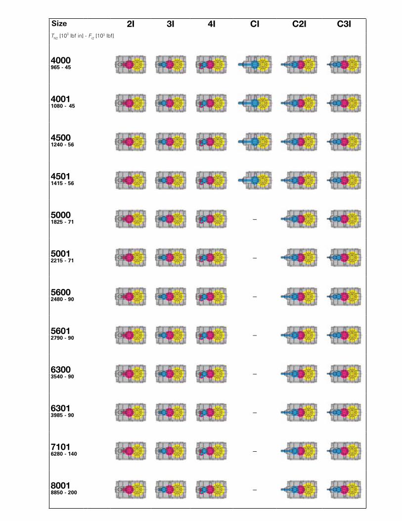
2I 3I 4I CI C2I C3ITN2 [103 lbf in] - Fr2 [103 lbf]
4000965 - 45
40011080 - 45
45001240 - 56
45011415 - 56
5000 –1825 - 71
5001 –2215 - 71
5600 –2480 - 90
5601 –2790 - 90
6300 –3540 - 90
6301 –3985 - 90
7101 –6280 - 140
8001 –8850 - 200
Size

Contents
Overview ......................................................................................................................................................... 4
1 - General specifications ............................................................................................................................. 11
2 - Designation.............................................................................................................................................. 15
3 - Service factor fs........................................................................................................................................ 19
4 - Thermal power Pt [hp]............................................................................................................................. 23
5 - Selection................................................................................................................................................... 27
6 - Structural and operational details............................................................................................................. 33
7 - Helical gear reducer selection tables........................................................................................................ 41
8 - Dimensions, designs, mounting positions (helical gear reducers)............................................................ 49
9 - Bevel helical gear reducer selection tables............................................................................................... 63
10 - Dimensions, designs, mounting positions (bevel helical gear reducers).................................................. 71
11 - Radial loads.............................................................................................................................................. 85
12 - Accessories and non-standard designs................................................................................................... 103
13 - Installation and maintenance.................................................................................................................... 127
Technical formulae........................................................................................................................................... 133
6
8
10
12
14
13
11
9
7
5
4
3
2
1
6
8
10
12
13
11
9
7
5
4
3
2
1

Who we are
In brief:
1953 Founded as a family business and still privately owned today
Your worldwide partner for high quality solutions
70’s First in Italy to adopt a completely modular system for helical and bevel helical gear reducers; fi rst in Italy to adopt a case hardened, tempered, ground gear pairs on helical and bevel helical gear reducers
80’s Worm gear reducers and gearmotors with universal mounting, single-piece housing and ZI involute profi le; Extension of the direct sales organization abroad with the addition of German, English, French and Spanish subsidiaries.
90’s Helical and bevel helical gear reducers and gearmotors with universal mounting and single-piece housing; fi rst transmission manufacturer in Italy and second in Europe to obtain Quality System Certifi cation ISO 9001.
1994 The only manufacturer to offer 3-year-warranty
1997 Acquisition of Seimec (Rossi Motor Division)
2002 Acquisition of SMEI (Rossi Planetary Division, WIND)
2003 ISO 9001 - 2000 (Vision 2000)
2004 New affi liated company in U.S.A.Habasit acquires important share in Rossi, to reinforce global presence and develop growth strategy
2009 (July) Habasit Holding owns 100% Rossi
2010 Logo and Company name change: from “Rossi Motoriduttori” to “Rossi S.p.A.”
2014-’16 Our US, UK, Brazil and China subsidiaries move to new facilities, striving to improve our customer service thanks to our modern structures and technologies
For more than 60 years we have been developing our business for the most demanding applications in order to become one of the world's leading gearbox and gearmotor manufacturers. Even in the toughest environment, we are recognized for providing state of the art technology, solid value and commitment to our customers.
Rossi in the 70’s
Rossi Industrial Gear Reducer Division, today
Rossi Planetary Gear Reducer Division
2003 ISO 9001 - 2000 (Vision 2000)

Where you can fi nd usClose to you, with facilities on six continents and each with a direct sales system to provide excellent service. Visit our website to fi nd your nearest facility. We are where you need us to be.
What we believe inChoosing the drive with the right technical specifi cations is vital for reliability and economy.We believe in integrity, ethical behavior, experience, creativity, innovation, good teamwork and above all customer focus: this what we at Rossi believe in. We strive to be a reliable company with the right fl exibility and know-how to respond to all market requests, all over the world, in all application fi elds, without ignoring our commitment to the environment and value on all human safety
What we can do for youRossi employs highly skilled specialists in different fi elds, there to provide you with the support and experience needed to fi nd the best solution for your application and commercial demands, and to accompany you step by step through the entire supply process.
What you can do for us, to help us improveYou are at the center of all we do, that is why we want your feedback and suggestions on how we can improve.You know your business better than anyone and by knowing what works for you will allow us to improve our service offering to you. We regard every relationship as a partnership and look for mutual benefi ts that will enhance our partnership at all times.
Who you can contactA well-organized Global after-sale service with the sole purpose of getting our customers back up and running quickly and cost effectively. Our online Rossi for You portal, allowing you to have 24/7/365 day access to all the documentations concerning our supplies, order tracking, and news in real time.
SubsidiariesDistributors / Dealers
WHERE WE’RE LOCATED

What we doOur wide standard product range and design allows us to provide the customer with the right engineered solution for every application including a 3 year worldwide warranty.
Gearmotors
Type of gear Catalog
Worm gearmotors A
Standardfi t worm gearmotors AS
Coaxial gearmotors E
Standardfi t coaxial gearmotors ES
Helical and bevel helical gear reducers G
Planetary (in-line and bevel helical) gearmotors EP
Gear reducers
Type of gear Catalog
Worm gear reducers A
Helical gear reducers G
Bevel Helical gear reducers G
Heavy duty helical gear reducers H
Heavy duty bevel helical gear reducers H
Planetary (in-line and bevel helical) gear reducers EP
Right angle shaft gear reducers L
Shaft mounted helical gear units P
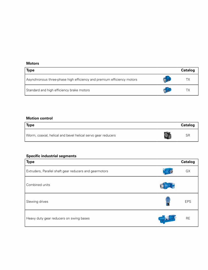
Motors
Type Catalog
Asynchronous three-phase high effi ciency and premium effi ciency motors TX
Standard and high effi ciency brake motors TX
Motion control
Type Catalog
Worm, coaxial, helical and bevel helical servo gear reducers SR
Specifi c industrial segments
Type Catalog
Extruders, Parallel shaft gear reducers and gearmotors GX
Combined units
Slewing drives EPS
Heavy duty gear reducers on swing bases RE

Features and Benefi ts
10 sizes with nominal torque from 965 to 3983 lbf inch
Increased performance maintaining the same fi nal reduction center distance, when compared with Rossi’s previous catalog H02
Sizes based on uniform incremental steps
• Improved ratings for the same required torque and more compact gear reducers compared with previous catalog H02
Gears designed, machined and measured according to high quality requirements (tooth grinding accuracy class DIN 6, both for cylindrical and bevel gears)
Bevel gears machined in closed-loop grinding process with correction of the measured deviations
Gear housings made with single placement bore machining and controlled through very high precision three-dimensional measuring systems
Load rating, according to standards, based on surface durability (pitting) and tooth bending strength
• Reliable and repeatable performances, suitable to satisfy Customer specifi cations
Horizontal center split housing cast in two halves from spheroidal cast iron (UNI ISO 1083) with reinforced stiff ening ribs
• Gear reducers suitable for low temperature operation (down to -40° F) without installation of accessories
Flexible mounting arrangements - typical mountings include horizontal, vertical, inclined and oscillating mounting positions
• Easy maintenance
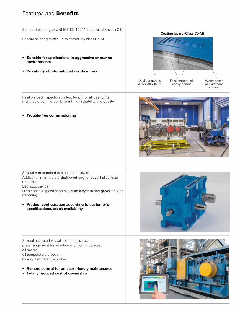
Features and Benefi ts
Standard painting to UNI EN ISO 12944-2 (corrosivity class C3)
Special painting cycles up to corrosivity class C5-M
• Suitable for applications in aggressive or marine environments
• Possibility of international certifi cations
Final on load inspection on test bench for all gear units manufactured, in order to grant high reliability and quality
• Trouble-free commissioning
Several non-standard designs for all sizes: Additional intermediate shaft overhung for bevel helical gear reducersBackstop deviceHigh and low speed shaft seal with labyrinth and grease feeder (taconite)
• Product confi guration according to customer's specifi cations, stock availability
Several accessories available for all sizes: pre-arrangement for vibration monitoring devicesoil heateroil temperature probesbearing temperature probes
• Remote control for an user friendly maintenance• Totally reduced cost of ownership
Dual-compound epoxy primer
Coating layers (Class C5-M)
Water-based polyurethane
enamel
Dual compound zink epoxy paint
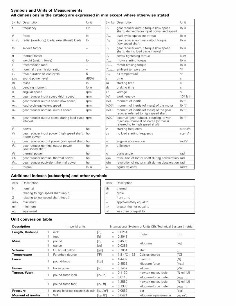
Symbols and Units of MeasurementsAll dimensions in the catalog are expressed in mm except where otherwise stated
Symbol Description Unit Symbol Description Unit
f frequency Hz T2 gear reducer output torque (low speed shaft), derived from input power and speed
lb in
F force lb T2eq load cycle equivalent torque lb in
Fr, Fa radial (overhung) loads, axial (thrust) loads lb TN2 gear reducer nominal output torque (low speed shaft)
lb in
fs service factor – T2i gear reducer output torque (low speed shaft), during load cycle interval i
lb in
ft thermal factor – TS screw tightening torque N m
G weight (weight force) lb Tstart motor starting torque lb in
i transmission ratio – Tbrake motor braking torque lb in
iN nominal transmission ratio – Tambient ambient temperature °F
Lh total duration of load cycle h Toil oil temperature °F
LWA sound power level dB(A) t time s
m mass lb ta starting time s
Mb bending moment lb in tb braking time s
n angular speed rpm U voltage V
n1 gear reducer input speed (high speed) rpm W work, energy 106 lb in
n2 gear reducer output speed (low speed) rpm WK moment of inertia lb ft2
n2eq load cycle equivalent speed rpm WK02 moment of inertia (of mass) of the motor lb ft2
nN2 gear reducer nominal output speed rpm WK12 moment of inertia (of mass) of the gear
reducer referred to high speed shaftlb ft2
n2i gear reducer output speed during load cycle interval i
rpm WKR2 external (gear reducer, coupling, driven
machine) moment of inertia (of mass) referred to to high speed shaft
lb ft2
P power hp z starting frequency starts/h
P1 gear reducer input power (high speed shaft), motor power
hp z0 no load starting frequency starts/h
P2 gear reducer output power (low speed shaft) hp α angular acceleration rad/s2
PN2 gear reducer nominal output power (low speed shaft)
hp η efficiency –
Pt thermal power hp ϕ plane angle rad
PtN gear reducer nominal thermal power hp ϕa1 revolution of motor shaft during acceleration rad
P1th gear reducer equivalent thermal power hp ϕb1 revolution of motor shaft during deceleration rad
T torque lb in ω agular velocity rad/s
Additional indexes (subscripts) and other symbols
Index Description Index Description
N nominal th thermal
1 relating to high speed shaft (input) c cycle
2 relating to low speed shaft (input) – from ... to
max maximum ≈ approximately equal to
min minimum greater than or equal to
eq equivalent less than or equal to
Unit conversion table
Description Imperial units International System of Units (SI), Technical System (metric)
Length, Distance 1 inch [in] = 0.0254meter [m]
1 foot [ft] = 0.3048
Mass 1 pound [lb] = 0.4536kilogram [kg]
1 ounce [oz] = 0.0283
Volume 1 US liquid gallon [gal] = 3.7854 liter [l]
Temperature 1 Farenheit degree [°F] = 1.8 · °C + 32 Celsius degree [°C]
Force1 pound-force [lb(f)]
= 4.4482 newton [N]
= 0.4536 kilogram force [kg(f)]
Power 1 horse power [hp] = 0.7457 kilowatt [kW]
Torque, Work1 pound-force inch [lb(f) in]
= 0.1130 newton meter, joule [N m], [J]
= 0.0115 kilogram-force meter [kg(f) m]
1 pound-force foot [lb(f) ft]= 1.3560 newton meter, joule [N m], [J]
= 0.1383 kilogram-force meter [kg(f) m]
Pressure 1 pound-force per square inch (psi) [lb(f) /in2] = 0.0689 bar [bar]
Moment of inertia 1 WK2 [lb(f) ft2] = 0.0421 kilogram square-meter [kg m2 ]

11RossiH series − Imperial units
1
2582
-01.
01
1 - General specifi cations

12 Rossi H series − Imperial units
11
2582
-01.
01
1 - General specifi cations
Closer size and performance steps; 5 size pairs (standard and strengthened) with fi nal reduction center distance to R 20 series, for a total of 12 sizes with performance intervals by about 18% Universal mounting: suitable for horizontal or vertical mountingRigid and precise spheroidal cast iron housing; high oil capacityGear pairs design especially studied to obtain high resistance, motion regularity, low noise and high effi ciency with consequent low heatingHigh, reliable and tested performancesPrearranged for backstop device, possibility of double extension low and high speed shaftPossibility of withstanding high loads on shaft endsPossibility of obtaining multiple and 90° drives with no restriction on direction of rotation of input/output shaftsManufacturing and product management fl exibilityHigh manufacturing quality standardMinimum maintenance requirementsLarge size gear reducers produced in series specifi cally conceived for granting highest reliability in heaviest application conditions. This series combines and exalts the traditional qualities of helical and bevel helical gear reducers – strength, effi ciency, compactness, reliability – with advantages derived from modern design, manufacturing and operating criteria – universality and application ease, wide size range, service, economy – the advantages typically associated with high quality gear reducers produced in series.
Main structural featuresMain specifi cations are:– universal mounting with feet integral with housing on 2 faces or frontal with spigot on low speed shaft cover (see ch. 6);– closer size and performance steps; 5 size pairs (standard and strengthened) with fi nal reduction center distance to R 20
series, for a total of 12 sizes with performance intervals by about 18%; the size pairs are obtained with the same housing and many components in common;
– gear reducer overall sized so as to permit the transmission of high nominal and maximum torques, and to withstand high loads on the high and low speed shaft ends;
– cylindrical low speed shaft end with key (right, left or double extension);– cylindrical high speed shaft end with key;– possibility of second high speed shaft extension (excluding C3I);– improved and upgraded modular construction both for component parts and assembled product;– standardized dimensions and compliance with standards;– spheroidal cast iron housing (400-15 UNI ISO 1083); stiff ening ribs and high oil capacity;– bearings: swinging roller bearings on low speed and intermediate shafts; coupled taper roller bearings plus one swinging
roller bearing on high speed shafts with train of gears 2I, CI, C2I, C3I and intermediate train of gears CI and C2I, taper roller bearing plus one cylindrical roller bearing on high speed shaft with train of gears 3I;
– oil bath lubrication; synthetic or mineral oil (ch. 13) including fi ller plug with valve, drain and level plug; sealed;– additional bearings lubrication through proper pipelines or pump;– natural or forced cooling (by fan, coil or independent cooling unit with heat exchanger, see ch. 12);– metal plugs; magnetic drain plug;– paint: external coating in water-soluble dual-compound polyurethan enamel resistant to atmospheric and aggressive
agents (corrosivity class C3 ISO 12944-2); suitable for further coats only with dual-compound products after degreasing and sanding; color blue RAL 5010 DIN 1843, other colors and/or painting cycles on request, see ch. . 12); internal protection in synthetic paint appropriate for resistance to mineral oils or to polyalphaolefi nes synthetic oils;
– optional designs: backstop device (always prearranged), shaft mounting arrangements, hollow low speed shaft with shrink disc or keyway, special paints, etc. (ch. 12).
13RossiH series − Imperial units
1
2582
-01.
01
1 - General specifi cations
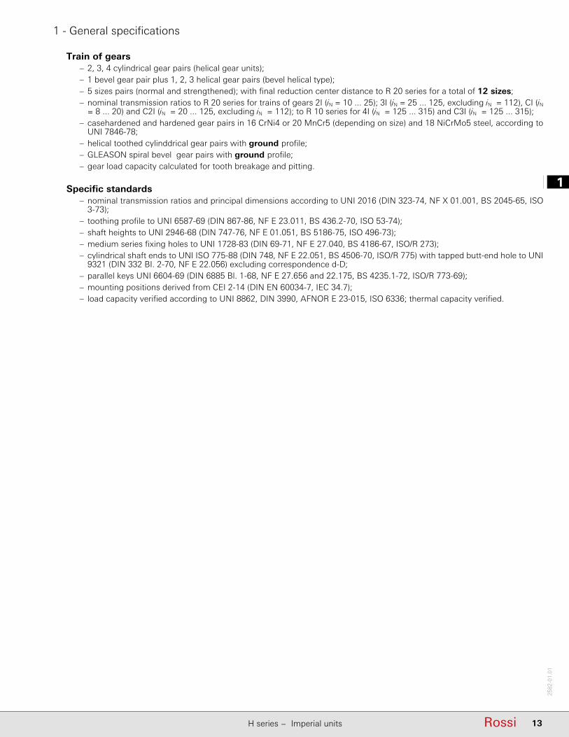
Train of gears– 2, 3, 4 cylindrical gear pairs (helical gear units);– 1 bevel gear pair plus 1, 2, 3 helical gear pairs (bevel helical type);– 5 sizes pairs (normal and strengthened); with fi nal reduction center distance to R 20 series for a total of 12 sizes;– nominal transmission ratios to R 20 series for trains of gears 2I (iN = 10 ... 25); 3I (iN = 25 ... 125, excluding iN = 112), CI (iN
= 8 ... 20) and C2I (iN = 20 ... 125, excluding iN = 112); to R 10 series for 4I (iN = 125 ... 315) and C3I (iN = 125 ... 315);– casehardened and hardened gear pairs in 16 CrNi4 or 20 MnCr5 (depending on size) and 18 NiCrMo5 steel, according to
UNI 7846-78;– helical toothed cylinddrical gear pairs with ground profi le;– GLEASON spiral bevel gear pairs with ground profi le;– gear load capacity calculated for tooth breakage and pitting.
Specifi c standards– nominal transmission ratios and principal dimensions according to UNI 2016 (DIN 323-74, NF X 01.001, BS 2045-65, ISO
3-73);– toothing profi le to UNI 6587-69 (DIN 867-86, NF E 23.011, BS 436.2-70, ISO 53-74);– shaft heights to UNI 2946-68 (DIN 747-76, NF E 01.051, BS 5186-75, ISO 496-73);– medium series fi xing holes to UNI 1728-83 (DIN 69-71, NF E 27.040, BS 4186-67, ISO/R 273);– cylindrical shaft ends to UNI ISO 775-88 (DIN 748, NF E 22.051, BS 4506-70, ISO/R 775) with tapped butt-end hole to UNI
9321 (DIN 332 BI. 2-70, NF E 22.056) excluding correspondence d-D;– parallel keys UNI 6604-69 (DIN 6885 Bl. 1-68, NF E 27.656 and 22.175, BS 4235.1-72, ISO/R 773-69);– mounting positions derived from CEI 2-14 (DIN EN 60034-7, IEC 34.7);– load capacity verifi ed according to UNI 8862, DIN 3990, AFNOR E 23-015, ISO 6336; thermal capacity verifi ed.

14 Rossi H series − Imperial units
11
2582
-01.
01
Page intentionally left blank
2
15RossiH series − Imperial units
2582
-01.
01
22
15Rossi
2 - Designation
H series − Imperial units
12
16 Rossi H series − Imperial units
2582
-01.
01
2 - Designation
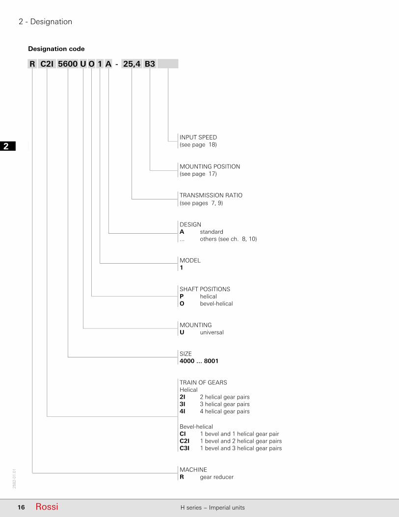
R C2I 5600 U O 1 A 25,4 B3-
INPUT SPEED(see page 18)
MOUNTING POSITION(see page 17)
TRANSMISSION RATIO(see pages 7, 9)
DESIGNA standard... others (see ch. 8, 10)
MODEL1
SHAFT POSITIONSP helicalO bevel-helical
MOUNTINGU universal
SIZE4000 … 8001
TRAIN OF GEARSHelical2I 2 helical gear pairs3I 3 helical gear pairs4I 4 helical gear pairs
Bevel-helicalCI 1 bevel and 1 helical gear pairC2I 1 bevel and 2 helical gear pairsC3I 1 bevel and 3 helical gear pairs
MACHINER gear reducer
Designation code
2
17RossiH series − Imperial units
2582
-01.
01
2 - Designation
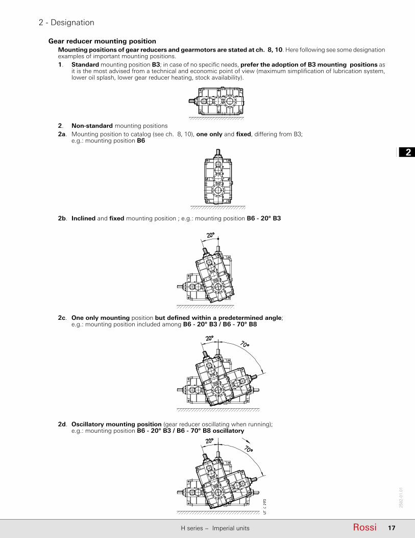
2. Non-standard mounting positions2a. Mounting position to catalog (see ch. 8, 10), one only and fi xed, diff ering from B3;
e.g.: mounting position B6
2d. Oscillatory mounting position (gear reducer oscillating when running);e.g.: mounting position B6 - 20° B3 / B6 - 70° B8 oscillatory
2c. One only mounting position but defi ned within a predetermined angle;e.g.: mounting position included among B6 - 20° B3 / B6 - 70° B8
2b. Inclined and fi xed mounting position ; e.g.: mounting position B6 - 20° B3
Gear reducer mounting positionMounting positions of gear reducers and gearmotors are stated at ch. 8, 10. Here following see some designation examples of important mounting positions.1. Standard mounting position B3; in case of no specifi c needs, prefer the adoption of B3 mounting positions as
it is the most advised from a technical and economic point of view (maximum simplifi cation of lubrication system, lower oil splash, lower gear reducer heating, stock availability).

12
18 Rossi H series − Imperial units
2582
-01.
01
2 - Designation
Input speedThe designation is always to be completed stating the input speed n1, chosen among the available ones as per catalog: 1 800 rpm (4 poles 60 Hz), 1 500 rpm (4 poles 50 Hz), 1 200 rpm (6 poles 60 Hz), 1 000 rpm (6 poles 50 Hz), 750 rpm (8 poles 50 Hz), 90 rpm (applications at low input speed).Example:R C2I 4501 UO1H-81,2 B3 n1 = 1 800 rpmR 3I 5600 UP1A-127 B3 n1 = 1 000 rpm
Accessories and non-standard designsIn the event of a gear reducer being required in a design diff erent from those stated above, specify it in detail (ch. 12).
3
19RossiH series − Imperial units
2582
-01.
01
33
19Rossi
3 - Service factor fs
H series − Imperial units

13
20 Rossi H series − Imperial units
2582
-01.
01
3 - Service factor fs
Service factor fs takes into account the diff erent running conditions (nature of load, running time, frequency of starting, speed n2, other considerations) which must be referred to when performing calculations of gear reducer selection and verifi cation.The power and torques shown in the catalog are nominal values (i.e. valid for fs = 1).The minimum service factor required is given by the following ratio:
fs required fs1 · fs2 · fs3 · fs4 · fs5
where fs1 … fs5 are stated in the following tables.
Service factor fs1 based on the nature of load and running time
Nature of load1) of the driven machine
fs1
Running time [h/d]
Ref. Description 2 4 8 16 24
a Uniform 1 1 1 1.18 1.32
b Moderate overloads (1.6 times the normal load) 1.12 1.18 1.25 1.5 1.7
c Heavy overloads (2.5 times the normal load) 1.4 1.5 1.7 2 2.24
Service factor fs2 based on nature of load and of frequency of starting
Nature of load1) of the driven machine
fs2
Frequency of starting z [starts/h]
Ref. Description 1 2 4 8 16 32
a Uniform 1 1.06 1.12 1.18 1.25 1.5
b Moderate overloads (1.6 times the normal load) 1 1 1.06 1.12 1.18 1.4
c Heavy overloads (2.5 times the normal load) 1 1 1 1.06 1.12 1.32
Details and considerations about service factor.fs values stated above are valid for:– maximum time on overload 15 s, on starting 3 s; if over and/or subject to heavy shock eff ect, consult us;– a whole number of overload cycles (or start) imprecisely completed in 1, 2, 3 or 4 revolutions of low speed shaft;
if precisely, a continuous overload should be assumed;Motors having a starting torque not exceeding nominal values (star-delta starting, particular types of motor operating on direct current, and single-phase motors), and particular types of coupling between gear reducer and motor, and gear reducer and driven machine (fl exible, centrifugal, fl uid and safety couplings, clutches and belt drives) aff ect service factor favourably, allowing its reduction in certain heavy-duty applications; consult us for verifi cation.
Service factor fs3 based on motor type
Motor typeDescription
fs3
Electric, turbine 1Electric three-phase with brake 1.06 4)
Internal combustion
multi-cylinder 1.25
single-cylinder 1.5
Service factor fs4 based on reliability level
Reliability level 5) fs4
Standard 1Average 1.25
High 1.4
Service factor fs5 based on output angular speed n2
Output speedn2 [min-1]
fs5
> 560 1.32560 − 355 1.25355 − 224 1.18
224 − 140 1.12140 − 90 1.06
90 1
1) For indication on the type of load of the driven machine according to the application, see table on next page.4) For Y- Δ starting, running with inverter or with «soft start» devices, fs3 = 1.5) Reliability degrees higher than normal are required in presence of very diffi cult maintenance, great importance of gear reducer in the production cycle,
safety,etc.
3
21RossiH series − Imperial units
2582
-01.
01
3 - Service factor fs
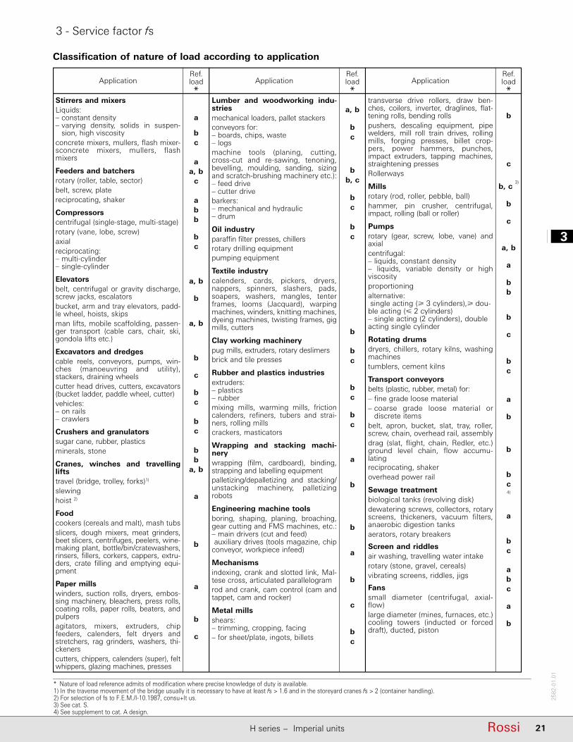
* Nature of load reference admits of modifi cation where precise knowledge of duty is available.1) In the traverse movement of the bridge usually it is necessary to have at least fs > 1.6 and in the storeyard cranes fs > 2 (container handling).2) For selection of fs to F.E.M./I-10.1987, consu+lt us.3) See cat. S.4) See supplement to cat. A design.
Application Application ApplicationRef.load*
Ref.load*
Ref.load*
Stirrers and mixersLiquids:– constant density– varying density, solids in suspen-
sion, high viscosityconcrete mixers, mullers, flash mixer-sconcrete mixers, mullers, flash mixers
Feeders and batchersrotary (roller, table, sector)belt, screw, platereciprocating, shaker
Compressorscentrifugal (single-stage, multi-stage)rotary (vane, lobe, screw)axialreciprocating:– multi-cylinder– single-cylinder
Elevatorsbelt, centrifugal or gravity discharge, screw jacks, escalatorsbucket, arm and tray elevators, padd-le wheel, hoists, skipsman lifts, mobile scaffolding, passen-ger transport (cable cars, chair, ski, gondola lifts etc.)
Excavators and dredgescable reels, conveyors, pumps, win-ches (manoeuvring and utility), stackers, draining wheelscutter head drives, cutters, excavators (bucket ladder, paddle wheel, cutter)vehicles:– on rails– crawlers
Crushers and granulatorssugar cane, rubber, plasticsminerals, stone
Cranes, winches and travelling liftstravel (bridge, trolley, forks)1)
slewinghoist 2)
Foodcookers (cereals and malt), mash tubsslicers, dough mixers, meat grinders, beet slicers, centrifuges, peelers, wine-making plant, bottle/bin/cratewashers, rinsers, fillers, corkers, cappers, extru-ders, crate filling and emptying equi-pment
Paper millswinders, suction rolls, dryers, embos-sing machinery, bleachers, press rolls, coating rolls, paper rolls, beaters, and pulpersagitators, mixers, extruders, chipfeeders, calenders, felt dryers and stretchers, rag grinders, washers, thi-ckenerscutters, chippers, calenders (super), felt whippers, glazing machines, presses
Lumber and woodworking indu-striesmechanical loaders, pallet stackersconveyors for:– boards, chips, waste– logsmachine tools (planing, cutting, cross-cut and re-sawing, tenoning, bevelling, moulding, sanding, sizing and scratch-brushing machinery etc.):– feed drive– cutter drivebarkers:– mechanical and hydraulic– drum
Oil industryparaffin filter presses, chillersrotary drilling equipmentpumping equipment
Textile industrycalenders, cards, pickers, dryers, nappers, spinners, slashers, pads, soapers, washers, mangles, tenter frames, looms (Jacquard), warping machines, winders, knitting machines, dyeing machines, twisting frames, gig mills, cutters
Clay working machinerypug mills, extruders, rotary deslimersbrick and tile presses
Rubber and plastics industriesextruders:– plastics– rubbermixing mills, warming mills, friction calenders, refiners, tubers and strai-ners, rolling millscrackers, masticators
Wrapping and stacking machi-nerywrapping (film, cardboard), binding, strapping and labelling equipmentpalletizing/depalletizing and stacking/unstacking machinery, palletizing robots
Engineering machine toolsboring, shaping, planing, broaching, gear cutting and FMS machines, etc.:– main drivers (cut and feed) auxiliary drives (tools magazine, chip conveyor, workpiece infeed)
Mechanismsindexing, crank and slotted link, Mal-tese cross, articulated parallelogramrod and crank, cam control (cam and tappet, cam and rocker)
Metal millsshears:– trimming, cropping, facing– for sheet/plate, ingots, billets
transverse drive rollers, draw ben-ches, coilers, inverter, draglines, flat-tening rolls, bending rollspushers, descaling equipment, pipe welders, mill roll train drives, rolling mills, forging presses, billet crop-pers, power hammers, punches, impact ex truders, tapping machines, straighte ning pressesRollerways
Millsrotary (rod, roller, pebble, ball)hammer, pin crusher, centrifugal, im pact, rolling (ball or roller)
Pumpsrotary (gear, screw, lobe, vane) and axialcentrifugal:– liquids, constant density– liquids, variable density or high viscosityproportioningalternative: single acting ( 3 cylinders), dou-ble acting ( 2 cylinders)– single acting (2 cylinders), double acting single cylinder
Rotating drumsdryers, chillers, rotary kilns, washing machinestumblers, cement kilns
Transport conveyorsbelts (plastic, rubber, metal) for:– fine grade loose material– coarse grade loose material or
discrete itemsbelt, apron, bucket, slat, tray, roller, screw, chain, overhead rail, assemblydrag (slat, flight, chain, Redler, etc.) ground level chain, flow accumu-latingreciprocating, shakeroverhead power rail
Sewage treatmentbiological tanks (revolving disk)dewatering screws, collectors, rotary screens, thickeners, vacuum filters, anaerobic digestion tanksaerators, rotary breakers
Screen and riddlesair washing, travelling water intakerotary (stone, gravel, cereals)vibrating screens, riddles, jigs
Fanssmall diameter (centrifugal, axial-flow)large diameter (mines, furnaces, etc.) cooling towers (inducted or forced draft), ducted, piston
a
bc
aa, b
c
abb
bc
a, b
b
a, b
b
c
bc
bc
bb
a, b
a
b
a
b
c
a, b
bc
bb, c
bc
bc
b
bc
bc
bc
a
b
b
a
b
c
bc
b
c
b, c 3)
b
c
a, b
a
bb
b
c
bc
a
b
b
bc4)
a
bc
abc
a
b
Classification of nature of load according to application

13
22 Rossi H series − Imperial units
2582
-01.
01
Page intentionally left blank

4
23RossiH series − Imperial units
2582
-01.
01
23Rossi
44
4 - Thermal power Pt [hp]
H series − Imperial units

14
24 Rossi H series − Imperial units
2582
-01.
01
4 - Thermal power Pt [hp]
The nominal thermal power PtN, stated in red in the table, is that which can be applied at the gear reducer input, without exceeding 203 °F1) (95 °C) approximately oil temperature when operating in following running conditions:– input speed n1 = 1 500 rpm– mounting position B3;– continuous duty S1;– maximum ambient temperature 68 °F (20° C) (in the table the values referred to 104 °F (40° C) are stated);– maximum altitude 3300 ft above sea level;– air speed 4 ft/s (typical value in presence of a self-cooled motor).
Always verify that the power applied P1 is lower than or equal to gear reducer thermal power PtN multiplied by correction coeffi cients ft1, ft2, ft3, ft4, ft5 (stated in the following tables) considering the various operating conditions:
P1 PtN · ft1 · ft2 · ft3 · ft4 · ft5
When the power applied is not constant and when the exact load cycle is given, it is possible, or advisable, to calculate the equivalent power applied, according to the formula:
3
c
n3
2i3
223
213
2eq 1
ni21th
......1
t
tPtPtPtP
P
[kN] 81,67
2
22r nd
PF
[kN] 32,20
2
22r nd
PF
[kN] 75,47
2
22r nd
PF
[kN] 1,19
2
22r nd
PF
[kN] yxyE/2
2r'2r
FF
[kN] 75,47
1
11r nd
PF
[kN] 65,28
1
11r nd
PF
richiesto richiesto f
20
2 MJJ
JMi
M
required required f
20
2 MJJ
JMi
M
required required - available start
start 20
22N
2 MJJ
JMM
MM
M
richiesto richiesto - edisponibil spunto
spunto 20
22N
2 MJJ
JMM
MM
M
c
n2i222122eq
ni21......
t
tntntntn n
p
c2
n2p2i2
p222
p212
p2
2eqeq
nnii2211......
tn
tnMtnMtnMtnM
M
where:η is the gear reducer effi ciency (see ch. 6);P2i [hp] is the power, referred to the gear reducer output, required in the time interval ti [s];tc = t1 + t2 + ... + ti + ... + tn is the total duration of load cycle [s].
In these cases choose factor ft2 from the continuous duty column S1.Whenever the thermal verifi cation should not be satisfi ed, in spite the prearrangement of cooling system, it is possible to install an independent cooling unit with heat exchanger (see ch. 12); consult us.Thermal power needs not be taken into account when maximum duration of continuous running time is 1 − 3 h (from small to large gear reducer sizes) followed by rest periods long enough to restore the gear reducer to near ambient temperature (likewise 2 − 4 h). For maximum ambient temperature higher than 122 °F (50° C) or lower than 32 °F (0° C) consult us.
1) Corresponding to an average temperature of the external housing surface of approximately 185 °F; locally housing temperature can achieve the oil temperature.
3) If, simultaneously, forced cooling with coil is acting, multiply the values by 1.8.4) For positions, dimensions and design verifi cation see ch. 12.5) Value also valid for electric fan (installed by the Buyer).6) With axial fan, values are to be multiplied by 1.12. Consult us. 7) (Duration of running on load / 60) · 100 [%].
Nominal thermal power PtN
TambTrain of gears
Gear reducer size
PtN [hp]
4000,4001
4500,4501
5000,5001
5600,5601
6300,6301
7101 8001
52 °F(20° C)
2I 425 475 670 750 950 1120 16003I 315 355 500 560 710 850 11804I 236 265 375 425 530 630 900CI 400 560 – – – – –C2I 315 355 500 560 710 850 1180C3I 236 265 375 425 530 630 900
104 °F(40° C)
2I 315 355 500 560 710 850 11803I 236 265 375 425 530 630 9004I 180 200 280 315 400 475 670CI 300 425 – – – – –C2I 236 265 375 425 530 630 900C3I 180 200 280 315 400 475 670

4
25RossiH series − Imperial units
2582
-01.
01
4 - Thermal power Pt [hp]
Thermal factor ft3 according to mounting position (see also ch. 8, 10): where it is not specifi ed ft3 = 1
Train of gears
ft3
mounting position
B3 B6 B7 V5 V6
2I 1 0.9 0.8 0.8 0.9
3I 1 0.9 0.8 0.8 0.9
4I 1 0.9 0.8 0.8 0.9
CI
UO1A, UO1A sin, UO1F, UO1F sin, UO1N, UO1N sin UO1V, UO1V sin, UO1S, UO1S sin, UO1L, UO1L sin 1 0.85 0.71 0.85 low speed wheel on the bottom
0.71 low speed wheel on the top
UO1H, UO1H sin, UO1G, UO1G sin, UO1M, UO1M sin 0.85 0.71 0.6 0.71 low speed wheel on the bottom0.6 low speed wheel on the top
C2I
UO1A, UO1Asin, UO1F, UO1Fsin, UO1N, UO1Nsin UO1V, UO1Vsin, UO1S, UO1Ssin, UO1L, UO1Lsin 1 0.9 0.8 0.9 low speed wheel on the top
0.8 low speed wheel on the bottom
UO1H, UO1H sin, UO1G, UO1G sin, UO1M, UO1M sin 0.9 0.8 0.71 0.8 low speed wheel on the top0.71 low speed wheel on the bottom
C3I 1 0.9 0.8 0.9 low speed wheel on the bottom0.8 low speed wheel on the top
Thermal factor ft1 (= ft1a · ft1b) according to cooling system and input speed n1
Cooling system
ft1a . ft1b
input speed n1 [rpm]
750 1 000 1 200 1 500 1 800
ft1aNaturalconvection
train of gears
2I. CI 1.18 1.12 1.06 1 0.853I. 4I. C2I. C3I 1.06 1.06 1.03 1 0.95
ft1b
Forced cooling3) 4) 6)
with 1 radial fan (helical gear units) 1.12 1.18 1.25 1.32 1.4
with 2 radial fans (helical gear units)with 1 radial fan (bevel helical gear units) 1.25 1.4 1.6 1.85) 2
with water coil4) 2
Thermal factor ft2 according to ambient temperature and service
Maximum ambient
temperature °F (°C)
ft2
ContinuousdutyS1
Intermittent duty S3 ... S6
Cyclic duration factor [%]for 60 min running7)
60 40 25 15
122 (50) 0.6 0.71 0.8 0.95 1104 (40) 0.75 0.9 1 1.12 1.2586 (30) 0.9 1.06 1.18 1.32 1.568 (20) 1 1.18 1.32 1.5 1.7
50 (10) 1.12 1.32 1.5 1.7 1.9
Thermal factor ft4 according to altitude of installation
Altitude a.s.l.[ft]
ft4
3300 13300 − 6600 0.956562 − 9843 0.9
9843 − 13123 0.85 13123 0.8
Thermal factor ft5 according to cooling air speed on housing
Air speedft/s
Installation environment ft5
< 2.07 very small environment or without air movements or with protected gear reducer consult us2.07 small environment and with limited air movements 0.713.28 wide environment without air movements 0.904.10 wide environment with light air movements (e.g. gearmotor with self-cooled
motor1.00
8.2 open and cooled 1.1813.12 with heavy air movements 1.32
14
26 Rossi H series − Imperial units
2582
-01.
01
Page intentionally left blank
5
27RossiH series − Imperial units
2582
-01.
01
27Rossi
5 - Selection
5.1 - Preliminary considerations ..................................................................................................................... ..28
5.2 - Determining the gear reducer size ........................................................................................................... 29
5.3 - Verifi cations ............................................................................................................................................. 30
5.4 - Selection questionnaire ............................................................................................................................ 30
H series − Imperial units

15
28 Rossi H series − Imperial units
2582
-01.
01
5 - Selection
5.1 - Preliminary considerations
Motor power
Taking into account the effi ciency of the gear reducer, and other drives – if any – motor power is to be as near as possible to the power rating required by the driven machine: accurate calculation is therefore recommended.The power required by the machine can be calculated, seeing that it is related directly to the power-requirement of the work to be carried out, to friction (starting, sliding of rolling friction) and inertia (particularly when mass and/or acceleration or deceleration are considerable). It can also be determined experimentally on the basis of tests, comparisons with existing applications, or readings taken with ammeters or wattmeters.An oversized motor would involve: a greater starting current and consequently larger fuses and heavier cable; a higher running cost as power factor (cosϕ) and effi ciency would suff er; greater stress on the drive, causing danger of mechanical failure, drive being normally proportionate to the power rating required by the machine, not to motor power.In such cases, a detailed description of duty requirement must be made available: duration and frequency per hour of work cycle, ac celeration and deceleration requirements if any, inertia, loads deriving from friction and work. In the absence of such data it is essential to provide all details which will permit their determination.Only high values of ambient temperature, altitude, frequency of starting or other particular conditions require an increase in motor power.
Input speed n1
The maximum gear reducer input speed, valid for continuous duty S1 and in absence of a forced lubrication system of gears and bearings (with eventual heat exchanger), is stated in the following table according to train of gears and gear reducer size.For intermittent duty or for particular needs, higher speeds are possible, but always lower than n1peak; consult us.Peak speed is admitted for a maximum duration of 5 s, including a proper rest period, or a low or null speed period for the cooling of gear reducer, especially on high speed shaft side. For variable n1, the selection should be carried out on the basis of n1max, but it should also be verifi ed on the basis of n1min.When there is a belt drive between motor and gear reducer, diff erent input speeds n1 should be examined in order to select the most suitable unit from engineering and economy standpoints alike.Input speed should not be higher than 1 800 rpm, unless conditions make it necessary; better to take advantage of the transmission, and use an input speed lower than 900 rpm.
Size Train of gears
2I 3I 4I CI C2I C3I
iN n1max n1peak iN n1max n1peak iN n1max n1peak iN n1max n1peak iN n1max n1peak iN n1max n1peak
rpm rpm rpm rpm rpm rpm rpm rpm rpm rpm rpm rpm
4000,4001
all 1 600 2 120 all 1 800 2 240 all 1 800 2 360 8 … 11,2 1 250 2 120 20 … 25 1 400 2 240 all 1 800 2 36012,5 … 18 1 600 2 120 28 … 40 1 600 2 240
45 … 100 1 800 2 240
4500,4501
all 1 600 2 120 all 1 800 2 240 all 1 800 2 360 8 … 10 1 180 2 120 22,4 … 28 1 400 2 240 all 1 800 2 36011,2 …12,5 1 250 2 120 31,5 … 45 1 600 2 240
14 … 20 1 600 2 120 50 … 125 1 800 2 240
5000,5001
all 1 250 2 000 31,5 1 600 2 120 all 1 800 2 240 – – – 22,4 … 25 1 180 2 120 all 1 800 2 240 35,5 1 800 2 120 28 … 40 1 250 2 120
45 … 100 1 600 2 120
5600,5601
all 1 250 2 000 40 1 600 2 120 all 1 800 2 240 – – – 25 … 28 1 180 2 120 all 1 800 2 240 45 1 800 2 120 31,5 … 45 1 250 2 120
50 … 125 1 600 2 120
6300,6301
all 1 060 1 900 31,5 1 400 2 000 all 1 800 2 120 – – – 28 … 35,5 1 180 2 000 all 1 800 2 12035,5 … 50 1 600 2 000 40 … 56 1 250 2 000
56 1 800 2 000 63 … 100 1 600 2 000
7101 14 900 1 400 35,5 1 180 2 000 160 1 600 2 120 – – – 40 900 1 700 125 1 400 2 120 16 1 060 40 … 50 1 400 200 1 800 45 1 180 160 1 600
56 1 700 200 1 800
8001 14 800 1 250 35,5 950 1850 160 1 320 2 000 – – – 40 900 1 600 125 1 180 2 000 16 900 40 … 50 1 120 200 1 600 45 1 180 160 1 250
56 1 400 200 1 600

5
29RossiH series − Imperial units
2582
-01.
01
5 - Selection
5.2 - Determining the gear reducer size
Constant load
– Fill out the questionnaire for the selection on page 31; in particular, make available required output power P2, the angular speeds n2 and n1, the running conditions (nature of load, frequency of starting h/d, frequency of starting z, other considerations) referring to ch. 3.
– Determine service factor fs required on the basis of running conditions (ch. 3).– Select the gear reducer size (also, the train of gears and transmission ratio i at the same time) on the basis of n2, n1 and of
a power PN2 greater than or equal to P2 · fs (ch. 7 and 9).– Calculate power P1 required at input side of gear reducer using the formula P2 / η, where η = 0,97 ÷ 0,94 is the effi ciency
of gear reducer (ch. 6).When for reasons of motor standardization, power P1 applied at input side of gear reducer turns out to be higher than the power required (considering motor/gear reducer effi ciency), it must be certain that this excess power applied will never be required, and frequency of starting z is so low as not to aff ect service factor (ch. 3).Otherwise, make the selection by multiplying PN2 by P1 applied P1 required.Calculations can also be made on the basis of torque instead of power; this method is even preferable for low n2 values.
Variable load
– Fill out the questionnaire for the selection on page 31; in particular, make available the torque T2 and the angular speed n2 required at gear reducer output, the running conditions (nature of load, duration of running required, frequency of starting z, other considerations) referring to ch. 3.
– In presence of required torque T2 and angular speed n2 variable in time, according to a given load cycle, calculate the equivalent torque T2eq and angular speed n2eq with the following formulae:
where:T2eq [lbf in] is the equivalent torque of load cycleT2i [lbf in] is the torque required (constant) of load level in2eq [rpm] is the equivalent speed in the load cyclen2i [rpm] is the low speed shaft speed (constant) of load level iti [min] is the duration of interval itc [min] is the total duration of cycle (t1 + ... + ti + ...+ tn) p = 6,61 for a running duration 8 h/dp = 3,33 for a running duration > 8 h/d
T T
T
T
T
15
30 Rossi H series − Imperial units
2582
-01.
01
5 - Selection
5.3 - Verifi cations– Verify possible radial loads Fr1, Fr2 and axial loads Fa2 according to instructions and values given in ch. 11.– When a load chart is available, and/or there are overloads – due to starting on full load (especially with high inertias and
low transmission ratios), braking, shocks, gear reducers in which the low speed shaft becomes driving member due to driven machine inertia, or other static or dynamic causes - verify that the maximum torque peak (ch. 6) is always lower than T2max (see ch. 7, 9), if higher or if it cannot be evaluated in the above cases, install a safety device so that T2max will bever be exceeded.
– Verify that the input speed is lower than or equal to n1max (see ch. 5.1);– Verify for each single interval i of the eventual load cycle that the required torque T2i is lower than T2max and that input
speed (relevant to output shaft speed n2i) is n1i n1max (see ch. 5.1);– Verify the possible need for forced cooling (ch. 4 and 12).– For gear reducers with backstop device, having particular iN or low values of fs, verify load capacity of backstop
device according to the values given in the table «Backstop device load capacity» (ch. 12).
5.4 - Selection questionnaireMake available all data and information necessary for a correct gear reducer selection by fi lling out the questionnaire on next page.Attach any technical specifi cations relevant to gear reducer, excluding data regarding the machine of the plant.When possible, attach all possible drawings, pictures and/or any further information facilitating the technical and economic selection.

5
31RossiH series − Imperial units
2582
-01.
01
5 - Selection
1 Application conditions Ambient temperature [°F] Gear reducer position:min standard max small environment with limited air
movement (vair < 2.07 ft/s)Application / Industry sector wide environment with free air
movement (vair 4.10 ft/s)Altitude [m above sea level]Type of machine to be driven open space, prot. against extremes of
weather and solar radiance new machine Environment: existing machine, running normal (industrial) indoor
gear reducer currently applied normal (industrial) outdoor dusty corrosive / humid
2 Load dataNature of load: Running time [h/d]
Required output speed [rpm] uniformmin nominal max moderate overloads
heavy overloadsTotal duration [h]
Torque required at low speed shaft [lbf in] Frequency of starting [starts/h]min nominal max
Duty cycle (S1 ... S10)Required output power [hp] Machine moment of inertia [lb ft2]
min nominal max min standard max
Load cycle attached
Input speed (gear reducers) [rpm] yes
min nominal max no
3 Motor IEC motor size (a.c. motor) Electric motor design (a.c. and d.c.): with independent cooling fan
Motor type: Type of a.c. motor starting: with encoder: asynchronous three-phase (a.c.) direct with tacho-generator asynchr.three-phase with inverter Y / ∆ d.c. motor with relevant converter soft starter / inverter System of motor-gear reducer mounting: int. combust. motor (single-cylinder) Electromagnetic motor with coupling int. combust. motor (multi-cylinder) parking brake with trapezoidal belts
work section No. dm [in] d1 [in]
Power P1 [hp] safetymin nominal max Braking torque [lbf in] with timing belt
section No. dm [on]
Nominal speed n1 [rpm] Starting torque [lbf in]min nominal max Eventual limit to drive dimensions
Moment of inertia [lb ft2]a.c. motor supply:
voltage [V] frequency [Hz]
4 Gear reducer Type of machine coupling shaft mounting
Mounting position with fl uid / fl exible coupling with cardan joint
Direction of rotation of output shaft with toothed belt drive white arrow pitch dm d1
ϕ
black arrow white and black arrow with chain
pitch No. z2 z3 overhang [in] ϕ
Backstop device (if present) free rotation, white arrow straight tooth cylindrical gear free rotation, black arrow pitch No. z2 z3 overhang [in] ϕ
Type of admitted cooling with fan Eventual axial load Fa [lbf] with coil with internal exchanger with UR O/A unit with UR O/W unit Eventual limit to drive dimensions
15
32 Rossi H series − Imperial units
2582
-01.
01
Page intentionally left blank
6
33RossiH series − Imperial units
2582
-01.
01
6 - Structural and operational details
Sound levels LWA and LpA ...................................................................................................................................... 34
Effi ciency ................................................................................................................................................................34
Overloads ...............................................................................................................................................................34
Moment of inertia (of mass) J1 [lb ft2] ....................................................................................................................35
High and low speed shaft end ...............................................................................................................................36
Plug dimensions .....................................................................................................................................................36
Side-cover dimensions ...........................................................................................................................................37
Direction of rotation ...............................................................................................................................................37
Forced bearing and/or gear lubrication or with independent cooling unit .............................................................38

16
34 Rossi H series − Imperial units
2582
-01.
01
6 - Structural and operational details
Sound levels LWA and LpA
Standard production sound power level LWA [dB(A)]1) and mean sound pressure level LpA [dB(A)]2) assuming nominal load, and input speed n1 = 1 5003) rpm. Tolerance +3 dB(A).If required, gear reducers can be supplied with reduced sound levels (normally 3 dB(A) less than tabulated values): consult us.In case of gear reducers with fan cooling, add to the values in the table 3 dB(A) for 1 fan and 5 dB(A) for 2 fans.
Size Helical gear reducers Bevel helical gear reducers
R 2I R 3I R 4I R CI R C2I R C3IiN 12,5 iN 14 iN 63 iN 71 iN 160 iN 200 iN 16 iN 18 iN 63 iN 71LWA LpA LWA LpA LWA LpA LWA LpA LWA LpA LWA LpA LWA LpA LWA LpA LWA LpA LWA LpA LWA LpA
4000 ... 4501 105 93 102 90 101 89 98 86 95 83 92 80 101 89 96 84 98 86 96 84 92 805000 ... 5601 – – 106 94 105 93 102 90 99 87 96 84 – – – – 101 89 99 87 96 846300, 6301 – – 110 98 109 97 106 94 103 91 100 88 – – – – 104 92 102 90 99 87
7101 – – 112 100 111 99 108 96 105 93 102 90 – – – – 106 94 104 92 102 908001 – – 114 102 113 101 110 98 107 95 104 92 – – – – 107 95 105 93 103 91
1) To ISO/CD 8579.2) Mean value of measurement at 3.18 ft from external profi le of gear reducer standing in free fi eld on a refl ecting surface.3) In the speed range n1 750 − 1 800 min-1, sum to the table values: –3 dB(A) for 750 rpm; –2 dB(A) for 1000 rpm;
–1 dB(A) for n1 = 1 200 rpm; +2 dB(A) for n1 = 1 800 rpm.
Effi ciencyThe effi ciency stated in the table is rough and referred to nominal running conditions (torque, speed, temperature); it is necessary to keep in mind that the effi ciency value can diminish considerably for values of T2 << TN2.
Nominaleffi ciency
Helical gear reducers Bevel helical gear reducers
R 2I R 3I R 4I R CI R C2I R C3I
η 0.970 0.955 0.940 0.970 0.955 0.940
OverloadsWhen a gear reducer is subjected to high static and dynamic overloads, the need arises for verifying that such overloads will always remain lower than T2max (see ch. 7, 9).Overloads are normally generated when one has:– starting on full load (especially for high inertias and low trans mission ratios), braking, shocks;– gear reducers in which the low speed shaft becomes driving member due to driven machine inertia;– applied power higher than that required; other static or dynamic causes.The following general observations on overloads are accompanied by some formulae for carrying out evaluations in certain typical instances.Where no evaluation is possible, install safety devices which will keep values within T2max.
Starting torque
When starting on full load (especially for high inertias and low transmission ratios) verify that T2max is equal to or greater than starting torque, by using the following formula:
T2 start = � T startTN
· T2 available – T2 required� WKR2
WKR2 + WK0
2 + T2 required
where:T start and TN are the starting torque and the motor nominal torque, respectively;T2 required is the torque absorbed by the machine through work and frictions;T2 available is the output torque due to motor nominal power;
WK02 is the moment of inertia (of mass) of the motor;
WKR2 is the external moment of inertia (of mass); gear reducers, couplings, driven machine referred to the motor
shaft;NOTE: when seeking to verify that starting torque is suffi ciently high for starting, take into account starting friction, if any, in evaluating T2 required.Stopping machines with high kinetic energy (high moments of inertia combined with high speeds) with brake motor
�Tbrake
· i + T2 required� WKR2
WKR2 + WK0
2 – T2 required < 1.6 · TN2
where:Tbrake is the braking torque applied on high speed shaft; for other symbols see above and ch. 1.

6
35RossiH series − Imperial units
2582
-01.
01
6 - Structural and operational details
Moment of inertia (of mass) WK12 [lb ft2]
The moment of inertia is referred to the high speed shaft of gear reducer, design with only one single HSS and LSS end; the one referred to the low speed shaft is given by following ratio: WK2
2 = WK12 · i 2.
Train of gears
iN
Gear reducer size1)
Moment of inertia of mass WK1 [lb ft2]
4000 4001 4500 4501 5000 5001 5600 5601 6300 6301
2I
10 16.92 17.37 – – – – – – – –11.2 16.23 16.61 18.98 19.29 – – – – – –12.5 11.08 11.34 17.96 18.25 – – – – – –
14 10.63 10.87 12.36 12.58 33.06 33.91 38.18 38.75 85.26 86.4516 10.23 10.44 11.75 11.91 31.63 32.34 36.12 36.62 80.97 81.3518 7.048 7.190 11.13 11.27 23.59 24.13 34.15 34.58 78.22 79.07
20 6.787 6.906 10.68 10.80 22.69 23.14 32.99 33.36 56.72 56.9522.4 6.621 6.739 7.356 7.451 19.17 19.53 24.28 24.56 55.01 55.53
3I
25 4.983 5.055 7.072 7.143 18.75 19.06 20.46 20.67 – –
28 4.888 4.936 5.316 5.363 14.29 14.50 15.50 15.64 36.21 36.5231.5 4.794 4.841 5.149 5.197 13.95 14.12 15.02 15.14 35.03 35.14
35.5 3.536 3.560 5.007 5.031 9.919 10.04 14.55 14.64 23.64 23.8340 3.465 3.488 3.702 3.726 9.706 9.801 14.26 14.36 22.92 22.9945 3.156 3.180 3.607 3.631 8.590 8.662 10.09 10.13 19.79 22.62
50 3.109 3.132 3.251 3.275 8.448 8.519 8.875 8.923 19.36 19.4156 1.780 1.804 3.204 3.204 5.719 5.766 8.685 8.733 13.17 14.9563 1.756 1.780 1.851 1.875 5.624 5.672 5.909 5.933 12.89 12.91
71 1.281 1.281 1.827 1.827 3.892 3.916 5.790 5.814 8.614 12.7780 1.258 1.258 1.329 1.329 3.844 3.868 4.010 4.034 8.448 8.47290 1.139 1.139 1.281 1.305 3.512 3.536 3.939 3.963 8.353 8.377
100 1.115 1.115 1.281 1.281 3.488 3.512 3.892 3.916 7.523 7.523125 – – 1.139 1.139 – – – – – –
4I
125 1.044 1.044 1.068 1.068 3.037 3.061 3.109 3.109 6.526 6.550160 0.831 0.831 0.831 0.831 2.515 2.515 2.563 2.563 5.885 5.885200 0.498 0.498 0.522 0.522 1.187 1.187 1.210 1.210 2.658 2.658
250 0.403 0.403 0.427 0.427 0.997 0.997 0.997 0.997 2.397 2.397315 0.356 0.356 0.403 0.403 0.854 0.854 0.997 0.997 1.993 1.993
CI
8 22.88 23.56 32.91 – – – – – – –9 21.74 22.38 30.47 31.06 – – – – – –
10 20.69 21.21 24.56 29.16 – – – – – –
11.2 20.05 20.55 22.99 23.37 – – – – – –12.5 13.57 13.93 21.86 22.16 – – – – – –14 13.19 13.50 15.05 15.28 – – – – – –
16 9.207 9.421 14.31 14.52 – – – – – –18 8.970 9.160 10.11 – – – – – – –
C2I
20 9.445 9.563 9.682 9.801 – – – – – –
22.4 9.279 9.373 9.967 10.04 29.90 30.23 – – – –25 9.112 9.207 9.706 9.777 29.33 29.62 31.11 31.30 – –
28 7.072 7.119 9.468 9.540 22.62 22.83 30.33 30.49 38.97 39.2731.5 6.953 7.024 7.356 7.380 22.26 22.45 23.40 23.54 37.90 37.9935.5 6.455 6.502 7.190 7.238 20.38 20.50 22.90 23.02 37.21 37.42
40 6.383 6.431 6.621 6.668 20.15 20.27 20.86 20.95 27.74 27.8145 4.295 4.319 6.526 6.550 13.38 13.48 20.55 20.62 24.39 27.4350 4.248 4.271 4.414 4.414 13.24 13.31 13.69 13.74 23.97 24.02
56 2.943 2.943 4.343 4.366 9.089 9.160 13.50 13.55 15.92 23.7863 2.895 2.919 2.990 3.014 9.018 9.041 9.279 9.326 15.66 15.6971 2.705 2.705 2.966 2.966 8.495 8.519 9.160 9.184 15.47 15.54
80 2.682 2.705 2.943 2.943 8.448 8.472 9.089 9.112 10.51 10.51100 1.614 1.637 1.780 1.780 5.244 5.268 5.672 5.695 10.39 10.39125 – – 1.637 1.637 – – 5.292 5.292 – –
C3I
125 1.210 1.234 1.234 1.258 3.868 3.868 3.939 3.939 7.570 7.570160 0.807 0.807 0.807 0.807 2.468 2.492 2.515 2.515 5.102 5.102200 0.641 0.641 0.641 0.641 2.065 2.065 2.088 2.088 3.251 4.010
250 0.380 0.380 0.380 0.380 1.234 1.234 1.258 1.258 2.563 2.563315 0.308 0.308 0.308 0.308 1.044 1.044 1.068 1.068 1.542 1.542
1) For sizes 7101 and 8001, consult us.
2

16
36 Rossi H series − Imperial units
2582
-01.
01
High and low speed shaft end
Gear reducer (Hollow) machine shaft
Shaft end Key Keyway
D E d S L2 α/2max b × h × l b t t1
Ø Ø arc min h9 h11 h9 hub shaft shaft1) N9 shaft
38 k6 80 M10 7.6 18.4 3.27 10 × 8 × 70 10 5 41.348 k6 110 M12 9.5 22.5 3.08 14 × 9 × 90 14 5.5 51.855 m6 110 M12 9.5 22.5 2.75 16 × 10 × 90 16 6 59.3
60 m6 140 M16 12.7 27.3 2.46 18 × 11 × 110 18 7 64.465 m6 140 M16 12.7 27.3 2.33 18 × 11 × 110 18 7 69.470 m6 140 M16 12.7 27.3 2.55 20 × 12 × 125 20 7.5 74.9
75 m6 140 M16 12.7 27.3 2.38 20 × 12 × 125 20 7.5 79.980 m6 170 M20 16 34 2.23 22 × 14 × 140 22 9 85.490 m6 170 M20 16 34 1.99 25 × 14 × 140 25 9 95.4
100 m6 210 M24 19 41 1.79 28 × 16 × 180 28 10 106.4110 m6 210 M24 19 41 1.63 28 × 16 × 180 28 10 116.4120 m6 210 M30 22 45 1.78 B32 × 18 × 180 32 11 127.4
125 m6 210 M30 22 45 1.71 32 × 18 × 180 32 11 132.4140 m6 250 M30 22 45 1.52 36 × 20 × 180 36 12 148.4150 m6 245 M36 27 54 1.42 36 × 20 × 220 36 12 158.4
150 m6 250 M36 27 54 1.42 B36 × 20 × 210 36 12 158.4180 m6 300 M36 27 54 1.18 45 × 25 × 250 45 15 190.4190 m6 280 M36 27 54 1.12 B45 × 25 × 250 45 15 200.4
200 m6 280 M36 27 54 1.07 B45 × 25 × 250 45 15 210.4200 m6 350 M36 27 54 1.07 45 × 25 × 320 45 15 210.4210 m6 300 M36 27 54 1.02 B50 × 28 × 280 50 17 221.4220 m6 300 M36 27 54 0.97 B50 × 28 × 280 50 17 231.4
240 m6 330 M45 33 67 1.06 B56 × 32 × 300 56 20 252.4250 m6 330 M45 33 67 1.02 B56 × 32 × 300 56 20 262.4270 m6 380 M45 33 67 0.94 B63 × 32 × 360 63 20 282.4
280 m6 380 M45 33 67 0.91 B63 × 32 × 360 63 20 292.4300 m6 430 M45 33 67 0.85 B70 × 36 × 400 70 22 314.4320 m6 430 M45 33 67 0.80 B70 × 36 × 400 70 22 334.4
360 m6 590 M45 33 67 1.45 B80 × 40 × 550 90 25 375.4400 m6 660 M45 33 67 1.50 B90 × 45 × 610 90 28 417.4
1) Maximum angular disalignment of keyways on double extension shafts
Plug dimensionsThe fi ller, drain and level plugs have standard threading G 1” for size 6301, G 1”¼ for size 7101, G 1”½ for size 8001.
6 - Structural and operational details

6
37RossiH series − Imperial units
2582
-01.
01
6 - Structural and operational details
Direction of rotation
Train of gears
Size 2I 3I, 4I, C2I, C3I 2I, 3I, 4I, CI C2I, C3I
d3 d2 d3 d2 c' d1 c' dØ Ø Ø Ø Ø Ø
(C2I) (CI) h7
iN 11.2 iN 12.5 iN 11.2 iN 12.54000, 4001 170 190 259 248 190 248 318 340 3631) 432
iN 12.5 iN 14 iN 12.5 iN 144500, 4501 170 190 259 248 190 248 318 340 3631) 4725000, 5001 228 320 228 320 4231) 388 – 5305600, 5601 228 320 228 320 423 432 – 5906300, 6301 248 362 248 362 468 510 – 648
7101 320 490 320 490 518 648 – 7822)
8001 388 550 388 550 580 782 – 8892)
1) Overhanging from C dimension (see ch. 10.1 and 10.2).2) For hollow low speed shaf: 842 (size 7101), 969 (size 8001).
Side-cover dimensionsThe low speed shaft covers are machined for spigot. For cover height, consider the diff erence C – H1 (ch. 8 and 10); for trains of gears CI and C2I the cover dimensions on bevel wheel side are stated in the table. Diameter tolerance ± 0.5 (excluding d dimension).
The correspondence between gear reducer high speed shaft and low speed shaft direction of rotation is given at ch. 8 and 10 and it is according to design and train of gears. For the arrows’ meaning interpretation refer to the examples on the left.Helical
gear reducer:R 2I ... UP1A
Bevel helical gear reducer:R C2I ... UO1A
Bevel helical gear reducer:R C2I ... UO1V
16
38 Rossi H series − Imperial units
2582
-01.
01
6 - Structural and operational details
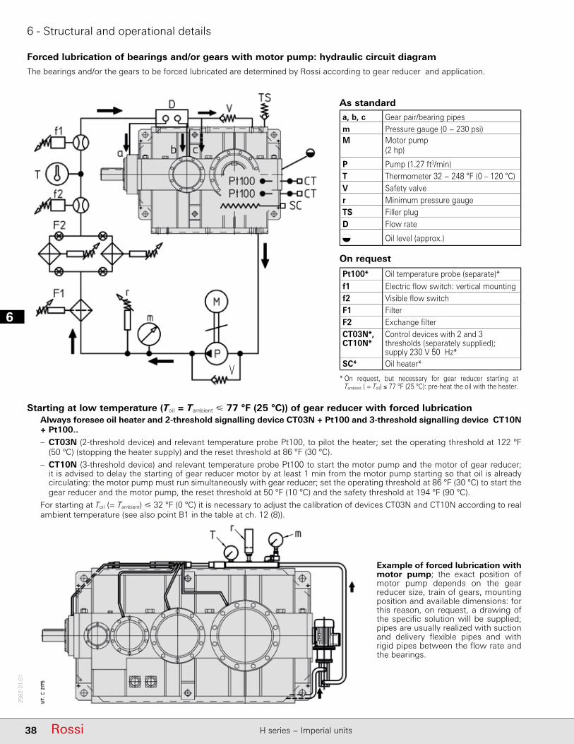
Forced lubrication of bearings and/or gears with motor pump: hydraulic circuit diagram
The bearings and/or the gears to be forced lubricated are determined by Rossi according to gear reducer and application.
As standarda, b, c Gear pair/bearing pipesm Pressure gauge (0 − 230 psi)M Motor pump
(2 hp)
P Pump (1.27 ft3/min)T Thermometer 32 − 248 °F (0 – 120 °C)V Safety valver Minimum pressure gaugeTS Filler plugD Flow rate
Oil level (approx.)
On request
Pt100* Oil temperature probe (separate)*
f1 Electric fl ow switch: vertical mountingf2 Visible fl ow switchF1 FilterF2 Exchange fi lter CT03N*,CT10N*
Control devices with 2 and 3 thresholds (separately supplied);supply 230 V 50 Hz*
SC* Oil heater*
* On request, but necessary for gear reducer starting at Tambient ( = Toil) ≤ 77 °F (25 °C): pre-heat the oil with the heater.
Starting at low temperature (Toil = Tambient 77 °F (25 °C)) of gear reducer with forced lubricationAlways foresee oil heater and 2-threshold signalling device CT03N + Pt100 and 3-threshold signalling device CT10N + Pt100..– CT03N (2-threshold device) and relevant temperature probe Pt100, to pilot the heater; set the operating threshold at 122 °F
(50 °C) (stopping the heater supply) and the reset threshold at 86 °F (30 °C).
– CT10N (3-threshold device) and relevant temperature probe Pt100 to start the motor pump and the motor of gear reducer; it is advised to delay the starting of gear reducer motor by at least 1 min from the motor pump starting so that oil is already circulating: the motor pump must run simultaneously with gear reducer; set the operating threshold at 86 °F (30 °C) to start the gear reducer and the motor pump, the reset threshold at 50 °F (10 °C) and the safety threshold at 194 °F (90 °C).
For starting at Toil (= Tambient) 32 °F (0 °C) it is necessary to adjust the calibration of devices CT03N and CT10N according to real ambient temperature (see also point B1 in the table at ch. 12 (8)).
Example of forced lubrication with motor pump; the exact position of motor pump depends on the gear reducer size, train of gears, mounting position and available dimensions: for this reason, on request, a drawing of the specifi c solution will be supplied; pipes are usually realized with suction and delivery fl exible pipes and with rigid pipes between the fl ow rate and the bearings.
V

6
39RossiH series − Imperial units
2582
-01.
01
6 - Structural and operational details
For starting at low temperature: see previous page.
Example of forced lubrication with cooling unit: the exact position of cooling unit depends on the gear reducer size, on train of gears, mounting position and available dimensions: for this reason, on request, a drawing of specifi c solution is supplied; the pipes are usually realized with suction/delivery fl exible pipes and with rigid pipes between the fl ow rate and the bearings.
As standarda, b, c Gear pair/bearing pipesd Flexible connection
(by Customer)
m Pressure gauge (0 − 230 psi)M Motor pump (ch. 12 (10))P Pump (ch. 12 (10))S Oil/air or oil/water exchangerv Motor fan (UR O/A)t Fan thermostat
32÷ 194 °F (0 – 90 °C) (UR O/A)
T Thermometer 32 − 248 °F (0 – 120 °C)V Safety valver Minimum pressure gaugeTS Filler plugD Flow rate
Approx. oil level
On requestPt100* Oil temperature probe (loose)*
f Flow switch (loose)F Filter with electric blockage warning
(with UR O/A it is supplied loose)
CT03N*, CT10N*
Control devices with 2 and 3 thresholds (separately supplied);supply 230 V 50 Hz*
T1 Thermometer 32 − 248 °F (0 – 120 °C)TT Bi-metal type thermostatSC* Oil heater*
* On request, but necessary for gear reducer starting at Tambient (= Toil) 77 °F (25 °C): pre-heat the oil with the heater.
Bearing and/or gear pair forced lubrication with oil/air or oil/water independent cooling unit: hydraulic circuit diagram
The bearings and/or the gears to be forced lubricated are determined by Rossi according to gear reducer and application.

16
40 Rossi H series − Imperial units
2582
-01.
01
Page intentionally left blank
7
41RossiH series − Imperial units
2582
-01.
01
7 - Selection tables (helical gear reducers)

17
42 Rossi H series − Imperial units
2582
-01.
01
7 - Selection tables (helical gear reducers)
n1 = 1 800 rpm
Necessary forced lubrication with motor pump and possible heat exchanger (see ch. 6 and 12).
Nominal output power P N2 [hp]i N n N2 Nominal output torque M N2 (M 2max) [103 lb in]
rpm
10 180840 (1360) 925 (1600)
11,2 160840 (1360) 940 (1600) 1010 (1850) 1090 (2180)
12,5 140840 (1400) 940 (1600) 1025 (1850) 1080 (2120)
14 132840 (1400) 940 (1600) 1045 (1900) 1150 (2180) 1415 (2800) 1595 (3150) 1985 (3750) 2245 (4250) 2965 (5300) 3245 (6150)
16 112840 (1360) 905 (1550) 1045 (1900) 1155 (2180) 1415 (2720) 1565 (3150) 1985 (3750) 2260 (4370) 2965 (5300) 3320 (6150)
18 100840 (1400) 940 (1600) 1035 (1800) 1095 (2060) 1415 (2720) 1595 (3150) 1985 (3650) 2200 (4120) 2965 (5000) 3300 (5800)
20 90840 (1400) 935 (1600) 1045 (1950) 1170 (2240) 1415 (2720) 1595 (3150) 1985 (3870) 2275 (4500) 2965 (5450) 3320 (6300)
22,4 80840 (1320) 940 (1500) 1045 (1850) 1135 (2120) 1415 (2800) 1595 (3150) 1985 (3650) 2275 (4250) 2965 (5150) 3320 (6000)
25 71840 (1500) 890 (1700) 1045 (1700) 1170 (1950) 1415 (2650) 1595 (3070) 1985 (3750) 2275 (4250) 4085 (8250)
28 63885 (1500) 945 (1700) 1020 (1950) 1095 (2180) 1680 (3000) 1865 (3450) 2015 (4000) 2170 (4370) 2830 (5600) 3280 (6500) 4400 (8750)
31,5 56885 (1500) 990 (1750) 1080 (2000) 1160 (2300) 1680 (2900) 1875 (3350) 2130 (4000) 2315 (4620) 2830 (5600) 3280 (6500) 5070 (10000)
35,5 50885 (1500) 970 (1750) 1105 (2060) 1180 (2240) 1680 (2900) 1875 (3350) 2150 (3870) 2430 (4370) 2890 (5800) 3350 (6700) 5580 (9750)
40 45885 (1450) 990 (1700) 1105 (2060) 1180 (2360) 1680 (2900) 1875 (3350) 2150 (4120) 2480 (4750) 2890 (5800) 3350 (6700) 5580 (10600)
45 40885 (1500) 990 (1700) 1105 (1950) 1240 (2240) 1680 (3000) 1875 (3450) 2150 (3870) 2480 (4500) 2950 (6000) 3420 (6900) 5540 (10900)
50 35,5885 (1500) 990 (1700) 1105 (2060) 1240 (2430) 1680 (3000) 1875 (3450) 2150 (4120) 2480 (4750) 3115 (6000) 3420 (6900) 5580 (10900)
56 31,5885 (1500) 990 (1750) 1105 (1950) 1240 (2240) 1680 (3070) 1875 (3450) 2150 (4000) 2480 (4500) 3135 (6000) 3485 (6900) 5580 (10900) 7970 (15500)
63 28885 (1500) 990 (1750) 1105 (2120) 1240 (2430) 1680 (3070) 1875 (3450) 2150 (4250) 2480 (4870) 3140 (6000) 3645 (6900) 5580 (10900) 7970 (15500)
71 25885 (1550) 990 (1750) 1105 (2000) 1240 (2300) 1680 (3070) 1875 (3550) 2150 (4000) 2480 (4620) 3140 (6150) 3645 (7100) 5580 (11200) 7970 (16000)
80 22,4885 (1550) 990 (1750) 1105 (2180) 1240 (2500) 1680 (3070) 1875 (3550) 2150 (4250) 2480 (5000) 3140 (6150) 3645 (7100) 5580 (11200) 7970 (16000)
90 20885 (1550) 990 (1750) 1105 (2060) 1240 (2360) 1680 (3070) 1875 (3550) 2150 (4120) 2480 (4750) 3140 (5800) 3645 (6700) 5580 (11200) 7970 (16000)
100 18885 (1550) 990 (1750) 1105 (2180) 1240 (2500) 1680 (3070) 1875 (3550) 2150 (4250) 2480 (4870) 3140 (6150) 3645 (7100) 5580 (11200) 7970 (16000)
125 141105 (1900) 1240 (2180) 2150 (3750) 2480 (4250)
125 14840 (1600) 940 (1800) 1105 (2240) 1265 (2500) 1680 (3150) 1825 (3650) 2150 (4250) 2445 (4870) 3055 (6150) 3540 (7100) 5750 (11200) 8190 (16000)
160 11,2885 (1600) 990 (1800) 1105 (2240) 1280 (2570) 1680 (3150) 1850 (3650) 2150 (4250) 2465 (4870) 3130 (6150) 3540 (7100) 5750 (11200) 8190 (16000)
200 9885 (1600) 990 (1800) 1105 (2240) 1280 (2570) 1680 (3150) 1875 (3650) 2150 (4250) 2465 (4870) 3055 (6150) 3540 (7100) 5750 (11200) 8190 (16000)
250 7,1885 (1600) 990 (1800) 1105 (2240) 1280 (2570) 1680 (3150) 1875 (3650) 2150 (4250) 2465 (4870) 3140 (6150) 3645 (7100) 5750 (11200) 8190 (16000)
315 5,6885 (1600) 990 (1800) 1105 (2060) 1285 (2360) 1680 (3150) 1875 (3650) 2150 (4120) 2480 (4750) 3140 (6150) 3645 (7100) 5750 (11200) 8190 (16000)
Trainof
gears
1930▲ 2640▲
2820▲ 3850▲
2450▲ 3340▲
–3010▲
4540▲
2220▲
–
–
–
–
– –
3040▲
–
–
–
–
–
– – –
– –
–
498 666▲
777 1090▲
631 844▲
979▲ 1400▲
1540▲ 2170▲
– –
1210▲ 1810▲
– – –2140▲ 2390▲ 2540▲
2500▲1780▲
2680▲
–
4540▲
4540▲
–
–
4510▲
3920▲
3450▲
– –
–
–
–
3990▲ 4510▲
2I
2430▲
1930▲ 2160▲ 2270▲ 2400▲ –
2080▲
– – –
2740▲ –
– – –
3100▲1360▲ 1520▲ 1590▲ 3450▲
1480▲ 1590▲ 1840▲ 2030▲ 2530▲ 2790▲ 3540▲
2290▲ 2890▲ 3250▲
1670▲ 2310▲ 2600▲
1700▲ 1900▲
–
4640▲
– –
6470▲
4030▲ 5140▲ 5650▲
– –
5160▲
–
5920▲
4460▲
1070▲ 1190▲ 1280▲ 1390▲ 1800▲ 2020▲ 2480▲ 2850▲ 3660▲ 4100▲
1180▲ 1310▲ 1450▲ 1620▲ 2020▲ 2270▲ 2830▲ 3250▲ 4060▲
3I
953 1010 1160▲ 1300▲ 1630▲ 1840▲ 2210▲
611 685 766 817 1160 1300 1500▲
344 473 528 605
– –
882 944 1000 1080 1670▲ 1860▲ 1980▲ 2130▲ 2950▲ 3410▲
2530▲
2560▲ 2910▲
705 774 834 889 1330 1480 1640▲ 1860▲ 2340▲ 2720▲
766 858 936 1000 1460▲ 1640▲ 1860▲ 2020▲
1730▲ 2040▲ 2320▲
559 627 666 746 1060 1180 1300 1500 1850▲ 2170▲
1830▲
440 493 529 592 858 957 1040 1190 1560 1760
486 544 608 681 924 1030 1180 1360 1700▲
1550
358 401 416 466 676 754 841 969 1250 1430
382 428 479 536 750 837 960 1110 1360
697 860
1240
286 321 339 379 541 603 663 764 983 1140
311 348 389 436 591 660 756 871 1090
4I
191 214 248 284 373 404 470 534
132 148 163 188 226 252 285 327
180 20884,6 94,8 98,4 114 145 162
104 117 128 148 184 205
195 226 303 333 382 437 530 590
264 300
232 265 329 375
403 459
980
– – 246 275 – – 484 558 – –
249 278 307
652 742
158 178
Gear reducer size
4000 4001 4500 4501 5000 5001 5600 5601 6300 6301 7101 8001
TN2 (T2max)
7
43RossiH series − Imperial units
2582
-01.
01
7 - Selection tables (helical gear reducers)
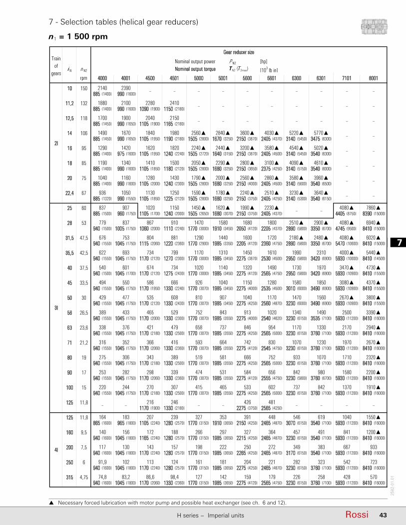
n1 = 1 500 rpm
Necessary forced lubrication with motor pump and possible heat exchanger (see ch. 6 and 12).
Nominal output power P N2 [hp]i N n N2 Nominal output torque M N2 (M 2max) [103 lb in]
rpm
10 150885 (1400) 990 (1600)
11,2 132885 (1400) 990 (1600) 1090 (1900) 1150 (2180)
12,5 118885 (1450) 990 (1650) 1105 (1900) 1165 (2180)
14 106885 (1450) 990 (1650) 1105 (1950) 1190 (2180) 1505 (2800) 1670 (3250) 2150 (3870) 2405 (4370) 3140 (5450) 3475 (6300)
16 95885 (1400) 975 (1600) 1105 (1950) 1240 (2240) 1505 (2720) 1640 (3150) 2150 (3870) 2405 (4500) 3140 (5450) 3540 (6300)
18 85885 (1400) 990 (1600) 1105 (1850) 1180 (2120) 1505 (2800) 1680 (3250) 2150 (3650) 2375 (4250) 3140 (5150) 3540 (6000)
20 75885 (1400) 990 (1600) 1105 (2000) 1240 (2300) 1505 (2800) 1680 (3250) 2150 (4000) 2405 (4500) 3140 (5600) 3540 (6500)
22,4 67885 (1320) 990 (1550) 1105 (1850) 1225 (2120) 1505 (2800) 1680 (3250) 2150 (3750) 2405 (4250) 3140 (5300) 3540 (6150)
25 60885 (1500) 960 (1750) 1105 (1700) 1240 (2000) 1505 (2650) 1680 (3070) 2150 (3750) 2405 (4370) 4405 (8750) 8390 (15000)
28 53940 (1500) 1005 (1750) 1060 (2000) 1110 (2240) 1770 (3000) 1910 (3450) 2050 (4120) 2205 (4370) 2890 (5800) 3350 (6700) 4745 (9500) 8410 (15000)
31,5 47,5940 (1550) 1045 (1750) 1115 (2060) 1220 (2360) 1770 (2900) 1985 (3350) 2205 (4120) 2360 (4750) 2890 (5800) 3350 (6700) 5470 (10600) 8410 (15000)
35,5 42,5940 (1550) 1045 (1750) 1170 (2120) 1270 (2300) 1770 (3000) 1985 (3450) 2275 (3870) 2530 (4500) 2950 (5800) 3420 (6900) 5930 (10000) 8410 (14500)
40 37,5940 (1500) 1045 (1700) 1170 (2120) 1275 (2430) 1770 (3000) 1985 (3450) 2275 (4120) 2565 (4750) 2950 (5800) 3420 (6900) 5930 (10900) 8410 (15500)
45 33,5940 (1550) 1045 (1750) 1170 (1950) 1330 (2240) 1770 (3070) 1985 (3450) 2275 (4000) 2535 (4500) 3010 (6000) 3490 (6900) 5930 (10900) 8410 (15500)
50 30940 (1550) 1045 (1750) 1170 (2120) 1330 (2430) 1770 (3070) 1985 (3450) 2275 (4250) 2560 (4870) 3230 (6000) 3490 (6900) 5930 (10900) 8410 (15500)
56 26,5940 (1550) 1045 (1750) 1170 (2000) 1330 (2300) 1770 (3070) 1985 (3550) 2275 (4000) 2540 (4620) 3230 (6150) 3535 (7100) 5930 (11200) 8410 (16000)
63 23,6940 (1550) 1045 (1750) 1170 (2180) 1330 (2500) 1770 (3070) 1985 (3550) 2275 (4250) 2565 (5000) 3230 (6150) 3760 (7100) 5930 (11200) 8410 (16000)
71 21,2940 (1550) 1045 (1750) 1170 (2060) 1330 (2360) 1770 (3070) 1985 (3550) 2275 (4120) 2545 (4750) 3230 (6150) 3760 (7100) 5930 (11200) 8410 (16000)
80 19940 (1550) 1045 (1750) 1170 (2180) 1330 (2500) 1770 (3070) 1985 (3550) 2275 (4250) 2565 (5000) 3230 (6150) 3760 (7100) 5930 (11200) 8410 (16000)
90 17940 (1550) 1045 (1750) 1170 (2060) 1330 (2360) 1770 (3070) 1985 (3550) 2275 (4120) 2555 (4750) 3230 (5800) 3760 (6700) 5930 (11200) 8410 (16000)
100 15940 (1550) 1045 (1750) 1170 (2180) 1330 (2500) 1770 (3070) 1985 (3550) 2275 (4250) 2565 (5000) 3230 (6150) 3760 (7100) 5930 (11200) 8410 (16000)
125 11,81170 (1900) 1330 (2180) 2275 (3750) 2565 (4250)
125 11,8865 (1600) 965 (1800) 1105 (2240) 1280 (2570) 1770 (3150) 1910 (3650) 2150 (4250) 2465 (4870) 3070 (6150) 3540 (7100) 5930 (11200) 8410 (16000)
160 9,5940 (1600) 1045 (1800) 1165 (2240) 1280 (2570) 1770 (3150) 1985 (3650) 2215 (4250) 2465 (4870) 3230 (6150) 3540 (7100) 5930 (11200) 8410 (16000)
200 7,5940 (1600) 1045 (1800) 1170 (2240) 1280 (2570) 1770 (3150) 1985 (3650) 2265 (4250) 2465 (4870) 3170 (6150) 3540 (7100) 5930 (11200) 8410 (16000)
250 6940 (1600) 1045 (1800) 1170 (2240) 1280 (2570) 1770 (3150) 1985 (3650) 2275 (4250) 2465 (4870) 3230 (6150) 3760 (7100) 5930 (11200) 8410 (16000)
315 4,75940 (1600) 1045 (1800) 1170 (2060) 1330 (2360) 1770 (3150) 1985 (3650) 2275 (4120) 2565 (4750) 3230 (6150) 3760 (7100) 5930 (11200) 8410 (16000)
▲ lubrificazione forzata
– –
1040 1550▲
428 570
841 1200▲
667 933
542 723
1580 2200▲
1370 1910▲
2500 3390▲
2170 2940▲
1970 2670▲
3080▲ 4370▲
2670▲ 3800▲
4080▲ 6020▲
4000▲ 5440▲
1710 2320▲
4080▲ 7860▲
4080▲ 6940▲
–
–
–
–
3470▲ 4730▲
–
–
–
–
–
–
–
–
–
–
–
–
349 383
91,9 102 113 124 161 181
159 179 226 258
204 221 282 323
74,8 83,2 86,6 98,4 127 142
546 619
140 156 172 188 266 297 327 364 457 491
4I
164 183 207 239 327 353 391 448
117 130 143 157 198 222 250 272
842
– – 216 246 – – 426 481 – –
220 244 270 307 415 465 533 602 737
1070
253 282 298 339 474 531 584 656 842 980
275 306 343 389 519 581 666 752 933
1330
316 352 366 416 593 664 742 830 1070 1230
338 376 421 479 658 737 846 954 1170
1560
389 433 465 529 752 843 913 1020 1340 1490
429 477 535 608 810 907 1040 1170 1470
1490 1730 1970
494 550 586 666 926 1040 1150 1280 1580 1850
2180▲ 2480▲
622 693 734 799 1170 1310 1450 1610 1990 2310
– –
779 837 867 910 1470 1580 1680 1800 2510▲ 2900▲
3I
837 907 1020 1150 1450▲ 1620▲ 1990▲ 2230▲
676 753 804 881 1290 1440 1600 1720
540 601 674 734 1020 1140 1320
3960▲
936 1050 1130 1250 1590▲ 1780▲ 2240▲ 2510▲ 3230▲ 3640▲
1040 1160 1280 1430 1790▲ 2000▲ 2560▲ 2860▲ 3580▲
3580▲ 4540▲ 5020▲
1190 1340 1410 1500 2050▲ 2290▲ 2800▲ 3100▲ 4090▲ 4610▲
– –
1490 1670 1840 1980 2560▲ 2840▲ 3600▲ 4030▲ 5220▲ 5770▲
– –
1880 2100 2280 2410 – – – – – –
2I
2140 2390 – – – – – –
1700 1900 2040 2150 – – – –
1290 1420 1620 1820 2240▲ 2440▲ 3200▲
4000 4001 4500 63014501 5000 5001 5600 5601 6300
Gear reducer sizeTrain
ofgears
7101 8001
TN2 (T2max)
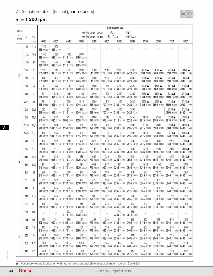
17
44 Rossi H series − Imperial units
2582
-01.
01
7 - Selection tables (helical gear reducers)
Necessary forced lubrication with motor pump and possible heat exchanger (see ch. 6 and 12).
n1 = 1 200 rpm
Nominal output power P N2 [hp]i N n N2 Nominal output torque M N2 (M 2max) [103 lb in]
rpm
10 118885 (1400) 995 (1650)
11,2 106885 (1400) 995 (1650) 1110 (1950) 1190 (2240)
12,5 95885 (1450) 995 (1650) 1110 (1950) 1205 (2240)
14 85885 (1450) 995 (1650) 1110 (1950) 1195 (2240) 1515 (2900) 1700 (3350) 2160 (3870) 2420 (4370) 3160 (5600) 3480 (6500) 5590 (9500) 7980 (13200)
16 75885 (1400) 995 (1600) 1110 (1950) 1245 (2240) 1515 (2800) 1695 (3250) 2160 (3870) 2420 (4500) 3160 (5600) 3560 (6500) 5590 (10000) 7980 (14500)
18 67885 (1450) 995 (1650) 1110 (1850) 1220 (2120) 1515 (2800) 1700 (3250) 2160 (3750) 2420 (4250) 3160 (5150) 3560 (6000) 5590 (9500) 7980 (13600)
20 60885 (1450) 995 (1650) 1110 (2000) 1245 (2300) 1515 (2800) 1700 (3250) 2160 (4000) 2420 (4500) 3160 (5600) 3560 (6500) 5590 (10300) 7980 (14500)
22,4 53885 (1360) 995 (1550) 1110 (1900) 1245 (2180) 1515 (2900) 1700 (3350) 2160 (3750) 2420 (4370) 3160 (5300) 3560 (6150) 5590 (9750) 7980 (14000)
25 47,5915 (1550) 995 (1750) 1110 (1750) 1245 (2000) 1515 (2720) 1700 (3150) 2160 (3750) 2420 (4370) 4560 (9000) 8430 (15500)
28 42,5940 (1550) 1040 (1750) 1095 (2000) 1120 (2240) 1770 (3070) 1975 (3550) 2110 (4120) 2220 (4500) 2915 (5800) 3380 (6700) 4910 (9750) 8430 (15500)
31,5 37,5940 (1550) 1045 (1800) 1150 (2060) 1260 (2360) 1770 (3000) 1990 (3450) 2280 (4120) 2385 (4750) 2915 (5800) 3380 (6700) 5660 (10600) 8430 (15500)
35,5 33,5940 (1550) 1045 (1800) 1170 (2120) 1315 (2300) 1770 (3000) 1990 (3450) 2285 (3870) 2535 (4500) 2975 (6000) 3450 (6900) 5940 (10300) 8430 (14500)
40 30940 (1500) 1045 (1750) 1170 (2120) 1315 (2430) 1770 (3000) 1990 (3450) 2285 (4250) 2575 (4870) 2975 (6000) 3450 (6900) 5940 (10900) 8430 (15500)
45 26,5940 (1550) 1045 (1750) 1170 (2000) 1330 (2300) 1770 (3070) 1990 (3550) 2285 (4000) 2540 (4620) 3035 (6000) 3520 (7100) 5940 (11200) 8430 (16000)
50 23,6940 (1550) 1045 (1750) 1170 (2120) 1330 (2430) 1770 (3070) 1990 (3550) 2285 (4250) 2565 (4870) 3245 (6000) 3540 (7100) 5940 (11200) 8430 (16000)
56 21,2940 (1550) 1045 (1750) 1170 (2000) 1330 (2300) 1770 (3070) 1990 (3550) 2285 (4000) 2545 (4620) 3245 (6150) 3540 (7100) 5940 (11200) 8430 (16000)
63 19940 (1550) 1045 (1750) 1170 (2180) 1330 (2500) 1770 (3070) 1990 (3550) 2285 (4250) 2575 (5000) 3245 (6150) 3770 (7100) 5940 (11200) 8430 (16000)
71 17940 (1550) 1045 (1750) 1170 (2060) 1330 (2360) 1770 (3070) 1990 (3550) 2285 (4120) 2550 (4750) 3245 (6150) 3770 (7100) 5940 (11200) 8430 (16000)
80 15940 (1550) 1045 (1750) 1170 (2180) 1330 (2500) 1770 (3070) 1990 (3550) 2285 (4250) 2575 (5000) 3245 (6150) 3770 (7100) 5940 (11200) 8430 (16000)
90 13,2940 (1550) 1045 (1750) 1170 (2060) 1330 (2360) 1770 (3070) 1990 (3550) 2285 (4120) 2555 (4750) 3245 (5800) 3770 (6700) 5940 (11200) 8430 (16000)
100 11,8940 (1550) 1045 (1750) 1170 (2180) 1330 (2500) 1770 (3070) 1990 (3550) 2285 (4250) 2575 (5000) 3245 (6150) 3770 (7100) 5940 (11200) 8430 (16000)
125 9,51170 (1900) 1330 (2180) 2285 (3750) 2575 (4250)
125 9,5895 (1600) 1000 (1800) 1105 (2240) 1280 (2570) 1770 (3150) 1980 (3650) 2150 (4250) 2465 (4870) 3175 (6150) 3540 (7100) 5940 (11200) 8430 (16000)
160 7,5940 (1600) 1045 (1800) 1170 (2240) 1280 (2570) 1770 (3150) 1990 (3650) 2285 (4250) 2465 (4870) 3245 (6150) 3555 (7100) 5940 (11200) 8430 (16000)
200 6940 (1600) 1045 (1800) 1170 (2240) 1280 (2570) 1770 (3150) 1990 (3650) 2285 (4250) 2465 (4870) 3245 (6150) 3540 (7100) 5940 (11200) 8430 (16000)
250 4,75940 (1600) 1045 (1800) 1170 (2240) 1280 (2570) 1770 (3150) 1990 (3650) 2285 (4250) 2465 (4870) 3245 (6150) 3770 (7100) 5940 (11200) 8430 (16000)
315 3,75940 (1600) 1045 (1800) 1170 (2060) 1330 (2360) 1770 (3150) 1990 (3650) 2285 (4120) 2575 (4750) 3245 (6150) 3770 (7100) 5940 (11200) 8430 (16000)
▲ lubrificazione forzata
Trainof
gears
343 457
674 964
535 748
435 579
– –
2140 3040▲
2000 2710
1740 2360
3210▲ 4360▲
2780 3790▲
2470 3500▲
3380▲
830 1240
1100 1530
1580 2140
1370 1860
1260 1760
5560▲
3380▲ 4830▲
3380▲ 6320▲
5910▲ 8190▲
5230▲ 7450▲
4730▲ 6740▲
7540▲ 10420▲
6540▲ 9060▲
–
–
–
–
–
–
2I
1710 1920 – – – – – –
1360
4620▲
– –
1510 1690 1860 2000 – – – – – –
1200 1340 1470 1590 2060 2310 2900 3240 4200▲
1520 1640
3650▲ 4040▲
957 1070 1130 1250 1650 1850 2250 2520 3290▲ 3710▲
1040 1160 1300 1460 1800 2020 2570 2880
3190▲
751 841 905 1010 1280 1440 1800 2020 2600▲ 2930▲
831 930 1030 1150 1440 1620 2060 2300 2880▲
3I
692 751 821 920 1170 1310 1600 1800
542 603 665 729 1030 1160 1320 1380
433 482 540 608 817 918 1060
– –
624 692 717 732 1180 1310 1380 1450 2020 2340
1760 2000
498 555 589 661 934 1050 1160 1290 1610 1860
1200 1400 1590
396 441 470 534 742 834 923 1030 1270 1490
1260
311 347 373 424 603 677 733 817 1080 1190
344 383 429 488 649 729 836 940 1180
1070
253 282 294 334 475 534 595 665 863 983
270 301 338 384 527 593 679 766 937
856
203 226 239 272 380 427 469 525 676 786
220 245 275 312 415 467 535 604 750
675
– – 173 197 – – 342 386 – –
176 196 217 246 332 374 428 483 592
4I
135 151 166 191 262 292 313 359
93,6 104 115 126 159 179 202 218
452 495
112 125 138 151 213 239 270 291 367 394
285 306
73,6 82 90,5 98,9 129 145
128 144 181 207
164 177 227 259
59,9 66,7 69,4 78,9 102 114
– –
7101 8001
Gear reducer size
4000 4001 4500
1780 – – – –
4501 5000 5001 5600 5601 6300 6301
TN2 (T2max)
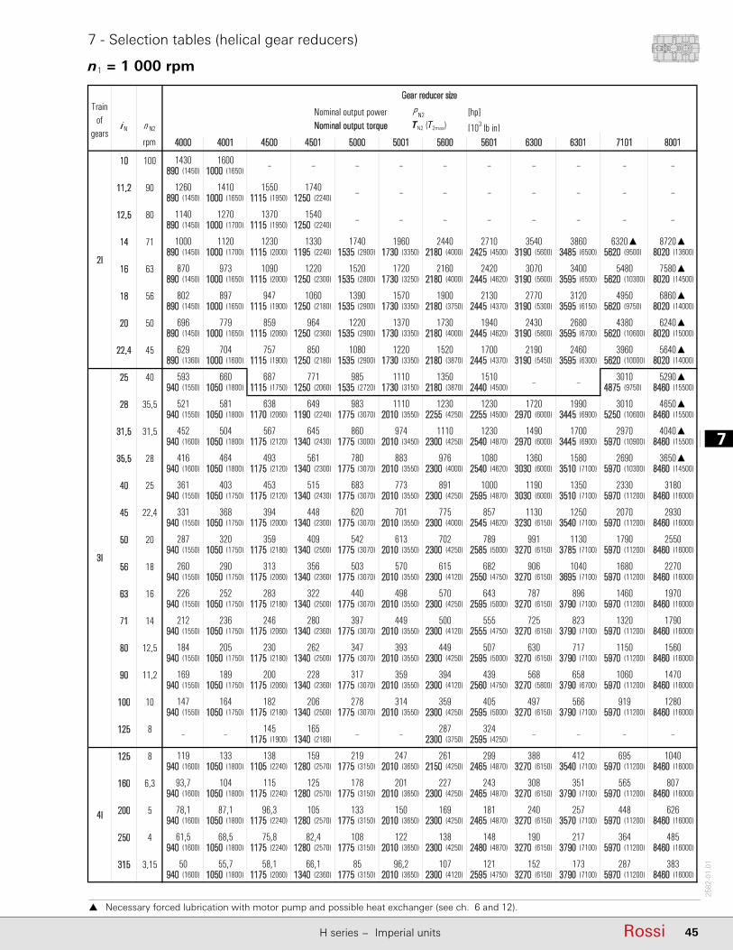
7
45RossiH series − Imperial units
2582
-01.
01
7 - Selection tables (helical gear reducers)
n1 = 1 000 rpm
Necessary forced lubrication with motor pump and possible heat exchanger (see ch. 6 and 12).
Nominal output power P N2 [hp]i N n N2 Nominal output torque M N2 (M 2max) [103 lb in]
rpm
10 100890 (1450) 1000 (1650)
11,2 90890 (1450) 1000 (1650) 1115 (1950) 1250 (2240)
12,5 80890 (1450) 1000 (1700) 1115 (1950) 1250 (2240)
14 71890 (1450) 1000 (1700) 1115 (2000) 1195 (2240) 1535 (2900) 1730 (3350) 2180 (4000) 2425 (4500) 3190 (5600) 3485 (6500) 5620 (9500) 8020 (13600)
16 63890 (1450) 1000 (1650) 1115 (2000) 1250 (2300) 1535 (2800) 1730 (3250) 2180 (4000) 2445 (4620) 3190 (5600) 3595 (6500) 5620 (10300) 8020 (14500)
18 56890 (1450) 1000 (1650) 1115 (1900) 1250 (2180) 1535 (2900) 1730 (3350) 2180 (3750) 2445 (4370) 3190 (5300) 3595 (6150) 5620 (9750) 8020 (14000)
20 50890 (1450) 1000 (1650) 1115 (2060) 1250 (2360) 1535 (2900) 1730 (3350) 2180 (4000) 2445 (4620) 3190 (5800) 3595 (6700) 5620 (10600) 8020 (15000)
22,4 45890 (1360) 1000 (1600) 1115 (1900) 1250 (2180) 1535 (2900) 1730 (3350) 2180 (3870) 2445 (4370) 3190 (5450) 3595 (6300) 5620 (10000) 8020 (14000)
25 40940 (1550) 1050 (1800) 1115 (1750) 1250 (2060) 1535 (2720) 1730 (3150) 2180 (3870) 2440 (4500) 4875 (9750) 8460 (15500)
28 35,5940 (1550) 1050 (1800) 1170 (2060) 1190 (2240) 1775 (3070) 2010 (3550) 2255 (4250) 2255 (4500) 2970 (6000) 3445 (6900) 5250 (10600) 8460 (15500)
31,5 31,5940 (1600) 1050 (1800) 1175 (2120) 1340 (2430) 1775 (3000) 2010 (3450) 2300 (4250) 2540 (4870) 2970 (6000) 3445 (6900) 5970 (10900) 8460 (15500)
35,5 28940 (1600) 1050 (1800) 1175 (2120) 1340 (2300) 1775 (3070) 2010 (3550) 2300 (4000) 2540 (4620) 3030 (6000) 3510 (7100) 5970 (10300) 8460 (14500)
40 25940 (1550) 1050 (1750) 1175 (2120) 1340 (2430) 1775 (3070) 2010 (3550) 2300 (4250) 2595 (4870) 3030 (6000) 3510 (7100) 5970 (11200) 8460 (16000)
45 22,4940 (1550) 1050 (1750) 1175 (2000) 1340 (2300) 1775 (3070) 2010 (3550) 2300 (4000) 2545 (4620) 3230 (6150) 3540 (7100) 5970 (11200) 8460 (16000)
50 20940 (1550) 1050 (1750) 1175 (2180) 1340 (2500) 1775 (3070) 2010 (3550) 2300 (4250) 2585 (5000) 3270 (6150) 3785 (7100) 5970 (11200) 8460 (16000)
56 18940 (1550) 1050 (1750) 1175 (2060) 1340 (2360) 1775 (3070) 2010 (3550) 2300 (4120) 2550 (4750) 3270 (6150) 3695 (7100) 5970 (11200) 8460 (16000)
63 16940 (1550) 1050 (1750) 1175 (2180) 1340 (2500) 1775 (3070) 2010 (3550) 2300 (4250) 2595 (5000) 3270 (6150) 3790 (7100) 5970 (11200) 8460 (16000)
71 14940 (1550) 1050 (1750) 1175 (2060) 1340 (2360) 1775 (3070) 2010 (3550) 2300 (4120) 2555 (4750) 3270 (6150) 3790 (7100) 5970 (11200) 8460 (16000)
80 12,5940 (1550) 1050 (1750) 1175 (2180) 1340 (2500) 1775 (3070) 2010 (3550) 2300 (4250) 2595 (5000) 3270 (6150) 3790 (7100) 5970 (11200) 8460 (16000)
90 11,2940 (1550) 1050 (1750) 1175 (2060) 1340 (2360) 1775 (3070) 2010 (3550) 2300 (4120) 2560 (4750) 3270 (5800) 3790 (6700) 5970 (11200) 8460 (16000)
100 10940 (1550) 1050 (1750) 1175 (2180) 1340 (2500) 1775 (3070) 2010 (3550) 2300 (4250) 2595 (5000) 3270 (6150) 3790 (7100) 5970 (11200) 8460 (16000)
125 81175 (1900) 1340 (2180) 2300 (3750) 2595 (4250)
125 8940 (1600) 1050 (1800) 1105 (2240) 1280 (2570) 1775 (3150) 2010 (3650) 2150 (4250) 2465 (4870) 3270 (6150) 3540 (7100) 5970 (11200) 8460 (16000)
160 6,3940 (1600) 1050 (1800) 1175 (2240) 1280 (2570) 1775 (3150) 2010 (3650) 2300 (4250) 2465 (4870) 3270 (6150) 3790 (7100) 5970 (11200) 8460 (16000)
200 5940 (1600) 1050 (1800) 1175 (2240) 1280 (2570) 1775 (3150) 2010 (3650) 2300 (4250) 2465 (4870) 3270 (6150) 3570 (7100) 5970 (11200) 8460 (16000)
250 4940 (1600) 1050 (1800) 1175 (2240) 1280 (2570) 1775 (3150) 2010 (3650) 2300 (4250) 2480 (4870) 3270 (6150) 3790 (7100) 5970 (11200) 8460 (16000)
315 3,15940 (1600) 1050 (1800) 1175 (2060) 1340 (2360) 1775 (3150) 2010 (3650) 2300 (4120) 2595 (4750) 3270 (6150) 3790 (7100) 5970 (11200) 8460 (16000)
▲ lubrificazione forzata
Trainof
gears
287 383
565 807
448 626
364 485
– –
1790 2550
1680 2270
1460 1970
2690 3650▲
2330 3180
2070 2930
3010
695 1040
919 1280
1320 1790
1150 1560
1060 1470
4650▲
2970 4040▲
3010 5290▲
4950 6860▲
4380 6240▲
3960 5640▲
6320▲ 8720▲
5480 7580▲
– –
– –
– –
2I
1430 1600 – – – – – –
1140
3860
– –
1260 1410 1550 1740 – – – – – –
1000 1120 1230 1330 1740 1960 2440 2710 3540
1270 1370
3070 3400
802 897 947 1060 1390 1570 1900 2130 2770 3120
870 973 1090 1220 1520 1720 2160 2420
2680
629 704 757 850 1080 1220 1520 1700 2190 2460
696 779 859 964 1220 1370 1730 1940 2430
3I
593 660 687 771 985 1110 1350 1510
452 504 567 645 860 974 1110 1230
361 403 453 515 683 773 891
– –
521 581 638 649 983 1110 1230 1230 1720 1990
1490 1700
416 464 493 561 780 883 976 1080 1360 1580
1000 1190 1350
331 368 394 448 620 701 775 857 1130 1250
1130
260 290 313 356 503 570 615 682 906 1040
287 320 359 409 542 613 702 789 991
896
212 236 246 280 397 449 500 555 725 823
226 252 283 322 440 498 570 643 787
717
169 189 200 228 317 359 394 439 568 658
184 205 230 262 347 393 449 507 630
566
– – 145 165 – – 287 324 – –
147 164 182 206 278 314 359 405 497
4I
119 133 138 159 219 247 261 299
78,1 87,1 96,3 105 133 150 169 181
388 412
93,7 104 115 125 178 201 227 243 308 351
240 257
61,5 68,5 75,8 82,4 108 122
107 121 152 173
138 148 190 217
50 55,7 58,1 66,1 85 96,2
– –
7101 8001
Gear reducer size
4000 4001 4500
1540 – – – –
4501 5000 5001 5600 5601 6300 6301
TN2 (T2max)
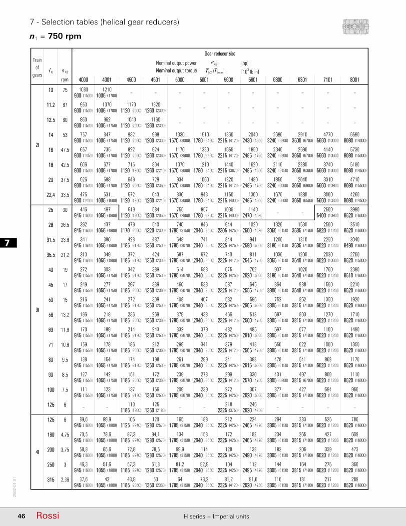
17
46 Rossi H series − Imperial units
2582
-01.
01
7 - Selection tables (helical gear reducers)
n1 = 750 rpm
Nominal output power P N2 [hp]i N n N2 Nominal output torque M N2 (M 2max) [103 lb in]
rpm
10 75900 (1500) 1005 (1700)
11,2 67900 (1500) 1005 (1700) 1120 (2000) 1260 (2300)
12,5 60900 (1500) 1005 (1750) 1120 (2000) 1260 (2300)
14 53900 (1500) 1005 (1750) 1120 (2060) 1200 (2300) 1570 (3000) 1780 (3450) 2215 (4120) 2430 (4500) 3240 (5800) 3500 (6700) 5660 (10000) 8080 (14000)
16 47,5900 (1450) 1005 (1700) 1120 (2060) 1260 (2360) 1570 (2900) 1780 (3350) 2215 (4120) 2485 (4750) 3240 (5800) 3650 (6700) 5660 (10600) 8080 (15000)
18 42,5900 (1500) 1005 (1700) 1120 (1950) 1260 (2240) 1570 (3000) 1780 (3450) 2215 (3870) 2485 (4500) 3240 (5450) 3650 (6300) 5660 (10000) 8080 (14500)
20 37,5900 (1500) 1005 (1700) 1120 (2060) 1260 (2360) 1570 (3000) 1780 (3450) 2215 (4120) 2485 (4750) 3240 (6000) 3650 (6900) 5660 (10900) 8080 (15500)
22,4 33,5900 (1400) 1005 (1600) 1120 (1950) 1260 (2240) 1570 (3000) 1780 (3450) 2215 (4000) 2485 (4500) 3240 (5600) 3650 (6500) 5660 (10300) 8080 (14500)
25 30945 (1600) 1055 (1800) 1120 (1800) 1260 (2060) 1570 (2800) 1780 (3250) 2215 (4000) 2470 (4620) 5400 (10900) 8520 (16000)
28 26,5945 (1600) 1055 (1800) 1170 (2060) 1320 (2300) 1785 (3150) 2040 (3650) 2305 (4250) 2500 (4620) 3050 (6150) 3535 (7100) 5820 (11200) 8520 (16000)
31,5 23,6945 (1600) 1055 (1800) 1185 (2180) 1350 (2500) 1785 (3070) 2040 (3550) 2325 (4250) 2590 (5000) 3180 (6150) 3535 (7100) 6020 (11200) 8490 (16000)
35,5 21,2945 (1600) 1055 (1800) 1185 (2180) 1350 (2300) 1785 (3070) 2040 (3550) 2325 (4120) 2545 (4750) 3055 (6150) 3540 (7100) 6020 (10600) 8520 (15000)
40 19945 (1550) 1055 (1750) 1185 (2180) 1350 (2500) 1785 (3070) 2040 (3550) 2325 (4250) 2620 (5000) 3190 (6150) 3540 (7100) 6020 (11200) 8510 (16000)
45 17945 (1550) 1055 (1750) 1185 (2060) 1350 (2360) 1785 (3070) 2040 (3550) 2325 (4120) 2555 (4750) 3300 (6150) 3540 (7100) 6020 (11200) 8520 (16000)
50 15945 (1550) 1055 (1750) 1185 (2180) 1350 (2500) 1785 (3070) 2040 (3550) 2325 (4250) 2605 (5000) 3305 (6150) 3815 (7100) 6020 (11200) 8520 (16000)
56 13,2945 (1550) 1055 (1750) 1185 (2060) 1350 (2360) 1785 (3070) 2040 (3550) 2325 (4120) 2560 (4750) 3305 (6150) 3815 (7100) 6020 (11200) 8520 (16000)
63 11,8945 (1550) 1055 (1750) 1185 (2180) 1350 (2500) 1785 (3070) 2040 (3550) 2325 (4250) 2610 (5000) 3305 (6150) 3815 (7100) 6020 (11200) 8520 (16000)
71 10,6945 (1550) 1055 (1750) 1185 (2060) 1350 (2360) 1785 (3070) 2040 (3550) 2325 (4120) 2565 (4750) 3305 (6150) 3815 (7100) 6020 (11200) 8520 (16000)
80 9,5945 (1550) 1055 (1750) 1185 (2180) 1350 (2500) 1785 (3070) 2040 (3550) 2325 (4250) 2615 (5000) 3305 (6150) 3815 (7100) 6020 (11200) 8520 (16000)
90 8,5945 (1550) 1055 (1750) 1185 (2060) 1350 (2360) 1785 (3070) 2040 (3550) 2325 (4120) 2570 (4750) 3305 (5800) 3815 (6700) 6020 (11200) 8520 (16000)
100 7,5945 (1550) 1055 (1750) 1185 (2180) 1350 (2500) 1785 (3070) 2040 (3550) 2325 (4250) 2620 (5000) 3305 (6150) 3815 (7100) 6020 (11200) 8520 (16000)
125 61185 (1900) 1350 (2180) 2325 (3750) 2620 (4250)
125 6945 (1600) 1055 (1800) 1125 (2240) 1280 (2570) 1785 (3150) 2040 (3650) 2325 (4250) 2465 (4870) 3305 (6150) 3815 (7100) 6020 (11200) 8520 (16000)
160 4,75945 (1600) 1055 (1800) 1185 (2240) 1280 (2570) 1785 (3150) 2040 (3650) 2325 (4250) 2465 (4870) 3305 (6150) 3815 (7100) 6020 (11200) 8520 (16000)
200 3,75945 (1600) 1055 (1800) 1185 (2240) 1280 (2570) 1785 (3150) 2040 (3650) 2325 (4250) 2490 (4870) 3305 (6150) 3815 (7100) 6020 (11200) 8520 (16000)
250 3945 (1600) 1055 (1800) 1185 (2240) 1280 (2570) 1785 (3150) 2040 (3650) 2325 (4250) 2495 (4870) 3305 (6150) 3815 (7100) 6020 (11200) 8520 (16000)
315 2,36945 (1600) 1055 (1800) 1185 (2060) 1350 (2360) 1785 (3150) 2040 (3650) 2325 (4120) 2620 (4750) 3305 (6150) 3815 (7100) 6020 (11200) 8520 (16000)
▲ lubrificazione forzata
Trainof
gears
217 289
427 609
339 473
275 366
– –
1350 1920
1270 1710
1100 1490
2030 2760
1760 2390
1560 2210
2500
525 786
694 966
1000 1350
868 1170
800 1110
3510
2250 3040
2500 3990
3740 5180
3310 4710
3000 4260
4770 6590
4140 5730
– –
– –
– –
2I
1080 1210 – – – – – –
860
2910
– –
953 1070 1170 1320 – – – – – –
757 847 932 998 1330 1510 1860 2040 2690
962 1040
2340 2590
606 677 715 804 1070 1210 1440 1620 2110 2380
657 735 822 924 1170 1330 1650 1850
2040
475 531 572 643 830 943 1150 1300 1670 1880
526 588 649 729 934 1060 1320 1480 1850
3I
446 497 519 584 755 857 1030 1140
341 380 428 487 648 741 844 941
272 303 342 389 514 588 675
– –
392 437 479 540 740 846 944 1020 1320 1530
1200 1310
313 349 372 424 587 672 740 811 1030 1200
762 937 1020
249 277 297 339 466 533 587 645 864 938
852
196 218 236 269 379 433 466 513 687 803
216 241 272 309 408 467 532 596 752
677
159 178 186 212 299 341 379 418 550 622
170 189 214 243 332 379 432 485 597
541
127 142 151 172 239 273 299 330 431 497
138 154 174 198 261 299 341 383 478
427
– – 110 125 – – 218 246 – –
111 123 137 156 209 239 272 307 377
4I
89,6 99,9 105 120 165 188 212 224
58,8 65,6 72,8 78,5 99,9 114 128 138
294 333
70,5 78,6 87,3 94,1 134 153 172 182 234 265
182 206
46,3 51,6 57,3 61,8 81,2 92,9
81,2 91,6 116 131
104 112 144 164
37,6 42 43,9 50 64 73,2
– –
7101 8001
Gear reducer size
4000 4001 4500
1160 – – – –
4501 5000 5001 5600 5601 6300 6301
TN2 (T2max)

7
47RossiH series − Imperial units
2582
-01.
01
7 - Selection tables (helical gear reducers)
n1 90 rpm
Nominal output power P N2 [hp]i N n N2 Nominal output torque M N2 (M 2max) [103 lb in]
rpm
10 9940 (1600) 1045 (1800)
11,2 8940 (1600) 1045 (1800) 1170 (2180) 1330 (2500)
12,5 7,1940 (1600) 1045 (1800) 1170 (2180) 1330 (2500)
14 6,3940 (1600) 1045 (1800) 1170 (2180) 1240 (2500) 1770 (3150) 2090 (3650) 2405 (4250) 2485 (4870) 3330 (6150) 3575 (7100) 5930 (10600) 8410 (15000)
16 5,6940 (1550) 1045 (1750) 1170 (2180) 1330 (2500) 1770 (3070) 2090 (3550) 2405 (4250) 2625 (5000) 3400 (6150) 3985 (7100) 5930 (11200) 8410 (16000)
18 5940 (1550) 1045 (1750) 1170 (2060) 1330 (2360) 1770 (3070) 2090 (3550) 2405 (4120) 2585 (4750) 3540 (5800) 3985 (6700) 5930 (10600) 8410 (15000)
20 4,5940 (1550) 1045 (1750) 1170 (2180) 1330 (2500) 1770 (3070) 2090 (3550) 2405 (4250) 2680 (5000) 3410 (6150) 3985 (7100) 5930 (11200) 8410 (16000)
22,4 4940 (1450) 1045 (1700) 1170 (2060) 1330 (2360) 1770 (3070) 2090 (3550) 2405 (4120) 2595 (4750) 3540 (5800) 3985 (6700) 5930 (10600) 8410 (15000)
25 3,55965 (1600) 1080 (1800) 1170 (1900) 1330 (2180) 1770 (2900) 2090 (3350) 2405 (4120) 2635 (4750) 6280 (11200) 8850 (16000)
28 3,15965 (1600) 1080 (1800) 1170 (2060) 1330 (2500) 1825 (3150) 2215 (3650) 2405 (4250) 2655 (4870) 3435 (6150) 3985 (7100) 6280 (11200) 8850 (16000)
31,5 2,8965 (1600) 1080 (1800) 1240 (2180) 1415 (2500) 1825 (3070) 2215 (3550) 2480 (4250) 2770 (5000) 3540 (6150) 3985 (7100) 6280 (11200) 8850 (16000)
35,5 2,5965 (1600) 1080 (1800) 1240 (2180) 1415 (2430) 1825 (3070) 2215 (3550) 2480 (4120) 2765 (4750) 3540 (6150) 3985 (7100) 6280 (10600) 8850 (15000)
40 2,24965 (1550) 1080 (1750) 1240 (2180) 1415 (2500) 1825 (3070) 2215 (3550) 2480 (4250) 2790 (5000) 3540 (6150) 3985 (7100) 6280 (11200) 8850 (16000)
45 2965 (1550) 1080 (1750) 1240 (2060) 1415 (2360) 1825 (3070) 2215 (3550) 2480 (4120) 2790 (4750) 3540 (6150) 3985 (7100) 6280 (11200) 8850 (16000)
50 1,8965 (1550) 1080 (1750) 1240 (2180) 1415 (2500) 1825 (3070) 2215 (3550) 2480 (4250) 2790 (5000) 3540 (6150) 3985 (7100) 6280 (11200) 8850 (16000)
56 1,6965 (1550) 1080 (1750) 1240 (2060) 1415 (2360) 1825 (3070) 2215 (3550) 2480 (4120) 2790 (4750) 3540 (6150) 3985 (7100) 6280 (11200) 8850 (16000)
63 1,4965 (1550) 1080 (1750) 1240 (2180) 1415 (2500) 1825 (3070) 2215 (3550) 2480 (4250) 2790 (5000) 3540 (6150) 3985 (7100) 6280 (11200) 8850 (16000)
71 1,25965 (1550) 1080 (1750) 1240 (2060) 1415 (2360) 1825 (3070) 2215 (3550) 2480 (4120) 2790 (4750) 3540 (6150) 3985 (7100) 6280 (11200) 8850 (16000)
80 1,12965 (1550) 1080 (1750) 1240 (2180) 1415 (2500) 1825 (3070) 2215 (3550) 2480 (4250) 2790 (5000) 3540 (6150) 3985 (7100) 6280 (11200) 8850 (16000)
90 1965 (1550) 1080 (1750) 1240 (2060) 1415 (2360) 1825 (3070) 2215 (3550) 2480 (4120) 2790 (4750) 3540 (5800) 3985 (6700) 6280 (11200) 8850 (16000)
100 0,9965 (1550) 1080 (1750) 1240 (2180) 1415 (2500) 1825 (3070) 2215 (3550) 2480 (4250) 2790 (5000) 3540 (6150) 3985 (7100) 6280 (11200) 8850 (16000)
125 0,711240 (1900) 1415 (2180) 2480 (3750) 2790 (4250)
125 0,71965 (1600) 1080 (1800) 1240 (2240) 1365 (2570) 1825 (3150) 2215 (3650) 2480 (4250) 2680 (4870) 3540 (6150) 3985 (7100) 6280 (11200) 8850 (16000)
160 0,56965 (1600) 1080 (1800) 1240 (2240) 1405 (2570) 1825 (3150) 2215 (3650) 2480 (4250) 2750 (4870) 3540 (6150) 3985 (7100) 6280 (11200) 8850 (16000)
200 0,45965 (1600) 1080 (1800) 1240 (2240) 1415 (2570) 1825 (3150) 2215 (3650) 2480 (4250) 2790 (4870) 3540 (6150) 3985 (7100) 6280 (11200) 8850 (16000)
250 0,355965 (1600) 1080 (1800) 1240 (2240) 1415 (2570) 1825 (3150) 2215 (3650) 2480 (4250) 2790 (4870) 3540 (6150) 3985 (7100) 6280 (11200) 8850 (16000)
315 0,28965 (1600) 1080 (1800) 1240 (2060) 1415 (2360) 1825 (3150) 2215 (3650) 2480 (4120) 2790 (4750) 3540 (6150) 3985 (7100) 6280 (11200) 8850 (16000)
27,2 36
53,5 75,9
42,4 58,9
34,5 45,6
– –
65,8 98,1
87 121
109 146
100 139
Trainof
gears
159 214
138 186
125 169
221 299
196 276
170 240
281
–
380
349 498
– –
521 716
470 647311
268
246
–
277
94,9 106 117
254 344
416 589
376 532
324 438
– –
207
177
161
75,9 84,5 89,4 102 144 170 188 202
– – – –
7101 8001
2I
136 151 – – – – – –
108 120 129 147
600 823
–
–
–
119 133 147 167 – – –
295 33982,4 91,7 103 117 158 186 215 234
124 181 213 242 250 332 356
59,5 66,3 71,5 81,2 112 133 151 162 218
65,9 73,3 81,1 92,2 126 149 172 191 233
3I
54,6 61,2 64,9 73,7 102 121 134 147
41,7 46,7 53,7 61,4 79,5 96,4 108 121
33,3 37,3 42,9 49 63 76,5 86,4
48,1 53,8 57,4 65,3 90,8 110 118 130 179
38,4 43 46,7 53,4 72,1 87,4 94,7 106 144
30,5 34,1 37,3 42,6 57,2 69,4 75,1 84,5 111
26,9 29,6 33,9 46,5 56,4 59,7 67,1 88,3
26,5 29,6 34,1 38,9 50,1 60,8 68,1 76,6 96,6
54,5 70,6 77,8
20,8 23,3 26,8 30,6 40,7 49,4 55,3 62,2 76,7
4I
11 12,3 13,9 15,3 20,2 24,5 27,1 29,3
7,21 8,07 9,13 10,4 12,3 14,9 16,4 18,5
10,4 11,7
13,3 15
16,4 19,9 2210,9 12,4 33,2
53,5
– – 13,8 15,7 – –
39,2 48,413,5 15,2 17,2 19,7 25,6 31,1 34,8
15,6 17,5 19 21,7 29,3 35,6 38,2
16,9 19 21,8 24,9 32 38,9 43,6
19,5 21,8 23,3 26,6 36,6 44,5 48,5
24
4,61 5,16 5,51 6,3 7,85 9,53 14,8 16,4
27,9 31,4 – –
23,4 25,8
5,67 6,35 7,18 8,21 9,96 12,1
37,8 41,8
8,64 9,67
6301
24,4 30
18,6 20,5
67,8
43 55,4 62,3
49 61,4
84,7
107
101
97,2 125 138
127
160
– –
– –
– –
Gear reducer size
4000 4001 4500 4501 5000 5001 5600 5601 6300
TN2 (T2max)
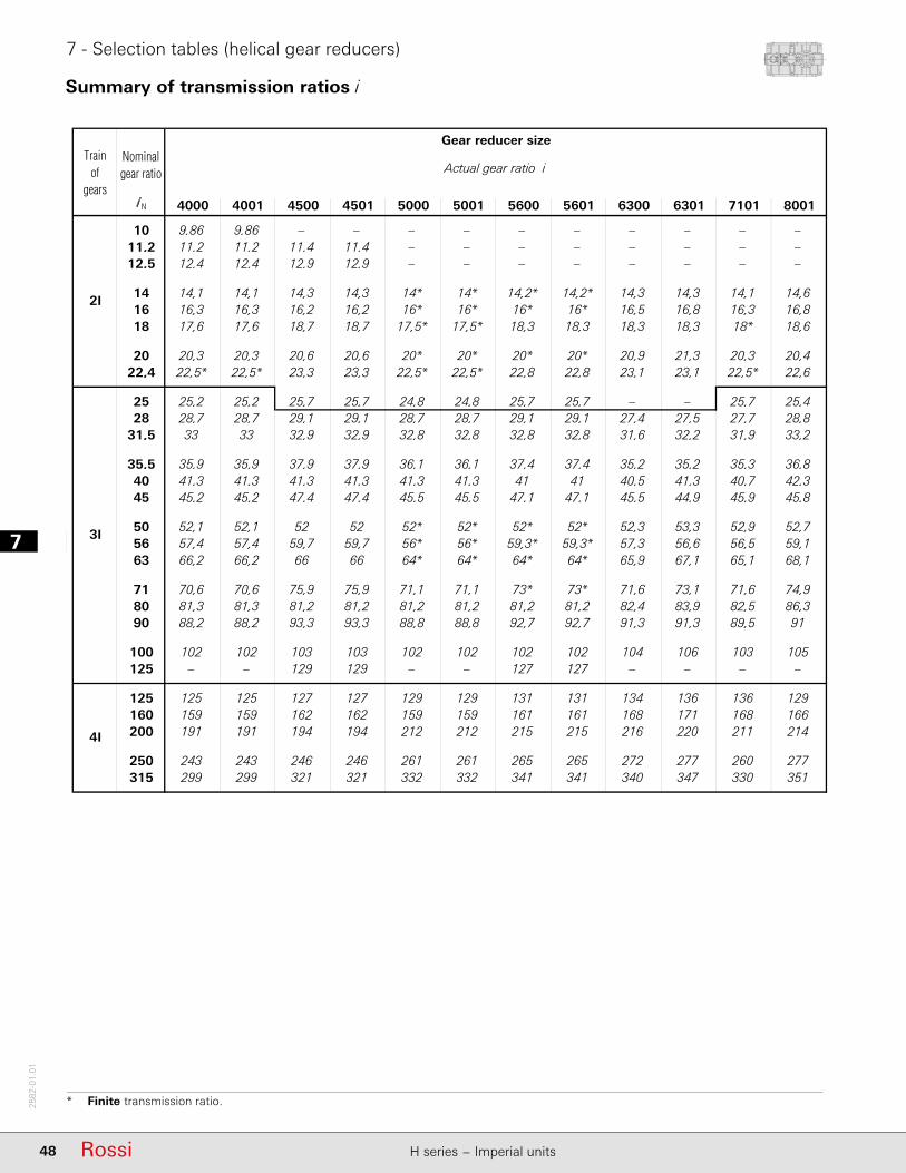
17
48 Rossi H series − Imperial units
2582
-01.
01
Summary of transmission ratios i
7 - Selection tables (helical gear reducers)
* Finite transmission ratio.
4000 4001 4500 4501 5000 5001 5600 5601 6300 6301 7101 8001
10 9,86 9,86 – – – – – – – – – –11,2 11,2 11,2 11,4 11,4 – – – – – – – –12,5 12,4 12,4 12,9 12,9 – – – – – – – –
14 14,1 14,1 14,3 14,3 14* 14* 14,2* 14,2* 14,3 14,3 14,1 14,616 16,3 16,3 16,2 16,2 16* 16* 16* 16* 16,5 16,8 16,3 16,818 17,6 17,6 18,7 18,7 17,5* 17,5* 18,3 18,3 18,3 18,3 18* 18,6
20 20,3 20,3 20,6 20,6 20* 20* 20* 20* 20,9 21,3 20,3 20,422,4 22,5* 22,5* 23,3 23,3 22,5* 22,5* 22,8 22,8 23,1 23,1 22,5* 22,6
25 25,2 25,2 25,7 25,7 24,8 24,8 25,7 25,7 – – 25,7 25,428 28,7 28,7 29,1 29,1 28,7 28,7 29,1 29,1 27,4 27,5 27,7 28,8
31,5 33 33 32,9 32,9 32,8 32,8 32,8 32,8 31,6 32,2 31,9 33,2
35,5 35,9 35,9 37,9 37,9 36,1 36,1 37,4 37,4 35,2 35,2 35,3 36,840 41,3 41,3 41,3 41,3 41,3 41,3 41 41 40,5 41,3 40,7 42,345 45,2 45,2 47,4 47,4 45,5 45,5 47,1 47,1 45,5 44,9 45,9 45,8
50 52,1 52,1 52 52 52* 52* 52* 52* 52,3 53,3 52,9 52,756 57,4 57,4 59,7 59,7 56* 56* 59,3* 59,3* 57,3 56,6 56,5 59,163 66,2 66,2 66 66 64* 64* 64* 64* 65,9 67,1 65,1 68,1
71 70,6 70,6 75,9 75,9 71,1 71,1 73* 73* 71,6 73,1 71,6 74,980 81,3 81,3 81,2 81,2 81,2 81,2 81,2 81,2 82,4 83,9 82,5 86,390 88,2 88,2 93,3 93,3 88,8 88,8 92,7 92,7 91,3 91,3 89,5 91
100 102 102 103 103 102 102 102 102 104 106 103 105125 – – 129 129 – – 127 127 – – – –
125 125 125 127 127 129 129 131 131 134 136 136 129160 159 159 162 162 159 159 161 161 168 171 168 166200 191 191 194 194 212 212 215 215 216 220 211 214
250 243 243 246 246 261 261 265 265 272 277 260 277315 299 299 321 321 332 332 341 341 340 347 330 351
2I
3I
4I
Trainof
gears
Gear reducer size
Actual gear ratio iNominalgear ratio
i N
49RossiH series − Imperial units
2582
-01.
01
49Rossi
8
8 - Dimensions, designs, mounting positions (helical gear reducers)
8.1 - Gear reducers R 2I ................................................................................................................. 50Dimensions ............................................................................................................................................ 50Designs (direction of rotation) ................................................................................................................ 51Mounting positions ................................................................................................................................ 52Lubrication - Plug position and oil quantity ........................................................................................... 53
8.2 - Gear reducers R 3I ................................................................................................................. 54Dimensions ............................................................................................................................................ 54Designs (direction of rotation) ................................................................................................................ 55Mounting positions ................................................................................................................................ 56Lubrication - Plug position and oil quantity ........................................................................................... 57
8.3 - Gear reducers R 4I ................................................................................................................. 58Dimensions ............................................................................................................................................ 58Designs (direction of rotation) ................................................................................................................ 59Mounting positions ................................................................................................................................ 60Lubrication - Plug position and oil quantity ........................................................................................... 61
H series − Imperial units

18
50 Rossi H series − Imperial units
2582
-01.
01
8 - Dimensions, designs, mounting positions (helical gear reducers)
8.1 - Gear reducers R 2I
Dimensions
* For size 6300.
1) Working length on thread 1,7 · F.2) For mounting positions B6, B7, V5, V6, dimension W2 increases by approx. 20 for overall dimensions of fi ller plug.3) c dimension overhangs from C dimension.4) Values valid for double extension low speed shaft end.
Size
a A A1 A2 A3 B C c F H H1 K K1 L L1 M T U W W2
h11 h12 Ø ØH11
M1 1) R 2) 4)
4000 700 505 625 90 – 500 330 330 M45 450 296 39 48 52 116 750 1260 580 1525 1567 5110 52704001 5290 5470
4500 750 505 675 90 – 500 358 330 M45 450 296 39 48 52 116 750 1310 580 1575 1617 5860 60604501 6020 6260
5000 875 630 785 115 – 625 410 4263) M56 560 370 48 60 65 148 930 1575 725 1905 1947 10010 103205001 10270 10630
5600 935 630 845 115 – 625 445 426 M56 560 370 48 60 65 148 930 1635 725 1965 2007 11970 124105601 12240 12720
6300 1080 770 970 115 – 695 490 472 M56 630 406 48 60 65 148 1070 1900 795 2230 2272 16870 174806301 17090 17810
7101 1270 930 1228 115 590 843 601 537 M56 710 481 48 66 71 185 1230 2279 943 2648 2676 28550 29650
8001 1430 1008 1286 145 596 944 682 600 M90 900 544 60 95 85 250 1574 2590 1064 3086 3114 43760 45350
Size
D E d e d eØ Ø Ø
iN 11,2 iN 12,5
4000 190 280 110 210 90 1704001 200
iN 12,5 iN 14
4500 210 300 110 210 90 1704501 220
5000 240 330 – – 110 2105001 250
5600 270 380 – – 110 2105601 280
6300 300 430 – – 125 2106301 320
7101 360 590 – – 180 300
8001 400 660 – – 200 350

8
51RossiH series − Imperial units
2582
-01.
01
8 - Dimensions, designs, mounting positions (helical gear reducers)
8.1 - R 2I gear reducers
Designs (direction of rotation)
Solid low speed shaft (standard)
Hollow low speed shaft with shrink disc on machine opposite side (on request)
Hollow low speed shaft with shrink disc on machine side (on request)
Hollow low speed shaft with keyway (on request)

18
52 Rossi H series − Imperial units
2582
-01.
01
B6
B7
B3
8 - Dimensions, designs, mounting positions (helical gear reducers)
Mounting positionsExcept specifi c needs, prefer mounting position B3 (see ch. 2).
8.1 - R 2I gear reducers
V5
V6
Possible high oil splash: for the corrective factor ft3 of nominal thermal power PtN see ch. 4.
Possible bearing lubrication pump: consult us for verifi cation.1) Mounting position B3 may be identifi ed from the position of the screw-heads as
arrowed. The same is valid for mounting positions V5 and V6 with double extension or hollow low speed shaft: in these cases, consider the position of low speed wheel, for the identifi cation of correct mounting position (see also «Designs» at the previous page).
Oil fi ller plug Oil level plug Oil drain plug
Oil fi ller plug on opposite side (not in view) Oil level plug on opposite side (not in view) Oil drain plug on opposite side (not in view)
* Valid in case of hollow low speed shaft (with shrink disc or keyway).

8
53RossiH series − Imperial units
2582
-01.
01
8 - Dimensions, designs, mounting positions (helical gear reducers)
Lubrication - Plug position and oil quantityOil quantity are approximate for provisioning and can vary according to the design and specifi c application. The exact quantity the gear reducer is to be fi lled with is defi nitely given by the level.
8.1 - R 2I gear reducers
See notes at previous page.
B3 B6 B7
V5 V6
UP1A UP1EUP1D UP1HUP1FUP1G
UP1A* UP1M*UP1D* UP1L*
UP1N UP1MUP1L
UP1A UP1EUP1D UP1HUP1FUP1G
UP1A* UP1M*UP1D* UP1L*
UP1N UP1MUP1L
Size Oil quantity [gal]
B3 B6 B7 V5, V6with low speed shaft on bottom with low speed wheel on top
4000, 4001 31 40 59 62 664500, 4501 30 37 62 59 665000, 5001 62 79 119 125 132
5600, 5601 59 70 119 119 1326300, 6301 88 106 177 166 188
7101 148 177 296 264 296
8001 251 280 476 449 502

18
54 Rossi H series − Imperial units
2582
-01.
01
8 - Dimensions, designs, mounting positions (helical gear reducers)
8.2 - Gear reducers R 3I
Dimensions
* For sizes 6300.
1) Working length on thread 1,7 · F.2) For mounting positions B6, B7, V5, V6, dimension W2 increases by approx. 20 for overall dimensions of fi ller plug.3) Values valid for double extension low speed shaft end.
Size
a A A1 A2 A3 B C c F H H1 K K1 L L1 M T U W W2
h11 h12 Ø ØH11
M1 1) R 2) 3)
4000 900 505 625 90 – 500 330 325 M45 450 296 39 48 52 116 750 1260 580 1525 1567 5220 53804001 5400 5580
4500 950 505 675 90 – 500 358 325 M45 450 296 39 48 52 116 750 1310 580 1575 1617 5950 61504501 6130 6370
5000 1125 630 785 115 – 625 410 405 M56 560 370 48 60 65 148 930 1575 725 1905 1947 10190 104905001 10450 10800
5600 1185 630 845 115 – 625 445 405 M56 560 370 48 60 65 148 930 1635 725 1965 2007 12190 126305601 12460 12940
6300 1380 770 970 115 – 695 490 455 M56 630 406 48 60 65 148 1070 1900 795 2230 2272 17110 177306301 17330 18060
7101 1630 930 1228 115 590 843 601 510 M56 710 481 48 66 71 185 1230 2279 943 2648 2676 29080 30180
8001 1880 1008 1286 145 596 944 682 577 M90 900 544 60 95 85 250 1574 2590 1064 3086 3114 45040 46630
Size
D E d e d eØ Ø Ø
iN 50 iN 56
4000 190 280 80 170 65 1404001 200
iN 56 iN 63
4500 210 300 80 170 65 1404501 220
iN 50 iN 56
5000 240 330 100 210 80 1705001 250
iN 56 iN 63
5600 270 380 100 210 80 1705601 280
iN 50 iN 56
6300 300 430 110 210 90 1706301 320
7101 360 590 120 210 – –
8001 400 660 150 250 – –
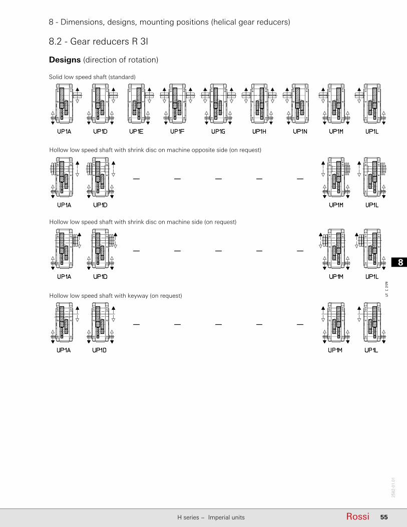
8
55RossiH series − Imperial units
2582
-01.
01
8 - Dimensions, designs, mounting positions (helical gear reducers)
8.2 - Gear reducers R 3I
Designs (direction of rotation)
Solid low speed shaft (standard)
Hollow low speed shaft with shrink disc on machine opposite side (on request)
Hollow low speed shaft with shrink disc on machine side (on request)
Hollow low speed shaft with keyway (on request)

18
56 Rossi H series − Imperial units
2582
-01.
01
8 - Dimensions, designs, mounting positions (helical gear reducers)
8.2 - Gear reducers R 3I
B6
B7
B3
Mounting positionsExcept specifi c needs, prefer mounting position B3 (see ch. 2).
V5
V6
Possible high oil splash: for the corrective factor ft3 of nominal thermal power PtN see ch. 4.
Possible bearing lubrication pump: consult us for verifi cation.1) Mounting position B3 may be identifi ed from the position of the screw-heads as
arrowed. The same is valid for mounting positions V5 and V6 with double extension or hollow low speed shaft: in these cases, consider the position of low speed wheel, for the identifi cation of correct mounting position (see also «Designs» at the previous page).
Oil fi ller plug Oil level plug Oil drain plug
Oil fi ller plug on opposite side (not in view) Oil level plug on opposite side (not in view) Oil drain plug on opposite side (not in view)
* Valid in case of hollow low speed shaft (with shrink disc or keyway).

8
57RossiH series − Imperial units
2582
-01.
01
8 - Dimensions, designs, mounting positions (helical gear reducers)
8.2 - Gear reducers R 3I
Lubrication - Plug position and oil quantityOil quantity are approximate for provisioning and can vary according to the design and specifi c application. The exact quantity the gear reducer is to be fi lled with is defi nitely given by the level.
B3 B6 B7
V5 V6
UP1A UP1EUP1D UP1HUP1FUP1G
UP1A* UP1M*UP1D* UP1L*
UP1N UP1MUP1L
UP1A UP1EUP1D UP1HUP1FUP1G
UP1A* UP1M*UP1D* UP1L*
UP1N UP1MUP1L
Size Oil quantity [gal]
B3 B6 B7 V5, V6with low speed shaft on bottom with low speed wheel on top
4000, 4001 37 62 59 62 664500, 4501 37 62 59 62 665000, 5001 74 119 119 119 132
5600, 5601 74 119 119 119 1326300, 6301 106 166 177 166 188
7101 166 251 280 264 296
8001 280 476 449 476 502
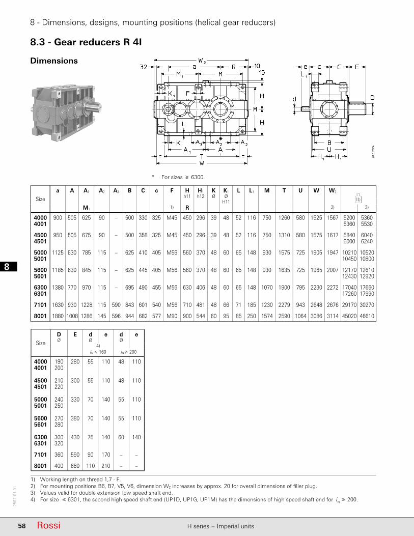
18
58 Rossi H series − Imperial units
2582
-01.
01
8 - Dimensions, designs, mounting positions (helical gear reducers)
8.3 - Gear reducers R 4I
Dimensions
* For sizes 6300.
1) Working length on thread 1,7 · F.2) For mounting positions B6, B7, V5, V6, dimension W2 increases by approx. 20 for overall dimensions of fi ller plug.3) Values valid for double extension low speed shaft end.4) For size 6301, the second high speed shaft end (UP1D, UP1G, UP1M) has the dimensions of high speed shaft end for iN 200.
Size
D E d e d eØ Ø Ø
4)iN 160 iN 200
4000 190 280 55 110 48 1104001 200
4500 210 300 55 110 48 1104501 220
5000 240 330 70 140 55 1105001 250
5600 270 380 70 140 55 1105601 280
6300 300 430 75 140 60 1406301 320
7101 360 590 90 170 – –
8001 400 660 110 210 – –
Size
a A A1 A2 A3 B C c F H H1 K K1 L L1 M T U W W2
h11 h12 Ø ØH11
M1 1) R 2) 3)
4000 900 505 625 90 – 500 330 325 M45 450 296 39 48 52 116 750 1260 580 1525 1567 5200 53604001 5360 5530
4500 950 505 675 90 – 500 358 325 M45 450 296 39 48 52 116 750 1310 580 1575 1617 5840 60404501 6000 6240
5000 1125 630 785 115 – 625 410 405 M56 560 370 48 60 65 148 930 1575 725 1905 1947 10210 105205001 10450 10800
5600 1185 630 845 115 – 625 445 405 M56 560 370 48 60 65 148 930 1635 725 1965 2007 12170 126105601 12430 12920
6300 1380 770 970 115 – 695 490 455 M56 630 406 48 60 65 148 1070 1900 795 2230 2272 17040 176606301 17260 17990
7101 1630 930 1228 115 590 843 601 540 M56 710 481 48 66 71 185 1230 2279 943 2648 2676 29170 30270
8001 1880 1008 1286 145 596 944 682 577 M90 900 544 60 95 85 250 1574 2590 1064 3086 3114 45020 46610
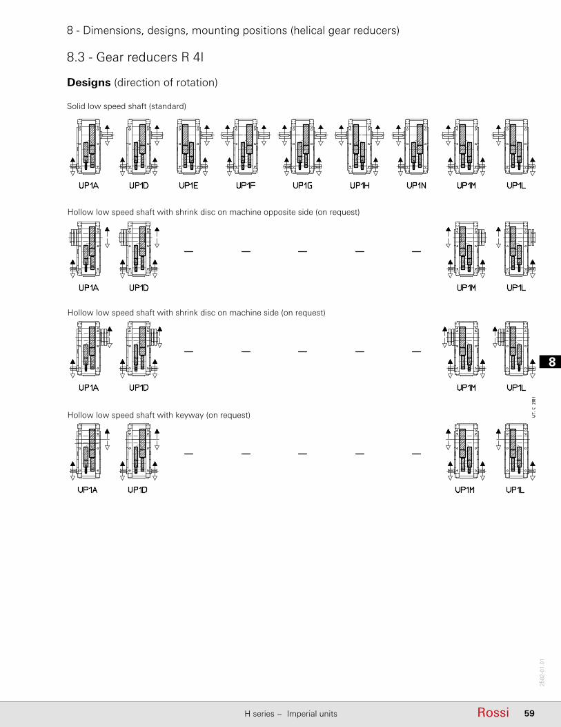
8
59RossiH series − Imperial units
2582
-01.
01
8 - Dimensions, designs, mounting positions (helical gear reducers)
8.3 - Gear reducers R 4I
Designs (direction of rotation)
Solid low speed shaft (standard)
Hollow low speed shaft with shrink disc on machine opposite side (on request)
Hollow low speed shaft with shrink disc on machine side (on request)
Hollow low speed shaft with keyway (on request)

18
60 Rossi H series − Imperial units
2582
-01.
01
8 - Dimensions, designs, mounting positions (helical gear reducers)
8.3 - Gear reducers R 4I
B6
B7
B3
V5
V6
Mounting positionsExcept specifi c needs, prefer mounting position B3 (see ch. 2).
Possible high oil splash: for the corrective factor ft3 of nominal thermal power PtN see ch. 4.
Possible bearing lubrication pump: consult us for verifi cation.1) Mounting position B3 may be identifi ed from the position of the screw-heads as
arrowed. The same is valid for mounting positions V5 and V6 with double extension or hollow low speed shaft: in these cases, consider the position of low speed wheel, for the identifi cation of correct mounting position (see also «Designs» at the previous page).
Oil fi ller plug Oil level plug Oil drain plug
Oil fi ller plug on opposite side (not in view) Oil level plug on opposite side (not in view) Oil drain plug on opposite side (not in view)
* Valid in case of hollow low speed shaft (with shrink disc or keyway).
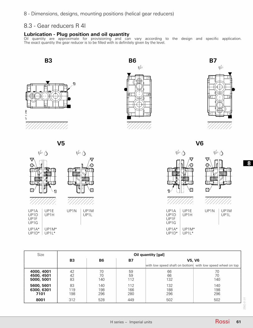
8
61RossiH series − Imperial units
2582
-01.
01
8 - Dimensions, designs, mounting positions (helical gear reducers)
8.3 - Gear reducers R 4ILubrication - Plug position and oil quantityOil quantity are approximate for provisioning and can vary according to the design and specifi c application. The exact quantity the gear reducer is to be fi lled with is defi nitely given by the level.
B3 B6 B7
V5 V6
UP1A UP1EUP1D UP1HUP1FUP1G
UP1A* UP1M*UP1D* UP1L*
UP1N UP1MUP1L
UP1A UP1EUP1D UP1HUP1FUP1G
UP1A* UP1M*UP1D* UP1L*
UP1N UP1MUP1L
Size Oil quantity [gal]
B3 B6 B7 V5, V6with low speed shaft on bottom with low speed wheel on top
4000, 4001 42 70 59 66 704500, 4501 42 70 59 66 705000, 5001 83 140 112 132 140
5600, 5601 83 140 112 132 1406300, 6301 119 198 166 188 198
7101 198 296 280 296 296
8001 312 528 449 502 502

18
62 Rossi H series − Imperial units
2582
-01.
01
Page intentionally left blank
9
63RossiH series − Imperial units
2582
-01.
01
9 - Selection tables(bevel helical gear reducers)

19
64 Rossi H series − Imperial units
2582
-01.
01
9 - Selection tables (bevel helical gear reducers)
n1 = 1 800 rpm
Necessary forced lubrication with motor pump and possible heat exchanger (see ch. 6 and 12).
Nominal output power P N2 [hp]i N n N2 Nominal output torque M N2 (M 2max) [103 lb in]
rpm
8 224645 (1250) 695 (1400) 860 (1700)
9 200710 (1320) 775 (1500) 885 (1700) 975 (1950)
10 180710 (1320) 795 (1500) 885 (1750) 990 (1800)
11,2 160710 (1320) 795 (1500) 885 (1750) 990 (2000)
12,5 140710 (1320) 765 (1550) 885 (1700) 990 (1700)
14 132710 (1250) 795 (1450) 885 (1750) 990 (2000)
16 112710 (1320) 755 (1450) 885 (1650) 960 (1850)
18 100710 (1280) 795 (1450) 865 (1750)
20 90840 (1450) 910 (1650) 885 (1650) 955 (1900)
22,4 80865 (1450) 945 (1650) 1020 (2000) 1105 (2240) 1680 (2900) 1835 (3350)
25 71885 (1400) 975 (1600) 1060 (2000) 1160 (2300) 1635 (2800) 1790 (3250) 2150 (4000) 2435 (4500)
28 63885 (1450) 990 (1650) 1090 (1850) 1195 (2120) 1680 (2900) 1875 (3350) 2150 (3750) 2460 (4250) 2655 (5300) 2965 (6000)
31,5 56885 (1450) 990 (1650) 1105 (2000) 1220 (2300) 1665 (2900) 1875 (3350) 2150 (4000) 2480 (4620) 2830 (5600) 3185 (6300)
35,5 50885 (1450) 990 (1700) 1105 (1900) 1240 (2180) 1680 (2900) 1875 (3350) 2150 (3750) 2480 (4370) 2965 (5600) 3365 (6300)
40 45885 (1450) 990 (1700) 1105 (2060) 1240 (2360) 1680 (2900) 1875 (3350) 2150 (4120) 2480 (4750) 3100 (5800) 3540 (6700)
45 40885 (1500) 990 (1700) 1105 (1950) 1240 (2240) 1680 (3000) 1875 (3450) 2150 (3870) 2480 (4500) 3140 (5800) 3645 (5600)
50 35,5885 (1500) 990 (1700) 1105 (2060) 1240 (2360) 1680 (3000) 1875 (3450) 2150 (4120) 2480 (4750) 3140 (5800) 3645 (6700)
56 31,5885 (1500) 990 (1750) 1105 (1950) 1240 (2240) 1680 (3070) 1875 (3450) 2150 (4000) 2480 (4500) 3140 (5800) 3645 (5600)
63 28885 (1500) 990 (1750) 1105 (2120) 1240 (2430) 1680 (3070) 1875 (3450) 2150 (4250) 2480 (4870) 3140 (6000) 3645 (6700)
71 25885 (1550) 990 (1750) 1105 (2000) 1240 (2300) 1680 (3070) 1875 (3550) 2150 (4000) 2480 (4620) 3140 (5800) 3645 (5450)
80 22,4885 (1550) 990 (1750) 1105 (2180) 1240 (2430) 1680 (3070) 1875 (3550) 2150 (4250) 2480 (4870) 3140 (6150) 3645 (6900)
90 20885 (1550) 990 (1750) 1105 (2060) 1240 (2360) 1680 (3070) 1875 (3550) 2150 (4120) 2480 (4750) 3140 (5800) 3645 (6700)
100 18885 (1550) 990 (1750) 1105 (2180) 1240 (2500) 1680 (3070) 1875 (3550) 2150 (4250) 2480 (4870) 3140 (5300) 3645 (6150) 4885 (9750) 8190 (16000)
125 141105 (1900) 1240 (2180) 2150 (3750) 2480 (4250)
125 14885 (1550) 990 (1750) 1105 (2180) 1240 (2500) 1680 (3070) 1875 (3550) 2150 (4250) 2480 (5000) 3140 (6000) 3375 (6700) 5750 (11200) 8190 (16000)
160 11,2885 (1550) 990 (1750) 1105 (2180) 1240 (2500) 1680 (3070) 1875 (3550) 2150 (4250) 2480 (5000) 3140 (6150) 3645 (7100) 5750 (11200) 8190 (16000)
200 9885 (1550) 990 (1750) 1105 (2180) 1240 (2500) 1680 (3070) 1875 (3550) 2150 (4250) 2480 (5000) 3140 (6000) 3645 (6700) 5750 (11200) 8190 (16000)
250 7,1885 (1550) 990 (1750) 1105 (2180) 1240 (2500) 1680 (3070) 1875 (3550) 2150 (4250) 2480 (5000) 3140 (6150) 3645 (7100) 5750 (11200) 8190 (16000)
315 5,6885 (1550) 990 (1750) 1105 (2180) 1240 (2500) 1680 (3070) 1875 (3550) 2150 (4250) 2480 (5000) 3140 (6150) 3540 (7100) 5750 (11200) 8190 (16000)
▲ lubrificazione forzata
566▲ – –
1370▲
351
–
–
–
–
–
–
–
–
– –
681 718
432 545 621 1010▲
–
498 677▲
859▲345 394 631
432 497 801 1090▲
272 30177,7 87 97,3 109 148 165 189 218
240 27695,5 107
C3I
194 218 243 272 369 412 472 544
327
120 134 188 209
121 136 152 170 238 265 304
375154 172
– – 246 275 – – 491▲
193 216 293
536▲ 614▲
1220▲
1120▲ – –
249 278 307 344 480▲ 2180▲708▲ 884▲ 1030▲ 1370▲
885▲ 1070▲
286 321 339 379 549▲ 612▲ 673▲ 776▲ 969▲
311 348 384 430 600▲ 670▲ 768▲
765▲ 841▲
–1550▲
358 401 423 474 686▲ –969▲ 1230▲ 1430▲
388 435 487 545 750▲ 837▲ 960▲ 1110▲ 1360▲ –
–
952▲ –
448 501 537 601 858▲ 957▲ 1070▲
1060▲ 1220▲ 1400▲ 1720▲ 1960▲
–1230▲ 1570▲ 1800▲ –
–
–2280▲
–1950▲ 2320▲ 2630▲
–1770▲
–
1540▲
1530▲ 1700▲
1210▲ 1350▲ 1550▲ 1980▲
2150▲ 2410▲
– –
–
783▲ 877▲ 980▲ 1080▲ 1500▲ 1690▲ 1930▲ 2230▲ 2450▲
2420▲ 2650▲ 2960▲
–2710▲
902▲ 1010▲
–
–1100▲ –
978▲ –2740▲ – –
1210▲ 1280▲ 1390▲ 2160▲ 2360▲ – –
2010▲ 2420▲
– –1120▲ 1260▲ 1330▲ – –– ––
–
–
1150▲ 1730▲ 1930▲ 2120▲1050▲
716▲ 802▲ 853▲ 955▲ 1370▲
1080▲ 1180▲ 1280▲ 1840▲
1420▲ 1600▲
C2I
1220▲ 1320▲ 1230▲ 1330▲ – –
568 636 677▲ 758▲ 1090▲
622▲ 696▲ 778▲ 872▲ 1200▲ 1340▲
493 552 617 691
1330▲ 1560▲ 1690▲ – – – –
– –
–
– – – –
–– – –
–
2510▲
–
1580▲ 1710▲ 1970▲ 2200▲ – – – –
– – – – –1800▲ 2020▲ 2170▲ 2430▲ – –
–
1990▲
–
Gear reducer size
4000 5601 6300 6301 7101 80014001 4500 4501 5000 5001 5600
2240▲
1710▲ 1920▲ – –
Trainof
gears
CI
2380▲ 2560▲ 3030▲ – –
2710▲ 2980▲ – –
2490▲ 2750▲ – –
1240▲
2290▲
– –
– –
1260▲ 1720▲
– – –
–
– – – –
– – – –
–
– –
– – –
TN2 (T2max)
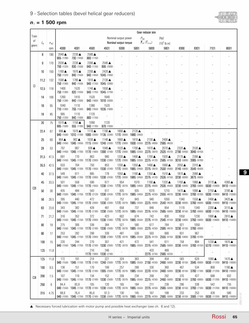
9
65RossiH series − Imperial units
2582
-01.
01
9 - Selection tables (bevel helical gear reducers)
n1 = 1 500 rpm
Necessary forced lubrication with motor pump and possible heat exchanger (see ch. 6 and 12).
Nominal output power P N2 [hp]i N n N2 Nominal output torque M N2 (M 2max) [103 lb in]
rpm
8 190665 (1280) 730 (1450) 880 (1750)
9 170750 (1320) 830 (1550) 940 (1750) 995 (2000)
10 150750 (1320) 840 (1550) 940 (1850) 1045 (1850)
11,2 132750 (1360) 840 (1550) 940 (1750) 1045 (2060)
12,5 118750 (1360) 820 (1550) 940 (1750) 1045 (1750)
14 106750 (1280) 840 (1500) 940 (1800) 1010 (2000)
16 95710 (1360) 755 (1500) 940 (1650) 1035 (1900)
18 85750 (1320) 840 (1500) 880 (1750)
20 75885 (1500) 955 (1700) 940 (1700) 970 (1950)
22,4 67940 (1500) 1010 (1700) 1060 (2000) 1135 (2240) 1770 (3000) 1980 (3450)
25 60940 (1450) 1045 (1650) 1115 (2000) 1240 (2300) 1770 (2900) 1930 (3350) 2275 (4000) 2565 (4620)
28 53940 (1450) 1045 (1700) 1170 (1900) 1300 (2180) 1770 (2900) 1985 (3350) 2275 (3870) 2525 (4370) 2790 (5450) 3040 (6150)
31,5 47,5940 (1450) 1045 (1700) 1170 (2060) 1330 (2360) 1770 (2900) 1985 (3350) 2275 (4120) 2565 (4750) 3010 (5800) 3365 (6700)
35,5 42,5940 (1500) 1045 (1700) 1170 (1950) 1330 (2240) 1770 (3000) 1985 (3450) 2275 (3870) 2530 (4500) 3140 (5800) 3540 (6500)
40 37,5940 (1500) 1045 (1700) 1170 (2060) 1330 (2430) 1770 (3000) 1985 (3450) 2275 (4120) 2535 (4750) 3230 (6000) 3675 (6900)
45 33,5940 (1500) 1045 (1750) 1170 (1950) 1330 (2240) 1770 (3070) 1985 (3450) 2275 (4000) 2535 (4500) 3230 (5800) 3760 (5800) 5930 (10900) 8410 (15500)
50 30940 (1500) 1045 (1750) 1170 (2120) 1330 (2430) 1770 (3070) 1985 (3450) 2275 (4250) 2555 (4870) 3230 (6000) 3760 (6700) 5930 (10900) 8410 (15500)
56 26,5940 (1550) 1045 (1750) 1170 (2000) 1330 (2300) 1770 (3070) 1985 (3550) 2275 (4000) 2540 (4620) 3230 (6000) 3760 (6000) 5930 (10600) 8410 (15000)
63 23,6940 (1550) 1045 (1750) 1170 (2180) 1330 (2500) 1770 (3070) 1985 (3550) 2275 (4250) 2565 (5000) 3230 (6150) 3760 (6900) 5930 (11200) 8410 (16000)
71 21,2940 (1550) 1045 (1750) 1170 (2060) 1330 (2360) 1770 (3070) 1985 (3550) 2275 (4120) 2545 (4750) 3230 (5800) 3760 (5800) 5930 (10600) 8410 (15000)
80 19940 (1550) 1045 (1750) 1170 (2180) 1330 (2500) 1770 (3070) 1985 (3550) 2275 (4250) 2565 (4870) 3230 (6150) 3760 (6900)
90 17940 (1550) 1045 (1750) 1170 (2060) 1330 (2360) 1770 (3070) 1985 (3550) 2275 (4120) 2555 (4750) 3230 (5800) 3760 (6700)
100 15940 (1550) 1045 (1750) 1170 (2180) 1330 (2500) 1770 (3070) 1985 (3550) 2275 (4250) 2565 (5000) 3230 (5450) 3760 (6150) 5270 (10600) 8410 (16000)
125 11,81170 (1900) 1330 (2180) 2275 (3750) 2565 (4250)
125 11,8940 (1550) 1045 (1750) 1170 (2180) 1240 (2500) 1770 (3070) 1985 (3550) 2150 (4250) 2480 (5000) 3230 (6150) 3545 (6900) 5930 (11200) 8410 (16000)
160 9,5940 (1550) 1045 (1750) 1170 (2180) 1305 (2500) 1770 (3070) 1985 (3550) 2270 (4250) 2480 (5000) 3230 (6150) 3760 (7100) 5930 (11200) 8410 (16000)
200 7,5940 (1550) 1045 (1750) 1170 (2180) 1330 (2500) 1770 (3070) 1985 (3550) 2275 (4250) 2480 (5000) 3230 (6150) 3760 (6900) 5930 (11200) 8410 (16000)
250 6940 (1550) 1045 (1750) 1170 (2180) 1330 (2500) 1770 (3070) 1985 (3550) 2275 (4250) 2565 (5000) 3230 (6150) 3760 (7100) 5930 (11200) 8410 (16000)
315 4,75940 (1550) 1045 (1750) 1170 (2180) 1330 (2500) 1770 (3070) 1985 (3550) 2275 (4250) 2565 (5000) 3230 (6150) 3565 (7100) 5930 (11200) 8410 (16000)
▲ lubrificazione forzata■ interpellarci
– –
– –
– –
– –
– –
– –
– –
– –
2390▲
–
– – –
–
170 189 257
583 629
428 580
735
68,6 76,4 85,6 97,3 130 145 167 188
211 239 296 338 54284,4 93,9
370 427 688 932
233 253
489 – –
1180▲
292
360 467 534 868
–
C3I
172 191 214 227 324 363 394 454
288
105 120 165 184
107 119 134 152 209 234 268
330136 151
– – 216 246 – – 433
472 541
658 737
1050
967 – –
220 244 270 307 421 1870▲611 758 884 1230▲
764 921
253 282 298 339 481 539 831
275 306 338 384 527 590 677
674 742
593 666
2490▲ 3420▲
1340 2200▲ 3110▲
316 352 372 423 602 2810▲830 1050 1230 1990▲
1050 1340
343 382 428 487 846 954 1170
3170▲ 4360▲
435 484 543 617 835 3780▲1210 1470▲ 1680▲ 2750▲
501 558 596 677 954 1070 1320▲ 1700▲ 1960▲1190▲
935 1070
–
2530▲2070▲ 2320▲
633 704 750 853 1200▲ 1660▲ 2050▲ 2310▲
691 770 863 980 1330▲ 1490▲ 1700▲ 1920▲ 2170▲
1890▲ 2120▲ – – –
887 938▲ 1040▲ 1520▲ 1700▲ 1870▲
1810▲ 2130▲ 2400▲ – –
395 440 472 537 752 843 940
2080▲1510▲ 1870▲549 611 685 778 1050▲ 1180▲ 1350▲
1550▲
––
– – –
C2I
1070▲ 1150▲ 1090 1120 – – –
996▲ 1070▲ 1110▲
864▲ 962▲ 1030▲ 1140▲ 1660▲
1350▲ 1490▲
797
1410 1520 1640 – –
–
1190▲
1040 1110 1380 1520 – – – – –
– – –
–
995 1110 1120 –
– – –
– – – – –1590▲ 1780▲ 1910▲ 2130▲ – –
– –
–– – –
– –– –
–
Gear reducer size
4000 5601 6300 6301 7101 80014001 4500 4501 5000 5001 5600
1760▲ 1970▲ 2200▲ 2420▲ –
Trainof
gears
CI
2040▲ 2230▲ 2580▲ – –
2030▲ 2230▲ 2540▲ –
1400 1520 1740▲ 1930▲ –
1260
– –
–
1080▲ 1470▲
– – –
2390▲
– – –
– ––
– – –
– – – –
– –
TN2 (T2max)
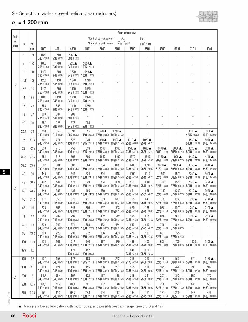
19
66 Rossi H series − Imperial units
2582
-01.
01
n1 = 1 200 rpm
9 - Selection tables (bevel helical gear reducers)
Necessary forced lubrication with motor pump and possible heat exchanger (see ch. 6 and 12).
Nominal output power P N2 [hp]i N n N2 Nominal output torque M N2 (M 2max) [103 lb in]
rpm
8 150685 (1280) 730 (1450) 890 (1800)
9 132755 (1360) 830 (1550) 945 (1750) 1005 (2000)
10 118755 (1360) 845 (1550) 945 (1900) 1050 (1900)
11,2 106755 (1360) 845 (1550) 945 (1800) 1050 (2060)
12,5 95755 (1360) 845 (1600) 945 (1800) 1050 (1800)
14 85755 (1280) 845 (1500) 945 (1800) 1020 (2060)
16 75735 (1360) 760 (1500) 945 (1700) 1050 (1950)
18 67755 (1320) 840 (1500) 890 (1800)
20 60890 (1500) 960 (1700) 945 (1700) 980 (1950)
22,4 53940 (1500) 1010 (1700) 1065 (2060) 1140 (2300) 1770 (3000) 1990 (3450) 4675 (9000) 8030 (13200)
25 47,5940 (1450) 1045 (1650) 1120 (2060) 1245 (2360) 1770 (2900) 1990 (3350) 2285 (4000) 2570 (4620) 5180 (10000) 8430 (14500)
28 42,5940 (1500) 1045 (1700) 1170 (1900) 1305 (2180) 1770 (3000) 1990 (3350) 2285 (3870) 2525 (4370) 2810 (5450) 3060 (6150) 5940 (10600) 8430 (15000)
31,5 37,5940 (1500) 1045 (1700) 1170 (2060) 1330 (2360) 1770 (3000) 1990 (3350) 2285 (4120) 2575 (4750) 3025 (5800) 3380 (6700) 5940 (10000) 8430 (14500)
35,5 33,5940 (1500) 1045 (1750) 1170 (1950) 1330 (2240) 1770 (3000) 1990 (3450) 2285 (3870) 2530 (4500) 3160 (5800) 3560 (6500) 5940 (10000) 8430 (14500)
40 30940 (1500) 1045 (1750) 1170 (2120) 1330 (2430) 1770 (3000) 1990 (3450) 2285 (4250) 2545 (4870) 3245 (6000) 3685 (6900) 5940 (10000) 8430 (14500)
45 26,5940 (1550) 1045 (1750) 1170 (2000) 1330 (2300) 1770 (3070) 1990 (3550) 2285 (4000) 2540 (4620) 3245 (5800) 3770 (6000) 5940 (10900) 8430 (16000)
50 23,6940 (1550) 1045 (1750) 1170 (2120) 1330 (2430) 1770 (3070) 1990 (3550) 2285 (4250) 2565 (4870) 3245 (6000) 3770 (6700) 5940 (11200) 8430 (16000)
56 21,2940 (1550) 1045 (1750) 1170 (2000) 1330 (2300) 1770 (3070) 1990 (3550) 2285 (4000) 2545 (4620) 3245 (6000) 3770 (6000) 5940 (10600) 8430 (15000)
63 19940 (1550) 1045 (1750) 1170 (2180) 1330 (2500) 1770 (3070) 1990 (3550) 2285 (4250) 2575 (5000) 3245 (6150) 3770 (6900) 5940 (11200) 8430 (16000)
71 17940 (1550) 1045 (1750) 1170 (2060) 1330 (2360) 1770 (3070) 1990 (3550) 2285 (4120) 2550 (4750) 3245 (6000) 3770 (6000) 5940 (10600) 8430 (15000)
80 15940 (1550) 1045 (1750) 1170 (2180) 1330 (2500) 1770 (3070) 1990 (3550) 2285 (4250) 2575 (4870) 3245 (6150) 3770 (6900)
90 13,2940 (1550) 1045 (1750) 1170 (2060) 1330 (2360) 1770 (3070) 1990 (3550) 2285 (4120) 2555 (4750) 3245 (5800) 3770 (6700)
100 11,8940 (1550) 1045 (1750) 1170 (2180) 1330 (2500) 1770 (3070) 1990 (3550) 2285 (4250) 2575 (5000) 3245 (5600) 3770 (6300) 5450 (10900) 8430 (16000)
125 9,51170 (1900) 1330 (2180) 2285 (3750) 2575 (4250)
125 9,5940 (1550) 1045 (1750) 1170 (2180) 1245 (2500) 1770 (3070) 1990 (3550) 2170 (4250) 2480 (5000) 3245 (6150) 3670 (6900) 5940 (11200) 8430 (16000)
160 7,5940 (1550) 1045 (1750) 1170 (2180) 1330 (2500) 1770 (3070) 1990 (3550) 2285 (4250) 2480 (5000) 3245 (6150) 3770 (7100) 5940 (11200) 8430 (16000)
200 6940 (1550) 1045 (1750) 1170 (2180) 1330 (2500) 1770 (3070) 1990 (3550) 2285 (4250) 2560 (5000) 3245 (6150) 3770 (6900) 5940 (11200) 8430 (16000)
250 4,75940 (1550) 1045 (1750) 1170 (2180) 1330 (2500) 1770 (3070) 1990 (3550) 2285 (4250) 2575 (5000) 3245 (6150) 3770 (7100) 5940 (11200) 8430 (16000)
315 3,75940 (1550) 1045 (1750) 1170 (2180) 1330 (2500) 1770 (3070) 1990 (3550) 2285 (4250) 2575 (5000) 3245 (6150) 3685 (7100) 5940 (11200) 8430 (16000)
▲ lubrificazione forzata
590
55 61,2 68,7 78,1 104 117 134 151
170 192 238 271 43567,6 75,2
392 – –
942
85,7 95,4 107 122 167 188 215 241
265 288 375 696109 121 136 155 206
469 520 870 1180▲
C3I
137 153 172 183 260 292 318 363
231
84,4 96 132 148
297 342 552 747
187 209 343 465
428
– – 173 197 – – 348
379 435
844
775 – –
176 196 217 246 337 1500▲490 608 709 1020
613 740
203 226 239 272 386 433 476 533 667
220 245 271 308 422 474 543
542 595
2740▲
1070 1760▲ 2490▲
253 282 299 339 482 2260▲665 846 984 1590▲
841 1080
275 306 343 390 766 938
317 353 431 603 677 755
1670 2760▲549 624 844 948 1090
1240 1990▲
3900▲
1570 2540▲ 3490▲
349 388 435 495 669 3030▲968 1180 1350 2210▲
1210 1500
402 447 478 543 1060 1360
440 490
3820▲ 5240▲
1920▲ 3450▲ 4740▲
507 564 602 684 964 4310▲1330 1650▲ 1850▲ 3050▲
1660▲ 1870▲
554 617 692 786 1540 1750▲
3830▲ 6350▲
692 771 827 920 1330▲ 6040▲1920▲ – – 3830▲
1520▲ 1710▲ – – –955
679
–800 887 909 – ––
798 859 893 –
– – –
638 710 752 839 1210 1360 1500▲ 2030▲
379
–
C2I
857 927 872 908 – – –
–
1490▲ 1710▲
1060 1190 1370
1080 1200
764 859 953
752 861
527 593
858 887 1110 1230 – – – –
–
–
– – –
– – –
–– – –– ––
–
–
–
–– – –
–
1120 1250 1400 1550 – – – –
– – – – –1280 1430 1540 1710 –
Gear reducer size
4000 5601 6300 6301 7101 80014001 4500 4501 5000 5001 5600
1920▲
1420 1580 1770 1940▲ –
Trainof
gears
CI
1680 1790 2080▲ – –
1630 1790 2050▲ –
1010 1130 1220 1320 –
– –
– –
–
– –
–
– – –
– – –
– ––
– – – –
– – –
TN2 (T2max)
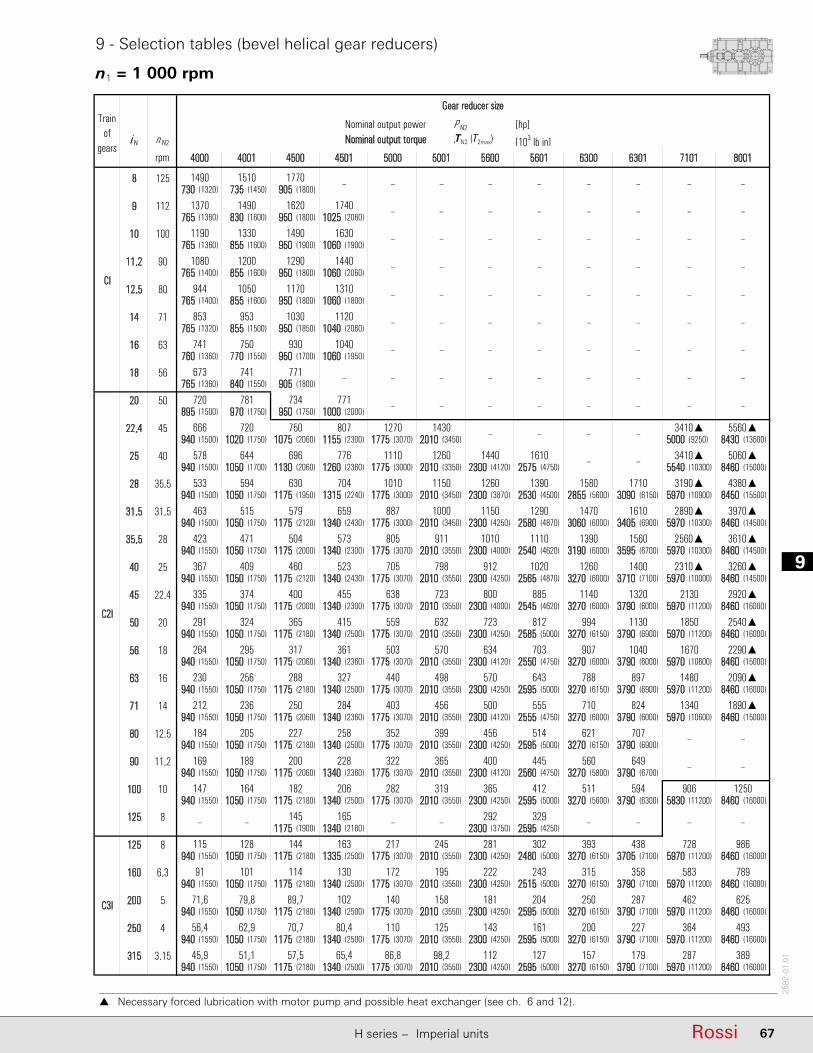
9
67RossiH series − Imperial units
2582
-01.
01
n1 = 1 000 rpm
9 - Selection tables (bevel helical gear reducers)
Necessary forced lubrication with motor pump and possible heat exchanger (see ch. 6 and 12).
Nominal output power P N2 [hp]i N n N2 Nominal output torque M N2 (M 2max) [103 lb in]
rpm
8 125730 (1320) 735 (1450) 905 (1800)
9 112765 (1360) 830 (1600) 950 (1800) 1025 (2060)
10 100765 (1360) 855 (1600) 950 (1900) 1060 (1900)
11,2 90765 (1400) 855 (1600) 950 (1800) 1060 (2060)
12,5 80765 (1400) 855 (1600) 950 (1800) 1060 (1800)
14 71765 (1320) 855 (1500) 950 (1850) 1040 (2060)
16 63760 (1360) 770 (1550) 950 (1700) 1060 (1950)
18 56765 (1360) 840 (1550) 905 (1800)
20 50895 (1500) 970 (1750) 950 (1750) 1000 (2000)
22,4 45940 (1500) 1020 (1750) 1075 (2060) 1155 (2300) 1775 (3070) 2010 (3450) 5000 (9250) 8430 (13600)
25 40940 (1500) 1050 (1700) 1130 (2060) 1260 (2360) 1775 (3000) 2010 (3350) 2300 (4120) 2575 (4750) 5540 (10300) 8460 (15000)
28 35,5940 (1500) 1050 (1750) 1175 (1950) 1315 (2240) 1775 (3000) 2010 (3450) 2300 (3870) 2530 (4500) 2855 (5600) 3090 (6150) 5970 (10900) 8450 (15500)
31,5 31,5940 (1500) 1050 (1750) 1175 (2120) 1340 (2430) 1775 (3000) 2010 (3450) 2300 (4250) 2580 (4870) 3060 (6000) 3405 (6900) 5970 (10300) 8460 (14500)
35,5 28940 (1550) 1050 (1750) 1175 (2000) 1340 (2300) 1775 (3070) 2010 (3550) 2300 (4000) 2540 (4620) 3190 (6000) 3595 (6700) 5970 (10300) 8460 (14500)
40 25940 (1550) 1050 (1750) 1175 (2120) 1340 (2430) 1775 (3070) 2010 (3550) 2300 (4250) 2565 (4870) 3270 (6000) 3710 (7100) 5970 (10000) 8460 (14500)
45 22,4940 (1550) 1050 (1750) 1175 (2000) 1340 (2300) 1775 (3070) 2010 (3550) 2300 (4000) 2545 (4620) 3270 (6000) 3790 (6000) 5970 (11200) 8460 (16000)
50 20940 (1550) 1050 (1750) 1175 (2180) 1340 (2500) 1775 (3070) 2010 (3550) 2300 (4250) 2585 (5000) 3270 (6150) 3790 (6900) 5970 (11200) 8460 (16000)
56 18940 (1550) 1050 (1750) 1175 (2060) 1340 (2360) 1775 (3070) 2010 (3550) 2300 (4120) 2550 (4750) 3270 (6000) 3790 (6000) 5970 (10600) 8460 (15000)
63 16940 (1550) 1050 (1750) 1175 (2180) 1340 (2500) 1775 (3070) 2010 (3550) 2300 (4250) 2595 (5000) 3270 (6150) 3790 (6900) 5970 (11200) 8460 (16000)
71 14940 (1550) 1050 (1750) 1175 (2060) 1340 (2360) 1775 (3070) 2010 (3550) 2300 (4120) 2555 (4750) 3270 (6000) 3790 (6000) 5970 (10600) 8460 (15000)
80 12,5940 (1550) 1050 (1750) 1175 (2180) 1340 (2500) 1775 (3070) 2010 (3550) 2300 (4250) 2595 (5000) 3270 (6150) 3790 (6900)
90 11,2940 (1550) 1050 (1750) 1175 (2060) 1340 (2360) 1775 (3070) 2010 (3550) 2300 (4120) 2560 (4750) 3270 (5800) 3790 (6700)
100 10940 (1550) 1050 (1750) 1175 (2180) 1340 (2500) 1775 (3070) 2010 (3550) 2300 (4250) 2595 (5000) 3270 (5600) 3790 (6300) 5830 (11200) 8460 (16000)
125 81175 (1900) 1340 (2180) 2300 (3750) 2595 (4250)
125 8940 (1550) 1050 (1750) 1175 (2180) 1335 (2500) 1775 (3070) 2010 (3550) 2300 (4250) 2480 (5000) 3270 (6150) 3705 (7100) 5970 (11200) 8460 (16000)
160 6,3940 (1550) 1050 (1750) 1175 (2180) 1340 (2500) 1775 (3070) 2010 (3550) 2300 (4250) 2515 (5000) 3270 (6150) 3790 (7100) 5970 (11200) 8460 (16000)
200 5940 (1550) 1050 (1750) 1175 (2180) 1340 (2500) 1775 (3070) 2010 (3550) 2300 (4250) 2595 (5000) 3270 (6150) 3790 (7100) 5970 (11200) 8460 (16000)
250 4940 (1550) 1050 (1750) 1175 (2180) 1340 (2500) 1775 (3070) 2010 (3550) 2300 (4250) 2595 (5000) 3270 (6150) 3790 (7100) 5970 (11200) 8460 (16000)
315 3,15940 (1550) 1050 (1750) 1175 (2180) 1340 (2500) 1775 (3070) 2010 (3550) 2300 (4250) 2595 (5000) 3270 (6150) 3790 (7100) 5970 (11200) 8460 (16000)
▲ lubrificazione forzata
493
45,9 51,1 57,5 65,4 86,8 98,2 112 127
143 161 200 227 36456,4 62,9
329 – –
789
71,6 79,8 89,7 102 140 158 181 204
222 243 315 58391 101 114 130 172
393 438 728 986
C3I
115 128 144 163 217 245 281 302
195
70,7 80,4 110 125
250 287 462 625
157 179 287 389
358
– – 145 165 – – 292
319 365
707
649 – –
147 164 182 206 282 1250412 511 594 906
514 621
169 189 200 228 322 365 400 445 560
184 205 227 258 352 399 456
456 500
2290▲
897 1480 2090▲
212 236 250 284 403 1890▲555 710 824 1340
703 907
230 256 288 327 643 788
264 295 361 503 570 634
1400 2310▲460 523 705 798 912
1040 1670
3260▲
1320 2130 2920▲
291 324 365 415 559 2540▲812 994 1130 1850
1020 1260
335 374 400 455 885 1140
367 409
3190▲ 4380▲
1610 2890▲ 3970▲
423 471 504 573 805 3610▲1110 1390 1560 2560▲
1390 1580
463 515 579 659 1290 1470
3410▲ 5560▲
578 644 696 776 1110 5060▲1610 – – 3410▲
1270 1430 – – –807
570
–673 741 771 – ––
666 720 750 –
– – –
533 594 630 704 1010 1150 1260 1710
317
–
C2I
720 781 734 771 – – –
–
1260 1440
887 1000 1150
911 1010
638 723 800
632 723
440 498
741 750 930 1040 – – – –
–
–
– – –
– – –
–– – –– ––
–
–
–
–– – –
–
944 1050 1170 1310 – – – –
– – – – –1080 1200 1290 1440 –
Gear reducer size
4000 5601 6300 6301 7101 80014001 4500 4501 5000 5001 5600
1620
1190 1330 1490 1630 –
Trainof
gears
CI
1490 1510 1770 – –
1370 1490 1740 –
853 953 1030 1120 –
– –
– –
–
– –
–
– – –
– – –
– ––
– – – –
– – –
TN2 (T2max)

19
68 Rossi H series − Imperial units
2582
-01.
01
9 - Selection tables (bevel helical gear reducers)
n1 = 750 rpm
Nominal output power P N2 [hp]i N n N2 Nominal output torque M N2 (M 2max) [103 lb in]
rpm
8 95735 (1360) 760 (1500) 930 (1850)
9 85775 (1400) 835 (1600) 965 (1850) 1055 (2120)
10 75775 (1400) 865 (1600) 965 (1950) 1075 (2000)
11,2 67775 (1450) 865 (1600) 965 (1850) 1075 (2120)
12,5 60775 (1450) 865 (1650) 965 (1850) 1075 (1850)
14 53775 (1360) 865 (1550) 965 (1900) 1070 (2120)
16 47,5765 (1400) 790 (1600) 965 (1750) 1075 (2000)
18 42,5775 (1400) 845 (1600) 930 (1850)
20 37,5905 (1550) 985 (1800) 965 (1800) 1025 (2060)
22,4 33,5945 (1550) 1025 (1800) 1090 (2120) 1180 (2360) 1785 (3150) 2040 (3550) 5540 (9500) 8460 (14000)
25 30945 (1500) 1055 (1750) 1145 (2120) 1285 (2430) 1785 (3070) 2040 (3450) 2325 (4250) 2585 (4870) 6020 (10600) 8520 (15500)
28 26,5945 (1550) 1055 (1750) 1185 (2000) 1330 (2300) 1785 (3070) 2040 (3550) 2325 (4000) 2540 (4620) 2920 (5800) 3135 (6300) 6020 (11200) 8480 (16000)
31,5 23,6945 (1550) 1055 (1750) 1185 (2180) 1350 (2500) 1785 (3070) 2040 (3550) 2325 (4250) 2590 (5000) 3110 (6150) 3450 (6900) 6020 (10600) 8520 (15000)
35,5 21,2945 (1550) 1055 (1750) 1185 (2060) 1350 (2360) 1785 (3070) 2040 (3550) 2325 (4120) 2545 (4750) 3240 (6150) 3650 (6900) 6020 (10600) 8500 (15000)
40 19945 (1550) 1055 (1750) 1185 (2180) 1350 (2500) 1785 (3070) 2040 (3550) 2325 (4250) 2590 (5000) 3305 (6150) 3750 (7100) 6020 (10300) 8520 (15000)
45 17945 (1550) 1055 (1750) 1185 (2060) 1350 (2360) 1785 (3070) 2040 (3550) 2325 (4120) 2555 (4750) 3300 (6000) 3815 (6150) 6020 (11200) 8520 (16000)
50 15945 (1550) 1055 (1750) 1185 (2180) 1350 (2500) 1785 (3070) 2040 (3550) 2325 (4250) 2600 (5000) 3305 (6150) 3815 (6900) 6020 (11200) 8520 (16000)
56 13,2945 (1550) 1055 (1750) 1185 (2060) 1350 (2360) 1785 (3070) 2040 (3550) 2325 (4120) 2560 (4750) 3305 (6150) 3815 (6150) 6020 (10600) 8520 (15000)
63 11,8945 (1550) 1055 (1750) 1185 (2180) 1350 (2500) 1785 (3070) 2040 (3550) 2325 (4250) 2610 (5000) 3305 (6150) 3815 (7100) 6020 (11200) 8520 (16000)
71 10,6945 (1550) 1055 (1750) 1185 (2060) 1350 (2360) 1785 (3070) 2040 (3550) 2325 (4120) 2565 (4750) 3305 (6150) 3815 (6150) 6020 (10600) 8520 (15000)
80 9,5945 (1550) 1055 (1750) 1185 (2180) 1350 (2500) 1785 (3070) 2040 (3550) 2325 (4250) 2620 (5000) 3305 (6150) 3815 (7100)
90 8,5945 (1550) 1055 (1750) 1185 (2060) 1350 (2360) 1785 (3070) 2040 (3550) 2325 (4120) 2570 (4750) 3305 (5800) 3815 (6700)
100 7,5945 (1550) 1055 (1750) 1185 (2180) 1350 (2500) 1785 (3070) 2040 (3550) 2325 (4250) 2620 (5000) 3305 (5800) 3815 (6500) 6020 (11200) 8520 (16000)
125 61185 (1900) 1350 (2180) 2325 (3750) 2620 (4250)
125 6945 (1550) 1055 (1750) 1185 (2180) 1350 (2500) 1785 (3070) 2040 (3550) 2325 (4250) 2575 (5000) 3305 (6150) 3720 (7100) 6020 (11200) 8520 (16000)
160 4,75945 (1550) 1055 (1750) 1185 (2180) 1350 (2500) 1785 (3070) 2040 (3550) 2325 (4250) 2620 (5000) 3305 (6150) 3815 (7100) 6020 (11200) 8520 (16000)
200 3,75945 (1550) 1055 (1750) 1185 (2180) 1350 (2500) 1785 (3070) 2040 (3550) 2325 (4250) 2620 (5000) 3305 (6150) 3815 (7100) 6020 (11200) 8520 (16000)
250 3945 (1550) 1055 (1750) 1185 (2180) 1350 (2500) 1785 (3070) 2040 (3550) 2325 (4250) 2620 (5000) 3305 (6150) 3815 (7100) 6020 (11200) 8520 (16000)
315 2,36945 (1550) 1055 (1750) 1185 (2180) 1350 (2500) 1785 (3070) 2040 (3550) 2325 (4250) 2620 (5000) 3305 (6150) 3815 (7100) 6020 (11200) 8520 (16000)
▲ lubrificazione forzata
372
34,6 38,5 43,5 49,5 65,3 74,7 85,1 96
108 122 151 172 27542,5 47,4
250 – –
595
53,9 60,1 67,8 77,1 105 120 137 155
169 190 239 44068,5 76,3 86,1 98 129
299 330 550 744
C3I
86,4 96,3 109 124 163 187 213 236
148
53,4 60,8 82,9 94,8
189 217 349 472
119 135 217 294
271
– – 110 125 – – 221
243 277
534
491 – –
111 123 137 156 212 947312 388 448 702
390 471
127 142 151 172 243 277 303 335 425
138 154 171 195 265 303 346
347 379
1730
677 1120 1580
159 178 189 215 303 1420418 539 622 1010
529 688
173 193 217 247 485 598
199 222 273 379 433 481
1060 1750348 396 530 607 692
785 1260
2460
994 1610 2210
219 244 276 314 421 1920614 754 855 1400
771 955
252 281 302 344 666 866
276 308
2410 3300
1220 2180 3000
319 355 381 433 606 2720836 1060 1190 1930
1040 1210
348 388 438 498 970 1120
2840 4190
435 485 529 592 835 38201210 – – 2780
954 1090 – – –618
432
–512 558 594 – ––
501 545 570 –
– – –
401 447 476 534 763 873 954 1300
240
–
C2I
546 595 558 594 – – –
–
955 1090
668 764 871
693 764
481 550 606
481 548
332 379
558 578 708 789 – – – –
–
–
– – –
– – –
–– – –– ––
–
–
–
–– – –
–
718 802 893 995 – – – –
– – – – –819 915 984 1100 –
Gear reducer size
4000 5601 6300 6301 7101 80014001 4500 4501 5000 5001 5600
1230
906 1010 1130 1240 –
Trainof
gears
CI
1120 1170 1370 – –
1040 1120 1340 –
649 725 780 867 –
– –
– –
–
– –
–
– – –
– – –
– ––
– – – –
– – –
TN2 (T2max)
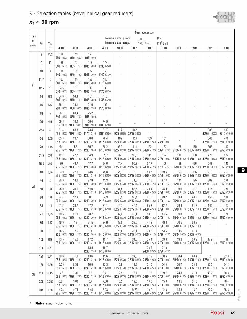
9
69RossiH series − Imperial units
2582
-01.
01
n1 90 rpm
9 - Selection tables (bevel helical gear reducers)
* Finite transmission ratio.
Nominal output power P N2 [hp]i N n N2 Nominal output torque M N2 (M 2max) [103 lb in]
rpm
8 11,2750 (1450) 810 (1600) 985 (1950)
9 10840 (1550) 885 (1750) 1035 (2060) 1135 (2240)
10 9840 (1550) 940 (1750) 1045 (2060) 1140 (2120)
11,2 8840 (1550) 940 (1700) 1045 (2060) 1170 (2360)
12,5 7,1840 (1550) 935 (1750) 1045 (1950) 1170 (1950)
14 6,3840 (1450) 940 (1700) 1045 (2000) 1135 (2240)
16 5,6780 (1500) 830 (1650) 1045 (1900) 1170 (2180)
18 5840 (1450) 860 (1700) 985 (1950)
20 4,5965 (1600) 1080 (1800) 985 (1900) 1080 (2180)
22,4 4965 (1600) 1080 (1800) 1170 (2180) 1300 (2500) 1825 (3150) 2215 (3650) 6280 (10000) 8710 (14500)
25 3,55965 (1550) 1080 (1750) 1240 (2180) 1415 (2500) 1825 (3070) 2215 (3550) 2480 (4250) 2680 (5000) 6280 (11200) 8850 (16000)
28 3,15965 (1550) 1080 (1750) 1240 (2060) 1415 (2360) 1825 (3070) 2215 (3550) 2480 (4120) 2675 (4750) 3125 (6150) 3405 (6900) 6280 (11200) 8850 (16000)
31,5 2,8965 (1550) 1080 (1750) 1240 (2180) 1415 (2500) 1825 (3070) 2215 (3550) 2480 (4250) 2760 (5000) 3425 (6150) 3660 (7100) 6280 (10600) 8850 (15000)
35,5 2,5965 (1550) 1080 (1750) 1240 (2060) 1415 (2360) 1825 (3070) 2215 (3550) 2480 (4120) 2755 (4750) 3540 (6150) 3985 (7100) 6280 (10600) 8850 (15000)
40 2,24965 (1550) 1080 (1750) 1240 (2180) 1415 (2500) 1825 (3070) 2215 (3550) 2480 (4250) 2790 (5000) 3540 (6150) 3985 (7100) 6280 (10900) 8850 (16000)
45 2965 (1550) 1080 (1750) 1240 (2060) 1415 (2360) 1825 (3070) 2215 (3550) 2480 (4120) 2790 (4750) 3540 (6150) 3985 (7100) 6280 (11200) 8850 (16000)
50 1,8965 (1550) 1080 (1750) 1240 (2180) 1415 (2500) 1825 (3070) 2215 (3550) 2480 (4250) 2790 (5000) 3540 (6150) 3985 (7100) 6280 (11200) 8850 (16000)
56 1,6965 (1550) 1080 (1750) 1240 (2060) 1415 (2360) 1825 (3070) 2215 (3550) 2480 (4120) 2790 (4750) 3540 (6150) 3985 (7100) 6280 (10600) 8850 (15000)
63 1,4965 (1550) 1080 (1750) 1240 (2180) 1415 (2500) 1825 (3070) 2215 (3550) 2480 (4250) 2790 (5000) 3540 (6150) 3985 (7100) 6280 (11200) 8850 (16000)
71 1,25965 (1550) 1080 (1750) 1240 (2060) 1415 (2360) 1825 (3070) 2215 (3550) 2480 (4120) 2790 (4750) 3540 (6150) 3985 (7100) 6280 (10600) 8850 (15000)
80 1,12965 (1550) 1080 (1750) 1240 (2180) 1415 (2500) 1825 (3070) 2215 (3550) 2480 (4250) 2790 (5000) 3540 (6150) 3985 (7100)
90 1965 (1550) 1080 (1750) 1240 (2060) 1415 (2360) 1825 (3070) 2215 (3550) 2480 (4120) 2790 (4750) 3540 (5800) 3985 (6700)
100 0,9965 (1550) 1080 (1750) 1240 (2180) 1415 (2500) 1825 (3070) 2215 (3550) 2480 (4250) 2790 (5000) 3540 (6150) 3985 (6900) 6280 (11200) 8850 (16000)
125 0,711240 (1900) 1415 (2180) 2480 (3750) 2790 (4250)
125 0,71965 (1550) 1080 (1750) 1240 (2180) 1415 (2500) 1825 (3070) 2215 (3550) 2480 (4250) 2790 (5000) 3540 (6150) 3800 (7100) 6280 (11200) 8850 (16000)
160 0,56965 (1550) 1080 (1750) 1240 (2180) 1415 (2500) 1825 (3070) 2215 (3550) 2480 (4250) 2790 (5000) 3540 (6150) 3985 (7100) 6280 (11200) 8850 (16000)
200 0,45965 (1550) 1080 (1750) 1240 (2180) 1415 (2500) 1825 (3070) 2215 (3550) 2480 (4250) 2790 (5000) 3540 (6150) 3985 (7100) 6280 (11200) 8850 (16000)
250 0,355965 (1550) 1080 (1750) 1240 (2180) 1415 (2500) 1825 (3070) 2215 (3550) 2480 (4250) 2790 (5000) 3540 (6150) 3985 (7100) 6280 (11200) 8850 (16000)
315 0,28965 (1550) 1080 (1750) 1240 (2180) 1415 (2500) 1825 (3070) 2215 (3550) 2480 (4250) 2790 (5000) 3540 (6150) 3985 (7100) 6280 (11200) 8850 (16000)
▲ lubrificazione forzata
136
–
19
– –
19,5 21,8 23,7 27,1 37,2
66,9
69,2 88,4
21,2 23,7 27,2 31,1 40,7 49,4 55,3
21,5 24,6 32,5 39,5
48,5 54,5 69,3 178
98,3 158 216
84,8 140 197
77,9 126
62,2 76,8
44,2
45,1
–
– –
– – – –
– –
– –
– –
–
–
– –
– –
– –
125
87,926
––
– –
173 – –
– –
54,6 61,4
11831,6 35,4 39,8 49,8 56,2
– –
13,5 15,2 17,2
C3I
15,6 17,5 29,8 36,1
– –
– –
10,6 11,8
15,3 16,9
24,3 27,1
C2I
19,7
19 21,7 38,8 43,6
49,8 60,516,9
92,8
13,8 15,7 28,3 31,8
27,2 30,6 38,4 40,4 6913,6 15,6 20 24,3
– –
36,6
46,4
4,23 4,74 5,45 6,23 8,01 9,72 10,9 12,3
13,8 15,6 19,5 21,5 34,55,21 5,83 6,7 7,66 10,2 12,3
27,2
58,8
74,2
6,6 7,39 8,5 9,71 12,9 15,7 17,5 19,7
21,6 24,3 30,7 33,9 55,28,39 9,39 10,8 12,3 15,9 19,3
43,7
24,4 27,3 30,1 34,3 46,5 56,4 61,5
62,6 70,1
202 275
26,9 30,1 34,6 39,5 51,6 23978,9 96,9 107 175
30,9 34,6 37,9 43,3 59 71,6 77,6 87,3 111
33,9 37,9 43,6 49,8 65,1 79 88,5 99,5 123
90,3 97,7
413
156 273 374
39 43,7 47,7 54,6 74,4 340109 138 156 242
42,7 47,7 54,9 62,7 82 99,5 111 124 148
517
53,3 59,7 68,6 78,4 102 476
49,1 55 59,7 68,2 93,7 114 122
124 139 151 349– –
132 156 170
61,4 68,8 73,4 81,7 117 142
– –
386– – – –
69,8 78,2 68,4 74,9 –
– – – –66,7 68,4 75,2 – ––
110 – –
– – – – – –
107 119 128 143
– – – – –
– – – – –
Gear reducer size
4000 5601 6300 6301 7101 80014001 4500 4501 5000 5001
Trainof
gears
136 143 158 173
5600
– –
CI
138 149 – – – – –
118 132 147 158
116
– –
93,6 104
–
–
– –
–
302
219 307
130
68,4 73,1 91,9 103
– – – –84,6 94,4 101
TN2 (T2max)
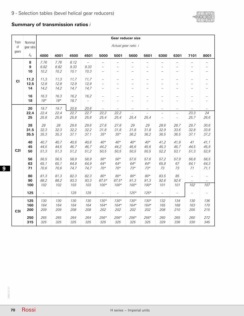
19
70 Rossi H series − Imperial units
2582
-01.
01
9 - Selection tables (bevel helical gear reducers)
Summary of transmission ratios i
4000 4001 4500 4501 5000 5001 5600 5601 6300 6301 7101 8001
8 7,76 7,76 8,12 – – – – – – – – –9 8,82 8,82 9,33 9,33 – – – – – – – –
10 10,2 10,2 10,1 10,3 – – – – – – – –
11,2 11,3 11,3 11,7 11,7 – – – – – – – –12,5 12,8 12,8 12,9 12,9 – – – – – – – –14 14,2 14,2 14,7 14,7 – – – – – – – –
16 16,3 16,3 16,2 16,2 – – – – – – – –18 18* 18* 18,7 – – – – – – – – –
20 19,7 19,7 20,6 20,6 – – – – – – – –22,4 22,4 22,4 22,7 22,7 22,2 22,2 – – – – 23,3 2425 25,8 25,8 25,8 25,8 25,4 25,4 25,4 25,4 – – 25,7 26,6
28 28 28 29,6 29,6 27,8 27,8 29 29 28,6 28,7 29,7 30,631,5 32,3 32,3 32,2 32,2 31,8 31,8 31,8 31,8 32,9 33,6 32,8 33,835,5 35,3 35,3 37,1 37,1 35* 35* 36,2 36,2 36,5 36,5 37,1 37,2
40 40,7 40,7 40,6 40,6 40* 40* 40* 40* 41,2 41,9 41 41,145 44,5 44,5 46,7 46,7 44,2 44,2 45,6 45,6 45,3 45,7 44,5 45,950 51,3 51,3 51,2 51,2 50,5 50,5 50,5 50,5 52,2 53,1 51,3 52,9
56 56,5 56,5 58,9 58,9 56* 56* 57,6 57,6 57,2 57,9 56,8 58,563 65,1 65,1 64,9 64,9 64* 64* 64* 64* 65,8 67 64,1 64,371 70,6 70,6 74,7 74,7 70* 70* 73* 73* 73 73 71 71,1
80 81,3 81,3 82,3 82,3 80* 80* 80* 80* 83,5 85 – –90 88,2 88,2 93,3 93,3 87,5* 87,5* 91,3 91,3 92,6 92,6 – –100 102 102 103 103 100* 100* 100* 100* 101 101 102 107
125 – – 129 129 – – 125* 125* – – – –
125 130 130 130 130 130* 130* 130* 130* 132 134 130 136160 164 164 164 164 164* 164* 164* 164* 165 168 163 170200 209 209 208 208 202 202 202 202 208 210 205 215
250 265 265 264 264 256* 256* 256* 256* 260 265 260 272315 325 325 325 325 325 325 325 325 329 336 330 345
CI
C2I
C3I
Trainof
gears
Gear reducer size
Actual gear ratio iNominalgear ratio
i N

71RossiH series − Imperial units
2582
-01.
01
10
10 - Dimensions, designs, mounting positions (bevel helical gear reducers)
10.1 - Gear reducers R CI ............................................................................................................... 72Dimensions .......................................................................................................................................... 72Designs (direction of rotation) ............................................................................................................. 73Mounting positions .............................................................................................................................. 74Lubrication - Plug position and oil quantity ......................................................................................... 75
10.2 - Gear reducers R C2I ............................................................................................................. 76Dimensions .......................................................................................................................................... 76Designs (direction of rotation) ............................................................................................................. 77Mounting positions .............................................................................................................................. 78Lubrication - Plug position and oil quantity ......................................................................................... 79
10.3 - Gear reducers R C3I ............................................................................................................. 80Dimensions .......................................................................................................................................... 80Designs (direction of rotation) ............................................................................................................. 81Mounting positions .............................................................................................................................. 82Lubrication - Plug position and oil quantity ......................................................................................... 83
71RossiH series − Imperial units

110
72 Rossi H series − Imperial units
2582
-01.
01
10 - Dimensions, designs, mounting positions (bevel helical gear reducers)
10.1 - Gear reducers R CI
Dimensions
1) Working length of thread 1,7 · F.2) For mounting positions B6, B7, V5, V6, dimension Y1 increases by approx. 20 for fi ller plug overall dimensions.3) The cover on bevel wheel side overhangs from C dimension (see ch. 6) by 33 mm for sizes 4000, 4001 and 5 mm for sizes 5000, 5001.4) Values valid for double extension low speed shaft.
Size
a A A1 A2 B C c F H H1 H2 K K1 L L1 M T U Wh11 h12 h11 Ø Ø
H11M1 3) 1) R 4)
4000 400 505 420 90 500 330 605 M45 450 296 – 39 48 52 116 750 1055 580 1320 4940 50904001 5090 5270
4500 450 505 470 90 500 358 605 M45 450 296 560 39 48 52 116 750 1105 580 1370 6060 62604501 6240 6480
Size
D E d e Y1 d e Y1
Ø Ø Ø
2) 2)
iN 11,2 iN 12,5
4000 190 280 110 210 1675 90 170 16354001 200
iN 12,5 iN 14
4500 210 300 110 210 1725 90 170 16854501 220

10
73RossiH series − Imperial units
2582
-01.
01
10 - Dimensions, designs, mounting positions (bevel helical gear reducers)
10.1 - Gear reducers R CI
Designs1) 2) (direction of rotation)Solid low speed shaft (standard)
(a) (b) (c) (a) (b) (c)
Solid low speed shaft (standard)
(a) (b) (c) (a) (b) (c)
Solid low speed shaft (standard)
(a) (b) (c) (a) (b) (c)
(a) Hollow low speed shaft with shrink disc on machine opposite side (on request, see ch. 12).(b) Hollow low speed shaft with shrink disc on machine side (on request, see ch. 12).(c) Hollow low speed shaft with keyway (on request, see ch. 12).1) The housing of designs UO1A ... UO1N sin is not prearranged for other designs (UO1H ... UO1L sin). 2) For UO1A, UO1H, UO1V designs and derivatives it is recommended to adopt the black arrow direction of rotation; for UO1A sin, UO1H sin,
UO1V sin designs and derivatives, the white arrow direction of rotation. If it is not possible, consult us.

110
74 Rossi H series − Imperial units
2582
-01.
01
10 - Dimensions, designs, mounting positions (bevel helical gear reducers)
Mounting positionsExcept specifi c needs, prefer mounting position B3 (see ch. 2).
10.1 - Gear reducers R CI
B6
B7
B3
V5
V6
Possible high oil splash: for the corrective factor ft3 of nominal thermal power PtN see ch. 4.
Possible bearing lubrication pump: consult us for verifi cation.1) Mounting position B3 may be identifi ed from the position of the screw-heads as
arrowed. The same is valid for mounting positions V5 and V6 with double extension or hollow low speed shaft: in these cases, consider the position of low speed wheel, for the identifi cation of correct mounting position (see also «Designs» at the previous page).
2) for designs UO1H ... UO1M sin, UO1V ... UO1L sin.3) for designs UO1A ... UO1N sin, UO1H ... UO1M sin.4) Mounting position B8 available only for designs UO1V ... UO1L sin.
Oil fi ller plug Oil level plug Oil drain plug
Oil fi ller plug on opposite side (not in view) Oil level plug on opposite side (not in view) Oil drain plug on opposite side (not in view)
B6
B7B84)
B3
V5
V6
* Valid in case of hollow low speed shaft (with shrink disc or keyway).

10
75RossiH series − Imperial units
2582
-01.
01
10 - Dimensions, designs, mounting positions (bevel helical gear reducers)
10.1 - Gear reducers R CI
Lubrication - Plug position and oil quantityOil quantity are approximate for provisioning and can vary according to the design and specifi c application. The exact quantity the gear reducer is to be fi lled with is defi nitely given by the level.
Size Oil quantity [gal]
B3 B6 B7 B84) V5, V6with low speed shaft on bottom with low speed wheel on top
4000, 4001 26 40 42 26 30 314500, 4501 35 50 56 35 37 45
2) 3)
UO1A UO1A sinUO1F UO1F sin
UO1H UO1H sinUO1G UO1G sin
UO1V UO1V sinUO1S UO1S sin
UO1A* UO1N sin*UO1H* UO1M sin*UO1V UO1L sin*
UO1N UO1N sin
UO1M UO1M sin
UO1L UO1L sin
UO1A UO1A sinUO1F UO1F sin
UO1H UO1H sinUO1G UO1G sin
UO1V UO1V sinUO1S UO1S sin
UO1A* UO1N sin*UO1H* UO1M sin*UO1V UO1L sin*
UO1N UO1N sin
UO1M UO1M sin
UO1L UO1L sin
B3 B6 B7 B84)
V5 V6
Notes at previous page.

110
76 Rossi H series − Imperial units
2582
-01.
01
10 - Dimensions, designs, mounting positions (bevel helical gear reducers)
10.2 - Gear reducers R C2I
Dimensions
* For sizes 6300, only.
1) Working length of thread 1,7 · F.2) For mounting positions B6, B7, V5, V6 dimension Y1 increases by approx.
20 for overall dimensions of fi ller plug. 3) Values valid for double extension low speed shaft.4) The cover on bevel wheel side overhangs from C dimension (see ch. 6) by
13 mm.5) The high speed shaft end shoulder is within dimension H.6) For size 6301: iN 56 and iN 63, respectively.
Size
a A A1 A2 A3 B C c F H H1 K K1 L L1 M T U Wh11 h12 Ø Ø
H11M1 1) R 3)
4000 700 505 625 90 – 500 330 480 M45 450 296 39 48 52 116 750 1260 580 1525 5380 55304001 5560 5730
4500 750 505 675 90 – 500 358 480 M45 450 296 39 48 52 116 750 1310 580 1575 6130 63304501 6280 6530
5000 875 630 785 115 – 625 4104) 605 M56 560 370 48 60 65 148 930 1575 725 1905 10560 108705001 10820 11180
5600 935 630 845 115 – 625 445 605 M56 560 370 48 60 65 148 930 1635 725 1965 12520 129605601 12790 13270
6300 1080 770 970 115 – 695 490 6055) M56 630 406 48 60 65 148 1070 1900 795 2230 17530 181406301 17770 18500
7101 1270 930 1228 115 590 843 601 833 M56 710 481 48 66 71 185 1230 2279 943 2648 29430 30530
8001 1430 1008 1286 145 596 944 682 934 M90 900 544 60 95 85 250 1574 2590 1064 3086 45300 46890
Size
D E d e Y1 d e Y1
Ø Ø Ø
2) 2)
iN 50 iN 56
4000 190 280 80 170 1810 65 140 17804001 200
iN 56 iN 63
4500 210 300 80 170 1860 65 140 18304501 220
iN 50 iN 56
5000 240 330 100 210 2260 80 170 22205001 250
iN 56 iN 63
5600 270 380 100 210 2320 80 170 22805601 280
iN 50 iN 56
6300 300 430 110 210 2535 90 170 24956301 320
iN 31,5 iN 35,5
7101 360 590 140 250 3073 110 210 3033
8001 400 660 150 245 3519 125 210 3474

10
77RossiH series − Imperial units
2582
-01.
01
10 - Dimensions, designs, mounting positions (bevel helical gear reducers)
10.2 - Gear reducers R C2I
Designs1) 2) (direction of rotation)Solid low speed shaft (standard)
(a) (b) (c) (a) (b) (c)
Solid low speed shaft (standard)
(a) (b) (c) (a) (b) (c)
Solid low speed shaft (standard)
(a) (b) (c) (a) (b) (c)
(a) Hollow low speed shaft with shrink disc on machine opposite side (on request, see ch. 12).(b) Hollow low speed shaft with shrink disc on machine side (on request, see ch. 12).(c) Hollow low speed shaft with keyway (on request, see ch. 12).1) The housing of designs UO1A ... UO1N sin is not prearranged for other designs (UO1H ... UO1L sin). 2) For UO1A, UO1H, UO1V designs and derivatives it is recommended to adopt the black arrow direction of rotation; for UO1A sin, UO1H sin,
UO1V sin designs and derivatives, the white arrow direction of rotation. If it is not possible, consult us.
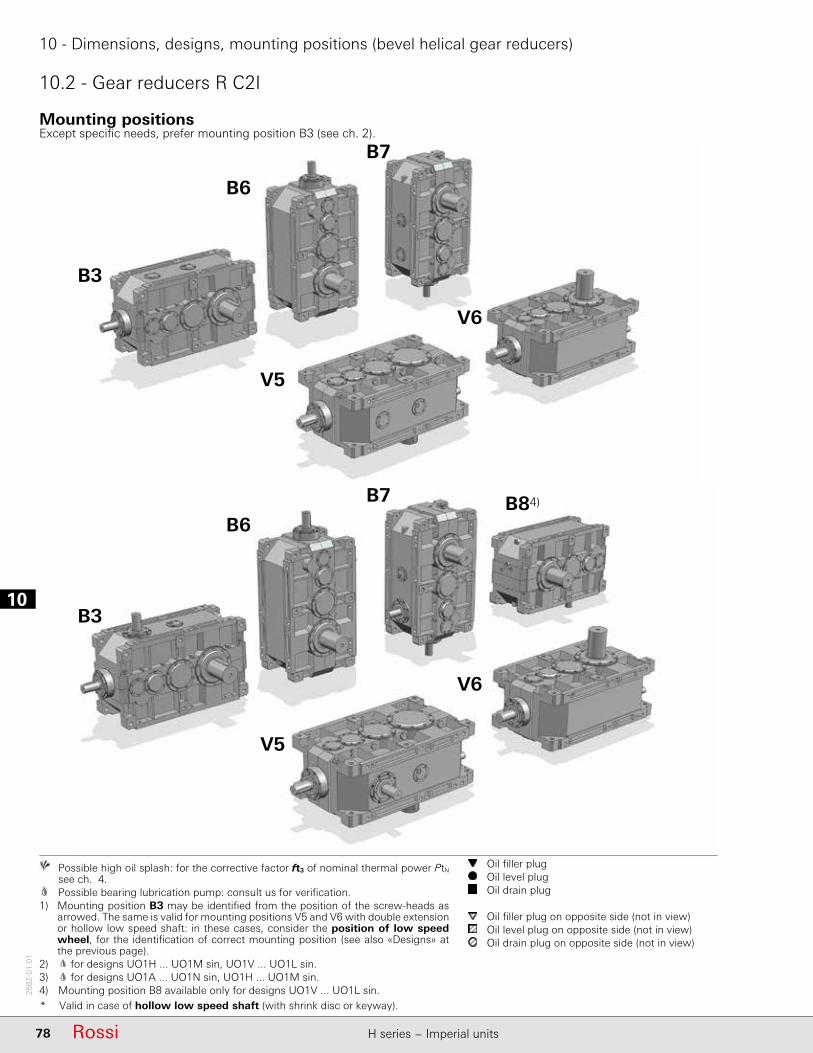
110
78 Rossi H series − Imperial units
2582
-01.
01
10 - Dimensions, designs, mounting positions (bevel helical gear reducers)
10.2 - Gear reducers R C2I
Mounting positionsExcept specifi c needs, prefer mounting position B3 (see ch. 2).
B6
B7
B3
V5
V6
Possible high oil splash: for the corrective factor ft3 of nominal thermal power PtN see ch. 4.
Possible bearing lubrication pump: consult us for verifi cation.1) Mounting position B3 may be identifi ed from the position of the screw-heads as
arrowed. The same is valid for mounting positions V5 and V6 with double extension or hollow low speed shaft: in these cases, consider the position of low speed wheel, for the identifi cation of correct mounting position (see also «Designs» at the previous page).
2) for designs UO1H ... UO1M sin, UO1V ... UO1L sin.3) for designs UO1A ... UO1N sin, UO1H ... UO1M sin.4) Mounting position B8 available only for designs UO1V ... UO1L sin.
Oil fi ller plug Oil level plug Oil drain plug
Oil fi ller plug on opposite side (not in view) Oil level plug on opposite side (not in view) Oil drain plug on opposite side (not in view)
B6
B7 B84)
B3
V5
V6
* Valid in case of hollow low speed shaft (with shrink disc or keyway).
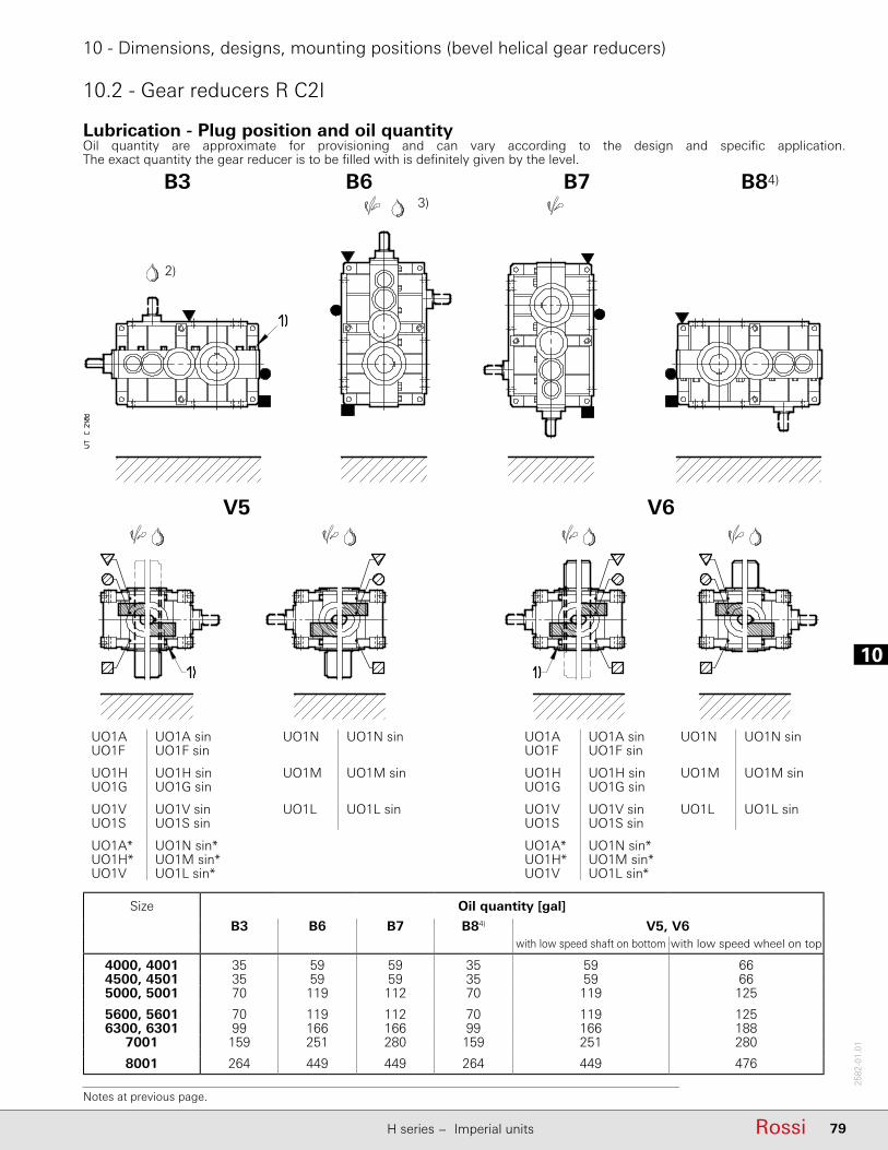
10
79RossiH series − Imperial units
2582
-01.
01
10 - Dimensions, designs, mounting positions (bevel helical gear reducers)
10.2 - Gear reducers R C2I
Lubrication - Plug position and oil quantityOil quantity are approximate for provisioning and can vary according to the design and specifi c application. The exact quantity the gear reducer is to be fi lled with is defi nitely given by the level.
2)
3) B3 B6 B7 B84)
V5 V6
UO1A UO1A sinUO1F UO1F sin
UO1H UO1H sinUO1G UO1G sin
UO1V UO1V sinUO1S UO1S sin
UO1A* UO1N sin*UO1H* UO1M sin*UO1V UO1L sin*
UO1N UO1N sin
UO1M UO1M sin
UO1L UO1L sin
UO1A UO1A sinUO1F UO1F sin
UO1H UO1H sinUO1G UO1G sin
UO1V UO1V sinUO1S UO1S sin
UO1A* UO1N sin*UO1H* UO1M sin*UO1V UO1L sin*
UO1N UO1N sin
UO1M UO1M sin
UO1L UO1L sin
Size Oil quantity [gal]
B3 B6 B7 B84) V5, V6with low speed shaft on bottom with low speed wheel on top
4000, 4001 35 59 59 35 59 664500, 4501 35 59 59 35 59 665000, 5001 70 119 112 70 119 125
5600, 5601 70 119 112 70 119 1256300, 6301 99 166 166 99 166 188
7001 159 251 280 159 251 280
8001 264 449 449 264 449 476
Notes at previous page.

110
80 Rossi H series − Imperial units
2582
-01.
01
10 - Dimensions, designs, mounting positions (bevel helical gear reducers)
10.3 - Gear reducers R C3I
Dimensions
1) Working length of thread 1,7 · F.2) For mounting positions B6, B7, V5, V6 dimension Y1 increases by approx, 20 for overall dimensions of fi ller plug.3) Values valid for double extension low speed shaft end.4) For size 6301: iN 200 and iN = 250, respectively.
* For sizes 6300, only.
Size
D E c d e Y1 c d e Y1 c d e Y1
Ø Ø Ø Ø
2) 2) 2)
iN 125 iN = 160, 200 iN 250
4000 190 280 282 48 110 1752 282 48 110 1752 282 38 80 17224001 200
iN 125 iN = 160, 200 iN 250
4500 210 300 282 48 110 1802 282 48 110 1802 282 38 80 17724501 220
iN 125 iN = 160, 200 iN 250
5000 240 330 380 70 140 2215 357 55 110 2162 357 48 110 21625001 250
iN 125 iN = 160, 200 iN 250
5600 270 380 380 70 140 2275 357 55 110 2222 357 48 110 22225601 280
iN 1604) iN = 200, 2504) iN = 315
6300 300 430 380 70 140 2540 357 55 110 2487 357 48 110 24876301 320
iN 160 iN = 200, 250 iN = 315
7101 360 590 480 90 170 3000 480 70 140 2970 480 70 140 2970iN 160 iN = 200, 250 iN = 315
8001 400 660 605 110 210 3605 605 90 170 3565 605 90 170 3565
Size
a A A1 A2 A3 B C F H H1 K K1 L L1 M T U Wh11 h12 Ø Ø
H11M1 1) R 3)
4000 900 505 625 90 – 500 330 M45 450 296 39 48 52 116 750 1260 580 1525 5270 54204001 5420 5600
4500 950 505 675 90 – 500 358 M45 450 296 39 48 52 116 750 1310 580 1575 5840 60404501 6000 6240
5000 1125 630 785 115 – 625 410 M56 560 370 48 60 65 148 930 1575 725 1905 10250 105605001 10520 10870
5600 1185 630 845 115 – 625 445 M56 560 370 48 60 65 148 930 1635 725 1965 12190 126305601 12410 12900
6300 1380 770 970 115 – 695 490 M56 630 406 48 60 65 148 1070 1900 795 2230 17000 176106301 17240 17970
7101 1630 930 1228 115 590 843 601 M56 710 481 48 66 71 185 1230 2279 943 2648 29230 30340
8001 1880 1008 1286 145 596 944 682 M90 900 544 60 95 85 250 1574 2590 1064 3086 45080 46670
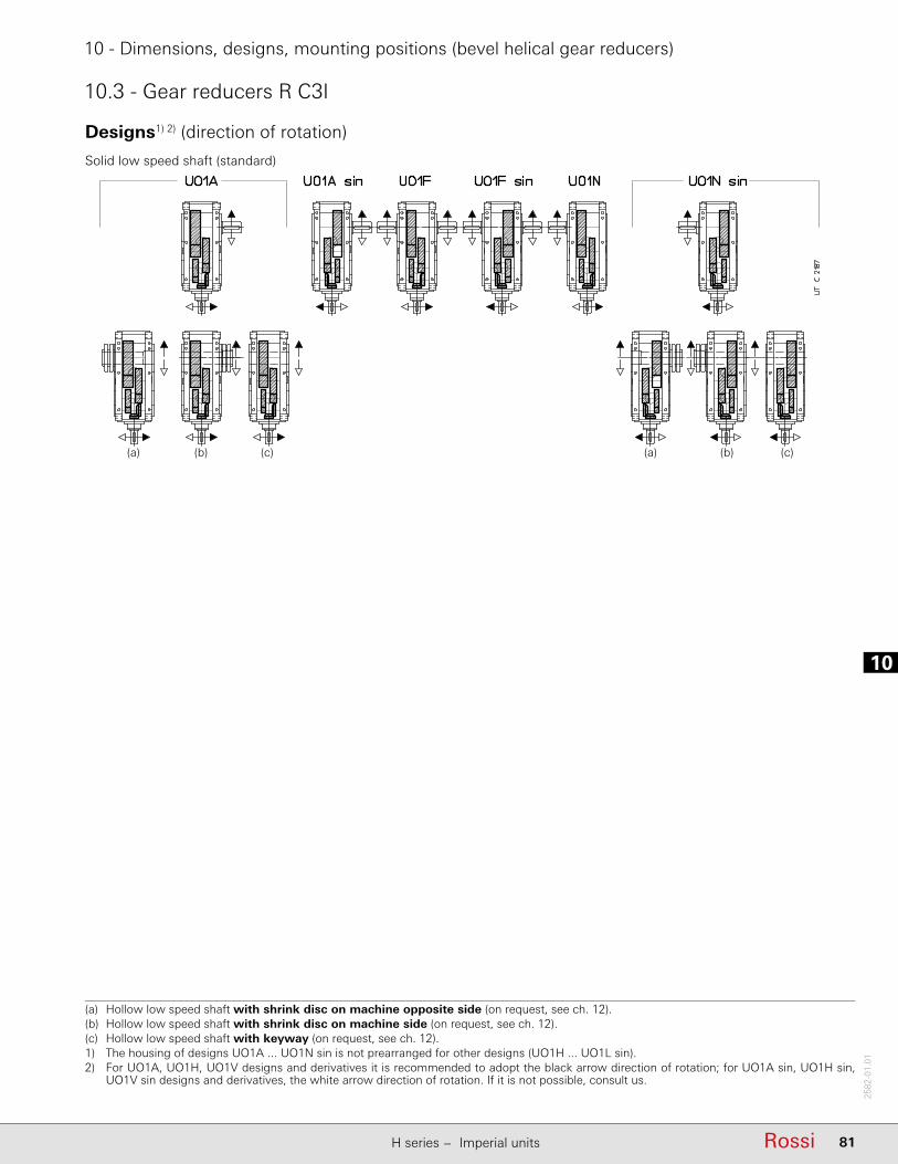
10
81RossiH series − Imperial units
2582
-01.
01
10 - Dimensions, designs, mounting positions (bevel helical gear reducers)
10.3 - Gear reducers R C3I
Designs1) 2) (direction of rotation)
Solid low speed shaft (standard)
(a) (b) (c) (a) (b) (c)
(a) Hollow low speed shaft with shrink disc on machine opposite side (on request, see ch. 12).(b) Hollow low speed shaft with shrink disc on machine side (on request, see ch. 12).(c) Hollow low speed shaft with keyway (on request, see ch. 12).1) The housing of designs UO1A ... UO1N sin is not prearranged for other designs (UO1H ... UO1L sin). 2) For UO1A, UO1H, UO1V designs and derivatives it is recommended to adopt the black arrow direction of rotation; for UO1A sin, UO1H sin,
UO1V sin designs and derivatives, the white arrow direction of rotation. If it is not possible, consult us.
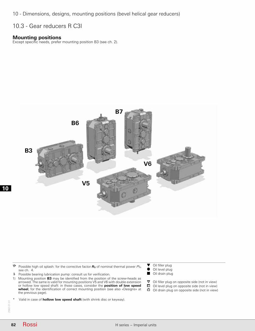
110
82 Rossi H series − Imperial units
2582
-01.
01
10 - Dimensions, designs, mounting positions (bevel helical gear reducers)
10.3 - Gear reducers R C3I
Mounting positionsExcept specifi c needs, prefer mounting position B3 (see ch. 2).
B6
B7
B3
V5
V6
Possible high oil splash: for the corrective factor ft3 of nominal thermal power PtN see ch. 4.
Possible bearing lubrication pump: consult us for verifi cation.1) Mounting position B3 may be identifi ed from the position of the screw-heads as
arrowed. The same is valid for mounting positions V5 and V6 with double extension or hollow low speed shaft: in these cases, consider the position of low speed wheel, for the identifi cation of correct mounting position (see also «Designs» at the previous page).
Oil fi ller plug Oil level plug Oil drain plug
Oil fi ller plug on opposite side (not in view) Oil level plug on opposite side (not in view) Oil drain plug on opposite side (not in view)
* Valid in case of hollow low speed shaft (with shrink disc or keyway).

10
83RossiH series − Imperial units
2582
-01.
01
10 - Dimensions, designs, mounting positions (bevel helical gear reducers)
10.3 - Gear reducers R C3I
Lubrication - Plug position and oil quantityOil quantity are approximate for provisioning and can vary according to the design and specifi c application. The exact quantity the gear reducer is to be fi lled with is defi nitely given by the level.
B3 B6 B7
V5 V6
UO1A UO1A sinUO1F UO1F sin
UO1A* UO1N sin*
UO1N UO1N sin UO1A UO1A sinUO1F UO1F sin
UO1A* UO1N sin*
UO1N UO1N sin
Size Oil quantity [gal]
B3 B6 B7 V5, V6with low speed shaft below with upper low speed wheel
4000, 4001 40 74 59 66 704500, 4501 40 74 59 66 705000, 5001 79 148 119 132 140
5600, 5601 79 148 119 132 1406300, 6301 112 225 166 188 198
7001 188 349 264 280 296
8001 296 592 449 476 502
Notes at previous page.

110
84 Rossi H series − Imperial units
2582
-01.
01
Page intentionally left blank
11
85RossiH series − Imperial units
2582
-01.
01
11 - Radial loads
11.1 - Radial loads Fr1 [103 lbf] ...................................................................................................... ..86V-belt drives ......................................................................................................................................... 87
11.2 - Axial loads Fa2 [103 lbf] or radial loads Fr2 [103 lbf] on low speed shaft end ............................. 88Axial loads Fa2 ...................................................................................................................................... 88Radial loads Fr2 ..................................................................................................................................... 88
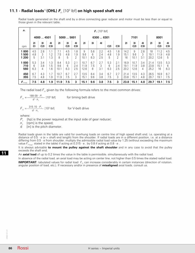
111
86 Rossi H series − Imperial units
2582
-01.
01
11.1 - Radial loads1) (OHL) Fr1 [103 lbf] on high speed shaft end
Radial loads generated on the shaft end by a drive connecting gear reducer and motor must be less than or equal to those given in the relevant table.
n1 Fr1 [103 lbf]
4000 ... 4501 5000 ... 5601 6300 ... 6301 7101 8001
2I 3I 4I 2I 3I 4I 2I 3I 4I 2I 3I 4I 2I 3I 4Irpm CI C2I C3I C2I C3I C2I C3I C2I C3I C2I C3I
1 800 4.5 2.8 1.1 7.1 4.5 1.8 9 5.6 2.2 4.5 1.8 14.2 9 2.8 18 11.2 4.51 500 4.8 3 1.2 7.5 4.8 1.9 9.6 6 2.4 4.8 1.9 15.1 9.6 3 19.1 11.9 4.81 200 5 3.1 1.3 8 5 2 10.1 6.3 2.5 5 2 16 10.1 3.1 20.2 12.6 5
1 000 5.3 3.4 1.3 8.4 5.3 2.1 10.7 6.7 2.7 5.3 2.1 16.9 10.7 3.4 21.4 13.5 5.3710 6 3.8 1.5 9.6 6 2.4 11.9 7.5 3 6 2.4 19.1 11.9 3.8 23.8 15.1 6560 6.3 4 1.6 10.1 6.3 2.5 12.6 8 3.1 6.3 2.5 20.2 12.6 4 25.2 16 6.3
450 6.7 4.3 1.7 10.7 6.7 2.7 13.5 8.4 3.4 6.7 2.7 21.4 13.5 4.3 26.5 16.9 6.7355 7.5 4.8 1.9 11.9 7.5 3 15.1 9.6 3.8 7.5 3 23.8 15.1 4.8 29.7 19.1 7.5
Fr1max 7.5 4.8 1.9 11.9 7.5 3 15.1 9.6 3.8 7.5 3 23.8 15.1 4.8 29.7 19.1 7.5
The radial load Fr1 given by the following formula refers to the most common drives:
Fr1 =189 09 · P1
d · n1
[103 lbf] for timing belt drive
Fr1 =315 15 · P1
d · n1
[103 lbf] for V-belt drive
where:P1 [hp] is the power required at the input side of gear reducer; n1 [rpm] is the speed; d [in] is the pitch diameter.
Radial loads given in the table are valid for overhung loads on centre line of high speed shaft end. i.e. operating at a distance of 0.5 · e (e = shaft end length) from the shoulder. If radial loads are in a diff erent position. i.e. at a distance diff ering from 0.5 · e from shoulder. multiply the admissible radial load value by 1.25 (without exceeding the maximum value Fr1max. stated in the table) if acting at 0.315 · e . by 0.8 if acting at 0.8 · e .It is always advisable to mount the pulley against the shaft shoulder and in any case to avoid that the pulley exceeds the shaft end.An axial load of up to 0.2 times the value in the table is permissible. simultaneously with the radial load.In absence of the radial load. an axial load may be acting on center line. not higher than 0.5 times the stated radial load.IMPORTANT: tabulated values for radial load Fr1 can increase considerably in certain instances (direction of rotation. angular position of load. etc.). If necessary and/or in presence of misaligned axial loads. consult us.

11
87RossiH series − Imperial units
2582
-01.
01
11.1 - Radial loads1) (OHL) Fr1 [103 lbf] on high speed shaft end
V-belt drivesSee the table for the driving pulleys advised for the various powers and motor polarities and the radial loads resulting on motor and gear reducer shaft ends.The transmissions have been calculated with a service factor 1.4; replace section SPA with SPB, section SPB with SPC, section SPC with 8V.in order to increase the service factor with the same d and belt number.The radial loads have been calculated according to the formula: (315 150 · P1 ) / (d · n1) at 60 Hz.The radial load Fr1, referring to the selected motor pulley, must be lower than or equal to the one admitted by gear reducer.IMPORTANT. For the good running of drive and in order not to overload motor and gear reducer bearings, reduce the overhung to a minimum and do not stress belts excessively. Pulleys with d 16 must be dynamically balanced.
1) Not valid for power 12.37 hp: d 140 mm.Note: Pulley face width: 1 Z 16, 2 Z 28, 1 A 20, 2 A-2 SPA 35, 3 A-3 SPA 50, 4 SPA 65, 3 SPB 63, 4 SPB 82, 5 SPB 101,6 SPB 120, 4 SPC 110, 5 SPC 136, 6 SPC 162, 5 8V 152.
Motor Motor pulley: belt number and section type, pitch diameter d[in], radial load Fr1[lb]
P1 Size d Fr1 d Fr1 d Fr1 d Fr1 d Fr1
hp andpolen. ≈ ≈ ≈ ≈ ≈
1.5 90S 4 2 A 3.55 80 2 A 4 71 2 A 4.5 63 1 A 5 56 1 A 5.6 5090L 6 2 A 3.55 118 2 A 4 100 2 A 4.5 90 2 A 5 80 1 A 5.6 75
2 90L 4 2 A 3.55 106 2 A 4 95 2 A 4.5 80 2 A 5 75 1 A 5.6 67100LA 6 3 A 3.55 150 3 A 4 140 2 A 4.5 118 2 A 5 112 2 A 5.6 100
3 100LA 4 3 A 3.55 160 3 A 4 140 3 A 4.5 125 2 A 5 112 2 A 5.6 100112M 6 3 A 4.5 180 3 A 5 160 3 A 5.6 150 2 A 6.3 132 2 A 7.1 118
4 100LB 4 3 A 4.5 160 3 A 5 150 2 A 5.6 132 2 A 6.3 118 2 A 7.1 106132S 6 3 SPA 4 280 3 SPA 4.5 250 2 SPA 5 224 2 SPA 5.6 200 2 SPA 6.3 170
5.4 112M 4 3 A 5 200 3 A 5.6 180 3 A 6.3 160 2 A 7.1 140 2 A 8 125132M 6 3 SPA 4.5 335 3 SPA 5 300 2 SPA 5.6 265 2 SPA 6.3 236 2 SPA 7.1 212
7.5 132S 4 3 SPA 4.5 315 3 SPA 5 280 2 SPA 5.6 250 2 SPA 6.3 224 2 SPA 7.1 200132MB 6 3 SPA 5.6 375 3 SPA 6.3 335 2 SPA 7.1 280 2 SPA 8 250 2 SPA 9 224
10 132M 4 3 SPA 5 375 3 SPA 5.6 335 2 SPA 6.3 300 2 SPA 7.1 265 2 SPA 8 236160M 6 3 SPA 6.3 425 3 SPA 7.1 375 3 SPA 8 335 2 SPA 9 300 2 SPA 10 280
12.4 132MB 4 – – – 3 SPA 5.6 400 2 SPA 6.3 355 2 SPA 7.1 315 2 SPA 8 280
15 160M 4 3 SPA 6.3 450 3 SPA 7.1 400 3 SPA 8 355 2 SPA 9 315 2 SPA 10 280160L 6 3 SPA 8 500 3 SPA 9 450 3 SPA 10 400 2 SPA 11.2 375 2 SPA 12.5 335
20 160L 4 3 SPA 7.1 530 3 SPA 8 475 3 SPA 9 400 3 SPA 10 375 2 SPA 11.2 335180L 6 4 SPA 8 670 4 SPA 9 600 4 SPA 10 560 3 SPA 11.2 500 3 SPA 12.5 450
25 180M 4 4 SPA 7.1 670 4 SPA 8 560 4 SPA 9 500 3 SPA 10 475 3 SPA 11.2 425200LR 6 4 SPB 8 850 4 SPB 9 750 3 SPB 10 670 3 SPB 11.2 600 3 SPB 12.5 560
30 180L 4 4 SPA 8 710 4 SPA 9 630 4 SPA 10 560 3 SPA 11.2 500 3 SPA 12.5 450200L 6 4 SPB 9 900 4 SPB 10 800 3 SPB 11.2 750 3 SPB 12.5 670 3 SPB 14 600
40 200L 4 4 SPB 9 800 4 SPB 10 750 3 SPB 11.2 670 3 SPB 12.5 600 3 SPB 14 530225M 6 5 SPB 10 1120 5 SPB 11.2 1000 4 SPB 12.5 900 4 SPB 14 800 4 SPB 16 670
50 225S 4 5 SPB 9 1000 5 SPB 10 950 4 SPB 11.2 850 4 SPB 12.5 750 4 SPB 14 670250M 6 6 SPB 10 1400 6 SPB 11.2 1250 5 SPB 12.5 1120 5 SPB 14 1000 5 SPB 16 850
60 225M 4 5 SPB 10 1120 5 SPB 11.2 1000 4 SPB 12.5 900 4 SPB 14 800 4 SPB 16 710
75 250M 4 6 SPB 10 1400 6 SPB 11.2 1250 5 SPB 12.5 1120 5 SPB 14 1000 5 SPB 16 850
100 280S 4 6 SPB 11.2 1700 5 SPB 12.5 1500 5 SPB 14 1320 5 SPB 16 1180 – – –
125 280M 4 6 SPB 12.5 1900 5 SPC 12.5 1900 5 SPC 14 1700 4 SPC 16 1400 – – –
150 315S 4 6 SPC 12.5 2240 5 SPC 14 2000 4 SPC 16 1700 – – – – – –
175 315M 4 6 SPC 14 2360 5 SPC 16 2000 4 SPC 18 1800 – – – – – –
200 315MC 4 6 SPC 16 2360 6 SPC 18 2000 5 8V 18 2000 – – – – – –
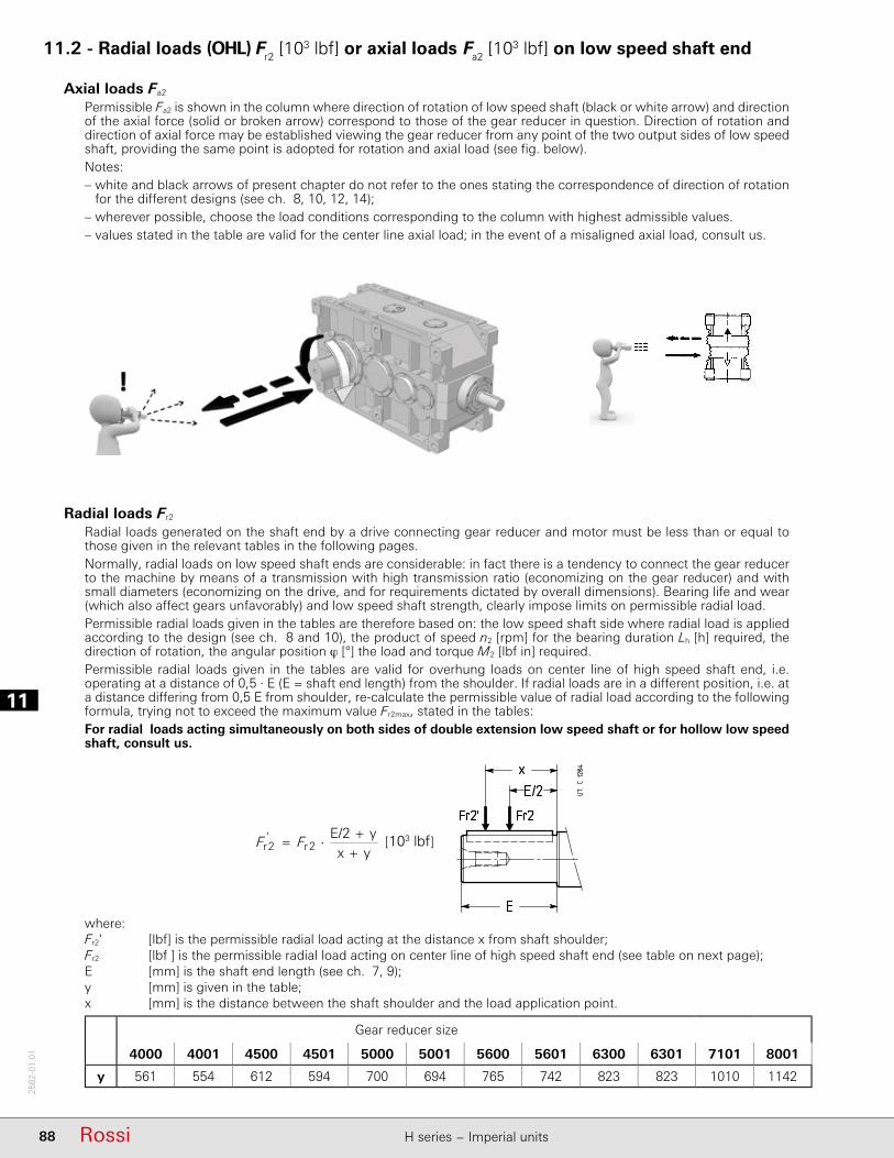
111
88 Rossi H series − Imperial units
2582
-01.
01
11.2 - Radial loads (OHL) Fr2 [103 lbf] or axial loads Fa2 [103 lbf] on low speed shaft end
Axial loads Fa2
Permissible Fa2 is shown in the column where direction of rotation of low speed shaft (black or white arrow) and direction of the axial force (solid or broken arrow) correspond to those of the gear reducer in question. Direction of rotation and direction of axial force may be established viewing the gear reducer from any point of the two output sides of low speed shaft, providing the same point is adopted for rotation and axial load (see fi g. below).Notes:– white and black arrows of present chapter do not refer to the ones stating the correspondence of direction of rotation
for the diff erent designs (see ch. 8, 10, 12, 14);– wherever possible, choose the load conditions corresponding to the column with highest admissible values.– values stated in the table are valid for the center line axial load; in the event of a misaligned axial load, consult us.
Radial loads Fr2
Radial loads generated on the shaft end by a drive connecting gear reducer and motor must be less than or equal to those given in the relevant tables in the following pages.Normally, radial loads on low speed shaft ends are considerable: in fact there is a tendency to connect the gear reducer to the machine by means of a transmission with high transmission ratio (economizing on the gear reducer) and with small diameters (economizing on the drive, and for requirements dictated by overall dimensions). Bearing life and wear (which also aff ect gears unfavorably) and low speed shaft strength, clearly impose limits on permissible radial load.Permissible radial loads given in the tables are therefore based on: the low speed shaft side where radial load is applied according to the design (see ch. 8 and 10), the product of speed n2 [rpm] for the bearing duration Lh [h] required, the direction of rotation, the angular position ϕ [°] the load and torque M2 [lbf in] required.Permissible radial loads given in the tables are valid for overhung loads on center line of high speed shaft end, i.e. operating at a distance of 0,5 · E (E = shaft end length) from the shoulder. If radial loads are in a diff erent position, i.e. at a distance diff ering from 0,5 E from shoulder, re-calculate the permissible value of radial load according to the following formula, trying not to exceed the maximum value Fr2max, stated in the tables: For radial loads acting simultaneously on both sides of double extension low speed shaft or for hollow low speed shaft, consult us.
where:Fr2' [lbf] is the permissible radial load acting at the distance x from shaft shoulder;Fr2 [lbf ] is the permissible radial load acting on center line of high speed shaft end (see table on next page); E [mm] is the shaft end length (see ch. 7, 9);y [mm] is given in the table;x [mm] is the distance between the shaft shoulder and the load application point.
Gear reducer size
4000 4001 4500 4501 5000 5001 5600 5601 6300 6301 7101 8001
y 561 554 612 594 700 694 765 742 823 823 1010 1142
3
c
n3
2i3
223
213
2eq 1
ni21th
......1
t
tPtPtPtP
P
[kN] 81,67
2
22r nd
PF
[kN] 32,20
2
22r nd
PF
[kN] 75,47
2
22r nd
PF
[kN] 1,19
2
22r nd
PF
[kN] yxyE/2
2r'2r
FF
[kN] 75,47
1
11r nd
PF
[kN] 65,28
1
11r nd
PF
richiesto richiesto f
20
2 MJJ
JMi
M
required required f
20
2 MJJ
JMi
M
required required - available start
start 20
22N
2 MJJ
JMM
MM
M
richiesto richiesto - edisponibil spunto
spunto 20
22N
2 MJJ
JMM
MM
M
c
n2i222122eq
ni21......
t
tntntntn n
p
c2
n2p2i2
p222
p212
p2
2eqeq
nnii2211......
tn
tnMtnMtnMtnM
M
[103 lbf]
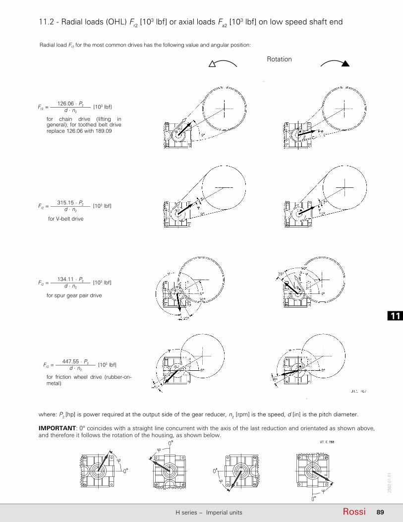
11
89RossiH series − Imperial units
2582
-01.
01
11.2 - Radial loads (OHL) Fr2 [103 lbf] or axial loads Fa2 [103 lbf] on low speed shaft end
where: P2 [hp] is power required at the output side of the gear reducer, n2 [rpm] is the speed, d [in] is the pitch diameter.
IMPORTANT: 0° coincides with a straight line concurrent with the axis of the last reduction and orientated as shown above, and therefore it follows the rotation of the housing, as shown below.
Fr2 = 126.06 · P2
d · n2 [103 lbf]
for chain drive (lifting in general); for toothed belt drive replace 126.06 with 189.09
Fr2 = 315.15 · P2
d · n2 [103 lbf]
for V-belt drive
Fr2 = 134.11 · P2
d · n2 [103 lbf]
for spur gear pair drive
Fr2 = 447.55 · P2
d · n2 [103 lbf]
for friction wheel drive (rubber-on-metal)
Rotation
Radial load Fr2 for the most common drives has the following value and angular position:

111
90 Rossi H series − Imperial units
2582
-01.
01
11.2 - Radial loads (OHL) Fr2 [103 lbf] or axial loads Fa2 [103 lbf] on low speed shaft end
n2 · Lh T2 Fr21) 2) Fa2
1)
rpm h 10³ lbf in 0 45 90 135 180 225 270 315 0 45 90 135 180 225 270 315355,000 710 45 45 45 45 45 45 45 45 37.5 33.5 35.5 45 45 45 45 45 7.1 18
500 45 45 45 45 45 45 45 45 45 45 45 45 45 45 45 45 9 18450,000 710 45 45 45 45 45 45 45 45 33.5 28 31.5 40 45 45 45 45 5.6 18
500 45 45 45 45 45 45 45 45 45 40 42.5 45 45 45 45 45 9 18560,000 710 45 45 37.5 33.5 45 45 45 45 28 23.6 26.5 35.5 45 45 45 37.5 4 18
500 45 45 45 45 45 45 45 45 40 35.5 37.5 45 45 45 45 45 9 18710,000 710 45 45 23.6 21.2 33.5 45 45 45 23.6 20 22.4 31.5 45 45 45 33.5 2.8 18
500 45 45 45 45 45 45 45 45 35.5 31.5 33.5 40 45 45 45 42.5 7.5 18900,000 710 45 21.2 9 8 13.2 45 42.5 45 19 15 17 26.5 40 45 42.5 30 2 18
500 45 45 45 45 45 45 45 45 31.5 28 30 35.5 45 45 45 37.5 6.3 18355 45 45 45 45 45 45 45 45 37.5 35.5 37.5 42.5 45 45 45 45 9 18
1,120,000 500 45 45 45 45 45 45 42.5 45 28 23.6 26.5 33.5 42.5 45 45 35.5 5.3 18355 45 45 45 45 45 45 45 45 33.5 31.5 33.5 37.5 45 45 45 40 8.5 18
1,400,000 500 45 45 37.5 35.5 45 40 40 42.5 23.6 21.2 22.4 30 37.5 45 40 31.5 4 18355 45 45 45 45 45 42.5 42.5 45 31.5 28 30 35.5 42.5 45 42.5 35.5 7.5 18
1,800,000 500 45 45 26.5 25 35.5 37.5 35.5 37.5 20 17 19 25 35.5 40 37.5 28 3 18355 45 45 45 45 45 40 37.5 40 28 25 26.5 31.5 37.5 42.5 40 33.5 6.3 17
2,240,000 500 42.5 33.5 18 17 25 33.5 33.5 35.5 17 14 16 22.4 31.5 37.5 33.5 25 2 17355 42.5 45 45 45 40 35.5 35.5 37.5 25 22.4 23.6 28 35.5 37.5 35.5 30 5.3 16
2,800,000 355 37.5 45 40 37.5 37.5 33.5 33.5 33.5 22.4 20 21.2 26.5 31.5 35.5 33.5 28 4.5 15250 40 42.5 45 42.5 37.5 35.5 33.5 35.5 28 25 26.5 30 33.5 37.5 35.5 31.5 7.1 14
3,550,000 355 35.5 40 33.5 31.5 35.5 31.5 30 31.5 19 17 18 22.4 30 33.5 31.5 25 3.55 14250 35.5 40 40 40 35.5 33.5 31.5 33.5 25 22.4 23.6 28 31.5 33.5 33.5 28 6 13.2
4,500,000 355 33.5 37.5 25 23.6 33.5 30 28 30 17 14 16 20 26.5 31.5 28 22.4 2.8 13.2250 33.5 37.5 37.5 35.5 33.5 31.5 30 31.5 22.4 20 21.2 25 30 31.5 30 26.5 5.3 12.5
max 45 max 9 max 18
355,000 850 45 45 45 45 45 45 45 45 45 45 45 45 45 45 45 45 9 18600 45 45 45 45 45 45 45 45 45 45 45 45 45 45 45 45 9 18
450,000 850 45 45 45 45 45 45 45 45 45 45 45 45 45 45 45 45 9 18600 45 45 45 45 45 45 45 45 45 45 45 45 45 45 45 45 9 18
560,000 850 45 45 45 45 45 45 45 45 45 42.5 45 45 45 45 45 45 9 18600 45 45 45 45 45 45 45 45 45 45 45 45 45 45 45 45 9 18
710,000 850 45 45 45 45 45 45 45 45 42.5 37.5 40 45 45 45 45 45 9 18600 45 45 45 45 45 45 45 45 45 45 45 45 45 45 45 45 9 18
900,000 850 45 45 45 45 45 45 45 45 37.5 31.5 33.5 45 45 45 45 45 8.5 18600 45 45 45 45 45 45 45 45 45 45 45 45 45 45 45 45 9 18425 45 45 45 45 45 45 45 45 45 45 45 45 45 45 45 45 9 18
1,120,000 600 45 45 45 45 45 45 45 45 45 40 42.5 45 45 45 45 45 9 18425 45 45 45 45 45 45 45 45 45 45 45 45 45 45 45 45 9 18
1,400,000 600 45 45 45 45 45 45 45 45 40 35.5 37.5 45 45 45 45 45 9 18425 45 45 45 45 45 45 45 45 45 45 45 45 45 45 45 45 9 18
1,800,000 600 45 45 45 45 45 45 45 45 33.5 31.5 33.5 40 45 45 45 45 9 18425 45 45 45 45 45 45 45 45 42.5 40 42.5 45 45 45 45 45 9 18
2,240,000 600 45 45 45 45 45 45 45 45 31.5 26.5 30 37.5 45 45 45 40 8 18425 45 45 45 45 45 45 45 45 37.5 35.5 37.5 42.5 45 45 45 45 9 18
2,800,000 425 45 45 45 45 45 45 45 45 35.5 31.5 33.5 40 45 45 45 42.5 9 18300 45 45 45 45 45 45 45 45 40 37.5 40 45 45 45 45 45 9 18
3,550,000 425 45 45 45 45 45 42.5 40 42.5 31.5 28 30 35.5 45 45 45 37.5 9 18300 45 45 45 45 45 45 42.5 45 35.5 33.5 35.5 40 45 45 45 42.5 9 18
4,500,000 425 45 45 45 45 45 40 37.5 40 28 25 26.5 31.5 40 45 42.5 35.5 8 18300 45 45 45 45 45 42.5 40 42.5 33.5 31.5 31.5 35.5 42.5 45 45 37.5 9 18
max 45 max 9 max 18
1) An axial load of up to 0.2 times the value in the table is permissible, simultaneously with the radial load. If exceeded consult us.2) An unfavorable direction of load can limit Fr2 to 0.9 · Fr2max.3) For radial loads acting simultaneously on both sides of double extension low speed shaft or for hollow low speed shaft, consult us.
4000size
4001size
Radial load on opposite low speed wheel side3)
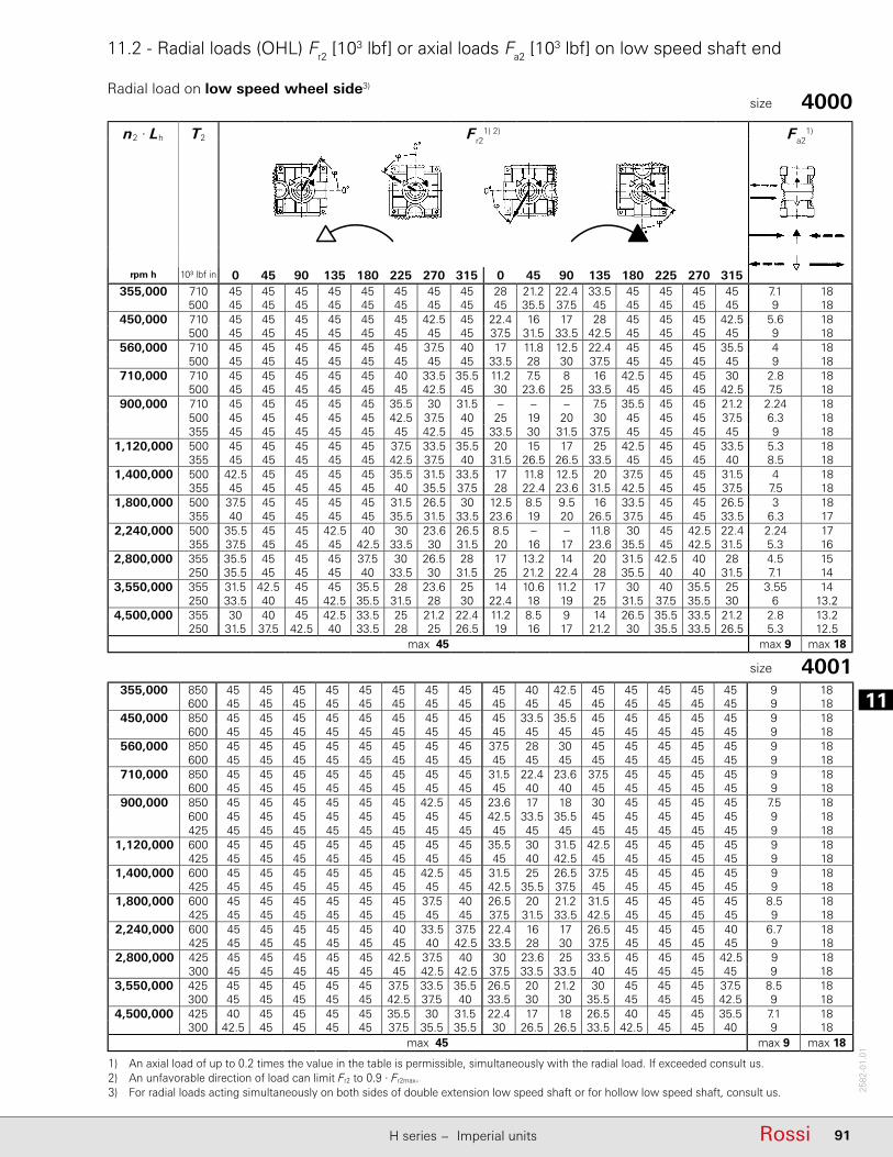
11
91RossiH series − Imperial units
2582
-01.
01
11.2 - Radial loads (OHL) Fr2 [103 lbf] or axial loads Fa2 [103 lbf] on low speed shaft end
n2 · Lh T2 Fr21) 2) Fa2
1)
rpm h 10³ lbf in 0 45 90 135 180 225 270 315 0 45 90 135 180 225 270 315355,000 710 45 45 45 45 45 45 45 45 28 21.2 22.4 33.5 45 45 45 45 7.1 18
500 45 45 45 45 45 45 45 45 45 35.5 37.5 45 45 45 45 45 9 18450,000 710 45 45 45 45 45 45 42.5 45 22.4 16 17 28 45 45 45 42.5 5.6 18
500 45 45 45 45 45 45 45 45 37.5 31.5 33.5 42.5 45 45 45 45 9 18560,000 710 45 45 45 45 45 45 37.5 40 17 11.8 12.5 22.4 45 45 45 35.5 4 18
500 45 45 45 45 45 45 45 45 33.5 28 30 37.5 45 45 45 45 9 18710,000 710 45 45 45 45 45 40 33.5 35.5 11.2 7.5 8 16 42.5 45 45 30 2.8 18
500 45 45 45 45 45 45 42.5 45 30 23.6 25 33.5 45 45 45 42.5 7.5 18900,000 710 45 45 45 45 45 35.5 30 31.5 – – – 7.5 35.5 45 45 21.2 2.24 18
500 45 45 45 45 45 42.5 37.5 40 25 19 20 30 45 45 45 37.5 6.3 18355 45 45 45 45 45 45 42.5 45 33.5 30 31.5 37.5 45 45 45 45 9 18
1,120,000 500 45 45 45 45 45 37.5 33.5 35.5 20 15 17 25 42.5 45 45 33.5 5.3 18355 45 45 45 45 45 42.5 37.5 40 31.5 26.5 26.5 33.5 45 45 45 40 8.5 18
1,400,000 500 42.5 45 45 45 45 35.5 31.5 33.5 17 11.8 12.5 20 37.5 45 45 31.5 4 18355 45 45 45 45 45 40 35.5 37.5 28 22.4 23.6 31.5 42.5 45 45 37.5 7.5 18
1,800,000 500 37.5 45 45 45 45 31.5 26.5 30 12.5 8.5 9.5 16 33.5 45 45 26.5 3 18355 40 45 45 45 45 35.5 31.5 33.5 23.6 19 20 26.5 37.5 45 45 33.5 6.3 17
2,240,000 500 35.5 45 45 42.5 40 30 23.6 26.5 8.5 – – 11.8 30 45 42.5 22.4 2.24 17355 37.5 45 45 45 42.5 33.5 30 31.5 20 16 17 23.6 35.5 45 42.5 31.5 5.3 16
2,800,000 355 35.5 45 45 45 37.5 30 26.5 28 17 13.2 14 20 31.5 42.5 40 28 4.5 15250 35.5 45 45 45 40 33.5 30 31.5 25 21.2 22.4 28 35.5 40 40 31.5 7.1 14
3,550,000 355 31.5 42.5 45 45 35.5 28 23.6 25 14 10.6 11.2 17 30 40 35.5 25 3.55 14250 33.5 40 45 42.5 35.5 31.5 28 30 22.4 18 19 25 31.5 37.5 35.5 30 6 13.2
4,500,000 355 30 40 45 42.5 33.5 25 21.2 22.4 11.2 8.5 9 14 26.5 35.5 33.5 21.2 2.8 13.2250 31.5 37.5 42.5 40 33.5 28 25 26.5 19 16 17 21.2 30 35.5 33.5 26.5 5.3 12.5
max 45 max 9 max 18
355,000 850 45 45 45 45 45 45 45 45 45 40 42.5 45 45 45 45 45 9 18600 45 45 45 45 45 45 45 45 45 45 45 45 45 45 45 45 9 18
450,000 850 45 45 45 45 45 45 45 45 45 33.5 35.5 45 45 45 45 45 9 18600 45 45 45 45 45 45 45 45 45 45 45 45 45 45 45 45 9 18
560,000 850 45 45 45 45 45 45 45 45 37.5 28 30 45 45 45 45 45 9 18600 45 45 45 45 45 45 45 45 45 45 45 45 45 45 45 45 9 18
710,000 850 45 45 45 45 45 45 45 45 31.5 22.4 23.6 37.5 45 45 45 45 9 18600 45 45 45 45 45 45 45 45 45 40 40 45 45 45 45 45 9 18
900,000 850 45 45 45 45 45 45 42.5 45 23.6 17 18 30 45 45 45 45 7.5 18600 45 45 45 45 45 45 45 45 42.5 33.5 35.5 45 45 45 45 45 9 18425 45 45 45 45 45 45 45 45 45 45 45 45 45 45 45 45 9 18
1,120,000 600 45 45 45 45 45 45 45 45 35.5 30 31.5 42.5 45 45 45 45 9 18425 45 45 45 45 45 45 45 45 45 40 42.5 45 45 45 45 45 9 18
1,400,000 600 45 45 45 45 45 45 42.5 45 31.5 25 26.5 37.5 45 45 45 45 9 18425 45 45 45 45 45 45 45 45 42.5 35.5 37.5 45 45 45 45 45 9 18
1,800,000 600 45 45 45 45 45 45 37.5 40 26.5 20 21.2 31.5 45 45 45 45 8.5 18425 45 45 45 45 45 45 45 45 37.5 31.5 33.5 42.5 45 45 45 45 9 18
2,240,000 600 45 45 45 45 45 40 33.5 37.5 22.4 16 17 26.5 45 45 45 40 6.7 18425 45 45 45 45 45 45 40 42.5 33.5 28 30 37.5 45 45 45 45 9 18
2,800,000 425 45 45 45 45 45 42.5 37.5 40 30 23.6 25 33.5 45 45 45 42.5 9 18300 45 45 45 45 45 45 42.5 42.5 37.5 33.5 33.5 40 45 45 45 45 9 18
3,550,000 425 45 45 45 45 45 37.5 33.5 35.5 26.5 20 21.2 30 45 45 45 37.5 8.5 18300 45 45 45 45 45 42.5 37.5 40 33.5 30 30 35.5 45 45 45 42.5 9 18
4,500,000 425 40 45 45 45 45 35.5 30 31.5 22.4 17 18 26.5 40 45 45 35.5 7.1 18300 42.5 45 45 45 45 37.5 35.5 35.5 30 26.5 26.5 33.5 42.5 45 45 40 9 18
max 45 max 9 max 18
1) An axial load of up to 0.2 times the value in the table is permissible, simultaneously with the radial load. If exceeded consult us.2) An unfavorable direction of load can limit Fr2 to 0.9 · Fr2max.3) For radial loads acting simultaneously on both sides of double extension low speed shaft or for hollow low speed shaft, consult us.
4000size
4001size
Radial load on low speed wheel side3)
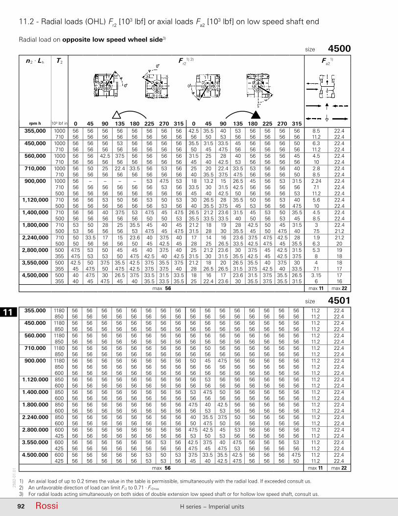
111
92 Rossi H series − Imperial units
2582
-01.
01
11.2 - Radial loads (OHL) Fr2 [103 lbf] or axial loads Fa2 [103 lbf] on low speed shaft end
n2 · Lh T2 Fr21) 2) Fa2
1)
rpm h 10³ lbf in 0 45 90 135 180 225 270 315 0 45 90 135 180 225 270 315355,000 1000 56 56 56 56 56 56 56 56 42.5 35.5 40 53 56 56 56 56 8.5 22.4
710 56 56 56 56 56 56 56 56 56 50 53 56 56 56 56 56 11.2 22.4450,000 1000 56 56 56 53 56 56 56 56 35.5 31.5 33.5 45 56 56 56 50 6.3 22.4
710 56 56 56 56 56 56 56 56 50 45 47.5 56 56 56 56 56 11.2 22.4560,000 1000 56 56 42.5 37.5 56 56 56 56 31.5 25 28 40 56 56 56 45 4.5 22.4
710 56 56 56 56 56 56 56 56 45 40 42.5 53 56 56 56 56 10 22.4710,000 1000 56 50 25 22.4 33.5 56 53 56 25 20 22.4 33.5 53 56 56 40 2.8 22.4
710 56 56 56 56 56 56 56 56 40 35.5 37.5 47.5 56 56 56 50 8.5 22.4900,000 1000 56 – – – – 53 47.5 53 18 13.2 15 26.5 45 56 53 31.5 2.24 22.4
710 56 56 56 56 56 56 53 56 33.5 30 31.5 42.5 56 56 56 56 7.1 22.4500 56 56 56 56 56 56 56 56 45 40 42.5 50 56 56 56 53 11.2 22.4
1,120,000 710 56 56 53 50 56 53 50 53 30 26.5 28 35.5 50 56 53 40 5.6 22.4500 56 56 56 56 56 56 53 56 40 35.5 37.5 45 53 56 56 47.5 10 22.4
1,400,000 710 56 56 40 37.5 53 47.5 45 47.5 26.5 21.2 23.6 31.5 45 53 50 35.5 4.5 22.4500 56 56 56 56 56 50 50 53 35.5 33.5 33.5 40 50 56 53 45 8.5 22.4
1,800,000 710 53 50 28 25 35.5 45 40 45 21.2 18 19 28 42.5 50 45 31.5 3 22.4500 53 56 56 56 53 47.5 45 47.5 31.5 28 30 35.5 45 50 47.5 40 7.5 21.2
2,240,000 710 50 33.5 17 15 23.6 40 37.5 40 17 14 16 23.6 37.5 47.5 42.5 28 1.9 21.2500 50 56 56 56 50 45 42.5 45 28 25 26.5 33.5 42.5 47.5 45 35.5 6.3 20
2,800,000 500 47.5 53 50 45 45 40 37.5 40 25 21.2 23.6 30 37.5 45 42.5 31.5 5.3 19355 47.5 53 53 50 47.5 42.5 40 42.5 31.5 30 31.5 35.5 42.5 45 42.5 37.5 8 18
3,550,000 500 42.5 50 37.5 35.5 42.5 37.5 35.5 37.5 21.2 18 20 26.5 35.5 40 37.5 30 4 18355 45 47.5 50 47.5 42.5 37.5 37.5 40 28 26.5 26.5 31.5 37.5 42.5 40 33.5 7.1 17
4,500,000 500 40 47.5 30 26.5 37.5 33.5 31.5 33.5 18 16 17 23.6 31.5 37.5 35.5 26.5 3.15 17355 40 45 47.5 45 40 35.5 33.5 35.5 25 22.4 23.6 30 35.5 37.5 35.5 31.5 6 16
max 56 max 11 max 22
355.000 1180 56 56 56 56 56 56 56 56 56 56 56 56 56 56 56 56 11.2 22.4850 56 56 56 56 56 56 56 56 56 56 56 56 56 56 56 56 11.2 22.4
450.000 1180 56 56 56 56 56 56 56 56 56 56 56 56 56 56 56 56 11.2 22.4850 56 56 56 56 56 56 56 56 56 56 56 56 56 56 56 56 11.2 22.4
560.000 1180 56 56 56 56 56 56 56 56 56 56 56 56 56 56 56 56 11.2 22.4850 56 56 56 56 56 56 56 56 56 56 56 56 56 56 56 56 11.2 22.4
710.000 1180 56 56 56 56 56 56 56 56 56 50 56 56 56 56 56 56 11.2 22.4850 56 56 56 56 56 56 56 56 56 56 56 56 56 56 56 56 11.2 22.4
900.000 1180 56 56 56 56 56 56 56 56 50 45 47.5 56 56 56 56 56 11.2 22.4850 56 56 56 56 56 56 56 56 56 56 56 56 56 56 56 56 11.2 22.4600 56 56 56 56 56 56 56 56 56 56 56 56 56 56 56 56 11.2 22.4
1.120.000 850 56 56 56 56 56 56 56 56 56 53 56 56 56 56 56 56 11.2 22.4600 56 56 56 56 56 56 56 56 56 56 56 56 56 56 56 56 11.2 22.4
1.400.000 850 56 56 56 56 56 56 56 56 53 47.5 50 56 56 56 56 56 11.2 22.4600 56 56 56 56 56 56 56 56 56 56 56 56 56 56 56 56 11.2 22.4
1.800.000 850 56 56 56 56 56 56 56 56 47.5 40 42.5 56 56 56 56 56 11.2 22.4600 56 56 56 56 56 56 56 56 56 53 53 56 56 56 56 56 11.2 22.4
2.240.000 850 56 56 56 56 56 56 56 56 40 35.5 37.5 50 56 56 56 56 11.2 22.4600 56 56 56 56 56 56 56 56 50 47.5 50 56 56 56 56 56 11.2 22.4
2.800.000 600 56 56 56 56 56 56 56 56 47.5 42.5 45 53 56 56 56 56 11.2 22.4425 56 56 56 56 56 56 56 56 53 50 53 56 56 56 56 56 11.2 22.4
3.550.000 600 56 56 56 56 56 56 53 56 42.5 37.5 40 47.5 56 56 56 53 11.2 22.4425 56 56 56 56 56 56 56 56 47.5 45 47.5 53 56 56 56 56 11.2 22.4
4.500.000 600 56 56 56 56 56 53 50 53 37.5 33.5 35.5 42.5 56 56 56 47.5 11.2 22.4425 56 56 56 56 56 53 53 56 45 40 42.5 47.5 56 56 56 50 11.2 22.4
max 56 max 11 max 22
1) An axial load of up to 0.2 times the value in the table is permissible, simultaneously with the radial load. If exceeded consult us.2) An unfavorable direction of load can limit Fr2 to 0.71 · Fr2max 3) For radial loads acting simultaneously on both sides of double extension low speed shaft or for hollow low speed shaft, consult us.
4500size
4501size
Radial load on opposite low speed wheel side3)
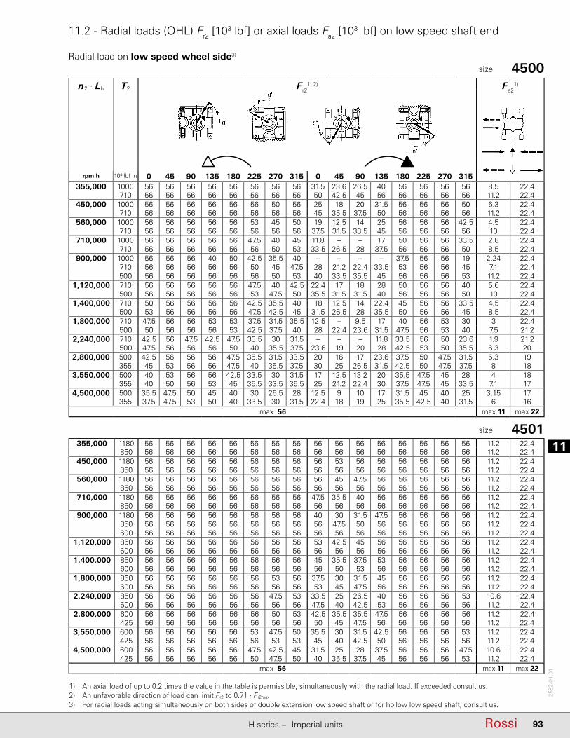
11
93RossiH series − Imperial units
2582
-01.
01
11.2 - Radial loads (OHL) Fr2 [103 lbf] or axial loads Fa2 [103 lbf] on low speed shaft end
n2 · Lh T2 Fr21) 2) Fa2
1)
rpm h 10³ lbf in 0 45 90 135 180 225 270 315 0 45 90 135 180 225 270 315355,000 1000 56 56 56 56 56 56 56 56 31.5 23.6 26.5 40 56 56 56 56 8.5 22.4
710 56 56 56 56 56 56 56 56 50 42.5 45 56 56 56 56 56 11.2 22.4450,000 1000 56 56 56 56 56 56 50 56 25 18 20 31.5 56 56 56 50 6.3 22.4
710 56 56 56 56 56 56 56 56 45 35.5 37.5 50 56 56 56 56 11.2 22.4560,000 1000 56 56 56 56 56 53 45 50 19 12.5 14 25 56 56 56 42.5 4.5 22.4
710 56 56 56 56 56 56 56 56 37.5 31.5 33.5 45 56 56 56 56 10 22.4710,000 1000 56 56 56 56 56 47.5 40 45 11.8 – – 17 50 56 56 33.5 2.8 22.4
710 56 56 56 56 56 56 50 53 33.5 26.5 28 37.5 56 56 56 50 8.5 22.4900,000 1000 56 56 56 40 50 42.5 35.5 40 – – – – 37.5 56 56 19 2.24 22.4
710 56 56 56 56 56 50 45 47.5 28 21.2 22.4 33.5 53 56 56 45 7.1 22.4500 56 56 56 56 56 56 50 53 40 33.5 35.5 45 56 56 56 53 11.2 22.4
1,120,000 710 56 56 56 56 56 47.5 40 42.5 22.4 17 18 28 50 56 56 40 5.6 22.4500 56 56 56 56 56 53 47.5 50 35.5 31.5 31.5 40 56 56 56 50 10 22.4
1,400,000 710 50 56 56 56 56 42.5 35.5 40 18 12.5 14 22.4 45 56 56 33.5 4.5 22.4500 53 56 56 56 56 47.5 42.5 45 31.5 26.5 28 35.5 50 56 56 45 8.5 22.4
1,800,000 710 47.5 56 56 53 53 37.5 31.5 35.5 12.5 – 9.5 17 40 56 53 30 3 22.4500 50 56 56 56 53 42.5 37.5 40 28 22.4 23.6 31.5 47.5 56 53 40 7.5 21.2
2,240,000 710 42.5 56 47.5 42.5 47.5 33.5 30 31.5 – – – 11.8 33.5 56 50 23.6 1.9 21.2500 47.5 56 56 56 50 40 35.5 37.5 23.6 19 20 28 42.5 53 50 35.5 6.3 20
2,800,000 500 42.5 56 56 56 47.5 35.5 31.5 33.5 20 16 17 23.6 37.5 50 47.5 31.5 5.3 19355 45 53 56 56 47.5 40 35.5 37.5 30 25 26.5 31.5 42.5 50 47.5 37.5 8 18
3,550,000 500 40 53 56 56 42.5 33.5 30 31.5 17 12.5 13.2 20 35.5 47.5 45 28 4 18355 40 50 56 53 45 35.5 33.5 35.5 25 21.2 22.4 30 37.5 47.5 45 33.5 7.1 17
4,500,000 500 35.5 47.5 50 45 40 30 26.5 28 12.5 9 10 17 31.5 45 40 25 3.15 17355 37.5 47.5 53 50 40 33.5 30 31.5 22.4 18 19 25 35.5 42.5 40 31.5 6 16
max 56 max 11 max 22
355,000 1180 56 56 56 56 56 56 56 56 56 56 56 56 56 56 56 56 11.2 22.4850 56 56 56 56 56 56 56 56 56 56 56 56 56 56 56 56 11.2 22.4
450,000 1180 56 56 56 56 56 56 56 56 56 53 56 56 56 56 56 56 11.2 22.4850 56 56 56 56 56 56 56 56 56 56 56 56 56 56 56 56 11.2 22.4
560,000 1180 56 56 56 56 56 56 56 56 56 45 47.5 56 56 56 56 56 11.2 22.4850 56 56 56 56 56 56 56 56 56 56 56 56 56 56 56 56 11.2 22.4
710,000 1180 56 56 56 56 56 56 56 56 47.5 35.5 40 56 56 56 56 56 11.2 22.4850 56 56 56 56 56 56 56 56 56 56 56 56 56 56 56 56 11.2 22.4
900,000 1180 56 56 56 56 56 56 56 56 40 30 31.5 47.5 56 56 56 56 11.2 22.4850 56 56 56 56 56 56 56 56 56 47.5 50 56 56 56 56 56 11.2 22.4600 56 56 56 56 56 56 56 56 56 56 56 56 56 56 56 56 11.2 22.4
1,120,000 850 56 56 56 56 56 56 56 56 53 42.5 45 56 56 56 56 56 11.2 22.4600 56 56 56 56 56 56 56 56 56 56 56 56 56 56 56 56 11.2 22.4
1,400,000 850 56 56 56 56 56 56 56 56 45 35.5 37.5 53 56 56 56 56 11.2 22.4600 56 56 56 56 56 56 56 56 56 50 53 56 56 56 56 56 11.2 22.4
1,800,000 850 56 56 56 56 56 56 53 56 37.5 30 31.5 45 56 56 56 56 11.2 22.4600 56 56 56 56 56 56 56 56 53 45 47.5 56 56 56 56 56 11.2 22.4
2,240,000 850 56 56 56 56 56 56 47.5 53 33.5 25 26.5 40 56 56 56 53 10.6 22.4600 56 56 56 56 56 56 56 56 47.5 40 42.5 53 56 56 56 56 11.2 22.4
2,800,000 600 56 56 56 56 56 56 50 53 42.5 35.5 35.5 47.5 56 56 56 56 11.2 22.4425 56 56 56 56 56 56 56 56 50 45 47.5 56 56 56 56 56 11.2 22.4
3,550,000 600 56 56 56 56 56 53 47.5 50 35.5 30 31.5 42.5 56 56 56 53 11.2 22.4425 56 56 56 56 56 56 53 53 45 40 42.5 50 56 56 56 56 11.2 22.4
4,500,000 600 56 56 56 56 56 47.5 42.5 45 31.5 25 28 37.5 56 56 56 47.5 10.6 22.4425 56 56 56 56 56 50 47.5 50 40 35.5 37.5 45 56 56 56 53 11.2 22.4
max 56 max 11 max 22
1) An axial load of up to 0.2 times the value in the table is permissible, simultaneously with the radial load. If exceeded consult us.2) An unfavorable direction of load can limit Fr2 to 0.71 · Fr2max 3) For radial loads acting simultaneously on both sides of double extension low speed shaft or for hollow low speed shaft, consult us.
4500size
4501size
Radial load on low speed wheel side3)

111
94 Rossi H series − Imperial units
2582
-01.
01
11.2 - Radial loads (OHL) Fr2 [103 lbf] or axial loads Fa2 [103 lbf] on low speed shaft end
n2 · Lh T2 Fr21) 2) Fa2
1)
rpm h 10³ lbf in 0 45 90 135 180 225 270 315 0 45 90 135 180 225 270 315355,000 1400 71 71 71 71 71 71 71 71 56 47.5 53 67 71 71 71 71 9.5 28
1000 71 71 71 71 71 71 71 71 71 67 71 71 71 71 71 71 14 28450,000 1400 71 71 63 60 71 71 71 71 47.5 40 45 60 71 71 71 63 7.1 28
1000 71 71 71 71 71 71 71 71 63 60 63 71 71 71 71 71 14 28560,000 1400 71 71 42.5 40 60 71 71 71 40 33.5 37.5 53 71 71 71 56 4.75 28
1000 71 71 71 71 71 71 71 71 60 53 56 67 71 71 71 71 12.5 28710,000 1400 71 47.5 20 18 31.5 71 71 71 33.5 28 31.5 45 67 71 71 50 3.35 28
1000 71 71 71 71 71 71 71 71 53 47.5 50 60 71 71 71 63 10.6 28900,000 1400 – – – – – – – – 22.4 18 20 33.5 56 71 63 37.5 3.75 28
1000 71 71 71 71 71 71 71 71 45 40 42.5 53 71 71 71 60 8.5 28710 71 71 71 71 71 71 71 71 56 53 56 63 71 71 71 67 14 28
1,120,000 1000 71 71 67 63 71 67 63 71 40 33.5 37.5 47.5 63 71 67 53 6.7 28710 71 71 71 71 71 71 71 71 53 47.5 50 60 67 71 71 60 11.8 28
1,400,000 1000 71 71 50 45 63 63 60 63 33.5 30 31.5 42.5 60 67 63 47.5 5.3 28710 71 71 71 71 71 67 63 67 47.5 42.5 45 53 63 71 67 56 10.6 28
1,800,000 1000 67 60 31.5 30 45 56 53 60 28 23.6 26.5 35.5 53 63 56 40 3.35 28710 71 71 71 71 67 60 60 63 40 35.5 40 47.5 60 63 60 50 8.5 26.5
2,240,000 1000 63 37.5 17 15 25 53 50 53 23.6 20 22.4 31.5 47.5 56 53 35.5 2.12 26.5710 63 71 71 67 63 56 53 56 35.5 31.5 35.5 42.5 53 60 56 45 7.5 25
2,800,000 710 60 67 60 56 60 53 50 53 31.5 28 31.5 37.5 50 56 53 40 6 23.6500 60 67 67 63 60 53 53 56 40 37.5 40 45 53 56 53 47.5 10 22.4
3,550,000 710 56 63 45 42.5 53 47.5 45 47.5 28 23.6 26.5 33.5 45 50 47.5 35.5 4.75 22.4500 56 63 63 60 56 50 47.5 50 35.5 33.5 35.5 40 47.5 53 50 42.5 8.5 20
4,500,000 710 53 56 33.5 30 45 45 42.5 45 23.6 20 22.4 30 40 47.5 42.5 31.5 3.35 20500 53 56 60 56 50 47.5 45 47.5 33.5 30 31.5 37.5 45 50 47.5 40 7.5 19
max 71 max 14 max 28
1) An axial load of up to 0.2 times the value in the table is permissible, simultaneously with the radial load. If exceeded consult us.2) An unfavorable direction of load can limit Fr2 to 0.9 · Fr2max.3) For radial loads acting simultaneously on both sides of double extension low speed shaft or for hollow low speed shaft, consult us.
5000size
5001size
355,000 1700 71 71 71 71 71 71 71 71 71 71 71 71 71 71 71 71 14 281180 71 71 71 71 71 71 71 71 71 71 71 71 71 71 71 71 14 28
450,000 1700 71 71 71 71 71 71 71 71 67 60 63 71 71 71 71 71 14 281180 71 71 71 71 71 71 71 71 71 71 71 71 71 71 71 71 14 28
560,000 1700 71 71 71 71 71 71 71 71 60 50 56 71 71 71 71 71 11.8 281180 71 71 71 71 71 71 71 71 71 71 71 71 71 71 71 71 14 28
710,000 1700 71 71 63 60 71 71 71 71 50 42.5 47.5 63 71 71 71 71 9 281180 71 71 71 71 71 71 71 71 71 63 67 71 71 71 71 71 14 28
900,000 1700 71 71 37.5 33.5 56 71 71 71 42.5 35.5 37.5 56 71 71 71 63 6.3 281180 71 71 71 71 71 71 71 71 63 56 60 71 71 71 71 71 14 28850 71 71 71 71 71 71 71 71 71 71 71 71 71 71 71 71 14 28
1,120,000 1180 71 71 71 71 71 71 71 71 56 50 53 67 71 71 71 71 13.2 28850 71 71 71 71 71 71 71 71 67 63 67 71 71 71 71 71 14 28
1,400,000 1180 71 71 71 71 71 71 71 71 50 42.5 47.5 60 71 71 71 67 11.2 28850 71 71 71 71 71 71 71 71 63 56 60 71 71 71 71 71 14 28
1,800,000 1180 71 71 67 63 71 71 67 71 42.5 35.5 40 53 71 71 71 60 8.5 28850 71 71 71 71 71 71 71 71 56 50 53 63 71 71 71 67 14 28
2,240,000 1180 71 71 50 47.5 71 63 60 67 37.5 31.5 33.5 47.5 67 71 71 53 6.7 28850 71 71 71 71 71 71 67 71 50 45 47.5 56 71 71 71 63 12.5 28
2,800,000 850 71 71 71 71 71 63 60 63 45 40 42.5 50 63 71 67 56 10.6 28600 71 71 71 71 71 67 63 67 53 50 53 60 67 71 71 63 14 28
3,550,000 850 67 71 71 71 67 60 56 60 40 33.5 35.5 45 60 67 63 50 9 28600 67 71 71 71 67 63 60 63 47.5 45 47.5 53 63 67 63 56 13.2 26.5
4,500,000 850 63 71 60 56 63 53 50 53 33.5 30 31.5 40 53 63 60 45 7.5 26.5600 63 71 71 71 63 56 56 56 42.5 40 42.5 47.5 60 63 60 53 11.8 25
max 71 max 14 max 28
Radial load on opposite low speed wheel side3)
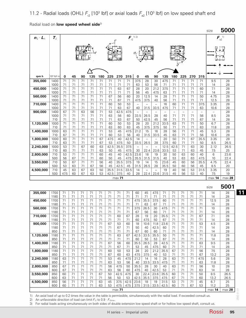
11
95RossiH series − Imperial units
2582
-01.
01
11.2 - Radial loads (OHL) Fr2 [103 lbf] or axial loads Fa2 [103 lbf] on low speed shaft end
n2 · Lh T2 Fr21) 2) Fa2
1)
rpm h 10³ lbf in 0 45 90 135 180 225 270 315 0 45 90 135 180 225 270 315355,000 1400 71 71 71 71 71 71 71 71 37.5 28 30 47.5 71 71 71 71 9.5 28
1000 71 71 71 71 71 71 71 71 63 53 56 71 71 71 71 71 14 28450,000 1400 71 71 71 71 71 71 63 67 28 20 21.2 37.5 71 71 71 60 7.1 28
1000 71 71 71 71 71 71 71 71 56 45 47.5 63 71 71 71 71 14 28560,000 1400 71 71 71 71 71 67 56 60 20 12.5 14 28 71 71 71 50 4.75 28
1000 71 71 71 71 71 71 67 71 47.5 37.5 40 56 71 71 71 71 12.5 28710,000 1400 71 71 71 71 71 60 50 53 – – – 16 60 71 71 37.5 3.35 28
1000 71 71 71 71 71 71 63 67 40 31.5 33.5 47.5 71 71 71 63 10.6 28900,000 1400 67 71 63 56 71 53 42.5 47.5 – – – – – – – – – 28
1000 71 71 71 71 71 63 56 60 33.5 26.5 28 40 71 71 71 56 8.5 28710 71 71 71 71 71 71 63 67 50 42.5 45 56 71 71 71 67 14 28
1,120,000 1000 71 71 71 71 71 60 50 53 28 20 21.2 33.5 63 71 71 50 6.7 28710 71 71 71 71 71 63 60 63 45 37.5 37.5 50 71 71 71 63 11.8 28
1,400,000 1000 63 71 71 71 71 53 45 47.5 21.2 15 16 28 56 71 71 45 5.3 28710 67 71 71 71 71 60 53 56 40 31.5 33.5 45 63 71 71 56 10.6 28
1,800,000 1000 60 71 71 71 67 47.5 40 42.5 14 – – 20 50 71 67 35.5 3.35 28710 63 71 71 71 67 53 47.5 50 33.5 26.5 28 37.5 60 71 71 50 8.5 26.5
2,240,000 1000 53 71 67 60 63 42.5 35.5 37.5 – – – 12.5 42.5 71 63 30 2.12 26.5710 60 71 71 71 63 50 45 47.5 30 22.4 23.6 33.5 53 71 63 45 7.5 25
2,800,000 710 53 71 71 71 60 45 40 42.5 23.6 18 19 30 50 63 60 40 6 23.6500 56 67 71 71 60 50 45 47.5 35.5 31.5 31.5 40 53 63 63 47.5 10 22.4
3,550,000 710 50 67 71 71 56 40 35.5 37.5 19 14 15 23.6 45 60 56 35.5 4.75 22.4500 53 63 71 67 56 45 42.5 45 31.5 26.5 28 35.5 50 60 56 45 8.5 20
4,500,000 710 45 63 67 63 50 35.5 31.5 33.5 14 – – 19 40 56 53 31.5 3.35 20500 47.5 60 67 63 53 42.5 37.5 40 28 22.4 23.6 31.5 45 56 53 40 7.5 19
max 71 max 14 max 28
355,000 1700 71 71 71 71 71 71 71 71 60 45 47.5 71 71 71 71 71 14 281180 71 71 71 71 71 71 71 71 71 71 71 71 71 71 71 71 14 28
450,000 1700 71 71 71 71 71 71 71 71 47.5 35.5 37.5 60 71 71 71 71 12.5 281180 71 71 71 71 71 71 71 71 71 63 67 71 71 71 71 71 14 28
560,000 1700 71 71 71 71 71 71 71 71 37.5 26.5 30 47.5 71 71 71 71 10 281180 71 71 71 71 71 71 71 71 67 56 60 71 71 71 71 71 14 28
710,000 1700 71 71 71 71 71 71 60 67 28 19 20 35.5 71 71 71 67 7.1 281180 71 71 71 71 71 71 71 71 60 47.5 50 67 71 71 71 71 14 28
900,000 1700 71 71 71 71 71 67 53 60 18 10.6 11.8 23.6 71 71 71 53 4.5 281180 71 71 71 71 71 71 67 71 50 40 42.5 60 71 71 71 71 14 28850 71 71 71 71 71 71 71 71 67 60 60 71 71 71 71 71 14 28
1,120,000 1180 71 71 71 71 71 71 63 67 42.5 33.5 35.5 50 71 71 71 71 11.8 28850 71 71 71 71 71 71 71 71 60 50 53 67 71 71 71 71 14 28
1,400,000 1180 71 71 71 71 71 67 56 60 35.5 26.5 28 42.5 71 71 71 63 9.5 28850 71 71 71 71 71 71 67 71 53 45 47.5 60 71 71 71 71 14 28
1,800,000 1180 71 71 71 71 71 60 50 53 28 20 21.2 35.5 67 71 71 56 7.5 28850 71 71 71 71 71 67 60 63 47.5 37.5 40 53 71 71 71 67 13.2 28
2,240,000 1180 63 71 71 71 71 53 45 47.5 21.2 14 16 28 63 71 71 47.5 5.6 28850 71 71 71 71 71 63 53 56 40 33.5 33.5 47.5 71 71 71 63 11.8 28
2,800,000 850 67 71 71 71 71 56 47.5 50 35.5 28 30 40 63 71 71 56 10 28600 67 71 71 71 71 63 56 60 47.5 40 42.5 53 71 71 71 63 14 28
3,550,000 850 60 71 71 71 67 50 42.5 47.5 30 22.4 23.6 35.5 60 71 71 50 8.5 26.5600 63 71 71 71 71 56 50 53 42.5 35.5 37.5 47.5 67 71 71 60 13.2 26.5
4,500,000 850 56 71 71 71 63 45 37.5 42.5 23.6 18 19 31.5 53 71 71 45 6.7 25600 60 71 71 71 63 53 47.5 47.5 37.5 31.5 33.5 42.5 60 71 67 53 11.2 25
max 71 max 14 max 28
1) An axial load of up to 0.2 times the value in the table is permissible, simultaneously with the radial load. If exceeded consult us.2) An unfavorable direction of load can limit Fr2 to 0.9 · Fr2max.3) For radial loads acting simultaneously on both sides of double extension low speed shaft or for hollow low speed shaft, consult us.
5000size
5001size
Radial load on low speed wheel side3)
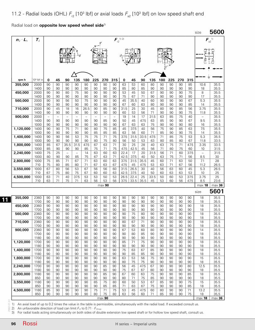
111
96 Rossi H series − Imperial units
2582
-01.
01
11.2 - Radial loads (OHL) Fr2 [103 lbf] or axial loads Fa2 [103 lbf] on low speed shaft end
n2 · Lh T2 Fr21) 2) Fa2
1)
rpm h 10³ lbf in 0 45 90 135 180 225 270 315 0 45 90 135 180 225 270 315355,000 2000 90 90 90 90 90 90 90 90 63 53 60 80 90 90 90 85 10.6 35.5
1400 90 90 90 90 90 90 90 90 85 80 85 90 90 90 90 90 18 35.5450,000 2000 90 90 80 75 90 90 90 90 53 45 50 67 90 90 90 75 8 35.5
1400 90 90 90 90 90 90 90 90 75 67 71 90 90 90 90 90 17 35.5560,000 2000 90 90 56 50 75 90 90 90 45 35.5 40 60 90 90 90 67 5.3 35.5
1400 90 90 90 90 90 90 90 90 67 60 63 80 90 90 90 85 14 35.5710,000 2000 90 45 18 16 26.5 90 85 90 31.5 25 30 45 80 90 85 56 3.75 35.5
1400 90 90 90 90 90 90 90 90 60 53 56 71 90 90 90 75 11.8 35.5900,000 2000 – – – – – – – – 19 14 17 31.5 63 85 75 40 – 35.5
1400 90 90 90 90 90 90 85 90 50 45 47.5 63 85 90 90 67 9.5 35.51000 90 90 90 90 90 90 90 90 67 63 63 75 90 90 90 80 16 35.5
1,120,000 1400 90 90 75 71 90 80 75 85 45 37.5 40 56 75 90 85 63 7.5 35.51000 90 90 90 90 90 85 85 85 63 56 60 71 85 90 90 75 14 35.5
1,400,000 1400 90 90 56 53 75 75 71 75 37.5 31.5 33.5 47.5 71 85 75 53 5.3 35.51000 90 90 90 90 90 80 75 80 56 50 53 63 80 85 80 67 11.8 33.5
1,800,000 1400 85 67 35.5 31.5 47.5 67 63 71 30 25 28 40 63 75 71 47.5 3.35 33.51000 85 90 90 90 85 75 71 75 47.5 42.5 45 56 71 80 75 60 10 31.5
2,240,000 1400 75 25 – – 14 63 60 63 22.4 17 20 31.5 56 71 60 37.5 – 31.51000 80 90 90 85 75 67 63 71 42.5 37.5 40 50 63 75 71 56 8.5 30
2,800,000 1000 75 85 71 67 71 63 60 63 37.5 31.5 35.5 45 60 71 63 50 7.1 28710 75 80 85 80 71 67 63 67 47.5 45 47.5 53 63 71 67 56 11.2 26.5
3,550,000 1000 67 80 56 53 67 56 56 60 31.5 26.5 30 40 56 63 60 45 5.3 26.5710 67 75 80 75 67 60 60 63 42.5 37.5 40 50 60 63 63 53 10 25
4,500,000 1000 63 71 40 37.5 53 53 50 53 26.5 22.4 25 33.5 50 60 53 37.5 3.75 25710 63 71 75 71 63 56 53 56 37.5 33.5 35.5 45 53 60 56 47.5 8.5 23.6
max 90 max 18 max 36
1) An axial load of up to 0.2 times the value in the table is permissible, simultaneously with the radial load. If exceeded consult us.2) An unfavorable direction of load can limit Fr2 to 0.71 · Fr2max 3) For radial loads acting simultaneously on both sides of double extension low speed shaft or for hollow low speed shaft, consult us.
5600size
5601size
355,000 2360 90 90 90 90 90 90 90 90 90 90 90 90 90 90 90 90 18 35.51700 90 90 90 90 90 90 90 90 90 90 90 90 90 90 90 90 18 35.5
450,000 2360 90 90 90 90 90 90 90 90 90 90 90 90 90 90 90 90 18 35.51700 90 90 90 90 90 90 90 90 90 90 90 90 90 90 90 90 18 35.5
560,000 2360 90 90 90 90 90 90 90 90 90 75 80 90 90 90 90 90 18 35.51700 90 90 90 90 90 90 90 90 90 90 90 90 90 90 90 90 18 35.5
710,000 2360 90 90 90 90 90 90 90 90 80 67 71 90 90 90 90 90 18 35.51700 90 90 90 90 90 90 90 90 90 90 90 90 90 90 90 90 18 35.5
900,000 2360 90 90 90 90 90 90 90 90 67 53 60 80 90 90 90 90 14 35.51700 90 90 90 90 90 90 90 90 90 80 85 90 90 90 90 90 18 35.51180 90 90 90 90 90 90 90 90 90 90 90 90 90 90 90 90 18 35.5
1,120,000 1700 90 90 90 90 90 90 90 90 85 71 75 90 90 90 90 90 18 35.51180 90 90 90 90 90 90 90 90 90 90 90 90 90 90 90 90 18 35.5
1,400,000 1700 90 90 90 90 90 90 90 90 75 63 67 85 90 90 90 90 18 35.51180 90 90 90 90 90 90 90 90 90 85 85 90 90 90 90 90 18 35.5
1,800,000 1700 90 90 90 90 90 90 90 90 63 53 56 75 90 90 90 90 15 35.51180 90 90 90 90 90 90 90 90 80 75 75 90 90 90 90 90 18 35.5
2,240,000 1700 90 90 90 90 90 90 85 90 56 45 47.5 67 90 90 90 80 12.5 35.51180 90 90 90 90 90 90 90 90 75 67 67 80 90 90 90 90 18 35.5
2,800,000 1180 90 90 90 90 90 90 85 90 67 60 63 75 90 90 90 85 18 35.5850 90 90 90 90 90 90 90 90 80 71 75 85 90 90 90 90 18 35.5
3,550,000 1180 90 90 90 90 90 85 75 80 60 50 53 67 85 90 90 75 15 35.5850 90 90 90 90 90 90 85 85 71 63 67 75 90 90 90 85 18 35.5
4,500,000 1180 85 90 90 90 90 75 71 75 53 45 47.5 60 80 90 90 71 13.2 35.5850 90 90 90 90 90 80 75 80 63 56 60 71 85 90 90 75 18 35,5
max 90 max 18 max 36
Radial load on opposite low speed wheel side3)
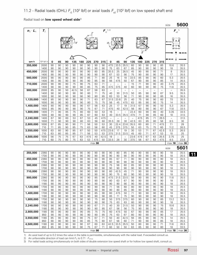
11
97RossiH series − Imperial units
2582
-01.
01
11.2 - Radial loads (OHL) Fr2 [103 lbf] or axial loads Fa2 [103 lbf] on low speed shaft end
n2 · Lh T2 Fr21) 2) Fa2
1)
rpm h 10³ lbf in 0 45 90 135 180 225 270 315 0 45 90 135 180 225 270 315355,000 2000 90 90 90 90 90 90 90 90 47.5 33.5 35.5 60 90 90 90 85 10.6 35.5
1400 90 90 90 90 90 90 90 90 75 63 67 85 90 90 90 90 18 35.5450,000 2000 90 90 90 90 90 90 80 85 35.5 25 26.5 45 90 90 90 71 8 35.5
1400 90 90 90 90 90 90 90 90 67 53 56 75 90 90 90 90 17 35.5560,000 2000 90 90 90 90 90 85 71 80 25 16 18 33.5 85 90 90 60 5.3 35.5
1400 90 90 90 90 90 90 85 90 56 47.5 50 67 90 90 90 85 14 35.5710,000 2000 90 90 90 75 90 75 63 71 – – – 15 71 90 90 40 3.75 35.5
1400 90 90 90 90 90 85 75 85 47.5 37.5 40 60 90 90 90 75 11.8 35.5900,000 2000 85 90 50 42.5 56 67 56 63 – – – – – – – – – 35.5
1400 90 90 90 90 90 80 71 75 40 30 31.5 50 85 90 90 67 9.5 35.51000 90 90 90 90 90 90 80 85 63 53 56 71 90 90 90 85 16 35.5
1,120,000 1400 85 90 90 90 90 71 63 67 31.5 23.6 25 40 75 90 90 60 7.5 35.51000 90 90 90 90 90 80 75 75 56 45 47.5 63 85 90 90 75 14 35.5
1,400,000 1400 80 90 90 90 90 67 56 63 25 17 19 31.5 67 90 90 50 5.3 35.51000 85 90 90 90 90 75 67 71 47.5 40 42.5 56 80 90 90 67 11.8 33.5
1,800,000 1400 71 90 85 75 80 60 50 53 16 – – 22.4 60 90 80 40 3.35 33.51000 80 90 90 90 85 67 60 63 40 33.5 35.5 47.5 71 90 85 60 10 31.5
2,240,000 1400 67 90 60 53 67 53 45 47.5 – – – – 47.5 85 71 26.5 – 31.51000 71 90 90 90 80 63 56 60 35.5 28 30 42.5 63 85 80 56 8.5 30
2,800,000 1000 67 85 90 90 71 56 50 53 30 22.4 23.6 35.5 60 80 71 47.5 7.1 28710 71 85 90 85 75 63 56 60 45 37.5 37.5 50 63 75 75 60 11.2 26.5
3,550,000 1000 63 80 90 85 67 50 50 47.5 23.6 17 19 30 53 71 67 42.5 5.3 26.5710 63 80 85 85 71 56 53 53 37.5 31.5 33.5 45 60 71 67 53 10 25
4,500,000 1000 56 75 75 67 63 47.5 40 42.5 18 – – 23.6 47.5 67 63 35.5 3.75 25710 60 75 80 75 63 53 47.5 50 33.5 28 30 37.5 56 67 63 47.5 8.5 23.6
max 90 max 18 max 36
355,000 2360 90 90 90 90 90 90 90 90 90 80 85 90 90 90 90 90 18 35.51700 90 90 90 90 90 90 90 90 90 90 90 90 90 90 90 90 18 35.5
450,000 2360 90 90 90 90 90 90 90 90 85 67 71 90 90 90 90 90 18 35.51700 90 90 90 90 90 90 90 90 90 90 90 90 90 90 90 90 18 35.5
560,000 2360 90 90 90 90 90 90 90 90 75 56 60 85 90 90 90 90 18 35.51700 90 90 90 90 90 90 90 90 90 90 90 90 90 90 90 90 18 35.5
710,000 2360 90 90 90 90 90 90 90 90 60 42.5 45 71 90 90 90 90 18 35.51700 90 90 90 90 90 90 90 90 90 75 80 90 90 90 90 90 18 35.5
900,000 2360 90 90 90 90 90 90 85 90 47.5 31.5 33.5 56 90 90 90 90 11.8 35.51700 90 90 90 90 90 90 90 90 80 63 67 90 90 90 90 90 18 35.51180 90 90 90 90 90 90 90 90 90 90 90 90 90 90 90 90 18 35.5
1,120,000 1700 90 90 90 90 90 90 90 90 71 56 60 80 90 90 90 90 18 35.51180 90 90 90 90 90 90 90 90 90 80 85 90 90 90 90 90 18 35.5
1,400,000 1700 90 90 90 90 90 90 85 90 60 47.5 50 71 90 90 90 90 18 35.51180 90 90 90 90 90 90 90 90 85 71 75 90 90 90 90 90 18 35.5
1,800,000 1700 90 90 90 90 90 90 75 80 50 37.5 37.5 60 90 90 90 85 13.2 35.51180 90 90 90 90 90 90 90 90 75 63 63 80 90 90 90 90 18 35.5
2,240,000 1700 90 90 90 90 90 80 67 71 40 30 31.5 50 90 90 90 75 10.6 35.51180 90 90 90 90 90 90 80 85 67 56 56 75 90 90 90 90 18 35.5
2,800,000 1180 90 90 90 90 90 85 75 75 60 47.5 50 67 90 90 90 85 17 35.5850 90 90 90 90 90 90 80 85 75 63 67 80 90 90 90 90 18 35.5
3,550,000 1180 85 90 90 90 90 75 67 71 50 40 42.5 56 85 90 90 75 14 35.5850 90 90 90 90 90 85 75 80 67 56 60 71 90 90 90 85 18 35.5
4,500,000 1180 80 90 90 90 90 67 60 63 42.5 33.5 35.5 50 80 90 90 71 11.8 35.5850 85 90 90 90 90 75 67 71 60 50 50 63 85 90 90 80 18 33.5
max 90 max 18 max 36
1) An axial load of up to 0.2 times the value in the table is permissible, simultaneously with the radial load. If exceeded consult us.2) An unfavorable direction of load can limit Fr2 to 0.71 · Fr2max 3) For radial loads acting simultaneously on both sides of double extension low speed shaft or for hollow low speed shaft, consult us.
5600size
5601size
Radial load on low speed wheel side3)

111
98 Rossi H series − Imperial units
2582
-01.
01
11.2 - Radial loads (OHL) Fr2 [103 lbf] or axial loads Fa2 [103 lbf] on low speed shaft end
n2 · Lh T2 Fr21) 2) Fa2
1)
rpm h 10³ lbf in 0 45 90 135 180 225 270 315 0 45 90 135 180 225 270 315355,000 2800 90 90 90 90 90 90 90 90 90 90 90 90 90 90 90 90 35.5 18
2000 90 90 90 90 90 90 90 90 90 90 90 90 90 90 90 90 35.5 18450,000 2800 90 90 90 90 90 90 90 90 90 90 90 90 90 90 90 90 35.5 18
2000 90 90 90 90 90 90 90 90 90 90 90 90 90 90 90 90 35.5 18560,000 2800 90 90 85 80 90 90 90 90 90 90 90 90 90 90 90 90 35.5 18
2000 90 90 90 90 90 90 90 90 90 90 90 90 90 90 90 90 35.5 18710,000 2800 90 90 75 67 80 90 90 90 90 90 90 90 90 90 90 90 35.5 18
2000 90 90 90 90 90 90 90 90 90 90 90 90 90 90 90 90 35.5 18900,000 2800 90 85 60 56 67 90 90 90 90 75 85 90 90 90 90 90 35.5 14
2000 90 90 85 80 90 67 90 90 90 90 90 90 90 90 90 90 35.5 181400 90 90 90 90 90 90 90 90 90 90 90 90 90 90 90 90 35.5 18
1,120,000 2000 90 90 80 71 80 90 90 90 90 90 90 90 90 90 90 90 35.5 181400 90 90 90 90 90 90 90 90 90 90 90 90 90 90 90 90 35.5 18
1,400,000 2000 90 85 67 63 71 90 90 90 90 90 90 90 90 90 90 90 35.5 181400 90 90 85 80 90 90 90 90 90 90 90 90 90 90 90 90 35.5 18
1,800,000 2000 90 75 60 56 63 85 90 90 90 90 90 90 90 90 90 90 35.5 161400 90 90 75 71 80 90 90 90 90 90 90 90 90 90 90 90 35.5 18
2,240,000 2000 90 67 53 47.5 56 75 90 90 90 75 80 90 90 90 85 90 35.5 12.51400 90 80 67 63 71 85 90 90 90 90 90 90 90 90 90 90 35.5 18
2,800,000 1400 90 75 63 60 63 80 90 90 90 90 90 90 90 90 85 90 35.5 181000 90 85 75 71 75 85 90 90 90 90 90 90 90 90 90 90 35.5 18
3,550,000 1400 85 67 53 50 56 71 90 90 90 90 90 90 90 85 80 80 35.5 161000 90 75 67 63 67 80 90 90 90 90 90 90 90 85 85 85 35.5 18
4,500,000 1400 75 60 47.5 45 50 63 80 90 85 80 90 90 90 75 71 75 35.5 13.21000 80 71 60 56 63 71 85 90 85 90 90 90 90 80 75 80 35.5 18
max 90 max 36 max 18
1) An axial load of up to 0.2 times the value in the table is permissible, simultaneously with the radial load. If exceeded consult us.2) An unfavorable direction of load can limit Fr2 to 0.71 · Fr2max 3) For radial loads acting simultaneously on both sides of double extension low speed shaft or for hollow low speed shaft, consult us.
6300size
6301size
355,000 3550 90 90 90 90 90 90 90 90 90 90 90 90 90 90 90 90 35.5 182500 90 90 90 90 90 90 90 90 90 90 90 90 90 90 90 90 35.5 18
450,000 3550 90 90 80 80 80 90 90 90 90 90 90 90 90 90 90 90 35.5 182500 90 90 90 90 90 90 90 90 90 90 90 90 90 90 90 90 35.5 18
560,000 3550 90 90 71 63 80 90 90 90 90 80 80 90 90 90 90 90 35.5 162500 90 90 90 90 90 90 90 90 90 90 90 90 90 90 90 90 35.5 18
710,000 3550 90 80 56 50 63 90 90 90 71 45 50 90 90 90 90 90 35.5 102500 90 90 80 80 90 90 90 90 90 90 90 90 90 90 90 90 35.5 18
900,000 3550 90 71 45 40 50 80 90 90 25 16 16 45 90 90 90 90 35.5 6.32500 90 90 80 71 80 90 90 90 90 90 90 90 90 90 90 90 35.5 181800 90 90 90 90 90 90 90 90 90 90 90 90 90 90 90 90 35.5 18
1,120,000 2500 90 80 63 63 71 90 90 90 90 90 90 90 90 90 90 90 35.5 161800 90 90 80 90 90 90 90 90 90 90 90 90 90 90 90 90 35.5 18
1,400,000 2500 90 80 56 56 63 80 90 90 90 80 80 90 90 90 90 90 35.5 141800 90 90 80 80 80 90 90 90 90 90 90 90 90 90 90 90 35.5 18
1,800,000 2500 90 71 50 45 56 80 90 90 80 56 56 90 90 90 90 90 35.5 101800 90 80 71 63 71 90 90 90 90 90 90 90 90 90 90 90 35.5 18
2,240,000 2500 90 56 40 35.5 45 71 90 90 50 31.5 35.5 80 90 90 80 80 35.5 81800 90 80 56 56 63 80 90 90 90 90 90 90 90 90 90 90 35.5 16
2,800,000 1800 90 71 56 50 56 80 90 90 90 90 90 90 90 90 80 80 35.5 141250 90 80 71 71 71 80 90 90 90 90 90 90 90 90 90 90 35.5 18
3,550,000 1800 80 56 50 45 50 71 80 90 90 71 80 90 90 80 80 80 35.5 12.51250 80 71 63 56 63 80 90 90 90 90 90 90 90 80 80 80 35.5 18
4,500,000 1800 80 56 40 35.5 45 56 80 90 80 56 56 90 90 80 71 71 35.5 91250 80 71 56 56 56 71 80 90 80 90 90 90 90 80 80 80 35.5 16
max 90 max 35.5 max 18
Radial load on opposite low speed wheel side3)

11
99RossiH series − Imperial units
2582
-01.
01
11.2 - Radial loads (OHL) Fr2 [103 lbf] or axial loads Fa2 [103 lbf] on low speed shaft end
n2 · Lh T2 Fr21) 2) Fa2
1)
rpm h 10³ lbf in 0 45 90 135 180 225 270 315 0 45 90 135 180 225 270 315355,000 2800 90 90 80 80 90 90 90 90 90 90 90 90 90 90 90 90 35.5 18
2000 90 90 90 90 90 90 90 90 90 90 90 90 90 90 90 90 35.5 18450,000 2800 90 90 67 63 80 90 90 90 90 90 90 90 90 90 90 90 35.5 18
2000 90 90 90 90 90 90 90 90 90 90 90 90 90 90 90 90 35.5 18560,000 2800 90 80 53 50 67 90 90 90 90 90 90 90 90 90 90 90 35.5 18
2000 90 90 90 85 90 90 90 90 90 90 90 90 90 90 90 90 35.5 18710,000 2800 90 67 42.5 37.5 53 90 90 90 90 90 90 90 90 90 90 90 35.5 16
2000 90 90 75 71 90 90 90 90 90 90 90 90 90 90 90 90 35.5 18900,000 2800 90 53 30 28 40 90 90 90 90 90 90 90 90 90 80 90 35.5 11.2
2000 90 90 63 63 75 90 90 90 90 90 90 90 90 90 90 90 35.5 181400 90 90 90 85 90 90 90 90 90 90 90 90 90 90 90 90 35.5 18
1,120,000 2000 90 80 56 53 67 90 90 90 90 90 90 90 90 90 90 90 35.5 181400 90 90 80 75 90 90 90 90 90 90 90 90 90 90 90 90 35.5 18
1,400,000 2000 90 67 47.5 42.5 56 90 90 90 90 90 90 90 90 90 80 90 35.5 171400 90 90 71 67 80 90 90 90 90 90 90 90 90 90 90 90 35.5 18
1,800,000 2000 90 56 35.5 33.5 45 80 90 90 90 90 90 90 90 80 71 85 35.5 13.21400 90 80 60 60 71 90 90 90 90 90 90 90 90 90 85 90 35.5 18
2,240,000 2000 90 47.5 30 26.5 37.5 71 90 90 90 90 90 90 90 71 63 75 35.5 10.61400 90 71 53 50 63 90 90 90 90 90 90 90 90 80 75 85 35.5 18
2,800,000 1400 90 63 45 42.5 53 80 90 90 90 90 90 90 90 75 71 80 35.5 171000 90 75 63 60 71 90 90 90 90 90 90 90 90 85 80 85 35.5 18
3,550,000 1400 85 53 37.5 35.5 47.5 71 90 90 90 90 90 90 85 67 63 71 35.5 141000 90 71 56 53 63 80 90 90 90 90 90 90 90 75 71 80 35.5 18
4,500,000 1400 75 47.5 31.5 30 37.5 63 90 90 85 90 90 90 80 63 56 67 35.5 11.81000 85 63 50 47.5 56 75 90 90 90 90 90 90 85 71 67 71 35.5 18
max 90 max 36 max 18
355,000 3350 90 90 56 53 71 90 90 90 90 90 90 90 90 90 90 90 35.5 182360 90 90 90 90 90 90 90 90 90 90 90 90 90 90 90 90 35.5 18
450,000 3350 90 71 42.5 37.5 56 90 90 90 90 90 90 90 90 90 90 90 35.5 162360 90 90 85 80 90 90 90 90 90 90 90 90 90 90 90 90 35.5 18
560,000 3350 90 56 30 28 40 90 90 90 90 90 90 90 90 90 90 90 35.5 11.82360 90 90 71 67 85 90 90 90 90 90 90 90 90 90 90 90 35.5 18
710,000 3350 90 37.5 18 16 25 80 90 90 90 90 90 90 90 90 80 90 35.5 7.12360 90 85 60 56 75 90 90 90 90 90 90 90 90 90 90 90 35.5 18
900,000 3350 90 16 – – 9 56 90 90 90 90 90 90 90 75 71 85 35.5 32360 90 75 50 45 63 90 90 90 90 90 90 90 90 90 90 90 35.5 181700 90 90 75 75 90 90 90 90 90 90 90 90 90 90 90 90 35.5 18
1,120,000 2360 90 63 40 37.5 50 90 90 90 90 90 90 90 90 90 80 90 35.5 151700 90 90 67 63 80 90 90 90 90 90 90 90 90 90 90 90 35.5 18
1,400,000 2360 90 50 31.5 28 40 80 90 90 90 90 90 90 90 80 75 85 35.5 11.81700 90 80 60 56 71 90 90 90 90 90 90 90 90 90 90 90 35.5 18
1,800,000 2360 90 37.5 21.2 19 28 67 90 90 90 90 90 90 90 71 63 75 35.5 81700 90 67 50 47.5 60 90 90 90 90 90 90 90 90 85 80 90 35.5 18
2,240,000 2360 80 26.5 12.5 11.8 18 56 90 90 90 90 90 90 90 63 56 67 35.5 5.31700 90 60 42.5 40 50 80 90 90 90 90 90 90 90 75 71 80 35.5 16
2,800,000 1700 90 53 33.5 31.5 42.5 71 90 90 90 90 90 90 90 71 63 75 35.5 12.51180 90 71 56 53 63 85 90 90 90 90 90 90 90 80 75 85 35.5 18
3,550,000 1700 80 42.5 28 25 33.5 63 90 90 90 90 90 90 80 63 56 67 35.5 101180 90 63 47.5 47.5 56 80 90 90 90 90 90 90 90 71 67 75 35.5 18
4,500,000 1700 71 35.5 20 19 26.5 56 90 90 85 90 90 90 75 56 50 60 35.5 7.51180 80 56 42.5 40 50 71 90 90 90 90 90 90 80 67 63 71 35.5 16
max 90 max 36 max 18
1) An axial load of up to 0.2 times the value in the table is permissible, simultaneously with the radial load. If exceeded consult us.2) An unfavorable direction of load can limit Fr2 to 0.71 · Fr2max 3) For radial loads acting simultaneously on both sides of double extension low speed shaft or for hollow low speed shaft, consult us.
6300size
6301size
Radial load on low speed wheel side3)

111
100 Rossi H series − Imperial units
2582
-01.
01
11.2 - Radial loads (OHL) Fr2 [103 lbf] or axial loads Fa2 [103 lbf] on low speed shaft end
n2 · Lh T2 Fr21) 2) Fa2
1)
min-1.h 10³ lbf in 0 45 90 135 180 225 270 315 0 45 90 135 180 225 270 315 355,000 5600 106 112 112 112 112 112 95 90 112 112 112 112 112 100 106 112 45 22.4 355,000 4000 112 112 112 112 112 112 112 112 112 112 112 112 112 112 112 112 45 22.4 450,000 5600 90 112 112 112 112 112 80 71 112 112 112 112 90 56 60 112 45 22.4 450,000 4000 112 112 112 112 112 112 112 112 112 112 112 112 112 112 112 112 45 22.4 560,000 5600 71 112 112 112 112 100 63 60 112 112 112 112 28 16 17 47.5 45 20 560,000 4000 112 112 112 112 112 112 106 100 112 112 112 112 112 112 112 112 45 22.4 710,000 5600 56 100 112 112 112 80 50 42.5 56 25 30 90 – – – – 45 13.2 710,000 4000 100 112 112 112 112 112 95 85 112 112 112 112 112 112 112 112 45 22.4 900,000 5600 31.5 71 112 112 112 53 26.5 22.4 112 80 95 90 – – – – 45 7.1 900,000 4000 85 112 112 112 112 106 80 75 112 112 112 112 112 100 106 112 45 22.4 900,000 2800 112 112 112 112 112 112 112 106 112 112 112 112 112 112 112 112 45 22.41,120,000 4000 75 106 112 112 112 95 67 63 112 112 112 112 100 67 75 112 45 22.41,120,000 2800 106 112 112 112 112 112 100 95 112 112 112 112 112 112 112 112 45 22.41,400,000 4000 63 95 112 112 112 80 56 50 112 112 112 112 63 37.5 40 90 45 191,400,000 2800 95 112 112 112 112 106 90 85 112 112 112 112 112 112 112 112 45 22.41,800,000 4000 50 80 112 112 112 67 45 37.5 112 112 106 112 10 5.3 6 18 45 13.21,800,000 2800 80 106 112 112 112 95 75 71 112 112 112 112 112 112 112 112 45 22.42,240,000 2800 71 95 112 112 112 90 67 63 112 112 112 112 112 100 106 112 45 22.42,240,000 2000 90 112 112 112 112 100 90 85 112 112 112 112 112 112 112 112 45 22.42,800,000 2800 63 85 112 112 106 75 60 53 112 106 100 106 106 75 80 112 42.5 21.22,800,000 2000 85 100 112 112 112 95 80 75 112 112 106 112 112 112 112 112 45 22.43,550,000 2800 53 75 106 112 95 67 47.5 45 112 100 90 95 75 50 56 100 40 183,550,000 2000 75 90 112 112 106 85 71 67 112 106 100 106 112 112 112 112 45 22.44,500,000 2800 45 67 95 106 90 60 40 35.5 106 90 85 90 45 28 31.5 67 35.5 13.24,500,000 2000 67 85 100 106 95 75 63 60 112 95 90 95 112 106 112 112 40 22.4
max 112 max 45 max 22.4
1) An axial load of up to 0.2 times the value in the table is permissible, simultaneously with the radial load. If exceeded consult us.2) An unfavorable direction of load can limit Fr2 to 0.71 · Fr2max 3) For radial loads acting simultaneously on both sides of double extension low speed shaft or for hollow low speed shaft, consult us.
Radial load on opposite low speed wheel side3)
7101size
8001size
355,000 8000 140 140 140 140 140 140 140 140 140 118 132 140 140 140 140 140 26.5 56 355,000 5600 140 140 140 140 140 140 140 140 140 140 140 140 140 140 140 140 28 56 450,000 8000 140 140 95 90 140 140 140 140 118 95 106 140 140 140 140 140 17 56 450,000 5600 140 140 140 140 140 140 140 140 140 140 140 140 140 140 140 140 28 56 560,000 8000 140 106 42.5 37.5 67 140 140 140 100 80 90 132 140 140 140 140 8.5 56 560,000 5600 140 140 140 140 140 140 140 140 140 132 140 140 140 140 140 140 28 56 710,000 8000 25 140 – – – 71 14 12.5 80 60 71 112 140 140 140 132 – 3.15 710,000 5600 140 140 140 140 140 140 140 140 132 118 125 140 140 140 140 140 28 56 900,000 8000 140 140 – – – 112 90 75 50 37.5 45 80 140 140 140 100 – 15 900,000 5600 140 140 140 140 140 140 140 140 118 100 112 140 140 140 140 140 26.5 56 900,000 4000 140 140 140 140 140 140 140 140 140 140 140 140 140 140 140 140 28 561,120,000 5600 140 140 118 112 140 140 140 140 100 85 95 125 140 140 140 140 20 561,120,000 4000 140 140 140 140 140 140 140 140 132 125 132 140 140 140 140 140 28 561,400,000 5600 140 140 80 71 112 140 140 140 85 71 80 112 140 140 140 125 13.2 561,400,000 4000 140 140 140 140 140 140 140 140 125 112 118 140 140 140 140 140 28 561,800,000 5600 140 80 33.5 30 53 140 140 140 71 56 63 95 140 140 140 112 6.3 561,800,000 4000 140 140 140 140 140 140 140 140 106 95 100 125 140 140 140 140 28 562,240,000 4000 140 140 140 132 140 140 140 140 95 85 90 112 140 140 140 125 23.6 562,240,000 2800 140 140 140 140 140 140 140 140 118 112 118 132 140 140 140 140 28 562,800,000 4000 140 140 112 106 140 140 132 140 85 71 80 100 140 140 140 112 19 562,800,000 2800 140 140 140 140 140 140 140 140 112 100 106 125 140 140 140 132 28 563,550,000 4000 140 140 80 75 112 125 118 125 71 60 67 90 125 140 132 100 13.2 563,550,000 2800 140 140 140 140 140 132 132 132 100 90 95 112 132 140 140 118 28 564,500,000 4000 140 100 50 45 71 118 106 118 60 50 53 80 112 140 125 90 8.5 564,500,000 2800 140 140 140 140 140 125 118 125 90 80 85 100 125 140 132 106 26.5 56
max 140 max 28 max 56

11
101RossiH series − Imperial units
2582
-01.
01
11.2 - Radial loads (OHL) Fr2 [103 lbf] or axial loads Fa2 [103 lbf] on low speed shaft end
n2 · Lh T2 Fr21) 2) Fa2
1)
min-1.h 10³ lbf in 0 45 90 135 180 225 270 315 0 45 90 135 180 225 270 315 355,000 5600 56 112 112 112 112 75 40 37.5 112 112 112 112 112 112 112 112 45 18 355,000 4000 112 112 112 112 112 112 100 95 112 112 112 112 112 112 112 112 45 22.4 450,000 5600 33.5 112 112 112 112 47.5 22.4 20 112 112 112 112 112 112 112 112 45 10.6 450,000 4000 100 112 112 112 112 112 85 80 112 112 112 112 112 112 112 112 45 22.4 560,000 5600 10.6 80 112 112 112 18 6.3 6 112 112 100 112 112 112 112 112 45 3.75 560,000 4000 90 112 112 112 112 100 71 63 112 112 112 112 112 112 112 112 45 22.4 710,000 5600 – 33.5 10.6 9.5 21.2 – – – 112 95 90 112 112 112 112 112 6 – 710,000 4000 71 112 112 112 112 85 53 50 112 112 112 112 112 112 112 112 45 22.4 900,000 5600 – 35.5 35.5 30 71 – – – 112 85 75 95 85 63 71 112 15 – 900,000 4000 53 112 112 112 112 67 40 35.5 112 112 106 112 112 112 112 112 45 18 900,000 2800 100 112 112 112 112 112 85 80 112 112 112 112 112 112 112 112 45 22.41,120,000 4000 37.5 95 112 112 112 50 28 25 112 100 95 112 112 112 112 112 45 12.51,120,000 2800 90 112 112 112 112 100 71 71 112 112 112 112 112 112 112 112 45 22.41,400,000 4000 22.4 80 112 112 112 33.5 15 14 112 90 85 100 112 112 112 112 45 7.11,400,000 2800 75 112 112 112 112 90 63 60 112 112 106 112 112 112 112 112 45 22.41,800,000 4000 3.75 50 112 112 95 6.7 2.24 2 112 80 71 90 112 106 112 112 45 1.321,800,000 2800 63 106 112 112 112 75 50 47.5 112 100 95 106 112 112 112 112 45 22.42,240,000 2800 50 95 112 112 112 63 40 35.5 112 90 85 100 112 112 112 112 45 182,240,000 2000 80 112 112 112 112 90 71 67 112 106 100 112 112 112 112 112 45 22.42,800,000 2800 40 80 112 112 100 50 30 28 106 80 75 90 112 112 112 112 45 13.22,800,000 2000 71 100 112 112 112 80 60 56 112 95 90 100 112 112 112 112 45 22.43,550,000 2800 28 71 112 112 90 37.5 20 19 100 71 67 80 112 112 112 112 45 9.53,550,000 2000 63 90 112 112 106 71 50 47.5 106 90 85 95 112 112 112 112 45 22.44,500,000 2800 17 56 112 112 80 25 11.2 10.6 90 63 60 71 106 95 106 112 42.5 5.34,500,000 2000 53 85 112 112 95 60 42.5 40 100 80 75 85 112 112 112 112 45 19
max 112 max 45 max 22.4
355,000 8000 140 140 140 140 140 140 140 140 80 56 60 106 140 140 140 140 28 56 355,000 5600 140 140 140 140 140 140 140 140 140 132 140 140 140 140 140 140 28 56 450,000 8000 140 140 140 140 140 140 140 140 53 33.5 35.5 75 140 140 140 140 28 56 450,000 5600 140 140 140 140 140 140 140 140 140 112 118 140 140 140 140 140 28 56 560,000 8000 140 140 140 140 140 140 132 140 25 14 16 37.5 140 140 140 118 28 56 560,000 5600 140 140 140 140 140 140 140 140 118 95 100 140 140 140 140 140 28 56 710,000 8000 140 140 140 140 140 140 118 125 – – – – 9 4.5 5.3 26.5 20 56 710,000 5600 140 140 140 140 140 140 140 140 100 75 80 118 140 140 140 140 28 56 900,000 8000 140 140 118 100 132 125 100 112 – – – – 80 28 33.5 45 11.8 56 900,000 5600 140 140 140 140 140 140 140 140 80 56 60 100 140 140 140 140 28 56 900,000 4000 140 140 140 140 140 140 140 140 132 106 112 140 140 140 140 140 28 561,120,000 5600 140 140 140 140 140 140 125 132 60 40 45 80 140 140 140 132 28 561,120,000 4000 140 140 140 140 140 140 140 140 118 95 95 132 140 140 140 140 28 561,400,000 5600 140 140 140 140 140 132 112 118 42.5 26.5 30 56 140 140 140 112 28 561,400,000 4000 140 140 140 140 140 140 140 140 100 80 85 118 140 140 140 140 28 561,800,000 5600 140 140 140 140 140 118 95 106 19 11.2 12.5 30 132 140 140 85 20 561,800,000 4000 140 140 140 140 140 140 125 132 85 63 67 100 140 140 140 132 28 562,240,000 4000 140 140 140 140 140 125 112 118 71 50 56 85 140 140 140 125 28 562,240,000 2800 140 140 140 140 140 140 132 132 106 90 95 118 140 140 140 140 28 562,800,000 4000 140 140 140 140 140 118 100 106 56 40 42.5 71 132 140 140 106 28 562,800,000 2800 140 140 140 140 140 132 118 125 95 80 80 106 140 140 140 132 28 563,550,000 4000 125 140 140 140 140 106 90 95 40 28 30 53 118 140 140 95 23.6 533,550,000 2800 140 140 140 140 140 125 106 112 85 67 71 95 140 140 140 118 28 564,500,000 4000 118 140 140 132 140 95 75 85 26.5 17 19 37.5 106 140 140 75 19 47.54,500,000 2800 125 140 140 140 140 112 95 106 71 56 60 85 125 140 140 112 28 53
max 140 max 28 max 56
1) An axial load of up to 0.2 times the value in the table is permissible, simultaneously with the radial load. If exceeded consult us.2) An unfavorable direction of load can limit Fr2 to 0.71 · Fr2max 3) For radial loads acting simultaneously on both sides of double extension low speed shaft or for hollow low speed shaft, consult us.
Radial load on low speed wheel side3)
7101size
8001size

111
102 Rossi H series − Imperial units
2582
-01.
01
Page intentionally left blank

12
103RossiH series − Imperial units
2582
-01.
01
12 - Accessories and non-standard designs
ATTENTION. The simultaneous presence on the same gear reducer of two or more accessories or non-standard designs is not always possible: consult us for verifi cation.
(1) Hollow low speed shaft with shrink disc ......................................................................104(2) Hollow low speed shaft with keyway (sizes 4000 ... 6301) ...........................................106(3) Hollow low speed shaft washer ....................................................................................107(4) Backstop device ............................................................................................................108(5) Reaction bolt using disc springs (sizes 4000 ... 6301) .................................................109(6) Fan cooling ....................................................................................................................110(7) Water cooling by coil (sizes 4000 ... 6301)...................................................................111(8) Independent cooling unit ..............................................................................................112(9) Forced bearing lubrication ...........................................................................................114(10) Oil heater .....................................................................................................................114(11) Special painting cycles ................................................................................................115(12) High and low speed shaft seals ..................................................................................116(13) Desiccant breather ......................................................................................................117(14) Oil level plug with dip stick .........................................................................................117(15) Oil drain tap .................................................................................................................118(16) Oil temperature probe .................................................................................................118(17) Oil temperature probe with terminal box
and ammetric transducer 4 ÷ 20 mA ..........................................................................119(18) Bearing temperature probe .........................................................................................120(19) Bearing temperature probe with terminal box and ammetric transducer
4 – 20 mA ....................................................................................................................121(20) Bi-metal type thermostat .............................................................................................121(21) Oil level switch with fl oat ............................................................................................122(22) Oil optical probe ..........................................................................................................122(24) Remote temperature indicator instrument with set point ...........................................122– Various ........................................................................................................................123

112
104 Rossi H series − Imperial units
2582
-01.
01
12 - Accessories and non-standard designs
(1) Hollow low speed shaft with shrink disc
Opposite side to machine
Stepped hollow low speed shaft with shrink disc on machine opposite side; this design facilitates installation and removal and aff ords a notable increase in rigidity of keying and resistance to bending and torsional-stresses at the shaft end of driven machine.Safety guards made of steel for shrink disc, supplied as standard.IMPORTANT. The shoulder diameter of the driven machine shaft end abutting with the gear reducer must be at least (1,12 − 1,18) · D (with stepped hollow shaft (1,18 − 1,25) · D).Possible gear reducer designs are given at ch. 7 and 9.
Gear reducer size
D D2** E E1 E2 F TS n d P r Z Z1 T2SD Δm
Ø Ø 1) 2) 3) Ø Ø 4)
H7 / h6, j6 lbf in 103 lbf in lb
4000, 4001 210 220 788 480 165 130 M20 n. 14 4336 14 260 430 5 330 497 2250 -1554500, 4501 230 240 799 465 180 130 M20 n. 16 4336 14 280 460 5 330 508 2895 -3105000, 5001 260 270 970 600 200 165 M20 n. 20 4336 16 320 520 6 410 605 4045 -355
5600, 5601 290 300 992 572 225 180 M20 n. 24 4336 16 360 590 6 410 627 5365 -5956300, 6301 325 335 1 110 650 250 200 M24 n. 21 7434 18 400 660 7 460 700 7715 -905
7101 360 370 1 394 782 280 225 M27 n.28 11062 20 460 770 7 551 899 14600 -970
8001 400 410 1 606 886 315 250 M27 n. 34 11062 20 530 910 8 626 1036 18760 -795
1) Values valid for R 4I.2) Screws UNI 5737-88 class 10.93) Screw tightening torque.4) Maximum torque value transmissible by shrink disc.5) In presence of «Labyrinth seal and low speed shaft greaser» (ch. 12.(12), it is necessary to increase E dimension (E2) by the A
quantity stated in the table at ch. 12.(12).* Protection for hollow low speed shaft with shrink disc, as standard.** Each hollow shaft type (standard, stepped, with shrink disc) has a slightly oversized diameter D at the input to facilitate the
assembly of gear reducer on machine shaft end: this, however, does not aff ect the connection reliability.
Supplementary description when ordering by designation: hollow low speed shaft with shrink disc, on machine opposite side.
4000 ... 5601 6300, 6301
Gear reducersize
P0 Y0
Ø
4000, 4001 449 5224500, 4501 479 5345000, 5001 536 635
5600, 5601 608 6596300, 6301 750 752
7101 850 990
8001 977 1127 7101, 8001

12
105RossiH series − Imperial units
2582
-01.
01
Gear reducer size
D D2** D0 E E0 E1 E2 F TS n d P r Z Z1 T2SD Δm
Ø Ø Ø 1) 2) 3) Ø Ø 4)
H7 / h6, j6 lbf in 103 lbf in lb
4000, 4001 210 220 215 754 307 446 165 130 M20 n. 14 4336 14 260 430 5 330 463 2520 -1754500, 4501 230 240 232 768 342 434 180 130 M20 n. 14 4336 14 280 460 5 330 477 3210 -3305000, 5001 260 270 265 935 380 565 200 165 M20 n. 16 4336 16 320 520 6 410 570 4435 -420
5600, 5601 290 300 295 958 428 538 225 180 M20 n. 16 4336 16 360 590 6 410 593 5825 -6606300, 6301 325 335 330 1 063 475 603 250 200 M24 n. 18 7434 18 400 660 7 460 653 8300 -1015
7101 360 370 – 1 335 – 774 327 327 M27 n. 28 11062 20 460 770 7 551 840 15045 -1015
8001 400 410 – 1 548 – 879 400 400 M27 n. 34 11062 20 530 910 8 626 978 19115 -880
1) Values valid for R 4I.2) Screws UNI 5737-88 class 10.9.3) Screw tightening torque.4) Maximum torque value transmissible by shrink disc.** Each hollow shaft type (standard, stepped, with shrink disc) has a slightly oversized diameter D at the input to facilitate the
assembly of gear reducer on machine shaft end: this, however, does not aff ect the connection reliability.
12 - Accessories and non-standard designs
Side to machine
Stepped hollow low speed shaft with shrink disc on machine side (interposed between gear reducer and machine); this design facilitates installation and removal and aff ords a notable increase in rigidity of keying, reduces the deformations of machine shaft end, avoiding the necessity of safety guards on the unit itself. Moreover, since deformability of keying area is greater (d - D2 < d - D) and friction area acts on a greater diameter (D2 > D), maximum transmissible torque increases by 18 − 25% compared to the solution with shrink disc on opposite side to machine.For the shaft end of driven machine on which gear reducer stepped hollow low speed shaft must be keyed, it is possible to adopt both «long» and «short» shaft end of driven machine: dimensions as per table.In the fi rst case (fi g. a), where the «long» shaft end of driven machine acts as a guide, mounting operations are facilitated. In the second case (fi g. b), the reduced axial dimension of the «short» shaft end of driven machine, limits the mounting and removing overall dimensions at the very least (consult us).In both cases the rigidity and the resistance to bending and torsional stresses at the shaft and of driven machine do not change, since the only surface through which torque transmission occurs is the D2 one.IMPORTANT. The shoulder diameter of the driven machine shaft end abutting with the gear reducer must be at least (1,18 − 1,25) · D.Possible gear reducer designs are given at ch. 8 and 10.
Supplementary description when ordering by designation: hollow low speed shaft with shrink disc, on machine side.
(a)Stepped hollow low speed shaft with locking assembly and
«long» machine shaft end
(b)«Short» shaft end of driven machine
(excluding sizes 7101, 8001)

112
106 Rossi H series − Imperial units
2582
-01.
01
12 - Accessories and non-standard designs
(2) Hollow low speed shaft with keyway (sizes 4000 ... 6301)Hollow low speed shaft, normal (fi g. a) or stepped (fi g. b), with keyway. With required torque higher than table values, two keyways at 120° are necessary.Safety guards made of steel on the area not used by hollow low speed shaft with keyway, supplied as standard. The safety guard is to be mounted on low speed wheel side (wheel opposite side for R 4I; see also ch. 8 and 10).Hollow low speed shaft washer (see ch. 12 (5), available on request.Important: the shoulder diameter of the driven machine shaft end abutting with the gear reducer must be at least (1,12 ÷ 1,18) · D (with stepped hollow shaft (1,18 ÷ 1,25) · D).Design not possible for sizes 7101 and 8001.
Supplementary description when ordering by designation: hollow low speed shaft with keyway, hollow low speed shaft with two keyways, stepped hollow low speed shaft with keyway, stepped hollow low speed shaft with two keyways.
Gear reducersize
Hollow shaft Shaft end of driven machine Parallel key Keyway T2
D** D2** n Z E E1 E2 m r b × h × l b t t1 Δm
Ø Ø 3) 3) 1) 3) h9 h11 H9hub 2)
H7 / h6, j6 N9shaft shaft hub 103 lbf in lb
4000, 4001 200 210 14 330 620 300 165 130 10 5 45 × 25 × 600 45 15 210,4 990 -3304500, 4501 220 230 14 330 620 300 180 130 10 5 50 × 28 × 600 50 17 231,4 1240 -5305000, 5001 250 260 16 410 775 400 200 165 13 6 56 × 32 × 750 56 20 262,4 1980 -660
5600, 5601 280 290 16 410 775 400 225 180 13 6 63 × 32 × 750 63 20 292,4 2210 -9256300, 6301 310 320 18 460 870 400 250 200 15 7 70 × 36 × 840 70 22 324,4 3140 -1475
1) Values valid for R 4I.2) Value of transmissible torque with keyway. For higher values, two keyways at 120° are necessary.3) In presence of «Labyrinth seal and low speed shaft greaser» (ch. 12.(12)), it is necessary to increase E dimension (E2) by the A
quantity stated in the table at ch. 12.(12).* Hollow low speed shaft protection with keyway, as standard.** Each hollow shaft type (standard, stepped, with shrink disc) has a slightly oversized diameter D at the input to facilitate the
assembly of gear reducer on machine shaft end: this, however, does not aff ect the connection reliability.
Gear reducersize
P0 Y0
Ø ≈
4000, 4001 437 3594500, 4501 479 3625000, 5001 536 445
5600, 5601 598 4456300, 6301 657 620
4000 .... 5601 6300, 6301
(a)Hollow low speed shaft
with keyway
(b)Stepped hollow low speed shaft
with keyway

12
107RossiH series − Imperial units
2582
-01.
01
12 - Accessories and non-standard designs
(3) Hollow low speed shaft washerWasher, retaining ring and screw for axial fastening of gear reducer with hollow low speed shaft with shrink disc or with keyway.
Supplementary description when ordering by designation: hollow low speed shaft washer with shrink disc or hollow low speed shaft washer with keyway.
installing
Gear reducer size A D D1 F F1 h n Axial fastening bolt1) Ø Ø 1) Ø 1) UNI 5737-88
4000, 4001 144 134 210 200 180 170 M30 M24 34 14 M30 × 904500, 4501 164 144 230 220 200 190 M30 M24 34 14 M30 × 905000, 5001 178 168 260 250 225 215 M36 M30 40 16 M36 × 110
5600, 5601 208 198 290 280 255 245 M36 M30 40 16 M36 × 1106300, 6301 228 218 325 310 285 270 M36 M30 45 18 M36 × 110
7101 228 – 360 – 319 – M45 M36 50 20 M45 × 150
8001 268 – 400 – 359 – M45 M36 50 20 M45 × 150
1) Dimension valid for design with hollow low speed shaft with keyway.
removing
axial fastening
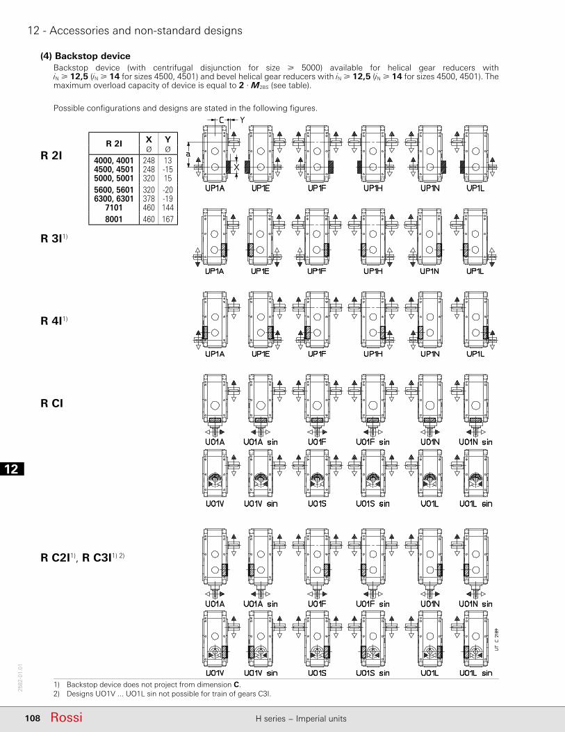
112
108 Rossi H series − Imperial units
2582
-01.
01
12 - Accessories and non-standard designs
(4) Backstop deviceBackstop device (with centrifugal disjunction for size 5000) available for helical gear reducers with iN 12,5 (iN 14 for sizes 4500, 4501) and bevel helical gear reducers with iN 12,5 (iN 14 for sizes 4500, 4501). The maximum overload capacity of device is equal to 2 · M2BS (see table).
Possible confi gurations and designs are stated in the following fi gures.
R 2I
R 3I1)
R 4I1)
R CI
R C2I1), R C3I1) 2)
1) Backstop device does not project from dimension C.2) Designs UO1V ... UO1L sin not possible for train of gears C3I.
R 2I X YØ Ø
4000, 4001 248 134500, 4501 248 -155000, 5001 320 155600, 5601 320 -206300, 6301 378 -19
7101 460 1448001 460 167
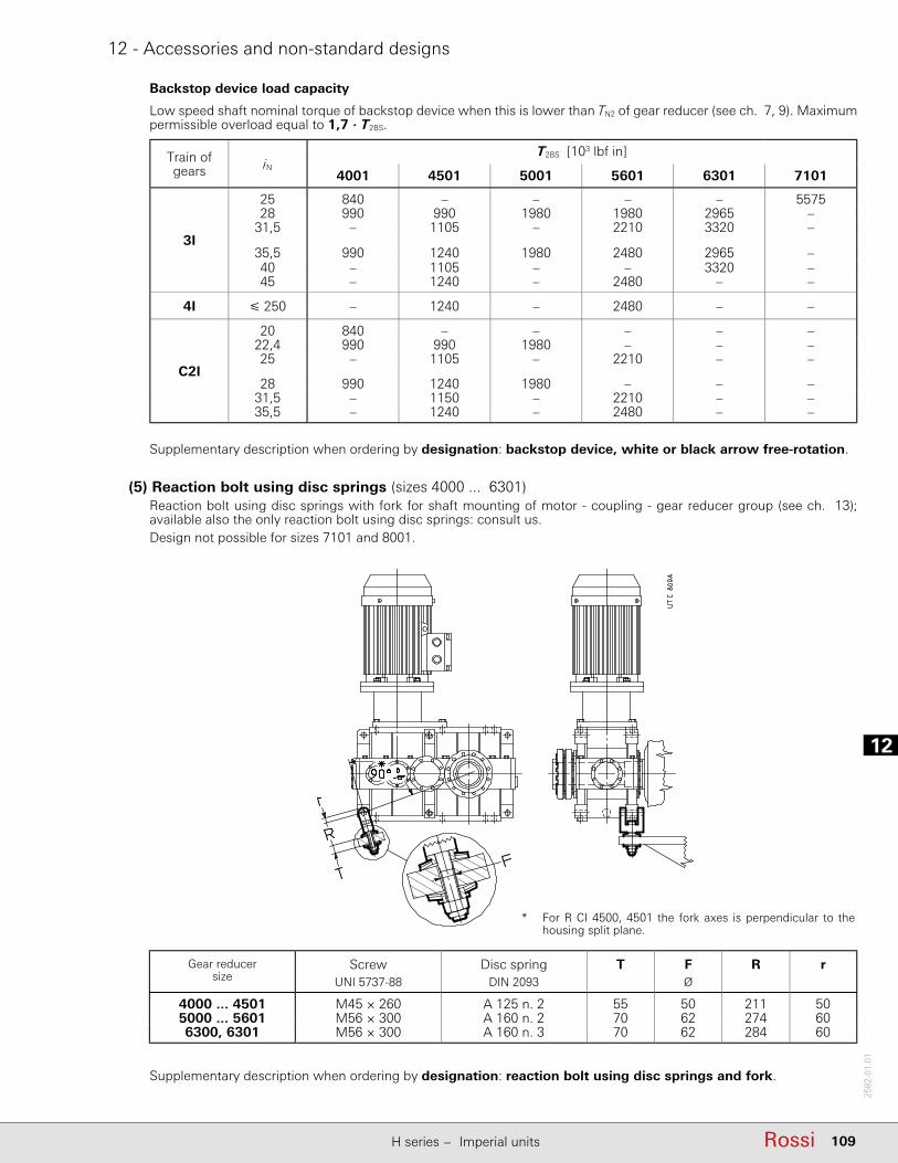
12
109RossiH series − Imperial units
2582
-01.
01
(5) Reaction bolt using disc springs (sizes 4000 ... 6301)Reaction bolt using disc springs with fork for shaft mounting of motor - coupling - gear reducer group (see ch. 13); available also the only reaction bolt using disc springs: consult us.Design not possible for sizes 7101 and 8001.
12 - Accessories and non-standard designs
Supplementary description when ordering by designation: reaction bolt using disc springs and fork.
Gear reducersize
Screw Disc spring T F R rUNI 5737-88 DIN 2093 Ø
4000 ... 4501 M45 × 260 A 125 n. 2 55 50 211 505000 ... 5601 M56 × 300 A 160 n. 2 70 62 274 606300, 6301 M56 × 300 A 160 n. 3 70 62 284 60
* For R CI 4500, 4501 the fork axes is perpendicular to the housing split plane.
Backstop device load capacity
Low speed shaft nominal torque of backstop device when this is lower than TN2 of gear reducer (see ch. 7, 9). Maximum permissible overload equal to 1,7 · T2BS.
Train of gears iN
T2BS [103 lbf in]
4001 4501 5001 5601 6301 7101
3I
25 840 – – – – 557528 990 990 1980 1980 2965 –
31,5 – 1105 – 2210 3320 –
35,5 990 1240 1980 2480 2965 –40 – 1105 – – 3320 –45 – 1240 – 2480 – –
4I 250 – 1240 – 2480 – –
C2I
20 840 – – – – –22,4 990 990 1980 – – –25 – 1105 – 2210 – –
28 990 1240 1980 – – –31,5 – 1150 – 2210 – –35,5 – 1240 – 2480 – –
Supplementary description when ordering by designation: backstop device, white or black arrow free-rotation.

112
110 Rossi H series − Imperial units
2582
-01.
01
12 - Accessories and non-standard designs
(6) Fan coolingThe helical gear reducers R 2I 4000 ... 5601 and R 3I 4000 ... 6301 can be supplied with one or two cooling fans keyed on high speed shafts. For dimensions e, and c see ch. 8.For sizes 7101 and 8001, consult us.
R 2I R 3I
Gear reducersize
2I 3I
G G1 R V0 G1 R V0 X Y1
1) 2) Ø 2) Ø
4000 ... 4501 63 50 363 220 40 163 175 590 6335000 ... 5001 75 50 453 290 50 203 220 740 7956300, 6301 75 – – – 50 203 220 880 980
1) Bolts projecting 6 mm from G dimension.2) The high speed shaft end length is equal to e - G1.
The bevel helical gear reducers of size and train of gears stated in the table can be supplied fi tted with one fan keyed on the high speed shaft. For dimensions e and c see ch. 10.For sizes 7101 and 8001, consult us.
Gear reducersize
G G1 V0 X X1 YØ
CI 4000 ... 4501 80 40 280 590 640 345
C2I4000 ... 4501 72 47 220 590 640 3105000 ... 5601 80 40 290 740 800 3806300, 6301 80 40 290 880 872 330
C3I 6300, 6301 iN = 160 57 32 220 880 872 380
1) Bolts projecting 6 mm from dimension X1 each side.2) The high speed shaft end length is equal to e - G1.

12
111RossiH series − Imperial units
2582
-01.
01
12 - Accessories and non-standard designs
With double extension high speed shaft designs both extensions are accessible even with fan: personnel safety-guards are the Buyer’s responsibility (2006/42/EEC).The possible designs and the position of fans are shown below.
Temperature of cooling air must not exceed ambient temperature.Also available independent cooling unit with heat exchanger (see ch. 12 (10)); consult us for verifi cation. Supplementary description when ordering by designation: fan cooling; in designs with double extension high speed shaft state – only for helical gear reducers – if pos. 1 or 2 or ... with 2 fans
(7) Water cooling by coil (sizes 4000 ... 6301)Coil made of copper alloy for gear reducer water cooling. On request, available also stainless steel coil (AISI 316) or cupro-nickel, consult us.Design not possible for vertical mounting positions (V5, V6) with low speed shaft wheel positioned on the bottom.Design not possible for sizes 7101 and 8001.
Cooling water specifi cations:– be not too hard;– be at max temperature 68 °F (20 °C);– capacity 2.6 − 5.2 gal/min;– pressure 29 − 58 psi (2 − 4 bar).A polished metallic pipe (with external diameter d stated on table) is suffi cient for the connection.The load loss of coil, according to capacity and water pressure, is approximately 9 − 12 psi. On request thermostatic valve which, automatically and without auxiliary supply need, permits water circulation when gear reducer oil reaches the set temperature; the valve sensor is equipped with immersion bulb. Mounting and setting, adjustable within 122 − 194 °F (50 – 90 °C), are Buyer’s responsibility.For ambient temperature lower than 32 °F (0 °C) consult us.Supplementary description when ordering by designation: water cooling by coil or water cooling by coil and thermostatic valve.
Gear reducersize
A d h OØ
4000 ... 4501 180 16 250 4725000 ... 5601 225 16 310 5776300, 6301 280 16 320 647

112
112 Rossi H series − Imperial units
2582
-01.
01
17 - Accessories and non-standard designs
(29) Independent cooling unit
Thermometer
Minimum pressure gauge
Manometer Oil
Oil
Thermometer Oil
Oil
Manometer
Minimum pressure gauge
Water
Oil/WaterAdditional cooling device in the event that the other forced cooling systems are not suffi cient for the dissipation of thermal power produced by gear reducer during operation (see ch. 4). Including:– oil/air heat exchanger (O/A; with thermostat and adjustable control knob 32 – 194 °F (0 – 90 °C) or
oil/water heat exchanger (O/W),– motor pump: screw pump with fl uoro rubber seals (gear pump for UR O/W5.4 hp – UR O/W 28 hp); 4 pole
motor B3/B5; motor-pump connection with coupling;– motor fan (O/A) (three-phase or single phase supply, see next table)– analogic manometer 0 – 250 psi (0 – 16 bar) mounted between pump and exchanger;– analogic thermometer 32 – 250 °F (0 – 120 °C) mounted at exchanger output;– low pressure switch (with on-off switch) mounted between pump and exchanger;– supporting frame with nameplate.On request, several accessories are at disposal (supplied separately, assembled by Customer) in order to satisfy all functionality and safety needs.– oil temperature probe Pt100;– 2-threshold signalling device CT03 (necessary also the oil temperature probe Pt100) for the mounting on
rail to DIN EN 50022;– 3-threshold signalling device CT10 (necessary also the oil temperature probe Pt100) for the mounting on
rail to DIN EN 50022;– bi-metal type thermostat;– fl ow gauge;– fi lter (with optical-electric blockage warning and one or two fi lters M60)Connections realized by fl exible pipes (type SAE 100 R1, maximum length 6 ft) between gear reducer and cooling unit and the assembly of accessories and signalling devices are Buyer’s responsibility.For the heat exchanger power required by the independent cooling unit:
Ps (P1 - PtN · ft1 · ft2 · ft3 · ft4) · (1 - η) · K1
where:Ps nominal power of unit [hp], i.e. the power dissipated by hot oil at approx. 176 °F (80 °C) and cooling air at 104 °F
(40 °C) (O/A) or cooling water at 68 °F (20°C) (O/W) with stated capacity (see next table);P1 power at gear reducer input [hp] (consider the power installed when being uncertain about the power absorbed).PtN nominal thermal power of gear reducer [hp] (see ch. 4);ft1 thermal factor according to input speed (see ch. 4);ft2 thermal factor according to ambient temperature (see ch. 4);ft3 thermal factor according to mounting position (see ch. 4);ft4 thermal factor according to altitude (see ch. 4); for UR O/A derate also the exchanger power: multiply Ps by 0.85
(for 3 300 – 8 200 ft a.s.l.) or by 0.71 (for 8 200 – 16 400 ft a.s.l.);η gear reducer effi ciency (see ch. 6);K1 = 1.18 takes into account the decrease of the exchanger effi ciency due to dirt on the external surface.
Oil/Air
Notes on page 347.1) Oil connection valid for UR O/A 21 hp.2) Oil connections valid when fi lter is present.3) It is advisable to delay the gear reducer motor starting by at least 1 min compared to the motor pump starting.4) The oil fi lter requires that cooling unit is started with oil already warm: refer to case A1 or B1.

12
113RossiH series − Imperial units
2582
-01.
01
17 - Accessories and non-standard designs
Ref. Gear reducerlubrication
system
Gear reducerstarting mode
Tamb
°F(°C)
Requiredaccessories
Requiredoil type
Description and remarks
A1 Splashlubrication
Without oilpre-heating
32 – 77(0 – 25)
Pt100 + CT10 Mineral oilor
synthetic oil(preferable)
Gear reducer starting and subsequent motor-pump starting with warm oil.The motor-pump is managed by the three-threshold oil temperature control system (Pt100 + CT10).Set the three-threshold device CT10 with:– operating temperature 140 °F (60 °C) (starting of motor-pump);– restoring temperature 104 °F (40 °C);– warning temperature 194 °F (90° C).
A2 Splashlubrication
Without oilpre-heating
> 77(> 25)
– Polyalphaolefi ne based
synthetic oil
Simultaneous starting of gear reducer and motor-pumpOil fi lter not possible4).
B1 Forcedlubrication(bearings
and/or gears)
With oilpre-heating
32– 77 (0 – 25)
Pt100 + CT03
Pt100 + CT10
Oil heater
Mineral oilor
synthetic oil(preferable)
Simultaneous starting of gear reducer and motor-pump after oil pre-heating3).The oil heater is managed by the two-threshold oil temperature control system (Pt100 + CT03).The motor-pump and the gear reducer motor are managed by the three-threshold oil temperature control system (Pt100 + CT10).Set the two-threshold device CT03 with:– operating temperature 122 °F (50 °C) (oil heater disconnection);– restoring temperature 86 °F (30° C).Set the three-threshold device CT10 with:– operating temperature 104°F (40 °C) (starting of motor-pump and
gear reducer motor);– restoring temperature 50 °F (10 °C);– warning temperature 194 °F (90° C).
B2 Forcedlubrication(bearings
and/or gears)
Without oilpre-heating
> 77(> 25)
– Polyalphaolefi ne based
synthetic oil
Simultaneous starting of gear reducer and motor-pump3)
Oil fi lter not possible4).
Starting mode and required accessories
Additional description when ordering by designation:independent oil-air cooling unit UR O/A ... or independent oil-water cooling unit UR O/W ... , possibly integrated, when required by the application, with description: «Forced lubrication …» and the statement of bearings and/or gear pairs to be lubricated. For dimensions, accessories and further technical details, see specifi c literature.
Designation Nominal power Heat Oil motor pump Motor fan Oil connections Exchanger
PS exchanger motor fl ow rate motor fl ow rate intake delivery capacity
hp kW code 3~ hp ft3/min hp ft3/min ft3
UR O/A 7hp 6.7 5 AP 300 E 2 1.1 0.20 1~ 540
1”(1¼”)2)
1”(1¼”)2)
0.07 130
UR O/A 9hp 9.4 7 AP 300/2 E 2 1.1 0.20 1~ 770 0.13 145
UR O/A 13hp 13 10 AP 430 E 2 1.1 0.15 3~ 1620 0.13 155
UR O/A 17hp 17 13 AP 430/2 E 2 1.1 0.19 3~ 2060 0.19 165
UR O/A 21hp 21 16 AP 580 EB 3 2 0.19 3~ 2830 0.53 210
UR O/A 28hp 28 21 AP 680 EB 3 2 1.41 3~ 5180 0.57 260
UR O/A 35hp 35 26 AP 730 EB 4 2 1.41 3~ 5180
1¼” 1½”(1”)1)
0.57 280
UR O/A 40hp 40 30 AP 730 EB 4 2.8 1.41 3~ 5180 0.57 280
UR O/A 54hp 54 40 AP 830 EB 3 2 1.74 3~ 6770 0.71 310
UR O/A 62hp 62 46 AP 830 EB 4 2.8 1.74 3~ 6770 0.71 310
Designation Nominal power Heat Oil motor pump Water pipe Oil connections Exchanger
PS exchanger motor fl ow rate fl ow rate connections intake delivery capacity
hp kW code 3~ hp ft3/min ft3/min ft3
UR O/W 5hp 5.4 4 T60CB1 0.5 0.6 ≥ 0.3 (≤ 1.1) Ø12 mm G ½” G ½” 0.01 30
UR O/W 8hp 8 6 T60CB2 0.5 0.6 ≥ 0.4 (≤ 1.1) Ø12 mm G ½” G ½” 0.02 35
UR O/W 12hp 12 9 T80CB2 0.75 0.6 ≥ 0.6 (≤ 1.1) Ø12 mm G ½” G ½” 0.04 40
UR O/W 17hp 17 13 MS84P2 1.5 1.1 ≥ 0.9 (≤ 1.6) G ½” G ¾” G ¾” 0.04 70
UR O/W 28hp 28 21 MS134P1 2 1.1 ≥ 1.4 (≤ 3.9) G 1” G ¾” G ¾” 0.11 95
UR O/W 42hp 42 31 MS134P1 3 2 ≥ 1.8 (≤ 3.9) G 1” G 1¼” G 1¼” 0.11 120
UR O/W 67hp 67 50 MS134P2 4 2.8 ≥ 2.8 (≤ 3.9) G 1” G 1¼” G 1¼” 0.16 155
see notes on page 112.

112
114 Rossi H series − Imperial units
2582
-01.
01
12 - Accessories and non-standard designs
(9) Forced bearing lubrication All gear reducers according to train of gears, design, transmission ratio, mounting position, input speed and duty cycle can be equipped with a non-oil-bath forced bearing lubrication system through internal piston pump (size 4000 ... 4501) or external lubrication system with motor pump (see ch. 6).The following table indicates the cases (see at ch. 8, 10) where – according to the only mounting position and for continous duty – it is necessary to foresee the bearing lubrication. For other operating conditions, consult us.
Train of gears Performance
Presence of lubrication pump
Mounting position
B3 B6 B7 B8 V5 V6
2I all – – – n.a. P P
3I all – – – n.a. P P
4I all – – – n.a. P P
CI
UO1A ... UO1N sin – P – n.a. P P
UO1H ... UO1M sin P P – n.a. P P
UO1V ... UO1L sin P – – – P P
C2I
UO1A ... UO1N sin – P – n.a. P P
UO1H ... UO1M sin P P – n.a. P P
UO1V ... UO1L sin P – – – P P
C3I all – P – n.a. P P
– Forced bearing lubrication not necessary.P Forced bearing lubrication necessary (with pump or motor pump).n.a. Mounting position not foreseen.
For cases highlighted with ch. 7 and 9, foresee the lubrication with motor pump and possible heat exchanger (see ch. 4, 6, 12 (10)).IMPORTANT. For the running at cold starting (Tambient = Toil 77 °F (25 °C)) and lubrication systems (see also ch. 6 and 12 (11)), always foresee the oil heater (see ch. 12 (12)).In general, when the maximum system reliability is required, in presence of particulary heavy load cycles or hard ambient conditions, it is recommended to evaluate the possibility to install anyway the bearing lubrication motor pump; consult us. Supplementary description when ordering by designation: bearing lubrication pump or bearing lubrication motor pump.
(10) Oil heaterOil heater for gear reducer starting at low ambient temperature.Specify the design «Oil temperature probe» together with this design.The heater is piloted through proper control device (at customer's care e.g..: PLC or supplied by Rossi e.g. 2-threshold signalling device CT03N or three-threshold signalling device CT10N) releasing when achieving the pre-set oil temperature.IMPORTANT. The data stated in the table refer to mounting positions B3; for other mounting positions, consult us.
Three-phaseconnection Y
Three-phaseconnection Δ
Gear reducer size
PkW
4000, 4001 n. 2 × 1.54500, 4501 n. 2 × 1.55000, 5001 n. 2 × 3
5600, 5601 n. 2 × 36300, 6301 n. 2 × 3.5
7101 n. 2 × 7.5
8001 n. 2 × 9

12
115RossiH series − Imperial units
2582
-01.
01
12 - Accessories and non-standard designs
The design can be not compatible with other designs, consult us. Features:– specifi c power 2W/in2;
– three-phase supply ∆230 Y400 V 50-60 Hz;– stainless steel resistors AISI 321;– metallic terminal box; cable gland Pg13; protection IP 65;– Horizontal mounting with oil bath lubrication;– max oil temperature 194 °F (90 °C);– threaded brass joint G 2”½;– available also in explosion-proof design ATEX II 2G EExd IIC T4: consult us.Available also in a version equipped with integrated thermostat. Supplementary description when ordering by designation: oil heater or oil heater with thermostat.
(11) Special painting cyclesSpecial painting cycles (base color blue RAL 5010), see following table, according to corrosivity class of operating environment. Other protections or colors on request: consult us.
Application fi eld Features Corrosivityclass
Durability classes
Description Average fi nal thickness on
machined parts
Code
ISO 12944-2 ISO 12944-2 μm
Applications in aggressive environments
Good resistance to atmospheric and
aggressive agents
C4 Low Dual-compound epoxy primer+
Water-soluble dual-compound enamel with acrylic-polyurethan resins
50 1HRAL5010(blue)
Medium Dual-compound epoxy primer (× 2)
+Water-soluble dual-compound
enamel with acrylic-polyurethan resins
200 2HRAL5010(blue)
High Dual-compound epoxy primer (× 4)
+Water-soluble dual-compound
enamel with acrylic-polyurethan resins
300 3HRAL5010(blue)
Outdoor applications
in saline environment
1)
Excellent resistance to atmospheric and aggressive agents
Outdoor applications in saline
environment
C 5 - M Medium Sanding+
Dual-compound antirust primer
with zinc phosphates+
Dual-compound epoxy primer+
Water-soluble dual-compound enamel with acrylic-polyurethan resins
300 2IRAL5010(blue)
Outdoor applications in chemically aggressive
environment and high humidity
industrial areas
1)
Excellent resistance to atmospheric and aggressive agents
Outdoor applications in chemically aggressive
environment (fertilizers, etc.)
C 5 - I Medium Sanding+
Dual-compound antirust primer with zinc phosphates
+Dual-compound epoxy primer
+Water-soluble
dual-compound enamel with epoxy resins
300 2LRAL5010(blue)
1) In these cases, according to the application type, it is advised to adopt specifi c construction measures and accessories/components able to off er an adequate protection for the installation environment: consult us.
Supplementary description when ordering by designation: special paint ... (see code stated in the table; e.g.: «special painting cycle 2HRAL5010».

112
116 Rossi H series − Imperial units
2582
-01.
01
12 - Accessories and non-standard designs
(12) High and low speed shaft sealsAvailable seal types (standard and on request) on high and low speed shafts are stated in the following table.
Seal type Scheme
Standard
Double sealon high speed
shaftQuite polluting environment
and/oroutdoor
Supplementary description when ordering by designation:double seal on high speed shaft.double seal on low speed shaft.
Low speed shaft
double seal
Quite polluting environment
and/oroutdoor
High speed shaft seal with labyrinth and grease feeder(«taconite»)
Very pollutingenvironment(e.g.: mining
industry)
Supplementary description when ordering by designation:high speed shaft seal with labyrinth and grease feeder.
Low speed shaft
double seal with labyrinth
andgrease feeder(«taconite»)
Very pollutingenvironment(e.g.: mining
industry)
1)
Supplementary description when ordering by designation:low speed shaft seal with labyrinth and grease feeder.
See notes at following page.
Gear reducer size
A B2) Ø
4000, 4001 19 9 3284500, 4501 19 9 3685000, 5001 19 11 402
5600, 5601 22 11 4626300, 6301 24 13 496
7101 0 10 6538001 0 10 759
Size 6301: 2 × G¼”Size 7101: 4 × G¼”
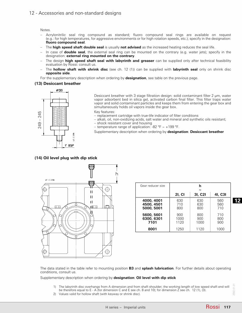
12
117RossiH series − Imperial units
2582
-01.
01
12 - Accessories and non-standard designs
Notes.– Acrylonitrilic seal ring compound as standard; fl uoro compound seal rings are available on request
(e.g.: for high temperatures, for aggressive environments or for high rotation speeds, etc.); specify in the designation: fl uoro compound seal.
– The high speed shaft double seal is usually not advised as the increased heating reduces the seal life.– In case of double seal, the external seal ring can be mounted on the contrary (e.g. water jets); specify in the
designation: external ring mounted on the contrary.– The design high speed shaft seal with labyrinth and greaser can be supplied only after technical feasibility
evaluation by Rossi: consult us.– The hollow shaft with shrink disc (see ch. 12 (1)) can be supplied with labyrinth seal only on shrink disc
opposite side.For the supplementary description when ordering by designation, see table on the previous page.
(13) Desiccant breather
Desiccant breather with 3 stage fi ltration design: solid contaminant fi lter 2 μm, water vapor adsorbent bed in silica gel, activated carbon fi nal fi lter. This fi lter traps water vapor and solid contaminant particles and keeps them from entering the gear box and simultaneously holds oil vapors inside the gear box. Key features:– replacement cartridge with true-life indicator of fi lter conditions– alkali, oil, non-oxidizing acids, salt water and mineral and synthetic oils resistant;– shock resistant cover and housing– temperature range of application: -82 °F − +199 °F.Supplementary description when ordering by designation: Desiccant breather
Supplementary description when ordering by designation: Oil level with dip stick
(14) Oil level plug with dip stick
The data stated in the table refer to mounting position B3 and splash lubrication. For further details about operating conditions, consult us.
Gear reducer size h≈
2I, CI 3I, C2I 4I, C3I
4000, 4001 630 630 5604500, 4501 710 630 5605000, 5001 800 800 710
5600, 5601 900 800 7106300, 6301 1000 900 800
7101 1120 1000 900
8001 1250 1120 1000
1) The labyrinth disc overhangs from A dimension and from shaft shoulder; the working length of low speed shaft end will be therefore equal to E - A (for dimension C and E see ch. 8 and 10); for dimension Z see ch. 12 (1), (3).
2) Values valid for hollow shaft (with keyway or shrink disc).
249
– 24
5
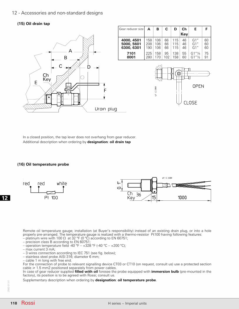
112
118 Rossi H series − Imperial units
2582
-01.
01
12 - Accessories and non-standard designs
(15) Oil drain tap
(16) Oil temperature probe
Remote oil temperature gauge; installation (at Buyer’s responsibility) instead of an existing drain plug, or into a hole properly pre-arranged. The temperature gauge is realized with a thermo-resistor Pt100 having following features:– platinum wire with 100 Ω at 32 °F (0 °C) according to EN 60751;– precision class B according to EN 60751;– operation temperature fi eld -40 °F – +328 °F (-40 °C – +200 °C);– max current 3 mA;– 3 wires connection according to IEC 751 (see fi g. below);– stainless steel probe AISI 316; diameter 6 mm;– cable 1 m long with free end.For the connection of probe to relevant signalling device CT03 or CT10 (on request, consult us) use a protected section cable 1.5 mm2 positioned separately from power cables.In case of gear reducer supplied fi lled with oil foresee the probe equipped with immersion bulb (pre-mounted in the factory), its position is to be agreed with Rossi; consult us.Supplementary description when ordering by designation: oil temperature probe.
In a closed position, the tap lever does not overhang from gear reducer.Additional description when ordering by designation: oil drain tap
B
A
C D
ChKey
E
F
Gear reducer size A B C D Ch E FKey
4000, 4501 158 106 66 115 46 G1” 605000, 5601 208 106 66 115 46 G1” 606300, 6301 190 106 66 115 46 G1” 60
7101 225 158 95 138 55 G1”¼ 758001 280 170 102 158 60 G1”½ 91
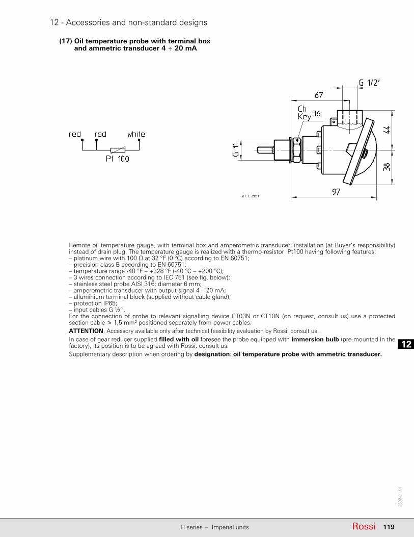
12
119RossiH series − Imperial units
2582
-01.
01
12 - Accessories and non-standard designs
(17) Oil temperature probe with terminal box and ammetric transducer 4 ÷ 20 mA
Remote oil temperature gauge, with terminal box and amperometric transducer; installation (at Buyer’s responsibility) instead of drain plug. The temperature gauge is realized with a thermo-resistor Pt100 having following features:– platinum wire with 100 Ω at 32 °F (0 °C) according to EN 60751;– precision class B according to EN 60751;– temperature range -40 °F – +328 °F (-40 °C – +200 °C);– 3 wires connection according to IEC 751 (see fi g. below);– stainless steel probe AISI 316; diameter 6 mm;– amperometric transducer with output signal 4 – 20 mA;– alluminium terminal block (supplied without cable gland);– protection IP65;– input cables G ½’’.For the connection of probe to relevant signalling device CT03N or CT10N (on request, consult us) use a protected section cable 1,5 mm2 positioned separately from power cables.ATTENTION. Accessory available only after technical feasibility evaluation by Rossi: consult us.In case of gear reducer supplied fi lled with oil foresee the probe equipped with immersion bulb (pre-mounted in the factory), its position is to be agreed with Rossi; consult us.Supplementary description when ordering by designation: oil temperature probe with ammetric transducer.

112
120 Rossi H series − Imperial units
2582
-01.
01
12 - Accessories and non-standard designs
(18) Bearing temperature probe
Probe for the remote monitoring of bearing temperature; installation (Buyer's responsibility) in a hole properly pre-arranged, next to a bearing to be agreed during order phase (for the most common cases, in order to facilitate the identifi cation of bearing to be monitored, refer to following scheme).The temperature gauge is realized with a thermo-resistor Pt100 having following features:– platinum wire with 100 Ω at 32 °F (0 °C) according to EN 60751;– precision class B according to EN 60751;– operation temperature fi eld -40 °F − 328 °F (-40 °C – + 200 °C);– max current 40 mA;– 3 wire connection according to IEC 751 (see fi g. on the top);– stainless steel AISI 316 fl at probe; diameter 6 mm;– stainless steel sliding steel;– cable 1 m long with free end.For the connection of probe to relevant signalling device CT03N or CT10N (on request, consult us) use a protected section cable 1,5 mm2 positioned separately from power cables.ATTENTION. Accessory available only after technical feasibility evaluation by Rossi: consult us. Supplementary description when ordering by designation: bearing temperature probe.

12
121RossiH series − Imperial units
2582
-01.
01
12 - Accessories and non-standard designs
(19) Bearing temperature probe with terminal box and ammetric transducer4 – 20 mA
Probe for remote bearing temperature monitoring, with terminal box and ammetric transducer; installation (at Buyer's responsibility) in a threaded hole properly pre-arranged next to a bearing to be agreed when ordering (for the most common cases, in order to facilitate the identifi cation of the bearing to be monitored, it is possible to refer to the scheme at point (18)).The temperature gauge is realized with a thermo-resistor Pt100 having following features:– platinum wire with 100 Ω at 32 °F (0 °C) according to EN 60751;– precision class B according to EN 60751;– operation temperature fi eld -40 °F − 328 °F (-40 °C – +200 °C);– 3 wire connection according to IEC 751 (see fi g. on the top);– ammetric transducer with output signal 4 − 20 mA;– alluminium terminal block (supplied without cable gland);– IP65 protection;– input cables G ½’’;– stainless steel AISI 316 fl at probe; diameter 6 mm;– stainless steel sliding steel;– cable 1 m long with free end.For the connection of probe to relevant signalling device CT03N or CT10N (on request, consult us) use a protected section cable 1,5 mm2 positioned separately from power cables.ATTENTION. Accessory available only after technical feasibility evaluation by Rossi: consult us. Supplementary description when ordering by designation: bearing temperature probe with ammetric transducer.
Bi-metal type thermostat for maximum oil temperature control.Thermostat specifi cations:– NC contact with maximum current 10 A 240 V a.c.
(5 A - 24 V c.c.);– G 1/2” thread connection;– cable gland Pg09 DIN 43650;– protection IP65;– operating temperature 194 °F ± 9 °F (90 ± 5 °C) (further
operating temperatures are available on request);– diff erential temperature 59 °F (15 °C).Mounting into a threaded plug (position to be defi ned according to mounting position and mounting arrangement: consult us) and oil bath lubrication is Buyer’s responsibility.ATTENTION. Accessory available only after technical feasibility evaluation by Rossi: consult us.
(20) Bi-metal type thermostat
Supplementary description when ordering by designation: bi-metal type thermostat.

112
122 Rossi H series − Imperial units
2582
-01.
01
12 - Accessories and non-standard designs
(21) Oil level switch with fl oat
(22) Oil optical probe
(24) Remote temperature indicator instrument with set pointDigital thermometer (dimensions 72×72×130 mm DIN 43700) to be used with oil or bearing temperature probe; moreover, it is equipped with switching contact (automatic reset) when reaching the (adjustable) temperature set point.Supplementary description when ordering by designation: remote temperature indicator instrument with set point.
It is a level control device with reed contacts in a supporting stem moved by the magnetic fi eld activated by the magnets included in the fl oat.The fl oat and the supporting stem are included in a hollow column of not magnetic material connected to the gear reducer housing through communicating vessels.Connecting features:– 2 wires connection;– max voltage: 350 V;– maximum current: 1.5 A;– 1 cable input 1/2” UNI 6125 – IP65;– G 1” brass joint.The switch is supplied ready for use; when level goes down approx 5 mm, the switch goes on and contact opens.When fi lling oil in the gear reducer it is necessary to verify that device is properly calibrated. If any problems occur during this operation contact Rossi.
Optical scanner, without mobile parts, for the constant control of oil level, inside the gear reducer at rest (e.g. control before starting the machine or the plant). Features:– stainless steel probe;– operation temperature range -40 °F − +257 °F (-40 °C – +125 °C);– d.c. supply 12 − 28 V (other types on request; consult us);– PNP output (other types on request, consult us), max 100 mA;– G 1/2” thread connection.
Supplementary description when ordering by designation: oil optical probe.
ATTENTION. Accessory available only after technical feasibility evaluation by Rossi: consult us. Supplementary description when ordering by designation: oil level switch with fl oat.
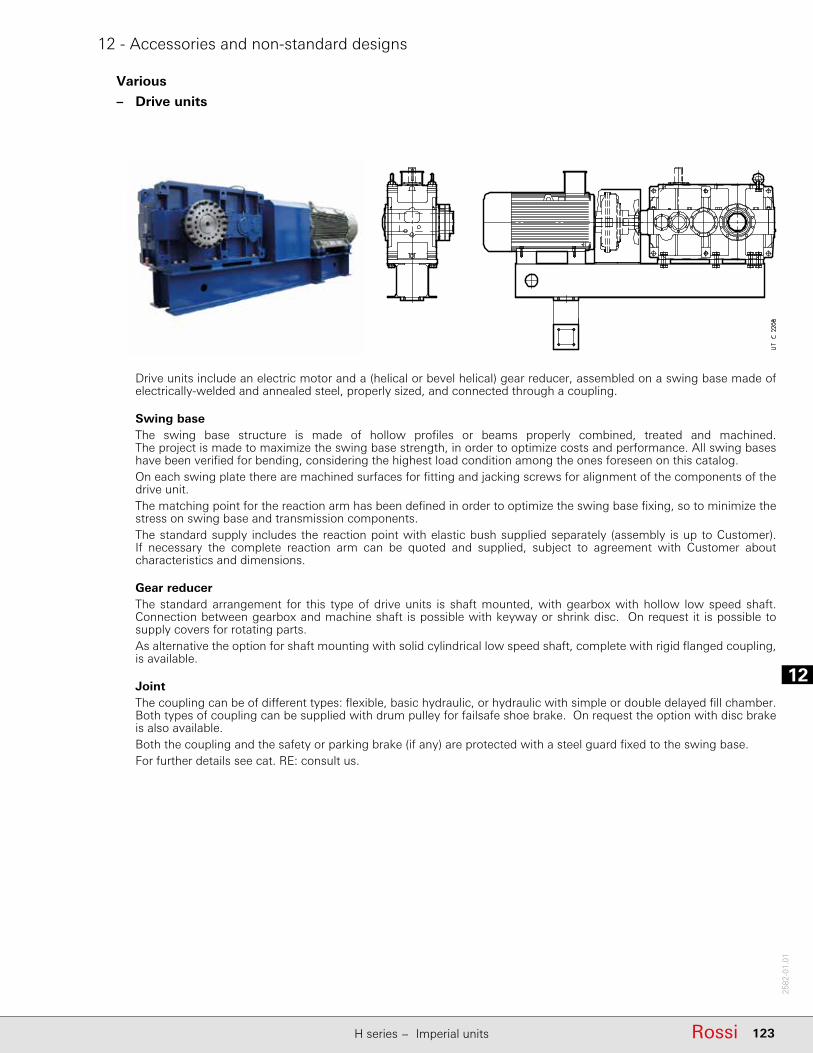
12
123RossiH series − Imperial units
2582
-01.
01
12 - Accessories and non-standard designs
Various
– Drive units
Drive units include an electric motor and a (helical or bevel helical) gear reducer, assembled on a swing base made of electrically-welded and annealed steel, properly sized, and connected through a coupling.
Swing baseThe swing base structure is made of hollow profi les or beams properly combined, treated and machined. The project is made to maximize the swing base strength, in order to optimize costs and performance. All swing bases have been verifi ed for bending, considering the highest load condition among the ones foreseen on this catalog.On each swing plate there are machined surfaces for fi tting and jacking screws for alignment of the components of the drive unit.The matching point for the reaction arm has been defi ned in order to optimize the swing base fi xing, so to minimize the stress on swing base and transmission components. The standard supply includes the reaction point with elastic bush supplied separately (assembly is up to Customer). If necessary the complete reaction arm can be quoted and supplied, subject to agreement with Customer about characteristics and dimensions.
Gear reducerThe standard arrangement for this type of drive units is shaft mounted, with gearbox with hollow low speed shaft. Connection between gearbox and machine shaft is possible with keyway or shrink disc. On request it is possible to supply covers for rotating parts.As alternative the option for shaft mounting with solid cylindrical low speed shaft, complete with rigid fl anged coupling, is available.
JointThe coupling can be of diff erent types: fl exible, basic hydraulic, or hydraulic with simple or double delayed fi ll chamber. Both types of coupling can be supplied with drum pulley for failsafe shoe brake. On request the option with disc brake is also available.Both the coupling and the safety or parking brake (if any) are protected with a steel guard fi xed to the swing base.For further details see cat. RE: consult us.
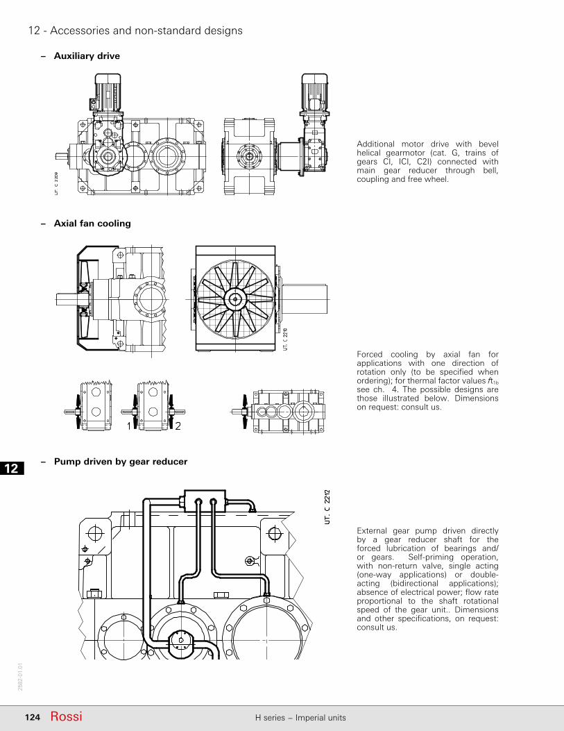
112
124 Rossi H series − Imperial units
2582
-01.
01
12 - Accessories and non-standard designs
Additional motor drive with bevel helical gearmotor (cat. G, trains of gears CI, ICI, C2I) connected with main gear reducer through bell, coupling and free wheel.
– Auxiliary drive
– Axial fan cooling
Forced cooling by axial fan for applications with one direction of rotation only (to be specifi ed when ordering); for thermal factor values ft1b see ch. 4. The possible designs are those illustrated below. Dimensions on request: consult us.
External gear pump driven directly by a gear reducer shaft for the forced lubrication of bearings and/or gears. Self-priming operation, with non-return valve, single acting (one-way applications) or double-acting (bidirectional applications); absence of electrical power; fl ow rate proportional to the shaft rotational speed of the gear unit.. Dimensions and other specifi cations, on request: consult us.
– Pump driven by gear reducer

12
125RossiH series − Imperial units
2582
-01.
01
12 - Accessories and non-standard designs
Train of gears
Nominal transmission ratio iN uN1
4000, 4001 4500, 4501 5000, 5001 5600, 5601 6300, 6301 1)
CI – iN 9
– – –
2iN 11,2 10 iN 12,5 2,5
12,5 iN 14 14 iN 16 3,15
iN 16 iN 18 4– – 5
C2I iN 25 iN 28 iN 25 iN 28 iN 31,5 228 iN 40 31,5 iN 45 28 iN 40 31,5 iN 45 40 iN 50 2,545 iN 50 50 iN 56 45 iN 50 50 iN 56 562) iN 71 3,15
56 iN 80 63 iN 90 56 iN 80 63 iN 90 iN 80 4iN 90 iN 100 iN 90 iN 100 5
C3I – – – – iN = 125 2iN = 125 iN = 125 iN = 125 iN = 125 iN = 160 2,5
160 iN 200 160 iN 200 160 iN 200 160 iN 200 2003) iN 250 3,15
iN 250 iN 250 iN 250 iN 250 iN 315 4
– – – – 5
1) First reduction stage nominal transmission ratio.2) For R C2I 6301 with iN = 56: uN1 = 2,5 instead of 3,15.3) For R C3I 6301 with iN = 200: uN1 = 2,5 instead of 3,15.
Size R CI R C2I R C3I
c c1 d1 e1 c c1 d1 e1 c c1 d1 e1
Ø Ø Ø
4000 ... 4501 330 370 120 210 335 335 90 170 325 325 65 1405000 ... 5601 – – – – 430 430 110 210 405 405 80 1706300, 6301 – – – – 475 475 125 210 435 435 90 170
In the following table the fi rst reduction stage transmission ratios are stated – according to total transmission ratios – thanks to which it is possible to calculate the rotation speed of auxiliary overhung.
Additional (single or double) overhung of fi rst reduction stage pinion shaft (bevel helical gear reducers' bevel wheel) for the realization of combined units or the application of auxiliary devices (e.g.: external backstop device). Main shaft end dimensions as per following table (for other dimensions see ch. 6). For sizes 7101 and 8001, consult us.
– Additional intermediate shaft overhung for bevel helical gear reducers

112
126 Rossi H series − Imperial units
2582
-01.
01
12 - Accessories and non-standard designs
– Low speed shaft with fl ange coupling for shaft mounting arrangements
Low speed cylindrical shaft without keyway for application of a fl ange coupling for drive unit shaft mounting.
Helical gear reducers sizes 4000 ... 4501 equipped with external auxiliary support to allow the coupling with single screw extruders (see ch. GX).
– Design for extruders
– ATEX designFor the application in potentially explosive atmospheres to ATEX 2014/34/UE category 2 GD (zone 1 (gas) or 21 (dust)) or 3 GD (zone 2 (gas) or 22 (dust)), surface temperature T 135 °C (T4).These are the main variations of the product:− fl uoro-rubber seal rings (double seal rings on low speed shaft for cat. 2 GD);− metal plugs; fi ller plug with fi lter and valve;− special name plate with ATEX mark and indication of application limits;− external protection with water soluble dual compound polyurethan conductive enamel, color grey RAL 7040,
corrosivity class C3 ISO 12944-2;− oil temperature probe and eventual bearing temperature probe (cat. 2 GD).
– Pre-arrangement for vibration monitoring devicesPosition, number and dimension of holes to be agreed when ordering.

13
127RossiH series − Imperial units
2582
-01.
01
13 - Installation and maintenance
13.1 - Safety .......................................................................................................................12813.2 - Application conditions and use limits ......................................................................12813.3 - General .....................................................................................................................12813.4 - Mounting of components on high and low speed shaft ends .................................12913.5 - Machine shaft end ...................................................................................................13013.6 - Lubrication ...............................................................................................................13013.7 - Gear reducer starting at low ambient temperature (Tamb = Toil 77 °F) ..................13113.8 - Shaft mounting arrangements .................................................................................13113.9 - Tightening torques ...................................................................................................13213.10 - Nameplate ..............................................................................................................132
113
128 Rossi H series − Imperial units
2582
-01.
01
13 - Installation and maintenance
13.1 - Safety
IMPORTANT: gear reducers and gearmotors supplied by Rossi are components and must be incorporated into machinery and should not be commissioned before the machinery in which the components have been incorporated conforms to:– Machinery directive 2006/42/EC and subsequent updatings; in particular, possible safety guards for
shaft ends not being used and for eventually accessible fan cover passages (or other) are the Buyer's responsibility;
– «Electromagnetic compatibility (EMC)» 2004/108/EC and subsequent updatings.Attention! It is recommended to pay attention to all instructions of present handbook, all existing safety laws and standards concerning correct installation. Whenever personal injury or property damage may occur, foresee adequate supplementary protection devices against:− release or breakage of fastening screws;– rotation or unthreading of the gear reducer from shaft end of driven machine following to accidental
breakage of the reaction arrangement;− the accidental breakage of shaft end of driven machine.If deviations from normal operation occur (temperature increase, unusual noise, etc.) immediately switch off the machine.
Installation
An incorrect installation, an improper use, the removing or disconnection of protection devices, the lack of inspections and maintenance, improper connections may cause severe personal injury or property damage. Therefore the component must be moved, installed, commissioned, handled, controlled, serviced and re-paired exclusively by responsible qualifi ed personnel specifi cally instructed and have the necessary experience to recognize any risks connected with present products avoiding any possible emergencies.Gear reducers and gearmotors of present handbook are normally suitable for installations in industrial areas: additional protection measures, if necessary, must be adopted and assured by the personnel responsible for the installation.Attention! Components in non-standard design or with special executions or with constructive variations may diff er in the details from the ones described here following and may require additional information.Attention! For the installation use and maintenance of the electric motor of the possible motor-variator and/or the electric supply device (frequency converter, soft-start, etc.), and/or any optional electric devices (e.g.: independent cooling unit, etc.), consult the specifi c attached documentation.If necessary, require it.
Maintenance
When operating on gear reducer or on components connected to it the machine must be at rest: disconnect motor (including auxiliary equipments) from power supply, gear reducer from load, be sure that safety systems are on against any accidental starting and, if necessary, pre-arrange mechanical locking devices (to be removed before commissioning).Attention! During the running the gear reducers could have hot surfaces; Always wait that the gear reducer or the gearmotor to cool before carrying out any operations.Further technical documentation (e.g. catalogs) can be downloaded from our website www.rossi-group.com.
13.2 - Application conditions and use limits
Gear reducers are designed for industrial applications according to name plate data, when no vibrations (permissible vibration velocity: veff < 0.14 in/s for P1 20 hp, veff < 0.18 in/s for P1 > 20 hp), no nuclear radiations and important magnetic fi elds, with ambient temperature -4 °F (-20 °C) − +104 °F (+40 °C) with peaks at +122 °F (+50 °C), with air velocity 4 ft/s, maximum altitude 3281 ft, and max relative humidity 80 % .For continuous ambient temperature higher than 104 °F (+40 °C) or lower than -4 °F (-20 °C) consult us.
13.3 - General
Be sure that the structure on which gear reducer or gearmotor is fi tted is plane, levelled and suffi ciently dimensioned in order to assure fi tting stability and vibration absence, keeping in mind all transmitted forces due to the masses, to the torque, to the radial and axial loads. Position the gear reducer or gearmotor so as to allow a free passage of air for cooling both gear reducer and motor (especially at gear reducer and motor fan sides).

13
129RossiH series − Imperial units
2582
-01.
01
13 - Installation and maintenance
If there is fan on the gear reducer verify that there is suffi cient space allowing for adequate circulation of cooling air also after fi tting coupling protection. If a coupling protection is fi tted smooth the coupling hub, if necessary.Avoid: any obstruction to the air-fl ow; heat sources near the gear reducer that might aff ect the temperature of cooling-air and of gear reducer for radiation; insuffi cient air recycle or any other factor hindering the steady dissipation of heat.
Mount the gear reducer so as not to receive vibrations.When external loads are present use pins or locking blocks, if necessary.When fi tting gear reducer and machine it is recommanded to use locking adhesives such as LOCTITE on the fastening screws (also on fl ange mating surfaces).For outdoor installation or in a hostile environment protect the gear reducer or gearmotor with anticorrosion paint. Added protection may be aff orded by water-repellent grease (especially around the rotary seating of seal rings and the accessible zones of shaft end).Gear reducers should be protected wherever possible, and by whatever appropriate means, from solar radiation and extremes of weather; weather protection becomes essential when high or low speed shafts are vertically disposed.For ambient temperatures greater than 104 °F (40 °C) or less than 32 °F (0 °C), consult us.If overloads are imposed for long periods or if shocks or danger of jamming are considered, then motor-protection, electronic torque limiters, fl uid couplings, safety couplings, control units or other similar devices should be fi tted.Attention! Bearing life, good shaft and coupling running depend on alignment precision between the shafts. Carefully align the gear reducer with the motor and the driven machine (with the aid of shims if need be), interposing fl exible couplings whenever possible.
Gear reducers sizes 6301 are equipped with level threaded holes on both feet surfaces and on the sides in order to permit an easy and precise positioning; after the adjustment, adequately shim. Whenever a leakage of lubricant could cause heavy damages, increase the frequency of inspections and/or envisage appropriate control devices (e.g.: remote oil level gauge, lubricant for food industry, etc.).In polluting surroundings, take suitable precautions against lubricant contamination through seal rings or other.
13.4 - Mounting of components on high and low speed shaft ends
Generally, it is recommended to machine the hole of parts keyed onto shaft end, tolerance H7. For high speed shaft end with D 55 mm tolerance can be G7, provided that load is uniform and light. Further data according to the table «High and low speed shaft end» (ch. 6).Before mounting, thoroughly clean mating surfaces with proper antirust products and lubricate against seizure and fretting corrosion.Installation and removal operations should be carried out with the aid of jacking screws and pullers using the tapped hole at the shaft butt-end (see table in fi g. 2) taking care to avoid impacts and shocks which may irreparably damage the bearings, the circlips or other parts or cause sparks; for H7/m6 and K7/j6 fi ts it is advisable that the part to be keyed is preheated to a temperature of 176 − 212 °F. (80 – 100 °C)The couplings having a tip speed on external diameter up to 66 ft/s must be statically balanced; for higher tip speeds they must be dynamically balanced.Where the transmission link between gear reducer and machine or motor generates shaft end loads, ensure that: loads do not rise above catalog values:– loads do not rise above the values stated at ch. 11 and loads do not rise above the values of the application design;– transmission overhang is kept to a minimum;– drive-chains should not be tensioned (if necessary – alternating loads and/or motion – foresee suitable chain
tighteners); if the peripheral speed of the chain is greater than 3.2 ft/s it is necessary to install proper malfunction markers such as aligning sensors, etc;
– in the gear transmission there is an adequate gear mesh (≈ 0,03 − 0,04 ·m) between pinion and rack (bushing);– drive-belts should not be over-tensioned.For splined couplings apply adequate products against oxydation.
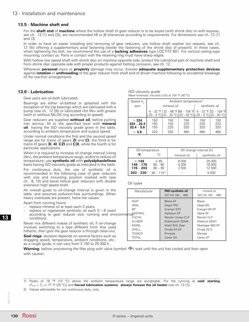
113
130 Rossi H series − Imperial units
2582
-01.
01
13 - Installation and maintenance
13.5 - Machine shaft end
For the shaft end of machine where the hollow shaft of gear reducer is to be keyed (with shrink disc or with keyway, see ch. 12 (1) and (3)), are recommended h6 or j6 tolerances according to requirements. For dimensions see ch. 12 (1) and (3).In order to have an easier installing and removing of gear reducers, use hollow shaft washer (on request, see ch. 12 (5)) off ering a supplementary axial fastening beside the fastening of the shrink disc (if present). In these cases, when tightening the bolt, we recommend the use of a locking adhesives type LOCTITE 601. For vertical ceiling-type mounting, contact us. Parts in contact with the retaining ring must have sharp edges.With hollow low speed shaft with shrink disc on machine opposite side, protect the cylindrical part of machine shaft end from shrink disc opposite side with proper products against fretting corrosion, see ch. 12.Whenever personal injury or property damage may occur, foresee adequate supplementary protection devices against rotation or unthreading of the gear reducer from shaft end of driven machine following to accidental breakage of the reaction arrangements.
13.6 - Lubrication
Gear pairs are oil-bath lubricated.Bearings are either oil-bathed or splashed with the exception of the top bearings which are lubricated with a pump (see ch. 12 (9)) or lubricated «for life» with grease (with or without NILOS ring according to speed).Gear reducers are supplied without oil; before putting into service, fi ll to the specifi ed level with mineral oil having the ISO viscosity grade given in the table, according to ambient temperature and output speed. Under normal conditions the fi rst and the second speed range are for trains of gears 2I and CI, the third is for trains of gears 3I, 4I, C2I and C3I, while the fourth is for particular applications.When it is required to increase oil change interval («long life»), the ambient temperature range, and/or to reduce oil temperature, use synthetic oil with polyalphaolefi nes basis having ISO viscosity grade as indicated in the table.For continuous duty, the use of synthetic oil is recommended in the following case of gear reducers with size and mounting position marked with (see ch. 8, 10) and bevel helical gear reducers with double extension high speed shaft.An overall guide to oil-change interval is given in the table, and assumes pollution-free surroundings. When heavy overloads are present, halve the values.Apart from running hours:– replace mineral oil at least each 3 years;– replace or regenerate synthetic oil each 5 – 8 years
according to gear reducer size, running and environmental conditions.
Never mix diff erent makes of synthetic oil; if oil-change involves switching to a type diff erent from that used hitherto, then give the gear reducer a through clean-out.Seal rings: duration depends on several factors such as dragging speed, temperature, ambient conditions, etc.: as a rough guide, it can vary from 3 150 to 25 000 h.Warning: before unscrewing the fi ller plug with valve (symbol ) wait until the unit has cooled and then open with caution.
1) Peaks of 18 °F (10 °C) above the ambient temperature range are acceptable. For the running at cold starting (Tamb = Toil 77 °F (25 °C)) and forced lubrication systems, always foresee the oil heater (see ch. 13 (7)).
2) Values admissible for not continuous duty, only.
ISO viscosity gradeMean kinematic viscosity [cSt] at 104 °F (40 °C).
Speed n2
rpmAmbient temperature1)
mineral oil synthetic oil
-4 – 32 °F(-20 – 0 °C)
32 – 68 °F(0 – 20 °C)
68 – 104 °F(20 – 40 °C)
-4 – 32 °F(-20 – 0 °C)
32 – 104 °F(0 – 40 °C)
224 150 150 150 150 150224 – 22.4 150 150 220 220 22022.4 – 5.6 150 220 320 320 320
5.6 220 320 460 460 460
Oil temperature Oil change interval [h]°F °C mineral oil synthetic oil
149 65 8 000 25 000149 – 176 65 – 80 4 000 18 000176 – 203 80 – 95 2 000 12 500203 – 2301) 95 – 1101) – 9 000
Manufacturer PAO synthetic oilISO VG 150 ... 460
mineral oilISO VG 150 ... 460
AGIP Blasia SX BlasiaARAL Degol PAS Degol BGBP Enersyn EPX Energol GR XPCASTROL Alphasyn EP Alpha SPFUCHS Renolin Unisys CLP Renolin CLPKLÜBER Klübersynth GEM4 Klüberoil GEM1MOBIL Mobil SHC Gear Mobilgear 600 XPSHELL Omala S4 GX Omala S2 GTEXACO Pinnacle MeropaTOTAL Carter SH Carter EP
Oil types

13
131RossiH series − Imperial units
2582
-01.
01
13 - Installation and maintenance
13.8 - Shaft mounting arrangements
The strength and shape of the housing off er advantageous possibilities for shaft mounting even – for instance – in the case of gearmotor with belt drive, hydraulic coupling, etc.A few possible examples of shaft mounting arrangements are shown.IMPORTANT. When shaft mounted, the gear reducer must be supported both axially and radially (also for mounting positions B3 ... B8) by the machine shaft end, as well as anchored against rotation only, by means of a reaction having freedom of axial movement and suffi cient clearance in its couplings to permit minor oscillations always in evidence without provoking dangerous overloading on the gear reducer. Lubricate with proper products the hinges and the parts subject to sliding; when mounting the screws it is recommended to apply locking adhesives type LOCTITE 601.In case of axial fastening with elastic constraint, in B3 or B8 mounting position, ensure that housing oscillation while running does not exceed the perfectly horizontal position.
Semi fl exible and economic reaction arrangement (see ch. (ch. 12 (7)): with bolt using disc springs, with bolt and fork using disc springs.
13.7 - Gear reducer starting at low ambient temperature (Tamb = Toil 77 °F (25 °C))
The minimum ambient temperature (equal to the oil one) to which it is allowed to start the gear reducer, depends on lubrication system and type of lubricant applied.
Gear reducers with splash lubrication
The gear reducer can be started with ambient/oil temperature - 4 °F (-20 °C), keeping in mind to follow the lubricant viscosity instructions stated on ch. 13.6.In presence of an eventual independent cooling unit with heat exchanger (but without forced lubrication, see also point A1 in table at ch. 12 (8)), it is necessary to drive the motorpump starting when achieving oil temperature of 140 °F.
Gear reducers with forced lubrication of bearings
In presence of forced lubrication systems of bearings (see ch. 6 and ch. 12 (8) and (9)), the gear reducer can be started only if oil temperature is 77 °F (25 °C), following the lubricant viscosity instructions as per ch. 13.6.Therefore, before gear reducer starting it is necessary to pre-heat the oil bath through the use of heaters (see ch. 12 (10)) up to a temperature of 77 °F (25 °C).

113
132 Rossi H series − Imperial units
2582
-01.
01
13 - Installation and maintenance
13.10 - Nameplate
13.9 - Tightening torques
Unless otherwise stated, usually it is suffi cient to use screws in class 8.8.Before tightening the bolt be sure that the eventual centering of fl anges are inserted properly.In general, the bolts are to be diagonally tightened with the maximum tightening torque.The bolts of shrink disc must be gradually and uniformly tightened, with continuous sequence (not diagonally!) and in several phases up to the reaching of maximum tightening torque.Before tightening, carefully degrease the screws; in the event of heavy vibrations, heavy duties, frequent drive inversions apply a proper thread-locking sealant Loxeal 23-18 or equivalent.
Bolts Tightening torque Ts [lbf in]
DIN 931DIN 912
Feet, fl anges and threaded holes at the shaft butt-end Shrink disc
Class 8.8 Class 10.9 Class 12.9 Class 10.9
M10 442 619 752 –M12 752 1062 1283 –M16 1814 2566 3097 –
M20 3540 4956 6018 4336M24 6283 8850 10619 7434M27 8938 12389 15044 11062
M30 12212 17257 20796 –M36 22124 31416 37168 –M45 44248 61947 74336 –
M56 86726 122124 146018 –
1 Designation2 Manufacturing code3 Installed power [kW]4 Nominal power on low speed shaft [kW], at input speed n1
5 Nominal low speed shaft torque [kN m], at input speed n1
6 Month and year of production7 Serial number8 Mounting position9 Transmission ratio
10 High speed shaft input speed [min-1]11 Service factor12 Ambient temperature if diff erent from conditions stated on catalog [°C]13 Approximative gear reducer weight [kg]


14
Index of revisions
List of updatings - Edition June 2018 available on rossi.com
Page 36 Completed table with missing valuesPage 52 Modified figures of mounting positionsPage 57 Modified figures of mounting positionsPage 61 Modified figures of mounting positionsPages 64-69 New selection tables (bevel helical gear reducers)Page 75 Modified figures of mounting positionsPage 79 Modified figures of mounting positionsPage 83 Modified figures of mounting positionsPage 88 Added note about radial and axial loads in case of hollow or double extension shaftsPage 102 Added note about machine shaft end dimension in case of design 12.(12)Page 102 Added note about hollow low speed shaft tollerancePage 104 Added note about machine shaft end dimension in case of design 12.(12) Page 104 Added note about hollow low speed shaft tollerancePage 104 Modified M2 values in the tablePage 104 Added on machine shaft end diameter abutting with gear reducerPage 106 Modified limit transmission ratios for design 12.(4)Page 108 Amended value of X dimension (4000 ... 4501) in the tablePage 112 Updated table of design 12.(9) Page 113 Updated table of design 12.(11) Page 118 Updated bearing identification scheme 12.(18) Page 120 Removed option 12.(23)
List of updatings - Edition 2582.PRD.CAT.H-us.en-COR-01.01 available on rossi.com
Range extension through the introduction of new sizes 7101 and 8001Page 24 Updated table Nominal thermal powerPage 28 Updated table Input speedPage 34 Updated table Sound levelsPage 36 Updated table Low and high speed shaft endPage. 37 Updated table Side cover dimensionsch. 7 Updated selection tables (parallel shaft gear reducers)Page 50 Updated figures of mounting positions and dimensional tablesPage 53 Updated oil quantity tablePage 54 Updated figures of mounting positions and dimensional tablesPage 57 Updated oil quantity tablePage 58 Updated figures of mounting positions and dimensional tablesPage 61 Updated oil quantity tablech. 9 Updated selection tables (right angle shaft gear reducers)Page 76 Updated figures of mounting positions and dimensional tablesPage 79 Updated oil quantity tablePage 80 Updated figures of mounting positions and dimensional tablesPage 82 Updated figures of mounting positionsPage 83 Updated oil quantity tablePage 86 Modified radial loads tablePage 100 Added axial and radial loads table sizes 7101-8001Page 101 Added axial and radial loads table sizes 7101-8001Page 102 Updated tablesPage 103 Updated tablePage 105 Updated tablePage 115 Updated tablePage 116 Updated tablePage 130 Inserted new nameplate and updated table

14
Rossi S.p.A.
Via Emilia Ovest 915/A41123 Modena - ItalyPhone +39 059 33 02 88fax +39 059 82 77 74e-mail: [email protected]
Product liability, application considerations
The Customer is responsible for the correct selection and application of product in view of its industrial and/or commercial needs, unless the use has been recommended by technical qualifi ed personnel of Rossi, who were duly informed about customer’s application purposes. In this case all the necessary data required for the selection shall be communicated exactly and in writing by the Customer, stated in the order and confi rmed by Rossi. The Customer is always responsible for the safety of product applications. Every care has been taken in the drawing up of the catalog to ensure the accuracy of the information contained in this publication, however Rossi can accept no responsibility for any errors, omissions or outdated data. Due to the constant evolution of the state of the art, Rossi reserves the right to make any modifi cation whenever to this publication contents. The responsibility for the product selection is of the customer, excluding diff erent agreements duly legalized in writing and undersigned by the Parties.
Every decision we make at Rossi impacts the world we live in. But new technologies and renewed commitment to sustainable practices have provided us with the opportunity to make environmentally friendly printing decisions. Our catalogs are printed on Forest Stewardship Council® (FSC®) certifi ed paper (1). This is our tangible commitment in terms of environment sustainability.
(1) The certifi cation means that fi nished wood-based products in the marketplace have been handled by companies that have also been certifi ed
and that the paper has been handled in an environmentally-friendly manner.
Australia
Rossi Gearmotors Australia Pty. Ltd.e-mail: [email protected]/australia
Benelux
Rossi BeNeLux B.V.e-mail: [email protected]/benelux
Brazil
Rossi do Brasil LTDAe-mail: [email protected]/brazil
Canada
Rossi North Americae-mail: [email protected]/canada
China
Rossi Gearmotors P.T.I. (Shanghai) Co., Ltd.e-mail: [email protected]/china
France
Rossi Motoréducteurs SARLe-mail: [email protected]/france
Germany
Rossi GmbHe-mail: [email protected]/germany
India
Rossi Gearmotors Pvt. Ltd.e-mail: [email protected]/india
Malaysia
Rossi Gearmotors South East Asia Sdn Bhde-mail: [email protected]/malaysia
Poland
Rossi Polska Sp.z o.o.e-mail: [email protected]/poland
Portugal
Rossi Motorreductores S.L.e-mail: [email protected] www.rossi.com
Spain
Rossi Motorreductores S.L.e-mail: [email protected] www.rossi.com/spain
South Africa
Rossi Southern Africae-mail: [email protected]/southafrica
Taiwan
Rossi Gearmotors Co. Ltd. e-mail: [email protected]/taiwan
Turkey
Rossi Turkey & Middle Easte-mail: [email protected]/turkey
United Kingdom
Rossi Gearmotors Ltd.e-mail: [email protected] www.rossi.com/uk
United States
Rossi North Americae-mail: [email protected]/northamerica
Global Service
Rossi S.p.A.e-mail: [email protected]
Registered trademarksCopyright Rossi S.p.A.Subject to alterationsPrinted in Italy2582.PRD.CAT.H-us.en-COR-01.01