Hardware Execution Framework (HW-XF)
76
HES-SO // MASTER Travail de Master of Science HES-SO in Engineering, orientation Technologies industrielles (TIN) Hardware Execution Framework rédigé par Oliver A. Gubler Sous la direction de Medard Rieder de la MRU TIN de HES-SO Valais Wallis Membres du jury Nicolas Zuchuat Spring 2012
Transcript of Hardware Execution Framework (HW-XF)

HES-SO // MASTER
Travail de Master of Science HES-SO in Engineering,orientation Technologies industrielles (TIN)
Hardware Execution Framework
rédigé par
Oliver A. Gubler
Sous la direction de Medard Rieder
de la MRU TIN de HES-SO Valais Wallis
Membres du jury
Nicolas Zuchuat
Spring 2012

Hardware Execution Framework Indexes
Table of Contents
1 ABSTRACT ............................................................................................................1
2 ACKNOWLEDGMENTS ......................................................................................2
3 INTRODUCTION ..................................................................................................33.1 GOALS.....................................................................................................................53.2 PLANNING.................................................................................................................63.3 OPERATING SYSTEM IN HARDWARE...............................................................................7
4 SOFTWARE FRAMEWORKS .............................................................................84.1 SOFTWARE FRAMEWORK..............................................................................................94.2 EXECUTION FRAMEWORK (XF)..................................................................................10
4.2.1 OS vs. XF.................................................................................................................104.2.2 Hardware Abstraction Layer (HAL)........................................................................104.2.3 Reactive Entity.........................................................................................................104.2.4 Services....................................................................................................................104.2.5 Framework...............................................................................................................124.2.6 Events.......................................................................................................................12
4.2.6.1 Event Queue..................................................................................................................................124.2.6.2 Event Dispatcher...........................................................................................................................12
4.2.7 Timing......................................................................................................................134.2.7.1 Timer.............................................................................................................................................134.2.7.2 Ticks..............................................................................................................................................134.2.7.3 Timer Manger................................................................................................................................14
5 HARDWARE FRAMEWORK ............................................................................165.1 ANALYSIS...............................................................................................................17
5.1.1 Executing.................................................................................................................175.1.2 Controlling...............................................................................................................175.1.3 XF............................................................................................................................17
5.2 SYSTEM..................................................................................................................185.2.1 H-HAL......................................................................................................................20
5.3 ARCHITECTURE........................................................................................................225.3.1 Events.......................................................................................................................225.3.2 Event Queue.............................................................................................................235.3.3 Event Dispatcher.....................................................................................................235.3.4 Timing......................................................................................................................235.3.5 Timer Queue.............................................................................................................255.3.6 Notification..............................................................................................................265.3.7 Data.........................................................................................................................27
5.4 IMPLEMENTATION......................................................................................................285.4.1 Event........................................................................................................................28
HES-SO MSE Spring 2012 ii

Hardware Execution Framework Indexes
5.4.2 Configuration...........................................................................................................295.4.3 Register Interface.....................................................................................................315.4.4 Tick Generator.........................................................................................................355.4.5 Event Dispatcher.....................................................................................................355.4.6 Event Queue.............................................................................................................35
5.5 VERIFICATION..........................................................................................................41
6 DEMONSTRATOR ..............................................................................................436.1 PLATFORM..............................................................................................................446.2 TOOLS...................................................................................................................476.3 SYNTHESIS..............................................................................................................496.4 SW-XF..................................................................................................................506.5 VSW-XF...............................................................................................................516.6 TESTS AND COMPARISON...........................................................................................52
6.6.1 Test 1: Ping-Pong....................................................................................................52
7 CONCLUSION .....................................................................................................54
8 BIBLIOGRAPHY ...................................................................................................I8.1 CITED..................................................................................................................... II8.2 COMPLEMENTARY READING........................................................................................IV
9 APPENDICES ......................................................................................................... I
HES-SO MSE Spring 2012 iii

Hardware Execution Framework Indexes
List of Figures
Figure 4-1: XF structure............................................................................................................11Figure 4-2: Interlinked Timer Manager.....................................................................................15Figure 5-1: complete HW-XF...................................................................................................18Figure 5-2: extended HW-XF....................................................................................................19Figure 5-3: multiplexing HW-XF..............................................................................................19Figure 5-4: multiplexing HW-XF with asymmetric processing units.......................................20Figure 5-5: decentralized multiplexing HW-XF with asymmetric processing units.................20Figure 5-6: multiplexing HW-XF architecture..........................................................................22Figure 5-7: HW-XF structure....................................................................................................24Figure 5-8: HW-XF top level....................................................................................................28Figure 5-9: HW-XF Event Queue Structure..............................................................................35Figure 5-10: HW-XF Event Handling Procedure......................................................................37Figure 5-11: HW-XF Timeout RAM Add Event procedure......................................................39Figure 5-12: HW-XF Timeout RAM Remove Event procedure...............................................40Figure 5-13: Simulation Screenshot AMBA APB push Basic Event........................................42Figure 6-1: Microsemi SmartFusion Architecture....................................................................44Figure 6-2: Microsemi's SmartFusion™ Evaluation Kit...........................................................45Figure 6-3: Xilinx Zynq-7000 EPP Block Diagram..................................................................46Figure 6-4: Workflow................................................................................................................48Figure 6-5: Test Applications Ping-Pong..................................................................................52
HES-SO MSE Spring 2012 iv

Hardware Execution Framework Indexes
List of Tables
Table 3-1: Planning.....................................................................................................................6Table 5-1: HW-XF Timeout Event Fields.................................................................................29Table 5-2: HW-XF Generics.....................................................................................................30Table 5-3: Implemented HW-XF Configurations......................................................................31Table 5-4: HW-XF Interface Registers......................................................................................33Table 5-5: HW-XF Register Mapping.......................................................................................33Table 5-6: HW-XF Register Interface Register Status Interrupt / Mask...................................33Table 5-7: HW-XF Register Interface Register Status Event Counter Value............................34Table 5-8: HW-XF Register Interface Register Status Event Counter Value............................34Table 5-9: HW-XF Register Interface Register Status Event Counter Value............................34Table 5-10: HW-XF Register Interface Register Config Event Threshold...............................34Table 5-11: HW-XF Register Interface Register Config Tick Interval......................................34Table 5-12: HW-XF Register Interface Register Push Control.................................................34Table 5-13: HW-XF Register Interface Register Push / Pop Event Identifier...........................34Table 5-14: HW-XF Register Interface Register Push / Pop Destination Identifier..................34Table 5-15: HW-XF Register Interface Register Push Timeout / Periodic Timeout Value.......34Table 5-16: HW-XF Register Interface Register Push / Pop Event Body.................................34Table 5-17: Longest Timeout based on Counter Width and Tick Interval................................36Table 6-1: Tools Used...............................................................................................................47Table 6-2: SmartFusion synthesis resource utilization report...................................................49Table 6-3: SmartFusion synthesis timing report.......................................................................49Table 6-4: SmartFusion power usage........................................................................................49Table 6-5: Test 1 Ping-Pong Measurement Results...................................................................52
HES-SO MSE Spring 2012 v

Hardware Execution Framework Indexes
List of Abbreviations and Symbols
AMBA Advanced Microcontroller Bus Architecture
AMP Asymmetric MultiProcessing
APB Advanced Peripheral Bus
cSoC customizable System on Chip
CW Calendar Week
DE Delete Event
DMA Direct Memory Access
EB Event Body
EID Event IDentifier
FIFO First In First Out
FPGA Field-Programmable Gate Array
FSM Finite State Machine
GPU Graphics Processing Unit
H-HAL High-level HAL
HAL Hardware Abstraction Layer
HES-SO University of Applied Sciences Western Switzerland
HOS Hardware Operating System
HW HardWare
HW-XF HardWare eXecution Framework
I/O Input / Output
IP Intellectual Property
IRQ Interrupt ReQuest
ISR Interrupt Service Routine
L-HAL Low-level HAL
LED Light Emitting Diode
nFP next Free Place
nTO next Timeout
nToV next Timeout Value
OOP Object-Oriented Programming
OVM Open Verification Methology
PCB Printed Circuit Board
PIC Peripheral Interface Controller
HES-SO MSE Spring 2012 vi

Hardware Execution Framework Indexes
pSW-XF pure Software eXecution Framework
RAM Random-Access Memory
RE Reactive Entity
SMP Symmetric MultiProcessing
SW-XF Software eXecution Framework
TIN Technologies INdustrielles / Industrial Technologies
TM Travail de Master / Master Thesis
UART Universal Asynchronous Receiver/Transmitter
USB Universal Serial Bus
VHDL VHSIC (Very High Speed Integrated Circuit) Hardware Description Language
vSW-XF virtual Software eXecution Framework
WP Work Package
HES-SO MSE Spring 2012 vii

Hardware Execution Framework 1. Abstract
1 Abstract ________________________
An event-driven execution framework (XF) written in software has been ported to configurable hardware (FPGA). The resulting hardware execution framework (HW-XF) provides the same interface to the application, still running on a processor, as the software XF (SW-XF). The main idea is to handle the event queues, especially the timer list, in HW to prevent the processor from being interrupted periodically. All components of the XF are explained and analyzed for their ability to be implemented in HW. The implemented HW-XF is presented and compared to a SW-XF.
HES-SO MSE Spring 2012 Page 1

Hardware Execution Framework 2. Acknowledgments
2 Acknowledgments _______________
My first words of acknowledgment go out to Medard Rieder, my mentor during this work. I like to thank him for bringing up such an interesting topic spanning the gap between processor programming and FPGA configuration. His enthusiasm towards the progress I made and the findings I presented was very motivating. Then there are also his collaborators Thomas Sterren and Michael Clausen, who were always available to push me forward in my knowledge of the software world. On the other side the hardware world was covered by François Corthay. He was always very willing to share his expertise in FPGA design.
Another thank goes to all my colleagues at HES-SO Valais, especially Marc Pignat and Silvan Zahno, who never got tired to listen to me when I had an urge to discuss something.
Then on the less technical side, I am really very grateful for the support I got from my family. Without them this work would not exist. There are my parents, who showed me the importance of education. But the most appreciation has eared my wife Fränzi, and with her our Boys Finn and Elio, for accepting their husband and dad to have his focus all to often at his work instead of them. Moreover for showing their love to me nonetheless. Thank you!
HES-SO MSE Spring 2012 Page 2

Hardware Execution Framework 3. Introduction
3 Introduction _____________________
An execution framework (XF) in general is very simple operating system. XFs are sometimes also called Interrupt Driven Frameworks.
One of the major advantages of an XF is to factor out OS-like functionalities and to simplify embedded system design by offering the possibility to implement reactive software parts using state machines. One of the major drawbacks of an XF is that its timing resolution cannot be smaller than approximately something like a millisecond, since otherwise the timer interrupt will overload the microprocessor, or respectively the microcontroller. In other terms: the timer resolution of an XF based system is an optimization between the processor load induced by the timer interrupt and real-time constraints, e.g. the timer resolution must be at least as small as the shortest timeout needed in the reactive parts. Unfortunately, this often means that fast processes have to be outsourced into separate timer interrupts and cannot be integrated into well designed state machine based and XF driven code. Systems based on an operating system perform even worse, since the overhead of an operating system is even bigger than that one of an XF alone. This is because the operating system provides processes and therefore must contain a scheduler that is also quite processing-time consuming.
One of the approaches to solve such a problems is to displace the very fast processes into hardware. This leads to hybrid systems that consist of a processor or controller based part that serves the “slow” (up to 1 millisecond) processes of the system and of a hardware part that serves the “fast” processes of the system. In theory, hardware- software co-design is a quite optimal solution, but in practice, it is a relatively expensive solution, since it requires also hybrid development systems and engineers with the necessary experience. Fabrication costs are also slightly higher than for monolithic solutions, but this criterion becomes more and more insignificant.
This is also one of the points where the hardware XF proposal starts. Today, very sophisticated hybrid chips are appearing on the market. These chips offer a 32-bit microprocessor core that is surrounded by programmable hardware and standard peripheral hardware such as digital and analogue I/O, serial interfaces and more. An example of such a chip is the Microsemi
HES-SO MSE Spring 2012 Page 3

Hardware Execution Framework 3. Introduction
SmartFusion® cSoC. It offers an FPGA with an ARM® Cortex™-M3 core and sophisticated periphery. It is important to state here that instead of such a modern device one could also use a standard processor or controller together with a standard FPGA.
The other important point, where the hardware XF proposal starts is the fact that an XF always does exactly the same things. It offers:
• Handling of timers of a certain resolution (start, trash, timeout)• Event handling (generation, trash, transformation from interrupts?)• An event queue
Since this would mean that the hardware XF is a kind of minimal and hard-wired operating system, this would also have a number of very interesting consequences:
• The peripheral devices would not interrupt the processor any more. Any peripheral interrupt will be transformed into an event that will be deposed in the central and shared event queue.
• The entire timer management would be done in hardware. This would very probably allow a much higher timer resolution (microseconds).
• The processor will “only” have to compute all the events that will arrive in the central event queue. Since it will not be occupied by the XF tasks, it will be able to do this very rapidly.
HES-SO MSE Spring 2012 Page 4

Hardware Execution Framework 3. Introduction
3.1 GoalsThe goal of the present master thesis (TM) is therefore to develop a prototype of such a hardware type XF. Several important tasks must be fulfilled:
1. Conduct an inquiry on existing solutions respectively on theoretical work concerning hardwired execution frameworks or similar. In case of eventually existing solutions compare and rate these.
2. Study of a software type XF in order to isolate the important components of it3. Estimate the “hardwireability” of each component.4. Propose hardware designs for each XF component5. Propose a complete hardware type XF consisting of the above mentioned components6. Propose an interface in order to connect the hardware XF to a microcontroller or a
microprocessor. The interface must be designed in a way that it does not represent a bottleneck in high-speed applications. It must also be designed in a way that it is processor and FPGA type independent.
7. Select a real world implementation platform8. Develop a prototype of the hardware XF and the corresponding interface.9. Develop a test application in order to show and rate the performance of the hardware
XF10. Establish corresponding documents like technical documentation, final report and final
presentation slides.
HES-SO MSE Spring 2012 Page 5

Hardware Execution Framework 3. Introduction
3.2 PlanningThe total duration of the TM was 18 weeks. The above mentioned goals are planned as work packages (WP) to achieve in the time-frame as shown in Table 3-1.
Week 1 2 3 4 5 6 7 8 9 10 11 12 13 14 15 16 17 18 19 20WP CW 38 39 40 41 43 44 45 46 47 48 49 50 51 2 3 4 5 6 7 1012345678910
MilestonesHW-XF hardwireability
HW-XF proposalHW-XF prototypeDelivery
Legend: planning realization in parallel
Table 3-1: Planning
HES-SO MSE Spring 2012 Page 6

Hardware Execution Framework 3. Introduction
3.3 Operating System in HardwareThe idea to relieve the processor of some of it's chores and doing them elsewhere is not new.
Coprocessors doing different tasks exist since many years. Coprocessors are processors specialised for one specific task. The main processor could normally do that task himself too. But the by sending the task to the coprocessor, the main processor can concentrate on other tasks. The coprocessor is also much more effective in doing his specific task. Examples are the mathematical coprocessors doing floating point arithmetic and also the graphic processing units (GPU).
Then implementing parts of the software, more precisely the operating systems (OS), in hardware (HW) has also already been elaborated. But these approaches mainly focus on the scheduler, especially for real-time operating systems [HIL+]. The goal there is not only the gain on speed, but even more the better determinism and predictability.
There exists concepts of so called hardware operating systems (HOS) [GA04]. But this is more an operating system running in software, able to manage the underlying HW in a more flexible manner. The OS is still running on the processor, but it is able to assign specific tasks to the HW.
All these efforts can be combined with the term reconfigurable computing.
The biggest difference from our approach to the ones mentioned above will be that the transition from a software-only XF to a hardware-supported XF is transparent to the application. Likewise our approach is not a full blown OS adding a lot of overhead, but a simple XF destined for power sensitive embedded applications. Nonetheless our XF could also be run on top of an OS.
HES-SO MSE Spring 2012 Page 7

Hardware Execution Framework 4. Software Frameworks
4 Software F rameworks ___________
This chapter introduces the concept of frameworks in software. In a first section the usage of frameworks in software design is explained. The reader familiar with this topic can easily jump to the second section which lays out the specific features of an execution framework.
HES-SO MSE Spring 2012 Page 8

Hardware Execution Framework 4. Software Frameworks
4.1 Software FrameworkA framework is a collection of classes to abstract related problems [JF88]. It abstracts the low-level details of the execution of these tasks to a more generic interface. Therefore the same framework may be adapted to work on different implementations of the tasks without any changes on the interface.
Contrary to a classic software library, a framework can be extended to customer needs by inheritance, thus adding or overwriting methods of classes of the framework [JF88]. Another difference is that the framework is not executed by the program. It is the framework that specifies the flow of execution [BGK+97]. This mechanism is often called inversion of control [JF88] and is also infamously known as the Hollywood Principle: “Don't call us; we'll call you.”. Furthermore the framework defines, by its own structure, how the classes using the framework are allowed to interact [Rie00].
Some well known software frameworks are the Microsoft .net1 framework or the IBM Rational Rhapsody Object Executive Framework2 (OXF).
1 http://www.microsoft.com/net2 http://publib.boulder.ibm.com/infocenter/rhaphlp/v7r6/index.jsp?topic=%2Fcom.ibm.rhp.frameworks.doc
%2Ftopics%2Frhp_t_fw_working_object_execution_framewk.html
HES-SO MSE Spring 2012 Page 9

Hardware Execution Framework 4. Software Frameworks
4.2 Execution Framework (XF)This chapter roughly summarizes the concept of an execution framework (XF) found in [RS09] completed with some more generic information about XFs.
4.2.1 OS vs. XF
Similarly to an operating system (OS), an execution framework is used to abstract the execution environment. All details of the structure underlying the application are hidden from the software developer. Here the underlying structure could be directly a processor or an OS running on that processor. In this work however only the OS-less XF is presented, as the OS-full XF would only add to the complexity of the system. Therefore there will always only be exactly one task running at a given time.
Note: If not stated explicitly otherwise, the word processor is used to describe anything like a processor, a controller or even a microprocessor or microcontroller, as their difference is not important for this work.
4.2.2 Hardware Abstraction Layer (HAL)
A hardware abstraction layer (HAL) isolates the underlying hardware (HW) from the XF, as it can be seen in Figure 4-1. A HAL can be divided into two parts, a low-level HAL (L-HAL) and a high-level HAL (H-HAL). The L-HAL is assigned to provide a uniform interface (IF) to access the underlying HW. The H-HAL then implements application specific tasks like data transfer protocols.
4.2.3 Reactive Entity
As stated in §4.1 the XF defines the structure of the application built on it. In this case, the applications ought to be one or more Finite State Machines (FSM). Here these FSMs are called Reactive Entities. When working in an object-oriented programming language a base class of a generic Reactive Entity might be present in the XF and implements the needed functions. Then the user simply derives a specific Reactive Entity from the Reactive Entity base class. In a non-OOP the XF provides functions the user needs to call. Nevertheless the Reactive Entity shall be implemented with two distinctive switch-case structures:
one controlling the sequence of the states, with its transitions and conditionsone executing the correct actions depending on the current state and conditions
This separation improves the readability and the maintainability of the code. Reactive Entities can also be used to build the H-HAL (§4.2.2).
4.2.4 Services
The XF as presented in Figure 4-1 provides basic services such as the event handling and the timer handling. Other services like memory management, the handling of critical sections or power management could also be included.
HES-SO MSE Spring 2012 Page 10

Hardware Execution Framework 4. Software Frameworks
HES-SO MSE Spring 2012 Page 11
Figure 4-1: XF structure

Hardware Execution Framework 4. Software Frameworks
4.2.5 Framework
In Figure 4-1 we can detect all the concepts defined in the second paragraph of §4.1. The Reactive Entities are derived from a class in the framework or built with a predefined structure. Also this framework not only provides a library of classes, it also defines how the Reactive Entities have to interact. The Reactive Entities' state changes are controlled by the Event Dispatcher. To be precise it's the Events sent trough the Event Dispatcher that might change a Reactive Entity’s state, but it's the Event Dispatcher that calls the Reactive Entity to pass the Event. As this system reacts on events it is called an event-driven system or a reactive system [Sam08].
4.2.6 Events
The core of the XF exposed in are the Events (ev). Events are composed of the event information and eventually data related to that event. The most important event information is the event identifier (ID). The identifier of the destination Reactive Entity may be included in the event ID or be presented as an independent value.
4.2.6.1 Event Queue
The Event Queue stores the Events in a First In First Out (FIFO) manner. This buffer is needed as an Event can occur while the system is still busy serving another. In Figure 4-1 it is shown that the Event Queue keeps a pointer on the next Event to read (pHead) and one on the last Event submitted (pTail). This allows to check if there are Events in the Event Queue or whether it is empty or full. The Event Queue should always be big enough to hold all current Events any given time, else Events will be lost. information. Event data can be rather small like the state of a button or quite large like a frame received over Ethernet. In that case, there might also only a pointer to that data be sent with the event. In a more simplistic approach the event ID could also be used to find the data associated with an Event [Hei04].
Events are stacked in the Event Queue and passed on to the corresponding Reactive Entity by the Event Dispatcher. The Reactive Entity treats the Event and returns to the Event Dispatcher. The Event Dispatcher destroys then the Event. There exists basically three types of events:
those generated by the H-HAL, issued by interrupt requests (IRQ) of the system's peripherals;
those generated by the Timer Manger, which are all timeout events;
and those generated by the Reactive Entities, to interact with other Reactive Entities.
The Reactive Entities have to pass their Events via the Event Queue to communicate with each other. Only like this it can be guaranteed that the Events arrive at the destination in the correct order. A Reactive Entity can even send Events to itself.
4.2.6.2 Event Dispatcher
The Event Dispatcher is constantly polling the Event Queue for Events. When it detects that the Queue is not empty it takes the first Event and passes it to the corresponding Reactive Entity. This is done by calling the event handling routine of the Reactive Entity. Once this
HES-SO MSE Spring 2012 Page 12

Hardware Execution Framework 4. Software Frameworks
routine returns, the Event Dispatcher destroys the Event. Then it restarts checking the Queue. In this unicast system, the Event Dispatcher has to know to which Reactive Entity an Event has to be sent.
In a broadcast system the Event Dispatcher sends the Events to all Reactive Entities before destroying it. This has the advantage that a single Event could be sent to all Reactive Entities, like for example the Event to initialize. This could reduce the size of the Event Queue size and the complexity of the Event Dispatcher and therefore lead to faster Event handling. But having each Reactive Entity handling each Event could really slow down the system.
Somewhere in between to two aforementioned systems lies the multicast approach. Here the Reactive Entity has to subscribe at the Event Dispatcher for the Events it likes to receive. A single Event could still be sent to multiple Reactive Entities, but restricted to those who really want it. This would prevent the Reactive Entities from processing unwanted Events, but the complexity of the Event Dispatcher would increase.
Events that will be used often, can be defined to be static during programming. This means they will not be destroyed after consumption and persist in the processor's memory. This saves time by omitting the dynamic memory allocation.
4.2.7 Timing
Timing is very crucial for embedded systems. In fact the timing is the very reason for this TM. As mentioned above, experience has shown that finest granularity of Timers like the one implemented cannot be smaller that about one millisecond without overloading the processor. Also it's the timing mechanism that slows down the system much more than the event management.
4.2.7.1 Timer
A Reactive Entity can create a Timer (tm) and push it to the Timer Manager. When the Timer times out, an event is sent to the Event Queue. Timers can either be one-shot or periodic [HCB+09]. The time in a system can either be seen relative or absolute. In a relative scheme, the time until the next timeout is compared to the current time (how many ticks to go). Compared to an absolute time where the timeouts are compared to a defined point in the time continuum (ticks since a specific time). A relative time scheme allows for longer event inter-arrival times while keeping the memory requirement low [HCB+09].
The number of hardware timers is normally limited. Thus the XF's Timers are implemented in software and rely on one single hardware timer (see §4.2.7.2).
4.2.7.2 Ticks
A hardware timer is configured to interrupt the processor at a constant interval. This IRQ is called tick. The tick defines the smallest granularity for the XF's Timers, and therefore for the overall system. The lower the tick interval gets, the more often the system is interrupted, until the point is reached where the system is constantly serving interrupts and has no more time to execute the application. Therefore it is crucial to reduce these interrupts when a very fast system shall be designed.
HES-SO MSE Spring 2012 Page 13

Hardware Execution Framework 4. Software Frameworks
Another solution would be a system where the hardware timer is configured newly each time there has been a timeout. By knowing how much time (or ticks) we have to wait until the next timeout, we could directly configure the hardware timer to interrupt the system exactly at that moment. Then the system only would get interrupted on timeouts instead of ticks. But also here a point might be reached where there are many short timeouts clogging the processor. In addition hardware timers are quite complex to configure in processors and their interface differs on various devices. A reconfigurable hardware timer, which had to be implemented in the L-HAL, would therefore not be very portable between different processors.
4.2.7.3 Timer Manger
The handling of the Timers can be done in two different ways. The most obvious one is the pseudo-parallel mode, where every Timer is decremented at each tick. Each Timer that reaches zero sends his Event to the Event Queue and then restarts or stops.
Another way is to sort and interlink the Timers beginning with the one with the least remaining ticks. Each Timer points also to the next Timer in the list (illustrated by pNext in Figure 4-1). On a tick from the ISR only the first Timer is decremented. On reaching zero the Timer pushes its Event to the Event Queue. Then it's removed from the list and the next Timer takes its place. Each Timer has to calculate how many ticks he has to decrement after the one just before him finished. Adding a Timer demands a little bit of work, as it's correct place in the list has to be found and the remaining ticks be calculated. An illustrative example is given in Error: Reference source not found.
The first pseudo-parallel solution is better suited for cases where there are not many timers running. As it is quite easy to add a new timer, it is also predestined in environments where new timers are started quite often. In contrary interlinking the timers uses fewer resources when there are many timers running at the same time. Nevertheless inserting a new timer is a little bit more complex and works therefore better if that doesn't has to be done all too often. Further solutions can be imagined and finding the best one for a given system might not be trivial.
Apart from managing the timeouts, the Timer Manager should also be able to remove a Timer from the list on request. Of course it then also has to update the rest of the list.
HES-SO MSE Spring 2012 Page 14

Hardware Execution Framework 4. Software Frameworks
HES-SO MSE Spring 2012 Page 15
Figure 4-2: Interlinked Timer ManagerSource: [RS09] modified
Hardware Execution Framework 5. Hardware Framework
5 Hardware Framework ____________
This chapter shows our approach in outsourcing parts of a software execution framework into hardware. By hardware we understand programmable hardware like in an FPGA. In the first part there is a discussion on why we like to do that. Then we try to estimate how well the different parts of a software execution framework can be transferred to hardware. Finally it is shown how we implemented and verified them.
HES-SO MSE Spring 2012 Page 16

Hardware Execution Framework 5. Hardware Framework
5.1 AnalysisAs pointed about before, in the current implementations it is often difficult to get the tick interval below 1 ms. This might be enough for most applications, but there are others where this introduces a real limit. Especially when there are tasks that have to be executed repeatedly and very often, like reading the inputs of a sensor. To speed up the execution of these applications, the idea emerged to take some burden off the processor by banning some tasks to HW.
5.1.1 Executing
The most obvious idea would be to speed up the FSM's actions, because they are often the most time consuming part. This approach however is already widely applied under the name of co-design. The existing solutions with that approach would require an important change in the workflow of the XF's user. Furthermore the parts of the application to be dislocated to HW would have to be adapted to a great extent. As we like to accomplish the speed-up of the system as transparent as possible to the user of the XF, the co-design approach is not well suited.
5.1.2 Controlling
The second part of a Reactive Entity, as shown in §4.2.3, is the FSM's states and transition structure. This is in fact a big conditional structure. This structure does not uses a lot of the processing time compared to the processing time used by the execution. As a result the need to optimize this part is rather insignificant. In addition, an FSM implemented in SW cannot be copied one-to-one into HW as there are some differences between the two concepts, e.g. events in SW are not totally equal to signals in HW.
However by moving the controlling structure of the FSMs to HW,the event-driven system would turn into an action-driven system. This means, instead of waiting on events to move on, the system in the HW would wait on actions to complete on the processor. This theory could be elaborated further if the approach presented in this work does not result in enough speed gain.
5.1.3 XF
This leaves the XF to be worked on. It should be possible to implement the model of the XF presented in §4.2 in HW. This approach should bring some relieve to the processor, namely by expatriating the timers to HW. There would be no more constant ticks interrupting the system. Despite the fact that the XF currently uses only a small percentage of the overall computation time, moving it out of the processor might liberate enough resources to be able to reduce the tick duration. This holds particularly true as the percentage of the processing time used by the XF increases with faster ticks.
HES-SO MSE Spring 2012 Page 17

Hardware Execution Framework 5. Hardware Framework
5.2 SystemThe first idea might be to move the complete XF to HW and leave only the Applications in SW (see Figure 5-1). This approach might be difficult as the IF of the Application is directly connected to the HW. As a consequence it might be difficult or even impossible to implement an IF for the HW-XF like for the existing SW-XF.
For this reason parts of the XF interacting directly with the Application have to reside in SW (see Figure 5-2), particularly the Event Dispatcher.
Definition: The part of the XF residing in the FPGA will generally be called the HW-XF. Whereas the part on the Processing Unit will be called virtual SW-XF (vSW-XF), even if might be implemented in hardware too. An XF implemented completely in software (SW-XF) can also be called pure SW-XF (pSW-XF) to better distinguish from the vSW-XF. Please refer also to Figure 5-2.
One single HW-XF could also drive multiple SW systems (see Figure 5-3). These SW systems would even be able to exchange Events. To prevent these systems from blocking each other, each needs a separate Event Queue in the HW-XF. When using multiple processors they not even have to be arranged in an symmetric structure. A nice use case of a asymmetric system would be to run time-critical tasks on one powerful processor, and the other tasks on a more consumption-optimized device, all coordinated by a single HW-XF (see Figure 5-4).
This extended HW-XF genuinely separates the main XF from the Application. The separation is done to such a degree that it might even be possible to have the HW-XF and the Application on two completely separated devices. They could even be very far away from each other and only connected by a network like e.g. the Internet (see Figure 5-6).
HES-SO MSE Spring 2012 Page 18
Figure 5-1: complete HW-XF
ProcessorFPGA
ApplicationHW-XF

Hardware Execution Framework 5. Hardware Framework
Definition: A Processing Unit describes anything able to run a state machine. These Processing Units could each run on a specific processor. There could also be multiple Processing Units on a single processor scheduled by an OS. Lastly they could even be implemented directly in configurable hardware.
HES-SO MSE Spring 2012 Page 19
Figure 5-2: extended HW-XF
ProcessorFPGA
ApplicationHW-XF
vSW-XF
Figure 5-3: multiplexing HW-XF
FPGA Processing Unit
Processing UnitHW-XF
Application
Application
vSW-XF
vSW-XF

Hardware Execution Framework 5. Hardware Framework
5.2.1 H-HAL
In a further step, parts of the H-HAL could be also be pushed to the HW. Currently peripherals send an interrupt to the the processor when they have an event to report. The H-HAL then writes these events back to the Event Queue residing in the HW. Certain peripherals could
HES-SO MSE Spring 2012 Page 20
Figure 5-4: multiplexing HW-XF with asymmetric processing units
FPGA Processing Unit
Processing UnitHW-XF
Application
Application
vSW-XF
vSW-XF
Figure 5-5: decentralized multiplexing HW-XF with asymmetric processing units
FPGA
Processing Unit
Processing UnitHW-XF
Application
Application
vSW-XF
vSW-XF

Hardware Execution Framework 5. Hardware Framework
write their events directly to the Event Queue in the HW. The interrupts not passed by the H-HAL would also result in a gain on processing time on the processor. Typical services of the H-HAL destined for moving to HW are for example the detection of button events or notifications about received data of a UART. How this would be implemented is very dependant of the available platform and might not be easy to port from one system to another.
HES-SO MSE Spring 2012 Page 21

Hardware Execution Framework 5. Hardware Framework
5.3 ArchitectureThe analysis done in §5.1 and §5.2 led to the proposal of the HW-XF architecture illustrated in Figure 5-6, or in a structural view in Figure 5-7. The following chapters discuss the different parts of the XF moved to HW from a HW perspective. These are the events(§5.3.1) with their queue (§5.3.2)and the timing mechanism (§5.3.4). For system with multiple processing unit an event dispatcher has also to be present in HW (§5.3.3). When speaking about putting the XF into hardware, another important part is the communication between the hardware and the rest of the software running on the processor (§5.3.6 and $5.3.7).
5.3.1 Events
The events seen from HW are just a vector of bits. Seen from SW this vector could, on one extreme,contain only an address to a location in memory where the real event data is stored. Meaning that no real Event information or data is passed to the HW-XF. This pointer could also serve as identifier (ID) of the event. On the other extreme this vector could contain all event information and data itself. With this approach the variable size of the events needs some additional management. There are many variants in between those two extremes and the ideal solution would depend on the design goals of the HW-XF. A compromise between resource usage in SW as well as HW and processing speed has to be found.
This said, a timer is not really different from an event. It also a vector of bits, only that it has not instantly to be returned to the system, but at a later moment. The exact moment on when to return the event, the timeout value, is just another element of the vector of bits that build en Event.
Definition: An Event with a timeout value is called Timeout Event. An Event without a timeout value, or with this value set to zero, might be named Basic Event.
HES-SO MSE Spring 2012 Page 22
Figure 5-6: multiplexing HW-XF architecture
FPGA Processing Unit
Processing Unit
Application
Application
Event Controller
Event Controller
Event QueueTick Generator
Event QueueTick Generator
Event Dispatcher
IF
IF
Hardware Execution Framework 5. Hardware Framework
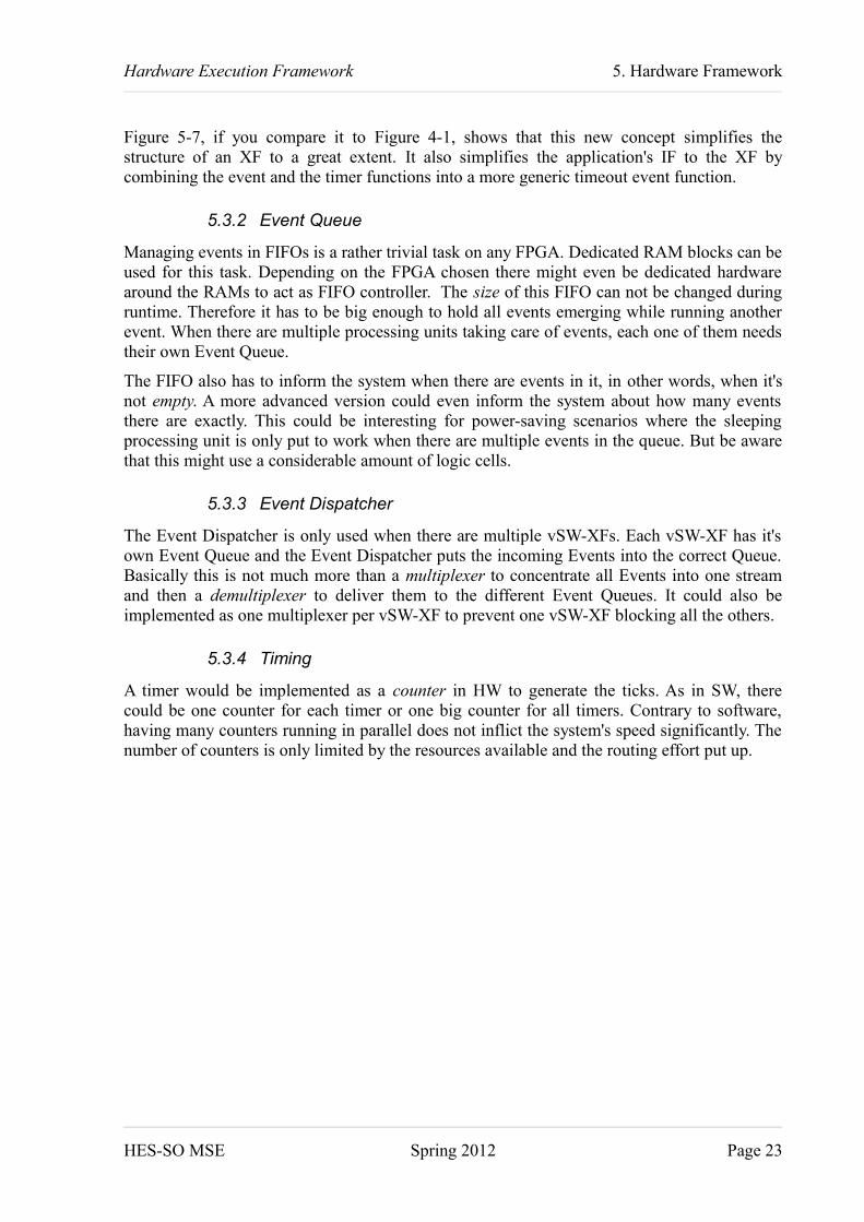
Figure 5-7, if you compare it to Figure 4-1, shows that this new concept simplifies the structure of an XF to a great extent. It also simplifies the application's IF to the XF by combining the event and the timer functions into a more generic timeout event function.
5.3.2 Event Queue
Managing events in FIFOs is a rather trivial task on any FPGA. Dedicated RAM blocks can be used for this task. Depending on the FPGA chosen there might even be dedicated hardware around the RAMs to act as FIFO controller. The size of this FIFO can not be changed during runtime. Therefore it has to be big enough to hold all events emerging while running another event. When there are multiple processing units taking care of events, each one of them needs their own Event Queue.
The FIFO also has to inform the system when there are events in it, in other words, when it's not empty. A more advanced version could even inform the system about how many events there are exactly. This could be interesting for power-saving scenarios where the sleeping processing unit is only put to work when there are multiple events in the queue. But be aware that this might use a considerable amount of logic cells.
5.3.3 Event Dispatcher
The Event Dispatcher is only used when there are multiple vSW-XFs. Each vSW-XF has it's own Event Queue and the Event Dispatcher puts the incoming Events into the correct Queue. Basically this is not much more than a multiplexer to concentrate all Events into one stream and then a demultiplexer to deliver them to the different Event Queues. It could also be implemented as one multiplexer per vSW-XF to prevent one vSW-XF blocking all the others.
5.3.4 Timing
A timer would be implemented as a counter in HW to generate the ticks. As in SW, there could be one counter for each timer or one big counter for all timers. Contrary to software, having many counters running in parallel does not inflict the system's speed significantly. The number of counters is only limited by the resources available and the routing effort put up.
HES-SO MSE Spring 2012 Page 23
Hardware Execution Framework 5. Hardware Framework
HES-SO MSE Spring 2012 Page 24
Figure 5-7: HW-XF structure

Hardware Execution Framework 5. Hardware Framework
5.3.5 Timer Queue
The Timeout Queue is the block whose implementation might have a big impact on speed (for certain scenarios) and resource usage of the HW-XF. As already seen in the SW-XF (see §4.2.7.3) handling the timers is not a trivial task. Problems arise when there are many Timeout Events that have to be added or removed from the Queue at the same time. To handle the Timeout Events correctly, three basic operations are needed:
Find; scan the Queue until a Timeout Event based on a given ID or Timeout Value is found
Remove; delete a specific Timeout Event from the Queue
Add; append a Timeout Event to the Queue
All other tasks like detecting timeouts or keeping an order in the Queue can be achieved with combinations of these basic operations. The basic information needed to execute them:
Timeout Value; the moment when the Timeout Event will time-out
Event ID; the ID of the Event, needed to remove a specific Timeout Event
Timeout Pointer; the location where to find the Timeout Event
The fastest processing time could be achieved by having all this information available all the time. This means they have to be stored in logic cells. Then each Timeout Event could manage itself automatically. Even if this would be a very simple solution in terms of complexity, it's biggest drawback is the usage of resources.
As all Timeout Events need quite a lot of storage space, it is quite natural to store them in a dedicated RAM block. Then however the information presented above is not any more available for all Timeout Events simultaneously. Therefore this information has to be stored separately. But again, if all information is stored for each Timeout Event, this might eat up much more logic cells than we have available. On the other hand, when storing none of these information separately, we have to scan each tick the whole Queue to find if there is a timeout. Likewise the whole Queue has to be scanned to remove a Timeout Event or to find the correct place to add one. As in the SW-XF (compare §4.2.7.3), a good trade-off might be achieved by storing the information for at least one Timeout Event, preferably the one which will timeout next. Then the Queue only has to be scanned to add or remove a Timeout Event, but not to find if there is a timeout. The worst case scenario for such a system is to add or remove many Timeout Events at the same time. When it proves to be too slow, the information for the next two or three Timeout Events could be stored, up until the the FPGA runs out of space.
Then there are different schemes on how to organize the Timeout Events in the RAM. We differentiate between ordered systems or random systems. Random systems have the advantage that there is no housekeeping to do when removing a Timeout Event. Adding one is also quite simple, as the first free place found can be taken. Finding a certain Timeout Event can however be a lengthy task, as in the worst case the whole RAM has to be scanned. Therefore it might be advantageous to put some order into how the Timeout Events are placed in the RAM. Most of the time we might be interested in finding the next Timeout Event to time out. Hence storing them in the order of the Timeout Value might be a good practice. On a system where Timeout Events are deleted more often than they time out, ordering the Timeout
HES-SO MSE Spring 2012 Page 25

Hardware Execution Framework 5. Hardware Framework
Events by their ID might even be better suited. Doing so we gained some time on finding a specific Timeout Event, but at the same time adding a Timeout Event got a little bit more complicated, as the correct place has to be found.
A second question we have to ask ourself is if we like our Queue to get fragmented or not. A Queue gets fragmented when, after removing a Timeout Event, we don’t fill the gap immediately. On a fragmented Queue it might be hard to find a specific Timeout Event as we don't know in advance which places of the Queue contain valid Timeout Events, thus we end up scanning the whole RAM. A de-fragmented Queue has the advantage that we know exactly where there are valid Timeout Events, but keeping the Queue in a clean state needs some work. When we remove a Timeout Event from the Queue we have to, depending on the organization scheme,copy another Timeout Event into the gap or reorder the whole Queue behind it.
The last point in arranging the Queue is defining the boundaries. In fragmented Queues there are no real boundaries, as in the worst case the Timeout Events are evenly distributed all over the RAM. However already in less fragmented systems it might be interesting to know the boundaries of the Queue, since we know there are no valid Timeout Events outside and don't have to scan these areas while searching for a specific Timeout Event. One of these boundaries could be defined to a specific location, address zero of the RAM for example, and only the other one be changed. Here only one boundary has to be taken care of when removing or adding Timeout Events. But when removing a Timeout Event at the fixed boundary, it has to be replaced by another or else fragmentation will appear. In a system where both boundaries are running free, both of them have to be managed. Special care has to be taken when the Queue rolls over the physical boundaries of the RAM. But removing a Timeout Event at either end of the Queue is very simple, for only the boundary has to be moved by one place.
Based on this thoughts there seems to be no optimal implementation of the Timer Queue for all HW-XFs. Each system has to be carefully evaluated before deciding on a certain combination. Most often it will be a trade-of between speed and resource usage as well as the complexity for the find task and the add or remove tasks.
5.3.6 Notification
There exists multiple mechanisms on how to inform the SW about events in the HW.
One solution is getting the events by polling. This means the processing units is running constantly and checks if there are any events present. As you can imagine, having the processing unit running all the time is not really a desired behaviour.
Another approach would be by HW interrupts. The HW-XF interrupts the processing unit each time there is a new Event in the Queue. The processing unit then either way has to confirms the consumption of the event or stores it in a local queue. Without this it might be possible to miss an event that occurs while processing an other. When the processing unit has to store the Events in a local queue, there would be a queue in the HW-XF and one in the precessing unit both doing almost the same work. On the other hand to be able to manage the confirmations the HW-XF would become a little bit more complex. Therefore this two solution are not optimal neither. On the positive side however, the processing unit could sleep while there are no events and thus economise on energy.
HES-SO MSE Spring 2012 Page 26

Hardware Execution Framework 5. Hardware Framework
A blending of the tow concepts could be a system where the processing unit always polls for events, but goes to sleep once it detects their absence. Then it is awaken by the HW-XF on approach of the next event with an IRQ. Once the Event is processed, the system checks the Event Register if there is a new Event which are directly taken care of. When there is no new Event, the system goes to sleep and awaits the next Event interruption. This would gain time corresponding to the Interrupted concept when there are events following each other by preventing the processor going to sleep and waking up in succession. Because the interrupt is just a notification to the system, the interrupt routine could be empty, thus any problems with dynamic memory allocation are omitted.
5.3.7 Data
Basically there are two concepts to transfer data from a peripheral to a processor. Usually it depends on the amount of data which of the two concepts is chosen.
If there are a lot of data to transfer, the data will be directly written to the processor's memory. This concept is known as direct memory access (DMA). It's advantage is that the processor usually can access the memory very fast.
Smaller amounts of data are exchanged using registers, because it's slower than DMA. But it's much more portable, as the access to the processor's memory by peripherals is often complicated or even impossible. To transfer data that's bigger than one register, multiple registers have to be used, or the data is passed through the same register in a FIFO manner.
For the Events, which by definition are not meant to exchange data, the concept using registers is therefore preferred.
HES-SO MSE Spring 2012 Page 27

Hardware Execution Framework 5. Hardware Framework
5.4 ImplementationFollowing the analysis and system design done and described in the previous chapters the following chapters describe the details of the chosen implementation for the HW-XF. Figure5-8 shows a excerpt of Figure 5-7 that constitutes the top level of the HW-XF. The different blocks are detailed in §5.4.3 for the Register Interface, §5.4.4 the Tick Generator, §5.4.5 the Event Dispatcher and §5.4.6 the Event Queue. The implementation is based on the platform chosen in §6.1. Nevertheless the implementation is independent of any platform and can be configured to a great extend trough compile-time generics (see §5.4.2) and run-time configuration registers (see §5.4.3). The first chapter hereafter introduces the Event as used in this implementation (§5.4.1).
5.4.1 Event
In the analysis and the architecture phases we discovered that an Event needs an ID and an ID of the destination Reactive Entity. Some data defined by the application might also be included.
Definition: The data associated to an Event will be summarized under the term of Event Body, independent of its size or content. This data is not analysed in any way by the XF and has to be handled by the application.
HES-SO MSE Spring 2012 Page 28
Figure 5-8: HW-XF top level
Configurable Logic
HW-XF
Tick GeneratorEvent Queue
status
Event Dispatcher
Register Interface
event event
statusIRQ
event
tick
config
config
event
status
event
eventevent
FIFORAM
Hardware Execution Framework 5. Hardware Framework
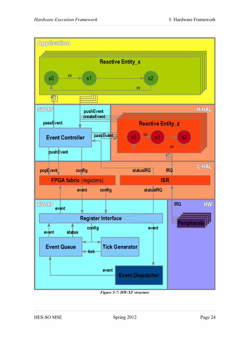
For further reduction of the applications work, a Periodic Timeout Value field has been added too. The value in this field makes the Event not to be deleted once it is returned to the Application. Instead its Timeout Value is recharged with the Periodic Timeout Value. This concept can be useful when the application has to do a specific task, like checking the value of a sensor, on a periodic schedule.
An Event is therefore defined by the fields in Table 5-1.
Field Name Abbr. Description
Unique Event Identifier
EID only one Event in a vSW-XF has this ID
Destination Reactive Entity Identifier
DID Unique Identifier of the Reactive Entity (RE) that has to process the Event; only one RE in a vSW-XF has this ID
Destination Unit Identifier
DUID Unique Identifier of the SW-XF that contains the RE that has to process the Event; there is only one vSW-XF in a HW-XF with this ID; needed only in multi-processing-unit systems
Timeout Value TOV number of Ticks the Event is delayed; handled by the HW-XF
Periodic Timeout Value
POV number of Ticks the Event is delayed periodically; handled by the HW-XF
Event Body EB additional Event information; to be defined and handled by the Reactive EntitiesTable 5-1: HW-XF Timeout Event Fields
5.4.2 Configuration
The HW-XF can be adapted with a series of constants defined in Table 5-2. These constants are collected in the package configure_pkg. Some configurations might be restricted depending on the hardware technology used. Table 5-3 shows the currently implemented configurations. This table should be completed for each new technology or variant added to the HW-XF.
HES-SO MSE Spring 2012 Page 29

Hardware Execution Framework 5. Hardware Framework
Group Content Description DefaultValue
General Register Width With of the Interface registers;32 in this implementation, cannot be changed
32
Tick Counter Width Number of bits in the Tick Interval counter 17Technology Technology of the FPGA;
defines how the FIFOs and RAMs are generated and therefore how much and which resources are used, see Table 5-3 for a complete list of val-id values
inter-preted
FIFO Read Waitstates Defines the number of clock cycles from setting the read signal until the output data are changed, depends mostly on Technology, see Table 5-3 for a complete list of valid values
2
RAM Read Waitstates Defines the number of clock cycles from setting the read signal until the output data are changed, depends mostly on Technology, see Table 5-3 for a complete list of valid values
2
Config Interrupt Mask Reset Value Reset Value of the Register Config Interrupt Mask, see Table 5-4 for the list of registers
0xFFFFFFFF
Event Threshold Reset Value Reset Value of the Register Config Event Threshold, see Table 5-4 for the list of registers
1
Tick Interval Reset Value Reset Value of the Register Config Tick Interval, see Table 5-4 for the list of registers
50'000
Event Event Body Size Body Size in bits = Event Body Size * Register Width;has to be greater or equal1
1
Event Queue Address Width Maximal number of Events in Queue = 2^Event Queue Address Width / 2^Event Address Width;depending on Technology not all values might be possible, see Table 5-3 for a complete list of valid values
8
Timeout Counter Width Width of the Timeout Counter;cannot be greater than Register Width
16
Timeout Queue Address Width Maximal number of Timeouts in Queue = (2^Timeout Queue Address Width) / (Event Body Size +4);depending on Technology not all values might be possible, see Table 5-3 for a complete list of valid values
8
Event Threshold Enable The vSW-XF is informed about Events in the Queue only if the number of Events gets higher than the Threshold given in register Event Threshold (see Table 5-4)
disabled
Table 5-2: HW-XF Generics
HES-SO MSE Spring 2012 Page 30

Hardware Execution Framework 5. Hardware Framework
Constant Name Valid values for TechnologiesTechnology interpreted actel_smartfusionEvent Address Width Any value Any valueEvent Queue Address Width Any value 8Timeout Counter Width Any value Any valueTimeout Queue Address Width Any value 8FIFO Read Waitstates 1 2RAM Read Waitstates 1 2
Table 5-3: Implemented HW-XF Configurations
5.4.3 Register Interface
The registers used by the SW to access the HW-XF are listed in Table 5-4. The Access column indicates if the register is meant to be accessed in read or write mode by the SW. Naturally all registers can be read by the SW, but writing to a register marked as read-only will be ignored.
The current implementation uses the Advanced Peripheral Bus (APB) flavour of the Advanced Microcontroller Bus Architecture (AMBA), developed by ARM, to interface the processor. The APB is a simple and power-optimized bus interface intended to be used to access registers [ARM04]. Here the processor acts as master on the bus and the HW-XF as slave, i.e. all register accesses are initiated by the processor. The HW-XF uses an interrupt signal and an interrupt register to inform the processor about important state changes.
To build the APB IF an IP developed at the HES-SO Valais Wallis is used. It translates the APB signals to a simple data array. A second block maps the data array to the corresponding register signals.
Table 5-5 indicates how the registers are mapped on the APB and thus to the processors' memory space. The bitwise content of each register is detailed in Table 5-6 through Table 5-16.
HES-SO MSE Spring 2012 Page 31

Hardware Execution Framework 5. Hardware Framework
Group Content Description Access DetailsStatus Interrupt:
• New Event (NE)• Event Queue Full (EF)• Timeout Queue Full (TF)• Delete Event Invalid (DI)• Event Queue Busy (EB)
An IRQ is asserted when one of these bits is set and is enabled in the Interrupt Mask.The Register is reset on read ac-cess.
read only Table 5-6
Event Counter Value (EC) Always shows the current number of Events in the Event Queue
read only Table 5-7
Timeout Event Counter Value (TEC)
Always shows the current number of Events in the Timeout Event Queue
read only Table 5-8
Next Timeout (NT) Number of Ticks until next Timeout read only Table 5-9Config Interrupt Mask:
• see Status Interrupt above
Enables / disables IRQ of the cor-responding Status Interrupt Flag; the Flag will nevertheless be set in the register
write Table 5-6
Event Threshold (ET) Defines the minimal number of Events in the Queue that trigger the New Event IRQ. Any bits higher than Event Queue Address Width are ignored.
write Table 5-10
Tick Interval (TI) Defines how many cock cycles there are between two Ticks. Any bits higher than Tick Counter Width are ignored.e.g. Clock = 25MHz, Tick = 1ms: TI = 25'000
write Table 5-11
Push Control:• Destination Unit ID
(DUID)• Delete Event (DE)
DUID, optional, only needed for systems with multiple vSW-XFWhen the DE bit is set, the Event with the same DUID and EID will be deleted.The Event is sampled by the HW-XF after writing this register. There-fore all other Push registers have to be in a valid state.
write Table 5-12
Event Identifier (EID) Unique per processing-unit write Table 5-13Destination Identifier (DID) Identifier of the Reactive Unit that's
the receiver of the Eventwrite Table 5-14
Timeout Value (TOV) Number of Ticks to wait; any bits higher than Timeout Counter Width are ignored
write Table 5-15
Periodic Timeout Value (POV) Number of Ticks to wait; any bits higher than Timeout Counter Width are ignored
write Table 5-15
Event Body (EB) Used by Application to transfer fur-ther information about the Event; Number of registers defined by Event Body Size (see Table 5-2)
write Table 5-16
Pop Event Identifier (EID) Unique per processing-unit read Table 5-13
HES-SO MSE Spring 2012 Page 32

Hardware Execution Framework 5. Hardware Framework
Group Content Description Access DetailsDestination Identifier (DID) Identifier of the Reactive Unit that
receives this Eventread Table 5-14
Event Body (EB) Used by Application to transfer fur-ther information about the Event; Number of registers defined by Event Body Size (see Table 5-2)Reading the last register of the EB acknowledges that the Event has been read
read only Table 5-16
Table 5-4: HW-XF Interface Registers
Register Register Number Address OffsetStatus Interrupt 0 0x00Status Event Counter Value 1 0x04Status Timeout Event Counter Value 2 0x08Status Next Timeout 3 0x0CConfig Interrupt Mask 4 0x10Config Event Threshold 5 0x14Config Tick Interval 6 0x18Push Control 7 0x1CPush Event Identifier 8 0x20Push Destination Identifier 9 0x24Push Timeout Value 10 0x28Push Periodic Timeout Value 11 0x2CPush Event Body 12 … 11+body_size° 0x30 … 0x2C+body_size*4°Pop Event Identifier 12+body_size° 0x30+body_size*4°Pop Destination Identifier 13+body_size° 0x34+body_size*4°Pop Event Body 14+body_size …
13+body_size+body_size°0x38+body_size*4 … 0x34+body_size*4+body_size*4°
Table 5-5: HW-XF Register Mapping
Status Interrupt / Mask31 30 29 28 27 26 25 24 23 22 21 20 19 18 17 16 15 14 13 12 11 10 9 8 7 6 5 4 3 2 1 0
Reserved EB DI TF EF NE
The HW-XF is busy handling the Events. Event Queue BusyThe ID of the Event to delete cannot be found in the Timer Queue. Delete Event InvalidThe Timer Queue is full. Timeout Queue FullThe Event Queue is full. Event Queue FullA new event is available in the Pop registers. New Event
Table 5-6: HW-XF Register Interface Register Status Interrupt / Mask
HES-SO MSE Spring 2012 Page 33

Hardware Execution Framework 5. Hardware Framework
Status Event Counter Value31 30 29 28 27 26 25 24 23 22 21 20 19 18 17 16 15 14 13 12 11 10 9 8 7 6 5 4 3 2 1 0
ECTable 5-7: HW-XF Register Interface Register Status Event Counter Value
Status Timeout Event Counter Value31 30 29 28 27 26 25 24 23 22 21 20 19 18 17 16 15 14 13 12 11 10 9 8 7 6 5 4 3 2 1 0
TECTable 5-8: HW-XF Register Interface Register Status Event Counter Value
Status Next Timeout31 30 29 28 27 26 25 24 23 22 21 20 19 18 17 16 15 14 13 12 11 10 9 8 7 6 5 4 3 2 1 0
NTTable 5-9: HW-XF Register Interface Register Status Event Counter Value
Config Event Threshold31 30 29 28 27 26 25 24 23 22 21 20 19 18 17 16 15 14 13 12 11 10 9 8 7 6 5 4 3 2 1 0
ETTable 5-10: HW-XF Register Interface Register Config Event Threshold
Config Tick Interval31 30 29 28 27 26 25 24 23 22 21 20 19 18 17 16 15 14 13 12 11 10 9 8 7 6 5 4 3 2 1 0
TITable 5-11: HW-XF Register Interface Register Config Tick Interval
Push Control31 30 29 28 27 26 25 24 23 22 21 20 19 18 17 16 15 14 13 12 11 10 9 8 7 6 5 4 3 2 1 0
DUID Reserved DETable 5-12: HW-XF Register Interface Register Push Control
Push / Pop Event Identifier31 30 29 28 27 26 25 24 23 22 21 20 19 18 17 16 15 14 13 12 11 10 9 8 7 6 5 4 3 2 1 0
EIDTable 5-13: HW-XF Register Interface Register Push / Pop Event Identifier
Push / Pop Destination Identifier31 30 29 28 27 26 25 24 23 22 21 20 19 18 17 16 15 14 13 12 11 10 9 8 7 6 5 4 3 2 1 0
DIDTable 5-14: HW-XF Register Interface Register Push / Pop Destination Identifier
Push Timeout / Periodic Timeout Value31 30 29 28 27 26 25 24 23 22 21 20 19 18 17 16 15 14 13 12 11 10 9 8 7 6 5 4 3 2 1 0
TOV / POVTable 5-15: HW-XF Register Interface Register Push Timeout / Periodic Timeout Value
Push / Pop Event Body31 30 29 28 27 26 25 24 23 22 21 20 19 18 17 16 15 14 13 12 11 10 9 8 7 6 5 4 3 2 1 0
EBGeneric Event Body Size (see §5.4.2) defines how many of these registers are generated.
Table 5-16: HW-XF Register Interface Register Push / Pop Event Body
HES-SO MSE Spring 2012 Page 34

Hardware Execution Framework 5. Hardware Framework
5.4.4 Tick Generator
The Tick Generator is a simple up-counter with threshold. Once it reaches that threshold, tick is set for one clock cycle and the counter is reset. The width of the counter is defined by Tick Counter Width (see Table 5-2). The threshold is configurable any time trough the register Tick Interval (see Table 5-4 and Table 5-11), however it is not recommended to change this value while there are Events in the Timeout Queue, as the time when the Events will be returned to the system is not predictable anymore. By default this register is reset to Event Threshold Reset Value (see Table 5-2). Upon changing the threshold the counter is not reset. If the newly set threshold is lower than the current counter value, the counter will count to it's maximal value before resetting.
5.4.5 Event Dispatcher
The Event Dispatcher is only needed for systems with multiple vSW-XFs. Then it should forward the Events to the correct Event Queue, as defined by the DUID. Because the current implementation contains only one vSW-XF, the Event Dispatcher simply forwards the Event. The DUID is not forwarded, as it is not needed later.
5.4.6 Event Queue
The most complicated block in this system is the Event Queue. There are four main blocks (see Figure 5-9). Two blocks for the handling of basic events (Event FIFO) and timeout events (Timeout RAM) respectively, one block counting the system time (Timeout Counter) and one block controlling (Event Handling) the others.
HES-SO MSE Spring 2012 Page 35
Figure 5-9: HW-XF Event Queue Structure
Event Queueevent
event
status
Event HandlingEvent FIFO
Timeout RAM
eventcommand
time
Timeout Counter
config
status
tick
eventstatus
eventcommand

Hardware Execution Framework 5. Hardware Framework
The Timeout Counter is, as the name already suggests, a counter. It is very similar to the Tick Generator (see §5.4.4), but instead of delivering a pulse now and then, it delivers it's counter value. It's size is configured by Timeout Counter Width (see §5.4.2). This width automatically limits the duration of a timeout. Table 5-17 lists some values to give you an idea of what might be possible. Of course these timeouts can be prolonged in the Reactive Entity by issuing the same Timeout Event several times before issuing the real Event.
Tick Interval Timeout Counter Width Longest Timeout1 ms 16 bit ~ 1 min
32 bit ~ 7 weeks1 us 16 bit ~ 65 ms
32 bit ~ 70 minutes
Table 5-17: Longest Timeout based on Counter Width and Tick Interval
The Event Handling is a state machine (see Figure 5-10) that analyses the incoming Event and sends it on to the correct Queue with a command associated. At first it verifies if the Delete Event command bit (see §5.4.3) is set. This command is instantly sent to the Timeout Queue. When the Event is not to be deleted and it's TOV is equal to zero, it is pushed to the Event Queue. Then when the POV of the same Event is not zero, it as also pushed to the Timeout Queue. Any Event whose TOV has not been zero, is directly sent to the Timeout Queue. The Queues respond with a busy signal to let the Handling know when they are finished with their task and it can send the next command (for simplicity, this is not visualized in Figure 5-10).
The Event FIFO contains all Basic Events or timed-out Timeout Events that have not yet been processed by the vSW-XF. The size of the FIFO can be configured by Event Queue Address Width (see §5.4.2). In fact, this block does not contains the FIFO itself, it contains the controlling and the connections to use an external FIFO. For technical reasons it has been chosen to place the FIFO outside of the HW-XF top-level. This simplifies the association of any FIFO, technology dependent or not, to the HW-XF. Nevertheless, a wrapper to simplify the connection of the FIFO has been implemented. The controlling of the FIFO is done by two small state machines, one to push an Event to the FIFO, and one to pop an Event from the FIFO and writing it to the Pop Registers (see §5.4.3).
The Timeout RAM holds, similarly to the Event FIFO, not the RAM itself. It's an interface to the RAM, where the Timeout Events are stored, instantiated outside of the HW-XF top-level. We decided to implement a random, unfragmented queue with one boundary fixed to beginning of the RAM. Following informations are stored separately:
next Timeout Value (nToV); the time when the next Timeout Event will time outnext Timeout (nTO); the pointer to Timeout Event that will time out next
next Free Place (nFP); the location in the RAM after the last Timeout Event
As a picture sometimes says more than some dozens of words, Figure 5-11 shows how a Timeout Event is added to the Queue. In any case even the figure is not clear enough, here some descriptive words for it. Any Timeout Event added is always placed at the location nFP. Then if the Timeout Value of the new Event is sooner than the nToV, nToV will be updated
HES-SO MSE Spring 2012 Page 36

Hardware Execution Framework 5. Hardware Framework
with the new value and nTO will be updated nFP. If the Timeout Value of the new Event is later than nToV, nothing special happens. Finally nFP is incremented by one location. As we expect that adding new Events might happen quite often, this operation needs only two steps: adding the Event and updating the stored information.
Figure 5-12 tries to visualize the actions needed to remove a Timeout Event from the Queue. First of all the Timeout Event is not really deleted from the RAM, it is rather overwritten by another Timeout Event. In the upper illustration the Timeout Event is removed from the middle of the Queue. The resulting gap is filled with the Timeout Event at the location just before nFP and nFP is decremented by one location. It's this recombination of removed Events that prevents fragmentation and randomizes the Queue. Obviously, if the Timeout Event happens to be the last in the Queue, as it is the case in the lower illustration, only nFP has to be decremented by one location to remove the Timeout Event from the Queue.
Finally when the removed Timeout Event has been the nTO, a new nToV and nTO have to be found. This is done by scanning the whole Queue from the beginning of the RAM until nFP. To find the new nTO the ToV of the first Event in the Queue is read and stored to nToV and nTO. Then the ToV of the next Event in the Queue is examined. If it is lower than nToV, then nToV and nTO are updated with the values of this Event. If the ToV of the examined Event is higher than nToV we simply switch to the next Event in the Queue.
Lastly comparing nFP to zero provides a very simple mechanism to define that the Queue is empty.
HES-SO MSE Spring 2012 Page 37
Figure 5-10: HW-XF Event Handling Procedure
Event Handling
toEventQueueDeleteEvent
1
Idle toTimeoutQueueDE
0
0
POV
TOV >0
0
>0

Hardware Execution Framework 5. Hardware Framework
HES-SO MSE Spring 2012 Page 38
Figure 5-11: HW-XF Timeout RAM Add Event procedure
Timeout RAM:Add Event
ToV < nToV
ToV >= nToV
ToEv: XToV: 5
ToEv: YToV: 3
ToEv: ZToV: 8
nToV: 3
nFP
nTO
ToEv: XToV: 5
ToEv: YToV: 3
ToEv: ZToV: 8
ToEv: VToV: 2
nToV: 3
nFP
nTO
ToEv: XToV: 5
ToEv: YToV: 3
ToEv: ZToV: 8
ToEv: VToV: 2
nToV: 2
nFP
nTO
ToEv: XToV: 5
ToEv: YToV: 3
ToEv: ZToV: 8
ToEv: VToV: 7
nToV: 3
nFP
nTO
ToEv: XToV: 5
ToEv: YToV: 3
ToEv: ZToV: 8
ToEv: VToV: 1
nToV: 3
nFP
nTO
ToEv: V add

Hardware Execution Framework 5. Hardware Framework
HES-SO MSE Spring 2012 Page 39
Figure 5-12: HW-XF Timeout RAM Remove Event procedure
Timeout RAM: Remove Event upon deleteID or Timeout
ToEv: YToV: 8
ToEv: ZToV: 3
ToEv: VToV: 9
nToV: 3
nFP
nTO
nToV: 3 nToV: 5
ToEv: XToV: 8
ToEv: Y delete
ToEv: ZToV: 3
ToEv: VToV: 9
nFP
nTO
ToEv: XToV: 8
ToEv: VToV: 9
ToEv: ZToV: 3
nFP
nTO
ToEv: XToV: 8
ToEv: YToV: 9
ToEv: ZToV: 3
ToEv: VToV: 5
nToV: 3
nFP
nTO
nToV: 3 nToV: 3
ToEv: XToV: 8
ToEv: Y delete
ToEv: ZToV: 3
ToEv: VToV: 5
nFP
nTO
ToEv: XToV: 8
ToEv: VToV: 5
ToEv: ZToV: 3
nFP
nTO
ToEv: XToV: 8
nToV: 3 nToV: 3 nToV: 5ToEv: Y deletenToV: 3 nToV: 3 nToV: 5ToCV: 3
ToEv: VToV: 5
ToEv: ZToV: 3
nFP
nTO
ToEv: XToV: 8
timeout
nFP
nTO
ToEv: VToV: 5
ToEv: XToV: 8
ToEv: VToV: 5
nFP
nTO
ToEv: XToV: 8

Hardware Execution Framework 5. Hardware Framework
5.5 VerificationA testbench to simulate and validate the register accesses has been developed. It is written in SystemVerilog3 and based on the Open Verification Methodology (OVM)4. The verification agent to simulate the AMBA APB register accesses is reused from another project at HES-SO Valais Wallis. There are basic test sequences to execute a read or a write access on the APB. These sequences have been put together to form the following commands:
set Config Tick Interval; write a specific value to the Config Tick Interval register
read Status registers; read all Status registers, used for automatic verification
push Basic Event; write the Push registers with the TOV and the POV set to zero, the EID is randomly chosen
push Timeout Event; same as push Basic Event but with the TOV set to 1000
pop Event; read the Pop EID register followed by reading the last register of the Pop EB
The master test sequence at first configures the Tick Interval. Then it pushes some Basic and Timeout Events to the HW-XF. Thereupon the Pop registers are read until all Events are removed from the HW-XF. After each Push or Pop sequence the sequence to read all Status registers is executed.
The correct functioning of the HW-XF has mainly been verified by checking the signals on the simulators waveform screen. An example of pushing a Basic Event is shown in Figure 5-13. Nevertheless a crude automatic verification of the registers, especially the Status register as well as the Pop registers has been implemented. It has not been updated to the latest test sequence, so error messages during the simulation are completely normal.
A simulation script has been written to compile the testbench and run the simulation in one go.
3 http://systemverilog.org/4 http://verificationacademy.com/verification-methodology
HES-SO MSE Spring 2012 Page 40

Hardware Execution Framework 5. Hardware Framework
HES-SO MSE Spring 2012 Page 41
Figure 5-13: Simulation Screenshot AMBA APB push Basic Event
Hardware Execution Framework 6. Demonstrator
6 Demonstrator ___________________
This chapter will introduce the platform chosen to implement the HW-XF, including the tools used. Then the tests done are explained and the results analyzed.
HES-SO MSE Spring 2012 Page 42

Hardware Execution Framework 6. Demonstrator
6.1 PlatformThere are multiple solutions when working with a processor connected to configurable hardware. The first one is to use two dedicated chips. At first glance this might seem like to best solution, as there exists plenty of processors and FPGAs that could be connected. But the problem of that solution is the interface between the two chips. As all signals have to be routed on the PCB. This not only uses a lot of space on the PCB, it also demands a considerable design effort. Last but not least this interface might also be source of problems like distortions on the lines and synchronization of different signals.
There exists also FPGAs that have a processor integrated as hard. This means that the processor uses dedicated hardware. Soft processors on the other hand can directly be implemented in the FPGAs' logic cells. However the processors used in these systems are typically vendor specific.
One commendable exception builds the Microsemi SmartFusion® cSoC5, which sports an ARM® Cortex™-M3 processor (see Figure 6-1). Here the processor is hard, can be run at 100 MHz at maximum and provides an AMBA interface to connect to the customizable logic. Even if not used in this work, it's worth to mention that the SmartFusion® cSoC also contains some programmable analog to digital and digital to analog converters.
5 http://www.actel.com/products/SmartFusion/default.aspx
HES-SO MSE Spring 2012 Page 43
Figure 6-1: Microsemi SmartFusion ArchitectureSource: http://www.actel.com/products/SmartFusion/default.aspx
Microcontroller Subsystem
FPGA Fabric Programmable Analog

Hardware Execution Framework 6. Demonstrator
Another interesting platform worth mentioning is the just released Xilinx Zynq™-7000 Extensible Processing Platform6. It combines an ARM® dual-core Cortex™-A9 MPCore™ with Xilinx 7 Series7 FPGA logic (see Figure 6-2). Here the processor could be run at up to 800 MHz and the configurable logic of the smallest device is about ten times bigger than the device on the SmartFusion evaluation kit.
6 http://www.xilinx.com/products/silicon-devices/epp/zynq-7000/index.htm7 http://www.xilinx.com/innovation/7-series-fpgas.htm
HES-SO MSE Spring 2012 Page 44
Figure 6-2: Xilinx Zynq-7000 EPP Block DiagramSource: http://www.xilinx.com/images/roadmap/zynq/processing-system.jpg

Hardware Execution Framework 6. Demonstrator
Finally the SmartFusion chip has been chosen as it is used in various projects at HES-SO Valais on the Evaluation Kit sold by Microsemi (see Figure 6-3). The eight LEDs, the small OLED display and the five user I/O pins are useful for quick debugging. Two USB connectors are used for programming, debugging and powering the board.
HES-SO MSE Spring 2012 Page 45
Figure 6-3: Microsemi's SmartFusion™ Evaluation KitSource: http://www.actel.com/images/products/hardware/SmartFusion_EvalBoard_lg.jpg

Hardware Execution Framework 6. Demonstrator
6.2 ToolsThe design flow of the HW-XF is given in Figure 6-4. It gives to the reader a synthetic view of the path that has been used to design and validate the IP. Not every detail is reported in this flow, but the essentials steps are presented. The most important software tools used are shown in Table 6-1.
Task Tool License LinkDocumentation OpenOffice v3.3.0 Free http://www.openoffice.org/download/in-
dex.htmlSW Design Microsemi SoftConsole
IDE v3.3 Free http://www.actel.com/download/software/
softconsole/files.aspxHW Design Microsemi Libero SoC
v10.0Libero Gold (Free)
https://www.actel.com/download/soft-ware/liberosoc/default.aspx
Mentor HDL-Designer 2010.3
Proprietary http://www.mentor.com/products/fpga/hdl_design/hdl_designer_series/
HW Verification Mentor QuestaSim v10.0d
Proprietary http://www.mentor.com/products/fv/questa/
Eclipse 3.7.1 with SVEditor 0.7.8
Free http://sveditor.sourceforge.net/
HW Synthesis Synopsys Synplify Pro 2011.09 SP1
Proprietary http://www.synopsys.com/tools/imple-mentation/fpgaimplementation/fpgasyn-thesis/pages/synplifypro.aspx
HW Place and Route Actel Designer v10.0 Included in Libero
see Microsemi Libero
Table 6-1: Tools Used
HES-SO MSE Spring 2012 Page 46

Hardware Execution Framework 6. Demonstrator
HES-SO MSE Spring 2012 Page 47
Figure 6-4: Workflow

Hardware Execution Framework 6. Demonstrator
6.3 SynthesisWith the configuration at default as defined in §5.4.2 the resource utilization is estimated at synthesis in Table 6-2 and the timing report is given in Table 6-1. Naturally the resource utilization, in percentage of the total, differs for the two assessed FPGAs, but as both are based on the same technology, the absolute values as well as the timing estimation is the same.
Target A2F200M3F-FBGA484-1 A2F500M3F-FBGA484-1
Core Cells 3190 of 4608 (69%) 3190 of 11520 (28%)
Block RAMs 4 of 8 (50%) 4 of 24 (16%)
Table 6-2: SmartFusion synthesis resource utilization report
Clock Net Requested Frequency Estimated FrequencyFAB_CLK 25 MHz 28.6MHz
Table 6-3: SmartFusion synthesis timing report
In the smaller A2F200M3F FPGA the HW-XF uses almost all Core Cells. In the bigger A2F500M3F FPGA there is still some place to implement other functionality.
With typical operating conditions Actel Designers' Power Estimator gives the results shown below in
Type Power (mW) PercentageNet 8 5.8Gate 79 57.25Analog 6 4.35I/O 3 2.17Memory 1 0.72Core Static 40 28.99Banks Static 1 0.72
Total 138 100
Table 6-4: SmartFusion power usage
HES-SO MSE Spring 2012 Page 48
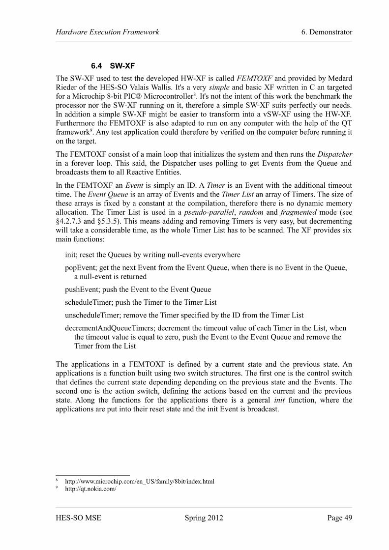
Hardware Execution Framework 6. Demonstrator
6.4 SW-XFThe SW-XF used to test the developed HW-XF is called FEMTOXF and provided by Medard Rieder of the HES-SO Valais Wallis. It's a very simple and basic XF written in C an targeted for a Microchip 8-bit PIC® Microcontroller8. It's not the intent of this work the benchmark the processor nor the SW-XF running on it, therefore a simple SW-XF suits perfectly our needs. In addition a simple SW-XF might be easier to transform into a vSW-XF using the HW-XF. Furthermore the FEMTOXF is also adapted to run on any computer with the help of the QT framework9. Any test application could therefore by verified on the computer before running it on the target.
The FEMTOXF consist of a main loop that initializes the system and then runs the Dispatcher in a forever loop. This said, the Dispatcher uses polling to get Events from the Queue and broadcasts them to all Reactive Entities.
In the FEMTOXF an Event is simply an ID. A Timer is an Event with the additional timeout time. The Event Queue is an array of Events and the Timer List an array of Timers. The size of these arrays is fixed by a constant at the compilation, therefore there is no dynamic memory allocation. The Timer List is used in a pseudo-parallel, random and fragmented mode (see §4.2.7.3 and §5.3.5). This means adding and removing Timers is very easy, but decrementing will take a considerable time, as the whole Timer List has to be scanned. The XF provides six main functions:
init; reset the Queues by writing null-events everywhere
popEvent; get the next Event from the Event Queue, when there is no Event in the Queue, a null-event is returned
pushEvent; push the Event to the Event Queue
scheduleTimer; push the Timer to the Timer List
unscheduleTimer; remove the Timer specified by the ID from the Timer List
decrementAndQueueTimers; decrement the timeout value of each Timer in the List, when the timeout value is equal to zero, push the Event to the Event Queue and remove the Timer from the List
The applications in a FEMTOXF is defined by a current state and the previous state. An applications is a function built using two switch structures. The first one is the control switch that defines the current state depending depending on the previous state and the Events. The second one is the action switch, defining the actions based on the current and the previous state. Along the functions for the applications there is a general init function, where the applications are put into their reset state and the init Event is broadcast.
8 http://www.microchip.com/en_US/family/8bit/index.html9 http://qt.nokia.com/
HES-SO MSE Spring 2012 Page 49

Hardware Execution Framework 6. Demonstrator
6.5 vSW-XFThe vSW-XF is a modified version of the FEMTOXF (see §6.4) and thus named FEMTOHWXF. To connect to the HW-XF (see §5.4.3) following functions have been modified:
popEvent; read the Pop Registers EID and the last EB
pushEvent; write the Push Registers EID, TOV and Control, TOV is always reset to zero
scheduleTimer; write the Push Registers EID, TOV and Control
unscheduleTimer; write the Push Registers EID, TOV and Control with DE bit set
As you can see, the FEMTOHWXF still separates between Events and Timers, but this is only for backward compatibility with the FEMTOXF. In fact both functions pushEvent and scheduleTimer access exact the same registers, but in pushEvent the register TOV is always written zero.
To compare the pSW-XF and the vSW-XF we like to be able to switch easily between the two variants. Two constants are therefore defined and enabling one or the other selects the corresponding variant to implement.
HES-SO MSE Spring 2012 Page 50

Hardware Execution Framework 6. Demonstrator
6.6 Tests and ComparisonSome tests have been executed to compare the SW-XF to the HW-XF. In a first round two simple Reactive Entities are exchanging Events. This allowed to verify the functionality of the system in general, but also to compare the performance of the two XFs. Then the different tasks like pushing or popping an Event have been examined in further detail.
6.6.1 Test 1: Ping-Pong
To test the functionality of the vSW-XF/HW-XF system an application with two Reactive Entities has been developed. The the Reactive Entities pass an Event between each other, like two players passing a ball between each other in table tennis or ping-pong. As you can see in Figure 6-5, there is LED1 turned off in the state ST_SM1_WAIT and turned on in the state ST_SM_PONG. The same is done with LED3 in the other Reactive Entity.
The state of LED1 and LED3 has also been visualized with the help of an oscilloscope. The device used is the Agilent Technologies MSO-X 3012A10. All screenshots of these measurements can be found in Appendix I. The formal results are summarized in Table 6-4 and analyzed hereafter.
In a first test, labeled a) in Table 6-4, the processor and the fabric are running at 25 MHz. The period of one on-off cycle is measured some thousands of times. The fastest period measured is about 219 us. Running the same application on the HW-XF we get a period of about 126 us. This means that by sending the Event through the HW-XF the Ping-Pong runs about 1.7 times faster. This is quite surprising, as we expected the overhead of sending an Event through the HW to be greater than handling the Event Queue in SW. But it shows that our approach of executing the XF in HW is a good idea, as it can have quite a big impact on the overall execution speed.
10 http://www.home.agilent.com/agilent/product.jspx?id=1947554&nid=-33573.970762.00&pid=1947554
HES-SO MSE Spring 2012 Page 51
Figure 6-5: Test Applications Ping-Pong

Hardware Execution Framework 6. Demonstrator
But it seems a little bit unfair to run the processor only at 25 MHz when it could be run at 100 MHz (Test c). Notice that the fabric still runs at 25 MHz. Having the pSW-XF running four times faster, the shortest period is divided by about 3.5 down to 61 us. But also the HW-XF version is accelerated the same amount, to a period of 36 us. From that we conclude that the HW-XF, even when running four times slower than the software part, is still fast enough to serve the vSW-XF in a perfect manner.
Running the Ping-Pong applications with at maximum three Events in the Queue is not really a hard task for an XF. The test the robustness of the HW-XF some more, the number of Ping-Pong pairs has been increased to fife (Test g), this means that ten applications are running at the same time. The period of our first Ping-Pong pair rose to 589 us for SW and 282 us for HW. What also rose is the ratio between HW-XF and SW-XF, up to more than a factor of 2. This can be explained by the fact that the amount of processing time used by the XF compared to taht used by the application is increased. Only the first two applications are controlling LEDs, so the other applications pass faster trough their states and reduce the amount of application processing time.
In all the tests above we notice another interesting fact. The difference between the shortest and the longest period in the SW-XF is very long ( about 23 us at 100 MHz) compared to the one in the HW-XF (less than 0.1 us at 100 MHz). The difference in the HW-XF is most probably related to measurement errors, because the mean value of the measurements lies in the middle between the minimal and the maximal value. In the SW-XF however the mean value lies much closer to the minimal value. Like it is a little bit visible in the figures in Appendix I, we observed on the oscilloscope that most times the period is the short one. But from time to time the period is the long one. Or in other words, the duration of the period in the SW-XF is not distributed equally between the minimal and the maximal value, but there is a very high peak at the minimal end and a lower one at the maximal end. In a first moment we thought this might be due to the fact, that sometimes there might be an Event more or less in the Queue, creating that delay. But as the code is running in a single thread, the execution is completely deterministic and therefore exactly the same for each period. On a second thought
HES-SO MSE Spring 2012 Page 52
Table 6-5: Test 1 Ping-Pong Measurement Results
Test Frequency [Mhz] SW-XF period [us] HW-XF period [us] SW / HWMSS FAB min max diff mean min max diff mean min max
Ping-Pong 1a) 25.00 25.00 219.28 300.98 81.70 228.40 126.27 126.34 0.07 126.30 173.66% 238.23%b) 50.00 25.00 109.65 150.51 40.86 114.68 63.70 63.73 0.03 63.71 172.14% 236.17%c) 100.00 25.00 61.22 84.38 23.16 64.10 36.42 36.43 0.01 36.42 168.09% 231.62%
Ping-Pong 2d) 100.00 25.00 140.94 164.12 23.18 148.13 75.03 75.06 0.03 75.05 187.84% 218.65%
Ping-Pong 3e) 100.00 25.00 251.52 274.72 23.20 263.46 128.67 128.72 0.05 128.70 195.48% 213.42%
Ping-Pong 4f) 100.00 25.00 393.91 417.15 23.24 412.94 198.22 198.30 0.08 198.26 198.72% 210.36%
Ping-Pong 5g) 100.00 25.00 589.70 613.09 23.39 594.17 282.36 282.46 0.10 282.40 208.85% 217.05%
Ping-Pong 5 – HW-Timer disabledh) 100.00 25.00 578.78 578.98 0.20 578.88 - - - - - -
Ping-Pong 1 – Max. Timer = 2i) 25.00 25.00 221.75 231.32 9.57 223.95 - - - - - -
Ping-Pong 5 – empty Timer IRQh) 100.00 25.00 582.96 584.48 1.52 583.56 - - - - - -

Hardware Execution Framework 6. Demonstrator
we found out that it hast to be the HW-Timer interrupting the system. It is configured to a period of 1 ms during the tests above. Since the Ping-Pong test does not makes usage of Timers, the HW-Timer could be turned off without affecting the functionality of the test application. Row h) of Table 6-5 shows the results for this scenario and it is clearly visible that really the HW-Timer has been the cause. Or better said it's not the really the HW-Timer, but more the XF scanning the whole Timer List to decrement eventual Timers. It is obvious that this scanning depends strongly on the length of the Timer List. In Row i) the same test but this time with a List of 2 elements instead of 51 (like the one in the HW-XF) has been used.
Now we were wondering how much time the empty interrupt request takes, without any handling of the Timer List in Test h). Only executing the IRQ callback function, clearing the IRQ and continuing the task takes about 1.52 us at 100 MHz or 152 clock cycles. Here is the evidence why it is impossible to reduce the tick for the SW-XF to 1 us.
HES-SO MSE Spring 2012 Page 53

Hardware Execution Framework 7. Conclusion
7 Conclusion ______________________
All goals set have been achieved. After a thorough analysis of the XF in software and how it could be moved to hardware, a prototype has been implemented. This has then been tested and analyzed on a demonstrator with different variants of an application. The test turned out surprisingly positive as the HW-XF is, depending on the application, 1.5 to 2.5 times faster than the SW-XF. However this has been done under laboratory conditions with applications specially designed to test the HW-XF.
It would be really interesting to see the HW-XF work with an application already employed somewhere. A further fascinating aspect to watch would be the HW-XF interacting with a more complex vSW-XF, maybe written in C++ and with an OOP approach. After that another enthralling project would be to drive multiple vSW-XFs in parallel. An FPGA with a hard processor and a soft processor is what comes to mind. And then exchange Events between those two processing units!
For further analysis the test application could be better automated. This means instead of measuring the on-off states of a LED and taking screenshots, a real-time clock could be used to measure the duration of different actions and maybe event sent to a computer with a serial interface.
Sion, 17. February 2012 Oliver A. Gubler
HES-SO MSE Spring 2012 Page 54

Hardware Execution Framework 8. Bibliography
8 Bibliography ____________________
HES-SO MSE SPRING 2012 I

Hardware Execution Framework 8. Bibliography
8.1 Cited
ARM04 ARM Limited. “AMBATM 3 APB Protocol Specification v1.0.” ARM. 2004.
BGK+97 Dirk Bäumer, Guido Gryczan, Rolf Knoll, Carola Lilienthal, Dirk Riehle, and Heinz Züllighoven. “Framework Development for Large Systems.” Communications of the ACM 40, 10 (October 1997). pp. 52-59.
GA04 Groza, V.; Abielmona, R.; , "What next? A hardware operating system?," Instrumentation and Measurement Technology Conference, 2004. IMTC 04. Proceedings of the 21st IEEE , vol.2, no., pp. 1496- 1501 Vol.2, 18-20 May 2004doi: 10.1109/IMTC.2004.1351349URL: http://ieeexplore.ieee.org/stamp/stamp.jsp?tp=&arnumber=1351349&isnumber=29627
HCB+09 Holenderski, M.; Cools, W.; Bril, R.J.; Lukkien, J.J.; , “Multiplexing real-time timed events”, Emerging Technologies & Factory Automation, 2009. ETFA 2009. IEEE Conference, pp. 1-4, 22-25. Sept. 2009doi: 10.1109/ETFA.2009.5347183URL: http://ieeexplore.ieee.org/stamp/stamp.jsp?tp=&arnumber=5347183&isnumber=5346987
Hei04 Stefan Heinzmann. “Yet Another Hierarchical State Machine.” Overload Journal Issue 64, Dezember 2004URL: http://accu.org/index.php/journals/252 [Accessed: 05. Sept. 2011].
HIL+ Jens Hildebrandt, Frank Golatowski, Dirk Timmermann. “Scheduling Coprocessor for Enhanced Least-Laxity-First Scheduling in Hard Real-Time Systems.” University of Rostock, Department of Electrical Engineering and Information Technology, Institute of Applied Microelectronics and Computer Science, Richard-Wagner-Str. 31, 18119 Rostock-Warnemünde, Germany
IBM09 IBM. “Rational Rhapsody: Frameworks and Operating Systems Reference.” 1997, 2009. URL: http://publib.boulder.ibm.com/infocenter/rsdp/v1r0m0/topic/com.ibm.help.download.rhapsody.doc/helpindex_rhapsody.html [Accessed 26.09.2011].
JF88 Ralph E. Johnson and Brian Foote. “Designing Reusable Classes.” Journal of Object-Oriented Programming 1, 2 (June/July 1988). pp. 2, 9–13.URL :http://www.laputan.org/pub/foote/DRC.pdf [Accessed 26.09.20011].
HES-SO MSE SPRING 2012 II

Hardware Execution Framework 8. Bibliography
Rie00 Dirk Riehle. “Framework Design: A Role Modeling Approach.” ETHZ, 2000. pp. 8–9, 54–56.URL: http://www.riehle.org/computer-science/research/dissertation/diss-a4.pdf [Accessed 26.09.20011].
RiM11 Medard Rieder. “Hardware Execution Framework.” TIN / HES-SO Valais, 2011
RS09 Medard Rieder, Rico Steiner. “Execution Framework (XF).” HES-SO Valais, 2009
Sam08 Miro Samek. “Practical UML statecharts in C/C++: event-driven programming for embedded systems.” Newnes/Elsevier. 2008. pp. xxvii-xxxi
SNB03 Slade, A.L.; Nelson, B.E.; Hutchings, B.L.; . “Reconfigurable computing application frameworks.” Field-Programmable Custom Computing Machines, 2003. FCCM 2003. 11th Annual IEEE Symposium. pp. 251- 260, 9-11 April 2003doi: 10.1109/FPGA.2003.1227260URL: http://ieeexplore.ieee.org/stamp/stamp.jsp?tp=&arnumber=1227260&isnumber=27544 [Accessed 26.09.2011].
HES-SO MSE SPRING 2012 III

Hardware Execution Framework 8. Bibliography
8.2 Complementary reading
Benedikt Huber. “Real-Time & Embedded Operating Systems.” VO Embedded Systems Engineering. WS 11.2010URL: http://ti.tuwien.ac.at/rts/teaching/courses/esevo/unterlagen/vortragsfolien-ws10/real-time-operating-systems [Accessed: 05. Sept. 2011].
Miro Samek and Paul Montgomery. “State-Oriented Programming.” Embedded Systems Programming. August 2000URL: www.state-machine.com/resources/samek0008.pdf [Accessed: 05. Sept. 2011].
Stephen Ferg. “Event-Driven Programming: Introduction, Tutorial, History”. Version 0.2, 08. February 2011URL: Tutorial_EventDrivenProgramming.sourceforge.net [Accessed: 10. Nov. 2011].
Christian Jenker, Harald Walcher. “An Approach for a Flexible Interface Platform.” Infineon Technologies, ESSCIRC 2002
HES-SO MSE SPRING 2012 IV

Hardware Execution Framework 9. Appendices
9 Appendices _____________________
HES-SO MSE SPRING 2012 I

Hardware Execution Framework 9. Appendices
Appendix I: Measurement ResultsIn the following figures the purple trail represents LED1 and the blue trail LED3. Therefore the signal is in its high state when the Reactive Entity is in the wait state. The low state of the signal represents the ping or the pong state respectively.
HES-SO MSE SPRING 2012 II
Oscilloscope Test a) SW-XF Ping-Pong 1, SW @ 25MHz, HW @ 25 MHz

Hardware Execution Framework 9. Appendices
HES-SO MSE SPRING 2012 III
Oscilloscope Test a) HW-XF Ping-Pong 1, SW @ 25MHz, HW @ 25 MHz
Oscilloscope Test b) SW-XF Ping-Pong 1, SW @ 50MHz, HW @ 25 MHz

Hardware Execution Framework 9. Appendices
HES-SO MSE SPRING 2012 IV
Oscilloscope Test c) SW-XF Ping-Pong 1, SW @ 100MHz, HW @ 25 MHz
Oscilloscope Test b) HW-XF Ping-Pong 1, SW @ 50MHz, HW @ 25 MHz

Hardware Execution Framework 9. Appendices
HES-SO MSE SPRING 2012 V
Oscilloscope Test c) HW-XF Ping-Pong 1, SW @ 100MHz, HW @ 25 MHz
Oscilloscope Test d) SW-XF Ping-Pong 2, SW @ 100MHz, HW @ 25 MHz

Hardware Execution Framework 9. Appendices
HES-SO MSE SPRING 2012 VI
Oscilloscope Test d) HW-XF Ping-Pong 2, SW @ 100MHz, HW @ 25 MHz
Oscilloscope Test e) SW-XF Ping-Pong 3, SW @ 100MHz, HW @ 25 MHz

Hardware Execution Framework 9. Appendices
HES-SO MSE SPRING 2012 VII
Oscilloscope Test e) HW-XF Ping-Pong 3, SW @ 100MHz, HW @ 25 MHz
Oscilloscope Test f) SW-XF Ping-Pong 4, SW @ 100MHz, HW @ 25 MHz
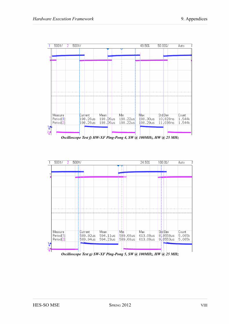
Hardware Execution Framework 9. Appendices
HES-SO MSE SPRING 2012 VIII
Oscilloscope Test g) SW-XF Ping-Pong 5, SW @ 100MHz, HW @ 25 MHz
Oscilloscope Test f) HW-XF Ping-Pong 4, SW @ 100MHz, HW @ 25 MHz

Hardware Execution Framework 9. Appendices
HES-SO MSE SPRING 2012 IX
Oscilloscope Test g) HW-XF Ping-Pong 5, SW @ 100MHz, HW @ 25 MHz
Oscilloscope Test h) HW-XF Ping-Pong 5, SW @ 100MHz, HW @ 25 MHz, HW-Timer disabled

Hardware Execution Framework 9. Appendices
HES-SO MSE SPRING 2012 X
Oscilloscope Test i) HW-XF Ping-Pong 5, SW @ 100MHz, HW @ 25 MHz, Timer List length = 2
Oscilloscope Test j) SW-XF Ping-Pong 5, SW @ 100MHz, HW @ 25 MHz, empty Timer IRQ

Hardware Execution Framework 9. Appendices
Appendix II: User GuideThis User Guide has to be used together with the Virtual Machine delivered. It shows the different tools have to be used.
HW-XF: design and verificationThe design in HDL-Designer contains two important libraries: HWXF_lib and HWXF_test_lib. In HWXF_lib the HW-XF can be found. The topmost entity is labeled toplevel_fabric. It has to be selected when the flow prepare for Libero is executed. This flow will generate all VHDL, concatenate it into one single file and launch a script that modifies it for the usage with Libero.
The toplevel_svtb in the HWXF_test_lib is needed to simulate the design. It has to be selected when the Questasim Flow is launched. If this flow is launched, a window will appear where you only have to press on OK: Then QuestaSim will launch automatically and execute the simulation. At the end it will as you Are you sure to finish? where you have to reply with NO, else QuestaSim will close. The Transcript window will show the results of the test in text and the Wave window shows all signals of the design.
To modify the testbench on the desktop the icon named HWXF Testbench has to be executed. This will open Eclipse with SVEditor, you just have to accept the chosen workspace. Any error messages can simply be accepted. Here the two important files are already open for you. control_master_seq_lib.sv holds the test sequences where basic_event_control_master_seq defines the master sequence. The file control_scoreboard.sv executes the automatic verification. To apply any changes here, save the file and rerun QuestaSim.
HW-XF: platformLibero SoC has to be launched. The opens automatically. Any error messages like the module x is instantiating itself can be ignored.
On the tabs SD processor has to be chosen to modify the processor. If you change anything, don't forget to execute SmartDesign->Generate Component from the menu.
To import the design from HDL-Designer, File→Import Files... has to be selected from the menu. A window will open where the file concatenated.vhd has to be chosen. The two following requests have to be answered with YES. Now you have to switch to the SD board_sd tab and execute SmartDesign→Generate Component here too. Any modifications in this view have also to be saved by generating the component.
The you can move your attention to the Design Flow on the left. Maybe you have to scroll down a bit, but you should find Program Design→Program Device. Double-click will launch this task which may take a while to complete but finally the FPGA is configured with our design.
SW-XF: coding and executingThe SW-XF can be modified with the Microsemi SoftConsole IDE. Also simply accept the preselect workspace and the project opens. Femtohwxf Debug will write the program to the processors memory.
HES-SO MSE SPRING 2012 XI