white paper selective catalytic reduction (scr) controls to abate ...
36
\csss WHITE PAPER SELECTIVE CATALYTIC REDUCTION (SCR) CONTROLS TO ABATE NO, EMISSIONS PREPARED BY: SCR COMMITTEE INSTITUTE OF CLEAN AIR COMPANIES, INC. OCTOBER 1994 Copyright Institute of Clean Am Companies. loc— 1994. All ngbu reserved.
-
Upload
khangminh22 -
Category
Documents
-
view
0 -
download
0
Transcript of white paper selective catalytic reduction (scr) controls to abate ...
\csss
WHITE PAPER
SELECTIVE CATALYTIC REDUCTION (SCR) CONTROLS TO ABATE NO, EMISSIONS
PREPARED BY:
SCR COMMITTEE
INSTITUTE OF CLEAN AIR COMPANIES, INC.
OCTOBER 1994
Copyright Institute of Clean Am Companies. loc— 1994. All ngbu reserved.

k

"--f I W-1.0 itie:Orts==ssiscszstm=
INSTITUTE OF CLEAN AIR COMPANIES
1707 L Street NW Suite 570 Washington, DC 20036-4201 202.457.0911 Fax 202.331.1388
The Institute of Clean Air Companies (ICAC) is the national association of companies that supply stationary source air pollution monitoring and control systems, equipment, and services. It was formed in 1960 (under the name IGCI) as a nonprofit corporation to promote the industry and encourage improvement of engineering and technical standards.
The Institute's mission is to assure a strong and workable air quality policy that promotes public health, environmental quality, and industrial progress. As the primary representative of the air pollution control industry, the Institute seeks to evaluate and respond to regulatory initiatives and establish technical standards to the benefit of all citizens.
Associate Members 3M Company Acme Structural, Inc. Bellefonte Lime Company, Inc. Caprice Construction Company The Clarkson Company Control Manufacturing Corporation Cormetech, Inc. Corning Incorporated Dravo Lime Company Entropy, Inc. W.L. Gore & Associates. Inc. Graver Tank & Mfg. Co.. Inc. The McIlvaine Company Midwesco Filter Resources, Inc. NWL Transformers 011elveny & Myers Pollution Control Technologies, Inc. Power Magazine Prototech Company PSP Industries Shelby Steel Fabricators, Inc. Structural Steel Services, Inc. Superior Roll Forming Union Boiler Company
Members ABB Environmental Systems AirPol, Inc. Anguil Environmental Systems, Inc. Babcock & Wilcox Belco Technologies Corporation Ceilcote Air Pollution Control CSM Environmental Systems, Inc. Engelhard Corporation Environmental Elements Corporation Hosokawa Nlikropul Environmental Systems Johnson Matthey Joy Environmental Technologies, Inc. Lurgi Corporation Munters Corporation Nalco Fuel Tech Noe11, Inc. Norton Chemical Process Products Corporation Procedair Industries Pure Air Research Cottrell, Inc. Riley Environmental Systems Southern Environmental, Inc. United McGill Corporation Wahlco, Inc. Wheelabrator Clean Air Zurn Air Systems Division
LWITIVTE OF

TABLE OF CONTENTS
PURPOSE 1
EXECUTIVE SUMMARY 2
SELECTIVE CATALYTIC REDUCTION (SCR) CONTROLS TO ABATE NOz EMISSIONS 3 1. Are NOz Emissions Harmful to Human Health? 3 2. Are NOz Emissions Harmful to the Environment? 3 3. What is SCR? 4 4. How Much NOz Can SCR Remove? 5 5. Is SCR Commercially Demonstrated in the U.S.? 7 6. Can SCR Be Used With High-Sulfur Fuels? 8 7. Does SCR Cost Too Much?- 9 8. How Long Do SCR Catalysts Last? 10 9. Can Ammonia Slip Be Controlled? 11 10. Are Any Dangerous Materials Used? 12 11. Is Disposal of Spent Catalyst A Problem? 13 12. What Developments in SCR Technology Are Expected? 13
REFERENCES 14
APPENDIX 1: Air Pollution Control Industry Estimate of Utility Boiler SCR System Costs 19
APPENDIX 2: Partial List of U.S. Applications of SCR 21
APPENDIX 3: Overseas SCR Installations on Coal-Fired Power Plants 27
:.seslITIZE OF
PURPOSE
Federal and state regulations require control of NOx emissions both to minimize the
direct effects of these emissions on human health and the environment, and to minimize the
formation of acid rain and ground level ozone, to which NOx is a major contributor.
Regulators and regulated industry seek controls which will be both reliable and effective, but without unreasonable cost to industry and society. One proven and cost-effective NO
x
control technology is selective catalytic reduction (SCR). Unfortunately, misconceptions regarding SCR have hindered its acceptance, and in some cases even its consideration.
The SCR Committee of the Institute of Clean Air Companies, Inc. (ICAC) prepared this white paper to educate all interested parties on the capabilities, limitations, and cost of
SCR.
ICAC is the non-profit national association of companies which supply stationary source air pollution control systems, equipment and services. Its members include suppliers
of SCR systems, as well as of alternative NOx control technologies.
2.11TrtiE OF
D icrD\ t„ k,to ?kV) Pryi;ceirme
r". FAN
EXECUTIVE SUMMARY
Emissions of nitrogen oxides (NO,) cause serious health effects, ranging from bronchitis to altered immune system function. Currently, 8.5 million Americans live in counties with NO, levels higher than EPA's health standards prescribe. NO, also contributes significantly to nationwide environmental problems of acid rain and ozone pollution. As of 1990, over 63 million Americans lived in counties with unhealthy ozone levels. To protect both human health and the environment, NO, levels thus must be lowered. The process which can reduce NO„ emissions the most from many industrial and utility sources is selective catalytic reduction (SCR).
First patented by a U.S. company in 1959, SCR is a proven technology used to significantly reduce NO, emissions from over 200 sources in the U.S., and over 500 sources worldwide. In the U.S., SCR has been applied on utility and industrial boilers, gas turbines, process heaters, internal combustion engines, chemical plants, and steel mills. Emissions reductions of greater than 90% are common with SCR, althouah this technology may be used economically for lower removal efficiencies as well.
Perceived high cost has been an impediment to the adoption of SCR in the U.S. While this perception has been based largely on incorrect information, both the capital and operating costs of SCR have dropped rapidly over the past decade as a result of technological innovation, increased manufacturing experience, and competition among manufacturers. An approximate doubling in expected catalyst life has contributed to the reduced operating cost.
Decreased costs, successful operating experience, and tic,htened permit limits have led to a sharp increase in the number of SCR systems installed in the U.S. Given a large and growing installed base and the increasing tendency of owners and operators of reaulated units to choose SCR, authorities with extensive NO, control experience have concluded that SCR technology is proven, safe, and economical now.
2,17TTLIM CF

SELECTIVE CATALYTIC REDUCTION (SCR) CONTROLS TO ABATE NO, EMISSIONS
1. Are NO, Emissions Harmful to Human Health? Yes.
Nitrogen oxides (N01) include nitric oxide (NO) and nitrogen dioxide (NO2), which are produced by the oxidation of atmospheric and fuel-bound nitrogen in combustion processes, including those in motor vehicles and industrial facilities. Nitric oxide is a colorless gas that is converted in the atmosphere to yellowish-brown NO2.
Nitrogen dioxide at the levels found in the air we breath causes adverse human health effects,' including bronchitis, pneumonia, lung irritation, and susceptibility to viral infection. Acute exposures to NO2 cause bronchial constriction and airway hyperactivity in asthmatics. Animal studies indicate that intermittent, low-level NO2 exposures also can induce alterations in the kidney, liver, spleen. red blood cells, and cells of the immune system.'
In short. NO2 health effects range from short term tissue damage, functional impairment, and exacerbation of other disease processes to irreversible pulmonary damage and death. According to the U.S. EPA, 8.5 million people live in areas with NO2 levels that exceed federal air quality standards.'
In addition to these direct health effects, NO, emissions also contribute to formation of ground-level ozone (photochemical smog). Ozone can irritate the mucous membranes of the respiratory system, causing coughing, choking, and impaired lung function, and can aggravate heart disease and respiratory diseases such as asthma and bronchitis. EPA has estimated that in 1990 about 63 million people lived in counties exceeding the ozone air quality standard, making ozone the nation's most ubiquitous air problem. As of April 1993. 96 areas across the country were not in attainment with the ozone standard.'
EPA calculations show that NO, reductions are necessary to solve our nation's ozone non-attainment problem.' Indeed, studies by the National Research Council and the U.S. EPA show that controlling NOx emissions alone with volatile organic compound (VOC) emissions is more effective than even more stringent strategies that control VOC alone.' Title I of the Clean Air Act Amendments of 1990 expressly calls for NOx reductions as a way to move toward attainment of the ozone standard.
2. Are NO, Emissions Harmful to the Environment? Yes.
As is the case with human health. NO, both has direct adverse effects on natural flora and fauna, and contributes to the formation of ground-level ozone. Ozone causes such negative environmental effects as crop and forest damage and visibility impairment.'
CYSTITCrE OF

Nitrogen oxides also contribute to the formation of acid rain, which has been shown to destroy fish and other forms of fresh and coastal water life, and to damage buildings and materials, forests, and agricultural crops. Leaching of metals, such as aluminum, from soils by acid rain has raised concerns about health effects as well.
In some western areas of the United States, NO, emissions are the primary contributor to acid deposition. In the East, NO, emissions are responsible for about one-third of rainfall's acidity over the full year,' and one-half during the winter.'
NO, also contributes to nitrification of rain, which may "over-fertilize" the soil, leaving foliage more vulnerable to damage from cold, insects, and disease.' Nitrification can also upset the ecological balance on both land and water.
3. What is SCR? In the SCR process. a catalyst facilitates a chemical reaction between NO, and ammonia to produce nitrogen and water. An ammonia-air or ammonia-steam mixture is injected into exhaust gases containing NO,. The gases mix thoroughly in a turbulent zone, and then pass through the catalyst where the NOx is reduced. The catalyst promotes the reaction, but is not consumed by it.
SCR is a process for controlling emissions of nitrogen oxides from stationary sources. The basic principle of SCR is the reduction of NO, to N2 and H20 by the reaction of NO, and ammonia (NH3) within a catalyst bed. The primary reactions occurring in SCR are given below. Note that these reactions require oxygen, so that catalyst performance is best at oxygen levels above 2-3%."
4N0 + 4 1VH3 + 02 4N2 + 6 H20
2 NO2 + 4 1\J-13 + 02 3 N2 "r 6 H2 0
Several different catalysts are available for use at different exhaust gas temperatures. In use the longest and most common are base metal catalysts, which typically contain titanium and vanadium oxides, and which also may contain molybdenum, tungsten, and other elements. Base metal catalysts are useful between 450 °F and 800 °F. For high temperature operation (675°F to over 1100 °F), zeolite catalysts may be used. In clean, low temperature (350-550 °F) applications, catalysts containing precious metals such as platinum and palladium are useful. (Note that these compositions refer to the catalytically active phase only: additional ingredients may be present to give thermal and structural stability, to increase surface area, or for other purposes.)
The mechanical operation of an SCR system is quite simple. It consists of a reactor chamber with a catalyst bed, composed of catalyst modules, and an ammonia handling and injection system, with the NH3 injected into the flue gas upstream of the catalyst as shown in Figure 1. (In some cases, a fluidized bed of catalyst pellets is used.) There are no moving parts. Other than spent catalyst. the SCR process produces no waste products.
241TTLY1E OF • • I., 1••• •

Flue Gas
E NO),
E NH3 -->
E NO),
NH3
H20
N,
H20
N2
Figure 1. Schematic Diagram of a Generic SCR System
NH Injection Nozzle
Cleaned Gas
In utility boiler applications in the U.S., the catalyst has been placed in a separate housing upstream of the air preheater and of any particulate collection device (see Figure 2). This "high-dust" configuration is less expensive to install and operate than other configurations. In several units in California, the catalyst has been installed in expanded ductwork between the economizer and preheater ("in-duct SCR") to meet space constraints and lower capital costs further:2 Use of preheater baskets coated with catalyst (''preheater SCR'') in order to obviate the need for a catalytic reactor has been the subject of several demonstrations.'
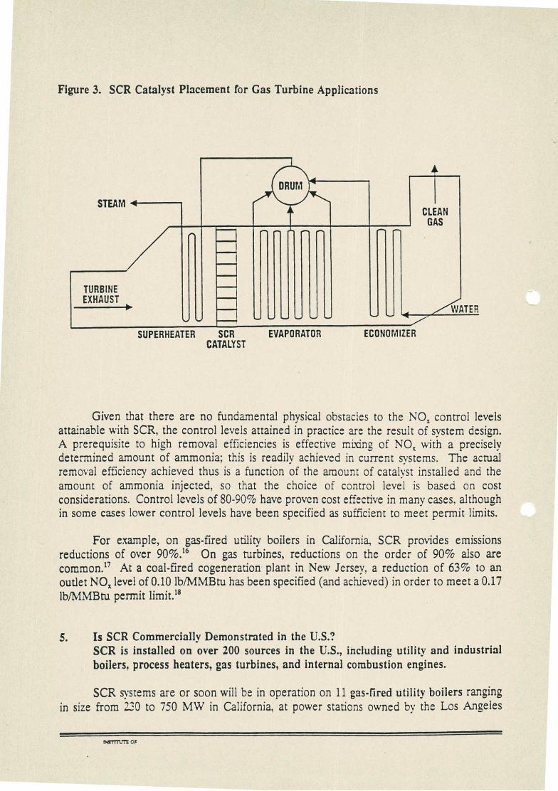
In combined-cycle gas turbine applications, the catalyst normally is placed after the superheater in the heat recovery steam generator (HRSG), where the temperature is in the range suitable for base metal operation (see Figure 3). At several sites in the U.S.. high-temperature catalyst has been installed upstream of the HRSG, as well as in simple-cycle turbine applications, where the temperature may be as high as 950-1050 oF.14
4. How Much NO, Can SCR Remove? By proper catalyst selection and system design, NOz removal efficiencies exceeding 90% may be achieved. In practice, SCR systems designed for a wide range of NOz removal efficiencies have proven economical.
In principle, SCR can provide reductions in NOx emissions approaching 100%. (Simple thermodynamic calculations indicate that a reduction of well over 99% is possible at 650 °F.15) In practice, commercial SCR systems have met control targets of over 90% in many cases.
C4TiTU1E OF

d•M•imé
NH
ESP low dust
oo..Em••nám..at...j ."'\\V/
7-13
NH.
tail end
ESP 111•M•1111~111~Ell
NH,
high dust AH
dIMMINEIMMEI.
SCR
heat
B = boiler AH = air preneater ESP = eiectrcstatic CrecID:tatcr ior other dust cd:!ector) FGD = flue gas cesuiphunsa=
ECONOMIZER
AMMONIA INJECTION
GRID TURNING Ak VALVES
4. CATALYST LAYERS
•;‹
FD AH SCR SCR
AIR HEATER
•
AH 177._. FGD
Figure 2. (a) SCR System Configurations for Utility Boiler Applications; (b) Schematic Diagram of a High Dust SCR System
TTTtJTE CF e•ILI /CrD\ t, 4 I-ytD N7r) Pmiccinttc
(a)
(b)
STEAM < CLEAN
GAS
••••••
TURBINE EXHAUST
•••••• .y0 ••••• ••••• 4 ..,,./<NATER
•••• •••••• ••••• •••••••
Figure 3. SCR Catalyst Placement for Gas Turbine Applications
SUPERHEATER SCR EVAPORATOR ECONOMIZER CATALYST
Given that there are no fundamental physical obstacles to the NO, control levels attainable with SCR, the control levels attained in practice are the result of system design. A prerequisite to high removal efficiencies is effective mixing of NO, with a precisely determined amount of ammonia: this is readily achieved in current systems. The actual removal efficiency achieved thus is a function of the amount of catalyst installed and the amount of ammonia injected, so that the choice of control level is based on cost considerations. Control levels of 80-90% have proven cost effective in many cases, although in some cases lower control levels have been specified as sufficient to meet permit limits.
For example, on gas-fired utility boilers in California, SCR provides emissions reductions of over 90%." On gas turbines, reductions on the order of 90% also are common.° At a coal-fired cogeneration plant in New Jersey, a reduction of 63% to an outlet NO, level of 0.10 lb/MMBtu has been specified (and achieved) in order to meet a 0.17 lb/MMBru permit limit.'
5. Is SCR Commercially Demonstrated in the U.S.? SCR is installed on over 200 sources in the U.S., including utility and industrial boilers, process heaters, gas turbines, and internal combustion engines.
SCR systems are or soon will be in operation on 11 gas-fired utility boilers ranging in size from 230 to 750 MW in California, at power stations owned by the Los Angeles
NITTTUTE OF

Department of Water and Power and Southern California Edison. Commitments for several more units are pending. An SCR system also is operating at two new 140 MW coal-fired boilers in New Jersey. Other systems are being installed on new coal-fired utility boilers in New Jersey, Florida, and Virginia. (See Appendix 2)
While SCR has not yet been installed on an existing coal-fired utility boiler in the U.S., demonstrations in the U.S.' and considerable experience abroad' suggest that SCR will be a useful retrofit control technology.
SCR is used to control NOz emissions from over 10 gas- and oil-fired industrial boilers in the U.S. These include both field-erected and small packaged boilers.
A number of process and refinery heaters in the U.S. have SCR systems installed to control NO, emissions. Typical control levels on these units are 80-90%.
SCR has found growing use for the control of NO, emissions from combined cycle gas turbines, with over 100 systems installed in the U.S.' Removal efficiencies of over 80% are common in this application. and SCR has been used alone or in combination with other control technologies to achieve outlet NOz levels below 5 ppm." The development of the high-temperature SCR catalyst has allowed the use of SCR on simple cycle turbines.'
Another use of SCR which is growing in importance is the control of NOz emissions from stationary reciprocating internal combustion engines. SCR systems have been used to control emissions from over 30 internal combustion engines burning natural gas, diesel fuel, and mixtures of these in the U.S., including engines on three marine vessels in California.' In some cases, NOz removal efficiencies have been greater than 90%.' SCR catalyst often is placed downstream of an oxidation catalyst to allow for simultaneous removal of NOz and hydrocarbons and carbon monoxide.
SCR also has been used on other types of sources. At nitric acid plants in Mississippi and Texas, SCR systems provide estimated reductions of over 90%." SCR units have been installed on annealing furnaces at steel mills in Indiana and California.'
6. Can SCR Be Used With High-Sulfur Fuels? SCR systems are commercially proven on high-sulfur oil and medium-sulfur coal applications. Based on the »idespread experience with SCR on coal-fired boilers abroad and successful demonstrations in the U.S., there is no technical impediment to the successful application of SCR systems to high-sulfur coal-firing facilities.
Concerns regarding the use of high-sulfur fuels center on the formation of ammonium bisulfate. a sticky substance which could mask the catalyst and clog air heater and other downstream surfaces. Ammonium bisulfate is formed through the reaction of ammonia with SO3, which in turn is formed primarily through the oxidation of SO2 by the SCR catalyst.
NSTITUTE OF

By minimizing ammonia slip and suppressing sulfur dioxide oxidation, the amount of ammonium bisulfate formed may be kept to a level which does not affect operation.
Thus, SCR has performed well on demonstrations on high-sulfur fuel in the U.S., using systems designed for low ammonia slip and catalyst formulations designed to minimize oxidation of SO2. For example, in testing sponsored by the U.S. Department of Energy, SCR catalysts made by a variety of U.S. and foreign manufacturers have been performing successfully over the last year on flue gas from a 75 MW tangentially fired boiler burning high sulfur (3%) coal. Criteria for successful performance in this testing include ammonia slip less than 5 ppm and less than 0.75% SO2 oxidation.'
Outside of the U.S., SCR systems are working successfully on over 35,000 MW of coal-fired utility capacity in Germany and Japan alone. Although low-sulfur coals are typically used, some installations do treat gases with SO2 contents that are the equivalent of medium-sulfur U.S. coals.
In Japan. for example, the 250 MW Takehara power plant is burning 2.3-2.5% sulfur coal. which produces a flue gas with a sulfur dioxide content of 1,850 ppm entering the SCR unit, and is performing at over an 80% NOx removal rate.' In Austria. the SCR unit on the Mellach Power Station has operated successfully with Polish coal which has not only a higher sulfur content than that used in Japan, but also higher concentrations of alkaline components such as CaO, MgO, Na20 and K2O, which are regarded as catalyst poisons. The potential of CaO and MgO to block catalyst pores is minimized by maintaining a sufficient linear velocity in the catalyst to prevent ash accumulation and by frequent sootblowing. The only limitation caused by the higher sulfur content is on the minimum operational temperature of the SCR reactor to prevent formation and accumulation of ammonia compounds on the catalyst layers.'
7. Does SCR Cost Too Much? No. In many cases, the cost of controlling NOx emissions with SCR meets EPA's definition of "reasonable" cost, and is competitive with the cost of other technologies in obtaining "post-RACT" control.
Cost may be measured against multiple yardsticks. One yardstick is "reasonable" cost, used to determine whether a technology should be considered Reasonably Available Control Technology (RACT). According to one EPA estimate, any technology which can remove
NOx for under $1300/ton should be considered reasonable.' As seen below, SCR then must be considered reasonable in many cases. In areas where more stringent control than RACT is warranted, the cost of SCR is competitive with other technologies.
By another yardstick, the environmental externality damage-cost value, which measures the cost to society of the damage done to the environment by NOx emissions, SCR is inexpensive. Estimates of NOx damage-cost values prepared for public utility commissions have ranged up to several thousand dollars per ton.'
1•STITL'TE OF

Actual costs for SCR vary by the type of unit controlled. For coal-fired utility boilers, early estimates of capital costs for retrofitting SCR of $150/kW have been proven wrong. Air pollution control industry consensus estimates of all-in retrofit costs of 540-70/kW (see Appendix A) are in line with actual figures in Germany.' The U.S. Department of Energy estimates the cost of installing SCR on a new 500 MW coal-fired boiler at $50/kW,' which is comparable to a recently reported cost for a unit in Florida?'
In part as a result of lower capital costs, the cost of removing each ton of NOx is lower than had been expected. Thus, one utility which estimated a removal cost or cost effectiveness of $4500/ton several years ago found an actual cost of $1500/ton in a recent demonstration.' In some cases, cost effectiveness values below $1000/ton are expected.'
For oil- and gas-fired utility boilers, SCR retrofit capital costs at several commercial installations have been on the order of $25-30/kW.39 These units cost less to control than coal-fired boilers because lower NOx emissions and the possibility of using a higher cell density mean that less catalyst is needed.
Capital costs for installing SCR on new industrial boilers range from about $4000-6000 per million Btu per hour (MMBtuihr) of heat input on small oil- and gas-fired units, to over $10,000/MMBtu/hr on larger coal-fired units. Based on these capital costs, the cost effective of SCR is approximately $1000-5000/ton of NQ removed, depending upon the uncontrolled NOx emissions and boiler size.4°
For gas turbines, the cost of retrofit SCR is on the order of $30-100/kW, depending upon the size of the turbine. Removal costs range from less than $1000/ton to about $2500/ton for continuously operated turbines.'
Based on a report prepared for the gas industry, the cost of installing retrofit SCR on large reciprocating internal combustion engines is on the order of somewhat over $125.11p.4: Compared to alternatives such as low emission combustion retrofits or replacement with electric engines, the cost of SCR thus is quite reasonable.
8. How Long Do SCR Catalysts Last? Catalysts have proven to be much more durable than initially expected.
SCR systems have been operating on power plants for over 15 years.' While early projections assumed a one year life before catalyst replacement would be necessary, operating experience has shown these projections to be unduly pessimistic. At many installations, catalyst has not been replaced yet, so that it is not possible to determine catalyst life with any certainty. Based on reports of SCR systems operating without catalyst additions or replacements for 4-5 years for coal-firing boilers, 7-10 years for oil-firing boilers, and more than 10 years for gas-firing boilers," current estimates of catalyst life are in the range of 6-10 years on coal-fired units, and 8-12 years on oil- and gas-fired units.
MITTLTE OF
For example, while the longest running SCR cogeneration installation in the U.S. initially estimated a 3 year catalyst life," this unit has run for over 8 years without any replacement of the catalyst.
Catalyst replacement rates depend on several site-specific factors such as equipment type, fuel characteristics, capacity factor, plant operation, inlet NOx concentration. NOx reduction level, ammonia to NOx ratio, and allowable ammonia slip. Catalyst formulations more resistant to thermal damage and poisoning from contaminants have been commercialized. Active research is ongoing to improve catalyst life further.'
Finally, it should be noted that with proper catalyst management techniques. there is no need to replace all of the catalyst at once. For example, a vacant space for additional catalyst normally is built into the SCR reactor. When NOx conversion decreases or ammonia slip increases to the permit level, fresh catalyst may be placed into the vacant space, leaving the remainder of the catalyst intact. Thereafter, periodic replacement of a fraction of the total catalyst inventory should be sufficient to maintain the desired activity.' Management schemes such as this result in a greatly reduced need for replacement catalyst.'
9. Can Ammonia Slip Be Controlled? Ammonia "slip," the emission of unreacted ammonia from SCR systems. can be controlled to levels low enough that effects on plant operation, ash properties, and health 'will be insignificant.
Ammonia slip, caused by the incomplete reaction of injected ammonia, has been cited as a potential environmental and health hazard. Slip may be minimized by designing SCR systems to ensure good distribution and mixing of injected ammonia.
In practice, ammonia slip is a design parameter for catalyst sizing, just as is the level of NOx reduction. Thus, the amount of catalyst used in a given system will be selected to meet permitted slip and outlet NOx limits. In economical systems, nitrogen oxide removal efficiencies of up to 90 percent commonly are achieved with ammonia slip values below 5 ppm. In fact, slip has been controlled to below 2 ppm through proper design and use of sufficient catalyst; note that at these levels there is no effect on fly ash disposability/sale.
In the U.S., permitted ammonia slip levels typically are in the 2-10 ppm ranges. At a recently commissioned coal-fired boiler in New Jersey, a maximum slip of 5 ppm is specified.49 An SCR system to be installed at a coal-fired unit in Florida will have an even lower 2 ppm slip limit.' In actual practice, ammonia slip levels much lower than these are achieved. Only when the catalyst is near the end of its service life will slip values reach permitted levels.'
According to U.S. utility industry research, retrofit SCR units in Europe and Japan typically have ammonia slip values of only 1 to 2 ppm in actual operation.' For example, at a high dust coal SCR installation in Germany, the ammonia slip initially was approximately 0.5 ppm, with a NOx removal efficiency of 75-80%. While the slip did
MM.-FE OF

increase to 2 ppm after over 18,500 hours of operation (more than two years), merely cleaning the plant was enough to brine the slip back to 0.5 ppm.'
Even permitted levels for ammonia slip in the U.S., which may not be reached during normal operation, are well below heath and odor thresholds. For example, in permitting a pulverized coal cogeneration plant in New Jersey, state officials predicted that the project's contributions to ambient ammonia concentrations would be 0.16 g/m3 (24 hour average), compared to the chronic health effect criterion of 34 gg/m3. The predicted maximum one hour contribution was 1.74 gg/m3, compared to an odor threshold of 3600 µg/m3.54
Finally, health organizations in this country have reported findings that naturally produced ammonia far exceeds any potential ammonia slip from SCR system operation. Holding slip in the gas stream below a level as high as 30 ppm would have a minimal effect on the ammonia concentration in ambient air, and thus would pose a negligible risk to public health.' Ammonia also is water soluble, and therefore does not reside in the atmosphere for very lone, unlike NOR.
10. Are Any Dangerous Materials Used? Neither the catalysts nor the reagents used in SCR pose any unreasonable risk.
Catalysts are composed of various active materials, such as titanium dioxide, vanadium pentoxide, and tungsten trioxide, as well as inert ingredients added to impart strength, for ease of forming, or for other purposes. While concerns over hazards have centered on vanadium pentoxide, this compound is never present in a free form: the vanadium pentoxide is formed from another ingredient during the manufacturing process, and combines with other materials in the catalyst. U.S. authorities concluded after detailed scrutiny that worker safety precautions adequately prevent any increased risk to workers handling the materials used in catalyst manufacture. Further, stack emissions of vanadium pentoxide are one million times less than the industrial worker exposure. Any potential population exposure is at an even lower concentration as a result of dispersion of stack gases in ambient air before they reach ground level.' (Catalysts which do not contain vanadium have not been the subject of safety concerns.)
Another concern is the risk of handling ammonia. This concern centers on the transportation and storage of a hazardous gas under pressure.57 However, ammonia has been used for many years in the U. S. for a variety of applications with an excellent overall safety record." These applications include the manufacture of fertilizers and a variety of other chemicals, as well as refrigeration. With the proper controls, which are amply documented, ammonia use is safe and routine."
To avoid the risk of handling anhydrous ammonia, nearly all current applications of SCR technology have begun to rely on the use of aqueous ammonia, which is over 70% water, and thus avoid nearly all of the safety issues associated with anhydrous ammonia gas. The majority of new utility SCR installations in California. for example, will use aqueous ammonia. Plants in Europe also have begun to use aqueous ammonfa.''
r.17171.71 OF

11. Is Disposal of Spent Catalyst A Problem? No. Longer-than-expected catalyst life minimizes spent catalyst volume, and the ability to recycle spent catalyst minimizes disposal concerns. Low disposal costs where catalyst is not recycled should not add significantly to the cost of SCR.
Based on actual operating experience, SCR catalyst disposal is much less frequent than had been assumed. As noted above, in commercial use SCR catalysts last for long periods of tirne, with replacement required only after as lone as 8-10 years, so that disposal of spent catalyst should be infrequent. Strategies relying on addition and partial replacement of catalyst may stretch the length of a replacement cycle to as long as 15 years.
Most, if not all, catalyst manufacturers offer a disposal service for spent catalyst. In some cases, this spent catalyst can be reactivated and reused. When this is not possible, components of the catalyst can be recycled for other uses. For example, in Japan. raw materials are recovered from the catalyst, with titanium dioxide being recycled for eventual use as a paint pigment."
Where the spent catalyst cannot be reactivated or recycled, it can be disposed of in an approved landfill. (The Environmental Protection Agency has determined that spent catalyst is not a hazardous waste.") Because the volume of such material has been small, the costs of disposal have been negligible in both Japan and Germany. In the U.S., the willingness of manufacturers to dispose of spent catalyst in a responsible manner, as well as other considerations, have led authorities to conclude that catalyst disposal will not have a serious environmental impact.'
12. What Developments in SCR Technology Are Expected? Improvements center on continuing to lower capital and operating costs, expanding range of industrial applications to which applicable, and where appropriate integrating with controls for other pollutants.
While SCR is a demonstrated, cost-effective technology' for control of NOx emissions, manufacturers of SCR catalysts and systems continue to work toward further improvements in performance and decreases in cost. Catalysts with enhanced activity and greater resistance to poisons are introduced on a regular basis. As noted above, alternative system confieurations, e.g., with the catalyst placed in existing ductwork, are being perfected to allow-least-cost reductions in NOx emissions.
Several manufacturers are working to integrate SCR with other air pollution control technologies in order to achieve simultaneous removal of multiple pollutants. Two systems, SNRB (Ox-NOx-Rox-Box), which combines SCR with dry flue gas desulfurization,' and the SNOX process,' which combines SCR with sulfur dioxide oxidation to produce (salable) sulfuric acid, already have been the subjects of successful demonstrations on coal-fired utility boilers.
O37111.1"E OF r• VAN /t_,_•,-, 1

REFERENCES
(1) Senate Report No. 100-231, 100th Cong., 1st Sess., pp. 174-176 (1987).
(2) Northeast States for Coordinated Air Use Management (NESCAUM), "Nitrogen Oxides Policy," October 1988, pp. 1-2.
(3) U.S. Environmental Protection Agency, National Air Quality and Emissions Trends Report, 1990, EPA 450/4-91-02.3, November 1991, p. 1-15.
(4) U.S. Environmental Protection Agency, The Plain English Guide to the Clean Air Act, EPA 400-K-93-001, April 1993, p. 25.
(5) Posseil. N. "Recent Regional Oxidant Model Simulation Results." Presented a: the September 27, 1994, meeting of the Ozone Transport Commission.
(6) National Research Council, Rethinking the Ozone Problem in Urban and Regional Air Pollution. 1991.
(7) For information on the influence of ozone on crops, see Chameides, W.L.; Kasibhatla, P.S.; Yienger, J.; Levy, H., II "Growth of Continental-Scale Metro-Agro-Flexes, Regional Ozone Pollution, and World Food Production." Science 1994, 264, 74-77, and references therein.
(8) House Report No. 101-490, 101st Cong., 2nd Sess.. p. 358 (1990).
(9) NESCAUM, supra n. 2, p. 2.
(10) E. Cowling, "Testimony on Our National Policy on Acid Rain and Other Air Pollutants Before the Subcommittee on Energy and Power of the Committee on Energy and Commerce," U.S. House of Representatives. May 26, 1988; T. Bruck, "Decline of Boreal Montaine Ecosystems in Central Europe and the Eastern North America - Links to Air Pollution and the Deposition of Nitrogen Compounds," Presented at the EPA-EPRI Joint Symposium, 1987.
(11) Cho, S.M. "Properly Apply Selective Catalytic Reduction for NOx Removal." Chemical Engineering Progress, January 1994, pp. 39-45.
(12) Johnson. L.W.; Kimoto, E.M.: Patel, V.K. "High Efficiency SCR Retrofit at Ormund Beach Station." Presented at PowerGen '93, Dallas. Texas, November 17-19, 1993.
(13) Collins. S. "Staged NOx Control Seeks to Avoid Full-Scale SCR." Power, September 1993, pp. 75-76. Holliday, J.H.; Veerkamp, G.R.: Jantzen, T.M.; Mansour, M.N.; Martin. L.W.; Sudduth, B.C. "An Assessment of Catalyst Air Heater for NOx Emission Control on Pacific Gas and Electric's Gas- and Oil-Fired Steam Generating Units." Presented at PowerGen '93, Dallas, Texas, November 17-19, 1993.
NITITUTE OF e .•••••es
(14) "Cogen Plant First to Use New High-Temperature De-NOz Process" Oil & Gas, April 13, 1992.
(15) Calculated using figures taken from Benson, S.W. Thermochemical Kinetics, Wiley, 1978.
(16) Freitas, T.; Wilkinson, J. "Full-Scale SCR Retrofit the First at a U.S. Plant." Power, April 1993, pp. 77-86.
(17) Heck, R.M.; Chen, J.M.; Speronello, B.K. "Commercial Operating Experience with High Temperature SCR NOz Catalyst." Presented at the 86th Annual Meeting of the Air & Waste Management Association, Denver, Colorado, June 13-18, 1993.
(18) "Advanced Emissions Control Brings Coal Back to New Jersey." Power, April 1994, pp. 24-26.
(19) reference: EPRI-sponsored SCR demonstrations on coal-fired units
(20) Hjalmarsson, A.-K.: N. Soud. H.N. NOx Control Installations on Coal-Fired Plants. IEA Coal Research, 1991, p. 22.
(21) U.S. Environmental Protection Agency, Alternative Control Techniques Document - NOx Emissions from Stationary Gas Turbines, January 1993, p. 5-63.
(22) Cho, S.M.: Seltzer, A.H.; Tsutsui, Z. "Design and Operating Experience of Selective Catalytic Reduction for NOz Control in Gas Turbine Systems." Presented at the International Gas Turbine and Aeroengine Congress and Exposition, Orlando, Florida, June 3-6, 1991.
(23) Makansi. J. "Can Advanced Gas Turbines Meet All Demands?" Power, July 1993, p. 39.
(24) Oil & Gas, supra n. 14.
(25) Gibson, J.; Groene, 0. "Selective Catalytic Reduction on Marine Diesel Engines." Automotive Engineering, October 1991, pp. 18-22.
(26) Heck, R.M., et al., supra n. 17.
(27) U.S. Environmental Protection Agency, Alternative Control Techniques Document --Nitric and Adipic Acid Manufacturing Plants. December 1991, p. 5-19 ff.
(28) U.S. Environmental Protection Agency, Alternative Control Techniques Document - NO, Emissions from Iron and Steel Mills. September 1994. Pages 5-25-5-27.
(29) "NO, Reduction by SCR/SNCR," PETC Review, Summer 1994, pp. 30-37.
2...TITFUTE OF r- SAM

(30) Behrens, E., et al. "SCR Operating Experience on Coal-fired Boilers and Recent Progress," Presented at The Joint EPA/EPRI NO, Symposium, March, 1991, pp. 2-5.
(31) Gottlieb, W. "Three Years Experience with the SCR-Unit in Mellach Power Station," Presented at STAPPA/ALAPCO Technical Briefing and Exhibition," October 18, 1989, pp. 1-3.
(32) Berry, DX "Cost Effective Nitrogen Oxides (NO,) Reasonably Available Control Technology (RACT)." Memorandum, March 16, 1994.
(33) See, for example, "Minn. PUC Issues Interim Externality Values for Utility Resource Planning," Utility Environment Report, February 18, 1994, p. 3.
(34) Cochran, J.; Gregory, M.; Rummenhohl, V. "The Effect of Various Parameters on SCR System Cost." Presented at PowerGen '93, Dallas. Texas, November 17, 1993.
(35) U.S. Department of Enerey, "Evaluation of NO, Removal Technologies. Volume 1. Selective Catalytic Reduction. Revision 1." February 1994.
(36) Cochran, J., et al., "Selective Catalytic Reduction for a 460 MW Coal Fueled Unit: Overview of a NO, Reduction System Section." Presented at the Joint Symposium on Stationary Combustion NO, Control, Miami, Florida, May 24-27, 1993.
(37) "Merck, Texaco, PSE&G, advocates seek governors' support for 0.2 lb/mmbtu." Air Daily, August 25, 1994, p. 1.
(38) U.S. Department of Energy, "Evaluation of NO, Removal Technologies. Volume 1. Selective Catalytic Reduction. Revision 1." February 1994.
(39) Personal communications with Larry Johnson, Southern California Edison. and Hal Loen. Los Angeles Department of Water and Power. 1993.
(40) State and Territorial Air Pollution Program Administrators/Association of Local Air Pollution Control Officials (STAPPA/ALAPCO), Controlling Nitrogen Oxides Under the Clean Air Act: A Menu of Options. July 1994, pp. 41-42.
(41) STAPPA/ALAPCO, supra n. 40, pp. 57-58,
(42) Arthur D. Little, Inc. "Improved Selective Catalytic NO, Control Technology for Compressor Station Reciprocating Engines." September 1992.
(43) Nagayama, S., et al., "SCR Application for NO, Control on Coal-fired Utility Boilers," Presented at Pittsburgh Coal Conference, September 1990, pp. 1-2.
(44) Ando, J.; Kaplan, N. "Recent Developments in SO2 and NO, Abatement Technology in Japan and China," First Combined FGD and Dry SO2 Control Symposium. St. Louis, Missouri, October 1988, p. 24.
INSTITUTE OF

(45) Gas Turbine World. "Trends in Low-NO, Combustion Design and Operating Experience," March-April 1990, p. 12.
(46) National Acid Precipitation Assessment Program (NAPAP), "Interim Assessment: The Causes and Effects of Acidic Deposition," Volume I, September 1987, p. 4-98.
(47) Cho. S.M.; Dubow, S.Z. Design of a Selective Catalytic Reduction System for NOz Abatement in a Coal-Fired Cogeneration Plant." Presented at the Annual Meeting of the American Power Conference, Chicago, Illinois, April 13-15, 1992.
(48) Morsing, P.; Sondergaard, K. "Use of Selective Catalytic Reduction for Reduction of NO, in Gas Engine Exhaust." Presented at the I MECH E Seminar "Gas Engines at Co-Generation, Birmingham, England, May 10-11, 1990.
(49) "Advanced Emissions Control Brings Coal Back to New Jersey." Power, April 1994, pp. 24-26.
(50) Cochran, J., et al., supra n. 36.
(51) Cho, S.M. supra n. 11.
(52) EPRI, "ECS Update," Spring-Summer 1989, p. 1-2.
(53) Maier, H.; Dahl, P. "Operating Experience With Tail-End and High-Dust DeN01 Techniques at the Power Plant of Heilbronn," Presented at the Joint EPAEPRI Symposium on Stationary Combustion NOz Control, Washington, DC, March 1991.
(54) N.J. Department of Environmental Protection, "Hearing Officer's Report by Chambers Cogeneration Limited Partnership," December 26, 1990, p. 5.
(55) American Lung Association, illzy NOR? April 1989, pp. 57-58.
(56) Caretto, L. "Hearing Officer Draft, Report of the Hearing Panel on Proposed Rules 1134 and 1135," April 8, 1989, pp. 15-16.
(57) Fogman, C.B.; Brummer, T.A. "Ammonia Storage for NOz Control," Hydrocarbon Processing, August, 1991.
(58) Baldock, P.J. "Accidental Releases of Ammonia: An Analysis of Reported Incidents", 1978.
(59) National Ammonia Company/Bower Ammonia and Chemical Company, Technical Bulletin, November, 1986.
(60) Hjalmarsson, A.-K., supra n. 20.
(61) Radian Corporation (for Electric Power Research Institute), "Environmental and
NST111.:TE OF

Economic Evaluation of Gas Turbine SCR NOx Control (RP 2936); Draft, October 1990, p. 5-18.
(62) Straus, MA. Memorandum to John L. Cherill. September 4, 1986.
(63) Lowe, P.: Ellison, W.; Perlsweig, M. "Understanding the German and Japanese Coal-Fired SCR Experience," Presented at the Joint EPNEPRI Symposium on Stationary Combustion NOx Control, Washington, D.C., March 1991.
(64) Lee, H. "Recent Developments in SCR NOx Control Technology."
(65) Durrani. S.M. "The SNOX Process: A Success Story." Environ. Sc!.. Technol. 1994, 28, pp. 88A-90A.
CanTurz OF —

APPENDIX 1: Air Pollution Control Industry Estimate of Utility Boiler SCR System Costs
The table below gives air pollution control industry consensus estimates of the expected capital costs for a hot-side, high-dust SCR retrofit on a 200 MW pulverized coal-fired boiler with a uncontrolled NO, emissions of 0.60 lb/MMBtu and a design removal efficiency of 75%. All costs are in
LINE
current dollars. C4- tit th;,,t, itA
COST ($/kW)
ITEM
1 Ducting 3.00
2 Fan Upgrade/Replace 0.00
3 Structural 4.00
4 Ammonia Storage & Distribution 2.00
5 Reactor/Catalyst 15.00
6 Controls 1.00
7 Air Heater 1.50
8 Purchased Equipment Cost 26.50
9 Direct Installation 13.25
10 Total Process Capital 39.75
11 Indirect Costs & Contingencies 15.90
12 Total Plant Costs 55.65
13 AFUDC 9.94
14 Total Capital Requirement 65.59
Notes to Table:
Line 1:
Line 2:
Given that the space available for locating SCR units at existing plants will vary widely, the amount of ducting needed will be highly variable. We feel that a total of $600,000 would be appropriate for this purpose given current experience, and assuming an in-line SCR system, with the reactor located over the air heater.
Normally the induced draft fan will have enough spare capacity to handle the 3-4" of extra pressure drop which the SCR system will contribute, so that there should be no need to upgrade or replace this fan.
Line 3: The structural cost given is based on the assumption that any needs are from base-plate up, with no site work needed.
1>TTTTLII OF

Line 4:
Line 5:
Line 6:
Line 7:
Line 9:
Line 11:
Line 13:
Ammonia storage and distribution equipment costs are relatively low. Note that lower total costs are being quoted than the figure which we use here, e.g,. $500,000-600,000 total for a 400 MW boiler, based on the use of anhydrous ammonia.
Catalyst costs have dropped considerably since original estimates were made. Thus, the use of 6000 ft3 of catalyst, at a cost of $400/ft3, with an added allowance for the cost of the reactor, would result in the figure shown. (The catalyst price is based on current market conditions.)
Our number includes two NO, analyzers and one ammonia analyzer, as well as control hardware.
Replacement of the entire air preheater typically is not a necessary component of an SCR retrofit. Replacing only the baskets instead would cost much less. Given anticipated low ammonia slip values, there may not be a need to do even this. In any case, we question whether the cost of preheater upgrades should be applied to the SCR in any case.
We believe that a typical direct installation cost, including the cost of relocating esting equipment, would be equal to 50% of the purchased equipment cost.
A figure of 40% is assumed for indirect costs and contingencies, to be split evenly between these categories.
We believe that an allowance for funds used during construction of 25% is generous.

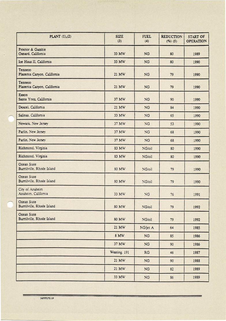
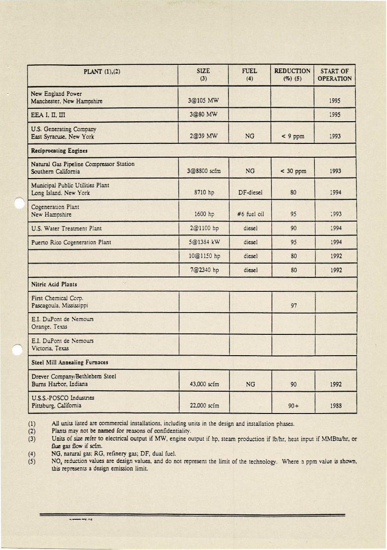
APPENDIX 2: Partial List of U.S. Applications of SCR
PLANT (1),(2) SIZE (3)
FUEL (4)
REDUCTION (%) (5)
START OF OPERATION
Utility Boilers ,
Los Angeles Department of Water and Power Haynes Station. Long Beach. California Unit 1 230 MW
- NG
i 92 1993
Unit 2 230 MW NO 92 1994
Unit 5 330 MW NG 92 1993
Unit 6 330 MW ,
NG 92 1994
Southern California Edison Redondo Beach, California Unit 7 480 MW NG 1994
Unit 8 480 MW NG 1993
Southern California Edison Alamitos. California Unit 3 320 MW NO 90 1995
Unit 4 320 MW NG 90 1995
Unit 5 430 MW NO 87 1994 ..
Unit 6 480 MW NG 87 1993
Southern California Edison Ormur,d Beach. California Unit 1 750 MW NO 93 1994
Unit 2 750 MW NO 93 1993
Southern California Edison El Sezundo. California Unit 3 335 MW NO 90
, 1995
Unit 4 335 MW NO _.
90 1994
Southern California Edison Etiwanda. California Unit 3 320 MW NG
, 90 1995
Unit 4 320 MW -
NG 90 ,
1995
City of Pasadena Pasadena. California B-3 70 MW NG
, 1994
,
Orlando Utilities Commission Stanton Unit 2 460 MW
. coal
. 1996
U.S. Generating Chambers Works, Carneys Point, New Jersey
- 2X140 MW coal 63 1994
U.S. Generating Keystone. New jersey 200 MW coal 1994

PLANT (1),(2) SIZE (3)
FUEL (4)
REDUCTION (%) (5)
,
START OF OPERATION
U.S. Generating Indiantown, Florida 320 MW coal
, 1995
Southern Electric International Birchwood, Virginia 245 MW coal 19%
Industrial Boilers
Lockhead Advanced Development Corp. Palmdale, California 90 MMbtuihr NG 1993
Refinery California 17,100 scfm
, refinery gas 1994
Wood Furniture Manufacturer Ohio 2@60 MMBtuihr wood waste 80 1993
TOSCO 176,000 lb/hr 1993
145,000 lb:hr 1993
Ultrarnar 200,000 lb/hr 1994
Shell 815,000 lbi'hr ,
1994
Kal Kan Vernon, California 15,000 scfm NG
- 88 1991
California Refinery Package Boiler ,
17,100 scfm RG 9 PPm -
1994
Process Heaters
Texaco Los Angeles. California 12,000 scfm NG 82 1990
Mobil Oil Company Torrance. California No.1 19,000 scfm
, NG 90 1990
.. Mobil Oil Company Torrance, California No.2
-. 19,000 scfm NG 90 1990
Mobil Oil Company Torrance, California No3 213,000 scfm
, NG 87 1990
Fletcher Oil 34 Refining Company Canon, California
. 9650 scfm
, 83
Ultrarnar Refining Wilmington, California 24,300 scfm 94 1992
Ashland Petroleum St. Paul, Minnesota 22,000 scfm 90 1993
Los Angeles Refinery 51,000 scfm RG 8 PPm 1994
California Refinery Hydrogen Reformer 82,000 scfm RG 90 1994
r_wITTILTE OF

PLANT (1),(2) SIZE (3)
FUEL (4)
REDUCTION (%) (5)
START OF OPERATION
Gas Turbines
Willarnette Oxnarci, California 21 MW
, NG 80 1986
ARCO Watson, California
.. 80 MW NG
'
90 ..
1987
ARCO Watson, California 80 MW NG 90 1988
, ARCO Watson. California 80 MW NG 90 1988
Chevron El Segundo. California
4
37 MW NG 90 1988
Chevron El Segundo. California
. 37 MW NG
. 90
4
1983
ARCO Watson, California 80 MW NG 90 1988
Los Angeles County Pitchess, California 21 MW NG 79 1988
Los Angeles County Civic Center Los Angeles. California 21 MW NG 79 1988
Cogen Tech. Bayonne. New Jersey 37 MW NG SO 1988
Cogen Tech. Bayonne. New Jersey 37 MW NG SO 1988
Cogen Tech. Bayonne, New Jersey
. 37 MW NG
— 80 1988
NEPCO Bakersfield, California 21 MW NO
, SO
, 1989
Navy California 21 MW NG 80 1989
Navy California 33 MW NG SO 1989
- Navy California 37 MW NO 80 1989
Chevron Richmond, California 37 MW NG 90 ?
Chevron Richmond. California 49 MW NG 90 ?
r_SSTTTLTE OF /9 1 •
PLANT (1),(2) SIZE
(3) FUEL
(4)
_ REDUCTION
(°,70) (5) START OF
OPERATION
Proctor ci Gamble Oxnard. California 33 MW NO 80 I 1989
Ice Haus II, California 33 MW NG 80 1990 ,
Tenneco Placenta Canyon. California 21 MW NG 79 1990
Tenneco Placenta Canyon, California 21 MW NO 79 1990
Exxon Santa Ynez, California 37 MW NG 90 1990
Dexcei. California 21 MW NG 84 1990
Salinas. California 33 MW NO ,
65 1990
Newark. New Jersey 37 MW NG 53 1990
Parlin. New Jersey 37 MW NG 68 1990
Parlin. New Jersey 37 MW NO 68 1990
Richmond. Virginia 83 MW NG/oil 80 1990
Richmond. Virginia 83 MW NG/oil 80 1990
Ocean State Burrillville. Rhode Island 80 MW NG/oil 79
4 1990
Ocean State Burrillville. Rhode Island 80 MW NG/oil 79
, 1990
City of Anaheim Anaheim. California 33 MW NO 76 1991
Ocean State Burrillville, Rhode Island
, 80 MW NG/oil 79 1992
Ocean State Burrillville, Rhode Island
i 80 MW
. NG/oil 79
. 1992
.
, 21 MW NG/jet A 64 1985
8 MW -.-
NG 85 1986
-. 37 MW NO
.. 90 1986
Westing. 191 RG 46 1987
21 MW NO 90 1988
21 MW NO 82 1989
33 MW NO 86 1989
:NSTTTLTE OF

PLANT (1),(2) SIZE
(3) FUEL
(4) REDUCTION
(%) (5) START OF
OPERATION
Pomona Cogeneration Partners Pomona, California 3.5 MW
.. -. < 9 PPm 1987
UNOCAL Science & Technology Center Brea, California 4.0 MW <9 PPm 1990
Southern California Gas Company Kern County, Ck. lifornia [email protected] MW
,.. NG <5 PPm 1993
City of Redding Redding, California [email protected] MW
NG-LPG backup 9 PPm 1994
March Point Cc-gen IlL'Anacortes -.
Engen Northwest 3@37 MW 1992 ,
Imperial Irrigation District California 80 MW 1992
Big Three Industries 37 MW 1993
Masspower 1993
Mobil Oil Beaumont. Tems 1993
LADWPI-larbor 10A&B 2@80 MW 1993
Onondoga 21, 33 MW 1993
UCLA Los Angeles, C_,Ilifornia 2g13 MW 1993
Olean 37 MW 1993
Lakewood 80 MW ,
1993
Gordonsville 84 MW ,
1993
Saranac 80 MW 1994
NEPCO,Vinland 42 MW .
1994
Allezherry 13 MW 1994
Tenaska 80 MW 1994
Selkirk 80 MW 1994
Naval Petroleum 21 MW ,
1994
Sithe EnergiesIndepencience 80 MW 1994
Anacortes II 2@37 MW 1994
WEPCO,Kirnber.ry 49 MW 1994
NTTTTUTE CF I 'I
PLANT (1),(2) SIZE
(3) FUEL
(4) -
REDUCTION (%) (5)
START OF OPERATION
New England Power Manchester. New Hampshire
- 3@105 MW
. 1995
EEA I, II, ITI 3@80 MW , .
1995 .
U.S. Generating Company East Syracuse. New York 2@39 MW NG
a <9 ppm 1993
Reciprocating Engines
Natural Gas Pipeline Compressor Station Southern California
.. 3E2.8800 scfm
. NO
, < 30 ppm 1993
Municipal Public Utilities Plant Long Island. New York 8710 hp DF-diesel 80 1994
Cogeneration Plant New Hampshire 1600 hp #6 fuel oil
. 95 1993
,
U.S. Water Treatment Plant 2@1100 hp diesel 90 1994
Puerto Rico Cogeneration Plant ,
5@13S4 kW .
diesel 95 1994
, 10@1150 hp diesel 80 1992
_ , 7@2340 hp diesel 80 1992
Nitric Acid Plants
First Chemical Corp. Pascagoula. Mississippi 97
E.I. DuPont de Nemours Orange. Texas
E.I. DuPont de Nemours Victoria. Texas
Steel Mill Annealing Furnaces ,
Dreyer Company/Bethlehem Steel Burns Harbor, Indiana 43,000 scfm
. NO
. 90 1992
U.S.S.-POSCO Industries Pittsburg, California 22,000 scfm 90+ 1988
All units listed are commercial installations, including units in the design and installation phases. Plants may not be named for reasons of confidentiality. Units of size refer to electrical output if MW, engine output if hp, steam production if lb/hr, heat input if !%,IMBtufhr, or Due gas flow if scfm. NG, natural gas; RG, refinery gas; DF, dual fuel. NO, reduction values are design values, and do not represent the limit of the technolog. Where a ppm value is shown, this represents a design emission limit.

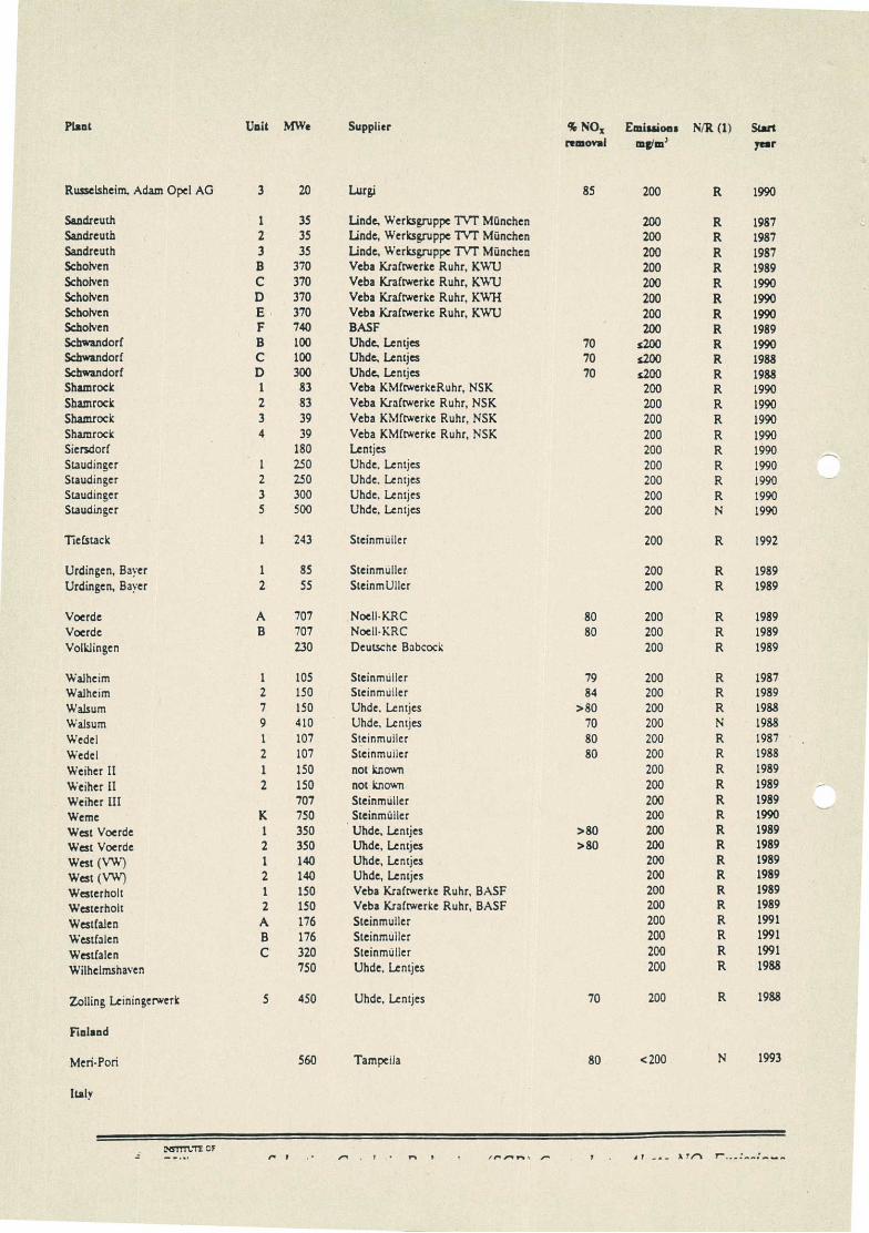
APPENDIX 3: Overseas SCR Installations on Coal-Fired Power Plants
Plant Unit MWe Supplier % NO, Emissions IsliR (1) Start removal mg/m' year
Austria
Darnrohr 1 405 Voest-Alpine, Babcock Hitachi KK 80 200 R 1986 Diarnroiar 2 320 Voest-Alpine, Babcock Hitachi KK 80 200 R 1986 Mellach 200 SGP-VA Energie, Mitsubishi 80 200 N 1986
Heavy Ind Voitsberg 3 330 Babcock Hitachi KK, KHI 150 R 1990
Dearnark
Arnagervaerket 3 2.50 not known 80 156 R 1998 Avedocrevaerket 1 250 Haldor Topsoe 80 156 R 1992
Federal Republic or Germany
Altbach Deizisau 5 420 Steinmuiler 69 200 R 1985 Aschaffenburg 21 150 Thyssen Engineering 80 200 R 1990 Aschaffenburg 31 150 Thyssen Engineering 80 200 R 1990
BASF Ludwigshafen (Mine) 2_50 Noell-KRC 200 R 1990 Beraka men A 747 Energie-und Verfahrenstechnik 75 200 R 1989 Bexbach 1 750 Energic-und Verfahrenstechnik 77 200 1989 Buer 150 Steinmuiler, NSK 75 200 R 1985
Charlottenburg 1 55 SteinmUllcr 85 200 R 1990 Charlottenburg 2 55 Steinmuller 85 200 R 1990 Charlottenburg 3 75 Steinmuiler 85 200 R 1990 Cuno (Herdecke) 2 96 Deutsche Babcock 200 N 1990
Dattein 1 48 Veba Krafr.verke Ruhr, NSK 200 R 1989 Dattein 2 48 Veba Krafrwerke Ruhr, NSK 200 R 1989 Dattein 3 48 Veba Krafrwerke Ruhr, NSK 200 R 1989 Dattein 4 48 Veba Krafrwerke Ruhr, NSK 200 R 1989 Dattein 5 97 Didier 200 1989 Dormazen, Bayer 7 37 Deutscne Babcock 200 R 1989
DU Stadtmate HKW II A 70 Thyssen Enzineering 85 200 R 1939
DU Stadtmitte IIKW II B 140 Thyssen Engineering 85 200 R 1989
Elverlingen E3 258 Steinmuller 86 200 R 1989 Elverlingen E4 258 Steinmuiler 200 R 1989 Ensdorf 2 110 Noell-KRC 200 1989
Ensdorf 3 300 Noell-KRC <200 R 1990
Farge 350 Uhde, Lentjes 200 R 1990
Fenne III 163 not known 200 R 1990
Flingem I 1-2 46 Lentjes, Steinrmiller, Hugo Petersen 200 R 1990
Flingern II 3-4 67 Lentjes, Steinmtiller, Hugo Petersen 200 R 1990
Franken II 1 200 ThyenEngineering. KWU 200 R 1990
Franken II 2 200 Thyssen Engineering. KWU 200 R 1990
Frankfurt Hóchst 1 44 Noell-KRC >78 200 R 1991
Frankfurt H6chst 2 44 Noell-KRC 200 R 1991
Frankfurt West 2 90 Lentjes 80 200 N 1989
Frankfurt West 3 90 Lentjes 80 200 N 1989
Garath 20 Steinmuiler, Hugo Petersen 200 R 1987
Hafen( Bremen 5 150 Energie- und Verfahrenstechnik 85 200 1990
Halen (Bremen) 6 300 Energie- und Verfahrenstechnik 85 200 1990
Halen (Hamburg) 2 85 Steinmuiler 75 200 N 1987
NSTITI:TE OF

Inapt Unit MWe Supplier % NO, Emissions N/R (1) Start removal eng/m3 year
Hannover-Stocken I 130 Uhdc, Lentjes 200 R 1989
Hannover-Stocken 2 130 Uhde, Lentjes 200 R 1989
Hastedt (Bremen) 15 130 Energie- und Verfahrenstechnik 70 200 N 1989
Heilbronn 3 110 Deutsche Babcock >80 200 R 1990
Heilbronn 4 110 Deutsche Babcock >80 200 R 1990
Heabronn 5 12.5 Deutscne Babcock >80 MO R 1990
Heilbronn 6 125 Deutscnc Babcock >80 200 R 1990
Heilbronn 7 750 Energie- und Verfahrenstechnik >80 200 R 1986
Herne 1 150 Uhde, Lentjes >80 200 R 1989
Herne 2 150 Uhde, Lentjes >80 200 R 1989
Herne 3 300 Uhde, Lentjes >80 200 R 1989
Heyden 4 800 Uhde, Lentjes 75 200 R 1988
Ibbenburen B 770 Uhde, Lentjes <200 R 1988
Karlsruhe West 3 64 Krupp Koppers 200 R 1988
Kellermann (Lunen) K10 150 Lentjes >80 200 R 1989
Kiel Ost 350 Uhde. Lentjes 80 200 R 1989
Knepper C 375 Uhdc, Lentjes, Thyssen Eng,ineering 90 200 R 1986 Kraftwerk HuLs I 4 125 Noel)-KRC 200 R 1990 Kraftwerk Huls I 5 131 Noel)-KRC 200 R 1991 Kraftwerkls 11 3 84 Thyssen Engineering 200 R 1990
La uswar d A 127 Lentjes, Steinmtiller, Hugo Petersen 200 R 1989
Lausward B 127 Lentjes, Steinmuller, Hugo Petersen 80 200 R 1989 La USWar d C 127 Lentjes, SteinmUiler, Hugo Petersen 80 200 R 1989 La uswar d D 127 Lentjes, Steinmtiller, Hugo Petersen 80 200 R 1989
Mainz 2 100 Deutsche Babcock 200 R 1988 Mainz 3 100 Deutscne Babcock 200 R 1988 Mannheim 3 220 Deutscne Babcock 200 R 1988 Mannheim 4 220 Deutscne Babcock 200 R 1988 Mannheim 7(K18) 475 Energie- und Verfahrenstechnik 75 200 R 1988 Mannheim 8(K19) 480 Energie- und Verfahrenstechnik 85 200 N 1992 !,,lehrum 3 700 Uhde, Lentjes, Hitachi 75 200 R 1988 Mine 1 87 Nod!-KRC 200 R 1988 MUnster (Stuttgart) 12 40 Energie•und Verfahrenstechnik 80 200 R 1986 Milnster (Stuttgart) 15 40 Enerue•und Verfahrenstechnik 80 200 R 1986 Munster (Stuttgart) 25 67 Energie-und Verfahrenstechnik 72 200 R 1986
Nord (München) 2 362 Deutscne Babcock 100 N 1992
Oberhavel 1 100 Steinmuiler 200 R 1990 Oberhavei 2 100 Steinmuiler 200 R 1990 Ost (Linen) Kil 350 Lentjes >80 200 R 1989
Porta WF Veltheim 1 100 Deutscne Babcock 82 200 R 1989 Porta WF Veltheina 2 100 Deutscne Babcock 200 R 1989 Porta WF Veltheim 3 330 Deutscne Babcock 200 R 1989
Reuter 1 50 Lentjes 200 R 1990 Reuter 2 50 Lentjes 200 R 1990 Reuter C 150 Lentjes 200 R 1990 Reuter West D 300 Deutscne Babcock, Balcke, DUrr, Borsig 200 N 1989 Reuter West E 300 Deutscne Babcock, Balcke, Dürr, Borsig 200 N 1989 Rheinhafen (Karlsruhe) 7 550 SteinmUiier 200 R 1989 Rudow 1 38 Deutscne Babcock 200 R 1990 Rudow 2 38 Deutscne Babcock 200 R 1990 Rudow 3 100 Deutscne Babcock 200 R 1990 Russeisheim. Adam Opel AG 2 20 Lurei 85 200 R 1990
r,sTrrtn-p
Plant Unit MWe Supplier % NO, Emissions NiR (1) Start removal tat& year
Russelsheim, Adam Opel AG 3 20 Lurgi 85 200 R 1990
Sandreuth 1 35 linde, Werksgruppe TVT München 200 R 1987 Sandreuth 2 35 Linde, Werksgruppe TVT München 200 R 1987 Sandreuth 3 35 Linde, Werksgruppe TVI" München 200 R 1987 Schotven B 370 Veba Kraftwerke Ruhr, KWU 200 R 1989 Schob:en C 370 Veba Kraftwerke Ruhr, KWU 200 R 1990 Schotven D 370 Veba Kraftwerke Ruhr, KW1-1 200 R 1990 Scholven E 370 Veba Kraftwerke Ruhr, KWU 200 R 1990 Schotven F 740 BASF 200 R 1989 Schwandorf B 100 Uhde, Lentjes 70 1200 R 1990 Schwandorf C 100 Uhde, Lentjes 70 1200 R 1988 Schwandorf D 300 Uhde, Lentjes 70 1200 R 1988 Shamrock 1 83 Veba KNIftwerkeRuhr, NSK 200 R 1990 Shamrock 2 83 Veba Kraftwerke Ruhr, NSK 200 R 1990 Shamrock 3 39 Veba KMftwerke Ruhr, NSK 200 R 1990 Shamrock 4 39 Veba KMftwerke Ruhr, NSK 200 R 1990 Siersdorf 180 Lentjes 200 R 1990 Staudinger 1 250 Uhde. Lentjes 200 R 1990 Staudinger 2 250 Uhde, Lentjes 200 R 1990 Staudinger 3 300 Uhde, Lentjes 200 R 1990 Staudinger 5 500 Uhde, Lentjes 200 N 1990
Tiefstack 1 243 Steinmuiler 200 R 1992
Urdingen, Bayer 1 85 Steinmuller 200 R 1989 Urdingen, Bayer 2 55 SteinmUller 200 R 1989
Voerde A 707 Noell-KRC 80 200 R 1989 Voerde B 707 Noell-KRC 80 200 R 1989 Volklingen 230 Deutsche Babcock 200 R 1989
Walheim 1 105 Steinmidler 79 200 R 1987 Walhe:m 2 150 Steinmuiler 84 200 R 1989 WaLsum 7 150 Uhde. Lentjes >80 200 R 1988 Walsum 9 410 Uhde, Lentjes 70 200 N 1988
Wedel 1 107 Steinmuiler 80 200 R 1987
Wedel 2 107 Steinmulier 80 200 R 1988
Weiher II 1 150 not known 200 R 1989
Weiher II 2 150 not known 200 R 1989
Weiher III 707 Steinmuiler 200 R 1989
Weme K 750 . Steinmitler 200 R 1990
West Voerde 1 350 Uhde, Lentjes >80 200 R 1989
West Voerde 2 350 Uhde, Lentjes >80 200 R 1989
West (VW) 1 140 Uhde, Lentjes 200 R 1989
West (VW) 2 140 Uhde, Lentjes 200 R 1989
Westerholt 1 150 Veba Kraftwerke Ruhr, BASF 200 R 1989
Vv'esterholt 2 150 Veba Kraftwerke Ruhr, BASF 200 R 1989
Westfalen A 176 Steinmuiler 200 R 1991
Westfalen B 176 Steinmuiler 200 R 1991
Westfalen C 320 Steinrmiller 200 R 1991
Wilhelmshaven 750 Uhde, Lentjes 200 R 1988
Zolling Leiningerwerk 5 450 Uhde, Lentjes 70 200 R 1988
Finland
Meri-Pori 560 Tampetla 80 <200 N 1993
Italy
'..NSITTLIT OF r. I
7

Plant Unit MWe
Brindisi Sud 1 660 Brindisi Sud 2 660 Brindisi Sud 3 660 Brindisi Sud 4 660 Fiume Santo 3 320 Fiume Santo 4 320 Fusina 1 160 Fusina 2 160 Fusina 3 320 Fusina 4 320 Gioia Tauro 1 660 Gioia Tauro 2 660 Gioia Tauro 3 660 Gioia Tauro 4 660 La Spezia 1 320 La Spezia 2 320 La Spezia 3 600 La Spezia 4 600 San Filippo Del Mcla 5 320 San Filippo Del Mcla 6 320 Su'cis 1 240 Suleis 2 240 Suleis 3 240 Tavazzano 3 320 Tava r7a no 4 320 Vado Ligure 1 320 Vado Ligure 2 320 Vado Ligure 3 320 Vado Ligure 4 320
Japan
Chiba Factory 2 90
Daicci Chemical Co_ 100 Aboshi Factory
Hekinan 2 700 Hekinan 3 700 Himeji No 1 1 33
Idemitsu Kosan Eneincering Co. A 50 Idemitsu Kosan Petroleum, 40
Hyogo Refinery
Matsuura (Kyushu Electric Power) 1 700 Matsuura (EPDC) 1 1000 Matsuura 2 1000 Minato 1 156 Mizushima 1 125 Mizushima 2 156
Nakoso 8 600 Nakoso 9 600
Saijo 1 156 54o 2 2.50 Sakata 1 350 Sakata 2 350 Sendai 2 175
Supplier
not known not known not known not known not known npt known not known not known not known not known not known not known not known not known not known not known not known not known not known not known not known not known not known not known not known not known not known not known not known
Mitsubishi Heavy Industries
Mitsubishi Heavy Industries
Mitsubishi Heavy Industries Ishikawajima Harima Heavy Ind Ishikawajima Harima Heavy Ind
Kawasaki Heavy Industries Babcock Hitachi KK
Mitsubishi Heavy Industries Babcock Hitachi KK not known Mitsubishi Heavy Industries Babcock Hitachi KK Babcock Hitachi KK
Mitsubishi Heavy Industries Ishikawajima Harima Heavy Ind
Mitsubishi Heavy Industries Ishikawajima Harima Heavy Ind Mitsubishi Heavy Industries Mitsubishi Heavy Industries Babcock Hitachi KK
go NO, removal
Emissions mgicia'
NIZ (1) Start year
80 <200 N 1992 80 c200 N 1993 80 200 N 1993 80 <200 N 1994 80 <200 N 1992 80 <200 N 1992 80 <200 R 1992 80 c200 R 1992 80 <200 R 1993 80 <200 R 1993 80 <200 N 1994 80 <200 N 1995 80 <200 N 1995 80 <200 N 1996 80 <200 R 1992 80 <200 R 1992 80 <200 R 1993 80 <200 R 1993 80 <200 R 1994 80 <200 R 1994 80 <200 R 1994 80 <200 R 1994 80 <200 R 1994 80 <200 R 1994 80 <200 R 1995 80 <200 R 1993 80 <200 R 1993 80 <200 R 1994 80 <200 R 1994
1985
1987
80 N 1992 80 N 1993 75 R 1982
>55 1987 60 1986
N 1989 80 123 N 1990
N 1999 53 R 1983 65 R 1984 65 R 1984
60 N 1983 60 N 1983
65 R 1983 65 R 1984 80 R 1984 35 N 1984 60 R 1983
MieTTT1 r1"F OF

-,
j
•,-,,
:,
• v..-
:..
.,
,I'