Wavelet coefficients clustering using morphological operations and pruned quadtrees
10
* Corresponding author. Tel.: #1-973-596-5654; fax: #1- 973-596-5777. E-mail address: shih@cis.njit.edu (F.Y. Shih). 0031-3203/00/$20.00 ( 2000 Pattern Recognition Society. Published by Elsevier Science Ltd. All rights reserved. PII: S 0 0 3 1 - 3 2 0 3 ( 9 9 ) 0 0 1 4 7 - 8 Pattern Recognition 33 (2000) 1611}1620 Wavelet coe$cients clustering using morphological operations and pruned quadtrees Eduardo Morales, Frank Y. Shih* Computer Vision Laboratory, Department of Computer and Information Science, New Jersey Institute of Technology, Newark, NJ 07102, USA Received 9 February 1999; received in revised form 1 June 1999; accepted 1 June 1999 Abstract Transform coding has been extensively applied in image compression. The wavelet transform possesses the character- istic of providing spatial and frequency domain information. This characteristic plays an important role in image compression so that identi"cation and selection of the signi"cant coe$cients in the wavelet transform become easier. The result has the advantages of better compression ratio and better image quality. The paper presents a new approach to create an e$cient clustering of the signi"cant coe$cients in the wavelet transform based on morphological operations and pruned quadtrees. In this way, only the signi"cant coe$cients and their map will be encoded and transmitted. The decoder process will use the map to place the signi"cant coe$cients in the correct locations and then apply the inverse wavelet transform to reconstruct the original image. Experimental results show that the combination of morphological operations and pruned quadtrees outperforms the conventional quadtrees by a compression ratio of 2 to 1 with the similar image quality. ( 2000 Pattern Recognition Society. Published by Elsevier Science Ltd. All rights reserved. Keywords: Wavelet transform; Image compression; Quadtree; Mathematical morphology 1. Introduction Image compression using the transform coding tech- niques [1}4] has been an active research area for many years. One of their characteristics is the ability to de- correlate data. As a consequence, a `densea signal is transformed into a `sparsea signal where most of the information is concentrated on just a few coe$cients. Compression can be achieved by setting all non-signi"- cant coe$cients to a single value and then applying the entropy encoding. The resulting bit sequence will mostly contain the information about the signi"cant coe$cients. One popular transform during the last few years has been the Discrete Cosine Transform (DCT). Industrial standards for compressing still images (e.g. JPEG) and motion pictures (e.g. MPEG) have been based on the DCT. Both standards have produced good results, but have limitations at high compression ratios [5,6]. At low data rates, the DCT-based transforms su!er from a `blocking e!ecta due to its unnatural block partition that is required in the computation. Other drawbacks include mosquito noise and aliasing distortions. Furthermore, the DCT does not improve the performance as well as the complexities of motion compensation and estimation in video coding [6]. Due to the shortcomings of DCT, the discrete wavelet transform (DWT) has become increasingly important. The main advantage of the DWT is that it provides the space}frequency decomposition of images [7,8], over- coming the DCT and the Fourier transform that only provide the frequency decomposition. By providing the space}frequency decomposition, the DWT allows energy compaction at the low-frequency subbands and the space localization of edges at the high-frequency subbands. Furthermore, the DWT does not present a blocking e!ect at the low data rates. In this paper, we present a new algorithm for identify- ing signi"cant coe$cients in the DWT and "nding an
-
Upload
independent -
Category
Documents
-
view
0 -
download
0
Transcript of Wavelet coefficients clustering using morphological operations and pruned quadtrees
*Corresponding author. Tel.: #1-973-596-5654; fax: #1-973-596-5777.
E-mail address: [email protected] (F.Y. Shih).
0031-3203/00/$20.00 ( 2000 Pattern Recognition Society. Published by Elsevier Science Ltd. All rights reserved.PII: S 0 0 3 1 - 3 2 0 3 ( 9 9 ) 0 0 1 4 7 - 8
Pattern Recognition 33 (2000) 1611}1620
Wavelet coe$cients clustering using morphological operationsand pruned quadtrees
Eduardo Morales, Frank Y. Shih*
Computer Vision Laboratory, Department of Computer and Information Science, New Jersey Institute of Technology, Newark, NJ 07102, USA
Received 9 February 1999; received in revised form 1 June 1999; accepted 1 June 1999
Abstract
Transform coding has been extensively applied in image compression. The wavelet transform possesses the character-istic of providing spatial and frequency domain information. This characteristic plays an important role in imagecompression so that identi"cation and selection of the signi"cant coe$cients in the wavelet transform become easier. Theresult has the advantages of better compression ratio and better image quality. The paper presents a new approach tocreate an e$cient clustering of the signi"cant coe$cients in the wavelet transform based on morphological operationsand pruned quadtrees. In this way, only the signi"cant coe$cients and their map will be encoded and transmitted. Thedecoder process will use the map to place the signi"cant coe$cients in the correct locations and then apply the inversewavelet transform to reconstruct the original image. Experimental results show that the combination of morphologicaloperations and pruned quadtrees outperforms the conventional quadtrees by a compression ratio of 2 to 1 with thesimilar image quality. ( 2000 Pattern Recognition Society. Published by Elsevier Science Ltd. All rights reserved.
Keywords: Wavelet transform; Image compression; Quadtree; Mathematical morphology
1. Introduction
Image compression using the transform coding tech-niques [1}4] has been an active research area for manyyears. One of their characteristics is the ability to de-correlate data. As a consequence, a `densea signal istransformed into a `sparsea signal where most of theinformation is concentrated on just a few coe$cients.Compression can be achieved by setting all non-signi"-cant coe$cients to a single value and then applying theentropy encoding. The resulting bit sequence will mostlycontain the information about the signi"cant coe$cients.
One popular transform during the last few years hasbeen the Discrete Cosine Transform (DCT). Industrialstandards for compressing still images (e.g. JPEG) andmotion pictures (e.g. MPEG) have been based on the
DCT. Both standards have produced good results, buthave limitations at high compression ratios [5,6]. At lowdata rates, the DCT-based transforms su!er from a`blocking e!ecta due to its unnatural block partition thatis required in the computation. Other drawbacks includemosquito noise and aliasing distortions. Furthermore,the DCT does not improve the performance as well as thecomplexities of motion compensation and estimation invideo coding [6].
Due to the shortcomings of DCT, the discrete wavelettransform (DWT) has become increasingly important.The main advantage of the DWT is that it provides thespace}frequency decomposition of images [7,8], over-coming the DCT and the Fourier transform that onlyprovide the frequency decomposition. By providing thespace}frequency decomposition, the DWT allows energycompaction at the low-frequency subbands and the spacelocalization of edges at the high-frequency subbands.Furthermore, the DWT does not present a blockinge!ect at the low data rates.
In this paper, we present a new algorithm for identify-ing signi"cant coe$cients in the DWT and "nding an

Fig. 1. Wavelet decomposition of an image.
e$cient way to describe their space locations. By doingso, the image compression coders can bene"t from ob-taining lower bits-per-pixel ratios. The coders are ableto only encode the coe$cients that contain most of theimage information as well as their respective spatial loca-tions. The coe$cients that represent noise and the detailsthat are almost imperceptible will be excluded from theencoding process.
The paper is organized as follows. Section 2 brie#yreviews the basic information of the wavelet transform.Section 3 introduces the steps in the transform codingprocess. Sections 4 and 5 discuss how to identify andrepresent the signi"cant transform coe$cients. Experi-mental results are presented in Section 6. Finally, con-clusions are made.
2. The wavelet transform
Wavelets are functions that integrate to zero wavingabove and below the x-axis [9]. Like sines and cosinesin the Fourier transform, wavelets are used as the basisfunctions for signal and image representation. Such basisfunctions are obtained by dilating and translating amother wavelet t(x) by amounts s and q, respectively:
(q,s(x)"GtAx!q
s B, (q, s)3R]R`H.The translation and dilation allow the wavelet trans-
form to be localized in time and frequency. Also, waveletbasis functions can represent functions with discontinui-ties and spikes in a more compact way than sines andcosines [8].
The continuous wavelet transform (CWT) can be de-"ned as
cwtt (q, s)"1
JDsD Px(t)(Hq,s (t) dt, (1)
where (Hq,s is the complex conjugate of (q,s and x(t) is theinput signal de"ned in the time domain.
The inverse CWT can be obtained from the transposeof Eq. (1):
x(t)"1
C2t PsPqcwtt (q, s)1
s2(q, s(t) dt ds, (2)
where Ct is a constant and depends on the wavelet used.To discretize the CWT, the simplest case is the uniform
sampling of the time}frequency plane. However, thesampling could be more e$cient by using the Nyquist'srule:
N2"
s1
s2
N1, (3)
where N1
and N2
denote the number of samples at scaless1
and s2, respectively, and s
2's
1. This rule means that
at higher scales (lower frequencies), the number of sam-ples can be decreased. The sampling rate obtained is theminimum rate that allows the original signal to be recon-structed from a discrete set of samples. A dyadic scalesatis"es the Nyquist's rule by discretizing the scale para-meter into a logarithmic series, and then the time para-meter is discretized by applying Eq. (3) with respect to thecorresponding scale parameters. The following equationsset the translation and dilation to the dyadic scale withlogarithmic series of base 2 for t
k,j:
q"k2j, s"2j.
We can view these coe$cients as "lters which areclassi"ed into two types. One set, H, works as a low-pass"lter and the other, G, as a high-pass "lter. These twotypes of coe$cients are called quadrature mirror xltersused in the pyramidal algorithms.
For a two-dimensional (2-D) signal, it is not necessary,although straight-forward, to extend the 1-D wavelettransform to its 2-D one. The strategy is described asfollows. The 1-D transform can be applied individually toeach of the dimensions of the image. By using the quadra-ture mirror "lters we can decompose an n]n imageI into the wavelet coe$cients as below. Filters H andG are applied on the rows of an image, splitting theimage into two subimages of dimensions n/2]n (half thecolumns) each. One of these subimages H
rI (where the
subscript r denotes row) contains the low-pass in-formation and the other, G
rI, contains the high-pass
1612 E. Morales, F.Y. Shih / Pattern Recognition 33 (2000) 1611}1620
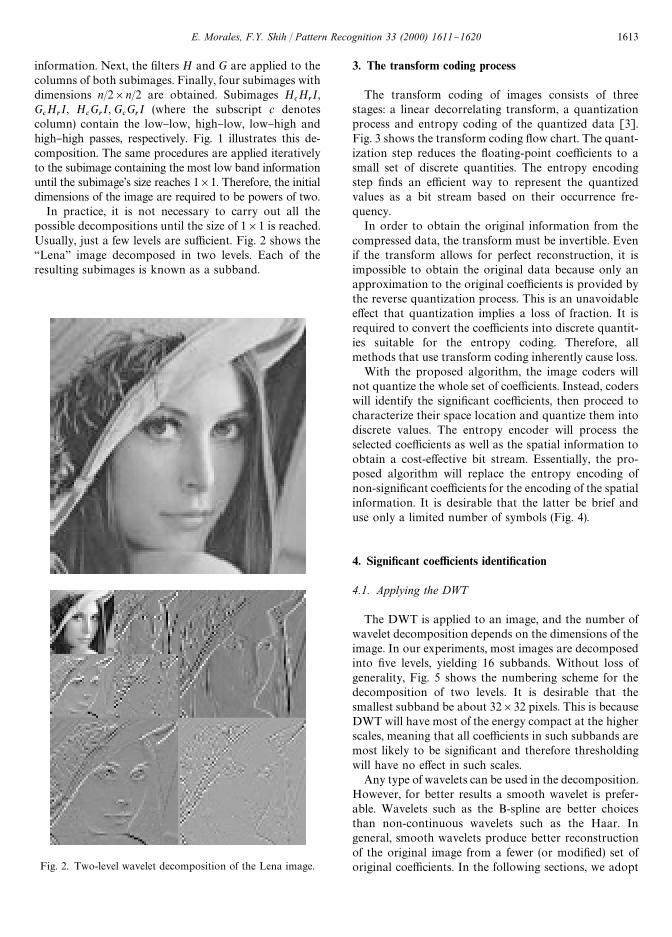
Fig. 2. Two-level wavelet decomposition of the Lena image.
information. Next, the "lters H and G are applied to thecolumns of both subimages. Finally, four subimages withdimensions n/2]n/2 are obtained. Subimages H
cH
rI,
GcH
rI, H
cG
rI, G
cG
rI (where the subscript c denotes
column) contain the low}low, high}low, low}high andhigh}high passes, respectively. Fig. 1 illustrates this de-composition. The same procedures are applied iterativelyto the subimage containing the most low band informationuntil the subimage's size reaches 1]1. Therefore, the initialdimensions of the image are required to be powers of two.
In practice, it is not necessary to carry out all thepossible decompositions until the size of 1]1 is reached.Usually, just a few levels are su$cient. Fig. 2 shows the`Lenaa image decomposed in two levels. Each of theresulting subimages is known as a subband.
3. The transform coding process
The transform coding of images consists of threestages: a linear decorrelating transform, a quantizationprocess and entropy coding of the quantized data [3].Fig. 3 shows the transform coding #ow chart. The quant-ization step reduces the #oating-point coe$cients to asmall set of discrete quantities. The entropy encodingstep "nds an e$cient way to represent the quantizedvalues as a bit stream based on their occurrence fre-quency.
In order to obtain the original information from thecompressed data, the transform must be invertible. Evenif the transform allows for perfect reconstruction, it isimpossible to obtain the original data because only anapproximation to the original coe$cients is provided bythe reverse quantization process. This is an unavoidablee!ect that quantization implies a loss of fraction. It isrequired to convert the coe$cients into discrete quantit-ies suitable for the entropy coding. Therefore, allmethods that use transform coding inherently cause loss.
With the proposed algorithm, the image coders willnot quantize the whole set of coe$cients. Instead, coderswill identify the signi"cant coe$cients, then proceed tocharacterize their space location and quantize them intodiscrete values. The entropy encoder will process theselected coe$cients as well as the spatial information toobtain a cost-e!ective bit stream. Essentially, the pro-posed algorithm will replace the entropy encoding ofnon-signi"cant coe$cients for the encoding of the spatialinformation. It is desirable that the latter be brief anduse only a limited number of symbols (Fig. 4).
4. Signi5cant coe7cients identi5cation
4.1. Applying the DWT
The DWT is applied to an image, and the number ofwavelet decomposition depends on the dimensions of theimage. In our experiments, most images are decomposedinto "ve levels, yielding 16 subbands. Without loss ofgenerality, Fig. 5 shows the numbering scheme for thedecomposition of two levels. It is desirable that thesmallest subband be about 32]32 pixels. This is becauseDWT will have most of the energy compact at the higherscales, meaning that all coe$cients in such subbands aremost likely to be signi"cant and therefore thresholdingwill have no e!ect in such scales.
Any type of wavelets can be used in the decomposition.However, for better results a smooth wavelet is prefer-able. Wavelets such as the B-spline are better choicesthan non-continuous wavelets such as the Haar. Ingeneral, smooth wavelets produce better reconstructionof the original image from a fewer (or modi"ed) set oforiginal coe$cients. In the following sections, we adopt
E. Morales, F.Y. Shih / Pattern Recognition 33 (2000) 1611}1620 1613
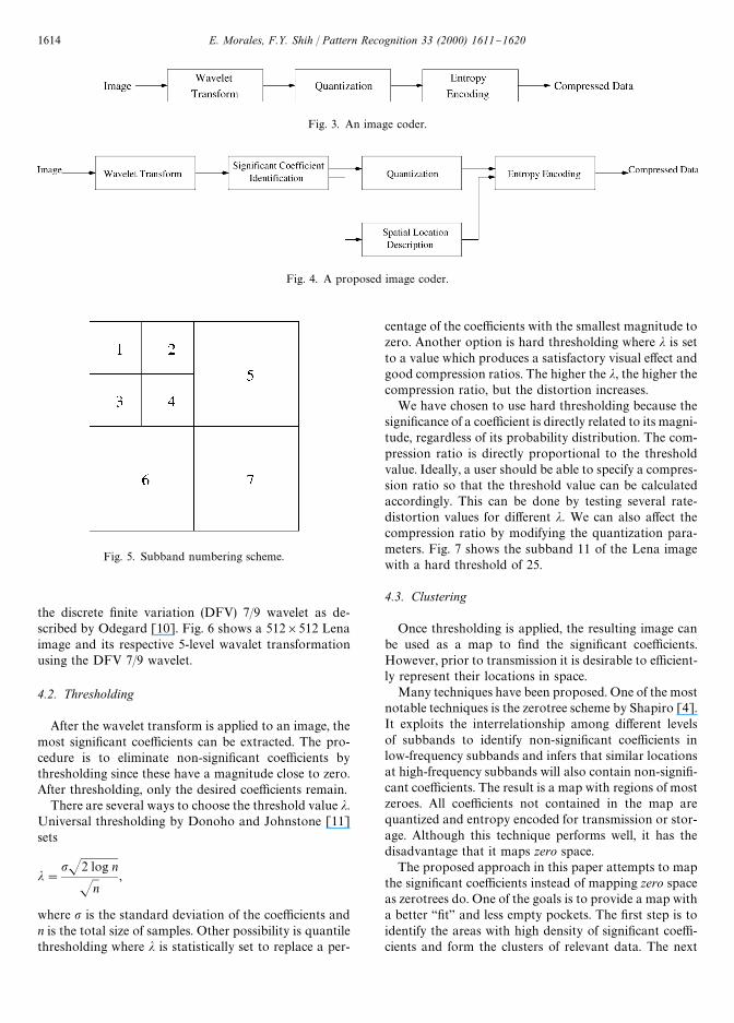
Fig. 3. An image coder.
Fig. 4. A proposed image coder.
Fig. 5. Subband numbering scheme.
the discrete "nite variation (DFV) 7/9 wavelet as de-scribed by Odegard [10]. Fig. 6 shows a 512]512 Lenaimage and its respective 5-level wavalet transformationusing the DFV 7/9 wavelet.
4.2. Thresholding
After the wavelet transform is applied to an image, themost signi"cant coe$cients can be extracted. The pro-cedure is to eliminate non-signi"cant coe$cients bythresholding since these have a magnitude close to zero.After thresholding, only the desired coe$cients remain.
There are several ways to choose the threshold value j.Universal thresholding by Donoho and Johnstone [11]sets
j"pJ2 log n
Jn,
where p is the standard deviation of the coe$cients andn is the total size of samples. Other possibility is quantilethresholding where j is statistically set to replace a per-
centage of the coe$cients with the smallest magnitude tozero. Another option is hard thresholding where j is setto a value which produces a satisfactory visual e!ect andgood compression ratios. The higher the j, the higher thecompression ratio, but the distortion increases.
We have chosen to use hard thresholding because thesigni"cance of a coe$cient is directly related to its magni-tude, regardless of its probability distribution. The com-pression ratio is directly proportional to the thresholdvalue. Ideally, a user should be able to specify a compres-sion ratio so that the threshold value can be calculatedaccordingly. This can be done by testing several rate-distortion values for di!erent j. We can also a!ect thecompression ratio by modifying the quantization para-meters. Fig. 7 shows the subband 11 of the Lena imagewith a hard threshold of 25.
4.3. Clustering
Once thresholding is applied, the resulting image canbe used as a map to "nd the signi"cant coe$cients.However, prior to transmission it is desirable to e$cient-ly represent their locations in space.
Many techniques have been proposed. One of the mostnotable techniques is the zerotree scheme by Shapiro [4].It exploits the interrelationship among di!erent levelsof subbands to identify non-signi"cant coe$cients inlow-frequency subbands and infers that similar locationsat high-frequency subbands will also contain non-signi"-cant coe$cients. The result is a map with regions of mostzeroes. All coe$cients not contained in the map arequantized and entropy encoded for transmission or stor-age. Although this technique performs well, it has thedisadvantage that it maps zero space.
The proposed approach in this paper attempts to mapthe signi"cant coe$cients instead of mapping zero spaceas zerotrees do. One of the goals is to provide a map witha better `"ta and less empty pockets. The "rst step is toidentify the areas with high density of signi"cant coe$-cients and form the clusters of relevant data. The next
1614 E. Morales, F.Y. Shih / Pattern Recognition 33 (2000) 1611}1620
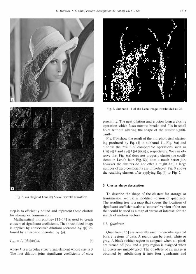
Fig. 6. (a) Original Lena (b) 5-level wavelet transform.
Fig. 7. Subband 11 of the Lena image thresholded at 25.
step is to e$ciently bound and represent those clustersfor storage or transmission.
Mathematical morphology [12}14] is used to createclusters of signi"cant coe$cients. The thresholded imageis applied by consecutive dilations (denoted by =) fol-lowed by an erosion (denoted by >):
Iclus
"Ij=k=k>k, (4)
where k is a circular structuring element whose size is 3.The "rst dilation joins signi"cant coe$cients of close
proximity. The next dilation and erosion form a closingoperation which fuses narrow breaks and "lls in smallholes without altering the shape of the cluster signi"-cantly.
Fig. 8(b) show the result of the morphological cluster-ing produced by Eq. (4) in subband 11. Fig. 8(a) andc show the result of comparable operations such asIj=k>k and Ij=k=k=k>k, respectively. We can ob-serve that Fig. 8(a) does not properly cluster the coe$-cients in Lena's hair. Fig. 8(c) does a much better job,however the clusters do not o!er a `tight "ta, a largenumber of zero coe$cients are introduced. Fig. 9 showsthe resulting clusters after applying Eq. (4) to Fig. 7.
5. Cluster shape description
To describe the shape of the clusters for storage ortransmission, we use a modi"ed version of quadtrees.The resulting tree is a map that covers the locations ofsigni"cant coe$cients, also a `coarsera version of the treethat could be used as a map of `areas of interesta for thesearch of motion vectors.
5.1. Quadtrees
Quadtrees [15] are generally used to describe squaredbinary regions of data. A region can be black, white orgray. A black (white) region is assigned when all pixelsare turned o! (on), and a gray region is assigned whenall pixels are mixed-typed. The quadtree of an image isobtained by subdividing it into four quadrants and
E. Morales, F.Y. Shih / Pattern Recognition 33 (2000) 1611}1620 1615
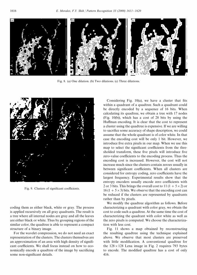
Fig. 8. (a) One dilation. (b) Two dilations. (c) Three dilations.
Fig. 9. Clusters of signi"cant coe$cients.
coding them as either black, white or gray. The processis applied recursively on all gray quadrants. The result isa tree where all internal nodes are gray and all the leavesare either black or white. Thus by grouping regions of thesimilar color, the quadtree is able to represent a compactstructure of a binary image.
For the wavelet compression, we do not need an exactrepresentation of the clusters. The clusters themselves arean approximation of an area with high density of signi"-cant coe$cients. We shall focus instead on how to eco-nomically encode a quadtree of the image by sacri"cingsome non-signi"cant details.
Considering Fig. 10(a), we have a cluster that "tswithin a quadrant of a quadtree. Such a quadrant couldbe directly encoded by a sequence of 16 bits. Whencalculating its quadtree, we obtain a tree with 17 nodes(Fig. 10(b)), which has a cost of 28 bits by using theHu!man encoding. It is clear that the cost to representa cluster using the quadtree is expensive. If we are willingto sacri"ce some accuracy of shape description, we couldassume that the whole quadrant is of color white. In thatcase the encoding cost will be only 1 bit. However, weintroduce "ve extra pixels in our map. When we use thismap to select the signi"cant coe$cients from the thre-sholded transform, these "ve pixels will introduce "vezero-value coe$cients to the encoding process. Thus theencoding cost is increased. However, the cost will notincrease much since the clusters contain zeroes usually inbetween signi"cant coe$cients. When all clusters areconsidered for entropy coding, zero coe$cients have thelargest frequency. Experimental results show that theentropy encoders usually encode zero coe$cients with2 or 3 bits. This brings the overall cost to 11 (1#5]2) or16 (1#5]3) bits. We observe that the encoding cost canbe reduced if the clusters are represented by quadrantsrather than by pixels.
We modify the quadtree algorithm as follows. Beforecharacterizing a quadrant with color gray, we obtain thecost to code such a quadtree. At the same time the cost ofcharacterizing the quadrant with color white as well asthe zero pixels is computed. We choose the characteriza-tion with less cost.
Fig. 11 shows a map obtained by reconstructingthe resulting quadtree using the technique explainedabove. We observe that most clusters are preservedwith little modi"cation. A conventional quadtree forthe 128]128 Lena image in Fig. 2 requires 793 bytesto encode. The modi"ed quadtree has a cost of only416.
1616 E. Morales, F.Y. Shih / Pattern Recognition 33 (2000) 1611}1620
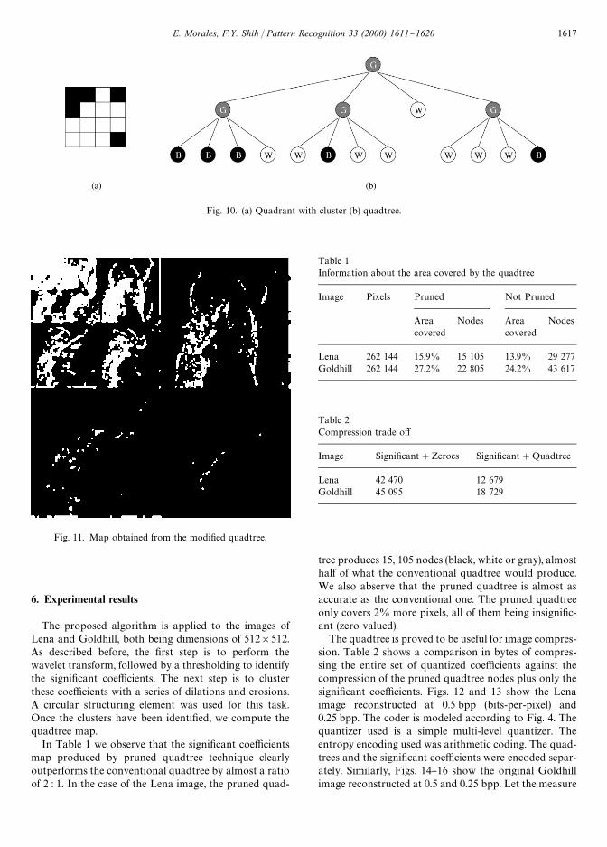
Fig. 10. (a) Quadrant with cluster (b) quadtree.
Fig. 11. Map obtained from the modi"ed quadtree.
Table 1Information about the area covered by the quadtree
Image Pixels Pruned Not Pruned
Areacovered
Nodes Areacovered
Nodes
Lena 262 144 15.9% 15 105 13.9% 29 277Goldhill 262 144 27.2% 22 805 24.2% 43 617
Table 2Compression trade o!
Image Signi"cant#Zeroes Signi"cant#Quadtree
Lena 42 470 12 679Goldhill 45 095 18 729
6. Experimental results
The proposed algorithm is applied to the images ofLena and Goldhill, both being dimensions of 512]512.As described before, the "rst step is to perform thewavelet transform, followed by a thresholding to identifythe signi"cant coe$cients. The next step is to clusterthese coe$cients with a series of dilations and erosions.A circular structuring element was used for this task.Once the clusters have been identi"ed, we compute thequadtree map.
In Table 1 we observe that the signi"cant coe$cientsmap produced by pruned quadtree technique clearlyoutperforms the conventional quadtree by almost a ratioof 2 : 1. In the case of the Lena image, the pruned quad-
tree produces 15, 105 nodes (black, white or gray), almosthalf of what the conventional quadtree would produce.We also abserve that the pruned quadtree is almost asaccurate as the conventional one. The pruned quadtreeonly covers 2% more pixels, all of them being insigni"c-ant (zero valued).
The quadtree is proved to be useful for image compres-sion. Table 2 shows a comparison in bytes of compres-sing the entire set of quantized coe$cients against thecompression of the pruned quadtree nodes plus only thesigni"cant coe$cients. Figs. 12 and 13 show the Lenaimage reconstructed at 0.5 bpp (bits-per-pixel) and0.25 bpp. The coder is modeled according to Fig. 4. Thequantizer used is a simple multi-level quantizer. Theentropy encoding used was arithmetic coding. The quad-trees and the signi"cant coe$cients were encoded separ-ately. Similarly, Figs. 14}16 show the original Goldhillimage reconstructed at 0.5 and 0.25 bpp. Let the measure
E. Morales, F.Y. Shih / Pattern Recognition 33 (2000) 1611}1620 1617
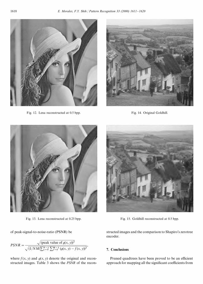
Fig. 12. Lena reconstructed at 0.5 bpp.
Fig. 13. Lena reconstructed at 0.25 bpp.
Fig. 14. Original Goldhill.
Fig. 15. Goldhill reconstructed at 0.5 bpp.
of peak-signal-to-noise-ratio (PSNR) be
PSNR"
J(peak value of g(x, y))2
J(1/NM)+N~1x/0
+M~1y/0
(g(x, y)!f (x, y))2,
where f (x, y) and g(x, y) denote the original and recon-structed images. Table 3 shows the PSNR of the recon-
structed images and the comparison to Shapiro's zerotreeencoder.
7. Conclusions
Pruned quadtrees have been proved to be an e$cientapproach for mapping all the signi"cant coe$cients from
1618 E. Morales, F.Y. Shih / Pattern Recognition 33 (2000) 1611}1620
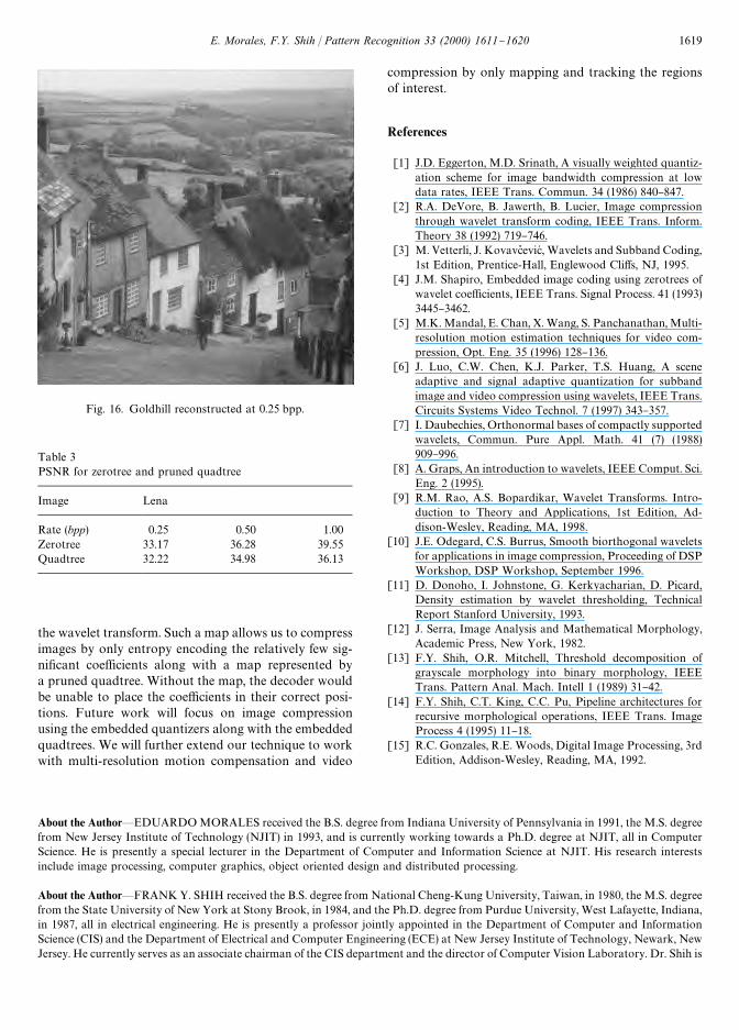
Fig. 16. Goldhill reconstructed at 0.25 bpp.
Table 3PSNR for zerotree and pruned quadtree
Image Lena
Rate (bpp) 0.25 0.50 1.00Zerotree 33.17 36.28 39.55Quadtree 32.22 34.98 36.13
the wavelet transform. Such a map allows us to compressimages by only entropy encoding the relatively few sig-ni"cant coe$cients along with a map represented bya pruned quadtree. Without the map, the decoder wouldbe unable to place the coe$cients in their correct posi-tions. Future work will focus on image compressionusing the embedded quantizers along with the embeddedquadtrees. We will further extend our technique to workwith multi-resolution motion compensation and video
compression by only mapping and tracking the regionsof interest.
References
[1] J.D. Eggerton, M.D. Srinath, A visually weighted quantiz-ation scheme for image bandwidth compression at lowdata rates, IEEE Trans. Commun. 34 (1986) 840}847.
[2] R.A. DeVore, B. Jawerth, B. Lucier, Image compressionthrough wavelet transform coding, IEEE Trans. Inform.Theory 38 (1992) 719}746.
[3] M. Vetterli, J. Kovavc\ evicH , Wavelets and Subband Coding,1st Edition, Prentice-Hall, Englewood Cli!s, NJ, 1995.
[4] J.M. Shapiro, Embedded image coding using zerotrees ofwavelet coe$cients, IEEE Trans. Signal Process. 41 (1993)3445}3462.
[5] M.K. Mandal, E. Chan, X. Wang, S. Panchanathan, Multi-resolution motion estimation techniques for video com-pression, Opt. Eng. 35 (1996) 128}136.
[6] J. Luo, C.W. Chen, K.J. Parker, T.S. Huang, A sceneadaptive and signal adaptive quantization for subbandimage and video compression using wavelets, IEEE Trans.Circuits Systems Video Technol. 7 (1997) 343}357.
[7] I. Daubechies, Orthonormal bases of compactly supportedwavelets, Commun. Pure Appl. Math. 41 (7) (1988)909}996.
[8] A. Graps, An introduction to wavelets, IEEE Comput. Sci.Eng. 2 (1995).
[9] R.M. Rao, A.S. Bopardikar, Wavelet Transforms. Intro-duction to Theory and Applications, 1st Edition, Ad-dison-Wesley, Reading, MA, 1998.
[10] J.E. Odegard, C.S. Burrus, Smooth biorthogonal waveletsfor applications in image compression, Proceeding of DSPWorkshop, DSP Workshop, September 1996.
[11] D. Donoho, I. Johnstone, G. Kerkyacharian, D. Picard,Density estimation by wavelet thresholding, TechnicalReport Stanford University, 1993.
[12] J. Serra, Image Analysis and Mathematical Morphology,Academic Press, New York, 1982.
[13] F.Y. Shih, O.R. Mitchell, Threshold decomposition ofgrayscale morphology into binary morphology, IEEETrans. Pattern Anal. Mach. Intell 1 (1989) 31}42.
[14] F.Y. Shih, C.T. King, C.C. Pu, Pipeline architectures forrecursive morphological operations, IEEE Trans. ImageProcess 4 (1995) 11}18.
[15] R.C. Gonzales, R.E. Woods, Digital Image Processing, 3rdEdition, Addison-Wesley, Reading, MA, 1992.
About the Author*EDUARDO MORALES received the B.S. degree from Indiana University of Pennsylvania in 1991, the M.S. degreefrom New Jersey Institute of Technology (NJIT) in 1993, and is currently working towards a Ph.D. degree at NJIT, all in ComputerScience. He is presently a special lecturer in the Department of Computer and Information Science at NJIT. His research interestsinclude image processing, computer graphics, object oriented design and distributed processing.
About the Author*FRANK Y. SHIH received the B.S. degree from National Cheng-Kung University, Taiwan, in 1980, the M.S. degreefrom the State University of New York at Stony Brook, in 1984, and the Ph.D. degree from Purdue University, West Lafayette, Indiana,in 1987, all in electrical engineering. He is presently a professor jointly appointed in the Department of Computer and InformationScience (CIS) and the Department of Electrical and Computer Engineering (ECE) at New Jersey Institute of Technology, Newark, NewJersey. He currently serves as an associate chairman of the CIS department and the director of Computer Vision Laboratory. Dr. Shih is
E. Morales, F.Y. Shih / Pattern Recognition 33 (2000) 1611}1620 1619

on the Editorial Board of the International Journal of Systems Integration. He is also an associate editor of the International Journal ofInformation Sciences, and of the International Journal of Pattern Recognition. He has served as a member of several organizingcommittees for technical conferences and workshops. He was the recipient of the Research Initiation Award from the National ScienceFoundation in 1991. He was the recipient of the Winner of the International Pattern Recognition Society Award for Outstanding PaperContribution. He has received several awards for distinguished research at New Jersey Institute of Technology. He has served severaltimes in the Proposal Review Panel of the National Science Foundation on Computer Vision and Machine Intelligence. He holds theIEEE senior membership. Dr. Shih has published over 100 technical papers in well-known prestigious journals and conferences. Hiscurrent research interests include image processing, computer vision, computer graphics, arti"cial intelligence, expert systems, robotics,computer architecture, fuzzy logic, and neural networks.
1620 E. Morales, F.Y. Shih / Pattern Recognition 33 (2000) 1611}1620