Wavefront propagation simulations for beamlines and experiments with \"Synchrotron Radiation...
7
This content has been downloaded from IOPscience. Please scroll down to see the full text. Download details: IP Address: 77.175.33.84 This content was downloaded on 16/10/2013 at 18:27 Please note that terms and conditions apply. Wavefront propagation simulations for beamlines and experiments with "Synchrotron Radiation Workshop" View the table of contents for this issue, or go to the journal homepage for more 2013 J. Phys.: Conf. Ser. 425 162001 (http://iopscience.iop.org/1742-6596/425/16/162001) Home Search Collections Journals About Contact us My IOPscience
-
Upload
independent -
Category
Documents
-
view
0 -
download
0
Transcript of Wavefront propagation simulations for beamlines and experiments with \"Synchrotron Radiation...
This content has been downloaded from IOPscience. Please scroll down to see the full text.
Download details:
IP Address: 77.175.33.84
This content was downloaded on 16/10/2013 at 18:27
Please note that terms and conditions apply.
Wavefront propagation simulations for beamlines and experiments with "Synchrotron
Radiation Workshop"
View the table of contents for this issue, or go to the journal homepage for more
2013 J. Phys.: Conf. Ser. 425 162001
(http://iopscience.iop.org/1742-6596/425/16/162001)
Home Search Collections Journals About Contact us My IOPscience

Wavefront propagation simulations for beamlines and experiments with "Synchrotron Radiation Workshop"
O Chubar, A Fluerasu, L Berman, K Kaznatcheev, L Wiegart Photon Sciences Directorate, Brookhaven National Laboratory, Upton NY, USA E-mail: [email protected] Abstract. An overview of the basic principles, the approach to fully- and partially-coherent synchrotron radiation wavefront propagation simulations, implemented in the "Synchrotron Radiation Workshop" (SRW) computer code, and simulation examples for different types of sources, including undulator and wiggler, different beamlines and experiments, are presented. Recent developments, such as the support of parallel calculations, which considerably increase the efficiency of partially-coherent wavefront propagation calculations, are described.
1. Introduction Over the past decade, many novel experimental techniques relying on X-ray coherence either for scattering or for imaging (e.g. X-ray photon correlation spectroscopy, scanning X-ray microscopy, phase-contrast and coherent diffraction imaging) have emerged. Evidently, traditional beamline ray-tracing analysis has to be extended beyond geometrical optics to include accurate calculation of the wave-optical characteristics of Synchrotron Radiation (SR) sources, and to allow for simulation of fully- and partially-coherent SR wavefront propagation through optical elements of a beamline.
After the first wave-optics computer codes for simulation of SR wavefront propagation became available [1 - 4], they have quickly found a number of important practical applications, such as optimization of infrared beamlines at 3rd generation SR sources [5 - 8], simulation and analysis of free-electron laser wavefronts [9 - 11], and electron beam diagnostics [4, 12, 13]. In most of these applications, however, simulations were performed only for fully-coherent wavefronts.
In the next section, we outline a general approach to the simulation of partially-coherent SR wavefront propagation through optical beamlines at storage rings and Energy-Recovery Linac (ERL) sources, which is essentially based on theoretical works by K.-J. Kim [14] and P. Elleaume [15]. In section 4, we provide results of partially-coherent wavefront propagation simulations for two different cases: an undulator-based beamline exploiting X-ray coherence in a low-emittance storage ring source [16], and a simple optical scheme for the focusing of X-ray radiation from a wiggler.
2. Method description 2.1. Radiation from one relativistic electron To compute synchrotron radiation emitted by a relativistic electron moving in a magnetic field of arbitrary configuration in free space, for observation conditions in the near-field region, an approach based on retarded potentials can be used. With this approach, one can easily obtain the expression for the frequency domain complex electric field of the synchrotron radiation [17].
11th International Conference on Synchrotron Radiation Instrumentation (SRI 2012) IOP PublishingJournal of Physics: Conference Series 425 (2013) 162001 doi:10.1088/1742-6596/425/16/162001
Published under licence by IOP Publishing Ltd 1
At a macroscopic distance from the electron, it is appropriate to consider only transverse components of the electric field. Besides, these field components can be considered in transverse plane(s) perpendicular to the "optical axis" (defined by the trajectory of the emitting electron), and treated in the approximation of small angles with respect to the optical axis. Such representation of the frequency-domain single-electron SR electric field allows for applying the Fourier-optics method [14] for the simulation of its propagation, from a transverse plane before the first optical element to a transverse plane at a desired location of a beamline. Such simulation consists in the application of a sequence of "propagators", which describe the modification of the electric field by each individual optical element and drift space. In many cases, these propagators can have CPU-efficient implementations, e.g. based on Fast Fourier Transforms for convolution-type integrals, and simple multiplications. Therefore, the entire simulation, even for a large wavefront containing thousands of transverse coordinates' and frequency mesh-points, may take only seconds on a moderately equipped desktop computer. In the cases of high or full transverse coherence, such as spontaneous infrared emission in 3rd generation sources [5 - 8] and FEL emission, the entire simulation does not require any other processing, except maybe a straightforward calculation of the spectral flux per unit surface (Stokes components) from the propagated electric field components.
2.2. Radiation from finite-emittance electron beam in storage rings and energy-recovery linacs In storage rings and ERLs, synchrotron emission by the entire electron beam is known to be only partially coherent for most part of the spectrum; therefore, more calculations are required for an accurate description of its characteristics. In particular, one has to take into account that the radiation is generated by electrons having different initial coordinates (horizontal, vertical, longitudinal), angles (horizontal and vertical) and energy, i.e. having different locations in the 6D phase-space occupied by the electron beam. In general case, the electric field wavefronts produced by these electrons may be propagating differently through optical elements of a beamline.
The flux per unit surface per unit relative bandwidth, or, more generally, the Stokes components of spontaneous radiation by the entire electron beam can be shown to include two terms: the "temporally incoherent" synchrotron radiation and coherent synchrotron radiation (CSR). The CSR term is only important at wavelengths comparable to the electron bunch length (or to a characteristic length of inhomogeneities in the electron density), i.e. in the microwave or THz spectral range in a "standard" storage ring operation mode. Therefore, at the X-ray SR simulations for storage ring sources, the CSR term can be safely neglected, and only the temporally incoherent term needs to be treated.
A relatively simple calculation method for the Stokes components of the temporally incoherent SR from a finite-emittance electron beam is based on averaging of the Stokes components obtained by simulation of the emission and propagation of electric fields from individual "macro-electrons" distributed in the 6D phase space of the electron beam. This method is implemented in the SRW computer code. For certain types of emission and/or particular optical systems, the Stokes components of the radiation from "macro-electrons" may not depend on some phase space variables. In other cases, the averaging over the electron beam phase space may be reduced to a convolution-type integral. If this is the case, the entire simulation is simplified and accelerated.
3. Recent technical improvements in SRW code The calculation of the single-electron SR electric field and the simulation of fully-coherent wavefront propagation were implemented in early versions of the SRW computer code released at the end of the nineties [2, 3]. Partially-coherent calculations, which are very important for X-ray beamlines exploiting radiation brightness and coherence in storage ring sources, are in general much more CPU-intensive. As a consequence, the number of successful applications of this type of calculations in this spectral range was, until recently, rather limited [18]. In this respect, a considerable technical improvement has been recently implemented in the SRW code: it became possible to run such CPU-intensive calculations using parallel processing, profiting from the presence of multiple processor cores in modern desktop computers, stand-alone servers and clusters. Two test implementations of parallel calculations with SRW are currently
11th International Conference on Synchrotron Radiation Instrumentation (SRI 2012) IOP PublishingJournal of Physics: Conference Series 425 (2013) 162001 doi:10.1088/1742-6596/425/16/162001
2
available: one using data file exchanges between different sub-processes [19], and the other using the Message Passing Interface. Since the algorithms of most calculations described above allow for independent parallel processing, the performance gain offered by the parallel versions is significant, practically proportional to the number of computer cores used. The parallel processing was implemented in Python versions of the SRW, which became available recently [20] in addition to the original IGOR Pro version [2]. These new versions support both Python 2.7 and 3.2 under either 32- or 64-bit Windows, Linux Mac OSX platforms. Also, a cross-platform C application programming interface of the SRW library is now available.
4. Examples of numerical simulations 4.1. From source to sample and detector along the Coherent Hard X-ray beamline at the National Synchrotron Light Source II An important part of the scientific program of the Coherent Hard X-ray (CHX) beamline at the National Synchrotron Light Source II (NSLS-II), a low-emittance 3rd generation SR source which is currently under construction at Brookhaven National Laboratory, is dedicated to studies of nanometer-scale dynamics in materials using X-ray Photon Correlation Spectroscopy (XPCS). A simplified conceptual optical scheme of the CHX beamline is shown in figure 1. The S1 aperture, located at 33.5 m from the source (a 3 m long U20 in-vacuum undulator) defines the phase space volume and degree of coherence of the radiation beam, which then passes through 1D vertically-focusing Be Compound Refractive Lenses (CRL) [21], located at 35.8 m from the source. Further downstream, the beam passes through a horizontally-focusing Kinoform Lens (KL) [22], so that the waists in the vertical and horizontal planes occur at 46 - 48 m from the source. The sample is located at a short distance after the waists, and the coherent scattering pattern is observed at 10 - 15 m from the sample. Beam-conditioning optics, such as a high-stability “pseudo channel-cut” double crystal monochromator, a horizontally-deflecting mirror and a number of beam-diagnostics, slits and fixed apertures are located upstream of the S1 aperture, but are not shown in figure 1 and not included in the present simulations. The CHX beamline is located in Low-Beta straight section of the NSLS-II.
XPCS is a photon-starved technique, and hence the beamline targets providing partially-coherent illumination of a sample with highest possible flux and sufficient degree of coherence. Tracking both the flux and degree of coherence of the radiation propagating through the beamline to the sample, and further on to detector, is therefore of high importance for the CHX beamline. The partially-coherent wavefront propagation simulations, performed for this purpose using the SRW code, are illustrated in figure 2, which shows 10 keV radiation intensity distributions at each principal optical element and at the sample (assuming "day one" 0.9 nm horizontal and 8 pm vertical electron beam emittance). To estimate the degrees of transverse coherence of the radiation wavefront in the horizontal and vertical directions at the sample location, hypothetic Young's 2-slit interference schemes were simulated. The far-field interference patterns calculated in such schemes for different orientations and transverse separations (hy, hx) of the slits, are shown in the plots on the right in figure 2. As one can see from these plots, the transverse coherence lengths are comparable in the horizontal and vertical directions (~10 µm), despite the S1 aperture size being much larger in the vertical direction. This is explained by a considerable difference between the vertical and horizontal electron beam sizes in the storage ring (2.9 µm vs. 43 µm). We note that in this arrangement, with a large vertical size of S1, not only will the sample receive high flux (~1013 ph/s/.1%bw at 0.5 A electron current) at a reasonably high degree of coherence (~20 %), but also the shape of the intensity "spot" at the sample will be close to Gaussian, without diffraction fringes, which is beneficial for XPCS experiments.
Since the coherent scattering in the kinematic approximation is described by a Fresnel-type "propagator" similar to those used at the wavefront propagation calculations, it was possible to make one additional step and simulate the scattering by a representative sample. Such a “test sample” was simulated by including a large number (~5000) of silica spheres of 200 nm diameter each, distributed randomly and projected onto a ~20 x 20 µm2 area in a plane perpendicular to the optical axis. A typical scattering pattern of such sample is shown in figure 3, in the image plot on the left (flux per unit solid
11th International Conference on Synchrotron Radiation Instrumentation (SRI 2012) IOP PublishingJournal of Physics: Conference Series 425 (2013) 162001 doi:10.1088/1742-6596/425/16/162001
3
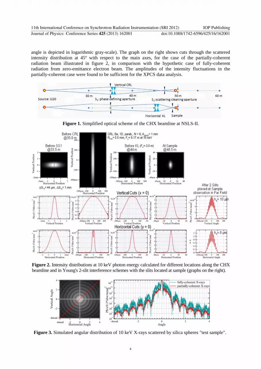
angle is depicted in logarithmic gray-scale). The graph on the right shows cuts through the scattered intensity distribution at 45º with respect to the main axes, for the case of the partially-coherent radiation beam illustrated in figure 2, in comparison with the hypothetic case of fully-coherent radiation from zero-emittance electron beam. The amplitudes of the intensity fluctuations in the partially-coherent case were found to be sufficient for the XPCS data analysis.
Figure 1. Simplified optical scheme of the CHX beamline at NSLS-II.
Figure 2. Intensity distributions at 10 keV photon energy calculated for different locations along the CHX beamline and in Young's 2-slit interference schemes with the slits located at sample (graphs on the right).
Figure 3. Simulated angular distribution of 10 keV X-rays scattered by silica spheres "test sample".
11th International Conference on Synchrotron Radiation Instrumentation (SRI 2012) IOP PublishingJournal of Physics: Conference Series 425 (2013) 162001 doi:10.1088/1742-6596/425/16/162001
4
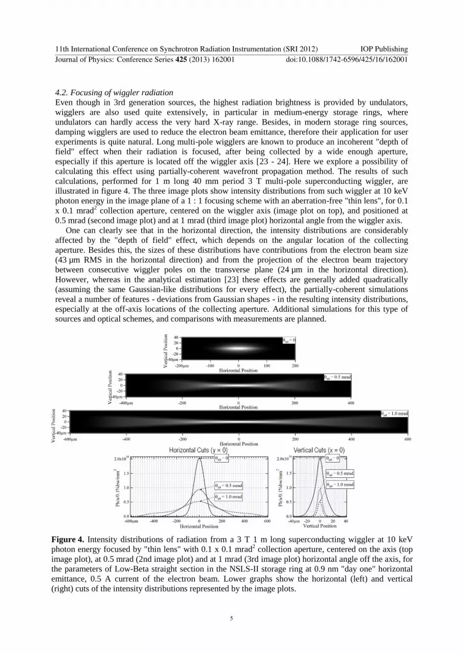
4.2. Focusing of wiggler radiation Even though in 3rd generation sources, the highest radiation brightness is provided by undulators, wigglers are also used quite extensively, in particular in medium-energy storage rings, where undulators can hardly access the very hard X-ray range. Besides, in modern storage ring sources, damping wigglers are used to reduce the electron beam emittance, therefore their application for user experiments is quite natural. Long multi-pole wigglers are known to produce an incoherent "depth of field" effect when their radiation is focused, after being collected by a wide enough aperture, especially if this aperture is located off the wiggler axis [23 - 24]. Here we explore a possibility of calculating this effect using partially-coherent wavefront propagation method. The results of such calculations, performed for 1 m long 40 mm period 3 T multi-pole superconducting wiggler, are illustrated in figure 4. The three image plots show intensity distributions from such wiggler at 10 keV photon energy in the image plane of a 1 : 1 focusing scheme with an aberration-free "thin lens", for 0.1 x 0.1 mrad2 collection aperture, centered on the wiggler axis (image plot on top), and positioned at 0.5 mrad (second image plot) and at 1 mrad (third image plot) horizontal angle from the wiggler axis.
One can clearly see that in the horizontal direction, the intensity distributions are considerably affected by the "depth of field" effect, which depends on the angular location of the collecting aperture. Besides this, the sizes of these distributions have contributions from the electron beam size (43 µm RMS in the horizontal direction) and from the projection of the electron beam trajectory between consecutive wiggler poles on the transverse plane (24 µm in the horizontal direction). However, whereas in the analytical estimation [23] these effects are generally added quadratically (assuming the same Gaussian-like distributions for every effect), the partially-coherent simulations reveal a number of features - deviations from Gaussian shapes - in the resulting intensity distributions, especially at the off-axis locations of the collecting aperture. Additional simulations for this type of sources and optical schemes, and comparisons with measurements are planned.
Figure 4. Intensity distributions of radiation from a 3 T 1 m long superconducting wiggler at 10 keV photon energy focused by "thin lens" with 0.1 x 0.1 mrad2 collection aperture, centered on the axis (top image plot), at 0.5 mrad (2nd image plot) and at 1 mrad (3rd image plot) horizontal angle off the axis, for the parameters of Low-Beta straight section in the NSLS-II storage ring at 0.9 nm "day one" horizontal emittance, 0.5 A current of the electron beam. Lower graphs show the horizontal (left) and vertical (right) cuts of the intensity distributions represented by the image plots.
11th International Conference on Synchrotron Radiation Instrumentation (SRI 2012) IOP PublishingJournal of Physics: Conference Series 425 (2013) 162001 doi:10.1088/1742-6596/425/16/162001
5

5. Summary and Prospects Combining high-accuracy calculation of the electric field of synchrotron radiation generated in arbitrary magnetic fields, and CPU-efficient Fourier-optics based electric field wavefront propagation simulation methods in SRW code has proven to be advantageous for a number of applications, including high-accuracy fully- and partially-coherent wavefront propagation simulations for the optimization of synchrotron radiation sources, beamlines and experiments. Recently-implemented support of parallel calculations in SRW considerably improves the efficiency of such simulations. Work is currently in progress on extending the library of electric field propagators, including better support for grazing-incidence and crystal optics, which would further increase the range of applications of the code for 3rd and 4th generation synchrotron radiation sources.
6. Acknowledgments We would like to thank G. Geloni, L. Samoylova, I. Agapov, A. Buzmakov (European XFEL), J. P. Sutter, D. Laundy (Diamond Light Source), R. Reininger (APS) for fruitful collaborations, and S. Molodtsov, H. Sinn (XFEL), G. Materlik, K. Sawhney (Diamond), J. Susini, A. Snigirev (ESRF), S. Dierker, Q. Shen (BNL) for the encouragement and support.
7. References [1] Bahrdt J, Applied Optics 36 (19), p. 4367 (1997). [2] Chubar O and Elleaume P, Proc. EPAC-98, 1177-1179 (1998). [3] Chubar O, Proc. SPIE 4143, 48-60 (2000). [4] Chubar O, Elleaume P, Kuznetsov S and Snigirev A, Proc. SPIE 4769, 145-151 (2002). [5] Reininger R. and May T, SRI-2003, AIP Conf. Proc. vol. 705, 462 - 465 (2004). [6] Dumas P, Polack F, Lagarde B, Chubar O, Giorgetta J-L and Lefrancois S, Infrared Physics &
Technology 49, 152-160 (2006). [7] Roy P, Rouzieres M, Qi Z, Chubar O, Infrared Physics & Technology 49, 139-146 (2006). [8] Chubar O, Susini J, Cotte M, Polack F, Lagarde B, Scheidt K, Elleaume P and Dumas P, SRI-
2006, AIP Conf. Proc. vol. 879, 607-610 (2007). [9] Reininger R, Feldhaus J, Gürtler P and Bahrdt J, Nucl. Instrum. and Meth. A 467, 38 (2001). [10] Bahrdt J, Phys. Rev. ST - Accel. Beams 10 (2007) 060701. [11] Chubar O, Couprie M-E, Labat M, Lambert G, Polack F, Tcherbakoff O, Nucl. Instr. and Meth.
A 593, 30-34 (2008). [12] Chubar O, Snigirev A, Kuznetsov S, Weitkamp T, Kohn V, Proc. DIPAC-2001, 88-90 (2001). [13] Tordeux M-A, Cassinari L, Chubar O, Denard J-C, Pedeau D, Pottin B, Proc. DIPAC-2007,
180-182 (2007). [14] Kim K-J, Nucl. Instr. and Meth. A 246, 71-76 (1986). [15] Elleaume P, "Generalities on the synchrotron radiation", "Undulator radiation", in "Undulators, wigglers
and their applications", ed. by Onuki H and Elleaume P, Taylor and Francis, London, 38-107 (2003). [16] Fluerasu A, Chubar O, Kaznatcheev K, Baltser J, Wiegart L, Evans-Lutterodt K, Carlucci-
Dayton M, Berman L, Proc. of SPIE Vol. 8141, 81410J (2011). [17] Chubar O, Rev. Sci. Instrum. 66 (2), 1872-1876 (1995). [18] Chubar O, Chu Y S, Kaznatcheev K and Yan H, Nucl. Instr. and Meth. A 649, 118-122 (2011). [19] Laundy D, Sutter J P, Wagner U H, Rau C, Thomas C A, Sawhney K and Chubar O, these
proceedings. [20] Samoylova L, Buzmakov A, Geloni G, Chubar O, Sinn H, Proc. of SPIE Vol. 8141, 81410A (2011). [21] Snigirev A, Kohn V, Snigireva I, Lengeler B, Nature, vol. 384, 49 (1996). [22] Evans-Lutterodt K, Ablett J M, Stein A, Kao C C, Tennant D M, Klemens F, Taylor A, Jacobsen
C, Gammel P L, Huggins H, Ustin S, Bogart G, Ocola L, Optics Express 11, 919-926 (2003). [23] Walker R P, "Bending magnet and wiggler radiation", in "Undulators, Wigglers and Their
Applications", ed. by H. Onuki and P. Elleaume, Taylor and Francis, London, 108–147 (2003). [24] Berman L E and Yin Z, Nucl. Instr. and Meth. A 649, 35-38 (2011).
11th International Conference on Synchrotron Radiation Instrumentation (SRI 2012) IOP PublishingJournal of Physics: Conference Series 425 (2013) 162001 doi:10.1088/1742-6596/425/16/162001
6