CERN Proton Synchrotron East Area Facility
123
CERN Yellow Reports: Monographs CERN–2021–004 CERN Proton Synchrotron East Area Facility Upgrades and renovation during Long Shutdown 2 Editors: Johannes Bernhard, Filipa Carvalho, Sébastien Evrard, Erwan Harrouch, Giulia Romagnoli
-
Upload
khangminh22 -
Category
Documents
-
view
2 -
download
0
Transcript of CERN Proton Synchrotron East Area Facility

CERN Yellow Reports: Monographs CERN–2021–004
CERN Proton Synchrotron East Area Facility
Upgrades and renovation during Long Shutdown 2
Editors:
Johannes Bernhard, Filipa Carvalho, Sébastien Evrard, Erwan Harrouch, Giulia Romagnoli

CERN Yellow Reports: Monographs
Published by CERN, CH-1211 Geneva 23, Switzerland
ISBN 978-92-9083-608-7 (paperback)
ISBN 978-92-9083-609-4 (PDF)
ISSN 2519-8068 (Print)
ISSN 2519-8076 (Online)
DOI https://doi.org/10.23731/CYRM-2021-004
Copyright © CERN, 2021
Creative Commons Attribution 4.0
This volume should be cited as:
CERN Proton Synchrotron East Area Facility: Upgrades and renovation during Long Shutdown 2, Eds.
Johannes Bernhard et al.
CERN Yellow Reports: Monographs, CERN-2021-004 (CERN, Geneva, 2021),
doi:10.23731/CYRM-2021-004.
Corresponding editor: [email protected].
Accepted in Oct. 2021, by the CERN Reports Editorial Board (contact [email protected]).
Published by the CERN Scientific Information Service (contact [email protected]).
Indexed in the CERN Document Server and in INSPIRE. Published Open Access to permit its wide
dissemination, as knowledge transfer is an integral part of the mission of CERN.

iii
CERN Proton Synchrotron East Area Facility
Upgrades and renovation during Long Shutdown 2
J. Bernhard, P. Burdelski, B. Carlsen, F. Carvalho, J. De La Gama, V. De Jesus, G. Dogru, F. Dragoni,
A. Ebn Rahmoun, S. Evrard, R. Froeschl, L. Gatignon, M. Gourber-Pace, S. Grau, E. Grenier Boley,
J-C. Guillaume, E. Harrouch, D. Jaillet, M. Lazzaroni, R. Lopez, S. Mcilwraith, R. Mompo, K. Papastergiou,
I. Ortega Ruiz, M. Polenghi, G. Romagnoli, E. Sanchez-Corral Mena, J. Tan, L. Wilhelm, H. Wilkens
CERN, Geneva, Switzerland
Abstract
In this document, we present the upgrade of the East Experimental Area facility
which took place during the Long Shutdown 2 (2019–2021). This document covers
the renovation of the East Hall beamlines and infrastructure according to a new
layout with the goal of improving the magnet and radiation situation in general. The
performance of the new beamlines will be optimized in terms of maximum
momentum and choice of particle type. Thanks to a cycled powering mode of the
magnets instead of a steady state one, considerable energy savings will be possible.
This report summarizes the various detailed studies completed from 2016 to 2019.
Keywords
Experimental areas; injectors; the CERN accelerator complex; test facility


v
Table of contents
EXECUTIVE SUMMARY .............................................................................................................................................. VII
CHAPTER 1 INTRODUCTION, SCOPE, AND SCHEDULE .............................................................................................. 1
1.1 INTRODUCTION ......................................................................................................................................................... 1 1.2 SCOPE OF THE RENOVATION ......................................................................................................................................... 1 1.3 PROJECT COST AND SCHEDULE ...................................................................................................................................... 5 1.4 SAFETY .................................................................................................................................................................... 5
CHAPTER 2 EAST AREA RENOVATION: MOTIVATIONS AND GENERAL DESCRIPTION ............................................... 7
2.1 GENERAL DESCRIPTION OF THE EAST AREA BEFORE AND AFTER LONG SHUTDOWN 2 (LS2) ....................................................... 7 2.2 PROBLEMS IN THE EAST AREA ...................................................................................................................................... 9 2.3 PHYSICS JUSTIFICATION ............................................................................................................................................. 11 2.4 MOTIVATIONS AND GUIDING PRINCIPLES FOR THE NEW DESIGN OF THE EAST AREA ............................................................... 13
CHAPTER 3 DESIGN OF THE EAST AREA FACILITY AFTER RENOVATION ................................................................. 17
3.1 BEAMLINE DESIGN AND LAYOUT .................................................................................................................................. 17 3.2 ENERGY SAVINGS ..................................................................................................................................................... 35 3.3 IMPACT ON RADIOPROTECTION AND GENERAL SAFETY ..................................................................................................... 38
CHAPTER 4 BEAMLINE – MAIN COMPONENTS ...................................................................................................... 43
4.1 MAGNETS .............................................................................................................................................................. 43 4.2 POWER CONVERTERS ................................................................................................................................................ 50 4.3 VACUUM SYSTEM DESCRIPTION .................................................................................................................................. 55 4.4 BEAM INTERCEPTING DEVICES ..................................................................................................................................... 57 4.5 BEAM INSTRUMENTATION ......................................................................................................................................... 62 4.6 SURVEY SYSTEMS ..................................................................................................................................................... 72 4.7 MACHINE INTERLOCKS .............................................................................................................................................. 73 4.8 BEAM CONTROLS ..................................................................................................................................................... 75 4.9 COLLIMATORS ......................................................................................................................................................... 76 4.10 RADIATION SHIELDING .......................................................................................................................................... 78 4.11 RADIATION MONITORING ...................................................................................................................................... 84
CHAPTER 5 INFRASTRUCTURE CONSOLIDATION ................................................................................................... 89
5.1 CIVIL ENGINEERING .................................................................................................................................................. 89 5.2 COOLING PLANT AND CIRCUITS ................................................................................................................................... 93 5.3 BUILDINGS 157 AND 251 VENTILATION ....................................................................................................................... 96 5.4 PRIMARY AREA VENTILATION ...................................................................................................................................... 99 5.5 ELECTRICAL DISTRIBUTION ....................................................................................................................................... 100 5.6 DC CIRCUITS ......................................................................................................................................................... 101 5.7 SIGNAL CABLES ...................................................................................................................................................... 103 5.8 PERSONNEL PROTECTION SYSTEMS ............................................................................................................................ 104 5.9 ALARMS ............................................................................................................................................................... 110 5.10 GAS SYSTEMS ................................................................................................................................................... 112


vii
Executive summary
The main goal of the upgrade was to ensure the long-term operation of the PS East Area experimental area
facility. Practically, this was achieved by implementing a new beamline layout, a new cycled powering scheme,
and thoroughly refurbishing the associated infrastructure.
To be able to change from a continuous to a pulsed power supply, the yokes of the magnets needed to
be laminated. In addition, over the last years of operation, the maintainability of the magnets has been a critical
issue, mainly because of long cooldown and repair times and the lack of spares for some magnet families.
These two reasons drove the complete renovation of the magnets - to install new magnets with laminated yokes
and of fewer families.
In fact, reducing the energy consumption of the facility was also a key point in the launching of the East
Area Renovation project. The new beamlines consist of 58 magnets of 12 different types powered by 61 power
converters. A significant part of this energy saving is obtained by using a cycling magnet current, hence
recovering and storing the magnet energy after each operation. The proposed powering solution is based on
the SIRIUS (power System for RapId Regulation with Internal controlled Unit of energy Storage) power
converter family, which has been developed especially for Accelerator Transfer Line applications and performs
magnet energy recovery after each magnetic cycle.
Concerning maintainability of the remaining equipment, the same approach was used, therefore
components such as beam stoppers or collimators were replaced with standard equipment. Beam
instrumentation is now modernized using, for instance, (recently developed) beam profile monitors and
scintillating fibres. Control of the beamline has been greatly improved with the implementation of a magnet
protection system, remote control of the vacuum system, and remotely controlled collimators.
The East Hall (Building 157), which hosts all the primary area, the secondary beamlines, the Cosmic
Leaving Outdoor Droplets (CLOUD) experiment, IRRAD and CHARM facilities, as well as the T09 and T10
test beam areas, will be renovated mainly in the North part of the building. In fact, the IRRAD and CHARM
facilities remained unchanged as the South part has been fully revamped during the Long Shutdown 2, in the
years 2013 and 2014.
To comply with the power consumption reduction, some services such as AC powering and the cooling
network were downsized and renewed according to lower operation requirements. Moreover, the shielding of
the primary area was completely modified to satisfy radioprotection requirements, and to reduce the time
needed to open it in case any equipment needs to be replaced. The access system was adapted to the new
configuration and the size of the high activation areas was reduced to limit the exposure of workers during
maintenance. The building envelope was completely refurbished to eliminate asbestos and improve greatly its
thermal insulation. With regards to the experimental areas (T09, T10, and T11), most of the services were
upgraded and include new control rooms, new gas distribution, and dedicated areas for detector/experiment
set-up.
Major refurbishment and new installation activities also took place in Building 352, housing the F61
and F62 beamlines, and in Building 251, where the new SIRIUS power converters are located. Indeed, the new
technology requires active air and water cooling systems, which were not available in the previous plant.
Undoubtedly the upgrade turned out to be a unique opportunity to bring the facility up to the modern
safety standards in terms of radioprotection by implementing dynamic air confinement in the primary area and
separating the cooling circuits between activated and non-activated water. On the conventional safety side, the
safe operation of the new power converters, which include large energy storage capacitors, and the compliance
to ATmosphere EXplosible regulations for the design of the new gas distribution system prevail.
The overall cost to completion of the renovation project amounts to 32 MCHF. Five sixths were
dedicated to material expenditures and the rest to personnel. By order of magnitude, the cost drivers were:
power converters, magnets, civil engineering, electrical systems, cooling, and ventilation.

viii
The project officially started in July 2016 with detailed study phases in 2016, 2017, and 2018. At the
same time as beamline operation in 2018, the civil engineering team has carried out the renovation of
Building 157 including walls, windows, and roof. The vast majority of the remaining consolidation activities
took place during the Long Shutdown 2 within a 36-month beam-to-beam period. The primary area and the
primary beamline area in Building 352 were the most critical and challenging zones with regard to schedule
and workload constraints. It is also worth mentioning that the CLOUD run without beam took place in Autumn
2019. Due to the COVID-19 pandemic, the initial schedule has been extended by 6 months, targeting a restart
of physics run by October 2021.
For clarification, at the time of writing this report, the project was still in between study and
commissioning phases, thus why the predominant verb tense throughout the document is in the future. As of
November 1st 2021, all the work in building 352 is concluded, and most of the work regarding the renovation
of the hall has been finished. The items that have not been completed concern CLOUD, such as the assembly
of the vertical access structure, the control room, and the chemical lab. Building 251 will have further works
done on its envelope and building structure.

1
Chapter 1 Introduction, scope, and schedule J. Bernhard, S. Evrard, E. Harrouch
1.1 Introduction
1.1.1 Motivation
The East Area of the CERN Proton Synchrotron has served the physics community for over 50 years and
remains extremely popular and necessary, among other things, to complete full calibration over a large energy
spectrum of the detectors to be installed in the Large Hadron Collider (LHC) experiments according to the
needs of the upgrade for the High Luminosity LHC. In addition, physics programs like CLOUD [1], and test
facilities such as IRRAD [2] and CHARM [1][3] are based on a reliable and easily maintainable East Area.
A detailed study was carried out over the years 2009–2015 and presented at the Consolidation Day on
the 11th of February 2016 [4] following a request to optimize the activities with a focus on what is required
for operation in line with the physics community needs.
The East Area renovation is considered as a priority for the Organization and sufficient funds were made
available in the Mid Term Plan (MTP) approved by Council in June 2016 to allow the major work to be
completed by the end of the Long Shutdown 2 (LS2). Therefore, the Accelerator & Technology Director
appointed a project team to take responsibility for the completion of the work.
The East Area renovation covered the refurbishment of the East Hall with its beamlines and
infrastructures. A redesign of the beamlines was included to improve the magnet and radiation situation in
general. The performance of the new beamlines was improved in terms of maximum momentum and in choice
of particle type. Thanks to a cycled powering mode of the magnets instead of a steady state one, considerable
energy savings are now possible.
This report summarizes the various detailed studies completed from 2016 to 2019 and outlined in
Ref. [5].
1.2 Scope of the renovation
Following the mandate of the Accelerator and Technology Sector Directorate [6], the main goal of the
renovation was to ensure the long-term operation of the PS East Area experimental area facility. Practically,
this was achieved by implementing a new beamline layout, a new cycled powering scheme, and thoroughly
refurbishing the associated infrastructure with the following objectives/means.
The new beamline layout:
– better cope with physics requirements (maximum momentum and choice of particle type (e, h, µ));
– minimize dose rates to personnel, and allow faster repair times by improving equipment accessibility;
– respect todays norms for radiation protection: new primary area ventilation + new dump system.
The new cycled powering scheme:
– replaced massive magnet yokes by laminated ones to allow cycling them;
– installed new SIRIUS power converters with energy recovery capacitor banks;
– allows to reduce the annual electrical energy consumption from 7 to 1 GWh for powering the magnets.

2
Infrastructure renovation:
– upgraded Building 157 envelope (wall and roof cladding) with a particular effort on thermal insulation,
allowing for an annual energy consumption reduction from 3 to 1 GWh;
– sanitized the building and got rid of asbestos;
– separation of primary and secondary beams and zones cooling circuits.
A new beamline layout, as illustrated in Fig. 1-1, which addresses most of the issues related to the
previous layout.
Fig. 1-1: New layout of the East Area.
1.2.1 Beamline: design and layout
Before renovation, the primary beam was extracted from the PS into the F61 beamline and could be sent either
to the T08 beamline used by IRRAD and CHARM or to the north target to produce secondary beams for the
experimental areas (T09, T10, and T11), as can be seen in Fig. 1-2.
After renovation, the primary beamline of the IRRAD/CHARM main parameters and optics remained
nearly unchanged. These parameters can be consulted in Table 1-1.
The North branch of the beamlines was modified to host two targets and allow a better performance of
the secondary beamlines (particle selection, maximum momentum, etc.).

3
Fig. 1-2: Schematic view of the layout in the East Area before (top) and after (bottom) renovation.
Table 1-1: Main parameters of the primary beam.
Parameter Value
Proton beam momentum [GeV/c] 24
Maximum # spills per typical super-cycle 6
Duration of typical super-cycle [s] 45.6
Maximum # protons per second 6.7 × 10¹⁰
Maximum assumed number of days of operation per year 200
Assumed efficiency 90%
Maximum number of super-cycles per year 340 000
Maximum number of protons per year 1.0 × 10¹⁸
In the new design, the secondary beams are produced at target B for T10 and T11, and target A for T09
with a vertical angle of 30 mrad with respect to the primary beam. This allows for clean stopping of the primary
beam (the part which does not interact with the targets) into a dedicated beam dump independently of the
secondary beams. In the pre-LS2 configuration, the primary beam was dumped in the magnets themselves
(causing high residual radiation and ageing of beamline components). The beam parameters for the new T09
and T10 beamlines are presented in Table 1-2. It should be noted that the new T11 beamline has a maximum
momentum of 3.6 GeV/c as before.

4
Table 1-2: Beam parameters for the new T09 and T10 beamlines. For convenience, a comparison to the old T09 values
is given in addition.
Parameter T09 (old) T09 (new) T10 (new)
Length up to the last element [m] 54.3 50.2 44.7
Max. momentum [GeV/c] 10 15 12
Momentum resolution 0.7 % 0.7 % 0.7 %
Max. momentum band 15 % 15 %
Horizontal acceptance 4.8 4 5
Vertical acceptance 4 3.8 3
Horizontal magnification at final focus 0.81 0.86 0.92
Vertical magnification at final focus 0.91 0.9 0.58
Max. flux per spill 106 106 106
1.2.2 Beamline: Hardware
To be able to change from a continuous to a pulsed power supply, the yokes of the magnets needed to be
laminated. In addition, over the final years of operation, maintainability of the magnets became a critical issue
mainly because of long cooldown, repair times, and the lack of spares for some magnet families. These two
reasons drove the need for the complete renovation of the magnets in order to install new magnets with
laminated yokes and of fewer families.
With the same philosophy concerning maintainability, components such as beam stoppers or collimators
were replaced with standard equipment. Beam instrumentation were also modernized using, for instance,
(recently developed) beam profile monitors and scintillating fibres.
Control of the beamline was greatly improved with the implementation of a magnet protection system
or remote control of the vacuum system and remotely controlled collimators.
1.2.3 Buildings 157, 251, and 352: infrastructure consolidation
Building 157, which hosts the primary area, the secondary beamlines, the CLOUD experiment, the IRRAD
and CHARM facilities, as well as the T09 and T10 test beam areas was renovated mainly in the North part of
the building. In fact, the IRRAD and CHARM facilities remained unchanged as the south part had already
been redone in 2013–2014.
To comply with the power consumption reduction, some services such as AC powering and the cooling
network were downsized and renewed according to lower operation requirements.
To cope with the new optics, the shielding of the primary area was completely modified to satisfy the
radioprotection requirement, and to reduce the time needed to open it in case an equipment needs to be
exchanged.
The access system was also renewed and the size of the high activation areas was reduced to limit the
exposure of workers during maintenance.
The experimental area services were upgraded (T09, T10, and T11): new control rooms, new gas
distribution, dedicated areas for detector/experiment set-up, etc.
The building’s envelope was completely refurbished to eliminate asbestos and improve greatly the
thermal insulation within the building.
Building 352, which houses part of the PS ring and the extraction line towards the East Hall, saw most of the
modifications in the F61–F62 and F6D beamlines. Following the renovation strategy, these lines were also
renovated (new magnets and power converters, standard beam stoppers, etc.). The infrastructure remains
generally identical but required a new cooling circuit and new cabling to match the new layout.

5
Building 251, which hosts all the power converters, was renovated to adapt to the new configuration and
requirements of the new beamlines.
The previous power converters had become unreliable and were replaced by different types of modern
SIRIUS power converters, including SIRIUS S, 2P, 4P, and 4P+. Since these new power converters have
different characteristics (weight, size) compared to the old ones, the structures on which these converters are
installed, the electrical supply system, and the cooling system was redone during the renovation.
In particular, the following actions took place during the renovation in LS2:
i) Renewal of the false floor to support all the power converters.
ii) New cooling network and ventilation dedicated to the power converters.
iii) Renewal of the electrical infrastructure to provide AC current to the power converters.
iv) Re-organization of the DC cabling to connect the power converters to the magnets in Building 157.
1.3 Project cost and schedule
1.3.1 Project cost
The cost to completion of the renovation project budget amounts to 30 MCHF. Four fifths are dedicated to
material expenditures and the rest to personnel. In order of importance, the cost drivers are power converters,
magnets, civil engineering, electrical systems, cooling, and ventilation.
1.3.2 Schedule
The project officially started in July 2016 with detailed study phases in 2016, 2017, and 2018. In parallel to
2018 beamline operation, the Site Management and Buildings department carried out the renovation of the
whole of Building 157 including walls, windows, and roof. The vast majority of consolidation activities took
place during the Long Shutdown 2 within a 36-month beam-to-beam. The primary area and the primary
beamline area in Building 352 were the most critical and challenging zones with regards to schedule and
workload constraints. It is also worth mentioning the CLOUD runs without beam, which took place in Autumn
2019. Due to the Covid-19 pandemic, the initial schedule has been extended by 6 months, targeting a restart
of physics run by October 2021.
1.4 Safety
The renovation of the East Area has ensured that the present level of safety is maintained and improved
(whenever possible) during all project phases (from the design phase until the operation of the facility). This
will be demonstrated in a dedicated safety file. The main objectives of the project in terms of safety are the
following.
i) Reduce the exposure to ionizing radiation during the maintenance of the facility (especially the primary
area).
ii) Bring the facility up to the modern safety standard in term of radioprotection (dynamic confinement in the
primary area, separation of cooling circuits, etc.) and conventional safety (refurbish the obsolete electrical
infrastructure, reduce the risk of falling, etc.).
iii) Design an adequate system to safely operate the facility in its new configuration (new access systems,
beam intercepting devices, safety matrixes, etc.).
iv) Ensure the structural resistance of all the shielding assemblies.
v) Ensure the safe operation of the new power converters which include large energy storage capacitors.
vi) Respect the ATEX regulations for the design of the new gas distribution system.

6
References
Some EDMS documents referenced in this report can be access restricted, access to those can be requested through
the EDMS platform.
[1] CLOUD Greybook: https://greybook.cern.ch/greybook/experiment/detail?id=PS215, last accessed
May 22nd 2019.
[2] F. Ravotti et al., A new high-intensity proton irradiation facility at the CERN PS East Area,
PoS TIPP2014 (2015), 354, http://dx.doi.org/10.22323/1.213.0354
[3] CHARM Greybook: https://greybook.cern.ch/greybook/experiment/detail?id=EA-IRRAD+Mixed-Field,
last accessed May 22nd 2019.
[4] ATS Consolidation Day, 11 February 2016, link to presentations: https://indico.cern.ch/event/492100/.
[5] L. Gatignon, The East Area upgrade - specifications and cost estimates, EDMS 1471844 (2015).
[6] F. Bordry, East Area renovation project mandate, EDMS 1715122 (2016).

7
Chapter 2 East Area renovation: Motivations and
general description J. Bernhard, S. Evrard, L. Gatignon, E. Harrouch, H. Wilkens
2.1 General description of the East Area before and after Long Shutdown 2 (LS2)
The East Area is one of the oldest experimental areas at CERN: the first implementation dates from the early
1960s. The experimental area itself is located in Building 157 on the Meyrin site and surrounded by a number
of associated service buildings (Fig. 2-1), including Buildings 251 and 263, which house the power converters.
Fig. 2-1: Aerial view of the East Area buildings.
Already before renovation (Fig. 2-2), the proton synchrotron (PS) extraction (F61) located in
Building 352 provided 24 GeV/c protons to the East Area. It provided slowly extracted primary proton beams
to the so-called T8 proton IRRADiation facility (IRRAD [1]) and CERN High energy AcceleRator Mixed field
facility (CHARM [2]). The last part of T08 together with IRRAD and CHARM was renovated during LS1.
The second branch, F61N, allowed protons to be sent onto the so-called North target, from which three
simultaneously running secondary beams were derived: T09, T10, and T11. The T09 and T10 beamlines were
used as general-purpose test beams, which, due to their design and also due to technical restrictions, were
limited to 10 and 6 GeV/c respectively. The T11 line had a maximum beam momentum of 3.6 GeV/c and was
most of the time used by the Cosmic Leaving Outdoor Droplets (CLOUD [3]) experiment. A synoptic of all
these beamlines is shown in Fig. 2-3 with indication of maximal momentum. The two primary proton branches
were operated in alternation, and each had its own dedicated 2.4 seconds PS cycles. The beam intensities were
of the order of 3–4 × 10¹¹ protons per PS cycle for the primary beams and up to 106 particles per cycle for the
secondary test beams.

8
Fig. 2-2: Schematic view of the layout in the East Area before (top) and after (bottom) renovation.
Fig. 2-3: Schematic view of the beam layout in the East Area before renovation with beam energies.
The users controlled their test beams themselves from a common local control room, the East Beam
Control Room (EBCR), inside Building 157. PS operators controlled the primary beams from the CERN
Central Control room. Certain equipment, e.g. collimators and vacuum, were only controllable locally from
the EBCR. The layout of the East Hall in its pre-LS2 configuration is shown in Fig. 2-4.
Over the years the East Area has served, in addition to the CLOUD experiment and the irradiation
facilities IRRAD and CHARM, a multitude of test beam users. Recently, T10 was mostly used by the
ALICE [4] collaboration, whereas T09 served many different users, from the Super Proton Synchrotron (SPS)
or Large Hadron Collider (LHC) experiments but also linear collider, space experiments, and R&D projects
from all over the world. Due to serious over-booking of the Experimental Hall North 1 (EHN1) test beams in
the SPS North Area, the East Area is getting increasingly popular.
The new layout after renovation (Fig. 2-2) presents a similar layout: the F61 line provides protons from
the extraction of the PS to the East Area. The first bend in the F61 line sends the protons to the F6D line with

9
a dump placed at the end used for PS extraction test beams. The protons will be deviated after the second bend
to T08 and the irradiation facilities CHARM and IRRAD; or they will be deviated through F62 to the other
lines. T09 will be still used as general-purpose test beam and will receive the beam after target A. If not present
in T08 and T09, the beam will go through F63 to target B and will serve the T10 and T11 lines. T10 will be
used like T09 as a general-purpose test beamline, however, T11 will always host the CLOUD experiment. A
general detailed description of the line with physics calculation is available in Section 2.3.
2.2 Problems in the East Area
Over the last decade the exploitation of the East Area has been hampered by a number of technical problems
and restrictions, mostly (but not only) related to magnet failures. Many of the 63 magnets installed in the East
Area are very old (up to 50 years) and belong to 22 different families, in many cases without spare magnets
being available.
Many of the critical magnets are located in a heavily shielded ‘primary area’, for which no ventilation
system is available. The production of ozone due to the passage of the beam through air has certainly
contributed to the degradation of the magnets, in combination with the high radiation levels. Whenever a
magnet in that area fails, the East Area must be stopped for a period of several weeks (one week to open the
6 metre thick roof and at least one week to fix the magnet itself).
Some critical magnets in the F61 and F61S branches are located in the PS ring zone. Their accessibility
is very difficult as well, so that an intervention takes at least a week during which the PS (and hence also the
SPS and LHC!) must be stopped.
One important incident occurred in 2004, when the MNP23 magnet in F61S failed after 30 years of
service, due to erosion induced blockage of its water circuits. During the 2006–2007 annual stop, the septum
magnet was replaced by a C-shaped bending magnet (MCB [5]), which is pulsed between EASTA and EASTB
cycles (Fig. 2-3). This allows all beamlines to be operated, but the option of running the irradiation facilities
and the test beams simultaneously on the same PS cycle was lost. This, aggravated at the same time by root-
mean-square power restrictions on the aging PS main power supply and thereby on the maximum number of
East Area cycles, has led to reduced cycle efficiency for the East Area exploitation with, in particular, a
severely reduced duty cycle for the test beams.
In 2010, the start-up of the East Area was delayed by more than two weeks because the MNP23 magnet
in T09 had to be replaced by a spare magnet, which has been modified to hopefully reduce the risk of short
circuits. As the new magnet showed some water leaks from the start, it was decided to lower the top momentum
of the T09 beam from 15 to 10 GeV/c. In 2011, the T10 beam had to be stopped 10 days before the end of the
proton run due to a failure of its first bending magnet.

10
Fig. 2-4: The 2018 layout of the East Area.

11
Also, a number of quadrupoles were causing worries. Three Q120 type quadrupoles had to be replaced
in the 2008/2009 shutdown. Two Q800 type quadrupoles could no longer operate at their nominal current since
the inlet temperature of the cooling water had been increased by a few degrees. The top momentum of the T10
beamline had correspondingly to be decreased from 7 to 6 GeV/c.
A number of magnets are quite radioactive. This concerns, in particular, the quadrupoles at the beginning
of the secondary beamlines and T09 first bending magnet and its surroundings. In fact, the protons that traverse
the North target without interacting are lost inside the magnet itself or just downstream of it, in uncontrolled
conditions. The whole environment has therefore high radiation levels. At this point it should be pointed out
that this magnet is the most critical magnet in the whole East Area.
2.3 Physics justification
The research and development activities pursued at the East Area are articulated along three main themes:
fundamental physics experiments, beam tests for detector R&D and experiments (like NP), and proton and
mixed field irradiation activities.
2.3.1 Fundamental physics experiments
Over the last 20 years, the East Area housed fours physics experiments: HARP [6], DIRAC [7], CLOUD, and
P349 [8]. HARP (PS214) was studying the hadron production of protons on a number of nuclear targets, to
constrain predictions of the neutrino fluxes at experiments such as MiniBooNe and K2K, performed from 2000
to 2002. The DIRAC experiment (PS212) aimed at measuring the lifetime of pionic atoms, to observe Kaon
atoms and to measure their lifetime. DIRAC took data over many years and was completed in 2012. The
CLOUD (PS215) experiment uses a special cloud chamber to study the possible link between galactic cosmic
rays and cloud formation. This is the first time a high-energy physics accelerator has been used to study
atmospheric and climate science. The results are contributing much to our fundamental understanding of
aerosols and clouds, and their effect on climate. CLOUD is in full swing and will continue for many years.
P349 took data in 2014 and 2015, to study polarization in the anti-proton production process, in view of
applications in the production of polarized anti-proton beams. The East Hall is the only location where new
experiments can be proposed at the PS.
2.3.2 Test beam for detector R&D
The test-beam program in the East Area covers all aspects of detector R&D in the high-energy physics field:
from collider and fixed target experiments (detector R&D for LHC, linear colliders, North Area, GSI, etc.
experiments), through cosmic ray detectors to be flown on balloons or satellites (PAMELA [9], AMS [10],
GLAST [11], PEBS [12], etc.), to emulsions and detectors to be used in neutrino or dark matter searches
(MINOS [13], OPERA [14], SHiP [15], baby-MIND [16], etc.). Throughout the conception cycle of new
particle detectors, the needs for test-beam campaigns are numerous, from the tests of new concepts, the
characterization of first prototypes, the validation of final designs, and the calibration and performance
assessments of the production modules.
The test beams in the East Area are as popular as ever, in spite of the low duty cycle for their operation.
This is illustrated in Fig. 2-5. Over time, less beamlines have been available for test beams as the irradiations
and experiments have been using more of the beam time on their dedicated beamlines.
The test-beamlines in the East Area are complementary to the test-beamlines at the SPS North Area, as
they allow significant flux in the energy range not or hardly covered in the North Area (typically limited to
≧ 10 GeV/c). Some experiments prepare their set-up in the East Area before running in the North Area. In
addition, some users that prefer the North Area beams accept running in the East Area, as the North Area
beamlines are increasingly over-booked.

12
Recently, users are more willing to come to the East Area since some minimal beam instrumentation
has been added (a scintillator and a delay wire chamber) at the end of each beam. This has further improved
with the introduction of a modern beam control system.
Fig. 2-5: Number of tests beam in the East Area and number of days of test beam operation.
The East Area is thus indispensable, both for the users with needs for the lower energy test beams (such
as ALICE, CBM [17], PANDA [18], etc.) and to cope with the overbooking of the EHN1 beams. However,
some users consider the East Area beamlines unsuitable, because there is no energy overlap with the beamlines
in the North Area. For them, the beamlines would be more usable only if the top momentum were well above
10 GeV/c and if there were more selectivity in particle type (electrons, hadrons, muons) as with the North Area
beamlines.
An important advantage of the East Area is also the short distance between control rooms and the test
beam areas, therefore allowing short cable lengths. The access to the test areas is much faster (< 15 seconds
for the movement of the beam stoppers) than in many of the EHN1 beams where the movement of the beam
dumps may take up to 6 minutes!
2.3.3 Irradiation facilities
Next to the test beams, the East Hall hosts the EA-Irradiation facility addressing the needs of the community
for proton irradiations and for mixed field irradiation (Radiation To Electronics (R2E) project).
The proton irradiation facility was designed and built driven by the need to qualify detectors and
materials for the increasingly harsh environments of the experiments at the LHC, which had to cope with the
doses induced by the design luminosity of 300 fb-1, and will have to develop detectors resisting the doses
induced by 3000 fb-1 proton–proton collisions, as illustrated in Fig. 2-6.
Up to 2012 proton irradiations were performed in the T7 beamline, alternating beam time with test
beams, until 2009, and this was the unique use from then on as the needs for irradiations grew. R2E had been
served by several parasitic facilities, such as a location behind the T6 target in TCC2, CNRAD, and H4IRRAD.
These facilities suffered from difficult access conditions and/or lack of flux. During Long Shutdown 1, a
dedicated facility in the East Area was thus build, with support from the EU AIDA funding, to satisfy the needs
of the proton irradiation and R2E project.

13
Fig. 2-6: Planned luminosity increase for the LHC accelerator.
This combined facility is installed in the zone once occupied by DIRAC, and profits from a number of
important advantages with respect to its precursor in the T7 line, as listed below.
i) There is significantly more space and infrastructure available, allowing for the housing of large objects
connected to power and cooling water.
ii) The shielding allows for higher integrated fluxes for the irradiations.
iii) The infrastructure is adapted properly to the needs of an irradiation facility.
iv) The access is a lot easier and, most importantly, no longer requires a long stop of the whole East Area.
Also, in the new layout, access exposes the personnel to much lower doses.
v) The same proton cycles serve at the same time the proton irradiation facility, formerly installed in T7, and
the mixed field facility in T8 previously behind DIRAC.
vi) There is more freedom in optimizing beam conditions for the proton irradiations than in T7 (the presence
of several quadrupoles in the T8 line gives flexibility in focusing).
With the LHC program running well into the next decades, the needs for the EA-irradiation facilities
have been established for many years to come. The needs of test beams, both for the LHC experiment upgrade
programs, and also for all the larger high-energy physics community, for instance, the development of detectors
for neutrino physics or dark matter searches, and the current physics experiment conducted in the East Hall
require the East Hall to remain functional. Finally, the East Hall is the only location to host new experiments
to be proposed at the PS.
2.4 Motivations and guiding principles for the new design of the East Area
This project is justified by:
1. The unique importance of the East Area for physics and test beams:
– optimize the general layout of Building 157 to provide all the services needed for the experiments
and allocate sufficient space for set-up in the test beam area itself and for storage purposes;
– improve the performance of the beamlines with increased control over beam particle type and
higher maximum beam momenta for T09 and T10 (15 and 12 GeV/c respectively, to be compared with
10 and 7 GeV/c now), allowing overlap with the momentum range of the EHN1 beamlines.

14
2. The extremely poor state of equipment, in particular magnets and power converters. On top of that, repairs
are extremely costly in terms of manpower, radiation dose, and beam time (impacting also the PS, SPS,
and LHC in some cases). The new design will:
– use fewer types of magnets with sufficient spares and considered reliable by the magnet group. In
particular, splitter magnets and delicate septum magnets must be eradicated;
– optimize access to the beamline elements by restricting the primary area to the minimum size
possible, reducing the time needed to open the shielded areas and the equipment density in all the
areas;
– replace the beamline components by standard systems (vacuum, collimators, beam stoppers,
interlocks, etc.) to ease their maintenance and ensure their long-term operation.
3. The non-conformity of the area to modern safety standards (e.g. electrical, presence of asbestos, etc.) and
to radioprotection requirements. The new design will:
– bring the area up to modern standards from a radiation protection, safety, and instrumentation point
of view;
– restrict high radiation levels to those locations where they cannot be avoided. Dump the unused
primary protons cleanly and as soon as possible after the two targets in a re-entrant dump;
– refurbish the building envelope to eliminate the presence of asbestos and improve the thermal
insulation of the building.
4. The reduction of the energy consumption of the facility. The new design will:
– implement a cycled powering mode of the magnets instead of a steady state one allowing
considerable energy savings in terms of electricity. Therefore, new generation SIRIUS power
converters will be used and fitted with capacity banks for energy recovery between the various magnet
cycles;
– size the general services (cooling, ventilation, and electrical infrastructure) to optimize the energy
consumption of the facility.
A new layout is proposed, as illustrated in Fig. 2-7 which addresses most of the issues related to the
existing layout. The beam design related options have been based on discussions with a number of physics
coordinators, with the technical groups and representatives of the East Area experiments, and with
representatives of the main East Area test beam users.

15
Fig. 2-7: Proposed new layout of the East Area.

16
References
[1] F. Ravotti et al., A new high-intensity proton irradiation facility at the CERN PS East Area,
PoS, TIPP2014 (2015) 354, https://doi.org/10.22323/1.213.0354.
[2] CHARM Greybook: https://greybook.cern.ch/greybook/experiment/detail?id=EA-IRRAD+Mixed-Field,
last accessed May 22nd 2019.
[3] CLOUD Greybook: https://greybook.cern.ch/greybook/experiment/detail?id=PS215,
last accessed May 22nd 2019.
[4] ALICE Greybook: https://greybook.cern.ch/greybook/experiment/detail?id=ALICE,
last accessed May 22nd 2019.
[5] Specification of the bending magnets for the ISR beam transfer system, ISR/BT group (I-5010-ISR)
(CERN, Geneva, November 1967), EDMS 1100428.
[6] HARP, Greybook: https://greybook.cern.ch/greybook/experiment/detail?id=PS214,
last accessed May 22nd 2019.
[7] DIRAC Greybook: https://greybook.cern.ch/greybook/experiment/detail?id=PS212,
last accessed May 22nd 2019.
[8] P349 Greybook: https://greybook.cern.ch/greybook/experiment/detail?id=P349,
last accessed May 22nd 2019.
[9] PAMELA Greybook: https://greybook.cern.ch/greybook/experiment/detail?id=RE2B,
last accessed May 22nd 2019.
[10] AMS Greybook: https://greybook.cern.ch/greybook/experiment/detail?id=AMS-RE1,
last accessed May 22nd 2019.
[11] Wood et al. (GLAST Collaboration), Bulletin of the AAS 27 (1995) 1387.
http://adsabs.harvard.edu/abs/1995AAS...187.7120W
[12] P. von Doetinchem et al. Nucl. Instrum. Meth. A581 (2007) 151,
https://doi.org/10.1016/j.nima.2007.07.053
[13] A. Habig et al. (MINOS Collaboration), The MINOS detectors, 29th International Cosmic Ray Conference
(ICRC), Punee, 2005, pp. 319–322 , arXiv:hep-ex/0507018
[14] OPERA Greybook: https://greybook.cern.ch/greybook/experiment/detail?id=CNGS1,
last accessed May 22nd 2019.
[15] SHiP Greybook: https://greybook.cern.ch/greybook/experiment/detail?id=SHiP,
last accessed May 22nd 2019.
[16] Baby-Mind Greybook: https://greybook.cern.ch/greybook/experiment/detail?id=NP05,
last accessed May 22nd 2019.
[17] CBM Greybook: https://greybook.cern.ch/greybook/experiment/detail?id=RE21,
last accessed May 22nd 2019.
[18] PANDA Greybook: https://greybook.cern.ch/greybook/experiment/detail?id=RE22,
last accessed May 22nd 2019.

17
Chapter 3 Design of the East Area facility after
renovation J. Bernhard, G. Dogru, S. Evrard, R. Froeschl, E. Harrouch, M. Lazzaroni
3.1 Beamline design and layout
3.1.1 Introduction
The PS primary proton beam is slowly extracted at 24 GeV/c towards the East Area with the help of the third-
order resonance technique over a typical spill length of 350 to 450 ns within 2.4 s cycles. The number of East
Area extractions is usually around five to six per overall PS super-cycle of typically 40 s and depends on both
users and schedule constraints, respectively. After passing both magnetic septa SMH57 and SMH61 (Fig. 3-1)
in the PS, the beam enters the F61 transfer line that transports the beam either to the so-called North Targets
via the lines F62 and F63 or towards T08, which serves the irradiation facilities IRRAD and CHARM. During
operation of primary ion beams, only these irradiation facilities can be operated. The principle of extraction by
third-order resonance and the corresponding optical elements inside the PS, such as the magnetic septa, will
be kept unchanged for the new East Area operation. Thus, only a replacement of the existing magnets by
laminated versions with slight optimization of the optics was chosen as the renovation baseline for F61 with
changes in the layout mostly due to integration constraints and considerations for improved radiation
protection. In particular, all the main horizontal bends have been replaced by reliable and robust MCB magnets,
which are available with sufficient spares and can be operated in pulsed mode. The splitting option, although
more efficient for operation, was dropped in 2005 for technical reasons that were hard to overcome in a reliable
manner. For further details on the recent operational history of F61 and the original ideas of the renovated East
Area beams, see Ref. [1].
Fig. 3-1: Employed slow extraction scheme in the PS ring towards F61; courtesy: R. Steerenberg, ‘Proton Beams in the
East Area’, OP course material, 2004.

18
3.1.2 The F61 transfer line matching section
The matching section of F61 uses a frontend of four quadrupole magnets to match the extracted beam for
further transfer. As the beam is horizontally extracted and thus horizontally large, at the start, strong and
compact focussing quadrupoles are required with a large horizontal aperture. While three Q74 magnets were
used in the old layout, only one laminated Q74 magnet will be used in the new design (F61.MQNCL007),
therefore reducing space restrictions in the very dense area between the PS main combined elements and
allowing for a better spare situation for this purposely made magnet. The first quadrupole is then followed by
a set of five beam stoppers that are used as safety elements during access to the zones downstream. Afterwards,
a triplet of quadrupoles follows (F61.MQNEL014, F61.MQNEF021, and F61.MQNEG030), which matches
the beam towards either F62 or T08.
Inside the triplet, after F61.MQNEF021, the M100 and M200 dipoles have been replaced by a single C-
shaped MCB magnet (F61.MBXDH025). At full current and inversed polarity, this magnet deflects the beam
towards the F6D dump position, which is required by Operation Group (BE-OP-PS) for setting up the slow
extraction. In nominal operation, F61.MBXHD025 in combination with F63.MBXHD001 provides a magnetic
chicane that enlarges the space between F61 and T08. This ensures enough space for the installation of two
North Targets instead of one. The destination of primary proton beam is chosen with the help of
F61.MBXHD033, which replaces the unreliable SMH01 splitter magnet. At zero field, the beam is transported
towards the North Targets, while at full field the beam is directed towards T08.
3.1.3 Transport towards the North Target – F62 and F63
A doublet of Q120C quadrupoles is used to focus the beam on the respective secondary targets. The
F63.MBXHD001 MCB-type dipoles correct the angle introduced by F61.MBXHD025, while another MCB-
type dipole (F63.MBSHD005) switches between the target locations, again with field off (target A serving
T09) or field on (target B serving T10/T11).
For both targets, the multi-target design chosen was introduced originally in 2014. Each target has five
target heads, each with a diameter of the order of 1 cm (see Table 3-1). The layout of the target region is shown
in Fig. 3-2, where the primary beam enters from the left side. In order to avoid changes in the main dipole
currents and to separate initial position matching the F61 correctors from steering on the targets, another set of
CR200 corrector magnets was introduced: F62.MCXCE013 for horizontal corrections and F62.MCXCE013
for vertical corrections. Figures 3-3 and 3-4 illustrate the optics configuration for beam extraction to the two
different target destinations.
Figures 3-5 and 3-6 depict the beam spots for target A and B, respectively, which were calculated using
the software TURTLE [2]. Table 3-2 summarizes the calculated parameters for the spot sizes on the two targets
as well as the corresponding beam size on the primary dump.
Table 3-1: Multi-target configuration of the two north targets. The position of the target heads as seen in beam direction
is depicted on the right side.
Head Material Length (mm) Diameter (mm) Comments
1 Be
W
200
3
10 + Al case Electron enriched
2 Al
W
100
3
10 Electron enriched
3 Al 200 10 Hadron
4 Air - - Empty
5 Al 20 10 Hadron

19
Fig. 3-2: Layout of the target region around the production targets for the T09 secondary beamline (target A) and for the
T10/T11 beamlines (target B).
Fig. 3-3: Optics for the primary proton beam in F61/F62 from the PS extraction to target A as calculated with
TRANSPORT. The sine-like ray is shown in red, the magnification term is depicted in green, and the dispersion term in
blue. The upper part shows the horizontal plane and the lower one the vertical plane.

20
Fig. 3-4: Optics for the primary proton beam in F61/F62 from the PS extraction to target B as calculated with
TRANSPORT. The sine-like ray is shown in red, the magnification term is depicted in green, and the dispersion term in
blue. The upper part shows the horizontal plane and the lower one the vertical plane.
Table 3-2: Calculated beam spot parameters for the two targets A and B as well as the corresponding size of the beam
when it enters the primary dump for destination A and B. For better comparability, the values are given in terms of the
standard deviation and 4 that were found by fitting a Gaussian model to the results of TURTLE raytracing.
Location Plane (mm) 4 (mm)
Target A Horizontal
Vertical
1.7
0.7
6.9
2.8
Target B Horizontal
Vertical
1.3
0.6
5.3
2.5
Dump for A Horizontal
Vertical
1.7
1.1
7.0
4.4
Dump for B Horizontal
Vertical
0.9
1.3
3.7
5.2

21
Fig. 3-5: Calculated beam spot parameters for target A (upper panels) and the corresponding spot size on the primary
dump (lower panels). The left side shows the horizontal plane while the right side shows the vertical one.
Fig. 3-6: Calculated beam spot parameters for target B (upper panels) and the corresponding spot size on the primary
dump (lower panels). The left side shows the horizontal plane while the right side shows the vertical one.
3.1.4 The primary beamline T08
The primary beamline T08 serves the irradiation facilities IRRAD and CHARM. Both experimental areas were
completely redone during LS1 in addition to changes in the T08 line, which are detailed in Ref. [2].

22
The aim of the currently discussed redesign of T08 is to keep both experimental areas unchanged, while
matching the line to the newly designed primary zones at the change-over point F61.BHZ02. Furthermore, the
T08 beamline has been cleared of leftover magnets due to the old T07 line and magnets have been exchanged
with similar laminated models in order to respect the new pulsed powering scheme.
After passing F61.MBXDH033, the beam is bent away from the location of the north targets by an MCB-
type dipole magnet and matched with the help of a first doublet of quadrupoles. Then, the beam is bent in
direction of the experimental areas by a pair of MCB-type dipoles. The final focus consists of a pair of Q200
quadrupoles that allow focussing of the beam on each IRRAD experimental table, as well as on the CHARM
production target. Figure 3-7 depicts the optics as an example for T08 for a focus on the second IRRAD table.
Steering of the beam as well as correction of a possible angular mismatch between F61 and the T08 line are
possible after introducing two sets of MDXL corrector magnets for both horizontal and vertical corrections.
These magnets can also be used to shift the beam position parallel to any direction in order to cope with possible
alignment mismatches of irradiation samples. In addition, a programmable function generator on the power
supply of these correctors allows a sweeping of the beam on the user samples if required.
Fig. 3-7: Optics for the primary proton beam in T8 from F61.BHZ02 to the irradiation facilities IRRAD and CHARM as
calculated with TRANSPORT, here exemplary for a focus on the second IRRAD table. The sine-like ray is shown in red,
the magnification term is depicted in green, and the dispersion term in blue. The upper part shows the horizontal plane
and the lower one the vertical plane.
For access purposes and as safety elements, five beam stoppers have been included in the beamline,
analogue to the beam stoppers in F61.

23
3.1.5 Summary of beam parameters, primary destinations, and operational considerations
The main beam parameters of the primary proton beam are listed in Table 3-3. The synoptics of destinations
of the new East Area is presented in Fig. 3-8 in comparison to the old scheme. Apart from the change of using
two production targets, the destination F6D has been included, for which the beam is dumped on the operational
dump that will be used for set-up of the PS extraction. The old destinations DIRAC, T07, and IRRAD (old)
have been already removed in LS1.
All primary lines, including T08, can be operated within the 2.4 s extraction cycles of the PS. Due to
limitations in the cycled powering of large dipoles in the secondary beams, these beams can only be operated
in 4.8 s cycles. Still, alternating the primary beam on the targets every 2.4 s is possible, as long as the same
target destination is not programmed twice in a row. Including radioprotection constraints as well, the
maximum number of T08 cycles should not exceed six per typical 45.6 s SPS super-cycle and the maximum
number of cycles per target destination shall not be more than three. The total instantaneous intensity in the
East Area shall not exceed 6.7 × 10¹⁰ protons per second. Assuming 90% efficiency and a maximum number
of 340 000 super-cycles per year, this would limit the integrated yearly intensity of protons to 1018.
Table 3-3: Main parameters of the primary beam.
Parameter Value
Proton beam momentum [GeV/c] 24
Maximum # spills per typical super-cycle 6
Duration of typical super-cycle [s] 45.6
Maximum # protons per second 6.7 × 10¹⁰
Maximum assumed number of days of operation per year 200
Assumed efficiency 90%
Maximum number of super-cycles per year 340 000
Maximum number of protons per year 1.0 × 10¹⁸
Fig. 3-8: Synoptics of the old East Area (upper panel) in comparison to the new East Area (lower panel).

24
3.1.6 The secondary beamlines T09 and T10
Both beamlines are based on the same concepts of secondary beams, based in the operational experience of
the West Area beamlines. Hence, both beams will be discussed at the same time while differences will be
highlighted when they occur. The general design aims at providing secondary beams with high selectivity of
particle species, i.e. purity. In addition, the aim was to optimize for high acceptance and momentum resolution.
The beams are derived from the targets A and B under a vertical production angle in order to prevent
primary protons coming into the experimental areas. The production angles were chosen to be 30 mrad (T09)
and 35 mrad (T10) in order to reach the same height in the experimental areas due to the different total lengths
of the beamlines. In T09, a fixed collimator (XTCX) with a cylindrical aperture of 80 mm diameter defines the
initial angular acceptance and acts at the same time as passive machine protection for the magnetic elements
that follow. For T10, such a dedicated fixed collimator was not deemed necessary as the beam is defined well
by the primary beam dump aperture and because no equipment upstream of the dump would need protection.
The non-interacting primary protons are dumped in the primary dump, while secondary particles are allowed
to pass through pre-defined apertures towards T09, T10, and T11 (see also the next section). In T09, a set of
two horizontally deflecting MDXL correctors can optionally be used as sweeping magnets to dump also
charged secondary particles, effectively leaving only a secondary neutral beam. Just after the primary dump, a
movable lead foil of 4 mm thickness can be employed to convert photons to electrons and positrons via pair
production. In this mode, electron and positron beams with high purity can be reached. This option was
unfortunately not possible for the T10 beam due to space and integration constraints related to the presence of
the T11 line. Nevertheless, this could be a valuable future upgrade option.
The frontends of T09 and T10 consist of a triplet of quadrupoles (QFO11, QDE2, and QFO3) that are
used to focus the secondary beam onto a horizontal collimator, COLL 3, which defines the central momentum
together with the initial horizontal deflection of BHZ1 (M200L dipole). In addition to COLL3, another set of
lead foils with three different thicknesses (4 mm, 8 mm, 26 mm) can be used as an absorber to filter out of the
beam a certain fraction of electrons respectively positrons (50%, 75%, 99%), leaving a hadron beam of
selectable purity. In between the second and third quadrupole, two collimators, COLL 1V and COLL 2H,
define the vertical and horizontal acceptance of the beamline, respectively. A second horizontal M200L dipole
magnet (BHZ02) is used to deflect the beam towards the respective experimental areas. Around the central
collimator COLL3, two quadrupoles are used as field lenses, with the aim of eliminating the dispersion after
BHZ2. The final focus consists of a triplet of quadrupoles (QDE6, QFO7, and QDE8), which focus the beam
at the user location. In T10, the last quadrupole is of type Q100L in contrast to T09, where a Q200L is necessary
due to the higher maximum momenta. In order to compensate the production angle of the target, a vertical
M100L magnet deflects the beam with the aim of making it parallel to the horizontal floor of the experimental
area. This magnet serves at the same time as a vertical corrector if necessary. For horizontal steering, a MDXL
corrector can be used. For access purposes, a dedicated, movable stopper-dump exists. This dump can be also
used as an effective filter for hadrons and electrons/positrons leaving muon beams of high purity, which can
be optionally momentum selected with the help of BHZ02. Alternatively, the first collimator can be closed off
axis to select a similarly pure muon beam.
The maximum beam momentum in T09 is 15 GeV/c and for T10 is 12 GeV/c. They differ mainly due
to the larger deflection angles in T10 that are necessary to deflect the beam away from T09 as well as to
compensate for the shorter length of the T10 line. Table 3-4 summarizes the calculated beam parameters for
both beamlines. In addition, the T09 parameters are compared to the values of the old T09 line. Figure 3-9
depicts the optics exemplary for T09.
1 Due to the different equipment names, but similar functions, the physics name for the beamline elements is used in this descriptive
part.

25
Table 3-4: Beam parameters for the future T09 and T10 beamlines. For convenience, a comparison to the old T09 values
is given in addition.
Parameter T09 (old) T09 (new) T10 (new)
Length up to the last element [m] 54.3 50.2 44.7
Max. momentum [GeV/c] 10 15 12
Momentum resolution 0.7 % 0.5 % 0.5 %
Max. momentum band 15 % 15 %
Horizontal acceptance 4.8 4 5
Vertical acceptance 4 3.8 3
Horizontal magnification at final focus 0.81 0.86 0.92
Vertical magnification at final focus 0.91 0.9 0.58
Max. flux per spill 106 106 106
3.1.6.1 Future options
In the baseline of the East Area Renovation, there are no spectrometer magnets in the T09 and T10
experimental areas, which might be a sensible future upgrade. Adding a converter and sweeping magnets in
T10 would allow for high purity electron and positron beams as for T09. However, current space restrictions,
especially due to the T11 beamline, do not permit this option at the moment. Figure 3-9 shows the optics for
the secondary T09 beamline from target A to the endpoint/dump of the experimental area.
Fig. 3-9: Optics for the secondary T09 beamline from target A to the endpoint/dump of the experimental area as calculated
with TRANSPORT. The sine-like ray is shown in red, the magnification term is depicted in green, and the dispersion
term in blue. The upper part shows the horizontal plane and the lower one the vertical plane.

26
3.1.7 The secondary beamline T11 for the CLOUD experiment
The T11 beamline employs the same principles as T09 and T10, however, in a more compact form and with
less elements due to the constraints of leaving the CLOUD experiment at the same place (see Fig. 3-10). The
beamline shares the production target B with T10 and the initial acceptance is well defined by the primary
dump aperture. The frontend and the final focus are doublets of quadrupoles in contrast to T09 and T10, where
more flexibility is required. Another difference is to use only one field lens quadrupole and collimators with
less control in both planes. In addition, the vertical M100L dipole was removed as it is not necessary for
CLOUD. There are also no correctors in this beamline. The beam optics are chosen to provide a large spot on
the CLOUD experiment by over-focusing the beam directly after the last quadrupole and hence the beam opens
up again due to the large divergence.
Fig. 3-10: Optics for the secondary T11 beamline from target B to the endpoint/dump of the experimental area of CLOUD
as calculated with TRANSPORT. The sine-like ray is shown in red, the magnification term is depicted in green, and the
dispersion term in blue. The upper part shows the horizontal plane and the lower one the vertical plane. The new layout
of the East Experimental Area.
3.1.8 Introduction
The implementation of the new beamlines (see Section 3.1) and the application of modern safety standards
(see Section 3.3) justify a major re-organization of the Building 157 hall. By extension, the proton synchrotron
(PS) extraction beamline located in Building 352 has also been completely renovated. In addition, the new
powering scheme of the magnets allows suppression of the need for Building 263 to host the power converters
but required a major renovation of Building 251 to accommodate all of them (see Section 4.2).

27
Figures 3-12 and 3-13 show, respectively, the configuration of the East Experimental Area before and
after renovation. Building 352 hosts the extraction line from the PS. In this area, until the wall separation with
Building 157, the lines F61, F62, F6D, and the first part of the line T08 will be installed. Building 157 hosts
instead the F63 line, the following parts of the T08 line, T09 T10, and T11 beamlines, and the experimental
areas.
Building 157 is sub-divided into different areas. Right after the wall separation with Building 352 the
primary area is installed; this area is further divided into three closed areas: the target area, the T08b area,
and the T08c area. The T08 line finishes with the IRRAD/CHARM (proton IRRADiation facility/CERN High
energy AcceleRator Mixed field facility) area that was installed during Long Shutdown 1 and will not be
affected by the renovation. After the target area, the protons enter the mixed area, where the secondary lines
start to separate. The T11 line, after the mixed area, directly enters the T11 experimental area hosting the
Cosmic Leaving Outdoor Droplets (CLOUD) experiment. On the other side, the T09 and T10 lines share a
second closed area called the T09-10 area before entering in the separate T09 and T10 experimental areas.
3.1.9 Building 352: PS extraction
The renovation in Building 352 consists mainly in installing the new F61, F62, F6D beamlines and the
beginning of T08 (see Section 3.1). Moreover, services like Direct Current (DC) cabling (see Section 5.6) and
the cooling network (see Section 5.2) will be renovated. In addition, F61 and T08 beamlines will be equipped
with new PS standard beam stoppers (see Section 4.4) and new beam loss monitors (see Section 4.5).
Figure 3-11 depicts the new layout for Building 352.
Fig. 3-11: Three-dimensional model of Building 352 after renovation.

28
Fig. 3-12: Configuration of the East Area before renovation.

29
Fig. 3-13: Configuration of the East Area after renovation.

30
3.1.10 Building 157: Experimental facility
3.1.10.1 Primary area
The goal of the new layout of the primary area after renovation is to improve the general safety, in particular
to minimize the radiation levels in each controlled area. For this reason, the target area has been reduced thanks
to a new cast iron dump located in between the target area and the mixed area, which stops the residual primary
particles coming from the interaction of the PS protons beam with the targets. All the primary areas will be
airtight, and a dedicated ventilation system will keep the internal pressure of the primary areas lower than the
atmospheric external pressure, so that any contaminated agents are kept inside the area (see Section 5.4).
The primary area is composed of three sectors: the target area, T08b, and T08c (see Fig. 3-14 and
Fig. 3-15). These, in particular the targets area, will be the most radioactive zones in the East Area, due to the
interactions of the PS primary beams with the two targets. Due to the high level of radiation, a shielding roof
in concrete and cast iron is required, and the total height of the whole shielding will be limited to 8 m (height
of the overhead cranes).
Inside the target area, magnets, targets, the fixed collimator (XTCX), and the stopper dump will be
equipped with a mechanical plug-in support to suppress the need for alignment in situ when the replacement
of an equipment is needed [2]. Although alignment is the most time-consuming task in this area, it will greatly
reduce the exposure of workers to radiation.
Fig. 3-14: Integration 3D model of targets area.

31
Fig. 3-15: T08b (top) and T08c (bottom) primary areas.
3.1.10.2 Mixed area
This new zone (see Fig. 3-16) is just downstream of the target area and it hosts the three secondary beams
(T09, T10, and T11). Because there is a low radiation level in this area, a thinner concrete shielding roof is
sufficient for safety protection. All the equipment is integrated on standard supports. The expected residual
radiation dose rate does not justify the installation of a plug-in system. All the secondary beamlines have a
vertical angle (production angle) in this area.

32
Fig. 3-16: Mixed area after renovation.
3.1.10.3 T09-10 area
This new zone is located just downstream of the mixed area and contains the last magnets and other equipment
of the secondary beamlines, as illustrated in Fig. 3-17. The benefit of creating this zone in both T09 and T10
experimental areas is that the users of the experimental areas will not be in proximity to the beamline
equipment, reducing personal electrical shock risks. In addition, maintenance in this area can be done while
the beam is circulating in the T08 and T11 beamlines.
The T09-10 area does not require roof shielding, thanks to the low radiation levels. The floor of this zone is
fully covered with 1.2 m standard concrete blocks to compensate for the beam height (around 3 m from the
floor of the building). The vacuum pumps for the T09 and T10 beamlines are placed in this area to limit
exposure to radiation of the maintenance teams.
Fig. 3-17: T09-10 area.
33
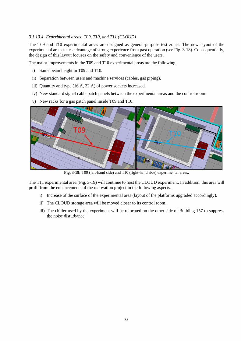
3.1.10.4 Experimental areas: T09, T10, and T11 (CLOUD)
The T09 and T10 experimental areas are designed as general-purpose test zones. The new layout of the
experimental areas takes advantage of strong experience from past operation (see Fig. 3-18). Consequentially,
the design of this layout focuses on the safety and convenience of the users.
The major improvements in the T09 and T10 experimental areas are the following.
i) Same beam height in T09 and T10.
ii) Separation between users and machine services (cables, gas piping).
iii) Quantity and type (16 A, 32 A) of power sockets increased.
iv) New standard signal cable patch panels between the experimental areas and the control room.
v) New racks for a gas patch panel inside T09 and T10.
Fig. 3-18: T09 (left-hand side) and T10 (right-hand side) experimental areas.
The T11 experimental area (Fig. 3-19) will continue to host the CLOUD experiment. In addition, this area will
profit from the enhancements of the renovation project in the following aspects.
i) Increase of the surface of the experimental area (layout of the platforms upgraded accordingly).
ii) The CLOUD storage area will be moved closer to its control room.
iii) The chiller used by the experiment will be relocated on the other side of Building 157 to suppress
the noise disturbance.

34
Fig. 3-19: T11 experimental area hosting the CLOUD experiment.
3.1.11 Building 251: Power converter facility
Building 251, which hosts all the power converters, will be renovated to accommodate the new configuration
and requirements of the future beamlines.
The existing power converters have become less reliable and will be replaced by different types of
modern SIRIUS power converters, including SIRIUS S, 2P, 4P, and 4P + (see Section 4.2). Since these new
power converters have different characteristics (weight, size) compared to the old ones, the structures on which
these converters are installed, the electrical supply system, and the cooling system must be redone during the
renovation (see details in Fig. 3-20 and Fig. 3-21).
Fig. 3-20: Configuration of Building 251 before (left) and after (right) renovation.
Furthermore, the poor state of the existing false floor and the difficulty of accommodating all the new
power converters and services, led to the decision to instal a new false floor in the building. The concept for
the new layout of Building 251 can be found in Fig. 3-21.
In particular, the following actions will take place during the renovation in LS2.
i) Renewal of the false floor to support all the power converters.
ii) New cooling network and ventilation dedicated to the power converters.

35
iii) Renewal of the electrical infrastructure to provide AC current to the power converters.
iv) Re-organization of the DC cabling to connect the power converters to magnets in Building 157.
Fig. 3-21: Future layout of Building 251.
3.2 Energy savings
One of the objectives of the East Area Renovation Project is to reduce the energy consumption of the facility.
This section summarizes the various measures taken to achieve an operational experimental facility with low
energy consumption.
3.2.1 The magnet power supply chain
The most substantial change induced by the renovation in terms of energy will be the modification of the
powering mode of the magnets. The new power converters, of type SIRIUS, conceived at CERN by the
Electrical Power Converters Group, will be able to operate the new laminated magnets in pulsed mode.
Equipped with capacitor banks, the SIRIUS converters will also be able to recover temporarily the inductive
energy stored in the magnetic field of the magnetic components, as shown in Fig. 3-22 and reuse it for the next
cycle. Those recovering units reduce the root mean square (RMS) current requirements of equipment upstream
of the electrical supply network and eliminate the voltage fluctuation of the CERN general electric grid, thus
simplifying it and decreasing the losses.

36
Fig. 3-22: Overview of the magnet power supply chain.
Today, the magnets are turned on at the start of the physics run and, if no major issue occurs, are never
turned off, even when no beams are being extracted towards the East Area. Bearing in mind that the beamlines
today count 54 magnets, which in theory only need to be generating a magnetic field for 2.25 seconds (which
equals to 5 extractions) per supercycle2, significant energy saving can result from a compatible magnet and
powering scheme. Such a cycled mode gives the opportunity to only feed the required magnets to extract and
direct the particles towards one of the four experiments.
Furthermore, a lower electricity consumption will significantly decrease the power losses and thus the
related dissipated heat, having consequently also a direct influence on the energy consumption needs for the
water cooling and air ventilation systems and therefore on their installation and operational units.
Even though it is impossible to predict the number of extractions occurring in a future physics run, an
estimated electricity consumption can be calculated based on the number of extractions which took place in
2017. Based on retrieved current data of the 2017 physics run, the electricity usage before renovation
(6786 MWh) was calculated. Compared to the estimated consumption in cycled mode (1028 MWh), a potential
saving of more than 80% can be demonstrated.
In addition, while power converters still consume electricity in maintaining stand-by mode, a future
remote control by the operators allows us to completely switch-off the equipment during long periods of
inactivity.
3.2.2 Air ventilation
Currently, air ventilation systems are present in the main experimental hall and the irradiation facilities3 on
beamline T8, ensuring thermal comfort and an adequate air quality inside the hall as well as a dynamic
confinement (preventing the activated air from escaping) for the highly radioactive areas. Building 251,
adjacent to the Building 157 hall and housing the power converters, is also equipped with a heating and
2 The supercycle of the PS accelerator lasts for 45.6 seconds and depicts the distribution of the particle bunches from the accelerator
towards the related experiments (nTof, AD, IRRAD, CHARM, …) and the Super Proton Synchrotron accelerator. 3 Highly radioactive areas are covered with thick (up to 6 metre) concrete walls allowing for the presence of the users inside the hall
during beam operation.
B-field
Grid
G
E-field
Surface level
DC bus
Underground
Energy
recovery unit
Line Supply Unit
QDE120
DC Cables
Magnet Supply
Unit
18kV/400V
400kV
66kV/18kV
400kV/66kV
Simplified Power Network
diagram
Galvanic
isolat ion
Reactive Power
Compensator
TCR TSC
18
kV
bu
s
66kV bus

37
ventilation system providing heating during winter and fresh air ventilation that partly removes the heat
dissipated from the converters during warmer periods.
The air ventilation’s energy consumption in the experimental hall is mainly due to the heating needs
during cold months. During the hotter months, the heating is turned off and thermal comfort is uniquely assured
by ventilation. Heating in the East Area and at CERN in general is provided by a central plant producing, by
means of gas combustion, super-heated water (SHW) which is distributed to the concerned infrastructures
located on the various CERN premises.
The cladding of the main hall is currently far from optimal when compared to today’s environmental
and safety standards, causing over the year an increase in air ventilation needs. Civil engineering works have
therefore been included in the project. By refurbishing the cladding and the roofing with more modern and
better performing insulated materials, associated thermal losses significantly decrease.
Detailed thermal studies of today’s and the post-renovation situation have been conducted [4]. From this
study, the following results have been found; the peak losses occurring during the coldest month (January) will
drop from 811 kW to 245 kW, the annual thermal energy consumption will decrease by 65% together with a
65% decrease of the related gas consumption.
The project also includes a modification in the disposition of the radioactive areas, similar to the one
performed for IRRAD/CHARM in LS1. Thus, introducing new specific air handling units to the primary [5]
and a new ventilation system to the mixed beam area (see Fig. 3-23), leads to a total of three dedicated
ventilation systems for those areas. In addition, to ensure a dynamic confinement, they compensate the
dissipated heat from the magnets, which will decrease due to the above described cycled operation mode.
Related thermal energy savings will amount to 75%. However, at the same time, the electricity consumption
for the primary areas must cover an increase of 42% (from 11 MWh to 19 MWh) due to the required additional
units.
Fig. 3-23: Layout of the new radioactive zones.
Finally, the power converter building will see a 96% reduction in cooling needs (from 955 to 63 MWh).
The substantial decrease is related to the fact that the new power converters will be water cooled after
renovation. The ventilation will only have to compensate 15% of the total heat dissipated from the converters,
while it is 100% today.
3.2.3 Water cooling
The last major energy consumer of the East Area is the water-cooling systems designed to cool the magnets
and, after the renovation, the power converters, given that they dissipate up to 85% of the energy they consume.

38
As mentioned previously, the cycled mode will significantly reduce the heat dissipation of the magnetic
components and the power converters. Based on the power losses calculated for the electricity consumption of
the magnets and the power converters, the cooling needs can be easily retrieved. The annual cooling needs will
massively drop from 4162 MWh to a mesmerizing 369 MWh (91% decrease).
Heat from East Area magnets and power converters is mainly absorbed by the demineralized water
circuit, passed to cooling tower water, and ultimately released to the atmosphere. The cooling tower is a heat
exchanger (air/water) of open wet type, meaning it partially evaporates and thus consumes the circuit’s raw
water to bring its temperature down.
As for the electricity consumption, which is predominantly caused by the water pumps generating the
required water flow inside the circuit, a corresponding decrease will be observed. Due to a careful pump
selection, the number of pumps in operation can be reduced from two to one. Combined with the fact that the
new pump differential pressure will be reduced from 24 to 12 bar and the water flow will be 275 m3/h instead
of 300 m3/h, the corresponding electricity consumption will also drop from 4246 to 1597 MWh, consequently
saving 76% in energy consumption.
3.2.4 Conclusion and outlook
As a result, the total energy consumption will decrease by 81% after renovation and for the thermal energy
consumption (heating and cooling needs combined), a saving of 82% will be attained, as illustrated in Fig. 3-24,
which compares the energy flows by type (cooling, heating, electricity) before and after consolidation.
Additional operational improvements can be implemented. Firstly, by switching off equipment such as
power converters while not in use (e.g. during technical stops). Secondly, replacing the water pumps of the
water-cooling circuit can provide additional savings as they will be oversized after the renovation [3]. Finally,
a renovation of the power converter building, which was constructed around the same period as the main
experimental hall and shows, today, the same insulation issues, should be considered.
Fig. 3-24: Summary diagrams of estimated energy consumption before and after renovation.
3.3 Impact on radioprotection and general safety
3.3.1 Introduction
The design, construction, commissioning, operation, and eventual dismantling of the East Area comply with
the standard CERN safety rules and applicable regulation. Following an initial risk assessment 0, the project

39
was classified as a project with major safety implications and will thus need a safety clearance from the CERN
safety authority before the facility is operated.
This section describes the main safety checks to be performed throughout the lifecycle of the project.
This work is continuously documented in the safety file of the facility and will be issued before the first beam
extraction to the East Area.
3.3.2 Impact on radioprotection
3.3.2.1 Air activation
The design goals for the ventilation system of the East Area renovation project are the following.
i) The committed effective dose due to inhalation has to be less than 1 μSv for a 1 hour long access.
ii) The effective dose to the reference group for members of the public should be less than 1 μSv per year,
from combined prompt radiation (sky shine) and from releases to the environment.
The methodology to obtain the radionuclide concentrations, the annual release to the environment, and
the resulting annual effective dose to members of the public is based on the weighting of track-length spectra
in air, obtained by FLUKA Monte Carlo simulations [8][9] with a dedicated set of air activation cross-
sections [10][11] , taking the time evolution, the characteristics of the ventilation circuit, and the beam
parameters [11] into account and finally applying conversion coefficients from released activity to effective
dose, computed with the dedicated Monte Carlo integration program EDARA [12]. A detailed description of
this methodology, including the location of the reference group, can be found in Ref. [13].
3.3.2.1.1 Primary zone
The ventilation system for the primary zone will provide dynamic confinement with a forced air extraction rate
between one and ten air renewals per hour. A flush of the primary zone resulting in 3 volume exchanges is
mandatory before granting access to the primary zone.
All releases from the ventilation system of the primary zone to the environment will be monitored by a
dedicated ventilation monitoring station [14]. The release point will be a dedicated chimney above the roof of
the East Hall.
Based on these conditions, an air activation study has been performed [15]. The effective dose to the
reference group for members of the public from releases of airborne radioactivity to the environment will be
less than 0.2 μSv per year. The committed effective dose due to inhalation will be well below 1 μSv for a
1-hour long access. Therefore, both design goals with respect to the air activation for the primary zone will be
achieved.
3.3.2.1.2 Mixed zone
A dedicated air activation study has been performed for the mixed zone [16], investigating both dynamic
confinement and static confinement configurations.
The release from the mixed zone is negligible with respect to the target zone, even for dynamic
confinement.
The committed effective dose due to inhalation was calculated by integrating over the 1-hour exposure
time after a cool-down period of 30 minutes without flush before access as a function of the air exchange rate.
Even for static confinement, the committed effective dose due to inhalation is far below 1 μSv for a 1-hour
long access. In addition, it is also negligible with respect to external exposure due to residual radioactivity.
Therefore, the connection of the mixed zone to the primary ventilation system (V1, V2, and V3) is not
required for radiation protection purposes, although a minimal airflow has to be ensured (see Fig. 3-25).

40
Fig. 3-25: Location of the primary zone bunkers (V1, V2, and V3) and the mixed area.
3.3.2.2 Water activation
Activation of the water used for the cooling of equipment, such as magnets, will radiologically only be
significant in the primary zone. Following best practices in water circuit design in radiation areas, the water
circuits for the primary zone shall be separated from the water circuits of the other parts of the East Hall,
including the mixed zone. The water circuits for the primary zone can be connected with the one for IRRAD
and CHARM since these two facilities also receive primary beam (see Section 5.2). All water circuits will be
equipped with sampling points that allow the extraction of water samples for radiological analysis.
3.3.2.3 Radiation protection aspects of the access system
The primary zone will be classified at least as a Limited Stay Radiation Area due to the residual radiation
levels [17]. Therefore, a Radiation Protection veto has to be implemented at the access point that grants access
to the primary zone, as is the case today [18]. The access system also has to verify that the flush of the primary
zone (see Section 5.8) has been completed before granting access to the primary zone. The access to the mixed
zone is excluded from this requirement.
3.3.3 Impact on conventional safety
3.3.3.1 Electrical design report for the capacitors
The new SIRIUS power converters in Building 251 include energy storage units that consist of capacitors that
recover the energy sent to the magnet at every pulse. These capacitors can in total store an energy of 10 MJ.
The design of the power converter included an in-depth investigation of the failure mechanisms to assess the
damage that could be caused by a failure of these systems and take measures to reduce the probability of
occurrence of such events. In addition, collective measures should be taken to supress any risk to the teams
working near the converters (see Section 4.2).
3.3.3.2 Structural validations
The general renovation of Building 157 requires a careful study of the structural resistance of the facility.
Starting from the slab load capacity to make sure that, during all the phases of the worksite until the final
configuration, no overloading happens. The assembly of shielding blocks itself needs to be validated both in
its static resistance and in its stability in case of earthquake.
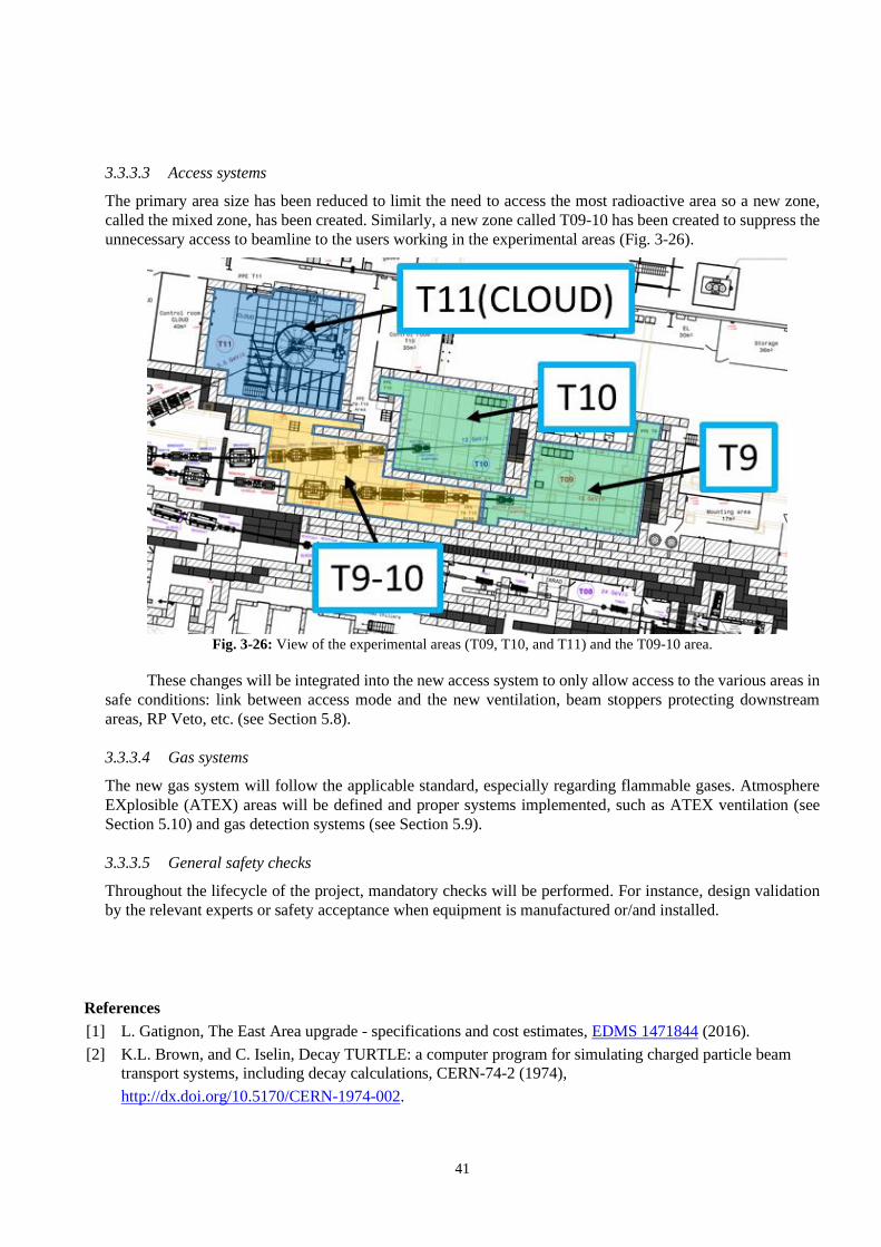
41
3.3.3.3 Access systems
The primary area size has been reduced to limit the need to access the most radioactive area so a new zone,
called the mixed zone, has been created. Similarly, a new zone called T09-10 has been created to suppress the
unnecessary access to beamline to the users working in the experimental areas (Fig. 3-26).
Fig. 3-26: View of the experimental areas (T09, T10, and T11) and the T09-10 area.
These changes will be integrated into the new access system to only allow access to the various areas in
safe conditions: link between access mode and the new ventilation, beam stoppers protecting downstream
areas, RP Veto, etc. (see Section 5.8).
3.3.3.4 Gas systems
The new gas system will follow the applicable standard, especially regarding flammable gases. Atmosphere
EXplosible (ATEX) areas will be defined and proper systems implemented, such as ATEX ventilation (see
Section 5.10) and gas detection systems (see Section 5.9).
3.3.3.5 General safety checks
Throughout the lifecycle of the project, mandatory checks will be performed. For instance, design validation
by the relevant experts or safety acceptance when equipment is manufactured or/and installed.
References
[1] L. Gatignon, The East Area upgrade - specifications and cost estimates, EDMS 1471844 (2016).
[2] K.L. Brown, and C. Iselin, Decay TURTLE: a computer program for simulating charged particle beam
transport systems, including decay calculations, CERN-74-2 (1974),
http://dx.doi.org/10.5170/CERN-1974-002.

42
[3] R Vanhoutte, et al., Design & Optimization of the Alignment Supports for the New Laminated Magnets
for the CERN East Area Consolidation Project, IPAC 2019, THPRB086,
http://dx.doi.org/10.18429/JACoW-IPAC2019-THPRB086.
[4] B. Carlsen. Preliminary thermal study of Building 157, 20 December 2017, EDMS 1886407 (2017).
[5] F. Dragoni, East Area Hall Renovation: Primary Zone Ventilation System Users’ Requirements,
EDMS 1871830 (2018).
[6] A. Henriques, Launch safety agreement – East Area Renovation, EDMS 1731887 (2017).
[7] T.T. Böhlen, F. Cerutti, M.P.W. Chin, A. Fassò, A. Ferrari, P.G. Ortega, A. Mairani, P.R. Sala, G.
Smirnov, and V. Vlachoudis, Nuclear Data Sheets 120 (2014) 211,
https://doi.org/10.1016/j.nds.2014.07.049.
[8] A. Ferrari et al., FLUKA: a multi-particle transport code, CERN (2005), CERN-2005-10,
INFN/TC_05/11, SLAC-R-773, http://dx.doi.org/10.5170/CERN-2005-010.
[9] M. Huhtinen, Determination of cross-sections for assessments of air activation at LHC, CERN (1997),
CERN/TIS-RP/TM/96-29, https://cmsdoc.cern.ch/~huu/airxsecs.ps.
[10] M. Brugger et al., Effective dose to the public from air releases at LHC point 7, CERN (2004), CERN–
SC–2004–064–RP–TN, EDMS 493681.
[11] M. Lazzaroni, J. Bernhard, and E. Harrouch. Beam stopper, stopper dump and target,
EDMS 1786687 (2018).
[12] P. Vojtyla, Models for environmental impact assessments of releases of radioactive substances from
CERN facilities, CERN–SC–2005–005–IE (2005), EDMS 607969.
[13] R. Froeschl, Radiation protection assessment of the proton irradiation and the CHARM facility in the East
Area, CERN-RP-2014-008-REPORTS-TN (2014), EDMS 1355933.
[14] D. Perrin, Description of the CERN radiation and environmental monitoring system, CERN-RP-2017-027-
REPORTS-TN (2017), EDMS 1723230.
[15] R. Froeschl, Preliminary air activation and release assessment for the East Area upgrade, EDMS 1837040.
[16] E. Iliopoulou, and R. Froeschl, Status update on the RP assessment for the East Area Renovation Project,
EDMS 1974733.
[17] D. Forkel-Wirth, Zonage radiologique au CERN, EDMS 810149 (2007).
[18] G. Dumont, Radiation veto configuration PS complex, CERN-DG-2009-097-RP-TN (2009),
EDMS 1043334 v2.1.

43
Chapter 4 Beamline – main components B. Carlsen, F. Carvalho, V. De Jesus, J. De La Gama, A. Ebn Rahmoun, R. Froeschl, M. Gourber-Pace,
E. Grenier Boley, R. Lopez, R. Mompo, K. Papastergiou, G. Romagnoli, J. Tan, L. Wilhelm
4.1 Magnets
4.1.1 Introduction
The East Area renovation will cover the refurbishment of the East Hall with its beamlines and infrastructures.
As defined in Section 2.1, a re-design of the beamlines is included to improve the magnet situation, the
radiation situation, and maintainability in general. Thanks to a cycled powering mode of the magnets instead
of a steady state one, considerable energy savings will be possible. Therefore, several magnet families have to
be re-designed to be in accordance with the purposes of the project.
The new East Area magnet system consists of 12 different designs with a total of 58 magnets among
which 15 are bending magnets, 31 are quadrupoles, and 12 are correctors. In the Proton Synchrotron (PS) area
(Building 352), the primary area (Building 157), and the line T08 (Building 157), the magnets will be cycled
every 2.4 s. This concerns the lines F61, F62, part of F63, and T08. The other lines, T09, T10, and T11, will
be cycled with a period of 4.8 s. Cycling the magnets is an important constraint for the construction of the
magnetic parts (yokes). In addition, the coils have to be adapted to match the power supply specifications. The
magnets have to be laminated to avoid eddy currents and large delays between the magnetic field and the
current application. All laminated magnets currently used and needed in the new in the East Area layout will
be refurbished, this concerns four families (or 22 units). The new magnets will be manufactured by industry
according to CERN’s design.
Another constraint is the magnet overall size limitations. As the layout was fixed at the beginning of the
project, all new large magnet designs had to have the same length and width as the present ones. This
complicates the designs, as laminated yokes need a larger mechanical structure around the yoke to maintain
the laminations. The total lengths and widths have been discussed with the integration team and after few
iterations a solution was found and the final designs approved.
4.1.2 Bending magnets
Seven C-shaped bending magnets and eight H-shaped bending magnets will be installed in the East Area
beamlines. The C-shaped ones are the refurbished MCB bending magnets [1] and the H-shaped will be two
new families with different overall lengths from the existing ones but with the same cross-section, the
M100 L [2] and M200 L [3]. In Fig. 4-1 it is possible to see the location of these magnets in the East Area.
Fig. 4-1: Bending magnet EEA layout.
MCB (x7)
M200L (x6)
M100L (x2)

44
4.1.2.1 MCB bending magnets
This type of magnet is being repurposed from old magnets back from the 1970s (see Fig. 4-2). They are part
of the bending magnet families made for the Intersecting Storage Ring (ISR) beam transfer system [4]. They
are widely used at CERN, in the Experimental Areas, Super Proton Synchrotron (SPS) North Area (NA), and
in T10 transfer line. Fourteen units are being used and seven spares are available. The range of integrated field
required for the Experimental Areas is from 2.05 to 4.4 Tm, the maximum achievable.
Three of the existing MCB need to be modified before their installation due to the limited power
converter voltage; the maximum cycled integrated field achievable with one converter in a 2.4 s period is
3.2 Tm. The large inductance requires the upper and lower coils to be powered separately by two converters.
With these different specifications, in addition of the seven units, one spare of each type (four magnets with a
single converter and three magnets with two converters) will be prepared, see Table 4-1.
Table 4-1: MCB bending magnet characteristics.
Number of magnets 4 + 1 3 + 1
CERN code PXMBXHDCWP
Electrical circuits 1 2
Short name MCB / HB2
Aperture [mm] 80
Iron length [mm] 2 500
Total length [mm] 3 120
Total width [mm] 1 246
Total height [mm] 1 250
Weight [kg] 20 500
Nominal current [A] 880
Resistance [mΩ] 165 2 × 82.5
Inductance [mH] 640 2 × 320
Power at nominal current [kW] 128 2 × 64
Delta P nominal [bar] 15
Nominal cooling flow [l/min] 56
Total number of turns 204 2 × 10²
Nominal field [T] 1.74
Integrated field [Tm] 4.44
Fig. 4-2: MCB magnet.

45
4.1.2.1 New M100 L and M200 L bending magnets
These two new families are laminated versions of the present M100 [5] and M200 [6] built in the 1960s, and
are mainly used in the experimental areas and where large apertures are needed. The present massive yoke
design can vary its aperture gap between 110 and 200 mm by adding steel plates between the two half-yokes.
This option of gap modification cannot be applied easily to laminated yokes. A schematic representation of
these magnets can be found in Fig. 4-3. The most important constraints for these two designs were the overall
sizes to fit in the layout, and the number of turns to match the characteristics of the power supplies. In the first
stage of the project, it was foreseen that the existing coils could be kept but, due to their too high inductance,
the number of turns had been reduced. The range of integrated fields required for the M100 L is 1.5 Tm and
from 2.5 to 3 Tm for the M200 L (see Table 4-2).
Table 4-2: M100 L – M200 L bending magnet characteristics.
CERN code PXMBXHFHWP PXMBXGFHWP
Short name M100 L M200 L
Number of magnets 2 + a set of coils 6 + a set of coils
Aperture [mm] 110 140
Iron length [mm] 1 000 2 000
Total length [mm] 1 730 2 730
Total width [mm] 1 820 1 820
Total height [mm] 1 300 1 300
Weight [kg] 17 100 33 000
Nominal current [A] 985 1 300
Resistance [mΩ] 58.1 83
Inductance [mH] 280 428
Power at nominal current [kW] 56.4 139
Delta P nominal [bar] 3 7.1
Nominal cooling flow [l/min] 50.4 67.2
Number of turns per pole 96 96
Nominal field [T] 1.646 1.716
Integrated field [Tm] 1.821 3.585
Fig. 4-3: New M100 L 3D CAD view.
4.1.3 Quadrupole magnets
Seven types of quadrupoles are needed for the EA renovation, as illustrated in Fig. 4-4. Available laminated
designs, the QDS [7], QFS [8], and QFL [9], are families built in the 1970s for the ISR beam transfer lines, as
with the MCB. Like the M100 and M200, the present Q100 [10] and Q200 [11] will be replaced by laminated
versions: Q100 L [12] and Q200 L [13]. New Q74 L [14] and Q120 C [15] will substitute the actual magnets,
only used in the EA, due to their poor state and high radiation activation.

46
Fig. 4-4: Quadrupole magnet EA layout.
4.1.3.1 QDS – QFS – QFL quadrupole magnets
The required quantity of magnets is covered by the spare ones stored. They will be tested, disassembled,
cleaned, improved, reassembled, certified, and magnetically measured. They are also commonly used at
CERN; 57 units are currently in operation mainly in the transfer lines and experiment areas. The maximum
required integrated gradients are 10.7, 12.2, and 19.5 T for the QDS, QFS, and QFL, respectively (see
Table 4-3). In Fig. 4-5 there are photos of these magnets assembled.
Table 4-3: QDS – QFS – QFL quadrupole magnet characteristics.
CERN code PXMQNDCTWP PXMQNEGTWP PXMQNEFTWP
Short name QDS QFS QFL
Number of magnets 4 + 1 8 + 1 3 + 1
Aperture [mm] 91 100
Iron length [mm] 820 800 1 200
Total length [mm] 1 080 1 080 1 481
Total width [mm] 600 844
Total height [mm] 900 1 000
Weight [kg] 1 600 2 900 4 200
Nominal current [A] 500
Resistance [mΩ] 59 62 96
Inductance [mH] 45 80 120
Power at nominal current [kW] 15 16 24
Delta P nominal [bar] 5
Nominal cooling flow [l/min] 8 8 12
Number of turns per pole 34 41
Nominal gradient [T/m] 19.2 18.9
Integrated gradient [T] 16.3 15.7 23.2

47
Fig. 4-5: QDS – QFS – QFL magnets.
4.1.3.2 New Q100 L – Q200 L quadrupole magnets
These two new families are laminated versions of the Q100 and Q200 built in the 1960s and mainly used in
the experimental areas and where large apertures are needed. The current designs have massive yokes and coils
that are in poor shape. The reuse of the current coils is not foreseen for reasons of reliability. Both families
have the same cross-section and only the iron length differs: at one (Q100 L) and two metres (Q200 L). The
maximum required integrated gradients are 11.8 and 20 T for the Q100 L and Q200 L, respectively (see
Table 4-4).
As with the Q100 L and Q200 L designs (Fig. 4-6), the more important constraint for the design was the
overall length to fit in the layout. The width can be increased, as long as the actual supports can be used, but
not the length. The iron lengths will be identical as in the present designs, consequently the coil and mechanical
designs have to be adapted.
Table 4-4: Q100 L – Q200 L quadrupole magnet characteristics.
CERN code PXMQNEVTWP PXMQNFKTWP
Short name Q100 L Q200 L
Number of magnets 5 + a set of coils
Aperture [mm] 200
Iron length [mm] 1 000 2 000
Total length [mm] 1 460 2 480
Total width [mm] 1 200
Total height [mm] 1 200
Weight [kg] 7 000 11 500
Nominal current [A] 800
Resistance [mΩ] 158 249
Inductance [mH] 166 320
Power at nominal current [kW] 101 159
Delta P nominal [bar] 4 7
Nominal cooling flow [l/min] 86 91
Number of turns per pole 70 70
Nominal gradient [T/m] 11.5
Integrated gradient [T] 12 24
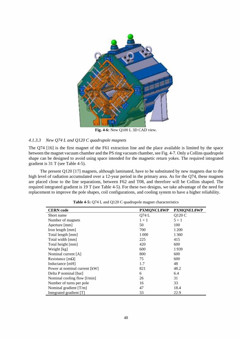
48
Fig. 4-6: New Q100 L 3D CAD view.
4.1.3.3 New Q74 L and Q120 C quadrupole magnets
The Q74 [16] is the first magnet of the F61 extraction line and the place available is limited by the space
between the magnet vacuum chamber and the PS ring vacuum chamber, see Fig. 4-7. Only a Collins quadrupole
shape can be designed to avoid using space intended for the magnetic return yokes. The required integrated
gradient is 31 T (see Table 4-5).
The present Q120 [17] magnets, although laminated, have to be substituted by new magnets due to the
high level of radiation accumulated over a 12-year period in the primary area. As for the Q74, these magnets
are placed close to the line separations, between F62 and T08, and therefore will be Collins shaped. The
required integrated gradient is 19 T (see Table 4-5). For these two designs, we take advantage of the need for
replacement to improve the pole shapes, coil configurations, and cooling system to have a higher reliability.
Table 4-5: Q74 L and Q120 C quadrupole magnet characteristics
CERN code PXMQNCL8WP PXMQNEL8WP
Short name Q74 L Q120 C
Number of magnets 1 + 1 5 + 1
Aperture [mm] 50 100
Iron length [mm] 700 1 200
Total length [mm] 1 000 1 360
Total width [mm] 225 415
Total height [mm] 420 600
Weight [kg] 600 1 939
Nominal current [A] 800 600
Resistance [mΩ] 75 600
Inductance [mH] 1.7 48
Power at nominal current [kW] 821 48.2
Delta P nominal [bar] 6 6.4
Nominal cooling flow [l/min] 26 31
Number of turns per pole 16 33
Nominal gradient [T/m] 47 18.4
Integrated gradient [T] 33 22.9

49
Fig. 4-7: Left: top view of Q74 maximum overall dimensions; right: new Q120 C 3D CAD view.
4.1.4 Corrector magnets
Two types of correctors are needed for the EA renovation (see Fig. 4-8). Some requirements could have been
fulfilled with the existing massive magnets such as the MEA19 [18] or MDX [19] but, due to the eddy currents,
the delay between field and current is at the limit of the cycle time required. The lengths available for these
two designs are limited by the new layout of the beamlines and challenging compromises have been made
between the magnet design and beam optic.
Fig. 4-8: Corrector magnets EA layout.
4.1.4.1 New CR200 and MDX L corrector magnets
The CR200 [20] corrector (Fig. 4-9) is a large aperture magnet tightly fitted between two quadrupoles. Its
design has been optimized to minimize the magnetic coupling between these magnets with a three-dimensional
study [21]. With the first requirement of a large aperture, at 150 mm, the CR200 corrector was not feasible.
Therefore, the aperture was reduced from 150 to 100 mm. Even with this aperture reduction, the distance
available between the adjacent magnets is at the limit of a realistic magnet’s overall length. The magnetic
coupling between these magnets has been studied, and proven to be negligible in terms of integrated magnetic
homogeneity (see Table 4-6).
The new MDX L 150 [22] is a laminated version of the actual MDX. As the M100 and M200 are
massive, the aperture of the actual MDX can vary its gap between 52 and 120 mm by adding steel plates
between the two half-yokes. This option of gap modification cannot be applied easily to laminated yokes. A
few different gaps were foreseen but, in order to have as few as possible different designs, it was decided to
do only one type with an aperture of 150 mm (see Table 4-6).
CR200 (x4)
MDX L (x8)

50
Table 4-6: CR200 and MDX L corrector magnet characteristics.
CERN code PXMCXCEHWP PXMCXCFHWP
Short name CR200 MDX L 150
Number of magnets 4 + 1 8 + 1
Aperture [mm] 100 150
Iron length [mm] 200 400
Total length [mm] 500 655
Total width [mm] 830 730
Total height [mm] 700 680
Weight [kg] 910 1 100
Nominal current [A] 600 240
Resistance [mΩ] 40.8 240
Inductance [mH] 22 300
Power at nominal current [kW] 14.7 221
Delta P nominal [bar] 10 10
Nominal cooling flow [l/min] 7.1 9
Number of turns per pole 64 180
Nominal field [T] 0.9 0.7
Integrated field [Tm] 0.28 0.36
Fig. 4-9: New CR200 3D CAD view.
4.2 Power converters
4.2.1 East Area present situation
The EA powering is presently supplied by 65 power converters that are located in Buildings 251 and 263.
There are 47 power converters in Building 251 and 18 power converters in Building 263.
A study has been performed in 2012 [22][23][24] by the electrical power converters group showing that
the energy consumption of East Area could be reduced from 11 GWh to 0.6 GWh per year after Long
Shutdown 2 (LS2). A significant part of this saving could be obtained by using a cycling magnet current, hence
recovering and storing the magnet energy after each physics operation. The study also highlighted the
possibility of self-funding part of the upgrade program, notably the power electronic converters, with a
depreciation period of five years for this investment.

51
4.2.2 East Area future layout and operation
The future beamlines (as defined in Section 2.1) of EA consist of 58 magnets of 12 different types (see
Fig. 4-10) to be powered by 61 power converters.
Fig. 4-10: The magnet map of East area. The axes correspond to the inductance and resistance of each magnet while the
bubble size represents the peak stored energy (and hence the size of the magnet).
The beamlines and key bending elements are depicted in Fig. 4-11.
Fig. 4-11: The proposed East Area layout after LS2.
The new layout will operate with a cycling current in all magnets in order to save energy. The form of
the cycle will be as illustrated in Fig. 4-12.

52
Fig. 4-12: Magnet current cycle in the new EA beamlines. The figure illustrates two successive beam extractions; one for
user A and a second for user B. The typical duration of each beam extraction is up to 400 ms and the time between two
successive extractions (Te-e) is 1.93 seconds minimum. Certain lines will cycle with a 2.4 s period whereas others will
have a 4.8 s period.
The duty cycle of the EA transfer lines will remain as it currently is at approximately 3.15 seconds
(7 extractions of an approximate extraction duration of 470 ms each) in a typical super-cycle of 46.8 seconds.
This implies a maximum duty cycle of 7% for the power converters (the time duration in a supercycle while
extraction to the East Area takes place).
The cycle characteristics appear in Fig. 4-13. The extraction time lasts 400 ms with a spill start and end
time tolerance of 10 ms on either side. Prior to the beam extraction, there is a maximum of 50 ms of current
settling into the magnet. The precise requirements are discussed in Refs. [25][26].
Fig. 4-13: Magnetic cycle characteristics. The settling time (Tset) allows for the current (and corresponding magnetic
field) to settle to a value within the required precision. A tolerance of 10 ms is defined for the start and stop of the beam
spill and hence for the beam extraction interval.
The root mean square (RMS) ratings of each circuit and losses in each circuit are listed in the following
tables.
User A beamend
Teco
t1
IA
Ieco
t2
Cu
rren
t
time
IB
User A beamstart
User Bbeamend
User B beamstart
Te-e
Teco
0
IA
PS beam extraction
start
Ieco
t1
Cu
rren
t
time
Tset
PS beam extraction finish
Current regulation precision band
Textract
10ms 10ms
Spill start—end time tolerance
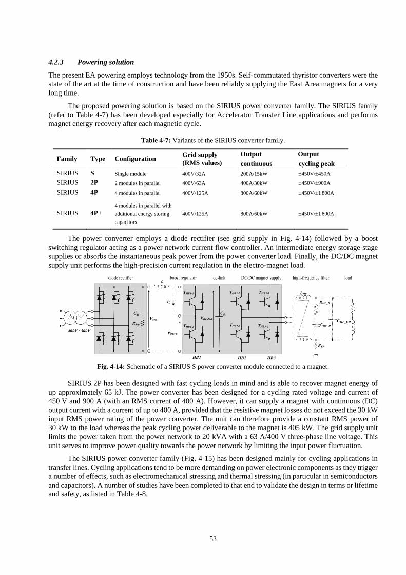
53
4.2.3 Powering solution
The present EA powering employs technology from the 1950s. Self-commutated thyristor converters were the
state of the art at the time of construction and have been reliably supplying the East Area magnets for a very
long time.
The proposed powering solution is based on the SIRIUS power converter family. The SIRIUS family
(refer to Table 4-7) has been developed especially for Accelerator Transfer Line applications and performs
magnet energy recovery after each magnetic cycle.
Table 4-7: Variants of the SIRIUS converter family.
Family Type Configuration Grid supply
(RMS values)
Output Output
continuous cycling peak
SIRIUS S Single module 400V/32A 200A/15kW 450V/450A
SIRIUS 2P 2 modules in parallel 400V/63A 400A/30kW 450V/900A
SIRIUS 4P 4 modules in parallel 400V/125A 800A/60kW 450V/1 800A
SIRIUS 4P+
4 modules in parallel with
additional energy storing
capacitors
400V/125A 800A/60kW 450V/1 800A
The power converter employs a diode rectifier (see grid supply in Fig. 4-14) followed by a boost
switching regulator acting as a power network current flow controller. An intermediate energy storage stage
supplies or absorbs the instantaneous peak power from the power converter load. Finally, the DC/DC magnet
supply unit performs the high-precision current regulation in the electro-magnet load.
Fig. 4-14: Schematic of a SIRIUS S power converter module connected to a magnet.
SIRIUS 2P has been designed with fast cycling loads in mind and is able to recover magnet energy of
up approximately 65 kJ. The power converter has been designed for a cycling rated voltage and current of
450 V and 900 A (with an RMS current of 400 A). However, it can supply a magnet with continuous (DC)
output current with a current of up to 400 A, provided that the resistive magnet losses do not exceed the 30 kW
input RMS power rating of the power converter. The unit can therefore provide a constant RMS power of
30 kW to the load whereas the peak cycling power deliverable to the magnet is 405 kW. The grid supply unit
limits the power taken from the power network to 20 kVA with a 63 A/400 V three-phase line voltage. This
unit serves to improve power quality towards the power network by limiting the input power fluctuation.
The SIRIUS power converter family (Fig. 4-15) has been designed mainly for cycling applications in
transfer lines. Cycling applications tend to be more demanding on power electronic components as they trigger
a number of effects, such as electromechanical stressing and thermal stressing (in particular in semiconductors
and capacitors). A number of studies have been completed to that end to validate the design in terms or lifetime
and safety, as listed in Table 4-8.

54
Table 4-8: References to studies performed during the development of SIRIUS.
Study Relevant components References
Accelerated aging testing Electrolytic capacitors [27][28]
Thermal cycling Semiconductor switches (IGBTs) [29]
Energy recovery Control loops [30][31][32]
Electrical Safety Electrolytic capacitors, semiconductor power stack [33]
Fig. 4-15: Features of SIRIUS power converters family.
4.2.3.1 Spare converters and spare parts
Three power converters, one 2P and two 4P+, will be available in the East Area in case of malfunction of any
of the operating power converters. All three can operate for a SIRIUS S in case of need. Interconnection of
spare converters with the magnet load will be made by means of power cables that will be temporarily laid on
the floor for the duration of spare converter operation.
4.2.3.2 MTG requirements
The machine timing generation (MTG) system is a programmable logic controller (PLC) based system that
monitors the status of different components of the accelerators and reconfigures the supercycle of the machine
accordingly. In the East Area, two power converters that direct the beam to the beam dump will be interfaced
with the MTG system (see Table 4-9). Following a change of strategy of the Power Converters Group post-
LS2, the EA power converters will not be interfaced to the MTG through a direct cable connection to the power
converter. Instead, the MTG subscribes to a converter property that notifies the converter state.

55
Table 4-9: Power converters connected to the MTG system.
Power converter name MTG interface
RPAEK.251.F61.RBXHD025A Software (by subscription to FGC property)
RPAEK.251.F61.RBXHD025B Software (by subscription to FGC property)
4.2.3.3 Elements important for safety (EIS) requirements
Two circuits will be part of an EIS-beam chain. In the case of a fault in one of the EIS power converters (see
Table 4-10), a spare scheme has been proposed with a safe to operate switch-over system that obliges the
operator to enable the EIS chain on the spare converter prior to connecting it to the EIS magnet [34].
Table 4-10: Power converters connected to the EIS system.
Power converter name Type of EIS
RPAEK.251.T8.MBXHD044 Beam
RPAEK.251.T8.MBXHD047 Beam
4.2.3.4 Energy saving
A new energy saving mode has been conceived for the SIRIUS converters installed for the transfer lines. The
algorithm runs in the FGC controller of the power converter. The operation requirements, such as the current
value and extraction, of each physics user are processed together with the circuit parameters and a current
waveform with the minimum possible RMS value is calculated prior to each magnetic cycle [35]. This process
is transparent for the operation and relies on a timing event received from the gateway by the FGC controller
over the FGCEther network. The timing will arrive 1.2 second prior to the extraction start instance so that
enough time is available for reaching the user current, even for magnets with a large time constant.
4.2.3.5 Control facility
A control room will be constructed that will allow technical personnel to operate in a quiet environment for
remote control and maintenance checks of the power converters.
4.3 Vacuum system description
The vacuum system of the EA will be renovated in the frame of the EA Renovation project: it includes the
hardware (vacuum chambers, pumps, gauges, etc.) and the remote control system.
The current vacuum system installed in the East Area is a very old and unreliable system. The pumps
are old, with a volume flow rate of 16 m3/h and with a very complex maintenance frequently required.
Furthermore, the control system only shows the vacuum level (which is not available remotely) but is does not
show the pumps’ status.
For these reasons, it has been decided to change and to upgrade the entire vacuum system of the East
Area, taking as a reference model the system installed in the North Area. The proposed vacuum system is in
line with other vacuum systems at CERN, and has been optimized to minimize intervention time and exposure
to radiation.
The system is equipped with on-line supervision to be monitored and controlled from the CERN Central
Control room (CCC) and remotely from a PLC platform. With the new chosen components, it is possible to
produce a 5 × 10⁻³ mbar vacuum.
The new vacuum system is divided into 5 sectors:

56
i) Sector 1: from the BTV in F61 line until the 1st bending, in green in Fig. 4-16.
ii) Sector 2: from the 1st bending to the 3rd bending in F62 and to the proton IRRADiation facility
(IRRAD) in T08, in yellow in Fig. 4-16.
iii) Sector 3: T09 line, in red in Fig. 4-16 .
iv) Sector 4: T10 line, in pink in Fig. 4-16.
v) Sector 5: T11 line, in grey in Fig. 4-16.
Fig. 4-16: Vacuum sectors of the East Area.
The new vacuum chambers are all in non-magnetic stainless steel (304L or 316L). Their standard size
is DN219, but at some points, they have different dimensions to adjust to the beam’s radius and they depend
on the outer equipment available space (magnets, collimators, etc.). The flanges used are conflate with metallic
seals. The windows for each sector are made of mylar or aluminium and their thickness depends on the beam’s
intensity and particle type.
Some cut-off manual section valves will be installed on the vacuum lines in order to isolate a part of the
vacuum sector in case maintenance is needed on a piece of equipment.
4.3.1 Pumping groups
The new EA vacuum system has 14 pumping groups and four gauges located at different positions in the
beamline. Each pumping group is made of valves, a gauge, a monitor, and a pump. The singular gauges are
just to control the vacuum level in the system. The general layout and structure can be seen in Fig. 4-17 and
more information is available in Ref. [36].
Inside the primary and mixed areas, no vacuum groups are installed because these areas are the most
radioactive ones. In this way, it is possible to reduce the radiation damage to the pumps and the electrical
systems, but also the exposure of the workers during maintenance. Inside the primary and mixed areas only
four gauges are installed to monitor the vacuum level.
In some cases, the most critical vacuum groups (of more difficult access) will have two pumps mounted
in parallel in order to have a redundant backup solution in case a fault occurs.

57
Fig. 4-17: Layout of the new vacuum system
4.3.2 Vacuum controls
The vacuum control system consists of a Siemens 1500 PLC, three sets of input/output (I/O) stations
with a Profinet communication protocol and five total pressure gauge controller (TPG300), each with a set of
Profibus, Pirani cards to receive the signal from the groups pumping. A supervisory control and data acquisition
(SCADA) system based on the WinCC Open Architecture (OA) forms the remote interface with the users. The
objective is to avoid radiation in the interventions on the pumping groups and on the Pirani gauges when the
East Area receives the PS beam. The SCADA application will be implemented in the complex PS framework
to include the East Area synoptic.
4.4 Beam intercepting devices
4.4.1 Introduction
The EA Beam Stopper Consolidation started before the Long Shutdown 1 (LS1). During LS1, a general
maintenance was performed, including urgent interventions on the beam stoppers, such as the replacement of
the compressed air distribution and the switches. During LS2, the layout of the beamlines will be modified.
This will affect the layout and functionality of the beam stoppers, stopper dumps, and multitargets.
– Beam stoppers, stopper dump:
in particular the basic layout of the North branch will be revised completely. In the present beam layout,
the primary protons that did not interact in the North multi-target are stopped in the T09 beam stoppers in case
of access to T09. In the new layout those protons will be stopped in a fixed dump and the T09 stopper dumps
will only see low-intensity secondary beams.
– Targets:
the new layout requires the installation of two multi-targets, one to produce the T09 beam and the second
to produce T10 and T11 beam. The special target used in CERN High energy AcceleRator Mixed field
facility (CHARM) is not affected by the renovation.
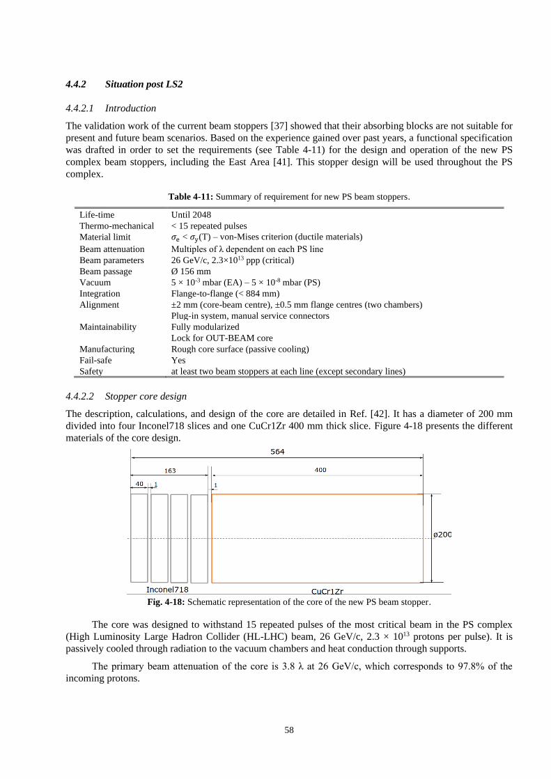
58
4.4.2 Situation post LS2
4.4.2.1 Introduction
The validation work of the current beam stoppers [37] showed that their absorbing blocks are not suitable for
present and future beam scenarios. Based on the experience gained over past years, a functional specification
was drafted in order to set the requirements (see Table 4-11) for the design and operation of the new PS
complex beam stoppers, including the East Area [41]. This stopper design will be used throughout the PS
complex.
Table 4-11: Summary of requirement for new PS beam stoppers.
Life-time Until 2048
Thermo-mechanical < 15 repeated pulses
Material limit 𝜎e < 𝜎y(T) – von-Mises criterion (ductile materials)
Beam attenuation Multiples of λ dependent on each PS line
Beam parameters 26 GeV/c, 2.3×10¹³ ppp (critical)
Beam passage Ø 156 mm
Vacuum 5 × 10⁻³ mbar (EA) – 5 × 10⁻⁸ mbar (PS)
Integration Flange-to-flange (< 884 mm)
Alignment ±2 mm (core-beam centre), ±0.5 mm flange centres (two chambers)
Plug-in system, manual service connectors
Maintainability Fully modularized
Lock for OUT-BEAM core
Manufacturing Rough core surface (passive cooling)
Fail-safe Yes
Safety at least two beam stoppers at each line (except secondary lines)
4.4.2.2 Stopper core design
The description, calculations, and design of the core are detailed in Ref. [42]. It has a diameter of 200 mm
divided into four Inconel718 slices and one CuCr1Zr 400 mm thick slice. Figure 4-18 presents the different
materials of the core design.
Fig. 4-18: Schematic representation of the core of the new PS beam stopper.
The core was designed to withstand 15 repeated pulses of the most critical beam in the PS complex
(High Luminosity Large Hadron Collider (HL-LHC) beam, 26 GeV/c, 2.3 × 10¹³ protons per pulse). It is
passively cooled through radiation to the vacuum chambers and heat conduction through supports.
The primary beam attenuation of the core is 3.8 λ at 26 GeV/c, which corresponds to 97.8% of the
incoming protons.

59
4.4.2.3 General description of the new beam stopper and stopper dump
Figure 4-19 shows the 3D model of the new beam stopper. This equipment is totally independent of
neighbouring mechanical equipment, with its own vacuum chamber, mechanism, plug-in, and support systems.
The new beam stopper has a weight of 550 kg and a height of 1 600 mm.
Fig. 4-19: Three-dimensional view and cut view of the new beam stopper.
The final design is composed of the following sub-systems, as shown in Fig. 4-20: the stopper core,
which is held by a fork. The fork is welded to the bellows, which are themselves connected to the base plate.
The shock absorbers and ball bearings are fixed onto this plate as well. The pneumatic actuator is also fixed
below this plate.
Fig. 4-20: Details of the stopper moving mechanism.
The pressurized pneumatic cylinder keeps the core in the OUT-BEAM position. The design has been
calculated to work with a pressure of 4 bars. This margin allows for an increase of the pressure in case of

60
friction. When it is de-pressurized, the core falls in the IN-BEAM position. The support plate is damped
through shock absorbers on the frame (see Fig. 4-19).
Whenever members of personnel want or are forced to access a downstream area or in fail-safe
situations [43], the core needs to move to the IN-BEAM position. The assembly slides in the guiding system
vertically.
On the top of the guiding shaft there is an adjustment table for surveying, which supports the tank, as
shown in Fig. 4-21.
Fig. 4-21: Dedicated vacuum chamber for the beam stoppers.
4.4.2.4 Multitarget
The new multitarget design can be found in Fig. 4-22 and is composed of five different sub-systems:
i) Aluminium profile chassis.
ii) X–Y motorization.
iii) Target arm with a beam screen.
iv) Camera.
v) First Plug-in support.
The major change from the first multitarget is the modification of the adjustment system on the target arm.
It allows surveys to be more precise and it is faster to align the target. Furthermore, a lower plugin position of
the chassis was added in case the entire multitarget has to be removed. The motorization has also changed to
better manage the spare pool.

61
Fig. 4-22: Multitarget new design.
4.4.2.5 East Area integration
In this new configuration (Fig. 4-23), five beam stoppers will be installed on the F61 and another five
on the T8 line. This number of stoppers on this line is due to the radiation protection requirements for the beam
attenuation and the facility of access to the downstream experimental area. Each secondary beamline is
protected by one stopper dump each (T09, T10, T11).

62
Fig. 4-23: New integration of the beam stoppers, stopper dumps, and multitargets.
4.5 Beam instrumentation
Most of the present beam instrumentation is preserved in the future East Area configuration [46]. The main
changes concern their integration into the layout of the new experimental lines. Some old beam profile monitors
in the secondary beamlines will be replaced by new ones based on scintillating fibres. New beam loss monitors
will be installed along the primary lines F61, T08, and around the two multi-targets. The monitors listed below
are classified by main observable.
4.5.1 Intensity measurement and particle counters
The measurement of bunched beam intensity in the transfer lines is performed by fast beam current
transformers (BCTF). During slow extraction, where the beam is debunched, the BCTF cannot measure the
spill due to the monitor’s limited bandwidth (low cut-off frequency), and also due to the low particle flux. Most
of the time, beam interacting devices are required in experimental beamlines.
4.5.1.1 Beam current measurement based on gas: BCGAA (formerly named LSD)
The longitudinal spill detection relies on collecting beam-induced ionization photons with nitrogen gas. The
electric signal generated by a photo-multiplier (PM) is amplified and sampled. As shown in Fig. 4-24, the plot
of the longitudinal spill is displayed on the East Area Vistar for routine check by the operators. Only one device
will be kept after the renovation. The monitor’s position will be about the same, i.e. 22 m from the extraction
point, before F61.MBXHD025 in the new layout (see Table 4-12).

63
Fig. 4-24: Left: longitudinal spill detector; right: signal from the monitor displayed on EA Vistar.
Table 4-12: Position of BCGAA in the new primary lines.
Line section Layout component name after LS2 Equipment code
F61 F61.BCGAA023 BCGAA
4.5.1.2 Secondary emission chamber: XSEC / XION
The phenomenon of secondary electron emission from the surfaces of thin metal foils hit by charged particles
can be used for particle detection. The so-called secondary emission chambers (XSEC) [44] consist of a stack
of plain and polarized hollow thin metal films in vacuum: secondary electrons collected by high voltage
electrodes are proportional to the total number of incoming particles. Calibration with a bunched beam (protons
or ions) is performed before each run. The comparison of signals from F61.BCTF022 with secondary monitors
gives a scaling factor so that the total beam flux and intensity integrated along the spill is deduced.
The argon ionization chambers (XION) use the ionization of argon by particle collisions and collect the
electron charge to count primary ion particles. Twenty-one parallel electrodes (5 um aluminium foils) are
placed in a stainless steel vessel filled with pure Ar gas slightly above atmospheric pressure: eleven of the
electrodes are connected to a local high voltage battery supply, whereas the ten charge collecting foils are
connected to the output. The ionization counter works with no avalanche amplification and gives a small but
reliable output signal that mirrors the intensity. The analogue signal is sent towards a counter (scaler) in the
APRON equipment room and is controlled by a front-end software architecture (FESA) class. The beam
intensity is read by controls for the SPS experimental areas (CESAR) system.
Few beam monitors can operate in the target zone due to the very high activation level, but XSEC and
XION can withstand high levels of radiation. Both are shown in Fig. 4-25, with the figure of merit for the
operators displayed in Vistar (red circles).

64
Fig. 4-25: Left: pictures of secondary emission chamber, middle: argon ionization chamber; right: each green dot
represents the integrated beam intensity per extraction.
After renovation, all secondary emission chambers will be kept at their current positions in the beamline, except
the one in F61, that will be relocated downstream for integration reasons. Like the F62 target, the new target
in the F63 line will be equipped with a XSEC. In total, five monitors will be deployed in the new EA layout
(see Fig. 4-26). Table 4-13 lists their positions in the extraction line sections and their names in the new layout
after renovation.
Fig. 4-26: Position of XSEC on the new East Area lines.
Table 4-13: Position of XSEC-XION in the new primary lines.
Line section Layout component name after LS2 Equipment code Comment
F61 F61.XSEC023 XSEC
F62 F62.XSEC022 XSEC F62 target zone
F63 F63.XSEC008 XSEC New F63 target zone
T08 T08.XSEC070 XSEC
T08 T08.XSEC094 XSEC
T08 T08.XION094 XION
4.5.1.3 Fast current transformer: BCTF
As mentioned in Section 4.5.1, the monitor F61.BCTF022 is used to calibrate XSEC and XION with bunched
beams (see Table 4-14). The current transformer will be kept as it is.
XION XSEC
Total proton beam
intensity

65
Table 4-14: Position of BCTF in the new primary lines.
Line section Layout component name after LS2 Equipment code
F61 F61.BCTF022 BCTF
4.5.1.4 Beam loss monitoring (BLM) system
Initially not present in the baseline of the East Area Renovation project, a system to acquire and process the
data from 15 BLM detectors spread along the lines has been installed in the East Area, with the scope of
observing the beam losses in real time and optimizing the beam process. The new system will be generic and
highly configurable. It is based on the ionization chamber (IC) design developed for the LHC that are now
widely used in the CERN accelerator complex. Similarly, all the electronics will be of the LHC Injector
Upgrade (LIU) type that has recently been deployed for the next run. The technology is reliable, radiation hard,
and comes with standard spare parts.
In total, seven BLM detectors will be installed along the primary lines, starting from the PS extraction
to the IRRAD and CHARM experimental areas. The beamlines concerned will be F61, F62, F63, and T08 as
shown in Fig. 4-27.
Eight additional detectors will be installed in sets of four units downstream of the T09 target
(F62.TMMTV026) and the T10/T11 target (F63.TMMTV009) as shown in Fig. 4-28. The idea is to equip each
target with a pair of BLMs per plane (horizontal and vertical).
Fig. 4-27: Sketch of BLM detector positions along the primary lines.
Fig. 4-28: A set of four BLMs will be installed downstream of each target, with the following layout: a couple of units
for both H and V planes.
4.5.1.5 Specific particle identification counter based on Cherenkov effect: XCET
Threshold Cherenkov counters are available in some of the East Area beamlines to obtain particle identification
information for individual particles in that beamline. The detector is filled with gas that is able to detect
particles with speed above the speed of light in the gas. For a certain beam energy, the lighter particles will

66
have a higher speed. The particles with a speed higher than the speed of light (relativistic particles) inside that
particular gas environment will produce Cherenkov light that can be detected by a photomultiplier. The gas
pressure inside the detector sets the limit of mass of the particles that can be detected. The beam enters in the
detector tube through an entrance window, traverses the tube filled with the selected gas, and exits through the
exit window (Fig. 4-29). Inside the top part of the vessel cone, also filled with gas, a mirror deflects the light
towards the optical window behind which the photomultiplier is located.
Fig. 4-29: Structure of a Cherenkov counter.
The Cherenkov counters installed in the East Area line consist of a 2.5 m long stainless steel tube with
a diameter of 168 mm. The overall desired length should be chosen in accordance with the light efficiency and
allowable multiple scattering. Both open ends, the entrance and the exit window of the counter are terminated
with 1.4 mm thick aluminium windows. The Cherenkov gases might be selected by the user but should be non-
flammable gases, e.g. CO2, N2, R218, R134a, etc. to a maximum gauge pressure of 15 bar.
The actual counters are very old instruments, with windows and support structures requiring renovation.
Furthermore, the gas pressure is difficult to set precisely and is manually controlled through the old control
panel (Fig. 4-32, left). Unlike the North Area, the PM high voltage supply and PM signals are controlled and
managed by the users. After renovation, T09 and T10 will be equipped with new pairs of Cherenkov counters.
Their respective locations are shown in Fig. 4-30.
Fig. 4-30: Location of the new Cherenkov counters in the T09 and T10 beamlines.
The structure of the new counters (see Fig. 4-31) is similar to that of Fig. 4-29, with a horizontal tube
which can be assembled in a modular way depending on the required length. The latter will be filled with either
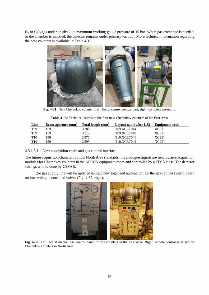
67
N2 or CO2 gas under an absolute maximum working gauge pressure of 15 bar. When gas exchange is needed,
or the chamber is emptied, the detector remains under primary vacuum. More technical information regarding
the new counters is available in Table 4-15.
Fig. 4-31: New Cherenkov counter. Left: body; centre: conical part; right: complete assembly.
Table 4-15: Technical details of the four new Cherenkov counters of the East Area.
Line Beam aperture (mm) Total length (mm) Layout name after LS2 Equipment code
T09 159 3 280 T09.XCET044 XCET
T09 159 3 115 T09.XCET048 XCET
T10 159 2 975 T10.XCET040 XCET
T10 159 2 595 T10.XCET043 XCET
4.5.1.5.1 New acquisition chain and gas control interface
The future acquisition chain will follow North Area standards: the analogue signals are sent towards acquisition
modules for Cherenkov counters in the APRON equipment room and controlled by a FESA class. The detector
settings will be done by CESAR.
The gas supply line will be updated using a new logic and automation for the gas control system based
on low-voltage-controlled valves (Fig. 4-32, right).
Fig. 4-32: Left: actual manual gas control panel for the counters in the East Area. Right: remote control interface for
Cherenkov counters in North Area.

68
4.5.1.6 Scalers
‘Scalers’ are counter channels from a VME board provided to experiments in groups of four. A large
experiment can have up to twenty. Scalers are based on SIS3803 modules located in the beam instrumentation
(BI) electronic rack in the APRON barrack. A set of four cables per user barrack will be dispatched.
4.5.2 Profile monitors
The beam profile is affected while crossing different accelerator components: bending magnets, quadrupoles,
or radio frequency (RF) cavities. A beam width control is important for the transverse matching between
machines and also for the beam spot towards the experiments. During slow extraction, profile monitors can
serve as position pick-ups. Under such beam conditions, as with the BCTF, standard beam position monitors
are blind due to their limited low-frequency bandwidth. There is a large variety of profile monitors, depending
on the particle type, current, and energy.
4.5.2.1 Beam observation monitor with fluorescenting screen with scintillating screen and target TV
4.5.2.1.1 BTV with scintillating screen
Following a large upgrade programme undertaken during YETS15-16 to replace the old ‘Marguerites’ stations,
proton beam profiles in the PS extraction line F61 upstream of the East Area are now acquired by intercepting
the beam with chromium-doped alumina screens and observing the emitted fluorescence with radiation hard
cameras. The screen insertion device is made via a vacuum compatible magnetic push–pull system, where
bellows are no longer needed. Only the first beam observation monitor with fluorescenting screen (BTV) in
T08, which is an operational BTV with bellow (see Fig. 4-33), was not in the scope of the upgrade programme.
Fig. 4-33: Reference picture from T8.BTV01 during the 2018 ion run.
4.5.2.1.2 Target TV
Besides the secondary emission chamber described earlier, that can operate in a very activated environment, a
radiation hard camera is placed upstream of the present F61 target to visualize the beam spot and resteer off-
centred beams if needed.
4.5.2.1.3 Layout change during LS2
Only five BTVs out of six will remain in the primary beamlines, with minor changes regarding their positions
in the new layout. Currently there are two target TVs, one for the F61 line and one for the CHARM target in
the T08 line. After LS2, a third TV will be implemented for the new target in the F63 line. Their positions are
schematically represented in Fig. 4-34. Some technical details and new layout names can be found in
Table 4-16.

69
Fig. 4-34: Position of the BTVs in the new layout.
Table 4-16: Technical details and new layout name of BTVs and target TVs after LS2.
Present name Layout name after LS2 BTV type Equipment code
F61.BTV01 F61.BTV012 PSZBTVMC (screen 100 mm) BTV
F61.BTV02 Spare PSZBTVMC (screen 100 mm) BTV
F61.BTV03 F62.BTV002 PSZBTVMC (screen 140 mm) BTV
F61D.BTV01 F6D.BTV010 PSZBTVMC (screen 100 mm) BTV
F61S.BTV01 T8.BTV020 PSZBTVMC (screen 100 mm) BTV
ZT8.BTV01 T8.BTV035 Old BTV design, with below BTV
F61N.BTV01 F62.TMMTV026 Target TV TMMTV
New F63.TMMTV009 Target TV TMMTV
ZT08.BTV02 T08.TMCRT097 Target TV TMCRT
4.5.2.2 Multi-wire proportional chamber in T08 Line: XWCM
This monitor is mainly used during the commissioning phase of secondary beamlines in the experimental areas.
Its typical particle flux range is 105 to 1011 p/s. The main observables are transverse beam profiles as well as
beam position (see Fig. 4-35).
The detector consists of a set of 40 µm stretched tungsten wires, having a 1 mm spacing. The plan is
placed between a couple of aluminium foils in a housing containing an equal mix of CO2 and Ar gas. A high
voltage is applied between the foils (cathode) and the wires (anode). The latter collects ionization-induced
electrons amplified by avalanche effect. The charges from each wire are integrated during the extraction time.
The beam profile is obtained by reading the integrator output voltage from each wire, as shown in Fig. 4-36.
Fig. 4-35: A multi-wire proportional chamber in the North Area (XWCA 021 492).

70
Fig. 4-36: Beam profiles from ZT08.XWCM135 during the 2018 ion run.
This monitor is operational and will be kept without consolidation. Only the layout name will change
(see Table 4-17).
Table 4-17: Position of XWCM in the new primary lines.
Line section Present name Layout component name after LS2 Equipment code
T08 ZT08.XZCM135 T08.XWCM103 XWCM
4.5.3 Scintillator-based detectors
A scintillator is an organic or inorganic material which emits photons following the excitation of atoms and
molecules by radiation (γ or particle radiation including neutrons and neutrinos). The material exists in the
three matter phases: solid, liquid, or gas. Scintillators are widely used in secondary beamlines as a multi-
purpose monitor, for triggering, or particle identification by pulse height analysis. Other possible applications
are light guide, wavelength shifter, calorimeters, or time of flight counters thanks to their very fast response
time.
4.5.3.1 Particles counters and triggers: XSCI
Plastic scintillators are currently installed in the East Area as particle counters or triggers. T09 is equipped with
a pair of scintillators, while T10 and T11 have only one. PMs with high voltage for light amplification and
output signal are connected to a dedicated acquisition module in the APRON equipment room, and controlled
by a FESA class. The present detectors are kept, with minor displacement in the new layout. T10 will get a
second detector. Their positions and new layout name are listed in Table 4-18.
Table 4-18: Position of XSCI in the new primary lines.
Line Layout name after LS2 Equipment code
T09 T09. XSCI041 XSCI
T09 T09. XSCI050 XSCI
T10 T10. XSCI036 XSCI
T10, new T10. XSCI044 XSCI
T11 T11. XSCI022 XSCI
4.5.3.2 Scintillating fibre monitors: XBPF
The experimental beam profile fibre monitor (XBPF) [45] is a scintillating fibre detector recently developed
at CERN for the measurement of the profile, position, and intensity of secondary beams. The physics principle
of particle detection with scintillating fibres relies in the creation of scintillation light, due to the passage of a
charged particle, and the transmission of this light inside the fibre by total internal reflexion. The XBPF is

71
composed of 100 or 200 scintillating fibres (depending on the size of the monitor) of 1mm thickness and square
cross-section. The fibres are packed together along one plane, forming the active area of the detector that stands
in front of the beam (Fig. 4-37, left). The light from every fibre is read out on one end by an individual silicon
photomultiplier that allows one to know which fibre has been activated and to subsequently measure the profile,
position, and intensity of the beam. A mirror glued on the non-read-out end of the fibre reflects back the light
travelling in that direction along the fibre, thus increasing the total light signal reaching the photomultiplier.
The XBPF has been designed to be vacuum compatible, which removes the need for vacuum windows,
therefore helping to reduce the material budget of the beamline. The photodetectors are located outside
vacuum, with the fibres exiting via a feedthrough based on an innovative gluing technique that guarantees the
necessary leak tightness. The vacuum tank of the new detectors has a modular design that allows two XBPF
to be hosted for the simultaneous measurement of the horizontal and vertical profiles of the beam (Fig. 4-37,
right).
Fig. 4-37: Left: XBPF on the left and front-end board with the 192 SiPMs on the right. Right: vacuum tank of the XBPF
during installation, with a front-end electronics board in place.
4.5.3.2.1 New detectors after LS2
These three aging gaseous wire chambers (XDWC) in each of the secondary beamlines, which can no longer
provide accurate profiles in all ranges of intensities, will be upgraded by dual-plane scintillator fibre monitors.
Table 4-19 summarizes the changes and the new layout names.
Table 4-19: Upgrade of beam profile monitors after LS2.
Line Changes after LS2 Equipment code Comment
ZT09 Removed XDWC Storage
ZT10 Removed XDWC Storage
ZT11 Removed XDWC Storage
T09 T09.XBPF041 XBPF New, 10 cm × 10 cm
T09 T09.XBPF050 XBPF New, 10 cm × 10 cm
T10 T10.XBPF045 XBPF New, 10 cm × 10 cm
T11 T11.XBPF022 XBPF New, 20 cm × 20 cm
To keep the versatility of the new experimental lines, the XBPF tanks will not be pumped down, but left
under atmospheric pressure.
4.5.3.2.2 Acquisition chain and cabling
The Beam Instrumentation (BI) group will produce the front-end boards (one per plane). On the back-end side,
a VFC-based acquisition board developed by BI for its applications will be used. The transmission between
them is performed via optical fibres.

72
4.6 Survey systems
Due to beam optics requirements, the correct positioning and alignment of all beamline components is
mandatory. The future configuration of the East Area will follow the survey requirements in terms of layout
[46][47] but also the CERN standards in terms of alignment.
All buildings where the new beamlines will be installed were scanned in three dimensions to do a
comparison with the integration model. A difference of 30 mm was found between the PS floor and the East
Area Building 157 floor. This height difference will be compensated in Building 157 with the beam equipment
supports.
4.6.1 Networks
Before the alignment of the components, a reference network of precise points will be done all around the
areas. The positions of these points will be uploaded on the survey database and will be used later to align the
equipment.
The network area includes Building 352 and all the beam areas in Building 157 as shown in Fig. 4-38.
In order to establish the point network between Buildings 352 and 157 there will be a hole in the separation
wall between these buildings. The same procedure must be applied for all internal walls of Building 157
between the closed zones. The network needs to be determined before dismantling the main components
already installed in the East Area.
Fig. 4-38: Building 352 (in blue), primary area (red), mixed area (green), T8 area (orange), secondary beam area (purple).
4.6.2 Fiducialization
Each component to be aligned will have two survey fiducials (usually spheres) on top of it, indicating
the entry and exit of the element (‘Entrée+Sortie’ E + S) plus a tilt surface to measure the angle of the element.
The two fiducials installed on the components should leave enough space to put the measuring system on top
(min. 50 cm).
In order to align each component with respect to the network, a fiducialization step has to be performed before
installation. The fiducialization is a procedure where the relative positioning between the two survey fiducials
(E+S) is measured with respect to the theoretical beam axis of the component. The fiducialization is a
procedure done before installation. The values coming from the fiducialization step give the geometry of the
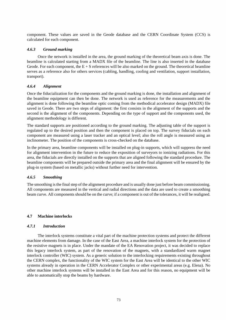
73
component. These values are saved in the Geode database and the CERN Coordinate System (CCS) is
calculated for each component.
4.6.3 Ground marking
Once the network is installed in the area, the ground marking of the theoretical beam axis is done. The
beamline is calculated starting from a MADX file of the beamline. The line is also inserted in the database
Geode. For each component, the E + S references will be also marked on the ground. The theoretical beamline
serves as a reference also for others services (cabling, handling, cooling and ventilation, support installation,
transport).
4.6.4 Alignment
Once the fiducialization for the components and the ground marking is done, the installation and alignment of
the beamline equipment can then be done. The network is used as reference for the measurements and the
alignment is done following the beamline optic coming from the methodical accelerator design (MADX) file
saved in Geode. There are two steps of alignment: the first consists in the alignment of the supports and the
second is the alignment of the components. Depending on the type of support and the components used, the
alignment methodology is different.
The standard supports are positioned according to the ground marking. The adjusting table of the support is
regulated up to the desired position and then the component is placed on top. The survey fiducials on each
component are measured using a laser tracker and an optical level; also the roll angle is measured using an
inclinometer. The position of the components is cross-checked on the database.
In the primary area, beamline components will be installed on plug-in supports, which will suppress the need
for alignment intervention in the future to reduce the exposition of surveyors to ionizing radiations. For this
area, the fiducials are directly installed on the supports that are aligned following the standard procedure. The
beamline components will be prepared outside the primary area and the final alignment will be ensured by the
plug-in system (based on metallic jacks) without further need for intervention.
4.6.5 Smoothing
The smoothing is the final step of the alignment procedure and is usually done just before beam commissioning.
All components are measured in the vertical and radial directions and the data are used to create a smoothing
beam curve. All components should be on the curve; if a component is out of the tolerances, it will be realigned.
4.7 Machine interlocks
4.7.1 Introduction
The interlock systems constitute a vital part of the machine protection systems and protect the different
machine elements from damage. In the case of the East Area, a machine interlock system for the protection of
the resistive magnets is in place. Under the mandate of the EA Renovation project, it was decided to replace
this legacy interlock system, as part of the renovation of the magnets, with a standardized warm magnet
interlock controller (WIC) system. As a generic solution to the interlocking requirements existing throughout
the CERN complex, the functionality of the WIC system for the East Area will be identical to the other WIC
systems already in operation in the CERN Accelerator Complex or other experimental areas (e.g. Elena). No
other machine interlock systems will be installed in the East Area and for this reason, no equipment will be
able to automatically stop the beams by hardware.
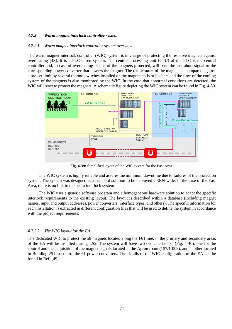
74
4.7.2 Warm magnet interlock controller system
4.7.2.1 Warm magnet interlock controller system overview
The warm magnet interlock controller (WIC) system is in charge of protecting the resistive magnets against
overheating [48]. It is a PLC-based system. The central processing unit (CPU) of the PLC is the central
controller and, in case of overheating of one of the magnets protected, will send the fast abort signal to the
corresponding power converter that powers the magnet. The temperature of the magnets is compared against
a pre-set limit by several thermo-switches installed on the magnet coils or busbars and the flow of the cooling
system of the magnets is also monitored by the WIC. In the case that abnormal conditions are detected, the
WIC will react to protect the magnets. A schematic figure depicting the WIC system can be found in Fig. 4-39.
Fig. 4-39: Simplified layout of the WIC system for the East Area.
The WIC system is highly reliable and assures the minimum downtime due to failures of the protection
system. The system was designed as a standard solution to be deployed CERN-wide. In the case of the East
Area, there is no link to the beam interlock system.
The WIC uses a generic software program and a homogeneous hardware solution to adapt the specific
interlock requirements to the existing layout. The layout is described within a database (including magnet
names, input and output addresses, power converters, interface types, and others). The specific information for
each installation is extracted in different configuration files that will be used to define the system in accordance
with the project requirements.
4.7.2.2 The WIC layout for the EA
The dedicated WIC to protect the 58 magnets located along the F61 line, in the primary and secondary areas
of the EA will be installed during LS2. The system will have two dedicated racks (Fig. 4-40), one for the
control and the acquisition of the magnet signals located in the Apron room (157/1-009), and another located
in Building 251 to control the 61 power converters. The details of the WIC configuration of the EA can be
found in Ref. [49].

75
Fig. 4-40: Layout of the East Area with the location of the two WIC racks.
4.8 Beam controls
4.8.1 Upgrade of the infrastructure
The control infrastructure provided by the Controls Group (BE-CO), Beams Department, will be
upgraded for the EA as part of the overall initiative to upgrade the hardware and software components during
the long shutdown LS2. New pulse repeaters (for the distribution of pulses) and new a general master timing
(GMT) distribution to all front-end computers (FECs) will be installed as well as new hardware components,
replacing the ageing components dating from 1980 with enhanced remote monitoring and diagnostics of the
whole distribution chain. New full digital distribution system (Matrox digital decoders) will replace
the old analogue video distribution system (CATV) (Fig. 4-41).
All FECs used in the East Area had to be upgraded to FESA3 version 7 and to CENT-OS7 by 1 January
2020; this date corresponds to the official end of life milestone for all BE-CO legacy components [50]. The
upgrade is under the responsibility of persons in charge of the FEC and of the FESA classes.
Fig. 4-41: New video distribution system.
WIC racks

76
4.9 Collimators
4.9.1 General description
The collimators are devices composed of internal jaws that are moved according to the operation requirements
to clean the beam by removing stray particles and protecting downstream equipment, shielding it from beam
trajectory errors. The internal aperture of a collimator can be used to define the range of beam energy, reduce
the beam intensity (acceptance collimator), find the beam by scanning the aperture, divide particles of different
types, and clean the beam disturbed by other collimators upstream.
The T09, T10, and T11 secondary beamlines are equipped with obsolete PS-type collimators, poorly
documented for their mechanics and with replacement parts hard to find. In addition, the current collimators
are also incompatible with computer control. Mechanical failure is the main issue with the beamline collimators
such as jammed positioning mechanism, broken ribbon, or faulty ball bearings or potentiometer. Electrical
failure is also likely including motor fault, impossible data reading, problems with electronics given by the
high radioactive environment, etc.
It is therefore proposed to replace the old East Area collimators by four 4-jaw collimators (XCHV) taken
from the North Area spare collimators [51] and three new 2-jaw collimators (XCSV and XCSH). The spare
collimators of the North Area can be re-used provided that a thorough refurbishment is completed and validated
by commissioning tests. The new collimators control system will be done via FESA classes, logged and
controlled by CESAR and TIMBER.
By using XCHV and XCSV/H, collimators already used in the North Area it will be possible to make
the device types and controls used at CERN in the experimental areas more uniform, easing the standardization
and classification of equipment and control systems.
In total, 7 new collimators will be installed: 3 XCHV for T09, 1 XCHV, 1 XCSH, and 1 XCSV for T10
and 1 XCSH for T11 (see Fig. 4-42). In addition to these collimators, a new fixed collimator, the XTCX, will
be added at the beginning of the T09 line during LS2 (see Section 4.9.4).
Fig. 4-42: Location of the new collimators in T09, T10 and T11.
4.9.2 XCHV collimator design
The XCHV collimators have four internal jaws made of steel (in grey in Fig. 4-43) of which two are moved
along the horizontal direction and two along the vertical one. Every jaw is motorized and the position is
controlled by a linear potentiometer (Fig. 4-44).

77
The external structure of the collimator is a vacuum vessel that is connected upstream and downstream
with the vacuum beam chamber.
Fig. 4-43: XCHV collimator drawing a longitudinal view and upstream view of the open collimators with jaws.
Fig. 4-44: Longitudinal view and downstream view of an open collimator with the jaws and motors.
4.9.3 XCSV-XCSH collimator design
The XCSV and XCSH collimators (Fig. 4-45) have two internal steel jaws that are able to move horizontally
(XCSH) or vertically (XCSV) driven by a DC motor and their position is controlled by a linear potentiometer.
Each jaw is moved by a motor operating in DC. Two micro-switches are mounted externally to indicate the
end of the outer movement and a third micro-switch is installed internally in common with the two jaws to
avoid collisions between them.

78
Fig. 4-45: Longitudinal view of a XCSV or XCSH collimator.
4.9.4 XTCX collimator
The XTCX (TCX stands for ‘target collimator experimental areas’) is a beam collimator that serves to protect
the facilities placed after the target [51]. It is designed to withstand primary beam intensities. It is composed
of an iron block mounted on an aluminium frame. The iron block permit absorption of the beam with a variable
momentum spread in order to transmit only the wanted secondary beam with a specific central momentum.
The XTCX is located on T09, just after the target (Fig. 4-46). No vacuum chambers pass through the XTCX.
The beam passes through the air and comes back through a vacuum chamber just after the XTCX, passing
through a 0.1 mm thick aluminium window. It is a passive component without water cooling. Design details
can be found in Refs. [52] and [53].
Fig. 4-46: Location of the XTCX in the T09 line.
4.10 Radiation shielding
4.10.1 Facility parameters
The beam parameters that were used for the design of the shielding were taken from Ref. [54]. The East Hall
receives a slowly extracted proton beam from the CERN PS with a beam momentum of 24 GeV/c with up to
5 × 10¹¹ protons per pulse and a maximum average beam intensity of 6.7 × 10¹⁰ protons per second.
Theoretically, up to 6 spills per supercycle of 45.6 seconds can be sent to the East Hall, up to 3 spills per
supercycle for T09, and up to 3 spills per supercycle for T10, with 3.3 × 10¹⁰ protons per second for each target.

79
Accounting for the number of days of operation per year and machine availability, the nominal annual number
of protons is 3.3 × 10¹⁷ protons per year and the maximum annual number of protons is 1018 protons per year.
4.10.2 Radiation protection requirements
The shielding of the East Area primary zone has to be designed so that the radiological area classification [55]
for the East Hall is respected. Being classified as a Supervised Radiation Area, this means that the ambient
dose equivalent rates should be below 3 μSv/h for the control rooms inside the East Hall and less than 15 μSv/h
(low occupancy area) at 40 cm outside the shielding walls for the maximum average beam intensity of
6.7 × 10¹⁰ p/s, at locations accessible during beam operation. In addition, the ambient dose equivalent rates
should be below 2.5 μSv/h outside of the hall for the maximum average beam intensity. These requirements
mean that all shielding passages (access chicanes, ventilation ducts, cable ducts) have to be designed in an
optimized way.
In addition to compliance with the limits of the radiological area classification, the shielding has to be
designed so that the ambient dose equivalent rates are well below the corresponding radiological area
classification limits at the most important locations, e.g. the control rooms, for optimization reasons. The
shielding also has to be designed so that the annual effective dose to the members of public, combined from
prompt radiation (sky shine) and from releases to the environment, is less than 1 μSv for the nominal annual
number of protons on the targets.
The design of the shielding tries to make use of as many existing concrete and iron shielding blocks as
possible. The design has to take into account the fact that there is limited space due to the already existing
facilities in the rest of the East Hall. Monte Carlo simulations were performed with the FLUKA [56][57] code
to estimate the prompt ambient equivalent dose rate levels for East Area Primary Zone.
4.10.3 PS - primary ring zone
The shielding in the PS extraction towards the East Area Primary Zone, was placed to protect persons in the
Primary Zone during accesses from beam losses in the PS. Three loss point locations have been studied for
two beam loss scenarios.
The first loss scenario is a continuous loss in the PS. After discussion with the Operation Group (BE-OP), a
3% loss of all beams injected in the PS was taken into consideration. Being driven mainly by the SFTPRO
beam, 4 cycles per supercycle with 2 × 10¹³ protons per cycles for the SFTPRO beam have been assumed. In
order to estimate the continuous loss close to the PS extraction towards the East Area Primary Zone, this
intensity was scaled with the ratio of the sum of the residual dose rates in PS sections 61 to 71 compared to the
sum of the residual dose rates in the full PS ring based on radioprotection (RP) survey data. The resulting
continuous loss rate was rounded up to 5 × 10⁹ protons per second.
The second loss scenario was to take into account the full beam loss of one SFTPRO cycle, i.e. 2 × 10¹³ protons.
The simulation results for the 3 loss point locations were normalized with these two loss scenarios and the
ambient dose equivalent rates and ambient dose equivalent were investigated to design the shielding around
the F61 beamline leading to the East Hall and to implement it accordingly [58]. The final design of the
shielding, after the above mentioned studies, around the F61 beamline can be found in Fig. 4-47. The ratio
between the dose rate at the location of the dose monitor PAXP502 (entrance of Building 352) and the dose
rate at the beginning of the Primary Zone will be used to ensure proper area monitoring of the Primary Zone
by adapting the dose rate alarm threshold of PAXP502 if needed.

80
Fig. 4-47: PS – Primary Zone, in CATIA model.
4.10.4 The Primary Zone
Simulations [59] have been performed with the FLUKA code for the shielding of the Primary Zone. The
shielding is presented in Fig. 4-48. The design of the access chicane towards the primary zone was based on
the simulation studies as well as the shielding towards the access point on the south side.
Fig. 4-48: Top view of the primary without the roof.
The shielding of the roof above the Primary Zone starts at 3.2 m height of the Primary Zone room and
consists of 0.8 m of concrete, 0.8 m of cast iron, and 3.2 m of concrete (up to 8 m from the floor level). The
roof shielding covers all of the Primary Zone area and continues until the access doors (Fig. 4-49). The
optimization of the shielding on the edges will be based on the simulations by FLUKA.
Limit with the PS

81
Fig. 4-49: Vertical cut of the primary area roof.
4.10.5 Beam dump for the F62 and F63 beamlines
The beam dump design is very important because it affects the prompt and residual radiation values upstream
and downstream of it.
Several scenarios were studied for the dump between the Primary Zone and the mixed zone, taking into
account the prompt and residual radiation. The dump optimization has yielded a significant reduction of the
prompt dose rate downstream and on the roof, leading to a reduction of shielding thicknesses. The most suitable
dump configuration was chosen, taking into consideration the construction, radiation, and cost constraints. The
optimized configuration of the dump is shown in Fig. 4-50, with a tungsten block of 20 cm × 20 cm × 40 cm
at the T10 line, see Fig. 4-51, inserted in the dump 10 cm downstream of the front face of the dump and centred
around the beam. The additional shielding for the T09 beam dump is shown in Fig. 4-52.
The residual dose rate optimization in the primary zone will be done by installing a movable shielding,
mounted on rails, to cover the two impact points of the beams T09 and T10 on the dumps and centred around
the beam, during accesses.
Fig. 4-50: Optimized configuration of the dump in CATIA model.
Limit with the PS

82
Fig. 4-51: Tungsten block of 20 cm × 20 cm × 40 cm at T10 beamline.
Fig. 4-52: T09 side of the beam dump.
4.10.6 Mixed zone
The shielding of the mixed zone, see Fig. 4-53, was designed taking into account the radiation derived from
the dump and the beam losses of the secondary beams transported in T09, T10, and T11.
T10 beamline Tungsten block
Non-interacting T10 beam
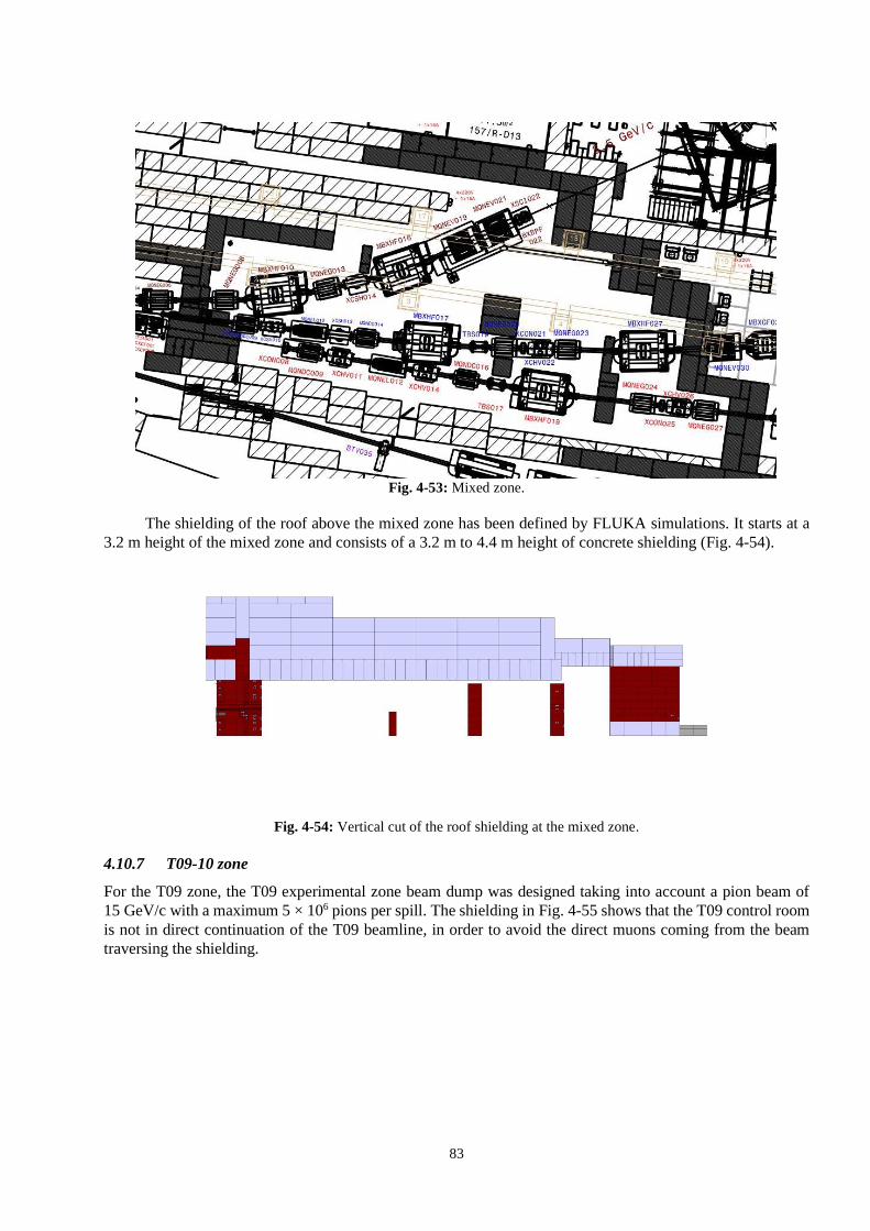
83
Fig. 4-53: Mixed zone.
The shielding of the roof above the mixed zone has been defined by FLUKA simulations. It starts at a
3.2 m height of the mixed zone and consists of a 3.2 m to 4.4 m height of concrete shielding (Fig. 4-54).
Fig. 4-54: Vertical cut of the roof shielding at the mixed zone.
4.10.7 T09-10 zone
For the T09 zone, the T09 experimental zone beam dump was designed taking into account a pion beam of
15 GeV/c with a maximum 5 × 10⁶ pions per spill. The shielding in Fig. 4-55 shows that the T09 control room
is not in direct continuation of the T09 beamline, in order to avoid the direct muons coming from the beam
traversing the shielding.

84
Fig. 4-55: T09-10 experimental zone.
4.11 Radiation monitoring
4.11.1 Purpose of the radiation monitoring system
The purpose of the radiation monitoring system is threefold. First, it has to provide radiological area
surveillance to ensure that the ambient dose equivalent rates at locations accessible during beam operation
remain below the limits determined by the radiological area classification. Second, the radiation levels due to
residual radiation are measured prior to granting access to the primary zone to ensure that the radiation levels
are optimized and that they are consistent with the ones used for the work and dose planning. Third, the airborne
radioactivity that is released by the ventilation system to ensure the dynamic confinement of the primary zone
is monitored.
4.11.2 Radiation fields in the East Area
The following radiation fields have to be monitored in the East Hall:
i) Neutron stray radiation emerging from beam interaction after traversing the shielding structures.
ii) Muons traversing the shielding structures: the only radiological relevant location in the East Hall is
downstream of the CHARM beam dump where a dedicated radiation monitor is already installed. The
muon fluxes downstream of the T09, T10, and T11 areas are very low; a fact that will be confirmed by
dedicated measurements using mobile devices during the commissioning phase after LS2.
iii) Photons from the decay of residual radioactivity in the primary zone.
4.11.3 Radiation monitoring devices
A general description of the CERN radiation monitoring system is given in Ref. [60]. High-pressure hydrogen
ionization chambers (20 bar), designated as IG5-H20 AMF, will be used to measure neutrons. Air filled
ionization chambers, designated IAM, will be used to measure photons from residual radiation in the primary
zone. A ventilation gas monitor, designated as VGM, will monitor the airborne radioactivity released by the
ventilation system for the primary zone that guaranties dynamic confinement.
4.11.4 Layout of the future radiation monitoring system
The preliminary layout of the radiation monitoring system related to the East Area Renovation project is shown
in Fig. 4-56. The currently installed monitor chambers will be re-used. Therefore, the identifiers of the monitors
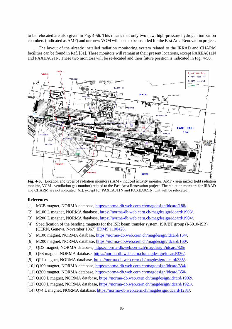
85
to be relocated are also given in Fig. 4-56. This means that only two new, high-pressure hydrogen ionization
chambers (indicated as AMF) and one new VGM will need to be installed for the East Area Renovation project.
The layout of the already installed radiation monitoring system related to the IRRAD and CHARM
facilities can be found in Ref. [61]. These monitors will remain at their present locations, except PAXEA811N
and PAXEA821N. These two monitors will be re-located and their future position is indicated in Fig. 4-56.
Fig. 4-56: Location and types of radiation monitors (IAM - induced activity monitor, AMF - area mixed field radiation
monitor, VGM - ventilation gas monitor) related to the East Area Renovation project. The radiation monitors for IRRAD
and CHARM are not indicated [61], except for PAXEA811N and PAXEA821N, that will be relocated.
References
[1] MCB magnet, NORMA database, https://norma-db.web.cern.ch/magdesign/idcard/188/.
[2] M100 L magnet, NORMA database, https://norma-db.web.cern.ch/magdesign/idcard/1903/.
[3] M200 L magnet, NORMA database, https://norma-db.web.cern.ch/magdesign/idcard/1904/.
[4] Specification of the bending magnets for the ISR beam transfer system, ISR/BT group (I-5010-ISR)
(CERN, Geneva, November 1967) EDMS 1100428.
[5] M100 magnet, NORMA database, https://norma-db.web.cern.ch/magdesign/idcard/154/.
[6] M200 magnet, NORMA database, https://norma-db.web.cern.ch/magdesign/idcard/160/.
[7] QDS magnet, NORMA database, https://norma-db.web.cern.ch/magdesign/idcard/325/.
[8] QFS magnet, NORMA database, https://norma-db.web.cern.ch/magdesign/idcard/336/.
[9] QFL magnet, NORMA database, https://norma-db.web.cern.ch/magdesign/idcard/335/.
[10] Q100 magnet, NORMA database, https://norma-db.web.cern.ch/magdesign/idcard/334/.
[11] Q200 magnet, NORMA database, https://norma-db.web.cern.ch/magdesign/idcard/350/.
[12] Q100 L magnet, NORMA database, https://norma-db.web.cern.ch/magdesign/idcard/1902/.
[13] Q200 L magnet, NORMA database, https://norma-db.web.cern.ch/magdesign/idcard/1921/.
[14] Q74 L magnet, NORMA database, https://norma-db.web.cern.ch/magdesign/idcard/1281/.
86
[15] Q120 C magnet, NORMA database, https://norma-db.web.cern.ch/magdesign/idcard/1901/.
[16] Q74 magnet, NORMA database, https://norma-db.web.cern.ch/magdesign/idcard/311/.
[17] Q120 magnet, NORMA database, https://norma-db.web.cern.ch/magdesign/idcard/338/.
[18] MEA19 magnet, NORMA database, https://norma-db.web.cern.ch/magnet/idcard/1343/.
[19] MDX magnet, NORMA database, https://norma-db.web.cern.ch/magdesign/idcard/231/.
[20] CR200 magnet, NORMA database, https://norma-db.web.cern.ch/magdesign/idcard/1906/.
[21] Study of the magnetic coupling between the CR200 and the Q120 C in the new East Area layout,
EDMS 2002996 (2018)
[22] MDX L 150 magnet, NORMA database, https://norma-db.web.cern.ch/magdesign/idcard/1905/.
[23] J. Burnet, and K. Papastergiou, Energy Saving; an example of a test facility upgrade with pulsed
magnets instead of DC magnets, saving 90% of energy consumption, EDMS 1770483 (2013).
[24] J. Cottet, and J. Burnet, East Area energy balance and possible improvements, EDMS 1255278 (2012).
[25] S. Evrard, East area renovation: notes BE-OP meeting, EDMS 1886001 (2017).
[26] K. Papastergiou, Minutes of meeting with Rende Steerenberg and Lau Gatignon,
EDMS 1506818 (2015).
[27] I. Josifovic, and L. Sburlino, Accelerated aging tests of electrolytic capacitors, EDMS 1804172.
[28] L. Sburlino, Lifetime investigation of electrolytic capacitors in power cycling applications,
EDMS 1597459 (2016).
[29] E. Coulinge, and K. Papastergiou, Thermal stress and lifetime of power semiconductors in PS transfer
lines, EDMS 1458404 (2012).
[30] S. Maestri et al., Study of power converter topologies with energy recovery and grid power flow control
Part B: boost converter with energy storage, CERN-ACC-2015-0049,
https://cds.cern.ch/record/2016791.
[31] S. Maestri et al., Study of power converter topologies with energy recovery and grid power flow control
Part C: a review of alternative structures, CERN-ACC-2017-0089, https://cds.cern.ch/record/2291044.
[32] S. Maestri et al., Study of power converter topologies with energy recovery and grid power flow
control. Part A: 2-quadrant converter with energy storage, CERN-ACC-2015-0026,
https://cds.cern.ch/record/1994175.
[33] K. Papastergiou, and A. Harle, Electrolytic capacitors failure mechanism,
EDMS Folder-0000189820 (2018).
[34] Papastergiou, K., Post-LS2 EIS-chain management specification for power converters,
EDMS 2045163 (2018).
[35] K. Papastergiou, Functional specification: Economy mode operation in accelerator transfer lines,
EDMS 1493325 (2015).
[36] E. Harrouch, and V. De Jesus, Vacuum control system for the East Area, CERN,
EDMS 1737544 (2016).
[37] A. Pilan Zanoni, Description and thermo-mechanical analysis of the beam stoppers BI.STPFA and
BI.STPS, EDMS 1698144 (2016).
[38] A. Pilan Zanoni, Thermo-mechanical analysis of the beam stopper BTY.STP103, EDMS 1703654.
[39] A. Pilan Zanoni, Description and thermo-mechanical analysis of the beam stopper BTP.STP10,
EDMS 1742948 (2017).
[40] A. Pilan Zanoni, Description and thermo-mechanical analysis of the beam stoppers in the PS extraction
(F16, FTA and FTN) lines, EDMS 1691345 (2017).
[41] A. Pilan Zanoni, PS beam stoppers, EDMS 1871447 (2018).
[42] A. Pilan Zanoni, Engineering and design of the new PS beam stoppers, EDMS 1979131 (2018).

87
[43] A. Pilan Zanoni, Core of the PS beam stoppers, EDMS 1899978 (2018).
[44] V. Agoritsas, Secondary emission chambers for monitoring the CPS ejected beams, Daresbury
Symposium on Beam Intensity Measurement, 23–26 April 1968, https://cds.cern.ch/record/299104.
[45] I. Ortega et al., Jour. Phys.: Conf. Ser. 763 (2016) 012012,
https://doi.org/10.1088/1742-6596/763/1/012012.
[46] E. Harrouch, and M. Lazzaroni, Beam instrumentation needs for the East Area renovation,
EDMS 1865542 (2018).
[47] D. Missiaen et al., Definition of the MADx output file for survey, EDMS 2052453 (2019).
[48] M. Zerlauth, and R. Mompo, Warm magnet interlock controller software functionality,
EDMS 1360775 (2016).
[49] A. Miranda Fontan, and R. Mompo, WIC magnet interlock system for the East Area,
EDMS 2037701 (2018).
[50] S. Deghaye, BE-CO plans for LS2, EDMS 1997812 (2018).
[51] S. Evrard, North Area Collimators, EDMS 1505414 (2015).
[52] J. Meignan, Engineering Spec. for the new TCX in the primary Area, EDMS 1889861 (2017).
[53] L. Gentili, TCS collimator plug-in ball support, EDMS 624352 (2016).
[54] M. Lazzaroni, J. Bernhard, and E. Harrouch, Beam stopper, stopper dump and target,
EDMS 1786687 (2018).
[55] D. Forkel-Wirth, Zonage radiologique au CERN, EDMS 810149 (2017).
[56] T.T. Böhlen et al., Nuclear Data Sheets 120 (2014) 211–214, https://doi.org/10.1016/j.nds.2014.07.049.
[57] A. Ferrari et al., FLUKA: a multi-particle transport code, CERN (2005), CERN-2005-10,
INFN/TC_05/11, SLAC-R-773, http://dx.doi.org/10.5170/CERN-2005-010.
[58] E. Iliopoulou, and R. Froeschl, Radiation Protection assessment of the shielding design of the East Area
target zone and test beamlines, EDMS 2058239 (2018).
[59] E. Iliopoulou, and R. Froeschl, Status update on the RP assessment for the East Area Renovation
Project, EDMS 1974733 (2018).
[60] D. Perrin, Description of the CERN radiation and environmental monitoring system,
CERN-RP-2017-027-REPORTS-TN, EDMS 1723230 (2017).
[61] R. Froeschl, Radiation protection assessment of the proton irradiation and the CHARM facility in the
East Area, CERN-RP-2014-008-REPORTS-TN, EDMS 1355933 (2014).

88

89
Chapter 5 Infrastructure consolidation P. Burdelski, F. Dragoni, S. Grau, J-C. Guillaume, D. Jaillet, S. Mcilwraith, M. Polenghi, E. Sanchez
5.1 Civil engineering
5.1.1 Introduction
Constructed in 1963, Building 157 is 113 m long and 43 m wide at ground level. The roof is 21.8 m high at
the central point above a skylight running longitudinally down its centre; it has a slope of 20% running down
to the longitudinal façade summits at 15.6 m. The roof is 47.4 m wide as the longitudinal façades include wings
protruding 2.2 m from a height of 7.5 m to the summits, running the entire length of the building. The
longitudinal façades are made up of a variety of materials (masonry, wood agglomerate, fibro-cement, and
glass, see Fig. 5-1 numbering for a detailed explanation). The end walls are made of reinforced concrete
(Northwest wall) or wood agglomerate (Southeast wall).
Fig. 5-1: East Hall as seen from the SMB-SE drone with material identification.
1. Masonry walls.
2. Lower windows (Northeast façade only).
3. Wood agglomerate panels (Durisol).
4. Corrugated fibro panels (forming the base and the lower part of the wing).
5. Two levels of mid-level windows.
The East Hall is now 55 years old and many facets of the building envelope are in an unacceptable state.
There are dilapidated and unsafe materials forming and falling from the envelope of the building. The
uninsulated envelope does not conform to current building energy-management requirements, resulting in
disproportional thermal losses and hence financial losses due to heating requirements.
The envelope renovation project has two principal objectives with a number of specific objectives [1].
– ‘To improve the safety and comfort in the building by replacing the existing envelope’.
4
1
2
3
5

90
o Removing the dilapidate asbestos-containing ceiling panels.
o Removing existing poorly fixed, single-glazed windows with asbestos containing joints.
o Removing existing uninsulated fibro-cement façade panels.
o Eradicating the water infiltrations coming from the roof.
– To ensure a synergy with the consolidation of the façade of the attached Building 156 (see
Fig. 5-2).
As such, the entire envelope was studied in an attempt to create a safe environment, optimizing energy
savings, responding to modern building codes, and respect an aesthetic liaison with Building 156.
Fig. 5-2: Sky view of Buildings 157 and 156.
5.1.2 Solutions
5.1.2.1 Long façades
All surfaces of the long façades will be modified to improve the safety, insulation (see Table 5-1), and
functionality of the building, as well as the aesthetics (see Fig. 5-3) [2].
i) The masonry walls will be insulated via the exterior face with sandwich panels.
ii) The lower windows will be replaced with better-insulated windows.
iii) The Durisol panels will be insulated via the exterior face with sandwich panels.
iv) The Eternit panels will be removed and replaced with 120 mm sandwich panels.
v) The lower part of the mid-level windows will be replaced with 120 mm sandwich panels. The upper
part of these windows will be replaced with translucent polycarbonate panels equipped with heat-
stop film on the exterior face. This will allow the passage of non-direct sunlight whilst reducing the
impact of extreme heat during the summer time and eliminating direct sunlight from the building.
Table 5-1: Comparison between existing and new materials thermal transmittance values for long façades.
Existing material Existing U
[W/m2K]
New material New U
[W/m2K]
Masonry walls 2 Masonry walls + 100 mm sandwich panels 0.17
Lower windows 5 New lower windows 1
Durisol panels 1 Durisol panels + 100 mm sandwich panels 0.16
Eternit 3 120 mm sandwich panels 0.19
Mid-level windows 5 120 mm sandwich panels/polycarbonate panels 0.19/1.1
B156

91
ELEVATION NORD
Fig. 5-3: Future Northeast and Southwest façade materials.
5.1.2.2 Roof and ceiling
Many solutions were considered for the replacement of the ceiling/roof system, however, the optimal solution
chosen is the removal of the asbestos containing ceiling panels and insulation and the dismantling of the roof
sheet. These will be replaced by a single system of insulated sandwich panels placed above the roof structure.
Furthermore, the existing sky lantern will be demolished and replaced with a classic gable roof (see Fig. 5-4),
as is already the case for the two extremities of the building. This demolition allows for a reduction of a lost
heating volume at the top of the building, it also reduces a number of thermal bridges given the number of
different materials constituting the sky lantern.
Due to the removal of the current building smoke ventilation opening windows, classic ventilation traps
will be added to the roof as illustrated in Fig. 5-5. This allows the upgrade to the correct extraction surface to
improve the safety of the building.
Fig. 5-4: New gable roof peak design.
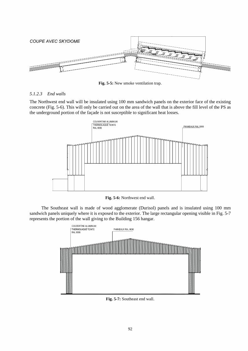
92
Fig. 5-5: New smoke ventilation trap.
5.1.2.3 End walls
The Northwest end wall will be insulated using 100 mm sandwich panels on the exterior face of the existing
concrete (Fig. 5-6). This will only be carried out on the area of the wall that is above the fill level of the PS as
the underground portion of the façade is not susceptible to significant heat losses.
Fig. 5-6: Northwest end wall.
The Southeast wall is made of wood agglomerate (Durisol) panels and is insulated using 100 mm
sandwich panels uniquely where it is exposed to the exterior. The large rectangular opening visible in Fig. 5-7
represents the portion of the wall giving to the Building 156 hangar.
Fig. 5-7: Southeast end wall.

93
5.1.3 Conclusions
The new envelope provides a significant reduction in building energy losses. The simplified calculation shows
that there is an 89% reduction in energy losses through the building envelope.
This new envelope equally provides a much safer and more functional work environment whilst at the
same time making a drastic aesthetic improvement to the building (see Fig. 5-8).
Fig. 5-8: Architects 3D rendering of future upper Northeast façade.
5.2 Cooling plant and circuits
5.2.1 Scope
The scope of this project is to consolidate the demineralized water-cooling systems for the East Area magnets
and power converters as follows (Fig. 5-9 summarizes the solution):
i) provide demineralized water cooling to magnets in Building 157 mixed and secondary zones;
ii) provide demineralized water cooling to equipment test lines employed by CERN High Energy
AcceleRator Mixed field facility/proton IRRADiation facility (CHARM/IRRAD) users in
Building 157;
iii) provide demineralized water cooling to power converters in Building 355 hall;
iv) provide demineralized water cooling to power converters in Building 251;
v) provide a dedicated demineralized-water cooling circuit to magnets inside Building 157 primary
zone bunkers, PS, and to those CHARM/IRRAD equipment test lines that are installed inside
CHARM bunker.
5.2.2 User’s requirements
The requirements for magnets, CHARM/IRRAD equipment test lines, and power converters are summarized
in Table 5-2 and in Ref. [3].

94
No specific requirements are made for pH and O2 values. The demineralized water circuits shall have
sampling points for water analysis purposes.
The demineralized water-cooling system shall have an n+1 redundancy on pumps. No connection to the
secured network is required.
Table 5-2: East Area demineralized water: user requirements.
Cooling
requirements Unit
Magnets
circuit –
mixed and
secondary
zones
Magnets
circuit –
primary
zones + PS
B355
Power
converters
circuits
B251
Power
converters
circuits
CHARM/
IRRAD
Equipment
lines
(External)
CHARM/
IRRAD
Equipment
lines
(R-050)
Nominal supply
temperature [°C] 27 30 27 27 27 30
Maximum supply
temperature [°C] 28 31 28 28 28 31
Maximum cooling power
of the system – cycling
operation
[kW] 142 150 120 398 14 7
Maximum flow rate [l/min] 961 561 467 1 764 20 10
[m3/h] 58 34 28 106 1.2 0.6
Pressure rating PN25 PN25 PN16 PN16 PN10 PN10
Water conductivity [μS/cm] < 1.0 < 1.0 < 1.0 < 1.0 < 1.0 < 1.0
5.2.3 Technical solution
The cooling of magnets, CHARM/IRRAD equipment test lines, and power converters is overseen by 2 cooling
stations and the associated distribution networks as follows (see Ref. [4]).
– Demineralized water station – Building 355 – FDED-00355 - that will supply demineralized
water to magnets in Building 157 mixed and secondary areas, CHARM/IRRAD equipment test lines in
Building 157 hall and power converter in Building 251 main hall. It will also act as primary for the
demineralized water skid FDED-00251 (Building 157).
– Demineralized water skid – Building 157 – FDED-00251 - that will supply demineralized water
to the magnets in Building 157 primary zone bunkers and Building 352 and to the CHARM/IRRAD
equipment test line installed in CHARM bunker 157/R-050.

95
Fig. 5-9: Synoptic of the East Area demineralized water distribution.
5.2.3.1 Demineralized water distribution network
Figure 5-9 shows the synoptic of the demineralized water distribution network. All existing piping of correct
nominal diameter (ND) size and in good status will be preserved and reused, the remaining will be replaced.
Redundant pipework will be removed.

96
Pipework will be routed in technical galleries and then supply demineralized water to:
– magnets: pipework will be installed along the various beamlines arriving in close proximity to each
magnet in order to minimize pressure drops in flexible piping. Pressure reducing valves will be installed
on main branches after having supplied demineralized water to those magnets with the highest pressure
drop;
– power converters: the piping coming from the cooling station will split in one DN100 and one
DN125 branches that will branch off piping of sizes ranging from DN40 to DN50 to reach each cluster
of power converters. Pressure reducing valves will be installed on the main branches;
– CHARM/IRRAD equipment test lines: the existing distribution to CHARM/IRRAD equipment
test lines external to the shielding block will be kept. The current test lines have pressure reducing valves
from 25 to 12 bar; as the new demineralized station, Building 355 will supply demineralized water with
a pressure of up to 14 bar; new pressure reducing valves will replace the existing ones. The final
distribution to CHARM/IRRAD equipment test line inside CHARM bunker will branch off the pipework
supplying demineralized water to the magnets in the V3 bunker.
5.3 Buildings 157 and 251 ventilation
5.3.1 Building 157 ventilation
5.3.1.1 Scope
The scope of this project is to consolidate the heating, ventilation, and air conditioning (HVAC) system of
Building 157 hall to provide heating during winter and ventilation during summer.
5.3.1.2 User requirements
The ventilation requirements for the Building 157 hall are listed in Table 5-3 and in Ref. [5]. No humidity
regulation is needed. All fresh and recirculated air will be filtered. Redundancy of any functionality of the
HVAC systems is not required during normal operation or in the case of a power cut or fault in the electrical
power supply systems.
Table 5-3: Building 157 hall: ventilation requirements
Temperature range
[°C]
Min fresh air rate
per person
[m3/h]
Max occupancy
[persons]
17–29 45 100
5.3.1.3 Technical solution
The HVAC system of B157, which is illustrated in Fig. 5-10, will have:
i) Eight air-handling units (AHUs) – four on the North side with a nominal flow rate of 12 000 m3/h
and four on the South side with a nominal flow rate of 9 000 m3/h. Each unit will be equipped with
heating coils for winter temperature control and summer ventilation. They will have fresh air intake
that will provide minimum 1 000 m3/h each.
ii) Eighteen destratification fans – with a nominal flow rate of 9 000 m3/h and 5 300 m3/h installed on
roof supporting steelwork. These fans will help de-stratify the temperature gradient associated with
convective heating.

97
iii) Two air curtains – to prevent a cold draft from entering the building during operation of the two
stacking doors on North façade.
iv) Hot water station and distribution circuits to feed the heating coils of the AHUs.
Fig. 5-10: Left: top view of Building 157 with the position ventilation systems, right: vertical cut of
Building 157.
The air handling units will have a common mixing chamber where fresh air is mixed with recirculated
air. This will normally occur in summer when the units will work with full fresh air during nights and with
recirculation during hot periods of the day.
Air will be supplied by new ductwork installed along the building walls. The ducts will have a single
wall construction and have grilles to ensure uniform distribution in the building. The return air intake will be
on top of each air handling unit.
5.3.1.4 Safety aspects
In case of fire detection and power failure, all AHUs and destratification fans will automatically stop and all
dampers will close.
5.3.2 Building 251 ventilation
5.3.2.1 Scope
The scope of this project is to provide HVAC systems to the following.
– Power converter hall (R-007) – to ensure temperatures inside power converters are within their
operating limits and to prevent frost damage in pipework installed in false floor.
– Plant room (R-005) – to provide heating during winter periods to avoid frost damage.
5.3.2.2 User’s requirements
The air-cooling requirements for power converters are as listed in Table 5-4 and in Ref. [5]. The minimum
temperature inside power converters is 15°C and maximum temperature is 33°C immediately above the
capacitors and of 38°C above the capacitors. No condensation will occur.
Ventilation air will be filtered. Redundancy of any functionality of the HVAC system for power
converters is not required during standard operation as well as maintaining specific functionalities in degraded
mode or in case of power cut or fault in the electrical power supply systems.

98
Table 5-4: Building 251 power converters: air cooling requirements.
Power
converter
type
Number of installed
power converters
Dissipated unit
power via air
cooling
[kW]
Total dissipated
power via air cooling
[kW]
SIRIUS S 19 1.4 26.6
SIRIUS 2P 25 + 1 (spare) 2.6 65.0
SIRIUS 4P 9 4.9 44.1
SIRIUS
4P+ 8 + 2 (spare) 5.9 47.2
TOTAL 182.9 kW
5.3.2.3 Technical solution
The HVAC system of Building 251 will have the following.
– Two air handling units – with a nominal flow rate of 31 000 m3/h each and heating and cooling
coils for temperature control and frost prevention of power converters hall 251/R-007.
– Two heating units – with a nominal flow rate of 10 000 m3/h with heating to coil to provide heating
to plant room 251/R-005.
– Chilled water and superheated water distribution circuits to feed the air handling and heating
units.
The air handling units will have a common mixing chamber where fresh air is mixed with recirculated
air. This will normally occur in winter and in summer, when the recirculated air is cooler than external air. In
summer, when recirculated air is hotter than the external air, the units will work with full fresh air. Air will be
blown by two air handling units into the plenum between the building floor and false floor and it will flow
through the power converters before being either recirculated or exhausted, as illustrated in Fig. 5-11.
Motorized dampers installed at a high level in the power converter hall will serve as air exhausts.
Air ducts will be of double wall construction for air supply above the false floor and single wall
construction inside the false floor. Air ducts will have grilles to ensure uniform distribution amongst power
converters. Heating units will ensure minimum temperatures are maintained in the plant room and that there
will be no frost.
Fig. 5-11: View of the Building 251 and the position of the ducts (in blue) in the power converter hall.

99
5.3.3 Safety aspects
In case of fire detection and power failure, the HVAC system of Building 251 will automatically stop
and all dampers will close.
5.4 Primary area ventilation
5.4.1 Scope of the project
The scope of this project is to provide HVAC systems to:
– Primary zone bunkers – to contribute to ensuring a dynamic confinement of the bunkers
(Fig. 5-12) during operation, to provide the flush of the bunkers before access, to cope with the heat load
of the magnets, and to guarantee the required temperature stability.
– Mixed area – ensuring fresh air supply during access to the area.
Fig. 5-12: Location of the primary zone bunkers (V1, V2, and V3) and the mixed area.
5.4.2 User’s requirements
The HVAC systems shall operate in three modes (see Refs. [6] and [7]).
i) Beam mode – when beamlines and magnets can receive the beam.
ii) Flush mode – when beamlines and magnets will not be receiving the beam and activated air is flushed
out of the primary zone bunkers; no flush is required for mixed area.
iii) Access mode – when access to primary zone bunkers is possible.
The HVAC system of the primary zone bunkers will ensure that temperatures are kept to 22 ±3°C inside
the bunkers in all modes of operation. Recirculated air and exhausted air will be filtered with F9 filters. No
humidity control is required.
This HVAC system will ensure dynamic confinement of the primary zone bunkers during the beam and
flush mode so that the bunkers are in underpressure with respect to adjacent areas (with an air permeability
rate of 10 m3 h-1 m-2 at 50 Pa the pressure difference should be –20 Pa). An interlock between the HVAC system
of the primary zone and the access system (see Section 5.8) is required to prevent access during beam and flush
modes.
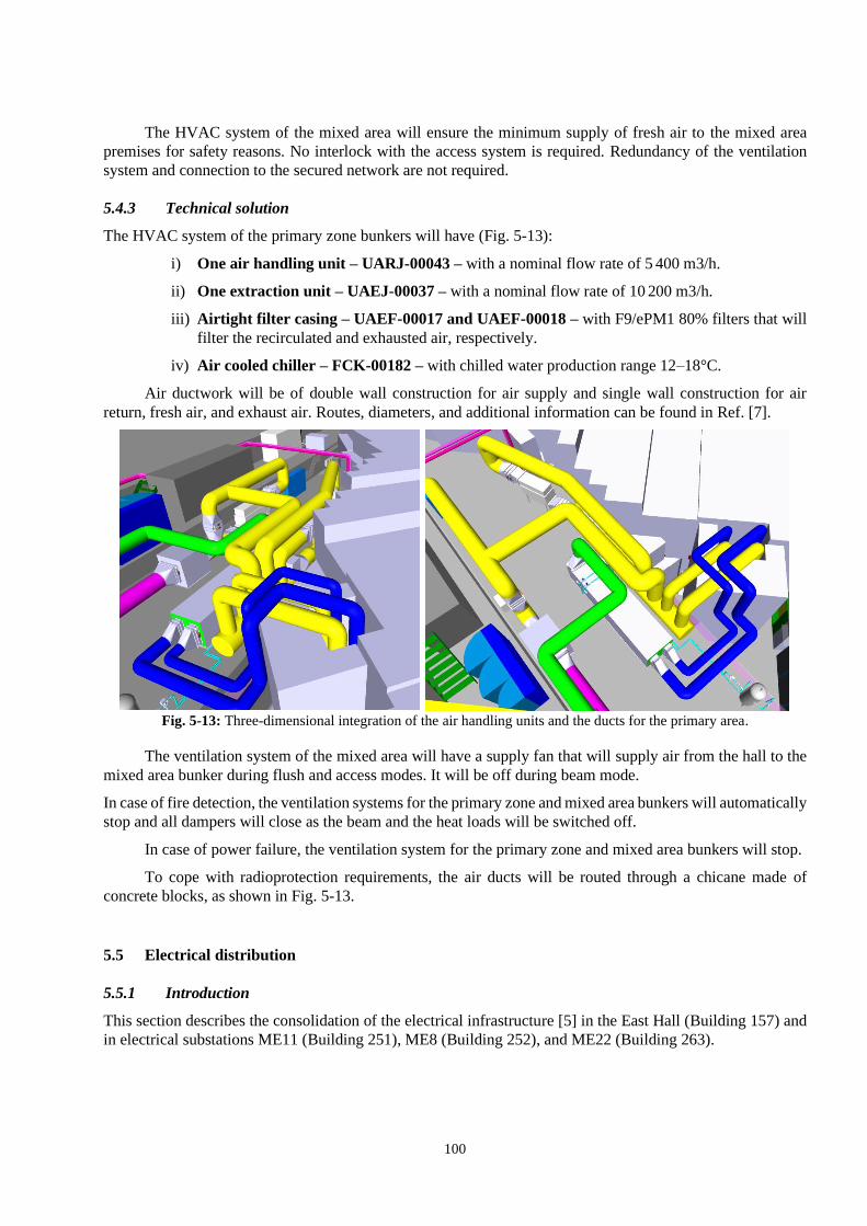
100
The HVAC system of the mixed area will ensure the minimum supply of fresh air to the mixed area
premises for safety reasons. No interlock with the access system is required. Redundancy of the ventilation
system and connection to the secured network are not required.
5.4.3 Technical solution
The HVAC system of the primary zone bunkers will have (Fig. 5-13):
i) One air handling unit – UARJ-00043 – with a nominal flow rate of 5 400 m3/h.
ii) One extraction unit – UAEJ-00037 – with a nominal flow rate of 10 200 m3/h.
iii) Airtight filter casing – UAEF-00017 and UAEF-00018 – with F9/ePM1 80% filters that will
filter the recirculated and exhausted air, respectively.
iv) Air cooled chiller – FCK-00182 – with chilled water production range 12–18°C.
Air ductwork will be of double wall construction for air supply and single wall construction for air
return, fresh air, and exhaust air. Routes, diameters, and additional information can be found in Ref. [7].
Fig. 5-13: Three-dimensional integration of the air handling units and the ducts for the primary area.
The ventilation system of the mixed area will have a supply fan that will supply air from the hall to the
mixed area bunker during flush and access modes. It will be off during beam mode.
In case of fire detection, the ventilation systems for the primary zone and mixed area bunkers will automatically
stop and all dampers will close as the beam and the heat loads will be switched off.
In case of power failure, the ventilation system for the primary zone and mixed area bunkers will stop.
To cope with radioprotection requirements, the air ducts will be routed through a chicane made of
concrete blocks, as shown in Fig. 5-13.
5.5 Electrical distribution
5.5.1 Introduction
This section describes the consolidation of the electrical infrastructure [5] in the East Hall (Building 157) and
in electrical substations ME11 (Building 251), ME8 (Building 252), and ME22 (Building 263).

101
In the existing network, seven 18/0.4 kV transformers supply the power converters and one supplies,
from Building 252, the general services of Building 157 and other surrounding buildings. Two special
transformers, which were already removed before the consolidation, supplied other converters.
The future design, based on the inputs received from the users, allows an important optimization of the
installed power, with an improvement in terms of operation and maintenance.
5.5.2 Future network topology
Figure 5-14 illustrates the simplified future single line diagram: two transformers (EMT105*11 and
EMT104*11) will supply the power converters in Building 251, one transformer (EMT103*11) the general
services network of the area, and one transformer (EMT106*EH) the experimental areas in Building 157.
Fig. 5-14: Future single line diagram.
5.6 DC circuits
5.6.1 Existing wiring principle
The current wiring principle gives a lot of flexibility to the direct current (DC) circuits in the East Area. All
the power converters are connected to a line selector in Building 251. This allows the operation team to choose
to which terminal boxes (TBs) the DC power should be sent to (Fig. 5-15). Ultimately, the magnets can be
connected to any of the terminal boxes in Building 157.

102
Fig. 5-15: Left: line selector in Building 251, right: terminal boxes in the technical gallery under
Building 157.
5.6.2 Requirements
The advertised current intensities implemented by the converters are 200, 400, and 800 A [8]. For waste
reduction reasons, it was determined if the existing cables could be re-used. The line selector (in light red in
Fig. 5-16) and the TBs are in a very old state and shall be dismantled, meaning that the magnets will be directly
connected to the power converters. DC circuits to Building 263 will be fully dismantled (in red in Fig. 5-16).
Only the two extremities of the cables will be replaced (in yellow in Fig. 5-16).
Fig. 5-16: DC cable wiring principle with the cables to be kept (green), replaced (yellow), and removed (red).
5.6.3 Technical solution
After study, the number of cables per circuit was determined as follows:
- 200 A: 1 × 240 mm2 aluminium per polarity giving 0.125 Ω/km at 20°C.
- 400 A: 2 × 240 mm2 aluminium per polarity giving 0.0625 Ω/km at 20°C.
- 800 A: 3 × 240 mm2 aluminium per polarity giving 0.0416 Ω/km at 20°C.
The voltage drop induced by the existing cables is then compatible with the future power converters.

103
Table 5-5 shows the total quantity of cables and lengths (new cables amount to a total of 14 km) taken into
consideration.
Table 5-5: Quantity of DC cables.
Beamline Quantity of cables Total Length
(m)
Total length re-used
(m)
F61 38 7 658 5 172
F62 14 2 852 1 792
F63 18 2 838 1 710
T08 42 5 412 3 186
T09 54 6 158 3 502
T10 48 5 770 3 198
T11 26 3 712 2 182
Total 240 34 400 20 742
5.6.4 Implementation
In the new layout, the distribution of magnets and converters is completely different, so it is not possible to
keep existing cables at their current locations. The recoverable part is located between the entrance of
Building 251 and the civil engineering openings of hall 157 and up to the TBs located in Building 352. At the
interfaces, each 1 × 240 mm2 aluminium cable will be sleeved with a single-pole 1 × 150 mm2 copper cable [9].
5.7 Signal cables
Current beam control systems were implemented some twenty years ago. The technicality of some of them
having evolved and the new configuration of the equipment of the beams being different, it was decided to:
i) Remove signal cables from obsolete systems.
ii) Remove signal cables from systems whose equipment is no longer in the same place.
iii) Install new cables for new systems as well as those whose equipment has changed place.
5.7.1 Removal of signal cables
Careful identification has been performed [10] to quantify and identify the cables to be removed [11]: about
285 km of cables will be removed in four different buildings (157, 251, 352, and gallery 817).

104
5.7.2 Installation of new cables
All the cables to be pulled are summarized in Table 5-6.
Table 5-6: Details of new cables to be installed for East Hall Renovation project.
System Quantity of cables
Machine Interlock 120
Beam instrumentation 150
Collimators control 18
Radiation monitoring 60
Targets control 36
Vacuum system 32
Beam stoppers 42
Access system 44
Gas detection 48
Controls for CHARM 27
Power converters control 67
Gas systems 37
5.7.3 Cable tray infrastructure
The cable trays installed in Building 251 and along the beamlines in the hall of Building 157 will be removed
and replaced with new ones according to the new configuration of beamlines and concrete blocks. The removal
corresponds to a total of 500 m.
Hall infrastructure paths as well as those existing in the gallery are retained and re-used.
5.8 Personnel protection systems
5.8.1 Introduction
This section describes the modifications required by the East Area Renovation Project to the existing personnel
protection systems (PPS) regulating the access of personnel to the East Area primary and experimental zones.
It presents the users’ technical requirements and the system principles. The renovation includes the
modification of two type of access systems:
– Access systems for primary beam areas:
Access to the East Area primary beamlines is managed by two independent areas, named EA1 and
EA2, each managed by a PPS. Modification of the PPS of EA1 and PPS of EA2 IRRAD-CHARM
concern the sectorization, the safety related elements, and the external safety conditions.
– Access system for secondary beam area and Building 157 control rooms, buffer zones, and
storage rooms:
Access to each of the East Area experimental areas is managed by a PPE (personnel protection
entry). The following modifications will be implemented:
– T09, T10, T11: PPEs re-located.
– New PPE for new zone T09-10.
– New function: EA experimental areas remote operation from the CERN CCC for veto
management and chain tests.
– Access control on doors of control rooms, buffer zones, and storages located inside
Building 157: re-located or new.

105
5.8.2 PS complex PPS principles and role
During Long Shutdown 1 (LS1), the PS Accelerator Complex access systems were renovated to cope with new
operational needs and regulations and standards applicable for the ‘Installation Nucléaire de Base (INB)’.
Each zone is managed by a dedicated PPS and can be divided into different access sectors (equipped
with various elements such as sector doors, end-of-zone doors, etc.). The access sectors are particularly
important to organize the patrol of the machine and to minimize the radiation exposure by means of a radiation
veto handled by the RP responsible person. Access to the zone is done via an access point composed of a
personnel access device (PAD) and a material access device (MAD). Adjacent zones are separated through
inter-machine doors. The closure of the external envelope of each zone is ensured by end-zone doors which
are normally used only for evacuation in case of emergency.
The East Beam primary area is divided into two interlocked zones, EA1 for the primary beamline area
and EA2 for IRRAD-CHARM primary areas.
The main role of the PPS is to ensure that there is no danger (radiological hazard or other risks identified
in the APR [15][16] such as activated air) during personnel access to the zone, and that no personnel are present
inside the zone during BEAM operation.
The PS PPS is composed of two complementary subsystems, the PS access control system (PACS) and
the PS access safety system (PASS). The PACS ensures a physical barrier and controls access by means of
automatic or remotely controlled security portals and access devices for personnel and material. Access points
regulate personnel access to supervised and controlled machine areas, it ensures users identification, biometric
authentication, and regulates at the highest safety level (single person check, audio, video, etc.) the access
according to the operation modes managed remotely by the CCC.
The PASS ensures that at any time and in every operation mode of the various machines, the PS Complex
is safe for the machine users by interlocking Access or Beam ‘Important Element for Safety (EIS)’ [14]. In
Access mode, all the EIS beams are maintained in a safe state. In Beam mode, any intrusion within the PS
Complex will immediately interlock the necessary EIS beam, stopping the beam operation to protect personnel
from exposure to radiation hazards.
Each beam zone has its own independent access conditions. The absence of a beam in each independent
beam zone is guaranteed by at least two beam safety elements, with at least one passive element (e.g. a
moveable stopper) and one active element (e.g. magnetic power converter interlock).
The operation modes of the PS PPS are: Access, Ready for Access/ Ready for Beam (RFA/RFB), and
Beam.
In ACCESS mode, safety vetoes are applied to all the EIS-beam/EIS-machine and EIS-external
elements. Safety vetoes are removed from the EIS-access depending on the inter-locked zone safety conditions
(radiation level, ventilation). In RFA/RFB mode, safety vetoes are applied to all the EIS-access and EIS-
beam/EIS-machine elements. It is an intermediate mode. In BEAM mode, safety vetoes are applied to all the
EIS-access elements, safety vetoes are removed from all the EIS-beam/EIS-machine/EIS-external elements.
BEAM operations are allowed in the inter-locked zones.
5.8.3 Requirements for the PPS of EA1 and EA2 primary beam zones
The requirements for the PPS of the EA Primary zones EA1 and EA2 concern the following elements:
i) Access sectorization.
ii) EIS-beam important safety elements of the machine against radiation exposure hazard.
iii) External safety conditions associated with the new EA ventilation system.

106
5.8.3.1 New access sectorization for EA1 and EA2
The new EA1 beam layout aims at reducing the exposure to radiation of the personnel. In the new layout,
the EA1 beam area is divided into a ‘primary area’ and ‘mixed area’, and the current single access sector is
divided into three sectors: one for the mixed area (S1), giving access to the EA primary zone via the Access
Point, and two sectors for the ‘primary area’ (S2, S3). Additionally, a corridor is created by opening the
shielding blocks, giving direct access from EA1 to the blind sector area (accessible only through IRRAD before
LS2) and therefore also to the EA2 external envelope. EA1 and EA2 are now connected with an ‘inter-zone
door’ which allows passage in case of emergency (see Fig. 5-17 and Fig. 5-18).
Fig. 5-17: Future access sectorization of the EA1 East Area primary beam zone.

107
Fig. 5-18: Future access sectorization of the EA2 East Area primary beam zone.
5.8.4 Implementation of requirements for the EA1 and EA2 PPS
The EAR requirements do not question the current PS Complex PPS architecture, equipment types, and
functionalities of the EA1 and EA2 PPS, which are described in the technical specifications in Ref. [23].
The architecture of the PS Complex and Experimental Area PPSs is presented in Fig. 5-19, and is
composed of the following four levels, each ensuring a set of functions:
i) Operation and supervision.
ii) Central computing and safety infrastructure.
iii) Zone safety controller.
iv) Zone equipment.
Functions iii) and iv) exist specifically for each PS interlocked zone (safety chain). Two independent
and redundant interlocked paths, a programmable logic controller (PLC), and a hardwired loop, ensure the PPS
safety interlocks.
The PS PPSs central computing and safety infrastructure is located in Building 271. The EA1 and EA2
EIS important safety elements (access, beam, external) signals are cabled individually to their specific safety
chain controller racks located in Building 271.
Due to the EAR project during LS2, all of the PPS EA1 installation located in Building 157 will be
dismantled and re-installed according to the EAR requirements [17]. As presented in Section 5.8.3.1, the PPS
EA2 is only slightly modified, and EAR works do not require dismantling of any PPS EA2 elements.

108
Fig. 5-19: PS Complex personnel protection system architecture.
5.8.5 Requirements for the EA experimental areas access safety systems
5.8.5.1 Scope of the renovation
An access control and safety system is currently operational in the three experimental areas (T09, T10, and
T11). It ensures safe access and beam in those three independent experimental areas. Access to an experimental
area is done via an access control door, known as PPE. Each area has at least one emergency door, known as
PPX (personnel protection exit) that is also supervised by the access system. The PPE is equipped with a
display panel (at the entry side, screen, and access) that provides the following functions.
i) Exploitation modes console.
ii) Safety veto management.
iii) Chain tests management.
iv) Views to show the status of the area and access and beam conditions, events log, and technical
alarms.
The modifications in the EA experimental areas [18], can be summarized as follows:
i) T09 and T10: position of the PPEs changed due to modification of the walls in the T10 and T09
areas.
ii) A new zone, T09-10 will be created consisting of a PPE and a PPX: following the latest RP
simulation studies for T09-10, a more restricted configuration of the T09-T10 experimental area
PPE will be required. Only authorized persons will be able to change the operation mode (from
CLOSED to ACCESS mode) by presenting their badge.

109
iii) T11: the current PPX will be removed, and a new emergency exit will be installed to allow
access the crinoline. The position of the PPE changes also.
A new generation of beam stopper dumps will be installed in new positions. Table 5-7 presents the list
of EIS related to the EA experimental areas and Fig. 5-20 presents the future layout.
Table 5-7: EA experimental area EIS.
T09-10 T09 T10 T11
EIS-Access PPE T09-10 PPE T09 PPE T10 PPE T11
PPX T09-10 PPX T11
EIS-Machine T09.TBS017 T09.TBS017 T10.TBS019 T11.TBS04
T10.TBS019
Fig. 5-20: EA experimental areas future layout.
5.8.5.2 PPEs principles
The experimental areas are considered secondary beam zones according to the radiological risk, which is lower
than in the primary beam areas. Therefore, only one EIS beam [14] is deemed necessary to interlock the beam.
Acceptable EIS can be both physical beam stoppers and interlocks on steering dipole magnet power supplies.
Given the energy of the particles and the low intensity of the beams in the EA experimental areas, beam
stoppers are foreseen as EIS, and they must be ‘fail-safe’, i.e. safe for access when not powered. When a zone
has to be accessed, the EIS must be confirmed as being in the ‘safe’ position. In case of danger detected in the
access system, the interlock acts both on the EIS of the area concerned, but also on the upstream interlocked
EIS.
The upstream interlock principle also applies. The access safety system will interlock the upstream area
in the following situations:
i) Danger for personnel: intrusion in BEAM mode with one EIS-Beam protecting the zone NOT in safe
position, loss of safe position of one EIS-Beam of the zone during ACCESS mode.
ii) At least one area in the ‘Chain test’ mode.
iii) The experimental area operation and access modes are presented in Fig. 5-21.

110
The current access system is able to manage up to eight areas without major modifications of the central
controller in Building 157; it manages the controller of each of the areas according to the defined safety matrix
implementing the interlocks.
Fig. 5-21: Experimental area access modes – PPE front panel display.
5.9 Alarms
5.9.1 Introduction
In order to reduce the risk of fire and explosion for people, environment, and assets, the following safety system
will be implemented in the frame of the renovation.
i) Fire detection.
ii) Gas detection.
iii) Beam imminent warning.
iv) Evacuation plan.
The safety functions of the above systems include early detection, warning occupants and firefighters in
case of upset conditions, and automatic protection measures upon detection.
5.9.2 Fire detection
The new fire detection system in the East hall will be an extension of the existing infrastructure, connected to
the SFDIN-00324 remote I/O control panel. A new ring connected fire detection loop will be installed as well
as its field device and new on-line connected sirens.
Due to the layout of the building and in order to ensure early detection, no smoke detection will be
installed under the ceiling but will be installed directly close to the beamlines.
The fire detection system will trigger the following actions:
i) Level 3 alarms to the fire brigade.
ii) Evacuation alarm.

111
iii) Ventilation stop.
iv) Smoke extraction. A fire risk analysis done in 2017 [19] explains this need.
5.9.3 Gas detection
The new gas detection system in the EA Facility (based on the same standard as in the North Area) will be the
state of art SYNTEL distributed control system, which allows the rationalization of the main infrastructure.
There will be one SYNTEL common central controller supervising the different experimental installations of
the facility and the flammable and toxic gas distribution from the gas barrack to the mixing areas and patch
panels. The gas distribution renovation is described in Ref. [20] (see Fig. 5-22).
Fig. 5-22: SYNTEL gas detection – flexible technology with addressable devices.
The main infrastructure will consist of the SYNTEL central I/O panel, two racks in this specific
configuration installed side by side.
5.9.4 Beam imminent warning (BIW)
The BIW is in use within the radioprotection primary area to warn people before the injection of high-energy
particle beams in the machine. In the East Area facility, it triggers the PS access control system.
The new BIW in the East hall will be an extension of the existing infrastructure connected to the
SESEV-00224. Fields device such as MACs (manual call point) and sirens will be installed as part of the
project scope of work.
5.9.5 Evacuation
There will be an overall evacuation system for the whole East Hall. All the siren sounders will be launched at
the same time. They will be connected and triggered by the SFDIN-00324.
A second evacuation system specifically designed for the risks in the primary RP areas of the EA facility
will be connected, as presented above, to the SESEV-00224. There will be an interface between the two
subsystems.

112
5.10 Gas systems
5.10.1 Introduction
The EA is supplied by a mixing area and gas piping network coming from a dedicated gases supply building
located outside Building 157. This gas supply building is equipped with gas supply panels with connected gas
bottles and banks, as shown in Fig. 5-23. It can provide many different types of gases (neutral, flammable) for
fixed or temporary experiments in the hall [21][22].
The renovation includes the replacement of the gas supply system and all associated components (pipe
and valves) as well as the creation of mixing areas for the premix and adjustment of gas parameters before use
by detectors inside the beamlines. The renovation of the gas distribution infrastructure will allow the
improvement and standardization of flammable gas safety from the supply building to the final user, in
accordance with CERN regulations for safety. The system will follow the ATEX regulations and the global
safety will be reinforced by the installation of closed gas racks equipped with ATEX air extraction and gas
detection systems that enable the reduction of the ATEX area and restrict accidental leaks to defined volumes.
Another objective of this renovation action is to improve the use of gases between the mixing areas and
beamlines (add insulated pipes and components for regulation). This is to in line with requests from many users
[23] and also to avoid accumulation of gas equipment not controlled or not correctly assembled. The EA
renovation also includes the removal of the gas delivery point to create a dedicated mixing area for the CLOUD
experiment.
Fig. 5-23: Building 157, current gas distribution infrastructure.
5.10.2 Gas distribution infrastructure for the EA
5.10.2.1 Gas supply building (outdoor)
The content of the gas supply building located outside will be dismantled. The building will be equipped with
new gas supply components with remote monitoring as well as a purge system with the possibility of recovering
green-house gases (GHG).
The gas supply building will be split into four separate sections (Fig. 5-24):
i) Gas mixing area and Dewar (LN2, LO2) for the CLOUD experiment with trace gases (SO2, DMA, TMB,
NAP, TOL):
T09
Mixing area T9/T10
CLOUD Dewar
LN2, LO2
Gas supply building (N2, Ar, CO2, H2,
CLOUD trace gases, C2H2F4, SF6, etc.)
T10
T11
Gas delivery point

113
a. The trace gases will be relocated in a closed safety cabinet with air extraction and N2 for
inertion. The gas supply panels will be replaced by new panels in conformity with safety rules.
ii) Gas supply area for Building 157 (N2, CO2, Ar, He):
a. Replacement of old gas supply panels by new switch-over panels located inside closed rack
equipped with remote monitoring and exhaust collection.
iii) Gas supply area for flammable or heated gases:
a. Three new closed flammable gas supply racks for T09, T10, and T11. These will be equipped
with gas detection, air extraction, remote monitoring, purge collection, N2 gas line for inertion,
and a single gas supply panel (no backup).
iv) Gas supply area H2 (CLOUD):
a. Change of old gas supply panels by new switch-over panels equipped with remote monitoring,
exhaust collection, and N2 gas line for inertion.
Fig. 5-24: Building 157, new gas distribution infrastructure (outdoor).
5.10.2.2 Gas mixing area T09/T10
The gas mixing area for T09 and T10 will be relocated and split into two dedicated mixing areas per beamline.
Each dedicated area supplies the gases inside the beamline via insulated stainless-steel pipes. The closed patch
panel for the beamline will be equipped with gas detection, ATEX air extraction, isolating valves, manometers,
connectors, safety valves, and two exhaust pipes (flammable and neutral). The connection of the pipes from
the patch panel to the experiment will be done via feedthroughs located in the patch panel to restrict a maximum
of gas connection to the closed area with air extraction.
The T09/T10 mixing area will be equipped with (see Fig. 5-25):
– Two closed distribution rack for flammable and neutral gases with one linked to the patch
panel in T09 and the other with the one in T10.
– Two enclosures (one for each experimental area) for setting up a temporary mixing gas rack
(user’s equipment).
CLOUD Dewar and
mixing area
157 Neutral area
N2, Ar, CO2, He
157 Flammable and
heated gases
CLOUD H2

114
– Two enclosures (one for each experimental area) for two premixed bottles (neutral gas quality
up to 6.0) used for short periods.
Fig. 5-25: Building 157 mixing area T09/T10.
5.10.2.3 Cherenkov's control rack
The Cherenkov control rack will provide gas (Ar, CO2, optional refrigerant gases) for the fours Cherenkovs
inside the T09 and T10 beamlines. Figure 5-26 shows the gas racks organization.
Fig. 5-26: Cherenkovs, gas rack location
References
[1] E. Perez-Duenas, East Hall cladding upgrade (Building 157), IPP-2016-13, EDMS 1591815 (2016).
[2] C. Gasnier, B157 civil engineering – preliminary design, EDMS 1817630 (2017).
[3] F. Dragoni, East Area hall renovation: demineralised water cooling system user’s requirements,
EDMS 1959531 (2018).

115
[4] F. Dragoni, East Area hall renovation: demineralised water cooling system work package,
EDMS 1991994 (2018).
[5] F. Dragoni, East Area Hall renovation: B157 and B251 ventilation system user’s requirements,
EDMS 1964526 (2018).
[6] F. Dragoni, East Area Hall renovation: Primary zone ventilation system user’s requirements,
EDMS 1871830 (2018).
[7] F. Dragoni, East Area Hall renovation: Primary zone and mixed area ventilation work package,
EDMS 2020740 (2018).
[8] K. Papastergiou, Summary of circuits in the post-LS2 East Experimental Area, EDMS 1546304 (2018).
[9] J-C. Guillaume, East Hall renovation – Etude préliminaire sur la disposition des câbles DC,
EDMS 2016265 (2019).
[10] E. Harrouch, Identification, labelling and disconnection procedure for obsolete cables in the East Area
during YETS 2017-2018, EDMS 1889546 (2018).
[11] E. Harrouch, Demande d’enlèvement de câbles (DEC) dans le cadre de la rénovation de la zone Est,
EDMS 1962098 (2018).
[12] D. Chapuis et al., Spécification des éléments d'accès et inter verrouillage de la zone East Area,
EDMS 990209 (2014).
[13] P.D. Chapuis et al., Spécification des éléments d'accès et inter verrouillage de la zone IRRAD,
EDMS 990210 (2014).
[14] A. Funken, Définition et inventaire des EIS-faisceau et EIS-machine, EDMS 1182293 (2015).
[15] L. Hammouti, PS personnel safety system technical requirement, EDMS 977036 (2010).
[16] L. Hammouti, PS complex access equipment technical requirements, EDMS 1053017 (2010).
[17] E. Harrouch, Evacuation distances in Primary, mixt and experimental area in the East Area (Building 157)
after LS2, EDMS 1892798 (2018).
[18] E. Harrouch, Modification of the experimental areas access system and SUSI systems update,
EDMS 1948473 (2018).
[19] A. Arnalich, B157 Renovation - Smoke extraction system - Performance-based fire risk assessment and
design, EDMS 1874322 (2017).
[20] D. Jaillet, Gas distribution East Area (user requirement), EDMS 1907012 (2018).
[21] D. Jaillet, Flammable gas safety file: Gas mixing area after LS2 (Bt.157), EDMS 1907283 (2018).
[22] D. Jaillet, Flammable gas safety file: Gas barrack after LS2(Bt.157), EDMS 1909609 (2018).
[23] H. Wilkens, Gas requirements from experiments in the East Area, EDMS 1907906 (2018).