Water Specifications - City of Franklin, TN
169
-
Upload
khangminh22 -
Category
Documents
-
view
2 -
download
0
Transcript of Water Specifications - City of Franklin, TN


Technical Specifications for Utility Installation Water Management Department
City of Franklin, Tennessee
TABLE OF CONTENTS
© City of Franklin, Tennessee. All rights reserved. 1
DIVISION 01 – GENERAL REQUIREMENTS 01 0000 General Information and Requirements .......................................................................... 7 01 7839 Project Record Documents ............................................................................................... 4 01 4200 References……………………………………………………………………………………………………………………4 DIVISION 03 – CONCRETE 03 3000 Cast-in-Place Concrete ...................................................................................................... 6 DIVISION 31 – EARTHWORK 31 0000 Earthwork ......................................................................................................................... 8 31 2319 Dewatering……. ................................................................................................................. 2 31 5000 Excavation Support and Protection……............................................................................. 2 DIVISION 32 – EXTERIOR IMPROVEMENTS 32 3113 Chain Link Fences and Gates ............................................................................................ 7 32 9219 Seeding……. ....................................................................................................................... 3 DIVISION 33 – UTILITIES 33 0000 General Design Requirements .......................................................................................... 1 33 0131 Rehabilitation of Sewer Utilities……. .............................................................................. 11 33 0133 Rehabilitation of Manholes…… ......................................................................................... 6 33 0523 Trenchless Installation of Utilities .................................................................................. 14 33 1100 Water Utility Distribution Piping .................................................................................... 25 33 1216 Valves .............................................................................................................................. 16 33 1219 Hydrants ............................................................................................................................ 5 33 1233 Water Service Assemblies ................................................................................................. 6 33 1234 Reclaimed Water Service Assemblies ............................................................................... 3 33 3113 Sanitary Sewer (Gravity) ................................................................................................. 25 33 3115 Sewer Flow Control……. .................................................................................................... 6 33 3125 Sewer Cleaning…… ............................................................................................................ 5 33 3130 Sewer Television Inspection ............................................................................................. 8 33 3213 Pump Stations ................................................................................................................. 29 33 3300 Reclaimed Water Distribution Piping ............................................................................. 19 33 3400 Sewage Force Main ......................................................................................................... 15 33 3913 Manholes .......................................................................................................................... 9 33 3914 Low Pressure Grinder Pump Stations ............................................................................... 9
Division No. Section Title No. of Pages

Technical Specifications for Utility Installation Water Management Department
City of Franklin, Tennessee
TABLE OF CONTENTS
© City of Franklin, Tennessee. All rights reserved. 2
STANDARD DETAIL DRAWINGS GENERAL CONSTRUCTION G – 1 Chain Link Fence with Double 6’ Gates .............................................................................. G – 2 Concrete Valve Box ............................................................................................................. G – 3 2” Blow-Off Assembly for Water and Reclaimed Water .................................................... G – 4 Utility Identification Marker ............................................................................................... G – 5 Restrained Joint Table - PVC ............................................................................................... G – 6 Restrained Joint Table - DIP ................................................................................................ G – 7 Thrust Block Table .............................................................................................................. G – 8 Utility Bedding and Backfill Detail ...................................................................................... G – 9 Concrete Protection for Buried Utilities ............................................................................. G – 10 Bore and Jack Casing ........................................................................................................... G – 11 Check Dam for Utility Lines ................................................................................................. G – 12 Utility Stream Crossings ...................................................................................................... G – 13 Combination Air Valve Assembly for Pressure Mains ........................................................ RECLAIMED WATER CONSTRUCTION RW – 1 ¾” Reclaimed Water Service Assembly .............................................................................. RW – 2 Air Release Assembly for Reclaimed Water Mains ............................................................. WATER CONSTRUCTION W – 1 ¾” and 1” Water Service Assemblies .................................................................................. W – 2 1-1/2” and 2” Water Service Assemblies ............................................................................ W – 3 3” – 8” Water Meter ........................................................................................................... W – 4 4” – 8” Fire Meter ............................................................................................................... W – 5 Reduced Pressure Backflow Preventer for ¾” and 1” Irrigation Lines ............................... W – 6 Reduced Pressure Backflow Preventer for ¾”, 1” and 2” Lines.......................................... W – 7 Reduced Pressure Backflow Preventer for 3” – 8” Lines (Above Ground) ......................... W – 8 Backflow Preventer 4” – 8” Lines ....................................................................................... W – 9 Fire Hydrant Setting ............................................................................................................ W – 10 Fire Hydrant Setting for Domestic Water Blow-Off ............................................................ SANITARY SEWER CONSTRUCTION WW – 1 48” Diameter Precast Manhole .......................................................................................... WW – 2 60” and 72” Diameter Precast Manholes ........................................................................... WW – 3 Manhole Frame and Cover ................................................................................................. WW – 4 Manhole and Vault Steps .................................................................................................... WW – 5 Resilient Boot Manhole Connection ................................................................................... WW – 6 Manhole Vent ..................................................................................................................... WW – 7 Drop Connection to Existing Manhole ................................................................................ WW – 8 Doghouse Manhole Over Existing Sewer ............................................................................ WW – 9 Sanitary Sewer Laterals ......................................................................................................

Technical Specifications for Utility Installation Water Management Department
City of Franklin, Tennessee
TABLE OF CONTENTS
© City of Franklin, Tennessee. All rights reserved. 3
WW – 10 Concrete Anchors for Sewer on Steep Grades .................................................................. WW – 11 Lateral Service Connection to Low Pressure Sanitary Sewer Force Main .......................... WW – 12 1” Auto Air Release Valve on Low Pressure Sanitary Sewer Main ..................................... WW – 13 Valve Box & Cleanout Arrangement at Low Pressure Main Junction ................................. WW – 14 Low Pressure Sewer System End of Line Flushing Assembly .............................................. WW – 15 Low Pressure Sewer Connection to Manhole.....................................................................

Technical Specifications for Utility Installation Water Management Department
City of Franklin, Tennessee GENERAL INFORMATION AND REQUIREMENTS Section 01 0000
© City of Franklin, Tennessee. All rights reserved. 01 0000 - 1
PART 1 – GENERAL 1.1 PURPOSE STATEMENT
A. These Specifications are guidelines for Engineers, Contractors, and Developers for the planning, design, and construction of water distribution systems, sanitary sewer collection systems, reclaimed water systems and associated appurtenances within the City of Franklin, Tennessee Water Management Department service area. The Specifications identify standards, criteria, submittal requirements, and approval procedures to be used for projects within the City of Franklin.
B. These Specifications shall govern the construction materials and installation of water, sanitary
sewer, and reclaimed water systems that are, or will become, the responsibility of the City of Franklin to operate and maintain as part of their system.
C. These Specifications are intended to meet or exceed the requirements of the State of Tennessee’s Department of Environment and Conservation (TDEC).
D. These Specifications are not intended to serve as a step-by-step design and construction
method nor can this manual address every situation that may arise. The application of sound engineering/surveying principles combined with the information contained herein is necessary to complete the planning, design, and construction of water, sanitary sewer, and reclaimed water systems.
1.2 DEFINITIONS A. Contractor: The person, firm, or corporation with whom Developer has executed an
agreement and is responsible for the work.
B. Developer: One who owns a proposed development where water, sanitary sewer or reclaimed water infrastructure is to be installed.
C. Engineer: One who prepared the construction plans for the installation of water, sanitary
sewer or reclaimed water and is the Engineer of Record. The Engineer must be licensed in the State of Tennessee.
D. Owner: City of Franklin, Tennessee E. Project: The organized process to construct infrastructure within the City of Franklin,
Tennessee.

Technical Specifications for Utility Installation Water Management Department
City of Franklin, Tennessee GENERAL INFORMATION AND REQUIREMENTS Section 01 0000
© City of Franklin, Tennessee. All rights reserved. 01 0000 - 2
F. Resident Project Representative: City of Franklin Water Management Department Inspector or its designee.
G. Subcontractor: An individual or entity having a direct contract with Contractor or with any
other Subcontractor for the performance of a part of the Work at the site. H. Surveyor: One who measures and records locations for the installation of water, sanitary
sewer or reclaimed water. The Surveyor must be licensed in the State of Tennessee.
I. Work: Any and all obligations, duties and responsibilities necessary to the successful completion of the Project assigned to or undertaken by Contractor.
1.3 SUMMARY A. The following are acronyms used throughout this document:
1. AWWA: American Water Works Association 2. COF: City of Franklin 3. TDEC: Tennessee Department of Environment and Conservation 4. WMD: Water Management Department 5. RPR: Resident Project Representative
1.4 CONTACT INFORMATION A. City of Franklin Water Management Department
124 Lumber Drive Franklin, TN 37064 (615) 794-4554
B. City of Franklin Fire Department Administration
109 3rd Avenue South, Suite 130 Franklin, TN 37064 (615) 791-3270
C. City of Franklin Engineering Department
109 3rd Avenue South, Suite 133 Franklin, TN 37064 (615) 791-3218
D. Tennessee Department of Environment and Conservation (TDEC)
Division of Water Pollution Control (DWPC) L & C Tower Annex, 6th Floor
Technical Specifications for Utility Installation Water Management Department
City of Franklin, Tennessee GENERAL INFORMATION AND REQUIREMENTS Section 01 0000
© City of Franklin, Tennessee. All rights reserved. 01 0000 - 3
401 Church Street Nashville, TN 37243 (615) 532-0625
E. Tennessee Department of Environment and Conservation (TDEC)
Division of Water Supply (DWS) L & C Tower Annex, 6th Floor 401 Church Street Nashville, TN 37243 (615) 532-0191
F. City of Franklin Streets Department
124 Lumber Drive Franklin, TN 37064 (615) 791-3254
G. Williamson County Highway Department
302 Beasley Drive Franklin, TN 37064 (615) 790-5596
H. City of Franklin Police Department
Communications Division 900 Columbia Avenue Franklin, TN 37064 (615) 794-2513
I. Williamson County Office of Public Safety
304 Beasley Drive Franklin, TN 37064 (615) 790-5752
J. City of Franklin Traffic Operations Center City Hall
109 3rd Avenue South Franklin, TN 37064 (615) 791-3218
1.5 GENERAL REQUIREMENTS A. General: The Contractor shall have full use of premises and dedicated easements for

Technical Specifications for Utility Installation Water Management Department
City of Franklin, Tennessee GENERAL INFORMATION AND REQUIREMENTS Section 01 0000
© City of Franklin, Tennessee. All rights reserved. 01 0000 - 4
construction operations, including use of project site, during construction. Contractor’s use of premises is limited only by Owner’s right to perform Work or to retain other contractors on portions of project and conditions of any easement or right-of-way occupancy permits.
B. Prior to commencement of Work, the Contractor shall review the construction site with the
Resident Project Representative to make permanent record of such existing damage as cracks, malfunctioning utility equipment and fixtures, or other similar damage. This record shall serve as a basis for determination of subsequent damage to the structures and adjacent areas due to Contractor’s operations. Any damage to these structures and adjacent areas not noted in original review record shall be reported immediately to Owner. Permanent record shall include photographs and/or video graphic recording.
C. Erosion Control: Erosion prevention and sediment control measures must be in place prior
to commencement of Work. All erosion control shall be in compliance with the City of Franklin’s Best Management Practices Stormwater Management Manual.
D. Fire Precautions: Fire or use of any fire- or explosion- producing tools or equipment will be
permitted on the premises only when review has been completed by the City of Franklin and the required jurisdictional permits have been obtained.
E. Manufacturers Qualifications: The manufacturers of all materials and equipment used must
be approved by the Owner and regularly engaged in the manufacture of the particular material or equipment for the use and service to which it will be subjected.
F. Compliance with state and local laws: Comply with all applicable requirements of state and
local laws and ordinances to the extent that such requirements do not conflict with federal laws or regulations.
G. Protection of public and private property: The Contractor shall be responsible for preservation
of and shall take special care in working areas to protect public and private property. The Contractor shall replace or repair at his own expense any damaged water pipes, power and communication lines, or other public utilities, roads, curbs, gutters, sidewalks, drain pipes, drainage ditches, all properties and fixtures (both permanent and temporary), and all plantings, including grass or sod on the site of the Work. Leave the site in original or better condition after all cleanup has been done.
H. Markers: Preserve all surveyed and privately owned markers and monuments; do not remove
or disturb any such markers without prior approval from the owner of the marker. Any removal and replacement of such markers shall be at the expense of the Contractor.
I. Pavement repair and/or replacement: Whenever existing asphalt is removed, restore traffic
over the disturbed area as quickly as possible by backfilling with at least 12 inches of

Technical Specifications for Utility Installation Water Management Department
City of Franklin, Tennessee GENERAL INFORMATION AND REQUIREMENTS Section 01 0000
© City of Franklin, Tennessee. All rights reserved. 01 0000 - 5
compacted Class A, Grade D crushed stone to within 2 inches of the existing surface and then applying a 2 inch layer of cold mix. Add material and otherwise maintain such surface until the permanent pavement is restored by the Contractor or until acceptance by the Owner. All roadway construction shall be in compliance with the Franklin Transportation and Street Technical Standards.
J. Department of Transportation Permits: The Contractor must obtain a street cutting permit and bore permit from the Owner, if applicable. All such Work shall be coordinated with and be subject to the approval of said transportation department and Owner. The Contractor shall be responsible for permits and bonding for Work not provided for on the Drawings.
K. Approved Chemicals: All chemicals used during project construction or furnished for project operation, whether herbicide, pesticide, disinfectant, polymer, reactant, or of other classification, must show approval of either EPA or USDA. The use of all such chemicals and the disposal of residues shall be in strict conformance with manufacturer's instructions. Material Safety Data Sheets (MSDS) must be available on site for inspection. All chemicals shall be transported and stored in original containers.
L. Catalog Data for Owners: Provide duplicate complete, bound sets of a compilation of catalog data of each manufactured item of mechanical and electrical equipment used in the Work, for transmittal to the Owner prior to acceptance. Include descriptive data and printed installation, operating, and maintenance instructions (including a parts list for each item of equipment). Provide a complete double index as follows: 1. List the products alphabetically by name. 2. List alphabetically the names of manufacturers whose products have been incorporated
in the Work, together with their addresses and the names and addresses of the local sales representative.
M. Installation, Testing and Guarantee: Install all materials and equipment exactly in accordance with the manufacturer's recommendations. The completely installed system shall be guaranteed against any and all defects of manufacture, materials, workmanship, or installation for a minimum period of one year from the date of acceptance by the Owner.
N. Operation and Maintenance of the Systems and Instruction to Owner: Where the
specifications for equipment require that a factory service representative provide operation and maintenance instruction to the Owner for that equipment, this service shall be performed by prior arrangement with the Owner after and in addition to the manufacturer's instructions to the Contractor for installation and start-up. The individual performing the instructions to the Owner is to be trained and/or certified by the manufacturer as its authorized operation, maintenance, and service specialist. If the said specialist is not a regular, full-time employee of the manufacturer, the specialist's qualifications shall be

Technical Specifications for Utility Installation Water Management Department
City of Franklin, Tennessee GENERAL INFORMATION AND REQUIREMENTS Section 01 0000
© City of Franklin, Tennessee. All rights reserved. 01 0000 - 6
submitted to the Owner for review and approval prior to scheduling the site visit for instructions to the Owner.
O. Drawings of Record: Provide and keep up-to-date a complete record set of drawings, which
shall be corrected daily to show every change. Keep this set of prints at the job site and use only as a record set. This shall not be construed as authorization for the Contractor to make changes in the approved layout without definite instructions in each case. Turn the set over to the Owner upon Final Completion of the project. Record drawings must be submitted to and approved by the Owner prior to acceptance of the project. Refer to Division 01 Section “Project Record Documents” for additional information.
P. Preservation of Existing Vegetation: Take reasonable care during construction to avoid
damage to vegetation. Where the area to be excavated is occupied by trees, brush, or other uncultivated vegetable growth, clear such growth from the area, and dispose of it in a manner satisfactory to the Owner. Leave undisturbed any trees, cultivated shrubs, flowers, etc., situated within public right-of-ways and/or easements through private property but not located directly within excavation limits. Take special precautions (including the provision of barricades and the temporary tying back of shrubbery and tree branches) for the protection and preservation of such objects throughout all stages of construction; the Contractor will be held liable for any damage that may result to said objects from excavation or construction operations. Refer to the COF Zoning Ordinance for Tree Protection Standards and Tree Removal Permit requirements.
Q. Existing Utilities: The Contractor shall notify Tennessee One-Call and the owner of all other
underground utilities no less than 3 business days or 72 hours in advance of excavation and/or proposed utility interruption. The Contractor is responsible for locating all existing utilities prior to construction and shall carefully protect from damage all utilities in the vicinity of the Work at all times. The Contractor shall be responsible for repairing any utilities that were properly located and marked. If it is necessary to repair, remove, and/or replace any such utility in order to complete the Work properly, do so in compliance with the rules, regulations, and approval of the particular utility involved.
Existing utilities shall remain in service at all times during construction. Contractor shall provide any temporary piping necessary to maintain utility service to existing customers.
R. Contractor shall comply with the requirements of the Manual on Uniform Traffic Control
Devices published by the U.S. Department of Transportation Federal Highway Administration in supplying adequate signage, flagging, personnel, etc. for the entire project. The Contractor shall be responsible for the placement and removal of all signage. Submit a traffic control plan to the authority having jurisdiction.
S. The Contractor shall maintain an acceptable flow of traffic through construction areas. If a
roadway must be closed in order to construct the Work, the Contractor shall notify, at a

Technical Specifications for Utility Installation Water Management Department
City of Franklin, Tennessee GENERAL INFORMATION AND REQUIREMENTS Section 01 0000
© City of Franklin, Tennessee. All rights reserved. 01 0000 - 7
minimum, the Franklin Police Emergency Communications, Williamson County Emergency Operations Center, City of Franklin Traffic Operations Center, local school superintendent(s), and local U.S. Postal Service office(s) at least two days prior to roadway closure. If lanes must be closed in order to construct the Work, the Contractor shall notify the City of Franklin Traffic Operations Center at least two days prior to lane closure.
T. Work in Rights-of-Way:
1. The Contractor shall notify the authorities having jurisdiction prior to entering and working in rights-of-way and shall be responsible for all damages resulting from said Work and for satisfying the requirements of said authorities.
2. The Contractor shall maintain a suitable and safe condition throughout the right-of-way affected by the Work and provide detours as necessary for public and private traffic.
3. Materials excavated in rights-of-way shall be hauled to a disposal site immediately and shall not be stockpiled in right-of-way.
U. Inspection of Work: The Contractor shall provide full access to the project site at all times
for inspection and observation of Work by the Owner, Engineer, and agents of any local, state, or federal agency having jurisdiction.
PART 2 – PRODUCTS (Not Used)
PART 3 – EXECUTION 3.1 OPERATION OF EXISTING UTILITIES
A. The Work shall be performed so as to cause minimum interference or interruption with the normal operation of the existing utilities. The Contractor shall plan and conduct construction sequencing operations to avoid disturbing existing utilities and equipment, except as may be provided or approved by the Owner.
END OF SECTION

Technical Specifications for Sanitary Sewer Utility Installation Water Management Department
City of Franklin, Tennessee REFERENCES Section 01 4200
© City of Franklin, Tennessee. All rights reserved. 01 4200 - 1
PART 1 – GENERAL 1.1 INDUSTRY STANDARDS
A. Industry Organizations: Where abbreviations and acronyms are used in Specifications or other Contract Documents, they shall mean the recognized name of the entities in the following list. Names, telephone numbers, and Web site addresses are subject to change and are believed to be accurate and up-to-date as of the date of the Contract Documents.
AA Aluminum Association, Inc. (The) www.aluminum.org
(703) 358-2960
AASHTO American Association of State Highway and Transportation Officials www.transportation.org
(202) 624-5800
ACI ACI International (American Concrete Institute) www.aci-int.org
(248) 848-3700
ACPA American Concrete Pipe Association www.concrete-pipe.org
(972) 506-7216
AGA American Gas Association www.aga.org
(202) 824-7000
AI Asphalt Institute www.asphaltinstitute.org
(859) 288-4960
AISC American Institute of Steel Construction (800) 644-2400 www.aisc.org (312) 670-2400
AISI American Iron and Steel Institute www.steel.org
(202) 452-7100
ANSI American National Standards Institute www.ansi.org
(202) 293-8020
AOSA Association of Official Seed Analysts www.aosaseed.com
(202) 870-2412
APA Architectural Precast Association www.archprecast.org
(850) 205-5637
ASCE American Society of Civil Engineers (800) 548-2723 www.asce.org (703) 295-6300

Technical Specifications for Sanitary Sewer Utility Installation Water Management Department
City of Franklin, Tennessee REFERENCES Section 01 4200
© City of Franklin, Tennessee. All rights reserved. 01 4200 - 2
ASHRAE American Society of Heating, Refrigerating and Air-Conditioning Engineers www.ashrae.org
(800) 527-4723 (404) 636-8400
ASME ASME International (800) 843-2763 (The American Society of Mechanical Engineers International)
www.asme.org
ASSE American Society of Sanitary Engineering www.asse-plumbing.org
(708) 995-3019
ASTM ASTM International (American Society for Testing and Materials International) www.astm.org
(610) 832-9500
AWS American Welding Society (800) 443-9353 www.aws.org
AWWA American Water Works Association (800) 926-7337 www.awwa.org (303) 794-7711
CDA Copper Development Association Inc. (800) 232-3282 www.copper.org (212) 251-7200
CGA Compressed Gas Association www.cganet.com
(703) 788-2700
CLFMI Chain Link Fence Manufacturers Institute www.chainlinkinfo.org
(301) 596-2583
CRSI Concrete Reinforcing Steel Institute www.crsi.org
(847) 517-1200
CSI Construction Specifications Institute (The) (800) 689-2900 www.csiresources.org (703) 684-0300
EJCDC Engineers Joint Contract Documents Committee (608) 798-0698 www.ejcdc.org
FCI Fluid Controls Institute www.fluidcontrolsinstitute.org
(216) 241-7333
FMG FM Global (Formerly: FM - Factory Mutual System) www.fmglobal.com
(401) 275-3000
FSA Fluid Sealing Association www.fluidsealing.com
(610) 971-4850

Technical Specifications for Sanitary Sewer Utility Installation Water Management Department
City of Franklin, Tennessee REFERENCES Section 01 4200
© City of Franklin, Tennessee. All rights reserved. 01 4200 - 3
GSI Geosynthetic Institute www.geosynthetic-institute.org
(610) 522-8440
HI Hydraulic Institute (888) 786-7744 www.pumps.org (973) 267-9700
IEEE Institute of Electrical and Electronics Engineers, Inc. (The) www.ieee.org
(212) 419-7900
LPI Lightning Protection Institute (800) 488-6864 www.lightning.org
MBMA Metal Building Manufacturers Association www.mbma.com
(216) 241-7333
MSS Manufacturers Standardization Society of The Valve and Fittings Industry Inc. www.mss-hq.com
(703) 281-6613
NACE NACE International (National Association of Corrosion Engineers International) www.nace.org
(281) 228-6200
NCMA National Concrete Masonry Association www.ncma.org
(703) 713-1900
NCPI National Clay Pipe Institute www.ncpi.org
(262) 742-2904
NEMA National Electrical Manufacturers Association www.nema.org
(703) 841-3200
NFPA NFPA (800) 344-3555 www.nfpa.org (617) 770-3000
NRMCA National Ready Mixed Concrete Association (888) 846-7622 www.nrmca.org (301) 587-1400
NSF NSF International (800) 673-6275 (National Sanitation Foundation International)
www.nsf.org (734) 769-8010
NSSGA National Stone, Sand & Gravel Association (800) 342-1415 www.nssga.org (703) 525-8788
PPI Plastic Pipe Institute www.plasticpipe.org
(469) 499-1044
Technical Specifications for Sanitary Sewer Utility Installation Water Management Department
City of Franklin, Tennessee REFERENCES Section 01 4200
© City of Franklin, Tennessee. All rights reserved. 01 4200 - 4
PCI Precast/Prestressed Concrete Institute www.pci.org
(312) 786-0300
SAE
SAE International www.sae.org
(724) 776-4841 (877) 606-7323
SSPC The Society for Protective Coatings (877) 281-7772
www.sspc.org (412) 281-2331
STI Steel Tank Institute www.steeltank.com
(847) 438-8265
SWRI Sealant, Waterproofing, & Restoration Institute www.swrionline.org
(816) 472-7974
TMS The Masonry Society www.masonrysociety.org
(303) 939-9700
UL Underwriters Laboratories Inc. (847) 272-8800 www.ul.com
UNI Uni-Bell PVC Pipe Association www.uni-bell.org
(972) 243-3902
PART 2 – PRODUCTS (Not Used)
PART 3 – EXECUTION (Not Used)
END OF SECTION

Technical Specifications for Utility Installation Water Management Department
City of Franklin, Tennessee PROJECT RECORD DOCUMENTS
Section 01 7839
© City of Franklin, Tennessee. All rights reserved. 01 7839 - 1
PART 1 – GENERAL 1.1 CLOSEOUT SUBMITTALS
A. Record Drawings: 1. Submit two paper copy sets of marked up record prints. 2. Submit *.dwg, *.dgn and *.pdf electronic files.
PART 2 – PRODUCTS 2.1 RECORD DRAWINGS
A. Record drawings must be stamped and signed by licensed surveyor or engineer within the State of Tennessee.
B. Record drawings shall be submitted after final grading of a Project has been completed, including but not limited to curb and gutter, roadway binder, storm drainage and utility installation.
C. Record Prints: Maintain one set of marked-up paper copies of the drawings, incorporating new and revised drawings as modifications are issued. 1. Preparation: Mark record prints to show the actual installation where installation varies
from that shown originally. Provide an inventory chart of all items. a. Give particular attention to information on buried elements that would be difficult to
identify or measure and record later. b. Record data as soon as possible after obtaining it. c. Record and check the markup before enclosing concealed installations. d. Cross-reference record prints to corresponding archive photographic documentation.
2. Content: Types of items requiring marking include, but are not limited to, the following: a. Include inventory of installed infrastructure:
1. Length and type of pipe (include size, material, pressure class, etc.). 2. Number of manholes (include depth, invert, etc.). 3. Number of valves, hydrants, meters, valve sizes, manufacturer, material, right
hand/left hand open/close, etc. b. Dimensional changes to drawings. c. Revisions to details shown on drawings. d. Locations and depths of underground utilities. e. Datum used. f. Provide profile. g. Details not on the original drawings.

Technical Specifications for Utility Installation Water Management Department
City of Franklin, Tennessee PROJECT RECORD DOCUMENTS
Section 01 7839
© City of Franklin, Tennessee. All rights reserved. 01 7839 - 2
h. For Water Booster Stations, Sanitary sewer pump Stations and Water Storage Facilities: 1. All revisions in pipe sizes 2. All revisions to electrical controls 3. All revisions to ventilation systems 4. Pump modifications 5. Include motor and pump info: manufacturer, model, serial #, HP, pump curve,
etc. 6. Changes in elevation for level controls 7. Equipment layout modifications 8. Building modifications 9. Location and elevation of existing utilities 10. Revisions to electrical circuitry and conduit (where applicable).
i. For Sanitary sewer Lines: 1. All revisions in pipe sizes, lengths, slopes and angles 2. Mainline and lateral invert elevations (to the nearest hundredth) 3. Manhole covers 4. Flow lines 5. Changes in offset distances of structures 6. Location and elevation of existing utilities
j. Property service connections for sanitary sewer laterals shall be shown as follows:
Whereas: A = The horizontal distance from the center of the wye or tee to the center of the downstream manhole. B = The horizontal distance from the center of the wye or tee to the end of the lateral. C = The vertical distance from the top of the ground to the top of the lateral at the plug or property line.
3. Mark the drawings completely and accurately. Use personnel proficient at recording graphic information in production of marked-up record prints.
4. Mark important additional information that was either shown schematically or omitted from original drawings.

Technical Specifications for Utility Installation Water Management Department
City of Franklin, Tennessee PROJECT RECORD DOCUMENTS
Section 01 7839
© City of Franklin, Tennessee. All rights reserved. 01 7839 - 3
D. Record Digital Data Files: Immediately or before releasing performance bond to maintenance, review marked-up record prints with Owner. Prepare a full set of corrected digital data files of the Contract Drawings, as follows: 1. Format: *.dwg, *.dgn or *.pdf. 2. Incorporate changes and additional information previously marked on record prints.
Delete, redraw, and add details and notations where applicable. 3. Refer instances of uncertainty to Owner for resolution.
E. Format: Identify and date each record drawing; include the designation "PROJECT RECORD DRAWING" in a prominent location. 1. Record Prints: Organize record prints and newly prepared record drawings into
manageable sets. Bind each set with durable paper cover sheets. Include identification on cover sheets.
2. Record Digital Data Files: Organize digital data information into separate electronic files that correspond to each sheet of the drawings. Name each file with the sheet identification. Include identification in each digital data file.
3. Identification: As follows: a. Project name b. Date c. Designation "PROJECT RECORD DRAWINGS" d. City of Franklin Project number
2.2 MISCELLANEOUS RECORD SUBMITTALS A. Assemble miscellaneous records required by other Specification Sections for miscellaneous
record keeping and submittal in connection with actual performance of the Work. Bind or file miscellaneous records and identify each, ready for continued use and reference.
B. Format: Submit miscellaneous record submittals as one paper-copy set and *.pdf electronic file. 1. Include miscellaneous record submittals directory organized by Specification Section
number and title, electronically linked to each item of miscellaneous record submittals.
C. To be submitted with the Record Drawings: Where water, reclaimed water or sanitary sewers are installed in new fill, a compaction letter sealed by a Geotechnical Engineer registered in the State of Tennessee shall be submitted to the Owner prior to installation of said utilities. An acceptable compaction letter shall state that field density testing indicates the fill has been compacted to at least 95% of the maximum dry density according to the Standard Proctor.

Technical Specifications for Utility Installation Water Management Department
City of Franklin, Tennessee PROJECT RECORD DOCUMENTS
Section 01 7839
© City of Franklin, Tennessee. All rights reserved. 01 7839 - 4
PART 3 – EXECUTION 3.1 RECORDING AND MAINTENANCE
A. Recording: Maintain one copy of each submittal during the construction period for project record document purposes. Post changes and revisions to project record documents as they occur; do not wait until end of Project.
B. Maintenance of Record Documents and Samples: Do not use project record documents for construction purposes. Maintain record documents in good order and in a clean, dry, legible condition, protected from deterioration and loss. Provide access to project record documents for reference during normal working hours.
END OF SECTION

Technical Specifications for Utility Installation Water Management Department
City of Franklin, Tennessee CAST-IN-PLACE CONCRETE Section 03 3000
© City of Franklin, Tennessee. All rights reserved. 03 3000 - 1
PART 1 – GENERAL 1.1 APPLICATION
A. Where cast-in-place concrete is allowed by the WMD the following section shall apply.
1.2 SUBMITTALS
A. General: In addition to the following, comply with submittal requirements in ACI 301.
B. Product Data: For each type of manufactured material and product indicated.
C. Design Mixes: For each concrete mix.
1.3 QUALITY ASSURANCE A. Installer Qualifications: An experienced installer who has completed concrete work similar in
material, design, and extent to that indicated for this Project and whose work has resulted in construction with a record of successful in-service performance.
B. Manufacturer Qualifications: A firm experienced in manufacturing ready-mixed concrete products complying with ASTM C 94 requirements for production facilities and equipment.
C. Source Limitations: Obtain each type of cement of the same brand from the same
manufacturer's plant, each aggregate from one source, and each admixture from the same manufacturer.
D. Comply with ACI 301, "Specification for Structural Concrete," including the following.
1. General requirements, including submittals, quality assurance, acceptance of structure, and protection of in-place concrete.
2. Formwork and form accessories. 3. Steel reinforcement and supports. 4. Concrete mixtures. 5. Handling, placing, and constructing concrete. 6. Lightweight concrete.

Technical Specifications for Utility Installation Water Management Department
City of Franklin, Tennessee CAST-IN-PLACE CONCRETE Section 03 3000
© City of Franklin, Tennessee. All rights reserved. 03 3000 - 2
PART 2 – PRODUCTS 2.1 FORMWORK
A. Furnish formwork and form accessories according to ACI 301.
2.2 STEEL REINFORCEMENT
A. Reinforcing Bars: ASTM A 615/A 615M, Grade 60 (Grade 420), deformed.
B. Plain-Steel Welded Wire Fabric: ASTM A 185, fabricated from as-drawn steel wire into flat sheets.
2.3 CONCRETE MATERIALS
A. Portland Cement: ASTM C 150, Type I.
B. Normal-Weight Aggregate: ASTM C 33, uniformly graded, not exceeding 1 1/2-inch (38 millimeters) nominal size.
C. Lightweight Aggregate: ASTM C 330. D. Water: Potable and complying with ASTM C 94.
2.4 ADMIXTURES A. General: Admixtures certified by manufacturer to contain not more than 0.1 percent water-
soluble chloride ions by mass of cement and to be compatible with other admixtures. Do not use admixtures containing calcium chloride.
B. Air-Entraining Admixture: ASTM C 260.
2.5 CURING MATERIALS
A. Evaporation Retarder: Waterborne, monomolecular film forming, manufactured for application to fresh concrete.
B. Absorptive Cover: AASHTO M 182, Class 2, burlap cloth made from jute or kenaf, weighing approximately 9 oz. /sq. yd. (305 g/sq. m) dry.
C. Moisture-Retaining Cover: ASTM C 171, polyethylene film or white burlap-polyethylene
sheet.

Technical Specifications for Utility Installation Water Management Department
City of Franklin, Tennessee CAST-IN-PLACE CONCRETE Section 03 3000
© City of Franklin, Tennessee. All rights reserved. 03 3000 - 3
D. Water: Potable.
2.6 CONCRETE MIXES A. Comply with ACI 301 requirements for concrete mixtures.
B. Prepare design mixes, proportioned according to ACI 301, for normal-weight concrete
determined by either laboratory trial mix or field test data bases, as follows: 1. Compressive Strength (28 Days): 4000 psi (27.6 MPa) vaults, water tank foundations. 2. Compressive Strength (28 Days): 3500 psi (24.1 MPa) pump station slabs. 3. Compressive Strength (28 Days): 3000 psi (20.7 MPa) concrete encasement, concrete
caps, and concrete anchors for water lines. Slump: 4 inches (100 millimeters).
C. Add air-entraining admixture at manufacturer's prescribed rate to result in concrete at point of placement having an air content of 2.5 to 4.5 percent.
2.7 CONCRETE MIXING A. Ready-Mixed Concrete: Comply with ASTM C 94.
1. When air temperature is between 85 and 90 deg F (30 and 32 deg C), reduce mixing and delivery time from 1-1/2 hours to 75 minutes; when air temperature is above 90 deg F (32 deg C), reduce mixing and delivery time to 60 minutes.
PART 3 – EXECUTION 3.1 FORMWORK
A. Design, construct, erect, shore, brace, and maintain formwork according to ACI 301.
3.2 STEEL REINFORCEMENT A. Comply with CRSI's "Manual of Standard Practice" for fabricating, placing, and supporting
reinforcement. 1. Do not cut or puncture vapor retarder. Repair damage and reseal vapor retarder before
placing concrete.
3.3 TESTING AND INSPECTION A. General: Construct joints true to line with faces perpendicular to surface plane of concrete.
B. Construction Joints: Locate and install so as not to impair strength or appearance of concrete,

Technical Specifications for Utility Installation Water Management Department
City of Franklin, Tennessee CAST-IN-PLACE CONCRETE Section 03 3000
© City of Franklin, Tennessee. All rights reserved. 03 3000 - 4
at locations indicated or as approved by Owner.
C. Isolation Joints: Install joint-filler strips at junctions with slabs-on-grade and vertical surfaces, such as column pedestals, foundation walls, grade beams, and other locations, as indicated. 1. Extend joint fillers full width and depth of joint, terminating flush with finished concrete
surface, unless otherwise indicated.
D. Contraction (Control) Joints in Slabs-on-Grade: Form weakened-plane contraction joints, sectioning concrete into areas as indicated. Construct contraction joints for a depth equal to at least one-fourth of the concrete thickness, as follows: 1. Grooved Joints: Form contraction joints after initial floating by grooving and finishing
each edge of joint with groover tool to a radius of 1/8 inch (3 millimeters). Repeat grooving of contraction joints after applying surface finishes. Eliminate groover marks on concrete surfaces.
3.4 CONCRETE PLACEMENT A. Comply with recommendations in ACI 304R for measuring, mixing, transporting, and placing
concrete.
B. Do not add water to concrete during delivery, at Project site, or during placement. C. Consolidate concrete with mechanical vibrating equipment.
3.5 FINISHING FORMED SURFACES A. Rough-Formed Finish: As-cast concrete texture imparted by form-facing material with tie
holes and defective areas repaired and patched, and fins and other projections exceeding 1/4 inch (6 millimeters) in height rubbed down or chipped off. 1. Apply to concrete surfaces not exposed to public view.
B. Smooth-Formed Finish: As-cast concrete texture imparted by form-facing material, arranged
in an orderly and symmetrical manner with a minimum of seams. Repair and patch tie holes and defective areas. Completely remove fins and other projections. 1. Apply to concrete surfaces exposed to public view or to be covered with a coating or
covering material applied directly to concrete, such as waterproofing, damp proofing, veneer plaster, or painting.
2. Apply the following rubbed finish, defined in ACI 301, to smooth-formed finished concrete. a. Grout-cleaned finish (for tank foundations).

Technical Specifications for Utility Installation Water Management Department
City of Franklin, Tennessee CAST-IN-PLACE CONCRETE Section 03 3000
© City of Franklin, Tennessee. All rights reserved. 03 3000 - 5
C. Related Unformed Surfaces: At tops of walls, horizontal offsets, and similar unformed
surfaces adjacent to formed surfaces, strike off smooth and finish with a texture matching adjacent formed surfaces. Continue final surface treatment of formed surfaces uniformly across adjacent unformed surfaces, unless otherwise indicated.
3.6 FINISHING UNFORMED SURFACES A. General: Comply with ACI 302.1R for screening, restraightening, and finishing operations for
concrete surfaces. Do not wet concrete surfaces.
B. Screed surfaces with a straightedge and strike off. Begin initial floating using bull floats or derbies to form a uniform and open-textured surface plane before excess moisture or bleed water appears on the surface. 1. Do not further disturb surfaces before starting finishing operations.
C. Float Finish: Apply float finish to surfaces of slabs that are to be beneath prefabricated
pumping stations.
3.7 TOLERANCES A. Comply with ACI 117, "Specifications for Tolerances for Concrete Construction and Materials."
3.8 CONCRETE PROTECTION AND CURING A. General: Protect freshly placed concrete from premature drying and excessive cold or hot
temperatures. Comply with ACI 306.1 for cold-weather protection and follow recommendations in ACI 305R for hot-weather protection during curing.
B. Evaporation Retarder: Apply evaporation retarder to concrete surfaces if hot, dry, or windy conditions cause moisture loss approaching 0.2 lb/sq. ft. x h (1 kg/sq. m x h) before and during finishing operations. Apply according to manufacturer's written instructions after placing, screening, and bull floating or darbying concrete, but before float finishing.
C. Begin curing after finishing concrete, but not before free water has disappeared from concrete surface.
D. Curing Methods: Cure formed and unformed concrete for at least seven days by moisture curing, moisture-retaining-cover curing, curing compound, or a combination of these as follows: 1. Moisture Curing: Keep surfaces continuously moist for no less than seven days. 2. Moisture-Retaining-Cover Curing: Cover concrete surfaces with moisture-retaining cover
for curing concrete, placed in widest practicable width, with sides and ends lapped at least
Technical Specifications for Utility Installation Water Management Department
City of Franklin, Tennessee CAST-IN-PLACE CONCRETE Section 03 3000
© City of Franklin, Tennessee. All rights reserved. 03 3000 - 6
12 inches (300 millimeters), and sealed by waterproof tape or adhesive. Immediately repair any holes or tears during curing period using cover material and waterproof tape.
3. Curing Compound: Apply uniformly in continuous operation by power spray or roller according to manufacturer's written instructions. Recoat areas subjected to heavy rainfall within three hours after initial application. Maintain continuity of coating and repair damage during curing period.
3.9 FIELD QUALITY CONTROL A. Testing Agency: Engage a qualified independent testing and inspecting agency to sample
materials, perform tests, and submit test reports during concrete placement according to requirements specified in this Section. Perform tests according to ACI 301. 1. Testing Frequency: Obtain at least one composite sample for each 100 cu. yd. (76 cu.
m) or fraction thereof of each concrete mix placed each day. 2. Testing not required on concrete for utility line anchors or encasement.
3.10 REPAIRS
A. Remove and replace concrete that does not comply with requirements in this Section.
END OF SECTION

Technical Specifications for Utility Installation Water Management Department
City of Franklin, Tennessee EARTHWORK Section 31 0000
© City of Franklin, Tennessee. All rights reserved. 31 0000 - 1
PART 1 – GENERAL 1.1 DEFINITIONS
A. Backfill: Materials used to fill an excavation. 1. Initial Backfill: Backfill placed beside and over pipe in a trench, including haunches to
support sides of pipe. 2. Final Backfill: Backfill placed over initial backfill to fill a trench.
B. Base Course: Layer placed between the subbase course and asphalt paving.
C. Bedding Course: Layer placed over the excavated subgrade in a trench before laying pipe. D. Borrow: Satisfactory soil as defined in Section 2.1A, approved by the Engineer and imported
from off-site for use as fill or backfill.
E. Excavation: Removal of material encountered above subgrade elevations.
F. Fill: Materials used to raise existing grades.
G. Rock: Rock material in beds, ledges, unstratified masses, and conglomerate deposits and boulders of rock material ¾ yd3 (0.57 m3) or more in volume that cannot be removed by an excavator.
H. Structures: Buildings, footings, foundations, retaining walls, slabs, tanks, curbs, mechanical
and electrical appurtenances, or other man-made stationary features constructed above or below the ground surface.
I. Subbase Course: Layer placed between the subgrade and base course for asphalt paving, or
layer placed between the subgrade and a concrete pavement or walk. J. Subgrade: Surface or elevation remaining after completing excavation, or top surface of a fill
or backfill immediately below subbase, drainage fill, or topsoil materials.
1.2 SUBMITTALS A. Blasting plan approved by authorities having jurisdiction, for record purposes.
1.3 QUALITY ASSURANCE A. Comply with applicable requirements of NFPA 495, "Explosive Materials Code."

Technical Specifications for Utility Installation Water Management Department
City of Franklin, Tennessee EARTHWORK Section 31 0000
© City of Franklin, Tennessee. All rights reserved. 31 0000 - 2
B. Comply with the "Underground Utilities Damage Prevention Act" (TCA Section 65-31-101,
et.seq., as amended).
1.4 EXISTING UTILITIES A. Utilities include above ground and underground pipes, conduits, ducts, and cables.
B. Existing Utilities: Do not interrupt utilities unless permitted in writing by the utility provider
and then only after arranging to provide temporary utility services according to requirements indicated: 1. Notify the utility provider not less than 72 hours in advance of proposed utility
interruptions. 2. Do not proceed with utility interruptions without the utility provider’s written permission. 3. Contact utility-locator service for area where Project is located before excavating.
PART 2 – PRODUCTS 2.1 SOIL MATERIALS
A. Satisfactory Soils: ASTM D 2487 soil classification groups GW, GP, GM, SW, SP, and SM, or a combination of these group symbols; free of rock or gravel larger than 3 inches (75 millimeters) in any dimension, debris, waste, frozen materials, vegetation, and other deleterious matter.
B. Unsatisfactory Soils: ASTM D 2487 soil classification groups GC, SC, ML, MH, CL, CH, OL, OH, and PT, or a combination of these group symbols. 1. Unsatisfactory soils also include satisfactory soils not maintained within 2 percent of
optimum moisture content at time of compaction.
C. Backfill and Fill: Backfill material for new water lines shall be satisfactory, sifted soil; if none available, must haul from offsite. If excavated materials intended for fill and backfill include unsatisfactory soil materials and rock, replace with satisfactory soil materials.
D. Subbase: Naturally or artificially graded mixture of natural or crushed gravel and crushed stone; ASTM D 2940; with at least 90 percent passing a 1 1/2-inch (38 millimeter) sieve and not more than 12 percent passing a No. 200 (0.075 millimeter) sieve.
E. Base: Naturally or artificially graded mixture of natural or crushed gravel and crushed stone; ASTM D 2940; with at least 95 percent passing a 1 1/2-inch (38 millimeter) sieve and not more than 8 percent passing a No. 200 (0.075 millimeter) sieve.

Technical Specifications for Utility Installation Water Management Department
City of Franklin, Tennessee EARTHWORK Section 31 0000
© City of Franklin, Tennessee. All rights reserved. 31 0000 - 3
F. Bedding: Class B, Natural sandy soil, all of which passes a 3/8-inch (9.5 millimeter) sieve and
not more than 10% passes a No. 200 (0.075 millimeter) sieve.
PART 3 – EXECUTION 3.1 PREPARATION
A. Protect structures, utilities, sidewalks, pavements, and other facilities from damage caused by settlement, lateral movement, undermining, washout, and other hazards created by earthwork operations.
B. Protect subgrades and foundation soils against freezing temperatures or frost. Provide protective insulating materials as necessary.
C. Provide erosion-control measures to prevent erosion or displacement of soils and discharge
of soil-bearing water runoff or airborne dust to adjacent properties and walkways per the Stormwater Management Ordinance.
3.2 DEWATERING A. Prevent surface water and ground water from entering excavations, from ponding on
prepared subgrades, and from flooding Project site and surrounding area.
B. Protect subgrades from softening, undermining, washout, and damage by rain or water accumulation. 1. Reroute surface water runoff away from excavated areas. Do not allow water to
accumulate in excavations. Do not use excavated trenches as temporary drainage ditches. 2. Install a dewatering system to keep subgrades dry and convey ground water away from
excavations. Maintain until dewatering is no longer required. 3. Meet the requirements of the Tennessee Department of Environment and Conservation
(TDEC) and the City of Franklin Stormwater Management Ordinance for stormwater discharge from construction-related activities.
3.3 EXPLOSIVES A. Explosives: Obtain written permission and required permits from authorities having
jurisdiction before bringing explosives to Project site or using explosives on Project site. 1. Do not damage adjacent structures, property, or site improvements or weaken the
bearing capacity of rock subgrade when using explosives.

Technical Specifications for Utility Installation Water Management Department
City of Franklin, Tennessee EARTHWORK Section 31 0000
© City of Franklin, Tennessee. All rights reserved. 31 0000 - 4
3.4 EXCAVATION FOR STRUCTURES
A. Excavate to indicated elevations and dimensions within a tolerance of plus or minus 1 inch (25 millimeters). Extend excavations a sufficient distance from structures for placing and removing concrete formwork, for installing services and other construction, and for inspections.
3.5 EXCAVATION FOR UTILITY TRENCHES A. Prior to installation of utility the site shall be within 1 foot of final subgrade elevation along
the utility alignment. A grade cut sheet indicating proposed final grade, proposed subgrade, and actual grade elevations shall be submitted and sealed by Engineer or Surveyor.
B. Excavate trenches to indicated gradients, lines, depths, and elevations.
C. Excavate trenches to uniform widths to provide a working clearance on each side of pipe or conduit. Trench walls shall be vertical from trench bottom to 12 inches (300 millimeters) higher than top of pipe or conduit, unless otherwise indicated. 1. Clearance: See Detail titled Bedding and Backfilling for Pressure Lines.
D. Trench Bottoms: In soil excavate trenches to required elevation. Hand excavate for bell of
pipe. 1. Excavate trenches 6 inches (150 millimeters) deeper than elevation required in rock or
other unyielding bearing material to allow for bedding course.
3.6 STORAGE OF SOIL MATERIALS A. Stockpile borrow materials and satisfactory excavated soil materials. Comply with the City of
Franklin Stormwater Management Ordinance requirements for stockpiles. 1. Use proper erosion control measures. Temporarily seed if left undisturbed for fifteen
(15) days. 2. Stockpile soil materials without intermixing. Place, grade, and shape stockpiles to drain
surface water. Cover to prevent windblown dust. 3. Stockpile soil materials away from edge of excavations. Do not store within drip line of
remaining trees.
3.7 BACKFILL A. Place and compact backfill in excavations promptly, but not before completing the following:
1. Surveying locations of underground utilities for record documents. 2. Inspecting underground utilities.

Technical Specifications for Utility Installation Water Management Department
City of Franklin, Tennessee EARTHWORK Section 31 0000
© City of Franklin, Tennessee. All rights reserved. 31 0000 - 5
3. Removing concrete formwork. 4. Removing trash and debris. 5. Removing temporary shoring and bracing, and sheeting.
B. Crushed Stone Refill
1. This item shall include furnishing, placing and installing refill at the locations as directed by the Engineer during construction. This shall also include the removing and disposing of all unsuitable unclassified material necessary to establish satisfactory foundations and install refill.
2. Work to be performed shall include all work necessary for the furnishing and replacing of refill. Crushed Stone refill furnished shall be as specified in Article 2.1 of this Section or other size approved by Engineer.
3.8 UTILITY TRENCH BACKFILL A. Place and compact bedding course on trench bottoms and where indicated. Shape bedding
course to provide continuous support for bells, joints, and barrels of pipes and for joints, fittings, and bodies of conduits.
B. Provide a complete stone backfill for piping within driveways, roadways, and parking areas. If in roadway or paved area, backfill entire trench with No. 67 stone to a height 12 inches below road surface. Final 12 inches shall be filled with compacted road base stone. 1. Backfill within TDOT right-of-way shall be in accordance with TDOT requirements.
C. Place and compact initial backfill of material, free of particles larger than 2 inches (51
millimeters), to a height of 12 inches (300 millimeters) over the utility pipe. 1. Carefully compact material under pipe haunches and bring backfill evenly up on both
sides and along the full length of utility piping to avoid damage or displacement of utility system.
D. Coordinate backfilling with utilities testing.
E. Fill voids with approved backfill materials while shoring and bracing, and as sheeting is removed. Maximum dimension of individual rock in backfill from 12 inches above pipe to top of ground shall not exceed 6 inches.
F. Place and compact final backfill of satisfactory soil material to final subgrade.

Technical Specifications for Utility Installation Water Management Department
City of Franklin, Tennessee EARTHWORK Section 31 0000
© City of Franklin, Tennessee. All rights reserved. 31 0000 - 6
G. Whenever excavation has been made within easements on private property, the top one (1) inch of backfill material shall be topsoil material consisting of fine, loose earth, free from large clods, vegetable matter, debris, stone, or other objectionable material.
Whenever existing asphalt is removed, restore traffic over the disturbed area as quickly as possible by backfilling with at least 12 inches of compacted Class A, Grade D crushed stone to within 2 inches of the existing surface and then applying a 2 inch layer of cold mix. Add material and otherwise maintain such surface until the permanent pavement is restored by the Contractor or until acceptance by the Owner.
3.9 MOISTURE CONTROL A. Uniformly moisten or aerate subgrade and each subsequent fill or backfill layer before
compaction to within 2 percent of optimum moisture content. 1. Do not place backfill or fill material on surfaces that are muddy, frozen, or contain frost
or ice. 2. Remove and replace, or scarify and air-dry, otherwise satisfactory soil material that
exceeds optimum moisture content by 2 percent and is too wet to compact to specified dry unit weight.
3.10 COMPACTION OF BACKFILLS AND FILLS A. Place backfill and fill materials in layers not more than 8 inches (200 millimeters) in loose
depth for material compacted by heavy compaction equipment, and not more than 4 inches (100 millimeters) in loose depth for material compacted by hand-operated tampers.
B. Compact soil to not less than the following percentages of 95 percent density according to ASTM D 698: 1. Under pavements, compact each layer of backfill or fill material at 95 percent. 2. Under walkways, scarify and recompact top 6 inches (150 millimeters) below subgrade
and compact each layer of backfill or fill material at 92 percent. 3. Under lawn or unpaved areas, scarify and recompact top 6 inches (150 millimeters) below
subgrade and compact each layer of backfill or fill material at 85 percent. 4. For gravel backfill, vibratory compaction is required.
3.11 GRADING A. General: Uniformly grade areas to a smooth surface, free from irregular surface changes.
Comply with compaction requirements and grade to cross sections, lines, and elevations indicated. 1. Provide a smooth transition between adjacent existing grades and new grades.

Technical Specifications for Utility Installation Water Management Department
City of Franklin, Tennessee EARTHWORK Section 31 0000
© City of Franklin, Tennessee. All rights reserved. 31 0000 - 7
2. Cut out soft spots, fill low spots, and trim high spots to comply with required surface tolerances.
3.12 SUBBASE AND BASE COURSES A. Under pavements and walks, place subbase course on prepared subgrade and as follows:
1. Place base course material over subbase. 2. Compact subbase and base courses at optimum moisture content to required grades,
lines, cross sections, and thickness to not less than 95 percent of maximum dry unit weight according to ASTM D 1557.
3. For gravel backfill, vibratory compaction is required. 4. Shape subbase and base to required crown elevations and cross-slope grades. 5. When thickness of compacted subbase or base course is 6 inches (150 millimeters) or less,
place materials in a single layer. 6. When thickness of compacted subbase or base course exceeds 6 inches (150 millimeters),
place materials in equal layers, with no layer more than 6 inches (150 millimeters) thick or less than 3 inches (75 millimeters) thick when compacted.
3.13 FIELD QUALITY CONTROL A. Testing Agency: Contractor will engage a qualified independent geotechnical engineering
testing agency to perform field quality-control testing. Contractor to pay for testing services. One copy of the test reports shall be sent to the Owner.
B. Allow testing agency to inspect and test subgrades and each fill or backfill layer. Proceed with subsequent earthwork only after test results for previously completed work comply with requirements.
C. Testing agency will test compaction of soils in place according to ASTM D 1556, ASTM D 2167,
ASTM D 2922, and ASTM D 2937, as applicable. Tests will be performed at the following locations and frequencies: 1. Trench Backfill: At each compacted initial and final backfill layer, at least one test for each
150 feet (46 meters) or less of trench length, but no fewer than two tests.
D. When testing agency reports that subgrades, fills, or backfills have not achieved degree of compaction specified, scarify and moisten or aerate, or remove and replace soil to depth required; recompact and retest until specified compaction is obtained.

Technical Specifications for Utility Installation Water Management Department
City of Franklin, Tennessee EARTHWORK Section 31 0000
© City of Franklin, Tennessee. All rights reserved. 31 0000 - 8
3.14 PROTECTION A. Protecting Graded Areas: Protect newly graded areas from traffic, freezing, and erosion. Keep
free of trash and debris.
B. Repair and reestablish grades to specified tolerances where completed or partially completed surfaces become eroded, rutted, settled, or where they lose compaction due to subsequent construction operations or weather conditions. 1. Scarify or remove and replace soil material to depth as directed by Owner; reshape and
recompact.
C. Where settling occurs before Project correction period elapses, remove finished surfacing, backfill with additional soil material, compact, and reconstruct surfacing. 1. Restore appearance, quality, and condition of finished surfacing to match adjacent work,
and eliminate evidence of restoration to the greatest extent possible.
3.15 DISPOSAL OF SURPLUS AND WASTE MATERIALS
A. Promptly remove surplus satisfactory soil and waste material, including unsatisfactory soil, trash, and debris from site unless written permission from property owner allows otherwise.
B. Obtain permission from applicable regulatory agency for disposal of debris to waste disposal site.
END OF SECTION
Technical Specifications for Utility Installation Water Management Department
City of Franklin, Tennessee DEWATERING Section 31 2319
© City of Franklin, Tennessee. All rights reserved. 31 2319 - 1
PART 1 – GENERAL 1.1 PERFORMANCE REQUIREMENTS
A. Dewatering Performance: Design, furnish, install, test, operate, monitor, and maintain dewatering system of sufficient scope, size, and capacity to control ground-water flow into excavations and permit construction to proceed on dry, stable subgrades.
1.2 QUALITY ASSURANCE A. Regulatory Requirements: Comply with water disposal requirements of authorities having
jurisdiction.
PART 2 – PRODUCTS (Not Used)
PART 3 – EXECUTION 3.1 PREPARATION
A. Protect structures, utilities, sidewalks, pavements, and other facilities from damage caused by settlement, lateral movement, undermining, washout, and other hazards created by dewatering operations. 1. Prevent surface water and subsurface or ground water from entering excavations, from
ponding on prepared subgrades, and from flooding site and surrounding area. 2. Protect subgrades and foundation soils from softening and damage by rain or water
accumulation.
3.2 INSTALLATION A. Install dewatering system utilizing wells, well points, or similar methods complete with pump
equipment, standby power and pumps, filter material gradation, valves, appurtenances, water disposal, and surface-water controls.
B. Before excavating below ground-water level, place system into operation to lower water to specified levels. Operate system continuously until structures such as drains and sewers have been constructed and fill materials have been placed, or until dewatering is no longer required.
C. Provide an adequate system to lower and control ground water to permit excavation, construction of structures, and placement of fill materials on dry subgrades. Install sufficient

Technical Specifications for Utility Installation Water Management Department
City of Franklin, Tennessee DEWATERING Section 31 2319
© City of Franklin, Tennessee. All rights reserved. 31 2319 - 2
dewatering equipment to drain water-bearing strata above and below bottom of foundations, drains, sewers, and other excavations.
D. Do not permit open-sump pumping that leads to loss of fines, soil piping, subgrade softening,
and slope instability. E. Reduce hydrostatic head in water-bearing strata below subgrade elevations of foundations,
drains, sewers, and other excavations. F. Dispose of water removed by dewatering in a manner that avoids endangering public health,
property, and portions of work under construction or completed. Dispose of water in a manner that avoids inconvenience to others. Provide sumps, sedimentation tanks, and other flow- control devices as required by authorities having jurisdiction.
G. Provide standby equipment on-site, installed and available for immediate operation, to
maintain dewatering on continuous basis if any part of system becomes inadequate or fails. If dewatering requirements are not satisfied due to inadequacy or failure of dewatering system, restore damaged structures and foundation soils at no additional expense to Owner. 1. Remove dewatering system from Project site on completion of dewatering. Plug or fill
well holes with sand or cut off and cap wells a minimum of 36 inches (900 millimeters) below overlying construction.
H. Damages: Promptly repair damages to adjacent facilities caused by dewatering operations.
END OF SECTION

Technical Specifications for Sanitary Sewer Utility Installation Water Management Department
City of Franklin, Tennessee EXCAVATION SUPPORT AND PROTECTION Section 31 5000
© City of Franklin, Tennessee. All rights reserved. 31 5000 - 1
PART 1 – GENERAL 1.1 PERFORMANCE REQUIREMENTS
A. Design, furnish, install, monitor, and maintain excavation support and protection system in compliance with current OSHA standards that are capable of: supporting excavation sidewalls, resisting soil and hydrostatic pressure, and supporting superimposed and construction loads. 1. Provide professional engineering services to assume engineering responsibility, including
preparation of Shop Drawings and a comprehensive engineering analysis by a qualified professional engineer.
1.2 SUBMITTALS A. Shop Drawings for Information: Prepared by or under the supervision of a qualified
professional engineer for excavation support and protection systems.
1.3 PROJECT CONDITIONS A. Survey adjacent structures and improvements within 50 feet of project limits, employing a
qualified professional engineer or land surveyor; establish exact elevations at fixed points to act as benchmarks. Clearly identify benchmarks and record existing elevations. 1. During installation of excavation support and protection systems, regularly resurvey
benchmarks, maintaining an accurate log of surveyed elevations and positions for comparison with original elevations and positions. Promptly notify Owner if changes in elevations or positions occur or if cracks, sags, or other damage is evident in adjacent construction.
PART 2 – PRODUCTS (Not Used)
PART 3 – EXECUTION 3.1 PREPARATION
A. Protect structures, utilities, sidewalks, pavements, and other facilities from damage caused by settlement, lateral movement, undermining, washout, and other hazards that could develop during excavation support and protection system operations.

Technical Specifications for Sanitary Sewer Utility Installation Water Management Department
City of Franklin, Tennessee EXCAVATION SUPPORT AND PROTECTION Section 31 5000
© City of Franklin, Tennessee. All rights reserved. 31 5000 - 2
B. Install excavation support and protection systems to ensure minimum interference with roads, streets, walks, and other adjacent occupied and used facilities.
C. Monitor excavation support and protection systems daily during excavation progress and for
as long as excavation remains open. Promptly correct bulges, breakage, or other evidence of movement to ensure that excavation support and protection systems remain stable.
D. Promptly repair damages to adjacent facilities caused by installing excavation support and
protection systems.
3.2 REMOVAL AND REPAIRS A. Remove excavation support and protection systems when construction has progressed
sufficiently to support excavation and bear soil and hydrostatic pressures. Remove in stages to avoid disturbing underlying soils or damaging structures, pavements, facilities, and utilities.
END OF SECTION

Technical Specifications for Utility Installation Water Management Department
City of Franklin, Tennessee CHAIN LINK FENCE Section 32 3113
© City of Franklin, Tennessee. All rights reserved. 32 3113 - 1
PART 1 – GENERAL 1.1 SUBMITTALS
A. Product Data: For each product indicated.
B. Shop Drawings: Show locations, components, materials, dimensions, sizes, weights, finishes of components, installation and operational clearances, gate swings, and details of post anchorage and attachment and bracing.
1.2 QUALITY ASSURANCE A. Fencing and all accessories shall be produced by a single manufacturer.
1.3 DELIVERY, STORAGE, AND HANDLING A. Each length of fabric shall be tightly rolled and firmly tied.
B. Each shipment of fabric shall be identified as to the material, color (as applicable), mesh size,
height and length of fabric in each roll, ASTM designation, and name or mark of the manufacturer.
C. Store materials in a clean, dry area. D. Handle materials in accordance with the manufacturer's instructions.
PART 2 – PRODUCTS 2.1 CHAIN LINK FENCE FABRIC
A. The fabric shall consist of one-piece fabric widths for fences up to 8-0" in height.
B. Steel Chain-Link Fence Fabric: Comply with Chain Link Fence Manufacturers Institute's "Product Manual." 1. Diamond Mesh and Wire Size: 2-inch (50 millimeters) mesh, 0.192-inch (4.88 millimeters)
diameter (6 gage). 2. Zinc-Coated Fabric: ASTM A 392, with zinc coating applied to steel wire mesh fabric after
weaving with Class 1, 1.2-oz./sq. ft. (366-g/sq. m) minimum coating weight.
C. Fabric Selvage: Twisted at top selvage and knuckled at bottom.

Technical Specifications for Utility Installation Water Management Department
City of Franklin, Tennessee CHAIN LINK FENCE Section 32 3113
© City of Franklin, Tennessee. All rights reserved. 32 3113 - 2
D. Fabric Height: 8 feet.
2.2 HEAVY DUTY FENCE FRAMING A. Round Steel Pipe: Standard weight, Schedule 40, galvanized steel pipe complying with ASTM
F 1083. ASTM F 1043, Material Design Group IA, external and internal coating Type A, consisting of not less than 1.8-oz./sq. ft. (0.55-kg/sq. m) zinc; and line, end, corner, and pull posts and rails and braces as required for heavy duty fence.
B. Rails and Braces: Top, Intermediate, and Bottom Rails shall be not less than 18 feet in length with swedged end or fitted with couplings for connecting the lengths into a continuous run. Couplings shall allow for expansion and contraction, be not less than 6 inches long, and have minimum wall thickness of 0.070 inches. Open seam outside sleeves shall be permitted only with a minimum wall thickness of 0.100 inches. 1. Post Brace Rails: Provide brace rail with truss rod assembly for each gate, end, and pull
post. Provide two brace rails extending in opposing directions, each with truss rod assembly, for each corner post and for pull posts. Provide rail ends and clamps for attaching rails to posts.
2. Means shall be provided for attaching rails to each gate, corner, pull, and end post. 3. Tension wire is required at top of fence if top rail is omitted.
C. Barbed Wire Supporting Arms: Shall be at an angle of approximately 45 degrees or vertical,
as required, and shall be fitted with clips or other means for attaching 3 strands of barbed wire. With 45 degree arms, the top wire shall be approximately 12 inches horizontally from the fence line and the other wires spaced uniformly between the top of the fence fabric and the outside strand. Arms shall be capable of supporting a weight of 250 pounds applied at the outer strand of barbed wire.
D. Barbed Wire: Commercial quality steel, 12-1/2 gage line wire, two strand twisted line wire with 4 point, 14 gage barbs at 5 inch spacing. Coating shall consist of a minimum of 0.80 ounces of zinc per square foot of wire surface conforming to ASTM A121 or a minimum of 0.30 ounces of aluminum per square foot of wire surface conforming to ASTM A585.
E. Components Dimensions and Weights:
1. Pipe Weight:
Nominal Pipe O.D. Pipe Weight (lbs/ft)
Group IA 1-5/8 inch 2.27 2 inches 2.72
2-1/2 inch 3.65

Technical Specifications for Utility Installation Water Management Department
City of Franklin, Tennessee CHAIN LINK FENCE Section 32 3113
© City of Franklin, Tennessee. All rights reserved. 32 3113 - 3
3 inches 5.79 3-1/2 inch 7.58 4 inches 9.11
2. Fence Post Size:
Group IA
Fabric Height Line Post
Nominal O.D. Terminal
Post Nominal 3 to 5 feet 2 inches 2-1/2 inches
6 to 8 feet 2-1/2 inches 3 inches 10 to 12 feet 3 inches 4 inches
3. Gate Post:
Group IA and IC Post O.D. Single Gate Width Double Gate Width 3 inches Up to 6 feet Up to 12 feet 4 inches 7 feet to 12 feet 13 feet to 25 feet
2.3 TIES AND CLIPS A. Ties and/or clips of adequate strength shall be provided for attaching the fence fabric securely
to all line posts at intervals not exceeding 15 inches; and not exceeding 24 inches when attaching fabric to rails or tension wire. 1. Stretcher Bar Bands: Heavy pressed steel spaced not over 15 inches on center to secure
stretcher bars to tubular end, corner pull, and gate post. 2. Wire Ties: For tying fabric to line posts, use 11 gauge steel wire clips for C-section posts
and a minimum 9 gauge aluminum wire ties for tubular posts, spaced 14 inches on center. For tying fabric to rails and braces, use 9 gauge aluminum wire ties spaced 24 inches on center. For tying fabric to tension wire, use 11 gauge hog rings spaced 24 inches on center.
2.4 TENSION BARS A. Not less than 3/16 inch by 3/4 inch and not less than 2 inches shorter than the normal height
of the fence fabric with which they are to be used. One tension bar shall be provided for each end and gate post, and two for each corner and pull post.
2.5 TERMINAL POST BANDS OR CLIPS A. Provided for attaching the fence fabric and stretcher bars to all terminal posts at intervals not
exceeding 15 inches.

Technical Specifications for Utility Installation Water Management Department
City of Franklin, Tennessee CHAIN LINK FENCE Section 32 3113
© City of Franklin, Tennessee. All rights reserved. 32 3113 - 4
1. Galvanized steel or aluminum alloy per ASTM F-626. 2. Formed From Flat or Beveled Steel:
a. Minimum thickness of 0.078 inch after galvanizing and minimum width of 3/4 inch for 4 inch O.D. or less posts.
b. Minimum thickness of 0.108 inch after galvanizing and minimum width of 7/8 inch for posts larger than 4 inches O.D.
3. Attachment bolts shall be 5/16 inch galvanized carriage bolts.
2.6 TENSION WIRE AND FITTINGS A. Metallic-Coated Steel Tension Wire: 7 gage, 0.177-inch-(4.5-mm-) diameter, Marcelled
tension wire complying with ASTM A824. Coating shall conform to ASTM A824 Type I, aluminum coated, 0.40 oz/ft2 or Type II zinc coated Class 2, 1.20 oz/ft2.
B. Fittings: Provide fittings for a complete fence installation, including special fittings for corners. Comply with ASTM F 626.
2.7 POST TOPS A. Post Tops: Pressed steel or malleable iron (designed as a weather tight closure cap for tubular
posts). Where top rail is used, provide tops to permit the passage of the top rail.
2.8 GATES
A. Swing gates shall conform to ASTM F900. 1. Materials: The base materials of the gate frame shall be round tubular members welded
at all corners or assembled with corner fittings. Gates assembled with corner fittings shall have adjustable truss rods 5/16 inch minimum diameter on panels 5 feet wide or wider. Truss rods shall be the same base metal and finish as the gate frames. a. The interior bracing, when needed shall be the same metal and shape tubular
material and finish as the gate frame, but need not be the same size. Gates leaves shall have vertical interior bracing at maximum intervals of 8 feet and shall have a horizontal interior member if the fabric height is 8 feet or more.
b. Zinc-coated steel frames shall be in accordance with ASTM Specifications F1043 or F1083, or a combination thereof, and shall match that selected for any adjoining fence framework. Welded joints shall be coated in accordance with Practice A780, employing a zinc-rich paint.
c. Gate fabric shall be the same type as used in fence construction. The fabric shall be attached securely to the gate frame at intervals not exceeding 15 inches.

Technical Specifications for Utility Installation Water Management Department
City of Franklin, Tennessee CHAIN LINK FENCE Section 32 3113
© City of Franklin, Tennessee. All rights reserved. 32 3113 - 5
d. Barbed Wire Top: The end members of the gate frame shall be extended 1 foot in height to accommodate three strands of barbed wire. Clips necessary for securing wire shall be provided.
2. Dimensions, Mass, and Permissible Variations: a. Size of the gate opening shall be measured from the inside face to inside face of gate
posts. b. Gate frame shall be designed for the width and built so that the outer members shall
not sag in excess of the lesser of 1 percent of the gate leaf width or 2 inches. 3. Gate Accessories: All gate accessories shall be of the materials as specified for the fence.
a. Gate Hinges: Hinges shall be structurally capable of supporting the gate leaf and allow the gate to open and close without binding. The hinges shall be so designed to permit the gate to swing a full 180 degrees.
b. Single Gate Latch: Gate latch shall be capable of retaining the gate in a closed position and shall have provision for a padlock.
c. Double Gate Latch: Gate latch shall be a drop rod or plunger bar arranged to engage the gate stop. Locking devices shall be constructed so that the center drop rod or plunger bar cannot be raised when the gate is locked. The latching devices shall have provision for a padlock.
d. Gate Stops: Gate stops shall be provided for all double gates. e. Keepers shall be provided for each gate leaf over 5 feet. f. Gates 5 feet and under shall have a self-closing mechanism.
2.9 CAST-IN-PLACE CONCRETE A. General: Comply with ACI 301 for cast-in-place concrete; materials consisting of portland
cement complying with ASTM C 150, aggregates complying with ASTM C 33, and potable water. 1. Concrete Mixes: Normal-weight concrete air entrained with not less than 3000-psi (20.7-
MPa) compressive strength (28 days), 3-inch(75-mm) slump, and 1-inch (25- mm) maximum size aggregate.
PART 3 – EXECUTION 3.1 INSTALLATION
A. General: Install chain-link fencing to comply with ASTM F 567 and more stringent requirements indicated. Do not begin installation before final grading is completed, unless otherwise permitted by the Owner. Install all fencing to the limits shown on the drawings.
B. Post Excavation: Drill or hand-excavate holes for posts to diameters, depths, and spacings indicated, in firm, undisturbed or compacted soil.
Technical Specifications for Utility Installation Water Management Department
City of Franklin, Tennessee CHAIN LINK FENCE Section 32 3113
© City of Franklin, Tennessee. All rights reserved. 32 3113 - 6
C. Post Setting: 1. Concrete Footings: Place concrete around posts and vibrate or tamp for consolidation.
Trowel smooth the top of each footing at a 20 degrees angle from the post to the surrounding ground to shed water away from the post. The post shall extend to the full depth of the footing. Verify that posts are set plumb, aligned, and at correct height and spacing, and hold in position during placement and finishing operations until concrete is sufficiently cured. Set the following post types in concrete footings and protect portion of posts aboveground from concrete splatter: a. Terminal. b. Line. c. Gate.
2. Set all posts with a vertical tolerance of less than 1 inches in 10 feet as measured with a plumb bob.
D. Terminal Posts: Locate terminal end, corner, and gate posts per ASTM F 567 and terminal pull posts at changes in horizontal or vertical alignment greater than 20 degrees. 1. Only one end or corner post shall be installed at the junction of different heights of fence
and shall be consistent with the largest post required at the junction.
E. Line Posts: Space line posts uniformly at 10 feet (3.05 meters) on center.
F. Intermediate Rails: Install in one piece at post-height center span, spanning between posts, using fittings, special offset fittings, and accessories.
G. Top Rails: Install, spanning between posts, using fittings and accessories. H. All fences shall have a bottom tension wire attached to the fabric and posts. I. Chain-Link Fabric: Apply fabric to outside of enclosing framework. J. Tie Wires: Attach wire to chain-link fabric per ASTM F 626. Tie fabric to line posts at maximum
interval of 12 inches (304 mm) o.c. and to braces at maximum interval of 24 inches (609 mm) o.c.
K. Assemble gate frames by welding or fittings and rivets for rigid connections. Install fabric with
stretcher bars at vertical edges, and tie at top and bottom edges. Attach stretcher bars to gate frame at not more than 15 inches on center. Attach hardware with rivets or by other means that will provide security against removal or breakage.
Technical Specifications for Utility Installation Water Management Department
City of Franklin, Tennessee CHAIN LINK FENCE Section 32 3113
© City of Franklin, Tennessee. All rights reserved. 32 3113 - 7
L. Gate Installation: Install gates level, plumb, and secure for full opening without interference. Attach hardware using tamper-resistant or concealed means. Install ground-set items in concrete for anchorage. Adjust gate to operate smoothly, easily, and quietly throughout entire operational range. Confirm that latches and locks engage accurately and securely without forcing or binding.
M. All corner, terminal and gate posts for fence 6 feet and higher shall have a mid-rail and 3/8
round adjustable truss rod to the next post.
END OF SECTION

Technical Specifications for Utility Installation Water Management Department
City of Franklin, Tennessee SEEDING Section 32 9219
© City of Franklin, Tennessee. All rights reserved. 32 9219 - 1
PART 1 – GENERAL 1.1 SUMMARY
A. This work shall be performed in all disturbed areas not receiving such site improvements as buildings, roads, walks, sod, planting, etc., and shall include, but not necessarily be limited to, all seed bed preparation; the supplying and placing of soil additives, seed, and mulch wherever directed by the Owner; and maintenance.
PART 2 – PRODUCTS 2.1 MATERIALS
A. Grass Seed: Contractor’s blend (including Kentucky 31 Fescue and annual rye) furnished in new bags or bags that are sound and not mended; no "below standard" seed accepted.
B. Fertilizer: Commercially manufactured; Grade 10-10-10; furnished in standard containers that are clearly marked with the name, weight, and guaranteed analysis of the contents and that ensure proper protection in transportation and handling; and in compliance with all local, state, and federal fertilizer laws.
C. Agricultural Limestone: Containing a minimum of 85 percent calcium carbonate and
magnesium carbonate combined, 85 percent of which passes a No. 10 mesh sieve. D. Mulch: Stalks of rye, oats, wheat, or other approved grain crops properly cured prior to baling,
air dried, and reasonably free of noxious weeds and weed seeds or other material detrimental to plant growth.
PART 3 – EXECUTION 3.1 SEEDING
A. Perform all seeding and related work as a continuous operation. Sow seed as soon as the seed bed has been prepared and perform subsequent work in a continuous manner.
B. Before beginning seeding operations in any area, complete the placing of topsoil and final grading, and have the work approved by the Owner.
C. Scarify, disk, harrow, rake, or otherwise work each area to be seeded until the soil has been
loosened and pulverized to a depth of not less than 2 inches. Perform this work only when the soil is in a tillable and workable condition.

Technical Specifications for Utility Installation Water Management Department
City of Franklin, Tennessee SEEDING Section 32 9219
© City of Franklin, Tennessee. All rights reserved. 32 9219 - 2
D. Apply fertilizer and agricultural limestone uniformly over the seed bed, and lightly harrow,
rake, or otherwise incorporate them into the soil for a depth of approximately 1 inch at the following rates: 1. Fertilizer: 40 pounds per 1,000 square feet 2. Agricultural Limestone: 80 pounds per 1,000 square feet
E. Sow seed uniformly with a rotary seeder, wheelbarrow seeder, or hydraulic equipment or by
other satisfactory means.
F. The seeding rate shall be 5 pounds per 1,000 square feet for Kentucky 31 Fescue (Festuca Elatior).
G. Perform no seeding during windy weather or when the ground surface is frozen, wet, or
otherwise un-tillable. H. When seeding with mulch is specified, spread the mulch material evenly over the seeded
areas immediately following the seeding operation.
I. Mulch Rate: 2 bales (100 pound minimum) per 1,000 square feet, depth = 2 inches min.
J. The mulch rate may be varied by the Owner, depending on the texture and condition of the mulch material and the characteristics of the area seeded. Cover all portions of the seeded areas with a uniform layer of mulch so that approximately 25 percent of the ground is visible.
K. Mulch shall be anchored by a tackifier or crimping. L. No equipment, material storage, construction traffic, etc., will be permitted on newly seeded
ground. M. Dispose of all surplus materials as directed by the Owner.
3.2 INSPECTIONS A. The Owner shall inspect the seeding within 14 days after planting and determine if the seeds
are germinating and 60 days to determine if the coverage is acceptable.
3.3 HIGH-VELOCITY CLEANING A. Secure an acceptable growth of grass in all areas designated for seeding.

Technical Specifications for Utility Installation Water Management Department
City of Franklin, Tennessee SEEDING Section 32 9219
© City of Franklin, Tennessee. All rights reserved. 32 9219 - 3
B. An area is considered acceptable if it is represented by a minimum of 100 seedlings per square foot of the permanent species of grass representative of the seed mixture. If an acceptable growth is not obtained on the first planting, reseeding and re-mulching will be required.
C. If the planting is less than 50 percent successful, rework the ground, re-fertilize, reseed and
re- mulch.
END OF SECTION

Technical Specifications for Utility Installation Water Management Department
City of Franklin, Tennessee GENERAL DESIGN REQUIREMENTS Section 33 0000
© City of Franklin, Tennessee. All rights reserved. 33 0000-1
PART 1 – GENERAL 1.1 EASEMENTS
A. Water, Wastewater and/or Reclaimed Water Mains: When required, permanent exclusive easements must be provided with a minimum width of 20 feet. Easement width requirements are as follow: 1. 0'-12' depth requires 20' easement. 2. 13'-20' depth requires 30' easement. 3. Depths greater than 20' require wider easements; these widths to be approved by the
WMD. A minimum 10-foot wide temporary construction easement on each side of the permanent easement must also be provided. No trees shall be planted within the permanent easements. No permanent structures shall be constructed within the permanent easement. Structures immediately adjacent to proposed or existing easements must be designed and signed by a licensed structural Engineer.
B. Easements for water, wastewater and/or reclaimed water line extensions may be provided in either of two ways. 1. Easement Document on forms provided by the City of Franklin Engineering Department,
which must include legal description of the easement(s), legal Owners name, map and parcel, and must be signed by the Owner; and then notarized and recorded.
2. Record with Subdivision Plat - If this method of recording easements is chosen, a
preliminary plat of the subdivision must be provided at the time of plans submittal, which clearly defines the easements to be recorded.
C. All easements for work on property not owned by the Developer or Owner must be obtained
and recorded before construction can begin. In new subdivisions, the letter of intent and preliminary plat showing the easements will be sufficient to start construction. However, the Final Plat must be recorded and delivered prior to final inspection of the new facilities by the WMD.
D. For developments which require either a water booster station or a sanitary sewer pump station, a parcel of land shall be deeded to the City of Franklin. Plats with descriptions and deeds shall be provided for all pumping stations and access roads to pumping stations.
1.2 ABANDONING UNACCEPTED INFRASTRUTURE
A. In the event that water, wastewater or reclaimed water infrastructure is constructed but is never accepted by the WMD for a period of twelve (12) months or more, the infrastructure shall be considered abandoned and require re-televising, re-testing, development of a

Technical Specifications for Utility Installation Water Management Department
City of Franklin, Tennessee GENERAL DESIGN REQUIREMENTS Section 33 0000
© City of Franklin, Tennessee. All rights reserved. 33 0000-2
punchlist of any deficiencies and correction of all deficiencies prior to final acceptance, release of performance bonds and allowing any service connections.
END OF SECTION

Technical Specifications for Utility Installation Water Management Department
City of Franklin, Tennessee TRENCHLESS INSTALLATION OF UTILITIES Section 33 0523
© City of Franklin, Tennessee. All rights reserved. 33 0523 - 1
PART 1 – GENERAL 1.1 DEFINITIONS
A. Methods of trenchless installation: 1. Bore and Jack (auger boring): A trenchless method that utilizes a rotating cutting head
and augers to excavate material along a predetermined alignment. The excavation, generally 6 inches ahead of the casing pipe being jacked simultaneously, occurs by an auger placed within the encasement. The spoil material is removed through the open end of the casing pipe. Pipe diameter range: 12 inches through 48 inches; maximum distance: 300 feet.
2. Directional Drilling: A trenchless method that consists of a multi-stage process to
excavate and install a pipeline. A pilot bore is drilled along the predetermined alignment. Drilling fluid is usually injected to minimize friction and prevent collapse of the bore hole. Typically, a radio signal from a transmitter located in the drill bit head indicates depth and alignment. The initial pilot bore can be adjusted by means of hydraulics until it reaches the termination point. The pilot bore is then replaced by a reaming device and pulled back through the initial bore alignment. The pipe material is attached to the reaming device and is pulled into the ground during the back reaming process. Pipe diameter range: 4 inches through 72 inches; maximum distance: 2,000 feet.
3. Microtunneling: A trenchless method similar to the bore and jack method with the exception that it is remotely controlled. The guidance system provides control of the steering head. Stability to the excavation face is provided by applying mechanical or fluid pressure to counterbalance earth and hydrostatic pressures. Pipe diameter range: 12 inches through 180 inches; maximum distance: unlimited.
4. Pipe Ramming: A trenchless method using a pneumatic ramming tool to push a casing
pipe through subsurface material, usually soil. The process effectively swallows the subsurface material into the interior of an open-ended casing pipe and is later removed by pneumatic or auger means. Pipe diameter range: 4 inches through 80 inches; maximum distance: 200 feet.
5. Tunneling: A trenchless method requiring hand mining or drilling equipment, such as a
tunnel boring machine (TBM), to excavate a predetermined alignment. Liner plates are installed as support for the open area. Tunnel diameter range: 48 inches through 192 inches, maximum distance: unlimited.
6. Pipe Bursting: A trenchless method used to replace and upsize existing utilities. The
method requires that the utility be temporarily abandoned to conduct work. A cutting

Technical Specifications for Utility Installation Water Management Department
City of Franklin, Tennessee TRENCHLESS INSTALLATION OF UTILITIES Section 33 0523
© City of Franklin, Tennessee. All rights reserved. 33 0523 - 2
head is pulled through the existing pipeline effectively displacing the fragments of the pipeline into the surrounding soil while simultaneously pulling a new pipeline into place behind it. Pipe diameter range: 4 inches through 54 inches, maximum distance: pressure pipe – fitting to fitting, gravity pipe – structure to structure.
B. Carrier Pipe: utility pipe in excess of 2 inch in diameter. C. Service Pipes: utility pipe ranging in diameter from ¾-inch to 2 inches.
1.3 SUBMITTALS A. Product Data:
1. Carrier pipe 2. Casing pipe 3. Casing spacers 4. End seals 5. Liner plates 6. Tunnel liner grout 7. Casing and tunnel pipe filler material 8. Backfill for abandoned casings and tunnels 9. Utility identification sign
B. The Contractor shall prepare a schedule for the Work and submit it to the Owner for approval.
The schedule shall include all major tasks to be performed including the following: 1. Equipment mobilization and setup 2. Pipe assembly 3. Pilot hole drilling (directional drilling) 4. Pre-reaming (directional drilling) 5. Pre-testing and pigging pipe before installation 6. Pipe pulling (directional drilling) 7. Testing and pigging pipe after reinstallation 8. Restoration and demobilization
1.4 QUALITY ASSURANCE A. The Contractor shall have a representative who is thoroughly knowledgeable of the
equipment, boring, and jurisdictional Agency procedures present at the job site during the entire installation and available to address immediate concerns and emergency operations.
B. Provide a record of the advancement of the casing or carrier pipe. The log shall indicate the
distance traveled and depth below existing grade over the entire length at 5-foot intervals.

Technical Specifications for Utility Installation Water Management Department
City of Franklin, Tennessee TRENCHLESS INSTALLATION OF UTILITIES Section 33 0523
© City of Franklin, Tennessee. All rights reserved. 33 0523 - 3
C. Conduct survey of finished work to ensure alignment of casing or carrier pipe is within
specified tolerances. D. Provide compaction testing of backfills and embankment, if required, as part of the field
quality control for the carrier pipe being constructed. Assure that at least one compaction test site occurs at each pit.
E. Do not remove failed casing, liner plate, or carrier pipe from bore or tunnel alignment. Upon
unsuccessful installation of casing or carrier pipe, backfill pipe or tunnel per the requirements of Part 2.
F. Provide three copies of complete record drawings for each utility pipeline crossing. Drawings
shall include plan view and profile view.
1.5 DELIVERY, STORAGE, AND HANDLING A. Deliver pipe, casing, and accessories to jobsite in accordance with manufacturer’s
recommendations. B. Accessory items shall be in manufacturer’s original, unopened packaging. Store and protect
materials in accordance with manufacturer’s recommendations.
PART 2 – PRODUCTS 2.1 CARRIER PIPE
A. The carrier pipe within the casing pipe shall be restrained joint and used to convey water, sewage, or other medium.
B. Refer to Division 33 Section Sanitary Sewer (Gravity) and Sewage Force Main for acceptable
materials. Refer to project Drawings for material type and identification.
2.2 SERVICE PIPE A. The service pipe within the casing pipe shall be used to convey water, sewage, or other
medium. B. Refer to Division 33 Section “Sanitary Sewer (Gravity)” for service pipe materials. Refer to the
Drawings for material type identification.

Technical Specifications for Utility Installation Water Management Department
City of Franklin, Tennessee TRENCHLESS INSTALLATION OF UTILITIES Section 33 0523
© City of Franklin, Tennessee. All rights reserved. 33 0523 - 4
2.3 CASING PIPE FOR UTILITY PIPELINES A. The casing pipe or encasement shall be used for structural integrity of the installation and
protection of the carrier pipe. In all instances the casing pipe shall have a minimum nominal diameter 4 inches larger than the greatest outside diameter of the carrier pipe, including the pipe bells. Casing pipe is required under local roadways, state roadways, and railways and meet the requirements of TDOT’s Design Guidance and the American Railway Engineering and Maintenance of Way Association’s Specifications for Pipelines Conveying Flammable and Non-Flammable Substances, current edition.
B. The casing pipe material shall be as noted on the Drawings and as approved by the Agency having jurisdiction over the area being crossed.
C. The casing pipe shall be new, welded or seamless steel pipe per ASTM A139, Grade B; ASTM
A252, Grade 2; or ASTM A53, Grade B. The steel casing pipe shall have a minimum yield strength of 35,000 psi and shall have a minimum wall thickness as shown in the following table:
TABLE OF MINIMUM THICKNESS FOR STEEL CASING
Casing Pipe Nominal Diameter (in)
Under Highway Wall Thickness (in)
Under Railroad Wall Thickness (in)
6 through 12 0.250 0.250 14 0.250 0.281 16 0.250 0.281 18 0.250 0.312 20 0.312 0.344 24 0.312 0.406 30 0.375 0.469 36 0.500 0.532 42 0.500 0.625 48 0.625 0.688 54 0.625 0.781 60 0.625 0.844 66 0.625 0.938 72 0.750 1.000
D. When the steel casing pipe is installed without the benefit of a protective coating, the wall
thickness should be increased to the nearest standard size, which is a minimum of 0.063 inches greater than the thickness indicated in the Table.
Technical Specifications for Utility Installation Water Management Department
City of Franklin, Tennessee TRENCHLESS INSTALLATION OF UTILITIES Section 33 0523
© City of Franklin, Tennessee. All rights reserved. 33 0523 - 5
E. For directional drilling applications, and as approved by WMD, the casing pipe may utilize new, welded, or seamless high density polyethylene (HDPE) type DR 11 per ASTM D3350-02.
2.4 CASING PIPE FOR UTILITY SERVICES A. The casing pipe shall be used for structural integrity of the installation and protection of the
service pipe. B. Utility service casing pipe material shall be new Schedule 40 PVC unless otherwise indicated
on the Drawings.
2.5 CASING SPACERS A. Casing spacers/isolators shall be installed on any carrier pipe passing through a casing pipe or
tunnel. They are designed to support and protect the carrier pipe, and electrically isolate the carrier pipe from the casing pipe. Casing spacers are not required when HDPE carrier pipe is used in directional drilling applications that utilize HDPE casing pipe. Casing spacers are not required for service pipe installations.
B. Spacing: Number of spacers and distance between spacers are determined by type of pipe
used. Recommended spacing for steel carrier pipe is 6 feet to 8 feet, recommended spacing for PVC pipe is 3 spacers per joint.
C. Band: shall be constructed of minimum 14 gauge 304 stainless, two segment. For carrier pipes
42 inch diameter and larger, bands shall be three or more segments and 12 gauge carbon steel.
D. Risers: shall be constructed of minimum 10 gauge high grade 304 stainless steel. Risers shall
be sized to position the carrier pipe in the casing, support all loads and provide proper contact for the isolation function.
E. Liner: the casing spacers/isolators shall have a flexible PVC liner of 0.09 inch thickness with a
durometer "A" 85-90 hardness and a minimum 58,000 volt dielectric strength. F. Runners: the runners shall be of high pressure molded glass reinforced polymer with a
minimum compressive strength of 18,000 psi, 2 inch in width and a minimum of 7 inches long. Polyethylene runners are not acceptable. The runners shall be attached to the band or riser by welded stainless steel studs and lock nuts which shall be recessed far below the wearing surface on the runner. The recess shall be filled with a corrosion inhibiting filler.
G. Hardware: the band sections shall be bolted together with 304 stainless steel studs, nuts and
washers. Hardware shall be 5/16-inch for pipes up to 42-inch diameter and 3/8-inch for

Technical Specifications for Utility Installation Water Management Department
City of Franklin, Tennessee TRENCHLESS INSTALLATION OF UTILITIES Section 33 0523
© City of Franklin, Tennessee. All rights reserved. 33 0523 - 6
carrier pipes 42-inch and larger.
2.6 END SEALS A. End seals shall be used to effectively seal the casing pipe to the carrier pipe at each end of the
casing pipe prior to backfilling. B. Material: shall be made of 1/8-inch thick synthetic rubber and use stainless steel bands and
clamps to secure each end to the casing and carrier pipes.
2.7 LINER PLATES A. The tunnel liner plate shall be of structural quality, hot-rolled, carbon-steel sheets or plates
in conformance with ASTM A1011. The steel liner plate shall have a minimum thickness of 12 gage.
B. The tunnel liner plate submittal should specify either smooth or corrugated, number of
flanges, exterior coating, and width of plate.
2.8 TUNNEL LINER GROUT A. Cement grout shall consist of a uniform mixture of 1:6 (cement:sand). Completely fill all voids
using a pumping system. The compressive strength at 28 days shall be 100 psi, minimum.
2.9 CASING AND TUNNEL PIPE FILLER A. The space between the casing pipe and the carrier pipe should not be filled completely to
avoid transfer of earth and live leads from the casing to the carrier pipe. B. Material: fill sand, flowable mortar, or controlled low strength material. Refer to tables for
approximate quantities. C. Compressive strength of flowable mortar at 28 days: 100 psi to 200 psi.
TABLE OF QUANTITIES FOR FLOWABLE MORTAR Material Type Quantity per Cubic Yard
Cement 100 lbs Fly ash 300 lbs
Fine aggregate 2,600 lbs
D. Compressive strength of controlled low strength material at 28 days: 50 psi.

Technical Specifications for Utility Installation Water Management Department
City of Franklin, Tennessee TRENCHLESS INSTALLATION OF UTILITIES Section 33 0523
© City of Franklin, Tennessee. All rights reserved. 33 0523 - 7
TABLE OF QUANTITIES FOR CONTROLLED LOW STRENGTH Material Type Quantity per Cubic Yard
Cement 50 lbs Fly ash 250 lbs
Fine aggregate 2,910 lbs
2.10 BACKFILL FOR ABANDONED CASINGS AND TUNNELS A. The space between the casing pipe and carrier pipe should be filled completely to avoid
settlement of casing due to earth and live loads.
B. Material: 3,000 psi minimum Portland cement concrete, flowable mortar, or controlled low strength material. Refer to tables above for approximately quantities.
C. Compressive strength at 28 days: 100 psi to 200 psi – refer to the above tables. D. Compressive strength at 28 days: 50 psi – refer to the above tables.
2.11 UTILITY IDENTIFICATION SIGN A. Provide a utility identification sigh for each end of a casing pipe or tunnel. Provide additional
signs as shown on the Drawings. B. Post: The post shall be constructed of composite material and have dimensions of 66-inches
high by 4 inches wide. The marker post shall be pigmented throughout based upon the utility type. 1. Water – blue 2. Sanitary sewer – green 3. Reclaimed – purple
C. Sign: The post shall have a sign affixed to it. The sign shall be constructed of powder coated
steel. The overall dimensions of the sign shall be 6-inches by 6-inches. The following information shall be engraved upon the sign:
Warning: Utility Water/Sanitary sewer/Reclaimed Crossing Contact: City of Franklin Water Management Department Phone: 615-794-4554

Technical Specifications for Utility Installation Water Management Department
City of Franklin, Tennessee TRENCHLESS INSTALLATION OF UTILITIES Section 33 0523
© City of Franklin, Tennessee. All rights reserved. 33 0523 - 8
D. The marker and sign shall be guaranteed in quality for 15 years against deterioration and discoloring.
PART 3 – EXECUTION 3.1 SCOPE OF WORK
A. The Contractor shall select a method of trenchless installation which is appropriate for anticipated subsurface conditions; will allow the pipe to be installed to the desired line and grade as specified; and will prevent heaving or settlement of the ground surface or damage to nearby facilities.
B. All borings and tunnels shall be accomplished by one of the specified and approved trenchless
installation methods; and shall meet the size, line, and grade shown on the Drawings. C. All trenchless installation work shall be done in accordance with Agencies having jurisdictional
authority over the utility being crossed. Contractor shall notify the jurisdictional agency a minimum of three business days prior to the start of trenchless activities.
D. Contractor shall protect all existing utilities and facilities in the work area. E. Upon successful installation of casing or carrier pipe based on tolerances stated herein,
backfill said pipe or tunnel per the requirements of Part 2 of this Section. F. Verify suitability of excavated materials for reuse as backfill per Section 31 0000. Remove and
stockpile topsoil for subsequent reuse. Do not mix topsoil with other excavated materials. Remove rock, rubbish, debris, and unsuitable materials. Excavate the minimum size pits necessary to safely and properly perform the work.
G. Comply with requirements of Division 31 Sections “Dewatering” and “Excavation Support and
Protection” as necessary. H. Clean up all affected sites and restore all areas to pre-construction or better condition.
3.2 ACCEPTABLE TRENCHLESS INSTALLATION METHODS A. Bore and Jack (Auger Boring):
1. Excavate a suitable sized pit to accommodate the equipment. Provide adequate walkway and workspace on each side of the auger and jacking equipment. The Contractor shall furnish and install trench shoring or bracing in compliance with OSHA standards.

Technical Specifications for Utility Installation Water Management Department
City of Franklin, Tennessee TRENCHLESS INSTALLATION OF UTILITIES Section 33 0523
© City of Franklin, Tennessee. All rights reserved. 33 0523 - 9
2. Provide continuous pressure to the face of the excavation to balance groundwater and earth pressures.
3. The carrier pipe shall be furnished by the Contractor. Jack the steel casing pipe into place as the boring proceeds. Ensure that the end of casing is true. Completely weld sections of pipe to provide watertight joints.
4. Upon acceptance of the casing, install the carrier pipe in the casing by jacking it through the casing. If necessary to achieve proper line and grade on the carrier pipe, use blocking material to offset any minor variations in the alignment of the casing. Otherwise, casing spacers shall be used for all pressure main installations. Spacers shall be installed 1 foot from each end of each pipe joint and at the midpoint of each pipe joint. The carrier pipe shall be restrained by the spacer within the casing.
5. Both ends of casing pipe shall be sealed with synthetic rubber end seals with stainless steel band and clamps.
6. Tolerances: a. Bore accuracy shall be within ±1% (both horizontally and vertically) of the total
borehole length. b. The borehole shall follow the design centerline of the pipe profile and alignment
described on the Drawings. At no point in the bore will the combined radii in the plan and profile exceed the allowable minimum radius of the pipeline manufacturer.
B. Directional Drilling:
1. Drilling until shall be equipped with an electrical strike safety package and shall be tested upon setup of the job.
2. Drill a pilot bore with the designed tolerances for radius requirements. The pilot bore shall be monitored using instrumentation which will accurately locate the pilot bore positions in the X, Y, and Z axes relative to the ground surface.
3. The enlargement of the hole to accommodate the carrier pipe shall be accomplished by the ream and pull back method: a. Prereaming: Prereaming operating shall be conducted at the discretion of horizontal
drilling Contractor. All provisions of this specification relating to simultaneous reaming and pulling back operations shall also pertain to prereaming operations.
b. Pulling Loads: Contractor shall be responsible for determining safe pulling loads required for proper installation. Such loads shall be minimized as required to prevent failure of the pipeline during installation.
c. Torsional Stress: A properly sized and fully operational swivel will be installed between the reaming assembly at the end of the drill pipe, and the pipeline to restrict torsional stress from being transmitted to the pipeline.
d. Pull Section Support: The pull section shall be supported as it proceeds during pull back so that it moves freely, and the pipe material is not damaged.
4. Tolerances: a. A smoothly drilled pilot hole shall follow the design centerline of the pipe profile and
alignment described on the Drawings. At no point in the bore will the combined radii in the plan and profile exceed the allowable minimum radius of the pipeline manufacturer.

Technical Specifications for Utility Installation Water Management Department
City of Franklin, Tennessee TRENCHLESS INSTALLATION OF UTILITIES Section 33 0523
© City of Franklin, Tennessee. All rights reserved. 33 0523 - 10
b. The course of the pilot hole must stay within the given right-of-way at all points along the drilled route. Contractor shall provide and use a separate steering system employing a ground survey grid system, such as “Tru-Tracker”.
c. The Contractor shall have accurate working gauges which register the tensile force being used to pull the pipeline back through the reamed borehole. It is the Contractor’s responsibility to prepare the reamed out hole such that pulling back operations do not exceed the tensile strength of the pipe. The Contractor shall provide estimated calculations for the pulling loads and allowable loads before pull back operations begin. If during the pipeline pulling process this force exceeds 75 percent of this allowable load for the pipeline, the project inspector must be notified immediately. Logs must be kept intact referencing all forces exerted on the pipeline during pullback.
d. The Contractor shall provide adequate supports along the stringing area to protect the pipe and allow free movement of the pipeline during pullback.
e. During pullback operations, Contractor shall monitor roller operation and use sidebooms, if required, to assist movement of the pipe. Situations which could cause damage to the pipe material shall be corrected immediately. Damaged pipe shall be repaired to the satisfaction of the Owner or replaced by the Contractor before pulling operations resume.
C. Microtunneling:
1. Excavate suitable sized pits to accommodate the tunneling equipment at entrance and exit of proposed microtunnel bore. The Contractor shall furnish and install trench shoring or bracing in compliance with OSHA standards.
2. Excavate the tunnel using a steerable, laser guided tunnel boring machine remotely controlled and monitored from the surface by the operator at all times. Functions of the system to be monitored at the remote console shall include rate of advance, length of conduit installed, thrust force, deviation from line and grade, roll, inclination, and valve positions.
3. Excavation of tunnel shall take place within the tunneling shield. Personnel should not enter the excavation. The tunnel shield shall be full faced with the capability of supporting the face both during excavation and during shutdown. When soil conditions dictate, the tunnel shield must be capable of removing cobbles and boulders. The excavation system shall be fully capable of excavating all material that it will encounter.
4. The jacking system, including any intermediate jacks used, shall be capable of continuously monitoring the jacking pressure, the rate of advancement and the distance jacked. The equipment shall have the capability of limiting the jacking force applied to the pipe/tunnel shield so as not to exceed the maximum compressive loads allowed for the pipe. A lubrication system shall be provided that injects an approved lubricant at the rear of the tunneling shield to lower the friction developed on the exterior of the pipe during jacking.
5. The spoil can be removed from inside the pipe or casing by auger, compressed air, or water jetting.
6. Tolerances: a. Microtunnel accuracy should be within ± 1 inch (both horizontally and vertically). b. The borehole shall follow the design centerline of the pipe profile and alignment

Technical Specifications for Utility Installation Water Management Department
City of Franklin, Tennessee TRENCHLESS INSTALLATION OF UTILITIES Section 33 0523
© City of Franklin, Tennessee. All rights reserved. 33 0523 - 11
described on the Drawings. At no point in the bore will the combined radii in the plan and profile exceed the allowable minimum radius of the pipeline manufacturer.
D. Pipe Ramming:
1. Excavate suitable sized pits to accommodate equipment at entrance and exit of proposed tunnel bore. The Contractor shall furnish and install trench shoring or bracing in compliance with OSHA standards.
2. Set guide rails to line and grade of proposed bore. The first section of pipe or casing shall be equipped with a steel band around the leading edge to over excavate the bore and reduce friction on successive sections.
3. Install steel pipe casing using a pneumatic tool hammer to push the pipe or casing into the ground. The leading edge of the pipe shall be left open for most applications, allowing the soil to enter the pipe or casing. The leading edge can be closed for pipe casing diameters of 4 inches or less.
4. Remove spoil from inside of pipe casing by auger, compressed air, or water jetting. 5. Tolerances:
a. Pipe ramming bore accuracy should be within ±5% (both horizontally and vertically) of total bore length.
b. The bore shall follow the design centerline of the pipe profile and alignment described on the Drawings. At no point in the bore will the combined radii in the plan and profile exceed the allowable minimum radius of the pipeline manufacturer.
E. Tunneling:
1. Excavate suitable sized pits/shafts to accommodate the equipment at entrance and exit of proposed tunnel bore. The Contractor shall furnish and install trench shoring or bracing in compliance with OSHA standards.
2. Excavate a utility tunnel using a tunnel boring machine (TBM) and conventional methods. Excavation of tunnel shall take place within tunneling shield. Tunneling shield shall be of steel construction and sufficient length to install one complete ring of liner plates before it is advanced for the installation of the next ring of liner plates.
3. Liner plate must be constructed in-place in the tail section of the tunneling shield. Liner plate shall have tapped grout holes of minimum 2 inch diameter, spaced at approximately 3 feet along the circumference of the tunnel. The grout holes shall be spaced 4 feet longitudinally along the tunnel course.
4. Inject grout through liner plate grout holes. Grout holes shall be plugged when grouting is completed.
5. Install utility carrier pipeline after tunnel is complete and fill remaining annular space completely with filler. Carrier pipe must be able to withstand potential earth loads transferred to the pipe after the annular space is filled with filler.
6. Tolerances: a. Tunnel accuracy shall be within ±1.0 feet horizontally and ±0.1 feet vertically. b. The borehole shall follow the design centerline of the pipe profile and alignment
described on the Drawings. At no point in the bore will the combined radii in the plan and profile exceed the allowable minimum radius of the pipeline manufacturer.
F. Pipe Bursting:

Technical Specifications for Utility Installation Water Management Department
City of Franklin, Tennessee TRENCHLESS INSTALLATION OF UTILITIES Section 33 0523
© City of Franklin, Tennessee. All rights reserved. 33 0523 - 12
1. Pipe Bursting shall be conducted using Horizontal Directional Drill (HDD)/Impactor, pneumatic, hydraulic or static pipe bursting systems. The pipe bursting unit shall be designed and manufactured to force its way through the existing line by fragmenting the pipe and compressing the broken pieces into the surrounding soil as its progresses. The bursting unit shall generate sufficient force to burst and compact the existing pipeline. See manufacturer specifications for what size unit should be used in what diameter of pipe, as well as parameters of what size unit for percentage of upsize allowed.
2. The HDD or winch should be fitted with a direct reading load gauge to measure the pullback force or winching load. The Contractor shall provide a system of guide pulleys and bracing at the exit pit to minimize cable contact with the existing line between launch and exit pits. The winch cable, burst head, and polyethylene pipe cannot come into contact with the supports of the trench shoring in the insertion pit.
3. All buried utilities adjacent to the pipe bursting operation shall be reviewed and where necessary be excavated to relieve transient loading during the insertion operation. If any utilities are within 24 inches of the pipe to be burst, the Contractor shall excavate a pit at the location to check clearance. The amount of clearance will be affected by the soil type, the amount of up-sizing and the location of the existing utility in relation to the line being burst. If adequate separation does not exist between the existing line and the subject utility, the Contractor shall employ substitute means to rehabilitate the existing line.
4. Any concrete encasements and/or PVC point repairs shall be excavated and broken out prior to the bursting operation to allow the steady and free passage of the pipe bursting head. All in-line valves and fittings shall be removed prior to the bursting operation.
5. The new polyethylene pipe shall be inserted immediately behind the bursting head in accordance with the manufacturer's recommended procedures. The bursting equipment shall be specifically designed and manufactured for the type of insertion process being used. The insertion pit shall be long enough to avoid imposing a bending radius of less than 35 times the outside diameter of the pipe liner during installation.
6. The polyethylene pipe shall be assembled and joined at the site using the butt-fusion method to provide a leak proof joint. Threaded or solvent-cement joints and connections are not permitted. All equipment and procedures used shall be in strict compliance with the manufacturer's recommendations. Fusing shall be accomplished by personnel certified as fusion technicians by a manufacturer of polyethylene pipe and/or fusing equipment. In cases where the insertion pit is not a manhole, the liner pipe may be joined by use of a stainless steel full encirclement clamp or the installation of a new manhole. Details of the recommended lengths of such clamps to afford adequate pullout protection are summarized as follows:
Inner Diameter of Liner Pipe (inches) Minimum Width of Clamp (inches)
8.0 15 12.0 20 15.0 30

Technical Specifications for Utility Installation Water Management Department
City of Franklin, Tennessee TRENCHLESS INSTALLATION OF UTILITIES Section 33 0523
© City of Franklin, Tennessee. All rights reserved. 33 0523 - 13
18.0 30
7. Any annular space between the existing pipe and the liner shall be filled with cement grout in accordance with Paragraph 2.6. Precautions shall be taken to prevent collapse of the liner with grouting pressure. Either place the grout under very low pressure, or hydrostatically pressurize the liner pipe during the grouting process to resist collapse.
8. At all points where the polyethylene pipe is exposed (such as at insertion shafts, at service connection fittings, or other points where the existing pipe must be removed), the polyethylene pipe shall be encased in a cement-stabilized sand or high density material to prevent deflection due to earth loading or subsidence. Material should be in accordance with the cement grout described in Paragraph 2.6.
9. After installation of the polyethylene liner pipe, a minimum of 6-inches of the liner pipe shall be left to protrude from the wall of the entrance and exit pits prior to relaxation. A minimum 48 hour relaxation period (longer if recommended by the manufacturer) shall be required to allow the pipe to stabilize. After the relaxation period, the protruding ends of the pipe shall be neatly trimmed back to fit the structure or match up to other equipment and materials. Allow a slight flaring of the material so that the liner will not pull away from the opening and retract into the original pipe.
10. Pressure test the polyethylene pipe in accordance with the contract document Section applicable for the pipeline intent.
11. Service connections to the polyethylene pipe shall be accomplished by the sidewall fusion method in accordance with the manufacturer's instructions. Refer to Division 33 Section “Sanitary sewer (Gravity)” for service connection materials.
12. Dimension Ratios: The minimum wall thickness of the polyethylene pipe shall meet the following:
Depth of Cover (feet) Minimum SDR
0 – 16 21 > 16 17
3.3 MANAGEMENT OF CUTTINGS AND FLUIDS
A. The approved methods of trenchless installation are to be conducted in a manner to eliminate the discharge of water, drilling mud, and cuttings to the creeks or land areas involved during the construction process. Contractor shall immediately contain and clean-up any inadvertent returns. Contractor shall also provide equipment and procedures to maximize the recirculation or reuse of drilling mud to minimize waste disposal.
B. Disposal of drilling and cutting fluids shall be responsibility of the Contractor and shall be
conducted in compliance with all relative environmental regulations, easement and work space agreements, and permit requirements.
C. Water supply is the Contractor’s responsibility, whether purchased locally, or hauled in.

Technical Specifications for Utility Installation Water Management Department
City of Franklin, Tennessee TRENCHLESS INSTALLATION OF UTILITIES Section 33 0523
© City of Franklin, Tennessee. All rights reserved. 33 0523 - 14
D. Drilling and cutting fluids must be free of all additives that will adversely affect the environment.
E. Adequate dewatering of all excavations and tunnels is the Contractor’s responsibility unless
otherwise stated. 1. Take measures to prevent surface water from entering excavation. 2. Pump surface water and groundwater from excavation or tunnel, of necessary. 3. Discharge water may not be discharged to adjacent property without written permission
from the property owner. 4. Excavation discharge water should not interfere with vehicular traffic and must be
directed away from adjacent electrical facilities. 5. Sanitary sewers are not an acceptable option for disposal of discharge water. 6. Erosion control measures should be taken to protect the discharge location(s), if
applicable. 7. Adjacent structures should be monitored for subsidence as a result of dewatering, if
applicable.
3.4 CLEANUP, REPAIRS, AND RESTORATION A. The Contractor is responsible for leaving all areas affected by his construction activities in a
condition equal to or better than the condition before construction.
B. All carrier pipe beyond the end of casing pipe as well as in entry and exit pits shall be bedded and backfilled in accordance with Division 31 Section "Earthwork".
C. The Contractor shall restore area around entry and exit pits within 1 day of work completion.
Fill to previous existing ground elevation and grade any areas where settlement occurs due to subsidence.
D. Install a utility identification sign above ground at each end of the casing or tunnel. If the
utility has been installed without a casing or tunnel, install utility identification signs as shown on the Drawings.
END OF SECTION

Technical Specifications for Water Utility Installation Water Management Department
City of Franklin, Tennessee WATER UTILITY DISTRIBUTION PIPING Section 33 1100
© City of Franklin, Tennessee. All rights reserved. 33 1100 - 1
PART 1 – GENERAL 1.1 STANDARDS
A. Buried piping shall be of the bell and spigot type.
B. Non-buried piping shall have flanged ends, unless otherwise noted on the Drawings. C. Use Mechanical Joint Fitting Restraining Device for plain end piping connections to fittings,
hydrants, valves, etc.
1.2 GENERAL REQUIREMENTS A. The minimum size water main shall be 8” unless otherwise approved in writing or required by
the WMD. The minimum size water line in commercial areas shall be 10” unless otherwise approved or required by the WMD.
B. Water main sizes shall be justified by hydraulic analysis based on flow demands and pressure requirements. Minimum pressure in system under all conditions of flow is 20 psi. Pressures no greater than 100 psi shall be delivered to the customer. Customers or customer’s representative shall be responsible for installation of a pressure reducing valve (PRV) on water line services with pressures greater than 100 psi.
C. Water mains shall be ductile iron pipe unless otherwise approved by the WMD. D. Generally, the following locations should be utilized for location of new water lines unless
field conditions such as other utilities, etc., make it impractical to do so: 1. New Subdivisions - New water mains shall be in the right-of-way near the edge of
pavement parallel to the property line, unless otherwise approved by the WMD and shall not be located under sidewalks or curbs.
2. Along older roads in existing subdivisions which have open ditches, the water main shall be located in easements unless otherwise approved by the WMD.
3. Where underground electrical service exists or is proposed, the water line must be located on the opposite side of the road.
E. Water mains and sanitary sewer mains or storm sewers shall not be laid in the same trench.
F. Water mains shall be laid at least 10 feet horizontally from any sanitary sewer main, storm
sewer or sewer manhole, whenever possible; the distance shall be measured edge-to-edge. G. Water mains crossing over sanitary sewer mains or storm sewers shall be laid to provide a
separation of at least 18 inches between the bottom of the water main and top of the sanitary sewer main or storm sewer.

Technical Specifications for Water Utility Installation Water Management Department
City of Franklin, Tennessee WATER UTILITY DISTRIBUTION PIPING Section 33 1100
© City of Franklin, Tennessee. All rights reserved. 33 1100 - 2
H. When conditions prevent a horizontal separation of 10 feet, a water main may be laid closer
to a sanitary sewer main or a storm sewer as long as the bottom of the water main is at least 18 inches above the top of the sanitary sewer main or storm sewer.
I. If the 18-inch vertical separation cannot be provided as described above, the water main and
sanitary sewer main shall both be constructed of ductile iron pipe. Water mains also passing under sanitary sewer mains shall have a vertical separation of at least 18 inches between the bottom of the sanitary sewer and the top of the water main; a flowable fill cap shall be installed on the water line; a full joint of water line pipe shall be used and centered at the point of crossing so that the joints will be equidistant and as far as possible from the sanitary sewer main. Requires prior approval by the WMD.
J. Where gas lines, telecommunication lines or any other public utilities exist or are proposed
there must be at least 10' horizontal separation between the water line and utility line and a minimum 18" vertical separation between the two lines.
K. No water main shall pass through or come into contact with any part of a sanitary sewer main
or manhole. L. Dead ends shall be minimized in order to provide better water service by looping the system. M. Water service from another adjacent feed source shall be required for all new subdivisions
unless otherwise approved by the WMD. The dual feed shall be used to improve water quality for residents and shall be looped with another, separate, feeding water line to provide appropriate circulation.
N. Fire hydrants shall be installed at the end of dead end water mains.
O. The minimum size water line to serve a fire hydrant is 6 inches.
1.5 SUBMITTALS A. Product Data
1. Ductile iron pipe. 2. Ductile iron fittings. 3. Ductile iron flanged pipe. 4. Pipe insulation and accessories. 5. High Density polyethylene pipe. 6. High Density polyethylene fittings. 7. Mechanical joint restraint devices. 8. Flanged coupling adapters. 9. Flexible expansion joint.

Technical Specifications for Water Utility Installation Water Management Department
City of Franklin, Tennessee WATER UTILITY DISTRIBUTION PIPING Section 33 1100
© City of Franklin, Tennessee. All rights reserved. 33 1100 - 3
10. Concrete vaults and accessories. 11. Line markers. 12. Utility warning tape. 13. Detection wire.
B. Shop Drawings:
1. Concrete vaults, including aluminum hatches, ladders, and drains.
C. Operation and Maintenance Data: For specialties to include in emergency, operation, and
maintenance manuals.
1.6 QUALITY ASSURANCE A. Product Options: Drawings indicate size, profiles, and dimensional requirements of piping
and specialties and are based on the specific system indicated.
B. Comply with the regulatory requirements of local, state and federal agencies having
jurisdiction.
C. Piping material shall bear label, stamp, or other markings of specified testing agency.
D. Water line depths shall not exceed 6 feet. Variances shall be discussed and approved by the
WMD. E. Comply with NSF 61 for materials for water service piping and specialties for domestic water.
F. The pipe manufacturer must furnish the Owner a notarized certificate stating that the pipe
furnished has been manufactured and tested in accordance with the applicable standards.
G. The length of each individual piece of ductile iron pipe shipped must be plainly marked on
each piece of pipe. Each piece of pipe shall bear the manufacturer’s name or trademark, the year in which it was produced, and the letters “DI” or the word “DUCTILE”.
H. All ductile iron pipe shall be the product of a single American based manufacturer with a
minimum of five (5) years of experience in manufacturing the size, class, and quantity of pipe specified herein. The manufacturer must have a successful performance record on projects of comparable scope and magnitude.

Technical Specifications for Water Utility Installation Water Management Department
City of Franklin, Tennessee WATER UTILITY DISTRIBUTION PIPING Section 33 1100
© City of Franklin, Tennessee. All rights reserved. 33 1100 - 4
1.7 PRODUCT DELIVERY, STORAGE, AND HANDLING A. Delivery: Deliver piping with factory-applied end caps. Maintain end caps through shipping,
storage, and handling to prevent pipe-end damage and to prevent entrance of dirt, debris, and moisture.
B. Storage:
1. Protect stored piping from moisture and dirt. Elevate above grade. Do not exceed structural capacity of floor when storing inside.
2. Store plastic piping protected from direct sunlight. Support to prevent sagging and bending.
C. Handling: Protect flanges, fittings, and specialties from moisture and dirt. D. Any pipes strung out along the route of the proposed lines before the actual installation of
water lines is due to take place shall be capped on both ends and shall not be lowered into the trench until they have been swabbed to remove any mud, debris, etc., that may have accumulated within them. Only string out what can be laid in a day. Remove all unnecessary material from the bell and spigot end of each pipe. Before any pipe is laid, brush and wipe clean the outside of its spigot end and the inside of its bell and leave dry and oil-free.
PART 2 – PRODUCTS 2.1 DUCTILE IRON PIPE
A. Ductile iron pipe shall conform to the requirements of ANSI 21.151/AWWA C151 latest revision for ductile iron pipe centrifugally cast in metal or sand-lined molds. It shall be made and tested in accordance with ASTM A536, latest revision. The pipe shall be able to withstand a hydrostatic pressure of 500 psi.
B. The design thickness shall be that specified by ANSI A21.50/AWWA C150 latest revision except
that all pipe with a diameter of 12 inches or less shall be Pressure Class 350 and all pipe with a diameter 14 inches or greater shall be Pressure Class 300 unless determined otherwise by the WMD.
C. Coatings and Lining: Pipe shall be lined with thin cement as specified in ANSI
A21.4/AWWA C104. In addition, an asphaltic coat approximately 1 mil thick shall be applied to the cement lining in accordance with the pipe manufacturer’s standard practices. The outside coating shall be an asphaltic coating approximately 1 mil thick in accordance with ANSI A21.51/AWWA C151.

Technical Specifications for Water Utility Installation Water Management Department
City of Franklin, Tennessee WATER UTILITY DISTRIBUTION PIPING Section 33 1100
© City of Franklin, Tennessee. All rights reserved. 33 1100 - 5
D. The bell of each pipe shall have a tapered annular opening and a cast or machined retaining groove for the gasket. The gasket shall have a flared design so that maximum deflection will be provided. The plain spigot end of the pipe shall be beveled to simplify its entry into and centering within the bell and compression of the gasket.
E. Gaskets:
1. Gaskets shall be Styrene Butadiene Copolymer (SBR) or Ethylene Propylene Diene Monomer (EPDM) in accordance with ANSI A21.11/AWWA C111, latest revision made in the form of a solid ring to exact dimensions. a. Push-on Joint Gaskets: The design of the gasket groove in the bell of the pipe
and the design, hardness, and other properties of the gasket itself shall be such that the joint is liquid tight for all pressures from a vacuum to a maximum rating of 350 psi of internal liquid pressures. Gaskets for pipe with an operating pressure greater than 160 psi shall be restrained joint gaskets. 1) Manufacturer/Model
a) American Ductile Iron Pipe “Fastite,” b) U.S. Pipe “Tyton,” or c) Approved equal.
b. Push-on Restrained Joint Gaskets: Restrained pipe and fittings are as shown on the Drawings. Retainer glands and similar devices will not be allowed unless otherwise noted or shown on the Drawings or approved by the Owner. Push-on joint restraint shall be incorporated in the design of the pipe bell and gasket. The restraint shall be provided by the wedging action developed between pairs of hardened high-strength, stainless steel elements spaced around the gasket. The push-on restrained joint shall be rated for 250 psi working pressure. 1) Manufacturer/Model:
a) American Ductile Iron Pipe “Fast-Grip” (for pipe sizes 24-inch and less), b) U.S. Pipe “Field Lok” Gaskets (for pipe sizes 24-inch and less), c) American Ductile Iron Pipe “Flex-Ring” (for pipe sizes 30 and 36 inch), d) American Ductile Iron Pipe “Lok-Ring” (for pipe sizes greater than 46 inches), e) U.S. Pipe “TR Flex” (for pipe sizes 24-inch and larger), or f) Approved equal.
2. Lubricant: Lubricant shall be furnished with each order to provide for the proper installation of the pipe supplied with said order. This lubricant shall be nontoxic, impart no taste or smell to the water, and have no harmful effect on the rubber gasket. It shall have a consistency that will allow it to be easily applied to the pipe in either hot or cold weather and that will enable it to adhere to either wet or dry pipe.
F. Welded-on Outlets:
1. Welded-on outlets shall be limited to branch outlets having a nominal diameter less than 70 percent of the nominal diameter of the main line pipe or 30-inch whichever is smaller as shown in the following table.

Technical Specifications for Water Utility Installation Water Management Department
City of Franklin, Tennessee WATER UTILITY DISTRIBUTION PIPING Section 33 1100
© City of Franklin, Tennessee. All rights reserved. 33 1100 - 6
Main Line Branch Outlet Nominal Diameter Nominal Diameter
10 inch 6 inch 12 inch 8 inch 14 inch 8 inch
16 inch 10 inch 18 inch 12 inch 20 inch 14 inch 24 inch 16 inch 30 inch 20 inch 36 inch 24 inch
2. Parent pipe and branch outlet candidate pipe shall be centrifugally cast ductile iron
designed in accordance with ANSI A21.50/AWWA C150 and manufactured in accordance with ANSI A21.51/AWWA C151. Minimum classes shall be: for sizes 4- inch through 54-inch, Special thickness Class 53; for sizes 60-inch through 64-inch, Pressure Class 350.
3. Welded-on outlets may be provided as a radial tee outlet, tangential outlet, or lateral outlet fabricated at a specific angle to the main line pipe in 1 degree increments between 45 degrees and 90 degrees from the axis of the main line pipe as shown on the Drawings.
4. All welded-on outlets shall be rated for a working pressure of 250 psi and must have a minimum safety factor of 2.0 based on proof of design hydrostatic test results.
5. The joints on welded-on branch shall meet, where applicable, the requirements of ANSI A21.11/AWWA C111 and/or ANSI A21.15/AWWA C115. The joint materials (glands, gaskets, and studs) shall be furnished where applicable.
6. Weldment for welded-on outlets shall be based on the method described in Section VIII of the ASME Unfired Pressure Vessel Code. Reinforcing welds shall be placed using Ni-Rod 55 cored wire or Ni-Rod 55 electrodes manufactured by INCO Alloys (or an electrode with equivalent performance properties). Carbon Steel electrodes are not acceptable.
7. Prior to the application of any coating or lining in the outlet area all weldments for branch outlets to be supplied on this project shall be subjected to an air pressure test of at least 15 psi. Air leakage is not acceptable. Any leakage shall be detected by applying an appropriate soapy water solution to the entire exterior surface of the weldment and adjoining pipe edges or by immersing the entire area in a vessel of water and visually inspecting the weld surface for the presence of air bubbles. Any weldment that shows signs of visible leakage shall be repaired and retested in accordance with the manufacturer’s written procedures.
8. Welded-on outlets shall be fabricated by the pipe manufacturer at the same facility where the pipe is produced. The pipe manufacturer shall have a minimum of 5 years of experience in the fabrication and testing of outlets of similar size and configuration.
9. The manufacturer shall have a fully documented welding quality assurance system and

Technical Specifications for Water Utility Installation Water Management Department
City of Franklin, Tennessee WATER UTILITY DISTRIBUTION PIPING Section 33 1100
© City of Franklin, Tennessee. All rights reserved. 33 1100 - 7
maintain resident quality assurance records based on ANSI/AWS D11.2, the Guide for Welding Iron Castings. The manufacturer shall maintain appropriate welding procedure specifications (WPS), procedure qualification (PQR), and welder performance qualification test (WPQR) records as well as appropriate air test logs documenting air leakage tests.
G. Manufacturer:
1. American Cast Iron Pipe Company, 2. Griffin Pipe Products, 3. McWane, 4. U.S. Pipe, or 5. Approved equal.
2.2 DUCTILE IRON FITTINGS
A. Standard and special fittings shall be Pressure Class 350 ductile iron. Use standard mechanical joint fittings or anchoring tees at hydrant locations. All fittings shall conform to the specifications of ANSI A21.10/AWWA C110 (Full Body) or ANSI A21.53/AWWA C153 (Compact), latest revisions.
B. All buried fittings shall be push-on or mechanical joint. Non-buried fittings shall be flanged unless otherwise shown on Drawings or directed by the Owner. Where flanged pipe is shown, no substitution of a Uni-Flange type joint will be used without prior approval of the Owner. Where push-on joint fittings are used, the fittings must be rodded to an anchor (i.e. dead-man, valve, etc.), have a mechanical joint fitting restraining device, or push-on restrained joint gasket. Use anchor tees or joint restraint device at hydrant locations.
C. Coatings and Lining: Fittings shall be lined with cement as specified in ANSI A21.4/AWWA
C104. In addition, an asphaltic coat approximately 1 mil thick shall be applied to the cement lining in accordance with the pipe manufacturer’s standard practices. The outside coating shall be an asphaltic coating approximately 1 mil thick in accordance with ANSI A21.51/AWWA C151.
D. Manufacturer:
1. Tyler/Union 2. American Cast Iron Pipe Company 3. U.S. Pipe and Foundry
2.3 DUCTILE IRON FLANGED PIPE
A. Flanged pipe shall meet the requirements of ductile iron pipe, as specified herein, unless

Technical Specifications for Water Utility Installation Water Management Department
City of Franklin, Tennessee WATER UTILITY DISTRIBUTION PIPING Section 33 1100
© City of Franklin, Tennessee. All rights reserved. 33 1100 - 8
otherwise specified.
B. All ductile iron flanged pipe shall comply with ANSI A21.15/AWWA C115, latest revision. The pipe barrel shall be manufactured in accordance with ANSI A21.51/AWWA C151, latest revision. All flanges shall be ductile iron and rated for 250 psi working pressure. To insure accountability, all flanged pipe shall be fabricated at the factory by the barrel manufacturer. All flanges (unless otherwise indicated or required) shall be faced and drilled ANSI B16.1 125-pound for ductile iron and ANSI B16.5 150-pound for steel.
C. Provide a flanged pipe gasket for each joint made of Styrene Butadiene Copolymer (SBR) or
Ethylene Propylene Diene Monomer (EPDM) which meet all the material requirements of ANSI A21.11/AWWA C111.
D. Gaskets for flanged pipe with an operating pressure greater than 160 psi shall be Toruseal
Flange Gasket as manufactured by American Cast Iron Pipe Company, American Ductile Iron Pipe Division, or approved equal.
E. Manufacturer:
1. U.S. Pipe 2. American Cast Iron Pipe Company 3. Approved equal
2.4 PIPE INSULATION AND ACCESSORIES A. Pipe Insulation:
1. Pipe insulation shall be polyisocyanurate foam insulation and meet the requirements of
ASTM-C591. Insulation shall have a maximum thermal conductivity of 0.19 BTU- in/hr-ft2-oF at a mean temperature of 75oF and 180 days aging.
2. Manufacturer / Model: a. Pittsburg-Corning, b. Trymer 2000, or c. Approved equal.
B. Aluminum Roll Jacketing:
1. Jacketing is to be manufactured from aluminum alloy conforming to ASTM B209 designation with 3/16 inch corrugated surface. Minimum thickness shall be 0.010 inch. All jacketing shall have an integrally bonded moisture barrier over the entire surface in contact with the insulation. Overlap jacketing 2 inch minimum at butt joints.
2. Manufacturer / Model: a. Childers, or b. Approved equal.
C. Fastening Devices:

Technical Specifications for Water Utility Installation Water Management Department
City of Franklin, Tennessee WATER UTILITY DISTRIBUTION PIPING Section 33 1100
© City of Franklin, Tennessee. All rights reserved. 33 1100 - 9
1. All insulation and jacketing shall be secured using a 1/2 inch wide aluminum strapping conforming to ASTM-B209. Strapping shall be 0.020 inch thick and installed on 12 inch centers.
2. Manufacturer / Model: a. Childers, or b. Approved equal.
2.5 HIGH DENSITY POLYETHYLENE (HDPE) PIPE A. Pipe shall be manufactured from a PE 3408 resin listed with the Plastic Pipe Institute (PPI)
as TR-4. The resin material will meet the specifications of ASTM D3350 with a cell classification of PE:345464C. Pipe shall have a manufacturing standard of ASTM F714. Pipe O.D. size shall be ductile iron pipe sizes (DIPS). Pipe shall be DR 11 (160 psi WPR). The pipe shall contain no recycled compounds except that generated in the manufacturer's own plant from resin of the same specification from the same raw material. All pipes shall be suitable for use as pressure conduits, listed as NSF 61, and per AWWA C906, have nominal burst values of three and one-half times the Working Pressure Rating (WPR) of the pipe. Peak flow water velocity of 5 ft./sec. shall be used in the hydraulic engineering design.
B. Manufacturer:
1. ISCO Industries, or 2. Approved equal.
2.6 HIGH DENSITY POLYETHYLENE (HDPE) FITTINGS A. Butt Fusion Fittings: Shall be PE3408 HDPE, Cell Classification of 345464C as determined by
ASTM D3350-02 and approved for AWWA use. Butt Fusion Fittings shall have a manufacturing standard of ASTM D3261. Molded and fabricated fittings shall have a pressure rating equal to the pipe unless otherwise specified in the drawings. Fabricated fittings are to be manufactured using Data Loggers. Temperature, fusion pressure, and a graphic representation of the fusion cycle shall be part of the quality control records. All fittings shall be suitable for use as pressure conduits, and per AWWA C906, have nominal burst values of three and one-half times the Working Pressure Rating (WPR) of the fitting.
B. Electrofusion Fittings: Shall be PE3408 HDPE, Cell Classification of 345464C as determined
by ASTM 3350-02. Electrofusion fittings shall have a manufacturing standard of ASTM F1055. Fittings shall have a pressure rating equal to the pipe unless otherwise specified on the plans. All electrofusion fittings shall be suitable for use as pressure conduits, and per AWWA C906 have nominal burst values of three and one-half times the Working Pressure Rating (WPR) of the fitting. All electrofusion couplings and fittings must use a 3- pin fusion system.
C. Flanged and Mechanical Joint Adapters: Shall be PE 3408 HDPE, Cell Classification of

Technical Specifications for Water Utility Installation Water Management Department
City of Franklin, Tennessee WATER UTILITY DISTRIBUTION PIPING Section 33 1100
© City of Franklin, Tennessee. All rights reserved. 33 1100 - 10
345464C as determined by ASTM D3350-02. Flanged and mechanical joint adapters shall have a manufacturing standard of ASTM D3261. Fittings shall have a pressure rating equal to the pipe.
2.7 MECHANICAL JOINT FITTING RESTRAINT DEVICES A. Ductile Iron Pipe Restraint Devices:
1. Restraint devices for nominal pipe sizes 3 inch through 48 inch shall consist of multiple gripping wedges incorporated into a follower gland meeting the applicable requirements of ANSI/AWWA C110/A21.10. Restraint device shall have torque limiting twist-off nuts.
2. Restraint devices shall have a working pressure rating of 350 psi for 4 through16 inch and 250 psi for 18 through 48 inch. Ratings are for water pressure and must include a minimum safety factor of 2 to 1 in all sizes.
3. Gland body, wedges and wedge actuating components shall be cast from grade 65-45- 12 ductile iron material in accordance with ASTM A536.
4. Manufacturer / Model: a. EBAA Iron Inc. Megalug Series 1100, or b. Approved equal.
B. Plain End to Plain End Pipe Restraint Device:
1. Joint restraint to prevent axial separation shall be incorporated into the design of the sleeve or coupling used to connect two plain ends of same or dissimilar materials, such as ductile iron pipe, steel pipe and or high density polyethylene (HDPE) pipe.
2. To prevent movement causing fitting to slide or rotate, internal pipe wall stiffeners must be used. The stiffeners must be sized to encompass the entire bearing length of the restraint devices.
3. Restraint devices shall consist of multiple gripping wedges incorporated into a follower gland. Restraint device shall have torque limiting twist-off nuts.
4. The coupling sleeve shall be coated internally with a minimum of 15mils of fusion bonded epoxy conforming to the applicable requirements of ANSI/AWWA C213.
5. Ductile Iron components shall meet or exceed the requirements of ASTM A536. 6. The restrained joining system shall meet the applicable requirements of AWWA C219,
ANSI/AWWA C111/A21.11, and ASTM D2000. 7. Manufacturer / Model:
a. EBAA Iron, Inc. Series 3800, or b. Approved equal.
2.8 FLANGED COUPLING ADAPTERS
A. Flanged coupling adapters shall be used to connect plain end pipe to flanged fittings, meters, valves, or equipment as shown on the Drawings shall be rated for 200 psi working pressure unless indicated otherwise.

Technical Specifications for Water Utility Installation Water Management Department
City of Franklin, Tennessee WATER UTILITY DISTRIBUTION PIPING Section 33 1100
© City of Franklin, Tennessee. All rights reserved. 33 1100 - 11
B. Materials: 1. Body or Sleeve: Steel per ASTM A53 2. Flange Type: 3-inch to 5-inch Pipe Size = ANSI 150 lb flat face
6-inch Pipe Size and above = AWWA C207 Class D, ANSI 150 lb drilling
3. Follower: 3-inch to 12-inch Pipe Size = Ductile Iron per ASTM A536 14-inch Pipe Size and above = Heavy Rolled Steel per AISI C1018
4. Gasket = Grade 30 5. Bolts and Nuts = 304 Stainless Steel 6. Interior Coating = Fusion Bonded Epoxy 7. Exterior Coating = 2 coats of Rust Inhibiting Synthetic Resin or Asphaltum Enamel
C. Manufacturer/Model
1. Smith-Blair Model 913 Steel Restrained Flanged Coupling Adapter with Optional Anchor Studs, or
2. Approved equal. 2.9 FLEXIBLE EXPANSION JOINT
A. Flexible expansion joints shall be installed in the locations indicated on the Drawings. Flexible expansion joints shall be cast from grade 65-45-12 ductile iron conforming to the material requirements of ASTM A536 and ANSI/AWWA C153/A21.53.
B. Each flexible expansion joint shall be pressure tested at the factory against its own restraint
to a minimum of 350 psi (250 psi for 30” diameter and larger.) A minimum 2:1 safety factor shall apply.
C. Each flexible expansion joint shall consist of an expansion joint designed and cast as an
integral part of a ball and socket type flexible joint, having a minimum per ball deflection of: 20 degrees, 3 inch – 12 inch; 15 degrees, 14 inch – 36 inch; 12 degrees, 48 inch and 4-inches minimum expansion. Additional expansion sleeves shall be available and easily added or removed at the factory or in the field. Both standardized mechanical joint and flange end connections shall be available.
D. All internal surfaces (wetted parts) shall be lined with a minimum of 15 mils of fusion
bonded epoxy conforming to the applicable requirements of ANSI/AWWA C213. Sealing gaskets shall be constructed of EPDM. The coating and gaskets shall meet ANSI/NSF-61.
E. All external surfaces shall be coated with a catalyzed coal tar epoxy conforming to the
material requirements of AWWA C210. Appropriately sized polyethylene sleeves, meeting ANSI/AWWA C105/A21.5, shall be included for direct buried applications.
F. Manufacturer / Model:

Technical Specifications for Water Utility Installation Water Management Department
City of Franklin, Tennessee WATER UTILITY DISTRIBUTION PIPING Section 33 1100
© City of Franklin, Tennessee. All rights reserved. 33 1100 - 12
1. EBAA Iron, Inc. FLEX-TEND, or 2. Approved equal
2.10 CONCRETE VAULTS AND ACCESSORIES A. Concrete vaults shall be rectangular or circular, precast reinforced concrete, of the
dimensions and specifications noted on the Drawings. Concrete shall have a 28-day compressive strength of 4000 psi. Circular precast concrete barrel sections for valve vaults shall conform to ASTM C478 except sections deeper than 12 feet shall have reinforcing equal to that ASTM C76 Class III reinforced concrete pipe unless otherwise noted on the Drawings.
B. Precast section joints shall be mortared or grouted; joined with AASHTO M-198-75 preformed flexible butyl type joint sealant. Joints should be water tight. 1. Manufacturer / Model:
a. Hamilton-Kent “Kent-Seal No. 2”, b. K.T. Snyder Company “rub ‘r-Nek”, c. Press Seal Gasket “E-Z Stik”, or d. Approved equal.
C. Concrete Vault Hatch
1. Channel frame shall be 1/4 inch (7 mm) thick extruded aluminum with a mill finish, incorporating a continuous concrete anchor. A 1-1/2 inch (38 mm) drainage coupling shall be located in the front left corner of the channel frame. A bituminous coating shall be applied to the frame exterior where it will come into contact with concrete. The entire frame must be supported by a full bed of Class A concrete (H-20 load rating).
2. The door panel(s) shall be 1/4 inch (7 mm) aluminum diamond plate, reinforced to withstand a live load of 300 psf or H-20 uniform live load with a maximum allowable deflection of 1/150 of the span and shall not protrude into the channel frame when in the open position. In grassed or landscaped (non-traffic) areas the access door shall be designed for 300 psf loading. In areas that may receive light vehicle traffic, such as sidewalks or edges of parking lots, the access door shall be designed for H-20 wheel loading.
3. Doors shall open to 90 degrees and automatically lock with a T-316 stainless steel hold open arm with an aluminum release handle. For ease of operation, the door hold open arm shall incorporate an enclosed stainless steel compression spring assist.
4. Doors shall close flush with the frame and rest on a built-in neoprene cushion/gasket (300 psf load rating).
5. Hinges and all fastening hardware shall be T-316 stainless steel. 6. Unit shall lock with a T-316 stainless steel slam lock with removable key and have a non-
corrosive handle. 7. Unit shall carry a lifetime guarantee against defects in material and/or workmanship.

Technical Specifications for Water Utility Installation Water Management Department
City of Franklin, Tennessee WATER UTILITY DISTRIBUTION PIPING Section 33 1100
© City of Franklin, Tennessee. All rights reserved. 33 1100 - 13
8. Manufacturer / Model: a. Halliday Products, Inc., Orlando, Florida, Series H2W (double leaf), or b. Approved equal.
D. Ladder/Steps:
1. Ladder/steps shall be steel encased in copolymer polypropylene plastic (or equal), “Press Fit” type, have an overall width of 12 inches, and spaced at 12 inches.
2. Manufacturer: a. M.A. Industries, or b. Approved equal.
E. A vent shall be provided in the top of the vault. The vent shall be constructed of PVC, a
minimum of 3 feet tall, and a minimum of 4-inches in diameter with a 24 mesh stainless steel screen. The vent shall be located such that it does not interfere with the opening/closing of the hatch or impede access to the vault interior. The vault penetration shall be a thrust collar wall pipe cast integrally into the vault top. The vent shall be flanged and bolt to the wall sleeve.
F. Pipe Penetrations shall be water tight and sealed in the vault wall opening with flexible and/or rigid connections. At least one pipe penetration shall be a rigid connection. 1. Flexible connections shall be provided using resilient connectors meeting the
requirements of ASTM C-923. Resilient connectors shall be compression type cast integrally into the vault wall. a. Manufacturer:
1) A-Lok Products, Inc., Tullytown, PA, or 2) Approved equal.
2. Rigid Connections shall be provided using a thrust collar wall pipe. Thrust collar wall pipes shall be cast integrally into the vault wall. Thrust collar wall pipes shall meet the requirements of ductile iron flanged piping, as specified herein, unless otherwise specified. a. Manufacturer:
1) U.S. Pipe, 2) American Ductile Iron Pipe, or 3) Approved equal.
G. Vault Drainage:
1. Vault drainage shall be as noted on the Drawings and according to the following. a. Drain pipe shall be schedule 80 PVC and penetrate the wall at floor level. Slope of
drain line shall be in accordance with local plumbing codes. A varmint screen shall be

Technical Specifications for Water Utility Installation Water Management Department
City of Franklin, Tennessee WATER UTILITY DISTRIBUTION PIPING Section 33 1100
© City of Franklin, Tennessee. All rights reserved. 33 1100 - 14
installed on the drain line inside the vault for ease of maintenance. A flap valve shall be installed on the drain line discharge.
b. The vault floor shall have a sump with a minimum depth of 12-inches and a minimum inside diameter of 14-inches. The sump is not required to be cast integrally in the floor of precast vaults. However, the seal between the vault and the sump shall be watertight and no part of the sump will be allowed to extend above the floor thereby inhibiting drainage. The sump shall be concrete or HDPE. 1) The sump pump shall be automatic with level operation. It shall operate on 115
volt, single phase, 60 hz power. The pump shall be 1/3 horsepower and pump a maximum flow of 30 gpm at 10-feet of head with a 1-1/2 inch discharge.
2) Continuous feed power shall be extended to the vault by the Contractor for operation of the sump pump.
3) Manufacturer / Model: a) Water Ace Model R3V, or b) Approved equal.
H. Vault Piping:
1. Piping shall be supported with column type pipe saddle supports, concrete block, or other Owner-approved method. a. Column type pipe saddle supports shall be stanchion type with vertical adjustability
and U-bolt attachment to pipe. The stanchion shall be properly sized to carry the pipe load. The saddle assembly and base shall be cast iron or carbon steel. 1) Manufacturer:
a) Grinnell Corporation, Providence, RI, or b) Approved equal.
b. Concrete pipe supports shall be full or half-size, solid CMU placed under pipe, valves, meters, etc. flanges or under flanged base bends. Flanged base bends shall be bolted to the concrete pipe support.
2. Piping shall be insulated in accordance with Paragraph 2.8 subparagraphs a and c and/or have heat tape.
I. Valves shall be in accordance with Division 33 Section "Valves"
J. Meters shall be in accordance with Division 33 Section “Water Service Assemblies.”
K. Manufacturer:
1. Barger Precast, or 2. Old Castle, or 3. Approved equal.

Technical Specifications for Water Utility Installation Water Management Department
City of Franklin, Tennessee WATER UTILITY DISTRIBUTION PIPING Section 33 1100
© City of Franklin, Tennessee. All rights reserved. 33 1100 - 15
2.11 LINE MARKERS A. Markers shall be single piece design, constructed of durable, UV resistant, composite
material, and have a pointed end for ease of installation. The marker shall have a constant flat “T” cross-sectional design and be 3.75 inch in width and of such length to provide a minimum height above the ground surface of 44 inches and a minimum embedment depth of 18 inches. The marker shall resist displacement from wind and vehicle impact forces. The marker shall be free of burns, discoloration, cracks, bulges, or other objectionable marks. A line shall be stamped horizontally across the front of the marker to indicate proper burial depth.
B. The marker shall be pigmented throughout the entire cross-section so as to produce a uniform color which is an integral part of the material. The marker shall be colored blue.
C. Line markers shall be labeled with the lettering “CAUTION WATER LINE” with the Owner’s name and telephone number written below the lettering.
D. Manufacturer / Model: 1. Carsonite International, Early Branch, SC Model CUM 375 or 2. Approved equal.
2.12 UTILITY WARNING TAPE A. Detectable underground utility warning tape, which can be located from the surface by a pipe
detector, shall have of a minimum thickness of 0.35 mils solid aluminum foil encased in a protective inert plastic jacket that is impervious to all known alkalis, acid, chemical reagents and solvents found in the soil. The tape shall have a minimum overall thickness of 5.0 mils and a minimum width of 6 inch (metallic piping) with a minimum unit weight of 2-1/2 pounds/ 1 inch x 1,000 foot. The tape shall be color coded blue in accordance with APWA National Color Code and permanently imprinted “Caution Buried Water Line Below”.
B. Non-detectable underground utility warning tape shall be installed directly above all utility
lines. The tape shall be polyethylene and have a minimum thickness of 4 mils and a minimum width of 3 inches. The tape shall be color coded blue in accordance with APWA National Color Code and permanently imprinted “Caution Buried Water Line Below”.
C. Manufacturer / Model:
1. Allen Systems, “Detect Tape”, 2. Empire Level Mfg. Corp., “Magnatee”, or 3. Approved equal.

Technical Specifications for Water Utility Installation Water Management Department
City of Franklin, Tennessee WATER UTILITY DISTRIBUTION PIPING Section 33 1100
© City of Franklin, Tennessee. All rights reserved. 33 1100 - 16
2.13 DETECTION WIRE A. Detection wire shall be UL approved, 14 AWG, type THHN solid copper. The wire shall be color
coded blue in accordance with APWA National Color Code.
B. Manufacturer: 1. Copperhead High Strength 1430 Tracer Wire, or 2. Approved equal.
PART 3 – EXECUTION 3.1 EARTHWORK
A. Refer to Division 31 Section “Earthwork” for excavating, trenching, and backfilling.
B. Do not excavate pipe trenches more than 200 feet ahead of the pipe laying, and not more than two hundred (200) feet of open ditch shall be left behind the pipe laying and perform all Work so as to cause the least possible inconvenience to the public. Construct temporary bridges or crossings when and where the Owner deems necessary to maintain vehicular or pedestrian traffic.
C. In all cases where materials are deposited along open trenches, place them so that in the
event of rain no damage will result to the Work and/or to adjacent property.
3.2 PIPING APPLICATIONS A. Use pipe, fittings, and joining methods for piping systems according to the following
applications. 1. Transition couplings and special fittings with pressure ratings at least equal to piping
pressure rating maybe used in applications below, unless otherwise indicated. 2. Do not use flanges, unions, or keyed couplings for underground piping. 3. Flanges, unions, keyed couplings, and special fittings shall be used, instead of joints
indicated, on aboveground piping and piping in vaults.
3.3 JOINT CONSTRUCTION A. Clean and assemble pipe joints and fittings according to the following:
1. Ductile-Iron Piping, Gasketed Joints for Water-Service Piping: AWWA C600 and AWWA M41.

Technical Specifications for Water Utility Installation Water Management Department
City of Franklin, Tennessee WATER UTILITY DISTRIBUTION PIPING Section 33 1100
© City of Franklin, Tennessee. All rights reserved. 33 1100 - 17
2. Ductile-Iron Piping, Grooved Joints: Cut-groove pipe. Assemble joints with keyed couplings, gaskets, lubricant, and bolts according to coupling manufacturer’s written instructions.
3. Dissimilar Materials Piping Joints: Use adapters compatible with both piping materials, with OD, and with system working pressure.
3.4 PIPING INSTALLATION
A. No connection to an existing water line shall be made until all lines have been pressure tested, microbiological sampling completed and approved for service by the Resident Project Representative.
B. Water Main Connections: Tap water main according to requirements below. 1. Make connections larger than 2 inch nominal diameter with tapping machine according
to the following: a. Install tapping sleeve and tapping valve according to MSS SP-60. b. Install tapping sleeve on pipe to be tapped. Position flanged outlet for gate valve. c. Install gate valve onto tapping sleeve. Comply with MSS SP-60. Install valve with stem
pointing up and with valve box. d. Use tapping machine compatible with valve and tapping sleeve; cut hole in main.
Remove tapping machine and connect water-service piping.
C. Install ductile iron pipe and fittings according to AWWA C600 and AWWA M41.
D. Bury piping with a depth of cover of at least 36 inches, with top of pipe at least 12 inches below level of maximum frost penetration, and according to the following: 1. Under Driveways: With at least 36 inches cover over top of pipe. 2. Under Roadways: With at least 42 inches cover over top of pipe. 3. Under Railroad Tracks: With at least 48 inches cover over top of pipe.
E. Install piping by trenchless methods, where indicated on the Drawings, in accordance with
Division 33 Section "Trenchless Installation of Utilities".
F. Install underground piping with restrained joints at horizontal and vertical changes in direction. Use restrained joint piping, thrust blocks, anchors, mechanical joint restraint, tie-rods and clamps, and other supports.
G. Contractor shall adhere to the requirements of Division 31 Section “Earthwork” for
installation and backfilling.

Technical Specifications for Water Utility Installation Water Management Department
City of Franklin, Tennessee WATER UTILITY DISTRIBUTION PIPING Section 33 1100
© City of Franklin, Tennessee. All rights reserved. 33 1100 - 18
H. For all underground piping installations, install continuous underground detectable warning tape during backfilling of trench. 1. Installation of detectable tape shall be per manufacturer’s recommendations and shall
be as close to the grade as is practical for optimum protection and detectability. Allow a minimum of 18 inches between the tape and the utility line. Allow a minimum of 6 inches between the tape and the ground surface.
I. Install line markers directly above pipeline alignment at intervals of 1,000 feet where indicated on the Drawings. Line markers shall be installed after final clean-up is completed.
3.5 CONCRETE VAULT INSTALLATION A. Dewater sufficiently to maintain the ground water level at or below the bottom of the vault
foundation prior to and during placement of the foundation.
B. Obtain an adequate foundation for the structure by removing and replacing unsuitable material with well graded granular material, by tightening with coarse rock, or by such other means as provided for foundation preparation of the connected lines or as directed by the Owner. Wherever water is encountered at the site, place all cast-in-place bases or monolithic structures on a one-piece waterproof membrane to prevent any movement of water into the fresh concrete.
C. When the foundation subgrade has been prepared and is approved by the Owner, carefully
construct he foundation for precast and monolithic structures to the line and grade required by the Drawings. The foundation shall be well graded granular material. In no case shall the vault be supported directly on rock.
D. Vault foundation shall be constructed such that the vault is fully and uniformly supported in
true alignment according to the Drawings and as site conditions allow. Make sure that all entering pipe can be installed at proper grade.
E. Thoroughly wet and the completely fill all lift holes and all interior joints between precast
elements with non-shrink grout. Smooth them inside to ensure water tightness. F. Carefully set the vault top at the required elevation, and properly bond it to the vault with
cement grout or rubber sealant. Wherever vaults are constructed in paved areas, tilt the vault top so as to conform to the exact slope and grade of the existing adjacent pavement.
G. Place backfill by hand around the vault and to a distance of at least one pipe length into each
trench, and tamp with selected material up to an elevation of 12 inches above the crown of
Technical Specifications for Water Utility Installation Water Management Department
City of Franklin, Tennessee WATER UTILITY DISTRIBUTION PIPING Section 33 1100
© City of Franklin, Tennessee. All rights reserved. 33 1100 - 19
all entering pipes. Continue backfilling in accordance with the requirements for trench backfilling.
H. Install pipe supports in accordance with the manufacturer’s recommendations. Supports shall
be installed in the locations shown on the Drawings. In cases where supports are not shown, supports shall be furnished and installed at appropriate locations to ensure adequate support of piping, valves, etc. Supports shall be installed in locations that ease removal and re-alignment of valves, meters, etc.
I. After the vault had been adjusted to the proper grade, it shall be visually inspected by the
Contractor in the presence of the Resident Project Representative. Any defects noted shall be corrected by the Contractor until the work is found satisfactory to the Resident Project Representative. In addition, at the Owner’s request, the Contractor may be required within one year to visually inspect any vault(s) that were adjusted. Any work that has become defective shall be redone by the Contractor at no additional expense to the Owner.
J. Vault shall have positive drainage when site conditions allow. When positive drainage is not
available, a sump pump approved by the WMD shall be installed.
3.6 FIELD QUALITY CONTROL A. Cleanup: Contractor is required to grade and clean all areas affected by the installation and
backfilling of the pipe trench. The Contractor shall do this work within the following constraints: 1. At a minimum:
a. No earlier than 2 weeks of pipe trench backfilling; and, b. No later than 10,000 feet of additional pipe installation.
2. At a maximum: a. No later than 3 weeks of pipe trench backfilling.
B. Piping Tests: Conduct piping tests after thrust blocks have hardened sufficiently. Fill pipeline
24 hours before testing and apply test pressure to stabilize system. Use only potable water. Conduct tests in accordance with AWWA C600 for ductile iron and AWWA C605 for PVC. The pipes must hold a pressure of 200 psi for a duration of 2 hours. 1. Pressure Tests:
a. Slowly fill each valved section of pipe with water, and apply the specified test pressure (based on the elevation of the lowest point of the line or section under test and corrected to the elevation of the test gauge) with a pump and piping arrangement satisfactory to the Owner. Furnish the pump, pipe, connections, gauges, and all necessary apparatus.
b. Generally, the newly laid line is to be filled using a 1 inch line between an existing water line and the new line. A 1 inch corporation cock is to be installed on each line

Technical Specifications for Water Utility Installation Water Management Department
City of Franklin, Tennessee WATER UTILITY DISTRIBUTION PIPING Section 33 1100
© City of Franklin, Tennessee. All rights reserved. 33 1100 - 20
and a 1 inch meter and 1 inch check valve installed in this line. Insert reduced pressure zone backflow preventer during testing. Remove reduced pressure zone backflow preventer and insert plugs in these taps after all tests are completed.
c. Before applying the specified test pressure, expel all air from the pipe. If hydrants or blow offs are not available at high points, make the necessary taps at the point of highest elevation before testing, and insert plugs after the test has been completed.
2. Carefully examine all exposed pipe, fittings, valves, and hydrants during the test. Remove any cracked or defective pipes, fittings, valves, or hydrants discovered in consequence of this pressure test, and replace with sound material in the manner specified. Repeat the test until the results are satisfactory to the Owner.
3. Prepare reports of all pressure test activities. 3.7 FLUSHING AND DISINFECTION
A. Preliminary Flushing: Before chlorination, fill lines to remove all air pockets and flush to remove particulates. Flushing velocity shall not be less than 2.5 feet per second.
B. Disinfection Tests: Conduct disinfection tests in accordance with AWWA C651.
1. During construction, take precautions to protect pipe interiors, fittings, and valves against contamination. When pipe laying is not in progress (e.g., at end of the day’s work), place watertight plugs in the ends of all pipe already in the trench; if water accumulates in the trench, leave the plugs in place until the trench is dry. Complete the joints of all pipes in the trench before stopping work for any reason.
2. If dirt or other foreign material that has gotten into a pipe will not, in the opinion of the Owner, be removed by flushing, clean the interior of the pipe, and swab with a disinfecting solution of 5 percent hypochlorite.
3. Make water flow from the existing distribution system or some other source approved by the Owner into the newly laid piping, and add chlorine to it. Feed water into the pipe, and chlorine into the water, at constant, measured rates so proportioned that that chlorine concentration in the water in the pipe is kept at a minimum of 25 mg/l available chlorine. To ensure that this concentration is maintained, measure the chlorine residual at regular intervals. Tablet method may also be used.
4. Table I shows how much chlorine is needed for each 100 feet of line for pipes of various diameters. A 1 percent chlorine solution may be prepared either with 1 pound of calcium hypochlorite for each 8.5 gallons of water or sodium hypochlorite.
TABLE 1 CHLORINE REQUIRED TO PRODUCE A 25 MG/L CONCENTRATION IN
100 FEET OF PIPE, BY DIAMETER Pipe Size 100% Chlorine 1% Chlorine Solutions
Technical Specifications for Water Utility Installation Water Management Department
City of Franklin, Tennessee WATER UTILITY DISTRIBUTION PIPING Section 33 1100
© City of Franklin, Tennessee. All rights reserved. 33 1100 - 21
Inches Pounds Gallons 4 0.014 0.163 6 0.031 0.367 8 0.054 0.653
10 0.085 1.02 12 0.123 1.47 14 0.167 2.00 16 0.218 2.61 18 0.276 3.31 20 0.340 4.08 24 0.490 5.88
5. While chlorine is being applied, use an approved backflow device so that the treatment dosage will not flow back into the line that is supplying the water. Continue application of chlorine until the entire line being treated is filled with the chlorine solution. Then retain the chlorinated water in the line for at least 24 hours, during which time all valves and hydrants in the line being treated shall be operated so that appurtenances can also be disinfected. After 24 hours, the treated water shall have a chlorine concentration of at least 10 mg/l throughout the line. Once the line has completed the Bac-T test, line should be dechlorinated prior to being placed in to service.
C. Final Flushing: Conduct final flushing in accordance with AWWA C651. 1. After applicable retention period, flush heavily chlorinated water from the line until
chlorine concentration in water leaving the main is no higher than that generally prevailing in the system, or less than 1 mg/l. Perform such flushing only at sites where Owner has approved. If no approved point of discharge is available, neutralizing chemicals must be applied to the water in order to neutralize the chlorine residual. The amount of chemicals required to neutralize various residual chlorine concentrations in 100,000 gallons of water are shown in Table II.
TABLE II REQUIRED CHEMICALS TO NEUTRALIZE CHLORINE CONCENTRATIONS Residual Chlorine
Concentration
Sulfur Dioxide (SO2)
Sodium Bisulfite
(NaHSO3)
Chemical Required
Sodium Sulfite
Sodium Thiosulfate
(Na2S2O3-5H2O)

Technical Specifications for Water Utility Installation Water Management Department
City of Franklin, Tennessee WATER UTILITY DISTRIBUTION PIPING Section 33 1100
© City of Franklin, Tennessee. All rights reserved. 33 1100 - 22
(Na2SO3) mg/l lb kg lb kg lb kg lb kg
1 0.8 (.36) 1.2 (.54) 1.4 (.64) 1.2 (.54) 2 1.7 (.77) 2.5 (1.13) 2.9 (1.32) 2.4 (1.09)
10 8.3 (3.76) 12.5 (5.67) 14.6 (6.62) 12.0 (5.44) 25 20.9 (9.46) 31.3 (14.20) 36.5 (16.56) 30.0 (13.61) 50 41.7 (18.91) 62.6 (28.39) 73.0 (33.11) 60.0 (27.22)
2. The velocity of water used to flush a line shall be at least 2.5 fps. The flow rates required to produce this velocity in various sizes of pipe are shown in Table III.
TABLE III
REQUIRED OPENINGS TO FLUSH PIPELINES
(40 PSI RESIDUAL PRESSURE)
Pipe Size
(Inches)
Flow Required to Produce 2.5 fps Velocity
(gpm)
Orifice Size
(Inches)
Hydrant Outlet Nozzles
Number Size
(Inches)
4 100 15/16 1 2-1/2
6 220 1-3/8 1 2-1/2
8 390 1-7/8 1 2-1/2
10 610 2-5/16 1 2-1/2
12 880 2-13/16 1 2-1/2
14 1,200 3-1/4 2 2-1/2
16 1,565 3-5/8 2 2-1/2
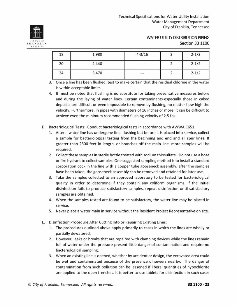
Technical Specifications for Water Utility Installation Water Management Department
City of Franklin, Tennessee WATER UTILITY DISTRIBUTION PIPING Section 33 1100
© City of Franklin, Tennessee. All rights reserved. 33 1100 - 23
3. Once a line has been flushed, test to make certain that the residual chlorine in the water is within acceptable limits.
4. It must be noted that flushing is no substitute for taking preventative measures before and during the laying of water lines. Certain contaminants-especially those in caked deposits-are difficult or even impossible to remove by flushing, no matter how high the velocity. Furthermore, in pipes with diameters of 16 inches or more, it can be difficult to achieve even the minimum recommended flushing velocity of 2.5 fps.
D. Bacteriological Tests: Conduct bacteriological tests in accordance with AWWA C651. 1. After a water line has undergone final flushing but before it is placed into service, collect
a sample for bacteriological testing from the beginning and end and all spur lines. If greater than 2500 feet in length, or branches off the main line, more samples will be required.
2. Collect these samples in sterile bottle treated with sodium thiosulfate. Do not use a hose or fire hydrant to collect samples. One suggested sampling method is to install a standard corporation cock in the line with a copper tube gooseneck assembly; after the samples have been taken, the gooseneck assembly can be removed and retained for later use.
3. Take the samples collected to an approved laboratory to be tested for bacteriological quality in order to determine if they contain any coliform organisms. If the initial disinfection fails to produce satisfactory samples, repeat disinfection until satisfactory samples are obtained.
4. When the samples tested are found to be satisfactory, the water line may be placed in service.
5. Never place a water main in service without the Resident Project Representative on site.
E. Disinfection Procedure After Cutting Into or Repairing Existing Lines: 1. The procedures outlined above apply primarily to cases in which the lines are wholly or
partially dewatered. 2. However, leaks or breaks that are repaired with clamping devices while the lines remain
full of water under the pressure present little danger of contamination and require no bacteriological sampling.
3. When an existing line is opened, whether by accident or design, the excavated area could be wet and contaminated because of the presence of sewers nearby. The danger of contamination from such pollution can be lessened if liberal quantities of hypochlorite are applied to the open trenches. It is better to use tablets for disinfection in such cases
18 1,980 4-3/16 2 2-1/2
20 2,440 --- 2 2-1/2
24 3,470 --- 2 2-1/2

Technical Specifications for Water Utility Installation Water Management Department
City of Franklin, Tennessee WATER UTILITY DISTRIBUTION PIPING Section 33 1100
© City of Franklin, Tennessee. All rights reserved. 33 1100 - 24
because they dissolve slowly and continue to release hypochlorite as water is pumped from the excavation site.
4. Where practical, treat the lines by the slug method in accordance with AWWA C651. 5. The following disinfection procedure is considered the minimum that may be used when
existing lines are repaired: a) Swab the interior of all pipes and fittings (particularly couplings and tapping sleeves)
that rare to be used in repairing an existing line with a solution of 5 percent hypochlorite before installing them.
b) The most practical means of removing contamination introduced into a line during repairs is to give the line a thorough flushing. If the locations of valves and hydrants make it possible, flushing in both directions is recommended. Start flushing as soon as repairs are completed and continue until all discolored water is eliminated.
END OF SECTION

Technical Specifications for Water Utility Installation Water Management Department
City of Franklin, Tennessee WATER UTILITY DISTRIBUTION PIPING Section 33 1100
© City of Franklin, Tennessee. All rights reserved. 33 1100 - 25
K.
3.6 FIELD QUALITY CONTROL 3.6 REMOVAL AND DISPOSAL OF DEBRIS 3.6 REMOVAL AND DISPOSAL OF DEBRIS 3.6 REMOVAL AND DISPOSAL OF DEBRIS 3.6 REMOVAL AND DISPOSAL OF DEBRIS 3.6 REMOVAL AND DISPOSAL OF DEBRIS 3.6 REMOVAL AND DISPOSAL OF DEBRIS 3.6 REMOVAL AND DISPOSAL OF DEBRIS END OF SECTION

Technical Specifications for Utility Installation Water Management Department
City of Franklin, Tennessee VALVES Section 33 1216
© City of Franklin, Tennessee. All rights reserved. 33 1216 - 1
PART 1 – GENERAL 1.1 SUMMARY
A. This section includes the following general-duty valves: (All water valves shall be left turn open) 1. Gate valves. 2. Plug valves. 3. Butterfly valves. 4. Globe valves. 5. Heavy-duty lever and weight swing check valves. 6. Air/vacuum valves. 7. Combination air valves. 8. Tapping sleeve and valve. 9. Hose bibbs.
10. Valve boxes and accessories. 11. Operators. 12. Blow off valve assemblies.
B. The following are standard abbreviations for metal and plastic materials:
1. PVC: Polyvinyl chloride. 2. DIP: Ductile iron pipe. 3. HDPE: High-density polyethylene.
C. Buried valves shall have mechanical joint ends.
D. Valves in structures or above ground shall have threaded or flanged ends, unless otherwise
noted on the Drawings.
E. Use mechanical joint fitting restraining device for plain end piping connections to fittings, valves, etc.
1.2 REFERENCES A. ANSI A.21.10 - Standard for Cast Iron Fittings 3 in. through 48 in., for water and other liquids. B. ANSI A.21.50 - Standard for the Thickness Design of Ductile-Iron Pipe. C. ANSI B.16.1 - Standard for Cast Iron Pipe Flanges and Flanged Fittings. D. C115/A21.15 - Standard for Flanged Ductile Iron. E. ANSI/AWWA C606 - Standard for Joints, Grooved and shouldered Type Fittings. F. AWWA C208 - Hydrostatic Testing of Steel Pipe.

Technical Specifications for Utility Installation Water Management Department
City of Franklin, Tennessee VALVES Section 33 1216
© City of Franklin, Tennessee. All rights reserved. 33 1216 - 2
G. ANSI B.31 - Pressure Piping.
1.3 SUBMITTALS
A. Product Data: For each type of valve indicated, include body, seating, and trim materials; valve design; pressure and temperature classifications; end connections; arrangement; dimensions; and required clearances. Include list indicating valve and its application. Include rated capacities; shipping, installed, and operating weights; furnished specialties; and accessories.
B. Action Submittals: 1. Shop Drawings:
a. Product data sheets for each make and model. Indicate valve Type Number, applicable Tag Number, and facility name/number or service where used.
b. Complete catalog information, descriptive literature, specifications and identification of materials of construction.
c. Sizing calculations for open-close/throttle and modulating valves. C. Informational Submittals:
1. Manufacturer’s Certificate of Compliance for: a. Electric operators; full compliance with AWWA C540. b. Butterfly valves; full compliance with AWWA C504.
2. Tests and inspection data. 3. Operation and maintenance data. 4. Manufacturer’s Certificate of Proper Installation
1.4 QUALITY ASSURANCE A. Product Options: Drawings indicate size, profiles, and dimensional requirements of piping
and specialties and are based on the specific system indicated.
B. Comply with regulatory requirements of local, state, and federal agencies having jurisdiction. C. Piping material shall bear label, stamp, or other markings of specified testing agency. D. Comply with ASTM F645 for selection, design, and installation of thermoplastic water piping. E. Comply with NSF 61 for materials for water service piping and specialties for domestic water.

Technical Specifications for Utility Installation Water Management Department
City of Franklin, Tennessee VALVES Section 33 1216
© City of Franklin, Tennessee. All rights reserved. 33 1216 - 3
1.5 DELIVERY, STORAGE AND HANDLING A. Delivery:
1. Prepare valves according to the following: a. Ensure that valves are dry and internally protected against rust and corrosion. b. Protect valves against damage to threaded ends and flange faces. c. Set valves in best position for handling. Set valves to closed to prevent rattling.
2. Deliver valves with factory-applied end caps. Maintain end caps through shipping, storage, and handling to prevent valve-end damage and to prevent entrance of dirt, debris, and moisture.
B. Storage: 1. Use precautions for valves according to the following:
a. Do not remove end protectors unless necessary for inspection. Following inspection, reinstall for storage.
b. Protect from weather. Store indoors and maintain temperature higher than ambient dew-point temperature. When outdoor storage is necessary, support valves off the ground or pavement in watertight enclosures.
C. Handling: 1. Use sling to handle valves and fire hydrants if size requires handling by crane or lift. Rig
valves to avoid damage to exposed parts. Do not use hand wheels or stems as lifting or rigging points.
2. Protect flanges, fittings, and specialties from moisture and dirt.
1.6 GENERAL REQUIREMENTS A. Water valves should generally be spaced a maximum of 1,000' along a water main and on
all lines at each intersection and should be located on the right- of-way line extended. In commercial districts valves should be located at not more than 500 foot intervals.
B. Air release valves or combination air relief valves must be provided at high points in
proposed transmission mains.
C. Sanitary sewer valves should be located at agreed upon locations between the Engineer and the WMD.
PART 2 – PRODUCTS 2.1 VALVES, GENERAL
A. In other Part 2 articles where subparagraph titles below introduce lists, the following

Technical Specifications for Utility Installation Water Management Department
City of Franklin, Tennessee VALVES Section 33 1216
© City of Franklin, Tennessee. All rights reserved. 33 1216 - 4
requirements apply for product selection:
B. Refer to Part 3 “Valve Applications” Article for applications of valves.
C. All valves to include operator, actuator, handwheel, chainwheel, extension stem, floor stand, worm and gear operator, operating nut, chain, wrench, and accessories for complete operation.
D. Valve to be suitable for intended service. Renewable parts not to be of a lower quality than
specified.
E. Valve Sizes: Same as upstream pipe, unless otherwise indicated.
F. Valve ends to suit adjacent piping. G. Size operator to operate valve for the full range of pressures and velocities.
H. Factory mount operator, actuator, and accessories. I. Valve Actuators:
1. Chainwheel: For attachment to valves, of size and mounting height, as indicated in the “Valve Installation” Article in Part 3.
2. Gear Drive: For quarter-turn valves NPS 8 (DN 200) and larger. 3. Handwheel: For valves other than quarter-turn types. 4. Lever Handle: For quarter-turn valves NPS 6 (DN 150) and smaller, except plug valves. 5. Wrench: For plug valves with square heads. Furnish Owner with one wrench for every
ten plug valves, for each size square plug head.
J. Factory Finishing 1. Exposed Valves:
a. Safety isolation valves and lockout valves with handles, handwheels, or chainwheels shall be “’Safety Yellow.”
b. Paint color shall be the same as the pipe.
2.2 GATE VALVES A. Resilient Seated – 2-inch through 10-inch
1. Valves shall conform to the latest revision of AWWA Standard C-509 or C-515 covering resilient seated gate valves. Valves shall have a design working pressure of 200 psi.
2. The valves shall have a cast or ductile iron body, bonnet, and O-ring plate. The wedge shall be totally encapsulated with rubber.
3. The sealing rubber shall be permanently bonded to the wedge to meet the requirements of ASTM D429.
4. Valves shall be supplied with O-ring seals at all pressure retaining joints. No flat gaskets shall be allowed. Blind bolts shall not be allowed.

Technical Specifications for Utility Installation Water Management Department
City of Franklin, Tennessee VALVES Section 33 1216
© City of Franklin, Tennessee. All rights reserved. 33 1216 - 5
5. The valves shall be non-rising stem, open by turning left, and provided with a 2-inch square operating nut for buried valves or handwheel for above-ground valves with the word “Open” and an arrow to indicate the direction to open.
6. Buried valves shall have mechanical joint connections and shall have all exterior surfaces shop painted with two coats of Fed. Spec. TT-V-51F asphaltic varnish. Any valve over 6 feet deep shall have an extension stem projecting within 2 feet of the ground surface and the stem extension shall be centered in the valve box and anchored to prevent horizontal movement and pinned to the valve nut below. The valve manufacturer shall provide all glands, gaskets, and all the accessories necessary to install the valve.
7. Stems for NRS assemblies shall be cast bronze or 316 stainless steel with integral collars in full compliance with AWWA. OS&Y (rising stems) shall be bronze or 316 stainless steel. All stems shall operate with bronze stem nuts independent of wedge and of stem (in NRS valves). NRS stems shall have two O-rings located above thrust collar and one O-ring below. Stem O-rings shall be replaceable with valve fully opened and subject to pressure. The NRS stems on 4-inch through 12-inch valves shall also have two low torque thrust bearings located above and below the stem collar to reduce friction during operation.
8. The waterway shall be smooth, unobstructed, and free of all pockets, cavities, and depressions in the seat area. Tapping valves 4-inch and larger shall accept a full size tapping cutter.
9. The body, bonnet, and O-ring plate shall be fusion-bonded epoxy coated. For the body and bonnet, both interior and exterior shall be coated. Epoxy coating shall be NSF approved and applied in accordance with ANSI/AWWA C-550.
10. Valves operating at a pressure of 160 psi or greater shall be faced and drilled ANSI B16.1 250-pound. Valves operating at less than 160 psi shall be faced and drilled ANSI B16.1 125-pound.
11. Each valve shall have the manufacturer’s name, pressure rating, and year in which it was manufactured cast in the body. Prior to shipment from the factory, each valve shall be tested by hydrostatic pressure equal to the requirements of AWWA C-509 for cast iron bodies and C-515 for ductile iron bodies (and UL/FM where applicable).
12. Valves shall have all component parts cast and assembled in the USA. 13. Model/Manufacturer:
a. Mueller 2360 Series Resilient Wedge/Mueller; Decatur, IL b. American Flow Control Series 2500 Resilient Wedge/ American Flow Control;
Birmingham, AL c. M&H Valve Company; Anniston, AL d. Approved equal.
2.3 PLUG VALVES A. Eccentric
1. Valves shall be of the 90 degree turn, non-lubricated eccentric type with resilient faced plugs and shall be furnished with end connections as shown on the drawings. Flanged valves shall be faced and drilled to the ANSI 125/150 lb. standard. Mechanical Joint ends

Technical Specifications for Utility Installation Water Management Department
City of Franklin, Tennessee VALVES Section 33 1216
© City of Franklin, Tennessee. All rights reserved. 33 1216 - 6
shall be to the AWWA Standard C111-64, grooved ends per AWWA C-606-87. Screwed ends shall be to the NPT standard.
2. Valve bodies shall be of ASTM A126 Class B cast iron. Bodies in 4” and larger valves shall be furnished with a 1/8” welded overlay seat of not less than 90% pure nickel, machined to mate with the resilient faced plug. Valves that do not provide positive mating of the resilient faced plug with the nickel seat shall not be acceptable. Seat area shall be raised, with raised surface completely covered with weld to ensure that the plug face contacts only nickel. Screwed-in seats shall not be acceptable.
3. True eccentric action shall be required. Design of the valve shall provide for a rectangular port that allows contact between the welded nickel seat and the plug to occur only in the final 3 degrees of the plug movement. Round ported valves as well as other non-eccentric action valves shall not be acceptable. If requested, the manufacturer shall provide a complete site visit to the manufacturing facility for the owner, engineer and contractor to witness the eccentric action of partially assembled valves and to verify the size and shape of the port area as well as the welded nickel seat.
4. Plugs shall be of ASTM A126 Class B cast iron. The plug shall have a cylindrical seating surface eccentrically offset from the center of the plug shaft. The interference between the plug face and the body seat, with the plug in the closed position, shall be externally adjustable in the field with the valve in line under pressure. The plug shall be completely coated with a chloroprene compound suitable for use with sewage. The plug coating shall be applied at the factory to ensure that the plug is completely coated and then heat-treated to insure a positive bond.
5. Valves shall have sleeve type metal bearings and shall be of sintered, oil impregnated permanently lubricated type 316 ASTM A743 Grade CF-8M in ½”-36” sizes. In valves larger than 36”, the upper and lower plug journals shall be fitted with ASTM A-240 type 316 stainless sleeves with bearings of ASTM B30, Alloy C95400 aluminum bronze. Non-metallic bearings shall not be acceptable.
6. Valves shaft seals shall be of the multiple V-ring type and shall be externally adjustable and repackable without removing the bonnet or actuator from the valve under pressure. Valves utilizing O-ring seals or non-adjustable packing shall not be acceptable.
7. Valve pressure ratings shall be 175 psi through 12” and 150 psi for 14” through 72”. Valves shall provide drip-tight shutoff up to the full pressure rating with pressure in either direction. Each valve shall be given a hydrostatic and seat test with the test results being certified in accordance with ANSI B16.1. If requested, the manufacturer shall provide a complete site visit to the manufacturing facility for the owner, engineer and contractor to witness the testing process.
8. Full Port Plug Valves shall be rectangular port design with minimum 100% open port area as defined as the geometric open port area of the plug valve that is greater than or equal to the open area of the connecting pipe. Manufacturers using Cv values to determine port opening area shall not be considered.
9. Valve actuators for manual valves shall have lever or gear actuators and tee wrenches, extension stems, floorstand, extended bonnet, etc. as indicated on the plans. All

Technical Specifications for Utility Installation Water Management Department
City of Franklin, Tennessee VALVES Section 33 1216
© City of Franklin, Tennessee. All rights reserved. 33 1216 - 7
extended bonnets must have gear located at the operator – stem extensions with handwheel operators are not an acceptable equivalent. All valves 6” and larger shall be equipped with gear actuators. All gearing shall be enclosed in a semi-steel housing and be suitable for running in a lubricant with seals provided on all shafts to prevent entry of dirt and water into the actuator. The actuator shaft and the quadrant shall be supported on permanently lubricated bronze bearings. Actuators shall clearly indicate valve position and an adjustable stop shall be provided to set closing torque and to provide seat adjustment to compensate for change in pressure differential or flow direction change. All exposed nuts, bolts and washers shall be zinc plated.
10. Valve and gear actuators for buried or submerged service shall have seals on all shafts and gaskets on the valve and actuator covers to prevent the entry of water. Actuator mounting brackets for buried or submerged service shall be totally enclosed and shall have gasket seals. All exposed buts, bolts and washers shall be stainless steel.
11. All eccentric plug valves and actuators shall be as manufactured by DeZURIK, Sartell, MN, Pratt, Aurora, IL, or Engineer approved equal.
2.4 BUTTERFLY VALVES A. Butterfly valves are used for water lines 12 inches and larger. Valves shall meet or exceed the
latest revision of AWWA Standard C504 for Class 150B butterfly valves and shall meet or exceed the requirements of this specification. All valves shall be tested at and shall be capable of withstanding bi-directional line hydrostatic test pressures up to 150 psi without leaking. All valve components shall conform to Underwriters Laboratories classification in accordance with ANSI/NSF Standard 61.
B. Valve bodies shall be of cast iron per ASTM A126 Class B. Flanged end valves shall be of the short body design with 125 lb. flanged ends faced and drilled per ANSI B16.1 standard for cast iron flanges. Mechanical joint end valves shall meet the requirements of AWWA C111/ANSI 21.11. All accessories (bolts, glands, and gaskets) shall be provided by the same manufacturer.
C. Disc shall be offset to provide an uninterrupted 360-degree seating edge and shall be cast iron per
ASTM A48, Class 40C. The disc seating edge shall be solid 316 stainless steel. Sprayed mating seating surfaces are not acceptable. The disc shall be securely attached to the valve shaft utilizing a field removable/replaceable 304 stainless steel torque screw on sizes 3-inch through 12-inch, a tangential pin locked in place with a set screw on sizes 4-inch through 20- inch, or 304 stainless steel taper pins on valves 24-inch and larger.
D. Valve shaft shall be 304 stainless steel. Valve shafts seals shall be self-compensating V-type packing with a minimum of four (4) sealing rings. One-piece molded shaft seal and O-ring shaft seals are not acceptable.

Technical Specifications for Utility Installation Water Management Department
City of Franklin, Tennessee VALVES Section 33 1216
© City of Franklin, Tennessee. All rights reserved. 33 1216 - 8
E. Seat shall be of Buna-N for water, or as required for other services, and shall be molded in and vulcanized to the valve body. The seat shall contain an integral shaft seal protecting the valve bearings and packing from any line debris. For valves 24- inch and larger, the seat shall be retained within a dovetail groove in the valve body and locked in place by an epoxy compound wedge. Compression between the seat and disc edge shall be adjustable from both the upstream and downstream side of the valve disc. The seat shall be field replaceable without disassembly of the disc and shaft. Seats vulcanized to cartridge inserts in the valve body and seats on the disc are not acceptable.
F. Valve shaft bearings shall be non-metallic and permanently lubricated. G. Interior and exterior metallic surfaces shall be shop painted per the latest revision of AWWA C504
unless otherwise indicated. The interior of the body shall have a full rubber lining vulcanized to the valve body. Mechanical joint valves shall be fully rubber lined to the point of pipe insertion. Rubber lining on the flange face and boot style seats is not acceptable.
H. Valve actuator shall be sized to operate the valve at the rated working conditions of the valve and
shall be as shown on the Drawings. Ten position locking levers shall be available for 3- inch through 6-inch valves. Provisions must be made for locking in any of the ten positions using a standard padlock.
I. Model/Manufacturer:
1. Model BAW Butterfly Valves/DeZURIK; Sartell, MN 2. Groundhog Buried Service Butterfly Valve/Henry Pratt Co.; Aurora, IL 3. Lineseal III/Mueller Co. Water Products Division 4. Approved equal
2.5 GLOBE VALVES
A. The valve shall regulate flow in a pipeline. Its most frequent use is as a sampling valve where it is normally shut except when samples are taken.
B. Bronze globe valves, general: MSS SP-80, with ferrous-alloy handwheel. C. Type 2, Class 150, bronze globe valves: bronze body with PTFE or TFE disc and union-ring
bonnet.
2.6 HEAVY-DUTY LEVER AND WEIGHT SWING CHECK VALVES A. The valve shall smoothly swing open and close quickly to prevent flow reversal. When closed,
the valve shall seat drop tight.

Technical Specifications for Utility Installation Water Management Department
City of Franklin, Tennessee VALVES Section 33 1216
© City of Franklin, Tennessee. All rights reserved. 33 1216 - 9
B. The valve shall exceed the minimum requirements of AWWA C508 with a heavy duty body
of high-strength cast iron conforming to ASTM A126 Class B with integral flanges. The valve shall be suitable for horizontal or vertical installation. Valves operating at pressures less than 150 psi shall be faced and drilled per ANSI B16.1 Class 125. Valves operating at pressures of 150 psi or greater shall be faced and drilled per ANSI B16.1 Class 250.
C. The valve body shall be the full waterway type, designed to provide a net flow area not less
than the nominal inlet pipe size when swung open no more than 25 degrees. The valve shall have a replaceable stainless steel body seat and a cast iron disc faced with a renewable resilient seat ring of rubber or other suitable material. The seat ring shall be held in place by stainless steel screws.
D. The disc arm shall be ductile iron or steel. The disc arm shall be suspended from and keyed to
an austenitic stainless steel shaft that is completely above the waterway. The shaft shall be supported at each end by heavy bronze bushings. The shaft shall rotate freely without the need for external lubrication. The shaft shall be sealed where it passes through the body by means of a stuffing box and adjustable packing. Simple O-ring shaft seals are not acceptable.
E. The valve shaft shall have the following size for the given valve sizes:
Valve Size (Inches)
Shaft Diameter (Inches)
3 3/4 4 7/8 6 1
8, 10 1-1/4 12 1-1/2
14, 16, 18, 20 2 24 2-3/4
F. Model/Manufacturer:
1. Figure 220, 221, or 222 Lever and Weight/GA Industries, Inc.; Mars, PA 2. Approved equal.
2.7 AUTOMATIC AIR RELEASE VALVES A. Manufacturer / Model
1. APCO / 200A

Technical Specifications for Utility Installation Water Management Department
City of Franklin, Tennessee VALVES Section 33 1216
© City of Franklin, Tennessee. All rights reserved. 33 1216 - 10
2. Crispin / A.R. Series 3. Approved Equal
2.8 AIR VACUUM VALVES
A. The Air/Vacuum valve shall be capable of exhausting air at up to sonic velocity without blowing shut during the filling of the pipeline or system. The valve shall automatically close when water fills the valve and remain closed while the system is pressurized but open automatically to admit air during draining or a negative pressure condition. The Air/Vacuum valve shall fully conform to AWWA C512 (latest revision).
B. The valve shall be of the size shown on the Drawings with a venting orifice no smaller than the nominal valve size. Valves 3-inch and smaller shall have an NPT inlet connection; valves 4-inch and larger shall have a flanged inlet. Valves 4-inch and smaller shall have NPT outlet connection, and unless specified otherwise, larger valves shall be supplied with a protective cowl on the outlet. Additional plugged NPT connections shall be provided near the top and bottom for testing and draining.
C. ANSI Class 125 flanged valves shall have a minimum 150 psi pressure rating, and NPT or
ANSI Class 250 flanged valves shall have a minimum 300 psi pressure rating.
D. Materials of Construction: 1. The valve body and cover shall be made from cast iron conforming to ASTM A126 Class
B. The cover shall be bolted to the body, and all internal components shall be replaceable through the cover.
2. The float ball shall be spherical and made from Type 316 stainless steel. Non-metallic float balls are not acceptable.
3. The seat shall be replaceable and made from Buna-N rubber or other suitable elastomer compounds.
4. The exterior of the valve shall be shop coated with enamel primer.
E. When shown on the Drawings, the valve shall have a flanged outlet connection.
F. Model/Manufacturer: 1. Figure 930/GA Industries, LLC, Cranberry Township, PA 2. Approved equal
2.9 COMBINATION AIR VALVES A. Combination air valves shall be designed such that they allow large volumes of air to escape
out of a large orifice when filling a pipeline and close when liquid enters the valve. In addition, they shall be designed such that a small orifice allows the release of small pockets of air.

Technical Specifications for Utility Installation Water Management Department
City of Franklin, Tennessee VALVES Section 33 1216
© City of Franklin, Tennessee. All rights reserved. 33 1216 - 11
B. The valves shall allow large volumes of air to enter the pipeline during drainage to break the
vacuum and prevent water column separation.
C. The valves shall be designed such that premature valve shut-off due to rushing air and water forces is prevented.
D. Valve operation shall be automatic.
E. The valves shall be constructed of corrosion resistant materials, be capable of operating with
a working pressure of 200 psi and provide drop-tight shut-off.
F. Model/Manufacturer: 1. ARI Model D-040/ARI Flow Control Accessories – water 2. ARI Model D-020, S020, S022 for sewer and reclaimed water 3. Approved equal
2.10 TAPPING SLEEVES AND VALVES A. General:
1. On water mains 12” and smaller, tapping sleeve shall be stainless steel type or mechanical joint type.
2. On water mains 12” and larger, tapping sleeve shall be ductile iron type. 3. Valves shall conform with “Gate Valves” listed herein.
B. Stainless Steel Type:
1. Sleeve shall be Type 304 Stainless Steel with test plug. "Waffle" 360° gasket with integral gap bridge. Outlet flange with dimensions and drilling that comply with ANSI B16.1, class 125 and with MSS SP-60.
2. Manufacturers: a. Mueller Co., Water Products Division b. Approved equal.
C. Ductile iron type:
1. Sleeve shall be type shall be full sleeve mechanical joint manufactured from ductile iron meeting ASTM A536, Grade 65-45-12. Outlet flange with dimensions and drilling that comply with ANSI B16.1, class 125 and with MSS SP-60.
2. Manufacturers: a. Mueller Co., Water Products Division b. American Cast Iron Pipe Co., American Flow Control Division c. Approved equal.

Technical Specifications for Utility Installation Water Management Department
City of Franklin, Tennessee VALVES Section 33 1216
© City of Franklin, Tennessee. All rights reserved. 33 1216 - 12
D. Tapping Valve: 1. Resilient wedge type with non rising stem. Conforms to all applicable parts of
ANSI/AWWA C500 and C509 Standards. One end flanged with alignment lip to attach to tapping sleeve.
2. Manufacturers/Model: a. Mueller Co., Water Products Division, Model T2360 b. Approved equal.
2.11 HOSE BIBBS A. Hose bibb shall be rough bronze body, with wheel handle, renewable composition disc, 1/2-
or 3/4-inch threaded or solder-joint inlet. Provide ASME B1.20.7 garden-hose threads on outlet and integral or field-installed, nonremovable, drainable, hose connection vacuum breaker.
2.12 VALVE BOXES AND ACCESSORIES A. Valve boxes shall consist of precast concrete risers with cast iron frames and covers. Valve
box risers shall be pre-cast concrete made accurately to the required dimensions, and shall be sound, smooth, clean and free from blisters and other defects. Defective castings which have been plugged or otherwise treated to remedy defects shall be rejected. Contact surfaces of frames and covers shall be machined so that the covers rest securely in the frames with no rocking and with the cover in contact with the frames for the entire perimeter of the contact surface. 1. Manufacturers:
a. Hula Concrete Products, Hickman TN b. Approved equal.
B. Install valve boxes on each proposed valve in accordance with the details shown on the
standard drawings.
C. Frames for reclaimed water valves are round. D. Cast iron frame and cover shall be roadway type for other applications. Unless otherwise
instructed by Resident Project Representative, furnish frame and covers specified below.
1. Manufacturers: a. John Bouchard No. 8006 b. Vulcan No. V-8455

Technical Specifications for Utility Installation Water Management Department
City of Franklin, Tennessee VALVES Section 33 1216
© City of Franklin, Tennessee. All rights reserved. 33 1216 - 13
2.13 MANUAL OPERATORS A. General:
1. Valves for water and wastewater service shall open to the left. 2. Valves for reclaimed water service shall open to the right. 3. Operator force not to exceed 40 pounds under any operating condition, including initial
breakaway. Gear reduction operator when force exceeds 40 pounds. 4. Operator self-locking type or equipped with self-locking device. 5. Position indicator on quarter-turn valves. 6. Worm and gear operators one-piece design worm-gears of gear bronze material. Worm
hardened alloy steel with thread ground and polished. Traveling nut type operators threader steel reach rods with internally threaded bronze or ductile iron nut.
B. Exposed Operator: 1. Galvanized and painted handwheels. 2. Lever operators allowed on quarter-turn valves 8 inches and smaller. 3. Cranks on gear type operators. 4. Chain wheel operator with tiebacks, extension stem, floor stands, and other accessories
to permit operation from normal operation level. 5. Valve handles shall be designed to be locked.
C. Buried Operator:
1. Buried service operators on valves larger than 2-1/2 inches shall have a 2-inch AWWA operating nut. Buried operators on valves 2 inches and smaller shall have cross handle for operation by forked key. Enclose moving parts of valve and operator in housing to prevent contact with the soil.
2.14 BLOW OFF VALVE ASSEMBLIES A. Blow off valve assemblies shall be required for dead end mains, or as otherwise required by
the WMD, and shall be equal to the main size. B. The blow off shall be installed in a concrete valve box with the ball valve located 1 foot from
the top of the box. The tracer wire shall be extended into the concrete valve box. C. The blow off assembly shall consist of a 2” threaded brass 90 degree bend, a 2” threaded
brass pipe, ball valve, and a 2 ½” diameter brass nipple 5” long with standard thread on one end and hose thread on the other end.

Technical Specifications for Utility Installation Water Management Department
City of Franklin, Tennessee VALVES Section 33 1216
© City of Franklin, Tennessee. All rights reserved. 33 1216 - 14
PART 3 – EXECUTION 3.1 EXAMINATION
A. Examine piping system for compliance with requirements for installation tolerances and other conditions affecting performance. 1. Proceed with installation only after unsatisfactory conditions have been corrected.
B. Examine valve interior for cleanliness, freedom from foreign matter, and corrosion. Remove
special packing materials, such as blocks, used to prevent disc movement during shipping and handling.
C. Operate valves in positions from fully open to fully closed. Examine guides and seats made accessible by such operations.
D. Examine threads on valve and mating pipe for form and cleanliness. E. Examine mating flange faces for conditions that might cause leakage. Check bolting for
proper size, length, and material. Verify that gasket is of proper size, its material composition is suitable for service, and it is free from defects and damage.
F. Do not attempt to repair defective valves; replace with new valves.
3.2 VALVE INSTALLATION A. Piping installation requirements are specified in other Division 33 Sections. Drawings indicate
general arrangement of piping, fittings, and specialties.
B. All valves and appurtenances shall be installed in strict conformance with the Drawings and manufacturer’s instructions.
C. Location of Valves:
1. In water mains, valves shall be located on the street right-of-way(R.O.W.) where possible. 2. Valves should installed be no more than 1,000 feet apart. 3. Need to place a valve at each T of an intersection. For example: if at a 3 way
intersection you need 3 valves and at a 4 way intersection you need to have 4 valves. D. Locate valves for easy access and for routine operation and maintenance. Provide separate
support where necessary.

Technical Specifications for Utility Installation Water Management Department
City of Franklin, Tennessee VALVES Section 33 1216
© City of Franklin, Tennessee. All rights reserved. 33 1216 - 15
E. Install valves so handles operate from fully opened to fully closed without encountering obstructions.
F. Valves shall be installed in such a way that operators and packing are easily accessible. Valves
with field replaceable seats shall be installed with sufficient clearance to permit removal of the valve bonnet and stem without removing the valve from the line.
G. Install valves in horizontal piping with stem at or above the center of pipe. Operators shall be
positioned so that they do not interfere with pedestrian traffic. In passageways or above platforms, the minimum clearance between the floor and the lowest protruding point on the valve or operator shall be six feet, eight inches (6’-8”). All valves shall be accessible for operation, maintenance, or removal.
H. Positioners or actuators shall be provided special support where they overhang from the valve or where the total valve, actuator, and position weight is excessive for the size of the pipeline.
I. Install valves with unions, dismantling joints, or flanged coupling adapters at each piece of
equipment arranged to allow service, maintenance, and equipment removal without system shutdown.
J. Install valves in position to allow full stem movement. K. Install check valves for proper direction of flow and as follows:
1. Swing Check Valves: In horizontal position with hinge pin level. 2. Single-Plate Check Valves: In horizontal or vertical position, between flanges. 3. Lift Check Valves: With stem upright and plumb.
L. Install chainwheel operators on valves 4-inches and larger and more than 7 feet above the
floor. Extend chains to 5 feet above finished floor elevation.
M. Extension Stem for Operator: Where the depth of the valve is such that its centerline is more than 5 feet below grade, furnish an operating extension stem with 2-inch operating nut to bring the operating nut to a point 12 inches below the surface of the ground and/or box cover.
3.3 TESTING AND INSPECTION A. Valve may either be tested while testing pipelines or as a separate step.
B. Following installation, the Contractor shall test that all valves open and close smoothly under
anticipated operating conditions. The ability of the valves to operate properly without

Technical Specifications for Utility Installation Water Management Department
City of Franklin, Tennessee VALVES Section 33 1216
© City of Franklin, Tennessee. All rights reserved. 33 1216 - 16
leakage, binding, sticking, fluttering, or excessive operating torque shall be demonstrated to the satisfaction of the Resident Project Representative. The Contractor shall at his own expense adjust and/or replace any valve as necessary to ensure satisfactory operation.
C. Count and record the number of turns to open and close the valve. Account for any
discrepancies with the manufacturer’s data.
D. Automatic valves to be tested in conjunction with control system testing.
3.4 MANUFACTURER’S SERVICES
A. Manufacturer's authorized representative shall be present at the jobsite for a minimum of one day (excluding travel time) for installation assistance and inspection.
B. Manufacturer's authorized representative shall be present at the jobsite for a minimum of one day (excluding travel time) for equipment start-up, functional and performance testing, and to train Owner's personnel in the operation, maintenance, and troubleshooting of the equipment provided.
3.5 ADJUSTING A. Adjust or replace valve packing after piping systems have been tested and put into service but
before final adjusting and balancing. Replace valves if persistent leaking occurs.
END OF SECTION

Technical Specifications for Water Utility Installation Water Management Department City of Franklin, Tennessee HYDRANTS Section 33 1219
© City of Franklin, Tennessee. All rights reserved. 33 1219 - 1
PART 1 – GENERAL 1.1 SCOPE
A. Work covered by this section includes furnishing all materials, labor, and equipment required to furnish, install, and test fire hydrants and yard hydrants and accessories as specified herein and/or shown on the Drawings.
1.2 SHOP DRAWINGS AND ENGINEERING DATA A. Complete shop drawings and engineering data shall be submitted to the Owner.
1.3 STORAGE AND PROTECTION A. Hydrants shall be stored and protected in accordance with manufacturer’s requirements.
1.4 SHOP PAINTING A. Hydrants and accessories shall be cleaned, shop primed, and shop painted as specified herein.
1.5 OPERATION AND MAINTENANCE DATA A. Submit complete operation and maintenance data on the hydrants to the Owner.
1.6 GUARANTEE A. Provide a guarantee against defective or deficient equipment and workmanship.
1.7 QUALITY ASSURANCE A. The manufacturer of the fire hydrants shall furnish a written certification to the Owner that
all hydrants furnished comply with all applicable requirements of AWWA C502, latest edition.
1.8 GENERAL REQUIREMENTS A. A fire hydrant shall be installed at the end of 6" and larger dead end water mains for flushing
purposes.
B. Public hydrants are those owned by the WMD. C. The number and spacing of hydrants shall be in accordance with the International Fire Code
as adopted.

Technical Specifications for Water Utility Installation Water Management Department City of Franklin, Tennessee HYDRANTS Section 33 1219
© City of Franklin, Tennessee. All rights reserved. 33 1219 - 2
D. All public fire hydrants shall be installed at street intersections where possible. E. Public hydrant spacing shall be measured along vehicle access routes. F. The fire department will review all hydrant locations.
PART 2 – PRODUCTS 2.1 FIRE HYDRANTS
A. Manufacturers 1. American Darling 5-1/4”, B-84-B-5 2. Mueller, “Super Centurion” No. A423 3. Approved equal
B. Fire hydrants shall be of the dry-barrel, compression type and shall conform to applicable
requirements of AWWA C502, latest edition. Fire hydrants shall be cast iron, bronze mounted, suitable for a working pressure of 200 psi. Name of the manufacturer and size of the main valve shall be cast upon the hydrant in raised letters.
C. Hydrants shall be constructed in a manner that will permit withdrawal of internal working parts without disturbing the barrel or casing. Valve shall be compression type, opening against pressure and so constructed that the main valve will remain closed should the hydrant be broken off by traffic accident. Valve opening shall be at least 5-1/4 inches in diameter and shall have a net area of waterway at the smallest part of not less than 120 percent of the valve opening when the valve is wide open. There shall be no chattering or water hammer under any conditions of operation.
D. Barrel shall be made in two pieces with flanged joint above the finished grade or ground line.
Lower barrel shall be fluted for strength and tapered to prevent frost heave. Ground line flange shall be of the break-away type. Two positive acting, bronze fitted drain valves shall be provided in the hydrant shoe automatically to open and provide rapid and complete drainage of the hydrant barrel when the main valve is closed.
E. Hydrant bonnet shall be designed to protect the operating head against rust, corrosion, and
dirt. The stuffing box shall have bronze glands and O-ring seal. Suitable means shall be provided for lubricating the stem threads, O-ring, and bearing surfaces in the bonnet.

Technical Specifications for Water Utility Installation Water Management Department City of Franklin, Tennessee HYDRANTS Section 33 1219
© City of Franklin, Tennessee. All rights reserved. 33 1219 - 3
F. The main valve rod shall be of steel and shall be bronze sheathed where it passes through the stuffing box. Stem shall be equipped with a two-piece safety or breakable stem coupling to prevent damage to the stem when hydrant is hit by a vehicle. A positive stop shall be provided to permit full opening of the valve and prevent over-travel of the stem.
G. Direction of opening shall be counterclockwise and shall be cast on the head. Operating nut
shall be National Standard, 1-1/2-inch, pentagon shaped. H. Two 2-1/2-inch hose nozzles and one 4-1/2-inch pumper nozzle shall be provided on each
hydrant. Hose and pumper nipples shall be of bronze or non-corrosive metal, and threads shall be National Standard in accordance with NFPA Standard No. 194. Nipple caps shall be securely chained to the barrel with galvanized, non-kinking chains.
I. Hydrants that are to be connected to ductile iron pipe shall be equipped with mechanical joint
inlet with restrained joint gland, gaskets, bolts, and nuts. Suitable ring-tight or fluid-tight inlets shall be provided on hydrants that are to be connected to cement asbestos pipe. Inlet bell shall have two lugs for harness restraint.
J. After fabrication, all exterior aboveground ferrous surfaces shall be blast-cleaned and painted
at the shop with one coat of zinc chromate primer conforming to Federal Specification TT-P- 636 and one coat of compatible alkyd enamel. Color shall be fire hydrant yellow. All interior and belowground, non-machined ferrous surfaces shall be blast-cleaned and painted at the shop with two coats of asphaltic varnish conforming to Federal Specification TT-V-51c.
2.2 YARD HYDRANTS A. Yard Hydrants shall only be installed at a pump station, lift station, water tank, or a booster
station.
B. Yard hydrants shall be of the nonfreezing, compression, post type hydrant with self-draining barrel as manufactured by Zurn Industries, Model Z1390 or approved equal. Yard hydrants shall be suitable for 125 psi static pressure.
C. Yard hydrants shall have a brass casing and base, bronze seats, resilient-faced disc, O-ring
stem seal, bronze or stainless steel stem, and galvanized steel barrel. D. Yard hydrants shall be furnished with 2-inch threaded female inlet connection per ANSI B2.1
and threaded 1-1/2-inch male outlet hose connection. A “T” or wheel handle shall be furnished to operate the valve.

Technical Specifications for Water Utility Installation Water Management Department City of Franklin, Tennessee HYDRANTS Section 33 1219
© City of Franklin, Tennessee. All rights reserved. 33 1219 - 4
E. All internal working parts shall be readily accessible and removable through the top for ease
of maintenance. F. Contractor shall provide 10 1-inch by 3/4-inch brass adapters for use on yard hydrants.
2.3 SPARE PARTS A. The following spare parts shall be furnished for hydrants furnished under this section, where
applicable:
PART NUMBER REQUIRED Packing, O-rings, and Gaskets One set each hydrant
Main Valve Disc One each hydrant Drain Valve Facing One each hydrant
Break-away Flange Repair Kit One set with Stem Coupling Seat Wrench One each type required
Lubricants One year supply
B. Spare parts shall be suitably protected against corrosion and impact to withstand long-term storage. Parts shall be clearly identified with the manufacturer's name and number and the equipment to which they belong.
PART 3 – EXECUTION 3.1 FACTORY TESTING
A. Each hydrant shall be tested at the factory at a hydrostatic pressure of 300 psig in accordance with AWWA C502, Section 5. Hydrants shall be tested in both the open and closed positions. Hydrants shall be completely drained and closed before shipment.
3.2 INSTALLATION A. Hydrants shall be installed at the locations and in the manner shown on the Drawings.
Hydrants shall be inspected, cleaned, and tested for operation prior to installation.
B. Fire hydrants shall be installed 3 feet to 7 feet from the sidewalk.
C. Fire hydrants shall be isolated from the water supply main with a buried gate valve not less than 6 inches in size. Hydrants shall be installed in a suitable rock drain and anchored against thrust according to the Specifications. Upper barrel joint shall be located approximately 2

Technical Specifications for Water Utility Installation Water Management Department City of Franklin, Tennessee HYDRANTS Section 33 1219
© City of Franklin, Tennessee. All rights reserved. 33 1219 - 5
inches above ground level. Barrel extensions shall be furnished as necessary.
D. Each yard hydrant shall be isolated from the water supply by a 1-inch curb stop as shown on the Drawings.
E. After installation, each valve shall be tested in the presence of the Owner for proper
operation and leak-tightness. Any leaks shall be corrected.
F. Following installation and testing, exposed ferrous surfaces of hydrants shall be field painted with alkyd system ferrous metal finish.
END OF SECTION
Technical Specifications for Water Utility Installation Water Management Department City of Franklin, Tennessee WATER SERVICE ASSEMBLIES Section 33 1233
© City of Franklin, Tennessee. All rights reserved. 33 1233 - 1
PART 1 - GENERAL 1.1 SUBMITTALS
A. Product Data: 1. Tapping Saddles 2. Corporation Stops 3. Service Pipes 4. Curb Stops 5. Water Meters 6. Meter Boxes 7. Water Pressure Regulators 8. Reduced Pressure Backflow Preventers (RPBP) 9. Double Check Valve Assemblies (DCA) 10. Linesetters
PART 2 - PRODUCTS 2.1 TAPPING SADDLE
A. Tapping saddles shall have double straps or a double wide band and shall be suitable for use with the various pipes at the installation point (i.e. will not cause electrolysis). For ¾-inch and 1-inch services, use a direct tap. For 1 ½-inch and 2-inch, use a tapping saddle. 1. Manufacturer / Model:
a. Smith-Blair Double Bale Model 313, b. Mueller BR2B, c. Ford Meter Box Style 202B, d. Approved equal.
2.2 CORPORATION VALVE
A. Corporation valve shall be designed and manufactured to conform to AWWA C800-84 and ASTM B-62 which cover thread dimensions, metal alloy (red brass: 85-5-5-5), and pressure rating. Inlet threads shall be AWWA Taper Thread CC. The outlet shall be suitable for the service piping required. Corporation valve shall be directly tapped into the water line/main using a tapping saddle. Insulators shall be used on dissimilar pipes as necessary for protection against electrolysis. Corporation valve shall be ball valve type suitable for pressures up to 300 psi. 1. Manufacturer / Model:
a. Ford Meter Box F1000 for ¾-inch and 1-inch b. Ford Meter Box FB1000 for 1 ½-inch and 2-inch c. Mueller B-20046N d. Approved equal.

Technical Specifications for Water Utility Installation Water Management Department City of Franklin, Tennessee WATER SERVICE ASSEMBLIES Section 33 1233
© City of Franklin, Tennessee. All rights reserved. 33 1233 - 2
2.3 SERVICE PIPE A. Residential service pipe shall be 3/4-inch. Service pipe, sizes 3/4-inch through 2- inch, shall be
one solid continuous run and of the following material(s): 1. Copper:
a. Below Grade: Type K, annealed temper, hard or soft copper tubing in accordance with ASTM B88.
b. Above Grade: Type M, drawn temper, hard or soft copper tubing in accordance with ASTM B88.
2. Any alteration of service shall result in replacement from tap to meter in one continuous run.
2.4 LINESETTER A. Meters shall be installed with a linesetter manufactured in compliance with ANSI/AWWA
C800 (latest revision). The linesetter shall have lead free solder joints and factory air tested under water at 85 PSIG. The line setter shall include a check valve lockwing ball style meter valve.
B. Manufacturer / Model: 1. McDonald 720 Series 2. Approved equal
2.5 WATER METER A. Water meters ¾-inch to 2-inch shall be provided by the WMD. Meters larger than 2 inches
may be installed by the WMD but at the Contractor’s expense.
B. Water meters 3-inch and larger shall be cold water turbine type meeting all requirements of ANSI/AWWA C701 or C702 as determined by the WMD. Meter registers shall be straight reading in U.S. gallons and be equipped with a device to afford capability for accurately testing the meter in accordance with AWWA Standards. The meters shall be equipped with a removable corrosion resistant strainer screen between the outer case and measuring chamber. The body case shall have the manufacturer’s serial number imprinted thereon and have raised markings to indicate the direction of flow. At a minimum, meters shall be rated to withstand a pressure of 150 psi. All meters shall be equipped with Radio Read Technology (SmartPoint 520M).
C. Manufacturer / Model: 1. Sensus Omni C2 or T2

Technical Specifications for Water Utility Installation Water Management Department City of Franklin, Tennessee WATER SERVICE ASSEMBLIES Section 33 1233
© City of Franklin, Tennessee. All rights reserved. 33 1233 - 3
2.6 METER BOX A. Meter boxes shall be high density polyethylene straight wall style. Wall thickness shall be such
that when buried the box will support an incidental traffic load. Top cover shall be removable with ductile iron traffic rated meter reading lid per ASTM A536. Reading lid shall have lettering “WATER METER”. Meter boxes shall be sized based on the meter size and other appurtenances to be included within the box.
B. Manufacturer / Model:
Meter Size Meter Box Meter Lid
¾” Sigma-Raven RMB132418-SW* Sigma LC 1324T-D* 1” Sigma-Raven RMB132418-SW* Sigma LC 1324T-D*
1 ½” Sigma-Raven RMB173018-SW* Sigma LC 1730T-D* 2” Sigma-Raven RMB173018-SW* Sigma LC 1730T-D*
*Or approved equal 2.7 REDUCED PRESSURE BACKFLOW PREVENTER
A. Reduced pressure zone assembly shall be installed at each possible cross-connection to prevent backsiphonage and backpressure backflow of hazardous materials into the potable water supply. If the assembly is installed in a location with more than its rated working pressure, a water pressure regulator shall be installed upstream of the assembly.
B. The assembly shall consist of a pressure differential relief valve located in a zone between two positive seating check valves.
C. Backsiphonage protection shall include provision to admit air directly into the reduced pressure zone via a separate channel from the water discharge channel, or directly into the supply pipe via a separate vent.
D. The assembly shall include two quarter-turn ball valves before and after the check valves, test cock, and air gap.
E. The assembly shall meet the requirements of ASSE Standard 1013; AWWA C-511-92 CSA B64.4 and national plumbing codes.
F. Materials: 1. Check Valve Body: Bronze 2. Check Valve Seat: 909 Celcon 3. Relief Valve Body: Bronze or FDA Epoxy Coated Cast Iron 4. Relief Valve Trim: Stainless Steel 5. Strainer: Bronze or FDA Epoxy Coated Cast Iron

Technical Specifications for Water Utility Installation Water Management Department City of Franklin, Tennessee WATER SERVICE ASSEMBLIES Section 33 1233
© City of Franklin, Tennessee. All rights reserved. 33 1233 - 4
G. Drain lines shall be provided for assembly discharge.
H. Contractor to see approved Cross Connection Control plan at the Water Management Department office or the City of Franklin website (franklintn.gov).
I. Manufacturer / Model: 1. Watts Industries, Inc. Series 909 with Series 909AG Air Gap 2. Approved equal
2.8 DOUBLE-CHECK ASSEMBLY
A. Manufacturers: Subject to compliance with requirements, provide products by one of the following: 1. Watts Industries, Inc.; Water Products Div. 2. Approved equal
B. Standard: ASSE 1048 and FMG approved or UL listed
C. Operation: Continuous-pressure applications
D. Pressure Loss: 5 psig (35 kPa) maximum, through middle 1/3 of flow range
E. Size: As scheduled on drawings
F. Design Flow Rate: As scheduled on drawings
G. Body: Cast iron with interior lining complying with AWWA C550 or that is FDA approved
H. End Connections: Flanged
PART 3 - EXECUTION 3.1 PREPARATION
A. Make no service assembly connections without approval from the WMD. B. No taps shall be made in any size pipe without approval of the WMD.
C. All service pipe shall be renewed from the new water line to existing meter location unless
otherwise directed by the Drawings or WMD. Where encountered, existing galvanized iron service piping shall be replaced up to a point 10 feet beyond the meter box.
D. Existing service assemblies and meter boxes shall be replaced by new equipment unless otherwise directed by the Drawings or WMD.
Technical Specifications for Water Utility Installation Water Management Department City of Franklin, Tennessee WATER SERVICE ASSEMBLIES Section 33 1233
© City of Franklin, Tennessee. All rights reserved. 33 1233 - 5
E. Service pipe shall be installed and connected to house/building service (at right-of-way or
easement) in accordance with national and local plumbing codes, the details shown on the Drawings, and as specified for customer service connections/re-connections.
3.2 INSTALLATION
A. In general, install the meter box as near the property line as possible within the public right-of- way, in the center of the building lot and out of the way of driveways, landscaping, headwalls, etc. Set plumb approximately 1 inch above the existing or proposed grade and so that the surface drainage will not enter it. Fill from the existing or proposed grade to the top of the meter box at a slope of 1:12. When the cut or fill slopes extend beyond the public right-of-way, install the meter box at the top or toe of slope, as applicable, or as directed by the Owner. Place a minimum of 2 cubic feet of clean dirt (free of rocks and bricks) under each meter box.
B. Set the line setter plumb and level at the bottom of the meter box.
C. For connecting the service lines to line setter and corporation cocks, use compression type
connections.
D. All residential meters shall be installed by the WMD. No meter shall be removed, tampered with, relocated, etc., unless approved by the WMD.
E. Where existing water service is proposed to be interrupted by the abandonment/ retirement
of an existing water line, Contractor shall reconnect service pipe to the new water line unless otherwise directed by the Drawings or WMD. Service assembly renewal shall be done after successful leakage and bacteriological testing of the new water line has been completed.
F. Service pipe proposed to be installed under paved roads shall be done utilizing trenchless
installation methods, unless otherwise directed by the Drawings or WMD. If rock is encountered, the governing roadway Agency should be contacted regarding open cutting the road to install the service pipe. Backfill and pavement repair requirements of the governing roadway Agency shall be followed. In some cases, the proposed service pipe crossing may need to be relocated. Minimum service pipe cover shall be the 36 inches under roadways.
G. Service pipe proposed to be installed parallel to a roadway shall have a minimum pipe cover
of 30 inches. H. Service pipe shall be installed at a minimum depth of 24 inches from the corporation valve to
the meter box.
I. After the service pipe and line setter is installed, turn water on service pipe between meter setter and main, blowing any accumulated trash out of the service pipe. A single piece of

Technical Specifications for Water Utility Installation Water Management Department City of Franklin, Tennessee WATER SERVICE ASSEMBLIES Section 33 1233
© City of Franklin, Tennessee. All rights reserved. 33 1233 - 6
copper pipe shall be used from the main to the meter unless the meter is over 100 feet from the main.
J. Reduced pressure backflow preventers and double check valve backflow assemblies shall be
installed in locations that facilitate testing and servicing, protects against freezing and vandalism, and allows for proper drainage.
K. The meter box is to be installed at a location such that it will not be in a driveway, sidewalk,
or under shrubs and trees. If, during construction of homes, the meter location conflicts with the location of the driveway, then the meter shall be moved at the expense of the builder or developer. A marker pole shall be installed at the meter box with a minimum of 3 feet in the ground and 2 feet above ground. The above ground portion of the pipe shall be painted blue.
END OF SECTION

Technical Specifications for Sanitary Sewer Utility Installation Water Management Department
City of Franklin, Tennessee
PUMPING STATIONS Section 33 3213
© City of Franklin, Tennessee. All rights reserved. 33 3213 - 1
PART 1 – GENERAL 1.1 SUBMITTALS
A. Product Data 1. Prior to fabrication, pump station manufacturer shall submit electronic copies of
submittal data for review and approval. 2. Submittal shall include shop drawings, electrical ladder logic drawings, and support data
as follows: Catalog cut sheets reflecting characteristics for major items of equipment, materials of construction, major dimensions, motor and v-belt drive data, pump characteristic curves showing the design duty point capacity (GPM), head (FT), net positive suction head required (NPSHr), and hydraulic brake horsepower (BHP). Electrical components used in the motor branch and liquid level control shall be fully described.
3. Shop drawings shall provide layout of mechanical equipment and anchor bolt locations for station. Pipe penetrations and station access clearances shall be dimensioned relative to the station centerline. The electrical ladder logic drawings shall illustrate motor branch and liquid level control circuits to extent necessary to validate function and integration of circuits to form a complete working system.
B. Operations and Maintenance Manuals
1. Operation shall be in accordance with written instructions provided by the pump station manufacturer. Comprehensive instructions supplied at time of shipment shall enable personnel to properly operate and maintain all equipment supplied. Content and instructions shall assume operating personnel are familiar with pumps, motors, piping and valves, but lack experience on exact equipment supplied.
2. Documentation shall be specific to the pump station supplied and collated in functional sections. Each section shall combine to form a complete system manual covering all aspects of equipment supplied by the station manufacturer. Support data for any equipment supplied by others, even if mounted or included in overall station design, shall be provided by those supplying the equipment. Instructions shall include the following as a minimum: a. Functional description of each major component, complete with operating
instructions. b. Instructions for operating pumps and pump controls in all modes of operation. c. Calibration and adjustment of equipment for initial start-up, replacement of level
control components, or as required for routine maintenance. d. Support data for commercially available components not produced by the station
manufacturer, but supplied in accordance with specifications, shall be supported by literature from the prime manufacturer and incorporated as appendices.

Technical Specifications for Sanitary Sewer Utility Installation Water Management Department
City of Franklin, Tennessee
PUMPING STATIONS Section 33 3213
© City of Franklin, Tennessee. All rights reserved. 33 3213 - 2
e. Electrical schematic diagram of the pump station circuits shall be in accordance with NFPA 79. Schematics shall illustrate, to the extent of authorized repair, pump motor branch, control and alarm system circuits including interconnections. Wire numbers and legend symbols shall be shown. Schematic diagrams for individual components, not normally repairable by the station operator, need not be included. Details for such parts shall not be substituted for an overall system schematic. Partial schematics, block diagrams, and simplified schematics shall not be provided in lieu of an overall system diagram.
f. Mechanical layout drawing of the pump station and components, prepared in accordance with good commercial practice, shall provide installation dimensions and location of all pumps, motors, valves and piping.
3. Operation and maintenance instructions which rely on vendor cut-sheets and literature which include general configurations, or require operating personnel to selectively read portions of the manual shall not be acceptable. Operation and maintenance instructions must be specific to equipment supplied in accordance with these specifications.
1.2 QUALITY ASSURANCE A. The manufacturer of the pump station shall have a minimum of five years’ experience in the
design and manufacture of factory-built automatic pump stations of similar size and shall guarantee the structure and all equipment to be free from defects in materials and workmanship for a period up to two years from the date of start-up, not to exceed 30 months from the date of shipment.
B. Product Options: Drawings indicate size, profiles, and dimensional requirements of pumping stations and are based on the specific system indicated. Refer to Division 01 Section "Product Requirements."
C. Electrical Components, Devices, and Accessories: Listed and labeled as defined in NFPA 70,
Article 100, by testing agency acceptable to authorities having jurisdiction, and marked for intended use.
D. Hydraulic Institute Compliance: Comply with Hydraulic Institute 1.1-1.5 for sewage and sump pumps.
E. NEMA Compliance: Comply with NEMA MG 1 for electric motors.
F. UL Compliance: Comply with UL 778 for sewage and sump pumps.

Technical Specifications for Sanitary Sewer Utility Installation Water Management Department
City of Franklin, Tennessee
PUMPING STATIONS Section 33 3213
© City of Franklin, Tennessee. All rights reserved. 33 3213 - 3
G. The pumps and pump station manufacturer must be ISO 9001:2000 revision certified, with scope of registration including design control and service after sales activities.
H. Upon request from the Owner, the pump station manufacturer shall prove financial stability and ability to produce the station within the specified delivery schedules. Evidence of facilities, equipment and expertise shall demonstrate the manufacturer's commitment to long term customer service and product support.
I. In order to unify responsibility for proper operation, it is the intent of these Specifications that all system components be furnished by a single supplier (unitary source) and that source shall be the pump manufacturer. The pumps must be of standard catalog design, totally warranted by the manufacturer. Under no circumstances will a system consisting of parts compiled and assembled by a manufacturer’s representative or distributor be accepted.
J. Manufacturer must show proof of original product design and testing. Products violating
intellectual property regulations shall not be allowed, as they may violate international law and expose the user to unintended liabilities. “Reverse-engineered” products fabricated to substantially duplicate the design of original product shall not be allowed, as they may contain substantial differences in tolerances and material applications addressed in the original design, which may contribute to product failure.
K. The term “pump manufacturer” or “pump station manufacturer” shall be defined as the entity which designs, machines, assembles, hydraulically tests and warranties the final product.
L. Pump Performance Certifications:
1. All internal passages, impeller vanes, and recirculation ports shall pass a 3-inch spherical solid. Smaller internal passages that create a maintenance nuisance or interfere with priming and pump performance shall not be permitted. Upon request from the Owner, manufacturer’s certified drawings showing size and location of the recirculation port(s) shall be submitted for approval.
2. Reprime Performance: a. Consideration shall be given to the sanitary sewage service anticipated, in which
debris is expected to lodge between the suction check valve and its seat, resulting in the loss of the pump suction leg, and siphoning of liquid from the pump casing to the approximate center line of the impeller. Such occurrence shall be considered normal, and the pump must be capable of automatic, unattended operation with an air release line installed.
b. During unattended operation, the pump shall retain adequate liquid in the casing to insure automatic repriming while operating at its rated speed in a completely

Technical Specifications for Sanitary Sewer Utility Installation Water Management Department
City of Franklin, Tennessee
PUMPING STATIONS Section 33 3213
© City of Franklin, Tennessee. All rights reserved. 33 3213 - 4
open system. The need for a suction check valve or external priming device shall not be required.
c. Pump must be capable of repriming 25 vertical feet at the specified speed and impeller diameter. Reprime lift is defined as the static height of the pump suction above the liquid, while operating with only one-half of the liquid remaining in the pump casing. The pump must reprime and deliver full capacity within five minutes after the pump is energized in the reprime condition. Reprime performance must be confirmed with the following test set-up: 1) A check valve to be installed downstream from the pump discharge flange.
The check valve size shall be equal (or greater than) the pump discharge diameter.
2) A length of air release pipe shall be installed between pump and the discharge check valve. This line shall be open to the atmosphere at all times duplicating the air displacement rate anticipated at a typical pump station fitted with an air release valve.
3) The pump suction check valve shall be removed. No restrictions in the pump or suction piping will prevent the siphon drop of the suction leg. Suction pipe configuration for reprime test shall incorporate a 2 feet minimum horizontal run, a 90o elbow and vertical run at the specified lift. Pipe size shall be equal to the pump suction diameter.
4) Impeller clearances shall be set as recommended in the pump service manual. 5) Repeatability of performance shall be demonstrated by testing five
consecutive reprime cycles. Full pump capacity (flow) shall be achieved within five minutes during each cycle.
6) Liquid to be used for reprime test shall be water. 3. Upon request from the Owner, certified reprime performance test results, prepared
by the manufacturer, and certified by a registered professional engineer, shall be submitted for approval prior to shipment.
M. Factory System Test: 1. All internal components including the pumps, motors, valves, piping and controls will
be tested as a complete working system at the manufacturer's facility. Tests shall be conducted in accordance with Hydraulic Institute Standards at the specified head, capacity, rated speed and horsepower. Factory operational test shall simulate actual performance anticipated for the complete station.
2. Upon request from the Owner, the operational test may be witnessed by the Owner, and/or representatives of his choice, at the manufacturer's facility.

Technical Specifications for Sanitary Sewer Utility Installation Water Management Department
City of Franklin, Tennessee
PUMPING STATIONS Section 33 3213
© City of Franklin, Tennessee. All rights reserved. 33 3213 - 5
N. The manufacturer’s technical representative shall inspect the completed installation, correct or supervise the correction of any defect or malfunction, and instruct operating personnel in the proper operation and maintenance of the equipment as described in Part 3 of this Section.
1.3 PROJECT CONDITIONS A. Existing Utilities: Do not interrupt utilities serving facilities occupied by Owner or others unless
permitted under the following conditions and then only after arranging to provide temporary utility services according to requirements indicated: 1. Notify Owner not less than two days in advance of proposed utility interruptions.
1.4 WARRANTY A. Warranties and guarantees of suppliers of various components in lieu of a single source
responsibility by the pump station manufacturer will not be accepted. The pump station manufacturer shall be solely responsible for the guarantee of the station and all components. In the event a component fails to perform as specified or is proven defective in service during the guarantee period, the pump station manufacturer shall provide a replacement part without cost to the Owner. He shall further provide, without cost, such labor as may be required to replace, repair or modify major components such as pumps, pump motors and sewage piping manifold.
1.5 MANUFACTURED EQUIPMENT EVALUATION A. The specifications and drawings detail approved manufacturer’s equipment and represent
the minimum standard of quality for both equipment and materials of construction. The Contractor shall prepare his bid based on this equipment for the purpose of determining the low bid without consideration of possible substitute.
B. Substitution of other makes may be considered if the equipment proposed for substitution
is superior or equal in quality and efficiency to the standards of quality named in the specifications and is demonstrated to the satisfaction of the Owner.
C. Contractors wishing to offer a deduct for substitute equipment shall include the following
submittal information. This submittal shall include all necessary information for the proper determination of the acceptability of the proposed substitution and shall not necessarily be limited to the following: 1. Complete description of the equipment, system, process or function, including a list of
system components and features, drawings, catalog information and cuts, manufacturer’s specifications, including materials descriptions.

Technical Specifications for Sanitary Sewer Utility Installation Water Management Department
City of Franklin, Tennessee
PUMPING STATIONS Section 33 3213
© City of Franklin, Tennessee. All rights reserved. 33 3213 - 6
2. Performance data and curves, and horsepower requirements. 3. Outside utility requirements, such as water, power, air, etc. 4. Functional description of any internal instrumentation and controls supplied including
list of parameters monitored, controlled or alarmed. 5. Addresses and phone numbers of nearest service centers and a listing of the
manufacturer’s or representative’s services available at these locations, including addresses and phone numbers of the nearest parts warehouses capable of providing full parts replacement and/or repair services.
6. A list of five similar in size installations in the states where similar equipment by the manufacturer is currently in similar service; include contact name, telephone number, mailing address of the municipality or installation; engineer, owner, and installing contractor. If five installations do not exist, the list shall include all that do exist, if any.
7. Detailed information on site, architectural, structural, mechanical, plumbing, electrical and control, and all other changes or modifications to the design and construction work necessary to adapt the equipment or systems to the arrangement shown and/or functions described on the drawings and in the technical specifications. This shall include plan view and section sketches illustrating any additional space requirements necessary to provide the minimum adequate clear space within and around the equipment for operation and maintenance, as shown on the drawings and specified.
8. All differences between the specifications and the proposed substitute equipment shall be clearly stated in writing under a heading of “differences”.
9. Other specific submittal requirements listed in the detailed equipment and material specifications.
D. Approval of the substitution to bid as an alternate shall in no way relieve the Contractor from submitting the specified shop drawings for approval or complying fully with all provisions of the specifications and drawings. If substituted equipment is accepted, the Contractor shall, at his own expense, make any changes in the structures, piping, electrical, etc. necessary to accommodate the equipment. If engineering is required due to substitution of alternate equipment, the Contractor shall pay for all engineering changes. To receive final consideration, copies of the manufacturer’s quotations for the equipment may be required to document the savings to the satisfaction of the Owner. It is the intent that the Owner shall receive the full benefit of the savings in cost of the equipment and the Contractor’s bid price shall be reduced by an amount equal to the savings. In all technical and other evaluations, the decision of the Owner is final.
Technical Specifications for Sanitary Sewer Utility Installation Water Management Department
City of Franklin, Tennessee
PUMPING STATIONS Section 33 3213
© City of Franklin, Tennessee. All rights reserved. 33 3213 - 7
PART 2 – PRODUCTS 2.1 SYSTEM DESCRIPTION
A. The sanitary sewer pumping system provided as required by this Specification shall be a complete, stand alone, pumping system with an enclosure suitable for above- ground outdoor installation, and shall include an emergency “quick connect” coupling, as specified by the Owner.
B. In addition to the station enclosure, principle items of equipment shall include two (or three) horizontal, self priming, centrifugal sewage pumps, V-belt drives, motors, internal piping, valves, motor control panel, automatic liquid level control system, and internal wiring.
C. Emergency supplemental power shall be provided as directed by the Owner.
2.2 MANUFACTURERS
A. Approved Manufacturers 1. Gorman-Rupp Company. 2. ABS. 3. Flygt. 4. Approved equal.
B. Terminology used may include reference to that manufacturer’s performance and product.
Such reference shall be construed only as establishing quality of materials and workmanship to be used under this Section. It shall not in any way, be construed as limiting competition.
2.3 DESIGN REQUIREMENTS
A. Operating Conditions 1. Ambient Air Temperature:
a. Maximum 105°F b. Minimum 10°F
2. Outdoor Continuous Service 3. Altitude 600 ft msl
B. Electrical Service: Electrical service provided at the pump station site shall be 480V, 3 phase,
60 cycle, 4 wire service as provided by the local electric utility. Voltage tolerance shall be plus or minus 10 percent. Phase-to-phase unbalance shall not exceed 1% average voltage as set forth in NEMA Standard MG-1. Control voltage shall not exceed 132 volts.
C. All electrical control panels and valves shall be above ground.
Technical Specifications for Sanitary Sewer Utility Installation Water Management Department
City of Franklin, Tennessee
PUMPING STATIONS Section 33 3213
© City of Franklin, Tennessee. All rights reserved. 33 3213 - 8
D. All stations shall be located within a site prepared, landscaped, fenced area and provided with a permanent asphalt drive, or approved equal, accessible at all times. The site must provide adequate area for the WMD personnel to maneuver onsite.
E. The access road to the pump station shall be a minimum of twelve (12) feet wide.
F. The slope of the drive shall not exceed twelve (12) percent.
G. Provisions shall include sufficient right-of-way for overhead power and telephone service.
H. All stations shall have a water supply for maintenance. I. Exterior security lights shall be installed at every station.
J. All pumping stations shall have back up air compressors. K. The station’s operational components shall be located at an elevation that is not subject to
the 100-year flood or shall otherwise be adequately protected against the 100-year flood damage. The top (floor) of the pumping station shall be a minimum of 6 inches above the finished grade of the site around the station. Where the wet well is at a depth greater than the water table elevation, special provisions shall be made to ensure water tight construction of the wet well. Any connections to the pump station should be made at an elevation higher than the maximum water table elevation, where possible.
L. In general, lift stations shall have an approved backflow preventer. Details of this installation shall be approved prior to installation. The backflow preventer shall be installed such that it is protected from freezing and in a manner to allow for proper drainage and testing.
M. Provide a diagram detailing how to bypass the pumps. This diagram shall be displayed within
the station enclosure so that it can be easily located.
2.4 SERVICE AND CAPACITY A. Sanitary sewer pumping systems must be designed to handle raw, unscreened, domestic sanitary
sewage and shall provide unattended, alternating duplex pump operation.
2.5 STATION ENCLOSURE A. The station enclosure shall provide sufficient inside area for maintenance personnel to
perform normal operation and maintenance inside, sheltered, and free from foul weather. The enclosure shall consist of a base to support the pumps and a cover. Minimum dimensions of the enclosure shall be eight feet by twelve feet and nine feet in height.

Technical Specifications for Sanitary Sewer Utility Installation Water Management Department
City of Franklin, Tennessee
PUMPING STATIONS Section 33 3213
© City of Franklin, Tennessee. All rights reserved. 33 3213 - 9
B. The station enclosure shall be manufactured of molded fiberglass reinforced orthophthalic
polyester resins with a minimum of 30% fiberglass, and a maximum of 70% resin. Glass fibers shall have a minimum average length of 1¼ inches. Resin fillers or extenders shall not be used. Major design considerations shall be given to structural stability, corrosion resistance, and water-tight properties. The polyester laminates shall provide a balance of mechanical, chemical, and electrical properties to insure long maintenance free life. They must be impervious to micro-organisms, mildew, mold, fungus, corrosive liquids, and gases which can reasonably be expected to be present in the environment surrounding the wet well. Wood core type enclosures shall not be considered acceptable and shall be basis for equipment rejection. See manufacturer's requirements for enclosure warranty in these specifications.
C. All interior surfaces of the housing shall be gel coated with a polyester resin. It shall be of
suitable thickness and formulated to provide: 1. Maintenance-free service 2. Abrasion resistance 3. Protection from sewage, greases, oils, gasoline, and other common chemicals. 4. Color fastness 5. Gloss retention
D. Interior surfaces of the enclosure cover shall be white for maximum light reflectivity. The base
shall be of a darker color to de-emphasize the presence of dirt, grease, etc. Colors used for both portions shall result in a pleasing looking structure.
E. The pump station shall be furnished with 1" thick foam insulation which shall be applied to the walls, door, and roof to achieve an R-6 insulation factor. A gasketed seal around the door shall also be included.
F. The outside of the enclosure shall be coated with a suitable pigmented resin compound to
insure long, maintenance-free life. The fiberglass enclosure shall be a regular product of the pump station manufacturer.
G. Station base shall be constructed of pre-cast, reinforced concrete encapsulated in a fiberglass mold. The design shall resist deformation of the structure during shipping, lifting, or handling. Base shall incorporate drainage provisions, and an opening sized to permit installation of piping and service connections to the wet well. After installation, the opening shall serve as a grout dam to be utilized by the Contractor. The base shall incorporate anchor bolt recesses for securing the complete station to a concrete pad (supplied by the Contractor) in accordance with the project plans.

Technical Specifications for Sanitary Sewer Utility Installation Water Management Department
City of Franklin, Tennessee
PUMPING STATIONS Section 33 3213
© City of Franklin, Tennessee. All rights reserved. 33 3213 - 10
H. Holes through the base shall be provided for suction and discharge lines, air release lines, and
level control line. Holes for the suction and discharge lines shall be provided with a grout dam incorporated in a grout retention cavity which the Contractor shall fill at installation with suitable grout to seal each pipe-to-base joint against the entrance of hazardous gases from the wet well.
I. Station base shall incorporate a suitable flange designed for securing the pump station to the concrete pad in accordance with the station plans.
J. The enclosure cover shall be provided with a hinged fiberglass reinforced access door. Minimum dimensions of the door shall be 36 inches wide by 78 inches high for access by maintenance personnel to station interior. Door shall be a minimum 1 7/8 inch thick and shall be hinged with a minimum of two heavy duty stainless steel hinges to the enclosure cover. Door shall be furnished with a padlockable handle connected to a latching mechanism. Latch shall engage door casing or maximum security against vandalism. All mounting hardware for door casing and door must be concealed or of such type as to prevent vandalism with ordinary tools.
K. Removable panels shall be supplied on two sides of the enclosure for additional access to
equipment. Location and size shall permit access for routine maintenance functions such as pump and motor inspection, drive belt adjustment, and pump clean-out. Non-hinged panels shall be secured with stainless steel tamper-proof hardware.
L. A duplex ground fault indicating utility receptacle providing 115 volts, single phase, 60 hertz shall be mounted inside the pump station. Receptacle shall be NEMA 5-15r configuration, heavy duty, specification grade and fitted with a weatherproof cover. The receptacle shall be protected by normal duty circuit breaker.
M. A shuttered exhaust fan with a minimum capacity of 500 CFM to change the air in the
enclosure once every minute, shall be mounted in the end wall approximately opposite the hinged door opening. An air intake vent shall be mounted in the hinged door assembly. Both intake and exhaust opening shall be equipped with a screen and cowl suitably designed to prevent the entrance of rain, snow, rocks, and other foreign material. The thermostatically controlled exhaust fan shall energize automatically at approximately 70 degrees F, and turned off at 55 degrees F. Fan circuit shall be protected by a normal duty circuit breaker.
N. Two enclosed and gasketed 80 watt fluorescent light fixtures shall be provided. The fixtures shall be NEMA 4, suitable for wet location. The fixtures shall be located to provide adequate
Technical Specifications for Sanitary Sewer Utility Installation Water Management Department
City of Franklin, Tennessee
PUMPING STATIONS Section 33 3213
© City of Franklin, Tennessee. All rights reserved. 33 3213 - 11
light to all parts of the station and shall not constitute a physical hazard to inspection or service personnel. Light circuit shall be protected by a normal duty circuit breaker and shall be provided with a disconnect switch.
O. Station Heater:
1. A 4 KW three-phase wall mounted forced air heater shall be provided for protection of the pump station equipment. The heater shall maintain an inside/outside temperature differential of 60 degrees F while operating on the primary electrical power available to the station. The heater shall be controlled by a thermostat and contactor and protected by a heavy duty circuit breaker.
P. Door Open Notification 1. The station enclosure shall include limit switches with defeater switch alarm circuit and
time delay, mounted and wired in the station enclosure to indicate that there has been a door left open or unauthorized entry to the station. There shall be an adjustable time period for the operator to disable alarm with an unmarked pushbutton located inside the station. The notification shall be activated when a station door or access panel is opened. Includes dry contacts pre-wired to a terminal strip for remote monitoring.
2.6 PUMPS A. Pump shall be horizontal, self-priming centrifugal type, designed specifically for handling raw
unscreened domestic sanitary sewage or industrial waste. Pump solids handling capability and performance criteria shall be in accordance with requirements listed under PART 1 - GENERAL of this Section.
B. The pump manufacturer must be ISO 9001:2000 revision certified, with scope of registration including design control and service after sales activities.
C. Materials and Construction Features 1. Pump casing shall be cast iron Class 30 with integral volute scroll. Casing shall
incorporate following features: a. Mounting feet sized to prevent tipping or binding when pump is completely
disassembled for maintenance. b. Fill port cover plate, 3 1/2" diameter, shall be opened after loosening a positive lock
clamp bar assembly. In consideration for safety, capscrew threads must provide slow release of pressure, and the clamp bar shall be retained by detente lugs. A non-metallic gasket shall prevent adhesion of the fill port cover to the casing while assuring a reliable seal.
c. Casing drain plug shall be at least 1 1/4" NPT to insure complete and rapid draining.

Technical Specifications for Sanitary Sewer Utility Installation Water Management Department
City of Franklin, Tennessee
PUMPING STATIONS Section 33 3213
© City of Franklin, Tennessee. All rights reserved. 33 3213 - 12
d. Liquid volume and recirculation port design shall be consistent with performance criteria listed under PART 1 - GENERAL of this Section.
2. Cover plate shall be cast iron Class 30. Design must incorporate the following maintenance features: a. Retained by hand nuts for complete access to pump interior. Coverplate removal
must provide ample clearance for removal of stoppages, and allow service to the impeller, seal, wearplate or check valve without removing suction or discharge piping.
b. A replaceable wearplate secured to the cover plate by weld studs and nuts shall be AISI 1015 HRS. Wearplate shall be self-cleaning design ensuring that debris is cleared away and does not collect on the impeller vanes.
c. In consideration for safety, a pressure relief valve shall be supplied in the cover plate. Relief valve shall open at 75-200 psi.
d. Two O-rings of Buna-N material shall seal cover plate to pump casing. e. Pusher bolt capability to assist in removal of cover plate. Pusher bolt threaded holes
shall be sized to accept same retaining capscrews as used in rotating assembly. f. Easy-grip handle shall be mounted to face of cover plate.
3. Rotating assembly, which includes impeller, shaft, mechanical shaft seal, lip seals, bearings, seal plate and bearing housing, must be removable as a single unit without disturbing the pump casing or piping. Design shall incorporate the following features: a. Seal plate and bearing housing shall be cast iron Class 30. Anti-rotation ribs shall be
cast into the sealplate to reduce internal wear and maximize component life. Separate oil filled cavities, vented to atmosphere, shall be provided for shaft seal and bearings. Cavities must be cooled by the liquid pumped. Three lip seals will prevent leakage of oil.
4. The bearing cavity shall have an oil level sight gauge and fill plug check valve. The clear sight gauge shall provide easy monitoring of the bearing cavity oil level and condition of oil without removal of the fill plug check valve. The check valve shall vent the cavity but prevent introduction of moist air to the bearings.
5. The seal cavity shall have an oil level sight gauge and fill/vent plug. The clear sight gauge shall provide easy monitoring of the seal cavity oil level and condition of oil without removal of the fill/vent plug.
6. Double lip seal shall provide an atmospheric path providing positive protection of bearings, with capability for external drainage monitoring. b. Impeller shall be ductile iron, two vane, semi-open, non-clog, with integral pump out
vanes on the back shroud. Impeller shall be statically or dynamically balanced. Impeller shall thread onto the pump shaft and be secured with a lockscrew and conical washer.

Technical Specifications for Sanitary Sewer Utility Installation Water Management Department
City of Franklin, Tennessee
PUMPING STATIONS Section 33 3213
© City of Franklin, Tennessee. All rights reserved. 33 3213 - 13
c. Shaft shall be AISI 4140 alloy steel unless otherwise specified by the Owner, in which case AISI 17-4 pH stainless steel shall be supplied.
d. Bearings shall be anti-friction ball type of proper size and design to withstand all radial and thrust loads expected during normal operation. Bearings shall be oil lubricated from a dedicated reservoir. Pump designs which use the same oil to lubricate the bearings and shaft seal shall not be acceptable.
e. Shaft seal shall be oil lubricated mechanical type. The stationary and rotating seal faces shall be silicon carbide alloy. Each mating surface shall be lapped to within three light bands flatness (35 millionths of an inch), as measured by an optical flat under monochromatic light. The stationary seal seat shall be double floating by virtue of a dual O-ring design. An external O-ring secures the stationary seat to the sealplate, and an internal O-ring holds the faces in alignment during periods of mechanical or hydraulic shock (loads which cause shaft deflection, vibration, and axial/radial movement). Elastomers shall be viton; cage and spring to be stainless steel. Seal shall be oil lubricated from a dedicated reservoir. The same oil shall not lubricate both shaft seal and shaft bearings. Seal shall be warranted in accordance with requirements listed under PART 1 - GENERAL of this Section.
f. Pusher bolt capability to assist in removal of rotating assembly. Pusher bolt threaded holes shall be sized to accept same capscrews as used for retaining rotating assembly.
7. Adjustment of the impeller face clearance (distance between impeller and wearplate) shall be accomplished by external means. a. Clearances shall be maintained by a four point external shimless cover plate
adjustment system, utilizing a four collar and four adjusting screw design allowing for incremental adjustment of clearances by hand as required. Each of the four points shall be lockable to prevent inadvertent clearance increases or decreases due to equipment vibration or accidental operator contact. The four point system also allows for equal clearance gaps at all points between the impeller and wear plate. Requirement of realignment of belts, couplings, etc., shall not be acceptable. Coverplate shall be capable of being removed without disturbing clearance settings. Clearance adjustment systems that utilize less than four points will not be considered.
b. There shall be provisions for additional clearance adjustment in the event that adjustment tolerances have been depleted from the cover plate side of the pump. The removal of stainless steel tabbed spacers from the rotating assembly side of the pump shall allow for further adjustment as described above.
c. Clearance adjustment which requires movement of the shaft only, thereby adversely affecting seal working length or impeller back clearance, shall not be acceptable.

Technical Specifications for Sanitary Sewer Utility Installation Water Management Department
City of Franklin, Tennessee
PUMPING STATIONS Section 33 3213
© City of Franklin, Tennessee. All rights reserved. 33 3213 - 14
5. An externally removable suction check valve shall be molded Neoprene with integral steel and nylon reinforcement. A blow-out center shall protect pump casing from hydraulic shock or excessive pressure. Removal or installation of the check valve must be accomplished from the top of pump without disturbing the suction piping or completely draining the casing. Sole function of check valve shall be to save energy by eliminating need to reprime after each pumping cycle. Pumps requiring a suction check valve to assist reprime will not be acceptable.
8. Pump shall include flange kit consisting of two ASA spool flanges that shall be one piece cast iron class 30 suitable for attachment to suction and discharge ports. Each spool shall have one 1-1/4" NPT and one 1/4" NPT tapped hole with pipe plugs for mounting gauges or other equipment.
D. Serviceability: 1. The pump manufacturer shall demonstrate to the Owner's satisfaction that
consideration has been given to reducing maintenance costs. 2. No special tools shall be required for replacement of any components within the pump.
E. Drain Kit:
1. Pumps to be supplied with a drain kit for ease of maintenance. The kit to contain 10' length of reinforced plastic hose with a female quick connect fitting at one end, and factory installed drain fittings in each pump. Fittings include a stainless steel pipe nipple, stainless steel bushing, stainless steel ball valve and aluminum male quick connect fitting.
F. Spare Parts Kit:
1. The following minimum spare parts shall be furnished with the pump station: a. One spare pump mechanical seal (complete with shaft sleeve) b. One cover plate O-Ring c. One rotating assembly O-Ring d. One set of rotating assembly spacers
2.7 VALVES AND PIPING A. Each pump shall be equipped with full flow type check valve capable of passing a 3" spherical
solid. Valve shall be constructed with flanged ends and fitted with an external lever and torsional spring. Valve seat shall be constructed of stainless steel, secured to the body to ensure concentricity, sealed by an O-ring, and shall be replaceable. The valve body shall be cast iron incorporating a clean-out port large enough to allow removal and/or replacement of valve clapper without removing valve or piping from the line. Valve clapper shall have a molded Buna seating surface incorporating low pressure sealing rings. Valve hinge pin and internal hinge arm shall be stainless steel supported on each end in brass bushings. Shaft nut

Technical Specifications for Sanitary Sewer Utility Installation Water Management Department
City of Franklin, Tennessee
PUMPING STATIONS Section 33 3213
© City of Franklin, Tennessee. All rights reserved. 33 3213 - 15
shall have double O-rings which shall be easily replaceable without requiring access to interior of valve body. All internal hardware shall be stainless steel. Valve shall be rated at 175 psi water working pressure, 350 psi hydrostatic test pressure. Valves other than full flow type or valves mounted in such a manner that prevents the passage of a 3" spherical solid shall not be acceptable.
B. Plug valves shall be of the non-lubricated, tapered type. Valve body shall be semi-steel with flanged end connection drilled to ANSI 125 lb. Standard. Valves shall have ports designed to pass spherical solids equal to the pump’s capability. Valves shall be furnished with a drip-tight shutoff plug mounted in stainless steel or Teflon over phenolic bearings, and shall have a resilient facing bonded to the sealing surface.
C. Automatic Air Release Valves
1. Each pump shall be equipped with an automatic air release valve designed to vent air to atmosphere during initial priming or unattended repriming cycles. Upon completion of the priming or repriming cycle, the valve shall automatically close operating solely on discharge pressure to prevent excess recirculation. A visible indication of valve closure shall be evident. Valves which connect to the suction line or rely on vacuum pumps shall not acceptable.
2. The air release valve shall be constructed of UV-inhibiting, high impact composite polyester containing not less than 30% glass-filler. The valve body shall incorporate an internal passageway that allows all debris to pass through the valve chamber between operational cycles, thus making the valve self-cleaning upon sequential cycles. The valve diaphragms shall be Buna-N, Fluorocarbon or EPDM, and shall incorporate a polyester mesh sufficient to withstand 250 psi of pressure. Diaphragm materials of lesser-rated durability will not be deemed equal.
3. The vertical valve plunger shall be constructed of Acetal and at least 20% PTFE fluorocarbon filler (DuPont Teflon or equivalent). The independent, dual diaphragms and single, vertical valve plunger shall incorporate a media fluid that passes through an orifice and separates the actions of each. This media fluid will impart sufficient energy for each diaphragm to act on the other to cause a metered stroke, allowing for predictable mechanical movement, thus opening and closing the valve smoothly, preventing chatter and harsh ramming forces. Valves with a single horizontal shaft or that do not incorporate straight-through passageways or media-limiting orifices will not be acceptable. The valve “seat” shall permit a prescribed bypass of the liquid being pumped to ensure that the valve does not become hydraulically locked in submerged discharge piping configurations.
4. The valve shall employ an externally-adjustable restrictor for applications below four feet of static discharge head. Valves having no means to accurately adjust their action, or which require spring selection and lubrication are unacceptable. Being mechanically maintenance-free, provisions for clearing debris in the internal passageway normally

Technical Specifications for Sanitary Sewer Utility Installation Water Management Department
City of Franklin, Tennessee
PUMPING STATIONS Section 33 3213
© City of Franklin, Tennessee. All rights reserved. 33 3213 - 16
associated with valves of this type are incorporated in the valve design and are accessible with only normal hand tools.
5. The valve body shall incorporate passageways having minimal constrictions and no directional course changes integral to the body of the valve. The inlet shall be 1 inch NPT female and the discharge outlet shall be 1-1/4 inch NPT female, assuring that any debris that makes its way through the valve body will have unobstructed passage back to the source. Valves having smaller throughput, bends or turns that restrict or impede flow and create pockets or traps for debris shall not be acceptable. The valve shall be mounted horizontally, 90 degrees to the vertical plunger by means of an integral mounting bracket.
6. The valve shall be able to operate on applications ranging from four to 400 feet of water column without the need for adjustment or interchange of springs or other parts.
7. Connection of the air release valves to pump station piping shall include stainless steel fittings.
D. Gauge Kit: 1. A gauge kit shall be supplied for each pump. Suction pressure must be monitored by a
glycerin-filled compound gauge, and discharge pressure by a glycerin-filled pressure gauge. Gauges to be at least 4 inches in diameter, graduated in feet water column. Rated accuracy shall be 1% of full scale reading. Compound gauge shall be graduated -34 to
2. +34 feet water column minimum. Pressure gauge to be graduated 0 to 140 feet water column minimum.
3. Gauges to be factory mounted on a resilient panel with frame assembly secured to pumps or piping. Gauge installations shall be complete with all hoses and stainless steel fittings, including a shutoff valve for each gauge line at the point of connection to suction and discharge pipes.
E. Piping:
1. Flanged header pipe shall be centrifugally cast, ductile iron, complying with ANSI/AWWA A21.51/C115 and class 53 thickness.
2. Flanges shall be cast iron class 125 and Comply with ANSI B16.1. 3. Pipe and flanges shall be threaded and suitable thread sealant applied before
assembling flange to pipe. 4. Bolt holes shall be in angular alignment within 1/2o between flanges. Flanges shall be
faced with a gasket finish.
F. Contractor must ensure all pipes connected to the pump station are supported to prevent
piping loads from being transmitted to pumps or station piping. Pump station discharge force main piping shall be anchored with thrust blocks where shown on the contract drawings.
G. Portable Pump Discharge Connection:

Technical Specifications for Sanitary Sewer Utility Installation Water Management Department
City of Franklin, Tennessee
PUMPING STATIONS Section 33 3213
© City of Franklin, Tennessee. All rights reserved. 33 3213 - 17
1. The station header pipe shall incorporate a 2-way plug valve to permit emergency access to the pump station force main after isolation of the pumps. Valve body shall be cast iron with flanged end connections drilled to 125 pound standard. The plug valve shall be non-lubricated type, furnished with a drip-tight shutoff plug mounted in stainless steel or Teflon over phenolic bearings, and shall have a resilient facing bonded to the sealing surface.
2. The bypass connection shall be accessible behind the hinged access panel on the wet well side of the station enclosure and shall terminate with a male OPW type quick connect fitting.
2.8 DRIVE UNIT
A. Motors (Note: Maximum motor frame size is 405T open drip-proof.) 1. Pump motors shall be TBD HP, 3 phase, 60 hertz, 460 VAC, horizontal ODP, 1,800 RPM,
NEMA design B with cast iron frame with copper windings, induction type, with Class F insulation and 1.15 service factor for normal starting torque and low starting current characteristics, suitable for continuous service. The motors shall not overload at the design condition or at any head in the operating range as specified.
2. Motors shall be tested in accordance with provisions of ANSI/IEEE Std 112.
2.9 DRIVE TRANSMISSION A. Power to pumps shall be transmitted through V-belt drive assemblies. The sheave/belt
combination shall provide the speed ratio needed to achieve the specified pump operating conditions.
B. Each drive assembly shall utilize at least two V-belts providing minimum a combined safety factor of 1.5. Single belt drives or systems with a safety factor of less than 1.5 are not acceptable. Computation of safety factors shall be based on performance data published by the drive manufacturer.
C. Precise alignment tolerances of the drive assemblies shall be achieved by means of a belt/sheave laser alignment system resulting in the reduction of vibration, accelerated wear, and premature failure.
D. The pump manufacturer shall submit power transmission calculations which document the following: 1. Ratio of pump/motor speed. 2. Pitch diameter of driver and driven sheaves. 3. Number of belts required per drive. 4. Theoretical horsepower transmitted per belt, based on vendor's data.

Technical Specifications for Sanitary Sewer Utility Installation Water Management Department
City of Franklin, Tennessee
PUMPING STATIONS Section 33 3213
© City of Franklin, Tennessee. All rights reserved. 33 3213 - 18
5. Center distance between pump and motor shafts. 6. Arc-length correction factor applied to theoretical horsepower transmitted. 7. Service factor applied to established design horsepower. 8. Safety factor ratio of power transmitted/brake horsepower required.
E. Pump drives to be enclosed on all sides by a guard constructed of fabricated steel or
combination of materials including expanded, perforated, or solid sheet metal. No opening to a rotating member shall exceed 1/2 inch. 1. Guards must be completely removable without interference from any unit component,
and shall be securely fastened and braced to the unit base. 2. Metal to be free from burrs and sharp edges. Structural joints shall be continuously
welded. Rivet spacing on panels shall not exceed five inches. Tack welds shall not exceed four inch spacing.
3. The guard shall be finished in accordance with Section 3, Color Definitions of ANSI 253.1; Safety Color Code for Marking Physical Hazards.
2.10 CORROSION PROTECTION A. Pumps, piping, and exposed steel framework shall be cleaned prior to painting. Exposed
surfaces to be coated with one coat gray W.R. non-lift primer and one coat white acrylic alkyd W.R. enamel. Paint shall be low VOC, alkyd based, high solids, semi-gloss white enamel for optimum illumination enhancement, incorporating rust inhibitive additives. The finish coat shall be 1.0 to 1.2 MIL dry film thickness (minimum), resistant to oil mist exposure, solvent contact, and salt spray. The factory finish shall allow for over-coating and touch up after final installation.
2.11 ELECTRICAL CONTROL COMPONENTS A. The pump station control panel will be tested as an integral unit by the pump station
manufacturer. The control panel shall also be tested with the pump station as a complete working system at the pump station manufacturer's facility.
B. Panel Enclosure: 1. Electrical control equipment shall be mounted within a common NEMA 1 stainless steel, dead front type control enclosures. Doors shall be hinged and sealed with a neoprene gasket and equipped with captive closing hardware. Control components shall be mounted on removable steel back panels secured to enclosure with collar studs. 2. All control devices and instruments shall be secured to the sub-plate with machine screws
and lockwashers. Mounting holes shall be drilled and tapped; self-tapping screws shall not be used to mount any component. All control devices shall be clearly labeled to indicate function.

Technical Specifications for Sanitary Sewer Utility Installation Water Management Department
City of Franklin, Tennessee
PUMPING STATIONS Section 33 3213
© City of Franklin, Tennessee. All rights reserved. 33 3213 - 19
C. UL Label Requirement: 1. Pump station components and controls shall conform to third party safety certification.
The station shall bear a UL label listed for “Pumping System”. The panel shall bear a serialized UL label listed for "Enclosed Industrial Control Panels". The pump station components, panel enclosure, and all components mounted on the sub-panel or control cover shall conform to UL descriptions and procedures.
D. Branch Components 1. All Motor branch and power circuit components shall be of highest industrial quality. The
short circuit current rating of all power circuit devices shall be a tested combination or evaluated per the National Electric Code Article 409. The lowest rated power circuit component shall be the overall control panel short circuit rating and shall not be less than the fault current available. The minimum control panel rating shall not be less than 10 kA, rms symmetrical. Control assemblies operating at 120 volts nominal or less may be provided with transformers which limit the fault current and may be rated less than the minimum required short circuit rating.
2. Circuit Breakers and Operating Mechanisms: a. A properly sized heavy duty circuit breaker shall be furnished for each pump motor.
The circuit breakers must be sealed by the manufacturer after calibration to prevent tampering.
b. An operating mechanism installed on each motor circuit breaker shall penetrate the control panel door. A padlockable operator handle shall be secured on the exterior surface. Interlocks must prevent opening the door until circuit breakers are in "OFF" position. An additional mechanism(s) shall be provided on the circuit breaker permitting the breaker to be operated and/or locked with the control panel door in the open position.
3. Motor Starters: a. An open frame, across-the-line, NEMA rated magnetic starter with under-voltage
release, and overload protection on all three phases, shall be furnished for each pump motor. Starters of NEMA size 1 and above shall allow addition of at least two auxiliary contacts. Starters rated "0", "00", or fractional size are not acceptable. Power contacts to be double-break type made of cadmium oxide silver. Coils to be epoxy molded for protection from moisture and corrosive atmospheres. Contacts and coils shall be easily replaceable without removing the starter from its mounted position. Each starter shall have a metal mounting plate for durability.
b. Overload relays shall be solid-state block type, having visual trip indication with trip-free operation. Electrically resetting the overload will cause one (1) normally open and one (1) normally closed isolated alarm/control contact to reset, thus re-establishing a control circuit. Trip setting shall be governed by solid-state circuitry

Technical Specifications for Sanitary Sewer Utility Installation Water Management Department
City of Franklin, Tennessee
PUMPING STATIONS Section 33 3213
© City of Franklin, Tennessee. All rights reserved. 33 3213 - 20
and adjustable current setting. Trip classes shall be 10, 15 and 20. Additional features to include phase loss protection, selectable jam/stall protection and selectable ground fault protection.
c. A reset pushbutton, mounted through the control panel door, shall permit resetting the overload relays without opening the door.
4. Phase Monitor: a. The control panel shall be equipped to monitor the incoming power and shut down
the pump motors when required to protect the motor(s) from damage caused by phase reversal, phase loss, high voltage, low voltage, and voltage unbalance. An adjustable time delay shall be provided to minimize nuisance trips. The motor(s) shall automatically restart, following an adjustable time delay, when power conditions return to normal.
E. Transient Voltage Surge Suppressor: 1. The control panel shall be equipped with a transient voltage surge suppressor to
minimize damage to the pump motor and control from transient voltage surges. The suppressor shall utilize thermally protected silicon-oxide varistors encapsulated in a non-conductive housing. Mechanical indicators shall be provided on each phase to indicate protection has been lost. The suppressor shall have a surge current rating of 100,000 Amps per phase and a 100 kA interrupting rating.
F. Control Circuit: 1. A normal duty thermal-magnetic circuit breaker shall protect all control circuits by
interrupting control power. 2. Pump mode selector switches shall permit manual start or stop of each pump individually,
even if the controller is non-operational, or permit automatic operation under control of the liquid level control system. Manual operation shall override all shutdown systems, except the motor overload relays. Selector switches to be oil-tight design with contacts rated NEMA A300 minimum.
3. Pump alternation shall be integral to the liquid level controller. Provisions for automatic alternation or manual selection shall also be integral to the liquid level controller.
4. Six digit elapsed time meter (non-reset type) shall be connected to each motor starter to indicate total running time of each pump in "hours" and "tenths of hours". Separate pilot lights shall be provided to indicate which motor is energized and should be running.
5. A high pump temperature protection circuit shall override the level control and shut down the pump motor(s) when required to protect the pump from excessive temperature. A thermostat shall be mounted on each pump casing. If casing temperature rises to a level sufficient to cause pump damage, the high pump temperature protection circuit shall interrupt power to the pump motor. A visible indicator, mounted through the control

Technical Specifications for Sanitary Sewer Utility Installation Water Management Department
City of Franklin, Tennessee
PUMPING STATIONS Section 33 3213
© City of Franklin, Tennessee. All rights reserved. 33 3213 - 21
panel door shall indicate motor stopped due to high pump temperature. The motor shall remain locked out until the pump has cooled and circuit has been manually reset. Automatic reset of this circuit is not acceptable.
6. A duplex ground fault receptacle providing 115 VAC, 60 Hz, single phase current, will be mounted on the side of the control enclosure. Receptacle circuit shall be protected by a 15 ampere thermal-magnetic circuit breaker.
7. The lift station shall be equipped with a 5 KVA step-down transformer to supply 115 volt, AC, single phase for the control and auxiliary equipment. The primary and secondary side of the transformer shall be protected by a thermal magnetic circuit breakers, sized to meet the power requirements of the transformer. An operating mechanism shall penetrate the control panel door and a padlockable operator handle shall be secured on the exterior surface. Interlocks must prevent opening the door until primary circuit breaker is in "OFF" position. An additional mechanism(s) shall be provided on the circuit breaker permitting the breaker to be operated and/or locked with the control panel door in the open position. a. Pump Start Delay
1. The control circuit for pump #2 shall be equipped with a time delay to prevent simultaneous motor starts.
8. Wiring: a. The pump station, as furnished by the manufacturer, shall be completely wired, except
for power feed lines to the main entrance terminal blocks and final connections to remote alarm devices.
b. All wiring, workmanship, and schematic wiring diagrams shall comply with applicable standards and specifications of the National Electric Code (NEC).
c. All user serviceable wiring shall be type MTW or THW, 600 volts, color coded as follows: 1. Line and Load Circuits, AC or DC power Black 2. AC Control Circuit Less Than Line Voltage Red 3. DC Control Circuit Blue 4. Interlock Control Circuit, from External Source Yellow 5. Equipment Grounding Conductor Green 6. Current Carrying Ground White 7. Hot With Circuit Breaker Open Orange
d. Control circuit wiring inside the panel, with exception of internal wiring of individual components, shall be 16 gauge minimum, type MTW or THW, 600 volts. Power wiring to be 14 gauge minimum. Motor branch wiring shall be 10 gauge minimum.
e. Motor branch and other power conductors shall not be loaded above the temperature of the connected termination. Wires must be clearly numbered at each end in conformance with applicable standards. All wire connectors in the control panel shall

Technical Specifications for Sanitary Sewer Utility Installation Water Management Department
City of Franklin, Tennessee
PUMPING STATIONS Section 33 3213
© City of Franklin, Tennessee. All rights reserved. 33 3213 - 22
be ring tongue type with nylon insulated shanks. All wires on the sub-plate shall be bundled and tied. All wires extending from components mounted on door shall terminate at a terminal block mounted on the back panel. All wiring outside the panel shall be routed through conduit.
f. Control wires connected to door mounted components must be tied and bundled in accordance with good commercial practice. Bundles shall be made flexible at the hinged side of the enclosure. Adequate length and flex shall allow the door to swing full open without undue stress or abrasion. Bundles shall be held on each side of hinge by mechanical fastening devices.
9. Factory installed conduit shall conform to the following requirements: a. All conduit and fittings to be UL listed. b. Liquid tight flexible metal conduit to be constructed of smooth, flexible galvanized
steel core with smooth abrasion resistant, liquid tight polyvinyl chloride cover. c. Conduit to be supported in accordance with articles 346, 347, and 350 of the National
Electric Code. d. Conduit shall be sized according to the National Electric Code.
10. Grounding: a. Station manufacturer shall ground all electrical equipment inside the pump station to
the control panel back plate. All paint must be removed from the grounding mounting surface before making final connection.
b. The Contractor shall provide an earth driven ground connection to the pump station at the main grounding lug in accordance with the National Electric Code (NEC).
11. Equipment Marking: a. Permanent corrosion resistant name plate(s) shall be attached to the control and
include following information: 1. Equipment serial number 2. Control panel short circuit rating 3. Supply voltage, phase and frequency 4. Current rating of the minimum main conductor 5. Electrical wiring diagram number 6. Motor horsepower and full load current 7. Motor overload heater element 8. Motor circuit breaker trip current rating 9. Name and location of equipment manufacturer
b. Control components shall be permanently marked using the same identification keys shown on the electrical diagram. Labels shall be mounted adjacent to device being identified.

Technical Specifications for Sanitary Sewer Utility Installation Water Management Department
City of Franklin, Tennessee
PUMPING STATIONS Section 33 3213
© City of Franklin, Tennessee. All rights reserved. 33 3213 - 23
c. Switches, indicators, and instruments mounted through the control panel door shall be labeled to indicate function, position, etc. Labels shall be mounted adjacent to, or above the device.
2.12 LIQUID LEVEL CONTROL A. The manufacturer of the liquid level control system must be ISO 9001:2000 revision certified,
with scope of registration including design control and service after sales activities.
B. The level control system shall start and stop the pump motors in response to changes in wet well level, as set forth herein.
C. The level control system shall be capable of operating as either an air bubbler type level
control system, submersible transducer type system, or ultrasonic transmitter type system. D. The level control system shall utilize alternation to select first one pump, then the second
pump, then the third pump (if required), to run as lead pump for a pumping cycle. Alternation shall occur at the end of a pumping cycle, or in the event of excessive run time.
E. The level control system shall utilize an electronic pressure switch which shall continuously monitor the wet well level, permitting the operator to read wet well level at any time. Upon operator selection of automatic operation, the electronic pressure switch shall start the motor for one pump when the liquid level in the wet well rises to the "lead pump start level". When the liquid is lowered to the "lead pump stop level", the electronic pressure switch shall stop this pump. These actions shall constitute one pumping cycle. Should the wet well level continue to rise, the electronic pressure switch shall start the second and/or third pump (if required) when the liquid reaches the "lag pump start level", or “standby pump start level” so that all pumps are operating. These levels shall be adjustable as described below. 1. The electronic pressure switch shall include integral components to perform all pressure
sensing, signal conditioning, EMI and RFI suppression, DC power supply and 120 volt outputs. Comparators shall be solid state, and shall be integrated with other components to perform as described below.
2. The electronic pressure switch shall be capable of operating on a supply voltage from 12-24VDC in an ambient temperature range of -10 degrees C (14 degrees F) through 55 degrees C (131 degrees F). Control range shall be 0 to 12.0 feet of water with an overall repeat accuracy of (plus/minus) 0.1 feet of water. Memory shall be non-volatile.
3. The electronic pressure switch shall consist of the following integral components: pressure sensor, display, electronic comparators and output relays. a. The internal pressure sensor shall be a strain gauge transducer and shall receive an
input pressure from the air bubbler system. The transducer shall convert the input

Technical Specifications for Sanitary Sewer Utility Installation Water Management Department
City of Franklin, Tennessee
PUMPING STATIONS Section 33 3213
© City of Franklin, Tennessee. All rights reserved. 33 3213 - 24
to a proportional electrical signal for distribution to the display and electronic comparators. The transducer output shall be filtered to prevent control response to level pulsations or surges. The transducer range shall be 0-15 psi, temperature compensated from -40 degrees C (-40 degrees F) through 85 degrees C (185 degrees F), with a repeat accuracy of (plus/minus) 0.25% full scale about a fixed temperature. Transducer overpressure rating shall be 3 times full scale.
b. The electronic pressure switch shall incorporate a digital back lighted LCD panel display which, upon operator selection, shall indicate liquid level in the wet well, and the preset start and stop level for both lead and lag pump. The display shall include twenty (20), 0.19" high alpha-numeric characters calibrated to read out directly in feet of water, accurate to within one-tenth foot (0.1 foot), with a full scale indication of not less than 12 feet. The display shall be easily convertible to indicate English or metric units.
c. Level adjustments shall be electronic comparator set-points to control the levels at which the pumps start and stop. Each of the level settings shall be easily adjustable with the use of membrane type switches, and accessible to the operator without opening any cover panel on the electronic pressure switch. Controls shall be provided to permit the operator to read the selected levels on the display. Such adjustments shall not require hard wiring, the use of electronic test equipment, artificial level simulation or introduction of pressure to the electronic pressure switch.
d. Each output relay in the electronic pressure switch shall be solid state. Each relay input shall be optically isolated from its output and shall incorporate zero crossover switching to provide high immunity to electrical noise. The "ON" state of each relay shall be indicated by illumination of a light emitting diode. The output of each relay shall be individually fused providing overload and short circuit protection. Each output relay shall have an inductive load rating equivalent to one NEMA size 4 contactor. A pilot relay shall be incorporated for loads greater than a size 4 contactor.
4. The electronic pressure switch shall be equipped with an output board which shall include LED status indicators and a connector with cable for connection to the main unit.
5. The electronic pressure switch shall be equipped with pump start delay(s) preset at a fixed delay time of five (5) seconds.
6. Circuit design in which application of power to the lag pump motor starter is contingent upon completion of the lead pump circuit shall not be acceptable.
7. The electronic pressure switch shall be equipped with a simulator system capable of performing system cycle testing functions.
8. The electronic pressure switch shall have internal capability of providing automatic alternation, manual selection of pump sequence operation, and alternation in the event of 1-199 hours excessive run time.

Technical Specifications for Sanitary Sewer Utility Installation Water Management Department
City of Franklin, Tennessee
PUMPING STATIONS Section 33 3213
© City of Franklin, Tennessee. All rights reserved. 33 3213 - 25
9. The electronic pressure switch shall be equipped with a security access code to prevent accidental set-up changes and provide liquid level set-point lock-out.
10. The electronic pressure switch shall be equipped with one (1) 0-33 ft. W.C. input, one (1) scalable analog input of either 0-5VDC, 0-10VDC, or 4-20mA, and one (1) 4-20mA scalable output. Output is powered by 10-24VDC supply. Load resistance for 4-20mA output shall be 100-1000 ohms.
11. The electronic pressure switch shall include a DC power supply to convert 120VAC control power to 12 or 24VDC EPS power. The power supply shall be 500mA (6W) minimum and be UL listed Class II power limited power supply.
12. The electronic pressure switch shall be equipped with an electronic comparator and solid state output relay to alert maintenance personnel to a high liquid level in the wet well. An indicator, visible on the front of the control panel, shall indicate that a high wet well level exists. The alarm signal shall be maintained until the wet well level has been lowered and the circuit has been manually reset. High water alarm shall be furnished with a dry contact wired to terminal blocks.
13. The electronic pressure switch shall be equipped with an electronic comparator and solid state output relay to alert maintenance personnel to a low liquid level in the wet well. An indicator, visible on the front of the control panel, shall indicate that a low wet well level exists. The alarm signal shall be maintained until the cause for the low wet well level has been corrected and the circuit has been manually reset. A low liquid level condition shall disable both pump motors. When the wet well rises above the low level point, both pump motors shall be automatically enabled. Low water alarm shall be furnished with a dry contact wired to terminal blocks.
14. EPS Analog Output circuit will be furnished with transient voltage surge suppression to protect related equipment from induced voltage spike from lighting.
F. An alarm silence pushbutton and relay shall be provided to permit maintenance personnel to de-energize the audible alarm device while corrective actions are under way. After silencing the alarm device, manual reset of the alarm condition shall clear the alarm silence relay automatically. The pushbutton shall be oil tight design with contacts rated NEMA A300 minimum.
G. Air Bubbler System: 1. The level control system shall be the air bubbler type, containing air bubbler piping
which extends into the wet well. A pressure sensor contained within the electronic pressure switch shall sense the air pressure in this piping to provide wet well level signals for the remainder of the level control system.
2. Two vibrating reed, industrial rated, air pumps shall be furnished to deliver free air at a rate of approximately 5 cubic feet per hour and a pressure not to exceed 7 psi. Liquid
Technical Specifications for Sanitary Sewer Utility Installation Water Management Department
City of Franklin, Tennessee
PUMPING STATIONS Section 33 3213
© City of Franklin, Tennessee. All rights reserved. 33 3213 - 26
level control systems utilizing air compressors delivering greater quantities of air at higher pressures, requiring pressure reducing valves, air storage reservoirs, and other maintenance nuisance items will not be acceptable. A selector switch shall be furnished to provide manual alternation of the air pumps. The switch shall be connected in such a manner that either pump may be selected to operate continuously. The selector switch shall be oil-tight design with contacts rated NEMA A300 minimum.
3. An air bell constructed of PVC 3 inches in diameter shall be provided for installation at the outlet of the air bubbler line in the wet well. The air bell shall have a 3/8" NPT tapped fitting for connection to the bubbler line.
4. An air flow indicator gauge shall be provided and connected to the air bubbler piping to provide a visual indication of rate of flow in standard cubic feet per hour.
2.13 ALARM LIGHT (EXTERNAL) A. Station manufacturer will supply one 115 VAC NEMA 4X alarm light fixture with red globe,
conduit box, and mounting base. The design must prevent rain water from collecting in the gasketed area of the fixture, between the base and globe. The alarm light will be shipped loose for installation by the Contractor.
2.14 SPARE CIRCUIT BREAKERS A. Station manufacturer will supply four (4) spare 20 amp, 115 volt circuit breakers designed to
provide power to SCADA RTU and flow meter. two (2) circuit breakers will serve as spares.
2.15 SCADA RTU AND MASTER UPGRADE A. The Contractor shall supply and install a SCADA RTU compatible with the Owner’s existing
system. The Contractor shall provide services to upgrade the existing Master to accept the new RTU including all programming, radio licensing, start-up services, antennas and other accessories and services to allow monitoring of the pump station by the Owner.
2.16 FLOW METER A. The Contractor shall supply and install a magnetic flow meter designed to provide
instantaneous flow readout in GPM. Flow meter sensor shall be installed in external vault and loop powered. Remote readout shall be mounted and wired in pump station enclosure. Flow meter shall be Magnetoflow model as manufactured by Badger Meter.

Technical Specifications for Sanitary Sewer Utility Installation Water Management Department
City of Franklin, Tennessee
PUMPING STATIONS Section 33 3213
© City of Franklin, Tennessee. All rights reserved. 33 3213 - 27
2.17 GENERATOR RECEPTACLE AND MANUAL TRANSFER SWITCH A. Contractor shall supply and install a manual transfer switch and generator connection
compatible with the Owner’s portable generator.
2.18 ONLINE INTERACTIVE O&M TRAINING PROGRAM
A. The pump station shall be supplied with an online interactive O&M training program. Program shall be approved for continuing education by the State of Tennessee and as provided by 360water, Inc.
PART 3 – EXECUTION 3.1 EXAMINATION
A. Contractor shall off-load equipment at installation site using equipment of sufficient size and design to prevent injury or damage. Station manufacturer shall provide written instruction for proper handling. Immediately after off-loading, Contractor shall inspect complete pump station and appurtenances for shipping damage or missing parts. Any damage or discrepancy shall be noted in written claim with shipper prior to accepting delivery. Validate all station serial numbers and parts lists with shipping documentation. Notify the manufacturer’s representative of any unacceptable conditions noted with shipper.
3.2 INSTALLATION A. Install, level, align, and lubricate pump station as indicated on project drawings. Installation
must be in accordance with written instructions supplied by the manufacturer at time of delivery.
B. Suction pipe connections must be vacuum tight. Fasteners at all pipe connections must be tight. Install pipe with supports and thrust blocks to prevent strain and vibration on pump station piping. Install and secure all service lines (level control, air release valve or pump drain lines) as required in wet well.
C. Check motor and control data plates for compatibility to site voltage. Install and test the
station ground prior to connecting line voltage to station control panel.
D. Prior to applying electrical power to any motors or control equipment, check all wiring for tight connection. Verify that protective devices (fuses and circuit breakers) conform to project design documents. Manually operate circuit breakers and switches to ensure operation

Technical Specifications for Sanitary Sewer Utility Installation Water Management Department
City of Franklin, Tennessee
PUMPING STATIONS Section 33 3213
© City of Franklin, Tennessee. All rights reserved. 33 3213 - 28
without binding. Open all circuit breakers and disconnects before connecting utility power. Verify line voltage, phase sequence and ground before actual start-up.
E. After all anchor bolts, piping and control connections are installed, completely fill the grout
dam in the pump station base with non-shrink grout.
3.3 FIELD QUALITY CONTROL A. Operational Test:
1. Prior to acceptance by Owner, an operational test of all pumps, drives, and control systems shall be conducted to determine if the installed equipment meets the purpose and intent of the specifications. Tests shall demonstrate that all equipment is electrically, mechanically, structurally, and otherwise acceptable; it is safe and in optimum working condition; and conforms to the specified operating characteristics.
2. After construction debris and foreign material has been removed from the wet well, Contractor shall supply water volume adequate to operate station through several pumping cycles. Observe and record operation of pumps, suction and discharge gauge readings, ampere draw, pump controls, and liquid level controls. Check calibration of all instrumentation equipment, test manual control devices, and automatic control systems.
B. Coordinate station start-up with manufacturer’s technical representative. The representative
or factory service technician will inspect the completed installation. The technician will calibrate and adjust instrumentation, correct or supervise correction of defects or malfunctions, and instruct operating personnel in proper operation and maintenance procedures.
C. Prior to acceptance, inspect interior and exterior of pump station for dirt, splashed material or damaged paint. Clean or repair accordingly. Remove from the job site all tools, surplus materials, scrap and debris.
D. The pump station should be placed into service immediately. If operation is delayed, station
is to be stored and maintained per manufacturer’s written instructions.
3.4 EARTHWORK A. Excavation, trenching, and backfilling are specified in Division 31 Section "Earthwork."
3.5 IDENTIFICATION A. Install identifying labels permanently attached to equipment.

Technical Specifications for Sanitary Sewer Utility Installation Water Management Department
City of Franklin, Tennessee
PUMPING STATIONS Section 33 3213
© City of Franklin, Tennessee. All rights reserved. 33 3213 - 29
B. Install operating instruction signs permanently attached to equipment or on pumping station wall near equipment.
3.6 CONNECTIONS
A. Sanitary sewer piping installation requirements are specified in Division 33 Section "Sanitary Sewer (Gravity)." Drawings indicate general arrangement of piping.
END OF SECTION
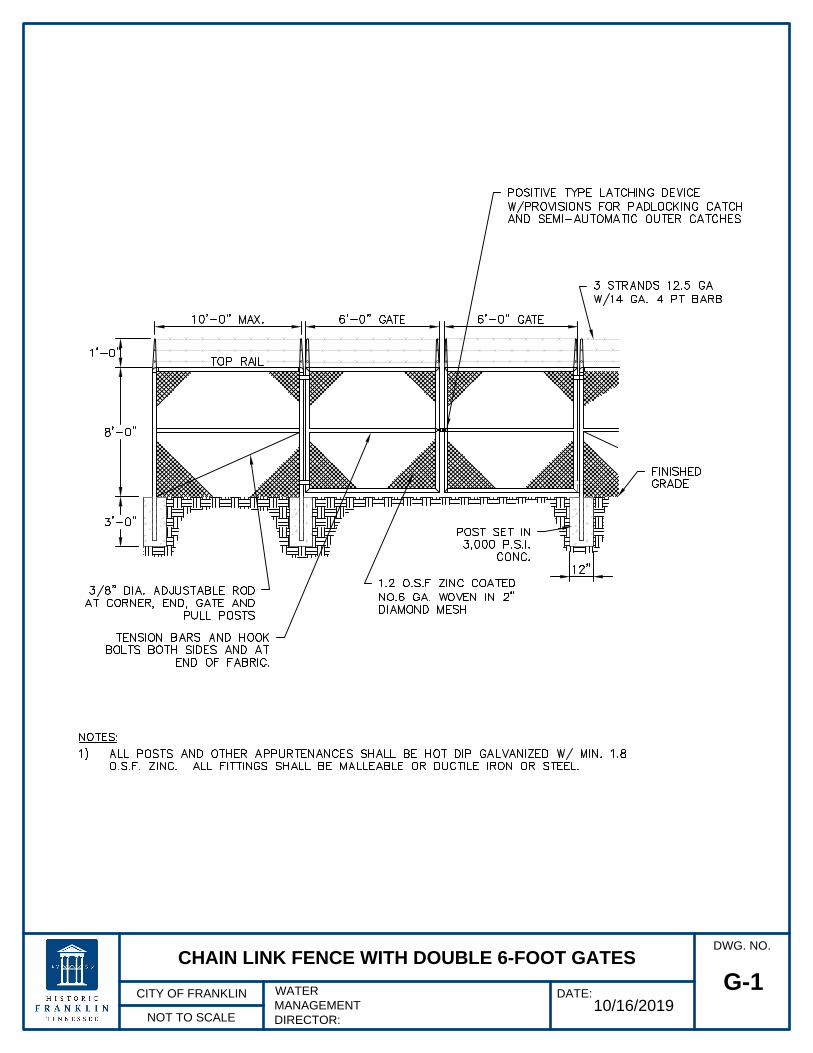
10/16/2019
NOT TO SCALE
DWG. NO.
CITY OF FRANKLIN
WATER
MANAGEMENT
DIRECTOR:
DATE:
G-1
CHAIN LINK FENCE WITH DOUBLE 6-FOOT GATES
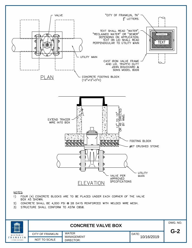
CITY OF FRANKLIN, TN
TEXT
10/16/2019
NOT TO SCALE
DWG. NO.
CITY OF FRANKLIN
WATER
MANAGEMENT
DIRECTOR:
DATE:
G-2
CONCRETE VALVE BOX
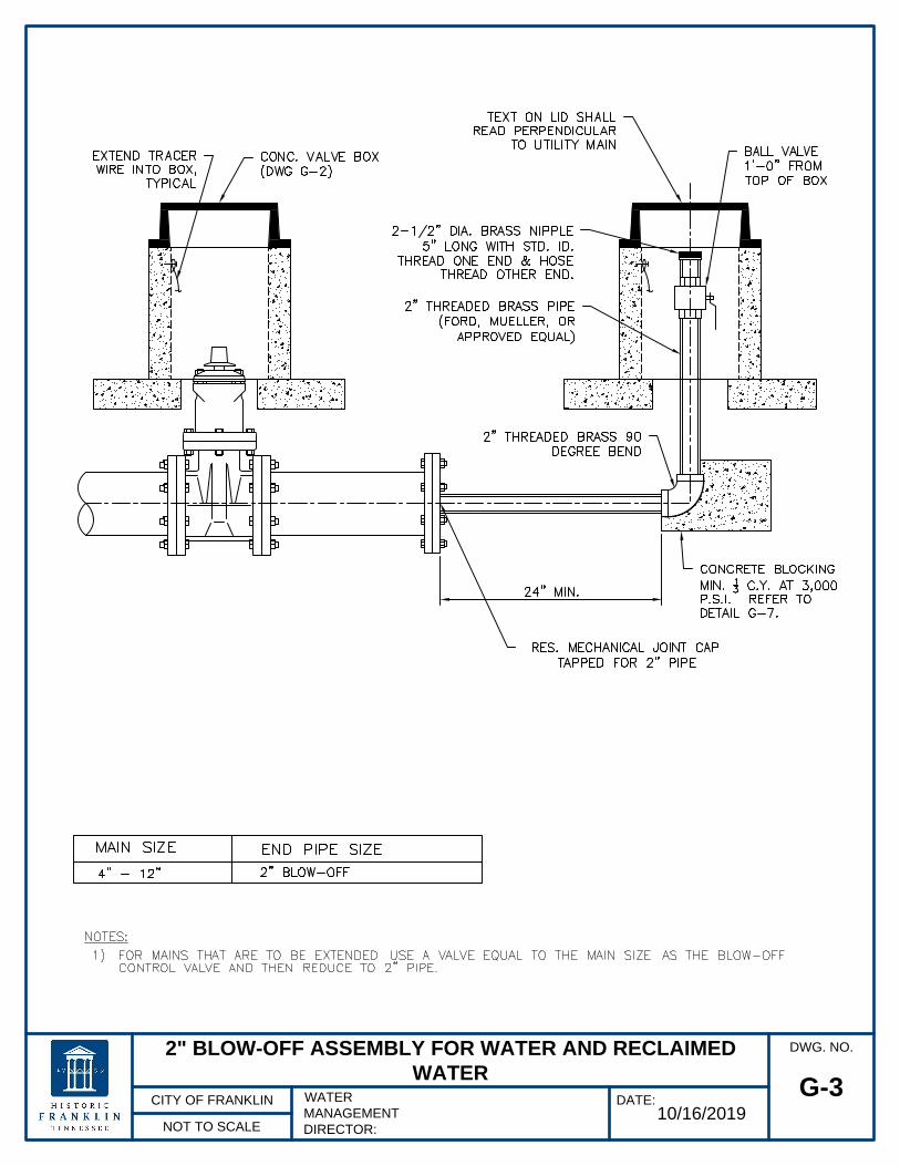
10/16/2019
NOT TO SCALE
DWG. NO.
CITY OF FRANKLIN
WATER
MANAGEMENT
DIRECTOR:
DATE:
G-3
2" BLOW-OFF ASSEMBLY FOR WATER AND RECLAIMED
WATER

10/16/2019
NOT TO SCALE
DWG. NO.
CITY OF FRANKLIN
WATER
MANAGEMENT
DIRECTOR:
DATE:
G-4
UTILITY IDENTIFICATION MARKER

10/16/2019
NOT TO SCALE
DWG. NO.
CITY OF FRANKLIN
WATER
MANAGEMENT
DIRECTOR:
DATE:
G-6
RESTRAINED JOINT TABLE - DIP

10/16/2019
NOT TO SCALE
DWG. NO.
CITY OF FRANKLIN
WATER
MANAGEMENT
DIRECTOR:
DATE:
G-7
THRUST BLOCK TABLE (NON-RESTRAINED JOINTS)
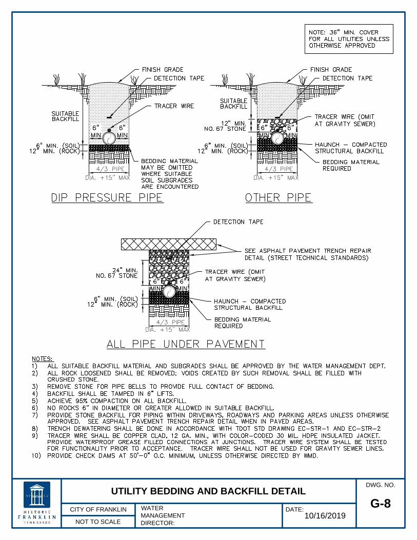
10/16/2019
NOT TO SCALE
DWG. NO.
CITY OF FRANKLIN
WATER
MANAGEMENT
DIRECTOR:
DATE:
G-8
UTILITY BEDDING AND BACKFILL DETAIL

10/16/2019
NOT TO SCALE
DWG. NO.
CITY OF FRANKLIN
WATER
MANAGEMENT
DIRECTOR:
DATE:
G-9
CONCRETE PROTECTION FOR BURIED UTILITIES

10/16/2019
NOT TO SCALE
DWG. NO.
CITY OF FRANKLIN
WATER
MANAGEMENT
DIRECTOR:
DATE:
G-10
BORE AND JACK CASING

10/16/2019
NOT TO SCALE
DWG. NO.
CITY OF FRANKLIN
WATER
MANAGEMENT
DIRECTOR:
DATE:
G-11
CHECK DAM FOR UTILITY LINES

NOT TO SCALE
DWG. NO.
CITY OF FRANKLIN
WATER
MANAGEMENT
DIRECTOR:
DATE:
G-12
UTILITY STREAM CROSSINGS
10/16/2019

10/16/2019
NOT TO SCALE
DWG. NO.
CITY OF FRANKLIN
WATER
MANAGEMENT
DIRECTOR:
DATE:
G-13
COMBINATION AIR VALVE ASSEMBLY FOR PRESSURE MAINS

10/16/2019
NOT TO SCALE
DWG. NO.
CITY OF FRANKLIN
WATER
MANAGEMENT
DIRECTOR:
DATE:
W-1
3/4" AND 1" WATER SERVICE ASSEMBLIES

10/16/2019
NOT TO SCALE
DWG. NO.
CITY OF FRANKLIN
WATER
MANAGEMENT
DIRECTOR:
DATE:
W-2
1-1/2" AND 2" WATER SERVICE ASSEMBLIES

3"-8" WATER METER
10/16/2019
DWG. NO.
NOT TO SCALE
CITY OF FRANKLIN
WATER
MANAGEMENT
DIRECTOR:
DATE:
W-3

4"-8" FIRE METER
10/16/2019
DWG. NO.
NOT TO SCALE
CITY OF FRANKLIN
WATER
MANAGEMENT
DIRECTOR:
DATE:
W-4

10/16/2019
NOT TO SCALE
DWG. NO.
CITY OF FRANKLIN
WATER
MANAGEMENT
DIRECTOR:
DATE:
W-5
REDUCED PRESSURE BACKFLOW PREVENTER FOR 3/4" AND
1" IRRIGATION LINES

10/16/2019
NOT TO SCALE
DWG. NO.
CITY OF FRANKLIN
WATER
MANAGEMENT
DIRECTOR:
DATE:
W-6
REDUCED PRESSURE BACKFLOW PREVENTER FOR 3/4", 1",
1-1/2", AND 2" LINES

10/16/2019
NOT TO SCALE
DWG. NO.
CITY OF FRANKLIN
WATER
MANAGEMENT
DIRECTOR:
DATE:
W-7
REDUCED PRESSURE BACKFLOW PREVENTER FOR 3"-8"
LINES (ABOVE GROUND)

10/16/2019
NOT TO SCALE
DWG. NO.
CITY OF FRANKLIN
WATER
MANAGEMENT
DIRECTOR:
DATE:
W-8
BACKFLOW PREVENTER FOR 4"-8" LINES

10/16/2019
NOT TO SCALE
DWG. NO.
CITY OF FRANKLIN
WATER
MANAGEMENT
DIRECTOR:
DATE:
W-9
FIRE HYDRANT SETTING

10/16/2019
NOT TO SCALE
DWG. NO.
CITY OF FRANKLIN
WATER
MANAGEMENT
DIRECTOR:
DATE:
W-10
FIRE HYDRANT SETTING FOR DOMESTIC WATER BLOW-OFF