Water Electrolysis for the Production of Hydrogen to Be ... - MDPI
28
metals Review Water Electrolysis for the Production of Hydrogen to Be Employed in the Ironmaking and Steelmaking Industry Pasquale Daniele Cavaliere 1, * , Angelo Perrone 1 and Alessio Silvello 2 Citation: Cavaliere, P.D.; Perrone, A.; Silvello, A. Water Electrolysis for the Production of Hydrogen to Be Employed in the Ironmaking and Steelmaking Industry. Metals 2021, 11, 1816. https://doi.org/10.3390/ met11111816 Academic Editor: Thomas Gries Received: 14 October 2021 Accepted: 11 November 2021 Published: 12 November 2021 Publisher’s Note: MDPI stays neutral with regard to jurisdictional claims in published maps and institutional affil- iations. Copyright: © 2021 by the authors. Licensee MDPI, Basel, Switzerland. This article is an open access article distributed under the terms and conditions of the Creative Commons Attribution (CC BY) license (https:// creativecommons.org/licenses/by/ 4.0/). 1 Department of Innovation Engineering, University of Salento, Via per Arnesano, 73100 Lecce, Italy; [email protected] 2 Thermal Spray Center CPT, Universitat de Barcelona, 08028 Barcelona, Spain; [email protected] * Correspondence: [email protected] Abstract: The way to decarbonization will be characterized by the huge production of hydrogen through sustainable routes. Thus, the basic production way is water electrolysis sustained by renewable energy sources allowing for obtaining “green hydrogen”. The present paper reviews the main available technologies for the water electrolysis finalized to the hydrogen production. We describe the fundamental of water electrolysis and the problems related to purification and/or desalinization of water before electrolysis. As a matter of fact, we describe the energy efficiency issues with particular attention to the potential application in the steel industry. The fundamental aspects related to the choice of high-temperature or low-temperature technologies are analyzed. Keywords: water electrolysis; ironmaking; steelmaking; purification; desalinization; direct reduction; energy; renewables; high temperature; low temperature 1. Introduction Ironmaking and Steelmaking are complex processing routes with many fundamental steps. The actual production routes are mainly based on carbon and gas for energy supply and to drive all the thermo-chemical reactions involved in the different iron oxides transformations. With the progress of technological advances, it is possible to reduce carbon dioxide emissions in different production steps. Obviously, the technological choices are strictly related to economic and local conditions [1]. Many gradual signs of progress are due to the gradual decarbonization of the steel industry with the partial replacement of coal with gas, oil, biomass, wastes, and electricity. Further improvements are due to the development of carbon capture and storage/utilization technologies. A big revolution is represented by the introduction of hydrogen in the ironmaking and steelmaking routes. As a matter of fact, and as the main difference with respect to coal utilization, hydrogen employment does not lead to carbon dioxide emissions. In addition, being an energy vercot, it can be used, transformed, and stored for various applications in a very versatile way. For all these reasons it is considered the best candidate in the transition of the steel industry toward decarbonization. Additionally, if hydrogen is produced through renewable energy sources, it allows for an emission-free scenario in those industries where it can be employed. Among all the solutions developed for the decarbonization of the steel industry, the main routes are evolving toward the employment of hydrogen as an energy carrier (Figure 1). At the present time, more than 90% of the produced hydrogen is obtained from fossil fuels through processes such as coal gasification or natural gas reforming; only 4% of hydrogen is produced via water electrolysis. The available main technologies are alkaline (AEL), Proton Exchange Membrane Electrolyzer (PEMEL), and Solid Oxide Electrolyzer (SOEL). PEMEL water electrolyzers can be further categorized into acidic PEMELs and alkaline PEMELs, but only the acidic PEM variant is widely commercially available [2]. Renewable hydrogen is believed to be essential for the restoring of industries “hard to Metals 2021, 11, 1816. https://doi.org/10.3390/met11111816 https://www.mdpi.com/journal/metals
-
Upload
khangminh22 -
Category
Documents
-
view
5 -
download
0
Transcript of Water Electrolysis for the Production of Hydrogen to Be ... - MDPI

metals
Review
Water Electrolysis for the Production of Hydrogen to BeEmployed in the Ironmaking and Steelmaking Industry
Pasquale Daniele Cavaliere 1,* , Angelo Perrone 1 and Alessio Silvello 2
Citation: Cavaliere, P.D.; Perrone, A.;
Silvello, A. Water Electrolysis for the
Production of Hydrogen to Be
Employed in the Ironmaking and
Steelmaking Industry. Metals 2021, 11,
1816. https://doi.org/10.3390/
met11111816
Academic Editor: Thomas Gries
Received: 14 October 2021
Accepted: 11 November 2021
Published: 12 November 2021
Publisher’s Note: MDPI stays neutral
with regard to jurisdictional claims in
published maps and institutional affil-
iations.
Copyright: © 2021 by the authors.
Licensee MDPI, Basel, Switzerland.
This article is an open access article
distributed under the terms and
conditions of the Creative Commons
Attribution (CC BY) license (https://
creativecommons.org/licenses/by/
4.0/).
1 Department of Innovation Engineering, University of Salento, Via per Arnesano, 73100 Lecce, Italy;[email protected]
2 Thermal Spray Center CPT, Universitat de Barcelona, 08028 Barcelona, Spain; [email protected]* Correspondence: [email protected]
Abstract: The way to decarbonization will be characterized by the huge production of hydrogenthrough sustainable routes. Thus, the basic production way is water electrolysis sustained byrenewable energy sources allowing for obtaining “green hydrogen”. The present paper reviewsthe main available technologies for the water electrolysis finalized to the hydrogen production.We describe the fundamental of water electrolysis and the problems related to purification and/ordesalinization of water before electrolysis. As a matter of fact, we describe the energy efficiencyissues with particular attention to the potential application in the steel industry. The fundamentalaspects related to the choice of high-temperature or low-temperature technologies are analyzed.
Keywords: water electrolysis; ironmaking; steelmaking; purification; desalinization; direct reduction;energy; renewables; high temperature; low temperature
1. Introduction
Ironmaking and Steelmaking are complex processing routes with many fundamentalsteps. The actual production routes are mainly based on carbon and gas for energysupply and to drive all the thermo-chemical reactions involved in the different iron oxidestransformations. With the progress of technological advances, it is possible to reduce carbondioxide emissions in different production steps. Obviously, the technological choices arestrictly related to economic and local conditions [1]. Many gradual signs of progress aredue to the gradual decarbonization of the steel industry with the partial replacement ofcoal with gas, oil, biomass, wastes, and electricity. Further improvements are due to thedevelopment of carbon capture and storage/utilization technologies. A big revolution isrepresented by the introduction of hydrogen in the ironmaking and steelmaking routes.As a matter of fact, and as the main difference with respect to coal utilization, hydrogenemployment does not lead to carbon dioxide emissions. In addition, being an energy vercot,it can be used, transformed, and stored for various applications in a very versatile way. Forall these reasons it is considered the best candidate in the transition of the steel industrytoward decarbonization. Additionally, if hydrogen is produced through renewable energysources, it allows for an emission-free scenario in those industries where it can be employed.
Among all the solutions developed for the decarbonization of the steel industry, the mainroutes are evolving toward the employment of hydrogen as an energy carrier (Figure 1).
At the present time, more than 90% of the produced hydrogen is obtained from fossilfuels through processes such as coal gasification or natural gas reforming; only 4% ofhydrogen is produced via water electrolysis. The available main technologies are alkaline(AEL), Proton Exchange Membrane Electrolyzer (PEMEL), and Solid Oxide Electrolyzer(SOEL). PEMEL water electrolyzers can be further categorized into acidic PEMELs andalkaline PEMELs, but only the acidic PEM variant is widely commercially available [2].Renewable hydrogen is believed to be essential for the restoring of industries “hard to
Metals 2021, 11, 1816. https://doi.org/10.3390/met11111816 https://www.mdpi.com/journal/metals

Metals 2021, 11, 1816 2 of 28
abate”; in the future, it is believed that installed water electrolyzer capacities will range upto terawatts [3].
Metals 2021, 11, x FOR PEER REVIEW 2 of 29
Figure 1. Pathways of technologies for greenhouse gases emissions abatement.
At the present time, more than 90% of the produced hydrogen is obtained from fossil fuels through processes such as coal gasification or natural gas reforming; only 4% of hy-drogen is produced via water electrolysis. The available main technologies are alkaline (AEL), Proton Exchange Membrane Electrolyzer (PEMEL), and Solid Oxide Electrolyzer (SOEL). PEMEL water electrolyzers can be further categorized into acidic PEMELs and alkaline PEMELs, but only the acidic PEM variant is widely commercially available [2]. Renewable hydrogen is believed to be essential for the restoring of industries “hard to abate”; in the future, it is believed that installed water electrolyzer capacities will range up to terawatts [3].
2. Water Electrolysis Water electrolysis was developed in the last century mainly to produce hydrogen.
Electricity allows for the splitting of water into hydrogen and oxygen then converting electrical energy into chemical energy. Being the hydrogen volume dependent on the elec-tric current, the energy efficiency of the employed system is fundamental.
The AEM was the first to be developed. In the alkaline water electrolysis, the nickel-based anode and cathode are submerged in an aqueous KOH or NaOH solution as shown in Figure 2a.
Figure 1. Pathways of technologies for greenhouse gases emissions abatement.
2. Water Electrolysis
Water electrolysis was developed in the last century mainly to produce hydrogen.Electricity allows for the splitting of water into hydrogen and oxygen then convertingelectrical energy into chemical energy. Being the hydrogen volume dependent on theelectric current, the energy efficiency of the employed system is fundamental.
The AEM was the first to be developed. In the alkaline water electrolysis, the nickel-based anode and cathode are submerged in an aqueous KOH or NaOH solution as shownin Figure 2a.
Water is reduced at the cathode forming hydrogen gas and hydroxide ions OH−.Hydroxide ions are then decomposed at the anode to form oxygen gas and water. Thelow-cost electrodes allow for the industrial scaling of this technology [4]. The separatornormally is a Zirfon porous membrane of 500 µm in thickness [5]. The operating conditionsare 70–90 C at 30 bars with a current density <0.4 A/cm2.
The PEMEL water electrolysis employs a solid polymer (sulfonated fluoropolymers)electrolyte that is a thin (250 µm thickness) proton-exchange membrane. The schematic ofthe process is given in Figure 2b.
Water is supplied to the anode, where water is first decomposed with sufficient electricpotential to oxygen gas. H+ protons cross the membrane, then, once arriving on the cathodesurface, it recombines with electrons in order to produce gaseous hydrogen. Iridium andplatinum are employed as a catalyst at the anode and cathode respectively. The currentcollector is made of titanium in order to increase the lifetime of the cell [6]. The designation‘PEMEL water electrolysis’ refers to the commercial, traditional acidic PEMEL variant, andthe alkaline PEMEL is referred to as anion exchange membrane (AEM) water electrolysis.Alkaline and PEMEL water electrolyzers are readily available, commercialized technologies,while SOEL is the least developed and not widely commercially available [7].
The schematic of the SOE electrolyzer is shown in Figure 2c.AEL and PEMEL electrolysis technologies have operating temperatures below 100 C.
SOEL is based on the electrolysis of steam with operating temperatures in the range700–1000 C [8].

Metals 2021, 11, 1816 3 of 28Metals 2021, 11, x FOR PEER REVIEW 3 of 29
Figure 2. (a) Alkaline water electrolysis schematic; (b) PEMEL schematic; (c) SOEL schematic; (d) High-temperature steam electrolysis process schematic.
Water is reduced at the cathode forming hydrogen gas and hydroxide ions OH−. Hy-droxide ions are then decomposed at the anode to form oxygen gas and water. The low-cost electrodes allow for the industrial scaling of this technology [4]. The separator nor-mally is a Zirfon porous membrane of 500 μm in thickness [5]. The operating conditions are 70–90 °C at 30 bars with a current density <0.4 A/cm2.
The PEMEL water electrolysis employs a solid polymer (sulfonated fluoropolymers) electrolyte that is a thin (250 μm thickness) proton-exchange membrane. The schematic of the process is given in Figure 2b.
Water is supplied to the anode, where water is first decomposed with sufficient elec-tric potential to oxygen gas. H+ protons cross the membrane, then, once arriving on the cathode surface, it recombines with electrons in order to produce gaseous hydrogen. Irid-ium and platinum are employed as a catalyst at the anode and cathode respectively. The current collector is made of titanium in order to increase the lifetime of the cell [6]. The designation ‘PEMEL water electrolysis’ refers to the commercial, traditional acidic PEMEL variant, and the alkaline PEMEL is referred to as anion exchange membrane (AEM) water electrolysis. Alkaline and PEMEL water electrolyzers are readily available, commercial-ized technologies, while SOEL is the least developed and not widely commercially avail-able [7].
The schematic of the SOE electrolyzer is shown in Figure 2c. AEL and PEMEL electrolysis technologies have operating temperatures below 100
°C. SOEL is based on the electrolysis of steam with operating temperatures in the range 700–1000 °C [8].
Figure 2. (a) Alkaline water electrolysis schematic; (b) PEMEL schematic; (c) SOEL schematic; (d) High-temperature steamelectrolysis process schematic.
High-Temperature Steam Electrolysis (HTSE) is a new and high-potential instrumentfor hydrogen production in a clean way. It is based on a reverse fuel cell setting (Figure 2d).
In the case of steam employment, water dissociation is easier with respect to thecase of AEM and PEMEL. This is because part of the required energy is provided by thehigh temperature of the steam. In general, this solution is suggested for those industrialapplications where high-temperature sources are available. This allows HTSE to be verypromising from an energy efficiency point of view. In general, as the temperature increases,the global energy efficiency of the process increases.
As a matter of fact, this technology requires less electricity consumption with respectto low-temperature water electrolysis. This is also due to the absolute less internal resis-tance of the high-temperature electrolysis cells. The cell has classical elements such asanodes, cathodes, and electrolytes. During electrolysis operations, steam and electricity areprovided to the porous fuel electrode. This allows the reduction of water molecules for theoxygen ions (O2−) and hydrogen at the cathode. The electrode, where oxidation reactionstake place, is alimented with air. Other complex solutions foresee the employment ofdifferent gases or vacuum depending on the cell design. In SOEL, an electrolyte is a thinmembrane allowing only oxygen ions to cross. This is a complex cell component that muststop all the hydrogen or different gases. As a function of the cell design, it can work indifferent ways such as thermo-neutral, endothermic, and exothermic depending on thesteam temperature and on the provided electricity [9].
Not all the provided electricity is employed for the steam electrolysis, in fact, due toimportant losses, a part of the provided energy is wasted under the formation of heat. So,a large percentage of the global efficiency of the cell is dependent on the balance betweenthe provided energy and the wasted one. The cell works in exothermic conditions once

Metals 2021, 11, 1816 4 of 28
the provided electric energy exceeds the heat required for the water steam splitting. Whenthe cell is working in endothermic conditions, the electrochemical reactions require moreheat with respect to the one that is provided by electricity. So, heat is lost, and the celltemperature decreases. In these conditions, additional heat must be provided to the cell.
The different cell performances are traditionally evaluated as a function of the electricpower that is consumed by the electrochemical reactions for a given hydrogen volume.A good summary is described in Figure 3 showing the difference among the differentelectrolyzers.
Metals 2021, 11, x FOR PEER REVIEW 5 of 29
Figure 3. Electrolyzers comparison.
As a general behavior, water electrolysis for hydrogen production is a high energy-consuming process. This energy is provided mainly by electricity [10]. The order of elec-trical power consumption in AEL and PEMEL cells falls in the range 4.4–4.9 kWh/m3 H2. Given the heating provided to the HTSE cells, the electric power consumption falls in the range 3.8–3.9 kWh/m3 H2 [11].
As previously mentioned, hydrogen production through water electrolysis can be a completely fossil-free route once the electric power is produced through renewable sources, such as solar and wind. In these conditions, low-temperature electrolysis (LTE) is able to produce hydrogen with a specific electricity consumption (SEC) in the range 50–60 kWh/kg H2.
The steam temperature in HTSE falls in the range 700–1000 °C. It is this condition that allows the SEC to be reduced at the order of 37 kWh/kg H2 [3]. In each case, the main limitation to the technology development is the fast degradation of the cell components due to the high temperature and to the environment. Obviously, if the cell temperature is below 700 °C, the cell can reach a durability of around 25,000 h. Anyway, as the tempera-ture decreases, the process efficiency decreases. So, an optimal balance must be done be-tween the steam temperature and the materials consumption. In order for HTSE to be-come competitive with LTE, the performances should exhibit very high production rates in the order of ~40 mgH2/cm2/h or ~−1 A/cm2. All this is in the case of a reasonable cost due to the fast electrodes and membranes consumption.
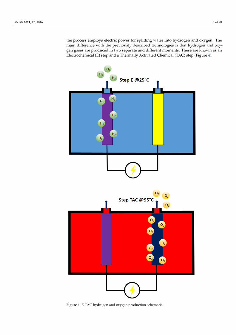
Very recently, a hydrogen production route very similar to electrolysis has been pro-posed [12]. This method is known as E-TAC. As with the other water-splitting technolo-gies, the process employs electric power for splitting water into hydrogen and oxygen. The main difference with the previously described technologies is that hydrogen and ox-ygen gases are produced in two separate and different moments. These are known as an Electrochemical (E) step and a Thermally Activated Chemical (TAC) step (Figure 4).
Figure 3. Electrolyzers comparison.
As a general behavior, water electrolysis for hydrogen production is a high energy-consuming process. This energy is provided mainly by electricity [10]. The order ofelectrical power consumption in AEL and PEMEL cells falls in the range 4.4–4.9 kWh/m3
H2. Given the heating provided to the HTSE cells, the electric power consumption falls inthe range 3.8–3.9 kWh/m3 H2 [11].
As previously mentioned, hydrogen production through water electrolysis can bea completely fossil-free route once the electric power is produced through renewablesources, such as solar and wind. In these conditions, low-temperature electrolysis (LTE)is able to produce hydrogen with a specific electricity consumption (SEC) in the range50–60 kWh/kg H2.
The steam temperature in HTSE falls in the range 700–1000 C. It is this condition thatallows the SEC to be reduced at the order of 37 kWh/kg H2 [3]. In each case, the mainlimitation to the technology development is the fast degradation of the cell components dueto the high temperature and to the environment. Obviously, if the cell temperature is below700 C, the cell can reach a durability of around 25,000 h. Anyway, as the temperaturedecreases, the process efficiency decreases. So, an optimal balance must be done betweenthe steam temperature and the materials consumption. In order for HTSE to becomecompetitive with LTE, the performances should exhibit very high production rates in theorder of ~40 mgH2/cm2/h or ~−1 A/cm2. All this is in the case of a reasonable cost dueto the fast electrodes and membranes consumption.
Very recently, a hydrogen production route very similar to electrolysis has been pro-posed [12]. This method is known as E-TAC. As with the other water-splitting technologies,
Metals 2021, 11, 1816 5 of 28
the process employs electric power for splitting water into hydrogen and oxygen. Themain difference with the previously described technologies is that hydrogen and oxy-gen gases are produced in two separate and different moments. These are known as anElectrochemical (E) step and a Thermally Activated Chemical (TAC) step (Figure 4).
Metals 2021, 11, x FOR PEER REVIEW 6 of 29
Figure 4. E-TAC hydrogen and oxygen production schematic.
Alkaline electrolysis is based on the contemporary oxygen and hydrogen evolution reactions taking place at high temperatures. In this solution, the membrane does not allow the O2/H2 crossover. In the case of E-TAC, the water-splitting process takes place in two
Figure 4. E-TAC hydrogen and oxygen production schematic.

Metals 2021, 11, 1816 6 of 28
Alkaline electrolysis is based on the contemporary oxygen and hydrogen evolutionreactions taking place at high temperatures. In this solution, the membrane does not allowthe O2/H2 crossover. In the case of E-TAC, the water-splitting process takes place in twoseparate steps. The first electrochemical step, acting at 25 C, proceeds following thereactions (Equations (1) and (2)):
4H2O + 4e− → 4OH− + 2H2 (1)(Ni(OH)2 + OH− → NiOOH + H2O + e−
)∗ 4 (2)
During this step, only hydrogen bubbles are observed without oxygen production atthe anode (in the supplementary material in [12], very interesting movies, describing theprocess, can be observed).
The second chemical step, acting at 90 C, proceeds following the reaction (Equation (3)):
4NiOOH + 2H2O→ 4Ni(OH)2 + O2 (3)
The results belonging to pilot plants show an efficiency close to 95%. The potential forindustrial scale-up is envisioned through a multi-cell design. In this design, cold and hotelectrolytes are moved from one cell to another in order to regenerate the anode and letgases flow (Figure 5).
Metals 2021, 11, x FOR PEER REVIEW 7 of 29
separate steps. The first electrochemical step, acting at 25 °C, proceeds following the reac-tions (Equations (1) and (2)): 4H O + 4e → 4OH + 2H (1)(Ni(OH) + OH → NiOOH + H O + e ) ∗ 4 (2)
During this step, only hydrogen bubbles are observed without oxygen production at the anode (in the supplementary material in [12], very interesting movies, describing the process, can be observed).
The second chemical step, acting at 90 °C, proceeds following the reaction (Equation (3)): 4NiOOH + 2H O → 4Ni(OH) + O (3)
The results belonging to pilot plants show an efficiency close to 95%. The potential for industrial scale-up is envisioned through a multi-cell design. In this design, cold and hot electrolytes are moved from one cell to another in order to regenerate the anode and let gases flow (Figure 5).
Figure 5. E-TAC multi-cell design.
The main advantage of this system is believed to be a membrane-free cell capable of producing hydrogen and oxygen in separate steps. This eliminates all the problems and costs related to membrane-based cells. The lack of a membrane enables high-pressure hy-drogen production, potentially exceeding 100 bars. The possibility of operating with low anode potential leads this system to be very competitive in terms of energy balance.
3. Water Electrolysis Fundamentals As already mentioned, the hydrogen production rate (mol/s) is linearly proportional
to the current of the cell (Equation (4)): = = (4)
where is the hydrogen production rate (mol/s), ηF is the Faraday efficiency, also known as the current efficiency, icell is the current density (A/cm2), Acell is the effective cell
Figure 5. E-TAC multi-cell design.
The main advantage of this system is believed to be a membrane-free cell capableof producing hydrogen and oxygen in separate steps. This eliminates all the problemsand costs related to membrane-based cells. The lack of a membrane enables high-pressurehydrogen production, potentially exceeding 100 bars. The possibility of operating withlow anode potential leads this system to be very competitive in terms of energy balance.
3. Water Electrolysis Fundamentals
As already mentioned, the hydrogen production rate (mol/s) is linearly proportionalto the current of the cell (Equation (4)):
.nH2 = ηF
icell AcellzF
= ηFIcellzF
(4)
Metals 2021, 11, 1816 7 of 28
where.nH2 is the hydrogen production rate (mol/s), ηF is the Faraday efficiency, also known
as the current efficiency, icell is the current density (A/cm2), Acell is the effective cell area(cm2), z is the number of moles of electrons transferred in the reaction (for hydrogen, z = 2),F is the Faraday constant (9.6485 × 10⁴ C/mol), and Icell is the stack current (A).
As a general behavior, the anodic and cathodic reactions in acidic media is given by(Equations (5) and (6)):
Anode : 2H2O→ 4H+ + O2 + 4e− (5)
Cathode : 2H+ + 2e− → H2 (6)
While in alkaline media (Equations (7) and (8)):
Anode : 4OH− → O2 + 2H2O + 4e− (7)
Cathode : 2H2O + 2e− → 2OH− + H2 (8)
The electrolyte pH is the quantity mainly influencing the number of hydroxide ionsand protons that drive the anodic and cathodic reactions. Here, in order to increase theionic conductivity between the electrodes, strong basics or acids must be employed aselectrolytes in order to increase the volume of energy carriers in terms of hydroxides ionsand protons. For this reason, once the same electrolyte is used for the anode and for thecathode, the thermodynamic conditions of the water-splitting are driven by the electrolytepH level.
The energy required for the water decomposition is the enthalpy change of the process,the enthalpy of formation of water, ∆H. The water electrolysis process is endothermic(∆H > 0). The free energy of the water-splitting reaction, called Gibbs free energy change∆G, must be supplied to the electrodes as electrical energy. The remainder is the thermalenergy Q, which is the product of the process temperature T and the entropy change ∆S.These thermodynamic quantities can be written as (Equation (9)):
∆H = ∆G + Q = ∆G + T∆S (9)
H is the enthalpy, G is the Gibbs free energy, T is the temperature, S is the entropy, andQ is the required heat. In constant standard ambient conditions (298.15 K, one-atmospherepressure), the required electrical work ∆G is equal to 237.2 kJ/mol (non-spontaneousreaction), and the amount of heat required Q is equal to 48.6 kJ/mol. Thus, the chemicalreaction for water electrolysis can be expressed as (Equation (10)):
H2O(l) + 237.2 kJel. ∗mol−1 + 48.6 kJHeat ∗mol−1 → H2(g) +12
O2(g) ∆H0 = 285.8 kJ ∗mol−1 (10)
Urev is the reversible voltage that is the minimum voltage necessary for the splitting ofwater. It is directly proportional to the Gibbs free energy change (Equation (11)):
Urev =∆GzF
(11)
Without the input of thermal energy, the minimum voltage required be-comes thethermoneutral voltage Utn (Equation (12)):
Utn =∆HzF
(12)
In standard room conditions, the reversible voltage and the thermoneutral voltageresult in 1.23 V and 1.48 V, respectively. For commercial water electrolyzers, all energy forthe water electrolysis process is provided as electrical energy. Both the reversible voltageand the thermoneutral voltage are thermo-dynamic state functions. These quantities are afunction of the cell pressure and temperature, albeit the thermoneutral voltage changes
Metals 2021, 11, 1816 8 of 28
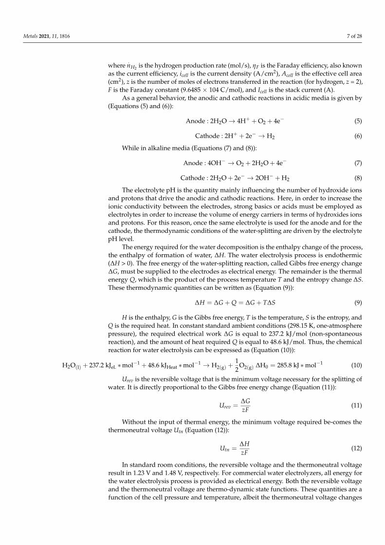
only slightly as a function of temperature and pressure [13]. The reversible voltage andthe thermoneutral voltage are illustrated in Figure 6a as a function of cell temperature atstandard room pressure.
Metals 2021, 11, x FOR PEER REVIEW 9 of 29
Figure 6. (a) Reversible and thermoneutral voltages as a function of cell temperature; (b) Reversible voltage as a function of pressure for different cell temperatures.
The effect of pressure on reversible voltage is exemplified in Figure 6b. An increase in temperature will slightly reduce the overall energy demand ∆H of an
ideal liquid water electrolysis process as the demand for electrical energy ∆G is more no-tably reduced than the demand for thermal energy T∆S is increased [14]. Operation at higher temperatures is favorable as heat losses caused by overvoltages can be used to re-duce the reversible voltage of water splitting. Thus, the utilization of thermal energy is an essential aspect of energy-efficient water electrolysis processes. The overall energy re-quirement ∆H will stay practically constant as a function of pressure in an ideal liquid water electrolysis process. However, a change in pressure will increase the demand for electrical energy ∆G; for instance, an increase from 0.1 MPa to 10 MPa at a cell temperature of 75 °C will increase the reversible voltage by 9%, but the demand for thermal energy T∆S is correspondingly reduced.
Now, the electrolysis cell voltage results from the sum of the reversible voltage and all the overpotentials developing in the cell through the following equation (Equation (13)): = + + + (13)
where Ucell is the cell voltage, Urev is the open circuit. The reversible voltage results are a function of temperature and pressure. Uohm is the overvoltage caused by Ohmic losses in the cell elements, Uact is the activation overvoltage, and Ucon is the concentration overvolt-age. The current–voltage characteristics of an electrolytic cell can be described by a polar-ization curve. An example of a polarization curve for AEL and PEMEL water electrolyzer cells is illustrated in Figure 7.
Figure 6. (a) Reversible and thermoneutral voltages as a function of cell temperature; (b) Reversible voltage as a function ofpressure for different cell temperatures.
The effect of pressure on reversible voltage is exemplified in Figure 6b.An increase in temperature will slightly reduce the overall energy demand ∆H of
an ideal liquid water electrolysis process as the demand for electrical energy ∆G is morenotably reduced than the demand for thermal energy T∆S is increased [14]. Operationat higher temperatures is favorable as heat losses caused by overvoltages can be used toreduce the reversible voltage of water splitting. Thus, the utilization of thermal energyis an essential aspect of energy-efficient water electrolysis processes. The overall energyrequirement ∆H will stay practically constant as a function of pressure in an ideal liquidwater electrolysis process. However, a change in pressure will increase the demand forelectrical energy ∆G; for instance, an increase from 0.1 MPa to 10 MPa at a cell temperatureof 75 C will increase the reversible voltage by 9%, but the demand for thermal energy T∆Sis correspondingly reduced.
Now, the electrolysis cell voltage results from the sum of the reversible voltage and allthe overpotentials developing in the cell through the following equation (Equation (13)):
Ucell = Urev + Uohm + Uact + Ucon (13)
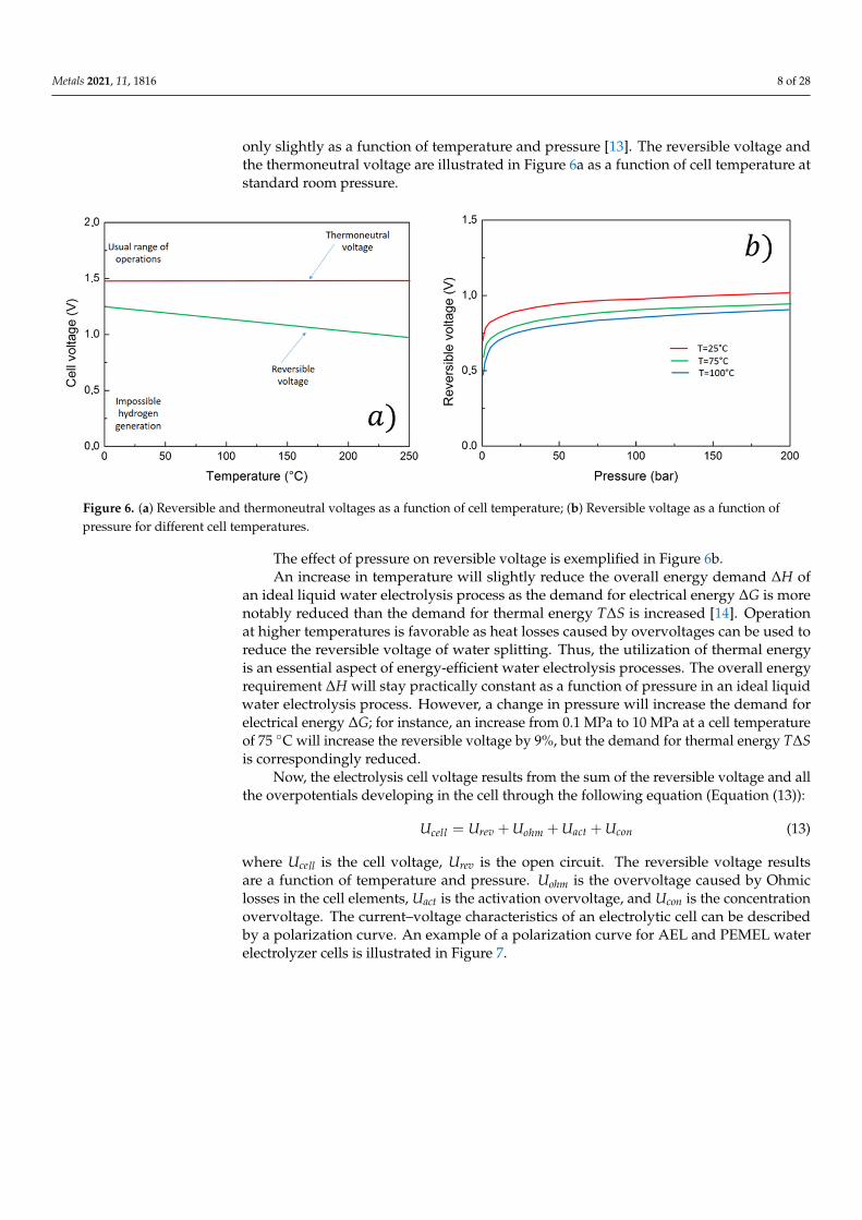
where Ucell is the cell voltage, Urev is the open circuit. The reversible voltage resultsare a function of temperature and pressure. Uohm is the overvoltage caused by Ohmiclosses in the cell elements, Uact is the activation overvoltage, and Ucon is the concentrationovervoltage. The current–voltage characteristics of an electrolytic cell can be describedby a polarization curve. An example of a polarization curve for AEL and PEMEL waterelectrolyzer cells is illustrated in Figure 7.
Metals 2021, 11, 1816 9 of 28
1
Figure 7. Overpotentials in AEL and PEMEL cells.
In the AEL water electrolysis, the Ohmic losses are mainly affected by the ionicconductivity of the liquid electrolyte, the thickness of the electrolyte layer, and the thicknessand conductivity of the electrodes [15]. In the PEMEL water electrolysis, the ionic resistanceof the polymeric membrane and the electrical resistance of the separator plates and currentcollectors are the main contributors to the Ohmic losses. The activation overpotential is
Metals 2021, 11, 1816 10 of 28
caused by the anode and cathode reaction kinetics. The concentration overpotential iscaused by mass transfer limitations at high current densities, where the supply of thereactant (water) is not sufficient to support the reaction rate of the production of hydrogenand oxygen gases at the electrode surfaces. The concentration losses are typically negligiblefor commercial water electrolyzers—especially for AEL electrolyzers—because of therelatively low current densities in the cells. Another non-linear region will appear in thecell polarization curve above the limiting (high) current density if mass transport lossesoccur. The evidence on the effect of temperature on the AEL performances underlines thatall the overvoltages, as the anode activation, the cathode the Ohmic, and the supplied cellones, increase in the case of the well-known bubble effect. So, as the bubble’s dimensionsand volume increase, the overvoltages increase. Now, the bubble’s number, dimension,and volume are directly related to the current density; in addition, as the current densityincreases, the Ohmic overvoltage linearly increases. It is worth noting that the temperatureincrease due to an increase in the current density is more pronounced with respect totemperature increase due to the bubble effect. In addition, it should be considered that thepower provided to the heater exponentially increases allow current densities levels while itlinearly decreases at high current density levels. Power consumption decreases as the celltemperature increases [16].
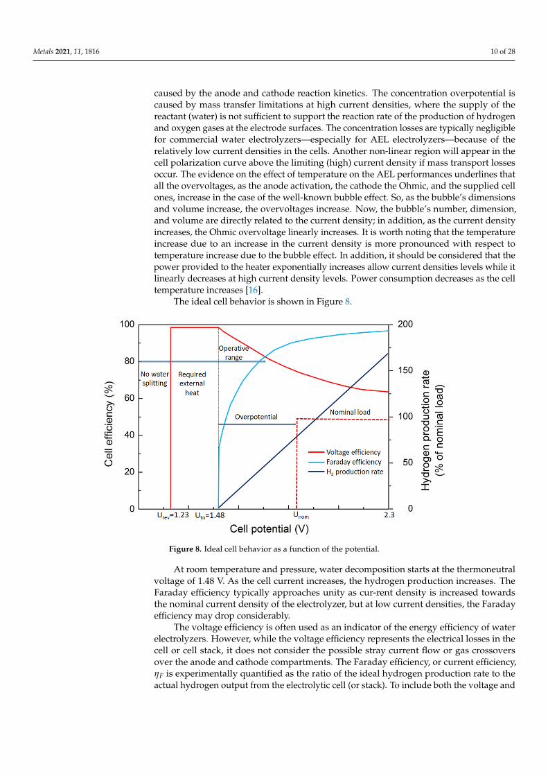
The ideal cell behavior is shown in Figure 8.
Metals 2021, 11, x FOR PEER REVIEW 11 of 29
and current collectors are the main contributors to the Ohmic losses. The activation over-potential is caused by the anode and cathode reaction kinetics. The concentration overpo-tential is caused by mass transfer limitations at high current densities, where the supply of the reactant (water) is not sufficient to support the reaction rate of the production of hydrogen and oxygen gases at the electrode surfaces. The concentration losses are typi-cally negligible for commercial water electrolyzers—especially for AEL electrolyzers—be-cause of the relatively low current densities in the cells. Another non-linear region will appear in the cell polarization curve above the limiting (high) current density if mass transport losses occur. The evidence on the effect of temperature on the AEL performances underlines that all the overvoltages, as the anode activation, the cathode the Ohmic, and the supplied cell ones, increase in the case of the well-known bubble effect. So, as the bub-ble's dimensions and volume increase, the overvoltages increase. Now, the bubble's num-ber, dimension, and volume are directly related to the current density; in addition, as the current density increases, the Ohmic overvoltage linearly increases. It is worth noting that the temperature increase due to an increase in the current density is more pronounced with respect to temperature increase due to the bubble effect. In addition, it should be considered that the power provided to the heater exponentially increases allow current densities levels while it linearly decreases at high current density levels. Power consump-tion decreases as the cell temperature increases [16].
The ideal cell behavior is shown in Figure 8.
Figure 8. Ideal cell behavior as a function of the potential.
At room temperature and pressure, water decomposition starts at the thermoneutral voltage of 1.48 V. As the cell current increases, the hydrogen production increases. The Faraday efficiency typically approaches unity as cur-rent density is increased towards the nominal current density of the electrolyzer, but at low current densities, the Faraday effi-ciency may drop considerably.
The voltage efficiency is often used as an indicator of the energy efficiency of water electrolyzers. However, while the voltage efficiency represents the electrical losses in the cell or cell stack, it does not consider the possible stray current flow or gas crossovers over the anode and cathode compartments. The Faraday efficiency, or current efficiency, ηF is experimentally quantified as the ratio of the ideal hydrogen production rate to the actual
Figure 8. Ideal cell behavior as a function of the potential.
At room temperature and pressure, water decomposition starts at the thermoneutralvoltage of 1.48 V. As the cell current increases, the hydrogen production increases. TheFaraday efficiency typically approaches unity as cur-rent density is increased towardsthe nominal current density of the electrolyzer, but at low current densities, the Faradayefficiency may drop considerably.
The voltage efficiency is often used as an indicator of the energy efficiency of waterelectrolyzers. However, while the voltage efficiency represents the electrical losses in thecell or cell stack, it does not consider the possible stray current flow or gas crossoversover the anode and cathode compartments. The Faraday efficiency, or current efficiency,ηF is experimentally quantified as the ratio of the ideal hydrogen production rate to theactual hydrogen output from the electrolytic cell (or stack). To include both the voltage and
Metals 2021, 11, 1816 11 of 28
Faraday efficiencies in a single quantity, the definition-specific energy consumption shouldbe used to assess the energy efficiency of a water electrolysis process (Equation (14)):
Es =
∫ t10 IstackUstackdt∫ t1
0.
mH2 dt(14)
where Es is the specific energy consumption, Istack is the stack current, Ustack is the stackvoltage,
.mH2 is the hydrogen gas mass flow rate, and t1 is the inspected time span. Hence,
the specific energy consumption describes the amount of energy consumed to produce amass unit of hydrogen gas. The energy efficiency of a water electrolysis process can becalculated from (Equation (15)):
ηe =HHVH2
Es(15)
where HHVH2 is the higher heating value of hydrogen (39.4 kWh/kg or 3.54 kWh/Nm3).Alternatively, the lower heating value of hydrogen (LHV) can be used as a reference
(33.3 kWh/kg or 3.00 kWh/Nm3). The difference between the LHV and HHV is thelatent heat of condensation. Typically, the HHV value is used as the reference for waterelectrolysis processes because liquid water is, in the case of alkaline and PEMEL waterelectrolyzers, usually supplied to the process, and the energy required for evaporationof water must be considered. The specific energy consumption of the water electrolysisprocess is further affected by the Faraday efficiency, which is non-linear with respect to thecurrent density.
The selection between the currently commercially widely available alkaline andPEMEL technologies will set requirements for the required system components; alkalinetechnology needs a supply of liquid electrolyte, its controlled circulation, and separationfrom product gases. Furthermore, alkaline electrolyzer stacks are typically limited in theirconstruction because of the liquid electrolyte supply and gas-liquid transport, which hasmade 200–300 V the typical stack voltage for industrial electrolyzers. The PEMEL tech-nology avoids the construction limitations of the alkaline stacks, but the requirement forhigh electric currents (to produce more gases) and the exclusively bipolar construction ofPEMEL stacks still set the stack DC currents relatively high compared with the stack DCvoltage.
PEMEL water electrolyzers achieve comparable voltage efficiencies at higher currentdensities, in other words, they have lower cell impedances. Therefore, smaller variationsin the instantaneous supply voltage cause greater fluctuations in the supplied current forPEMEL cells. As instantaneous, high variations in current density may have an adverseimpact on cell degradation, actions may have to be taken to limit the current slew rate. Celldegradation increases the cell voltage over time, and the increased electrolyzer voltageresulting from degradation should be considered in the system design and operation.
Operating conditions, mainly cell temperature and pressure, affect the reversiblevoltage and impedance of the electrolytic cell and have an impact on the system efficiency.Increasing the cell temperature is generally beneficial to the cell voltage efficiency, butselected materials will limit the temperature. The cell reversible voltage is also affected byanode and cathode compartment pressures. The resulting change in voltage efficiency froman increase in pressure is comparable with the ideal isothermal compression of hydrogengas. However, if the surrounding system, such as post-electrolysis synthesis processes orgaseous storage of hydrogen gas, requires elevated pressures, PEMEL electrolyzers mayopt to operate at a differential pressure and output only hydrogen gas at elevated pressure,while alkaline electrolyzers are limited to balanced pressure operation. In the PEMEL waterelectrolysis, the change in hydrogen outlet pressure from 20 bar to 40 bar may result inun-changed electrical energy consumption [17]. However, an increase in pressure maycompromise the control range of the electrolyzer and its specific energy consumptionas the gas crossover rate is increased. Furthermore, operating the water electrolyzer innon-optimal conditions may risk the lifetime of the electrolytic cells.

Metals 2021, 11, 1816 12 of 28
As a matter of fact, the summarized properties of the described systems are listed inTable 1 [7].
Table 1. Electrolysis cells properties.
Technology AEC PEMEL SOEC
Electrolyte KOH NAFION YSZCathode Ni, Ni-Mo alloys Pt, Pt-Pd Ni, YSZAnode Ni, Ni-Co alloys RuO2, IrO2 LSM/YZS
Current density (A/cm2) 0.2–0.4 0.6–2 0.3–2Cell voltage (V) 1.8–2.4 1.8–2.2 0.7–1.5
Voltage efficiency (%) 62–82 67–82 ~100Cell area (m2) <4 <0.3 <0.01
Operating temperature (C) 60–80 50–80 650–1000Operating pressure (bar) <30 <200 <25Production rate (m3/h) <760 <40 <40Stack energy (kWh/m3) 4.2–5.9 4.2–5.5 >3.2
Lifetime (h) <90,000 <60,000 <10,000Maturity Mature Commercial Demonstration
Capital cost (euro/kW) <1200 <2300 >2000
Water supply and water purification are required to guarantee the normal operationof the water electrolysis process and to preserve the lifetime of the electrolytic cells. In thealkaline water electrolysis, water is consumed from the liquid electrolyte solution, whoseconcentration must be maintained by an inlet of deionized water. Meanwhile, the PEMELwater electrolysis is electrolysis of deionized water. The conductivity of the inlet wateraffects the operation of the electrolytic cell, its energy efficiency and aging, and the presenceof alkaline electrolyte decreases the gas solubility, which has an impact on the gas crossover.The water supply can also be considered from the system integration point.
Alternative solutions are underlined such as in [18]. Here, energy-saving yet chlorine-free seawater electrolysis for efficient hydrogen production by a hybrid seawater splittingstrategy is proposed. This chemistry consumes the seawater on the cathode to generate H2by hydrogen evolution reaction (HER); while the crossover of released OH– to the anodeside supply the hydrazine degradation to harmless H2 and water with reduced salinity.Beyond the state-of-the-art seawater electrolysis, it enables hydrogen production at ultralowcell voltages but large current densities without chlorine hazards and limiting hydrogen-yielding efficiency. The hybrid seawater electrolyzer (HSE) using NiCo/MXene-basedsuperaerophobichydrophilic and hydrazine-friendly electrodes requires a dramaticallylower electricity expense of 2.75 kWh/m3 H2 than alkaline seawater electrolyzer (ASE) atindustrial-scale current densities. This electrolyzer simultaneously allows fast hydrazinedegradation to a rather lower residual while harvesting water with reduced salinity fromseawater. On this basis, self-powered seawater electrolysis can be further realized byintegrating the HSE into solar or hydrazine fuel cells for better cost-effectiveness andsustainability.
4. Decoupled Electrochemical Water Splitting
Interesting recent progress in water splitting technologies development is the so-calleddecoupled water splitting. It results in a highly flexible alternative to traditional waterelectrolysis technologies. During electrochemical water splitting, a redox mediator (M−) isemployed in an oxidation half-reaction that is coupled with the HER. On the other hand,the M half reduction is coupled with the OER (Equations (16)–(21)):
Cathode : 2H+ + 2e− → H2 (16)
Anode : 2M− → 2M + 2e− (17)
Overall : 2H+ + 2M− → H2 + 2M (18)

Metals 2021, 11, 1816 13 of 28
Cathode : 2M + 2e− → 2M− (19)
Anode : H2O→ 2H+ + 2e− +12
O2 (20)
Overall : 2M + H2O→ 2M− + 2H+ +12
O2 (21)
The overall reaction is exactly equivalent to the traditional water-splitting reactionpreviously described. The mediator (M) is continuously cycled through different oxidationstates in a way similar to the well-known redox-flow battery (RFB) or a solid-state battery.Obviously, this behavior is dependent on its physical state.
As in traditional water-splitting technologies, inputs are water and electricity whilethe products are hydrogen and oxygen gases [19]. In the case of decoupled water splitting,pH is related to the electrolyte (as in the case of traditional electrolysis) but also to thecurrent provided during the independent decoupled reactions.
The previous equations can be modified slightly for mediators that also up-take andrelease protons during operation (Equations (22)–(27)):
Cathode : 2H+ + 2e− → H2 (22)
Anode : 2MH2 → 2M∗ + 2H+ + 2e− (23)
Overall : 2MH2 → H2 + 2M∗ (24)
Cathode : 2M∗ + 2H+ + 2e− → 2MH2 (25)
Anode : H2O→ 2H+ + 2e− +12
O2 (26)
Overall : 2M∗ + H2O→ 2MH2 +12
O2 (27)
The overall reaction is the same as the overall water splitting reaction even if thesystem is proton balanced. In the case of alkaline electrolytes, the reactions are similar; theonly difference is that balancing is performed by hydroxide ions.
The employment of the mediator allows for the separation of the hydrogen and oxygenevolution reactions in space and time. So, the benefits are mainly due to the possibilityof controlling separately the steps with increased efficiency. Other positive aspects arerepresented by the possibility of employing low-cost electrolyzers; favoring the integrationwith renewable sources; improving the safety conditions of all the processes mainly relatedto the risks of explosion.
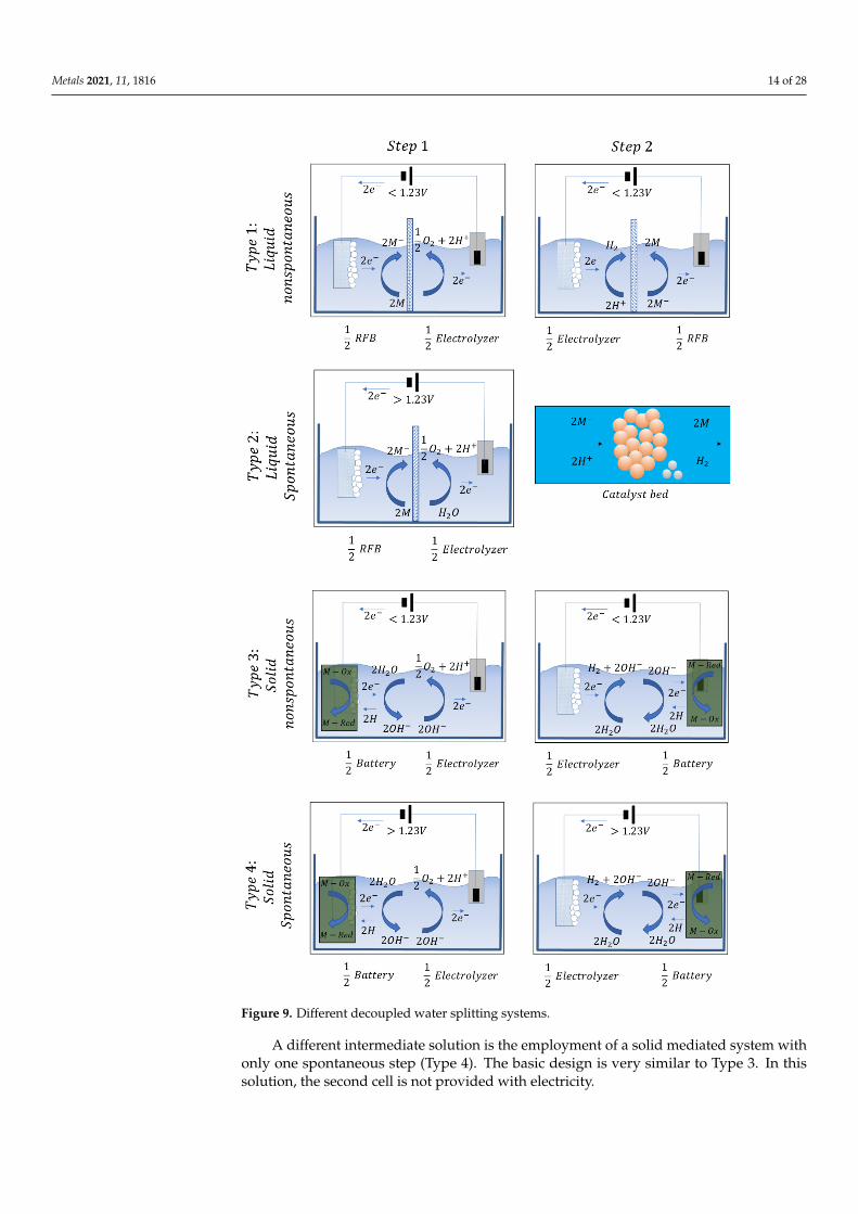
Given all those aspects, the decoupled water splitting systems are grouped into fourclasses depending on the physic conditions of the mediator, and on the input of theelectricity (Figure 9).
The type 1 system is liquid mediated. This system consists of an RFB half-cell and anelectrolysis half-cell. The mediator is contained in the electrolyte, it is reduced during step1 (left) then, it is sent to the second cell. Here the mediator is re-oxidized. On the contrary,the electrode can be changed for the half-cell electrolysis by driving the reactions through apolarity opposite with respect to step 1.
In this kind of cell, the separator is employed in order to avoid the mixing of themediator and the electrolysis products. Another kind of cell is represented by a situationwhere the second step evolves spontaneously (Type 2). Here the cell is composed of an RFBhalf-cell and an electrolysis half-cell with a catalyst bed. Here, HER acts spontaneouslythen, external input is not necessary.
Another type of decoupled water splitting is a solid-based technology based on twonon-spontaneous steps (Type 3). This kind of cell employs only one electrode that is coupledalternatively to another electrode for the development of HER or OER in alternative ways.The basic construction of this solution is, for driving the two steps, an electrolysis half-celland a battery half-cell.
Metals 2021, 11, 1816 14 of 28Metals 2021, 11, x FOR PEER REVIEW 15 of 29
Figure 9. Different decoupled water splitting systems.
The type 1 system is liquid mediated. This system consists of an RFB half-cell and an electrolysis half-cell. The mediator is contained in the electrolyte, it is reduced during step 1 (left) then, it is sent to the second cell. Here the mediator is re-oxidized. On the contrary, the electrode can be changed for the half-cell electrolysis by driving the reactions through a polarity opposite with respect to step 1.
Figure 9. Different decoupled water splitting systems.
A different intermediate solution is the employment of a solid mediated system withonly one spontaneous step (Type 4). The basic design is very similar to Type 3. In thissolution, the second cell is not provided with electricity.

Metals 2021, 11, 1816 15 of 28
The continuous development of these systems led to the possibility of employingnon-precious catalysts arriving to be competitive with the underdeveloped best PEM cells.It is also possible to employ low-cost membranes depending on the chosen configuration.
5. Water Purification
Water to be split during electrolysis must respond to many compositional require-ments. These are standardized by the American Society for Testing and Materials (ASTM)Type II deionized (DI) water (resistivity 41 MΩ cm) while ASTM Type I DI water (410 MΩcm) is preferred. ASTM defines Type II water, as required in commercial electrolyzers, ashaving a resistivity of 41 MΩ cm, sodium, and chloride content <5 µg L−1 and <50 ppb oftotal organic carbon (TOC).
The requirements needed by the water to be split in Alkaline electrolyzers are lessstringent if compared to those needed for PEM. Anyway, as the water purity increases,the cell stability improves. Many techniques are available in order to reach such puritylevels. The main applied ones are reverse osmosis (RO), multi-stage flash distillation (MSF),electrodialysis (ED), multiple-effect distillation (MED) to desalinate water. Sometimes theyare coupled with an ion exchange or electrodeionization (EDI) for further improvement ofthe water quality.
In the case of seawater electrolysis, operating and capital costs must be seriouslyconsidered because of the equipment consumption depending on the starting water qual-ity [20].
In the recent past, many developments have to reach toward the optimization ofelectrodes and catalysts for the OER in alkaline media of the seawater. The best conditionsare underlined in the order of (4300 mA cm−2) at the typical seawater pH (8). Now, seawateris very rich in borates and carbonites; the presence of these compounds limits high currentdensities. This limit can be overcome through the addition of additives such as KOH.All these additives led to an increase in the conductivity as the concentration increased.Obviously, it must be taken into account that the increase in additives concentration leadsto a variation in the water pH. Strong variations in the pH impact the durability andstability of the electrodes. Other problems to be faced are eventual presences of other kindsof impurities such as various dimensions particles, ions, bacteria, microbes, all impactingon the system stability and long-term durability.
Much progress has been done in the recent past on desalinization through seawaterreverse osmosis (SWRO). The improvements are mainly due to the development of highlyresistant, stable, and efficient membranes, highly efficient energy recovery devices, andprocess optimization of reverse osmosis (RO) systems. All this progress led to the reductionin electricity consumption as well as to an important drop in operating costs. At thepresent time, the energy requirement of SWRO desalination plants has decreased from9–10 kWh m−3 to <3 kWh m−3.
A schematic of a typical desalinization plant coupled with a PEM electrolyzer is shownin Figure 10.
The PEM electrolysis plant consists of the electrolyzer stacks and the mechanicaland electrical balance of plant (BoP) components. The electrical BoP consists of the ACto DC rectifier for converting grid electricity while the mechanical BoP consists of otherauxiliary components such as pumps, heat exchangers, temperature swing adsorption(TSA) subsystem, and most importantly a deionizer (DI) system.
The SWRO plant contains the RO unit which uses a membrane barrier and pumpingenergy to separate salts from saline water. Using high-pressure pumps, water is forcedthrough semi-permeable membranes that have a dense separation layer (thin-film com-posite membrane) allowing the passage of pure water molecules while rejecting dissolvedsalts and other impurities. In addition, in order to control RO membrane (bio)fouling andscaling, the SWRO system necessitates physical (e.g., dual media, sediment and carbonfilters or low-pressure membranes, such as ultrafiltration) and chemical (e.g., coagulantpolymer, antiscalant, acid, chlorination/dechlorination) pre-treatment steps with variable

Metals 2021, 11, 1816 16 of 28
complexity depending on raw feed water quality. A combination of these filters provides abroad spectrum of reduction.
Metals 2021, 11, x FOR PEER REVIEW 17 of 29
Figure 10. Seawater desalinization for hydrogen production.
The PEM electrolysis plant consists of the electrolyzer stacks and the mechanical and electrical balance of plant (BoP) components. The electrical BoP consists of the AC to DC rectifier for converting grid electricity while the mechanical BoP consists of other auxiliary components such as pumps, heat exchangers, temperature swing adsorption (TSA) sub-system, and most importantly a deionizer (DI) system.
The SWRO plant contains the RO unit which uses a membrane barrier and pumping energy to separate salts from saline water. Using high-pressure pumps, water is forced through semi-permeable membranes that have a dense separation layer (thin-film com-posite membrane) allowing the passage of pure water molecules while rejecting dissolved salts and other impurities. In addition, in order to control RO membrane (bio)fouling and scaling, the SWRO system necessitates physical (e.g., dual media, sediment and carbon filters or low-pressure membranes, such as ultrafiltration) and chemical (e.g., coagulant polymer, antiscalant, acid, chlorination/dechlorination) pre-treatment steps with variable complexity depending on raw feed water quality. A combination of these filters provides a broad spectrum of reduction.
There are several RO pre-treatment designs that could be adopted depending on the quality of water needed. The desalination unit consists of a double-pass RO system de-signed to attain the high purity of water required by the PEM electrolyzer. The SWRO-PEM coupled system could be located in coastal regions with intense solar irradiation and/or wind energy available to produce renewable electricity via photovoltaic cells, wind turbines, or even offshore structures if hydrogen supply for shipping for example was desired.
6. Efficient Hydrogen Production The classically employed electrocatalysts for both the hydrogen evolution reaction
(HER) and oxygen evolution reaction (OER) are precious metals such as platinum (Pt), and ruthenium (Ru) as well as their compounds. Obviously, these are very expensive ma-terials; for this reason, electrolysis development limited in the past the large-scale indus-trial applications of these technologies.
For these reasons, technological and scientific research focused on the development of less expensive non-precious metals-based catalysts HER and OER.
The best alternatives have been recognized in metal-organic frameworks (MOFs) composites and transition-metal-based compounds such as metal oxides, hydroxides, sul-fides, phosphides, nitrides, and selenides with high electrocatalytic properties for the de-velopment of HER and OER [21].
Figure 10. Seawater desalinization for hydrogen production.
There are several RO pre-treatment designs that could be adopted depending onthe quality of water needed. The desalination unit consists of a double-pass RO systemdesigned to attain the high purity of water required by the PEM electrolyzer. The SWRO-PEM coupled system could be located in coastal regions with intense solar irradiationand/or wind energy available to produce renewable electricity via photovoltaic cells, windturbines, or even offshore structures if hydrogen supply for shipping for example wasdesired.
6. Efficient Hydrogen Production
The classically employed electrocatalysts for both the hydrogen evolution reaction(HER) and oxygen evolution reaction (OER) are precious metals such as platinum (Pt),and ruthenium (Ru) as well as their compounds. Obviously, these are very expensivematerials; for this reason, electrolysis development limited in the past the large-scaleindustrial applications of these technologies.
For these reasons, technological and scientific research focused on the development ofless expensive non-precious metals-based catalysts HER and OER.
The best alternatives have been recognized in metal-organic frameworks (MOFs)composites and transition-metal-based compounds such as metal oxides, hydroxides,sulfides, phosphides, nitrides, and selenides with high electrocatalytic properties for thedevelopment of HER and OER [21].
All the present efforts are devoted to increasing the efficiency of these non-preciousmaterials catalysts in order to reduce the electric power required for hydrogen production.
Being electrochemical water splitting is one of the most environmentally friendlyapproaches used to produce hydrogen because it involves no carbon footprint. The half-cell reactions (HER and OER) occurring at cathode and anode, respectively; it must be fedby renewable sources. The final electrochemical decomposition of H2O into H2 and O2(by-product) is shown in (Equations (28) and (29)):
4H+ + 4e− → 2H2(HER at cathode) (28)
2H2O→ O2 + 4H+ + 4e−(OER at anode) (29)
Metals 2021, 11, 1816 17 of 28
so, the global reaction will be (Equation (30)):
2H2O→ 2H2 ↑ +O2 ↑ (30)
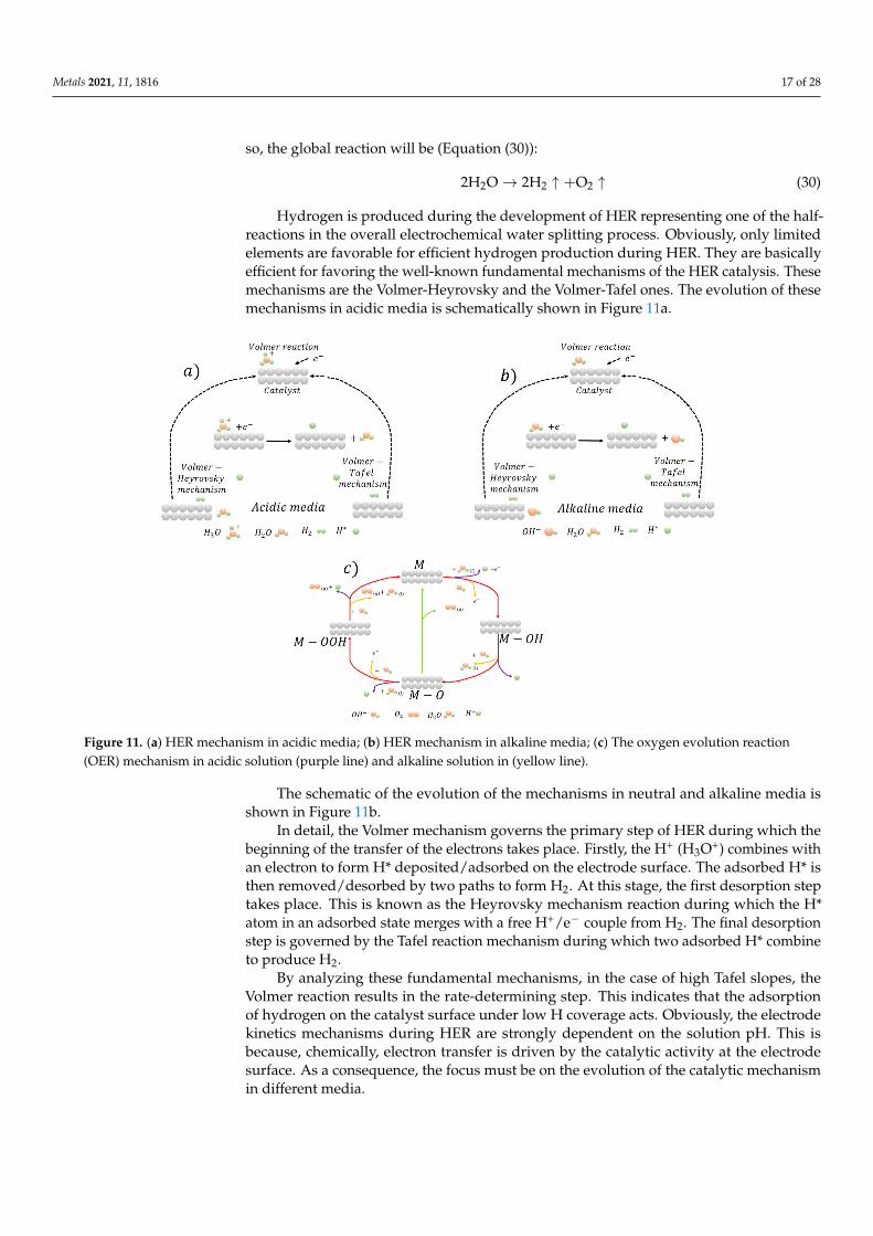
Hydrogen is produced during the development of HER representing one of the half-reactions in the overall electrochemical water splitting process. Obviously, only limitedelements are favorable for efficient hydrogen production during HER. They are basicallyefficient for favoring the well-known fundamental mechanisms of the HER catalysis. Thesemechanisms are the Volmer-Heyrovsky and the Volmer-Tafel ones. The evolution of thesemechanisms in acidic media is schematically shown in Figure 11a.
Metals 2021, 11, x FOR PEER REVIEW 18 of 29
All the present efforts are devoted to increasing the efficiency of these non-precious materials catalysts in order to reduce the electric power required for hydrogen produc-tion.
Being electrochemical water splitting is one of the most environmentally friendly ap-proaches used to produce hydrogen because it involves no carbon footprint. The half-cell reactions (HER and OER) occurring at cathode and anode, respectively; it must be fed by renewable sources. The final electrochemical decomposition of H2O into H2 and O2 (by-product) is shown in (Equations (28) and (29)): 4H + 4e → 2H (HER at cathode) (28)2H O → O + 4H + 4e (OER at anode) (29)
so, the global reaction will be (Equation (30)): 2H O → 2H ↑ +O ↑ (30)
Hydrogen is produced during the development of HER representing one of the half-reactions in the overall electrochemical water splitting process. Obviously, only limited elements are favorable for efficient hydrogen production during HER. They are basically efficient for favoring the well-known fundamental mechanisms of the HER catalysis. These mechanisms are the Volmer-Heyrovsky and the Volmer-Tafel ones. The evolution of these mechanisms in acidic media is schematically shown in Figure 11a.
Figure 11. (a) HER mechanism in acidic media; (b) HER mechanism in alkaline media; (c) The oxygen evolution reaction (OER) mechanism in acidic solution (purple line) and alkaline solution in (yellow line).
The schematic of the evolution of the mechanisms in neutral and alkaline media is shown in Figure 11b.
In detail, the Volmer mechanism governs the primary step of HER during which the beginning of the transfer of the electrons takes place. Firstly, the H+ (H3O+) combines with an electron to form H* deposited/adsorbed on the electrode surface. The adsorbed H* is then removed/desorbed by two paths to form H2. At this stage, the first desorption step takes place. This is known as the Heyrovsky mechanism reaction during which the H* atom in an adsorbed state merges with a free H+/e− couple from H2. The final desorption
Figure 11. (a) HER mechanism in acidic media; (b) HER mechanism in alkaline media; (c) The oxygen evolution reaction(OER) mechanism in acidic solution (purple line) and alkaline solution in (yellow line).
The schematic of the evolution of the mechanisms in neutral and alkaline media isshown in Figure 11b.
In detail, the Volmer mechanism governs the primary step of HER during which thebeginning of the transfer of the electrons takes place. Firstly, the H+ (H3O+) combines withan electron to form H* deposited/adsorbed on the electrode surface. The adsorbed H* isthen removed/desorbed by two paths to form H2. At this stage, the first desorption steptakes place. This is known as the Heyrovsky mechanism reaction during which the H*atom in an adsorbed state merges with a free H+/e− couple from H2. The final desorptionstep is governed by the Tafel reaction mechanism during which two adsorbed H* combineto produce H2.
By analyzing these fundamental mechanisms, in the case of high Tafel slopes, theVolmer reaction results in the rate-determining step. This indicates that the adsorptionof hydrogen on the catalyst surface under low H coverage acts. Obviously, the electrodekinetics mechanisms during HER are strongly dependent on the solution pH. This isbecause, chemically, electron transfer is driven by the catalytic activity at the electrodesurface. As a consequence, the focus must be on the evolution of the catalytic mechanismin different media.

Metals 2021, 11, 1816 18 of 28
The second half-reaction of water splitting is the oxygen evolution reaction (OER). Ittakes place at the anode electrode surface. The main difference with respect to the HER isthat this reaction evolves through a four-electron transfer.
With respect to HER, OER requires higher overpotentials. This aspect is responsiblefor the strict matters related to the overall energy behavior and efficiency of the electrolysisprocesses. The main intermediate products of OER mechanisms are O*, OH*, and OOH*.Due to the nature of these products, the oxygen evolution follows different routes depend-ing on the solution media. The main aspect of ORER is that, here, OH− is absent in acidicsolution. For this reason, the metal (M) reacts with water producing MOH. Then, it reactscontinuously with electrons by transforming into MO.
MO and oxygen can be produced via two different mechanisms: in the first, two MOcombine in order to produce oxygen directly; in the second, MO reacts continuously withoxygen by forming the intermediate species MOOH, later, MOOH forms O2.
The decomposition of MOOH forming O2 is shown in Figure 11c.According to the Sabatier principle, the adsorption phenomenon is high pronounced
to produce desorption; so, it is necessary to employ catalysts with the moderate bindingcapability to drive the whole process. In this view, when catalysts have weak bondingwith O, the intermediate species OH* does not evolve easily into OOH*. It is believedthat the best catalytic performance can be reached once the bonding of O acts in moderateconditions.
The best way to produce clean hydrogen is the employment of renewable powersources such as wind, solar, and biomass. Anyway, at the present time, only 4% of theconsumed hydrogen is produced via this route. The remaining percentage is still relatedto technologies different from water electrolysis. The main problem is related to theorigin of power and to the issues connected with the consumption of the electrolysis cellscomponents.
Now, from a chemical point of view, the minimum energy needed for the water-splitting is the Gibbs free energy related to the needed voltage at a given temperatureand pressure. In order to have efficient water splitting, the catalytic behavior duringboth OER and HER mast be kinetically increased for high overall electrolysis efficiency.At the present time, precious metals such as platinum are the best choices for efficientwater splitting. However, much progress has been done in the recent past with respectto the development of catalysts based on less expensive materials. The main route is thereplacement of precious metals with non-metal ones especially the transition materials.
Several transition metals compounds result in a very effective application in alkalinewater electrolysis (AWE). They are mainly based on Fe, Mn, Co, and Ni-based, includingtheir oxides resulting very efficiently during HER and OER half-cell reactions in watersplitting. The main routes toward their large utilization are the improvement of electricalconductivity, the increased stability in different environments and media, the possibility ofdesigning hybrid solutions by coupling such compounds with carbon-based materials.
More serious problems are faced during the development of water steam electrolysis.In fact, the very high temperature of the steam (in the order of 1000 C) leads to fastdegradation of the cell components, in particular, electrodes. In addition, such high-temperature conditions lead to the high instability of the electrocatalysts. In addition,critical issues are represented by ionic conductivity, electronic conductivity, and catalyticconductivity in SOEL. One of the primary solutions is the expansion of the surfaces of theelectrode in order to reduce excessive heating. Costs can be reduced by deeply employingnon-precious metals as catalysts. The cell duration can be increased by reducing theoverpotential well as improving the stability of the catalysts.
Being the more recently developed, non-precious materials catalysts research forPEMEL cells is at the beginning. The main problem is that the stability of catalysts intoacidic media is very crucial. The mainly employed materials for HER in acidic media arethe oxides of transitional metals such as NbC, SnO2, Ta2O5, TiO2, WC, and TiC. The field

Metals 2021, 11, 1816 19 of 28
is still very open because it is very difficult to substitute precious metals catalysts for theoxygen evolution reaction in PEMEL cells.
Other alternative solutions are represented by the employment of MOF electrocatalystsfor OER and HER. They have large potentials because of their large surface area, optimalphysiochemical properties, and porous structures.
7. Steel Manufacturing with Renewables Integration
During the direct reduction of iron oxides through hydrogen, water vapor is producedinstead of carbon dioxide of the traditional ironmaking and steelmaking routes [22,23].Then the water vapor can be separated and condensed or employed as input in the elec-trolyzers for water splitting. In this scenario, the only produced carbon dioxide is theone belonging to the power to be employed for the electrolysis operations. As abovementioned, H2 is currently mainly produced from fossil sources (natural gas, coal, oil),by biomass gasification, and from non-carbon sources, such as water electrolysis [24].Once fossil sources are employed, as in the case of natural gas or methane, the generatedcarbon dioxide must be captured and stored with largely increased costs. If green power isemployed, the consumed power is in the order of ~5 kWh/m3 of H2. It is believed thatfurther developments of the different technologies will lead to a remarkable reduction inconsumption [25].
Hydrogen has large potentials for the direct reduction of iron ores. Obviously, the bestsolution is to reduce iron oxides through hydrogen produced via water electrolysis. In thisway, it is estimated that the overall process can lead to carbon dioxide emissions in theorder of 300 kg/t HRC.
The main employed direct reduction reactors in the world steel industry are based onthe MIDREX or HYL processes. Here the dynamic control of the different transformationsis optimal for the direct reduction through hydrogen. Obviously, many issues are relatedto the temperature and pressure in the reactor in terms of safety, product quality, andefficiency of the whole reduction process. Another fundamental aspect is represented bythe metallization degree and by the presence of carbon in the reduced iron [1].
Generally, hydrogen can be employed as the only reductant gas in these king of plantsas well as mixed with different percentages of natural gas. By considering the MIDREX®
Plant, in the case of H2 addition, one-third of the required natural gas can be substituted.For example, 60,000 Nm3/h of H2 can be substituted for approximately 20,000 Nm3/h ofnatural gas in a 2.0 Mtpy plant, which represents approximately 30% of the total natural gasconsumption. MIDREX® Plants generally employ three different ratios of H2 and CO. Mostuse natural gas and a standard MIDREX® Reformer that produces a reducing gas with 55%H2 and 36% CO (H2/CO of 1.5). As above mentioned, hydrogen is very volatile, so thereactor pressure is fundamental. The equilibrium diagram for the reforming processes isshown in Figure 12.
The hematite reduction act through the following reactions (Equations (31)–(36)):
2Fe2O3(s) + H2(g) → 2Fe3O4(s) + H2O(g) (31)
Fe3O4(s) +1619
H2(g) →6019
Fe0.95O(s) +1619
H2O(g) (32)
Fe0.95O(s) + H2(g) → 0.95Fe(s) + H2O(g) (33)
2Fe2O3(s) + CO(g) → 2Fe3O4(s) + CO2(g) (34)
Fe3O4(s) +1619
CO(g) →6019
Fe0.95O(s) +1619
CO2(g) (35)
Fe0.95O(s) + CO(g) → 0.95Fe(s) + CO2(g) (36)
The FMO MIDREX® Plant in Venezuela is designed with a steam reformer, and H2/COcan vary from 3.3 to 3.8. There are six MIDREX® Modules that utilize gas made from coal,and these have hydrogen to CO ratios from 0.37 to 0.56. Thus, the MIDREX® Process

Metals 2021, 11, 1816 20 of 28
has successfully produced DRI at H2/CO ratios from 0.37 to 3.8. In these plants, 100%of pure hydrogen can also be employed. However, in the case of MIDREX, the reactorconfiguration does not change if natural gas or hydrogen is used as a reductant. H2 inputgas is generated external to the process and there is no reformer. With this design, a gasheater is employed to heat the gas to the required temperature. In the practice, the reducinggas H2 content is about 90%, with the balance CO, CO2, H2O, and CH4.
Metals 2021, 11, x FOR PEER REVIEW 21 of 29
Figure 12. Equilibrium diagram with phases and gas compositions at room pressure.
The hematite reduction act through the following reactions (Equations (31)–(36)): 2Fe O ( ) + H ( ) → 2Fe O ( ) + H O( ) (31)Fe O ( ) + H ( ) → Fe . O( ) + H O( ) (32)Fe . O( ) + H ( ) → 0.95Fe( ) + H O( ) (33)2Fe O ( ) + CO( ) → 2Fe O ( ) + CO ( ) (34)Fe O ( ) + 1619 CO( ) → 6019 Fe . O( ) + 1619 CO ( ) (35)Fe . O( ) + CO( ) → 0.95Fe( ) + CO ( ) (36)
The FMO MIDREX® Plant in Venezuela is designed with a steam reformer, and H2/CO can vary from 3.3 to 3.8. There are six MIDREX® Modules that utilize gas made from coal, and these have hydrogen to CO ratios from 0.37 to 0.56. Thus, the MIDREX® Process has successfully produced DRI at H2/CO ratios from 0.37 to 3.8. In these plants, 100% of pure hydrogen can also be employed. However, in the case of MIDREX, the reac-tor configuration does not change if natural gas or hydrogen is used as a reductant. H2 input gas is generated external to the process and there is no reformer. With this design, a gas heater is employed to heat the gas to the required temperature. In the practice, the reducing gas H2 content is about 90%, with the balance CO, CO2, H2O, and CH4.
These last gases come from the addition of natural gas for temperature control and carbon addition in order to tune the needed carbon percentage in the reduced iron. Since H2 is converted to H2O and condensed in the top gas scrubber, no CO2 removal system is necessary. With this plant setting, hydrogen consumption is approximately 550 Nm3/t DRI. Additionally, up to 250 Nm3/t DRI of H2 or other environmentally friendly heat sources such as waste heat, electricity, and/or natural gas are required as fuel for the re-duction gas heater. With this process, CO2 emissions could be reduced up to 80% vs. the BF/BOF steelmaking route. There are a number of considerations for the MIDREX H2™ Process, the first of which is temperature. With these high hydrogen percentages, the DRI is deeply cooled. So, natural gas is necessary to sustain the needed temperature levels.
Figure 12. Equilibrium diagram with phases and gas compositions at room pressure.
These last gases come from the addition of natural gas for temperature control andcarbon addition in order to tune the needed carbon percentage in the reduced iron. SinceH2 is converted to H2O and condensed in the top gas scrubber, no CO2 removal system isnecessary. With this plant setting, hydrogen consumption is approximately 550 Nm3/t DRI.Additionally, up to 250 Nm3/t DRI of H2 or other environmentally friendly heat sources suchas waste heat, electricity, and/or natural gas are required as fuel for the reduction gas heater.With this process, CO2 emissions could be reduced up to 80% vs. the BF/BOF steelmakingroute. There are a number of considerations for the MIDREX H2™ Process, the first of whichis temperature. With these high hydrogen percentages, the DRI is deeply cooled. So, naturalgas is necessary to sustain the needed temperature levels. According to Midrex indications,the addition of natural gas at a rate of 50 Nm3/t DRI should accomplish this.
As mentioned above, the other crucial aspect is the iron carburizing. The vast majorityof DRI is used in EAFs for further processing. EAF steelmaking practices today generallyemploys carbon added either in metallic charge materials such as DRI, HBI, and pig iron oras pure carbon. Burning this carbon with injected oxygen creates significant heat whichreduces electricity consumption and enables faster melting. Since pig iron is made fromBF hot metal that is saturated with carbon, it contains 4–4.5 percent carbon. DRI can have1–4.5 percent carbon depending on the process, reducing gas used, and the way the DRplant is operated.
In the case of hydrogen produced via electrolysis, a crucial aspect is also represented bythe location of electrolysis plants to produce hydrogen because this is the most electricity-consuming section of the integrated plant. To give an idea of electricity needed, forfossil-free electricity in the electric arc furnace, the amount of electricity is only about
Metals 2021, 11, 1816 21 of 28
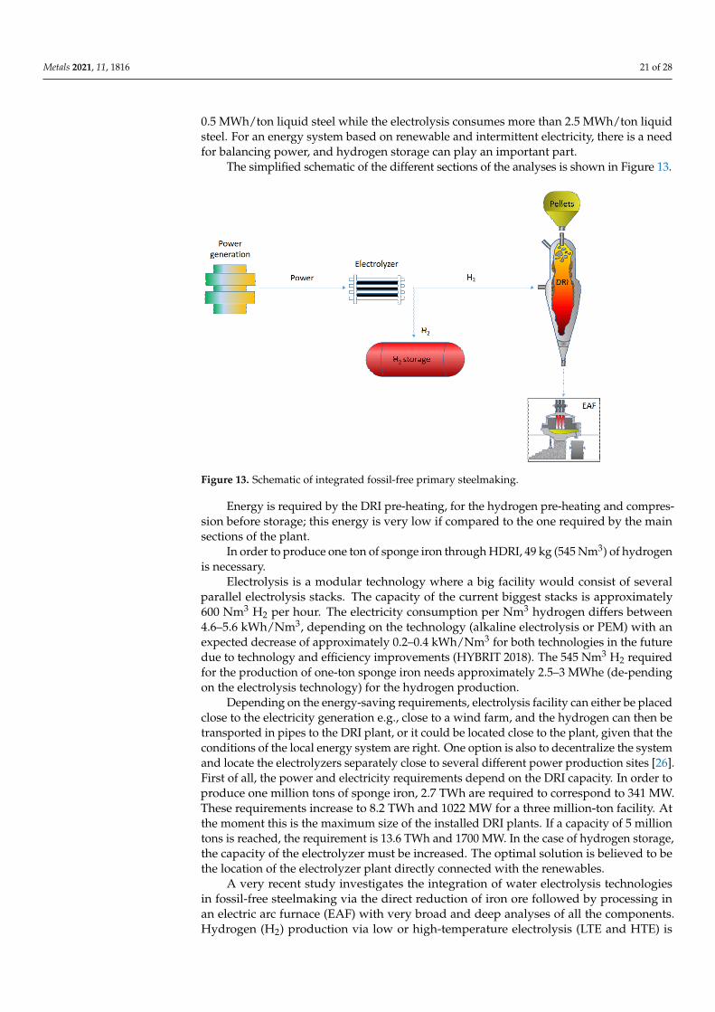
0.5 MWh/ton liquid steel while the electrolysis consumes more than 2.5 MWh/ton liquidsteel. For an energy system based on renewable and intermittent electricity, there is a needfor balancing power, and hydrogen storage can play an important part.
The simplified schematic of the different sections of the analyses is shown in Figure 13.
Metals 2021, 11, x FOR PEER REVIEW 22 of 29
According to Midrex indications, the addition of natural gas at a rate of 50 Nm3/t DRI should accomplish this.
As mentioned above, the other crucial aspect is the iron carburizing. The vast major-ity of DRI is used in EAFs for further processing. EAF steelmaking practices today gener-ally employs carbon added either in metallic charge materials such as DRI, HBI, and pig iron or as pure carbon. Burning this carbon with injected oxygen creates significant heat which reduces electricity consumption and enables faster melting. Since pig iron is made from BF hot metal that is saturated with carbon, it contains 4–4.5 percent carbon. DRI can have 1–4.5 percent carbon depending on the process, reducing gas used, and the way the DR plant is operated.
In the case of hydrogen produced via electrolysis, a crucial aspect is also represented by the location of electrolysis plants to produce hydrogen because this is the most elec-tricity-consuming section of the integrated plant. To give an idea of electricity needed, for fossil-free electricity in the electric arc furnace, the amount of electricity is only about 0.5 MWh/ton liquid steel while the electrolysis consumes more than 2.5 MWh/ton liquid steel. For an energy system based on renewable and intermittent electricity, there is a need for balancing power, and hydrogen storage can play an important part.
The simplified schematic of the different sections of the analyses is shown in Figure 13.
Figure 13. Schematic of integrated fossil-free primary steelmaking.
Energy is required by the DRI pre-heating, for the hydrogen pre-heating and com-pression before storage; this energy is very low if compared to the one required by the main sections of the plant.
In order to produce one ton of sponge iron through HDRI, 49 kg (545 Nm3) of hydro-gen is necessary.
Electrolysis is a modular technology where a big facility would consist of several parallel electrolysis stacks. The capacity of the current biggest stacks is approximately 600 Nm3 H2 per hour. The electricity consumption per Nm3 hydrogen differs between 4.6–5.6 kWh/Nm3, depending on the technology (alkaline electrolysis or PEM) with an expected decrease of approximately 0.2–0.4 kWh/Nm3 for both technologies in the future due to technology and efficiency improvements (HYBRIT 2018). The 545 Nm3 H2 required for the production of one-ton sponge iron needs approximately 2.5–3 MWhe (de-pending on the electrolysis technology) for the hydrogen production.
Figure 13. Schematic of integrated fossil-free primary steelmaking.
Energy is required by the DRI pre-heating, for the hydrogen pre-heating and compres-sion before storage; this energy is very low if compared to the one required by the mainsections of the plant.
In order to produce one ton of sponge iron through HDRI, 49 kg (545 Nm3) of hydrogenis necessary.
Electrolysis is a modular technology where a big facility would consist of severalparallel electrolysis stacks. The capacity of the current biggest stacks is approximately600 Nm3 H2 per hour. The electricity consumption per Nm3 hydrogen differs between4.6–5.6 kWh/Nm3, depending on the technology (alkaline electrolysis or PEM) with anexpected decrease of approximately 0.2–0.4 kWh/Nm3 for both technologies in the futuredue to technology and efficiency improvements (HYBRIT 2018). The 545 Nm3 H2 requiredfor the production of one-ton sponge iron needs approximately 2.5–3 MWhe (de-pendingon the electrolysis technology) for the hydrogen production.
Depending on the energy-saving requirements, electrolysis facility can either be placedclose to the electricity generation e.g., close to a wind farm, and the hydrogen can then betransported in pipes to the DRI plant, or it could be located close to the plant, given that theconditions of the local energy system are right. One option is also to decentralize the systemand locate the electrolyzers separately close to several different power production sites [26].First of all, the power and electricity requirements depend on the DRI capacity. In order toproduce one million tons of sponge iron, 2.7 TWh are required to correspond to 341 MW.These requirements increase to 8.2 TWh and 1022 MW for a three million-ton facility. Atthe moment this is the maximum size of the installed DRI plants. If a capacity of 5 milliontons is reached, the requirement is 13.6 TWh and 1700 MW. In the case of hydrogen storage,the capacity of the electrolyzer must be increased. The optimal solution is believed to bethe location of the electrolyzer plant directly connected with the renewables.
A very recent study investigates the integration of water electrolysis technologiesin fossil-free steelmaking via the direct reduction of iron ore followed by processing inan electric arc furnace (EAF) with very broad and deep analyses of all the components.Hydrogen (H2) production via low or high-temperature electrolysis (LTE and HTE) is

Metals 2021, 11, 1816 22 of 28
considered for the production of carbon-free direct reduced iron (DRI) [3,27,28]. Producingcarbon-free DRI with H2 produced via LTE is probably the most straightforward route tofossil-free steel. HTE is attractive due to its high efficiency, given that steam is available,but is a much less proven technology than LTE [29]. Anyway, in all those situations wherehigh-temperature sources and steam are available, THE is very efficient. Obviously, theperformance and the durability of these high-temperature cells are fundamental for thelarge diffusion in the steel industry.
The schematic of the DRI plant integrated with LTE and HTE is shown in Figure 14.
Metals 2021, 11, x FOR PEER REVIEW 23 of 29
Depending on the energy-saving requirements, electrolysis facility can either be placed close to the electricity generation e.g., close to a wind farm, and the hydrogen can then be transported in pipes to the DRI plant, or it could be located close to the plant, given that the conditions of the local energy system are right. One option is also to decen-tralize the system and locate the electrolyzers separately close to several different power production sites [26]. First of all, the power and electricity requirements depend on the DRI capacity. In order to produce one million tons of sponge iron, 2.7 TWh are required to correspond to 341 MW. These requirements increase to 8.2 TWh and 1022 MW for a three million-ton facility. At the moment this is the maximum size of the installed DRI plants. If a capacity of 5 million tons is reached, the requirement is 13.6 TWh and 1700 MW. In the case of hydrogen storage, the capacity of the electrolyzer must be increased. The optimal solution is believed to be the location of the electrolyzer plant directly con-nected with the renewables.
A very recent study investigates the integration of water electrolysis technologies in fossil-free steelmaking via the direct reduction of iron ore followed by processing in an electric arc furnace (EAF) with very broad and deep analyses of all the components. Hy-drogen (H2) production via low or high-temperature electrolysis (LTE and HTE) is con-sidered for the production of carbon-free direct reduced iron (DRI) [3,27,28]. Producing carbon-free DRI with H2 produced via LTE is probably the most straightforward route to fossil-free steel. HTE is attractive due to its high efficiency, given that steam is available, but is a much less proven technology than LTE [29]. Anyway, in all those situations where high-temperature sources and steam are available, THE is very efficient. Obviously, the performance and the durability of these high-temperature cells are fundamental for the large diffusion in the steel industry.
The schematic of the DRI plant integrated with LTE and HTE is shown in Figure 14.
Metals 2021, 11, x FOR PEER REVIEW 24 of 29
Figure 14. Schematic of the integration of DRI with LTE and HTE.
In all the described solutions, hydrogen is sent to the reactor at a temperature around 900 °C. By employing LTE, hydrogen must be pre-heated through heat exchange with the top gases, heating recovery from post-combustion of top gases, or traditional electricity facilities.
In order to avoid inert gas accumulation in the reactor, a top gas purge stream is employed. Recycled gas is normally purged at percentages around 10. This solution nor-mally leads to increased hydrogen production in the case of low-temperature electrolysis. In this case, oxygen (produced in water splitting) is employed as fuel for the purge stream. In the case of high-temperature electrolysis facilities, top gas is directly sent to the electro-lyzer. So, steam is produced through the heating provided by the top gas. In this solution, being the operating temperature of the electrolyzer in the order of 900–100 °C, it is not necessary the pre-heating of the produced hydrogen before the insertion in the reducing reactor. Of course, if the hydrogen is cooled, the extra heating will be provided to reach the required temperature levels of the reducing gas. In the case of HTE, a crucial aspect is represented by the sulfur removal before entering the DR shaft.
Generally, the top gas recycling stuck is a cyclone equipped with off-gas de-dusting and a condenser for heat recovery and hydrogen separation from the de-dusted off-gas. Pure hydrogen is produced via electrolysis based on renewables or nuclear energy. So, hydrogen from electrolysis is mixed with the separated hydrogen and then sent to the shaft furnace after compression (the pressure level depends on the type of plant; normally HYL reactor is designed for high-pressure hydrogen in order to increase the process effi-ciency).
The reducing gas is inserted from the bottom of the furnace, and it reduces the iron oxides at high temperature by encountering the iron-bearing pellets that are charged from the top of the furnace. The direct reduced iron is then collected at the bottom and sent to the electric arc furnace for further processing and melting.
The process is high heat consuming because of the endothermic nature of reactions involving pure hydrogen. So, in this view, it is fundamental to balance the employment
Figure 14. Schematic of the integration of DRI with LTE and HTE.
In all the described solutions, hydrogen is sent to the reactor at a temperature around900 C. By employing LTE, hydrogen must be pre-heated through heat exchange with the

Metals 2021, 11, 1816 23 of 28
top gases, heating recovery from post-combustion of top gases, or traditional electricityfacilities.
In order to avoid inert gas accumulation in the reactor, a top gas purge stream is em-ployed. Recycled gas is normally purged at percentages around 10. This solution normallyleads to increased hydrogen production in the case of low-temperature electrolysis. In thiscase, oxygen (produced in water splitting) is employed as fuel for the purge stream. In thecase of high-temperature electrolysis facilities, top gas is directly sent to the electrolyzer.So, steam is produced through the heating provided by the top gas. In this solution, beingthe operating temperature of the electrolyzer in the order of 900–100 C, it is not necessarythe pre-heating of the produced hydrogen before the insertion in the reducing reactor. Ofcourse, if the hydrogen is cooled, the extra heating will be provided to reach the requiredtemperature levels of the reducing gas. In the case of HTE, a crucial aspect is representedby the sulfur removal before entering the DR shaft.
Generally, the top gas recycling stuck is a cyclone equipped with off-gas de-dustingand a condenser for heat recovery and hydrogen separation from the de-dusted off-gas.Pure hydrogen is produced via electrolysis based on renewables or nuclear energy. So,hydrogen from electrolysis is mixed with the separated hydrogen and then sent to the shaftfurnace after compression (the pressure level depends on the type of plant; normally HYLreactor is designed for high-pressure hydrogen in order to increase the process efficiency).
The reducing gas is inserted from the bottom of the furnace, and it reduces the ironoxides at high temperature by encountering the iron-bearing pellets that are charged fromthe top of the furnace. The direct reduced iron is then collected at the bottom and sent tothe electric arc furnace for further processing and melting.
The process is high heat consuming because of the endothermic nature of reactionsinvolving pure hydrogen. So, in this view, it is fundamental to balance the employmentof hydrogen from electrolysis and hydrogen from gas separation in order to sustain theprocess with constant and high efficiency.
So, the limiting aspect is those conditions related to the managing of hydrogen interms of pressure and temperature.
The type of hydrogen also strongly influences the degree of metallization of the directreduced iron. In the ideal case of 100% of metallization, the ratio recycled to electrolysishydrogen is higher than 3. In this condition, the energy consumption is in the order of13.7 GJ/t-DRI, where large energy consumption is due to the electricity required by theelectrolysis plant. They provide heat that can be reduced if carbon monoxide is employedas an additional reductant. In this case, also carburization of iron is facilitated. Normally,Midrex plants employ hydrogen up to 75% and carbon monoxide up to 30%. With thiscarbon monoxide percentage, it is easy to take the temperature in the furnace under control.
As mentioned above, the carburization of iron is a fundamental aspect. In direct-reduced iron, carbon is contained in the form of cementite. Many studies are presentedin the literature about the nature and the kinetics of cementite formation during thedirect reduction of iron oxides. Different controlling mechanisms have been suggested forcementite formation such as the chemical reaction rates at the pore surfaces of reduced ironand the rate of mass transfer of carbon in iron.
In the case of sulfur presence, the stability of cementite is increased and the presenceof free carbon in the iron is reduced. For this reason, sulfur presence is controlled with greatprecision. Again, the gas temperature has a large influence on the carbide’s transformationsand diffusion. In fact, the reduction rate is largely influenced by the temperature drivingthe chemical equilibrium of the reactions. At the same time, the cementite stability isgoverned by the carbon activity that is related to the temperature level. In addition, as thetemperature is increased, the reduction rate increases because of a faster chemical reactionand mass transfer.
The general TENOVA-HYL direct reduction plant schematic is shown in Figure 15.

Metals 2021, 11, 1816 24 of 28
Metals 2021, 11, x FOR PEER REVIEW 25 of 29
of hydrogen from electrolysis and hydrogen from gas separation in order to sustain the process with constant and high efficiency.
So, the limiting aspect is those conditions related to the managing of hydrogen in terms of pressure and temperature.
The type of hydrogen also strongly influences the degree of metallization of the direct reduced iron. In the ideal case of 100% of metallization, the ratio recycled to electrolysis hydrogen is higher than 3. In this condition, the energy consumption is in the order of 13.7 GJ/t-DRI, where large energy consumption is due to the electricity required by the elec-trolysis plant. They provide heat that can be reduced if carbon monoxide is employed as an additional reductant. In this case, also carburization of iron is facilitated. Normally, Midrex plants employ hydrogen up to 75% and carbon monoxide up to 30%. With this carbon monoxide percentage, it is easy to take the temperature in the furnace under con-trol.
As mentioned above, the carburization of iron is a fundamental aspect. In direct-re-duced iron, carbon is contained in the form of cementite. Many studies are presented in the literature about the nature and the kinetics of cementite formation during the direct reduction of iron oxides. Different controlling mechanisms have been suggested for ce-mentite formation such as the chemical reaction rates at the pore surfaces of reduced iron and the rate of mass transfer of carbon in iron.
In the case of sulfur presence, the stability of cementite is increased and the presence of free carbon in the iron is reduced. For this reason, sulfur presence is controlled with great precision. Again, the gas temperature has a large influence on the carbide’s trans-formations and diffusion. In fact, the reduction rate is largely influenced by the tempera-ture driving the chemical equilibrium of the reactions. At the same time, the cementite stability is governed by the carbon activity that is related to the temperature level. In ad-dition, as the temperature is increased, the reduction rate increases because of a faster chemical reaction and mass transfer.
The general TENOVA-HYL direct reduction plant schematic is shown in Figure 15.
Figure 15. Schematic of HYL-DRI plant.
The operating temperature of the reactor is higher than 1050 °C, the reactor pressure falls in the range 6–8 bar. This pressure allows for the low volatility of the reducing gases with a remarkable increase in the overall efficiency. The plant is designed to employ var-ious reducing gases including hydrogen in a broad range of percentages. The flexibility of the solution allows for the use of any energy source. The iron ores dimensions are in the
Figure 15. Schematic of HYL-DRI plant.
The operating temperature of the reactor is higher than 1050 C, the reactor pressurefalls in the range 6–8 bar. This pressure allows for the low volatility of the reducing gaseswith a remarkable increase in the overall efficiency. The plant is designed to employ variousreducing gases including hydrogen in a broad range of percentages. The flexibility of thesolution allows for the use of any energy source. The iron ores dimensions are in the range3.2–18 mm. The plant allows for the selective removal of carbon dioxide demonstrating itsintrinsic capability of CCSU.
The carbon dioxide capture corresponds to 45% of the total carbon input. The freeCO2 emissions to the atmosphere are 30% of the total carbon input. The carbon in the DRIis 25% of the total input.
For comparison, carbon input and output streams as well as the distribution of carbonflow within the MIDREX process are shown in Figure 16 (the figure shows the carbonbalance for both NG and H2 processes).
The main unit operations of the process comprise DR-shaft, reformer, top gas scrubber,product gas compressors, and heat exchangers. The reformer of the DR-NG schematiccomprises one part for the reforming of NG providing the required energy for producingthe syngas. The reforming process approaches a state of thermodynamic equilibrium inpractice. The third main component is the top gas scrubber which has the goal to reducethe water content on the one hand and control the temperature levels of the two separatedgas output streams on the other hand. Therefore, the temperature and the pressure level ofthese two streams—reducing gas input and top gas fuel—are set to fixed values. NG canbe injected at different process stages: NG as input to the reforming gas, as an energy inputfor heating the reformer or reduction gas heater as well as directly to the bustle gas beforeentering the shaft furnace. The input of hydrogen in the DR-NG process is foreseen in thereforming gas before entering the reformer. In the hydrogen-based schematic, the reformerof the DR-NG process is replaced by a reduction gas heater representing a combinationof a gas burner, mixer, and heat exchanger model. Hydrogen can be added either to thereduction gas and/or to the top gas fuel for heating purposes. The energy supplied to theheater can also be provided by NG. To achieve comparable results, the same solid inputmaterial compositions and amounts, as well as the same basic assumptions for the DR shaft(e.g., reduction degree, carburization behavior, temperature distribution, and so on), the topgas scrubber (temperatures and pressure levels) and the gas burner (excess air), is appliedfor both process models. In the proposed schematics, about 30% of the NG can be replacedby hydrogen without any process changes. The replacement of NG by hydrogen leads to anincreased volume flow in the shaft furnace due to changing gas compositions. The gradualinjection of hydrogen entails a corresponding decrease in carbon monoxide, whereas the
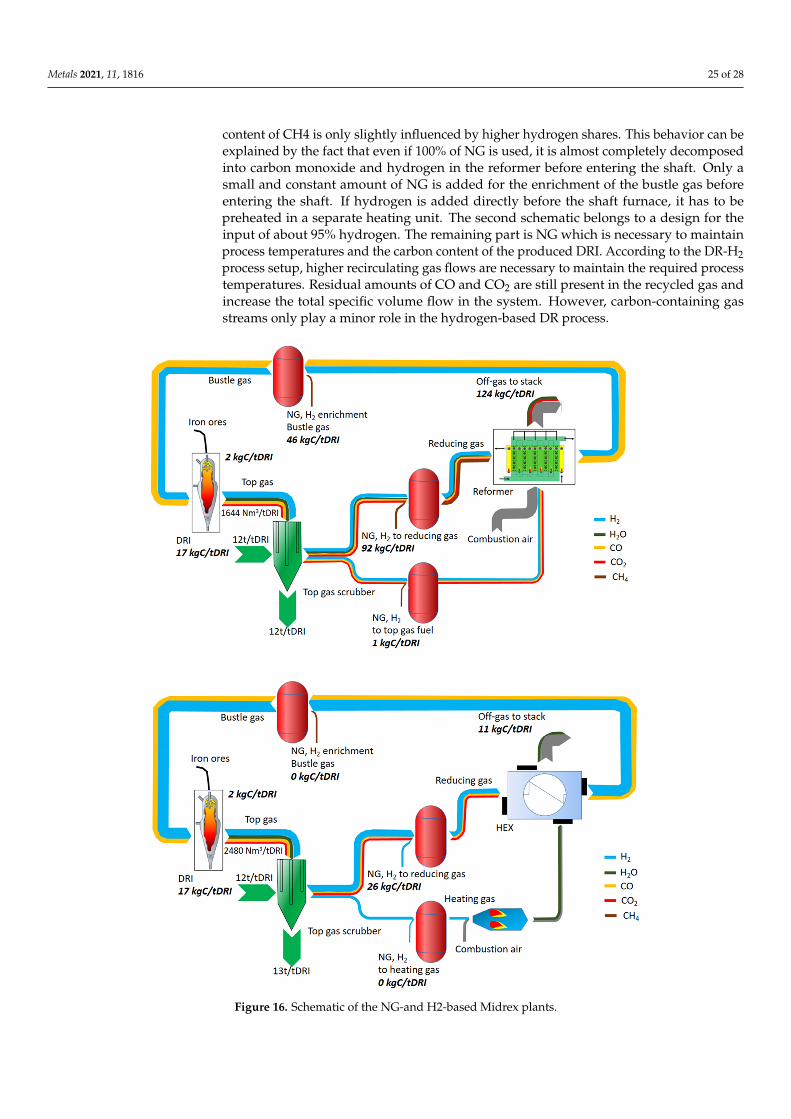
Metals 2021, 11, 1816 25 of 28
content of CH4 is only slightly influenced by higher hydrogen shares. This behavior can beexplained by the fact that even if 100% of NG is used, it is almost completely decomposedinto carbon monoxide and hydrogen in the reformer before entering the shaft. Only asmall and constant amount of NG is added for the enrichment of the bustle gas beforeentering the shaft. If hydrogen is added directly before the shaft furnace, it has to bepreheated in a separate heating unit. The second schematic belongs to a design for theinput of about 95% hydrogen. The remaining part is NG which is necessary to maintainprocess temperatures and the carbon content of the produced DRI. According to the DR-H2process setup, higher recirculating gas flows are necessary to maintain the required processtemperatures. Residual amounts of CO and CO2 are still present in the recycled gas andincrease the total specific volume flow in the system. However, carbon-containing gasstreams only play a minor role in the hydrogen-based DR process.
Metals 2021, 11, x FOR PEER REVIEW 26 of 29
range 3.2–18 mm. The plant allows for the selective removal of carbon dioxide demon-strating its intrinsic capability of CCSU.
The carbon dioxide capture corresponds to 45% of the total carbon input. The free CO2 emissions to the atmosphere are 30% of the total carbon input. The carbon in the DRI is 25% of the total input.
For comparison, carbon input and output streams as well as the distribution of car-bon flow within the MIDREX process are shown in Figure 16 (the figure shows the carbon balance for both NG and H2 processes).
Figure 16. Schematic of the NG-and H2-based Midrex plants.
The main unit operations of the process comprise DR-shaft, reformer, top gas scrub-ber, product gas compressors, and heat exchangers. The reformer of the DR-NG schematic comprises one part for the reforming of NG providing the required energy for producing the syngas. The reforming process approaches a state of thermodynamic equilibrium in
Figure 16. Schematic of the NG-and H2-based Midrex plants.
Metals 2021, 11, 1816 26 of 28
NG either used for reforming, enrichment, or heating purposes represents the maincarbon input to the DR-NG reference process. In addition to the carbon output via theDRI product, the major emission source of carbon is the off-gas of the reformer. About124 kg C/t DRI which are equivalent to about 453 kgCO2/tDRI are emitted at this point. Incomparison, the carbon output of the DR-H2 process is almost equally distributed betweenthe DRI and stack emissions (released by using the top gas as combustion gas for theheater), representing 17 and 11 kg C/tDRI, respectively. The main carbon source, in thiscase, is as well NG which is required for maintaining the carbon content of the DRI [30].
As mentioned, the TENOVA plant can work with different concentrations of hydrogenin the feeding gas. As the hydrogen content in the mixture increases, the total energyconsumption in the reactor decreases. A strong decrease in electricity consumption isrecorded as the hydrogen content increases.
8. Conclusions
Hydrogen is believed to be the best actor toward the decarbonization of industrieshard to abate. It is considered the energy vector of the next future, capable of addressingmultiple energy challenges and the cleanest solution to decarbonize industries. Hydrogenhas the potential to be employed in the production of carbon steels, special metals, andsemiconductors in the steel and electronics industries.
At the present time, more than 95% of the employed hydrogen is produced from fossilfuels. The most typical hydrogen production routes from fossil sources are coal gasificationor natural gas reforming. At the present time, only 4% of hydrogen is produced via waterelectrolysis. Obviously, the decarbonization of human activities needs hydrogen to beproduced through sustainable routes. One of the most promising ways is the electrolysis ofwater with the energy sources provided by renewables.
During electrolysis, water is split into hydrogen and oxygen through electricity. So,the electric energy is converted into chemical energy (though hydrogen) and thermalenergy. At a given water volume, the produced hydrogen quantity directly dependson the electric current. The main water electrolysis technologies are: alkaline (AEL),Proton Exchange Membrane Electrolyzer (PEMEL), and Solid Oxide Electrolyzer (SOEL).The energy needed for polymer electrolyte membrane electrolyzers and alkaline waterelectrolysis is in the order of 4.4–4.9 kWh/m3 H2. Obviously, this energy demands decreasefor high-temperature water electrolysis cells falling in the order of 3.8–3.9 kWh/m3 H2.
Water input represents a crucial aspect of these technologies, Alkaline electrolyzersare less stringent on water quality as compared to PEM, but it is recommended to employhigh purity water in order to reach long-term stability and duration of the electrolysisplants. Such high purity water as required by water electrolysis systems is producedthrough a combination of either reverse osmosis (RO), multi-stage flash distillation (MSF),electrodialysis (ED), multiple-effect distillation (MED) to desalinate water, and commonlyan additional technology such as ion exchange or electrodeionization (EDI).
The best solution for the steel industry seems to replace the traditional route based oncoal and coke with the direct reduction reactors employing hydrogen as the main reductant.Midrex and HYL Energiron are the processes with the highest capacities in-stalled worldwide.H2 can also be used as the reductant in conventional direct reduction reactors. In a routebased on hydrogen and direct reduction, the output after the re-duction is the porous materialof DRI, or sponge iron, which can possibly be transported to an EAF in a different location(or pressed to hot briquetted iron, HBI, which is favorable for transportation). The energyrequired for the melting in the EAF depends on the inlet temperature of the DRI, which willbe different depending on if it has been transported or not.
If H2 is produced by water electrolysis using hydro or nuclear electricity, then CO2emissions could be lowered to less than 300 kg/t HRC by saving almost 1700 kg/t HRC.Obviously, different gas mixings can be employed because of the temperature levels neededinside the reactor as well as because of the required metallization degree and cementitecontent in the reduced iron. In addition, the different gas mixings are responsible for the

Metals 2021, 11, 1816 27 of 28
overall efficiency of the reduction process. The hydrogen pressure is also a fundamentalparameter to be considered for the optimization of the new ironmaking and steelmakingroutes.
Author Contributions: P.D.C.—Conceptualization, Supervision, Validation Writing; A.P.—Datacuration; A.S.—Data curation. All authors have read and agreed to the published version of themanuscript.
Funding: This research received no external funding.
Institutional Review Board Statement: Not applicable.
Informed Consent Statement: Not applicable.
Conflicts of Interest: The authors declare no conflict of interest.
References1. Cavaliere, P. Clean Ironmaking and Steelmaking Processes-Efficient Technologies for Greenhouse Emissions Abatement. In Clean
Ironmaking and Steelmaking Processes; Springer: Cham, Switzerland, 2019. [CrossRef]2. Schalenbach, M.; Tjarks, G.; Carmo, M.; Lueke, W.; Mueller, M.; Stolten, D. Acidic or Alkaline? Towards a New Perspective on the
Efficiency of Water Electrolysis. J. Electrochem. Soc. 2016, 163, 3197–3208. [CrossRef]3. Kruger, A.; Andersson, J.; Gronkvist, S.; Cornell, A. Integration of water electrolysis for fossil-free steel production. Int. J.
Hydrogen Energy 2020, 45, 29966–29977. [CrossRef]4. Shalenbach, M.; Zeradjanin, A.R.; Kasian, O. A Perspective on Low-Temperature Water Electrolysis –Challenges in Alkaline and
Acidic Technology. Int. J. Electrochem. Soc. 2018, 13, 1173–1226. [CrossRef]5. Lehner, M.; Tichler, R.; Steinm¨uller, H.; Koppe, M. Power-to-Gas: Technology and Business Models; Springer International Publishing:
New York, NY, USA, 2014. [CrossRef]6. Carmo, M.; Fritz, D.; Mergel, J.; Stolten, D. A comprehensive review on PEM water electrolysis. Int. J. Hydrogen Energy 2013, 38,
4901–4934. [CrossRef]7. Schmidt, O.; Gambhir, A.; Staffell, I.; Hawkes, A.; Nelson, J.; Few, S. Future cost and performance of water electrolysis: An expert
elicitation study. Int. J. Hydrogen Energy 2017, 42, 30470–30492. [CrossRef]8. Herz, G.; Muller, N.; Adam, P. High Temperature Co-Electrolysis as a Key Technology for CO2 Emission Mitigation—A Model-
Based Assessment of CDA and CCU. Chem. Ing. Tech. 2020, 92, 1044–1058. [CrossRef]9. Motylinski, K.; Wierzbicki, M.; Kupecki, J.; Jagielski, S. Investigation of off-design characteristics of solid oxide electrolyser (SOE)
operating in endothermic conditions. Renew Energy 2021, 170, 277–285. [CrossRef]10. Koj, J.C.; Wulf, C.; Schreiber, A.; Zapp, P. Site-Dependent Environmental Impacts of Industrial Hydrogen Production by Alkaline
Water Electrolysis. Energies 2017, 10, 860. [CrossRef]11. Smolinka, T.; Wiebe, N.; Sterchele, P.; Palzer, A.; Lehner, F.; Jansen, M.; Kiemel, S.; Miehe, R.; Wahren, S.; Zimmermann, F. Studie
IndWEDe: Industrial-Isierung der Wasserelektrolyse in Deutschland: Chancen und Herausforderungen für nachhaltigen Wasserstoff fürVerkehr, Strom und Wärme; Fraunhofer-Institut für Produktionstechnik und Automatisierung: Stuttgard, Germany, 2018.
12. Dotan, H.; Landman, A.; Sheehan, S.W.; Malviya, K.D.; Shter, G.E.; Grave, D.A.; Arzi, Z.; Yehudai, N.; Halabi, M.; Gal, N.; et al.Decoupled hydrogen and oxygen evolution by a two-step electrochemical–chemical cycle for efficient overall water splitting. Nat.Energy 2019, 4, 786–795. [CrossRef]
13. Ulleberg, Ø. Modeling of advanced alkaline electrolyzers: A system simulation approach. Int. J. Hydrogen Energy 2003, 28, 21–33.[CrossRef]
14. Ursua, A.; Gandia, L.M.; Sanchis, P. Hydrogen production from water electrolysis: Current status and future trends. Proc. IEEE2012, 100, 410–426. [CrossRef]
15. Milewski, J.; Guandalini, G.; Campanari, S. Modeling an alkaline electrolysis cell through reduced-order and loss-estimateapproaches. J. Power Sources 2014, 269, 203–211. [CrossRef]
16. Jang, D.; Choi, W.; Cho, H.-S.; Cho, W.C.; Kim, C.H.; Kang, S. Numerical modeling and analysis of the temperature effect on theperformance of an alkaline water electrolysis system. J. Power Sources 2021, 506, 230106. [CrossRef]
17. Koponen, J.; Kosonen, A.; Ruuskanen, V.; Huoman, K.; Niemelä, M.; Ahola, J. Control and energy efficiency of PEM waterelectrolyzers in renewable energy systems. Int. J. Hydrogen Energy 2017, 42, 29648–29660. [CrossRef]
18. Sun, F.; Qin, J.; Wang, Z.; Yu, M.; Wu, X.; Sun, X.; Qiu, J. Energy-saving hydrogen production by chlorine-free hybrid seawatersplitting coupling hydrazine degradation. Nat. Commun. 2021, 12, 1–11. [CrossRef] [PubMed]
19. Ifkovits, Z.P.; Evans, J.M.; Meier, M.C.; Papadantonakis, K.M.; Lewis, N.S. Decoupled electrochemical water-splitting systems: Areview and perspective. Energy Environ. Sci. 2021, 14, 4740–4759. [CrossRef]
20. Khan, M.A.; Al-Attas, T.; Roy, S.; Rahman, M.M.; Ghaffour, N.; Thangadurai, V.; Larter, S.; Hu, J.; Ajayan, P.M.; Kibria, G. Seawaterelectrolysis for hydrogen production: A solution looking for a problem? Energy Environ. Sci. 2021, 14, 4831–4839. [CrossRef]
21. Anwar, S.; Khan, F.; Zhang, Y.; Djire, A. Recent development in electrocatalysts for hydrogen production through water electrolysis.Int. J. Hydrogen Energy 2021, 46, 32284–32317. [CrossRef]

Metals 2021, 11, 1816 28 of 28
22. Chevrier, V. Midrex H2 TM: Ultimate low-CO2 ironmaking and its place in the new hydrogen economy. In Proceedings of theAISTech-Iron and Steel Technology Conference Proceedings, Philadelphiam, PA, USA, 7–10 May 2018; pp. 725–729.
23. Ghadi, A.Z.; Valipour, M.S.; Biglari, M. CFD simulation of two-phase gas-particle flow in the Midrex shaft furnace: The effect oftwin gas injection system on the performance of the reactor. Int. J. Hydrogen Energy 2017, 42, 103–118. [CrossRef]
24. Prammer, J. The actual problems of current decarbonization. Chernye Met. 2019, 1, 55–59.25. Lei, Q.; Wang, B.; Wang, P.; Liu, S. Hydrogen generation with acid/alkaline amphoteric water electrolysis. J. Energy Chem. 2019,
38, 162–169. [CrossRef]26. Cavaliere, P. Direct Reduced Iron: Most Efficient Technologies for Greenhouse Emissions Abatement. In Clean Ironmaking and
Steelmaking Processes; Springer: Cham, Switzerland, 2019. [CrossRef]27. Müller, N.; Herz, G.; Reichelt, E.; Jahn, M.; Michaelis, A. Assessment of fossil-free steelmaking based on direct reduction applying
high-temperature electrolysis. Clean. Eng. Technol. 2021, 4, 100158. [CrossRef]28. Cavaliere, P. Ironmaking and Steelmaking Processes-Greenhouse Emissions, Control, and Reduction; Springer: Cham, Switzerland, 2016.
[CrossRef]29. Andersson, J.; Grönkvist, S. A comparison of two hydrogen storages in a fossil-free direct reduced iron process. Int. J. Hydrogen
Energy 2021, 46, 28657–28674. [CrossRef]30. Rechberger, K.; Spanlang, A.; Conde, A.S.; Wolfmeir, H.; Harris, C. Green Hydrogen-Based Direct Reduction for Low-Carbon
Steelmaking. Steel Res. Int. 2020, 91, 2000110. [CrossRef]