
wan web services graduation project com-400 - Near East ...
135
NEAR EAST UNIVERSITY Faculty of Engineering Department of Computer Engineering WAN WEB SERVICES GRADUATION PROJECT COM-400 Nicosia 2005 ent: MOH'D MURAD AL-SMADI (20010943) uoervisor: Assist. Prof. Dr. Firudin Muradov
-
Upload
khangminh22 -
Category
Documents
-
view
0 -
download
0
Transcript of wan web services graduation project com-400 - Near East ...

NEAR EAST UNIVERSITY
Faculty of Engineering
Department of Computer Engineering
WAN WEB SERVICES
GRADUATION PROJECT
COM-400
Nicosia 2005
ent: MOH'D MURAD AL-SMADI (20010943)
uoervisor: Assist. Prof. Dr. Firudin Muradov

Acknowledgements
I would like to grant all the thanks and appreciation to my advisor Assist. Prof Dr. Firudin Muradov, who through his wisdom and experience kindly guided me through these four years of studying to graduate as a computer engineer. I would also like to thank the computer engineering department with its entire staff for making my dream come true.I would also like to give my very special thanks and respect to my parents, for if it wasn't for them these four years would have been impossible to complete. It was their support and prayers that made me get this far.
And not to forget my dear friends, especially Sameer, Qays, Tawfeek, Samer the Lebanese, and his brother Nader, and last but not least my relative Khaled.

ABSTRACT
This Project introduces the various protocols and technologies used in wide-area
network (WAN) environments. A WAN is a data communications network that covers a
relatively broad geographic area and that often uses transmission facilities provided by
common carriers, such as telephone companies. WAN technologies generally function at
the lower three layers of the OSI reference model: the physical layer, the data link layer,
and the network layer. A point-to-point link provides a single, pre-established WAN
communications path from the customer premises through a carrier network, such as a
telephone company, to a remote network Switched circuits allow data connections that
can be initiated when needed and terminated when communication is complete. This
works much like a normal telephone line works for voice communication. Integrated
Services Digital Network (ISDN) is a good example of circuit switching. WANs use
numerous types of devices that are specific to WAN environments. WAN switches,
access servers, modems, CSU/DSUs, and ISDN terminal adapters. Other devices found in
WAN environments that are used in WAN implementations include routers, A TM
switches, and multiplexers.
In addition to that, this project describes the Web Services Architecture. It identifies
the functional components and describes the relationships among those components to
affect the desired properties of the overall architecture.
ii
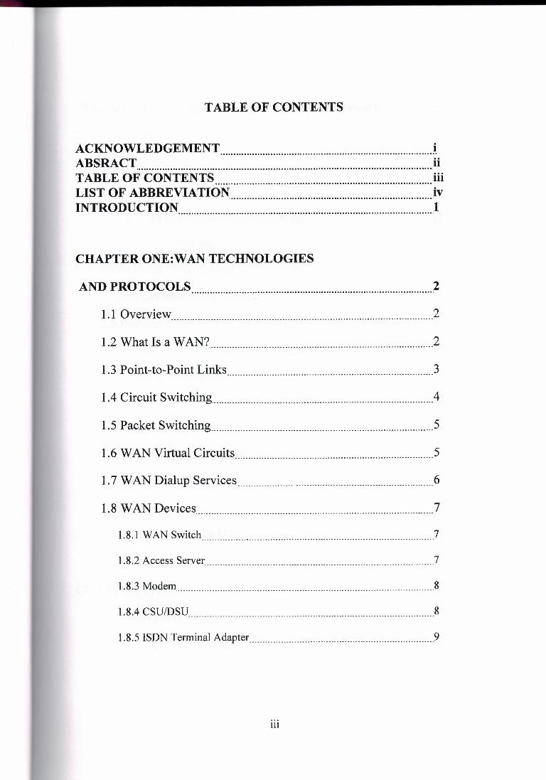
TABLE OF CONTENTS
ACKNOWLEDGEMENT i ABSRACT ii TABLE OF CONTENTS ..iii LIST OF ABBREVIATION Jv INTRODUCTION I
CHAPTER ONE:WAN TECHNOLOGIES
AND PROTOCOLS 2
1.1 Overview 2
1.2 What Is a WAN? 2
1.3 Point-to-Point Links 3
1.4 Circuit Switching 4
1.5 Packet Switching 5
1.6 WAN Virtual Circuits 5
1.7 WAN Dialup Services 6
1.8 WAN Devices 'l
1.8.1 WAN Switch 7
1.8.2 Access Server 7
1.8.3 Modem 8
1.8.4 CSU/DSU 8
1.8.5 ISDN Terminal Adapter 9
Ill

CHAPTER TWO: Implementing a Wide Area Network ..10
2.1 Overview I 0
2.2 Classification I 0
2.3 Queuing, 11
2.3.1 Link Fragmentation and Interleaving .12
2.3.2 Traffic Shaping 13
2.4 Network Provisioning 14
2.4.1 Call Admission Control .16
2.5 Point-to-Point WAN. 16
2.5.1 LFI on Point-to-Point WANs .16
2.5.2 cRTP on MLP Connections .17
2.5.3 LLQ for VoIP over MLP .17
2.6 Frame-Relay WAN 17
2.6.1 FRF.12 for LFI on Frame-Relay WANs .18
2.6.2 LLQ for VoIP over Frame Relay .18
2. 7 ATM W AN 19
2.8 Frame-Relay-to-ATM Intemetworking WAN 20
CHAPTER THREE: WAN DEVICES 22
3 .1 Overview 22
3 .2 Network Model (OSI) 22
3 .3 Network Protocols 23
IV

3.3.1 LAN Manager I Microsoft Network I NT Domains 23
3.3.2 TCP/IP 24
3.4 Physical network types 25
3.4.1 Ethernet 25
3.4.2 Leased lines 26
3.5 Network Devices 27
3.5.1 Introduction to Routers 28
3.5.1.1 Routing 32
3.5.1.2 Information in Packet 33
3.5.1.3 Router Operation 33
3.5.1.4 Directly Attached Networks 34
3.5.1.5 Non-Directly Attached Networks 35
3.5.1.6 Network Numbers 35
3.5.1.7 Routing Information Protocol (RIP} 36
3.5.1.8 Multiprotocol Routers 36
3.5.2 Hubs 37
3.5.2.1 General Characteristics of Hubs 37
3.5.2.2 Key Features ofHubs 37
3.5.3 Bridges 39
3.5.4 Modems . ., 39
3.5.4.1 The Modem Plug (RS-232 Interface overviewL 40
3.5.4.2 Error Correction and Data Compression 41
3.5.4.3 Direct, Normal, and Reliable Connections 41
V

3.5.5 Integrated Services Digital Network (ISDN) _41
3.5.5.1 ISDN Components .42
3.5.6 CSU/DSU 49
3.5.6.1 Comparing Basic Capabilities 50
3.5.6.2 Value Added 53
3.5.6.3 Diagnostic Testing 56
3.5.6.4 Single Point of Failure 58
3.5.6.5 Frame Relay Application 58
3.6 External connections to WANs 60
3.6.1 Permission For External Connections 60
3.6.2 Example Incoming Connections 61
3.6.3 Example Outgoing Connections .61
3.6.4 Simple Internet or Bulletin Board Access. 61
3.6.5 Insecure subnets 62
3.6.6 Network Management I Monitoring 62
CHAPTER FOUR: Web Services Architecture 63
4.1 Purpose of the Web Service Architecture 63
4.2 Document Organization 63
4.3 What is a Web service?·--------------------------------·-------·-·----------------------------64
4.3.1 Agents and Services 64
4.3.2 Requesters and Providers 65
4.3.3 Service Description .65
Vl

4.3.4 Semantics 65
4.3.5 Overview of Engaging a Web Service 66
4.4 Concepts and Relationships 67
4.4.1 Concepts 68
4.4.2 Relationships 68
4.4.3 Concept Maps 69
4.4.4 Model 69
4.4.5 Conformance _70
4.4.6 The Architectural Models 71
4.5 Message Oriented Model 75
4.5.1 Message Oriented Model Introduction _75
4.5.1.1 Address 76 -- -----------------------------------------------------------
4.5.1.2 Delivery Policy .77
4.5.1.3 Message .78
4.5 .1.4 Message Body .79
4.5 .1.5 Message Correlation --------------------------------------- .. 79
4.5 .1.6 Message Envelope --------------------------------- .. 80
4.5.1. 7 Message Exchange Pattern (MEP) 80
4.5.1.8 Message Header 81
4.5.1.9 Message Receiver 82
4.5.1.10 Message Reliability 82
4.5.1.11 Message Sender 83
4.5.1.12 Message Sequence 83
Vil

4.5.1.13 Message Transport 83
4.5.2 The Service Oriented Model 84
4.5.2.1 Action 85
4.5.2.2 Agent 86
4.5.2.3 Choreography 86
4.5.2.4 Capability 87
4.5.2.5 Goal State 87
4.5.2.6 Provider Agent 88
4.5.2.7 Provider Entity 88
4.5.2.8 Requester Agent 89
4.5.2.9 Requester Entity 89
4.5.2.10 Service 89
4.5.2.11 Service Description 90
4.5.2.12 Service Interface 90
4.5.2.13 Service Intermediary 91
4.5.2.14 Service Role 92
4.5.2.15 Service Semantics 92
4.5.2.16 Service Task 93
4.5.3 The Resource Oriented Model 94
4. 5 .3 .1 Discovery 95
4.5.3.2 Discovery Service 96
4.5.3.3 Identifier 97
4.5.3.4 Representation 97
viii

4.5.3.5 Resource 97
4.5.3.6 Resource description 98
4.5.4 The Policy Model 99
4.5.4.1 Audit Guard 100
4.5.4.2 Domain 100
4.5.4.3 Obligation 100
4.5.4.4 Permission 101
4.5.4.5 Permission Guard 102
4.5.4.6 Person or Organization 102
4.5.4.7 Policy 102
4.5.4.8 Policy Description 103
4.5.4.9 Policy Guard 103
4.6 Relationships I 04
4.6.1 The describes relationship -104
4.6.2 The has a relationship -104
4.6.3 The owns relationship 105
4.6.4 The realized relationship 105
4. 7 Stakeholder's Perspectives I 05
4.7.1 Web Services and Architectural Styles .106
4.7.2 Relationship to the WWW and REST Architectures 107
4.7.3 Web Services Technologies 108
4.7.4 Using Web Services 109
4.7.5 Web Service Discovery 111
ix

4.7.6 Peer-to-Peer (P2P) Discovery l14
4.7.7 Web Service Semantics _l 15
4.7.8 Web Services Security 115
4.7.9 Web Services Security Requirements : _116
4.7.10 Authorization l 16
4. 7 .11 Peer-to-Peer Interaction _l 16
4.7.12 Web Services Reliability _l 18
4.7.13 Web Service Management _l 18
4.7.14 Web Services and EDI: Transaction Tracking 120
4.7.15 Web Services Security _121
ILUSION 122 ......................................................................................................... ,
NCES 123 ......................................................................................................... ,
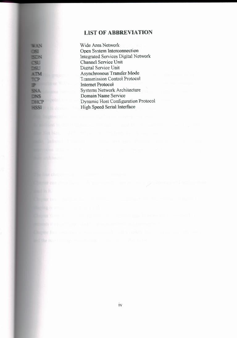
LIST OF ABBREVIATION
Wide Area Network Open System Interconnection Integrated Services Digital Network Channel Service Unit Digital Service Unit Asynchronous Transfer Mode Transmission Control Protocol Internet Protocol Systems Network Architecture Domain Name Service Dynamic Host Configuration Protocol High Speed Serial Interface
lV

INTRODUCTION
t This project is mainly made of four chapters. The first three talk about Wide Area
.orks or WAN. These chapters introduce the various protocols and technologies used
wide-area network (WAN) environments. .Topics stated in these chapters include
int-to-point links, circuit switching, packet switching, virtual circuits, dialup services,
WAN devices. They also explain the classification, queuing, network provisioning,
fragmentation and interleaving, traffic shaping Call admission control. of the WAN.
addition to that it introduces the devices used in wan connections, such as protocols
e: Net bias, TCP/IP, physical network types like: leased lines, ISDN, Ethernet, ATM,
radio, infrared, Microwave, satellite, and pure network devices: routers, bridges,
encryption units and modems. The last chapter of the project discusses web services and
their architecture.
The four chapters can be summarized as follows:
Chapter one describes a wide area network, and describes the protocols and technologies
used in it.
Chapter two describes the infrastructure of the network, its organization, its control, and
shaping in order to maintain a high efficiency.
Chapter three presents the hardware and software used in establishing a network It also ..-csents the procedures used in network security and management.
ter four describes a conceptual model and a context for understanding Web services
the relationships between the components of this model.

CHAPTER ONE
WAN TECHONOLGIES AND PROTOCOLS
1.1 Overview
This chapter introduces the various protocols and technologies used in wide-area
network (WAN) environments. Topics summarized here include point-to-point links,
ircuit switching, packet switching, virtual circuits, dial up services, and WAN devices.
1.2 What Is a WAN?
A WAN is a data communications network that covers a relatively broad geographic
area and that often uses transmission facilities provided by common carriers, such as
lephone companies. WAN technologies generally function at the lower three layers of the
OSI reference model: the physical layer, the data link layer, and the network layer. Figure
.2 illustrates the relationship between the common WAN technologies and the OSI model.
Figure 1.1 Shows Global Wide Area Network
2

Point-to-Point Links
A point-to-point link provides a single, pre-established WAN communications path
the customer premises through a carrier network, such as a telephone company, to a
te network. Point-to-point lines are usually leased from a carrier and thus are often
ed leased lines. For a point-to-point line, the carrier allocates pairs of wire and facility
ware to your line only. These circuits are generally priced based on bandwith required
distance between the two connected points. Point-to-point links.
""
______ ,,..
~·J~t~l,,,!\,lf,'. l,a!JEIF
Daita link I [1}tl;'r
~;i.fi.C
Sll!bli'!i;ff3!r'
-
Pti)'8JG81 la"i,11:1r
n, - r... 111 ,N :'..i
::,.. ,T.I - ':ii r_~ ~ Ci. ',;,;. tS: ...I ~ ...I e, '41 0 !=i,., Cl 'ill: ~ :t: .fh _J ,:w:i .•.. I...
ff! CJ ~ (JJ
E' ltiiTLI\•? 3:, E llil"T"Lb.-4 49 11 ·,<", v.as v., .•.
1:;t HSSI G.703 2'l ,- EIA-530 111\4 x
Figure 1.2 WAN Technologies Operate at the Lowest Levels of the OSI Model are
generally more expensive than shared services such as Frame Relay. Figure 1.3 illustrates a
typical point-to-point link through a WAN.
3

tgnre 1.3 A Typical Point-to-Point Link Operates Through a WAN to a Remote Network
1.4 Circuit Switching
Switched circuits allow data connections that can be initiated when needed and
terminated when communication is complete. This works much like a normal telephone
· e works for voice communication. Integrated Services Digital Network (ISDN) is a good
example of circuit switching. When a router has data for a remote site, the switched circuit
· initiated with the circuit number of the remote network. In the case of ISDN circuits, the
vice actually places a call to the telephone number of the remote ISDN circuit. When the
two networks are connected and authenticated, they can transfer data. When the data
transmission is complete, the call can be terminated. Figure 1.4 illustrates an example of
this type of circuit.
Cu?.tormir taierflie;:ect,
Figure 1.4 A Circuit-Switched WAN Undergoes a Process Similar to That Used for a
Telephone Call
4

eket Switching
ket switching is a WAN technology in which users share common carrier resources.
a•se this allows the carrier to make more efficient use of its infrastructure, the cost to
omer is generally much better than with point-to-point lines. In a packet switching
. networks have connections into the carrier's network, and many customers share the
wier's network. The carrier can then create virtual circuits between customers' sites by
packets of data are delivered from one to the other through the network. The section
carrier's network that is shared is often referred to as a cloud.
ome examples of packet-switching networks include Asynchronous Transfer Mode
-·~,, Frame Relay, Switched Multi-megabit Data Services (SMDS), and X.25. Figure
shows an example packet-switched circuit. The virtual connections between customer
are often referred to as a virtual circuit.
Figure 1.5 Packet Switching Transfers Packets Across a Carrier Network
1.6 WAN Virtual Circuits
A virtual circuit is a logical circuit created within a shared network between two
network devices. Two types of virtual circuits exist: switched virtual circuits (SVCs) and
permanent virtual circuits (PVCs).
5
SVCs are virtual circuits that are dynamically established on demand and terminated
en transmission is complete. Communication over an SVC consists of three phases:
uit establishment, data transfer, and circuit termination. The establishment phase
• volves creating the virtual circuit between the source and destination devices. Data
fer involves transmitting data between the devices over the virtual circuit, and the
uit termination phase involves tearing down the virtual circuit between the source and
ination devices. SVCs are used in situations in which data transmission between
ices is sporadic, largely because SVCs increase bandwidth used due to the circuit
establishment and termination phases, but they decrease the cost associated with constant
rirtual circuit availability.
PVC is a permanently established virtual circuit that consists of one mode: data
transfer. PVCs are used in situations in which data transfer between devices is constant.
PVCs decrease the bandwidth use associated with the establishment and termination of
virtual circuits, but they increase costs due to constant virtual circuit availability. The
service provider generally configures PVCs when an order is placed for service.
1. 7 WAN Dialup Services
Dialup services offer cost-effective methods for connectivity across WANs. Two
popular dialup implementations are dial-on-demand routing (DDR) and dial backup. DDR
is a technique whereby a router can dynamically initiate a call on a switched circuit when it
needs to send data. In a DDR setup, the router is configured to initiate the call when certain
criteria are met, such as a particular type of network traffic needing to be transmitted. When
the connection is made, traffic passes over the line. The router configuration specifies an
idle timer that tells the router to drop the connection when the circuit has remained idle for
a certain period.
Dial backup is another way of configuring DDR. However, in dial backup, the
switched circuit is used to provide backup service for another type of circuit, such as point
to-point or packet switching. The router is configured so that when a failure is detected on
the primary circuit, the dial backup line is initiated. The dial backup line then supports the
6

WAN connection until the primary circuit is restored. When this occurs, the dial backup connection is terminated.
1.8 WAN Devices
WANs use numerous types of devices that are specific to· WAN environments. WAN
switches, access servers, modems, CSU/DSUs, and ISDN terminal adapters are discussed
in the following sections. Other devices found in WAN environments that are used in WAN
implementations include routers, A TM switches, and multiplexers.
1.8.1 WAN Switch
A WAN switch is a multipart internetworking device used in carrier networks. These
devices typically switch such traffic as Frame Relay, X.25, and SMDS, and operate at the
data link layer of the OSI reference model. Figure 1.6 illustrates two routers at remote ends
of a WAN that are connected by WAN switches.
Figure 1.6 WAN Switches can connect Two Routers at Remote Ends of a WAN
1.8.2 Access Server
An access server acts as a concentration point for dial-in and dial-out connections.
Figure 1. 7 illustrates an access server concentrating dial-out connections into a WAN.
7

Figure 1.7 Access Server Concentrates Dial-Out Connections into a WAN
1.8.3 Modem
A modem is a device that interprets digital and analog signals, enabling data to be
transmitted over voice-grade telephone lines. At the source, digital signals are converted to
form suitable for transmission over analog communication facilities. At the destination,
ese analog signals are returned to their digital form. Figure 1.8 illustrates a simple
odem-to-modem connection through a WAN.
Figure 1.8 A Modem Connection Through a WAN Handles Analog and Digital Signals
1.8.4 CSU/DSU
A channel service unit/digital service unit (CSU/DSU) is a digital-interface device used
connect a router to a digital circuit like a Tl. The CSU/DSU also provides signal timing
or communication between these devices. Figure 1.9 illustrates the placement of the
CSU/DSU in a WAN implementation.
8

Figure 1.9 The CSU/DSU Stands Between the Switch and the Terminal
ISDN Terminal Adapter
An ISDN terminal adapter is a device used to connect ISDN Basic Rate Interface (BRI)
ections to other interfaces, such as EIA/TIA-232 on a router. A terminal adapter is
tially an ISDN modem, although it is called a terminal adapter because it does not
lly convert analog to digital signals. Figure I. IO illustrates the placement of the
· al adapter in an ISDN environment.
rSDN lermLM1 aaapler
Figure 1.10 Terminal Adapter Connects the ISDN Terminal Adapter to Other Interfaces
9

CHAPTER TWO
Implementing a Wide Area Network
.1 Overview
A lower total cost of ownership is one of the most compelling reasons for migrating to
converged data, voice, and video network. While a converged network can lower overall
sts of the enterprise communications infrastructure, solid planning and design is still
required for a successful deployment. Nowhere is this fact more evident than when running
oIP over a Wide Area Network (WAN).
As stated in "Overview" three basic tools must be used on every portion of the IP
ork to provide an environment that can ensure voice quality over the network:
• Classification
• Queuing
• Network provisioning
When the low bandwidths and slow link speeds of a WAN are introduced, you must
also use several additional tools:
• Link Fragmentation and Interleaving (LFI)
• Traffic shaping
• Call admission control
All of these tools are described in the following sections .
. 2 Classification
Classification is the method by which certain traffic types are classified, or marked, as
ving unique handling requirements. These requirements might be a minimum required
amount of bandwidth or a low tolerance for latency. This classification can be signaled to
e network elements via a tag included· in the IP Precedence or Differentiated Services
10

Code Point (DSCP), in Layer 2 schemes such as 802.1 p, in the source and destination IP
addresses, or in the implicit characteristics of the data itself, such as the traffic type using
the Real-time Transport Protocol (RTP) and a defined port range.
In the recommended model, classification is done at both Layer 2 and Layer 3 on the IP
one. In this model, the phone is the "edge" of the managed network, and it sets the Layer
802.1 p CoS value to 5 and the Layer 3 IP Precedence value to 5 or the DSCP value to EF .
.3 Queuing
As was discussed in previous chapters, interface queuing is one of the most important
hanisms for ensuring voice quality within a data network. This is even more vital in the
·AN because many traffic flows are contending for a very limited amount of network
resources. Once traffic has been classified, the flow can be placed into an interface egress
eue that meets its handling requirements. Voice over IP, because of its extremely low
lerance for packet loss and delay, should be placed into a Priority Queue (PQ). However,
er traffic types may have specific bandwidth and delay characteristics as well. These
uirements are addressed with the Low-Latency Queuing (LLQ) feature in IOS.
LLQ combines the use of a PQ with a class-based weighted fair queuing scheme.
Classes are defined with classification admission schemes. Traffic flows have access to
er the PQ, one of the class-based queues, or a default weighted fair queue. LLQ, the
mmended queuing scheme for all low-speed links, allows up to 64 traffic classes with
ability to specify such parameters as priority queuing behavior for voice, a minimum
dwidth for Systems Network Architecture (SNA) data, and control protocols and
ighted fair queuing for other traffic types.
When a Priority Queuing class is configured, the PQ has direct access to the transmit
ring. This is, of course, unless interleaving is configured, in which case interleaving
urs prior to placing the PQ traffic onto the TX-ring. The maximum configured
dwidth in the PQs and class-based queues cannot exceed the minimum available amount
bandwidth on the WAN connection.
11

A practical example is a Frame Relay LLQ with a Committed Information Rate (CIR)
of 128 kbps. If the PQ for VoIP is configured for 64 kbps and both the SNA and AVVID
control protocol class-based queues are configured for 20 kbps and 10 kbps, respectively,
the total configured queue bandwidth is 94 kbps. IOS defaults to a minimum CIR (mincir)
value of CIR/2. The mincir value is the transmit value a Frame Relay router will "rate
down" to when Backward Explicit Congestion Notifications (BECNs) are received. In this
example, the mincir value is 64 kbps and is lower than the configured bandwidth of the
combined queues. For LLQ to work in this example, a mincir value of 128 kbps should be
configured.
2.3.1 Link Fragmentation and Interleaving
For low-speed WAN connections (in practice, those with a clocking speed of 768 kbps
or below), it is necessary to provide a mechanism for Link Fragmentation and Interleaving
(LFI). A data frame can be sent to the physical wire only at the serialization rate of the
interface. This serialization rate is the size of the frame divided by the clocking speed of the
interface. For example, a 1500-byte frame takes 214 ms to serialize on a 56-kbps circuit. If
a delay-sensitive voice packet is behind a large data packet in the egress interface queue,
the end-to-end delay budget of 150-200 ms could be exceeded. In addition, even relatively
small frames can adversely affect overall voice quality by simply increasing the jitter to a
value greater than the size of the adaptive jitter buffer at the receiver. Table 2.1 shows the
serialization delay for various frame sizes and link speeds.
Table 2.1 Shows Serialization Delay
II Link Speed Frame Size (Bytes) 64 128 256 512 1024 1500
I 56 kbps 9ms 18 ms 36ms 72ms 144ms 214 ms I 64 kbps 8 ms 16ms 32ms 64ms 128 ms 187 ms I 128 kbps 4ms 8 ms 16 ms 32 ms 64ms 93 ms I 256 kbps 2ms 4ms 8 ms 16 ms 32 ms 46ms I 512 kbps 1 ms 2ms 4ms 8 ms 16 ms 23 ms I 768 kbps 0.640 ms 1.28 ms 2.56 ms 5.12 ms 10.4 ms 15 ms
12

FI tools are used to fragment large data frames into regularly sized pieces and to
leave voice frames into the flow so that the end-to-end delay can be predicted
:urately. This places bounds on jitter by preventing voice traffic from being delayed
· d large data frames.
The two techniques used for this are FRF.12 for Frame Relay and Multi-link Point-to
int Protocol (MLP) for point-to-point serial links. A 10-ms blocking delay is the
mmended target to use for setting fragmentation size. To calculate the recommended
ent size, divide the recommended 10 ms of delay by one byte of traffic at the
visioned line clocking speed, as follows:
fragment_Size = (Max_Allowed_Jitter * Link_Speed_in_kbps) I 8
for example:Fragment_Size = (10 ms* 56) I 8 = 70 bytes
Table 2.2 Shows the Recommended Fragment Size for Various Link Speeds.
Link Speed Recommended Fragment
Size
56 kbps 70 bytes
64 kbps 80 bytes
128 kbps 160 bytes
256 kbps 320 bytes
512 kbps 640 bytes
768 kbps 960 bytes
.2 Traffic Shaping
In A TM and Frame-Relay networks, where the physical access speed varies between
-o endpoints, traffic shaping is used to prevent excessive delay from congested network
terface buffers caused by these speed mismatches. Traffic shaping is a tool that meters the
transmit rate of frames from a source router to a destination router. This metering is
ypically done at a value that is lower than the line or circuit rate of the transmitting
13

tiillErface, The metering is done at this rate to account for the circuit speed mismatches that
mmon in current multiple-access, non-broadcast networks.
Traffic leaving a high-speed interface such as a Tl line at a central site often terminates
remote site that may have a much slower link speed (for example, 56 kbps). This is
common and, in fact, has been one of the big selling points for Frame Relay. In Figure
the Tl interface on the router at the central site sends data out at a Tl rate even if the
te site has a clock rate of 56 kbps. This causes the frames to be buffered within the
ier Frame-Relay network, increasing variable delay. This same scenario can be applied
erse. For example, the many remote sites, each with small WAN connections, when
together can oversubscribe the provisioned bandwidth or circuit speed at the central
Traffic shaping is required for Frame-Relay networks for three reasons:
rer subscription of sites is part of the nature of Frame-Relay networks.
common for configurations to allow bursts that exceed the Committed Information
(CIR).
default interval for Frame-Relay devices can add unnecessary delay.
following sections describe some of the aspects of traffic shaping for Frame-Relay
.orks.
Network Provisioning
Properly provisioning the network bandwidth is a major component of designing a
cessful A VVID network. You can calculate the required bandwidth by adding the
dwidth requirements for each major application (for example, voice, video, and data).
· sum then represents the minimum bandwidth requirement for any given link, and it
uld not exceed approximately 75% of the total available bandwidth for the link. This
5% rule assumes that some bandwidth is required for overhead traffic; such as routing and
Layer 2 keep alive, as well as for additional applications such as e-mail and Hypertext
Transfer Protocol (HTTP) traffic.
14

A VoIP packet consists of the payload, IP header.: User Data gram Protocol (UDP)
er, Real-time Transport Protocol (RTP) header, and Layer 2 Link header. At the
fault packetization rate of 20 ms, VoIP packets have a 160-byte payload for G.711 or a
byte payload for G.729. The IP header is 40 bytes, the UDP header is 8 bytes, and the
TP header is 12 bytes. The link header varies in size according to media.
The bandwidth consumed by VoIP streams is calculated by adding the packet payload
d all headers (in bits), then multiplying by the packet rate per second (default of 50
kets per second). Table 2.3 details the bandwidth per VoIP flow at a default packet rate
f 50 packets per second (pps). This does not include Layer 2 header overhead and does not
e into account any possible compression schemes, such as compressed Real-time
Transport Protocol (cRTP). You can use the Service Parameters menu in CallManager
dministration to adjust the packet rate.
Table 2.3 Bandwidth Consumption for Voice Payload Only
CODEC I Sampling Rate Voice Payload in Packets per Bandwidth per Bytes Second Conversation
G.711 20ms 160 50 80 kbps G.711 30 ms 240 33 53 kbps G.729A 20ms 20 50 24 kbps G.729A 30ms 30 33 16 kbps
A more accurate method for provisioning is to include the Layer 2 headers in the bandwidth
calculations, as shown in Table 2.4.
Table 2.4 Bandwidth Consumption with Headers Included
Ethernet PPP ATM Frame-Relay
CODEC 14 Bytes of 6 Bytes of 53-Byte Cells 4 Bytes of Header Header with a 48-Byte Header Payload
G.711 at 50 pps 85.6 kbps 82.4 kbps 106 kbps 81.6 kbps G.711 at 33 pps 56.5 kbps 54.4 kbps 70 kbps 54 kbps G.729A at 50 pps 29.6 kbps 26.4 kbps 42.4 kbps 25.6 kbps G.729A at 33 pps 19.5 kbps 17.4 kbps 28 kbps 17 kbps
15

.1 Call Admission Control
Call admission control is a mechanism for ensuring that voice flows do not exceed the
imum provisioned bandwidth allocated for voice conversations. After doing the
calculations to provision the network with the required bandwidth to support voice, data,
d possibly video applications, it is important to ensure that voice does not oversubscribe
e portion of the bandwidth allocated to it. While most QoS mechanisms are used to
tect voice from data, call admission control is used to protect voice from voice.
2.5 Point-to-Point WAN
Point-to-point WANs, while not as popular as in the past, are still one of the most
ommon types of networks in use today. When designing a point-to-point WAN for an
A VVID network, keep the following recommendations in mind:
IOS Release 12.1(3) Tis the minimum recommended release for a point-to-point WAN.
Use Link Fragmentation and Interleaving (LFI) techniques on all WAN connections with
speeds below 768 kbps.
Use Low-Latency Queuing (LLQ) with a priority queue for VoIP bearer streams and a class
queue for VoIP control sessions.
Call admission control is required when the number of calls across the WAN can
oversubscribe the allocated VoIP bandwidth.
2.5.1 LFI on Point-to-Point W ANs
If the clocking speed of the connection is below 768 kbps, LFI must be used. Multi
link PPP (MLP) instead of PPP is required on all point-to-point links where LFI is needed.
To enable LFI on point-to-point WANs, use the IOS command set for MLP.
16

cRTP on MLP Connections
Compressed R TP ( cR TP) can have a dramatic impact on the amount of bandwidth each
call uses. Prior to IOS Release 12.0(7) T, cRTP was process switched. In fact, fast
hing for cR TP was not available on the Catalyst 2600 and 3600 until a bug fix was
emented in IOS Release 12.0(7) T. In addition, some of the newer versions of IOS
ifically, Release 12.1(2.x) T) still use process switching for cRTP. Always read the
lldease notes before attempting to use any specific feature.
LLQ for VoIP over MLP
Low-Latency Queuing (LLQ) is required to support voice over the WAN. When
guring LLQ for MLP-enabled interfaces, put the service-policy output in the multi
interface configuration. In the following example, two classes are defined: one for the
oIP media stream and one for the control traffic. Access to these classes, and therefore the
ues they service, is done through access lists that match either Layer 3 ToS
assification or source and destination IP addresses and ports. The access lists look slightly
ifferent for the control traffic at the central site because a Catalyst 6000 has already
Iassified VoIP Control sessions with a DSCP value of 26 (Af 31, which is backward
compatible with IP Precedence 3).
All VoIP media traffic is placed into the Priority Queue (PQ), which is given 100 kbps
of bandwidth. All Skinny Protocol control traffic is placed into a class-based queue and is
given 10 kbps of bandwidth. All other traffic is queued using Weighted Fair Queuing.
2.6 Frame-Relay WAN
Frame-Relay networks are the most popular WANs in use today because of the low
cost associated with them. However, because Frame Relay is a non-broadcast technology
that uses over subscription to achieve costs savings, it is not always an easy platform on
which to implement A VVID solutions. While this section outlines the basic requirements
17

for successfully deploying A VVID solutions across a Frame-Relay WAN, extensive
explanations of Frame Relay committed information rate (CIR), committed burst rate (Be),
excess burst rate (Be), and interval configurations are examples of frame relay WAN.
When designing a Frame-Relay WAN for an A VVID network, keep the following
recommendations in mind:IOS Release 12.1(2) Tis the minimum recommended release for
a Frame-Relay WAN. You must use traffic shaping with Frame-Relay WANs. Use Link
Fragmentation and Interleaving (LFI) techniques on all virtual circuits with speeds below
768 kbps. Use Low-Latency Queuing (LLQ) with a Priority Queue (PQ) for VoIP bearer
streams and a class-based queue for VoIP control sessions.
Call admission control is required when the number of calls across the WAN can
oversubscribe the allocated VoIP bandwidth.
2.6.1 FRF.12 for LFI on Frame-Relay W ANs
To enable Link Fragmentation and Interleaving (LFI) on Frame-Relay WANs, you
must also use traffic shaping. Unlike MLP, the actual fragment size must be configured
when using LFI on Frame Relay. In Frame-Relay networks, the fragmentation size is based
on the Permanent Virtual Circuit (PVC), not the actual serialization rate (clocking speed) of
the interface.
This method is used because the Frame-Relay traffic shaping policy allows only the
specified bit rate in the Committed Information Rate (CIR) to enter the interface transmit
buffer.
In other words, the rate of the PVC CIR is the clocking rate to reference when
estimating fragmentation requirements in a frame-relay environment.
2.6.2 LLQ for VoIP over Frame Relay
Low-Latency Queuing (LLQ) is required to support voice over the WAN. When
configuring LLQ for Frame-Relay interfaces, put the service-policy output in the map-class
frame-relay configuration section. In the following example, two classes are defined: one
18

,r the VoIP media stream and one for the control traffic. Access to these classes, and
erefore the queues they service, is done through access lists that match either Layer 3 ToS
lassification or source and destination IP addresses and ports. The access lists look slightly
ifferent for the control traffic at the central site because a Catalyst 6000 has already
lassified VoIP Control sessions with a DSCP value of 26.
All VoIP media traffic is placed into the Priority Queue (PQ), which is given 100 kbps
of bandwidth. All Skinny Protocol control traffic is placed into a class-based queue and
given 10 kbps of bandwidth. All other traffic is queued using Weighted Fair Queuing.
2.7 ATM WAN
Asynchronous Transfer Mode (A TM) is becoming a more common medium for WAN s
because many service providers have adopted this technology.
One of the difficulties with using ATM in WANs is that it was designed for high
speeds, not low speeds. Many enterprises are attempting to deploy A VVID solutions over
low-speed A TM connections. This generally results in complications because many of the
IOS QoS tools are not currently supported on A TM interfaces, and many of the interface
defaults are automatically configured for high-speed ATM circuits.
This is evident in the default sizing of ATM TX-ring buffers. For example, by default,
the 7200 router OC-3 interface (the PA-A3) sets the TX-ring buffer to 8192 bytes. This is a
correct setting for an OC-3, but, for a 256-kbps Permanent Virtual Circuit (PVC)
configured on the interface, very large TX-ring buffer delays can occur. Because of this, the
TX-ring has to be configured to a much lower value on a sub-interface level. When
designing an A TM WAN for an A VVID network, keep the following recommendations in
mind:
IOS Release 12.1(5) T for MLP over ATM is the minimum recommended release for an
ATM WAN.
For all ATM connections below DS-3 speeds, you must adjust the TX-ring buffer size.
19

is preferable to use two Permanent Virtual Circuits (PVCs) if the PVC speed is less than
68 kbps.
If using single PVC that is less than 768 kbps, use MLP over ATM for LFI.
If using single PVC, use LLQ with a Priority Queue (PQ) for VoIP bearer streams and a
class-based queue for VoIP control sessions.
Call admission control is required when the number of calls across the WAN can
oversubscribe the allocated VoIP bandwidth.
2.8 Frame-Relay-to-ATM lnternetworking WAN
Many enterprises are deploying A VVID networks that use Frame Relay at the remote
sites and ATM at the central location. The conversion is accomplished through ATM-to
Frame-Relay Service Intemetworking (FRF.8) in the carrier network.
When designing a Frame-Relay-to-ATM Intemetworking WAN for an A VVID
network, keep the following recommendations in mind:
IOS Release 12.1(5) T for MLP over ATM and MLP over Frame Relay is the
minimum recommended release for this configuration.
FRF.8 Transparent Mode is the only support method for MLP over ATM and Frame
Relay Service Intemetworking.
For all ATM connections below DS-3 speeds, you must adjust the TX-ring buffer size.
Use two Permanent Virtual Circuits (PVCs) if the ATM and Frame-Relay PVC speed is
less than 768 kbps.
If using single PVC that is less than 768 kbps, use MLP over A TM and Frame Relay for
LFI.
20

using single PVC, use LLQ with a Priority Queue (PQ) for VoIP bearer streams and a
lass-based queue for VoIP control sessions.
Call admission control is required when the number of calls across the WAN can
oversubscribe the allocated VoIP bandwidth.
21

CHAPTER THREE
WAN DEVICES
3.1 Overview
Network security is vital. Many applications (IBM 3270 telnet emulation, Telnet, ftp ... )
send unencrypted passwords across the network. Although a network cannot be completely
secured, the weakest links should be protected. It is not realistic to expect the Network to be
ever 100% secure. There are two principal tendencies in network security today:
New applications being developed are often designed so that they can transfer data
securely across insecure networks. i.e. some type of authentication I encryption is built-in.
IP level encryption (for TCP/IP networks) offers a secure channel between two
machines, even over insecure networks. One example is SKIP
Network security could easily be enhanced if Vendors replaced relics such as ftp, telnet
and rlogin with more secure alternatives such as ssh, if NIS+ and/or Kerberos clients were
bundled with all major OSs and a secure email system such as pgp were fully integrated
into vendors email clients. But history shows that this is unlikely to happen ... Centralized
network management is important for maintaining network security. The Network
(meaning both LAN and WAN) is analyzed here in terms of:
Protocols: Net bios, TCP/IP, SNA, IPX, DECnet... Physical network types: leased
lines, ISDN, X25, FDDI, Ethernet, ATM, radio, infra red, Microwave, GSM, satellite. Pure
Network devices: routers, bridges, encryption units and modems. Firewalls are discussed in
the next chapter.
3.2 Network Model (OSI)
The Open Systems Interconnect model is the standard for describing the transmission
of data across networks. The seven-layer model is particularly useful in comparing different
22

hitectures. The following diagram should help to understand the relationships between
OSI, TCP/IP and communications layers used by LAN Manager.
,QSI Layer 7
Application
Layer 6 Presentation
Layer S Session
Layer 4 Tram.port
1 i I! ~ t=======CB=
Layer 1 ~ , Physical I
Layer3 Network
Layer 2 Data Link
TCP/IP Applic;ation
Telnet, ftp, }TFS, NIS Sessioa
RPC e.g.
I Transpod j
: Sockets l Streams - TLI
I TCP I UDP I 1 Neihv'Ork IP +ARPIRARP/ICJv!P
Physical protocol J 1 Ethemev'TR/FDDI/P~~.
T . . _.... 1 . raosm!SSIOD lllnilUJU j Coax, Fiber, I Obaee'I ..
Lan Manager A pplicati.on
file/printer shares
Sessien t e.g.1 RPG, Named pi12es NetBIOS/SMB I Tt'd
I sockets, J NetB'111JI I 1;,,w,,._ .,.., .··· .· ~ • · · ···, · ····- je,g. NBF)
TCP !UDP
Network 1P
Physlcal p1-otoec>cl
Tra nsntiss:i,on nt (!(1iun1
Figure 3.1 Shows the Seven OSI Layer Representation
3.3 Network Protocols
3.3.1 LAN Manager I Microsoft Network I NT Domains
NetBEUI: Use only on local subnets. WINS (Windows Internet Naming Service)
allows Net bios name to IP address resolution via a highly automated dynamic database. It
reduces the need for LMHOSTS files. RAS (Remote Access Service).
23

TCP/IP
• Weaknesses
• TCP/IP was not designed for high security:
o Protection through the use of privileged ports (0-1000) has little value since
PCs have become TCP/IP clients.
o No traffic priority (easy to flood the network).
raffic can be injected; packets can be stolen or hijacked, so ensure routers and firewall
plement anti-spoofing.
LTIP ( data gram based) offers no authentication.
TCP ( connection based) offers weak authentication.
_,o confidentiality (no encryption). IP spoofing is easy (weak authentication), machines can lie about IP addresses. Routers can
tricked. Header checksums are not sufficient.
Checksums are easy to cheat (weak algorithm).
However, TCP/IP is reliable, robust and the de-facto standard.
DNS (Domain Name Service)
The DNS, which is used on the internal network, should not be visible to the outside
world (Internet). Firewalls, which provide DNS information to the Internet, should only
resolve firewall addresses/names (i.e. for email, an MX record which points to the firewall
itself) and not provide any information about hosts on the internal network.
The internal DNS server can be set up to send unresolved queries to the external DNS
server, which will then search the Internet.
Internal clients should point to the internal DNS server(s).
24

Clients with very few, designated connections do not need to use DNS.
DNS servers should be configured as class .
Use replica (secondary) servers to increase availability.
Up the latest version of the Public Domain BIND for the Internet exposed DNS servers, the
public versions evolves more quickly and bug are fixed more rapidly than most vendors.
DHCP (Dynamic Host Configuration Protocol)
DHCP is very practical, especially for Laptops and in environments where
reorganizations are constant. However, dynamic DHCP makes it difficult to uniquely
identify machines, so for class networks, avoid the use of dynamic IP addressing. Static
DHCP may be useful for centralizing the management of IP addresses.
An IP address should uniquely identify a machine (to prevent host spoofing and allow
use of IP address access control i.e. inetd tcp _ wrappers on UNIX machines). If DHCP is to
be used (for large laptop populations for example), class servers should have static IP
address and not be configured via DHCP.
Ethernet MAC addresses can also be used to uniquely identify a host's traffic, if the MAC
addresses are recorded and a database kept up to date and relevant network monitoring
software exists.
3.4 Physical network types
If confidentiality is a major concern, use fiber optics, they are very difficult to interrupt or
sniff.
3.4.1 Ethernet
Use hubs instead of Thin Ethernet (Star formation). Use switches instead of hubs for
better performance and security (all packets are not sent to all nodes).
25

A void "unused" lived connections.
Do not daisy chain.
Disconnect unused sockets.
_ fotworks could be physically secured by using conduit.
3.4.2 Leased lines
Copper leased lines should be hardware or software encrypted.
FDDI
Because FDDI is a fiber optic ring, it is impossible to "listen" by detection of magnetic
fields and if someone tries to connect to the ring, they need specialist equipment and the
ring would be disturbed - it should not go unnoticed.
ATM
ATM (Asynchronous transfer mode) is a complex suite of protocols with many
interesting features, such as bandwidth allocation, virtual networks, and high speed ... They
are useful primarily by telecom providers. The complexity of A TM makes it difficult for
hackers to crack, but also difficult to configure correctly.
HSSI
HSSI (High Speed Serial Interface) is an interface technology that was developed to fill the needs for a high-speed data communication solution over WAN links. It uses
differential emitter-coupled logic (ECL), which provides high-speed data transfer with low
noise level. HSSI makes bandwidth resources easy to allocate, making T3 and other
oadband services available and affordable. HSSI requires the presence of only two ntrol signals, making it highly reliable because there are fewer circuits that can fail. HSSI
orms four loop back tests for reliability.
26

Access Campus Wde Area Network
~111[1]Qll('M ~·
- ETH ~ •. PCCl~1t
FRPll a:o!U FR
JIJcatel 1100 LSS®5QJ
JIJcatel1100 HSS®700
FR Alcatel1100 HSS®'IJO
...,..,111CD LESll210
Ata'l!l111110~ - I•
ETH--~-·. PCC;;t··~
I FRAD3XtU
FR
ATM JIJoatel11ClJ HSS®700 :~;;.,--:--,-..-
FR
ljsj·_·. -ETH •- I
~Vk PCC111!1t
Campus ATM
ru; FETH ~-•
PCCl~U
\_-::."'s; - ,:;:-@_::;-·:,
LAAS!!ruu
Figure 3.2 Shows a Physical Component of WAN
3.5 Network Devices
Most attacks come from the inside, so: No "sniffer" or "network analyzer" software is
to be allowed on any PC unless the Network manager, the Security manager and the user,
has authorized it is fully aware of his responsibilities and the PC is logged on a list of
dangerous machines. The status of these machines should be reviewed yearly.
On systems (such as SunOS, Solaris) which include such software as standard, should
eitherDelete the utility or Change permissions on the utility so that it can only be used by
root. Of course the user must NOT have access to the root account in this case.
27

lass systems should not be allowed on the same subnet as
ll a packet filter/firewall between internal networks and class systems.
Network interface cards in PCs: some cards cannot be switched into promiscuous mode
g. those based on the TROPIC chipset (HP Ether twist). Buy Ethernet cards, which do not
low promiscuous mode.
Hubs, bridges and routers are getting very intelligent; they have more and more
nfiguration options and are increasingly complex. This is useful for additional features,
the added complexity increases the security risk.
On critical subnets, it's important correctly configure network devices: only enable
needed services, restrict access to configuration services by port/interface/IP address,
isable broadcasts, source routing, choose strong (non default) passwords, enable logging,
oose carefully who has user/enable/admin access, etc.
3.5.1 Introduction to Routers
Routers are data forwarding devices but operate differently than a transparent or source
Route Bridge. They separate networks into regions like each region is assigned a unique
network number. These network numbers are unique for each network they are assigned to
and packet forwarding is based on these network IDs. Routers route packets based on a
protocol as well as a network ID as most routers today are Multiprotocol in that one box
can forward different protocol packets. Routers, like bridges, can be used locally or
remotely.
28
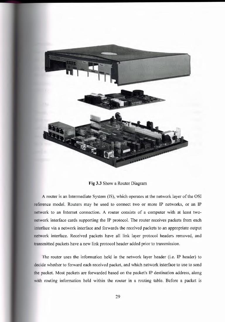
Fig 3.3 Show a Router Diagram
A router is an Intermediate System (IS), which operates at the network layer of the OSI
reference model. Routers may be used to connect two or more IP networks, or an IP
network to an Internet connection. A router consists of a computer with at least two
network interface cards supporting the IP protocol. The router receives packets from each
interface via a network interface and forwards the received packets to an appropriate output
network interface. Received packets have all link layer protocol headers removed, and
transmitted packets have a new link protocol header added prior to transmission.
The router uses the information held in the network layer header (i.e. IP header) to
decide whether to forward each received packet, and which network interface to use to send
the packet. Most packets are forwarded based on the packet's IP destination address, along
with routing information held within the router in a routing table. Before a packet is
29
orwarded, the processor checks the Maximum Transfer Unit (MTU) of the specified
· terface. The router into two or more smaller packets must fragment packets larger than
e interface's MTU. If a packet is received which has the Don:t Fragment (DF) bit set in
e packet header, the packet is not fragmented, but instead discarded. In this case, an
ICMP error message is returned to the sender (i.e. to the original packet's IP source address)
informing it of the interface's MTU size. This forms the basis for Path MTU discovery
(PMTU).
The routing and filter tables resemble similar tables in link layer bridges and switches.
Except, that instead of specifying link hardware addresses (MAC addresses), the router
table specify network (IP addresses). The routing table lists known IP destination addresses
with the appropriate network interface to be used to reach that destination. A default entry
may be specified to be used for all addresses not explicitly defined in the table. A filter
table may also be used to ensure that unwanted packets are discarded. The filter may be \,
used to deny access to particular protocols or to prevent unauthorized access from remote
computers by discarding packets to specified destination addresses.
30

Network 4 '//////////////////////////,
DD
H
DD Network 3
D
Network 2 I
Network 1 I
Figure 3.4 Shows a Routing of a Router
A router forwards packets from one IP network to another IP network. Like other systems,
it determines the IP network from the logical AND of an IP address with the associated sub
network address mask. One exception to this rule is when a router receives an IP packet to a
network broadcast address. In this case, the router discards the packet. Forwarding
broadcast packet can lead to severe storms of packets, and if uncontrolled could lead to
network overload. A router introduces delay (latency) as it processes the packets it receives.
The total delay observed is the sum of many components including:
Time taken to process the frame by the data link protocol
Time taken to select the correct output link (i.e. filtering and routing)
Queuing delay at the output link (when the link is busy)
31

Other activities which consume processor resources ( computing routing tables, network
management, generation of logging information)
The router queue of packets waiting to be sent also introduces a potential cause of
packet loss. Since the router has a finite amount of buffer memory to hold the queue, a
router, which receives packets at too high a rate, may experience a full queue. In this case,
the router ahs no other option than to simply discard excess packets. If required, these may
later be retransmitted by a transport protocol.
D fferent networl< n unoers
1R<Mllr~Y \ 1F1ter1Tab~1 Netw::irl< Relay (Rou:er}
Similar or dfferent slbnetw::irl<s
Figure 3.5 Shows Architecture of a router
Routers are often used to connect together networks, which use different types of links
(for instance an HDLC link connecting a WAN to a local Ethernet LAN). The optimum
(and maximum) packet lengths (i.e. the Maximum Transfer Unit (MTU)) are different for
different types of network. A router may therefore use IP to provide segmentation of
packets into a suitable size for transmission on a network. Associated protocols perform
network error reporting (ICMP), communication between routers (to determine appropriate
routes to each destination) and remote monitoring of the router operation.
3.5.1.1 Routing
Most network protocols were designed with network-layer routing. Routers base
forwarding decisions on an embedded network number in the network layer header of the
packet. They include network numbers that can be thought of as area codes in the phone
32

system as we must use the area code to call different areas. Any number of end stations
may be assigned to one network number like routers do not keep track of individual end
stations' addresses. Network numbers group network stations into one or more network
numbers. Routers combine networks and form Intemets.
3.5.1.2 Information in Packet
Each OSI layer in the implementation of hardware and software of a WAN
controller will be placed in the packet. Network layer information is placed in the data field
of packet, which is placed in this header for the network number, and this layer header
contains more than just network numbers. Source and destination MAC address fields are
reserved for the beginning of a packet. Whether bytes in the packet' the hardware and
software headers do not consume are left for the user data or control information.
Ethernet Packet Original Data Field
DA SA TF ]1 Network data I Transport data I Session Data I Application data CRC
---------- 1518 Bytes
Figure 3.6 Shows the Information in a Packet
3.5.1.3 Router Operation
Routers forward packets based not on the MAC address of the packet but on the
network number inside the packet. Each network separated by a router is assigned a unique
network number End stations know only of the network number of the network to which
they are attached. Before an end station transmits a packet, it compares the network number
of the destination to the network number and if the network numbers are the same, the
packet is simply transmitted on the cable, addressed to the destination station, as the
destination station is local. If the network numbers do not match, the end station must find a
router that it can send the packet to so that it can be transmitted to the original end. The
requesting station submits a special type of packet to the network requesting information
33

from the routers. The requesting station acquires the router's MAC address by some means
specific to the protocol.
3.5.1.4 Directly Attached Networks
A router receives the request and if it can find the network number, it sends a
response back to the requesting station. Node A picks the path that has the lowest cost to
the final destination. There is only one router response in this example. Node A sends the
packet to router Z. The source MAC address is A and the destination MAC address is B
(the router's MAC address. The destination network number is'located on the other side of
the router. The router directly to the end station forwards the packet. The packet is
addressed with source address as the routers address, source address C. The destination
address is the destination end station, destination station D. If the destination is not on the
other side of the router, the router has the next router's address in its routing table and the
packet is forwarded to the next router. Different network protocols operate differently.
Node D
Step4 Router forwards packet to network station D
Network 100
Step2 Send packet to router Z
Network 1 Step 1 Find network 1 00 Step3
Packet is given to the router
Node A
Figure 3.7 Shows a Directly Attached Network to WAN
34

3.5.1.5 Non-Directly Attached Networks
If the destination network is not directly attached to the router, the router will forward
the packet to another router in the forwarding path of the destination network. Router-to
router communication is directly MAC addressed. All routers in the path will perform the
same decisions as the previous router. The last router in the path to the destination will
forward the packet directly to the destination. Important to note that the data link MAC
headers will constantly change while the packet is being forwarded. Very little information
in the network header will change the network layer header in the packet will contain the
originator's full address and final destination address of the packet. The full address of a
network station is the combination of the network ID and its MAC address. This uniquely
identifies any station on the Internet.
3.5.1.6 Network Numbers
With the addition of routers, there are now two types of addresses on the network one
is network numbers, and other is MAC address. The XNS network numbers are 32 bits
long, allowing for 4,294,967,294 unique network numbers. Multiple methods for acquiring
a network number are as follows:
Routers are assigned their network numbers, usually one per port.
End stations can listen to the network (router updates).
It can be assigned to an end station.
End stations can build passive tables based on router updates.
end station can request it from a router.
An end station can acquire a remote stations network address from a name server.
35

3.5.1.7 Routing Information Protocol (RIP)
This is known as a routing table update protocol as most commonly found router
update protocol is called Routing Information Protocol (RIP). Developed by Xerox and
gained widespread acceptance by the proliferation of TCP/IP's implementation of it in
UNIX. Other protocols adopted RIP as their standard routing update protocol. Different
protocol implementations of RIP cannot update each other this is known as a distance
vector protocol and vector is the network number and the distance is how far away (hops)
the »network is one hop is considered one router traversed. Devised for very stable, small
to-medium size networks (less than a few hundred nodes).
3.5.1.8 Multiprotocol Routers
LANs currently operate with many different types of protocols.
Apple Computers can use AppleTalk.
UNIX workstations use TCP /IP.
Client/Server applications could use Novell Net Ware.
Forward on MAC address Route on
network IDs
Combine both into one box
Incoming packet Can packet be routed based on protocol type?
l Bridge packet if not
Bridged or routed packet
Figure 3.8 Shows a Block Diagram ofMultiprotocol Router
36

Routes not only based on the network IDs but also are able to pass the packet to the
rrect protocol processor by examining the Type of packet.
.2 Hubs
A special type of network device called the hub can be found in many home and small
siness networks. Though they've existed for many years, the popularity of hubs has
exploded recently, especially among people relatively new to networking. Do you own a
ub, or are you considering purchasing one? This article explains the purpose of hubs and
some of the technology behind them.
3.5.2.1 General Characteristics of Hubs
A hub is a small rectangular box, often constructed mainly of plastic that receives its ' power from an ordinary wall outlet. A hub joins multiple computers (or other network
devices) together to form a single network segment. On this network segment, all
computers can communicate directly with each other. Ethernet hubs are by far the most
common type, but hubs for other types of networks (such as USB) also exist.
A hub includes a series of ports that each accepts a network cable. Small hubs network
four computers. They contain four or sometimes five ports (the fifth port being reserved for
"uplink" connections to another hub or similar device). Larger hubs contain eight, 12, 16,
and even 24 ports.
3.5.2.2 Key Features of Hubs
Hubs classify as Layer 1 devices in the OSI model. At the physical layer, hubs can
support little in the way of sophisticated networking. Hubs do not read any of the data
passing through them and are not aware of a packet's source or destination. Essentially, a
hub simply receives incoming packets, possibly amplifies the electrical signal, and
broadcasts these packets out to all devices on the network (including the one that sent the
packet!). Hubs remain a very popular device for small networks because of their low cost.
A good five-port Ethernet hub can be purchased for less then $50 USD.
37

Technically speaking, three different types of hubs exist:
1. Passive
2. Active
3. Intelligent
Passive hubs do not amplify the electrical signal of incoming packets before
broadcasting them out to the network. Active hubs, on the other hand, will perform this
function -- a function that is also present in a different type of dedicated network device
called a repeater. Some people use the terms concentrator when referring to a passive hub
and multiport repeater when referring to an active hub. Intelligent hubs add extra features to
an active hub that are of particular importance to businesses. An intelligent hub typically is
stackable (built in such a way that multiple units can be placed one on top of the other to
conserve space). It also typically includes remote management support via SNtvfP support.
Figure 3.9 Shows an Active Hub Used with ISDN Router
38

;.3 Bridges
Useful for breaking up subnets into small segments, making it easier to localize
errors.Restricts traffic local to machines to that segment, by sensing what Ethernet
esses are where. This improves both network performance and privacy (makes sniffing
re difficult).
_ ,ewer bridges also have built in http servers, if possible restrict access to certain IP
dress/interfaces, and avoid using this service from public or potentially hostile networks. '
3.5.4 Modems
A modem is used to connect a computer to the Internet. It begins with an overview of
some of the basic signals the RS-232 serial interface uses to connect an external modem to
a computer. Theimportance of these signals for proper operation of the modem will be
discussed in terms of both modem and software configuration. This is known as Network
Interface Card (NIC)
Figure 3.10 Shows a Network Interface Card
39

3.5.4.1 The Modem Plug (RS-232 Interface overview)
The EIA (Electronic Industries Association) RS-232 standard specifies signals for
serial interfaces used to connect computers and modems. For technical precision, the terms
Data Terminal Equipment (DTE) and Data Communication Equipment (DCE) are used to
distinguish between the computer and the modem, respectively. This is useful because
serial interfaces are used for many things besides computers and modems such as dumb
terminals, plotters, scanners, printers, etc. These terms are important because they are used
to define the interface signals. A different type of serial cable is needed to connect a
modem to a computer (DTE to DCE connections use a modem cable) than is used to, say,
connect one computer to another (DTE to DTE connections use a null-modem cable). Such
PC programs such as Lap-Link, or the MS-DOS INTERLNK command use null modem
cables.
The standard is based on a 25-pin connector, of which ten connections are commonly
used. The names of the signals and the pin designations on a standard DB25 pin connector
are: protective (frame) ground 1, transmit data 2, receive data 3, request to send 4, clear to
send 5, data set ready 6, signal ground 7, carrier detect 8, data terminal ready 20, and ring
indicator 22. Many manufacturers have designed serial connectors that use fewer
connections, such as the IBM AT DB9 connector, or the Macintosh DIN 8. To simplify
discussion of these signals this document will generally only refer to pin designation
numbers for the standard 25-pin connector (DB25). Modem cables for computers with
non-standard connectors are usually available, which provide a DB25 connector at the
modem end with a subset of the 10 connections mentioned above.
Three of these connections are absolutely essential: transmit data, receive data, and
signal ground. The transmit data line is where data are transmitted from the computer (DTE) to the modem (DCE). Tne receive data \ine is where data are received from the
modem (DCE) by the computer (DTE). Signal ground is the reference against which all
other signals apply voltage. Think of a battery and a light bulb: it is not possible for current
to flow without two wires. Signal ground is the second wire for all the other signals.
40

3.5.4.2 Error Correction and Data Compression
Almost more confusing than the actual protocols and modem commands is the
terminology used to describe error correction (also called error control). Error correction is
imilar to file transfer protocols such as Kermit, X, Y, or Z modem. File transfer protocols
reak files up into chunks called packets. Error correction does the same thing except the
locks of data are called frames and are generally smaller than those typically used by
modem file transfer protocols. In all cases additional information such as a checksum is
added to the packet (frame) to verify that the data was undamaged in transit. If the data
does not match the checksum the entire packet or frame must be resent. This technique
trades off some speed for reliability. Like sliding-windows protocol severalframes may be
sent before an acknowledgment is required. The maximum data block size and the number
of frames allowed before an acknowledgment is required are parameters negotiated by the
modems when they connect.
3.5.4.3 Direct, Normal, and Reliable Connections
Many modems will use these terms to distinguish between several types of modem
configurations. A direct connection is the old-fashioned sort with no error correction or
data compression. In a direct connection the DTE rate ( computer serial speed) and the link
rate (modem connection speed) must match. A normal connection uses flow control for
speed buffering so the DTE and link rates may differ. A reliable connection uses flow
control and will often hang up if error correction and data compression cannot be
established. An auto-reliable connection is like a reliable one except the modem will fall
back to normal or direct mode automatically rather than hang up.
3.5.5 Integrated Services Digital Network (ISDN)
Integrated Services Digital Network (ISDN) is comprised of digital telephony and data
transport services offered by regional telephone carriers. ISDN involves the digitalization
of the telephone network, which permits voice, data, text, graphics, music, video, and other
source material to be transmitted over existing telephone. The emergence of ISDN
represents an effort to standardize subscriber services, user/network interfaces, and network
41

and Internet work capabilities. ISDN applications include high-speed image applications
such as Group IV facsimile), additional telephone lines in homes to serve the
lecommuting industry, high-speed file transfer, and video conferencing. Voice service is
also an application for ISDN. This chapter summarizes the underlying technologies and
services associated with ISDN.
3.5.5.1 ISDN Components
ISDN components include terminals, terminal adapters (TAs), network-termination
devices, line-termination equipment, and exchange-termination equipment. ISDN terminals
come in two types. Specialized ISDN terminals are referred to as terminal equipment type I
(TEI). Non-ISDN terminals, such as DTE, that predates the ISDN standards are referred to
as terminal equipment type 2 (TE2). TEis connect to the ISDN network through a four
wire, twisted-pair digital link. TE2s connect to the ISDN network through a TA. The ISDN
TA can be either a standalone device or a board inside the TE2. If the TE2 is implemented
as a standalone device, it connects to the TA via a standard physical-layer interface.
Examples include EIA/TIA-232-C (formerly RS-232-C), V.24, and V.35. Beyond the TEI
and TE2 devices, the next connection point in the ISDN network is the network termination
type I (NTI) or network termination type 2 (NT2) device. These are network-termination
devices that connect the four-wire subscriber wiring to the conventional two-wire local
loop. In North America, the NTI is a customer premises equipment (CPE) device. In most
other parts of the world, the NTI is part of the network provided by the carrier. The NT2 is
a more complicated device that typically is found in digital private branch exchanges
(PBXs) and that performs Layer 2 and 3 protocol functions and concentration services. An
NTl/2 device also exists as a single device that combines the functions of an NTI and an
NT2. ISDN specifies a number of reference points that define logical interfaces between
functional groupings; such as TAs and NTis. ISDN reference points include the following:
• R-The reference point between non-ISDN equipment and a TA.
• S-The reference point between user terminals and the NT2.
• T-The reference point between NT I and NT2 devices.
42

The reference point between NTl devices and line-termination equipment in the carrier
twork. The U reference point is relevant only in North America, where the carrier
twork does not provide the NTl function. Figure 12-1 illustrates a sample ISDN
configuration and shows three devices attached to an ISDN switch at the central office.
Two of these devices are ISDN-compatible, so they can be attached through an S
reference point to NT2 devices. The third device (a standard, non-ISDN telephone) attaches
through the reference point to a TA. Any of these devices also could attach to an NTl/2
device, which would replace both the NTl and the NT2. In addition, although they are not
shown, similar user stations are attached to the far right ISDN switch.
Switclled network
TE1 device (computer)
s T u
ISDN swltcn W---,---..., ISDN
switch
TE1 device (ISDN telephone)
s T u
TE2 device R. (stamiard telephone)
s T
Figure 3.11 Shows a Sample ISDN configuration is illustrated.
The ISDN Basic Rate Interface (BRI) service offers two B channels and one D channel
(2B+D). BRI B-channel service operates at 64 kbps and is meant to carry user data; BRI D
channel service operates at 16 kbps and is meant to carry control and signaling information,
43
ugh it can support user data transmission under certain circumstances. The D channel
ing protocol comprises Layers 1 through 3 of the OSI reference model. BRI also
vides for framing control and other overhead, bringing its total bit rate to 192 kbps. The
physical-layer specification is International Telecommunication Union
ommunication Standardization Sector (ITU-T) (formerly the Consultative Committee
International Telegraph and Telephone [CCITT]) I.430. ISDN Primary Rate Interface
service offers 23 B channels and one D channel in North America and Japan, yielding
total bit rate of 1.544 Mbps (the PRI D channel runs at 64 Kbps). ISDN PRI in Europe,
ustralia, and other parts of the world provides 30 B channels plus one 64-Kbps D channel
a total interface rate of 2.048 Mbps. The PRI physical-layer specification is
ISDN physical-layer (Layer 1) frame formats differ depending on whether the frame is
bound (from terminal to network) or inbound (from network to terminal). Both physical
yer interfaces are shown in Figure 12-2). The frames are 48 bits long, of which 36 bits
represent data. The bits of an ISDN physical-layer frame are used as follows:
F-Provides synchronization
• L-Adjusts the average bit value
• E-Ensures contention resolution when several terminals on a passive bus
contend for a channel
• A-Activates devices
• S-Unassigned
• B 1, B2, and D-Handles user data
44

Fi-al cl le ngtll , in bits ·1 1 8 1 1 1 ·1 ·1 8 1 1 1 B 1 1 ·1 B
1+1 81 H+l+I 82 H+I 81 H+I 82 I ··· I f,JT frame (network to terminal)
Field lengt11, in l~ts 1 1 1 1 1 8 1 1 1 8 8 ·1 1 1 1 1
F L B 1 E D A F F B2 E D S B 1 E D S B2 · · ·
TE frame (terminal to net,.11rorl,:;)
A= Activation bit 8·1 = B1 channel bits 82 = B2 channel bits D = D cl1annel (4 bits x 4000 rramssrsec.> 16 kbps) E = Echo of previous D bit F = Framing bit L = Load l:;,alancing S = Spare blt
Figure 3.12 Shows ISDN Physical-layer frame formats
Multiple ISDN user devices can be physically attached to one circuit. In this
configuration, collisions can result if two terminals transmit simultaneously. ISDN
therefore provides features to determine link contention. When an NT receives a D bit from
the TE, it echoes back the bit in the next E-bit position. The TE expects the next E bit to be
the same as its last transmitted D bit. Terminals cannot transmit into the D channel unless
they first detect a specific number of ones (indicating "no signal") corresponding to a pre
established priority. If the TE detects a bit in the echo (E) channel that is different from its
D bits, it must stop transmitting immediately. This simple technique ensures that only one
terminal can transmit its D message at one time. After successful D- message transmission,
the terminal has its priority reduced by requiring it to detect more continuous ones before
transmitting. Terminals cannot raise their priority until all other devices on the same line
have had an opportunity to send a D message. Telephone connections have higher priority
than all other services, and signaling information has a higher priority than non-signaling
information.
45

Layer 2
Layer 2 of the ISDN signaling protocol is Link Access Procedure, D channel (LAPD).
LAPD is similar to High-Level Data Link Control (HDLC) and Link Access Procedure,
Balanced (LAPB). As the expansion of the LAPD acronym indicates, this layer it is used
across the D channel to ensure that control and signaling information flows and is received
properly. The LAPD frame format (see Figure 12-3) is very similar to that of HDLC and,
like HDLC, LAPD uses supervisory, information, and unnumbered frames. The LAPD
protocol is formally specified in ITU-T Q.920 and ITU-T Q.921. The LAPD Flag and
Control fields are identical to those of HDLC. The LAPD Address field can be either 1 or 2
bytes long. If the extended address bit of the first byte is set, the address is 1 byte; if it is
not set, the address is 2 bytes. The first Address-field byte contains identifier service access
point identifier (SAPI), which identifies the portal at which LAPD services are provided to
Layer 3.
Field length, in bytes Variable 2
Flag Address Control
,- ,- \ '- ,- \ ; ' ~
'- ,- r ~ '-
SAPI I C!RIEAI TEI IEA
Dat::'I FGS I Flat1
SAPI = Service access point iclentifier (6 bits) G/R = corrmandnssponss l)it ~ EA = Extended adclrnssing bits fr1 TEI = Terminal endpoint identifier c.'i?
Figure 3.13 Shows LAPD frame format is similar to HDLC and LAPB.
The CIR bit indicates whether the frame contains a command or a response. The
terminal end-point identifier (TEI) field identifies either a single terminal or multiple
terminals. A TEI of all ones indicates a broadcast.
46

specifications are used for ISDN signaling: ITU-T (formerly CCITT)
(also known as ITU-T Q.930) and ITU-T 1.451 (also known as ITU-T Q.931).
er, these protocols support user-to-user, circuit-switched, and packet-switched
~tions. A variety of call-establishment, call-termination, information, and
llaneous messages are specified, including SETUP, CONNECT, RELEASE, USER
ORMATION, CANCEL, STATUS, and DISCONNECT. This Address Flag Control
FCS Flag Field length, in bytes variable messages are functionally similar to those
vided by the X.25 Figure 3 .14, from ITU-T 1.451, shows the typical stages of an ISDN
I = Service access point identifier ( 6 bits)
= Command/response bit
EA = Extended addressing bits
TEI = Terminal endpoint identifier
47

outer call
Calling DTE
Calling DCE
Called DCE
Galled CallEH DTE router
---
IOW _.l----- ---
---
Figure 3.14 Shows an illustration of Circuit Switch Call.
48
3.5.6 CSU/DSU
High-speed, LAN-attached applications continue to rise, generating an increasing need
for cost-effective WAN access for intranet and Internet access implementation. Routed
networking is today the most widely implemented network solution for organizations of all
types. Digital circuits operating at speeds from 56Kbps (DDS service) to l.544Mbps (Tl
and Fractional T 1 services) to T3 ( 45 Mbps or 28 T 1 's) provide the WAN infrastructure
that interconnects the routers located at each location served by the network. The traditional
approach to terminating DDS, Tl/FTl and T3 circuits at each location is to use a
standalone or high-density rack mounted Channel Service Unit/Data Service Unit
(CSU/DSU). "Line-by-line" CSU/DSUs and CSU/DSUs providing integrated Tl access are
mature products, and are available with enhancements such as SNMP management, direct
Ethernet connections, and dial restoral features. In addition to traditional standalone
CSU/DSU solutions, routers with an integral CSU/DSU are available. Integrated CSU/DSU
functionality initially might appear to be a good choice, i.e., having one integrated unit
instead of two functional units may provide certain reliability advantages. It might be
thought that having the CSU/DSU integrated into the router will:
Provide a lower cost than comparable separate CSU/DSU devices
Eliminate a potential point of failure in the network, namely, the cabling required to
connect an external CSU/DSU to a router
Save rack space at a central site, and reduce two boxes to one at remote sites however,
while these beoeJJts appear goo4 there are other factors that require consideration.
This management briefing will discuss that, depending on the application; integrated approaches do not necessarily save money or eliminate points of failure. In addition, this
briefing will outline valuable features available only in non-integrated CSU/DSUs.
49

3.5.6.1 Comparing Basic Capabilities
Figure 3.15 shows a basic Tl network access arrangement using traditional non
integrated CSU/DSUs at both the remote and central sites.
WAN
High De.nsity Rackmount CSU/DSUs
Network l'itanagement
St.atic.n
£ Ulemet / LA~l
Figure 3.15 Shows a Basic Tl Network Access
The network depicted in Figure 3.14 can be viewed as either being traditional point-to
point DDS/Tl networking or as frame relay. Figure 3.16 shows the same Tl access
objective achieved with integral CSU/DSUs. At first glance, it seems that the router with
integral CSU/DSU approach is simpler to install and should be more cost effective.
However, another look at both approaches shows that this may not be the case. Cost
Savings Proponents of router-integrated Tl CSU/DSUs argue that the internal units are less
costly to purchase than separate, external CSU/DSUs.
50
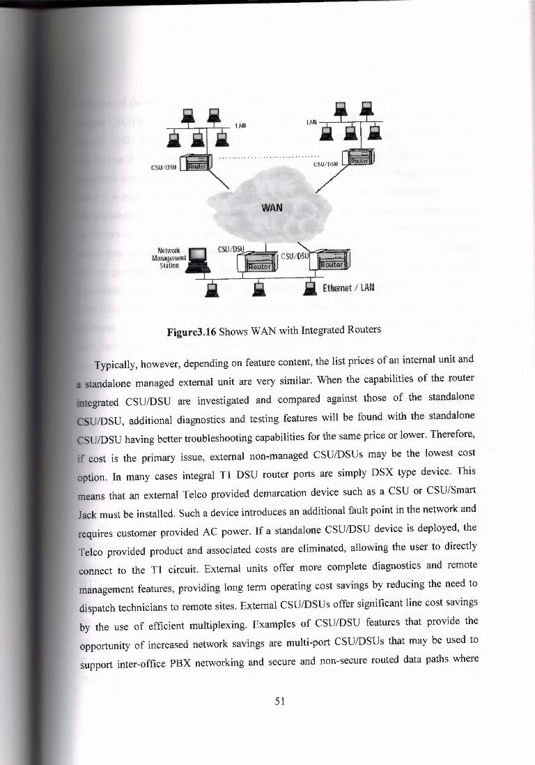
WAN
Network l,1anagement
Sta~ion
Ethernet / LAN
Figure3.16 Shows WAN with Integrated Routers
Typically, however, depending on feature content, the list prices of an internal unit and
standalone managed external unit are very similar. When the capabilities of the router
· tegrated CSU/DSU are investigated and compared against those of the standalone
CSU/DSU, additional diagnostics and testing features will be found with the standalone
CSU/DSU having better troubleshooting capabilities for the same price or lower. Therefore,
if cost is the primary issue, external non-managed CSU/DSUs may be the lowest cost
option. In many cases integral Tl DSU router ports are simply DSX type device. This
means that an external Telco provided demarcation device such as a CSU or CSU/Smart
Jack must be installed. Such a device introduces an additional fault point in the network and
requires customer provided AC power. If a standalone CSU/DSU device is deployed, the Telco provided product and associated costs are eliminated, allowing the user to directly
connect to the Tl circuit. External units offer more complete diagnostics and remote
management features, providing long term operating cost savings by reducing the need to
dispatch technicians to remote sites. External CSU/DSUs offer significant line cost savings
by the use of efficient multiplexing. Examples of CSU/DSU features that provide the
opportunity of increased network savings are multi-port CSU/DSUs that may be used to
support inter-office PBX networking and secure and non-secure routed data paths where
51

ples of these applications are discussed later in this paper. Points of Failure because
~l CSU/DSUs eliminate the need for a cable between the WAN port of the router and
CSU/DSU (DTE interface), a potential point of failure may have been eliminated. This
.; be true if cables were prone to failure, which typically they are not. However, the non
ated solution also provides relief from a single point of failure. Should a problem
ur in a router with integral CSU/DSU - much more likely than a cable failure - on-
• troubleshooting to determine which internal component has failed will be necessary. If
results of the testing are in any way inconclusive or ambiguous, replacing the entire
ter may appear to be needed, when in fact the problem actually may be a network
ice problem, easily identified by an external CSU/DSU. If diagnostic testing
capabilities of an integral CSU/DSU were deemed comparable to those of a nonintegrated
CSU/DSU then the integral CSU/DSU solution would provide a superior solution.
However, this is not the case by design. Many non-integrated CSU/DSUs offer superior
fault isolation through comprehensive line and BERT diagnostic testing. This briefing
concludes that troubleshooting the rare cable failure and its repair, is much easier and far
less disruptive to the network operation than troubleshooting and replacing of a router, or
the integral CSU installed in the router. Space Saving For central site rack mounting of
large numbers of WAN links, the initial size of the router(s) with integral CSU/DSUs takes
up much more real estate than that of a high density CSU/DSU shelf. For example, two
CSU/DSUs using GDC's Spectra- Comm 2000 shelf require only 1.75" (44.45 mm) of rack
height, and up to 16 CSU/DSU units can be housed in the SpectraComm 5000 shelf, which
is only 7" high (180 mm).
Power Savings of power is not usually a benefit put forth by the proponents of integral
CSU/DSUs. Why? Routers are designed for environmentally controlled computer rooms.
Routers typically exhaust a considerable amount of heat consuming a high amount of
BTUs. When a CSU/DSU is placed inside a router it becomes part of the power
consumption equation. Routers are typically AC powered with backup power (if supplied)
provided via generator. Commercial power interruption of a router with integral CSU/DSU
affects the WAN connection as well as the integral LAN. Redundant power supply modules
may not be an option of many low-to-medium end routers. Lack of commercial power is a
major point of failure to a router with integral CSU/DSU. Many standalone and all rack
52

t CSU/DSUs manufactured by GDC offer dual power options (AC and DC).
undant power supply modules are available on all SpectraComm and Universal Access
/Stem products. All GDC CSU/DSUs, standalone as well as rack mount, use six watts or
of power. GDC CSU/DSU shelves do not use fans and due to the very low power
dget design dissipate heat. Air-conditioned environments are not needed. NEBS
-~etwork Equipment Building Standards) NEBS compliancy is a requirement when sharing
Telco Central Office space, but many aspects of NEBS are beneficial to premise
installations. Very few routers with integral CSU/DSUs can pass the stringent NEBS tests,
and therefore, are not allowed to be installed in the Central Office. Applicable NEBS
benefits include fire safety, electrical hazard and shock protection, lightning protection and
power line isolation. Costly repairs and network disasters can be greatly reduced by the use
of an external CSU/DSU. For example, if an integral DSU were utilized, a lightning strike
of power surge on the network would travel directly into the router and conceivably pass to
the LAN, which may be connected to PCs and other LAN devices. As a result, all attached
users and equipment are put at risk. However, by using GDC's CSU/DSUs, which protect
against hazardous line transients including power lines and transmission lines, the risk is
eliminated.
3.5.6.2 Value Added
Most standalone CSU/DSUs offer additional capabilities typically not provided by
integral CSU/DSU offerings. These include:
1. DSL Services
2. Multiport Capability
3. Drop-and-Insert Capability
4. Upgradeable
5. Portable
6. Demarcation of Service Point
7. Variable Line Equalization I Build outs
8. Automatic Service Rate Selection
9. Service Line Isolation I Protection
53

WAN/PSTN
~tv\lll'k Manag.iment
Station
Efher~t I LAN
Figure 3.17 Shows a PBX and Router Sharing Single
Tl Access with "Drop-and-Insert" CSU/DSU Depending upon the application, these
capabilities can be critical to the resiliency, manageability, and cost effectiveness of a
network; and any one of them can make a strong case for a non-integrated as opposed to a
router-integrated approach. Unlike integrated Tl CSU/DSUs, non-integrated Tl
CSU/DSUs support multiple ports and/or drop-and insert capabilities. The advantage of this
is far greater applications flexibility - assuming incremental T 1 channel capacity is
available. For example, as shown in Figure 3.18, users can easily add via drop-and-insert an
additional application, such as voice from a PBX, saving the cost of a separate new Tl
circuit. DSL Services The ILEC's competitors, known as the CLECs, are emerging and
offering comparable Tl replacement services such as DSL. These services provide an
external NTU device, which connects conventional WAN traffic to DSL. An integral
CSU/DSU within a router prevents customers from leveraging this future cost savings,
which is predicted to dominate service markets for years to come. Multiport Capability
allows individual DSO channels (56/64Kbps) of a Tl to be segmented to support a legacy
54

lication. This can be an effective way of eliminating the cost of an analog leased line
een corporate headquarters and a regional facility. The ability to support multiple
lications over a simple Tl without adding multiplexing equipment allows maximum use
the Tl line and saves on multiple line costs. Only a non-integrated solution has this
ability, Many non-integrated Tl access devices support up to four separate data terminal
ipment (DTE) ports with standard physical interfaces such as V.35, EIA- 530/422, and
TIA-232-E. This capability can be in addition to the drop-and-insert capability and can
used to support an additional application, such as a PBX, via a DSX-1 interface port.
The DSX-1 port also allows the standalone unit to act as a CSU, thus supporting " plications where CSU-only functions are required. Figure 3.17 shows a dual router
plication - again a single Tl access circuit is shared to reduce network costs. Drop-and-
ert Capability allows a T 1 circuit to be groomed into two or more "channels" each
comprising a selected number of DSOs. For example, the data network could be assigned
512Kbps (8 DSOs) and a PBX assigned the remaining 1024 kbps (16 DSOs) for voice. This
mapping or DSOs would eliminate the need for two separate circuits; one for data and one
for voice. If two circuits were required to meet the total bandwidth requirement, network
diversity could be implemented for the data network ( or the voice network), without having
to purchase additional circuits. Drop-and-insert can also be used to split a Tl circuit
between two routers, each being assigned a fractional T 1 circuit speed, for example,
l,024Kbps (16 DSOs) and 512Kbps (8 DSOs) respectively. This accommodates situations
where secure server access has to be provided for Internet access, but the firewall is not
required (or desired) on the organization's intranet. Upgradeable Unlike an integrated
CSU/DSU that is limited to its basic functionality, a non-integrated CSU/DSU can easily be
upgraded to support drop-and- Access with "Drop-and Insert" CSU/DSU insert and/or
multiport features.
55

WAN
High Density Rackmount CSU/DSUs
fletr~urk Mc1nc13E111~t
Station
Figure 3.18 Shows Dual Routers Sharing Single Tl
In this way, non-integrated access greatly increases the flexibility to accommodate
network change and growth and match the best router and best access features to the
application. Portable a non-integrated CSU/DSU, whether directly or indirectly LAN
connected, can be easily relocated. A non-integrated unit can also be used with any
manufacturer's router and also within non-routed applications in the same Tl network.
3.5.6.3 Diagnostic Testing
Fault Insulation and Troubleshooting With an integral CSU/DSU, fault isolation
troubleshooting can be difficult. Should the router at the central site fail, the network
administrator cannot immediately isolate the problem as to an integral CSU/DSU failure, a
Tl line failure, or a network failure. If the router at the remote site fails the network
manager will probably have to dispatch a technician to test the router or at the very least
contact the Telco to check the Tl circuit. In contrast, as illustrated in Figure 5, a non
integrated solution can include a LAN-connected, out-of-band management path to the
CSU/DSU at the central site and an in-band management path at the remote site.
Consequently, if the central site router fails, the condition of the central site CSU/DSU and
56

- and the router DTE connection and corresponding leads can be determined via a
IN-attached Network Manager. If the remote router fails, the condition of the remote
and CSU/DSU can be determined directly from the central site. If the circuit fails,
ement communications can be maintained to the remote CSU/DSU via the switched
rk using a collocated analog modem. The necessary Tl line diagnostic tests can be
without the need to contact the Telco, further reducing the cost of ownership for the
lone solution. Comprehensive Diagnostic Loop back Testing As figure 6 shows, in
· onal T 1 and multi port applications, loop-back testing at the channel level is essential
isolating problems within the Tl 24 DSO channel bundle. However, most router
ted CSU/DSUs support only full Tl payload loop backs, while Out-of-Band
gement non-integrated CSU/DSUs support non-intrusive channel loop back tests that
not interfere with data passing through other channels .
. \ .- \... WAN .. ·"·,,.·· .,.__In-Ban~ Management \ /" viaP\IC
...•.. \...-·"·,,..,.····
High Density Rackmount CSU/DSUs
Out,of,Balild Managerrent _ _....,_ ~--~ - via LAN
Figure 3.19 Shows Centralized, In-Band Management
57

Line Monitoring Break-in line monitoring and testing are standard Tl CSU/DSU
features that allow a technician to break into the Tl path to monitor the condition of the
circuit and corresponding T 1 channels, as well as to trouble shoot by sending specific test
transmit/ receive signals. Break-in line monitoring and testing is done using external test
equipment without disturbing the data flow via a convenient front panel connector on the
CSU/DSU. Most integrated CSU/DSUs do not have this feature. When they do, the break
in connector is inconveniently located at the back of the router lost among all the cables.
3.5.6.4 Single Point of Failure
Router vendors argue that the integrated approach allows easier installation and
integrating the CSU/DSU in the router eliminates two sources of possible failure:
Either the separate CSU/DSU itself or the associated cabling. Consider that the
CSU/DSU is still an active component of the network and should failure occur as stated
earlier, the network disruption in servicing an integrated router is much greater than that
created by servicing a non-integrated CSU/DSU.
Integrated CSU/DSUs do not have comparable meantime- between-failure (MTBF) ratios
to that of the telecom-standard CSU/DSUs, which are typically expressed in hundreds of
years. The most likely points of failure are the local loop or the router itself, with its
complicated software and integral hardware components. Strong diagnostic capabilities as
described in the previous paragraphs cannot be considered an option; they are a "must
have" item. If a router with an CSU/DSU fails Figure 3.20, the integral CSU/DSU
functionality will be lost - or at best significantly diminished - potentially crippling any
ability to troubleshoot the network.
3.5.6.5 Frame Relay Application
A major portion of installed data networks consist of routed frame relay. Frame relay
networks offer many obvious benefits, including an economic advantage over multiple
point-to-point networks. With frame relay, optimum network design requires good
knowledge of the traffic volumes actually being carried. If a frame relay network is over-
58

signed, much of the economic advantage will be lost. If the network is under-specified
e network response times during busy periods will become unacceptable, resulting in loss
of productivity, not to mention complaints from users. In addition, due to the bursty nature
of LAN-to-LAN traffic, it may be difficult without actual monitoring of the traffic, to know
.hether poor response times are the result of congestion in the carriers network or the
result of under-sized (i.e. under specified) frame relay circuits, or the result of server
response times. The solution to these potential problems is the Frame Relay Probe or
"Frame-Aware'' CSU/DSU, which can provide real-time network traffic information and
network status information. Frame Relay analysis capabilities found within routers is not
enough.
RoUt((S ~1tl11111£gratM CSll.tDSUs ' arevutn!'.f aole to ra·llu.rn or e.lthe.·r . urn
ti);! rout •• r or the CSU/DSU -
~
LAN ,~'- ,-
' - WAN
D -c n)1I Ce11tr.al'.slt.,e 10t1te.rl1as OM •.•.• ,~...- .
!l,nultiple CSIJ/DSUs en a, single blade
Figure 3.20 Sows Single Point of Failure Risk
Frame Probe For example, GDC's Frame Relay Probe provides both the probe and the
CSU/DSU functionalities in one unit providing valuable information on:
I. Network Availability
2. PVC Availability
59

_ ;etwork Delay
PVC Throughput
End-to-End Frame Loss
Forward and Backward Explicit Congestion
Notifications (FECNs and BECNs)
Discard Eligibility (DE) Frames
Local Management Interface (LMI) Statistics
. (Timeouts and No Responses)
. Bandwidth Utilization
. Committed Information Rate (CIR) Utilization.
Data can be retrieved from each innovx unit via the web and can be stored in a PC
ork man~gement station. Using either Innovx Frame Manager software or industry
ailable network management software such as Concord's Network Health; weekly,
onthly, quarterly and yearly trend analysis and data reporting is readily available .
. 6 External connections to WAN s
3.6.1 Permission for external connections
For external access (via modem for example) to internal systems or from internal
systems to the outside (Internet for example), a user should have the written permission.
The user should prove that such an external access is absolutely necessary.
These external connections can be classed as incoming and outgoing:
60

3.6.2 Example Incoming connections
Dialup access for company partners.
Dialup access for II staff and directors.
Access from universities (co-ordination on research projects).
Internet Email.
Enterprise WWW Server.
EDI
3.6.3 Example Outgoing Connections
Access to Vendor Bulletin boards (for getting information, drivers).
Customer connections: providing special services to clients (examples?).
Internet Email.
Normal Internet access: Netscape via proxy server.
Special Internet Access: WWW, Archie, ftp, news, telnet, gopher, wais.
EDI (see above).
3.6.4 Simple Internet or Bulletin board access
If Internet access is required for information browsing (e.g. ftp or Web) on a sensitive
zone, one solution is to use a simple PC with modem but with absolutely no (internal)
61

network connection. It is important that these connections be registered with, and audited
regularly by centralized security staff.
3.6.5 Insecure subnets
Where many external connections are required in one building, one possibility is to
group together the external connections on an "Insecure Subnet" which has direct outside
access, but which is separated from the internal network via a Firewall. This minimizes cost
(only one firewall) and maximizes flexibility, but great care must be taken in the daily
usage on these machines on the "Insecure Subnet", as they must be considered as
dangerous, penetrated hosts.
3.6.6 Network Management I Monitoring
Networks are becoming more important, data speeds and volumes are increasing and
networks are becoming more and more heterogeneous. Professional Network monitoring
can help to analyze and predict problems (and increase availability). Such monitors can also
be used to increase security by two methods:
a) "Strange" network behavior could be an intrusion, so a monitor should be able to note
"strange" (i.e. not "normal") network behavior.
b) If security policy specifies that certain services are not to be used by certain hosts at
specified times, network monitor software could be used to check this. e.g. if the security
policy for a network specifies that ftp is not to be used between 00:00 and 06:00, then any
ftp traffic on the network at this time should be monitored an reported as a security alert.
This kind of monitoring is especially useful for local high security networks.The Solaris 1
utility etherfind or the Solaris 2 utility snoop or the VMS utility ethermon could be used to
monitor the network for unusual behavior, but only from qualified, trusted personnel!
Utilities such as Satan can be used to identify devices on an IP network, as well as report on
TCP/IP security problems. Such utilities should be removed from all other machines.
62

CHAPTER FOUR
W eh Services Architecture
4.1 Purpose of the Web Service Architecture
Web services provide a standard means of interoperating between different software
applications, running on a variety of platforms and/or frameworks. This document (WSA)
is intended to provide a common definition of a Web service, and define its place within a
larger Web services framework to guide the community. The WSA provides a conceptual
model and a context for understanding Web services and the relationships between the
components of this model.
The architecture does not attempt to specify how Web services are implemented, and
imposes no restriction on how Web services might be combined. The WSA describes both
the minimal characteristics that are common to all Web services, and a number of
characteristics that are needed by many, but not all, Web services.
The Web services architecture is interoperability architecture: it identifies those global
elements of the global Web services network that are required in order to ensure
interoperability between Web services.
4.2 Document Organization
This document has two main sections: a core concepts section (2 Concepts and
Relationships) and a stakeholder's perspectives section (3 Stakeholder's Perspectives).
Two Concepts and Relationships provide the bulk of the conceptual model on which
conformance constraints could be based. For example, the resource concept states that
resources have identifiers (in fact they have URls). Using this assertion as a basis, we can
assess conformance to the architecture of a particular resource by looking for its identifier.
If, in a given instance of this architecture, a resource has no identifier, then it is not a valid
instance of the architecture.
63
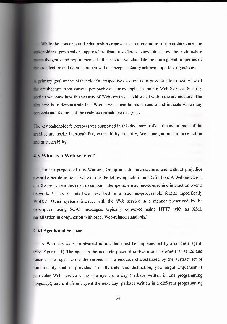
While the concepts and relationships represent an enumeration of the architecture, the
holders' perspectives approaches from a different viewpoint: how the architecture
the goals and requirements. In this section we elucidate the more global properties of
architecture and demonstrate how the concepts actually achieve important objectives.
primary goal of the Stakeholder's Perspectives section is to provide a top-down view of
architecture from various perspectives. For example, in the 3.6 Web Services Security
· on we show how the security of Web services is addressed within the architecture. The
here is to demonstrate that Web services can be made secure and indicate which key
cepts and features of the architecture achieve that goal.
e key stakeholder's perspectives supported in this document reflect the major goals of the
hitecture itself: interopability, extensibility, security, Web integration, implementation
d manageability .
. 3 What is a Web service?
For the purpose of this Working Group and this architecture, and without prejudice
toward other definitions, we will use the following definition:[Definition: A Web service is
a software system designed to support interoperable machine-to-machine interaction over a
network. It has an interface described in a machine-processable format (specifically
WSDL). Other systems interact with the Web service in a manner prescribed by its
description using SOAP messages, typically conveyed using HTTP with an XML
serialization in conjunction with other Web-related standards.]
4.3.1 Agents and Services
A Web service is an abstract notion that must be implemented by a concrete agent.
(See Figure 1-1) The agent is the concrete piece of software or hardware that sends and
receives messages, while the service is the resource characterized by the abstract set of
functionality that is provided. To illustrate this distinction, you might implement a
particular Web service using one agent one day (perhaps written in one programming
language), and a different agent the next day (perhaps written in a different programming
64

language) with the same functionality. Although the agent may have changed, the Web
service remains the same .
. 3.2 Requesters and Providers
The purpose of a Web service is to provide some functionality on behalf of its owner -
a person or organization, such as a business or an individual. The provider entity is the
person or organization that provides an appropriate agent to implement a particular service.
(See Figure 1-1: Basic Architectural Roles.)
A requester entity is a person or organization that wishes to make use of a provider entity's
Web service. It will use a requester agent to exchange messages with the provider entity's
provider agent.
(In most cases, the requester agent is the one to initiate this message exchange, though not
always. Nonetheless, for consistency we still use the term "requester agent" for the agent
that interacts with the provider agent, even in cases when the provider agent actually
initiates the exchange.)
4.3.3 Service Description
The mechanics of the message exchange are documented in a Web service description
(WSD). (See Figure 1-1) The WSD is a machine-processable specification of the Web
service's interface, written in WSDL. It defines the message formats, data types, transport
protocols, and transport serialization formats that should be used between the requester
agent and the provider agent. It also specifies one or more network locations at which a
provider agent can be invoked, and may provide some information about the message
exchange pattern that is expected. In essence, the service description represents an
agreement governing the mechanics of interacting with that service.
4.3.4 Semantics
The semantics of a Web service is the shared expectation about the behavior of the
service, in particular in response to messages that are sent to it. In effect, this is the
65

tract" between the requester entity and the provider entity regarding the purpose and
uences of the interaction. Although this contract represents the overall agreement
een the requester entity and the provider entity on how and why their respective agents
interact, it is not necessarily written or explicitly negotiated. It may be explicit or
licit, oral or written, machine processable or human oriented, and it may be a legal
ment or an informal (non-legal) agreement. (Once again this is a slight simplification
will be explained further in 3.3 Using Web Services.)
While the service description represents a contract governing the mechanics of
teracting with a particular service, the semantics represents a contract governing the
meaning and purpose of that interaction. The dividing line between these two is not
essarily rigid. As more semantically rich languages are used to describe the mechanics
,f the interaction, more of the essential information may migrate from the informal
semantics to the service description. As this migration occurs, more of the work required to
hieve successful interaction can be automated .
.3.5 Overview of Engaging a Web Service
There are many ways that a requester entity might engage and use a Web service. In
general, the following broad steps are required, as illustrated in Figure 1-1: ( 1) the requester
and provider entities become known to each other ( or at least one becomes know to the
other); (2) the requester and provider entities somehow agree on the service description and
semantics that will govern the interaction between the requester and provider agents; (3) the
service description and semantics are realized by the requester and provider agents; and ( 4)
the requester and provider agents exchange messages, thus performing some task on behalf
of the requester and provider entities. (I.e., the exchange of messages with the provider
agent represents the concrete manifestation of interacting with the provider entity's Web
service.) These steps are explained in more detail in 3.4 Web Service Discovery. Some of
these steps may be automated, others may be performed manually.
66
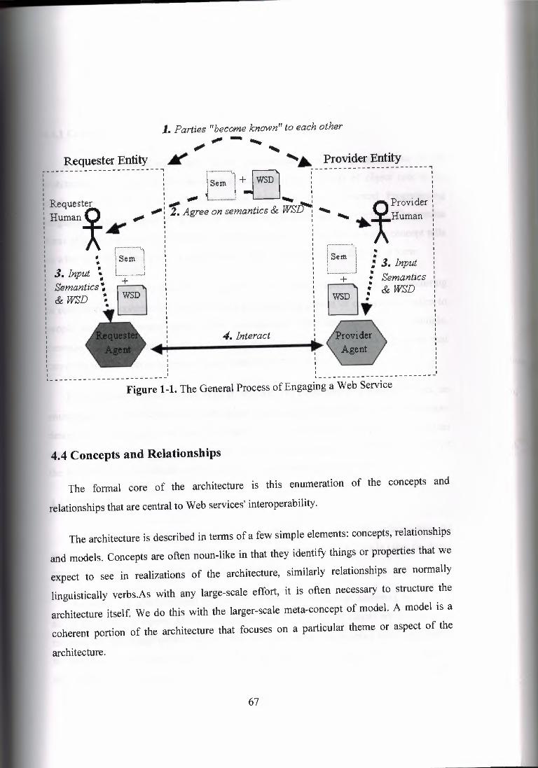
Requester Entity
1. Parties "become known" to each other -- - •.... .,,,,. ' ¥ '• Provider Entity
I ------------------, I I
------------------------, : r ,~ , iSem ! + WSD I l : I : I I 1j : Requester , _.,. .,,,,, ,................... -. ,
Human* ;tit' ....••• ..-: 2. Agree on semantics & ~
: -:, ~ l Sem l
3. Input ~ L , Semanucs"; & WSD ~ •
.Q Provider : .•.. A Human
" •• : 3. Input • + •.
1~D JJ Semantics &WSD
4. Interact 4-1
I
" - - - - - - - - - - - - - - - - - - - - - - - - _1 ~-------------------------' Figure 1-1. The General Process of Engaging a Web Service
4.4 Concepts and Relationships
The formal core of the architecture is this enumeration of the concepts and
relationships that are central to Web services' interoperability.
The architecture is described in terms of a few simple elements: concepts, relationships
and models. Concepts are often noun-like in that they identify things or properties that we
expect to see in realizations of the architecture, similarly relationships are normally
linguistically verbs.As with any large-scale effort, it is often necessary to structure the
architecture itself. We do this with the larger-scale meta-concept of model. A model is a
coherent portion of the architecture that focuses on a particular theme or aspect of the
architecture.
67

4.1 Concepts
A concept is expected to have some correspondence with any realizations of the
hitecture. For example, the message concept identifies a class of object (not to be
nfused with · Objects and Classes as are found in Object Oriented Programming
languages) that we expect to be able to identify in any Web services context. The precise
orm of a message may be different in different realizations, but the message concept tells
what to look for in a given concrete system rather than prescribing its precise form.
Not all concepts will have a realization in terms of data objects or structures occurring
in computers or communications devices; for example the person or organization refers to
people and human organizations. Other concepts are more abstract still; for example,
message reliability denotes a property of the message transport service - a property that
cannot be touched but nonetheless is important to Web services.
Each concept is presented in a regular, stylized way consisting of a short definition, an
enumeration of the relationships with other concepts, and a slightly longer explanatory
description. For example, the concept of agent includes as relating concepts the fact that an
agent is a computational resource, has an identifier and an owner. The description part of
the agent explains in more detail why agents are important to the archicture.
4.4.2 Relationships
Relationships denote associations between concepts. Grammatically, relationships are
verbs; or more accurately, predicates. A statement of a relationship typically takes the form:
concept predicate concept. For example, in agent, we state that:
An agent is a computational resource This statement makes an assertion, in this case
about the nature of agents. Many such statements are descriptive, others are definitive: A
message has a message sender such a statement makes an assertion about valid instances of
the architecture: we expect to be able to identify the message sender in any realization of
the architecture. Conversely, any system for which we cannot identify the sender of a
68

message is not conformant to the architecture. Even if a service is used anonymously, the
sender has an identifier but it is not possible to associate this identifier with an actual
person or organization .
. 4.3 Concept Maps
Many of the concepts in the architecture are illustrated with concept maps. A concept
map is an informal, graphical way to illustrate key concepts and relationships. For example
the diagram:
~ re11atio111,Ship-----.._
::r.~.p T "-- ·. yet anofher reli:rlionship
·~ s->': l"""_c_o_nc_e_;p_t$_· ~[
Figure 2.1 Concept Map
Shows three concepts which are related in various ways. Each box represents a concept,
and each arrow ( or labeled arc) represents a relationship. The merit of a concept map is that
it allows rapid navigation of the key concepts and illustrates how they relate to each other.
It should be stressed however that these diagrams are primarily navigational aids; the
written text is the definitive source .
. 4.4 Model
A model is a coherent subset of the architecture that typically revolves around a
particular aspect of the overall architecture. Although different models share concepts, it is
usually from different points of view; the major role of a model is to explain and
encapsulate a significant theme within the overall Web services architecture.
69
For example, the Message Oriented Model focuses and explains Web services strictly
from a message passing perspective. In particular, it does not attempt to relate messages to
services provided. The Service Oriented Model, however, lays on top of and extends the
Message Oriented Model in order to explain the fundamental concepts involved in service -
in effect to explain the purpose of the messages in the Message Oriented Model.
Each model is described separately below, in terms of the concepts and relationships
inherent to the model. The ordering of the concepts in each model section is alphabetical;
this should not be understood to imply any relative importance. For a more focused
viewpoint the reader is directed to the Stakeholder's perspectives section which examines
the architecture from the perspective of key stakeholders of the architecture.
The reason for choosing an alphabetical ordering is that there is a large amount of
cross-referencing between the concepts. As a result, it is very difficult, if not misleading, to
choose a non-alphabetic ordering that reflects some sense of priority between the concepts.
Furthermore, the optimal ordering depends very much on the point of view of the reader.
Hence, we devote the Stakeholders perspectives section to a number of prioriterized
readings of the architecture.
4.4.5 Conformance
Unlike language specifications, or protocol specifications, conformance to an
architecture is necessarily a somewhat imprecise art. However, the presence of a concept in
this enumeration is a strong hint that, in any realization of the architecture, there should be
a corresponding feature in the implementation. Furthermore, if a relationship is identified
here, then there should be corresponding relationships in any realized architecture. The
consequence of non-conformance is likely to be reduced interoperability: The absence of
such a concrete feature may not prevent interoperability, but it is likely to make such
interoperability more difficult.
A primary function of the Architecture's enumeration in terms of models, concepts and
relationships is to give guidance about conformance to the architecture. For example, the
architecture notes that a message has a message sender; any realization of this architecture
70

at does not permit a message to be associated with its sender is not in conformance with
e architecture. For example, SMTP could be used to transmit messages. However, since
~TP (at present) allows forgery of the sender's identity, SMTP by itself is not sufficient to
discharge this responsibility.
4.4.6 The Architectural Models
This architecture has four models, illustrated in Figure 2-2. Each model in Figure 2-2 is
labeled with what may be viewed as the key concept of that model.
Po.licy Model
Policy
Service Oriented Model
••• Panially !aye.red on •••
Message Oriented Model
Figure 2.2 Meta Model of the Architecture
The four models are:
The Message Oriented Model focuses on messages, message structure, message
transport and so on - without particular reference as to the reasons for the messages, nor
to their significance.
71

agent
processes ortginv
body J--""' ~.··. message .1 ...__ has delivers
Message Transport
Figure 2.3 Simplified Message Oriented Model
The essence of the message model revolves around a few key concepts illustrated
above: the agent that sends and receives messages, the structure of the message in terms of
message headers and bodies and the mechanisms used to deliver messages. Of course, there
are additional details to consider: the role of policies and how they govern the message
level model. The abridged diagram shows the key concepts; the detailed diagram expands
on this to include many more concepts and relationships.
The Service Oriented Model focuses on aspects of service, action and so on. While
clearly, in any distributed system, services cannot be adequately realized without some
means of messaging, the converse is not the case: messages do not need to relate to
services.
72

~ . :realizes
Person or organization
owns/controls - ~ I
&iAnals
mete-data Message
Figure 2.4 Simplified Service Oriented Model
The Service Oriented Model is the most complex of all the models in the architecture.
However, it too revolves around a few key ideas. A service is realized by an agent and used
by another agent. Services are mediated by means of the messages exchanged between
requester agents and provider agents.
A very important aspect of services is their relationship to the real world: services are
mostly deployed to offer functionality in the real world. We model this by elaborating on
the concept of a service's owner - which, whether it is a person or an organization, has a
real world responsibility for the service.
Finally, the Service Oriented Model makes use of meta-data, which, as described in 3 .1
Service Oriented Architecture, is a key property of Service Oriented Architectures. This
meta-data is used to document many aspects of services: from the details of the interface
and transport binding to the semantics of the service and what policy restrictions there may
be on the service. Providing rich descriptions is key to successful deployment and use of
services across the Internet.
The Resource Oriented Model focuses on resources that exist and have owners.
73
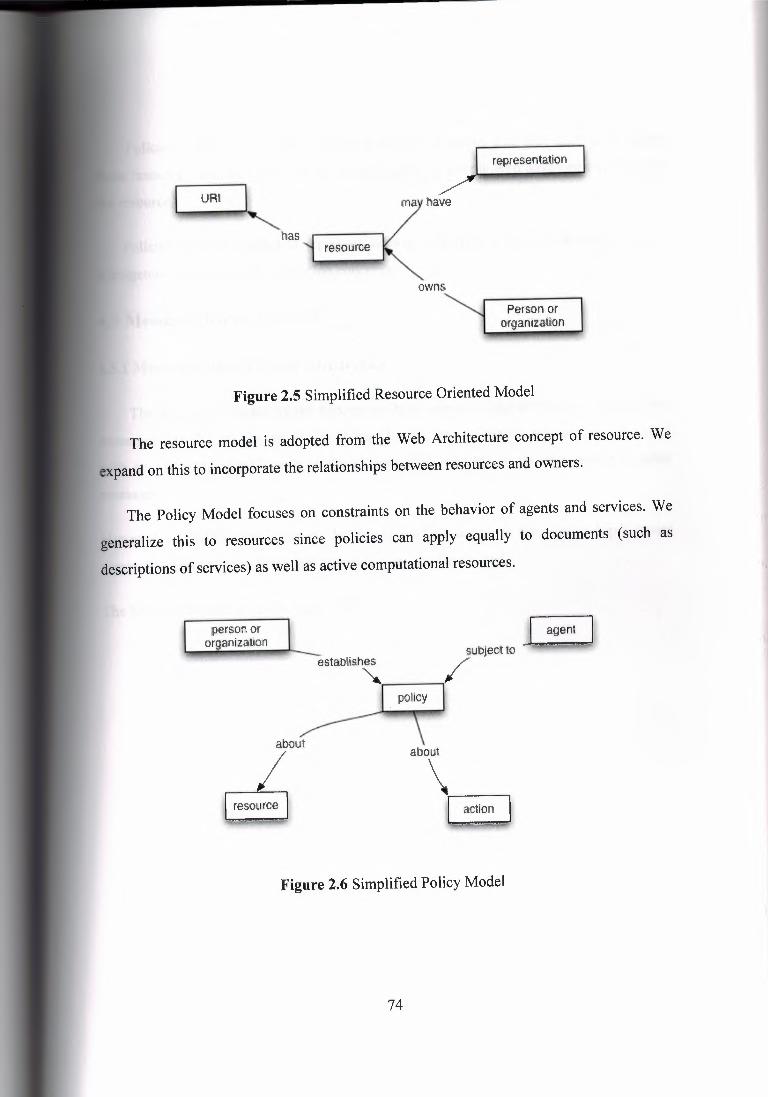
representation
.> mav have
~ -· "-has
reso:urce
owns
Person or organiza1io.n
Figure 2.5 Simplified Resource Oriented Model
The resource model is adopted from the Web Architecture concept of resource. We
expand on this to incorporate the relationships between resources and owners.
The Policy Model focuses on constraints on the behavior of agents and services. We
generalize this to resources since policies can apply equally to documents (such as
descriptions of services) as well as active computational resources.
person or organization establishes . _I . agent · -, /ubJect 10
policy
about
~
abo\ ~
Figure 2.6 Simplified Policy Model
74

Policies are about resources. They are applied to agents that may attempt to access
resources, and are put in place, or established, by people who have responsibility for
Policies may be enacted to represent security concerns, quality of service concerns,
agement concerns and application concerns.
Message Oriented Model
.1 Message Oriented Model Introduction
The Message Oriented Model focuses on those aspects of the architecture that relate to
ssages and the processing of them. Specifically, in this model, we are not concerned
significance of the content of a message or its relationship to other
messages.
However, the MOM does focus on the structure of messages, on the relationship between
message senders and receivers and how messages are transmitted.
The MOM is illustrated in the Figure 2- 7:
75
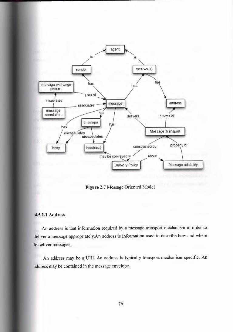
is
~~ has message exchange
panem has ""\
I 7ress I known, by
associates -, delivers
message correlation
Delivery Palicy Message reliability
Figure 2. 7 Message Oriented Model
4.5.1.1 Address
An address is that information required by a message transport mechanism in order to
deliver a message appropriately.An address is information used to describe how and where
to deliver messages.
An address may be a URI. An address is typically transport mechanism specific. An
address may be contained in the message envelope.
76

-
In order for message transport mechanisms to function, it is normally necessary to
provide information that allows messages to be delivered. This is called the address of the
message receiver.
Typically, the form of the address information will depend of the particular message
transport. In the case of an HTTP message transport, the address information will take the
form of a URL.
The precise method that a message sender uses to convey address information will also
depend on the transport mechanism used. On occasion, the address information may be
provided as additional arguments to the invoking procedure. Or the address information
may be located within the message itself; typically in the message envelope.
4.5.1.2 Delivery Policy
A delivery policy is a policy that constrains the methods by which messages are
delivered by the message transport.Delivery policy is a policy.
Delivery policy constrains message transport .Delivery policy may be expressed in a
policy description language .Delivery policy may express the quality of service associated
with delivering a message by a message transport mechanism .
Delivery policies are those policies that relate to the delivery of messages.Typically, a
delivery policy applies to the combination of a particular message and a particular message
transport mechanism. The policies that apply, however, may originate from descriptions in
the message itself, or be intrinsic to the transport mechanism, or both.Examples of delivery
policies include quality of service assurances - such as reliable versus best effort message
delivery - and security assurances - such as encrypted versus unencrypted message
transport. Another kind of delivery policy could take the form of assertions about recording
an audit of how the message was delivered.
77

.5.1.3 Message
A message is the basic unit of data sent from one Web services agent to another in the
context of Web services.
A message is a unit of data sent from one agent to another
A message may be part of a message sequence .
A message may be described using a service description language
A message has a message sender .A message has one or more message recipients
A message may have an identifier A message has a message body.
A message has zero or more message headers.
A message has a message envelope .
A message is delivered by a message transport system.
A message may have a delivery policy associated with it .
A message represents the data structure passed from its sender to its recipients. The
structure of a message is defined in a service description.
The main parts of a message are its envelope, a set of zero or more headers, and the
message body. The envelope serves to encapsulate the component parts of the message and
it serves as a well-known location for message transport services to locate necessary
addressing information. The header holds ancillary information about the message and
facilitates modular processing. The body of the message contains the message content or
URis to the actual data resource.
78

A message can be as simple as an HTTP GET request, in which the HTTP headers are
the headers and the parameters encoded in the URL are the content. Note that extended
Web services functionality in this architecture is not supported in HTTP headers.
A message can also simply be a plain XML document. However, such messages do not
support extended Web services functionality defined in this architecture.
A message can be a SOAP XML, in which the SOAP headers are the headers. Extended
Web services functionality are supported in SOAP headers.
4.5.1.4 Message Body
A message body is the structure that represents the primary application-specific content
that the message sender intends to deliver to the message recipient.A message body is
contained by the message envelope. A message body is the application-specific content
intended for the message recipient.
The message body provides a mechanism for transmitting information to the recipient
of the message. The form of the message body, and other constraints on the body, may be
expressed as part of the service description.In many cases, the precise interpretation of the
message body will depend on the message headers that are in the message.
4.5.1.5 Message Correlation
Message correlation is the association of a message with a context. Message correlation
ensures that a requester agent can match the reply with the request, especially when
multiple replies may be possible.Message Correlation is a means of associating a message
within a specific conversational context. Message correlation may be realized by including
message identifiers to enable messages to be identified. Message correlation allows a
message to be associated with a particular purpose or context. In a conversation, it is
important to be able to determine that an actual message that has been received is the
expected message. Often this is implicit when conversations are relayed over stream
oriented message transports; but not all transports allow correlation to be established so
implicitly.
79
For situations where correlation must be handled explicitly, one technique is to
ciate a message identifier with messages. The message identifier is an identifier that
ows a received message to be correlated with the originating request. The sender may
so add an identifier for a service, not necessarily the originating sender, who will be the
ipient of the message (see asynchronous messaging).
Correlation may also be realized by the underlying protocol. For example, HTTP/1.1 allows
one to correlate a request with its response .
. 5.1.6 Message Envelope
A message envelope is the structure that encapsulates the component parts of a
message: the message body and the message headers.A message envelope may contain
address information about the intended recipients of its associated message A message
envelope contains the message body. A message envelope contains the message headers.
4.5.1.7 Message Exchange Pattern (MEP)
A Message Exchange Pattern (MEP) is a template, devoid of application semantics,
that describes a generic pattern for the exchange of messages between agents. It describes
relationships (e.g., temporal, causal, sequential, etc.) of multiple messages exchanged in
conformance with the pattern, as well as the normal and abnormal termination of any
message exchange conforming to the pattern.A message exchange pattern describes a
generic pattern for the exchange of messages between agents. A message exchange pattern
should have a unique identifier. A message exchange pattern may realize message
correlation .A message exchange pattern may describe a service invocation distributed
applications in a Web services architecture communicate via message exchanges. These
message exchanges are logically factored into patterns that may be composed at different
levels to form larger patterns. A Message Exchange Pattern (MEP) is a template, devoid of
application semantics, that describes a generic pattern for the exchange of (one-way)
messages between agents. The patterns can be described by state machines that define the
flow of the messages, including the handling of faults that may arise, and the correlation of
messages.
80
4.5.1.8 Message Header
A message header is the part of the message that contains information about a specific
aspect of the message. A message header is contained in a message envelope .A message
header may be a specific well known types .A message header may identify .A service
role, which denotes the kind of processing expected for the header. A message header may
be processed independently of the message body
Message headers represent information about messages that is independently
standardized (such as WS-Security) - and may have separate semantics -- from the
message body. For example, there may be standard forms of message header that describe
authentication of messages. The form of such headers is defined for all messages; although,
of course, a given authentication header will be specific to the particular message.
The primary function of headers is to facilitate the modular processing of the message,
although they can also be used to support routing and related aspects of message
processing. The header part of a message can include information pertinent to extended
Web services functionality, such as security, transaction context, orchestration information,
message routing information, or management information.
Message headers may be processed independently of the message body, each message
header may have an identifying service role that indicates the kind of processing that should
be performed on messages with that header. Each message may have several headers, each
potentially identifying a different service role.
Although many headers will relate to infrastructure facilities, such as security, routing,
load balancing and so on; it is also possible that headers will be application specific. For
example, a purchase order processing Web service may be structured into layers;
corresponding to different functions within the organization. These stakeholders may
process headers of different messages in standardized ways: the customer information may
be captured in one standardized header, the stock items by a different standardized header
and so on.
81

4.5.1.9 Message Receiver
A message receiver is an agent that receives a message. A message receiver is a agent
.A message receiver is the recipient of a message The message receiver is an agent that is
intended to receive a message from the message sender.
Messages may be passed through intermediaries that process aspects of the message,
typically by examining the message headers. The message recipient may or may not be
aware of processing by such intermediaries.
Often a specific message receiver, the ultimate recipient, is identified as the final
recipient of a message. The ultimate recipient will be responsible for completing the
processing of the message.
4.5.1.10 Message Reliability
Message reliability is the degree of certainty that a message will be delivered and that
sender and receiver will both have the same understanding of the delivery status.Message
reliability is a property of message delivery. Message reliability may be realized by a
combination of message acknowledgement and correlation. Message reliability may be
realized by a transport mechanism .The goal of reliable messaging is to both reduce the
error frequency for messaging and to provide sufficient information about the status of a
message delivery. Such information enables a participating agent to make a compensating
decision when errors or less than desired results occur. High level correlation such as "two
phase commit" is needed if more than two agents are involved. Note that in a distributed
system, it is theoretically not possible to guarantee correct notification of delivery;
however, in practice, simple techniques can greatly increase the overall confidence in the
message delivery.
It is important to note that a guarantee of the delivery of messages alone may not
improve the overall reliability of a Web service due to the need for end-to-end reliability.
(See "End-to-End Arguments in System Design".) It may, however, reduce the overall cost
of a Web service.
82

Message reliability may be realized with a combination of message receipt
acknowledgement and correlation. In the event that a message has not been properly
received and acted upon, the sender may attempt a resend, or some other compensating
action at the application level.
4.5.1.11 Message Sender
A message sender is the agent that transmits a message.A message sender is an agent
.A message sender is the originator of a message
A message sender is an agent that transmits a message to another agent. Although every
message has a sender, the identity of the sender may not be available to others in the case of
anonymous interactions.
Messages may also be passed through intermediaries that process aspects of the
message; typically by examining the message headers. The sending agent may or may not
be aware of such intermediaries.
4.5.1.12 Message Sequence
A message sequence is a sequence of related messages.A message sequence is a
sequence of related messages .A message sequence may realize a documented message
exchange pattern A requester agent and a provider agent exchange a number of messages
during an interaction. The ordered set of messages exchanged is a message sequence.This
sequence may be realizing a well-defined MEP, usually identified by a URI.
4.5.1.13 Message Transport
A Message Transport is a mechanism that may be used by agents to deliver
messages.A message transport is a mechanism that delivers messages. A message transport
has zero or more capabilities .A message transport is constrained by various delivery
policies .A message transport must know sufficient address information in order to deliver a
message. The message transport is the actual mechanism used to deliver messages.
Examples of message transport include HTTP over TCP, SMTP, message oriented
83
middleware, and so on.The responsibility of the message transport is to deliver a message
from a sender to one or more recipient, i.e. transport a SOAP Infoset from one agent to
another, possibly with some implied semantics (e.g. HTTP methods semantics).Message
transports may provide different features (e.g. message integrity, quality of service
guaranties, etc.).For a message transport to function, the sending agent must provide the
address of the recipient.
4.5.2 The Service Oriented Model
The Service Oriented Model (SOM) focuses on those aspects of the architecture that
relate to service and action.The primary purpose of the SOM is to explicate the
relationships between an agent and the services it provides and requests. The SOM builds on the MOM, but its focus is on action rather than message.The concepts and relationships
in the SOM are illustrated in Figure 2-8:
84

. .~ Agent I IIS,m ,
requester agent
service description
policy
describes
adopts
~ abstracts
applies to
• ___.. has · I service intertaee ...-- pertains to '\. achieves -T.; ' '\. Goal stale
. ..__ uses choreography "'"'""~tes .,;;fines ,...,ns in /"°"'
partof ~1 ~
~ r-;;}--. / processes ao!ion ~,.:..- results irn
Figure 2.8 Service Oriented Model
4.5.2.1 Action
An action, for the purposes of this architecture, is any action that may be performed by
an agent, possibly as a result of receiving a message, or which results in sending a message
or another observable state change. An action may result in a desired goal state. An action
may be the sending of a message .An action may be the processing of a received message.
At the core of the concept of service is the notion of one party performing action(s) at the
behest of another party. From the perspective of requester and provider agents, an action is
typically performed by executing some fragment of a program.
85

-- In the WSA, the actions performed by requester and provider agents are largely out of
scope, except in so far as they are the result of messages being sent or received. In effect,
the programs that are executed by agents are not in scope of the architecture, however the
resulting messages are in scope.
4.5.2.2 Agent
An agent is a program acting on behalf of person or organization. (This definition is a
specialization of the definition in [Web Arch]. It corresponds to the notion of software
agent in [Web Arch].)An agent is a computational resource .An agent has an owner that is a
person or organization .An agent may realize zero or more services .An agent may request
zero or more services .Agents are programs that engage in actions on behalf of someone or
something else. For our purposes, agents realize and request Web services. In effect,
software agents are the running programs that drive Web services - both to implement
them and to access them.
Software agents are also proxies for the entities that own them. This is important as
many services involve the use of resources which also have owners with a definite interest
in their disposition. For example, services may involve the transfer of money and the
incurring of legal obligations as a result.We specifically avoid any attempt to govern the
implementation of agents; we are only concerned with ensuring interopability between
systems.
4.5.2.3 Choreography
A choreography defines the sequence and conditions under which multiple cooperating
independent agents exchange messages in order to perform a task to achieve a goal state.A
choreography uses one or more service interfaces . A choreography defines the pattern of
possible interactions between a set of agents . A choreography may be expressed in a
choreography description language .A choreography pertains to a given task .A
choreography defines the relationship between exchanged messages and tasks of a service.
A choreography is a model of the sequence of operations, states, and conditions that control
the interactions involved in the participating services. The interaction prescribed by a
86

,reography results in the completion of some useful function. Examples include the
ement of an order, information about its delivery and eventual payment, or putting the
JStem into a well-defined error state.
A choreography can be distinguished from an orchestration. An orchestration defines
e sequence and conditions in which one Web service invokes other Web services in order
to realize some useful function.
A choreography may be described using a choreography description language. A
choreography description language permits the description of how Web services can be
composed, how service roles and associations in Web services can be established, and how
the state, if any, of composed services is to be managed.
4.5.2.4 Capability
A capability is a named piece of functionality ( or feature) that is declared as supported
or requested by an agent. .A capability has a identifier which is a URI .
A capability has a description of its semantics .A capability can be advertised by an
agent that supports it .A capability can be required by agent that wishes to use it .A capability may be referenced by a service description .Agents participating in an exchange
may implement a wide variety of features. For example, there may be different ways to
achieve the reliable delivery of a message, or there may be several mechanisms available to
support security. A Web service may advertise that it supports a particular capability, and
an agent requiring that capability might select the service on that basis. Or a Web service
may indicate that it requires a particular capability of any requester agent that uses it, and a
requester agent may select it or avoid it on that basis. There may also be a negotiation -
either manual or automatic -- about which capabilities to select. The concept of capability
encompasses SOAP features, but is broader.
4.5.2.5 Goal State
A goal state is a state of some service or resource that is desireable from some person
or organization's point of view. A goal state is a state of the real world, which includes the
87

state of relevant resources .A goal state is desired by some person or organization which
has an interest in defining it. A goal state may be characterized informally, or formally with
a formal expression ..
Goal states are associated with tasks. Tasks are the unit of action associated with
services that have a measurable meaning. Typically measured from the perspective of the
owner of a service, a goal state is characterized by a predicate that is true of that state - for
example; a book selling service may have as its goal state that a book has been purchased
by a legitimate customer.
It is difficult to be formal about vague properties such as desirable, however, it is also
clear that services are deployed and used with an intention. An e-commerce service is
oriented towards buying and selling, a stock ticker service is oriented towards giving timely
information. A goal state is simply a way of being able to declare success when a task has
completed successfully.
4.5.2.6 Provider Agent
A provider agent is an agent that is capable of and empowered to perform the actions
associated with a service on behalf of its owner - the provider entity.A provider agent is a
Web service software agent .A provider agent realizes one or more services. A provider
agent performs, or causes to perform the actions associated with a task. A provider agent
acts on behalf of a provider entity .The provider agent is the software agent that realizes a
Web service by performing tasks on behalf of its owner - the provider entity.A given
service may be offered by more than one agent, especially in the case of composite
services, and a given provider agent may realize more than one Web service.
4.5.2. 7 Provider Entity
The provider entity is the person or organization that is providing a Web service.A
provider entity is a person or organization .A provider entity offers a Web service.
88

A provider entity owns a provider agent .The provider entity is the person or
organization that is offering a Web service. The provider agent acts on behalf of the
provider entity that owns it.
4.5.2.8 Requester Agent
A requester agent is a software agent that wishes to interact with a provider agent in
order to request that a task be performed on behalf of its owner - the entity. A requester
agent is an agent .A requester agent uses a service. A requester agent acts on behalf of a
requester entity .The requester agent is the software agent that requires a certain function to
be performed on behalf of its owner - the requester entity. From an architectural
perspective, this is the agent that is looking for and invoking or initiating an interaction
with a provider agent.
4.5.2.9 Requester Entity
The requester entity is the person or organization that wishes to use a provider entity's
Web service. A requester entity is a person or organization .A requester entity owns a
requester agent . The requester entity is the person or organization that wishes to make use
of a Web service. The requester entity is the counterpart to the provider entity.
4.5.2.10 Service
A service is an abstract resource that represents a capability of performing tasks that
represents a coherent functionality from the point of view of provider entities and requester
entities. To be used, a service must be realized by a concrete provider agent.
A service is a resource .A service performs one or more tasks .A service has a service
description .A service has a service interface. A service has service semantics. A service
has an identifier. A service has a service semantics .A service has one or more service roles
in relation to the service's owner .A service may have one or more policies applied to it.A
service is owned by a person or organization. A service is provided by a person or
organization. A service is realized by a provider agent. A service is used by a requester
agent.
89

A service is an abstract resource that represents a person or organization in some
collection of related tasks as having specific service roles. The service may be realized by
one or more provider agents that act on behalf of the person or organization - the provider
entity. The critical distinction of a Web service, compared to other Web resources, is that
Web services do not necessarily have a representation; however, they are associated with actions.
4.5.2.11 Service Description
A service description is a set of documents that describe the interface to and semantics
of a service.A service description is a machine-processable description of a service .A
service description is a machine-processable description of the service's interface. A service
description contains a machine-processable description of the messages that are exchanged
by the service. A service description may include a description of the service's semantics .A
service description is expressed in a service description language A service description contains the details of the interface and, potentially, the expected behavior of the service.
This includes its data types, operations, transport protocol information, and address. It
could also include categorization and other metadata to facilitate discovery and utilization. The complete description may be realized as a set of XML description documents.
There are many potential uses of service descriptions: they may be used to facilitate the construction and deployment of services, they may be used by people to locate
appropriate services, and they may be used by requester agents to automatically discover
appropriate provider agents in those case where requester agents are able to make suitable
choices.
4.5.2.12 Service Interface
A service interface is the abstract boundary that a service exposes. It defines the types
of messages and the message exchange patterns that are involved in interacting with the
service, together with any conditions implied by those messages.A service interface defines
the messages relevant to the service .A service interface defines the different types of
90

messages that a service sends and receives, along with the message exchange patterns that
may be used.
4.5.2.13 Service Intermediary
A service intermediary is a Web service whose main role is to transform messages in a
value-added way. (From a messaging point of view, an intermediary processes messages en
route from one agent to another.) Specifically, we say that a service intermediary is a
service whose outgoing messages are equivalent to its incoming messages in some
application-defined sense. A service intermediary is a service. A service intermediary
adopts a specific service role. A service intermediary preserves the semantics of messages it
receives and sends.A service intermediary is a specific kind of service which typically acts
as a kind of filter on messages it handles. Normally, intermediaries do not consume
messages but rather forward them to other services. Of course, intermediaries do often
modify messages but, it is of the essence that from some application specific perspective
they do not modify the meaning of the message.
Of course, if a message is altered in any way, then from some perspectives it is no
longer the same message. However, just as a paper document is altered whenever anyone
writes a comment on the document, and yet it is still the same document, so an intermediary
modifies the messages that it receives, forwarding the same message with some changes.
Coupled with the concept of service intermediary is the service role is adopts.
Typically, this involves one or more of the messages' headers rather than the bodies of messages. The specification of the header is coupled with the permissable semantics of the
intermediary should make it clear to what extent the messages forwarded by an
itnermediary are the same message and what modifications are permitted.
There are a number of situations where additional processing of messages is required.
For example, messages that are exchanged between agents within an enterprise may not
need encryption; however, if a message has to leave the enterprise then good security may
suggest that it be encrypted. Rather than burden every software agent with the means of
encrypting and decrypting messages, this functionality can be realized by means of an
91

intennediary. The main responsiblity of the software agents then becomes ensuring that the
messages are routed appropriately and have the right headers targetted at the appropriate
intermediaries.
4.5.2.14 Service Role
A service role is an abstract set of tasks which is identified to be relevant by a person
or organization offering a service. Service roles are also associated with particular aspects
of messages exchanged with a service.A service role is a set of service tasks .A service role
may be defined in terms of particular properties of messages. A service role may be
established by a service owner. A service role is an intennediate abstraction between
service and task. A given message that is received by a service may involve processing
associated with several service roles. Similarly, messages emitted may also involve more
than one service role.We can formalize the distinction by noting that a service role is
typically associated with a particular property of messages. For ultimate processing, the
service role may be to determine some final disposition of messages received. However,
other service roles may be associated with more generic properties of messages - such as their encryption, or whether they reference a customer or inventory item.Service roles
identify the points of interest that a service owner has in the processing of messages. As
such, they are established by the party that offers in the service.
4.5.2.15 Service Semantics
The semantics of a service is the behavior expected when interacting with the service.
The semantics expresses a contract (not necessarily a legal contract) between the provider
entity and the requester entity. It expresses the intended real-world effect of invoking the
service. A service semantics may be fonnally described in a machine readable form,
identified but not fonnally defined, or informally defined via an "out of band" agreement between the provider entity and the requester entity.Service semantics is the contract
between the provider entity and the requester entity concerning the effects and requirements
pertaining to the use of a service.
92

Service semantics describes the intended effects of using a service .Service semantics
is about the service tasks that constitute the service. Service semantics should be identified
in a service description. Service semantics may be described in a formal, machine
processable language.
Knowing the type of a data structure is not enough to understand the intent and
meaning behind its use. For example, methods to deposit and withdraw from an account
typically have the same type signature, but with a different effect. The effects of the
operations are the semantics of the operation. It is good practice to be explicit about the
intended effects of using a Web service; perhaps even to the point of constructing a
machine readable description of the semantics of a service.
Machine processable semantic descriptions provide the potential for sophisticated
usage of Web services. For example, by accessing such descriptions, a requester agent may
autonomously choose which provider agent to use.
Apart from the expected behavior of a service, other semantic aspects of a service
include any policy restrictions on the service, the relationship between the provider entity
and the requester entity, and what manageability features are associated with the service.
., 4.5.2.16 Service Task
A service task is an action or combination of actions that is associated with a desired
goal state. Performing the task involves executing the actions, and is intended to achieve a
particular goal state.A service task is an action or combination of actions. A service task is
associated with one or more intended goal states. A service task is performed by executing
the actions associated with the task. A service task has a service interface. A service task is
an abstraction that encapsulates some intended effect of invoking a service.
93

•.. ------------------------------~---------
Tasks are associated with goal states - characterized by predicates that are satisfied on
successful completion.The performance of a task is made observable by the exchange of
messages between the requester agent and the provider agent. The specific pattern of
messages is what defines the choreography associated with the task.
In addition to exchanged messages, there may be other private actions associated with
a task. For example, in a database update task, the task may be signaled by an initiating
message and a completion message, which are public, and the actual database update,
which is typically private.
In the case of a service oriented architecture only the public aspects of a task are
important, and these are expressed entirely in terms of the messages exchanged. Tasks
represent a useful unit in modeling the semantics of a service and indeed of a service role a
given service may consist of a number of tasks.
4.5.3 The Resource Oriented Model
The Resource Oriented Model focuses on those aspects of the architecture that relate to
resources. Resources are a fundamental concept that underpins much of the Web and much
of Web services; for example, a Web service is a particular kind of resource that is
important to this architecture. 'I
The ROM focuses on the key features of resources that are relevant to the concept of
resource, independent of the role the resource has in the context of Web services. Thus we
focus on issues such as the ownership of resources, policies associated with resources and
so on. Then, by virtue of the fact that Web services are resources, these properties are
inherited by Web services.
We illustrate the basic concepts and relationships in the ROM in Figure 2-9:
94

service
agent
indexes { URI J
~ '* ."' cont:ai ns has .,/
discovers
t representation discovery se.rvice
mav have
resource
owns
..__,__ may reter to _
\ app~lies to Person or orga:nizaliori
• ~ establishes
resource description
Figure 2.9 Resource Oriented Model
4.5.3.1 Discovery
Discovery is the act of locating a machine-processable description of a Web service
related resource that may have been previously unknown and that meets certain functional
criteria. It involves matching a set of functional and other criteria with a set of resource descriptions. The goal is to find an appropriate Web service-related resource.[WS Glossary]
.Discovery is the act of locating a resource description .Discovery involves matching a set
of functional and other criteria with a set of resource descriptions. Discovery may be performed by an agent, or by an end-user. Discovery may be realized using a discovery
service.
95

In the context of Web services, the resources being discovered are usually service
descriptions. If a requester entity does not already know what service it wishes to engage,
the requester entity must discover one. There are various means by which discovery can be
performed. Various things - human end users or agents - may initiate discovery.
Requester entities may find service descriptions during development for static binding, or
during execution for dynamic binding. For statically bound requester agents, using
discovery is optional, as the service description might be obtained in other ways, such as being sent directly from the provider entity to the requester entity, developed
collaboratively, or provided by a third party, such as a standards body.
4.5.3.2 Discovery Service
A discovery service is a service that enables agents to retrieve Web service-related
resource descriptions. A discovery service is a service .A discovery service is used to
publish descriptions .A discovery service is used to search for resource descriptions. A
discovery service may be used by an agent .A discovery service is used to publish and
search for descriptions meeting certain functional or semantic criteria. It is primarily
intended for use by requester entities, to facilitate the process of finding an appropriate
provider agent for a particular task. However, depending on the implementation and policy
of the discovery service (3.4.2 Discovery: Registry, Index or Peer-to-Peer?), it may also be used by provider entities to actively publish their service descriptions. Although the
resource model is general purpose, the most important resource for our purposes is the Web
service. Furthermore, the primary role of a discovery service is to facilitate the discovery of
Web services. For dynamic discovery, the requester agent may interact directly with the
discovery service to find an appropriate provider agent to engage. For static discovery, a
human may interact with the discovery service through an appropriate software agent, such
as a browser. The use of an automated discovery service is optional, since other means can
be used to enable a requester entity and provider entity to agree on the service description
that will govern the interaction. For example, the requester entity might obtain the service
description directly from the provider entity, the two parties might develop the service
description collaboratively, or, in some circumstances, the service description may be
created by the requester entity and dictated to the provider entity. (For example, a large
96

company may require its suppliers to provide Web services that conform to a particular
service description.) Likewise, a requester entity can obtain a service description from other
sources besides a discovery service, such as a local file system, FTP site, URL, or WSIL
document.
4.5.3.3 Identifier
An identifier is an unambiguous name for a resource. An identifier should be realized
a URI .An identifier identifies a resource that is relevant to the architecture. Identifiers are
used to identify resources. In the architecture we use Uniform Resource Identifiers [RFC
2396] to identify resources.
4.5.3.4 Representation
A representation is a piece of data that describes a resource state. A resource may have
a representation .Representations are data objects that reflect the state of a resource. A
resource has a unique identifier (a URI). Note that a representation of a resource need not
be the same as the resource itself; for example the resource associated with the booking
state of a restaurant will have different representations depending on when the
representation is retrieved. A representation is usually retrieved by performing an HTTP
"GET" on a URI.
4.5.3.5 Resource
A resource is defined by [RFC 2396] to be anything that can have an identifier.
Although resources in general can be anything, this architecture is only concerned with
those resources that are relevant to Web services and therefore have some additional
characteristics. In particular, they incorporate the concepts of ownership and control: a
resource that appears in this architecture is a thing that has a name, may have reasonable
representations and which can be said to be owned. The ownership of a resource is
critically connected with the right to set policy on the resource.A resource has an identifier
.A resource may have zero or more representations . A resource may have zero or more
resource descriptions .A resource is owned by a person or organization .A resource may be
97

governed by zero or more policies .Resources form the heart of the Web architecture itself.
The Web is a universe ofresources that have URis as identifiers, as defined in [RFC 2396].
From a real-world perspective, a most interesting aspect of a resource is its ownership:
a resource is something that can be owned, and therefore have policies applied to it.
Policies applying to resources are relevant to the management of Web services, security of
access to Web services and many other aspects of the role that a resource has in the world.
4.5.3.6 Resource description
A resource description is any machine readable data that may permit resources to be
discovered. Resource descriptions may be of many different forms, tailored for specific
purposes, but all resource descriptions must contain the resource's identifier. A resource
description contains the resource's identifier. A resource description may reference the
policies applicable to the resource .A resource description may reference the semantics
applicable to the resource.A resource description is a machine-processable description of a
resource. Resource descriptions are used by and within discovery services to permit agents
to discover the resource.The precise contents of a resource description will vary, depending
on the resource, on the purpose of the description and on the accessibility of the resource.
However, for our purposes it is important to note that the description must contain the
resource's identifier. I.e., a description of the form: "the new resource that is owned by
XYZ co." is not regarded as a valid resource description because it does not mention the
resource's identifier.
A primary purpose of resource descriptions is to facilitate the discovery of the
resource. To aid that purpose, the description is likely to contain information about the
location of the resource, how to access it and potentially any policies that govern the policy.
Where the resource is a Web service, the description may also contain machine-processable
information about how to invoke the Web service and the expected effect of using the Web
service.
98

4.5.4 The Policy Model
The Policy Model focuses on those aspects of the architecture that relate to policies
and, by extension, security and quality of service.Security is fundamentally about
constraints; about constraints on the behavior on action and on accessing resources.
Similarly, quality of service is also about constraints on service. In the PM, these
constraints are modeled around the core concept of policy; and the relationships with other
elements of the architecture. Thus the PM is a framework in which security can be
realized.However, there are many other kinds of constraints, and policies that are relevant
to Web services, including various application-level constraints.
The concepts and relationships in the PM are illustrated in Figure 2-10:
.,....-"'I da~ain scoped by
., \ ---::-:::--
person or mganizaUon
owns
\ owns
........ constrains
Pol icy description,
is
constrains $ / perm .. ·ission
I- ~ . irequires . enforces
\ ' ensures
agent
Permission ,guard
references
\. - - f :resource j
monitors
Figure 2.10 Policy Model
99

4.5.4.1 Audit Guard
An audit guard is a mechanism used on behalf of an owner that monitors actions and
agents to verify the satisfaction of obligations.A audit guard is a policy guard .An audit
guard may monitor one or more resources. An audit guard may monitor actions relative to
one or more services. An audit guard may determine if an agent's obligations have been
discharged. An audit guard is an enforcement mechanism. It is used to monitor the
discharge of obligations. The role of the audit guard is to monitor that agents, resources and
services are consistent with any associated obligations established by the service's owner or
manager.Typically, an audit guard monitors the state of a resource or a service, ensuring
that the obligation is satisfied. It determines whether the associated obligations are
satisfied.By their nature, it is not possible to proactively enforce obligations; hence, an
obligation violation may result in some kind of retribution after the fact of the violation.
4.5.4.2 Domain
A domain is an identified set of agents and/or resources that is subject to the constraints
of one of more policies. A domain is a collection of agents and/or resources.
A domain defines the scope of application of one or more policies .A domain defines
the scope of applicability of policies. A domain may be defined explicitly or implicitly.
Members of an explicitly defined domain are enumerated by a central authority; members
of an implicitly defined domain are not. For example, membership in an implicitly defined
domain may depend on the state of the agent or something it possesses, and thus may be
dynamic.
4.5.4.3 Obligation
An obligation is a kind of policy that prescribes actions and/or states of an agent and/or
resource.An obligation is a kind of policy .An obligation may require an agent to perform
one or more actions .An obligation may require an agent or service to be in one or more
allowable states. An obligation may be discharged by the performance of an action or other
event. An obligation is one of two fundamental types of policies. When an agent has an
100

obligation to perform some action, then it is required to do so. When the action is
performed, then the agent can be said to have satisfied its obligations.
Not all obligations relate to actions. For example, an agent providing a service may
have an obligation to maintain a certain state of readiness. (Quality of service policies are
often expressed in terms of obligations.) Such an obligation is typically not discharged by
any of the obligee's actions; although an event (such as a certain time period expiring) may
discharge the obligation.
Obligations, by their nature, cannot be proactively enforced. However, obligations are
associated with enforcement mechanisms: audit guards. These monitor controlled resources
and agents and may result in some kind of retribution; retributions are not modeled by this
architecture.
An obligation may continue to exist after its requirements have been met (for example,
an obligation to maintain a particular credit card balance), or it may be discharged by some
action or event.
4.5.4.4 Permission
Permission is a kind of policy that prescribes the allowed actions and states of an agent
and/or resource.A permission is a type of policy. A permission may enable one or more
actions .A permission may enable one or more allowable states .A permission is one of two
fundamental types of policies. When an agent has permission to perform some action, to
access some resource, or to achieve a certain state, then it is expected that any attempt to
perform the action etc., will be successful. Conversely, if an agent does not have the
required permission, then the action should fail even if it would otherwise have succeeded.
Permissions are enforced by guards, in particular permission guards, whose function is to
ensure that permission policies are honored.
101

4.5.4.5 Permission Guard
A permission guard is a mechanism deployed on behalf of an owner to enforce
permission policies.A permission guard is a policy guard .A permission guard is a a
mechanism that enforces permission policies. A permission guard may control one or more
resources. A permission guard enables actions relative to one or more services. A
permission guard is an enforcement mechanism that is used to enforce permission policies.
The role of the permission guard is to ensure that any uses of a service or resource are
consistent with the policies established by the service's owner or manager.
Typically, a permission guard sits between a resource or service and the requester of
that resource or service. In many situations, it is not necessary for a service to be aware of
the permission guard. For example, one possible role of a message intermediary is to act as
a permission guard for the final intended recipient of messages.A permission guard acts by
either enabling a requested action or access, or by denying it. Thus, it is normally possible
for permission policies to be proactively enforced.
4.5.4.6 Person or Organization
A person or organization may be the owner of agents that provide or request Web
services. A person or organization may own an agent .A person or organization may belong
to a domain .A person or organization may establish policies governing resources that they
own .The WSA concept of person or organization is intended to refer to the real-world
people that are represented by agents that perform actions on their behalf. All actions
considered in this architecture are ultimately rooted in the actions of humans.
4.5.4. 7 Policy
A policy is a constraint on the behavior of agents or people or organizations. A policy
is a constraint on the allowable actions or states of an agent or person or organization. A policy may have an identifier .A policy may be described in a policy description .A policy
may define a capability. A policy is a constraint on the behavior of agents as they perform
actions or access resources. There are many kinds of policies, some relate to accessing
102
resources in particular ways, others relate more generally to the allowable actions an agent
may perform: both as provider agents and as requester agents. Logically, we identify two
types of policy: permissions and obligations. Although most policies relate to actions of
various kinds, it is not exclusively so. For example,' there may be a policy that an agent
must be in a certain state ( or conversely may not be in a particular state) in relation to the
services it is requesting or providing. Closely associated with policies are the mechanisms
for establishing policies and for enforcing them. This architecture does not model the
former. Policies have applications for defining security properties, quality of service
properties, management properties and even application properties.
4.5.4.8 Policy Description
A policy description is a machine-processable description of a policy or set of
policies.A policy description describes a policy .A policy description is a machine
processable description of some constraint on the behavior of agents as they perform
actions, access resources.The policy description itself is not the policy, but it may define
the policy and it may be used to determine if the policy applies in a given situation .. Policy
descriptions may include specific conditions, such as "agents of XXX Co. may access files
in directory FFF". They may also include more general rules, such as "if an entity has the
right to access files in the directory FFF, it also has the obligation to close them after 20
seconds".
4.5.4.9 Policy Guard
A policy guard is a mechanism that enforces one or more policies. It is deployed on
behalf of an owner.A policy guard has an owner responsible for establishing the guard .A
policy guard is an abstraction that denotes a mechanism that is used by owners of resources
to enforce policies.The architecture identifies two kinds of policy guards: audit guards and
permission guards. These relate to the core kinds of policies ( obligation and permission
policies respectively).
103

4.6 Relationships
The X is a Y relationship denotes the relationship between concepts X and Y, such
that every X is also a Y .Assuming that X is a Y, then: true of if P is true of Y then P is true
of X contains ifY has a P then X has a Q such that Q is a P. transitive if Pis true of Y then
P is true of X .Essentially, when we say that concept Xis a Y we mean that every feature of
Y is also a feature of X. Note, however, that since X is presumably a more specific concept
than Y, the features of X may also be more specific variants of the features of Y.
For example, in the service concept, we state that every service has an identifier. In the
more specific Web service concept, we note that a Web service has an identifier in the form
of a URI identifier.
4.6.1 The describes relationship
The concept Y describes X if and only if Y is an expression of some language L and
that the values of Y are instances of X.Assuming that Y describes X, then: if Y is a valid
expression of L, then the values of Y are instances of concept X
For example, in the service description concept, we state that service descriptions are
expressed in a service description language. That means that we can expect legal
expressions of the service description language to be instances of the service description
concept.
4.6.2 The has a relationship
Saying that "the concept X has a Y relationship" denotes that every instance of X is
associated with an instance of Y.Assuming that X has a Y, then: if E is an instance of X
then Y is valid for E.When we say that "concept X has a Y" we mean that whenever we see
an X we should also see a Y .For example, in the Web service concept, we state that Web
services have URI identifiers. So, whenever the Web service concept is found, we can
assume that the Web service referenced has an identifier. This, in tum, allows
104

implementations to use identifiers to reliably refer to Web services. If a given Web service
does not have an identifier associated with it, then the architecture has been violated.
4.6.3 The owns relationship
The relationship "X owns Y" denotes the relationship between concepts X and Y, such
that every X has the right and authority to control, utilize and dispose of Y. Assuming that X owns Y, then: policy X has the right to establish policies that constrain agents and other
entities in their use of Y disposal X has the right to transfer some or all of his rights with
respect to Y to another entity. Transitive if P is true of Y then P is true .Essentially, when we say that X owns Y we mean that X has a significant set of rights with respect to Y, and
that those rights are transferrable. In general, ownership is partial, and there may be many
entities that have rights with respect to some service or resource.
4.6.4 The realized relationship
The statement "concept X is realized as Y" denotes that the concept X is an abstraction
of the concept Y. An equivalent view is that the concept X is implemented using
Y .Assuming that X is realized as Y, then: implemented if Y is present, or true of a system,
then the concept X applies to the system reified Y is a reification of the concept X. When we say that the concept or feature X is realized as Y, we mean that Y is an implementation
or reification of the concept X. I.e., if Y is a valid concept of a system then we have also ensured that the concept X is valid of the same system. For example, in the correlation
feature, we state that message correlation requires that we associate identifiers with
messages. This can be realized in a number of ways - including the identifier in the
message header, message body, in a service binding and so on. The message identifier is a
key to the realization of message correlation.
4.7 Stakeholder's Perspectives
This section examines the architecture from various perspectives, each perspective
representing one coherent view of the architecture. For example, security represents one
major stakeholder's perspective of the architecture itself.
105

4.7.1 Web Services and Architectural Styles
Distributed object systems have a number of architectural challenges. [Dist Comp] and
others point out:Problems introduced by latency and unreliability of the underlying
transport. The lack of shared memory between the caller and object. The numerous
problems introduced by partial failure scenarios. The challenges of concurrent access to
remote resources. The fragility of distributed systems if incompatible updates are
introduced to any participant.
These challenges apply irrespective of whether the distributed object system is
implemented using COM/CORBA or Web services technologies. Web services are no less
appropriate than the alternatives if the fundamental criteria for successful distributed object
architectures are met. If these criteria are met, Web services technologies may be
appropriate if the benefits they offer in terms of platform/vendor neutrality offset the
performance and implementation immaturity issues they may introduce.
Conversely, using Web services technologies to implement a distributed system doesn't
magically tum a distributed object architecture into an SOA. Nor are Web services
technologies necessarily the best choice for implementing SOAs -- if the necessary
infrastructure and expertise are in place to use COM or CORBA as the implementation
technology and there is no requirement for platform neutrality, using SOAP/WSDL may
not add enough benefits to justify their costs in performance, etc.
In general SOA and Web services are most appropriate for applications:That must
operate over the Internet where reliability and speed cannot be guaranteed; Where there is
no ability to manage deployment so that all requesters and providers are upgraded at once;
Where components of the distributed system run on different platforms and vendor
products; Where an existing application needs to be exposed for use over a network, and
can be wrapped as a Web service.
106
4.7.2 Relationship to the WWW and REST Architectures
The World Wide Web operates as a networked information system that imposes
several constraints: Agents identify objects in the system, called resources, with Uniform
Resource Identifiers (URis). Agents represent, describe, and communicate resource state
via representations of the resource in a variety of widely-understood data formats ( e.g.
XML, HTML, CSS, JPEG, PNG). Agents exchange representations via protocols that use
URis to identify and directly or indirectly address the agents and resources. [Web Arch]
An even more constrained architectural style for reliable Web applications known as
Representation State Transfer (REST) has been proposed by Roy Fielding and has inspired
both the W3C Technical Architecture Group's architecture document [Web Arch] and many
who see it as a model for how to build Web services [Fielding]. The REST Web is the
subset of the WWW (based on HTTP) in which agents provide uniform interface semantics
essentially create, retrieve, update and delete -- rather than arbitrary or application-specific
interfaces, and manipulate resources only by the exchange of representations. Furthermore,
the REST interactions are "stateless" in the sense that the meaning of a message does not
depend on the state of the conversation.We can identify two major classes of Web
services:REST-compliant Web services, in which the primary purpose of the service is to
manipulate XML representations of Web resources using a uniform set of "stateless"
operations; and arbitrary Web services, in which the service may expose an arbitrary set of
operations.
Both classes of Web services use URis to identify resources and use Web protocols
(such as HTTP and SOAP 1.2) and XML data formats for messaging. (It should be noted
that SOAP 1.2 can be used in a manner consistent with REST. However, SOAP 1.2 can
also be used in a manner that is not consistent with REST.)
107

4.7.3 Web Services Technologies
Web service architecture involves many layered and interrelated technologies. There
are many ways to visualize these technologies, just as there are many ways to build and use
Web services. Figure 3-1 below provides one illustration of some of these technology
families.
"'~ . •I ' ·Processes
~
' m Discovery, Aggregation, Choreography ... m i i i t '· ~
a 5 ;. 0 Descriptions 8"
8 1 Web Services Descriptions (WSDL) "' . J. E h )( )(
C , ~ u r R J Messages J .. I
..
T m SOAP Extensions en y ft Reliability, Correlation, Transactions ... n
I i h - a
•• I I
•• SOAP
Communications HTTP, SMTP, FTP, JMS, IIOP, ....
Figure 3.1 Web Services Architecture Stack
In this section we describe some of those technologies that seem critical and the role
they fill in relation to this architecture. This is a necessarily bottom-up perspective, since, in
this section, we are looking at Web services from the perspective of tools which can be
used to design, build and deploy Web services.
108
M A N A G E M E N T
I•

The technologies that we consider here, in relation to the Architecture, are XML,
SOAP, WSDL. However, there are many other technologies that may be useful. (For
example, see the list of Web services specifications compiled by Roger Cutler and Paul
Denning.) See also B An Overview of Web Services Security Technologies
4. 7 .4 Using Web Services
The introduction outlined and illustrated (in Figure 1-1) the four broad steps involved
in the process of engaging a Web service (see 1.4.5 Overview of Engaging a Web Service).
This section expands on these steps. Although these steps are necessary, they may not be
sufficient: many scenarios will require additional steps, or significant refinements of these
fundamental steps. Furthermore, the order in which the steps are performed may vary from
situation to situation.
The requester and provider entities "become known to each other", in the sense that
whichever party initiates the interaction must become aware of the other party. There are
two cases.
In a typical case, the requester agent will be the initiator. In this case, we would say
that the requester entity must become aware of the provider entity, i.e., the requester agent
must somehow obtain the address of the provider agent. There are two ways this may
typically occur: (1) the requester entity may obtain the provider agent's address directly
from the provider entity; or (2) the requester entity may use a discovery service to locate a
suitable service description (which contains the provider agent's invocation address) via an
associated functional description, either through manual discovery or autonomous selection. These cases are described more fully in 3.4 Web Service Discovery.
In other cases, the provider agent may initiate the exchange of messages between the
requester and provider agents. In this case, saying that the requester and provider entities
become known to each other actually means that the provider entity becomes aware of the requester entity, i.e., the provider agent somehow obtains the address of the requester agent.
How this occurs is application dependent and irrelevant to this architecture. Although this
109

-
case is expected to be less common than when the requester agent is the initiator, it is
important in some "push" or subscription scenarios.
The requester entity and provider entity agree on the service description (a WSDL
document) and semantics that will govern the interaction between the requester agent and
the provider agent. (See the note below on "Agreeing on the Same Semantics and Service
Description for further explanation of what is meant here by "agree".)
This does not necessarily mean that the requester and provider entities must
communicate or negotiate with each other. It simply means that both parties must have the
same ( or compatible) understandings of the service description and semantics, and intend to
uphold them. There are many ways this can be achieved, such as:
The requester and provider entities may communicate directly with each other, to
explicitly agree on the service description and semantics. The provider entity may publish and offer both the service description and semantics as take-it-or-leave-it "contracts" that
the requester entity must accept unmodified as conditions of use.
The service description and semantics ( excepting the network address of the particular
service) may be defined as a standard by an industry organization, and used by many
requester and provider entities. In this case, the act of the requester and provider entities
reaching agreement is accomplished by both parties independently conforming to the same
standard.
The service description and semantics (perhaps excepting the network address of the
service) may be defined and published by the requester entity (even if they are written from
provider entity's perspective), and offered to provider entities on a take-it-or-leave-it basis.
This may occur, for example, if a large company requires its suppliers to provide Web
services that conform to a particular service description and semantics. In this case,
agreement is achieved by the provider entity adopting the service description and semantics
that the requester entity has published. Depending on the scenario, Step 2 ( or portions of
Step 2) may be performed prior to Step 1.
I 10
The service description and semantics are input to, or embodied in, both the requester
agent and the provider agent as appropriate. In other words, the information in them must
either be input to, or implemented in, the requester and provider agents. There are many
ways this can be achieved, and this architecture does not specify or care what means are
used. For example: An agent could be hard coded to implement a particular, fixed service t
description and semantics. An agent could be coded in a more general way, and the desired
service description and/or semantics could be input dynamically. An agent could be created
first, and the service description and/or semantics could be generated or deduced from the
agent code. For example, a tool could examine a set of existing class files to generate a
service description.
Regardless of the approach used, from an information perspective both the semantics
and the service description must somehow be input to, or implemented in, both the
requester agent and the provider agent before the two agents can interact. (This is a slight
simplification; see the note below on "Agreeing" on the Same Semantics and Service
Description for further explanation.) The requester agent and provider agent exchange
SOAP messages on behalf of their owners.
4.7.5 Web Service Discovery
If the requester entity wishes to initiate an interaction with a provider entity and it does
not already know what provider agent it wishes to engage, then the requester entity may
need to "discover" a suitable candidate. Discovery is "the act of locating a machine
processable description of a Web service that may have been previously unknown and that
meets certain functional criteria. " [WS Glossary] The goal is to find an appropriate Web
service.A discovery service is a service that facilitates the process of performing discovery.
It is a logical role, and could be performed by either the requester agent, the provider agent
or some other agent. Figure 3-2 ("Discovery Process") expands on Figure 1-1 to describe
the process of engaging a Web service when a discovery service is used.
111

RequesQ Human A -4"
-E].+EJ ',1.a.
\ Provider ~~!!~ i t:1 :- - - - - - - - - -
i Sem i 2. , """'! :- I
L l """" -... ..., ..._ _QProvider ••••• AHuman
... •
II .. , ... ~ i
3 : [Se m • • : """""
II + ~ IWSDJ
i"""""""'"', ~
i " [Sem • 3 : 1111 • l.. ~
•
••• : · ~~~ , Provider 4. :II-\ Agent
Interact
Figure 3.2 Discovery Process
·-------------------------
Service engagement using a discovery service proceeds in roughly the following steps.
The requester and provider entities "become known to each other": The discovery service
somehow obtains both the Web service description ("WSD" in Figure 3-2) and an
associated functional description ("FD") of the service. The functional description ("FD" in
Figure 3-2) is a machine-processable description of the functionality ( or partial semantics)
of the service that the provider entity is offering. It could be as simple as a few words of
112

meta data or a URI, or it may be more complex, such as a TModel (in UDDI) or a
collection ofRDF, DAML-S or OWL-S statements.
This architecture does not specify or care how the discovery service obtains the service
description or functional description. For example, if the discovery service is implemented
as a search engine, then it might crawl the Web, collecting service descriptions wherever it
finds them, with the provider entity having no knowledge of it. Or, if the discovery service
is implemented as a registry (such as UDDI), then the provider entity may need to actively
publish the service description and functional description directly to the discovery service.
The requester entity supplies criteria to the discovery service to select a Web service
description based on its associated functional description, capabilities and potentially other
characteristics. One might locate a service having certain desired functionality or
semantics; however, it may be possible to specify "non-functional" criteria related to the
provider agent, such as the name of the provider entity, performance or reliability criteria,
or criteria related to the provider entity, such as the provider entity's vendor rating.
The discovery service returns one or more Web service descriptions (or references to
them) that meet the specified criteria. If multiple service descriptions are returned, the
requester entity selects one, perhaps using additional criteria.
The requester and provider entities agree on the semantics ("Sem" in Figure 3-2) of the
desired interaction. Although this may commonly be achieved by the provider entity
defining the semantics and offering them on a take-it-or-leave-it basis to the requester
entity, it could be achieved in other ways. For example, both parties may adopt certain
standard service semantics that are defined by some industry standards body. Or in some
circumstances the requester could define the semantics. The important point is that the
parties must agree (in the sense described in 3.3 Using Web Services) on the semantics,
regardless of how that is achieved.
Step 2 also requires that the parties agree (in the sense described in 3.3 Using Web
Services) on the service description that is to be used. However, since the requester entity
113

obtained the Web service description in Step 1.c, in effect the requester and provider
entities have already done so.
The service description and semantics are input to, or embodied in, both the requester
agent and the provider agent, as appropriate. The requester agent and provider agent
exchange SOAP messages on behalf of their owners.
4.7.6 Peer-to-Peer (P2P) Discovery
Peer-to-Peer (P2P) computing provides an alternative that does not rely on centralized
registries; rather it allows Web services to discover each other dynamically. Under this
view, a Web service is a node in a network of peers, which may or may not be Web
services. At discovery time, a requester agent queries its neighbors in search of a suitable
Web service. If any one of them matches the request, then it replies. Otherwise each queries
its own neighboring peers and the query propagates through the network until a particular
hop count or other termination criterion is reached.
Peer-to-peer architectures do not need a centralized registry, since any node will
respond to the queries it receives. P2P architectures do not have a single point of failure,
such as a centralized registry. Furthermore, each node may contain its own indexing of the
existing Web services. Finally, nodes contact each other directly, so the information they
they receive is known to be current. (In contrast, in the registry or index approach there
may be significant latency between the time a Web service is updated and the updated
description is reflected in the registry or index.)
The reliability provided by the high connectivity of P2P systems comes with
performance costs and lack of guarantees of predicting the path of propagation. Any node
in the P2P network has to provide the resources needed to guarantee query propagations
and response routing, which in tum means that most of the time the node acts as a relayer
of information that may be of no interest to the node itself. This results in inefficiencies and
large overhead especially as the nodes become more numerous and connectivity increases.
Furthermore, there may be no guarantee that a request will spread across the entire network,
therefore there is no guarantee to find the providers of a service.
114

4.7.7 Web Service Semantics
For computer programs to successfully interact with each other a number of conditions
must be established:There must be a physical connection between them, such that data from
one process may reach another
There must be agreement (in the sense discussed in 3.3 Using Web Services) on the
form of the data such as whether the data is lines of text, XML structures, etc. The two ( or
more) programs must share agreement (in the sense discussed in 3.3 Using Web Services)
as to the intended meaning of the data. For example, whether the data is intended to
represent an HTML page to be rendered, or whether the data represents the current status of
a bank account; the expectations and the processing involved in processing the data is
different - even if the form of the data is identical.
There must be agreement (in the sense discussed in 3.3 Using Web Services) as to the
implied processing of messages exchanged between the programs. For example, purchase
ordering Web service is expected - by the agent that places the order - to process the
document containing the purchase order as a purchase order, as opposed to simply
recording it for auditing purposes.
4.7.8 Web Services Security
Threats to Web services involve threats to the host system, the application and the
entire network infrastructure. To secure Web services, a range of XML-based security
mechanisms are needed to solve problems related to authentication, role-based access
control, distributed security policy enforcement, message layer security that accommodate
the presence of intermediaries.
At this time, there are no broadly-adopted specifications for Web services security. As
a result developers can either build up services that do not use these capabilities or can
develop ad-hoc solutions that may lead to interoperability problems.Web services
implementations may require point-to-point and/or end-to-end security mechanisms,
depending upon the degree of threat or risk. Traditional, connection-oriented, point-to-point
115

security mechanisms may not meet the end-to-end security requirements of Web services.
However, security is a balance of assessed risk and cost of countermeasures. Depending on
implementers risk tolerance, point-to-point transport level security can provide enough
security countermeasures.
4.7.9 Web Services Security Requirements
There are many security challenges for adopting Web services. At the highest level, the
objective is to create an environment, where message level transactions and business
processes can be conducted securely in an end-to-end fashion. There is a need to ensure that
messages are secured during transit, with or without the presence of intermediaries. There
may also be a need to ensure the security of the data in storage. The requirements for
providing end-to-end security for Web services are summarized in the next sub-sections.
4.7.10 Authorization
Authorization is needed in order to control access to resources. Once authenticated,
authorization mechanisms control the requester access to appropriate system resources.
There should be controlled access to systems and their components. Policy determines the
access rights of a requester. The principle of least privilege access should be used when
access rights are given to a requester.
4.7.11 Peer-to-Peer Interaction
To support Web services interacting in a peer to peer style, the architecture must
support peer to peer message exchange patterns, must permit Web services to have
persistent identity, must permit descriptions of the capabilities of peers and must support
flexibility in the discovery of peers by each other.
In the message exchange pattern concept we allow for Web services to communicate
with each other using a very general concept of message exchange. Furthermore, we allow
for the fact that a message exchange pattern can itself be identified - this permits
interacting Web service agents to explicitly reference a particular message pattern in their
interactions.
116

A Web service wishing to use a peer-to-peer style interaction may use, for example, a
publish-subscribe form of message exchange pattern. This kind of message exchange is just
one of the possible message exchange patterns possible when the pattern is explicitly
identifiable.
In the agent concept we note that agents have identifiers. The primary role of an agent
identifier is to permit long running interactions spanning multiple messages. Much like
correlation, an agent's identifier can be used to link messages together. For example, in a
publish and subscribe scenario, a publishing Web service may include references to the
Web service that requested the subscription, separately from and additionaly to, the actual
recipient of the service.
The agent concept also clarifies that a given agent may adopt the role of a provider
agent and/or a requester agent. I.e., these are roles of an agent, not necessarily intrinsic to
the agent itself. Such flexibility is a key part of the peer to peer mode of interaction
between Web services.
In the service concept we state that services have a semantics that may be identified in
aservice description and that may be expressed in a service description language. This
identification of the semantics of a service, and for more advanced agents the description of
the service contract itself, permits agents implementing Web services to determine the
capabilities of other peer agents. This is tum, is a critical success factor in the architecture
supporting peer-to-peer interaction of Web services.
Finally, the fact that services have descriptions means that these descriptions may be
published in discovery agencies and also retrieved from such agencies. In effect, the
availability of explicit descriptions enables Web services and agents to discover each other
automatically as well as having these hard-coded.
117

4.7.12 Web Services Reliability
Dealing with errors and glitches is an inescapable fact of life, especially in the context
of a global network linking services belonging to many different people. While we cannot
eliminate errors and glitches, our goal is to both reduce the the error frequency for
interactions and, where errors occur, to provide a greater amount of information about
either successful or unsuccessful attempts at service.
Note that our focus on reliability is not really on issues such as syntax errors, or even
badly written applications. There is sufficient scope for things to go wrong at the level of
network connections being broken, servers being switched off and on in the middle of
transactions and even people entering incorrect information in some description file.
In the context of Web services, we can address the issues of reliability at several
distinct levels: the reliable and predictable delivery of infrastructure services, such as
message transport and service discovery, of reliable and predictable interactions between
services, and of the reliable and predictable behavior of individual requester and provider
agents. This analysis is generally separate from concerns of fault tolerance, availability or
security, but there may of course be overlapping issues.
In the context of security, deliberate acts can cause things to go wrong -- for example,
denial of service attacks. This is a sufficiently important case that we deal with it in a
separate section.
4.7.13 Web Service Management
Web service management is the management of Web services through a set of
management capabilities that enable monitoring, controlling, and reporting of, service
qualities and service usage. Such service qualities include health qualities such as
availability (presence and number of service instances) and performance (e.g. access
latency and failure rates), and also accessibility (of endpoints). Facets of service usage
information that may be managed include frequency, duration, scope, functional extent, and
access authorization.
118

A Web service becomes manageable when it exposes a set of management operations
that support management capabilities. These management capabilities realize their
monitoring, controlling and reporting functions with the assistance of a management
information model that models various types of service usage and service quality
information associated with management of the Web service. Typical information types
include request and response counts, begin and end timers, lifecycle states, entity identifiers
(e.g. of senders, receivers, contexts, messages, etc.).
Although the provision of management capabilities enables a Web service to become
manageable, the extent and degree of permissible management are defined in management
policies that are associated with the Web service. Management policies therefore are used
to define the obligations for, and permissions to, managing the Web service.
Just as the Web service being managed needs to have common service semantics that
are understood by both the requester and provider entities, Web service management also
requires common management semantics, in relation to management policies and
management capabilities, to be understood by the requester and provider entities.
Figure 3-5 illustrates how the concepts of service, policy and capability defined in this
architecture can be applied to management.
119

management policy
delines
~ Life-cydle mgt. capabil illy Monitoningi mgt capability QoS mgt capability
is a -- ·1 is" ~erviice I~
-""'!!I'
Figure 3.5 Management Concepts and Relationships
More detailed information about Web services management is available in the management
documents that were produced by the Management Task Force of this Working Group.
4.7.14 Web Services and EDI: Transaction Tracking
One of the basic assumptions that many people make about the role of Web services is
that they will be used for functions similar to those presently provided by Electronic Data
Interchange (EDI). Since EDI is a well established technology, it is useful to examine the
expectations that current EDI users may have for a technology that is to be used as a
replacement. That is, what do they do now that they will also expect from a new
technology? The most basic of these expectations concern security, message reliability and
a function that we will call "tracking". Since security and message reliability are covered
elsewhere in this document, this section will focus on tracking.
120

4.7.15 Web Services Security
Developed at OASIS, Web Services Security (WSS) defines a SOAP extension
providing quality of protection through message integrity, message confidentiality, and
message authentication. WSS mechanisms can be used to accommodate a wide variety of
security models and encryption technologies.
The work provides a general mechanism for associating security tokens with messages.
The specification does not require a specific type of security token. It is designed to support
multiple security token formats. WSS describes how to encode binary security tokens. The
specification describes how to encode X.509 certificates and Kerberos tickets. Additionally,
it also describes how to include opaque encrypted keys.
The WSS specification defines an end to end security framework that provides support
for intermediary security processing. Message integrity is provided by using XML
Signature in conjunction with security tokens to ensure that messages are transmitted
without modifications. The integrity mechanisms can support multiple signatures, possibly
by multiple actors. The techniques are extensible such that they can support additional
signature formats. Message confidentiality is granted by using XML Encryption in
conjunction with security tokens to keep portions of SOAP messages confidential. The
encryption mechanisms can support operations by multiple actors.
121

CONCLUSION
This Project presents inclusive information for technology of Wide Area Network
(WAN), devices and its cabling. Wide Area Networks are today's need as we can
connect many LANs working in different buildings. We can establish communication
between many regions and between their terminals. Every one can share information
easily without wastage of time from any terminal attached to a WAN. There are some
basic components for WAN which help to establish this communication between each
terminal and between other LANs. It also uses some reference models, which are some
standards communications and protocols. One of the main disadvantages of WAN is
security. As WAN is use to communicate between the systems at a distance ad many
terminals are attached so it is difficult to maintain security and also difficult to reduce
bad traffic on a line. The main advantage of WAN is only subscribed user can share or
manipulate information. Today many big companies are using W ANs. Such as all the
Air reservation Companies Uses WAN for reservation of a person from any of their
regional office or travel agency. We believe this architecture substantially meets the
requirements defined in [WSA Reqs], with the exception of security and privacy.
Although this architecture contains substantial material that lays the foundation for
addressing these, more work is needed. The Working Group wanted to do more to
address these but was not able to do so with the available resources.
This architecture lays the conceptual foundation for establishing interopable Web
services. The architecture identifies a number of important abstractions and their
interdependencies. Contributions of this work include the following:
• Provides a coherent framework that allows specific technologies to be
considered in a logical context and facilitates the work of specification writers
and architects. • Defines a consistent vocabulary, including an authoritative definition of "Web
service" that has received widespread acceptance in industry [WS Glossary].
• Clarifies the architectural relationship between the Web and Web services
• Clarifies the relationship between Web services and REST.
• Identifies gaps and inconsistencies in existing Web services specifications.
122

REFERENCES
[l] Tanebaum Andrew S., Computer Networks, 1996 [2] Martin Michael J., Understanding the Network: A Practical Guide to
Internetworking, Macmillan Computer publishing, USA, 2000 [3] Mahler, Kevin. CCNA Training Guide. Indianapolis: New Riders, 1999. [4] Cisco !OS Wide Area Networking Solutions. Indianapolis: Cisco Press, 1999. [5] http://www.w3.orgffR/2004/NOTE-ws-arch-20040211/ [6] http://www.w3.orgffR/ws-arch/ [7] http://www.w3.orgffR/2003/WD-ws-arch-20030808/
123