Velocity Series™ - Henny Penny
108
FM06-069B SERVICE MANUAL OXE-100 VVeelloocciittyySSeerriieess™™ OOppeenn
-
Upload
khangminh22 -
Category
Documents
-
view
5 -
download
0
Transcript of Velocity Series™ - Henny Penny

FM06-069B
SERVICEMANUAL
OXE-100
VVeelloocciittyy SSeerriieess™™OOppeenn


Con
tents
i
Table of Contents
Safety and Compliance.................................................................................................v
Chapter 1 Annual Inspections ..........................................................................................11.1 Inspect Castors and Frame.....................................................................................11.2 Inspect Counterweight Cables.................................................................................21.3 Inspect and Lubricate the Carriage Wheels ..............................................................31.4 Oil Migration ..........................................................................................................41.5 Inspect Fry Pot for Leaking .....................................................................................51.6 Temperature and Level Probe Inspection .................................................................61.7 Inspect the Power Cable.........................................................................................81.7.1 Electrical Requirements....................................................................................81.7.2 International Requirements...............................................................................9
1.8 High Limit and Module Inspection............................................................................91.9 Measuring AMP Draw...........................................................................................101.10 Drain Pan Component Inspection ........................................................................ 111.11 ATO Reservoir Inspection and pump test..............................................................121.12 Testing the Drain Valve .......................................................................................141.12.1 Service Procedure Guidance ........................................................................15
1.13 Bulk Dispose Test...............................................................................................161.14 Heating Element Spreader Bars Tightening and Inspection ...................................171.15 Oil Return Diverters and Pressure Outlet Inspection..............................................181.16 Inspect for Plumbing Leaks in the Filtration System...............................................191.17 Inspect Cam Slide Fillers ....................................................................................211.18 Replacement Maintenance Parts.........................................................................221.18.1 Ordering Parts .............................................................................................221.18.2 Parts List .....................................................................................................22
Chapter 2 Programming ................................................................................................232.1 Program Menu.....................................................................................................232.2 Tech Mode Menu .................................................................................................23
Chapter 3 Troubleshooting ............................................................................................293.1 Troubleshooting Guide .........................................................................................293.2 Error Codes.........................................................................................................29
Chapter 4 Software Updates..........................................................................................374.1 Software Updates ................................................................................................374.1.1 Control Board Updates ...................................................................................374.1.1.1 USB Port Overview.....................................................................................374.1.1.2 SanDisk USB Flash Drive ...........................................................................374.1.1.3 Version Updates.........................................................................................384.1.1.3.1 Access the Extranet .............................................................................384.1.1.3.2 Locate and Download the Latest Version of Software ..............................38
4.1.1.4 Loading the Software..................................................................................394.2 Download a Report ..............................................................................................39
Chapter 5 Repair and Replacement Procedures..............................................................415.1 Maintenance Hints ...............................................................................................415.2 Control Board Replacement..................................................................................41

Con
tents
ii
5.3 Power Switch Replacement ..................................................................................435.4 USB Port Replacement.........................................................................................435.5 Nylatron Vertical Strip Replacement Procedure .....................................................445.5.1 Estimated Resource and Time ........................................................................445.5.2 Required Tools...............................................................................................455.5.3 Kit Parts ........................................................................................................455.5.4 Technician Training ........................................................................................465.5.5 Remove the Counterweights and Secure Carriage Assembly ............................465.5.6 Remove the Tilt Stop ......................................................................................475.5.7 Remove the Retaining Rod .............................................................................475.5.8 Remove the Front Shroud...............................................................................485.5.9 Clean the Nylatron Filler Strip Channels...........................................................485.5.10 Install the New Nylatron Filler Strip ................................................................485.5.11 Reconnect the Retaining Rod........................................................................495.5.12 Install the Tilt Stop........................................................................................495.5.13 Install the Cover Panels ................................................................................495.5.14 Test the Nylatron Strips.................................................................................505.5.15 Install the Rack Carrier .................................................................................50
5.6 High Limit Thermocouples Replacement................................................................515.6.1 Troubleshooting.............................................................................................515.6.2 Replacement .................................................................................................51
5.7 High Limit Module Replacement............................................................................535.8 Primary Contactor Replacement............................................................................545.9 Heat Contactor Replacement ................................................................................545.10 AIF Multi-Tab Transformer Replacement ..............................................................555.11 Control Transformer Replacement .......................................................................565.12 Drain Valve and Actuator Replacement ................................................................575.12.1 Prepare the Fryer .........................................................................................575.12.2 Remove the Drain Valve Extension................................................................575.12.3 Remove the Actuator and Drain Valve............................................................585.12.4 Install the Drain Valve and Actuator ...............................................................585.12.5 Install the Drain Valve Extension ...................................................................585.12.6 Install the Drain Valve Actuator......................................................................585.12.7 Test the Drain Valve and Actuator Operation ..................................................59
5.13 Filter Pump Motor Replacement ..........................................................................595.14 Filter Pump Motor Seal Replacement...................................................................615.15 Filter Pump Motor Roller Replacement.................................................................625.16 Flex Tube Replacement ......................................................................................635.17 Lid Cable Replacement ......................................................................................635.18 Label Replacement ............................................................................................65
Chapter 6 Replaceable Parts .........................................................................................676.1 Parts ...................................................................................................................676.1.1 Introduction ...................................................................................................676.1.2 Genuine Parts ...............................................................................................676.1.3 When Ordering Parts......................................................................................676.1.4 Prices ...........................................................................................................676.1.5 Delivery.........................................................................................................676.1.6 Warranty .......................................................................................................676.1.7 Recommended Spare Parts For Distributors ....................................................676.1.8 Lasered Acrylic Labels ...................................................................................79
Chapter 7 Wiring and Plumbing Diagrams.......................................................................85
Con
tents
iii
7.1 208-240V 3PH 3+G 24V Controls..........................................................................857.2 480V 3PH 3+G 24V Controls ................................................................................867.3 380-415V 3PH 3+G 24V Controls..........................................................................877.4 Oil Line Connections for Bulk Disposal...................................................................887.5 Oil Line Connections for Non-Bulk Disposal ...........................................................89
Chapter 8 Annual Inspection Checklist Form...................................................................918.1 Required Tools.....................................................................................................948.2 Required Parts.....................................................................................................94

Con
tents
iv
List of TablesTable 1-1 Replacement Maintenance Parts .......................................................................22Table 2-1 Tech Mode Menu Function.................................................................................23Table 3-1 Troubleshooting Guide ......................................................................................29Table 3-2 Error Codes......................................................................................................30Table 5-1 Required Tools .................................................................................................45Table 5-2 Required Tools .................................................................................................45Table 5-3 Required Tools .................................................................................................45Table 5-4 Kit Parts ...........................................................................................................46Table 6-1 Flex Lines.........................................................................................................77Table 6-2 Flex Line ..........................................................................................................79Table 8-1 Annual (12 month) Inspection Checklist ..............................................................91
List of FiguresFigure 5-1 Pump Seal Kit Placement.................................................................................61Figure 5-2 Pump Rollers ..................................................................................................62Figure 6-1 Components ...................................................................................................68Figure 6-2 Drain Pan Assembly ........................................................................................69Figure 6-3 Heating Elements ............................................................................................71Figure 6-4 Thermocouple, Heat Contactor & Control Transformer .......................................73Figure 6-5 Left Side Vat ...................................................................................................74Figure 6-6 Bottom Of Fryer...............................................................................................76Figure 6-7 Front Top View ................................................................................................78Figure 6-8 Pump and Valve ..............................................................................................79

Preface
v
SSaaffeettyy aanndd CCoommpplliiaanncceeHenny Penny fryers have many safety features incorporated. However, the only wayto ensure safe operation is to fully understand the proper installation, operation, andmaintenance procedures. The instructions in this manual have been prepared to aidyou in learning the proper procedures. Where information is of particular importanceor is safety related, the words DANGER, WARNING, CAUTION, or NOTICE are used.Their usage is described as follows:
DDAANNGGEERR!! indicates hazardous situation which, if notavoided, will result in death or serious injury.
DDAANNGGEERR!!
WWAARRNNIINNGG!! indicates hazardous situation which, if notavoided, could result in death or serious injury.
WWAARRNNIINNGG!!
CCAAUUTTIIOONN!! indicates hazardous situation which, if notavoided, could result in moderate or minor injury.
CCAAUUTTIIOONN!!
NOTICENOTICE is used for information considered importantregarding property damage.

Preface
vi
These are the original version controlled Henny Penny instructions for Velocity OpenElectric (OXE) model 100 (OXE 100).This manual is available on the Henny Penny Public website (www.hennypenny.com).Read these instructions completely prior to installation and operation of this applianceto ensure compliance to all required installation, operation and safety standards. Readand obey all safety messages to avoid damage to the appliance and personal injury.
• BBOOIILLOOVVEERR RRIISSKK!! TThhiiss ffrryyeerr mmuusstt bbee iinnssttaalllleedd aanndduusseedd iinn aa wwaayy tthhaatt wwaatteerr ddooeess nnoott ccoonnttaacctt tthhee ooiillwwhhiicchh ccaann ccaauussee ssppllaasshhiinngg aanndd bbooiilliinngg oovveerr ooff ooiillaanndd sstteeaamm lleeaaddiinngg ttoo ppeerrssoonnaall iinnjjuurryy;; eexxcclluuddeessnnoorrmmaall pprroodduucctt mmooiissttuurree..
• BBUURRNN RRIISSKK!! DDoo nnoott mmoovvee tthhee ffrryyeerr oorr ffiilltteerr ddrraaiinnppaann wwhhiillee ccoonnttaaiinniinngg hhoott ooiill.. PPeerrssoonnaall iinnjjuurryy oorrsseerriioouuss bbuurrnnss ccaann rreessuulltt ffrroomm ssppllaasshhiinngg hhoott ooiill..
This appliance is intended for commercial use in kitchens of restaurants, bakeries,hospitals, etc. but not for the continuous mass production of food such as in a factorysetting. During use the units airborne A-weighted emission sound pressure is below70 db(A). All repairs must be performed by the manufacturer, its service agent orsimilarly qualified persons in order to avoid a hazard.
Always use strain relief. The provided power cord must be installed with a strain reliefin a way that if the strain relief fails, wires L1, L2, L3 and N must draw taunt and failfirst. If the supplied power cord or an existing one becomes damaged, do not use it;rather, replace it with a known good power cord. The powercord must be replaced bythe manufacturer, its service agent or similarly qualified persons in order to avoid ahazard.
Proper daily, weekly, monthly, quarterly and yearly maintenance must be performedon this appliance to ensure safe and continuous operation. This appliance must neverbe cleaned with a water jet or steam cleaning tool. Cleaning brushes are shipped withthe appliance and proper cleaning instructions are included in this manual.
Proper maintenance also increases the usable life of the appliance and oil, whichreduces lifetime operating costs. Additionally, old oil increases the possibility of surgeboiling and fire due to the reduced flash point of the oil. The oil temperature mustnever exceed 450° F (230°C).
This appliance is not intended for use by persons (including children) with reducedphysical, sensory or mental capabilities, or lack of experience and knowledge, unlessthey have been given supervision or instruction concerning use of the appliance by a

Preface
vii
person responsible for their safety. Children should be supervised to ensure that theydo not play with the appliance.
This appliance is not intended to be operated by means of an external timer or aseparate remote control system.

Preface
viii

Ann
ualInspections
1
CChhaapptteerr 11 AAnnnnuuaallIInnssppeeccttiioonnssA certified technician should inspect the entire fryer annually (once every 12 months).Use the Chapter 8 Annual Inspection Checklist Form, page 91 below to ensure allrequired maintenance procedures are completed.
11..11 IInnssppeecctt CCaassttoorrss aanndd FFrraammeeAA ccrraacckkeedd ffrraammee ccrreeaatteess aa ttiippppiinngg rriisskk.. IIff ccrraacckkeedd ffrraammee iissffoouunndd,, iimmmmeeddiiaattee aatttteennttiioonn iiss nneeeeddeedd ttoo rreeppaaiirr tthhee ffrraammeebbyy hhaavviinngg iitt pprrooffeessssiioonnaallllyy rreeppaaiirreedd bbyy aa wweellddeerr,, oorr hhaavviinnggtthhee ffrryyeerr rreeppllaacceedd..
Ensure the fryer sits level, casters are mechanically sound and able to hold the weightof the fryer, and that the tube steel frame is not cracked or bent. If the fryer is not level,inspect the condition of the floor. Repair the floor as necessary, have any missing orcracked tiles replaced. If there is a slope due to a floor drain, the fryer may need to berepositioned so the caster is on level flooring. Casters on the fryer ccaannnnoott be adjustedup or down. Inspect casters and the tube steel frame by removing the side panels andusing a flashlight to look for cracks and/or bent framing. Replaced any damaged orbroken casters by doing the following:
Ann
ualInspections
2
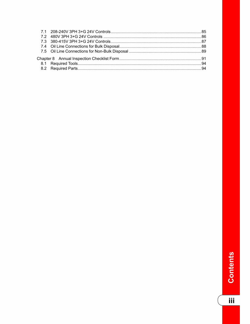
11.. Raise the lid to lower the fryer’scenter of gravity.
22.. Discard oil from the fry pot.
33.. Remove the racks from the carrier.
44.. Position two floor jacks under theframe (A), near the casters (B), onthe same side of the fryer.
55.. Block the casters on the oppositeside of the fryer with small wheelchocks.
66.. Raise the fryer approximately 2.5”(63mm).
77.. Use an adjustable wrench to removethe caster (B).
88.. Use an adjustable wrench to installthe new caster. Ensure a snug fit butdo not overtighten.
99.. Continue to the next inspection orreinstall components as applicable.
11..22 IInnssppeecctt CCoouunntteerrwweeiigghhtt CCaabblleessThis unit uses two cables in the counter-weight mechanism that helps in the raisingand lowering of the lid. Cables should be visually inspected yearly, either as part of aplanned maintenance program or during a routine service call. Cables more than 10years old should be replaced regardless of inspection results. Call for service to haveboth cables replaced.
:
IIff tthhee lliidd bbeeccoommeess ddiiffffiiccuulltt ttoo ooppeerraattee,, ssttoopp uussiinngg tthhee ffrryyeerraanndd ccaallll ffoorr sseerrvviiccee bbeeccaauussee tthhee ccaabblleess nneeeedd ttoo bbeerreeppllaacceedd..

Ann
ualInspections
3
WWoorrnn CCoouunntteerrwweeiigghhtt CCaabbllee UUssaabbllee CCoouunntteerrwweeiigghhtt CCaabbllee
11.. Use a 3/8” socket, to remove the 6keps nuts around exterior of rearcover and remove the back shroud.
22.. Inspect the counter-weight cables. Ifcables have cracks in the jacket,missing pieces in the jacket, or otherobvious signs of wear, replace bothcables.
33.. Continue to the next inspection orreinstall components as applicable.
11..33 IInnssppeecctt aanndd LLuubbrriiccaattee tthhee CCaarrrriiaaggee WWhheeeellssThe carriage wheels inside the back of the fryer should be lubricated at least once ayear to allow for easy lid movement.

Ann
ualInspections
4
11.. If necessary, use a 3/8” socket toremove the 6 keps nuts aroundexterior of rear cover and removethe back shroud.
22.. Inspect the carriage wheels andensure proper operation.
33.. Use spindle lube (PN 12124) andplace a small amount on all four (4)wheels, both top and bottom, leftand right rollers.
44.. Continue to the next inspection orreinstall components as applicable.
11..44 OOiill MMiiggrraattiioonnTToo aavvooiidd sseerriioouuss ppeerrssoonnaall iinnjjuurryy::• UUnnpplluugg ffrryyeerr bbeeffoorree rreemmoovviinngg tthhee lleefftt ssiiddee ppaanneell ttoopprreevveenntt eelleeccttrriiccaall sshhoocckk..
• OOnnllyy ppeerrffoorrmm tthhiiss pprroocceedduurree wwhheenn tthhee ffrryyeerr iiss ccooooll oorrsseevveerree bbuurrnnss mmaayy rreessuulltt..
Inspect behind the left side panel for excessive oil seeping through either the high limitpot fittings, the temperature probe pot fitting, level probe fitting, pressure transducerfitting, or the heating element fittings. If oil migration or seepage is found, remove andclean the fittings, applying pipe thread sealant and then re-install the fitting. Ifexcessive oil migration is discovered, the insulation on the side of the fryer must bereplaced.
1. If necessary, remove the left side panel.
2. Inspect for oil seepage at the probefittings, high limit fittings, pressuretransducer fitting and heatingelement fittings.
3. Complete any necessary repairs.
4. Continue to the next inspection orreinstall components as applicable.
Ann
ualInspections
5
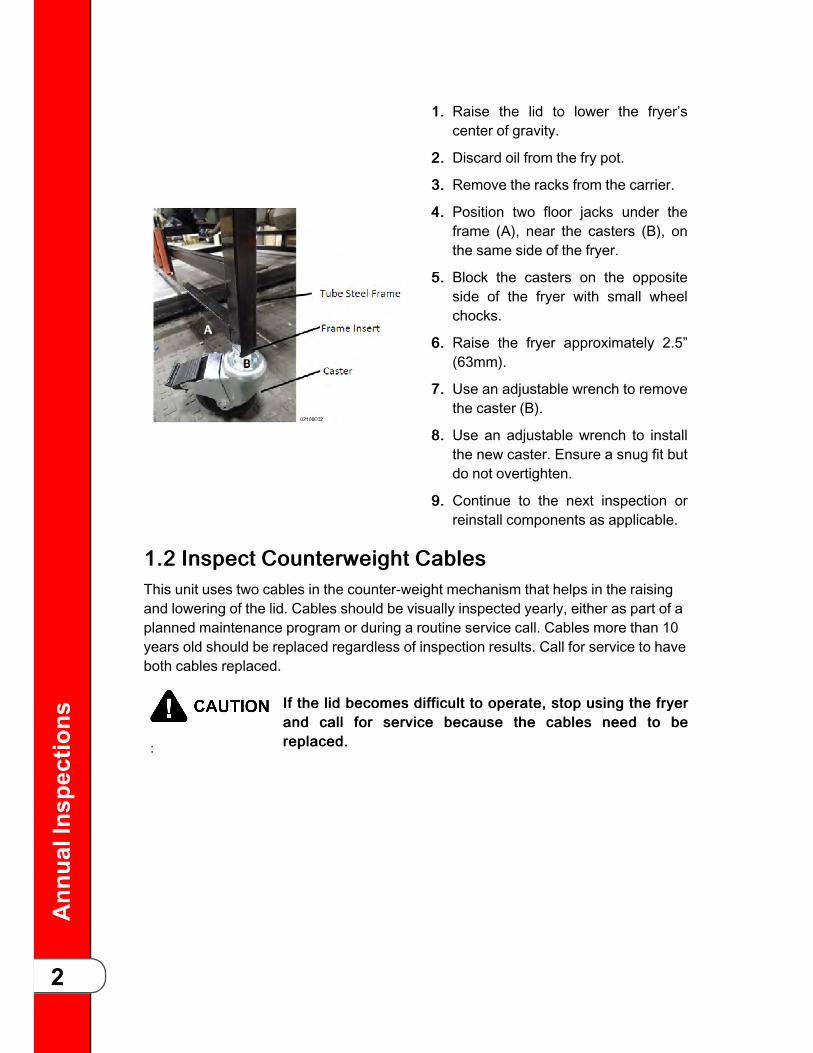
11..55 IInnssppeecctt FFrryy PPoott ffoorr LLeeaakkiinnggOOiill aaccccuummuullaattiioonn oonn tthhee eexxtteerriioorr ooff tthhee ffrryyppoott ccrreeaatteess aa ffiirreerriisskk.. TTaakkee tthhee ffrryyeerr oouutt ooff sseerrvviiccee uunnttiill tthhee ooiill aaccccuummuullaattiioonniiss rreemmoovveedd,, oorr tthhee ffrryyeerr iiss rreeppllaacceedd..
Excessive oil accumulation on the exterior of the fry pot may indicate the fryer ishaving a hardware issue or the operator is not following recommended operatingprocedures. With both side panels and the back shroud removed, clean off the oilaccumulation, and then use a flashlight to inspect the fry pot, fry pot welds, fry potplumbing and fittings, and the probe and element fittings.
If the fry pot is suspected of leaking, do the following:
• If the oil accumulation is toward the upper half of the fry pot, take the fryer out ofservice immediately, and replace the fryer.
• If the oil accumulation is toward the lower half of the fry pot, and it is not evident ifthe oil accumulation is due to the store using a drain pan without a cover or otheroperator error, do the following:
If necessary, scrape and clean off the existing oil from the fry pot and welds, and thenhave the store bread and cook 4 head or greater of bone in chicken. During cooking,monitor the suspected area for leaking:• If oil is pushed out of the fry pot or welded areas while the fryer is under pressure,take the fryer out of service and replace the fryer.

Ann
ualInspections
6
• If the pot is not leaking, take the fryer out of service until the oil accumulation isremoved and the store operates the fryer with a drain pan cover or the operatorerror is corrected.
11..66 TTeemmppeerraattuurree aanndd LLeevveell PPrroobbee IInnssppeeccttiioonnTToo aavvooiidd sseerriioouuss ppeerrssoonnaall iinnjjuurryy.. UUnnpplluugg ffrryyeerr bbeeffoorreerreemmoovviinngg tthhee lleefftt ssiiddee ppaanneell ttoo pprreevveenntt eelleeccttrriiccaall sshhoocckk..OOnnllyy ppeerrffoorrmm tthhiiss pprroocceedduurree wwhheenn tthhee ffrryyeerr iiss ccooooll oorrsseevveerree bbuurrnnss mmaayy rreessuulltt..
Ensure the temperature and level probes are undamaged and working withinspecification by doing the following:

Ann
ualInspections
7
1. Press and hold the menu button until*MAIN* appears on the display.
2. Press the number one product button toenter the filter menu.
3. Press the right arrow until 4. DRAIN ->displays.
4. Select 44.. DDRRAAIINN -->>, and drain all the oilin the fry pot into the drain pan.
5. On the inside of the vat, clean off anybuild up or debris from thetemperature probe and level probe.If a probe is bent or damaged,replace the probe.
6. Check that each probe is inserted intothe fry pot 3/8” into the oil. If a probeeither extends too far into the oil or istoo shallow, do the following:
a) Remove the left side panel.
b) Adjust the probe to the correct depth byloosening the ½” compression nuton the temperature probe.
c) Slide the probe to the correct depththen tighten the compression nut.
7. Select 55.. FFIILLLL <<--. Allow oil to fully fillthe vat. Once filled, cancel the filterpump motor and exit out of the filtermenu by pressing and holding themenu button.
8. Continue to the next inspection orreinstall components as applicable.

Ann
ualInspections
8
11..77 IInnssppeecctt tthhee PPoowweerr CCaabblleeFFiirree RRiisskk aanndd EElleeccttrriiccaall SShhoocckk PPoossssiibbllee.. IIff aannyy ooff tthheesseeccoonnddiittiioonnss aarree ffoouunndd,, ttaakkee tthhee ffrryyeerr oouutt ooff sseerrvviiccee uunnttiill aanneeww ppoowweerr ccoorrdd oorr pplluugg ccaann bbee iinnssttaalllleedd.. AAllwwaayyss aaddhheerree ttoollooccaall eelleeccttrriiccaall ccooddee uuppoonn iinnssttaallllaattiioonn ooff tthhee ppoowweerr ccoorrdd..
TThhiiss ffrryyeerr mmuusstt bbee aaddeeqquuaatteellyy aanndd ssaaffeellyy ggrroouunnddeedd((eeaarrtthheedd)) oorr eelleeccttrriiccaall sshhoocckk ccoouulldd rreessuulltt.. RReeffeerr ttoo llooccaalleelleeccttrriiccaall ccooddeess ffoorr ccoorrrreecctt ggrroouunnddiinngg ((eeaarrtthhiinngg))pprroocceedduurreess oorr iinn aabbsseennccee ooff llooccaall ccooddeess,, wwiitthh TThhee NNaattiioonnaallEElleeccttrriiccaall CCooddee,, AANNSSII//NNFFPPAA NNoo.. 7700--((tthhee ccuurrrreenntt eeddiittiioonn))..IInn CCaannaaddaa,, aallll eelleeccttrriiccaall ccoonnnneeccttiioonnss aarree ttoo bbee mmaaddee iinnaaccccoorrddaannccee wwiitthh CCSSAA CC2222..11,, CCaannaaddiiaann EElleeccttrriiccaall CCooddeePPaarrtt 11,, aanndd//oorr llooccaall ccooddeess..
TToo aavvooiidd eelleeccttrriiccaall sshhoocckk,, tthhiiss aapppplliiaannccee mmuusstt bbee eeqquuiippppeeddwwiitthh aann eexxtteerrnnaall cciirrccuuiitt bbrreeaakkeerr wwhhiicchh wwiillll ddiissccoonnnneecctt aalllluunnggrroouunnddeedd ((uunneeaarrtthheedd)) ccoonndduuccttoorrss.. TThhee mmaaiinn ppoowweerrsswwiittcchh oonn tthhiiss aapppplliiaannccee ddooeess nnoott ddiissccoonnnneecctt aallll lliinneeccoonndduuccttoorrss..
FFOORR EEQQUUIIPPMMEENNTT WWIITTHH CCEE MMAARRKK OONNLLYY!! TToo pprreevveenntteelleeccttrriicc sshhoocckk hhaazzaarrdd tthhiiss aapppplliiaannccee mmuusstt bbee bboonnddeedd ttooootthheerr aapppplliiaanncceess oorr ttoouucchhaabbllee mmeettaall ssuurrffaacceess iinn cclloosseepprrooxxiimmiittyy ttoo tthhiiss aapppplliiaannccee wwiitthh aann eeqquuiippootteennttiiaall bboonnddiinnggccoonndduuccttoorr.. TThhiiss aapppplliiaannccee iiss eeqquuiippppeedd wwiitthh aanneeqquuiippootteennttiiaall lluugg ffoorr tthhiiss ppuurrppoossee.. TThhee eeqquuiippootteennttiiaall lluugg iissmmaarrkkeedd wwiitthh tthhee ffoolllloowwiinngg ssyymmbbooll..
NOTICE
:
The supply power cords shall be oil-resistant, sheathed flexiblecable, no lighter than ordinary polychloroprene or otherequivalent synthetic elastomer-sheathed cord. It isrecommended that a 30 mA rated protective device such as aresidual current circuit breaker (RCCB), or ground fault circuitinterrupter (GFCI), be used on the fryer circuit.
Replace any power cord with torn or damaged sheathing, any exposed wire, or anyfraying. Replace the plug if there are any signs of damage, loose wires showing, orburnt connections.
11..77..11 EElleeccttrriiccaall RReeqquuiirreemmeennttssThe electric fryer requires 208 or 240 volt, three phase, 50/60 Hertz service. Thepower cord may be already attached to the fryer, or provided at installation. Check thedata plate mounted just above the lid, on the left side of the back shroud, to determinethe correct power supply. A terminal block is mounted inside the fryer for the cable

Ann
ualInspections
9
wiring. A decal on the inside of the right side panel will help in the wiring of the unit.Refer to .
11..77..22 IInntteerrnnaattiioonnaall RReeqquuiirreemmeennttssUnits being used outside the United States may not be shipped with the power cordattached to the unit because of the different wiring codes. The fryers are availablefrom the factory wired for 208, 240, 380 and 415 volts, 3 phase, 50 Hertz service. Aterminal block is mounted inside the fryer for the cable wiring. A decal on the inside ofthe right side panel will help in the wiring of the unit. Refer to .
11..88 HHiigghh LLiimmiitt aanndd MMoodduullee IInnssppeeccttiioonn
NNeevveerr lleeaavvee aa ffrryyeerr wwiitthh aa hhiigghh lliimmiitt bbyyppaasssseedd.. TThhiiss ccaannlleeaadd ttoo ffiirree,, pprrooppeerrttyy ddaammaaggee,, ppeerrssoonnaall iinnjjuurryy oorr ddeeaatthh..
TToo aavvooiidd sseerriioouuss ppeerrssoonnaall iinnjjuurryy.. UUnnpplluugg ffrryyeerr bbeeffoorreerreemmoovviinngg tthhee lleefftt ssiiddee ppaanneell ttoo pprreevveenntt eelleeccttrriiccaall sshhoocckk..OOnnllyy ppeerrffoorrmm tthhiiss pprroocceedduurree wwhheenn tthhee ffrryyeerr iiss ccooooll oorrsseevveerree bbuurrnnss mmaayy rreessuulltt..
Ensure the high limit and module are undamaged and working within specification bydoing the following:
1. Locate the two high limit controlmodules mounted on the lefthand side of the shroud behindthe control.
2. Visually inspect the modules forcracks, broken or looseterminals.
3. Visually inspect the high limitmomentary reset switch andensure it works.

Ann
ualInspections
10
4. Follow red wire RHL 1 from the control board and make sure that it is securelyattached to the terminal on the lower module. If this wire is not connected,reconnect it to match the diagram on the left.
5. Follow red wire RHL 2 from the control board and make sure that it is securelyattached to the terminal on the upper module. If this wire is not connected,reconnect it to match the diagram on the left.
6. Make sure red wire HLJ connects the two modules as shown in the drawing onthe left.
7. Verify all other wires attached to the high limit modules have secure connections.
8. Continue to the next inspection or reinstall components as applicable.
11..99 MMeeaassuurriinngg AAMMPP DDrraawwEnsure that the amp draw of the fryer equals the amp draw listed on the data label.Why is this important? If amp draw is less than what is on the data label, this would bean indication that one of the phases that comes into the fryer may be missing, theremay be an issue with one of the contactors, or there may be an issue in one of the firebar heating elements.
HHIIGGHH VVOOLLTTAAGGEE PPRREESSEENNTT!! TThhiiss pprroocceedduurree sshhoouulldd oonnllyybbee ppeerrffoorrmmeedd bbyy aa sseerrvviiccee tteecchhnniicciiaann wwhhoo iiss ttrraaiinneedd aanndduunnddeerrssttaannddss eelleeccttrriiccaall ssaaffeettyy..
Ann
ualInspections
11
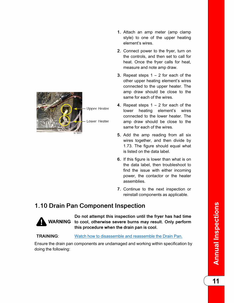
11.. Attach an amp meter (amp clampstyle) to one of the upper heatingelement’s wires.
22.. Connect power to the fryer, turn onthe controls, and then set to call forheat. Once the fryer calls for heat,measure and note amp draw.
33.. Repeat steps 1 – 2 for each of theother upper heating element’s wiresconnected to the upper heater. Theamp draw should be close to thesame for each of the wires.
44.. Repeat steps 1 – 2 for each of thelower heating element’s wiresconnected to the lower heater. Theamp draw should be close to thesame for each of the wires.
55.. Add the amp reading from all sixwires together, and then divide by1.73. The figure should equal whatis listed on the data label.
66.. If this figure is lower than what is onthe data label, then troubleshoot tofind the issue with either incomingpower, the contactor or the heaterassemblies.
77.. Continue to the next inspection orreinstall components as applicable.
11..1100 DDrraaiinn PPaann CCoommppoonneenntt IInnssppeeccttiioonnDDoo nnoott aatttteemmpptt tthhiiss iinnssppeeccttiioonn uunnttiill tthhee ffrryyeerr hhaass hhaadd ttiimmeettoo ccooooll,, ootthheerrwwiissee sseevveerree bbuurrnnss mmaayy rreessuulltt.. OOnnllyy ppeerrffoorrmmtthhiiss pprroocceedduurree wwhheenn tthhee ddrraaiinn ppaann iiss ccooooll..
TTRRAAIINNIINNGG: Watch how to disassemble and reassemble the Drain Pan.
Ensure the drain pan components are undamaged and working within specification bydoing the following:
Ann
ualInspections
12
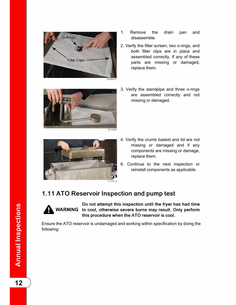
1. Remove the drain pan anddisassemble.
2. Verify the filter screen, two o-rings, andboth filter clips are in place andassembled correctly. If any of theseparts are missing or damaged,replace them.
3. Verify the standpipe and three o-ringsare assembled correctly and notmissing or damaged.
4. Verify the crumb basket and lid are notmissing or damaged and if anycomponents are missing or damage,replace them.
6. Continue to the next inspection orreinstall components as applicable.
11..1111 AATTOO RReesseerrvvooiirr IInnssppeeccttiioonn aanndd ppuummpp tteessttDDoo nnoott aatttteemmpptt tthhiiss iinnssppeeccttiioonn uunnttiill tthhee ffrryyeerr hhaass hhaadd ttiimmeettoo ccooooll,, ootthheerrwwiissee sseevveerree bbuurrnnss mmaayy rreessuulltt.. OOnnllyy ppeerrffoorrmmtthhiiss pprroocceedduurree wwhheenn tthhee AATTOO rreesseerrvvooiirr iiss ccooooll..
Ensure the ATO reservoir is undamaged and working within specification by doing thefollowing:
Ann
ualInspections
13
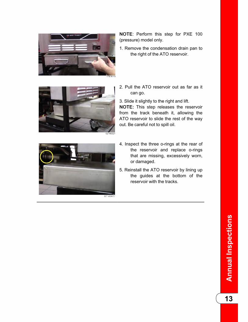
NNOOTTEE: Perform this step for PXE 100(pressure) model only.
1. Remove the condensation drain pan tothe right of the ATO reservoir.
2. Pull the ATO reservoir out as far as itcan go.
3. Slide it slightly to the right and lift.NNOOTTEE:: This step releases the reservoirfrom the track beneath it, allowing theATO reservoir to slide the rest of the wayout. Be careful not to spill oil.
4. Inspect the three o-rings at the rear ofthe reservoir and replace o-ringsthat are missing, excessively worn,or damaged.
5. Reinstall the ATO reservoir by lining upthe guides at the bottom of thereservoir with the tracks.

Ann
ualInspections
14
NOTICE:
• IInnssppeecctt tthhee oo--rriinnggss aanndd rreeppllaaccee iiffddaammaaggeedd oorr eevveerryy 9900 ddaayyss..
• UUssee aa ssmmaallll ssccrreeww ddrriivveerr ttoo ggeennttllyypprryy oo--rriinnggss ffrroomm tthheeiirr ggrroooovvee ttooiinnssppeecctt ffoorr ddaammaaggee.. RReeiinnssttaallll bbyyggeennttllyy rroolllliinngg tthheemm iinn ttoo ppllaaccee..
• WWaattcchh aa sshhoorrtt vviiddeeoo eexxppllaaiinniinngg hhoowwttoo lluubbrriiccaattee tthhee oo--rriinnggss aafftteerriinnssttaallllaattiioonn..
6. Press and hold the menu button until*MAIN* appears on the display.
7. Press the number one product button toenter the filter menu.
8. Press the right arrow until 6. FILL <-ATO displays.
9. Press and hold the select button next to6. FILL <- ATO and test the ATOsystem. If oil pumps from thereservoir, the system is working. Ifoil does not pump, troubleshoot theATO issue.
NNOOTTEE: PXE 100 model only.
10. Reinstall the condensation drain pan.
11. Continue to the next inspection orreinstall components as applicable.
11..1122 TTeessttiinngg tthhee DDrraaiinn VVaallvveeEnsure the drain valve is undamaged and working within specification by doing thefollowing:

Ann
ualInspections
15
1. Press and hold the menu button until*MAIN* appears on the display.
2. Press the number one product button toenter the filter menu.
3. Press the right arrow until 4. DRAIN ->displays.
4. Select 44.. DDRRAAIINN -->>.
5. Once all the oil drains into the drainpan, visually inspect the drain andvalve.
6. Ensure the drain valve is fully open andnot partially closed, which indicatesthe valve assembly may bemisaligned or needs replaced.
7. Select 55.. FFIILLLL <<--.
8. Ensure the drain valve is fully closedand not partially closed, whichindicates the valve assembly may bemisaligned or needs to be replaced.
9. Allow oil to fully fill the vat.
10. Once filled, cancel the filter pumpmotor and exit out of the filter menuby pressing and holding the menubutton.
11. Continue to the next inspection orreinstall components as applicable.
11..1122..11 SSeerrvviiccee PPrroocceedduurree GGuuiiddaanncceeISSUE / SYMPTOM SERVICE RECOMMENDATION
Oil leaking in to drain pan. Replace drain valve.
Valve not moving but hear actuator moving. Remove actuator and check for actuatorcouple movement. Check if drain valve isseized. Likely replace actuator only, valvealso if seized.

Ann
ualInspections
16
11..1133 BBuullkk DDiissppoossee TTeesstt
NOTICE
:
Before performing this procedure, make sure the bulk oilsystem is securely connected to the dispose port on the fryerand the quick disconnect is engaged.
Ensure the bulk dispose process is working within specification by doing the following:
1. Press and hold the menu buttonuntil*MAIN* appears on the display.
2. Press the number one product button toenter the filter menu.
3. Press the right arrow until 4. DRAIN ->displays.
4. Select 44.. DDRRAAIINN -->>, and then cancelafter draining about 2” of oil in the frypot.
5. Press the right-arrow until 7. DISPOSEdisplays.
6. Select 77.. DDIISSPPOOSSEE and let the motorrun for about 1 min., and then stopthe pump.
7. Wearing PPE, pull out the drain panand verify the oil pumped out of thedrain pan and into the bulk oilsystem.
a) If oil pumped out of the drain pan, exitout of the filter menu by pressingand holding the menu button.
b) If oil did not pump out, troubleshootdispose plumbing, selector valveissues etc.
8. Continue to the next inspection orreinstall components as applicable.
NNOOTTEE: Replenish the oil in the fry pot bypouring oil from a jug or from bulk oil asapplicable.

Ann
ualInspections
17
11..1144 HHeeaattiinngg EElleemmeenntt SSpprreeaaddeerr BBaarrss TTiigghhtteenniinngg aannddIInnssppeeccttiioonn
TToo aavvooiidd sseerriioouuss ppeerrssoonnaall iinnjjuurryy::• UUnnpplluugg ffrryyeerr bbeeffoorree rreemmoovviinngg tthhee lleefftt ssiiddee ppaanneell ttoopprreevveenntt eelleeccttrriiccaall sshhoocckk..
• OOnnllyy ppeerrffoorrmm tthhiiss pprroocceedduurree wwhheenn tthhee ffrryyeerr iiss ccooooll oorrsseevveerree bbuurrnnss mmaayy rreessuulltt..
Ensure the heating element spreader bars are undamaged and working withinspecification by doing the following:
1. Press and hold the menu button until*MAIN* appears on the display.
2. Press the number one product button toenter the filter menu.
3. Press the right arrow until 4. DRAIN ->displays.
4. Select 44.. DDRRAAIINN -->>, and drain all the oilin the fry pot into the drain pan.
5. Using a Phillips screwdriver, check thetightness of the screws on all fourspreader bars.
NNOOTTEE: Do not overtighten screws. If anyspreader bar is missing or any of thespreader bar screws are missing,replace them.
6. Select 55.. FFIILLLL <<--. Allow oil to fully fillthe vat.
7. Once filled, cancel the filter pump motorand exit out of the filter menu bypressing and holding the menubutton.
7. Continue to the next inspection orreinstall components as applicable.

Ann
ualInspections
18
11..1155 OOiill RReettuurrnn DDiivveerrtteerrss aanndd PPrreessssuurree OOuuttlleettIInnssppeeccttiioonn
TToo aavvooiidd sseerriioouuss ppeerrssoonnaall iinnjjuurryy::• UUnnpplluugg ffrryyeerr bbeeffoorree rreemmoovviinngg tthhee lleefftt ssiiddee ppaanneell ttoopprreevveenntt eelleeccttrriiccaall sshhoocckk..
• OOnnllyy ppeerrffoorrmm tthhiiss pprroocceedduurree wwhheenn tthhee ffrryyeerr iiss ccooooll oorrsseevveerree bbuurrnnss mmaayy rreessuulltt..
Ensure the oil return diverters and pressure outlet are undamaged and working withinspecification by doing the following:
1. Press and hold the menu button until*MAIN* appears on the display.
2. Press the number one product button toenter the filter menu.
3. Press the right arrow until 4. DRAIN ->displays.
4. Select 44.. DDRRAAIINN -->>, and drain all the oilin the fry pot into the drain pan.
5. Use a Phillips head screwdriver, andremove the screws on each of the oilreturn diverters located at thebottom of the fry pot.
6. Remove both oil diverters and o-rings.

Ann
ualInspections
19
7. Clean and remove debris from the oilreturn tube at the bottom of the frypot.
8. Clean the oil diverters by removing alldebris from the narrow opening.
9. If the o-rings are not cracked ordamaged reuse them, otherwisereplace them.
10. Reinstall the oil diverters, ensuringthat the opening is aimed to returnoil in the directions shown.
11. Select 55.. FFIILLLL <<--. Allow oil to fully fillthe vat. Once filled, cancel the filterpump motor and exit out of the filtermenu by pressing and holding themenu button.
12. Continue to the next inspection orreinstall components as applicable.
11..1166 IInnssppeecctt ffoorr PPlluummbbiinngg LLeeaakkss iinn tthhee FFiillttrraattiioonnSSyysstteemm
TToo aavvooiidd sseerriioouuss ppeerrssoonnaall iinnjjuurryy::• UUnnpplluugg ffrryyeerr bbeeffoorree rreemmoovviinngg tthhee lleefftt ssiiddee ppaanneell ttoopprreevveenntt eelleeccttrriiccaall sshhoocckk..
• OOnnllyy ppeerrffoorrmm tthhiiss pprroocceedduurree wwhheenn tthhee ffrryyeerr iiss ccooooll oorrsseevveerree bbuurrnnss mmaayy rreessuulltt..
Ensure the filtration pump, tubing and connectors are undamaged and working withinspecification by doing the following:

Ann
ualInspections
20
1. Use a flashlight to inspect the fittings ofthe filtration plumbing and betweenthe filter pump and motor for oilleaks.
2. Press and hold the menu button until*MAIN* appears on the display.
3. Press the number one product button toenter the filter menu.
4. Press the right arrow until 4. DRAIN ->displays.
5. Select 44.. DDRRAAIINN -->>, and drain abouthalf of the oil in the fry pot into thedrain pan.
6. Select 55.. FFIILLLL <<--, and pump the oilback in to the fry pot.
7. While the oil is pumping, use a flashlightto inspect for oil leaks. If leaks aredetected:
- In the plumbing, disassemble, clean andreassemble fittings using pipe threadsealant on tapered thread fittingsand/or replace any flex lines, and/orcompression fittings as applicable.
- In the filter pump and motor,disassemble and replace the seal(and rollers) with a new seal kit.

Ann
ualInspections
21
11..1177 IInnssppeecctt CCaamm SSlliiddee FFiilllleerrssTToo aavvooiidd sseerriioouuss ppeerrssoonnaall iinnjjuurryy::• DDoo nnoott ooppeerraattee wwiitthhoouutt lliidd ccoovveerr iinn ppllaaccee aanndd aallllccoommppoonneennttss iinnssttaalllleedd..
• DDoo nnoott ttaammppeerr wwiitthh aannyy ccoommppoonneenntt ooff tthhee lliidd lloocckkiinnggmmeecchhaanniissmm dduurriinngg ooppeerraattiioonn..
DDoo nnoott aatttteemmpptt tthhiiss pprroocceedduurree wwhhiillee tthhee ffrryyeerr iiss iinn uussee oorrtthhee ffrryy ppoott iiss hhoott.. SSeevveerree bbuurrnnss mmaayy rreessuulltt.. OOnnllyy ppeerrffoorrmmtthhiiss pprroocceedduurree wwhheenn tthhee ffrryyeerr iiss ccooooll aanndd ddiissccoonnnneecctteeddffrroomm tthhee ppoowweerr ssoouurrccee..
Inspect the cam slide fillers on the sides of the lid cover. If either side is damaged ormissing, replace with new cam slide fillers. Why is this important? The cam slide fillershelp minimize the amount of grease laden vapor, breading, dust and debris that canaccumulate on the components under the lid cover.
1. Remove old left and right cam slidefillers if necessary by pulling theremaining pieces out of its channeland discarding.
2. Install the new left and right cam slidefillers by flexing open the slot in thecircular opening.
3. Fit the new cam slide filler around thecircular handle cam, ensuring theedge of the filler is inserted into thechannel.
4. Reinstall the lid cover, ensure the camslide fillers are completely seated onthe inside of the cover.
5. Test that the handle slides forward andbackwards with little resistance.Stoppage or resistance usuallyindicates an obstruction present inthe channel, or that the slide is notseated properly.
6. Continue to the next inspection orreinstall components as applicable.

Ann
ualInspections
22
11..1188 RReeppllaacceemmeenntt MMaaiinntteennaannccee PPaarrttssOperators must replace normal wear parts (items) to maintain the safe reliableoperation of the unit.
11..1188..11 OOrrddeerriinngg PPaarrttssUse only genuine Henny Penny parts in this unit. Using a lesser quality substitute partmay result in damage to the unit or personal injury. Your service provider or distributorhas a parts price list and will be glad to provide you with part(s) costs. Commonlyreplaced items are stocked by your service provider or distributor and are sent outwhen your order is processed. Less common parts ordered from Henny Penny byyour service provider or distributor normally take three working days. All replacementparts (except lamps and fuses) are warranted for 90 days against manufacturingdefects and workmanship. If damage occurs during shipping, notify the carrier at onceso that a claim may be properly filed. Refer to the warranty for other rights andlimitations.
11..1188..22 PPaarrttss LLiissttThese are commonly replaced parts that are ordered due to normal wear, accidentalbreakage or loss.
TTaabbllee 11--11 RReeppllaacceemmeenntt MMaaiinntteennaannccee PPaarrttss
Qty. Part # Description When to Replace
5 86349 DRAIN PAN O-RING -116 SUCTION LINE
Used to seal the oil tubing connections. Replaceevery 90 days or sooner if cut, flattened ormissing.
2 90085 O RING - CRUMBSWEEP
Ports in the bottom of the vat where fresh oil en-ters during a cleaning cycle to wash across thebottom of the vat. Replace as required.
100 12102 DRAIN PAN FILTERENVELOPES
Used inside the drain pan as apart of the filtra-tion assembly. Replace at least daily, more of-ten as required.
1 17572-7
NYLATRON FILLERSTRIP KIT
Used to cover the lid arm slots to prevent fooddebris, oil and water from entering the internalmechanics of the unit. Replace when broken.
2 14061-0 KIT, LID CABLE
Used to connect the lid assembly to the carriageweight assembly in the back of the unit to offsetthe lid weight. Replace cables when worn.
Prog
ramming
23
CChhaapptteerr 22 PPrrooggrraammmmiinngg22..11 PPrrooggrraamm MMeennuuFrom the MAIN menu, refer to , select 4. PROG, and then 1. PRODUCTS.
22..22 TTeecchh MMooddee MMeennuuTo access the Tech Mode menu from the Program menu, press the 77.. TTeecchh MMooddeebutton and then type the code 11221122.
TTaabbllee 22--11 TTeecchh MMooddee MMeennuu FFuunnccttiioonn
MenuItem(Mod-e)
Display Function
T-1 SOFTWARE ID’S Press and hold lower-left button to view software re-lease level. Shows the active version of software in themiddle display.
T-2 METADATA Displays information about the file that was used toflash the software into the control board, includes: in-cluding the “ID” of the file, date it was created, originalfile size, original file name, the version number of themetadata information, the authentication (checksum),and the board assemblies that the software is compati-ble with.
T-3 FRYER TYPE Shows what type of fryer (pressure or open) in the mid-dle display. To change the fryer type, press the illumi-nated lower-left button to change from “PRESSURE”to “OPEN”. The model type will change in the middledisplay.
T-4 FRYER HAS SELVALVE
NO- The unit is not equipped with a selector valve.YES - The unit is equipped with a selector valve. If in-correctly labeled, use the plus or minus button tochange.
T-4A FRONT DISPOSE KITINSTALLED?
An optional kit is available to support a front disposeconnection, where a hose is connected to a quick dis-connect fitting at the front of the fryer, and bulk disposeoperations pump directly into a portable disposal cart.
T-5 FRYER SERIALNUMBER
This fryer’s serial number is programmed into the con-trol so that it can be included in USB reports and canbe used when naming data log files.
T-6 PUSH BUTTON TEST This section tests all the button to confirm all are work-ing correctly. Press any of the non-illuminated button to
Prog
ramming
24
MenuItem(Mod-e)
Display Function
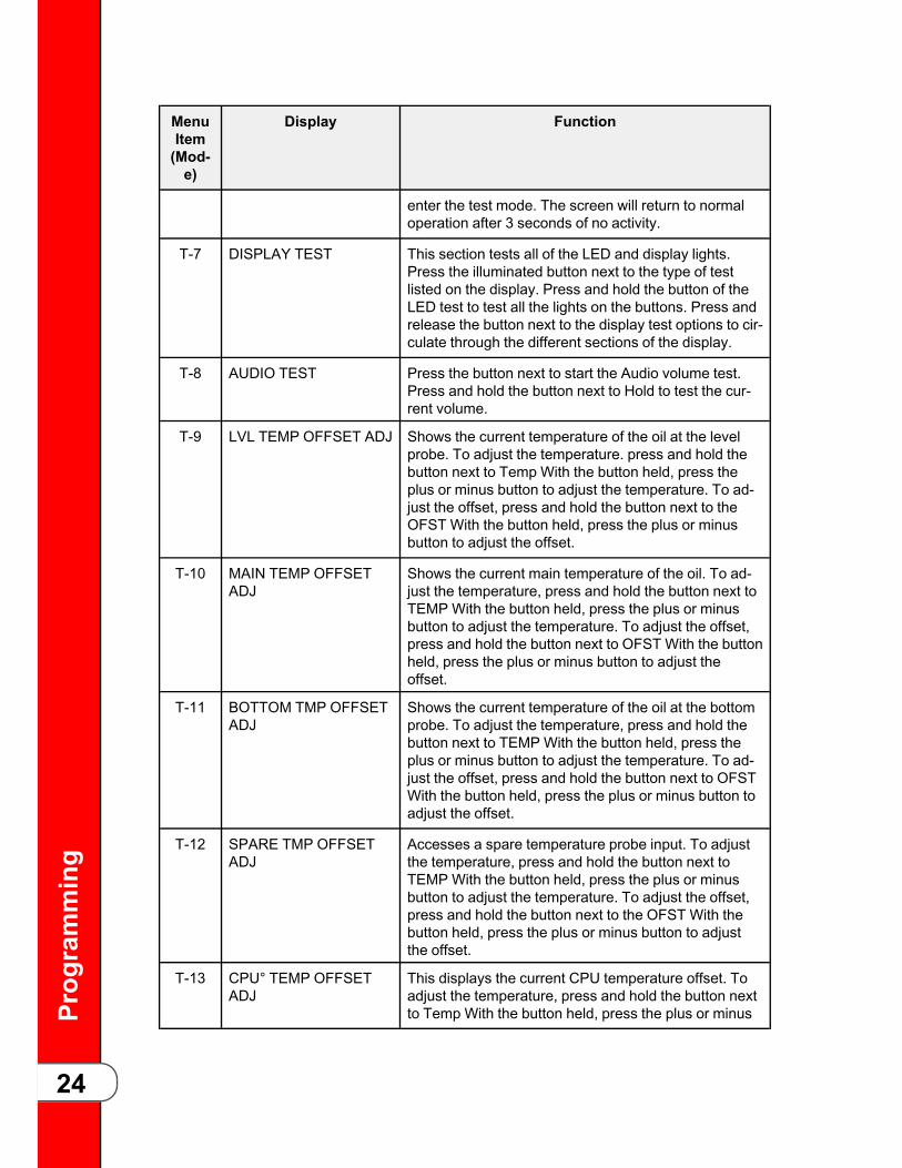
enter the test mode. The screen will return to normaloperation after 3 seconds of no activity.
T-7 DISPLAY TEST This section tests all of the LED and display lights.Press the illuminated button next to the type of testlisted on the display. Press and hold the button of theLED test to test all the lights on the buttons. Press andrelease the button next to the display test options to cir-culate through the different sections of the display.
T-8 AUDIO TEST Press the button next to start the Audio volume test.Press and hold the button next to Hold to test the cur-rent volume.
T-9 LVL TEMP OFFSET ADJ Shows the current temperature of the oil at the levelprobe. To adjust the temperature. press and hold thebutton next to Temp With the button held, press theplus or minus button to adjust the temperature. To ad-just the offset, press and hold the button next to theOFST With the button held, press the plus or minusbutton to adjust the offset.
T-10 MAIN TEMP OFFSETADJ
Shows the current main temperature of the oil. To ad-just the temperature, press and hold the button next toTEMP With the button held, press the plus or minusbutton to adjust the temperature. To adjust the offset,press and hold the button next to OFST With the buttonheld, press the plus or minus button to adjust theoffset.
T-11 BOTTOM TMP OFFSETADJ
Shows the current temperature of the oil at the bottomprobe. To adjust the temperature, press and hold thebutton next to TEMP With the button held, press theplus or minus button to adjust the temperature. To ad-just the offset, press and hold the button next to OFSTWith the button held, press the plus or minus button toadjust the offset.
T-12 SPARE TMP OFFSETADJ
Accesses a spare temperature probe input. To adjustthe temperature, press and hold the button next toTEMP With the button held, press the plus or minusbutton to adjust the temperature. To adjust the offset,press and hold the button next to the OFST With thebutton held, press the plus or minus button to adjustthe offset.
T-13 CPU° TEMP OFFSETADJ
This displays the current CPU temperature offset. Toadjust the temperature, press and hold the button nextto Temp With the button held, press the plus or minus

Prog
ramming
25
MenuItem(Mod-e)
Display Function
button to adjust the temperature. To adjust the offset,press and hold the button next to OFST With the buttonheld, press the plus or minus button to adjust theoffset.
T-14 INPUTS-1 A H D S F P M shows in the middle display. A - PowerSwitch. H - High Limit. D- Drain Switch Jumper. S -Power Switch. F - Fan Switch Jumper. P - Not in use atthis time. M - Not in use at this time. check - signal pre-sent. - signal not present.
T-15 INPUTS-2 24dc - 24 DC Supply. Pan - Filter Drain Pan. Lid - LidLiner Pin. OK - lid pin is down (not under pressure).Flashing PR - lid pin is raised (under pressure) check -active. - inactive.
T-16 INPUTS-3 DTF, HDP, AFR show in the middle display. DTF - Dis-card Tank Full. check - Tank is full; cannot dispose oilto tank. HDP - High Dispose Pressure check - Disposepumping caused high pressure. AFR - ATO Fill Re-quest. check - Switch is asking to pump Bulk SupplyOil to refill the ATO tank.
T-17 PRESSURE INPUTS This section shows the current psi of the lid. If OK is onthe display, the lid is safe to open. Otherwise, PR;flashes showing lid is under pressure. The bottom dis-play reads Lid Pin;. If OK is on the display, the lid pin isdown. Other wise, PR flashes showing the pin is raised(under pressure).
T-17A PUMPING PRESSURE This section shows the current pumping pressure inpsi.
T-18 OUTPUTS Press the illuminated button next to the feature to test.Pri - Primary Contactor. Ht - Heat (regulating) Contac-tor. Pr - Pressure Solenoid. * - On. - - Off.
T-19 DRN VALVE Be sure drain pan is in place before testing drain valve.This section tests the drain valve functions. ► - Showsnext to the drain valve current state. Par - Partiallyopen. Stp - Forced stop. Opn - Fully open. At - Wherethe drain valve stopped from 00-20. Max open positionmay be as high as 25 or 50. Cls - Fully closed.
T-20 SEL VALVE FWD/REV This section tests the selector valve rotation position.Cst - Coast counts how much the motor coasts afterbeing turned off (11 = typical). Stp - Stop the selectorvalve rotation. Fwd - Press to rotate the selector valveforward. Rev - Press to rotate the selector valve in re-verse. Enc (encoder) - Shows the position count, 0 to

Prog
ramming
26
MenuItem(Mod-e)
Display Function
999. When running, top line shows time of eachrevolution.
T-21 SEL VALVE PORTS This section tests the positioning of each port on theselector valve. P0 - At pot. P1 - At dispose (rear dis-pose) P2- At FDI (front dispose) Enc - Encoder posi-tion. FAIL - Selector valve does not function properly.
T-22 PUMPS Press the illuminated button next to the function to starttest * - On - - Off Fltr - Filter pump ATO- JIB pump (op-tional) Drn C - Drain valve (c - closed, o - open)
T-23 OPS/QPM SYSTEMENABLED?
This section shows if the unit is equipped with a radiosystem. To change the option press the plus or minusbutton to select YES or NO
T-24 RADIO COM (Zigbee) If the control is equipped with an OPS/QPM ZigBeeradio module, and it has been enabled (step T-23 orSP-4), this test mode displays information receivedfrom the radio module via the wired connection. If theOPS System is disabled (see previous step), this stepsimply displays ZigBee IS -OFF-
T-25 ANALOG CHANNELS This test mode is available to display the current low-level analog status of any of the analog inputs on theprimary Analog to Digital converter chip inside thecontrol.
T-26 HEAT CTRL This test mode has very specialized and very limiteduse. It displays information about the heating algorithmand its performance, and can be useful when tuningthe heating algorithm for a brand new fryer type.
T-27 ALLOW LID OPEN n/a
T-28 LID LINER PIN -MUST-ACTUATE
n/a
T-29 AFTER COOK, PRES-SURE STUCK ONGIVES ERROR
n/a
T-30 AUTO-CYCLE PRES-SURE SOLENOID?
n/a
T-31 BLOCKED DRAINAUTO-REV RETRIES
The control gets a feedback signal from the motorizeddrain valve when it is at the fully open and fully closedpositions. If the control is commanding the drain valveto close, but it doesn’t see the closed feedback signalwithin a reasonable time, it presumes that maybe abrush has been left in the open drain valve and that is

Prog
ramming
27
MenuItem(Mod-e)
Display Function
preventing the valve from closing. In response, thecontrol automatically opens the drain valve back up,sounds a sequence of fast beeps, and displays DrainBlocked for a few seconds, giving the user time to re-move the brush. After a short delay, the control auto-matically tries to close the drain valve again.
T-32 ATO DELTA: -FULL- The auto-topoff (ATO) oil level detection system moni-tors the temperature difference between the mainprobe (just above the heating elements) and the levelprobe (located at the desired oil fill level). In static, non-cooking situations, the level probe, high in the pot, isgenerally cooler than the main probe, even when thepot is properly filled and both probes are immersed inthe oil (the oil at the top of the pot radiates a lot of itsheat, and conducts heat away, into the air).
T-33 ATO DELTA: -LOW- The auto-topoff (ATO) oil level detection system moni-tors the temperature difference between the mainprobe (just above the heating elements) and the levelprobe (located at the desired oil fill level). In static non-cooking situations, the level probe high in the pot isgenerally cooler than the main probe even when thepot is properly filled and both are immersed in the oil.
T-34 QUICK FLTR: FILL TOLVL PROBE - TEMPRISE
When refilling the pot after a filter operation, the controlmonitors the upper temperature probe (the level probe,at the oil fill line) and looks for a temperature rise therethat indicates the oil has refilled high enough to reachor splash on that probe.
T-35 DAILY+POL: FILL TOLVL PROBE - TEMPRISE
When refilling the pot after a filter operation, the controlmonitors the upper temperature probe (the level probe,at the oil fill line) and looks for a temperature rise therethat indicates the oil has refilled high enough to reachor splash on that probe.
T-36 ANY FILL: LVL PROBEMIN DETECT
How the control monitors the level probe for a tempera-ture rise when refilling the pot is described in the de-tails of step T-34. This T-36 parameter specifies aminimum reasonable filling time for that temperaturerise to be trusted.
T-37 CHANGE TECH CODE The default Tech Mode password can be changed bythe user. This password is used for entry to Tech Modeand Stats Mode. It is recommended that this passwordnot be changed except under extreme circumstances,as a service technician visiting the store to service the

Prog
ramming
28
MenuItem(Mod-e)
Display Function
fryer would probably not know the new password andwould not be able to access Tech Mode.
T-38 TOTAL INIT Press and hold the button next to hold on the display toinitialize the control board.
T-40 PROTECTION PROBE Manually turn on the protection probe feature. Must up-grade software to v1.60 to use this feature. For soft-ware v1.60 and after, the control auto-detects whetherthe probe is connected when the fryer enters the meltcycle for the first time and sees the probe 50°F hotterthan the main temp probe.

Trou
blesho
oting
29
CChhaapptteerr 33 TTrroouubblleesshhoooottiinngg33..11 TTrroouubblleesshhoooottiinngg GGuuiiddee
NOTICE
:
More detailed troubleshooting information is available in theTechnical Manual, available at www. hennypenny. com, or 1-800-417-8405 or 1-937-456-8405.
TTaabbllee 33--11 TTrroouubblleesshhoooottiinngg GGuuiiddee
Problem Cause Correction
Power switch is onbut the fryer is com-pletely inoperative.
Open circuit.• Fryer plugged in.
• Check breaker or fuse at wall.
• Check circuit breakers betweencontrol panel and ATO tank.
Oil not heating. High temperature limittripped.
Reset high temperature limit. Referto 3.1 Operating Components in theOperator’s Manual.
Foaming or boilingover.
Some customers choose notto use oil stabilizers whichcan cause foaming and boil-over.
Product with excessive ice crystalsshould be dipped once quickly thenremoved from the fryer to allow icecrystals to melt and excessive waterto evaporate. Then place the productback into the fryer and cooknormally.
See boil-over chart on fryerand Boil-Over Preventionsection of Operator’s Manual.
Refer to 2.7 Boil-Over Prevention inthe Operator’s Manual.
Oil not draining. Drain valve clogged. Push cleaning rod through opendrain valve.
Filter motor won’trun.
Motor overheated. Reset motor. Refer to Filter PumpMotor Protector - Manual Reset sec-tion of Operator’s Manual.
33..22 EErrrroorr CCooddeessIn the event of a system failure the control board displays an error message. Thesemessages are coded as E which represents an error, a number designation and errormessage, such as E-4 CPU TO HOT. Also, a constant tone sounds. To silence thetone, press any of the product buttons. Use the following table to interpret and correctan error code.

Trou
blesho
oting
30
TTaabbllee 33--22 EErrrroorr CCooddeess
Error Cause Correction
E-1 LOWOIL INPOT
The top heating ele-ment where theprobe is located isgetting hotter than itwould if the elementwere submerged inoil.
If the Protection Probe monitoring function determinesthat the oil level is too low—below the main probe—itgenerates an E-1 error code and displays the messageLOW OIL IN POT!, CHECK OIL LEVEL.
E-4 CPUTOO HOT
Control boardoverheating.
Turn the switch to off position, then turn the switchback to on. if E-4 continues to display, the board is get-ting too hot. Check for signs of overheating behind thecontrol panel. Once the panel cools down the controlsshould return to normal operation. If the E-4 error per-sists, replace the control.
E-5 OILTOO HOT
Oil overheating. Turn the switch to off position, then turn the switchback to on. If E-5 continues to display, the heating cir-cuits and temperature probe should be checked. Oncethe unit cools down, the controls should return to nor-mal operation. If the E-5 error persists, replace thecontrol.
E-6A MAINTEMPPROBEFAILED(OpenCircuit)
Temperature probefailure.
Turn the switch to off position, then turn the switchback to on. If E-6 continues to display, the temperatureprobe should be checked. Once the temperature probeis repaired, or replaced, the controls should return tonormal operation. If the E-6 error persists, replace thecontrol.
E-6B MAINTEMPPROBEFAILED(Shorted)
E-10 High limit tripped(Software prior toversion 1.60).
Check the error log to find out the vat temperature atthe time the high limit tripped. If this temperature wasvery low, this may be a sign that the vat was turned onwith low or no oil. If this was the case, fill the pot withoil and reset the high limit. If the trip temperature wasseveral degrees above the oil setpoint temperature,test for a sticking contactor and replace if faulty. If thehigh limit tripped at an oil temperature, inspect the high
Trou
blesho
oting
31
Error Cause Correction
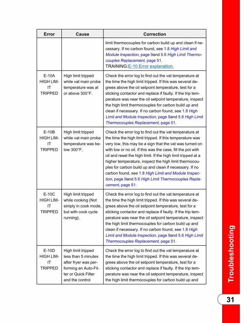
limit thermocouples for carbon build up and clean if ne-cessary. If no carbon found, see 1.8 High Limit andModule Inspection, page 9and 5.6 High Limit Thermo-couples Replacement, page 51.TRAINING:E-10 Error explanation.
E-10AHIGH LIM-
ITTRIPPED
High limit trippedwhile vat main probetemperature was ator above 300°F.
Check the error log to find out the vat temperature atthe time the high limit tripped. If this was several de-grees above the oil setpoint temperature, test for asticking contactor and replace if faulty. If the trip tem-perature was near the oil setpoint temperature, inspectthe high limit thermocouples for carbon build up andclean if necessary. If no carbon found, see 1.8 HighLimit and Module Inspection, page 9and 5.6 High LimitThermocouples Replacement, page 51.
E-10BHIGH LIM-
ITTRIPPED
High limit trippedwhile vat main probetemperature was be-low 300°F.
Check the error log to find out the vat temperature atthe time the high limit tripped. If this temperature wasvery low, this may be a sign that the vat was turned onwith low or no oil. If this was the case, fill the pot withoil and reset the high limit. If the high limit tripped at ahigher temperature, inspect the high limit thermocou-ples for carbon build up and clean if necessary. If nocarbon found, see 1.8 High Limit and Module Inspec-tion, page 9and 5.6 High Limit Thermocouples Repla-cement, page 51.
E-10CHIGH LIM-
ITTRIPPED
High limit trippedwhile cooking (Notsimply in cook mode,but with cook cyclerunning).
Check the error log to find out the vat temperature atthe time the high limit tripped. If this was several de-grees above the oil setpoint temperature, test for asticking contactor and replace if faulty. If the trip tem-perature was near the oil setpoint temperature, inspectthe high limit thermocouples for carbon build up andclean if necessary. If no carbon found, see 1.8 HighLimit and Module Inspection, page 9and 5.6 High LimitThermocouples Replacement, page 51.
E-10DHIGH LIM-
ITTRIPPED
High limit trippedless than 5 minutesafter fryer was per-forming an Auto-Fil-ter or Quick Filterand the control
Check the error log to find out the vat temperature atthe time the high limit tripped. If this was several de-grees above the oil setpoint temperature, test for asticking contactor and replace if faulty. If the trip tem-perature was near the oil setpoint temperature, inspectthe high limit thermocouples for carbon build up and

Trou
blesho
oting
32
Error Cause Correction
returned to cookmode on its ownafter detecting thatthe oil was pumpedup (based on tem-perature rise on levelprobe).
clean if necessary. If no carbon found, see 1.8 HighLimit and Module Inspection, page 9and 5.6 High LimitThermocouples Replacement, page 51.
E-10FHIGH LIM-
ITTRIPPED
High limit trippedwhile filtering (in-cluding Auto-Filter,Daily Filter, Polish,Dispose, Drain toPan, Fill from Pan,etc.).
Check the error log to find out the vat temperature atthe time the high limit tripped. If this was several de-grees above the oil setpoint temperature, test for asticking contactor and replace if faulty. If the trip tem-perature was near the oil setpoint temperature, inspectthe high limit thermocouples for carbon build up andclean if necessary. If no carbon found, see 1.8 HighLimit and Module Inspection, page 9and 5.6 High LimitThermocouples Replacement, page 51.
E-10MHIGH LIM-
ITTRIPPED
High limit trippedwhile fryer was inMelt Mode.
Check the error log to find out the vat temperature atthe time the high limit tripped. If this temperature wasvery low, this may be a sign that the vat was turned onwith low or no oil. If this was the case, fill the pot withoil and reset the high limit. If the high limit tripped at ahigher temperature, inspect the high limit thermocou-ples for carbon build up and clean if necessary. If nocarbon found, see 1.8 High Limit and Module Inspec-tion, page 9and 5.6 High Limit Thermocouples Repla-cement, page 51.
E-10SHIGH LIM-
ITTRIPPED
High limit trippedwhile vat was inStart-up Mode (notincluding Meltmode), but not whileit was executing oneof the filteroperations.
Check the error log to find out the vat temperature atthe time the high limit tripped. If this temperature wasvery low, this may be a sign that the vat was turned onwith low or no oil. If this was the case, fill the pot withoil and reset the high limit. If the high limit tripped at ahigher temperature, inspect the high limit thermocou-ples for carbon build up and clean if necessary. If nocarbon found, see 1.8 High Limit and Module Inspec-tion, page 9and 5.6 High Limit Thermocouples Repla-cement, page 51.
E-10YHIGH
High limit trippedless than 5 minutesafter user responded
Check the error log to find out the vat temperature atthe time the high limit tripped. If this temperature wasvery low, this may be a sign that the vat was turned on

Trou
blesho
oting
33
Error Cause Correction
LIMITTRIPPED
YES to, Is PotFilled? question.
with low or no oil. If this was the case, fill the pot withoil and reset the high limit. If the high limit tripped at ahigher temperature, inspect the high limit thermocou-ples for carbon build up and clean if necessary. If nocarbon found, see 1.8 High Limit and Module Inspec-tion, page 9and 5.6 High Limit Thermocouples Repla-cement, page 51.
E-15CDRAINVALVEERROR
The control ener-gized the drain valveto close it, andwaited a reasonableamount of time, butdidn’t see the ex-pected feedback sig-nal that would haveconfirmed that thedrain valve was fullyclosed.
Check the drain valve for obstruction. Carefully removeany obstruction found. If no obstruction, check to makesure both connections to the drain valve are plugged insecurely. If connections are secure, operate the drainvalve using the drain valve test in tech mode. If nodrain valve movement, test to make sure the drainvalve is getting 24 VDC from control board when test-ing both directions (open and closed) from connectorP9 pins 3 & 4. If voltage is present and no movement,replace drain valve motor. If no DC voltage, replacecontrol board.
E-15PDRAINVALVEERROR
The control ener-gized the drain valveto open it, andwaited a reasonableamount of time, butdidn’t see the ex-pected feedback.signal that wouldhave confirmed thatthe drain valve wasfully open.
Check to make sure both connections to the drainvalve are plugged in securely. If connections are se-cure, operate the drain valve using the drain valve testin tech mode. If no drain valve movement, test to makesure the drain valve is getting 24 VDC from controlboard when testing both directions (open and closed)from connector P9 pins 3 and 4. If voltage is presentand no movement, replace drain valve motor. If no DCvoltage, replace control board.
E-18A LE-VEL SEN-
SORFAILED(OpenCircuit)
The oil level probehas failed. • Press “” button to keep using the fryer. Error
repeats every four hours until fixed.
• If circuit is open, check connection.
• Replace probe.
E-18B LE-VEL SEN-
SOR

Trou
blesho
oting
34
Error Cause Correction
FAILED(Shorted)
E-19 PRO-TECTIONPROBEFAILED
A setting in TechMode (T-40) speci-fies whether or notthe fryer is equippedwith a protectionprobe system. If theT-40 option is set toYES, and the controldoes not detect a va-lid reading on theprotection probe in-put, an E-19 error isgenerated.
Replace the protection probe. Once the error code isacknowledged, the E-19 message goes away and nor-mal operation resumes without the benefit of the pro-tection probe feature. If the protection probe input is ina continuously failed state, the E-19 error repeatsevery 4 hours. If this E-19 error occurs in a fryer thatdoes not have and is not supposed to have a protectionprobe installed, access Tech Mode and change the T-40 option to NO.
E-41P-1-LOST
System data lost.Both the RAM copyand stored copy ofthe settings havebeen lost. Settingsare reset to default.
Replace control board if occurs repeatedly.
E-41 SYS-TEM DATA
LOST
System data lost.Both the RAM copyand stored copy ofthe settings havebeen lost. Settingsare reset to default.
Replace control board if occurs repeatedly.
E-46C IN-TERNALSD MEMERR
Issue with microSDchip.
Check to ensure chip is not ejected from slot.
E-46WDATASAVEFAILED
Unable to communi-cate and save datato the microSD chip.
Replace control board if occurs repeatedly.
Corrupt file.
E-47 ANA-LOG SYS-TEM OR
Problem reading theA-to-D Analog to • Check 12 VDC and 5 VDC analog power supplies
• Unplug pressure transducer at back of control.

Trou
blesho
oting
35
Error Cause Correction
12 VOLTFAILED
Digital converterinputs.
• Unplug filter pump relay at back of control.
• Replace control board.
E-48 IN-PUT SYS-
TEMERROR
Failure of the CPUboard.
Replace control board.
E-54CMAIN
TEMP CIR-CUIT
FAILURE
Fault on the CPUboard. • Initialize the CPU board.
• Replace control board
E-54DMAINTEMPDSC
ERROR
Fault on the CPUboard. • Initialize the CPU board.
• Replace control board
E-70A FANJUMP
MISSING
Jumper wire is looseor missing from 15pin connector.
Check connector for loose connection.
E-70BPWR
SWITCHOR WIRESFAILED”
Short in wires/ looseconnection.
Check connections of all four wires on the powerswitch
Power switch maybe faulty.
Replace power switch.
E-70CDRN JUM-
PERMISSING
Loose connection onthe 15 pinconnector.
Check connection.
E-82 SE-LECTORVALVEFAILURE
The selector valvefailed calibration ornot responding.
• Check motor, encoder or wiring.
• If unit is not equipped with a selector valve andgives this error: check settings in to confirmsettings are correct.
E-93 24VDC
SUPPLY
2nd transformer dis-connected fromcontrol.
• Check transformer plug on back of control.
• Check wire connections on 2nd transformer.

Trou
blesho
oting
36
Error Cause Correction
Short in drain motoror selector valvemotor.
Test motors.

Softw
areUpd
ates
37
CChhaapptteerr 44 SSooffttwwaarree UUppddaatteessTTRRAAIINNIINNGG: Watch a short video explaining software updates.
Periodically the software is updated with enhancements, menu changes or must bereloaded such as when a control board is replaced or updated with a newer modelcontrol. Use the following procedures to reload the software.
44..11 SSooffttwwaarree UUppddaatteess44..11..11 CCoonnttrrooll BBooaarrdd UUppddaatteessThe control board is operated by an onboard Micro SD card, which is loaded with HPsoftware during the factory programming process and/or installation; it occasionallyrequires an update. The software on a control board must be loaded from a USBdrive. The file type used for loading software is an .hpf (Henny Penny Flash) file. All .hpf files are encrypted and are checksum protected, in order to prevent accidental ormalicious changes to the official HP software. In addition, the boot-loader program onthe control board allows selection of only the .hpf files that are designed for thatspecific unit’s control assembly. This prevents accidental loading of say a holdingcabinet in to a pressure fryer control, or similar mistake.
44..11..11..11 UUSSBB PPoorrtt OOvveerrvviieeww
DDiissccoonnnneecctt tthhee ppoowweerr oorr eelleeccttrriiccaall sshhoocckk mmaayy ooccccuurr..LLoowweerriinngg tthhee ccoonnttrrooll bbooaarrdd eexxppoosseess tthhee tteecchhnniicciiaann ttoo 224400VVAACC eelleeccttrriicciittyy iinnssiiddee tthhee ffrryyeerr..
The external USB port on the front of the unit is connected to an internal USB port onthe control board with a short wiring harness. If the external USB port fails, accessand use the internal USB port by lowering the control board from the unit to gainaccess to the internal USB port. Refer to 5.4 USB Port Replacement, page 43.
44..11..11..22 SSaannDDiisskk UUSSBB FFllaasshh DDrriivvee
NNOOTTEE: It is recommended that before performing a service call, technicians check forand download the latest version of the software, and then update the unit while onsite. Updated versions contain the latest customer requested features and fixes.
Two SanDisk brand USB flash drives with plastic tips, 2 to 8 GB of storage space andformatted with FAT 32 are shipping with each unit. One is zip tied externally to thefront of the unit and the second internally to the back of the control board. Eachcontains the most current version .hpf file for the unit based on ship date. If thecustomer’s USB drives are missing or outdated, refer to 4.1.1.3 Version Updates,page 38.

Softw
areUpd
ates
38
44..11..11..33 VVeerrssiioonn UUppddaatteess
Current versions of the software are maintained on the HP Extranet by unit model andsoftware version. Because the customer’s on site USB flash drive may be outdated.Download the newest version of the software to an approved plastic tipped USB flashdrive before performing a service call. Refer to 4.1.1.2 SanDisk USB Flash Drive,page 37and 4.1.1.3.1 Access the Extranet, page 38to download the most currentversion of software.
44..11..11..33..11 AAcccceessss tthhee EExxttrraanneettNNOOTTEE: Add the Extranet to the Favorite list in the browser of the laptop for ease offuture access.
The better the quality of ISP service the quicker the access to the Extranet. Alwaysuse a non-public, secure connection to the Extranet to prevent non-authorizedaccess. Access the HP Extranet by doing the following:
11)) From a Internet connected laptop, navigate to MyHennyPenny.22)) Scroll down to the QQuuiicckk LLiinnkkss on the right side of the page. The Extranet-
Distributor Network link displays.33)) Click the EExxttrraanneett--DDiissttrriibbuuttoorr NNeettwwoorrkk link. Wait, a login displays.44)) Type your HP assigned e-mail address in the EEmmaaiill aaddddrreessss text box and then
your user defined password in the PPaasssswwoorrdd text box.55)) Click the LLOOGGIINN button. The HP Extranet home page displays.
44..11..11..33..22 LLooccaattee aanndd DDoowwnnllooaadd tthhee LLaatteesstt VVeerrssiioonn ooff SSooffttwwaarreeNNOOTTEE: Always select the latest version of software from the list unless directedotherwise by HP Technical Support.
Download the latest .hpf software by doing the following:
11)) In the upper right corner of the HP Extranet home page, type SSooffttwwaarree UUppddaatteein the search box, and then press EEnntteerr. All Documents displays in the leftnavigation bar.
22)) Click the SSooffttwwaarree UUppddaattee link from the All Document menu list. A list ofupdates displays in the center navigation bar.
33)) Scroll through the list and locate the latest .hpf file and then click on theassociated RREEAADD MMOORREE>> link. A pop-up window displays asking if you want tosave the file. If not, ensure pop-up blockers are disabled.
NNOOTTEE: Optionally download the file by right-clicking the READ MORE> link andselecting the Save Target As option.
44)) Click SSaavvee and save the file to the laptop using the default file name.NNOOTTEE: Do not change the file name, it is used during the reflashing process and todifferentiate customer specific information.

Softw
areUpd
ates
39
55)) Move the file to an approved plastic tipped USB flash drive. Refer to 4.1.1.2SanDisk USB Flash Drive, page 37.
44..11..11..44 LLooaaddiinngg tthhee SSooffttwwaarree
NNOOTTEE: E-41 (data lost) and other errors are common.
The control board is operated by an onboard Micro SD card loaded with HP softwareduring the factory programming process or installation. The software can be reloadedfrom a plastic tipped USB flash drive. Perform a software reload by doing thefollowing:
11)) Begin with the control in -OFF- mode, and the filter drain pan in place.22)) Insert the USB flash drive in to the external USB port on the control board.33)) Press and hold the MMaaiinn MMeennuu button until *MAIN* displays. Refer to .44)) Select 33.. UUSSBB//DDAATTAA from the Main Menu. Additional menus display. Refer to .55)) Select UUSSBB MMeennuu ppaaggee 22. Additional menus display.66)) Select 44.. RREEFFLLAASSHH SSWW. Additional menus display.77)) Select 11.. UUppddaattee. Files display.88)) Locate and select the ..hhppff file. Are You Sure displays.99)) Select YY.1100))Wait. The control saves a copy of the current software, erases program
memory, flashes in new software, and then reboots back to -OFF-.1111))Remove the USB drive.
44..22 DDoowwnnllooaadd aa RReeppoorrttUse the following procedure to download a report.
11)) Begin with the control in -OFF- mode, and the filter drain pan in place.22)) Insert the USB flash drive in to the external USB port on the control board.33)) Press and hold the MMaaiinn MMeennuu button until *MAIN* displays. Refer to .44)) Select 33.. UUSSBB//DDAATTAA from the Main Menu. Additional menus display. Refer to .55)) Select 11.. RREEPPOORRTTSS. Additional menus display.66)) Select PPrriinntt RReeppoorrtt. Additional menus display.77)) Select PPrriinntt. Once the print process is complete, REMOVE USB displays.88)) Select RREEMMOOVVEE UUSSBB.99)) Wait. OK to Remove displays.1100))Remove the USB drive.1111))Select XX. -OFF- mode displays.

Softw
areUpd
ates
40

Repaira
ndReplacementP
rocedu
res
41
CChhaapptteerr 55 RReeppaaiirr aannddRReeppllaacceemmeenntt PPrroocceedduurreessThis section provides checkout and replacement procedures, for various parts of thefryer.
55..11 MMaaiinntteennaannccee HHiinnttssDDoo nnoott mmoovvee tthhee ffrryyeerr wwiitthh hhoott ooiill iinn tthhee vvaatt oorr ffiilltteerr ppaann..SSeevveerree bbuurrnnss ccaann rreessuulltt ffrroomm ssppllaasshhiinngg hhoott ooiill..
NOTICE
:
A multimeter can help you to check the electric components:• When the manual refers to the circuit being closed, themultimeter should read zero unless otherwise noted.
• When the manual refers to the circuit being open, themultimeter should read infinity.
55..22 CCoonnttrrooll BBooaarrdd RReeppllaacceemmeennttDDiissccoonnnneecctt tthhee ppoowweerr oorr eelleeccttrriiccaall sshhoocckk mmaayy ooccccuurr..LLoowweerriinngg tthhee ccoonnttrrooll bbooaarrdd eexxppoosseess tthhee tteecchhnniicciiaann ttoo 224400VVAACC eelleeccttrriicciittyy iinnssiiddee tthhee ffrryyeerr..
1. Use the Phillips head screwdriver toremove the two screws securing thecontrol board to the front shroud.
2. Press in on the bottom of the board,and rotate the panel down until itrests on the shroud.
3. Disconnect all the connectors on theback of the control board.
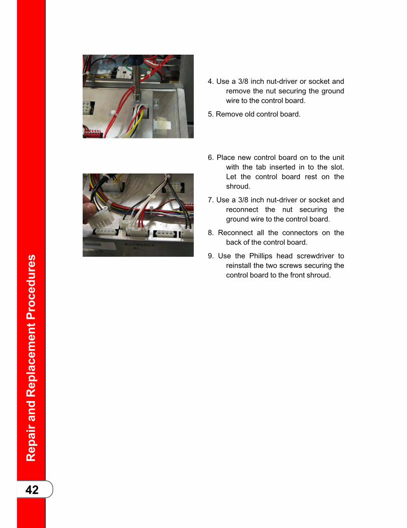
Repaira
ndReplacementP
rocedu
res
42
4. Use a 3/8 inch nut-driver or socket andremove the nut securing the groundwire to the control board.
5. Remove old control board.
6. Place new control board on to the unitwith the tab inserted in to the slot.Let the control board rest on theshroud.
7. Use a 3/8 inch nut-driver or socket andreconnect the nut securing theground wire to the control board.
8. Reconnect all the connectors on theback of the control board.
9. Use the Phillips head screwdriver toreinstall the two screws securing thecontrol board to the front shroud.
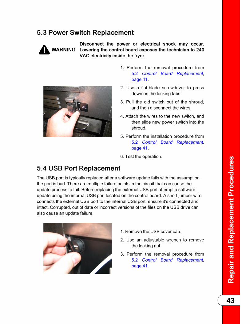
Repaira
ndReplacementP
rocedu
res
43
55..33 PPoowweerr SSwwiittcchh RReeppllaacceemmeennttDDiissccoonnnneecctt tthhee ppoowweerr oorr eelleeccttrriiccaall sshhoocckk mmaayy ooccccuurr..LLoowweerriinngg tthhee ccoonnttrrooll bbooaarrdd eexxppoosseess tthhee tteecchhnniicciiaann ttoo 224400VVAACC eelleeccttrriicciittyy iinnssiiddee tthhee ffrryyeerr..
1. Perform the removal procedure from5.2 Control Board Replacement,page 41.
2. Use a flat-blade screwdriver to pressdown on the locking tabs.
3. Pull the old switch out of the shroud,and then disconnect the wires.
4. Attach the wires to the new switch, andthen slide new power switch into theshroud.
5. Perform the installation procedure from5.2 Control Board Replacement,page 41.
6. Test the operation.
55..44 UUSSBB PPoorrtt RReeppllaacceemmeennttThe USB port is typically replaced after a software update fails with the assumptionthe port is bad. There are multiple failure points in the circuit that can cause theupdate process to fail. Before replacing the external USB port attempt a softwareupdate using the internal USB port located on the control board. A short jumper wireconnects the external USB port to the internal USB port, ensure it’s connected andintact. Corrupted, out of date or incorrect versions of the files on the USB drive canalso cause an update failure.
1. Remove the USB cover cap.
2. Use an adjustable wrench to removethe locking nut.
3. Perform the removal procedure from5.2 Control Board Replacement,page 41.

Repaira
ndReplacementP
rocedu
res
44
4. Disconnect the USB plug from thereceiver on the back of the controlboard.
5. Remove the old USB port assemblyfrom the hole in the control board.
6. Install the new USB port assembly inthe hole in the control board.
7. Use one adjustable wrench to hold theUSB port in place while usinganother adjustable wrench to tightenthe locking nut.
8. Reconnect the USB plug on to thereceiver on the back of the controlboard.
5. Perform the installation procedure from5.2 Control Board Replacement,page 41.
55..55 NNyyllaattrroonn VVeerrttiiccaall SSttrriipp RReeppllaacceemmeenntt PPrroocceedduurree• OObbjjeeccttss ccaann ffaallll aanndd ssppllaasshh hhoott ooiill oorr hhoott wwaatteerr wwhhiilleeppeerrffoorrmmiinngg tthhiiss pprroocceedduurree.. CCoovveerr tthhee vvaatt wwiitthh aa sshheeeettppaann oorr ddrraaiinn tthhee vvaatt aanndd aallllooww ttoo ccooooll ootthheerrwwiissee sseerriioouussbbuurrnnss mmaayy rreessuulltt..
• LLiidd mmaayy bbee hhoott.. AAllllooww lliidd ttoo ccooooll bbeeffoorree ppeerrffoorrmmiinngg tthhiisspprroocceedduurree,, oorr bbuurrnnss mmaayy rreessuulltt..
• TThhee ccaarrrriieerr mmaayy bbee hhoott.. AAllllooww ccaarrrriieerr ttoo ccooooll ttoo pprreevveennttppeerrssoonnaall iinnjjuurryy..
NOTICE:SSnnuugg tthhee 22 ccoouunntteerrwweeiigghhtt sseeccuurriinngg bboollttss ttoo tthhee rreeaarr ooff tthheeuunniitt bbuutt ddoo nnoott oovveerrttiigghhtteenn oorr rriisskk ssttrriippppiinngg oouutt tthhee bboolltthhoolleess..
55..55..11 EEssttiimmaatteedd RReessoouurrccee aanndd TTiimmeeEstimated resource and time to completion is: 1 Technician, 1.5 hour.
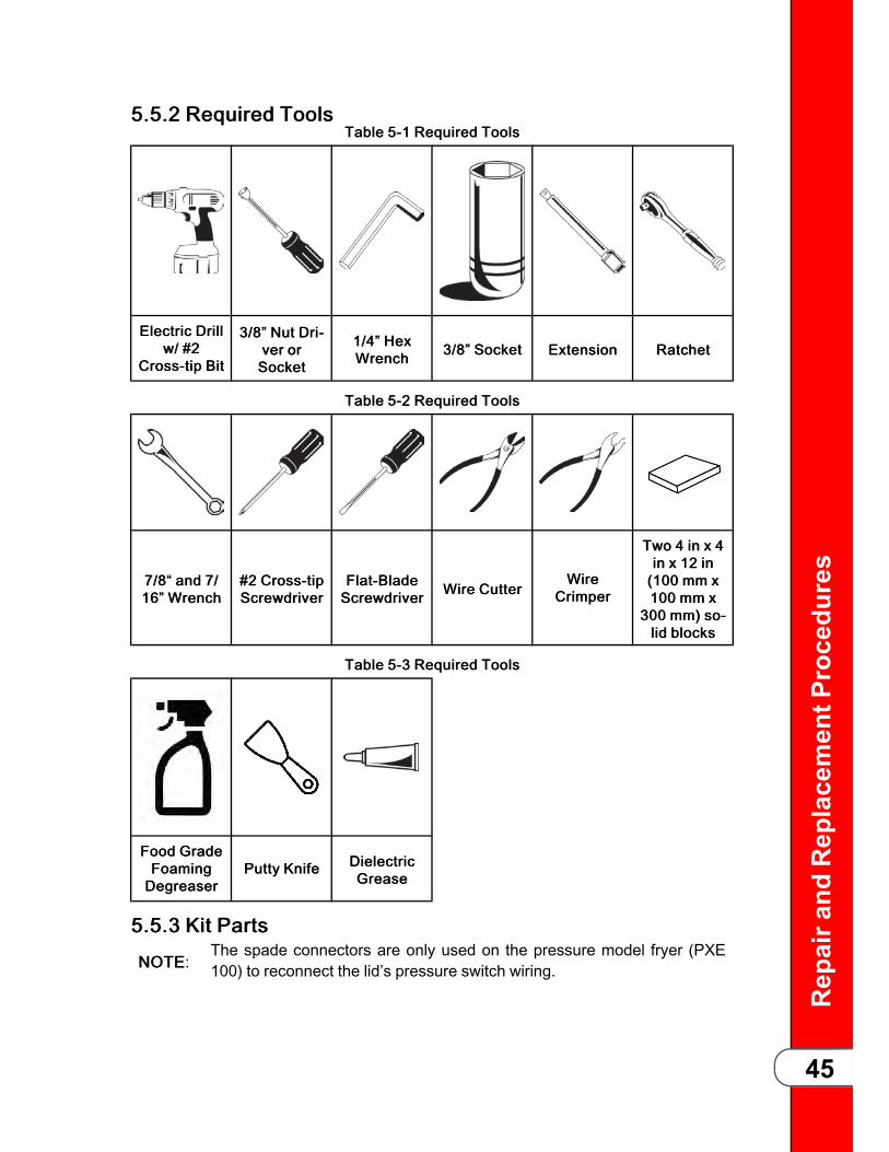
Repaira
ndReplacementP
rocedu
res
45
55..55..22 RReeqquuiirreedd TToooollssTTaabbllee 55--11 RReeqquuiirreedd TToooollss
EElleeccttrriicc DDrriillllww// ##22
CCrroossss--ttiipp BBiitt
33//88”” NNuutt DDrrii--vveerr oorrSSoocckkeett
11//44”” HHeexxWWrreenncchh 33//88”” SSoocckkeett EExxtteennssiioonn RRaattcchheett
TTaabbllee 55--22 RReeqquuiirreedd TToooollss
77//88““ aanndd 77//1166”” WWrreenncchh
##22 CCrroossss--ttiippSSccrreewwddrriivveerr
FFllaatt--BBllaaddeeSSccrreewwddrriivveerr WWiirree CCuutttteerr
WWiirreeCCrriimmppeerr
TTwwoo 44 iinn xx 44iinn xx 1122 iinn((110000 mmmm xx110000 mmmm xx
330000 mmmm)) ssoo--lliidd bblloocckkss
TTaabbllee 55--33 RReeqquuiirreedd TToooollss
FFoooodd GGrraaddeeFFooaammiinnggDDeeggrreeaasseerr
PPuuttttyy KKnniiffee DDiieelleeccttrriiccGGrreeaassee
55..55..33 KKiitt PPaarrttss
NNOOTTEE:The spade connectors are only used on the pressure model fryer (PXE100) to reconnect the lid’s pressure switch wiring.

Repaira
ndReplacementP
rocedu
res
46
The kit contains all the necessary components to complete the task outlined in thisdocument. If replacement parts are required due to damage or loss, technicians mustorder another 175727 kit. Single Nylatron slides are not offered individually forVelocity fryers. The kit includes:
TTaabbllee 55--44 KKiitt PPaarrttss
xx22)) NNyyllaattrroonn FFiilllleerr SSttrriippss xx22)) BBoollttss xx33)) CCoonnnneeccttoorrss ((PPXXEE 110000OOnnllyy))
55..55..44 TTeecchhnniicciiaann TTrraaiinniinnggWatch the following video before replacing the Nylatron vertical filler strip (slides).
TTRRAAIINNIINNGGVVIIDDEEOO: • Use this video to ramp-up on the procedure: https://
vimeo.com/332593461/0ffcfa8add.
55..55..55 RReemmoovvee tthhee CCoouunntteerrwweeiigghhttss aanndd SSeeccuurree CCaarrrriiaaggeeAAsssseemmbbllyy
TThhee lliidd aanndd ccoouunntteerrbbaallaannccee wweeiigghhtt ccaarrrriiaaggee aasssseemmbbllyymmoovveess wwiitthh ffoorrccee aanndd ccaann ccaauussee iinnjjuurryy.. SSeeccuurree tthhee wweeiigghhttccaarrrriiaaggee ttoo tthhee rreeaarr ooff tthhee uunniitt wwiitthh sseeccuurriinngg bboollttss ttoopprreevveenntt iinnjjuurryy..
NNOOTTEE:Navigate to training video timestamp 00:15 - 01:48 forprocedures specific to this step.
The counterweight assembly is attached to one end of the Nylatron vertical filler stripsand must be detached by doing the following:
11)) Using a #2 cross-tip screwdriver or electric drill with bit, remove 4 pan headscrews from the top access panel and then remove the panel. Do not removethe deadweight valve or the safety relief valve.
22)) Using a 3/8 in nut driver, remove 6 locking flange nuts from the rear accesspanel and then remove the panel. The weight carriage assembly is visible.
33)) Raise the lid assembly to its full height.

Repaira
ndReplacementP
rocedu
res
47
44)) Remove the lid rack carrier.55)) Using a large flat head screwdriver or pry bar, separate and remove three
individual weights from the top of the counterbalance weight carriage assemblyto lighten the assembly.
66)) Close the lid, engaging the front lid hold down.77)) Engage the lid handle by pulling forward on the handle until the lid handle rollers
are firmly inside the locking slots.88)) Push down on the handle ensuring both cams (sides) are engaged in the locking
slots.99)) Insert 2 bolts from kit through the upper left and right corners of the
counterbalance weight carriage assembly and snug using 1/4 in hex wrench.
NNOOTTEE: The counterbalance weight carriage assembly can be moved to alignthe 2 counterweight securing bolts with the holes in rear of the unit as required.
1100))PPXXEE 110000 OOnnllyy: Using a 3/8 in socket and ratchet, remove the p-clip holding thecondensate line to the back of the front panel.
NNOOTTEE: The front panel is restricted from removal if the p-clip is not removed.1111))Using a 7/16 in open-end wrench remove the two bolts holding the Nylatron
strips to the weight carriage.
55..55..66 RReemmoovvee tthhee TTiilltt SSttoopp
NNOOTTEE:Navigate to training video timestamp 02:30 - 02:36 for proceduresspecific to this step.
The tilt stop, also referred to as the lid kickstand, must be removed so the front shroudcan be removed. Remove the lid tilt stop by doing the following:
11)) Remove the lid tilt stop inner retaining c-clip.22)) Remove the lid tilt stop assembly by pulling the rod out of the outer side of the
lid's left lifting arm.33)) Lay the lid tilt stop assembly aside to a safe and protected space.
55..55..77 RReemmoovvee tthhee RReettaaiinniinngg RRoodd
NNOOTTEE:Navigate to training video timestamp 03:05 - 04:04 for proceduresspecific to this step.
The lid arms must be disconnected from the lid so the front shroud can be fullyremoved. Remove the lid by doing the following:
11)) Disengage the lid handle by lifting up on the handle, and then pushing back.22)) Obtain two 4 in x 4 in x 12 in (100 mm x 100 mm x 300 mm) solid blocks.33)) Disengage the front lid hold down, lift the front of the lid up, and then prop up the
lid with a block of wood. Force on the lid retaining rod is relieved.44)) Remove a c-clip and washer from one side (left or right) of the retaining rod.
Repaira
ndReplacementP
rocedu
res
48
55)) Remove both inner left and right c-clips from the inner left and right lid grooves.66)) Slide the retaining rod out from the lid's arms and the lid lifting arms. Two
washers fall off the retaining rod.77)) Retrieve the two washers and save for reassembly.
55..55..88 RReemmoovvee tthhee FFrroonntt SShhrroouuddNNOOTTEE: Navigate to training video timestamp 04:05 - 04:30.
Lift and pull forward the top, front shroud to remove. Remove the front shroud toaccess the Nylatron filler strip channels on the inside by doing the following:
11)) Using a #2 cross-tip screwdriver or electric drill with bit, remove 4 pan headscrews from the sides of the front shroud.
22)) Raise the lift arm up and pull the front shroud clear from the arms and wire bydoing the following:
A. Press the safety lock wiring against the lid's left lifting arm. This is necessary toprovide clearance for the front shroud removal.
B. Lean the front shroud toward the front of the fryer and pull forward until it is free of thelid's lifting arms, and then lift up at an angle to remove.
55..55..99 CClleeaann tthhee NNyyllaattrroonn FFiilllleerr SSttrriipp CChhaannnneellssNNOOTTEE: Navigate to training video timestamp 04:31 - 04:52.
Over time the Nylatron filler strip channels fill with debris and add friction and wear tothe movement of the Nylatron vertical filler strips. Clean the Nylatron strip channels bydoing the following:
11)) Remove the Nylatron vertical filler strips from the channel and discard.22)) Clean the channels using food grade foaming degreaser and a putty knife until
clean.
55..55..1100 IInnssttaallll tthhee NNeeww NNyyllaattrroonn FFiilllleerr SSttrriippNNOOTTEE: Navigate to training video timestamp 04:53 - 05:54.
Once both Nylatron filler strip channels are clean, start the reassembly process byinstalling the Nylatron vertical filler strips and front shroud by doing the following:
11)) Insert new Nylatron vertical filler strips in to each of the strip channels with thebolt hole that attaches to the counterweight positioned toward the top of thefryer.
22)) Using an electric drill with a #2 cross-tip bit or a #2 cross-tip screwdriver,remove the 5 pan head screws, and then the center access panel.
33)) Align the two rectangular shaped holes in the Nylatron vertical filler strips, overboth of the lid's lifting arms and carefully guide the bottom and then the top ofthe shroud in to place.
44)) Gently guide the safety lock wiring through the front shroud opening next to theleft lifting arm.

Repaira
ndReplacementP
rocedu
res
49
55)) Ensure the lower lip slides into the retention channel.
55..55..1111 RReeccoonnnneecctt tthhee RReettaaiinniinngg RRooddNNOOTTEE: Navigate to training video timestamp 05:55 - 06:32.
Reattach the lid lift arms to the lid by doing the following:
11)) Pull the lid forward to allow the lid lifting arms to clear the lid arms.22)) Apply downward pressure on the lid's lifting arms and align the holes in the lid's
arms with the holes in the lid's arms.33)) Install 1 c-clip and washer on one end of the retaining rod. The c-clip is on the
outside.44)) Slide the opposite end of the retaining rod through the lid's left arm and lifting
arm mounting holes.55)) Stop, install 2 washers on the end of the retaining rod, and then push the
retaining rod through the lid's right arm and lifting arm mounting holes.66)) Using a nut driver install a washer and c-clip on the end of the retaining rod. The
c-clip is installed on the outside of the washer.77)) Push the two inner washers against the inside of the lid's lifting arms.88)) Using a nut driver install 2 inner c-clips in to the retaining rod's retaining
grooves.
55..55..1122 IInnssttaallll tthhee TTiilltt SSttooppIInnssttaallll aass iinnssttrruucctteedd,, oorr tthhee lliidd ccaann ffaallll wwiitthh ffoorrccee ccaauussiinnggsseerriioouuss ppeerrssoonnaall iinnjjuurryy..
NNOOTTEE: Navigate to training video timestamp 06:33 - 06:41.
Install the lid tilt stop, and then test by doing the following:
11)) Ensure the tilt stop is clean prior to installation.22)) Insert the lid tilt stop assembly's retaining rod through the outside of the lid's left
lifting arm, tilt stop hole.33)) Install the inner retaining C-Clip.44)) Test the tilt stop by doing the following:
A. Pull on the tilt stop to ensure the C-clip is fully seated.
B. Raise the lid to 45 degrees and setting the tilt stop in to place, then lower. Repeatseveral times to ensure the tilt stop does not bind or fail.
55..55..1133 IInnssttaallll tthhee CCoovveerr PPaanneellssNNOOTTEE: Navigate to training video timestamp 07:43 - 08:55.
Install all the cover panels by doing the following:
11)) Ensure the weight carriage lift cables are aligned properly over the pulleys.

Repaira
ndReplacementP
rocedu
res
50
22)) Remove the solid blocks (lid props), and then lower and lock the lid.33)) Replace the lid's sheet metal cover by aligning the cover's two front pins with the
mounting holes in the front of the lower cast lid.44)) Tilt the sheet metal cover down in to place, aligning the rear screw holes.55)) Using a #2 cross-tip screwdriver, install 3 pan head screws, along the back,
securing the sheet metal cover to the lower cast lid.66)) Using an electric drill with a #2 cross-tip bit or a #2 cross-tip screwdriver, install
5 pan head screws to secure the center access panel.77)) Using an electric drill with a #2 cross-tip bit or a #2 cross-tip screwdriver, install
4 pan head screws to secure the sides of the front panel.88)) PPXXEE 110000 OOnnllyy: Using a 3/8 in socket and ratchet, install the p-clip holding the
condensate line to the back of the front panel.99)) Remove the 2 bolts from the upper left and right corners of the counterbalance
weight carriage assembly.1100))Install the counterweights into the counterbalance weight carriage assembly.1111))Using a 7/8 in open end wrench and 2 bolts with lock and flat washers, attach
the bolt hole end of the Nylatron vertical filler strips to the counterbalance weightcarriage assembly.
1122))Using a 3/8 in nut driver, install 6 locking flange nuts to secure the rear panel tothe mounting studs and torque snug.
1133))Place the top access panel over the side panels, ensuring the safety relief valveassembly is not pinched or hindered.
1144))Using an electric drill with a #2 cross-tip bit or a #2 cross-tip screwdriver, install4 pan head screws to secure the top access panel.
1155))Ensure the safety relief valve is not pinched or hindered.
55..55..1144 TTeesstt tthhee NNyyllaattrroonn SSttrriippssMove the lid up and down several times to ensure the Nylatron filler strip moves freelyin the channel and in synchronization with the counterbalance weight carriageassembly.• If the Nylatron filler strip moves freely, continue at .
• If the Nylatron filler strip does not move freely, diagnose and correct beforecontinuing.
55..55..1155 IInnssttaallll tthhee RRaacckk CCaarrrriieerrNNOOTTEE: Navigate to training video timestamp 08:58.
11)) Reinstall the rack carrier onto the lid rails.22)) Continue to .

Repaira
ndReplacementP
rocedu
res
51
55..66 HHiigghh LLiimmiitt TThheerrmmooccoouupplleess RReeppllaacceemmeenntt55..66..11 TTrroouubblleesshhoooottiinnggAn ohm reading can be taken of the protection probe from the P3 connector pins 7&8on the rear of the board. The values follow our standard RTD 1000 chart we use for allother Henny Penny RTDs.
The Protection probe can be viewed by entering Info mode and scrolling to Temps.Once in temps, the lower right selection button is blinking. Press, and the protectionprobe displays rather than the Bot display. The displayed temp should be quite a bithigher than the main temp probe. If 999 displays, it indicates an open probe.
Before pressing the lower right button After pressing the lower right button
<= TEMPS =>Main Lvl Bot
348° 331° 287°
<= TEMPS =>Main Lvl PPrb348° 331° 462°
55..66..22 RReeppllaacceemmeennttDDiissccoonnnneecctt tthhee ppoowweerr oorr eelleeccttrriiccaall sshhoocckk mmaayy ooccccuurr..LLoowweerriinngg tthhee ccoonnttrrooll bbooaarrdd eexxppoosseess tthhee tteecchhnniicciiaann ttoo 224400VVAACC eelleeccttrriicciittyy iinnssiiddee tthhee ffrryyeerr..
NNOOTTEE:
The E-1 - “Low Oil In Pot” error code triggers if the protectionprobe is around 280° F (approximate) hotter than the maintemperature probe. If this happens, the heat shuts off for 20seconds to wait for the heat to dissipate from the element. Ifthe element remains hotter than the temperature probe afterthis time, the control triggers an E-1 error. This error wouldtrigger in the place of a high limit trip if the fryer is turned onwith no oil in the pot as the element would be substantiallyhotter than the main temp probe and the heat would notdissipate into the oil. Troubleshooting a nuisance E-1, check oillevel is at the fill mark, make sure the store is performing aclean out procedure. An E-1 can occur with carbon build upand breading build up just like with nuisance high limit trips.
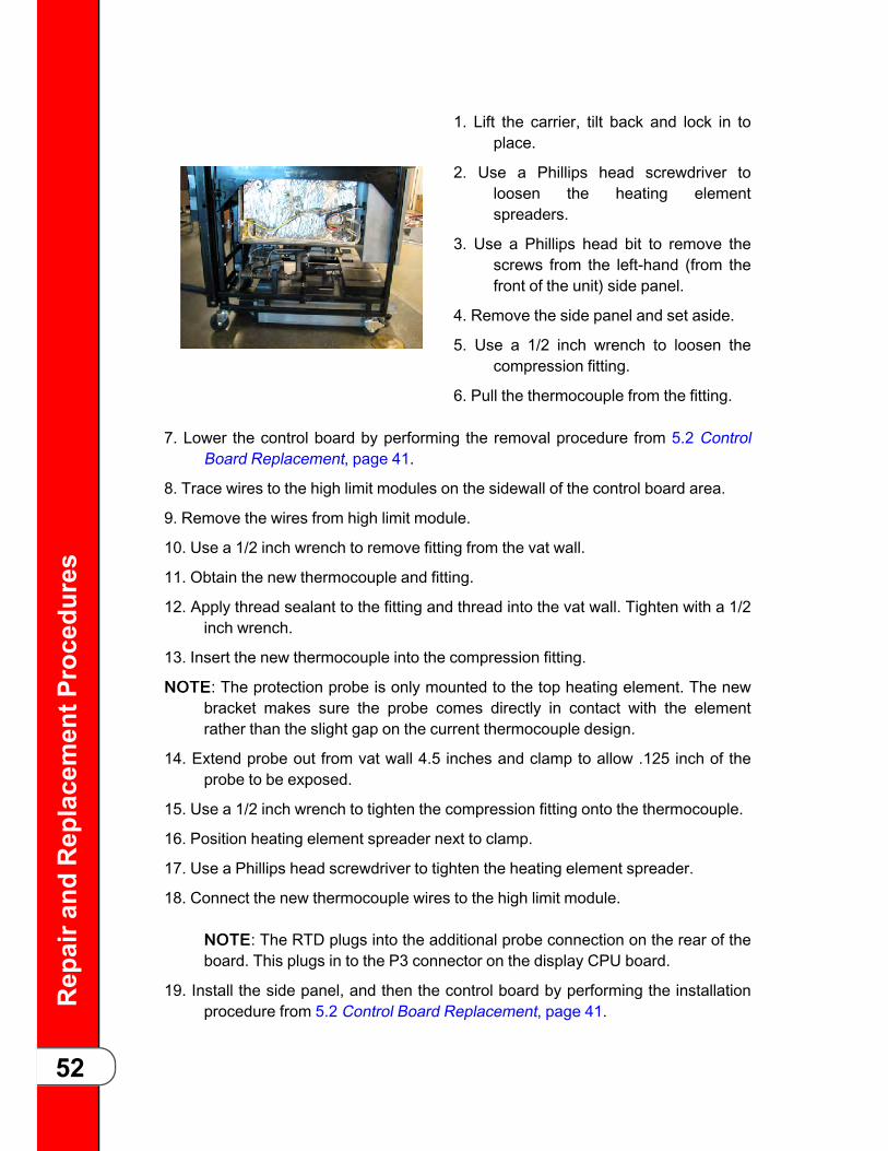
Repaira
ndReplacementP
rocedu
res
52
1. Lift the carrier, tilt back and lock in toplace.
2. Use a Phillips head screwdriver toloosen the heating elementspreaders.
3. Use a Phillips head bit to remove thescrews from the left-hand (from thefront of the unit) side panel.
4. Remove the side panel and set aside.
5. Use a 1/2 inch wrench to loosen thecompression fitting.
6. Pull the thermocouple from the fitting.
7. Lower the control board by performing the removal procedure from 5.2 ControlBoard Replacement, page 41.
8. Trace wires to the high limit modules on the sidewall of the control board area.
9. Remove the wires from high limit module.
10. Use a 1/2 inch wrench to remove fitting from the vat wall.
11. Obtain the new thermocouple and fitting.
12. Apply thread sealant to the fitting and thread into the vat wall. Tighten with a 1/2inch wrench.
13. Insert the new thermocouple into the compression fitting.
NNOOTTEE: The protection probe is only mounted to the top heating element. The newbracket makes sure the probe comes directly in contact with the elementrather than the slight gap on the current thermocouple design.
14. Extend probe out from vat wall 4.5 inches and clamp to allow .125 inch of theprobe to be exposed.
15. Use a 1/2 inch wrench to tighten the compression fitting onto the thermocouple.
16. Position heating element spreader next to clamp.
17. Use a Phillips head screwdriver to tighten the heating element spreader.
18. Connect the new thermocouple wires to the high limit module.
NNOOTTEE: The RTD plugs into the additional probe connection on the rear of theboard. This plugs in to the P3 connector on the display CPU board.
19. Install the side panel, and then the control board by performing the installationprocedure from 5.2 Control Board Replacement, page 41.

Repaira
ndReplacementP
rocedu
res
53
55..77 HHiigghh LLiimmiitt MMoodduullee RReeppllaacceemmeennttDDiissccoonnnneecctt tthhee ppoowweerr oorr eelleeccttrriiccaall sshhoocckk mmaayy ooccccuurr..LLoowweerriinngg tthhee ccoonnttrrooll bbooaarrdd eexxppoosseess tthhee tteecchhnniicciiaann ttoo 224400VVAACC eelleeccttrriicciittyy iinnssiiddee tthhee ffrryyeerr..
NNOOTTEE:
• The upper module controls the lower thermocouple.
• The lower module controls the upper thermocouple.
1. Lower the control board by performingthe removal procedure from 5.2Control Board Replacement, page41.
2. Locate the faulty high limit module onthe left-hand (from the front) sidewall.
3. Mark all the wire locations, and thendisconnect all the wires.
5. Use a 3/8 inch socket or nut-driver toremove the nuts.
6. Remove the two metal lock strips, andthen slide the old high limit moduleoff of the mounting studs.
7. Slide the new high limit module on tothe mounting studs, and then placethe two metal lock strips onto thestuds.
8. Secure in place with a 3/8 inch socketor nut-driver, and then reconnect thewires.
10. Install the control board by performingthe installation procedure from 5.2Control Board Replacement, page41.

Repaira
ndReplacementP
rocedu
res
54
55..88 PPrriimmaarryy CCoonnttaaccttoorr RReeppllaacceemmeennttDDiissccoonnnneecctt tthhee ppoowweerr oorr eelleeccttrriiccaall sshhoocckk mmaayy ooccccuurr..LLoowweerriinngg tthhee ccoonnttrrooll bbooaarrdd eexxppoosseess tthhee tteecchhnniicciiaann ttoo 224400VVAACC eelleeccttrriicciittyy iinnssiiddee tthhee ffrryyeerr..
NOTICE
:
Do not connect L1 & L2 to a circuit operating at more than 150 voltsto ground (gnd) or component damage may result.
1. Lower the control board by performingthe removal procedure from 5.2Control Board Replacement, page41.
2. Mark the location of the wires.
3. Use a Phillips head screwdriver toremove the:
a) L1, L2, and L3 wires from the contactor.
b) T1, T2, and T3 wires from the side ofthe contactor.
c) RS1 and RS2 yellow wires.
4. Use a 3/8 in. nut-driver to remove the nuts that secure the contactor to theshroud.
5. Lift up on the contactor and remove it from the studs.
6. Place the new contactor on to the studs, and then use a 3/8 in. nut-driver tosecure in place.
7. Use a Phillips head screwdriver to install the:
a) RS1 and RS2 yellow wires.
b) T1, T2, and T3 wires to the side of the contactor.
c) L1, L2, and L3 wires to the contactor.
8. Install the control board by performing the installation procedure from 5.2 ControlBoard Replacement, page 41.
55..99 HHeeaatt CCoonnttaaccttoorr RReeppllaacceemmeennttDDiissccoonnnneecctt tthhee ppoowweerr oorr eelleeccttrriiccaall sshhoocckk mmaayy ooccccuurr..LLoowweerriinngg tthhee ccoonnttrrooll bbooaarrdd eexxppoosseess tthhee tteecchhnniicciiaann ttoo 224400VVAACC eelleeccttrriicciittyy iinnssiiddee tthhee ffrryyeerr..
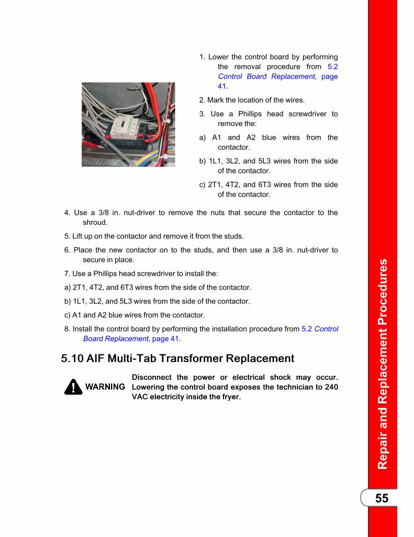
Repaira
ndReplacementP
rocedu
res
55
1. Lower the control board by performingthe removal procedure from 5.2Control Board Replacement, page41.
2. Mark the location of the wires.
3. Use a Phillips head screwdriver toremove the:
a) A1 and A2 blue wires from thecontactor.
b) 1L1, 3L2, and 5L3 wires from the sideof the contactor.
c) 2T1, 4T2, and 6T3 wires from the sideof the contactor.
4. Use a 3/8 in. nut-driver to remove the nuts that secure the contactor to theshroud.
5. Lift up on the contactor and remove it from the studs.
6. Place the new contactor on to the studs, and then use a 3/8 in. nut-driver tosecure in place.
7. Use a Phillips head screwdriver to install the:
a) 2T1, 4T2, and 6T3 wires from the side of the contactor.
b) 1L1, 3L2, and 5L3 wires from the side of the contactor.
c) A1 and A2 blue wires from the contactor.
8. Install the control board by performing the installation procedure from 5.2 ControlBoard Replacement, page 41.
55..1100 AAIIFF MMuullttii--TTaabb TTrraannssffoorrmmeerr RReeppllaacceemmeennttDDiissccoonnnneecctt tthhee ppoowweerr oorr eelleeccttrriiccaall sshhoocckk mmaayy ooccccuurr..LLoowweerriinngg tthhee ccoonnttrrooll bbooaarrdd eexxppoosseess tthhee tteecchhnniicciiaann ttoo 224400VVAACC eelleeccttrriicciittyy iinnssiiddee tthhee ffrryyeerr..

Repaira
ndReplacementP
rocedu
res
56
1. Lower the control board by performingthe removal procedure from 5.2Control Board Replacement, page41.
2. Mark the location of the wires, and thendisconnect.
3. Use a 3/8 in. nut-driver to remove thenuts that secure the transformer tothe shroud.
4. Lift up on the transformer and remove itfrom the studs.
5. Place the new transformer on to the studs, and then use a 3/8 in. nut-driver tosecure in place.
6. Reconnect the wires.
7. Install the control board by performing the installation procedure from 5.2 ControlBoard Replacement, page 41.
55..1111 CCoonnttrrooll TTrraannssffoorrmmeerr RReeppllaacceemmeennttDDiissccoonnnneecctt tthhee ppoowweerr oorr eelleeccttrriiccaall sshhoocckk mmaayy ooccccuurr..LLoowweerriinngg tthhee ccoonnttrrooll bbooaarrdd eexxppoosseess tthhee tteecchhnniicciiaann ttoo 224400VVAACC eelleeccttrriicciittyy iinnssiiddee tthhee ffrryyeerr..
1. Lower the control board by performingthe removal procedure from 5.2Control Board Replacement, page41.
2. Locate the 5-pin connector leading fromthe transformer, and thendisconnect.

Repaira
ndReplacementP
rocedu
res
57
3. Use a 3/8 in. socket and extension toremove the nuts that secure thetransformer to the shroud.
4. Lift up on the transformer and remove itfrom the studs.
5. Place the new transformer on to thestuds, and then use a 3/8 in. socketand extension to secure in place.
6. Locate the 5-pin connector leads, and then connect.
7. Install the control board by performing the installation procedure from 5.2 ControlBoard Replacement, page 41.
55..1122 DDrraaiinn VVaallvvee aanndd AAccttuuaattoorr RReeppllaacceemmeenntt
BBuurrnn RRiisskk.. UUssiinngg PPPPEE,, rreemmoovvee hhoott ooiill ffrroomm ffrryyeerr bbeeffoorreeppeerrffoorrmmiinngg pprroocceedduurree oorr ppeerrssoonnaall iinnjjuurryy mmaayy ooccccuurr..
SShhoocckk RRiisskk.. RReemmoovvee ppoowweerr ffrroomm ffrryyeerr bbeeffoorree ppeerrffoorrmmiinnggpprroocceedduurree oorr ppeerrssoonnaall iinnjjuurryy mmaayy ooccccuurr..
TTRRAAIINNIINNGG:
To replace either the drain valve or actuator or both, do the following:
55..1122..11 PPrreeppaarree tthhee FFrryyeerr11)) Access the Filter Menu, refer to .22)) Drain oil from vat (frypot) in to the drain pan, and then remove the drain pan.33)) Close the drain valve, and then exit the menu.44)) With the drain valve closed, remove power from the fryer.55)) Remove the left-side panel.
55..1122..22 RReemmoovvee tthhee DDrraaiinn VVaallvvee EExxtteennssiioonn11)) Disconnect the drain valve harness connector.22)) Remove the drain valve extension from valve by gripping it with hands or
channel lock pliers, and then turning the tube 1/8 turn (45°) clockwise, whenviewed from top down.
33)) Pull the drain valve extension down and out of the drain valve.44)) Remove the drain valve extension, and then set aside.
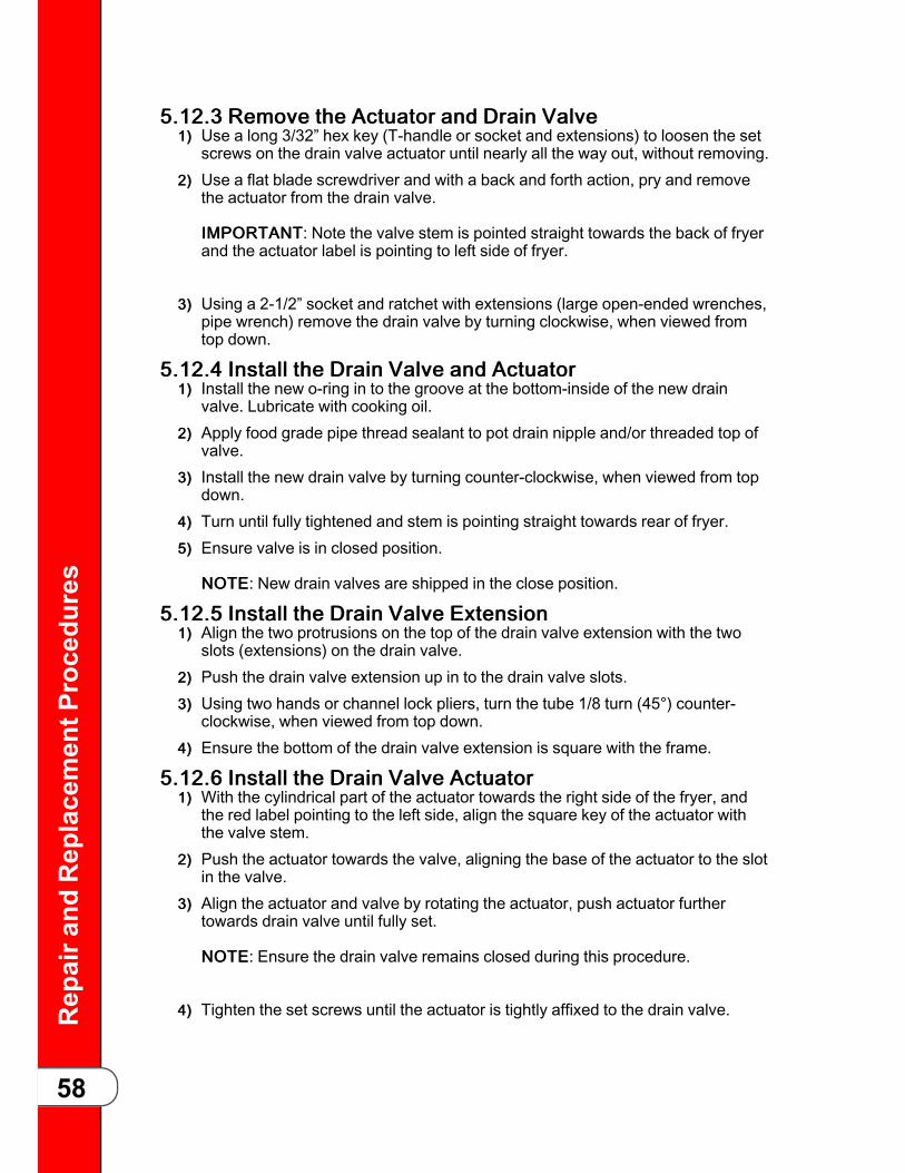
Repaira
ndReplacementP
rocedu
res
58
55..1122..33 RReemmoovvee tthhee AAccttuuaattoorr aanndd DDrraaiinn VVaallvvee11)) Use a long 3/32” hex key (T-handle or socket and extensions) to loosen the set
screws on the drain valve actuator until nearly all the way out, without removing.22)) Use a flat blade screwdriver and with a back and forth action, pry and remove
the actuator from the drain valve.
IIMMPPOORRTTAANNTT: Note the valve stem is pointed straight towards the back of fryerand the actuator label is pointing to left side of fryer.
33)) Using a 2-1/2” socket and ratchet with extensions (large open-ended wrenches,pipe wrench) remove the drain valve by turning clockwise, when viewed fromtop down.
55..1122..44 IInnssttaallll tthhee DDrraaiinn VVaallvvee aanndd AAccttuuaattoorr11)) Install the new o-ring in to the groove at the bottom-inside of the new drain
valve. Lubricate with cooking oil.22)) Apply food grade pipe thread sealant to pot drain nipple and/or threaded top of
valve.33)) Install the new drain valve by turning counter-clockwise, when viewed from top
down.44)) Turn until fully tightened and stem is pointing straight towards rear of fryer.55)) Ensure valve is in closed position.
NNOOTTEE: New drain valves are shipped in the close position.
55..1122..55 IInnssttaallll tthhee DDrraaiinn VVaallvvee EExxtteennssiioonn11)) Align the two protrusions on the top of the drain valve extension with the two
slots (extensions) on the drain valve.22)) Push the drain valve extension up in to the drain valve slots.33)) Using two hands or channel lock pliers, turn the tube 1/8 turn (45°) counter-
clockwise, when viewed from top down.44)) Ensure the bottom of the drain valve extension is square with the frame.
55..1122..66 IInnssttaallll tthhee DDrraaiinn VVaallvvee AAccttuuaattoorr11)) With the cylindrical part of the actuator towards the right side of the fryer, and
the red label pointing to the left side, align the square key of the actuator withthe valve stem.
22)) Push the actuator towards the valve, aligning the base of the actuator to the slotin the valve.
33)) Align the actuator and valve by rotating the actuator, push actuator furthertowards drain valve until fully set.
NNOOTTEE: Ensure the drain valve remains closed during this procedure.
44)) Tighten the set screws until the actuator is tightly affixed to the drain valve.
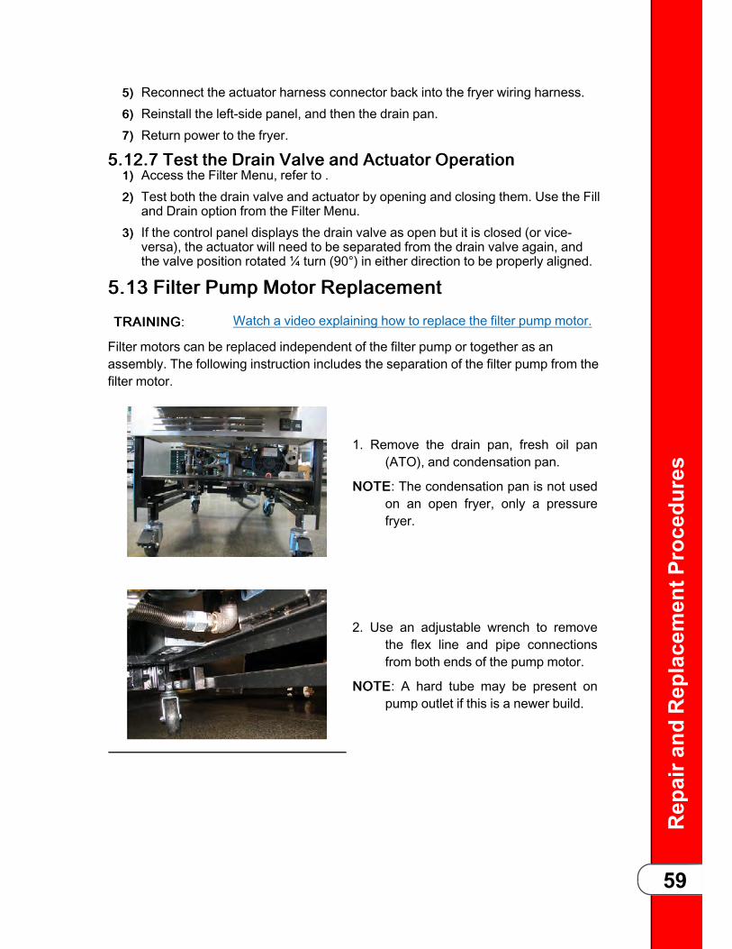
Repaira
ndReplacementP
rocedu
res
59
55)) Reconnect the actuator harness connector back into the fryer wiring harness.66)) Reinstall the left-side panel, and then the drain pan.77)) Return power to the fryer.
55..1122..77 TTeesstt tthhee DDrraaiinn VVaallvvee aanndd AAccttuuaattoorr OOppeerraattiioonn11)) Access the Filter Menu, refer to .22)) Test both the drain valve and actuator by opening and closing them. Use the Fill
and Drain option from the Filter Menu.33)) If the control panel displays the drain valve as open but it is closed (or vice-
versa), the actuator will need to be separated from the drain valve again, andthe valve position rotated ¼ turn (90°) in either direction to be properly aligned.
55..1133 FFiilltteerr PPuummpp MMoottoorr RReeppllaacceemmeenntt
TTRRAAIINNIINNGG: Watch a video explaining how to replace the filter pump motor.
Filter motors can be replaced independent of the filter pump or together as anassembly. The following instruction includes the separation of the filter pump from thefilter motor.
1. Remove the drain pan, fresh oil pan(ATO), and condensation pan.
NNOOTTEE: The condensation pan is not usedon an open fryer, only a pressurefryer.
2. Use an adjustable wrench to removethe flex line and pipe connectionsfrom both ends of the pump motor.
NNOOTTEE: A hard tube may be present onpump outlet if this is a newer build.

Repaira
ndReplacementP
rocedu
res
60
3. Use a Phillips head screwdriver toremove the two screws that securethe plate onto the pump motor.
4. Mark the locations of the black wires.
5. Remove the black wires from the pumpmotor.
6. Use a flat blade screwdriver to removethe conduit retainer ring from thepump motor.
7. Remove the conduit retainer andconduit from the pump motor.
8. Use a 1/2 inch wrench to remove thetwo nuts on the mounting plate.
9. Lift up on the pump motor then pull it offthe mounting plate.
10. If replacing the motor only, remove thetwo screws connecting the filterpump to the face of the filter motor.
11. Separate the pump and motorassemblies.

Repaira
ndReplacementP
rocedu
res
61
12. Install the two screws connecting thefilter pump to the face of the filtermotor.
13. Place the new pump motor onto themounting plate so the hanger boltsrest on the top lip and slide down sothe studs are in line with the holes inthe pump motor base.
14. Use a 1/2 inch wrench to secure thepump motor to the mounting plate.
15. Use an adjustable wrench toreconnect the lines to the correctport of the pump motor.
55..1144 FFiilltteerr PPuummpp MMoottoorr SSeeaall RReeppllaacceemmeennttThe filter pump and filter motor must be seperated for this procedure, see 5.13 FilterPump Motor Replacement, page 59. The oil seals prevent oil from migrating into themotor assembly, which can damage the motor. With the new filter motor on a flatsturdy work surface, using seal kit 17476, install the pump seal components on to thenew filter pump motor as shown in Figure 5-1 Pump Seal Kit Placement, page 61.
Figure 5-1 Pump Seal Kit Placement

Repaira
ndReplacementP
rocedu
res
62
55..1155 FFiilltteerr PPuummpp MMoottoorr RRoolllleerr RReeppllaacceemmeennttThe filter pump and filter motor must be seperated for this procedure, see 5.13 FilterPump Motor Replacement, page 59. The rollers inside the filter pump that creates theoil pressure, wear and require replacement. Replace the rollers by doing the following:
11)) Remove the four screws attaching the cover to the filter pump, and then removethe cover.
22)) Replace the five old rollers with the new rollers.33)) Replace the cover’s old o-ring with the new o-ring.44)) Install the cover using four screws on to the filter pump.
Figure 5-2 Pump Rollers

Repaira
ndReplacementP
rocedu
res
63
55..1166 FFlleexx TTuubbee RReeppllaacceemmeenntt
FFlleexx ttuubbeess ccaarrrryy hhoott ooiill uunnddeerr pprreessssuurree
WWhheenn iinnssttaalllliinngg nneeww fflleexx ttuubbeess,, ffoollllooww tthhee lliisstteedd gguuiiddeelliinneessttoo pprreevveenntt ffaaiilluurreess ooff tthhee nneeww fflleexx ttuubbee.. WWhheenn bbeennddiinngg tthheefflleexx ttuubbee ddoo nnoott::
-- BBeenndd ssmmaalllleerr tthhaann aa ggoollff bbaallll iinn rraaddiiuuss..
-- BBeenndd mmoorree tthhaann 33 ttiimmeess iinn tthhee ssaammee aarreeaa ooff ttuubbee..
-- BBeenndd tthhee fflleexx ttuubbee wwiitthhiinn 44 ffiinnggeerr wwiiddtthhss ooff tthhee eennddffiittttiinnggss..
DDiissccaarrdd aannyy ttuubbee bbeenntt mmoorree tthhaann 33 ttiimmeess iinn tthhee ssaammee aarreeaaooff ttuubbee..WWhheenn ttoorrqquuiinngg,, hhoolldd tthhee bbrraassss ffiittttiinngg tthhaatt tthhee fflleexx ttuubbee iissbbeeiinngg ttoorrqquueedd oonnttoo,, ttoo aavvooiidd ttwwiissttiinngg ooff tthhee fflleexx ttuubbee..
1. Notice the routing of the old flex tubebefore removal.
2. Use two adjustable wrenches to loosenthe brass fitting and remove the flextube. One wrench holds the flex tubefitting and the other holds theattaching fitting.
3. Use the old flex tube as a template torough bend the new tube.
4. Install the new flex tube by torquingfinger tight, and then turning (torque)an additional 1/4 turn.
55..1177 LLiidd CCaabbllee RReeppllaacceemmeennttThe weight carriage on the rear of the fryer counter-balances the lid system for easeof operation. Two cables attached to it; the safety cable on the left-side and the lifting

Repaira
ndReplacementP
rocedu
res
64
cable in the middle. The lifting cable tension should be tight and the safety cabletension should be loose enough that when squeezing the cable together, the twosides can touch. Both cables should be replaced in pairs. The white label denotes thecable replacement date and should be affixed to the back of the fryer's frame.
1. Using a 3/8” nut driver, remove the nutssecuring rear shroud of the fryer andremove the shroud.
2. Using a Phillips screwdriver, removescrews securing the top cap andremove.
3. Lower the lid until it latches, and theninsert two 5/16” carriage bolts, onethrough each side of the weightcarriage and in to the frame tosecure the carriage. Ensure thecarriage is level.
NNOOTTEE: Carriage bolt holes are provided inthe frame for securing the carriage.
4. Unscrew and remove both cables fromthe weight carriage assembly, andthen the chassis. Remove weightsas needed.
5. Screw a 5/16” lock-nut on each end ofthe new cables.
6. Apply blue Loctite thread sealant to thecable threads.
7. Using an adjustable wrench, screw oneend of each new cable in to theweight carriage assembly until tight.
8. Using a 1/2” wrench, tighten the lock-nut against the weight carriageassembly, securing both cables in toplace.
9. Thread the cables over the pulleys anddown behind the weight assembly.
10. Apply blue Loctite thread sealant tothe cable threads.
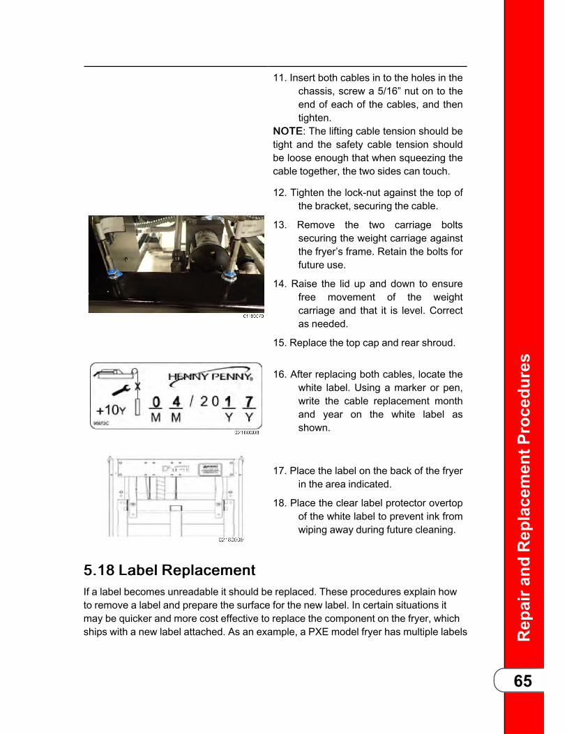
Repaira
ndReplacementP
rocedu
res
65
11. Insert both cables in to the holes in thechassis, screw a 5/16” nut on to theend of each of the cables, and thentighten.
NNOOTTEE: The lifting cable tension should betight and the safety cable tension shouldbe loose enough that when squeezing thecable together, the two sides can touch.
12. Tighten the lock-nut against the top ofthe bracket, securing the cable.
13. Remove the two carriage boltssecuring the weight carriage againstthe fryer’s frame. Retain the bolts forfuture use.
14. Raise the lid up and down to ensurefree movement of the weightcarriage and that it is level. Correctas needed.
15. Replace the top cap and rear shroud.
16. After replacing both cables, locate thewhite label. Using a marker or pen,write the cable replacement monthand year on the white label asshown.
17. Place the label on the back of the fryerin the area indicated.
18. Place the clear label protector overtopof the white label to prevent ink fromwiping away during future cleaning.
55..1188 LLaabbeell RReeppllaacceemmeennttIf a label becomes unreadable it should be replaced. These procedures explain howto remove a label and prepare the surface for the new label. In certain situations itmay be quicker and more cost effective to replace the component on the fryer, whichships with a new label attached. As an example, a PXE model fryer has multiple labels
Repaira
ndReplacementP
rocedu
res
66
affixed to the top lid cover and it would be quicker to replace the lid cover than tryingto clean off all the label glue and readhering new labels.NOTICE: Do not use a scotch brite pad or other similar abrasive material anywhere onthe fryer.
11)) Peel off as much of the old, failing label as possible by hand.22)) Use a 3M Adhesive Eraser Wheel in a hand drill to remove the remainder of
label, quickly and easily.33)) Wipe away the label debris with a towel.44)) If necessary, remove any remaining adhesive remnant by lightly spraying the
surface with 3M citrus based adhesive remover. Let stand for a minimum of fiveminutes.
55)) Gently scrape, scrub and wipe away remaining adhesive remnants.66)) Using isopropyl alcohol wipes, thoroughly clean the surface to remove any oil or
other film from the surface.77)) Remove the adhesive liner from new label.88)) Apply the new label, laying the label flat on to the surface. Ideally working from
the center of the label outward using the 3M PA-1 blue applicator, which isincluded.
99)) To eliminate any large bubbles, use a pin to create an airhole, and then pressdown the bubble using the 3M PA-1 blue applicator.

ReplaceablePa
rts
67
CChhaapptteerr 66 RReeppllaacceeaabbllee PPaarrttss66..11 PPaarrttss66..11..11 IInnttrroodduuccttiioonnThis section lists the replaceable parts of the Henny Penny Velocity Series OpenFryer.
66..11..22 GGeennuuiinnee PPaarrttssUse only genuine Henny Penny parts in your fryer. Using a part of lesser quality orsubstitute design may result in damage to the unit or personal injury.
66..11..33 WWhheenn OOrrddeerriinngg PPaarrttssOnce the parts have been identified from the parts list, write down the item number,part number, description, product number, serial number, and voltage. NNOOTTEE:Examples provided.
Parts Information Data Plate Information
Item Number 2 Product Number 01100
Part Number 60241 Serial Number 0001
Description High Limit Voltage 208
66..11..44 PPrriicceessYour distributor has a price parts list and will be glad to inform you of the cost of yourparts order.
66..11..55 DDeelliivveerryyCommonly replaced items are stocked by your distributor and will be sent out whenyour order is received. Other parts will be ordered, by your distributor, from HennyPenny Corporation. Normally, these will be sent to your distributor within threeworking days.
66..11..66 WWaarrrraannttyyAll replacement parts (except lamps and fuses) are warranted for 90 days againstmanufacturing defects and workmanship. If damage occurs during shipping, notify thecarrier at once so that a claim may be properly filed. Refer to the warranty for otherrights and limitations.
66..11..77 RReeccoommmmeennddeedd SSppaarree PPaarrttss FFoorr DDiissttrriibbuuttoorrssRecommended replacement parts are indicated with A or B in the parts lists:- A: Indicates the parts should be stocked on service vans or trucks.- B: Indicates the parts should be stocked at the distributor/KES location.Inventory on all other parts not identified, should be based upon usage in the territory.Please use care when ordering recommended parts, because all voltages and

ReplaceablePa
rts
68
variations are marked. Distributors should order parts based upon common voltagesand equipment sold in their territory.
Figure 6-1 Components
ItemNo.
Part No. Description Qty.
1A 35227 ROLLER, LINKAGE SHAFT 2
2A 52224 SWITCH, COVERED POWER 1
3 35154 CASTER, 4 INCH SWIVEL STEM 2
4 151783 ASSY, DRAIN PAN OFX (see Figure 6-2 Drain Pan Assembly,page 69 for breakdown.)
1
5 90227 CASTER, 3.5 RIGID W/ END BRAKE 2
6 150598 TANK, FRESH OIL 1
7A 96804 ASSY, OXE100 CONTROL 1
8* 96613 DECAL, OXE100 1
9B* 26974 ASSY, SPEAKER 1
10* 03734 RADIO, ZIGBEE 1
Recommend Parts: A = Truck Stock / B = Dist. Stock* = Not Shown

ReplaceablePa
rts
69
ItemNo.
Part No. Description Qty.
11B* 140440 KIT, LID ROLLER 1
12* 151042 WELD ASSY, OXE 100 2-3/8 CARRIER 1
13* 140597 KIT, BULK DISPOSE FRONT (built prior to 2016) 1
14* 140596 KIT, SELECTOR VALVE TO ATO FLEX TUBE (built prior to2016)
1
Recommend Parts: A = Truck Stock / B = Dist. Stock* = Not Shown
Figure 6-2 Drain Pan Assembly
ItemNo.
Part No. Description Qty.
1 151783 ASSY, DRAIN PAN PFX 1
2 156492 WELD ASSY, FILTER DRAIN PAN 1
3 19004 CASTER, 2 IN SWIVEL MTG PLATE 4
Recommend Parts: A = Truck Stock / B = Dist. Stock* = Not Shown / AR = As Required

ReplaceablePa
rts
70
ItemNo.
Part No. Description Qty.
4 NS04-005 LOCKNUT, SERRATED FLANGE 1/4–20 16
5 92889 WELD ASSY, FILTER SECTION 1
6 150739 WELD ASSY, CARRIER CLIP 2
7 151819 WELD ASSY, CRUMB CATCHER 1
8A 86349 O-RING, 116 SUCTION LINE 5
9 94289 ASSY, DRAIN PAN COVER PFX 1
10B* 12102 PHT FILTER ENVELOPES - 100CT AR
11* 152204 WELD ASSY, PNP UNIT 1
Recommend Parts: A = Truck Stock / B = Dist. Stock* = Not Shown / AR = As Required

ReplaceablePa
rts
71
Figure 6-3 Heating Elements
ItemNo.
Part No. Description Qty.
1A 154252 ASSY, 2 IN RTD PROBE 1
1A* 140593 KIT, PROBE GUARD 1
2B 161612-001
ELEMENT, HEATING 8.5 KW (208V) 1
2B 161612-003
ELEMENT, HEATING 8.5 KW (240V) 1
Recommend Parts: A = Truck Stock / B = Dist. Stock* = Not Shown / AR = As Required
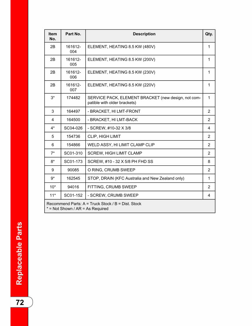
ReplaceablePa
rts
72
ItemNo.
Part No. Description Qty.
2B 161612-004
ELEMENT, HEATING 8.5 KW (480V) 1
2B 161612-005
ELEMENT, HEATING 8.5 KW (200V) 1
2B 161612-006
ELEMENT, HEATING 8.5 KW (230V) 1
2B 161612-007
ELEMENT, HEATING 8.5 KW (220V) 1
3* 174482 SERVICE PACK, ELEMENT BRACKET (new design, not com-patible with older brackets)
1
3 164497 - BRACKET, HI LMT-FRONT 2
4 164500 - BRACKET, HI LMT-BACK 2
4* SC04-026 - SCREW, #10-32 X 3/8 4
5 154736 CLIP, HIGH LIMIT 2
6 154866 WELD ASSY, HI LIMIT CLAMP CLIP 2
7* SC01-310 SCREW, HIGH LIMIT CLAMP 2
8* SC01-173 SCREW, #10 - 32 X 5/8 PH FHD SS 8
9 90085 O RING, CRUMB SWEEP 2
9* 162545 STOP, DRAIN (KFC Australia and New Zealand only) 1
10* 94016 FITTING, CRUMB SWEEP 2
11* SC01-152 - SCREW, CRUMB SWEEP 4
Recommend Parts: A = Truck Stock / B = Dist. Stock* = Not Shown / AR = As Required

ReplaceablePa
rts
73
Figure 6-4 Thermocouple, Heat Contactor & Control Transformer
ItemNo.
Part No. Description Qty.
1B 83581-002 CONTROL, WATLOW HIGH LIMIT (208V) 2
1B 156985 CONTROL, WATLOW HIGH LIMIT (CE) 2
2* 84987 HL SWITCH, MOMENTARY SPLASH PROOF 1
3B 65073 CONTACTOR, SQUARED D-24V 1
4 EF02-125 BREAKER, PUSH BUTTON RESET 2
5* EF02-104 HOLDER, FUSE - 20A 250V 2
6* EF02-105 FUSE 15 AMP 2
7B 51795 CONTACTOR, 24 VAC COIL 1
8B 86087 ASSY, 24V/240V 75VA TRANSFORMER 1
9 TS22-012 TRANSFORMER 1
10* ME90-008 RELAY, P&B T92 12VDC COIL 30AMP 1
Recommend Parts: A = Truck Stock / B = Dist. Stock* = Not Shown
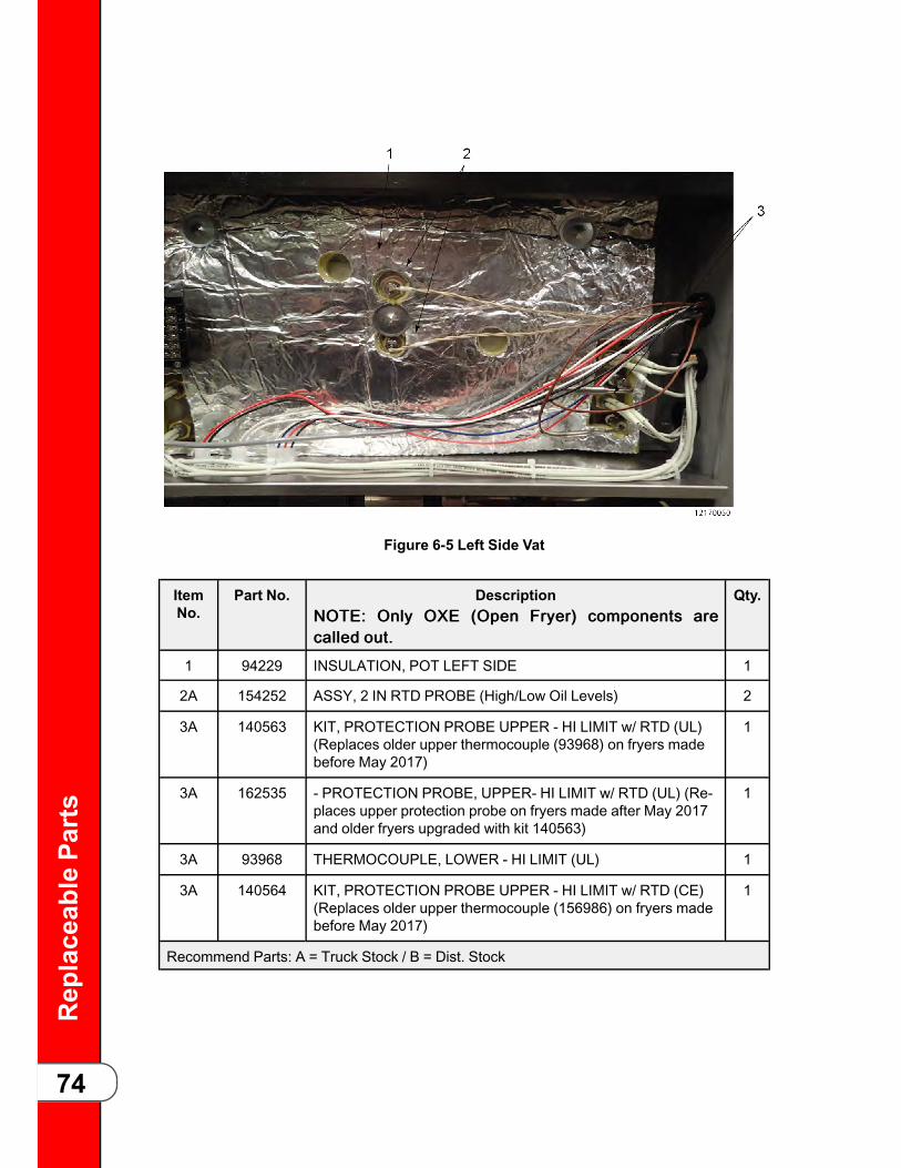
ReplaceablePa
rts
74
Figure 6-5 Left Side Vat
ItemNo.
Part No. DescriptionNNOOTTEE:: OOnnllyy OOXXEE ((OOppeenn FFrryyeerr)) ccoommppoonneennttss aarreeccaalllleedd oouutt..
Qty.
1 94229 INSULATION, POT LEFT SIDE 1
2A 154252 ASSY, 2 IN RTD PROBE (High/Low Oil Levels) 2
3A 140563 KIT, PROTECTION PROBE UPPER - HI LIMIT w/ RTD (UL)(Replaces older upper thermocouple (93968) on fryers madebefore May 2017)
1
3A 162535 - PROTECTION PROBE, UPPER- HI LIMIT w/ RTD (UL) (Re-places upper protection probe on fryers made after May 2017and older fryers upgraded with kit 140563)
1
3A 93968 THERMOCOUPLE, LOWER - HI LIMIT (UL) 1
3A 140564 KIT, PROTECTION PROBE UPPER - HI LIMIT w/ RTD (CE)(Replaces older upper thermocouple (156986) on fryers madebefore May 2017)
1
Recommend Parts: A = Truck Stock / B = Dist. Stock

ReplaceablePa
rts
75
ItemNo.
Part No. DescriptionNNOOTTEE:: OOnnllyy OOXXEE ((OOppeenn FFrryyeerr)) ccoommppoonneennttss aarreeccaalllleedd oouutt..
Qty.
3A 162523 - PROTECTION PROBE, UPPER - HI LIMIT w/ RTD (CE) (Re-places upper protection probe on fryers made after May 2017and older fryers upgraded with kit 140564)
1
3A 156986 THERMOCOUPLE, LOWER - HI LIMIT (CE) 1
Recommend Parts: A = Truck Stock / B = Dist. Stock
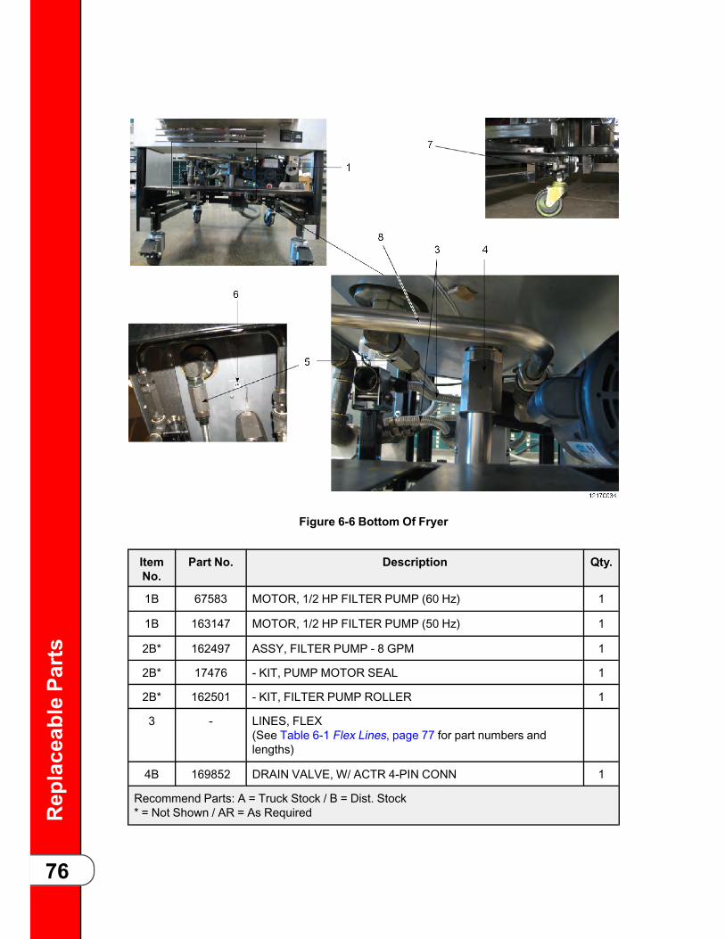
ReplaceablePa
rts
76
Figure 6-6 Bottom Of Fryer
ItemNo.
Part No. Description Qty.
1B 67583 MOTOR, 1/2 HP FILTER PUMP (60 Hz) 1
1B 163147 MOTOR, 1/2 HP FILTER PUMP (50 Hz) 1
2B* 162497 ASSY, FILTER PUMP - 8 GPM 1
2B* 17476 - KIT, PUMP MOTOR SEAL 1
2B* 162501 - KIT, FILTER PUMP ROLLER 1
3 - LINES, FLEX(See Table 6-1 Flex Lines, page 77 for part numbers andlengths)
4B 169852 DRAIN VALVE, W/ ACTR 4-PIN CONN 1
Recommend Parts: A = Truck Stock / B = Dist. Stock* = Not Shown / AR = As Required

ReplaceablePa
rts
77
ItemNo.
Part No. Description Qty.
4B 162922 DRAIN VALVE (only) 1
4B 162918 O-RING, DRAIN VALVE (only) 1
4B* 169857 ACTUATOR (only) 1
5B 90506-001 VALVE, CHECK SAE 12 (max 200 psi) AR
6A 154252 ASSY, 2 IN RTD PROBE 1
7B 91700 ASSY, LH DRAIN PAN SWW/ CONN 1
8 140444 KIT, FORM TUBE (NO SELECTOR VALVE) 1
8 140446 KIT, FORM TUBE (BULK OIL) (WITH SELECTOR VALVE) 1
Recommend Parts: A = Truck Stock / B = Dist. Stock* = Not Shown / AR = As Required
TTaabbllee 66--11 FFlleexx LLiinneess
Part Number Length
77523-002 12 INCH
77523-011 10 INCH

ReplaceablePa
rts
78
Figure 6-7 Front Top View
ItemNo.
Part No. Description Qty.
1 175727 SVC PACK, NYLATRON SLIDE 1
2 35962 ASSY, BRACKET/WHEEL 1
3 140610 KIT, LID CABLE 1
4 94259 COUNTERWEIGHT, BAR FULL AR
4 167010 COUNTERWEIGHT, BAR HALF AR
Recommend Parts: A = Truck Stock / B = Dist. Stock* = Not Shown / AR = As Required
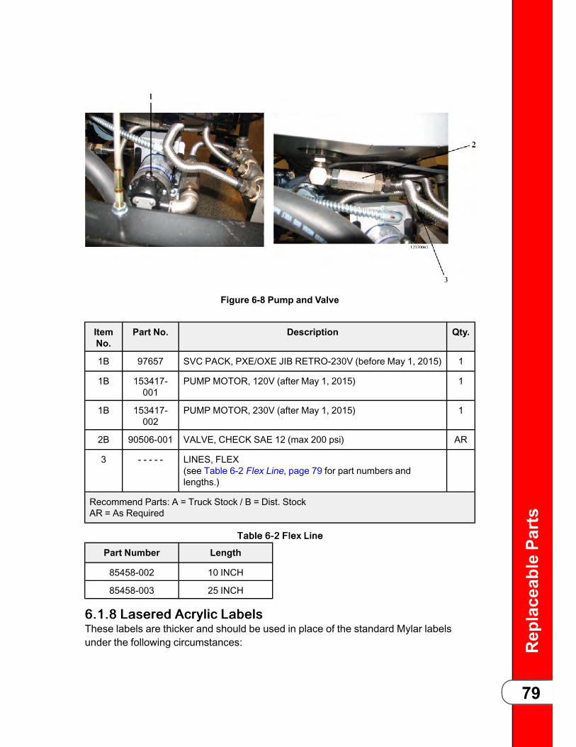
ReplaceablePa
rts
79
Figure 6-8 Pump and Valve
ItemNo.
Part No. Description Qty.
1B 97657 SVC PACK, PXE/OXE JIB RETRO-230V (before May 1, 2015) 1
1B 153417-001
PUMP MOTOR, 120V (after May 1, 2015) 1
1B 153417-002
PUMP MOTOR, 230V (after May 1, 2015) 1
2B 90506-001 VALVE, CHECK SAE 12 (max 200 psi) AR
3 - - - - - LINES, FLEX(see Table 6-2 Flex Line, page 79 for part numbers andlengths.)
Recommend Parts: A = Truck Stock / B = Dist. StockAR = As Required
TTaabbllee 66--22 FFlleexx LLiinnee
Part Number Length
85458-002 10 INCH
85458-003 25 INCH
66..11..88 LLaasseerreedd AAccrryylliicc LLaabbeellssThese labels are thicker and should be used in place of the standard Mylar labelsunder the following circumstances:

ReplaceablePa
rts
80
• Required by Agency.
• Mylar label peels due to environment.
Part No. Description Image
170332 LABEL, SHORTENINGMELT (GM)
170333 LABEL, BOILOVER PRE-VENTION (GM)
170334 LABEL, VOLTAGE TOGROUND
170336 LABEL, SECUREAPPLIANCE
* = Not Shown

ReplaceablePa
rts
81
Part No. Description Image
170632 LABEL, LID DANGER(PRESSURE)
170676 LABEL, VOLTAGE TOGROUND
168024 LABEL, HOT SURFACEWARNING
168025 LABEL, DRAIN PANWARNING
* = Not Shown

ReplaceablePa
rts
82
Part No. Description Image
168569 LABEL, DISCONNECTPOWER
168570 LABEL, LID DANGER(PRESSURE)
168571 LABEL, SERVICE COVER
168572 LABEL, LID INSTRUC-TION (PRESSURE)
* = Not Shown
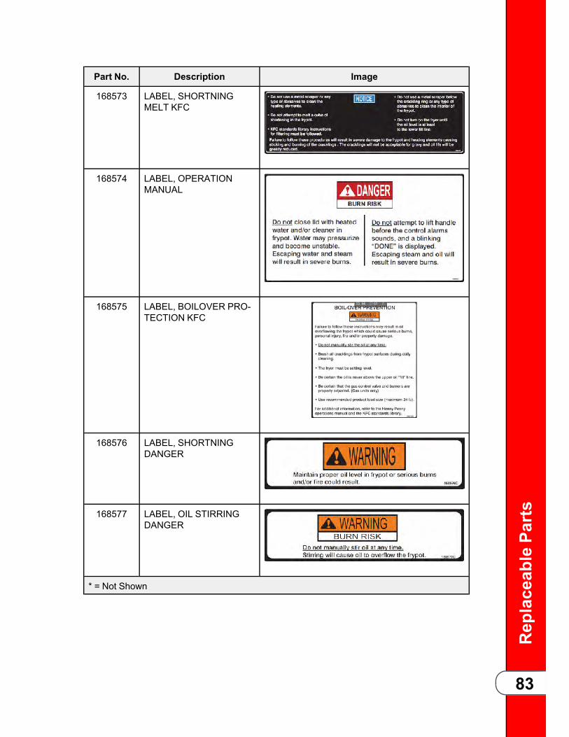
ReplaceablePa
rts
83
Part No. Description Image
168573 LABEL, SHORTNINGMELT KFC
168574 LABEL, OPERATIONMANUAL
168575 LABEL, BOILOVER PRO-TECTION KFC
168576 LABEL, SHORTNINGDANGER
168577 LABEL, OIL STIRRINGDANGER
* = Not Shown

ReplaceablePa
rts
84

Wiring
andPlum
bing
Diagram
s
85
CChhaapptteerr 77 WWiirriinngg aannddPPlluummbbiinngg DDiiaaggrraammss77..11 220088--224400VV 33PPHH 33++GG 2244VV CCoonnttrroollssNNOOTTEE: Omit pressure transducer and pressure valve for Open Fryer (OXE).

Wiring
andPlum
bing
Diagram
s
86
77..22 448800VV 33PPHH 33++GG 2244VV CCoonnttrroollssNNOOTTEE: Omit pressure transducer and pressure valve for Open Fryer (OXE).

Wiring
andPlum
bing
Diagram
s
87
77..33 338800--441155VV 33PPHH 33++GG 2244VV CCoonnttrroollssNNOOTTEE: Omit pressure transducer and pressure valve for Open Fryer (OXE).

Wiring
andPlum
bing
Diagram
s
88
77..44 OOiill LLiinnee CCoonnnneeccttiioonnss ffoorr BBuullkk DDiissppoossaallNNOOTTEE: Not an actual depiction of plumbing fittings or oil line routing. Includes bulkdisposal selector valve components. (154835)

Wiring
andPlum
bing
Diagram
s
89
77..55 OOiill LLiinnee CCoonnnneeccttiioonnss ffoorr NNoonn--BBuullkk DDiissppoossaallNNOOTTEE: Not an actual depiction of plumbing fittings or oil line routing. Excludes bulkdisposal selector valve components. (154903)

Wiring
andPlum
bing
Diagram
s
90

Ann
ualInspectionChecklistF
orm
91
CChhaapptteerr 88 AAnnnnuuaall IInnssppeeccttiioonnCChheecckklliisstt FFoorrmmPerform the following annual inspection in the order provided.*Critical Item - Take fryer out of service until repaired.
TTaabbllee 88--11 AAnnnnuuaall ((1122 mmoonntthh)) IInnssppeeccttiioonn CChheecckklliisstt
##AAsssseessss VVaatt aanndd FFrraammee ((rreemmoovvee rreeaarr ccoovveerraanndd bbootthh ssiiddee ppaanneellss))
OOKK CClleeaann RReeppllaaccee
1.* Inspect the fry pot for leaks or oilaccumulation.
2.Ensure the fryer sits level. Inspect the castersand fryer frame for damage.
3.* Inspect the electrical cord and plug.
4.*Inspect lid cables as per instructions for thisstep.
5. Check that the counterweight frame hangslevel.
6.Inspect and lubricate lid carriage rollers andcable pulleys. Make sure the lid moves up anddown freely.
7.Inspect lid wiring for damage or excessivewear from lid pin switch to left side panel.
8. Replace filter pump seals and rollers.
9.Clean and replace the Nylatron slides asnecessary.
Behind Service Access Panel - Pressure System
10. Inspect the steam exhaust hose insert.
11.
Remove the condensation box cover. Inspectthe condensation box gasket, deadweight, andorifice. Inspect and clean the condensationdrain hose. Ensure each component is in goodworking condition. Clean and re-install all com-ponents after step 13 is complete.
12.Clean the Safety Relief Valve – Install onlyafter step 13 is complete.
13.Remove the solenoid valve and clean and re-assemble. Install only after step 13 iscomplete.

Ann
ualInspectionChecklistF
orm
92
14.
Remove all pressure system tubing. Inspect,clean, or replace any tubing or fitting that isblocked, or obstructed. If leaking is found atany fitting, clean and replace the compressionfitting.
Filter Components and Drain Oil
15.
Verify all components of the drain pan are pre-sent and not damaged. Components includefive O-rings, filter screen, two filter clips, stand-pipe, crumb basket, drain pan, drain pan coverand drain pan casters. Replace any compo-nents that are missing or damaged.
16.
Remove ATO reservoir (not used in bulk fill ap-plications). Inspect that reservoir is clean withno obstructions. Replace any damaged ormissing O-rings.
17.
Use the filter menu to test the opening andclosing of the drain valve. Visually ensure thedrain valve is fully open and fully closed whencommanded from the control. OK to drain oil inthis step and leave oil in drain pan until fin-ished with the heat system inspection.
18.If a bulk oil system is connected to the fryer,dispose a small amount of oil to make sure thissystem is working correctly.
19.
Using the appropriate step in the filter menu totest the ATO pump (not used in bulk fill appli-cations). Make sure the fry pot fills from theATO reservoir.
Heat System
20.Tighten heating element spreader bars andhigh limit bracket.
21.
Inspect both the temperature probe and levelprobe, verify neither is bent nor damaged.Check the insertion depth of each probe with agauge – adjust if necessary.
22.
Remove the covers on both oil return diverters.Clean and replace O-rings if necessary. In-spect the pressure transducer inlet inside thefry pot is clean and free from any obstruction.
23.*Inspect for excessive oil migration behind leftside panel.

Ann
ualInspectionChecklistF
orm
93
24.
Verify that the high limit modules are wired inthe high limit circuit and wires are secured onthe terminals of the modules. Verify high limitthermocouples are clean and mounted prop-erly to the heating elements.
25.
Test filtration system – motor is running, oil ispumping freely back to fry pot. No leaks andno leaks back to drain pan (drain valve, checkvalve not leaking). Pump all oil back to fry pot.
26.*Check that all six heating circuits have similaramp draw. Electrically troubleshoot issues ifany are found.
Pressure System
27.Remove lid cover and inspect lid components– Please read and follow PXE-100 Lid Inspec-tion instructions for this step.
28.*
Remove and inspect the lid gasket and checkthe tightness of lid liner screws as per the in-structions for this step. Replace the gasket if ithas not been replaced in the last 12 months,or if the gasket is hardened, brittle, damaged,or blackened.
29.Inspect Lid Handle Rollers – Please read andfollow all instructions for this step.
30. Inspect cam slide fillers located on each sideof the lid cover.
31.Inspect front lid latch and make adjustmentsas necessary.
32.Inspect pressure pads. Rotate if excessivelyworn, replace if cracked or both sides are ex-cessively worn.
33. Manually test lid pin switch. Refer to testinstructions.
34. Check error log and address recent pressureerrors.
General Fryer, ATO, and Filtration System
35.Verify all labels are in place and legible onfryer.

Ann
ualInspectionChecklistF
orm
94
88..11 RReeqquuiirreedd TToooollssEnsure you have the following tools prior to performing the annual inspection:
• Temperature probe depth gauges
• Pipe snake
• Amp clamp
• Imperial size socket set
• Imperial size set of hex key wrenches
• Full range pliers set, from needle nose to 12” large slip joint
• Phillips and flat blade screwdriver set
• Pipe wrenches 8–12”
• Wire stripping tool
• Wire cutter
• Crimping tool
• Adjustable wrench set 8–12”
• Open end wrench set (imperial sizes)
88..22 RReeqquuiirreedd PPaarrttssEnsure you have the following parts prior to performing the annual inspection:
• Safety relief valve (one per fryer)
• Lid cables
• Pressure pads
• Lid gasket
• Temperature probe
• Spindle lube
• Pipe thread sealant
• Towels
• Steel and teflon sleeve fittings
• Condensation box hose
• Check valve
• Lid handle rollers
• Nylatron slides
• Side cam filters
• Lid latch
• Plumbing elbows

Ann
ualInspectionChecklistF
orm
95
• Drain switch
• Splice connectors

Ann
ualInspectionChecklistF
orm
96

blank page

HHeennnnyy PPeennnnyy CCoorrppoorraattiioonnPP..OO..BBooxx 6600EEaattoonn,, OOHH 4455332200wwwwww..hheennnnyyppeennnnyy..ccoomm
IInnssiiddee tthhee UU..SS..::11--880000--441177--88440055tteecchhnniiccaallsseerrvviicceess@@hheennnnyyppeennnnyy..ccoomm
OOuuttssiiddee tthhee UU..SS..11--993377--445566--88440055iinnttlltteecchhssuuppppoorrtt@@hheennnnyyppeennnnyy..ccoomm