VCC-G32S21CL Product Specification & Operation Manual
30
English SXGA B/W Camera 72MHz Pixel Clock Camera Link VCC-G32S21CL Product Specification & Operation Manual CIS Corporation 900-525-31-00 1
-
Upload
khangminh22 -
Category
Documents
-
view
0 -
download
0
Transcript of VCC-G32S21CL Product Specification & Operation Manual
English
SXGA B/W Camera 72MHz Pixel Clock Camera Link
VCC-G32S21CL
Product Specification & Operation Manual
CIS Corporation
900-525-31-00 1
900-525-31-00 2
Table of Contents
1. Scope of Application ..................................................................................................................... 3 2. Notice ......................................................................................................................................... 3 3. Product Outline ............................................................................................................................ 3 4. System Connection Diagram.......................................................................................................... 4 5. Specification ................................................................................................................................ 5
5.1. General Specification.............................................................................................................. 5 5.2. Camera Output Signal Specification ......................................................................................... 6 5.3. Camera Link Connector Bit Assignment (Base Configuration)..................................................... 8 5.4. Function Setting..................................................................................................................... 9
6. External Connector Pin Assignment...............................................................................................12 6.1. 12 pins Circular Connector HR10-10R-12PA (73) (HIROSE) ....................................................12 6.2. 26 Pins Compact Camera Link Compatible Connector (3M) .......................................................12
7. Switch Settings, Adjustment Potentiometer Specifications...............................................................13 7.1. Rear Panel Switch Function 10bit DIP-SW................................................................................13
7.1.1. Shutter Speed Settings (Rear panel SW1: E0, SW2: E1, SW2: E2) .....................................13 7.1.2. Operation Mode Settings (Rear panel SW4: MODE0, SW5: MODE1) ...................................14 7.1.3. Partial Scan Setting Switch (Rear Panel SW: 6 SCAN) .........................................................15 7.1.4. (Rear Panel SW7: - )........................................................................................................17 7.1.5. (Rear Panel SW8: -).........................................................................................................17 7.1.6. 8 bit / 10bit Selection Switch (Rear Panel SW9: 8Bit/10Bit) ...............................................17 7.1.7. HD / VD Input / Output Selection Switch (Rear panel SW10: IN/OUT) .................................17 7.1.8. WEN (Write Enable) Signal Output..................................................................................17
7.2. 12 Turn Rotary Potentiometer for Manual Gain Adjustment .......................................................17 7.3. Internal Adjustment Switches and Potentiometer Information ...................................................18 7.4. HD/VD Trigger Input/Output Circuit of 12pin Circular Connector................................................19 7.5. Remote Interface Function .....................................................................................................20
8. Safety/Quality Standards..............................................................................................................21 9. Durability....................................................................................................................................22 10. Timing Chart .............................................................................................................................23
10.1. Horizontal Synchronous Signal Timing...................................................................................23 10.2. Vertical Synchronous Timing.................................................................................................24 10.3. Vertical Synchronous Timing (73 fps Partial Scan Mode) .........................................................25 10.4. Standard Trigger Timing.......................................................................................................26 10.5. Pulse Width Trigger Timing ..................................................................................................27
11. Dimensions ...............................................................................................................................28 12. Cases for Indemnity (Limited Warranty) ......................................................................................29 13. Handling Precautions .................................................................................................................30
900-525-31-00 3
1. Scope of Application
This is to describe VCC-G32S21CL Camera Link B/W CCD Camera. All specifications contained herein are
subject to change without prior notice. Reproduction in whole or in part is prohibited.
2. Notice
The camera must not be used for any nuclear equipments or aerospace equipments with which
mechanical failure or malfunction could result in serious bodily injury or loss of human life. Our warranty
does not apply to damages or defects caused by irregular and/or abnormal use of the product. Please
refer to Clause 13. Handling Precautions.
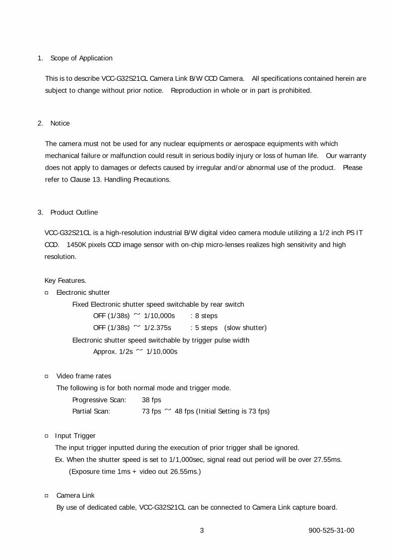
3. Product Outline
VCC-G32S21CL is a high-resolution industrial B/W digital video camera module utilizing a 1/2 inch PS IT
CCD. 1450K pixels CCD image sensor with on-chip micro-lenses realizes high sensitivity and high
resolution.
Key Features.
□ Electronic shutter
Fixed Electronic shutter speed switchable by rear switch
OFF (1/38s) ~ 1/10,000s : 8 steps
OFF (1/38s) ~ 1/2.375s : 5 steps (slow shutter)
Electronic shutter speed switchable by trigger pulse width
Approx. 1/2s ~ 1/10,000s
□ Video frame rates
The following is for both normal mode and trigger mode.
Progressive Scan: 38 fps
Partial Scan: 73 fps ~ 48 fps (Initial Setting is 73 fps)
□ Input Trigger
The input trigger inputted during the execution of prior trigger shall be ignored.
Ex. When the shutter speed is set to 1/1,000sec, signal read out period will be over 27.55ms.
(Exposure time 1ms + video out 26.55ms.)
□ Camera Link
By use of dedicated cable, VCC-G32S21CL can be connected to Camera Link capture board.

4. System Connection Diagram
Camera Link Cable
Installed to PC
Camera Link Camera
* Camera Output : 26pin Camera Link Connector Camera Power Supply : 6pin or 12pin Circular Connector
*Recommended Ripple Voltage : under ±500mV (Same ripple voltage applies when supplying power to frame grabber board.)
Frame Grabber BoardFor Camera Link
Camera Power Supply OUT PUT:DC12.0V
900-525-31-00 4
900-525-31-00 5
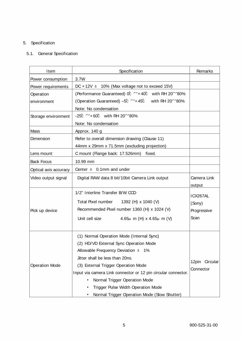
5. Specification
5.1. General Specification
Item Specification Remarks
Power consumption 3.7W
Power requirements DC +12V ± 10% (Max voltage not to exceed 15V)
Operation
environment
(Performance Guaranteed) 0℃~+40℃ with RH 20~80%
(Operation Guaranteed) –5℃~+45℃ with RH 20~80%
Note: No condensation
Storage environment -25℃~+60℃ with RH 20~80%
Note: No condensation
Mass Approx. 140 g
Dimension Refer to overall dimension drawing (Clause 11)
44mm x 29mm x 71.5mm (excluding projection)
Lens mount C mount (Flange back: 17.526mm) fixed.
Back Focus 10.99 mm
Optical axis accuracy Center ± 0.1mm and under
Video output signal Digital RAW data 8 bit/10bit Camera Link output Camera Link
output
1/2” Interline Transfer B/W CCD
Total Pixel number 1392 (H) x 1040 (V)
Recommended Pixel number 1360 (H) x 1024 (V)
Unit cell size 4.65μm (H) x 4.65μm (V)
Pick up device
ICX267AL
(Sony)
Progressive
Scan
Operation Mode
(1) Normal Operation Mode (Internal Sync)
(2) HD/VD External Sync Operation Mode
Allowable Frequency Deviation ± 1%
Jitter shall be less than 20ns.
(3) External Trigger Operation Mode
Input via camera Link connector or 12 pin circular connector.
・ Normal Trigger Operation Mode
・ Trigger Pulse Width Operation Mode
・ Normal Trigger Operation Mode (Slow Shutter)
12pin Circular
Connector
900-525-31-00 6
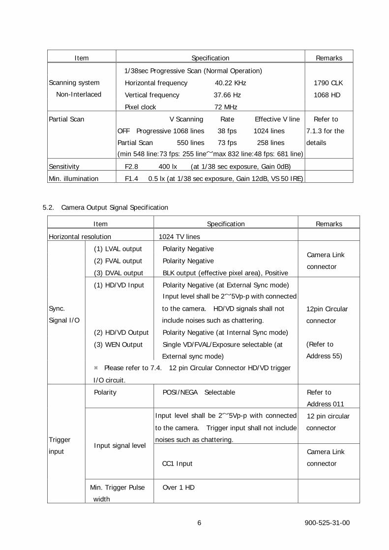
Item Specification Remarks
1/38sec Progressive Scan (Normal Operation)
Horizontal frequency 40.22 KHz 1790 CLK
Vertical frequency 37.66 Hz 1068 HD
Scanning system
Non-Interlaced
Pixel clock 72 MHz
Partial Scan V Scanning Rate Effective V line
OFF Progressive 1068 lines 38 fps 1024 lines
Partial Scan 550 lines 73 fps 258 lines
(min 548 line:73 fps: 255 line~max 832 line:48 fps: 681 line)
Refer to
7.1.3 for the
details
Sensitivity F2.8 400 lx (at 1/38 sec exposure, Gain 0dB)
Min. illumination F1.4 0.5 lx (at 1/38 sec exposure, Gain 12dB, VS 50 IRE)
5.2. Camera Output Signal Specification
Item Specification Remarks
Horizontal resolution 1024 TV lines
(1) LVAL output Polarity Negative
(2) FVAL output Polarity Negative
(3) DVAL output BLK output (effective pixel area), Positive
Camera Link
connector
(1) HD/VD Input Polarity Negative (at External Sync mode)
Input level shall be 2~5Vp-p with connected
to the camera. HD/VD signals shall not
include noises such as chattering.
(2) HD/VD Output Polarity Negative (at Internal Sync mode)
(3) WEN Output Single VD/FVAL/Exposure selectable (at
External sync mode)
Sync.
Signal I/O
※ Please refer to 7.4. 12 pin Circular Connector HD/VD trigger
I/O circuit.
12pin Circular
connector
(Refer to
Address 55)
Polarity POSI/NEGA Selectable Refer to
Address 011
Input level shall be 2~5Vp-p with connected
to the camera. Trigger input shall not include
noises such as chattering.
12 pin circular
connector
Input signal level
CC1 Input
Camera Link
connector
Trigger
input
Min. Trigger Pulse
width
Over 1 HD
900-525-31-00 7
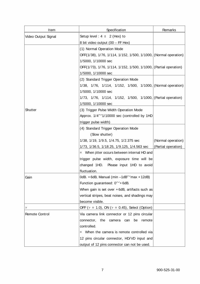
Item Specification Remarks
Video Output Signal Setup level : 4 ± 2 (Hex) to
8 bit video output (00 – FF Hex)
(1) Normal Operation Mode
OFF(1/38), 1/76, 1/114, 1/152, 1/500, 1/1000,
1/5000, 1/10000 sec
OFF(1/73), 1/76, 1/114, 1/152, 1/500, 1/1000,
1/5000, 1/10000 sec
(Normal operation)
(Partial operation)
(2) Standard Trigger Operation Mode
1/38, 1/76, 1/114, 1/152, 1/500, 1/1000,
1/5000, 1/10000 sec
1/73, 1/76, 1/114, 1/152, 1/500, 1/1000,
1/5000, 1/10000 sec
(Normal operation)
(Partial operation)
(3) Trigger Pulse Width Operation Mode
Approx. 1/4~1/10000 sec (controlled by 1HD
trigger pulse width)
(4) Standard Trigger Operation Mode
(Slow shutter)
1/38, 1/19, 1/9.5, 1/4.75, 1/2.375 sec
1/73, 1/36.5, 1/18.25, 1/9.125, 1/4.563 sec
(Normal operation)
(Partial operation)
Shutter
※ When jitter occurs between internal HD and
trigger pulse width, exposure time will be
changed 1HD. Please input 1HD to avoid
fluctuation.
Gain 0dB. +6dB, Manual (min –1dB~max +12dB)
Function guaranteed: 0~+6dB.
When gain is set over +6dB, artifacts such as
vertical stripes, beat noises, and shadings may
become visible.
γ OFF (γ= 1.0), ON (γ= 0.45), Select (Option)
Remote Control Via camera link connector or 12 pins circular
connector, the camera can be remote
controlled.
※ When the camera is remote controlled via
12 pins circular connector, HD/VD input and
output of 12 pins connector can not be used.
900-525-31-00 8
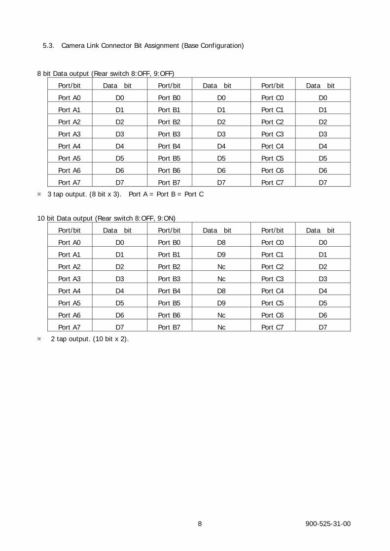
5.3. Camera Link Connector Bit Assignment (Base Configuration)
8 bit Data output (Rear switch 8:OFF, 9:OFF)
Port/bit Data bit Port/bit Data bit Port/bit Data bit
Port A0 D0 Port B0 D0 Port C0 D0
Port A1 D1 Port B1 D1 Port C1 D1
Port A2 D2 Port B2 D2 Port C2 D2
Port A3 D3 Port B3 D3 Port C3 D3
Port A4 D4 Port B4 D4 Port C4 D4
Port A5 D5 Port B5 D5 Port C5 D5
Port A6 D6 Port B6 D6 Port C6 D6
Port A7 D7 Port B7 D7 Port C7 D7
※ 3 tap output. (8 bit x 3). Port A = Port B = Port C
10 bit Data output (Rear switch 8:OFF, 9:ON)
Port/bit Data bit Port/bit Data bit Port/bit Data bit
Port A0 D0 Port B0 D8 Port C0 D0
Port A1 D1 Port B1 D9 Port C1 D1
Port A2 D2 Port B2 Nc Port C2 D2
Port A3 D3 Port B3 Nc Port C3 D3
Port A4 D4 Port B4 D8 Port C4 D4
Port A5 D5 Port B5 D9 Port C5 D5
Port A6 D6 Port B6 Nc Port C6 D6
Port A7 D7 Port B7 Nc Port C7 D7
※ 2 tap output. (10 bit x 2).
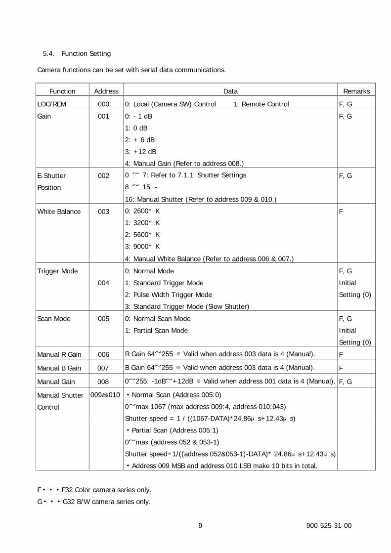
5.4. Function Setting
Camera functions can be set with serial data communications.
Function Address Data Remarks
LOC/REM 000 0: Local (Camera SW) Control 1: Remote Control F, G
Gain 001 0: - 1 dB
1: 0 dB
2: + 6 dB
3: +12 dB
4: Manual Gain (Refer to address 008.)
F, G
E-Shutter
Position
002 0 ~ 7: Refer to 7.1.1. Shutter Settings
8 ~ 15: -
16: Manual Shutter (Refer to address 009 & 010.)
F, G
White Balance 003 0: 2600°K
1: 3200°K
2: 5600°K
3: 9000°K
4: Manual White Balance (Refer to address 006 & 007.)
F
Trigger Mode
004
0: Normal Mode
1: Standard Trigger Mode
2: Pulse Width Trigger Mode
3: Standard Trigger Mode (Slow Shutter)
F, G
Initial
Setting (0)
Scan Mode 005 0: Normal Scan Mode
1: Partial Scan Mode
F, G
Initial
Setting (0)
Manual R Gain 006 R Gain 64~255 ※Valid when address 003 data is 4 (Manual). F
Manual B Gain 007 B Gain 64~255 ※Valid when address 003 data is 4 (Manual). F
Manual Gain 008 0~255: -1dB~+12dB ※Valid when address 001 data is 4 (Manual). F, G
Manual Shutter
Control
009&010 ・Normal Scan (Address 005:0)
0~max 1067 (max address 009:4, address 010:043)
Shutter speed = 1 / ((1067-DATA)*24.86μs+12.43μs)
・Partial Scan (Address 005:1)
0~max (address 052 & 053-1)
Shutter speed=1/((address 052&053-1)-DATA)* 24.86μs+12.43μs)
・Address 009 MSB and address 010 LSB make 10 bits in total.
F・・・F32 Color camera series only.
G・・・G32 B/W camera series only.
900-525-31-00 9
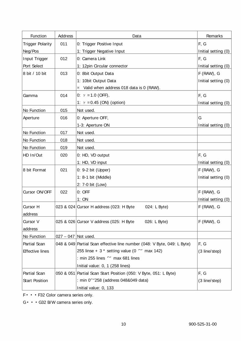
Function Address Data Remarks
Trigger Polarity
Neg/Pos
011 0: Trigger Positive Input
1: Trigger Negative Input
F, G
Initial setting (0)
Input Trigger
Port Select
012 0: Camera Link
1: 12pin Circular connector
F, G
Initial setting (0)
8 bit / 10 bit 013 0: 8bit Output Data
1: 10bit Output Data
※ Valid when address 018 data is 0 (RAW).
F (RAW), G
Initial setting (0)
Gamma 014 0: γ=1.0 (OFF),
1: γ=0.45 (ON) (option)
F, G
Initial setting (0)
No Function 015 Not used.
Aperture 016 0: Aperture OFF,
1-3: Aperture ON
G
Initial setting (0)
No Function 017 Not used.
No Function 018 Not used.
No Function 019 Not used.
HD In/Out 020 0: HD, VD output
1: HD, VD input
F, G
Initial setting (0)
8 bit Format 021 0: 9-2 bit (Upper)
1: 8-1 bit (Middle)
2: 7-0 bit (Low)
F (RAW), G
Initial setting (0)
Cursor ON/OFF 022 0: OFF
1: ON
F (RAW), G
Initial setting (0)
Cursor H
address
023 & 024 Cursor H address (023: H Byte 024: L Byte) F (RAW), G
Cursor V
address
025 & 026 Cursor V address (025: H Byte 026: L Byte) F (RAW), G
No Function 027 – 047 Not used.
Partial Scan
Effective lines
048 & 049 Partial Scan effective line number (048: V Byte, 049: L Byte)
255 linse + 3 * setting value (0 ~ max 142)
: min 255 lines ~ max 681 lines
Initial value: 0, 1 (258 lines)
F, G
(3 line/step)
Partial Scan
Start Position
050 & 051 Partial Scan Start Position (050: V Byte, 051: L Byte)
: min 0~258 (address 048&049 data)
Initial value: 0, 133
F, G
(3 line/step)
F・・・F32 Color camera series only.
G・・・G32 B/W camera series only.
900-525-31-00 10
F・・・F32 Color camera series only.
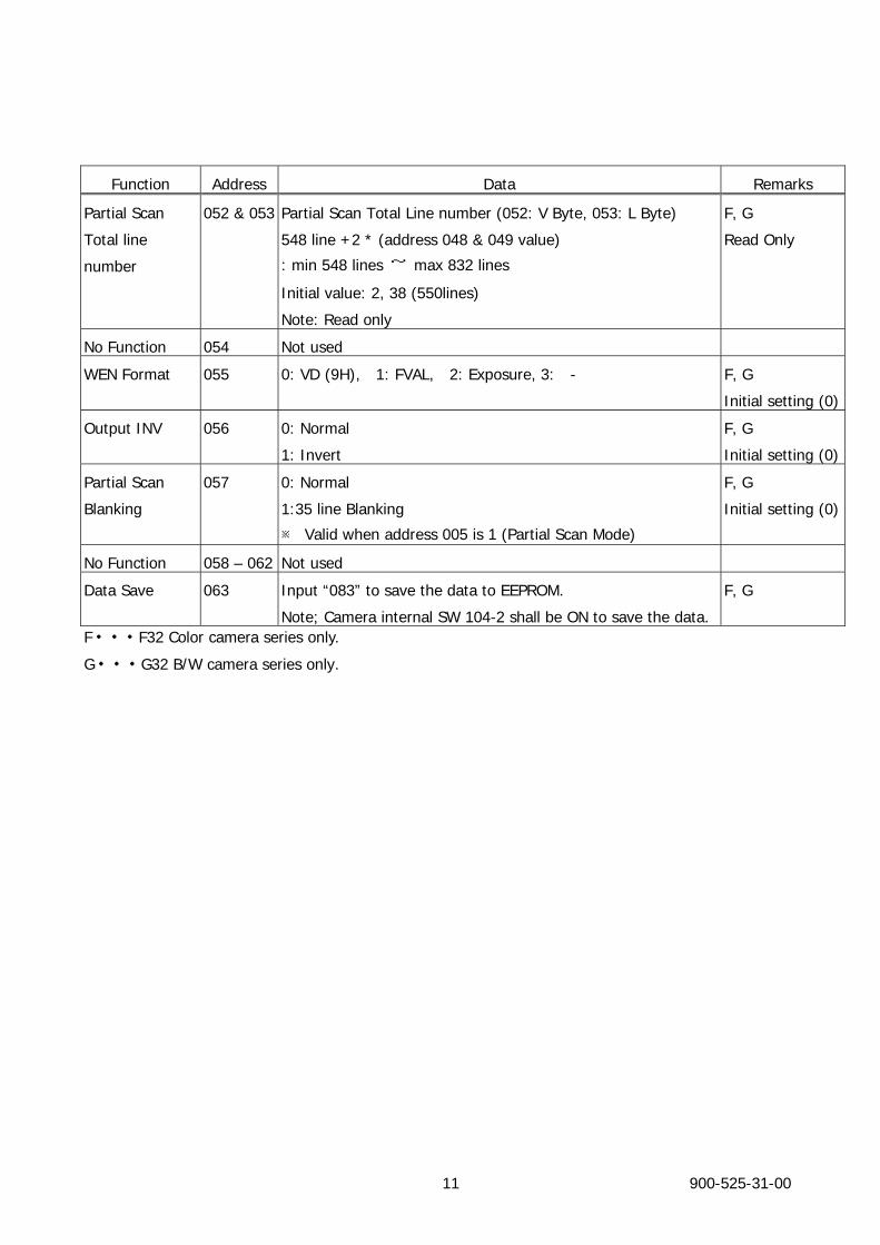
Function Address Data Remarks
Partial Scan
Total line
number
052 & 053 Partial Scan Total Line number (052: V Byte, 053: L Byte)
548 line +2 * (address 048 & 049 value)
: min 548 lines ~ max 832 lines
Initial value: 2, 38 (550lines)
Note: Read only
F, G
Read Only
No Function 054 Not used
WEN Format 055 0: VD (9H), 1: FVAL, 2: Exposure, 3: - F, G
Initial setting (0)
Output INV 056 0: Normal
1: Invert
F, G
Initial setting (0)
Partial Scan
Blanking
057 0: Normal
1:35 line Blanking
※ Valid when address 005 is 1 (Partial Scan Mode)
F, G
Initial setting (0)
No Function 058 – 062 Not used
Data Save 063 Input “083” to save the data to EEPROM.
Note; Camera internal SW 104-2 shall be ON to save the data.
F, G
G・・・G32 B/W camera series only.
900-525-31-00 11
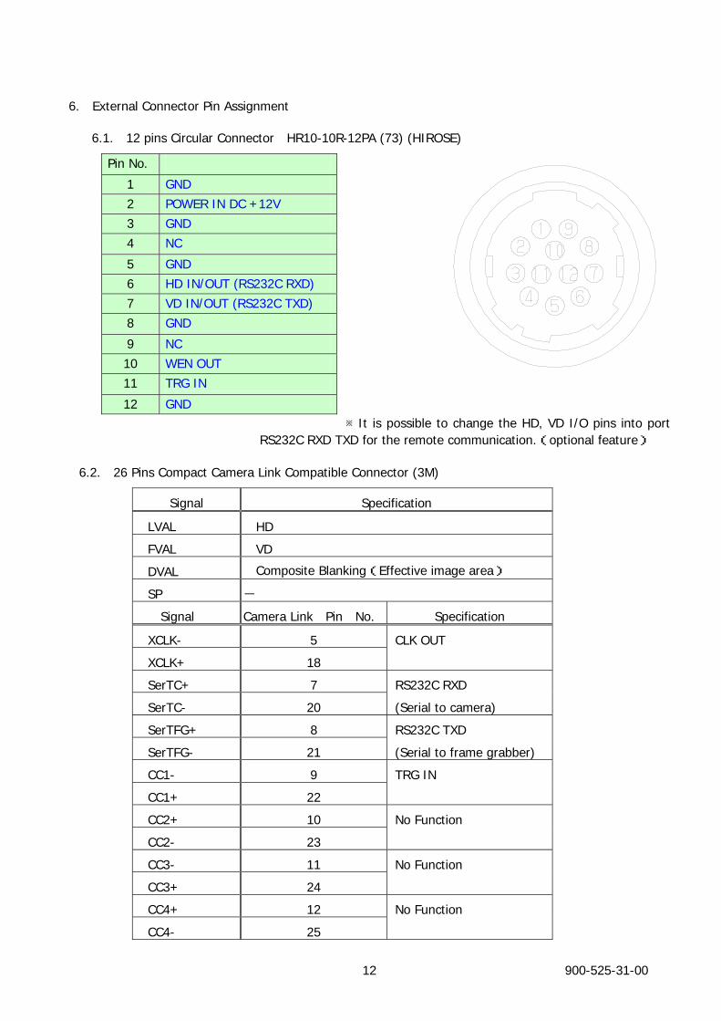
6. External Connector Pin Assignment
6.1. 12 pins Circular Connector HR10-10R-12PA (73) (HIROSE)
It is possible to change the HD, VD I/O p※ ins into port RS232C RXD TXD for the remote communication.(optional feature)
6.2. 26 Pins Compact Camera Link Compatible Connector (3M)
Signal Specification
LVAL HD
FVAL VD
DVAL Composite Blanking(Effective image area)
SP -
Signal Camera Link Pin No. Specification
XCLK- 5 CLK OUT
XCLK+ 18
SerTC+ 7 RS232C RXD
SerTC- 20 (Serial to camera)
SerTFG+ 8 RS232C TXD
SerTFG- 21 (Serial to frame grabber)
CC1- 9 TRG IN
CC1+ 22
CC2+ 10 No Function
CC2- 23
CC3- 11 No Function
CC3+ 24
CC4+ 12 No Function
CC4- 25
Pin No.
1 GND 2 POWER IN DC +12V 3 GND 4 NC
5 GND 6 HD IN/OUT (RS232C RXD) 7 VD IN/OUT (RS232C TXD) 8 GND
9 NC 10 WEN OUT 11 TRG IN
12 GND
900-525-31-00 12
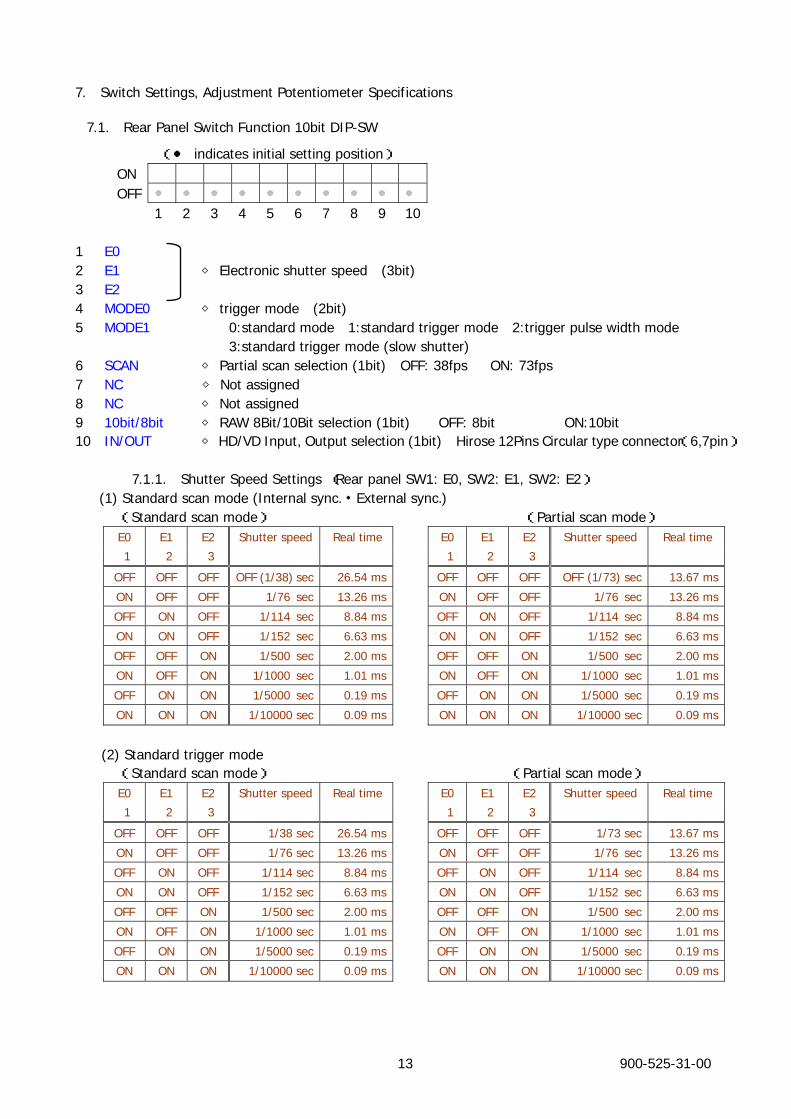
7. Switch Settings, Adjustment Potentiometer Specifications
7.1. Rear Panel Switch Function 10bit DIP-SW
(● indicates initial setting position) ON
OFF ● ● ● ● ● ● ● ● ● ●
1 2 3 4 5 6 7 8 9 10
1 E0 2 E1 Electronic shutter speed◇ (3bit)
900-525-31-00 13
3 E2 4 MODE0 trigger mode (2bit)◇ 5 MODE1 0:standard mode 1:standard trigger mode 2:trigger pulse width mode 3:standard trigger mode (slow shutter) 6 SCAN ◇ Partial scan selection (1bit) OFF: 38fps ON: 73fps 7 NC ◇ Not assigned 8 NC ◇ Not assigned 9 10bit/8bit ◇ RAW 8Bit/10Bit selection (1bit) OFF: 8bit ON:10bit 10 IN/OUT HD/VD Input◇ , Output selection (1bit) Hirose 12Pins Circular type connector(6,7pin)
7.1.1. Shutter Speed Settings (Rear panel SW1: E0, SW2: E1, SW2: E2) (1) Standard scan mode (Internal sync.・External sync.) (Standard scan mode) (Partial scan mode)
E0 E1 E2 Shutter speed Real time E0 E1 E2 Shutter speed Real time
1 2 3 1 2 3
OFF OFF OFF OFF (1/38) sec 26.54 ms OFF OFF OFF OFF (1/73) sec 13.67 ms
ON OFF OFF 1/76 sec 13.26 ms ON OFF OFF 1/76 sec 13.26 ms
OFF ON OFF 1/114 sec 8.84 ms OFF ON OFF 1/114 sec 8.84 ms
ON ON OFF 1/152 sec 6.63 ms ON ON OFF 1/152 sec 6.63 ms
OFF OFF ON 1/500 sec 2.00 ms OFF OFF ON 1/500 sec 2.00 ms
ON OFF ON 1/1000 sec 1.01 ms ON OFF ON 1/1000 sec 1.01 ms
OFF ON ON 1/5000 sec 0.19 ms OFF ON ON 1/5000 sec 0.19 ms
ON ON ON 1/10000 sec 0.09 ms ON ON ON 1/10000 sec 0.09 ms
(2) Standard trigger mode (Standard scan mode) (Partial scan mode)
E0 E1 E2 Shutter speed Real time E0 E1 E2 Shutter speed Real time
1 2 3 1 2 3
OFF OFF OFF 1/38 sec 26.54 ms OFF OFF OFF 1/73 sec 13.67 ms
ON OFF OFF 1/76 sec 13.26 ms ON OFF OFF 1/76 sec 13.26 ms
OFF ON OFF 1/114 sec 8.84 ms OFF ON OFF 1/114 sec 8.84 ms
ON ON OFF 1/152 sec 6.63 ms ON ON OFF 1/152 sec 6.63 ms
OFF OFF ON 1/500 sec 2.00 ms OFF OFF ON 1/500 sec 2.00 ms
ON OFF ON 1/1000 sec 1.01 ms ON OFF ON 1/1000 sec 1.01 ms
OFF ON ON 1/5000 sec 0.19 ms OFF ON ON 1/5000 sec 0.19 ms
ON ON ON 1/10000 sec 0.09 ms ON ON ON 1/10000 sec 0.09 ms
900-525-31-00 14
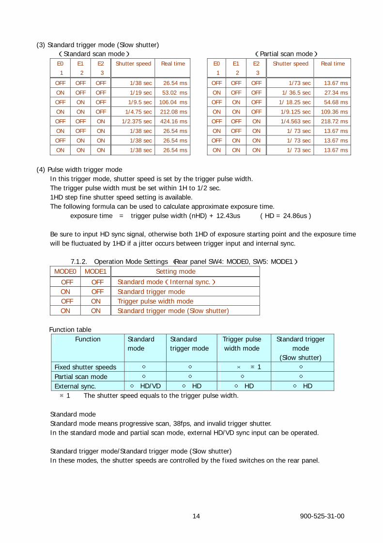
(3) Standard trigger mode (Slow shutter) (Standard scan mode) (Partial scan mode)
E0 E1 E2 Shutter speed Real time E0 E1 E2 Shutter speed Real time
1 2 3 1 2 3
OFF OFF OFF 1/38 sec 26.54 ms OFF OFF OFF 1/73 sec 13.67 ms
ON OFF OFF 1/19 sec 53.02 ms ON OFF OFF 1/ 36.5 sec 27.34 ms
OFF ON OFF 1/9.5 sec 106.04 ms OFF ON OFF 1/ 18.25 sec 54.68 ms
ON ON OFF 1/4.75 sec 212.08 ms ON ON OFF 1/9.125 sec 109.36 ms
OFF OFF ON 1/2.375 sec 424.16 ms OFF OFF ON 1/4.563 sec 218.72 ms
ON OFF ON 1/38 sec 26.54 ms ON OFF ON 1/ 73 sec 13.67 ms
OFF ON ON 1/38 sec 26.54 ms OFF ON ON 1/ 73 sec 13.67 ms
ON ON ON 1/38 sec 26.54 ms ON ON ON 1/ 73 sec 13.67 ms
(4) Pulse width trigger mode In this trigger mode, shutter speed is set by the trigger pulse width. The trigger pulse width must be set within 1H to 1/2 sec. 1HD step fine shutter speed setting is available. The following formula can be used to calculate approximate exposure time. exposure time = trigger pulse width (nHD) + 12.43us ( HD = 24.86us )
Be sure to input HD sync signal, otherwise both 1HD of exposure starting point and the exposure time will be fluctuated by 1HD if a jitter occurs between trigger input and internal sync.
7.1.2. Operation Mode Settings (Rear panel SW4: MODE0, SW5: MODE1) MODE0 MODE1 Setting mode
OFF OFF Standard mode(Internal sync.) ON OFF Standard trigger mode OFF ON Trigger pulse width mode ON ON Standard trigger mode (Slow shutter)
Function table Function Standard
mode Standard trigger mode
Trigger pulse width mode
Standard trigger mode
(Slow shutter) Fixed shutter speeds ○ ○ × ※1 ○ Partial scan mode ○ ○ ○ ○ External sync. ○ HD/VD ○ HD ○ HD ○ HD
※1 The shutter speed equals to the trigger pulse width.
Standard mode Standard mode means progressive scan, 38fps, and invalid trigger shutter. In the standard mode and partial scan mode, external HD/VD sync input can be operated.
Standard trigger mode/Standard trigger mode (Slow shutter) In these modes, the shutter speeds are controlled by the fixed switches on the rear panel.
900-525-31-00 15
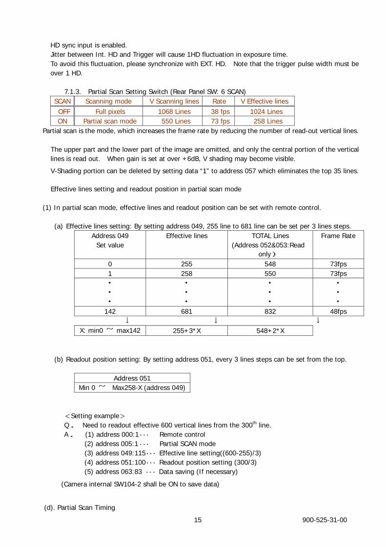
HD sync input is enabled. Jitter between Int. HD and Trigger will cause 1HD fluctuation in exposure time. To avoid this fluctuation, please synchronize with EXT. HD. Note that the trigger pulse width must be over 1 HD.
7.1.3. Partial Scan Setting Switch (Rear Panel SW: 6 SCAN) SCAN Scanning mode V Scanning lines Rate V Effective lines OFF Full pixels 1068 Lines 38 fps 1024 Lines ON Partial scan mode 550 Lines 73 fps 258 Lines
Partial scan is the mode, which increases the frame rate by reducing the number of read-out vertical lines.
The upper part and the lower part of the image are omitted, and only the central portion of the vertical lines is read out. When gain is set at over +6dB, V shading may become visible.
V-Shading portion can be deleted by setting data “1” to address 057 which eliminates the top 35 lines.
Effective lines setting and readout position in partial scan mode (1) In partial scan mode, effective lines and readout position can be set with remote control.
(a) Effective lines setting: By setting address 049, 255 line to 681 line can be set per 3 lines steps. Address 049
Set value Effective lines
TOTAL Lines
(Address 052&053:Read only)
Frame Rate
0 255 548 73fps 1 258 550 73fps ・ ・ ・
・ ・ ・
・ ・ ・
・ ・ ・
142 681 832 48fps ↓ ↓ ↓
X: min0 ~ max142 255+3*X 548+2*X
(b) Readout position setting: By setting address 051, every 3 lines steps can be set from the top.
Address 051 Min 0 ~ Max258-X (address 049)
<Setting example> Q. Need to readout effective 600 vertical lines from the 300th line. A. (1) address 000:1 ・・・ Remote control (2) address 005:1 ・・・ Partial SCAN mode (3) address 049:115・・・ Effective line setting((600-255)/3) (4) address 051:100・・・ Readout position setting (300/3) (5) address 063:83 ・・・ Data saving (If necessary)
(Camera internal SW104-2 shall be ON to save data)
(d). Partial Scan Timing
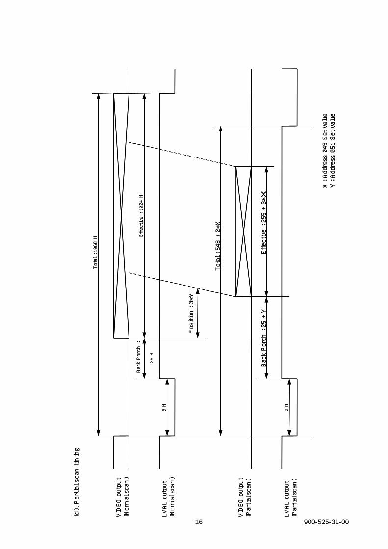
(d). Partial scan timing
LVAL output
(Normal scan)
9 H
VIDEO output
(Normal scan)
Total : 1068 H
Effective: 1024 H
VIDEO output
(Partial scan)
LVAL output
(Partial scan)
9 H
Back Porch :
35 H
Effective: 255 + 3*X
Total : 548 + 2*X
Position : 3*Y
Back Porch : 25 + Y
X : Address049 Set value
Y : Address051 Set value
900-525-31-00 16
900-525-31-00 17
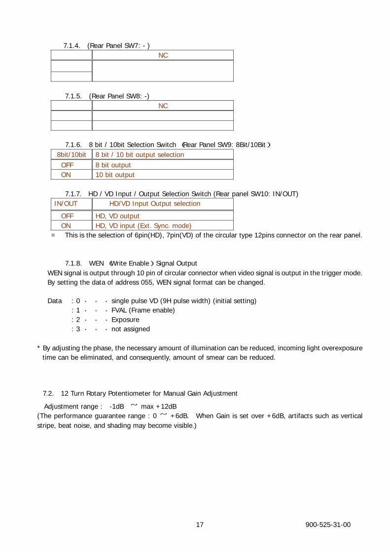
7.1.4. (Rear Panel SW7: - ) NC
7.1.5. (Rear Panel SW8: -) NC
7.1.6. 8 bit / 10bit Selection Switch (Rear Panel SW9: 8Bit/10Bit)
8bit/10bit 8 bit / 10 bit output selection OFF 8 bit output ON 10 bit output
7.1.7. HD / VD Input / Output Selection Switch (Rear panel SW10: IN/OUT)
IN/OUT HD/VD Input Output selection
OFF HD, VD output ON HD, VD input (Ext. Sync. mode)
※ This is the selection of 6pin(HD), 7pin(VD) of the circular type 12pins connector on the rear panel.
7.1.8. WEN (Write Enable) Signal Output WEN signal is output through 10 pin of circular connector when video signal is output in the trigger mode. By setting the data of address 055, WEN signal format can be changed. Data : 0 ・ ・ ・ single pulse VD (9H pulse width) (initial setting)
: 1 ・ ・ ・ FVAL (Frame enable) : 2 ・ ・ ・ Exposure : 3 ・ ・ ・ not assigned
* By adjusting the phase, the necessary amount of illumination can be reduced, incoming light overexposure time can be eliminated, and consequently, amount of smear can be reduced.
7.2. 12 Turn Rotary Potentiometer for Manual Gain Adjustment
Adjustment range : -1dB ~ max +12dB (The performance guarantee range : 0 ~ +6dB. When Gain is set over +6dB, artifacts such as vertical stripe, beat noise, and shading may become visible.)
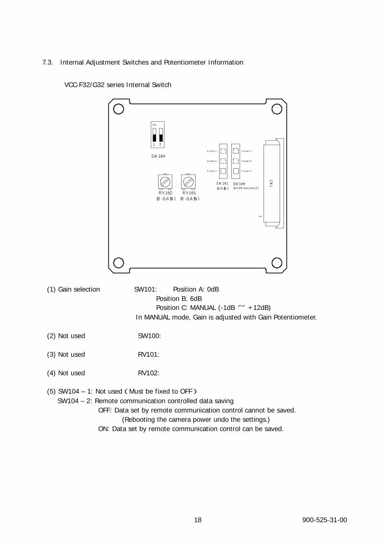
7.3. Internal Adjustment Switches and Potentiometer Information
VCC-F32/G32 series Internal Switch
900-525-31-00 18
SW104
1
CN1SW100
(WHITE BALANCE)
SW101(GAIN)
(Position B)
1 2
ON
RV102(B-GAIN)
RV101(R-GAIN)
(Position C)
(Position A)
(Position B)
(Position C)
(Position A)
(1) Gain selection SW101: Position A: 0dB
Position B: 6dB Position C: MANUAL (-1dB ~ +12dB)
In MANUAL mode, Gain is adjusted with Gain Potentiometer. (2) Not used SW100: (3) Not used RV101: (4) Not used RV102: (5) SW104 – 1: Not used(Must be fixed to OFF) SW104 – 2: Remote communication controlled data saving
OFF: Data set by remote communication control cannot be saved. (Rebooting the camera power undo the settings.)
ON: Data set by remote communication control can be saved.

7.4. HD/VD Trigger Input/Output Circuit of 12pin Circular Connector
HD out
HD in
VCC
VCC470p
VCC
NM’T
10 K
100
HD74LV1GT126A
6pin
Vih min 2.0V / Vil max 0.8VVoh min 3.8V / Vol max 0.55V
WEN out
VCC
470p
10010pin
HD74LV1 GT 04 AVoh min 3. 8V / Vol max 0.55V
TRG in
VCC
11pin
HD 74LV1GT14AVt+ max 1. 9V / Vt - min 0.5V
470p
VCC
NM’T
1K
VD out
VD in
VCC
VCC470p
VCC
NM ’T
10 K
100
HD74 LV1 GT126 A
7pin
Vih min 2.0V / Vil max 0.8VVoh min 3. 8V / Vol max 0 .55V
HD
VD
WEN
TRG
※ VCC : 5V NM ' T : No mount
12 pins Circular connector
HR10-10R-12PA(73)
Please refer to the manufacturer’s data sheets for the characteristics of component parts.
900-525-31-00 19
900-525-31-00 20
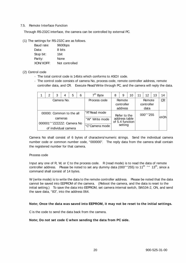
7.5. Remote Interface Function
Through RS-232C interface, the camera can be controlled by external PC.
(1) The settings for RS-232C are as follows. Baud rate: 9600bps Data: 8 bits Stop bit: 1bit Parity: None XON/XOFF: Not controlled
(2) Control code ・ The total control code is 14bits which conforms to ASCII code.
・ The control code consists of camera No, process code, remote controller address, remote controller data, and CR. Execute Read/Write through PC, and the camera will reply the data.
1 2 3 4 5 6 7th Byte 8 9 10 11 12 13 14Camera No. Process code Remote
controller address
Remote controller
data
CR
”R”Read mode
“W” Write mode
00000: Common to the all cameras
000001~ZZZZZZ: Camera No of individual camera
“C”Camera mode
Refer to the address table of 5.4 function
setting
000~255
0Dh
Camera No shall consist of 6 bytes of characters/numeric strings. Send the individual camera number code or common number code, “000000”. The reply data from the camera shall contain the registered number for that camera.
Process code Input any one of R, W, or C to the process code. R (read mode) is to read the data of remote controller address. Please be noted to set any dummy data (000~255) to 11th ~ 13th, since a command shall consist of 14 bytes.
W (write mode) is to write the data to the remote controller address. Please be noted that the data cannot be saved into EEPROM of the camera. (Reboot the camera, and the data is reset to the initial setting.) To save the data into EEPROM, set camera internal switch, SW104-2, ON, and send the save data, “83”, into the address 064.
Note; Once the data was saved into EEPROM, it may not be reset to the initial settings.
C is the code to send the data back from the camera. Note; Do not set code C when sending the data from PC side.
900-525-31-00 21
Remote controller address
Note; Do not save the data into the address other than specified, since it may cause the damages or malfunction of the camera.
Remote controller data
Set the decimal number (000~255) for the remote controller data. Please be noted to set any dummy data in read control mode.
CR Be sure to input “CR” to confirm the end of the command. (3) Setting Example Set Gain to +6dB with remote control function.
Step 1 Set the camera to “000000”(assign the common camera number).
Write “1” into address “000” to set the camera into remote control mode. Please be noted that the camera control switch becomes invalid in remote control mode. Code from the PC: “000000W000001CR”
Step 2 Set Gain to +6dB.
Code from the PC: “000000W001002CR”
8. Safety/Quality Standards
・ UL Standard
Conform to UL Standard including materials and others.
・ CE Marking (to be acquired)
Conform to EN50081-2 (Emission)
Conform to EN50082-2 (Immunity)
・ RoHS Conform to RoHS restricted items.
・ FCC Compliance Conform to FCC Class A Digital Device
This device complies with Part 15 of the FCC Rules. Operation is subject to the following two conditions: (1) this device may not cause harmful interference, and (2) this device must accept any interference received, including interference that may cause undesired operation.
900-525-31-00 22
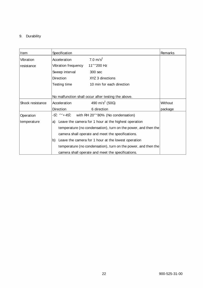
9. Durability
Item Specification Remarks
Vibration
resistance
Acceleration 7.0 m/s2
Vibration frequency 11~200 Hz
Sweep interval 300 sec
Direction XYZ 3 directions
Testing time 10 min for each direction
No malfunction shall occur after testing the above.
Shock resistance Acceleration 490 m/s2 (50G)
Direction 6 direction
Without
package
Operation
temperature
-5℃~+45℃ with RH 20~80% (No condensation)
a) Leave the camera for 1 hour at the highest operation
temperature (no condensation), turn on the power, and then the
camera shall operate and meet the specifications.
b) Leave the camera for 1 hour at the lowest operation
temperature (no condensation), turn on the power, and then the
camera shall operate and meet the specifications.
10. Timing Chart
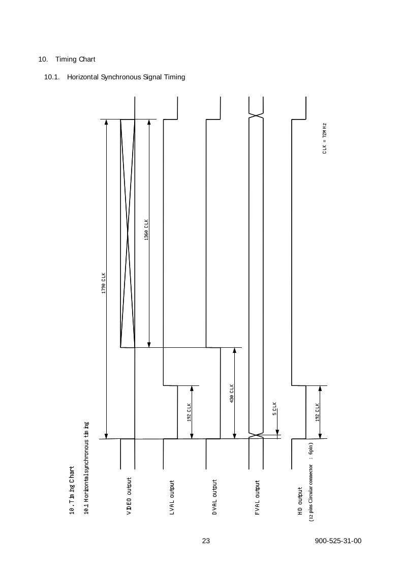
10.1. Horizontal Synchronous Signal Timing 10. Timing Chart
10.1 Horizontal synchronous timing
LVAL output
192 CLK
VIDEO output
DVAL output
430 CLK
FVAL output
5 CLK
HD output
192 CLK
1790 CLK
1360 CLK
CLK = 72MHz
(12
pins
Circ
ular
con
nect
or:
6pin
)
10. Timing Chart
10.1 Horizontal synchronous timing
LVAL output
192 CLK
VIDEO output
DVAL output
430 CLK
FVAL output
5 CLK
HD output
192 CLK
1790 CLK
1360 CLK
CLK = 72MHz
(12
pins
Circ
ular
con
nect
or:
6pin
)
900-525-31-00 23
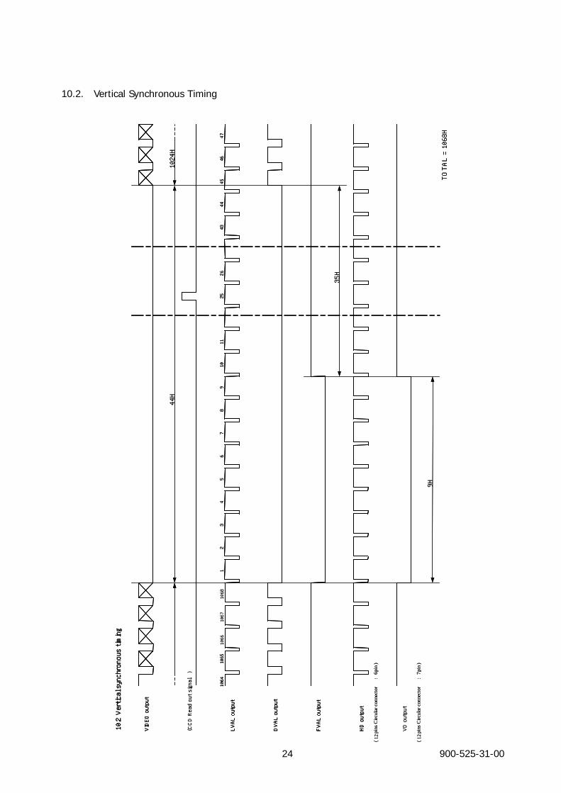
10.2. Vertical Synchronous Timing
10.2 Vertical synchronous timing
LVAL output
VIDEO output
DVAL output
FVAL output
12
34
56
78
910
1065
1064
4546
4711
2526
4344
HD output
VD output
(CCD Read out signal)
9H
44H
1024H
35H
TOTAL = 1068H
1068
1067
1066
(12
pin
s Circ
ular
con
nect
or:
6pin
)
(12
pin
s Circ
ular
con
nect
or:
7pin
)
10.2 Vertical synchronous timing
LVAL output
VIDEO output
DVAL output
FVAL output
12
34
56
78
910
1065
1064
4546
4711
2526
4344
HD output
10.2 Vertical synchronous timing
LVAL output
VIDEO output
DVAL output
FVAL output
12
34
56
78
910
1065
1064
4546
4711
2526
4344
HD output
VD output
(CCD Read out signal)
9H
44H
1024H
35H
TOTAL = 1068H
1068
1067
1066
(12
pin
s Circ
ular
con
nect
or:
6pin
)
(12
pin
s Circ
ular
con
nect
or:
7pin
)
900-525-31-00 24
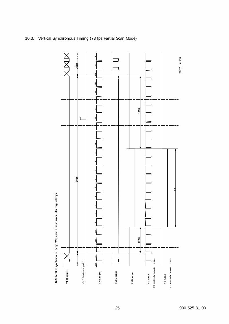
10.3. Vertical Synchronous Timing (73 fps Partial Scan Mode)
10.3 Vertical synchronous timing (73fps partial scan mode : factory setting)
LVAL output
VIDEO output
DVAL output
FVAL output
12
34
56
78
910
421
420
168
169
170
1125
26166
167
HD output
VD output
(CCD Read out signal)
9H
292H
258H
158H
TOTAL = 550H
550
549
125H
(12
pin
s Circ
ular
con
nect
or:
6pin
)
(12
pin
s Circ
ular
con
nect
or:
7pin
)
10.3 Vertical synchronous timing (73fps partial scan mode : factory setting)
LVAL output
VIDEO output
DVAL output
FVAL output
12
34
56
78
910
421
420
168
169
170
1125
26166
167
HD output
10.3 Vertical synchronous timing (73fps partial scan mode : factory setting)
LVAL output
VIDEO output
DVAL output
FVAL output
12
34
56
78
910
421
420
168
169
170
1125
26166
167
HD output
VD output
(CCD Read out signal)
9H
292H
258H
158H
TOTAL = 550H
550
549
125H
(12
pin
s Circ
ular
con
nect
or:
6pin
)
(12
pin
s Circ
ular
con
nect
or:
7pin
)
900-525-31-00 25

10.4. Standard Trigger Timing
10.4 Standard trigger timing
LVAL output
VIDEO output
DVAL output
FVAL output
HD output
VD output
9H
35H
Trigger input
(CCD Read out signal)
Exposure Time
Jitter 1H max
19
451068
1024H
WEN output
1068H
19
45
1068
1024H
(12
pin
s Circ
ular
con
nect
or:
6pin
)
(12
pin
s Circ
ular
con
nect
or:
7pin
)
(12
pin
s Circ
ular
co
nnec
tor
: 10
pin)
(A
ddre
ss05
5: 0
VD
)
(A
ddre
ss05
5: 1
FVA
L )
(A
ddre
ss05
5: 2
Expo
sure
)
10.4 Standard trigger timing
LVAL output
VIDEO output
DVAL output
FVAL output
HD output
VD output
9H
35H
Trigger input
10.4 Standard trigger timing
LVAL output
VIDEO output
DVAL output
FVAL output
HD output
VD output
9H
35H
Trigger input
(CCD Read out signal)
Exposure Time
Jitter 1H max
19
451068
1024H
WEN output
1068H
(CCD Read out signal)
Exposure Time
Jitter 1H max
19
451068
1024H
WEN output
1068H
19
45
1068
1024H
(12
pin
s Circ
ular
con
nect
or:
6pin
19
45
1068
1024H
(12
pin
s Circ
ular
con
nect
or:
6pin
)
(12
pin
s Circ
ular
con
nect
or:
7pin
)
(12
pin
s Circ
ular
co
nnec
tor
: 10
pin)
(A
ddre
ss05
5: 0
VD
)
(A
ddre
ss05
5: 1
FVA
L )
(A
ddre
ss05
5: 2
Expo
sure
)
900-525-31-00 26
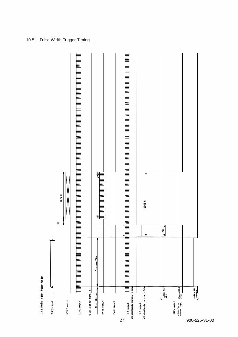
10.5. Pulse Width Trigger Timing
900-52527 -31-00
10.5 Pulsewidtht rigert iming
LVAL output
VIDEO output
DVAL output
FVAL output
HD output
VD output
9H
35H
Trigger input
(CCD Read out signal)
Exposure Time
Jitter 1H max
19
45
1068
1024H
WEN output
1068H
(12
pin
s Circ
ular
con
nect
or:
6pin
)
(12
pin
s Circ
ular
con
nect
or:
7pin
)
(12
pin
s Circ
ular
co
nnec
tor
: 10
pin)
(A
ddre
ss05
5: 0
VD
)
(A
ddre
ss05
5: 1
FVA
L )
(A
ddre
ss05
5: 2
Expo
sure
)
10.5 Pulsewidtht rigert iming
LVAL output
VIDEO output
DVAL output
FVAL output
HD output
VD output
9H
35H
Trigger input
10.5 Pulsewidtht rigert iming
LVAL output
VIDEO output
DVAL output
FVAL output
HD output
VD output
9H
35H
Trigger input
(CCD Read out signal)
Exposure Time
Jitter 1H max
19
45
1068
1024H
WEN output
1068H
(CCD Read out signal)
Exposure Time
Jitter 1H max
19
45
1068
1024H
WEN output
1068H
(12
pin
s Circ
ular
con
nect
or:
6pin
)
(12
pin
s Circ
ular
con
nect
or:
7pin
)
(12
pin
s Circ
ular
co
nnec
tor
: 10
pin)
(A
ddre
ss05
5: 0
VD
)
(A
ddre
ss05
5: 1
FVA
L )
(A
ddre
ss05
5: 2
Expo
sure
)
(12
pin
s Circ
ular
con
nect
or:
6pin
)
(12
pin
s Circ
ular
con
nect
or:
7pin
)
(12
pin
s Circ
ular
co
nnec
tor
: 10
pin)
(A
ddre
ss05
5: 0
VD
)
(A
ddre
ss05
5: 1
FVA
L )
(A
ddre
ss05
5: 2
Expo
sure
)
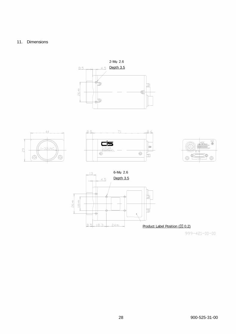
11. Dimensions
2-Mφ2.6
Depth 3.5
6-Mφ2.6
Depth 3.5
Product Label Position (凹 0.2)
900-525-31-00 28

900-525-31-00 29
12. Cases for Indemnity (Limited Warranty)
We shall be exempted from taking responsibility and held harmless for damage or losses incurred by the user in
the following cases.
In case damage or losses are caused by fire, earthquake, or other acts of God, acts by third party, deliberate
or accidental misuse by the user, or use under extreme operating conditions.
In case indirect, additional, consequential damages (loss of business interests, suspension of business
activities) are incurred as result of malfunction or non-function of the equipment, we shall be exempted from
responsibility for such damages.
In case damage or losses are caused by failure to observe the information contained in the instructions in this
product specification & operation manual.
In case damage or losses are caused by use contrary to the instructions in this product specification &
operation manual.
In case damage or losses are caused by malfunction or other problems resulting from use of equipment or
software that is not specified.
In case damage or losses are caused by repair or modification conducted by the customer or any unauthorized
third party (such as an unauthorized service representative).
Expenses we bear on this product shall be limited to the individual price of the product.
900-525-31-00 30
13. Handling Precautions
【Important】 Please observe all warnings and cautions stated below.
Our warranty does not apply to damages or malfunctions caused by neglecting
these precautions.
Do not use or store the camera in the following extreme conditions:
Extremely dusty or humid places.
Extremely hot or cold places (operating temperature –5 to +45 )℃ ℃
Close to generators of powerful electromagnetic radiation such as radio or TV transmitters.
Places subject to fluorescent light reflections.
Places subject to unstable (flickering, etc.) lighting conditions.
Places subject to strong vibration.
Remove dust or dirt on the surface of the lens with a blower.
Do not apply excessive force or static electricity that could damage the camera.
Do not shoot direct images that are extremely bright (e.g., light source, sun, etc.), and when camera
is not in use, put the lens cap on.
Follow the instructions in Chapter 6, “External connector pin assignment” for connecting the camera.
Improper connection may cause damages not only to the camera but also to the connected devices.
Confirm the mutual ground potential carefully and then connect the camera to monitors or computers.
AC leaks from the connected devices may cause damages or destroy the camera.
Do not apply excessive voltage. (Use only the specified voltage.) Unstable or improper power supply
voltage may cause damages or malfunction of the camera.
Make sure that the camera and peripheral equipments are properly connected before turning the camera
on. Especially in INT/EXT sync signal settings, improper connection may cause damages to the camera
and the connected devices.
VCC-G32S21CL can be connected to a capture board for Camera Link by use of dedicated cable.
In case of abnormal operation, contact the distributor from whom you purchased the product.