Product specification - IRB 14000
128
ROBOTICS Product specification IRB 14000
-
Upload
khangminh22 -
Category
Documents
-
view
3 -
download
0
Transcript of Product specification - IRB 14000

ROBOTICS
Product specificationIRB 14000

Trace back information:Workspace 21C version a3Checked in 2021-09-23Skribenta version 5.4.005

Product specificationIRB 14000
Document ID: 3HAC052982-001Revision: P
© Copyright 2015-2021 ABB. All rights reserved.Specifications subject to change without notice.

The information in this manual is subject to change without notice and should notbe construed as a commitment by ABB. ABB assumes no responsibility for any errorsthat may appear in this manual.Except as may be expressly stated anywhere in this manual, nothing herein shall beconstrued as any kind of guarantee or warranty by ABB for losses, damage to personsor property, fitness for a specific purpose or the like.In no event shall ABB be liable for incidental or consequential damages arising fromuse of this manual and products described herein.This manual and parts thereof must not be reproduced or copied without ABB'swritten permission.Keep for future reference.Additional copies of this manual may be obtained from ABB.
Original instructions.
© Copyright 2015-2021 ABB. All rights reserved.Specifications subject to change without notice.

Table of contents7Overview of this specification ..........................................................................................................
111 Description111.1 Structure .........................................................................................................111.1.1 Introduction to structure ...........................................................................121.1.1.1 Robot description ........................................................................161.1.2 The Robot ..............................................................................................191.2 Safety .............................................................................................................191.2.1 Applicable standards ...............................................................................221.2.2 Safety functions ......................................................................................231.3 Installation .......................................................................................................241.3.1 Operating requirements ............................................................................251.3.2 Mounting the manipulator .........................................................................301.4 Load diagram ...................................................................................................301.4.1 Introduction to load diagram ......................................................................311.4.2 Load diagram .........................................................................................331.4.3 Maximum load and moment of inertia ..........................................................341.5 Mounting of equipment .......................................................................................341.5.1 General .................................................................................................351.5.2 Robot ....................................................................................................371.5.3 Tool flange .............................................................................................391.6 Calibration .......................................................................................................391.6.1 Calibration methods .................................................................................411.6.2 Fine calibration .......................................................................................421.6.3 Absolute Accuracy calibration ...................................................................441.7 Maintenance and troubleshooting .........................................................................441.7.1 Introduction to maintenance and trouble shooting .........................................451.8 Robot motion ....................................................................................................451.8.1 Working range and type of motion ..............................................................481.8.2 Performance according to ISO 9283 ............................................................491.8.3 Velocity .................................................................................................501.8.4 Stopping distance / time ...........................................................................511.9 Customer connections .......................................................................................
532 Grippers532.1 Structure .........................................................................................................532.1.1 Introduction ............................................................................................542.1.2 Function modules ....................................................................................602.2 Technical data ..................................................................................................602.2.1 General .................................................................................................652.2.2 Servo module .........................................................................................682.2.3 Vacuum module ......................................................................................692.2.4 Vision module .........................................................................................712.2.5 Fingers ..................................................................................................722.3 Installation .......................................................................................................722.3.1 Operating requirements ............................................................................732.3.2 Recommended standard tightening torque ...................................................742.3.3 Mounting the gripper ................................................................................772.3.4 Mounting the fingers ................................................................................782.3.5 Mounting tools to the vacuum module .........................................................802.4 Maintenance and trouble shooting ........................................................................802.4.1 Introduction ............................................................................................
813 Controller813.1 Overview .........................................................................................................
Product specification - IRB 14000 53HAC052982-001 Revision: P
© Copyright 2015-2021 ABB. All rights reserved.
Table of contents

843.2 Connections .....................................................................................................843.2.1 Connecting power and the FlexPendant ......................................................863.2.2 Connecting a PC and Ethernet based options ...............................................873.2.2.1 Connectors on the computer unit ....................................................913.2.3 Connecting I/O signals .............................................................................933.2.4 Connecting fieldbuses ..............................................................................963.2.5 Connecting safety signals .........................................................................
1013.3 I/O system .......................................................................................................1013.3.1 Local I/O devices .....................................................................................1033.3.2 Conveyor tracking module ........................................................................1053.4 Memory functions ..............................................................................................1053.4.1 SD-card memory .....................................................................................1063.4.2 Connecting an USB memory .....................................................................1073.5 Installation of add-ons ........................................................................................1073.5.1 Installation of Local I/O devices .................................................................1103.5.2 Installation of conveyor tracking module ......................................................1123.6 What is Cartesian speed supervision? ...................................................................
1134 Specification of variants and options1134.1 Introduction to variants and options ......................................................................1144.2 Manipulator ......................................................................................................1154.3 Grippers ..........................................................................................................1174.4 Basic ..............................................................................................................1214.5 Unlisted options ................................................................................................
1235 Accessories
125Index
6 Product specification - IRB 140003HAC052982-001 Revision: P
© Copyright 2015-2021 ABB. All rights reserved.
Table of contents

Overview of this specificationAbout this product specification
It describes the performance of the manipulator or a complete family of manipulatorsin terms of:
• The structure and dimensional prints• The fulfilment of standards, safety and operating requirements• The load diagrams, mounting of extra equipment, the motion and the robot
reach• The specification of variants and options available
The product specification also contains information for the controller.
UsageProduct specifications are used to find data and performance about the product,for example to decide which product to buy. How to handle the product is describedin the product manual.
UsersIt is intended for:
• Product managers and product personnel• Sales and marketing personnel• Order and customer service personnel
References
Document IDDocument name
3HAC052984-001Product manual, spare parts - IRB 14000
3HAC052982-001Product specification - IRB 14000
3HAC054949-001Product manual - Grippers for IRB 14000
3HAC052986-001Operating manual - IRB 14000
3HAC050778-003Circuit diagram - IRB 14000
3HAC031045-001Safety manual for robot - Manipulator and IRC5 or OmniCore con-troller i
3HAC042927-001Technical reference manual - Lubrication in gearboxes
3HAC021313-001Product manual - IRC5
3HAC050948-001Technical reference manual - System parameters
3HAC059109-001Application manual - Scalable I/O
3HAC050991-001Application manual - Conveyor trackingi This manual contains all safety instructions from the product manuals for the manipulators and the
controllers.
RevisionsDescriptionRevision
First edition.-
Continues on next pageProduct specification - IRB 14000 73HAC052982-001 Revision: P
© Copyright 2015-2021 ABB. All rights reserved.
Overview of this specification

DescriptionRevision• Minor corrections/updateA• Changed torque y for endurance load and maximum load.• Main cable options added.
B
• Revised Tool I/O descriptions• Applicable ESD-standards added.• Modified maximum speed of IRB 14000 gripper from 20 mm/s to
25 mm/s.
C
Published in release R16.2. The following updates are done in this revi-sion:
• Added part number for Mill-Max connector used on the tool flange.See Tool flange on page 37 and Tool flange on page 52.
• Max current information added to tool flange, see Tool flange onpage 52.
• Max current added for pins A to D on the tool flange, when theyare not used as Ethernet interfaces, see Tool flange on page 52.
• Max current added for pin 9 on connector XS7 and XS8.• Added line fusing, rated power, and required equipment informa-
tion for power connection to the controller. SeeConnecting powersupply on page 84.
D
Published in release R17.1. The following updates are done in this revi-sion:
• SoftMove is now supported since Robotware 6.04• Restriction of load diagram added.• Air input changed.
E
Published in release R17.2. The following updates are done in this revi-sion:
• Updated list of applicable standards.• Minor corrections/update.• YuMi is available for clean room.
F
Published in release R18.1. The following updates are done in this revi-sion:
• Minor changes.• The maximum motor power information added.
G
Published in release R18.1. The following updates are done in this revi-sion:
• Minor changes.
H
Published in release R18.2. The following updates are done in this revi-sion:
• Updated the figure of the hole configuration on base.• Editorial corrections.• Removed the phased out option GPRS/Internet (Remote Service)
[890-1] from the unlisted option list.
J
Published in release 20A The following updates are done in this revision:• Updated information about Absolute Accuracy.• The description of Type A added in robot description chapter.
K
Published in release 20B. The following updates are made in this revision:• Updated robot arm dimension.• Standard Warranty extended with 12 months.• New option 1526-3 added. 1526-1 and 1526-2 phased out.• Updated safety relay section.
L
Published in release 20D. The following updates are made in this revision:• Warranty section updated.
M
Continues on next page8 Product specification - IRB 14000
3HAC052982-001 Revision: P© Copyright 2015-2021 ABB. All rights reserved.
Overview of this specificationContinued

DescriptionRevision
Published in release 21B. The following updates are made in this revision:• Update clean room information.• Removed Axis resolution.
N
Published in release 21C. The following updates are made in this revision:• Option [438-6] added.
P
Product specification - IRB 14000 93HAC052982-001 Revision: P
© Copyright 2015-2021 ABB. All rights reserved.
Overview of this specificationContinued

This page is intentionally left blank

1 Description1.1 Structure
1.1.1 Introduction to structure
GeneralThe IRB 14000 is ABB Robotics first generation dual arms robot with 7-axis eacharm, industrial robot, designed specifically for manufacturing industries that useflexible robot-based automation, e.g. 3C industry. The robot has an open structurethat is especially adapted for flexible use, and can communicate extensively withexternal systems.
Continues on next pageProduct specification - IRB 14000 113HAC052982-001 Revision: P
© Copyright 2015-2021 ABB. All rights reserved.
1 Description1.1.1 Introduction to structure

1.1.1.1 Robot description
1.1.1.1.1 Robot type description
Type A of IRB 14000The difference between IRB 14000 and IRB 14000 Type A is that the Type A hasa reinforced design on the arm.As a result of this, the following parts differ between types:
• Motor brake, axis 1 and axis 2• Gearbox, axis 4 and axis 5• Mechanical design, axis 4 and axis 5• Cable harness design
Those robots in original design are simply named IRB 14000 (no-type-specified).
How to know which type the robot is?The following characteristics can be used to figure out the robot type.
Axis 5 appearance
IRB 14000 Type AIRB 14000 (no-type-specified)
xx1900001957xx1900001956
Continues on next page12 Product specification - IRB 14000
3HAC052982-001 Revision: P© Copyright 2015-2021 ABB. All rights reserved.
1 Description1.1.1.1.1 Robot type description

Robot dimension
A
157
xx1900001958
IRB 14000 Type AIRB 14000 (no-type-specified)
146 mm137 mmA
Continues on next pageProduct specification - IRB 14000 133HAC052982-001 Revision: P
© Copyright 2015-2021 ABB. All rights reserved.
1 Description1.1.1.1.1 Robot type description
Continued

Arm configuration during system installationThe robot type must be correctly selected when setting the arm configuration duringsystem installation, otherwise, unexpected motion error or performance issuesmay occur.Type A is available for selection as below only in RobotStudio 2019.5.3 or laterand RobotWare 6.10.2 or later.
xx2000002171
Clean room classification
xx1700001493
Particle emission from the robot (IRB 14000 YuMi including gripper and suctioncup) fulfill Clean room class 5 standard according to DIN EN ISO 14644-1, -14.According to IPA test result, the robot IRB 14000 YuMi is suitable for use in cleanroom environments.Classification of airborne molecular contamination, see below:
Test environment parameters
Relative humidityTemperatureAirflow patternAirflow velocityCleanroom AirCleanlinessClass(According toISO 14644-1)
45% ± 0.5%22°C ± 0.5°Cvertical laminarflow
0.45 m/sISO 1
Test procedure parameters
Operation ofeach axis
Operation ofeach arm
Pressure of ul-traclean air
Attached payloadCapacity
separatelyseparately/togeth-er
6 bar0.5 kg50% and 100%
Test result/Classification:
14 Product specification - IRB 140003HAC052982-001 Revision: P
© Copyright 2015-2021 ABB. All rights reserved.
1 Description1.1.1.1.1 Robot type descriptionContinued
When operated under the specified test conditions, the IRB 14000 YuMi includinggripper and suction cup is suitable for use in cleanrooms fulfilling the specificationsof the following Air Cleanliness Classes according to ISO 14644-1.
Air Cleanliness ClassTest parameter(s)
5Capacity=50%
5Capacity=100%
5Suction cup
5Overall result
ProtectionThe robot has IP30 protection.
Operating systemThe robot is equipped with the controller (located inside the boby of the robot) androbot control software, RobotWare. RobotWare supports every aspect of the robotsystem, such as motion control, development and execution of applicationprograms, communication etc. See Operating manual - IRC5 with FlexPendant.
SafetyThe safety standards are valid for the complete robot.
Additional functionalityFor additional functionality, the robot can be equipped with optional software forapplication support, for example communication features, network communication,and advanced functions such as multitasking, sensor control etc. For a completedescription on optional software, see the Product specification - Controller IRC5.
Arm axes
+
+
+
+
+
+
+
-
+
++
++
+
+
1
1 6
6
5
5
4
4
3
3
7
7
2
2
-
-
---
-
-
-
-
-
-
-
-
xx1500000254
Product specification - IRB 14000 153HAC052982-001 Revision: P
© Copyright 2015-2021 ABB. All rights reserved.
1 Description1.1.1.1.1 Robot type description
Continued
1.1.2 The Robot
GeneralThe IRB 14000 can only be mounted on table or other flat surface, no other mountingposition is permitted.
Reach (m)Handling capacity (kg)Robot
0.559 m0.5 kgIRB 14000
Manipulator weight
WeightData
38 kgIRB 14000
Other technical data
NoteDescriptionData
< 70 dB (A) Leq (acc. to the work-ing space Machinery directive2006/42/EG)
The sound pressure level outsideAirborne noise level
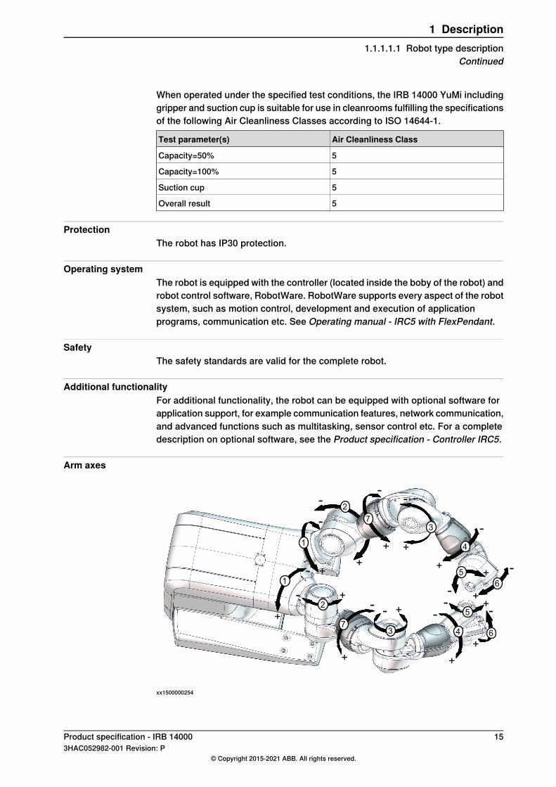
Power consumptionPath E-E2-E3-E4 in the ISO Cube, maximum load.
Power consumption (kW)Type of movement
< 0.17 kWAverage power consumption
IRB 14000Robot in 0 degree position
0.09 kWBrakes engaged
0.14 kWBrakes disengaged
xx0900000265
DescriptionPosition
250 mmA
Continues on next page16 Product specification - IRB 14000
3HAC052982-001 Revision: P© Copyright 2015-2021 ABB. All rights reserved.
1 Description1.1.2 The Robot

Dimensions
Robot
47
0
(360)
421
187.5
(3
05
)
220
96
399
26
0
CL
75
57
1
xx1500000103
Continues on next pageProduct specification - IRB 14000 173HAC052982-001 Revision: P
© Copyright 2015-2021 ABB. All rights reserved.
1 Description1.1.2 The Robot
Continued

Robot arms
A
157
xx1900001958
IRB 14000 Type AIRB 14000 (no-type-specified)
146 mm137 mmA
18 Product specification - IRB 140003HAC052982-001 Revision: P
© Copyright 2015-2021 ABB. All rights reserved.
1 Description1.1.2 The RobotContinued
1.2 Safety
1.2.1 Applicable standards
Note
The listed standards are valid at the time of the release of this document. Phasedout or replaced standards are removed from the list when needed.
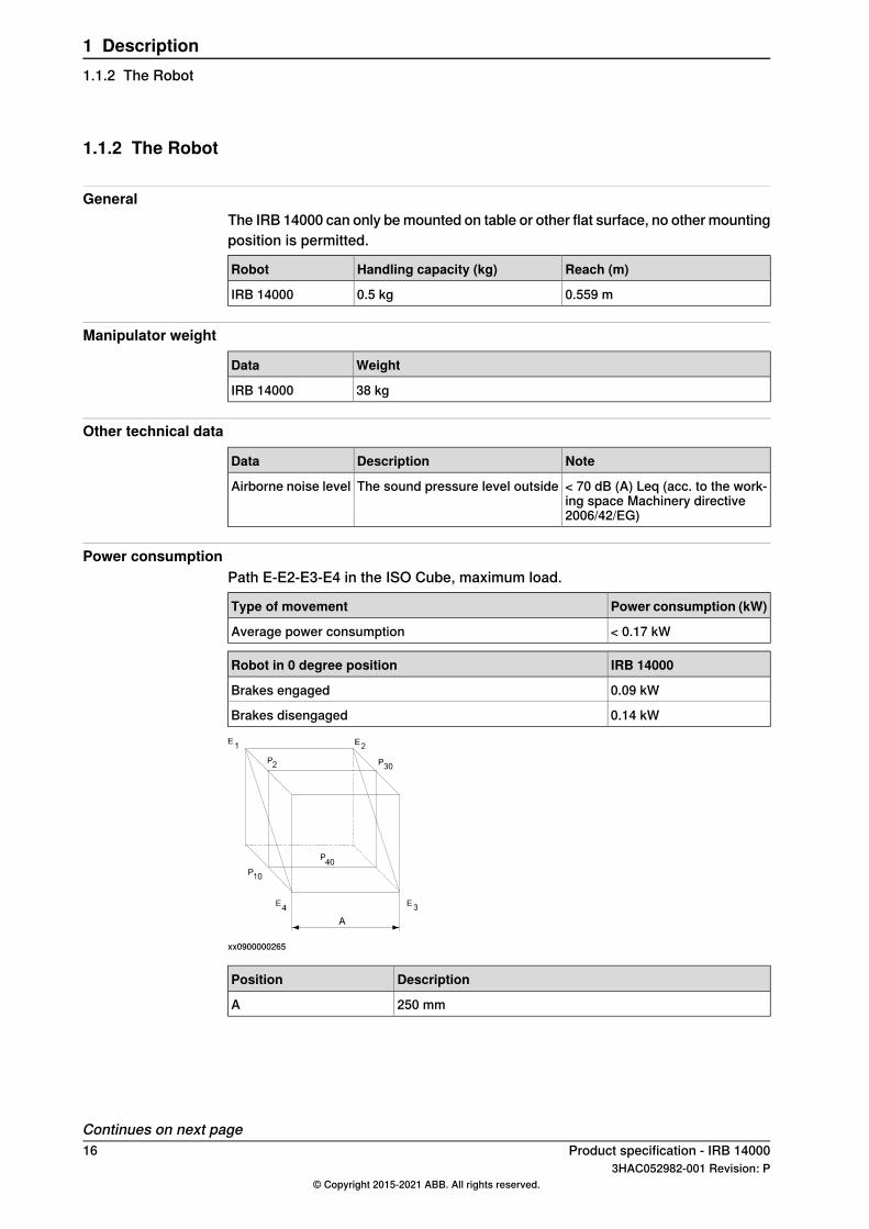
GeneralThe product is designed in accordance with ISO 10218-1:2011, Robots for industrialenvironments - Safety requirements -Part 1 Robots, and applicable parts in thenormative references, as referred to from ISO 10218-1:2011. In case of deviationsfrom ISO 10218-1:2011, these are listed in the declaration of incorporation whichis part of the product delivery.
Normative standards as referred to from ISO 10218-1
DescriptionStandard
Manipulating industrial robots - Performance criteria and relatedtest methods
ISO 9283:1998
Robots and robotic devices - Safety requirements for industrialrobots - Part 2: Robot systems and integration
ISO 10218-2
Safety of machinery - General principles for design - Risk as-sessment and risk reduction
ISO 12100
Safety of machinery - Safety related parts of control systems- Part 1: General principles for design
ISO 13849-1:2006
Safety of machinery - Emergency stop - Principles for designISO 13850
Safety of machinery - Electrical equipment of machines - Part1: General requirements
IEC 60204-1:2005
Safety of machinery - Functional safety of safety-related elec-trical, electronic and programmable electronic control systems
IEC 62061:2005
Deviations from ISO 10218-1:2011 for IRB 14000ISO 10218-1:2011 was developed with conventional industrial robots in mind.Deviations from the standard are motivated for IRB 14000 in the table below. Moreinformation about ISO 10218-1 compliance is given in technote_150918.The IRB 14000 is by default always in collaborative operation.
MotivationDeviation for IRB14000
Requirement
The alternative paragraph §5.4.3 for othersafety-related control system performanceis used instead of §5.4.2.
The robot fulfills per-formance level b withstructure category B.
§5.4 Performance leveld and structure cat-egory 3.
A comprehensive risk assessment has res-ulted in performance requirement of PL b,Cat B.
Continues on next pageProduct specification - IRB 14000 193HAC052982-001 Revision: P
© Copyright 2015-2021 ABB. All rights reserved.
1 Description1.2.1 Applicable standards

MotivationDeviation for IRB14000
Requirement
Automatic and manual mode are usabilityfeatures for IRB 14000, but not safety fea-tures. Locking the operating mode does notcontribute to a necessary risk reduction. i
The mode selector isimplemented in soft-ware on FlexPendant.
§5.7.1 Mode selectorwhich can be locked ineach position.
The IRB 14000 robot is intended for collab-orative applications where contact betweenrobot and the operator is harmless. An en-abling device does not further contribute toa risk reduction.
The enabling deviceon FlexPendant is notactive.
§5.7.3 & §5.8.3 En-abling device
The IRB 14000 robot is intended for collab-orative applications where contact betweenrobot and the operator is harmless. An autoinitiation requirement does not further con-tribute to a risk reduction.
It is possible to activ-ate manipulator auto-matic operation fromthe FlexPendant.
§5.7.3 & §5.8.5 Initiat-ing automatic opera-tion
The IRB 14000 robot is intended for collab-orative applications where contact betweenrobot and the operator is harmless. Limitingthe working range is then not necessary forrisk reduction. Note that PPE (PersonalProtective Equipment) may be required.
IRB 14000 does nothave adjustable mech-anical stops or provi-sions to install non-mechanical limitingdevices.
§5.12.1 Limiting therange of motion by ad-justable stops(§5.12.2) or by safetyfunctions (§5.12.3).
i The selector is replaced by a selection through software and user authorities can be set to restrictthe use of certain functions of the robot (e.g. access codes).
Region specific standards and regulations
DescriptionStandard
Safety requirements for industrial robots and robot systemsANSI/RIA R15.06
Safety standard for robots and robotic equipmentANSI/UL 1740
Industrial robots and robot Systems - General safety require-ments
CAN/CSA Z 434-14
Protection of Electrical and Electronic Parts, Assemblies andEquipment (Excluding Electrically Initiated Explosive Devices)
ANSI/ESD S20.20:2007
Other standards used in design
DescriptionStandard
Robots and robotic devices -- Coordinate systems and motionnomenclatures
ISO 9787:2013
Electromagnetic compatibility (EMC) – Part 6-2: Genericstandards – Immunity standard for industrial environments
IEC 61000-6-2
Electromagnetic compatibility (EMC) – Part 6-4: Genericstandards – Emission standard for industrial environments
IEC 61000-6-4
Ergonomics of the thermal environment - Part 1ISO 13732-1:2006
Arc welding equipment - Part 1: Welding power sourcesIEC 60974-1:2012 i
Arc welding equipment - Part 10: EMC requirementsIEC 60974-10:2014 i
Classification of air cleanlinessISO 14644-1:2015 ii
Degrees of protection provided by enclosures (IP code)IEC 60529:1989 + A2:2013
Protection of electronic devices from electrostatic phenomena- General requirements
IEC 61340-5-1:2010
Continues on next page20 Product specification - IRB 14000
3HAC052982-001 Revision: P© Copyright 2015-2021 ABB. All rights reserved.
1 Description1.2.1 Applicable standardsContinued

DescriptionStandard
Robots and robotic devices - Safety requirements - Industrialcollaborative workspace
ISO/TS 15066
i Only valid for arc welding robots. Replaces IEC 61000-6-4 for arc welding robots.ii Only robots with protection Clean Room.
Product specification - IRB 14000 213HAC052982-001 Revision: P
© Copyright 2015-2021 ABB. All rights reserved.
1 Description1.2.1 Applicable standards
Continued

1.2.2 Safety functions
Functional safetyThe following safety functions are inherent design measures in the control system,contributing to power and force limiting. They are certified to category B,performance level b, according to EN ISO 13849-1.
DescriptionSafety functions
The Cartesian speed of the elbow (arm check point, ACP) andthe wrist (wrist center point, WCP) are supervised. If a limit isexceeded, the robot motion is stopped and a message dis-played to the user. The default speed limit can be modifiedbased on the risk assessment of the robot installation.
Cartesian speed supervi-sion
The function is active in both manual and automatic mode. Thespeed limits are set by system parameters. See Operatingmanual - IRB 14000.
The controller has an electrical input which can be accessedin external devices mode to stop the robot, e.g. from a safetyPLC. The protective stop function removes power from theactuators, and is a Category 0 stop, according to ISO 13850.
Protective stop (safetystop)
In standalone mode, the FlexPendant emergency stop buttonis routed to this input, and utilizes the safety function to stopthe robot.
Motor power safetyThe maximum power of all the motors, integrated in IRB 14000, is less than 80W.
Additional safety features in the control system
DescriptionSafety functions
The FlexPendant is always equipped with a three-position en-abling device, but for the IRB 14000 system the enabling deviceis not used. Therefore the enabling device is disabled and in-active when the FlexPendant is connected to an IRB 14000system, but it is enabled and active when connected to anotherrobot.
Three-position enablingdevice
External safety devices can be connected by removing thesafety bridge connector on the controller. This also allows forstopping external machinery from the FlexPendant emergencystop button with retained dual channel safety.
Connecting externaldevices
In case of an unexpected mechanical disturbance, like a colli-sion, the robot will stop and then slightly back off from its stopposition.
Collision detection
The robot system complies with the requirements of UL (Un-derwriters Laboratories) for fire safety.
Fire safety
The robot system complies with the requirements of UL forelectrical safety.
Electrical safety
As an option, a safety lamp mounted on the manipulator canbe connected. The lamp is activated when the controller is inthe MOTORS ON state.
Safety lamp
22 Product specification - IRB 140003HAC052982-001 Revision: P
© Copyright 2015-2021 ABB. All rights reserved.
1 Description1.2.2 Safety functions

1.3 Installation
Introduction to installationIRB 14000 is intended for use in industrial environment.An arm can handle a maximum payload of 0.5 kg.
Continues on next pageProduct specification - IRB 14000 233HAC052982-001 Revision: P
© Copyright 2015-2021 ABB. All rights reserved.
1 Description1.3 Installation

1.3.1 Operating requirements
Protection standard
Protection standard IEC529Robot variant
IP30Manipulator + controller
Explosive environmentsThe robot must not be located or operated in an explosive environment.
Working range limitationsEPS will not be selectable and no mechanical limitations available.
Ambient temperature
TemperatureStandard/OptionDescription
+ 5°C i (41°F) to + 40°C (104°F)StandardManipulator + controllerduring operation
- 10°C (14°F) to + 55°C (131°F)StandardComplete robot duringtransportation and storagei At low environmental temperature < 10ºC is, as with any other machine, a warm-up phase
recommended to be run with the robot. Otherwise there is a risk that the robot stops or run withlower performance due to temperature dependent oil and grease viscosity.
Relative humidity
Relative humidityDescription
Max. 85% at constant temperatureComplete robot during operation, transportation andstorage
24 Product specification - IRB 140003HAC052982-001 Revision: P
© Copyright 2015-2021 ABB. All rights reserved.
1 Description1.3.1 Operating requirements

1.3.2 Mounting the manipulator
Maximum loadMaximum load in to the base coordination system. See Figure below.
Table mounted
Max. load (emergency stop)Endurance load (in operation)Force
±178 N±89 NForce x
±294 N±147 NForce y
+380 ±280 N+380 ±140 NForce z
±202 Nm±101 NmTorque x
+14 ±172 Nm+14 ±98 NmTorque y
±122 Nm±61 NmTorque z
Ty
Fz
Tz
Fy
Fx
Tx
xx1500000104
Force in the X planeFx
Force in the Y planeFy
Force in the Z planeFz
Bending torque in the X planeTx
Bending torque in the Y planeTy
Bending torque in the Z planeTz
Continues on next pageProduct specification - IRB 14000 253HAC052982-001 Revision: P
© Copyright 2015-2021 ABB. All rights reserved.
1 Description1.3.2 Mounting the manipulator

The table shows the various forces and torques working on the robot during differentkinds of operation.
Note
These forces and torques are extreme values that are rarely encountered duringoperation. The values also never reach their maximum at the same time!
Continues on next page26 Product specification - IRB 14000
3HAC052982-001 Revision: P© Copyright 2015-2021 ABB. All rights reserved.
1 Description1.3.2 Mounting the manipulatorContinued

Fastening holes robot baseThe illustration shows the hole configuration used when securing the robot.
0
0
40
40
162
143
162
124
143
124
0.3
0.06
58 1
0
6Thru 8x
1
-
98 -
0
2x 6
6
m6
2x 6 N8 12
24
12 ±2
(A) (2x)
0.1
C
C
C - C
B
B
10
8x 10.5
8x 6 0.3
0.3
B - B
xx1400002124
Guide pins, 3HNP00449-1, one is to fit round hole, the other is to fit slot hole.A
Continues on next pageProduct specification - IRB 14000 273HAC052982-001 Revision: P
© Copyright 2015-2021 ABB. All rights reserved.
1 Description1.3.2 Mounting the manipulator
Continued

32
4
28
6
20
-
40
80
6++
0.0250.015(A)
8x M5 57
24
8
H
1.6
0.2
2
6++
0.0250.015
(B)
1.6
DETAIL H
xx1400002121
Master hole (round)A
Alignment hole (slot)B
Attachment bolts, specificationThe table specifies the type of securing screws and washers to be used to securethe robot directly to the foundation. It also specifies the type of pins to be used.
M5x25Suitable screws
5.3x10x1Suitable washers
8 pcsQuantity
8.8Quality
2 pcs, article number 3HNP00449-1Guide pins
3.8 Nm ± 0.38 NmTightening torque
Continues on next page28 Product specification - IRB 14000
3HAC052982-001 Revision: P© Copyright 2015-2021 ABB. All rights reserved.
1 Description1.3.2 Mounting the manipulatorContinued
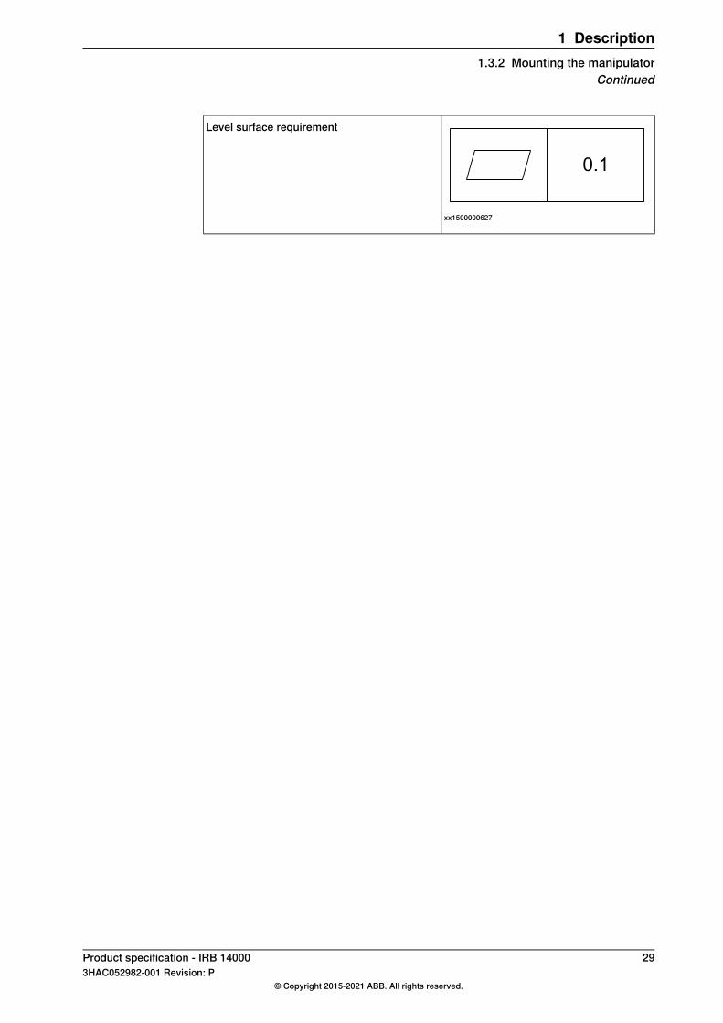
0.1
xx1500000627
Level surface requirement
Product specification - IRB 14000 293HAC052982-001 Revision: P
© Copyright 2015-2021 ABB. All rights reserved.
1 Description1.3.2 Mounting the manipulator
Continued

1.4 Load diagram
1.4.1 Introduction to load diagram
Information
WARNING
It is very important to always define correct actual load data and correct payloadof the robot. Incorrect definitions of load data can result in overloading of therobot.If incorrect load data is used, and/or if loads outside the load diagram are used,the following parts can be damaged due to overload:
• motors• gearboxes• mechanical structure
WARNING
In RobotWare, the service routine LoadIdentify can be used to determine correctload parameters. The routine automatically defines the tool and the load. SeeOperating manual - IRC5 with FlexPendant, for detailed information.
WARNING
Robots running with incorrect load data and/or with loads outside the loaddiagram, will not be covered by robot warranty.
GeneralThe load diagram includes a nominal pay load inertia, J0 of 0.001 kgm2 . At differentmoment of inertia the load diagram will be changed. For robots that are allowedtilted, wall or inverted mounted, the load diagrams as given are valid and thus it isalso possible to use RobotLoad within those tilt and axis limits.
30 Product specification - IRB 140003HAC052982-001 Revision: P
© Copyright 2015-2021 ABB. All rights reserved.
1 Description1.4.1 Introduction to load diagram

1.4.2 Load diagram
IRB 14000 - 0.5/0.5 (without gripper)
0,00
0,05
0,10
0,15
0,20
0,00 0,05 0,10
0,3 kg
0,4 kg
0,5 kg
Z -
(m
)
L - (m)
xx1500000097
Continues on next pageProduct specification - IRB 14000 313HAC052982-001 Revision: P
© Copyright 2015-2021 ABB. All rights reserved.
1 Description1.4.2 Load diagram

IRB 14000 - 0.5/0.5(with gripper)Hand CoG, see table below.
Z -
(m
)
L - (m)
0,10
0,15
0,20
0,050,00
0,00
84
0,1 kg
0,15 kg
0,2 kg
0,05
xx1500000501
LZMass
13.9 mm47.3 mm280 g
The load diagram with gripper is an example, given for the heaviest combinationof IRB 14000 Gripper options (servo + 2 vacuum modules), including fingers andsuction tools. Actual load capacity should be determined from the robot loaddiagram and the mass data of the actual gripper and end effectors.
32 Product specification - IRB 140003HAC052982-001 Revision: P
© Copyright 2015-2021 ABB. All rights reserved.
1 Description1.4.2 Load diagramContinued

1.4.3 Maximum load and moment of inertia
GeneralTotal load given as: Mass in kg, center of gravity (Z and L) in m and moment ofinertia (J0x, J0y, J0z) in kgm2 . L= √(X2 + Y2).
Full movement
Max. valueRobot variantAxis
J5 = Mass x ((Z + 0.045)2 + L2 ) + max (J0x, J0y) ≤ 0.012 kgm2IRB 14000 - 0.5/0.55
J6 = Mass x L2 + J0Z ≤ 0.009 kgm2IRB 14000 - 0.5/0.56
xx1500000774
DescriptionPosition
Center of gravityA
Max. moment of inertia around the X, Y and Z axes at center ofgravity.
J0x, J0y, J0z
Wrist torqueThe table below shows the maximum permissible torque due to payload.
Note
The values are for reference only, and should not be used for calculating permittedload offset (position of center of gravity) within the load diagram, since thosealso are limited by main axes torques as well as dynamic loads. Also arm loadswill influence the permitted load diagram, contact your local ABB organization.
Max torque valid atload
Max wrist torqueaxis 6
Max wrist torqueaxes 4 and 5
Robot variant
0.5 kg0.23 Nm0.64 NmIRB 14000
Product specification - IRB 14000 333HAC052982-001 Revision: P
© Copyright 2015-2021 ABB. All rights reserved.
1 Description1.4.3 Maximum load and moment of inertia

1.5 Mounting of equipment
1.5.1 General
Each arm ends with a tool flange, for mounting of available grippers, see Gripperson page 53 or for customer specific equipment and on robot.Below is an overview of the robot and tool flange, see Tool flange on page 37 fordetails.
34 Product specification - IRB 140003HAC052982-001 Revision: P
© Copyright 2015-2021 ABB. All rights reserved.
1 Description1.5.1 General

1.5.2 Robot
Top mounting interface body
4
55
150
M8 (A)
24
48
3 x M4 Helicoil 2d
0.3
A
A
12
B
B
150
48
90
±0
.10
2 x M4 Helicoil 2d
0.3
xx1500000495
DescriptionPos
M8 hole for lifting eye, thru holeA
Continues on next pageProduct specification - IRB 14000 353HAC052982-001 Revision: P
© Copyright 2015-2021 ABB. All rights reserved.
1 Description1.5.2 Robot

Chest mounting interface
30°
60
3 x M4 8
15
32
A
A
34
0.9
xx1500000494
36 Product specification - IRB 140003HAC052982-001 Revision: P
© Copyright 2015-2021 ABB. All rights reserved.
1 Description1.5.2 RobotContinued

1.5.3 Tool flange
(A)
(B)
(C)
(D)
(E) (F)
xx1500000099
DescriptionPos
4 x 2.9 thru holes for M2.5 screwsA
2E8 pin hole for alignmentB
15H7 for alignment, max depth 5 mmC
Mill-Max (430-10-208-00-240000), spring-loaded header, double row 8 padconnector for 24V and Ethernet or IO
D
Outer diam. 7.5e8 and inner diam. 4.4F10 for air hoseE
Calibration mark for axis 6F
Continues on next pageProduct specification - IRB 14000 373HAC052982-001 Revision: P
© Copyright 2015-2021 ABB. All rights reserved.
1 Description1.5.3 Tool flange

7.5 e8
19 ±0.03
15
±0
.03
2 E8 4
R28.3
6.5
13.6
R26.5
63
8
3
15 H7
2.5 4
27.7
60°
J J
HA
(A)
5.1
5.5
+ 0.1
0 2
0° 0
.5
30°
1
4x 2.9
4x 5.5
4.5
1.0
4 (
± 0
.20
)
0.2
J - J
2.5 2
.5 1
0.2
5.1
HA
(B)
6
xx1500000098
DescriptionPos
Dimensions air hoseA
Mill-Max (430-10-208-00-240000), spring-loaded header, double row 8 padconnector
B
38 Product specification - IRB 140003HAC052982-001 Revision: P
© Copyright 2015-2021 ABB. All rights reserved.
1 Description1.5.3 Tool flangeContinued

1.6 Calibration
1.6.1 Calibration methods
OverviewThis section specifies the different types of calibration and the calibration methodsthat are supplied by ABB.More information is available in the product manual.
Types of calibration
Calibration methodDescriptionType of calibration
The calibrated robot is positioned at calibrationposition.
Standard calibration
Standard calibration data is found on the SMB(serial measurement board) or EIB in the robot.For robots with RobotWare 5.04 or older, thecalibration data is delivered in a file, calib.cfg,supplied with the robot at delivery. The fileidentifies the correct resolver/motor positioncorresponding to the robot home position.
CalibWareBased on standard calibration, and besidespositioning the robot at synchronization posi-tion, the Absolute accuracy calibration alsocompensates for:
• Mechanical tolerances in the robotstructure
• Deflection due to loadAbsolute accuracy calibration focuses on pos-itioning accuracy in the Cartesian coordinatesystem for the robot.
Absolute accuracycalibration (option-al)
Absolute accuracy calibration data is foundon the SMB (serial measurement board) in therobot.For robots with RobotWare 5.05 or older, theabsolute accuracy calibration data is deliveredin a file, absacc.cfg, supplied with the robot atdelivery. The file replaces the calib.cfg file andidentifies motor positions as well as absoluteaccuracy compensation parameters.A robot calibrated with Absolute accuracy hasa sticker next to the identification plate of therobot.To regain 100% Absolute accuracy perform-ance, the robot must be recalibrated for abso-lute accuracy after repair or maintenance thataffects the mechanical structure.
xx0400001197
Continues on next pageProduct specification - IRB 14000 393HAC052982-001 Revision: P
© Copyright 2015-2021 ABB. All rights reserved.
1 Description1.6.1 Calibration methods

Brief description of calibration methods
CalibWare - Absolute Accuracy calibrationThe CalibWare tool guides through the calibration process and calculates newcompensation parameters. This is further detailed in the Applicationmanual - CalibWare Field.If a service operation is done to a robot with the option Absolute Accuracy, a newabsolute accuracy calibration is required in order to establish full performance.For most cases after replacements that do not include taking apart the robotstructure, standard calibration is sufficient.
40 Product specification - IRB 140003HAC052982-001 Revision: P
© Copyright 2015-2021 ABB. All rights reserved.
1 Description1.6.1 Calibration methodsContinued

1.6.2 Fine calibration
GeneralFine calibration is made by moving the axes so that the synchronization mark oneach joint is aligned, and running the CalHall routine.For detailed information on calibration of the robot see Product manual - IRB 14000.
xx1500000526
Product specification - IRB 14000 413HAC052982-001 Revision: P
© Copyright 2015-2021 ABB. All rights reserved.
1 Description1.6.2 Fine calibration

1.6.3 Absolute Accuracy calibration
PurposeAbsolute Accuracy is a calibration concept that improves TCP accuracy. Thedifference between an ideal robot and a real robot can be several millimeters,resulting from mechanical tolerances and deflection in the robot structure.AbsoluteAccuracy compensates for these differences.Here are some examples of when this accuracy is important:
• Exchangeability of robots• Offline programming with no or minimum touch-up• Online programming with accurate movement and reorientation of tool• Programming with accurate offset movement in relation to eg. vision system
or offset programming• Re-use of programs between applications
The option Absolute Accuracy is integrated in the controller algorithms and doesnot need external equipment or calculation.
Note
The performance data is applicable to the corresponding RobotWare version ofthe individual robot.
xx1500000761
What is includedEvery Absolute Accuracy robot is delivered with:
• compensation parameters saved on the robot’s serial measurement board• a birth certificate representing the Absolute Accuracymeasurement protocol
for the calibration and verification sequence.A robot with Absolute Accuracy calibration has a label with this information on themanipulator.
Continues on next page42 Product specification - IRB 14000
3HAC052982-001 Revision: P© Copyright 2015-2021 ABB. All rights reserved.
1 Description1.6.3 Absolute Accuracy calibration

Absolute Accuracy supports floor mounted, wall mounted and ceiling mountedinstallations. Compensation parameters saved in the robot’s serial measurementboard differ depending on which Absolute Accuracy option is selected.
When is Absolute Accuracy being usedAbsolute Accuracy works on a robot target in Cartesian coordinates, not on theindividual joints. Therefore, joint based movements (e.g. MoveAbsJ) will not beaffected.If the robot is inverted, the Absolute Accuracy calibration must be performed whenthe robot is inverted.
Absolute Accuracy activeAbsolute Accuracy will be active in the following cases:
• Any motion function based on robtargets (e.g. MoveL) and ModPos onrobtargets
• Reorientation jogging• Linear jogging• Tool definition (4, 5, 6 point tool definition, room fixed TCP, stationary tool)• Work object definition
Absolute Accuracy not activeThe following are examples of when Absolute Accuracy is not active:
• Any motion function based on a jointtarget (MoveAbsJ)• Independent joint• Joint based jogging• Additional axes• Track motion
Note
In a robot system with, for example, an additional axis or track motion, theAbsolute Accuracy is active for the manipulator but not for the additional axis ortrack motion.
RAPID instructionsThere are no RAPID instructions included in this option.
Precision and tolerancesTypical production data regarding absolute accuracy calibration are:
Global absolute accuracy (mm)Robot
% Within 1 mmMaxAverage
1000.450.25IRB 14000 - 0.5/0.5
Product specification - IRB 14000 433HAC052982-001 Revision: P
© Copyright 2015-2021 ABB. All rights reserved.
1 Description1.6.3 Absolute Accuracy calibration
Continued

1.7 Maintenance and troubleshooting
1.7.1 Introduction to maintenance and trouble shooting
GeneralThe robot requires only a minimum of maintenance during operation. It has beendesigned to make it as easy to service as possible:
• Maintenance-free AC motors are used.• Grease used for all gear boxes.• The cabling is routed for longevity.• It has a program memory “battery low” alarm.
MaintenanceThe maintenance intervals depend on the use of the robot, the required maintenanceactivities also depends on selected options. For detailed information on maintenanceprocedures, see Maintenance section in the Product Manual.
44 Product specification - IRB 140003HAC052982-001 Revision: P
© Copyright 2015-2021 ABB. All rights reserved.
1 Description1.7.1 Introduction to maintenance and trouble shooting

1.8 Robot motion
1.8.1 Working range and type of motion
Robot motion
Degree of motionType of motionAxis
-168.5° to +168.5°Arm - Rotation motionAxis 1
-143.5° to +43.5°Arm - Bend motionAxis 2
-168.5° to +168.5°Arm - Rotation motionAxis 7
-123.5° to +80°Arm - Bend motionAxis 3
-290° to +290°Wrist - Rotation motionAxis 4
-88° to +138°Wrist - Bend motionAxis 5
-229° to +229°Flange - Rotation motionAxis 6
Continues on next pageProduct specification - IRB 14000 453HAC052982-001 Revision: P
© Copyright 2015-2021 ABB. All rights reserved.
1 Description1.8.1 Working range and type of motion

Illustration, working range IRB 14000The illustrations show the unrestricted working range of the robot.
Front view
0
347
593
1018
94
0
14
45
1
23
5
66
4
Z
Y
xx1500000105
Side view
0
1018
94
347
593
0
60
27
4
68
1
40
5
53
90
X
Z
xx1500000660
Continues on next page46 Product specification - IRB 14000
3HAC052982-001 Revision: P© Copyright 2015-2021 ABB. All rights reserved.
1 Description1.8.1 Working range and type of motionContinued

Top view
0
14
45
1
23
5
66
4
0
53
60
274
680.8
405
X
Y
xx1500000336
Isometric view
xx1500000661
Product specification - IRB 14000 473HAC052982-001 Revision: P
© Copyright 2015-2021 ABB. All rights reserved.
1 Description1.8.1 Working range and type of motion
Continued

1.8.2 Performance according to ISO 9283
GeneralAt rated maximum load, maximum offset and 1.5 m/s velocity on the inclined ISOtest plane, with all six axes in motion. Values in the table below are the averageresult of measurements on a small number of robots. The result may differdepending on where in the working range the robot is positioning, velocity, armconfiguration, from which direction the position is approached, the load directionof the arm system. Backlashes in gearboxes also affect the result.The figures for AP, RP, AT and RT are measured according to figure below.
xx0800000424
DescriptionPositionDescriptionPosition
Programmed pathEProgrammed positionA
Actual path at program executionDMean position at programexecution
B
Max deviation from E to average pathATMean distance from pro-grammed position
AP
Tolerance of the path at repeatedprogram execution
RTTolerance of position B at re-peated positioning
RP
ValuesDescription
IRB 14000
0.02Pose repeatability, RP (mm)
0.02Pose accuracy, AP (mm)
0.10Linear path repeatability, RT (mm)
1.36Linear path accuracy, AT (mm)
0.37Pose stabilization time, Pst (s) within 0.1 mm of the position
48 Product specification - IRB 140003HAC052982-001 Revision: P
© Copyright 2015-2021 ABB. All rights reserved.
1 Description1.8.2 Performance according to ISO 9283

1.8.3 Velocity
General
Axis 6Axis 5Axis 4Axis 3Axis 7Axis 2Axis 1Robot variant
400 °/s400 °/s400 °/s180 °/s180 °/s180 °/s180 °/sIRB 14000
Supervision is required to prevent overheating in applications with intensive andfrequent movements.
Product specification - IRB 14000 493HAC052982-001 Revision: P
© Copyright 2015-2021 ABB. All rights reserved.
1 Description1.8.3 Velocity

1.8.4 Stopping distance / time
GeneralStopping distance/time for emergency stop (category 0) at max speed, maxstretched out and max load, categories according to EN 60204-1. All results arefrom tests on one moving axis. All stop distances are valid for floor mounted robot,without any tilting.
Category 0 stop
Stop time (s)Stopping distance indegrees
AxisRobot variant
0.37231IRB 14000
0.37232
0.40267
0.40263
Note
Axes 4, 5, and 6 may have small residual movements after the stop due to theinfluence of gravity and inertia.
50 Product specification - IRB 140003HAC052982-001 Revision: P
© Copyright 2015-2021 ABB. All rights reserved.
1 Description1.8.4 Stopping distance / time

1.9 Customer connections
Introduction to customer connectionsCustomer connection, the cables are integrated in the robot and the connectorsare placed on the left side at the base and in the tool flange.The tool flange is equipped with an 8-pole pad-type connector for signal and power.Positions E-H are for power (24V) and PE. Positions A-D are for signal, and canbe either Ethernet or IO signals.Upon delivery, the robot has Ethernet on the flange positions A-D. The Ethernetconnection from each arm is routed to the LAN2 port on the main computer via aninternal Ethernet switch in the controller. The user can reconnect inside thecontroller to instead get IO signals on the flanges. There is a female Ethernetconnector waiting next to the Ethernet switch inside of the controller, by whichflange positions A-D can instead be routed to XP12 on the left side panel of thecontroller. There, cross connections to DI and DO connectors XS8 and XS7 caneasily be made.On each flange, only one of Ethernet and IO signals can be used at the same time.When selecting the IRB 14000 SmartGrippers, Ethernet will be used, and the ToolIO signals on XP12 are not available on the flange. The Tool IO signals, on theother hand, can be used when integrating a basic pneumatic or electric gripperthat is controlled by a small number of IO signals, and that is not Ethernet-based.
Robot baseFor customer connections robot base, see Controller on page 81.
Continues on next pageProduct specification - IRB 14000 513HAC052982-001 Revision: P
© Copyright 2015-2021 ABB. All rights reserved.
1 Description1.9 Customer connections

Tool flange
Note
Customer signals (each arm) at tool flange is only available when no grippersare selected. Tool connector type, Spring-loaded Header Double row, Mill-Max(430-10-208-00-240000).
A
BDFH
G E C
xx1500000492
DescriptionPin
EtherNet RD-A
EtherNet TD-B
EtherNet RD+ (Max current = 2A, when not used as Ethernet signals)C
EtherNet TD+ (Max current = 2A, when not used as Ethernet signals)D
PEE
SpareF
0V, IOG
24V, IO (Max current = 1 A/arm)H
52 Product specification - IRB 140003HAC052982-001 Revision: P
© Copyright 2015-2021 ABB. All rights reserved.
1 Description1.9 Customer connectionsContinued

2 Grippers2.1 Structure
2.1.1 Introduction
GeneralThe IRB 14000 gripper is a smart, multifunctional gripper for part handling andassembly. The gripper has one basic servo module and two optional functionalmodules, vacuum and vision. The three modules can be combined to provide fivedifferent combinations for users in different applications.A pair of getting-started fingers are provided together with the gripper for demoand test purposes. These fingers should be replaced with fingers designed for theactual application by the system integrator.If the vacuum module option is selected, a first set of suction cups and filters areprovided together with the gripper.
Note
It is the same gripper as for IRB 14050.
ProtectionThe IRB 14000 gripper has IP30 protection.
CommunicationThe IRB 14000 gripper communicates with the IRB 14000 controller over an EthernetIP fieldbus. A RobotWare add-in, SmartGripper, is provided to facilitate the operationand programming of the gripper. The add-in contains RAPID driver, FlexPendantinterface and configuration files.
Left and rightThe IRB 14000 gripper can be mounted on left or right arm without restrictions. Itcan also be moved between arms and between robots. After a gripper is installedto the robot, the setup of Left or Right identity (chirality) of the gripper is done fromthe FlexPendant interface.
SafetyThe IRB 14000 gripper has a patented floating shell structure that helps absorbimpacts during collisions. End effectors such as fingers and suction tools need tobe designed for the actual application and included in the risk assessment by thesystem integrator.
Product specification - IRB 14000 533HAC052982-001 Revision: P
© Copyright 2015-2021 ABB. All rights reserved.
2 Grippers2.1.1 Introduction

2.1.2 Function modules
GeneralThe functions of the three gripper modules are described as follows.
DescriptionFunction module
The servo module is the basic part of the gripper. Itgives the function of gripping objects. Fingers are in-stalled on the base of the servo module, and fingermovement and force can be controlled and super-vised.
Servo1
The vacuum module contains the vacuum generator,vacuum pressure sensor and blow-off actuator. Whenthe suction tools are mounted, the gripper can pickup objects by the suction function and place the ob-jects by the blow-off function.
Vacuum2
The vision module contains a Cognex AE3 In-Sightcamera, supporting all functions of ABB IntegratedVision.
Vision3
The three function modules can be combined into five different possibilities aslisted in the following table.
Includes...Combination
One servo moduleServo1
One servo module and one vacuum moduleServo + Vacuum2
One servo module and two vacuum modulesServo + Vacuum 1 + Vacuum 23
One servo module and one vision moduleServo + Vision4
One servo module, one vision module, and onevacuum module
Servo + Vision + Vacuum5
Continues on next page54 Product specification - IRB 14000
3HAC052982-001 Revision: P© Copyright 2015-2021 ABB. All rights reserved.
2 Grippers2.1.2 Function modules

Combination views
ServoThe following figure illustrates the gripper with one servo module.
xx1400002137
Continues on next pageProduct specification - IRB 14000 553HAC052982-001 Revision: P
© Copyright 2015-2021 ABB. All rights reserved.
2 Grippers2.1.2 Function modules
Continued

Servo + VacuumThe following figure illustrates the gripper with one servo module and one vacuummodule.
xx1400002138
Continues on next page56 Product specification - IRB 14000
3HAC052982-001 Revision: P© Copyright 2015-2021 ABB. All rights reserved.
2 Grippers2.1.2 Function modulesContinued

Servo + Vacuum 1 + Vacuum 2The following figure illustrates the gripper with one servo module and two vacuummodules.
xx1400002139
Continues on next pageProduct specification - IRB 14000 573HAC052982-001 Revision: P
© Copyright 2015-2021 ABB. All rights reserved.
2 Grippers2.1.2 Function modules
Continued

Servo + VisionThe following figure illustrates the gripper with one servo module and one visionmodule.
xx1400002140
Continues on next page58 Product specification - IRB 14000
3HAC052982-001 Revision: P© Copyright 2015-2021 ABB. All rights reserved.
2 Grippers2.1.2 Function modulesContinued

Servo + Vision + VacuumThe following figure illustrates the gripper with one servo module, one vacuummodule and one vision module.
xx1400002141
Product specification - IRB 14000 593HAC052982-001 Revision: P
© Copyright 2015-2021 ABB. All rights reserved.
2 Grippers2.1.2 Function modules
Continued

2.2 Technical data
2.2.1 General
Weight and load capacity
Max. load capa-city (g) of thewhole gripper ii
Max. load capa-city (g) withoutfingers, suctioncup(s), and fil-ter(s) ii
Weight (g) ofthe whole grip-per
Weight (g)without fingers,suction cup(s),and filter(s) i
Combination
270285230215Servo
252274.5248225.5Servo + Vacuum 1
220250280250Servo + Vacuum 1 +Vacuum 2
256271244229Servo + Vision
238260.5262239.5Servo + Vision + Vacu-um 1i The getting-started fingers weights 15 g, and the standard suction cups and filters weight 7.5 g per
set.ii Load capacity = 500 - Weight
Center of gravity (CoG) limitations applied. See the robot load diagram.
Detailed mass data - Center of Gravity
CoG (mm) of the whole gripperCoG (mm) without fingers, suctioncup(s), and filter(s)
Combination
zyxzyx
5211.78.249.212.38.7Servo
52.711.78.648.712.38.9Servo + Vacu-um 1
47.311.97.144.812.47.4Servo + Vacu-um 1 + Vacuum2
52.711.87.548.712.47.9Servo + Vision
50.711.97.848.112.58.2Servo + Vision+ Vacuum 1
Detailed mass data - Inertia
Inertia (kgm2 ) of the whole gripperInertia (kgm2 ) without fingers,suction cup(s), and filter(s)
Combination
lzzlyylxxlzzlyylxx
0.000090.000240.000210.000080.000200.00017Servo
0.000090.000240.000210.000080.000200.00017Servo + Vacu-um
0.000120.000290.000250.000110.000240.00020Servo + Vacu-um 1 + Vacuum2
0.000080.000230.000210.000080.000190.00017Servo + Vision
Continues on next page60 Product specification - IRB 14000
3HAC052982-001 Revision: P© Copyright 2015-2021 ABB. All rights reserved.
2 Grippers2.2.1 General

Inertia (kgm2 ) of the whole gripperInertia (kgm2 ) without fingers,suction cup(s), and filter(s)
Combination
lzzlyylxxlzzlyylxx
0.000090.000240.000220.000090.000200.00018Servo + Vision+ Vacuum
Tooldata definitions without fingers, suction cup(s), and filter(s)
TooldataCombination
[ TRUE, [ [0, 0, 0], [1, 0, 0 ,0] ], [0.215, [8.7, 12.3, 49.2], [1,0, 0, 0], 0.00017, 0.00020, 0.00008] ]
Servo
[ TRUE, [ [0, 0, 0], [1, 0, 0 ,0] ], [0.226, [8.9, 12.3, 48.7], [1,0, 0, 0], 0.00017, 0.00020, 0.00008] ]
Servo + Vacuum
[ TRUE, [ [0, 0, 0], [1, 0, 0 ,0] ], [0.250, [7.4, 12.4, 44.8], [1,0, 0, 0], 0.00020, 0.00024, 0.00011] ]
Servo + Vacuum 1 + Vacuum 2
[ TRUE, [ [0, 0, 0], [1, 0, 0 ,0] ], [0.229, [7.9, 12.4, 48.7], [1,0, 0, 0], 0.00017, 0.00019, 0.00008] ]
Servo + Vision
[ TRUE, [ [0, 0, 0], [1, 0, 0 ,0] ], [0.240, [8.2, 12.5, 48.1], [1,0, 0, 0], 0.00018, 0.00020, 0.00009] ]
Servo + Vision + Vacuum
Tooldata definitions with fingers, suction cup(s), and filter(s)
TooldataCombination
[ TRUE, [ [0, 0, 0], [1, 0, 0 ,0] ], [0.230, [8.2, 11.7, 52.0], [1,0, 0, 0], 0.00021, 0.00024, 0.00009] ]
Servo
[ TRUE, [ [0, 0, 0], [1, 0, 0 ,0] ], [0.248, [8.6, 11.7, 52.7], [1,0, 0, 0], 0.00021, 0.00024, 0.00009] ]
Servo + Vacuum
[ TRUE, [ [0, 0, 0], [1, 0, 0 ,0] ], [0.280, [7.1, 11.9, 47.3], [1,0, 0, 0], 0.00025, 0.00029, 0.00012] ]
Servo + Vacuum 1 + Vacuum 2
[ TRUE, [ [0, 0, 0], [1, 0, 0 ,0] ], [0.244, [7.5, 11.8, 52.7], [1,0, 0, 0], 0.00021, 0.00023, 0.00008] ]
Servo + Vision
[ TRUE, [ [0, 0, 0], [1, 0, 0 ,0] ], [0.262, [7.8, 11.9, 50.7], [1,0, 0, 0], 0.00022, 0.00024, 0.00009] ]
Servo + Vision + Vacuum
Continues on next pageProduct specification - IRB 14000 613HAC052982-001 Revision: P
© Copyright 2015-2021 ABB. All rights reserved.
2 Grippers2.2.1 General
Continued

Mass data, illustrationThe following figure shows the mass data of the gripper with one servo moduleand one vacuum module as an example.
xx1500000826
CoGANote: Dimensions of CoG in the brackets are without the fingers and suctiontools
Getting-started finger lengthB
Travel length: 0-50 mmC
Continues on next page62 Product specification - IRB 14000
3HAC052982-001 Revision: P© Copyright 2015-2021 ABB. All rights reserved.
2 Grippers2.2.1 GeneralContinued

Airborne noise level
NoteDescription
< 55 dB, measured at a location 0.5 m awayfrom the gripper.
The sound pressure level outside
Power consumptionThe gripper is powered by 24 V DC and the maximum power consumption of thewhole gripper is 9 W.
Continues on next pageProduct specification - IRB 14000 633HAC052982-001 Revision: P
© Copyright 2015-2021 ABB. All rights reserved.
2 Grippers2.2.1 General
Continued

DimensionsThe following figure shows the dimension of the gripper with one servo moduleand two vacuum modules. The dimensions of other gripper options can be obtainedby simply removing the dimension data of the suction cups and filters. For thespecific dimension of the camera used in the gripper with a vision module, seeCamera, dimensions on page 69.
(A)
(84)
136
52
69
37.5
83
18,5
41
,5
127
22
xx1500000106
DescriptionPos
Travel length = 0 - 50 mmA
64 Product specification - IRB 140003HAC052982-001 Revision: P
© Copyright 2015-2021 ABB. All rights reserved.
2 Grippers2.2.1 GeneralContinued

2.2.2 Servo module
Travel length
DataDescription
0-50 mm (max. 25 mm per finger)Travel length
Maximum speed
DataDescription
25 mm/sSpeed
±0.05 mmRepeatability
Gripping force
DataDescription
Inward or outwardGripping direction
20 N (at the gripping point of 40 mm)Maximum gripping force
15 N (at the gripping point of 40 mm)External force (not in gripping directions)
±3 NForce control accuracy
Load diagramThe following figures show the relationship between the maximum allowed grippingforce and gripping point to the finger flange.
xx1500000792
Continues on next pageProduct specification - IRB 14000 653HAC052982-001 Revision: P
© Copyright 2015-2021 ABB. All rights reserved.
2 Grippers2.2.2 Servo module

xx1500000797
DescriptionPos
Gripping force, in unit of NF
Length from the gripping point to the finger flange, in unit of mmL
The following figures show the relationship between the maximum allowed externalforce and gripping point to the finger flange.
xx1500000798
Continues on next page66 Product specification - IRB 14000
3HAC052982-001 Revision: P© Copyright 2015-2021 ABB. All rights reserved.
2 Grippers2.2.2 Servo moduleContinued

xx1500000799
DescriptionPos
External force, in unit of NF
Length from the gripping point to the finger flange, in unit of mmL
Position control and calibrationThe servo module has integrated position control with the repeatability of ±0.05mm. The servo module is calibrated by RAPID instructions or using the FlexPendantinterface.For details, see the section IRB 14000 gripper FlexPendant application and chapterRAPID references in Product manual - Grippers for IRB 14000.
Product specification - IRB 14000 673HAC052982-001 Revision: P
© Copyright 2015-2021 ABB. All rights reserved.
2 Grippers2.2.2 Servo module
Continued

2.2.3 Vacuum module
Vacuum generatorThe vacuum module has an integrated vacuum generator that is designed with amaximum payload of 150 g. The actual payload capacity depends on the followingfactors:
• Suction tool design and the choice of suction cups• The surface structure of the object being picked• The pickup point and the CoG of the object being picked• Robot motion while the object is picked• Air pressure input to the robot
Vacuum pressure sensorThe air pressure of the vacuum module can be monitored in real time using anin-built vacuum sensor. This makes it possible to detect whether the object iscorrectly picked up by the suction tool.
Blow-off actuatorTo minimize cycle time and ensure accurate drop-off of the picked objects, ablow-off actuator is integrated in the vacuum module.
68 Product specification - IRB 140003HAC052982-001 Revision: P
© Copyright 2015-2021 ABB. All rights reserved.
2 Grippers2.2.3 Vacuum module

2.2.4 Vision module
GeneralThe vision module includes a Cognex AE3 camera and provides powerful andreliable vision and identification tools.
Camera, specification
DataDescription
1.3 MegapixelResolution
6.2mm f/5Lens
Integrated LED with programmable intensityIllumination
Powered by Cognex In-SightSoftware engine
ABB Integrated vision or Cognex In-SightExplorer
Application programming software
Camera, dimensionsThe following figure shows the dimension of the Cognex AE3 camera.
xx1500001395
DescriptionPos
Internal illuminationA
Continues on next pageProduct specification - IRB 14000 693HAC052982-001 Revision: P
© Copyright 2015-2021 ABB. All rights reserved.
2 Grippers2.2.4 Vision module

DescriptionPos
LensB
70 Product specification - IRB 140003HAC052982-001 Revision: P
© Copyright 2015-2021 ABB. All rights reserved.
2 Grippers2.2.4 Vision moduleContinued

2.2.5 Fingers
Getting-started finger, dimensionsThe following figure shows the dimension of the getting-started finger.
xx1500001606
Design requirements for customized fingersExcept for the two getting-started fingers delivered together with the IRB 14000gripper, it is also possible for users to customize fingers based on actualrequirements. When designing fingers, the following requirements should be met:
• To enhance the stiffness for gripping and extend lifetime of the fingers, it isrecommended metal be used as the finger materials.
• The finger size must be designed properly to prevent any collision with thegripper shell during the finger movement or gripping.
• The length of the screws that are used for fastening the fingers to the fingerflange must be proper and less than the maximum hole depth on the flange.For details about the maximum hole depth, see Hole configuration, fingerflange on page 77.
• Installation direction and position of the fingers should follow those of thegetting-started fingers. For details, see Getting-started finger, dimensionson page 71.
Product specification - IRB 14000 713HAC052982-001 Revision: P
© Copyright 2015-2021 ABB. All rights reserved.
2 Grippers2.2.5 Fingers

2.3 Installation
2.3.1 Operating requirements
Protection standard
Protection standard IEC529Option combination
IP30All gripper combinations
Ambient temperature
TemperatureStandard/OptionDescription
+ 5°C (41°F) to + 40°C (104°F)StandardGripper during operation
- 10°C (14°F) to + 55°C (131°F)StandardGripper during transporta-tion and storage
Air inputThe nominal operating pressure is 6 bar. Considering the working pressure of airtube in arm, in normal operation the gripper is recommended to be supplied with5-6 bar air input. Before the air input, ensure that the input air is filtered and clean.
Relative humidity
Relative humidityDescription
85% at constant temperature(gaseous only)
Complete gripper during operation, transportation andstorage
72 Product specification - IRB 140003HAC052982-001 Revision: P
© Copyright 2015-2021 ABB. All rights reserved.
2 Grippers2.3.1 Operating requirements

2.3.2 Recommended standard tightening torque
Standard tightening torqueThe table below specifies the recommended standard tightening torque for thescrews.
Tightening torque (Nm) on plasticTightening torque (Nm) on metalScrew type
0.05N/AM1.2
N/A0.25M1.6 (12.9 classcarbon steel screw)
0.05N/AM1.6 (stainlesssteel screw)
0.10.25M2
0.450.45M2.5
Product specification - IRB 14000 733HAC052982-001 Revision: P
© Copyright 2015-2021 ABB. All rights reserved.
2 Grippers2.3.2 Recommended standard tightening torque

2.3.3 Mounting the gripper
Mounting flangeThree M2.5 holes and one guide pin are used to assemble the gripper to the armtool flange.
xx1500000126
DescriptionPos
Recommended screws, three M2.5 x 8A
Air hoseB
8-pin connector (spring-loaded)C
Guide pinD
Continues on next page74 Product specification - IRB 14000
3HAC052982-001 Revision: P© Copyright 2015-2021 ABB. All rights reserved.
2 Grippers2.3.3 Mounting the gripper

The pins of the connector (shown as C in the preceding figure) are defined asfollows.
xx1500000796
DescriptionPin
EtherNet RD-A
EtherNet TD-B
EtherNet RD+C
EtherNet TD+D
PEE
SpareF
0V, IOG
24V, IOH
Continues on next pageProduct specification - IRB 14000 753HAC052982-001 Revision: P
© Copyright 2015-2021 ABB. All rights reserved.
2 Grippers2.3.3 Mounting the gripper
Continued

Hole configuration, mounting baseThe following figure shows the hole configuration when assembling the gripper tothe arm tool flange.
xx1500000793
DescriptionPos
Stroke = 1 mmB
76 Product specification - IRB 140003HAC052982-001 Revision: P
© Copyright 2015-2021 ABB. All rights reserved.
2 Grippers2.3.3 Mounting the gripperContinued

2.3.4 Mounting the fingers
GeneralA pair of getting-started fingers are provided together with the gripper for demoand test purposes. These fingers should be replaced with fingers designed for theactual application by the system integrator and must be included in the final riskassessment done by the system integrator.
Hole configuration, finger flangeThe following figures show the hole configuration and main dimensions of thefinger flanges.
xx1500000794
DescriptionPos
Position of the maximum displacementA
Maximum hole depthB
Product specification - IRB 14000 773HAC052982-001 Revision: P
© Copyright 2015-2021 ABB. All rights reserved.
2 Grippers2.3.4 Mounting the fingers

2.3.5 Mounting tools to the vacuum module
GeneralThe vacuum module is delivered with a first set of suction cups and filters for demoand test purposes. Application-specific suction tools should be designed andchosen by the system integrator. Air filters are required in the suction tools toensure the long-term performance of the vacuum module. If the vacuum functionis not required, passive assembly tools, such as press tools, can also be mountedto the suction tool interface. Any tools mounted to the gripper must be included inthe final risk assessment by the system integrator.
Continues on next page78 Product specification - IRB 14000
3HAC052982-001 Revision: P© Copyright 2015-2021 ABB. All rights reserved.
2 Grippers2.3.5 Mounting tools to the vacuum module

Hole configuration, vacuum toolsThe following figure shows the hole configuration and tool interface of the vacuummodule.
xx1500000795
DescriptionPos
Length from the center to the outer shell surfaceA
Length from the center to the inner shell surfaceB
Shell hole diameterC
Product specification - IRB 14000 793HAC052982-001 Revision: P
© Copyright 2015-2021 ABB. All rights reserved.
2 Grippers2.3.5 Mounting tools to the vacuum module
Continued

2.4 Maintenance and trouble shooting
2.4.1 Introduction
GeneralThe gripper requires only a minimum of maintenance during operation. It has beendesigned to make it as easy to service as possible.
MaintenanceThe maintenance intervals depend on the use of the gripper, and the requiredmaintenance activities also depend on the selected options.For detailed about the maintenance procedures, see the Maintenance chapter inthe Product manual - Grippers for IRB 14000.
80 Product specification - IRB 140003HAC052982-001 Revision: P
© Copyright 2015-2021 ABB. All rights reserved.
2 Grippers2.4.1 Introduction

3 Controller3.1 Overview
Safety informationObserve all safety information before conducting any service work.There are general safety aspects that must be read through, as well as more specificsafety information that describes the danger and safety risks when performing theprocedures. Read Safety manual for robot - Manipulator and IRC5 or OmniCorecontroller before performing any service work.
OverviewThe IRB 14000 integrated controller is based on the standard IRC5 controller, andcontains all functions needed to move and control the robot.
xx1400002127
Note
When replacing a unit in the controller, report the following data to ABB, for boththe replaced unit and the replacement unit:
• the serial number• article number• revision
This is particularly important for the safety equipment to maintain the safetyintegrity of the installation.
Continues on next pageProduct specification - IRB 14000 813HAC052982-001 Revision: P
© Copyright 2015-2021 ABB. All rights reserved.
3 Controller3.1 Overview

Controller interface, left sideThe following illustration describes the interface on the left side panel of thecontroller.
xx1400002129
Tool I/O, left and right armXS124x4 digital I/O signals to the tool flanges, to be cross connected with XS8 and/orXS9. This is alternative to Ethernet on the tool flange.
DeviceNet Master/SlaveXS17
Fieldbus adapterXS10PROFIBUS Anybus device (fieldbus adapter option)
Safety signalsXS9
Digital inputsXS88 digital input signals (approx. 5 mA) to the internal I/O board (DSQC 652)Pin number 9 (24 V = max current 3A)
Digital outputsXS78 digital output signals (150 mA/channel) from the internal I/O board (DSQC 652)Pin number 9 (24 V = max current 3A)
ServiceXP23
WAN (connection to factory WAN).XP28
LAN2 (connection of Ethernet based options).XP25
LAN3 (connection of Ethernet based options).XP26
FA = Fieldbus adapterXP11PROFINET or EtherNet/IP (fieldbus adapter option)
USB port to main computerXP24
Air supply, left armAir LOuter diameter of air hose 4 mm; 0.6 MPa air pressure
Air supply, right armAir ROuter diameter of air hose 4 mm; 0.6 MPa air pressure
Continues on next page82 Product specification - IRB 14000
3HAC052982-001 Revision: P© Copyright 2015-2021 ABB. All rights reserved.
3 Controller3.1 OverviewContinued

Controller interface, right sideThe following illustration describes the interface on the right side panel of thecontroller.
xx1400002125
Power switchQ1
FlexPendantXS4
Power inputXP0Main AC power connector, IEC 60320-1 C14, 100-240 VAC, 50-60 Hz
Product specification - IRB 14000 833HAC052982-001 Revision: P
© Copyright 2015-2021 ABB. All rights reserved.
3 Controller3.1 Overview
Continued

3.2 Connections
3.2.1 Connecting power and the FlexPendant
OverviewThe following illustration shows the connectors on the right side of the controller.
xx1500000503
Power switchQ1
FlexPendantXS4
Power inputXP0Main AC power connector, IEC 60320-1 C14, 100-240 VAC, 50-60 Hz
Connecting power supply
Line fusingLine fusing of the IRB 14000 is 5A at 100-240 V.
Rated powerRated power of the IRB 14000 is 360 W.
Required equipment
NoteEquipment
Power supply cable (single phase)
8AExternal circuit breaker
30mAExternal earth fault protection at control cables 3 -15m
Continues on next page84 Product specification - IRB 14000
3HAC052982-001 Revision: P© Copyright 2015-2021 ABB. All rights reserved.
3 Controller3.2.1 Connecting power and the FlexPendant

NoteEquipment
300mAExternal earth fault protection at control cables >15m
See Circuit diagram - IRB 14000.Circuit diagram
Connecting power to the controllerThe following procedure describes how to connect the main power to the controller.
CAUTION
Always inspect the connector for dirt or damage before connecting it to thecontroller. Clean or replace any damaged parts.
Note
This product may cause interference if used in residential areas. Such use mustbe avoided unless the user takes special measures to reduce electromagneticemissions to prevent interference to the reception of radio and televisionbroadcasts.
InformationAction
The power switch must be turned off.Locate the main AC power connector onthe right side of the controller.
1
Connect the power cable2
Connecting a FlexPendantThe following procedure describes how to connect a FlexPendant to the controller.
CAUTION
Always inspect the connector for dirt or damage before connecting it to thecontroller. Clean or replace any damaged parts.
InformationAction
The controller must be in manual mode.Locate the FlexPendant socket connectoron the right side of the controller.
1
Plug in the FlexPendant cable connector.2
Screw the connector lock ring firmly byturning it clockwise.
3
Product specification - IRB 14000 853HAC052982-001 Revision: P
© Copyright 2015-2021 ABB. All rights reserved.
3 Controller3.2.1 Connecting power and the FlexPendant
Continued

3.2.2 Connecting a PC and Ethernet based options
IntroductionThe following connectors on the interface on the left side panel of the controllerare directly connected to the Ethernet ports of the IRC5 main computer.For more information about the functionality of each connector, see Connectorson the computer unit on page 87.
xx1400002129
ServiceXP23
WAN (connection to factory WAN).XP28
LAN2 (connection of Ethernet based options).XP25
LAN3 (connection of Ethernet based options).XP26
USB port to main computerXP24
Continues on next page86 Product specification - IRB 14000
3HAC052982-001 Revision: P© Copyright 2015-2021 ABB. All rights reserved.
3 Controller3.2.2 Connecting a PC and Ethernet based options

3.2.2.1 Connectors on the computer unit
Overview of the computer unitThe following illustration shows an overview of the computer unit.
xx1300000608
Power supplyX1
Service (connection of PC).X2 (yellow)
LAN1 (connection of FlexPendant).X3 (green)
LAN2 (connection of Ethernet based options).X4
LAN3 (connection of Ethernet based options).X5
WAN (connection to factory WAN).X6
Panel unitX7 (blue)
Axis computerX9 (red)
USB ports (4 ports)X10, X11
Note
It is not supported to connect multiple ports of the main computer (X2 - X6) tothe same external switch, unless static VLAN isolation is applied on the externalswitch.
Service port test middleThe service port is intended for service engineers and programmers connectingdirectly to the controller with a PC.
Continues on next pageProduct specification - IRB 14000 873HAC052982-001 Revision: P
© Copyright 2015-2021 ABB. All rights reserved.
3 Controller3.2.2.1 Connectors on the computer unit

The service port is configured with a fixed IP-address, which is the same for allcontrollers and cannot be changed, and has a DHCP server that automaticallyassigns an IP-address to the connected PC.
Note
For more information about connecting a PC to the service port, see sectionConnecting a PC to the controller in Operating manual - RobotStudio.
WAN portThe WAN port is a public network interface to the controller, typically connectedto the factory network with a public IP address provided by the networkadministrator.The WAN port can be configured with fixed IP-address, or DCHP, from the Bootapplication on the FlexPendant. By default the IP-address is blank.Some network services, like FTP and RobotStudio, are enabled by default. Otherservices are enabled by the respective RobotWare application.
Note
The WAN port cannot use any of the following IP-addresses which are allocatedfor other functions on the IRC5 controller:
• 192.168.125.0 - 255• 192.168.126.0 - 255• 192.168.127.0 - 255• 192.168.128.0 - 255• 192.168.129.0 - 255• 192.168.130.0 - 255
The WAN port cannot be on a subnet which overlaps with any of the abovereserved IP-addresses. If a subnet mask in the class B range has to be used,then a private address of class B must be used to avoid any overlapping. Pleasecontact your local network administrator regarding network overlapping.See the section about topic Communication in Technical referencemanual - System parameters.
Note
For more information about connecting a PC to the WAN port, see sectionConnecting a PC to the controller in Operating manual - RobotStudio.
LAN portsThe LAN 1 port is dedicated for connecting the FlexPendant.
Continues on next page88 Product specification - IRB 14000
3HAC052982-001 Revision: P© Copyright 2015-2021 ABB. All rights reserved.
3 Controller3.2.2.1 Connectors on the computer unitContinued

The LAN 2 and LAN 3 ports are intended for connecting network based processequipment to the controller. For example field buses, cameras, and weldingequipment.
Note
When using IRB 14000 grippers, the following restrictions apply to the usage ofLAN2:
• Any external units connected to LAN2 need to have IP addresses on thesame subnet as the grippers, network 192.168.125.0/24.
• If option 841-1 EtherNet/IP Scanner/Adapter is used for external units(EtherNet/IP scanners or adapters), these units must be connected to LAN2,network 192.168.125.0/24. These units will share EtherNet/IP network withthe IRB 14000 grippers.
Note that option 840-1 EtherNet/IP Anybus Adapter can be used withoutrestrictions.
LAN 2 can only be used as private network to the IRC5 controller.
Isolated LAN 3 or LAN 3 as part of the private network (only for RobotWare 6.01 and later)The default configuration is that LAN 3 is configured as an isolated network. Thisallows LAN 3 to be connected to an external network, including other robotcontrollers. The isolated LAN 3 network has the same address limitations as theWAN network.
Note
The isolated LAN 3 cannot be used to connect to any HMI device (RobotStudio,Robot Web Services, or PC SDK client) since it does not support the protocolneeded for communication.
WANLAN 2 LAN 3
Private
Robot Controller
LAN 1Service
PublicIsolated
LAN 3
xx1500000393
An alternative configuration is that LAN 3 is part of the private network. The portsService, LAN 1, LAN 2, and LAN 3 then belong to the same network and act justas different ports on the same switch. This is configured by changing the system
Continues on next pageProduct specification - IRB 14000 893HAC052982-001 Revision: P
© Copyright 2015-2021 ABB. All rights reserved.
3 Controller3.2.2.1 Connectors on the computer unit
Continued

parameter Interface, in topic Communication and type Static VLAN, from "LAN 3"to "LAN". See Technical reference manual - System parameters.
WANLAN 2 LAN 3
Private
LAN 1Service
Public
Robot Controller
xx1500000394
Note
For more information and examples of connecting to different networks, seeApplication manual - EtherNet/IP Scanner/Adapter or Applicationmanual - PROFINET Controller/Device.
USB portsThe USB ports are intended for connecting USB memory devices.
Note
It is recommended to use the USB ports USB1 and USB2 on the X10 connectorfor connecting USB memory devices.The USB ports on the X11 connector are intended for internal use.
90 Product specification - IRB 140003HAC052982-001 Revision: P
© Copyright 2015-2021 ABB. All rights reserved.
3 Controller3.2.2.1 Connectors on the computer unitContinued

3.2.3 Connecting I/O signals
IntroductionIt is possible to connect digital I/O signals to the IRB 14000 through the connectorson the interface on the left side panel of the controller.
xx1400002129
Tool I/O, left and right armXS124x4 digital I/O signals to the tool flanges, to be cross connected with XS8 and/orXS9. This is alternative to Ethernet on the tool flange.
Digital inputsXS88 digital input signals to the internal I/O board (DSQC 652)Pin number 9 (24 V = max current 3A)
Digital outputsXS78 digital output signals from the internal I/O board (DSQC 652)Pin number 9 (24 V = max current 3A)
Tool I/OTool I/O is an alternative to Ethernet on the tool flange.When not using Ethernet to the tool flanges it is possible to use the XS12 connectorfor connecting digital I/O signals instead.
xx1500000012
For more information about connecting the tool I/O, see Circuit diagram - IRB14000.
Continues on next pageProduct specification - IRB 14000 913HAC052982-001 Revision: P
© Copyright 2015-2021 ABB. All rights reserved.
3 Controller3.2.3 Connecting I/O signals

Digital inputs and outputsThe connectors for digital inputs and outputs on the controller interface areconnected to the internal DeviceNet I/O unit in the controller.
xx1500000429
The signals are predefined in the system parameters in topic I/O System, with thenames custom_DI_x and custom_DO_x. The customer should change the namesto fit the current application.For more information about configuring I/O, see Application manual - DeviceNetMaster/Slave and Technical reference manual - System parameters
92 Product specification - IRB 140003HAC052982-001 Revision: P
© Copyright 2015-2021 ABB. All rights reserved.
3 Controller3.2.3 Connecting I/O signalsContinued

3.2.4 Connecting fieldbuses
IntroductionThe IRC5 Controller may be fitted with a number of different fieldbus adapters andfieldbus master/slave boards.The following connectors on the interface on the left side panel of the controllerare directly connected to the fieldbus connectors on the integrated IRC5 maincomputer.
xx1400002129
DeviceNetXS17
Fieldbus adapterXS10PROFIBUS (fieldbus adapter option)
Fieldbus adapterXP11PROFINET or EtherNet/IP (fieldbus adapter option)
Note
DeviceNet m/s (option 709-1) is provided at XS17 as default.The DeviceNet fieldbus adapter (option 840-4) is not supported by IRB 14000.
Continues on next pageProduct specification - IRB 14000 933HAC052982-001 Revision: P
© Copyright 2015-2021 ABB. All rights reserved.
3 Controller3.2.4 Connecting fieldbuses

Expansion board for fieldbus adaptersAn expansion board needs to be installed to be able to fit a fieldbus adapter. Ontop of the main computer unit, there is one slot available for installing the expansionboard.
A
xx1300000605
Assembled expansion board for fieldbus adapters, without adapter.A
Fieldbus adaptersThe fieldbus adapters are inserted into the expansion board on top of the maincomputer unit. There is one slot available for installing a fieldbus adapter.
A
xx1300000604
Continues on next page94 Product specification - IRB 14000
3HAC052982-001 Revision: P© Copyright 2015-2021 ABB. All rights reserved.
3 Controller3.2.4 Connecting fieldbusesContinued

Slot for AnybusCC fieldbus adaptersA
DeviceNet master/slave boardThe DeviceNet m/s board is installed the right side of the main computer.
A
xx1300001968
Slot for DeviceNet m/s boardA
Termination resistors in the DeviceNet busEach end of the DeviceNet bus must be terminated with a 121 ohm resistor. Thetwo terminating resistors should be as far apart as possible.The termination resistor is placed in the cable connector. There is no internaltermination on the DeviceNet PCI board. The termination resistor is connectedbetween CANL and CANH - that is, between pin 2 and pin 4 according to theillustration below.
xx0400000674
ReferencesFor more information on how to install and configure the fieldbuses, see therespective fieldbus application manual.
Product specification - IRB 14000 953HAC052982-001 Revision: P
© Copyright 2015-2021 ABB. All rights reserved.
3 Controller3.2.4 Connecting fieldbuses
Continued

3.2.5 Connecting safety signals
IntroductionThe IRB 14000 safety stop signals (SS) are accessed through the safety connectoron the interface on the left side panel of the controller. This is covered by a safetybridge connector by default in standalone mode. If the bridge connector is removed,it is external device mode.
xx1400002129
Safety signalsXS9
Standalone safetyIRB 14000 standalone is not connected to any external safety devices. The safetyconnector on the foot interface is plugged with a safety bridge connector, thatcloses both emergency stop channels of the FlexPendant.The safety stop input on each drive monitors this channel, and triggers a safetystop if the circuit is open or not powered.
4
XS/XP4
5
6
3
XS/XP91 2 3 4 5 6 7 8
(+) (-) (+) (-)
24V
0V
DSQC462 Drive board_Right arm (1#)
-A51
DSQC462 Drive board_Left arm (2#)
-A52
FlexPendant
IRC5 controller
xx1500000013
Continues on next page96 Product specification - IRB 14000
3HAC052982-001 Revision: P© Copyright 2015-2021 ABB. All rights reserved.
3 Controller3.2.5 Connecting safety signals

Safety when connected to external devicesTo connect to external safety devices, the safety bridge connector must be removed.The system integrator shall then use a safety PLC or safety relay to feed andmonitor the dual channel emergency stop of the IRB 14000 FlexPendant.
Safety PLCThe safety PLC shall process the input from the IRB 14000 emergency stop, aswell as inputs from other safety devices in the cell, and set the necessary outputsto stop machinery in the cell.Dual channel safety performance can be maintained where such is required. IRB14000 can be stopped from the safety PLC by routing back a single channel stopsignal to the safety connector XS9.
ES1+ES1-
ES2+ES2-
SDO+SDO-
Safety PLC
4
XS/XP4
5
6
3
XS/XP91 2 3 4 5 6 7 8
(+) (-) (+) (-)
24V
0V
DSQC462 Drive board_Right arm (1#)
-A51
DSQC462 Drive board_Left arm (2#)
-A52
FlexPendant
IRC5 controller
xx1500000014
For more information about connecting the safety signals, seeCircuit diagram - IRB14000.
Continues on next pageProduct specification - IRB 14000 973HAC052982-001 Revision: P
© Copyright 2015-2021 ABB. All rights reserved.
3 Controller3.2.5 Connecting safety signals
Continued

Safety relay (option 1526-X)Both the external protective stop and IRB 14000 internal emergency stop aredaisy-chained and connected directly to the safety relay (option 1526-X) throughthe safety connector XS9. The safety relay also receives main power inputs andthen feeds the inputs to the robot power inlet. Contact ABB for further information.
RT6 (Safety Relay)
IRB14000 Controller
FlexPendant
100~240VAC 50~60Hz
Note1Jumper cable need be removed if the external safety relay is connected.
Note1)
A12313
14 24A2
33
34
0V 24V+
S34 S14S13 S23 S24 S53 X1 X4
J1(26.2.2)(26.3.2)
XP43
4
5
6
XP9 1 2 3 4 5 6 7 8 XP0 L PEN
-A52
DSQC462 Drive board_Left arm (2#)
-A51
DSQC462 Drive board_Right arm (1#)
X2 1 2 3 4 X2 1 2 3 4
TPU_E-stop
L PEN
Mains.
Protective stop
K1
K2
K3
K4
K5
K6
xx2000000518
Continues on next page98 Product specification - IRB 14000
3HAC052982-001 Revision: P© Copyright 2015-2021 ABB. All rights reserved.
3 Controller3.2.5 Connecting safety signalsContinued

IRB14000 Controller
FlexPendant
Note1Jumper cable need be removed if the external safety relay is connected.
Note1)
NC Contact botton
Switch to A
100~240VAC, 50~60Hz
0V 24V+
J1(26.1.2)(26.3.2)
XP43
4
5
6
XP9 1 2 3 4 5 6 7 8 XP0 L PEN
-A52
DSQC462 Drive board_Left arm (2#)
-A51
DSQC462 Drive board_Right arm (1#)
X2 1 2 3 4 X2 1 2 3 4
TPU_E-stop
-SSR10MSafety relay Auto-reset
-A1 -A2 -T1 -R1 -T2 -R2 -13 -23 -33 -41
-14 -24 -34 -42-X1 -X4
-MainsL N PE
Protective stop
xx2000000519
Continues on next pageProduct specification - IRB 14000 993HAC052982-001 Revision: P
© Copyright 2015-2021 ABB. All rights reserved.
3 Controller3.2.5 Connecting safety signals
Continued

IRB14000 Controller
FlexPendant
Note1Jumper cable need be removed if the external safety relay is connected.
Note1)
NC Contact botton
100~240VAC, 50~60Hz
NO Contact push botton,push down botton---- Closerelease botton-------- Open
Switch to M
0V 24V+
J1(26.1.2)(26.2.2)
XP43
4
5
6
XP9 1 2 3 4 5 6 7 8 XP0 L PEN
-A52
DSQC462 Drive board_Left arm (2#)
-A51
DSQC462 Drive board_Right arm (1#)
X2 1 2 3 4 X2 1 2 3 4
TPU_E-stop
-MainsL N PE
Protective stop
-SSR10MSafety relay
Manual-reset
-A1 -A2 -T1 -R1 -T2 -R2 -13 -23 -33 -41
-14 -24 -34 -42-X1 -X4
-Manual-reset button
xx2000000520
For more information about connecting the safety signals, seeCircuit diagram - IRB14000.
100 Product specification - IRB 140003HAC052982-001 Revision: P
© Copyright 2015-2021 ABB. All rights reserved.
3 Controller3.2.5 Connecting safety signalsContinued

3.3 I/O system
3.3.1 Local I/O devices
GeneralABB Scalable I/O is a modular, compact, and scalable I/O system that consists ofa base device, which is the minimum configuration, and add-on devices.Up to four add-on devices can be controlled by each base device with maintainedperformance, and any combination of add-on devices is supported.
CommunicationThe base device communicates over the EtherNet/IP communication protocol tothe robot controller or to other EtherNet/IP scanners. Up to 20 devices in total canbe connected to the robot controller over EtherNet/IP. This includes base devicesand other third-party I/O devices.
OptionsWhen using the standard Plug & Produce interface, no additional RobotWareoptions or hardware options are required to connect to the robot controller.When using the RobotWare optionEtherNet/IP Scanner/Adapter, more configurationpossibilities are available.
Device interfacesThe add-on devices have an optical interface and must be attached to a basedevice. The additional Ethernet port on the base device can be used to daisy chainany Ethernet based equipment on the same network, for example additional basedevices.
MountingThe I/O devices are designed to be mounted vertically on a mounting rail in anIP20 protected environment with normal air convention. Forced air is needed if thedevices are mounted horizontally.
Continues on next pageProduct specification - IRB 14000 1013HAC052982-001 Revision: P
© Copyright 2015-2021 ABB. All rights reserved.
3 Controller3.3.1 Local I/O devices

xx1600002032
Local I/O devices and partsFor more information about Local I/O device and parts, see Product manual, spareparts - IRB 14000.
102 Product specification - IRB 140003HAC052982-001 Revision: P
© Copyright 2015-2021 ABB. All rights reserved.
3 Controller3.3.1 Local I/O devicesContinued

3.3.2 Conveyor tracking module
GeneralThe conveyor tracking module, DSQC 2000 CTM-01, is a network based conveyorinterface that provides connections for 4 encoders and 8 cameras. The cameraconnections can also be used for other sensor types, for example photocells. Themodule uses network communication to share conveyor speed and position datawith one or more robot controllers.
xx1800000941
Encoder interface unitsThe table below specifies the encoder interface units:
NoteArt. no.Description
Conveyor trackingmodule
3HNA027579-001DSQC2000 CTM-01
Connector kit
Note
The connector kit in-cludes contacts for 2encoders and 4 camer-as.Two connector kitsare needed to handleadditional encodersand cameras.
3HNA029345-001CONNECTOR KIT - DSQC2000
Continues on next pageProduct specification - IRB 14000 1033HAC052982-001 Revision: P
© Copyright 2015-2021 ABB. All rights reserved.
3 Controller3.3.2 Conveyor tracking module

Further informationThe table below gives references to additional information:
Found in:Information:
Application manual - Conveyor tracking,How to install and configure Convey-or Tracking. 3HAC050991-001
104 Product specification - IRB 140003HAC052982-001 Revision: P
© Copyright 2015-2021 ABB. All rights reserved.
3 Controller3.3.2 Conveyor tracking moduleContinued

3.4 Memory functions
3.4.1 SD-card memory
GeneralThe controller is fitted with an SD-card memory containing ABB Boot Applicationsoftware. The SD-card memory is located inside the computer unit.
Note
Only use SD-card memory supplied by ABB.
Product specification - IRB 14000 1053HAC052982-001 Revision: P
© Copyright 2015-2021 ABB. All rights reserved.
3 Controller3.4.1 SD-card memory
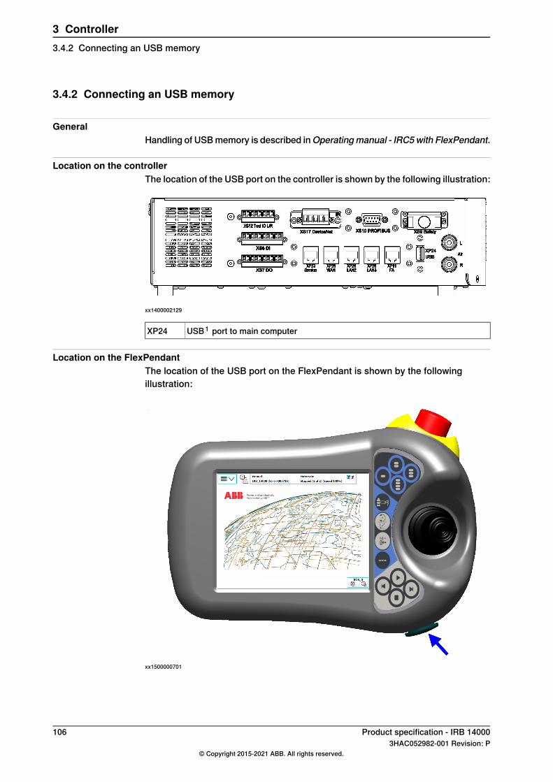
3.4.2 Connecting an USB memory
GeneralHandling of USB memory is described inOperatingmanual - IRC5with FlexPendant.
Location on the controllerThe location of the USB port on the controller is shown by the following illustration:
xx1400002129
USB1 port to main computerXP24
Location on the FlexPendantThe location of the USB port on the FlexPendant is shown by the followingillustration:
xx1500000701
106 Product specification - IRB 140003HAC052982-001 Revision: P
© Copyright 2015-2021 ABB. All rights reserved.
3 Controller3.4.2 Connecting an USB memory

3.5 Installation of add-ons
3.5.1 Installation of Local I/O devices
Installation of Local I/O base deviceThe base device to be installed is shown in the illustration below.
xx1600002033
Use this procedure to install the base device.
NoteAction
DANGER
Before commencing any work inside the cabinetmake sure that the main power has been switchedoff.
1
Continues on next pageProduct specification - IRB 14000 1073HAC052982-001 Revision: P
© Copyright 2015-2021 ABB. All rights reserved.
3 Controller3.5.1 Installation of Local I/O devices

NoteAction
xx1700000275
Fit the device by snapping it onto the mountingrail.
2
Connect the Ethernet cable from the robot control-ler, or the EtherNet/IP scanner, to any of the con-nectors X3 or X5.
3
For information about the pinout,see Application manual - ScalableI/O
Connect the logic power supply to connector X4.4
CAUTION
The process power supply must besupplied separately. Connectingthe process power supply throughthe logical power supply connectormay damage the device.
Connect process power supply and GND to theinput and output connectors X1 and X2.
Note
The process power supply also powers the opticalinterface to the add-ons.
5
Connect wires to the inputs and outputs as re-quired.
6
Configure the device, see Application manu-al - Scalable I/O.
7
Continues on next page108 Product specification - IRB 14000
3HAC052982-001 Revision: P© Copyright 2015-2021 ABB. All rights reserved.
3 Controller3.5.1 Installation of Local I/O devicesContinued

Installation of Local I/O add-on deviceThe add-on devices to be installed and the base device is shown in the illustrationbelow.
xx1600002032
For more information about installing Local I/O add-on devices, please seeApplication manual - Scalable I/O.
Product specification - IRB 14000 1093HAC052982-001 Revision: P
© Copyright 2015-2021 ABB. All rights reserved.
3 Controller3.5.1 Installation of Local I/O devices
Continued

3.5.2 Installation of conveyor tracking module
LocationThe conveyor tracking module must be powered by a 24V power supply andconnected to the Ethernet.
A
B
C
xx1800002638
X1, Power inlet 24VDCA
X20, Optional camera power inlet 24VDCB
X7 WAN, Ethernet connectionC
Required equipment
NoteArticle numberEquipment
3HNA027579-001DSQC 2000 CTM-01
3HNA029345-001CONNECTOR KIT - DSQC 2000
-Standard toolkit
Continues on next page110 Product specification - IRB 14000
3HAC052982-001 Revision: P© Copyright 2015-2021 ABB. All rights reserved.
3 Controller3.5.2 Installation of conveyor tracking module

Note
The connector kit includes contacts for 2 encoders and 4 cameras. Two connectorkits are needed to handle additional encoders and cameras.
Required document
Document numberDocument
3HAC050991-001Application manual - Conveyor tracking
3HAC050778-003Circuit diagram - IRB 14000
FittingThe procedure below details how to fit the units.
Note/IllustrationAction
DANGER
Before any work inside the cabinet, readthe section "Electrical safety" in Safetymanual for robot - Manipulator and IRC5or OmniCore controller.
1
ELECTROSTATIC DISCHARGE(ESD)
The unit is sensitive to ESD. Before perform-ing any service work, read the section "Theunit is sensitive to ESD" in Safety manualfor robot - Manipulator and IRC5 or Omni-Core controller.
2
External 24VDC power supply is neededfor option 1551-1.
Connect 24VDC power supply to X1 (powerinlet, main functions) and X20 (optionalcamera power inlet) on the conveyortracking module.
3
The WAN port of the CTM must be con-nected to the same Ethernet network asthe robot controllers.
Connect the Ethernet cable to the connect-or X7 WAN on the conveyor tracking mod-ule.
4
Described in theApplicationmanual - Con-veyor tracking.
Connect wires to the encoder and cameraconnectors as required.
5
Product specification - IRB 14000 1113HAC052982-001 Revision: P
© Copyright 2015-2021 ABB. All rights reserved.
3 Controller3.5.2 Installation of conveyor tracking module
Continued

3.6 What is Cartesian speed supervision?
Definition of Cartesian speed supervisionThe Cartesian speed supervision is a safety function that supervises the Cartesianspeed of the elbow (arm check point, ACP) and the wrist (wrist center point, WCP).The default speed limit can be modified if needed, based on the risk assessmentfor the robot installation. If any of the configured speed limits are exceeded, thenthe robot motion is stopped and a message is displayed.The Cartesian speed supervision is active in both manual and automatic mode.The setting is defined by system parameters.
112 Product specification - IRB 140003HAC052982-001 Revision: P
© Copyright 2015-2021 ABB. All rights reserved.
3 Controller3.6 What is Cartesian speed supervision?

4 Specification of variants and options4.1 Introduction to variants and options
GeneralThe different variants and options for the IRB 14000 are described in the followingsections. The same option numbers are used here as in the specification form.The variants and options related to the robot controller are described in the productspecification for the controller.
Product specification - IRB 14000 1133HAC052982-001 Revision: P
© Copyright 2015-2021 ABB. All rights reserved.
4 Specification of variants and options4.1 Introduction to variants and options

4.2 Manipulator
Manipulator variants
Reach (m)Handling capacity (kg)IRB TypeOption
0.5590.5IRB 14000435-131
WarrantyFor the selected period of time, ABB will provide spare parts and labour to repairor replace the non-conforming portion of the equipment without additional charges.During that period, it is required to have a yearly Preventative Maintenanceaccording to ABB manuals to be performed by ABB. If due to customer restrainsno data can be analyzed in the ABB Ability service Condition Monitoring &Diagnostics for robots with OmniCore controllers, and ABB has to travel to site,travel expenses are not covered. The Extended Warranty period always starts onthe day of warranty expiration. Warranty Conditions apply as defined in the Terms& Conditions.
Note
This description above is not applicable for option Stock warranty [438-8]
DescriptionTypeOption
Standard warranty is 12 months fromCustomer DeliveryDate or latest 18 months after Factory Shipment Date,whichever occurs first. Warranty terms and conditionsapply.
Standard warranty438-1
Standard warranty extended with 12 months from enddate of the standard warranty. Warranty terms and con-ditions apply. Contact Customer Service in case of otherrequirements.
Standard warranty + 12months
438-2
Standard warranty extended with 6 months from enddate of the standard warranty. Warranty terms and con-ditions apply.
Standard warranty + 6months
438-6
Maximum 6 months postponed start of standard war-ranty, starting from factory shipment date. Note that noclaims will be accepted for warranties that occurred be-fore the end of stock warranty. Standard warranty com-mences automatically after 6 months from FactoryShipment Date or from activation date of standard war-ranty in WebConfig.
Note
Special conditions are applicable, seeRoboticsWarrantyDirectives.
Stock warranty438-8
114 Product specification - IRB 140003HAC052982-001 Revision: P
© Copyright 2015-2021 ABB. All rights reserved.
4 Specification of variants and options4.2 Manipulator

4.3 Grippers
Below are the gripper options.
First gripper
DescriptionTypeOption
Servo1512-1
Requires: Servo [1512-1]Vacuum 11513-1
Requires: Servo [1512-1] and Vacuum 1 [1513-1], Nottogether with: Vision [1515-1]
Vacuum 21514-1
Requires: Servo [1512-1], Integrated Vision support[1520-1]
Vision1515-1
Second gripper
DescriptionTypeOption
Servo1516-1
Requires: Servo [1516-1]Vacuum 11517-1
Requires: Servo [1516-1] and Vacuum 1 [1517-1], Nottogether with: Vision [1519-1]
Vacuum 21518-1
Requires: Servo [1516-1], Integrated Vision support[1520-1]
Vision1519-1
Grippers
DescriptionTypeOption
Servo1512(6)-1
Vacuum 1Servo + one vacuum unit
1512(6)-1 + 1513(7)-1
Vacuum 2Servo + two vacuum units
1512(6)-1+1513(7)-1+1514(8)-1
Continues on next pageProduct specification - IRB 14000 1153HAC052982-001 Revision: P
© Copyright 2015-2021 ABB. All rights reserved.
4 Specification of variants and options4.3 Grippers

DescriptionTypeOption
VisionServo + integrated vision cam-era
1512(6)-1+1515(9)-1
VisionServo + integrated visioncamera + one vacuum unit
1512(6)-1+1513(7)-1+1515(9)-1
116 Product specification - IRB 140003HAC052982-001 Revision: P
© Copyright 2015-2021 ABB. All rights reserved.
4 Specification of variants and options4.3 GrippersContinued

4.4 Basic
Mains cable
DescriptionTypeOption
IEC C14 cable assembly with locking system andCEE7/VII line-side plug.
EU mains cable, 2 m1525-1
IEC C14 cable assembly with locking system andBS1363 line-side plug, 5A fused.
UK mains cable, 2 m1525-2
IEC C14 cable assembly with locking system andNEMA5-15 line-side plug.
US mains cable, 6 ft1525-3
IEC C14 cable assembly with locking system andJI8303 line-side plug.
JP mains cable, 2 m1525-4
IEC C14 cable assembly with locking system andCPCS-CCC line-side plug.
CN mains cable, 2 m1525-5
IEC C14 cable assembly with locking system andAS/NZS 3112 line-side plug.
AU mains cable, 2 m1525-6
Safety relay
DescriptionTypeOption
SSR10M relay for 115VAC and 230VACSSR10M relay, 85-265VAC
1526-3
FlexPendantColor graphic pendant with touch screen.
DescriptionOption
FlexPendant 10 m701-1
xx1400002067
DescriptionPos
DisplayA
Continues on next pageProduct specification - IRB 14000 1173HAC052982-001 Revision: P
© Copyright 2015-2021 ABB. All rights reserved.
4 Specification of variants and options4.4 Basic

DescriptionPos
Emergency stop buttonB
Enabling control device (no function)C
JoystickD
FlexPendant removal
DescriptionOption
Connector plug702-1The option consists of a jumper connector to close the safety chains. This ismandatory if a FlexPendant is not connected.
RS232 serial port
DescriptionOption
RS232 Serial Channel970-1One RS232 serial channel for permanent use which can be used for communic-ation point to point with printers, terminals, computers, and other equipment.
The fieldbus adapter and the RS232 serial channel is located on the fieldbus adapterexpansion board. Therefore the option 970-1 is required when using a fieldbusadapter, see Fieldbus adapters on page 118.
DeviceNetTM m/s
DescriptionOption
Single channel. Occupies 1 PCI slot.709-1
PROFIBUS DP
DescriptionOption
PROFIBUS DP Master NOT TOGETHER WITH:PROFIBUS DP [840-2]969-1
PROFINET IO
DescriptionOption
PROFINET IO m/s SW888-2Occupies one Ethernet port.
PROFINET IO slave SW888-3Occupies one Ethernet port.
Fieldbus adapters
DescriptionOption
EtherNet/IPTM840-1Up to 1024 digital inputs and 1024 digital outputs can be transferred serially toa master equipped with an EtherNet/IPTM interface. The bus cable is connecteddirectly to the adapter RJ45 connector.
Continues on next page118 Product specification - IRB 14000
3HAC052982-001 Revision: P© Copyright 2015-2021 ABB. All rights reserved.
4 Specification of variants and options4.4 BasicContinued

DescriptionOption
PROFIBUS DP840-2Up to 512 digital inputs and 512 digital outputs can be transferred serially to amaster equipped with a PROFIBUS DP interface. The bus cable is connected tothe adapter D-sub connector.
PROFINET IO840-3Up to 1024 digital inputs and 1024 digital outputs can be transferred serially toa master equipped with a PROFINET IO interface. The bus cable is connectedto the adapter RJ45 connector.
The fieldbus adapter and the RS232 serial channel is located on the fieldbus adapterexpansion board. Therefore the option 970-1 is required when using a fieldbusadapter, see RS232 serial port on page 118.
A
xx1300000604
Slot for AnybusCC fieldbus adaptersA
Enc. interface unit-Exte
DescriptionOption
Encoder interface unit- Exte826-1REQUIRES: DeviceNetTM m/s [709-X] or DeviceNetTM Lean [748-1]
Conveyor Tracking
DescriptionOption
Conveyor Tracking606-1NOT TOGETHER WITH: Prep. for PickMaster 3 [642-1]REQUIRES: Encoder interface unit [826-1]
Continues on next pageProduct specification - IRB 14000 1193HAC052982-001 Revision: P
© Copyright 2015-2021 ABB. All rights reserved.
4 Specification of variants and options4.4 BasicContinued

High resolution PoE cameraIntegrated Vison interface
DescriptionOption
(1-2) Choose quantity1521-1Only for IRB 14000.
120 Product specification - IRB 140003HAC052982-001 Revision: P
© Copyright 2015-2021 ABB. All rights reserved.
4 Specification of variants and options4.4 BasicContinued

4.5 Unlisted options
Included by default, not listed in the specification form
NameOptionNameOption
Collision detection613-1Multimove, coordinated604-1
EtherNet/IPTM m/s841-1RW Add-In prepared988-1
Path Recovery611-1World Zones608-1
PC Interface616-1Path Offset612-1
FlexPendant Interface617-1RobotStudion App Connect688-1
Safety Lamp213-1Vision Interface1341-1
Prep. for CE labelling129-1Integrated Vision SW1520-1
UL/CSA429-1
Not currently supported, not listed in the specification form
NameOptionNameOption
Sensor Sync607-1Advanced shape tuning602-1
Independent Axis610-1Analog Sync607-2
Discrete Appl. Platform625-1Cont. Appl. Platform624-1
MultiProcess634-1Sensor Interface628-1
Machine Tending1167-1Dispense641-1
Force Control base661-2PickMaster 5642-2
Hot plug702-2Advanced robot motion687-1
DeviceNet IO (Fieldbus ad-apter)
840-4Optical Tracking813-1
WristMove900-1RRI897-1
T10 Jogging device976-1RW Cutting951-1
Production Manager812-1Enabling983-1
Additional axes and drive module options
Product specification - IRB 14000 1213HAC052982-001 Revision: P
© Copyright 2015-2021 ABB. All rights reserved.
4 Specification of variants and options4.5 Unlisted options

This page is intentionally left blank

5 AccessoriesIntroduction to accessories
GeneralThere is a range of tools and equipment available.
Basic software and software options for robot and PCFor more information, see Product specification - Controller IRC5 and Productspecification - Controller software IRC5.
Robot peripherals• Grippers• Signal lamp• Stationary camera
Note
Cognex In-Sight Micro 1402 is a stationary camera specific to IRB 14000.See Product specification - Integrated Vision.
Product specification - IRB 14000 1233HAC052982-001 Revision: P
© Copyright 2015-2021 ABB. All rights reserved.
5 Accessories

This page is intentionally left blank

IndexAAbsolute Accuracy, 42Absolute Accuracy, calibration, 40
BBase
Local, 101
Ccalibration
Absolute Accuracy type, 39standard type, 39
calibration, Absolute Accuracy, 40CalibWare, 39Cartesian speed supervision, 22, 112compensation parameters, 42
EEtherNet/IP, 101
II/O device, 101
LLocal
Base, 101
Ooptions, 113
PPlug & Produce, 101product standards, 19
Ssafety standards, 19Scalable I/O, 101standards, 19
ANSI, 20CAN, 20EN IEC, 19EN ISO, 19
standard warranty, 114stock warranty, 114
UUSB port
FlexPendant, 106
Vvariants, 113
Wwarranty, 114
Product specification - IRB 14000 1253HAC052982-001 Revision: P
© Copyright 2015-2021 ABB. All rights reserved.
Index


ABB ABRobotics & Discrete AutomationS-721 68 VÄSTERÅS, SwedenTelephone +46 (0) 21 344 400
ABB ASRobotics & Discrete AutomationNordlysvegen 7, N-4340 BRYNE, NorwayBox 265, N-4349 BRYNE, NorwayTelephone: +47 22 87 2000
ABB Engineering (Shanghai) Ltd.Robotics & Discrete AutomationNo. 4528 Kangxin HighwayPuDong DistrictSHANGHAI 201319, ChinaTelephone: +86 21 6105 6666
ABB Inc.Robotics & Discrete Automation1250 Brown RoadAuburn Hills, MI 48326USATelephone: +1 248 391 9000
abb.com/robotics
3HAC052982-001,Rev
P,en
© Copyright 2015-2021 ABB. All rights reserved.Specifications subject to change without notice.