Product specification - IRB 1300
74
ROBOTICS Product specification IRB 1300
-
Upload
khangminh22 -
Category
Documents
-
view
3 -
download
0
Transcript of Product specification - IRB 1300
ROBOTICS
Product specificationIRB 1300

Trace back information:Workspace 21D version a10Checked in 2021-12-06Skribenta version 5.4.005
Product specificationIRB 1300-11/0.9
IRB 1300-10/1.15IRB 1300-7/1.4
OmniCore
Document ID: 3HAC070393-001Revision: F
© Copyright 2020-2021 ABB. All rights reserved.Specifications subject to change without notice.
The information in this manual is subject to change without notice and should notbe construed as a commitment by ABB. ABB assumes no responsibility for any errorsthat may appear in this manual.Except as may be expressly stated anywhere in this manual, nothing herein shall beconstrued as any kind of guarantee or warranty by ABB for losses, damage to personsor property, fitness for a specific purpose or the like.In no event shall ABB be liable for incidental or consequential damages arising fromuse of this manual and products described herein.This manual and parts thereof must not be reproduced or copied without ABB'swritten permission.Keep for future reference.Additional copies of this manual may be obtained from ABB.
Original instructions.
© Copyright 2020-2021 ABB. All rights reserved.Specifications subject to change without notice.
Table of contents7Overview of this specification ..........................................................................................................
91 Description91.1 Structure .........................................................................................................91.1.1 Introduction ............................................................................................
131.1.2 Different robot versions ............................................................................141.1.3 Definition of version designations ...............................................................141.1.3.1 Technical data ............................................................................181.1.3.2 Dimensions ................................................................................201.1.3.3 Working range ............................................................................251.2 Standards ........................................................................................................251.2.1 Applicable standards ...............................................................................261.3 Installation .......................................................................................................261.3.1 Introduction to installation .........................................................................271.3.2 Operating requirements ............................................................................281.3.3 Mounting the manipulator .........................................................................291.4 Calibration and references ..................................................................................291.4.1 Calibration methods .................................................................................311.4.2 Fine calibration .......................................................................................321.4.3 Absolute Accuracy calibration ...................................................................351.5 Load diagrams ..................................................................................................351.5.1 Introduction ............................................................................................361.5.2 Diagrams ...............................................................................................
421.5.3 Maximum load and moment of inertia for full and limited axis 5 (center line down)
movement ..............................................................................................441.5.4 Wrist torque ...........................................................................................451.5.5 Maximum TCP acceleration .......................................................................461.6 Fitting equipment on the robot (robot dimensions) ...................................................511.7 Maintenance and troubleshooting .........................................................................521.8 Robot motion ....................................................................................................521.8.1 Adjusting the working range ......................................................................531.8.2 Mechanically restricting the working range ...................................................561.8.3 Performance according to ISO 9283 ............................................................571.8.4 Velocity .................................................................................................581.8.5 Robot stopping distances and times ...........................................................591.9 Customer connections .......................................................................................
632 Specification of variants and options632.1 Introduction to variants and options ......................................................................642.2 Manipulator ......................................................................................................682.3 Floor cables .....................................................................................................
693 Accessories
71Index
Product specification - IRB 1300 53HAC070393-001 Revision: F
© Copyright 2020-2021 ABB. All rights reserved.
Table of contents

This page is intentionally left blank
Overview of this specificationAbout this product specification
This product specification describes the performance of the manipulator or acomplete family of manipulators in terms of:
• The structure and dimensional prints• The fulfilment of standards, safety, and operating equipment• The load diagrams, mounting or extra equipment, the motion, and the robot
reach• The specification of available variants and options
The specification covers the manipulator using the OmniCore controller.
UsageProduct specifications are used to find data and performance about the product,for example to decide which product to buy. How to handle the product is describedin the product manual.The specification is intended for:
• Product managers and product personnel• Sales and marketing personnel• Order and customer service personnel
ReferencesDocumentation referred to in the manual, is listed in the table below.
Document IDDocument name
3HAC070390-001Product manual - IRB 1300
3HAC065034-001Product specification - OmniCore C line
3HAC060860-001Product manual - OmniCore C30
3HAC073706-001Product manual - OmniCore C90XT
3HAC070392-001Product manual, spare parts - IRB 1300
3HAC068887-003Circuit diagram - IRB 1300
3HAC079823-001Product specification - OmniCore E line
Continues on next pageProduct specification - IRB 1300 73HAC070393-001 Revision: F
© Copyright 2020-2021 ABB. All rights reserved.
Overview of this specification
RevisionsDescriptionRevision
First edition.A
Published in release 20D. The following updates aremade in this revision:• Restricted working range updated.• Max. Armload added.• Minor changes.• Warranty section updated.
B
Published in release 21A. The following updates aremade in this revision:• New protection added. 3350-670 Base 67, 3351-4 Cleanroom 4
and 3352-10 Foundry Plus2 67.• New option 209-2 ABB White std added.• Specification of connectors R1.C3 and R2.C3 is updated.• Type of R1.C3 connector, which is used for cable wiring, is added.• Maximum TCP acceleration added.
C
Published in release 21B. The following updates aremade in this revision:• Performance data according to ISO 9283 updated.• Modified the air hose diameter description.• Text regarding fastener quality is updated.• Updated the description of option 3303-1/3303-2.• Added a note to remind users that mechanical stop locations
cannot be adjusted. See Adjusting the working range on page52.• Absolute Accuracy calibration production data added.• Removed Axis resolution.• Added a note in manipulator protection chapter.
D
Published in release 21C. The following updates are done in this revision:• Updated the tool flange standard figure for IP40, IP67 and Clean
Room robots.• Supported controller OmniCore E10 is added.• Updated data for maximum axis speed.
E
Published in release 21D. The following updates are done in this revision:• Add information that Clean room option is available for IP54 pro-
tection class.
F
8 Product specification - IRB 13003HAC070393-001 Revision: F
© Copyright 2020-2021 ABB. All rights reserved.
Overview of this specificationContinued
1 Description1.1 Structure
1.1.1 Introduction
GeneralThe IRB 1300 is one of ABB Robotics latest generation of 6-axis industrial robot,with a payload of 7 kg, 10 kg and 11 kg designed specifically for manufacturingindustries that use flexible robot-based automation, e.g. 3C industry. The robothas an open structure that is especially adapted for flexible use, and cancommunicate extensively with external systems.
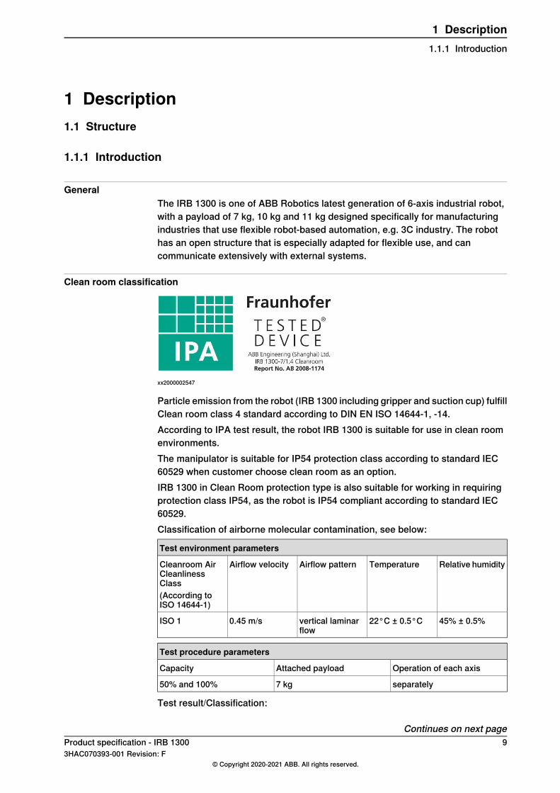
Clean room classification
xx2000002547
Particle emission from the robot (IRB 1300 including gripper and suction cup) fulfillClean room class 4 standard according to DIN EN ISO 14644-1, -14.According to IPA test result, the robot IRB 1300 is suitable for use in clean roomenvironments.The manipulator is suitable for IP54 protection class according to standard IEC60529 when customer choose clean room as an option.IRB 1300 in Clean Room protection type is also suitable for working in requiringprotection class IP54, as the robot is IP54 compliant according to standard IEC60529.Classification of airborne molecular contamination, see below:
Test environment parameters
Relative humidityTemperatureAirflow patternAirflow velocityCleanroom AirCleanlinessClass(According toISO 14644-1)
45% ± 0.5%22°C ± 0.5°Cvertical laminarflow
0.45 m/sISO 1
Test procedure parameters
Operation of each axisAttached payloadCapacity
separately7 kg50% and 100%
Test result/Classification:
Continues on next pageProduct specification - IRB 1300 93HAC070393-001 Revision: F
© Copyright 2020-2021 ABB. All rights reserved.
1 Description1.1.1 Introduction
When operated under the specified test conditions, the IRB 1300 including gripperand suction cup is suitable for use in cleanrooms fulfilling the specifications of thefollowing Air Cleanliness Classes according to ISO 14644-1.
Air Cleanliness ClassTest parameter(s)
2Capacity=50%
4Capacity=100%
4Overall result
Protection type Foundry Plus 2Robots with the option Foundry Plus 2 are designed for harsh environments wherethe robot is exposed to sprays of coolants, lubricants and metal spits that aretypical for die casting applications or other similar applications.Typical applications are spraying insertion and part extraction of die-castingmachines, handling in sand casting and gravity casting, etc. (Please refer to FoundryPrime robots for washing applications or other similar applications). Special caremust be taken in regard to operational and maintenance requirements forapplications in foundry are as well as in other applications areas. Please contactABBRobotics Sales organization if in doubt regarding specific application feasibilityfor the Foundry Plus 2 protected robot.The robot is painted with two-component epoxy on top of a primer for corrosionprotection. To further improve the corrosion protection additional rust preventiveare applied to exposed and crucial areas, e.g. has the tool flange a specialpreventive coating. Although, continuous splashing of water or other similar rustformation fluids may cause rust attach on the robots unpainted areas, joints, orother unprotected surfaces. Under these circumstances it is recommended to addrust inhibitor to the fluid or take other measures to prevent potential rust formationon the mentioned.The entire robot is IP67 compliant according to IEC 60529 - from base to wrist,which means that the electrical compartments are sealed against water and solidcontaminants. Among other things all sensitive parts are better protected than thestandard offer.Selected Foundry Plus 2 features:
• Improved sealing to prevent penetration into cavities to secure IP67• Additional protection of cabling and electronics• Special covers that protect cavities• Well-proven connectors• Additional stainless steel flange as extra protection• Rust preventives on screws, washers and unpainted/machined surfaces• Extended service and maintenance program
The Foundry Plus 2 robot can be cleaned with appropriate washing equipmentaccording to the robot product manual. Appropriate cleaning and maintenance is
Continues on next page10 Product specification - IRB 1300
3HAC070393-001 Revision: F© Copyright 2020-2021 ABB. All rights reserved.
1 Description1.1.1 IntroductionContinued
required to maintain the protection, for example can rust preventive be washed offwith wrong cleaning method.
Available robot versionsThe option Foundry Plus 2 might not be available for all robot versions.See Specification of variants and options on page 63 for robot versions and otheroptions not selectable together with Foundry Plus 2.
IP67 protectionThe robot has IP67 as an option. The option will add sealing, machining parts andgasket.
Software product rangeWe have added a range of software products - all falling under the umbrelladesignation of Active Safety - to protect not only personnel in the unlikely eventof an accident, but also robot tools, peripheral equipment and the robot itself.
Operating systemThe robot is equipped with the OmniCore C30/C90/E10 controller and robot controlsoftware, RobotWare. RobotWare supports every aspect of the robot system, suchas motion control, development and execution of application programs,communication etc. See Operating manual - OmniCore.
SafetySafety standards valid for complete robot, manipulator and controller.
Additional functionalityFor additional functionality, the robot can be equipped with optional software forapplication support - for example communication features - network communication- and advanced functions such as multitasking, sensor control etc. For a completedescription on optional software, see the Product specification - OmniCore C lineand Product specification - OmniCore E line.
Continues on next pageProduct specification - IRB 1300 113HAC070393-001 Revision: F
© Copyright 2020-2021 ABB. All rights reserved.
1 Description1.1.1 Introduction
Continued
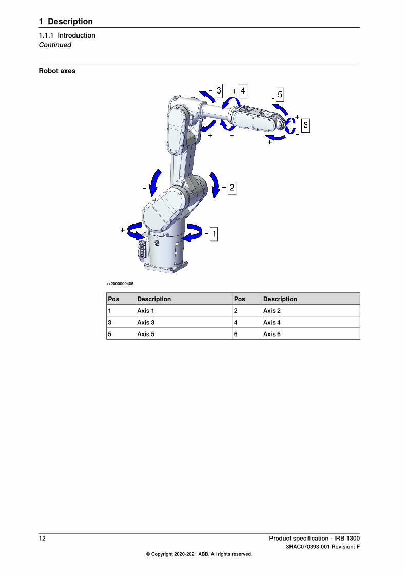
Robot axes
xx2000000405
DescriptionPosDescriptionPos
Axis 22Axis 11
Axis 44Axis 33
Axis 66Axis 55
12 Product specification - IRB 13003HAC070393-001 Revision: F
© Copyright 2020-2021 ABB. All rights reserved.
1 Description1.1.1 IntroductionContinued
1.1.2 Different robot versions
GeneralThe IRB 1300 is available in three versions.
Robot typesThe following robot versions are available.
Reach (m)Handling capacity (kg)Robot type
0.9 m11 kgIRB 1300-11/0.9
1.15 m10 kgIRB 1300-10/1.15
1.4 m7 kgIRB 1300-7/1.4
Product specification - IRB 1300 133HAC070393-001 Revision: F
© Copyright 2020-2021 ABB. All rights reserved.
1 Description1.1.2 Different robot versions
1.1.3 Definition of version designations
1.1.3.1 Technical data
Weight, robotThe table shows the weight of the robot.
Nominal weightRobot model
IRB 1300-11/0.9: 74.5 kgIRB 1300IRB 1300-10/1.15: 77 kgIRB 1300-7/1.4: 78.5 kg
Note
The weight does not include additional options, tools and other equipment fittedon the robot.
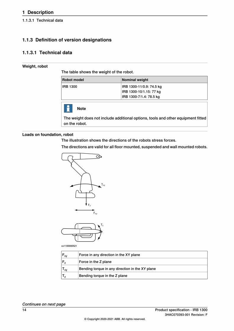
Loads on foundation, robotThe illustration shows the directions of the robots stress forces.The directions are valid for all floor mounted, suspended and wall mounted robots.
xy
xy
z
z
T
F
F
T
xx1100000521
Force in any direction in the XY planeFxyForce in the Z planeFzBending torque in any direction in the XY planeTxyBending torque in the Z planeTz
Continues on next page14 Product specification - IRB 1300
3HAC070393-001 Revision: F© Copyright 2020-2021 ABB. All rights reserved.
1 Description1.1.3.1 Technical data
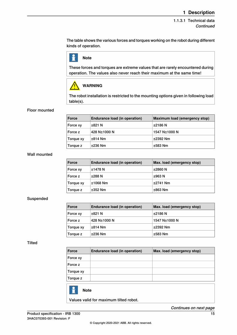
The table shows the various forces and torquesworking on the robot during differentkinds of operation.
Note
These forces and torques are extreme values that are rarely encountered duringoperation. The values also never reach their maximum at the same time!
WARNING
The robot installation is restricted to the mounting options given in following loadtable(s).
Floor mounted
Maximum load (emergency stop)Endurance load (in operation)Force
±2186 N±821 NForce xy
1547 N±1000 N428 N±1000 NForce z
±2392 Nm±814 NmTorque xy
±583 Nm±236 NmTorque z
Wall mounted
Max. load (emergency stop)Endurance load (in operation)Force
±2860 N±1478 NForce xy
±963 N±288 NForce z
±2741 Nm±1068 NmTorque xy
±863 Nm±352 NmTorque z
Suspended
Max. load (emergency stop)Endurance load (in operation)Force
±2186 N±821 NForce xy
1547 N±1000 N428 N±1000 NForce z
±2392 Nm±814 NmTorque xy
±583 Nm±236 NmTorque z
Tilted
Max. load (emergency stop)Endurance load (in operation)Force
Force xy
Force z
Torque xy
Torque z
Note
Values valid for maximum tilted robot.
Continues on next pageProduct specification - IRB 1300 153HAC070393-001 Revision: F
© Copyright 2020-2021 ABB. All rights reserved.
1 Description1.1.3.1 Technical data
Continued
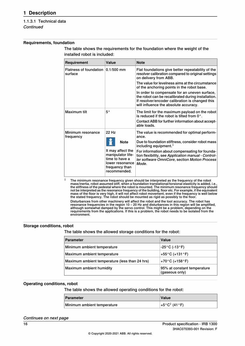
Requirements, foundationThe table shows the requirements for the foundation where the weight of theinstalled robot is included:
NoteValueRequirement
Flat foundations give better repeatability of theresolver calibration compared to original settingson delivery from ABB.
0.1/500 mmFlatness of foundationsurface
The value for levelness aims at the circumstanceof the anchoring points in the robot base.In order to compensate for an uneven surface,the robot can be recalibrated during installation.If resolver/encoder calibration is changed thiswill influence the absolute accuracy.
The limit for the maximum payload on the robotis reduced if the robot is tilted from 0°.
5°Maximum tilt
Contact ABB for further information about accept-able loads.
The value is recommended for optimal perform-ance.
22 Hz
Note
It may affect themanipulator life-time to have alower resonancefrequency thanrecommended.
Minimum resonancefrequency
Due to foundation stiffness, consider robot massincluding equipment. iFor information about compensating for founda-tion flexibility, see Application manual - Control-ler software OmniCore, sectionMotion ProcessMode.
i The minimum resonance frequency given should be interpreted as the frequency of the robotmass/inertia, robot assumed stiff, when a foundation translational/torsional elasticity is added, i.e.,the stiffness of the pedestal where the robot is mounted. Theminimum resonance frequency shouldnot be interpreted as the resonance frequency of the building, floor etc. For example, if the equivalentmass of the floor is very high, it will not affect robot movement, even if the frequency is well belowthe stated frequency. The robot should be mounted as rigid as possibly to the floor.Disturbances from other machinery will affect the robot and the tool accuracy. The robot hasresonance frequencies in the region 10 – 20 Hz and disturbances in this region will be amplified,although somewhat damped by the servo control. This might be a problem, depending on therequirements from the applications. If this is a problem, the robot needs to be isolated from theenvironment.
Storage conditions, robotThe table shows the allowed storage conditions for the robot:
ValueParameter
-25°C (-13°F)Minimum ambient temperature
+55°C (+131°F)Maximum ambient temperature
+70°C (+158°F)Maximum ambient temperature (less than 24 hrs)
95% at constant temperature(gaseous only)
Maximum ambient humidity
Operating conditions, robotThe table shows the allowed operating conditions for the robot:
ValueParameter
+5°C i (41°F)Minimum ambient temperature
Continues on next page16 Product specification - IRB 1300
3HAC070393-001 Revision: F© Copyright 2020-2021 ABB. All rights reserved.
1 Description1.1.3.1 Technical dataContinued
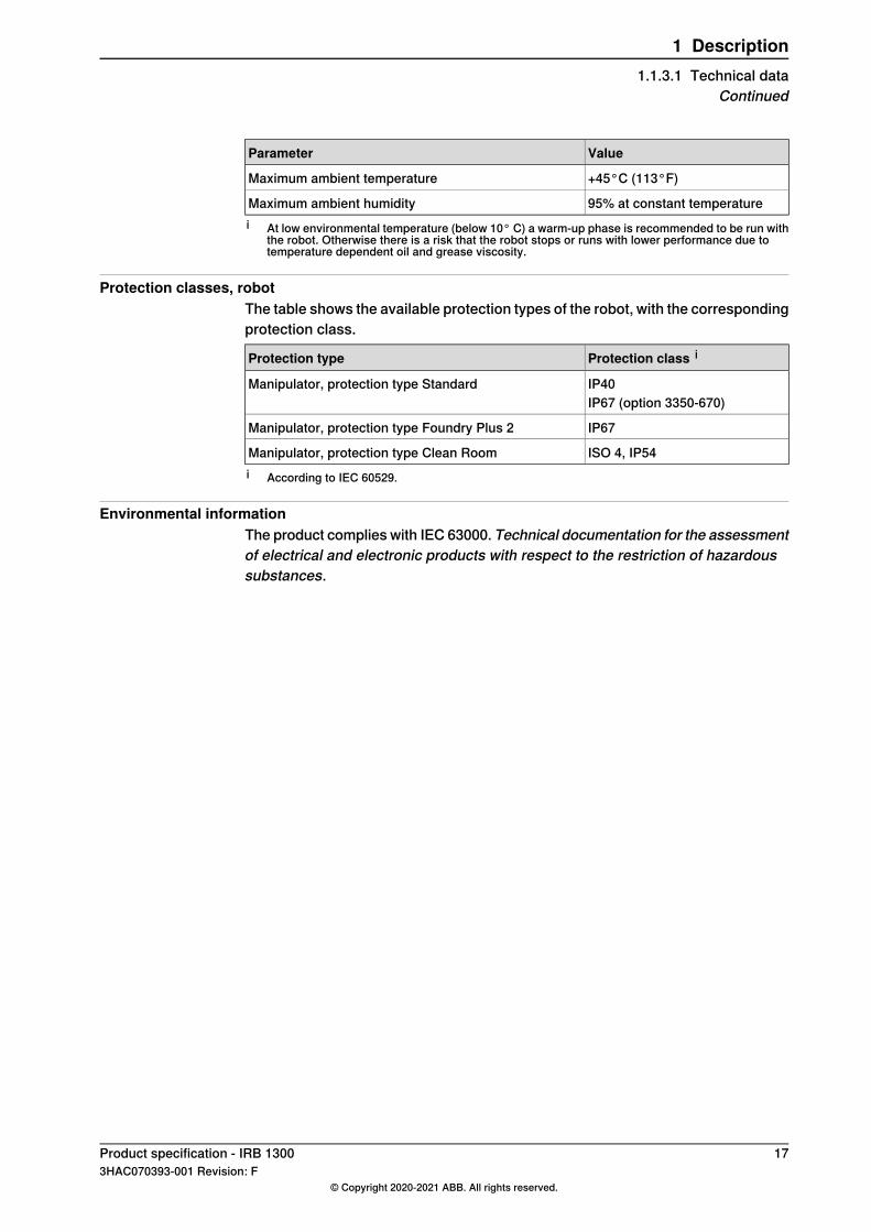
ValueParameter
+45°C (113°F)Maximum ambient temperature
95% at constant temperatureMaximum ambient humidityi At low environmental temperature (below 10° C) a warm-up phase is recommended to be run with
the robot. Otherwise there is a risk that the robot stops or runs with lower performance due totemperature dependent oil and grease viscosity.
Protection classes, robotThe table shows the available protection types of the robot, with the correspondingprotection class.
Protection class iProtection type
IP40Manipulator, protection type StandardIP67 (option 3350-670)
IP67Manipulator, protection type Foundry Plus 2
ISO 4, IP54Manipulator, protection type Clean Roomi According to IEC 60529.
Environmental informationThe product complies with IEC 63000. Technical documentation for the assessmentof electrical and electronic products with respect to the restriction of hazardoussubstances.
Product specification - IRB 1300 173HAC070393-001 Revision: F
© Copyright 2020-2021 ABB. All rights reserved.
1 Description1.1.3.1 Technical data
Continued
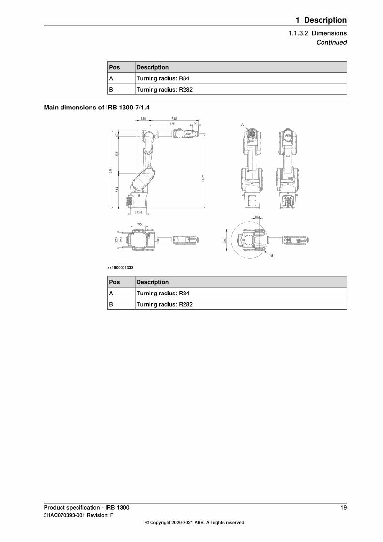
1.1.3.2 Dimensions
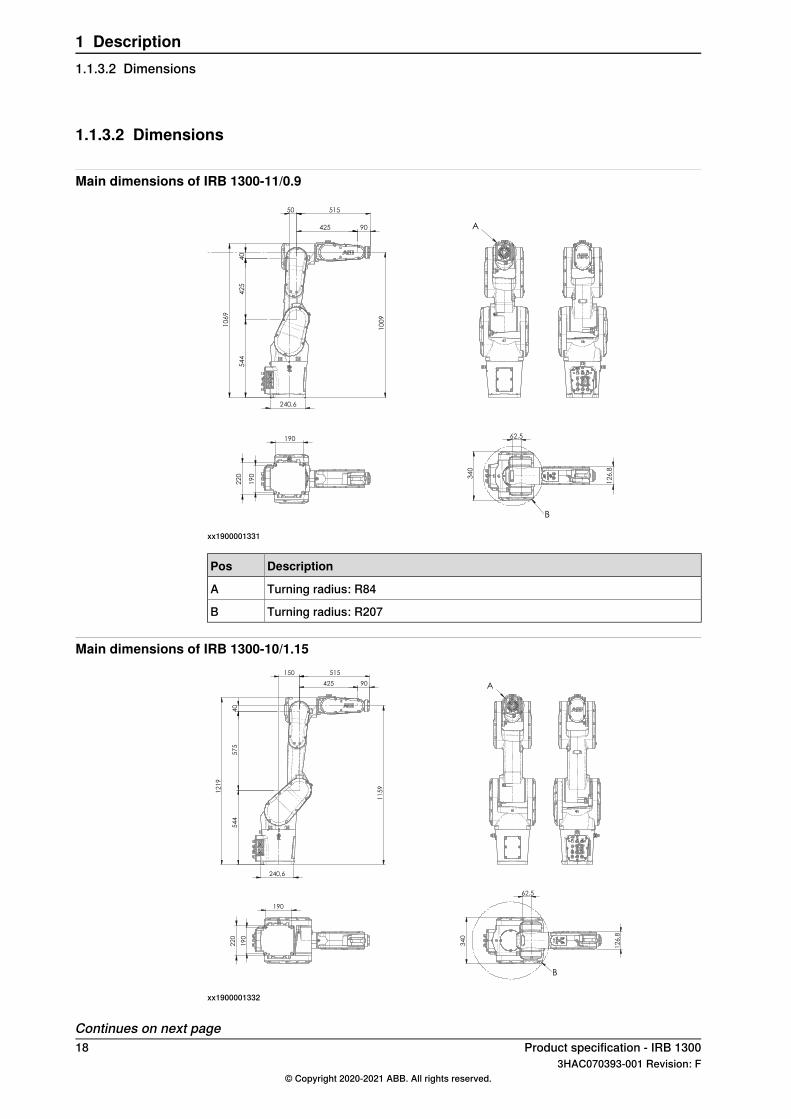
Main dimensions of IRB 1300-11/0.9
10
69
425
42
5
40
240,6
10
09
54
4
50 515
90
34
0
12
6,8
62,5 190
19
0
22
0
A
B
xx1900001331
DescriptionPos
Turning radius: R84A
Turning radius: R207B
Main dimensions of IRB 1300-10/1.15
240,6
12
19
425
150
57
5
40
5
44
11
59
515
90 A
34
0
12
6,8
62,5
B
190
19
0
22
0
xx1900001332
Continues on next page18 Product specification - IRB 1300
3HAC070393-001 Revision: F© Copyright 2020-2021 ABB. All rights reserved.
1 Description1.1.3.2 Dimensions
DescriptionPos
Turning radius: R84A
Turning radius: R282B
Main dimensions of IRB 1300-7/1.4 1
21
9
675
57
5
40
150
240,6
11
59
54
4
90
765
A
34
0
62,5
B
190
19
0
22
0
xx1900001333
DescriptionPos
Turning radius: R84A
Turning radius: R282B
Product specification - IRB 1300 193HAC070393-001 Revision: F
© Copyright 2020-2021 ABB. All rights reserved.
1 Description1.1.3.2 Dimensions
Continued
1.1.3.3 Working range
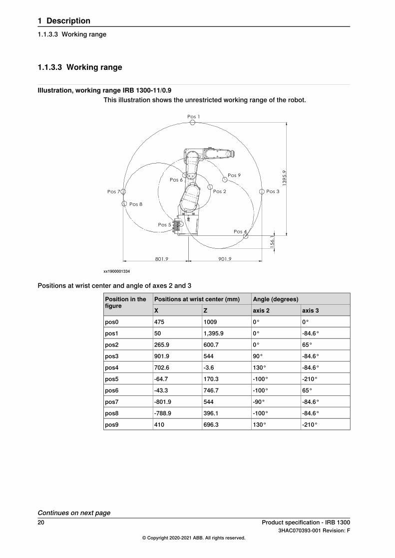
Illustration, working range IRB 1300-11/0.9This illustration shows the unrestricted working range of the robot.
13
95
.9
901.9
15
6.1
801.9
Pos 1
Pos 7
Pos 8
Pos 5
Pos 6Pos 9
Pos 2 Pos 3
Pos 4
xx1900001334
Positions at wrist center and angle of axes 2 and 3
Angle (degrees)Positions at wrist center (mm)Position in thefigure
axis 3axis 2ZX
0°0°1009475pos0
-84.6°0°1,395.950pos1
65°0°600.7265.9pos2
-84.6°90°544901.9pos3
-84.6°130°-3.6702.6pos4
-210°-100°170.3-64.7pos5
65°-100°746.7-43.3pos6
-84.6°-90°544-801.9pos7
-84.6°-100°396.1-788.9pos8
-210°130°696.3410pos9
Continues on next page20 Product specification - IRB 1300
3HAC070393-001 Revision: F© Copyright 2020-2021 ABB. All rights reserved.
1 Description1.1.3.3 Working range
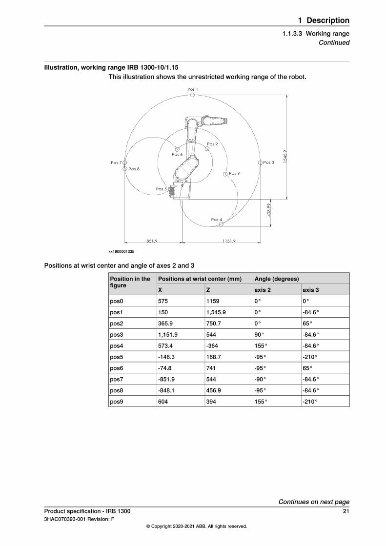
Illustration, working range IRB 1300-10/1.15This illustration shows the unrestricted working range of the robot.
15
45
.9
1151.9 851.9
40
3.9
9
Pos 1
Pos 7
Pos 8
Pos 6
Pos 9
Pos 4
Pos 3
Pos 5
Pos 2
xx1900001335
Positions at wrist center and angle of axes 2 and 3
Angle (degrees)Positions at wrist center (mm)Position in thefigure
axis 3axis 2ZX
0°0°1159575pos0
-84.6°0°1,545.9150pos1
65°0°750.7365.9pos2
-84.6°90°5441,151.9pos3
-84.6°155°-364573.4pos4
-210°-95°168.7-146.3pos5
65°-95°741-74.8pos6
-84.6°-90°544-851.9pos7
-84.6°-95°456.9-848.1pos8
-210°155°394604pos9
Continues on next pageProduct specification - IRB 1300 213HAC070393-001 Revision: F
© Copyright 2020-2021 ABB. All rights reserved.
1 Description1.1.3.3 Working range
Continued
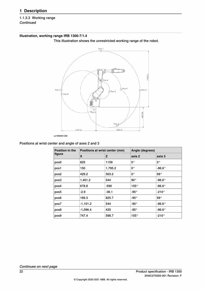
Illustration, working range IRB 1300-7/1.4This illustration shows the unrestricted working range of the robot.
17
95
.2
65
3.3
5
1401.2 1101.2
Pos 1
Pos 7
Pos 8
Pos 6
Pos 2
Pos 5
Pos 4
Pos 9Pos 3
xx1900001336
Positions at wrist center and angle of axes 2 and 3
Angle (degrees)Positions at wrist center (mm)Position in thefigure
axis 3axis 2ZX
0°0°1159825pos0
-86.6°0°1,795.2150pos1
69°0°503.2429.2pos2
-86.6°90°5441,401.2pos3
-86.6°155°-590678.8pos4
-210°-95°-36.1-2.9pos5
69°-95°825.7166.3pos6
-86.6°-90°544-1,101.2pos7
-86.6°-95°435-1,096.4pos8
-210°155°598.7747.4pos9
Continues on next page22 Product specification - IRB 1300
3HAC070393-001 Revision: F© Copyright 2020-2021 ABB. All rights reserved.
1 Description1.1.3.3 Working rangeContinued
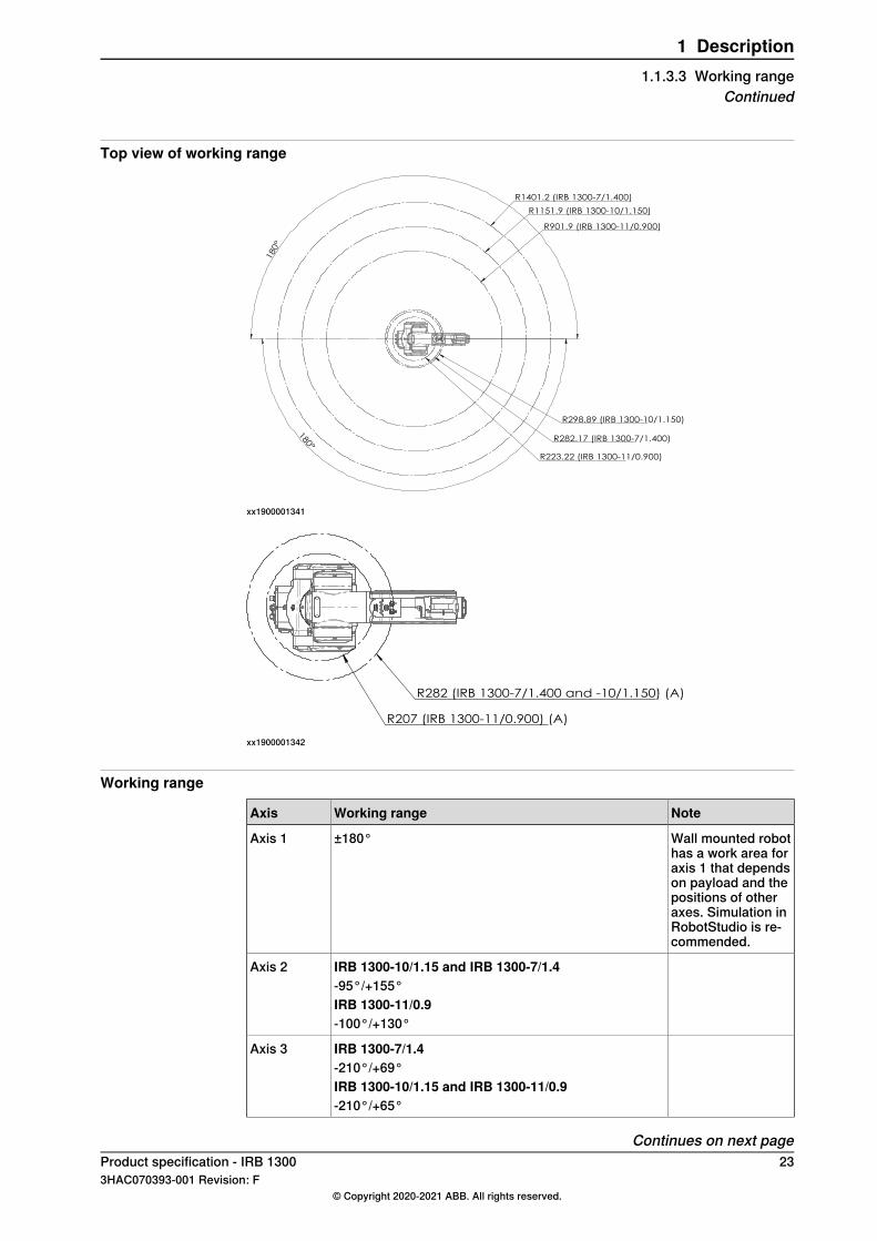
Top view of working range
180°
180°
R1401.2 (IRB 1300-7/1.400)
R1151.9 (IRB 1300-10/1.150)
R901.9 (IRB 1300-11/0.900)
R298.89 (IRB 1300-10/1.150)
R282.17 (IRB 1300-7/1.400)
R223.22 (IRB 1300-11/0.900)
xx1900001341
R282 (IRB 1300-7/1.400 and -10/1.150) (A)
R207 (IRB 1300-11/0.900) (A)
xx1900001342
Working range
NoteWorking rangeAxis
Wall mounted robothas a work area foraxis 1 that dependson payload and thepositions of otheraxes. Simulation inRobotStudio is re-commended.
±180°Axis 1
IRB 1300-10/1.15 and IRB 1300-7/1.4Axis 2-95°/+155°IRB 1300-11/0.9-100°/+130°
IRB 1300-7/1.4Axis 3-210°/+69°IRB 1300-10/1.15 and IRB 1300-11/0.9-210°/+65°
Continues on next pageProduct specification - IRB 1300 233HAC070393-001 Revision: F
© Copyright 2020-2021 ABB. All rights reserved.
1 Description1.1.3.3 Working range
Continued
NoteWorking rangeAxis
±230°Axis 4
±130°Axis 5
Default value.±400°Axis 6
Maximum revolutionvalue.
±242
The default workingrange for axis 6 canbe extended bychanging parametervalues in the soft-ware.
Other technical data
NoteDescriptionData
< 70 dB(A) Leq (acc. to ma-chinery directive 2006/42/EC)
The sound pressure level out-side the working space.
Airborne noise level
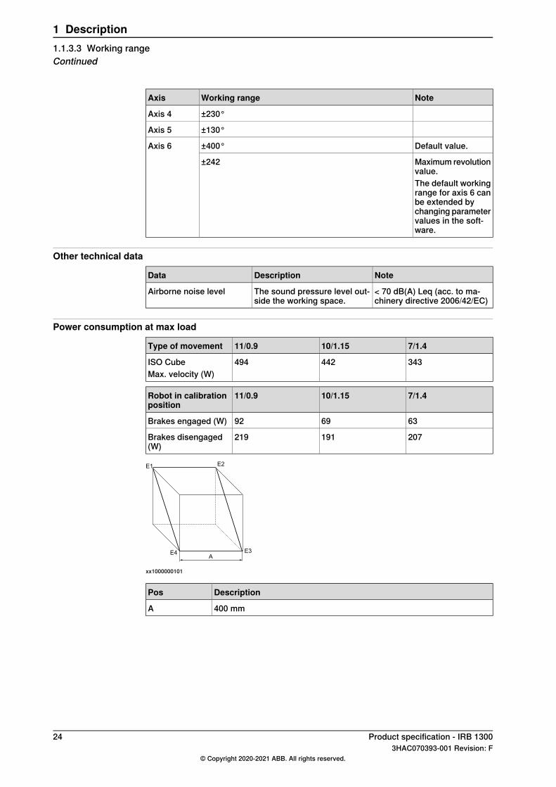
Power consumption at max load
7/1.410/1.1511/0.9Type of movement
343442494ISO CubeMax. velocity (W)
7/1.410/1.1511/0.9Robot in calibrationposition
636992Brakes engaged (W)
207191219Brakes disengaged(W)
E1
E4 E3
E2
A
xx1000000101
DescriptionPos
400 mmA
24 Product specification - IRB 13003HAC070393-001 Revision: F
© Copyright 2020-2021 ABB. All rights reserved.
1 Description1.1.3.3 Working rangeContinued
1.2 Standards
1.2.1 Applicable standards
GeneralThe product is compliant with ISO 10218-1:2011,Robots for industrial environments- Safety requirements - Part 1 Robots, and applicable parts in the normativereferences, as referred to from ISO 10218-1:2011. In case of deviation from ISO10218-1:2011, these are listed in the declaration of incorporation. The declarationof incorporation is part of the delivery.
Robot standards
DescriptionStandard
Manipulating industrial robots – Performance criteria and re-lated test methods
ISO 9283
Robots and robotic devices – Coordinate systems and motionnomenclatures
ISO 9787
Manipulating industrial robots – Presentation of characteristicsISO 9946
Other standards used in design
DescriptionStandard
Safety of machinery - Electrical equipment of machines - Part1: General requirements, normative reference from ISO 10218-1
IEC 60204
Electromagnetic compatibility (EMC) – Part 6-2: Genericstandards – Immunity standard for industrial environments
IEC 61000-6-2
Electromagnetic compatibility (EMC) – Part 6-4: Genericstandards – Emission standard for industrial environments
IEC 61000-6-4
Safety of machinery - Safety related parts of control systems- Part 1: General principles for design, normative referencefrom ISO 10218-1
ISO 13849-1:2006
Region specific standards and regulations
DescriptionStandard
Safety requirements for industrial robots and robot systemsANSI/RIA R15.06
Safety standard for robots and robotic equipmentANSI/UL 1740
Industrial robots and robot Systems - General safety require-ments
CAN/CSA Z 434-03
Product specification - IRB 1300 253HAC070393-001 Revision: F
© Copyright 2020-2021 ABB. All rights reserved.
1 Description1.2.1 Applicable standards
1.3 Installation
1.3.1 Introduction to installation
GeneralIRB 1300 is available in three variants and all variants can be floor mounted,inverted/suspended, wall mounted, or tilted mounted (any angle).Depending on the robot variant, an end effector with max. weight of 7 kg, 10 kgand 11 kg including payload, can be mounted on the tool flange (axis 6). See Loaddiagrams on page 35.
Extra loadsThe upper arm can handle an additional load of 0.5 kg (1 kg for reach 0.9m).
Working range limitationThe working range of axes 1 can be limited by mechanical stops as option. SeeWorking range on page 23.
26 Product specification - IRB 13003HAC070393-001 Revision: F
© Copyright 2020-2021 ABB. All rights reserved.
1 Description1.3.1 Introduction to installation
1.3.2 Operating requirements
Protection standard
Protection standard IEC529Robot variant
IP40All variants, manipulator
IP67Option, all variants
Explosive environmentsThe robot must not be located or operated in an explosive environment.
Working range limitationsEPS will not be selectable. No mechanical limitation.
Ambient temperature
TemperatureProtection classDescription
+ 5°C i (41°F) to + 45°C (113°F)StandardManipulator during opera-tion
See Product specification - Omni-Core C line
Standard/OptionFor the controller
- 25°C (-13°F) to + 55°C (131°F)StandardComplete robot duringtransportation and storage
up to + 70°C (158°F)StandardFor short periods (not ex-ceeding 24 hours)i At low environmental temperature < 10ºC is, as with any other machine, a warm-up phase
recommended to be run with the robot. Otherwise there is a risk that the robot stops or run withlower performance due to temperature dependent oil and grease viscosity.
Relative humidity
Relative humidityDescription
Max. 95% at constant temperatureComplete robot during operation, transportation andstorage
Product specification - IRB 1300 273HAC070393-001 Revision: F
© Copyright 2020-2021 ABB. All rights reserved.
1 Description1.3.2 Operating requirements
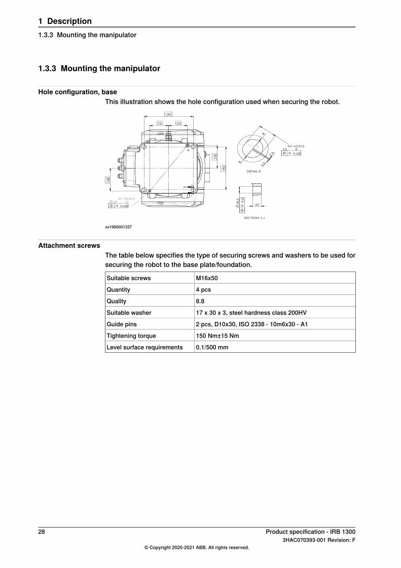
1.3.3 Mounting the manipulator
Hole configuration, baseThis illustration shows the hole configuration used when securing the robot.
10
0
19
0
190
73
10
H7
+
0.015
0
10
0
73
K
J
J
0.08
10
H7
+
0.015
0
R
R
0.5
0.5
DETAIL K
0.08
22
1
8.5
SECTION J-J
0.2
xx1900001337
Attachment screwsThe table below specifies the type of securing screws and washers to be used forsecuring the robot to the base plate/foundation.
M16x50Suitable screws
4 pcsQuantity
8.8Quality
17 x 30 x 3, steel hardness class 200HVSuitable washer
2 pcs, D10x30, ISO 2338 - 10m6x30 - A1Guide pins
150 Nm±15 NmTightening torque
0.1/500 mmLevel surface requirements
28 Product specification - IRB 13003HAC070393-001 Revision: F
© Copyright 2020-2021 ABB. All rights reserved.
1 Description1.3.3 Mounting the manipulator
1.4 Calibration and references
1.4.1 Calibration methods
OverviewThis section specifies the different types of calibration and the calibrationmethodsthat are supplied by ABB.The original calibration data delivered with the robot is generated when the robotis floor mounted. If the robot is not floor mounted, then the robot accuracy couldbe affected. The robot needs to be calibrated after it is mounted.More information is available in the product manual.
Types of calibration
Calibration methodDescriptionType of calibration
Axis CalibrationThe calibrated robot is positioned at calibrationposition.
Standard calibration
Standard calibration data is found on the SMB(serial measurement board) or EIB in the robot.
CalibWareBased on standard calibration, and besidespositioning the robot at synchronization posi-tion, the Absolute accuracy calibration alsocompensates for:
• Mechanical tolerances in the robotstructure
• Deflection due to loadAbsolute accuracy calibration focuses on pos-itioning accuracy in the Cartesian coordinatesystem for the robot.
Absolute accuracycalibration (option-al)
Absolute accuracy calibration data is foundon the SMB (serial measurement board) in therobot.A robot calibrated with Absolute accuracy hasthe option information printed on its nameplate.To regain 100% Absolute accuracy perform-ance, the robot must be recalibrated for abso-lute accuracy after repair or maintenance thataffects the mechanical structure.
Brief description of calibration methods
Axis Calibration methodAxis Calibration is a standard calibration method for calibration of IRB 1300. It isthe recommended method in order to achieve proper performance.The following routines are available for the Axis Calibration method:
• Fine calibration• Update revolution counters• Reference calibration
The calibration equipment for Axis Calibration is delivered as a toolkit.
Continues on next pageProduct specification - IRB 1300 293HAC070393-001 Revision: F
© Copyright 2020-2021 ABB. All rights reserved.
1 Description1.4.1 Calibration methods
The actual instructions of how to perform the calibration procedure and what todo at each step is given on the FlexPendant. You will be guided through thecalibration procedure, step by step.
CalibWare - Absolute Accuracy calibrationThe CalibWare tool guides through the calibration process and calculates newcompensation parameters. This is further detailed in the Applicationmanual - CalibWare Field.If a service operation is done to a robot with the option Absolute Accuracy, a newabsolute accuracy calibration is required in order to establish full performance.For most cases after replacements that do not include taking apart the robotstructure, standard calibration is sufficient.The Absolute Accuracy option varies according to the robot mounting position.This is printed on the robot name plate for each robot. The robot must be in thecorrect mounting position when it is recalibrated for absolute accuracy.
30 Product specification - IRB 13003HAC070393-001 Revision: F
© Copyright 2020-2021 ABB. All rights reserved.
1 Description1.4.1 Calibration methodsContinued
1.4.2 Fine calibration
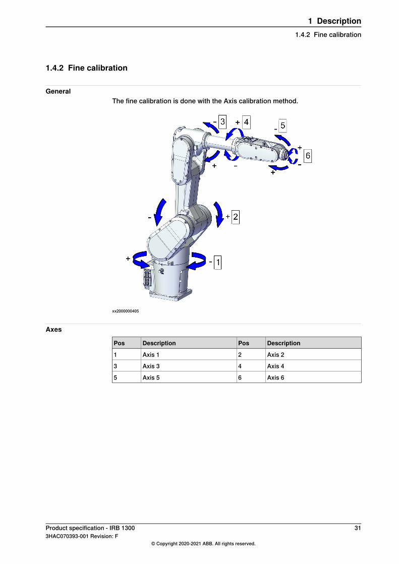
GeneralThe fine calibration is done with the Axis calibration method.
xx2000000405
Axes
DescriptionPosDescriptionPos
Axis 22Axis 11
Axis 44Axis 33
Axis 66Axis 55
Product specification - IRB 1300 313HAC070393-001 Revision: F
© Copyright 2020-2021 ABB. All rights reserved.
1 Description1.4.2 Fine calibration

1.4.3 Absolute Accuracy calibration
PurposeAbsolute Accuracy is a calibration concept that improves TCP accuracy. Thedifference between an ideal robot and a real robot can be several millimeters,resulting frommechanical tolerances and deflection in the robot structure.AbsoluteAccuracy compensates for these differences.Here are some examples of when this accuracy is important:
• Exchangeability of robots• Offline programming with no or minimum touch-up• Online programming with accurate movement and reorientation of tool• Programming with accurate offset movement in relation to eg. vision system
or offset programming• Re-use of programs between applications
The option Absolute Accuracy is integrated in the controller algorithms and doesnot need external equipment or calculation.
Note
The performance data is applicable to the corresponding RobotWare version ofthe individual robot.
What is includedEvery Absolute Accuracy robot is delivered with:
• compensation parameters saved on the robot’s serial measurement board• a birth certificate representing the Absolute Accuracymeasurement protocol
for the calibration and verification sequence.
Continues on next page32 Product specification - IRB 1300
3HAC070393-001 Revision: F© Copyright 2020-2021 ABB. All rights reserved.
1 Description1.4.3 Absolute Accuracy calibration
A robot with Absolute Accuracy calibration has a label with this information on themanipulator.Absolute Accuracy supports floor mounted, wall mounted and ceiling mountedinstallations. Compensation parameters saved in the robot’s serial measurementboard differ depending on which Absolute Accuracy option is selected.
When is Absolute Accuracy being usedAbsolute Accuracy works on a robot target in Cartesian coordinates, not on theindividual joints. Therefore, joint based movements (e.g. MoveAbsJ) will not beaffected.If the robot is inverted, the Absolute Accuracy calibration must be performed whenthe robot is inverted.
Absolute Accuracy activeAbsolute Accuracy will be active in the following cases:
• Any motion function based on robtargets (e.g. MoveL) and ModPos onrobtargets
• Reorientation jogging• Linear jogging• Tool definition (4, 5, 6 point tool definition, room fixed TCP, stationary tool)• Work object definition
Absolute Accuracy not activeThe following are examples of when Absolute Accuracy is not active:
• Any motion function based on a jointtarget (MoveAbsJ)• Independent joint• Joint based jogging• Additional axes• Track motion
Note
In a robot system with, for example, an additional axis or track motion, theAbsolute Accuracy is active for the manipulator but not for the additional axis ortrack motion.
RAPID instructionsThere are no RAPID instructions included in this option.
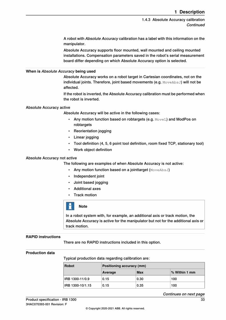
Production dataTypical production data regarding calibration are:
Positioning accuracy (mm)Robot
% Within 1 mmMaxAverage
1000.300.15IRB 1300-11/0.9
1000.350.15IRB 1300-10/1.15
Continues on next pageProduct specification - IRB 1300 333HAC070393-001 Revision: F
© Copyright 2020-2021 ABB. All rights reserved.
1 Description1.4.3 Absolute Accuracy calibration
Continued
Positioning accuracy (mm)Robot
% Within 1 mmMaxAverage
1000.400.20IRB 1300-7/1.4
34 Product specification - IRB 13003HAC070393-001 Revision: F
© Copyright 2020-2021 ABB. All rights reserved.
1 Description1.4.3 Absolute Accuracy calibrationContinued
1.5 Load diagrams
1.5.1 Introduction
WARNING
It is very important to always define correct actual load data and correct payloadof the robot. Incorrect definitions of load data can result in overloading of therobot.If incorrect load data is used, and/or if loads outside the load diagram are used,the following parts can be damaged due to overload:• motors• gearboxes• mechanical structure
WARNING
In RobotWare, the service routine LoadIdentify can be used to determine correctload parameters. The routine automatically defines the tool and the load. SeeOperating manual - OmniCore, for detailed information.
WARNING
Robots running with incorrect load data and/or with loads outside the loaddiagram, will not be covered by robot warranty.
GeneralThe load diagrams include a nominal payload inertia, J0 of 0.012 kgm2 , and anextra load of 0.5 kg (1 kg for reach 0.9m) at the upper arm housing.At different moment of inertia the load diagram will be changed. For robots thatare allowed tilted, wall or inverted mounted, the load diagrams as given are validand thus it is also possible to use RobotLoad within those tilt and axis limits.
Control of load case with RobotLoadTo verify a specific load case, use the RobotStudio add-in RobotLoad.The result from RobotLoad is only valid within the maximum loads and tilt angles.There is no warning if the maximum permitted arm load is exceeded. For over-loadcases and special applications, contact ABB for further analysis.
Product specification - IRB 1300 353HAC070393-001 Revision: F
© Copyright 2020-2021 ABB. All rights reserved.
1 Description1.5.1 Introduction
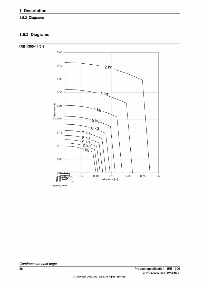
1.5.2 Diagrams
IRB 1300-11/0.9
0.00
0.05
0.10
0.15
0.20
0.25
0.30
0.35
0.40
0.45
0.00 0.05 0.10 0.15 0.20 0.25 0.30
Z-d
ista
nc
e (
m)
L-distance (m)
2 kg
3 kg
4 kg
5 kg
6 kg7 kg
8 kg9 kg
10 kg11 kg
xx2000001095
Continues on next page36 Product specification - IRB 1300
3HAC070393-001 Revision: F© Copyright 2020-2021 ABB. All rights reserved.
1 Description1.5.2 Diagrams
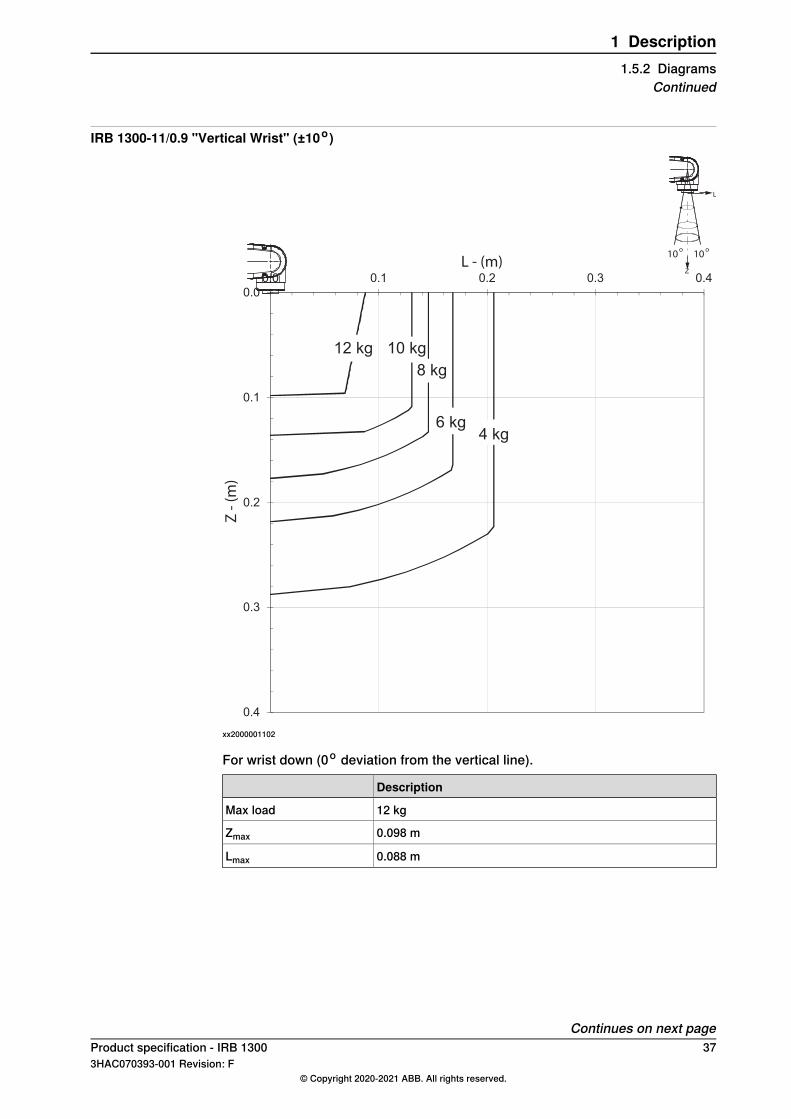
IRB 1300-11/0.9 "Vertical Wrist" (±10o)
0.0
0.1
0.2
0.3
0.4
0.0 0.1 0.2 0.3 0.4
L - (m)
Z -
(m
)
Z
L
10o
10o
12 kg 10 kg
8 kg
6 kg4 kg
xx2000001102
For wrist down (0o deviation from the vertical line).
Description
12 kgMax load
0.098 mZmax
0.088 mLmax
Continues on next pageProduct specification - IRB 1300 373HAC070393-001 Revision: F
© Copyright 2020-2021 ABB. All rights reserved.
1 Description1.5.2 Diagrams
Continued
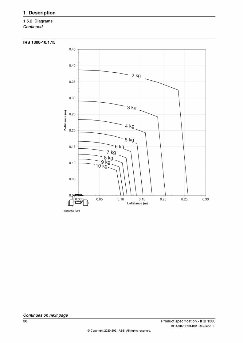
IRB 1300-10/1.15
0.00
0.05
0.10
0.15
0.20
0.25
0.30
0.35
0.40
0.45
0.00 0.05 0.10 0.15 0.20 0.25 0.30
Z-d
ista
nc
e (
m)
L-distance (m)
2 kg
3 kg
4 kg
5 kg
6 kg
7 kg8 kg
9 kg10 kg
xx2000001094
Continues on next page38 Product specification - IRB 1300
3HAC070393-001 Revision: F© Copyright 2020-2021 ABB. All rights reserved.
1 Description1.5.2 DiagramsContinued
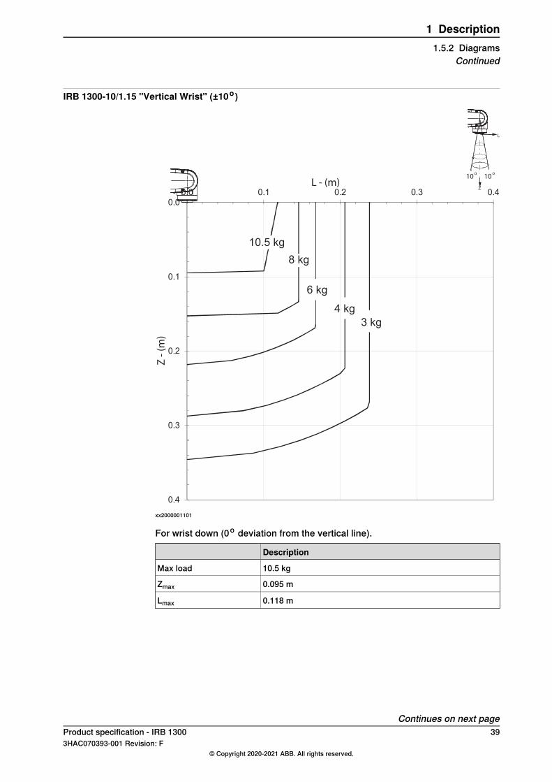
IRB 1300-10/1.15 "Vertical Wrist" (±10o)
0.0
0.1
0.2
0.3
0.4
0.0 0.1 0.2 0.3 0.4
Z -
(m
)
L - (m)Z
L
10o
10o
10.5 kg
8 kg
6 kg
4 kg
3 kg
xx2000001101
For wrist down (0o deviation from the vertical line).
Description
10.5 kgMax load
0.095 mZmax
0.118 mLmax
Continues on next pageProduct specification - IRB 1300 393HAC070393-001 Revision: F
© Copyright 2020-2021 ABB. All rights reserved.
1 Description1.5.2 Diagrams
Continued
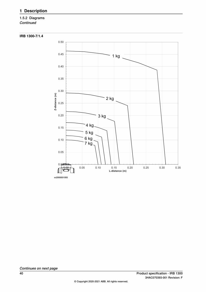
IRB 1300-7/1.4
0.00
0.05
0.10
0.15
0.20
0.25
0.30
0.35
0.40
0.45
0.50
0.00 0.05 0.10 0.15 0.20 0.25 0.30 0.35
Z-d
ista
nc
e (
m)
L-distance (m)
1 kg
2 kg
3 kg
4 kg
5 kg
6 kg
7 kg
xx2000001093
Continues on next page40 Product specification - IRB 1300
3HAC070393-001 Revision: F© Copyright 2020-2021 ABB. All rights reserved.
1 Description1.5.2 DiagramsContinued
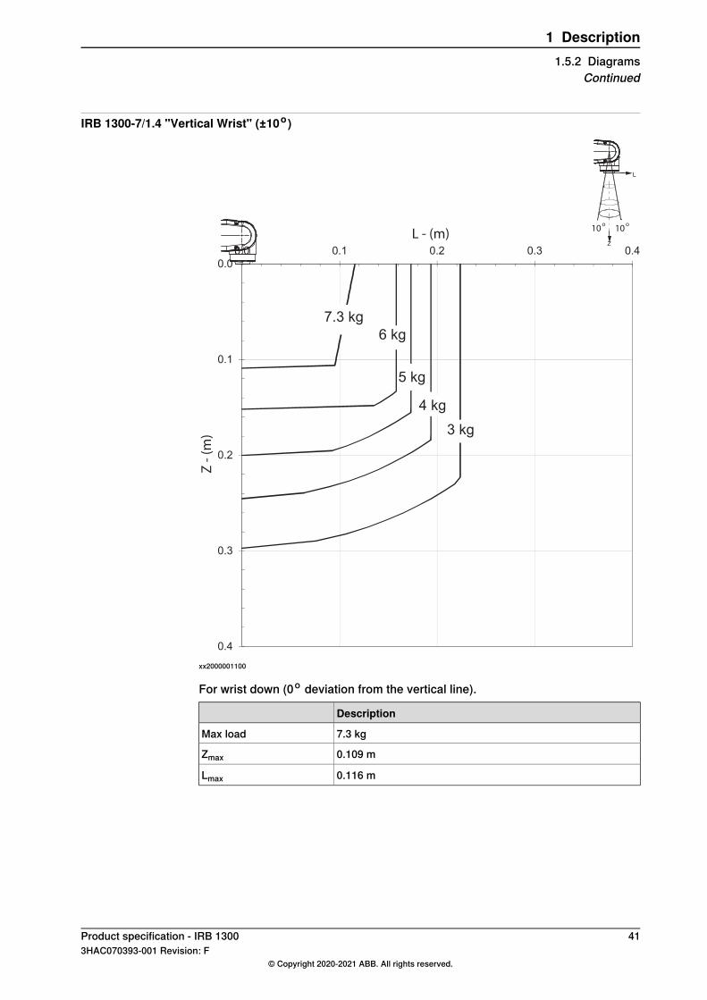
IRB 1300-7/1.4 "Vertical Wrist" (±10o)
0.0
0.1
0.2
0.3
0.4
0.0 0.1 0.2 0.3 0.4
Z -
(m
)
L - (m)Z
L
10o
10o
7.3 kg
6 kg
5 kg
4 kg
3 kg
xx2000001100
For wrist down (0o deviation from the vertical line).
Description
7.3 kgMax load
0.109 mZmax
0.116 mLmax
Product specification - IRB 1300 413HAC070393-001 Revision: F
© Copyright 2020-2021 ABB. All rights reserved.
1 Description1.5.2 Diagrams
Continued
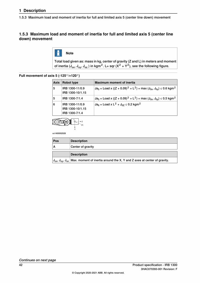
1.5.3 Maximum load and moment of inertia for full and limited axis 5 (center linedown) movement
Note
Total load given as: mass in kg, center of gravity (Z and L) in meters andmomentof inertia (Jox, Joy, Joz ) in kgm2 . L= sqr (X2 + Y2), see the following figure.
Full movement of axis 5 (-125°/+120°)
Maximum moment of inertiaRobot typeAxis
Ja5 = Load x ((Z + 0.09)2 + L2 ) + max (J0x, J0y) ≤ 0.6 kgm2IRB 1300-11/0.9IRB 1300-10/1.15
5
Ja5 = Load x ((Z + 0.09)2 + L2 ) + max (J0x, J0y) ≤ 0.5 kgm2IRB 1300-7/1.45
Ja6 = Load x L2 + J0Z ≤ 0.2 kgm2IRB 1300-11/0.9IRB 1300-10/1.15
6
IRB 1300-7/1.4
xx1400002028
DescriptionPos
Center of gravityA
Description
Max. moment of inertia around the X, Y and Z axes at center of gravity.Jox, Joy, Joz
Continues on next page42 Product specification - IRB 1300
3HAC070393-001 Revision: F© Copyright 2020-2021 ABB. All rights reserved.
1 Description1.5.3 Maximum load and moment of inertia for full and limited axis 5 (center line down) movement
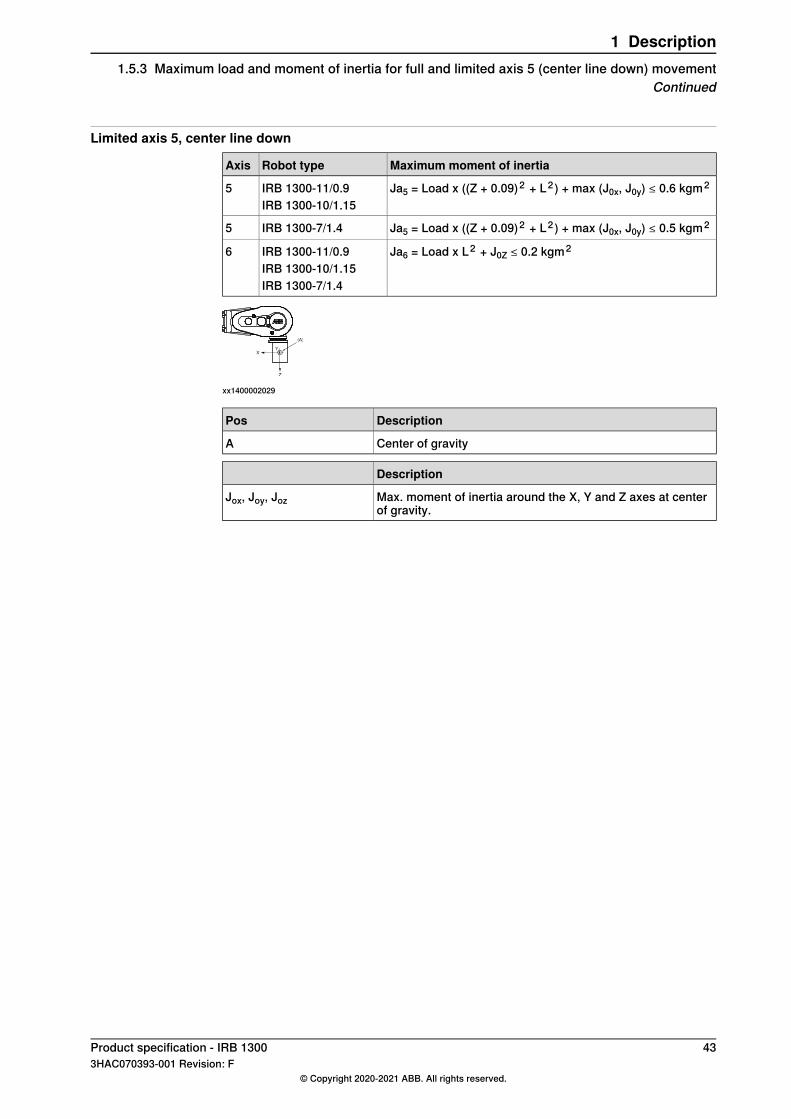
Limited axis 5, center line down
Maximum moment of inertiaRobot typeAxis
Ja5 = Load x ((Z + 0.09)2 + L2 ) + max (J0x, J0y) ≤ 0.6 kgm2IRB 1300-11/0.9IRB 1300-10/1.15
5
Ja5 = Load x ((Z + 0.09)2 + L2 ) + max (J0x, J0y) ≤ 0.5 kgm2IRB 1300-7/1.45
Ja6 = Load x L2 + J0Z ≤ 0.2 kgm2IRB 1300-11/0.9IRB 1300-10/1.15
6
IRB 1300-7/1.4
xx1400002029
DescriptionPos
Center of gravityA
Description
Max. moment of inertia around the X, Y and Z axes at centerof gravity.
Jox, Joy, Joz
Product specification - IRB 1300 433HAC070393-001 Revision: F
© Copyright 2020-2021 ABB. All rights reserved.
1 Description1.5.3 Maximum load and moment of inertia for full and limited axis 5 (center line down) movement
Continued

1.5.4 Wrist torque
Note
The wrist torque values are for reference only, and should not be used forcalculating permitted load offset (position of center of gravity) within the loaddiagram, since those also are limited by main axes torques as well as dynamicloads. Furthermore, arm loads will influence the permitted load diagram. To findthe absolute limits of the load diagram, use the RobotStudio add-in RobotLoad.
TorqueThe table below shows the maximum permissible torque due to payload.
Max torque valid atload
Max wrist torqueaxis 6
Max wrist torqueaxis 4 and 5
Robot type
11 kg10.8 Nm20.45 NmIRB 1300-11/0.9
10 kg9.8 Nm18.59 NmIRB 1300-10/1.15
7 kg6.9 Nm13 NmIRB 1300-7/1.4
44 Product specification - IRB 13003HAC070393-001 Revision: F
© Copyright 2020-2021 ABB. All rights reserved.
1 Description1.5.4 Wrist torque
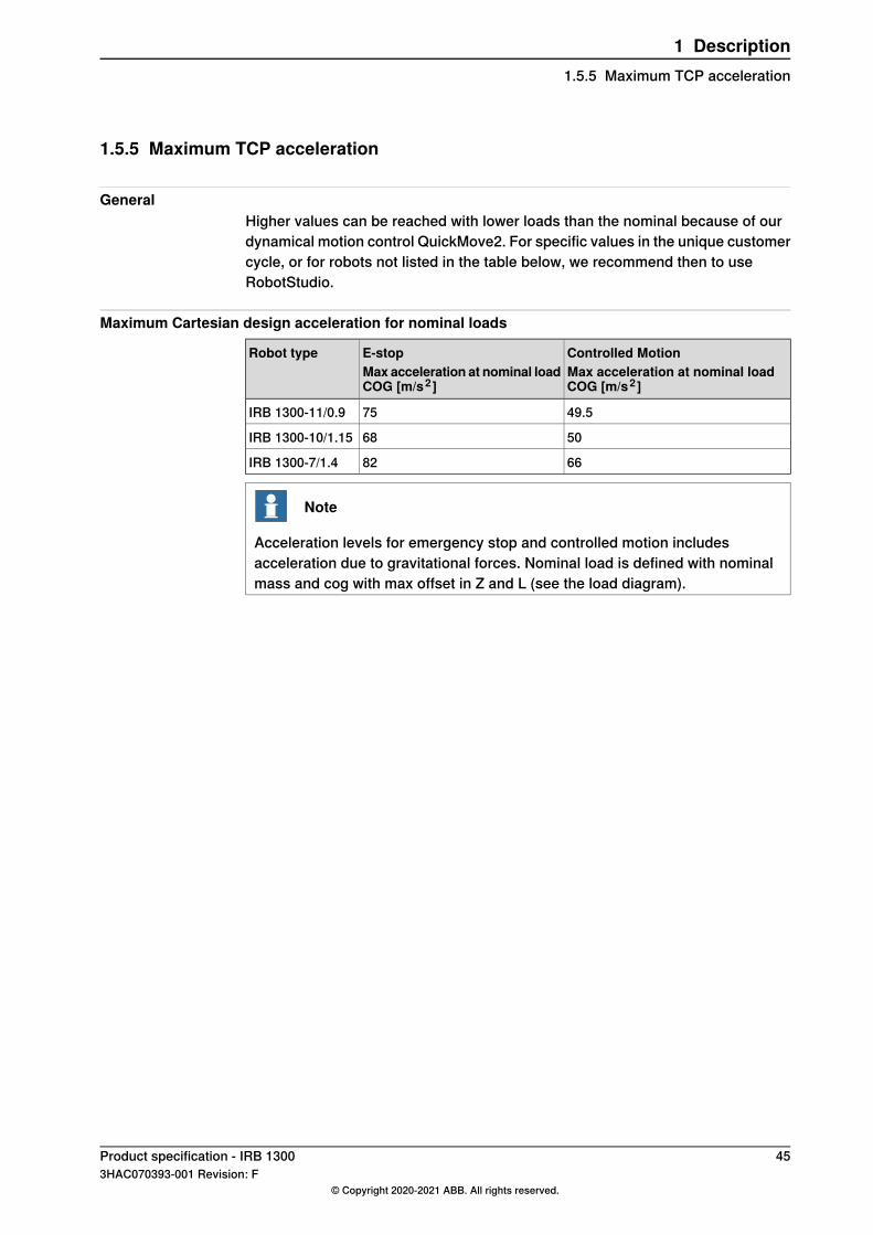
1.5.5 Maximum TCP acceleration
GeneralHigher values can be reached with lower loads than the nominal because of ourdynamical motion control QuickMove2. For specific values in the unique customercycle, or for robots not listed in the table below, we recommend then to useRobotStudio.
Maximum Cartesian design acceleration for nominal loads
Controlled MotionMax acceleration at nominal loadCOG [m/s2 ]
E-stopMax acceleration at nominal loadCOG [m/s2 ]
Robot type
49.575IRB 1300-11/0.9
5068IRB 1300-10/1.15
6682IRB 1300-7/1.4
Note
Acceleration levels for emergency stop and controlled motion includesacceleration due to gravitational forces. Nominal load is defined with nominalmass and cog with max offset in Z and L (see the load diagram).
Product specification - IRB 1300 453HAC070393-001 Revision: F
© Copyright 2020-2021 ABB. All rights reserved.
1 Description1.5.5 Maximum TCP acceleration
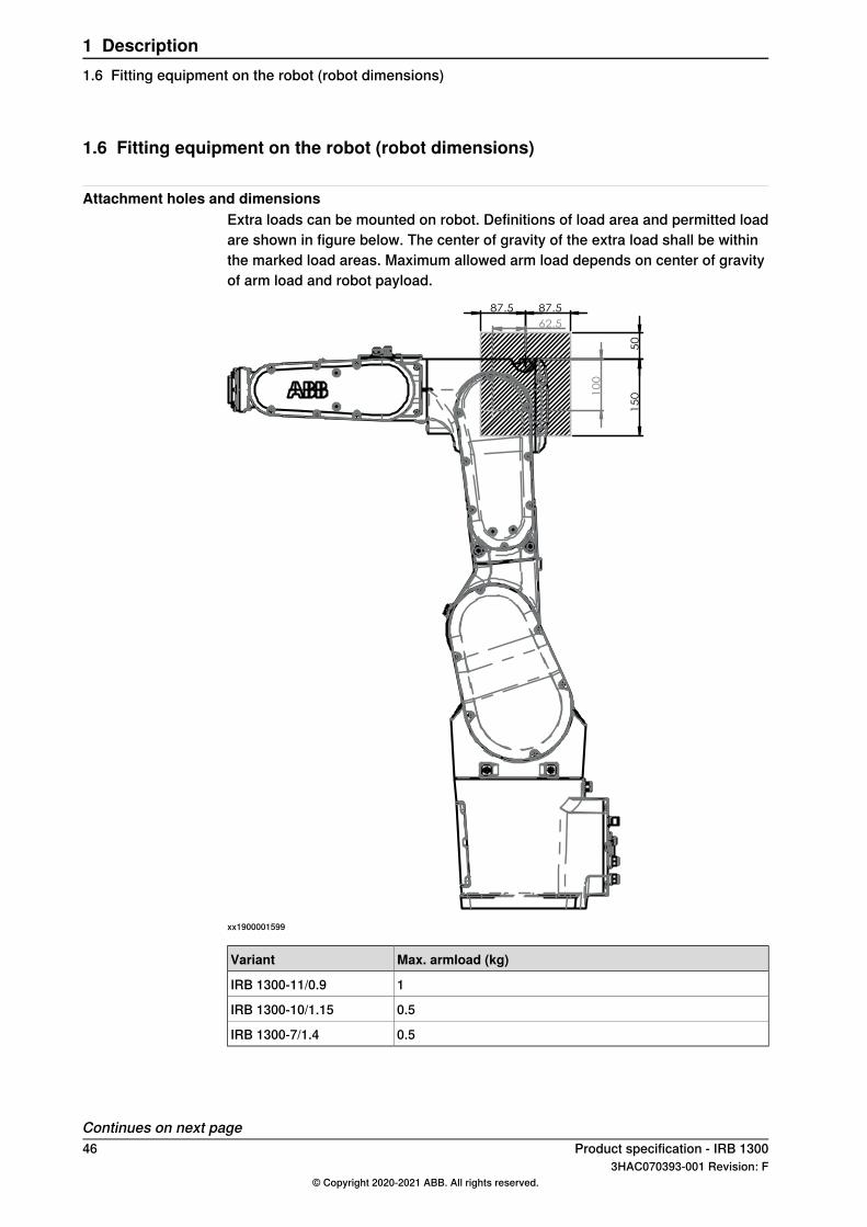
1.6 Fitting equipment on the robot (robot dimensions)
Attachment holes and dimensionsExtra loads can be mounted on robot. Definitions of load area and permitted loadare shown in figure below. The center of gravity of the extra load shall be withinthe marked load areas. Maximum allowed arm load depends on center of gravityof arm load and robot payload.
10
0
62.5
50
1
50
87.5 87.5
xx1900001599
Max. armload (kg)Variant
1IRB 1300-11/0.9
0.5IRB 1300-10/1.15
0.5IRB 1300-7/1.4
Continues on next page46 Product specification - IRB 1300
3HAC070393-001 Revision: F© Copyright 2020-2021 ABB. All rights reserved.
1 Description1.6 Fitting equipment on the robot (robot dimensions)
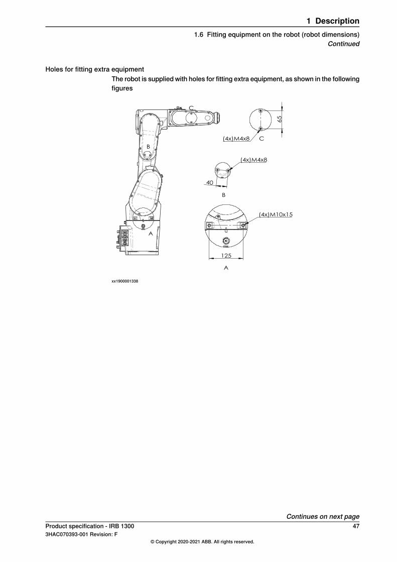
Holes for fitting extra equipmentThe robot is supplied with holes for fitting extra equipment, as shown in the followingfigures
A
B
C
125
(4x)M10x15
A
B
40
(4x)M4x8
65
(4x)M4x8 C
xx1900001338
Continues on next pageProduct specification - IRB 1300 473HAC070393-001 Revision: F
© Copyright 2020-2021 ABB. All rights reserved.
1 Description1.6 Fitting equipment on the robot (robot dimensions)
Continued
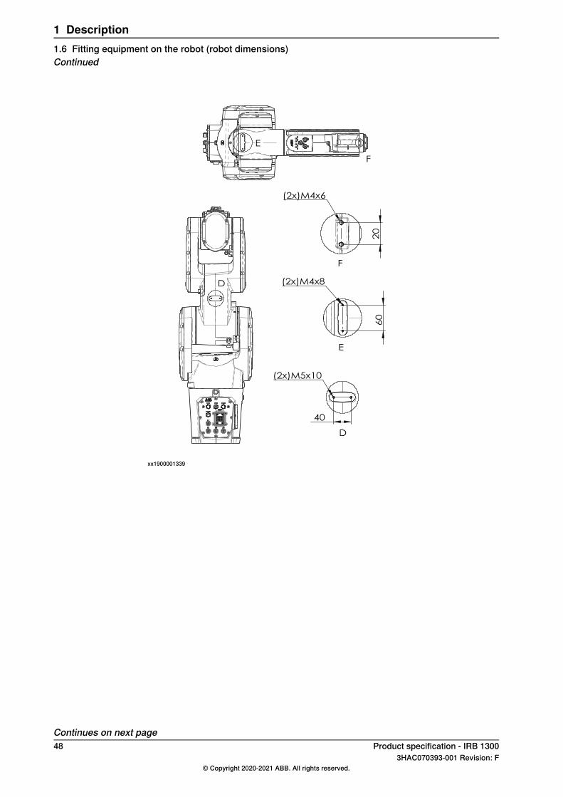
D
E
F
40
(2x)M5x10 6
0
(2x)M4x8
E
20
(2x)M4x6
D
F
xx1900001339
Continues on next page48 Product specification - IRB 1300
3HAC070393-001 Revision: F© Copyright 2020-2021 ABB. All rights reserved.
1 Description1.6 Fitting equipment on the robot (robot dimensions)Continued
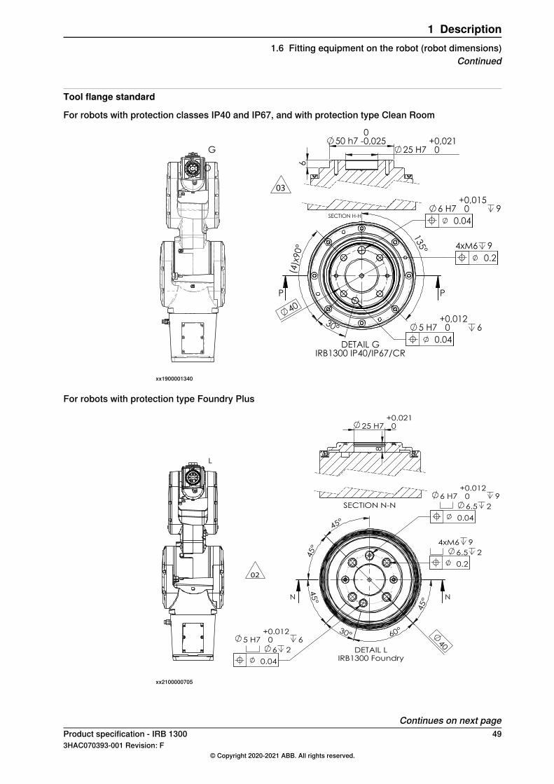
Tool flange standard
For robots with protection classes IP40 and IP67, and with protection type Clean Room
G
O
SECTION H-H
03
30°
(4)x
90°
135°
4xM6 9
5 H7 + 0,0120 6
40
6 H7 + 0,0150 9
PP
0.2
0.04
0.04
50 h7 -00,025
6
25 H7 + 0,0210
DETAIL GIRB1300 IP40/IP67/CR
xx1900001340
For robots with protection type Foundry Plus
02
L
4xM6 9
6.5 2
45°
30° 60°
45°
6 H7 + 0.0120 9
6.5 2
45°
5 H7 + 0.0120 6
6 2
40
45°
NN
DETAIL LIRB1300 Foundry
0.2
0.04
0.04
8
25 H7 + 0.0210
SECTION N-N
xx2100000705
Continues on next pageProduct specification - IRB 1300 493HAC070393-001 Revision: F
© Copyright 2020-2021 ABB. All rights reserved.
1 Description1.6 Fitting equipment on the robot (robot dimensions)
Continued
Fastener qualityWhen fitting tools on the tool flange, only use screws with quality 12.9. For otherequipment use suitable screws and tightening torque for your application.
50 Product specification - IRB 13003HAC070393-001 Revision: F
© Copyright 2020-2021 ABB. All rights reserved.
1 Description1.6 Fitting equipment on the robot (robot dimensions)Continued
1.7 Maintenance and troubleshooting
GeneralThe robot requires only minimum maintenance during operation. It has beendesigned to make it as easy to service as possible:
• Maintenance-free AC motors are used.• Oil is used for the gearboxes.• The cabling is routed for longevity, and in the unlikely event of a failure, its
modular design makes it easy to change.
MaintenanceThe maintenance intervals depend on the use of the robot. The requiredmaintenance activities also depend on the selected options. For detailed informationonmaintenance procedures, see themaintenance section in Product manual - IRB1300.
Product specification - IRB 1300 513HAC070393-001 Revision: F
© Copyright 2020-2021 ABB. All rights reserved.
1 Description1.7 Maintenance and troubleshooting
1.8 Robot motion
1.8.1 Adjusting the working range
Reasons for adjusting the manipulator working rangeThe working range of each manipulator axis is configured in the software. If thereis a risk that the manipulator may collide with other objects at installation site, itsworking space should be limited. The manipulator must always be able to movefreely within its entire working space.
Working range configurationsThe parameter values for the axes working range can be altered within the allowedworking range and according to available options for the robot, either to limit or toextend a default working range. Allowed working ranges and available options foreach manipulator axis are specified inWorking range on page 23.
Mechanical stops on the manipulatorMechanical stops are and can be installed on the manipulator as limiting devicesto ensure that the manipulator axis does not exceed the working range values setin the software parameters.
Note
The mechanical stops are only installed as safety precaution to physically stopthe robot from exceeding the working range set. A collision with a mechanicalstop always requires actions for repair and troubleshooting.
Movable mechanical stop iiFixed mechanical stop iAxis
noyesAxis 1
noyesAxis 2
noyesAxis 3
noyesAxis 4
noyesAxis 5
nonoAxis 6i Part of the casting or fixed on the casting and can not /should not be removed.ii Can be installed in one or more than one position, to ensure a reducedworking range, or be removed
to allow extended working range.
52 Product specification - IRB 13003HAC070393-001 Revision: F
© Copyright 2020-2021 ABB. All rights reserved.
1 Description1.8.1 Adjusting the working range
1.8.2 Mechanically restricting the working range
Location of mechanical stops
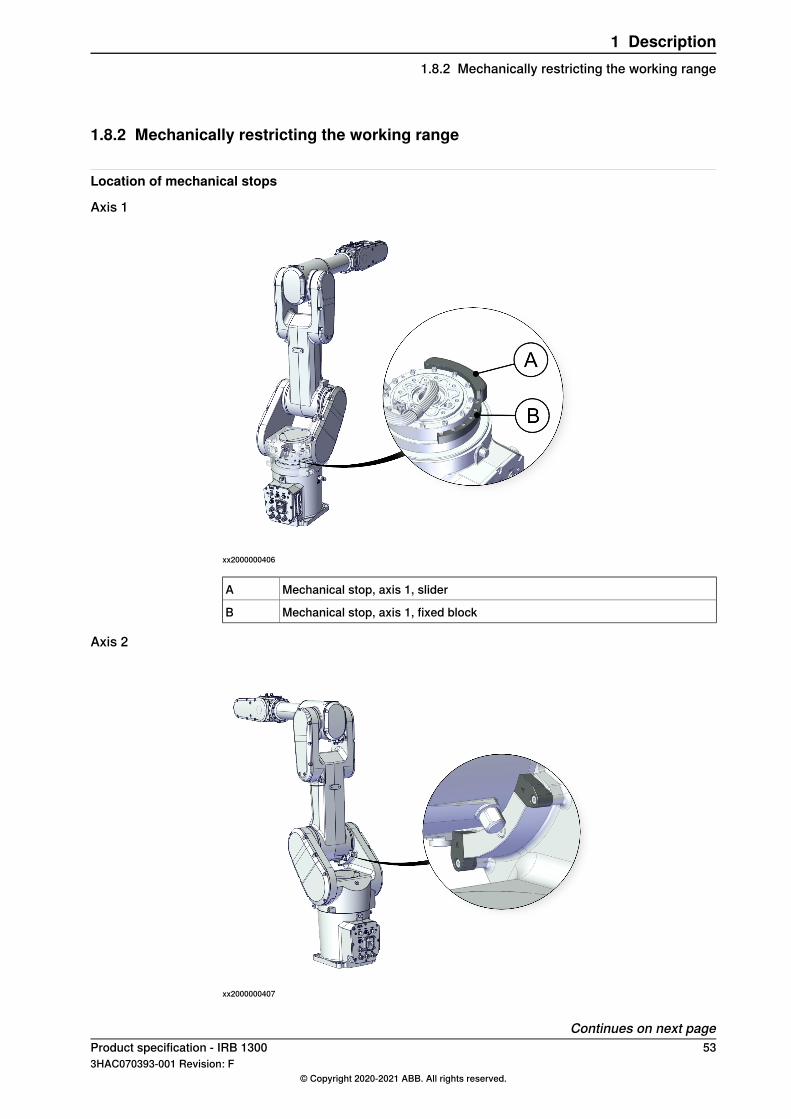
Axis 1
xx2000000406
Mechanical stop, axis 1, sliderA
Mechanical stop, axis 1, fixed blockB
Axis 2
xx2000000407
Continues on next pageProduct specification - IRB 1300 533HAC070393-001 Revision: F
© Copyright 2020-2021 ABB. All rights reserved.
1 Description1.8.2 Mechanically restricting the working range
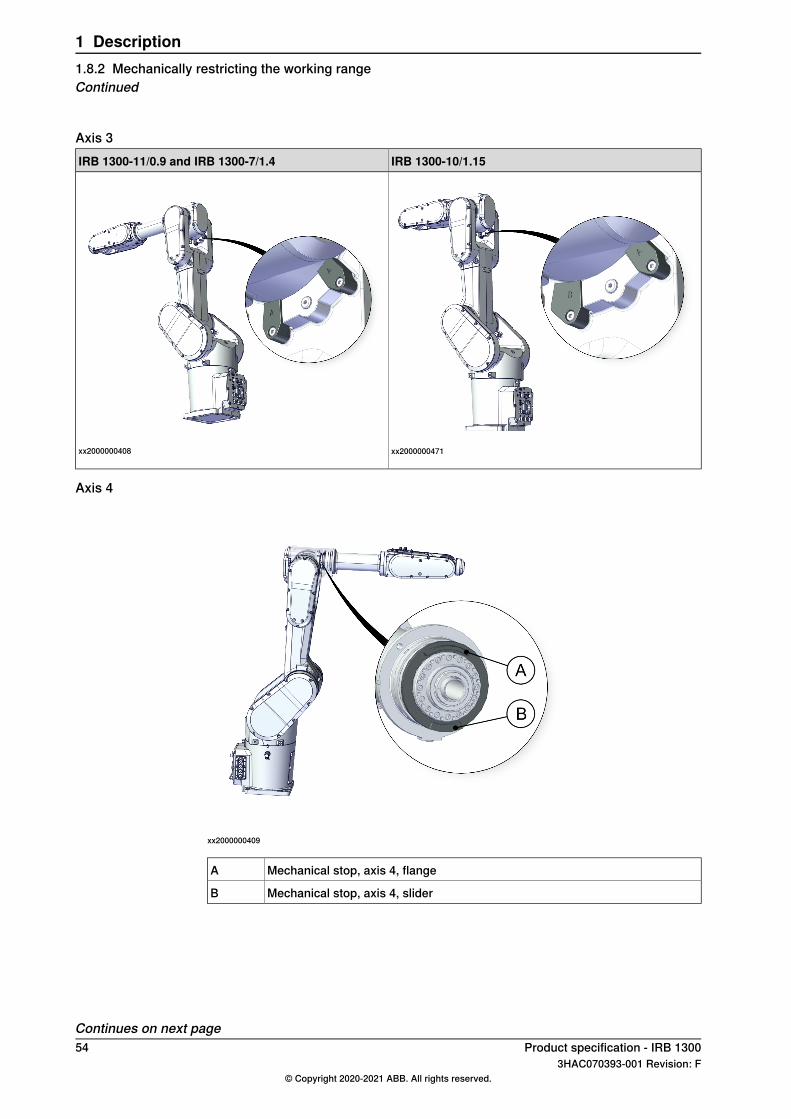
Axis 3IRB 1300-10/1.15IRB 1300-11/0.9 and IRB 1300-7/1.4
xx2000000471xx2000000408
Axis 4
xx2000000409
Mechanical stop, axis 4, flangeA
Mechanical stop, axis 4, sliderB
Continues on next page54 Product specification - IRB 1300
3HAC070393-001 Revision: F© Copyright 2020-2021 ABB. All rights reserved.
1 Description1.8.2 Mechanically restricting the working rangeContinued
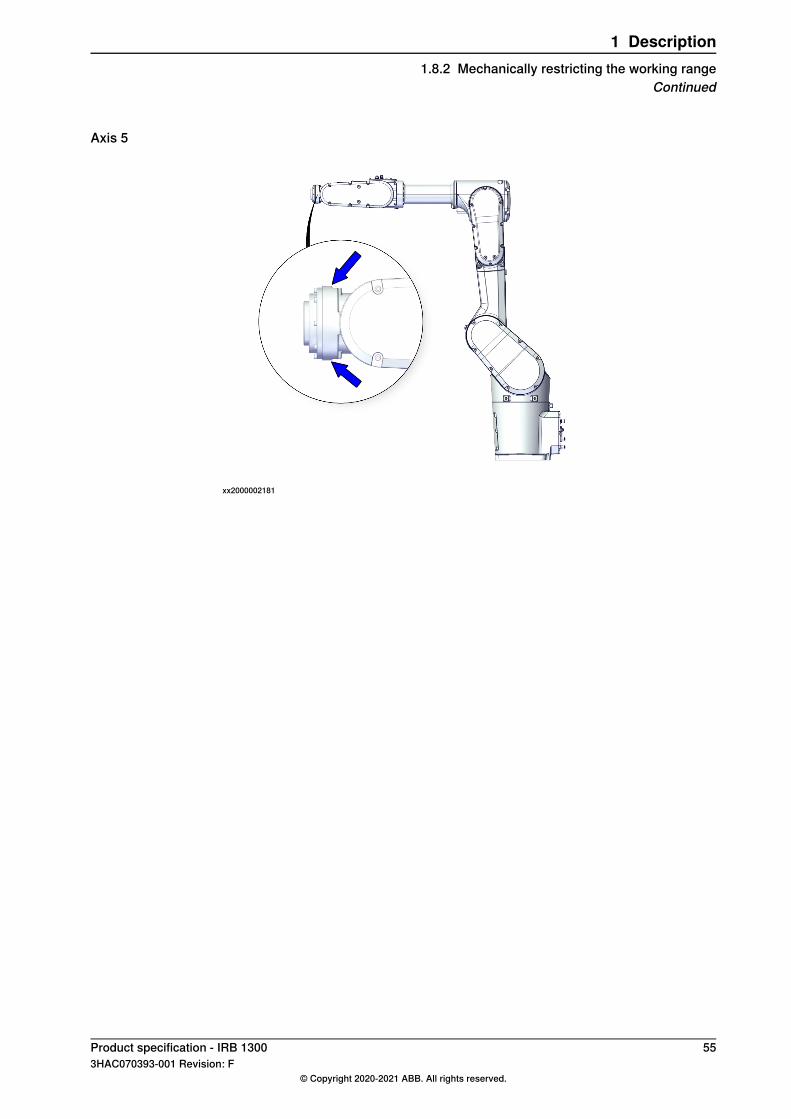
Axis 5
xx2000002181
Product specification - IRB 1300 553HAC070393-001 Revision: F
© Copyright 2020-2021 ABB. All rights reserved.
1 Description1.8.2 Mechanically restricting the working range
Continued
1.8.3 Performance according to ISO 9283
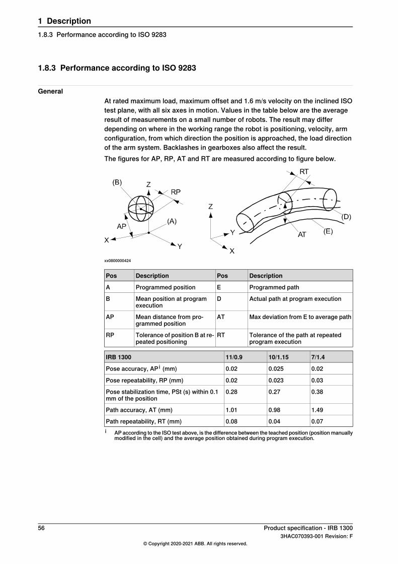
GeneralAt rated maximum load, maximum offset and 1.6 m/s velocity on the inclined ISOtest plane, with all six axes in motion. Values in the table below are the averageresult of measurements on a small number of robots. The result may differdepending on where in the working range the robot is positioning, velocity, armconfiguration, from which direction the position is approached, the load directionof the arm system. Backlashes in gearboxes also affect the result.The figures for AP, RP, AT and RT are measured according to figure below.
xx0800000424
DescriptionPosDescriptionPos
Programmed pathEProgrammed positionA
Actual path at program executionDMean position at programexecution
B
Max deviation from E to average pathATMean distance from pro-grammed position
AP
Tolerance of the path at repeatedprogram execution
RTTolerance of position B at re-peated positioning
RP
7/1.410/1.1511/0.9IRB 1300
0.020.0250.02Pose accuracy, AP i (mm)
0.030.0230.02Pose repeatability, RP (mm)
0.380.270.28Pose stabilization time, PSt (s) within 0.1mm of the position
1.490.981.01Path accuracy, AT (mm)
0.070.040.08Path repeatability, RT (mm)i AP according to the ISO test above, is the difference between the teached position (positionmanually
modified in the cell) and the average position obtained during program execution.
56 Product specification - IRB 13003HAC070393-001 Revision: F
© Copyright 2020-2021 ABB. All rights reserved.
1 Description1.8.3 Performance according to ISO 9283
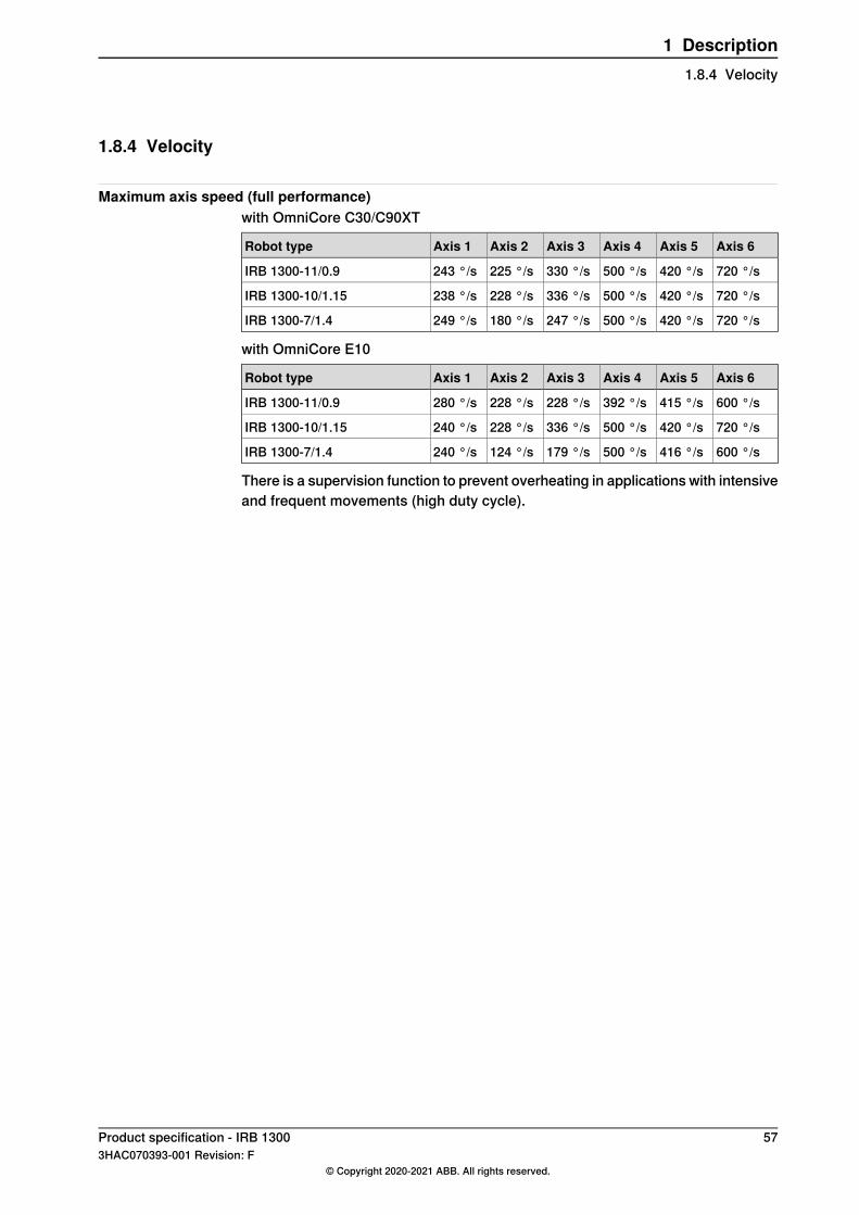
1.8.4 Velocity
Maximum axis speed (full performance)with OmniCore C30/C90XT
Axis 6Axis 5Axis 4Axis 3Axis 2Axis 1Robot type
720 °/s420 °/s500 °/s330 °/s225 °/s243 °/sIRB 1300-11/0.9
720 °/s420 °/s500 °/s336 °/s228 °/s238 °/sIRB 1300-10/1.15
720 °/s420 °/s500 °/s247 °/s180 °/s249 °/sIRB 1300-7/1.4
with OmniCore E10
Axis 6Axis 5Axis 4Axis 3Axis 2Axis 1Robot type
600 °/s415 °/s392 °/s228 °/s228 °/s280 °/sIRB 1300-11/0.9
720 °/s420 °/s500 °/s336 °/s228 °/s240 °/sIRB 1300-10/1.15
600 °/s416 °/s500 °/s179 °/s124 °/s240 °/sIRB 1300-7/1.4
There is a supervision function to prevent overheating in applications with intensiveand frequent movements (high duty cycle).
Product specification - IRB 1300 573HAC070393-001 Revision: F
© Copyright 2020-2021 ABB. All rights reserved.
1 Description1.8.4 Velocity
1.8.5 Robot stopping distances and times
IntroductionThe stopping distances and times for category 0 and category 1 stops, as requiredby EN ISO 10218-1 Annex B, are listed in Product specification - Robot stoppingdistances according to ISO 10218-1 (3HAC048645-001).
58 Product specification - IRB 13003HAC070393-001 Revision: F
© Copyright 2020-2021 ABB. All rights reserved.
1 Description1.8.5 Robot stopping distances and times
1.9 Customer connections
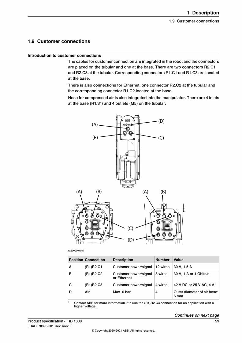
Introduction to customer connectionsThe cables for customer connection are integrated in the robot and the connectorsare placed on the tubular and one at the base. There are two connectors R2.C1and R2.C3 at the tubular. Corresponding connectors R1.C1 and R1.C3 are locatedat the base.There is also connections for Ethernet, one connector R2.C2 at the tubular andthe corresponding connector R1.C2 located at the base.Hose for compressed air is also integrated into the manipulator. There are 4 inletsat the base (R1/8”) and 4 outlets (M5) on the tubular.
(A) (A)
(A)
(B) (B)
(B)
(C)
(C)
(D)
(D)
xx2000001007
ValueNumberDescriptionConnectionPosition
30 V, 1.5 A12 wiresCustomer power/signal(R1)R2.C1A
30 V, 1 A or 1 Gbits/s8 wiresCustomer power/signalor Ethernet
(R1)R2.C2B
42 V DC or 25 V AC, 4 A i4 wiresCustomer power/signal(R1)R2.C3C
Outer diameter of air hose:6 mm
4Max. 6 barAirD
i Contact ABB for more information if to use the (R1)R2.C3 connection for an application with ahigher voltage.
Continues on next pageProduct specification - IRB 1300 593HAC070393-001 Revision: F
© Copyright 2020-2021 ABB. All rights reserved.
1 Description1.9 Customer connections
Connector kits (optional)
Connector kits, baseR1.C1 and R1.C2 connectors on the base are parts of the CP/CS cable and Ethernetfloor cable, respectively. For details about the robot cabling, see "Robot cablingand connection points" in Product manual - IRB 1300.Customers need to do wiring when using the R1.C3 connector on the base. Makesure to use the R1.C3 connector in M12 A-code 4p female type.
Connector kits, tubularThe table describes the CP/CS and Ethernet (if any) connector kits for tubular.
Art. no.DescriptionPosition
3HAC066098-001M12 CPCS Male straightconnector kits
R2.C1CP/CSConnectorkits
3HAC066099-001M12 CPCS Male angled con-nector kits
3HAC068412-001M12 CPCS Male straightconnector kits
R2.C3
3HAC068413-001M12 CPCS Male angled con-nector kits
3HAC067413-001M12 Ethernet CAT6a Malestraight connector kits
R2.C2Ethernet
3HAC067414-001M12 Ethernet CAT6a Maleangled connector kits
Continues on next page60 Product specification - IRB 1300
3HAC070393-001 Revision: F© Copyright 2020-2021 ABB. All rights reserved.
1 Description1.9 Customer connectionsContinued
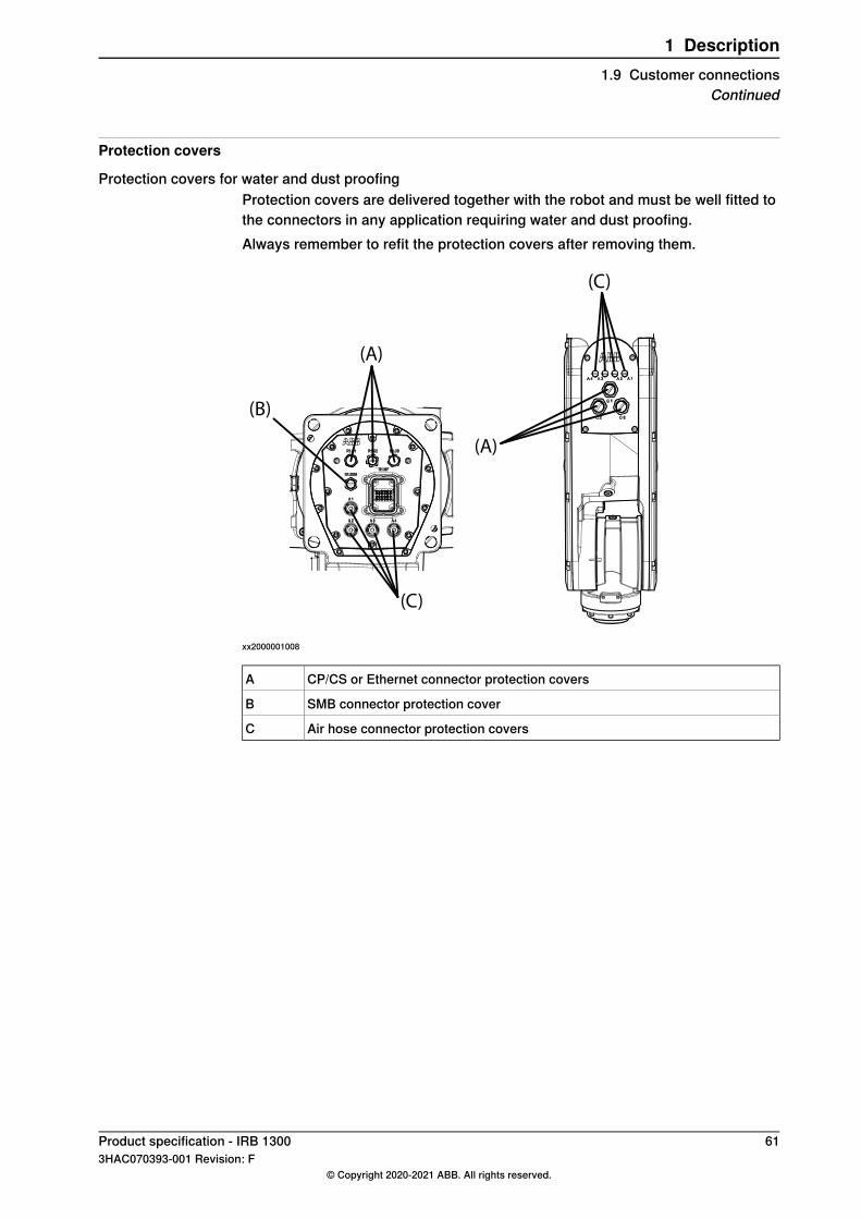
Protection covers
Protection covers for water and dust proofingProtection covers are delivered together with the robot and must be well fitted tothe connectors in any application requiring water and dust proofing.Always remember to refit the protection covers after removing them.
(A)
(A)
(B)
(C)
(C)
xx2000001008
CP/CS or Ethernet connector protection coversA
SMB connector protection coverB
Air hose connector protection coversC
Product specification - IRB 1300 613HAC070393-001 Revision: F
© Copyright 2020-2021 ABB. All rights reserved.
1 Description1.9 Customer connections
Continued

This page is intentionally left blank
2 Specification of variants and options2.1 Introduction to variants and options
GeneralThe different variants and options for the IRB 1300 are described in the followingsections. The same option numbers are used here as in the specification form.The variants and options related to the robot controller are described in the productspecification for the controller.
Product specification - IRB 1300 633HAC070393-001 Revision: F
© Copyright 2020-2021 ABB. All rights reserved.
2 Specification of variants and options2.1 Introduction to variants and options
2.2 Manipulator
Manipulator variants
Reach (m)Handling capacity (kg)IRB TypeOption
0.91113003300-8
1.151013003300-9
1.4713003300-10
Manipulator color
DescriptionOption
ABB White std, required 3351-4 clean room209-2
ABB Graphite White std209-202
Note
Notice that delivery time for painted spare parts will increase for none standardcolors.
Manipulator protection
DescriptionOption
Base 40,IP403350-400
Base 67,IP673350-670
Clean Room 4, ISO Class 43351-4
Foundry Plus2 67, IP673352-10
Note
Base 40 includes IP40, according to standard IEC 60529.Base 67 includes IP67, according to standard IEC 60529.Clean Room class 4 includes ISO class 4 standard, according to DIN EN ISO14644-1, -14. The robot selected with option Clean Room is also available forIP54 applications, according to standard IEC 60529.
Signs on manipulator
DescriptionOption
ABB3302-1
Robot cabling routing
DescriptionOption
Under the base3309-1
From side of base3309-2
Continues on next page64 Product specification - IRB 1300
3HAC070393-001 Revision: F© Copyright 2020-2021 ABB. All rights reserved.
2 Specification of variants and options2.2 Manipulator

xx1300000388
Media & CommunicationWhen 3303-1 Parallel & Air is selected then 3304-1 and 3305-1 options are activatedfor selecting.When 3303-2 Ethernet, Parallel, Air is selected then 3304-1,3305-1,3306-1 and3307-1 are activated for selecting.
DescriptionTypeOption
Includes CP/CS (C1) and air.Parallel & Air3303-1
Includes CP/CS (C1,C3) + PROFINET or Ethernet(C2), and air.
Ethernet, Parallel, Air3303-2
Connector kits manipulatorThe kit consists of connectors, pins and sockets.
DescriptionOption
Male-type, Straight arm connector kits3304-1
Male-type, Angled arm connector kits3305-1
Male-type, Straight arm Ethernet connector kits3306-1
Male-type, Angled arm Ethernet connector kits3307-1
Continues on next pageProduct specification - IRB 1300 653HAC070393-001 Revision: F
© Copyright 2020-2021 ABB. All rights reserved.
2 Specification of variants and options2.2 Manipulator
Continued
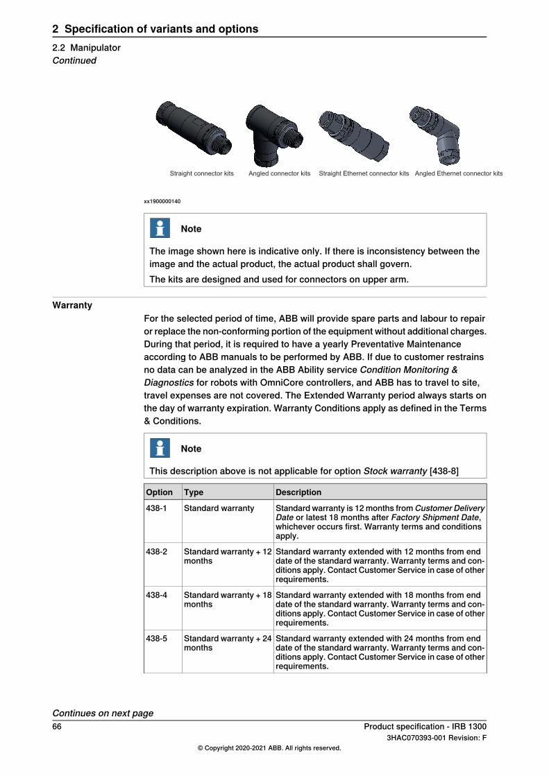
Straight connector kits Angled connector kitsits Straight Ethernet connector kits kits Angled Ethernet connector kits
xx1900000140
Note
The image shown here is indicative only. If there is inconsistency between theimage and the actual product, the actual product shall govern.The kits are designed and used for connectors on upper arm.
WarrantyFor the selected period of time, ABB will provide spare parts and labour to repairor replace the non-conforming portion of the equipment without additional charges.During that period, it is required to have a yearly Preventative Maintenanceaccording to ABB manuals to be performed by ABB. If due to customer restrainsno data can be analyzed in the ABB Ability service Condition Monitoring &Diagnostics for robots with OmniCore controllers, and ABB has to travel to site,travel expenses are not covered. The Extended Warranty period always starts onthe day of warranty expiration. Warranty Conditions apply as defined in the Terms& Conditions.
Note
This description above is not applicable for option Stock warranty [438-8]
DescriptionTypeOption
Standard warranty is 12months fromCustomer DeliveryDate or latest 18 months after Factory Shipment Date,whichever occurs first. Warranty terms and conditionsapply.
Standard warranty438-1
Standard warranty extended with 12 months from enddate of the standard warranty. Warranty terms and con-ditions apply. Contact Customer Service in case of otherrequirements.
Standard warranty + 12months
438-2
Standard warranty extended with 18 months from enddate of the standard warranty. Warranty terms and con-ditions apply. Contact Customer Service in case of otherrequirements.
Standard warranty + 18months
438-4
Standard warranty extended with 24 months from enddate of the standard warranty. Warranty terms and con-ditions apply. Contact Customer Service in case of otherrequirements.
Standard warranty + 24months
438-5
Continues on next page66 Product specification - IRB 1300
3HAC070393-001 Revision: F© Copyright 2020-2021 ABB. All rights reserved.
2 Specification of variants and options2.2 ManipulatorContinued
DescriptionTypeOption
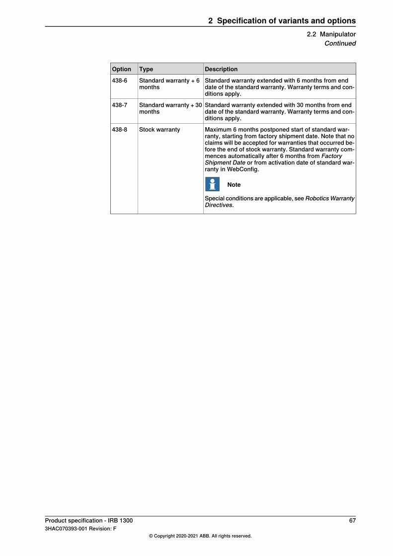
Standard warranty extended with 6 months from enddate of the standard warranty. Warranty terms and con-ditions apply.
Standard warranty + 6months
438-6
Standard warranty extended with 30 months from enddate of the standard warranty. Warranty terms and con-ditions apply.
Standard warranty + 30months
438-7
Maximum 6 months postponed start of standard war-ranty, starting from factory shipment date. Note that noclaims will be accepted for warranties that occurred be-fore the end of stock warranty. Standard warranty com-mences automatically after 6 months from FactoryShipment Date or from activation date of standard war-ranty in WebConfig.
Note
Special conditions are applicable, seeRoboticsWarrantyDirectives.
Stock warranty438-8
Product specification - IRB 1300 673HAC070393-001 Revision: F
© Copyright 2020-2021 ABB. All rights reserved.
2 Specification of variants and options2.2 Manipulator
Continued
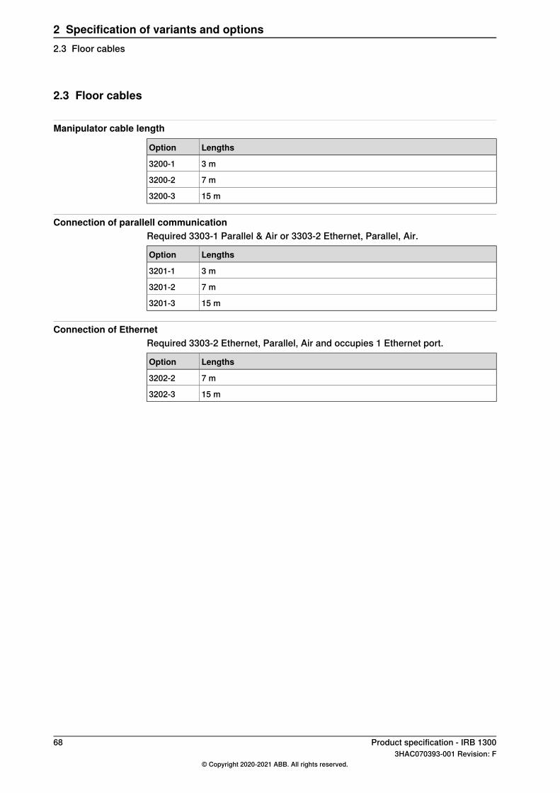
2.3 Floor cables
Manipulator cable length
LengthsOption
3 m3200-1
7 m3200-2
15 m3200-3
Connection of parallell communicationRequired 3303-1 Parallel & Air or 3303-2 Ethernet, Parallel, Air.
LengthsOption
3 m3201-1
7 m3201-2
15 m3201-3
Connection of EthernetRequired 3303-2 Ethernet, Parallel, Air and occupies 1 Ethernet port.
LengthsOption
7 m3202-2
15 m3202-3
68 Product specification - IRB 13003HAC070393-001 Revision: F
© Copyright 2020-2021 ABB. All rights reserved.
2 Specification of variants and options2.3 Floor cables

3 AccessoriesGeneral
There is a range of tools and equipment available.
Basic software and software options for robot and PCFor more information, see Application manual - Controller software OmniCore,Product specification - OmniCore C line and Product specification - OmniCore Eline.
Product specification - IRB 1300 693HAC070393-001 Revision: F
© Copyright 2020-2021 ABB. All rights reserved.
3 Accessories

This page is intentionally left blank
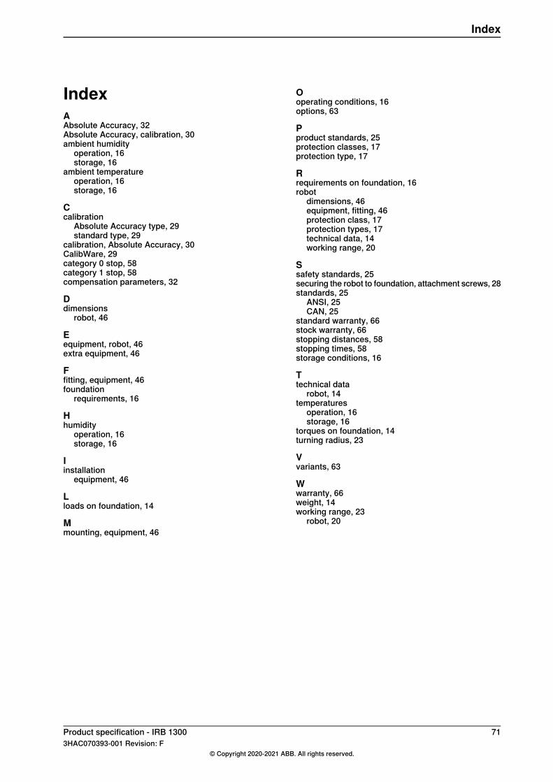
IndexAAbsolute Accuracy, 32Absolute Accuracy, calibration, 30ambient humidity
operation, 16storage, 16
ambient temperatureoperation, 16storage, 16
Ccalibration
Absolute Accuracy type, 29standard type, 29
calibration, Absolute Accuracy, 30CalibWare, 29category 0 stop, 58category 1 stop, 58compensation parameters, 32
Ddimensions
robot, 46
Eequipment, robot, 46extra equipment, 46
Ffitting, equipment, 46foundation
requirements, 16
Hhumidity
operation, 16storage, 16
Iinstallation
equipment, 46
Lloads on foundation, 14
Mmounting, equipment, 46
Ooperating conditions, 16options, 63
Pproduct standards, 25protection classes, 17protection type, 17
Rrequirements on foundation, 16robot
dimensions, 46equipment, fitting, 46protection class, 17protection types, 17technical data, 14working range, 20
Ssafety standards, 25securing the robot to foundation, attachment screws, 28standards, 25
ANSI, 25CAN, 25
standard warranty, 66stock warranty, 66stopping distances, 58stopping times, 58storage conditions, 16
Ttechnical data
robot, 14temperatures
operation, 16storage, 16
torques on foundation, 14turning radius, 23
Vvariants, 63
Wwarranty, 66weight, 14working range, 23
robot, 20
Product specification - IRB 1300 713HAC070393-001 Revision: F
© Copyright 2020-2021 ABB. All rights reserved.
Index


ABB ABRobotics & Discrete AutomationS-721 68 VÄSTERÅS, SwedenTelephone +46 (0) 21 344 400
ABB ASRobotics & Discrete AutomationNordlysvegen 7, N-4340 BRYNE, NorwayBox 265, N-4349 BRYNE, NorwayTelephone: +47 22 87 2000
ABB Engineering (Shanghai) Ltd.Robotics & Discrete AutomationNo. 4528 Kangxin HighwayPuDong DistrictSHANGHAI 201319, ChinaTelephone: +86 21 6105 6666
ABB Inc.Robotics & Discrete Automation1250 Brown RoadAuburn Hills, MI 48326USATelephone: +1 248 391 9000
abb.com/robotics
3HAC070393-001,Rev
F,en
© Copyright 2020-2021 ABB. All rights reserved.Specifications subject to change without notice.