Utkal Model : An Innovative Approach to Fixed Dome Biogas Plant with Ferrocement Technology
9
ISSN - 0125 1759 VoL. 27, *.2, April 1997 International Ferrocement Information Center L
Transcript of Utkal Model : An Innovative Approach to Fixed Dome Biogas Plant with Ferrocement Technology

ISSN - 0125 1759VoL. 27, *.2, April 1997
International Ferrocement Information Center
L

Journal of Ferroeement: Vol. 27, No. 2, April 1997 145
Utkal Model : An Innovative Approach to Fixed DomeBiogas Plant with Ferrocement Technology
Purnendu Kumar Mohanty
The high cost of construction of family size biogas plant keeps the Biogas program beyond the
reach of rural poors having adequate bovine population. There is a challenging task before the techno-
crats involved in Renewable Energy Program to provide a cost effective, durable biogas plant model
without compromising with the quality. Now-a-days Deenabandhu Model** has been widely accepted
due to its low cost. On reviewing a good number of failure fixed dome model biogas plants, it can be
concluded that some of the causes of failure are due to the quantum of brick joints in the structure and
use of poor quality building materials.
This paper presents a modified design of the Deenabandhu plant utilizing ferrocement tech-
nology resulting in reduction in cost of construction by at least 25%. Ferrocement the highly versatile
form of composite materials made up of cement mortar layers of wire mesh and small diameter G.I. wires
has been used for Utkal Model. The wide spread dispersion of fillers in the brittle matrix not only
improves the tensile and flexural strength of the structure but also increases toughness and impact
resistance. By the use of easy construction procedure with molds, the gesta(ion period has been reduced
drastically. Use ofscarce materials like kiln burnt bricks has been dispensed with and use of minimum
quanity of cement is ensured to reduce the cost of construction. The model has been tried at different field
conditions since June 1990 and the results are encouraging . Not a single case of failure of the structure
of the Utkal Model have been reported.
WfTRODUCTION
The scientific use of organic waste to minimize the conventional energy consumption and opti-mize use of available non-conventional energy sources is biogas. It is obtained by anaerobic fermentationof organic waste, (cow dung mixed with water). This fermentation takes place in biogas plants. A fixeddome plant consists of a digester for fermentation of input materials which also serves as the storagespace for gas after decomposition, an inlet system for letting in the slurry and an outlet tank to let thedigested slurry go out of the biogas plant after digestion. This outlet tank of the fixed dome model governsthe pressure of the gas generated for end use. Hence it is also termed as pressure chamber.
Almost all fixed dome models so far approved require bricks, sand and cement as building
materials. The major portion of such plants are brick masonry. Quantity and quality of these building
Assistant Engineer ( Renewable Energy ) under Orissa Renewable Energy Development Agency, District Rural
Development Agency, Keonjhar, Orissa , India, Pin - 758001.• • It is a low cost fixed dome model Bio-Gas Plant.

146 Journa l of Ferrocement : VoL 27, No. 2, April 1997
materials affect the quality , durability and cost of construction of biogas plants . Also limitations of brickmasonry for tensile stresses and occurance of so many joints in brick masonry results in leakage andcracking in Fixed Dome model biogas plants, which is a major cause of failure of biogas plant.
This paper describes the construction of Fixed Dome Model biogas plants by involvingferrocement technology . About 200 pieces of Utkal Model biogas plants have been constructed since
June 1990 , in different rural field conditions in Orissa and the results are quite encouraging and proved tobe the most useful one to cater to the needs of the rural poor in developing countries. Use of scarcematerials like kiln burnt bricks has been dispensed with and attempts have been made to use minimumquantity of cement which minimizes the cost of construction.
THE TECHNOLOGY
The technology adopted is ferrocement technology which is principally the same as reinforcedcement concrete with the following differences.
• Its thickness rarely exceeds 25 mm.• A rich portland cement mortar is used without any coarse aggregate.• Ferrocement consists of closely spaced small diameter wiremesh , distributed uniformly throughout
the cross -section.• Its tensile strength to weight ratio is higher than that of reinforced concrete and its cracking
behavior is superior.• Ferrocement is a thin-walled reinforced concrete which is light, durable and impermeable.• It is a kind of composite materials where the filler materials usually brittle in nature called matrix is
reinforced with fibers dispersed throughout the composite resulting in better structural perfor-mance than that of individual ones.
• It is advantageous in spatial structures and has relatively better mechanical properties anddurability.
• It is used in thin-walled structures where strength and rigidity are developed through form or shape.• Finished ferrocement works are resistant to corrosion.• The dispersion of fibers in the brittle matrix not only improves the engineering properties like
fracture strength , flexural strength , toughness , fatigue resistance and impact resistance but alsoprovides advantages in terms of product and components.
• Painting the ferrooement finished surface with epoxy results in total leak -proofness of the structure.
COMPOSITION
The essential constituent materials of the mortar which represent about "% of ferrocement areportand cement , sand, water and in some cases , admixture.
Journ
MAT
PROPO
• T
• G30
• SI
TIPS FO]
Journal ofFerrocement : W. 27, No. 2. April 1997 147
limitations of brickis in leakage and
plant.plants by involving
constructed sinceSing and proved to
tries. Use of scarceto use minimum
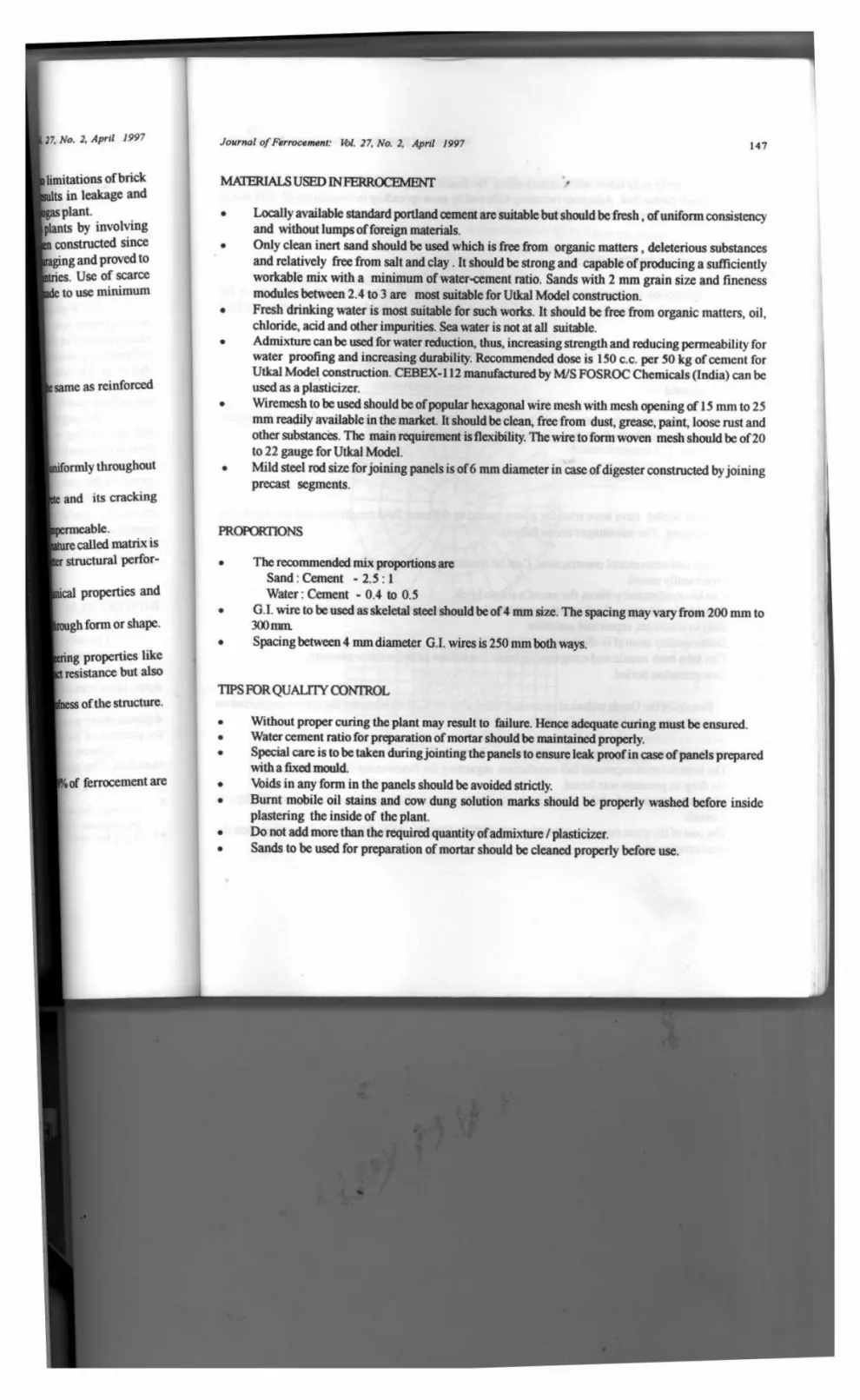
MATERIALS USED IN FERROCEMENT
• Locally available standard portland cement are suitable but should be fresh, of uniform consistencyand without lumps of foreign materials.
• Only clean inert sand should be used which is free from organic matters , deleterious substancesand relatively free from salt and clay. It should be strong and capable ofproducing a sufficientlyworkable mix with a minimum of water-cement ratio . Sands with 2 mm grain size and finenessmodules between 2.4 to 3 are most suitable for Utkal Model construction.
• Fresh drinking water is most suitable for such works . It should be free from organic matters, oil,chloride, acid and other impurities . Sea water is not at all suitable.
• Admixture can be used for water reduction , thus , increasing strength and reducing permeability forwater proofing and increasing durability . Recommended dose is 150 c.c. per 50 kg of cement forUtkal Model construction . CEBEX- 112 manufactured by M/S FOSROC Chemicals (India) can beused as a plasticizer.
• Wiremesh to be used should be of popular hexagonal wire mesh with mesh opening of 15 mm to 25mm readily available in the market. It should be clean , free from dust, grease, paint , loose rust andother substances . The main requirement is flexibility . The wire to form woven mesh should be of 20to 22 gauge for Utkal Model.Mild steel rod size for joining panels is of 6 nun diameter in case of digester constructed by joiningprecast segments.
PROPORTIONS
properties and
rough form or shape.
ng properties like
resistance but also
Hess of the structure.
• The recommended mix proportions areSand : Cement - 2.5 : 1Water : Cement - 0.4 to 0.5
• G.I. wire to be used as skeletal steel should be of 4 nun size . The spacing may vary from 200 mm to300 min.
• Spacing between 4 mm diameter G. I. wires is 250 mm both ways.
TIPS FOR QUALITY CONTROL
• Without proper curing the plant may result to failure . Hence adequate curing must be ensured.• Water cement ratio for preparation of mortar should be maintained properly.• Special care is to be taken during jointing the panels to ensure leak proof in case of panels prepared
with a fixed mouldVoids in any form in the panels should be avoided strictly.
• Burnt mobile oil stains and cow dung solution marks should be properly washed before insideplastering the inside of the plant.
• Do not add more than the required quantity of admixture / plasticizer.• Sands to be used for preparation of mortar should be cleaned properly before use.
148 Journal of Ferroeement: Vol. 27, No. 2, April 1997
Special care is to be taken while constructing the foundation portion of Utkal Model in loose soiland black cotton Soil . Adequate ramming followed by sand spreading in foundation of 100 mm to1 50 mm thickness is necessary for such soil conditions.
PROCEDURE FOR CONSTRUCTION
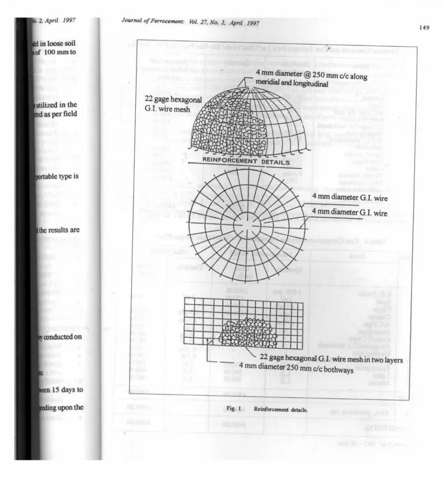
Construction of Utkal Model (Fig. 1) is dependent upon the type of mold to be utilized in theconstruction process, Generally any one of the following three types of mold can be selected as per fieldrequirement.
• Instant mold
• Fixed mold
• Portable mold
On analyzing the processes in all the three types of molds mentioned above the portable type isfound to be most suitable for fault free time saving construction in clusters.
RESULTS
Utkal Model have been tried for a long period in different field conditions and the results arequite encouraging. The advantages are as follows.
• Cheap and economical construction . Cost of construction is reduced by 25%.• Structurally sound.• Can be constructed without the use of a single brick.
Suitable for all types of soil conditions particularly in low land and canal areas.• Easy to construct , repair and maintain.• Better quality control in clusters.
• Can take both tensile and compressive loads in addition to hydrostatic pressure.• Low gestation period.
Results of the Oreda technical committee headed by Sri C. V. Krishna for the survey conducted on20 plants selected on random sampling basis are as follows.
• All the plants were functioning well.• The beneficiaries expressed full satisfaction regarding the functioning of the plants.• No drop in pressure was found.
• The gestation period of the plants from starting to commissioning ranged in between 15 days to1 month.
• The cost of the plant ranged between Rs. 4000 (US $ 120) to Rs. 4500 (US $ 135 ) depending upon the
local conditions.
Journal of Fen
(o. 2. April 1997 Journal ofFerrocement: Vol. 27, No. 2, April 1997149
el in loose soil
,of 100 mm to
tilized in thed as per field
portable type is
Ithe results are
kv conducted on
keen 15 days to
4 mm diameter @ 250 mm c/c alongmeridial and longitudinal
REINFORCEMENT DETAILS
`- 22 gage hexagonal G.I. wire mesh in two layers4 mm diameter 250 mm c/c bothways
^nding upon the Fig. 1. Reinforcement details.
150 Journal of Ferrocenent: 16L 27, No. 2. April 1997
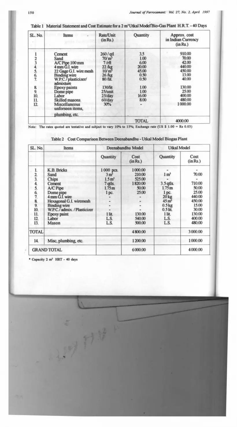
Table l Material Statement and Cost Estimate fora 2 m'Utkal Model Bio-Gas Plant H. RT. - 40 Days
SL. No. Items - Rate/Unit(in Rs.)
Quantity Approx. costin Indian Currency
(in Rs.)
1 Cement 260 / qtl 3.5 910.002 Sand 70/ m 1.00 70.003 A/C Pi 100 nun 7 /rft 6.00 42.004. 4 mm G.I. wine 22 /kp 20.00 440.005. 22 Gage G. I. wire mesh 10/m 45.00 450.006. Binding wire 26 /kg 0.50 13.007. W.P.C./ plasticizer/
id80/fit. 0.50 40.00
8.m xturea
Epoxy paints 130/lit 1.00 130.009. Dome pipe 25/unit 1.00 25.0010. Labor 25/day 16.00 400.0011. Skilled masons 60/day 8.00 480.0012. Miscellaneous 30% - 1000.00
unforseen items,plumbing. etc.
TOTAL 4000.00Note: The rates quoted are tentative and subject to vary 10% to 15•h; Exchange rate (US S 1.00 - Rs 0.03)
Table 2 Cost Comparison Between Deenabandhu - Utkal Model Biogas Plant
SL. No. Items Decnabandhu Model Utkal Model
Quantity Cost Quantity Cost(in Rs.) (inRs.)
1. K.B. Bricks 1000 1000.00 - -2. Sand 3 m 210.00 1 m' 70.003. Chips 1.5 in' 525.00 - -4. Cement 7 qtls. 1820.00 3.5 gtls. 710.005. A/C Pipe 1.75 in 50.00 1.75m 50.006. Dome pipe 1 pc. 25.00 1 pc. 25.007. 4 mm G. I. wire - - 20 440.008. Hexagonal G. I. wiremesh - - 45 450.009. Binding wire - - 0.5 kg 15.0010. WPC./ admix . / Plasticizer - - 0.5 fit 30.0011. Epoxy paint l lit 130.00 1 lit 130.0012. Labor L.S. 540.00 L.S. 400.0013. Mason L.S. 500.00 L.S. 480.00
TOTAL 4800 .00 3000.00
14. Misc, plumbing, etc. 1200.00 1000.00
GRAND TOTAL 6000.00 4000.00
Capacity 2 m ' HRT-40days
i
. 2, April 1997
40 Days
00A0,001001.00{.001.00
00.00.001.0000
C
Cost(in Rs.)
70.00
710.0050.0025.00
440.00450.00
15.0030.00
130.00400.00480.00
3000.00
1000.00
4000.00
Journal of Ferrocement: Vol. 27, No. 2, April 1997 151
CONCLUSION
In analyzing the comparative statement showing cost of construction of existing popular biogasplant model in India it can be concluded that Utkal Model which has been modified in respect of construc-tional materials used is the most suitable family size fixed dome model biogas plant (Tables 1 and 2). Itseasy structural design , user 's friendliness, cost effectiveness and easy time saving installation procedurewould help the technocrats involved in biogas program to render their efficiency and skill in an errorlessmanner. The beneficiaries of developing countries can derive much benefit from this model.
Defects due to so many joints in brick masonry and use of poor quality bricks can very well beavoided.
Since the model have been practically tried at different field conditions over long span andalmost all the plants are in excellent running condition, Utkal Model may be popularized widely.
RCS
L Khandelwal, K.C., and Mahdi, S.S. 19??. Bio-Gas technolog, A practical Hand Book.
2. Chawla, 0. P. 19??. Advances in Bio-Gas Technology.
3. Singh, J.B.; Myles, R; and Dhussa, A. 19??. Manual on Deenabandhu Bio-Gas Plant.4. Paul, B. K., and Pama , R.P. 1978. Ferrocement. Bangkok: International Ferrocement Information
Center.
174
p:
K. BHATTACHARYA
Journal of Ferrocement: Vol. 27, No. 2, April 1997
AUTHORS'PROF ILE
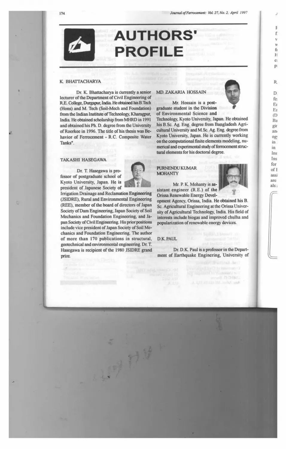
Dr. K. Bhattacharya is currently a seniorlecturer of the Department of Civil Engineering ofR.E. College , Durgapur, India . He obtained his B.Tech(Ions) and M. Tech (Soil-Meth and Foundation)from the Indian Institute of Technology, Kharagpur,India . He obtained scholarship from MHRD in 1991and obtained his Ph. D. degree from the University
of Roorkee in 1996. The title of his thesis was Be-havior of Ferrocement - R.C. Composite Water
Tanks".
TAKASHI HASEGAWA
Dr. T. Hasegawa is pro-fessor of postgraduate school ofKyoto University, Japan. He ispresident of Japanese Society ofIrrigation Drainage and Reclamation Engineering(JSIDRE), Rural and Environmental Engineering
(REE), member of the board of directors of JapanSociety of Dam Engineering, Japan Society of SoilMechanics and Foundation Engineering, and Ja-pan Society of Civil Engineering. His prior positionsinclude vice president of Japan Society of Soil Me-chanics and Foundation Engineering. The authorof more than 170 publications in structural,geotechnical and environmental engineering. Dr. T.Hasegawa is recipient of the 1980 JSIDRE grand
prize.
MD. ZAKARIA HOSSAIN
Mr. Hossain is a post-graduate student in the Divisionof Environmental Science andTechnology, Kyoto University, Japan . He obtainedhis B.Sc. Ag. Eng. degree from Bangladesh Agri-cultural University and M. Sc. Ag. Eng. degree fromKyoto University, Japan. He is currently working
on the computational finite elements modeling, nu-merical and experimental study of ferrocement struc-tural elements for his doctoral degree.
PURNENDU KUMARMOHANTY
Mr. P. K. Mohanty is as-sistant engineer (R.E.) of theOrissa Renewable Energy Devel-opment Agency, Orissa, India. He obtained his B.Sc. Agricultural Engineering at the Orissa Univer-sity of Agricultural Technology, India. His field ofinterests include biogas and improved chulha andpopularization of renewable energy devices.
D.K. PAUL
Dr. D.K. Paul is a professor in the Depart-
ment of Earthquake Enginering, University of
R
D.
fe:
Er
Er
(D
Ba
girany
og!
in
in
Ins
Ins
for
of I
assi
are
als