FD8169 Fixed Dome - User's Manual - Quadrant Systems
199
User’s Manual FD8169 Fixed Dome Network Camera 2MP • Smart IR • 3-Axis Rev. 1.0
-
Upload
khangminh22 -
Category
Documents
-
view
0 -
download
0
Transcript of FD8169 Fixed Dome - User's Manual - Quadrant Systems

User’s ManualFD8169 Fixed Dome
Network Camera
2MP • Smart IR • 3-Axis
Rev. 1.0

VIVOTEK
2 - User's Manual
Table of Contents
Overview .....................................................................................................................................................3Revision History ...................................................................................................................................... 3Read Before Use ..................................................................................................................................... 4Package Contents ................................................................................................................................... 4Symbols and Statements in this Document ............................................................................................. 4Hardware Installation ............................................................................................................................... 5Network Deployment ............................................................................................................................... 9
Software Installation .............................................................................................................................. 12Ready to Use ......................................................................................................................................... 13
Accessing the Network Camera ............................................................................................................14Using Web Browsers ............................................................................................................................. 14Using RTSP Players .............................................................................................................................. 17Using 3GPP-compatible Mobile Devices ............................................................................................... 18Using VIVOTEK Recording Software .................................................................................................... 19
Main Page .................................................................................................................................................20Client Settings ..........................................................................................................................................25Configuration ............................................................................................................................................30
System > General settings .................................................................................................................... 31System > Homepage layout ................................................................................................................. 33System > Logs ...................................................................................................................................... 36System > Parameters ........................................................................................................................... 38System > Maintenance .......................................................................................................................... 39Media > Image .................................................................................................................................... 43Media > Video ....................................................................................................................................... 54Media > Video ....................................................................................................................................... 55Network > General settings ................................................................................................................... 59Network > Streaming protocols ........................................................................................................... 66Network > SNMP (Simple Network Management Protocol) .................................................................................75
Security > User accounts ...................................................................................................................... 76Security > HTTPS (Hypertext Transfer Protocol over SSL) ........................................................ 77Security > Access List ......................................................................................................................... 84PTZ > PTZ settings ............................................................................................................................... 89Event > Event settings........................................................................................................................... 93Applications > Motion detection........................................................................................................... 106Recording > Recording settings ......................................................................................................... 109Local storage > SD card management ................................................................................................ 114Local storage > Content management ................................................................................................ 115
Appendix ................................................................................................................................................118URL Commands for the Network Camera ........................................................................................... 118Technical Specifications ...................................................................................................................... 196Technology License Notice .................................................................................................................. 197Electromagnetic Compatibility (EMC) .................................................................................................. 198

VIVOTEK
User's Manual - 3
Overview
VIVOTEK FD8169 is an easy-to-use fixed dome network camera specifically designed for indoor security applications with a compact, stylish exterior. Equipped with a 2MP sensor enabling viewing resolution of 1920x1080 at a smooth 30 fps, the FD8169 is an all-in-one camera capable of capturing high quality and high resolution video up to 2 Megapixel.
In order to adapt to constantly changing lighting conditions, the FD8169 features a removable IR-cut filter as well as improved IR illuminators effective up to 15M for superior image quality around the clock. Featuring 3D Noise Reduction Technology, it enables the FD8169 to capture clear, polished video under low-light conditions, which also helps to reduce bandwidth from sensor noise.
The FD8169 supports the industry-standard H.264 compression technology, drastically reducing file sizes and conserving valuable network bandwidth. With H.264, and MJPEG compatibility both included, multiple streams can be simultaneously transmitted in any of these formats at different resolutions, frame rates, and image qualities for versatile platforms. Thereby it further optimizes bandwidth and storage efficiency.
Incorporating a number of advanced features standard for VIVOTEK cameras, including tamper detection, 802.3af compliant PoE, MicroSD/SDHC/SDXC card slot, and VIVOTEK’s 32-channel recording software, the FD8169 is the ideal solution for your indoor surveillance needs.
Revision History
■ Rev. 1.0: Initial release

VIVOTEK
4 - User's Manual
Read Before UseThe use of surveillance devices may be prohibited by law in your country. The Network Camera is not only a high-performance web-ready camera but can also be part of a flexible surveillance system. It is the user’s responsibility to ensure that the operation of such devices is legal before installing this unit for its intended use.
It is important to first verify that all contents received are complete according to the Package Contents listed below. Take note of the warnings in the Quick Installation Guide before the Network Camera is installed; then carefully read and follow the instructions in the Installation chapter to avoid damage due to faulty assembly and installation. This also ensures the product is used properly as intended.
The Network Camera is a network device and its use should be straightforward for those who have basic networking knowledge. It is designed for various applications including video sharing, general security/surveillance, etc. The Configuration chapter suggests ways to best utilize the Network Camera and ensure proper operations. For creative and professional developers, the URL Commands of the Network Camera section serves as a helpful reference to customizing existing homepages or integrating with the current web server.
Package Contents■ FD8169■ L-type Hex key wrench, dessicant bag, screws■ Software CD■ Warranty Card■ Quick Installation Guide
Symbols and Statements in this Document
i INFORMATION: provides important messages or advices that might help prevent inconvenient or problem situations.
NOTE: Notices provide guidance or advices that are related to the functional integrity of the machine.
Tips: Tips are useful information that helps enhance or facilitae an installation, function, or process.
WARNING! or IMPORTANT!: These statements indicate situations that can be dangerous or hazardous to the machine or you.
Electrical Hazard: This statement appears when high voltage electrical hazards might occur to an operator.

VIVOTEK
User's Manual - 5
Hardware Installation
1 2 3
1. Loosen the screw on the dome cover. 2. Press the release button. 3. Remove the dome cover.
6. Route an Ethernet cable and DC wires (if preferred) through the hole.
4. Install the SD card. 5. Attach the alignment sticker to preferred location. Drill anchor holes and cabling holes
into the ceiling or wall.
5
6

VIVOTEK
6 - User's Manual
10. Adjust the camera lens shooting angle.
Rotate 345ºTilt 70º
Pan 348º
8
7
7. Hammer in the screw anchors. Route cables through the hole at the bottom of the camera. 8. Secure the camera using the included screws. 9. Connect Ethernet and DC wires. Arrange the cables neatly and use a cable tie to secure DC
wires to bracket.
9DC12V
GND

VIVOTEK
User's Manual - 7
11. Align and install the dome cover and secure the cover with the screw on the side.
12. Jot down the MAC address of your camera, and use the included IW2 software utility to locate and access your camera on the local network.

VIVOTEK
8 - User's Manual
Hardware Reset
The reset button is used to reset the system or restore the factory default settings. Sometimes resetting the system can return the camera to normal operation. If the system problems remain after reset, restore the factory settings and install again.
Reset: Press the recessed reset button. Wait for the Network Camera to reboot.
Restore: Press and hold the reset button until the status LED rapidly blinks. Note that all settings will be restored to factory default. Upon successful restore, the status LED will blink green and red during normal operation.
Micro SD/SDHC/SDXC Card Capacity
This network camera is compliant with Micro SD/SDHC/SDXC 16GB / 8GB / 32GB / 64GB and other preceding standard SD cards.
Reset Button

VIVOTEK
User's Manual - 9
Network DeploymentGeneral Connection (PoE)
When using a PoE-enabled switchThe Network Camera is PoE-compliant, allowing transmission of power and data via a sin-gle Ethernet cable. Follow the below illustration to connect the Network Camera to a PoE-enabled switch via Ethernet cable.
POWER COLLISIONLINK
RECEIVEPARTITION1 2 3 4 5
PoE Switch
When using a non-PoE switchUse a PoE power injector (optional) to connect between the Network Camera and a non-PoE switch.
POWER COLLISIONLINK
RECEIVEPARTITION1 2 3 4 5
Non-PoE Switch
PoE Power Injector(optional)

VIVOTEK
10 - User's Manual
Internet connection via a router
Before setting up the Network Camera over the Internet, make sure you have a router and follow the steps below.
1. Connect your Network Camera behind a router, the Internet environment is illustrated below. Regarding how to obtain your IP address, please refer to Software Installation on page 12 for details.
IP address : 192.168.0.3Subnet mask : 255.255.255.0Default router : 192.168.0.1
IP address : 192.168.0.2Subnet mask : 255.255.255.0Default router : 192.168.0.1
LAN (Local Area Network)Router IP address : 192.168.0.1
WAN (Wide Area Network )Router IP address : from ISP
Cable or DSL Modem
POWER COLLISIONLINK
RECEIVEPARTITION
1 2 3 4 5
Internet
2. In this case, if the Local Area Network (LAN) IP address of your Network Camera is 192.168.0.3, please forward the following ports for the Network Camera on the router.
■ HTTP port: default is 80■ RTSP port: default is 554■ RTP port for video: default is 5556■ RTCP port for video: default is 5557If you have changed the port numbers on the Network page, please open the ports accordingly on your router. For information on how to forward ports on the router, please refer to your router’s user’s manual.
3. Find out the public IP address of your router provided by your ISP (Internet Service Provider). Use the public IP and the secondary HTTP port to access the Network Camera from the Internet. Please refer to Network Type on page 60 for details.
Internet connection with static IP
Choose this connection type if you are required to use a static IP for the Network Camera. Please refer to LAN setting on page 59 for details.
Internet connection via PPPoE (Point-to-Point over Ethernet)
Choose this connection type if you are connected to the Internet via a DSL Line. Please refer to PPPoE on page 60 for details.

VIVOTEK
User's Manual - 11
Configure the router, virtual server or firewall, so that the router can forward any data com-ing into a preconfigured port number to a network camera on the private network, and allow data from the camera to be transmitted to the outside of the network over the same path. From Forward to122.146.57.120:8000 192.168.2.10:80122.146.57.120:8001 192.168.2.11:80... ...
When properly configured, you can access a camera behind the router using the HTTP request as follows: http://122.146.57.120:8000
If you change the port numbers on the Network configuration page, please open the ports accordingly on your router. For example, you can open a management session with your router to configure access through the router to the camera within your local network. Please consult your network administrator for router configuration if you have troubles with the configuration.
For more information with network configuration options (such as that of streaming ports), please refer to Configuration > Network Settings. VIVOTEK also provides the automatic port forwarding feature as an NAT traversal function with the precondition that your router must support the UPnP port forwarding feature.

VIVOTEK
12 - User's Manual
Software InstallationInstallation Wizard 2 (IW2), a software included in the product CD, helps you set up your Network Camera on the LAN.
1. Install IW2 under the Software Utility directory from the software CD. Double-click the IW2 shortcut on your desktop to launch the program.
2. The program will conduct an analysis of your network environment. After your network environment is analyzed, please click Next to continue the program.
3. The program will search for all VIVOTEK network devices on the same LAN.
4. After a brief search, the installer window will prompt. Click on the MAC and model name that matches the one printed on the product label. You can then double-click on the address
to open a management session with the Network Camera.
0002D1730202
00-02-D1-73-02-02 192.168.5.151 FD8169
InstallationWizard 2
IW2
Network CameraModel No: FD8169
Made in Taiwan
This device complies with part 15 of the FCC rules. Operation is subject to the following two conditions: (1)This device may not cause harmful interference, and (2) this device must accept any interference received, including interference that may cause undesired operation.
Pat. 6,930,709
MAC:0002D1730202RoHS

VIVOTEK
User's Manual - 13
Ready to Use
1. A browser session with the Network Camera should prompt as shown below.2. You should be able to see live video from your camera. You may also install the 32-channel
recording software from the software CD in a deployment consisting of multiple cameras. For its installation details, please refer to its related documents.

VIVOTEK
14 - User's Manual
Accessing the Network CameraThis chapter explains how to access the Network Camera through web browsers, RTSP players, 3GPP-compatible mobile devices, and VIVOTEK recording software.
Using Web Browsers
Use Installation Wizard 2 (IW2) to access the Network Cameras on LAN. If your network environment is not a LAN, follow these steps to access the Netwotk Camera: 1. Launch your web browser (e.g., Microsoft® Internet Explorer or Mozilla Firefox).2. Enter the IP address of the Network Camera in the address field. Press Enter. 3. Live video will be displayed in your web browser.4. If it is the first time installing the VIVOTEK network camera, an information bar will prompt as
shown below. Follow the instructions to install the required plug-in on your computer.
NOTE
► For Mozilla Firefox or Chrome users, your browser will use Quick Time to stream the live video. If you don’t have Quick Time on your computer, please download it first, then launch the web browser.
NOTE:

VIVOTEK
User's Manual - 15
► By default, the Network Camera is not password-protected. To prevent unauthorized access, it is highly recommended to set a password for the Network Camera. For more information about how to enable password protection, please refer to Security on page 76.
► If you see a dialog box indicating that your security settings prohibit running ActiveX® Controls, please enable the ActiveX® Controls for your browser.
1. Choose Tools > Internet Options > Security > Custom Level.
2. Look for Download signed ActiveX® controls; select Enable or Prompt. Click OK.
3. Refresh your web browser, then install the ActiveX® control. Follow the instructions to complete installation.

VIVOTEK
16 - User's Manual
• Currently the Network Camera utilizes 32-bit ActiveX plugin. You CAN NOT open a management/view session with the camera using a 64-bit IE browser.
• If you encounter this problem, try execute the Iexplore.exe program from C:\Windows\SysWOW64. A 32-bit version of IE browser will be installed.
• On Windows 7, the 32-bit explorer browser can be accessed from here: C:\Program Files (x86)\Internet Explorer\iexplore.exe
• If you open a web session from the IW2 utility, a 32-bit IE browser will be opened.
IMPORTANT:
1. The onscreen Java control can malfunction under the following situations: A PC con-nects to different cameras that are using the same IP address (or the same camera running different firmware versions). Removing your browser cookies will solve this
problem.
2. If you encounter problems with displaying the configuration menus or UI items, try dis-able the Compatibility View on IE8 or IE9.
You may also press the F12 key to open the developer tools utility, and then change the Browser Mode to the genuine IE8 or IE9 mode.
Tips:
• In the event of plug-in compatibility issues, you may try to uninstall the plug-in that was previously installed.

VIVOTEK
User's Manual - 17
Using RTSP Players
To view the streaming media using RTSP players, you can use one of the following players that support RTSP streaming.
Quick Time Player
VLC media player
VLC media player
mpegable Player
pvPlayer
As most ISPs and players only allow RTSP streaming through port number 554, please set the RTSP port to 554. For more information, please refer to RTSP Streaming on page 67.For example:
4. The live video will be displayed in your player.For more information on how to configure the RTSP access name, please refer to RTSP Streaming on page 67 for details.
rtsp://192.168.5.151:554/live.sdp
1. Launch the RTSP player.2. Choose File > Open URL. A URL dialog box will pop up.3. The address format is rtsp://<ip address>:<rtsp port>/<RTSP streaming access name for
stream1 or stream2>
Video 16:38:01 2012/01/25

VIVOTEK
18 - User's Manual
Using 3GPP-compatible Mobile Devices
To view the streaming media through 3GPP-compatible mobile devices, make sure the Network Camera can be accessed over the Internet. For more information on how to set up the Network Camera over the Internet, please refer to Setup the Network Camera over the Internet on page 9.
To utilize this feature, please check the following settings on your Network Camera:
1. Because most players on 3GPP mobile phones do not support RTSP authentication, make sure the authentication mode of RTSP streaming is set to disable.
For more information, please refer to RTSP Streaming on page 67.
2. As the the bandwidth on 3G networks is limited, you will not be able to use a large video size. Please set the video streaming parameters as listed below.
For more information, please refer to Stream settings on page 54.
Video Mode H.264Frame size 176 x 144Maximum frame rate 5 fpsIntra frame period 1SVideo quality (Constant bit rate) 40kbps
3. As most ISPs and players only allow RTSP streaming through port number 554, please set the RTSP port to 554. For more information, please refer to RTSP Streaming on page 67.
4. Launch the player on the 3GPP-compatible mobile devices (e.g., Quick Time).
5. Type the following URL commands into the player. The address format is rtsp://<public ip address of your camera>:<rtsp port>/<RTSP streaming access name for stream # with small frame size and frame rate>.
For example:
You can configure Stream #2 into the suggested stream settings as listed above for live viewing on a mobile device.

VIVOTEK
User's Manual - 19
Using VIVOTEK Recording Software
The product software CD also contains an ST7501 recording software, allowing simultaneous monitoring and video recording for multiple Network Cameras. Please install the recording software; then launch the program to add the Network Camera to the Channel list. For detailed information about how to use the recording software, please refer to the user’s manual of the software or download it from http://www.vivotek.com.

VIVOTEK
20 - User's Manual
Main PageThis chapter explains the layout of the main page. It is composed of the following sections: VIVOTEK INC. Logo, Host Name, Camera Control Area, Configuration Area, Menu, and Live Video Window.
VIVOTEK INC. LogoClick this logo to visit the VIVOTEK website.
Host NameThe host name can be customized to fit your needs. The name can be changed especially there are many cameras in your surveillance deployment. For more information, please refer to System on page 31.
Camera Control AreaVideo Stream: This Network Camera supports multiple streams (streams 1 and 2) simultaneously. You can select any of them for live viewing. For more information about multiple streams, please refer to page 54 for detailed information.
Manual Trigger: Click to enable/disable an event trigger manually. Please configure an event setting on the Application page before you enable this function. A total of 3 event configuration can be configured. For more information about event setting, please refer to page 92. If you want to hide this item on the homepage, please go to Configuration> System > Homepage Layout > General settings > Customized button to deselect the “show manual trigger button” checkbox.
VIVOTEK INC. Logo
Live View Window
Camera Control Area
Configuration Area
Host Name
Resize Buttons
Hide Button

VIVOTEK
User's Manual - 21
Configuration AreaClient Settings: Click this button to access the client setting page. For more information, please refer to Client Settings on page 25.
Configuration: Click this button to access the configuration page of the Network Camera. It is suggested that a password be applied to the Network Camera so that only the administrator can configure the Network Camera. For more information, please refer to Configuration on page 30.
Language: Click this button to choose a language for the user interface. Language options are available in: English, Deutsch, Español, Français, Italiano, 日本語, Português, 簡体中文, and 繁體中文. Please note that you can also change a language on the Configuration page; please refer to page 30.
Hide ButtonYou can click the hide button to hide or display the control panel.
Resize Buttons
: Click the Auto button, the video cell will resize automatically to fit the monitor. Click 100% is to display the original homepage size.Click 50% is to resize the homepage to 50% of its original size.Click 25% is to resize the homepage to 25% of its original size.
Live Video Window
■ The following window is displayed when the video mode is set to H.264:
Video Title: The video title can be configured. For more information, please refer to Video Settings on page 43.
H.264 Protocol and Media Options: The transmission protocol and media options for H.264 video streaming. For further configuration, please refer to Client Settings on page 25.
Time: Display the current time. For further configuration, please refer to Media > Image > Genral settings on page 43.
Title and Time: The video title and time can be stamped on the streaming video. For further configuration, please refer to Media > Image > General settings on page 48.
Video 17:08:56 2014/03/25Title and Time2014/03/25 17:08:56 TimeVideo (TPC-AV)
H.264 Protocol and Media Options
Video Title
x4.0Zoom Indicator
Video Control Buttons

VIVOTEK
22 - User's Manual
Global View: Click on this item to display the Global View window. The Global View window contains a full view image (the largest frame size of the captured video) and a floating frame (the viewing region of the current video stream). The floating frame allows users to control the e-PTZ function (Electronic Pan/Tilt/Zoom). For more information about e-PTZ operation, please refer to E-PTZ Operation on page 89. For more information about how to set up the viewing region of the current video stream, please refer to page 89.
The viewing region of the curruent video stream
The largest frame size
PTZ Panel: This Network Camera supports “digital“ (e-PTZ) pan/tilt/zoom control, which allows roaming a smaller view frame within a large view frame. Please refer to PTZ settiings on page 89 for detailed information.
NOTE:
For a megapixel camera, it is recommended to use monitors of the 24" size or larger, and are capable of 1600x1200 or better resolutions.
Note that the PTZ buttons on the panel are not operational unless you are showing only a portion of the full image. If the live view window is displaying the full view, the PTZ buttons are not functional.

VIVOTEK
User's Manual - 23
Video Control Buttons: Depending on the Network Camera model and Network Camera configuration, some buttons may not be available.
Snapshot: Click this button to capture and save still images. The captured images will be displayed in a pop-up window. Right-click the image and choose Save Picture As to save it in JPEG (*.jpg) or BMP (*.bmp) format.
Digital Zoom: Click and uncheck “Disable digital zoom” to enable the zoom operation. The navigation screen indicates the part of the image being magnified. To control the zoom level, drag the slider bar. To move to a different area you want to magnify, drag the navigation screen.
Pause: Pause the transmission of the streaming media. The button becomes the Resume button after clicking the Pause button.
Stop: Stop the transmission of the streaming media. Click the Resume button to continue transmission.
Start MP4 Recording: Click this button to record video clips in MP4 file format to your computer. Press the Stop MP4 Recording button to end recording. When you exit the web browser, video recording stops accordingly. To specify the storage destination and file name, please refer to MP4 Saving Options on page 26 for details.
Full Screen: Click this button to switch to full screen mode. Press the “Esc” key to switch back to normal mode.

VIVOTEK
24 - User's Manual
■ The following window is displayed when the video mode is set to MJPEG:
Video Title: The video title can be configured. For more information, please refer to Media > Image on page 48.
Time: Display the current time. For more information, please refer to Media > Image on page 48.
Title and Time: Video title and time can be stamped on the streaming video. For more information, please refer to Media > Image on page 48.
Video Control Buttons: Depending on the Network Camera model and Network Camera configuration, some buttons may not be available.
Snapshot: Click this button to capture and save still images. The captured images will be displayed in a pop-up window. Right-click the image and choose Save Picture As to save it in JPEG (*.jpg) or BMP (*.bmp) format.
Digital Zoom: Click and uncheck “Disable digital zoom” to enable the zoom operation. The navigation screen indicates the part of the image being magnified. To control the zoom level, drag the slider bar. To move to a different area you want to magnify, drag the navigation screen.
Start MP4 Recording: Click this button to record video clips in MP4 file format to your computer. Press the Stop MP4 Recording button to end recording. When you exit the web browser, video recording stops accordingly. To specify the storage destination and file name, please refer to MP4 Saving Options on page 26 for details.
Full Screen: Click this button to switch to full screen mode. Press the “Esc” key to switch back to normal mode.
Video 17:08:56 2014/07/25Title and Time2014/07/25 17:08:56 TimeVideo (HTTP-V)Video Title
Video Control Buttons

VIVOTEK
User's Manual - 25
Client SettingsThis chapter explains how to select the stream transmission mode and saving options on the local computer. When completed with the settings on this page, click Save on the page bottom to enable the settings.
H.264 Protocol Options
Depending on your network environment, there are four transmission modes of H.264 streaming:
UDP unicast: This protocol allows for more real-time audio and video streams. However, network packets may be lost due to network burst traffic and images may be broken. Activate UDP connection when occasions require time-sensitive responses and the video quality is less important. Note that each unicast client connecting to the server takes up additional bandwidth and the Network Camera allows up to ten simultaneous accesses.
UDP multicast: This protocol allows multicast-enabled routers to forward network packets to all clients requesting streaming media. This helps to reduce the network transmission load of the Network Camera while serving multiple clients at the same time. Note that to utilize this feature, the Network Camera must be configured to enable multicast streaming at the same time. For more information, please refer to RTSP Streaming on page 67.
TCP: This protocol guarantees the complete delivery of streaming data and thus provides better video quality. The downside of this protocol is that its real-time effect is not as good as that of the UDP protocol.
HTTP: This protocol allows the same quality as TCP protocol without needing to open specific ports for streaming under some network environments. Users inside a firewall can utilize this protocol to allow streaming data through.
H.264 Protocol Options

VIVOTEK
26 - User's Manual
MP4 Saving Options
Users can record live video as they are watching it by clicking Start MP4 Recording on the main page. Here, you can specify the storage destination and file name.
Folder: Specify a storage destination on your PC for the recorded video files. The location can be changed.
File name prefix: Enter the text that will be appended to the front of the video file name. A specified folder will be automatically created on your local hard disk.
Add date and time suffix to the file name: Select this option to append the date and time to the end of the file name.
Local Streaming Buffer Time
Due to the unsteady bandwidth flow, the live streaming may lag and not be very smoothly. If you enable this option, the live streaming will be stored temporarily on your PC’s cache memory for a few seconds before being played on the live viewing window. This will help you see the streaming more smoothly. If you enter 3,000 Millisecond, the streaming will delay for 3 seconds.
CLIP_20130321-180853
Date and time suffixThe format is: YYYYMMDD_HHMMSS
File name prefix

VIVOTEK
User's Manual - 27
Joystick settings
Enable JoystickConnect a joystick to a USB port on your management computer. Supported by the plug-in (Microsoft’s DirectX), once the plug-in for the web console is loaded, it will automatically detect if there is any joystick on the computer. The joystick should work properly without installing any other driver or software.
Then you can begin to configure the joystick settings of connected devices. Please follow the instructions below to enable joystick settings.1. Select a detected joystick, if there are multiple, from the Selected joystick menu. If your joystick
is not detected, if may be defective. 2. Click Calibrate or Configure buttons to configure the joystick-related settings.
• If you want to assign Preset actions to your joystick, the preset locations should be configured in advance in the Configuration > PTZ page.
• If your joystick is not working properly, it may need to be calibrated. Click the Calibrate button to open the Game Controllers window located in Microsoft Windows control panel and follow the instructions for trouble shooting.
NOTE:
• The joystick will appear in the Game Controllers list in the Windows Control panel. If you want to check out for your devices, go to the following page: Start -> Control Panel -> Game Controllers.

VIVOTEK
28 - User's Manual
Buttons ConfigurationIn the Button Configuration window, the left column shows the actions you can assign, and the right column shows the functional buttons and assigned actions. The number of buttons may differ from different joysticks. Please follow the steps below to configure your joystick buttons:1. Choosing one of the actions and click Assign will pop up a dialog. Then you can assign this
action to a button by pressing the joystick button or select it from the drop-down list. For example: Assign Home (move to home position) to Button 1.
2. Click OK to confirm the configuration.

VIVOTEK
User's Manual - 29
Buttons ConfigurationClick the Configure Buttons button, a window will prompt as shown below. Please follow the steps below to configure your joystick buttons:1. Select a button number from the Button # pull-down menu.
2. Select a corresponding action, such as Patrol or Preset#.
If you are not sure of the locations of each button, use the Properties window in the Game Controllers utility.
Tips:
3. Click the Assign button to assign an action to the button. You can delete an association by selecting a button number, and then click the Delete button.
Repeat the process until you are done with the configuration of all preferred actions.
The buttons you define should appear on the button list accordingly.
4. Please remember to click the Save button on the Client settings page to preserver your settings.

VIVOTEK
30 - User's Manual
ConfigurationClick Configuration on the main page to enter the camera setting pages. Note that only Administrators can access the configuration page.
VIVOTEK provides an easy-to-use user interface that helps you set up your network camera with minimal effort. In order to simplify the user interface, detailed information will be hidden unless you click on the function item. When you click on the first sub-item, the detailed information for the first sub-item will be displayed; when you click on the second sub-item, the detailed information for the second sub-item will be displayed and that of the first sub-item will be hidden.
The following is the interface of the main page:
Configuration List
Firmware Version
Navigation Area
Each function on the configuration list will be explained in the following sections.
The Navigation Area provides access to all different views from the Home page (for live viewing), Configuration page, and multi-language selection.

VIVOTEK
User's Manual - 31
System > General settings
This section explains how to configure the basic settings for the Network Camera, such as the host name and system time. It is composed of the following two columns: System, and System Time. When finished with the settings on this page, click Save at the bottom of the page to enable the settings.
System
Host name: Enter a desired name for the Network Camera. The text will be displayed at the top of the main page, and also on the view cells of the ST7501 and VAST management software.
Turn off the LED indicators: If you do not want others to notice the network camera is in operation, you can select this option to turn off the LED indicators.
VIVOTEK
32 - User's Manual
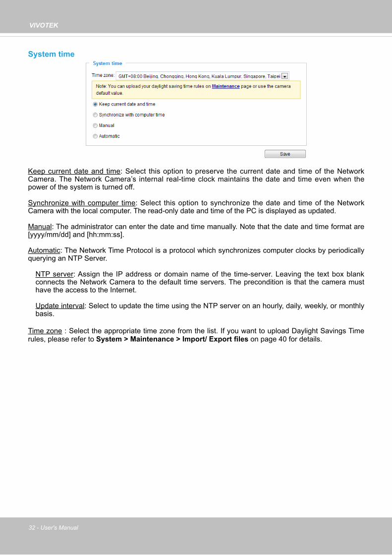
System time
Keep current date and time: Select this option to preserve the current date and time of the Network Camera. The Network Camera’s internal real-time clock maintains the date and time even when the power of the system is turned off.
Synchronize with computer time: Select this option to synchronize the date and time of the Network Camera with the local computer. The read-only date and time of the PC is displayed as updated.
Manual: The administrator can enter the date and time manually. Note that the date and time format are [yyyy/mm/dd] and [hh:mm:ss].
Automatic: The Network Time Protocol is a protocol which synchronizes computer clocks by periodically querying an NTP Server.
NTP server: Assign the IP address or domain name of the time-server. Leaving the text box blank connects the Network Camera to the default time servers. The precondition is that the camera must have the access to the Internet.
Update interval: Select to update the time using the NTP server on an hourly, daily, weekly, or monthly basis.
Time zone : Select the appropriate time zone from the list. If you want to upload Daylight Savings Time rules, please refer to System > Maintenance > Import/ Export files on page 40 for details.

VIVOTEK
User's Manual - 33
System > Homepage layout
This section explains how to set up your own customized homepage layout.
General settingsThis column shows the settings of your hompage layout. You can manually select the background and font colors in Theme Options (the second tab on this page). The settings will be displayed automatically in this Preview field. The following shows the homepage using the default settings:
■ Hide Powered by VIVOTEK: If you check this item, it will be removed from the homepage.
Logo graphHere you can change the logo that is placed at the top of your homepage.
Follow the steps below to upload a new logo:1. Click Custom and the Browse field will appear. 2. Select a logo from your files. 3. Click Upload to replace the existing logo with a new one.4. Enter a website link if necessary.5. Click Save to enable the settings.
Customized buttonIf you want to hide manual trigger buttons on the homepage, please uncheck this item. This item ischecked by default.

VIVOTEK
34 - User's Manual
Theme OptionsHere you can change the color of your homepage layout. There are three types of preset patterns for you to choose from. The new layout will simultaneously appear in the Preview filed. Click Save to enable the settings.
Font Color of the Video Title
Background Color of the Video AreaFrame Color
Font ColorBackground Color of the Control AreaFont Color of the Configuration Area
Background Color of the Configuration Area
Preset patterns

VIVOTEK
User's Manual - 35
■ Follow the steps below to set up the customed homepage:1. Click Custom on the left column.2. Click the field where you want to change the color on the right column.
3. The palette window will pop up as shown below.
4. Drag the slider bar and click on the left square to select a desired color. 5. The selected color will be displayed in the corresponding fields and in the Preview column.6. Click Save to enable the settings.
12
3
4
Color Selector
Custom Pattern

VIVOTEK
36 - User's Manual
System > Logs
This section explains how to configure the Network Camera to send the system log to a remote server as backup.
Log server settings
Follow the steps below to set up the remote log:
1. Select Enable remote log.2. In the IP address text box, enter the IP address of the remote server.2. In the port text box, enter the port number of the remote server.3. When completed, click Save to enable the setting.
You can configure the Network Camera to send the system log file to a remote server as a log backup. Before utilizing this feature, it is suggested that the user install a log-recording tool to receive system log messages from the Network Camera. An example is Kiwi Syslog Daemon. Visit http://www.kiwisyslog.com/kiwi-syslog-daemon-overview/.
System log
This column displays the system log in a chronological order. The system log is stored in the Network Camera’s buffer area and will be overwritten when reaching a certain limit.

VIVOTEK
User's Manual - 37
PC runningST7501 Recording Software
Internet
VIVOTEK Network Cameras
3G Cell phone
Cell phoneShort message
EmailGSMModem
HTTP
PTZDigital output
You can install the included ST7501 recording software, which provides an Event Management function group for delivering event messages via emails, GSM short messages, onscreen event panel, or to trigger an alarm, etc. For more information, refer to the ST7501 User Manual.

VIVOTEK
38 - User's Manual
Access log
Access log displays the access time and IP address of all viewers (including operators and administrators) in a chronological order. The access log is stored in the Network Camera’s buffer area and will be overwritten when reaching a certain limit.
System > Parameters
The View Parameters page lists the entire system’s parameters. If you need technical assistance, please provide the information listed on this page.

VIVOTEK
User's Manual - 39
System > Maintenance
This chapter explains how to restore the Network Camera to factory default, upgrade firmware version, etc.
General settings > Upgrade firmware
This feature allows you to upgrade the firmware of your Network Camera. It takes a few minutes to complete the process. Note: Do not power off the Network Camera during the upgrade! Follow the steps below to upgrade the firmware:1. Download the latest firmware file from the VIVOTEK website. The file is in .pkg file format.2. Click Browse… and locate the firmware file.3. Click Upgrade. The Network Camera starts to upgrade and will reboot automatically when the upgrade completes.
If the upgrade is successful, you will see “Reboot system now!! This connection will close”. After that, re-access the Network Camera.
The following message is displayed when the upgrade has succeeded.
The following message is displayed when you have selected an incorrect firmware file.
General settings > Reboot
This feature allows you to reboot the Network Camera, which takes about one minute to complete. When completed, the live video page will be displayed in your browser. The following message will be displayed during the reboot process.
If the connection fails after rebooting, manually enter the IP address of the Network Camera in the address field to resume the connection.
Starting firmware upgrade...Do not power down the server during the upgrade.The server will restart automatically after the upgrade is completed.This will take about 1 - 5 minutes.Wrong PKG file formatUnpack fail
Reboot system now!!This connection will close.

VIVOTEK
40 - User's Manual
General settings > Restore
This feature allows you to restore the Network Camera to factory default settings.
Network: Select this option to retain the Network Type settings (please refer to Network Type on page 60).
Daylight Saving Time: Select this option to retain the Daylight Saving Time settings (please refer to Import/Export files below on this page).
Custom Language: Select this option to retain the Custom Language settings.
If none of the options is selected, all settings will be restored to factory default. The following message is displayed during the restoring process.
Import/Export files
This feature allows you to Export / Update daylight saving time rules, custom language file, configuration file, and server status report.
Export daylight saving time configuration file: Click to set the start and end time of DST (Daylight Saving).
Follow the steps below to export:1. In the Export files column, click Export to export the daylight saving time configuration file from the
Network Camera.2. A file download dialog will pop up as shown below. Click Open to review the XML file or click Save to
store the file for editing.

VIVOTEK
User's Manual - 41
3. Open the file with Microsoft® Notepad and locate your time zone; set the start and end time of DST. When completed, save the file.
In the example below, DST begins each year at 2:00 a.m. on the second Sunday in March and ends at 2:00 a.m. on the first Sunday in November.
Update daylight saving time rules: Click Browse… and specify the XML file to update.
If the incorrect date and time are assigned, you will see the following warning message when uploading the file to the Network Camera.

VIVOTEK
42 - User's Manual
The following message is displayed when attempting to upload an incorrect file format.
Export language file: Click to export language strings. VIVOTEK provides nine languages: English, Deutsch, Español, Français, Italiano, 日本語, Português, 簡体中文, and 繁體中文.
Update custom language file: Click Browse… and specify your own custom language file to upload.
Export configuration file: Click to export all parameters for the device and user-defined scripts.
Update configuration file: Click Browse… to update a configuration file. Please note that the model and firmware version of the device should be the same as the configuration file. If you have set up a fixed IP or other special settings for your device, it is not suggested to update a configuration file.
Export server staus report: Click to export the current server status report, such as time, logs, parameters, process status, memory status, file system status, network status, kernel message ... and so on.
Tips:
• If a firmware upgrade is accidentally disrupted, say, by a power outage, you still have a last resort method to restore normal operation. See the following for how to bring the camera back to work:
Applicable scenario:
(a) Power disconnected during firmware upgrade.(b) Unknown reason causing abnormal LED status, and a Restore cannot recover normal working
condition.
You can use the following methods to activate the camera with its backup firmware:(a) Press and hold down the reset button for at least one minute.(b) Power on the camera until the Red LED blinks rapidly.(c) After boot up, the firmware should return to the previous version before the camera hanged. (The
procedure should take 5 to 10 minutes, longer than the normal boot-up process). When tthis process is completed, the LED status should return to normal.

VIVOTEK
User's Manual - 43
Media > Image This section explains how to configure the image settings of the Network Camera. It is composed of the following four columns: General settings, Picture settings, Exposure, and Privacy mask.
General settings
Video titleShow_timestamp_and video_title_in_video_and_snapshots: Enter a name that will be displayed on the title bar of the live video as the picture shown below. A zoom indicator will be displayed on the Home page when you zoom in/out on the live viewing window as shown below. You may zoom in/out on the image by scrolling the mouse wheel inside the live viewing window, and the maximum zoom in will be up to 4 times.
Position of timestamp and video title on image: Select to display time stamp and video title on the top or at the bottom of the video stream.
Timestamp and video title font size: Select the font size for the time stamp and title.
Color: Select to display color or black/white video streams.
Power line frequency: Set the power line frequency consistent with local utility settings to eliminate image flickering associated with fluorescent lights. Note that after the power line frequency is changed, you must disconnect and reconnect the power cord of the Network Camera in order for the new setting to take effect.
Video orientation: Flip - vertically reflect the display of the live video; Mirror - horizontally reflect the display of the live video. Select both options if the Network Camera is installed upside-down (e.g., on the ceiling) to correct the image orientation. Please note that if you have preset locations, those locations will be cleared after flip/mirror setting.
Video TitleTitle and Time Video 17:08:56 2014/7/09
2014/7/09 17:08:56
X2.1Zoom Factor
Zoom In Zoom Out

VIVOTEK
44 - User's Manual
Day/Night Settings
Switch to B/W in night modeSelect this to enable the Network Camera to automatically switch to Black/White during night mode.
Turn on built-in IR illuminator in night modeSelect this to turn on the camera’s onboard IR illuminator when the camera detects low light condition and enters the night mode.

VIVOTEK
User's Manual - 45
Smart IR disabled; distance: 5M Smart IR enabled; distance: 5M
Smart IR disabled; distance: 3M Smart IR enabled; distance: 3M
The Smart IR function is more beneficial when the spot of intrusions or an object of your interest is close to the lens and the IR lights. For example, if an intruder has a chance of getting near the range of 3 meters, Smart IR can effectively reduce the over-exposure. For a surveillance area at a greater distance, e.g., 5 meters, the Smart IR function may not bring as significant benefits as in close range.
Smart IRWhen enabled, the camera automatically adjust the IR projection to adjacent objects in order to avoid over-exposure in the night mode.

VIVOTEK
46 - User's Manual
IR cut filterWith a removable IR-cut filter, this Network Camera can automatically remove the filter to let IR light enter the light sensor during low light conditions.
■ Auto modeThe Network Camera automatically removes the filter by judging the level of ambient light.
■ Day modeIn day mode, the Network Camera switches on the IR cut filter at all times to block infrared light from reaching the sensor so that the colors will not be distorted.
■ Night modeIn night mode, the Network Camera switches off the IR cut filter at all times for the sensor to accept infrared light, thus helping to improve low light sensitivity.
■ Synchronize with digital input The Network Camera automatically removes the IR cut filter when a Digital Input is triggerred. For example, the digital input can come from a housing that is equipped with IR illumination and control circuits such as VIVOTEK’s AM-214.
Exclude x
Tips:
If there is an object in close proximity, the IR lights reflected back from it can mislead the Smart IR’s calculation of light level. To solve this issue, you can place an “Exposure Exclude” window on an unavoidable object in the Exposure setting window. See page 51 for how to do it.
You can also configure the “Exposure Exclude” window in a night mode “Profile” setting so that your day time setting is not affected.
Exclude x

VIVOTEK
User's Manual - 47
■ Schedule modeThe Network Camera switches between day mode and night mode based on a specified schedule. Enter the start and end time for day mode. Note that the time format is [hh:mm] and is expressed in 24-hour clock time. By default, the start and end time of day mode are set to 07:00 and 18:00.
SensitivityTune the responsiveness of the IR filter to lighting conditions as Low, Normal, or High.
When completed with the settings on this page, click Save to enable the settings.

VIVOTEK
48 - User's Manual
Image settingsOn this page, you can tune the White balance and Image adjustment.
White balance: Adjust the value for the best color temperature.■ You may follow the steps below to adjust the white balance to the best color temperature.
1. Place a sheet of paper of white or cooler-color temperature color, such as blue, in front of the lens, then allow the Network Camera to automatically adjust the color temperature.
2. Click the On button to Fix current value and confirm the setting while the white balance is being measured.
■ You may also manually tune the color temperature by pulling the RGain and BGain slide bars.
Image Adjustment■ Brightness: Adjust the image brightness level, which ranges from 0% to 100%.
■ Contrast: Adjust the image contrast level, which ranges from 0% to 100%.
■ Saturation: Adjust the image saturation level, which ranges from 0% to 100%.
■ Sharpness: Adjust the image sharpness level, which ranges from 0% to 100%.
■ Gamma curve: Adjust the image sharpness level, which ranges from 0 to 0.45. You may let firmware Optimize your display or select a value to change the preferred level of
Gamma correction towards higher contrast or towards the higher luminance for detailed expression for both dark and lighted areas of an image.
Sensor Setting 2: For special situations
Sensor Setting 1:For normal situations

VIVOTEK
User's Manual - 49
Note that the Preview button has been cancelled, all changes made to image settings is directly shown on screen. You can click Restore to recall the original settings without incorporating the changes. When completed with the settings on this page, click Save to enable the setting. You can also click on Profile to adjust all settings above in a pop-up window for special lighting conditions.
Activated period: Select the mode this profile to apply to: Day mode, Night mode, or Schedule mode. Please manually enter a range of time if you choose Schedule mode. Then check Save to take effect.
Noise reduction■ Enable noise reduction: Check to enable noise reduction in order to reduce noises and flickers
in image. This applies to the onboard 3D Noise Reduction feature. Use the pull-down menu to adjust the reduction strength. Note that applying this function to the video channel will consume system computing power.
3D Noise Reduction is mostly applied in low-light conditions. When enabled in a low-light condition with fast moving objects, trails of after-images may occur. You may then select a lower strength level or disable the function.

VIVOTEK
50 - User's Manual
Exposure
On this page, you can set the Exposure measurement window, Exposure level, Exposure mode, Exposure time, Gain control, and Day/Night mode settings. You can configure two sets of Exposure settings: one for normal situations, the other for special situations, such as the day/night/schedule mode.
Measurement Window: This function allows users to set measurement window(s) for low light compensation. For example, where low-light objects are posed against an extremely bright background. You may want to exclude the bright sunlight shining through a building's corridor.
■ Full view: Calculate the full range of view and offer appropriate light compensation.
■ Custom: This option allows you to manually add customized windows as inclusive or exclusive regions. A total of 10 windows can be configured. Please refer to the next page for detailed illustration.
Sensor Setting 1:For normal situations
Sensor Setting 2: For special situations

VIVOTEK
User's Manual - 51
Exposure control:■ Exposure level: You can manually set the Exposure level, which ranges from -2.0 to +2.0 (dark
to bright). You can click and drag the semi-circular pointers on the Exposure time and Gain control slide bars to specify a range of shutter time and Gain control values within which the camera can automatically tune to an optimal imaging result. You may prefer a shorter shutter time to better capture moving objects, while a faster shutter reduces light and needs to be compensated by electrical brightness gains.
■ Flickerless: This function helps avoid the flickering on images because of the fast shutter movement and the inconsistency between power line frequency (50 or 60Hz) and exposure time. When selected, the exposure time will be forced to stay longer than 1/120 second. For cameras that come with fixed iris lens, setting the exposure time to longer than 1/120 second may introduce too much lights to the lens. Users can use this option to observe whether the result of long exposure time is satisfactory.
The inclusive window refers to the “weighed window“; the exclusive window refers to “ignored window“. It adopts the weighed averages method to calculate the value. The inclusive windows have a higher priority. You can overlap these windows, and, if you place an exclusive window within a larger inclusive window, the exclusive part of the overlapped windows will be deducted from the inclusive window. An exposure value will then be calculated out of the remaining of the inclusive window.
■ BLC (Back Light Compensation): This option will automatically add a “weighted region“ in the middle of the window and give the necessary light compensation.
Include
Exclude
Weighted region
Ignored region
Include
Exclude

VIVOTEK
52 - User's Manual
Please follow the steps below to set up a profile:1. Select Enable this profile.2. Select the applicable mode: Day mode, Night
mode, or Schedule mode. Please manually enter a range of time if you choose Schedule mode.
3. Configure Exposure control settings in the folowing columns. Please refer to previous dicussions for detailed information.
4. Click Save to enable the setting and click Close to exit the page.
You can click Restore to recall the original settings without incorporating the changes. When completed with the settings on this page, click Save to enable the settings.
If you want to configure another sensor setting for day/night/schedule mode, please click Profile to open the Profile of exposure settings page as shown below.
Activated period: Select the mode this profile to apply to: Day mode, Night mode, or Schedule mode. Please manually enter a range of time if you choose Schedule mode. Then check Save to take effect.

VIVOTEK
User's Manual - 53
Privacy mask Click Privacy Mask to open the settings page. On this page, you can block out sensitive zones to address privacy concerns.
■ To set the privacy mask windows, follow the steps below:1. Click New to add a new window.2. You can use the mouse cursor to size and drag-drop the window, which is recommended to be
at least twice the size of the object (height and width) you want to cover.3. Enter a Window Name and click Save to enable the setting.4. Click on the Enable privacy mask checkbox to enable this function.
► Up to 5 privacy mask windows can be set up on the same screen.
► If you want to delete the privacy mask window, please click the ‘x’ mark on the upper right corner of the window.
2013/12/09 17:08:56
NOTE:

VIVOTEK
54 - User's Manual
Media > Video
Stream settings
This Network Camera supports multiple streams with frame sizes ranging from 176 x 144 to 1920 x 1080 pixels.
The definition of multiple streams:■ Stream 1: Users can define the "Region of Interest" (viewing region) and the "Output Frame Size"
(size of the live view window). ■ Stream 2: The default frame size for Stream 2 is set to the 1920 x 1080. ■ Stream 3: The default frame size for Stream 3 is set to the 640 x 360, and the Viewing Window
function is not available for stream 3.
Click Viewing Window to open the viewing region settings page. On this page, you can configure the Region of Interest and the Output Frame Size for a video stream. For example, you can crop only a portion of the image that is of your interest, and thus save the bandwidth needed to transmit the video stream. As the picture shown below, the area of your interest in a parking lot should be the vehicles. The blue sky is of little value for the surveillance purpose.

VIVOTEK
User's Manual - 55
Media > Video► All the items in the “Region of Interest” should not be larger than the “Output Frame Size“
(current maximum resolution).
■ The parameters of the multiple streams:
When completed with the settings in the Viewing Window, click Save to enable the settings and click Close to exit the window. The selected Output Frame Size will immediately be applied to the Frame size of each video stream. Then you can go back to the home page to test the e-PTZ function. For more information about the e-PTZ function, please refer to page 89.
X2.1
Region of Interest(Viewing Region)
Output Frame Size (Size of the Live View Window)
Region of Interest Output frame size
Stream 1 1920 X 1080 ~ 176 x 144 (Selectable) 1920 X 1080 ~ 176 x 144 (Selectable)Stream 2 1920 X 1080 ~ 176 x 144 (Selectable) 1920 X 1080 ~ 176 x 144 (Selectable)Stream 3 Fixed Fixed
NOTE:
Please follow the steps below to set up those settings for a stream:1. Select a stream for which you want to set up the viewing region.2. Select a Region of Interest from the drop-down list. The floating frame, the same as the one
in the Gloabl View window on the home page, will resize accordingly. If you want to set up a customized viewing region, you can also resize and drag the floating frame to a desired position with your mouse.
3. Choose a proper Output Frame Size from the drop-down list according to the size of your monitoring device.

VIVOTEK
56 - User's Manual
Click the stream item to display the detailed information. The maximum frame size will follow your settings in the above Viewing Window sections.
This Network Camera offers real-time H.264 and MJPEG compression standards (Dual Codec) for real-time viewing. If the H.264 mode is selected, the video is streamed via RTSP protocol. There are several parameters through which you can adjust the video performance:
■ Frame sizeYou can set up different video resolution for different viewing devices. For example, set a smaller frame size and lower bit rate for remote viewing on mobile phones and a larger video size and a higher bit rate for live viewing on web browsers. Note that a larger frame size takes up more bandwidth.
■ Maximum frame rateThis limits the maximum refresh frame rate per second. Set the frame rate higher for smoother video quality and for recognizing moving objects in the field of view.
If the power line frequency is set to 50Hz, the frame rates are selectable at 1fps, 2fps, 3fps, 5fps, 8fps, 10fps, 12fps, 15fps, 20fps, and 25fps. If the power line frequency is set to 60Hz, the frame rates are selectable at 1fps, 2fps, 3fps, 5fps, 8fps, 10fps, 12fps, 15fps, 20fps, 25fps, and 30fps. You can also select Customize and manually enter a value.

VIVOTEK
User's Manual - 57
The frame rate will decrease if you select a higher resolution.
■ Intra frame periodDetermine how often for firmware to plant an I frame. The shorter the duration, the more likely you will get better video quality, but at the cost of higher network bandwidth consumption. Select the intra frame period from the following durations: 1/4 second, 1/2 second, 1 second, 2 seconds, 3 seconds, and 4 seconds.
■ Video qualityConstant bit rate:
• Constant bit rate: A complex scene generally produces a larger file size, meaning that higher bandwidth will be needed for data transmission. The bandwidth utilization is configurable to match a selected level, resulting in mutable video quality performance. The bit rates are selectable at the following rates: 20Kbps, 30Kbps, 40Kbps, 50Kbps, 64Kbps, 128Kbps, 256Kbps, 512Kbps, 768Kbps, 1Mbps, 2Mbps, 3Mbps, 4Mbps, 6Mbps, 8Mbps, 10Mbps, 12Mbps, 14Mbps, and 16Mbps. You can also select Customize and manually enter a value up to 40Mbps.- Target bit rate: select a bit rate from the pull-down menu. The bit rate ranges from 20kbps to a maximum of 16Mbps. The bit rate then becomes the Average or Upper bound bit rate number. The Network Camera will strive to deliver video streams around or within the bit rate limitation you impose. - Policy: If Frame Rate Priority is selected, the Network Camera will try to maintain the frame rate per second performance, while the image quality will be compromised. If Image quality priority is selected, the Network Camera may drop some video frames in order to maintain image quality.
• Fixed quality: On the other hand, if Fixed quality is selected, all frames are transmitted with the same quality; bandwidth utilization is therefore unpredictable. The video quality can be adjusted to the following settings: Medium, Standard, Good, Detailed, and Excellent. You can also select Customize and manually enter a value.
Maximum bit rate: With the guaranteed image quality, you might still want to place a bit rate limitation to control the size of video streams for bandwidth and storage concerns. The configurable bit rate starts from 1Mbps to 40Mbps.
You may also manually enter a bit rate number by selecting the Customized option.
VIVOTEK
58 - User's Manual
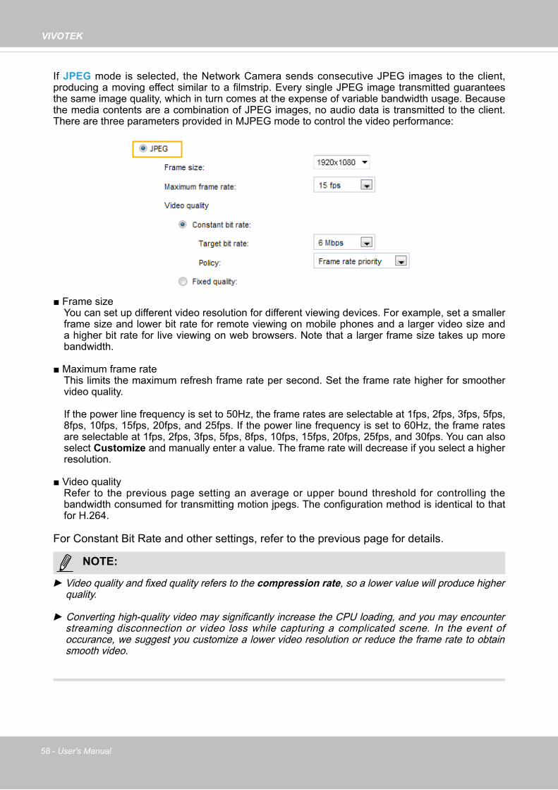
If JPEG mode is selected, the Network Camera sends consecutive JPEG images to the client, producing a moving effect similar to a filmstrip. Every single JPEG image transmitted guarantees the same image quality, which in turn comes at the expense of variable bandwidth usage. Because the media contents are a combination of JPEG images, no audio data is transmitted to the client. There are three parameters provided in MJPEG mode to control the video performance:
■ Frame sizeYou can set up different video resolution for different viewing devices. For example, set a smaller frame size and lower bit rate for remote viewing on mobile phones and a larger video size and a higher bit rate for live viewing on web browsers. Note that a larger frame size takes up more bandwidth.
■ Maximum frame rateThis limits the maximum refresh frame rate per second. Set the frame rate higher for smoother video quality.
If the power line frequency is set to 50Hz, the frame rates are selectable at 1fps, 2fps, 3fps, 5fps, 8fps, 10fps, 15fps, 20fps, and 25fps. If the power line frequency is set to 60Hz, the frame rates are selectable at 1fps, 2fps, 3fps, 5fps, 8fps, 10fps, 15fps, 20fps, 25fps, and 30fps. You can also select Customize and manually enter a value. The frame rate will decrease if you select a higher resolution.
■ Video qualityRefer to the previous page setting an average or upper bound threshold for controlling the bandwidth consumed for transmitting motion jpegs. The configuration method is identical to that for H.264.
For Constant Bit Rate and other settings, refer to the previous page for details.
► Video quality and fixed quality refers to the compression rate, so a lower value will produce higher quality.
► Converting high-quality video may significantly increase the CPU loading, and you may encounter streaming disconnection or video loss while capturing a complicated scene. In the event of occurance, we suggest you customize a lower video resolution or reduce the frame rate to obtain smooth video.
NOTE:

VIVOTEK
User's Manual - 59
Network > General settings
This section explains how to configure a wired network connection for the Network Camera.
Network Type
LANSelect this option when the Network Camera is deployed on a local area network (LAN) and is intended to be accessed by local computers. The default setting for the Network Type is LAN. Please rememer to click on the Save button when you complete the Network setting.
Get IP address automatically: Select this option to obtain an available dynamic IP address assigned by the DHCP server each time the camera is connected to the LAN.
Use fixed IP address: Select this option to manually assign a static IP address to the Network Camera.
1. You can make use of VIVOTEK Installation Wizard 2 on the software CD to easily set up the Network Camera on LAN. Please refer to Software Installation on page 12 for details.
2. Enter the Static IP, Subnet mask, Default router, and Primary DNS provided by your ISP or network administrator.
Subnet mask: This is used to determine if the destination is in the same subnet. The default value is“255.255.255.0”.
Default router: This is the gateway used to forward frames to destinations in a different subnet. Invalid router setting will disable the transmission to destinations across different subnets.

VIVOTEK
60 - User's Manual
Primary DNS: The primary domain name server that translates hostnames into IP addresses.
Secondary DNS: Secondary domain name server that backups the Primary DNS.
Primary WINS server: The primary WINS server that maintains the database of computer names and IP addresses.
Secondary WINS server: The secondary WINS server that maintains the database of computer names and IP addresses.
Enable UPnP presentation: Select this option to enable UPnPTM presentation for your Network Camera so that whenever a Network Camera is presented to the LAN, the shortcuts to connected Network Cameras will be listed in My Network Places. You can click the shortcut to link to the web browser. Currently, UPnPTM is supported by Windows XP or later. Note that to utilize this feature, please make sure the UPnPTM component is installed on your computer.
Enable UPnP port forwarding: To access the Network Camera from the Internet, select this option to allow the Network Camera to open ports automatically on the router so that video streams can be sent out from a LAN. To utilize of this feature, make sure that your router supports UPnPTM and it is activated.
PPPoE (Point-to-point over Ethernet)Select this option to configure your Network Camera to make it accessible from anywhere as long as there is an Internet connection. Note that to utilize this feature, it requires an account provided by your ISP. Follow the steps below to acquire your Network Camera’s public IP address.1. Set up the Network Camera on the LAN.2. Go to Configuration > Event > Event settings > Add server (please refer to Add server on page
96) to add a new email or FTP server.3. Go to Configuration > Event > Event settings > Add media (please refer to Add media on page
101). Select System log so that you will receive the system log in TXT file format which contains the Network Camera’s public IP address in your email or on the FTP server.4. Go to Configuration > Network > General settings > Network type. Select PPPoE and enter the
user name and password provided by your ISP. Click Save to enable the setting.
5. The Network Camera will reboot.6. Disconnect the power to the Network Camera; remove it from the LAN environment.
Mega-pixel Network Camera (192.168.5.151)

VIVOTEK
User's Manual - 61
► If the default ports are already used by other devices connected to the same router, the Network Camera will select other ports for the Network Camera.
► If UPnPTM is not supported by your router, you will see the following message: Error: Router does not support UPnP port forwarding.
► Steps to enable the UPnPTM user interface on your computer:Note that you must log on to the computer as a system administrator to install the UPnPTM components.
1. Go to Start, click Control Panel, then click Add or Remove Programs.
2. In the Add or Remove Programs dialog box, click Add/Remove Windows Components.
3. In the Windows Components Wizard dialog box, select Networking Services and click Details.
NOTE:

VIVOTEK
62 - User's Manual
4. In the Networking Services dialog box, select Universal Plug and Play and click OK.
5. Click Next in the following window.
6. Click Finish. UPnPTM is enabled.
► How does UPnPTM work?UPnPTM networking technology provides automatic IP configuration and dynamic discovery of devices added to a network. Services and capabilities offered by networked devices, such as printing and file sharing, are available among each other without the need for cumbersome network configuration. In the case of Network Cameras, you will see Network Camera shortcuts under My Network Places.
► Enabling UPnP port forwarding allows the Network Camera to open a secondary HTTP port on the router-not HTTP port-meaning that you have to add the secondary HTTP port number to the Network Camera’s public address in order to access the Network Camera from the Internet. For example, when the HTTP port is set to 80 and the secondary HTTP port is set to 8080, refer to the list below for the Network Camera’s IP address.From the Internet In LANhttp://203.67.124.123:8080 http://192.168.4.160 or
http://192.168.4.160:8080
► If the PPPoE settings are incorrectly configured or the Internet access is not working, restore the Network Camera to factory default; please refer to Restore on page 40 for details. After the Network Camera is reset to factory default, it will be accessible on the LAN.

VIVOTEK
User's Manual - 63
Enable IPv6Select this option and click Save to enable IPv6 settings. Please note that this only works if your network environment and hardware equipment support IPv6. The browser should be Microsoft® Internet Explorer 6.5, Mozilla Firefox 3.0 or above.
When IPv6 is enabled, by default, the network camera will listen to router advertisements and be assigned with a link-local IPv6 address accordingly.
IPv6 Information: Click this button to obtain the IPv6 information as shown below.
If your IPv6 settings are successful, the IPv6 address list will be listed in the pop-up window. The IPv6 address will be displayed as follows:
Link-global IPv6 address/network maskLink-local IPv6 address/network mask
Refers to Ethernet

VIVOTEK
64 - User's Manual
Please follow the steps below to link to an IPv6 address:1. Open your web browser.2. Enter the link-global or link-local IPv6 address in the address bar of your web browser.3. The format should be:
4. Press Enter on the keyboard or click Refresh button to refresh the webpage. For example:
► If you have a Secondary HTTP port (the default value is 8080), you can also link to the webpage using the following address format: (Please refer to HTTP streaming on page 66 for detailed information.)
► If you choose PPPoE as the Network Type, the [PPP0 address] will be displayed in the IPv6 information column as shown below.
Manually setup the IP address: Select this option to manually set up IPv6 settings if your network environment does not have DHCPv6 server and router advertisements-enabled routers. If you check this item, the following blanks will be displayed for you to enter the corresponding information:
http://[2001:0c08:2500:0002:0202:d1ff:fe04:65f4]/
IPv6 address
http://[2001:0c08:2500:0002:0202:d1ff:fe04:65f4]/:8080
IPv6 address Secondary HTTP port
NOTE:
VIVOTEK
User's Manual - 65
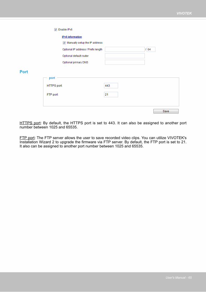
Port
HTTPS port: By default, the HTTPS port is set to 443. It can also be assigned to another port number between 1025 and 65535.
FTP port: The FTP server allows the user to save recorded video clips. You can utilize VIVOTEK's Installation Wizard 2 to upgrade the firmware via FTP server. By default, the FTP port is set to 21. It also can be assigned to another port number between 1025 and 65535.

VIVOTEK
66 - User's Manual
Network > Streaming protocols
HTTP streaming To utilize HTTP authentication, make sure that your have set a password for the Network Camera first; please refer to Security > User account on page 76 for details.
Authentication: Depending on your network security requirements, the Network Camera provides two types of security settings for an HTTP transaction: basic and digest. If basic authentication is selected, the password is sent in plain text format and there can be potential risks of being intercepted. If digest authentication is selected, user credentials are encrypted using MD5 algorithm and thus provide better protection against unauthorized accesses.
HTTP port / Secondary HTTP port: By default, the HTTP port is set to 80 and the secondary HTTP port is set to 8080. They can also be assigned to another port number between 1025 and 65535. If the ports are incorrectly assigned, the following warning messages will be displayed:
To access the Network Camera on the LAN, both the HTTP port and secondary HTTP port can be used to access the Network Camera. For example, when the HTTP port is set to 80 and the secondary HTTP port is set to 8080, refer to the list below for the Network Camera’s IP address.
Access name for stream 1 ~ 3: This Network camera supports multiple streams simultaneously. The access name is used to identify different video streams. Users can click Media > Video > Stream settings to set up the video quality of linked streams. For more information about how to set up the video quality, please refer to Stream settings on page 54.
When using Mozilla Firefox to access the Network Camera and the video mode is set to JPEG, users will receive video comprised of continuous JPEG images. This technology, known as “server push”, allows the Network Camera to feed live pictures to Mozilla Firefox.
On the LANhttp://192.168.4.160 or http://192.168.4.160:8080

VIVOTEK
User's Manual - 67
URL command -- http://<ip address>:<http port>/<access name for stream 1, 2, or 3>For example, when the Access name for stream 2 is set to video2.mjpg:1. Launch Mozilla Firefox or Netscape.2. Type the above URL command in the address bar. Press Enter.3. The JPEG images will be displayed in your web browser.
NOTE
► Microsoft® Internet Explorer does not support server push technology; therefore, you will not be able to access a video stream using http://<ip address>:<http port>/<access name for stream 1, 2, or 3> .
RTSP StreamingTo utilize RTSP streaming authentication, make sure that you have set a password for controlling the access to video stream first. Please refer to Security > User account on page 76 for details.
http://192.168.5.151/video2.mjpg
NOTE:

VIVOTEK
68 - User's Manual
Authentication: Depending on your network security requirements, the Network Camera provides three types of security settings for streaming via RTSP protocol: disable, basic, and digest. If basic authentication is selected, the password is sent in plain text format, but there can be potential risks of it being intercepted. If digest authentication is selected, user credentials are encrypted using MD5 algorithm, thus providing better protection against unauthorized access. The availability of the RTSP streaming for the three authentication modes is listed below:
Access name for stream 1 ~ 3: This Network camera supports multiple streams simultaneously. The access name is used to differentiate the streaming source. If you want to use an RTSP player to access the Network Camera, you have to set the video mode to H.264 and use the following RTSP URL command to request transmission of the streaming data.rtsp://<ip address>:<rtsp port>/<access name for stream 1 to 3>For example, when the access name for stream 1 is set to live.sdp:1. Launch an RTSP player.2. Choose File > Open URL. A URL dialog box will pop up.3. Type the above URL command in the text box. 4. The live video will be displayed in your player as shown below.
RTSP port /RTP port for video, audio/ RTCP port for video, audio ■ RTSP (Real-Time Streaming Protocol) controls the delivery of streaming media. By default, the
port number is set to 554.
■ The RTP (Real-time Transport Protocol) is used to deliver video and audio data to the clients. By default, the RTP port for video is set to 5556.
■ The RTCP (Real-time Transport Control Protocol) allows the Network Camera to transmit the data by monitoring the Internet traffic volume. By default, the RTCP port for video is set to 5557.
The ports can be changed to values between 1025 and 65535. The RTP port must be an even number and the RTCP port is the RTP port number plus one, and thus is always an odd number. When the RTP port changes, the RTCP port will change accordingly.
If the RTP ports are incorrectly assigned, the following warning message will be displayed:
rtsp://192.168.5.151:554/live.sdp
Quick Time player VLC
Disable O OBasic O ODigest O X
Video 16:38:01 2012/01/25

VIVOTEK
User's Manual - 69
Multicast settings for streams: Click the items to display the detailed configuration information. Select the Always multicast option to enable multicast for video streams.
Unicast video transmission delivers a stream through point-to-point transmission; multicast, on the other hand, sends a stream to the multicast group address and allows multiple clients to acquire the stream at the same time by requesting a copy from the multicast group address. Therefore, enabling multicast can effectively save Internet bandwith.
The ports can be changed to values between 1025 and 65535. The multicast RTP port must be an even number and the multicast RTCP port number is the multicast RTP port number plus one, and thus is always odd. When the multicast RTP port changes, the multicast RTCP port will change accordingly.
If the multicast RTP video ports are incorrectly assigned, the following warning message will be displayed:
Multicast TTL [1~255]: The multicast TTL (Time To Live) is the value that tells the router the range a packet can be forwarded.
Initial TTL Scope0 Restricted to the same host1 Restricted to the same subnetwork32 Restricted to the same site64 Restricted to the same region128 Restricted to the same continent255 Unrestricted in scope

VIVOTEK
70 - User's Manual
Network > DDNS
This section explains how to configure the dynamic domain name service for the Network Camera. DDNS is a service that allows your Network Camera, especially when assigned with a dynamic IP address, to have a fixed host and domain name.
Express link Express Link is a free service provided by VIVOTEK server, which allows users to register a domain name for a network device. One URL can only be mapped to one MAC address. This service will examine if the host name is valid and automatically open a port on your router. If using DDNS, the user has to manually configure UPnP port forwarding. Express Link is more convenient and easier to set up.
Please follow the steps below to enable Express Link:1. Make sure that your router supports UPnP port forwarding and it is activated.2. Check Enable express link.3. Enter a host name for the network device and click Save. If the host name has been used by
another device, a warning message will show up. If the host name is valid, it will display a message as shown below.
https://0002D1123456.2bthere.net
2010/12/10 17:08:56
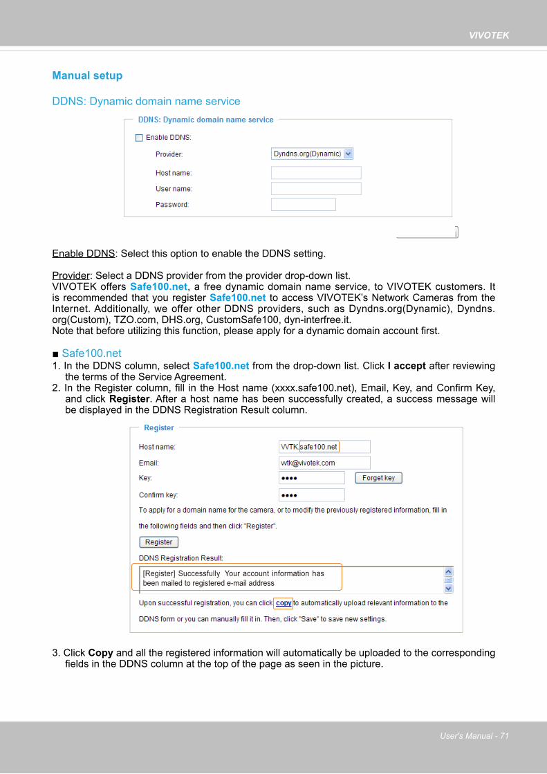
VIVOTEK
User's Manual - 71
Manual setup
DDNS: Dynamic domain name service
Enable DDNS: Select this option to enable the DDNS setting.
Provider: Select a DDNS provider from the provider drop-down list.VIVOTEK offers Safe100.net, a free dynamic domain name service, to VIVOTEK customers. It is recommended that you register Safe100.net to access VIVOTEK’s Network Cameras from the Internet. Additionally, we offer other DDNS providers, such as Dyndns.org(Dynamic), Dyndns.org(Custom), TZO.com, DHS.org, CustomSafe100, dyn-interfree.it. Note that before utilizing this function, please apply for a dynamic domain account first.
■ Safe100.net1. In the DDNS column, select Safe100.net from the drop-down list. Click I accept after reviewing
the terms of the Service Agreement.2. In the Register column, fill in the Host name (xxxx.safe100.net), Email, Key, and Confirm Key,
and click Register. After a host name has been successfully created, a success message will be displayed in the DDNS Registration Result column.
3. Click Copy and all the registered information will automatically be uploaded to the corresponding fields in the DDNS column at the top of the page as seen in the picture.
[Register] Successfully Your account information has been mailed to registered e-mail address

VIVOTEK
72 - User's Manual
[Register] Successfully Your account information has been mailed to registered e-mail address
4. Select Enable DDNS and click Save to enable the setting.
■ CustomSafe100VIVOTEK offers documents to establish a CustomSafe100 DDNS server for distributors and system integrators. You can use CustomSafe100 to register a dynamic domain name if your distributor or system integrators offer such services.
1. In the DDNS column, select CustomSafe100 from the drop-down list.2. In the Register column, fill in the Host name, Email, Key, and Confirm Key; then click Register.
After a host name has been successfully created, you will see a success message in the DDNS Registration Result column.
3. Click Copy and all for the registered information will be uploaded to the corresponding fields in the DDNS column.
4. Select Enable DDNS and click Save to enable the setting.
Forget key: Click this button if you have forgotten the key to Safe100.net or CustomSafe100. Your account information will be sent to your email address.
Refer to the following links to apply for a dynamic domain account when selecting other DDNS providers:■ Dyndns.org(Dynamic) / Dyndns.org(Custom): visit http://www.dyndns.com/■ dyn-interfree.it: visit http://dyn-interfree.it/

VIVOTEK
User's Manual - 73
Network > QoS (Quality of Service) Quality of Service refers to a resource reservation control mechanism, which guarantees a certain quality to different services on the network. Quality of service guarantees are important if the network capacity is insufficient, especially for real-time streaming multimedia applications. Quality can be defined as, for instance, a maintained level of bit rate, low latency, no packet dropping, etc.
The following are the main benefits of a QoS-aware network:■ The ability to prioritize traffic and guarantee a certain level of performance to the data flow. ■ The ability to control the amount of bandwidth each application may use, and thus provide higher
reliability and stability on the network.
Requirements for QoSTo utilize QoS in a network environment, the following requirements must be met:■ All network switches and routers in the network must include support for QoS. ■ The network video devices used in the network must be QoS-enabled.
QoS models
CoS (the VLAN 802.1p model)IEEE802.1p defines a QoS model at OSI Layer 2 (Data Link Layer), which is called CoS, Class of Service. It adds a 3-bit value to the VLAN MAC header, which indicates the frame priority level from 0 (lowest) to 7 (highest). The priority is set up on the network switches, which then use different queuing disciplines to forward the packets.
Below is the setting column for CoS. Enter the VLAN ID of your switch (0~4095) and choose the priority for each application (0~7).
If you assign Video the highest level, the switch will handle video packets first.
► A VLAN Switch (802.1p) is required. Web browsing may fail if the CoS setting is incorrect.
►The Class of Service technologies do not guarantee a level of service in terms of bandwidth and delivery time; they offer a "best-effort." Users can think of CoS as "coarsely-grained" traffic control and QoS as "finely-grained" traffic control.
► Although CoS is simple to manage, it lacks scalability and does not offer end-to-end guarantees since it is based on L2 protocol.
NOTE:

VIVOTEK
74 - User's Manual
QoS/DSCP (the DiffServ model)DSCP-ECN defines QoS at Layer 3 (Network Layer). The Differentiated Services (DiffServ) model is based on packet marking and router queuing disciplines. The marking is done by adding a field to the IP header, called the DSCP (Differentiated Services Codepoint). This is a 6-bit field that provides 64 different class IDs. It gives an indication of how a given packet is to be forwarded, known as the Per Hop Behavior (PHB). The PHB describes a particular service level in terms of bandwidth, queueing theory, and dropping (discarding the packet) decisions. Routers at each network node classify packets according to their DSCP value and give them a particular forwarding treatment; for example, how much bandwidth to reserve for it.
Below are the setting options of DSCP (DiffServ Codepoint). Specify the DSCP value for each application (0~63).

VIVOTEK
User's Manual - 75
Network > SNMP (Simple Network Management Protocol)
This section explains how to use the SNMP on the network camera. The Simple Network Management Protocol is an application layer protocol that facilitates the exchange of management information between network devices. It helps network administrators to remotely manage network devices and find, solve network problems with ease.
■ The SNMP consists of the following three key components: 1. Manager: Network-management station (NMS), a server which executes applications that
monitor and control managed devices.2. Agent: A network-management software module on a managed device which transfers the status
of managed devices to the NMS.3. Managed device: A network node on a managed network. For example: routers, switches,
bridges, hubs, computer hosts, printers, IP telephones, network cameras, web server, and database.
Before configuring SNMP settings on the this page, please enable your NMS first.
SNMP Configuration
Enable SNMPv1, SNMPv2c Select this option and enter the names of Read/Write community and Read Only community according to your NMS settings.
Enable SNMPv3This option contains cryptographic security, a higher security level, which allows you to set the Authentication password and the Encryption password.
■ Security name: According to your NMS settings, choose Read/Write or Read Only and enter the community name.
■ Authentication type: Select MD5 or SHA as the authentication method.
■ Authentication password: Enter the password for authentication (at least 8 characters).
■ Encryption password: Enter a password for encryption (at least 8 characters).

VIVOTEK
76 - User's Manual
Security > User accounts
This section explains how to enable password protection and create multiple accounts.
Root Password
The administrator account name is “root”, which is permanent and can not be deleted. If you want to add more accounts in the Manage User column, please apply the password for the “root” account first.1. Type the password identically in both text boxes, then click Save to enable password protection.2. A window will be prompted for authentication; type the correct user’s name and password in their
respective fields to access the Network Camera.
Privilege Management
PTZ control: You can modify the management privilege for operators or viewers. Select or deselect the checkboxes, then click Save to enable the settings. If you give Viewers the privilege, Operators will also have the ability to control the Network Camera through the main page. (Please refer to Configuration on page 30).
Allow anonymous viewing: If you check this item, any client can access the live stream without entering a User ID and Password.
Account Management
Administrators can create up to 20 user accounts.1. Input the new user’s name and password.2. Select the privilege level for the new user account. Click Add to enable the setting.
Access rights are sorted by user privilege (Administrator, Operator, and Viewer). Only administrators can access the Configuration page. Although operators cannot access the Configuration page, they can use the URL Commands to get and set the value of parameters. For more information, please refer to URL Commands of the Network Camera on page 119. Viewers can only access the main page for live viewing.
Here you also can change a user’s access rights or delete user accounts.1. Select an existing account to modify.2. Make necessary changes and click Update or Delete to enable the setting.

VIVOTEK
User's Manual - 77
Security > HTTPS (Hypertext Transfer Protocol over SSL) This section explains how to enable authentication and encrypted communication over SSL (Secure Socket Layer). It helps protect streaming data transmission over the Internet on higher security level.
Create and Install Certificate Method
Before using HTTPS for communication with the Network Camera, a Certificate must be created first. There are three ways to create and install a certificate: Create self-signed certificate1. Select this option from a pull-down menu.2. In the first column, select Enable HTTPS secure connection, then select a connection option:
“HTTP & HTTPS” or “HTTPS only”.3. Click Create certificate to generate a certificate.
4. The Certificate Information will automatically be displayed as shown below. You can click Certifi-cate properties to view detailed information about the certificate.

VIVOTEK
78 - User's Manual
5. Click Save to preserve your configuration, and your current session with the camera will change to the encrypted connection.
6. If your web session does not automatically change to an encrypted HTTPS session, click Home to return to the main page. Change the URL address from “http://” to “https://“ in the address bar and press Enter on your keyboard. Some Security Alert dialogs will pop up. Click OK or Yes to enable HTTPS.
https://192.168.5.151/index.html
https://

VIVOTEK
User's Manual - 79
Create certificate request and install1. Select the option from the Method pull-down menu. 2. Click Create certificate to proceed.3. The following information will show up in a pop-up window after clicking Create. Then click Save
to generate the certificate request.
4. The Certificate request window will prompt.
If you see the following Information bar, click OK and click on the Information bar at the top of the page to allow pop-ups.

VIVOTEK
80 - User's Manual
5. Look for a trusted certificate authority, such as Symantec’s VeriSign Authentication Services, that issues digital certificates. Sign in and purchase the SSL certification service. Copy the certificate request from your request prompt and paste it in the CA’s signing request window. Proceed with the rest of the process as CA’s instructions on their webpage.
6. Once completed, your SSL certificate should be delivered to you via an email or other means. Copy the contents of the certificate in the email and paste it in a text/HTML/hex editor/converter, such as IDM Computer Solutions’ UltraEdit.

VIVOTEK
User's Manual - 81
7. Open a new edit, paste the certificate contents, and press ENTER at the end of the contents to add an empty line.
8. Convert file format from DOS to UNIX. Open File menu > Conversions > DOS to Unix.

VIVOTEK
82 - User's Manual
9. Save the edit using the “.crt” extension, using a file name like “CAcert.crt.”
10. Return to the original firmware session, use the Browse button to locate the crt certificate file, and click Upload to enable the certification.

VIVOTEK
User's Manual - 83
11. When the certifice file is successfully loaded, its status will be stated as Active. Note that a certificate must have been created and installed before you can click on the “Save" button for the configuration to take effect.
12.To begin an encrypted HTTPS session, click Home to return to the main page. Change the URL address from “http://” to “https://“ in the address bar and press Enter on your keyboard. Some Security Alert dialogs will pop up. Click OK or Yes to enable HTTPS.

VIVOTEK
84 - User's Manual
Security > Access List
This section explains how to control access permission by verifying the client PC’s IP address.
General Settings
Maximum number of concurrent streaming connection(s) limited to: Simultaneous live viewing for 1~10 clients (including stream 1 to stream 3). The default value is 10. If you modify the value and click Save, all current connections will be disconnected and automatically attempt to re-link (IE Explorer or Quick Time Player).
View Information: Click this button to display the connection status window showing a list of the current connections. For example:
Note that only consoles that are currently displaying live streaming will be listed in the View Information list.
■ IP address: Current connections to the Network Camera.
■ Elapsed time: How much time the client has been at the webpage.
■ User ID: If the administrator has set a password for the webpage, the clients have to enter a user name and password to access the live video. The user name will be displayed in the User ID column. If the administrator allows clients to link to the webpage without a user name and password, the User ID column will be empty.
There are some situations that allow clients access to the live video without a user name and password:1. The administrator does not set up a root password. For more information about how to set up
a root password and manage user accounts, please refer to Security > User account on page 76.
2. The administrator has set up a root password, but set RTSP Authentication to “disable“. For more information about RTSP Authentication, please refer to RTSP Streaming on page 67.
3. The administrator has set up a root password, but allows anonymous viewing. For more information about Allow Anonymous Viewing, please refer to page 76.

VIVOTEK
User's Manual - 85
■ Refresh: Click this button to refresh all current connections.
■ Add to deny list: You can select entries from the Connection Status list and add them to the Deny List to deny access. Please note that those checked connections will only be disconnected temporarily and will automatically try to re-link again (IE Explore or Quick Time Player). If you want to enable the denied list, please check Enable access list filtering and click Save in the first column.
■ Disconnect: If you want to break off the current connections, please select them and click this button. Please note that those checked connections will only be disconnected temporarily and will automatically try to re-link again (IE Explore or Quick Time Player).
Filter Enable access list filtering: Check this item and click Save if you want to enable the access list filtering function.
Filter type: Select Allow or Deny as the filter type. If you choose Allow Type, only those clients whose IP addresses are on the Access List below can access the Network Camera, and the others cannot. On the contrary, if you choose Deny Type, those clients whose IP addresses are on the Access List below will not be allowed to access the Network Camera, and the others can.
Then you can Add a rule to the following Access List. Please note that the IPv6 access list column will not be displayed unless you enable IPv6 on the Network page. For more information about IPv6 Settings, please refer to Network > General settings on page 59 for detailed information.

VIVOTEK
86 - User's Manual
Network: This rule allows the user to assign a network address and corresponding subnet mask to the Allow/Deny List. The address and network mask are written in CIDR format. For example:
Range: This rule allows the user to assign a range of IP addresses to the Allow/Deny List. Note: This rule only applies to IPv4 addresses.For example:
Administrator IP addressAlways allow the IP address to access this device: You can check this item and add the Administrator’s IP address in this field to make sure the Administrator can always connect to the device.
IP address range 192.168.2.x will be bolcked.
There are three types of rules:Single: This rule allows the user to add an IP address to the Allowed/Denied list. For example:
192.168.2.1
If IPv6 filter is preferred, you will be prompted by the following window. Enter the IPv6 address and the two-digit prefix length to specify the range of IP addresses in your configuration.

VIVOTEK
User's Manual - 87
Security > IEEE 802.1X
Enable this function if your network environment uses IEEE 802.1x, which is a port-based network access control. The network devices, intermediary switch/access point/hub, and RADIUS server must support and enable 802.1x settings.
The 802.1x standard is designed to enhance the security of local area networks, which provides authentication to network devices (clients) attached to a network port (wired or wireless). If all certificates between client and server are verified, a point-to-point connection will be enabled; if authentication fails, access on that port will be prohibited. 802.1x utilizes an existing protocol, the Extensible Authentication Protocol (EAP), to facilitate communication.
■ The components of a protected network with 802.1x authentication:
1. Supplicant: A client end user (camera), which requests authentication. 2. Authenticator (an access point or a switch): A “go between” which restricts unauthorized end
users from communicating with the authentication server. 3. Authentication server (usually a RADIUS server): Checks the client certificate and decides
whether to accept the end user’s access request.
■ VIVOTEK Network Cameras support two types of EAP methods to perform authentication: EAP-PEAP and EAP-TLS.
Please follow the steps below to enable 802.1x settings:1. Before connecting the Network Camera to the protected network with 802.1x, please apply
a digital certificate from a Certificate Authority (i.e., your network administrator) which can be validated by a RADIUS server.
2. Connect the Network Camera to a PC or notebook outside of the protected LAN. Open the configuration page of the Network Camera as shown below. Select EAP-PEAP or EAP-TLS as the EAP method. In the following blanks, enter your ID and password issued by the CA, then upload related certificate(s).
Supplicant(Network Camera)
Authenticator(Network Switch)
Authentication Server(RADIUS Server)

VIVOTEK
88 - User's Manual
3. When all settings are complete, move the Network Camera to the protected LAN by connecting it to an 802.1x enabled switch. The devices will then start the authentication automatically.
► The authentication process for 802.1x:1. The Certificate Authority (CA) provides the required signed certificates to the Network Camera
(the supplicant) and the RADIUS Server (the authentication server).2. A Network Camera requests access to the protected LAN using 802.1X via a switch (the
authenticator). The client offers its identity and client certificate, which is then forwarded by the switch to the RADIUS Server, which uses an algorithm to authenticate the Network Camera and returns an acceptance or rejection back to the switch.
3. The switch also forwards the RADIUS Server’s certificate to the Network Camera.4. Assuming all certificates are validated, the switch then changes the Network Camera’s state to
authorized and is allowed access to the protected network via a pre-configured port.
VIVOTEK Network Camera
RADIUS Server
Certificate Authority(CA)
Protected LAN
Certificate11
2
3
4
Network Switch
Certificate
NOTE:

VIVOTEK
User's Manual - 89
PTZ > PTZ settings
This section explains how to control the Network Camera’s Pan/Tilt/Zoom operation. There are two ways to enable the camera control function: Digital: Control the e-PTZ operation. Within a field of view,it allows users to quickly move the
focus to a target area for close-up viewing without physically moving the camera.
Digital PTZ Operation (E-PTZ Operation)
The e-PTZ control settings section will be displayed as shown below:
Only stream 1 supports the e-PTZ related settings. For details, please refer to page 91.
Auto pan/patrol speed: Select the speed from 1~5 (slow/fast) to set up the Auto pan/patrol speed control.
Zoom factor displayIf you check this item, the zoom indicator will be displayed on the home page when you zoom in/out the live viewing window as the picture shown on the next page. When completed with the e-PTZ settings, click Save to enable the settings on this page.
x1.8x1.82014/08/20 09:57:30
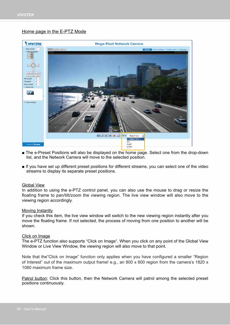
VIVOTEK
90 - User's Manual
Home page in the E-PTZ Mode
■ The e-Preset Positions will also be displayed on the home page. Select one from the drop-down list, and the Network Camera will move to the selected position.
■ If you have set up different preset positions for different streams, you can select one of the video streams to display its separate preset positions.
Global ViewIn addition to using the e-PTZ control panel, you can also use the mouse to drag or resize the floating frame to pan/tilt/zoom the viewing region. The live view window will also move to the viewing region accordingly.
Moving InstantlyIf you check this item, the live view window will switch to the new viewing region instantly after you move the floating frame. If not selected, the process of moving from one position to another will be shown.
Click on ImageThe e-PTZ function also supports “Click on Image“. When you click on any point of the Global View Window or Live View Window, the viewing region will also move to that point.
Note that the”Click on Image” function only applies when you have configured a smaller “Region of Interest” out of the maximum output frame! e.g., an 800 x 600 region from the camera’s 1820 x 1080 maximum frame size.
Patrol button: Click this button, then the Network Camera will patrol among the selected preset positions continuously.
x3.3

VIVOTEK
User's Manual - 91
Patrol settings
You can select some preset positions for the Network Camera to patrol.Please follow the steps below to set up a patrol schedule:1. Select the preset locations on the list, and click .2. The selected preset locations will be displayed on the Patrol locations list.3. Set the Dwelling time for the preset location during an auto patrol. 4. If you want to delete a preset location from the Patrol locations list, select it and click Remove.5. Select a location and click to rearrange the patrol order.6. Select patrol locations you want to save in the list and click Save to enable the patrol settings.7. To implement the patrol schedule, please go to homepage and click on the Patrol button. Please refer
to the next page.
x1.82013/3/20 09:57:30
1
2
6
54
3

VIVOTEK
92 - User's Manual
►The Preset Positions will also be displayed on the Home page. Select one from the Go to menu, and the Network Camera will move to the selected preset position.
►Click Patrol: The Network Camera will patrol along the selected positions repeatedly.
NOTE:

VIVOTEK
User's Manual - 93
Event > Event settings
This section explains how to configure the Network Camera to respond to particular situations (event). A typical application is that when a motion is detected, the Network Camera sends buffered images to an FTP server or e-mail address as notifications. Click on Help, there is an illustration shown in the pop-up window explaining that an event can be triggered by many sources, such as motion detection or external digital input devices. When an event is triggered, you can specify what type of action that will be performed. You can configure the Network Camera to send snapshots or videos to your email address or FTP site.
Event
To configure an event with reactive measures such as recording video or snapshots, it is necessary to configure the server and media settings so that the Network Camera will know what action to take (such as which server to send the media files to) when a trigger is activated. An event is an action initiated by a user-defined trigger source. In the Event column, click Add to open the event settings window. Here you can arrange three elements -- Schedule, Trigger, and Action to set an event. A total of 3 event settings can be configured.

VIVOTEK
94 - User's Manual
■ Event name: Enter a name for the event setting.
■ Enable this event: Select this option to enable the event setting.
■ Priority: Select the relative importance of this event (High, Normal, or Low). Events with a higher priority setting will be executed first.
■ Detect next event after seconds: Enter the duration in seconds to pause motion detection after a motion is detected. This can prevent event-related actions to take place too frequently.
1. ScheduleSpecify the period of them during which the event trigger will take effect. Please select the days of the week and the time in a day (in 24-hr time format) for the event triggering schedule. For example, you may prefer an event to be triggered only during the off-office hours.
2. TriggerThis is the cause or stimulus which defines when to trigger the Network Camera. The trigger source can be configured to use the Network Camera’s built-in motion detection mechanism or external digital input devices.
There are several choices of trigger sources as shown on the next page. Select the item to display the detailed configuration options.
■ Video motion detectionThis option makes use of the built-in motion detection mechanism as a trigger source. To enable this function, you need to configure a Motion Detection Window first. For more information, please refer to Motion Detection on page 106 for details.
■ PeriodicallyThis option allows the Network Camera to trigger periodically for every other defined minute. Up to 999 minutes are allowed.
■ System bootThis option triggers the Network Camera when the power to the Network Camera is disconnected and re-connected.
■ Recording notifyThis option allows the Network Camera to trigger when the recording disk is full or when recording starts to overwrite older data.

VIVOTEK
User's Manual - 95
■ Camera tampering detectionThis option allows the Network Camera to trigger when the camera detects that is is being tampered with. To enable this function, you need to configure the Tampering Detection option first. Please refer to page 109 for detailed information.
■ Manual TriggerThis option allows users to enable event triggers manually by clicking the on/off button on the homepage. Please configure 1 to 3 associated events before using this function.
3. ActionDefine the actions to be performed by the Network Camera when a trigger is activated.
■ Backup media if the network is disconnectedSelect this option to backup media file on SD card if the network is disconnected. This function will only be displayed after you set up a network storage (NAS). The media to back up can include snapshot images, video, or system logs depending on your event settings.

VIVOTEK
96 - User's Manual
Add server
It is necessary to configure the server and media settings so that the Network Camera will know what action to take (such as which server to send the media files to) when a trigger is activated. Click Add server to open the server setting window. You can specify where the notification messages are sent to when a trigger is activated. A total of 5 server settings can be configured.
There are four choices of server types available: Email, FTP, HTTP, and Network storage. Select the item to display the detailed configuration options. You can configure either one or all of them.
Server type - EmailSelect to send the media files via email when a trigger is activated.
■ Server name: Enter a name for the server setting.
■ Sender email address: Enter the email address of the sender.
■ Recipient email address: Enter the email address of the recipient.
■ Server address: Enter the domain name or IP address of the email server.
■ User name: Enter the user name of the email account if necessary.
■ Password: Enter the password of the email account if necessary.
■ Server port: The default mail server port is set to 25. You can also manually set another port.
If your SMTP server requires a secure connection (SSL), select This server requires a secure connection (SSL).

VIVOTEK
User's Manual - 97
To verify if the email settings are correctly configured, click Test. The result will be shown in a pop-up window. If successful, you will also receive an email indicating the result.
Click Save server to enable the settings.
Note that after you configure the first event server, the new event server will automatically display on the Server list. If you wish to add other server options, click Add server.
Server type - FTPSelect to send the media files to an FTP server when a trigger is activated.
■ Server name: Enter a name for the server setting.
■ Server address: Enter the domain name or IP address of the FTP server.
■ Server port: By default, the FTP server port is set to 21. It can also be assigned to another port number between 1025 and 65535.
■ User name: Enter the login name of the FTP account.
■ Password: Enter the password of the FTP account.
■ FTP folder nameEnter the folder where the media files will be placed. If the folder name does not exist, the Network Camera will automatically create one on the FTP server.

VIVOTEK
98 - User's Manual
■ Passive modeMost firewalls do not accept new connections initiated from external requests. If the FTP server supports passive mode, select this option to enable passive mode FTP and allow data transmission to pass through the firewall. The firmware default has the Passive mode checkbox selected.
To verify if the FTP settings are correctly configured, click Test. The result will be shown in a pop-up window as shown below. If successful, you will also receive a test.txt file on the FTP server.
Click Save server to enable the settings.
Server type - HTTPSelect to send the media files to an HTTP server when a trigger is activated.
■ Server name: Enter a name for the server setting.
■ URL: Enter the URL of the HTTP server.
■ User name: Enter the user name if necessary.
■ Password: Enter the password if necessary.
To verify if the HTTP settings are correctly configured, click Test. The result will be shown in a pop-up window as shown below. If successful, you will receive a test.txt file on the HTTP server.
Click Save server to enable the settings.

VIVOTEK
User's Manual - 99
Network storage: Select to send the media files to a networked storage when a trigger is activated. Please refer to NAS server on page 113 for details. Note that only one NAS server can be configured.
Click Save server to enable the settings.
■ SD Test: Click to test your SD card. The system will display a message indicating the result as a success or a failure. If you want to use your SD card for local storage, please format it before use. Please refer to page 101 for detailed information.
■ View: Click this button to open a file list window. This function is only for SD card and Network Storage. If you click the View button for an SD card, a Local storage page will prompt so that you can manage
the recorded files on SD card. For more information about Local storage, please refer to page 115. If you click the View button for a Network storage, a file directory window will prompt for you to view recorded data on Network storage. For detailed illustration, please refer to the next page.
■ Create folders by date, time, and hour automatically: If you select this item, the system will automatically create folders by the date when video footages are stored onto the networked storage.
The following is an example of a file destination with video clips:
20140120
20140121
20140122
Click to delete selected items
Click to delete all recorded data
The format is: YYYYMMDDClick to open the directory

VIVOTEK
100 - User's Manual
Click 20140120 to open the directory:
Click to delete selected items
Click to delete all recorded data
Click to go back to the previous level of the directory
The format is: HH (24r)Click to open the file list for that hour
The format is: File name prefix + Minute (mm)You can set up the file name prefix on Add media page. Please refer to next page for detailed information.
2014/01/20
2014/01/20
2014/01/20
2014/01/20

VIVOTEK
User's Manual - 101
Add media
Click Add media to open the media setting window. You can specify the type of media that will be sent when a trigger is activated. A total of 5 media settings can be configured. There are three choices of media types available: Snapshot, Video Clip, and System log. Select the item to display the detailed configuration options. You can configure either one or all of them.
Media type - Snapshot Select to send snapshots when a trigger is activated.
■ Media name: Enter a name for the media setting.
■ Source: Select to take snapshots from any of the video streams.
■ Send pre-event imagesThe Network Camera has a buffer to temporarily hold data up to a certain limit. Enter a number to decide how many images to capture before a trigger is activated. Up to 7 images can be generated.
■ Send post-event imagesEnter a number to decide how many images to capture after a trigger is activated. Up to 7 images can be generated.
For example, if both the Send pre-event images and Send post-event images are set to 7, a total of 15 images can be generated after a trigger is activated.
■ File name prefixEnter the text that will be appended to the front of the file name.
1 pic. 2 pic. 3 pic. 4 pic. 5 pic. 6 pic. 7 pic. 8 pic. 9 pic. 10 pic. 11 pic. 10 pic. 12 pic. 13 pic. 14 pic. 15 pic.
Trigger Activation

VIVOTEK
102 - User's Manual
■ Add date and time suffix to the file nameSelect this option to add a date/time suffix to the file name.
For example:
Click Save media to enable the settings.
Note that after you set up the first media server, a new column for media server will automatically display on the Media list. If you wish to add more media options, click Add media.
Media type - Video clipSelect to send video clips when a trigger is activated.
■ Media name: Enter a name for the media setting.
■ Source: Select a video stream as the source of video clip.
■ Pre-event recordingThe Network Camera has a buffer to temporarily hold data up to a certain limit. Enter a number to decide the duration of recording before a trigger is activated. Up to 9 seconds can be set.
■ Maximum durationSpecify the maximum recording duration in seconds. The duration can be up to 10 seconds.For example, if pre-event recording is set to five seconds and the maximum duration is set to ten seconds, the Network Camera continues to record for another 4 seconds after a trigger is activated.
Snapshot_20101213_100341
Date and time suffixThe format is: YYYYMMDD_HHMMSS
File name prefix
1 sec. 2 sec. 3 sec. 4 sec. 5 sec. 6 sec. 7 sec. 8 sec. 9 sec. 10 sec.
Trigger Activation

VIVOTEK
User's Manual - 103
■ Maximum file sizeSpecify the maximum file size allowed. Some users may need to stitch the video clips together when searching and packing up forensic evidence.
■ File name prefixEnter the text that will be appended to the front of the file name.
For example:
Click Save media to enable the settings.
Media type - System logSelect to send a system log when a trigger is activated.
Click Save media to enable the settings, then click Close to exit the page.
Video_20101213_100341
Date and time suffixThe format is: YYYYMMDD_HHMMSS
File name prefix

VIVOTEK
104 - User's Manual
In the Event settings column, the Servers and Medias you configured will be listed; please make sure the Event -> Status is indicated as ON, in order to enable the event triggering action.
When completed, click the Save event button to enable the settings and click Close to exit Event Settings page. The new Event / Server settings / Media will appear in the event drop-down list on the Event setting page.
Please see the example of the Event setting page below:
When the Event Status is ON, the event configuration above is triggered by motion detection, the Network Camera will automatically send snapshots via e-mail.
If you want to stop the event trigger, you can click on the ON button to turn it to OFF status or click the Delete button to remove the event setting.
To remove a server setting from the list, select a server name from the drop-down list and click Delete. Note that you can only delete a server setting when it is not applied in an existing event setting.
To remove a media setting from the list, select a media name from the drop-down list and click Delete. Note that you can only delete a media setting when it is not applied in an existing event setting.

VIVOTEK
User's Manual - 105
Customized Script
This function allows you to upload a sample script (.xml file) to the webpage, which will save your time on configuring the settings. Please note that there is a limited number of customized scripts you can upload; if the current amount of customized scripts has reached the limit, an alert message will prompt. If you need more information, please contact VIVOTEK technical support.
20130213
20130213
Click to upload a file
Click to modify the script online

VIVOTEK
106 - User's Manual
Applications > Motion detection
This section explains how to configure the Network Camera to enable motion detection. A total of three motion detection windows can be configured.
Follow the steps below to enable motion detection:Follow the steps below to enable motion detection:1. Click New to add a new motion detection window.2. In the Window Name text box, enter a name for the motion detection window.
■ To move and resize the window, drag it to a preferred location, and let cursor stay on the edge of the window until it changes into the resize cursor.
■ To delete a window, click the X mark on the upper right corner of the window.3. Define the sensitivity to moving objects and the space ratio of all alerted pixels by moving the
Sensitivity and Percentage slider bar.4. Click Save to enable the settings.5. Select Enable motion detection to enable this function.For example:
The Percentage Indicator will rise or fall depending on the variation between sequential images. When motions are detected by the Network Camera and are considered to exceed the preset threshold, the red bar rises. Meanwhile, the motion detection window will be outlined in red. Photos or videos can be captured instantly and configured to be sent to a remote server (via an Email or FTP server). For more information on how to configure an event setting, please refer to Event settings on page 93.
2010/12/10 17:08:56
hallway
2014/07/20
Video(TCP-AV) 2010/12/10 17:08:56
hallway
2014/07/20
Motion Detection Setting 2:For special situations
Motion Detection Setting 1:For normal situations

VIVOTEK
User's Manual - 107
A green bar indicates that even though motions have been detected, the event has not been triggered because the image variations still fall under the preset threshold.
If you want to configure other motion detection settings for day/night/schedule mode (e.g., for a different lighting condition), please click Profile to open the Motion Detection Profile Settings page as shown below. Another three motion detection windows can be configured on this page.
Please follow the steps beolw to set up a profile:1. Create a new motion detection window.2. Check Enable this profile.3. Select the applicable mode: Day mode, Night mode, or Schedule mode. Please manually enter a time
range if you choose Schedule mode.4. Click Save to enable the settings and click Close to exit the page.
This motion detection window will also be displayed on the Event Settings page. You can go to Event > Event settings > Trigger to select it as a trigger source. Please refer to page 111 for detailed information.
Percentage = 30%
Video(TCP-AV) 2010/12/10 17:08:562014/07/20
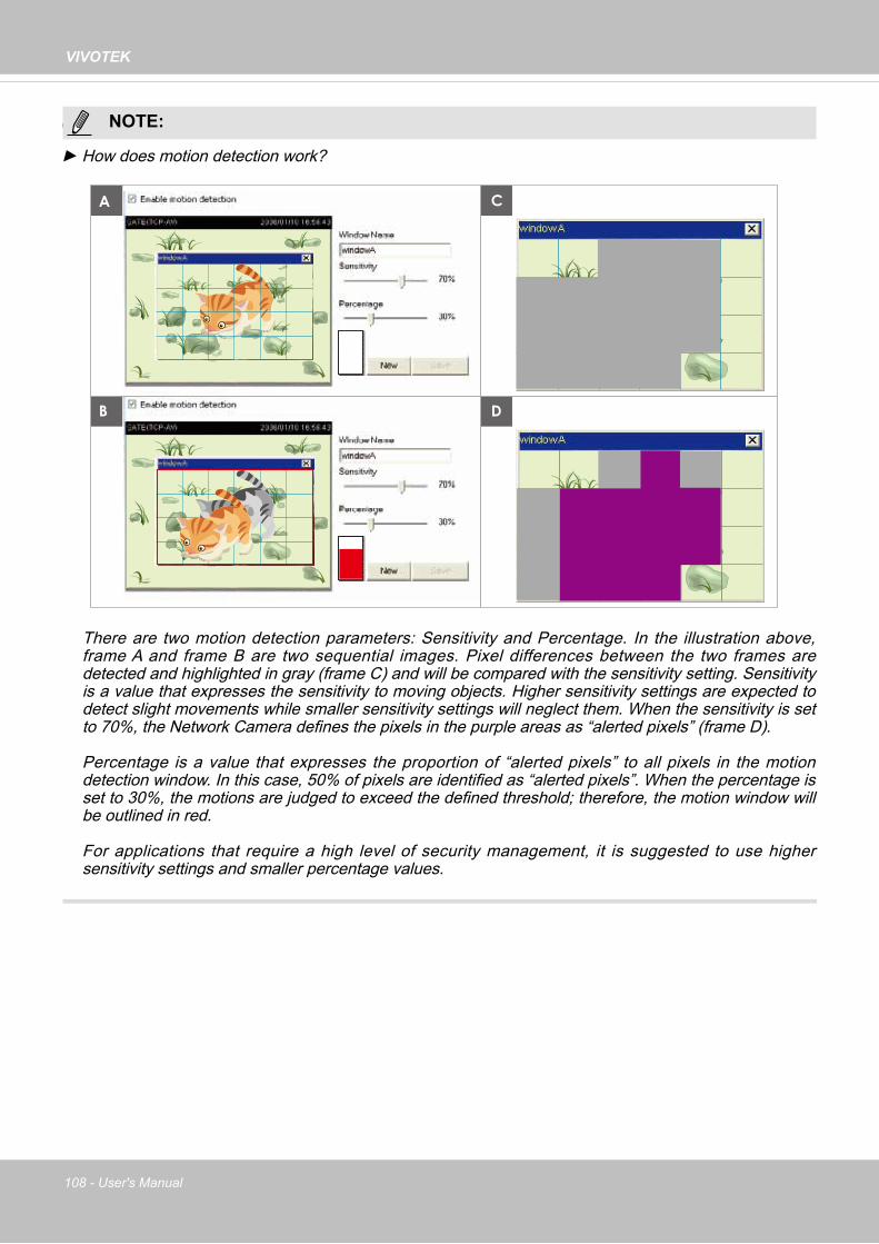
VIVOTEK
108 - User's Manual
NOTE
► How does motion detection work?
There are two motion detection parameters: Sensitivity and Percentage. In the illustration above, frame A and frame B are two sequential images. Pixel differences between the two frames are detected and highlighted in gray (frame C) and will be compared with the sensitivity setting. Sensitivity is a value that expresses the sensitivity to moving objects. Higher sensitivity settings are expected to detect slight movements while smaller sensitivity settings will neglect them. When the sensitivity is set to 70%, the Network Camera defines the pixels in the purple areas as “alerted pixels” (frame D).
Percentage is a value that expresses the proportion of “alerted pixels” to all pixels in the motion detection window. In this case, 50% of pixels are identified as “alerted pixels”. When the percentage is set to 30%, the motions are judged to exceed the defined threshold; therefore, the motion window will be outlined in red.
For applications that require a high level of security management, it is suggested to use higher sensitivity settings and smaller percentage values.
A
B D
C
NOTE:

VIVOTEK
User's Manual - 109
Applications > Tampering detection
This section explains how to set up camera tamper detection. With tamper detection, the camera is capable of detecting incidents such as redirection, blocking or defocusing, or even spray paint.
Please follow the steps below to set up the camera tamper detection function:1. Check Enable camera tampering detection.2. Enter the tamper trigger duration. (10 sec. ~ 10 min.) The tamper alarm will be triggered
only when the tampering factor (the difference between current frame and pre-saved background) exceeds the trigger threshold.
3. You can configure Tampering Detection as a trigger element to the proactive event configurations in Event -> Event settings -> Trigger. For example, when the camera is tampered with, camera can be configured to send pre- and post-event video clips to a networked storage device. Please refer to page 95 for detailed information.

VIVOTEK
110 - User's Manual
Recording > Recording settings
This section explains how to configure the recording settings for the Network Camera.
Recording Settings
► Please remember to format your SD card via the camera’s web console (in the Local storage . SD card management page) when using it for the first time. Please refer to page 115 for detailed information.
Insert your SD card and click here to test
Recording Settings
Click Add to open the recording setting window. On this page, you can define the adaptive recording, recording source, recording schedule, and recording capacity. A total of 2 recording settings can be configured.
■ Recording name: Enter a name for the recording setting.
■ Enable this recording: Select this option to enable video recording.
■ With adaptive recording: Select this option will activate the frame rate control according to alarm trigger. The frame control means that when there is a triggered alarm, the frame rate will raise up to the value you’ve configured on the Video quality page. Please refer to page 57 for more information.
NOTE:

VIVOTEK
User's Manual - 111
The alarm trigger includes: motion detection and DI detection. Please refer to Event Settings on page 93.
■ Pre-event recording and post-event recordingThe Network Camera has a buffer that temporarily holds data for a period of time. Therefore, when an event occurs, the camera can restrieve image frames taken several seconds ago. Enter a number to define the duration of recording before and after a trigger is activated.
■ Priority: Select the relative importance of this recording (High, Normal, or Low). Recording with a higher priority setting will be executed first.
■ Source: Select a video stream as the recording source.
► To enable recording notification please configure Event settings first . Please refer to page 93.
If you enable adaptive recording on a camera, only when an event is triggered on Camera A will the server record the full frame rate streaming data; otherwise, it will only request the I frame data during normal monitoring, thus effectively saves bandwidths and storage space.
Time
Bandwidth
Bandwidth
Activity Adaptive Streaming for Dynamic Frame Rate Control
I frame ---> Full frame rate ---> I frame
Continuous recording
► To enable adaptive recording, please make sure you’ve set up the trigger source such as Motion Detection, DI Device, or Manual Trigger.
► When there is no alarm trigger: - JPEG mode: record 1 frame per second.- H.264 mode: record the I frame only.
► When the I frame period is >1s on Video settings page, firmware will force decrease the I frame period to 1s when adaptive recording is enabled.
Please follow the steps below to set up the recording.
1. Trigger Select a trigger source.
■ Schedule: The server will start to record files on the local storage or network storage (NAS).
■ Network fail: Since network fail, the server will start to record files on the local storage (SD card).
NOTE:
NOTE:

VIVOTEK
112 - User's Manual
2. Destination You can select the SD card or network storage (NAS) for the recorded video files. If you have not configured a NAS server, see details in the following.
NAS server
Click Add NAS server to open the server setting window and follow the steps below to set up:1. Fill in the information for your server. For example:
2. Click Test to check the setting. The result will be shown in the pop-up window.
1
2
3
4
Network storage path (\\server name or IP address\folder name)
User name and password for your server
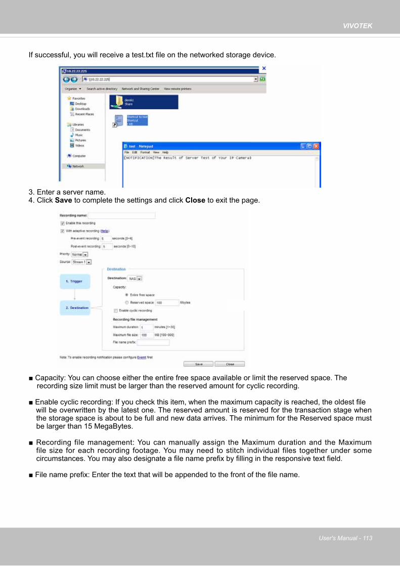
VIVOTEK
User's Manual - 113
If successful, you will receive a test.txt file on the networked storage device.
3. Enter a server name.4. Click Save to complete the settings and click Close to exit the page.
■ Capacity: You can choose either the entire free space available or limit the reserved space. The recording size limit must be larger than the reserved amount for cyclic recording.
■ Enable cyclic recording: If you check this item, when the maximum capacity is reached, the oldest file will be overwritten by the latest one. The reserved amount is reserved for the transaction stage when
the storage space is about to be full and new data arrives. The minimum for the Reserved space must be larger than 15 MegaBytes.
■ Recording file management: You can manually assign the Maximum duration and the Maximum file size for each recording footage. You may need to stitch individual files together under some circumstances. You may also designate a file name prefix by filling in the responsive text field.
■ File name prefix: Enter the text that will be appended to the front of the file name.

VIVOTEK
114 - User's Manual
To remove a recording setting from the list, select a recording name from the drop-down list and click Delete.
■ Click recording (Name): Opens the Recording Settings page to modify. ■ Click ON (Status): The Status will become OFF and stop recording.■ Click NAS (Destination): Opens the file list of recordings as shown below. For more information
about folder naming rules, please refer to page 99 for details.
20140210
20140211
20140212
If you want to enable recording notification, please click Event to configure event triggering settings. Please refer to Event > Event settings on page 93 for more details.
When completed, select Enable this recording. Click Save to enable the setting and click Close to exit this page. When the system begins recording, it will send the recorded files to the network storage. The new recording name will appear in the drop-down list on the recording page as shown below.

VIVOTEK
User's Manual - 115
Local storage > SD card management
This section explains how to manage the local storage on the Network Camera. Here you can view SD card status, and implement SD card control.
SD card stausThis column shows the status and reserved space of your SD card. Please remember to format the SD card when using for the first time.
SD card control
■ Enable cyclic storage: Check this item if you want to enable cyclic recording. When the maximum capacity is reached, the oldest file will be overwritten by the latest one.
■ Enable automatic disk cleanup: Check this item and enter the number of days you wish to retain a file. For example, if you enter “7 days”, the recorded files will be stored on the SD card for 7 days.
Click Save to enable your settings.
no SD card

VIVOTEK
116 - User's Manual
Local storage > Content management
This section explains how to manage the content of recorded videos on the Network Camera. Here you can search and view the records and view the searched results.
Searching and Viewing the RecordsThis column allows the user to set up search criteria for recorded data. If you do not select any criteria and click Search button, all recorded data will be listed in the Search Results column.
■ File attributes: Select one or more items as your search criteria.■ Trigger time: Manually enter the time range you want to search for contents created at a specific point
in time.
Click Search and the recorded data corresponding to the search criteria will be listed in Search Results window.

VIVOTEK
User's Manual - 117
Search ResultsThe following is an example of search results. There are four columns: Trigger time, Media type, Trigger type, and Locked. Click to sort the search results in either direction.
Numbers of entries displayed on one page
Enter a key word to filter the search results
Highlight an item
■ View: Click on a search result which will highlight the selected item in purple as shown above. Click the View button and a media window will pop up to play back the selected file. For example:
2013/3/26 10:43:06
Click to adjust the image size
■ Download: Click on a search result to highlight the selected item in purple as shown above. Then click the Download button and a file download window will pop up for you to save the file.
■ JPEGs to AVI: This functions only applies to “JPEG“ format files such as snapshots. You can select several snapshots from the list, then click this button. Those snapshots will be converted into an AVI file.

VIVOTEK
118 - User's Manual
■ Lock/Unlock: Select the desired search results, then click this button. The selected items will become Locked, which will not be deleted during cyclic recording. You can click again to unlock the selections. For example:
■ Remove: Select the desired search results, then click this button to delete the files.
Click to switch pages

VIVOTEK
User's Manual - 119
Appendix URL Commands for the Network Camera1. Overview
For some customers who already have their own web site or web control application, the Network Camera/Video Server can be easily integrated through URL syntax. This section specifies the external HTTP-based application programming interface. The HTTP-based camera interface provides the functionality to request a single image, control camera functions (PTZ, output relay etc.), and get and set internal parameter values. The image and CGI-requests are handled by the built-in Web server.
2. Style Convention
In URL syntax and in descriptions of CGI parameters, text within angle brackets denotes content that is to be replaced with either a value or a string. When replacing the text string, the angle brackets should also be replaced. An example of this is the description of the name for the server, denoted with <servername> in the URL syntax description below, that is replaced with the string myserver in the URL syntax example further down in the page.
URL syntax is denoted with the word "Syntax:" written in bold face followed by a box with the referenced syntax as shown below. For example, name of the server is written as <servername> and is intended to be replaced with the name of the actual server. This can either be a name, e.g., "mywebcam" or "thecam.adomain.net" or the associated IP number for the server, e.g., 192.168.0.220.
Syntax:
http://<servername>/cgi-bin/viewer/video.jpg
Description of returned data is written with "Return:" in bold face followed by the returned data in a box. All data is returned in HTTP format, i.e., each line is separated with a Carriage Return and Line Feed (CRLF) printed as \r\n.
Return:
HTTP/1.0 <HTTP code> <HTTP text>\r\n
URL syntax examples are written with "Example:" in bold face followed by a short description and a light grey box with the example.
Example: request a single snapshot image
http://mywebserver/cgi-bin/viewer/video.jpg

VIVOTEK
120 - User's Manual 5
3. General CGI URL Syntax and Parameters When the CGI request includes internal camera parameters, these parameters must be written exactly as they are named in the camera or video server. The CGIs are organized in functionally-related directories under the cgi-bin directory. The file extension .cgi is required. Syntax:http://<servername>/cgi-bin/<subdir>[/<subdir>...]/<cgi>.<ext>[?<parameter>=<value>[&<parameter>=<value>...]]

VIVOTEK
User's Manual - 121 6
4. Security Level SECURITY LEVEL
SUB-DIRECTORY DESCRIPTION
0 anonymous Unprotected. 1 [view] anonymous, viewer,
dido, camctrl 1. Can view, listen, talk to camera. 2. Can control DI/DO, PTZ of the camera.
4 [operator] anonymous, viewer, dido, camctrl, operator
Operator access rights can modify most of the camera’s parameters except some privileges and network options.
6 [admin] anonymous, viewer, dido, camctrl, operator, admin
Administrator access rights can fully control the camera’s operations.
7 N/A Internal parameters. Unable to be changed by any external interfaces.

VIVOTEK
122 - User's Manual 7
5. Get Server Parameter Values Note: The access right depends on the URL directory. Method: GET/POST
Syntax:http://<servername>/cgi-bin/anonymous/getparam.cgi?[<parameter>][&<parameter>…]
http://<servername>/cgi-bin/viewer/getparam.cgi?[<parameter>][&<parameter>…]
http://<servername>/cgi-bin/operator/getparam.cgi?[<parameter>][&<parameter>…]
http://<servername>/cgi-bin/admin/getparam.cgi?[<parameter>][&<parameter>…]
Where the <parameter> should be <group>[_<name>]. If you do not specify any parameters, all the parameters on the server will be returned. If you specify only <group>, the parameters of the related group will be returned.
When querying parameter values, the current parameter values are returned. A successful control request returns parameter pairs as follows: Return:HTTP/1.0 200 OK\r\n Content-Type: text/html\r\n Context-Length: <length>\r\n \r\n <parameter pair> where <parameter pair> is <parameter>=<value>\r\n [<parameter pair>]
<length> is the actual length of content.
Example: Request IP address and its response Request:http://192.168.0.123/cgi-bin/admin/getparam.cgi?network_ipaddress

VIVOTEK
User's Manual - 123 8
Response:HTTP/1.0 200 OK\r\n Content-Type: text/html\r\n Context-Length: 33\r\n \r\n network_ipaddress=192.168.0.123\r\n

VIVOTEK
124 - User's Manual 9
6. Set Server Parameter Values Note: The access right depends on the URL directory. Method: GET/POST
Syntax:http://<servername>/cgi-bin/anonymous/setparam.cgi? <parameter>=<value> [&<parameter>=<value>…][&return=<return page>]
http://<servername>/cgi-bin/viewer/setparam.cgi? <parameter>=<value>[&<parameter>=<value>…][&return=<return page>]
http://<servername>/cgi-bin/operator/setparam.cgi? <parameter>=<value>[&<parameter>=<value>…][&return=<return page>]
http://<servername>/cgi-bin/admin/setparam.cgi? <parameter>=<value>[&<parameter>=<value>…][&return=<return page>]
PARAMETER VALUE DESCRIPTION<group>_<name> value to assigned Assign <value> to the parameter <group>_<name>.return <return page> Redirect to the page <return page> after the parameter is
assigned. The <return page> can be a full URL path or relative path according to the current path. If you omit this parameter, it will redirect to an empty page.
(Note: The return page can be a general HTML file (.htm, .html). It cannot be a CGI command or have any extra parameters. This parameter must be placed at the end of the parameter list
Return:HTTP/1.0 200 OK\r\n Content-Type: text/html\r\n Context-Length: <length>\r\n \r\n <parameter pair> where <parameter pair> is <parameter>=<value>\r\n [<parameter pair>] Only the parameters that you set and are readable will be returned.

VIVOTEK
User's Manual - 125 10
Example: Set the IP address of server to 192.168.0.123: Request:http://myserver/cgi-bin/admin/setparam.cgi?network_ipaddress=192.168.0.123
Response:HTTP/1.0 200 OK\r\n Content-Type: text/html\r\n Context-Length: 33\r\n \r\n network_ipaddress=192.168.0.123\r\n

VIVOTEK
126 - User's Manual 11
7. Available parameters on the server This chapter defines all the parameters which can be configured or retrieved from VIVOTEK network camera or video server. The general format of description is listed in the table below Valid values: VALID VALUES DESCRIPTIONstring[<n>] Text strings shorter than ‘n’ characters. The characters “,’, <,>,& are
invalid.string[n~m] Text strings longer than `n’ characters and shorter than `m’ characters.
The characters “,’, <,>,& are invalid. password[<n>] The same as string but displays ‘*’ instead. integer Any number between (-231 – 1) and (231 – 1). positive integer Any number between 0 and (232 – 1). <m> ~ <n> Any number between ‘m’ and ‘n’. domain name[<n>] A string limited to a domain name shorter than ‘n’ characters (eg.
www.ibm.com). email address [<n>] A string limited to an email address shorter than ‘n’ characters (eg.
[email protected]). ip address A string limited to an IP address (eg. 192.168.1.1). mac address A string limited to contain a MAC address without hyphens or colons. boolean A boolean value of 1 or 0 represents [Yes or No], [True or False],
[Enable or Disable]. <value1>,<value2>,<value3>,…
Enumeration. Only given values are valid.
blank A blank string. everything inside <> A description integer primary key SQLite data type. A 32-bit signed integer. The value is assigned a unique
integer by the server. text SQLite data type. The value is a text string, stored using the database
encoding (UTF-8, UTF-16BE or UTF-16-LE). coordinate x, y coordinate (eg. 0,0) window size window width and height (eg. 800x600)
NOTE: The camera should not be restarted when parameters are changed.

VIVOTEK
User's Manual - 127 12
7.1 system Group: systemNAME VALUE DEFAULT SECURITY
(get/set) DESCRIPTION
hostname string[64] FD8169 1/6 Host name of server.
ledoff <boolean> 0 6/6 Turn on (0) or turn off (1) all led indicators.
date <YYYY/MM/DD>, keep,auto
<currentdate>
6/6 Current date of system. Set to ‘keep’ to keep date unchanged. Set to ‘auto’ to use NTP to synchronize date.
time <hh:mm:ss>, keep,auto
<currenttime>
6/6 Current time of the system. Set to ‘keep’ to keep time unchanged. Set to ‘auto’ to use NTP to synchronize time.
datetime <MMDDhhmmYYYY.ss>
<currenttime>
6/6 Another current time format of the system.
ntp <domain name>, <ip address>, <blank>
<blank> 6/6 NTP server.
timezoneindex -489 ~ 529 320 6/6 Indicate timezone and area. -480: GMT-12:00 Eniwetok, Kwajalein -440: GMT-11:00 Midway Island, Samoa -400: GMT-10:00 Hawaii -360: GMT-09:00 Alaska -320: GMT-08:00 Las Vegas, San_Francisco,Vancouver -280: GMT-07:00 Mountain Time, Denver -281: GMT-07:00 Arizona -240: GMT-06:00 Central America, Central Time, Mexico City, Saskatchewan

VIVOTEK
128 - User's Manual 13
-200: GMT-05:00 Eastern Time, New York, Toronto -201: GMT-05:00 Bogota, Lima, Quito, Indiana -180: GMT-04:30 Caracas -160: GMT-04:00 Atlantic Time, Canada, La Paz, Santiago-140: GMT-03:30 Newfoundland-120: GMT-03:00 Brasilia, Buenos Aires, Georgetown, Greenland -80: GMT-02:00 Mid-Atlantic-40: GMT-01:00 Azores, Cape_Verde_IS. 0: GMT Casablanca, Greenwich Mean Time: Dublin, Edinburgh, Lisbon, London 40: GMT 01:00 Amsterdam, Berlin, Rome, Stockholm, Vienna, Madrid, Paris 41: GMT 01:00 Warsaw, Budapest, Bern 80: GMT 02:00 Athens, Helsinki, Istanbul, Riga 81: GMT 02:00 Cairo 82: GMT 02:00 Lebanon, Minsk83: GMT 02:00 Israel 120: GMT 03:00 Baghdad, Kuwait, Riyadh, Moscow, St. Petersburg, Nairobi 121: GMT 03:00 Iraq 140: GMT 03:30 Tehran 160: GMT 04:00 Abu Dhabi, Muscat, Baku, Tbilisi, Yerevan 180: GMT 04:30 Kabul

VIVOTEK
User's Manual - 129 14
200: GMT 05:00 Ekaterinburg, Islamabad, Karachi, Tashkent 220: GMT 05:30 Calcutta, Chennai, Mumbai, New Delhi230: GMT 05:45 Kathmandu 240: GMT 06:00 Almaty, Novosibirsk, Astana, Dhaka, Sri Jayawardenepura 260: GMT 06:30 Rangoon 280: GMT 07:00 Bangkok, Hanoi, Jakarta, Krasnoyarsk 320: GMT 08:00 Beijing, Chongging, Hong Kong, Kuala Lumpur, Singapore, Taipei 360: GMT 09:00 Osaka, Sapporo, Tokyo, Seoul, Yakutsk 380: GMT 09:30 Adelaide, Darwin 400: GMT 10:00 Brisbane, Canberra, Melbourne, Sydney, Guam, Vladivostok 440: GMT 11:00 Magadan, Solomon Is., New Caledonia 480: GMT 12:00 Aucklan, Wellington, Fiji, Kamchatka, Marshall Is. 520: GMT 13:00 Nuku'Alofa
daylight_enable <boolean> 0 6/6 Enable automatic daylight saving time in time zone.
daylight_auto_begintime string[19] NONE 6/7 Display the current daylight saving start time.
daylight_auto_endtime string[19] NONE 6/7 Display the current daylight saving end time.
daylight_timezones string 0 6/6 List time zone index which support daylight saving time.

VIVOTEK
130 - User's Manual 15
updateinterval 0, 3600, 86400, 604800, 2592000
0 6/6 0 to Disable automatic time adjustment, otherwise, it indicates the seconds between NTP automatic update intervals.
restore 0, <positiveinteger>
N/A 7/6 Restore the system parameters to default values after <value> seconds.
reset 0, <positiveinteger>
N/A 7/6 Restart the server after <value> seconds if <value> is non-negative.
restoreexceptnet 0, <positiveinteger>
N/A 7/6 Restore the system parameters to default values except (ipaddress, subnet, router, dns1, dns2, pppoe). This command can cooperate with other “restoreexceptXYZ” commands. When cooperating with others, the system parameters will be restored to the default value except for a union of the combined results.
restoreexceptdst 0, <positiveinteger>
N/A 7/6 Restore the system parameters to default values except all daylight saving time settings. This command can cooperate with other “restoreexceptXYZ” commands. When cooperating with others, the system parameters will be restored to default values except for a union of combined results.

VIVOTEK
User's Manual - 131 16
restoreexceptlang 0, <positiveinteger>
N/A 7/6 Restore the system parameters to default values except the custom language file the user has uploaded. This command can cooperate with other “restoreexceptXYZ” commands. When cooperating with others, the system parameters will be restored to the default value except for a union of the combined results.
7.1.1 system.info Subgroup of system: info (The fields in this group are unchangeable.) NAME VALUE DEFAULT SECURITY
(get/set) DESCRIPTION
modelname string[40] FD8169 0/7 Internal model name of the server
extendedmodelname string[40] FD8169 0/7 This field will be equal to “modelname”
serialnumber <mac address>
<productmacaddress>
0/7 12 characters MAC address (without hyphens).
firmwareversion string[40] <product dependent>
0/7 Firmware version, including model, company, and version number in the format: <MODEL-BRAND-VERSION>
language_count <integer> 9 0/7 Number of webpage languages available on the server.
language_i<0~(count-1)> string[16] English Deutsch EspañolFrançais Italiano日本語
Português
0/7 Available language lists.

VIVOTEK
132 - User's Manual 17
简体中文
繁體中文
customlanguage_maxcount <integer> 1 0/6 Maximum number of custom languages supported on the server.
customlanguage_count <integer> 0 0/6 Number of custom languages which have been uploaded to the server.
customlanguage_i<0~(maxcount-1)>
string N/A 0/6 Custom language name.
7.2 status Group: statusNAME VALUE DEFAULT SECURITY
(get/set) DESCRIPTION
daynight day, night 0 7/7 Current status of day, night.
onlinenum_rtsp integer 0 6/7 Current number of RTSP connections.
onlinenum_httppush integer 0 6/7 Current number of HTTP push server connections.
eth_i0 <string> <blank> 1/7 Get network information from mii-tool.
vi_i<0~(nvi-1)> <boolean> 0 1/7 Virtual input 0 => Inactive 1 => Active
7.3 security Group: securityNAME VALUE DEFAULT SECURITY
(get/set) DESCRIPTION
privilege_camctrl view, operator, admin
view 1/6 Indicate which privileges and above can control ePTZ
user_i0_name string[64] root 6/7 User name of root
user_i<1~20>_name string[64] <blank> 6/7 User name
user_i0_pass password[64] <blank> 6/6 Root password
user_i<1~20>_pass password[64] <blank> 7/6 User password
user_i0_privilege admin admin 6/7 Root privilege

VIVOTEK
User's Manual - 133 18
user_i<1~20>_privilege
view, operator, admin
<blank> 6/6 User privilege
7.4 network Group: networkNAME VALUE DEFAULT SECURITY
(get/set) DESCRIPTION
preprocess <positive integer>
NULL 6/6 An 32-bit integer, each bit can be set separately as follows:Bit 0 => HTTP service; Bit 1=> HTTPS service; Bit 2=> FTP service; Bit 3 => Two way audio and RTSP Streaming service;
To stop service before changing its port settings.
It’s recommended to set this parameter when change a service port to the port occupied by another service currently. Otherwise, the service may fail. Stopped service will auto-start after changing port settings.Ex:Change HTTP port from 80 to 5556, and change RTP port for video from 5556 to 20480. Then, set preprocess=9 to stop both service first. ”/cgi-bin/admin/setparam.cgi? network_preprocess=9&network_http_port=5556& network_rtp_videoport=20480”
type lan, pppoe
lan 6/6 Network connection type.
resetip <boolean> 0 6/6 1 => Get ipaddress, subnet, router, dns1, dns2 from DHCP server at next reboot. 0 => Use preset ipaddress, subnet, rounter, dns1, and dns2.
ipaddress <ip address>
<productdependent>
6/6 IP address of server.
subnet <ip <blank> 6/6 Subnet mask.

VIVOTEK
134 - User's Manual 19
address>
router <ip address>
<blank> 6/6 Default gateway.
dns1 <ip address>
<blank> 6/6 Primary DNS server.
dns2 <ip address>
<blank> 6/6 Secondary DNS server.
wins1 <ip address>
<blank> 6/6 Primary WINS server.
wins2 <ip address>
<blank> 6/6 Secondary WINS server.
7.4.1 802.1x Subgroup of network: ieee8021x NAME VALUE DEFAULT SECURITY
(get/set) DESCRIPTION
enable <boolean> 0 6/6 Enable/disable IEEE 802.1x
eapmethod eap-peap, eap-tls
eap-peap 6/6 Selected EAP method
identity_peap String[64] <blank> 6/6 PEAP identity
identity_tls String[64] <blank> 6/6 TLS identity
password String[200] <blank> 6/6 Password for TLS
privatekeypassword String[200] <blank> 6/6 Password for PEAP
ca_exist <boolean> 0 6/6 CA installed flag
ca_time <integer> 0 6/7 CA installed time. Represented in EPOCH
ca_size <integer> 0 6/7 CA file size (in bytes)
certificate_exist <boolean> 0 6/6 Certificate installed flag (for TLS)
certificate_time <integer> 0 6/7 Certificate installed time. Represented in EPOCH
certificate_size <integer> 0 6/7 Certificate file size (in bytes)
privatekey_exist <boolean> 0 6/6 Private key installed flag (for TLS)
privatekey_time <integer> 0 6/7 Private key installed time. Represented in EPOCH
privatekey_size <integer> 0 6/7 Private key file size (in bytes)

VIVOTEK
User's Manual - 135 20
7.4.2 QOS Subgroup of network: qos_cosNAME VALUE DEFAULT SECURITY
(get/set) DESCRIPTION
enable <boolean> 0 6/6 Enable/disable CoS (IEEE 802.1p)
vlanid 1~4095 1 6/6 VLAN ID
video 0~7 0 6/6 Video channel for CoS
audio 0~7 0 6/6 Audio channel for CoS
eventalarm 0~7 0 6/6 Event/alarm channel for CoS
management 0~7 0 6/6 Management channel for CoS
eventtunnel 0~7 0 6/6 Event/Control channel for CoS
Subgroup of network: qos_dscp NAME VALUE DEFAULT SECURITY
(get/set) DESCRIPTION
enable <boolean> 0 6/6 Enable/disable DSCP
video 0~63 0 6/6 Video channel for DSCP
audio 0~63 0 6/6 Audio channel for DSCP
eventalarm 0~63 0 6/6 Event/alarm channel for DSCP
management 0~63 0 6/6 Management channel for DSCP
eventtunnel 0~63 0 6/6 Event/Control channel for DSCP
7.4.3 IPV6 Subgroup of network: ipv6NAME VALUE DEFAULT SECURITY
(get/set) DESCRIPTION
enable <boolean> 0 6/6 Enable IPv6.
addonipaddress <ip address> <blank> 6/6 IPv6 IP address.
addonprefixlen 0~128 64 6/6 IPv6 prefix length.
addonrouter <ip address> <blank> 6/6 IPv6 router address.
addondns <ip address> <blank> 6/6 IPv6 DNS address.
allowoptional <boolean> 0 6/6 Allow manually setup of IP address setting.

VIVOTEK
136 - User's Manual 21
7.4.4 FTP Subgroup of network: ftpNAME VALUE DEFAULT SECURITY
(get/set) DESCRIPTION
port 21, 1025~65535 21 6/6 Local ftp server port.
7.4.5 HTTP Subgroup of network: httpNAME VALUE DEFAULT SECURITY
(get/set) DESCRIPTION
port 80, 1025 ~ 65535
80 1/6 HTTP port.
alternateport 1025~65535 8080 6/6 Alternate HTTP port.
authmode basic, digest
basic 1/6 HTTP authentication mode.
s0_accessname string[32] video.mjpg 1/6 HTTP server push access name for stream 1.
s1_accessname string[32] video2.mjpg 1/6 HTTP server push access name for stream 2.
s2_accessname string[32] video3.mjpg 1/6 Http server push access name for stream 3
anonymousviewing <boolean> 0 1/6 Enable anoymous streaming viewing.
7.4.6 HTTPS port Subgroup of network: httpsNAME VALUE DEFAULT SECURITY
(get/set) DESCRIPTION
port 443, 1025 ~ 65535
443 6/6 HTTPS port.
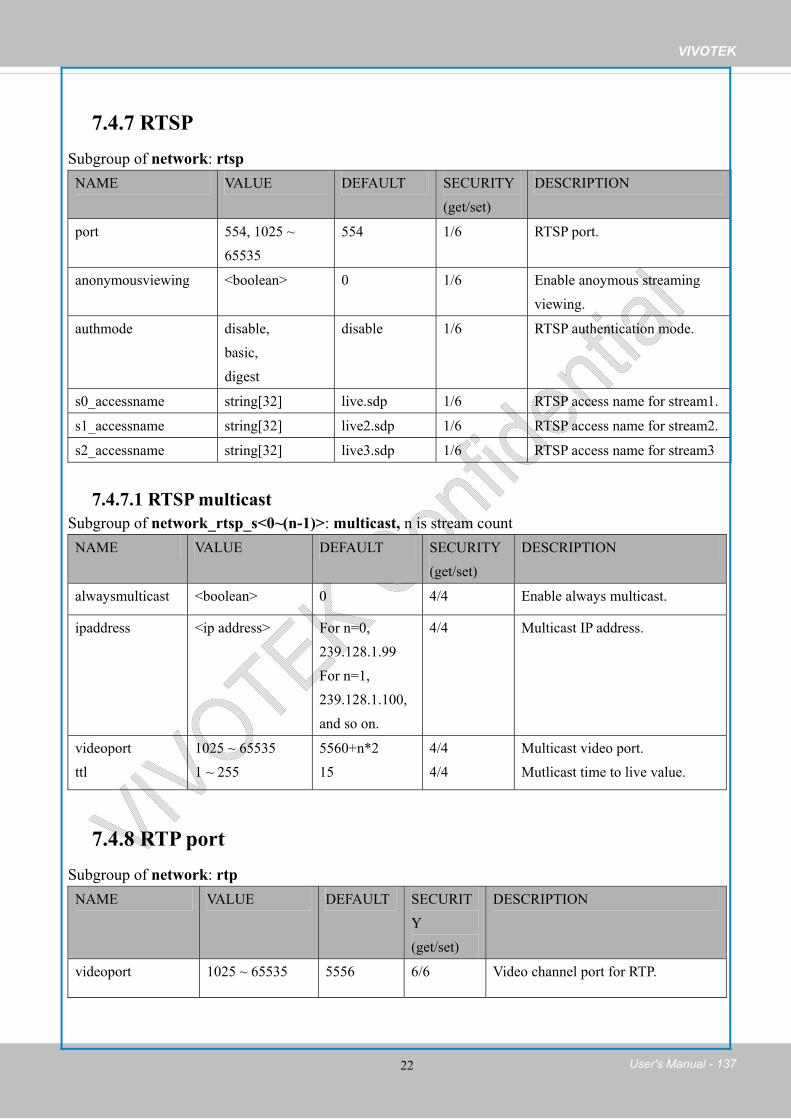
VIVOTEK
User's Manual - 137 22
7.4.7 RTSP Subgroup of network: rtspNAME VALUE DEFAULT SECURITY
(get/set) DESCRIPTION
port 554, 1025 ~ 65535
554 1/6 RTSP port.
anonymousviewing <boolean> 0 1/6 Enable anoymous streaming viewing.
authmode disable, basic, digest
disable 1/6 RTSP authentication mode.
s0_accessname string[32] live.sdp 1/6 RTSP access name for stream1.
s1_accessname string[32] live2.sdp 1/6 RTSP access name for stream2.
s2_accessname string[32] live3.sdp 1/6 RTSP access name for stream3
7.4.7.1 RTSP multicast Subgroup of network_rtsp_s<0~(n-1)>: multicast, n is stream count NAME VALUE DEFAULT SECURITY
(get/set) DESCRIPTION
alwaysmulticast <boolean> 0 4/4 Enable always multicast.
ipaddress <ip address> For n=0, 239.128.1.99 For n=1, 239.128.1.100, and so on.
4/4 Multicast IP address.
videoport ttl
1025 ~ 65535 1 ~ 255
5560+n*2 15
4/4 4/4
Multicast video port. Mutlicast time to live value.
7.4.8 RTP port Subgroup of network: rtpNAME VALUE DEFAULT SECURIT
Y(get/set)
DESCRIPTION
videoport 1025 ~ 65535 5556 6/6 Video channel port for RTP.

VIVOTEK
138 - User's Manual 23
7.4.9 PPPoE Subgroup of network: pppoeNAME VALUE DEFAULT SECURITY
(get/set) DESCRIPTION
user string[128] <blank> 6/6 PPPoE account user name.
pass password[64] <blank> 6/6 PPPoE account password.
7.5 IP Filter
7.5.1 ipfilter for ONVIF Group: ipfilter NAME VALUE DEFAULT SECURITY
(get/set) DESCRIPTION
enable <boolean> 0 6/6 Enable access list filtering.
admin_enable <boolean> 0 6/6 Enable administrator IP address.
admin_ip String[43] <blank> 6/6 Administrator IP address.
maxconnection 0~10 10 6/6 Maximum number of concurrent streaming connection(s).
type 0, 1 1 6/6 Ipfilter policy : 0 => allow 1 => deny
ipv4list_i<0~9> Single address: <ip address> Networkaddress: <ip address / network mask> Rangeaddress:<start ip address - end ip address>
<blank> 6/6 IPv4 address list.
ipv6list_i<0~9> String[43] <blank> 6/6 IPv6 address list.

VIVOTEK
User's Manual - 139 24
7.6 video input Group: videoinNAME VALUE DEFAULT SECURITY
(get/set) DESCRIPTION
cmosfreq 50, 60 60 4/4 CMOS frequency.
whitebalance auto, manual,rbgain
auto 4/4 “auto” indicates auto white balance.“manual” indicates keep current value.
“rbgain” indicates using rgain and gbain.
exposurelevel 0~12 6 4/4 Exposure level
color 0, 1 1 4/4 0 =>monochrome 1 => color
flip <boolean> 0 4/4 Flip the image.
mirror <boolean> 0 4/4 Mirror the image.
text string[16] <blank> 1/4 Enclose caption.
imprinttimestamp <boolean> 0 4/4 Overlay time stamp on video.
7. 6.1 video input setting per channel Group: videoin_c<0~(n-1)> for n channel products, and m is stream numberNAME VALUE DEFAULT SECURITY
(get/set) DESCRIPTION
whitebalance auto, manual,rbgain
auto 4/4 “auto” indicates auto white balance.“manual” indicates keep current value.
“rbgain” indicates using rgain and gbain.
rgain 0~100 16 4/4 Manual set rgain value of gain control setting.
bgain 0~100 21 4/4 Manual set bgain value of gain control setting.
exposurelevel 0~12 6 4/4 Exposure levelcmosfreq 50, 60 60 4/4 CMOS frequency.

VIVOTEK
140 - User's Manual 25
mode 0 ~ "capability_videoin_c<n>_nmode"-1
0 4/99 Indicate the video mode on use.
maxgain 0~100 100 4/4 Manual set maximum gain value.
mingain 0~100 0 4/4 Manual set minimum gain value.
color 0, 1 1 4/4 0 =>monochrome 1 => color
flip <boolean> 0 4/4 Flip the image.
mirror <boolean> 0 4/4 Mirror the image.
ptzstatus <integer> 2 1/7 A 32-bit integer, each bit can be set separately as follows: Bit 0 => Support camera control function; 0(not support), 1(support)
Bit 1 => Built-in or externalcamera; 0 (external), 1(built-in)
Bit 2 => Support panoperation; 0(not support), 1(support)
Bit 3 => Support tiltoperation; 0(not support), 1(support)
Bit 4 => Support zoomoperation; 0(not support), 1(support)
Bit 5 => Support focusoperation; 0(not support), 1(support)
text string[64] <blank> 1/4 Enclose caption.
imprinttimestamp <boolean> 0 4/4 Overlay time stamp on video.
textonvideo_position top, bottom top 4/4 Position of timestamp and video title on image
textonvideo_size 15,25,30 15 4/4 Timestamp and video title font-size
minexposure 5~32000 32000 4/4 Minimum exposure time.

VIVOTEK
User's Manual - 141 26
maxexposure 5~32000 30 4/4 Maximum exposure time. s<0~(m-1)>_codectype mjpeg, h264 h264 1/4 Video codec type.
svc is only supported with stream 0.
s<0~(m-1)>_resolution Reference capability_videoin_resolution
1920x1080 1/4 Video resolution in pixels.
s<0~(m-1)>_h264_intraperiod
250, 500, 1000, 2000, 3000, 4000
1000 4/4 Intra frame period in milliseconds.
s<0~(m-1)>_h264_prioritypolicy
framerate, imagequality
framerate 4/4 The policy to apply when the target bit rate is not sufficient to satisfy current encoded conditions. “framerate” indicates frame rate first. “imagequality” indicates image quality first.
s<0~(m-1)>_h264_ratecontrolmode
cbr, vbr cbr 4/4 cbr, constant bitrate vbr, fix quality
s<0~(m-1)>_h264_quant 1~5,99, 100 3 4/4 Quality of video when choosing vbr in “ratecontrolmode”. 1 = worst quality, 5 = best quality. 100: Use the quality level in "qpercent"99: Use the quality level in "qvalue"
s<0~(m-1)>_h264_qpercent 1~100 50 4/4 Set quality by percentage. 1: Worst quality 100: Best quality (s<0~(m-1)>_h264_quant = 100)
s<0~(m-1)>_h264_qvalue 0~51 29 4/4 Manual video quality level input. (s<0~(m-1)>_h264_quant = 99)
s<0~(m-1)>_h264_bitrate 1000~4000000 3000000 4/4 Set bit rate in bps when

VIVOTEK
142 - User's Manual 27
0 choosing cbr in “ratecontrolmode”.
s<0~(m-1)>_h264_maxframe 1~30 30 1/4 Set maximum frame rate in fps (for h264).
s<0~(m-1)>_h264_profile 0~2 1 1/4 Indicate H264 profiles 0: baseline 1: main profile 2: high profile
s<0~(m-1)>_mjpeg_prioritypolicy
framerate, imagequality
framerate 4/4 The policy to apply when the target bit rate is not sufficient to satisfy current encoded conditions. “framerate” indicates frame rate first. “imagequality” indicates image quality first.
s<0~(m-1)>_mjpeg_ratecontrolmode
cbr, vbr vbr 4/4 cbr, constant bitrate vbr, fix quality
s<0~(m-1)>_mjpeg_quant 1~5, 99, 100 3 4/4 Quality of JPEG video. 1 = worst quality, 5 = best quality. 100: Use the quality level in "qpercent"99: Use the quality level in "qvalue"
s<0~(m-1)>_mjpeg_maxframe
1~30 30 1/4 Set maximum frame rate in fps (for JPEG).
s<0~(m-1)>_mjpeg_qvalue 10~200 49 4/4 Manual video quality level input. (s<0~(m-1)>_mjpeg_quant = 0)
s<0~(m-1)>_mjpeg_qpercent 1~100 50 4/4 Set quality by percentage. 1: Worst quality 100: Best quality (s<0~(m-1)>_mjpeg_quant = 100)
s<0~(m-1)>_mjpeg_bitrate 1000~40000000
6000000 4/4 Set bit rate in bps when choosing cbr in “ratecontrolmode”.
s<0~(m-1)>_forcei 1 N/A 7/6 Force I frame.

VIVOTEK
User's Manual - 143 28
7.6.1.1 Alternative video input profiles per channelIn addition to the primary setting of video input, there can be alternative profile video input setting for each channel which might be for different scene of light (daytime or nighttime). Group: videoin_profile_i<0~(m-1)> NAME VALUE DEFAULT SECURITY
(get/set) DESCRIPTION
enable <boolean> 0 4/4 Enable/disable this profile setting
policy day, night, schedule
night 4/4 The mode which the profile is applied to.
begintime hh:mm 18:00 4/4 Begin time of schedule mode.
endtime hh:mm 06:00 4/4 End time of schedule mode.
exposurelevel 0~12 6 4/4 Exposure level
minexposure 5~32000 32000 4/4 Minimum exposure time.
maxexposure 5~32000 30 4/4 Maximum exposure time.
maxgain 0~100 100 4/4 Manual set maximum gain value.
mingain 0~100 0 4/4 Manual set minimum gain value.
whitebalance auto, manual, rbgain
auto 4/4 “auto” indicates auto white balance.“manual” indicates keep current value. “rbgain” indicates using rgain and gbain.
rgain 0~100 16 4/4 Manual set rgain value of gain control setting.
bgain 0~100 21 4/4 Manual set bgain value of gain control setting.

VIVOTEK
144 - User's Manual 29
7.7 IR cut control Group: ircutcontrol NAME VALUE DEFAULT SECURITY
(get/set) DESCRIPTION
mode auto, day, night,schedule
auto 6/6 Set IR cut control mode
sir <boolean> 0 6/6 Enable/disable Smart IRdaymodebegintime 00:00~23:59 07:00 6/6 Day mode begin time
daymodeendtime 00:00~23:59 18:00 6/6 Day mod end time
disableirled <boolean> 0 6/6 Enable/disable built-in IR led
bwmode <boolean> 1 6/6 Switch to B/W in night mode if enabled
sensitivity low, normal, high
normal 6/6 Sensitivity of light sensor
7.8 image setting per channel Group: image_c<0~(n-1)> for n channel products NAME VALUE DEFAULT SECURITY
(get/set) DESCRIPTION
brightness -5 ~ 5 0 4/4 Adjust brightness of image according to mode settings.
saturation -5 ~ 5, 100 100 4/4 Adjust saturation of image according to mode settings.
saturationpercent 0~100 50 4/4 Adjust saturation value of percentage when saturation=100
contrast -5 ~ 5 0 4/4 Adjust contrast of image according to mode settings.

VIVOTEK
User's Manual - 145 30
sharpness -3 ~ 3, 100 100 4/4 Adjust sharpness of image according to mode settings.
sharpnesspercent 0~100 50 4/4 Adjust sharpness of image by percentage. Softer 0 <-> 100 Sharper
gammacurve 0~100 0 4/4 Gamma curve. dnr_mode 0~1 1 4/4 3D noise reduction.
0: off 1: on
dnr_strength 1~100 50 4/4 3D noise reduction strength.
lowlightmode <boolean> 1 4/4 Enable/disable low light mode.
profile_i0_enable <boolean> 0 4/4 Enable/disable this profile setting
profile_i0_policy day, night,schedule
night 4/4 The mode which the profile is applied to.
profile_i0_begintime hh:mm 18:00 4/4 Begin time of schedule mode.
profile_i0_endtime hh:mm 06:00 4/4 End time of schedule mode.
profile_i0_brightness -5~5 0 4/4 Adjust brightness of image according to mode settings.
profile_i0_contrast -5 ~ 5 0 4/4 Adjust contrast of image according to mode settings.
profile_i0_saturation -5~5,100 100 4/4 Adjust saturation of image according to mode settings. 100 for saturation percentage mode.
profile_i0_saturationpercent
0~100 50 4/4 when profile_i0_saturation=100, adjust saturation value of percentage

VIVOTEK
146 - User's Manual 31
according to mode settings.
profile_i0_sharpness -3~3,100 100 4/4 Adjust sharpness of image according to mode settings.
profile_i0_sharpnesspercent
0~100 50 4/4 Adjust sharpness value of percentage when sharpness=100
profile_i0_gammacurve 0~100 0 4/4 Gamma curve profile_i0_dnr_mode 0~1 1 4/4 3D noise reduction.
0: off 1: on
profile_i0_dnr_strength 1~100 50 4/4 3D noise reduction strength.
profile_i0_lowlightmode <boolean> 1 4/4 Enable/disable low light mode.
7.9 Time Shift settings Group: timeshift, c for n channel products, m is stream number NAME VALUE DEFAUL
TSECURITY(get/set)
DESCRIPTION
enable <boolean> 0 4/4 Enable time shift streaming.
c<0~(n-1)>_s<0~(m-1)>_allow
<boolean> 0 4/4 Enable time shift streaming for specific stream.
7.10 Motion detection settings Group: motion_c<0~(n-1)> for n channel productNAME VALUE DEFAULT SECURITY
(get/set) DESCRIPTION
enable <boolean> 0 4/4 Enable motion detection.
win_i<0~2>_enable <boolean> 0 4/4 Enable motion window 1~3.
win_i<0~2>_name string[14] <blank> 4/4 Name of motion window 1~3.
win_i<0~2>_left 0 ~ 320 0 4/4 Left coordinate of window position.
win_i<0~2>_top 0 ~ 240 0 4/4 Top coordinate of window position.

VIVOTEK
User's Manual - 147 32
win_i<0~2>_width 0 ~ 320 0 4/4 Width of motion detection window.
win_i<0~2>_height 0 ~ 240 0 4/4 Height of motion detection window.
win_i<0~2>_objsize 0 ~ 100 0 4/4 Percent of motion detection window.
win_i<0~2>_sensitivity 0 ~ 100 0 4/4 Sensitivity of motion detection window.
Group: motion_c<0~(n-1)> profile for m profile and n channel product (capability.nmotionprofile > 0)NAME VALUE DEFAULT SECURITY
(get/set) DESCRIPTION
i<0~(m-1)>_enable <boolean> 0 4/4 Enable profile 1 ~ (m-1).
i<0~(m-1)>_policy day, night, schedule
night 4/4 The mode which the profile is applied to.
i<0~(m-1)>_begintime hh:mm 18:00 4/4 Begin time of schedule mode.
i<0~(m-1)>_endtime hh:mm 06:00 4/4 End time of schedule mode.
i<0~(m-1)>_win_i<0~2>_enable <boolean> 0 4/4 Enable motion window.
i<0~(m-1)>_win_i<0~2>_name string[14] <blank> 4/4 Name of motion window.
i<0~(m-1)>_win_i<0~2>_left 0 ~ 320 0 4/4 Left coordinate of window position.
i<0~(m-1)>_win_i<0~2>_top 0 ~ 240 0 4/4 Top coordinate of window position.
i<0~(m-1)>_win_i<0~2>_width 0 ~ 320 0 4/4 Width of motion detection window.
i<0~(m-1)>_win_i<0~2>_height 0 ~ 240 0 4/4 Height of motion detection window.
i<0~(m-1)>_win_i<0~2>_objsize 0 ~ 100 0 4/4 Percent of motion detection window.
i<0~(m-1)>_win_i<0~2>_sensitivity 0 ~ 100 0 4/4 Sensitivity of motion detection window.

VIVOTEK
148 - User's Manual 33
7.11 Tampering detection settings Group: tampering_c<0~(n-1)> for n channel product NAME VALUE DEFAULT SECURITY
(get/set) DESCRIPTION
enable <boolean> 0 4/4 Enable or disable tamper detection.
duration 10 ~ 600 10 4/4 If tampering value exceeds the ‘threshold’ for more than ‘duration’ second(s), then tamper detection is triggered.
7.12 DDNS Group: ddns NAME VALUE DEFAULT SECURITY
(get/set) DESCRIPTION
enable <boolean> 0 6/6 Enable or disable the dynamic DNS.
provider Safe100, DyndnsDynamic, DyndnsCustom, CustomSafe100
DyndnsDynamic
6/6 Safe100 => safe100.net DyndnsDynamic => dyndns.org (dynamic) DyndnsCustom => dyndns.org (custom) CustomSafe100 => Custom server using safe100 method
<provider>_hostname
string[128] <blank> 6/6 Your DDNS hostname.
<provider>_usernameemail
string[64] <blank> 6/6 Your user name or email to login to the DDNS service provider
<provider>_passwordkey
string[64] <blank> 6/6 Your password or key to login to the DDNS service provider.
<provider>_servername
string[128] <blank> 6/6 The server name for safe100. (This field only exists if the provider is customsafe100)

VIVOTEK
User's Manual - 149 34
7.12.1 Express link Group:expresslinkNAME VALUE DEFAULT SECURITY
(get/set) DESCRIPTION
enable <boolean> 0 6/6 Enable or disable express link.
state onlycheck, onlyoffline, checkonline,badnetwork
badnetwork 6/6 “onlycheck” : You have to input the host name of your camera and press "Register" button to register it. “onlyoffline” : Express link is active, you can now connect to this camera at expresslink_url. “checkonline” : Express link is not active.“badnetwork” : Express Link is not supported under this network environment.
url string[64] <blank> 6/6 The URL to connect to this camera by express link.
7.13 UPnP presentation Group: upnppresentationNAME VALUE DEFAULT SECURITY
(get/set) DESCRIPTION
enable <boolean> 1 6/6 Enable or disable the UPnP presentation service.
7.14 UPnP port forwarding Group: upnpportforwardingNAME VALUE DEFAULT SECURITY
(get/set) DESCRIPTION
enable <boolean> 0 6/6 Enable or disable the UPnP port forwarding service.
upnpnatstatus 0~3 0 6/7 The status of UPnP port forwarding, used internally. 0 = OK, 1 = FAIL, 2 = no IGD router, 3 = no need for port forwarding

VIVOTEK
150 - User's Manual 35
7.15 System log Group: syslogNAME VALUE DEFAULT SECURITY
(get/set) DESCRIPTION
enableremotelog <boolean> 0 6/6 Enable remote log.
serverip <IP address> <blank> 6/6 Log server IP address.
serverport 514, 1025~65535 514 6/6 Server port used for log.
level 0~7 6 6/6 Levels used to distinguish the importance of the information:0: LOG_EMERG 1: LOG_ALERT 2: LOG_CRIT 3: LOG_ERR 4: LOG_WARNING 5: LOG_NOTICE 6: LOG_INFO 7: LOG_DEBUG
setparamlevel 0~2 0 6/6 Show log of parameter setting.0: disable 1: Show log of parameter setting set from external. 2. Show log of parameter setting set from external and internal.
7.16 SNMP Group: snmpNAME VALUE DEFAULT SECURITY
(get/set) DESCRIPTION
v2 0~1 0 6/6 SNMP v2 enabled. 0 for disable, 1 for enable
v3 0~1 0 6/6 SNMP v3 enabled. 0 for disable, 1 for enable
secnamerw string[31] Private 6/6 Read/write security name
secnamero string[31] Public 6/6 Read only security name

VIVOTEK
User's Manual - 151 36
authpwrw string[8~128] <blank> 6/6 Read/write authentication password
authpwro string[8~128] <blank> 6/6 Read only authentication password
authtyperw MD5,SHA MD5 6/6 Read/write authentication type
authtypero MD5,SHA MD5 6/6 Read only authentication type
encryptpwrw string[8~128] <blank> 6/6 Read/write passwrd
encryptpwro string[8~128] <blank> 6/6 Read only password
encrypttyperw DES DES 6/6 Read/write encryption type
encrypttypero DES DES 6/6 Read only encryption type
rwcommunity string[31] Private 6/6 Read/write community
rocommunity string[31] Public 6/6 Ready only community
7.17 Layout configuration Group: layoutNAME VALUE DEFAULT SECURIT
Y(get/set)
DESCRIPTION
logo_default <boolean> 1 1/6 0 => Custom logo 1 => Default logo
logo_link string[128] http://www.vivotek.com
1/6 Hyperlink of the logo
logo_powerbyvvtk_hidden <boolean> 0 1/6 0 => display the power by vivotek logo 1 => hide the power by vivotek logo
theme_option 1~4 1 1/6 1~3: One of the default themes.4: Custom definition.
theme_color_font string[7] #ffffff 1/6 Font color
theme_color_configfont string[7] #ffffff 1/6 Font color of configuration area.
theme_color_titlefont string[7] #098bd6 1/6 Font color of video title.
theme_color_controlbackground
string[7] #565656 1/6 Background color of control area.
theme_color_configbackground string[7] #323232 1/6 Background color of configuration area.

VIVOTEK
152 - User's Manual 37
theme_color_videobackground string[7] #565656 1/6 Background color of video area.
theme_color_case string[7] #323232 1/6 Frame color
custombutton_manualtrigger_show
<boolean> 1 1/6 Show or hide manual trigger (VI) button in homepage 0 -> Hidden 1 -> Visible
7.18 Privacy mask Group: privacymask_c<0~(n-1)> for n channel product NAME VALUE DEFAULT SECURITY
(get/set) DESCRIPTION
enable <boolean> 0 4/4 Enable privacy mask.
win_i<0~4>_enable <boolean> 0 4/4 Enable privacy mask window.
win_i<0~4>_name string[14] <blank> 4/4 Name of the privacy mask window.
win_i<0~4>_left 0 ~ 320 0 4/4 Left coordinate of window position.
win_i<0~4>_top 0 ~ 240 0 4/4 Top coordinate of window position.
win_i<0~4>_width 0 ~ 320 0 4/4 Width of privacy mask window.
win_i<0~4>_height 0 ~ 240 0 4/4 Height of privacy mask window.
7.19 Capability Group: capabilityNAME VALUE DEFAULT SECURITY
(get/set) DESCRIPTION
api_httpversion <string> 0300a 0/99 The HTTP API version.
bootuptime <positive integer>
70 0/99 Server bootup time.
nir 0, <positiveinteger>
1 0/99 Number of IR interfaces.(Recommand to use ir for built-in IR and extir for external IR)

VIVOTEK
User's Manual - 153 38
npir 0, <positiveinteger>
0 0/99 Number of PIRs.
ndi 0, <positiveinteger>
0 0/99 Number of digital inputs.
nvi 0, <positiveinteger>
3 0/99 Number of virtual inputs (manual trigger)
ndo 0, <positiveinteger>
0 0/99 Number of digital outputs.
naudioin 0, <positiveinteger>
0 0/99 Number of audio inputs.
naudioout 0, <positiveinteger>
0 0/99 Number of audio outputs.
nvideoin <positive integer>
1 0/99 Number of video inputs.
nvideoout 0, <Positive
Integer>
0 0/99 Number of video out
interface.
nvideoinprofile <positive integer>
1 0/99 Number of video input profiles.
nmediastream <positive integer>
3 0/99 Number of media stream per channels.
naudiosetting <positive integer>
0 0/99 Number of audio settings per channel.
nuart 0, <positiveinteger>
0 0/99 Number of UART interfaces.
nmotion 0, <positive integer>
3 0/99 Number of motion window.
nmotionprofile 0, <positive integer>
1 0/99 Number of motion profiles.
ptzenabled 0, <positive integer>
0 0/99 An 32-bit integer, each bit can be set separately as follows: Bit 0 => Support camera control function;

VIVOTEK
154 - User's Manual 39
0(not support), 1(support) Bit 1 => Built-in or external video source; 0(external), 1(built-in) Bit 2 => Support pan operation, 0(not support), 1(support) Bit 3 => Support tilt operation; 0(not support), 1(support) Bit 4 => Support zoom operation; 0(not support), 1(support) Bit 5 => Support focus operation; 0(not support), 1(support) Bit 6 => Support iris operation; 0(not support), 1(support) Bit 7 => External or built-in PT; 0(built-in), 1(external)Bit 8 => Invalidate bit 1 ~ 7; 0(bit 1 ~ 7 are valid), 1(bit 1 ~ 7 are invalid) Bit 9 => Reserved bit; Invalidate lens_pan, Lens_tilt, lens_zoon, lens_focus, len_iris. 0(fields are valid), 1(fields are invalid) Examples: PT8133: 0b1111 SD8362: 0b111111 VS8102: 0b10111101

VIVOTEK
User's Manual - 155 40
windowless <boolean> 1 0/99 Indicate whether to support windowless plug-in.
eptz 0, <positive integer>
3 0/99 A 32-bit integer, each bit can be set separately as follows:Bit 0 => stream 1 supports ePTZ or not. Bit 1 => stream 2 supports ePTZ or not. The rest may be deduced by analogy
remotefocus <boolean> 0 0/99 Indicate whether to support remote focus function.
npreset 0, <positive integer>
20 0/99 Number of preset locations.
protocol_https < boolean > 1 0/99 Indicate whether to support HTTP over SSL.
protocol_rtsp < boolean > 1 0/99 Indicate whether to support RTSP.
protocol_sip <boolean> 0 0/99 Indicate whether to support SIP.
protocol_maxconnection <positive integer>
10 0/99 The maximum allowed simultaneous connections.
protocol_maxgenconnection <positive integer>
10 0/99 The maximum general streaming connections .
protocol_maxmegaconnection <positive integer>
10 0/99 The maximum megapixel streaming connections.
protocol_rtp_multicast_ scalable
<boolean> 1 0/99 Indicate whether to support scalable multicast.
protocol_rtp_multicast_ backchannel
<boolean> 1 0/99 Indicate whether to support backchannel multicast.
protocol_rtp_tcp <boolean> 1 0/99 Indicate whether to support RTP over TCP.

VIVOTEK
156 - User's Manual 41
protocol_rtp_http <boolean> 1 0/99 Indicate whether to support RTP over HTTP.
protocol_spush_mjpeg <boolean> 1 0/99 Indicate whether to support server push MJPEG.
protocol_snmp <boolean> 1 0/99 Indicate whether to support SNMP.
protocol_ipv6 <boolean> 1 0/99 Indicate whether to support IPv6.
protocol_pppoe <boolean> 1 0/99 Indicate whether to support PPPoE.
protocol_ieee8021x <boolean> 1 0/99 Indicate whether to support IEEE802.1x.
protocol_qos_cos <boolean> 1 0/99 Indicate whether to support CoS.
protocol_qos_dscp <boolean> 1 0/99 Indicate whether to support QoS/DSCP.
protocol_ddns <boolean> 1 0/99 Indicate whether to support DDNS.
videoin_type 0, 1, 2 2 0/99 0 => Interlaced CCD 1 => Progressive CCD2 => CMOS
videoin_codec <string> mjpeg, h264
0/99 Available codec of a device.The sequence is not limited.
videoin_streamcodec <Positive Integer>
6,6,6 0/99 This equals "capability_videoin_c0_streamcodec".
videoin_flexiblebitrate 0, 1 1 0/99 Support flexible bit rate control or not.
videoin_resolution <a list of availableresolution separated by commas>
176x144,384x216,640x360,1280x720,1360x768,1600x904,1920x1080
0/99 Available resolutions list.
videoin_nresolution < number of 7 0/99 How many resolution

VIVOTEK
User's Manual - 157 42
availableresolution list>
options (listed in "resolution") in current video mode.
videoin_maxframerate <a list of availablemaximum frame rate separated by commas>
30,30,30,30,30,30,30
0/99 Available maximum frame list.
videoin_mjpeg_maxframerate
<a list of availablemaximum codec frame rate separated by commas>
30,30,30,30,30,30,30
0/99 Available maximum codec frame list.
videoin_h264_maxframerate
<a list of availablemaximum codec frame rate separated by commas>
30,30,30,30,30,30,30
0/99 Available maximum codec frame list.
timeshift <boolean> 1 0/99 Indicate whether to support time shift caching stream.
audio_aec <boolean> 0 0/99 Indicate whether to support acoustic echo cancellation.
audio_mic <boolean> 0 0/99 Indicate whether to support built-in microphone input.
audio_extmic <boolean> 0 0/99 Indicate whether to support external microphone input.
audio_ intmic <boolean> 0 0/99 Indicate whether to support internal microphone input.

VIVOTEK
158 - User's Manual 43
audio_linein <boolean> 0 0/99 Indicate whether to support external line input. (It will be replaced by audio_mic and audio_extmic.)
audio_lineout <boolean> 0 0/99 Indicate whether to support line output.
audio_headphoneout <boolean> 0 0/99 Indicate whether to support headphone output.
audioin_codec <string> - 0/99 Available codec list for audio input.
audioout_codec g711 <blank> 0/99 Available codec list for SIP.
uart_httptunnel <boolean> 0 0/99 Indicate whether to support HTTP tunnel for UART transfer.
camctrl_httptunnel <boolean> 0 0/99 The attribute indicates whether sending camera control commands through HTTP tunnel is supported. 0: Not supported 1: Supported
camctrl_privilege <boolean> 1 0/99 Indicate whether to support “Manage Privilege” of PTZ control in the Security page.1: support both /cgi-bin/camctrl/camctrl.cgi and /cgi-bin/viewer/camctrl.cgi0: support only /cgi-bin/viewer/camctrl.cgi
transmission_mode Tx, Rx,
Tx 0/99 Indicate transmission mode of the machine:

VIVOTEK
User's Manual - 159 44
Both TX = server, Rx = receiver box, Both = DVR.
network_wire <boolean> 1 0/99 Indicate whether to support Ethernet.
network_wireless <boolean> 0 0/99 Indicate whether to support wireless.
derivative_brand <boolean> 1 0/99 Indicate whether to support the upgrade function for the derivative brand. For example, if the value is true, the VVTK product can be upgraded to VVXX. (TCVV<->TCXX is excepted)
evctrlchannel <boolean> 1 0/99 Indicate whether to support HTTP tunnel for event/control transfer.
joystick <boolean> 1 0/99 Indicate whether to support joystick control.
storage_dbenabled <boolean> 1 0/99 Media files are indexed in database.
nanystream 0, <positive integer>
0 0/99 number of any media stream per channel
iva <boolean> 0 0/99 Indicate whether to support Intelligent Video analysis
ir <boolean> 1 0/99 Indicate whether to support built-in IR led.
extir <boolean> 0 0/99 Indicate whether to support external IR led.
whitelight <boolean> 0 0/99 Indicate whether to support white light led.
iris <boolean> 0 0/99 Indicate whether to support iris control.
tampering <boolean> 1 0/99 Indicate whether to support tampering

VIVOTEK
160 - User's Manual 45
detection.
temperature <boolean> 0 0/99 Indicate whether to support temperature detection.
version_onvifdaemon <string> 1.8.0.5 0/99 Indicate ONVIF daemon version
version_onvifevent <string> 1.3.0.6 0/99 Indicate ONVIF event version
media_totalspace <positive integer>
20000 0/99 Available memory space (KB) for media.
media_snapshot_sizepersecond <positive integer>
500 0/99 Maximum size (KB) of one snapshot image.
media_snapshot_maxpreevent <positive integer>
7 0/99 Maximum snapshot number before event occurred.
media_snapshot_maxpostevent <positive integer>
7 0/99 Maximum snapshot number after event occurred.
media_videoclip_maxsize <positive integer>
4096 0/99 Maximum size (KB) of a videoclip.
media_videoclip_maxlength <positive integer>
20 0/99 Maximum length (second) of a videoclip.
media_videoclip_maxpreevent <positive integer>
9 0/99 Maximum duration (second) after event occurred in a videoclip.
localstorage_manageable <boolean> 1 0/99 Indicate whether manageable local storage is supported.
localstorage_seamless <boolean> 0 0/99 Indicate whether seamless recording is supported.
localstorage_modnum 0,<positiveinteger>
0 0/99 The maximum MOD connection numbers.
localstorage_modversion <string> 1.0.1.19 0/99 Indicate MOD daemon version
localstorage_slconnum 0, <positiveinteger>
0 0/99 The maximum seamless connection number.

VIVOTEK
User's Manual - 161 46
adaptiverecording <boolean> 1 0/99 Indicate whether to support adaptive recording.
adaptivestreaming <boolean> 1 0/99 Indicate whether to support adaptive streaming.
remotecamctrl_master 0, <positive integer>
0 0/99 Indicate whether to support remote auxiliary camera (master side), this value means supporting max number of auxiliary camera.
remotecamctrl_slave <boolean> 0 0/99 Indicate whether to support remote camera control (slave side).
fisheye <boolean> 0 0/99 Indicate where fisheye camera
vadp <positive integer>
0 0/99 An 32-bit integer, each bit can be set separately as follows: Bit 0 => VADP interface Bit 1 => Capture video raw data Bit 2 => Support encode jpeg Bit 3 => Audio Bit 4 => Event
smartstream_support <boolean> 0 0/99 Indicate whether smart stream is supported.
smartstream_nstream <positiveinteger>
0 0/99 Number of stream that support smart stream
smartstream_mode_autotracking
<boolean> 0 0/99 Indicate whether autotracking smart stream is supported
smartstream_mode_manual <boolean> 0 0/99 Indicate whether manual smart stream is supported

VIVOTEK
162 - User's Manual 47
smartstream_mode_hybrid <boolean> 0 0/99 Indicate whether hybrid(autotracking+manual) smart stream is supported
smartstream_nwindow_autotracking
<positiveinteger>
0 0/99 Maximum number of tracking window of autotracking
smartstream_nwindow_ manual
<positiveinteger>
0 0/99 Maximum number of tracking window of manual
smartstream_nwindow_ hybrid_autotracking
<positiveinteger>
0 0/99 Maximum number of tracking window of autotracking in hybrid mode
smartstream_nwindow_ hybrid_ manual
<positiveinteger>
0 0/99 Maximum number of tracking window of manual in hybrid mode
smartstream_supportquality <string> excellent,detailed,good,standard,medium,low
0/99 Available quality of smart stream
smartstream_supportmaxbitrate
<string> 1Mbps,2Mbps,4Mbps,6Mbps,8Mbps,10Mbps,20Mbps,30Mbps,40Mbps
0/99 Available maxbitrate of smart stream
version_genetec <string> 1.0.2.3 0/99 Indicate genetec version
Group: capability_image_c<n>, where n = channel index from 0 ~ "capability_nvideoin"-1 NAME VALUE DEFAULT SECURITY
(get/set) DESCRIPTION
wdrc 0, 1 1 0/99 0: Non-support WDR Enhanced1: Support WDR Enhanced
wdr 0, 1 0 0/99 0: Non-support WDR Pro 1: Support WDR Pro

VIVOTEK
User's Manual - 163 48
dnr 0, 1 1 0/99 0: Non-support 3D noise reduction 1: Support 3D noise reduction
iristype piris, dciris, - - 0/99 Indicate iris type. "piris": P-Iris "dciris": DC-Iris "-": No Iris control support* Note: For some cameras, this value may be varied depending on mounted lens.
focusassist 0, 1 0 0/99 0: Non-support focus assistance 1: Support focus assistance
remotefocus 0, 1 0 0/99 0: Non-support remote focus1: Support remote focus
7.20 WebAPI: Information for a channel Group: capability_videoin_c<n>, n = channel index from 0 to "capability_nvideoin"-1PARAMETER VALUE DEFAULT SECURITY
(get/set)DESCRIPTION
nmode <Positive Integer>
1 0/99 Indicate how many video modes supported by this channel.
maxsize <WxH> 1920x1080 0/99 The maximum resolution of all modes in this channel, the unit is pixel.
mode <Integer> 0 0/99 Indicate current video mode.
nresolution <Positive Integer>
7 0/99 How many resolution options (listed in "resolution") in current video mode.

VIVOTEK
164 - User's Manual 49
resolution A list of <WxH>
176x144,384x216,640x360,1280x720,1360x768,1600x904,1920x1080
0/99 Resolution options in current video mode. These options are the possible options for "videoin_c<n>_s<m>_resolution".The last one is the maximum resolution in current mode.
maxframerate A list of <Integer>
30,30,30,30,30,30,30
0/99 Indicate how many frame rate image sensor outputs in current video mode. One to one mapping to the resolution in "resolution".
mjpeg_ maxframerate A list of <Positive Integer> and "-"
30,30,30,30,30,30,30
0/99 Maximum fps that the device can encoded with MJPEG on resolutions in current video mode."-" means not support.
mjpeg_maxbitrate <Positive Integer>, -
40000000 0/99 Maximum bitrates of MJPEG. The unit is bps. "-" means MJPEG does not support bit rate control.
h264_ maxframerate A list of <Positive Integer> and "-"
30,30,30,30,30,30,30
0/99 Maximum fps that the device can encoded with H.264 on resolutions in current video mode. "-" means not support.
h264_maxbitrate <Positive Integer>
40000000 0/99 Maximum bitrates of H.264. The unit is bps.

VIVOTEK
User's Manual - 165 50
streamcodec <Positive Integer>
6,6,6 0/99 Represent supported codec types of each stream. This contains a list of positive integers, split by comma. Each one stands for a stream, and the definition is as following: Bit 0: Support MPEG4. Bit 1: Support MJPEG Bit 2: Support H.264
7.21 WebAPI: Information for a mode Group: capability_videoin_c<n>_mode<m>, n = channel index from 0 to "capability_nvideoin"-1, m = mode index from 0 to "capability_videoin_c<n>_nmode"-1 PARAMETER VALUE DEFAULT SECURITY
(get/set)DESCRIPTION
effectivepixel <WxH> 1920x1080
0/99 The visible area of full scene in this video mode. The unit is pixel in source.
outputsize <WxH>
1920x1080
0/99 The output size of source, equal to the captured size by device, in this video mode. The unit is pixel. This value is used as a basic coordinate system for many features, like ePTZ, privacy mask, motion, etc.
binning 0, 1, 3
0
0/99 Indicate binning is used or not in this video mode. 0: No binning 1: 2x2 binning 3: 3x3 binning
nresolution <Positive Integer>
70/99 How many resolution options in
this video mode. resolution A list of
<WxH> 176x144,384x216,640x360,1280x720,1360x768,1600x904,1920x1080
0/99 Resolution options in this video mode.The last one is the maximum resolution in this video mode.

VIVOTEK
166 - User's Manual 51
maxframerate A list of <Positive Integer>
30, 30, 30, 30, 30, 30, 30
0/99 Indicate how many frame rate image sensor outputs in this video mode.
maxfps_mjpeg A list of <Positive Integer> and "-"
30, 30, 30, 30, 30, 30, 30
0/99 Maximum fps which the device can encoded with MJPEG on resolutions in this video mode. "-" means not support.
maxfps_h264 A list of <Positive Integer> and "-"
30, 30, 30, 30, 30, 30, 30
0/99 Maximum fps which the device can encoded with H.264 on resolutions in this video mode. "-" means not support.
* One to one mapping to the resolution in "resolution". * The element number is defined as "nresolution" in this group. * This parameter records the frame rate when "videoin_c<n>_cmosfreq"=60 or "videoin_c<n>_modulation"=ntsc* Only available when 'h264' is listed in "capability_videoin_codec".
description <String[128]>
na0/99 Description about this mode.
7.22 Customized event script Group: event_customtaskfile_i<0~2>PARAMETER VALUE Default SECURITY
(get/set) DESCRIPTION
name string[40] NULL 6/6 Custom script identification of this entry.
date string[4-20] NULL 6/6 Date of custom script.
time string[4-20] NULL 6/6 Time of custom script.

VIVOTEK
User's Manual - 167 52
7.23 Event setting Group: event_i<0~2>PARAMETER VALUE Default SECURITY
(get/set) DESCRIPTION
name string[40] NULL 6/6 Identification of this entry.
enable 0, 1 0 6/6 Enable or disable this event.
priority 0, 1, 2 1 6/6 Indicate the priority of this event: “0” = low priority “1” = normal priority “2” = high priority
delay 1~999 10 6/6 Delay in seconds before detecting the next event.
trigger boot, motion, seq,recnotify, tampering, vi
boot 6/6 Indicate the trigger condition: “boot” = System boot “motion” = Video motion detection “seq” = Periodic condition “recnotify” = Recording notification.“tampering” = Tamper detection. “vi”= Virtual input (Manual trigger)
triggerstatus String[40] trigger 6/6 The status for event trigger
vi 0~7 0 6/6 Indicate the source id of vi trigger. This field is required when trigger condition is “vi”. One bit represents one digital input. The LSB indicates VI 0.
mdwin 0~7 0 6/6 Indicate the source window id of motion detection. This field is required when trigger condition is “md”. One bit represents one window. The LSB indicates the 1st window. For example, to detect the 1st and 3rd
windows, set mdwin as 5.
mdwin0 0~7 0 6/6 Similar to mdwin. The parameter takes effect when profile 1 of motion detection is enabled.

VIVOTEK
168 - User's Manual 53
inter 1~999 1 6/6 Interval of snapshots in minutes. This field is used when trigger condition is “seq”.
weekday 0~127 127 6/6 Indicate which weekday is scheduled.One bit represents one weekday. bit0 (LSB) = Saturday bit1 = Friday bit2 = Thursday bit3 = Wednesday bit4 = Tuesday bit5 = Monday bit6 = Sunday For example, to detect events on Friday and Sunday, set weekday as 66.
begintime hh:mm 00:00 6/6 Begin time of the weekly schedule.
endtime hh:mm 24:00 6/6 End time of the weekly schedule. (00:00 ~ 24:00 sets schedule as always on)
action_cf_enable 0. 1 0 6/6 Enable media write on CF or other local storage media
action_cf_folder string[128] NULL 6/6 Path to store media.
action_cf_media NULL, 0~4 NULL 6/6 Index of the attached media.
action_cf_datefolder <boolean> 1 6/6 Enable this to create folders by date, time, and hour automatically.
action_cf_backup <boolean> 0 6/6 Enable the capability of backing up recorded files to the SD card when network is lost. 0: Disabled 1: Enabled
action_server_i<0~4>_enable
0, 1 0 6/6 Enable or disable this server action.
action_server_i<0~4>_media
NULL, 0~4 NULL 6/6 Index of the attached media.
action_server_i<0~4>_datefolder
<boolean> 0 6/6 Enable this to create folders by date, time, and hour automatically.

VIVOTEK
User's Manual - 169 54
action_server_i<0~4>_foldername
string[40] %Y%M%D%H
6/6 The template of the folder name to be created. Slashes can be used in the template, and following placeholders can also be used: %Y: Year (e.g. 2010) %M: Month %D: Date %H: Hour
7.24 Server setting for event action Group: server_i<0~4>PARAMETER VALUE DEFAULT SECURITY
(get/set) DESCRIPTION
name string[40] NULL 6/6 Identification of this entry
type email, ftp,http,ns
email 6/6 Indicate the server type: “email” = email server “ftp” = FTP server “http” = HTTP server “ns” = network storage
http_url string[128] http:// 6/6 URL of the HTTP server to upload.
http_username string[64] NULL 6/6 Username to log in to the server.
http_passwd string[64] NULL 6/6 Password of the user.
ftp_address string[128] NULL 6/6 FTP server address.
ftp_username string[64] NULL 6/6 Username to log in to the server.
ftp_passwd string[64] NULL 6/6 Password of the user.
ftp_port 0~65535 21 6/6 Port to connect to the server.
ftp_location string[128] NULL 6/6 Location to upload or store the media.
ftp_passive 0, 1 1 6/6 Enable or disable passive mode. 0 = disable passive mode 1 = enable passive mode
email_address string[128] NULL 6/6 Email server address.
email_sslmode 0, 1 0 6/6 Enable support SSL.
email_port 0~65535 25 6/6 Port to connect to the server.
email_username string[64] NULL 6/6 Username to log in to the server.
email_passwd string[64] NULL 6/6 Password of the user.

VIVOTEK
170 - User's Manual 55
email_senderemail string[128] NULL 6/6 Email address of the sender.
email_recipientemail string[640] NULL 6/6 Email address of the recipient.
ns_location string[128] NULL 6/6 Location to upload or store the media.
ns_username string[64] NULL 6/6 Username to log in to the server.
ns_passwd string[64] NULL 6/6 Password of the user.
ns_workgroup string[64] NULL 6/6 Workgroup for network storage.
7.25 Media setting for event action Group: media_i<0~4> (media_freespace is used internally.) PARAMETER VALUE DEFAULT SECURITY
(get/set) DESCRIPTION
name string[40] NULL 6/6 Identification of this entry
type snapshot, systemlog, videoclip, recordmsg
snapshot 6/6 Media type to send to the server or store on the server.
snapshot_source 0~2 0 6/6 Indicate the source of media stream. 0 means the first stream. 1 means the second stream. 2 means the third stream.
snapshot_prefix string[16] <blank> 6/6 Indicate the prefix of the filename.
snapshot_datesuffix 0, 1 0 6/6 Add date and time suffix to filename: 1 = Add date and time suffix. 0 = Do not add.
snapshot_preevent 0 ~ 7 1 6/6 Indicates the number of pre-event images.
snapshot_postevent 0 ~ 7 1 6/6 The number of post-event images
videoclip_source 0~2 0 6/6 Indicate the source of media stream. 0 means the first stream. 1 means the second stream. 2 means the third stream.
videoclip_prefix string[16] <blank> 6/6 Indicate the prefix of the filename.

VIVOTEK
User's Manual - 171 56
videoclip_preevent 0 ~ 9 0 6/6 Indicates the time for pre-event recording in seconds.
videoclip_maxduration 1 ~ 20 5 6/6 Maximum duration of one video clip in seconds.
videoclip_maxsize 50 ~ 4096 500 6/6 Maximum size of one video clip file in Kbytes.
7.26 Recording Group: recording_i<0~1> PARAMETER VALUE DEFAULT SECURITY
(get/set) DESCRIPTION
name string[40] NULL 6/6 Identification of this entry.
enable 0, 1 0 6/6 Enable or disable this recording.
priority 0, 1, 2 1 6/6 Indicate the priority of this recording:“0” indicates low priority. “1” indicates normal priority. “2” indicates high priority.
source 0,1,2 0 6/6 Indicate the source of media stream.0 means the first stream. 1 means the second stream and so on.
limitsize 0,1 0 6/6 0: Entire free space mechanism 1: Limit recording size mechanism
cyclic 0,1 0 6/6 0: Disable cyclic recording 1: Enable cyclic recording
notify 0,1 1 6/6 0: Disable recording notification 1: Enable recording notification

VIVOTEK
172 - User's Manual 57
notifyserver 0~31 0 6/6 Indicate which notification server is scheduled.One bit represents one application server (server_i0~i4). bit0 (LSB) = server_i0. bit1 = server_i1. bit2 = server_i2. bit3 = server_i3. bit4 = server_i4. For example, enable server_i0, server_i2, and server_i4 as notification servers; the notifyserver value is 21.
weekday 0~127 127 6/6 Indicate which weekday is scheduled.One bit represents one weekday. bit0 (LSB) = Saturday bit1 = Friday bit2 = Thursday bit3 = Wednesday bit4 = Tuesday bit5 = Monday bit6 = Sunday For example, to detect events on Friday and Sunday, set weekday as 66.
begintime hh:mm 00:00 6/6 Start time of the weekly schedule.
endtime hh:mm 24:00 6/6 End time of the weekly schedule. (00:00~24:00 indicates schedule always on)
prefix string[16] <blank> 6/6 Indicate the prefix of the filename.
cyclesize 100~ 100 6/6 The maximum size for cycle recording in Kbytes when choosing to limit recording size.
reserveamount 0~15000000 100 6/6 The reserved amount in Mbytes when choosing cyclic recording mechanism.

VIVOTEK
User's Manual - 173 58
dest cf, 0~4
cf 6/6 The destination to store the recorded data.“cf” means local storage (SD card).“0~4” means the index of the network storage.
cffolder string[128] NULL 6/6 Folder name.
trigger schedule, networkfail
schedule 6/6 The event trigger type schedule: The event is triggered by schedulenetworkfail: The event is triggered by the failure of network connection.
adaptive_enable 0,1 0 6/6 Indicate whether the adaptive recording is enabled
adaptive_preevent 0~9 5 6/6 Indicate when is the adaptive recording started before the event trigger point (seconds)
adaptive_postevent 0~10 5 6/6 Indicate when is the adaptive recording stopped after the event trigger point (seconds)
maxsize 100~2000 100 6/6 Unit: Mega bytes. When this condition is reached, recording file is truncated.
maxduration 60~3600 60 6/6 Uuit: Second When this condition is reached, recording file is truncated.
7.27 HTTPS Group: httpsNAME VALUE DEFAULT SECURITY
(get/set) DESCRIPTION
enable <boolean> 0 6/6 To enable or disable secure HTTP.
policy <Boolean> 0 6/6 If the value is 1, it will force HTTP connection redirect to HTTPS connection
method auto, manual,install
Auto 6/6 auto => Create self-signed certificate automatically. manual => Create self-signed

VIVOTEK
174 - User's Manual 59
certificate manually. install => Create certificate request and install.
status -3 ~ 1 0 6/6 Specify the https status. -3 = Certificate not installed -2 = Invalid public key -1 = Waiting for certificate 0 = Not installed 1 = Active
countryname string[2] TW 6/6 Country name in the certificate information.
stateorprovincename string[128] Asia 6/6 State or province name in the certificate information.
localityname string[128] Asia 6/6 The locality name in the certificate information.
organizationname string[64] VIVOTEK Inc.
6/6 Organization name in the certificate information.
unit string[64] VIVOTEK Inc.
6/6 Organizational unit name in the certificate information.
commonname string[64] www.vivotek.com
6/6 Common name in the certificate information.
validdays 0 ~ 3650 3650 6/6 Valid period for the certification.
7.28 Storage management setting Currently it’s for local storage (SD card) Group: disk_i<0~(n-1)> n is the total number of storage devices. PARAMETER VALUE Default SECURITY
(get/set) DESCRIPTION
cyclic_enabled <boolean> 0 6/6 Enable cyclic storage method.
autocleanup_enabled <boolean> 0 6/6 Enable automatic clean up method. Expired and not locked media files will be deleted.
autocleanup_maxage 1~<positive integer>
7 6/6 To specify the expired days for automatic clean up.

VIVOTEK
User's Manual - 175 60
7.29 Region of interest Group: roi_c<0~(n-1)> for n channel product, and m is the number of streams which support ROI. PARAMETER VALUE Default SECURITY
(get/set) DESCRIPTION
s<0~(m-1)>_home <coordinate> 0,0 1/6 ROI left-top corner coordinate.
s<0~(m-1)>_size <window size> 1920x1080 1/6 ROI width and height. The width value must be multiples of 16 and the height value must be multiples of 8
7.30 ePTZ setting Group: eptz_c<0~(n-1)> for n channel product. PARAMETER VALUE Default SECURITY
(get/set) DESCRIPTION
osdzoom <boolean> 1 1/4 Indicates multiple of zoom in is “on-screen display” or not
smooth <boolean> 1 1/4 Enable the ePTZ "move smoothly" feature
tiltspeed -5 ~ 5 0 1/7 Tilt speed (It should be set by eCamCtrl.cgi rather than by setparam.cgi.)
panspeed -5 ~ 5 0 1/7 Pan speed (It should be set by eCamCtrl.cgi rather than by setparam.cgi.)
zoomspeed -5 ~ 5 0 1/7 Zoom speed (It should be set by eCamCtrl.cgi rather than by setparam.cgi.)
autospeed 1 ~ 5 1 1/7 Auto pan/patrol speed (It should be set by eCamCtrl.cgi rather than by setparam.cgi.)
Group: eptz_c<0~(n-1)>_s<0~(m-1)> for n channel product and m is the number of streams which support ePTZ. PARAMETER VALUE Default SECURITY
(get/set) DESCRIPTION

VIVOTEK
176 - User's Manual 61
patrolseq string[120] <blank> 1/4 The patrol sequence of ePTZ. All the patrol position indexes will be separated by ","
patroldwelling string[160] <blank> 1/4 The dwelling time (unit: second) of each patrol point, separated by “,”.
preset_i<0~19>_name string[40] <blank> 1/7 Name of ePTZ preset. (It should be set by ePreset.cgi rather than by setparam.cgi.)
preset_i<0~19>_pos <coordinate> <blank> 1/7 Left-top corner coordinate of the preset. (It should be set by ePreset.cgi rather than by setparam.cgi.)
preset_i<0~19>_size <window size> <blank> 1/7 Width and height of the preset. (It should be set by ePreset.cgi rather than by setparam.cgi.)
7.31 Exposure window setting per channel Group: exposurewin_c<0~(n-1)> for n channel products NAME VALUE DEFAULT SECURITY
(get/set)DESCRIPTION
mode auto, custom, blc
auto 4/4 The mode indicates how to decide the exposure.auto: Use full view as the only one exposure window. custom: Use inclusive and exclusive window. blc: Use BLC.
win_i<0~9>_enable <boolean> 0 4/4 Enable or disable the window.
win_i<0~9>_policy 0~1 0 4/4 0: Indicate exclusive. 1: Indicate inclusive.
win_i<0~9>_home <coordinate> 110,90 4/4 Left-top corner coordinate of the window.

VIVOTEK
User's Manual - 177 62
win_i<0~9>_size <window size> 100x75 4/4 Width and height of the window.
Group: exposurewin_c<0~(n-1)>_profile for m profile and n channel product NAME VALUE DEFAULT SECURITY
(get/set)DESCRIPTION
i<0~(m-1)>_mode auto, custom, blc auto 4/4 The mode indicates how to decide the exposure.auto: Use full view as the only one exposure window. custom: Use inclusive and exclusive window. blc: Use BLC.
i<0~(m-1)>_win_i<0~9>_enable
<boolean> 0 4/4 Enable or disable the window.
i<0~(m-1)>_win_i<0~9>_policy
0~1 0 4/4 0: Indicate exclusive.1: Indicate inclusive.
i<0~(m-1)>_win_i<0~9>_home
<coordinate> 110,90 4/4 Left-top corner coordinate of the window.
i<0~(m-1)>_win_i<0~9>_size
<window size> 100x75 4/4 Width and height of the window.

VIVOTEK
178 - User's Manual 63
8. Useful Functions
8.1 Capture Single Snapshot Note: This request requires Normal User privileges. Method: GET/POST
Syntax:http://<servername>/cgi-bin/viewer/video.jpg?[channel=<value>][&resolution=<value>] [&quality=<value>][&streamid=<value>]
If the user requests a size larger than all stream settings on the server, this request will fail. PARAMETER VALUE DEFAULT DESCRIPTIONchannel 0~(n-1) 0 The channel number of the video source. resolution <available
resolution> 0 The resolution of the image.
quality 1~5 3 The quality of the image. streamid 0~(m-1) <product
dependent>The stream number.
The server will return the most up-to-date snapshot of the selected channel and stream in JPEG format. The size and quality of the image will be set according to the video settings on the server.
Return:HTTP/1.0 200 OK\r\n Content-Type: image/jpeg\r\n [Content-Length: <image size>\r\n]
<binary JPEG image data>
8.2 Account Management Note: This request requires Administrator privileges. Method: GET/POST
Syntax:http://<servername>/cgi-bin/admin/editaccount.cgi?method=<value>&username=<name>[&userpass=<value>][&privilege=<value>]
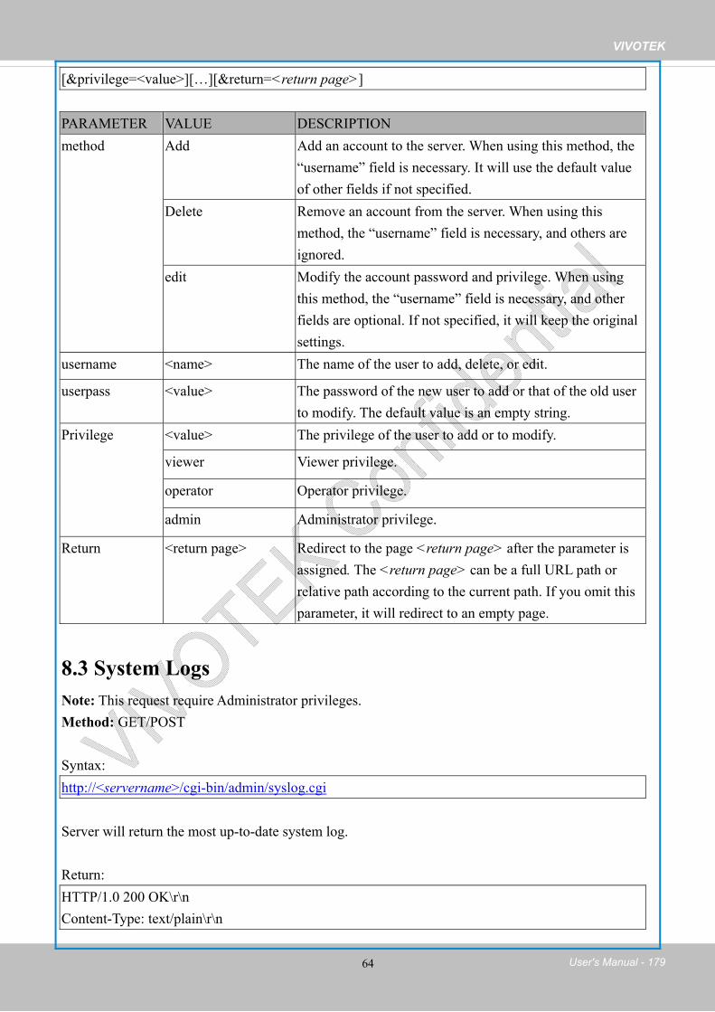
VIVOTEK
User's Manual - 179 64
[&privilege=<value>][…][&return=<return page>]
PARAMETER VALUE DESCRIPTIONmethod Add Add an account to the server. When using this method, the
“username” field is necessary. It will use the default value of other fields if not specified.
Delete Remove an account from the server. When using this method, the “username” field is necessary, and others are ignored.
edit Modify the account password and privilege. When using this method, the “username” field is necessary, and other fields are optional. If not specified, it will keep the original settings.
username <name> The name of the user to add, delete, or edit.
userpass <value> The password of the new user to add or that of the old user to modify. The default value is an empty string.
Privilege <value> The privilege of the user to add or to modify.
viewer Viewer privilege.
operator Operator privilege.
admin Administrator privilege.
Return <return page> Redirect to the page <return page> after the parameter is assigned. The <return page> can be a full URL path or relative path according to the current path. If you omit this parameter, it will redirect to an empty page.
8.3 System Logs Note: This request require Administrator privileges. Method: GET/POST
Syntax:http://<servername>/cgi-bin/admin/syslog.cgi
Server will return the most up-to-date system log.
Return:HTTP/1.0 200 OK\r\n Content-Type: text/plain\r\n

VIVOTEK
180 - User's Manual 65
Content-Length: <syslog length>\r\n \r\n <system log information>\r\n
8.4 Upgrade Firmware Note: This request requires Administrator privileges. Method: POST
Syntax:http://<servername>/cgi-bin/admin/upgrade.cgi
Post data: fimage=<file name>[&return=<return page>]\r\n \r\n <multipart encoded form data>
Server will accept the file named <file name> to upgrade the firmware and return with <return page> if indicated.
8.5 ePTZ Camera Control Note: This request requires camctrl privileges. Method: GET/POST
Syntax:http://<servername>/cgi-bin/camctrl/eCamCtrl.cgi?channel=<value>&stream=<value> [&move=<value>] – Move home, up, down, left, right [&auto=<value>] – Auto pan, patrol [&zoom=<value>] – Zoom in, out[&zooming=<value>&zs=<value>] – Zoom without stopping, used for joystick[&vx=<value>&vy=<value>&vs=<value>] – Shift without stopping, used for joystick [&x=<value>&y=<value>&videosize=<value>&resolution=<value>&stretch=<value>] – Click on image (Move the center of image to the coordination (x,y) based on resolution or videosize.)[ [&speedpan=<value>][&speedtilt=<value>][&speedzoom=<value>][&speedapp=<value>] ] – Set speeds [&return=<return page>]
Example:

VIVOTEK
User's Manual - 181 66
http://myserver/cgi-bin/camctrl/eCamCtrl.cgi?channel=0&stream=0&move=right http://myserver/cgi-bin/camctrl/eCamCtrl.cgi?channel=0&stream=1&vx=2&vy=2&vz=2 http://myserver/cgi-bin/camctrl/eCamCtrl.cgi?channel=0&stream=1&x=100&y=100& videosize=640x480&resolution=640x480&stretch=0
PARAMETER VALUE DESCRIPTIONchannel <0~(n-1)> Channel of video source. stream <0~(m-1)> Stream. move home Move to home ROI.
up Move up.
down Move down.
left Move left.
right Move right.
auto pan Auto pan.
patrol Auto patrol.
stop Stop auto pan/patrol.
zoom wide Zoom larger view with current speed.
tele Zoom further with current speed.
zooming wide or tele Zoom without stopping for larger view or further view with zs speed, used for joystick control.
zs 0 ~ 6 Set the speed of zooming, “0” means stop.
vx <integer> The direction of movement, used for joystick control.
vy <integer>
vs 0 ~ 7 Set the speed of movement, “0” means stop.
x <integer> x-coordinate clicked by user. It will be the x-coordinate of center after movement.
y <integer> y-coordinate clicked by user. It will be the y-coordinate of center after movement.
videosize <window size> The size of plug-in (ActiveX) window in web page
resolution <window size> The resolution of streaming.
stretch <boolean> 0 indicates that it uses resolution (streaming size) as the range of the coordinate system. 1 indicates that it uses videosize (plug-in size) as the range of the coordinate system.

VIVOTEK
182 - User's Manual 67
speedpan -5 ~ 5 Set the pan speed.
speedtilt -5 ~ 5 Set the tilt speed.
speedzoom -5 ~ 5 Set the zoom speed.
speedapp 1 ~ 5 Set the auto pan/patrol speed.
return <return page> Redirect to the page <return page> after the parameter is assigned. The <return page> can be a full URL path or relative path according to the current path.
8.6 ePTZ Recall Note: This request requires camctrl privileges. Method: GET/POST
Syntax:http://<servername>/cgi-bin/camctrl/eRecall.cgi?channel=<value>&stream=<value>& recall=<value>[&return=<return page>]
PARAMETER VALUE DESCRIPTIONchannel <0~(n-1)> Channel of the video source.
stream <0~(m-1)> Stream.
recall Text string less than 40 characters
One of the present positions to recall.
return <return page> Redirect to the page <return page> after the parameter is assigned. The <return page> can be a full URL path or relative path according to the current path.
8.7 ePTZ Preset Locations Note: This request requires Operator privileges. Method: GET/POST
Syntax:http://<servername>/cgi-bin/operator/ePreset.cgi?channel=<value>&stream=<value> [&addpos=<value>][&delpos=<value>][&return=<return page>]
PARAMETER VALUE DESCRIPTION

VIVOTEK
User's Manual - 183 68
channel <0~(n-1)> Channel of the video source.
stream <0~(m-1)> Stream.
addpos <Text string less than 40 characters>
Add one preset location to the preset list.
delpos <Text string less than 40 characters>
Delete preset location from the preset list.
return <return page> Redirect to the page <return page> after the parameter is assigned. The <return page> can be a full URL path or relative path according to the current path.
8.8 IP Filtering Note: This request requires Administrator access privileges. Method: GET/POST
Syntax:http://<servername>/cgi-bin/admin/ipfilter.cgi? method=<value>&[start=<ipaddress>&end=<ipaddress>][&index=<value>][&return=<return page>]
PARAMETER VALUE DESCRIPTIONmethod addallow Add allowed IP address range to the server. Start and end
parameters must be specified. If the index parameter is specified, it will try to add starting from the index position.
adddeny Add denied IP address range to the server. Start and end parameters must be specified. If the index parameter is specified, it will try to add starting from the index position.
deleteallow Remove allowed IP address range from server. If start and end parameters are specified, it will try to remove the matched IP address. If index is specified, it will try to remove the address from given index position. [start, end] parameters have higher priority then the [index] parameter.
deletedeny Remove denied IP address range from server. If start and end parameters are specified, it will try to remove the matched IP address. If index is specified, it will try to remove the address from given index position. [start, end] parameters have higher priority then the [index] parameter.
start <ip address> The starting IP address to add or to delete.

VIVOTEK
184 - User's Manual 69
end <ip address> The ending IP address to add or to delete.
index <value> The start position to add or to delete.
return <return page> Redirect to the page <return page> after the parameter is assigned. The <return page> can be a full URL path or relative path according to the current path. If you omit this parameter, it will redirect to an empty page.
8.8.1 IP Filtering for ONVIF Syntax: <product dependent>http://<servername>/cgi-bin/admin/ipfilter.cgi?type[=<value>] http://<servername>/cgi-bin/admin/ipfilter.cgi?method=add<v4/v6>&ip=<ipaddress>[&index=<value>][&return=<return page>]http://<servername>/cgi-bin/admin/ipfilter.cgi?method=del<v4/v6>&index=<value>[&return=<return page>]PARAMETER VALUE DESCRIPTIONtype NULL Get IP filter type
allow, deny Set IP filter type method addv4 Add IPv4 address into access list.
addv6 Add IPv6 address into access list.
delv4 Delete IPv4 address from access list.
delv6 Delete IPv6 address from access list.
ip <IP address> Single address: <IP address> Network address: <IP address / network mask> Range address:<start IP address - end IP address>
index <value> The start position to add or to delete. return <return page> Redirect to the page <return page> after the parameter is
assigned. The <return page> can be a full URL path or relative path according to the current path. If you omit this parameter, it will redirect to an empty page.

VIVOTEK
User's Manual - 185 70
8.9 Event/Control HTTP Tunnel Channel Note: This request requires Administrator privileges. Method: GET and POST
Syntax:http://<servername>/cgi-bin/admin/ctrlevent.cgi -------------------------------------------------------------------------GET /cgi-bin/admin/ctrlevent.cgi x-sessioncookie: string[22] accept: application/x-vvtk-tunnelled pragma: no-cache cache-control: no-cache
-------------------------------------------------------------------------POST /cgi-bin/admin/ ctrlevent.cgi x-sessioncookie: string[22] content-type: application/x-vvtk-tunnelledpragma : no-cache cache-control : no-cache content-length: 32767 expires: Sun, 9 Jam 1972 00:00:00 GMT
User must use GET and POST to establish two channels for downstream and upstream. The x-sessioncookie in GET and POST should be the same to be recognized as a pair for one session. The contents of upstream should be base64 encoded to be able to pass through the proxy server.
This channel will help perform real-time event subscription and notification as well as camera control more efficiently. The event and control formats are described in another document.
See Event/control tunnel spec for detail information

VIVOTEK
186 - User's Manual 71
8.10 Get SDP of Streams Note: This request requires Viewer access privileges. Method: GET
Syntax:http://<servername>/<network_rtsp_s<0~m-1>_accessname>
“m” is the stream number. “network_accessname_<0~(m-1)>” is the accessname for stream “1” to stream “m”. Please refer to the “subgroup of network: rtsp” for setting the accessname of SDP. You can get the SDP by HTTP GET. When using scalable multicast, Get SDP file which contains the multicast information via HTTP.
8.11 Open the Network Stream Note: This request requires Viewer access privileges.
Syntax:For HTTP push server (MJPEG): http://<servername>/<network_http_s<0~m-1>_accessname>
For RTSP (MP4), the user needs to input the URL below into an RTSP compatible player. rtsp://<servername>/<network_rtsp_s<0~m-1>_accessname>
“m” is the stream number. For details on streaming protocol, please refer to the “control signaling” and “data format” documents.

VIVOTEK
User's Manual - 187 72
8.12 Storage managements Note: This request requires administrator privileges. Method: GET and POST
Syntax:http://<servername>/cgi-bin/admin/lsctrl.cgi?cmd=<cmd_type>[&<parameter>=<value>…]
The commands usage and their input arguments are as follows.
PARAMETER VALUE DESCRIPTIONcmd_type <string> Required.
Command to be executed, including search, insert, delete,update, and queryStatus.
Command: searchPARAMETER VALUE DESCRIPTIONlabel <integer primary key> Optional.
The integer primary key column will automatically be assigned a unique integer.
triggerType <text> Optional. Indicate the event trigger type. Please embrace your input value with single quotes. Ex. mediaType=’motion’ Support trigger types are product dependent.
mediaType <text> Optional. Indicate the file media type. Please embrace your input value with single quotes.
Ex. mediaType=’videoclip’ Support trigger types are product dependent.
destPath <text> Optional. Indicate the file location in camera. Please embrace your input value with single quotes. Ex. destPath =’/mnt/auto/CF/NCMF/abc.mp4’
resolution <text> Optional. Indicate the media file resolution. Please embrace your input value with single quotes. Ex. resolution=’800x600’
isLocked <boolean> Optional.

VIVOTEK
188 - User's Manual 73
Indicate if the file is locked or not. 0: file is not locked. 1: file is locked. A locked file would not be removed from UI or cyclic storage.
triggerTime <text> Optional. Indicate the event trigger time. (not the file created time) Format is “YYYY-MM-DD HH:MM:SS” Please embrace your input value with single quotes. Ex. triggerTime=’2008-01-01 00:00:00’ If you want to search for a time period, please apply “TO” operation.Ex. triggerTime=’2008-01-01 00:00:00’+TO+’2008-01-01 23:59:59’ is to search for records from the start of Jan 1st
2008 to the end of Jan 1st 2008. limit <positive integer> Optional.
Limit the maximum number of returned search records. offset <positive integer> Optional.
Specifies how many rows to skip at the beginning of the matched records. Note that the offset keyword is used after limit keyword.
To increase the flexibility of search command, you may use “OR” connectors for logical “OR” search operations. Moreover, to search for a specific time period, you can use “TO” connector. Ex. To search records triggered by motion or di or sequential and also triggered between 2008-01-01 00:00:00 and 2008-01-01 23:59:59. http://<servername>/cgi-bin/admin/lsctrl.cgi?cmd=search&triggerType=’motion’+OR+’di’+OR+’seq’&triggerTime=’2008-01-01 00:00:00’+TO+’2008-01-01 23:59:59’
Command: deletePARAMETER VALUE DESCRIPTIONlabel <integer primary key> Required.
Identify the designated record.Ex. label=1
Ex. Delete records whose key numbers are 1, 4, and 8. http://<servername>/cgi-bin/admin/lsctrl.cgi?cmd=delete&label=1&label=4&label=8
Command: update

VIVOTEK
User's Manual - 189 74
PARAMETER VALUE DESCRIPTIONlabel <integer primary key> Required.
Identify the designated record.Ex. label=1
isLocked <boolean> Required. Indicate if the file is locked or not.
Ex. Update records whose key numbers are 1 and 5 to be locked status. http://<servername>/cgi-bin/admin/lsctrl.cgi?cmd=update&isLocked=1&label=1&label=5
Ex. Update records whose key numbers are 2 and 3 to be unlocked status. http://<servername>/cgi-bin/admin/lsctrl.cgi?cmd=update&isLocked=0&label=2&label=3
8.12.1 Return Message The returned results are always in XML format, except for storage status related elements that can be returned in javascript format. (i.e. status, totalSize, freeSize, and usedSize.) The elements are listed as follows. Group: stormgrElement name Type Descriptioncounts <Positive Integer> Total number of matched records. limit <Positive Integer> Limit the maximum number of returned search records.
Could be empty if not specified. offset <Positive Integer> Specifies how many rows to skip at the beginning of the
matched records. Could be empty if not specified.
statusCode <Integer> The reply status (see table below) Value of return-code Description 200 OK 400 Unrecognized Message Type/Content
500 Server executes command error.
501 Parse Input Message Failed.
502 Error Occurs When Searching Database.
503 Storage is Not Ready.
statusString string Return string describing the reason that status code is not OK.
Subgroup of stormgr: i<0~(n-1)>: n is the total number of displayed records.

VIVOTEK
190 - User's Manual 75
Element name Type Descriptionlabel <Integer Primary Key> A unique integer. triggerType <Text> Indicate the event trigger type. mediaType <Text> Indicate the file media type. destPath <Text> Indicate the file location in camera. resolution <Text> Indicate the media file resolution. isLocked <Boolean> Indicate if the file is locked or not. triggerTime <Text> Indicate the event trigger time.
Format is “YYYY-MM-DD HH:MM:SS” backup <Boolean> Indicate if the file is generated when network loss.
Subgroup of stormgr_disk: i<0~(n-1)>: n is the total number of storage devices. Element name Type Descriptionname string Description of specified storage device. status ready, detached, error,
and readonly The storage device status. ready: storage is ready for access. detached: storage is not mounted. error: failed to open storage device. readonly: storage is write protected.
totalSize <Positive Integer> The overall storage size in kilobytes. freeSize <Positive Integer> The available storage size in kilobytes. usedSize <Positive Integer> The used storage size in kilobytes. path string Location of database of storage sink
Ex. Returned results of search command <?xml version="1.0" encoding="ISO-8859-1" ?>
<stormgr version="0.0.0.1">
<counts>5</counts>
<limit>2</limit>
<offset>0</offset >
<i0>
<label>1</label>
<triggerType>motion</triggerType>
<mediaType>videoclip</mediaType>
<destPath>/mnt/auto/NCMF/abc/abc.jpg</destPath>
<resolution>800x600</resolution>
<isLocked>0</isLocked>
<triggerTime>2009-01-24 12:00:00</triggerTime>
<backup>0</backup>

VIVOTEK
User's Manual - 191 76
</i0>
<i1>
<label>2</label>
<triggerType>di</triggerType>
<mediaType>snapshot</mediaType>
<destPath>/mnt/auto/NCMF/123/123.jpg</destPath>
<resolution>800x600</resolution>
<isLocked>0</isLocked>
<triggerTime>2009-01-24 12:01:00</triggerTime>
<backup>0</backup>
</i1>
</stormgr>
Ex. Local storage status in XML format. <?xml version="1.0" encoding="ISO-8859-1" ?>
<stormgr version="0.0.0.1">
<disk>
<i0>
<name>SDcard</name>
<status>ready</status>
<totalSize>7824444</totalSize>
<freeSize>7824388</freeSize>
<usedSize>56</usedSize>
</i0>
</disk>
</stormgr>
Ex. Local storage status in javascript format. disk_i0_name=’SDcard’
disk_i0_status='ready'
disk_i0_totalSize='7824444'
disk_i0_freeSize='7824388'
disk_i0_usedSize='56'
disk_i0_path=i0/NCMF/.db/.localStorage.db
Command: queryStatus PARAMETER VALUE DESCRIPTIONretType xml or javascript Optional.
Ex. retype=javascript The default return message is in XML format.

VIVOTEK
192 - User's Manual 77
Ex. Query local storage status and call for javascript format return message. http://<servername>/cgi-bin/admin/lsctrl.cgi?cmd=queryStatus&retType=javascript
There are two cgi commands for download and composing jpegs to avi format. For download single selected file, you can use “/cgi-bin/admin/downloadMedias.cgi”. Just assign the request file path to this cgi.
Syntax:http://<servername>/cgi-bin/admin/downloadMedias.cgi?<File_Path>The <File_Path> is in queryststus return message.
Ex.http://<servername>/cgi-bin/admin/downloadMedias.cgi?/mnt/auto/CF/NCMF/20090310/07/02.
mp4
For creating an AVI file by giving a list of JPEG files, you can use “/cgi-bin/admin/jpegtoavi.cgi”.
Syntax:http://<servername>/cgi-bin/admin/jpegtoavi.cgi?<resolution>=<width>x<height>&<fps>=<num>&<list>=<fileList>
PARAMETER VALUE DESCRIPTIONresolution <width>x<height> Resolutionfps <positive integer> Frame rate list <fileList> The JPEG file list.
The file path should be embraced by single quotation marks
Ex.http:// <servername>/cgi-bin/admin/
jpegtoavi.cgi?resolution=800x600&fps=1&list=’/mnt/auto/CF/NCMF/video1650.jpg’, ’/mnt/auto/C
F/NCMF/video1651.jpg’, ’/mnt/auto/CF/NCMF/video1652.jpg’,

VIVOTEK
User's Manual - 193 78
8.13 Virtual input Note: Change virtual input (manual trigger) status. Method: GET/POST
Syntax:http://<servername>/cgi-bin/admin/setvi.cgi?vi0=<value>[&vi1=<value>][&vi2=<value>] [&return=<return page>]
PARAMETER VALUE DESCRIPTION
vi<num> state[(duration)nstate]
Where "state" is 0, 1. “0” means inactive or normal state while “1” means active or triggered state.
Where "nstate" is next state after duration.
Ex: vi0=1
Setting virtual input 0 to trigger state
Ex: vi0=0(200)1
Setting virtual input 0 to normal state, waiting 200 milliseconds, setting it to trigger state.
Note that when the virtual input is waiting for next state, it cannot accept new requests.
return <return page> Redirect to the page <return page> after the request is completely assigned. The <returnpage> can be a full URL path or relative path according the current path. If you omit this parameter, it will redirect to an empty page.
Return Code Description200 The request is successfully executed. 400 The request cannot be assigned, ex. incorrect parameters.
Examples: 1. setvi.cgi?vi0=0(10000)1(15000)0(20000)1
No multiple duration. 2. setvi.cgi?vi3=0
VI index is out of range. 3. setvi.cgi?vi=1
No VI index is specified. 503 The resource is unavailable, ex. Virtual input is waiting for next state.
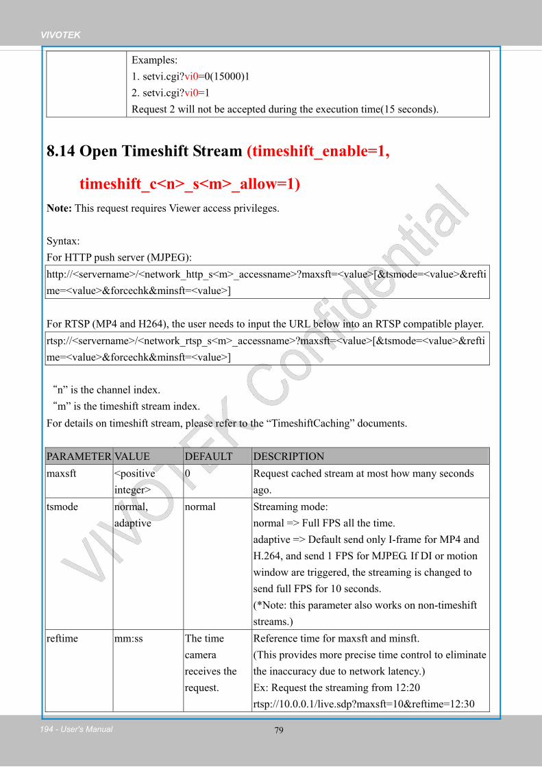
VIVOTEK
194 - User's Manual 79
Examples: 1. setvi.cgi?vi0=0(15000)12. setvi.cgi?vi0=1Request 2 will not be accepted during the execution time(15 seconds).
8.14 Open Timeshift Stream (timeshift_enable=1,
timeshift_c<n>_s<m>_allow=1)Note: This request requires Viewer access privileges.
Syntax:For HTTP push server (MJPEG): http://<servername>/<network_http_s<m>_accessname>?maxsft=<value>[&tsmode=<value>&reftime=<value>&forcechk&minsft=<value>]
For RTSP (MP4 and H264), the user needs to input the URL below into an RTSP compatible player. rtsp://<servername>/<network_rtsp_s<m>_accessname>?maxsft=<value>[&tsmode=<value>&reftime=<value>&forcechk&minsft=<value>]
“n” is the channel index. “m” is the timeshift stream index. For details on timeshift stream, please refer to the “TimeshiftCaching” documents.
PARAMETER VALUE DEFAULT DESCRIPTIONmaxsft <positive
integer> 0 Request cached stream at most how many seconds
ago.tsmode normal,
adaptive normal Streaming mode:
normal => Full FPS all the time. adaptive => Default send only I-frame for MP4 and H.264, and send 1 FPS for MJPEG. If DI or motion window are triggered, the streaming is changed to send full FPS for 10 seconds. (*Note: this parameter also works on non-timeshift streams.)
reftime mm:ss The time camera receives the request.
Reference time for maxsft and minsft. (This provides more precise time control to eliminate the inaccuracy due to network latency.) Ex: Request the streaming from 12:20 rtsp://10.0.0.1/live.sdp?maxsft=10&reftime=12:30

VIVOTEK
User's Manual - 195 80
forcechk N/A N/A Check if the requested stream enables timeshift, feature and if minsft is achievable. If false, return “415 Unsupported Media Type”.
minsft <positive integer>
0 How many seconds of cached stream client can accept at least. (Used by forcechk)
Return Code Description400 Bad Request Request is rejected because some parameter values are illegal. 415 Unsupported Media Type Returned, if forcechk appears, when minsft is not achievable or
the timeshift feature of the target stream is not enabled.
8.15 Export Files Note: This request requires Administrator privileges. Method: GET
Syntax:For daylight saving time configuration file: http://<servername>/cgi-bin/admin/exportDst.cgi
For language file: http://<servername>/cgi-bin/admin/export_language.cgi?currentlanguage=<value>
PARAMETER VALUE DESCRIPTIONcurrentlanguage 0~20 Available language lists.
Please refer to: system_info_language_i0 ~ system_info_language_i19.
For setting backup file: http://<servername>/cgi-bin/admin/export_backup.cgi?backup

VIVOTEK
196 - User's Manual 81
8.16 Upload Files Note: This request requires Administrator privileges. Method: POST
Syntax:For daylight saving time configuration file: http://<servername>/cgi-bin/admin/upload_dst.cgi
Post data: filename =<file name>\r\n \r\n <multipart encoded form data>
For language file: http://<servername>/cgi-bin/admin/upload_lan.cgi
Post data: filename =<file name>\r\n \r\n <multipart encoded form data>
For setting backup file: http://<servername>/cgi-bin/admin/upload_backup.cgi
Post data: filename =<file name>\r\n \r\n <multipart encoded form data>
Server will accept the file named <file name> to upload this one to camera.
<End of document> i

VIVOTEK
User's Manual - 197
Technical Specifications
Compatible Accessories
Mounting Kits
AM-51A
Mounting Adapter
AM-520
Mounting Adapter
AM-214
L shape bracket
AM-712
Conduit Box
Model
CPU
Flash
RAM
Image Sensor
Maximum Resolution
Lens Type
Focal Length
Aperture
Field of View
Shutter Time
Day/Night
Minimum Illumination
Pan Range
Tilt Range
Rotation Range
Pan/tilt/zoom Functionalities
IR Illuminators
On-board Storage
Compression
Maximum Frame Rate
Maximum Streams
S/N Ratio
Dynamic Range
Video Streaming
Image Settings
Users
Protocols
Interface
ONVIF
System Information
Camera Features
Video
Network
FD8169
Multimedia SoC (System-on-Chip)
128MB
256MB
1/2.7" Progressive CMOS
1920x1080 (2MP)
Fixed-focal
f = 2.8 mm
F2.0
105° (Horizontal)87° (Vertical) 135° (Diagonal)
1/5 sec. to 1/32,000 sec.
Removable IR-cut filter for day & night function
1.22 Lux @ F2.0 (Color)0.008 Lux @ F2.0 (B/W)0 Lux @ IR LED ON
348°
70°
345°
ePTZ:48x digital zoom (4x on IE plug-in, 12x built-in)
Built-in IR illuminators, effective up to 15 meters with Smart IRIR LED*6
MicroSD/SDHC/SDXC card slot
H.264 & MJPEG
30 fps @ 1920x1080In both compression modes
3 simultaneous streams
Above 53 dB
54.5 dB
Adjustable resolution, quality and bitrateConfigurable video cropping for bandwidth saving
Adjustable image size, quality and bit rateTime stamp, text overlay, flip & mirrorConfigurable brightness, contrast, saturation, sharpness, white balance, exposure control, gain, backlight compensation, privacy masksScheduled profile settings, 3D Noise Reduction
Live viewing for up to 10 clients
IPv4, IPv6, TCP/IP, HTTP, HTTPS, UPnP, RTSP/RTP/RTCP, IGMP, SMTP, FTP, DHCP, NTP, DNS, DDNS, PPPoE, CoS, QoS, SNMP, 802.1X,UDP, ICMP
10Base-T/100 BaseTX Ethernet (RJ-45)
Supported, specification available at www.onvif.org
Video Motion Detection
Alarm Triggers
Alarm Events
Connectors
LED Indicator
Power Input
Power Consumption
Dimensions
Weight
Safety Certifications
Operating Temperature
Warranty
Operating System
Web Browser
Other Players
CD
Others
Intelligent Video
Alarm and Event
General
System Requirements
Included Accessories
Triple-window video motion detection
Video motion detection, manual trigger, periodical trigger, system boot, recording notification, camera tampering detection
Event notification using digital output, HTTP, SMTP, FTP and NAS serverFile upload via HTTP, SMTP, FTP and NAS server
RJ-45 for Network/PoE connection
System power and status indicator
DC 12VIEEE 802.3af PoE Class 3
Max.6.5W
Ø: 128 mm x 98 mm
Net: 435 g
CE, LVD, FCC Class B, VCCI, C-Tick
Starting Temperature: 0°C ~ 50°CWorking Temperature: -10°C ~ 50°C
24 months
Microsoft Windows 7/Vista/XP/2000
Mozilla Firefox 7~10 (streaming only)Internet Explorer 7/8/9
VLC: 1.1.11 or aboveQuickTime: 7 or above
User's manual, quick installation guide, Installation Wizard 2, ST7501 32-channel recording software
Quick installation guide, warranty card, alignment sticker, screw pack
Technical Specifications
Dimensions
Ø128 mm
98 m
m
All specifications are subject to change without notice. Copyright © VIVOTEK INC. All rights reserved.
Ver 1.7Distributed by:
6F, No.192, Lien-Cheng Rd., Chung-Ho, New Taipei City, 235, Taiwan, R.O.C. T: +886-2-82455282 F: +886-2-82455532 E: [email protected]
VIVOTEK INC. VIVOTEK USA2050 Ringwood Avenue, San Jose, CA 95131 T: 408-773-8686 F: 408-773-8298 E: [email protected]
VIVOTEK EuropeRandstad 22-133, 1316BW Almere, The NetherlandsT: +31(0)36-5298-434E: [email protected]

VIVOTEK
198 - User's Manual
Technology License Notice
AMR-NB Standard
THIS PRODUCT IS LICENSED UNDER THE AMR-NB STANDARD PATENT LICENSE AGREEMENT. WITH RESPECT TO THE USE OF THIS PRODUCT, THE FOLLOWING LICENSORS’ PATENTS MAY APPLY:
TELEFONAKIEBOLAGET ERICSSON AB: US PAT. 6192335; 6275798; 6029125; 6424938; 6058359. NOKIA CORPORATION: US PAT. 5946651; 6199035. VOICEAGE CORPORATION: AT PAT. 0516621; BE PAT. 0516621; CA PAT. 2010830; CH PAT. 0516621; DE PAT. 0516621; DK PAT. 0516621; ES PAT. 0516621; FR PAT. 0516621; GB PAT. 0516621; GR PAT. 0516621; IT PAT. 0516621; LI PAT. 0516621; LU PAT. 0516621; NL PAT. 0516621; SE PAT 0516621; US PAT 5444816; AT PAT. 819303/AT E 198805T1; AU PAT. 697256; BE PAT. 819303; BR PAT. 9604838-7; CA PAT. 2216315; CH PAT. 819303; CN PAT. ZL96193827.7; DE PAT. 819303/DE69611607T2; DK PAT. 819303; ES PAT. 819303; EP PAT. 819303; FR PAT. 819303; GB PAT. 819303; IT PAT. 819303; JP PAT. APP. 8-529817; NL PAT. 819303; SE PAT. 819303; US PAT. 5664053. THE LIST MAY BE UPDATED FROM TIME TO TIME BY LICENSORS AND A CURRENT VERSION OF WHICH IS AVAILABLE ON LICENSOR’S WEBSITE AT HTTP://WWW.VOICEAGE.COM.

VIVOTEK
User's Manual - 199
Electromagnetic Compatibility (EMC)
FCC StatementThis device compiles with FCC Rules Part 15. Operation is subject to the following two conditions.
■ This device may not cause harmful interference, and
■ This device must accept any interference received, including interference that may cause undesired operation.
This equipment has been tested and found to comply with the limits for a Class B digital device, pursuant to Part 15 of the FCC Rules. These limits are designed to provide reasonable protection against harmful interference in a residential installation. This equipment generates, uses and can radiate radio frequency energy and, if not installed and used in accordance with the instructions, may cause harmful interference to radio communications. However, there is no guarantee that interference will not occur in a partial installation. If this equipment does cause harmful interference to radio or television reception, which can be determined by turning the equipment off and on, the user is encouraged to try to correct the interference by one or more of the following measures:
■ Reorient or relocate the receiving antenna.
■ Increase the separation between the equipment and receiver.
■ Connect the equipment into an outlet on a circuit different from that to which the receiver is connected.
■ Consult the dealer or an experienced radio/TV technician for help.
Shielded interface cables must be used in order to comply with emission limits.
CE Mark Warning
This is a Class B product. In a domestic environment, this product may cause radio interference, in which case the user may be required to take adequate measures.
VCCI Warningこの装置は、情報処理装置等電波障害自主規制協議会(VCCI)の基準にづくクラスB情報技術装置
です。この装置は、家庭環境で使用することを目的としていますが、この装置がラジオやテレビジョン
受信機に近接して使用されると、受信障害を引き起こすことがあります。
取扱説明書に従って正しい取り扱いをして下さい
LiabilityVIVOTEK Inc. cannot be held responsible for any technical or typographical errors and reserves the right to make changes to the product and manuals without prior notice. VIVOTEK Inc. makes no warranty of any kind with regard to the material contained within this document, including, but not limited to, the implied warranties of merchantability and fitness for any particular purpose.