Contemporary Fixed Prosthodontics_ 5ed_5.pdf
100
14 Tissue Management and Impression Making 391 void-free mixes. Typically, a single degree of viscosity is used for the syringe and the tray material. Mixing machines offer the advantage of bulk loading larger quan- tities of material, which may be advantageous in certain practice settings. This equipment should be located close to the dental chair to reduce time loss between mixing and the actual making of the impression. Evaluation The impression must be inspected for accuracy when it is removed (Fig. 14-35). (Viewing with magnification is helpful.) If bubbles or voids appear in the margin, the impression must be discarded. An intact, uninterrupted cuff of impression material should be present beyond the margin circumferentially. Streaks of base or catalyst material indicate improper mixing and may render an consequently bubbles and voids in the impression, are more likely to be included. As described previously, the syringe tip must follow the impression material as it flows onto the prepared tooth surfaces. Following the manu- facturer’s directions and bleeding the cartridge before inserting the tip are crucial to ensure that possible residue of partially polymerized material is removed from the cartridge openings, which might prevent equal amounts of base and catalyst from being dispensed. Automix mate- rial is not available for the polysulfide polymers because these materials are too sticky for proper mixing with existing cartridge tips. Machine Mixing Technique. An alternative method for improving impression mixing is to use a machine mixer (Pentamix Automatic Mixing Unit, 3M ESPE Dental) (Fig. 14-34). These systems are convenient and produce FIGURE 14-33 ■ A, Automix addition silicone impression materials are available in various degrees of viscosity. B, The barrels should be “bled” to ensure that any partially set material is removed and that the flow is even from each component. To prevent cross contamination of the catalyst and base, a mixing tip should remain attached to the cartridge after each use. The light-bodied mate- rial can be dispensed into an impression syringe (C) or directly onto the prepared tooth with a special tip (D). The heavy-bodied material is dispensed into the adhesive-coated tray (E). A B C D E
-
Upload
khangminh22 -
Category
Documents
-
view
0 -
download
0
Transcript of Contemporary Fixed Prosthodontics_ 5ed_5.pdf

14 Tissue Management and Impression Making 391
void-free mixes. Typically, a single degree of viscosity is used for the syringe and the tray material. Mixing machines offer the advantage of bulk loading larger quan-tities of material, which may be advantageous in certain practice settings. This equipment should be located close to the dental chair to reduce time loss between mixing and the actual making of the impression.
Evaluation
The impression must be inspected for accuracy when it is removed (Fig. 14-35). (Viewing with magnification is helpful.) If bubbles or voids appear in the margin, the impression must be discarded. An intact, uninterrupted cuff of impression material should be present beyond the margin circumferentially. Streaks of base or catalyst material indicate improper mixing and may render an
consequently bubbles and voids in the impression, are more likely to be included. As described previously, the syringe tip must follow the impression material as it flows onto the prepared tooth surfaces. Following the manu-facturer’s directions and bleeding the cartridge before inserting the tip are crucial to ensure that possible residue of partially polymerized material is removed from the cartridge openings, which might prevent equal amounts of base and catalyst from being dispensed. Automix mate-rial is not available for the polysulfide polymers because these materials are too sticky for proper mixing with existing cartridge tips.
Machine Mixing Technique. An alternative method for improving impression mixing is to use a machine mixer (Pentamix Automatic Mixing Unit, 3M ESPE Dental) (Fig. 14-34). These systems are convenient and produce
FIGURE 14-33 ■ A, Automix addition silicone impression materials are available in various degrees of viscosity. B, The barrels should be “bled” to ensure that any partially set material is removed and that the flow is even from each component. To prevent cross contamination of the catalyst and base, a mixing tip should remain attached to the cartridge after each use. The light-bodied mate-rial can be dispensed into an impression syringe (C) or directly onto the prepared tooth with a special tip (D). The heavy-bodied material is dispensed into the adhesive-coated tray (E).
A B
C D
E

392 PART II Clinical Procedures: Section 1
FIGURE 14-34 ■ Machine mixing system. A, Pentamix machine. B, Polyether impression material. C, Loading an impression tray. (Courtesy 3M ESPE Dental, St. Paul, Minnesota.)
A
B
C
FIGURE 14-35 ■ Impression evaluation. A, Low magnification of elastomeric impression. On the left, an adequate cuff is formed by material extending beyond the preparation margin. On the right side (arrow), the impression does not extend adequately. B, This impression reproduces an adequate amount of the unprepared tooth structure cervical to the preparation margin.
A B

14 Tissue Management and Impression Making 393
(Fig. 14-37, A and B). Submerge the tray in a tem-pering bath (see Fig. 14-37, C).
5. Carefully remove the cord from the sulcus, and flood the sulcus with warm water (see Fig. 14-37, D).
6. Remove the impression tray from the tempering bath and seat the tray in the patient’s mouth. After seating, initiate and maintain the flow of room-temperature water through the tray (see Fig. 14-37, E).
7. Hold the tray firmly in the patient’s mouth while the impression material is gelling.
8. Remove the tray with a rapid motion, wash it with room-temperature water, disinfect it (see Table 14-3), and evaluate it for accuracy. Potassium sulfate can be used as a dipping solution for improved stone characteristics.
9. After the impression is judged to be acceptable, pour immediately in Type IV or V stone. If delay is inevitable, the impression can be immersed in a special oil-based solution (Extend-A-Pour, Dux Dental).
Evaluation
A reversible hydrocolloid impression is evaluated in the same manner as polysulfide polymer (see Fig. 14-37, F). However, the translucency of the material may make small imperfections difficult to detect. If doubt exists, it may be expedient to make a new impression because this does not require additional tissue displacement and can be easily accomplished.
Closed-mouth Impression TechniqueThe closed-mouth impression technique, also called the dual-arch or triple-tray technique, is popular for making impressions for single units and less expensive restora-tions made to conform to the existing occlusion.71,72 The impression is made in maximum intercuspation with a high-viscosity polyvinyl siloxane or polyether impression material supported by a thin mesh in a frame. Similar success rates have been reported with these impression material types.73 The impression includes the prepared tooth, the adjacent teeth, and the opposing teeth and records their maximum intercuspation relationship (hence the name “triple tray”). Because the impression is made at the occlusal vertical dimension, the technique facilitates making an accurate impression74,75 and occlusal record. However, the laboratory stages must be per-formed very carefully and, as no eccentric relationships are recorded, after the restoration has been fabricated, these need to be evaluated and adjusted at the delivery appointment.
Step-by-Step Procedure
1. Select and evaluate a closed-mouth tray. Make sure the patient can close easily into maximal intercus-pation without interference with the tray. If the preliminary impression (external mold) for the interim restoration (see Chapter 15) is made with
impression useless. If the impression passes all these tests, it can then be disinfected (see the section “Disinfection” later in this chapter) and poured to obtain a die and definitive cast (see Chapter 17).
Reversible HydrocolloidReversible hydrocolloid impression material requires a special conditioning unit (Fig. 14-36) that is made up of three thermostatically controlled water baths:
• A liquefaction (boiling) bath (100°C [212°F]) for the heavy-bodied tray material and the light-bodied syringe material
• A storage bath (≅65°C [150°F]) for maintaining liquefied materials until they are needed
• A tempering bath (≅40°C [105°F]) for reducing the temperature of the heavy-bodied tray material enough to avoid tissue damage
Step-by-Step Procedure
1. Select the correct size of water-cooled impression tray. For maximum accuracy, use the largest size that can be comfortably accommodated by the patient.
2. Place prefabricated stops across the posterior of the tray to prevent overseating and to provide addi-tional retention.
3. For adequate access, displace the gingival tissues as previously described.
4. Fill the impression tray with heavy-bodied material from the storage bath. Add wash material to the surface of the hydrocolloid tray material in the area of the preparation and one adjacent tooth
FIGURE 14-36 ■ Hydrocolloid conditioning equipment consists of three thermostatically controlled water baths: boiling or liqui-faction, storage, and tempering. (Courtesy Dux Dental, Oxnard, California.)

394 PART II Clinical Procedures: Section 1
contralateral side to verify that maximum intercus-pation was achieved and remains sustained through-out the setting of the impression material.
5. Remove the polymerized impression; help the patient open the mouth by applying pressure to the set material or tray border.
Evaluation
The impression is evaluated for accuracy and detail (see Fig. 14-38, E). Ensure that the patient has not closed into the sides or distal bar of the tray. Check the centric contact of the unprepared teeth. Light should shine
a closed-mouth tray, this will serve as a useful rehearsal of the procedure for the patient (Fig. 14-38, A).
2. Load both sides of the closed-mouth tray with a high-viscosity elastomeric impression material. Many closed-mouth trays do not require an adhesive because they have mechanical locks in their design, but if necessary, apply adhesive to the tray walls. The adhesive should not be painted on the mesh.
3. Concurrently, remove cord and, using a syringe, apply impression material onto critical areas.
4. Place the loaded closed-mouth tray into position and have the patient close properly. Check the
FIGURE 14-37 ■ Hydrocolloid impression technique. A, The water-cooled impression tray is loaded with heavy-bodied material. B, The wash hydrocolloid is squeezed onto the tray material in the area of the preparations. C, The filled tray is placed in a temper-ing bath for the recommended 3 minutes. D, The sulcus is flooded with water or a surfactant. Alternatively, some dentists prefer a syringe technique. E, Water-cooling tubes are connected and then the tray is seated. F, The completed impression. Light-bodied material should have been displaced by the tray material. (Courtesy Dux Dental, Oxnard, California.)
A B
C D
E F

14 Tissue Management and Impression Making 395
been in contact with body fluids. The materials should be disinfected according to the recommended proce-dures for the material being used. After being removed from the patient’s mouth, the impression is immediately rinsed with tap water and dried with an air syringe. Suitable chemicals should be used for disinfection, such as glutaraldehyde solutions or iodophor sprays. Table 14-4 shows the most commonly recommended techniques for the materials discussed in this section. Some are perfectly acceptable for one material but unsuitable for others. Because of its tendency to distort and absorb moisture, polyether or “hydrophilic” addi-tion silicone impression materials should be sprayed and stored in a plastic bag rather than submerged and soaked in a glutaraldehyde solution. Disinfection is an essential step for preventing cross infection and expo-sure of laboratory personnel. If it is performed prop-erly, disinfection does not affect the accuracy or surface reproduction of the elastomer.76-79
through in these areas, demonstrating proper centric closure by the patient.
Special ConsiderationsCertain modifications of the basic impression technique are sometimes needed, particularly for making impres-sions with additional retention features, such as for the post space of endodontically treated teeth.
Elastomeric materials can be successfully used to make impressions of the post space when endodontically treated teeth are being restored. The procedure involves rein-forcing the impression with a plastic pin or suitable wire (e.g., orthodontic wire), as described in Chapter 12.
DisinfectionWhen they are removed from the patient’s mouth, it must be assumed that all impression materials have
FIGURE 14-38 ■ Closed-mouth impression technique. A, The tray is selected and evaluated. B, The tray is loaded. C, Impression mate-rial is delivered by syringe. D, Patient closes into maximum intercuspation. E, Completed impression. (A to D, Courtesy Premier Dental Products Co., Plymouth Meeting, Pennsylvania.)
A B
C D
E

396 PART II Clinical Procedures: Section 1
FIGURE 14-39 ■ The completed impression. A and B, Careful technique ensures a complete cuff of impression material beyond the margin and greatly facilitates trimming of the die and contouring of the wax pattern.
A B
Modified from Merchant VA: Update on disinfection of impressions, prostheses, and casts. ADA 1991 guidelines, J Calif Dent Assoc 20:10, 31, 1992.
*Immersion time should be minimized. Dip in glutaraldehyde, rinse in sterile water, dip again, and delay pouring for 10 minutes while maintaining a humid environment. Alternatively, spray with sodium hypochlorite, rinse, and respray with a similar 10-minute delay before pouring.
†Imbibition distortion results from prolonged immersion. For 1:10 hypochlorite or chlorine dioxide: spray, rinse, repeat, spray again, and delay pouring for approximately 10 minutes.
TABLE 14-4 RecommendedDisinfectionMethodbyImpressionMaterial
DisinfectionIrreversible*Hydrocolloid
Reversible*Hydrocolloid Polysulfide Silicones Polyether†
Glutaraldehyde 2% (10-minute soak time) Not recommended Not recommended Yes Yes NoIodophors (1:213 dilution) Yes Yes Yes Yes NoChlorine compounds (1:10 dilution of
commercial bleach)Yes Yes Yes Yes Yes
Complex phenolics Not recommended Limited date Yes Yes NoPhenolic glutaraldehydes Not recommended Yes Yes Yes No
EvaluationAfter disinfection, the completed impression (Fig. 14-39) is inspected carefully before the definitive cast is made. An elastomeric impression should be dried before it is evaluated. The following points are then considered:
1. Has the material been properly mixed? An impres-sion that contains visible streaks of base or catalyst material should be rejected.
2. Is there an area where the custom tray shows through? This must be identified and its potential effect on the quality of the impression assessed. A common error is rotation and the resulting inac-curate seating of the tray. This can result in the tray’s contacting several teeth and an uneven thick-ness of impression material. Normally this occurs only at the tray stops, but when it touches a critical area, the impression must be discarded and a new one made. However, if a thin spot is not near the prepared teeth, it can sometimes be allowed to remain.
3. Are there any voids, folds, or creases? These should have been avoided by careful technique; however, the impression may still be acceptable when a small
defect is present in a noncritical area (e.g., away from the margin of a prepared tooth). Careful judg-ment must be exercised.
4. Is there an even, uninterrupted extension of impres-sion material beyond the margins of the prepared teeth? This is essential if restorations with well-fitting margins and correct contours are to be made.
5. Has the impression material separated from the tray? This is a common cause of distorted impres-sions and results from improper application and/or inadequate drying of the adhesive.
DIGITAL IMPRESSION TECHNIQUES
Dental digital impression systems were initially envi-sioned by Duret in the 1970s for digital impression making directly in the patient’s mouth or on a cast.80 Mörmann et al developed the first in-office optical capture and ceramic machining system which allowed chairside milling of inlays from prefired ceramic blocks after optical data acquisition directly in the patient’s mouth.81 Initial scanning relied on stripe scanning and

14 Tissue Management and Impression Making 397
video chips of crude design by today’s standards, and the first optical impression of a cavity was obtained in 1982.
The resulting restorations had less than optimal adap-tation and required substantial intraoral adjustment. Scanning technologies evolved in the subsequent decades, and the dimensional accuracy of optical scanning of tooth preparations is now comparable to or even better than conventional impression techniques.82,83
Subsequent improvements gradually led to wider appli-cation expanding from the initial optical capture of inlay preparations to onlays and veneers, and eventually to crowns and short-span partial fixed dental prostheses.
Although market penetration of digital impression technologies remains relatively modest, it has the poten-tial to accelerate certain steps of the laboratory fabrica-tion process. Digital impressions can be sent electronically to fabrication units in the dental office for chair-side fabrication of restorations for same-day delivery, or alter-natively to off-site dental laboratories for fabrication of definitive fixed prostheses through conventional or digital means (see Chapter 25).
Types of Scanning SystemsThree dimensional scanning systems developed fairly wide acceptance well before becoming popular in den-tistry. This technology found application in rapid proto-typing for purposes of industrial design and is in use in the entertainment industries.
Scanners can be divided into contact and non-contact scanners. Contact scanning relies on physical contact of a probe with the object being copied. A simple example would be the mechanical device used to generate dupli-cates of keys. However, contact between the scanner’s sensor and the object being scanned may cause damage to a fragile substrate. This renders contact scanners less useful for scanning of unique or costly items that are not readily replaceable, such as museum quality artifacts. Such concerns helped shift the focus to optical scanning, paving the path for optical scanning as we know it today in dentistry.
Non-contact scanners include radiation, ultrasound, and light. Dental scanners are three-dimensional light scanners that collect distance information for every
pixel being captured. The purpose is to create a three-dimensional “point-cloud” that is refined into a virtual record of the three-dimensional structure that is recorded for further manipulation. Although early dental systems relied on single static scans, as the three-dimensional complexity of the object being scanned increases, multi-ple scans taken from many different directions are neces-sary to enable accurate computer renderings of the original object. Structured light scanners project a spe-cific light pattern onto an object, and its sensors focus on distortions or deviations from that known pattern, using them to compute distance information.
Most dental scanners are triangulation scanners based on the same principles underlying the original technol-ogy developed in the 1970s.84 A light source, typically a laser, shines onto an object and its reflection is captured by a sensor that is positioned slightly off-angle to the angle of the incident light. As the next laser beam is reflected by an adjacent location at a different distance to the light source, it is recorded in a different location on the sensor array (Fig. 14-40). It is this difference that is used to compute the difference in distance to the original source, and by inference the topography of the surface being scanned.
As scanner resolution evolved, it became possible to move the scanner head while capturing the data, as opposed to static scans that are “stitched together.” This led to the development of contemporary intraoral scan-ners that can be moved around the tooth preparation and arch while gathering information. Trackers can be built into the scanner, or multiple cameras can be used to record ambient light from infrared LEDs to keep spatial records of the path traveled by such scanning heads. A record of the path traveled is needed to permit computa-tion of the actual geometry of the substrate. Similarly, those data are used to compensate for inadvertent opera-tor movement during the acquisition. Current scanning accuracy is in the range of 10 to 20 µm.
Light ReflectionScanning accuracy depends in part on achieving a uniform surface reflection of the incident light. If the surface reflects unevenly or incompletely, accuracy will be affected.
FIGURE 14-40 ■ How a triangulation scanner works.
Triangulation scanners
Laser shines dot on object
Location on sensor
Determines differential
SensorLens
Laser
Distance A
Distance B
Object

398 PART II Clinical Procedures: Section 1
1,000,000 points at 200 focal depths 50 µm apart. Its tel-ecentric system is said not to require powdering.
Architecture of Captured DataThe computer files generated on completion of the scan have either an open or closed format. Open systems present the data in an industry standardized format that permits the data to be interpreted independent of a given manufacturer, although the dental laboratory may require information technology support to initially develop its software interface.
Closed architecture files are manufacturer linked and proprietary data files, requiring that subsequent fabrication steps of prostheses are performed solely with compatible software and equipment from the same manufacturer.
Optical Impression UnitsChairside optical impression units typically consist of a computer with screen attached to a mobile base. The optical scanning wand is used for the intraoral capture, and some systems (Figure 14-42) permit direct visualiza-tion of the intraoral target that is to be acquired as the three dimensional rendering is in progress.
SUMMARY
An impression or negative likeness of the teeth and sur-rounding structures is used to obtain a cast, on which the planned restoration is fabricated. A good impression is an exact negative replica of each prepared tooth and must include all of the prepared surfaces and an adequate amount of unprepared tooth structure adjacent to the margin.
Healthy soft tissues and the control of saliva flow are essential for a successful impression. However, caution must be exercised to prevent injury to the gingiva. Cotton rolls, cards, and saliva evacuators are needed for adequate moisture control. Use of a local anesthetic to minimize discomfort and to reduce saliva flow during the impres-sion procedure is recommended.
Optical scanners encounter some difficulty when scan-ning transparent or shiny objects such as teeth. Teeth scatter the incident light, some of the dispersed light travels laterally before re-emerging, and as a result, the reflected return to the sensor array is affected. Use of a thin layer of highly reflective powder (such as titanium oxide) is a means of compensating for this problem, but care is needed to prevent an unnecessary build-up of material, as accuracy of the scan can be affected. Powder-ing requires a dry field. One system (Planmeca PlanScan System, E4D Technologies) advocates the use of an accent liquid if difficulty in acquisition is encountered, typically on thin (translucent) enamel, or on reflective surfaces such as metallic restorations.
Active Wave-front SamplingDental scanning systems that use active wave-front sam-pling include the True Definition Scanner (Figure 14-41, 3M ESPE Dental).85 The system uses a single lens to obtain the necessary information through complex pro-prietary algorithms.84,86 The system has a small light-weight wand that allows one-handed scanning from multiple positions. Once the field is prepared, an experi-enced user can scan an arch in as little as 60 seconds.
Parallel Confocal ScanningiTero Principle
In contrast with the laser scanners, one system uses a mul-titude (100,000) concurrent beams of red light. Its scanner head has sensors that force reflected light to pass through sensors preprogrammed to be reflected from specific dis-tances. Only light reflected at a known distance will pass through the filtering device and be used to compute the geometry of the substrate. The illustrated system captured
FIGURE 14-41 ■ The 3M True Definition Scanner uses active wavefront sampling to obtain an accurate scan of the prepared tooth. (Courtesy 3M ESPE Dental, St. Paul, Minnesota). FIGURE 14-42 ■ Optical impression being generated.

14 Tissue Management and Impression Making 399
21. LaForgia A: Cordless tissue retraction for impressions for fixed prosthesis. J Prosthet Dent 17(4):379, 1967.
22. Livaditis GJ: The matrix impression system for fixed prosthodon-tics. J Prosthet Dent 79:208, 1998.
23. Harris HS: Electrosurgery in dental practice. Philadelphia, JB Lip-pincott, 1976.
24. Gnanasekhar JD, al-Duwairi YS: Electrosurgery in dentistry. Quin-tessence Int 29:649, 1998.
25. Louca C, Davies B: Electrosurgery in restorative dentistry. I. Theory. Dent Update 19:319, 1992.
26. Louca C, Davies B: Electrosurgery in restorative dentistry. II. Clinical applications. Dent Update 19:364, 1992.
27. Podshadley AG, Lundeen HC: Electrosurgical procedures in crown and bridge restorations. J Am Dent Assoc 77:1321, 1968.
28. Maness WL, et al: Histologic evaluation of electrosurgery with varying frequency and waveform. J Prosthet Dent 40:304, 1978.
29. DeVitre R, et al: Biometric comparison of bur and electrosurgical retraction methods. J Prosthet Dent 53:179, 1985.
30. Walter C: Dental treatment of patients with cardiac pacemaker implants. Quintessence Int 8:57, 1975.
31. Dawes JC, et al. Electrosurgery in patients with pacemakers/implanted cardioverter defibrillators. Ann Plast Surg 57:33, 2006.
32. Krejci RF, et al: Effects of electrosurgery on dog pulps under cervi-cal metallic restorations. Oral Surg 54:575, 1982.
33. Parker S: The use of lasers in fixed prosthodontics. Dent Clin North Am 48:971, 2004.
34. Scott A. Use of an erbium laser in lieu of retraction cord: a modern technique. Gen Dent 53:116, 2005.
35. Gherlone EF, et al: The use of 980-nm diode and 1064-nm Nd:YAG laser for gingival retraction in fixed prostheses. J Oral Laser Appl 4:183, 2004.
35a. Schoinohoriti OK, Chrysomali E, Iatrou I, et al: Evaluation of lateral thermal damage and reepithelialization of incisional wounds created by CO2-laser, monopolar electrosurgery, and radiosurgery: a pilot study on porcine oral mucosa. Oral Surg Oral Med Oral Pathol Oral Radiol 113:741-747, 2012.
36. Tjan AH, et al: Clinically oriented evaluation of the accuracy of commonly used impression materials. J Prosthet Dent 56:4, 1986.
37. Setz J, et al: Profilometric studies on the surface reproduction of dental impression materials. Dtsch Zahnarztl Z 44:587, 1989.
38. Luebke RJ, et al: The effect of delayed and second pours on elas-tomeric impression material accuracy. J Prosthet Dent 41:517, 1979.
39. Eames WB, et al: Elastomeric impression materials: effect of bulk on accuracy. J Prosthet Dent 41:304, 1979.
40. Cullen DR, Sandrik JL: Tensile strength of elastomeric impression materials, adhesive and cohesive bonding. J Prosthet Dent 62:142, 1989.
41. Herfort TW, et al: Tear strength of elastomeric impression materi-als. J Prosthet Dent 39:59, 1978.
42. Hondrum SO: Tear and energy properties of three impression materials. Int J Prosthodont 7:517, 1994.
43. Harcourt JK: A review of modern impression materials. Aust Dent J 23:178, 1978.
44. Fusayama T, et al: Accuracy of the laminated single impression technique with silicone materials. J Prosthet Dent 32:270, 1974.
45. Tjan AH: Effect of contaminants on the adhesion of light-bodied silicones to putty silicones in putty-wash impression technique. J Prosthet Dent 59:562, 1988.
46. Henry PJ, Harnist DJR: Dimensional stability and accuracy of rubber impression materials. Aust Dent J 19:162, 1974.
47. Mansfield MA, Wilson HJ: Elastomeric impression materials: a method of measuring dimensional stability. Br Dent J 139:267, 1975.
48. Nally FF, Storrs J: Hypersensitivity to a dental impression material: a case report. Br Dent J 134:244, 1973.
48a. Mittermüller P, Szeimies RM, Landthaler M, et al: A rare allergy to a polyether dental impression material. Clin Oral Investig 16:1111-1116, 2012.
49. Lacy AM, et al: Time-dependent accuracy of elastomer impression materials. II. Polyether, polysulfides, and polyvinylsiloxane. J Pros-thet Dent 45:329, 1981.
50. Sivers JE, Johnson GK: Adverse soft tissue response to impression procedures: report of a case. J Am Dent Assoc 116:58, 1988.
51. Peregrina A, et al: Effect of two types of latex gloves and surfactants on polymerization inhibition of three polyvinylsiloxane impression materials. J Prosthet Dent 90:289, 2003.
Mechanical, chemical, and surgical methods for enlargement of the gingival sulcus can be used to obtain access to subgingival margins of prepared teeth. However, a narrow cord impregnated with a mild astringent (e.g., AlCl3) is recommended. To protect the smear layer, excessive contact between hemostatic agents and cut tooth structure should be avoided.
A custom acrylic resin tray should be used when making an impression with any of the elastomeric materi-als. All impression materials should be rinsed, dried, and disinfected when removed from the mouth. Impres-sions made with polysulfide polymer should be poured within 1 hour. Impressions made with polyether or addi-tion silicone have high dimensional stability and can be stored considerably longer before pouring. When making pin-retained restorations, a cement tube, lentulo, or nylon bristle is needed for an accurate impression of the pinholes or post spaces. In this technique and others, a good impression is crucial for an accurately fitting restoration.
REFERENCES1. McCormick JT, et al: Wettability of elastomeric impression materi-
als: effect of selected surfactants. Int J Prosthod 2:413, 1989.2. Kissov HK, Chalashkanova MI: The impression as a means for
analysis of clinical mistakes in fixed prosthodontics. Folia Med (Plovdiv) 43(1-2):84, 2001.
3. Council on Dental Therapeutics, American Dental Association: Accepted dental therapeutics, 38th ed, p 247. Chicago, American Dental Association, 1979.
4. Sherman CR, Sherman BR: Atropine sulfate: a current review of a useful agent for controlling salivation during dental procedures. Gen Dent 47:56, 1999.
5. Findlay D, Lawrence JR: An alternative method of assessing changes in salivary flow: comparison of the effects of clonidine and tiamenidine (HOE 440). Eur J Clin Pharmacol 14:231, 1978.
6. Wilson EL, et al: Effects of methantheline bromide and clonidine hydrochloride on salivary secretion. J Prosthet Dent 52:663, 1984.
7. Baba NZ, et al: Gingival displacement for impression making in fixed prosthodontics: contemporary principles, materials, and tech-niques. Dent Clin North Am 58:45, 2014.
8. Bennani V, et al: Comparison of pressure generated by cordless gingival displacement materials. J Prosthet Dent 112(2):163, 2014.
9. Acar O, et al: A clinical comparison of cordless and conventional displacement systems regarding clinical performance and impres-sion quality. J Prosthet Dent 111:388, 2014.
10. Laufer BZ, et al: The closure of the gingival crevice following gingival retraction for impression making. J Oral Rehabil 24:629, 1997.
11. Bowles WH, et al: Evaluation of new gingival retraction agents. J Dent Res 70:1447, 1991.
12. Land MF, et al: Disturbance of the dentinal smear layer by acidic hemostatic agents. J Prosthet Dent 72:4, 1994.
13. Land MF, et al: Smear layer instability caused by hemostatic agents. J Prosthet Dent 76:477, 1996.
14. Rosenstiel SF, Rashid RG: Postcementation hypersensitivity: sci-entific data versus dentists’ perceptions. J Prosthodont 12:73, 2003.
15. Pelzner RB, et al: Human blood pressure and pulse rate response to racemic epinephrine retraction cord. J Prosthet Dent 39:287, 1978.
16. Jokstad A: Clinical trial of gingival retraction cords. J Prosthet Dent 81:258, 1999.
17. Hansen PA, et al: Current methods of finish-line exposure by prac-ticing prosthodontists. J Prosthodont 8:163, 1999.
18. Cranham JC: Tips from the lab: predictable impressioning. Dent Equip Mater (May-June):46, 2003.
19. Sarmento HR, et al: A double-blind randomised clinical trial of two techniques for gingival displacement. J Oral Rehabil 41:306, 2014.
20. Feinmann BPP, Martignoni M: Material and method for dentistry. Washington, D.C., U.S. Patent Office, Publication No. US4677139A, June 30, 1987.

400 PART II Clinical Procedures: Section 1
69. McCabe JF, Carrick TE: Rheological properties of elastomers during setting. J Dent Res 68:1218, 1989.
70. Chong YH, et al: The effect of mixing method on void formation in elastomeric impression materials. Int J Prosthod 2:323, 1989.
71. Wilson EG, Werrin SR: Double arch impressions for simplified restorative dentistry. J Prosthet Dent 49:198, 1983.
72. Donovan TE, Chee WWL: A review of contemporary impression materials and techniques. Dent Clin North Am 48:445, 2004.
73. Johnson GH, et al: Clinical trial investigating success rates for polyether and vinyl polysiloxane impressions made with full-arch and dual-arch plastic trays. J Prosthet Dent 103:13, 2010.
74. Ceyhan JA, et al: The effect of tray selection, viscosity of impres-sion material, and sequence of pour on the accuracy of dies made from dual-arch impressions. J Prosthet Dent 90:143, 2003.
75. Wöstmann B, et al: Accuracy of impressions obtained with dual-arch trays. Int J Prosthodont 22:158, 2009.
76. Drennon DG, et al: The accuracy and efficacy of disinfection by spray atomization on elastomeric impressions. J Prosthet Dent 62:468, 1989.
77. Drennon DG, Johnson GH: The effect of immersion disinfection of elastomeric impressions on the surface detail reproduction of improved gypsum casts. J Prosthet Dent 63:233, 1990.
78. Estafanous EW, et al: Disinfection of bacterially contaminated hydrophilic PVS impression materials. J Prosthodont 21:16, 2012.
79. Carvalhal CI, et al: Dimensional change of elastomeric materials after immersion in disinfectant solutions for different times. J Contemp Dent Pract 12:252, 2011.
80. McLaren E. CAD/CAM dental technology. Compend Contin Educ Dent 32:73, 2011.
81. Mörmann WH. The evolution of the CEREC system. J Am Dent Assoc 137(Suppl):7S, 2006.
82. Tidehag P, et al: Accuracy of ceramic restorations made using an in-office optical scanning technique: an in vitro study. Oper Dent 39:308, 2014.
83. Ng J, et al: A comparison of the marginal fit of crowns fabricated with digital and conventional methods. J Prosthet Dent 112:555, 2014.
84. Mayer R: Scientific Canadian: invention and innovation from Can-ada’s National Research Council. Vancouver, B.C., Raincoast Books, 1999.
85. Rohaly J, et al: Three-channel camera systems with non-collinear apertures. Washington, D.C., U.S. Patent Office, Publication No. US7372642 B2, May 13, 2008.
86. Kachalia PR, Geissberger MJ: Dentistry a la carte: in-office CAD/CAM technology. J Calif Dent Assoc 38:323, 2010.
52. Al-Sowygh ZH: The effect of various interim fixed prosthodontic materials on the polymerization of elastomeric impression materi-als. J Prosthet Dent 112(2):176, 2014.
53. Tseng KC, et al: Effect of dithiocarbamate on polymerization of polyvinylsiloxane impression materials [Abstract 1645]. Presented at American Association of Dental Research/International Associa-tion of Dental Research Annual Session, Baltimore, March 9-12, 2005.
54. Kimoto K, et al: Indirect latex glove contamination and its inhibi-tory effect on vinyl polysiloxane polymerization. J Prosthet Dent 93:433, 2005.
55. Matis BA, et al: The effect of the use of dental gloves on mixing vinyl polysiloxane putties. J Prosthodont 6:189, 1997.
56. Boening KW, et al: Clinical significance of surface activation of silicone impression materials. J Dent 26:447, 1998.
57. Pratten DH, Craig RG: Wettability of a hydrophilic addition sili-cone impression material. J Prosthet Dent 61:197, 1989.
58. Oda Y, et al: Evaluation of dimensional stability of elastomeric impression materials during disinfection. Bull Tokyo Dent Coll 36:1, 1995.
59. Millar BJ, et al: In vitro study of the number of surface defects in monophase and two-phase addition silicone impressions. J Prosthet Dent 80:32, 1998.
60. Nassar U, et al: An in vitro study on the dimensional stability of a vinyl polyether silicone impression material over a prolonged storage period. J Prosthet Dent 109:172, 2013.
61. Peregrina A, et al: The effect of different adhesives on vinyl polysi-loxane bond strength to two tray materials. J Prosthet Dent 94:209, 2005.
62. Millstein P, et al: Determining the accuracy of stock and custom tray impression/casts. J Oral Rehabil 25:645, 1998.
63. Gordon GE, et al: The effect of tray selection on the accuracy of elastomeric impression materials. J Prosthet Dent 63:12, 1990.
64. Martinez LJ, von Fraunhofer JA: The effects of custom tray material on the accuracy of master casts. J Prosthodont 7:106, 1998.
65. Wirz J, et al: Light-polymerized materials for custom impression trays. Int J Prosthod 3:64, 1990.
66. Bindra B, Heath JR: Adhesion of elastomeric impression materials to trays. J Oral Rehabil 24:63, 1997.
67. Burton JF, et al: The effects of disposable and custom-made impres-sion trays on the accuracy of impressions. J Dent 17:121, 1989.
68. Pagniano RP, et al: Linear dimensional change of acrylic resins used in the fabrication of custom trays. J Prosthet Dent 47:279, 1982.
STUDY QUESTIONS
1. Discuss the prerequisites to successful and predictable impression making with elastomeric impression materials.
2. Discuss three ways to ensure access to prepared tooth structure for impression making. What are the respec-tive indications and contraindications?
3. Name three classes of impression materials for fixed prosthodontics, and discuss their advantages and dis-advantages. Illustrate their indicated use with three clinical scenarios.
4. Describe 10 issues to consider before electrosurgery is implemented.
5. What are the requirements for a successful custom impression tray?
6. Disinfection techniques vary among materials. Select three classes of impression material and illustrate how the respective disinfection techniques change for each.
7. Explain the principle underlying triangulation scanning.
8. What is the difference between open and closed archi-tecture of optically scanned impression data?

401
Interim Fixed RestorationsAnthony G. Gegauff • Julie A. Holloway
C H A P T E R 1 5
Interim crowns or interim partial fixed dental prostheses (FDPs) are essential in prosthodontic therapy. The word interim means established for the time being, pending a permanent arrangement. Even though a definitive resto-ration may be placed as quickly as a few weeks after tooth preparation, the interim restoration must satisfy impor-tant needs of the patient and dentist. Unfortunately, tem-porary usually connotes laxity. If this becomes a philosophy governing the interim phase of treatment, clinical effi-ciency and treatment quality will be adversely affected. Experience has repeatedly shown that time and efforts expended in fulfilling the requirements of interim fixed restorations are well spent.
Because of unforeseen events (e.g., laboratory delays or patient unavailability), an interim restoration may have to function for an extended period. For other patients, a delay in placing the definitive restoration may be inten-tional (e.g., because the etiologic factors of a temporo-mandibular disorder or periodontal disease must be corrected). Whatever the intended length of treatment time, an interim restoration must be adequate to main-tain patient health. Thus it should not be casually fabri-cated on the basis of an expected short term of use.
Interim procedures also must be performed efficiently because they are made during the same appointment that the teeth are prepared. Costly chairside time must not be wasted, and yet the dentist must produce an acceptable restoration. Failure to do so results in the eventual loss of more time than was initially thought saved. For example, an inadequate restoration may necessitate repairs that were previously unnecessary or result in the need to treat gingival inflammation and remake an elas-tomeric impression. Such problems can be avoided if the dentist thoroughly understands what is required of the interim restoration and makes the effort to meet these requirements.
REQUIREMENTS
An optimum interim fixed restoration must satisfy many interrelated factors, which can be classified as biologic, mechanical, and esthetic (Fig. 15-1).
Biologic RequirementsPulpal Protection
An interim fixed restoration must seal and insulate the prepared tooth surface from the oral environment to prevent sensitivity and further irritation of the pulp. A certain degree of pulp trauma is inevitable during tooth
preparation because of the sectioning of dentinal tubules (Fig. 15-2). In health, each tubule contains the cytoplas-mic process of a cell body (the odontoblast), whose nucleus is in the pulp cavity. Unless the environment around the exposed dentin is carefully controlled, adverse pulp effects can be expected.1 In addition, pulpal health of a tooth requiring a cast restoration is likely to be com-promised before and after preparation (Table 15-1). In severe situations, leakage can cause irreversible pulpitis, with the consequent need for root canal treatment.2
Periodontal Health
To facilitate plaque removal, an interim restoration must have good marginal fit, proper contours, and smooth surfaces. This is particularly important when the crown margin is placed intrasulcularly.3 If the interim fixed res-toration is inadequate and plaque control is impaired, gingival health deteriorates.4
The maintenance of good gingival health is always desirable, but it has special practical significance when fixed prosthodontic treatment is undertaken. Inflamed or hemorrhagic gingival tissues during treatment make sub-sequent procedures (e.g., impression making and cemen-tation) very difficult. The longer the interim fixed restoration must serve, the more significant any deficien-cies in its fit and contour become (Fig. 15-3). When gingival tissue is impinged on, ischemia is likely to develop, detected initially as tissue blanching. If it is not corrected, a localized inflammation or necrosis can develop.
Occlusal Compatibility and Tooth Position
The interim restoration should establish or maintain proper contacts with adjacent and opposing teeth (Fig. 15-4). Inadequate contacts allow supraeruption and hor-izontal movement. Such supraeruption is detected at the evaluation appointment, when the definitive restoration makes premature contact. It is sometimes possible to correct this in the operating room, but the effort is time consuming and the resulting restoration often has poor occlusal form and function. If supraeruption is severe, it may be necessary to reprepare the tooth and make a new impression. Horizontal movement results in excessive or deficient proximal contacts. The former necessitate tedious chairside adjustment; the latter involve a laboratory procedure to add metal or ceramic to the deficient site. In spite of these efforts, proximal crown contours are distorted. This distortion, along with resulting root proximity (Fig. 15-5), can impair oral hygiene measures.

402 PART II Clinical Procedures: Section 1
FIGURE 15-1 ■ Factors to be considered in making an interim restoration. The central area represents the optimum, in which biologic, mechanical, and esthetic requirements are adequately met.
BIOLOGIC
Protect pulpMaintain periodontal healthProvide occlusal compatibilityMaintain tooth positionProtect against fracture
MECHANICAL
Resist functional loadsResist removal forcesMaintain interabutment alignment
ESTHETIC
Easily contourableColor compatibilityTranslucencyColor stability
Optimalinterimrestoration
FIGURE 15-2 ■ Pulp trauma and exposure of the dentinal tubules from tooth preparation.
FIGURE 15-3 ■ An interim restoration should have good marginal fit, proper contour, and a smooth surface finish. A, A properly contoured interim restoration. It is smoothly continuous with the external surface of the tooth. B, Overcontouring. The transi-tion from the restoration to the root surface is irregular, and marginal adaptation is inadequate. These contribute to plaque accumulation and an unhealthy periodontium.
Rough margins around interim restorations will jeopardizesubsequent procedures.
A B
FIGURE 15-4 ■ Proper occlusal and proximal contacts promote patient comfort and maintain tooth position.
If an interim restoration does notensure positional stability,tooth movement can occur,and additional treatmentwill be necessary.
TABLE 15-1 Factors Contributing to Pulp Death
PastPresent (during Fixed Prosthodontic Therapy)
Caries Preparation traumaOperative dentistry Microbial exposureBruxism DesiccationPeriodontal surgery Chemical exposureProsthodontic
therapyThermal exposure

15 Interim Fixed Restorations 403
reductions increase the cross-sectional area of the con-nector while reducing the stress concentration associated with sharp internal line angles. The biologic and some-times the esthetic requirements place limits on just how much larger connectors can be made. To avoid jeopard-izing periodontal health, they should not be overcon-toured near the gingiva (Fig. 15-9). Good access for plaque control must be a high priority.
Prevention of Enamel Fracture
The interim fixed restoration should protect teeth weak-ened by crown preparation (Fig. 15-6). This is particularly true with partial coverage designs, in which the margin of the preparation is close to the occlusal surface of the tooth and could be damaged during chewing. Even a small chip of enamel will render the definitive restoration unsatisfac-tory and necessitate a time-consuming remake.
Mechanical RequirementsFunction
The greatest stresses in an interim fixed restoration occur during mastication. Unless the patient avoids contacting the prosthesis when eating, internal stresses are similar to those occurring in the definitive restoration. However, the strength of polymethyl methacrylate (PMMA) resin is about one-twentieth that of metal-ceramic alloys,5 and thus the interim fixed restoration is much more likely to fracture. Fracture is not usually a problem with a com-plete crown interim restoration, as long as the tooth has been adequately reduced (Fig. 15-7). More frequently, breakage occurs with partial-coverage interim restora-tions and partial FDPs. Partial-coverage restorations are inherently weaker because they do not completely encir-cle the tooth.
A partial FDP must function as a beam in which sub-stantial occlusal forces are transmitted to the abutments. This creates high stresses in the connectors,6 which are commonly the sites of failure. To reduce the risk of failure, connector size is increased in the interim res-toration in comparison with the definitive restoration (Fig. 15-8). Greater strength is achieved by reductions in the depth and sharpness of the embrasures. These
FIGURE 15-5 ■ A missing proximal contact allows tooth migra-tion. The resulting root proximity may necessitate surgical or orthodontic correction to allow impression making.
FIGURE 15-6 ■ The interim restoration must protect the tooth. Fracture of a tooth after the impression phase delays treatment and jeopardizes restorability.
FIGURE 15-7 ■ This acrylic interim crown fractured. The interoc-clusal record between the preparation and its antagonist shows that the preparation was underreduced.
FIGURE 15-8 ■ The connectors of an interim fixed dental prosthe-sis are often purposely overcontoured. A, In the anterior region, the degree of overcontouring is substantially limited by esthetic requirements. B, In the posterior region, esthetics is less restric-tive, but overcontouring still must not jeopardize the mainte-nance of periodontal health.
Areas ofovercontouring
B
Areas ofovercontouring
to improvestrength
A

404 PART II Clinical Procedures: Section 1
A long-span posterior partial fixed dental prosthesisProlonged treatment timePatient’s inability to avoid excessive forces on the prosthesisAbove-average masticatory muscle strengthHistory of frequent breakage
BOX 15-1 Indications for Fiber-reinforced Interim Restorations
FIGURE 15-9 ■ In this mesiodistal section, an overcontoured con-nector impinges on the gingiva. Pressure ischemia and poor access for plaque removal promote gingivitis.
In some instances, fiber-reinforced, heat-processed resin or cast metal interim restorations can spare the practitioner and the patient inconvenience, lost time, and the expense of remaking a restoration (Box 15-1).
Displacement
If pulp irritation and tooth movement are to be avoided, a displaced interim restoration must be recemented promptly. An additional office visit is usually required, which results in considerable inconvenience for both patient and dentist. Displacement is best prevented through proper tooth preparation and an interim restora-tion with a closely adapted internal surface. Excessive space between the restoration and the tooth places greater demands on the luting agent, which has lower strength than regular cement and thus cannot withstand the added force. For this and for biologic reasons, unlined pre-formed crowns should be avoided.
Removal for Reuse
Interim restorations often need to be reused and so should not be damaged when removed from the teeth at the subsequent appointment. In most instances, if the cement is sufficiently weak and the interim restoration has been well fabricated, it does not break upon removal.
Esthetic RequirementsThe appearance of an interim fixed restoration is particu-larly important for incisors, canines, and sometimes premolars. Although it may not be possible to duplicate the appearance of an unrestored natural tooth exactly, the tooth contour, color, translucency, and texture are essen-tial attributes. When necessary, esthetic enhancement procedures are available to create personalized details; however, because these are not routinely called for, they
are addressed in “Esthetic Enhancement,” after the dis-cussion of cementation and repair.
An essential requirement of prosthodontic treatment is that a material matches the color of adjacent teeth initially. However, some resins discolor with time intraorally,7 and thus color stability (along with the pro-pensity for stain accumulation) governs the selection of materials when a long period of service is anticipated.
The interim restoration is often used as a guide to achieve optimum esthetics in the definitive restoration. In complete denture prosthodontic treatment, it is cus-tomary to have a wax evaluation so that the patient can respond to the dentist’s esthetic interpretation before the denture is processed. Many dentists consider this essen-tial because of the frequency of patients’ requests for changes and the ease with which such changes can be made. Fixed prosthodontic treatment in the anterior oral cavity greatly influences appearance, and the patient should be given an opportunity to voice an opinion. Beauty and personal appearance are highly subjective and difficult to communicate verbally, and a facsimile pros-thesis can play a vital role in the patient’s consideration of esthetics and the effect that the prosthesis has on his or her self-image. Obtaining the opinions of others whose judgment is valued is also important. An accurate interim restoration is a practical way of obtaining specific feed-back for the design of a definitive restoration. Word descriptions alone are often too vague and frequently lead to overcorrections, which are difficult or impossible to reverse in the definitive restoration. The interim restora-tion is shaped and modified until its appearance is mutu-ally acceptable to dentist and patient. When this is achieved, an impression is made of the interim restora-tion (Fig. 15-10), and a cast is poured. This cast accom-panies the fixed prosthodontic work order to the laboratory, where the contours are then replicated in the definitive restoration. This process is most efficient when it begins with diagnostic waxing procedures. Involving the patient in decision making increases the patient’s satisfaction.
MATERIALS AND PROCEDURES
Many procedures involving a wide variety of materials are available to make satisfactory interim restorations (Fig. 15-11). As new materials are introduced, associated techniques are reported, and thus there is even more variety. In all the procedures, a mold cavity is formed, into which a plastic material is poured or packed. Fur-thermore, the mold cavity is created by two correlated parts: one forming the external contour of the crown or FDP, the other forming the prepared tooth surfaces and (when present) the edentulous ridge contact area. The terms external surface form (ESF) and tissue surface form (TSF) are suggested for these mold parts. These terms are used in the ensuing discussions.
External Surface FormThere are two general categories of ESFs: custom and preformed.

15 Interim Fixed Restorations 405
A custom ESF can be produced from thermoplastic sheets, which are heated and adapted to a stone cast with vacuum or air pressure while the material is still pliable (Fig. 15-14). This produces a transparent form with thin walls, which makes it advantageous in the direct tech-nique because of its minimum interference with the occlusion. It is filled with resin, placed in the mouth, and fully seated as the patient closes the jaws into maximum intercuspation. Little additional effort is then required to adjust the occlusal contacts. The thinness of the material, however, may also be a disadvantage in the direct technique. The material is a poor dissipater of the heat released during resin polymerization, and so care must be taken to remove it from the mouth before poten-tial thermal injury can occur. A thermoplastic ESF has other uses in fixed prosthodontic treatment, in both the clinical and the laboratory phase; for example, it can be helpful in evaluating the adequacy of tooth reduction8,9 (Fig. 15-15).
Transparent sheets are available in cellulose acetate or polypropylene of various sizes and thicknesses; a 125 × 125 mm sheet of 0.5-mm (0.020-inch) thickness is rec-ommended for making interim restorations. Polypropyl-ene is preferred because it produces better surface detail and is more tear resistant. Better tear resistance makes initial removal from the forming cast less tedious and enables the ESF to be used more than once.
Although thermoplastic sheets have a number of advantages, a wide variety of other materials and methods can be used successfully. For example, some practitioners favor baseplate wax because it is convenient and eco-nomical (see Fig. 15-11, B), although it is usually not adapted easily with a high degree of precision; additional adjustment time is required.
Preformed
Various preformed crowns are available commercially. On their own, they rarely satisfy the requirements of an interim restoration, but they can be thought of as ESFs rather than as finished restorations and thus must be lined with autopolymerizing resin. Most crown forms need some modification (internal relief, axial recontouring, occlusal adjustment) in addition to the lining procedure (Fig. 15-16). When extensive modification is required, a custom ESF is superior because it is less time consuming. Preformed crowns are generally limited to use as single restorations because it is not feasible to use them as pontics for partial FDPs.
Materials from which preformed ESFs are made (Fig. 15-17) include polycarbonate, cellulose acetate, alumi-num, tin-silver, and nickel-chromium. These are availa-ble in a variety of tooth types and sizes (Table 15-2).
Polycarbonate. Polycarbonate (Fig. 15-18) has the most natural appearance of all the preformed materials. When properly selected and modified, it rivals a well-executed porcelain restoration in appearance. Although it is avail-able in only a single shade, this can be modified to a limited extent by the shade of the lining resin. Polycar-bonate ESFs are supplied in incisor, canine, and premolar tooth types.
Custom
A custom ESF is a negative reproduction of either the patient’s teeth before preparation or a modified diagnos-tic cast. It may be obtained directly with any impression material. Impressions made in a quadrant tray with irre-versible hydrocolloid or silicone are convenient. The higher cost of addition silicone may be offset by its ability to be retained for possible reuse at any future appoint-ment. Accurate reseating of the ESF is easier, and the mold cavity produces better results, if thin areas of impression material (as may be found interproximally or around the gingival margin) are trimmed away (Fig. 15-12). The moldable putty materials are popular because they can be used without a tray and are easily trimmed to minimum size with a sharp knife. Also, their flexibility facilitates subsequent removal of the polymer-ized resin (Fig. 15-13).
FIGURE 15-10 ■ A, This interim dental prosthesis was used to establish anterior guidance, incisal edge position, proper pho-netics, and function before work on the definitive prostheses began. B and C, The definitive restorations closely match their interim predecessors in form and function.
A
B
C

406 PART II Clinical Procedures: Section 1
FIGURE 15-11 ■ Although there are many variations, molds used in making interim restorations consist of an external surface form (ESF) and a tissue surface form (TSF). Direct techniques entail use of the patient’s mouth directly as the TSF. A, Indirect technique: ESF is an alginate impression; TSF, a quick-set plaster cast. B, Direct technique: ESF is a baseplate wax impression; TSF, the patient. C, Direct technique: ESF is a vacuum-formed acetate sheet; TSF, the patient. D, Direct technique: ESF is a polycarbonate preformed shell; TSF, the patient. E, Indirect-direct technique: ESF is a custom preformed three-unit fixed dental prosthesis shell (maxillary right central incisor to canine) made indirectly; TSF, the patient. F, Indirect technique: ESF is a silicone putty impression; TSF, a quick-set plaster cast of the preparations.
A B
C D
E F
FIGURE 15-12 ■ Shortening proximal projections of the impression material facilitates complete reseating of the ESF. Note that excess impression material palatally and facially has been trimmed away with a sharp knife for this reason. The anterior sextant tray shown was selected because it adequately captures the teeth adjacent to the proposed interim restoration.

15 Interim Fixed Restorations 407
FIGURE 15-13 ■ A, One of the flexible silicone putties suitable for making external surface forms. B, The putty form has been spread apart. Note the completed resin interim restoration in place, to demonstrate the degree of putty flexibility.
A B
FIGURE 15-14 ■ A, Inexpensive system for producing external surface forms from thermoplastic sheets. B, After heating, the sheet is formed with reusable putty and finger pressure applied over a stone cast. C, More expensive system incorporating an electric heating element and a vacuum source. D, Trimmed polypropylene external surface form. Note the detail that can be captured with this material.
A
C
B
D

408 PART II Clinical Procedures: Section 1
FIGURE 15-15 ■ A, The thinness and transparency of these external surface forms (ESFs) allow their use directly as tooth-reduction guides both in and out of the mouth. B, The dentist may assess tooth reduction by using the ESF to mold alginate over the prepared tooth. When the alginate is set, the ESF is removed, and a periodontal probe is pushed through the alginate for measurements at desired locations. (B, Courtesy Dr. T. Roongruangphol.)
A B
FIGURE 15-16 ■ A, The time necessary to modify this particular preformed crown outweighs the advantages it might provide. A custom external surface form, if available, would be more effi-cient and more economical. B, The internal lingual wall of this preformed crown is tapered excessively, which necessitates grinding in order to accommodate a properly prepared tooth. The stone cast in the lower portion of the illustration duplicates the internal surface of the preformed crown.
A
B
FIGURE 15-17 ■ A, Preformed anterior crown forms: polycar-bonate (left) and cellulose acetate (right). B, Preformed posterior crown forms: aluminum shell (left), aluminum anatomic (center), and tin-silver anatomic (right).
A
B
TABLE 15-2 Preformed Crowns
Material
Area of Use
INCISOR CANINE PREMOLAR MOLAR SIZES IN EACH MOLDAPPROXIMATE COST ($/UNIT)
ResinCellulose acetate X X X X 6 1.83Photopolymerized composite resin X X X 2 11.52Polycarbonate X X X 7 1.11
Metal
Aluminum X X 20 0.24Aluminum (anatomic) X X 6 5.45Aluminum (tooth colored) X X 6 4.60Tin-silver (anatomic) X X 7 5.20Stainless steel (anatomic) X* X* X X 5 7.17
*Primary teeth.

15 Interim Fixed Restorations 409
been preformed as individual maxillary and mandibular posterior teeth. Care must also be taken to avoid fractur-ing the delicate cavosurface margin of the tooth prepara-tion when a metal crown form is fitted. This is a greater risk if adaptation entails having the patient occlude force-fully on the crown shell. The edge of the shell can engage the margin and fracture it under biting pressure. An even greater risk occurs when the crown has a constricted cervical contour. Tin-silver crowns are deliberately so designed (see Fig. 15-17, B). This highly ductile alloy allows the crown cervix to be stretched to fit the tooth closely. Direct stretching on the tooth is practical only where feather-edge margins are used. For other margin designs, cervical enlargement should be performed indi-rectly on a swaging block, which should be supplied with the crown kit.
Stainless Steel. Stainless steel shells (Fig. 15-20) are used primarily for children with extensively damaged primary teeth. In that application, they are not lined with resin but are trimmed, adapted with contouring pliers, and luted with a high-strength cement. They may be applied to secondary teeth but are more suitable for deciduous teeth, for which longevity is less critical. Stainless steel is very hard and thus can be used for longer term interim restorations.
Tissue Surface FormThere are two primary categories of TSFs: indirect and direct. A third category, indirect-direct, is the sequential application of these.
Indirect Procedure
An impression is made of the prepared teeth and ridge tissue and is poured in quick-setting gypsum or polyvinyl siloxane.10 The interim restorations are fabricated outside the mouth. This technique (Table 15-3) has several advantages over the direct procedure:
1. There is no contact of free monomer with the pre-pared tooth or gingiva, which might cause tissue damage11 and an allergic reaction or sensitization.12-15
FIGURE 15-18 ■ Polycarbonate crowns. They are available in maxillary and mandibular incisor, canine, and premolar shapes.
FIGURE 15-19 ■ Aluminum anatomic crowns. They are available in a variety of sizes and shapes. The manufacturer has produced two maxillary and four mandibular shapes for the left and right side of the mouth, each in six sizes.
Cellulose Acetate. Cellulose acetate is a thin (0.2- to 0.3-mm), transparent material available in all tooth types and a range of sizes (see Fig. 15-17, A). Shades are entirely dependent on the autopolymerizing resin. The resin does not chemically or mechanically bond to the inside surface of the shell; therefore, after polymerization, the shell is peeled off and discarded to prevent staining at the inter-face. The disadvantage of removing the shell is the neces-sity to add resin to reestablish proximal contacts.
Aluminum and Tin-Silver. Aluminum (Fig. 15-19) and tin-silver are suitable for posterior teeth. The most elabo-rate crown forms have anatomically shaped occlusal and axial surfaces. The most basic and least expensive forms are merely cylindrical shells resembling a tin can (see Fig. 15-17, B).
The nonanatomic cylindrical shells are inexpensive but must be modified to achieve acceptable occlusal and axial surfaces. It is more efficient to use crowns that have
FIGURE 15-20 ■ Stainless steel anatomic crowns. They are avail-able in a variety of sizes and shapes, including ones for the primary teeth, with straight and contoured axial surfaces.

410 PART II Clinical Procedures: Section 1
FIGURE 15-21 ■ Allergic reactions after brief exposure to polymethyl methacrylate monomer. A, Labial ulcerations. B, Gingival ulcera-tions. C, Adverse tissue reaction to contact with PMMA interim pontics 6 days after placement.
B,CA
TABLE 15-3 Summary of Techniques Used to Fabricate Interim Crowns
TechniqueTissue Surface Form
External Surface Form Advantages Disadvantages
Direct Tooth preparation itself
Custom or preformed
1. Quick2. Easy3. No laboratory work needed
1. Free mononer2. Heat production3. Margin inaccuracy
Indirect Analog of tooth preparation
Custom 1. Easy on tissues2. No polymerization shrinkage3. Marginal accuracy
1. Time consuming
Indirect/direct combination
Diagnostic preparation
Custom 1. Easy on tissues2. Efficient
1. Prior preparation is estimate; internal adjustment may be needed before relining
Digital Scan of tooth preparation
Custom digital form
1. Efficient2. No laboratory work needed3. Easy on tissues4. Lowest residual monomer5. Generally more wear resistant6. No air-inhibited layer7. No polymerization shrinkage; some
can be bonded to tooth structure8. Definitive restoration can be milled
as an exact duplicate of interim
1. Digital impression and in-office mill needed
2. Some blanks are monocolor
One group of investigators16 reported a 20% inci-dence of allergic sensitivity in patients previously exposed to a monomer patch test. The risk of sen-sitization in patients who are not allergic to monomer increases with the frequency of exposure. In allergic patients, exposure to even small amounts of monomer usually causes painful ulceration and stomatitis (Fig. 15-21).
2. Prepared teeth are not subjected to the heat evolved from polymerizing resin. The exotherms charted in Figure 15-22 give an indication of temperature increases with time for several materials under similar experimental conditions. Clinical simula-tion experiments17,18 have shown peak temperature increases of approximately 10° C in the pulp cham-bers of prepared teeth upon which direct interim restorations were made. That amount of tempera-ture elevation is capable of causing irreversible damage to the pulp.19 The simulation experiments also indicate that temperature rise depends directly on the type and volume of resin present. Therefore,
a directly made restoration with a large pontic is more likely to cause injury than one for a single crown (especially if the tooth is prepared conserva-tively). These studies also demonstrate that the heat-conducting properties of the ESFs signifi-cantly influence how high the temperature can reach. However, of importance is that peak tem-peratures were not reached until 7 to 9 minutes had elapsed18 (Fig. 15-23). For this and the practical reason that it must be drawn through the undercuts of adjacent proximal tooth surfaces, the resin should be removed at the rubbery stage of polymerization, which typically occurs 2 to 3 minutes after insertion in the mouth. In Figure 15-23, the temperature rise is negligible at 3 minutes, which suggests that thermal injury is easily avoidable.
3. The marginal fit of interim restorations that have been polymerized undisturbed on stone casts is sig-nificantly better than that of interim restorations that have been removed from the mouth before becoming rigid.20,21 This is because (1) the stone

15 Interim Fixed Restorations 411
can be made at the dentist’s convenience before the patient arrives. This minimizes disruption of the office schedule and earns the appreciation of the patient. Whether using an elastomer TSF results in margins that fit as well as those obtained with a gypsum TSF is not known. The elastomer may not resist polymerization shrinkage as effec-tively as does the gypsum.
5. The technique gives the patient a chance to rest, and it frees the dentist to perform other tasks, pro-vided that auxiliary staff are trained to carry out the laboratory procedures.
Direct Procedure
The patient’s prepared teeth and gingival tissues (in the case of a partial FDP) directly provide the TSF, and so the intermediate steps of the indirect technique are elimi-nated (see Table 15-3). This is convenient when assistant training and office laboratory facilities are inadequate for efficiently producing an indirect restoration. However, the direct technique has significant disadvantages: poten-tial tissue trauma from the polymerizing resin and inher-ently poorer marginal fit. Therefore, the routine use of directly formed interim restorations is not recommended when indirect techniques are feasible.
Indirect-Direct Procedure
In this technique (see Table 15-3), the indirect component produces a “custom-made preformed ESF” similar to a preformed polycarbonate crown. In most cases, the practi-tioner uses a custom ESF and a diagnostic cast with inten-tionally underprepared diagnostic preparations as the TSF.
FIGURE 15-22 ■ Heat generated during resin polymerization. Under nonclinical experimental conditions, the temperature rises are severe. Sevriton (a polymethyl methacrylate resin) produced significantly higher temperatures than did the others represented. This is useful information for selecting resins to be used intraorally, although under clinical conditions the differences may be insignificant. TCB, Temporary crown and bridge. (Redrawn from Braden M, et al: A new temporary crown and bridge resin. Br Dent J 141:269, 1976.)
70
60
50T
empe
ratu
re (
°C)
40
30
200 1 2 3 4 5 6
Time (min)
Scutan
Sevriton
TCB
Trim
7 8 9 10 11
FIGURE 15-23 ■ These exotherms (time in minutes) are derived from a simulated clinical procedure for making a single crown with silicone putty as the external surface form (ESF). A ther-mocouple probe in the pulp chamber of an extracted tooth was used to measure temperature changes. Initial readings reflect the cooling effect of room-temperature resin mixtures. For all three classes of resins tested, the temperatures did not exceed 35° C until more than 6 minutes had elapsed. Bis-GMA, Bisphe-nol A-glycidylether methacrylate. (Redrawn from Tjan AHL, et al: Temperature rise in the pulp chamber during fabrication of provi-sional crowns. J Prosthet Dent 62:622, 1989.)
1
40
30
°C 35
Methyl methacrylate (Jet)Vinyl ethyl methacrylate (Trim)Bis-GMA Composite (Protemp)
2 3 4 5 6 7
Time
8 9 1210 11
restricts resin shrinkage during polymerization and (2) separating the resin from the tooth in the rubbery phase causes distortion. Directly made long-span or multiple-abutment partial FDPs are likely to have unacceptable marginal discrepancies caused by shrinkage and distortion.
4. When a dimensionally stable elastomer impression is made to form the TSF,10 it can be retained for possible reuse with the ESF. This allows the dentist to make replacement restorations without having the patient present. For example, if a patient calls to report a lost interim partial FDP, a replacement

412 PART II Clinical Procedures: Section 1
• Microfilled composite• Light-polymerizedThe properties of these resins are compared in Table
15-4. The overall performances of the groups are similar; no material is superior in all categories. The choice of material should be based on optimally satisfying the requirements or conditions crucial for the success of the treatment. For example, materials with the least toxicity and least polymerization shrinkage should be chosen for a direct technique. Alternatively, when a long-span pros-thesis is being fabricated, high strength is an important selection criterion. The residue from some interim mate-rials may interfere with the polymerizing of polyvinyl siloxane elastomeric impression materials.23 Although the resin can be cleaned in hydrogen peroxide to prevent this interaction, the problem can be avoided if the interim restoration is made indirectly or the impression is made before a direct interim restoration is made.
MATERIALS SCIENCEWilliam M. Johnston
The material used for fabrication of an interim restora-tion consists of pigments, monomers, filler, and an ini-tiator, all combining to form an esthetic restorative substance. The pigments are incorporated by the man-ufacturer so that the set material appears as much like natural tooth structure as possible; a variety of shades are available. Although each of the other ingredients plays a role in the handling, setting, and final properties of the interim restoration, many important characteris-tics of the material are determined by the primary monomer. The ability of this monomer to convert to a polymer allows the material, after it has been formed as desired, to set into a solid that is durable enough to withstand the oral environment for the necessary interim period.
Depending on the brand, the most commonly used monomers are methyl methacrylate, ethyl methacrylate, isobutyl methacrylate, bisphenol A-diglycidylether meth-acrylate (bis-GMA), and urethane dimethacrylate. Each of these, or combinations thereof, may be converted to a polymer by free radical polymerization, although the conversion process is never perfectly complete.
Free Radical PolymerizationThe polymerization process invokes chemical, mechani-cal, dimensional, and thermal changes that affect the suc-cessful use of these materials in dentistry. Because monomers may be unpleasant or even harmful biologi-cally, the chemical conversion of monomer to a biologi-cally inert polymer is desirable. Also, if the polymerization process is not properly initiated or if it is prematurely terminated, the resultant restoration may not have ade-quate mechanical properties and may fail easily or quickly. However, because the density of the polymer is inher-ently and often substantially greater than that of the monomer, a dimensional contraction occurs during polymerization. The polymerization reaction is exother-mic, which causes the material to become hot before it
The resulting mold forms a shell that, after tooth prepara-tion, is lined with additional resin (the patient’s mouth serving as the TSF). This last step is the direct component of the procedure. Another method of creating the shell, which eliminates the need for an indirect TSF, is to paint monomer liquid into the ESF and carefully sprinkle or blow resin powder on it. Shell thickness is difficult to control with this technique, however, and may result in the need for time-consuming corrective grinding.
The indirect-direct approach has these advantages:• Chairside time is reduced. Most of the procedures
have been completed before the patient’s visit.• Less heat is generated in the mouth. The volume
of resin used during lining is comparatively small.• Contact between the resin monomer and soft
tissues is minimized in comparison with the direct procedure. Because pontic ridge areas do not nor-mally require lining, the risk of allergic reaction is reduced.
However, even with the diagnostic cast method, adjustments are frequently needed to seat the shell com-pletely on the prepared tooth. This is the chief disadvan-tage of the indirect-direct procedure.
Materials for Interim Fixed RestorationsWhile in a fluid state, the interim restorative materials fill the cavity formed by the ESF and TSF; they then solidify, producing a rigid restoration.
Ideal Properties
The characteristics of an ideal interim material are as follows:
• Convenient handling: adequate working time, easy molding, rapid setting time
• Biocompatibility: nontoxic, nonallergenic, nonexo-thermic
• Dimensional stability during solidification• Ease of contouring and polishing• Adequate strength and abrasion resistance• Good appearance: translucent, color controllable,
color stable• Good acceptability to patient: nonirritating, odorless• Ease of adding to or repairing• Chemical compatibility with interim luting agents
Currently Available Materials
As yet, an ideal interim material has not been developed. A major problem still to be solved is dimensional change during solidification. These materials (Fig. 15-24) shrink and cause marginal discrepancy,20-22 especially when the direct technique is used (Fig. 15-25). Also, the resins currently employed are exothermic and not entirely biocompatible.
The materials can be divided into four resin groups:• PMMA• Poly-R′ methacrylate*
*The R′ represents an alkyl group larger than methyl (e.g., ethyl or isobutyl).

15 Interim Fixed Restorations 413
loses its fluidity, and so when it cools, the restoration contracts further. If a direct technique is being used, the heat of reaction can cause irreversible damage to nearby pulpal tissues, which may already have been thermally insulted during cavity preparation.
Initiation
Free radical polymerization begins with the formation of a free radical, a process called activation, and the subse-quent combination of this free radical with a monomer. Free radicals are formed by the decomposition of a chem-ical (the initiator); the method of decomposition is dependent on the nature of the initiator. Possible initia-tors include benzoyl peroxide and camphorquinone.
FIGURE 15-24 ■ Currently available interim materials. A and B, Polymethyl methacrylate resins. C, A poly-R′ methacrylate resin. D, Microfilled composite resins with automix delivery system. E, Photopolymerized polymethyl methacrylate. (A, Courtesy Lang Dental Manufacturing Co., Inc, Wheeling, Illinois. B and E, Courtesy GC America Inc., Alsip, Illinois.)
C
E
D
A B
FIGURE 15-25 ■ With ideal axial wall convergence, a 2% reduc-tion in crown diameter results in a comparatively high marginal discrepancy.
A small amount ofresin shrinkage willresult in a significant-ly open margin.

414 PART II Clinical Procedures: Section 1
Camphorquinone decomposes to free radicals in the presence of both an aliphatic amine and blue light energy, and this process is called visible-light activation. Light-activated materials have two advantages: (1) The ingre-dients can be mixed by the manufacturer with little porosity, and (2) working time is infinite because no setting occurs if the material is kept in a dark environ-ment. The limitation of this method is the depth to which visible light can penetrate (less for darker materials). Whenever possible, the activation illumination should be directed toward the center of the restoration from all surfaces. Also, for darker materials, the exposure time should be longer.
Propagation
After its onset, the polymerization process continues by including more monomer molecules in the growing molecular chain. It is important that the material be allowed to set undisturbed because, during this phase, defects can easily result if the material is jostled. During propagation, (1) the setting material undergoes an increase in density, which causes contraction; (2) the exo-thermic reaction heat may cause a substantial increase in temperature, with subsequent increased contraction; and (3) other physical properties (e.g., rigidity, strength, and resistance to dissolution) increase.
Termination
Because of the randomness of position of the growing chains, it is possible that some of them might combine
Benzoyl peroxide decomposes to free radicals at approximately 50° C or higher in a process called thermal activation. Because the heating of some monomers to temperatures near 100° C can cause them to vaporize, with subsequent formation of porosity in the resultant polymer, excessive temperatures should be avoided during the early stages of thermal activation. Thermal activation results in greater contraction on cooling than is obtained with other activation methods and therefore is usually avoided for interim restorations.
Benzoyl peroxide also decomposes to free radicals when catalyzed by a tertiary amine, and this process is called chemical activation. Chemical activation occurs when the activator, initiator, and monomer are mixed together, and so these materials are usually supplied separately, the monomer and activator in one container and the initiator and filler in another. Proper mixing is necessary to prevent voids. Because chemical activation requires intimate contact of the chemical activator with the initiator, this activation method is not as efficient as thermal activation. Inefficient activation of the initiator results in more resid-ual monomer and less color stability of the restoration, inasmuch as unreacted benzoyl peroxide can cause color changes. However, because benzoyl peroxide is decom-posed by both thermal and chemical activation, increased temperature can enhance its decomposition in a chemi-cally polymerized system and does not increase contrac-tion if the restoration initially undergoes chemical setting. Heating a recently set restoration in 100° C water pro-motes greater polymerization efficiency and removes any unconverted monomer, which might cause a sensitivity reaction in a patient susceptible to monomer irritation.
TABLE 15-4 Ranked Characteristics of Representative Provisional Restoration Resins
Material
Characteristic
A B C D E F G H I J K L M N
Jet (PMMA) 2* 2† 3 1‡ 1† 3† 1§ 2 1 1 2|| 1 3 1Duralay (PMMA) 1† — 3 — — — 1 2 1 1 — 1 3 1Trim (PR′MA) 2† 1† 2 3‡ — 3† 2† 3 1 1 3|| 1 2 1Snap (PR′MA) 2† 2† 2 — — 2† 2 3 1 1 — 1 2 1Temphase Fast-set (bis-acryl composition) 1 1 1 2 — 1 2 3 1 2 1 2 2 2Protemp Garant (bis-GMA composition) 1* 1 1 2 2 1 2† 3 2 2 1|| 2 1 2Tuff-Temp (dual-polymerized, urethane) 1 1 1 3** — 1 2 3 1 2 1 2 2 2Unifast LC (light-polymerized, PR′MA) 2* 2¶ 3 — — 2# 2 1 3 1 — 2 3 2Triad (light-polymerized, urethane DMA composition) 2§ 3† 1 1 1† 1† 3† 1 3 3 — 3 1 3
A, Marginal adaptation (indirect); B, temperature release during reaction; C, toxicity/allergenicity; D, strength (fracture toughness); E, repair strength (percentage of original); F, color stability (ultraviolet light); G, ease of trimming and contouring; H, working time; I, setting time; J, flowability for mold filling; K, contaminated by free eugenol; L, special equipment needed; M, odor; N, unit volume cost.
Bis-GMA, Bisphenol A-diglycidylether methacrylate; DMA, dimethacrylate; PMMA, polymethyl methacrylate; PR′MA, poly-R′ methacrylate.1, Most desirable; 2, less desirable; 3, least desirable; -- data unavailable.*Source of data: Tjan AHL, et al: Marginal fidelity of crowns fabricated from six proprietary provisional materials. J Prosthet Dent 77:482,
1997.†Source of data: Wang RL, et al: A comparison of resins for fabricating provisional fixed restorations. Int J Prosthodont 2:173, 1989.‡Source of data: Gegauff AG, Pryor HG: Fracture toughness of provisional resins for fixed prosthodontics. J Prosthet Dent 58:23, 1987.§Source of data: Koumjian JH, Holmes JB: Marginal accuracy of provisional restorative materials. J Prosthet Dent 63:639, 1990.||Source of data: Gegauff AG, Rosenstiel SF: Effect of provisional luting agents on provisional resin additions. Quintessence Int 18:841,
1987.¶Source of data: Castelnuovo J, Tjan AH: Temperature rise in pulpal chamber during fabrication of provisional resinous crowns. J Prosthet
Dent 78:441, 1997.#Source of data: Doray PG, et al: Accelerated aging affects color stability of provisional restorative materials. J Prosthodont 6:183, 1997.**Source of data: Kerby RE, et al: Mechanical properties of urethane and bis-acryl interim resin materials. J Prosthet Dent 110:21, 2013.

15 Interim Fixed Restorations 415
• Cotton-roll pliers• Plastic filling instrument• Cotton pellets• Petrolatum• Autopolymerizing resin• Dropper• Three dappen dishes• Cement spatula• Backhaus towel clamp forceps• Straight slow-speed handpiece• Carborundum disks with mandrels, straight
handpiece• Fine garnet paper disks (7
8-inch diameter) with mandrels, straight handpiece
• Tungsten carbide burs, straight handpiece• High-speed handpiece with air-water supply• Round bur (No. 4), friction-grip• Tungsten carbide 12-fluted finishing bur, friction-
grip (e.g., 7803)• High-volume evacuation• Articulating ribbon and holder• Disposable brush• Cup of warm water
Basic Laboratory Armamentarium• Protective eyewear• Face mask (for respiratory protection)• Disposable brush
and thereby terminate the growth process. This type of termination cannot be avoided, although termination is desirable only after polymerization of all the monomer. Termination may also result from the reaction with eugenol, hydroquinone, or oxygen; therefore, contact with these substances must be avoided or at least mini-mized when possible.
Properties Associated with the MonomerThe various monomers exhibit different initial and setting characteristics, and the resulting polymers have signifi-cantly different properties (e.g., viscosity before setting, exothermic heat of reaction, dimensional change on setting, and strength). In general, the greater the size of the monomer molecule, the less the exothermic heat of reaction on setting and the lower the physical strength of the set mass. Properties of available materials are presented in Table 15-4.
Filler
Although the primary properties of an interim restorative material are determined by the monomer or monomers involved, a decrease in the less desirable setting and mechanical properties is accomplished mainly through the filler. An increase in filler content reduces the relative amounts of exothermic heat and contraction while increasing the strength of the set material. However, too much filler can lead to insufficient handling characteris-tics before setting; this impedes mixing and shaping and introduces porosity in the set restoration. For light-activated systems, the amount of filler is determined by the manufacturer; for the other systems, it is desirable to incorporate as much filler as possible without interfering in the handling or manipulation characteristics of the material.
• • •
PROCEDURES
The basic clinical armamentarium (Fig. 15-26) and the basic laboratory armamentarium (Fig. 15-27) are listed only once; they may be referred to as needed. As each procedure is discussed, only items necessary to augment the basic armamentarium are listed.
Basic Clinical Armamentarium• Gloves• Face mask• Protective eyewear• Mouth mirror• Explorer• Periodontal probe• Saliva evacuator• Cotton rolls• Gauze squares• Gingival displacement cord• Astringent solution
FIGURE 15-26 ■ A and B, Basic clinical armamentarium for interim fixed dental prostheses.
A
B

416 PART II Clinical Procedures: Section 1
FIGURE 15-27 ■ Basic laboratory armamentarium for interim fixed dental prostheses. A, Assorted small items appearing on the accompanying list (see text). B, Pressure-polymerization vessel. C, Cast trimmer. D, Dental lathe and dust collector. E, Ultrasonic cleaner and liquid detergent.
A B
C D
E
• Gypsum-resin separating medium• Autopolymerizing resin• Dropper• Two dappen dishes• Cement spatula• Polypropylene syringe• Rubber bands• Pressure vessel• Cast trimmer• Straight slow-speed handpiece• Carborundum disks with mandrels, straight
handpiece• Fine garnet paper disks (7
8-inch diameter) with mandrels, straight handpiece
• Tungsten carbide burs, straight handpiece• Dental lathe• Muslin wheels• Robinson bristle brushes
• Felt wheels (1-inch diameter) with mandrels• Fine pumice• Resin-polishing compound• Ultrasonic cleaner with detergent solution
Interim Partial Fixed Dental Prostheses: Custom Indirect MethodThe custom indirect procedure is probably the best overall technique for partial FDPs and should provide the most predictable results with the least risk to the patient’s health.
Additions to Clinical Armamentarium
• Shade guide• Irreversible hydrocolloid impression material• Rubber bowl

15 Interim Fixed Restorations 417
• Impression tray• Mixing spatula
Step-by-Step Procedure
1. After shade selection and tooth preparation, obtain an impression tray for an irreversible hydrocolloid impression. A sextant impression is adequate only if it extends one tooth beyond the abutments, and so the ESF will correspond accurately to the cast (TSF).
2. Displace the gingiva if necessary to expose the cavosurface margins (Fig. 15-28).
3. Make an irreversible hydrocolloid impression. Other clinical procedures (e.g., making the defini-tive impression) can take place while the assistant is pouring the cast.
Additions to Laboratory Armamentarium
• Accelerated-setting plaster• Rubber bowl• Spatula• Vibrator• ESF
Step-by-Step Procedure
The clinician can accelerate the setting of plaster by shaking dry powder with the water before mixing (1 tsp of powder in 30 mL of water).24 Alternative methods include adding salt, mixing with lukewarm water, or using a commercially available quick-setting plaster.
1. Pour the quick-setting stone or plaster into the irreversible hydrocolloid impression, and allow it to set for 8 minutes.
2. Remove the cast and trim it to provide proper indexing with the ESF. The ESF is normally made from a diagnostic waxing of the proposed restora-tion. Check that the two forms fit together pas-sively and completely.
FIGURE 15-28 ■ For subgingival margins, tissues often must be displaced before an adequate impression can be made. Alginate in a disposable tray produces an economical and satisfactory impression. After treatment for infection control, the impression is poured in quick-set plaster to create the tissue surface form (TSF).
3. Paint the cast uniformly with separating medium (Fig. 15-29). Avoid leaving unpainted “islands” on the cast, especially at the cavosurface margin areas. Drying can be accelerated by a gentle stream of air. Do not forcefully blow the medium from the surface of the cast. When the cast is thor-oughly dry, it is optional to mark the cavosurface margins of the preparations with a soft lead pencil to serve as a guide for trimming later. This should not be done where the margins are visible because the pencil marks are difficult to remove from the resin.
4. Mix autopolymerizing resin (e.g., methyl meth-acrylate), and load it into a polypropylene syringe. The orifice of the syringe tip should be about 2 to 3 mm in diameter.
5. Fill the ESF methodically with the syringe, start-ing at one end of the restoration space and working to the other. To avoid trapping air, keep the syringe tip in constant contact with the resin. The mold should not be overfilled; the resin should just reach the level of the gingiva (Fig. 15-30).
6. Seat the TSF into the filled ESF (Fig. 15-31). They can be lightly held together by rubber bands. The assembly is then placed in warm water (40° C [100° F]) in a pressure vessel, after which air is applied at about 0.15 MPa (20 pounds/square inch). Postpolymerizing heat treatment has been shown to improve physical properties,25 and pres-sure polymerization reduces resin porosity.
FIGURE 15-29 ■ A, After trimming, the indirect tissue surface form (TSF) is fitted with the external surface form (ESF) to verify accurate passive indexing. B, With this accomplished, the forms are separated, and the TSF is completely coated with a resin-gypsum separating medium (brushed on).
A
B

418 PART II Clinical Procedures: Section 1
FIGURE 15-30 ■ A polymer syringe with a widened orifice (2 mm in diameter) is useful for filling the external surface form (ESF). To avoid entrapping air, it is best to begin at one end and progress slowly to the other, keeping the syringe tip in contact with the expressed resin.
FIGURE 15-31 ■ A, The resin-filled external surface form is seated on the tissue surface form. B, Rubber bands are placed around the mold assembly and located over adjacent unprepared teeth. This avoids distorting the external surface form. C, The assembly is placed into a pressure vessel filled with warm water. D, The resin polymerizes for 5 minutes under 0.15-MPa (20 pounds/square inch) pressure.
A B
C D
FIGURE 15-32 ■ External surface form removed.
7. Remove the assembly after 5 minutes.8. Separate the ESF from the polymerized resin res-
toration, which usually remains in contact with the TSF (Fig. 15-32). The bulk of the stone can be removed on a cast trimmer and with a carborun-dum disk (Fig. 15-33). If the margins were marked with lead, dielike remnants of the TSF should be retained for use as a guide to correct trimming. However, the TSF often separates completely from the resin during handling. This is an advantage because it eliminates any further effort needed to remove the stone. This should not be postponed because the margins are more difficult to identify accurately after trimming is begun.
9. Eliminate resin flash with an acrylic-trimming bur and a fine-grit garnet paper disk.
10. Contour the pontic areas according to proper pontic design (Fig. 15-34) (see Chapter 20).
11. Finish the restoration with wet pumice. Include the gingival surface of the pontic. If this area is not otherwise accessible, a Robinson brush on a straight handpiece should be used.
12. Check for and remove any resin blebs or remnants of stone on the internal surfaces of the restoration.
13. Clean the restoration, using appropriate infection control procedures in preparation for clinical try-in.
Evaluation
The interim partial FDP should be evaluated in the patient’s mouth for proximal contacts, contour, surface defects, marginal fit, and occlusion. Deficient proximal contacts, imperfections in contour, or surface defects can

15 Interim Fixed Restorations 419
FIGURE 15-33 ■ The tissue surface form is reduced to attain the final shape of the restoration. A, Bulk reduction on a cast trimmer. B, Sectioning and removal of pontic-contact areas with a carborundum disk. C, Linguogingival surface of the pontic shaped with a tapered bur. D, An abrasive disk (7
8-inch diameter, garnet) is excellent for creating proper embrasure form. It must be carefully oriented parallel to the desired contour so that overtrimming at the margins is avoided. E, The contoured restoration.
A B,C
D E
FIGURE 15-34 ■ The restoration before try-in.
be corrected by the addition of resin through the brush- bead technique (Fig. 15-35; see Fig. 15-73).
Unacceptable marginal fit can be corrected as for custom indirect-direct partial FDPs (see “Interim Partial Fixed Dental Prostheses: Custom Indirect-Direct Method,” steps 3 to 8 of “Step-by-Step Procedure”) if the patient has no history of allergy to monomer. If occlusal correction is needed, the restoration is marked with articulating ribbon and adjusted with a 12-fluted tungsten carbide finishing bur rotating at high speed with copious air-water spray to prevent the resin from melting (Fig. 15-36). Adequate intraoral evacuation and eye pro-tection are essential.
After practicing appropriate infection control proce-dures, return to the laboratory for wet pumice finishing and dry polishing with resin-polishing compound. If
FIGURE 15-35 ■ Proximal contact added by the brush-bead tech-nique. When the resin reaches the doughy stage, the restoration is set on the prepared tooth to form the contact.
FIGURE 15-36 ■ Intraoral adjustment of occlusal contacts.

420 PART II Clinical Procedures: Section 1
FIGURE 15-37 ■ Additions to the basic laboratory armamentar-ium for the indirect-direct procedure: the diagnostic tissue surface form (TSF) and the polypropylene external surface form (ESF).
FIGURE 15-38 ■ Preparations involved in making the articulator-mounted diagnostic cast. A, Conservative depth-orientation grooves. B, Placement of supragingival cavosurface margins.
A
B
FIGURE 15-39 ■ The prepared cast is duplicated by means of an alginate impression. This creates the indirect tissue surface form. Quick-set plaster is used.
access to the gingival surfaces of the pontics is restricted, a 3
4-inch diameter felt wheel can be used for polishing.
Interim Partial Fixed Dental Prostheses: Custom Indirect-Direct MethodThe custom indirect-direct procedure may be a good compromise when laboratory support is not immediately available and chair time must be minimized.
Additions to Laboratory Armamentarium
The following equipment is also needed (Fig. 15-37):• Diagnostic TSF (duplicate of conservatively pre-
pared diagnostic cast)• ESF (vacuum-formed polypropylene sheet)• Original diagnostically prepared cast mounted on
an articulator• Articulating ribbon
Step-by-Step Procedure
1. Prepare the abutment teeth on articulator-mounted diagnostic casts (Fig. 15-38). The diagnostic prepa-ration should be more conservative than the even-tual tooth preparation and should have supragingival margins. These preparations are often helpful for treatment planning (see Chapter 2), and make actual clinical preparation much easier.
2. Make an irreversible hydrocolloid impression of the diagnostic preparations to duplicate them in stone (Fig. 15-39).
3. Coat the stone TSF with separating medium.4. Perform a diagnostic waxing procedure on the
articulated casts. This step is often recommended in the treatment planning phase as well. The ESF is made from the diagnostically waxed cast. If a thermoplastic sheet is used, it should be molded over a stone duplicate of the cast rather than directly on the wax (which melts if contacted by the heated sheet) (Fig. 15-40).
5. Check that the ESFs and TSFs fit together accu-rately (Fig. 15-41).
6. Using a syringe, apply the resin into the ESF, and complete the interim restoration as described in the preceding section (see Figs. 15-30 to 15-34).
7. If the wax has been removed from the diagnostic cast (after duplication), seat the completed interim restoration (custom-preformed ESF) on it and refine the occlusion by using the articulator. If this cannot be done, more clinic time is required for adjustment.
8. Finish and clean the preformed ESF for try-in, which follows tooth preparation (Fig. 15-42).
Addition to Clinical Armamentarium
• Custom-preformed ESF

15 Interim Fixed Restorations 421
disadvantage of the indirect-direct procedure. The adjustment process can be tedious, particularly if the preliminary steps were not performed with attention to detail. The remaining steps outline the (direct) procedure for lining, which is necessary to produce internal and marginal adaptation (Fig. 15-44). Because of their relatively low potential for tissue trauma, resins in the poly-R′ methacrylate group are recommended for direct procedures.
3. Apply a uniform coat of petrolatum on the pre-pared abutment teeth, gingival tissues, and outside of the ESF.
4. Make a vent hole with a round bur through the occlusal (or lingual) surface of each retainer.
5. Fill the retainers with resin, and after it loses its surface sheen, seat the restoration. Placing finger-tips over the vent holes in a manner similar to playing a flute can control the quantity of excess resin expressed around the margin. When a small amount of excess resin appears around the entire periphery of the margin, lift the fingertip to allow trapped air and remaining excess resin to escape. Resin on the occlusal surface can be wiped away immediately, which eliminates the need to grind it off after it sets.
6. When the rubbery stage of polymerization is reached (about 2 minutes in the mouth), engage the facial and lingual surfaces of an abutment retainer with the Backhaus forceps, and rock the interim restoration buccolingually to loosen it. Move to the other retainer and rock it in a similar manner. When the partial FDP is loosened at both ends, remove it from the patient’s mouth. The forceps tines may make small indentations in the resin, but this is not usually a concern for posterior units. The defects can be smoothed later during the finishing procedures.
7. Place the interim restoration in warm water (37° C) to hasten polymerization.
FIGURE 15-40 ■ Creating a custom external surface form (ESF) from a diagnostic waxing. A, The diagnostically waxed articu-lated casts. Patterns should satisfy biologic, mechanical, and esthetic requirements. B, If a thermoplastic ESF is desired, the completed waxing must be duplicated in stone.
A
B
FIGURE 15-41 ■ Proper relationship between the external surface form (ESF) and the tissue surface form (TSF). If it is necessary to remove any cast artifacts to correct the relationship, this should be done before the separating medium is applied.
FIGURE 15-42 ■ The completed custom-preformed external surface form (ESF). This is the end product of the indirect com-ponent of the indirect-direct technique.
Step-by-Step Procedure
1. Prepare the patient’s teeth in the usual manner.2. Try in the preformed ESF (Fig. 15-43). If it is not
compatible with the occlusion (does not seat com-pletely) and the teeth have been reduced adequately, the internal surface of the ESF should be reduced until the occlusion is acceptable. If the teeth require more reduction, this should be done and the ESF then reevaluated and adjusted. This is a distinct
FIGURE 15-43 ■ The custom-preformed external surface form (ESF) fully seated over the prepared teeth. Note the marginal discrepancy on each abutment. The tip of the periodontal probe easily fits into the space, which will be filled by a direct lining procedure.

422 PART II Clinical Procedures: Section 1
FIGURE 15-44 ■ Lining the custom-preformed external surface form (ESF). This is the direct component of the indirect-direct technique. A, Oral tissues are protected with petrolatum. B, Vent holes help eliminate trapped air. C, Abutment retainers are filled with lining resin. D, The restoration is completely seated. (The amount of resin at the margins is controlled by covering or uncovering the vent holes.)
A
C
B
D
FIGURE 15-45 ■ Removal of excess after the lining resin hardens. A, Gross resin excess is quickly removed. (Margins must be avoided.) B, The final axial contours, connectors, and marginal fit are perfected with an abrasive disk rotating toward the margin to prevent debris from obscuring the margin. Note the orientation of the disk, parallel to the desired final contour.
A
B
8. After 3 to 5 minutes, eliminate the excess resin. The bulk of it can be removed with an acrylic resin-trimming bur or carborundum disk (Fig. 15-45). Use a fine-grit garnet paper disk to complete axial shaping.
To simplify accurate trimming to the margins, the disk can be held virtually parallel to the desired final contour. A paper-thin extension remaining beyond the marked margin is an indication that the contour is correct and the cavosur-face margin fully covered. Often this flash can be easily peeled away from the margin with the fingers (Fig. 15-46).
The clinician then confirms the marginal fit and occlu-sion, refinishes and polishes where necessary, and cements the restoration (Fig. 15-47).
Custom Single-Unit Interim RestorationsComplete Crowns
Single-unit complete crowns or splinted crowns may be made directly or indirectly in accordance with the basic procedures described for partial FPDs. Because pontics are not involved, creating an ESF is simpler. Diagnostic procedures are not required unless extensive coronal changes are planned. For example, extensive changes are usually required when the occlusal vertical dimension is increased. If diagnostic procedures are not needed, an alginate impression of the crown or crowns before tooth preparation should be adequate to serve directly as the ESF or indirectly when a cast has been poured in another impression material.
Onlays and Partial Veneer Crowns
The technique for making onlay and partial veneer interim restorations is similar to that for making custom single

15 Interim Fixed Restorations 423
Step-by-Step Procedure
1. For a two- or three-surface inlay, apply the matrix band and wedges as in preparation for condensing a class II amalgam restoration. The wedges should be placed with firm pressure so that when the band is removed, proximal contact is reestab-lished. The band must seal all aspects of the proxi-mal cavosurface margins.
2. Using petrolatum on a small cotton pellet, lightly coat all sides of the cavity preparation and the matrix band.
3. Make a handle to remove the resin by placing one end of a 2- to 3-cm length of unwaxed dental floss in the preparation cavity.
4. Mix a small amount of poly-R′ methacrylate, and when it can be kneaded like bread dough, mold a small cone of it on the end of an amalgam condenser.
5. Lightly condense the resin into the cavity, being careful not to force it past the matrix into an undercut. Immediately remove as much occlusal excess as possible with a sharp spoon excavator.
6. Monitor the polymerization by light probing with a hand instrument. When the resin reaches the late rubbery stage, remove it by tugging the floss handle with a cotton roll forceps along the path of withdrawal (Fig. 15-48).
7. Place the resin in a cup of warm water (37° C) for 5 minutes.
8. Trim away whatever flash may be present.9. Return the polymerized resin to the cavity prepa-
ration and adjust the occlusion, using marking film and a slow-speed handpiece. (Take extreme care to avoid removing tooth structure.) Leave the floss handle in place as long as it does not interfere with adjustments of the occlusion.
10. Remove the adjusted interim restoration with the floss handle, and put it aside where it may be found easily after impression making for the definitive inlay.
11. Clean and dry the cavity preparation, and place a thin coat of interim cement on the cavity walls. Immediately insert the interim restoration.
crowns. However, the interim restorations are more easily distorted during handling because of the conservative tooth preparations that interrupt the continuity of the axial walls. Thus the direct method mandates extra care in sepa-rating the resin from the tooth. Significantly better results can be expected with the indirect procedure.
When the polymerized resin is trimmed to the margin, it is advisable to leave an excess of resin at the occlusal cavosurface margin. This helps prevent enamel fracture, which is likely to result from the lesser strength of resin in comparison with metal. Second, if lining is needed, an occlusal vent hole is not necessary because the high loca-tion of the margin and its configuration provides an adequate escape way for trapped air and excess resin.
Inlays
Inlays present the challenge of being small and difficult to handle, especially during trimming. Making interim inlay restorations requires a number of modifications.
Additions to Clinical Armamentarium
• Tofflemire retainer/matrix band• Wedges• Amalgam condenser• Spoon excavator• Scalpel handle and blade (No. 15)
FIGURE 15-46 ■ Flash at the margin of a restoration whose axial surface was contoured with proper disk orientation. (Courtesy Dr. R.E. Kerby.)
FIGURE 15-47 ■ Occlusal contacts of the completed restoration are checked and adjusted before polishing. Note that the units are splinted together for increased resistance to dislodg-ment during an anticipated lengthy treatment period. (Courtesy Dr. R. Liu.)
FIGURE 15-48 ■ A floss handle facilitates removal of an inlay resin interim restoration during late rubbery stage.

424 PART II Clinical Procedures: Section 1
commercial mill, because the blanks for in-office mills are generally too small for restorations larger than five units. The practitioner also must inquire about the appropriate materials for relining a milled provisional, so that delami-nation, separation, or leakage does not occur between the milled material and the relining material.
Interim restorations can be milled from a blank of resin of one color or layered colors. When a single-color blank is used, the crown or all the units of an FDP will be the same shade (Fig. 15-50). All milled materials need to be highly polished before cementation in the mouth because roughness from the milling burs remains. Depending on the composition of the milled blank, adjustment of color and characterization may be possible with matching materials.26
It is important to use matching materials for long-term color stability and adhesion. In-office mills often require additional software or a modified tank or coolant filler system, or both, to avoid clogging of the cooling and lubricating circulation system caused by ground polymer particles.
Because not all clinical situations can be restored the same day as tooth preparation, CAD/CAM interim restorations have many advantages. The composite- based materials in particular are sufficient in their mechani-cal properties, wear resistance, color stability, and bonding ability to warrant their use as long-term interim restorations.
Laminate VeneersAdditions to Clinical Armamentarium
• Composite resin shade guide• Photopolymerized composite resin• Hand-held polymerization light• Phosphoric acid etchant gel• Autopolymerizing unfilled resin
Step-by-Step Procedure
1. Select the most appropriate resin shade or combi-nation of shades before preparing the tooth.
2. When tooth preparation is complete, apply a thin coat of petrolatum to the prepared tooth surface.
3. Using a plastic instrument wetted with alcohol, form the preselected photopolymerized resin. If the material is difficult to control, placement and polymerization may be accomplished in stages. It is also possible to form the veneers indirectly by cre-ating a TSF and an ESF, as was recommended for the partial FDP interim restoration. The indirect method may be more efficient if multiple veneers are being made.
4. Photopolymerize the resin, and remove it from the tooth surface.
5. Thoroughly clean the petrolatum from the pre-pared tooth enamel, and apply the etchant gel to three 1-mm-diameter areas to form an equilateral triangle, with two of the corners at the mesioincisal and distoincisal line angles and the third centered
12. When the cement is set, remove the excess with an explorer and a spoon excavator. Carefully cut off the floss handle with the scalpel blade.
Digital Interim Fixed RestorationsWith the advent of digital impression technology and computer-aided design and computer-aided manufactur-ing (CAD/CAM) production of restorations, definitive restorations can be fabricated the same day as tooth prep-aration, and interim crowns are not necessary. However, not all clinical situations are amenable to treatment with same-day CAD/CAM restorations, necessitating the use of interim restorations. Such situations include the need for large reconstructions, evaluating the effects of changes in occlusion in the presence of a temporomandibular disorder, a planned change in occlusal vertical dimension, and the period of healing of pontic or implant sites. In these situations, interim restorations can be extremely helpful. The patient can now evaluate comfort, function, and appearance before the fabrication of the definitive restorations.
Interim restorations can be fabricated by means of a digital workflow. The TSF consists of a three-dimensional virtual image of the prepared tooth. The ESF consists of one of the following: a three-dimensional virtual image of the intended tooth before preparation, a scan of a preoperative diagnostic waxing, or a virtual shape proposal generated by computer. The digital infor-mation is sent to a milling machine at the time of tooth preparation and the TSF and ESF are milled from solid blocks/disks of resin. Thus there is no need to have analog representations of the TSF and ESF or to then fill a mold cavity with material. Resins available for milling interim restorations include PMMA and composite.
The CAD/CAM process reduces the patient’s expo-sure to chemicals dramatically, inasmuch as the commer-cially produced blanks from which interim restorations are milled contain only approximately 1% residual-free monomer.25 Therefore, the digital method of fabricating an interim crown is an entirely indirect method. The CAD/CAM interim restorations have been shown to be stronger and more accurate than traditional bis-acryl composite prostheses.26 Another advantage of the digital production of interim restorations is that the data file can be used to mill the definitive restoration, if the tooth preparations (and tissue contours) have not been altered (Fig. 15-49).
Interim restorations must be formed efficiently at the time of tooth preparation, and digital technologies also allow fabrication of large multiple-unit composite or PMMA ESFs in advance for use with the indirect-direct technique. A preoperative diagnostic wax-up or diagnostic tooth preparations are provided to the dental laboratory, where digital design software is used to virtually “prepare” the tooth with a margin near the gingival margin or to design the external contours, or both. An interim shell is milled, which will be later relined in the mouth at the time of tooth preparation. When large multiple-unit restora-tions are planned, the dentist probably needs to recruit the assistance of a dental laboratory possessing a large

15 Interim Fixed Restorations 425
Interim Crowns Mass Produced from External Surface FormsUnder most circumstances, a custom ESF yields the best results in the shortest time. However, there are instances when a custom ESF is not readily available: for example, a first-visit emergency in which a crown is missing and must be replaced. If by coincidence a crown form closely matches the size and shape of the desired interim restora-tion, the mass-produced form is more convenient than initiating custom procedures (generating a diagnostic cast and waxing the missing crown contours). Such coinci-dences, however, are not routine and should not be relied upon. Whatever the situation, the dentist should think of mass-produced interim crowns as ESFs; they need to be lined with resin to meet the basic requirements of an interim restoration.
Polycarbonate Crown FormsPolycarbonate crown forms are useful for making interim restorations on single anterior teeth and premolars.
Additions to Clinical Armamentarium
• Assorted polycarbonate crowns• Boley gauge or dividers• Green stone, straight handpiece
Step-by-Step Procedure
1. Measure the mesiodistal width of the crown space with dividers (some crown kits provide a selection guide), and select a shell that is of the same or slightly larger width (Fig. 15-51).
2. Mark the crown height (from the incisal edge) with the dividers (Fig. 15-52), and use this
FIGURE 15-49 ■ A, Maxillary three-unit fixed dental prosthesis (FDP) milled from polymethyl methacrylate (PMMA) as an interim (left) and the definitive restoration fabricated from monolithic zirconia (right). B, The interim restoration used during the healing of a dental implant in the opposing arch. C, The definitive zirconia FDP restoration.
A B,C
FIGURE 15-50 ■ CAD/CAM interim restorations milled from resin disk.
more cervically. Allow the etchant to remain for 20 seconds; then rinse completely with water, and dry.
6. Mix the autopolymerizing unfilled resin, and place a small amount on the three etched areas. Immedi-ately place the veneer on the tooth, and hold it in place until the resin is set.
7. At the patient’s return visit, remove the veneers with a spoon excavator.

426 PART II Clinical Procedures: Section 1
measurement as a guide to trimming the shell so that it matches the approximate curvature of the prepared cavosurface margin. For this trimming, it is recommended that a green stone or small-diameter tungsten carbide bur be used.
3. Try the shell on the prepared tooth (Fig. 15-53), being especially careful that the incisal edge and labial surface of the shell align properly with those of the adjacent teeth. The internal surface of the shell often needs reduction to achieve this match. For now, the occlusion should be ignored, inas-much as it is usually better to adjust it after lining. When the shell can be properly positioned without forceful gingival contact, it is ready to be lined with resin.
4. Apply a uniformly thin coat of petrolatum to the prepared teeth and adjacent gingiva (Fig. 15-54). This prevents direct contact of the monomer with these tissues and the possibility of injury.
5. Mix the autopolymerizing resin and fill the shell (poly-R′ methacrylate is recommended). When the surface just loses its gloss or the resin forms a peak without slumping, place the shell over the
FIGURE 15-51 ■ Crown selection. A, Measuring the mesiodistal width of the space with dividers. B, Selecting the appropriate crown size for the measured space.
A
B FIGURE 15-52 ■ Crown length adjustment. A, Incisocervical height required for the completed restoration. B, Measurement transferred to the crown. C, Cervical portion of the crown adjusted to duplicate the curvature of the cavosurface margin.
A
B
C
FIGURE 15-53 ■ A, Cervical portion of the crown trimmed until the length and axial inclination are correct. B, If necessary, internal surfaces are adjusted for proper orientation of the crown.
A
B
tooth, and align the incisal and labial surfaces with those of the adjacent teeth.
6. Immediately eliminate any marginal excess. If polymerization is too far advanced, the doughy resin will pull away from the margin, and a later repair will be necessary.

15 Interim Fixed Restorations 427
FIGURE 15-54 ■ Lining the adjusted shell. A, Protection with pet-rolatum. The shell is filled with resin (B) and is seated (C) when the resin does not slump after a peak is formed with the tip of an explorer. D, Excess resin is immediately removed after the crown has been positioned.
A
B C
D
7. When the rubbery stage of polymerization is reached (after about 2 minutes), rock the crown faciolingually to loosen and remove it. The Back-haus forceps should be kept within easy reach in case there is difficulty separating the crown from the tooth. However, because it makes small inden-tations in the crown surface, the forceps should be used only when needed on anterior units.
8. Place the crown in warm water (40°C) (Fig. 15-55).9. When the resin has fully set (after approximately
5 minutes), the axial surfaces can be shaped, and the flash eliminated, with straight-handpiece tungsten carbide burs or abrasive disks.
10. Try on the newly lined crown, and adjust the lingual surface to the desired occlusion and contour (Fig. 15-56).
11. Polish and cement the restoration (Fig. 15-57).
Aluminum Crown FormsAluminum shells are useful for restoring single posterior teeth, where their unnatural appearance is not a disadvantage.
Additions to Clinical Armamentarium
The following equipment is needed (Fig. 15-58)• Assorted aluminum crowns• Dividers• Crown-and-collar scissors• Contouring pliers• Cylindrical green stone, straight handpiece• Coarse garnet paper disk ( 7
8-inch diameter)
Step-by-Step Procedure
1. Measure the mesiodistal width of the crown space, using dividers, and select an appropriate shell type with a width as close as possible to that measured. A slightly larger or smaller shell can be deformed with contouring pliers to attain the proper fit (Fig. 15-59).
2. Measure the occlusocervical height, and trim the shell with crown-and-collar scissors so that it extends about 1 mm apical to the cavosurface margin (Fig. 15-60). Sharp edges left by the scissors can be smoothed or rounded with the green stone.
3. Place the trimmed shell over the prepared tooth, and apply seating pressure gradually while observing the gingiva. Trim the margins farther at any location where the gingiva blanches. The shell margin should not engage the prepared tooth margin.
FIGURE 15-55 ■ A, When the resin has reached the rubbery stage, the crown is removed and placed in warm water (40°C). Hot water must not be used because it increases resin shrinkage. However, warm water is not recommended for polymethyl methacrylate resin because excessive shrinkage makes the marginal fit unacceptable. B, After about 5 minutes in warm water, the resin should be rigid enough for removal of the excess lining resin starting with a coarse garnet disk.
BA
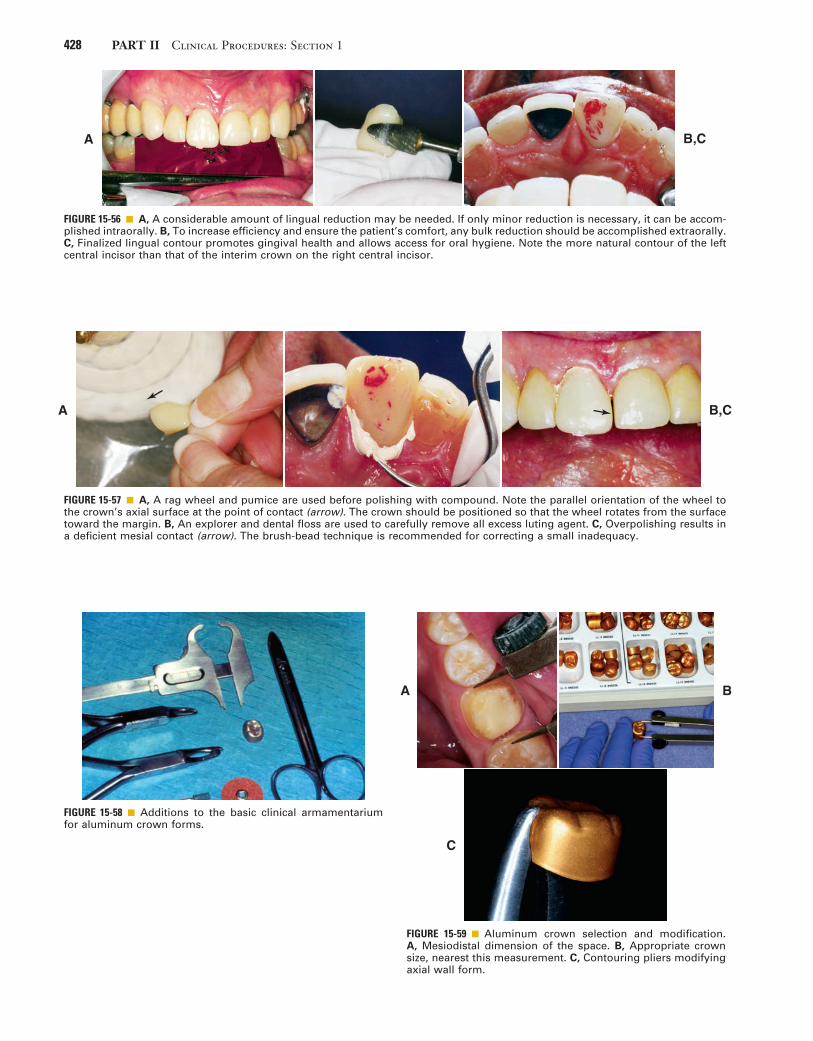
428 PART II Clinical Procedures: Section 1
FIGURE 15-56 ■ A, A considerable amount of lingual reduction may be needed. If only minor reduction is necessary, it can be accom-plished intraorally. B, To increase efficiency and ensure the patient’s comfort, any bulk reduction should be accomplished extraorally. C, Finalized lingual contour promotes gingival health and allows access for oral hygiene. Note the more natural contour of the left central incisor than that of the interim crown on the right central incisor.
A B,C
FIGURE 15-57 ■ A, A rag wheel and pumice are used before polishing with compound. Note the parallel orientation of the wheel to the crown’s axial surface at the point of contact (arrow). The crown should be positioned so that the wheel rotates from the surface toward the margin. B, An explorer and dental floss are used to carefully remove all excess luting agent. C, Overpolishing results in a deficient mesial contact (arrow). The brush-bead technique is recommended for correcting a small inadequacy.
A B,C
FIGURE 15-58 ■ Additions to the basic clinical armamentarium for aluminum crown forms.
FIGURE 15-59 ■ Aluminum crown selection and modification. A, Mesiodistal dimension of the space. B, Appropriate crown size, nearest this measurement. C, Contouring pliers modifying axial wall form.
A B
C

15 Interim Fixed Restorations 429
FIGURE 15-60 ■ A, Cervical portion of the crown trimmed to proper length. B, Smoothing the cut edge to prevent gingival injury.
A
B
FIGURE 15-61 ■ The patient is instructed to bite on the shell after the length has been adjusted. Note the occlusal indentation and gingival blanching (arrows). Where the shell causes blanching, additional shortening is needed.
4. Repeat the evaluation, and trim as necessary.5. Instruct the patient to close the jaws with moder-
ate force. The soft aluminum should deform until normal intercuspation is reached (Fig. 15-61).
6. Apply petrolatum to the prepared tooth and adja-cent gingival tissues; mix poly-R′ methacrylate resin, and fill the shell.
7. When the resin surface becomes matte, place the shell over the tooth and guide it to a slightly supra-clusal position (Fig. 15-62). Have the patient close the jaws.
8. To avoid pulling the resin away from the cavosur-face margin, immediately remove the marginal excess.
9. When the rubbery stage of polymerization is reached (after approximately 2 minutes in the mouth), engage the crown with the Backhaus forceps to just penetrate the aluminum shell (Fig. 15-63). Loosen and remove the crown by rocking it buccolingually or by using the thumb and index finger of the other hand to apply occlusally directed force under the tines. The small buccal and lingual holes created in the surface of the aluminum are not usually a problem and can be ignored until the patient returns, whereupon they may be used to remove the crown again.
10. Place the shell in a cup of warm water (40°C).11. After about 5 minutes, mark the margins and trim
away any excess. To establish periodontally healthy axial contours, the aluminum shell frequently is ground away in certain areas (Fig. 15-64).
12. Replace the crown, and adjust the occlusion as deemed necessary. If either proximal surface lacks contact, resin can be added to correct the defi-ciency. Metal must be ground away in the contact area to provide a resin-to-resin bond (Fig. 15-65).
13. Polish, clean, and cement the restoration.
Post and Core Interim RestorationsIntraradicular retention and support are often obtained from a cast metal post and core restoration (see Chapter
FIGURE 15-62 ■ A, The prepared tooth is protected with petrola-tum. B, The adjusted shell is filled with lining resin and seated to just short of its final position after the resin has lost its sheen. C, The final position is determined by the patient’s closing into maximum intercuspation. Excess resin is immediately removed.
A
B
C

430 PART II Clinical Procedures: Section 1
FIGURE 15-63 ■ A, Backhaus forceps provides definite purchase of the shell for controlled removal. B, After 5 minutes in warm water, the margin is marked with a pencil. C, A coarse garnet disk is recommended for initial contouring of the axial surfaces. This usually necessitates partial removal of the aluminum. After the overcontoured aluminum has been ground away, a fine garnet disk is used to finalize the axial contours (including the marginal areas). Again, disk orientation is important for estab-lishing a straight emergence profile and well-adapted margins.
A
B C
FIGURE 15-64 ■ A, Proper contouring of the axial walls exposes lining resin in the cervical area. Note the indentations in the shell from the Backhaus forceps. B, Final occlusal adjustment removes the anodized gold finish, but this is of no concern.
BA
FIGURE 15-65 ■ Adding proximal contacts to aluminum crowns. A, Contacts are absent in this lined crown (arrows). B, The metal in the contact area is ground away to expose the underlying resin. The brush-bead technique is then used for correcting the deficiency. C, Appearance of the crown after resin addition to the mesial surface. Further contouring with a disk is recommended to improve the gingival embrasure form.
A B,C
12). An interim restoration is needed while the casting is being made.
Additions to Clinical Armamentarium
• Wire• Wire-cutting pliers• Cylindrical green stone, straight handpiece• Wire-bending pliers• Paper points
Step-by-Step Procedure
1. Place a piece of wire (e.g., a straightened paper clip) in the post space. To avoid root fracture, it must extend passively to the end of the post space. A mounted stone can be used to taper the wire if binding occurs.
2. Mark the wire with a pencil at the mouth of the post space. Then, at a point slightly occlusal to this mark, use the pliers to make a 180-degree bend in the wire (Fig. 15-66).
3. Lubricate the tooth and surrounding soft tissues with petrolatum. Paper points are convenient for lubricating the post space.
4. Fill the ESF with interim resin (poly-R′ methac-rylate is recommended).

15 Interim Fixed Restorations 431
5. When the resin loses its surface gloss, place the wire in the post space, and seat the ESF over it (Fig. 15-67). Precautions, including using a gauze throat pack and not placing the patient supine, must be taken to protect the patient from swallowing or aspirating the wire.
6. Remove the ESF while the resin is still rubbery (after 2 to 21
2 minutes). The stage of polymeriza-tion should be monitored. If the resin is allowed to become rigid and lock into the undercut surfaces within the post preparation, removing it and the wire will be time consuming and risk the restorabil-ity of the tooth. The interim usually remains in the ESF, which can be placed in warm water to hasten polymerization. The wire must not be disturbed while the resin is soft. If the interim remains on the tooth, it should be loosened and reseated several times and then removed before the resin has fully polymerized.
7. Trim and contour the restoration with disks or straight-handpiece tungsten carbide burs.
8. Evaluate the restoration in the mouth, and adjust as necessary.
9. Polish, clean, and cement the restoration (Fig. 15-68).
CementationThe primary function of the interim luting agent is to provide a seal, preventing marginal leakage and hence
FIGURE 15-66 ■ Interim post preparation. A, Wire is marked so that the bend is made at the correct level. When in position, the wire must not interfere with the external surface form. B, A 180-degree or greater bend in the wire is made to resist displacement in the lining resin.
A B
pulp irritation. The luting agent should not be relied upon to resist occlusal forces, inasmuch as it is purposely formulated to have low strength. Unintentional displace-ment of an interim restoration is frequently caused by a nonretentive tooth preparation or excessive cement space rather than the choice of luting agent.
Ideal Properties
Desirable characteristics of an interim luting agent are as follows:
• Seal against leakage of oral fluid• Strength consistent with intentional removal
FIGURE 15-67 ■ A, Wire is inserted in the post space just before placement of the filled external surface form (ESF). A gauze throat pack is recommended to protect the patient from aspirating or swallowing the wire. The patient should not be placed in the supine position. B, Filled ESF is seated.
A B
FIGURE 15-68 ■ The completed interim post and crown restora-tion. (The unusual mesial contour is the result of a mesiobuccal root amputation.)

432 PART II Clinical Procedures: Section 1
In situations in which the tooth preparation lacks retention, a span is long or long-term use is anticipated, or parafunction exists, it may be desirable to use a cement of higher strength. A good compromise would be rein-forced ZOE; another might be eugenol-free zinc oxide, which has slightly greater strength than cements contain-ing eugenol.30 Conversely, sometimes minimum strength is desired, as with temporary placement of the definitive restoration. (Its removal may be needed to refire the porcelain.) Petrolatum can be mixed with equal parts of the interim cement base and catalyst to reduce the cement’s strength by more than half. When the definitive cement planned is a resin luting agent, non-eugenol cements are recommended for the interim restoration because of the adverse effect of eugenol on bond strength.
Armamentarium
The following equipment is needed (Fig. 15-70):• Interim luting agent• Mixing pad• Cement spatula• Plastic filling instrument• Petrolatum• Mirror and explorer• Dental floss• Gauge
Step-by-Step Procedure
Most interim luting agents are supplied as a two-part system (Fig. 15-71).
1. To facilitate removal of excess cement, lubricate the polished external surfaces of the restoration with petrolatum (see Fig. 15-71, A).
2. Mix the two pastes together rapidly, and apply a small quantity just occlusal to the cavosurface margin (see Fig. 15-71, B). A marginal bead of cement forms the required seal against oral fluids.
• Low solubility• Blandness or obtundent quality• Chemical compatibility with the interim polymer• Convenience of dispensing and mixing• Ease of eliminating excess• Adequate working time and short setting time
Available Materials
Of the currently available materials (Fig. 15-69), zinc oxide–eugenol (ZOE) cements appear to be the most satisfactory. Zinc phosphate, zinc polycarboxylate, and glass ionomer cements are not recommended because their comparatively high strength makes intentional removal difficult. Using high-strength cements fre-quently damages the restoration or even the tooth when removal is attempted and can make seating of the defini-tive restoration difficult. Weaker ZOE cements provide for easy removal, allowing the restoration to be reused when additional service is needed. ZOE has an obtundent effect on the pulp, in addition to its acceptable sealing properties.27 Unfortunately, however, free eugenol acts as a plasticizer of methacrylate resins. It has been shown to reduce surface hardness28 and presumably strength. New resin applied over polymerized resin previously in contact with free eugenol results in softening29 of the added resin, which precludes successful linings or repairs. The poly-R′ methacrylate resins are severely affected by free eugenol. Methyl methacrylate resins are affected moderately, and the composites are only slightly softened. These adverse effects have stimulated the marketing of interim luting agents without eugenol, but in the studies cited, the mere presence of eugenol in a cement was not enough to cause adverse effects. It appears that unreacted or free eugenol must be present to cause problems. Therefore, when using products that contain eugenol, the dentist must be sure that the correct proportions are blended. Whether free eugenol is necessary to provide an obtundent effect on the pulp remains a question.
FIGURE 15-69 ■ Interim luting agents are available in various formulations. A non–eugenol-containing product is recommended for bonded restorations; the clear luting agent is used for improved esthetics. (Courtesy Kerr Corp., Orange, California.)

15 Interim Fixed Restorations 433
FIGURE 15-70 ■ Interim restoration luting armamentarium. A, Interim luting agent; B, mixing pad; C, cement spatula; D, plastic filling instrument; E, petrolatum; F, mirror and explorer; G, dental floss; H, gauze.
B
A C
D E
F
G
H
C
Filling the crown or abutment retainers should be avoided, because it prolongs cleanup and increases the risk of leaving debris in the sulcus.
3. Seat the restoration, and allow the cement to set (see Fig. 15-71, C).
4. Carefully remove excess with an explorer and dental floss (see Fig. 15-71, D to F).
Cement remnants left in the sulcus have an irritating effect on the gingiva and may cause severe periodontal inflammation with possible bone loss. Therefore, the sulcus must be carefully checked and irrigated with the air-water syringe.
Removal, Recementation, and RepairArmamentarium
• Backhaus towel clamp forceps or hemostatic forceps• Spoon excavator• Ultrasonic cleaner with cement-remover solutionThe interim restoration is removed when the patient
returns for placement of the definitive restoration or for continued preparation. Fracture of the prepared tooth or foundation must be avoided. Risk of this can be mini-mized if removal forces are directed parallel to the long axis of the preparation. The Backhaus towel clamp forceps or a hemostatic forceps is effective for obtaining sound purchase on a single unit (Fig. 15-72). A slight buccolin-gual rocking motion helps break the cement seal.
Damage can occur when an FDP is being removed. If one abutment retainer suddenly breaks loose, the other can be subjected to severe flexure stresses when the FDP acts as a lever arm. Care must be exercised to remove the prosthesis along the path of placement. Sometimes it is helpful to loop dental floss under the connector at each end of the FDP.
Step-by-Step Procedure
1. If the interim restoration is going to be recemented, clean out the bulk of existing cement with a spoon excavator.
2. Place the restoration in a cement-dissolving solu-tion, and set this in the ultrasonic cleaner.
3. Line the restoration with a fresh mix of resin if necessary (e.g., if the tooth preparation has been modified). The internal surface is relieved slightly
FIGURE 15-71 ■ Luting procedure. A, The external surface is lightly coated with petrolatum to aid removal of the set luting agent. B, Careful placement of the luting agent seals the margins and reduces the clean-up effort. C, The restoration is seated with firm finger pressure, or (for posterior restorations) the patient may bite on a cotton roll. D and E, An explorer is used to remove excess and to probe the sulcus gently for remnants. F, The proximal contact areas and sulcus are cleaned with dental floss (a knot will help remove excess cement), followed by copious irrigation with the air-water syringe.
A
D
B,C
E,F

434 PART II Clinical Procedures: Section 1
FIGURE 15-72 ■ Backhaus towel clamp forceps provides positive purchase on interim restorations. For maximum control, occlu-sal finger pressure is applied directly to the tines.
FIGURE 15-73 ■ Brush-bead technique for repairs. A, Monomer liquid is painted on the surface of the thoroughly cleaned restoration to which resin will be added. B, The brush is dipped in monomer and briefly touched to the powder, which causes a small bead to form on the tip. C, The bead is touched to the repair site, and the brush handle is rolled to deposit it. Bead placement continues in this manner until the desired contour is achieved. To prevent excessive porosity, the unset resin should be painted lightly with monomer until hard.
A B,C
and painted with monomer to ensure good bonding of the new material.
A fractured or damaged interim restoration can be repaired easily with resin, added directly by means of the brush-bead technique (Fig. 15-73).
Esthetic EnhancementContour, color, translucency, and texture are the key ele-ments of coronal appearance. Contour and color are esthetically fundamental and more important than the other two elements. The indirect partial FDP procedure just described includes methods for controlling contour and color.
Contour
Diagnostic waxing provides the ultimate control of contour, and shade selection before tooth preparation gives the operator some control of color. If contour and color are well controlled, most interim restorations are very acceptable or even excellent in appearance. Rou-tinely achieving this outcome requires attention to detail and skill. Also, achieving translucency in an interim crown can be a significant challenge for patients with unabraded teeth.
Color
Whereas some resin manufacturers use only general color descriptors (light, medium, dark) for their products, most cross-reference their colors to popular shade guides for porcelain or denture teeth. However, even when colors are cross-referenced, shade matching can be inac-curate because of manufacturer and material differences. Better control of color is obtained through the use of a custom shade guide. The dentist can make this easily by casting the resins into an elastomeric putty mold of an extracted incisor crown. Combining two or more existing hues in known proportions can create a wider selection of shades; resin-coloring tints are another option.
Custom color effects that simulate intrinsic and extrin-sic stains, cracks, or hypocalcification of adjacent teeth may be added to interim restorations with the help of paint-on stain kits (Fig. 15-74). These are best applied
FIGURE 15-74 ■ This interim stain kit contains violet, blue, yellow, orange, brown, white, and gray paint-on colorants to create custom effects and a clear material used to form a glazed trans-lucent surface. The liquids are formulated to dry quickly, which requires that they be kept covered until immediately before use. A thinner and a brush cleaner are provided.

15 Interim Fixed Restorations 435
Texture
With practice, texture effects require only a small amount of time, but they may contribute significantly to the overall appearance of the interim restoration. These effects are most important for maxillary anterior teeth adjacent to teeth with well-defined lobes, imbrication lines, or developmental defects.
Developmental lobes are best simulated in wax during the final stage of the diagnostic waxing. To produce a natural effect, it is crucial to avoid making grooves that are straight, have sharp edges, or have uniform cross sec-tions. Rather, the simulation should have a gentle cres-cent shape, the edges should be softened, and the cross section slightly varied by burnishing with the largest diameter waxing wire. If a polypropylene sheet is used to form the ESF, these subtle details can be reproduced in the resin.
Placement of developmental defects is best accom-plished in the resin just before pumice and rag wheel fin-ishing. Depending on their size and definition, these features may be made with a sharp-edged, inverted- cone green stone rotating parallel to the occlusal plane and touched briefly to the resin. Often the defects are most noticeable in the cervical third of the tooth, but an adjacent tooth is the best guide for determining their distribution.
Imbrication lines may be simulated with a coarse diamond rotary instrument rotating slowly and moved across the facial surface from proximal to proximal. This reduces the surface reflectance of the resin after it is finished and polished. However, as with all texture effects, overfinishing obliterates these lines. Care must be taken to monitor the finishing by rinsing pumice from the surface and drying it. A completely smooth and highly polished interim restoration may be excellent for plaque control but not esthetically compatible with the adjacent teeth. The debate as to which is more important can probably best be settled by consultation with the patient to determine his or her needs.
quickly, and overmanipulation should be avoided because it causes streaking and surface roughness. Under optimum conditions, the surface should have a glazed appearance similar to that of porcelain. Thickening of stains as a result of the evaporation of solvent is a common problem that hampers manipulation. Another problem with the paint-on colorants is their poor resistance to abrasion. Loss of the pigments in high-abrasion areas produces an unattractive mottled effect.
Translucency
Coronal translucency is determined by the type and amount of enamel present. In an unworn anterior tooth where there is no dentin in the light path, the incisal edge often takes on a blue or gray hue, which comes about from the dark oral cavity. This effect is most pro-nounced with enamel that scatters very little light as a result of the absence of pigments or opacifying miner-alization (e.g., fluorosis). Although less obvious, the translucent appearance of enamel is observable over the entire incisal or occlusal third of the crown. Thus when it is readily visible in adjacent teeth or when a more realistic appearance is desired, translucency can be sim-ulated in the interim. The procedure requires two resins: one colored to match the body of the tooth and one to match the enamel of the tooth. Some manufac-turers produce enamel or incisal shades that may be used without modification. When these are not available or when variation is needed, clear resin powder may be mixed with a smaller fraction of the “body” powder to produce the desired translucency.
Two procedures can be followed to create a translu-cent effect. In the first, which is more difficult to control, the enamel color resin is carefully brush-beaded onto the occlusal or incisal surface of the ESF and tapered to end at the middle or cervical third. The ten-dency to flow where it is not wanted is controlled in part by the orientation of the ESF with regard to gravity and in part by manipulation with the brush tip. When the desired distribution of enamel color resin is achieved, a disposable syringe is loaded with body color resin, and the ESF is immediately filled to avoid disrup-tion of the enamel color resin. The TSF is then posi-tioned in the ESF, and normal procedures are followed (Fig. 15-75).
In the second procedure, the enamel color resin is allowed to polymerize on the ESF without the addition of body color resin on the TSF. The rigid enamel veneer is removed from the ESF and trimmed to occupy only the space intended for enamel. It is important to check that the ESF and TSF can be fitted without inter-ference from the in-place veneer. With the veneer in place, monomer liquid is painted on it and the body color resin is added. The TSF is then inserted, and standard procedures are followed for the remainder of the restoration. The timing for this procedure is less crucial than for the first one described and may be better suited to practitioners with less experience. A dis-advantage is that sometimes this approach results in a more obvious demarcation between the enamel and the body resins.
FIGURE 15-75 ■ The layering of translucent resin and dentin-shaded resin allows a more realistic appearance of the premolar and canine interim restorations. They serve as removable dental prosthesis (RDP) abutments and are splinted together to help resist dislodgment.

436 PART II Clinical Procedures: Section 1
internal glass fiber–reinforced composite substructure covered by a particulate composite (Fig. 15-77).
Available MaterialsFRC materials are categorized according to the following characteristics:
• Type of fiber• Fiber orientation• Whether the resin impregnation of the fiber is per-
formed by the dentist/laboratory technician or by the manufacturer
The most commonly used fibers in dental applications are glass, polyethylene, and carbon. Fiber architectures in dentistry include unidirectional patterns, in which all fibers are parallel, and braided and woven patterns. Commer-cially available non–resin-impregnated materials include polyethylene weaves (e.g., Ribbond, Ribbond, Inc., and Construct, Kerr Corp.) and glass weaves (e.g., GlasSpan, GlasSpan, Inc.). For these products, the resin must be added to the fibers by hand. Resin-preimpregnated materi-als include everStick and StickNET (GC America Inc.), which are hand formed and available in both unidirectional and woven-glass forms; FibreKor (Pentron Clinical), which is hand formed and available as a unidirectional glass material; and Splint-It (Pentron Clinical), which is also hand formed and available in both unidirectional and woven glass forms (Fig. 15-78).
Different FRC materials exhibit different handling and mechanical properties. Fiber type, fiber orientation, and the quality of fiber impregnation with the resin matrix have a substantial effect on handling characteris-tics and physical properties. Glass materials with a unidi-rectional architecture exhibit flexural properties that are superior to the polyethylene materials with a woven or braided architecture (Table 15-5). These glass materials have a flexural strength that is more than twice the strength of polyethylene materials and a flexural modulus almost eight times as great.16 Because of their good han-dling characteristics, the braided and woven polyethylene products may be useful for other dental applications (e.g., operatory fabrication of periodontal splints).
Currently available materials demonstrate excellent esthetics, good handling characteristics, and good flexure properties.32,34-37 Commercial products have been based on these formulations. The fabrication of a complete-coverage prosthesis with a commercially available, preimpregnated unidirectional FRC (FibreKor, Pentron Clinical) and a hand-fabricated technique is shown in Figure 15-79.
SUMMARY
Although interim restorations are usually intended for short-term use and then discarded, they can be made to provide pleasing esthetics, adequate support, and good protection for teeth while maintaining periodontal health. They may be fabricated in the dental office from any of several commercially available materials and by a number of practical methods. The success of fixed prosthodontic treatment often depends on the care with which the interim restoration is designed and fabricated.
FIBER-REINFORCED COMPOSITE FIXED PROSTHESESMartin A. Freilich • Jonathan C. Meiers • A. Jon Goldberg
Fiber-reinforced fixed prostheses consist of a fiber-reinforced composite (FRC) substructure veneered with a particulate composite material. The substructure pro-vides strength, and the veneer, because it is laboratory processed, exhibits better physical properties and esthet-ics than do direct placement composite restoratives (Fig. 15-76). They are ideal prostheses when a longer term interim restoration is needed.
Because of their good flexure strength and other phys-ical characteristics, FRCs are suitable substructure mate-rials for FDPs.31-33 In addition, the FRC substructure is translucent, and no opaque masking is required. This allows a relatively thin layer of particulate covering com-posite and excellent esthetics. FRCs have been used to make two-phase all-polymer prostheses composed of an
FIGURE 15-76 ■ A, All-ceramic crown restoring the right maxillary central incisors. B and C, Maxillary anterior teeth restored with facial veneers and an all-ceramic fixed dental prosthesis. (B and C, Courtesy Dr. D.H. Ward.)
A
B
C

15 Interim Fixed Restorations 437
FIGURE 15-77 ■ A, Fiber-reinforced composite (FRC) substructure for a three-unit polymer fixed dental prosthesis (FDP). B, Particulate composite veneers completed over FRC substructure. C, Internal surface of FRC-reinforced polymer FDP.
A B
C
FIGURE 15-78 ■ Scanning electron micrographs of fiber-reinforced composite (FRC) materials. A, Woven polyethylene FRC (Construct, Kerr Corporation). B, Braided polyethylene FRC (Ribbond, Ribbond, Inc.). C, Unidirectional long glass fiber FRC (FibreKor, Pentron Clinical Technologies, LLC). D, Unidirectional long glass fibers with a polymethyl methacrylate (PMMA) outer membrane (everStick, GC America Inc.).
A B
C D

438 PART II Clinical Procedures: Section 1
FIGURE 15-79 ■ The step-by-step fabrication of a complete-coverage fiber-reinforced composite (FRC) prosthesis with a unidirectional glass material (FibreKor, Pentron Clinical Technologies, LLC), accomplished with a hand-fabricated technique. A, Dies showing posterior abutment preparations for an FRC polymer fixed prosthesis. B, Thin coping of opacious body particulate composite adapted to the die. C, Bar of multiple layers of FRC spanning the pontic region, bonding the copings together. D, Continuous strip of FRC bonded to one end of the pontic bar and then wrapped around the axial surfaces of the copings while being polymerized. E, Occlusal view of the completed FRC substructure. F, Completed prosthesis with particulate resin veneers on model. G, Tissue side view of completed prosthesis, showing the internal adaptation to preparation design of the abutment teeth.
A B
DC
E F
G
*Data generated in the authors’ laboratory.†Manufacturer’s data.M, Mean; SD, standard deviation.
TABLE 15-5 Flexure Properties of Commercial Fiber-Reinforced Composite Materials*
Material Fiber TypeFiber Architecture
Flexural Strength (MPa)Flexural Modulus (GPa)
m sd m sd
FibreKor 2K Glass Unidirectional 541 32 25.0 2.0FibreKor 16K Glass Unidirectional 639-919† 35-42 28.0 3.0everStick Glass Unidirectional 739 47 24.3 1.5GlasSpan Glass Braid 321 28 13.9 1.1Construct Polyethylene Braid 222 23 8.3 0.5Ribbond Polyethylene Leno weave 206 15 3.9 0.7

15 Interim Fixed Restorations 439
21. Monday JJL, Blais D: Marginal adaptation of provisional acrylic resin crowns. J Prosthet Dent 54:194, 1985.
22. Robinson FB, Hovijitra S: Marginal fit of direct temporary crowns. J Prosthet Dent 47:390, 1982.
23. Al-Sowygh ZH: The effect of various interim fixed prosthodontic materials on the polymerization of elastomeric impression materi-als. J Prosthet Dent 112:176, 2014.
24. Von Fraunhofer JA, Spiers RR: Accelerated setting of dental stone. J Prosthet Dent 49:859, 1983.
25. Thompson GA, Luo Q: Contribution of postpolymerization condi-tioning and storage environments to the mechanical properties of three interim restorative materials. J Prosthet Dent 112:638, 2014.
26. Yao J, et al: Comparison of the flexural strength and marginal accuracy of traditional and CAD/CAM interim materials before and after thermal cycling. J Prosthet Dent 112:649, 2014.
27. Pashley EL, et al: The sealing properties of temporary filling mate-rials. J Prosthet Dent 60:292, 1988.
28. Rosenstiel SF, Gegauff AG: Effect of provisional cementing agents on provisional resins. J Prosthet Dent 59:29, 1988.
29. Gegauff AG, Rosenstiel SF: Effect of provisional luting agents on provisional resin additions. Quintessence Int 18:841, 1987.
30. Olin PS, et al: Retentive strength of six temporary dental cements. Quintessence Int 21:197, 1990.
31. Karmaker AC, et al: Fiber reinforced composite materials for dental appliances. In ANTEC 1996 Plastics: Plastics—Racing into the Future, Volume 3: Special Areas, pp 2777–2781. Indianapolis, Society of Plastic Engineers, 1996.
32. Freilich MA, et al: Flexure strength of fiber-reinforced composites designed for prosthodontic application [Abstract no. 999]. J Dent Res 76:138, 1997.
33. Freilich MA, et al: Flexure strength and handling characteristics of fiber-reinforced composites used in prosthodontics [Abstract no. 1561]. J Dent Res 76:184, 1997.
34. Goldberg AJ, Burstone CJ: The use of continuous fiber reinforce-ment in dentistry. Dent Mater 8:197, 1992.
35. Karmaker AC, et al: Extent of conversion and its effect on the mechanical performance of Bis-GMA/PEGDMA-based resins and their composites with continuous glass fibers. J Mater Sci 8:369, 1997.
36. Freilich MA, et al: Preimpregnated, fiber-reinforced prostheses. I. Basic rationale and complete-coverage and intracoronal fixed partial denture designs. Quintessence Int 29:689, 1998.
37. Freilich MA, et al: Development and clinical applications of a light-polymerized fiber-reinforced composite. J Prosthet Dent 80:311, 1998.
REFERENCES1. Seltzer S, Bender IB: The dental pulp; biologic considerations in
dental procedures, 3rd ed, p 191. Philadelphia, Lippincott, 1984.2. Seltzer S, Bender IB: The dental pulp; biologic considerations in
dental procedures, 3rd ed, pp 267-272. Philadelphia, Lippincott, 1984.3. Larato DC: The effect of crown margin extension on gingival
inflammation. J South Calif Dent Assoc 37:476, 1969.4. Waerhaug J: Tissue reactions around artificial crowns. J Periodon-
tol 24:172, 1953.5. Phillips RW: Skinner’s science of dental materials, 8th ed, pp 221,
376. Philadelphia, WB Saunders, 1982.6. El-Ebrashi MK, et al: Experimental stress analysis of dental resto-
rations. VII. Structural design and stress analysis of fixed partial dentures. J Prosthet Dent 23:177, 1970.
7. Koumjian JH, et al: Color stability of provisional materials in vivo. J Prosthet Dent 65:740, 1991.
8. Preston JD: A systematic approach to the control of esthetic form. J Prosthet Dent 35:393, 1976.
9. Moskowitz ME, et al: Using irreversible hydrocolloid to evaluate preparations and fabricate temporary immediate provisional resto-rations. J Prosthet Dent 51:330, 1984.
10. Roberts DB: Flexible casts used in making indirect interim restora-tions. J Prosthet Dent 68:372, 1992.
11. Hensten-Pettersen A, Helgeland K: Sensitivity of different human cell lines in the biologic evaluation of dental resin-based restorative materials. Scand J Dent Res 89:102, 1981.
12. Munksgaard EC: Toxicology versus allergy in restorative dentistry. Adv Dent Res 6:17, 1992.
13. Dahl BL: Tissue hypersensitivity to dental materials. J Oral Rehabil 5:117, 1978.
14. Weaver RE, Goebel WM: Reactions to acrylic resin dental pros-theses. J Prosthet Dent 43:138, 1980.
15. Giunta J, Zablotsky N: Allergic stomatitis caused by self-polymerizing resin. Oral Surg 41:631, 1976.
16. Spealman CR, et al: Monomeric methyl methacrylate: studies on toxicity. Industrial Med 14:292, 1945.
17. Moulding MB, Teplitsky PE: Intrapulpal temperature during direct fabrication of provisional restorations. Int J Prosthodont 3:299, 1990.
18. Tjan AHL, et al: Temperature rise in the pulp chamber during fabrication of provisional crowns. J Prosthet Dent 62:622, 1989.
19. Zach L, Cohen G: Pulpal response to externally applied heat. Oral Surg 19:515, 1965.
20. Crispin BJ, et al: The marginal accuracy of treatment restorations: a comparative analysis. J Prosthet Dent 44:283, 1980.
STUDY QUESTIONS
1. What are the ideal properties of an interim restorative material? What are the ideal properties of the optimum interim luting agent?
2. List at least five requirements for the success of an interim restoration.
3. Explain why these factors are crucial for clinical success. What would occur if they were not appropri-ately performed or obtained?
4. Select three techniques for fabricating an interim res-toration for a single tooth. Identify the factors involved when a certain technique is selected for an indication or tooth.
5. What are the currently available materials for fabrica-tion of interim restorations? What are their respective material properties, advantages, and disadvantages?
6. Explain the basic chemical events involved in resin polymerization.
7. What factors should be considered in the decision of whether to use a direct, indirect, or indirect-direct fabrication technique for interim fixed dental prostheses?

This page intentionally left blank

PART III
LABORATORY PROCEDURES

This page intentionally left blank

443
Communicating with the Dental Laboratory
C H A P T E R 1 6
To make a high-quality fixed prosthesis, all members of the dental team must understand what they can reason-ably expect from each other. A mutual knowledge of individual limitations is crucial. The dentist who does not understand and appreciate the challenges faced by the technician is at a serious disadvantage when prescribing and delegating laboratory procedures (Fig. 16-1). Crucial to the development of sound clinical judgment is a thorough understanding of technical procedures and their rationale, which are described in the chapters of this section.
DENTAL TECHNOLOGY TRAINING AND CERTIFICATION
The National Association of Dental Laboratories (NADL) is committed to upholding and advancing the commercial dental laboratory industry. This organization emphasizes the following information1:
In 46 states, there are no laws to set minimum quali-fications for performance of dental technology or the operation of a dental laboratory. However, several states are moving forward with legislative proposals on “man-dated technician certification.” At the 2013 American Dental Association (ADA) House of Delegates, the ADA passed a resolution that came from cooperative work from the ADA Council on Dental Practice and the NADL that “strongly encourages all state dental boards to register dental laboratories.”
Certification of technicians and laboratories is evi-dence of their commitment to maintaining professional standards in dental technology. There were approxi-mately 44,000 individual dental laboratory technicians in the United States, as of June 2013, according to the U.S. Department of Labor. Because technicians are not required to be registered or licensed in most states, track-ing has to come from various government and private sources.
In 2002, 25 programs in dental laboratory technology were approved (accredited) by the Commission on Dental Accreditation in conjunction with the ADA. Today, there are only 18.
The National Board for Certification in Dental Labo-ratory Technology, an independent board established by the NADL, offers voluntary certification in dental labo-ratory technology. Certification can be obtained in six specialty areas: crowns and bridges, ceramics, partial dentures, complete dentures, implants, and orthodontic appliances. Certification is required in Kentucky, Texas, and South Carolina. The standards and requirements for certification do not vary across state lines. A certified
dental technician (CDT) tested in New England must demonstrate the same competencies as a CDT tested on the Pacific coast.
To qualify for certification, technicians must have a 2-year dental technology degree or at least 5 years’ expe-rience in dental technology and must pass written and practical examinations. To maintain certification, they must document at least 12 hours of continuing education annually, including 1 hour in regulatory standards that includes study on the Occupational Safety and Health Administration’s (OSHA’s) standards about bloodborne pathogens, infection control, and the U.S. Food and Drug Administration’s (FDA’s) quality systems. The requirements for a certified dental laboratory include having a CDT present to supervise each department in the specialty, in which they and the laboratory are certi-fied, to ensure that proper safety and production practices are followed. Certification must be renewed annually.*
Technicians who maintain their certification must take 12 hours of continuing education each year, including a required hour in regulatory standards.
The first CDTs were tested in 1958. Today the National Board for Certification tests more than 1200 technicians annually. In 1978, the current standards for laboratory certification were adopted; today there are more than 300 certified dental laboratories (C.A.E. Bennett Napier, personal communication, November 19, 2013).
In 2012, the U.S. dental laboratory industry produced approximately $7 billion in sales. The number of dental laboratories in the United States is just over 9000.
MUTUAL RESPONSIBILITIES
Good communication—the key to the technical success of the dental team2-4—requires a close working relation-ship between the dentist and laboratory technician. Anticipating satisfactory results is unrealistic if the dentist does not have a reasonable amount of experience with, and a thorough understanding of, dental laboratory pro-cedures. Active participation in the technical procedures by the dentist is paramount, and clinicians who take the time to develop an in-depth understanding of laboratory work make better clinical decisions because of their understanding of applicable technical and material science limitations. Only then can a dentist select the best com-promise between (1) technical restrictions, (2) biologic factors, and (3) esthetic needs. Similarly, if the technician
*Reproduced by permission of National Association of Dental Laboratories.

444 PART III Laboratory Procedures
Surveys5-7 of fixed prosthodontic laboratories have revealed that dentists delegate a significant proportion of their responsibilities. The technicians surveyed were often dissatisfied with the quality of assignments received; complaints included insufficient information being included in the work authorization, the submis-sion of deficient impressions, and inadequate occlusal records. Such surveys highlight significant problems in dentist-technician communication. In other studies and opinions concerning dentist-technician interaction, whether written by dentists or technicians, the authors emphasized that better patient care is achievable only by better communication about patient care.8
The ADA issued guidelines to improve the relation-ship between dentist and technician.9 The introduction is reprinted as follows:
Working relationships between dentists and dental laboratories: The current high standard of prosthetic dental care is directly related to, and remains dependent upon, mutual respect within the dental team for the abilities and contributions of each member. The following guidelines are designed to foster good relations between dental laboratories, dental laboratory technicians and the dental profession. Applicable laws shall take precedence if they are inconsistent with any of the following guidelines.
The guidelines themselves are reprinted in the follow-ing two sections.9
The Dentist1. The dentist should provide written instructions to
the laboratory or dental technician. The written instructions should detail the work which is to be performed, describe the materials which are to be used, and be written in a clear and understandable fashion. A duplicate copy of the written instruc-tions should be retained for an appropriate time as may be required by law.
2. The dentist should provide the laboratory techni-cian with accurate impressions, casts, occlusal reg-istrations and/or mounted casts. Materials submitted should be identified.
3. The dentist should identify, as appropriate, the crown margins, postpalatal seal, denture borders, any areas to be relieved, and design of the remov-able partial dentures on all cases.
4. The dentist should furnish instruction regarding preferred materials, coloration, [and] description of prosthetic tooth/teeth to be utilized for fixed or removable prostheses, which may include, but [is] not limited to, a written description, photograph, drawing, or shade button.
5. The dentist should provide verbal or written approval to proceed with a laboratory procedure, or make any appropriate change(s) to the written instructions as the dentist deems necessary, when notified by a laboratory/dental technician that a case may have a questionable area with respect to paragraphs 2-4.
does not appreciate and respect the clinical demands or the treatment rationale of the dentist, the results will be unsatisfactory (Fig. 16-2). The dentist can earn this respect by being prepared to meet personal responsibili-ties, by listening carefully to technical advice rendered, and by actively participating in the technical decision-making process.
FIGURE 16-1 ■ A, This six-unit anterior metal-ceramic framework did not seat. After it was sectioned between the incisors, the adaptation of the individual components was satisfactory. Note the (correct) narrow width of the soldering gap. B, Appearance of the two segments indexed with autopolymerizing resin for subsequent soldering. C, The dentist sectioned this fixed dental prosthesis (FDP) incorrectly: The soldering gap is much too wide (arrow), and distortion during soldering will almost cer-tainly result.
A
B
C
FIGURE 16-2 ■ Soft tissue contours and embrasure forms present a challenge for technicians. In this case, these substructures were not fabricated properly: The metal-porcelain junction was placed too far facially (arrows). Unless corrected during clinical evaluation, metal would be visible and detract from the appear-ance of the prosthesis.
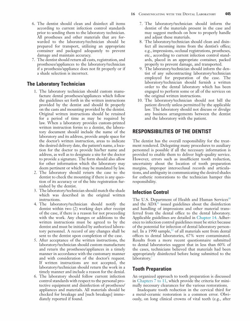
16 Communicating with the Dental Laboratory 445
7. The laboratory/technician should inform the dentist of the materials present in the case and may suggest methods on how to properly handle and adjust these materials.
8. The laboratory/technician should clean and disin-fect all incoming items from the dentist’s office; e.g., impressions, occlusal registrations, prostheses, etc., according to current infection control stand-ards, placed in an appropriate container, packed properly to prevent damage, and transported.
9. The laboratory/technician should inform the den-tist of any subcontracting laboratory/technician employed for preparation of the case. The laboratory/technician should furnish a written order to the dental laboratory which has been engaged to perform some or all of the services on the original written instructions.
10. The laboratory/technician should not bill the patient directly unless permitted by the applicable law. The laboratory should not discuss or divulge any business arrangements between the dentist and the laboratory with the patient.
RESPONSIBILITIES OF THE DENTIST
The dentist has the overall responsibility for the treat-ment rendered. Delegating many procedures to auxiliary personnel is possible if all the necessary information is provided to enable them to deliver high-quality service. However, errors such as insufficient tooth reduction, uncertainty about the location of tooth preparation margins, improper interocclusal records and articula-tions, and ambiguity in communicating the desired shades for esthetic restorations to the technician hamper this responsibility.
Infection ControlThe U.S. Department of Health and Human Services10 and the ADA11 issued guidelines about the disinfection and handling of impressions and other material trans-ferred from the dental office to the dental laboratory. Applicable guidelines are detailed in Chapter 14. Adher-ence to infection control guidelines must be strict because of the potential for infection of dental laboratory person-nel. In a 1990 sample,12 of all materials sent from dental offices to dental laboratories, 67% were contaminated. Results from a more recent questionnaire submitted to dental laboratories suggest that in less than 60% of the cases, technicians believed that materials had been appropriately disinfected before being submitted to the laboratory.7
Tooth PreparationAn organized approach to tooth preparation is discussed in Chapters 7 to 11, which provide the criteria for mini-mally necessary clearances for the various restorations.
Inadequate tooth reduction in the cervical third for a metal-ceramic restoration is a common error. Obvi-ously, on long clinical crowns of vital teeth (e.g., after
6. The dentist should clean and disinfect all items according to current infection control standards prior to sending them to the laboratory technician. All prostheses and other materials that are for-warded to the laboratory/technician should be prepared for transport, utilizing an appropriate container and packaged adequately to prevent damage and maintain accuracy.
7. The dentist should return all casts, registration, and prostheses/appliances to the laboratory/technician if a prosthesis/appliance does not fit properly or if a shade selection is incorrect.
The Laboratory Technician1. The laboratory technician should custom manu-
facture dental prostheses/appliances which follow the guidelines set forth in the written instructions provided by the dentist and should fit properly on the casts and mounting provided by the dentist. Original written instructions should be retained for a period of time as may be required by law. When a laboratory provides custom-printed written instruction forms to a dentist, the labora-tory document should include the name of the laboratory and its address, provide ample space for the doctor’s written instruction, areas to indicate the desired delivery date, the patient’s name, a loca-tion for the doctor to provide his/her name and address, as well as to designate a site for the doctor to provide a signature. The form should also allow for other information which the laboratory may deem pertinent or which may be mandated by law.
2. The laboratory should return the case to the dentist to check the mounting if there is any ques-tion of its accuracy or of the bite registration fur-nished by the dentist.
3. The laboratory/technician should match the shade which was described in the original written instructions.
4. The laboratory/technician should notify the dentist within two (2) working days after receipt of the case, if there is a reason for not proceeding with the work. Any changes or additions to the written instructions must be agreed to by the dentist and must be initialed by authorized labora-tory personnel. A record of any changes shall be sent to the dentist upon completion of the case.
5. After acceptance of the written instructions, the laboratory/technician should custom manufacture and return the prostheses/appliances in a timely manner in accordance with the customary manner and with consideration of the doctor’s request. If written instructions are not accepted, the laboratory/technician should return the work in a timely manner and include a reason for the denial.
6. The laboratory should follow current infection control standards with respect to the personal pro-tective equipment and disinfection of prostheses/appliances and materials. All materials should be checked for breakage and [such breakage] imme-diately reported if found.

446 PART III Laboratory Procedures
A B
C D,E
F
G,H
I
FIGURE 16-3 ■ Unrealistic expectations. Restoration failure result-ing from excessive axial contours. A, Recently placed metal-ceramic crowns have contributed to gingival inflammation. B, After removal of the restorations, shoulder margin width is seen to be insufficient when the crowns are removed. C and D, Excessive contours. Note the cervical bulge on the facial aspect of this restoration (D). E, A significant amount of axial wall is visible from a gingival view. F to H, The restorations are recon-toured and polished. Compare the view in G with that in D and the view in H with that in E. I, Tissue health quickly improves when the recontoured restorations are temporarily recemented. After correction of the underreduced tooth preparations, replace-ment crowns were made for esthetic reasons.
periodontal surgery), it is not always possible to reduce the desired 1.2 to 1.5 mm without pulp exposure. Nev-ertheless, it is generally impossible, even for an experi-enced ceramist, to achieve superior esthetic results if the tooth is underprepared.13 Inexperienced technicians tend
to resolve the problem by overcontouring (Fig. 16-3), but this usually leads to the initiation or recurrence of peri-odontal disease. Esthetic difficulties and treatment limi-tations such as these should be discussed with the patient during the treatment planning phase. Communication

16 Communicating with the Dental Laboratory 447
regarding any deviation from “ideal” criteria is essential ahead of time and can prevent misunderstanding, frustra-tion, and ultimate failure.
Preparation MarginsMargins should be easily discernible and accessible on the casts submitted to the technician. The saying “If you can’t see it, you can’t wax it” describes the situation well. (The requirements for dies are listed in Chapter 17.)
The dentist should outline the margins on the dies14 (Fig. 16-4). However, in practice, few dentists do this.15 If the teeth are properly prepared and the impression is accurate, the margins should be obvious, which makes this step unnecessary. When doubt exists, the dentist’s knowledge of the extent of the preparation should resolve any uncertainty.
Dentists must understand the importance of margin design and geometry. For instance, it is unrealistic to request a collarless restoration on a shoulder-bevel type of margin or a lithium disilicate ceramic crown res-toration on a tooth with a narrow chamfer finish line (Figs. 16-5 and 16-6).
Although an experienced technician will probably bring any unrealistic demands to the attention of the dentist, some well-meaning technicians may attempt to meet a request that is doomed to failure from the begin-ning. To quote one excellent dentist, “When you discover an error has occurred—STOP! Don’t proceed. Return to the step where the error occurred and correct it. Attempt-ing to blunder on without correcting it properly will only compound and complicate the error.”
ArticulationProper articulation of opposing casts is the responsibility of the dentist. Often it is advisable to schedule a separate appointment with the patient for verification of the artic-ulation. This is particularly crucial as the complexity of treatment increases (Fig. 16-7). An apparently slight dis-crepancy may necessitate a remake or hours of corrective
FIGURE 16-4 ■ Marking the preparation margin with a colored pencil. The line must be clearly visible but of minimal thickness.
FIGURE 16-5 ■ A, The expectations of the dentist in this treatment are not realistic. These preparations are unsuitable for the metal-ceramic restorations requested because the gingival third of the tooth was inadequately reduced. B, After correction, proper retainer contour is achievable.
A
B
FIGURE 16-6 ■ Three types of esthetic restorations. The restora-tion with the metal collar can be fabricated on a shoulder or shoulder-bevel margin; the porcelain labial margin metal-ceramic crown can be fabricated on a shoulder margin; and the all-ceramic crown requires a slightly rounded internal angle. The latter two require margins that are glasslike in smoothness.
grinding and a compromised result. With careful plan-ning, the articulation can be verified efficiently. The dentist should trim the interocclusal records appropri-ately. Only after trimming is it possible to verify the positional stability of the record on the cast (Fig. 16-8).
Work AuthorizationIn some jurisdictions, the written instructions are referred to as a work authorization; elsewhere, it may be referred to as a laboratory work order or prescription. In addition to certain general information that is required by law, a

448 PART III Laboratory Procedures
FIGURE 16-7 ■ A common error is for the dentist and technician to try to achieve normal anatomic contours on a compromised preparation outline form. Periodontal complications invariably result. A, Atypical coronal form after root resection. B, Note that every effort was made to achieve axial contours with optimal emergence profile resulting in modified axial contours. C, The definitive restoration permits optimal access for oral hygiene measures.
A
B
C
FIGURE 16-8 ■ It is important that interocclusal records are trimmed through the buccal cusp tips to enable easy verification that both casts are properly positioned in the record and stable.
work authorization form (Fig. 16-9) should include the following:
• General description of the restoration to be made• Material specification (e.g., anatomic contour
zirconia)• Desired occlusal scheme• Connector design for fixed dental prostheses• Pontic design, including the material specification
for tissue contact• Substructure design for metal-ceramic restorations• Information regarding the shade selection for
esthetic restorations• Proposed partial removable dental prosthesis design
(if applicable)• Date of the patient’s next scheduled appointment
and the stage of completion required by thenThe dentist must be familiar with the materials that
the technician prefers to use for certain procedures. Spec-ifying those materials can save both time and effort. The technician should also respect the selection when the dentist requests a specific material. Written instructions should be explicit.16
Communication improves if the technician and dentist discuss a particular choice, rather than if the dentist merely writes a statement on the work authorization form. It may be inconvenient for the technician to comply with a request, and so its importance should be discussed.
Occlusion
The work authorization form should designate the loca-tion of the occlusal contacts. It must be specified whether they are to be on metal or ceramic. In theory, the two most desirable occlusal schemes are cusp-fossa and cusp–marginal ridge. Assuming that these will be attained in every restoration is unrealistic, however, because they can be accomplished consistently only when the opposing teeth are reasonably close to ideal relative positions (Angle class I occlusion; see Chapter 1). Compromises often must be made, especially when teeth are being restored to conform to an existing dentition. For example, when a mandibular molar is in a buccolingual edge-to-edge posterior relationship with its antagonist, a decision must be made whether to restore the tooth in a reverse articulation or whether the tooth preparation should be modified (additional reduction of the buccal functional cusp bevel) to accommodate a more conventional occlu-sal relationship. As an alternative, restoring the opposing tooth may need to be considered.
If the dentist has performed a diagnostic tooth prepa-ration and waxing (see Chapter 2), it is possible to com-municate the desired occlusal relationship or tooth form very specifically (Fig. 16-10). A wax record rim that has been adjusted intraorally can convey a general idea of the desired position of the occlusal plane (Fig. 16-11). Simi-larly, a custom anterior guide table made by the dentist from anterior interim restorations that have proved com-fortable for the patient is most helpful to the technician in reproducing the same anterior guidance in the defini-tive fixed prostheses (Fig. 16-12). An impression of an interim crown poured in fast-setting dental stone is an excellent means of communicating the desired size and

16 Communicating with the Dental Laboratory 449
FIGURE 16-9 ■ Work authorization form. Cond. Guid., Condylar guidance angle; Inc. Guid., incisal guidance; ISS, immediate side shift; Porc., porcelain; PSS, progressive side shift; SDM, School of Dental Medicine.
SHADE GUIDE
PONTIC DESIGN (circle)

450 PART III Laboratory Procedures
Connectors
The work authorization form should specify which con-nectors are to be cast, which are to be soldered before ceramic application, and which are to be soldered after ceramic application. The sequence of the planned proce-dures should be indicated and discussed when necessary or when clarity can be enhanced. If nonrigid connectors are requested, the desired type of connector and path of placement should be specified.
Pontic and Substructure Design
Pontic design is discussed in Chapter 20. A simple check-list on the work authorization form should suffice if the dentist and technician have agreed on applicable expecta-tions and requirements.16,17
The design of metal substructures for metal-ceramic restorations is somewhat controversial. Many technicians believe that it is not necessary to create the contours of the completed restoration in wax first and then cut back
contours (Fig. 16-13). On occasion, when a single crown is to be made, an existing malocclusion may be accepted. This can limit the need for more extensive treatment, although it makes sense only if the opposing teeth will not need a restoration in the near future.
FIGURE 16-10 ■ Diagnostic waxing used to communicate desired occlusal form (A), the mandibular incisal edge position (B), and the shape of maxillary incisors (C). (Courtesy Dr. M. Chen.)
A
B
C
FIGURE 16-11 ■ A wax record rim that has been adjusted intraorally with a Fox plane can provide helpful information to the technician. Note that the desired position of the midline has been marked.
FIGURE 16-12 ■ A custom anterior guide table made from ante-rior interim restorations that have proved comfortable for the patient. The guide table helps the technician replicate lingual contours in the fixed prostheses.
FIGURE 16-13 ■ A putty impression of the interim restorations has been poured. The resulting cast conveys desired tooth size and form and can be used as a starting point for contour waxing (see Chapter 19). (Courtesy Dr. M. Chen.)

16 Communicating with the Dental Laboratory 451
the veneering area. The reasoning behind disagreement with that belief is discussed in Chapter 19 (Fig. 16-14). The authorization should specify whether the anatomic contour wax patterns are to be returned for evaluation and possible modification. The more complex the restor-ative effort is, the more crucial a careful evaluation is at this stage. Long-term success is the goal, and inadequate framework design is a relatively common cause of failure for which the dentist bears the responsibility (although the dentist often blames the ceramist).
Shade Selection
With the variety of tooth-colored restorations, dentists and technicians have become acutely aware of the diffi-culty involved in communicating shade selection. A thor-ough understanding of the principles of color science (presented in Chapter 23) and of the use of internal and surface colorants (discussed in Chapters 24 and 29) is essential to both parties.
A diagram of the tooth that allows specifications of multiple shades is often helpful (Fig. 16-15).18 The
FIGURE 16-14 ■ A, Anatomic contour waxing with the use of incisal polyvinyl siloxane index. B, Cutback with the use of facial polyvinyl siloxane index. C, The same indexes are used during porcelain application. D, The desired form is accurately replicated. E, This leads to predictable success when esthetic appearance is paramount. (Courtesy Dr. M. Chen.)
A B
DC
E
FIGURE 16-15 ■ A shade distribution chart must be adequate in size to allow inclusion of enough detail. Subtle differences observed in cervical shades are identified, as are surface details such as hypocalcification, incisal translucency, and stains.
Extra translucent
B3 B3
B3
558 558 558
B3/B2 B3
B4
Orange stain
Translucent
Hypocalcified

452 PART III Laboratory Procedures
color measurement reproducibility is better in a control-led research laboratory setting than intraorally. Several of these systems provide a detailed color analysis in printed or electronic format, which can be used to help commu-nicate the specific shade or shades to the dental ceramist.
If esthetic requirements are extensive or difficult to communicate through the means just described, involv-ing dental laboratory personnel in the shade selection process may be helpful. The ADA takes the position that when a dentist requests the assistance of a dental labora-tory technician in the shade selection process, this does not constitute the practice of dentistry by the tech-nician, provided the activity is undertaken in consulta-tion with the dentist and that it complies with the dentist’s written instructions. Specifically, the shade selection site, whether dental office or laboratory (where lawful), should be determined by the professional judg-ment of the dentist in the best interest of the patient and where communication between dentist, patient, and technician is enhanced.9
Additional Information
Additional information often helps the technician consid-erably. Reference to diagnostic waxing can communicate specific information about desired tooth length and form or a desired occlusal arrangement. A custom anterior guide table (see Chapter 2) provides specific information to follow as anterior guidance is established in maxillary and/or mandibular anterior crowns. Casts of interim restorations are invaluable to the technician when he or she is asked to fabricate fixed dental prostheses with a high esthetic requirement. They provide information about midlines, incisal edge position, and coronal
diagram should be large enough to designate a cervical shade, an incisal shade, and any applicable individual characterization. Diagrams on most preprinted labora-tory work authorization forms do not provide adequate space (see Fig. 16-9), and so other space must be availa-ble. A separate entry regarding the value or brightness can be helpful. When selecting a shade, the dentist should use a guide that corresponds to the ceramic system used by the technician. On occasion, it may not be possible to obtain a match with a simple shade guide (e.g., the Vita Lumin vacuum system). In those cases, an alternative guide or a shade distribution chart (outlined in Chapter 23) should be used. The dentist must have excellent color perception skills and should be able to transfer those precisely onto a written prescription that includes a large, detailed diagram that enables the ceramist to accurately reproduce the shade observed and described by the clini-cian. Close communication and cooperation are obvi-ously necessary, and a trial porcelain firing may be needed.
A practical alternative to written color communication is the use of light-polymerized, resin-based staining kits to custom-stain a shade tab. The closest matching shade tab is selected and modified by stains mixed with liquid resin. Once the desired match has been obtained, the resin is light-polymerized, and the customized tab is sent to the dental laboratory. The ceramist then has an actual reference and can compare the work and make the required modifications, thus ensuring predictable success. A number of tooth shade–recording devices have been developed: colorimeters, spectrophotometers, and digital camera systems (Fig. 16-16). (See also Chapter 23.) These techniques hold promise, although research on their reliability and reproducibility has revealed varying results with different shade guides. In general,
FIGURE 16-16 ■ A, The VITA Easyshade Advance 4.0 shade measuring system. B, VITA Easyshade Compact system. The probe tip is placed on the tooth and the tooth shade is recorded in VITA Classical or VITA System 3D-Master shade units. (A, Courtesy of Vident, Brea, California.)
B
A

16 Communicating with the Dental Laboratory 453
FIGURE 16-17 ■ A, Diagnostic casts, anterior guide table, and waxing provide additional information for the technician. B and C, Carefully adjusted interim restorations are an essential part of complex rehabilitation. This 19-year-old patient had generalized hypoplastic amelogenesis imperfecta, rough pattern (type I F). Her interim restorations were duplicated and replicated in the defini-tive prosthesis. (B and C, Courtesy Dr. A. Hernandez.)
A
B C
form and are the most practical way of accurately convey-ing information to the laboratory (Fig. 16-17). The diag-nostic waxing enables the dentist to explore all the treatment alternatives before choosing a course of therapy. A resin interim restoration can be fabricated and adjusted intraorally as necessary for optimum appear-ance and function. Standardized digital images can be especially helpful in conveying essential additional information.
APPROPRIATE CHECKS
In any new working relationship between a dentist and a technician, every laboratory step should be reviewed in detail for the initial patients. Only then can teamwork develop over time. As the dentist and technician become familiar with each other’s preferences, several steps may then be combined.
The initial review may include the wax patterns for corrective shaping of occlusal and axial contours of retainers and pontics. When treating patients with fixed dental prostheses and metal-ceramic crowns, the dentist must decide whether the restorations should be completed through porcelain application in the labora-tory or whether a preliminary appointment for metal substructure evaluation is needed. Routine evaluations of the metal substructure are recommended for metal-ceramic restorations (Fig. 16-18). As an example, the technician may not have adequate information to
FIGURE 16-18 ■ Unrealistic expectations by the dental technician. A, Inappropriate substructure design provides insufficient support for the porcelain veneer. This fixed dental prosthesis must be remade. B, An appropriately designed superstructure.
A
B

454 PART III Laboratory Procedures
FIGURE 16-19 ■ Chairside correction. A, Note that excess porcelain obliterates the cervical embrasure. B, An ultrathin separating disk is used to reestablish normal emergence profile. C, Note the difference between the facial embrasure between the lateral and central incisors, which was opened by separating the two units with a thin diamond disk. The distal embrasure has not yet been modified. D, Incisal edge modification to mimic the adjacent tooth. E, Surface stain being applied. F, Appearance after modification.
A
C
E
B
D
F
FIGURE 16-20 ■ Intraoral fabrication of a soldering index with autopolymerizing resin. This index relates two components of a fixed dental prosthesis.
evaluate how far the veneering area should be extended into the cervical embrasures, and this can be readily determined by the dentist during evaluation (Fig. 16-19). When fixed dental prostheses are soldered, often it is best to index the component parts directly in the mouth rather than rely on the accuracy of the definitive cast (Fig. 16-20). An evaluation appointment can facilitate making small corrections of discrepancies that could later become significant errors. Similarly, it may be advanta-geous to plan an evaluation appointment for final con-touring, texturing, and characterization of a metal-ceramic restoration in the bisque bake stage, before glazing. It takes time and effort to perform these clinical procedures (see Chapter 29), but patients will recognize and appreci-ate the improved results.
The use of checklists by both clinician and technician can be helpful.17,19 For instance, before an impression leaves the dental office, the dentist and auxiliary person-nel can use a standard protocol to confirm that finish lines are distinct; that no blood or saliva is present in impres-sions; that disinfection protocols were followed; that no voids, tears, defects, or areas where the tray was seated are present; and that contact has not occurred between occlusal surfaces and the tray, which would create thin
spots that can lead to articulation errors. For casts, the dentist must confirm die trimming, the absence of under-cuts, the retention form, the adequacy of reduction for facial porcelain and porcelain margins, and the occlusal clearance.

16 Communicating with the Dental Laboratory 455
FIGURE 16-21 ■ Tripod marks provide accurate information to the technician about the planned path of placement of the partial removable dental prosthesis.
FIGURE 16-22 ■ High quality fixed prosthodontic care is facilitated by excellent communication between dentist and dental technician and the use of magnification.
Where retainers for partial removable dental prosthe-ses are involved, the work authorization and cast are checked to ensure availability of all pertinent information in relation to the path of insertion of the partial remov-able dental prosthesis, the guide planes, the rest seats, and the desired heights of contour (Fig. 16-21).
SUMMARY
The key to high-quality fixed prosthodontics is good communication between the dentist and the technician (Fig. 16-22). All too often, each operates in a vacuum: The dentist forgets how a straightforward step such as rounding line angles can expedite the fabrication of a restoration, or the technician is unaware of the difficulties of a particular clinical phase (e.g., impression making or a remount procedure).
Through mutual respect and a coordinated effort, each can contribute to the delivery of patient care and, at the same time, keep failures to a minimum.
The most common problems seen by the dentist at evaluation are poor marginal adaptation, poor occlusion, poor axial contour (specifically, overcontouring of the cervical third of the tooth), and haphazard pontic and substructure design. The most common problems encountered by the technician are inadequate tooth reduction, “mystery (indistinct) margins,” improper articulation, and vagueness in color communication.
The use of certain ancillary devices (e.g., diagnostic waxing and casts of interim restorations) helps both dentist and technician deliver more effective treatment to the prosthodontic patient.
The student and practitioner involved in fixed prostho-dontic treatment must acquire an in-depth understanding of the laboratory procedures described in the following chapters in this section. Often such understanding is most rapidly developed by personal involvement in the technical aspects of clinical dentistry. Over time, this leads to signifi-cantly improved interaction with dental technicians, which results in improved clinical decision making and more predictable and successful fixed prostheses.

456 PART III Laboratory Procedures
REFERENCES1. National Association of Dental Laboratories: NADL news. Avail-
able at http://www.nadl.org/news/index.cfm (accessed March 13, 2015).
2. Small BW: Laboratory communication for esthetic success. Gen Dent 46:566, 1998.
3. Gleghorn T: Improving communication with the laboratory when fabricating porcelain veneers. J Am Dent Assoc 128:1571, 1997.
4. Warden D: The dentist-laboratory relationship: a system for success. J Am Coll Dent 69:12, 2002.
5. Aquilino SA, Taylor TD: Prosthodontic laboratory and curriculum survey. III. Fixed prosthodontic laboratory survey. J Prosthet Dent 52:879, 1984.
6. Leith R, et al: Communication between dentists and laboratory technicians. J Ir Dent Assoc 46:5, 2000.
7. Lynch CD, Allen PF: Quality of written prescriptions and master impressions for fixed and removable prosthodontics: a comparative study. Br Dent J 198:17, 2005.
8. Landesman HM: Prosthodontics. Clinical practice—professional affairs. Review of the literature. J Prosthet Dent 64:252, 1990.
9. American Dental Association: Current policies, adopted 1954-2003, pp 141-142. Chicago: American Dental Association.
STUDY QUESTIONS
1. Discuss the guidelines issued by the American Dental Association in relation to working relationships between dentists and dental laboratories. What are specific responsibilities of the dentist? What are the responsibilities of the dental technician?
2. What is a certified dental technician (CDT)? What are requirements for certification?
3. Write a series of complete and comprehensive pre-scriptions for the various stages of laboratory
fabrication of an anterior metal-ceramic fixed dental prosthesis from tooth #8 to tooth #11 (two pontics), to be fabricated in two segments and soldered after clinical evaluation and before porcelain application. List the various materials and models to be submitted with each prescription.
4. What is the purpose of submitting a custom anterior guide table to the dental laboratory? When would this be advisable?
10. Centers for Disease Control: Recommended infection control practices for dentistry. MMWR Morb Mort Wkly Rep 35(15):237, 1986.
11. Infection control recommendations for the dental office and the dental laboratory. Council on Dental Materials, Instruments, and Equipment. Council on Dental Practice. Council on Dental Thera-peutics. J Am Dent Assoc 116:241, 1988.
12. Powell GL, et al: The presence and identification of organisms transmitted to dental laboratories. J Prosthet Dent 64:235, 1990.
13. Jorgenson MW, Goodkind RJ: Spectrophotometric study of five porcelain shades relative to dimensions of color, porcelain thick-ness, and repeated firings. J Prosthet Dent 42:96, 1979.
14. Leeper SH: Dentist and laboratory: a “love-hate” relationship. Dent Clin North Am 23:87, 1979.
15. Olin PS, et al: Current prosthodontic practice: a dental laboratory survey. J Prosthet Dent 61:742, 1989.
16. Drago CJ: Clinical and laboratory parameters in fixed prosthodon-tic treatment. J Prosthet Dent 76:233, 1996.
17. Deyton G: Communications checksheet will ease relations with laboratories. Mo Dent J 74(5):32, 1994.
18. Pensler AV: Shade selection: problems and solutions. Compendium Contin Educ Dent 19:387, 1998.
19. Maxson BB: Quality assurance for the laboratory aspects of pros-thodontic treatment. J Prosthodont 6:204, 1997.

457
Definitive Casts and Dies
C H A P T E R 1 7
Because direct fabrication of patterns for extracoronal restorations in the mouth is inconvenient, difficult, time consuming, and next to impossible, practically all wax patterns are made in the dental laboratory. This tech-nique requires an accurate reproduction of the prepared tooth, the surrounding soft tissues, and the adjacent and opposing teeth. A solid cast-and-die system captures the necessary information so the laboratory has all necessary information to fabricate the prescribed restoration. Most commonly, solid definitive casts are fabricated from improved stone (see Chapter 2), although some other materials may be used as well. For an increasing number of dental procedures, virtual casts can also be used.
To learn to properly use virtual casts, the underlying principles of conventional definitive cast-and-die systems must be understood. Virtual systems model the same information in three-dimensional formats that enable the technician to use virtual tools for certain phases of the restoration fabrication process. The virtual systems con-tinue to improve and are rapidly gaining widespread acceptance in the dental laboratory industry; even at their current level of development, they already offer the potential of significantly improved efficiency. Through-out this chapter, the terms solid and virtual are used to identify the type of specific system that is referred to.
A solid definitive cast (or master or working cast) is a replica of the prepared teeth, ridge areas, and other parts of the dental arch. The die is the positive reproduction of the prepared tooth and consists of a suitable hard sub-stance of sufficient accuracy (usually an improved stone, resin, or metal plating; Fig. 17-1).
The accuracy of a cast-and-die system is a function of the completeness and accuracy of the impression, or optical capture. The cast cannot contain more informa-tion than the impression from which it was made.
In this chapter, the requirements of a cast-and-die system are described first, and these are correlated with the available materials. A later section describes virtual cast-and-die systems. The procedures are generally straightforward, but the steps must be followed carefully if the intended prosthesis is to be successful.
PREREQUISITES
A solid cast that will be used to make a fixed restoration must meet certain requirements. It must reproduce all details captured in the impression and should be free of defects (Fig. 17-2). Minor imperfections, however, may be acceptable, depending on their location. The cast must meet certain requirements:
• It must be an exact reproduction of both prepared and unprepared tooth surfaces.
• The unprepared teeth immediately adjacent to the prepared tooth or teeth must be free of voids.
• All surfaces of any teeth involved in anterior guid-ance and the occlusal surfaces of all unprepared teeth must allow for precise articulation of the opposing casts (Fig. 17-3).
• All relevant soft tissues should be reproduced in the definitive cast, including all edentulous spaces and residual ridge contours that will be involved in the fixed prosthesis.
The die for the fixed restoration also must meet certain requirements:
• It must be an exact reproduction of the prepared tooth.
• All surfaces must be accurately duplicated, and no bubbles or voids can be accepted.
• The remaining unprepared tooth structure imme-diately cervical to the finish line should be easily discernible on the die, ideally with 0.5 to 1 mm visible (enough must be present to help the techni-cian establish the correct cervical contour of the restoration; Fig. 17-4).
• Adequate access to the margin is imperative.
MATERIALS SCIENCEJames L. Sandrik
GypsumThe two crucial characteristics of cast-and-die materials, dimensional accuracy and resistance to abrasion while the wax pattern is being formed, are adequately achieved with gypsum. This material is inexpensive, is easy to use, and produces consistent results. Manufactured in enormous quantities for industrial use, it can easily be modified for dental use.
Dental gypsum products are available in five forms (American Dental Association [ADA] types I to V), defined as impression plaster; model plaster; dental stone; high-strength dental stone; and high-strength, high-expansion stone. The gypsum components are identical chemically. The setting reaction results from the hydra-tion of calcium sulfate hemihydrate:
CaSO H O H O CaSO H O41
2 21
2 2 4 21 2⋅ + → ⋅
The hemihydrate is manufactured by heating of the dihydrate under controlled conditions to drive off some of the water of crystallization (a process called calcination). The differences between the various types of dental gypsum are attributable to calcination. The physical

458 PART III Laboratory Procedures
25 mL of water, depending on the particular brand. The-oretically, the stoichiometric amount of water needed for the setting reaction is 18.6 mL. Only die stone has suit-able physical properties for making cast restorations. However, its properties are totally dependent on accurate measurement of the water-to-powder ratio.
Hand mixing of gypsum products is easy, but results are better when the mixing is done mechanically in a vacuum; porosity is reduced, with a concomitant increase in strength, after only 15 seconds of mechanical vacuum mixing. Newly poured casts should be left undisturbed for at least 30 minutes; superior results are achieved at 1 hour, although setting times may vary among brands.
Surface detail reproduction with type IV and type V gypsum products is acceptable for fixed prosthodontics. These materials are capable of reproducing a 20-µm-wide line as prescribed by ADA specification No. 19.1 However, not all brands of die stone are compatible with all brands of impression material,2,3 and if surface detail reproduction is poor, use of an alternative product may resolve the problem.
With some techniques (e.g., when a cast is prepared for duplication), it is necessary to soak a set gypsum cast in water to prevent the duplicating material from sticking
FIGURE 17-1 ■ Removable die system. A, Definitive cast. The dies of the prepared teeth are retained by the dowel pins in the pink base pour. B, The individual stone dies removed from the cast. C, Epoxy dies with metal castings. (B, Courtesy Dr. J.H. Bailey.)
A
B
C
FIGURE 17-2 ■ Examples of individual dies. These are sectioned from a solid pour.
A B
FIGURE 17-3 ■ Defect-free occlusal surfaces are essential for precise articulation.
properties of die stone are improved over those of dental stone and plaster because less water is needed to obtain a sufficiently fluid mix. Thus 100 g of plaster requires 45 to 50 mL of water, 100 g of dental stone requires 30 to 35 mL of water, and 100 g of die stone requires 20 to

17 Definitive Casts and Dies 459
FIGURE 17-4 ■ To facilitate trimming, the impression should extend beyond the preparation margin. A properly trimmed die must have the same cervical contour as the tooth (light yellow). The gold areas on the side indicate the parts of the die to be removed during trimming.
Additional die materials that are even stronger are also available. These include resin and electroplated dies.
ResinResins may be used as a die material to overcome the low strength and abrasion resistance of die stone. Most available resin die materials are epoxy resins, but poly-urethane is also used. Epoxy resin is well known as a household and industrial adhesive. It can be polymerized at room temperature without expensive or complicated equipment, and the result is a form that is reasonably stable dimensionally. Its abrasion resistance is many times greater than that of gypsum products. However, it is more expensive than gypsum and undergoes some shrink-age during polymerization, which can be compensated for by slight adjustments in other steps of the fabrication of the restoration.
Epoxy resins suitable for fabrication of precision dies are available, but there is great variability among brands.10 The amount of shrinkage upon polymeriza-tion is quantitatively about equal to the expansion that occurs in fabricating a model with gypsum. Polymeriza-tion shrinkage is less of a problem with newer for-mulations11 and polyurethane resin.12 When used with polyvinyl siloxane, contemporary resin systems produce complete arch casts with dimensional accuracy similar to that of traditional die stone.13 In general, detail reproduction is better14; however, prostheses fabricated on resin dies tend to fit more tightly than those made on gypsum.15
Certain impression materials (e.g., polysulfide and hydrocolloid) are not compatible with resin. However, good results may routinely be achieved with silicone and polyether.
Flexible Die MaterialsChemically, flexible die materials are similar to heavy-bodied silicone or polyether impression materials (see Chapter 14), and they have been used to make interim restorations,16,17 indirect composite resin inlays, and onlays18,19 at chairside. The advantages of the flexible material over a stone die include more rapid setting and the ease of removal of the interim restoration or inlay. When choosing materials for flexible dies, the dentist must be sure to select impression and die materials that are compatible and whose combination provides good surface details. One study20 revealed that the best detail reproduction was obtained when Impregum F die mate-rial (3M ESPE Dental) was combined with Extrude Light impression material (Kerr Corp).
• • •
SELECTION CRITERIA
Choosing one cast-and-die system over another depends on several factors:
• The material must allow fabrication of a dimension-ally accurate cast that should be strong and resistant to abrasion.
to the cast. However, although the cast appears to be insoluble, when immersed, the gypsum slowly dissolves, which ruins the surface detail of the original cast. If soaking is required, it should be done in water saturated with plaster slurry and only long enough to achieve the desired degree of wetting that will enable easy separation of the original cast from the duplicating material used.
Gypsum’s greatest disadvantage is its relatively poor resistance to abrasion. This may be partly overcome through the use of “gypsum hardeners.” Although these materials (e.g., colloidal silica) actually have relatively little effect on the hardness of the stone, they improve abrasion resistance (some by as much as 100%).4 Their use is accompanied by a slight increase in setting expan-sion, but this increase is not necessarily clinically signifi-cant. An alternative approach5 is to impregnate the surface of the relatively porous die with a low-viscosity resin such as cyanoacrylate, which also results in improved abrasion resistance. Care is needed to select a low-viscosity resin to ensure that after application, resin film will have no significant thickness.6 Experts continue their efforts to improve the properties of die stone. One approach is to apply additives used in industrial applica-tions (e.g., concrete manufacture) to dental gypsum products.7 Another is the use of a gum arabic, calcium hydroxide mixture.8 Resin-strengthened gypsum prod-ucts with high strength and low expansion,9 such as ResinRock (Whip Mix Corp.), are also popular and are particularly suitable for casts for implant restorations (see Chapter 13). Highly reflective stones are available to fabricate solid casts that may be scanned in the dental laboratory to generate subsequent virtual cast-and-die systems.

460 PART III Laboratory Procedures
• It should be easy to section and trim with routinely available equipment.
• It should be compatible with the separating agent that will be used so that wax patterns do not stick to the die.
• It should reproduce surface detail accurately.• It should be available in a color that contrasts with
the wax used so that the preparation margin can be seen and even very small amounts of excess material are readily discernible
• It should be easily wettable by the wax. In addi-tion, it must be compatible with the impression material.
The advantages and disadvantages of the available materials are summarized in Table 17-1.
Available MethodsRemovable Dies
In a removable die system (see Fig. 17-1), the die is an integral component of the definitive cast and can be lifted from the cast to facilitate access. Precise relocation of the die in the definitive cast is crucial to the success of this system and is usually accomplished with brass pins or dowels (Fig. 17-5). When a single dowel is used, it should have at least one flat surface to provide resistance against rotation. In alternative methods, such as the popular Pindex system (Coltène/Whaledent, Inc; Fig. 17-6), multiple or interlocking dowels are used to ensure such resistance.
The cast is made in two pours of type IV or V stone of contrasting colors: the first forms the teeth, and the second forms the base of the cast (type V stone, with greater expansion, requires less die spacing [see Chapter 18] to achieve the appropriate space for luting agent). The area to be removed is shaped, and then coated with a separating agent before the second layer is poured. In other areas, undercuts are provided to prevent unwanted separation. The location and orientation of the dowels are critical; if they are improperly placed, the
TABLE 17-1 Die Materials
Material Advantages Disadvantages Recommended Use Precautions
ADA type IV stone
Dimensional accuracyStraightforward in-office
procedure
Will be damaged if not handled carefully
Most situations Accurate proportioning essential
ADA type V stone
Straightforward technique
Low costStraightforward in-office
procedureHarder than type IV stone
Increased expansion Most situations Accurate proportioning essential
Vacuum mixing recommended
Epoxy resin High strengthGood abrasion resistance
Polymerization shrinkageTime-consuming,
complex procedure
Complete ceramic crowns
Not compatible with polysulfide or hydrocolloid
Electroplating High strengthGood abrasion resistance
Time-consumingSpecial equipment
needed
Complete ceramic crowns
Silver entails use of cyanide, which is toxic
Incompatible with many impression materials
ADA, American Dental Association.
dowels do not allow the die of the prepared teeth to be withdrawn from the cast (Fig. 17-7).
Dowels may be positioned in the stone of the initial pour before it is set. An alternative method is to drill controlled holes into the set stone cast and then cement the pins into the stone base.21
FIGURE 17-5 ■ Dowel pins.
FIGURE 17-6 ■ Removable dies made with the Pindex dowel system (see Fig. 17-21). (Courtesy Coltène/Whaledent AG, Altstatten, Switzerland.)
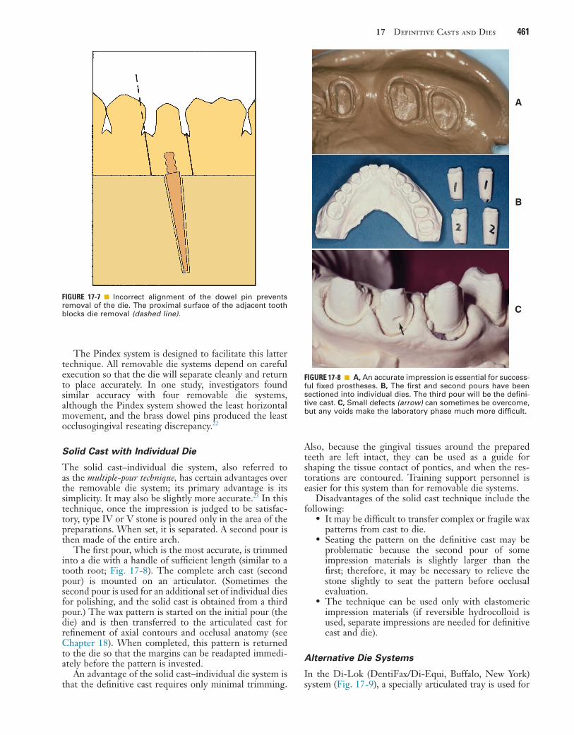
17 Definitive Casts and Dies 461
Also, because the gingival tissues around the prepared teeth are left intact, they can be used as a guide for shaping the tissue contact of pontics, and when the res-torations are contoured. Training support personnel is easier for this system than for removable die systems.
Disadvantages of the solid cast technique include the following:
• It may be difficult to transfer complex or fragile wax patterns from cast to die.
• Seating the pattern on the definitive cast may be problematic because the second pour of some impression materials is slightly larger than the first; therefore, it may be necessary to relieve the stone slightly to seat the pattern before occlusal evaluation.
• The technique can be used only with elastomeric impression materials (if reversible hydrocolloid is used, separate impressions are needed for definitive cast and die).
Alternative Die Systems
In the Di-Lok (DentiFax/Di-Equi, Buffalo, New York) system (Fig. 17-9), a specially articulated tray is used for
The Pindex system is designed to facilitate this latter technique. All removable die systems depend on careful execution so that the die will separate cleanly and return to place accurately. In one study, investigators found similar accuracy with four removable die systems, although the Pindex system showed the least horizontal movement, and the brass dowel pins produced the least occlusogingival reseating discrepancy.22
Solid Cast with Individual Die
The solid cast–individual die system, also referred to as the multiple-pour technique, has certain advantages over the removable die system; its primary advantage is its simplicity. It may also be slightly more accurate.23 In this technique, once the impression is judged to be satisfac-tory, type IV or V stone is poured only in the area of the preparations. When set, it is separated. A second pour is then made of the entire arch.
The first pour, which is the most accurate, is trimmed into a die with a handle of sufficient length (similar to a tooth root; Fig. 17-8). The complete arch cast (second pour) is mounted on an articulator. (Sometimes the second pour is used for an additional set of individual dies for polishing, and the solid cast is obtained from a third pour.) The wax pattern is started on the initial pour (the die) and is then transferred to the articulated cast for refinement of axial contours and occlusal anatomy (see Chapter 18). When completed, this pattern is returned to the die so that the margins can be readapted immedi-ately before the pattern is invested.
An advantage of the solid cast–individual die system is that the definitive cast requires only minimal trimming.
FIGURE 17-7 ■ Incorrect alignment of the dowel pin prevents removal of the die. The proximal surface of the adjacent tooth blocks die removal (dashed line).
FIGURE 17-8 ■ A, An accurate impression is essential for success-ful fixed prostheses. B, The first and second pours have been sectioned into individual dies. The third pour will be the defini-tive cast. C, Small defects (arrow) can sometimes be overcome, but any voids make the laboratory phase much more difficult.
A
B
C

462 PART III Laboratory Procedures
FIGURE 17-9 ■ The Di-Lok system. A, The system involves the use of specially segmented trays. With a single-pour technique, the impression is formed in the usual way, and the Di-Lok tray is filled. Then the tray is inserted into the impression while the stone is still wet. After the die stone has fully set, the locking and curved arms of the tray are removed. The clinician can then remove the cast by tapping the anterior pad of the tray base. B, The clinician sections the dies by sawing three-fourths through the stone and separates them by breaking the remaining stone base. C, Trimmed dies. D, Assembled cast, ready for articulating. (Courtesy DentiFax/Di-Equi, Buffalo, New York.)
A
C
B
D
precise reassembly of a sectioned definitive cast. The impression is poured, and the cast is trimmed into a horseshoe configuration that fits in the special tray. The tray is filled with a second mix, and the cast is seated. When the stone has set, the tray is disassembled, saw cuts are made on each side of the preparation, and the result-ing die is trimmed. The cast and die can be reassembled in the tray, which is then mounted on an articulator. A disadvantage of this system is that the overall size of the tray can make articulation and manipulation awkward and difficult.
In the DVA Model System (Dental Ventures of America, Inc., Corona, Fig. 17-10) and the Zeiser model system (Zeiser Dentalgeräte GmBH, Hemmingen, Germany) (Fig. 17-11), a precision drill is used, and special baseplates are aligned and drilled to provide die removal. These systems offer the advantage of allowing for the expansion of stone, which is relieved by the saw cuts.
Choice of Definitive Cast-and-Die System
The choice of a specific technique is determined by the technician’s personal preference and an assessment of
each method’s advantages and disadvantages. If used properly, all available systems achieve clinically accepta-ble accuracy.24-26 When the dentist establishes a new relationship with a dental technician, it is important to determine which cast-and-die systems are preferred and why the technician has chosen them. Close cooperation between the dentist and technician is a key factor.
The solid cast technique simplifies cast-and-die fabri-cation, but makes the waxing and porcelain stages more difficult. However, there is no need for special equip-ment, and the soft tissues immediately adjacent to the preparation are not removed (which facilitates contour-ing the gingival areas of the restorations). The use of a solid definitive cast precludes errors caused by incom-plete seating of a removable die. In practice, this means that the components of a fixed dental prosthesis (FDP) can be indexed from the cast for assembly; on the other hand, it also means that if an FDP is not fabricated accu-rately, the stone abutment teeth can be easily broken off, which makes subsequent steps more difficult.
The first pour from an elastomeric impression is the most accurate, and it is essential to readapt the margins of the wax pattern on the first-pour die immediately

17 Definitive Casts and Dies 463
A B
DC
E F
G H
FIGURE 17-10 ■ DVA Model System. A, Trimmed impression on alignment fixture. B, Marking dowel pin locations on clear plate. C, Drilling holes for dowel pins as marked. D, Alternatively, the holes can be drilled with the top/baseplate positioned on the under-side of the fixture base. The pointer identifies the pin location. E, Inserting dowels in the baseplate. An adhesive is not required. F, The impression is poured, and stone is placed around the dowel pins. G, The alignment fixture is re-placed over poured impres-sion. H, Set cast is removed from the baseplate with gentle tapping. Continued

464 PART III Laboratory Procedures
I J
K L
FIGURE 17-10, cont’d ■ I, The cast is trimmed. J, The cast is sectioned. K and L, Definitive casts trimmed with the DVA Model System. (A to K, Courtesy Dental Ventures of America, Inc., Corona, California. L, Courtesy Dr. A.G. Wee.)
before the pattern is invested. As the pattern is trans-ferred back and forth from the solid cast to the individual die, the risk of pattern breakage is increased in compari-son with removable die systems. After casting, some dif-ficulty may be encountered in seating the metal casting on the solid model, and it may have to be relieved slightly to enable full seating.
In contrast to the solid model, a removable die sys-tem’s main advantage is that it requires less manipulation of the wax pattern, which reduces the chances of pattern breakage during fabrication. In addition, the handling of porcelain restorations is easier, particularly if a porcelain labial margin is used. For these reasons, many technicians believe that the extra steps involved in making a cast with dowels and a removable die are worthwhile.
Nevertheless, the procedures are technically quite challenging. It is common to encounter dies that do not seat properly or that have poorly placed dowels. Diffi-culty may then be encountered in sawing the die out of the cast. Interproximal margins can be damaged easily during the sectioning procedure, particularly if clearance between a proximal preparation margin and the adjacent tooth is minimal.
In the popular Pindex system, a special drilling unit is used to ensure standardized pin placement. Careful model trimming of the initially poured cast is necessary before the holes for the pins are drilled. If the preparatory trimming is done correctly, the resulting removable dies are highly accurate and stable; however, the cost of the additional equipment must be considered.
The advantages and disadvantages of various cast-and-die systems are summarized in Table 17-2.
TECHNIQUE
The techniques for pouring stone dies are similar for most of the popular systems. To avoid repetition, the procedure involving single dowel pins is described in detail, with an emphasis on the differences between the solid cast (multiple-pour) system and the Pindex system.
ArmamentariumThe following equipment is needed (Fig. 17-12):
• Impression• Small camelhair brush• Type IV or V stone• Water• Surfactant• Dowel pins• Retention devices• Orientation aids• Vacuum mixer and bowl• Mixing spatula• Vibrator• Petrolatum• Pencil• Die saw

17 Definitive Casts and Dies 465
FIGURE 17-11 ■ A, Zeiser model system. B, The impression is leveled, blocked out with silicone putty, and positioned over the base-plate. C, The pin locations are determined and the pinholes drilled in the base. D, Pins are inserted into the base. E, The impression is poured. F, The base inverted into the stone. G and H, The cast is separated from the impression when set and then separated from the base. I, A precision saw aids sectioning. J, The sectioned cast. (Courtesy Zeiser Dentalgeräte GmbH, Hemmingen, Germany.)
A,B C,D
E F
G H
I J

466 PART III Laboratory Procedures
TABLE 17-2 Cast-and-Die Systems
System Advantages Disadvantages Recommended Use Precautions
Solid cast with individual die
Straightforward procedure
No special equipment
Awkward wax and porcelain manipulation
Most situationsCan be indexed
with confidence from cast
Stone fixed dental prosthesis abutment easily broken
Brass dowel pin Removable die facilitates waxing and porcelain
No special equipment
Difficult to master Most situations Care needed in cast pouring and dowel placement
Pindex (Coltène/Whaledent)
Removable dieCast pouring unimpeded
Special equipment needed
Excellent if equipment is well maintained
Careful attention to detail needed
Di-Lok (DentiFax/Di-Equi)
Removable dieCast pouring unimpededMuch less costly than
Pindex
BulkyCare needed during
reassembly
Awkward to use on some articulators
Care needed when second pour is made
DVA Model System (Dental Ventures of America)
Removable dieCast pouring unimpededCompensates for
expansion of cast
Special equipment needed
Quite technique sensitive
Excellent if carefully done
Care needed when seating pins
Zeiser (Dentalgeräte GmBH)
Single pourRemovable dieCast pouring unimpededCompensates for
expansion of cast
Special equipment needed
Excellent if carefully done
—
After the impression has been removed from the patient’s mouth, it is washed under running tap water, blown dry, inspected, and disinfected (see Chapter 14). When it is judged to be satisfactory, it is taken to the laboratory, where the necessary armamentarium should have been prepared in advance. A vacuum mixer (e.g., the Vac-U-Spat, Whip Mix Corp) is strongly recommended. At this time the impression can be sprayed with a sur-factant or, in the case of hydrocolloid, placed in a potas-sium sulfate (K2SO4) solution (if recommended by the manufacturer).
FIGURE 17-12 ■ Armamentarium for pouring dies depending on system used.
Step-by-Step Procedure1. If dowels are to be used, position them over the
prepared teeth with one of the methods illustrated in Figure 17-13. Their correct location and ori-entation are important. For example, placing the head of a dowel too deep in the impression may weaken the die; positioning the dowel at an incor-rect angle may prevent later die removal. At this stage, some technicians mark the best locations for the dowels in the buccal and lingual sulci or on the palate and place the dowels in the stone shortly after it is poured before its initial setting, because prepositioning the dowels makes pouring more difficult. In addition, the relatively brittle sticky wax commonly used to lute the pins in place can break loose during vibration. If dowels are not prepositioned, the viscosity of the stone should be carefully gauged, and correct timing of dowel placement is critical. If the stone is too runny, the dowels do not remain in place, and in many such cases, a new impression must be made.
2. Measure the proper proportions of type IV or V stone and water. To reduce air bubbles in the mix, the water should be placed in the mixing bowl first. The powder is then added and quickly incor-porated by hand spatulation (Fig. 17-14, A and B). The spatula should be wiped clean on the blade of the mechanical mixer rather than on the edge of the mixing bowl, where stone can interfere with the vacuum seal. Some mixing units obviate the need for hand incorporation (see Fig. 17-14, A).

17 Definitive Casts and Dies 467
FIGURE 17-13 ■ Positioning dowel pins before cast pouring can be accomplished with bobby pins and sticky wax (A to C) or with prefabricated wire-tube aid (D and E).
A B
C D
E
3. Close the mixing bowl, and select the applicable mixing program (see Fig. 17-14, B).
4. Insert the drive shaft into the chuck of the mixer, and mix the stone for the recommended time. The mix is vibrated to allow the stone to settle in the bowl (see Fig. 17-14, C).
5. Blow or suction any excess surfactant out of the impression, pick up a small amount of stone with a suitable brush or instrument, and place it in the most critical area (usually the occlusal aspect of narrow preparations or immediately adjacent to the sulcus area). For small preparations, a thin instrument (e.g., a periodontal probe) may prove helpful with this procedure. Bubbles are trapped when too much stone is added abruptly or if two sizable masses of stone meet (Fig. 17-15).
Therefore, small quantities of stone should be added incrementally in one area, which allows the stone to seek its own path (Fig. 17-16). During pouring, the tray should be held on a vibrator. For easy cleanup, the vibrator table can be covered with a paper towel or plastic bag.
6. Slowly tease the stone into the preparation along the axial walls by tilting the impression and guiding the material with the instrument. Be absolutely sure that the stone flows onto the margins of the preparation without trapping any air bubbles. Bubbles and voids are always a potential complica-tion when impressions are poured. If the first pour is defective, a second pour will result in the loss of some accuracy, and a new impression is usually required. In addition, thin areas of the impression

468 PART III Laboratory Procedures
FIGURE 17-14 ■ Vacuum method of mixing type IV stone. A, The mixing bowl is rinsed, and excess water is shaken out. Measured distilled water is poured into the bowl, and weighed powder is added, or premeasured envelopes are used. The powder-to-liquid ratio should be in accordance with the manufacturer’s recommended proportions. B, The mixture is mechanically spatulated under vacuum. C, At the end of the mixing cycle, the vacuum is broken and the lid is removed. D, Excess stone is removed from the paddle, and the impression is poured. (Courtesy Whip Mix Corporation, Louisville, Kentucky.)
A B
C D
FIGURE 17-15 ■ Incorrect technique for pouring an impression. An air bubble (red circle) is trapped if two masses of stone (arrows) are allowed to meet.
Bubbles form where two masses of material meet.
FIGURE 17-16 ■ Pouring an impression. A and B, To avoid trap-ping air, start with a very small amount of stone.
A
B

17 Definitive Casts and Dies 469
near the margin are often torn when the first pour is separated. For this reason, pouring a bubble-free cast the first time is essential for avoiding the need to make a new impression. The ease with which an impression can be poured without bubble formation depends on the contact angle that the advancing die stone makes when the impression material is wetted. Of the elastomers, polyethers have the lowest contact angle, which means they are the easiest to pour27,28; silicones have the highest contact angle and are the most difficult to pour, although the newer “surface-activated” or “hydrophilic” formulations are easier.29 Overall, however, these materials do not seem to greatly facilitate impression making.30
7. Place a second amount of stone on top of the first, and continue with a third and so forth until the preparation is completely filled. The rest of the impression can then be filled to a height of at least 5 mm beyond the free gingival margins. If individual dowels are used, the head of each dowel must be covered with stone (Figs. 17-17 and 17-18).
FIGURE 17-17 ■ Dowel pins must be carefully positioned so that the first pour of stone completely covers the knurled head of each pin; otherwise, the parts do not separate cleanly. However, the stone should not extend onto the shaft and reduce stability.
Secondpour ofstone
Impression
Firstpour ofstone
Tray
Dow
el p
in
Solid Cast–Multiple Pour Technique
For individual die pours, the stone mass must be built up to a height of approximately 25 mm to obtain a die handle of adequate length (see Fig. 17-18, C). The occlusal surfaces of teeth immediately adjacent to the preparation will be filled with stone, but this is of no concern (see Fig. 17-18). When the first pour has set, the cast is separated and repoured. The first pour is then sectioned into individual dies.
8. Place retentive devices31 in areas where there are no dowels so that the two layers of stone do not separate in the wrong place (Fig. 17-19). Alterna-tively, lockwashers can be partially submerged in the wet stone to provide retention.
9. Allow the stone to set for the recommended time (usually 30 minutes).
10. Inspect the area where separation for the dies will be required, smooth it as necessary, and coat it with a separating medium (e.g., 10% sodium silicate). Then pour another layer of stone to act as a base and retain the dowels. This second layer should not cover the tips of the dowels. If for some reason the base must be built up more, wax or rubber tubing can be placed on the tip of the dowel to facilitate its retrieval later. Before the base of a mandibular impression is poured, the lingual aspect should be blocked out with a suitable molding material (e.g., Mortite Weatherstrip and Caulking Cord, Thermwell Products Co., Inc.); otherwise, the stone will lock around the tray and hamper removal of the cast from the impression. This is much easier than grinding excess stone away later to obtain access to the lingual aspect of mandibular prepa-rations (Figs. 17-20 and 17-21). When the cast is separated from the impression, it must be carefully inspected for voids. If any are found in the marginal area of a prepared tooth, the cast is rejected, and a new impression must be made. Careful pouring technique prevents this. If the cast is satisfactory, it is ready for sectioning and trimming.
11. Trim the buccal and lingual vestibular areas adja-cent to the removable sections first to facilitate die separation.
12. Mark the position of each saw cut (which should be parallel to the dowel) with a pencil.
13. Carefully insert the saw blade between the prepa-ration and the adjacent tooth; make sure that neither the margin nor the proximal contact is damaged (Fig. 17-22). The cuts must pass com-pletely through the first layer of stone. If this is not done, the die will not separate cleanly. When the saw cuts are made, the dies can be tapped out and are ready for trimming for waxing. (Typical trimmed and untrimmed dies are shown in Fig. 17-23.)
All excess stone, with the exception of the critical few millimeters immediately adjacent and cervical to the margin, should be removed with an Arbor band or a suit-able cutting wheel in a lathe. The stone closer to the margin is removed with a large tungsten carbide bur. This is a critical step because easy access to the margin is mandatory for waxing and margination (see Chapters 18 and 22). Any residual flash is trimmed away with a sharp scalpel blade. The margin must not be damaged during this entire process. A binocular microscope is helpful during this step. It is important not to create a ditch apical to the margin, which could lead to poor gingival contour in the completed restoration (Fig. 17-24).

470 PART III Laboratory Procedures
FIGURE 17-18 ■ Pouring an impression for individual dies and solid cast (multiple-pour system). A, The critical margin area must be covered. B, Stone is added in the preparation area only. C, Bulk for the die handles must be sufficient. D, The first and second pours (individual dies) and the third pour (definitive cast). E, Sectioning the individual dies. F, The trimmed dies and definitive cast before articulation.
A
C
B
D
E F
FIGURE 17-19 ■ Blobs of stone serve as retention devices in parts of the cast where separation is not desired.
When die trimming is completed, the dies are reposi-tioned in the definitive cast, and their accurate and precise repositioning is verified. The definitive cast is then mounted on an articulator. Trimmed dies must be handled carefully. To minimize potential breakage, they should be secured in a container lined with foam plastic, gauze, or cotton.
MOUNTING CASTS ON AN ARTICULATOR
The articulation of diagnostic casts is discussed in Chapter 2. The technique for mounting a solid definitive (master) cast is identical. The procedure for attaching a definitive cast with removable dies to an articulator differs only in that access must be allowed to the area of the base into
Text continued on p. 475
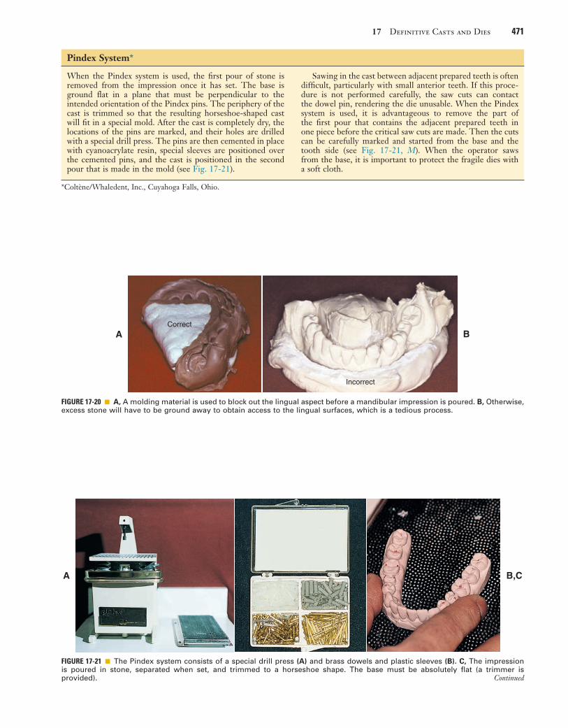
17 Definitive Casts and Dies 471
FIGURE 17-20 ■ A, A molding material is used to block out the lingual aspect before a mandibular impression is poured. B, Otherwise, excess stone will have to be ground away to obtain access to the lingual surfaces, which is a tedious process.
Correct
Incorrect
A B
*Coltène/Whaledent, Inc., Cuyahoga Falls, Ohio.
When the Pindex system is used, the first pour of stone is removed from the impression once it has set. The base is ground flat in a plane that must be perpendicular to the intended orientation of the Pindex pins. The periphery of the cast is trimmed so that the resulting horseshoe-shaped cast will fit in a special mold. After the cast is completely dry, the locations of the pins are marked, and their holes are drilled with a special drill press. The pins are then cemented in place with cyanoacrylate resin, special sleeves are positioned over the cemented pins, and the cast is positioned in the second pour that is made in the mold (see Fig. 17-21).
Sawing in the cast between adjacent prepared teeth is often difficult, particularly with small anterior teeth. If this proce-dure is not performed carefully, the saw cuts can contact the dowel pin, rendering the die unusable. When the Pindex system is used, it is advantageous to remove the part of the first pour that contains the adjacent prepared teeth in one piece before the critical saw cuts are made. Then the cuts can be carefully marked and started from the base and the tooth side (see Fig. 17-21, M). When the operator saws from the base, it is important to protect the fragile dies with a soft cloth.
Pindex System*
A B,C
FIGURE 17-21 ■ The Pindex system consists of a special drill press (A) and brass dowels and plastic sleeves (B). C, The impression is poured in stone, separated when set, and trimmed to a horseshoe shape. The base must be absolutely flat (a trimmer is provided). Continued

472 PART III Laboratory Procedures
J K,L
M N
D E,F
G H,I
FIGURE 17-21, cont’d ■ D, The location of each dowel is marked on the occlusal surface. Two dowels are needed to stabilize each segment. (Alternative single pins are available for small preparations.) E, The cast is positioned on the drill stage; a light indicates the location of the drill. The cast is held firmly and the lever depressed; this activates the drill, which penetrates into the cast. F, Each hole should be cleanly drilled; a hand reamer is available if necessary. G, The pins are tried in and cemented in place. For accessibility, the short locating dowels should be used on the lingual surface. H, The assembly is coated with petrolatum to ensure clean separation. I, The plastic sleeves are positioned. J, The assembly is placed in the special mold. K, The second pour of stone is made into the mold. After some stone has been painted between the pins, the first pour is placed into this mix. L, Sawing the dies. M, With the Pindex system, it is sometimes helpful to remove the first pour, use it as a block, and commence sawing from the base. Marking all the saw cuts with a pencil is recommended. N, The Pindex cast after sectioning. (A to M, Courtesy Dr. J.O. Bailey. N, Courtesy Coltène/Whaledent Inc., Cuyahoga Falls, Ohio.)

17 Definitive Casts and Dies 473
FIGURE 17-22 ■ Sectioning removable dies. A, The saw cuts should converge slightly toward the dowel; otherwise, the die will be locked in by undercuts (B). C, The intended saw cuts are marked in pencil, and the saw blade is carefully positioned. It must not touch the prepared tooth. D, The first pour is sawed completely through. Finishing the cut short of the second pour will prevent a clean separation.
Correct
A B
C D
When the die is sectioned, the saw cutsshould be parallel to each other or shouldslightly converge (A). Be careful not tocreate an undercut (B), because the diethen will not be readily removable fromthe cast. Cutting into a pin when sectioningthe cast will render it useless, and a newcast will need to be made.
Incorrect

474 PART III Laboratory Procedures
FIGURE 17-23 ■ Trimming dies. A, Armamentarium: saw, gypsum trimming disk, separating disks, Arbor band, scalpel, acrylic-trimming bur, colored pencil. B, Sectioned dies. In this instance, the Pindex system has been used. C, Bulk trimming is accomplished with an Arbor band on a lathe equipped with efficient dust collection. D, An acrylic-trimming bur is used near the margin. E, A sharp scalpel is used to trim to final contour, working away from the margin. F, The trimmed dies. (B-F, Courtesy Dr. W.V. Campagni.)
A B
C D
E F
FIGURE 17-24 ■ Excessive trimming causes the resulting crown to be bulky because the trimmed die acts as a guide to gingival contour when the restoration is being waxed.
IMPORTANT! When the die is trimmed,the original contour of the structurebelow the margin must be preserved.Overtrimming (dotted line) will resultin overcontoured restorations!

17 Definitive Casts and Dies 475
FIGURE 17-25 ■ A, Definitive cast attached to an articulator. B, To facilitate removal, the mounting should allow access to the end of each dowel. This is achieved by adding wax or weather strip-ping to the tips of the pins.
A
B
to restorations fabricated and adjusted on the casts. This subsequently translates into the necessity for additional chair time at the evaluation and clinical delivery appoint-ment. Whenever possible, definitive casts should be mounted with a record made at the occlusal vertical dimension at which the restoration will be fabricated. If possible, the MI of unprepared teeth should be used.34 This eliminates any arcing movement of the casts once the record is removed without resulting inaccuracy in the static occluded position. If this is not possible, a kinematic facebow recording is recommended because it relates the maxillary cast in its correct position in relation to the hinge axis. Subsequent articulation of the mandibular cast with a CR record at an increased vertical dimension enables closing the articulator without introduction of error. Weinberg35 analyzed problems associated with mounting casts with a CR record when an arbitrary facebow was used. He calculated that a 3-mm-thick record can create an occlusal discrepancy in the first molar region of 0.2 mm when the arbitrary axis differs from the true hinge axis by 5 mm (a common error).
In addition, an elastomeric (rather than an irreversible hydrocolloid) impression should be made for the oppos-ing cast. The elastomer’s improved precision results in a more accurate opposing cast, which reduces the need to adjust the restoration at evaluation.
Conformative OcclusionOn many occasions, a cast restoration is made to conform to the patient’s existing occlusion, even if CR and MI positions are discrepant. Typically, if no significant signs of clinical disease are detected, fabricating simple pros-theses in the stable MI position is acceptable. The objec-tive is to maintain rather than reorganize a healthy dentition.
When a patient has symptom-free occlusion and requires relatively few cast restorations (i.e., when only a small part of the dentition needs to be restored), the MI position is the most desirable treatment. Therefore, in many patients who need only one or two single crowns (or a small FDP), the best restorations conform to their existing occlusion.
Articulating a definitive cast for a restoration that is to be waxed to conform to existing occlusion poses certain problems. If the cast is mounted with a CR record (as described for diagnostic casts in Chapter 2), the MI posi-tion is not reproduced accurately enough for precise waxing because it is in a translated mandibular position. This position cannot be reached with absolute precision on a semiadjustable articulator. In addition, during closing of the instrument, the stone cast can be easily damaged.
The most practical solution is to articulate the defini-tive cast in MI through the use of a small interocclusal record (e.g., with polyvinyl siloxane) interposed between the tooth preparation and the opposing arch in the closed position (Fig. 17-26). At evaluation, after the restoration has been fabricated, only minimal inaccuracies should exist in the occluded MI position. The patient’s CR closure is examined next, to ascertain that the restoration conforms to the dynamic occlusion, specifically the slide from CR to MI. No premature contacts should occur on
which the dowels penetrate. This expedites removal of the dowels (Fig. 17-25).
Definitive Casts versus Diagnostic CastsThe accuracy of the casts and their mounting is even more crucial for definitive casts than for diagnostic casts. Although diagnostic casts can still provide much of the necessary information even when mounted slightly inac-curately, definitive casts must be mounted precisely if lengthy chairside adjustment of fabricated restorations is to be avoided.
Diagnostic casts are most useful when mounted with a centric relation (CR) record (see Chapter 2). This allows the practitioner to visualize the full range of man-dibular movement for occlusal diagnosis, and on the articulator, it is possible to replicate any CR–maximum intercuspation (MI) difference diagnosed clinically. This enables the dentist to make appropriate decisions whether occlusal intervention is indicated before fabrication of definitive restorations (see Chapter 6).
Because of its material thickness, the CR record is made at an increased vertical dimension (see Chapter 2). Closing the articulator on removal of the record induces error if an arbitrary facebow is used.32 There is a slight error even if a kinematic facebow is used.33 Although such errors are probably not clinically significant with diag-nostic casts, they are significant when definitive casts are involved because the degree of inaccuracy is transferred

476 PART III Laboratory Procedures
the new restoration. In CR closure, new occlusal interfer-ences may have been introduced on the newly fabricated restoration, and the discrepancy between CR and MI may be effectively increased, which can lead to new problems (Fig. 17-27). It is therefore necessary to adjust the resto-ration to allow the original closing movement of the patient and to provide a smooth transition from the CR position to the MI position. After subsequent evaluation of excursive compatibility with the existing occlusion, the restoration is ready for cementation.
Reorganized OcclusionThe decision to reorganize a patient’s occlusion (i.e., by making CR coincide with MI before the fabrication of the restoration begins) is made at the treatment planning stage (see Chapter 3). Treatment steps may then include occlusal adjustment of the existing dentition by selective reshaping (see Chapter 6) and reorganization of the ante-rior (incisal) guidance before tooth preparation for defin-itive cast restorations.
The following question should be asked during treat-ment planning: Has any discernible pathologic process arisen from malocclusion? In the presence of wear facets, widened periodontal ligament spaces, tooth mobility, elevated muscle tone, and muscle tenderness, the potential benefits of occlusal adjustment should be weighed. Two other questions must also be asked: Will
A
C
B
FIGURE 17-26 ■ A, Interocclusal record made with polyvinyl siloxane polymer, conforming to the patient’s existing occlusion. B, Interocclusal records before trimming. C, Trimmed interocclusal records.
reorganization of the occlusion benefit the patient? Will it enhance the overall prognosis of the dentition? If the answers are yes, occlusal adjustment can be performed (see Chapter 6), first diagnostically on articulated casts, and then clinically, after which definitive tooth prepara-tion for fixed prosthodontics should be initiated.
The definitive casts can then be related at the occlusal vertical dimension with one of several techniques. Autopolymerizing resin may be used to record the rela-tionship (Fig. 17-28). Alternative materials include impression plaster, zinc oxide–eugenol impression paste on a suitable carrier (e.g., autopolymerizing acrylic resin or gauze), and some of the stiffer elastomers (polyether or polyvinyl siloxane).
These records are optimal if they include only the cusp tips (see Fig. 17-26). If more detail of the grooves is inad-vertently captured, it should be carefully trimmed away. Otherwise, the cast will not seat properly, and subsequently fabricated restorations will be in supraocclusion.
Verification of MountingIt is essential to check the accuracy of the articulation before the laboratory phase of treatment. This is critical when prosthodontic treatment is complex (see Fig. 17-28) For less complex fixed prosthodontics, the dentist can check simply by comparing the occlusal contacts in the patient’s mouth with those made by the casts. (Mylar shim
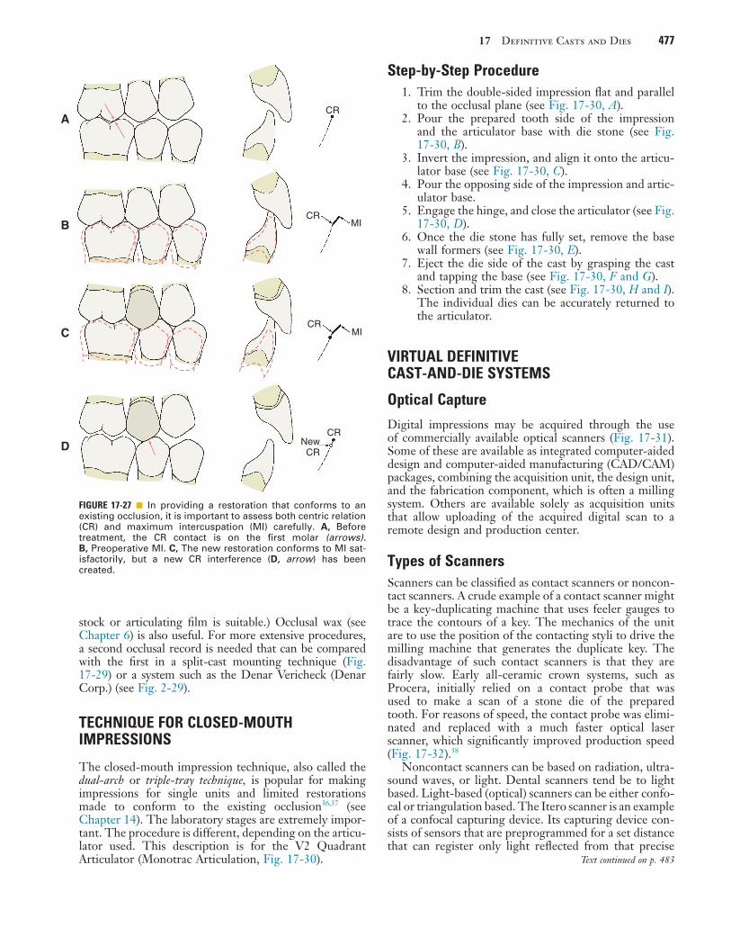
17 Definitive Casts and Dies 477
stock or articulating film is suitable.) Occlusal wax (see Chapter 6) is also useful. For more extensive procedures, a second occlusal record is needed that can be compared with the first in a split-cast mounting technique (Fig. 17-29) or a system such as the Denar Vericheck (Denar Corp.) (see Fig. 2-29).
TECHNIQUE FOR CLOSED-MOUTH IMPRESSIONS
The closed-mouth impression technique, also called the dual-arch or triple-tray technique, is popular for making impressions for single units and limited restorations made to conform to the existing occlusion36,37 (see Chapter 14). The laboratory stages are extremely impor-tant. The procedure is different, depending on the articu-lator used. This description is for the V2 Quadrant Articulator (Monotrac Articulation, Fig. 17-30).
FIGURE 17-27 ■ In providing a restoration that conforms to an existing occlusion, it is important to assess both centric relation (CR) and maximum intercuspation (MI) carefully. A, Before treatment, the CR contact is on the first molar (arrows). B, Preoperative MI. C, The new restoration conforms to MI sat-isfactorily, but a new CR interference (D, arrow) has been created.
CR
CR
CR
CRNewCR
MI
MI
A
B
C
D
Step-by-Step Procedure1. Trim the double-sided impression flat and parallel
to the occlusal plane (see Fig. 17-30, A).2. Pour the prepared tooth side of the impression
and the articulator base with die stone (see Fig. 17-30, B).
3. Invert the impression, and align it onto the articu-lator base (see Fig. 17-30, C).
4. Pour the opposing side of the impression and artic-ulator base.
5. Engage the hinge, and close the articulator (see Fig. 17-30, D).
6. Once the die stone has fully set, remove the base wall formers (see Fig. 17-30, E).
7. Eject the die side of the cast by grasping the cast and tapping the base (see Fig. 17-30, F and G).
8. Section and trim the cast (see Fig. 17-30, H and I). The individual dies can be accurately returned to the articulator.
VIRTUAL DEFINITIVE CAST-AND-DIE SYSTEMS
Optical Capture
Digital impressions may be acquired through the use of commercially available optical scanners (Fig. 17-31). Some of these are available as integrated computer-aided design and computer-aided manufacturing (CAD/CAM) packages, combining the acquisition unit, the design unit, and the fabrication component, which is often a milling system. Others are available solely as acquisition units that allow uploading of the acquired digital scan to a remote design and production center.
Types of ScannersScanners can be classified as contact scanners or noncon-tact scanners. A crude example of a contact scanner might be a key-duplicating machine that uses feeler gauges to trace the contours of a key. The mechanics of the unit are to use the position of the contacting styli to drive the milling machine that generates the duplicate key. The disadvantage of such contact scanners is that they are fairly slow. Early all-ceramic crown systems, such as Procera, initially relied on a contact probe that was used to make a scan of a stone die of the prepared tooth. For reasons of speed, the contact probe was elimi-nated and replaced with a much faster optical laser scanner, which significantly improved production speed (Fig. 17-32).38
Noncontact scanners can be based on radiation, ultra-sound waves, or light. Dental scanners tend be to light based. Light-based (optical) scanners can be either confo-cal or triangulation based. The Itero scanner is an example of a confocal capturing device. Its capturing device con-sists of sensors that are preprogrammed for a set distance that can register only light reflected from that precise
Text continued on p. 483

478 PART III Laboratory Procedures
A B
C D,E
F G
H I,J
FIGURE 17-28 ■ Mounting definitive casts on the articulator. A, When extensive fixed prosthodontic care is necessary, accuracy of the articulation is essential for successful treatment. B, Recording centric relation (CR) at the occlusal vertical dimension minimizes the error inherent in a facebow transfer. Autopolymerizing acrylic resin was used as the recording medium. C, Manipulation of the mandible into CR. D and E, Definitive casts articulated with the CR record interposed. F to J, Restorations waxed to anatomic contour, with anterior guidance.

17 Definitive Casts and Dies 479
K L,M
N O,P
Q R
K to M, Metal-ceramic restorations on the definitive cast. N to R, The completed restorations (see Fig. 31-45). FIGURE 17-28, cont’d ■

480 PART III Laboratory Procedures
FIGURE 17-29 ■ A, Magna-Split system. In this system, indexed magnetic plastic mounting plates (A) are used to facilitate split-cast mounting (B and C). D-F, The system is used to attach the maxillary cast. The second record is confirmed if the indices align precisely. (Courtesy Panadent Corporation, Colton, California.)
A
C
E
B
D
F
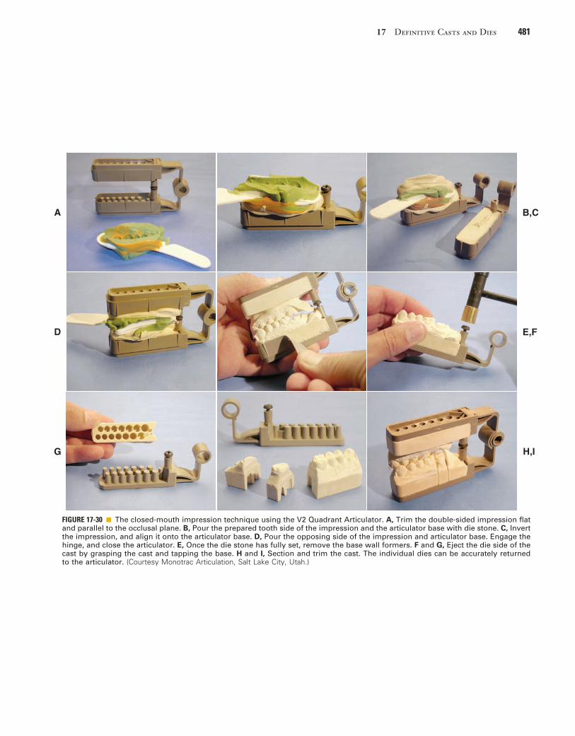
17 Definitive Casts and Dies 481
FIGURE 17-30 ■ The closed-mouth impression technique using the V2 Quadrant Articulator. A, Trim the double-sided impression flat and parallel to the occlusal plane. B, Pour the prepared tooth side of the impression and the articulator base with die stone. C, Invert the impression, and align it onto the articulator base. D, Pour the opposing side of the impression and articulator base. Engage the hinge, and close the articulator. E, Once the die stone has fully set, remove the base wall formers. F and G, Eject the die side of the cast by grasping the cast and tapping the base. H and I, Section and trim the cast. The individual dies can be accurately returned to the articulator. (Courtesy Monotrac Articulation, Salt Lake City, Utah.)
A B,C
D E,F
G H,I

482 PART III Laboratory Procedures
FIGURE 17-31 ■ Chairside digital impression scanner. A, Cerec AC. B, iTero. C, Lava COS. (A, Courtesy Sirona Dental Systems, Inc; B, Courtesy Align Technology, Inc. C, Courtesy 3M ESPE Dental.)
A B,C
FIGURE 17-32 ■ Laboratory digital scanner. NobelProcera’s 3D laser scanner. (Courtesy Nobel Biocare.)

17 Definitive Casts and Dies 483
distance. In contrast, scanning devices such as CEREC (Sirona Dental Systems) or Lava COS (3M ESPE Dental) rely on a triangulation approach. The object to be scanned, such as the prepared tooth and the adjacent portion of the dental arch, are illuminated, and the system registers the distance for every pixel. As object complex-ity increases, scanning from multiple directions is neces-sary to produce the pertinent information efficiently. Some systems accomplish this by generating still shots from various directions, whereas others take so many images while the scanning head is moved around the target that, for purposes of analogy, a “movie” is gener-ated. Light sources in the scanners are often a lase or light-emitting diode (LED).
The captured data undergo a number of computa-tional transitions from the initial noisy scan to a smoothed rendering, clusters, representatives, and triangulation, which after refinement is followed by the definitive ren-dering (Fig. 17-33).39
Virtual CastsVirtual casts may be generated from data captured directly intraorally or by a scan of a solid model of the dentition obtained through a conventional impression technique in the dental laboratory with a special scanning device. Many large commercial laboratories use virtual casts to improve productivity.
The digital data are used to generate a virtual replica of the scanned portion of the dentition. Software can be restrictive in that it can be used with only the equipment provided by a single manufacturer (closed source), or it can allow data manipulation with equipment generated by other manufacturers (open source). In chairside fabri-cation systems, the virtual model is used to generate the restoration design, which is fabricated immediately. No solid definitive cast is ever generated. The disadvantage of this technique is that no die is available for correction of contours or occlusion to help support the restoration. Also, it limits the number of materials in which the res-toration can be fabricated.
Alternatively, the digital data can be used to generate solid definitive casts, which can be stereolithographic casts, made in an additive process in which incremental layers of resin are polymerized by a laser or milled from
FIGURE 17-33 ■ The captured data undergo a number of computational transitions from the initial noisy scan to a smoothed render-ing, clusters, representatives, and triangulation, after which refinement results in the definitive, final rendering. (From Mederos B, et al: Smooth surface reconstruction from noisy clouds. J Braz Comp Soc 9(3), 2004.)
Noisy Smooth Clusters Representatives Triangulation Refinement Final
A B C D E F G
specially formulated urethane resins (Fig. 17-34). Such casts have been shown to have accuracy similar to that of conventional gypsum dies.40 In the workflow, such models are generally articulated on hinge articulators, which limits the degree of precision with which subsequent res-torations can be fabricated (see Chapter 2). For one system, special mounting brackets have been developed to enable positioning them arbitrarily on a conventional articulator (Fig. 17-35).
Alternatively, instead of using the data to generate solid definitive casts, the virtual casts can be positioned in a virtual rendering of an articulator (Fig. 17-36). Most of the current software systems position such virtual casts arbitrarily within the virtual instrumentation. One company has devised a method with a laboratory scanner to scan articulated solid casts, to generate virtual casts and place them in their correct position relative to the hinge axis within the virtual articulator (Fig. 17-37), Chapter 2. Current systems enable the dentist to adjust posterior articulator controls, but anterior guidance tends to be a function of average values that have been preprogrammed in the software. Developments in this area are extremely rapid, and precise capture of dynamic mandibular movement is one of the next logical steps in software development.
SUMMARY
Accurate definitive casts and dies are essential for the success of cast restorations. Various materials and tech-niques provide an extremely precise reproduction of the prepared teeth. Type IV stone is recommended in most instances, although careful handling is necessary to avoid chipping or abrading margins. Epoxy resin and electro-plated metal (silver or copper) are durable alternatives. The die of the prepared tooth can be made removable by the use of dowels or the more convenient Pindex system. Alternatively, a solid definitive cast and separate die can be used. Whatever system is chosen, it must articulate precisely with an accurately made opposing cast. Virtual casts may be acquired from data captured with optical intraoral scanners or from solid casts scanned in the dental laboratory.
Text continued on p. 488

484 PART III Laboratory Procedures
A
D
F G,H
E
B,C
FIGURE 17-34 ■ Virtual cast-and-die system: Cerec Omnicam. A, After optical scanning of both quadrants, a scan is made of the buccal surfaces in maximum intercuspation. B, The buccal “occlusal registration” is superimposed on both quadrant scans, and the software then relates the two virtual renderings to each other. C, Occlusal view demonstrating location and intensity of occlusal contacts. D, The quadrant scan containing the tooth preparation is oriented in the arch form. Orientation in relation to the curve of Spee and the curve of Wilson can be adjusted to some extent. E, The preparation margin has been delineated (blue line). F, The software generates a virtual crown that best fits in the available space. G, The virtual cast can be sectioned at any desired location, and resulting segments (H) can be manipulated individually.

17 Definitive Casts and Dies 485
I
L
N
M
J,K
I, Any final refinements to the delineation of the margin are made at this time. J, Proximal contact intensity (penetration) is represented by the colors and can be reduced from tight (red) to passive (yellow/light blue) (K). L, Occlusal form can be manipulated to achieve the desired occlusal contact relationships. M, An approximation of a functionally generated path is graphically represented, and mandibular motion can be simulated to assist in evaluation and further adjustment of the virtu-ally designed restoration. N, On-screen preview of the position of the mill in the selected block. (Software manipulation courtesy Dr. J. Schmidt.)
FIGURE 17-34, cont’d ■

486 PART III Laboratory Procedures
FIGURE 17-35 ■ A, Special mounting brackets have been developed to enable positioning stereolithographic casts arbitrarily on a conventional articulator (B). (Courtesy Whip Mix Corporation, Louisville, Kentucky.)
A B
FIGURE 17-36 ■ Virtual rendering of an articulator in which virtual casts are positioned.

17 Definitive Casts and Dies 487
FIGURE 17-37 ■ Articulation of virtual casts on the Denar Mark 330 Articulator. A, A conventional arbitrary facebow transfer is used to transfer a solid maxillary cast to the articulator. Note the thickness of the mounting plate and the V-shaped notches that will enable transfer to the scanner. B, Mounting stone is added. C, The mandibular mounting plate also has substantial height. D and E, The mandibular cast has been stabilized and is mounted conventionally. F, Condylar controls are adjusted on the basis of occlusal records or a Cadiax recording (see Chapter 2). G, The articulated solid casts on the articulator with adjusted controls. H, Mandibular cast is removed from the articulator. I, The casts are scanned individually. J, The combined thickness of the two mounting plates reduces the height of the articulated models, which allows them to fit inside the scanner. The transfer platform in the scanner corresponds geometrically to the mounting plates. In this case, centric relation (CR) and maximum intercuspation (MI) were coin-cident. K, Screenshot of the virtually articulated casts in their correct relationship to the axis of the articulator. The virtual controls are then set to correspond with the adjusted controls of the initial solid cast articulation. (Courtesy Whip Mix Corporation, Louisville, Kentucky.)
A
D
G
J
B,C
E,F
H,I
K

488 PART III Laboratory Procedures
REFERENCES1. Revised American Dental Association specification no. 19 for non-
aqueous, elastomeric dental impression materials. J Am Dent Assoc 94:733, 1977.
2. Schelb E, et al: Compatibility of type IV dental stone with polysulfide impression materials. J Prosthodont 1:32, 1992.
3. Omana HM, et al: Compatibility of impressions and die stone material. Oper Dent 15:82, 1990.
4. Toreskog S, et al: Properties of die materials: a comparative study. J Prosthet Dent 16:119, 1966.
5. Fukui H, et al: Effectiveness of hardening films on die stone. J Prosthet Dent 44:57, 1980.
6. Campagni WV, et al: Measurement of coating agents used for surface protection of stone dies. J Prosthet Dent 55:470, 1986.
7. Zakaria MR, et al: The effects of a liquid dispersing agent and a microcrystalline additive on the physical properties of type IV gypsum. J Prosthet Dent 60:630, 1988.
8. Alsadi S, et al: Properties of gypsum with the addition of gum arabic and calcium hydroxide. J Prosthet Dent 76:530, 1996.
9. Wee AG, et al: Evaluation of the accuracy of solid implant casts. J Prosthodont 7:161, 1998.
10. Yaman P, Brandau HE: Comparison of three epoxy die materials. J Prosthet Dent 55:328, 1986.
11. Chaffee NR, et al: Dimensional accuracy of improved dental stone and epoxy resin die materials. I. Single die. J Prosthet Dent 77:131, 1997.
12. Schaffer H, et al: Distance alterations of dies in sagittal direction in dependence of the die material. J Prosthet Dent 61:684, 1989.
13. Chaffee NR, et al: Dimensional accuracy of improved dental stone and epoxy resin die materials. II. Complete arch form. J Prosthet Dent 77:235, 1997.
14. Derrien G, Le Menn G: Evaluation of detail reproduction for three die materials by using scanning electron microscopy and two-dimensional profilometry. J Prosthet Dent 74:1, 1995.
15. Nomura GT, et al: An investigation of epoxy resin dies. J Prosthet Dent 44:45, 1980.
16. Nash RW, Rhyne KM: New flexible model technique for fabricat-ing indirect composite inlays and onlays. Dent Today 9:26, 1990.
17. Roberts DB: Flexible casts used in making indirect interim restora-tions. J Prosthet Dent 68:372, 1992.
18. Rada RE: In-office fabrication of indirect composite-resin restora-tions. Pract Periodont Aesthet Dent 4:25, 1992.
19. Trushkowsky RD: One-visit composite onlay utilizing a new flex-ible model material. Am J Dent 1:55, 1997.
20. Gerrow JD, Price RB: Comparison of the surface detail reproduc-tion of flexible die material systems. J Prosthet Dent 80:485, 1998.
21. Smith CD, et al: Fabrication of removable stone dies using cemented dowel pins. J Prosthet Dent 41:579, 1979.
22. Serrano JG, et al: An accuracy evaluation of four removable die systems. J Prosthet Dent 80:575, 1998.
23. Aramouni P, Millstein P: A comparison of the accuracy of two removable die systems with intact working casts. Int J Prosthodont 6:533, 1993.
24. Covo LM, et al: Accuracy and comparative stability of three remov-able die systems. J Prosthet Dent 59:314, 1988.
25. Schaefer O, et al: Qualitative and quantitative three-dimensional accuracy of a single tooth captured by elastomeric impression mate-rials: an in vitro study. J Prosthet Dent 108:165, 2012.
26. Sivakumar I, et al: A comparison of the accuracy of three removable die systems and two die materials. Eur J Prosthodont Restor Dent 21:115, 2013.
27. Chong YH, et al: Relationship between contact angles of die stone on elastomeric impression materials and voids in stone casts. Dent Mater 6:162, 1990.
28. Lepe X, et al: Effect of mixing technique on surface characteristics of impression materials. J Prosthet Dent 79:495, 1998.
29. Vassilakos N, Fernandes CP: Surface properties of elastomeric impression materials. J Dent 21:297, 1993.
30. Boening KW, et al: Clinical significance of surface activation of silicone impression materials. J Dent 26:447, 1998.
31. Balshi TJ, Mingledorff EB: Matches, clips, needles, or pins. J Pros-thet Dent 34:467, 1975.
32. Walker PM: Discrepancies between arbitrary and true hinge axes. J Prosthet Dent 43:279, 1980.
33. Bowley JF, et al: Reliability of a facebow transfer procedure. J Prosthet Dent 67:491, 1992.
34. Peregrina A, Reisbick MH: Occlusal accuracy of casts made and articulated differently. J Prosthet Dent 63:422, 1990.
35. Weinberg LA: An evaluation of the face-bow mounting. J Prosthet Dent 11:32, 1961.
36. Wilson EG, Werrin SR: Double arch impressions for simplified restorative dentistry. J Prosthet Dent 49:198, 1983.
37. Donovan TE, Chee WWL: A review of contemporary impression materials and techniques. Dent Clin North Am 48:445, 2004.
38. Denissen H, et al: Marginal fit and short-term clinical performance of porcelain-veneered CICERO, CEREC, and Procera onlays. J Prosthet Dent 84:506, 2000.
39. Mederos B, et al: Smooth surface reconstruction from noisy clouds. J Braz Comp Soc 9(3), 2004.
40. Kim SY, et al: Accuracy of dies captured by an intraoral digital impression system using parallel confocal imaging. Int J Prostho-dont 26:161, 2013.
STUDY QUESTIONS
1. Discuss the material considerations for gypsum, resin, and electroplated die systems. List advantages, disad-vantages, and typical indications for each category.
2. Contrast the advantages, disadvantages, and limita-tions of the following definitive cast-and-die systems:a. Solid cast with individual dieb. Single brass dowel pinc. Pindexd. Di-Loke. DVA
3. Discuss the Pindex system in a step-by-step manner. Identify critical steps and precautions.
4. For articulating definitive casts, which interocclusal record system results in the most accurate mounting? Why?
5. Describe how optical capture systems differ.
6. Describe current applications of virtual casts.

489
Wax Patterns
C H A P T E R 1 8
A large percentage of time and effort spent in fabricating metal or pressed-ceramic fixed prostheses is devoted to producing a very accurate wax pattern. From this pattern, the finished restoration is duplicated through the use of the lost-wax process as part of the indirect procedure.
The technique consists of obtaining an accurate impression of the prepared tooth (Fig. 18-1, A) and making a cast from the impression (see Fig. 18-1, B) on which a wax pattern that resembles the shape of the definitive restoration is shaped (see Fig. 18-1, C). A mold is then made around the wax pattern with a refractory investment material (see Fig. 18-1, D). When the invest-ment has set, the wax is vaporized in an electric furnace. The hollow mold is then filled with molten casting alloy, reproducing every detail of the wax pattern (see Fig. 18-1, E). The metal casting is retrieved, excess metal is removed, and after polishing, the cast restoration is ready for clini-cal evaluation (see Fig. 18-1, F).
If an optical capture is used (see Chapter 14), a virtual cast can be generated on which the crown can be designed (Fig. 18-2). The wax pattern can then be milled from a solid block of specially formulated wax, or it can be printed (Fig. 18-3).1 The margins of the resulting pat-terns are then readapted manually to ensure optimal adaptation, invested, and cast as described previously.
As the solidifying metal (casting) cools to room tem-perature, it shrinks. Dimensional accuracy of the casting is achieved by balancing this shrinkage against precisely controlled expansion of the mold (see Chapter 22). Wax is used to make the patterns because it can be con-veniently manipulated and precisely shaped. With heating, it can be completely eliminated from the mold after investing.
The lost-wax technique is widely used in industrial and jewelry manufacturing. The first bronze castings report-edly were made in the third millennium bce with beeswax and clay refractory materials. Ancient lost-wax castings such as Chinese bronzes, Egyptian deities, and Greek statues have withstood the centuries, yielding informa-tion about ancient societies and cultures. The lost-wax method may have been used in Sumer as early as the Second Early Dynastic Period (2700-2500 bce) for figu-rines and even larger body parts.2
In the dental laboratory, successful results depend on careful handling of the wax. It must be understood that every defect or void in the wax will appear in the casting. Most defects can be corrected easily in wax but not in a metal casting. Compensating for an error in waxing tech-nique is typically impossible once the metal casting has been formed. Careful evaluation of the pattern, prefera-bly under low-power (up to 10 times) magnification, is crucial to obtain a good casting.
This chapter approaches the waxing procedure in a logical sequence. As with most aspects of fixed
prosthodontics, a restoration is successful only if each step is carefully followed and evaluated before the dentist moves on to the next.
PREREQUISITES
The definitive die and cast may require small modifica-tions before waxing is started. Depending on the proce-dure, the dentist can increase the size of the die slightly by applying a thin layer of painted-on spacer, which helps slightly enlarge the internal diameter of the restoration.
Correction of DefectsEven a very small undercut on the die of a tooth prepara-tion makes wax pattern removal very difficult. Small dimples in the die (resulting from caries removal or loss of a previous restoration) may be undercut in relation to the path of placement of the planned restoration. Such areas are normally blocked out intraorally with glass ionomer or restored with amalgam or another suitable foundation material as part of the mouth preparation phase (see Chapter 6). On occasion, however, blocking them out on the working die may be more practical and convenient, as long as the defect does not extend to within 1 mm of the cavity margin. Zinc phosphate cement is a suitable mate-rial (see Chapter 30), but other commercial products (e.g., resin) are available for this purpose (Fig. 18-4).
Provision of Adequate Space for the Luting AgentSince the 1920s,3 practitioners have recognized that a space should exist between the internal surface of the casting and the prepared surface of the tooth everywhere except immediately adjacent to the margin. The space provides room for the luting agent (a material that on hardening fills the space and binds the tooth and crown together) and allows complete seating of the restoration during cementation (see Chapters 7 and 30). At the prepa-ration margin, there should be a band of close adaptation (about 1 mm wide) to prevent disintegration and dissolu-tion of the luting agent. The ideal dimension4-6 for the luting agent space has been suggested at 20 to 40 µm for each wall, which implies that a complete crown should have an internal diameter between 40 and 80 µm larger than the diameter of the prepared tooth. Through the use of available techniques in an appropriately standardized manner, such a degree of casting adaptation can be obtained routinely, independent of the geometry of the finish line.7,8
If the luting agent space is too narrow, the restoration will not seat properly during cementation because of hydraulic pressure that develops when the viscous mass

490 PART III Laboratory Procedures
• Use of an internal (initial) layer of soft wax in the wax pattern
• Use of die spacers• Increased expansion of the investment mold (see
Chapter 22)• Removal of metal from the fitting surface by grind-
ing, airborne-particle abrasion, etching with aqua regia, or electrochemical milling
All other conditions remaining equal, each of these factors individually results in an increased distance between the internal surface of the casting and the surface of the prepared tooth. Although the dentist has little control over the polymerization shrinkage of impression materials, die system selection has a direct influence on the size of the wax pattern. With some impression mate-rials, using a multiple-pour system for fabrication of a solid definitive cast and a separate die yields a die that is slightly larger than the prepared tooth. The pattern is, in effect, stretched during manipulation, which results in a proportionally larger internal casting diameter. An inter-nal layer of soft wax is subject to slightly more compres-sion by the setting refractory investment material, which leads to a looser fit. Spacers enlarge the die by coating the occlusal surface and vertical axial walls with a thin layer of rapidly drying paint. To increase the expansion
of luting agent cannot escape through the narrow gap between crown and preparation as the restoration is seated. Conversely, if the luting agent space is too wide, the casting is loose on the tooth, resistance form (see Chapter 7) is reduced, and the position of the crown is difficult to maintain accurately during evaluation and occlusal adjustment (see Chapter 28). In addition, the risk that the crown will loosen during function increases considerably, and its longevity is adversely affected. The precise amount of space for the luting agent that is obtained depends on the materials and techniques used in the indirect process, particularly the choice of impres-sion material (see Chapter 14), die material (see Chapter 17), investment (see Chapter 22), and casting alloy (see Chapters 19 and 22 and Fig. 18-1). These factors directly affect the size of the cement space.
Increasing the Space for the Luting Agent
A number of factors increase the space for the luting agent for a complete crown:
• Increased thermal and polymerization shrinkage of the impression material (see Chapter 14)
• Use of a solid cast with individual stone dies (see Chapter 17)
FIGURE 18-1 ■ Most dental castings are made indirectly by the lost-wax process. A, Impression. B, Cast. C, Wax pattern on die. D, The pattern is attached with sprue to a rubber crucible former and invested. E, Casting. F, Luted restoration.
Casting
Tooth
Tooth
Restoration
Tray
Impression
Impression
Cast
Tray
Investment
Sprue
Crucibleformer
Ringliner
Castingring
Die
Waxpattern
The “lost-wax” casting technique datesto the Bronze Age (approximately 3000-3500 BCE), when sandstone molds wereused to cast molten metal. Today, theunderlying principles remain virtuallyidentical.
A
F E D
B C