ferrocement - IDRC Digital Library
120
-
Upload
khangminh22 -
Category
Documents
-
view
0 -
download
0
Transcript of ferrocement - IDRC Digital Library

ISSN 0125 - 1759
JOURNAL OF
FERROCEMENT
Abstracted in: Cambridge Scient.ific Abstract; USSRs Refcrativni Zhumal; ACT Concrete Abstracts; Engineered Materials Abstracts; International Civil Engineering Abstracts.
Reviewed in: Aplied Mechanics Review
EDITOR-li';'-CHlEF Ricardo P. Pama
EDITORIAL STAFF
EDITOR EXECUTIVE EDITOR I I. Arthur Yespry
Professor, Structural Engineering and Construction Division
Vice-President for Development
Lilia Robles-Austriaco Senior lnfonnation Scientist IFIC
Director, IFJC/Library and Regional Documentation Center
AIT AIT
Mr. DJ. Alexander Professor A.R. Cusens
Mr. J. Fyson
Mr. M.E. Ioms
Professor A.E. Naaman
Professor J.P. Romualdi
Professor S.P. Shah
Professor D.N. Trikha Professor B.R. Walkus
Mr. D.P. Barnard
Dr. G.L Bowen Dr. M.D. Daulat Hussain
Mr. Lawrence Mahan Mr. Prem Chandra Sharma
Dr. B.V. Subrahmanyam
Mr. S.A. Qadeer
EDITORJAL ASSISTANT Erano E. Sera Information Scientist IFIC
EDITORIAL BOARD
Alexander and Associates, Consulting Engineering, Auckland, New Zealand. Head, Depanment of Civil Engineering, University of Leeds, Leeds LS2 9JT, England, U.K. Fishery Industry Officer (Vessels). Fish Production and Marketing Service, UNFAO, Rome, Italy. Ferrocement International Co., 1512 Lakewood Drive, West Sacramento, CA 95691, U.S.A. Depanment of Civil Engineering, The University of Michigan, 304 West Engineering Building, Ann Arbor, MI 48109-1092, U.S.A. Professor of Civil Engineering, Camegie-MeUon University, Piusburg, Pennsylvania, U.S.A. Depanment of Civil Engineering, Northwestern University, Evanston, Illinois 60201, U.S.A. Professor of Civil Engineering, University of Roorkee, Roorkec, U.P, India. Depanment of Civil Engineeri ng, Technical University of Czcstochowa Malchowskicgo 80, 90- 159 Lodz, Poland.
CORRESPONDENT S
Director, New Zealand Concrete Research Association, Private Bag, Porirua, New Zealand. P.O. Box 23 11, Sitka, Alaska 99835, U.S.A. Associate Professor, Faculty of Agricultural Engineering, Bangladesh Agricultural University, Mymensingh, Bangladesh. 737 Race Lane, R.F.D. No. I , Marstons Mills, Mass. 02648, U.S.A. Scientist and Project Leader, Drinking Water Project Mission Project, Structural Engineering Research Cent.re, Sector 19, Central Government, Enclare Kamla Nehru Nagu Gha:z.iabad, U.P., India. Chief Executive, Dr. BYS Consultants, 76 ·rnird Cross Street Raghava Reddy Colony, Madras 600 095, India. Managing Director, Safety Scalers (Eastern) Ltd., P.O. Box No. 8048, Karachi, 29 Pakistan.
. .., .. ' JOURNAL OF FERROCEMENT
Volume 19, Number 2, April 1989 MICAOFICHED
CONTENTS
ABOUT IFIC
EDITORIAL
PAPERS ON RESEARCH AND DEVELOPM ENT
Cracking Behaviour of Ferrocement in Tension A.K.M. Aktaruzzaman and R.P. Pama
Fire Resistance of Ferrocement Load Bearing Sandwich Panels I A. Basunbul. S.M. Nuh and R .8. Williamson
PAPERS ON APPLICATIONS AND TECHNIQUES
Ferrocement Gate with Reversed Hyperbolic Flat Shell. Zhao Lu-Guang and Yuan Shou-Qian
Rice Husk Ash Cement for Fer rocement C. Choeypunt. P. Nimityongskul and L. Robles-Austriaco
Use of Ferrocement for Confinement of Concrete P. Balaguru
SPECIAL FOCUS
,, .~
Ferrocement Housing: Toward Integrated High Technology Solutions A. Naaman
TIPS FOR AMATEUR BUILDERS
Steam C uring and Post Construction Tips S. Smith
Bibliographic List
News and Notes IFIC Consultants IFIC Reference Centers
Authors' Profile Book Review
Abstracts
Internationa l Meetings IFIC Publications
Advertising Rates and Fees for IFIC Services Ad vertisement
I 0 RC LIBRARY
818LIOTHEQUE DU c RD I
A~~:'r 1.1 1989
OTTA WA J ----...;.~
Discussion of the lcchnical maierial published in this issue is open until July I, 1989 for publication in The Journal.
ii
iii
101
109
125
129
135
141
151
155 163 176 189 194 197 198 20 1
206 212 213
The Editors and lhe Publishers arc nol responsible for any statement made or any opinion expressed by the authors in the Joumal. No pan of this publication may be reproduced in any form without written permission from lhe publisher. All correspondences related to manuscript submission, discussions, permission to reprint, advertising, subscriptions or change of address should be sent to: The Editor, Journal of Ferroccmenl, IFlC/AIT, G.P.O. Box 2754, Bangkok 10501, Thailand.
The International J.<'e rrocement Information Center (IFIC) was founded in October 1976 at the Asian l nstituteofTechnology underthejoint sponsorship of the lnstitute's Division of Structural Engineering and Cons1ruction and the Library and Regional Documentation Cemer. IFIC was established as a result of the recommendations made in 1972 by the U.S. National Academy of Sciences' Advisory Commiuecon Technological Innovation (ACTI). IFIC receives financial support from U1e Canadian International Development Agency (CIDA), Government of France, and the International Development Research Center (IORC) of Canada.
Basically, IFIC serves as a clearing house for information on ferrocement and related materials. In cooperation wilh national societies, universities, libraries, information centers, government agencies, research organizations, engineering and consulting firms all over the world, lFIC attempts to collect information on all forms of ferrocemenL applications either published or unpublished. This information is identified and sorted before it is repackaged and disseminated as widely as possible through IFlC's publications, reference and rcprographic services and technology transfer activities. All information collected by IFIC arc entered into a computerized data base using ISIS system. These information arc available on request. In addilion, lFIC offers referral services.
A quarterly publication, Lhclournal of Ferrocement, is the main disseminating tool ofIFJC. IFIC has also published the monograph Ferrocement, Do IL Yourself Booklets, Slide Presentation Series. Slate-of-the-Art Reviews, Fcrroccmcnt Abstracts, bibliographies and reports. FOCUS. the infonnation brochure of IFIC, is published in 19 languages as part of IFJC's auempl to reach out to the rural areas o( the developing countries. rnc is compiling a directory of consultants and fcrrocemcnt experts. The first volume, fn1erna1ional Directory of Ferrocement Organizations and Experts 1982-1984, is now available.
To transfer ferrocement technology. Lo I.he rural areas of developing countries, IFIC organizes Lrdining programs, seminars, study-Lours, conferences and symposia. For these activities, IFI C acts as an initiator; identifying needs, solicil.ing funding, identifying experts, and bringing people together. So far, IFIC has successfully undenaken training programs for Indonesia and Malaysia; a regional symposium and training course in India; a seminar to introduce fcrrocement in Malaysia; another seminar to introduce ferrocemenl to Africans; study-tour in Thailand and Indonesia for African officials; t11e Second International Symposium on Ferrocemenl and a Short Course on Design and Construction ofFerrocement Structures. Currenlly, IFIC is involved in establishing the Ferrocemcnt Information Network in Asia and Africa. l FIC has organized the Ferrocement Corrosion: An International Correspondence Symposium.
H
o I~ 0 ..... 1
The lntcrnalional Symposium on Ferrocemem, held every three years, provides I.he regu lar personal contact for the ferroccmcnt experts, researchers and users. It is a forum to exchange ideas and LO
team new developments in material properties, applications and techniques of construction. This forum is of great importance to instill confidence on I.he use of the materials and LO cncourngc innovative applications.
During the Third lntcrmuional Symposium on Ferroccmcnt. last December, it was resolved LO establish the lmcmational Sodcty of Fcrrot:crncm (JSF) under IJ1e auspiccsoflFIC. There is a need LO unify experts, users, builders and manufacwrcrs to provide forum ror the exchange of ideas and to provide focus forcollaboralion,enhancing coopcralion and goodwill.
The formation of ISF will give the ferrocement industry an international identity with unique membership. The members consist of professional engineers, researchers, manufacturers. professional bui lders, amateur builders and end users. These arc the people who sustained the growtll and utility of ferrocemcnl.
Now, JFJC under the leadership of Dr. R.P. Pama is forming 1.he mcmbcr:.hip of the slCcring committee to establish IJ1c TSF. The responsibility of the steering commiuce is to draft the siatutes to provide dircclion for TSF. All readers are encouraged to provide feedback to the steering commincc. Please send your comments or contribution to IFIC.
T he Ed itor
iii
Journal of FerrocemenJ: Vol. 191 No.2, April 1989 101
Cracking Behaviour of Ferrocement in Tension•
A.K.M. Akhtaruzzaman• and R.P. Pama**
This study deals with a11 analytical and experimental investigation of crack spacing and crack width of ferrocement in direct tensile loading. The theoretical derivation are based on the classical theory of cracking in reinforced concrete members on the assumption tha1 the tensile strength of the mortar surrounding Lhe reinforcement are uniformly distributed over an e.ffec1ive cross-section and a certain bond stress exists along the reinforcement. To check the validity of the proposed model, an exLensive experimental work was carried oul by casting some Lensile mortar prisms reinforced with small diameter wire. The theoretical average crack spacing and maximum crack width at the level of reinforcement and the experime11tal crack spacing a11d crack width al 1heface of the specimen showed good agreemen1.
LIST OF SYMBOLS
A,,,, A,
Esp
E "'
!,,,
!,...,
= Cross-sectional area of mortar and steel, respectively
= Young's modulus of elasticity of steel
= Slope of idealized stress-strain curve of steel after yielding
= Modulus of elasticity of mortar = Average steel stress and ma1rix
stress at section x, respectively Average steel stress at cracked section UltimaLC tensile strength of mortar
= 1ncrement of steel stress at section x after yielding
= lncrement of steel stress al
INTRODUCTION
!y K
m
m'
=
= =
cracked section aflcr yielrung Yield strength of steel Slip modulus (slope of idealized bond-slip curve)
Modular ratio(£/£,,) Modular ratio after yielding (E IE)
sp '"
Reinforcement ratio (A/ A)
= Bond stress at section x
Ultimate bond stress =
=
Steel strain at section x and cracked secLion, respectively Yield strain of steel Increment of steel strain after yielding at section x anc.I cracked section, respectively
The crack fonnation stages of fcrrocemem can be closely illustrated by the classical mechanisms of cracking of reinforced concrete members. Crack formaLion in the simple model as shown in
+ Reprinted from rerrocement: Applications and Progress, Proceedings of the Third lntcmalional Symposium on Ferrocemenl (8-10 December 1988), Roorkec, India by pcnnission ofthe publisher.
• Assistant Professor. Depanment of Civil Engineering. Bangladesh Inslitute of Technology (BIT), Khulna, Bangladesh. • • Vice President for Development, Asian Institute of Technology, Bangkok, Thailand.
l02
~F------ ---f-:1 ... -o --------- er
"'>_~/ Matrix stress d1slflbut1an
~ Steel s1ress distribution
~ ~ Cj "=J Bond stress distribution
Fig. I. Cracking of member under allial tcn~1on.
Journal of Ferrocement: Vol. 19. No. 2, Ap1 ii 1989
db I
:1 It ,, ,, " " ,, ,, "
nn '----\j-'
fig. 2. free-body diagram of a portion of .stei!L
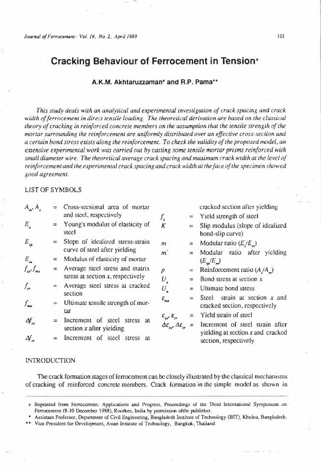
Fig. 1 can be described in I.he light of tJ1c work of Bianchini, Kesler and wtt [ lJ as follows:
Primary cracks form UL random critical ~cctions where the unifonn tensile strength exceeds tJ1c concrete strength. A slip occurs between the concrete and the reinforcement bars at the primary crack 'CCtion. Concrete surface al the cracked sections are free of stress and only the reinforcement carries Lhe external loads. Concrete tension stresses arc present between the primary cracks due to bonding <lCLion that take place as the concrete tends Lo deform with the reinforcing steel. Distribution and 1m1gn itudc of the bond stress between the concrete and reinforcement will detcrm inc the distribution or concrete stress and steel stress between t.he primary crack sections. A new crack fom1s as the external load increases and the uniform concrelc stress exceeds the concrete tensile strenglh.
Fini le clement and other methods have been used LO predict the cracking behaviour of reinforced concrete st.ructural members [2, 3. 4, 5, 6].
PROPOSED THEORETICAL APPROACH
In the reinforced mmrix member subjencd Lo uniaxial tensile force, cracks form al random sections when the composite strain exceeds the matri x strain. The cracking load of the composite can be expressed as:
.. ......... ... .. .... (1)
where Per is the cracking load. When the crdck fonns, the tensile stress in the matrix immediately adjacent to the crack drops Lo zero and the reinforcement alone carries the external load. Between t.he two consecutive cracks, tensile force is transferred from the steel Lo the matrix by bond. The lheorelical approach are based on the following assumptions:
· Bond-slip reJation is idealized as elastic up to critical slip, then perfectly plastic. - The stresMtrain relation of the reinforcement is idealized as a bilinear curve. · Bond stress is zero and changes iJS sign halfway between the cracks.
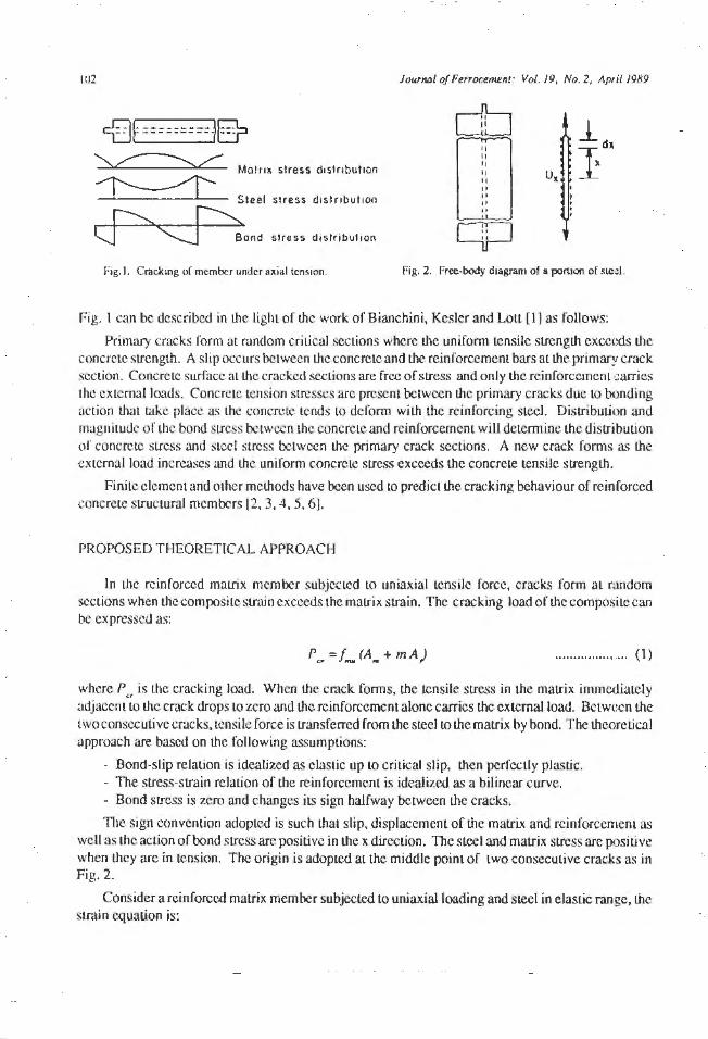
The sign convention adopted is such that slip, displacement of the matrix and reinforcement as well as the action of bond stress are positive in the x direction. The steel and matrix stress are positive when they are in tension. The origin is adopted at the middle point of two consecutive cracks as in Fig. 2.
Consider a reinforced matrix member subjected to uni axial loading and steel in elastic range, the strain equation is:
Journal of Fur<><:e~nJ : Vol. 19, No. 2, April 19R9
£,.'It E:cr=E:u+
pm
The local sLip can be expressed as:
1E::z;
S.a = 0 (E:s:z;-E:nu ) dx
From Eqs. (1) and (3):
ds .. dx = - pmE:c,+ E:s:r (l+ mp)
103
.................... (2)
................... . (3)
. ................... (4)
The equilibrium of forces acting on Lhe free body of Lhc portion of lhc reinforcement in Fig. 2 is:
fsx = fer+ R f0
112 Ux dx ... ........... ...... (5)
where R is lhe ralio of Lhe pcri phery Lo Lhe cross-sectional areas of Lhe steel. In view of Eqs. ( 4) and from bond-slip assumption, Eq. (5) becomes:
2
dfn RK( )f RK ( J. ) O --2
- - l+mp .<;r+ - mP cr = dx Es Es
.................... (6)
The complete solution of lhe above equal.ion is:
.. ......... ......... (7)
where
2 RK 2 RK c, = - ( l+mp), C2 = - (mpfc,) Es Es
and A and B arc the constants of integration. When bond stress and steel stress at crack section are below lhe ultimate values, then steel srrcss, bond stress, matrix stress and crack width are as follows:
!. c 1(1P. u ) c 1(l/l-x)
fsx = --"- re +e +mp] l +mp '11
e +I ···················· (8)
.................... (9)
!. c 1(t.a+z) c 1(1/1.-x)
fmx =~l l - e ;e --1 I +mp /•+I
.................... ( 10)
104 Journal of Ftmxt~nt: Vol. 19, No. 2, April 1989
.................... ( 11)
where I is equal Lo crack spacing. When ultimate bond stress attained at /0
distance from origm and sLecl stress is below yield stress at cracked section then bond stress, malrix stress and crack width in regime one and regime two are as follows:
2c1(1ou) c 1(lo-:.:)
fsx = [~+RU.,(1!2-lo)] [e +e ] - (-!}2
................... (12) ' 1 +mp c,lo c,
e + 1
2c I (/oH) C 1(/o->:)
fsx = l~+RUuOfl- lo) ] [e +e ]-(..~/ ................... . (13) I +mp c,lo c1
e +I
'6,,.1 = fcr+RUu (lfl - x)
(,,.,,1
= - pR U,, (1!2- x)
................... (14)
............... .... ( 15)
................... (16)
When the steel stress is above the yield strength, the total slip takes the fonn:
The Eq. (6) becomes: 2
d L'.1f,,, _ RK ( I + • ) A# _ R Kfy + R K fn o A# ) -- - ntp UJSX -- - \f'fn UJcr = dx2 Esp Es Esp
The solution is:
where
2 C11 =
'u" ·C u" ,C'l},.,2 fsx = / 1 + A e + Be - l- J
C11
R K (I +m'p), Esp
.................... (17)
0 .................... (18)
.................... (19)

Journal of Ferroce~n1 : Vol 19. No. 2 , llpnl 1989 IOS
When ultimate steel s1ress aua.incd at a clistance 11 from on gin and bond stress at crack section are below ultimate value, then in regime one (1
0 5x 5 l
1) and in regime two (115 .x 5 l1 ) the steel stress, bond
stress, matrix stress and crack width can be caJculated. If the bond stress at the cracked section is equal to the ultimate bond stress and 1
05 1
1, then this case involves two regimes. Both those regimes
arc analyzed by Eqs. (12) to (15). If 10 > 1
1, thcn this case involves three regimes.
Applying proper boundary conditions the steel stress, bond stress, matrix stress and cr::ick width can be calculated. Detailed analyses are done by Akhtaruzzaman f7].
Fora given set of six parameters which are evident in the theory, K, U.f _ . E,. E,,,andp, a computer program was developed to obtain the theoretical values of maximum crack spacing, crack width, steel stress. bond stress and matrix sucss distribution along the reinforcement between two consecutive cracks.
EXPERIMENT AL lNVESTTGA TION
The expcrimentaJ program consisted of a number of prismatic !>-pecimens (25 mm x 75 mm x 432 mm). The specimens were reinforced by4 laycrs, 5 layers and 6 layers of wires. The tensile tests were conducted with constant crosshead speed of 1 mm per minut.c. The monotonically applied loads were stopped at intervals of 50 kg (490 N) to scan Lhe surface of the specimen, count the number of cracks and measure the crack width with the help of coordinate micrometer microscope with an accuracy of 0.001 mm.
DISCUSSIONS
The tJicoretical model can predict the maximum crack spacing and crack widLh for a set of parameters and specific load level.
Figs. 3 to 8 show the variation of crack spacing and crack width wilh steel stress :u crack section for 6, 5 and 4 layers of steel , respectively and good agreement is observed between thcorcLicaJ and experimenial results.
The effect of six parameters related to mortar and reinforcement properties which control the cmcks are shown in Figs. 9 to 20. Crack spacing and crack width arc ploued against steel stress at the crack scclion by varying the value of the parameters from -25% to +25% from the mean value.
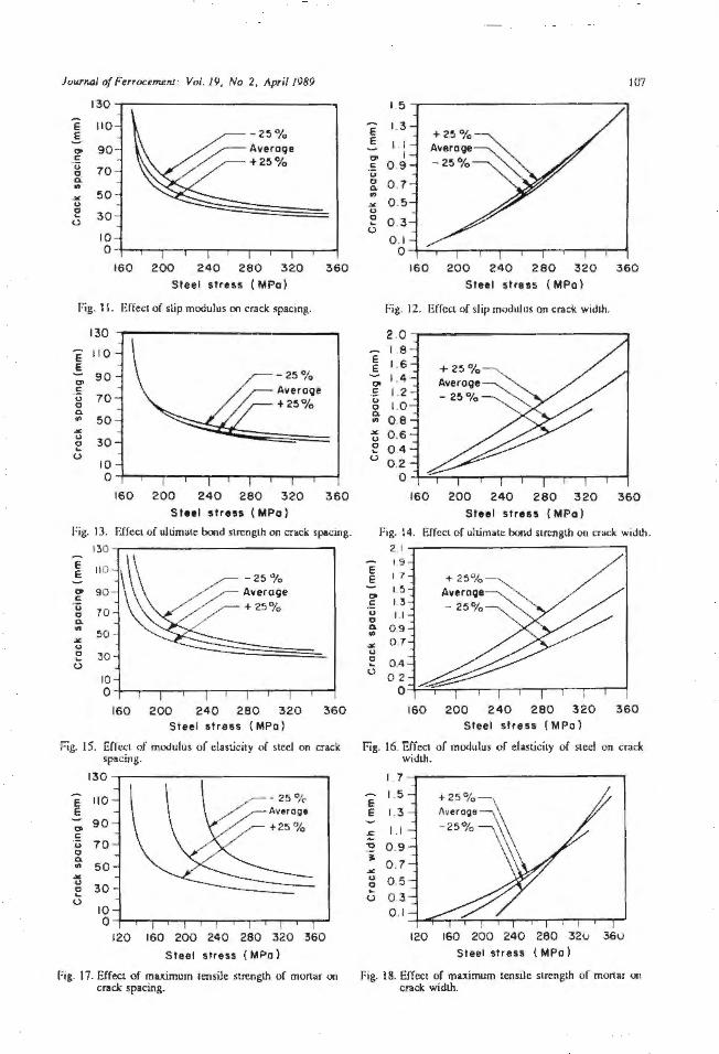
Figs. 9 and 10 show thl:lt, increase in the volume fraction decrease tJ1e crack spacing and incrcac;c U1e crack width. Figs. 1Iand12 indicate LhaLtheslip modulusK has negligible effect on crack spacing and crack width.
In Figs. 13 and 14 it is observed thal the ultimate bond strength U. has negl igiblc effect on crack spacing but crack width is significantly affected.
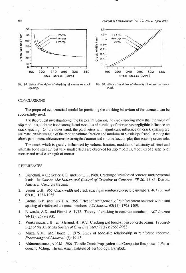
In Figs. 15 and 16 it is observed that increasing the value of the modulus of elasticity or steel E, decreases the crack width and increases the crack spacing. Figs. 17 and I 8 show that Lhe maximum tensile strength of mortar f _is an inl1 uential parameter for crack spacing and crack width prediction. Figs. J 9 and 20 show that modulus of elasticity of mortar E,,, has negligible effect on crack spacing and crack width.

106
E e 0 £ 0 0 Q. .. ~ 0
~ 0
~
E E
0 c 0 0 Q. ..
.:& 0 0 ... 0
e e 0 c ·;:; 0 Q. ..
.'1{.
" 0
0
130
110
90
70
50
30
10
160
-- Theory o Tut
6 loyt rs
200 240 280 320 Steel stress ( MPo)
360
r:ig. 3. Predicted and experimental crack spacing.
110 -Theory 0 Tut
90 !1 loyers
70 spoclno
50
30 8
10 190 230 270 310 350
Steel stress ( MPo)
Fig. S. Predicted and experimental crack spacing
130--.-~~~~~~~~~~~~-.
- Theory 110 0 Tut
4 loyrrs 90
70 0
50 0
0
30 0
20 240 260 280 300 320 340 360
Ste.el stress { MPo)
Fig. 7. Predicied and e1iperimcntal crack spacing
130~~~~~~~~~~~~-----.
e 110 E
0 90
.: 70 0 0 Q.
50 .. ~ 0 30 0 ... 0
10 0
160 200 24 0 280 320 360 Steel stress ( MPo)
Fig. 9. Effect of volume fraction on crack spacing.
JourMI of Pemx:~~fll: Vol. 19. No. 2. April 1989
1.5- --------------
E 1.3 E
I . I
: 0.9 "O
• 0. 7 "" 0 .5 0 0 ... 0 0 .3
0.1
--Theory o Test
6 foyers
160 200 240 280 320 360 Steel stress { MPo)
Fig. 4. Predicted and cxperimenLal crack wiJth.
I. 4 -..-------------------.
1.2
~ I ~ 0.9 .&.
; 0 . 7 • .>C 0 .5 0
~ 0.3 0
0.1
190
-- Theory o Test
!1 loyen
230 270 310 350 Steel stress ( MPo )
Fig. 6. PredicLcd and experimental crack widt i .
~ 0.9 E E 0.7
~ 0.5
~ 0 .3 0 ... 0 0 .1
-Theory o Test
4 loyef$
o-+~-~~~~-...-~~-....-...-....... --1
E E
0 E. 0 0 Q.
"' .¥; 0
~ 0
240 260 280 300 320 340 360 Steel stress ( MPo)
rig. 8. Predicted and experimental crack width.
1.5 1.3 I. I
0 .9 0 .7 0.5 0.3 0 .1
0 160 200 240 280 320 360
Steel stress ( MPo)
Fig. JO. Effeel of volume fraction on crack widlh.
JourNJl <>f Ferrocem$fl/ ' Vol. 19, No . 2, April 1989
-E .§ 00 c . ., 0 0. • .... u ~
(..)
130 -r---------------11 0
90
70
50
30
10 0
160
-25 % Average +25%
200 240 260 320
Steel stress ( MPo )
360
fig. I I. Effect of shp modulus on crack ~pacing.
130
E 110 E
"' 90
.!: 70 u
0 0. .. 50 .... u
30 ~ 0
10 0
160
-25% Avero9e + 25 %
200 240 280 320
Stttl stress ( MPo)
360
Fig. 13. Effect of ultimate bond strength on crack spacing.
E E CJ> c ·;:; 0 0.
"' .... u ~ 0
130-.----------------.
110
90
70
50
30
10 0
160
-25% Averooe + 25°/o
200 240 260 320 360 Steel stress (MPo)
Fig. 15. Effect of modulus or elasticity of steel on crack spacing.
E E
00 .: u 0 0. .. Jot u 0 ... 0
13 0 -r---------------. 110
90
70
50
30
10 0
120
- 25%·
160 200 240 260 320 360
Steel stress ( MPo)
Fig. 17. Effect of muimum tensile strength of mortar on crack spacing.
l<Y7
I 5 -r------ ----------. L3 E
E I I o I c 0 9 . ., 0 0. .. 0 . 7
.... 0 . 5 u 0 ... 0
0 .3
0 . 1 o-+---.-........ --.-..--.--.---.----..---r-""""'I
E E 00 .: u 0 0.
"' .... u 0 ... 0
160 200 240 260 320 360
Steel stress ( MPo)
Fig. 12. Effect of slip modulus on crack width.
2 .0--~~~~~~~~~~~~
1.8
160 200 240 280 320 360
Steel stress ( MPo)
Fig. 14. Effect of ultimate bond strength oo crack width. 21 ~--------------,
17 L5 1.3 I .I
09 07
04 02
0
160 200 2 4 0 280 320 360 Steel stress ( MPo l
Fig. 16. f:.ff cct or modulus of elasticity of steel on crack width.
E E
:: 'O
~
.;<; <)
~ (..)
17
1.5
1.3
I. I
0.9
0 .7
0 .5 0 3 0 .1
120 160 200 240 260 32U 360 Steel stress ( MPo)
Fig. I 8. Effect of maximum tensile strength of mortar on crack width.
108
130
E 110 E O> 90
.!: u 70 0 ~ ..
:50 "" u 0 30 0
10 0
160 200 240 280 320 360
Jo11Tnaf o[Furocunent: Vol. 19, No. 2. April 1989
~ 1.3 E E I.I -1:)
• 0 .7
~ 0 5
~ 0 3 (..)
160 200 240 280 320 360 Steel stress ( MPa ) Steel stress ( MPa )
Fig. 19. Effcc1 of mod1Jlus of clastici1y of mol'\ilr on crack Fig. 20. Effect of modulus o f elasucity of morutr Oii cmck spacing, width.
CONCLUSIONS
The proposed mathematical model for predicting the cracking behaviour of fcrrocemcnt can be successfully used.
The theoretical investigation of the factors influencing Lhe crack spacing show that the value of slip modulus, ultimate bond strength and modulus of elasticity of mortar has negligible inOuence on cn1ck sp::tcing. On the other hand, the parameters with significant innuence on crack spacing arc ulLimaLe tensile strength of the mort.ar, volume fraction and modulus of elasticity of steel. Amo11g Lhe above parameters, ultimate tensile slfength of mortar and volume fraction play tJ1emost importan. role.
The crack width is greatly innuenced by volume fraction, modulus of elasticity of steel and ultimate bond sLrength but very small effects are observed for slip modulus, modulus of elasticity of mortar and tensile strength of mortar.
REFERENCES
Bianchini,A.C.; Kesler, C.E.; and Lou,J .L. 1968. Cracking of reinforced concrete underex1emal loads. In Causes. Mechanism and Control of Cracking in Concrete. SP-20. 75-85. Dmoit American Concrete Institute.
2. Broms, B.B. 1965. Crack width and crack spacing in reinforced concrete members. A Cl.Journal 62(10): 1237-1255.
3. Broms, B.B. , and Lutz, L.A. 1965. Effect of arrangement of rcinforccmem on crack width and spacing of reinforced concrete members. AC/ Journal 62( 11 ): 1395-1409.
4. Edwards, A.D., and Picard, A. 1972. Theory of cracking in concrete members. AC/ Jo1"nal 94( 12): 2687-2700.
5. Venkateswarlu, B .• and Gesund, H. 1972. Cracking and bond-slip in concrete beams. Proceedings of the American Society of Civil Engineers 98(12): 2663-2983.
6. Mirza, S.M. and Houde, J. 1975. Study of bond-slip relationship in reinforced concrete. Proceedings AC/ Journal (?): 19-45.
7. Akhiaruzzaman, A.K.M. 1986. Tensile Crack Propagation and Composite Response of Ferrocement. M.Eng. Thesis, Asian Institute of Technology, Bangkok.
Journal of Ftrroctml!fll : Vol. 19, No .2 , April 1989
Fire Resistance of Ferrocement Load Bearing Sandwich Panels
I.A. Basunbur, S.M. Nuh0 and R.B. Wllliamson~0
109
A 12/t (3.658' m)wide by 8fl(2.438m) tall wall was constructed using three 4ftx8ft (l .219 mx 3.658 m) panels 6 in. (0.15 m) thick. Each panel consists of twoferrocemeflt plates 112 in. (12.7 mm) thick connected with J 12 in . (72.7 mm) central corrugated stiffener. One of the 4 ft x 8/t (1219 mx 3.658 m) panels was tested in compression to establish the maximum compressive load which was 328 kips (1459 kN).
One of the panels of the fire test wall specimen was filled with polyurethane foam. Another was filled with mineral wool and the cavities in the middle panel were left unfilled. The wall was placed in the standard wall frame of the ASTM E-119 testfurnace and subjected to a total compression live load o/80 kips (356 kN). The test was conducted according toASTM E-119/oraperiod of 3 hrs. The wall carried the applied load for the entire test period witJwut any sign of structural failure. 'I'hc polyurethane filled panel failed at l 39"C (25G°F) average face temperature rise criteria at 62 minutes into the test. The open cell panel failed the same average temperature rise criteria at 74 minutes and the mineral wool filled panel failed the single point temperature rise at l 8!°C (325°F) al 73 minutes. There was some spalling observed on the furnace exposed surf ace of one of 1 he panels early in the test. but there was no other indication of problems.
INTRODUCTION
Ferroccment construction represents a technology that is well suited Lo the needs of both developed and developing countries. Il uses relatively inexpensive materials that arc available on a worldwide basis and for I.he developing country it is atuacti ve because it does not require investmenLS in large industrial plants and equipment and it can effectively utilize a largely unskilled labor force. Ferroccmcntsandwich panels arc well suited forroofing and wall units as I.hey offer in a single building element an economical mel.hod of providing structural requirements, Lhermal and sound insulation and attractive architectural flexibility. These attributes give ferrocement construction technology an important economical advanLage over other fonns of cons1ruction for both the developed and developing nations [ 1-6].
An important aspect of any bui !ding technology is its fire performance. Fire safety represents one engineering parameter that is often not fully considered even I.hough the failure lo do so can result in catastrophic fai lure of a structure. The present investigation provides an evaluation of I.he fire resistance of a specific form of load bearing ferrocement sandwich wall panels.
* Assistant Professor, Department of Civil Engineering. King Fahd Univenity of Petroleum and Minerals. Dhahr.in 31261, Saodi Arabia.
••Assistant Professor, Depanmenl of Civil Engineering, Al- Fateh University, Tripoli, Libya.
• 0 Professor of Civil Engineering, University of California, Berkeley. U.S.A.
JJO Journal of Ferrocement: Vol. 19, No. 2 , April 1989
EXPERlMENT AL PROGRAM
Test Specimen
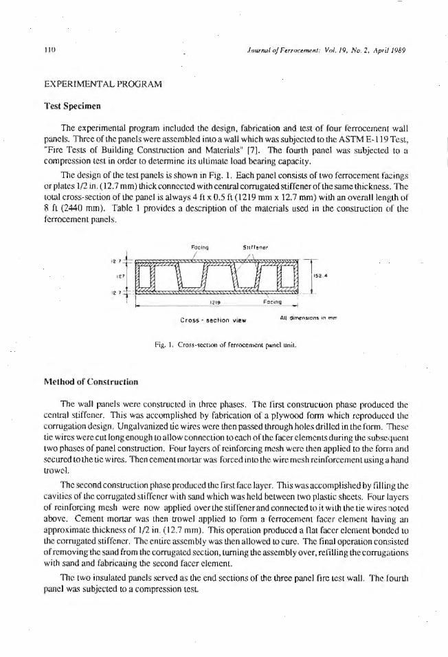
The experimental program included the design, fabrication and test of four ferrocemcni wall panels. Threcoflhe panels were assembled into a wall which was subjected to the ASTM E-119 Test, "Fire Tests of Building Construction and Materials" f7). The fourth panel was subjected to a compression test in order to determine its ultimate load bearing capacity.
The desjgn of the test panels is shown in Fig. 1. Each panel consists of two ferrocement fa::ings or plates 1/2 in. ( 12. 7 mm) thick connected with central corrugated stiffener of the same thickness. The total cross-section of the panel is always 4 ft x 0.5 ft (1219 mm x 12.7 mm) with an overall length of 8 ft (2440 mm). Table 1 provides a description of the materials used in the construction of the fcrroccmcnt panels.
'"~rr:D:OJJ} 12+=== '"' 12 .7 • .
L -- 1219 F~oing
Cross - 11ection view All dlmen>1ons In mm
foig. I. Cross-section of ferrocemenl panel unit.
Method of Construction
The wall panels were constructed in three phases. The first construction phase produced the central stiffener. This was accomplished by fabrication of a plywood form which reproduced the corrugation design. Un galvanized tie wires were then passed Lhrough holes drilled in the form. 111ese tic wires were cut long enough Lo allow connection to each of the facer clements during I.he subsequent two phases of panel construct.ion. Four layers of reinforcing mesh were then applied to the form and secured to the tic wires. Then cement mortar was forced into the wire mesh reinforcemenL using a hand trowel.
The second construction phase produced the first face layer. This was accomplished by filling the cavities of the corrugated stiffener with sand which was held between two plastic sheets. Four layers of reinforcing mesh were now applied over the stiffener and connected to it wilh the Lie wires noted above. Cement mortar was then trowel applied LO form a ferrocernent facer element haviug an approximate thickness of 1/2 in. (12.7 mm). This operation produced a f1at facer element bonded to Ille corrugated sti ffener. The entire assembly was then allowed LO cure. The final operation consisted of removing the sand from I.he corrugated section, turning the assembly over, refilling thecorrugmlons with sand and fabricating the second facer element.
The two insulated panels served as the end sections of the three panel fire test wall. The fourth panel was subjected Lo a compression test.

Journal of F'trrocemem: Vol. 19, No. 2, April 1989
Reinforcement
Mortar
INSTRUMENT A TI ON
Table l Construct.ion Materials.
Four layers of chicken wire
I in. (25.4 mm) hexagonal openings galvanized, LwisLed wires gauge no, 20 (0.9 mm diameter)
Average ullimate sLrengLh = 64.4 x 1()3 psi (444 MPa)
Cement Ordinary porlland cement type II
Sand: Olympia no. "O" with 2.6 fineness modulus 90% passing sieve no. 8 6% passing sieve no. 100
Cement-sand rut.io = 0.70 Water-cement rat.io = 0.40
Average 28 days compressive strength= 7902 psi (54.5 MPa)
Admixture: Chromium trioxide (Cr03)
300 ppm by weight of the mix waler
JI 1
Each panel of the wall has been instIUmented with nine thermocouples placed on its unexposed (i.e. non-fire side) face. The location of t.hese thermocouples are indicated in Fig. 2. The Lhermocouples were securely fastened Lo the wall surface and covered by 6 in. x 6 in. (152 mm x 152 mm) felte<l asbesLos pads as required by the ASTM E-119 test.
To measure the variat.ion of temperature across the cross-section of the wall, thermocouples were placed al I in. (25.4 mm) and 5 in. (127 mm) away from the face fronting the fire as shown in Fig. 2.
The deflection along the middle horizontal line of the wall which is the line of Lhc maximum defiection were measured using five linear variable displacement 1ransducers (L VDT).
1ESTING PROCEDURE AND RESULTS
Compression T est
Compression test was performed on one complcLcd wall panel using 400 kips (1780 kN) universal Lesting machine. TI1e axial and lateral deflection were measured using polential melcrs. The load was
11 2
x
Side panel -I
t TC Tc._ .. 07.2
;;;
.. • 06 .4
355. 6
Journal of Ferroctment: Vol. 19, No 2, April 1989
- 1219
Cross- seclfonol view
I Middl e pane l _ Sioe panel
I I •o&• 406.4
+ TC L .pc re _. TC • L .. I 1na
.. 1178 !:! ~
3~5 8 4 572
TC 1 f .. TC
"' .. z ;
Face racing lire
~ _J)( N
El ...
• TC TC• • TC I • TC
I • 0 6.4
re..-
•Os •
lO• 8 l( 304 .8 '3658 -------- --
Elevat ion Atl 01mens1ons in mm
Fig. 2. Pcrroccmcnl wall 12fl ll 8 ft ll 0.5 ft (305 mm x 203 mm ;r. 13 mm) 1cs1cd under /\STM fi· l 19 fire test.
applied al a rale of20 kips/min (89 k.N/min). The load versus deneclion graph (Fig. 3) shows thal the ullimme capacily of lhe4 fl (1219 mm) wide wall panel was 329.6 kips (1466 kN) which produced an ultimaLC stress of 3084 psi (21.3 MPa).
Fire Test
TI1c fi re test specimen consists of three panels. Two of the panels were Ii lled whh insulal.ion: one panel was insulated with polyurethane foam and the other with rock wool. The two insulated panels served as the end sections of the three panel fire lesl wall as shown in r: ig. 4. The fire lest equipment employed in this program consisLed of a large scale vertical furnace, a wall loading frame and associated hydraulic cquipmcnl used to impose the toad on the tcsl wall section. A schematic diagram of fire test set up is shown in Fig. 5. Loading of the ferrocemenl Lcsl wall was accompt ished by placing five hydraulic jacks benealll the steel beam which supported the wall, detail of tcsl equipmenl anJ Lest sel-upcan be found in Ref. [8). Dueto thc limitedcapacityoflhe loading frame, the wall was not loaded to iLS capacity during fire test, but 1.he live load of80 kips (356 k.N) for the 12 fl (3658 mm) wal l was applied. This corresponds to 6380 1 b/ft (93 kN/m} which covers many desjgn applications.
Fire test was conducted by following the standard time versus temperature relal.ionship outlined m ASTM E-119 as shown in Fig. 6. Furnace temperatures were measured by nine type K, chromclalumcl, lhermocouplcs encased in 1/2 in. (12.7 mm) standard pipe size in conel sheaths.
Journal of Ferrocemefll: Vol. 19, No . 2, April 1989
z ~
,. u .. .. 0 u
... 0 0 _,
1600
1461
1400
1200
1139
Ulllmole copoelty - --:-c-- ----
I /_
/
1000 I Croct\6 st or I 983 ------------
800 ! I
600
400
200
0 0 .5 1.0 l.5 20
Oeflectl on lmml
Lateral deflection
Vert 1cot deflectlon
Rote of loodin9 : 534 \N/min
2 ,5 3,0
Fig. 3. Load versus deflection for the ferrocemenl fire test wall specimen.
--
"2438 Potyurerone foam
lnsulotlon lJnlnS<Jloted Rock .. ool lnsulatlon
,_..._ 1219------1219--1
Unexposed face All dlrneo1lons in mm
Fig. 4. Schematic diagram of the three panel ferrocemenl fire test wall specimen.
113
114 JoiJrna/ of Fe"ocemEnt: Vol. 19, No. 2, April .1989
- -}
Fig. 5. Schematic diagram o( furnace used !or ASTM E-119 fire tesL
Fire Test Results
The first three hours of the ASTM E-119 time-temperature history are presented in Table 2. The ferrocemenl wall was subjected to Lhis heating history for a period of 185 minutes. IL is noted that the actual furnace temperature recorded during lhe test complied satisfactorily wilh Lhe ASTM E-119 requirements. The ferrocement wall was loaded throughout the test period.
Unexposed Face Temperature Rise
The ASTM E-1 19 test standard specifies two acceptance criteria that are based on allowable temperature rise of lhe unexposed face of a test wall. These criteria state that the average unexposed
Jc11;rnol of F'errocemenl : Vol. 19. No. 2, /\pri( 1989
1300
1200
1100
IOOO
900
800
.u 700
~ :>
0 soo ~ a. E .. 500 ....
400
30 0 •
200
100
0 1.0 2 .0 30
Tim& l hours )
I ll I000°F @ 5 mtn
l2) 1350°F @ 10 min
(3) 1sso•r @30min.
( 4) i700°F @l I hr .
l 5) 18 5 0 °F @ 2 hrs .
1s) 2000°F @ 4 hr5.
( 7} 2300°F' @> 8 hrs. or more
5 .0 6.0 7.0
Fig. 6. Timc·tcmpcra1urc curve for ASTM E-11 9 stand1ml fire tesl.
l!S
8 .0
face temperature rise should not exceed 139"C (250"F) and that the maximum single point temperature rise should not exceed 191 "C (325°F). The aclUal unexposed face temperature rise recorded during I.his test are presented in Tables 3-5 and Figs. 7 ·9. Table 3 inclicatcs the temperature rise recorded at three locations on the panel insulated with polyurethane foam (No. 1 ), Table 4 presents the rise for the uninsulated panel (No. 2), and Table 5 indicates the temperature rise of the rock wool insulated panel (No. 3).
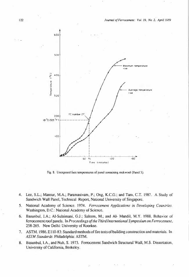
Table 6 provides a comparison of the Lime required for each of the three panels Lo exceed the 139"C average and I 8 l°C single point temperature rise criteria. Fig. 7 shows that the polyurethane insulated panel provided the least fire resistance having failed both temperature rise criteria al 62 minutes. The rock wool insulated panel (No. 3) provided longer fire endurance than the uninsulated panel (No. 2) with respect to the average temperature rise, 90 minutes versus 74 minutes; however, the rock wool panel failed Lhe single point rise at 73 minutes as opposed to the 80 minute single point du.ration of the uninsulated panel. The early failure of Panel No. l was due to combustion of Lhe jnsulalion within the wall cavity. The acLUal fire endurance according to ACI 216 [91 recommendations of Panel Nos. I, 2 and 3 were 62, 74, 73 minutes, respec tively, with Panel Nos. 1 and 2 failing due Lo average temperature rise and Panel No. 3 due to jts single point temperature rise.
116 Journal of Perrocemall: Vol. 19, No. 2, April 1989
Table2 Three Hour ASTM E-119 Timc-Temperalure History.
St.andard time-temperature curve for control of fire tests
Time Temperature Area above 68°F base Temperature Area above 20"C base (hr: min) (OF) ("C)
(°F-mio) (°F-hr) ("C-min) ("C-hr)
0:00 68 00 0 20 00 0 0:05 1,000 2,330 39 538 1,290 22 0:10 1,300 7,740 129 704 4,300 72 0:15 1,399 14,150 236 760 7,860 13 l 0:20 1,462 20,970 350 795 11,650 194 0:25 1,510 28,050 468 821 15,590 260 0:30 1,550 35,360 589 843 19,650 328 0:35 1,584 42,860 714 862 23,810 397 0:40 1,613 50,510 842 878 28,060 468 0:45 1,638 58,300 971 892 32,390 540 0:50 1,661 66,200 1,103 905 36,780 613 0.55 1,681 74,220 1,237 916 41 ,230 687 1:00 1,700 82,330 1,372 927 45,740 762 1:05 1,718 90,540 1,509 937 50,300 838 1:10 1,735 98,830 1,647 946 54,910 915 1:15 1,735 98,830 1,647 955 59,560 993 1:20 1,765 115,650 1,928 963 64,250 1,071 1:25 1,779 124, 180 2,070 971 68,990 1,150 1:30 1,792 132,760 2,213 978 73,760 1,229 1:35 1,840 141,420 2,357 985 78,560 1,309 1:40 1,815 150,120 2,502 991 83,400 1,390 1:45 1,826 158,890 2,648 996 88,280 1,471 1:50 1,835 167,700 2,795 1,001 93,170 1,553 1:55 1,843 176,550 2,942 l,006 98,080 1,635 2:00 1,850 185,440 3,091 1,010 103,020 1,717 2:10 1,862 203,330 3,389 1,017 112,960 1,882 2:20 1,875 211 ,330 3,689 1,024 122,960 2,049 2:30 1,888 239,470 3,991 1,031 133,040 2,217 2:40 1,900 257,720 4,295 1,038 143, 180 1,386 2:50 1,912 276,110 4,602 1,045 153,390 2,556 3:00 1,925 294,610 4,900 1,052 163,670 2,728
Horizontal Deflections
Horizontal deflection of the unexposed face of the wall was measured lhroughoul the test at the seven locations. Table 7 lists the deflection measurements of the unexposed face. The maximum deflections away from the fire for Panel Nos. 1. 2 and 3 were 0.4 in., 0.3 in. and 0.2 in. (10.2 mm,
Journal of Ferrocemlnl : Vol. 19, No. 2, April 1989
Table 3 Unexposed TemperaLUre Rise Recorded on Panel No. 1 which was Insulated with Polyurethane Foam.
Elapsed time Thermocouple number Average (min) temperature
23 26 29 (°C)
000 005 10 8 10 9 010 10 9 10 9 015 10 9 IO 9 020 10 9 10 9 025 10 10 11 10 030 11 13 13 12 035 13 21 16 17 040 23 40 32 32 045 55 61 60 59 050 81 78 90 83 055 106 98 120 108 l ()() 128 117 147 131 I OS 152 140 190 161 110 205 194 264 221 l 15 238 227 305 257 l 20 284 278 366 309 J 30 353 357 444 385 I 40 414 425 514 451 l 50 467 503 498 489 200 473 481 525 493 2 10 489 499 551 513 220 501 518 565 528 230 521 540 574 545 240 538 555 582 558 250 552 567 591 561
Note: Average air temperature= 22"C
117
7.6 mm and 5.1 mm), respectively. The maximum deflections toward the fire for Panel Nos. 1, 2and 3 were0.2 in., 0.3 in. and 0.2 in. (5.1 mm, 7.7 mm and 5.1 mm), respectively. Deflections towards the fire generally occurred during the first part of the test period.
DISCUSSION OF EXPERIMENTAL RESULTS
The LbermaJ qualities of the three panels were dependent on the insulation used on thefoterior of the specimen. Tho combustible polyurethane foam insulation was the poorest while the rock wool or
t 18 Journal of Ferrocernent: Vol. 19, No. 2. A.pril J989
Table4 Unexposed Temperature Rise Recorded on Panel No. 2 which was Uninsulated.
Elapsed time Thermocouple numbers Average (min) temperature
22 25 28 ("C)
000 005 5 4 3 4 010 12 10 4 9 0 15 34 36 12 27 020 49 53 35 46 025 55 60 45 53 030 59 64 53 59 035 64 66 59 63 040 71 68 63 67 045 78 70 68 72 050 84 74 72 77 055 91 81 76 83 100 98 92 81 90 105 105 110 88 101 1 10 125 148 102 125 l 15 147 174 110 144 1 20 184 216 127 176 1 30 244 284 172 240 140 299 345 224 289 1 50 347 386 275 339 200 391 435 322 383
Note: A veragc air temperature = 22°C
mineral wool insulation gave the best performance. However, based on model building codes used intemationally, all of the panels would be rated at one hour since the codes only recognize one, two, three and four hour fire resistance for walls.
From a load bearing siandpoint, the three panels continued to carry the load for the full 185 minute test period. This would give this design a three hour rating in the building codes.
CONCLUSIONS
The fire resistance of the ferrocement wall shown above should be encouraging for designers of Ierrocernent buildings. Thougb the thin shell nature of ferrocement has raised questions about it!; fire resistance, this study shows that ferrocement retains much of the load bearing qualities of ordinary reinforced concrete. Its heat transmission qualities are not as good as those of reinforced cont;rele which would be just under four hours, but 01is latter consideration is more dependent on the mass of the wall.

Journal of FerrocemenJ: Vol. 19, No. 2, April 1989 119
Table 5 Unexposed Temperature Rise Recorded on Panel No. 3 which was Insulated with Rock Wool.
Elapsed time Thennocouple numbers Average (min) temperature
21 24 27 ("C)
000 7 4 3 5 005 7 5 3 5 () 10 7 6 6 6 0 15 8 9 14 10 020 8 16 41 22 025 14 23 58 32 030 28 37 66 44 035 43 49 69 54 040 56 58 76 63 045 62 63 83 69 050 66 66 91 74 0 55 67 67 80 78 I 00 68 69 114 84 l 05 68 71 132 90 I 10 68 74 168 103 l 15 68 77 190 112 I 20 68 83 224 125 130 69 92 282 148 1 40 70 105 334 170 l 50 71 121 377 190 200 73 141 414 209 210 76 165 443 228 2 20 247 188 465 300 230 350 211 471 345 240 378 234 480 365 250 384 256 49 1 377
Note: Average air temperature= 22°C
Limited problems of spalling of che front faccsheeis occurred during the early portion of the Lese. This spalling was not severe enough to cause serious structural damage during the period in which the wall satisfied the ASTM E-119 performance criteria, and less spalling would have been expected in an assembly with a longer curing period than the only 28 day curing of the tested assembly. Otl1er potcnLial problems. such as debonding of the face sheets was noted only during the final minutes of tlle 3 hour test. ll would be interesting Lo find out how this design would perfom1 in a floor/ceiling fire resistance test. Potentially, this design could be used for a floor system, though its fire resistance may be a limiting factor.
120 Journal o/Ferrocemenl: Vol. 19, No. 2, April 1989
Table 6 A comparison of the Time to Reach the Average and Single Point Failure Criteria for Each of the Three Panels.
Panel number
2
3
Time of average temperature rise failure l39°C (250"P)
62 minutes
74 minutes
90 minutes
600
500
400
200
Time of single point temperature rise failure 181 °C (325°F)
62 minutes at TC no. 29 70 minutes at TC nos. 23 and 26
80 minutes at TC nos. 22 and 25 100 minutes a l TC no. 28
73 minutes at TC no. 27 140 minutes at TC nos. 21 and 24
Moil mum temperature rtse
,,..._ __ Average remperoture rtse
"'""''°J-------1 I
60 62 120 Tome (minute•)
180
Fig. 7. UnCJ\posed face lcmperatures of panel con1.aining polyurelhane foam (Panul I).
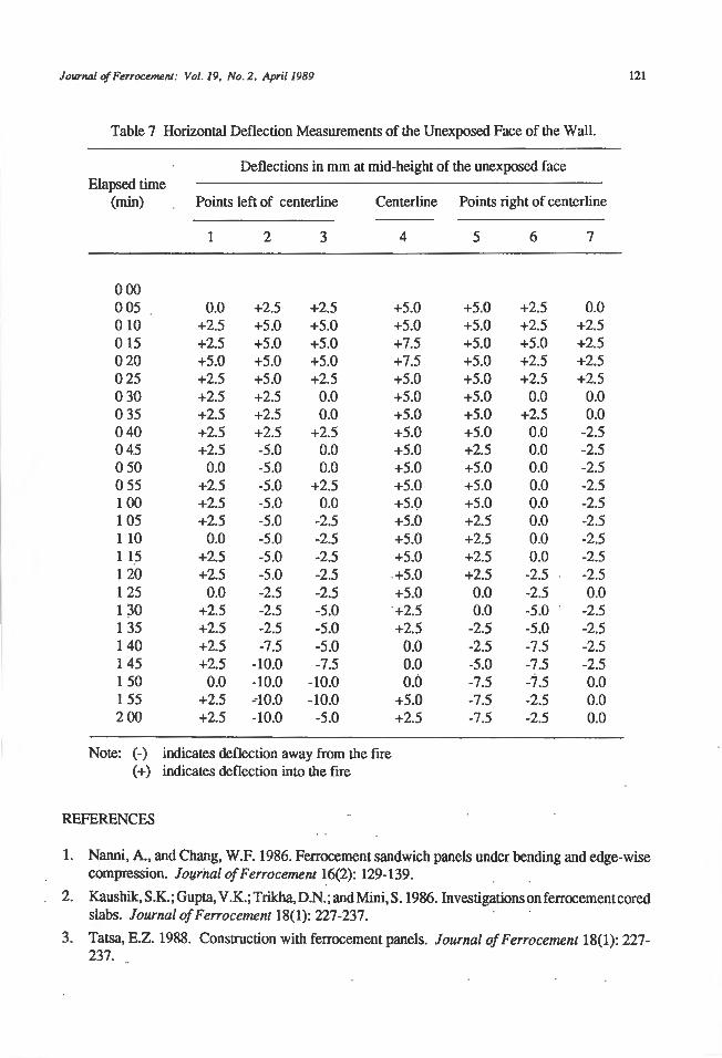
Journal of Ferrocemenl: Vol . 19, No. 2, April 1989 121
Table 7 Horizontal Deflection Measurements of the Unexposed Face of the Wall.
Deflections in mm at mid-height of the unexposed face Elapsed time
(min) Points left of centerline Centerline Points right of centerline
2 3 4 5 6 7
000 005 0.0 +2.5 +2.5 +5.0 +5.0 +2.5 0.0 010 +2.5 +5.0 +5.0 +5.0 +5.0 +2.5 +2.5 0 15 +2.5 +5.0 +5.0 +7.5 +5.0 +5.0 +2.5 020 +5.0 +5.0 +5.0 +7.5 +5.0 +2.5 +2.5 025 +2.5 +5.0 +2.5 +5.0 +5.0 +2.5 +2.5 030 +2.5 +2.5 0.0 +5.0 +5.0 0.0 0.0 0 35 +2.5 +2.5 0.0 +5.0 +5.0 +2.5 0.0 040 +2.5 +2.5 +2.5 +5.0 +5.0 0.0 -2.5 045 +2.5 -5.0 0.0 +5.0 +2.5 0.0 -2.5 0 50 0.0 -5.0 0.0 +5.0 +5.0 0 .0 -2.5 0 55 +2.5 -5.0 +2.5 +5.0 +5.0 0.0 -2.5 100 +2.5 -5.0 0.0 +5.0 +5.0 0.0 -2.5 1 05 +2.5 -5.0 -2.5 +5.0 +2.5 0.0 -2.5 1 10 0.0 -5.0 -2.5 +5.0 +2.5 0.0 -2.5 1 15 +2.5 -5 .0 -2.5 +5.0 +2.5 0.0 -2.5 1 20 +2.5 -5.0 -2.5 +5.0 +2.5 -2.5 -2.5 1 25 0 .0 -2.5 -2.5 +5.0 0.0 -2.5 0.0 1 30 +2.5 -2.5 -5.0 +2.5 0.0 -5.0 -2.5 1 35 +2.5 -2.5 -5.0 +2.5 -2.5 -5.0 -2.5 140 +2.5 -7.5 -5.0 0.0 -2.5 -7.5 -2.5 1 45 +2.5 -10.0 -7.5 0.0 -5.0 -7.5 -2.5 1 50 0.0 -10.0 -10.0 0.0 -7.5 -7.5 0 .0 1 55 +2.5 -10.0 -10.0 +5.0 -7.5 -2.5 0.0 200 +2.5 -10.0 -5.0 +2.5 -7.5 -2.5 0.0
Note: (-) indicates deflection away from the fire (+) indicates deflection into the fire
REFERENCES
1. Nanni, A., and Chang, W.F. 1986. Ferrocement sandwich panels under bending and edge-wise compression. Journal of F errocement 16(2): 129-139.
2. Kaushik, S.K.; Gupta, V .K.; Trikha, D.N.; and Mini, S. 1986. Investigations on ferrocementcored slabs. Journal of Ferrocement 18(1): 227-237.
3. Tatsa, E.Z. 1988. Construction with ferrocement panels. Journal of Ferrocement 18(1): 227-237.
122 Jourfl/J/ of Ferroceml!.n.I: Vol. 19, No. '2 . April 1989
6 00
500
rise
1e1°ct325 •n
60 75 120 1ao Time ( mrnules)
Fig. 8. Unexposed face temperatures of panel comaining rock wool (Panel 3).
4. Lee, S.L.; Mansur, M.A.; Paramasivam, P.; Ong, K.C.G.; and Tam, C.T. 198?. A Study of Sandwich Wall Panel, Technical Report, Nal.ional University of Singapore.
5. National Academy of Science. 1974. Ferrocemenr Applicarions in Developing Countries. Washington, D.C.: National Academy of Science.
6. Basunbul, I.A.; Al-Sulaimani, GJ.; Saleem, M.; and Al- Mandi!, M.Y. 1988. Behavior of ferrocemenl roof panels. In Proceedings of the Third International Symposiwn on F errocement , 258-265. New Delhi: University of Roorkee.
7. ASTM. 1986. E 110-83: Standard met.hods of fire tests of building construction and materials. In ASTM Srandards. Philadelphia: ASTM.
8. Basunbul, I.A., and Nuh, S. 1973. Ferrocemem Sandwich Structural Wall, M.S. Dissertation, Unjvcrsi!y of California, Berkeley.
Journal of Ferrocel>U!nJ ; Vol.19, No. 2, April 1989
.. ;; 0 O; c. E .. ...
600
500
139°C(250°F )
T ime (minutes)
Fig. 9. Unexposed face temperatures of middle panel (Panel 2).
123
9. American Concrete Institute. 1981. Guide for Determining the Fire Endurance of Concrete Elements: AC! 216R-81. Detroit.: American Concrete Institute.
Journal of Perrocemenl: Vol. 19, No. 2, April 1989 l25
Ferrocement Gate with Reversed Hyperbolic Flat Shell+
Zhao Lu·Guang*' and Yuan Shou-Qlan•
The application of ferrocement gatewi1h reversed hyperbolic flat shell to irrigation and drainage engineering in Hebei province of China is reported. The structure and geometry of the gate. material used, construction procedure, technique required and design theory are also described.
APPLICATION OF FERROCEMENT GA TE WITH REVERSED HYPERBOLIC FLAT SHELL (FGRHS) IN CHIN A
In the later 1960's, al the middle of lhe waler conservancy construction of China, lhe FGRHS, a new type of gate according to the design concepl of ferrocement space structures, was introduced. This gate has the ad vantages of reasonable bearing, light weighl, lesser sleet requirement and low cost. lt is suited for developing countries for use in water conservancy construction. It was used both in B ian River Water Conservancy Construction of AnRui province and in Horse Village Water Conservancy Construction of Hebei province. Between them, this gate made more oulStancling features in Horse Village Water Conservancy Construclion of Hebei province.
The FGRHS, which is used in Horse Village Waler Conservancy for repelling water, is a submerged orifice type with 5 m height. This gale is 3.37 tons (3057 kg) in weight, using 434.5 kg of sleel and l 08.19 mz wire net If a plane ferrocement gate were used, the weight would be 5 tons (4535 kg), the amount of steel and wire net needed would be 700 kg and 100 m2, respectively. If a steel gate were used, the amount of steel needed would be about 2000 kg.
The above comparison shows the advantages Of the FGRHS. The reason by which the material property in each part of the gate gets oplimum development is because ferrocemenl as a shell is homogeneous elastomer with good compressive and tensile properties; the reversed shell develops d1e tensile property of the shell and makes the edge of reinforced concrete in compression resulting jn a decrease of the djmension of the edge of reinforced concrete.
STRUCTURAL DETAILS OF THE FGRHS
The gate is a reversed hyperbolic flat she! Land the concave of the shell bears the water pressure; the sagittal height of Lhe shell is smal 1 com pared with the covering area and the curvature radius.
The gate is made mainly of two parts: the wire net hyperbolic flat shell and the edge structure of reinforced concrete (beam and column). In the hyperbolic flat shell, the main internal force is the membrane i ntemal force and the maximum primary stress takes place at the comer. ThS primary stress at the comer is about two times that in the centre of the shell and depends directly on RzR
1 of the flat
shell (Rr R1
are curvature raclius in x and y clireclions, respectively).
+ Reprinted Irom Ferroccmcnt: Applications and Progress, Proceedings of the Third lntemational Symposium on Ferrocement (8 - 10 December 1988), Roorkec, India by permission of the publisher.
~ Department of Civil Engineering, Agricultural University of Hebei, llebei, China.
126 Jourriol of Furocemenl: Vol. 19, No. 2, April 1989
The assumptions taken in the calculations are: ( 1) The calculation of the hyperbolic Oat shell used the membrane theory and the edge disturbance. (The membrane state of the shell mainly bears the load when the load is suddenly changed in the boundary. The bending moment is added to keep the continuity of defonnation); and (2) Ferrocement material is a homogeneous isotropic elastomer for the calculation of the stress of the flat shell.
The thickness in the centre area of the body of the Oat shell is given by:
where:
C = thickness of cover layer n
1, n
1 = layer members of reinforcing steel and wire net, respectively
d1
, d1 = diameter of reinforcing steel and wire net, respectively
.... ... ....... ...... ( l )
The uniform thickness for square shell with equal curvature radius is given by:
I\ -2.28 fRT = ..................... (2) 2
where:
a = side length of the square Oat shell
The centre of the flat shell was Laken as the centre of the circle and a as the radius, this range is the centre area of equal thickness. ln order to secure the safety of the angle point, the thickness gradually increased from the edge of the centre area to the comer and edge structure in the centre.
111e radius of the symmetry of the shell can be evaluated from the following formula:
R~ = - [ -) + f~ J 1 ~ 2 2
2/x 1 ,b 2 2
Ry= - ! ~::-) +fy ] 2fy 2
where:
a = span of the shell in horizontal (x) direction b = span of the shell in vertical (y) direction fr!, = sagittal height in the x and y djrections, respectively R,. R
1 = radiust in the x and y directions, respectively
.................... (3)
The stress of the shell is dependent on the span (which can be expressed as a function of curv a Lure radius), hence the curvature radius is the main basis of internal force of the shell.
The flat shell requires the sagittal height as follows:
f = !~ + fy < a IS or b I 5 .................... (4)
Journal of Fe"ocemen1: Vol. 19, No. 2, April 1989 127
In adclicion, to develop Cully the hyperbolic action of the shell, it was specified that the ratio of any one raclius compared to any other radius and the ratio ofany one side length compared to any other side length should not be greater than 2. Since the reinforced concrete edge structure generally used the same height, it would be better to use the similarity sagittaJ height in order to develop fully two-way action.
For the ferrocemenL structure, the following materials are required: silicate cement over 500#, clean medium sand with an average grain size of 0.35 mm-0.38 mm and rust-free steel wire 1 mm in cliamcter made into I 0 mm x 10 mm mesh.
The size of the external side ofFGRHS in Horse Village, Hebci province of China, is 3.3 m x 3.3 m (height x width). The plane of the shell is 400# cement-sand grout made of 500# general silicate cement Water-cement ratio is 0.3-0.35. Sand-cement ratio is 1-1.5. The sand is natural medium sand cleaned before construction so that the mud con Lem (including crumbs) would be below 2%. The form of the steel wire net is 1 mm diameter, 10 mm x 10 mm mesh.
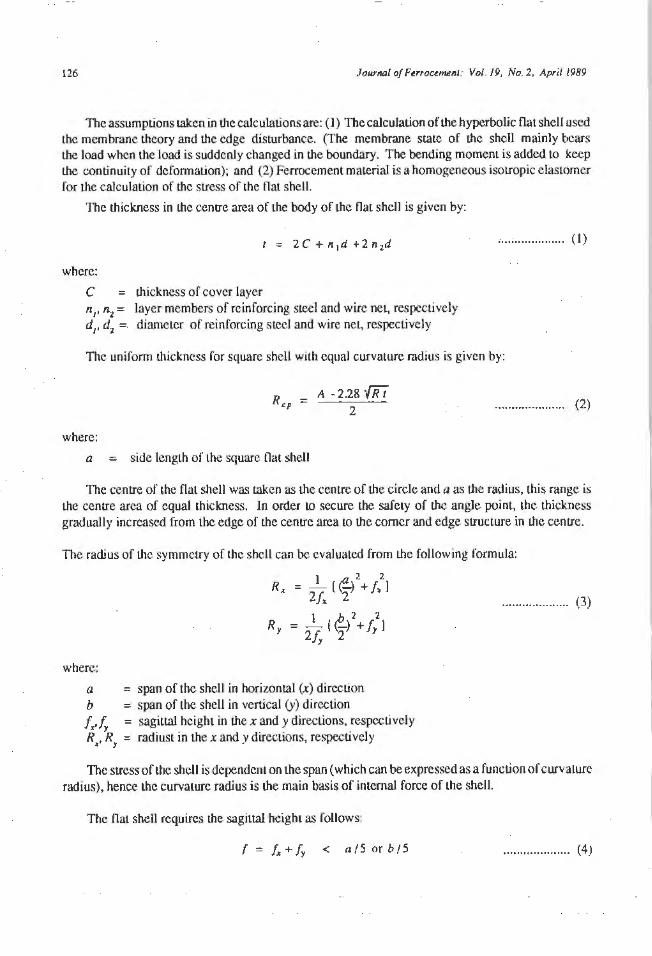
The size of reinforced concrete edge structure in this gate is 400 mm. The sagittal height of the square symmetry flat shell used was 466 mrn. The radius of the symmetry of the flat shell used was 4625 mm; the thickness of the flat shell in the centre area of equal thickness was taken as40 mm; and the uniform thickness raclius in the centre area of equal thickness was taken as 1000 mm.
The thickness of the comer is 70 mm, which gradually increased from the edge of centre area; the thickness in the centre of edge slrucure is 60 mm, which gradual! y increased from the edge of the ccntte area (Fig. 1).
'"'
1-
1-,~~~~~~=======d ... j ':;;;
~•oo_ ?IOO/_! U.0011 -
~nn•c-.tG ~u iff1 ~
II 1ffiil! I I ' I
tJ J.(!I l.@:~ff (
Fig. I, Dclails of lhe f.GRHS gate.

128 Jo1unal of Ferrocenu:nt: Vol. 19, No. 2, April 1989
CONSTRUCTION OF THE FGRHS
An actual example of such type of gate located at Horse Village, Hebei province of China is taken to explain Lhe construction procedure of such gale. For Lhe shell, surface earth form with upward convex surface is made and for the side structure, wood form is used in order to take care of the precast steel parts.
The earth form is formed from several dumped layers consolidated by drop hammer where the exact convex surface shape is maintained by concave scraping blade whose radius R is 4625 mm. Scraping work is performed in two perpendicular directions carefully adjusted to fulfill the requiremenL Then rich cement-sand mortar with thickness of I 0 mm is spread over the earth form surface. This should be done carefully and pressed to conform to a smooth surface. Over this eartl1 form surface, a lhin layer of anticohesion agent such as thkk soap solution should be applied. Thereafter reinforcement net should be laid smoolhly and tightly. This steel wire net and main reinforcement steel bars should penetrate into the side structures over 100 mm or more in order lo secure the rigidity between the shell surface and its sides.
With respect to such surface shell, maximum stress often occurred at the comer area and near Lhe bottom side at about 1/8 lo 1/2 of the height. Hence, more reinforcement steel should be used within such area, the direction of the reinforcement steel al the comer along 45° direction with respect to the centre line of the shell. However, the diameter of reinforcement steel should not be larger than 6 mm-9 mm.
The casting work of concrete should begin from the side frame and then cum to the shell surface plate. Later neat cement mortar should be plastered and pressed to improve against seepage. The thickness of cover layer of such shell should be limited to 3 mm-5 mm.
CONCLUSION
This gate has many advantages. However, it was observed that when the gate was opened, the starting force is increasing and the shell plane is pulled because of the weight of water in the shell. To prevent the ferrocement gate from cracking, the size of the gate must be limited. It is recommended that further investigation should be done.
Journal of Perrocerru:111: Vol. 19, No. 2, April 1989 129
Rice Husk Ash Cement for Ferrocement·
C. Choeypunt", P. Nlmltyongskur• and L. Robles--Austriaco ...
Rich husk ash (RI/A) cemenz isa mixture of groundRllA and lime or Portland cement. RI/A can be used to partially replace cement in making mortar and concrete. This paper presents the properties of ferrocement using RllA cement "wrtar. The properties investigated are compressive strength, tensile strength,.flexural strength. impact strength, heat of hydration of cement and acidic resistance. The test results showed that RI/A cement mortar has beuer resistance to acidic attack than Portland cement mortar. RHA inferrocement improved its impact s1rength; however. its compres.~ive, tensile and.flexural strength decreased.
INTRODUCTION
The annual rice production of the world exceeds over 300 million tons, a major port.ion of which is produced by Lhe main rice producing countries of SouthcasLAsia. Rice husk (RH) consti tutes about 15%-20% of the paddy by weight. therefore, about 60 million Lons of RH is produced every year and most of it is abandoned as agro-waste wi l11out any effective use. When RH is burnt, about 17%-25% of i ts weight remains as ash, which is characterised by high silicalc(SiO:) content. 111e silicate content of ash exceeds 95% by weight when the husk is well burnt.
Rice husk ash (RHA) still retains the skeleton of cellular structure, which makes its porosity and surface area high. These characteristics com.ributc well to i ts grindabili ty. Besides, amorphosity of RHA can be controlled by varying burning conditions. The lower burning temperature and shorter burning period gi veamorphous silica. The higher temperature and longer period of bum ing accelerate its crystallisalion into cristobaJitc and tridymiLc.
Both fonns ofRHA, vi1.. amorphous or crystalline, can be used but the reaction condition should be optimised according to iLS amorphosity or crystallinily. So far, amorphous RHA proved superior tocrysLallinc R HA. Amorphous RHA with high reactivity was easily obtained al burning temperatures of 400"C to 7 SO"C.
Several usages of RHA have been reported: pozzolanic cement, sodium sil icate, filtration medium, insulation marerials, refractory malcrials, scouring powder, etc. Among these, the usage as a po1..zolanic cement has been well studied in ASEAN countries.
RHAcemcntisa mixture of ground RHA and limcorPorllandcemenl. Sil ica contained in RHA reacts with lime in Lhe presence of water to form calcium silicate hydrates which function as binder in RHA cement. RHA cement can be produced by correctly burning and grinding the rice husk ash.
+ Reprinted from Ferrocemcnt: Applications and Progre..~s. Proceedings of the Third lntcmational Symposium on Fcrroccrnent (8-10 December 1988). Roorkce. India by pennission of the publisher.
• Materials Senior Laboratory Supcrvi~or, •• Associate Profossor. S1ructural Engineering and C-Ons1ruc1ioo Division, Asian lnsliw1e of Technology, BMgkok, Thailand. Senior Tnfonnation Scicniin, ln1crnauonaJ FcrTOCCmcm lnfonnalion Center, Bangkok, Thailand
130 Journal of FerrocttNrtt· Vol. 19, No 2, April 1989
RH A can be used to partiaJlyrcplaceccmenLin making mortarandconcrele. As a rcsulLofacontinuous research program at Lhc Asian Insitutc of Technology, Bangkok, Thailand, an economical process for manufacturing RHA has been developed and the siruclural performance of RHA concrcLc is also well studied [1-6]. Requ.iring no sophisticated equipmenL, the AIT manufacturing process is very well suited to the rural areas of developing countries, where cement is not only expensive butalsocons1.amly in short supply.
When RHA is utilised as an industrial raw material, not only its characteristics but also its procurement of necessary quantities becomes a matter of concern. In the lauer purpose, the tropical zone is well situated where harvcsL of paddy is possible Lwice a year.
However, the freighL cosLS of RH and RHA are high because of its bulkiness. ConscquenLly. the quMLit y of RH and R HA locally available economically seems to be limi led in itself to a certain CKtem. From these points of view, it seems to be much feasible to set usageofRH andRHA in the field of small '3nd medium scale industries as locally available siJ iceous and energy resources.
EXPERTMENTAL INVESTIGATION
The main purpose of this experimenlal investigation is to study and compare the mechanical properties of the RHA fcrrocement, hitherto calledferrhacemenl and the Portland cement ferroccment as a structural material. The mechanical properties to be investigated are compressive strength. t;:nsilc strength and flexural strength. The impact strength resistance of ferrhacemem, Lhe heat of hydration and lhe resistance to chemical attact ofRHA cement were also investigated . RHA will be w;c<l as partial replacement of cement in an ordinary mortar mix which will be kept constant. 111e watcrcemenl ratio of the RHA cement mortar will also be kept constant. The main parameter in this sLudy is Lhe number of layers of wire mesh used in compression, tension and flexure specimens.
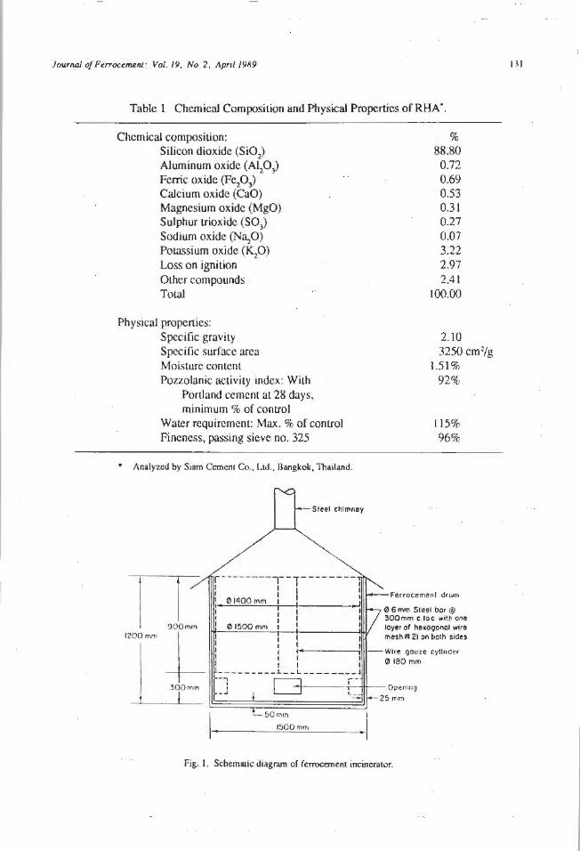
TheRHA cement used in ll1is experimenlal investigation is a mixture of Portland cemem 1.ypc V and RHA which was produced by Islam's and Awm's melhods 13, 5]. The mixing procedure for Lhc mortar was in accordance with ASTM C 305-65. The percentage of cemem replacemem by RHA was fixed at 50% by weight and the chemical composition and physical properties of RHA arc given in Table 1. The ferroccrnem incinerator used for burning rice husk is shown in Fig. 1.
The Portland cement used in this experimental investigation for comparison with R HA c~ment was type V Portland cement.
Thi.! consistency of mortars made Crom both Portland cement type V and RHA were kept equal to a flow value of 110± 5%. The ratio of Portland cement to sand is 1:2.75 and a water-cemen t ratio of0.485 was used forPortlandcementmortarascontrol specimens. ForRHA mortar, thcratioorRllA cement to sand is 1 :2.75 and a water-cement ratio of 0.60 was used for RHA cemem mortar as test specimens. No admixture was used in the mix. These mix proportions were used LhroughouL lhe investigation.
Mild steel rods 6 mm in diameter and 19 mm hexagonal galvanized wire mesh of gauge number 21 were used for this experiment.al study.
TEST RESULTS AND DISCUSSIONS
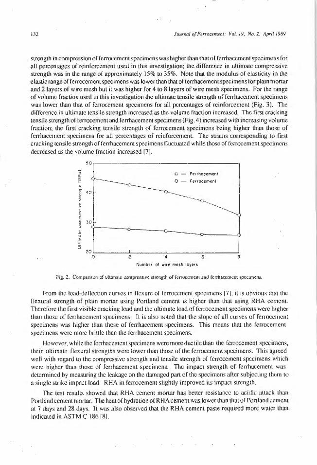
The average values of ultimaLC compressive strength for different number of wire mesh layers of fcrrhacement and fcrrocement specimens are compared in Fig. 2. lt can be seen that the ultimate
Journal of Perrocemerit; Vol, 19, No. 2. April 1989
Table l Chemical CompoSiLion and Physical Properties of RHA •.
Chemical composition: Silicon dioxide (Si0
2)
AJuminum oxide (~03) Ferric oxide (FepJ Calcium oxide (CaO) Magnesium oxide (MgO) Sulphur trioxide (S03)
Sodium oxide CNUzO) Potassium oxide (~O) Loss on ignition Olher compounds Toi.al
Physical properties: Specific gravily Specific surface area Moisture conrent Pozzolanic activity index: With
Portland cement at 28 days, minimum % of control
Water requirement: Max. % of conlrol Fineness, passing sieve no. 325
• Analyzed by Siam Cement Co., Ltd .. Bangkok, Thailand.
-Sleel chlmnay
'---50mm
l500mm
% 88.80
0.72 0.69 0.53 0.31 0.27 0.07 3.22 2.97 2.41
t00.00
2.10 3250 cm2/g
I.51 % 92%
ll5% 96%
Ferrocemenl drum
0 6 mm Steel bor@ 300mm c.toc, with one loyer or hexogonol wjre mesh~ 21 on borh sides
Fig. I. Schematic diagram of ferrocement incinerator.
131
132 Jowrwl of Ferrournent: Vol. 19, No. 2, April 1989
strength in compression of ferrocemcnt specimens was higher than thatof ferrhacement specimens for all percenrages of reinforcement used in this investigation; the difference in ultimate compressive strength was in the range of approximately 15% to 35%. Note that the modulus of elasticity in the elastic range of ferrocementspecimens was lower than that of ferrhacement specimens for plain mortar and 2 layers of wire mesh but it was higher for 4 to 8 layers of wire mesh specimens. For the range of volume fraction used in this investigation the ul timate tensile strength of ferrhacement specimens was lower than that of fcrrocement specimens for all percent.ages or reinforcement (Fig. 3). The difference in ultimate tensile strength increased as the volume fraction increased. The first cracking tensile strength of ferrocement and fcrrhacement specimens (Fig. 4) increased with increasing volume fraction; the first cracking tensile strength of fcrrocemcnl specimens being higher than those of ferrhacement specimens for all percentages of reinforcement. T he strains corresponding to first cracking tensile strength of fcrrhaccment specimens fluctuated while those of ferrocement specimens decreased as the volume fraction increased f7l.
50
J'.. o - f'errhoocmenr :i: 0 - Ferrocement
= C!' 40 c ~ ~ ., ~ "' ~ 0
8 30 -u
~ 0
§
3 20
0 2 4 6 9
Number ol wire JT1e$h layers
Pig. 2. Comparison of ultimate oornprcssivc ~trcngth of fcrroccmcnt anti fcrrhaccmcnt specimens.
From the load-denection curves in llexure of fcrrocemenl specimens [7], i t is obvious LhHt lhe flexural strengLh of plain mortar using PorLland cemenL is higher lhan that using RHA cement. Therefore lhe first visible cracking Load and the ultimate load of ferrocement specimens were higher than those of ferrhacement specimens. IL is also noted that Lhe slope of all curves of ferrocemcnt specimens was higher Lhan Lhose of ferrhacemem specimens. This means that the fcrrocernent specimens were more brittle Lhan the ferrhacement specimens.
However, while Lhc f'crrhacemenl specimens were more ductile than the fcrrocement specimens, their ultimate OexuraJ strengths were lower than Lhosc of the fcrrocement specimens. Thjs agreed well with regard Lo Lhe compressive strength and tensile strength of fcrroccment specimens which were higher than those of fcrrhacemcnt specimens. The impacl strength of ferrhacement was determined by meac;uring Lhe leakage on the damaged part of Lhe specimens afLer subjecting them to a single strike impact load. RHA in ferrocement slightl y improved i ts impact strength.
The test results showed that RHA cement mortar has better resistance to acidic aum:k than Portland cement mortar. The heat of hydration of R HA cement was lower than that of Portland cement at 7 days and 28 days. IL was also observed I.hat the RHA cemenL paste required more water than indicated in ASTM C 186 [8].

Jour1111.l of FurocemenJ; Vol. 19. No. 2. April 1989
~ .,. c .. "' ., 'iii c ..
6~~~~~~~~~~~~~~~~~~~~~---.
O - Ferrhocemenl
5 - 0 - Ferrocemenl
3 -
05 '--~~~~-'-~~~~~~' ~~~~~-'-~~~~-' 0 2 4 6 8
Number of w1rn me'>h luycr s
Fig. 3. Comparison of ultimate tensile sirength of forroccmcnt and fenhacemcnt specimens.
30
0 Q. ::;: 0- Ferrhocemenl
= 2 .5 - 0- ferrocement
"' c ~ ., 0 2.0 -= .x u 0
u
:.. 15 u.
0
Number of wire mesh layers
Fig. 4. Comparison of fini cracking strength from tension tcsL
CONCLUSIONS
133
From lhe results obtained in this experimental investigation, the following conclusions can be drawn:
1. The increase of reinforcement in lhe specimens caused a decrease in their compressive strength bul an increase in their ductility. The ductility of the ferrhacement specimens was higher than that of ferrocement specimens.
2. The tensile strength of ferrhacement specimens was slightly lower than that of ferrocement specimens. The increase in volume fraction of reinforcement in both types of specimens led to an

134 lounw./ of Furocemu11: Vol. 19, No. 2, April /98Y
increase in ductiliLy and Lcns1le strength of both ferrocemcnt and ferrhacemem specimens.
3. The uJ timalc flexural strength of ferrocement specimens was higher lhan lhat of fcrrhaccmcn L specimens. The firslcrncking'Slrenglh of both types of specimens depended on U1e strengU1 of mortnr or Lhc modulus of rupture.
4. The impact sLrengU1 of fcrrhacemcnt specimens was almosL the same as that of fcrrocemem specimen . The crack pattern of U1e lower surface of fcrrhacement specimens was similar Lo that of ferrocement specimens.
5. The heal of hydration of RHA cement is lower than Lhat of Portland cement for au vo ume fractions of reinforcement. However, RHA cement needs more water in mixing mortar than Porlland cement.
6. The RHA cement morlilr showed a bcucr resistance LO acidic att.ack than normal Penland cement mortar, thus, it is useful as a construction material for structures such as sewage pipes, sludge tanks and other chemical containers or appliances.
7. As proved elsewherc, lheapplicationsorRHA cement in fcrrocement for construction of smallscaJe structures like water tanks is possible, and wonllwhile.
REFERENCES
l. Lakho, S.M. 1980. Production of Reactive RHA and i tS Applications in Pressed Soil-Cement Block, M.Eng. Thesis No. ST- 80-14, Asian Institute of Technology, Bangkok.
2. Si lva, M.W J.A. 1980. Current Swge of Research 0 11 ReacLivity of Rice Husk Ash Cc1nenL, M.Eng. Thesis No. ST-80-5, A-;ian Institute of Technology, Bangkok.
1. Islam, M.S. 1981. Grinding MeU1ods and their Effect on the Reactivity of Rice Hull Ash, M.Eng. Thesis No. ST-81-7, Asian Institute of Technology, Bangkok.
4. We, A.B. 1981. Production ofRHA and iLS Applications in Mortar and Concrete, M.Eng. Thesis No. ST-81-20, Asian Institute of Technology, Bangkok.
5. Alam, F.E. 1982. A More Effective Grinding Method tor Ri<.:e Husk Ash, M.Eng. Thesis No. ST-82-1, Asian Institute of Technology, Bangkok.
6. Khan , A.O. 1982. The Behaviour of Reinforced RHA Concrete Beams, M.Eng. Thesis No. ST-82- 10, Asian Institute of Technology, Bangkok.
7. Choeypunt,C. 1985. UscorRice HuskAshinFerroccmcnt, M.Eng. Thesis No.ST-85-5. Asian lnstilute of Technology, Bangkok.
8. American Society for Testing and Materials. 1979. Annual Book of ASTM Standards. Parts 13 and 14. Philadelphia, Pennsylvania: American Society of Testing and Materials.
Journal of Fl!TrocemenJ: Vol. 19. No. Z, April 1989 135
Use of Ferrocement for Confinement of Concrete•
P. Balaguru•
This paper presents the results of an investigalion on the behavior of plain concrete r:ylinders confined inferrocement shells. The experimental part of the investigation consisted of strength tests using 6in.x12 in. (1501runx 300 mm) cylinders. The primary variables were: compressive sLrength of concrete in the range of 3 ksi to 6 ksi (20 MP a to 40 MP a}, and 1to 4 layersof wire mesh. The wire mesh provided effective confinement, resulting in increase of compressive strength and increase in ductility. The increase in number of wire mesh resulted in consistent increase in both s1rength and ducLility. The increase in compressive strengths es1imated using constitu1ive models for confined concre1e compares well with the experimental results.
INTRODUCTION
IL is well known that confinement of concrete.increases the compressive strength and t11eductility. This contribulion to ductility is more important in structural components used in earthquake resistant design. AJmostalJ code of pracLices around the world stipulate ductile failurcof structural components used in the regions prone to earlhquakes. In a typical building, columns are considered to be the critical load bearing clements, and hence a considerable amount of research has been done to improve the ductility of columns. One of the most effective methods to improve the ducliJity is confinement of concrete. In normal reinforced concrete columns, confinement is achieved using continuous spiral reinforcement [IJ. In most cases, confinement is provided using ci rcular spiral, even though in some instances rectangular spirals are used. Circular spirals provide helter confinement because of lheir geometry.
This paper deals with the use of ferrocement shell for providing confinemenl. Since ferrocement has much better cracking characteristics compared LO reinforced concrete, the spalllng during failure could be reduced. InitiaJly cast ferocementshells could also be used as form work leading LO integrated construction. The technique can also be used for repair and strengthening of exisling columns and other vertical load bearing members.
EXPERIMENT AL PROGRAM
The experimental program was designed to Obtain the stress-strain behavior of concrete confined in ferrocement shell. The primary variables were: concrete strength which varied from about 20 MPa to 40 MPa; and the number of layers of wire mesh (0, I. 2, 3, 4 layers) used for confinement.
Materials
The materials used consisted of Type I (ASTM) cement, crushed stone and quarried sand. Wat.er-
+ Reprinted from Ferrocement: Applications and Progress, Proceedings of the Third International Symposium on Fcrroce· ment (8·10 December 1988), Roorkee, India by pcnnission of the publisher.
• Pmfessor, Civil Engineering, Rutgers, The State Univenity , New Jersey, U.S.A.
136 JourflOI of Ferroce~lll: Vol. 19, No. 2. April 1989
cement ratio was lowered to obtain higher strength by using high range water reducing admixtures (superplasticizer) to improve the workability.
Galvanized woven wire mesh was used with a square opening of 0.5 in. (12.5 mm) and a wire diameter of 0.043 in. (1.09 mm).
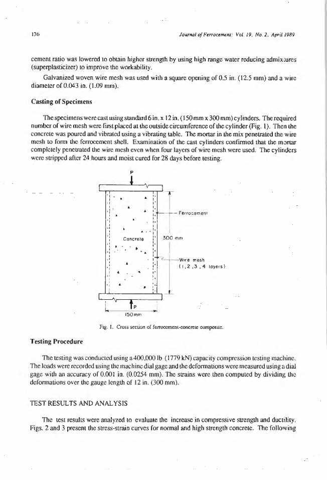
Casting of Specimens
The specimens werecasl using standard6in.x12 in. (150 mm x 300mm) cylinders. The required number of wire mesh were fust placed at the outside circumference of the cylinder (Fig. 1). Then the concrete was poured and vibrated using a vibrating table. The mortar in I.he mix penetrated the wire mesh to Conn the ferrocemenL shell. Examination of the cast cylinders confirmed that the mortar completely penetrated the wire mesh even when four layers of wire mesh were used, The cylinders were stripped after 24 hours and moist cured for 28 days before testing.
Testing Procedure
'I I
• I I
·f I ' I ., I
" I
p
'· • I ,. '· • : . ~" -+- Ferrocement t ,. I
'· • . I ·l
1 Concrete :· 300 mm . I .
t • t ., I
·' I ., I •
" I
:· :· f t Wn e mesh :· (1,2 ,3,4 loyers ) ,. I .
I I 'I • , •
,_...~'~~~~~~·~· _,_L
p
150mm
Fig. I. Cross section of ferrocement-concreie composile.
The testing was conducted using a 400,000 lb (1779 k:N) capacity compression testing machine. The loads were recorded using the machine dial gage and the deformations were measured using a dial gage wi l.h an accuracy of 0.001 in. (0.0254 mm). The s1rains were then computed by dividing the deformations over the gauge length of 12 in. (300 mm).
TEST RESULTS AND ANALYSIS
The test results were analyzed to evaluate the increase in compressive strength and ductility. Figs. 2 and 3 present the stress-strain curves for nonnal and high strength concrete. The following
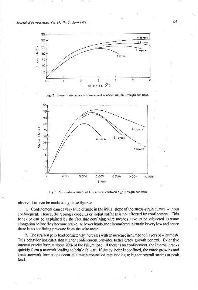
Journal of Ftrroctmenl: Vol. 19, No. 2. llpril 1989 137
35 4 layers
30
0 25 0.. ~ 20 .. 15 .. ., ~
(/') 10
5
0 2 3 4 - 3
Strain ( x 10 )
Fig. 2. Stress-strain curves of fcrroccmcnt confined normal $Lrcngth concrete.
55
50
45
40
0 0. 35 ~
.. .. 25 ..
~
(/)
20 3 toyers
15
10
5
Strain
Fig. 3. Stress-sLrain rurves of fcrrocemcnt confined high strength concrete.
observations can be made using these figures:
1. Confinement causes very liuJe change in I.he initial slope of I.he stress-strain curves without confinement Hence, I.he Young's modulus or initial stiffness is not effected by confinement. This behavior can be explained by the fact that confining wire meshes have to be subjected to some elongation before I.hey become active. Al lower loads, I.he circumferential strain is very low and hence there is no confining pressure from I.he wire mesh.
2. Thcsrrain at peak load consistently increases with an increase in number of layers of wire mesh. This behavior indicates I.hat higher confinement provides better crack growth control. Extensive mtemal cracks form at about 70% of I.he failure load. ff there is no confmement, I.he internal cracks quickly form a network leading lo brittle failure. If I.he cylinder is confined, the crack growths and crack-network formations occur at a much controlled rate leading to higher overall strains at peak load.
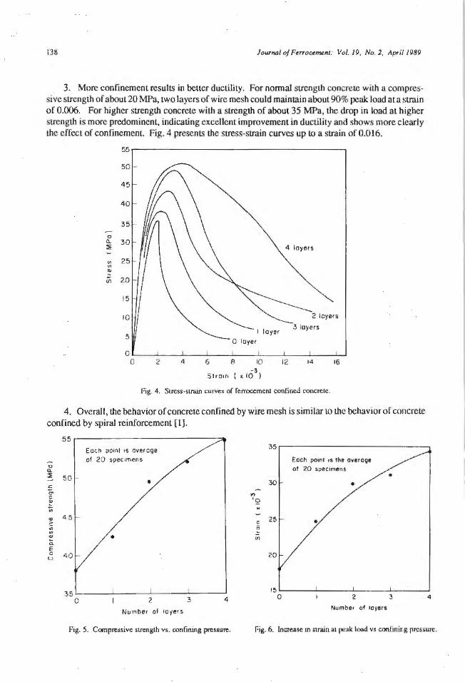
138 JourftD/ of F~rrocetMnl: Vol. 19, No. 2, April 1989
3. More confinemem results in beucr ductility. For nonnal sLrength concrete with a compressive strength of about 20 MPa, two layers of wire mesh could main lain about 90% peak load ata strain of 0.006. For higher strength concrete with a strength of about 35 MPa, the drop in load at higher strength is more predomincnl, indicating excellent improvement in ductility and shows more clearly the effect of confinement. Fig. 4 presents the stress-strain curves up to a strain of 0.016.
55
50
45
40
35
0 a. "30 :l!
"' 25 "' "'
U'l 20
15
10
5
0 0 2 4 ' 6 8 10
-3 St ram ( x 10 )
12 14
l'ig. 4. Sircss·sll'llin cul"Ves of fcrroccment confined concrete.
t6
4. Overall, the behavior of concrete confined by wire mesh is similar to the behavior or concrete confined by spiral reinforcement [ l]. 55~~~~~~~~~~~~~~---:a.
50
.. 45 ~ .. .. .. c E 0
t..> 40
Each point is overage of 20 specimens
.... ' Q
30
c 25 0 (/)
20
Each point 1s lhe avero9e of 20 specimens
35'--~~-'-~~~-'-~~~~~~--' 15'-~~-'-~~~-'-~~~.._--~--'
0 2 4 0 2 4
Number of layers Number of layer$
Fig. 5. Compressive strength vs. oonfming pressure. foig. 6. Increase m strain at peak load vs conf.irur g pressure.

Jou'1wl of Ftrroctmefll: Vol. 19, No. 2, April 1989 139
Figs. 5 and 6 present the varial.ion or compressive strength and strain al peak load as a funclion of confinement The confinement is represented by the number of wire meshes placed around the cylinder. The results are presented only for Lhe high strength concrete for the sake of brevity. From Fig. 5, iL can be seen that an increase in the number of layers consisten lly increases the compressive strength. The strength increase could be as high as 50%.
From Fig. 6, il can be seen thaL lhc strain al peak load can be doubled by providing four layers of wire mesh confinement As discussed above, post peak performance is also improved substantially.
PREDICTION OF SJRENGTH INCREASE
The increase in compressive strengths for various confinemenl pressures were computed using general constitutive equations of concrete. It was assumed Lhat the rcinf orcement yielded at the maximum load. The force generated by the wire mesh, P. was assumed to be uniformly distributed across the length of the cylinder.
TI1e f orcc P can be computed using the equation:
p =A f. , ' .................... ( I )
where A,= cross-sectional area of all the wires across the height of the cylinder. [For example, iflwo layers of half-woven wire mesh (wire spacing= l(l in. (12.7 mm)). are used , the area, is 48 times I.he area of one wire.l
and / , = yield strength of reinforcement
The ring tension, R. resulting from the force P can be computed using the equation:
where, l = height of the cylinder.
p R = - lb/in. (N/mm)
I ................... (2)
The ring tension R, produces a confining pressure, p computed using lhe equation:
2R p = d psi (N/mm2
) .................... (3)
where d = diameler of lhe cylinder.
The confining pressures produced by various amounts of wire mesh and the data of Shah and Associates [2, 3] were used lo estimate the increased compressive strengths. Fig. 7 shows I.he comparison of the experimental and Lhe predicted values. From Fig. 7. iL can be seen that the precUction is reasonably accurate. Hence, the research resulLS available in the area of spirally confined concrete can be utilized for the analysis of fcrroccrnent confined concrete.
CONCLUSIONS
Based on the results obtained in I.his investigation, the foJJowing conclusions can be drawn:
I. Ferrocement can be effectively used as a confining shell for concrete.
140
0
~ 50
~ 45
"' "' .. ii E. 0
u 40
Journal of Fe"ocernen1: Vol. 19, No. 2, April 1989
•
35'--~~~~~~~~~~~~~
0 2 3 4
Number of layers
Fig. 7. Comparison of e,xperimental and predicted increase in compressive strengih.
2. Confinement of concrete with ferrocement results in increase of compressive sLrengU1 and ductility. The increase in ductility is substantial. Large amount of deformations can be sustained while maintaining about 90% of the peak load.
3. The compressive strength of concrete confined in ferrocement shell can be predicted witl1 reasonable accuracy, using the existing models.
REFERENCES
1. Bertero, V.V., and Vellens, J. 1977. Confined concrete: Research and development needs. In Workshop on Earthquake-Resistant Reinforced Concrete Building Construction, 594-610. Berkeley: University of California.
2. Palanisamy, R., and Shah, S.P. 1974. Fracture and stress-strain relationship of concrete under triaxial compression. Journal of the Structural Division, ASCE 100(5): 901-916.
3. Ahmad, S.H., and Shah. S.P. 1982. SLress-strain curves of confined concrete. Journal of American Concrete Institute 79(6): 484-490.
Jownal of Femx:eme111: Vol. 19. No. 2, April /989
Ferrocement Housing: Toward lntergrated High Technology Solutions+
A.E. Naaman*
141
After a brief review of llu: different levels of techoologies used inferrocement housing products. the present paper focuses on the resul1s of a feasibility study recently completed at the Univerity of Michigan where advanced manufacturing techniques were considered for the production of housing unils usingferrocement panels. The study suggested that most common hou.~ing requirements could be sati.~fied f rom a pool of abolll ftf1een standard panel config urations. Box shaped panels were considered for the walls and lintels, while U shaped panels were considered for flooring and roofing. System requirements are described and needed research suggested.
CNTRODUCTION
The success of ferrocement in various terresLrial applications including housing has been auributcd to !he ready availabil ity of i ts component materials, !he low level of technology needed for 11S construction and the relatively low cost of !he final product However forrocementoffer:, one often overseen feature, tliaL of quality and cost. High quality can be readily observed in such recent applications as the dome of !he Mausoleum Mosque in Amman, Jordan ;md the sixty foot (18.3 m) long louvres in LheMenil Museum in Houston. Although thcquality of ferrocement prod ucLS has been proven in many ways, the level of 1cchnology involving ferrocement consLruclion is lagging well behind progress in other indusLries.
Ferrocement has been used in various forms of housing systems requir ing various Jevels of Lechnology. Al one end, ferrocement domcs were used on a self-help basis as roofs LIJ or simply LO
build entire enclosures called a room or a house. A higher level of t.cchnology was considered in building fcrrocemem sandwich panels with integrated foam insulation [2, 3) and a higher level of quali ty is also expecLed from such products. Highly i ntegraLcd modular housing units made out primarily of ferrocemenl have been suggested in various technical publications [4-8) but no real application of such systems is known Lo the author. Clearly, the higher the degree of integration und sophistication in concept is, the higher !he level of possible industrialization is.
Today, an extraordinary connucnce of new technology and a large market for housing products worldwide can bring about a revolution in the way ferrocement is used. Advanced technology can expand Lhe applications of fcrrocement and greatly improve iLS subjective acceptance by the user a'> a high quaJiLy, high technology, high luxury, durable and cost competitive (buLnol cheap) consLruction material.
Ferrocement is ready for new technologies and, while housing components of fcrroccmenl can be built using advanced manufacturing t.cchniqucs, there is need to develop entire housing packages where the fcrrocement subsystem is intc&'Tated as part of the whole housing system and can occupy
+ Reprinted from 17erroccmcnt: Applicalions and Progress, Proceedings of the 'Third International Symposium on r:crroccmcnt (8-10 December 1988), Roorkcc, l ndia by pennission of the publisher.
• Dcpanmcnt of Civil Engineering, U111vcrsi1y of Michigan. Arm Arbor, Michigan, U.S.A.
142 Journal of Ferrocemenl; Vol. 19. No. 2. April J<JiJ9
a balanced portion of it Current advances in robotics, computerized manufacturing, machine vision, expert systems and the li.ke allow us to project that such advanced technologies which arc already in use in the auto industry can bcsucccssfulJy utilized in the production of manufactured housi.ng systems where ferrocement is lhe primary structural material.
Afler a brief review of the different levels of technologies used in ferroccment housing product.'\, lhe present paper focuses on the results of a feasibility study where advanced manufacturing techniques were considered for the production of single family housing units using ferrocernent panels. One of the constraints considered was lhat the housing system so produced should be of c:qual if not better quality than standard single family housing uni ts currently found on the U.S. market. The study suggested that most common housing requirements could be satisfied from a pool of about fifteen standard panel configurations. Although the ferrocement subsystem can occupy a wide range of structural and protective functions within the housing unit, iL was shown that the same group of panels could be used for the sk.in (outside bearing walls}, the floors and the roof of the house. ln all cases, the connection between various elements was assumed satisfied by bolting. An analysis of the requirement.-; and the potential of such a ferroccment sysLem for housing are described below and related conclusions drawn ,
HOUSING CONSTRUCTION: ENGINEERING VISION AND BUYER'S DREAM
It is nm uncommon that what seems lo be today an engineering vision will likely become common practice a decade from now. ln thecontexLofthis study, it was anLicipalcd that an expert system would be designed for Lhc use of a ferroccment building system in single family housing construction. Thus, a potential buyercan interact in a friendly relaxed environment wilh a computer and be brought by the expert system, through questions and answers, lO specify the housing requirements he would like to purchase. The system would then provide information on the entire house package. Such informal.ion would not only include obvious iLems like floor plans and elevations, but also isometric views of Lhc house in a particular setting (say niral versus urban), three dimensional views of each room and what is seen from various angles, and olher technical details such as types and corresponding numbers of ferrocemenl panels for factory production and eslimatcd cost. The customer would then interact. wiLh a salesperson to place an order for a house to be delivered within few weeks. Of course this assumes that a site is available and has been re.adicd for housing permit, foundation, sewer and the like. In such a scenario, ferrocemenl panels could be delivered with their insulation and all electrical jacks inst.ailed. Special mudular units may be used for bathrooms and be deliverc_fl entirely finished.
SYSTEM REQUTREMENTS
Four classes of single family housing systems can be found in the U.S. market: on site construction, modular, panelized and mobile homes. Their share of the market is described in Fig. 1. In these systems, timber is the primary construction and structural material. Each system may require different levels of technology and integration. Everythjng else being equal, for on site construction, a low level of technology is sufficient, while a panelized system would require intermediate level of industrialization and a modular system would require a high level of industrialization.
Modular units using (errocement have been considered in Lhc past but their usc has been limited. An example was described in an earlier study on prefabricaled housing [SJ. It seemed Lhat the 11se of a panelized system had a better chance of covering a wider range of applications and was ffoxible enough to satisfy a larger number of constraints.
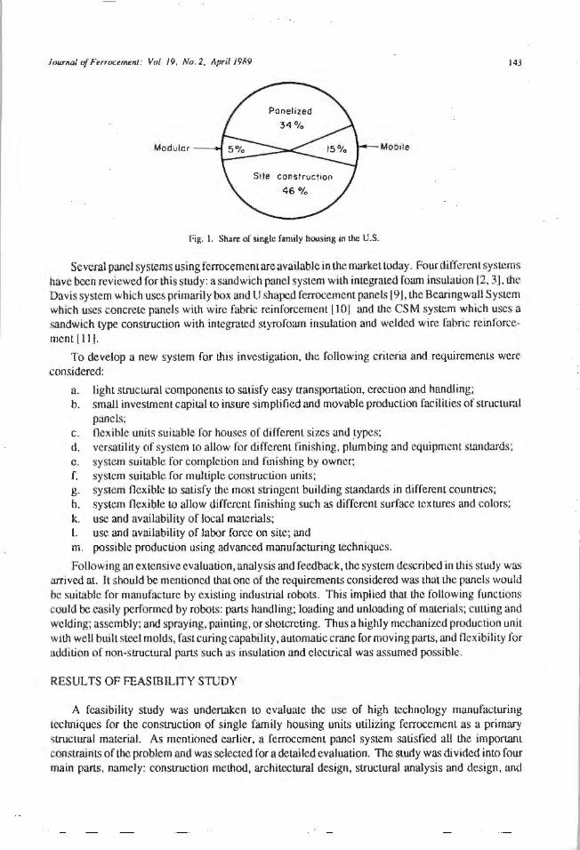
Journal of Ferroctnuml: Vol. 19, No. 2, April 1989 143
Modular Moo11e
foig. l. Shuro of ~ingle family housing in the U.S.
Several panel systems using forrocemcmareavailable in the market today. Four different systems have been reviewed for this study: a sandwich panel system with imegrated foam insulation f2, 3J, the Davis system which uses primarily box and U shaped ferrocemcnt panels 19 J, the Bearing wall System which uses concrete panels with wire fabric reinforcement [10] and the CSM system which uses a sandwich type construction with integrated styrofoam insulation and welded wire fabric reinforcement fl I].
To develop a new system for this investigation, the following criteria and requirements were considered:
a. light structural companents to satisfy easy transportation, erection and handling; b. small investment capital LO insure simplified and movable production facilities of structuml
panels; c. ncxiblc- units suit.able for houses o( different sizes and types; d. versatility of system to allow for different finishing, plumbing and equipment standards: e. system suitable for completion and finishing by owner; f. system suitable for mulLiple construction units; g. system Oexible LO satisfy the most stringent building standards in different countries; h. system flexible to allow different finishing such as different surface textures and colors: k. use and availability of local materials; I. use and availability of labor force on site~ and m. possible production using advanced manufacturing tcehniqucs.
Following an extensive evaluation, analysis and feedback, the system described in this study was arrived at. It should be mentioned that one of the requirements considered was that the panels would be suitable for manufacture by exisling industrial robots. This implied that the following functions could be e.:tsily performed by robots: parts handljng; loading and unloading of materials; cutting and wcldfog; assembly; and spraying, painting, or shotcreting. Thus a highly mechanized production unit with well built steel molds, fast curing capability, automatic crane for moving parts, and flexibility for addilion of non-structural parts such as insulation and electrical was assumed possible.
RES UL TS OF FEASIBILITY STUDY
A feasibility study was undertaken to evaluate the use of high technology manufacturing rechniques for the construction of single family housing units utilizing ferrocement as a primary structural material. As mentioned earlier, a ferrocement panel system satisfied aU the important constrain IS of the problem and was selected for a detailed evaluation. The study was divided into four main parts, namely: consuuction method, architectural design, structural analysis and design, and
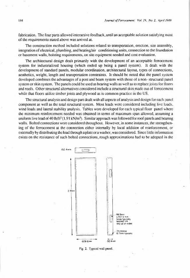
1411 Jo1;rnal of Ferrocef'lefll: Vo{. 19, No. Z. April 1989
fabrication. The four parts allowed imeracLivc feedback, until an accept.able solution satisfying most of the requirements stated above was arrived at.
The construction method included solutions related to transportation, erection, sit.e assembly, integration of electrical, plumbing, and heating/air conditioning units, connection to the foundation or basement walls, hoisting requirements, on site equipment needed and cost evaluation.
The architectural design dealt primarily with the development of an acceptable ferrocement system for industrialized housing (which ended up being a panel system). It dealt with the development of standard panels, moduJar coordination , architectural layout, types of connections, aesthetics, weight, length and transportation constraints. It should be not.ed that the panel syst.cm developed combines the advantages of a post and beam system with those of a non- structural pane1 system or skin system. The panels could be used as bearing walls as well as to replace joists for Ooors and roofs. Other structuml alternatives considered include a structural skin made out of ferrocemcm while tba.l Ooors utilize timber joisL<> and plywood as is common practice in the US.
The structural analysis and design pan dealt with all aspects of analysis and design for each panel component as well as the total structural system. Most loads were considered including live loads. wind loads and lateral stabiliLy analysis. Tables were developed for each typical floor panel where the minimum reinforcement needed was obtained in terms of maximum span allowed, a5suming a uniform live load of 40 lb/ft2 (1.91 kN/m2). Similar approach was followed for roof panels and bearing walls. Bolted connections were considered throughout. However, in some instances, the strengthening of the ferrocement at the connection either internally by local addition of reinforcement, or externally by distributing the load through a plate or a washer, was considered. Since little information exists on the resistance of such bolted connections, rough approximations had to be adopted in the
152.<!mm 1: ..... ~---J
~ B8.9mm ~ 457 2 mm
~:~.~~/~lly woy up on side'
Tt11c~ne-&a 12 ?mm IYPoCOllV
609 6"'"' 1524mm
Fig. 2. Typical wall panel.
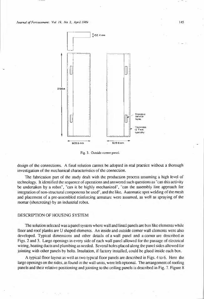
Journal of Ferrocemenl t Vol. 19, No . 2, April 1989
259m
.. ...... .. ....
609.6 '""' 6096mm
Fig. 3. Outside comer panel.
S1andard service 1>01 ..
, Tt>tckness ll!,7mm typically
145
design of the connections. A final solution cannot be adopted in real practice without a thorough investigation of the mechanical characteristics of the connection.
The fabrication part of lhe study dealt with the production process assuming a high level of technology. It identified the sequence of operations and answered such questions as "can this activity be undertaken by a robot'', "can it be highly mechanized", "can the assembly line approach for integration of non-structural components be used", and the like. Automatic spot welding of lhe mesh and placement of a pre-assembled reinforcing armature were assumed, as well as spraying of the mortar (shotcreling) by an industrial robot
DESCRIPTION OF HOUSING SYSTEM
The solution selected was a panel system where wall and Lintel panels are box like elements while Ooor and roof planks are U shaped elements. An inside and outside corner wall elements were also developed. Typical dimensions and other details of a wall panel and a comer are described in Figs. 2 and 3. Large openings in every side of each wall panel allowed for the passage of electrical wiring, heating ducts and plumbing as needed. Several boles placed along the panel sides allowed for jointing with other panels by bolts. Insulation, if factory installed, could be glued inside each box.
A typical floor layout as well as two typical floor panels are described in Figs. 4 to 6. Here the large openings on the sides, as found in Lhc wall units, were left optional. The arrangement of roofing panels and their relative positioning and jointing to the ceiling panels is described in Fig. 7. Figure 8
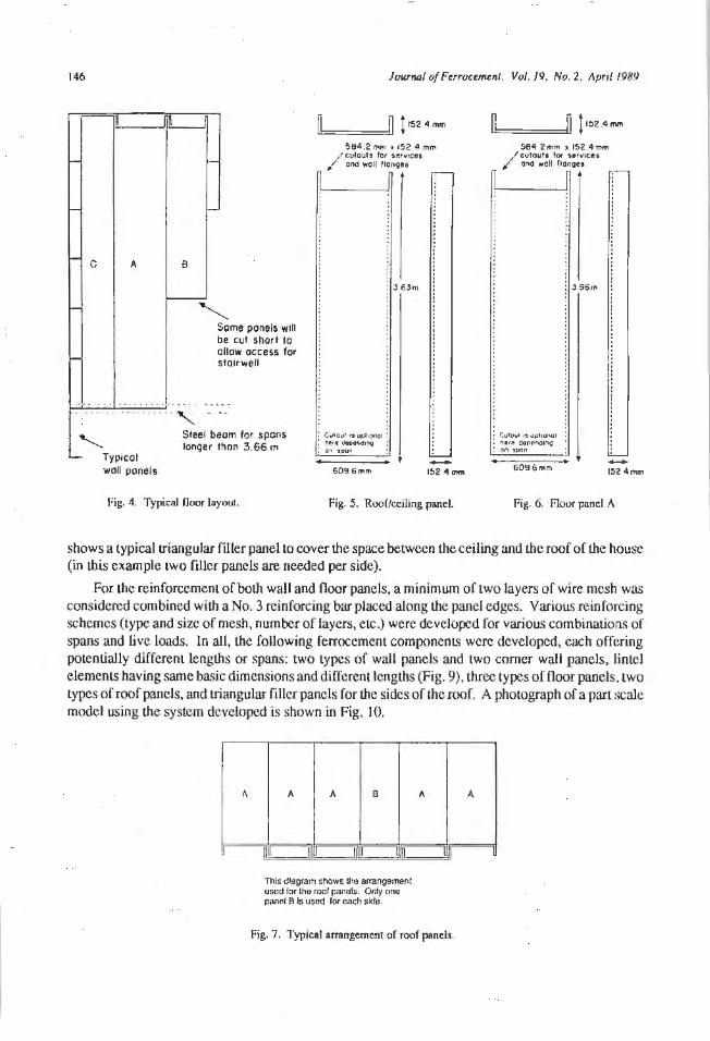
146 Journal of Ferrocem.ent: Vo/. 19. No. 2, April 1989
I
,_ c A
-
n
,_
B
,__
"' Some panels will be cut shorl to allow access for stal rwell
. . . . . . . . . -· . . . . . . . . - ~ ·:·-- ..... .. .. .... , "-
Typlcol wall panels
Slee! beam for spans longer thon 3.66 m
fig. 4. Typical floor layout.
Ll:::~ ===il" f 152.4 mm
584.2 mm • 152.4 mm
/ cutou1 s for 1ervlces. end woll llonoes
Cu101.1f !9 Qf.lh~I hfl. dtot"dl"V on apon
60 9.6mm
3 63m
152 4 mm
Fig. 5. Roof/ceiling panel
l!=n ===!.In ! 152.4mm
584.2 mm • 152 4 mm
I cutbu!J '°' service. " ono well llcnoes
CufOol 19 '1Pl!l)l'\Qf ~ere ct.nono1no on SUDO
609.6 mm
•
396m
-15? 4mm
Fig. 6. Floor panel A
shows a typical triangular filler panel to cover the space between the ceiling and the roof of the house (in I.his example two fi.llcr panels are needed per side).
For lhe reinforcement of both wall and floor panels, a minimum of two layers of wire mesh was considered combined with a No. 3 reinforcing bar placed along lhe panel edges. Various reinforcing schemes (type and size of mesh, number of layers, elc.) were developed for various combinations of spans and live loads. In all, the following ferroccment components were developed, each offering potentially different lengl.hs or spans: two types of wall panels and two comer wall panels, lintel elements having same basic dimensions and different lengths (Fig. 9), three types of floor panels. two types of roof panels, and triangular filler panels for the sides of the roof. A photograph of a part scale model using the system developed is shown in Fig. I 0.
fl A A B
I n n m
Tt1ls diagram shows the arcangement usod for the roof panels. Only one panel B is used for each side.
A
n
Fig. 7 . Typical arrangement o[ roof panels.
A
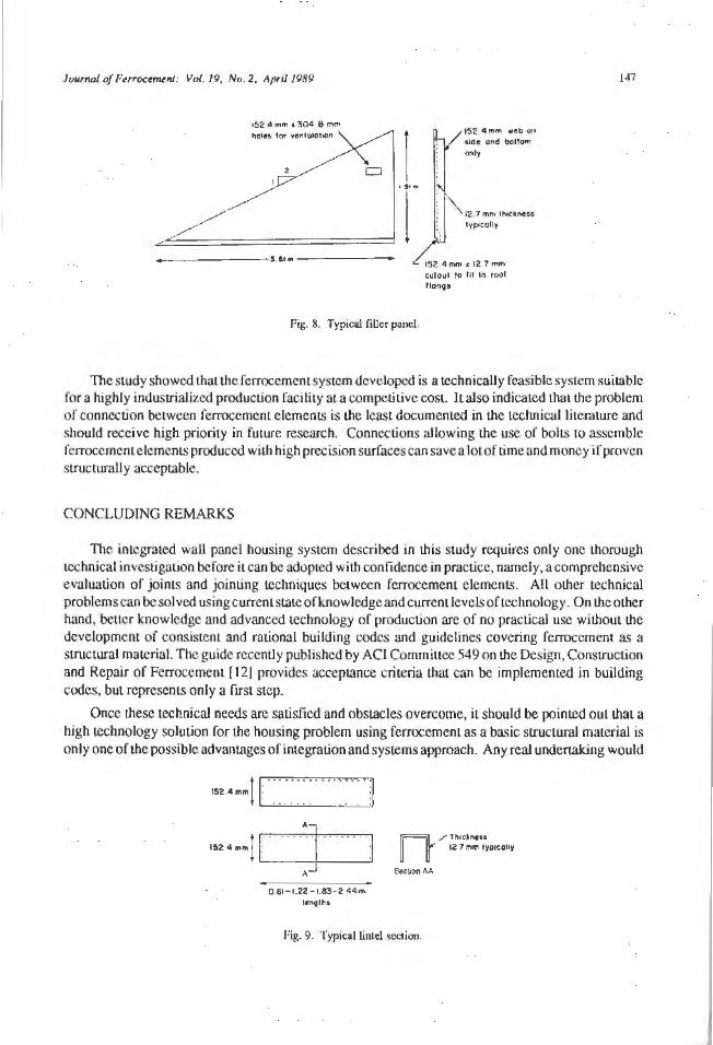
Journal of FerrocemLnJ: Vol. 19, No. 2, April 1989
152 4mm 1304 8 mm
1 I 91"'
I ---- - --3 ..... ----- -
Fig. 8. Typical filler panel.
152 4 mm web on 11dt a"d bot1om only
12 7 mm lhoc-ness lyp<colly
15 2 4 mm • 12 7 mm c ul oul 10 Ill In roof
llono•
147
The sLudy showed Lhat Lhe fcrrocernenL system developed is a technically feasible system suiLable for a highly industrial ized producLion facility al a compeliLive cost. IL also indkated that lhe problem of connection between ferrocement elemenLS is Lhe least documented in the technical l i terature and should receive high priority in future research. Connections al lowing Lhe use of bolts to assemble ferrocemcntelements produced wilh high precision surfaces can save a lot of time and money if proven sLructuraUy acceptable.
CONCLUDING REMARKS
The integrated wall panel housing system described in Lhis study requires only one thorough Lcchnical investigation before i t can be adopted wilh confidence in practice, namely, a comprehensive evaluation of joints and jointing techniques between fcrrocement elements. All other technical problems can be solved usingcurrentstmeofknowledge and current levels of technology. On Lhe olher hand, better knowledge and advanced technology of production arc of no practical use without the development of consistent and rational building codes and guidelines covering ferrocemcnt as a structural material. The guide recently published by ACI CommiLLcc 549 on the Design, ConsLrucLion and Repair of Ferrocemem [ 12J provides acceptance criteria that can be implemented in building codes, but represents only a first step.
Once lhese technical needs arc satisfied and obstacles overcome, it should be pointed out I.hat a high technology solution for the housing problem using f erroccment as a basic sLrUctural material is only one of Lhe possible advantages of integration and systems approach. Any real undertaking would
152 41 mm 1 , . • . • • • • .. • • --- • :1 I . . . . . .
• '] uuul A
0 61-1.22-1.83-2.44-IT'
l••Qlh •
12 1 mm IVP<COlly n / l f'l1c• n111
Scci.on M
Fig. 9. Typical lintel section

148 Journal of FerrocerMnt: Vol. 19. No. 2, April 1989
Fig. I 0. Scale model.
require careful planning, effective organization, financial backing and s1rong marketing. Marketing is particularly needed to educate the engineering profession first and the public next, to eradicate the misconception that ferroccment provides solely "cheap", "low cost" solutions for housing. Nc:xt to wood, ferrocement is today the most versatile building material for housing, since it can be effectively used in all struccural and non structural components.
REFERENCES
1. Castro, J. 1977. Ferrocement roofing manufactured on a self-help basis. Journal of F errocemem 7(1): 17-27.
2. Tatsa, E.Z.; Prawel, S.P.; Moses, A.; and Oromodion, T. 1981. MulLi-sLOrey construclion using ferrocement panels. Journal of Ferrocement 18(1): 67-76.
3. Tatsa, EZ. 1988. Construction with ferrocement panels. Journal of F errocemem 18(1): l 7-33.
4. Naaman, A.E. 1979. Acostevalualion of optimally prefabricated housing. Housing Science 3(1 ): 35-53.
5. Robles-Austriaco, L. and Pama, R.P. 1981. Ferrocement- An innovalive technology for housing. Journal of Ferrocement 11(1): 23-45.
6. 1981. Housing Applications in Ferrocement. Journal of Ferrocement 11(2).
7. Yom-Tov, S. 1983. Building with ferrocement - Free-form space structures. Journal of Ferrocement 13(4): 327-334.
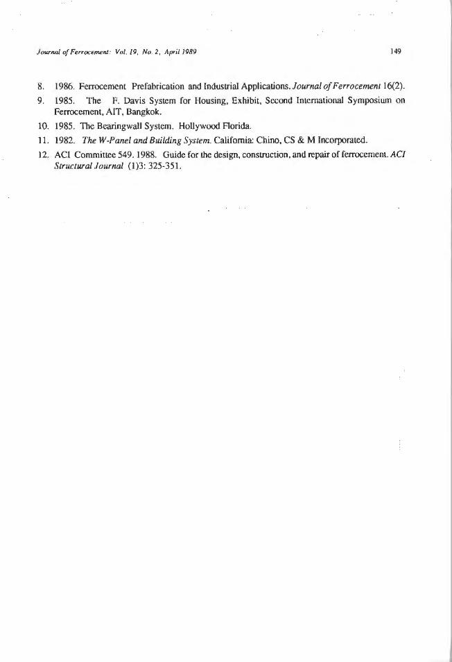
JourflDl of Fe" ocemenl: Vo/.19, No. 2, April 1989 149
8. 1986. Ferrocement Prefabrication and Industrial Applications. Journal of Ferrocement 16(2).
9. 1985. The F. Davis System for Housing, Exhibit, Second International Symposium on Ferrocement, AIT, Bangkok.
10. 1985. The Bearingwall System. HolJywood Florida.
11 . 1982. The W-Panel and Building System. California: Chino, CS & M Incorporated.
12. ACI Committee 549. 1988. Guide for the design, construction, and repair of ferrocemem. AC! Structural Journal { 1)3: 325-35 1.
Journal of Ferrocement: Vol. 19, No. 2, Apri/1989 151
TIT JP~ W (Q) IB &IMI& TIElIJJE IffilIJJIILJD)JEffi§
Steam Curing and Post Construction Tips
S. Smith*
STEAM CURING
Some people feel thal lhere is a lot of mystery surrounding the idea of steam curing concrete. This is really not the case- it has simply been done only occasionally because not too many people know what to do, how long to do il, why il needs to be done, and so forth.
MosthuJls arc cured by keeping them wet and letting them sit around in the weather for28 days. There is some consensus among the cognoscenti that the hulls should then sit around for at least six monlhs to finish curing before beginning to put on paint and such. This is true. However, it turns out that cement slowly continues to cure for much longer than that. A number of paint adhesion problems on older hulls can be related to the age of the cement. In one particular case, epoxy paint showed poor adhesion to one-year-old concrete patches on a five-year old concrete hull, while the same epoxy paint showed excelleOL adhesion to the hull itself. The adhesion problems were in the form of small blisters. What may happen is that as the concrete cures, it tends to close up and become less permeable to water. Sun or temperature differences can cause the water trapped between the impermeable concrete and the epoxy sealer Lo lift the sealer off the concrcu::. This is noc a breakdown in the adhesion of the sealer because small pieces of concrete can be found adhering to the backside of the skin or sealer when the bubbles arc cul open.
Lime is present in fresh cement and as it cures, the lime is used up by the curing reaccion. The presence of lime and moisture seems to break down the bond between the concrete and almost anything. Blisters formed in this manner show little or no cement particles adhering to Lhe inside of the blisters.
Cement can bleed alkali under some conditions for many months after it was plastered on the steel mesh. Whatever the situatjon may be, any reasonable degree of adhesion cannot be expected between any polymer coating and the cement umil lhe cement is chemically and mechanically stable and free of migrating alkaline residues.
Now the question is what can be done about lhis. The easiest thing to do, given a lot of time, is
•Principal, Smith and CompAny, 5100 Channel Ave., Richmond, California 94804. U.S.A.
152 Jounwl of Furuc<!mMI Vol. 19, No. 2. April 1989
to let the hull sit for about five years. lL appears that hulls that have been around for fi vc years and then have been painted have not had any problems of this son. Another method is to steam-cure the hull. A eoncret.c hulJ exposed to l 80"F (82.2"C) steam for appro~imately 48 hours willcurc to theequi valcm of about five years of sitting around in SO"F ( I O"C) weather. This is why some people steam-cure their hulls. So the question is how LO do it.
To begin with, get a steam generator. The steam gen em tors that have been used are rated at about 500,000 Btu/hour or 15 boiler HP.
The entire hull should be draped with visqueen Lo cover it across the top and down to 1.he ground on both sides. Stitch parallel SI.rips of the visqueen together with 16-penny nails or whatever else is handy and sandbag the ends on both sides so that they slay against the ground. Direct the steam generally into the area under the hull, being careful to avoid spraying li ve steam on any one particular point of the hull. Place a thermometer near I.he shear line and c.heck it after several hours. The temperature should be up to about 180"F (82.2"C). Keep it there for two days.
Basically what happens is this: Concrete will slowly cure for a considerable length of Lime. The dcndrilic structures that give concrete its strength continue to grow at nonnal temperatures for many years. Jf this process is accelerated, one ends up with relatively st.able concrete in a short time. The rate of chcrnicaJ reaction will approximately double for every l 5°F (8.33"C) increase. So if one can't get it up to 180"F (82.2"C) for 48 hours but can get it up LO 165°F (73.9"C), then the hull should be kept at that temperature for 96 hours - twice as long. If one can only get iL up to 150"F (65.6"C), the hull should be kept al that temperature for 192 hours. The steam supplies whatever moisture the concrete requires and the heat accelerates the curing reaction to produce good aged concrete in a reasonable length of time. This is basically what happens in the process of st.cam-curing concrete.
To summarize the curing time rccommendaLions: Experience by the author and Urnt of Jim Campbell over the last 16 years tells that hulls that have had absolutely no problem haveconsist~ntly been cured in San Diego weather (roughly 80"F (26.7"C)) for about two years. Hulls that have been cured in San Francisco wealher in temperatures of 60"F (15.6°C) for about three times that length of time (roughly five to six years) have had no problems. These then would be recommended cure times for hulls exposed to the weather before applying any paint or adhesive.
COVERING THE HULL
Rai n water should not be allowed to collect inside the hull. Either leave it upside down, build a roof over it or put the deck on promptly. Rain water si uing in the hu II can oflen cause the bond between the sealer and the cement to deteriorate, especially on hulls that were not steam cured.
ZINCS AND ELECTROLYTIC PROTECTION
All ferrocemcnt boats should be 1.reatcd as steel hulls. An clcctroguard system should be installed with the z.iocs according to the manufacturer's directions.
COMPATIBILITY OF MATERIALS
About the relative compatibilJty of various materials, some materials will not adhere to others. 0 ftcn the order of app Licatioo is im por1.an t (a urethane will adhere to a clean epoxy surf ace but an epoxy
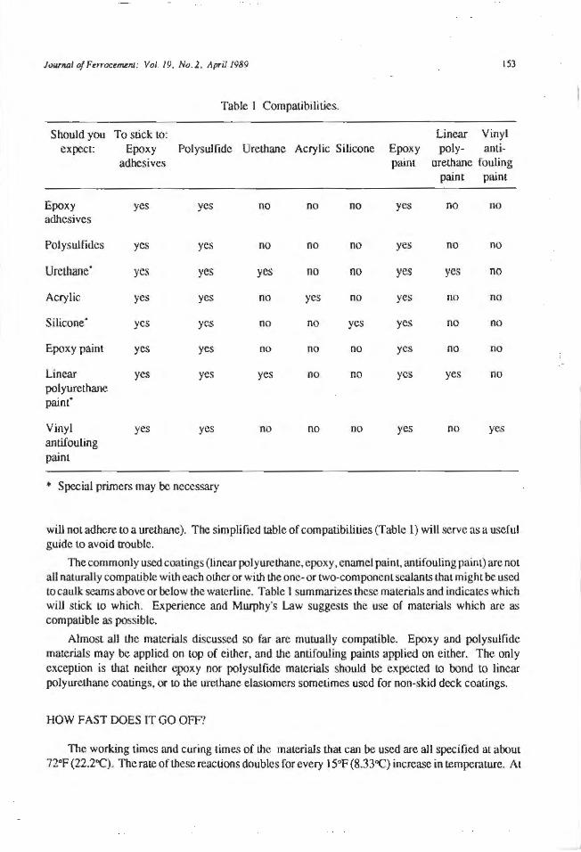
JourMI o/Ferroce~/'11: Vol. 19, No. 2. April 1989 153
Table I Compatibilities.
Should you To stick Lo: Linear Vinyl expect Epoxy Polysulfide Urethane Acrylic Silicone Epoxy poly- ami-
adhesives painl urethane fouling paint paint
Epoxy yes yes no no no yes no no adhesives
Polysulfides yes yes no no no yes no no
Urethane· yes yes yes no no yes yes no
Acrylic yes yes no yes no yes no no
Silicone· yes yes no no yes yes no no
Epoxy paint yes yes no no no yes no no
Linear yes yes yes no no yes yes no polyurethane paint"
Vinyl yes yes no no no yes no yes antif ouling painl
* Special primers may be necessary
will not adhere to a urethane). The simplified table of compatibilities (Table 1) will serve as a useful guide Lo avoid trouble.
The commonly used coatings (linear polyurethane, epoxy, enamel paint, anti fouling paint) are not all natural I y compatible with each other or with the one- or Lwo-compoocnt seal an Ls that might be used to caulk seams above or below the waterline. Table 1 summarizes these materials and indicates which wiU stick Lo which. Experience and Murphy's Law suggests the use of materials which arc as compatible as possible.
Almost all the materials discussed so far are mutually compatible. Epoxy and polysulfide materials may be applied on top of either, and the antifouling paints applied on either. The only exception is that neither epoxy nor polysuHide materials should be expected LO bond to linear polyurethane coatings. or to the urethane elastomers sometimes used for non-skid deck coatings.
HOW FAST DOES 11" GO OFF?
The working times and curing times of the materials that can be used are all specified at about 72°F (22.2"C). Tbe rate of these reactions doubles for every I 5°F (8.33"C) increase in temperature. At
154 low-NJ/ of Ftrroct~n1: Vol. 19, No. 2, Apri/ /!189
87°F (30.6°C) one will have aboul half the poL life (and the curing Lime), and at 57"F (I 3.9"C) the figures will double. Many epoxy systems do nOL cure properly or at all below 50"F (10°C). Polysulfidcs with fast catalysts do not adhere well when applied in weather around 50°F (10°C) to 60"F (15.6"C) because 1l1ey arc Loo stiff to Oow wel I and do not wet the surface sufficiently. Paints that are put on outside in hot weather cure very rapidly. Clear sealer on wood is a good example: iL can take a month Lo cure in Seattle, a week in 1.heSan Francisco Bay Arca in the winter, two days in the San Francisco Bay Area in the summer, or three hours in San Diego in the summer. The ncxL material to go on needs to be put on before the previous material has fully cured Lo obtain the best bond.
HOW FAR DOES lTGO'?
A handy conversion faclor lo remember is that one gallon contains 231 in.3 (3785 lhcrs). It is a little more useful to realize that that number of cubic inches spread out in a film a 32nd of an inch (0.8 mm) thick will cover48 ft2(4.46 m2
). Whal this means is that liquid resin used as a coating covers 48 ft1 (4.46 m1) to a gallon in a film that is a 32nd of an inch (0.8 mm) lhick.
When a manufacturer recommends spreading an epoxy coating ouL Lo, say, 30 ft2-35 f(1 (2.79 m2-
3.25 m2) toa gallon, thatisancquivalentcoaling thickness of about 0.04 in. ( L mm). lfthe manufa~Lurer recommends that a pound (0.45 kg) of the maLcrial be spread out over abouL 30 fL2-35 fl2 (2.79 m2-
3.25 m2), that is very approximately a coating thickness of 4 to 5 one-thousandths or an inch (0. IC mm-0. I 3 mm). Epoxy resins on the average arc 10 pounds (4.5 kg) per gallon or something a liuk less. If one were going to bond 30 ft2-35 fl2 (2.79 m1- 3.25 m2) or plywood with a pound of epoxy resin, tJ1is means there arc only 4 LO 5 one-thousandths of an inch (0. 13 mm) of space on the average be1wecn Lhosc two materials. lt is rather unlikely that two pieces of plywood or mosL any kind of lumber will mate thaL well.
A glue line thickness between two pieces of plywood could more rcal isl.ically be expected LO be on tJ1c order of 10 mils. When bonding two pieces of wood with an epoxy resin it is important to remember thaLU1eresin will have some tendency Lo soak into the wood. If Lhe resin is spread in a thin film on both pieces of wood and then clamps or fasteners used to hold the pieces together, the resin will tend Lo soak imo the wood before it cures. Since the only reservoir which supplies lhat re:>in is the thickness of the joint itself, the resin will Lend to soak away from the middle of the joint and produce a glue- starved joint. This is very bad, and means that the finished product will tend to fall apart. 1L is for l11is reason that it is recommended to seal both surfaces of wood members Lo be bonded with CPES before they are bonded. Not only docs iL produce a stronger surface, but it keeps the adhesive where it belongs and where it is needed- namely in the joint itself . With planed or milled woodorhighqunliLy new plywood, a glue line thickness on the average of 5 mils may be obtained. With somewhat cough or weathered plywood after a heavy application of CPES, an average glue line thickness of 10 to 20 mils can be achieved, depending on how rough the wood is.
REFERENCE
Smith, S. 1987. flow to Finish Your Ferrocement llull. Richmond: Smith & Company.
Journal of FerrocemenJ: Vol. 19, No. 2, April 1989 155
I83 II I83 IL II (Q) CG JEAJF IBI II CC ILII§T
This list includes a partial bibliography, with keywords, on ferrocement and relat.ed topics. Reprints and reproductions, where copyright laws permiL. are available at a nominaJ cost (see page 212).
All information collecLcd by lFlC are entered into a computerized database using CDS/ISIS System. Stored information can be retrieved using keywords, author names. Lilies, etc. Specialized searches are performed on request.
RESEARCH AND DEVELOPMENT
Material Properties
Songuansing. S. 1988. Further Investigation on lhe Fracture ProperLies of Ferrocemem, M.Eng. Thesis, Asian Institute of Technology, Bangkok.
experimentation I ferrocement I fracwre mechanics I mechanical properties I AJT Pub Thailand
Paramasivam, P., and Sri Ravindrarajah, R. 1988. Effect of arrangcmcnLS of reinforcemenL<; on mechanical properties of ferrocemenc. ACJ Structural Journal 85(1): 3-J 1.
crack spacing I crar:k width I deflection I ferroce"lent I flexural strength I mechanical properties I reinforcement I tensile strength I welded wire mesh
Standards and Specifications
National Standards of People's Republic of China (Beijing, China). 1983. Test Method of F errocemem Panels in Flexure (In Chinese) . 8 pp. Beijing: StandardS Press of China.
ferrocement I flexure I panels I standard.~ I tests China
'National Standards of People's Republic of China (Beijing, China). 1984. Test Method of FerrocemenL Panels in Axial Tension (In Chinese). 8+ii pp. Beijing: Standards Press of China.
ferrocement I panels f standards I tension tests I tests China
National Standards of People's Republic of China (Beijing, China). 1985. Test Method for Strength of llydraulic Cement Mortar (In Chinese). 4+ii pp. Beijing: Standards Press of China.
156
mortars I standards I slrength I tests China
Jourru:il ofFerrocerJti!.nt: Vol. 19, No. 2. April 1989
National Standards of People's Republic of China (Beijing, China). 1985. Terms and their Definition of Ferrocemeni (Jn Chinese). 20+iii pp. Beijing: Standards Press of China.
ferrocement I standards China
National Standards of People's Republic of China (Beijing, China). 1987. F errocement Farming Box (In Chinese). 34+ii pp. Beijing: Standards Press of China.
boats I ferrocement I standards China
National Standards of People's Republic of China (Beijing, China). 1987. Hull Quality Requirement for Ferrocement Ships (In Chinese). 5+ii pp. Beijing: Standards Press of China.
ferrocement I hulls I ship.~ I standards China
Housing Applications
Swamy, R.N., and El-Abboud, M.I. 1988. Application offcrrcx:emcnt concept to low cost lightweight concrete sandwich panels. Journal of Ferrocemenl 18(3): 285-292.
applications I ferrocement I housing I lightweight concretes I low cost I panels I sandwich plates 1 I FIC Pub
CONSTITUENT MATERIALS
Mor tar Preparation and Plastering
Nagataki, S.; Mansur, M.A.; and Ohga, H. 1988. Carbonation or mortar in relation to fcrroccmcnt construction. AC/ Materials Journal 85(1): 17-25.
carbonation I compressive strength I curing I durability I ferroccmenr I flexural strength I nuirtars (material) I protective coatings/ Jests
Substitute Materials for Mortar Preparation
Mathews, J.D. 1987. Pulverized-fuel ash - Its use in concreLC - Part l MaLeriaJ properties. Brilish standards and concrete strength. Building Research Establishment Information Paper (?): 4 pp.
compressive strength I concrete I durability I fly ash I port/and cement I production I standards ifK '
Mathews, J .D. 1987. Pulverized fuel ash - Its use in concreLC- Part 2 Influences on durability. D w lding Research Establishment Information Paper (?): 4 pp.
compressive strength I concrete I durability I fly ash I port/and cement I produc1ion I standards V.K.
Journal of Ferrocemen1: Vol. 19, No. 2 , /lpril JfJ89 157
Ravina, D. 1987. Fly ash perfonnancc in plastic concrete. In The Building Research Station, Publicmioris 1987, 109-123. Technion: Technion - Israel Institute of Technology.
bleeding I chemical reactions I concrete I fly ash I mortars I physical properties I selling
Yuan Cheng-Ping. 1988. Development of a Cementitious Material Based on Calcareous and Siliceous Materials, M.Eng. Thesis, Asian Institute of Technology, Bangkok.
cement I experimentation I lime I mechanical properties I rice husk ash I AJT Pub Thailand
Mirza, W.H., and Al-Noury, S.I. 1988. Powdered lightweight aggregate as a cement replacement material. The fnlernalional Journal of Cement Composites and Lightweight Concrete 10(3): 171 - 173.
admixtures I cement I chemical resistance I compressive strength I concrete I durability I ligl11weigh1 aggregates I mortars (material) I pozzola11s f strength
Gutschick, K.A.1988. An impon.amconslruct.ion material: Lime.AS'/M Standardization News 16(7): 32-35.
cement I construction material I lime I mortars (material) I plaster I roads
Erel, Y.; Matthews, A.; and Nathan, Y. 1988. Potential use of coal ash in the Israel cemem industry. Cement and Concrete Research 18(4): 503-512.
ash I cement I clay I coal I uses Israel
Admixtures
Betancourt, G.H. 1988. Admixtures, workability, vibration and segregation. Mace rials and Structures 21(124): 286-288.
admixtures I cement pastes I density I vibration I viscosity I workability
General
Tan J uat Ngoh. I 988. Use ofRauan as Reinforcement, Research Paper, Asian InstituteofTechnology. Bangkok.
experimentation I mechanical properties I properties I rauan I reinforcement I AJT Pub Thailand
Rao, ARK.; Srinivasan, G.; and Mahcshwari, H.K. 1978. Effect of beating on bamboo fibers.lndian Pulp and Paper 32(5): 35-46.
bamboo I bond I bursting I density I fibers I mechanical properties I strength I tension I testing
National Standards of People's Republic of China (Be.ijing, China). 1985. Cement Nomenclature (In Chinese). 2+ii pp. Beijing: Standards Press of China.
cement I standards China
158 Jourltlll of Ferrocement: Vol. 19, Nu. 2, Apri,' 1989
National Standards of People's Republic of China (Beijing, China). 1986. Definition and Terminology of Cement (Jn Chinese). 6+iii pp. Beijing: Standards Press of China.
cement I standards China
Bentur, A., and Cohen, M.D. 1987. Effect of condensed silica fume on the rnicrostructure of the interfacial zone in portland cement mortars. In 1'he Building Research Szation, Publications 198 7, 17-22. Technion: Technion - Israel Institute of Technology.
cement pastes I microstructure f mortars (material) I silica fume
Bentur, A., and Puterman, M. 1987. Adaptation of special materials for the development of construction automation. In The Building Research Station, Publications 1987, 65-80. Technion: Technion - Israel Jnsticutc of Technology .
.cements I construction methods I fiber reinforced cement I materials I polymers I polymers
Patel, R.G.; Killoh, D.C.; Parrott, L.J. ; and Guueridge, W.A. 1988. Influence of curing at different relative humidities upon compound reactions and porosity in portland cement paste. Materials and Structures 21(123): 292-197.
cement pastes I chemical reactio11s I curing I humidity I porosity
_ _ . 1988. Silica fume shotcrete. Indian Concrete Journal 62(5): 217-218 & 222.
mechanical properties I shotcrete I silicafwne
Kayyali , 0.A., and Haque M.N. 1988. Effect of carbonation on the chloride concentration in pore solution of mortars with and without Oy ash. Cement and Concrete Research 18(4): 636-648.
carbonation I chlorides I curing/ fly ash I mortars (material)
Chauerji, S. 1988. On the properties of freshly made portland cement paste: Part 2 Sedimentation and strength of flocculation. Cement and Concrete Research 18(4): 615-620.
cement pastes I port/and cement I properties I sedimer11ation I strength
Papo, A. 1988. The thixotropic behavior of white portland cement pastes. Cement and Concrete Research 18(4): 595-603.
cement pastes I constitutive equations I rheology I shear I tests
Luke, K.; Glasser, F.P. 1988. Intemalional chemical evolution of the constitution of blended ccmets. Cement and Concrete Research 18(4): 495-502.
blast f urnace slag I cemencs I fly ash
Durekovic, A. 1988. Silicate anions polymerization in the pastes of OPC and OPC-silica fume bends during hydration and after action of leaching attack: Part fl study by use of molybdate method. Cement and Concrete Research 18(4): 532-538.
cement pastes I protection I silica fume
Jourrrtl/ of Ftrroa~nJ: Vol. 19, No. 2, April 1989 159
Gughcs, D.C. 1988. The use of sol vent exchange to monitor di ff us ion characterislics of cement pastes containing silica fume. Cement and Concrete Research 18(2): 321-324.
cement pastes I concrete I permeability I silica fwne I Jests UJ<.
MARrNE APPL1CA TTONS
Construction and Testing
Smith, S. 1988. Fastening things to the hull. Journal of Ferrocement 18(3): 315-316.
cons1ruc1ion I ferrocement I hulls/ IFIC Pub
General
Syed Mansur, SJ .. and Ali. K.M. 1988. The first Malaysian inter- university ferrocement canoe race 1988. Journal of Ferrocement 18(3): 309-314.
canoe I ferrocemenr I informa1ion dissemination I !FIC Pub Malaysia
TERRESTRIAL APPLICATIONS
Water Resources Structures
Primavera, J.H. 1983. Land-based broodstock tank system. In Broodstock of Sugpo, Penaeus monodon Fabricius, 17-20. Tigbauan, lloilo: Southeast Asian Fisheries Development Center.
agriculture I ferrocement I water 1a11ks
Gould . J.E. 1984. Rainwater Catchment Possibilities. 27 pp. Gaborone: Botswana Technology Center.
ferrocement I low cost I rainwater I water ranks Botswana
Polprasert, C.; Edwards, P.; Rajpul, V.S.; and Pacharaprak:ili, C. 1986. Integrated biogas Leehnogy in Lhc tropics I. Performance of small scale d.igcsters. Waste Management and Research 4: 197-213.
biog as I development I digester If errocemem I nightsoil I rice straw I rnral I wastes Thailand
Zakaria, M.A. 1987. PortlandCementandFerrocementfor VillageTechnology(lflMalaysian). 8 pp. Palau Pinang: Univesiti Sains Malaysia.
aµµlications I cemenl I ferrocemen1 I housing I hulls I water tanks
160 Jownal of Fe"oanv.nl: Vol. 19, No. 2, /\prir 1989
PROTECTION AND RELATED TOPICS
Corrosion in Marine Environment
Hope, B.B., and lp, K.C.A. 1987. Choloridc corrosion threshold in concrete. AC/ Materials Jour11al (J ul.-Aug.): 306-318.
chlorides I concrete I corrosion I rein/ orcing steels I slabs
__ . 1988. Technical guidelines for the use of sulphate- resisting cemenL Indian Concrete Journal (June): 307-309.
cement I chemical resislance I corrosion I pro1ec1ion
Killl , P.; Perret, R: Alvarez, N.; and Diaz, G. 1988. On durability and mechanical properties improvement of a compacted copper-fibre cement composite subjected LO general corrosion. Cement and Concrete Research 18(4): 539-544.
corrosion I durability I fiber cemenl composi1es I mechanical properties I meUJl fibers
Coatings and Surface Treatment
Fauuhi, N.I., and Hughes, B.P. 1988. The performance of cement paste and concrete subjected 10
sulphuric acid alr.ack. Cemenl and Concrete Research 18(4): 545-533.
acid resistance I cemenl pas/es I concrete / Jests
Coroka, I, and Carmel, D. 1987. Durability of external renderings in a marine environment. In The Building Research S1a1ion , Publicaiions 1987. 124- 135. Technion: Technion - Israel lnslil11Le of Technology.
cladding I durability I environmenl I Jail we I field tesls I marine environment I morzars I performance I pla.wer I testing
Chandra, S. 1988. Hydrochloric acid attack on cement mortar - An analytical study. Cement and Concrete Research 18(2): 193-203.
acid resistance 1es1s I analysis I cement I mortars (nuuerinl)
FIBER REINFORCED COMPOSITES
Steel Fiber Composites
Bemur, A., and Cree4 R. 1987. Cement reinforced with steel wool. In The Building Research S111.tion, Publications 1987. 23-29. Technion: Technion - Israel Institute of Technology.
cemenis I composite materials I cracking (fracturing) I deflection I fabrication I fibre cement composites I flexural strength I flexure I fracture mechanics I properties I steel wool I strength t 1es1s I thin sheets I toughness
Alexander, D. 1988. Fibre reinforced concrete. Journal of Ferrocemcnl 18(3): 293-300.
Journal of FerrocemutJ: Vol. 19, No . 2, April 1989 161
ductility I fiber reinforced concrete I impact I mechanical properties I shear I steel fibers I tensiot1 I IFICPub
CederqvisL, H. 1988. Fibre shotcretc. Journal of Ferrocemenl 18(3): 301-308.
fiber reinforced concrete I produCL development I properties I repair I shotcrete I steel fibers I IFIC Pub
Mangal, P .S., and Motamedi Azari, M. 1988. Shrinkage of steel fibre reinforced cement composites. MaterialsandS1ruc1ures 21(123): 163-171.
analysis I experimentation I fiber reinforced composites I shrinkage I steel fibers
Natural and Organic Fiber Composites
Shafiq, N.; Robles-Austriaco. L.; and Nimityongskul, P. 1988. Durability of natural fibres in RHA mortar. Journal of Ferrocement 18(3): 249-262.
durability I experimentation I mechanical properties I mortars I natural fibers I pozzolanas I rice husk ash I IF!C Pub
Suvansinpan. S. 1988. Mechanical Properties of Palm Fiber~Cement Composites Containing Ri<.:e Husk Ash, M.Eng, Thesis, Asian Institute of Technology, Bangkok.
experimentation I fiber cement composites I fibers I mechanical properties I palm fibers I plant fibers I rice husk ash I AIT Pub
Thailand
General
Gopalaratman, V .S., and Shah, S.P. 1985. Strength, defonnation and fracture toughness of fiber cement composiles al different rates of flexural loading. Jn Steel Fibre Concrete: US-Sweden .Joint Seminar (NSF,STU), 299-331. Essex: Elsevier Applied Science Publishers.
bending I experimentation I fiber reinforced composites I loads (forces) I mechanicul properties
Bentur, A .. and Diamond, S. 1987. Aging and microsiructure of glass fiber cement composites reinforced with different types of glass fibers. In The Building Research Station, Publications 1987. 30-55. Technion: Technion - Israel Institute of Technology.
cements I chemical attack! composites I fiber cement composites I glass fibers I mechanical properties I microstructure I reinforcement I GFRC
Shah, S.P. 1988. Theoretical models for predicling the performance of fiber reinforced concrete. Journal of Ferrocem.ent 18(3): 263-284.
crack propagation I fiber reinforced concrete I mechanical properties I models I performance I 1 FIC Pub
Wang, Y.; Li, V.C.; and Backer, S. 1988. Modelling of fibre pull-out from a cement matrix. The International Journal of Cement Composites and Lightweight Concrete 10(3): 143-149.
162 Jourl'llJI of Ptrroce17ll!111: Vol. 19, No. 2. Aprt/ 1989
bond I bond slrenglh I bond stress I fiber cemenl composi1es /fiber reinforced concrete I ma1 hematir.al uwdel I me1al fibers I polypropylene fibers I pullout tests I shear strength
Building Research Station (Garslon, Watford, U.K.). 1988. Glass fi bre reinforced cement Building Research Establishment Digest (331 ): 1-8.
applir.a1ions I fiber reinforced cement I glass fibers I manufacture I mechanical properties I physical properties I GFRC
GENERAL
Technology Transfer
Roblcs-Aus1riaco, L. 1988. Fcrrocemcm: Development in lraining and education. In Civil Engineering: Education, Research and Professional Development, 25 1-270. Sclangor: Universili Pcrwnian Malaysia.
development I ferrocement I informa1ion dissemination Africa I India I Indonesia I Malaysia I Philippines I Thailand
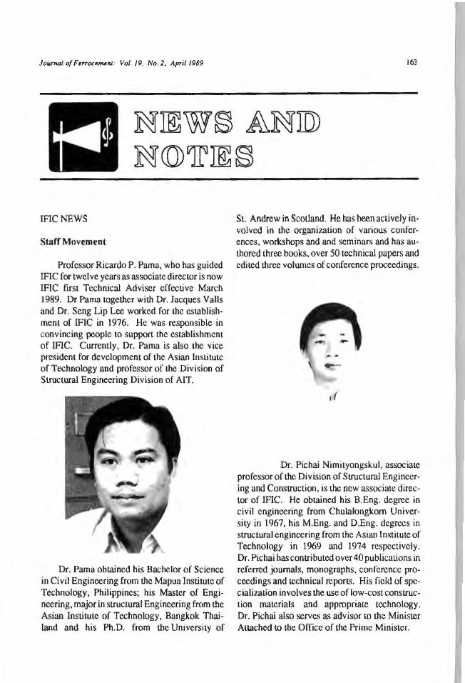
Jo11Jna/ of Ferrocemelll: Vol. 19, No. 2. April 1989
IFICNEWS
Staff Movement
Professor Ricardo P. Pama, who has guided IFIC for twelve years as associate director is now IFIC first Technical Adviser effective March 1989. Dr Pama together with Dr. Jacques Valls and Dr. Seng Lip Lee worked for the establish· ment of IFIC in 1976. He was responsible in convincing people to support the est.ablishmem of IFIC. Currently, Dr. Pama is also the vice president for developmem of the Asian Institute of Technology and professor of the Division of Structural Engineering Division of AIT.
Dr. Pama obtained his Bachelor of Science in Civil Engineering from the Mapua Institute of Technology, Philippines; his Master of Engineering, major in strUctural Engineering from the Asian Institute of Technology, Bangkok Thailand and his Ph.D. from the University of
163
St. Andrew in Scotland. He has been actively involved in the organization of various conferences, workshops and and seminars and has authored three books, over 50 technical papers and edited three volumes of conference proceedings.
Dr. Pichai Nimityongskul, associate professor of the Division of Structural Engineering and Construction, is the new associate director of IFIC. He obtained his B.Eng. degree in civil engineering from Chulalongkom University in 1967, his M.Eng. and D.Eng. degrees in structural engineering from the Asian Institute of Technology in 1969 and 1974 respectively. Dr. Pichai has contributed over 40 publications in referred journals, monographs, conference proceedings and technical reports. His field of specialization involves the use of low-cost construction materials and appropriate technology. Dr. Pichai also serves as advisor 10 the Minister Attached to the Office of the Prime Minister.
Journal of FerrocemenJ: Vol. 19, No. 2, April 1989
IFICNEWS
Staff Movement
Professor Ricardo P. Pama, who has guided IFIC for twelve years as associate director is now IFIC first Technical Adviser effective March 1989. Dr Pama together with Dr. Jacques Valls and Dr. Seng Lip Lee worked for lhe establishment of IFIC in 1976. He was responsible in convincing people to support lhe establishment of IFIC. Currently, Dr. Pama is also lhe vice president for development of the Asian Institute of Technology and professor of lhe Division of Structural Engineering Division of AIT.
Dr. Pama obtained his Bachelor of Science in Civil Engineering from the Mapua Institute of Technology, Philippines; his Master of Engineering, major in structural Engineering from the Asian Institute of Technology, Bangkok Thailand and his Ph.D. from the University of
163
St. Andrew in Scotland. He has been actively involved in the organization of various conferences, workshops and and seminars and has authored three books, over 50 technical papers and edited lhree volwnes of conference proceedings.
Dr. Pichai Nimityongskul, associate professor of the Division of Structural Engineering and Construction, is the new associate director of IFIC. He obtained his B.Eng. degree in civil engineering from Chulalongkom University in 1967, his M.Eng. and D.Eng. degrees in structural engineering from the Asian Institute of Technology in 1969 and 1974 respectively. Dr. Pichai has contributed over 40 publications in referred journals, monographs, conference proceedings and technical reports. His field of specialization involves the use oflow-cost construction materials and appropriate technology. Dr. Pichai also serves as advisor to the Minister Attached to the Office of lhe Prime Minister.
164 JourNJI ofFerrocemR.nl: Vo/.1 9, No. 2, April 1989
reports for each session and the lhrust areas in research, application and technology transfer.
Dr. D.N. Trikha, professor of civil engineer- Some delegates wilh Dr. Pama in frontof lheIFIC exhibition.
ing at the University of Roorkee, was recently appointed as editorial board member of the Journal of Ferrocement. Dr. Trikha obtained his Master's degree in structural engineering from the University of Roorkee and his Ph.D. from Imperial College of Science and Technology, London. He has been teaching courses in structural mechanics, finite element method and design of structures.
The Third International Symposium on Ferrocement
The Third International Symposium on Fcrrocement was held 8 - 10 December 1988 at New Delhi, India. The symposium was attended by 145 delegates from 14 countries. The 72 technicals papers were divided into six sessions as follows:
Session
Session II Session Ill Session IV Session V
Mechanical properties, corrosion and durability Rural and marine applications Ferrocement structures Housing applications National experiences, prospects and trends - special structures
Session VI Standards, codes and technology transfer
Session VII and VIII were devoted to the
The cultural show during lhe symposium.
During the concluding session the following resolutions were presented and accepted by the delegates.
Resolu1ion I Establish in the University of Roorkee the FIN (Ferrocement Information Network) Ferrocement Manufacturers Internction Forum (FFIF) in India. The objective is to provide continuous interaction between FIN and the manufacturers for upgrading the ferr()C(;ment technology.
Resolution II Establish the Ferrocement Propagation Fund in India. The objective is to finance a high profile dissemination effort of FIN (India).
Resolution Ill Provide relevant codes and specifications on ferrocement and its products in
Journal of Ferroct.rM.nJ: Vol. 19, No. 2, /\pri/ 1989
coordination with FIN (India). The objective is to provide quality assurance to end users.
ResolUJion lV Translate IFIC publicalions in Indian languages. The objective is Lo provide (ndian users IFIC pub I ications at very low cost in a language they can understand.
Resolu1ion V Establish an IntemalionaJ Society of Ferroccmem under Lhe auspices of TFlC and under the presidency of Dr. R.P. Pama. The objectives arc to provide design and conscruction criteria and to assist engineers establish fcrrocemenl in its own righL as an alLCrnative structural material.
Resolu1io11 VJ Request the Government of India to specify Lhc use of fcrrocemenl in at least 2% of construction and maintenance projects.
The Third ImemalionaJ Symposium on Ferrocement was organized by the Civil Engineering Department, University of Roorkee, a member of the Ferrocement Information Network (FIN).
Guide for the Design, Construction, and Repair of Ferrocement
This guide supplements two earlier publications (ACI 549R-82, State.of-the-Art Report on Ferrocement, and SP-61, Ferrocemcnt-Materials and Applications). It provides technicaJ information on materials and materiaJ selection, design criteria and approaches, construction methods, maintenance and repair procedures and testing. The objectives arc to promote more effective use of ferrocement in terrestrial structures, provide architects and engineers with Lhe necessary tools to specify and use fcrroccmcm and provide owners or their representatives with a reference document to check the acceptabil ity of a ferrocemcnt alternative in a given applicat.ion.
The guide oulline is as follows:
Chapter l - GeneraJ 1.1 Scope 1.2 Approval to use procedures
Chapter 2 - Terminology
2. 1 Reinforcement parameters 2.2 Notation 2.3 Definitions
Chapter 3 - MaLeriaJs 3.1 Matrix 3.2 Reinforcement
Chapter 4 - Design 4.1 Design methods 4.2 Strength requirements 4.3 Service load design 4.4 Serviceability 4.5 Particular design parameters 4.6 Examples 4.7 Design aids
Chapter 5 - Fabricalion 5. l General requiremcntS 5.2 Construction methods
Chapter 6 - Maintenance and repair 6.1 Introduction 6.2 Blemish and stain removal 6.3 Protective surface treatments 6.4 Damage repair 6.5 Repair materiaJs 6.6 Repair procedure
Chapter 7 - Testing 7 .1 Test methods
Chapter 8 - References 8.1 Recommended ref crcnces 8.2 Cited references
165
Appendix A-Calculation of volume fraction of reinforcement
Appendix B - Flexural strength analysis of ferroccment sections
Appendix C - Simplified design aids
Appendix D - Surface treatment for ferroce.ment structures attacked by commonly used chemicals.
The guide was prepared by the ACI Committee 549. The principal aulhors are: Go1don B. Batson (current chainnan), Ronald F. Zolo (current secretary), Perumalsamy N. BaJaguru, Martin E. loms and Antoine Naaman (former chairman).
166
The Second East Asia-Pacific Conference on Structural Engineering & Construction (EASEC-2)
The Second East Asia-Pacific Conference on Structural Engineering & Construction (EASEC-2) under lhe Conference lheme -Achievements, Trends and Challenges, was organized by lhe Asian InsLituLe of Technology {AIT) in cooperation wiLh Chiang Mai University, Engineering Institute of Thailand and University of Tokyo, during 11 -13 January 1989 at Chiang Mai Orchid Hotel in Chiang Mai , under the auspices of International Association for Bridges and Structural Engineering {IABSE) and 15 professional associaLions from 13 counlrics in Asia-Pacific region. It is the second Conference in lhc series after Lhe first EASEC Conference in Bangkok in 1986.
TheobjectiveoflheConferencc is to provide a forum for professional structural engineers, researchers, and academicians working in Asia and the Pacific Region for mutual interchange of views and awareness of new LOO ls and technology for implementation in professional application.
The EASEC-2 Conference was atcnded by more Lhan 350 participants from 33 countries in and outside Lhe Asia-Pacific region. Twelve guest papers and 262 contributed papers on subject areas wilhin lhe broad fields of structural engineering and construcLion, and in a tone related to Lhc Conference theme, were presented during Lhe conference. These papers arc pub-
The opening ceremony was presided by Dr. Su bin Pinkayan, Minister of Commerce (founh from left).
Jourll/Jl ofFerrocemefll : Vol. 19, No. 2, April 1989
lished in the Lhrce volumes of the Conference Proceedings. They arc grouped into 14 subject areas, namely: (1) Analytical methods, (2) Composite structures, (3) Computer-aided c~ngincering, ex pert systems & computer soft ware, ( 4) Concrete structures & te.chnology, (5) Construction techniques & management, (6) Experimentation & instrumentation, (7) Foundation and relaLed substructures, (8) Innovative and large structures, (9) Long-span bridges, {11) Numerical & computational approach, (12) Stability, strength & steel structures, (13) Structural design, reliability and optimization, (4) Structural dynamics & cartl1quake engineering.
In the official meeting of Lhe EASEC l nternational Stccrin~ Committee during lhe Confer-
Some partic1pant.s shov.cd great interest in lFTC publications.
Dr. Sashi Kunnath Kumar (second from right), fonncr infor· mation scientist al IFIC and now affiliated with the National Center for Earthquake Engineering (NCEER) t.hc State Uni· vcrsity of New York at Buffalo with IFlC staff (I - r) Mr. Romeo Agustin. Mr. Saha. Mrs. L.R. Austriaco a11d Mr. Erano Sera.
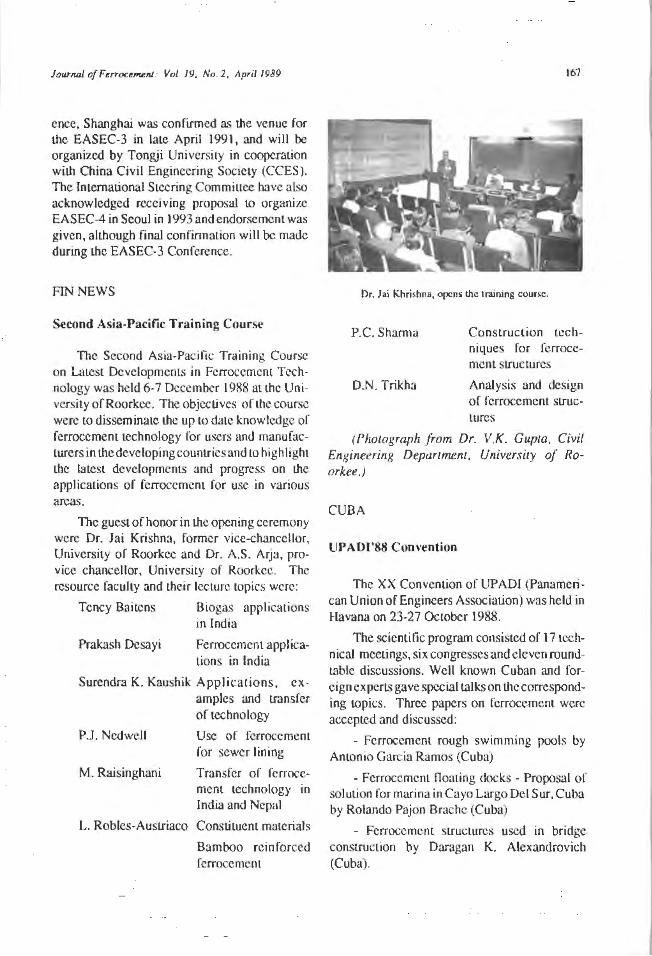
JourNJI of Ferrocemenl" Vol 19. No. 2, April 1989
ence, Shanghai was confirmed as the venue for Lhe EASEC-3 in late April 1991, and will be organized by Tongji University in cooperation with China Civil Engineering Society (CCES). The International Steering Commiuee have also acknowledged receiving proposal to organize EASEC-4 in Seoul in 1993 and endorsement was given, aJLhough rinal confirmation will be made during the EASEC-3 Conference.
FIN NEWS
Second Asia-Pacific Training Course
The Second Asia-Pacific Training Course on Latest Developments in Ferrocement Technology was held 6-7 December 1988 at Lhc University ofRoorkec. The objectives or the course were to disseminate the up to date knowledge of ferrocemem technology for users and manufacturers in the developing countries and to highlight the latest developments and progress on the applications or ferrocement for use in various areas.
The guest of honor in the opening ceremony were Dr. Jai Krishna, former vice-chancellor, University of Roorkcc and Dr. A.S. ArJa, pro· vice chancellor, University of Roorkee. The resource faculty and their lecture topics were:
Tency Baitens Biogas applications in India
Prakash Desayi Ferroccmcnt applications in India
Surendra K. Kaushik Applications, examples und transfer of technology
P.J. Ned well
M. Raisjnghani
Use or rcrrocement for sewer lining
Transfer of fcrrocement technology in India and Nepal
L. Robles-Austriaco Consti tuent materiaJs
Bamboo reinforced fcrroccmcnt
167
Dr. Jai Khri~hnn, opens the Ir.tining cou r~.
P.C. Sharma
D.N. Trikha
Construction techniques for ferrocemc11t structures
Analysis and design of fcrrocement structures
(Photograph from Dr. V.K. Gupta, Civil Engineering Department, Ur1iversi1y of Roorkee.)
CUBA
UPA01'88 Con vention
The XX Convention of UPADI (Panamerican Union of Engineers Association) was held in Havana on 23-27 October 1988.
The scienli lie program consisted of 17 technical meetings, six congresses and eleven roundtable discussions. Well known Cuban and foreign experts gave special talks on the corresponding topics. Three papers on fcrrocemcnt were accepted and discussed:
- Ferrocement rough swimming pools by Antonio Garcia Ramos (Cuba)
- Ferrocemenl noating docks - Proposal of solution for marina in Cayo Largo Del Sur, Cuba by Rolando Pajon Brache (Cuba)
- Ferrocement structures used in bridge construction by Daragan K. Alexandrovich (Cuba).
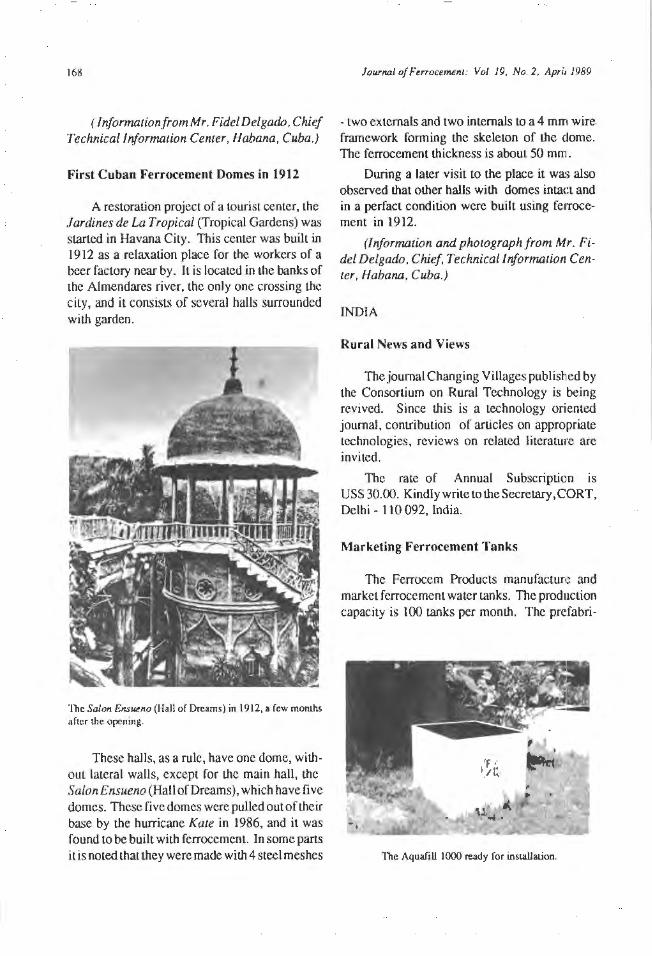
168
( lnformationfromMr. Fide/Delgado, Chief Technical information Center, /-labana , Cuba.)
First Cuban Ferrocement Domes in 1912
A restoration project of a tourist center, the Jardines de La Tropical (Tropical Gardens) was started in Havana City. This center was built in 1912 as a relaxation place for the workers of a beer factory near by. It is located in the banks of the Almendares river, the only one crossing the city, and it consists of several halls surrounded with garden.
The Salon Ensueno (Hali of Dreams) in 1912, a few monlhs after the opening.
These halls, as a rule, have one dome, without lateral walls, except for the main hall, the Salon Ensueno (Hall of Dreams), which have five domes. These five domes were pulled out of their base by the hurricane Kate in 1986, and it was found to be built with ferrocement. In some parts it is noted that they were made with 4 steel meshes
Journal of FerrocemJmt: Vol. 19, No. 2, April 1989
- two externals and two internals to a 4 mm wire framework forming the skeleton of the dome. The ferrocement thickness is about 50 mm.
During a later visit to the place it was also observed that other halls with domes intact and in a perfact condition were built using fe1Tocement in 1912.
(Information and photograph from Mr. Fidel Delgado, Chief, Technical Information Center, Habana , Cuba.)
INDIA
Rural News and Views
The journal Changing Villages published by the Consortium on Rural Technology is being revived. Since this is a technology oriented journal, contribution of articles on appropriate technologies, reviews on related literature are invited.
The rate of Annual Subscription is US$30.00. Kindlywrite totheSecretary,CORT, Delhi - 110 092, India.
Marketing Ferrocement Tanks
The Ferrocem Products manufacture and market ferrocement water tanks. The production capacity is 100 tanks per month. The prefabri-
The Aquafill 1000 ready for insLa.IJat.ion.
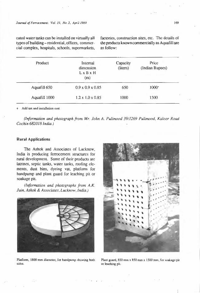
Journal of Fe"ocemvu: Vol. 19, No. 2, April 1989
catcd water tanks can be installed on virtually all types of building- residential, offices, commercial complex, hospitals, schools, supennarkets,
Product Internal dimension L xBxH
(m)
169
factories, construction sites, e tc. The details of the products known commercially as Aquafill are as follow:
Capacity (liters)
Price (Indian Rupees)
AquafiU 650 0.9 x 0.9 x 0.85 650 1000·
Aquafill 1000 1.2 x 1.0 x 0.85 1000 1500
+ Add tax and installaLion cost
(Information and photograph from Mr. John A. Pulimood 3911269 Pulimood, Kaloor Road Cochin 682018 India.)
Rural Applications
The Ashok and Associates of Lucknow, India is producing fcrrocement structures for rural development. Some of their products arc latrines, septic tanks, water tanks, roofing elements, dust bins, dyeing vat, platf onn for handpump and plant guard for leaching pit or soakage pit.
(Information and photographs from A.K. Jain, Ashok & Associates. Lucknow, India.)
Plat.form, 1800 mm diameter, for handpump showing both sides.
-~ ( , ,,,,. '. '' ,,,,, ,. , .. ,,,,,,, ,, · .. ,,,, , ,, ,,._,,~,
' ' ' ' \
' ' ' ' ' ' ~ \ ' ' ' " ' \ ' ' ' '
Plant guard, 850 mm x 850 nun x 1500 mm, for soakage pil or leaching pi1.
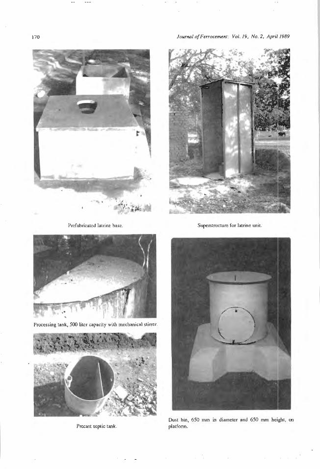
170
Prefabricated latrine base.
Processing tank, 500 liter capacity wilh mechanical stirrer.
Prccast septic tank.
Journal o/Ferrocement: Vol. 19, No. 2, April 1989
Superstructure for latrine unit.
Dust bin, 650 mm in diameter and 650 mm height, on platfonn.
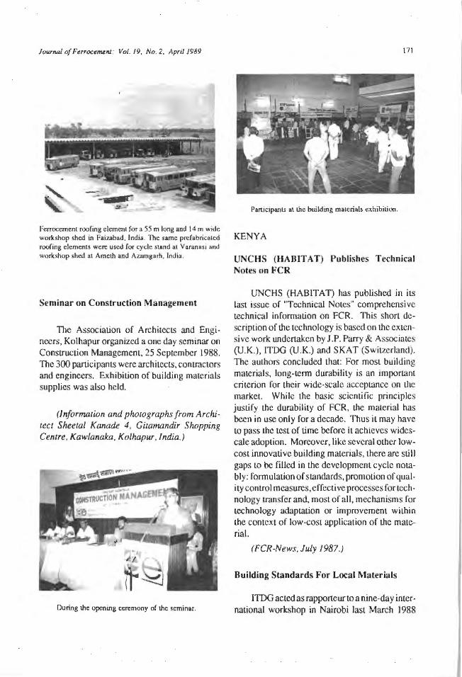
Journal of Furoctml!fll: Vol. 19, No. 2, April 1989
Fcrroccmenl roofing element for a 55 m long and 14 m wide workshop shed in Faiwbad, India. The same prefabricated roofing clements were used for cycle sl.llnd al Varanasi and workshop shed al Amcth and Auungarh, India.
Seminar on Construction Management
The Association of ArchiteclS and Engineers, Kolhapur organized a one day seminar on Construction Management. 25 September 1988. The 300 participants were architects, conlractors and engineers. Exhibit.ion of building materials supplies was also held.
(Information and photographs from Architect Sheetal Kanade 4, Gicamandir Shopping Centre, Kawlanaka, Kolhapur , lndia.)
During the opening ceremony of the seminar.
171
Participants at the building materials exhibition.
KENYA
UN C HS (HABIT AT) Publishes Technical Notes on FCR
UNCHS (HABITAT) has published in its last issue of "Technical Notes" comprehensive technical information on FCR. This short description of the technology is based on the extensive work undertaken by J.P. Parry & Associates (U.K.), ITDG (U.K.) and S KAT (Switzerland). The authors concluded Lhat: For most building materia ls, long-term durability is an important criterion for the ir wide-scale acceptance on the market. While the basic scientific principles justify the durability of FCR, the material has been in use only for a decade. Thus it may have to pass Lhe test of Lime before it achieves widescalcadoption. Moreover, like several other lowcosL innovative building materials, there arc still gaps Lo be filled in the development cycle notably: formulation of standards, promotion of quality control measures, e ffective processes for technology transfer and, most of all, mechanisms for technology adaptation or improvement within the context of low-cost application of the material.
(FCR-News. July 1987.)
Building Standards For Local Materials
ITDG acted as rapporteur LO a nine-day international workshop in Nairobi last March 1988
172
aimed at fonnulating building standards and specifications for local building materials in African countries. The workshop was jointly sponsored by the Unil.ed Nations Centre for Human Settlements (Habitat), IJ1e African Regional Organization for Standardization and the Commonwealth Science Council.
Held at Habitat's Nairobi headquarters. the meeting drew together representatives from 28 African counlries as well as several international agencies concerned with building policy on the cominent, including the International Organization for Standardization (ISO), the United Nations Economic Commission for Africa (ECA) and Shelter Afrique.
A major constrain no wider adoption oflocal maLerials has been the lack of appropriate standards and speci ficalion for their use. These organizations have embarked on a collaborative effort lo develop the indigenous building materials sect.or in African countries.
The workshop reviewed 1.hc standards and specifications for soil blocks, bumt clay bricks, 1 ime, pozzolana and FC roofing and idcnti lied the obstacles LO appropriate standards for the local level.
The organizations called on African governments lo promote the indigenous building materials sector to reduce dependence on imported building materials. This would stirnul:ue other areas of Lhe economy and help Lo meet the growing demand for adequate sheller in rural and urban are<.1s.
(FCR - News. July 1987.)
POLAND
Working Group on Ferrocement
The Polish Academy of Science has established a Working Group on Fcrroccment at the Academy's Department of Civil Engineering. The Group is under the leadership of Professor Bernard Walkus of the Technical University of
JourNJ/ of FtmJC£11Unl: Vol. 19, No. 2, April 1989
Czes1.oehowa. For more information on fc1Tocemenl development in Poland, contact
Dr. Bernard R. Walkus Professor of Civil Engineering Technical U niversi1y of Czes1ochowa ul. Dig/era 31. 42-200 Czestochowa Poland
U.S.A.
The Fiber Concrete Advantage
Fiber concrete is a homogeneous material thal consists of a conventional concrete mix and fibers. Because the fibers arc ductile materials in a briltlc mat.rix, lhe resulting composite material has quasi-ductile properties thatarcsignificanlly differcnL from those or standard concrete.
The primary function offibers in concrete is LO provide a crack-arrest mechanism for shrinkage st.resscs. These stresses occur immediately after the concrete begins to set and result in micro cracks. As the micro crac!l..-s connect, they develop into larger cracks and propagate, unless they meet sufficient resistance to stop. When fibers arc dispersed in the concrete, they can form a bridge close to where the cracks star. and prevcnl micro cracks from developing. TI1is mechanism results in raising the flexurc:ll st.rength of concrete and improving its resistance to spalling, abrasion, heat, cavitalion, and impact
Jn structurally reinforced concrelC the: matrix absorbs the compression stresses while the steel reinforcing absorbs the tensile stresses. Reinforcing is placed in specific areas of the concrete LO absorb known design st.resscs. When these stresses arc high , conventional reinforcement has no substitute. Under certain conditions, however, some fibers can ace as secondary reinforcement. When the design stresses arc moderate, the fibers can be effective in resisting tension stresses in areas of greac stress.
The quality of fibrous concrete depends, lo a great extent, on the amount of waler in the mix,
Journal ofl'enocemtnl: Vol. 19, NI). 2, April 1989
JUSt as it does with regular concrete.
Recommended wmer con Lent in Lhe concrete mix is40%, or a maximum of50%,ofthcccmcnt weight. Most concrete should contain no more than 540 lb/yd3 (320 kg/m3) of cement. If water is limited to 216 Jb/yd3 {l28 kg/m3), the 28-day strength of the concrete normally reaches 5000 psi (34.5 N/mm1). Because uggregmes generally contain 10 gal/yd3 LO 12 gal/yd3
(2.9 l/m3 to 3.5 l/m3) of free water, onl y 16 gal (60.6 1) of water should be added for each cubic yard of the mix. A superplasticizer should be added for fluidity, at a rate of 15 oz to 18 oz (0.S g LO 0.6 g) for every 100 lb (45.4 kg) of cemcnl. The resulting mix will yield a slump of 6 in. (152 mm) to 8 in. (203 mm) with no segregation.
Fiber concrete reduces initial slwnp by at
least 2 in. (51 mm). If Lhe concrete mix is stony, or gravelly, some. sand is added to keep the percentage of fine aggregate between 45% and 48%. ln most cases, the basic mix contains an adequate amount of sane!. ln general, 50 lb (22.7 kg) to 120 lb (54.4 kg) of fiber arc used for each cubic yard (0.765 m3) of the concrete mix, depending on the type of fiber. Polypropylene fiber is added in quantities of 1 lb/ycl3
(0.593 kg/m3) to 1.6 lb/yd3 (0.949 kg/m3)
Adding a large amount of cement with the necessary amount or water to achieve high strengtJ1 is not advised because the mi x will have an excessively large shrinkage problem. 1t is much more effective to limit the quantities of cement and water and add a supcrplaslicizer to a"ow ordinary 3000 psi (20.69 N/rnm1
) concrete to reach a strength of 5000 psi (34.5 N/mm2).
Many materials can be used as fiber, including steel. polypropylene, acrylic, nylon, polyester, glass and rock wool. Most fibers are available in a variety of dimensions or Jengths, and have somewhat different properties when added to concrete. Two commonly used types of fiber in industrial applications are polypropylene and steel.
173
Polypropylenelibersarccffectivc in holding the concrete together when micro cracks develop. The recommended dose of 1.5 lb/yd3
(0.89 kg/m3) of concrete is estimated to cont.a.in approximately 300 fibcrs/in.3 (1.64 x io·s m3).
Because there are so many fibers in any given volume, polypropylene fibers need not be very strong or have much bond to be effective. These fibers cannot increase the allowable tension of the concrete.
Steel fibers are frequently used as secondary reinforcement LO arrcsc tension stresses from shrinkage and bending. The fiber increases the tensile strength in conventional concrete Lo approximately 1200 psi (8.27 N/mm2) . This capability is an important design consideration, because the tensile property of convenl.ional concrete can rarely be used even though it is theoretically available.
When 2 1/2 in. (63.5 mm) long steel fibers are used in the recommended dose of 50 lb/yd3
(29.7 kg/m3) of concrete, the matrix contains about 2.06 fibers/in.3 (1.64 x 10·~ m~). The smaller straight steel fiber has 36 fibers/in.3
(1.64 x w-s m3) for the recommended 80 lb/yd3
( 4 7 .5 kg/m3) of concrele. Compared Lo pol ypropylcne fibers, Lhe larger steel fibers are much stronger both in tension and in bond.
When steel fiber concrete is used, a design safety factor or 1.5 to 2 should be used for allowable ex treme fiber stresses (from 600 psi (4.14 N/mm2) Lo 900 psi (6.21 N/mm2)), depending on the type of fiber, tbc type of coocretc, ancl the 1ypc of application. The moduJus of rupture in steel fiber concrete is consislenl if the concrete mix design docs not vary. This modulus can be used as a standard in the design wilh an appropriate factor of safety.
(Kuilman, C. 1988. The Fiber Concrete Advantage. Plane Engineering October: 52-53. Reference sent by Dr. Gary L. Bowen, Chief Engineer, Alaska Pulp Corporation, P.O. Box 1050, Mile 6 Samii/ Creek Road Sitka, Alaska 99835.)
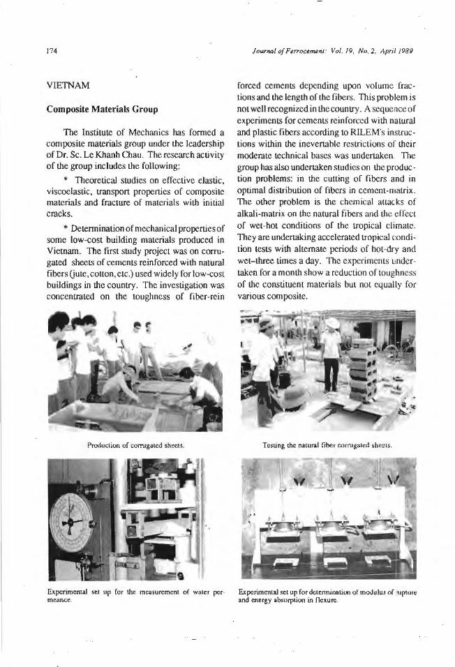
174
VIETNAM
Composite Materials Group
The Institute of Mechanics has formed a composite materials group under the leadership of Dr. Sc. Le Khanh Chau. The research activity of the group includes the following:
• Theoretical studies on effective elastic, viscoelastic, transport properties of composite materials and fracture of materials with initial cracks.
* Determination of mechanical properties of some low-cost building materials produced in Vietnam. The first study project was on corrugated sheets of cements reinforced with natural fibers (jute, cotton, etc.) used widely for low-cost buildings in the country. The investigation was concentrated on the toughness of fiber-rein
Production of comJgaLcd sheets.
Journal of FerrocemenJ: Vol. 19, No. 2, April 1989
forced cements depending upon volume fractions and the length of the fibers. This problem is not well recognized in the country. A sequence of experiments for cements reinforced with natural and plastic fibers according to RILEM's insLiuctions within the inevertabJe restrictions of their moderate technical bases was undertaken. The group has also undertaken studies on the production problems: in the cutting of fibers and in optimal distribution of fibers in cement-rnaLiix . The other problem is the chemical attacks of alkali-matrix on the natural fibers and the effect of wet-hot conditions of the tropical climate. They are undertaking accelerated tropical rnndition tests with alternate periods of hot-dry and wet- three times a day. The experiments undertaken for a month show a reduction of toughness of the constituent materials but not equally for various composite.
TcsLing Lhc naLUral fiber comJgated sheets.
Experimental sel up for Lhe measurement of waler per· Experimenlal set up for determination of modulus of rupiure meancc. and energy absorption in ncxurc.
Jounwl of Ferrocemeni: Vol. 19, No 2, April 1989
COMPUTER NEWS
FOTRAN Mathematical Libraries for PC
* MlNPACKl-LIB. Solves systems of nonlinear equations and nonlinear least-squares problems: derived from the Argonne national Laboratory MI.NPACK-1 mainframe produc~ test programs include one with 40 nonlinear equations and unknowns.
* FI'TLIB. Fits curves or surfaces through a given set of data p0ints; derived from Dr. Alan Cline's FlTPACK mainframe product; uses tension splines, which avoid the bad riLS often produced by cubic splines; also provides first and second derivatives.
*SPARSGEM. Solves sparse systems or linear equations; derived from the SMPAK mainframe product developed by Scientific Computing Associates; solves a nonsymmetric, 0.3% dense system of 1600 linear equal.ions and unknowns in double precision in 2.5 minutes on an 8-MHz LBM PC AT wilh a math coprocessor chip.
*FFTLIB. One-dimensional and multidimensional fast Fourier transforms; derived from Lhe NCAR FFTPACK and other fast Fourier
175
transfonn packages. FFT computation times: 16,384 pts. in 34 seconds, 32,768 pis. in 73 seconds (single precision real data sequences on an 8- MHz IBM PC AT wilh a math coprocessor chip).
*QUADLIB. Numerical integration, including improper integrals and multiple integrals: derived from the QUADPACK mainframe product; allows you to specify the desired accuracy and gives you the maximum error or tl1e result.
*ODELIB. Solves systems of first order ordinary differential equations, including stiff systems (has automatic stiffness detection); derived from the Lawrence Livermore Laboratory ODEPACK mainframe product.
These products are derived from mainframe products tllat have been Lhoroughly tested al hundreds of mainframe sites, but have major enhancements for ease of use and understanding not available in the mainframe.
More information from:
PC Scientific Inc. 6 Pine Tree Drive Suite 250 St. Paul MN 55ll2 U.S.A.
176 Journal of Ferrocement: Vol. 19. No. 2, Apri: 1989
IlJFJICC CC(Q)N§IDJILT&NT§
IFIC consultants arc individuals who arc willing to entertain rcforral letters from IFIC on I.heir field of expertise.
ARGENTINA
Mr. Horacio Berretta Iqualdad 3600 Villa Siburu 5000 Cordoba Argentina
AUSTRALIA
Mr. Denis Backhouse Griffit.h University Nathan 4111 Queensland Australia
Mr. Jim Dielenberg Middle Park 3206 Victoria Australia
Mr. James Douglas Couston 21 Brighton Ave. ToronLO, N.S.W. 2283 Australia
Dr. Russell Quinlin Bridge School of Civil & Mining Engineering University of Syney N.S.W. 2006 Australia
Dr . .John Lindsay Meek Civil Engineering Dept University of Queensland Brisbane, Queensland Australia
Mr. Graeme J ohn 1'illy 32 Hayes Terrace Mosman Park WA 6012 Australia
Mr. Robert J ohn Wheen School of Civil and Mining Engineering The University of Sydney Sydney 2006 Australia
BANGLADESH
Mr. Kazi Ata-ul Haque Housing & Building Research lnstiLULe Darus-Salam Mirpur, Dhaka Bangladesh
Dr. Md. Daulat Hussain Faculty of Agricultural Engineering Bangladesh Agricultural University Mymensingh Bangladesh

lourMI of Ftrr<X.t~llJ: Vol. 19, No. 2. April 1989
Mr. Muhammad Misbahuddin Khan Housing & Building Research lnstilutc Darus-Salam Mirpur, Dhaka Bangladesh
Mr. A.K.M. Syeed-ul-Haque Housing & Building Research Institute Darus-Salam Mirpur, Dhaka Bangladesh
BELGfUM
Mr. V. Debeuckelaere a B-8550 Zwevegem Belgium
Mr. Paul Tuts EllcsLraat 44 B-8550 Zwevegem Belgium
Mr. J ean Paul Sterck 14 Ruitcrsolrcef B-8550 Zwevegem Belgium
BRAZIL
Mr. Walter CaiafTa Hebl Rua Alagoas 515/146 01242-Sao Paulo Brazil
Mr. Alexandre Oulio Vieira Diogenes Rua Monsenhor Bruno 810 CEP:60,000, Fortaleza-Ccara Brazil
Dr. Joao Bento Hanai Av. das Az.aleas 456, 13560 Sao Carlos-SP Brazil
Dr. Luis Alberto de Melo Carvalho Rua Antonio Augusto 949 Fortaleza-Ceara, CEP:60,000 Brazil
Dr. Dante A.O. Martinelli Escola de Engenharia de Sao Carlos VSP., Avcn ida Carlos Bote liLo Brazil
Mr. Fausto C. Tarran P.O. Boit 2090 I 0100 Sao Paulo-SP Brazil
CANADA
Dr. Colin Deane Johnston Oepartmenl of Civil Engineering University of Calgary Calgary, Alberta T2N 1N4 Canada
Mr. Angus 0 . Galbraith Box 518, Lake Cowicban British Columbia VOR 260 Canada
COLOMBIA
Mr. C ipriano Londono A.A. 52816 McdeUin Colombia
CUBA
Mr. Hugo Wainshtok Rivas Cal le 202 No. 23504e/235 y 239 Font.anar, Mcpo. Rancho Boycros Ciudad de la Habana Cuba
m

178
DENMARK
Mr. Michael Edward Freddie The School of ArchitecLUrc Institute of Building Science Koagens Nytorv I DK 1050 Copenhagen K. Denmark
Mr. Arne Damgaard Jensen Technological Institute Building Technique Gregerscnsvej DK- 2630 Taastrup Denmark
DOMlNlCAN REPUBLIC, WEST 1NDIES
Mr. Antonio Jose Guerra Calle Jose D. Valverde 53, Santo Domingo Dominican Republic, West Indies
ETHIOPIA
Or. Haifa Giorgir Worknech P.O. Box 1296 Ethiopia
FRANCE
Mr. Alain Armane Dupuis Co-Manager SARL Chantier Naval de St. Jean D' Angle 17620 Saint Agnanl France
Or. Ripley, D. Fox La Roq UClt.C
34 190 St Bauzillede Putois France
Mr. J. Fys<)n Grand Rue 53570 Correos (Var) France
Joumal of Furoumeflt: Vol. 19, No. 2, Apri' 1989
Mr. Rene Lepee Co-Manager SARL Chantier Naval de SL Jean D' Angle 17620 Saint Agnant France
Mr. Adam Michel 9 rue la Perous 75 784 Paris Ccdcx 16 France
FEDERAL REPUBLIC OF GERMANY
Or. Edwin Bayer c/o Bauberatung Zement Beethovcns1.rassc 5 D-6000 Frankfurt am Main Ge on any
GREECE
Dr. Tassios Theodossius Chair of Reinforced Concrete National Technical University of Athens 42 Patission St. Athens Greece
GUATEMALA
Mr. Francisco J avier Quinonez 4a. Calle 9-13, Z. 7 Guatemala C.A.
HONG KONG
Mr. Peter E. Ellen Peter Ellen and Associates Lld. 20/F, 167-169 Hennessy Road Hong Kong
Journal of Ft"oct~nJ: Vol. 19, No. 2, llpril 1989
lNDIA
Mr. E. Abd ul Ka rim Structural Engineering Research Center Tharamani P.O. Mad.ms 600 113 India
Mr. Mad bu Sudan Acharya Agricultural Engineering DircctOraLe of Extension Education
Univcrsil y of Udaipur Udaipur (Raj) lndja
Or. H. Achyutha Structural Engineering Laboratory Deparunem or Ci vii Engineering Indian Institute of Technology Madras 600 036 India
Dr. N. Balasubramaruan Asbestos Cement Ltd. 21 B Pcenya Phase 11 Bangalore 560 058 India
Dr. Il .S. Basavarajaiah Kamataka Regional Engineering College Surathkal P.O. Srinivesnagar-574 157 lndja
Mr. Shiv Shanker Bhar gara Insti tute of Engineering and Rural Technology Allahabad, U.P. India
Mr . Bhartcndu Bhushan F-178 Naroji Nagar New Delhi 110029 India
Or. Pra kash Desayi Department of Civil Engince.ring Indian Institute of Science Bangalore S(i()() 12 India
Mr. Ramachandra Murthy D.S. Structural Engineering Research Center CSIR, Campus, Taramani Madras-600 113 India
Dr. N. Ganesan Civil Engineering Department Regional Engineering College Calicut-673601 India
Mr. V.G. Goklmle Bombay Chemicals Pvt. Ltd. CASTONE-Precast Concrete Division 129 Mahatma Gandhi Road Bombay 400 023 India
Mr. S. Gopalakrishnan Scientsit Structural Engineering Research Centre CSIR Complex Madras 600 113 lnrua
Mr. Man Bahadur Gurung Assistant Engineer (Civil) c/o Chief Engineer Power Department Gangtok, Sikkim India
Mr. D. Hariharan COSTED IIT-Madras Mad.ms 600 036 India
Mr. Alex .Jacob 136 Kalashelfa Colony Besant Nagar Madras 600 090 India
179
180
Mr. Ashok Kumar J ain M/S Ashok and Associates 314/69 Mirza Mandi, Chowk Lucknow 226003 India
Mr. S.C. Jain Institute of Engineering and Rural Technology Allahabad lndia
Mr. Nagesh GO\•ind Joshi A/5 Adinath Tophill, Wadala Bombay 400 037 India
Dr. Surendra Kumar Kaushik Civil Engineering Deparunent University of Roorkee Roorkee 247667 India
Mr. Ramesh Ranchhodlal Kotdawala L.D. College ofEngineering Ahmcdabad 380 015 lndia
Or. A.G. Madhava Rao Structural Engineering Rcsarch Center Madras 600 113 India
Dr. S.C. Natesan Department of Civi l Engineering P.S.G. College of Technology Coimbatore-4641004 India
Mr. N.P. Rajamane Structural Engineering Research Centre CSfR Campus, Tharamani Madras 600 113 India
JourNJ/ of Fcnoctmen1: Vol. 19, No. 2. Aprrl 1989
Dr. S. Rajasekarao Deparunent of Civil Engineering P.S.G. College of Technology Coimbatore-4 Tamil Nadu, 641004 lndia
Mr. N.V. Ra man Structural Engineering Research Centre CSIR Campus, Tharamani Madras 600 113 lnclia
Mr. K. Ravindran Fishing Craft Materials Central Institute of Fisheries Technology Cochin-682029 India
Mr. A. Subramanian Iyer C-15 Yugdharma Complex 27 Central Bazar Road Nagpur- 10 India
Dr. n.V. Subrahmanyam 68, Fourth Avenue Ashok Nagar Madras 600 083 India
Mr. G.V. Surya Kumar Structural Engineering Research Center CSJR Complex Tharamani Madras 600 I 13 India
Mr. S.P. Upasani R-11. N.D.S.E. Part-II New Delhi-1 10049 India
Mr. H.V. Venkata Krishna Kamataka Regional Engineering College Suralhkal (D.K.) Srinivasnagar Kamataka, 574 157 India
Journal of Fe"oce~nJ: Vol. 19, No. 2, April 1989
INDONESIA
Mr. Ansori Djausal Civil Engineering Deparunenl Instilul Telcnologi Bandung Jalan Ganesha 10, Bandung Indonesia
Dr. Nilyardj Kahar Lcmbaga Fisika Nasional-LIP£ JI. Cistu-Kompleks UPI Bandung Indonesia
Mr. Ron Van Kerkvoorden Rural Waler Supply Project Wesl Java Indonesia JI. Banda 25, Bandung Indonesia
M r. Aji Hari Siswoyo PT. WASECO TIRTA Consult.ants for Waler Supply, Sanitation and the Environment
JI. Adiliawarman 28, PO Box 116/KBT Kcbayoran Baru, Jakarta Indonesia
Mr. David James Wells P.O. Box410 Jayapura, Irian Jaya Indonesia
Mr . Winar to P.O. Box 19 Bulaksummur Yogyakana Indonesia
ISRAEL
Dr. F. Bljuger Technion City Haifa 32000 Israel
Dr. Zvi Reichverger Geula Str. 28/2 Dfar-Sava Israel
Dr. Elisha, Z. Tatsa Faculty of Civil Enginering Technion Israel lnstilute of Technology Haifa 32000 Israel
Mr. Simcha Yom-Tov KibulZ Dalia 18920 Israel
rTALY
Mr. Vittorio Barberio Via Ombrone 12, 00198 Roma Italy
Dr. Fabrizio Cortelazzi c/o Canliere Navale IDSEA Via Ponserone 5- 16037 Riva Trigoso (GE) Italy
Mr. J ohn Forbes Fyson Fishery Industries Officer Division FAO, Via delle Terrne di Caracalla Rome ltaly
Dr. Franco Levi Instituto di Scicnza delle Costruzioni Politecnico Corso Duca degli Abruzzi 24 10129 Torino Italy
181
182
JAPAN
Mr. Hajime lnoul! Ship Strucmrc Division Ship Research Institute Ministry of Transport 6-38- 1 Shinkawa Mil.aka Shi, Tokyo Japan
Dr. Makoto Kawakami l - 1, Tcgata gakuen-cho Akita-Shi 010 Japan
Mr. Yuki Kobayashi Japan, Ship Structure Division Ship Research lnstitute 6-38- 1 Shinkawa Mitaka Shi , Tokyo 181 Japan
Mr. Yoshilaka Mimori Sayama-City-Heits No. 307 Irumagawa 3 -l 0- Z Sayama City, Suitama Japan
Dr . Yoshibiko Ohama College of Engineering Nihon University Koriyama, Fukushima-Ken Japan
Mr. Atsushi Shirai Depanmem of Habitation Science, Tokyo Kasei Gakuin College 2600 Aihara-machi, Machida, 194-02 Japan
Dr. Hiroshi Tokuda Deparunem of Civil Engineering Akita University 1-1, Tegala ga.kuen-cho Akit.a-shi 0 10 Japan
JoW"nal of FurocemenJ: Vol. /9, No. 2, April 1989
MALAYSIA
Mr. Abang Ali Abang Abdullah Facully of Engineering Univcrsiti Pertanian Malaysia Serdang, Sclangor Malaysia
Mr. Juhari bin Husin Faculty of Fisheries and Marine Science University of Agriculture Malaysia, Mcngabang Talipot K. Trcnnggane. Trcngganu Malaysia
Mr. Syed Mansur Bin Syed Jun id Deparunenl of Civil and Environmental
Engineering Facully of Engineering Un ivcrsiti Pcrtanian Malaysia 43400 UPM, Serdang, Selangor Malaysia
Dr. John Chow Ang Tang Managing Director Structural Concrete Sdn. Bhd. No. 44 JaJan Radin Anum 2 Sri Peuiling, Kuala Lumpur Malaysia
MEXICO
Mr. Alfonso Cardoso Medina Apartado Postal 2325-B Durango DGO. C.P. 34000 Mexico
NEPAL
Mr. Krishna Raj Pandey Chakratirth Gaon Panchayal Alkatar-6, Lamjung District Nepal
JOW'llQ/ of Fe"oumelll : Vol. 19, No. 2, April 1989
Mr. Bijaya Gopal Rajbbandari P.O. Box 11 87 UNICEF Ka1.hmandu Nepal
Mr. Raj Dass Shrestha Research CenLie for Applied Science
and Technology (RECAST) Tribhuvan University Kin.ipur Nepal
NEW ZEALAND
Mr. Douglas Alexander 12- 14 Manukau Road Epsom Auckland 3 New Zealand
Mr. Brian William Donovan c/o Tepapapal Auckland New Zealand
Mr. Everard Ralph Sayer P.O. Box 3082 Oncrahi, Whangerei New Zealand
NIGERIA
Mr . Olusequn Adedeji P.O. Box 4555 Lagos Nigeria
PAKJSTAN
Mr. Mahmood A. Futehally Merin Limited, Data Chambers M.A. Jinnah Road P.O. Box 4145, Karachi-2 Pakistan
Mr. Sahibzada Farooq Ahmad Rafeeqi 303-304 Noor Estate Shahra-e-Faisal, Karachi-0816 Pakistan
PAPUA NEW GULNEA
Mr. Steve Layton VIRTU Box 378, ARA WA North Solomone Papua New Guinea
Mr. Charles Nakau Appropriate Technology Developmem Institute
P.O. Box 798 Lae, Morobc Province Papua New Guinea
PHTLlPPINES
Mr. Vicente S. Traviha Aquacullure Dcpartmem Southeast Asian Fisheries Development Center
Tigbauan, lloilo Philippines 5928
Mr. Rodol fo Torrcfranca Tolosa Tolosa Bujlders Inc. Las Palmas Subdivision Jaro. lloilo City Philippines
POLAND
Dr. Lech Czarnecki Institute of Technology and Organization of Building Production
Civil Engineering DeparUTient Warsaw Technical University Al. Annu Ludowej 16 00-637 Warszawa Poland
183
184
Dr. J ao Grabowski FerrocemenL Research Laborawry Technical University of Warsaw ul. Stupecka 7m 35 02-309 Warszawa Poland
Dr. Andnej Mackiewicz Borufraterska lOB/54 00 213 Warszawa Poland
Dr. J an Michajlowski Prominskcigo 29/43 93-281 Lodz Poland
Dr . Michal Sandowicz Fcrrocement Research L:iboraLory Technical UniversiLy of Warsaw ul. Warskiego 25 02-645 Warsaw Poland
Dr. Grzegorz Strzelecki Olimpijska 3m 48 94-043 Lodz Poland
Mr. Jan S' cibior 02-726 Warszawa u.I WarchaJowslciego 11 m 34 Poland
Or. Bernard Ryszard Walk us Technical UniversiLy of Czeslochowa Malachowskicgo 80 10-159 Lodz Poland
RWANDA
Mr. Theo Schilderman P.P.C.T., B.P. 31 Ruhengcri Rwanda
Joun1LJ( of Ferrocernmt: Vol. 19. No. 2, l\pril /989
SAUDI ARABIA
Dr. Is lem Ahmed Basunbul Chairman, Civil Engineering Department UPM No. 1895 UniversiLy of Petroleum and Minerals Box G 17, Dhahran 31261 Saudi Arabia
Or. Ghazi J. AI-Sulaimani Civil Engineering Deparunent University of Petroleum and Minerals Box 617, Dhahran 31261 Saudi Ardbia
SINGAPORE
Dr . P. Paramasivam Department of Civil Engineering National University of Singapore Kem Ridge 0511 Singapore
SOUTH AFRICA
Dr. S.W. Norton P.O. Box 168 Halfway House Soulh Africa
SRI LANKA
Mr. M.F. Ma rikkar 54 Davidson Road Bampalapitiya, Colombo 4 Sri Lanka
SWEDEN
Ms. Kerstin Kohler John EricssonsgaLan 4 112 22 Stockholm Sweden
Joli.rnaJ of Ferrocemenl: Vol. 19, No. 2. April 1989
SWITZERLAND
Mr. Mueller Heinrich c/o Baswap, G.P.O. Box 2841 Road No. 15, House No. 19 New Dhammodi R.A. Switzerland
Mr. Hans D. Sulzer Inslitul HBT Swiss InsLitULe of Technology 8093 Zurich Switzerland
TANZAN1A
Mr. Michael Henry Leach MBEGA MEL VIN Consulling Engineering P.O. Box425 Arusha Tanzania
Dr. A.A. Makange Tanzania Portland Cement Co., Ltd. P.O. Box 1950 Dar-Es-Salaam Tanzanfa
THAil..AND
Mr. Sorapoj Kanjanawongse Nakorn Srilhummaraj Technical College Amphur Muang Nakom Srilhummaraj Thailand
Dr. Worsak Kanok-Nukulcbai Division of Structural Engineering and
Cons1ruction Asian Institute of Technology P.O. Box 2754, Bangkok 10501 Thailand
Dr. Pichai Nimityoogskul Division of Structural Engineering and
Construction Asian Inslitute of Technology P.O. Box 2754, Bangkok 10501 Thailand
Mr. Jens Overgaard United Nations ESCAP Bangkok l 0200 Thailand
Dr. Ricardo P. Pama Vice-President for Development Asian Institute of Technology G.P.O. Boll 2754, Bangkok 10501 Thailand
Mrs. Lilia Robles-Austriaco fmemational Ferrocemenl Information
Ce mer Asian Institute of Technology G.P.O. Box 2754, Bangkok 10501 Thailand
Mr. Suddhisakdi Samr ejprasong Director of Building Materials Laboratory Thailand Inslitut.e of Scienlific and
Technological Research 196 Phahonyolhin Road, Bangkok Thailand
Mr. Narong Sukapaddhanadhi Metallurgical and Ceramic Engineering
Laboratory Thailand lnsti~ute of Scientific and
Technological Research (TISTR) 196 Phahonyothin Road Bangkhen, Bangkok Thailand
THE NETHERLANDS
Mr. Chris J .A. Hakkaart Simonsstraat 88, 2628 TJ Delft The Netherlands
185
186
Mr. H. Hofman Stadhouderslaan 83 3 I l6 HL Schicdam The Netherlands
Mr. uewis P.O. Box 3231 5203 De's Hertogenbosch The Netherlands
Mr. Cees Pieck Public Health & Environmental Engineering
DeparLmem DHV Consulting Engineers Breukelen, Orttswarande 22 3621 XP The Netherlands
Jr. Caspar L.P.M. Pompe Bouelroos 8 2651 XH Berke! en Rodenrijs The Netherlands
Dr. Piet Stroeven H. Casimirstraal 154 Vlaardingen The Netherlands
Mr. Jette Waltevs FCS P.B. 3090 9701 DB Groningren The Netherlands
THE PEOPLE'S REPUBLIC OF CHINA
Mr. Hui-Xiang Li Building Design Insl.itule China National New Bldg. Materials Corp, De Wai Xi-San-Qi, Beijing The People's Republic of China
Mr. Kai Ming Wang North-Western InslituLcof Architectural Engineering
Xian The People's Republic of China
Jowrnal of Furocem.ust : Vol. 19, No. 2, /\pri/ 1989
Mr. Zhu Yuankang 5, Jiaotong Road Fuzhou, Fujian Province The People's Republic of China
Mr. Guofan Zhao Dalian Institute of Technology Dalian The People's Republic of China
TONGA
Mr. Lloyd Howard Belz P.O. Box 908, Nukualora Tonga
U.K.
Dr. A.A. Alwasb 17 Bakehouse Lane Barnsley, South Yorkshire U.K.
Dr. E.W. Bennett The University of Leeds Depanmem of Civil Engineering Leeds LS2 9JT U.K.
Mr. AJ.K. Bisbrown Storage Department Tropical Development and Research Road London Road, Slough Berks U.K.
Mr. Colin Brookes Hartley & Brookes Boat Design Ltd. Heybridge Basin Maldon, Essex U.K.
Mr. Peter Finch 437a Pode Rd. Branksome Poole, Sorset U.K.
lourMI of FurocerM1": Vol. 19, No. 2. April 1989
Mr. Patrick. J . Jennings NCL Consul Ling Engineers l 92- L98 Vauxhall Bridge Road London swrv 1 ox U.K.
Mr. Brian Malcolm J ones BarFab RcinforccmenLs Alma SLrcct Smethwick, Warley West Midlands, B 662 RR U.K.
Mr. Robert Gowan MucAlistcr Managing Director MacAJistcr Ellioll & Partners LLd . 56 High Street Lymington, Hants S04 9GY U.K.
Mr. John Michael Pemberton 36 Alder Hill Grove Leeds 7 2PT U.K.
Mr. Derek Vincent Russel Director Alphacretc ConsLruction Linings (U.K.) Ltd_ The Chalet, Bailey Lane Riogway, Manchester M22 5NR U.K.
Dr. Ramnath Narayan Swamy Oeparuncot of Civil and Structural
Engineering University of Sheffield Mappin SL, SheffieJd SI 3JD U.K.
Mr. J eremy Martin Morrison Turner Lamus Manor Norwich NRlO SJQ U.K.
Or. Charles Bryan Wilby Schools of Civil and SLrUcLural Engineering University of Bradford Bradford BD7 TOR U.K.
U.S.A.
Or. Perumalsamy N. Bataguru DeparunenL of Civil Engineering Rutgers. The State UniversiLy of New Jcrsy Box 909, Piscataway, NJ 08854 U.S.A.
Mr. Russell J . Bartell 615 SW SL Lusie St. Stuart Fl., 33497 U.S.A.
Dr. Gary Lee Bowen P.O. Box 23 11 Sitka, AK 99835 U.S.A.
Mr. R. Gusler John 6893 S Scctionline Road Delaware, OH 43015 U.S.A.
Dr. George C. Hoff SLructures LaboraLOry USAEWES P.O. Box 63 1, Vicksburg, MS 39180 U.S.A.
Mr. Martin E. Iorns Ferroccmcnt Laminates 1512 Lakewood Drive W. Sacramento, CA 95691 U.S.A.
Prof. Antoine E. Naaman DepartmcnL of Civil Engineering The University of Michigan 304 West Engineering Building, Ann Arbor Ml 48109 U.S.A.
187
l!ll!
Mr. Louis Pevarnik Jr. P.O. Box 683, La1robe, PA 15650 U.S.A.
Dr. S.P. Prawel Jr. Departmenl of Civil Engineering SiaLc University of New Yourk al Buffalo R-8 Engineering West, Amherst N.Y. 14260 U.S.A.
Mr. Steven Iddings 5825 Horsehoe Bend Road Ludlow Falls, OH 45339 U.S.A.
Mr. Guru ''ayur Subramaniam Ramaswamy
Department of Civi l Engineering University of Arizona Tuczon AZ 85721 U.S.A.
Dr. Andrei Reinhorn Department of Civil Engineering State UnivcrsiLy of New York at Buffalo 212 Engineering West R-8 Buffalo, NY 14260 U.S.A.
Mr. Eldred Hiter Robinson Ill 6055 Flamingo Dr. sl4, Roanoke VA U.S.A.
Journal of FerrocetMfll ; Vol. 19. No. 2, April 1989
Dr. J ames Romualdi 5737 Wilkins Ave. Piusburgh, PA 15217 U.S.A.
Dr. Gajanan, M . Sabnis 13721 Town Line Rd. Silver Spring MD 20906 U.S.A.
Mr. Stevie Smith 5100 Channel Ave. Richmond, CA 94804 U.S.A.
Dr. Micbael A. Taylor Civil Engineering Department University of California at Davis Davis CA 95616 U.S.A.
Dr. Ronald F. Zollo Department of Civil Engineering UnivcrsiLy of Miami Coral Gables, FL 33124 U.S.A.
VANUATU, SOUTH PACIFIC
Mr. Gerald J a mes Neuburger P.O. Box 240 Santo Vanuatu, Southwest Pacific
JourflaJ of Femx:uneni: Vol. 19, No 2, April 1989 189
ITJFIICC IBJEJFJEJEJENCCJE CCJENTJEJE§
Fcrrocemcnt basic reference collection is available in the following IFIC Reference Centers. Each Center has a resource person who will emen.ain queries on fcrrocement.
ARGENTINA
Universidad Nacional del Sur Civil Engineering Deparunenl (Concrete Area) A vda. Al em 1253 (8000) Bahia Blanca Argentina Resource Person: Prof. Ing. Rodolfo Ernesto
Serralunga
AUSTRALIA
Australia Ferro-cement Marine association 10 Stanley Ave. Canterbury, 3126, Victoria Australia Resource Person: Mr. Kevin Duff
BANGLADESH
Bangladesh Institute of Technology (B.I.T.) Civil Engineering Deparunent Khulna Bangladesh Resource Person: Mr. A.K.M. Akhtaruzzaman
Bangladesh University of Engineering and Technology
Civil Engineering Department Library Dhaka Bangladesh Resource Person: Dr. A.M.M.T. Anwar
BRAZIL
Associacao Brasileira de Cimento Portfand Av. Torres de Oliveira, 76 05347 Sao Paulo/Sp Brazil Resource Person: Mr. Adrwno Wagner Ballarin
Pontiticia Universidade Catolica do Rio de Jancirio
Civi l Engineering Library Rua Marcpucs de Sao Vicente 225 Gavca 22.453, Rio de Janeiro Brazil Resource Person: Prof K. Ghavami
Universidade Catolica de Pelotas Laboratory of Material Resistance/
Construction Materials Rua Felix de Cunha, 423 Caixa PostaJ 402, Pelow RS, Brazil Resource Person: Mr. Sergio Lund Azevedo
CHILE
Pontificia Universidade Catolica de Chile
Departmento de Ingenieria de ConstrucLion Escuela de lngenicria Vicuna Mackcnna 4860 Casilla 6177, Santiago Chile Resource Person: Mr. Carlos Videla C.
190
Universidad Federico Santa Maria Main Library Casi Ila 110-V, Valparaiso Chile Resource Person: Professor Pablo Jorquera
CHINA
Dalian Institute ofTeclmology StrucLural LaboraLory Dalian, 116024 China Resource Person: Professor Zhao Guofan
Research Institute of 8uilding Materials and Concrete
Guanzhuang, Chaoyang DisLricL, Beijing China Resource Person: Mr. Lu lluiwng
Su1.hou Concrete and Cement Products Research Institute
Information Research Department Stale Adm inisLraLion of Building Materials
Industry Suzhou, Jiangsu Province China Resource Person: Mr. Xu Ruyua11
COLOMBIA
Universidad del Cauca Facultad de lngeniera Civil Popayan, Colombo Resource Person: Prof Rodrigo Cajiao V.
CUBA
Technical Information Center Emprcsa de ProyecLOs de Obras para el
Transporte Oficios 172 Cuba Resource Person: Mr. Fidel Delgado
JourNJI of PtrroctrMnt: Vol. 19. No. 2, April 1989
ECUADOR
Ponlificia Universidad Catolica del Ecuador
Facultad de lngenieria Apartado 2 184, 12 de Octubre y Carion Quito, Ecuador Resource Person: Sr. Valentino Carlderon V
EL SALVADOR
Univers idad de El Salvador Faculty of Engineering and ArchiLet:Lurc
Library Facultad de Ingcnicria y Arquitectura San Salvador El Salvador Resource Person: Ing. Roberto 0. Salazar M.
ETHIOPIA
Univers ity of Addis Ababa Faculty of Technology, SouLhern Campu~
P.O. Box 5 18, Addis Ababa Ethiopia Resourse Person: Dr. Z.awde Berhall('
GUATEMALA
Centro de Estudios Mesaomerkano sob re Technologia Apropriada (CEMA T)
Ccmat Documentation Center 4a Ave. 2-28 Zona l GualcmaJa City Guatemala Resource Person: Mr. Edgardo Caceres
Univers idad de San Carlos de Guatemala Central Library ArchiLecture Facultad De Arquitectura Ciudad Univcrsit.aria, Zona 12 Guatemala City Guatemala Resource Person: Lie. Raquel P. de Recinos
Journal of FerrocmumJ : Vol. 19, No. 2, April 1989
HUNGARY
Central Library of the Technica l University of Budapest
H-111 Budapest Budafok.i UL 4 Hungary Resource Person: Dr. Eng. lmre Lebovits
INDIA
Indian Institute of Technology Departmental Library Building Technology Division Building Science Block Civil Engineering Department Madras 600 036 India Resource Person: Dr. T.P. Ganesan
Calicut Regional Egnineering College P.O. Calicut Regional Engineering College Calicut 67360 I, Keva la India Resource Person: Dr. K. Subramania Iyer
Malaviya Regiona l E ngineering College Jaipur 302017, Rajaslban 1ndia Resource Person: Dr. M. Raisinghani
University of Roorkee Deparuncnt of Ci vii Engineering Roorkce 247667 Lndia Resource Person: Dr. S.K. Kaushik
INDONESIA
Hasanuddin University Heavy Laboratory Building Faculty of Engineering JI. Mcsjid Raya 55 U jung Padang lndoncsja Resource Persons: Ir. J.B. Manga
fr. M . Amin lfayat
Institut Teknologi Bandung Center for Research on Technology Institute for Research P.O. Box 276 Bandung lmlonesia
19 1
Resource Persons: Dr. Widiadnyana Merati fr. OmemLJr ffandojo Dr. Puti Yamin
Petra Christian University Jalan SiwaJankcrto 12 1-131 Tromolpos 5304 Surabaya Indonesia Resource Person: Mr. Hurija1110 Koe111joro
University Lampung Civil Engineering Dcpartrncnl Kampur Gedung Menang Bander Lampung Indonesia Resource Person: Mr. Ansori Djausal
MALAYSIA
Universiti Pertan ian Malaysia Faculty of Engineering Serdang, Sclangor Malaysia Resource Person: Dr. Abang Ali
Dr. Abang Abdul/uh
MEXICO
Universidad Autonoma de Nuevo Leon Civil Engineering Institute Civil Engineering Faculty Apdo. Postal J 7 San Nicolas de los Garza NucvoLeon Mexico Resource Person: Professor Dr. Raymundo
Rivera Villareal
192
MOROCCO
Centre National de Documentation BP 826 Charii Maa Al Ainain Haut-Agdal, Rabal Morocco Resource Person: Miss Karima Frej
NIGERIA
University of' Ibadan Deparunenl or Civil Engineering Ibadan Nigeffit Resource l'erson: Dr. G.A. Acade
Uni versity of llorin DeparllnenL of Civi l Engineering P.M.B. 1518, llorin Nigeria Resource Person: Dr. 0.A. Adetifa
PAKISTAN
University of Engineering and Technology Faculty of Civil Engineering Department of Civil Engineering Lahore 31 Pakistan Resource Person: Professor Ziauddin Main
PERU
Pontificia Universidad Catolica del Peru Laboratorio de Rcsistencia <.le Materials Dp10. de lngcnieria Apar1.ado 12534, Lima Peru Resource Person: Ing. Juan Harman Infantcs
PHfLIPPINES
College of Engineering Jaro, lloilo City 5901 Philippines Resource Person: Engr. Francisco M. Franco
Journal of Ft rroctmtnt: Vol. 19. No. 2, April 1989
Mindanao State University Regional Adaptive Technology Center Marawi City Philippines Resource Person: Dr. Cosain Derico
Philippine Business for Social Progress Center for Rural Technology Devclopmc111 San Isidro, Calauan Laguna, Philippines Resource Person: Mr . Jaime Aristotle B. A.lip
Philippine Council for Industry & Energy Research & Development
Rm. 513, Slh Floor Ortigas Building Ortigas A venue, Pasig Metro Manila, PhjJippines Resource Person: Mr . Romualdo A. Chavez Jr.
University of Nueva Caceres College of Engineering Naga City, Philippines Resource Person: Engr. Andrie P. Frucl
University of the Philippines College of Engineering Di Ii man, Quezon City Me1ro Manila 3004 Philippines Resource Person: Professor Jose Ma. de Castro
PUERTO RICO
Uni ver sity of Puerto Rico Materials Laboratory Faculty of Engineering, Mayagucz 00709 Puerto Rico Resource Person: Professor Roberto lfoyke
REPUBLICA DOMINICANA
Universidad Catolica Madre y Maestra Civil Engineering Deparunnet Santiago de los Cabalcros Rcpublica Dominicana Resource Person: Professor Ing. Orlando
Franco

Journal of Ferrocemenl: Vol. /9, No. 2, April 1989
ROMANlA
lnstitutul P olitechnic Laboratorul de Belon Annal Str. G. Bariliu nr. 25, Cluj Napoca Romania Resource Person: Ing. Ladislau Szigeti
SAUDI ARABIA
King Abdulaziz Univers ity Deparunem of Ci vii Engineering P.O. Box 9027, Jeddah 21413 Saudi Arabia Resource Person: Dr. SJ . Al-Noury
SRI LANKA
National Building Research Organi1,at ion Minisl!y of Local Govemmem, Housing
and Construction 99/1 Jawaue Road Colombo, Sri Lanka Resource Person: Mr. J.S. Pathirana
THAILAND
King Mongkut's Institute of Technology Tbonburi
KMIT Library 91 Suksawasdi 4 Road Bangkok 10140 Thailand Resource Person: Dr. Kraiwood Kialltlwrrwl
Non gkh a i Industria l Tra in ing a nd Boatb uilding Center
Ampur Muan, Nongkhai 43000 Thailand Resource Person: Mr . Surasak Arporntewan
Prince of Songkla University Department of Civil Engineering P.O. Box 2 Korhong Hatyai SongkJa 90112 Thailand Resource Person: Dr. Vachara Thongcharoen
Yasothon T echnical College Amphur Muang Yosothon 35-000 Thailand
193
Resource Person: Mr. Songsawat Tiphyakongka
TRINIDAD, WEST INDIES
University of the West Indies Department of Civil Engineering St. Augustine Trinjdad, W .I. Resource Person: Mr . Robin Osborne
TURKEY
Cukurova University Civil Engineering Deparunem (Reading Room) Facully of Engineering and Architecture Adana Turkey Resource Person: Dr. Tefaruk llak.ranit
Dokuz Eylul Univers itesi Muhendislik-Mimarlik Facultesi Insaat Muhendis ligi Bolumu Bomova-Izmir Turkey Resource Person: Dr. Bulent Barada11
VIETNAM
Ins titute of Communication and Transport Ferrocemenl Center Hanoi, Yiemam Resource Person: Mr . Do Toan
ZIMBABWE
University of Zimbabwe Department of Civil Engineering P.O. Box MP 167 Mount Pleasant, Harate Zimbabwe Resource Person: Dr. A.G. Mponde
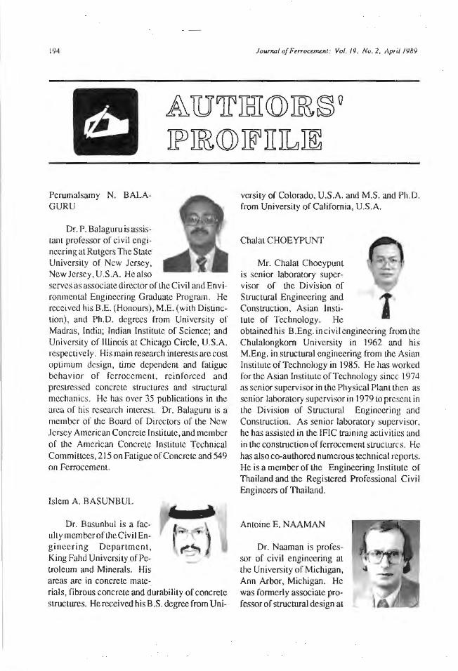
194 Journal of Ferroceme111: Vol. 19, No. 2, April 1989
& 1IJTIHI (Q) IB § Q
IF IB (Q) JF JI J1 JE
PerwnaJsamy N. BALAGURU
Dr. P. Balaguru is assistant professor of civil engineering at Rutgers The S talc University or New Jersey, New Jersey, U.S.A. He also serves as associate director of the Civil and Environmental Engineering Graduate Program. He received his B.E. (Honours), M.E. (with Distinction), and Ph.D. degrees from University or Madras, India; Indian Institute of Science; and University of Illinois al Chicago Circle, U.S.A. respecti vc I y. His main research interests arc cost optimum design, Lime dependent and fatigue behavior o f ferroccmcnt, reinforced and prestrcssc<l concrete strucLUrcs and structural mechanics. He has over 35 publications in the area of his research imcrcsL. Dr. Balaguru is a member of the Board or Directors of the New Jersey American Concrete Institute, and member of the American Concrete Institute Technical Commillees, 215 on Fatigue or Concrete and 549 on Ferroccmcnt.
Islcm A . BASUNBUL
Dr. Basunbul i s a facully membcroftheCivil Eng ineering D epartment , King Fahd University of Petroleum and Minerals. His areas arc in concrete mate-rials, fibrous concrete and durability of concrete structures. He received his B.S. degree from Uni-
vcrsity of Colorado. U.S.A. and M.S. and Ph.D. from University of CaJifomia, U.S.A.
Chalat CHOEYPUNT
Mr. ChaJat Chocypunt is senior laboratory supervisor of the Division of
Structural Engineering and 1 Construction , Asian lnsli-Lute of Technology. He obtained his B.Eng. in civil engineering from the Chulalongkorn University in 1962 and his M.Eng. in structural engineering from the Asian lnstilute of Technology in 1985. He has worked for the Asian Institute of Technology since: 1974 as senior supervisor in the Physical Plant then as senior laboratory supervisor in 1979 to prei:em in the Division of Structural Engineering and Construclion. A s senior laboratory supervisor, he has assisted in the IFIC !raining activities and in the construction of fcrrocement sLructures. He has also co-authored numerous technical reports. He is a member of the Engineering Institute of Thailand and the Registered Professional Civil Engineers of Thailand.
Antoine E. NAAMAN
Dr. Naaman is professor of civil engineering at the University of Michigan, Ann Arbor, Michigan. He was formerly associate professorof structural design at
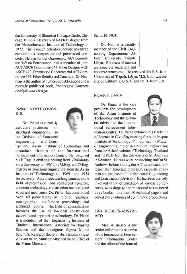
Journal of Ftrrocem.v11: Vol. /9, No. 2, April 1989
the University of lllinois at Chicago Circle, Chicago, IUinois. He received his Ph.D. degree from the Massachussetts Institute of Technology in 1972. His research activities include advanced cemenLitious composites and prestresscd concrete. He was former chairman of ACI Committee 549 on Ferrocement and a member of joint ACI-ASCE Committee 544, Fiber Design; AC1-ASCE423, Prestressed Concrete; and ACI Commiuee 544, Fiber Reinforced Concrete. Dr. Naaman is the author of numerous publications and a recenlly published book, Prestressed Concrete Analysis and Design.
Pichai NIMITYONG SKUL
Dr. Pichai is currenlly associate professor of structural engineering in the Division of Structural Engineering and Cons-truction. Asian lnstiwte of Technology and associate director of the lmernational Ferrocement Information Center. He obtained his B.Eng. in civil engineering from Chulalongkom University in 1967, his M.Eng. and D.Eng. degrees in structural engineering from the Asian Institute of Technology in 1969 and 1974 respecti vely. A pan from teaching courses in the field of prcstressed and reinforced concrete, concrete technology, construe Lion materials and structural mechanics, Dr. Pichai has contributed over 40 publications in referred journals, monographs. conference proceedings and technical reports. His field of specialization involves the use of low-cost construction materials and appropriate technology. Dr. Pichai is a member of the Engineering Institute of Thailand, International Associate for Housing Sc ience and Lhe prestigious Sigma Xi- Lhe Scientific Research Society. He is also serving as Advisor to the Minister Alt.ached to the Office of the Prime Minister.
SamirM. NUH
Dr. Nuh is a faculty member of the Civil Engineering DcpartmenL, AlFateh University, Tripoli, Libya. His areas of interest arc concrete materials and
195
concrete structures. He received his B.S. from University of Tripoli, Libya, M.S. from University of California, U.S.A. and Ph.D. from U.K.
RicardoP. PAMA
Dr. Pama is the vice president for development of ll1c Asian Institute or Technology and the technical advisor to the lmemational Fcrrocement lnfor. malion Center. Dr. Pama obtained his Bachelor of Science in Civil Engineering from Lhe Mapua Institute of Technology, Philippines; his Master of Engineering, major in structural engineering from the Asian lnstitutc of Technology, Thailand and his Ph.D. from the University of SL. Andrews in Scotland. He was with the teaching staff at St. Andrews before joining Lhc AIT as assistant professor Lhcn associate professor, associate chairman and professor of the Structural Engineering and Construction Division. He has been actively involved in the organization of various conferences, workshops and seminars and has authored three books, more tl1an 50 technical papers and edited three volumes of conference proceedings.
Lilia ROBLES-AUSTRlACO
Mrs. Austriaco is the senior information scientist of the lntemalional Ferrocemem Information Center and the editor of the Journal
196
of Ferrocement. She obtained a Bachelor of Science in Civil Engineering (Cum Laude) from the Mapua Institute of Technology and a Master of Engineering, major in structural engineering from the Asian Institute of Technology. Mrs. Ausl.riaco served as civil engineer, Bureau of Public Works, Philippines; associate professor and reviewer, Mapua Institute of Technology, Philippines; informal.ion scientist, Asian Information Center for Geotechnical Engineering, Asian Institute of Technology, Thailand; and lecturer in the undergraduate and graduate programs of the School of Housing, Building and Planning, Universiti Sains Malaysia, Malaysia. She is a member of the Philippine Institute of
Journal of Ftrroce~nt: Vol. 19 , No. 2, April 1989
Civil Engineers and the American Society for Civil Engineering Education. She has authored numerous publications in ferrocement and fiber reinforced cement
R.B. Wll..LIAMSON
Dr. Williamson is professor of civil engineering, Dcparunem of Structural Mechanics and Structural Engineering, University of California, U.S.A.
JourflD/ of Ftrroce~nl: Vol. 19. No. 2, April 1989 197
NATURAL FIBRE REINFORCED CEMENT AND CONCRETE
Concrete Technology & Design Volume 5
R.N. Swamy, editor
PublishedbyBlackieandSonLtd.BishopbriggsGlasgowG64 2NZ, 7 l eicester Place.London WC2/I 7BP England.
This latest volume.in Lhc Concrete Technology and Design series offers a comprehensive and authoritative review of narural fibres in cement and concrete, cir.awing on the experience of eight inLemationally recognized experts.
The book begins with a discussion of the background and chronological development of natural fibres and goes on Lo provide descriptions of fibre types, specific physico-chemical properties and applications, and the advantages, disadvantages and appropriate uses for cen.ain fibre types. Olher important topics covered include durability, methods of pulp production, fibre processing techniques, production requiremenLs and procedures, materials properties related to fabrication criteria, and specification data.
This volume, which links recent research and fundamental knowledge Lo practical applications, will be of interest to practising civil and structural engineers, engineers in academic and industrial research, and designers and materials technologists.
Contents:
Wood fibre reinforced cement composites: R.S.P. CoutLs. Wood fibre reinforced concrete: A. Sarja. Bamboo reinforcement for cement and concrete: L. Robles-Austriaco and R.P. Pama. Durabi)j ty of natural fibres in concrete: H.-E. Gram. Natural or modified cellulose fi bres as reinforcement in cement composites: Z. Fordos. Vegetable fibre reinforced building mat.crials -developments in Brazil and olher Lalin American countries: V. Agopyan. Use of natural fibre concrete in lndia: S.S. Rehsi. Natural fibre concrete roofing: H.-E. Gram.
288 +xii pp English
155 cmx235 ISBN 0-216-92493-6
Hardback 1988
198 Jour1111/ of F~ffocumnJ: Vol. 19. No. 2. April 1989
Abstracts
FPl 18 CRACKING BEHA YIOUR OF FERROCEMENT IN TENSION
KEYWORDS: Cracking, Crack spacing, Crack widlh, Experiment.alion, Ferrocemenl, Tension
ABSTRACT: This study deals wilh an analytical and expcrimenlal invcsLigation of crack spacing and crnck width of ferrocemem in direcl Lensile loading. The theoretical derivation arc based on the classical 1.hcory of cracking in reinforced concrc1.e members on 1.hc assumplion Uial Lhc Lensile sLrcngLh of Lhe mortar surrounding the reinforcernenL arc uniformly disLribuled over an effective cross-sect.ion and a certain bond stress cxisLS along Lhe reinforcement. To check Lhe validily of Lhe proposed model, an exlensive experiment41l work was carried out by casting some tensile mortar prisms reinforced wiLh small diameter wire. The theoretical average crack spacing and maximum crack width al Lhc level of reinforcement and theexpcrimenlal crack spacing anti crack width auhe face of the specimen showed good agreement
REFERENCE: Akhtaruzzaman, A.K.M., and Pama, R.P. 1989. Cracking behavior ol ferroccment in tension. Journal of Ferrocemenl 19(2): 101-108.
FPl 19 FIRE RESISTANCE OF FERROCEMENT LOAD BEARING SANDWICH PANELS
KEYWORDS: Bearing walls, Compression, Ferroccment, Fire rcsis1.ancc. Panels, Sandwich panels
ABSTRACT: A 12 ft (3.658 m) wide by 8 fl (2.438 m) tall wall was constructed using three 4 ft x 8 ft (l.219 m x 3.658 m) panel.s 6 in. (0.15 m) Lhick. Each panel consists of two ferrocemem plaLes 1/2 in. (12.7 mm) thick connected wilh 1(2 in. (12.7 mm) central corrugated stiffener. One of Lhe 4 fl x 8 fl ( L2 I 9 m x 3.658 m) panels was tested in compression to estnblish the maximum compressive load which was 328 kips (1459 kN). One of the panels of the fire Lest wall specimen was fi lied with polyurethane foam. Anothc:r was filled with mineral wool and the cavities in Lhe middle panel were left unfilled. The waU was placed in Lhe standard wall frameofLheASTM E- 11 9 tcsL furnace and subjected toa total compression live load of 80 kips (356 k.N). The test was conducted according lo ASTM E-119 fora period of3 hrs. The wall carried Lheapplicd load forlheenlire test period wilhoul any sign of structural failure. The polyurethane filled panel failed at 139"C (250UF) average face tcmpcraltire rise criteria at 62 minutes into Lhe test The open cell panel failed the same average temperature rise criteria al 74 minutes and Lhe mineral wool filled panel failed the single poinl. temperature rise al 181 "C (325°F) al 73 minutes. There was some spalling observed on the furnace expo ed surface of one of the panels early in Lhe tesl, but Lhere was no other indicalion of problems.
REFERENCE: Basunbul, I.A.; Nuh, S.M.; and Williamson, R.B. 1989. Fire resistance cf fcrrocemenl load bearing sandwich panels. Journul of Ferrocement 19(2): I 09-123.

Journal of Ferrocement· Vol. 19. No 2, April 1989
FPI20 FERROCEMENT GATE WITH REVERSED HYPERBOLIC FLAT SHELL
KEYWORDS: Applicatfons, FerrocemcnL, Gales (hydraulics). Hydraulic SliucLurcs China
ABSTRACT: The upplicalion of ferrocemem gate with reversed hyperbolic nat sheU LO
irrigation and drainage engineering in Hebci province of China is reported. The structure and geometry of the gate, material used, consLrucLion procedure, LCChniquc required and Jcsign theory arc also described.
REFERENCE: Zhao Lu-Guang, and Yuan Shou-Quian. 1989. Fcrroccmenl gate with reversed hyperbolic flat shell. Journal of F errocement I 9(2): I 25- I 28.
FP1 21 RICE HUSK ASH CEMENT FOR FERROCEMENT
KEYWOR OS: Acid resistance, Compressive sLrCngth, Fcrroccmcm, Flexural strength, Heal of hydraLion, Impact strengl11 , Pozzolana, Rice husk ash, Tensile slicngLh
ABSTRACT: Rich husk ash (RHA)ccmcnLisamixLureofgroundRHAand lime or Portland ccmcnL RHA can be used Lo partially replace cement in making mortar and concrete. This paper presents l11c properties of ferroccmcnL using RHA cement monar. The properties investigated arc comprcs~ive slicngth, tensile strength, flexural strengl11 , impact strength, heal of hydration of cement and acidic resistance. The test results showed th al RHA cement mortar has bcner resistance to acidic attack than Portland cement mortar. RHA in ferrocement improved iLS impact strengl11; however, tls compressive, tensile and flexural strcngl11 dct:rcascd.
REf.ERENCE: Choeypunt, C; Nimityongskul, P.; and Robles- Austriaco, L. 1989. Rice husk ash cement for ferroccmcnt. Journot of Ferrocemem 19(2): 129-134.
FP 122 USE OF FERROCEMENT FOR CONFlNEMENT OF CONCRETE
KEYWORDS: Columns (supports), Compressive slicngth, Concrete, Ductility, Ferrcx:cmcnt, Repair, Retrofit
ABSTRACT: This paper presents the rcsulL<; of an investigation on the behavior of plain concretccylindcrsconfinccl in Ccrroccmcntshells. The experimental part of the investigation consisted of strcngl11 tests using 6 in. x 12 in. (150 mm x 300 mm) cyl inders. The primary variables were: compressive strength of concrete in the range of 3 ksi to 6 ksi (20 MPa Lo
40 MPa), and 1 to 4 layers of wire mesh. The wire mesh provided effective confinement, resulting in im.:rease of compressive strength and increase in ducti lity. The increase in number of wire mesh resulted in consbtent increase in both strength and duclility. The increase in compressive.strengths estimated usmg constitutive models for confined concrcLe compares well with l11c experimental results.
REFERENCE: Balaguru, P. 1989. Use of fcrroccmcnt for confinement of conrctc. Journal of Fcrrocemcnt 19(2): 135-140.
199

200 Journo./ of Ftrroctf>IJ!nt: Vol. 19, No. 2, Ap1il 1989
FP123 FERROCEMENT HOUSING: TOW ARD INTEGRATED HIGH TECHNOLOGY SOLUTIONS
KEYWORDS: Ferrocement, Floors, Housing, Manufacturing, Panels, Research, Roofs, Walls
ABSTRACT: AfLcr a brief review of lhe djfferent levels of technologies used in femx:emenl housing producLS, lhe prescnl paper focuses on lhe results of a feasibility sludy recently completed at lhe Univerity of Michigan where advanced manufacturing techniques we re considered for the production of housing units using fcrrocement panels. The sludy suggested lhaL most common housing requirements could be satisfied from a pool of about fifteen standard panel configurations. Box shaped panels were considered for the walls and lintels, while U shaped panels were considered for nooring and roofing. System requirements arc described and needed research suggesLed.
REFERENCE: Naaman, A.E. 1989. Ferroccment housing: Toward integrated high Lechnology solutions. Journal of Ferrocement 19(2): 141-149.

Jourfl/J/ of Ferrocenuuu; Vol. 19, No. 2, Apr il 1989 201
•
IlNTJEJENATil(Q)NAJL J™IJEJETIING§
April 16-21 , 1989: 11th IRF World Meeting, Seoul, Korea. Contact: Sccratary General, Organizing Committee, 11 t.h £RF World Meeting SeouJ, c/o Korea Highway Corporation, 293- 1 Kumto-Dong, Songnam-Si, Kyonggi-Do, Seoul C.P.O. Box 5147, Republic of Korea.
April 23-29, 1989: ASNT 12th World Confer ence on Nondestructive Testing, Amsterdam, the Netherlands. ContacL: American Society for Nondestructive Testing, 4153 Arlingate Plaza. Colombus, Ohio 43228, U.S.A.
April 24-26, 1989: International Seminar on T he Life of Structures, Brighton, U.K. Contact: Dr. J .L. Clarke, British Cement Association, Wexham Spring, Slough, England SL3 6PL.
May 10-13, 1989: Concrete '89 The Concrete Institute of Australia, Australia. Comact: The Conference Manager, Concrete '89, Concrete Institute of Australia, 11 Bagol SL, North Adelaide 5006, Australia.
May 25-26, 1989: Seminar on Alkali Reactive Aggregates, Singapore. Contact: En gr. J .S. Y. Tan, Conference Organizer, Serangoon Garden, P.O. Box 411, Singapore 9155.
June 5-8, 1989: The 9th Diennial National Housing Congress, South Africa. Contact: The Congress Organiser, Insti tute for Housing of SA, P.O. Box 2526, Randburg, Republic of South Africa 2125. Tel: (01 1) 886-1630.
June 7-9. 1989: ERMCO '89 The Norway to Concrete, Stavanger , Norway. Contact: ERMCO '89 Congress Office, Norccm Cement NS, P.O. Box 1386 Vika, 0114 Oslo I ,Norway. Tel: +47 24 1 71 70; Telex: 71148 nocem n.
June 12-J.J, 1989: Conference on Concrete Engineering and Technology, Kuala Lumpur, Malaysia. Contact Sccret.ariat CONCET '89, Insti tut Teknologi Mara, 40450 Shah Alam, Malaysia.
June 12-16. 1989: T he 10th lnternationaJ Conference on Port and Ocean Engineer ing under Artie Condition, Sweden. Cont.act: POAC '89 Conference, Lulea University of Technology, S-951 87 LuJea, Sweden. Tel: +46 92091000; Telex: 80447 luh s; Telefax: +46920 972 88.
June 13-17. 1989: I nternational Conference on Composite Inter faces (ICCI-2), Cleveland, Ohio, U.S.A. Contact: Advanced Composites Manufacturing Centre, Department of Mechanjcal Engineering, Plymouth Polytechnic, Drake Circus, Plymouth, U.K. PL4 8AA.
June 19-23, 1989: Xllh International Congress CIB '89, Paris, France. Contact: JeanLouis Fclz or Angela Ghivasky, Center Scientifiquc Cl Technique du Batiment (CSTB) Relations cxterieures, 4 avenue du Recteur -Poincare, 75782 Paris Cedex 16, France.
202
June 19-26, 1989: Third Interna tional Conference on the Use of F ly Ash, Silica Fume, Slags and Natural Pozzolans in Concrete, Trondheim, Norway. Contact Dr. V.M. Malhotra, CAN MET, 405 Rochester St., Ottawa, Ontario, Canada KIA OG 1.
June 25-29. 1989: Inte rnational Confe rence on Composite Materials for High Temperatures: Fundamental Principles and Performance, J erusalem, Israel. Contact Mrs. ShulamiL Cahan a, Min is try of Science and Development, PO Box 18195, 01181 Jerusalem, Israel.
June 26-27, 1989: Interna tional Conference on Some Aspects of Admixtures and Industria l Byproducts on the Durability of Concrete, Gothcnb~rg, Sweden. Contact: Dr. S. Chandra, Division of Building Materials, Chalmers University of Technology, S-41296 Gothenberg, Sweden.
June 27-29, 1989: Fourth Interna tional Conference on Str uctura l Faults and Repair, London, U.K. Contact Dr. M.C. Forde, Department of Civil Engineering and Building Science, University of Edinburgh, The King's Buildings, Mayfield Road, Edinburgh, Scotland EH9 3JL.
June 27-29, 1989: 4th J oint US-J apan Conference on Com posite Materials, Washington, D.C., U.S.A. Contact: Advanced Composites Manufacturing Centre, Depanmcnt of Mechanical Engineering, Plymouth Polytechnic, Drake Circus, Plymouth, U.K. PlA 8AA.
July 17-20. 1989: Eighth International Conference on Alkali Aggregate Reaction, Kyoto, Japan. Contact: Conference Services, The Socie ty of Materials Science, Japan, 1-101, lzumidono-chou, Sakyou-ku, Kyoto 606, Japan.
July 24-26.1989: International Conference on Composite Structures, Paisley, Scotland . Con1ac1: Dr. I.H . Marshall, Dcpanment of Mechanical and Production Engineering, Paisley
JourNJI of Furoument: Vol. 19, No. 2, l\pnl 1989
College of ~hnology, HJgh St., Paisley, Scotland PAI 2BE.
August 1-2. 1989: Structural Dynamics Symposium, Kuala Lumpur, Malaysia. Contact: The Secretary, SDS '89, Faculty of Civil Engineering, Universiti Teknologi Malaysia, Jalan Semarak, 54100 Kuala Lumpur, Malaysia.
August 8-11, 1989: Fifth International Conl'erence on Structural Safety and Reli:.1bility (ICOSSAR. '89), San Francisco, U.S.A. Contact: ICOSSAR '89 Secretariat, c/o ASCC, 345 East 47th St., New York, NY 10017-2398, U.S.A.
August 21. 1989: Second Symposiu m on Concrete and Structures, Jakarta, lndont:sia. Contact: Engr. J .S. Y. Tan, Conference Organizer, Serangoon Garden, P.O. Box 411 , Singapore 9155.
August 24-25, 1989: Fourteenth Conference on O ur World in Concrete and Struct ures, Singapore. Contact: Engr. J.S.Y. Tan, Conference Director, 150 Orchard Road #07- 14. Singapore 0923. Tel: 7332922; Telex: RS 33577 COMPA; Fax: 2353530.
August 25-28. 1989· Seventh International Conference on Composite Materials, Beijing, C hina. Contact: Mr. Tu Dczhang, China Scieiety of Aeronautics and Astronautics, 67 South S Lreet. Jiao Daokou, Beijing, China.
August 28, 1989: Second Sympos ium on Concrete and Structures, Malaysia. Contact: Engr. J.S.Y. Tan, Conference Organizer, Serangoon Garden, P.O. Box 41 l , Singapore 9 L55.
September 5-8. 1989: T he Second Beijing International Symposium on Cement and Concrete, Beijing, Ch ina. Contact: Mr. Zhaoqi Wu, China Building Mate rials Accdemy. Guanzhuang, East Suburb, Beijing 100024. China.
J11wnal of PerrtK:t!t~rU : Vol. 19 No. 2, April 1981J
September 6-8. 1989: IABSE Symposium on Durability of Structures, Lisbon, P ortugal. Contact: Organizing Committee, 1989 IABSE Symposiwn, LNEC, Avcnida do Brazil 101, P-1799, Lisbon, Portugal.
September8-l J, 1989: NZCRA/NZCS Pacific Concrete Conference, Auckland, New Zealand. Cont.act: The Secretary, New Zealand Concrete Society, P.O. Box 17-268 Karori, WellingLOn, New Zealand.
September l 1-15.1989: 10 Years of Progress in Shell and Spatial Str uctures: 30 Aniversary of IA S, Madrid, Spain. Coniact.: Sr. D.A. de las Casas, LaboraLorio Ccnt.ral de Estructuras y Materiales - Ccdex, Alfonso XJl. 3, 280 14 Madrid, Spain.
September 18-20, 1989: International Conference on Pumped Storage, Manchester , U.K. Contact Conf crencc Office, Institution of Civil Engineers, l-7 Great George St., Westmins ter. London, U.K. SWlP 3AA.
September 18-20. 7989: rntcrnational Conference on Recent Developments in Fiber Reinforced Cement and Concrete. Cardiff, U.K. Contact: Dr. B. Barr, Conference Secretary. School of Engineering, University of Wales College of Cardiff, Newpon Road, Cardiff, U. K. CF2 IXH. Tel: Cardiff(0222) 874000 Ext 5692/ 4826; Fax: (0222) 37 192 1; Telex: 498635 Ulibclg.
September 19-21, 1989: International Conference on Civil and Structural Engineering Computing, London, U.K. Conract: Dr. B.H. V. Topping, Department or Civil Engineering, Hcriot-Wau University, Riccarton, Edinburgh , U.K. EH 14 4AS.
September 20-22. 1989: Conference on Structural Adhesives in Engineering II, Bristol, U.K. Contact: Mr. J. Herriot, SAE 11, Butterworth ScientiGc Ltd., PO Box 63, Westbury
203
House, Bury SL, Guildford, Surrey, U.K. GU2 5BH.
September 20-22, 1989: International Conference on Recent Developments on the Fracture of Concrete and Rock, Cardiff, U.K. Contact: Dr. B. Barr, Conference Secretary, School of Engineering, University of Wales College of Cardiff, Newport Road, Cardiff, U.K. CF2 l XH. Tel: Cardiff (0222) 874000 Ext. 5692/4826; Fax: (0222) 371921; Telex: 498635 Ulibcf g.
September 28-29.1989: International Sympos ium on Noteworthy Deve lo pments in Prestre~d and Precast Concrete, Singapore. Contact: Engr. J .S. Y. Tan. Symposium Director, 150 Orchard Road #07-14, Singapore 0923. Tel: 7332922: Telex: RS 33577 COMP A; Fax: 2353530.
October 2-6. 1989: 9th European Congress on Corrosion, Utrecht, the Netherlands. Coniact Congress Bureau, Royal Netherlands Industries Fair. PO Box 8500 3503 RM Utrecht, the Neth· erlands.
October 4-6. 1989: Third lnternalional Conference on the Use of Super plasticizers and Other Chemical Admixtures in Concrete, Ottawa, Canada. Conuict: H.S. Wilson, PO Box 3065, Station C. Ottawa, Ontario, Canada KIA OGL Tel: (6 1)996-5617; Telex: 053-3117; Fax: (61)952-2587.
October 21-24, 1989: Third International Conference on the Deterioration and Repair of Rdnforced Concrete in the Arabian Gulf', Bahrain. Conract: Concrete Ill, The Conference Secretariat, The Bahrain Society of Engineers, PO Box 835, Manama, Bahrain.
October 23-28, 1989: Fourth International Symposium on Practical Design of Ships and Mobile Units. Coniacr: Prads '89, Organizing Commiu.ee, Bulgarian Ship Hydrodynamics Center, 9000 Varna, Bulgaria. Tel: (052) 775 180, (052) 775186; Telex: 77497 BSHC BG.
204
October 23-28, 1989: lAHS World Congress on Housing, Oporto, Portugal. Contact Prof. Oktay Ural, IAHS, Housing Congress- Ponugal, P.O. Box 340254, Coral Gables, Miami, Florida 33134, U.S.A.; Prof. Vitor Arbrantes, Facaldad de Engenharia, Gabinete de Construcoes Civis, Rua dos Bragas, 4099 Porto Codex, Portugal.
November 6-9. 1989: Symposium on Composite Materials: Fatigue and Fracture, Orlando, U.S.A. Contact: Ms. D. Savini, ASTM, 1916 Race SL, Philadelphia 19103, U.S.A.
November 7-9. 1989: Asia Pacific Structural Analysis Conference, Kuala Lumpur/Malacca, Malaysia. Contact: Organising Secretary, APSAC, Faculty of Civil Engineering, Universili Teknologi Malaysia, Jal an Scmarak, 54100 Kuala Lumpur, Malaysia.
November 8-9, 1989: International Symposium on Architectura l Precast Concrete Cladding -Its Contribution to Lateral Resistance of Buildings, Chic.ago, Illinois, U.S.A. Contact Sidney Freedman, Director, Architectural Precasl Concrete Services, Prcstrcssed Concrete Institute, 175 West Jackson Boulevard, Suite 1859, Chicago, Illinois60604, U.S.A. Tel: (312) 786-0300; Fax.: (312) 786-0353.
November 8-10, 1989: Conference UK Corrosion '89, Blackpool, U.K. Coni.act Programme Coordinator, UK Corrosion '89, Exeter House, 48 Holloway Head, Birmingham, U.K. Bl lNQ.
November 20·23. 1989: International Conrerence on Evaluation of Materials Performance in Severe Environments, Japan. Contact: Secretarial, EV ALMAT'89, The Iron and Steel InstituteofJapan, Keidanren Kaikan, l-9-40tcmachi, Chi yoda-ku, Tokyo 100, Japan.
November 22, 1989: AFPC/lTBTP Confer ence on the Future of Concrete, Paris, France. Contact: Association Francaise pour Ia Construction, 46, avenue Aristide Briand, F-92220 Bagneux, France.
)oW'nal of FtffOCl~nt: Vol, 19. No. 2, April 1989
November 22-24, 1989: European Conforence on Meterials, Aacbaen, German Federal Republic. Contact: Deutsche Gesellschaft fur Metallkunde eV Adenauerallee 21 D-6370 Obcrursel 1, Federal Republic of Germany.
March 25-30. 1990: Symposium on Concrete Durability, Toronto, Canada. Cont.act Mr. Paul Klieger, Consult.ant, PO Box 2275, Northbrook, Illinois (l()()65-2275, U.S.A.
M<'Y 14-17, 7990: Internationa1Symposium on Admixtures ror Concrete: Improvement of Properties, .Barcelona, Spain. Contact Prof. Dr. E. Vasquez, Depanamentodelngenieriadela Construccion, Escuela Tee. Sup. lnginicros de Caminos, Canales y Puertos, Jorge Girona Salgado 31, 08034 Barcelona, Spain.
May 20-22, 1990: Second Internationa l Symposium on Applications of High Strength Concretes, Cali fornia, U.S.A. Contacl: Prof. Weston T. Hester,2 15 McLaughlin HaJI, University of California, Berkeley, California 94720, U.S.A.
June 3-7. 1990: FIP '90: Xlth International Congress on Prestressed Concrete, Hamburg, U.K. Contact Dr.J.Dougill ,FIP, The InstiLULion of Structural Engineers, 11 Upper Belgrave SL, London, U.K. SWIX 8BH.
September 24-27. 1990: Sixth Interna1ional Congress on Polymers in Concrete, Shanghai, China. Contacl: lCPIC-90 Secretariat, c/o Associate Prof. Tan Muhua, Institute of Materials Science and Engineering, Tong.ii University, Shanghai, China.
February 10-15. 1991: International Symposium on Polymer Materials Prepara tion Characterization and Properties, Me lbo~Jrne ,
Australia. Contact RACI Polymer Division, P.O. Box 224, Belmont Victoria 3216, Australia.
luhe 3-7, 1991 : 11th FIP Congress, Ham bur, West Germany. Contact: FJP Office, The lnsti-
Journal of Ferroctment: Vol.19, No. 2, April 1989
tution of Structural Engineers, 11 Upper Belgrave Street, GB-London, U.K SWlX 8BH.
November 23-28, 1992: 9th International Congress on the Chemistry of Cement, New
205
Delhi, India. Contact: The Secretary-General, 9th International Congress on the Chemistry of Cement 1992, National Council for Cement and Building Materials, M 10 South Extension II, Ring Road, New Delhi 110 049, India.

206 Journal ofFerrocement: Vol.19, No.2 , April 1981.i
001 FERROCEMENT 003 FERROCEMENT, A VERSA TILE CONSTRUCTION MATERIAL: ITS
B.K. Paul and R.P. Pmnn INCREASING USE IN ASIA
This publication discusses every uspccl of rerrocemcm technology: historical background, consLituenL materials, construction procedures, mechanical properties and potential applications. The l1exfoover edit.ion includes over75 literaturc references on the subject. 149 pp., 74 illus.
Surface nu1i/ Subscribers US$12.00 Non-subscribers US$15.00
Air rrwi/ US$14.00 US$17.00
002 THE POTENTIALS OF FERRO CEMENT A D RELAT ED MATERIALS FOR RURAL I NDONES IA - A FEASil31LITY STUDY
R.P. Pama and Opas Phromratanap<mg~e
The rcpon recommends seven potential applications of ferroccmem aml related materials found particularly suit.able for rural Indonesia. Good reference for volunteer groups and government officers involved witll rural development
Surface mail Air mnil
US$2.00 US$4.00
Edited by R.P. Pama, Seng-Lip Let: and /Voe/ D \lirtmeyer
This report is Lhe product of Lhc workshop " Introduction of Technologies in Asia -Ferroccmcnt, A Case Study". jointly sponsored by lhc Asian lnslituLc of Te~hnology (AIT) and Lhc U.S. National Academy of Sciences (NAS). Thirteen case studies on the 'State-of-the-An' of fcrroccmcnucchnology and applicmions in nine countries in Asia and Australja arc presented. 106 pp., 59 illus.
Surface mail Air nwil
US.$2.00 US$4.00
004 FERROC.EMENT AND ITS APPLlCATJON -A IllilLIOGRAPHY,
Volume 1
It prescms acomprehensive listof refe1ences covering all aspects of fcrrocemenl technology and its applications. This first volume lists 736 references classified according to subject and author indices. All listed refcrcencc> arc available at IFIC which can provide photocopies on request aL nominal cost ldeal for researchers and amateur builders. 56 pp.
Surface mail Air mnil
US$2.00 US$4.00
Journal of Fi" ocerrumJ: Vol. 19. No. 2, April 1989
005 DO IT YOURSELF SERIES
To accclcraLe 1.ransfer or ferrocement Lcchnology to developing countries, IFIC has published Lhe following eight Booklets in the Do It Yourself Series:
Ferroceme111 Grain Swrage Bin- Book/el No. I Ferrocemen1 \Vmer Tank - Bookle1 No. 2 Ferrocement Biagas JI older - Booklet No. 3 Fcrrocement Canoe - Booklet No. 4
Cost per Booklet Surface mail Air mail
US$2.00 US$4.00
Ferrocement Roofing Element - Booklet No. 5 Ferrocement Biagas Digester - Booklet No. 6 Ferroccmem Canal Lining - Booklet No. 7 Ferror:ement Pour-Flush lairine- Booklet No. 8
Cost per Booklet Surface mail Air mail
US$4.00 US$6.00
The dcscripLive text m each booklet is in a nontechnical language. Material specifications, material estimations, construction and postconstrucLion operaLion of each uLiliLy structure arc well discussed. Construction drawings and construction guidelines to ensure betLcr workmanship and finished sLrucLures arc presented. Also included are additional readings and sample calculaLions.
006 FOCUS
This pamphlet inlrOduces ferrocemem as a highly versatile fonn of reinforced concrcLC used for construction with a minimum of skilled labour. Published in Bengal i, D urmcsc. Chinese, English, French, Hindi, Indonesian, Japanese, Nepalese, Pilipino. Portuguese, Singhalcsc, Spanish, Swahili, Tamil, Thai. Urdu. These pamphleLS could be obtained FREE of Charge.
007 SLIDE PRESENTATION SERIES
Construction of Ferrocemem Waler Tank - Series No. I
An Introduction to Ferrocement - Series No. 2
Ferrocemcnt - A Technology for /lousing - Series No. 3
llistorical Development of Ferrocement - Series No. 4
Introducing Bamboo as Reinforcement - Series No. 5
207
Each set contains 30 color slides with a dcscripLion of each slide on an accompanying booklet Addi tionaJ background information arc included where appropriate. The sljde scLs listed are intended ror use in schools, colleges, trajning centers and w ill be equally useful ror organizations involved in rural development
Cost per Serits Developing countries Developed countries
Air mail US$15.00 US$20.00
008 FERROCEMENT APPLICATIONS: STATE-OF-THE-ART REVIEWS
Volume 1
This volume is the compilaLion of the Si.ateof-lhe-Arl Reviews published in Lhe Journal of Ferrocemenl. A valuable source volume thaL summari zes publi shed information before January 1982.
Surface nwil Air mat/
009 HOUSI NG BIBLIOGRAPHY
Specialized Bibliographies Vol. 1
US$ 8.00 US$10.00
Housing Bibliography inc ludes all references available at IFIC on housing, constructed in siLu and prefabricated.
Surface mail Air mail
US$2.00 US$4.00
208
010 INTERNATIONAL DIRECTORY OF FERROCEMENT ORGANIZATIONS AND EXPERTS 1982-1984
This directory is an inderpcnsable source for decision making to select firms/experts for ferrocement related design, construction and engineering services.
226 firms and expen s present their capabilities and experience. In addition, Lhey are indexed by types of services performed and by geographic location of their offices.
Surface mail Air mail For Experts and Firms US$ 5.00 US$ 7.00
listed in the directory List price US$15.00 US$17.00
011 PROCEEDINGS OF THE SECOND INTERNATIONAL SYMPOSI UM ON FERROCEMENT
Edited by: L. Robles-Ausiriaco. RP. Pama, K. Sashi Kwnar and E.G. Mehta.
The proceedings provide an opportunity to
review and update the existing knowledge and further understand the latest developments and progress made in ferrocemem technology.
List price:
Air mail postage Asia Others
US$ 60.00 (surface postage included)
US$ 5.00 US$ 12.00
Journal o[Ferrocr.meril: Vol. 19, No. 2, April 1989
012 LECTURE NOTES: SHORT CO URSE ON DESIGN AND CONSTRUCTION OFFERROCEMENTSTRUCTURES
This is a compilation of the lecLUre notes of the Short Course on Design and Construction of Ferrocemem Structures held at the Asian Institute of Technology, Bangkok, Thai land. 8-12 January 1985. This publication contains every aspect of ferrocement from its historical background and constiuent materials to the construction procedures. An imponam rcalure or the lecture notes is Lhe design criteria for ferrocement incl uding examples of analysis problems based Crom the "ACT Design Guide for Ferrocemcnt."
list price:
Air mail postage Asia Others
US$45.00 (surface postage included)
US$ 5.00 US$12.00
01 3 FERROCEM ENT ABSTRACTS
Each volume contains 300 abstracts on ferrocemenl Lcchnology. Each abstracL is numerically coded and indexed by keywords, authors and lilies.
Surface mail Air mm/
Volume I Volttme 2
US$4.00 US$6.00
US$6.00 US$8.00
Jowl'llJ/ of Ft"oumel'll : Vol. 19, No 2, April 1989 209
JOURNAL OF FERROCEMENT
SUBSCRIPTION RATES
The annual subscription rates in US$ for the Journal of Ferrocemem (inclusive of pos1.age by surface mail) are as follows:
Region A. North America, Europe, Australia,
New Zealand, Middle East and Japan
B. Countries other than those listed in Region A
Status lndividuaJ Institutional
Individual Institutional
Rate 36.00 70.00
22.00 40.00
Multi-year Subscription Discounts
AJT Alumni Others
1 to 2 years: 3 to 4 years: 5 years:
15% 18% 20%
l to 2 years: 3 to 4 years: 5 years:
10% 15% 20%
We encourage subscription to the Journal of Ferrocement through air mail, in which case the following extra charges in US$ are LO be added to the annual subscription rates as specified above:
Region
Asia Oceania, Europe and Africa America
MODES OF PAYMENT
Additional charge
US$ 6.00 US$10.00 USS12.00
AJl payments (subscription fees, advenisement fees and service fees) are to be paid in advance and can be made by bank draft, cashier's cheque or international money order in us dollars in favor of IFIC.
BACK ISSUES
Special Issues
* Marine Applications (Vol. 10. No. 3, July 1980)
* Housing Applications (Vol. 11, No.I, January 1981)
• Water Decade (Vol. 1, No. 3, July 198 1)
Cost per issue*
Individual Institutional
Surface mail Air mail US$ 6.00 US$ 8.00 US$12.50 US$14.50
*Agricultural Applications (Vol. 12, No. 1, January 1982)
* Prefabricated Ferrocement Housing (Vol. 13, No. l , January 1983)
* Water Resources Structures (Vol. 14, No. l, January 1984)
*Prefabrication & Industrial Applications (Vol. 16, No. 3, 1986)
*Fiber Reinforced Cement StrucLUres (Vol. 18, No. 3, 1988)
Cost per issue*
I {ldividual Institutional
Surface mail US$ 7.50 US$14.00
Air mail US$ 9.50 US$17.00
210
Regular Issues
Vol. 8 (all issues) Vol. 10 (No. I , No.2, No. 4) Vol. 9 (all issues) Vol. 11 (No. 2, No. 4)
Cost per issue*
Developing countries Developed countries
Individual lnstitUJiona/ US$3.75 US$ 7.50 US$6.00 US$U.50
Vol. 12 (No. 2, No. 3, No. 4) Vol. l3 (No. 2, No. 3, No. 4) Vol. 14 (No. 2, No. 3, No. 4) Vol. 15 (al l issues)
Cost per issue*
Developing countries Developed countries
lndividtwl I 11Sti1u1ional US$4.50 US$ 9.00 US$7 .50 US$15.00
Jounwt of Ferroctmefll: Vol. 19, No. 2, April 1989
Vol. 16 (No. 2, No. 3, No. 4) Vol. 17 (all issues) Vol. 18 (No. l, No. 2, No. 4)
Cost per issue•
Developing countries Developed countries
1ndividualI11Sti1u1ional US$5.50 US$10.00 US$9.00 US$17.S0
Vol. 7, Nos. 1 and 2 are out of print Photocopies of individual articles from these issues could be ordered at US$0. I 5 per page for developing countries and US$0.20 per page for developed countries. CosL inclusive of surface postage.
* Inclusive of surface mail postage Add USS2.00 per issue for air mail postage
JourNJ/ ofFerrocemenJ. Vol. 19, No 2, April 1989
PLEASE POST SUBSCRIPTION FORM TO:
The Director International Ferrocement Information Center Asian lnsliwLe of Technology P.O. Box 2754, Bangkok LOSOl, Thailand
211
Enclosed is a cheque/draft/money order in the amoum of USS for one/two/three year(s) subscription to the JOURNAL OF FERROCEMENT from January _ _ to December __ by air mail/surface mail. (Please strike out as applicable)
lNOIVIDUAL SUBSCRIPTION:
Name: Address: __________________ ___ ________ _
Date: ------------- Signature: ------------ --
INSTITUTIONAL SUBSCRIPTlON:
Name of Institution: ---------- ----------- --- --Address: _______ _______ _______ ___ _____ _
Con~ctPerson: - ------------------ --- ------Position: - --- -------------------- ------Date: Signature:
OTHER PUBLICATIONS:
Enclosed is a cheque/clrafl/money order in the amount of USS _ __ for the following:
Item Quantity Remarks Amount
Name: Address: ___________________ ___ ____ ___ _
Subscriber YES CJ NO CJ
212 Journal of Ferroceme fl/ : Vol. 19, No. 2, April 1989
ADVERTISING RATES
Number of consecutive years l 2 3
Class Type area RaLes in U.S. Dollars*
Whole page 71/
2" x 51
/ 1" 150 240 315 (190 mm x 140 mm)
Half page 3~/8" x 51/
2" 80 128 168
(92 mm x 140 mm)
Quanerpagc 35/ " x 2)/ " I 8 50 80 105
(92 mm x 67 mm)
* A rcducLion of 30% for four or more years will be allowed.
FEES FOR TFIC SERVICES Reprograpbic Service Fees:
A. Photocopy -Xerox Microform/Printer
n. Microfroms -Microfiches+ (60 pages)
AlT Publications* -AIT M.Eng. T hesis, Doctoral Dissertation & AIT Research Report
Photograph -Postcard size
Reference Service Fee
5% Discount for subscribers to ilie Journal of Ferrocemenl. +Including air mail. * Service Charge: US$5.00 per publication. All f ees include surface mailing charges.
Developing Countries
US$0.1 S/page USSU.30/pagc
Developed Countries
USS0.20/page US$0.30/page
US$3.00/ft che US$3.00/ficnc
USS0.1 5/page USS0.20/pagc
Black & While Colored
US$0.25/copy
First Hour US$10.00
USS0.40/copy
Hourly Rate (Uiere aflcr) US$5.00
Ferrocement Design Service
Mesh Reinforced Ferrocement * * *
HT Wire Reinforced Ferrous Ferrocement Pre-stress Ferrocement - Fibre Concrete for application on
Services include: -
* * * * * *
Off-Shore Structures, Tanks - Water, Fish Fanns etc., Floating Wharves, Pontoons., Housing & Commercial Buildings, Cladding, Ships & Barges.
Design, Specification, Implementation, Technology Transfer.
ALEXANDER & ASSOCIATES Consulting Engineers 12-14 Manukau Road Auckland 3 New Zealand Phone 503-198
Yes! I would li ke to know more about UMI Article Clearinghouse. I am interested in electronic ordering through the following system(sl:
0 DIALOGIDialorder 0 ITT Dialcom 0 OnTyme 0 OCLC ILL Subsystem 0 Other (please specify)r ________ _ 0 I am interested in sending my order by mail. 0 Please send me your current catalog and user
instructions for the system(s) I checked abO\'e.
Name _____________ _
Title, _____________ _
Institution/Company. _________ _
Oepartmen"------------Addres,,_ _ ___________ _
City State _ _ ZiP•---
Phone t--'·-----------Mail to: University Microfilms International 300 North Zeeb Road. Box 91 Ann Arbor. Ml 48106
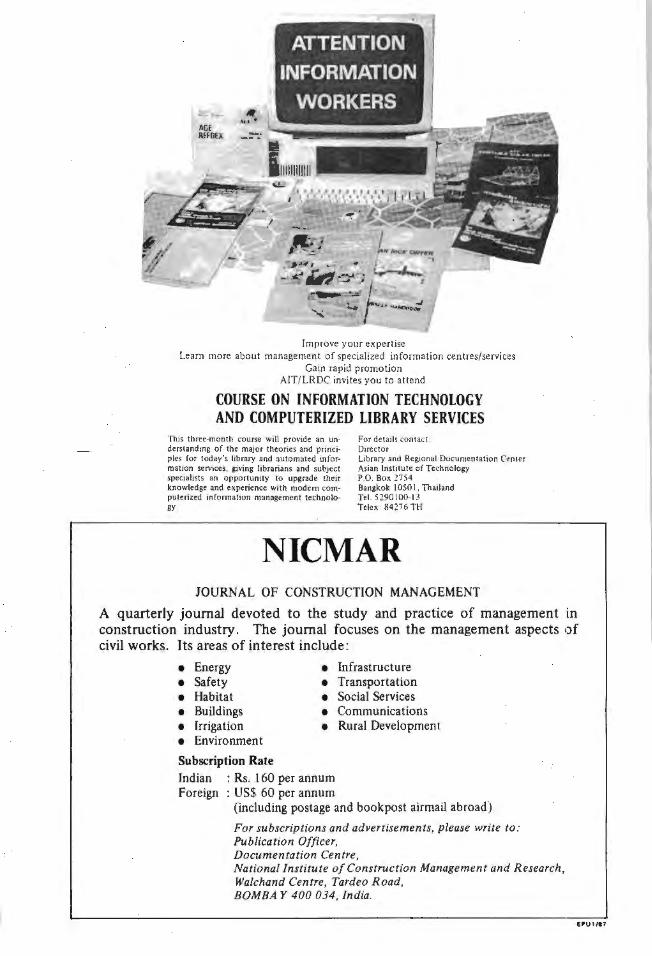
Improve your expertise Learn more about management of specialized information centres/services
Gain rapid promotion AIT/ LRDC invites you to attend
COURSE ON INFORMATION TECHNOLOGY AND COMPUTERIZED LIBRARY SERVICES
This three-month course will provide an understanding of the major theories and princi· pies for today's library and automated infor· mation services, giving librarians and subject specialists an opportunity to upgrade their knowledge and experience with modem com· puterized information management technolo· gy.
For details contact : Director Library and Regional Documentation Center Asian Institute of Technology P.O. Box 2754 Bangkok 1050 I , Thailand Tel. 5290 100·13 Telex: 84276 TH
NICMAR JOURNAL OF CONSTRUCTION MANAGEMENT
A quarterly journal devoted to the study and practice of management in construction industry. The journal focuses on the management aspects of civil works. Its areas of interest include:
• Energy • Infrastructure
• Safety • Transportation
• Habitat • Social Services
• Buildings • Communications
• Irrigation • Rural Development
• Environment
Subscription Rate Indian : Rs. 160 per annum Foreign : US$ 60 per annum
(including postage and bookpost airmail abroad)
For subscriptions and advertisements, please write to: Publication Officer, Documentation Centre, National Institute of Construction Management and Research, Walchand Centre, Tardeo Road, BOMBAY 400 034, India.
EPU1/17
JOURNAL OF FERROCEMENT
Aims and Scope
Theloumal of Ferrocement is published quarterly by the lmemalional Ferrocernent lnformation Center (IPIC ) al the Asian lnslilute of Technology. The purpose of the Journal is to disseminate the latest research findings on fcrroccmcnt and o ther related ma1crials and to encourage their praclical applications especially in
developing coumries. The Journal is divided into fou r main sec1ions: (a) Papers on Research and lJevcloprncnL
(b) Papers on Applications and T.:chniques (c) T echnical Notes (d) Bibliographic List, News and Notes, lntemalional Meetings, Book Reviews, Md AbsL.racts.
Notts for the Guidance of Authors
Original papers o r technical n otes on ferrocement and other related moterials and their applicatins arc
solicited. Manuscri pLS should be submitted to: The Editor Journal 1Jf Fcrrocement IFIC/AIT P.O. Box 2754 B angkok l 0501, Thailand
Papers submitted will be reviewed and accepted on the understanding that they have not been published elsewhere prior to their pub1icalion in Lhc Journal of Ferrocement. There is no limit lo the length of contributions
but it is suggested lhnt a maximum length of 12,000 word-equivalent be used as a guide (approximately 15 pages).
1. The complete manuscripl should be wriucn in English and I.he desired order of contents is Tille, Abstract. List of Symbols, Main T ext. Acknowledgements, References and Appendices. The Standard
fn tcmational System of Units (SI) should be used. 2 . The manuscript should be iypcd on one side oft.he paper only (preferably 81/2" x 11" bond paper)
with double spacing between lines and a 1 1/2 in. margin on the lefl. 3. Two copies of t.he manuscript and illustra tions (one set original) should be sent to the Editor" 4. The title should be brief (maximum of l 50charactcrs including blank in between words orothcrnon
::1;phnbetical characters) and fo llowed by Lhe author's name, affiliation and address.
5. The abstracl should be brief, sclf-co nwined and cicplicit. The suggested length i.s about 150 words. 6. Internationally accepted standard symbols should be used. In the list of symbols Roman letters
should precede Greek leuers and upper cas.: symbols sho uld precede lower case.
7. Each reference should be numbered sequentially and U1ese nwnbers should appear in square brake ts J in the text.
Typical examples are:
I. Bro'1tman, LJ., and Krock, R.H. 1967. Modern Composi1e Maieria/. London: AddisonWcslcy Publishing Co.
2. Da1anandana. N.; Sukapaddhanadhi, N.; and Disalhien, P. 1969. Ferroccment for Construction
of Fishing Vessels, Report No. 1, Applied Scientific Research Corporation of Thailand, Bangkok.
3. Naaman, A.E .. ancJ Shah. S.P. 1972. T ensilctests ofFcrrocement. AC/Journ.a/ 68(9): 693-698. 4. Raisinghani, M. 1972. Mechanical Properties of ferrocemcnt Slabs. M . Eng. Thesis, Asian
Insti tute of Technology, Bangkok.
8. Graphs. charts. drawings, sketches and diagrams should be drawn in black ink on tracing or white drawing paper. Illustrations should preferably be drawn on 81 (2" x l l" sheets. Pho tographs should be black and white prinL~ on golssy paper and preferably 3 1(2 in. x 7 in. size.
9. Illustrations should be numbered consecutively and given proper legends and should be attached to
Lhc end of the manuscript.
Published by the International Ferrocement Information (:enter
Asian lnscituce of Technolo9y G.P.O. Box 2754, Ban9kok 10501, Thciland
No. 73/89, April 1989
rlUN'TE.D 8 \ TliAI \A.'AT\NA PAt"ICH PRUS N . 1 t TI> • • 891 RAMA I R.O~ D. IAWOli\OK. MR. THUlA T. $t !WAN, PAINTEP.. lt , E, 2SJ1