IDRC-MR102eR Proceedings of a Workshop on Hydraulic ...
124
IDRC-MR102eR Proceedings of a Workshop on Hydraulic Ram Pump (Hydram) Technology February 1986
-
Upload
khangminh22 -
Category
Documents
-
view
1 -
download
0
Transcript of IDRC-MR102eR Proceedings of a Workshop on Hydraulic ...
IDRC-MR102eR
Proceedings of a Workshop onHydraulic Ram Pump (Hydram)Technology
February 1986

fhc lmemational Development Research Centre is a public corporation created by the Parliament of Canada in 1970 to suppon research designed lo adapt ~cience and technology 10 the needs of d<!\'eloping coumrie~. lhe Centre' acthity is concmltaled in si.,; sectors: agriculture. food and nutntion sCJcnccs: health sciences: information science~: ~odal sciences; earth and engineering ~1enc1:s: and communicutions. IDRC is financ~ solely by the Parhament or Canada; it~ polides, howner. are set by an international Board of GoH~rnors. rhc Cmlre'<> hcadquan~ .ire 111 Ouawa, Canada. Regional off~ are 10\.""atcd in Africa, 1\~1a, Latin America, and the Middle East.
I e Centre du recherches pour le developperncru in1ernnt1011ul, ~oci~te publique cr~ce en 1970 par une loi du ParLemont cnnodicn, a pour mi~~ion u'appuyer des rccherche~ \'i'iaJlt a adapter la \Cicnec et la technologic uux bc~oin~ de" pays en de\doppcmcnt: ii concentre son activit~ dan!I ~ix 'CCtc:urs : agriculture, alimcnta-1ion ct nutrition; infonnation; sant~; sciences ocinh:s; sciences de la tcrre et du genie ct communications. Le CRDl est finan1;e entl~rcmcnt park Parlemcm canad1cn, mai .. c'c.st un Conscil des gouvcrneur~ international q111 en determine l'orien-1a1ion cl le.\ pohtiques. Etabli ~ Otta~a (Canada), ii a d~-s bureaui'C rc!gionau:\ en
frique, en A.sic. en Ameriquc latine et au Moyen Orient.
El Centro Internacional de lmestigacionc parn cl Ocsarrollo es unu corporaci6n publica creada en 1970 por cl Parlamento de Cnnad4 con el objeto de apoyar la imc tigaci6n destinada a adaptar la cimda y la tccnologfa a la~ nec~ldade; de lo paiscs en de>arrollo. Su actM\lad sc concemra en scis .settorcs: e1cnda agricola.s, altmcntos y nutriciOn; ciencias de la salud; ocncias de la infonnaci6n: ciencia' oclalc~; ciencias de la tierra c ingcnierla; y 1;omun1cacione • El Ccmro c<; finan
c1ado C\clu i\'amenre por el Parlamento de Canada; ~in embargo. ~lh politicas son tra1adas por un Con<>ejo de Gobernadores de carictcr 1111ernacio11al. La sedc Jel Centro c~ta en Olla\\ a, Canada, y ~us olicina rcgion.ilcs en America Latina, Africa, Asi;1 y el Mcdfo Orien1e.
This ~rit'> Includes mttting docwuent • internal rtport~. and prtliminan. lttboic:al do(umenl!. that ma) later form thr basts of a formal poblica1lon. A Manu;cnpl Report I ghH a mall d~1ritiution 10 a higbl) :o111«i11iztd audlencr.
La prist'nlr \Crie f51 r~tt an documents is u dr culloqurs, 1lU\ napports iDIMDf'.<I
fl IUl documtnb lfdmiques ~ptibles d'ttrr publi#s plus lard dans Uftl' serfr tk publiCltlinns plu!I wlgu~. O'un tiraite ttstrei111, le rapport manuscril csl d~tine a uo public ires spitialise.
F ta wrie lnclo)e poneocias de reunion", informes lntrmos ~ documento lecnko que pueden posteriormente cooformar la base dr una publlnclon formal. F.I informe rttibe di!!lrihudon limltada entre uoa audiend• altamrnlr ''Pt'ciallzada.
tDRC-MR102eR
PROCEEDINGS OF A WORKSHOP ON
HYDRAULIC RAM PUMP (HYDRAM) TECHNOLOG~
ORGANIZERS:
HELD AT ARUSHA, TANZANIA
MAY 29 - JUNE 1, 1984
CENTRE FOR AGRICULTURAL MECHANIZATION AND RURAL TECHNOLOGY (CAMARTEC) ARUSHA, TANZANIA
INTERNATIONAL DEVELOPMENT RESEARCH CENTRE (IDRC) OTTAWA, CANADA
Technical Editor: Eric J. Schiller
Material contained in this report is produr.ed as submitted and has not been subiected to peer review or riqornus editing by IDRC Communications Division staff.
Mention of proprietary names does not constitute endorsement of the oroduct and is qiven only for information.
-2-
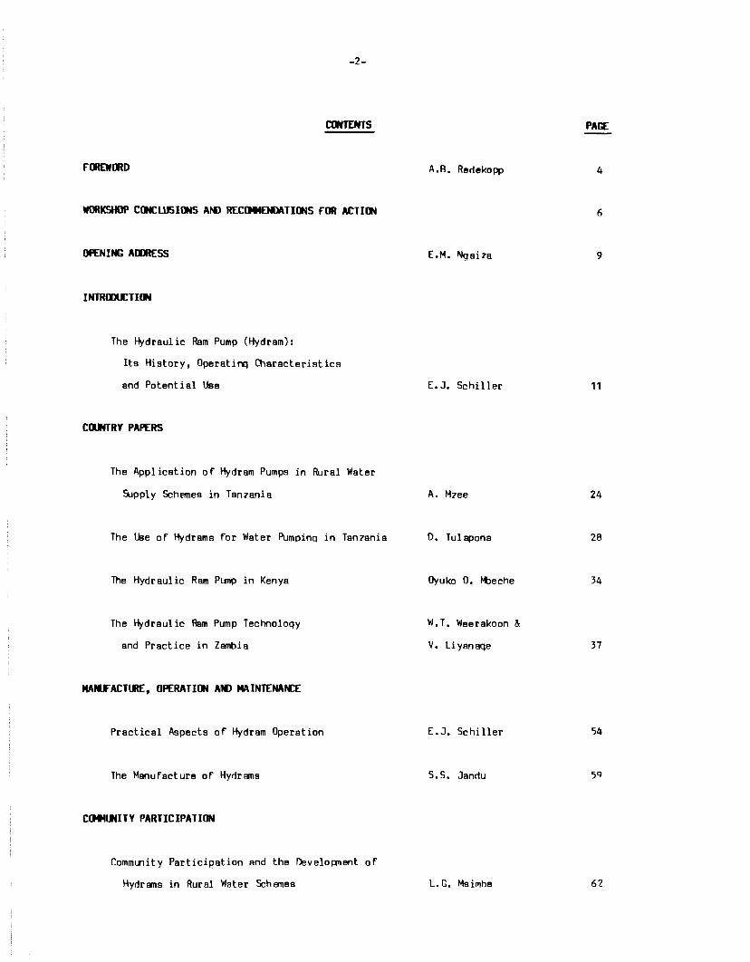
CONTENTS
WORKSHOP CIKUJSIONS AN> RECtl4MENMTIONS FOR ACTION
OPENING AlllRESS
INTRCDlJ:TION
The Hydraulic Ram Pump (Hydram):
Its History, Operati~ Characteristics
and Potential Use
COONTRY PAPERS
The Application of Hydram Pumps in Rural Water
5.Jpply Schemes in Tan1ania
The Use of Hydrams for Water Pumpinq in Tan1ania
The Hydraulic Ram Pump in Kenya
The Hydraulic Ram Pump Technoloqy
and Practice in Zambia
MAl'IFACTLRE, OPERATION AINI> MAINTENAN:E
Practical Aspects of Hydram Operation
The Manufacture of Hydr!llls
CCl441.fi11TY PARTICIPATION
Community Participation and the DevelolJ!lent of
Hydrams in Rural Water Schemes
A.B. Redekopp
E.M. Nqai1a
E. J. Schiller
A. M1ee
D. Tulapona
Oyuko O. Mbeche
W.T. Weerakoon &
V. Li yanaqe
E.J. Schiller
S.S. Jandu
L. G. Msimbe
PACE
4
6
9
11
24
28
34
37
54
62
-3-
CONTENTS ( lhntinl.Ed)
Socio-economic Considerations in fllral
Water ~pply Develo pnent
RESEARCH NEEl!i
The lheory and tesiqn of the llt.Jtomatic
Hydraulic Ram Punp
Hydraulic ~ms as Fbtential l\Jmpinq
lhits for Rural Water !iipply Schenes
in Tan78nia
LIST IF PARTICIPANTS
w. &ynit
P. 0. Kahal'l'.lire
T. S.A. MJ1ette and
E. 1h. P. Prat ren
PAii:
66
71
100
120
- 4 -
FOREWoto
Providing adequate domestic water supplies for scattered rural populations poses a major
problem to many developing countries. Sparsely populated settlements cannot be easily served by
conventional piped water systems. In addition, the fuel and maintenance costs of operating a
conventional pumping system using diesel or gasoline engines are becoming prohibitive for many
developing countries, The hydraulic ram pump (hydram) is a simple technology that uses readily
available, renewable energy (a drop in water level of at least 1-2 meters in a flowing stream)
and has only two moving parts that can be manufactured and maintained by local peraonnel.
In the context of the International Drinking Water and Sanitation Decade, hydram technology
hll'l not received the attention it deserves as a potentially useful component in national rural
water supply programs. Widely used in the 19th and the early 20th centuries, hydrams have been
installed throughout the world for water supply to villages and farms and for small scale
irrigation. In India, they supplied water to the famous fountains in front of the Taj Mahal. In
recent years the lack of emphasis placed on hydram technology by international agencies is due to
the preference of groundwater over surface water as a source of domestic water supplies.
However, in many regions of the world potable ground water is not readily available.
Untll recently, research on operating characteristics and standardized designs for hydrams
have been lacking. Recently, research has been conducted by the University of Ottawa, the
University of Dar es Salaam and elsewhere on commercially-available hydrams as well as simple
locally-made models. These tests have determined the characteristics of some commercially-made
hydrams with the objective of designing simple locally-made pumps with comparable operating
characteristics.
This research needs to be continued in order to improve the design and durability of
locally-made hydrams. locally-made pumps need to be field-tested to determine their performance
characteristics and durability under operating conditions in village settings. The social
acceptance of these pumping devices will need to be established to determine if and how these
devices fit into the existing social patterns of supplying water. These pumps will have to be
maintained by the local community which will involve close cooperation, and community
participation of local users. Socio-cultural studies will need to be conducted in this
connection. Having developed a locally-made, economical, durable and socially acceptable pump,
the final step will be to assist in the planning of an indigenous production capacity.
- 5 -
IDRC recently sponsored a workshop held in Arusha, Tanzania to address the it>ove issues and
to look carefully at various aspects of the implementation of these systems at the village level
within the context of East Africa. The workshop also included a visit to Jandu Plumbers (Arusha)
who are manufacturers of hydrams and field trips to observe pumps inst al led in the vicinity of
Arusha. The workshop provided an opportunity for participants to share information on hydram
technology and plan for future development of this technology. Research priorities for Africa
were discussed and research protocols prepared.
Acknowledgement a
Mr. D. Tulai:x>na of CAMARTEC and Mr. A. Redekopp of I~C, served as adninistrative organizers
for this workshop. The followinq assisted in the research proposal writing process at the end of
the workshop. A. Redekopp and J. Chauvin, IDRC, E.J. Schiller, lkliversity of ottawa, E. Protzen,
University of Dar es Salaam, and P. Kahangire of the Water Department of Uganda. Finally, E.J.
Schiller served as technical editor in the publication of the proceedings.

- 6 -
WRKSHOP D*D.USl..S AN> RECOll£N>ATilltS FOR ACTION
Conclusions
1. Conventional pumping methods are bec001ing more and more difficult to maintain in developing
countries. The need to use renewable energy technologies in rural areas has increased. The
use of the hydraulic ram pump (hydram) is an example.
2. Che of the problems with hydram technology is that a majority of potential users are not
aware of these pumping devices. Therefore, pr001ot ion and dissemination of information of
hydram technology should be increased. Hydrams are commercially available and technical
drawings of working devices already exist. These must be made available to users. Even
more detailed technical information must be generated and disseminated.
3. Training of users, water engineers and technicians in installation, operation and
maintenance should be stressed.
4. It seems that at present a pred001inant problem is that most durlble hydrams are
prohibitively expensive. There is a need to develop low cost, locally manufactured
lightweight versions.
5. The first step in such a development is a good evaluation of existing analytical models as a
design aid. All interested groups should be involved in this process.
6. Each country should identify ~11 potential hydram sites including hydrological,
topographical, geographical, water-quality and population data.
7. Each country should make a thorough survey of existing operatirg and non-operating hydrams
for technical and sociological information.
8. A designed lightweight version should be installed in selected sites and field-tested. To
facilitate this, complete operating characteristics must be developed with the aid of a
c001puterized analytical model. Field tests could indicate the need for future desiqn and
manufacturing improvements.
- 7 -
9. There is a need to interest manufacturers in the lightweight, low-cost version ard improve
fiscal benefits by more cooperation between users, design engineers ard manufacturers.
10. Though the hydram is a low maintenance device, it is still important to plan for adequate
maintenance ard spare parts supplies. When schemes are commissioned beneficiaries should
feel responsible to protect, operate and maintain the system.
11. Lack of health education makes the community less aware of the importance of improved water
supply systems. AlED cultural beliefs in some instances may not favour the use of hydrams.
R~iana for Action
1. Countries planning to promote hydram technology should begin with a thorough survey and
inventory of potential sites and existing installations. This should include a study of the
technical, social ard economic potential of hydrams.
2. A common East African computerized hydram model should be completed immediately to a
a) generate operating characteristics of all existing hydrams; and
b) to assist in the design of new low-cost versions of the hydram.
3. Local manufacture of low-cost, sufficiently durable hydrams should be undertaken.
4. The new versions of the hydram should be inst al led and field-tested.
5. Health education programmes should be implemented to improve water use hltlits.
6. Hydram operator-caretakers should be chosen from among the villages and properly trained.
- 8 -
Research Needs
Given the above recommendations, there is a need to conduct research on the technical,
social and economic potential of hydrams. Demonstration schemes should also be set up to assess
their technical performance and social acceptability, and to train and monitor the effectiveness
of village level operator caretakers.
. . .,.,,., __ ,_tlf,.!tt,.:~·4<:.~-•o.-?.~''°'·~ 4.·.,.,.,.,,,,,,.,,~ .. »~-·-1'l'< .... ~ . .,.r.£, ~-..,,.:;....~·i~--.-.. ""'"·"""°'~-.... ~l'*' -~
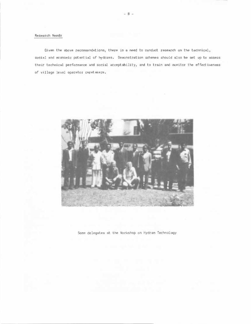
Some delegates at the Workshop on Hydram Technology
- 9 -
OPENING ADDRESS
E.M. Ngaiza
I take this opportLnity to welcome participants of this Workshop to Tanzania and Aruehe in
pert iculer. It ie my hope that you had a pleasant trip here. Welcome to T anzenie and please
feel et home during your stay.
I would like, et this jLncture, to thank IDRC for convening this Workshop in Tanzania and
especially in Aruehe l'klere CAMARTEC ie located. I feel we ere very much honoured to have
CAMARTEC ea co-organizers of the Workshop. We will do our beet to make the Workshop a success.
Also, we will do our beet to make your stay ea comfortable ae possible.
The theme of the Workshop ie of great importance. You ell know the current socio-economic
problems facing many conwnLnitiee of the developing coLntriee. Thie has pranpted many
researchers, social end natural scientists, to explore various alternative means of solving our
development problems. Among the socio-economic problems, l'klich ie of greet importance to our
development, ie water supply. The question of water supply and sanitation ie crucial. We need
water for domestic use, for irrigation, and for producing power. Thie Workshop focuses on the
use of water energy to supply water, that ia, the hydraulic ram technology.
The use of hydraulic rams to pump water for domestic use end irrigation ie not ea widespread
ea the use of other water lifting devices. Many factors ere involved but I will make reference
to a few. You will have time during the sessions to discuss them in detail. Technical end
social barriers effect the wideeprellf use of hydraulic rams. Technically, in each cotlltry there
have been engineering design problems. In Tanzania, for example, the manufacturers of hydraulic
rams ere Jendu Plunt>ere Ltd. of Aruehe who have been working on hydraulic rams in East Africa for
the lest fifty years. The enqineering design in use in Tanzania hes not changed much end hes not
been given serious study by experts other than those working with Jendu Plumbers Ltd. It should
be possible to modify the design to make it more ettra:tive end lees costly.
Socially, the widespread use of the hydraulic rams ie effected by the different ways of
introducing the technology to the end users. A lack of exposure end knowledge of the technology
to the users end potential manufacturers ie one of the major factors. The end-users need to be
aware of the advent age a of uei ng hydreul ic rams for domeet ic end farm water supply. Coate of the
pumps should be within the limit of the user' a purchasing power.

- 10 -
I hope the participants will have time to consider the problems mentioned above and will
finally come out with well considered projects for implementation.
I, therefore, declare this Workshop open and wish you all the best.

- 11 -
THE HmtAIJ.IC RAH PUMP (HYlltAH):
ITS HISTOOY 9 (Jl[RATI~ CHARACTERISTICS Rt> POTENTIAL l.JSACI:
E.J. Schiller
ABSTRACT
The hydram is introduced as one of a series of renewlble energy technologies in rural water
supply. The operating principles of the hydran are outlined. A short history of hydram
development is given. Present day usage is surveyed. The main operating characteristics of
hydrams are described. Present and future research activities are noted.
INTRmll:Tlr..I
The hydraulic ran pump (hydram) is one of a group of renewlble energy technologies that use
the energy of the sun or an energy from that is directly derived from the sun. In the case of
the hydram, the energy source is a small drop in elevation in a flowing stream.
The hydram shares several characteristics in common with other renewlble energy technoloqies
used in the water supply sector such as wincfpower pumping, handpumps, stream-driven turbines and
solar driven devices. Many of these devices have the capability of being manufactured locally
using local skills and materials. These technologies are relatively simple compared to fossil
fuel devices that require heat resistant metals, and electrical devices that require an
electrical network or an electrical generator. Most renewable energy devices can be operated
independently with minimal spare parts needed for regular maintenance. They can therefore
function reasonlbly well even if the transportation and communications network in a country is
not highly developed. This factor makes these devices well suited to rural populations that are
wide! y scattered.
THE IJ>ERATlr..I CF THE HYlltAH
The hydram makes use of the sudden stoppage of flow in a pipe to create a high pressure
surge. This is commonly known as water hammer. This high pressure wave is utilized to pump

- 12 -
some of the water to a higher elevation or to a location that is displaced horizontally Fran the
pump. If the flow in an inelastic pipe is stopped instantaneously, the theoretical pressure rise
that can be obtained is
aH = - Ve q
where ,o H = pressure rise (m)
V = the original velocity in the pipe (m/s)
c = the speed of an acoustic wave in the fluid (m/s)
g = acceleration due to gravity (9.8 m!s2)
The above represents the maximum pressure rise possible. The actual value will be lower
since all pipes have some elasticity, and it is impossible to instantaneously stop the flow in a
pipe.
To make use of the above principle, a typical hydram is constructed as in the diagram below.
HEADER TANK
h
1---.....------1 - -- -- -- --
SUPPLY
AIR VALVE
AIR CHAMBER
AIR
Figure 1: A TYPICAL ARRANIUENT IN A HYllU'lt INSTALLATllW
DELIVERY VALVE
Hd
- 13 -
The hydr!lll is simple in construction. It contains only two moving parts, the waste valve
and the delivery valve. There are two pipes, the drive pipe leading the water into the pump and
the delivery pipe directing the water to the place where it will be stored and subsequently
used. An air chamber and air valve are the other two components in the body of the hydr!lll.
The pumping cycle of the hydram begins with the waste valve open. In a natural stre!lll, the
supply is taken from upstream, perhaps from a small d!lll created in the stream. Because of the
head created, water accelerates in the drive pipe and leaves through the waste valve. The
equation for this acceleration is well known in fluid mechanics and can be given as,
I'll ere
H - M v2 : L dV 2g g dt
M v2 ex presses the tot al fiction losses 2g
L = length of the drive
and V = velocity of flow in the pipe
t = time
(1)
Eventually this flow will accelerate enough to begin to close the waste valve. This occurs
when the drag and pressure forces in the water equal the weight of the waste valve. For the
purpose of analysis, the force on the valve can be represented as a drag force, Fd, given by the
equation.
where Av = cross sect ion al area of the waste valve
y = speci fie weight of water
Cd = drag coefficient of the waste valve
(2)
For optimum operation, the closir.:i of the valve should be as fast as possible. en this
basis alone a light valve with a short stroke length is best. However, if a valve is too light
it will not open aeon enouqh later in the cycle; on the other hand, if the stroke is too short,
not enough water can escape out of the waste valve opening, this limiting pipe velocities and
thus reducing water hammer pressures. The proper design of the waste valve must therefore be an
optimal balance between all the various factors involved.
- 14 -
The sudden closing of the waste valve creates a high pressure surge as explained
previously. This surge is great enough to open the delivery valve and release some of the water
into the delivery pipe. With the release of this water, the high pressure surge in the drive
pipe collapses and slight negative pressure recoi 1 occurs.
Three significant things occur when the pressure wave collapses in the drive pipe. Firstly,
the delivery valve closes thus ending the pressure surge that is sent to the delivery pipe. The
air chanber cushions the pressure pulse so that a reasonably continuous flow is sent to the
delivery pipe. In this cushioning process the air-water interface is continually agitated and
moving. This tends to dissolve the air into the water. The air supply is replenished by a
second phenomenon that occurs at this time. The slight negative pressure pulse enables air to be
sucked into the air valve. Later in the deli very phase, this air passes the deli very valve and
goes to the air chamber. This air valve can be a one-way air valve or it can be a ,very small
drilled hole (1mm) which releases water during the pressure surge and sucks in air during the
collapse of the pressure wave.
The third event that occurs at the end of the pressure pumping phase is that the waste valve
opens, either by the action of its own weight or by means of an activating spring. When this
happens, the flow is ready to begin again. The hydram cycle thus repeats itself continually, at
a frequency between 40 to 200 beats per minute. The fact that this pump operates 24 hours per
day with only minimal maintenance is one of its main advantages.
HE HISTORY CF TIE HYDRAH
The history of the hydram goes back more than 200 years. We are, therefore, not discussing
a new technology, but an old technology that is experiencing a renaissance, brought about by the
fossil fuel crisis and energy shortages in general. The hydram shares this characteristic with
other renewable energy technologies such as windmills, handpumps and various solar devices.
The first person apparently to try to use a water hammer pressure in a pipe for pumping was
John Whitehurst, an Englishman in 1775. His hydram was not automatic, but the operation was
controlled manually by opening and closing a stop-cock. Although Whitehurst installed a few of
these devices, the apparatus was difficult to operate and did not become very popular.
The inventor of the automatic hydram as we know it today was a Frenchman, Joseph
Montgolfier, who patented the device in 1797. He introducted the waste valve that opened and
closed automatically and gave us the name "hydraulic ram" pump. This creative Frenchman also

- 15 -
invented the hot air balloon, lltlich in the French language is named after him. However, the
hydram of Montgolfier suffered from a defect. The air in his air chamber eventually dissolved,
causing intense banging in the mechanism lltlich was especially serious with the larger models. It
was his son, Pierre Franc;ois Montgolfier, who designed the air or snifter valve to introduce air
into the air chamber. This made possible the design and construction of large hydrans and made
it possible to pump water to higher delivery heads.
During the nineteenth century there was intense activity in the design and construction of
hydrams often on a very large scale. This activity, lltlich originated in Europe, including
Britain, spread to North America. Very large hydrams are reported in the U.S.A. from the end of
the nineteenth century (Mead, 1901) with a 10-inch (250mm) diameter intake pipe capS:>le of
pumping 870 L/min. to a height of 25m in Illinois and an even larger 12-inch (300mm) diameter
hydram in Seattle lltlich is reported to have pumped 1700 L/min. to a height of 43m (Carver, 1918;
Mead, 1933), These hydrams were enormous in size and the drive pipe walls had to be made very
thick to withstand the water hammer pressures.
With the advent of steam power, fossil fuel driven engines and electrification, this period
of hydram manufacture began to decline. Although same few companies have continued to
manufacture hydrams, it is only in the last two decades that a renewed interest in hydrams has
occurred as the world-wide energy shortage has begun to change our energy patterns. Canpanies
are now developing smaller, lighter hydrams suitB:lle for use in scattered areas.
A list of present day manufacturers and distributers in l'tlrth America and England is as
follows:
- Berry Hill Limited (Davey hydrams)
75 Burwell Road
St. Thomas, Ontario N5P 3R5
CANADA
Rife Hydraulic Engine Manufacturing Canpany (Rife hydrams)
132 Main Street
Andover, New Jersey 07821
USA
- C.W. Pipe Inc. (Fleming hydro-ram)
P.O. Box 698
Amherst, Virginia 24521
USA
- John Blake Limited (Blake hydrams)
Hydraulic Engineers
P.O. Box 43
Royal Works, Lancashire
ENGLAND BB5 5LP
- Green and Carter Ltd. (Vulcan hydram)
Vulcan Works
Winchester
ENGLAND
PRESENT DAY USAIL IF HmfAMS
- 16 -
The hydram is employed in many scattered areas of the world, although not in great nurrbers.
They are still employed throughout Europe, England North America although their period of peak
usage there dates back to the last century. The famous fountains of India's Taj Mahal were
powered by hydrams and they are used in rural areas in Russia.
However, the main area of interest for present-day hydram application is in the countries of
the developing world. They are used throughout East A fr ice. They are most appropriate with
streams in hilly terrains, and it is in such regions ~ere hydrams tend to be concentrated.
It is the role of women to carry water in most developil'I} countries, and carrying water in
hilly country is especially arduous. Therefore, women have the most to gain by the development
of pt.nnping technology (Madeley, 1981).
HYmAM IJ>[RATIMi DIARACTERISTICS
It is standard engineering practice to depict the performance of water ptnps by giving their
operating characteristics. for the hydram there are two sets of characteristic curves that are
especially useful.

- 17 -
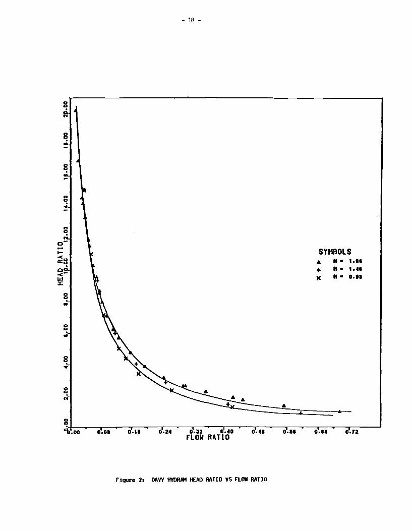
The first is a plot of head ratio (h/H) versus flow ratio ( Q/Qw). For def in it ions of the
symbols see Figure 1. This is a dimensionless curve that illustrates hydran performance for a
given supply head. For high head ratios the curves tend to be similar but some divergence is
noted for the lower head ratios. Kahangire ( 1984) found this trend to be true for most of the
hydrans that he tested.
In general, these curves show that hydr ans can pump much water for low lifts, but as the
lift increases the amount of water decreases.
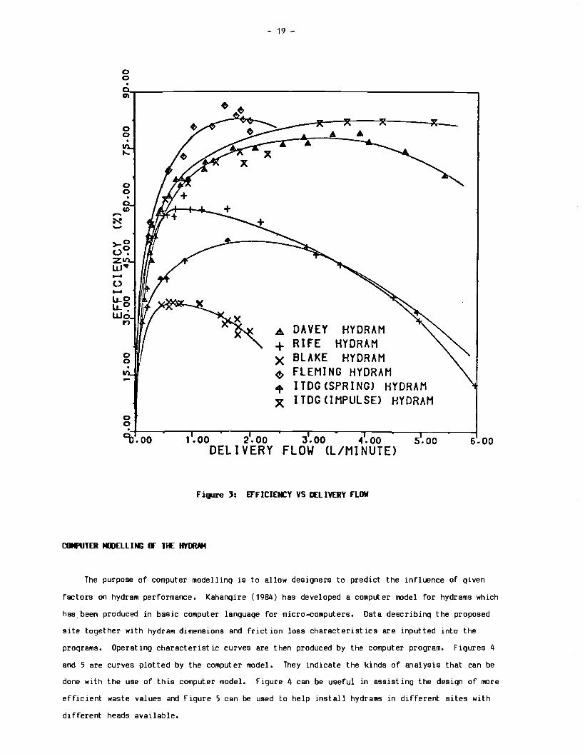
Another useful curve is the curve of efficiency, defined as
e = Q.h
Qw.H
as a function of delivery flow. This tells how efficient! y the hydran pumps the water. This is
important where the driving source of water is limited and waste water must be kept to a
minimum. Where the strean flow is abundant, the efficiency is not so important. However,
efficiency readings give us a good indication of the hydraulic perfonnance of the hydram. Hiqh
efficiency machines have low friction losses are hydraulically well designed. For a given head
(H), the efficiency curves of different hydrans will indicate ltlich type of hydran is most
suitable for the particular setting. Figure J shows the efficiency curves for various hydrans
operating with a head of 2m.
0
0 0 .
0 0 .
0 0 .
0 0 . ...
0 0 .
<-l&J :i:
0 0 . -0 0 .. g . ...
0 0 . ...
0.01
- 18 -
SYHBOLS .& H• .... + H• ..... )( H• o.ts
0.11 o.:sz 0.40 ..... • ••• . .... 0.12 FLO\I RATIO
Figure 2: DAVY HYDRAM 1£AD RATIO VS FLOW RATIO
0 0
en
0 0 . .....
0 0 . co -N -
>-0 (.)~ z w• -(.)
o· 0
~
- 19 -
A DAVEY + RIFE
HY DRAM HY DRAM
X BLAKE HYDRAM ~ FLEM I NG HYDRAM + lTDGCSPRING> HYDRAM X lTDGCIMPULSE> HYDRAM
"-t-~~..--~--,-~~.....-~---,.---~~~~.....-~--..~~.......-~~~~~~~~~ .........
°o.oo 1.00 2.00 J.oo 4.oo s.oo s.oo DELIVERY FLOW CL/MINUTE>
Figure l: EFFICIENCY VS II:LIVERY FLOW
COMPUTER tll>ELLIM; lF TIE HYDRAH
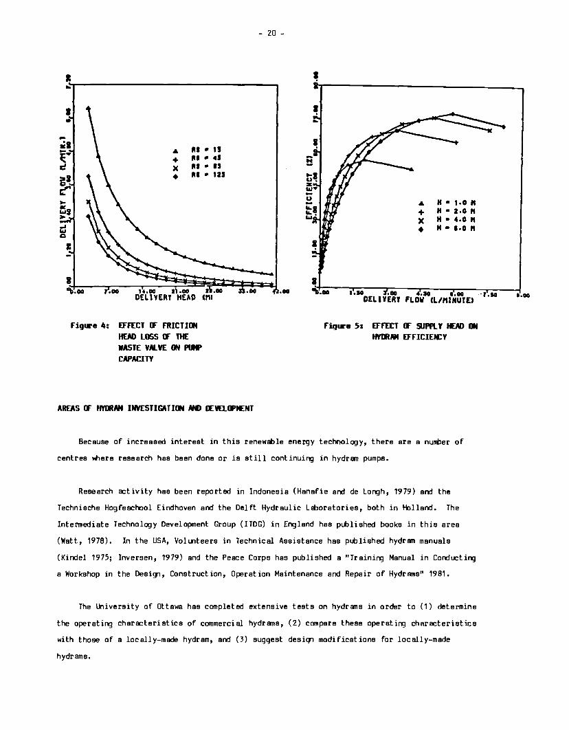
The purpose of computer modelling is to allow designers to predict the influence of given
factors on hydram performance. Kahangire ( 1984) has developed a computer model for hydrams which
has.been produced in basic computer language for micro-computers. Data describinq the proposed
site together with hydram dimensions and friction loss characteristics are inputted into the
programs. Operating characteristic curves are then produced by the computer program. Figures 4
and 5 are curves plotted by the computer model. They indicate the kinds of analysis that can be
done with the use of this computer model. Figure 4 can be useful in assistinq the design of more
efficient waste values and Figure 5 can be used to help install hydrams in different sites with
different heads available.
I .. I •
-•1 Ill • " ~· ... + ltl • 41
c )( ltS • IS
>I • ltl • 121
~ ... ~, > -' .., c
I
I C\l.oo .oo
figure 4: EFFECT CF FRICTION HEAD LOSS CF THE WASTE VALVE ON IVIP CAPACITY
AREAS CF HYlllM INVESTIGATION AMl OCVELIPflENT
- 20 -
.oo
-N -.... u. z w•
I
I
.& H • 1 ·0 " + H • z.o" X H • 4.0" • H • l·O"
~~-~-=-~~,~.~ .. ::----J"":.oo::-~-,~.~IO":"-~-,r.oo------~,r.so--~~ •. oo DELIYERT FLOW CL/MINUTE>
Fiq1re 5: EFFECT CF 9.JPR. Y HEAD ON HYlllMt EFFICIEfCY
Because of increased interest in this renewable energy technology, there are a nunber of
centres where research has been done or is still continuing in hydran pumps.
Research activity has been reported in Indonesia (Hanafie and de Longh, 1979) and the
Technische Hogfeschool Eindhoven and the Del ft Hydraulic Lt=boratories, both in Holland. The
Intermediate Technology Development Group (ITDG) in England has published books in this area
(Watt, 1978). In the USA, Volunteers in Technical Assistance has published hydran manuals
(Kindel 1975; Inversen, 1979) and the Peace Corps has published a "Training Manual in Conducting
a Workshop in the Design, Construct ion, Operation Maintenance and Repair of Hydr ans" 1981.
The University of Ottawa has completed extensive tests on hydrans in order to (1) determine
the operating characteristics of commercial hydrams, (2) compare these operating characteristics
with those of a locally-made hydram, and (3) suggest desiqn modifications for locally-made
hydrams.
- 21 -
Finally, in Tanzania, the Institute for Productivity Innovation at the lhiversity of Dar es
Salaam is corrlucting tests to model hydrEWn performance with a goal to improve present designs.
FUTlltE HYOOAM OCVEl..(FfENT
Three main areas for future research are identified:
1) Existing hydram designs, some of ~ich are very dureble have a price that makes it
difficult to be purchased in developing counties. Economic studies should be done to
determine true hydran costs, spreed over the lifetime of the hydram.
2) Low priced hydran models need to be designed, manufactured and field-tested.
3) An improved computerized hydram model needs to be developed and produced for computation
with microcomputers. This would enlble rapid compariBJns to be made of existing
hydrans. It would alBJ be a useful tool in future design modifications.
- 22 -
REFEROCES
1. Behrends, F.G. (1926) "Use of the Hydraulic Ram". The Farm Water Supply (Part ii). Cornell
Extension Bulletin 145, New York State College of Agriculture, Cornell University.
2. Cmine, Charles ( 1937) "Joseph de Montgolfier et le Belier Hydraulique". Proceedinqs,
Institution of Civil Engineers, London.
3. Carver, T .H. (1918) "Hydraulic Ran Shows 91% Efficiency". Engineering News Record, Vol. 80,
No. 21, New York.
4. Dickenson, H.W. (1937) "Early Years of the Hydraulic Ram". Proceedings of the Institution
of Civil Engineers, January, pp. 73-83, London.
5. Hanafie, J. and DeLongh, H. (1979) "Teknologi Panpa Hidraulik Ram". lnstitut Teknologi
Bandung.
6. Inversin, A.R. (1979) "Hydraulic Ram for Tropical Climates". Vita Publication, V.ita, Mt.
Rainier, Maryland.
7. Iversen, H.W. (1975) "An Analysis of the Hydraulic Ram". Journal of Fluids Engineering,
MME No. 75-FE-F, Transactions. New York, ASME, June, pp. 191-196.
8. Kahangire, P.O. (1984) "An Experimental Investigation and Design of Hydraulic Ran Pumps",
M.A.Sc. Thesis, Civil Engineering Department, University of ottawa.
9. Kindel, E.W. (1975). A Hydraulic Ran for Village Use. A Vita Publication, Mt. Rainier,
Maryland.
10. Krol, J. (1952) "The Automatic Hydraulic Ram". Proceedinqs of the Institution of Mechanical
Engineers, Vol. 165, pp. 53-65.
11. Lansford, W.M. and Dugan, W.G. (1941) "An Analytical and Experimental Study of the Hydraulic
Ram". Bulletin No. 326, Vol. 38. University of Illinois Engineering Experimental Station.
12. Madeley, J. (1981) "Ram Pumps and Kenyan Wanen's Water Trek", World Water, London, October,
PP• 51-52.
- 23 -
13, Mead, D, W, ( 1933) "The Hydraulic Ram". Hydraulic Machinery, New York: pp. 358-383,
14. Mead, D.W. (1901) "A Large Hydraulic Ram". The Engineering Record, Vol. 44, No. 8, New
York: August.
15. Peace Corps (1981). A Training Manual in Conducting a Workshop in the Design, Construction,
Operation, Maintenance and Repair of Hydrama.
16. Protzen, LP. (1980) "A Proposal for Simple Performance Prediction of the Hydraulic Ram".
(Unpublished Reaerch results), Institute for Production Innovation. University of Dar ea
Salaam, Dar ea Salaam.
17. Schiller, E.J. (1982) "Development of a Locally Made Hydraulic Ram Pump". ENERGEX '82
Conference Proceedings, Solar Energy Society of Canada. August, pp. 503-506.
18. Schiller, E.J. (1982) "Renewable Energy Pumping from Rivera and Stream". Water Supply and
Sanitation for Developing Countries. Michigan: Ann Arbor Science Publishers, pp. 53-64.
19. Silver, Mitchell (1977), Use of Hydraulic Rama in Nepal. A guide to Manufacturing and
Installation, Kathumandu, Nepal: UNICEF, Septentier.
20. Smallman, W.S. (1934) "The Hydraulic Ram, Its Construction and Use". Newcastle, Australia,
Newcastle Division of the Engineers of Australia, paper No. 569, pp. 357-360.
21. Stevena-Guille, P.E. (1970) "An Innovation in Water Ram Pumps for Domestic and Irrigation
Use". London, Appropriate Technology, Vol. 5, No. 1.
22. Stevena-Guille, P.O. (1977) "How to Make and Install a Low-coat Water Ram Pump for Domestic
and Irrigation Use". Cape Town: Department of Mechanical Engineering, University of Cape
Town, August.
23. Watt, S.B. (1978) A Manual on the Hydraulic Ram for Pumping Water. London, Intermediate
Technology Limited.
ABSTRACT
- 24 -
T1£ APPLICATION OF HYDRAM PUtf>S IN RURAL
WATER !illPLY SDEtES IN TANZANIA
A. Mzee
A survey of Tanzania's water development goals is given, together with the mix of
technologies presently used in the water supply sector. A preliminary survey of hydram potential
is advocated, together with a field testing program. The proposed program should determine in
detail the potential for hydram development in Tanzania.
INTRmUCTillil
The Tanzanian twenty-year (1971-1991) long-term water supply goals, in accordance with UN
Water Supply and Sanitation Decade reaolutions, plans to supply everyone with clean, potable and
adequate water within easy reach by 1991.
A major constraint in the implementation of the Rural Water Supply Programme is a lack of
adequate financial reaources for construction of new projects as well as operation and
maintenance of the completed schemes. With the high cost of fuels and equipment, it is of utmost
importance to deploy technologies with less enerqy demand that can utilize available renewable
energy reaources. It is equally important to fabricate and maintain locally-made appropriate
devices used in harnessing such resources. At present, most of water pumps in rural areas are
run on diesel. These pumps and engines need a constant supply of fuel, skilled manpower, spares,
equipment and transportation for their maintenance. These are scarce and costly commodities. To
reduce dependency on these items, the need for alternative methods is desirable.
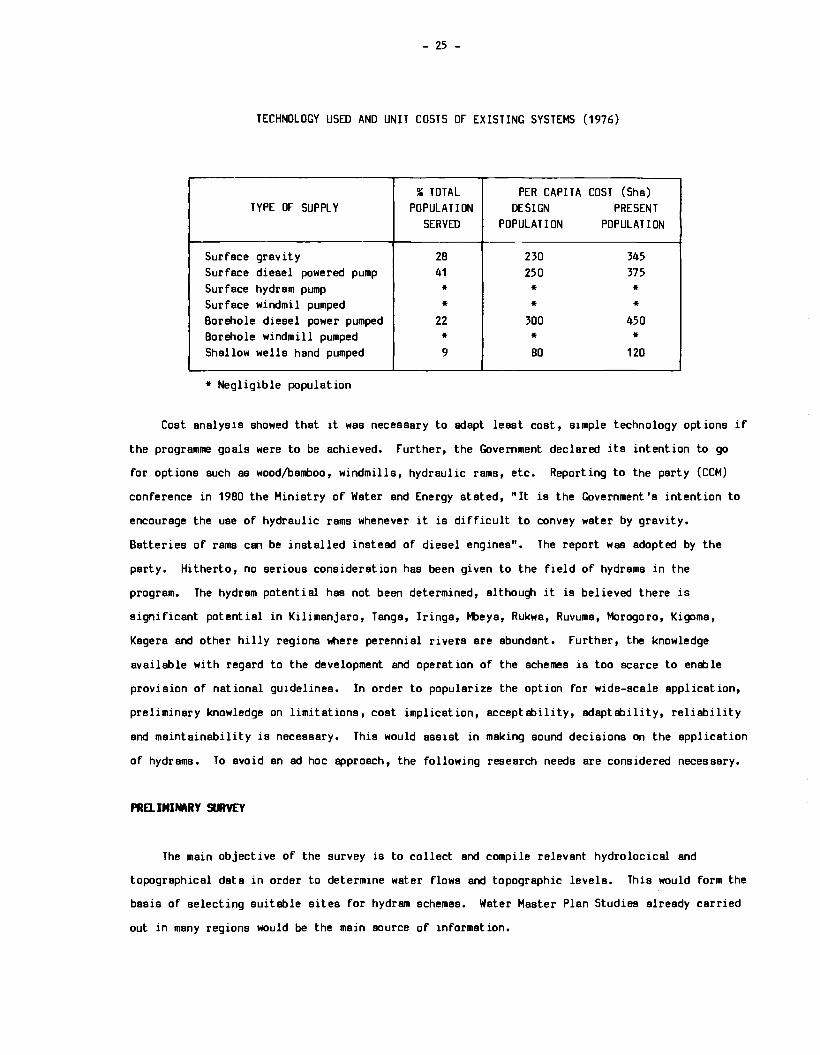
A water sector review in 1976 showed that water supply systems were being undertaken in
accordance with the following technology mix:
- 25 -
TECHNOLOGY USED AND UNIT COSTS OF EXISTING SYSTEMS (1976)
,___....
" TOTAL PER CAPITA COST (Sha) TYPE OF SUPPLY POPULATION DESIGN PRESENT
SERVED POPULATION POPULATION
Surf ace gravity 2B 230 345 Surface diesel powered pump 41 250 375 Surface hydram pump * * * Surface windmil pumped * * * Borehole diesel power pumped 22 300 450 Borehole windmill pumped * * * Shallow wells hand pumped 9 BO 120
* Negligible population
Cost analysis showed that it was necessary to adapt least cost, simple technology options if
the programme goals were to be achieved. Further, the Government declared its intention to go
for options such as wood/bamboo, windmills, hydraulic rams, etc. Reporting to the party (CCM)
conference in 19BO the Ministry of Water and Energy stated, "It is the Government's intention to
encourage the use of hydraulic rams whenever it is difficult to convey water by gravity.
Batteries of rams can be installed instead of diesel engines". The report was adopted by the
party. Hitherto, no serious consideration has been given to the field of hydrams in the
program. The hydram potential has not been determined, although it is believed there is
significant potential in Kilimanjaro, Tangs, Iringa, t-l>eya, Rukwa, Ruvuma, Morogoro, Kigoma,
Kagera and other hilly regions where perennial rivers are abundant. Further, the knowledge
available with regard to the development and operation of the schemes is too scarce to enable
provision of national guidelines. In order to popularize the option for wide-scale application,
preliminary knowledge on limitations, cost implication, acceptability, adaptability, reliability
and maintainability is necessary. This would assist in making sound decisions on the application
of hydrams. To avoid an ad hoc approach, the following research needs are considered necessary.
PRD. ININARY SlllYEY
The main objective of the survey is to collect and compile relevant hydrolocical and
topographical data in order to determine water flows and topographic levels. This would form the
basis of selecting suitable sites for hydram schemes. Water Master Plan Studies already carried
out in many regions would be the main source of information.
- 26 -
A survey of village patterns including locations, size, population and water demand will be
carried out to assess areas of use srxl relevant size of hydran project. This will help in
knowing the extent to l'llich the hydran technology will be used in canpsrism with other
technology mixes. An ides of the most canmon size of s hydran pump likely obtained fran such
information would further assist in fixing standards for the hydran designs.
Upon selection of suitlt>le project locations further preliminary surveys will be undertaken
to investigate the econanic factors, existing s:icial corxlitions, attitude of villagers towards
scheme ownership, participation in construction srxl maintenance of the hydrsm water supply
system.
ORGNHZATI._. IJ" TIE HYDRAM FIELD TESTIM;
Based on the findings of the preliminary survey, hydran schemes will be constructed st
selected villages under normal project implementation procedures. llJided by the input fran the
villagers, the method of implementation shall be decided with emphasis of beneficiaries'
participation, self-help labour or otherwise. The installation of hydrans shall be done by
project pers:innel who would continue to inspect arxl monitor its performance.
During the course of the hydran operation, performance tests shall be carried out. This
will include collect ion of important information and taking measurements to verify design
paraneters arxl to assess durability of hydrans under field conditions. The behaviour of various
components of the system such as valves, springs, air chambers arxl pipe fittings shall be
monitored. An analysis of hydran parts at the erxl of the project shall be necessary. Paraneters
such as volumetric efficiency, water hea:I, water output, frequency of use, strean flows shall be
recorded. Suitable arxl reasonably accurate devices shall be used in taking measurements.
Careful consideration shall be given to the location of the schemes. For ease and
convenience of construction and maintenance, inspection arxl monitoring the accessibility to the
site will be important. The scheme construction shall be as simple as possible. Locally
available materials such as burnt mud bricks or wood staves shall be used to construct the hea:I
porxl arxl supply reservoirs. The piping material shall be determined by the drive, delivery and
supply hea:ls available for each scheme. For the purpose of canparing operating chars:teristics,
it is proposed to install both locally arxl commercially made hydraulic ram pumps.

- 27 -
CON:LUSHW
In view of the high cost of fuels and lubricants, difficulties in transportation, shortage
of skilled manpower and materials to maintain diesel engines, it is imperative to encourage use
of indigenous renewable energy resources such as hydraulic ram pumps. The research proposed here
aims at understanding the suitability of such applications in Tanzania. At the end of the
research, answers to the following questions should be found:
1. Are hydraulic ram pump applications technically, economically and socially acceptable?
2. What is the approximate cost and size of a village hydram scheme?
J. What would be the most common size of a hydram to be used in the water programme?
4. What is the unit cost of water production using hydrams as an optional technology?
5. To what extent can hydrams be used in the water programme?
6. What is the extent of energy saving using this option?
7. What are the weak parts of the hydraulic ram as a pumping device?
8. What level of reliability can be expected from a village hydram scheme?
9. How comparable in performance and economy are locally fabricated hydrams?
10. To what extent should beneficiaries' participation be expected in construction, operation
and maintenance of a hydraulic ram system?
11. Who should be encouraged to own a hydraulic ram scheme - a public institution or a private
undertaking?
Finally, it is hoped that the existence of such preliminary knowledge will assist planners,
engineers and financiers in making sound decisions on the use of hydraulic ram pumping schemes in
the development of water schemes in the country.
- 28 -
THE USE OF HYDRAMS FOR WATER PUfPINC IN TANZANIA
by D. Tulapona
ABSTRACT
The need for more renewS:>le energy technologies in the rural water supply sector is
highlighted. Some design aspects are discussed and the outlook for local manufacture is
surveyed.
I NTRlllll:TION
In Tanzania, as in most developing colJltries, the problem of water supply is not only its
general scarcity, but also lltlere it is plentiful there is the problem of getting it to lltlere it
is needed. In principle, there is water everywhere in Tanzania even in the drier central
plateau. The success of the Shallow Wells Project in the Lake Zone and Morogoro Region proves
the point. The southern and northern highlands are endowed with fast flowing rivers lltlich have
enough water all the year round. The great lakes lltlich almost surround half of the country and
smaller lakes scattered throughout the colJltry are all cold water sources.
In general, Tanzania's water sources can be utilized for domestic and irrigation purposes.
The saline water of the sea has been left out of this discussion purposely as its use for
domestic or irrigation purposes requires technologies not included in this Workshop. The three
forms in lltlich cold water occurs are: running water (rivers, springs, streams), stagnant water
(lakes, dams, ponds) and underground water. Being on the surface, the first two forms are easy
to tap and ready for use, provided health precautions are observed. ltiderground water, on the
other hand, has to be extracted by digging and drilling wells to bring water to the surface. The
water tlble varies from place to place thus making the task of lifting the water even more
difficult.
There are a number of water-lifting devices with varying outputs and uses. There are the
pumps which range from the simple low-output handpumps to the high-speed high-capacity
centrifugal punps. Others include Persian wheels, Archimedean screws, axial flow punps and
hydraulic rams. Of course, there are also shadoofs, windlass and pail, treadmill and others less
familiar in this colJltry.
- 29 -
All these devices require energy to operate them. The energy required varies a:cordinq to
the type of device and the amount of water to be lifted. The low-speed, low-output devices such
as hsndpumps, Persian wheels, shsdoofs, windlass and pail, treadmill and Archimedesn screw ell
utilize human or animal power. Windmills are also used to drive pumps which lift water from bore
holes and deep wells. The well-known hsndpump and the windlass and pail are primarily for
lifting water for domestic use and stock watering only. Due to their low output, they are not
suitable for lifting water for irrigation. In most cases, they are used to lift water from
wells. The Persian \ltieel lifts water from wells, the shsdoof \ltiich lifts water from wells or
rivers (canals) and the treadmill, i.tiich lifts water from rivers, are mostly found in Asia but
could be introduced in this country as well.
The high-speed and high-output centrifugal pumps \ltiich supply water to urban areas or large
scale irrigation farms are beyond the scope of this paper. But the medium capacity centrifugal
or piston pumps driven by fuel engines and used to supply water to rural commlllities need special
mention. A nunber of these were installed in many villages in this country but unfortU'lstely
most of them are not working. There are many factors lr41 ich have contributed to this problem.
Lack of expertise in the villages to repair the engines and pumps, shortage of spare parts and
the shortage and ever-rising prices of fuels are just a few of the factors.
Hydraulic rams, \ltiich are not very numerous in this country, require neither fossil fuel,
animal nor human power to pump water from rU'lning streans to very high levels. Although the
technology for this device has been in existence for the last two centuries, its use in Tanzania
has not been widespread. A few hydrams were installed and used in settler coffee and sisal
estates around Arushs and Moshi about forty to fifty years ago, but most of them are not working
now due to neglect. In recent years, however, people have come to realize the usefulness of
hydrmns, especially after engine operated pumps failed due to reasons mentioned above. During
this period there have been efforts to continue production and supply of hydr1111s in Tanzania.
Jsndu Plunbers Ltd. of Arushs has been the only local manufacturer of hydr1111s.
The performance of a hydrmn is determined by the working fell down "'1ich the driving water
travels and also by the vertical height to "'1ich the pumped water must be raised. Thus, "'1en
working fall and vertical height are know, the output can easily be determined from operating
charts or tli>les. The increase of vertical fall usually increases the mnount of drive water and
thus increases the output of the hydram.
- 30 -
To calculate output of the hydram, some required infonnation must be known. The vertical
fall in meters, volume of drive water in litres per minute and the vertical delivery elevation in
meters must be measured accurately. A typical efficiency of hydrams is around 60%. The output
can, therefore, be estimated according to the following simple formula:
D : V x F x 6 --E 10
where D = Output in litres per minute
V = Volume of water flowing through drive pipe in litres per minute
F = Vertical (working) in meters
E = Vertical elevation of delivery in meters
After obtaining the D in litres per minute, hourly and daily outputs can be obtained by
multiplying it by 60 and 1,440 respectively.
- 31 -
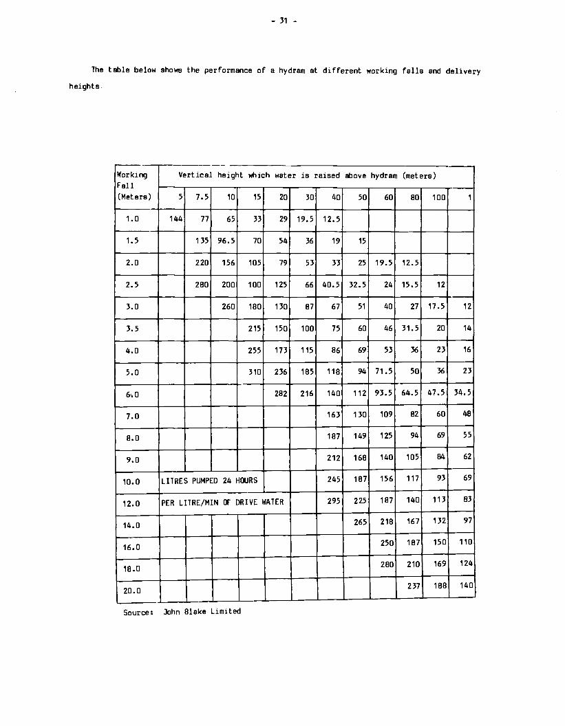
The table below shows the performance of a hydram at different working falls and delivery
heights
~
Working Vertical height which water is raised above hydram (meters) Fall (Meters) 5 7.5 10 15 20 30 40 50 60 BO 100 1
1. 0 144 77 65 33 29 19.5 12. 5
1.5 135 96.5 70 54 36 19 15
2.0 220 156 105 79 53 33 25 19.5 12.5
2.5 2BO 200 100 125 66 40.5 32.5 24 15.5 12
3.0 260 180 130 B7 67 51 40 27 17.5 12
3.5 215 150 100 75 60 46 31.5 20 14
4.0 255 173 115 B6 69 53 36 23 16
5.0 310 236 1B5 11B 94 71.5 50 36 23
6 ... o 2B2 216 140 112 93.5 64.5 47.5 34.5
7.0 163 130 109 B2 60 48
B.O 1B7 149 125 94 69 55
9.0 212 16B 140 105 84 62
10.0 LITRES PUMPED 24 HOURS 245 1B7 156 117 93 69
12.0 PER LITRE/MIN OF DRIVE WATER 295 225 1B7 140 113 83
14.0 265 21B 167 132 97
16.0 250 1B7 150 110
18.0 2BO 210 169 124
20.0 237 1BB 140
Source: John Blake Limited
SM tcSia. CDNSltcRATIONS
Over the yeua •any re1earchere hive been eicperiMntinq with neit ••terhla and neit •thoda
or •Wlufecture in en 1tt•pt. to deaiqn • liqhtweiqht hydrltll ic r... Moat of theae lightweiqht
designs have proven ~aatiafac:tory due to the Material not beirr:i atrorw.;i enough to support the
high preeaurea itlich.develop within the hydr•. Althouqh the hydr•• have initially perfonud
well, it· ii not known for how lorg they will continue to fU'lCtion. It ia doubtful "'8ther they
will be cep~la of r~nirw.;i for .fifty years or 11Dre, like the traditional ones •ad• of heavy ceat
ateel.
Volunteers in Tectvlical Aaaiatance (VITA) and the Inte!'lllediate Tecl'v'lola;iy Developnient Croup
(ITDC), to .. ntion juat two organizations, have done research on ai11ple hydr•• Wlich have been
field-tt11ted wit.h encouragirw.;i results. The VITA hydr• is constructed fr~ .Vaihble galvanized
iron pipe fittirqa and locally-11ade valves. The coMtruct ion ·requires no special akil l and
11ini11U11 nunt>er of tools. A drill press and sonie hand tOola are all that ia reQuired. Weldirw.;i,
brazirq and a:ilderirq are not required. The coat of the hydrem ia very low CCJ11pered· to the cast
one bl.t its durability ia yet to be deten11ined.
The first conaiderat ion for hydr• desiqi is durability. The hydrem exploit a the
non-c0111preaaibility of water. If water flowirw.;i at a certain speed is abruptly stopped, a hiqh
preaaura (water h.,..er) will develop. The hydran ut ilizea this property by harneasirw.;i the water
h-er and any pU11p body with a tendency to expand under preaa1.re o~ ia 11ade of weal< 11aterial
111ust not be uaa1 aa it will break. Although rather expensive, it ia neceasary to use hell'Vy
non-elastic 111aterials. Heavy cast steel with parts of copper and brass have pr011ed moat ideal.
Another v1Hy import ant consideration is the internal contour of the hydrem body, both fr an
the point of view of frictional losses "1ich will prevent the maximl.111 speed fran beirw.;i achieved
and air pockets "1ich will prevent attainnent o( maximl.111 pressure. Loss of speed and preastre
will seriously affect the efficiency of the plJ'llp.
The ai..ccesa of the hydrMI will be guaranteed 1f rigid materials are used, 1f it ia correctly
made and inatal l~ and requires very little attention. The workinq parts "1ich need charqirq
Ibo ut once a year are the ri.bber valve di ecs. Only simlJle maintenance i a required to ensure that
the waterways are clear and free-flow1rq.
- ll -
The 1111r1.1facture of hydr11111 in Janzania u not aa wideapread aa would ha\19 been 111Cpect,.cf,
tald~ into conaideration the acute.,,.oble111 of water liftirq. There nhh adeqUlta
111anufacturirq facilitin but the 11ain conetra1nt on w1deapraad local ••nufacture or the J)ulp~ ii
that strict Qt.11lity control during 1111rufecture ia naential if the r• ii to aper.ta ffficiently
for a long period of t i111e. Weil 111ade pU11p11 have been known to ri.n cont inoual y for 11>ra than
fifty years with only 111ni111U111 111aintenence bl,11: poorly engineered pu.pa bre1k down aaeily ard
quickly.
During the era of che'Bp oil of the 1950's and 1960 1 11, intereet in the use and, therefore,
the 111enufacture of the hydr11tt1s waned in Tanzania end else"1ere. lt>wever, di.e to the feet that
hydr911s require no fuel to run the-t11, they are now back in favour. Bec11.1se of this lapse in
interest for they hydr11111s, 111any people do not know 111uctt about the111, but now that they have been
red1!1Covered, they should be popularized •nd 111ade available.
in Europe and ~rice, a few firms ari:. st Ill 1unufacturing hydr11111a, though not ea a 1118ln
product line. John Blake Ltd .. of Enoland and Rife Hydra1.Jl1c Enaine Manufacturing <:o~New
.Jersey, U.S.A. are well know.ii and experienced hydr1111 11anufactur,era. Unfortunately, hydr1111a frOlll
these long-standirt1 manufacturers are not being i111p0rted into Tanzania. The few i111ported hya1 •s,
were 1~t ailed before theo cheep oil era. One of the 1hin reasoria for the underut: ilizat ion of
hvdrams is a lack of awareness of thia technoloov 111110rq pot~tial users.
The sole manufacturer of hydrems in lAnzania is Jandu Pll.Jtlbers Ltd. of Arusha. A variety of
sizes are produced but the product ion rate is very small. Only about ten hydr111111 are produced
per month but the demand for the111 is increasing, both within the col.rltry ard in neigttiourirq
co1J1tr1es. Jandu P!untiers could produce 111'.lre 1f the hydr1111s were 111ade the 111ain product line. As
111ent 1oned earlier, there are a nulllber of monufacturina fiMlls in Tanzania with &1eqt.11te facilities
lo produce hvdrems. These firms could~ ~rsuRded to include hydr111111 as a product line and
would be wllllnq to do !!O if the market could he riuaranteed. Small scale industries "1ich are
111ushroetnJllQ ell over tht- coi.ntry could bl'! ut ll1zed to manufacture the hyclrema, ea~cially at the
esSPntdv steqe. Complicated part a cou?<) be manufActured by medium or larqe BClll~ industries
·-rich have better iiroduct ion facillt 1es. Small acale industries could produce the simple parts
and pPrform stmpleI' OPP.rat ions and the final essentilv.

- 34 -
THE HYDRAll..IC RAM PUtP IN KENYA
Dyulco a. LllJeche
ABSTRACT
The present rural water supply structure in Kenya is outlined, and reference made to the
role of hydrams. Community involvement, oroanizational financing, operation and maintenance and
public health aspects of rural hydram development are surveyed.
I IW'"ClllA T Hll
Reports from the Ministry of Water Development (MWD) state that the access of the rural
population to improved water supplies varies widely from 13-15% as a national averllJe to 3-4% in
some districts. The Government, through the Ministry, has initiated four nation al Rural Water
Supply Programmes over the years involving some 2AO schemes, half of which are operational, with
the other under design or construction.
It is est imsted that one-hsl f to two-thirds of the rural population with access to an
improved water supply is directly supplied through the MWD schemes. The rural water supplies
under the MWD are administered mainly throuqh the following proqrammes:
Rural Water Supply Programmes (RWSI, RWSII, RWSIII and RWSIV) started in early 1970
Self-help Schemes Programmes
Rehabilitation Programme
International agencies and bilateral donors, for example, the Government of Sweden through
5IDA and the World Bank, have over the years assisted the RWS in the country.
Hydraulic ram pumps along with other types of pumps have been used in many Self-help Schemes
Programme following the 1976 International Women's Year - Harambee ya Wanawake Kwa Afya. In the
early 1950's and prior to 19AO, British-made hydrams dominated the Kenyan market. Today in 1984,
due to strinqent controls on foreign exchange, the major finns who had been importing these and
similar foreign-made hydrams, no longer stock them. The inexpensive Intermediate Technology
- 35 -
Development Group (ITDG), U.K., and Volunteers in Technical Aaaiatance (VITA), USA, hydrama
produced at rural and village polytechnics in the country are now more popular among rural
communities.
CIMUIITY INVOLVDENT AN> CIU~NIZATlllt\L FINANCING
The Kenya Government, through ita Ministry of Water Development haa been Eble to implement
various water schemes in the country. The Ministry, however, haa indicated that the problem
experienced in water supply ia the difficulty in obtaining payment for the water supplied coupled
with the lack of canmunity involvement. A water use study carried out by the Ministry haa
revealed that only Ebout 30-50% of water distributed and invoiced in the rural areas in Kenya are
paid for by the uaera. The reason ia that due to culture and tradition, water ia free and the
idea of paying for water ia altogether strange, if not repugnant. Thia defeats many self-help
effort a, such ea the Rural Development Fund (RDF), by killing any forthcaning cash contributions
and possible lEbour input. Similarly, the uae of communal water points have suffered setbacks
due to questions of revenue collection, responsibility and ownership.
OPERATiml AN> MINTENMO:
Different types of ownership generate different management structures, due to the fact that
different problem a arise depending upon '°'"ether the structures are privately, inatitut ion al 1 y or
publically owned. The moat difficult problems arise fran types of ownership resulting in
unfairness in distribution, such ea the exclusion, restriction and interference in institutional
activities. other problems result from the general failure of water uaera, particularly in
communal government projects, to share responsibility for hygiene and cleanliness at the source.
For example, sometimes communities fail to contribute the lEbour required to prevent the pumping
site fran lapsing into a state of disrepair. Finally, for many government or donor projects in
the rural communities a can11Dn problem ia one of a lack of follow-up with a reliEble maintenance
ayatem. The ideal situation would occur if people at the canmunal or village level would be Eble
to buy, own, manage, maintain, repair, and overhaul or replace the pump, if and when the need
ariaea. For every pump installation there ia also a need for local organization within the
communities with an elected and highly motivated management committee to insure a reliEble
program of future care and maintenance.
- 36 -
PIEL IC fEAl TH
It is a truism that a community cannot exist without water. However, access to that water
has direct and implicit costs to the community. These costs vary with each community in terms of
time and energy spent in collecting water, ill-health due to lack of sufficient water, ill-health
due to contaminated water, and in some cases, actual cash paid for water.
At the outset, it is important to determine a community's health situation Wiich should
include:
1. the determination of the incidence of water-related diseases, such as skin diseases,
trachoma, diarrhoeas, cholera, bilharzia, and others;
2. the commlllity's level of knowledge and awareness;
3. the community's practices and expectations; and
4. the community's social and economic structure.
After determining the commlllities' health status, a sustained progranme of water and health
education should be developed to create an awareness and appreciation of clean, safe water in
rural areas through community involvement and participation.

- 37 -
H'YDRMLIC RAM PUW TE°'8-0GY NI> PRACTICE IN ZA~IA
W. T. Weeralcoon and V. Li yanage
ABSTRACT
A hydram installation in the Western Province of Zambia is examined in detail. Its history
of usage, modifications and improvements are documented. Test results and analysis for this
hydram installation are given.
The rural water supply situation in Zambia is surveyed with emphasis on community
participation programs. Research on locally-made hydrams at the University of Zanbia is
described and preliminary conclusions are drawn.
INTllJDOCTIDN
Historical information reveals that hydraulic ram p1.J11ps have not been used in Zambia except
in a few instances. This may be due to the fact that the full potential of this particular
technology has not been exploited. However, it appears that windmills have been most popular
among farmers to lift water fr an boreholes. With the introduction of engine and
electrically-driven p1111ps, windmills too, got phased out of the system. The only known hydram is
inst al led at St. Mary's Mission in Kawsmbwa (Luapula Province). This pump was inst al led in 1961
and has a supply head of 9 metres and delivery head of 70 metres. The diameter of the drive pipe
is 6 inches (151lnm) and the capacity is 182m3/day. The main storage tank is situated at a
distance of 3.Skm away. After nearly fifteen years of use, this pllRp has had to be repaired
several times. Main repairs were carried out on the delivery pipe and bronze impulse valve
seat. Since 1976, this p1.J11p has not been operating properly. It was repaired once again by the
Technology Development and Advisory Unit (TDAU) and it is now in operation with an output of
144m3/day.
Due to the increased price in fuel and difficulty in obtaining foreign exchange, it has
becane necessary to look at the possibility of reintroducing hydraulic ram pumps in Zambia. At
present, Zambia has to rely on engine- or electrically-driven p1.J11ps. The maintenance of these
pumps are now becaning expensive and difficult. The hydram because of its low cost, ease of
operation, dependability, efficiency and simplicity in construction offers a better choice to
Zambia than other pumps. However, these pumps will be restricted to speci fie areas i.tiere a
sufficient and steady water supply is availfble with a minimum required water head.
- 38 -
Since hydrams have not been widely used, it is not possible to provide comprehensive
information about their operation. However, it can be concluded that dt.e to foreign exchange
difficulties and a lack of infrastructural facilities available, repairs and maintenance of
conventional pumping systems has become an extremely difficult task. It is in this context that
hydrams can play an important role, both in the comm111ity water supply and agricultural
development.
TtE HYDRAlLIC WATER RM PlW IN TIE 'IESTEIW PROVl~E
The hydram at the Bubenshi River was installed by the manufacturer in 1961, when St. Mary's
Mission was esteblished in this region. The water is taken from the river at a spot of 9m above
the hydram. It is led through a pipe to an open surge tank, 36m from the ram. From there, the
water goes through the drive pipe to the ram (see Figure 1). The breather pipe was not present.
The ram pumped the water through a 3.5km long 2-inch (50mm) delivery pipe to the main storage
tanks, 70m Ebove the ram. According to the manufacturer's data, the rElll capacity was 100m3 /day.
From the start, the ram installation experienced a technical fault: the drive pipe burst.
A team from the manufacturing company (Blake) visited the site and suggested strengthening of the
drive pipe, especially at the elbow bend.
The commt.nity, using water from this installation, was expanding and after some time the ram
was considered to be too small. It was replaced by a diesel plJllp and later by two electric
pumps, all situated in a pumphouse near the inlet of the supply pipe of the surge tank. The
electric pt.111ps have a combined capacity of 290m3/day.
However, the maintenance of the diesel pl.IDp becanie increasingly troti>lesome, and the power
supply to the electric pumps was irregular, especially during the rainy season. An automatic
on/off switching mechanism for the electric pumps failed to operate. This led to an erratic
water supply, sometimes interrupting the water supply to the users. To overcome these problems,
it was dee ided to use the hydr am installation again.
During the initial use of the hydram, the bronze impulse valve seat heel shattered. A new
cast-iron valve seat was copied from the remainder of the old one and installed in 1975.
Meanwhile, the delivery pipe of the ram was increased to 3-inches (75mm) and led from the hydram
to the pumphouse, where it was connected to the pump's delivery pipe. According to Blake's data,
the ram can plJllp up to 182m3/day under these circlJllstances. These flows have not been obtained
at this site. When the TDAU engineers visited the site, the hydram was pumping, but only
occasionally did this flow reach the tanks.
- 39 -
tD>IFICATllltS CARRIED llJT [Iii TtE HYIJUIM
The interference of shock waves in the drive pipe caused an effective hydraulic blockage in
the pipe. It may have been contributing to the bursting of the drive pipe as well. To overcane
this interference, a breather pipe was welded on the drive pipe Ebout 4m downstream of the elbow
(see Figure 1).
The rubber of the faulty non-return valve was cut to the appropriate size. The holes in the
impulse valve seat were cleaned. The diameter of the hole in the impulse valve rubber was
increased over a depth of 5mm to allow a greater valve opening. Provisions were made to have the
rubber move easily over the valve seat (see Figure 2).
Finally, the valve rubber was secured by a tapered rubber washer in the lowest position.
The diameter enlargement in the rubber had to extend over 10mm in length in this configuration
(aee Figure 3). Several other modifications have been tried out with different results. f'.hne of
these were finally incorporated and are therefore not included in this para]raph.
RE&ILTS IF TtE MmlFICATilltS
After the installation of the breather, it was found initially that the ram was still
beating irregularly and weakly. The interference of shock waves in the drive pipe could no
longer be observed. After cleaning the holes in the impulse valve seat and the introduction of
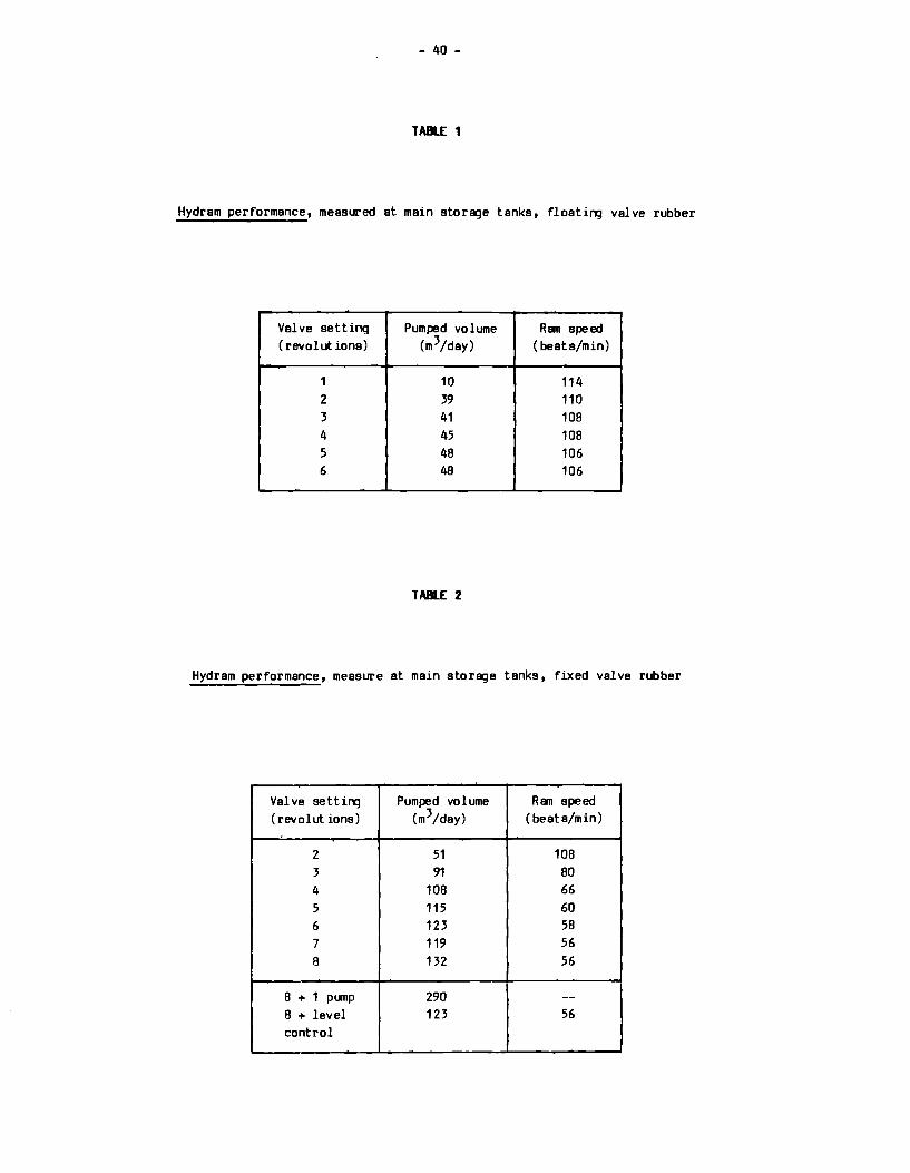
the cut-out in the valve rubber, the ram beat became strong and steady. Systematic tests of this
modification - indicated as floating valve rubber - were carried out. The canplete test results
are presented in Tables 1 and figures 4 and 5. It was found that the hydram was pumping up to
48m3/day with a high beating frequency.
An attempt to increase the hydram performance by increasing the stroke of the non-return
valve failed canpletely. The hydram was only pumping air and the output in the tanks was nil.
Blocking one of the four air vents did not alter this. Next, the impulse valve rubber was
secured in the lowest position by a tapered rubber washer. With this modification systematic
tests were carried out as well. The canplete test results are presented in TEble 2 and figures 4
and 5.
- 40 -
TAll..E 1
Hydram performance, measured at main storage tanks, floating valve rubber
Valve setting Pumped volume Ran speed (revolutions) (m 3 /day) (beats/min)
1 10 114 2 39 110 3 41 10B 4 45 10B 5 4B 106 6 48 106
TAll..E 2
Hydram performance, measure at main storage tanks, fixed valve rubber
Valve setting Pumped volume Ran speed (revolutions) (m3 /day) (beat a/min)
2 51 10B 3 91 BO 4 10B 66 5 115 60 6 123 SB 7 119 56 8 132 56
B + 1 pump 290 --B + level 123 56 control
- 41 -
The hydrem performance increased dramatically while the beating frequency reduced. The
maximum pumping capacity was found to be 132m3/dey. To reduce the chance of pumping air, the
water level in the surge tank of the rem was controlled by letting smell amounts of air escape
through a tap. This reduced the rem performance by 8%.
Using a flat rubber washer instead of a tapered one increased the maximum measured rem
performance by 8% to 144m3/dey. After fifteen hours pumping, however, the outer part of this
washer was completely smashed. The surface of the valve seat was also damaged; smell perts had
disappeared. It was also found that with the fixed valve rubber, the hydram could cooperate with
one electric pump. The pumping capacity was then 290m3/dey which is just es much es both
electric pumps. A third pump further increased the pumped volume of water.
DISCUSSICltl Cltl THE TEST RESULTS
It can be seen clearly from figures 4 end 5 that the fixed valve rubber modification had the
highest pumping capacity end the lowest beating frequency. Reducing the maximum stroke of the
impulse valve rubber reduced the pumped volume end increased the beating frequency.
The largest measured volume of water being pumped was 75% of the manufacturer's prediction.
Unfortunately, only the diameter of the delivery pipe end the delivery height was stated, end it
is not clear whether the friction of the 3.5km delivery pipe length was included as well. Both
floating end fixed valve rubbers increased the effective taper of the impulse valve. lbwever,
the required axial movement of the floating valve rubber was apparently much slower es compared
with the elastic bending of the fixed rubber end reduced the magnitude of the weterhemmer shock
wave needed for pumping. Since it was observed that the beating frequency with the floating
rubber was higher end didn't very very much with the valve setting, the conclusion may be
justified that the valve never opened completely. This would reduce the maximum weterflow
through the impulse valve end therefore reduce the weterhemmer pressure. The damage of the
surface of the valve seat may have three causes:
Cavitation or surface fatigue
Corrosion of the valve seat during the six-year inactive period
Casting faults
- 42 -
If the damage was caused by cavitation or surface fatigue, the damaged area will increase,
eventual! y leading to failure of the valve seat. In th is case, one may use a harder material for
the valve seat, like cast steel to delay or stop the phenomenon. It may be possible, and even
likely that due to the waterflow and the impact of the valve ruber, corroded parts have been
cleaned and small bits of material near ahrinkage cracks or graphite inclusions have been torn
off. In this case, the damaged area will not increase.
C~ITY PARTICIPATION
Community involvement and participation in water projects has been one of the built-in
features in Zambia. According to the Third National Development Plan (TNDP), it is clearly
stated that the Ministry of Health and all those working in the health field will redouble their
efforts in educating and mobilizing the people to take greater responsibility in promotion and
preservation of health and prevention of diseases. Since the Government alone cannot provide
adequate water, refuse disposal and environmental health facilities for all, comm1J1ities will
therefore be encouraged to undertake these projects on a communal basis, with the technical
advice available from the Ministry of Health, Water Affairs and other agencies. An example of
such a community activity is the Public Stand Water Supply in Mwachisanpola Health Demonatration
Zone.
Organization of public participation is usually encouraged through existing networks and
government agencies. Usually, project managers seconded fran their respective duties for a
speci fie period in these projects are the key figures responsible for organizing public
participation. Financing canes fran either the Government or outside agencies. For example,
funds for the above project came from the International Reference Centre for Comm1J1ity Water
Supply (IRCCWS) in the Netherlands.
In almost all projects, due to lack of technically qualified manpower, breakdowns occur
which are not attended to immediately. lack of spares and transport and preventive maintenance
programmes can be said to be the other features that aggravate this situation. Training of
manpower and educating the communities can go a long way to cope with this situation.
RtllAL NATER SUPPLY SITUATION IN ZAMBIA
During the Second National Development Plan (1972-1976), about 1,531 wells, 342 well points,
652 boreholes and 100 piped water supplies were completed under the Village Cooperative and Water
Supplies Programme. Approximately 250,000 people benefited from these facilities, bringing the
- 43 -
total of rural population with hygienic water to 2.1 million. During the TNDP (1979-1983), aome
progreaa waa mir:le, but due to increased fuel prices and erratic behaviour of the world economy,
it waa not poaaible to maintain the aame speed of progress.
Still, large nunt>era of people have no access to clean water supply. Due to an absence of
adequate reli!t>le water supply, many children under the age of six years die. Statistical
reports indicate that 111'.lre than 70% of the diseases are connected with unclean water. An attempt
has been mir:le by the Government and local authorities to make avail!t>le safe water to all rural
villages. Although cities and urban areas usually have satisfactory water storage and
distributing facilities, still mt.eh more work is needed to make clean water available to the
rural population.
RESEARDI Ml> II:VELIPtENT ACTIVITIES
The first research and development activities related to hydr1111s started in 1975 by the
Magoye Regional Research Station (Department of Agriculture) in Magoye. The second pump was
manufactured by Jere (TDAU). Both these pumps hir:I not been previously tested properly, so that
it was felt necessary to carry out tests to determine the operational vi!Dility of these pumps.
Work reported here is a result of the extensive work carried out by Mwafulilwa of Scl"Dol of
Engineering. This project was jointly sponsored by the School of Engineering and Technology
Development and Advisory Unit (DTAU).
The purpose of the Lusaka project was to determine the performance of the TDAU and Magoye
manufactured hydrams in order to examine the effect of varying the supply heir:!, supply rate,
drive pipe, impulse valve stroke and tension, the hydram beat frequmcies, delivery height and
the delivery rate on the efficiency and performance of the hydran.
The following conclusions were reached from the tests carried out on the two pumps:
1. An increase in number of cycles per minute decreases the efficiency. This can be seen for
the curves 5 and 6 (see Figure 6).
2. The delivery rate increases with the increase in efficiency up to a certain point only (see
Figure 7).
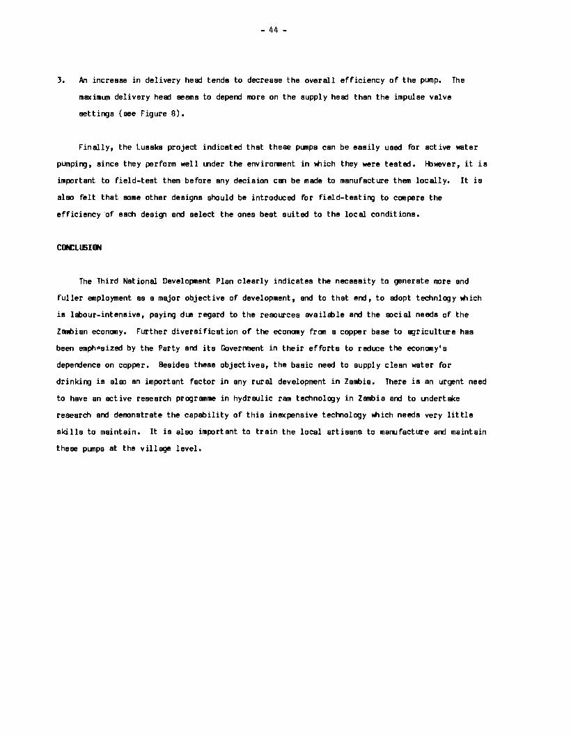
- 44 -
3. An increase in delivery hee::t tends to decrease the overall efficiency of the pump. The
maximun delivery hee::t seems to depend more on the supply hee::t than the impulse valve
settings (see Figure 8).
Finally, the Lusaka project indicated that these punps can be easily used for active water
pumping, since they perform well Ulder the environment in Wiich they were tested. lt>wever, it is
important to field-test them before any decision can be made to manufacture them locally. It is
also felt that some other designs should be introduced for field-testing to compare the
efficiency of each design and select the ones best suited to the local conditions.
CON:LIJSillll
The Third National Development Plan clearly indicates the necessity to generate 11Dre and
fuller employment as a major objective of development, and to that end, to e::topt teehnlogy Wiich
is labour-intensive, paying due regard to the resources available and the social needs of the
Zambian economy. Further diversification of the economy from a copper base to agriculture has
been emphasized by the Party and its Goverrvnent in their efforts to reduce the economy's
dependence on copper. Besides these objectives, the basic need to supply clean water for
drinking is also an important factor in any rural development in Zambia. There is an urgent need
to have an active research programme in hydraulic ram technology in Zambia and to Uldertake
research and demonstrate the capability of this inexpensive technology Wiich needs very little
skills to maintain. It is also important to train the local artisans to manufacture and maintain
these punps at the village level.

- 45 -
TABLE J: NDTATl(W flit DmVES (W FIGtfiES 6, 7 AN> 8
a) SUPPLY HEAD = 3.205m
b)
Curve Number
2
3
SUPPLY HEAD = 4.22m
Curve Number
4
5
6
7
8
REFERENCES
Valve Stroke
(mm)
10
20
30
Valve Stroke
10
10
10
20
30
Bolt Tens ion
(no. of clock-wise turns)
0
0
0
Bolt Tension
0
2
0
0
1. Report on Trouble Shooting Visit to Waterram in Kawambwa, Luapula Province. Colijn, A;
Hommerson, G.; Shouten, C.P.; and Vlugman, A.A. 1982.
2. The Hydraulic Analysis of Water Rams. Hioiafulilwa. 1983
3. Public Standpost Water Supplies, Volume 13 and 14. IRCCWS Publication. 1979.
4. Third National Development Plan, Zambia. 1979.
5. Public Stand Water Supplies (PSWS) Project Lusaka. 1983.
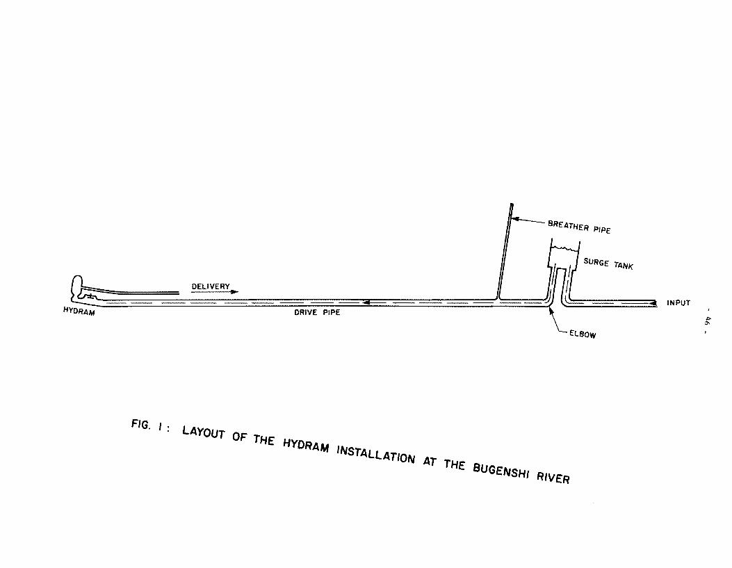
,,__ __ BREATHER PIPE
SURGE TANK
INPUT HYDRAM
ELBOW
FIG. I : LAYOUT OF THE HYDRAAA INSTALLATION AT THE BUGENSHI RIVER
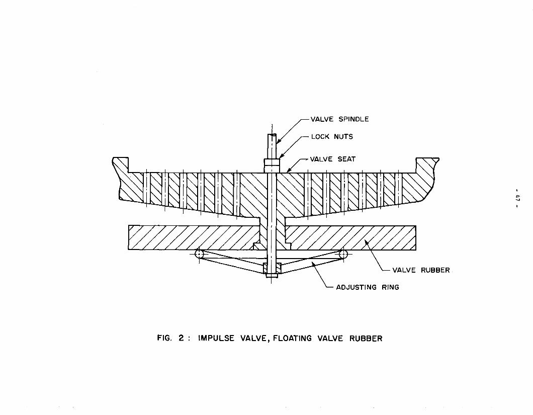
VALVE SPINDLE
LOCK NUTS
SEAT
RUBBER
RING
FIG. 2 : IMPULSE VALVE, FLOATING VALVE RUBBER
VALVE SPINDLE
LOCK NUTS
SEAT
RUBBER
RING
FIG. 3 : IMPULSE VALVE, FIXED VALVE RUBBER
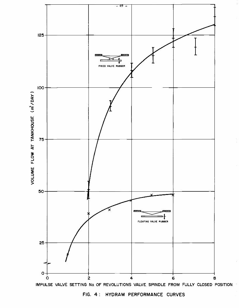
FIXED VALVE RUBBER
100
~ 0
' "'e ......
w (/) :::> 0 ::c ::.:: z ~ 75
ti ~ 0 ...J u. w :E :::> ...J 0 >
50
mzm rzznm ~t
FLOATING VALVE RUBBER
I
2 4 6 8
IMPULSE VALVE SETTING No. OF REVOLUTIONS VALVE SPINDLE FROM FULLY CLOSED POSITION
FIG. 4 : HYDRAM PERFORMANCE CURVES

z ~ ...... (/)
~ UJ m -0 UJ UJ a.. (/)
UJ
~ ~ UJ (/) ...J :> a.. ~
- 50 -
FLOATING VALVE RUBBER
mzm D>>>Fi
~ t
100
75 FIXED VALVE RUBBER
~ rzzzn ;s:q.
O-+-~~~~~~-+~~~~~~~-+-~~~~~~~+-~~~~~~---i
0 2 4 6
IMPULSE VALVE SETTING
( No. OF REVOLUTIONS OF THE VALVE SPINDLE FROM FULLY CLOSED POSITION )
FIG. 5: HYORAM FREQUENCY AS A FUNCTION
OF IMPULSE VALVE SETTING
8
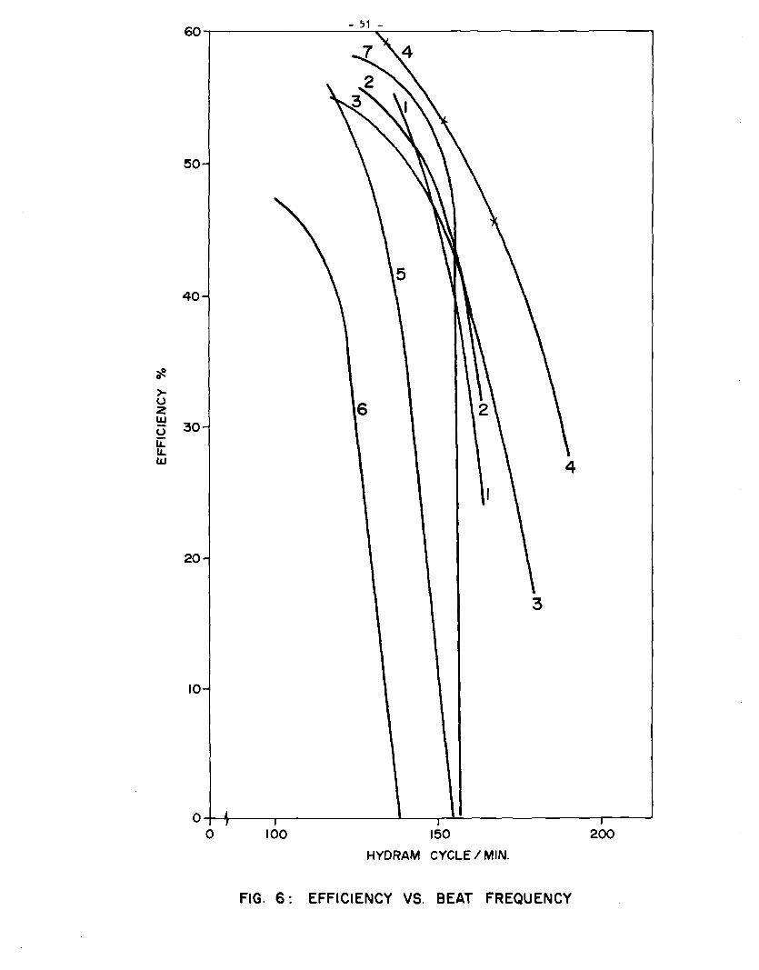
>u z
50
40
ILi 30 u Li: LL ILi
20
10
3
0-+-+--~--.-~~~~~---''-----r_._;..__~~~~~~~~___..
0 100 150 200
HYDRAM CYCLE I MIN.
FIG. 6: EFFICIENCY VS. BEAT FREQUENCY
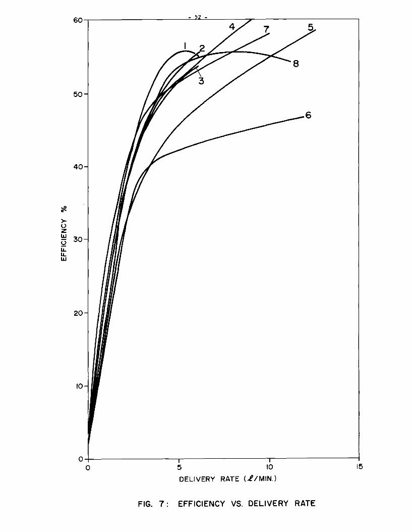
::e 0
>u z
50
40
ILi 30 u LL LL lLI
20
10
0-+-~~~~~~~~~~~~~~~----..--~~~~~~---1
0 5 10 15
DELIVERY RATE (,//MIN.)
FIG. 7: EFFICIENCY VS. DELIVERY RATE

50
40
>u z UJ 30 Q It UJ
20
10
0 10 20 30
DELIVERY HEAD (M)
FIG. 8: EFFICIENCY VS. DELIVERY HEAD
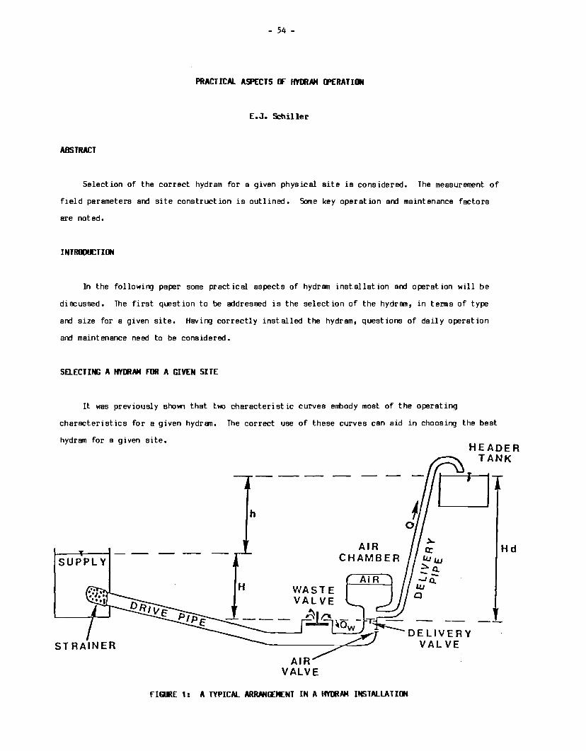
- 54 -
PRACTICAL ASPECTS rF HYDRAH IJ>ERATI•
E.J. Schiller
ABSTRACT
Selection of the correct hydram for a given physical site is considered. The measurement of
field parameters and site construction is outlined. Some key operation and maintenance factors
are noted.
INTRmll:TUW
In the followirg paper some practical aspects of hydram installation and operation will be
discussed. The first question to be addressed is the selection of the hydram, in terms of type
and size for a given site. Having correctly installed the hydram, questions of daily operation
and maintenance need to be considered.
SEl.ECTIN; A HYDRAH FDR A GIVEN SITE
It was previously shown that two characteristic curves embody most of the operating
characteristics for a given hydram. The correct use of these curves can aid in choosing the best
hydram for a given site. HEADER
TANK
h
~--+-----! - -- -- --SUPPLY
AIR VALVE
AIR CHAMBER
AIR
rIGRE 1: A TYPICAL ARRMIEENT IN A HYDRAH INSTALLA HON
DELIVERY VALVE
Hd
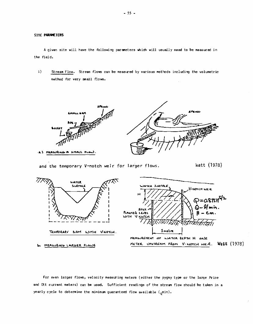
- 55 -
SITE PAIWETERS
A given site will have the following parameters Wiich will usually need to be measured in
the field.
i) Stream Flow. Stream flows can be measured by various methods inciuding the volumetric
method for very small flows.
and the temporary V-notch weir for larger flows. watt (1978)
I I I ,_ ____ -- -- - -- --·
H
~ 1 ... elrR.
£\) ::o. Cl;rs tff 'J..
Q-~ ••lo\. p - C..M •
""£.P.'5oo.illf:r1ENT &!IF l..),.."fEA.. CIEP"TH H ollJE
ME"1E"- \JPb-rR..~AM FRDM v- MOTLK w£1R.. Watt ( 1978)
For even larger flows, velocity measuring meters (either the pygmy type or the larqe Price
and ott current meters) can be used. Sufficient readings of the stream flow should be taken in a
yearly cycle to determine the minimum guaranteed flow available (qmin).

- 56 -
ii) The drop in the flowing strean fran the source to the site of the hydram is an important
parameter. The stream may have a natural drop or a drop can be created by means of a
small dam. The amount of this drop can usually be determined with a simple surveying
level or even with a carpenter's level attached to a stick.
l.1.JC.\
~a.\:. up c.lo."K so..stL.L A.l\..l l:o.\l.a. o.. rucl •A~
lno'L ~l:.a~.\ """""'c::--...L. Wf~ S \TL do&.>nhi\\ a."iil. tak o. raa..liA9
k'att (1978)
iii) The distance from the hydram site to the storage point must be measured both in terms of
the lift required (Hd, Figure 1) and in terms of the length of the delivery pipe
required.
iv) An estimate of the water demand is required. If this is to be used for domestic
consumption in a rural setting, this can be approximated by:
Water Demand = Population x Per Capita Consumption (1)
A typical per capital consumption is 30-40 L/p/day. If animals are present, their water
consumption should be included also.
MATCHIM: PllF CHARACTERISTICS TO THE SITE AND !£MAND CHARACTERISTICS
Given the water demand from equation (1) and the fact that hydrans operate twenty-four hours
per day, the required flow will be:
Q = Water Demand 24 x 60
(litres) (min)
(2)
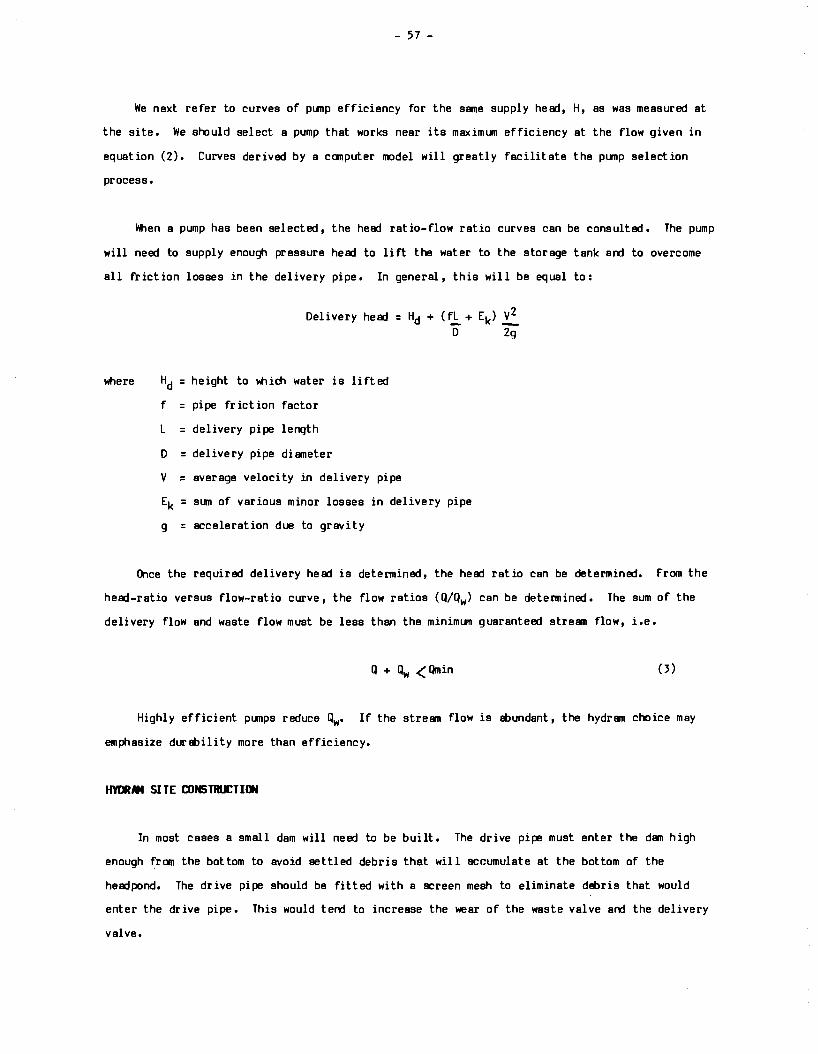
- 57 -
We next refer to curves of plfllp efficiency for the same supply head, H, as was measured at
the site. We should select a pump that works near its maximun efficiency at the flow given in
equation (2). Curves derived by a canputer model will greatly facilitate the punp selection
process.
\'tien a pump has been selected, the head ratio-flow ratio curves can be consulted. The pump
will need to supply enough pressure head to lift the water to the storage tank and to overcome
all friction losses in the delivery pipe. In general, this will be equal to:
Delivery head = Hd + ( f.,!;,_ + Ek) £ D 2g
where Hd = height to W'lich water is lifted
f = pipe friction factor
L = delivery pipe length
D = delivery pipe diameter
v = average velocity in delivery pipe
Ek = sum of various minor losses in delivery pipe
g = acceleration due to gravity
Once the required delivery head is determined, the head ratio can be determined. from the
head-ratio versus flow-ratio curve, the flow ratios ( Q/Qw) can be detennined. The sum of the
deli very flow and waste flow must be less than the minimun guaranteed stream flow, i.e.
Highly efficient plfllps reduce Qw• If the stream flow is !Eundant, the hydram choice may
emphasize dur!Eility more than efficiency.
HYlltllM SITE CONSTRUCTIIW
In most cases a small dam will need to be built. The drive pipe must enter the dam high
enough from the bottom to avoid settled debris that will accumulate at the bottom of the
headpond. The drive pipe should be fitted with a screen mesh to eliminate debris that would
enter the drive pipe. This would tend to increase the wear of the waste valve and the delivery
valve.
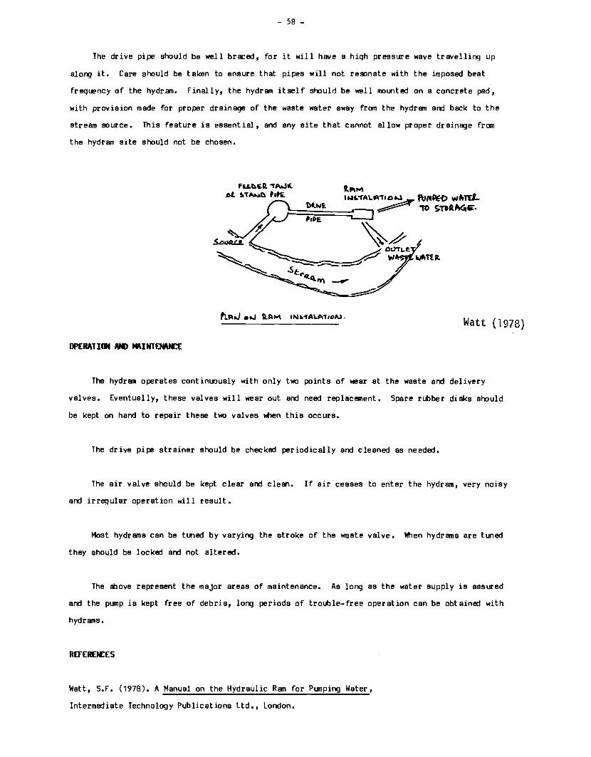
- 58 -
The drive pipe should be well bra::ed, for it will have a high pressure wave tr av el ling up
along it. Care should be taken to ensure that pipes will not res:mate with the imposed beat
frequency of the hydran. Finally, the hydram itself should be well mounted on a concrete pad,
with provision made for proper drainage of the waste water away from the hydram and back to the
stream source. This feature is essential, and any site that cannot allow proper drainage frCITI
the hydram site should not be chosen.
OPERATillil #I> MIHNTENIUl:f:
Fu.~t:Q. "1'AW'ot !.T!lll..,.C) Pat£
Watt (1978)
The hydram operates continuously with only two points of wear at the waste and delivery
valves. Eventually, these valves will wear out and need replacement. Spare rubber disks should
be kept on hand to repair these two valves when this occurs.
The drive pipe strainer should be checked periodically and cleaned as needed.
The air valve should be kept clear and clean. If air ceases to enter the hydram, very noisy
and irregular operation will result.
Most hydrams can be tuned by varying the stroke of the waste valve. When hydrams are tuned
they should be locked and not altered.
The above represent the major areas of maintenance. As long as the water supply is assured
and the pump is kept free of debris, long periods of trouble-free operation can be obtained with
hydrams.
REFEREN:ES
Watt, S.F. (1978). A Manual on the Hydraulic Ram for Punping Water,
Intermediate Technology Publications Ltd., London,
- 59 -
THE *NlFACTlltE IF HYMAMS
S.S. Janlu
ABSTRACT
lklrealistic approaches to local hydram design and manufacture are examined. Some aspects of
the manufacture of hydrems in Tanzania are considered.
INTRODtETI~
Jandu Plumbers Ltd. first began installirg hydraulic rams in East Africa fifty )'ears ago at
which time the technology was alreedy two hlJ'ldred years old. The type of hydrams that Jandu has
installed hed previously been in manufacture for over seventy )'ears. Therefore, our initial
reaction on receivirg an invitation to a seminar on the design and use of hydraJlic rams was one
of surprise that it should be necessary to do research into such a long-established technology.
We have seen hydraulic rams become beloved of the armchair Intermediate Technology (I.T.)
and Appropriate Technology (A. T.) ergineers for romantic rather than rational reasons. Indeed,
it is party for similar reasons that we manufacture them ourselves rather than some more
profitable line. However, as ergineers, we now see that the problems of makirg this sort of
technology available to the rural population as a whole, are RDre social or even political than
technical. We shall be happy to leave this aspect to the experts but would like to comment on
one example of the naive application of the I. T. attitude. You will all have seen the neat
hydram mede from standard pipe fittirgs and edopted by VITA. t-bw - this is very convenient for
the vollJ'lteer with the VITA handbook workirg in a remote area and with access to those fittirgs,
but do we foresee hlJ'ldreds of villagers deacendirg on their nearest town to purchase fittirgs and
then makirg and installirg the ram in the village? We contend that it is much more likely that
such technology will spreed if appropriate equipment is reedily available at the local market
to1t1 at reasonable prices. Tanzania is, we believe, not lJ'ltypical of many developirg economies
in its lack of spare parts and equipment. If you were to set out to build the VITA ram here, you
would spend considerable time searchirg for the parts and should you be fortlJ'late enough to find
them, then the open market value of the components would be quite high since they will have been
imported into the country, and consequently be a foreign exchange cost-to the country. If you
add this to the time and expense of searchirg and assemblinq, then the cost is considerable.
Surely then, it is better to make available a commercially-built ram, or better still, to
encourB:)e the local manufacture of a hydram.
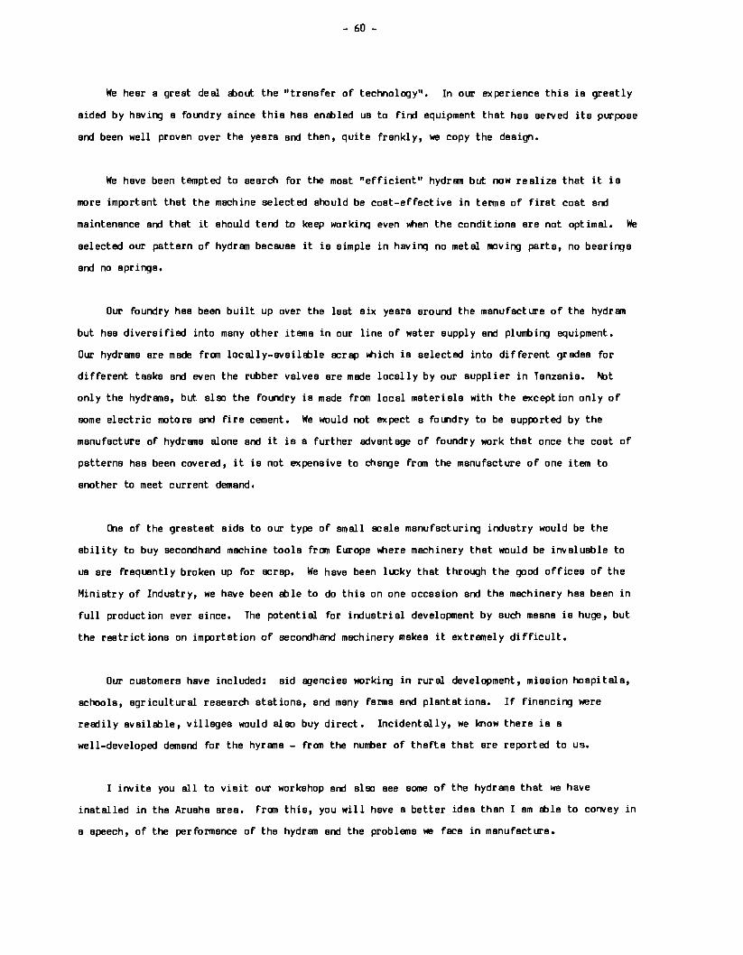
- 60 -
We hear a great deal Etlout the "transfer of technology". In our experience this is greatly
aided by having a fo111dry since this has enitiled us to find equipment that has served its purpose
and been well proven over the years and then, quite frankly, we copy the design.
We have been tempted to search for the moat "efficient" hydran but now realize that it is
more important that the machine select.ed should be coat-effective in terms of first coat and
maintenance and that it should tend to keep working even l'hen the conditions ere not optimal. We
selected our pattern of hydran because it is simple in havinq no metal moving parts, no bearinqa
and no springs.
Our foundry has been built up over the last six years around the manufacture of the hydran
but has diversified into many other items in our line of water supply and plumbing equipment.
Our hydrame are made from locally-availitile scrap \ltiich is selected into different grades for
different tasks and even the rubber valves ere made locally by our supplier in Tanzania. l't>t
only the hydr1111a, but aloo the foundry is made from local materials with the exception only of
some electric motors and fire cement. We would not expect a fo111dry to be supported by the
manufacture of hydr1111e alone and it is a further advantage of foundry work that once the coat of
patterns has been covered, it is not expensive to change from the manufacture of one item to
another to meet current demand.
One of the greatest aide to our type of small scale manufacturing industry would be the
ability to buy secondhand machine tools fran Europe l'lhere machinery that would be invaluable to
us are frequent! y broken up for scrap. We have been lucky that through the good offices of the
Ministry of Industry, we have been Ible to do this on one occasion and the machinery has been in
full production ever since. The potential for industrial development by such means is huge, but
the restrictions on importation of secondhand machinery makes it extremely difficult.
Our customers have included: aid BJenciea working in rural development, mission hospitals,
schools, agricultural research stations, and many farms and plantations. If financing were
readily available, villages would alao buy direct. Incidentally, we know there is a
well-developed demand for the hyrane - from the number of thefts that ere reported to us.
I invite you all to visit our workshop and aloo see some of the hydrane that we have
installed in the Aruaha area. From this, you will have a better idea than I am itile to convey in
a speech, of the performance of the hydrsn and the problems we face in manufacture.
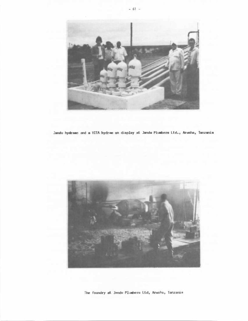
- 61 -
Jandu hydra11S md a VITA -hydram on display at Jandu Pl....,era Ltd., Arusha, Tanz.U.a
The foundry at Jandu PlUlllbers Ltd, Arusha, Tanzania

ABSTRACT
- 62 -
CIMUIITY PMTICIPATIIW IN TH£ MVEl.O'tENT MD MAINTENAM:£
IF HYCRMS IN RURAL WA T£R SCI£rt::£5
L. G. Mailllbe
A historical review of the role of comml.llity participation in rural water supply in Tanzania
is qiven. Possible areas of local participation in a hydram development program are qiven.
INTRODll:TIIW
Community participation in the development and maintenance of hydr1111s in water schemes has
to be seen as an inteoral part of the beneficiaries' involvement in the total development of
public services qiven to the rural populace, such as health centres, schools, roads, water
schemes, etc. Durinq the struqqle for political independence, and as a result, in the early
years of independence, mass mobilization was quite hiqh. As a result, in the early years of
independence, people's participation in lllat was then popularly known as self-help development
proqr1111s was remarkedly hiqh. The success of the famous 'MTU NI AFYA' (a periim is his health)
campaign in the sixties and the number of schools, dispensaries, and health centres built durirg
that time on a self-help basis clearly demonstrated the spirit people had towards development
proqrams. In a nutshell, people had accepted that development was their own responsibility and
that there would be no outside group who would help them in the trans format ion of their lives.
LOSS IF flJTIYATillf
However, as years went by, that spirit progressively faded away. Although there are many
factors Illich led to this change of attitude, the following are a few of the main ones:
1. Government involvement in the implementation of development schemes assumed a
predominant role. The introduction of hiq development programs necessitated
institutional manaqement, and involvement of benefici airies was ignored l.llder the
pretext of achieving the objectives within a predetermined economic t imeframe. Planners
felt that involvement was a parameter that they could not control.
- 63 -
2. The removal of local government authorities in the early seventies meant development
pr<XJrams would be more centrally planned and executed.
3. Some of the political decisions were misunderstood by the general public to mean the
government was duty-bound to provide the basic public services free.
4. The second half of the sixties and first half of the seventies were very 'rosy' times and
the government seemed financially able to assume the role of providi!'ll for the basic needs
to its rural populace.
5. Some government decisions disturbed the order in society to the extent that people could not
really identify their role in the development of their country.
6. Some individuals misused the existing potential of commtnity participation for their own
benefits. Incidences are on record where people were persuaded to put effort into projects
which later had to be it>andoned.
7. The present hard economic times char~terized by shortages of many of the essential
commodities has encouraged individualistic development.
8. Public participation was done on a voluntary basis. There was no leqislation to enforce it
and ensure its continuity as a necessary input in the development process.
9. There was no assessment made to evaluate the aocial and economic impact of commtnity
development on development programs.
RESTOIATillll EFFlllTS
In the course of time, the government realized its limitations in terms of reeources and
implementation capacity. More importantly, the government realized that development cannot be
'planted'. Beneficiaries' involvement is a ncessary input if development programs are to be real
and meaningful. Therefore, the government is now t eking positive steps to restore the apparent! y
lost glamour of local participation. As a first step, the government encouraged formation of
village governments which wil 1 manage funds and provide public services. The process of village
legislation has been regrettably slow. The establishment of local government in 1983 is also
seen as a positive contribution towards reactivation of the self-help spirit, although it also
has some undesirable features like personal tax.
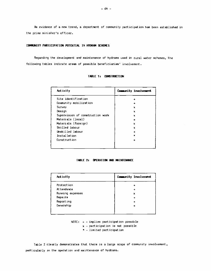
- 64 -
As evidence of a new trend, a department of community participation has been established in
the prime minister's officer.
CO!tll'4ITY PARTICIPATIIJI POTENTIAL IN HYDRAH !:£HEMES
Regarding the development and maintenance of hydrams used in rural water schemes, the
following tables indicate areas of possible beneficiaries' involvement.
TABLE 1: IDNSTRUCTION
Activity ec-.nity Involvement
Site identification +
Community mobilization +
Survey x Design x Supervision of construction work x Materials (local) +
Materi els (foreign) x Skilled labour x l.klskilled labour +
Installation * Construct ion +
TABLE 2: (JJ[RATllJI IM) MIHNTENANCE
Activity C.-mity Involvement
Protect ion +
Attendance +
Running expenses x Repairs +
Reporting +
Ownership +
NOTE: + - implies participation possible x - participation is not possible * - limited participation
Table 2 clearly demonstrates that there is a large scope of community involvement,
particularly in the operation and maintenance of hydrams.
- 65 -
CONCLUSIONS Ntl REClllEN>ATilltS
The need for community participation in development programs cannot be overemphasized. At
present, it is difficult to organize community participation. Therefore, there is a need to
conduct a study to ascertain the level of community participation that would be possible in the
development and maintenance of hydrams. The main objectives of the study should be the
following:
identification of options which will reactivate the spirit of community participation,
particularly in the development and maintenance of hydrams;
determination of cultural influences on the acceptability of hydrams;
assessment of attitudes of people towards water supply services;
assessment of local skills and their influence on the development and maintenance of
hydrams;
assessment of the level of need of service; and
determination of the influence of economic differences in the development and
maintenance of hydrams.
- 66 -
SO:IO-ECOtllUC CONSIOCRATll'.WS IN RlfiAL WATER SUPA.. Y OCVELIPtENT
W. Baynit
ABSTRACT
Some cultural constraints to hydram usage are noted. The difficulty with fossil-fuel
pumpirg is enumerated and potential areas for hydran development in Tanzania are listed. Some
aspects of a hydram feasibility study are given.
INTRODIETION
Constraints to the application of any technology should not necessarily be confined to
technical aspects. Social and even political aspects may be crucial in constrainirg the demand
for a technology. This is true for hydrams as well as any other technology.
SOCIAL mNSTRAINTS IN HYlltM APA...ICATION
When discussirg the social constraints in the application of hydrams in Tanzania, a major
issue may be the potential users' lack of awareness and exposure to hydram technology in areas
where this technology could be used. Other social and economic barriers could includes
excessive! y high capital costs, users' cultural barriers and sensitivities, social structure of
the users' community-like settlement patterns, ownership pattern, government policies, and
economic aspects such as inflation.
One of the main cultural barriers and sensitivities of the rural communities in Tanzania as
well as in most other African countries, is superstition. The unique sound that hydrams make
while workirg could trigger some speculation amorg the villagers. Some hydrams are installed in
strange-lookirg areas and left unattended. There are thus no visible paths leadirg to them and
yet the sound reaches quite a distance. This may make the villagers suspicious and refuse to
accept the hydram as a useful tool. It is a commonly-held belief that the natural water sources
like sprirgs are holy places and should not be tampered with. Experience has shown that, in some
cases, villagers will not only abandon the area in l'klich the pump is installed but also the river
from which the hydram draws its water. Villagers would rather look for an alternative water
source which may be miles away than draw their water from a tampered-with or "bewitched'' river or
sprirg. This problem will be resolved through exposure to various workirg hydrams and education.

- 67 -
POTENTIAL FOR WIIISPREAD USE IF HYMAMS
Followin;:i the campaign to settle peasants in Ujamaa (commi.nal) villages, a nurrtier of water
pumps were installed to supply water to these villages. Most of the pumps were driven by
fossel-fuel engines and a few by windmills. The p1.J11ps were installed at a time ~en ~e world
was lt>out to bid farewell to the cheap fuel era. The villagers did not enjoy piped water for
lon;:i be fore the oil crisis struck. For some time more punps continued to be installed as the
world expected the crisis to be temporary but only recently has it been realized that the che""
oil era is gone forever.
With the ever risin;:i prices of fossil-fuel and spares, the engines one by one ground to a
stop. Villagers ~o could afford the fuel and spares lacked the expertise to repair and maintain
the engines. The last blow came ~en fuel was in short supply and rationing was introduced. It
became very difficult for villagers to obtain tne fuel although some had the money to buy it.
The punps were lt>andoned with unservicelt>le engines and the villagers had to revert to trekking
miles in search of water. The situation is still the same today and there is no indication of
ever revivin;:i the engines again. In fact, some of the engines have been brought back to towns
~ere they are dr ivin;:i other machines, includin;:i grain mills.
Windmills have been used to pump water in Tanzania but the initial costs of purchasin;:i and
instellin;:i them are out of reach of most villages. The few seen here and there in some parts of
the country were bought by the government and installed free-of-charge to the villages. Even a
government cannot afford to supply a windmill free-of-charge to every village in the coi.ntry.
Even with the few windmills supplied by the goverrrnent, most of them are either not working or
the punps are not workin;:i due to lack of regular maintenance.
The hydram, therefore, is the ideal elternat ive to the punps mentioned Ebove. The fact that
it consumes no fossil-fuel, needs minimum maintenance and can be reasonlt>ly priced, weighs
heavily in its favor. As mentioned earlier, the technology is quite simple and all the hydrsms
~ich may be required can be manufactured locally. This will serve two purposes. Firstly,
foreign currency can be saved, and secondly, the end users will have some~ere to turn in case of
problems.
There are many areas in Tanzania ~ere hydrams could be installed both for domestic and
irrigation purposes. The Northern Highlands with fast-flowin;:i rivers are quite ideal. It is in
this area that some of the oldest hydrams were istalled many years ago; some of them can still be
found in workin;:i condition. The Southern Highlands have numerous rivers ri.nnin;:i in deep ravines
formed by low hills. Dwelling houses are built on the hills makin;:i it difficult to fetch water
up the hills. Some hydrams can be found in this area als:1.
- 68 -
The Usambara Mountains are another potential area for installing hydrams. The area has
plenty of rivers with many waterfalls but most of the rivers run deep between steep, low hills
thus creating a problem of fetching water uphill. In the Uluguru Mountains, people live on the
slopes and a lot of rivers run down the slopes to the sea many miles away. As in the Usambara,
here also hydrams could be useful to lift water to the dwellings. The people living in these
areas are good cultivators of vegetables but they have difficulty in bringing water to the high
ground where they live and farm.
CONCLUSION #() RECOtlENATICJI
In Tanzania the experience of the failure of the engine-powered pumps should give all those
concerned a new outlook in rural water supply. The fact that a hydram uses no fossil fuel and
has the ability to work continuously for up to fifty years with minimum maintenance, confirms the
appropriateness of the pump. The experience of owners of hydrams installed around Arusha after
the cheap oil era proves further that hydrams have a future in this country.
It is true that the initial cost of the pumps and installation is rather high and beyond the
reach of most individuals. For domestic purposes, one hydram can supply water to a sizeable
community provided the storage tank is big enough. The cost, therefore, will be spread amonq all
potential users.
To promote the widespread use of hydrams in Tanzania, a feasibility study, especially of
water sources available and socio-economic aspects, must be made. The recommendations mentioned
below may prove useful in this respect.
1. A study on the use of hydrams should be carried out to find out the actual potential for
these devices. This will include water sources and the geograhical and socio-economic
aspects.
2. Efforts should be made to enhance the manufacture of hydrams within the country. More
entrepreneurs should be encouraged to use their facilities for this purpose. The small
scale industries which have heen established in various parts of the country could be most
useful for this purpose.
3. Institutions such as CAMARTEC should be charged with the responsibility of selecting and
evaluating a few proven designs which can be manufactured locally.
- 69 -
4. The technology must be disseminated in the rural areas by launching a nation-wide campaign.
A few demonstration pumps could be installed in selected areas and villagers should be
encouraged to meet all expenses.
5. Owners should be trained to adjust the hydrams and to change worn-out working parts. This
also could be done by CAMARTEC or the manufacturers. other maintenance aspects of the
hydram should also be taught to the owners.
6. Villages now are bigger and more populous than before the Ujamaa villages. This calls for
larger size hydrams, as these will be cheaper than a number of smaller ones.
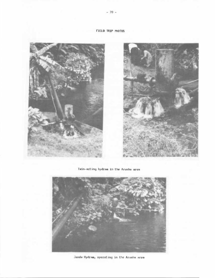
- 70 -
FIELD TRIP PHOTOS
Twin-acting hydra11 in the Arusha area
Jardu Hydra., operating in the Arusha area
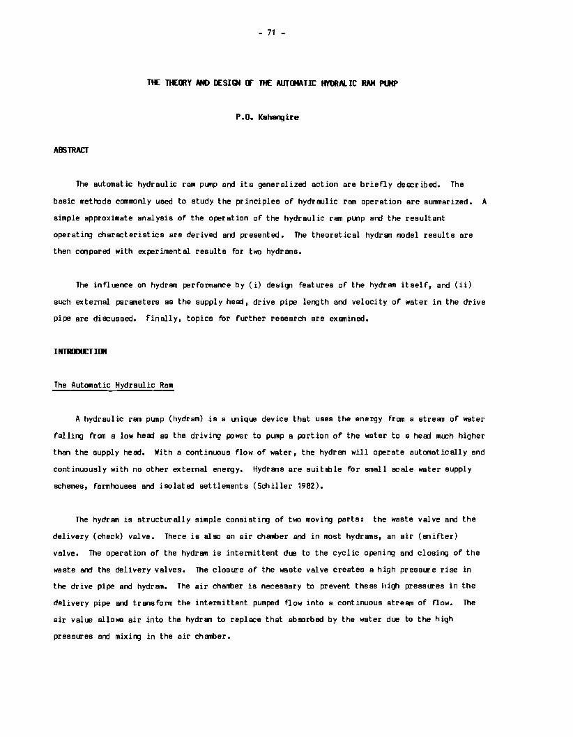
- 71 -
THE TtEmY AND IESI~ CF THE AUTCJ4ATIC HYDRALIC RAM Pll4P
P.O. Kahangire
ABSTRACT
The automatic hydraulic ram pump and its generalized action are briefly des:ribed. The
basic methods commonly used to study the principles of hydraulic ram operation are summarized. A
simple approximate analysis of the operation of the hydraulic ram pump and the resultant
operating characteristics are derived and presented. The theoretical hydram model results are
then compared with experimental results for two hydrams.
The influence on hydram performance by (i) desi!Jl features of the hydram itself, and (ii)
such external parameters as the supply head, drive pipe length and velocity of water in the drive
pipe are discussed. finally, topics for further research are examined.
The Automatic Hydraulic Ram
A hydraulic ram pump (hydram) is a unique device that uses the energy from a stream of water
falling from a low herd as the driving power to pump a portion of the water to a herd mt.Ch higher
than the supply head. With a continuous flow of water, the hydram will operate automatically and
continuously with no other external energy. Hydrams are suitEble for small scale water supply
schemes, farmhouses and isolated settlements (Schiller 1982).
The hydram is structurally simple consisting of t11«1 moving parts: the waste valve and the
delivery (check) valve. There is also an air chamber and in most hydrams, an air (snifter)
valve. The operation of the hydram is intermittent due to the cyclic opening and closing of the
waste and the delivery valves. The closure of the waste valve creates a high pressure rise in
the drive pipe and hydram. The air chamber is necessary to prevent these high pressures in the
delivery pipe and transform the intermittent pumped flow into a continuous stream of flow. The
air value allows air into the hydram to replace that abSJrbed by the water due to the high
pressures and mixing in the air chamber.
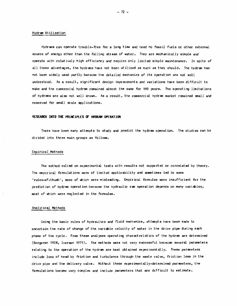
- 72 -
Hydran Utilization
Hydrans can operate trouble-free for a long time and need no fossil fuels or other external
source of energy other than the falling stream of water. They are mechanically simple and
operate with relatively high efficiency and require only limited simple maintenance. In spite of
all these edvantages, the hydrans have not been utilized as much as they should, The hydran has
not been widely used partly because the detailed mechanics of its operation are not well
understood. As a result, significant design improvements and variations have been difficult to
make and the commercial hydran remained almost the same for 190 years. The operating limitations
of hydrans are also not well known. As a result, the commercial hydran market remained small and
reserved for small scale applications.
RESEAROt INTO TtE PRIN:IPLES IF HYlllAM IFERATION
There have been many attempts to study and predict the hydran operation. The studies can be
divided into three main groups as follows,
Empirical Methods
The method relied on experimental tests with results not supported or correlated by theory.
The empirical formulations were of limited applicability and sometimes led to some
'rules-of-thuni>', some of Illich were misleading. Empirical formulas were insufficient for the
prediction of hydran operation because the hydraulic ran operation depends on many vari!bles,
most of 'ftlich were neglected in the formulas.
Analytical Methods
Using the basic rules of hydraulics and fluid mechanics, at tempts have been made to
ascertain the rate of change of the vari!t>le velocity of water in the drive pipe during each
phase of the cycle. From these analyses operating characteristics of the hydran are determined
(Bergeron 1928, Iversen 1975), The methods were not very successful because several parameters
relating to the operation of the hydran are best obtained experimentally. These paraneters
include loss of head by friction and turbulence through the waste valve, friction loss in the
drive pipe and the delivery valve. Without these experimentally-determined paraneters, the
formulations become very complex and include parameters that are difficult to estimate.
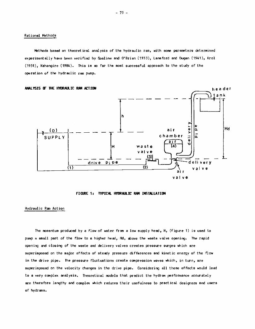
- 73 -
Rational Methods
Methods based on theoretical analysis of the hydraulic ram, with some parameters determined
experimentally have been verified by Gosline and O'Brien (1933), Lansford and Dugan (1941), Krol
(1951), Kahangire (1984). This is ao far the most successful approach to the study of the
operation of the hydraulic ram pump.
AN.\L YSIS rF THE HYmAlL IC RAM ACT ION header
tank
( 0)
SUPPLY
Hydraulic Ram Action
h
---- - --
H waste valve
---- ~ drive Pi Pe
( 1 ) (2)
air chamber
air 4
a i r
-o ... QI QI a. >
QI "C
Q.
deli very
v a Ive
v a Ive
rIGRE 1: TYPICAL HYmAll...IC RAM INSTALLATION
The momentum produced by a flow of water from a low supply head, H, (Figure 1) is used to
pllllp a small part of the flow to a higher head, I-kl, !Dove the waste valve opening. The rapid
opening and closing of the waste and delivery valves creates pressure surges "'1ich are
superimposed on the major effects of steady pressure differences and kinetic energy of the flow
in the drive pipe. The pressure fluctuations create compression waves "'1ich, in turn, are
superimposed on the velocity changes in the drive pipe. Considering all these effects would lead
to a very complex analysis. Theoretical models that predict the hydram performance accurately
are therefore lengthy and complex "'1ich reduces their usefulness to practical designers and users
of hydrams.
Hd
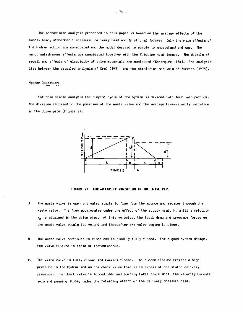
- 74 -
The approximate analysis presented in this paper is based on the average effects of the
supply head, atmospheric pressure, delivery head and frictional forces. Oily the main effects of
the hydram action are considered and the model derived is simple to understand and use. The
major waterhammer effects are considered together with the friction head losses. The details of
recoil and effects of elasticity of valve materials are neglected (Kahangire 1984). The analysis
lies between the detailed analysis of Krol (1951) and the simplified analysis of Iversen (1975).
Hydram Operation
For this simple analysis the pumping cycle of the hydram is divided into four main periods.
The division is based on the position of the waste valve and the average time-velocity variation
in the drive pipe (Figure 2).
f > .... 0 0 ..J w >
>
TIME (I)
flGl.RE 2: TU£-VB.O:ITY VARIATION IN Tf£ IJUVE PIPE
A. The waste valve is open and water starts to flow fr an the source and escapes through the
waste valve. The flow accelerates under the effect of the supply head, H, until a velocity
V0 is attained in the drive pipe. At this velocity, the total drag and pressure forces on
the waste valve equals its weight and thereafter the valve begins to close.
B. The waste valve continues to close and is finally fully closed. For a good hydram design,
the valve closure is rapid or instantaneous.
C. The waste valve is fully closed and remains closed. The sudden closure creates a high
pressure in the hydram and on the check valve that is in excess of the static delivery
pressure. The check valve is forced open and ptrnping takes place until the velocity becomes
zero and pumping stops, under the retarding effect of the delivery pressure hea:t.
- 75 -
D. The delivery valve closes. The pressure near the check valve is much higher than the static
supply pressure and the flow is reversed towards the supply source. This action is termed
recoil. The recoil action creates a vacuum in the hydram, temporarily forcing a small
amount of air to be sucked into the hydram through the air valve. The pressure on the
underside of the waste valve is also reduced and together with the effect of its own weight,
the waste valve opens automatically. The water in the drive pipe returns to the static
supply pressure as before and the next cycle begins. The action is repeated automatically
at a frequency of a few beats to over 300 beats per minute.
TtEORETICAL MWEL lF THE HYDRAll.IC RAM
At the University of Ottawa, a computerized theoretical model based on the assumed cycle of
operation given in the previous section was developed to assist in deriving the operating
characteristics of any given hydraulic ram pump. The computer program listing was originally
given in Fortran language but has now been converted to Basic language for use on microcomputers.
The development of the model is based on the following assumptions:
1. Approximate one-dimensional steady flow equation is ~plicable for the flow in the drive
pipe.
2. The friction losses in the drive pipe and pump do not vary with the variation in velocity
but are constant. Therefore, the parameters determined under steady flow conditions are
approximately constant.
3. The waste valve closure is instantaneous.
4. The velocity of water in the drive pipe when the waste valve begins to close and that when
the waste valve is finally close are almost the same.
5. The resistance due to spindle movement through the valve guide is negligible and constant.
6. Only the average flow velocity and pressure difference variations in the system are
considered.
- 76 -
In order to use the derived model, the followirr;i par11nters need to be obtained (some
experimentally) from the hydram design and installation. These include: (a) drive pipe lerr;ith
(L); (b) cross-sectional area of the drive pipe; (c) drive pipe diameters and thickness; (d)
supply head (H); (e) delivery head (h); (f) friction head loss in the drive pipe alone (XM); (g)
friction losses through the waste valve alone (RS); (h) friction head los at the delivery valve
(HVD); (i) the velocity in the drive pipe ltlen the waste valve begins to close (V0 ); and (j) the
steady flow velocity (Vs) through the waste valve when fully open.
ClllPARISON CT llJSERVED MD IDIPUTER tllEL RESJLTS
The theoretical hydram model derived above was tested against experimental results from t1«>
11 inch (32mm) hydrams, one of ltlich was made locally from steel pipe fittirr;is. Various
experimental test results were done for a supply head of about 2m, stroke lengths between
1mm-12mm and drive pipe lerr;ith of 15. 5m (Kaharr;i ire, 1984). For a typical run, Vs, M, N, V0 , HVD
and XM were determined experimentally under steady flow conditions. The results presented here
are for the locally made hydram with a valve weight of 0.36N, valve stroke lerr;ith of 2mm, and
drive pipe length of 15.5m. For this test run, the following parameter values were obtained and
used in the model: V0 = 0.40m/sec; M = 69; N = 69; HVD = 70; and XM = 12. The canpariSJn of the
observed and model results is shown in figures 3, 4, 5 and 6. This pattern of agreement was
observed in the other tests with the locally-made hydram and the canmercial hydram (Davey model
4) (Kahangire, 1984).
PRACTICAL ASPECTS CT HYIJIM IESia. MD INSTALLATION
Efficiency
There are two methods commonly used to compute the efficiency of a hydram installation; the
R111kine and the D'Al.buisson methods, both of which were proposed by Eytelwein (Mead 2933, Calvert
1957). The difference depends on whether the surface elevation of the water source or the waste
valve opening is taken as the datum.
E (Rankine) = Q.h ( 1 )
Qw.H
E (D 'Albuisson) = Q.Hd (2)
(Q+Qw)H
- 77 -
Where Q is the pumped flow per minute, Qw is the wasted flow per minute, h is the pump hea:l Ebove
the source, H is the supply hea:l itiov e the waste valve opening and Hd is the tot al delivery hea:l
above the waste valve opening (Figure 1),
For practical purposes, it does not matter l'ttlich formula is used. The two equations give
slightly different results and any references to hydram efficiency values should indicate the
method used. The D'Aliluisson formula gives higher values. It also has the shortcoming of giving
efficiency values even l'ttlen no useful work is done by the pump. For field tests and practical
applications, the Rankine definition of efficiency is to be preferred.
Some empirical formulas have been suggested based on experimental tests. Eytelwein with
data from over 1100 experiments from two different hydrams derived the following equation for
hydram efficiency
E: 1.12 - 0.2 V h (3)
li
(Cleghorne 1919). Another one by D'Aliluisson was of the form
E = 1.42 - 0.28 V hd (4) -H
(Anderson 1922) ~ere h and H are as defined earlier. These equations relate to the specific
hydrams tested, They also indicate the general nature of the efficiency curves for these types
of pumps and show how efficiency reduces as the pump hea:l increases for a given supply hea:l.
Drive Pipe Specifications
The drive pipe is an important component of the hydram installation. The drive pipe must be
able to sustain a high waterhammer pressure caused by the closing of the waste valve. Its
diameter depends on the size of the hydram, strength requirements, cost considerations,
availability of pipe materials and, in some cases, the available supply flow.
In spite of several experimental investigations, there is no agreement as to l'ttlat length of
the drive pipe should be used. The drive pipe length should depend on the supply he!rl and its
own diameter. The length commonly used in Europe and l'tlrth America lies between the limits
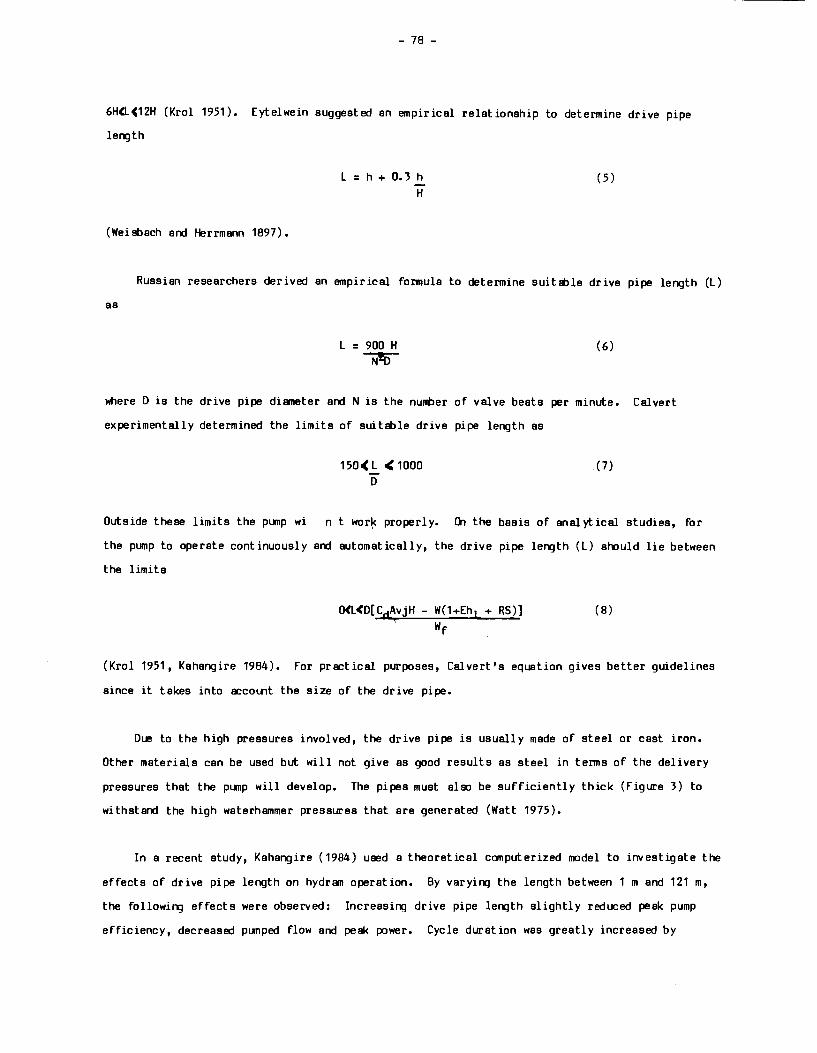
- 78 -
6H<LC12H (Krol 1951). Eytelwein suggested an empirical relationship to determine drive pipe
length
(Weisbach and Herrmann 1897).
L = h + O. 3 h
H (5)
Russian researchers derived an empirical formula to determine suitB::ile drive pipe length (L)
as
L = 900 H (6)
~
where D is the drive pipe di1111eter and N is the nunt>er of valve beats per minute. Calvert
experimentally determined the limits of suitable drive pipe length as
150( L < 1000 D
(7)
Outside these limits the pump wi n t war~ properly. On the basis of analytical studies, for
the pump to operate continuously and automatically, the drive pipe length (L) should lie between
the limits
0<L(D[C4AvjH - W(1+Eh1 + RS)] \
wf (8)
(Krol 1951 , Kahangire 1984). For practical purposes, Calvert's equation gives better guidelines
since it takes into accol.flt the size of the drive pipe.
Due to the high pressures involved, the drive pipe is usual! y made of steel or cast iron.
Other materials can be used but will not give as good results as steel in terms of the delivery
pressures that the pump will develop. The pipes must also be sufficiently thick (Figure 3) to
withstand the high waterhammer pressures that are generated (Watt 1975).
In a recent study, Kahangire ( 1984) used a theoretical computerized model to investigate the
effects of drive pipe length on hydram operation. By varying the length between 1 m and 121 m,
the following effects were observed: Increasing drive pipe length slightly reduced peak pump
efficiency, decreased pumped flow and peak power. Cycle duration was greatly increased by
- 79 -
40-50%, Generally, the lef'Y;1th should not be too short as the valve will close very fast, often
with no significant increase in water beif'Y;1 pumped, If the lef'Y;1th is very lof'Y;1, the friction
head losses will dominate and reduce the pump capability. If the supply head is high and the
drive pipe is lof'Y;1, the momentum of water in the drive pipe will be very high and the pump will
be damaged. In that case, a stand pipe should be inserted alof'Y;1 the drive pipe to reduce the
effective supply head.
Air Chamber
The effect of the air chamber size on hydram operation is not clearly known. Krol (1951)
noted an increase of 10% in pump efficiency when the air chamber volume was doubled, Krol
recommends the air volume to be approximately 100 times the volume of water delivered per cycle.
Cheghorne (1919) recommended the volume to be approximately twice the volume of the vertical
height of the delivery pipe, Experiments with a locally-made hydram from pipe fittif'Y;1S with a
2-inch (51mm) diameter pipe and lef'Y;1ths between 0.30 m - 1,3 m showed no significant effect of
the air chamber volume on the operatif'Y;1 characteristics of the hydram (Kaharqire 1984), Inversin
(1978) al!!D found no effect of air chamber volume on hydram operation. Problt>ly for high supply
heads and lof'Y;1 drive pipes, large air chambers and air vo1umes may be necessary to lt>sorb the
increased waterhammer pressures that will occur in the hydram.
Air Valve
This is usually a small hole or a one-way valve. Experiments with different sizes indicate
that the size has a negligible effect on the hydram operation. llily ~en the hole became !!Kl
large that half of the pumped flow was eecapif'Y;1 through it, did the effect become noticelt>le on
hydram efficiency (Figure 4), The pump capacity, however, was not affected. A small hole less
than 1.0 mm should suffice (Kaha1"Y;1ire 1984),
Design of the Waste Valve
A good waste valve design and proper adjustment are very essential for soooth and efficient
hydram operation. The design details include proper proportionif'Y;1 of the valve openirg or
orifice area (A0
) and the cross-sectional area (Av), its weight (W) and the stroke length (S) of
the waste valve itself, The mechanism controllif'Y;1 the valve movement or valve guide should allow
free and smooth movement. If good quality steel is not availlt>le, weighted impulse valves are
more suitlt>le than sprif'Y;1-type valves.
- 80 -
Common sizes of the waste valve are less than 4 inches (100 mm) and very few actually exceed
3-inch (75 mm). These sizes are considered more efficient l'thile larger sizes are not (Richards
1922). Bergeron (1928) showed analytically that the flow area through the waste valve should
equal or exceed the cross-sectional area of the drive pipe to avoid 'choking' the flow. In most
commercial hydrams, the waste valve area Ay is usually bigger than the size of the inlet at the
drive pipe-hydram connection.
Experiments at the University of Ottawa with a locally-made hydram indicated that there is a
wide range of combination of -\, and Ay for l'thich the hydram operation was not affected for valve
sizes not exceeding 70-75~ of the valve 'pot' or 'housing' diameter (figure 5). The experiments
aloo incidated that changing valve stroke had a similar effect as changing the valve weight on
hydram operation. ft>wever, increasing valve stroke gave better and a smoother hydram operation
than increasing the weight. In general, increasing valve stroke or weight reduced plJllp
efficiency (figure 6) but increased the flow. The head ratio- flow ratio-curve remained the same
(figure 7). The effect of valve stroke on hydram operation for well-designed commercial hydrams
may be small. Changing the valve stroke length altered the characteristics of the valve (figure
8) and the results indicate that hydram operation may be roore st!Ele for stroke lengths greater
than 4 mm. It was verified with the theoretical model that high friction losses through the
waste valve are undesir!Ele as they reduce the plJllp capacity (figure 9) and affect its general
operating characteristics. To minimize energy losses, the waste valve should be reason!E ly light
and adjusted in such a way that it will close fast. It was shown analytically that for a given
installation and valve design and stroke, the valve weight should lie within the limits
(9)
Krol (1976) indicated that there is a relationship between valve stroke (S) and the maximum
weight of the waste valve, Wmax' that can be used, such that
SWmax = Constant ( 10)
- 81 -
Delivery (Check) Valve
Generally, the valve should be such that it opens fast, closes evenly and offers as little
resistance to the flow as posible. As to its opening, Anderson (1922) recanmends one square inch
(6.54 sq cm) of area through the valve for every gallon (4.5 litres) of water to be delivered.
Recent experimental studies with delivery valves made of a perforated plate and covered with a
rubber disc of different thickness indicated that thin rubbers give high hydran efficiencies but
weaken fast and have to be replaced quite often. The rubber tends to get sucked into the
perforations and get cut due to the back pressure fran the delivery pipe and air charrber.
Increasing the rubber thickness affected hydran operation, primarily the pump efficiency (Figure
10). The theoretical model gave correlated results showing that the head losses through the
delivery valve had their largest effect on hydram efficiency (Figure 11). For high supply and
delivery heads, a thicker rubber will be necessary to withstand the back pressure and last long.
In that case, the perforations could be enlarged to minimize the friction losses. It was noted
in the experiment that except for very thick rubbers (10 mm) the pi.mped flow was not
significantly affected (Figure 12).
Supply Head
Increasing the supply head increases the velocity and momentum of water in the drive pipe.
Inversin (1978) deduced from experimental results that with the simple weighted impulse valves,
the supply head should not exceed 4 m, otherwise the valve will be closing oo rapidly and
frequently that no useful work will be done. In such a case, the valve should be assisted by a
spring to regulate its closure. Experimental results indicated pump efficiency and pumped flow
increased in direct proportion to the increase in supply head, particularly pi.mp flow (Q). Power
and valve beat frequency also increased. The theoretical model using supply heads of 2 m - 6 m
indicated a big increase in peak p1.111p efficiency and pumped flow. The cycle duration was greatly
decreased. Therefore, depending on the waste valve design, stroke length and weight, there is a
maximl.111 supply head at Wiich the p1.111p will not work properly. There is also a minimi.m supply
head necessary to operate the hydran.
Velocity of Water in the Drive Pipe
The most important design paraneter is the velocity at lltlich the waste begins to close, V0 •
Studies with the theoretical model (Kahangire 1984) indicated that this parameter is the most
important for determining hydran operation (Figure 13 and 14). Therefore, any hydran design,
- 82 -
installation and adjustment conditions that affect the valve of V0 , will dramatically affect the
general operating characteriatica of the hydram. V0 is affected by the weight, stroke length,
size and the general design of the waste valve.
CON:Llfilm.
Many researchers have shown that with some aaaumptiona and parameters determined
empirically, the performance of the hydraulic ram can be predicted. Ka hang ire ( 1984) went
further and demonstrated that the models can be used for preliminary design of hydrama and
investigation of auitmle hydram sites.
The mechanism of a hydram and its simple mechanical design and maintenance requirements make
it a unique water-pumping machine potentially auitmle for small scale water supply schemes in
developing countries. !hly a spring balance, atop watch and a calibrated cylinder or pail are
sufficient to determine factors for the desiCf! of a simple efficient hydraulic ram pump. The
computer proqram can also determine its performance curves.
Theoretical models can be used to predi~t hydram performance and can assist in the
preliminary design and survey of possible sites for hydran use. The simple model developed has
the capability of predicting the major characteristics of the hydram within acceptmle errors.
Some more work is needed to improve on its accuracy "1ile still keeping it simple.
Information on practical hydram sizes and installation limitations is often not availmle.
Such information is necessary to prevent expensive failures in the field and arbitrary hydram
designs and installations. Computer programs can yield this information. Thia would lead to
coat-effective hydram designs and installations.
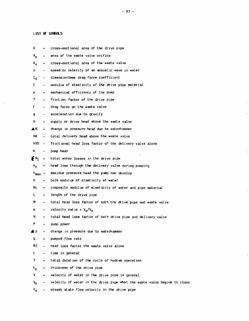
- 83 -
LIST CF S'MJOLS
A cross-sectional area of the drive pipe
A0 area of the waste valve orifice
Av cross-sectional area of the waste valve
c speed or celerity of an acoustic wave in water
Cd dimensionless drag force coefficient
E modulus of elasticity of the drive pipe material
e mechanical efficiency of the pump
f friction factor of the drive pipe
F drag force on the waste valve
g acceleration due to gravity
H supply or drive head above the waste valve
AH change in pressure head due to waterhammer
Hd total delivery head above the waste valve
HVD frictional head loss factor of the delivery valve alone
h pump head
f H1 total minor losses in the drive pipe
hr head loss through the delivery valve during pumping
hmax - maximum pressure head the pump can develop
K bulk modulus of elasticity of water
Kc composite modulus of elasticity of water and pipe material
L length of the drive pipe
M total head loss factor of both the drive pipe and waste valve
m velocity ratio = V0 /Vs
N total head loss factor of both drive pipe and delivery valve
P pump power
• p change in pressure due to waterhammer
Q pumped flow rate
RS head loss factor the waste valve alone
t time in general
T total duration of the cycle of hydram operation
tp thickness of the drive pipe
V velocity of water in the drive pipe in general
V0 velocity of water in the drive pipe when the waste valve begins to close
Vs steady state flow velocity in the drive pipe

- 84 -
LIST Of S'MllLS (continued)
Vm the velocity of the drive pipe just before complete waste valve closure
4 V change in velocity due to waste valve closure
V flow volume per period of the cycle
W maximum weicflt or spring tension of the waste valve
XM frictional head loss factor of the drive pipe alone
~ specific weight of water
~ density of water
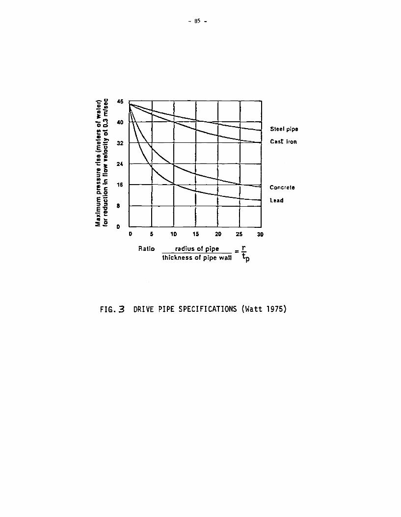
-.:-"' 46 CD CD _.,, c:i-~E
- C') 40 Oo .,,_ ... 0 ~ >-CD - 32 eu -o CD "i Ill> ;: ~ 2(
CD 0 ... _ :::i-Ill c .,,_
16 !c Cl. 0
E~ :I ::i 8 e-c -0 JI( ... CD._
::EE 0 0
- 85 -
5 10 15 20 25
Ratio radius of pipe = !. thickness of pipe wall tp
30
Steel pipe
Cut Iron
Concrete
lead
FIG. 3 DRIVE PIPE SPECIFICATIONS (Watt 1975)

8 .
8 0.10 1.10
SYMBOLS & AIR YALYI DIA·• 0.40 tit + AIR YALYE DIA·• 0.11 tit X AIR YALYE DIA·• 1·41 tit
1.10 1.40 .oo 3.10 4.10 c.10 DELIVERY FLOW (L/HINUTE>
s.co 1.00
FIG. Jr ITDG<IHPULSE) HYDRAM•EFFECT OF AIR VALVE ON PUMP EFFICIENCY.
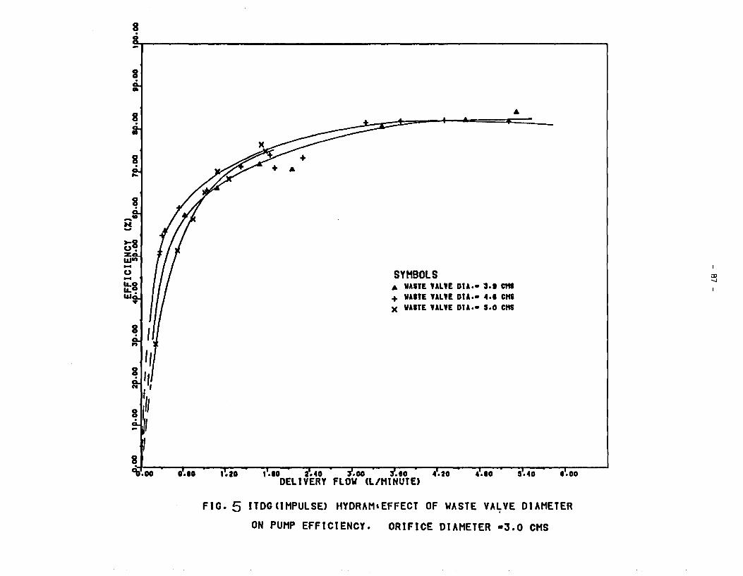
8 .
0.10 1.10
SYMBOLS A VAST£ YALYE DIA·• 3.t C"9 + VAITE YALYE DIA·• 4.1 CHS X VAITE YALYE DIA·• s.o CHS
1.10 a.4o .oo 3.eo 4.20 DELIVERY FLOW (L/MtNUTE>
•• oo
FIG. 5 ITDG<IMPULSE> HYDRAM•EFFECT OF WASTE VA~VE DIAMETER
ON PUMP EFFICIENCY. ORIFICE DIAMETER •3.0 CHS
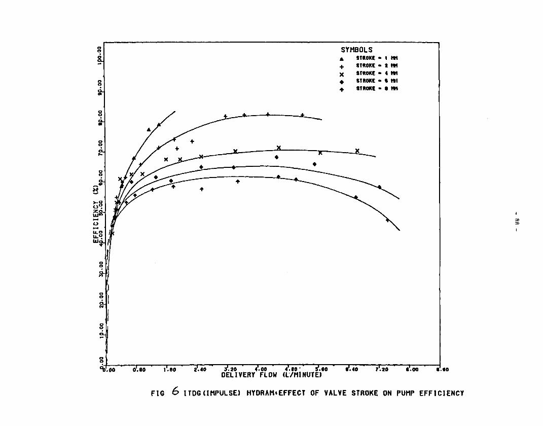
0 0
0 0 .
0.10
SYMBOLS .. STROKt • I ...
+ STltOKt • I ...
x STltOKt • 4 ...
• StltOKt • I 111
+ STltOtll • IM
• •
1.eo .20 4.00 1.00 1.10 DELIVERY FLOW
FIG (;, ITDGCIMPULSE> HYDRAH•EFFECT OF VALVE STROKE ON PUMP EFFICIENCY
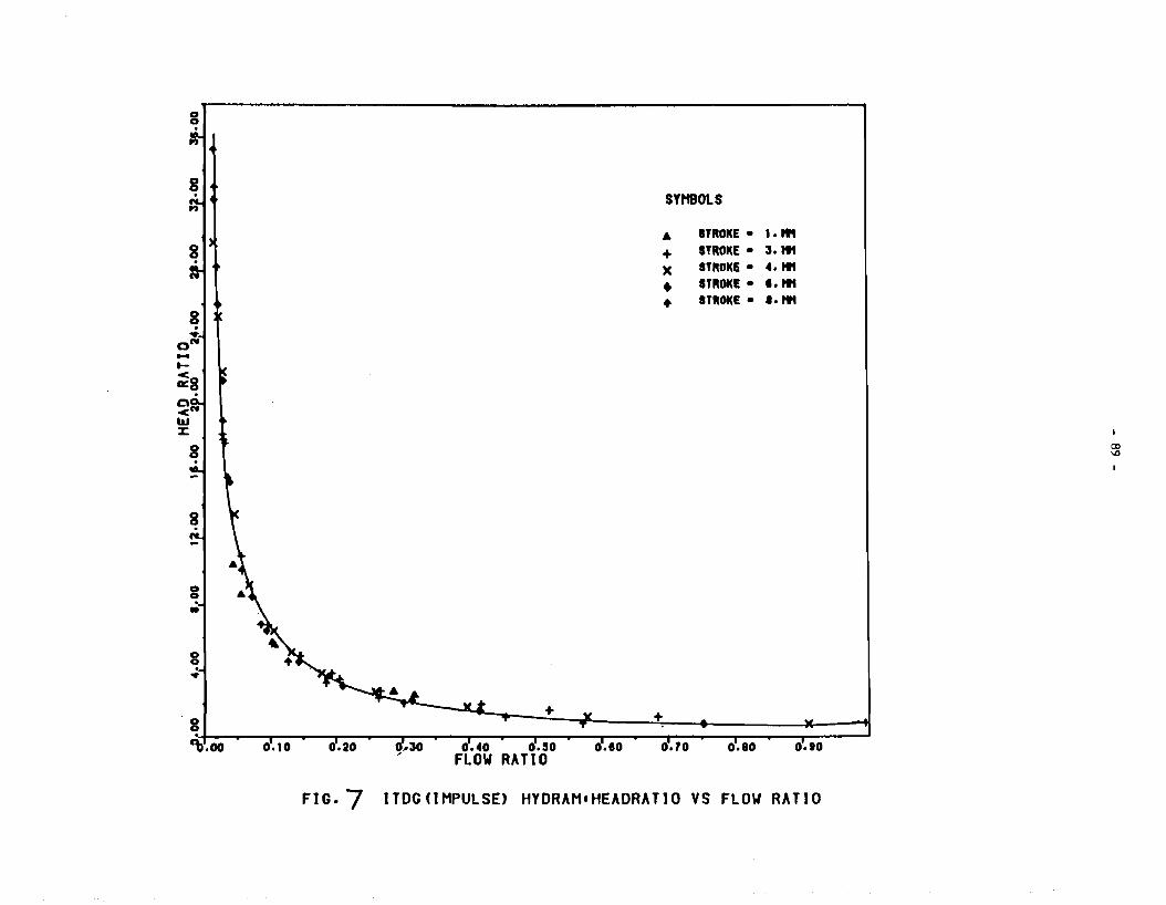
-t-
g . ..,
~8
g •
0 0
•
g + +
SYHBOLS
A STROKE • 1.ttt
+ STROKE • ;,. "' x STROKE • 4."' • STROKE • .. "' • STROKE • .. "'
+------------------------..-----------------------..--------------------' 9>.oo 0-10 o.4o o.so o.eo 0.10 o.ao 0.10 FLOW RATIO
FIG.-, ITOG(lMPULSE) HYDRAM•HEADRATIO VS FLOW RATIO
CD
'°
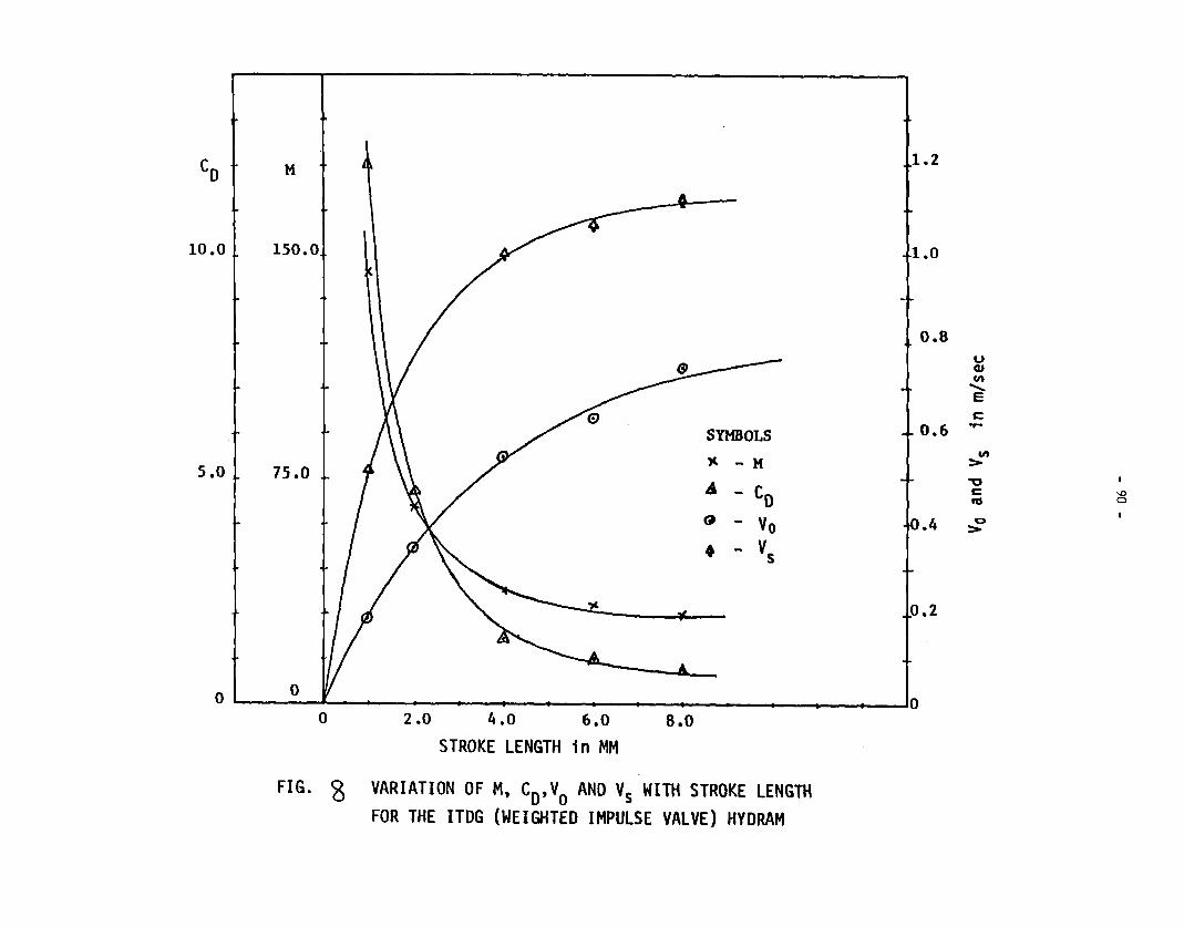
M 1.2
10.0 150.0 1.0
0.8
SYMBOLS 0.6
s.o 75.0 >' - M
A - Co @ - Vo .4
• - vs
0.2
0 0 L---------A.-----~--~--~-----------------------------------+----'0
0 2.0 4.0 6.0 8.0
STROKE LENGTH in MM
FIG. 8 VARIATION OF M, CD,vo ANO Vs WITH STROKE LENGTH FOR THE ITDG (WEIGHTED IMPULSE VALVE) HYDRAM
u cu en
.......... E c -en
> ""O c '° res 0
0 >
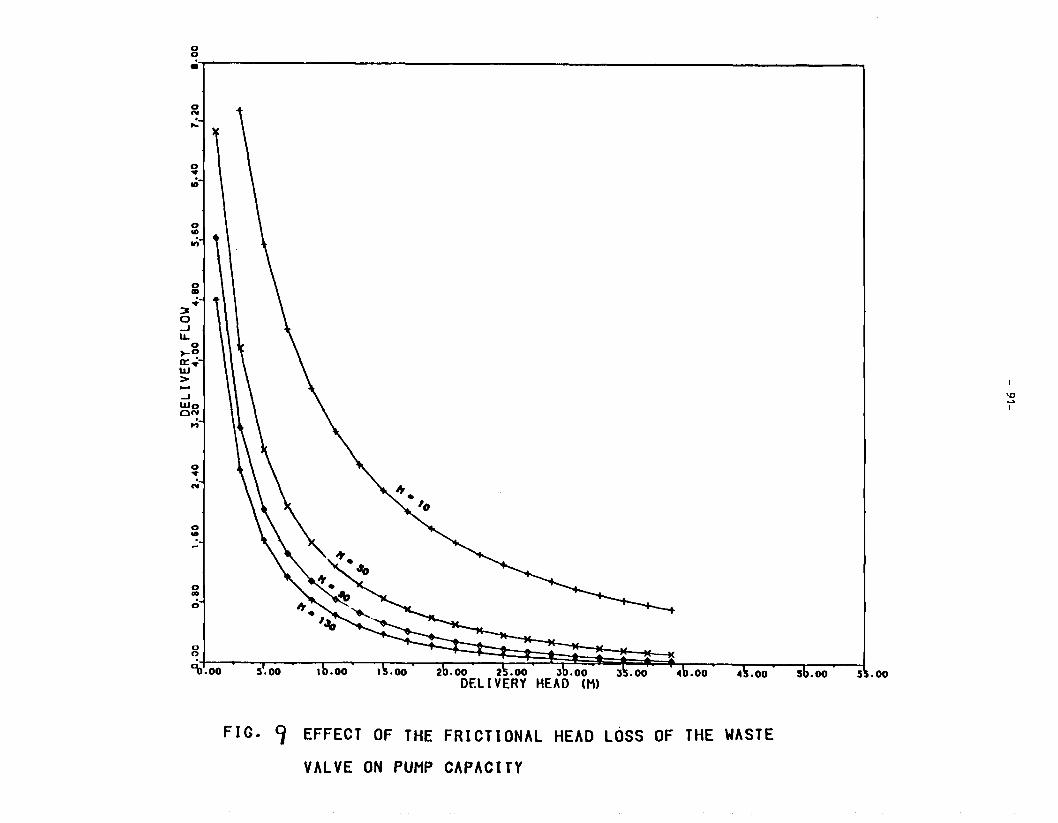
0 0 .:r-~~~~~~~~~~~~~~~~~~~~~~~~~~~~~~~~~~~--,
0 N . ~
0 • . •
0 ~o
~· UJ > J UJo ON .
M
0 • N
0 • -
FIG. ~ EFFECT OF THE FRICTIONAL HEAD LOSS OF THE WASTE
VALVE ON PUMP CAPACITY
5 .oo
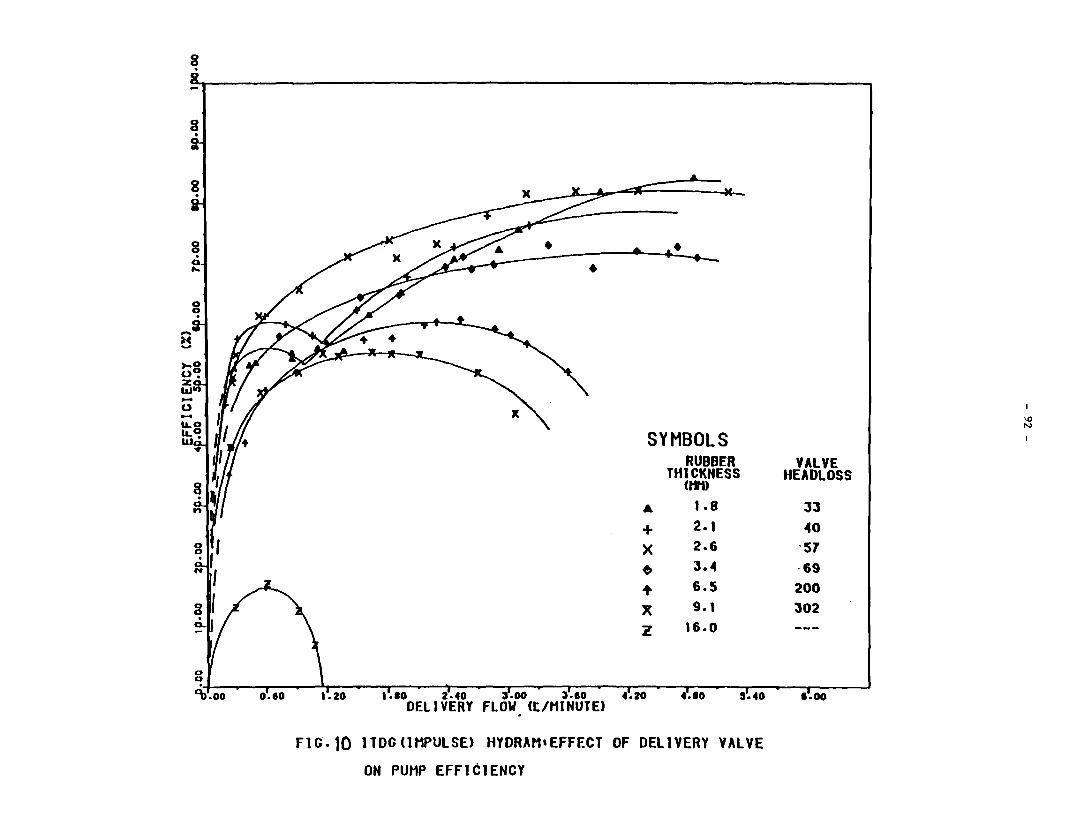
8 .
g .
8 . 0 ...
o.eo
• • •
SYMBOLS RUBBER
THlCKNESS (tft)
A 1.e + 2.1
x 2.6
~ J.4
+ 6.5
x 9.1
z 16.0
1.10 2.40 :s.oo ;,.ao 4.20 S.40 DELIVERY FLOW (t/MINUTE>
F1a.10 lTDG<lMPULSE> HYDRAM•EFFECT OF DELIVERY VALVE
ON PUMP EFFICIENCY
VALVE HEADLOSS
JJ 40
·57 ·69
200 302
1.00
\() N

- 93 -
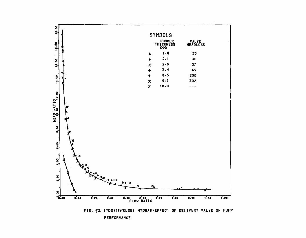
8 ...
i
8
>t
0 -<""' l&.I ~
1 •
8 . •
x )(
• .. +>< •• ..... a+X
SYMBOLS RUBBER_
TH1CKHES9 U1H>
.. 1 • 8 -.. 2. 1
;( 2 .15
6 J.4
+ 15. s )( 9.1
z 115. 0
0.14
VA~E HEAD OSS
JJ
40
57 69
200
J02
O.H 1.01 1.20
FIG~ 1~ ITDG<IMPULSE) HYDRAH•EFFECT OF DELIVERY VALVE ON PUMP
PERFORt1ANCE
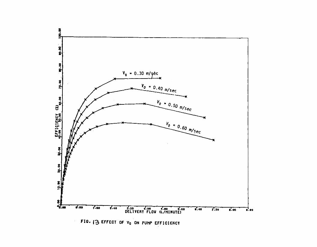
8 .
8 .
V0 .. 0.30 m/ c
_____ v..:.o_" ...:._o. 40 m/s ec
~
·10 f .IO .20 4.00 4.10 .10 DELIVERY FLOW Cl/MINUTE>
1.40 1.00 1.10
Flo. 13 EFFECT OF Vo ON PUMP EFFICIENCY
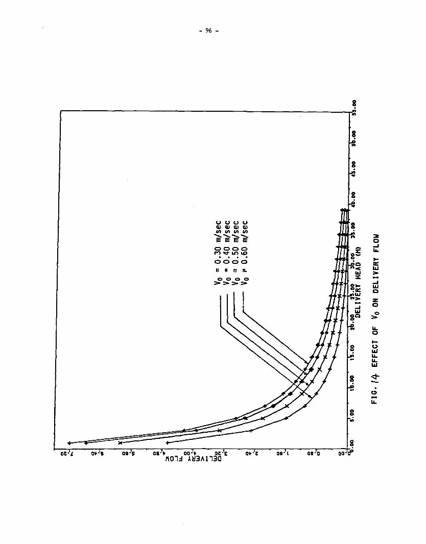
- 96 -
uuuu Cl.> Cl.> Cl.> Cl.> Cl) Cl) Cl) Cl)
"E' -e-e-e-0000 M~Lt'>\O . . . . 0000
II II II IL
c 0 0 0 >>>>
8 .
8 .
g
~ i--o-~~-~l-----o-t,·-,--~-o-1,·5----.--o-a~·t--~--o-o~·t------o-~T·t--~--at>-.~i-------01-·rt------o-1-·~o------o-o-+-:·rf'
l\01:J ~~3Al13C
:a 0 .... "->a: l&J > -.... l&J Q
z 0
0 >
"-0
.... 0 l&J ""l&J
-. 0 -"-

- 97 -
REFEROCES
1. Addison, H. A treatise on Applied Hydraulics. London: Chapman and Hall Ltd., 1964.
2. Anderson, E.W. "Hydraulic Rams". Institution of Mechanical Enqineers, Proceedinqs, Vol. 1,
1922. pp 337-335.
3. Berqeron, L. "Beliers Hydrauliqt.es" (Translation). Paris: Dunod, 1928. pp 60-104.
4. Calvert, N.G. "Drive Pipe of a Hydraulic Ram." The Enqineer, Vol. 206 No. 5370. London:
Decenber, 1985. pp1001.
5. Calvert, N.G. "Hydraulic Ram as a Suction Pump." The Engineer. London: April, 1960.
7. Clark, J.W. "Hydraulic Rams, their Principles and Construction: A Handbook for Practical
Men." London: T.T. Batsford, Sept. 1907 (2nd Edition).
8. Cleqhorne, W.S.H. "The Hydraulic Ram." South African Journal of Industries. Feb. 1919. pp
135-142.
9. Gibson, A.M. Hydraulics and its Applications. London: (5th Edition) 1961.
10. Hwang, N.H. Fundsnentals of Hydraulic Engineering Systems. New Jersey: Prentice-Hall Inc.,
Eagle wood Cliffs. 1981.
11. Inversin, A.R. "Hydraulic Ram for Tropical Climates." Vita Publication. Vita, Mt. Rainier,
Maryland. 1979.
12. Inversin, A.R. "The Construction of a Hydraulic Ram PLmp." Papua New Guinea: South Pacific
Appropriate Technology Foundation. Feb. 1978.
13. Iversen, H. W. "An Analysis of the Hydraulic Ram." Journal of Fluids Engineering, A9'1E, No.
75-FE-F, Transactions. New York: ASME, J1.11e 1975. pp 191-196.
14. Kindel, E.W. A Hydraulic Ram for Village Use. A Vita Publication. Mt. Rainier, Maryland:
Vita Inc. 1970.
- 98 -
15. Krol, J, "The Automatic Hydraulic Ram." Proceedings of the Institution of Mechanical
Engineers, Vol. 165. 1952. pp 53-65.
16. Krol, J, "The Automatic Hydraulic Rams: Its Theory and Design." ASME Proceedings. ASME,
January 1977.
17. Kaufman, A.W. "Hydraulic Ram Forces Water to Pump Itself." Popular Science, October 1948.
pp 231-133.
18. Madeley, John. "Ram Pumps End Kenyan Woman's Water Trek." World Water, October 1981.
19. Massey, B.S. Mechanics of Fluids, 13(3rd Edition). London: Van Nostrand Reinhold Co.,
1968.
20. Lansford, W.M. and Dugan, W.G. "An Analytical and Experimental Study of the Hydraulic Ram."
Bulletin No. 326, Vol. 38. University of Illinois Engineering Experimental Station: 1941.
21. Mead, O.W. "The Hydraulic Ram." Hydraulic Machinery. New York: 1933. pp 358-383.
22. Mead, O.W. "The Hydraulic Ram for Use in Public Waterworks Systems". Illinois Society of
Engineers and Surveyors, 11th Annual Report. Illinois: 1896.
23. Mead, O.W. "A Large Hydraulic Ram". The Engineering Record, Vol. 44 No 8. New York: August
1901.
24. Molyneux, F. "The Hydraulic Ram Pump for Rural Water Supply." Journal of Fluid Handling,
October 1960. pp 274-276.
25. Gosline, J.E. and O'Brien, M.P. "The Hydraulic Ram". University of California Publications
in Engineering, Vol. 3, No. 1. University of California Press: Berkeley, California,
1933. pp 1-58.
26. Parker, P.M. "The Hydraulic Ram". The Control of Water as Applied to Irrigation, Power and
Town Water Supply Purposes. London: Routledge, G & Sons Ltd., 1932. pp 843-853.
27. Parmakian, John. Waterhammer Analysis. New York: ~ver Publications, Inc. 2nd Edition.
1963.
- 99 -
28. Protzen, E.P. "A proposal for Simple Performance Prediction of the Hydraulic Ram."
(Unpublished Research Results), Institute for Production Innovation. Dar Es Sala1111,
University of Dar Es Salaam. Jllle 1980.
29. Richards, J. "Hydraulic Rens." New York, Journal of the Association of Engineering
Societies, Vol. 10. January 1898. pp 27-50.
30. Rife Hydraulic Engine Mfg. Co. Rife Hydraulic Ren (Owner's guide to installation,
operation, maintenance and service). New Jersey, 1969.
31. Rife Hydraulic Engine Mfg. Co. Manual of Information: Rife Hydraulic Water Rens, New
Jersey: 1981 •
32. Schiller, E.J. "Development of a Locally Made Hydraulic Ren Pump." ENERGEX '82 Conference
Proceedings, Solar Energy Society of Canada. August 1982. pp 503-506.
33. Schiller, E.J. "Renewable Energy Pumping from Rivers and Stre1111s. 11 Water Supply and
Sanitation for Developing Countries. Michiqan: Ann Arbor Science Publishers, 1982. pp
53-64.
34. Silver, Mitchell. Use of Hydraulic Rams in Nepal. A guide to Manufacturing and
Installation. Kathumandu, Nepal: UNICEF, September 1977.
35. Stevens-Guille, P.O. "An Innovation in Water Ram Pumps for Domestic and Irrigation Use."
London, Appropriate Technology, Vol. 5 No. 1, May 1970.
36. Stevens-Guille, P.O. 11 1-bw to Make and Install a Low-cost Water Ram Pump for Domestic and
Irrigation Use." Cape Town: Department of Mechanical Engineering, University of Cape Town,
August 1977.
37. Streeter, V.L. and Wyle, E.B. Hydraulic Transients. N.Y.: McGraw Hill Book Company, 1967.
38. Watt, S.B. A Manual on the Hydraulic Ram for Pumping Water. London, Intermediate
Technology. London, Intermediate Technology Ltd. 1975.
39. Weisbach, J. and Herrmann, G. " The Hydraulic Ram." The Mechanics of Pumping Machinery.
London: McMillan, 1897. pp 255-265.
-100-
HQAILIC RAMS AS POTENTIAL P\MPING UNITS rm RlRAl 'WATER Sl.FPl y SCtEM£5 IN TANZANIA
T.S.A. Minette and E. Th. P. Protzen
SIHtARY
This paper presents one of the many efforts made by the Faculty of EnqineerinQ and the Institute
of Production Innovation of the llDSM (lhiversity of !Air Es Salaam) towards the realization of the aims
of the International Water 5.Jpply and Sanitation ~cade. Special reference is made to the use of
hydraulic rans alone with some simple water treatment methods. &yond the account of theoretical and
practical work done to date in the field of water supply, the followinq recommendations are ma:le in
order to enm>le water enaineers to utilize the hydraulic ram in their future desiqn l'Drk:
1) that an ex tern al sponsor be identified to help evaluate the presented theoretical model to enable
an evaluation of present desiqns and, "'1ere necessary, make modifications.
2) that tests be made on a typical t:lesiqn. The work can easily be done locally since hydraulic rams
are already produced in Tanzania.
3) that an external sponsor help produce performance charts for the Tanzanian desiqn.
4) that the new desiqn be marketed.
INTRll>ll:TION
For several years now members of staff of the Faculty of Enqineerinq and the Institute of
Production Innovation at the lhiversity of !Air es Salaan have been worl<lnq on simple water treatment
and pumpinQ systems. This paper qives a brief summary of detailed investiqat.ions carried out in this
field. Extensive documentation of these activities can be found in references (2), (4) and (7).
Tanzania has kno...n the hydraulic ram for at least five decades, but most of the many pumps initially
installed have now disappeared althouqh their simplicity of operation, their relatively neqliqible
maintenance requirement and especially the fact that these pumps draw their motive power from their
water source are technical factors Illich hiqhly favour their application in remote rural areas.
-11J1 -
The authors both remember very well how fascinated they were as children by the nU11erous thumping
water punps \'ttiich could be found along many streams and brooks. It seems a Joke that people should now
be working on the reactivation of liydraulic ram technology.
A SHORT HISTORY CF Tl£ HlDRAILIC RAM
Invention of the hydraulic ram is credited to an Ei1qlishm111, Mr. l>hn Whitehurst, whose first
machine was installed in a brewery in 1773. The drive valve - tap - was operated manually by a
child. ( 8) In 1779 Joseph Michae 1 de M:intqol fier developed the self-acting hydraulic ram. On his
machine it was found that over a period of time the air in the air vessel was gradually absorbed by the
water passinq through it and the working of the ram was affected. This problem was solved by the
yourger brother of M:intqolfier who added the sn.ifter valve to keep the vessel supplied with air.
Since then, quite a number of types of hydraulic ram pumps have been put on the world market -
some have disappeared, others are still being manufactured. Cl.lite a lot of ~rk has been invested in
the theoretical approach (5), (6), (1). It seems though that to date, the minufacturers and the
theoreticians have seldom got down to ~rking together in an attempt to optimize the perfonnance and
use of the hydraulic ram in water supply systems.
APPLICABil.ITY CF HlDRAILIC RAMS IN WAlER SIPPLY SCtEMES
Regarding the possibility of introducing hydraulic rams into drinking (or small scale irrigation)
water supply schemes: as long as topographical and hydrological requirements are satisfied, they can be
used to pump either raw water from a source into the treatment pl int or as a single stage pump from a
pretreatment unit into the main treatment facilities. 1-bwever, it is not very conmon to use hydraulic
rams for pumping treated water to storage tanks because the conventional design would involve wastage
of a big proportion of th.e treated water \'ttiich ~uld have to pass throt.qh the drive valve durinq the
pumping c~les. It would only be possible if the raw water does not need any treatment besides
disinfection before distribution. In this case, disinfect ion can be conveniently done in the stor IK:le
tank if no contact reservoir is provided. (It must be noted here that rams are available that can
utilize untreated water to ounp clean water.) In essence, this means that hydraulic rams can be very
suitably applied in schemes where the source is loier than the end user if the topography allows water
to be supplied by gravity after single st.age punpinq throt.qh the treatment plant or storaqe tank. A
cross section of such a system is shol'tf1 in fig. 1 helow.

River
Hydraulic ram
-102-
Treatment Plant
Vi 11 age
rig. 1 Schematic cross section of a villrge water supply scheme with a hydraulic ran punp.
HWlRAll.IC RAMS IN SIMR.E TREAlMENT R.ANf'S
In cases llhere raw water has to be treated or improved to acceptable levels before distribution to
consuners, the use of hydraulic rans along with sane simple treabnent or pretreabnent methods can
ensure the reliability and appropriateness of the llhole scheme in remote rural areas. The flow charts
l'tis. 1 - 4 below qive sane for the options of simple treabnent systens for raw water punped by
hydraulic rans.
1. Source L~-------t r Hydran
Plain Sedimentation
Tank Storrge Tank
To ConsL111ers
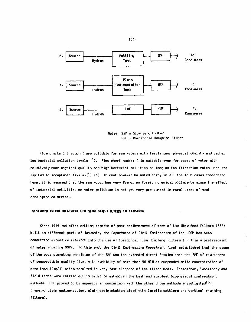
-101-
fi M 2. Source Settling S!r To
Hydran Tank Consumers
Plain
J. Source ~ Sedimentation ~F To
Hydran Tank Consumers
H 4. Source HRf H S!i" To
Hydran Consumers
Note: SSF = Slow Sand Filter HRF = Horizontal Roughing Filter
Flow charts 1 throu:ih 3 are suitable for raw waters with fairly poor physical quality and rather
low bacterial pollution levels (4). Flow chart nunber 4 is suitable even for cases of water with
relstivel y poor physical quality and high bacterial pollution as long as the filtration rates used are
limited to acceptable levels.(1) (2) It must however be noted that, in all the four cases considered
here, it is assumed that the raw water has very few or no foreign chemical pollutants since the effect
of industrial activities on water pollution is not yet very prono!Xlced in rural areas of most
developinq countries.
RESEARCH IN PRETREAlMENT rm SLOW SAN> flllfRS IN TANZANIA
Since lq79 B"ld after qettinq reports of poor performmces of most of the Slow Sand Filters (SSF)
built in different parts of Tanzania, the Department of Civil Enqineerinq of the UD~ has been
condu::ting extensive research into the use of 1-bri 20ntal Flow Ro u:ihinq Filters (HRF) 113 a pretreatment
of water enterinq SSFs •. To this end, the Civil Enqineerinq Department first established that the cause
of the poor operating condition of the SSF was the extended direct feedino into the SSF of raw waters
of unacceptable quality (i.e. with turbidity of more than 50 NTU or suspended SJlid concentration of
more than lOnq/ 1) ltlich resulted in very fast cloqq inq of the filter beds. Thereafter, 1 eborator y and
field tests were carried out in order to establish the best and simplest biophysical pretreatment
methods. HRF proved to be superior in comparison with the other three methods investiqated(3)
(namely, plain sedimentation, plain sedimentation aided with 11111ella settlers and vertical rou:ihinq
filters).
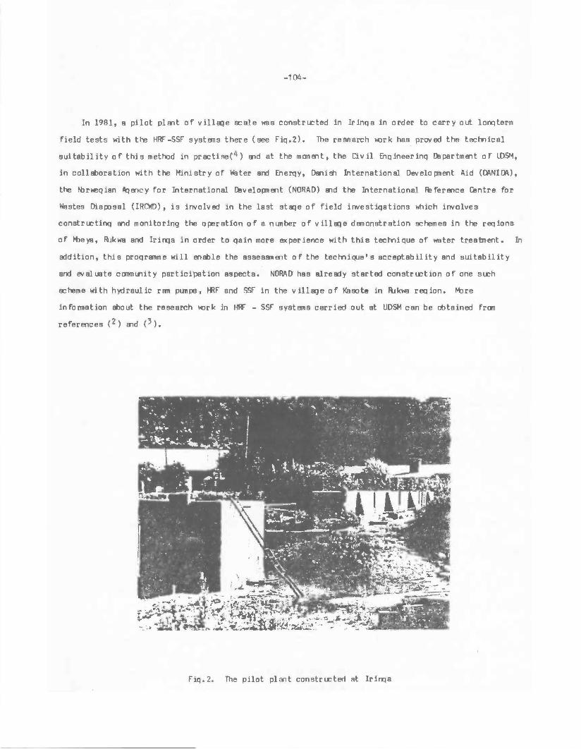
-104-
In 1981, a pilot plant of villa:ie scale was constrLCted in Irinqa in order to carry out lonqterm
field tests with the HRF -SSF systems there (see Fiq.2). The research l«lrk has proved the tecmical
suitability of this method in pr acti se(4) and at the moment, the Civil EilQ ineer inq ll:! par tment of LDSM,
in coll!Eoration with the Ministry of Water and Eiierqy, DS'lish International Developnent Aid (ll\Nlll\),
the ~riegian Pqency for International ll:!velopnent (NORAD) and the International le Ference r.entre for
Wastes DisJXJsal (IRCWD), is involved in the last sta:ie of field investiqations which involves
constrLCtinQ and monitoring the operation of a nunber of villa:ie demonstration schemes in the reqions
of Mleya, lllkwa and lrinqa in order to qain more experience with this tecmique of water treatment. In
addition, this proqramme will en!Ele the assessnent of the tect-nique' s acceptability and suitability
and evaluate community participation aspects. NORAD' has already started construction of one SLCh
scheme with hydraulic ram pumps, Hff and SSf in the village of Kasote in lllkwa req ion, ~re
infonnation !Eout the research l«lrk in HRr - SSF systems carried out at UDSM can be obtained from
references (2) and (3).
FiQ. 2. The pilot plant constructed at lrinqa
-105-
OPTIMAL HlDRAll.IC RAM PE:RFIJltAtcE
It is our idea that for every size of h)tlraulic rams, suppliers should have at hand a set of
charts that will help enqineers to fully utilize the possibilities of the punp. lhis is common
practice for any other type of punps (centrifuQal punps, plU"'lqer punps). Only with such charts in hand
can water enqineers set out to design qood water supply systems with hydraulic r11119. To this end,
since 1976 the Department of Mechanical fnQineerinQ of the raculty of EnqineerinQ and lster the
Institute of Product ion Innovation both at the USIJ.1 have been anal ysillQ theoretical approaches to the
prediction of pump operation. We have been followi.nq the activities of Jendu Plunbers in Arusha who
are competent builders of hydraulic rans of the Blake type. We are aware of the fact that there is
still a lot of scope for improvement and that it is possible to develop a new qeneration with yet
better and truly predictable performance, possibly competitive enou:ih for e1Cport to neiqtnourinq
colJ"'ltries.
EXJERlll\L INPUTS REllJIRED Fllt A CIWTIMMTION IT STARTED WCRK AT Tt£ UNl\IERSITY IT DAR ES SALAAM
Based mainly on he published papers(5)(6) Wiich in our view qive sufficient theoretical
background to the desiqn enqineer for a qood optimization of dimensions, performance and end use, we
formulated a theoretical model in 1980 (1) that to dste has required only limited refinement. An
evaluation of the model requires the use of quite a powerful computer with a plotter, both of Wlich we
do not have.
It is very easy to build a NJrkinq hydraulic ran, but an opt imun design with predictable
perform1r1ce can only be mErle once the full evaluation of a theoretical model has taken place.
THE Tt£DRETICAL MIDEL
ror the followi.nq developnent we assume that the reader is familiar with basic hydraulic ram
theory. lhe symbols used are defined at the end of this paper.
The entire period of s complete cycle of events in hydraulic ram operation is composed of:
a) the period of acceleration of the drive flow from zero velocity to the velocity at Wiich
closure of the drive valve takes place;
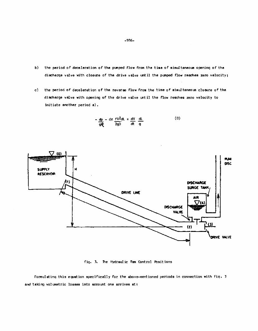
-106-
b) the period of deceleration of the pt.-nped flow from the time of simultaneous openinq of the
discharqe valve with closure of the drive valve until the punped flow reaches zero velocity;
c) the period of deceleration of the reverse flow from the time of simultaneous closure of the
discharge valve with opening of the drive valve until the flow reaches zero velocity to
initiate another periods).
- dp - dz fV2dL : dV dl g~ 2g0 dt g
(O)
H
f"iq. 3. The Hydraulic Ram Control Fbsit ions
OISCNA,_GE ~GE TMK/
AIR (4) t
I
\DRIVE VAL VE
FormulatinQ this equation specifically for the above-mentioned periods in connection with Fiq. 3
and takit'l:l volunetric losses into account one arrives ati
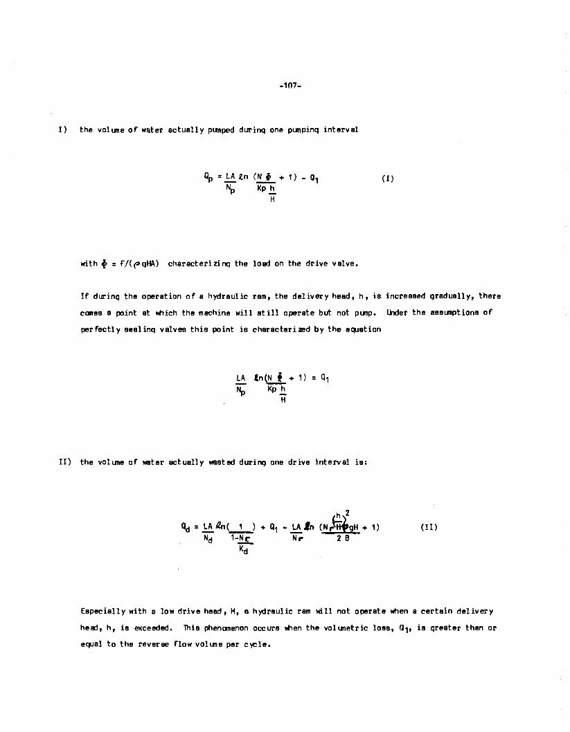
-107-
I) the volune of water actually p1.111ped durinq one punpinq interval
Qp = LA (.n (!!l_ + 1) - Q1 (I) Np Kp .!!_
H
with f : r/((-lqHA) characterizinq the load on the drive valve.
If durinq the operation of a hydraulic ram, the delivery head, h, is increased qraduall y, there
comes a point at llhich the machine will still operate but not punp. Uider the assunptions of
perfectly sealinq valves this point is characterized by the equation
LA tn(!!j_ + 1) = Q1 Np Kp .!!_
H
II) the volune of water actually wastad during one drive interval is:
(II)
Especially with s low drive head, H, a hydraulic ram will not operate when a certain delivery
head, h, is exceeded. This phenanenon occurs Wien the vol unetric loss, Q1, ia qreater then or
equal to the reverse flow voltme per c~le.
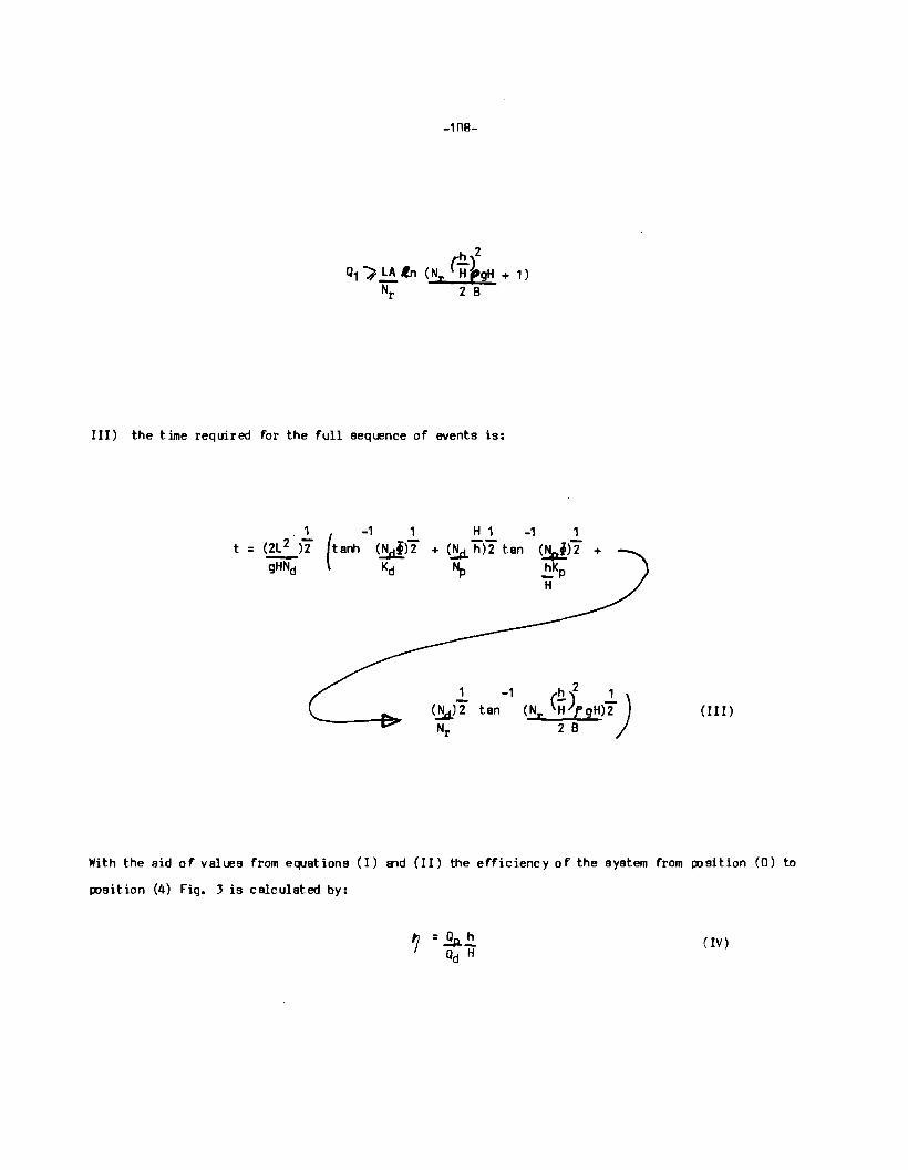
III) the time required for the full sequence of events is:
1 ( -1 1 H 1 -1 1 t = (2L 2 ff tanh (Ndtff + (~ "h)2 tan (Npiff +
gHNd Kd Np .!!_Kp H
(III)
With the aid of values from equations (I) and (II) the efficiency of the system from position (0) to
position (4) Fig. 3 is calculated by:
(IV)
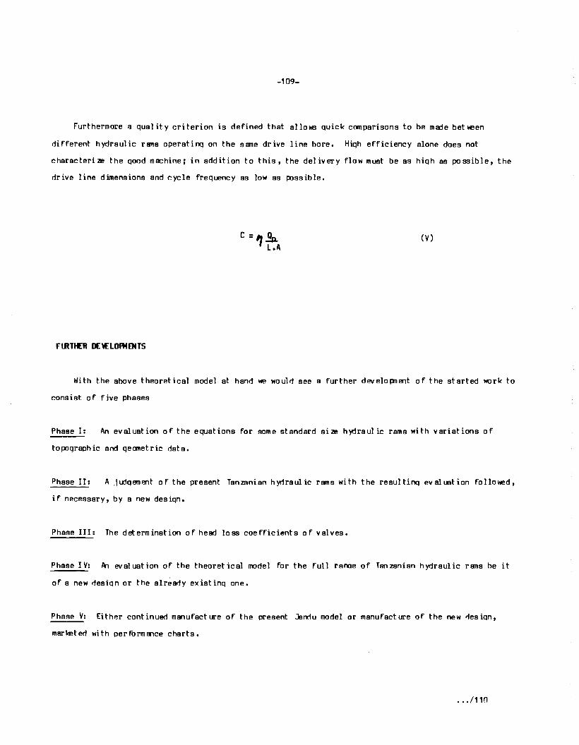
-109-
Furthermore a quality criterion is defined that allo~ quick comparisons to be mer:le beheen
different hydraulic rans operat.ino on the sane drive line bore. Hiqh efficiency alone does not
characterim the qood machine; in addition to this, the delivery flow must be as hiqh as possible, the
drive line dimensions and cycle frequency as low as passible.
(V)
FlRTtER D£\£LOff4ENTS
With the above theoretical model at hand we woulri see a further developnent of the started work to
consist of five phases
Phase I: An evaluation of the equations for some standard sim hyrlraulic rams with variations of
topaqraphic and qecrnetric data.
Phase II: A .iudq!'fllent of the present Tanzanian hyrlraul ic rams with the resultinq evaluation followed,
if necessary, by a new desiqn.
Phase III: The determination of head loss coefficients of valves.
Phase IV: A-1 evaluation of the theoretical model for the full ranoe of Tanzanian hydraulic rans be it
of a new riesion or the alreariy existinq one.
Phase V: Either continued manufacture of the present Janrlu model or manufact.ure of the new rlesion,
marketed with performance charts.
.. ./110
-110-
As already stated above, we are not in the position to do the evaluation work in Tanzania. We are
fully aware of the fact that this involves pure donkey l«lrk anrl we l'lluld qladly do it if we had the
riqht computer at our dispasal. How rewerdinq the expected results would be, is rlemonstrated in Fiq.
4 to 9 which compare the values of"f/, C, 'f, i , 9P' ft for ht> hydraulic rams on a 3-inch drive
1 ine and a 3-inch delivery valve. One ram has a 4 1/4 inch the other an fl 1/2 inch drive valve.
9:rikinq is the short drive line on the latter and the slhstantially increased performance for points
on the max-2% line. The fiqures are a result of a tedious effort to proqramme the theoretical model
on an electronic calculator and finally to plot the results manually. Since the performance of a
h)'tlraulic ram depends on the Re~olds nunber the evaluation for Riase I would have to be undertaken for
say a 3/4 inch and an 8 inch drive pipe by:
- var yi nq H from H = 1 m to H = 20 m
- varyirri Ap/A fran AplA 1 to Ap/A
var yinq !\ii A from !\ii A = 1 to !\ii A = 20
and plottinq ?(L h/H), C(L h/H), l(L h/H), i(L h/H), fp(L h/H), 't (L h/H)
- with L from L = H to L = lOOOm
- with h from h = H H
to h = 100 H
- with { varyinq at any point (L h/H) to maximize efficiency.
lhe judqement in Riase II l'lluld then allow the sane evaluation to take place in Riase IV with
selected values of Ap/A, Ad/A. Whereas, in Phase I any sensible value of valve loss coefficients would
serve the purflJse, true measured values from Phase III l'lluld be inserted for Riase IV.
• •• /111
-111-
COC:WSIONS
1. From the point of view of water supply design, the engineers are only awaitinQ a h)tlraulic ram
with established performance data ao as to confidently incorporate it in their schemes.
2. The theoretical model for hydram optimization and performance predicition is ready for
evaluation. This evaluation cannot be done in Tanzania for lack of sufficient computer capacity.
J. Given a sponsor for the evaluation desiQn work on a new Qeneration of rams with true performance
data, the work can be undertaken and designs placed at the disposal of water engineers.
-112-
REfEREM:ES:
1) "Slow Sand Filtration for r.ommU"lity Water 5.Jpply in l:evelopinq lliU"ltries", A Desiqn and
r.onstrtEtion ~nual. Technical paper 11, ( 1978). IRC/WHO, The Ha:iue - The Netherlands.
2) WEG.IN, M. and M3WETTE, T.S.A. (July 19A2). "Slow Sand Filter lesearch Project Report 3".
Research report CWS 82. 3, lhiversity of Dar es Salaam - Tanzania.
3) WECELIN, M. (July 19AO). "Slow Sand Filter Research Project Report 2". Research Report CWS 80.2,
lhiversity of Dar es Salaam - Tanzania.
4) M3WETTE, T.S.A. (October 1983). "lbrizontal Flow Rot.qhinq Filters for l\Jral Water Treatment in
Tanzania'', M.Sc. Thesis, Lhiversity of Dar es Salaam - Tanzania.
5) IVERSEN, H.W. (June 1975). "Pn Pnalysis of the !-¥draulic Ram", .burnal of Fluids Enqineering
(Transact of the A9'1E), pp 191 - 196.
6) KROLL, J. (1951). "The ~tomatic !-¥draulic Ram", Institution of Mechanical Enqineerinq
Proceedirqs, Vol. 165, !lb. 64, pp 53 - 73.
7) PROTZEN, E. Th.P. "A Proposal for Simple PerformEnce Predicition of the !-¥draulic Ram" Internal
Technical Report Available from IPI, LIS[).1.
8) STARMER, c. (MARCH 1981). "Blake's !-¥dram or The Rise and Fall of the !-¥draulic Ram, CME,
pp19-21.
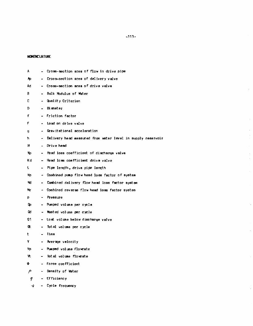
-113-
N(J40ClATlRE
A
~
Ad
B
c
D
f
F
q
h
H
Kp
Kd
l
Np
~
Nr
p
Q:>
()j
Q1
Cl:
t
v Vp
Vt
~
f>
t'/ -v
- Cross-section area of flow in drive pipe
- Cross-section area of delivery valve
- Cross-section area of drive valve
- Bulk H:idulus of Water
- Quality Criterion
- Di aneter
- Friction factor
- Load on drive valve
- Gravitational acceleration
Delivery head measured from water level in supply reservoir
- Drive head
I-bad loss coefficient of discharqe valve
- Head loss coefficient drive valve
Pipe lenqth, drive pipe lenqth
- Combined pump flow head loss factor of system
- Combined delivery flow head loss factor system
- Combined reverse flow head loss factor system
Pressure
- Pumped volune per C)'Cle
- Wasted volume per cycle
- Lost volune below discharge valve
Total volune per cycle
- Time
- Average velocity
- Pumped volume flowrate
Total volune flowrate
- Force coefficient
- Density of Water
- Efficiency
- Cycle frequency
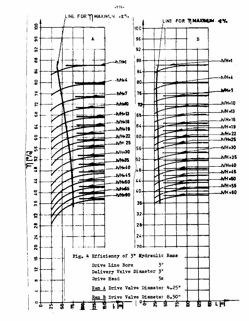
0 52
co
°' N O'I
co co
... cm
0 CID
'° ,...
~
GO
'° ... co
0 co
I
~.,, I .. !:.~ F. ... I ... ... I 0 i ... I
\
co ,.,,
I ... I ""
• N . -·
... N
0 N
co -N -CID
~
0 0
-114-
L INt. F 01~ 11 MAX IM;..'V• -2 •;. I I Ito I
LINE" FOR "fl flt..,_.. · .. .,. J
·-·
I
0
A. 9 6
...... r·- 9 2
/Hsi s
84
·-Mis4 8 0
7 6
-... 6 &
6 4
6 0
5 ti.JO I
~ 6
2
(: 6
4
\ 4 0
... ... 3
3 2
.. -. 2
2 4·
I i
' i -
....-t--l I I
~ ---r-.. ,,,_,,,---~ ,.,,,,,. -... ----"' .......... ~ -
""'......-:: ,__......
---.,,.
--- ---i.,. ......... ~
-~ ...-:-i..---
~ -· ~
~ , .,,_. --~.,,..
-
--
. -. l- ·-· I? 0- ----4---
Fig. 4 Efficiency of 3•
Drive Line Bore Deliver1 Valve Di Drive Head
Ram A Drive Valve
Valve
I
H;rdraulic Rame
3'' ameter 3"
511:
Diamete1· 4.25"
Diamete1· 8.50" 0. .
b t(l ~ "' ~
B
h/H•1
h/H.s4
...... ..,;;,
.. /Hs10
.M•13
Hs16 -
L.'H•19 ..,,...22
~
.. ,Han
- h/Hc30
.. ,,.'H aJS
- ~.,H•40
....~.45 ....... _, .. •55
.... _~alO
:a l~ IS Lt'(
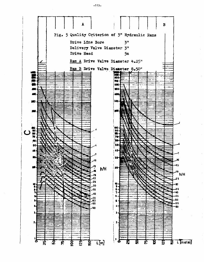
-115-
i i j. !
I I
I
... • I --to
I • iU '° I " I ,to
·IO .. --
Fig.
LL-----...:.. -r;- -··-
- .
- '• --. . -.. . -.. . ., .. -·· ·' "" \! .... --· ~ ---~ - -. - .
....... .c:i. --......... ,,--....-' ... ...... ' ' .. .... 1 ' ' '
n. ....
-----.. _.. ·-
A
5 Quality O~te
Drive L:tne Bo Delivery Valv
Drive Head
Ram A Drive v
Ram B Drive v
---
-- .. ..........
" ----.... --~ --- ..
.... ..... ' --
--- .,
'&fi,~ . -• 'rJillS ";-#
~~·· .. ...,...10 '• --= ·~ ,, • --- .
~ct ..... ~ .,..... - -~ -. - ·- - ~. 9 - - - -~ ... , ...... u. - ~2 - - ..... -~- -- ..... .... - - - -~5 IO ... ""'-- ...... ~ ~ .....
• JI)
• - ~- ~ ·~-- ... is
' .~ ,.40 . ~+ -~ " 'I .... ~
I I I I
rion o f 3" H;rdraulic
re ;" e Diam eter 3"
5m · ameter
i&lleter
alve Di
alve D
4.25"
8.50" . --·r· .. .. --------IOO·
. - --100
r--- . -- --- --·-110 ~:- -- ------- -
-~ --- . (~._
~ -·-, .... --· ~ 1r.·-
' . -I . ' . .
-t-
I . .
•• ... i ..
I ' .. ,, it00 ' ... " I IO - ~
i• - .. 1·-- -:L.: ... .... I ... . ... -I~:
.. ' ' 1 .. ' ' " ' ,, -, . '0
, ..... - . ' . -I
h/H lit i -I - -- - -- - -...__
i - .. ............. ""'
"",~
I IO "' """" "' t ---- -1 • I --
B
Rams
i------- - ..... ---·- .. .. ------ ----
···-...,_ __ ----
-· ...
----·---...... ---- ·---
--
-- -" " ........
-~
-- -,..,.. ..... -............. .... ..
...... .... ....... --- , ,
- -i , -- .... 1 • .... ..... -
"' ..... -
__J,
-7
-10
;3
-'' h/H ~s
SI
-s 'O 45
-- -'S . - ........ ....... AO I -so ,. ...... ......
9 --- . .... 55 . - - -~-
·- _;50 ... - -- ,__
I 55 I
' '° I i .. --- ---
I~ - --.. I ) - -- - -I ~
-2 ..
-- ----- ,_ ... -- ,_
··- -·--
I ·- ·-i 2 I
I __ ,_
-- ---- ~- --- ---- ·-· --- I 1
I -- -· ·--- --0 a., . )
I~ Cl ~ Cl L~ ~ '.I() Cl - - I • 4
·-·
it lrll B ~ ts N l ~ L]matcrJ ~ -m]
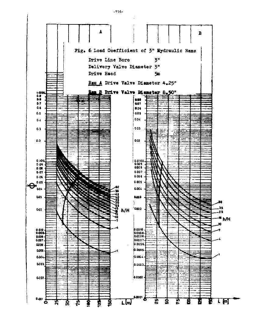
Fig.
0.1.
0.3
-116-
A
1 B
6 Load Coetticient of ~" B;rdrauli c Rams
Drive Line Bore 3" Delivery Valve Diameter 3" Drive Bead 5m Bp .A Drive Valve Diameter 4.25"
0.05 - ..... -==-=:f:-=·-·- ~---== t::-:_ t:..,__ .. _:._- ·- -
o.ol -1o----
002 --- ----- __ ,_
·- ·----------i . -::~~--·~=--: -~··==:i==:l --- ~-.-,j, ---t---i
·-. --~--~-,...._
I g:gJ~O:f=~a:~'' r·. _.:.:. ·.~~- -o.ooa ~--=-~~~:1r\rt--1:..:....:::..:i:.::::::~~::::::a==~ 0.001 -· l ~ \:J ""' ·- -------0.001 _ =-- ~ . ,~ r~-=::.. ___ + __ ,___
~, \~' ,~. ---···· -o.oos - ---L..: . - - ··-
'·0402
~=\: --;~-- ~ - -~_ .. -_, ·-· - ·-~.~
o.oou1.= · _ ~ -~=~ '"'" - -0.0001--:::- :\.~ ..:.::;__; ,_~· .. ~t O.OC:>I ::::::::-_ -~~ :-:~-·-
0.000?- --- --- .:----· - ...-4 o.ooo~ --- ·· · · · ·~ ------=
---. ---ooos---.... _-__ -,--__ ~ -- r~~-~i-~-~;E~g
0.~4 =:- -~~~ ----~~---·- -= -~. -10.0003 =· --~.....::= ···--~- ---= ~=-~: :==:~.=:l::;:=a
=..:-.=~- • -c~::= .=-
I ·-·- . -··-~- ·- . ··-loo-- ·-~- ..::. ··- •• :- .• -
lo.ooo:z -- -· ·--- -::-::: ---:.~,__ l ~ ~- - ' -·- ---··-- :~--
- . -~-- --·- t--· - ~------ .... ·-·-9'----c --- ---··· ···-·- -----t"------c -· -· --· ·---- - - --•-----<I-------- ..
I l I J L tnl
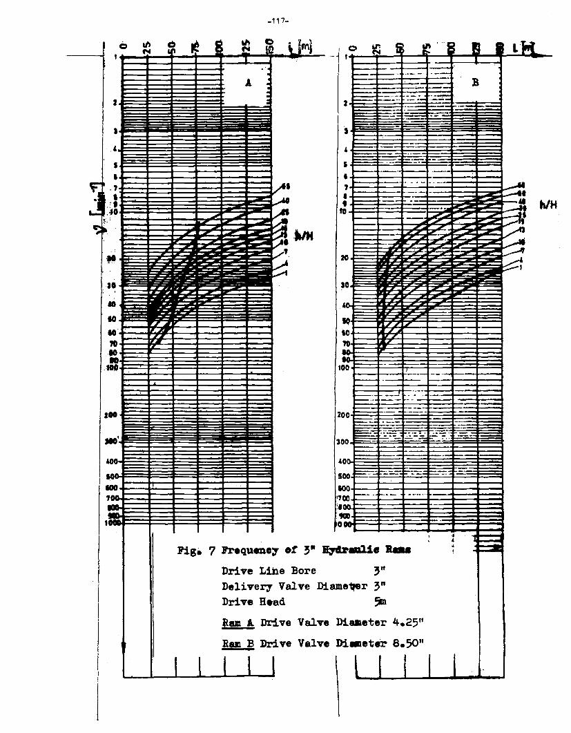
-117-
I 0 th ~ ~ 1~ "' C>
\ ~· N ~ l • I I ... .
A . . . 2 . ~
•• i ~
·' I
' ·' • • >• .M
.JO ..- -.. ; .A
. ~ - -~ ~~~·"" ~ • '· ~ H .
ill • '° IG , ----70 -IO • . ,. .
I .. I ~
400
so: IOO .,--~
::::...;,:.
1 ~~~
Fig• 7 Frequeno1 ot ~·
Drive Lihe Bore
0 ~ i1 J~ ... B I I LM
I I . ·-· .. ·--· -- ·--. - B --- ·--.
2 - ~--·· :=:- ----. ·--- ---= -·--=- :..:....-= "':"';... ---~ 1 -
-· -- - ·--4 -- . ------ ... ·---s ·--- --·
·-·· ..
' - . - .. -.. - __.. ' • - . - ---!I
' - ... - !I 0 - -·· •f - -~ --- ~ - -- :::;...K
t
,6 - -- - -. - -~ ~ . -20 i Ir 10 ~- ~ ~ - -4:
IO
'° -_ ... .;::::
00
2 00
3 00
o: 4
s IO .,
00
0 00 ·---~
:1 :a 0
..
I I ,, -~ "7 -
- -- -
-·-..... ___
--- ·---· ------ --- .. - --- ·-· - -
-
t::=:=:-:::.: -·-....__. .,_ ___ --
--~ ~
~
T .... __ ,.._
···-· . .. -.. ---·- --
--··-:;,_
~:..--:..=
----··
-
-.U• .... 3"
~
·-
--···
·-·
- ·---- ·--.... -::::_:--.. -. -
. ~-::-:: --·
-
. .j
• • 1
Delivery Va1ve Diam e1'er 3"
I I
Drive Head
Mam A Drive Valv
Ra11 B Drive Valv
I I l
e Di
e Di
"1
aaeter 4.25"
•eter 8.50"
l I I I I
hi H
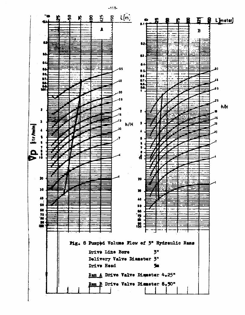
-11 B-.... ,~ ~ "2 g ~
~ l lh ! N -- - J .. n It .,, I 1f"" t I L}neterJ .............. .,.. ......... _ .... _..,_,..._,._......;;. .. ~..;;..J.
. .. ·--
-· - -
•• -- ·-· .. -- . . - - ----... ------i..-- ·---- ·-., - -- ·--- --- -··-:.z: -- . - ·-·-....... . ... ·- - ... - _.;~ -.... . .... . -=*' .. ·- ,,_,,_ -
I
-.-:: ... -
" A . . -
·- ,....__._ - -- SS
-~
·- 0 ·-··-
......... JO --- .. -
~
,,-: . . ~
~21 . .. ,,
,,
. B .
--- --- ·:: .. = ~=-- .. ... ~ . --····. -- ··-·- ·-.., __ : ---· - ~~. - -- .. -:-: -.::.: -- --=:-~· .. : . : .... : ·:-:::- : ··-. ~=--f
~~~~!::~~-~:~·~-~~:~:~·~~~·~~~-~~~-1-!!!! - . :.-: .., ·- ....:..:::.· ·:::: -- - ---· -· ·-
-- -------· --... ----= .. --·- - ·-·-··- - .. - -·-- ·- -· ~ ---- - •. .••• . 1-- ... -....---- - . - ---· - ~ . ... - . ·--·· - . -· . ·-- .. . - --·t---:::::--~-c ... . .. . - . ·-· ------+ .... ---+---4
i7~~~~-~:.:__~·~-~-~--~-~-~~~·-~-:.-~r:~--~--~~~-~==· ..... =-:-~.:::::.. __ :-.... ~- . •• -- - . ···-.JC- - .-15 t __ ,,,
t---l~•,,.'-t . . ... _, !..--- ~ ,.._·: -·~ ~·-···· ~----i
. :. ::ii! ==-. - - IE-=-=. . - -·- ---~- ~ 13 . ·--h/ H - ... - -
0 ,..-. .:,:. ..
··- . ---~ .:~~- /' - -- -
c
l ' .. I .. .-. I
r -·· ~------ -~ ~ ' 0.: -
" -- - . .. ~ - -- ~-- ---... ..--.. .. -·
-
I 0-~ • 0 . . • ' • .. 0 ' ... ... -.. •
-
._
..
-
:Hg. 8
t j
•
'° 10 ------
-'-<1--. - ~ -+----t---t---4 ... ....--+----+---4---t--....... ---t
·= '·- _i:=_E---~1--~·-~~--00 E -------
-·-- --·- ---- --
Pmap'4 Voluae n ow ot 3• ~aulic Ram•
l>r1v• Liile Bore 3" DeliTery Valve Diaaeter 3" Dr:l.Te
Ram A .Ram a
-
Bead
J)riTe
DriTe
,. Valv e D:l.apaeter 4.25"
• Di••t•r s.'°" Valv l I f I I I I
h/H
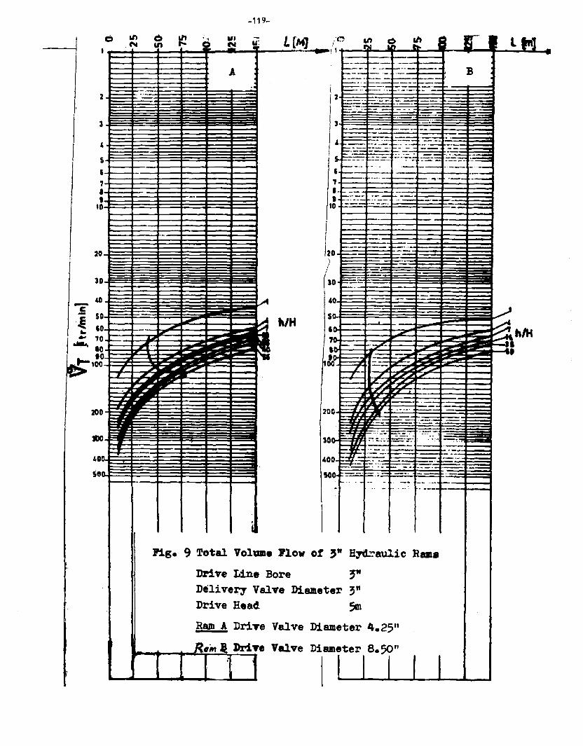
2
3
' 5
' ., • t
tO
20
JD
9¥ .@ 50
~ U'a
,...__ ,_ __ -··-·-
-
-
.. 60 .. 10
.-.. IO -~ ~
t- to 100
200 .
1.0
se 0
"
-·
I -, --..
--.
--
-119-
• .... .,, "' n ~ i
A ' . ..
~
--
15 ...
~ ~ ~
iMt .. --
- ~
. I
h/H
lo------- t--- ---~--..,.
~-··----~---to---••
~-- - ·-· ----------~-- -·-..-.---~ ... ·----1'-----P"-"--
t :::::=-:.:.-~- ".':"' ~-~:=- - ::-r-12 ··~--- ---...._ . ---~--·· ·--- -~-
·--· ... - --· ,..._._
- ·- ·- ..
B . '
' ~ -· - .. -__ · ·-· t.:: -·= ·-··-== -· I ~-- - - -·..-- - - ---~--- __ .,_._ -'"'~~~-=-=- ;;:. .. ~;-: ::.~-= :-:~r-::== ----- ·--- ----·- -----, ___ _._ __ -4 ---t---+·--t---
, .... -__ . - ·--..t.::.::::~.=--·-~-· +-. -·--+---~
11----1-- ---4~-t-- - -·-----t : ----- ·--lzo_:::=---
') --~-·
I JO - ...: --40-·- ~- ----- ..
so .
• . r-~ - .. ·-·- . 200 ~- .'--- ....
. :z~h/H i~~;
.• "'--:--=--~ ··- . ·- ·-·----- .. - -- - - - ., -=-- i:=::.:=7'. ··~- . . ~ 10· __ .. _____ ·····1....,.,.--~-
- .... -··- :.: _ ___:_ .~:.:... __ ~ t:" -:::..: .:;:J:-:=-:'.. _:::r_~_::::T_ ·-
400 == -= =- - . -. ,... ·-- -- -·-·--· -- -· ·- - -- -.. --- -soo ==.;-
.__ . . . - ~.. . .. -- ..... ,.--+----t ... - ... -· . ---- t--·-+--...
Pig. 9 Total VolUllle J'lo w of 3" H~au1ic Rams
Drive Line Bore Delivery Valve Drive Head.
~ Diameter 3"
5m Ram A DriTe Valv e Diameter 4.2511
e Diameter a.50" R•wt l J>riTe Valv '. I I I f I

Tmzania
- 120 -
HYDRN4 ~KSHCP PARTICIPANTS
Mr. William A. Baynit Sociologist Centre for Agricultural Mechanization and Rural Technology (CAMARTEC) Box 764 Ar us ha Tanzania
Mr. Apollo T. Bwojo Mechanical Engineer Water Resources Institute P.O. Box 35059 Dar Ea Salaam Tanzania
Mr. S.S. Jandu Jandu Plunt>ers P.O. Box 409 Arusha Tanzania
Mr. A.N. Kaaya CAMARTEC Box 764 Arusha Tanzania
Mr. S.A. t4:iwette Faculty of Engineering Department of Civil Engineering Box 35131 University of Dar Ea Salaam Tanzania
Mr. L. Ms int>e Research Engineer Ministry of Water, Energy and Minerals Box 9153 Dar Ea Salaam Tanzania
Mr. A. Mzee Chief Maintenance Engineer Ministry of Water, Energy and Minerals Box 9153 Dar Es Salaam Tanzania
Mr. E.M. Ngaiza Director-General
CAMARTEC Box 764 Arusha Tanzania
TMZANIA (cont.'d)
Uganla
Zamia
CMADA
Mr. E. Th. Protzen Technical Manager
- 121 -
Institute for Production Innovation University of Dar Es Salaam P.O. Box 35075 Dar Es Salaam Tanzania
Mr. Alexander Schlusser CAMARTEC Arusha Tanzania
Mr. David Tulapona CAMARTEC A rush a Tanzania
Mr. Patrick KaharY,;1ire Hydrologist Ministry of Lands, Minerals and Water Resources Box 19 Entebbe Uganda
Mr. Robert Kilama Mechanical Engineer Ministry of Lands, Minerals and Water Resources Box 19 Entebbe Uganda
Mr. V. Liyanage Senior Project Engineer TechnolOQy Development and Advisory l.hit (TDAU) Lusaka Campus The University of Zambia P.O. Box 32379 Lusaka Zambia
Mr. James Chauvin Program Officer International Development Research Centre P.O. Box 8500 Ottawa, Ontario K1G 3H9 Canada
Mr. Alex Redekopp Senior Program Officer International Development Research Centre P.O. Box 8500 Ott awe, Ont er io Kl G 3H9 Canada
Dr. Eric Schiller Civil Engineering Department University of ottawa Ottawa, Ontario K1N 9B4