USTL-230/734 INSTALLATION MANUAL - Kleinn Air Horns
33
USTL-230/734 INSTALLATION MANUAL REV: C (6/25/2021) © Kleinn Air Horns 2021, All Rights Reserved PO Box 91278 Tucson, AZ 85752 Phone: (520) 579-1531 Web: https://www.kleinn.com
-
Upload
khangminh22 -
Category
Documents
-
view
3 -
download
0
Transcript of USTL-230/734 INSTALLATION MANUAL - Kleinn Air Horns
USTL-230/734 INSTALLATION MANUAL
REV: C (6/25/2021)
© Kleinn Air Horns 2021, All Rights Reserved PO Box 91278 Tucson, AZ 85752
Phone: (520) 579-1531 Web: https://www.kleinn.com

USTL-230/734
Kleinn Air Horns
INSTALLATION MANUAL
Go to Table of Contents REV: C (6/25/2021) 2
This digital PDF is interactive
Please save ink and paper…
Open interactive manual using Adobe Reader ®
on PC, Mac, and smart devices
USTL-230/734
Kleinn Air Horns
INSTALLATION MANUAL
Go to Table of Contents REV: C (6/25/2021) 3
Table of Contents 1 How to Use This Manual ....................................................................................................................... 6
1.1 Interactive Manual Using Adobe Reader ...................................................................................... 6
1.2 Your SKU Number & this Manual .................................................................................................. 6
1.2.1 USTL-230 or USTL-734 .......................................................................................................... 6
1.3 Illustration/Photo Details & Orientation ...................................................................................... 6
2 Safety First ............................................................................................................................................ 7
3 Application Chart .................................................................................................................................. 8
3.1 Bolt-On Vehicle List ....................................................................................................................... 8
3.1.1 Full-Size Trucks by Generation .............................................................................................. 8
3.1.2 Mid-Size Trucks by Generation ............................................................................................. 9
3.2 Known Fitment Issues ................................................................................................................. 10
3.2.1 Newer RAM Trucks .............................................................................................................. 10
3.3 Excluded Vehicles ........................................................................................................................ 11
3.4 Aftermarket Product Compatibility ............................................................................................ 11
4 Installation Overview .......................................................................................................................... 12
4.1 Kit Layout & System Location(s) ................................................................................................. 12
4.2 Install Process Outline ................................................................................................................. 13
4.3 Approximate Installation Time.................................................................................................... 13
5 List of Tools & Supplies ....................................................................................................................... 14
5.1 Standard Tool List (Required) ..................................................................................................... 14
5.2 Special Tool List (Recommended) ............................................................................................... 14
5.3 Shop Consumables List (Recommended) .................................................................................... 14
6 Parts List .............................................................................................................................................. 15
6.1 Review Parts List ......................................................................................................................... 15
6.2 Pre-Packaged Electromechanical Kit Items ................................................................................. 15
6.3 Air Fittings & Related Items ........................................................................................................ 16
6.4 Electrical Components & Related Items ..................................................................................... 17
6.5 Mounting Brackets & Special Hardware ..................................................................................... 17
6.6 Hardware, Fasteners, & Soft Parts .............................................................................................. 18
7 Test Fit USTL* ...................................................................................................................................... 19
USTL-230/734
Kleinn Air Horns
INSTALLATION MANUAL
Go to Table of Contents REV: C (6/25/2021) 4
8 Bench Assembly .................................................................................................................................. 20
8.1 Assemble Air Fittings to Air Tank ................................................................................................ 20
8.2 Assemble Air Filter to Air Compressor ........................................................................................ 21
8.3 Attach Threaded Rod to USTL Structure ..................................................................................... 21
8.4 Assemble Kit Components to USTL Structure ............................................................................. 22
8.4.1 Assemble Air Horns to USTL Structure ................................................................................ 22
8.4.2 Assemble Compressor to USTL Structure ........................................................................... 22
8.4.3 Assemble Tank to USTL Structure ....................................................................................... 23
8.4.4 Adhere Rubber to USTL Structure ....................................................................................... 23
8.4.5 Install Snap-In Caps ............................................................................................................. 24
8.4.6 Attach Leader Hose to Tank & Route Air to Horns ............................................................. 24
9 On-Vehicle Mechanical Assembly ....................................................................................................... 26
9.1 Remove Spare Tire ...................................................................................................................... 26
10 On-Vehicle Electrical Installation .................................................................................................... 27
10.1 Relay & Fuse Diagram for Air Horn System ................................................................................ 27
10.2 Disconnect Vehicle Battery(s) ..................................................................................................... 28
10.3 Connect Wires to Fuse & Relay ................................................................................................... 28
10.4 Install Horn Button ...................................................................................................................... 29
10.5 Connect Pressure Switch............................................................................................................. 29
10.6 Connect Air Compressor ............................................................................................................. 29
10.7 Connect Air Horn Solenoid(s) ...................................................................................................... 29
10.8 Raise USTL Assembly into Final Position ..................................................................................... 30
10.9 Secure Wiring to Vehicle ............................................................................................................. 30
11 Final Steps & Testing ....................................................................................................................... 31
11.1 Reconnect Vehicle Battery(s) ...................................................................................................... 31
11.2 Test Air Compressor .................................................................................................................... 31
11.3 Test Train Horns .......................................................................................................................... 31
11.4 Test Quick Connect Coupler ........................................................................................................ 31
12 General Operation .......................................................................................................................... 32
12.1 Compressor Operation ................................................................................................................ 32
12.2 Horn Operation ........................................................................................................................... 32
USTL-230/734
Kleinn Air Horns
INSTALLATION MANUAL
Go to Table of Contents REV: C (6/25/2021) 5
13 Routine Maintenance ..................................................................................................................... 32
14 Warranty Information ..................................................................................................................... 33
END OF TABLE OF CONTENTS
USTL-230/734
Kleinn Air Horns
INSTALLATION MANUAL
Go to Table of Contents REV: C (6/25/2021) 6
1 How to Use This Manual
1.1 Interactive Manual Using Adobe Reader It is recommended to open this digital PDF using Adobe Reader® to take advantage of following key features:
• Hyperlinks (blue underlined text) allow access to additional content via internet; click/tap to activate. Hyperlinks also allow users to jump to specific spots in within the document.
• Includes Installation Figures and “Figure xx”
• Table of Contents page allows easily navigating this manual; click/tap any section line to go to it
• Bookmarks allow quick navigation to any section; click/tap
• Zoom IN on pictures by pressing “CTRL and +” at same time on PC, or pinch in on smart devices
• Zoom OUT on pictures by pressing “CTRL and -” at same time on PC, or pinch out on smart devices
To Download & Install Adobe Reader®
On PC or Mac:
• Visit https://get.adobe.com/reader/otherversions/
On Android/iOS, and Windows devices:
• Visit https://get.adobe.com/reader/otherversions/
1.2 Your SKU Number & this Manual This manual covers installation, testing, and operation of the following SKU part numbers
1.2.1 USTL-230 or USTL-734 NOTE: Illustrations and pictures contained herein may represent only one kit part number.
Where critical differences exist between kits, (i.e., different parts, orientation, mounting points,
etc.) additional text, or necessary graphics are provided to minimize confusion.
Parts list explicitly state kit differences with (BOLD TEXT) inside parenthesis, shown below part
number
1.3 Illustration/Photo Details & Orientation This manual may use digitally created illustrations and/or actual photos of example vehicle. These graphics may not include exact items found on your vehicle (i.e., electrical wiring, fuel lines, body panels, etc.). Illustrations typically will be missing details and are for clarity to show critical mounting locations and orientation on vehicle.
Throughout the manual, yellow arrows with text reading “FRONT” may be present over illustrations and pictures. These arrows specify direction toward the front of the vehicle and provide clarity as to how illustration is viewed.
END OF SECTION
FRONT

USTL-230/734
Kleinn Air Horns
INSTALLATION MANUAL
Go to Table of Contents REV: C (6/25/2021) 7
2 Safety First Read this manual thoroughly before starting installation of this kit. Verify that you have all of the parts
listed, and that you clearly understand the installation procedure. Contact Kleinn technical support with
any questions.
Installation of this kit requires moderate mechanical aptitude; seek professional help if you’re not
competent using hand tools in tight uncomfortable spaces and around possibly rusted and sharp vehicle
parts.
Before starting, obtain proper tools required to perform installation correctly, adequate lighting, eye
protection, hearing protection (for operating train horns), and hand protection to guard against sharp
edges and metal burrs which may be present on kit parts and/or vehicle parts.
Throughout this manual the following words may be used; be aware of their meaning and application.
CAUTION: means damage could occur to vehicle or kit parts during or after installation.
WARNING: means injury could occur to you or others, including damage to vehicle or kit parts.
DANGER: means serious injury or death could occur to you or others during installation.
END OF SECTION

USTL-230/734
Kleinn Air Horns
INSTALLATION MANUAL
Go to Table of Contents REV: C (6/25/2021) 8
3 Application Chart
3.1 Bolt-On Vehicle List The USTL structure has been designed as a universal kit to fit many makes/models of trucks. This kit
replaces the spare tire. The following trucks have been verified to be compatible with the USTL.
3.1.1 Full-Size Trucks by Generation
Generation Make Model Fitment Confirmed On GM
1988 - 2000 Chevrolet/GMC C/K1500 TBD
1999 - 2006 Chevrolet/GMC 1500/2500/3500 11/27/2020
2007 - 2013 Chevrolet/GMC 1500/2500/3500 11/30/2020
2014 - 2018 Chevrolet/GMC 1500/2500/3500 11/27/2020
2019 - 2021(+) Chevrolet/GMC 1500/2500/3500 3/3/2021
Ford
1987 - 1991 Ford F-150/F-250 TBD
1992 - 1996 Ford F-150/F-250 TBD
1997 – 2003 Ford F-150/F-250 TBD
2006 - 2008 Lincoln Mark LT 11/27/2020
2004 - 2008 Ford F-150/F-250 11/27/2020
2009 - 2014 Ford/Lincoln F-150/F-250/Mark LT 11/30/2020
2015 - 2020(+) Ford F-150/F-250 11/25/2020
Dodge
1981 - 1993 Dodge Ram 150/250/350 TBD
1994 - 2001 Dodge Ram
1500/2500/3500 TBD
2002 - 2008 Dodge Ram
1500/2500/3500 11/30/2020
2009 - 2018 Dodge/Ram* 1500/2500/3500 11/27/2020
2019 - 2021(+) Ram* 1500/2500/3500 TBD
Toyota
2000 - 2006 Toyota Tundra TBD
2007 - 2021(+) Toyota Tundra 11/27/2020
Nissan
2004 - 2015 Nissan Titan 11/30/2020
2017 - 2021(+) Nissan Titan/Titan XD TBD
USTL-230/734
Kleinn Air Horns
INSTALLATION MANUAL
Go to Table of Contents REV: C (6/25/2021) 9
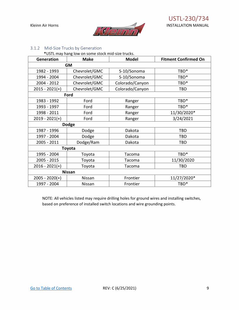
3.1.2 Mid-Size Trucks by Generation *USTL may hang low on some stock mid-size trucks.
Generation Make Model Fitment Confirmed On
GM
1982 - 1993 Chevrolet/GMC S-10/Sonoma TBD*
1994 - 2004 Chevrolet/GMC S-10/Sonoma TBD*
2004 - 2012 Chevrolet/GMC Colorado/Canyon TBD*
2015 - 2021(+) Chevrolet/GMC Colorado/Canyon TBD
Ford
1983 - 1992 Ford Ranger TBD*
1993 - 1997 Ford Ranger TBD*
1998 - 2011 Ford Ranger 11/30/2020*
2019 - 2021(+) Ford Ranger 3/24/2021
Dodge
1987 - 1996 Dodge Dakota TBD
1997 - 2004 Dodge Dakota TBD
2005 - 2011 Dodge/Ram Dakota TBD
Toyota
1995 - 2004 Toyota Tacoma TBD*
2005 - 2015 Toyota Tacoma 11/30/2020
2016 - 2021(+) Toyota Tacoma TBD
Nissan
2005 - 2020(+) Nissan Frontier 11/27/2020*
1997 - 2004 Nissan Frontier TBD*
NOTE: All vehicles listed may require drilling holes for ground wires and installing switches,
based on preference of installed switch locations and wire grounding points.
USTL-230/734
Kleinn Air Horns
INSTALLATION MANUAL
Go to Table of Contents REV: C (6/25/2021) 10
3.2 Known Fitment Issues
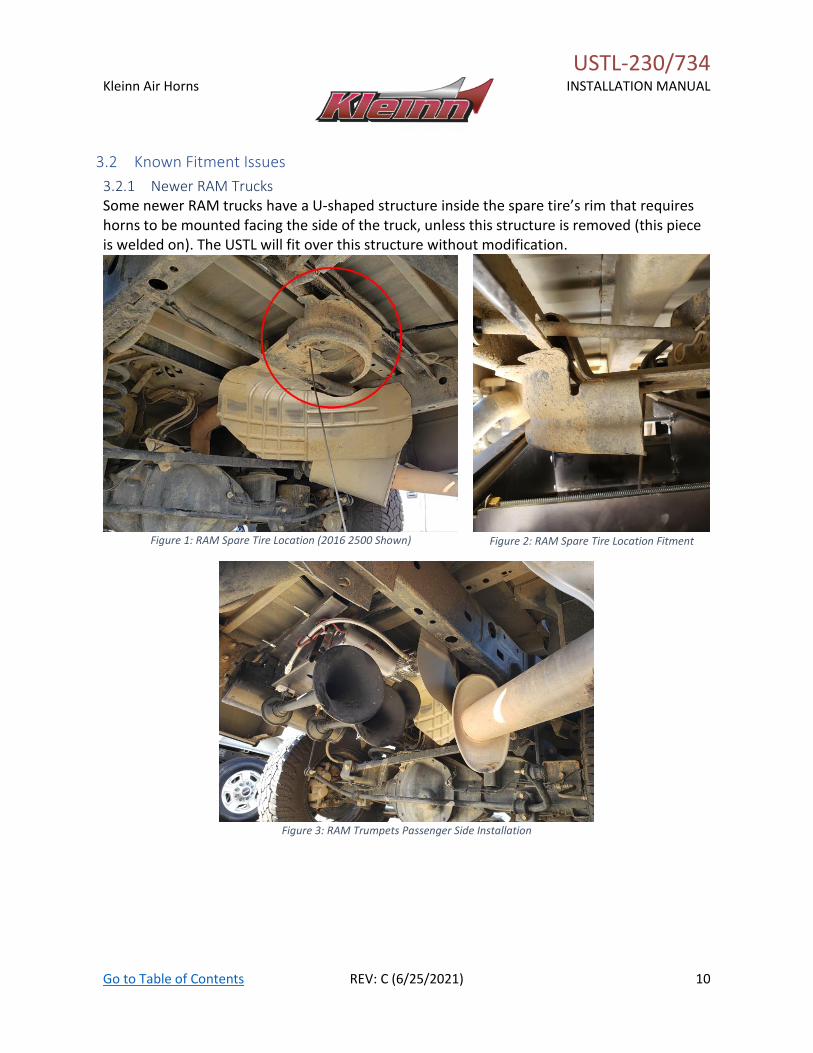
3.2.1 Newer RAM Trucks Some newer RAM trucks have a U-shaped structure inside the spare tire’s rim that requires horns to be mounted facing the side of the truck, unless this structure is removed (this piece is welded on). The USTL will fit over this structure without modification.
Figure 1: RAM Spare Tire Location (2016 2500 Shown)
Figure 2: RAM Spare Tire Location Fitment
Figure 3: RAM Trumpets Passenger Side Installation
USTL-230/734
Kleinn Air Horns
INSTALLATION MANUAL
Go to Table of Contents REV: C (6/25/2021) 11
3.3 Excluded Vehicles The following vehicles have been found to be incompatible with the designed kit:
MODEL YEAR MODEL DRIVE ENGINE BODY TRIM
N/A - - - - -
3.4 Aftermarket Product Compatibility This kit has not been designed to work with the following aftermarket products:
• Aftermarket dual exhaust systems
NOTE: Review this manual in full before unpacking items to verify correct space and mounting
locations exist with your aftermarket product(s). To install this kit alongside your other aftermarket
product(s), modification to the included parts, your vehicle, or your aftermarket product(s) may be
required.
END OF SECTION
USTL-230/734
Kleinn Air Horns
INSTALLATION MANUAL
Go to Table of Contents REV: C (6/25/2021) 12
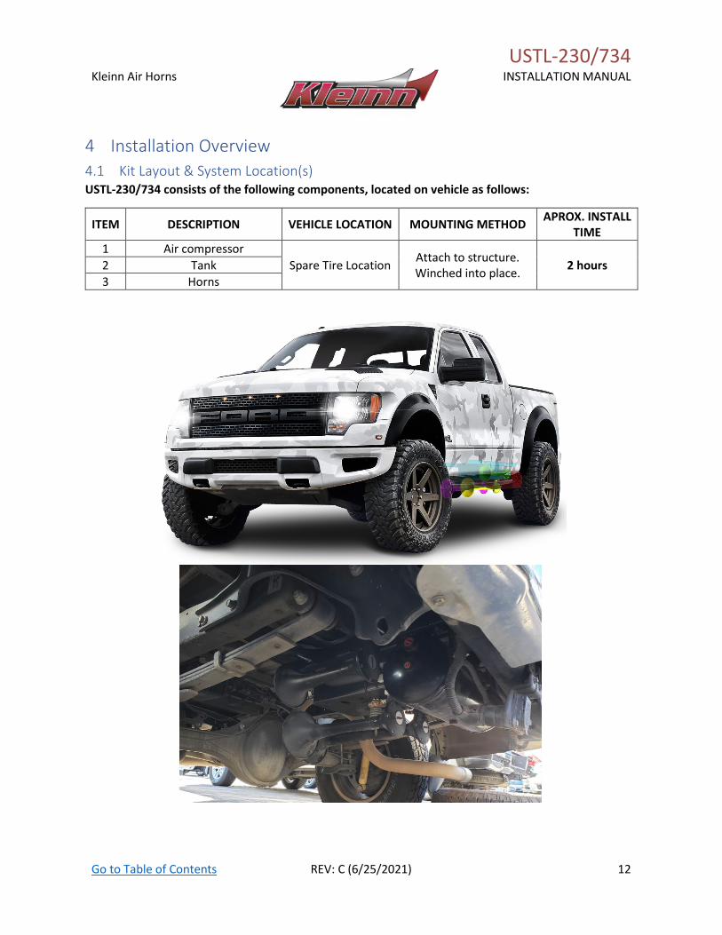
4 Installation Overview
4.1 Kit Layout & System Location(s) USTL-230/734 consists of the following components, located on vehicle as follows:
ITEM DESCRIPTION VEHICLE LOCATION MOUNTING METHOD APROX. INSTALL
TIME
1 Air compressor
Spare Tire Location Attach to structure. Winched into place.
2 hours 2 Tank
3 Horns
USTL-230/734
Kleinn Air Horns
INSTALLATION MANUAL
Go to Table of Contents REV: C (6/25/2021) 13
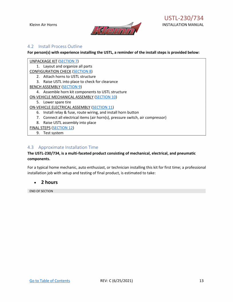
4.2 Install Process Outline For person(s) with experience installing the USTL, a reminder of the install steps is provided below:
UNPACKAGE KIT (SECTION 7) 1. Layout and organize all parts
CONFIGURATION CHECK (SECTION 8) 2. Attach horns to USTL structure 3. Raise USTL into place to check for clearance
BENCH ASSEMBLY (SECTION 9) 4. Assemble horn kit components to USTL structure
ON-VEHICLE MECHANICAL ASSEMBLY (SECTION 10) 5. Lower spare tire
ON-VEHICLE ELECTRICAL ASSEMBLY (SECTION 11) 6. Install relay & fuse, route wiring, and install horn button 7. Connect all electrical items (air horn(s), pressure switch, air compressor) 8. Raise USTL assembly into place
FINAL STEPS (SECTION 12) 9. Test system
4.3 Approximate Installation Time The USTL-230/734, is a multi-faceted product consisting of mechanical, electrical, and pneumatic
components.
For a typical home mechanic, auto enthusiast, or technician installing this kit for first time; a professional
installation job with setup and testing of final product, is estimated to take:
• 2 hours
END OF SECTION
USTL-230/734
Kleinn Air Horns
INSTALLATION MANUAL
Go to Table of Contents REV: C (6/25/2021) 14
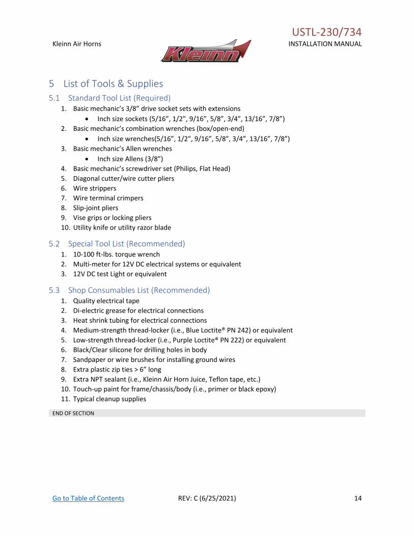
5 List of Tools & Supplies
5.1 Standard Tool List (Required) 1. Basic mechanic’s 3/8” drive socket sets with extensions
• Inch size sockets (5/16”, 1/2", 9/16”, 5/8”, 3/4”, 13/16”, 7/8”)
2. Basic mechanic’s combination wrenches (box/open-end)
• Inch size wrenches(5/16”, 1/2", 9/16”, 5/8”, 3/4”, 13/16”, 7/8”)
3. Basic mechanic’s Allen wrenches
• Inch size Allens (3/8”)
4. Basic mechanic’s screwdriver set (Philips, Flat Head)
5. Diagonal cutter/wire cutter pliers
6. Wire strippers
7. Wire terminal crimpers
8. Slip-joint pliers
9. Vise grips or locking pliers
10. Utility knife or utility razor blade
5.2 Special Tool List (Recommended) 1. 10-100 ft-lbs. torque wrench
2. Multi-meter for 12V DC electrical systems or equivalent
3. 12V DC test Light or equivalent
5.3 Shop Consumables List (Recommended) 1. Quality electrical tape
2. Di-electric grease for electrical connections
3. Heat shrink tubing for electrical connections
4. Medium-strength thread-locker (i.e., Blue Loctite® PN 242) or equivalent
5. Low-strength thread-locker (i.e., Purple Loctite® PN 222) or equivalent
6. Black/Clear silicone for drilling holes in body
7. Sandpaper or wire brushes for installing ground wires
8. Extra plastic zip ties > 6” long
9. Extra NPT sealant (i.e., Kleinn Air Horn Juice, Teflon tape, etc.)
10. Touch-up paint for frame/chassis/body (i.e., primer or black epoxy)
11. Typical cleanup supplies
END OF SECTION
USTL-230/734
Kleinn Air Horns
INSTALLATION MANUAL
Go to Table of Contents REV: C (6/25/2021) 15
6 Parts List
6.1 Review Parts List
Unpackage and organize kit across a large work area and verify all parts are included, as listed
below. Contact Kleinn support with any questions.
1. Review pre-packaged kit items (K_)
2. Review Air Fittings and Tubing (F_)
3. Review Wiring and Accessories (E_)
4. Review Bolt-On Mounting Brackets (C_)
5. Review Hardware/Fasteners (H_)
6. Review Add-On Accessories (X_)
7. Familiarize yourself with how the parts assemble
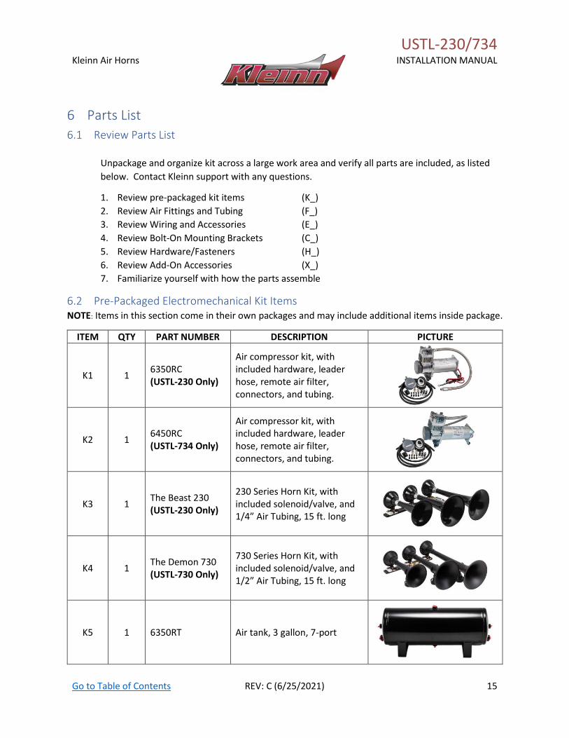
6.2 Pre-Packaged Electromechanical Kit Items NOTE: Items in this section come in their own packages and may include additional items inside package.
ITEM QTY PART NUMBER DESCRIPTION PICTURE
K1 1 6350RC (USTL-230 Only)
Air compressor kit, with included hardware, leader hose, remote air filter, connectors, and tubing.
K2 1 6450RC (USTL-734 Only)
Air compressor kit, with included hardware, leader hose, remote air filter, connectors, and tubing.
K3 1 The Beast 230 (USTL-230 Only)
230 Series Horn Kit, with included solenoid/valve, and 1/4” Air Tubing, 15 ft. long
K4 1 The Demon 730 (USTL-730 Only)
730 Series Horn Kit, with included solenoid/valve, and 1/2” Air Tubing, 15 ft. long
K5 1 6350RT Air tank, 3 gallon, 7-port
USTL-230/734
Kleinn Air Horns
INSTALLATION MANUAL
Go to Table of Contents REV: C (6/25/2021) 16
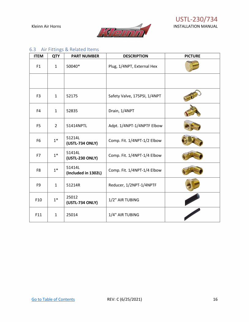
6.3 Air Fittings & Related Items ITEM QTY PART NUMBER DESCRIPTION PICTURE
F1 1 50040* Plug, 1/4NPT, External Hex
F3 1 52175 Safety Valve, 175PSI, 1/4NPT
F4 1 52835 Drain, 1/4NPT
F5 2 51414NPTL Adpt. 1/4NPT-1/4NPTF Elbow
F6 1* 51214L (USTL-734 ONLY)
Comp. Fit. 1/4NPT-1/2 Elbow
F7 1* 51414L (USTL-230 ONLY)
Comp. Fit. 1/4NPT-1/4 Elbow
F8 1* 51414L (Included in 1302L)
Comp. Fit. 1/4NPT-1/4 Elbow
F9 1 51214R Reducer, 1/2NPT-1/4NPTF
F10 1* 25012 (USTL-734 ONLY)
1/2" AIR TUBING
F11 1 25014 1/4" AIR TUBING
USTL-230/734
Kleinn Air Horns
INSTALLATION MANUAL
Go to Table of Contents REV: C (6/25/2021) 17
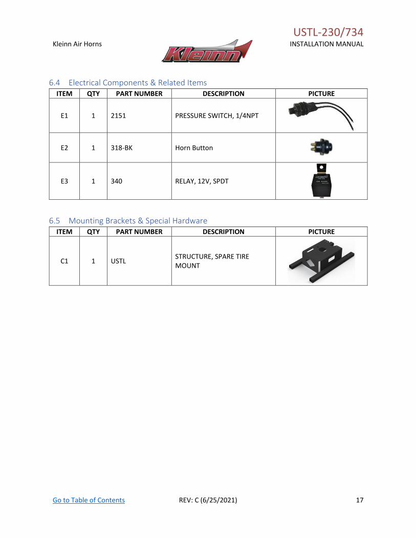
6.4 Electrical Components & Related Items ITEM QTY PART NUMBER DESCRIPTION PICTURE
E1 1 2151 PRESSURE SWITCH, 1/4NPT
E2 1 318-BK Horn Button
E3 1 340 RELAY, 12V, SPDT
6.5 Mounting Brackets & Special Hardware ITEM QTY PART NUMBER DESCRIPTION PICTURE
C1 1 USTL STRUCTURE, SPARE TIRE MOUNT
USTL-230/734
Kleinn Air Horns
INSTALLATION MANUAL
Go to Table of Contents REV: C (6/25/2021) 18
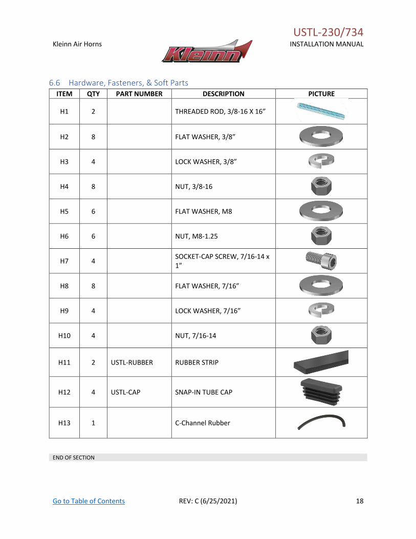
6.6 Hardware, Fasteners, & Soft Parts ITEM QTY PART NUMBER DESCRIPTION PICTURE
H1 2 THREADED ROD, 3/8-16 X 16”
H2 8 FLAT WASHER, 3/8”
H3 4 LOCK WASHER, 3/8”
H4 8 NUT, 3/8-16
H5 6 FLAT WASHER, M8
H6 6 NUT, M8-1.25
H7 4 SOCKET-CAP SCREW, 7/16-14 x 1”
H8 8 FLAT WASHER, 7/16”
H9 4 LOCK WASHER, 7/16”
H10 4 NUT, 7/16-14
H11 2 USTL-RUBBER RUBBER STRIP
H12 4 USTL-CAP SNAP-IN TUBE CAP
H13 1 C-Channel Rubber
END OF SECTION
USTL-230/734
Kleinn Air Horns
INSTALLATION MANUAL
Go to Table of Contents REV: C (6/25/2021) 19
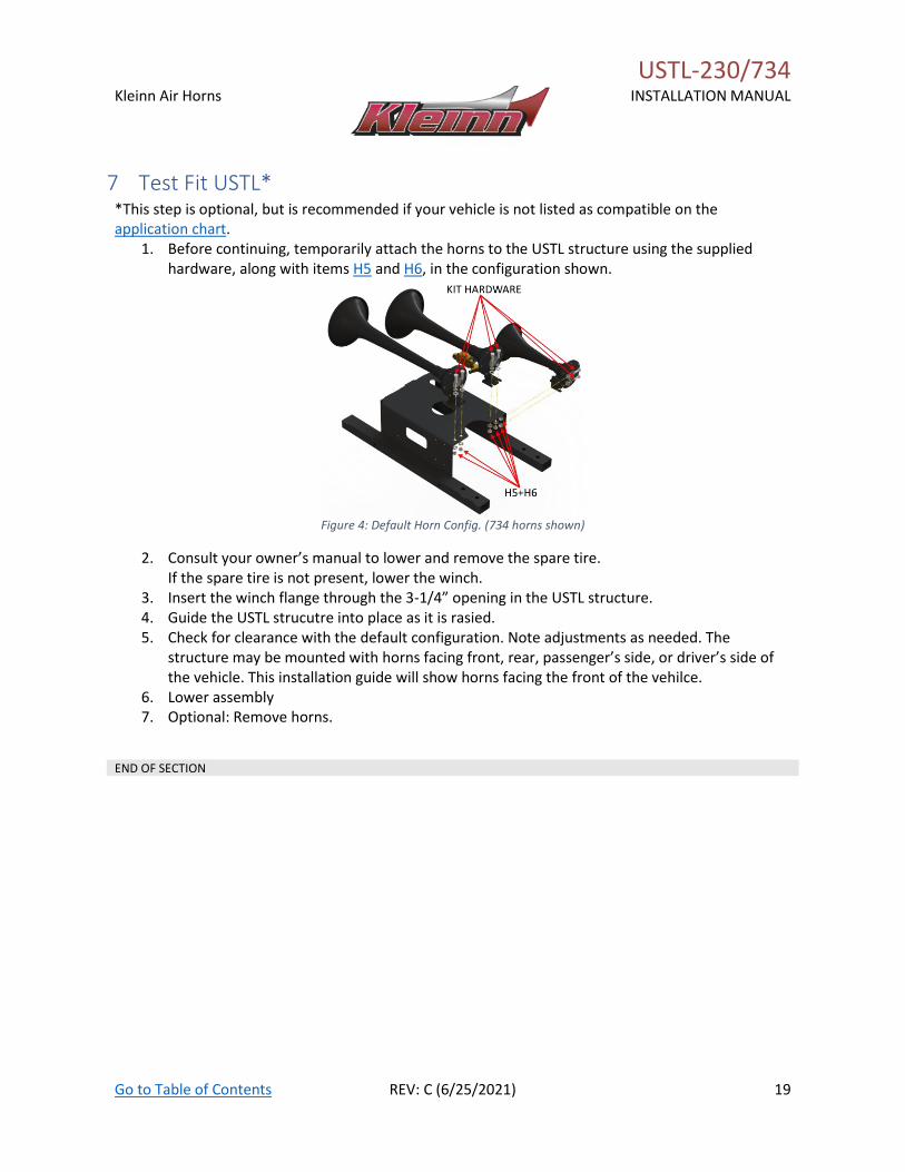
7 Test Fit USTL* *This step is optional, but is recommended if your vehicle is not listed as compatible on the application chart.
1. Before continuing, temporarily attach the horns to the USTL structure using the supplied hardware, along with items H5 and H6, in the configuration shown.
Figure 4: Default Horn Config. (734 horns shown)
2. Consult your owner’s manual to lower and remove the spare tire. If the spare tire is not present, lower the winch.
3. Insert the winch flange through the 3-1/4” opening in the USTL structure. 4. Guide the USTL strucutre into place as it is rasied. 5. Check for clearance with the default configuration. Note adjustments as needed. The
structure may be mounted with horns facing front, rear, passenger’s side, or driver’s side of the vehicle. This installation guide will show horns facing the front of the vehilce.
6. Lower assembly 7. Optional: Remove horns.
END OF SECTION
USTL-230/734
Kleinn Air Horns
INSTALLATION MANUAL
Go to Table of Contents REV: C (6/25/2021) 20
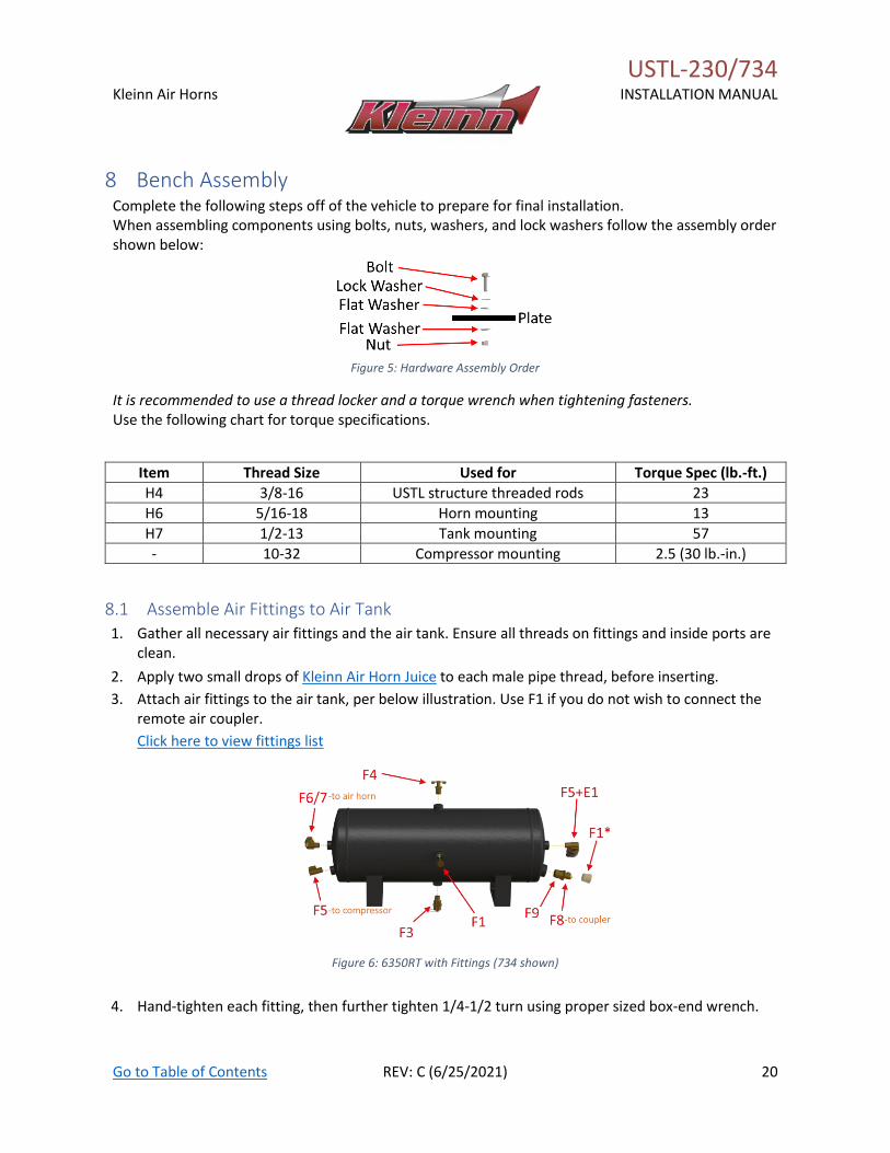
8 Bench Assembly Complete the following steps off of the vehicle to prepare for final installation. When assembling components using bolts, nuts, washers, and lock washers follow the assembly order shown below:
Figure 5: Hardware Assembly Order
It is recommended to use a thread locker and a torque wrench when tightening fasteners. Use the following chart for torque specifications.
Item Thread Size Used for Torque Spec (lb.-ft.)
H4 3/8-16 USTL structure threaded rods 23
H6 5/16-18 Horn mounting 13
H7 1/2-13 Tank mounting 57
- 10-32 Compressor mounting 2.5 (30 lb.-in.)
8.1 Assemble Air Fittings to Air Tank 1. Gather all necessary air fittings and the air tank. Ensure all threads on fittings and inside ports are
clean.
2. Apply two small drops of Kleinn Air Horn Juice to each male pipe thread, before inserting.
3. Attach air fittings to the air tank, per below illustration. Use F1 if you do not wish to connect the remote air coupler.
Click here to view fittings list
Figure 6: 6350RT with Fittings (734 shown)
4. Hand-tighten each fitting, then further tighten 1/4-1/2 turn using proper sized box-end wrench.

USTL-230/734
Kleinn Air Horns
INSTALLATION MANUAL
Go to Table of Contents REV: C (6/25/2021) 21
8.2 Assemble Air Filter to Air Compressor
1. Remove the compressor from its packaging, including hardware and air filter.
2. Review included directions in the compressor package pertaining to the remote air filter. Select the location on the vehicle where the air filter will be mounted, or if desired, filter housing may be secured to included structure using zip ties.
3. Pry-open the plastic air filter housing and ensure the foam filter is intalled. Attach fittings for filter to the end of the air the compressor and filter housing. Follow instructions included in the compressor package.
NOTE: The air filter tubing is rigid and may be difficult to install over barb fittings. If necessary, use a hair dryer, candle, or heat gun at a safe distance to soften the end of the air tubing and place over fitting. Do not bend tubing excessively and cause it to kink. Use even heat if necessary, to bend tubing sharply.
Figure 7: Air Compressor Remote Air Filter and Tubing (shown without air compressor)
8.3 Attach Threaded Rod to USTL Structure Repeat the following steps twice, once for each threaded rod (H1) provided.
1. Insert threaded rod halfway through USTL structure. 2. Add hardware in order shown.
Figure 8: Threaded Rod Assembly
3. Insert threaded rod the rest of the way though USTL structure. 4. Add remaining hardware as shown. 5. Center threaded rod on the structure and tighten hardware. 6. Repeat for second threaded rod.
Air Filter Remote
Mounting Flange
Air Tubing w/Fitting
for Remote Mount
Air Filter Housing
USTL-230/734
Kleinn Air Horns
INSTALLATION MANUAL
Go to Table of Contents REV: C (6/25/2021) 22
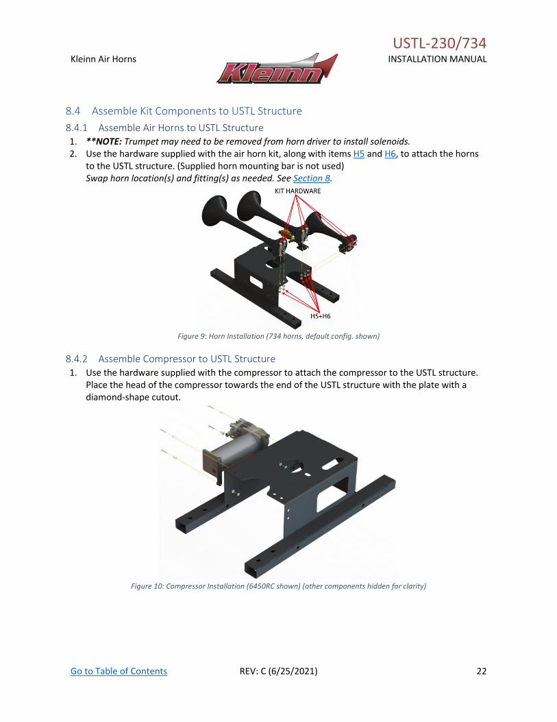
8.4 Assemble Kit Components to USTL Structure
8.4.1 Assemble Air Horns to USTL Structure 1. **NOTE: Trumpet may need to be removed from horn driver to install solenoids. 2. Use the hardware supplied with the air horn kit, along with items H5 and H6, to attach the horns
to the USTL structure. (Supplied horn mounting bar is not used) Swap horn location(s) and fitting(s) as needed. See Section 8.
Figure 9: Horn Installation (734 horns, default config. shown)
8.4.2 Assemble Compressor to USTL Structure 1. Use the hardware supplied with the compressor to attach the compressor to the USTL structure.
Place the head of the compressor towards the end of the USTL structure with the plate with a diamond-shape cutout.
Figure 10: Compressor Installation (6450RC shown) (other components hidden for clarity)
USTL-230/734
Kleinn Air Horns
INSTALLATION MANUAL
Go to Table of Contents REV: C (6/25/2021) 23
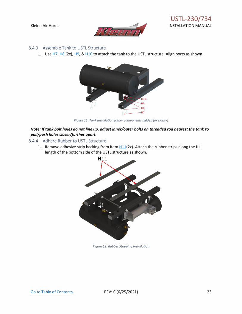
8.4.3 Assemble Tank to USTL Structure 1. Use H7, H8 (2x), H9, & H10 to attach the tank to the USTL structure. Align ports as shown.
Figure 11: Tank Installation (other components hidden for clarity)
Note: If tank bolt holes do not line up, adjust inner/outer bolts on threaded rod nearest the tank to pull/push holes closer/further apart.
8.4.4 Adhere Rubber to USTL Structure 1. Remove adhesive strip backing from item H11(2x). Attach the rubber strips along the full
length of the bottom side of the USTL structure as shown.
Figure 12: Rubber Stripping Installation

USTL-230/734
Kleinn Air Horns
INSTALLATION MANUAL
Go to Table of Contents REV: C (6/25/2021) 24
8.4.5 Install Snap-In Caps 1. Insert item H12(4x) in each end of the USTL structure tubes.
Figure 13: Snap-In Cap Installation
8.4.6 Attach Leader Hose to Tank & Route Air to Horns 1. Attach the compressor’s leader hose to the tank inlet. 2. Run an airline from the tank outlet to the horn solenoid. 3. Use H14 on edges of the bracket where the airline passes through, in order to protect the
airline from abrasion.
Figure 14: USTL Bench Assembly
END OF SECTION

USTL-230/734
Kleinn Air Horns
INSTALLATION MANUAL
Go to Table of Contents REV: C (6/25/2021) 25
USTL-230/734
Kleinn Air Horns
INSTALLATION MANUAL
Go to Table of Contents REV: C (6/25/2021) 26
9 On-Vehicle Mechanical Assembly Complete the following steps on-vehicle.
9.1 Remove Spare Tire 1. Consult your owner’s manual to lower and remove the spare tire.
If the spare tire is not present, lower the winch. The assembly will be raised in to place after electrical connections have been made. See Section 11
END OF SECTION
USTL-230/734
Kleinn Air Horns
INSTALLATION MANUAL
Go to Table of Contents REV: C (6/25/2021) 27
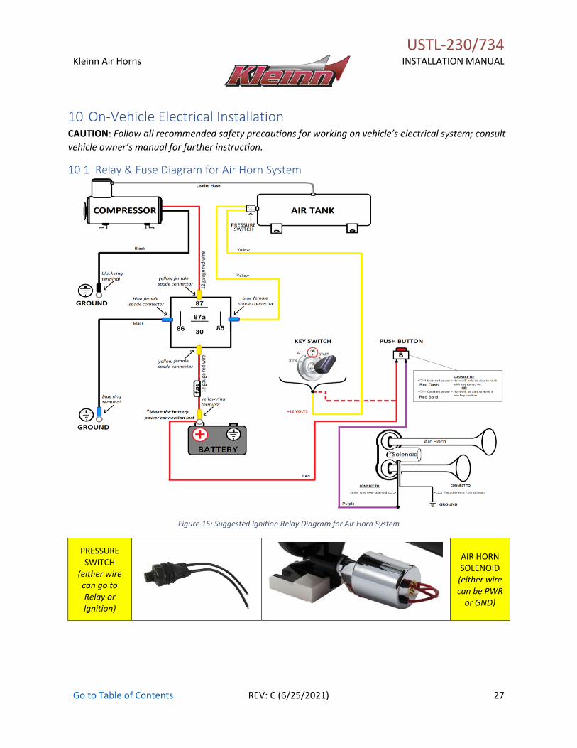
10 On-Vehicle Electrical Installation CAUTION: Follow all recommended safety precautions for working on vehicle’s electrical system; consult
vehicle owner’s manual for further instruction.
10.1 Relay & Fuse Diagram for Air Horn System
Figure 15: Suggested Ignition Relay Diagram for Air Horn System
PRESSURE SWITCH
(either wire can go to Relay or Ignition)
AIR HORN SOLENOID
(either wire can be PWR
or GND)
USTL-230/734
Kleinn Air Horns
INSTALLATION MANUAL
Go to Table of Contents REV: C (6/25/2021) 28
10.2 Disconnect Vehicle Battery(s) 1. Consult owner’s manual to disconnect your vehicle’s battery.
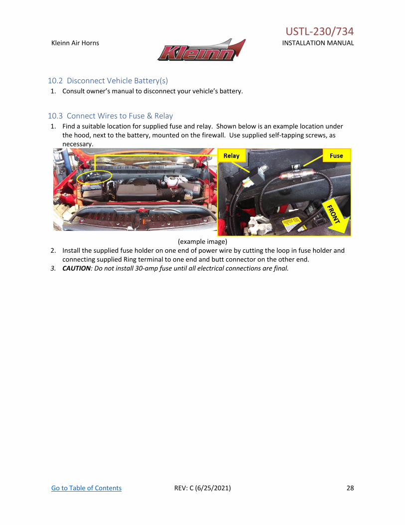
10.3 Connect Wires to Fuse & Relay 1. Find a suitable location for supplied fuse and relay. Shown below is an example location under
the hood, next to the battery, mounted on the firewall. Use supplied self-tapping screws, as necessary.
(example image)
2. Install the supplied fuse holder on one end of power wire by cutting the loop in fuse holder and connecting supplied Ring terminal to one end and butt connector on the other end.
3. CAUTION: Do not install 30-amp fuse until all electrical connections are final.
USTL-230/734
Kleinn Air Horns
INSTALLATION MANUAL
Go to Table of Contents REV: C (6/25/2021) 29
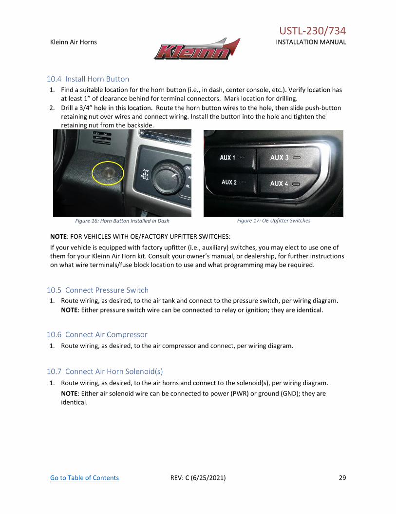
10.4 Install Horn Button 1. Find a suitable location for the horn button (i.e., in dash, center console, etc.). Verify location has
at least 1” of clearance behind for terminal connectors. Mark location for drilling.
2. Drill a 3/4” hole in this location. Route the horn button wires to the hole, then slide push-button retaining nut over wires and connect wiring. Install the button into the hole and tighten the retaining nut from the backside.
Figure 16: Horn Button Installed in Dash
Figure 17: OE Upfitter Switches
NOTE: FOR VEHICLES WITH OE/FACTORY UPFITTER SWITCHES:
If your vehicle is equipped with factory upfitter (i.e., auxiliary) switches, you may elect to use one of them for your Kleinn Air Horn kit. Consult your owner’s manual, or dealership, for further instructions on what wire terminals/fuse block location to use and what programming may be required.
10.5 Connect Pressure Switch 1. Route wiring, as desired, to the air tank and connect to the pressure switch, per wiring diagram.
NOTE: Either pressure switch wire can be connected to relay or ignition; they are identical.
10.6 Connect Air Compressor
1. Route wiring, as desired, to the air compressor and connect, per wiring diagram.
10.7 Connect Air Horn Solenoid(s)
1. Route wiring, as desired, to the air horns and connect to the solenoid(s), per wiring diagram.
NOTE: Either air solenoid wire can be connected to power (PWR) or ground (GND); they are identical.
USTL-230/734
Kleinn Air Horns
INSTALLATION MANUAL
Go to Table of Contents REV: C (6/25/2021) 30
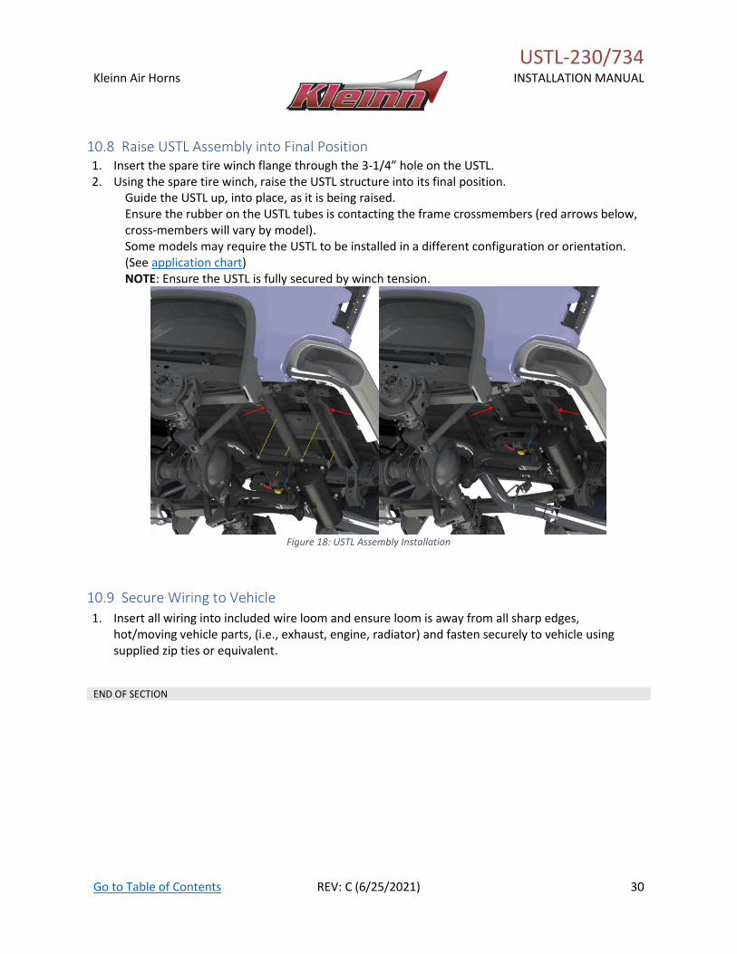
10.8 Raise USTL Assembly into Final Position 1. Insert the spare tire winch flange through the 3-1/4” hole on the USTL. 2. Using the spare tire winch, raise the USTL structure into its final position.
Guide the USTL up, into place, as it is being raised. Ensure the rubber on the USTL tubes is contacting the frame crossmembers (red arrows below, cross-members will vary by model). Some models may require the USTL to be installed in a different configuration or orientation. (See application chart) NOTE: Ensure the USTL is fully secured by winch tension.
Figure 18: USTL Assembly Installation
10.9 Secure Wiring to Vehicle
1. Insert all wiring into included wire loom and ensure loom is away from all sharp edges, hot/moving vehicle parts, (i.e., exhaust, engine, radiator) and fasten securely to vehicle using supplied zip ties or equivalent.
END OF SECTION
11 Final Steps & Testing
11.1 Reconnect Vehicle Battery(s) CAUTION: Before connecting the vehicle battery(s), verify all
wiring is properly connected and no shorts exists. Use of
Multi-meter, or test light is recommended to check
continuity of all connections.
11.2 Test Air Compressor 1. Turn the vehicle ignition to the ON position and
allow the compressor to fill the air tank. Initial fill
may take approximately 1.5-3 minutes. The air
compressor should shut off automatically once
full pressure is achieved.
2. If the compressor runs excessively, (i.e., 5
minutes or more) disconnect electrical power to
the air compressor and listen for air leaks in
system. Repair any problems and retest. Contact
Kleinn technical support if problems persist.
3. Inspect all air line connections (i.e., air tank
fittings, quick connect fittings, air horn fittings,
etc.) for leaks by using a soap and water solution
sprayed directly onto fittings.
4. System must be pressurized, or at least the air
compressor must be running.
5. If an air leak is found:
6. Safely release air pressure from system (i.e.,
slowly open drain valve).
7. Disassemble leaky connection, re-seal and
reinstall fittings as needed.
11.3 Test Train Horns 1. Allow the air compressor to run and shut-off
automatically (i.e., air tank is full)
2. Verify all tubing and electrical wires are securely
fastened to the vehicle, brackets, or kit parts. If
necessary, use extra zip ties to hold tubing and
wire in place.
3. Ensure all nearby persons have adequate hearing
protection and provide courtesy warning to
neighbors or others in vicinity.
WARNING: NEVER operate train horns with ears close to
trumpets or in an enclosed space without substantial
hearing protection (i.e., > Ear Plugs and Earmuffs) for all
persons closer than 100 feet from vehicle. Never
operate train horns outdoors when persons are near
vehicle without adequate hearing protection.
4. Briefly activate the horns by pressing the horn
button for one (1) second. Repeat three (3) times
with a short rest period between (i.e., 1-3
seconds).
5. Horns should sound as expected and be loud.
click to listen to example 230 Kit
6. Horn sound/loudness will taper quickly as the air
tank pressure decreases.
7. Allow the air compressor to refill the tank, if
needed, and activate the horns for three (3)
second period to ensure the horns are
functioning properly.
11.4 Test Quick Connect Coupler 1. Allow the air compressor to refill the tank, if
needed.
2. Attach the supplied INF-1 inflator kit to the quick
connect coupler and verify adequate air pressure
is available
3. Test fill tires on vehicle, bicycle, etc.
4. Test air blow gun
5. Test air impact gun
END OF SECTION
USTL-230/734
Kleinn Air Horns
INSTALLATION MANUAL
Go to Table of Contents REV: C (6/25/2021) 32
12 General Operation
12.1 Compressor Operation WARNING: NEVER operate the air compressor above its
MAXIMUM PRESSURE RATING (see label on body). Operation
exceeding maximum pressure will damage the compressor
and potentially cause air system failure.
1. Kleinn’s oil-less compressor is equipped with an
automatic thermal overload protection circuit
designed to protect the air compressor from
overheating and causing permanent damage.
2. Automatic thermal overload protector will reset
after 30 minutes.
3. To prevent discharge of the vehicle’s battery,
and for best performance, keep the vehicle’s
engine running while using the air compressor
for any prolonged use (i.e., filling tires, using air
tools, etc.).
12.2 Horn Operation 1. Allow the air compressor to run until it shuts off
automatically, (i.e., air tank is full) or for at least
one minute between horn activations.
2. Press the horn button to activate the horns
3. Horn sound/loudness will taper quickly as the air
tank pressure decreases.
4. Horns should sound for 3-7 seconds depending
on kit and tank size.
WARNING: NEVER operate train horns with ears near
trumpets or in an enclosed space without hearing protection
(i.e., > Ear Plugs/Muffs) for all persons closer than 100 feet
from vehicle. Never operate train horns outdoors when
persons are near vehicle without hearing protection.
END OF SECTION
13 Routine Maintenance Perform following maintenance at least once during
recommended intervals:
1. Yearly, or every 12,000 miles, verify all mounting
fasteners are properly torqued. Applying witness
marks across fasteners and mounting parts is
good practice to quickly ensure fasteners have
not moved.
2. Yearly, or every 12,000 miles, inspect OE wiring,
tubing, cables, etc. where kit parts may touch to
verify no abrasion or rubbing.
3. Yearly, or every 12,000 miles, remove all road
grime and mud from the mounting brackets and
kit parts using clean water from a garden hose.
Pay special attention to corners where dirt may
collect. Touch up all paint chips using
automotive grade enamel in either spray or
brush form.
NOTE: Do this more frequently if traveling regularly off-road,
or in winter climates with road salts. High-pressure washers
may damage part finishes and must be used with care.
4. Yearly, or every 12,000 miles, check electrical
connections, wires, and air fittings for abrasion,
corrosion, or other damage. Replace damaged
components.
NOTE: if system runs continuously or turns on unexpectedly,
leaks or a poor electrical connection may be present.
5. Monthly, or every 10 hours of compressor run
time, drain moisture from the air tank using thee
drain valve installed at the bottom of the tank.
WARNING: Failure to regularly drain the air tank may result
in corrosion inside the tank and possible failure in the tank or
air tubing, causing injury.
6. Yearly, or every 12,000 miles, clean or replace
the air compressor air filter element.
Replacement frequency depends on operating
frequency and conditions of environment (i.e.,
daily use requires more frequent changes).
Order replacement filters at Kleinn.com.
NOTE: NEVER lubricate or add liquids to the compressor.
END OF SECTION
USTL-230/734
Kleinn Air Horns
INSTALLATION MANUAL
Go to Table of Contents REV: C (6/25/2021) 33
14 Warranty Information Thank you for purchasing USTL-230/734. Shall you experience any unexpected problems during installation, or
have problems with any part at any time, please contact Kleinn support.
END OF MANUAL
© Kleinn Air Horns 2020, All rights reserved. PO Box 91278 Tucson, AZ 85752
Phone: (520) 579-1531 Web: https://www.kleinn.com