
Using 3174 in TCP/IP Networks - bitsavers.org
406
Using 3174 in TCP/IP Networks GGU417l-,OO
-
Upload
khangminh22 -
Category
Documents
-
view
2 -
download
0
Transcript of Using 3174 in TCP/IP Networks - bitsavers.org
Using 3174 in TCP/IP Networks
GGU417l-,OO
I~
Using 3174 in TCP/IP Networks
Document Number GG24-4172-00
June 1994
International Technical Support Organization Raleigh Center
/
Take Note! --------------------------------------------------------------------------~
Before using this information and the product it supports, be sure to read the general information under "Special Notices" on page xxiii.
First Edition (June 1994)
This edition applies to the 3174 Network Controller Configuration Support-C3 through C5 TCP/IP Support.
Order publications through your IBM representative or the IBM branch office serving your locality. Publications are not stocked at the address given below.
An ITSO Technical Bulletin Evaluation Form for reader's feedback appears facing Chapter 1. If the form has been removed, comments may be addressed to:
IBM Corporation, International Technical Support Organization Dept. 985, Building 657 P.O. Box 12195 Research Triangle Park, NC 27709-2195
When you send information to IBM, you grant IBM a non-exclusive right to use or distribute the information in any way it believes appropriate without incurring any obligation to you.
© Copyright International Business Machines Corporation 1994. All rights reserved. Note to U.S. Government Users - Documentation related to restricted rights - Use, duplication or disclosure is subject to restrictions set forth in GSA ADP Schedule Contract with IBM Corp.
~ Abstract
The 3174 Establishment Controller is a very important component in multi-protocol networks involving subarea SNA, Advanced Peer-to-Peer Networking (APPN), Peer Communication, Token-Ring and Ethernet LANs, X.25, Integrated Services Digital Network (ISDN), asynchronous communication, frame relay, and Transmission Control Protocol/Internet Protocol (TCP/IP).
This document focuses on the roles of the 3174 in TCP/IP networks. It includes functions introduced by the 3174 TCP/IP TELNET RPQ 8Q0935, enhancements such as TN3270, TCP/IP host printer, and SNMP MIS-II support offered by 3174 TCP/IP Enhancements RPQ 8Q1041 and the recently available IP Forwarding RPQ 8Q1289.
This document is intended to help customers and systems engineers understand the functionality provided and how to customize the 3174 for participation in a TCP/IP network. It is organized to help the reader understand the basics of the TCP/IP Architecture in general and the 3174 implementation specifically. The scenarios include sample configuration files and panels for the 3174 and other TCP/IP hosts in the network. The reader is assumed to have a basic knowledge of TCP/IP as implemented by the other products used in the scenarios.
(373 pages)
© Copyright IBM Corp. 1994 iii

iv Using the 3174 TCP/IP Networks
Contents
Abstract ....
Special Notices
Preface How This Document is Organized Related Publications ...... . International Technical Support Organization Publications Acknowledgments ................... .
Chapter 1. An Introduction to 3174 TCP/IP Support 1.1 3174 Functional Overview .. 1.2 TCP/IP Overview ............. . 1.3 TCP/IP Architecture ........... .
1.3.1 Transmission Control Protocol (TCP) 1.3.2 Telnet ................. . 1.3.3 I nternet Protocol (I P) ........ . 1.3.4 Internet Control Messaging Protocol (ICMP) 1.3.5 User Datagram Protocol (UDP) ....... . 1.3.6 Address Resolution Protocol (ARP) .... . 1.3.7 Simple Network Management Protocol (SNMP) 1.3.S Domain Name System 1.3.9 Packet Internet Groper (PING) 1.3.10 TCP/IP Gateways
1.4 TCP/IP Protocols Supported
Chapter 2. 3174 TCP/IP Telnet Support 2.1 Support before 3174 TCP/IP Telnet RPQ SQ0935 2.2 Support with 3174 TCP/IP Telnet RPQ 8Q0935 .. 2.3 Support with Configuration Support-C Release 3 2.4 Support with 3174 TCP/IP Enhancements RPQ SQ1041 2.5 Support with Configuration Support-C Release 5 ... 2.6 Support with 3174 IP Forwarding RPQ SQ12S9 2.7 TELNET Emulation and NLS Support 2.S 3174 Models Supported .....
2.S.1 Gateway 3174 Configuration . 2.S.2 DSPU 3174 Configuration
2.9 Devices Supported 2.10 Hosts Supported ...... . 2.11 Storage Requirements
2.11.1 Sessions ...... . 2.11.2 TCP/I P Data Buffers
2.12 Microcode Packaging ..
Chapter 3. Adding 3174 to TCP/IP Network . 3.1 IP Addresses ...... . 3.2 Subnet Masks ...... . 3.3 Customizing IP Addresses 3.4 Names ..... 3.5 Name Servers . 3.6 3174 Nicknames
© Copyright I BM Corp. 1994
iii
xxiii
xxv xxv
xxvi xxvii
xxviii
1 1 3 3 3 5 5 6 6 6 7 7 7 7 7
9 9 9
..... 10 10 10 11 11 12
. .... 12 13 14 15 15 15 15 16
19 19 20 21 21 21 21
v
3.7 How the 3174 TCP/IP Telnet Support Looks at Names ., 3.8 Routes ................... . 3.9 Customizing 3174 TCP/IP Telnet Support
3.9.1 Example Scenario .... . 3.9.2 Panel Flow ........ . 3.9.3 Configure AEA and TCP/IP 3.9.4 Enabling AEA and TCP/IP 3.9.5 Defining Port Set ..... . 3.9.6 Mapping Port to Port Set .. 3.9.7 Defining 3270 Host and Display Station Sets . 3.9.8 Defining TCP/IP Station Sets ..... 3.9.9 Defining Default Destinations .... . 3.9.10 Defining TCP/IP Options .... . 3.9.11 Defining TCP/IP Routing Information 3.9.12 Defining Domain Name Services 3.9.13 Defining TCP/IP Nicknames 3.9.14 Configure Complete ..... 3.9.15 Token-Ring Considerations . 3.9.16 Ethernet Considerations
3.10 How to Use the 3174 TCP/IP Telnet Support 3.11 Terminal Operation with the 3174 TCP/IP Telnet Support
3.11.1 Opening a Connection ....... . 3.11.2 Escaping to Local Mode ...... . 3.11.3 Returning to The Connection Menu . 3.11.4 Returning to the Telnet Session . 3.11.5 TELNET Session Resources ..... 3.11.6 Operation: Telnet to RS/6000 Host 3.11.7 Operation: Telnet to MVS TCP/IP Host 3.11.8 Local Mode Commands ........ . 3.11.9 Special Considerations for ASCII Terminals 3.11.10 SpeCial Considerations for 3270 Terminals 3.11.11 Special Considerations for 3270 Emulation
3.12 If Things Go Wrong ... 3.13 Telnet Codes 3.14 Data Flows ..... .
Chapter 4. Scenario 1: TCP/IP Using 3174 Peer Communication Only 4.1 Scenario 1 Configuration Diagram .. . 4.2 Scenario 1 Configuration Description ...... . 4.3 Communications Manager/2 Definitions ..... . 4.4 TCP/IP V1.2.1 for OS/2 Installation/Configuration . 4.5 Installation: TCP/IP LAN Adapter and Protocol Support (TCPLAPS) 4.6 Personal Communications/3270 Definitions ......... .
4.6.1 Personal Communications/3270 Configuration Program 4.7 Installation: TCP/IP for DOS ...... .
4.7.1 System Files ............. . 4.8 USing TCP/IP Application for Windows
4.8.1 Overview of the TCP/IP for Windows 4.8.2 Windows Ping ..... . 4.8.3 Windows TELNET
4.9 RISC System/6000 Definitions 4.9.1 SMIT TCP/IP ...... . 4.9.2 Minimum Configuration and Setup
4.10 3174-11R Customization 4.10.1 SDLC ................ .
vi Using the 3174 TCP/IP Networks
22 23 24 24 26 26 28 29 30 32 33 38 39 40 41 43 44 44 44 45 46 46 47 48 48 48 49 51 51 59 60 61 61 63 64
67 67 68 69 75 78 82 82 91 96 99 99
100 101 105 105 106 107 107
4.10.2 Common SNA ...... . 4.10.3 Common Network 4.10.4 Ring Address Assignment
4.11 3174-Peer Definition ...... . ... . 4.11.1 Question 650: 3174-Peer Support 4.11.2 Question 651: Bridge Support 4.11.3 Question 652: LAN Manager Support 4.11.4 Question 653: 3174-Peer Online Test Updates 4.11.5 Question 660: 3174-Peer Port Address Range 4.11.6 Question 661: Percentage of Discard Threshold 4.11.7 3174-Peer Bridge Profile 4.11.8 LAN Manager Profile
4.12 Display 3174-Peer Status ..
Chapter 5. Scenario 2: Concurrent Access to SNA and TCPIIP Hosts 5.1 Scenario 2 Configuration Diagram .. . 5.2 Scenario 2 Configuration Description ....... . 5.3 3174-12L Multi-Host Customization
5.3.1 Common Network (1B Host) ..... 5.3.2 Ring Address Assignment (1 B Host) 5.3.3 Ring Transmission Definition (1B Host) 5.3.4 Configure Complete ....
5.4 3174 TCP/IP Customizing 5.4.1 Enabling AEA And TCP/IP 5.4.2 Defining Port Set ..... 5.4.3 Mapping Port To Port Set 5.4.4 Defining 3270 Host and Display Station Sets 5.4.5 Defining TCP/IP Station Sets 5.4.6 Defining Default Destinations 5.4.7 Defining TCP/IP Options 5.4.8 Defining TCP/IP Routing Information 5.4.9 Defining Domain Name Services . 5.4.10 Defining TCP/IP Nicknames 5.4.11 Configure Complete ........ .
5.5 Operation: TELNET to RISC System/6000 5.6 RISC System/6000 Definitions
5.6.1 SNA Services ..... 5.6.2 Configure SNA Profiles . 5.6.3 Quick Configuration ... 5.6.4 Quick Configuration for a 3270 Communication Connection:
Information ............. . 5.6.5 Command Status ...... . 5.6.6 Advanced SNA Configuration 5.6.7 Physical Units ........ . 5.6.8 Token-Ring .......... . 5.6.9 SNA Token Ring Attachment Profile Name 5.6.10 Change/Show SNA Token Ring Attachment Profile 5.6.11 Manage SNA Services 5.6.12 Start SNA Resources 5.6.13 Start an SNA Link Station 5.6.14 Display SNA Resources. .. . . . . . . . ... . 5.6.15 Command Status ..... ........ . ...... . 5.6.16 AIX 3270 Host Communication Program/6000 (HCON) .. 5.6.17 HCON User Functions 5.6.18 Add an HCON Session ................... .
Contents
108 108 109 109 110 110 111 111 112 113 113 117 118
119 119 120 121 127 128 128 130 131 131 132 133 134 135 138 139 140 141 142 142 143 146 146 147 147
148 148 149 150 150 151 151 152 152 153 153 154 155 156 156
vii
5.6.19 Add SNA Display Session 5.6.20 Command Status 5.6.21 HCON Session ......... .
157 157 158
Chapter 6. Scenario 3: APPN and TCPIIP via 3174 to AS/400 and VTAM 159 6.1 Scenario 3 Configuration Diagram ................... 159 6.2 Scenario 3 Configuration Description ................. 160 6.3 3174-11R APPN, Peer Communication and TCP/IP Customization 161
6.3.1 Customize Control Disk Menu .......... 161 6.4 3174 as an APPN Network Node .................... 161 6.5 3174 APPN and Peer Communication Customization ........ 162
6.5.1 SDLC .................... 164 6.5.2 Common SNA ....... 164 6.5.3 Common Network ..... 168 6.5.4 Ring Address Assignment 168 6.5.5 APPN Node Definition 169
6.6 Network Resources Definition 170 6.6.1 Network Resources 171 6.6.2 Associated LUs 172
6.7 COS Definitions ....... 172 6.7.1 Mode/COS Correlation 173
6.8 3174-Peer Definitions ..... 175 6.8.1 3174-Peer Definition Panel 176 6.8.2 3174-Peer Bridge ~rofile 177
6.9 AS/400 Definitions 178 6.9.1 Network Attributes 178 6.9.2 Configuration Status 178 6.9.3 Controller Description Screens (C31742) . . . . . 179 6.9.4 Device Description Screens (PS2COAX) . . . . . 181
6.10 Communications Manager/2 Definitions for 5250 Emulation 182 6.10.1 Communications Manager/2 Installation and Setup 182 6.10.2 Communications Manager Setup .............. 183 6.10.3 Open Configuration ...................... 183 6.10.4 Communications Manager Configuration Definition-PSEN3174 184 6.10.5 Communications Manager Profile List Sheet .......... 185 6.10.6 Token-Ring or Other LAN Types DLC Adapter Parameters . . 185 6.10.7 Local Node Characteristics ................ 186 6.10.8 SNA Features List ....... 186 6.10.9 5250 Emulation ............ 187
6.11 LAN Adapter and Protocol Support 188 6.11.1 LAN Adapter and Protocol Support 188 6.11.2 Configure LAN Transports ..... . . . . . . . . 188 6.11.3 Configure Workstation ........ . . . . . . . . . . . . . .. 189 6.11.4 Parameters for 3270 Adapter for 3174 Peer Communications 189 6.11.5 LAN Adapter and Protocol Support . . . . . . . . .. 190 6.11.6 3174-11R Online Display . . . . . . . . .. 191
6.12 VTAM Definition List .......... 192 6.13 3174 TCP/IP Definitions ... . . 198
6.13.1 AEA And TCP/IP Configure 198 6.13.2 Defining Port Set ...... 198 6.13.3 Mapping Port To Port Set . 200 6.13.4 Defining 3270 Host and Display Station Sets 200 6.13.5 Defining TCP/IP Station Sets 201 6.13.6 Defining Default Destinations 202 6.13.7 Defining TCP/IP Options 202
viii Using the 3174 TCP/IP Networks
6.13.8 Defining TCP/IP Routing Information 6.13.9 Defining Domain Name Services 6.13.10 Defining TCP/IP Nicknames 6.13.11 Configure Complete 6.13.12 TELNET to AS/400 6.13.13 TELNET Prompt " 6.13.14 AS/400 Sign-On Screen 6.13.15 AS/400 Main Menu
6.14 Display 3174-Peer Status ..
Chapter 7. Scenario 4: TCP/IP via 3174 and RS/6000 Router to VAX 7.1 Scenario 4 Configuration .............. . 7.2 Scenario 4 Description ................ . 7.3 3174-11R TCP/IP and Peer Support Customization
7.3.1 Customize Control Disk Menu 7.4 3174-Peer Definition ...... .
7.4.1 3174-Peer Definition Panel 7.5 3174 TCP/IP Definitions
7.5.1 AEA and TCP/IP Configure 7.5.2 Defining Port Set ..... 7.5.3 Mapping Port to Port Set . 7.5.4 Defining 3270 Host and Display Station Sets 7.5.5 Defining TCP/IP Station Sets 7.5.6 Defining Default Destinations 7.5.7 Defining TCP/IP Options 7.5.8 Defining TCP/IP Routing Information 7.5.9 Defining Domain Name Services .. 7.5.10 Defining TCP/IP Nicknames .... .
7.6 RS/6000 Definitions ............. . 7.6.1 Router Definition on RISC System/6000 7.6.2 Command Status ...... . 7.6.3 Router Definition on DEC VAX
7.7 TELNET to VAX Host ....... .
Chapter 8. 3174 Ethernet Considerations 8.1 3174 Configuration Support C, Release 4
8.1.1 Configurations ..... . 8.1.2 Alternate Configurations 8.1.3 Storage Requirements 8.1.4 Configuration Examples 8.1.5 MAC Layer ...... . 8.1.6 LLC Layer ...... . 8.1.7 Frame Format Discovery Process
8.2 3174 Ethernet Adapter .. 8.2.1 Capacity ., . . . . . . . . . . . . . . 8.2.2 Configurations ........... . 8.2.3 CSMA/CD LAN Physical Interfaces 8.2.4 Hardware Group and Type Number 8.2.5 Field Replaceable Unit Identification (FRU ID) 8.2.6 Status Codes ....... .
8.3 3174 Ethernet Customization 8.4 Configuration Questions ... .
8.4.1 Modell Attach Panel ... . 8.4.2 Ethernet Description Panel 8.4.3 Local Area Network Panel
203 204 205 205 206 206 207 207 208
209 209 210 211 211 212 212 213 213 214 215 215 216 217 217 218 219 220 221 221 223 223 224
227 227 228 228 228 230 232 234 236 244 244 244 244 246 246 247 248 248 249 251 253
Contents ix
8.4.4 Common Network Panel (Gateway 900) 8.4.5 Gateway 940 Panel 8.4.6 Gateway 941 Panel ..... . 8.4.7 TCP/IP Options Menu .... . 8.4.8 End-User Productivity Panel .
8.5 Online Test ("/TEST") .... . 8.5.1 /1 -- Logs Display ...... . 8.5.2 /2 -- Display Customization 8.5.3 /9 -- LAN Tests ...... . 8.5.4 /15 - Host Status Summary 8.5.5 /17 - APPN Tests .....
Chapter 9. 3174 TCP/IP Enhancements RPQ 8Q1041 9.1 Configurations 9.2 Devices ............. . 9.3 Hosts .............. . 9.4 3174 Microcode and Packaging 9.5 Storage Requirements
9.5.1 Sessions 9.5.2 Data Buffers
9.6 Protocols .. 9.7 TN3270 .....
9.7.1 Function " 9.7.2 ASCII TELNET vs TN3270
9.8 Line Printer Daemon (LPD) 9.8.1 Printer Pooling . 9.8.2 LPD Data Stream 9.8.3 Banner Page " 9.8.4 Internal Queuing 9.8.5 Translation Support
9.9 MIB-II .......... . 9.10 TCP/IP Enhancements Customization
9.10.1 AEA and TCP/IP Configure . 9.10.2 Defining TN3270 Station Set 9.10.3 Defining Printer Station Set 9.10.4 Defining Default Destinations 9.10.5 Defining TCP/IP Options
9.11 Scenario 1 - 3174 Line Printer Daemon (LPD) 9.11.1 Scenario Description ..... ...... . 9.11.2 3174 Line Printer Daemon Customization 9.11.3 Defining 3270 Printer Station Set 9.11.4 Defining Default Destinations ..... . 9.11.5 Defining TCP/IP Options ......... . ... . 9.11.6 3174 Line Printer Daemon Configuration for OS/2 ......... . 9.11.7 Printing with the 3174 Line Printer Daemon from TCP/IP for OS/2 9.11.8 3174 Line Printer Daemon Configuration for DOS ........ . 9.11.9 Printing with the 3174 Line Printer Daemon from TCP/IP for DOS 9.11.10 3174 Line Printer Daemon Configuration for AS/400 9.11.11 Printing with the 3174 Line Printer Daemon on AS/400 9.11.12 3174 Line Printer Daemon Configuration for RS/6000 ...... . 9.11.13 Manage Local Printer Subsystem ........... . 9.11.14 Manage Remote Printer Subsystem .......... . 9.11.15 Server Services ............................. . 9.11.16 Printing with the 3174 Line Printer Daemon from RS/6000 9.11.17 3174 Line Printer Daemon Configuration for HP-UX Workstation .
X Using the 3174 TCP/IP Networks
254 255 255 255 255 256 256 256 257 261 261
263 264 265 265 265 267 267 267 269 269 270 272 273 274 276 279 279 280 280 291 291 292 293 294 294 295 295 296 296 297 297 297 301 301 303 303 310 311 313 316 318 319 320
9.11.18 3174 Line Printer Daemon Configuration for SunOS Workstation 328 331 332 332 333 333 334 334 335 340 340 340 341 342 342 343 343 344 344 345 345 346 348 349
9.12 Scenario 2 - TN3270 to MVS Host . . . . . . . 9.12.1 Scenario Descri ption 9.12.2 TN3270 Customization .... 9.12.3 Defining Default Destinations 9.12.4 Defining TCP/IP Options 9.12.5 Defining TCP/IP Routing Information 9.12.6 Defining Domain Name Services 9.12.7 Connection Menu ..... .
9.13 Scenario 3 - TN3270 to CICS/6000 9.13.1 Scenario Descri ption 9.13.2 TN3270 Customization .... 9.13.3 Defining Default Destinations 9.13.4 Defining TCP/IP Options 9.13.5 Defining TCP/IP Routing Information 9.13.6 Defining Domain Name Services 9.13.7 Defining TCPIIP Nicknames 9.13·.8 CICS/6000 Overview .... 9.13.9 CICS/6000 Environment .. 9.13.10 CICS/6000 TELNET Server 9.13.11 TCP/IP Port Number 9.13.12 Connection Menu ....... . 9.13.13 CICS Signon Screen ..... . 9.13.14 Working with Your CICS/6000 Region .
Chapter 10. 3174 Configuration Support C, Release 5 10.1 Multiprotocol Frame Relay 10.2 DLCI ..... . 10.3 IP Support ...... . 10.4 Interoperability .... . 10.5 Migration - Coexistence 10.6 Frame Relay Customization ......... .
10.6.1 Modell Attach Panel ....... . 10.6.2 Frame Relay Host Panel Layout for the 1A Host 10.6.3 Frame Relay Host Panel Layout for the 1 B-1 H Hosts 10.6.4 Frame Relay Description Panel Layout 10.6.5 Customization Error Messages ....... .
Appendix A. Address Bit Order for Ethernet Addresses
Appendix B. SNMP Variables
Abbreviations
Index .....
351 352 352 352 352 352 353 353 354 354 355 357
359
363
371
373
Contents xi

xii Using the 3174 TCPIIP Networks
Figures
1. 2. 3. 4. 5. 6. 7. 8. 9.
10. 11. 12. 13. 14. 15. 16. 17. 18. 19. 20. 21. 22. 23. 24. 25. 26. 27. 28. 29. 30. 31. 32. 33. 34. 35. 36. 37. 38. 39. 40. 41. 42. 43. 44. 45. 46. 47. 48. 49. 50. 51.
© Copyright I BM Corp. 1994
TCP Logical Connections TCP Connection Establishment . Using Ports to Direct Datagrams Protocols Supported by the 3174 TCPJIP Telnet Support 3174 Gateway Configurations with 3174 TCP/IP Telnet Support 3174 DSPU Configuration with 3174 TCPJIP Telnet Support Classes of IP Addresses .......... . ..... . TCPJIP Resolving NameJDestination .. TCPJIP Router Example ........ . TCP/IP Router Example Customization TCPJIP Example Scenario ...... . TCPJIP Customization Panel Flow Define AEA and TCPJIP Option Configure AEA and TCPJIP Option AEA and TCP/IP Configure Panel Port Set Panel ........... . Port to Port Set Map Panel (1 of 3) Port to Port Set Map Panel (2 of 3) Port to Port Set Map Panel (3 of 3) AEA and TCPJIP Station Set Panel (1 of 4) AEA and TCP/IP Station Set Panel (2 of 4) AEA and TCP/IP Station Set Panel (3 of 4) AEA and TCPJIP Station Set Panel (4 of 4) AEA and TCP/IP Default Destination Panel TCP/IP Options Menu ..... . .... TCP/IP Routing Information TCP/IP Domain Name Services . TCP/IP 3174 Defined Nicknames AEA and TCP/IP Configure Complete Connection Menu Immediately after 3174 IMLed Connection Menu after 3174 Becomes Active
4 5 6 8
13 14 19
. ..... 22 23 24 25 26 27 27 28 29 30 31 32 32 34 37 37 38 39 40 41 43
Connection Menu after 3174 Becomes Active And Enter Pressed
..... 44 45 45 46 48 49 49 50 50
TCPJIP Resources Not Available .... Selecting Connection to RSJ6000 Host TELNET Local Mode ...... . RS/6000 after Login ..... RS/6000 after Invoking SMIT Logging On to MVS TSO .. . ...... . TCP/IP Using NAMES Command . . .... . TCP/IP Using PING Command - to Default Destination TCP/IP Using PING Command - with Parameters . TCP/IP Using PING Command - Help TCP/IP Using PING Command - Messages .... . TCP/IP Using CLOSE Command .......... . TCP/IP Using STATUS Command TCP/IP Using DISPLAY Command Online Test 13,3,26 .......... . TCP/IP Connection Establishment TCP/IP Access through 3174 Peer Communication Communications Manager/2 Installation and Setup Communications Manager Setup .......... .
51 . .... 52
53 53 53 54 55 56 57 62 65 67 69 70
xiii
52. 53. 54. 55. 56. 57. 58. 59. 60. 61. 62. 63. 64. 65. 66. 67. 68. 69. 70. 71. 72. 73. 74. 75. 76. 77. 78. 79. 80. 81. 82. 83. 84. 85. 86. 87. 88. 89. 90. 91. 92. 93. 94. 95. 96. 97. 98. 99. 100. 101. 102. 103. 104. 105. 106.
Open Configuration .............................. . Communications Manager Configuration Definition for 3270 Emulation 3270 Emulation through Token-Ring .................... . Communications Manager Configuration Definition for 3270 Emulation TCP/IP V1.2.1 for OS/2 ICATlntroduction Panel ..... TCP/IP V1.2.1 for OS/2 ICAT Installation Panel ICAT Configuration Menu ........... . ICAT Configure Network Interface Parameters IFCONFIG Statement in SETUP.CMD File TCPLAPS Introduction Panel TCPLAPS Installation Panel .. TCPLAPS Reinstall Selection Target Drive .......... . TCPLAPS Configuration Panel TCPLAPS Configuration Selection CONFIG.SYS Update Updated CONFIG.SYS ...... . PC/3270 Logo . . . . . . . PC/3270 Create Configuration File PC/3270 Choose Configuration PC/3270 Attachment Types PC/3270 Advanced Options for 3174 Peer Communication PC/3270 Advanced Options for 3174 Network Stations PC/3270 Screen Sizes ....... . PC/3270 Keyboard and Code Pages PC/3270 Startup Options ...... . PC/3270 End of Link Option .... . PC/3270 End of Configuration (Before Save) PC/3270 End of Configuration (After Save) PC/3270 Customize Communication (Windows Mode) Customize Communication - 3270 Host (Windows Mode) IEEE 802.2 (Windows Mode) ..... . IEEE 802.2 Advanced (Windows Mode) IBM TCP/IP for DOS Installation Tool IBM TCP/IP for DOS CUSTOM Read TCP/IP Configuration ..... . NDIS Interface and Protocol Manager Configuration NDIS Interfaces ..... . Read TCP/IP Configuration Write TCP/IP Configuration The TCP/IP Program Group PING .. . HOST ......... . Ping (OK) ............ . TELNET ............. . IBM TCP/IP TELNET Configure Define Session ........ . IBM TCP/IP TELNET Connection Open Session ..... Session Establishment .... . SMIT TCP/IP .......... . Minimum Configuration and Startup . 3174-11R Customization ........ . Customizing the 3174-11R for an SDLC Link. Names to Identify the 3174-11R Network Node
xiv Using the 3174 TCPIIP Networks
71 72 73 74 75 76 77 77 78 78 79 79 79 80 80 81 81 82 83 83 84 84 85 85 86 86 87 87 88 89 89 90 90 91 93 93 94 94 95 96
100 100 101 101 102 102 103 103 104 104 105 106 107 107 108
107. 108. 109. 110. 111. 112. 113. 114. 115. 116. 117. 118. 119. 120. 121. 122. 123. 124. 125. 126. 127. 128. 129. 130. 131. 132. 133. 134. 135. 136. 137. 138. 139. 140. 141. 142. 143. 144. 145. 146. 147. 148. 149. 150. 151. 152. 153. 154. 155. 156. 157. 158. 159. 160. 161.
Token-Ring Definition for the 3174-11 R .................. . Ring Address Assignment .......................... . Enabling 3174 Peer Communication Functions .............. . Format of 3174-Peer Device Address ................... . 3174-Peer Bridge Parameters ........................ . Display 3174-Peer Status .......................... . 3174 MLT Access to SNA 3270 and TCP/IP Hosts ............ . 3174-11L Multi-Host Customization ..................... . Multi-Host Defi n ition ............................. . Customizing the 3174-12L for an ESCON Connection .......... . Names to Identify the 3174-12L Network Node .............. . Token-Ring Definition for the 3174-12L .................. . Ring Address Assignment .......................... . Ring Transmission Definition ........................ . Port Assignment ............................... . Port Address .................................. . Customizing the 3174-12L for an ESCON Connection (1B Host) .... . Token-Ring Definition for the 3174-12L .................. . Ring Address Assignment (1 B Host) .................... . Ring Transmission Definition (1 B Host) .................. . Port Assignment (1 B Host) ......................... . Port Address (1B Host) ............................ . Configure Complete ............................. . AEA and TCP/IP Configure Panel ..................... . Port Set Panel ................................. . Port to Port Set Map Panel (1 of 3) ................ . AEA and TCP/IP Station Set Panel (1 of 3) ................ . AEA and TCP/IP Station Set Panel (2 of 3) ................ . AEA and TCP/IP Station Set Panel (3 of 3) ................ . AEA and TCP/IP Default Destination Panel ................ . TCP/IP Options Menu ............................ . TCP/IP Domain Name Services ....................... . TCP/IP 3174 Defined Nicknames ...................... . AEA And TCP/IP Configure Complete ................... . Connection Menu Immediately after 3174 IMLed ............ . Connection Menu after 3174 Becomes Active .............. . Connection Menu after 3174 Becomes Active and Enter Pressed Selecting Connection to RS/6000 Host .................. . TELNET Local Mode ............................. . RS/6000 after Login .............................. . RS/6000 after Invoking SMIT ........................ . SNA Services ................................. . Configure SNA Profiles ............................ . Quick Configuration .............................. . Quick Configuration for a 3270 Communication: Information ..... . Command Status ......................... . .... . Advanced SNA Configuration .................. . .... . Physical Units ................................. . Token Ring ................................... . SNA Token Ring Attachment Profile Name ................ . Change/Show SNA Token Ring Attachment Profile ........... . Manage SNA Services ............................ . Start SNA Resources . . .......................... . Start SNA Link Station ................. . Display SNA Resources
108 109 110 112 114 118 119 121 122 123 124 124 125 125 126 126 127 127 128 128 129 129 130 131 132 133 134 136 137 138 139 141 142 142 143 143 144 144 145 145 145 146 147 147 148 148 149 150 150 151 151 152 152 153 153
Figures XV
162. 163. 164. 165. 166. 167. 168. 169. 170. 171. 172. 173. 174. 175. 176. 177. 178. 179. 180. 181. 182. 183. 184. 185. 186. 187. 188. 189. 190. 191. 192. 193. 194.
195. 196. 197. 198. 199. 200. 201. 202. 203. 204. 205. 206. 207. 208. 209. 210. 211. 212. 213. 214. 215.
COMMAND STATUS AIX 3270 Host Communication Program/6000 (HCON) HCON User Functions Add an HCON Session ... Ad,d SNA Display Session COMMAND STATUS Host ............... . ... . 3174 in an APPN, TCP/IP and SNA Environment . Customize Control Disk Menu ....... . 3174 Customization Panel Flow Sequence Customizing the 3174-11 R for an SDLC Link . Names to Identify the 3174-11R Network Node Token-Ring Definition for the 3174-11 R Ring Address Assignment . APPN Node Definition Network Resources Associated LUs COS Defi n ition ..... Correlating Mode Names with COS Table Names Enabling 3174 Peer Communication Functions Parameters for the Internal Bridge Function . Network Attributes of the AS/400 ... . Configuration Status .......... . Controller Description (C31742) 1 of 4 . Controller Description (CP31742) 2 of 4 Controller Description (CP31742) 3 of 4 Controller Description (CP31742) 4 of 4 Device Description (PS2COAX) 1 of 2 Device Description (PS2COAXl2 of 2 Communications Manager/2 Installation and Setup Communications Manager Setup ........... . Open Configuration ................... . Communications Manager/2 Configuration Definition for 5250 Emulation ............................. . Communications Manager Profile List Sheet ........ . Token-Ring or Other LAN Types DLC Adapter Parameters Local Node Characteristics SNA Features List ........... . 5250 Emulation ............ . LAN Adapter and Protocol Support .
Configure LAN Transports Configure Workstation ....... . Network Adapter Address ..... . LAN Adapter and Protocol Support
Display of Nodes Adjacent to the 3174-11 R. AEA and TCP/IP Configure Panel Port Set Panel ................ . Port To Port Set Map Panel ........ . AEA and TCP/IP Station Set Panel (1 of 2) AEA and TCP/IP Station Set Panel (2 of 2) AEA and TCP/IP Default Destination Panel TCP/IP Options Menu ..... TCP/IP Routing Information TCP/IP Domain Name Services .. TCP/IP 3174 Defined Nicknames
xvi Using the 3174 TCP/IP Networks
154 155 156 156 157 157 158 159 161 163 164 165 168 168 169 171 172 172 174 176 177 178 178 179 179 179 180 181 181 182 183 183
184 185 185 186 186 187 188 188 189 189 190 191 198 198 200 200 201 202 202 203 204 205
216. 217. 218. 219. 220. 221. 222. 223. 224. 225. 226. 227. 228. 229. 230. 231. 232. 233. 234. 235. 236. 237. 238. 239. 240. 241. 242. 243. 244. 245. 246. 247. 248. 249. 250. 251. 252. 253. 254. 255. 256. 257. 258. 259. 260. 261. 262. 263. 264. 265. 266. 267. 268. 269. 270.
AEA and TCP/IP Configure Complete ................... . Selecting Emulation for AS/400 ....................... . Command and Destination ......................... . AS400 Sign On Screen ............................ . AS/400 Main Menu .............................. . Display 3174-Peer Status .......................... . TCP/IP to DEC VAX and AS/400 Hosts .................. . Customize Control Disk Menu Enabling 3174 Peer Communication Functions .............. . AEA and TCP/IP Configure Panel ..................... . Port Set Panel ................................. . Port to Port Set Map Panel ......................... . AEA and TCP/IP Station Set Panel ..................... . AEA and TCP/IP Station Set Panel ..................... . AEA and TCP/IP Default Destination Panel ................ . TCP/IP Options Menu ............................ . TCP/IP Routing Information ......................... . TCP/IP Domain Name Services ....................... . TCP/IP 3174 Defined Nicknames ...................... . SMIT TCP/IP .................................. . Further Configuration ............................. . Static Routes .................................. . Add Static Route ............................... . Command Status ............................... . Selecting Connection to VAX Host ..................... . TELNET Connection to VAX host ...................... . TELNET Cession to VAX host ........................ . NCU Configuration .............................. . Gateway Configuration ............................ . APPN Configuration ............................. . TCP/IP Configuration ............................. . Frame Format ................................. . Frame Format Discovery for TCP/I P ................... . Hardware Configuration Table ...................... . Model I Attach ................................ . Model I Attach ................................ . Ethernet Description Panel ......................... . Local Area Network Panel .......................... . Common Network ............................... . Common Network ............................... . 3174 Test Menu ................................ . LAN Test Menu ................................ . LAN Test Menu Monitor LAN Status .............................. . Ethernet Adapter Status Summary ..................... . Link Status Test ................................ . 3270 Host Status Summary ......................... . Link Status ................................... . 3174 TCP/IP in a LAN ............................. . TCP/IP Protocols Provided by the 3174 .................. . 3174 Processing for ASCII TELNET and TN3270 ............. . 3174 LPD Support ............................... . Printer Queue Validation Flow ................... . AEA and TCP/IP Configure Panel .............. . AEA and TCP/I P Station Set Panel ............... .
205 206 206 207 207 208 209 211 212 213 214 215 215 216 217 217 218 219 220 221 221 222 222 223 224 224 225 230 230 231 232 233 237 246 249 249 251 253 254 254 256 257 257 258 259 260 261 261 264 269 272 273 275 291 292
Figures xvii
271. 272. 273. 274. 275. 276. 277. 278. 279. 280. 281. 282. 283. 284. 285. 286. 287. 288. 289. 290. 291. 292. 293. 294. 295. 296. 297. 298. 299. 300. 301. 302. 303. 304. 305. 306. 307. 308. 309. 310. 311. 312. 313. 314. 315. 316. 317. 318. 319. 320. 321. 322. 323. 324. 325.
AEA and TCP/I P Station Set Panel ..... AEA and TCP/IP Default Destination Panel TCP/IP Options Menu ...... . 3174 LPD Support .............. . AEA and TCP/IP Station Set Panel .... . AEA and TCP/IP Default Destination Panel TCP/IP Options Menu ........... . TCP/IP Configuration ............ . TCP/IP Configuration Configure Services Page 1 of 3 TCP/IP Configuration Configure Services Page 2 of 3 TCP/IP Configuration Configure Services Page 3 of 3 Closing TCP/IP Configuration Network Services Printer Services .. AS/400 Main Menu Communications Network Configuration Configure Communications and Remote Hardware Configure TCP/IP Work with TCP/IP Links Display TCP/IP Link .. Configure TCP/IP Work with TCP/IP Host Table Entries Communications Network Management TCP/IP Administration TCP/I P Administration TCP/IP Administration Send TCP/IP Spooled File SNDTCPSPLF TCP/IP Administration .......... . RISC System/6000 ............ . System Management (SMIT Text Interface) Spooler Print Jobs ....... . Manage Local Printer Subsystem Add a Local Queue ....... . Queue to Change / Show Change / Show Characteristics of a Queue Local Printer Queues QUEUE Name ..... Start a Queue ..... .... . Command Status Panel .... . Spooler Print Jobs ... . ... . Manage Remote Printer Subsystem Client Services ........... . Queue to Change / Show ..... . Change / Show Characteristics of a Queue Manage Remote Printer Subsystem Server Services ........ . Ipd Remote Printer Subsystem Start Using the Ipd Subsystem Spooler Print Jobs Start a Print Job .... Command Status Panel Login at HP Host System Administrations Manager (SAM) Panel
xviii Using the 3174 TCPIIP Networks
293 294 294 295 296 297 297 298 298 299 300 300 301 302 303 304 304 305 305 306 306 307 307 308 308 309 309 310 310 311 312 312 313 313 313 314 314 315 315 315 316 316 316 317 317 318 318 318 319 319 319 320 320 321 322
326. 327. 328. 329. 330. 331. 332. 333. 334. 335. 336. 337. 338. 339. 340. 341. 342. 343. 344. 345. 346. 347. 348. 349. 350. 351. 352. 353. 354. 355. 356. 357. 358. 359. 360. 361. 362. 363. 364. 365. 366. 367. 368. 369. 370. 371. 372. 373. 374. 375. 376. 377. 378. 379. 380.
Printer/Plotter Menu Bar Printer/Plotter Manager Add Remote Printer/Plotter Add Remote Printer/Plotter Enable Printer/Plotter Printer/Plotter Status . Start Up Print Spooler Print Spooler Running TELNET with HP Workstation Login at HP Host ..... . Ping Command to SunOS Host . TELNET with SunOS Host Login to SunOS Host Ipc Program ...... . TN3270 to MVS Host AEA and TCP/I P Station Set Panel .. AEA and TCP/IP Default Destination Panel TCP/IP Options Menu .... . TCP/IP Routing Information ........ . TCP/IP Domain Name Services ...... . Connection Menu Immediately after 3174 IMLed Connection Menu after 3174 Becomes Active and Enter Pressed TELNET Local Mode NETVIEW ACCESS Application Selection TSO Logon ..... . ISPF/PDF Primary Option Menu ISPF/PDF Primary Option Menu TSO Command Processor TSO Command Processor netstat devlinks ..... . TN3270 to RS/6000 Host AEA and TCP/I P Station Set Panel AEA and TCP/IP Default Destination Panel TCP/IP Options Menu ..... TCP/IP Routing Information TCP/IP Domain Name Services .. TCP/IP 3174 Defined Nicknames cicsteld Protocol ......... . TCP/IP Port Number .......... . Connection Menu after 3174 Becomes Active and Enter pressed TELNET Local Mode ..... . ..... Checking User ......... . Searching Available Regions . Available CICS Regions Connect to Region ..... CESN - CICS Signon Screen Inquire Task ........ . 3174 Frame Relay Communications Feature Model I Attach ................ . Frame Relay Connection Parameter . Frame Relay Connection Parameter . Frame Relay Description ...... . B-1. Ethernet Address ........ . B-2. Example of Address with the Leftmost Bit Transmitted First
322 323 323 324 325 325 326 326 327 327 328 328 329 330 331 332 333 333 334 334 335 335 336 336 337 337 338 338 339 339 339 340 341 341 342 342 343 343 345 346 346 347 347 347 347 348 348 349 351 353 354 354 355 359 359
Figures xix

381. B-3. An Example of How an Ethernet Address is Converted ...... 361
XX Using the 3174 TCP/IP Networks
Tables
1. Function Availability Matrix ........... . 2. 3174 TCP/IP Telnet RPQ Storage Requirements 3. 3174-Peer Online Test Updates Allowed 4. Alternative Configurations ............ . 5. 3174 CS-C4 TCP/IP TELNET Storage Requirements 6. Transmission Table for SNA Frame Format Discovery 7. 10base-5 AUI Connector Pin Assignment ..... . 8. 10base-T RJ-45 Connector Pin Assignment 9. TCP/IP Enhancements RPQ Storage Requirements
10. ASCII Control Codes for 3270 Printers 11. LPD Commands ......... . 12. LPD Control File Commands 13. Customization Error Messages . 14. Address Conversion Table
© Copyright IBM Corp. 1994
2 15
111 228 228 239 245 246 267 274 277 278 357 360
xxi

xxii Using the 3174 TCP/IP Networks
Special Notices
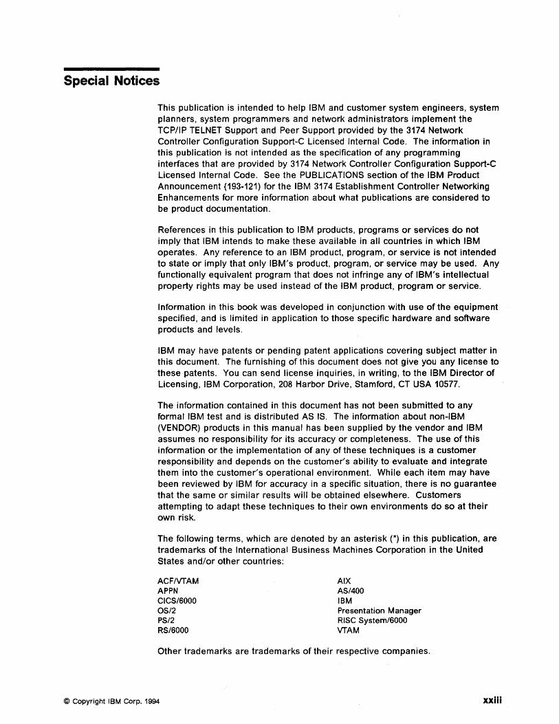
This publication is intended to help IBM and customer system engineers, system planners, system programmers and network administrators implement the TCP/IP TELNET Support and Peer Support provided by the 3174 Network Controller Configuration Support-C Licensed Internal Code. The information in this publication is not intended as the specification of any programming interfaces that are provided by 3174 Network Controller Configuration Support-C Licensed Internal Code. See the PUBLICATIONS section of the IBM Product Announcement (193-121) for the IBM 3174 Establishment Controller Networking Enhancements for more information about what publications are considered to be product documentation.
References in this publication to IBM products, programs or services do not imply that IBM intends to make these available in all countries in which IBM operates. Any reference to an IBM product, program, or service is not intended to state or imply that only IBM's product, program, or service may be used. Any functionally equivalent program that does not infringe any of IBM's intellectual property rights may be used instead of the IBM product, program or service.
Information in this book was developed in conjunction with use of the equipment specified, and is limited in application to those specific hardware and software products and levels.
IBM may have patents or pending patent applications covering subject matter in this document. The furnishing of this document does not give you any license to these patents. You can send license inquiries, in writing, to the IBM Director of Licensing, IBM Corporation, 208 Harbor Drive, Stamford, CT USA 10577.
The information contained in this document has not been submitted to any formal IBM test and is distributed AS IS. The information about non-IBM (VENDOR) products in this manual has been supplied by the vendor and IBM assumes no responsibility for its accuracy or completeness. The use of this information or the implementation of any of these techniques is a customer responsibility and depends on the customer's ability to evaluate and integrate them into the customer's operational environment. While each item may have been reviewed by IBM for accuracy in a specific situation, there is no guarantee that the same or similar results will be obtained elsewhere. Customers attempting to adapt these techniques to their own environments do so at their own risk.
The following terms, which are denoted by an asterisk (*) in this publication, are trademarks of the International Business Machines Corporation in the United States and/or other countries:
ACFIVTAM APPN CICS/SOOO OS/2 PS/2 RS/SOOO
AIX AS/400 IBM Presentation Manager Rise System/SOOO VTAM
Other trademarks are trademarks of their respective companies.
© Copyright I BM Corp. 1994 xxiii

xxiv Using the 3174 TCP/IP Networks
Preface
The 3174 Establishment Controller is a very important component in multi-protocol networks involving subarea SNA, Advanced Peer-to-Peer Networking (APPN), Peer Communication, Token-Ring and Ethernet LANs, X.25, Integrated Services Digital Network (ISDN), asynchronous communication, frame relay, and Transmission Control Protocol/Internet Protocol (TCP/IP).
This document focuses on the roles of the 3174 in TCP/IP networks. It includes functions introduced by the 3174 TCP/IP TELNET RPQ 8Q0935, enhancements such as TN3270, TCP/IP host printer, and SNMP MIB-II support offered by 3174 TCP/IP Enhancements RPQ 8Q1041 and the recently available IP Forwarding RPQ 8Q1289.
This document is intended to help customers and systems engineers understand the functionality provided and how to customize the 3174 for participation in a TCP/IP network. It is organized to help the reader understand the basics of the TCP/IP Architecture in general and the 3174 implementation specifically. The scenarios include sample configuration files and panels for the 3174 and other TCP/IP hosts in the network. The reader is assumed to have a basic knowledge of TCP/IP as implemented by the other products used in the scenarios.
How This Document is Organized The document is organized as follows:
© Copyright IBM Corp. 1994
• Chapter 1, "An Introduction to 3174 TCP/IP Support" on page 1
- This chapter gives a functional overview of 3174 TCP/IP support. It also contains a description of the TCP/I P architecture.
• Chapter 2, "3174 TCP/IP Telnet Support" on page 9
- This chapter provides information on how to implement the 3174 to support TCP/IP.
• Chapter 3, "Adding 3174 to TCP/IP Network" on page 19
- This chapter describes the terminal operation with 3174 TCP/IP TELNET support what is required to add the 3174 to a TCP/IP network.
• Chapter 4, "Scenario 1: TCP/IP Using 3174 Peer Communication Only" on page 67
This scenario shows how a PS/2 workstation, coax-attached to a 3174 Establishment Controller, can communicate with other TCP/IP host on the LAN via the 3174 Peer Communications bridge.
• Chapter 5, "Scenario 2: Concurrent Access to SNAand TCP/IP Hosts" on page 119
This scenario shows a RS/6000 workstation using the 3174 Gateway to access the 3270 SNA host while the 3270 coax-attached terminal use the 3174 TCP/IP TELNET client support to access the RS/6000 as a TCP/IP host.
• Chapter 6, "Scenario 3: APPN and TCP/IP via 3174 to AS/400 and VTAM" on page 159
xxv
This chapter (Scenario 3) shows the capability of a PS/2 EN utilizing an 3174 NN to communicate to an AS/400 NN and Subarea Node simultaneously. An 3270 CUT terminal using the 3174 Gateway to establish TCP/IP session with the TCP/IP on the AS/400 and establish a session with the SNA host
• Chapter 7, "Scenario 4: TCP/IP via 3174 and RS/6000 Router to VAX" on page 209
This chapter (Scenario 4) shows the capability of a PS/2 and 3270 3270 CUT terminal using the 3174 Gateway to establish a TCP/IP session to the VAX host which is connected via Ethernet on the RS/6000 router. Simultaneously the PS/2 and the 3270 CUT terminal using the 3174 Gateway to establish a TCP/IP session to an AS/400 host.
• Chapter 8, "3174 Ethernet Considerations" on page 227
- This chapter discusses, in general, the 3174 Ethernet support. This include the microcode, adapter and customization.
• Chapter 9, "3174 TCPIIP Enhancements RPQ 8Q1041" on page 263
- This chapter discusses the enhancements made to the 3174 TCP/IP support in the 3174 TCP/IP Enhancements RPQ 8Q1041.
• Chapter 10, "3174 Configuration Support C, Release 5" on page 351
This chapter discusses the ability to for the 3174 to communicate using TCP/IP protocol over a frame relay link, provided in Configuration Support-C Release 5
• Appendix A, "Address Bit Order for Ethernet Addresses" on page 359
- This Appendix discusses addressing issues when using 3174 Ethernet support.
• Appendix B, "SNMP Variables" on page 363
Related Publications
This Appendix contains a table of the SNMP variables supported by the 3174.
The publications listed in this section are considered particularly suitable for a more detailed discussion of the topics covered in this document.
• 3174 Establishment Controller Functional Description, GA23-0218
• 3174 Establishment Controller Configuration Support';'C Release 3 Planning Guide, GA27-3918
• 3174 Establishment Controller Configuration Support-C Release 3 Utilities Guide, GA27-3920
• 3174 Establishment Controller Status Codes, GA27-3832
• 3174 Establishment Controller Supplemental Customer Information for Configuration Support-C Release 4 Ethernet Adapter, GA27-3994
• 3174 Establishment Controller Customer Problem Determination, GA23-0217
• 3174 Establishment Controller Terminal User's Reference for Expanded Functions, GA23-0332
• Communications Manager/2 Configuration Guide, SC31-6171
xxvi Using the 3174 TCP/IP Networks
• IBM Transmission Control Protocol/Internet Protocol Version 2.0 for OS/2: User's Guide, SC31-6076
• NTS/2 LAN Adapter and Protocol Support Configuration Guide, S96F8489
• IBM Transmission Control Protocolllnternet Protocol Version 2.1.1 for DOS: Installation and Administration, SC31-7047
• IBM Transmission Control Protocolllnternet Protocol Version 2.1.1 for DOS: User's Guide, SC31-7045
• AIX Version 3 RISC System/60D0, Communication Concepts and Procedure, GC23-2203
• AIX System Management System/60D0, Communication Concepts and Procedure, GC23-2487
• Sun Microsystems System and Network Administration, 800-3805-10
• HP-UX System Administration Manual, Release 9.0, 800-3805-10
International Technical Support Organization Publications • 3174 Establishment Controller, Installation Guide, GG24-3061
• 3174 Establishment Controller APPN Implementation Guide, GG24-3702
• IBM Personal Communicationl3270 Version 3.0 Implementation Guide, GG24-3949
• IBM TCPIIP V2.1 for VM Installation and Interoperability, GG24-3624
• TCPIIP Tutorial and Technical Overview, GG24-3531
A complete list of International Technical Support Organization publications, with a brief description of each, may be found in:
Bibliography of International Technical Support Organization Technical Bulletins, GG24-3070.
To get listings of ITSO technical bulletins (redbooks) online, VNET users may type:
TOOLS SENDTO WTSCPOK TOOLS REDBOOKS GET REDBOOKS CATALOG
How to Order ITSO Technical Bulletins (Redbooks) -----------,
IBM employees in the USA may order ITSO books and CD-ROMs using PUBOROER. Customers in the USA may order by calling 1-800-879-2755 or by faxing 1-800-284-4721. Visa and Master Cards are accepted. Outside the USA, customers should contact their local IBM office.
Customers may order hardcopy red books individually or in customized sets, called GBOFs, which relate to specific functions of interest. IBM employees and customers may also order redbooks in online format on CD-ROM collections, which contain the redbooks for multiple products.
Preface xxvii
Acknowledgments The advisor for this project was:
Fran Collins International Technical Support Organization, Raleigh
The author of this document is:
Josef Minderlein IBM Germany
This publication is the result of a residency conducted at the International Technical Support Organization, Raleigh.
Thanks to the following people for the invaluable advice and guidance provided in the production of this document:
Tony Tan IBM Australia
Cathy Cunningham David Clark David Galloway 3174 Development Research Triangle Park, Raleigh
Rita Steffes-Hollaender Andrea Paravan IBM Germany
Thanks to the following people for the invaluable editorial advice and guidance provided in the production of this document:
Shawn Walsh Gail Wojton Janet Yoho International Technical Support Organization, Raleigh
xxviii Using the 3174 TCPIIP Networks
Chapter 1. An Introduction to 3174 TCP/IP Support
Transmission Control Protocolllnternet Protocol (TCP/IP) is a set of standards that have been widely accepted by the computer industry, both users and manufacturers, for communication between multivendor systems.
The 3174, traditionally a cluster controller for 3270 host devices, was enhanced with the TCP/IP Telnet client capability to allow 3270 displays operating in CUT mode, and ASCII displays attached to the Asynchronous Emulation Adapter (AEA), to access TCP/IP Telnet servers in TCP/IP networks. This capability was offered, in March 1992, as a no-charge 3174 TCP/IP Telnet RPQ 8Q0935, based on Configuration Support-C Release 2 LlC.
In May 1993, Configuration Support-C Release 3 was announced. Its base microcode includes the base functions of previous releases of 3174 Licensed Internal Code. In addition, the functions provided by the 3174 TCP/IP Telnet RPQ 8Q0935 are now integrated in the base functions of Configuration Support-C Release 3. This integrated capability is referred to as the 3174 TCPIIP Telnet Support in this document. Configuration Support-C Release 3 became available in June 1993.
In May 1993, Configuration Support-C Release 4 was also announced. Included in this announcement was the 3174 TCP/IP Enhancements RPQ 8Q1041, which provides TN3270 support, TCPIIP-dependent host printer support, and SNMP MIB-II support. This RPQ, available as of April 1994, combines the token-ring support of Configuration Support-C Release 3 with the Ethernet support of Configuration Support-C Release 4.
Currently the 3174 performs the function of a bridge for TCPIIP hosts that are coax-attached using the 3174 Peer Communications support. In this case there is no routing of IP traffic being done by the 3174. RPQ 8Q1289, scheduled for July 1994, expands the 3174 services of programmable workstation running TCPIIP by providing IP forwarding, via static routing.
This document focuses on the TCP/IP functions provided by the Configuration Support-C Release 3 and Configuration Support-C Release 4 base microcode and the RPQ 8Q1041. A brief discussion on TCPIIP support in Configuration Support-C Release 5 has been included to assist in doing some preliminary planning.
This chapter provides an overview of TCP/IP, and briefly describes the TCP/IP protocols supported by the 3174. This chapter uses material from the following document:
• TCPIIP Tutorial and Technical Overview, GG24-3531
1.1 3174 Functional Overview The following table is an overview of the functionality available in the different 3174 Configuration Support C microcode releases and RPQs.
© Copyright IBM Corp. 1994 1
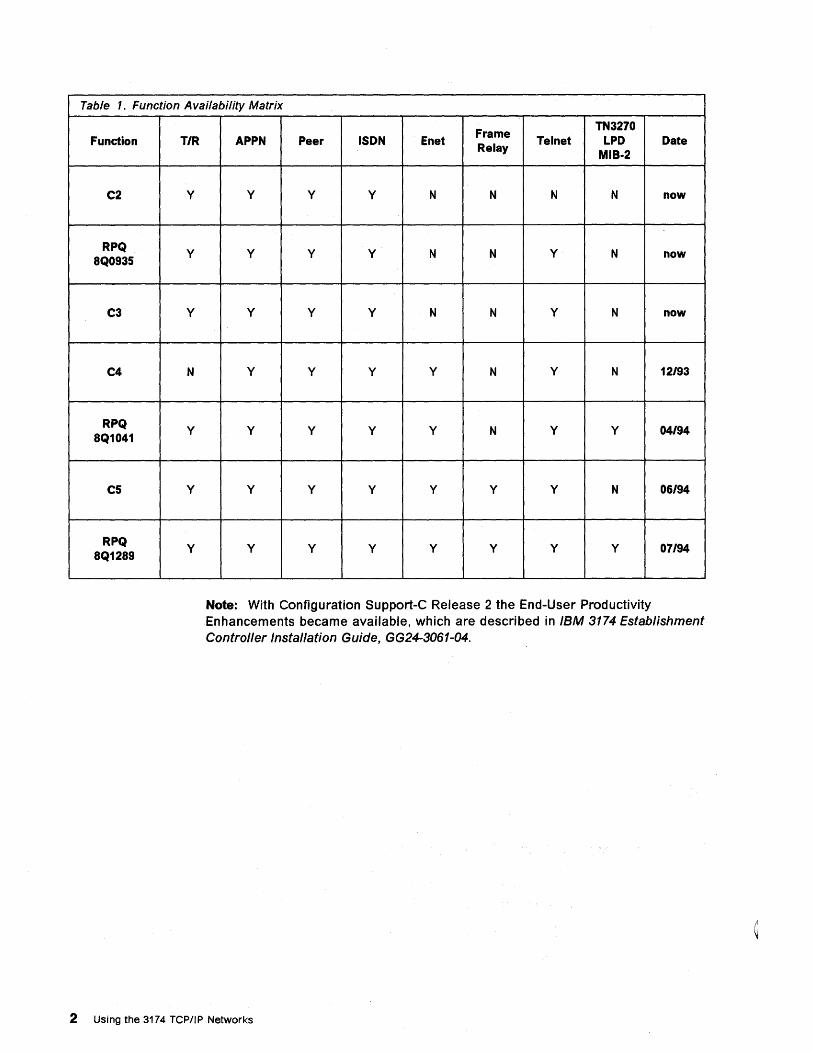
Table 1. Function Availability Matrix
Function T/R
C2 y
RPQ y 8Q0935
C3 Y
C4 N
RPQ y 8Q1041
C5 Y
RPQ y 8Q1289
Frame TN3270
APPN Peer ISDN Enet Telnet LPD Date Relay
MIB·2
y y y N N N N now
y y y N N Y N now
y y y N N Y N now
Y Y Y Y N Y N 12/93
y y y y N Y Y 04/94
Y Y Y Y Y y N 06/94
y y y y y y y 07/94
Note: With Configuration Support-C Release 2 the End-User Productivity Enhancements became available, which are described in IBM 3174 Establishment Controller Installation Guide. GG24-3061-04.
2 Using the 3174 TCP/IP Networks
1.2 TCP/IP Overview TCP/IP includes a set of network standards specifying the details for computer communication, as well as a set of conventions for interconnecting networks and routing traffic. Its primary use is for interconnection of networks providing universal communication services. The collection of these networks interconnected through TCP/IP is known as an internet.
Each network uses a gateway, a bridge or a router to connect into an internet. All nodes on all networks within an internet communicate with each other as if all other nodes were in the same network. TCP/IP connectivity includes routing capabilities for both local area and wide area networks.
When TCP/IP is used on a token-ring network, all the normal token-ring network management functions are available because token-ring network management is independent of the higher-level protocol. This applies as well to environments using an SNA network as the transport mechanism for TCP/IP.
In today's multivendor and multiprotocol world, SNA networks and TCP/IP networks need to run side by side to allow users to access, from a single display station, any application in the network.
Together with the 3174 TCP/IP Telnet Support, the 3174 is now able to support TCP/IP environments via the token-ring network.
1.3 TCP/IP Architecture This section briefly describes the TCP/IP architectural layers supported by the 3174 TCP/IP Telnet Support.
The internet protocols are modeled into four functional layers:
• Application
This is a user process cooperating with another process on the same or different host.
• Transport
This layer provides the end-to-end data transfer.
• Internetwork
This layer provides the "virtual network" image of internet and shields the higher levels from the network architecture below it. It is probably the most important protocol.
• Network Interface
This layer is the interface to the actual network hardware.
1.3.1 Transmission Control Protocol (Tep) Most of the user application protocols, such as Telnet and FTP, use TCP as the underlying protocol. TCP is a connection-oriented, end-to-end reliable protocol providing logical connections between pairs of processes.
For applications making use of this protocol, TCP provides the following:
• Stream data transfer
Chapter 1. An Introduction to 3174 TCPIIP Support 3
From the application's viewpoint, TCP transfers a contiguous stream of bytes through the internet. First it groups the data into TCP segments, before passing the segments to IP for transmission to its destination.
• Reliability
TCP assigns a sequence number to each transmitted byte and expects a positive acknowledgment (ACK) from the receiving TCP. If the ACK is not received within a timeout interval, the data is retransmitted.
• Flow control
The receiving TCP, when sending an ACK back to the sender, indicates to the sender the number of bytes it can receive beyond the last received TCP segment, without causing overruns or overflows.
• Multiplexing
With this technique datagrams are directed through the use of ports.
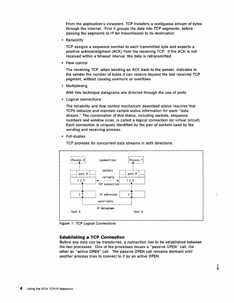
• Logical connections
The reliability and flow control mechanism described above requires that TCPs initialize and maintain certain status information for each "data stream." The combination of this status, including sockets, sequence numbers and window sizes, is called a logical connection (or virtual circuit). Each connection is uniquely identified by the pair of sockets used by the sending and receiving process.
• Full-duplex
TCP provides for concurrent data streams in both directions.
connections
sockets
reliable T C P +------ ....
'-----+-----' TCP connect i on '-----+-----' T C P
IP addresses
unreliable
IP datagrams host A host B
Figure 1. rcp Logical Connections
Establishing a TCP Connection Before any data can be transferred, a connection has to be established between the two processes. One of the processes issues a "passive OPEN" call, the other an "active OPEN" call. The passive OPEN call remains dormant until another process tries to connect to it by an active OPEN.
4 Using the 3174 TCP/IP Networks
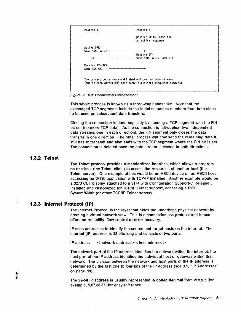
1.3.2 Telnet
Process 1
Active OPEN
Process 2
passive OPEN, waits for an active response
Send SYN, seq=n --------~ Receive SYN
+41--------- Send SYN, seq=m, ACK n+l
Receive SYN+ACK Send ACK m+l
The connection is now established and the two data streams (one in each direction) have been initialized (sequence numbers).
Figure 2. rcp Connection Establishment
This whole process is known as a three-way handshake. Note that the exchanged TCP segments include the initial sequence numbers from both sides to be used on subsequent data transfers.
Closing the connection is done implicitly by sending a TCP segment with the FIN bit set (no more TCP data). As the connection is full-duplex (two independent data streams, one in each direction), the FIN segment only closes the data transfer in one direction. The other process will now send the remaining data it still has to transmit and also ends with the TCP segment where the FIN bit is set. The connection is deleted once the data stream is closed in both directions.
The Telnet protocol provides a standardized interface, which allows a program on one host (the Telnet client) to access the resources of another host (the Telnet server). One example of this would be an ASCII device on an ASCII host accessing an S/390 application with TCP/IP installed. Another example would be a 3270 CUT display attached to a 3174 with Configuration Support-C Release 3 installed and customized for TCP/IP Telnet support, accessing a RISC System/6000· (or other TCP/IP Telnet server).
1.3.3 Internet Protocol (lP) The Internet Protocol is the layer that hides the underlying physical network by creating a virtual network view. This is a connectionless protocol and hence offers no reliability, flow control or error recovery.
IP uses addresses to identify the source and target hosts on the internet. The internet (IP) address is 32 bits long and consists of two parts:
IP address = < network address> < host address>
The network part of the IP address identifies the network within the internet; the host part of the IP address identifies the individual host or gateway within that network. The division between the network and host parts of the IP address is determined by the first one to four bits of the IP address (see 3.1, HIP Addresses" on page 19).
The 32-bit IP address is usually represented in dotted decimal form w.x.y.z (for example, 9.67.38.87) for easy reference.
Chapter 1. An Introduction to 3174 TCP/IP Support 5
1.3.4 Internet Control Messaging Protocol (ICMP) ICMP is a standard protocol. The IP is used for datagram services in an interconnected set of networks (internets). The network connection devices are IP gateways that exchange routing information between themselves using special TCP/IP protocols. ICMP 'functions are characterized as:
• ICMP uses IP as if it were a higher-level protocol. It is also an integral part of IP and is implemented in every IP module.
• ICMP is used to report errors found during datagram processing, and is used by:
The gateway - The destination host
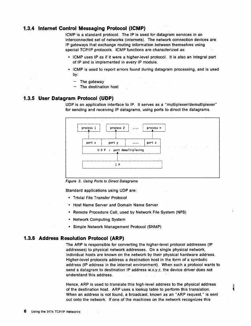
1.3.5 User Datagram Protocol (UDP) UDP is an application interface to IP. It serves as a "multiplexer/demultiplexer" for sending and receiving IP datagrams, using ports to direct the datagrams.
U D P : port demultiplexing
I P
Figure 3. Using Ports to Direct Datagrams
Standard applications using UDP are:
• Trivial File Transfer Protocol
• Host Name Server and Domain Name Server
• Remote Procedure Call, used by Network File System (NFS)
• Network Computing System
• Simple Network Management Protocol (SNMP)
1.3.6 Address Resolution Protocol (ARP) The ARP is responsible for converting the higher-level protocol addresses (IP addresses) to physical network addresses. On a single physical network, individual hosts are known on the network by their physical hardware address. Higher-level protocols address a destination host in the form of a symbolic address (IP address in the internet environment). When such a protocol wants to send a datagram to destination IP address w.x.y.z, the device driver does not understand this address.
Hence, ARP is used to translate this high-level address to the physical address of the destination host. ARP use.s a lookup table to perform this translation. When an address is not found, a broadcast, known as an "ARP request," is sent out onto the network. If one of the machines on the network recognizes this
6 Using the 3174 TCP/IP Networks
address, an "ARP reply" is sent back to the requesting host with the physical hardware address of the host and source route information. This is then stored for future use.
1.3.7 Simple Network Management Protocol (SNMP) SNMP is used to communicate management information between the network management stations and the agents in the network elements.
1.3.8 Domain Name System The Domain Name System, through the use of a server application, provides the translation between high-level machine names and the IP addresses. The client function (called the resolver) is transparent to the user and is called by most of the other applications to resolve the symbolic high-level names into real IP addresses.
1.3.9 Packet Internet Groper (PING) PING is an application that sends out an ICMP datagram to a specified destination and waits for its return. The server counterpart merely echoes the frame it receives back to the originator. PING, therefore, can be used to determine if the destination host can be reached, that is, to check the connectivity path between two machines.
1.3.10 TCP/IP Gateways Gateways interconnect multiple networks to form an internet. In the IBM* environment we use the following definitions for bridges, routers and gateways:
• Bridge
A bridge interconnects LAN segments at the data link layer and forwards frames between them. It performs the function of a MAC relay and is independent of any higher layer protocols.
• Router
A router interconnects networks at the network layer and route packets between them. Because it needs to understand the network addressing schemes used, a router is protocol-dependent. Routers are able to optimize packet sizes and transmission paths.
• Gateway
A gateway interconnects networks at higher layers than bridges or routers, ranging from the network layer to the application layer. It usually supports address mapping from one network to another~
In the TCP/IP environment, the terms "gateway" and "internet gateway" are used to qualify what is defined above as being a router.
1.4 TCP/IP Protocols Supported The 3174 supports the following protocols:
• Tel. (client only)
• TCP - Transmission Control Protocol
• IP - Internet Protocol
Chapter 1. An Introduction to 3174 TCP/IP Support 7
• ICMP - Internet Control Messaging Protocol
• UDP - User Datagram Protocol
• ARP - Address Resolution Protocol
• SNMP - Simple Network Management Protocol (MIB-I agent only)
• DNS - Domain Name System (resolver client only)
• PING - Packet Internet Groper
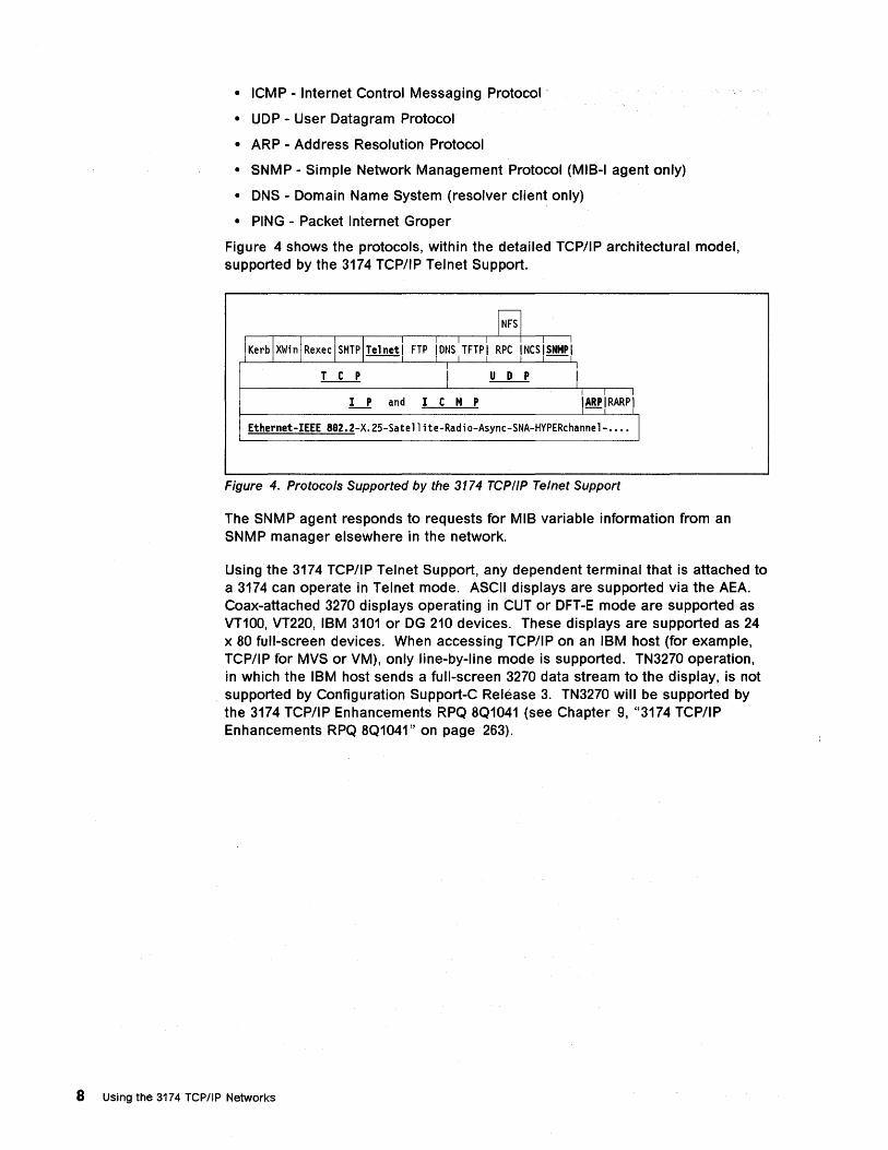
Figure 4 shows the protocols, within the detailed TCP/IP architectural model, supported by the 3174 TCP/IP Telnet Support.
IKerbjxwinjRexeclsMTPI!!ln!!1 FTPIDNS:TFTPI RPC NCS1~1
LL! I LL1 i I P and I C M P IARPIRARPI
Ethernet-IEEE aB2.2-X.25-Satellite-Radio-Async-SNA-HYPERchannel- •.•. I
Figure 4. Protocols Supported by the 3174 TCP/IP Telnet Support
The SNMP agent responds to requests for MIB variable information from an SNMP manager elsewhere in the network.
Using the 3174 TCP/IP Telnet Support, any dependent terminal that is attached to a 3174 can operate in Telnet mode. ASCII displays are supported via the AEA. Coax-attached 3270 displays operating in CUT or DFT-E mode are supported as VT100, VT220, IBM 3101 or DG 210 devices. These displays are supported as 24 x 80 full-screen devices. When accessing TCP/IP on an IBM host (for example, TCP/IP for MVS or VM), only line-by-line mode is supported. TN3270 operation, in which the IBM host sends a full-screen 3270 data stream to the display, is not supported by Configuration Support-C Release 3. TN3270 will be supported by the 3174 TCP/IP Enhancements RPQ 8Q1041 (see Chapter 9, "3174 TCP/IP Enhancements RPQ 8Q1041" on page 263).
8 Using the 3174 TCPIIP Networks
Chapter 2. 3174 TCP/IP Telnet Support
Existing IBM program products, TCPIIP for DOS and TCPIIP for OS/2*, provide TCP/IP support for intelligent workstations. These workstations may be attached using a Token-Ring, IBM PC Network, Ethernet, 3174 Peer (LAN over COAX), or Asynchronous Serial Line Internet Protocol (SLIP). 3174 TCP/IP Telnet support, provides TCP/IP host access to CUT and ASCII terminals directly attached.
This chapter describes the 3174 TCP/IP Telnet Support, including the 3174 models supported, the customization required, and operational aspects of this capability. This chapter uses material from the following document:
• 3174 TCP/IP Telnet RPQ Diskettes Installation Instruction (provided with the RPQ 8Q0935 package).
The 3174 TCP/IP Enhancements RPQ 8Q1041 and Configuration Support-C Release 5 enhancements are described, in later chapters.
2.1 Support before 3174 TCP/IP Telnet RPQ 8Q0935 With the addition of the Peer Communication LlC feature or the Peer Communication RPQ 8Q0718 in a 3174 that is attached to a Token-Ring, the intelligent workstations can be coax-attached to the 3174 and participate in TCP/IP networking. For this configuration, the workstations require the appropriate LAN-Over-Coax device drivers provided by the following:
• For DOS, Workstation Peer Communication Support Program
• For OS/2, Extended Services, OS/2 LAN Server or NTS/2
Note:
The DOS Workstation Peer Communications Support Program has been replaced with the NOIS compliant driver, IBMXLN.DOS.
The 3174, in this instance, provides nothing more than an internal ring and an internal bridge to allow the coax-attached workstations access to the Token-Ring; it has no TCPIIP capability and dependent (CUT, DFT-E or ASCII) terminals attached to the 3174 cannot participate in TCP/IP networking.
The TCP/IP hosts to be accessed by the intelligent workstations may be attached directly to the same Token-Ring, or they may be accessible through the Token-Ring via bridges or routers.
2.2 Support with 3174 TCP/IP Telnet RPQ 8Q0935 With the announcement of the 3174 TCP/IP Telnet RPQ 8Q0935 and Configuration Support-C Release 2 in March 1992, a new capability was added to a Token-Ring attached 3174: the 3174 could now be customized to provide TCPIIP Telnet client services to allow dependent (CUT, DFT-E or ASCII) terminals attached to the 3174 to communicate with TCP/IP Telnet servers.
With the 3174 TCPIIP Telnet RPQ 8Q0935, a dependent (CUT, DFT-E and ASCII) terminal attached to the 3174 can establish a TCP/IP Telnet connection with a TCP/IP hosVserver anywhere in the existing LAN/WAN network. The TCP/IP
@ Copyright IBM Corp. 1994 9
hosts to be accessed by the dependent terminals may be attached directly to the same Token-Ring, or they may be accessible through the Token-Ring via bridges or routers.
Each terminal user can have up to five logical terminals (L Ts) if Multiple Logical Terminal(MLT) is customized. These five LTs can be used to access 3270, ASCII or TCP/IP host sessions; that is, all five LTs may be used to access five 3270 host sessions, or five ASCII host sessions, or five TCP/IP host sessions, or some combination of 3270, ASCII and TCP/IP host sessions. The desired host connection can be selected by means of the Connection. Menu, or established by default. Any LT can be used to access the TCP/IP "pipe," very much the same way that a dial-out AEA port is accessed. For each TCP/IP LT, a simple set of commands allows the user to request and operate a session with any TCP/IP host in the network.
As seen above, the 3174 TCP/IP Telnet RPQ 8Q0935 works in conjunction with MLT and AEA functions. You can also use the 3174 TCP/IP Telnet RPQ 8Q0935 concurrently with all other functions that a given 3174 is capable of, such as Peer Communication and APPN*.
2.3 Support with Configuration Support-C Release 3 In May 1993, Configuration Support-C Release 3 was announced. Its base microcode includes the base functions of previous releases of 3174 Licensed Internal Code. In addition, the functions provided by the 3174 TCP/IP Telnet RPQ 8Q0935 are now integrated in the base functions of Configuration Support-C Release 3. This integrated capability is referred to as the 3174 TCP/IP Telnet Support in this document.
In other words, the TCP/IP capabilities provided by the 3174 TCP/IP Telnet RPQ 8Q0935 are now provided by Configuration Support-C Release 3 base microcode.
2.4 Support with 3174 TCP/IP Enhancements RPQ 8Q1041 In May 1993, Configuration Support-C Release 4 was also announced. Included in this announcement was the 3174 TCP/IP Enhancements RPQ 8Q1041, which will provide TN3270 support, TCP/IP dependent host printer support, and SNMP MIB-II support. This RPQ, was made available April 1994, and is based on Configuration Support-C Release 4. With RPQ 8Q1041, therefore, the TCP/IP capabilities of the 3174 are extended even further.
2.5 Support with Configuration Support-C Release 5 . Configuration Support-C Release 5 and frame relay support expands the 3174 connectivity for 3174 TCP/IP support. Prior to Configuration Support-C Release 5 all TCP/IP access to and from the 3174 assumed LAN (token-ring or Ethernet). With Configuration Support-C Release 5, you are able to telnet to TCP/IP host in the network via frame wide area network links. As of the publication date of this document, 3174 TCP/IP Enhancements RPQ8Q1041 was not available for Configuration Support-C Release 5.
10 Using the 3174 TCP/IP Networks
2.6 Support with 3174 IP Forwarding RPQ 8Q1289 3174 IP Forwarding RPQ 8Q1289 enables intelligent workstation that are not directly attached to the 3174 using Peer Communications, access to TCP/IP hosts via the 3174 the frame relay link(s). The 3174 actually, provides static IP routing for LAN (token-ring or Ethernet) attached intelligent workstation running as TCP/I P hosts.
2.7 TELNET Emulation and NLS Support The 3174 TCP/IP Telnet Support allows CUT terminals to have up to five TELNET sessions. The supported emulators for National Language Support (NLS) are:
• VT100
• VT220 7 -bit
Note: IBM3101, DG210 and VT220 8-bit emulation are not supported for NLS
In our scenario, we have tested NLS for the German and Canadian/Bilingual languages. In TELNET session with the RISC System/6000, we use the SMIT (Systems Management Interface Tool) facility.
German NLS experience:
• VT100 emulation:
- All PF keys useable.
- Use Alt instead of Esc key.
• VT220 7-bit emulation:
SMIT panel displays OK.
All PF keys usable.
Canadian/Bilingual NLS experience:
• VT100 emulation:
All PF keys, except the PF8, PF9 and PF10 keys, are usable.
PF8, PF9 and PF10 keys only capable in conjunction with Esc key.
Use Alt instead of Esc key.
• VT220 7-bit emulation:
SMIT panel displays OK.
All PF keys usable.
Note: If you are using a PS/2· with a 3270 CUT mode emulation program, you have to respond to 3174 customization Question 168 with 1. This function allows you to define the Home key as hot key.
Using this emulation will require you to define some additional keys. For more information about the different keyboard maps, see Terminal User's Reference for Expanded Functions, GA23-0332.
Chapter 2. 3174 TCPIIP Telnet Support 11
2.8 3174 Models Supported The 3174 TCP/IP Telnet Support allows display devices that are attached to a 3174 to communicate with any TCP/IP host that is accessible via the LAN (token-ring or Ethernet). The TCP/IP host may be attached directly to the LAN (token-ring or Ethernet), or it may be bridged or routed to the LAN (token-ring or Ethernet) from elsewhere in the network.
The 3174 can be attached to a LAN (token-ring or Ethernet), either as a gateway, DSPU or stand-alone. Stand-alone requires no SNA host, and was first available in Configuration Support-C Release 4. For Configuration Support-C Release 3 and earlier versions the only way to customize the token-ring adapter was as a gateway or DSPU. Once you have the LAN (token-ring or Ethernet) attachment, the 3174 TCP/IP Telnet Support can be used on most models of the 3174.
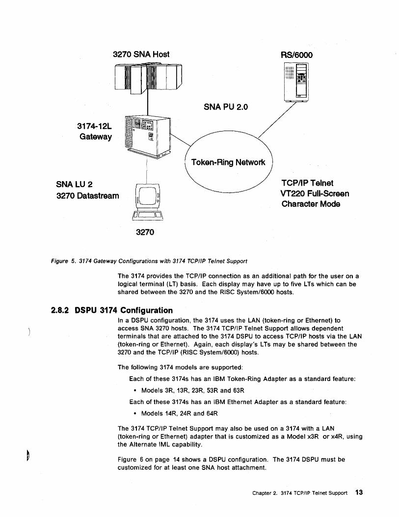
2.8.1 Gateway 3174 Configuration In a gateway configuration, the 3174 is attached to the SNA 3270 host either by a channel or a teleprocessing attachment. The 3174 gateway allows other devices on the LAN (token-ring or Ethernet) to access the 3270 host. The 3174 TCP/IP Telnet Support supports this configuration, allowing terminals that are attached to the 3174 gateway to access TCP/IP hosts via the LAN (token-ring or Ethernet).
The following 3174 models, customized as gateways, can be used with the 3174 TCP/IP Telnet Support; each of these 3174s requires a LAN adapter (IBM TOken-Ring Adapter feature #3026, #3030 or #3044 or IBM Ethernet Adapter feature #3045):
• Models 01 L, 01 R, 02R
• Models 11L, 11R, 12L, 12R, 14R
• Models 21 L, 21 R, 22L, 22R, 24R
• Models 51 R, 61 R, 62R, 64R
One and only one LAN adapter can be customized and operational.
Figure 5 on page 13 shows a gateway configuration. In this configuration, the RISC System/6000 is using the 3174 gateway to access the 3270 host. The RISC System/6000, in turn, is being accessed as a TCP/IP host by the 3174 terminals. The token ring, in this case, can be replaced by an Ethernet LAN.
12 Using the 3174 TCPIIP Networks
3174-12L Gateway
SNALU 2
3270 SNA Host
SNA PU 2.0
RS/6000
1I111111~ 11111111 11111111 11111111
3270 Datastream
TCP/IP Telnet VT220 Full-Screen Character Mode
3270
Figure 5. 3174 Gateway Configurations with 3174 TCPIIP Telnet Support
The 3174 provides the TCP/IP connection as an additional path for the user on a logical terminal (L T) basis. Each display may have up to five LTs which can be shared between the 3270 and the RISC System/BOOO hosts.
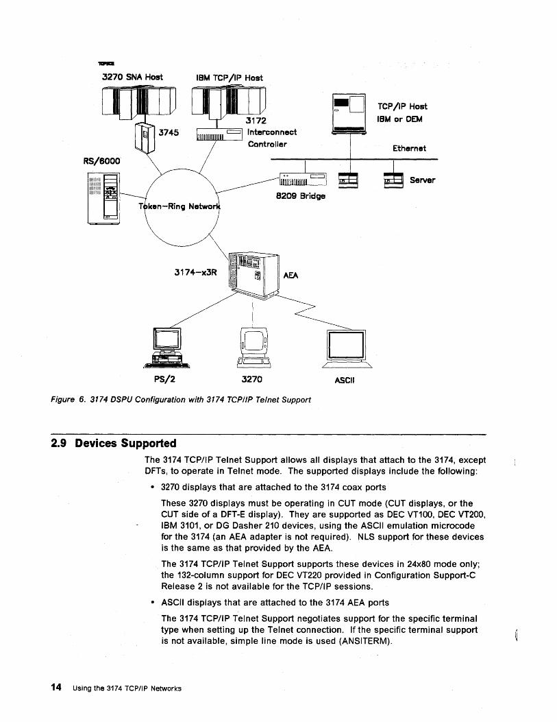
2.8.2 DSPU 3174 Configuration In a DSPU configuration, the 3174 uses the LAN (token-ring or Ethernet) to access SNA 3270 hosts. The 3174 TCP/IP Telnet Support allows dependent terminals that are attached to the 3174 DSPU to access TCP/IP hosts via the LAN (token-ring or Ethernet). Again, each display's L Ts may be shared between the 3270 and the TCP/I P (RISC System/BOOO) hosts.
The following 3174 models are supported:
Each of these 3174s has an IBM Token-Ring Adapter as a standard feature:
• Models 3R, 13R, 23R, 53R and B3R
Each of these 3174s has an IBM Ethernet Adapter as a standard feature:
• Models 14R, 24R and B4R
The 3174 TCP/IP Telnet Support may also be used on a 3174 with a LAN (token-ring or Ethernet) adapter that is customized as a Model x3R or x4R, using the Alternate IML capability.
Figure B on page 14 shows a DSPU configuration. The 3174 DSPU must be customized for at least one SNA host attachment.
Chapter 2. 3174 TCP/IP Telnet Support 13
3270 SNA Host IBM TCP/IP. Host
RS/6000
IIIIIIII~ 11111111 11111111 11111111
c
-Rin; N
J174-xJR
PS/2
Interconnect
Controller
8209 Bridge
AEA
3270
D ASCII
TCP/IP Host
IBM or OEM
Ethernet
Server
Figure 6. 3174 DSPU Configuration with 3174 TCPIIP Telnet Support
2.9 Devices Supported The 3174 TCP/IP Telnet Support allows all displays that attach to the 3174, except DFTs, to operate in Telnet mode. The supported displays include the following:
• 3270 displays that are attached to the 3174 coax ports
These 3270 displays must be operating in CUT mode (CUT displays, or the CUT side of a DFT-E display). They are supported as DEC VT100, DEC VT200, IBM 3101, or DG Dasher 210 devices, using the ASCII emulation microcode for the 3174 (an AEA adapter is not required). NLS support for these devices is the same as that provided by the AEA.
The 3174 TCP/IP Telnet Support supports these devices in 24x80 mode only; the 132-column support for DEC VT220 provided in Configuration Support-C Release 2 is not available for the TCP/IP sessions.
• ASCII displays that are attached to the 3174 AEA ports
The 3174 TCP/IP Telnet Support negotiates support for the specific terminal type when setting up the Telnet connection. If the specific terminal support is not available, simple line mode is used (ANSITERM).
14 Using the 3174 TCP/IP Networks
2.10 Hosts Supported The 3174 TCP/IP Telnet Support connects the supported devices to any host or device attached to the network that can communicate with TCP/IP and Telnet protocols, including IBM and non-IBM hosts. The TCP/IP hosts may be attached directly to the LAN (token-ring or Ethernet), or they may be bridged or routed to the LAN (token-ring or Ethernet) from elsewhere in the network.
Access to IBM TCP/IP hosts (TCP/IP for VM or MVS), however, is limited to line mode only, when using base Configuration Support-C Release 3 or 4. This is because the 3174 TCP/IP Telnet Support currently available in the base Configuration Support-C Release 3 or 4 does not support TN3270 protocols. Support for TN3270 is available in 3174 TCP/IP Enhancements RPQ 8Q1041 (see Chapter 9, "3174 TCP/IP Enhancements RPQ 8Q1041" on page 263).
2.11 Storage Requirements
2.11.1 Sessions
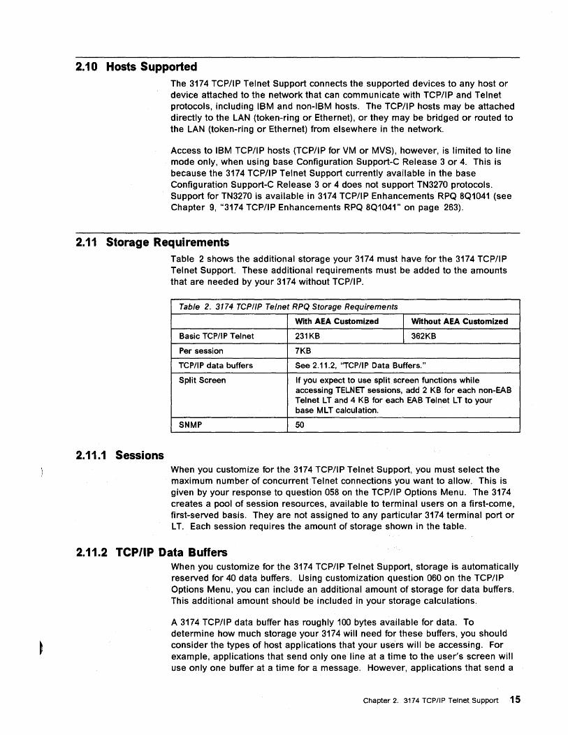
Table 2 shows the additional storage your 3174 must have for the 3174 TCP/IP Telnet Support. These additional requirements must be added to the amounts that are needed by your 3174 without TCP/IP.
Table 2. 3174 TCP/IP Telnet RPQ Storage Requirements
With AEA Customized Without AEA Customized
Basic TCP/IP Telnet 231KB 362KB
Per session 7KB
TCP/IP data buffers See 2.11.2, "TCP/I P Data Buffers."
Split Screen If you expect to use split screen functions while accessing TELNET sessions, add 2 KB for each non-EAB Telnet LT and 4 KB for each EAB Telnet LT to your base MLT calculation.
SNMP 50
When you customize for the 3174 TCP/IP Telnet Support, you must select the maximum number of concurrent Telnet connections you want to allow. This is given by your response to question 058 on the TCP/IP Options Menu. The 3174 creates a pool of session resources, available to terminal users on a first-come, first-served basis. They are not assigned to any particular 3174 terminal port or LT. Each session requires the amount of storage shown in the table.
2.11.2 TCP/IP Data Buffers When you customize for the 3174 TCP/IP Telnet Support, storage is automatically reserved for 40 data buffers. Using customization question 060 on the TCP/IP Options Menu, you can include an additional amount of storage for data buffers. This additional amount should be included in your storage calculations.
A 3174 TCP/IP data buffer has roughly 100 bytes available for data. To determine how much storage your 3174 will need for these buffers, you should consider the types of host applications that your users will be accessing. For example, applications that send only one line at a time to the user's screen will use only one buffer at a time for a message. However, applications that send a
Chapter 2. 3174 TCP/IP Tel net. Support 15
full screen of information with screen formatting controls included may send much larger messages, requiring many 3174 buffers at a time. Your decision will also be affected by the number of concurrent sessions you select in question 058.
When the 3174 runs out of buffers:
• The 3174 discards data from the TCP/IP network, causing retransmissions and adversely affecting response times.
• Requests to establish host connections will be rejected, and the users must retry to establish the connection.
2.12 Microcode Packaging • RPQ 8Q0935 packaging
The information in this section is included for completeness.
The 3174 TCP/IP Telnet RPQ 8Q0935 is a Control/Utility/Extension disk RPQ. This means that you receive a complete set of 3174 diskettes with each order of the RPQ. It is based on Configuration Support-C Release 2 L1C and provides all Configuration Support-C Release 2 functions. Just as with other Configuration Support-C releases, any DSL or feature microcode must be merged onto the Control Extension diskette before the feature can be used.
Notes:
1. The 3174 TCP/IP Telnet RPQ 8Q0935 may not be compatible with other Configuration Support-C Release 2 RPQs. You should check with your IBM marketing representative if you have questions about RPQ compatibility.
2. The 3174 TCP/IP Telnet RPQ 8Q0935 should not be used in configurations that has the TCP/IP capability disabled (via customization).
• Configuration Support-C Release 3 packaging
The 3174 TCP/IP Telnet Support functions are integrated in Configuration Support-C Release 3, which is shipped as follows:
One Utility diskette
Two Control diskettes
One Control Extension diskette
• Configuration Support-C Release 4 packaging
The 3174 TCP/IP Telnet Support functions are enhanced for Ethernet connectivity in Configuration Support-C Release 4, which is shipped as follows:
One Utility diskette
Two Control diskettes
One Control Extension diskette
• 3174 TCP/IP Enhancements RPQ 8Q1041 packaging
The 3174 TCP/IP functions are enhanced in 3174 TCP/IP Enhancements RPQ 8Q1041, with TN3270, LPD and SNMP MIB-II, which is shipped as follows:
- One Utility diskette
16 Using the 3174 TCP/IP ~etworks
Two Control diskettes
One Control Extension diskette (pre-merged)
Notes:
1. Depending on IBM business and technical judgements, the 3174 TCP/IP Enhancements RPQ 8Q1041 may be integrated into the Configuration Support-C base microcode in the future.
• Configuration Support-C Release 5 packaging
Configuration Support-C Release 5 adds the additional connectivity option of frame relay to 3174 TCP/lP, which is shipped as follows:
One Utility diskette
Two Control diskettes
One Control Extension diskette(pre-merged)
One optional frame relay DSL
• 3174 IP Forwarding RPQ 8Q1289 packaging
3174 IP Forwarding RPQ 8Q1289 provides static IP routing for LAN (token-ring or Ethernet) attached intelligent workstations via 3174 frame relay link(s), which is shipped as follows:
- One mergeable RPQ diskette
Chapter 2. 3174 TCPIIP Telnet Support 11

18 Using the 3174 TCP/IP Networks
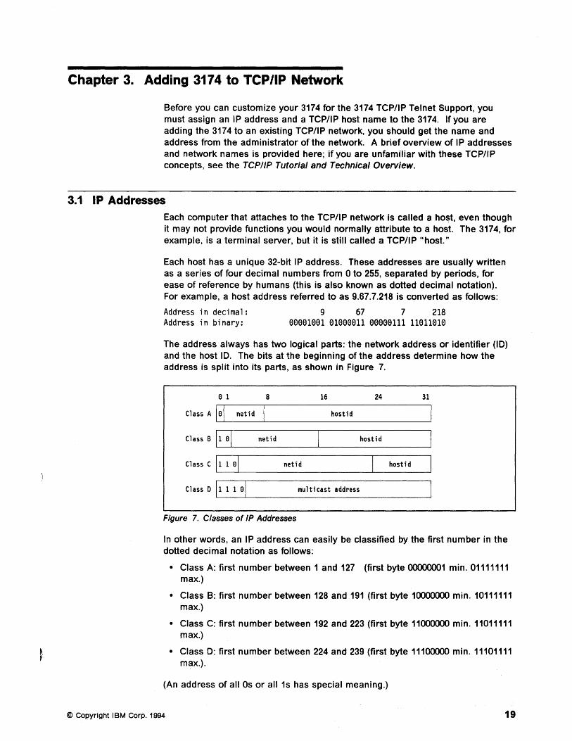
Chapter 3. Adding 3174 to TCP/IP Network
Before you can customize your 3174 for the 3174 TCP/IP Telnet Support, you must assign an IP address and a TCP/IP host name to the 3174. If you are adding the 3174 to an existing TCP/IP network, you should get the name and address from the administrator of the network. A brief overview of IP addresses and network names is provided here; if you are unfamiliar with these TCP/IP concepts, see the TCP/IP Tutorial and Technical Overview.
3.1 IP Addresses Each computer that attaches to the TCP/IP network is called a host, even though it may not provide functions you would normally attribute to a host. The 3174, for example, is a terminal server, but it is still called a TCP/IP "host."
Each host has a unique 32-bit IP address. These addresses are usually written as a series of four decimal numbers from 0 to 255, separated by periods, for ease of reference by humans (this is also known as dotted decimal notation). For example, a host address referred to as 9.67.7.218 is converted as follows:
Address in decimal: 9 67 7 218 Address in binary: 00001001 01000011 00000111 11011010
The address always has two logical parts: the network address or identifier (ID) and the host ID. The bits at the beginning of the address determine how the address is split into its parts, as shown in Figure 7.
a 1 8 16 24 31
Class A lal netid hostid
Class B 11 al netid hostid
Class C 1L-1_1_a-.J..·I ____ n_et_i d ______ ~_h_os_tl_· d_~
Class 0 11 1 1 al multicast address
Figure 7. Classes of IP Addresses
In other words, an IP address can easily be classified by the first number in the dotted decimal notation as follows:
• Class A: first number between 1 and 127 (first byte 00000001 min. 01111111 max.)
• Class B: first number between 128 and 191 (first byte 10000000 min. 10111111 max.)
• Class C: first number between 192 and 223 (first byte 11000000 min. 11011111 max.)
• Class D: first number between 224 and 239 (first byte 11100000 min. 11101111 max.).
(An address of all Os or all 1s has special meaning.)
© Copyright I BM Corp. 1994 19
We can see that 9.67.7.218 is a Class A address, with 9 (the first byte) as the network ID and 67.7.218 (the next three bytes) as the host ID.
You will, therefore, need an IP address for the 3174 being customized (see your system/network administrator).
3.2 Subnet Masks A single TCP/IP network, however, can be further divided into multiple smaller networks, known as subnetworks or sUbnets. You may wish to divide a single large TPC/IP network at your organization into several subnets, for example, by department.
To identify these subnets, we use some of the host ID bits to form the subnet ID. A subnet mask determines which bits of the host 10 will be used. The subnet mask contains a 1 for each bit of the IP address that is used for the network or subnet ID. For example, using a subnet mask of 255.255.255.0 and applying it to the address 9.67.7.218 yields the following:
Address in decimal: 9 67 7 218 Address in binary: eeee1eel e1eeee11 eeeee111 11e11e1e Subnet mask in binary: 11111111 11111111 11111111 eeeeeeee Subnet mask in decimal: 255 255 255 e Address interpretation: INetwork IOI Subnet IO 1 Host IOI
What this means is that:
• The first eight bits are used as the network ID (because it is a Class A address)
• The next 16 bits are used as the subnet ID (because of the 1 bits in the subnet mask)
• The last eight bits are used as the host ID (because of the 0 bits in the subnet maSk).
If a different subnet mask is used, the bits are interpreted differently. For example, using a subnet mask of 255.255.240.0 and applying it to the address 9.67.7.218 yields the following:
Address in decimal: Address in binary: Subnet mask in binary: Subnet mask in decimal: Address interpretation:
9 67 7 218 eeee1eel e1eeee11 eeeee111 11e11e1e 11111111 11111111 1111eeee eeeeeeee
255 255 24e e INetwork 101 Subnet IO 1 Host 10 1
Now, what this means is that:
• The first eight bits are used as the network 10 (as before).
• The next 12 bits are used as the subnet ID.
• The last 12 bits are used as the host ID.
USing subnet mask 255.255.255.0 on IP address 9.67.7.218 shows that the host is identified as being in network ID 9, subnet ID 17152, host ID 218. Using subnet mask 255.255.240.0 on the same I P address shows that the host is identified as being in network ID 9, subnet ID 1072, host ID 2010.
20 Using the 3174 TCPIIP Networks
If your TCP/IP network is split into'subnets, you will, therefore, have to know the subnet mask to use when you customize the 3174.
3.3 Customizing IP Addresses
3.4 Names
Whenever you are asked to provide an IP address on the 3174 customization panels, you must give the full address, with leading zeros. The panels provide the "dots." For example, 9.67.7.218 is entered as:
009.067.007.218
When you enter a network or subnet address, you must provide all four parts of the address. For example, network 9 is entered as:
009.000.000.000
Subnet 9.67 is entered as:
009.067.000.000
Since most people can remember names better than numeric addresses, TCP/IP allows you to assign names to each host. These names can be grouped into domains, so that they do not have to be unique across the entire network. For example, OURNET.OURDEPT.HOST1 is a different host from YOURNET.YOURDEPT.HOST1. When you customize the 3174 for the 3174 TCP/IP Telnet Support, you must give both a host name and a domain name. When appended, these give the fully-qualified name of your host in the network.
3.5 Name Servers Unfortunately, most communication protocols including TCP/IP, do not work with character-string names very well and must instead use numeric addresses. To convert names to addresses, your network may have Domain Name Servers. These servers maintain tables of name-to-address correlations. A TCP/IP host can send a server a name, and the server returns the IP address assigned to that name. This means the hosts do not need to maintain extensive tables for name-to-address resolution, and only the server's table is updated when hosts are added to or deleted from the network.
3.6 3174 Nicknames The 3174 TCP/IP Telnet Support allows you to define a set of nicknames for your users. You provide an IP address to associate with each nickname.
If your network does not have name servers, these nicknames can make life a little easier for your users, as they will not have to remember numeric IP addresses.
Chapter 3. Adding 3174 to TCP/IP Network 21
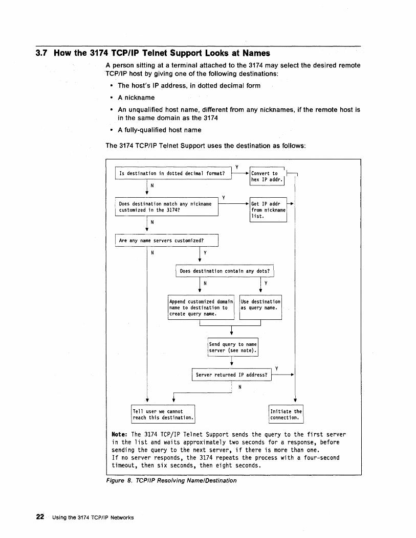
3.7 How the 3174 TCP/IP Telnet Support Looks at Names A person sitting at a terminal attached to the 3174 may select the desired remote TCP/IP host by giving one of the following destinations:
• The host's IP address, in dotted decimal form
• A nickname
• An unqualified host name, different from any nicknames, if the remote host is in the same domain as the 3174
• A fully-qualified host name
The 3174 TCP/IP Telnet Support uses the destination as follows:
fonnat?
N
~------------------------~ y
N
t---------. Get IP addr from nickname list.
Append customized domain Use destination name to destination to as query name. create query name.
y Server returned IP address?
N
Note: The 3174 TCP/IP Telnet Support sends the query to the first server in the list and waits approximately two seconds for a response, before sending the query to the next server, if there is more than one. If no server responds, the 3174 repeats the process with a four-second timeout, then six seconds, then eight seconds.
Figure 8. TCP//P Resolving Name/Destination
22 Using the 3174 TCP/IP Networks
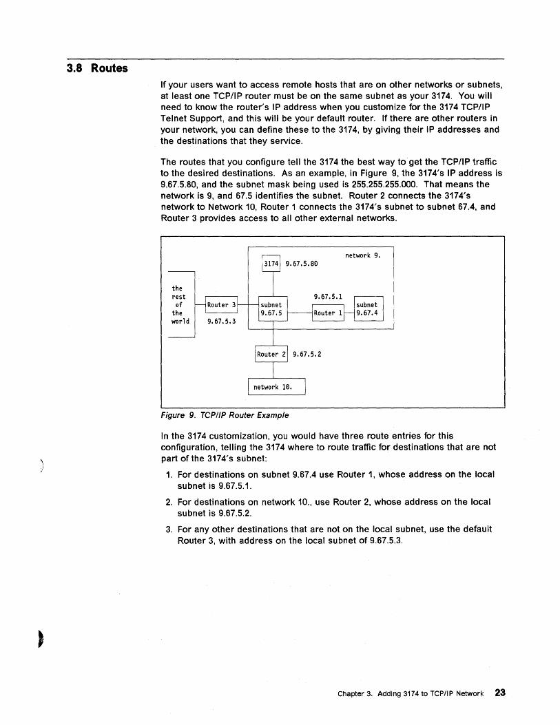
3.8 Routes
)
If your users want to access remote hosts that are on other networks or subnets, at least one TCP/IP router must be on the same subnet as your 3174. You will need to know the router's IP address when you customize for the 3174 TCP/IP Telnet Support, and this will be your default router. If there are other routers in your network, you can define these to the 3174, by giving their IP addresses and the destinations that they service.
The routes that you configure tell the 3174 the best way to get the TCPIIP traffic to the desired destinations. As an example, in Figure 9, the 3174's IP address is 9.67.5.80, and the subnet mask being used is 255.255.255.000. That means the network is 9, and 67.5 identifies the subnet. Router 2 connects the 3174's network to Network 10, Router 1 connects the 3174's subnet to subnet 67.4, and Router 3 provides access to all other external networks.
the rest of
the world
Figure 9. TCP/IP Router Example
In the 3174 customization, you would have three route entries for this configuration, telling the 3174 where to route traffic for destinations that are not part of the 3174's subnet:
1. For destinations on subnet 9.67.4 use Router 1, whose address on the local subnet is 9.67.5.1.
2. For destinations on network 10., use Router 2, whose address on the local subnet is 9.67.5.2.
3. For any other destinations that are not on the local subnet, use the default Router 3, with address on the local subnet of 9.67.5.3.
Chapter 3. Adding 3174 to TCP/IP Network 23
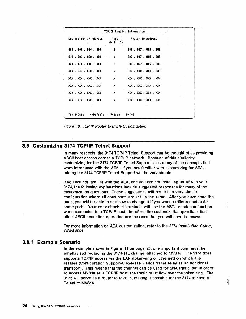
__ TCPjIP Routing Information __
Destination IP Address Type Router IP Address (N,S,H,D)
SSg • S67 • SS4 • ses s SSg • S67 • SSS • SSI
SIS • SSS • SSS • SSS N SSg • S67 • SSS • SS2
XXX • XXX • XXX • XXX D SSg • S67 • SSS • SS3
XXX • XXX • XXX • XXX X XXX • XXX • XXX • XXX
XXX • XXX • XXX • XXX X XXX • XXX • XXX • XXX
XXX • XXX • XXX • XXX X XXX • XXX • XXX • XXX
XXX • XXX • XXX • XXX X XXX • XXX • XXX • XXX
XXX • XXX • XXX • XXX X XXX • XXX • XXX • XXX
PF: 3=Quit 4=Default 7=Back 8= Fwd
Figure 10. TCP/IP Router Example Customization
3.9 Customizing 3174 TCP/IP Telnet Suppori In many respects, the 3174 TCP/IP Telnet Support can be thought of as providing ASCII host access across a TCP/IP network. Because of this similarity, customizing for the 3174 TCP/IP Telnet Support uses many of the concepts that were introduced with the AEA. If you are familiar with customizing for AEA, adding the 3174 TCP/IP Telnet Support will be very simple.
If you are not familiar with the AEA, and you are not installing an AEA in your 3174, the following explanations include suggested responses for many of the customization questions. These suggestions will result in a very simple configuration where all coax ports are set up the same. After you have done this once, you will be able to see how to change it if you want a different setup for some ports. Your coax-attached terminals will use the ASCii emulation function when connected to a TCP/IP host; therefore, the customization questions that affect ASCII emulation operation are the ones that you will have to answer.
For more information on AEA customization, refer to the 31741nsta/lation Guide, GG24-3061.
3.9.1' Example Scenario In the example shown in Figure 11 on page 25, one important point must be emphasized regarding the 3174-11 L channel-attached to MVS18. The 3174 does supports TCP/IP access via the LAN (token-ring or Ethernet) on which it is resides (Configuration Support-C Release 5 adds frame relay as an additional transport). This means that the channel can be used for SNA traffic, but in order to access MVS18 as a TCP/IP host, the traffic must flow over the token ring. The 3172 will serve as a router to MVS18, making it possible for the 3174 to have a Telnet to MVS18.
24 Using the 3174 TCP/IP Networks
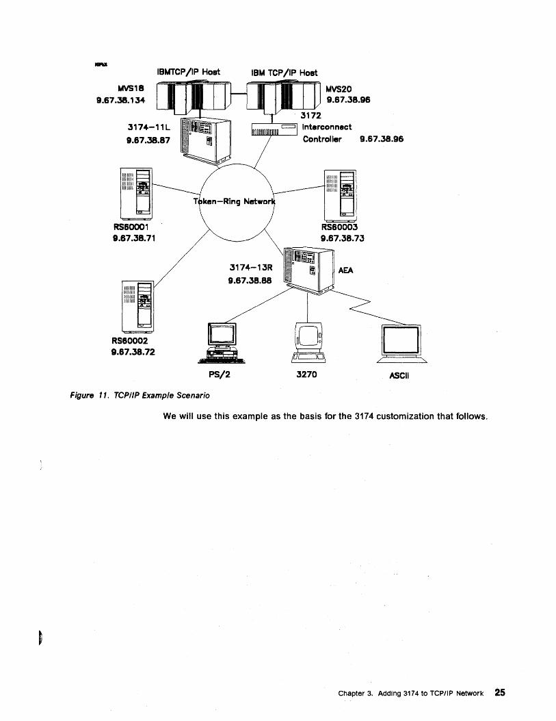
IBMTCP /IP Host IBM TCP /IP Host
MVS18 9.67.38.134
3174-11L
9.67.38.87
11111111 11111111 11111111 11111111
RS60001 9.67.38.71
11111111 11111111 11111111 11111111
RS60002 9.67.38.72
3174-13R
9.67.38.88
PS/2
Figure ". TCPIIP Example Scenario
MVS20 9.67.38.96
Interconnect Controller 9.67.38.96
3270
IIIIIIII~ 11111111 11111111 11111111
RS60003 9.67.38.73
ASCII
We will use this example as the basis for the 3174 customization that follows.
Chapter 3. Adding 3174 to TCPIIP Network 25

3.9.2 Panel Flow Figure 12 shows the panel flow sequence when customizing the 3174 TCP/IP Telnet Support.
Question 700=10
Customize Control Disk
Option 5
AEA and TCP/IP Menu
Option 1
AEA and TCP/IP Configure
Port Set
Port to Port Set Map
AEA and TCP/IP Station Set
AEA and TCP/IP Default Destination
AEA and TCP/IP Configure Complete
TCP/IP Options Menu
Figure 12. TCPI/P Customization Panel Flow
3.9.3 Configure AEA and TCP/IP After you have IMLed your 3174 from a Utility diskette, select Customize the Control Disk from the Master Menu. The Customize Control Disk Menu panel is displayed (see Figure 13 on page 27).
26 Using the 3174 TCP/IP Networks
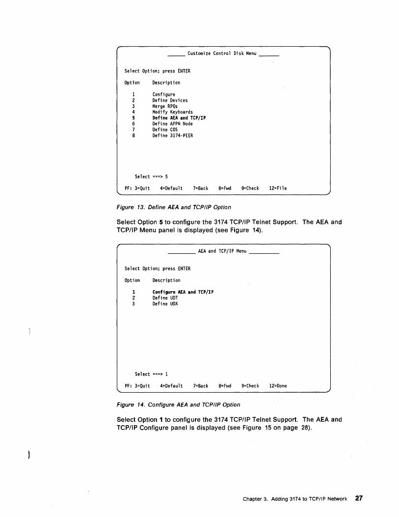
Customize Control Disk Menu __ _
Select Option; press ENTER
Option
1 2 3 4 5 6 7 8
Description
Configure Define Devices Merge RPQs Modify Keyboards Def;ne AEA and TCP/IP Define APPN Node Define COS Define 3174-PEER
Select ===> 5
PF: 3=Quit 4=Default 7=Back 8= Fwd 9=Check 12=File
Figure 13. Define AEA and TCPIIP Option
Select Option 5 to configure the 3174 TCPJIP Telnet Support. The AEA and TCP/IP Menu panel is displayed (see Figure 14).
____ AEA and TCPjIP Menu ___ _
Select Option; press ENTER
Option
1 2 3
Description
Conf;gure AEA and Tep/IP Define UDT Define UDX
Select ===> 1
PF: 3=Quit 4=Default 7=Back 8= Fwd 9=Check 12=Done
Figure 14. Configure AEA and TCPIIP Option
Select Option 1 to configure the 3174 TCPJIP Telnet Support. The AEA and TCP/IP Configure panel is displayed (see Figure 15 on page 28).
Chapter 3. Adding 3174 to TCPIIP Network 27
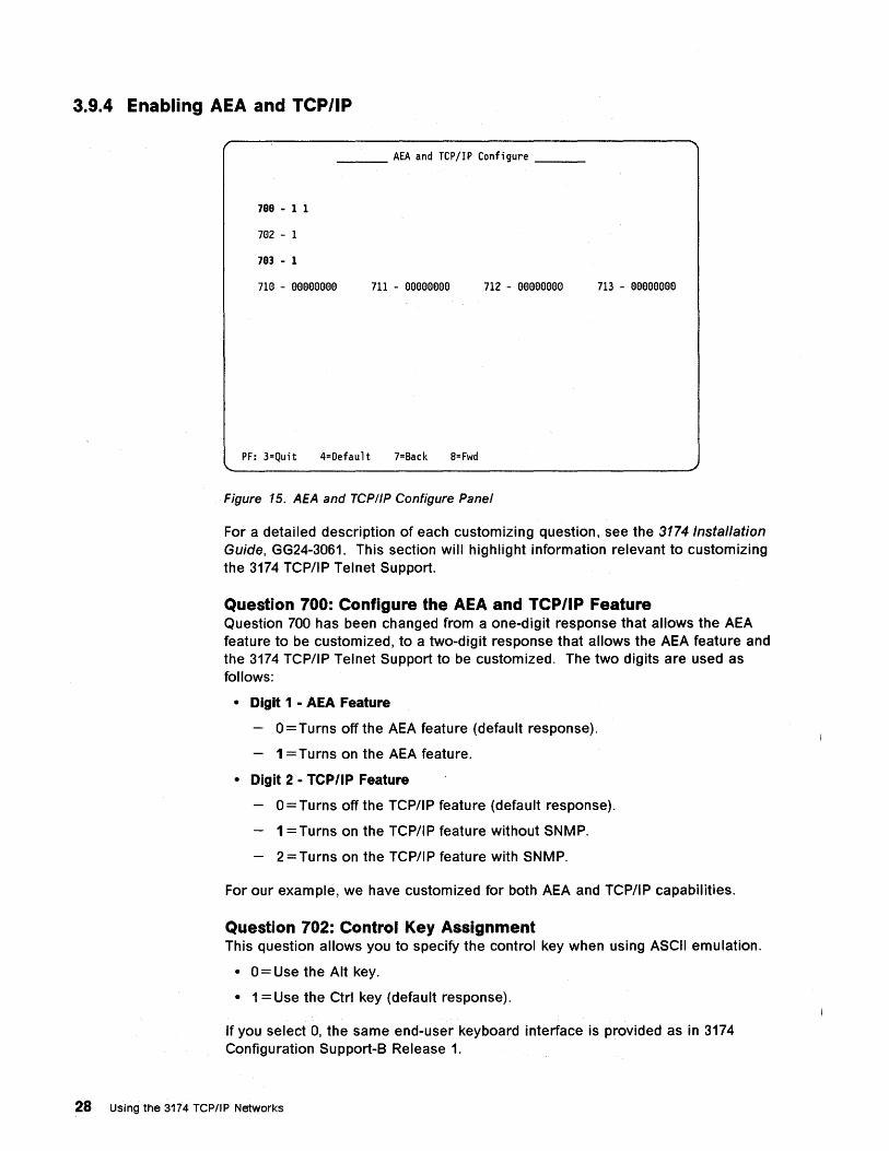
3.9.4 Enabling AEA and TCP/IP
___ AEA and TCPjIP Configure __ _
7GG - 1 1
7132 - 1
7G3 - 1
7113 - eeeeeeee 711 - eeseesee 712 - eeeeeeee 713 - sssseeee
PF: 3=Quit 4=Default 7=Back 8= Fwd
Figure 15. AEA and TCP/IP Configure Panel
For a detailed description of each customizing question, see the 3174 Installation Guide, GG24-3061. This section will highlight information relevant to customizing the 3174 TCP/IP Telnet Support.
Question 700: Configure the AEA and TCP/IP Feature Question 700 has been changed from a one-digit response that allows the AEA feature to be customized, to a two-digit response that allows the AEA feature and the 3174 TCP/IP Telnet Support to be customized. The two digits are used as follows:
• Digit 1 • AEA Feature
0= Turns off the AEA feature (default response).
1 =Turns on the AEA feature.
• Digit 2 • TCP/IP Feature
o =Turns off the TCP/IP feature (default response).
1 =Turns on the TCP/IP feature without SNMP.
2 =Turns on the TCP/IP feature with SNMP.
For our example, we have customized for both AEA and TCP/IP capabilities.
Question 702: Control Key Assignment This question allows you to specify the control key when using ASCII emulation.
• O=Use the Alt key.
• 1 = Use the Ctrl key (default response).
If you select 0, the same end-user keyboard interface is provided as in 3174 Configuration Support-B Release 1.
28 Using the 3174 TCP/IP Networks
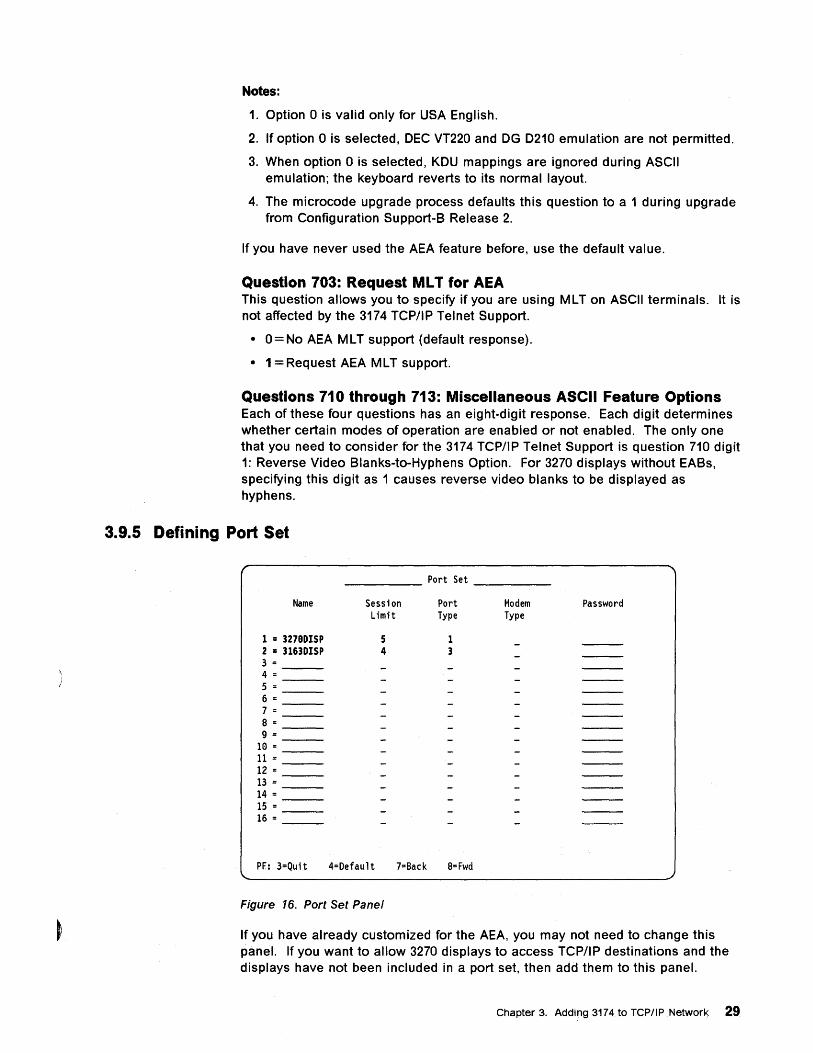
Notes:
1. Option 0 is valid only for USA English.
2. If option 0 is selected, DEC VT220 and OG 0210 emulation are not permitted.
3. When option 0 is selected, KDU mappings are ignored during ASCII emulation; the keyboard reverts to its normal layout.
4. The microcode upgrade process defaults this question to a 1 during upgrade from Configuration Support-B Release 2.
If you have never used the AEA feature before, use the default value.
Question 703: Request ML T for AEA This question allows you to specify if you are using MLT on ASCII terminals. It is not affected by the 3174 TCP/IP Telnet Support.
• O=No AEA MLT support (default response).
• 1 = Request AEA MLT support.
Questions 710 through 713: Miscellaneous ASCII Feature Options Each of these four questions has an eight-digit response. Each digit determines whether certain modes of operation are enabled or not enabled. The only one that you need to consider for the 3174 TCP/IP Telnet Support is question 710 digit 1: Reverse Video Blanks-to-Hyphens Option. For 3270 displays without EABs, specifying this digit as 1 causes reverse video blanks to be displayed as hyphens.
3.9.5 Defining Port Set
Name
1 = 3279DISP 2 = 3163DISP 3= __ _ 4= __ _ 5 = __ _ 6= __ _ 7= __ _ 8= __ _ 9 =
10 = ---
11 = __ _ 12 = __ _ 13 = __ _ 14 = __ _ 15 = __ _ 16 = __ _
Port Set
Session Port Limit Type
5 1 4 3
PF: 3=Quit 4=Default 7=Back 8=Fwd
Figure 16. Port Set Panel
Modem Password Type
If you have already customized for the AEA, you may not need to change this panel. If you want to allow 3270 displays to access TCP/IP destinations and the displays have not been included in a port set, then add them to this panel.
Chapter 3. Adding 3174 to TCP/IP Network 29
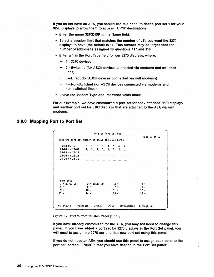
If you do not have an AEA, you should use this panel to define port set 1 for your 3270 displays to allow them to access TCP/IP destinations:
• Enter the name 3270DISP in the Name field.
• Select a session limit that matches the number of L Ts you want the 3270 displays to have (the default is 1). This number may be larger than the number of addresses assigned by questions 117 and 118.
• Enter a 1 in the Port Type field for our 3270 displays, where:
1 = 3270 devices
2 = Switched (for ASCII devices connected via modems and switched lines)
3 = Direct (for ASCII devices connected via null modems)
4 = Non-Switched (for ASCII devices connected via modems and non-switched lines).
• Leave the Modem Type and Password fields blank.
For our example, we have customized a port set for coax attached 3270 displays and another port set for 3163 displays that are attached to the AEA via null modems.
3.9.6 Mapping Port to Port Set
___ Port to Port Set Hap __ _
Type the port set number to group the 3174 ports
3270 Ports 26-88 to 26-87 26-08 to 26-15 26-16 to 26-23 26-24 to 26-31
Port Sets 1 = 3270DISP 5 = 9 =
13 =
0 1 2 3 I_ I_ 1 - I_
2 = 3163DISP 6 =
10= 14 =
4 I_
5 I_
3 = 7 =
11 = 15 =
6 I_
7
Page en of 03
4 = 8 =
12 = 16 =
PF: 3=Quit 4=Default 7=Back 8= Fwd 10=PageBack II=PageFwd
Figure 17. Port to Port Set Map Panel (1 of 3)
If you have already customized for the AEA, you may not need to change this panel. If you have added a port set for 3270 displays in the Port Set panel, you will need to assign the 3270 ports to that new port set using this panel.
If you do not have an AEA, you should use this panel to assign coax ports to the port set, named 3270DISP, that you have defined in the Port Set panel:
30 Using the 3174 TCP/IP Networks
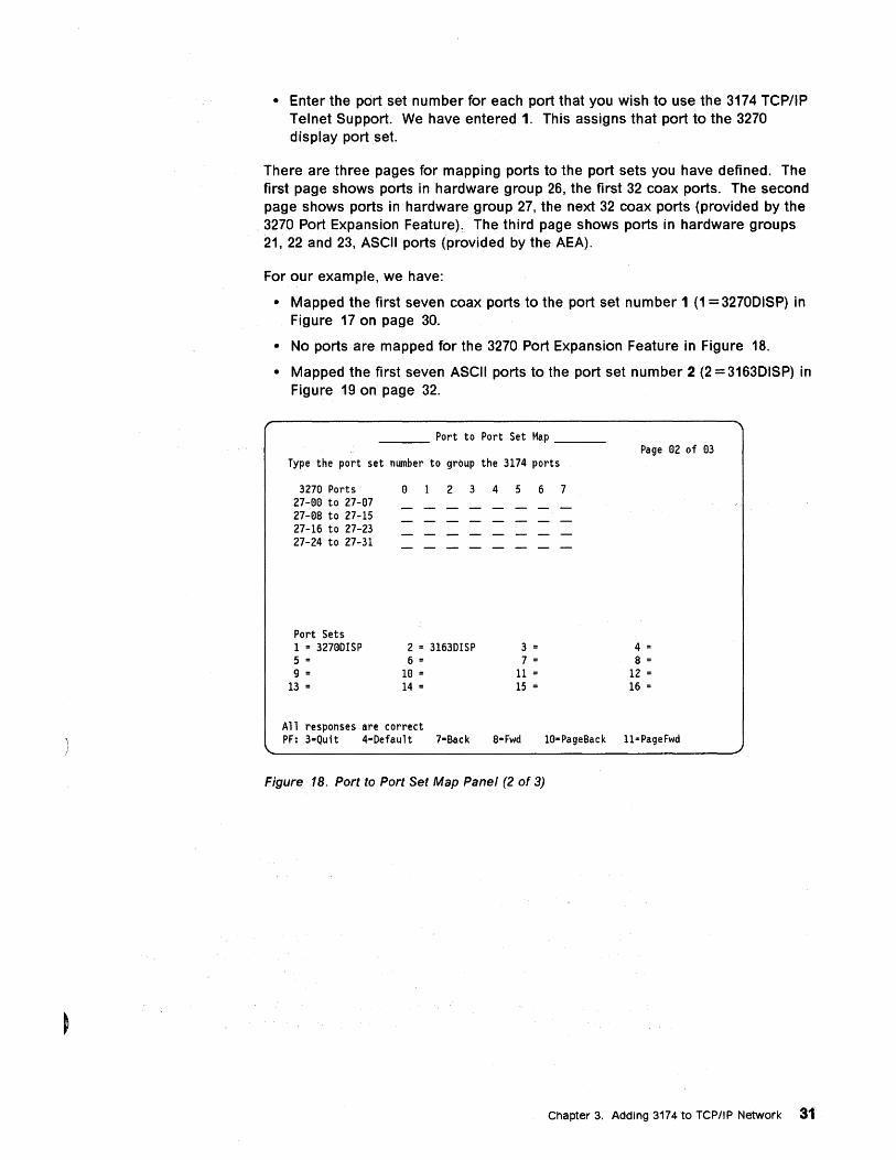
• Enter the port set number for each port that you wish to use the 3174 TCPIIP Telnet Support. We have entered 1. This assigns that port to the 3270 display port set.
There are three pages for mapping ports to the port sets you have defined. The first page shows ports in hardware group 26, the first 32 coax ports. The second page shows ports in hardware group 27, the next 32 coax ports (provided by the 3270 Port Expansion Feature). The third page shows ports in hardware groups 21, 22 and 23, ASCII ports (provided by the AEA).
For our example, we have:
• Mapped the first seven coax ports to the port set number 1 (1 = 3270DISP) in Figure 17 on page 30.
• No ports are mapped for the 3270 Port Expansion Feature in Figure 18.
• Mapped the first seven ASCII ports to the port set number 2 (2 = 3163DISP) in Figure 19 on page 32.
___ Port to Port Set Map __ _
Type the port set number to group the 3174 ports
3270 Ports 27-00 to 27-07 27-08 to 27-15 27-16 to 27-23 27-24 to 27-31
Port Sets 1 = 32700ISP 5 =
9 = 13 =
2 3 4 5 6 7
2 = 31630ISP 6 =
10 = 14 =
3 = 7 =
11 = 15 =
All responses are correct
Page 02 of 03
4 = 8 =
12 = 16 =
PF: 3=Quit 4=Oefault 7=Back 8=Fwd 10=PageBack 11=PageFwd
Figure 18. Port to Port Set Map Panel (2 of 3)
Chapter 3. Adding 3174 to TCP/IP Network 31

___ Port to Port Set Map ~ __
Type the port set number to group the 3174 ports
AEA Ports 21-88 to 21-87 22-GG to 22-G7 23-GG to 23-G7
Port Sets 1 = 327aDISP 5 = 9 =
13 =
a 123 4 5 6 7 2_ 2_ 2_ 2_ 2_ 2_ 2_
2 .. 3163DISP 3 .. 6 .. 7 =
1G .. 11 .. 14 .. 15 ..
All responses are correct
Page G3 of G3
4 = 8 ..
12 .. 16 ..
PF: 3=Quit 4=Default 7=Back 8= Fwd 1a=PageBack 11"PageFwd
Figure 19. Port to Port Set Map Panel (3 of 3)
3.9.7 Defining 3270 Host and Display Station Sets
___ AEA and TCP/IP Station Set __ _
1 721 - 3278 HOST 722 - 3H 723 - 725 - 1 731 - 1 732 - 1 733 - a 734 - 735 - a 736 - 1 737-741 - GGG 742 - GIS 743 - 1 744 - a- 745 - a 746 - a a 751 - 752 - ___________ -------761 --1 762 - 1 763 - 1 764 - 1 765 - a 771 - 1 772 - 1 773 - 1 774 - 1 775 - 1 776 - 1
781 - a 782 - a 783 - a66 784 - 1 785 - 11111aaa 786 - 132 787 - a 79a - aaa • aaa • aaa • aaa
2 121 - 3278 DISPLAY 722 - 3D 723 - 327aDISP 725 - 1 731 - 1 732 - 1 733 - a 734 - 735 - a 736 - 1 737-741 - aaa 742 - a15 743 - 1 744 - a- 745 - a 746 - a a 751 - 752 -
761 --1 762 - -::-1-""=7":":63~---:-1---:7::-::6-::"4 --~1:---:7:":'6-=-5 ,....--::a~-----
771 - 1 772 - 1 773 - 1 774 - 1 775 - 1 776 - 1 781 - a 782 - a 783 - a66 784 - 1 785 - 11111aaa 786 - 132 787 - a 79a - aaa • aaa • aaa • aaa
PF: 3=Quit 4=Default 7-Back 8= Fwd 1a=Page Back 11=Page Fwd
Figure 20. AEA and TCPIIP Station Set Panel (1 of 4)
If you have already customized for AEA, you will have defined station sets for the 3270 host and the 3270 displays that are attached to your 3174. You will still need to define station sets for TCP/IP access, so do not skip this panel. You may, however, proceed to 3.9.8, "Defining TCP/IP Station Sets" on page 33.
If you do not have an AEA, you should define two station sets, one for the 3270 host and one for the 3270 displays we have added. You will also need to define
32 Using the 3174 TCP/IP Networks
station sets for TCP/IP access (see 3.9.8, "Defining TCP/IP Station Sets" on page 33). We will start by defining station set 1 for the 3270 host:
Q721 Enter a station set name for the 3270 host to be accessed. Whatever name you enter here will be displayed on the Connection Menu as a possible destination for the LT. If your 3270 host has a common name that the terminal users will recognize, enter that name.
In our example, we have used the name 3270 HOST.
Q722 Ent.er 3H as the station type for the 3270 host.
Leave all other questions at their default values.
Next, we will define station set 2 for the 3270 displays:
Q721 Enter a station set name for the 3270 displays we have added in the Port Set panel.
Q722 Enter 3D as the station type for the 3270 displays.
Q723 Enter 3270DISP as the port set name (the name we defined on the Port Set panel) to which the 3270 displays will be mapped.
Q725 Leave the response at its default value of 1.
This allows the terminal users to use the Connection Menu to select alternative host connections for an LT. After you are more familiar with Connection Menu operation, you may wish to change this to O.
Response 0 means that the terminal users in this station set will not be allowed to select host connections from the Connection Menu; they are restricted to access only the connection defined in their Default Destination.
Leave all other responses at their default values.
3.9.8 Defining TCP/IP Station Sets A station set for TCP/IP access defines a set of ASCII emulation characteristics and an optional host IP address. The 3174 TCP/IP Telnet Support supports the following ASCII terminal emulation:
• DEC VT100
• IBM 3101
• DG D210 (USA English only)
• DEC VT220, 7-bit control
• DEC VT220, 8-bit control
Each TCP/IP station set you define will be displayed on the host Connection Menu for the terminal user to select as a connection.
For each station set definition, you may specify an IP host address, or use the default response (all zeros), in question 790. Your response is used as follows:
• If you specify an address, the 3174 does not automatically connect to that address when the station set is selected from the Connection Menu. The address is used if the user issues a. PING or an OPEN command without specifying a destination;
Chapter 3. Adding 3174 to TCP/IP Network 33
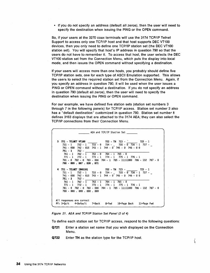
• If you do not specify an address (default all zeros), then the user will need to specify the destination when issuing the PING or the OPEN command.
So, if your users at the 3270 coax terminals will use the 3174 TCP/IP Telnet Support to access only one TCP/IP host and that host supports DEC VT100 devices, then you only need to define one TCP/IP station set (the DEC VT100 station set). You will specify that host's IP address in question 790 so that the users do not have to remember it. To access that host, the user selects the DEC VT100 station set from the Connection Menu, which puts the display into local mode, and then issues the OPEN command without specifying a destination.
If your users will access more than one hosts, you probably should define five TCP/IP station sets, one for each type of ASCII Emulation supported. This allows the users to select the required station set from the Connection Menu. Again, if you specify an address in question 790, it will be used when the user issues a PING or OPEN command without a destination. If you do not specify an address in question 790 (default all zeros), then the user will need to specify the destination when issuing the PING or OPEN command.
For our example, we have defined five station sets (station set numbers 3 through 7 in the following panels) for TCP/IP access. Station set number 3 also has a "default destination" customized in question 790. Station set number 8 defines 3163 displays that are attached to the 3174 AEA; they can also select the TCP/IP connections from their Connection Menu.
___ AEA and TCPjIP Station Set __ _
3 721 - TELNET VT100 722 - TH 723 - \ 725 - 1 731 - 1 732 - 1 ~- 0 734 - 735 - 0 736 - 1 737-741 - 000 742 - 015 743 - 1 744 - 0- 745 - 0 746 - 0 0 751 - 1 752-761 - 1 762 - -:-1--:::-77':63~---:-0-7~6~4---1~7~6-::-5 --~O:-"· -----771 - 1 772 - 1 773 - 1 774 - 1 775 - 1 776 - 1
781 - 0 782 - 0 783 - 066 784 - 1 785 - 11111000 786 - 132 787 - 0 790 - 009 • 067 • 038 • 071
4 721 - TELNET IBM3191 722 - TH 723 - 725 - 1 731 - 1 732 - 1 733 - 0 734 - 735 - 0 736 - 1 737-741 - 000 742 - 015 743 - 1 744 - 0- 745 - 0 746 - 0 0 751 - 2 752 -
761 - 1 762 - -:-1--:::-7"":"':63~-~1-7~6~4---1~7=6-::-5 ---0:-"' -----771 - 1 772 - 1 773 - 1 774 - 1 775 - 1 776 - 1
781 - 0 782 - 0 783 - 066 784 - 1 785 - 11111000 786 - 132 787 - 0 790 - 000 • 000 • 000 • 000
All responses are correct PF: 3=Quit 4=Default 7=Back 8= Fwd 10=Page Back 11=Page Fwd
Figure 21. AEA and TCP/IP Station Set Panel (2 of 4)
To define each station set for TCP/IP access, respond to the following questions:
Q721 Enter a station set name that you wish displayed on the Connection Menu.
Q722 Enter TH as the station type for the TCP/I P host.
34 Using the 3174 TCP/IP Networks
Q751 Specify the data stream supported by the TCP/IP host:
• 1 = DEC VT100
• 2=IBM 3101
• 3 = DG 0210 (USA English only)
• 4 = DEC VT220, 7-bit control
• 5 = DEC VT220, 8-bit control
Your response to this question only affects the operation of 3270 displays. It determines the type of ASCII emulation that the 3174 provides for the 3270 display when the user selects this station set as the destination. When the user at an ASCII terminal selects a TCPIIP destination, the value of this field is ignored.
Q761 Respond only for VT100 or VT220 data stream, that is, if question 751 = 1, 4 or 5. The valid responses are:
• 0 = Auto XON/XOFF disabled.,
• 1 = Auto XON/XOFF enabled (default response).
Q762 Respond only for VT100 or VT220 data stream, that is, if question 751 = 1, 4 or 5. The valid responses are:
• O=Wraparound option disabled.
• 1 =Wraparound option enabled (default response).
Q763 Respond only for VT100 or VT220 data stream, that is, if question 751 = 1, 4 or 5. The valid responses are:
• 0 = New line option disabled.
• 1 = New line option enabled (default response).
Your response to this question depends on the host applications you will be using. If not answered correctly, characters may be placed in the wrong positions on the screen. When set to 1, the 3174 treats a line feed character from the host as a new line (line feed followed by carriage return).
Note: For connections to RS/6000* hosts, question 763 should be O.
Q764 Respond only for VT100 or VT220 data stream, that is, if question 751 = 1, 4 or 5. The valid responses are:
• 0 = Margin bell disabled.
• 1 = Margin bell enabled (default response).
Q765 Respond only for VT100 or VT220 data stream, that is, if question 751 = 1, 4 or 5. The valid responses are:
• 0 = DEC host ASCII character set is NRC (default response).
• 1 = DEC host ASCII character set is MCS.
Q771 Respond only for IBM 3101 data stream, that is, if question 751 =2. The valid responses are:
• O=Automatic line feed disabled.
• 1 = Automatic line feed enabled (default response).
The receipt of a carriage return from the host will cause a carriage return and a line feed at the terminal.
Chapter 3. Adding 3174 to TCPIIP Network 35
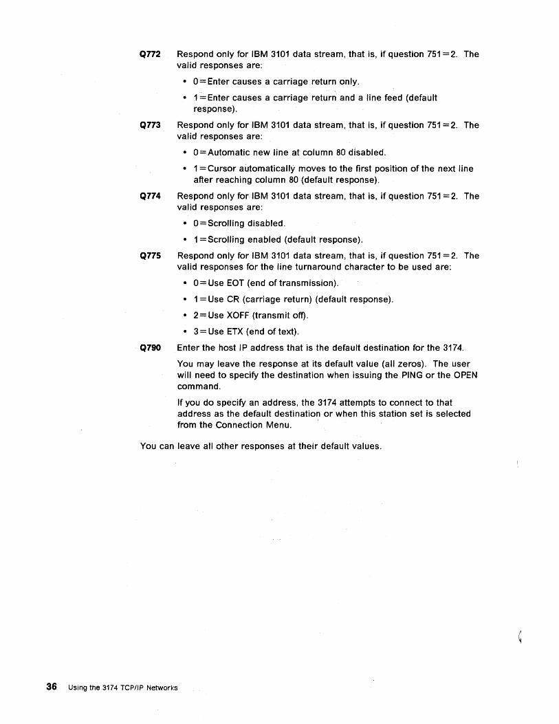
Q772 Respond only for IBM 3101 data stream, that is, if question 751 =2. The valid responses are:
• 0 = Enter causes a carriage return only.
• 1 = Enter causes a carriage return and a line feed (default response).
Q773 Respond only for IBM 3101 data stream, that is, if question 751 =2. The valid responses are:
• o = Automatic new line at column 80 disabled.
• 1 = Cursor automatically moves to the first position of the next line after reaching column 80 (default response).
Q774 Respond only for IBM 3101 data stream, that is, if question 751 = 2. The valid responses are:
• O=Scrolling disabled.
• 1 = Scrolling enabled (default response).
Q775 Respond only for IBM 3101 data stream, that is, if question 751 = 2. The valid responses for the line turnaround character to be used are:
• 0 = Use EOT{end of transmission).
• 1 = Use CR (carriage return) (default response).
• 2 = Use XOFF (transmit off).
• 3 = Use ETX (end of text).
Q790 Enter the host IP address that is the default destination for the 3174.
You may leave the response at its default value (all zeros). The user will need to specify the destination when issuing the PING or the OPEN command.
If you do specify an address, the 3174 attempts to connect to that address as the default destination or when this station set is selected from the Connection Menu.
You can leave all other responses at their default values.
36 Using the 3174 TCP/IP Networks
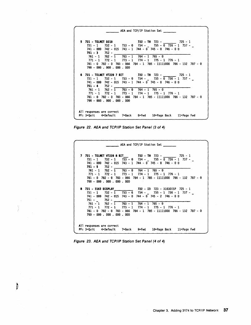
___ AEA and TCPjIP Station Set __ _
5 721 - TELNET D218 722 - TH 723 - 725 - 1 731 - 1 732 - 1 733 - a 734 - 735 - a 736 - 1 737-741 - aee 742 - e15 743 - 1 744 - e- 745 - e 746 - e e 751 - 3 752 -761 - 1 762 - '::""1--::7~63~--::1--::7~64~--::1--:7~6-=-5---e=-· ------771 - 1 772 - 1 773 - 1 774 - 1 775 - 1 776 - 1
781 - e 782 - e 783 - e66 784 - 1 785 - 11111eaa 786 - 132 787 - a 79a - aea • aaa • eaa . aee
6 721 - TELNET VT228 7 BIT 731 - 1 732 - 1 733 - a 741 - aae 742 - a15 743 - 1 751 - 4 752-
722 - TH 723 - 725 - 1 734 - 735 - a 736 - 1 737-
744 - a- 745 - e 746 - a a
761 - 1 762 - '::""1--::7~63~--::a:---::7~64-::----::1--:7~6-=-5 ---a=-· ------771 - 1 772 - 1 773 - 1 774 - 1 775 - 1 776 - 1
781 - a 782 - a 783 - e66 784 - 1 785 - 11111aea 786 - 132 787 - a 79a - eaa • eaa • eaa • aaa
All responses are correct PF: 3-Quit 4-0efault 7=Back a=Fwd le-Page Back ll=Page Fwd
Figure 22. AEA and TCPIIP Station Set Panel (3 of 4)
___ AEA and TCPjIP Station Set __ _
7 721 - TELNET VT228 8 BIT 731 - 1 732 - 1 733 - a 741 - eee 742 - a15 743 - 1 751 - 5 752 -
722 - TH 723 - 725 - 1 734 - 735 - e 736 - 1 737-
744 - e- 745 - a 746 - a a
761 - 1 762 - -l-....,.7~63--..... a-....,.7:-64~--1:--7~6~5 ---a'::""· ------771 - 1 772 - 1 773 - 1 774 - 1 775 - 1 776 - 1
781 - a 782 - a 783 - a66 784 - 1 785 - 11111aaa 786 - 132 787 - a 79a - eea • eaa • eea • eea
8 721 - 3163 DISPLAY 722 - 13 723 - 31630ISP 725 - 1 731 - 1 732 - 1 733 - 6 734 - 735 - 1 736 - 1 737-741 - eaa 742 - e15 743 - a 744 - a- 745 - 2 746 - a a 751 - 752 - ________________ _
761 --1 762 - 1 763 - 1 764 - 1 765 - a 771 - 1 772 - 1 773 - 1 774 - 1 775 - 1 776 - 1
781 - a 782 - e 783 - e66 784 - 1 785 - 11111aaa 786 - 132 787 - a 7ge - eea • eaa • eaa • aee
All responses are correct PF: 3-Quit 4=Oefault 7=Back 8= Fwd 1a=Page Back ll=Page Fwd
Figure 23. AEA and TCPIIP Station Set Panel (4 of 4)
Chapter 3. Adding 3174 to TCPIIP Network 37
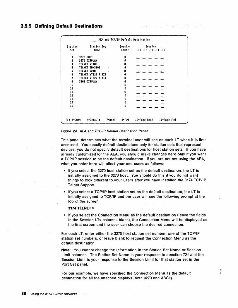
3.9.9 Defining' Default Destinations
____ AEA and TCPjIP Default Destination ____
Station Station Set Session Session Set Name Limit LTl LT2 LT3 LT4 LT5
1 3278 HOST 8 2 3278 DISPLAY 5 3 TELNET VT188 8 4 TELNET IBM3101 8 5 TELNET D218 8 6 TELNET VT228 7 BIT 8 7 TELNET VT228 8 BIT 8 8 3163 DISPLAY 4 9 0
10 0 11 0 12 0 13 0 14 0 15 0
PF: 3=Quit 4=Default 7=Back 8= Fwd 10=Page Back 11=Page Fwd
Figure 24. AEA and TCP/IP Default Destination Panel
This panel determines what the terminal user will see on each L T when it is first accessed. You specify default destinations only for station sets that represent devices; you do not specify default destinations for host station sets. If you have already customized for the AEA, you should make changes here only if you want a TCP/IP session to be the default destination. If you are not not using the AEA, what you enter here will affect your end users as follows:
• If you select the 3270 host station set as the default destination, the L T is initially assigned to the 3270 host. You should do this if you do not want things to look different to your users after you have installed the 3174 TCP/IP TelnetSupport.
• If you select a TCP/IP host station set as the default destination, the L T is initially assigned to TCP/IP and the user will see the following prompt at the top of the screen:
3174 TELNET>
• If you select the Connection Menu as the default destination (leave the fields in the Session L Tx columns blank), the Connection Menu will be displayed as the first screen and the user can choose the desired connection.
For eachLT, enter either the 3270 host station set number, one of the TCP/IP station set numbers, or leave blank to request the Connection Menu as the default destination.
Note:, You cannot change the information in the Station Set Name or Session Limit columns. The Station Set Name is your response to question 721 and the Session Limit is your response to the Session Limit for that station set in the Port Set panel.
For our example, we have specified the Connection Menu as the default destination for all the attached displays (both 3270 and ASCII).
38 Using the 3174 TCP/IP Networks
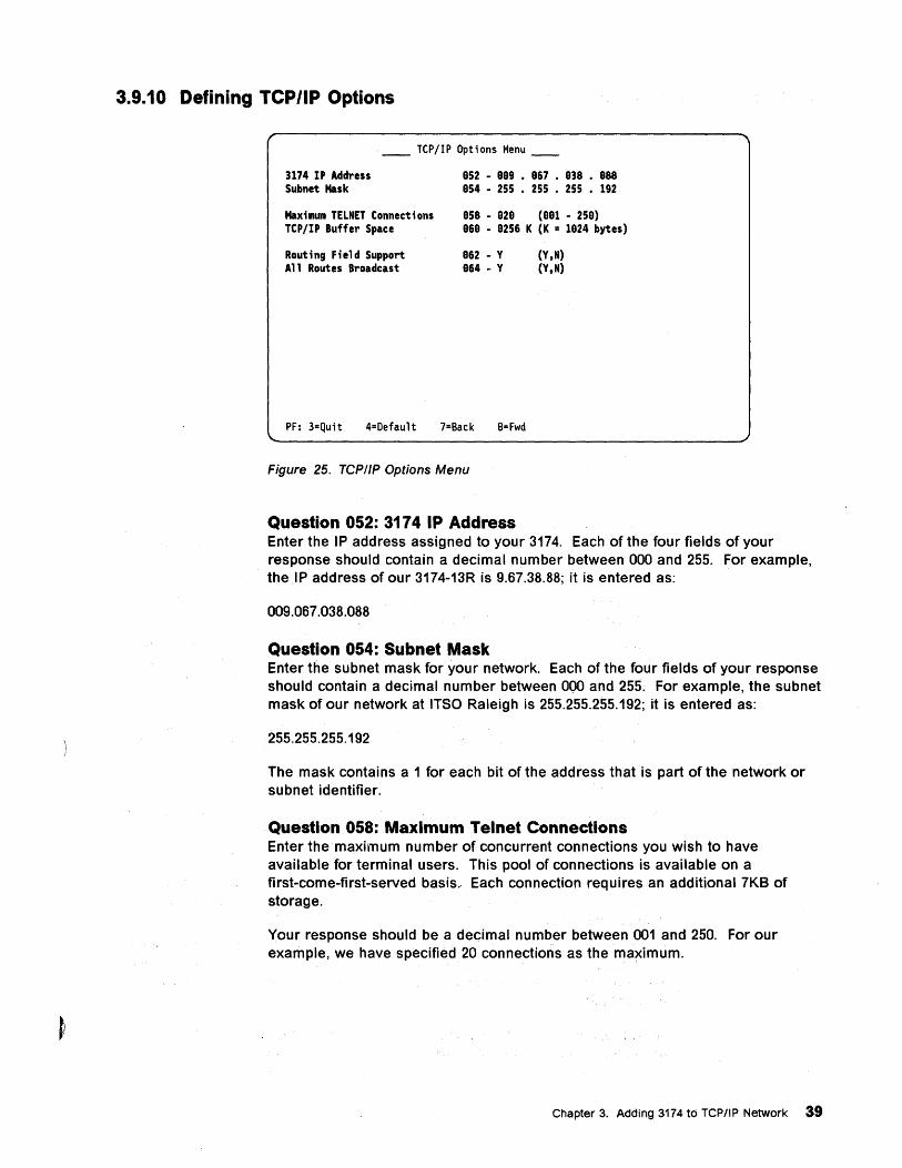
3.9.10 Defining TCP/IP Options
__ TCP/IP Options Menu __
3174 IP Address Subnet Mask
Max;mum TELNET Connections TCP/IP Buffer Space
Rout;ng F;eld Support All Routes Broadcast
852 - 889 • 867 • 838 • 888 854 - 255 • 255 • 255 • 192
858 - 828 (881 - 258) 868 - 8256 K (K = 1824 bytes)
862 - Y 864 - Y
(Y,N) (Y,N)
PF: 3=Quit 4=Default 7=Back 8= Fwd
Figure 25. TCP/IP Options Menu
Question 052: 3174 IP Address Enter the IP address assigned to your 3174. Each of the four fields of your response should contain a decimal number between 000 and 255. For example, the .IP address of our 3174-13R is 9.67.38.88; it is entered as:
009.067.038.088
Question 054: Subnet Mask Enter the subnet mask for your network. Each of the four fields of your response should contain a decimal number between 000 and 255. For example, the subnet mask of our network at ITSO Raleigh is 255.255.255.192; it is entered as:
255.255.255.192
The mask contains a 1 for each bit of the address that is part of the network or subnet identifier.
Question.058: Maximum Telnet Connections Enter the maximum number of concurrent connections you wish to have available for terminal users. This pool of connections is available on a first-come-first-served basis. Each connection requires an additional 7KB of storage.
Your response should be a decimal number between 001 and 250. For our example, we have specified 20 connections as the maximum.
Chapter 3. Adding 3174 to TCP/IP Network 39
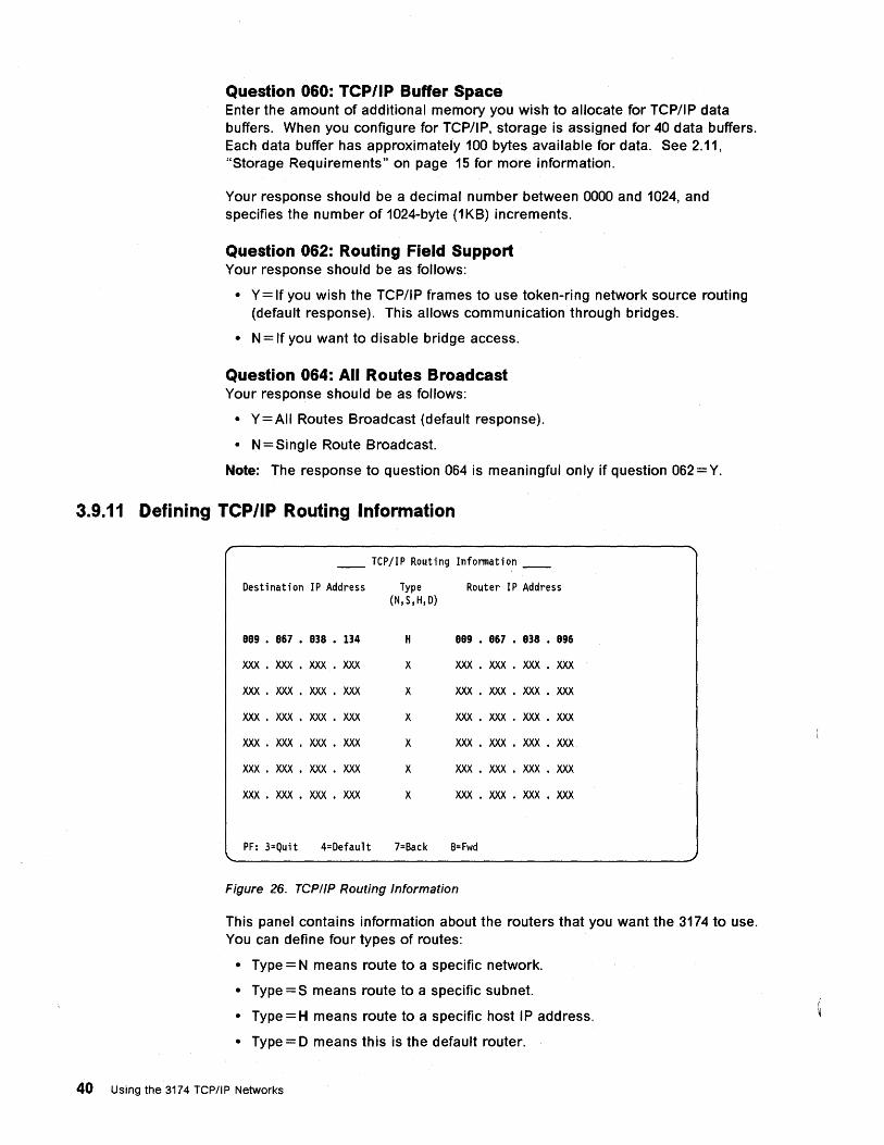
Question 060: TCP/IP Buffer Space Enter the amount of additional memory you wish to allocate for TCP/IP data buffers. When you configure for TCP/IP, storage is assigned for 40 data buffers. Each data buffer has approximately 100 bytes available for data. See 2.11, "Storage Requirements" on page 15 for more information.
Your response should be a decimal number between 0000 and 1024, and specifies the number of 1024-byte (1KB) increments.
Question 062: Routing Field Support Your response should be as follows:
• Y= If you wish the TCP/IP frames to use token-ring network source routing (default response). This allows communication through bridges.
• N = If you want to disable bridge access.
Question 064: All Routes Broadcast Your response should be as follows:
• Y=AII Routes Broadcast (default response).
• N = Single Route Broadcast.
Note: The response to question 064 is meaningful only if question 062 = Y.
3.9.11 Defining TCP/IP Routing Information
__ TCP/IP Routing Infonnation __
Destination IP Address Type Router IP Address (N,S,H,D)
009 • 067 • 038 • 134 H 009 • 067 • 038 • 096
XXX • XXX • XXX • XXX X XXX • XXX • XXX • XXX
XXX • XXX • XXX • XXX X XXX • XXX • XXX • XXX
XXX • XXX • XXX • XXX X XXX • XXX • XXX • XXX
XXX • XXX • XXX • XXX X XXX • XXX • XXX • XXX
XXX • XXX • XXX • XXX X XXX • XXX • XXX • XXX
XXX • XXX • XXX • XXX X XXX • XXX • XXX • XXX
PF: 3=Quit 4=Default 7=Back 8=Fwd
Figure 26. TCP/IP Routing Information
This panel contains information about the routers that you want the 3174 to use. You can define four types of routes:
• Type = N means route to a specific network.
• Type = S means route to a specific subnet.
• Type =H means route to a specific host IP address.
• Type = 0 means this is the default router.
40 Using the 3174 TCP/IP Networks
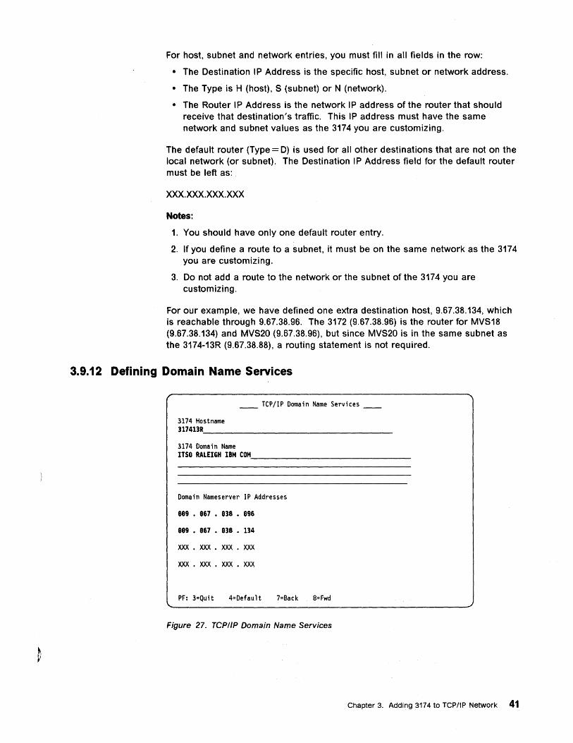
For host, subnet and. network entries, you must fill in all fields in the row:
• The Destination IP Address is the specific host, subnet or network address.
• The Type is H (host), S (subnet) or N (network).
• The Router IP Address is the network IP address of the router that should receive that destination's traffic. This IP address must have the same network and subnet values as the 3174 you are customizing.
The default router (Type = D) is used for all other destinations that are not on the local network (or subnet). The Destination IP Address field for the default router must be left as:
xxx.xxx.xxx.xxx
Notes:
1. You should have only one default router entry.
2. If you define a route to a subnet, it must be on the same network as the 3174 you are customizing.
3. Do not add a route to the network or the subnet of the 3174 you are customizing.
For our example, we have defined one extra destination host, 9.67.38.134, which is reachable through 9.67.38.96. The 3172 (9.67.38.96) is the router for MVS18 (9.67.38.134) and MVS20 (9.67.38.96), but since MVS20 is in the same subnet as the 3174-13R (9.67.38.88), a routing statement is not required.
3.9.12 Defining Domain Name Services
__ TCPjIP Domain Name Services __
3174 Hostname 317413R'---_______________ ___
3174 Domain Name ITSO RALEIGH IBM COM. _____________ _
Domain Nameserver IP Addresses
889 • 867 • 838 • 896
889 • 867 • 838 • 134
xxx . XXX • XXX • XXX
XXX • XXX • XXX • XXX
PF: 3=Quit 4=Default 7=Back 8=Fwd
Figure 27. TCPIIP Domain Name Services
Chapter 3. Adding 3174 to TCP/IP Network 41
3174 Hostname A response is required for this field. Enter the name assigned to your 3174. Observe the following rules when defining the 3174 Hostname:
• The name may be up to 63 characters long.
• Only alphabetic (A through Z), numeric (0 through 9) and the hyphen characters are allowed.
• Use the dollar sign ($) to represent a hyphen.
• No imbedded blanks are allowed.
• Although you enter the name in uppercase characters, the 3174 converts it to lowercase before using it.
3174 Domain Name Enter the name of the domain that your 3174 is in. This name can be made up of several parts. Observe the following rules when defining the 3174 Domain Name:
• Each part of the name may be up to 63 characters long.
• Only alphabetic (A through Z), numeric (0 through 9) and the hyphen characters are valid.
• Use the dollar sign ($) to represent a hyphen.
• Use blanks to separate the parts of the name.
For example, you would enter MYDEPT.MY-COMPANY.MYNET as MYDEPT MY$COMPANY MYNET.
• Although you enter the name in uppercase characters, the 3174 converts it to lowercase before using it.
A domain name is required if any Domain Nameserver IP Address is entered.
Domain Nameserver IP Addresses Enter the IP addresses of the name servers that the 3174 should use to resolve names to IP addresses. Enter the primary name server's address first. These responses are optional.
42 Using the 3174 TCP/IP Networks
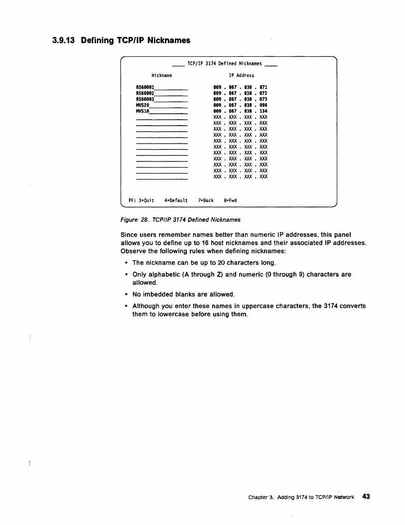
3.9.13 Defining TCP/IP Nicknames
__ TCP/IP 3174 Defined Nicknames __
Nickname
RS60001 ___ _ RS60002 ___ _ RS60003 ___ _ MVS20 ____ _ MVS18 ____ _
IP Address
009 • 067 • 038 • 071 009 • 067 • 038 • 072 009 • 067 • 038 • 073 009 • 067 • 038 • 096 OOg • 067 • 038 • 134 XXX • XXX • XXX • XXX XXX • XXX • XXX • XXX XXX • XXX • XXX • XXX XXX • XXX • XXX • XXX XXX • XXX • XXX • XXX XXX • XXX • XXX • XXX XXX • XXX • XXX • XXX XXX • XXX • XXX • XXX XXX • XXX • XXX • XXX XXX • XXX • XXX • XXX XXX • XXX • XXX • XXX
PF: 3=Quit 4=Default 7=Back 8=Fwd
Figure 28. TCPIIP 3174 Defined Nicknames
Since users remember names better than numeric IP addresses, this panel allows you to define up to 16 host nicknames and their associated IP addresses. Observe the following rules when defining nicknames:
• The nickname can be up to 20 characters long.
• Only alphabetic (A through Z) and numeric (0 through 9) characters are allowed.
• No imbedded blanks are allowed.
• Although you enter these names in uppercase characters, the 3174 converts them to lowercase before using them.
Chapter 3. Adding 3174 to TCPIIP Network 43
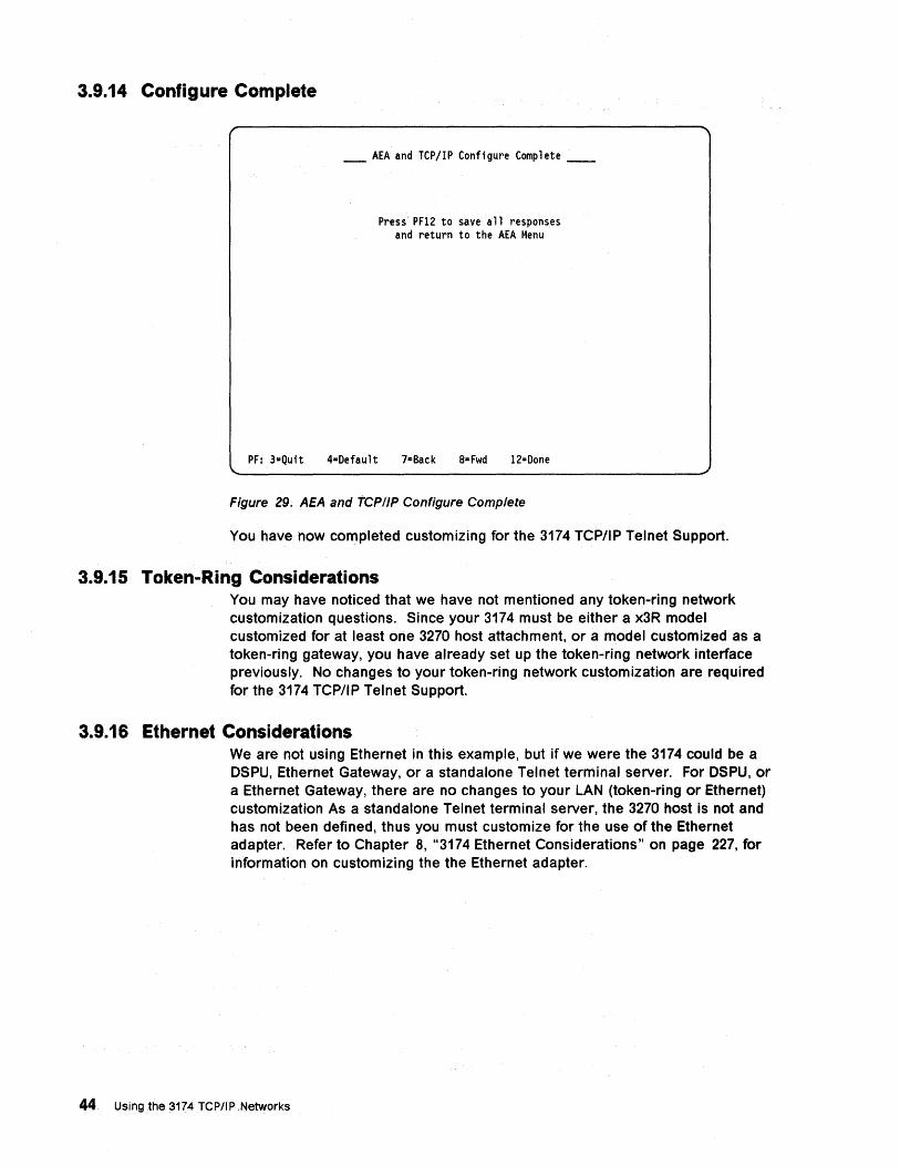
3.9.14 Configure Complete
____ AEA and TCPjIP Configure Complete ___ __
Press' PF12 to save all responses and return to the AEA Menu
PF: 3=Quit 4=Defau1t 7=Back 8= Fwd 12=Done
Figure 29. AEA and TCPIIP Configure Complete
You have now completed customizing for the 3174 TCP/IP Telnet Support.
3.9.15 Token-Ring Considerations You may have noticed that we have not mentioned any token-ring network customization questions. Since your 3174 must be either a x3R model customized for at least one 3270 host attachment, or a model customized as a token-ring gateway, you have already set up the token-ring network interface previously. No changes to your tOken-ring network customization are required for the 3174 TCP/IP Telnet Support.
3.9.16 Ethernet Considerations We are not using Ethernet in this example, but if we were the 3174 could be a DSPU, Ethernet Gateway, or a standalone Telnet terminal server. For DSPU, or a Ethernet Gateway, there are no changes to your LAN (token-ring or Ethernet) customization As a standalone Telnet terminal server, the 3270 host is not and has not been defined, thus you must customize for the use of the Ethernet adapter. Refer to Chapter 8, "3174 Ethernet Considerations" on page 227, for information on customizing the the Ethernet adapter.
44 Using the 3174 TCP/lPNetworks
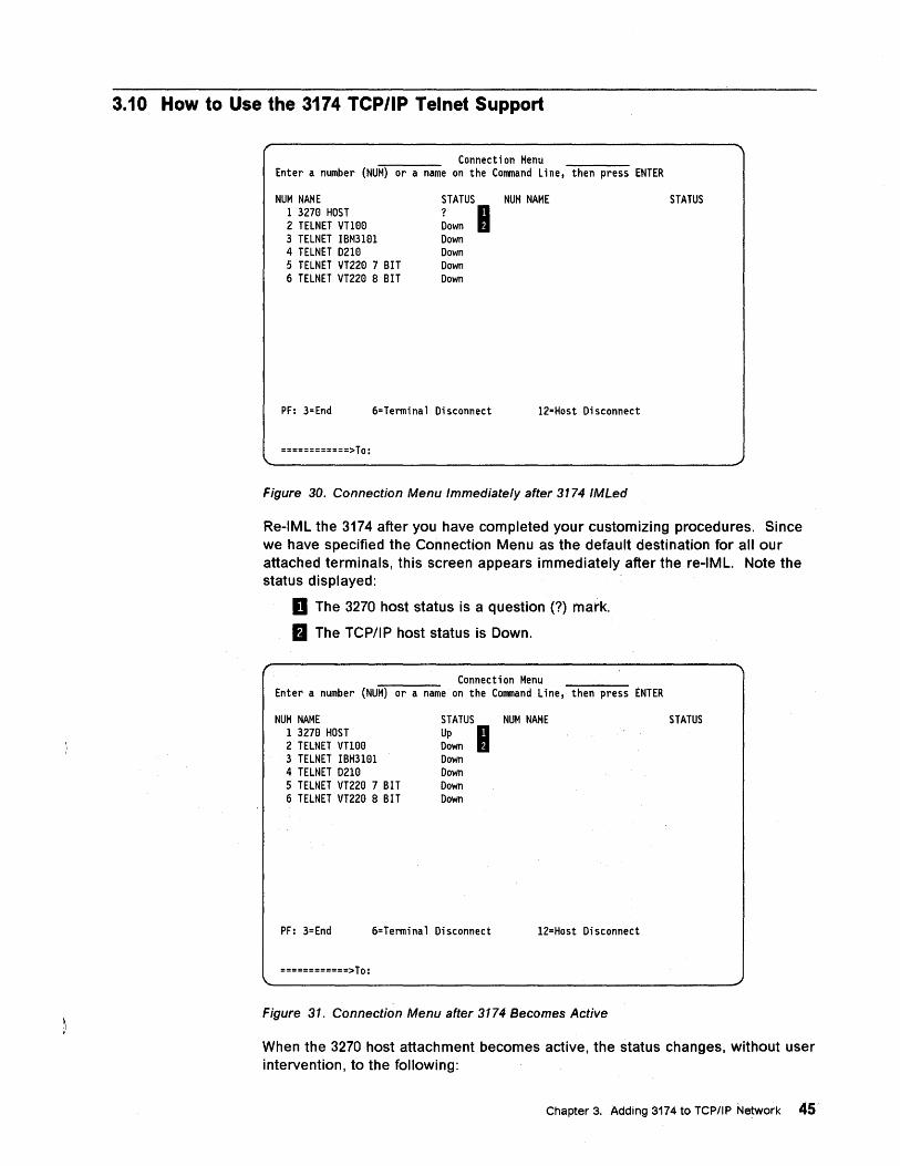
3.10 How to Use the 3174 TCP/IP Telnet Support
Connection Menu Enter a number (NUM) or a name on the Command Line, then press ENTER
NUM NAME 1 3270 HOST 2 TELNET VT100 3 TELNET IBM3101 4 TELNET D2Ie 5 TELNET VT220 7 BIT 6 TELNET VT220 8 BIT
STATUS NUM NAME ? 0 Down II Down Down Down Down
PF: 3=End 6=Terminal Disconnect 12=Host Disconnect
============>To:
Figure 30. Connection Menu Immediately after 3174 IMLed
STATUS
Re-IML the 3174 after you have completed your customizing procedures. Since we have specified the Connection Menu as the default destination for all our attached terminals, this screen appears immediately after the re-IML. Note the status displayed:
D The 3270 host status is a question (?) mark.
fJ The TCP/IP host status is Down.
Connection Menu Enter a number (NUM) or a name on the Command Line, then press ENTER
NUM NAME 1 3270 HOST 2 TELNET VTHl0 3 TELNET IBM3101 4 TELNET D2Ie 5 TELNET VT220 7 BIT 6 TELNET VT220 8 BIT
STATUS NUM NAME Up 0 Down II Down Down Down Down
PF: 3=End 6=Terminal Disconnect 12=Host Disconnect
============>To:
Figure 31. Connection Menu after 3174 Becomes Active
STATUS
When the 3270 host attachment becomes active, the status changes, without user intervention, to the following:
Chapter 3. Adding 3174 to TCP/IP Network 45
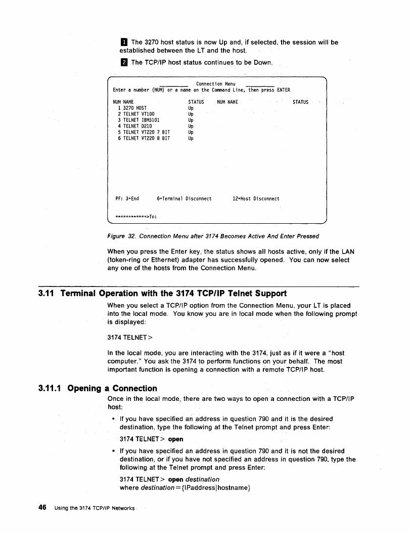
D The 3270 host status is now Up and,ifselected, the session will be established between the L T and the host.
II The rCP/IP host status continues to be Down~
Connection Menu Enter a number (NUM) or a name on the Command Line, then press ENTER
NUM NAME 1 327e HOST 2 TELNET VTlee 3 TELNET IBM31el 4 TELNET 021(;) 5 TELNET VT22e 7 BIT 6 TELNET VT22e 8 BIT
STATUS Up Up Up Up Up Up
PF: 3=End 6=Terminal Disconnect
============>To:
NUM NAME
12=Host Disconnect
STATUS
Figure 32. Connection Menu after 3174 Becomes Active And Enter Pressed
When you press the Enter key, the status shows all hosts active, only if the LAN (token-ring or Ethernet) adapter has successfully opened. You can now select anyone of the hosts from the Connection Menu.
3.11 Terminal Operation with the 3174 TCP/IP Telnet Support When you select a TCP/IP option from the Connection Menu, your L T is placed into the local mode. You know you are in local mode when the following prompt is displayed:
3174 TELNET>
In the local mode, you are interacting with the 3174, just as if it were a "host computer." You ask the 3174 to perform functions on your behalf. The most important function is opening a connection with a remote TCP/IP host.
3.11.1 Opening a Connection Once in the local mode, there are two ways to open a connection with a TCP/IP host:
• If you have specified an address in question 790 and it is the desired destination, type the following at the Telnet prompt and press Enter:
3174 TELNET> open
• If you have specified an address in question 790 and it is not the desired destination, or if you have not specified an address in question 790, type the following at the Telnet prompt and press Enter:
3174 TELNET> open destination where destination={IPaddress/hostname}
46 Using the 3174 TCPIIP Networks
Once your connection is opened, you leave the local mode and enter into session with the remote host.
When you are in session with the host, you can return to the local mode temporarily, without losing your connection to the host, by pressing the escape key.
3.11.2 Escaping to Local Mode To escape to the local mode while you are in an active Telnet session, use the escape key (the escape key usually involves pressing more than one key and is not the key marked Esc or ESC on your keyboard). To find out what the escape key is, type the following at the Telnet prompt and press Enter:
3174 TELNET> display
Figure 46 on page 57 shows an example of the resulting display. Note the line that shows:
escape ["L]
This is the default setting; it means that:
• If you have a Ctrl key on your keyboard and your display is setup offline for native mode (Standard), press and hold the Ctrl key (a +- shows in the OIA) and then press the L key.
• If you do not have a Ctrl key, enter Extension mode (for example, press and hold Alt, and then press Erase EOF), then press and release the C key, which puts you into the Ctrl mode (a +- now shows in the OIA), then press the L key.
If you find this cumbersome, use the SET command to define your preferred escape key (for example, the $ key) before you open the connection:
3174 TELNET> set escape $
Once you have escaped to the local mode, you can e.nter local commands (see 3.11.8, "Local Mode Commands" on page 51). If you enter the CLOSE or the QUIT command, the connection will be ended.
After the command is performed, you automatically return to your host session, unless the command was a request to end the connection. You may have to press Enter once to regain the host prompt.
If you did not issue any command when you escaped toJhe local mode, just press Enter once and you will be returned to your host session.
When you return to your host session, you may need to request the host application to refresh the screen. For example, if you are working with SMIT (System Management Interface Tool) on the RS/6000, press the PF2 key to refresh. Otherwise, the commands and responses that were displayed during local mode remain on the screen until they are replaced by data from the host.
Chapter 3. Adding 3174 to TCP/IP Network 47
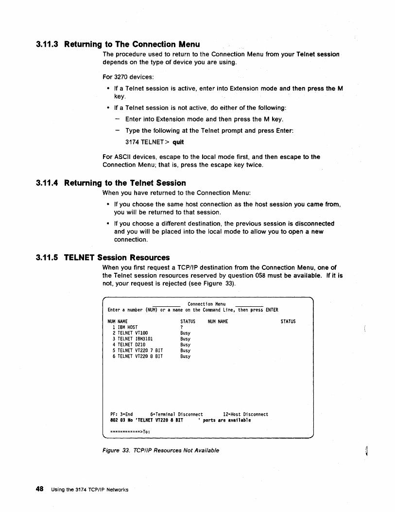
3.11.3 Returning to The Connection Menu The procedure used to return to the Connection Menu from your Telnet session depends on the type of device you are using.
For 3270 devices:
• If a Telnet session is active, enter into Extension mode and then press the M key.
• If a Telnet session is not active, do either of the following:
Enter into Extension mode and then press the M key.
Type the following at the Telnet prompt and press Enter:
3174 TELNET > quit
For ASCII devices, escape to the local mode first, and then escape to the Connection Menu; that is, press the escape key twice.
3.11.4 Returning to the Telnet Session When you have returned to the Connection Menu:
• If you choose the same host connection as the host session you came from, you will be returned to that session.
• If you choose a different destination, the previous session is disconnected and you will be placed into the local mode to allow you to open a new connection.
3.11.5 TELNET Session Resources When you first request a TCP/IP destination from the Connection Menu, one of the Telnet session resources reserved by question 058 must be available. If it is not, your request is rejected (see Figure 33).
Connection Menu Enter a number (NUM) or a name on the Command Line, then press ENTER
NUM NAME 1 IBM HOST 2 TELNET VT100 3 TELNET IBM3101 4 TELNET 0210 5 TELNET VT220 7 BIT 6 TELNET VT220 8 BIT
STATUS ? Busy Busy Busy Busy Busy
NUM NAME
PF: 3=End 6=Terminal Disconnect 12=Host Disconnect 882 83 No 'TELNET VT228 8 BIT ' ports are ava;lable
============>To:
Figure 33. TCP/IP Resources Not Available
48 Using the 3174 TCP/IP Networks
STATUS
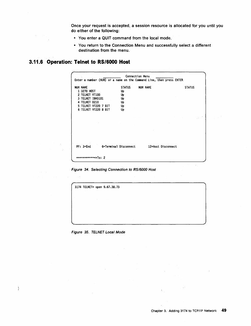
Once your request is accepted, a session resource is allocated for you until you do either of the following:
• You enter a QUIT command from the local mode.
• You return to the Connection Menu and successfully select a different destination from the menu.
3.11.6 Operation: Telnet to RS/6000 Host
Connection Menu Enter a number (NUM) or a name on the Command Line, then press ENTER
NUM NAME 1 327El HOST 2 TELNET VnElEl 3 TELNET IBM31ElI 4 TELNET D21El 5 TELNET VT22El 7 BIT 6 TELNET VT22El B BIT
STATUS Up Up Up Up Up Up
PF: 3=End 6=Terminal Disconnect
=~=====·=·=·>To: 2
NUM NAME
12=Host Disconnect
Figure 34. Selecting Connection to RS/6000 Host
3174 TELNET> open 9.67.38.73
Figure 35. TELNET Local Mode
STATUS
Chapter 3. Adding 3174 to TCP/IP Network 49
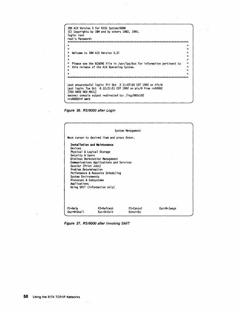
IBM AIX Version 3 for RISC System/6000 (C) Copyrights by IBM and by others 1982, 1991. login: root root's Password: ******************************************************************************* * * * Welcome to IBM AIX Version 3.2! * * * Please see the README file in /usr/1pp/bos for information pertinent to * this release of the AIX Operating System. * *
* * * * * * * * *
*******************************************************************************
Last unsuccessful login: Fri Oct 2 11:07:03 COT 1992 on hft/0 Last login: Tue Oct 6 12:21:51 COT 1992 on pts/8 from rs60092 [YOU HAVE NEW MAIL] swcons: console output redirected to: /10g/960ct92 <rs69003># smit
Figure 36. RSI6000 after Login
System Management
Move cursor to desired item and press Enter.
Installation and Maintenance Devices Physical & Logical Storage Security & Users Diskless Workstation Management Communications Applications and Services Spooler (Print Jobs) Problem Determination Performance & Resource Scheduling System Environments Processes & Subsystems Applications Using SMIT (information only)
Fl-Help Esc+g-Shel1
F2=Refresh Esc+0=Exit
F3=Cance1 Enter=Do
Figure 37. RSI6000 after Invoking SMIT
50 Using the 3174 TCP/IP Networks
Esc+8=Image
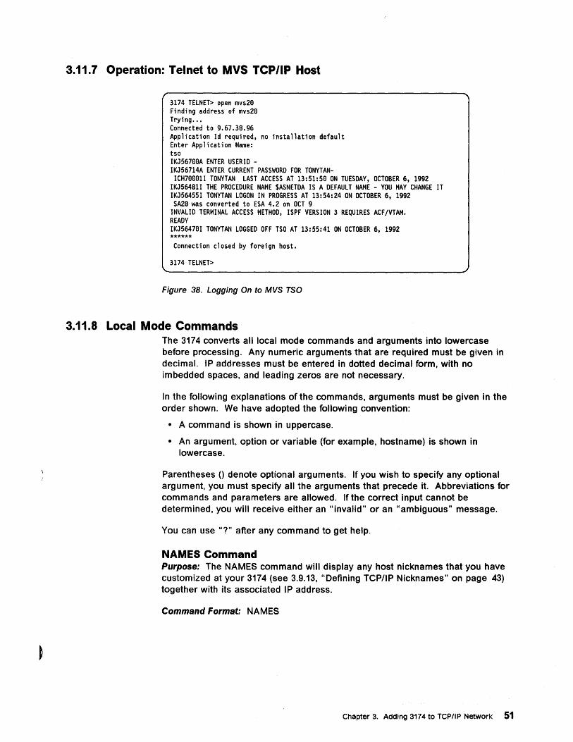
3.11.7 Operation: Telnet to MVS TCP/IP Host
3174 TELNET> open mvs29 Finding address of mvs29 Trying ••• Connected to 9.67.38.96 Application Id required, no installation default Enter Application Name: tso IKJ56799A ENTER USERID -IKJ56714A ENTER CURRENT PASSWORD FOR TONYTAN-ICH79901I TONYTAN LAST ACCESS AT 13:51:50 ON TUESDAY, OCTOBER 6, 1992
IKJ56481I THE PROCEDURE NAME $ASNETDA IS A DEFAULT NAME - YOU MAY CHANGE IT IKJ56455I TONYTAN LOGON IN PROGRESS AT 13:54:24 ON OCTOBER 6, 1992 SA20 was converted to ESA 4.2 on OCT 9
INVALID TERMINAL ACCESS METHOD, ISPF VERSION 3 REQUIRES ACFjVTAH. READY IKJ56470I TONYTAN LOGGED OFF TSO AT 13:55:41 ON OCTOBER 6, 1992 ****** Connection closed by foreign host.
3174 TELNET>
Figure 38. Logging On to MVS TSO
3.11.8 Local Mode Commands The 3174 converts all local mode commands and arguments into lowercase before processing. Any numeric arguments that are required must be given in decimal. IP addresses must be entered in dotted decimal form, with no imbedded spaces, and leading zeros are not necessary.
In the following explanations of the commands, arguments must be given in the order shown. We have adopted the following convention:
• A command is shown in uppercase.
• An argument, option or variable (for example, hostname) is shown in lowercase.
Parentheses 0 denote optional arguments. If you wish to specify any optional argument, you must specify all the arguments that precede it. Abbreviations for commands and parameters are allowed. If the correct input cannot be determined, you will receive either an "invalid" or an "ambiguous" message.
You can use "?" after any command to get help.
NAMES Command Purpose: The NAMES command will display any host nicknames that you have customized at your 3174 (see 3.9.13, "Defining TCP/IP Nicknames" on page 43) together with its associated I P address.
Command Format: NAMES
Chapter 3. Adding 3174 to TCP/IP Network 51
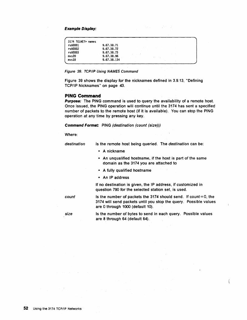
Example Display:
3174 TELNET> names rs6eeEll 9.67.38.71
9.67.38.72 9.67.38.73 9.67.38.96 9.67.38.134
rs6eee2 rs6eee3 mvs2e mvs18
Figure 39. TCP/IP Using NAMES Command
Figure 39 shows the display for the nicknames defined in 3.9.13, "Defining TCP/IP Nicknames" on page 43.
PING Command Purpose: The PING command is used to query the availability of a remote host. Once issued, the PING operation will continue until the 3174 has sent a specified number of packets to the remote host (if it is available). You can stop the PING operation at any time by pressing any key.
Command Format: PING (destination (count (size)))
Where:
destination
count
size
52 Using the 3174 TCPIIP Networks
Is the remote host being queried. The destination can be:
• A nickname
• An unqualified hostname, if the host is part of the same domain as the 3174 you are attached to
• A fully qualified hostname
• An IP address
If no destination is given, the IP address, if customized in question 790 for the selected station set, is used.
Is the number of packets the 3174 should send. If count=O, the 3174 will send packets until you stop the query. Possible values are 0 through 1000 (default 10).
Is the number of bytes to send in each query. Possible values are 8 through 64 (default 64).
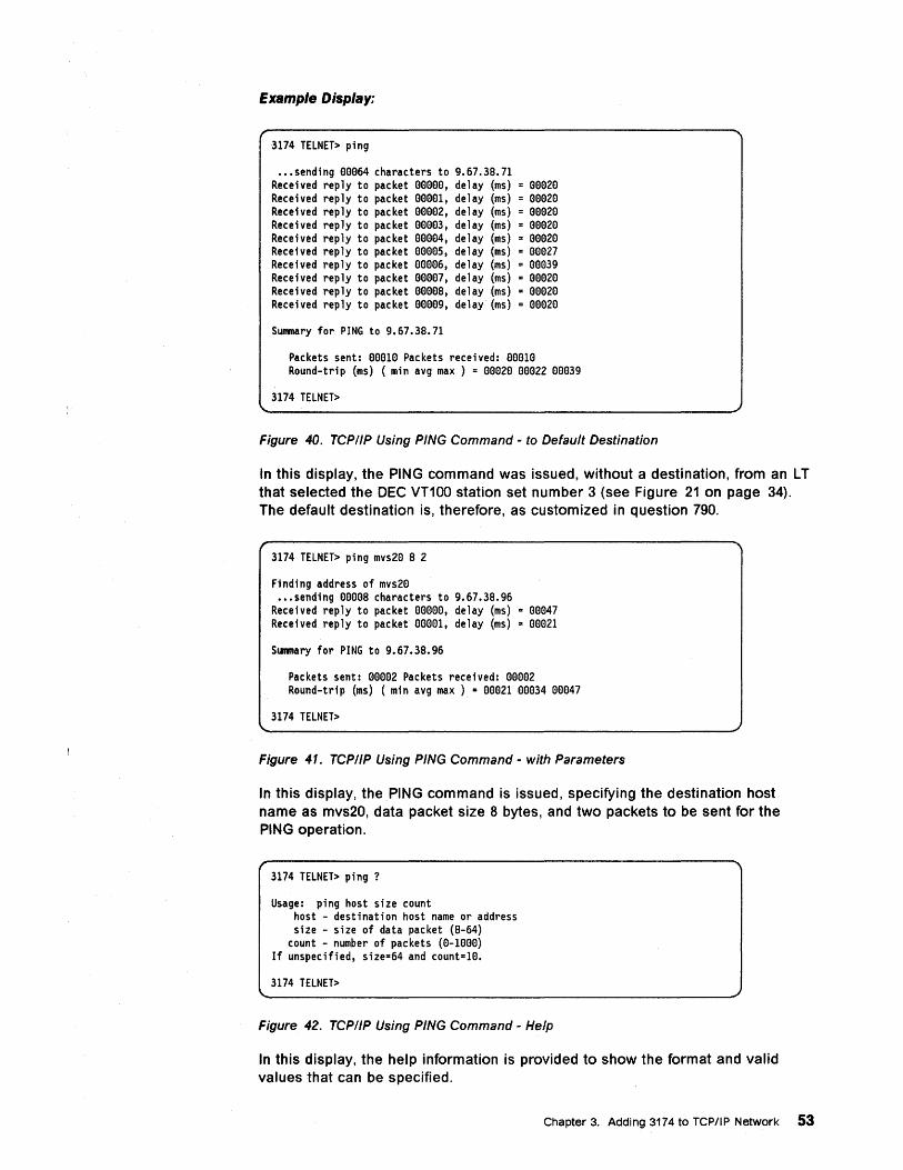
Example Display:
3174 TELNET> ping
••• sending eee64 characters to 9.67.3S.71 Received reply to packet eeeee, delay (ms) = eee2e Received reply to packet eeeel, delay (ms) = eee2e Received reply to packet eeee2, delay (ms) = eee2e Received reply to packet eeee3, delay (ms) = eee2e Received reply to packet eeee4, delay (ms) = eee2e Received reply to packet eeees, delay (ms) = eoe27 Received reply to packet eeee6, delay (ms) = eee39 Received reply to packet eeee7, delay (ms) = eee2e Received reply to packet eeees, delay (ms) = eee2e Received reply to packet eeee9, delay (ms) = ee02e
Summary for PING to 9.67.3S.7l
Packets sent: eeele Packets received: eeOle Round-trip (ms) (min avg max ) = eOe2e eOe22 eee39
3174 TELNET>
Figure 40. TCPIIP Using PING Command - to Default Destination
In this display, the PING command was issued, without a destination, from an L T that selected the DEC VT100 station set number 3 (see Figure 21 on page 34). The default destination is, therefore, as customized in Question 790.
3174 TELNET> ping mvs2e S 2
Finding address of mvs2e ••• sending eeees characters to 9.67.3S.96
Received reply to packet eeeee, delay (ms) = eee47 Received reply to packet eeee1, delay (ms) = eee2l
Summary for PING to 9.67.3S.96
Packets sent: eeoe2 Packets received: eeee2 Round-trip (ms) (min avg max) = eee2l eee34 eee47
3174 TELNET>
Figure 41. TCPI/P Using PING Command - with Parameters
In this display, the PING command is issued, specifying the destination host name as mvs20, data packet size 8 bytes, and two packets to be sent for the PING operation.
3174 TELNET> ping ?
Usage: ping host size count host - destination host name or address size - size of data packet (S-64)
count - number of packets (e-leee) If unspecified, size=64 and count=le.
3174 TELNET>
Figure 42. TCPI/P Using PING Command - Help
In this display, the help information is provided to show the format and valid values that can be specified.
Chapter 3. Adding 3174 to TCP/IP Network 53
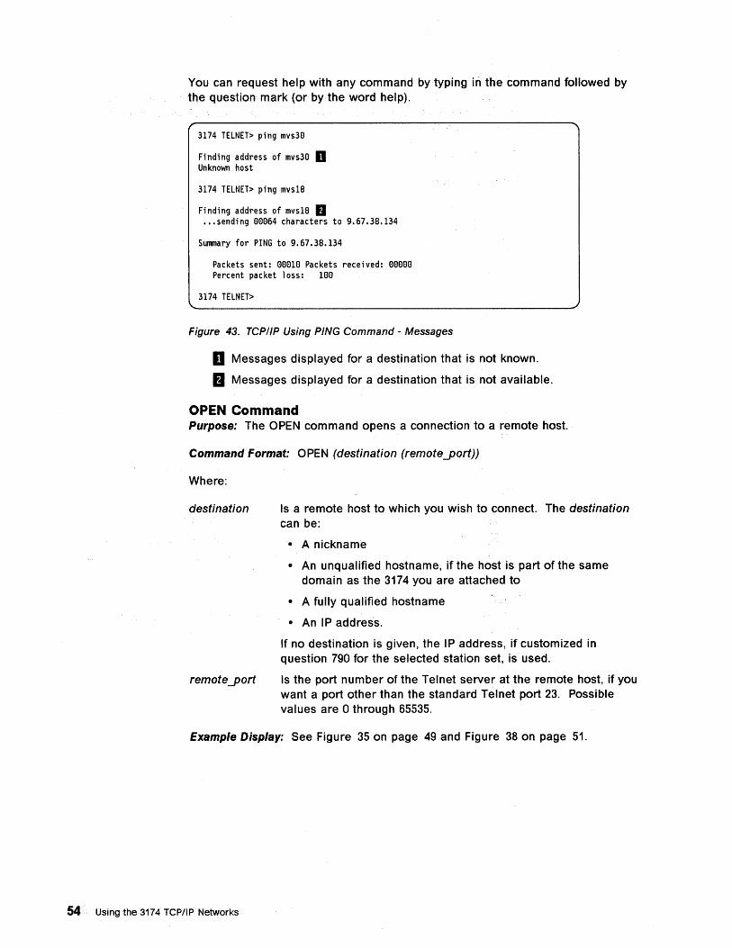
You can request help with any command by typing in the command followed by the question mark (or by the word help).
3174 TELNET> ping mvs30
Finding address of mvs30 II Unknown host
3174 TELNET> ping mvs18
Finding address of mvs18 II ••• sending 00064 characters to 9.67.38.134
Summary for PING to 9.67.38.134
Packets sent: 00010 Packets received: 00000 Percent packet loss: 100
3174 TELNET>
Figure 43. TCP/IP Using PING Command - Messages
D Messages displayed for a destination that is not known.
fJ Messages displayed for a destination that is not available.
OPEN Command Purpose: The OPEN command opens a connection to a remote host.
Command Format: OPEN (destination (remote""port))
Where:
destination
remote ""port
Is a remote host to which you wish to connect. The destination can be:
• A nickname
• An unqualified hostname, if the host is part of the same domain as the 3174 you are attached to
• A fully qualified hostname
• An IP address.
If no destination is given, the IP address, if customized in question 790 for the selected station set, is used.
Is the port number of the Telnet server at the remote host, if you want a port other than the standard Telnet port 23. Possible values are 0 through 65535.
Example Display: See Figure 35 on page 49 and Figure 38 on page 51.
54 Using the 3174 TCPIIP Networks
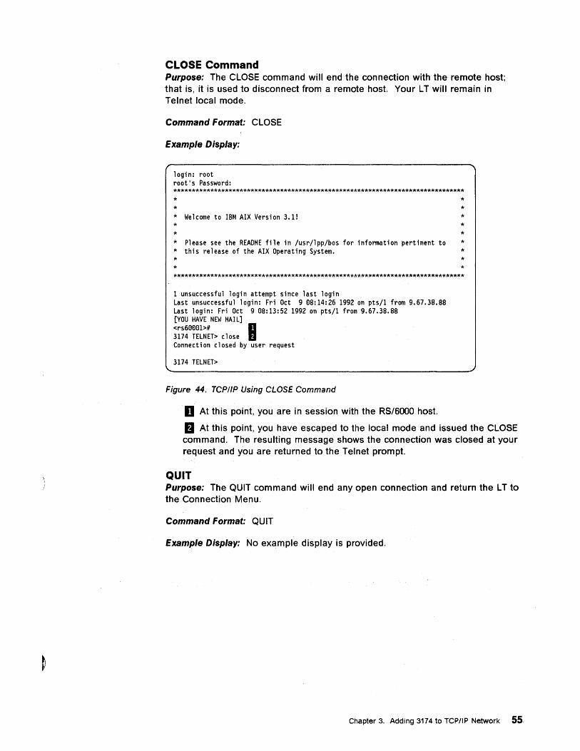
CLOSE Command Purpose: The CLOSE command will end the connection with the remote host; that is, it is used to disconnect from a remote host. Your L T will remain in Telnet local mode.
Command Format: CLOSE
Example Display:
login: root root's Password: ******************************************************************************* * * * Welcome to IBM AIX Version 3.1! * * * Please see the README file in /usr/lpp/bos for information pertinent to * this release of the AIX Operating System. * *
* * * * * * * * *
*******************************************************************************
1 unsuccessful login attempt since last login Last unsuccessful login: Fri Oct 9 08:14:26 1992 on pts/l from 9.67.38.88 Last login: Fri Oct 9 08:13:52 1992 on pts/l from 9.67.38.88 [YOU HAVE NEW MAIL] <rs60001># II 3174 TELNET> close II Connection closed by user request
3174 TELNET>
Figure 44. TCP/IP Using CLOSE Command
D At this point, you are in session with the RS/6000 host.
fJ At this point, you have escaped to the local mode and issued the CLOSE command. The resulting message shows the connection was closed at your request and you are returned to the Telnet prompt.
QUIT Purpose: The QUIT command will end any open connection and return the L T to the Connection Menu.
Command Format: QUIT
Example Display: No example display is provided.
Chapter 3. Adding 3174 to TCP/IP Network 55
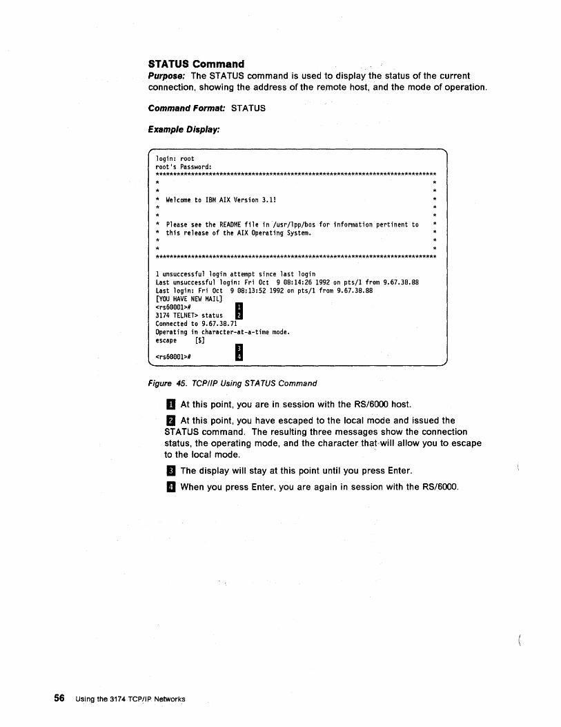
STATUS Command Purpose: The STATUS command is used to display the status of the current connection, showing the address of the remote host, and the mode of operation.
Command Format: STATUS
Example Display:
login: root root's Password: ******************************************************************************* * * * Welcome to IBM AIX Version 3.1! * * * Please see the README file in/usr/1pp/bos for information pertinent to * this release of the AIX Operating System. * *
* * * * * * * * *
*******************************************************************************
1 unsuccessful login attempt since last login Last unsuccessful login: Fri Oct 9 08:14:26 1992 on pts/1 from 9.67.38.88 Last login: Fri Oct 9 08:13:52 1992 on pts/1 from 9.67.38.88 [YOU HAVE NEW MAIL] <rs60001># I 3174 TELNET> status Connected to 9.67.38.71 Operating in character-at-a-time mode. escape [$]
<rs60001># I Figure 45. TCPIIP Using STATUS Command
II At this point, you are in session with the RS/6000 host.
fJ At this point, you have escaped to the local mode and issued the STATUS command. The resulting three messages show the connection status, the operating mode, and the character that/will allow you to escape to the local mode.
II The display will stay at this point until you press Enter.
II When you press Enter, you are again in session with the RS/6000.
56 Using the 3174 TCP/IP Networks
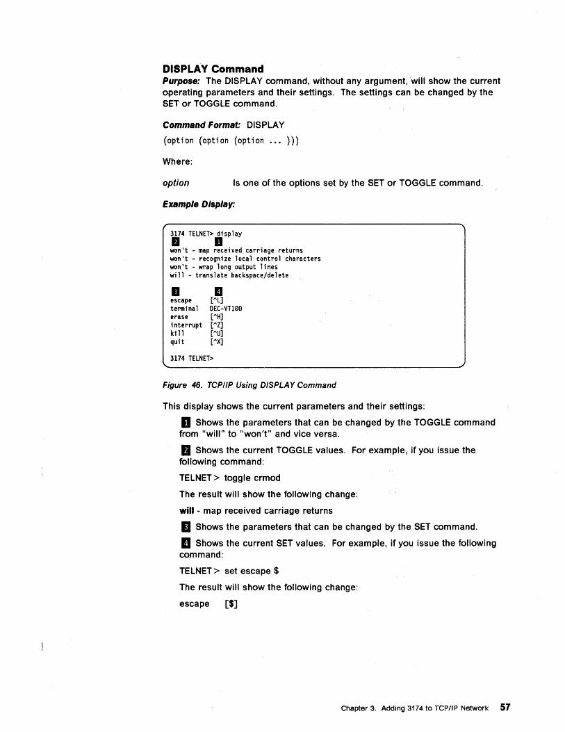
DISPLAY Command Purpose: The DISPLAY command, without any argument, will show the current operating parameters and their settings. The settings can be changed by the SET or TOGGLE command.
Command Format: DISPLAY
(option (option (option .•• )))
Where:
option Is one of the options set by the SET or TOGGLE command.
Example Display:
3174 TELNET> display II II won't - map received carriage returns won't - recognize local control characters won't - wrap long output lines will - translate backspace/delete
II II escape [AL] tenninal DEC-VT100 erase [AH] interrupt [AZ] ki 11 [AU] quit [AX]
3174 TELNET>
Figure 46. TCPIIP Using DISPLA Y Command
This display shows the current parameters and their settings:
II Shows the parameters that can be changed by the TOGGLE command from "will" to "won't" and vice versa.
fJ Shows the current TOGGLE values. For example, if you issue the following command:
TELNET> toggle crmod
The result will show the following change:
will - map received carriage returns
II Shows the parameters that can be changed by the SET command.
II Shows the current SET values. For example, if you issue the following command:
TELNET> set escape $
The result will show the following change:
escape [$]
Chapter 3. Adding 3174 to TCP/IP Network 57
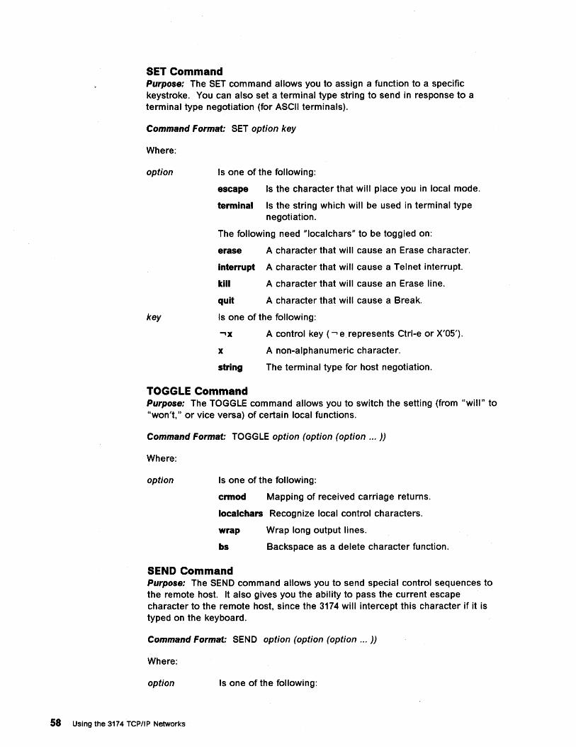
SET Command Purpose: The SET command allows you to assign a function to a specific keystroke. You can also set a terminal type string to send in response to a terminal type negotiation (for ASCII terminals).
Command Format: SET option key
Where:
option
key
Is one of the following:
escape Is the character that will place you in local mode.
terminal Is the string which will be used in terminal type negotiation.
The following need "Iocalchars" to be toggled on:
erase A character that will cause an Erase character.
interrupt A character that will cause a Telnet interrupt.
kill A character that will cause an Erase line.
quit A character that will cause a Break.
Is one of the following:
x
string
A control key ( ...., e represents Ctrl-e or X'OS').
A non-alphanumeric character.
The terminal type for host negotiation.
TOGGLE Command Purpose: The TOGGLE command allows you to switch the setting (from "will" to "won't," or vice versa) of certain local functions.
Command Format: TOGGLE option (option (option ... ))
Where:
option Is one of the following:
crmod Mapping of received carriage returns.
localchars Recognize local control characters.
wrap Wrap long output lines.
bs Backspace as a delete character function.
SEND Command Purpose: The SEND command allows you to send special control sequences to the remote host. It also gives you the ability to pass the current escape character to the remote host, since the 3174 will intercept this character if it is typed on the keyboard.
Command Format: SEND option (option (option ... ))
Where:
option Is one of the following:
58 Using the 3174 TCPIIP Networks
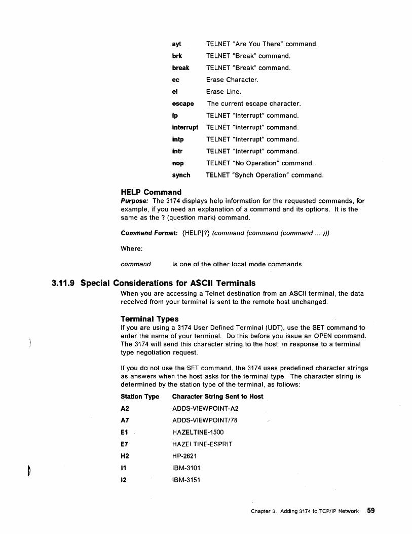
ayt TELNET "Are You There" command.
brk TELNET "Break" command.
break TELNET "Break" command.
ec Erase Character.
el Erase Line.
escape The current escape character.
ip TELNET "Interrupt" command.
interrupt TELNET "Interrupt" command.
intp TELNET "Interrupt" command.
intr TELNET "Interrupt" command.
nop TELNET "No Operation" command.
synch TELNET "Synch Operation" command.
HELP Command Purpose: The 3174 displays help information for the requested commands, for example, if you need an explanation of a command and its options. It is the same as the? (question mark) command.
Command Format: {HELPI?} (command (command (command ... )))
Where:
command Is one of the other local mode commands.
3.11.9 Special Considerations for ASCII Terminals When you are accessing a Telnet destination from an ASCII terminal, the data received from your terminal is sent to the remote host unchanged.
Terminal Types If you are using a 3174 User Defined Terminal (UDT), use the SET command to enter the name of your terminal. Do this before you issue an OPEN command. The 3174 will send this character string to the host, in response to a terminal type negotiation request.
If you do not use the SET command, the 3174 uses predefined character strings as answers when the host asks for the terminal type. The character string is determined by the station type of the terminal, as follows:
Station Type Character String Sent to Host
A2
A7
E1
E7
H2
11
12
ADDS-VIEWPOINT-A2
ADDS-VIEWPOINT 178
HAZELTINE-1500
HAZEL TINE-ESPRIT
HP-2621
IBM-3101
IBM-3151
Chapter 3. Adding 3174 to TCPIIP Network 59
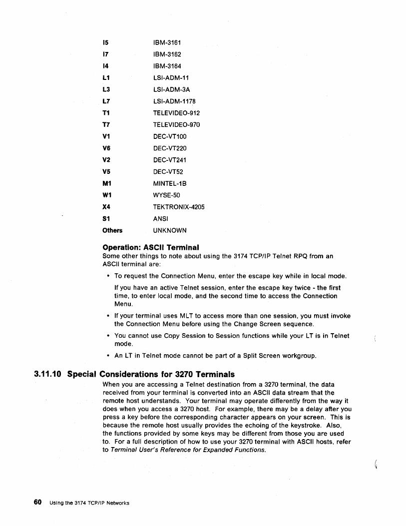
15 IBM-3161
17 IBM-3162
14 IBM-3164
L1 LSI-ADM-11
L3 LSI-ADM-3A
L7 LSI-ADM-1178
T1 TELEVIDEO-912
T7 TE LEVI DEO-970
V1 DEC-VT100
V6 DEC-VT220
V2 DEC-VT241
V5 DEC-VTS2
M1 MINTEL-1B
W1 WYSE-SO
X4 TEKTRON IX-420S
51 ANSI
Others UNKNOWN
Operation: ASCII Terminal Some other things to note about using the 3174 TCP/IP Telnet RPQ from an ASCII terminal are:
• To request the Connection Menu, enter the escape key while in local mode.
If you have an active Telnet session, enter the escape key twice - the first time, to enter local mode, and the second time to access the Connection Menu.
• If your terminal uses ML T to access more than one session, you must invoke the Connection Menu before using the Change Screen sequence.
• You cannot use Copy Session to Session functions while your LT is in Telnet mode.
• An L T in Telnet mode cannot be part of a Split Screen workgroup.
3.11.10 Special Considerations for 3270 Terminals When you are accessing a Telnet destination from a 3270 terminal, the data received from your terminal is converted into an ASCII data stream that the remote host understands. Your terminal may operate differently from the way it does when you access a 3270 host. For example, there may be a delay after you press a key before the corresponding character appears on your screen. This is because the remote host usually provides the echoing of the keystroke. Also, the functions provided by some keys may be different from those you are used to. For a full description of how to use your 3270 terminal with ASCII hosts, refer to Terminal User's Reference for Expanded Functions.
60 Using the 3174 TCP/IP Networks
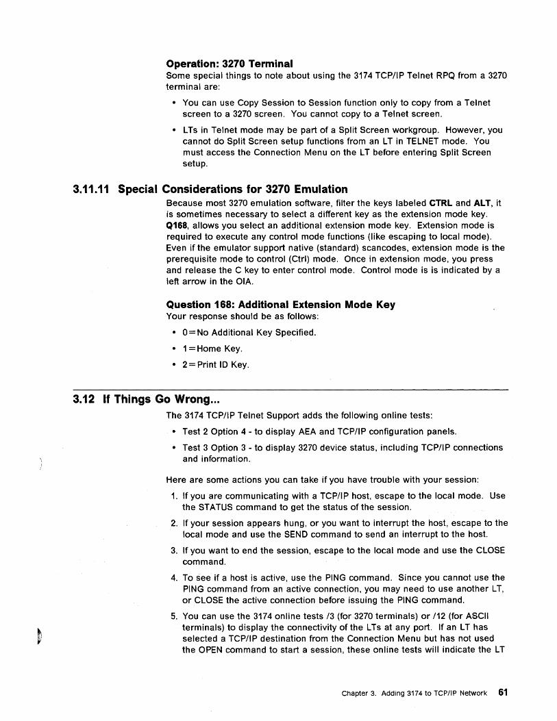
Operation: 3270 Terminal Some special things to note about using the 3174 TCPIIP Telnet RPQ from a 3270 terminal are:
• You can use Copy Session to Session function only to copy from a Telnet screen to a 3270 screen. You cannot copy to a Telnet screen.
• L Ts in Telnet mode may be part of a Split Screen workgroup. However, you cannot do Split Screen setup functions from an L T in TELNET mode. You must access the Connection Menu on the L T before entering Split Screen setup.
3.11.11 Special Considerations for 3270 Emulation Because most 3270 emulation software, filter the keys labeled CTRL and ALT, it is sometimes necessary to select a different key as the extension mode key. Q168, allows you select an additional extension mode key. Extension mode is required to execute any control mode functions (like escaping to local mode). Even if the emulator support native (standard) scancodes, extension mode is the prereqUisite mode to control (Ctrl) mode. Once in extension mode, you press and release the C key to enter control mode. Control mode is is indicated by a left arrow in the OIA.
Question 168: Additional Extension Mode Key Your response should be as follows:
• 0 = No Additional Key Specified.
• 1 =Home Key.
• 2 = Print 10 Key.
3.12 If Things Go Wrong ... The 3174 TCP/IP Telnet Support adds the following online tests:
• Test 2 Option 4 - to display AEA and TCP/IP configuration panels.
• Test 3 Option 3 - to display 3270 device status, including TCPIIP connections and information.
Here are some actions you can take if you have trouble with your session:
1. If you are communicating with a TCP/IP host, escape to the local mode. Use the STATUS command to get the status of the session.
2. If your session appears hung, or you want to interrupt the host, escape to the local mode and use the SEND command to send an interrupt to the host.
3. If you want to end the session, escape to the local mode and use the CLOSE command.
4. To see if a host is active, use the PING command. Since you cannot use the PING command from an active connection, you may need to use another L T, or CLOSE the active connection before issuing the PING command.
5. You can use the 3174 online tests 13 (for 3270 terminals) or 112 (for ASCII terminals) to display the connectivity of the L Ts at any port. If an L T has selected a TCP/IP destination from the Connection Menu but has not used the OPEN command to start a session, these online tests will indicate the L T
Chapter 3. Adding 3174 to TCPIIP Network 61
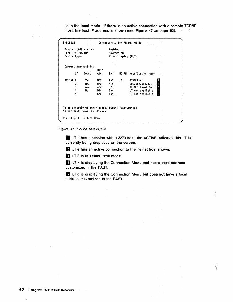
is in the local mode. If there isan active connection with a remote TCP/IP host, the host IP address is shown (see Figure 47 on page 62).
BKBCP235 __ Connectivity for PN 1:)3, HG 26 __
Adapter (HG) status: Port (PN) status: Device type:
Current connectivity-Host
LT Bound Addr
ACTIVE 1 Yes e92 2 n/a n/a 3 n/a n/a 4 No 014 5 n/a
Enabled Powered on Video display (MLT)
IOn HG_PN Host/Station Name
1A1 16 327e host n/a 999.967.938.971 n/a TELNET Local Mode 1A4 LT not available lAS LT not available
To go directly to other tests, enter: /Test,Option Select Test; press ENTER ===>
PF: 3=Quit 12=Test Menu
Figure 47. Online Test /3,3,26
I
I LT-1 has a session with a 3270 host; the ACTIVE indicates this LT is currently being displayed on the screen.
fJ LT-2 has an active connection to the Telnet host shown.
II LT-3 is in Telnet local mode.
II LT-4 is displaying the Connection Menu and has a local address customized in the PAST.
II LT-5 is displaying the Connection Menu but does not have a local address customized in the PAST.
62 Using the 3174 TCPIIP Networks
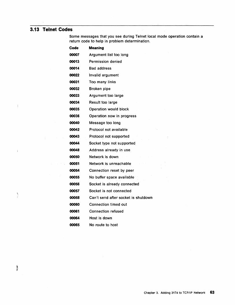
3.13 Telnet Codes Some messages that you see during Telnet local mode operation contain a return code to help in problem determination.
Code Meaning
00007 Argument list too long
00013 Permission denied
00014 Bad address
00022 Invalid argument
00031 Too many links
00032 Broken pipe
00033 Argument too large
00034 Result too large
00035 Operation would block
00036 Operation now in progress
00040 Message too long
00042 Protocol not available
00043 Protocol not supported
00044 Socket type not supported
00048 Address already in use
00050 Network is down
00051 Network is unreachable
00054 Connection reset by peer
00055 No buffer space available
00056 Socket is already connected
00057 Socket is not connected
00058 Can't send after socket is shutdown
00060 Connection timed out
00061 Connection refused
00064 Host is down
00065 No route to host
Chapter 3. Adding 3174 to TCPIIP Network 63
3.14 Data Flows Figure 48 on page 65 shows an example flow of TCP/IP traffic to initiate a session for an LT. The flow shows these steps:
1. The user has already selected one of the Telnet options from the Connection Menu. He then types in "open MVS1.HOST1".
2. The 3174 TCP/IP Telnet Support uses the Domain Name Service function to determine the IP address associated with that host name. If the current routing table does not contain an entry for this host, a request is sent into the network to the Domain Name Server to resolve the address. For this flow, assume that the 3174 TCP/IP Telnet Support already has an entry for MVS1.HOST.
3. The 3174 TCP/IP Telnet Support determines that the request should be forwarded to the router at 128.10.0.2.
4. It does not know the MAC address of the router, so it uses ARP to find out.
5. The 3174 TCP/IP Telnet Support forwards the request to start a session (the first TCP message sent to do this is a SYN request).
6. The router discovers that the host is on a network that it can address directly and uses ARP to seek out the host's MAC address. It forwards the request.
7. The host processes the request, builds a reply and consults its routing tables which point to the router.
8. On the return journey, neither the host nor the router needs to use ARP, because they have both seen recent ARP activity which identifies the MAC addresses they need. These combinations are kept in a sort of cache and are discarded at regular intervals so that any changes can be reflected. Thus, such discovery activity is not restricted to the login, but could happen at any point during the user's host session.
64 Using the 3174 TCPIIP Networks
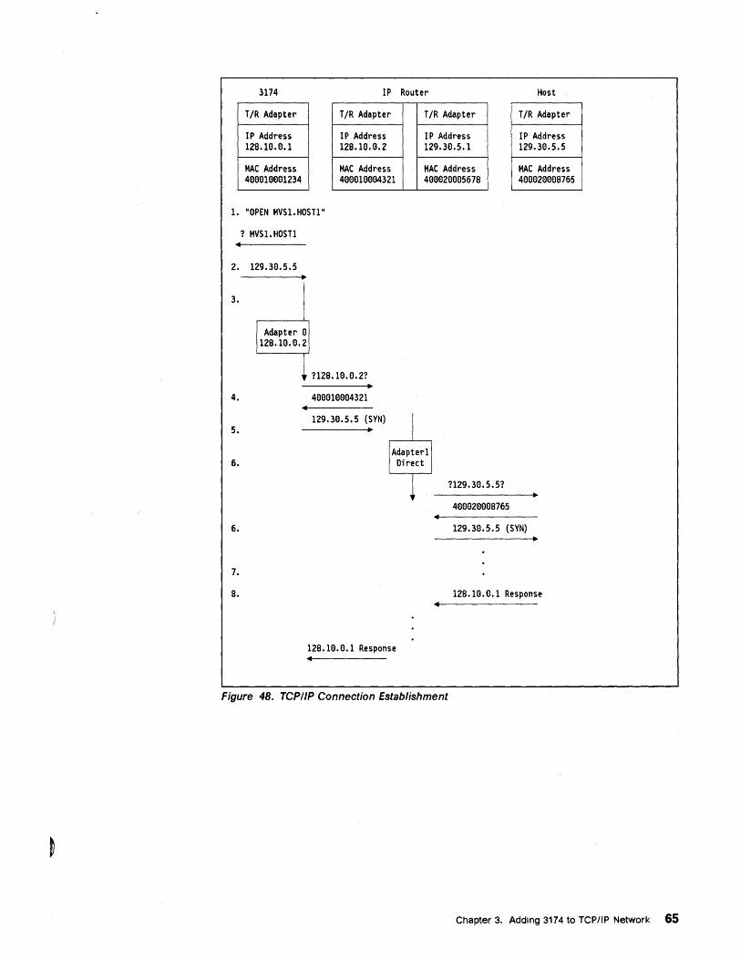
3174 IP Router
T/R Adapter
IP Address 12S.1El.El.1
MAC Address 4eeelElee1234
T/R Adapter
IP Address 12S.1El.El.2
MAC Address 4ElElEllElElEl4321
1. "OPEN MVS1.HOST1"
? MVSl. HOSTl
2. 129.3El.5.5
3.
I Adapter El
12S.lEl.El.2
1 112B.1B. e. 21 ..
4. 4EleEl1ElEle4321
5. 129.3El.5.5 (SYN) .. I
T/R Adapter
IP Address 129.3El.5.1
MAC Address 4ElElEl2ElElEl567S
6. IAdapter11 Direct
1 ?l29.3El.5.5?
4ElElEl2eEleS765
Host
T/R Adapter
IP Address 129.3El.5.5
MAC Address 4ElElEl2ElElElS765
6. 129.3El.5.5 (SYN)
7.
S.
12S.1e.El.1 Response •
Figure 48. TCPIIP Connection Establishment
12S.1El.e.1 Response
Chapter 3. Adding 3174 to TCPIIP Network 65

66 Using the 3174 TCP/IP Networks
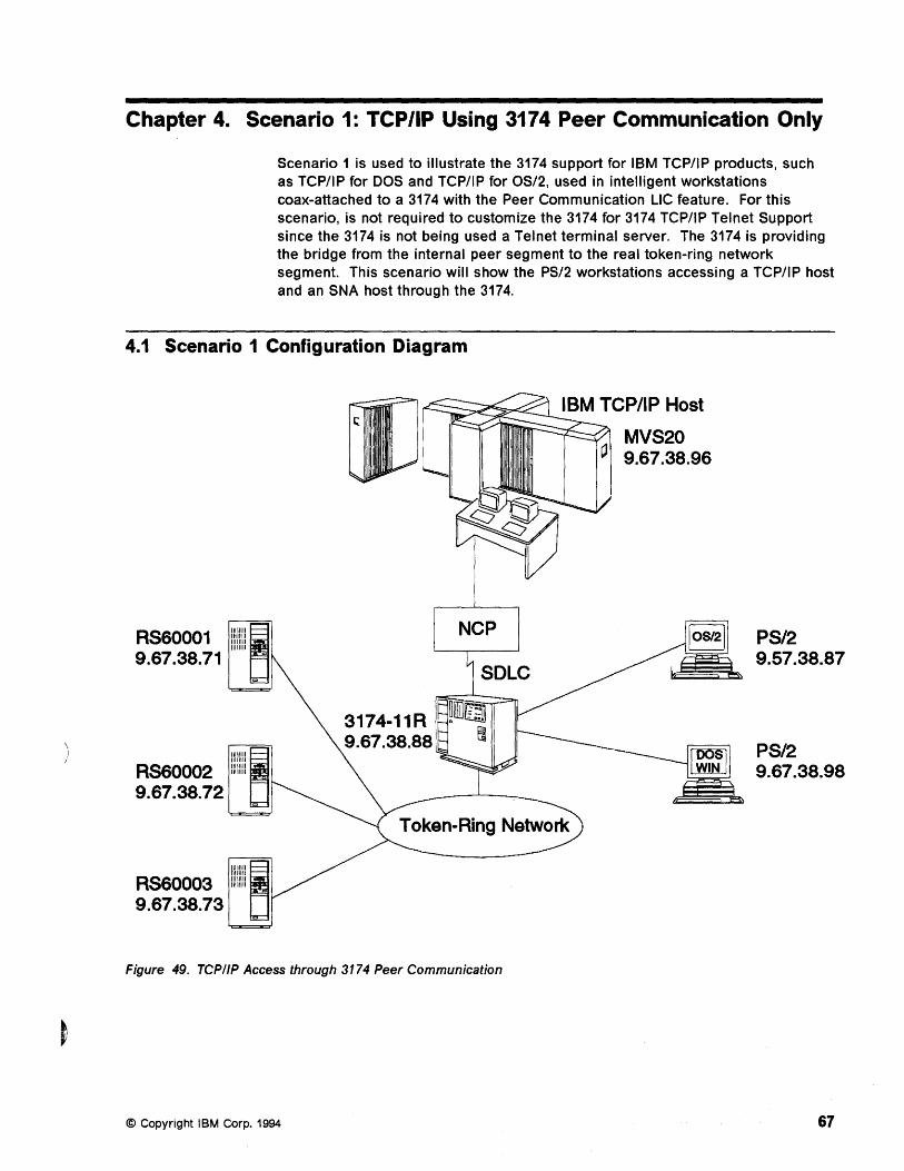
Chapter 4. Scenario 1: TCP/IP Using 3174 Peer Communication Only
Scenario 1 is used to illustrate the 3174 support for IBM TCP/IP products, such as TCP/IP for DOS and TCP/IP for OS/2, used in intelligent workstations coax-attached to a 3174 with the Peer Communication LlC feature. For this scenario, is not required to customize the 3174 for 3174 TCP/IP Telnet Support since the 3174 is not being used a Telnet terminal server. The 3174 is providing the bridge from the internal peer segment to the real token-ring network segment. This scenario will show the PS/2 workstations accessing a TCP/IP host and an SNA host through the 3174.
4.1 Scenario 1 Configuration Diagram
RS60001 9.67.38.71
NCP
3174-11R ~~rnll' 9.67.38.88 S
Figure 49. TCPIIP Access through 3174 Peer Communication
© Copyright IBM Corp. 1994
o MVS20 9.67.38.96
PS/2 9.57.38.87
PS/2 9.67.38.98
67
4.2 Scenario 1 Configuration Description Scenario 1 shows an OS/2· and a DOS PS/2 workstation, each coax-attached to the 3174-11R using the Peer Communication LlC feature in Configuration Support-C Release 3 to bridge to the real token-ring network.
The composite network has the following components:
• An S/370 MVS host with ACF/VTAM* V4.1
• A channel-attached 3745 with ACF/NCP V6.2
• A 3174-11R Establishment Controller:
- As a token-ring gateway to the S/370 host
- With Peer Communication (LAN-aver-Coax) support enabled.
• A PS/2 OS/2 workstation, coax-attached to the 3174-11R, with:
OS/2 V2.0
Communications Manager/2 V1.0
Token-Ring address (400031742992)
Peer attachment (LAPS)
TCP/IP V1.2.1 for OS/2.
• A PS/2 DOS workstation, coax-attached to the 3174-11R, with
PC DOS V5.02
Personal Communications/3270 V3.0
Token-Ring address (400031744992)
Peer attachment (Peer NDIS Driver in LAN Support Program V1.33)
TCP/IP V2.1 for DOS.
68 Using the 3174 TCP/IP Networks
4.3 Communications Manager/2 Definitions On the OS/2 workstation, we start Communications Manager/2.
• Communications Manager Installation/Setup
• Communication Setup
• Open Configuration
• Communication Manager Configuration Definition - 3270TCP
• 3270 Emulation through Token-Ring
• Communication Setup Close
Communications Manager/2 Installation and Setup
g CMSETUP
- - - -- ... .. - ----- - - _ ..... --. ---- , --Communications Manager/2 Installation and Setup Version 1.0
Ic) Copyright IBM Corp. 1988. 1992. All rights reserved IBM is a registered trademark of
International Business Machines Corp.
Figure 50. Communications Managerl2 Installation and Setup
To initiate setup, either click OK on the CMSETUP panel if Communications Manager/2 is already installed, or enter cmsetup from the command prompt if this is the initial installation.
Refer to the Communications Manager/2lnstallation Guide for more details.
Note: If you do not have LAPS installed, you will have to do so prior to cmsetup.
Chapter 4. Scenario 1: TCP/IP Using 3174 Peer Communication Only 69
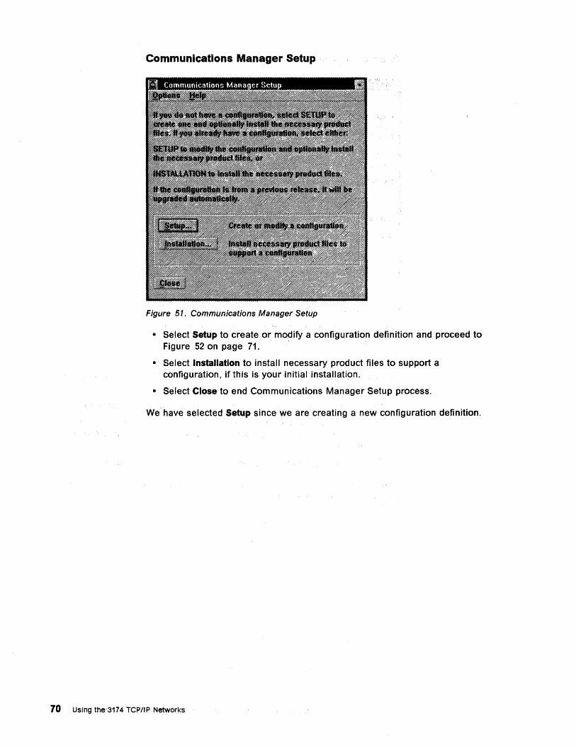
Communications Manager Setup
Figure 51. Communications Manager Setup
• Select Setup to create or modify a configuration definition and proceed to Figure 52 on page 71.
• Select Installation to install necessary product files to support a configuration, if this is your ,initial ,installation.
• Select Close to end Communications Manager Setup process.
We have selected Setup since we are creating a new configuration definition.
70 Using the 3174 TCPIIP Networks
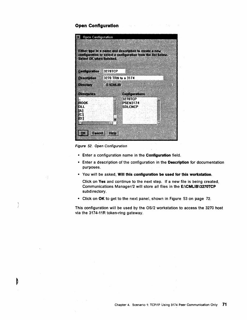
Open Configuration
Figure 52. Open Configuration
• Enter a configuration name in the Configuration field.
• Enter a description of the configuration in the Description for documentation purposes.
• You will be asked, Will this configuration be used for this workstation.
Click on Yes and continue to the next step. If a new file is being created, Communications Manager/2 will store all files in the E:\CMLIB\3270TCP subdirectory.
• Click on OK to get to the next panel, shown in Figure 53 on page 72.
This configuration will be used by the OS/2 workstation to access the 3270 host via the 3174-11R token-ring gateway.
Chapter 4. Scenario 1: TCP/IP Using 3174 Peer Communication Only 11
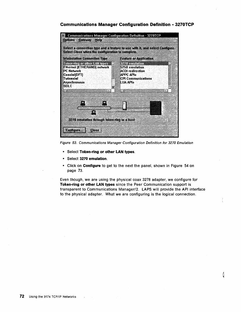
Communications Manager Configuration Definition - 3270TCP
Figure 53. Communications Manager Configuration Definition for 3270 Emulation
• Select Token-ring or other LAN types.
• Select 3270 emulation.
• Click on Configure to get to the next the panel, shown in Figure 54 on page 73.
Even though, we are using the physical coax 3278 adapter, we configure for Token-ring or other LAN types since the Peer Communication support is transparent to Communications Manager/2. LAPS will provide the API interface to the physical adapter. What we are configuring is the logical connection.
72 Using the 3174 rep/lp Networks
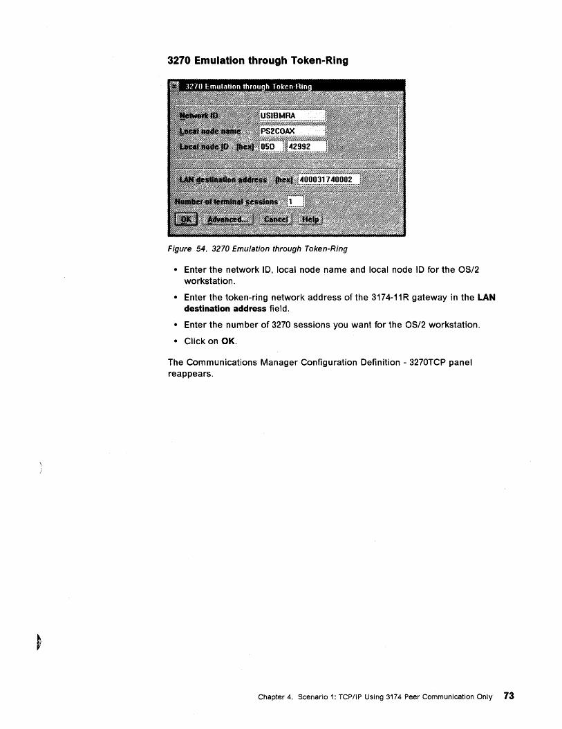
3270 Emulation through Token-Ring
Figure 54. 3270 Emulation through Token-Ring
• Enter the network 10, local node name and local node 10 for the OS/2 workstation.
• Enter the token-ring network address of the 3174-11R gateway in the LAN destination address field.
• Enter the number of 3270 sessions you want for the OS/2 workstation.
• Click on OK.
The Communications Manager Configuration Definition - 3270TCP panel reappears.
Chapter 4. Scenario 1: TCP/IP Using 3174 Peer Communication Only 73
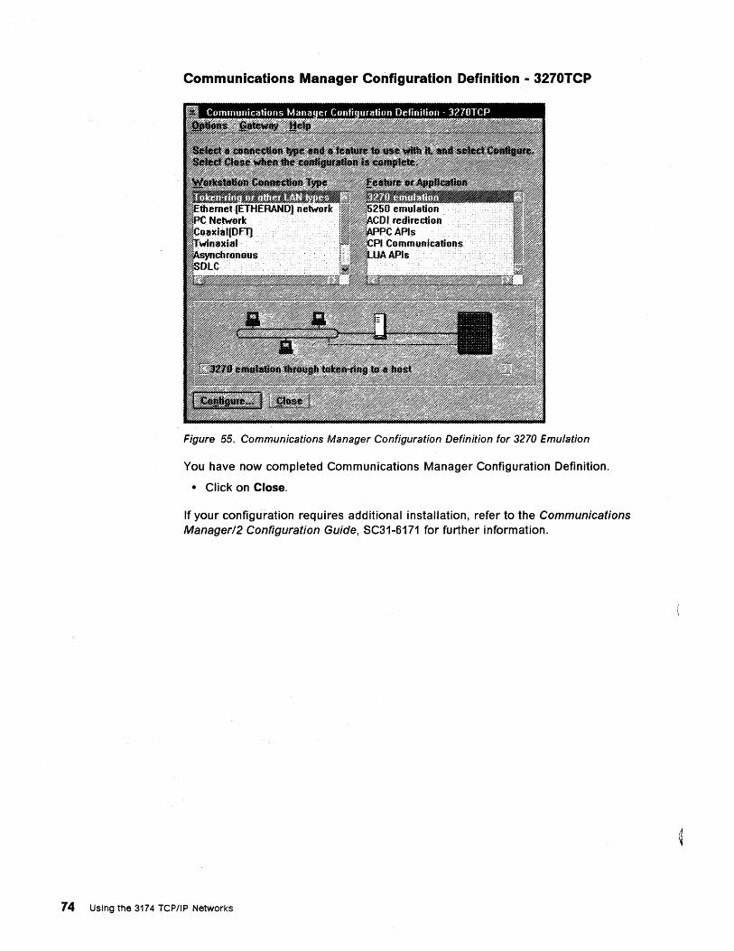
Communications Manager Configuration Definition - 3270TCP
Figure 55. Communications Manager Configuration Definition for 3270 Emulation
You have now completed Communications Manager Configuration Definition.
• Click on Close.
If your configuration requires additional installation, refer to the Communications Managerl2 Configuration Guide, SC31-6171 for further information.
74 Using the 3174 TCP/IP Networks
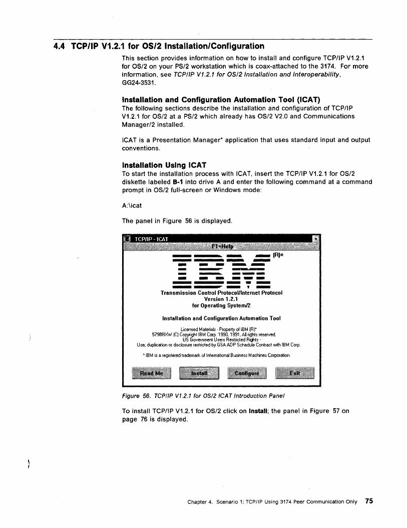
4.4 TCP/IP V1.2.1 for OS/2 Installation/Configuration This section provides information on how to install and configure TCP/IP V1.2.1 for OS/2 on your PS/2 workstation which is coax-attached to the 3174. For more information, see TCP/IP V1.2.1 for OS/2 Installation and Interoperability, GG24-3531.
Installation and Configuration Automation Tool (ICAT) The following sections describe the installation and configuration of TCP/IP V1.2.1 for OS/2 at a PS/2 which already has OS/2 V2.0 and Communications Manager/2 installed.
ICAT is a Presentation Manager* application that uses standard input and output conventions.
Installation Using ICAT To start the installation process with ICAT, insert the TCP/IP V1.2.1 for OS/2 diskette labeled B·1 into drive A and enter the following command at a command prompt in OS/2 full-screen or Windows mode:
A:\icat
The panel in Figure 56 is displayed.
===:. - --- -- ---- - - ---- ---- -,-Transmission Control Protocol/internet Protocol
Version 1.2.1 for Operating System/2
Installation and Configuration Automation Tool
Licensed Materials· Property of IBM [RJx 5798RXW lCI Copyright IBM Corp. 1990, 1991, All rights reserved.
US Government Users Restricted Rights· Use, duplication or discloslJfe restricted by GSA ADP Schedule Contract with IBM Corp.
"IBM is a registered trademark of International Business Machines Corporation.
Figure 56. TCPIIP V1.2.1 for OS/2 ICAT Introduction Panel
To install TCP/IP V1.2.1 for OS/2 click on Install; the panel in Figure 57 on page 76 is displayed.
Chapter 4. Scenario 1: TCPIIP Using 3174 Peer Communication Only 75
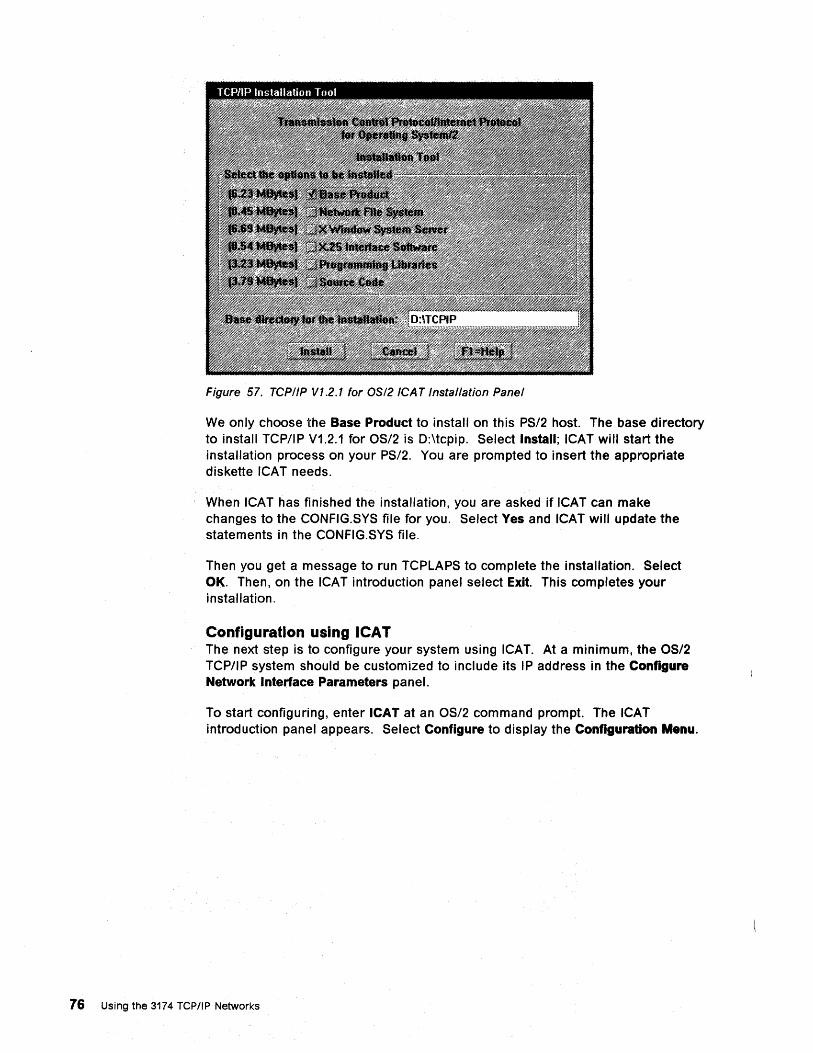
Figure 57. TCP/IP Vl.2.1 for OS/2 ICAT Installation Panel
We only choose the Base Product to install on this PS/2 host. The base directory to install TCP/IP V1.2.1 for OS/2 is D:\tcpip. Select Install; ICAT will start the installation process on your PS/2. You are prompted to insert the appropriate diskette ICAT needs.
When ICAT has finished the installation, you are asked if ICAT can make changes to the CONFIG.SYS file for you. Select Ves and ICAT will update the statements in the CONFIG.SYS file.
Then you get a message to run TCPLAPS to complete the installation. Select OK. Then, on the ICAT introduction panel select Exit. This completes your installation.
Configuration using ICAl The next step is to configure your system using ICAT. At a minimum, the OS/2 TCP/IP system should be customized to include its IP address in the Configure Network Interface Parameters panel.
To start configuring, enter ICAT at an OS/2 command prompt. The ICAT introduction panel appears. Select Configure to display the Configuration Menu.
76 Using the 3174 TCP/IP Networks
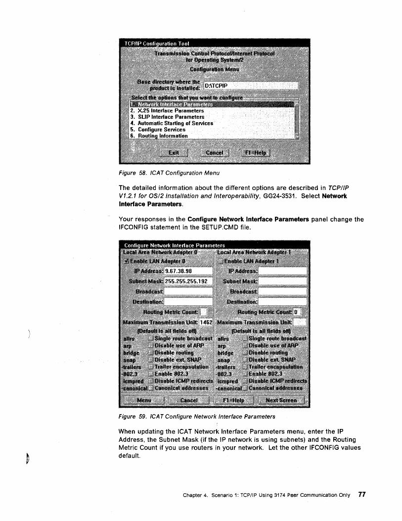
Figure 58. ICAT Configuration Menu
The detailed information about the different options are described in TCP/IP V1.2.1 for OS/2 Installation and Interoperability, GG24-3531. Select Network Interface Parameters.
Your responses in the Configure Network Interface Parameters panel change the IFCONFIG statement in the SETUP.CMD file.
Figure 59. ICAT Configure Network Interface Parameters
When updating the ICAT Network Interface Parameters menu, enter the IP Address, the Subnet Mask (if the IP network is using subnets) and the Routing Metric Count if you use routers in your network. Let the other IFCONFIG values default.
Chapter 4. Scenario 1: TCP/IP Using 3174 Peer Communication Only 77
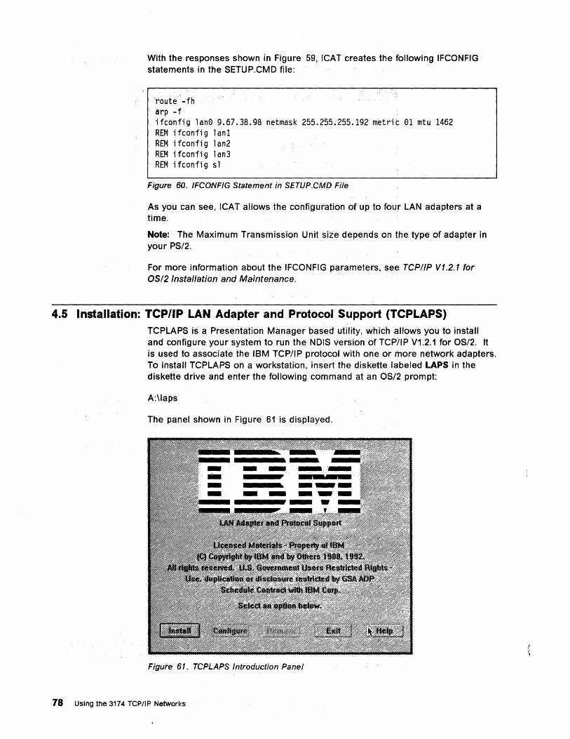
With the responses shown in Figure 59, ICAT 'creates the following IFCONFIG statements in the SETUP.CMO file:
'route -fh arp -f , ifconfig lan0 9~67.38.98 netmask255.255.255.192 metrit 01 mtu 1462 REM ifconfig lan1 REM ifconfig lan2 REM ifconfig lan3 REM i fconfi 9 s 1
Figure 60. IFCONFIG Statement in SETUP.CMD File
As you can see, ICAT allows the configuration of up to four LAN adapters at a time.
Note: The Maximum Transmission Unit size depends on the type of adapter in your PS/2.
For more information about the IFCONFIG parameters,see TCP/IP V1.2.1 for OS/2 Installation and Maintenance.
4.5 Installation: TCP/IP LAN Adapter and Protocol Support (TCPLAPS) TCPLAPS is a Presentation Manager based utility, which allows you to install and configure your system to run the NOIS version of TCP/IP V1.2.1 for OS/2. It is used to associate the IBM TCP/IP protocol with one or more network adapters. To install TCPLAPS on a workstation, insert the diskette ,labeled LAPS in the diskette drive and enter the following command at an OS/2 prompt:
A:\laps
The panel shown in Figure 61 is displayed.
Figure 61. TCPLAPS Introduction Panel
78 Using the 3174 TCP/IP Networks
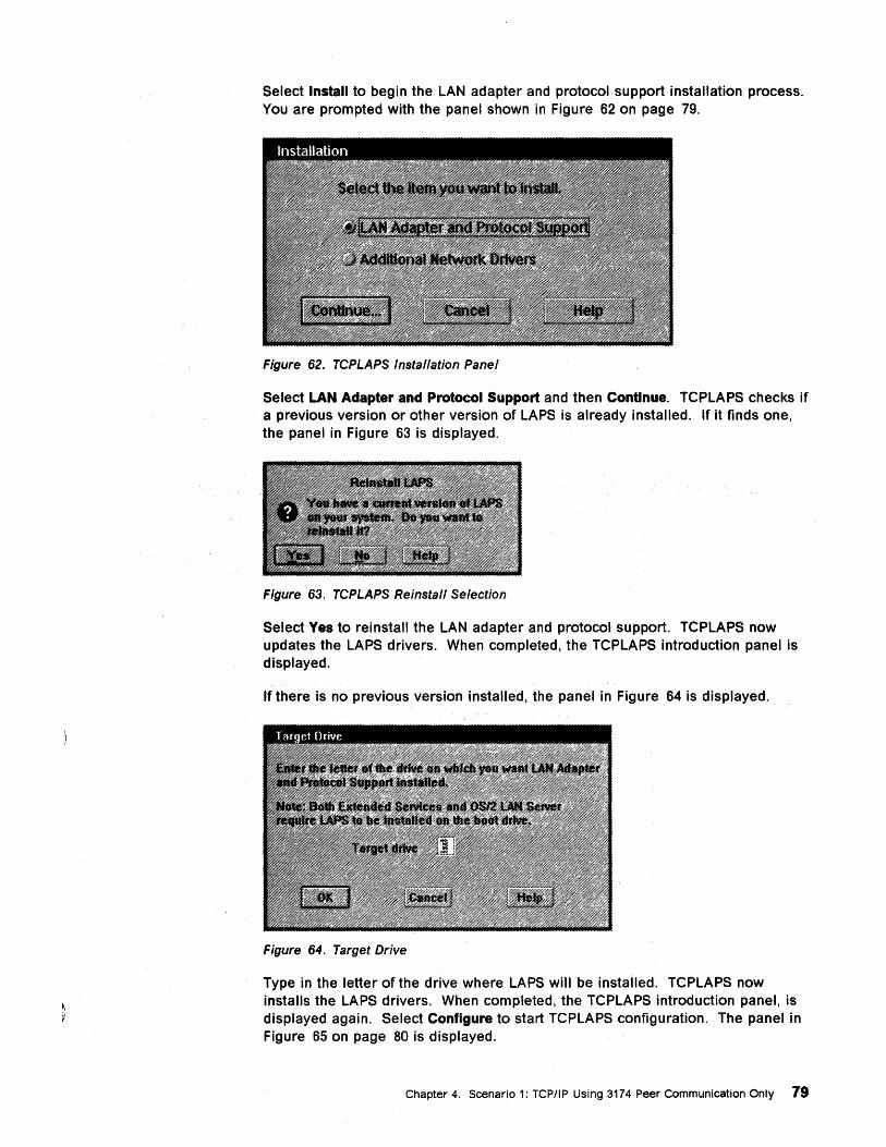
Select Install to begin the LAN adapter and protocol support installation process. You are prompted with the panel shown in Figure 62 on page 79.
Figure 62. TCPLAPS Installation Panel
Select LAN Adapter and Protocol Support and then Continue. TCPLAPS checks if a previous version or other version of LAPS is already installed. If it finds one, the panel in Figure 63 is displayed.
Figure 63. TCPLAPS Reinstall Selection
Select Yes to reinstall the LAN adapter and protocol support. TCPLAPS now updates the LAPS drivers. When completed, the TCPLAPS introduction panel is displayed.
If there is no previous version installed, the panel in Figure 64 is displayed.
Figure 64. Target Drive
Type in the letter of the drive where LAPS will be installed. TCPLAPS now installs the LAPS drivers. When completed, the TCPLAPS introduction panel, is displayed again. Select Configure to start TCPLAPS configuration. The panel in Figure 65 on page 80 is displayed.
Chapter 4. Scenario 1: rCP/IP Using 3174 Peer Communication Only 79
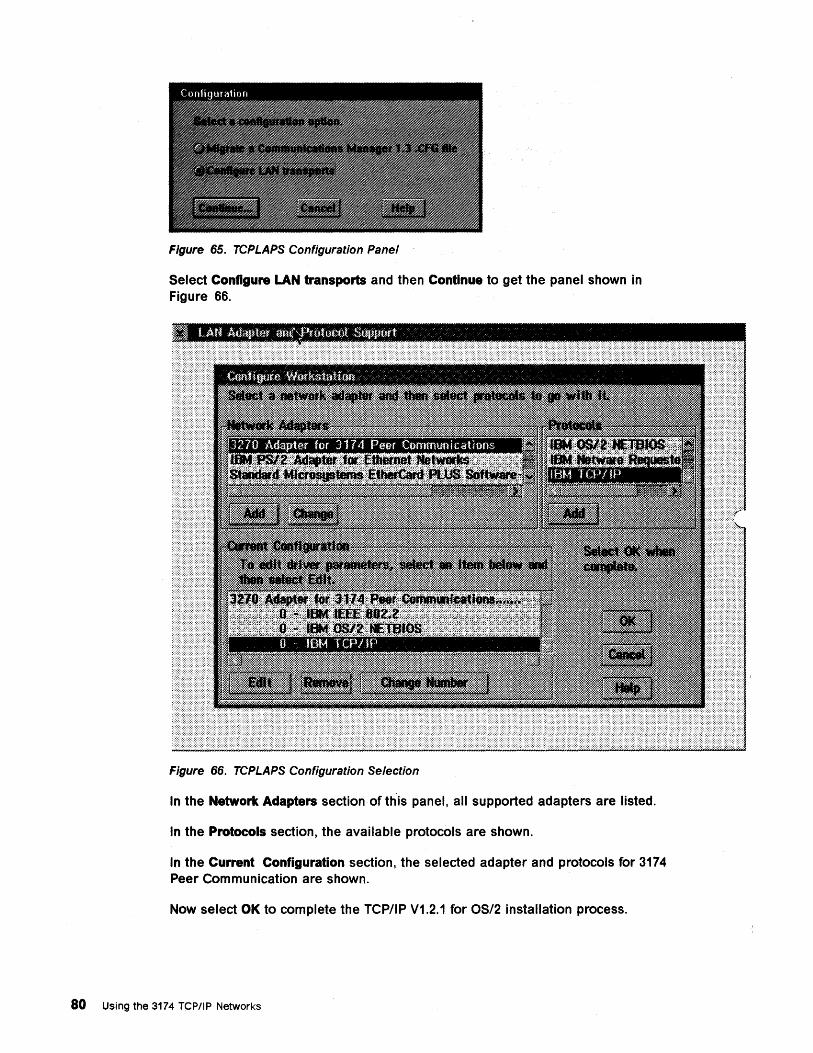
Figure 65. TCPLAPS Configuration Panel
Select Configure LAN transports and then Continue to get the panel shown in Figure 66.
Figure 66. TCPLAPS Configuration Selection
In the Network Adapters section of this panel, all supported adapters are listed.
In the Protocols section, the available protocols are shown.
In the Current Configuration section, the selected adapter and protocols for 3174 Peer Communication are shown.
Now select OK to complete the rCP/I P V1.2.1 for OS/2 installation process.
80 Using the 3174 TCP/IP Networks
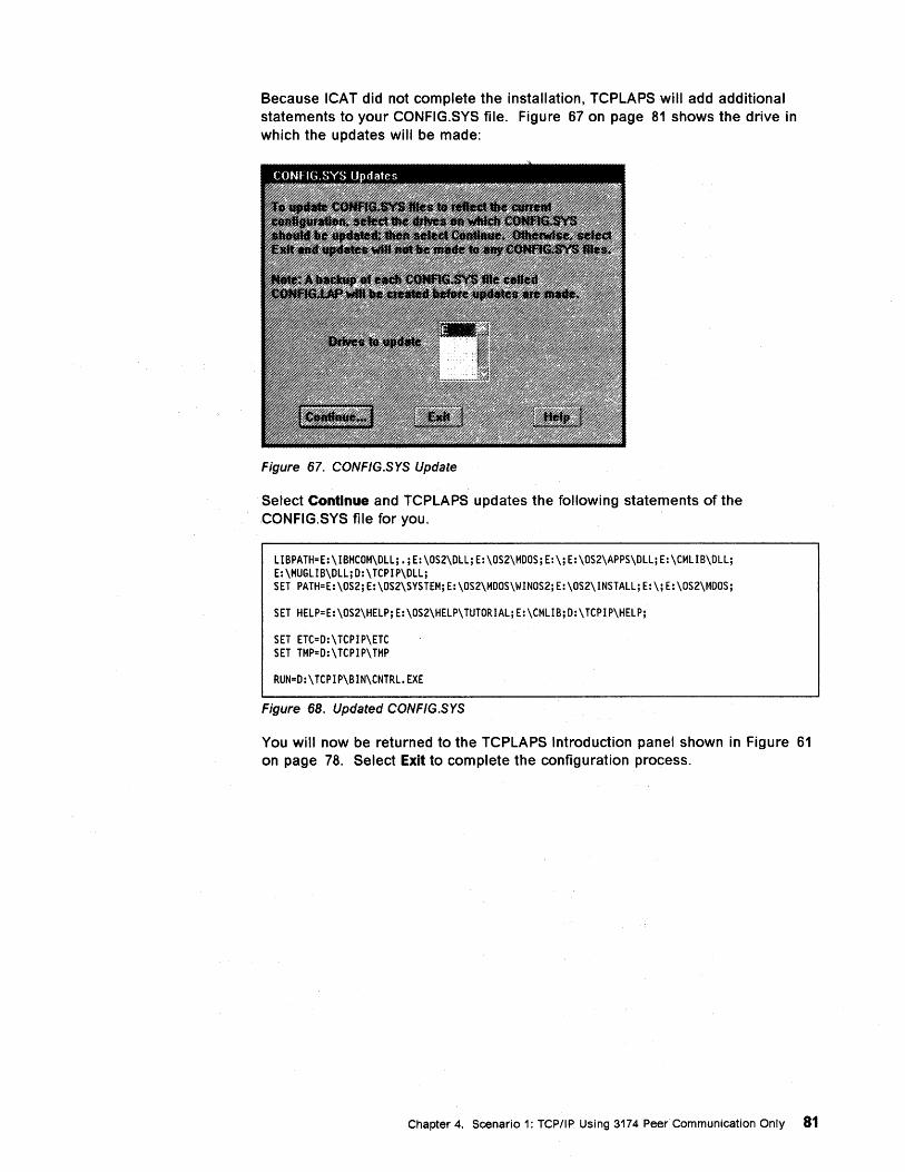
Because ICAT did not complete the installation, TCPLAPS will add additional statements to your CONFIG.SYS file. Figure 67 on page 81 shows the drive in which the updates will be made:
Figure 67. CONFIG.SYS Update
Select Continue and TCPLAPS updates the following statements of the CONFIG.SYS file for you.
lIBPATH=E:\IBMCOM\Dllj.jE:\OS2\DlljE:\OS2\MDOSjE:\jE:\OS2\APPS\DlljE:\CMlIB\Dllj E:\MUGlIB\DlljD:\TCPIP\Dllj SET PATH=E:\OS2jE:\OS2\SYSTEMjE:\OS2\MDOS\WINOS2jE:\OS2\INSTAlljE:\jE:\OS2\MDOSj
SET HElP=E:\OS2\HElPjE:\OS2\HElP\TUTORIAljE:\CMlIBjD:\TCPIP\HElPj
SET ETC=D:\TCPIP\ETC SET TMP=D:\TCPIP\TMP
RUN=D:\TCPIP\BIN\CNTRl.EXE
Figure 68. Updated CONFIG.SYS
You will now be returned to the TCPLAPS Introduction panel shown in Figure 61 on page 78. Select Exit to complete the configuration process.
Chapter 4. Scenario 1: TCPIIP Using 3174 Peer Communication Only 81
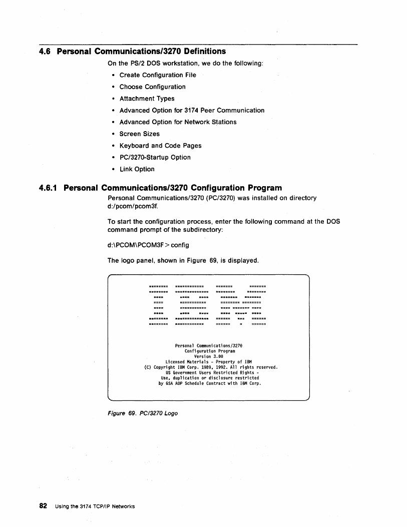
4.6 Personal Communications/3270 Definitions On the PS/2 DOS workstation, we do the following:
• Create Configuration File
• Choose Configuration
• Attachment Types
• Advanced Option for 3174 Peer Communication
• Advanced Option for Network Stations
• Screen Sizes
• Keyboard and Code Pages
• PC/3270-Startup Option
• Link Option
4.6.1 Personal Communications/3270 Configuration Program Personal Communications/3270 (PC/3270) was installed on directory d:/pcom/pcom3f.
To start the configuration process, enter the following command at the DOS command prompt of the subdirectory:
d:\PCOM\PCOM3F> config
The logo panel, shown in Figure 69, is displayed.
Persona 1 Communi ca ti ons /3278 Confi gurati on Program
Version 3.88 Licensed Materials - Property of IBM
(C) Copyright IBM Corp. 1989, 1992. All ri ghts reserved. US Government Users Restri cted Ri ghts -
Use, duplication or disclosure restricted by GSA ADP Schedule Contract with IBM Corp.
Figure 69. PCI3270 Logo
82 Using the 3174 TCPIIP Networks
Create Configuration File
Create Configuration File
Enter the requi red i nformati on and press F8 to conti nue.
Name of an existing configuration file (optional) ••••••••
Dri ve and di rectory in whi ch you wi 11 store PC/3276 confi gurati on data fil es D: \PCOM\PCOM3F
Name of the new configuration file (Thi sis what you wi 11 type
to start PC/3276). . • • • •• PC3278
Fl=He 1 p F3=Exi t F8=Forward
Figure 70. PCI3270 Create Configuration File
More: +
The Create Configuration File panel allows you to specify your own subdirectory and startup batch file name. Enter your preferred responses, then press Fa to take you to the Choose Configuration panel.
Choose Configuration
Choose Confi gurati on
Press Fl6 to change the choi ce.
Type of confi gurati on ••••• • • • • • • •••
Advanced link options ••••••••••••••
! More than one LAN or communi ca ti ons adapter ! More than one type of host connecti on ! Connecti on to more than one gateway ! X.25 connecti on
Use expanded memory
Use a Task Swapper • Update CONFIG.SYS
More: -+
Network station
Yes
No
No No
Fl=Help F3=Exit F7=Backward F8=Forward F9=Prev choice n6=Next choice
Figure 71. PCI3270 Choose Configuration
The Choose Configuration panel allows you to specify the type of configuration you require. For more details 9n configuring, refer to IBM Personal Communications/3270 Version 3.0 Implementation Guide, GG24-3949.
Select Yes for Advanced link options for the simplest of configuration scenarios.
Chapter 4. Scenario 1: TCP/IP Using 3174 Peer Communication Only 83
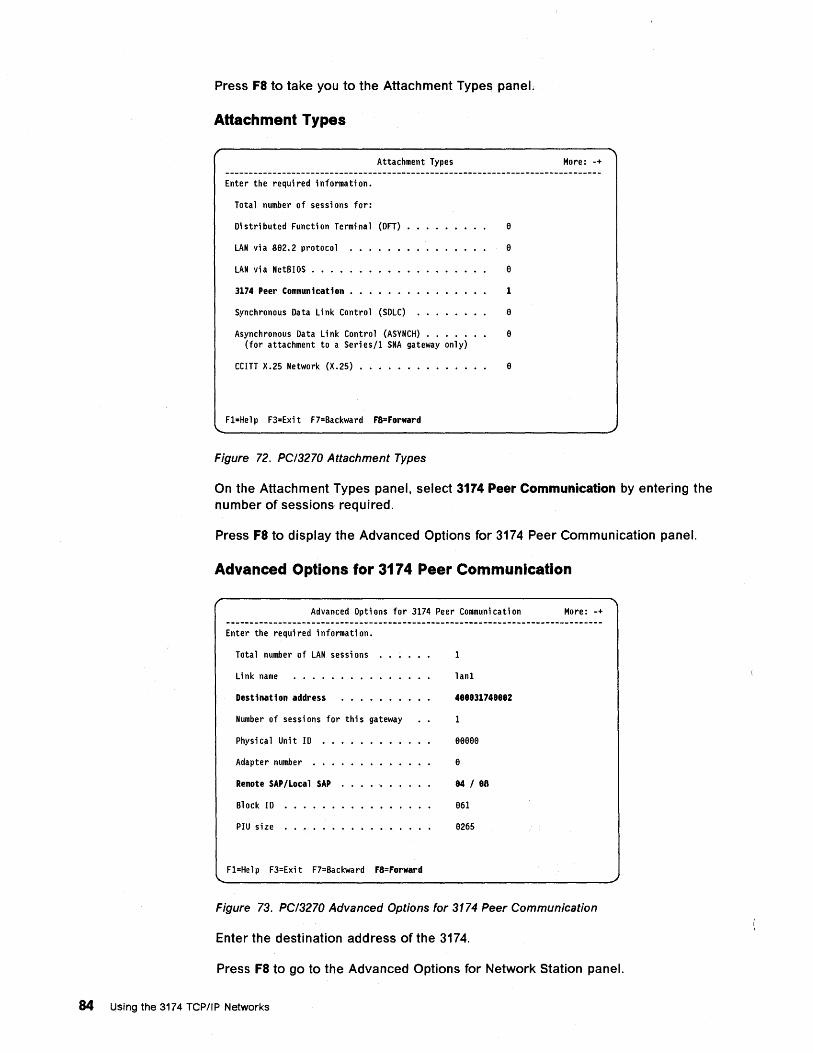
Press Fa to take you to the Attachment Types panel.
Attachment Types
Attachment Types More: -+
Enter the required information.
Total number of sessions for:
Distributed Function Terminal (OFT) a
LAN vi a Sa2. 2 protoco 1 a
LAN via NetBIOS • • • • a
3174 Peer Communication • 1
Synchronous Data Link Control (SDLC) a
Asynchronous Data Link Control (ASVNCH) • • • • a (for attachment to a Series/1 SNA gateway only)
CCITT X.25 Network (X.25) • • • • • • • • • • • • a
F1=Hel p F3=Exi t F7=Backward F8=Forward
Figure 72. PC/3270 Attachment Types
On the Attachment Types panel, select 3174 Peer Communication by entering the number of sessions required.
Press Fa to display the Advanced Options for 3174 Peer Communication panel.
Advanced Options for 3174 Peer Communication
Advanced Opti ons for 3174 Peer Communi cati on More: -+
Enter the required information.
Tota 1 number of LAN sessi ons
Link name lan1
Destination address 488831748882
Number of sessi ons for thi s gateway
Physical Unit 10 aaaaa
Adapter number • • • a
Remote SAP/Local SAP 84 / 88
Block 10 a61
PIU size a265
F1=Hel p F3=Exi t F7=Backward F8=Forward
Figure 73. PC/3270 Advanced Options for 3174 Peer Communication
Enter the destination address of the 3174.
Press Fa to go to the Advanced Options for Network Station panel.
84 Using the 3174 TCPIIP Networks
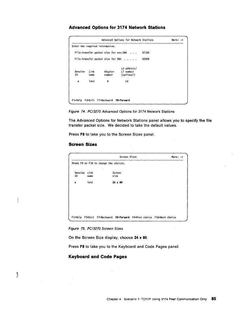
Advanced Options for 3174 Network Stations
Advanced Options for Network Stations
Enter the requi red i nformati on.
Fil e-transfer packet si ze for non-SNA 87168
File-transfer packet size for SNA • • 82S99
Session Link 10 name
a lanl
Adapter number
LU addressl LT number (optional)
LU
Fl=Help F3=Exit F7=Backward F8=Forward
More: -+
Figure 74. PC/3270 Advanced Options for 3174 Network Stations
The Advanced Options for Network Stations panel allows you to specify the file transfer packet size. We decided to take the default values.
Press F8 to take you to the Screen Sizes panel.
Screen Sizes
Screen Si zes
Press F9 or Fle to change the choi ces.
Sessi on L; nk 10 name
a lanl
Screen size
24 x 88
More: -+
Fl=Help F3=Exit F7=Backward F8=Forward F9=Prev choice Fle=Next choice
Figure 75. PC/3270 Screen Sizes
On the Screen Size display, choose 24 x 80.
Press F8 to take you to the Keyboard and Code Pages panel.
Keyboard and Code Pages
Chapter 4. Scenario 1: TCPIIP Using 3174 Peer Communication Only 85
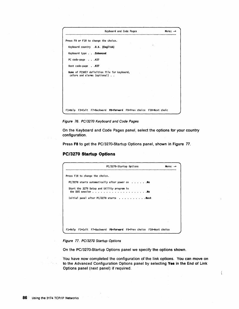
Keyboard and Code Pages
Press F9 or Fl8 to change the choi ce.
Keyboard country .U.S. (English)
Keyboard type. • Enhanced
PC code-page. .437
Host code-page .837
Name of PCSKEY defi niti on fil e for keyboard, colors and alarms (optional) •.
More: -+
Fl=Help F3=Exit F7=Backward F8=Forward F9=Prev choice ne=Next choic
Figure 76. PC/3270 Keyboard and Code Pages
On the Keyboard and Code Pages panel, select the options for your country configuration.
Press F8 to get the PC/3270-Startup Options panel, shown in Figure 77.
PC/3270 Startup Options
PC/3278-Startup Opti ons More: -+
Press Fle to change the choi ce.
PC/3278 starts automatically after power on .No
Sta rt the 3278 Setup and Util i ty program in the DOS sessi on • • • • • • • • • • • • • • .No
Initial panel after PC/327e starts ••.••••..• Host
Fl=Help F3=Exit F7=Backward F8=Forward F9=Prev choice Fl8=Next choice
Figure 77. PC/3270 Startup Options
On the PC/3270-Startup Options panel we specify the options shown.
You have now completed the configuration of the link options. You can move on to the Advanced Configuration Options panel by selecting Yes in the End of Link Options panel (neXt panel) if required.
86 Using the 3174 TCPIIP Networks
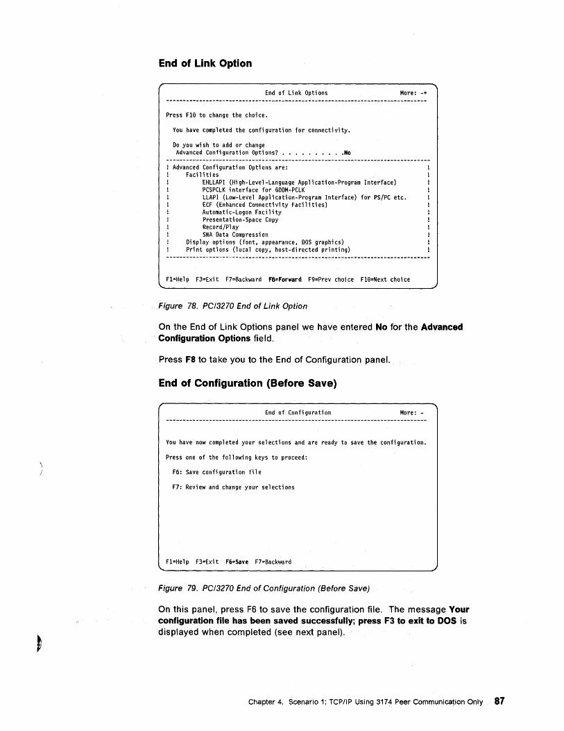
End of Link·Option
End of Link Opti ons
Press Fle to change the choi ce.
You have compl eted the confi gurati on for connecti vity.
Do you wish to add or change Advanced Conti gurati on Opti ons? ••••••••.• No
Advanced Configuration Options are: Facilities
EHLLAPI (High-Level-Language Application-Program Interface) PCSPCLK interface for GDDM-PCLK
More: -+
LLAPI (Low-Level Application-Program Interface) for PS/PC etc. ECF (Enhanced Connectiv; ty Facil i ti es) Automati c-Logon Faci 1 i ty Presenta ti on-Space Copy Record/Pl ay SNA Data Compressi on
Display options (font, appearance, DOS graphics) Pr; nt opt; ons (l oca 1 copy, host-di rected pri nti ng)
Fl=Help F3=Exit F7=Backward F8=Forward F9=Prev choice Fle=Next choice
Figure 78. PC/3270 End of Link Option
On the End of Link Options panel we have entered No for the Advanced Configuration Options field.
Press F8 to take you to the End of Configuration panel.
End of Configuration (Before Save)
End of Confi gurati on More:. -
You have now completed your selections and are ready to save the configuration.
Press one of the fo 11 owi ng keys to proceed:
F6: Save confi gurati on fil e
F7: Review and change your selections
Fl=He 1 p F3=Exi t F6=Save F7=Backward
Figure 79. PC/3270 End of Configuration (Before Save)
On this panel, press F6 to save the configuration file. The message Your configuration file has been saved successfully; pressF3 to exit to DOS is displayed when completed (see next panel).
Chapter 4. Scenario 1: TCP/IP Using 3174 Peer Communication Only 87
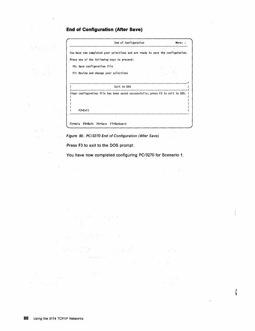
End of Configuration (After Save)
End of Confi gurati on More: -
You have now completed your selections and are ready to save the configuration.
Press one of the fo 11 owi ng keys to proceed:
F6: Save confi gurati on ti 1 e
F7: Revi ew and change your se 1 ecti ons
Exi t to DOS 1------------------------------------------------------------------------------1 1 Your conti gurati on fil e has been saved successfully; press F3 to exi t to DOS. 1
F3=Exit
F1=Hel p F3=Exit F6=Save F7=Backward
Figure 80. PCI3270 End of Configuration (After Save)
Press F3 to exit to the DOS prompt.
You have now completed configuring PC/3270 for Scenario 1.
88 Using the 3174 TCPIIP Networks
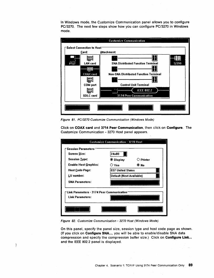
In Windows mode, the Customize Communication panel allows you to configure PC/3270. The next few steps show how you can configure PC/3270 in Windows mode.
I ----------------------------------Customize Communication
Select Connection to Host------------------------,
.card: Attachment:
LAN card . ---SNA Distributed Function Terminal
• D • Non-SNA Distributed Function Terminal
• D
Figure 81. PCI3270 Customize Communication (Windows Mode)
Click on COAX card and 3714 Peer Communication, then click on Configure. The Customize Communication - 3270 Host panel appears.
- -Customize Communication - 3270 Host
Session Parameters---------------------,
Screen .size:
Session Iype:
Enable Host §raphics:
Host .code-Page:
!.U number:
SNA Parameters:
Link Parameters:
124x80 11,1 @ Display
OVes
1037 United States
o Printer
@No
IDefault [Next Available)
Figure 82. Customize Communication - 3270 Host (Windows Mode)
On this panel, specify the panel size, session type and host code page as shown. (If you click on Configure SNA ... , you will be able to enable/disable SNA data compression and specify the compression buffer size.) Click on Configure Link ... and the IEEE 802.2 panel is displayed.
Chapter 4. Scenario 1: TCP/IP Using 3174 Peer Communication Only 89
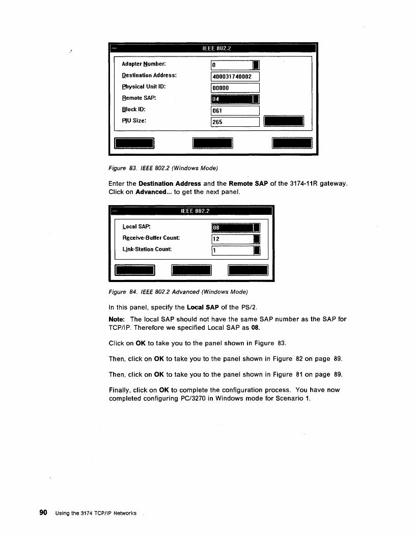
.' ~ IEEE 802.2
Adapter Number:
Ilestination Address:
fhysical Unit ID:
Bemote SAP:
Block ID:
10 1:1 1~000317~0002 I 100000 I
1061 I PIU Size: 1,--26_5 _----'I =1_= ......... = ...... = ......... =dJ
I_I
Figure 83. IEEE 802.2 (Windows Mode)
Enter the Destination Address and the Remote SAP of the 3174-11R gateway. Click on Advanced ... to get the next panel.
- IEEE 802.2
,bocal SAP:
R,!;.ceive-Buffer Count:
Link-Station Count:
Figure 84. IEEE 802.2 Advanced (Windows Mode)
In this panel, specify the Local SAP of the PS/2.
Note: The local SAP should not have the same SAP number as the SAP for TCP/I P. Therefore we specified Local SAP as OS.
Click on OK to take you to the panel shown in Figure 83.
Then, click on OK to take you to the panel shown in Figure 82 on page 89.
Then, click on OK to take you to the panel shown in Figure 81 on page 89.
Finally, click on OK to complete the configuration process. You have now completed configuring PC/3270 in Windows mode for Scenario 1.
90 Using the 3174 TCP/IP Networks
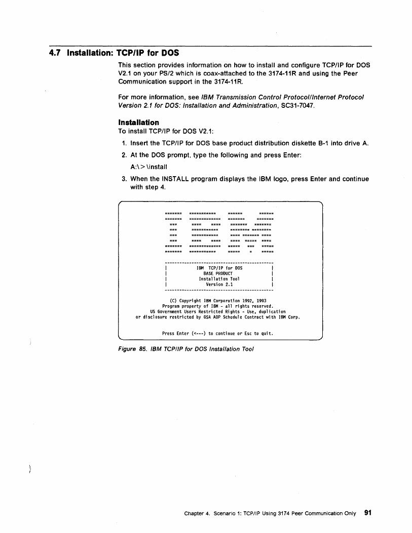
4.7 Installation: TCP/IP for DOS This section provides information on how to install and configure TCPIIP for DOS V2.1 on your PS/2 which is coax-attached to the 3174-11R and using the Peer Communication support in the 3174-11R.
For more information, see IBM Transmission Control Protocolllnternet Protocol Version 2.1 for DOS: Installation and Administration, SC31-7047.
Installation To install TCP/IP for DOS V2.1:
1. Insert the TCP/IP for DOS base product distribution diskette B-1 into drive A.
2. At the DOS prompt, type the following and press Enter:
A:\ > \install
3. When the INSTALL program displays the IBM logo, press Enter and continue with step 4.
IBM TCP/IP for DOS BASE PRODUCT
Installati on Tool Version 2.1
(C) Copyri ght IBM Corporati on 1992, 1993 Program property of IBM - all rights reserved.
US Government Users Restri cted Ri ghts - Use. dup 1 i ca ti on or di scl osure restri cted by GSA ADP Schedul e Contract wi th IBM Corp.
Press Enter «---) to conti nue or Esc to qui t.
Figure 85. IBM TCP/IP for DOS Installation Tool
Chapter 4. Scenario 1: TCP/IP Using 3174 Peer Communication Only 91
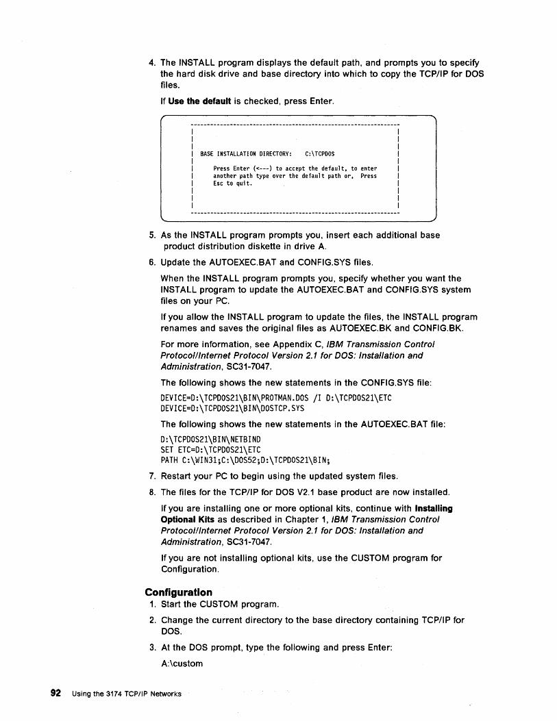
4. The INSTALL program displays the default path, and prompts you to specify the hard disk drive and base directory into which to copy the TCP/IP for DOS files.
If Use the default is checked, press Enter.
BASE INSTALLATION DIRECTORY: C:\TCPDOS
Press Enter «---) to accept the default, to enter another path type over the default path or, Press Esc to qui t.
5. As the INSTALL program prompts you, insert each additional base product distribution diskette in drive A.
6. Update the AUTOEXEC.BAT and CONFIG.SYS files.
When the INSTALL program prompts you, specify whether you want the INSTALL program to update the AUTOEXEC.BAT and CONFIG.SYS system files on your PC.
If you allow the INSTALL program to update the files, the INSTALL program renames and saves the original files as AUTOEXEC.BK and CONFIG.BK.
For more information, see Appendix C, IBM Transmission Control Protocolllnternet Protocol Version 2.1 for DOS: Installation and Administration, SC31-7047.
The following shows the new statements in the CONFIG.SYS file:
DEVICE=D:\TCPDOS21\BIN\PROTMAN.DOS /1 D:\TCPDOS21\ETC DEVICE=D:\TCPDOS21\BIN\DOSTCP.SYS
The following shows the new statements in the AUTOEXEC.BAT file:
D:\TCPDOS21\BIN\NETBIND SET ETC=D:\TCPDOS21\ETC PATH C:\WIN31;C:\DOS52;D:\TCPDOS21\BIN;
7. Restart your PC to begin using the updated system files.
8. The files for the TCP/IP for DOS V2.1 base product are now installed.
If you are installing one or more optional kits, continue with Installing Optional Kits as described in Chapter 1, IBM Transmission Control Protocolllnternet Protocol Version 2.1 for DOS: Installation and Administration, SC31-7047.
If you are not installing optional kits, use the CUSTOM program for Configuration.
Configuration 1. Start the CUSTOM program.
2. Change the current directory to the base directory containing TCP/IP for DOS.
3. At the DOS prompt, type the following and press Enter:
A:\custom
92 Using the 3174 TCP/IP Networks
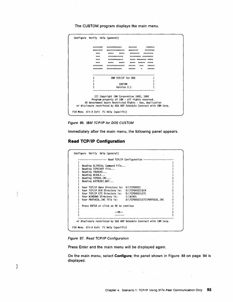
The CUSTOM program displays the main menu.
Confi gure Verify Help (general)
IBM TCP/IP for DOS
CUSTOM Versi on 2.1
(C) Copyri ght IBM Corporati on 1992. 1993 Program property of IBM - all ri ghts reserved.
US Government Users Restricted Rights - Use. duplication or di scl osure restri cted by GSA ADP Schedul e Contract with IBM Corp.
Fle Menu Alt-X Exit Fl Help (specific)
Figure 86. IBM TCPIIP for DOS CUSTOM
Immediately after the main menu, the following panel appears.
Read TCP/IP Configuration
Configure Verify Help (general)
--------------------- Read TCP II P Confi gurati on ---------------------
Reading SLIPDIAL Command File ••• Readi ng TCPSTART fil e ••• Reading TRUSERS ••• Reading RESOLV ••• Reading TCPDOS. IN!. .. Reading AUTOEXEC.BAT •••
Your TCP/IP Base Directory is: Your TCP/IP BIN Directory is: Your TCP/IP ETC Directory is: Your WINDOWS Di rectory is: Your PROTOCOL.INI file is:
0:\ TCPDOS21 0:\ TCPDOS21\BIN 0:\ TCPOOS21\ETC C:\WIN31 0:\ TCPOOS21\ETC\PROTOCOL. INI
Press ENTER or click on OK to continue
--OK--
or disclosure restri cted by GSA AOP Schedul e Contract with IBM Corp.
Fle Menu Alt-X Exit Fl Help (specific)
Figure 87. Read TCP/IP Configuration
Press Enter and the main menu will be displayed again.
I I I
On the main menu, select Configure; the panel shown in Figure 88 on page 94 is displayed.
Chapter 4. Scenario 1: TCP/IP Using 3174 Peer Communication Only 93
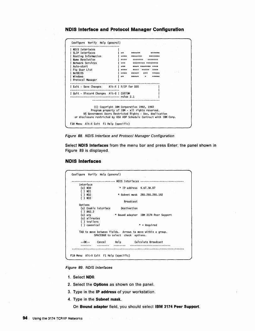
NDIS Interface and Protocol Manager Configuration
Confi gure Verify Help (genera 1)
I NDIS Interfaces I SLIP Interfaces I Routi ng Informati on I Name Reso 1 uti on I Network Servi ces I Auto-start I Ftp User List I NetBIOS I Wi ndows I Protocol Manager
I Exi t - Save Changes Al t-X I P/IP for DOS
I Quit - Discard Changes Alt-Q I CUSTOM --------------------------------- rsion 2.1
(C) Copyri ght IBM Corporati on 1992. 1993 Program property of IBM - a 11 ri ghts reserved.
US Government Users Restri cted Ri ghts - Use. dup 1 i ca ti on or di scl osure restri cted by GSA ADP Schedul e Contract with IBM Corp.
Fle Menu Alt-X Exit Fl Help (specific)
Figure 88. NDIS Interface and Protocol Manager Configuration
Select NDIS Interfaces from the menu bar and press Enter; the panel shown in Figure 89 is displayed.
NDIS Interfaces
Confi gure Verify Help (genera 1)
----------------------------- NDIS Interfaces -----------------------------Interface
(x) NDe * IP address 9.67.38.87 ( ) ND1 ( ) ND2 * Subnet mask 255.255.255.192 ( ) ND3
Broadcast Opti ons
(x) Enable interface Destination ( ) 8e2.3 (x) arp * Bound adapter IBM 3174 Peer Support (x) a 11 routes ( ) trail ers ( ) canoni ca 1 * = Requi red
TAB to move between fi e 1 ds. Arrows to move wi thi n a group. SPACEBAR to select check options.
--OK-- Cancel Help Calculate Broadcast
F1e Menu Alt-X Exit F1 Help (specific)
Figure 89. NDIS Interfaces
1. Select NDO.
2. Select the Options as shown on the panel.
3. Type in the IP address of your workstation.
4. Type in the Subnet mask.
On Bound adapter field, you should select IBM 3174 Peer Support.
94 Using the 3174 TCP/IP Networks
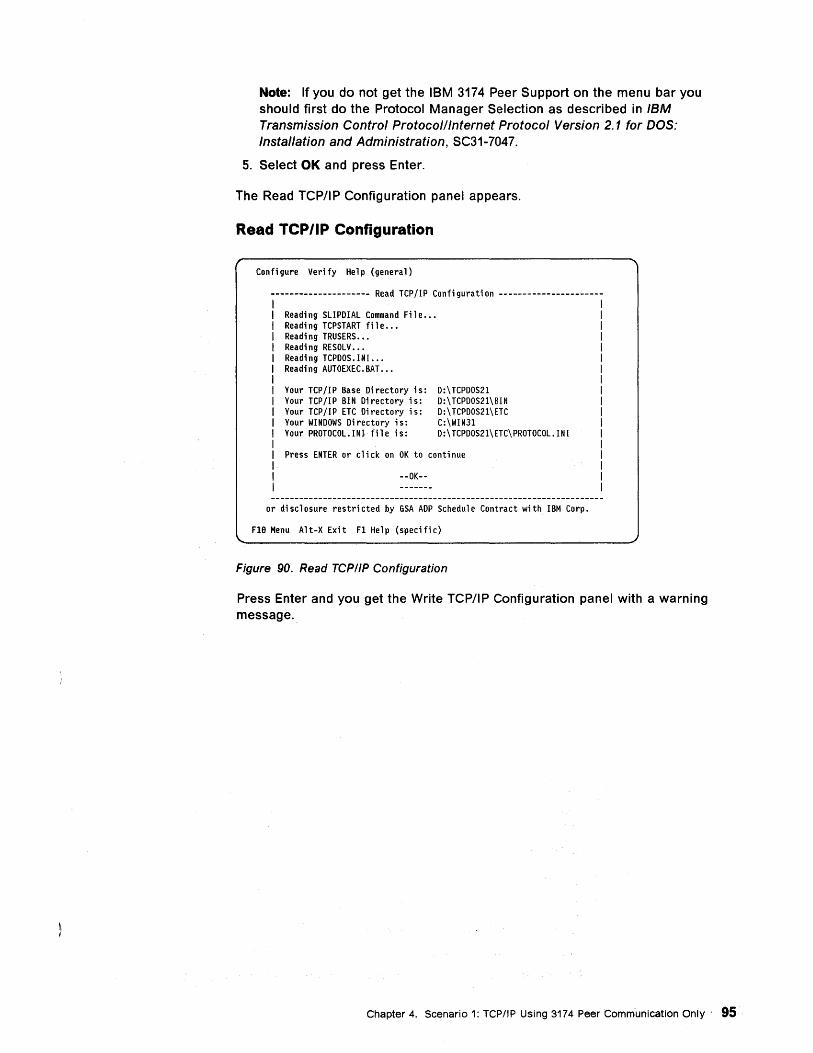
Note: If you do not get the IBM 3174 Peer Support on the menu bar you should first do the Protocol Manager Selection as described in IBM Transmission Control Protocolllnternet Protocol Version 2.1 for DOS: Installation and Administration, SC31-7047.
5. Select OK and press Enter.
The Read TCP/IP Configuration panel appears.
Read TCP/IP Configuration
Configure Verify Help (general)
--------------------- Read TCP lIP Confi gurati on ---------------------
Reading SLIPDIAL Command File ... Reading TCPSTART file •.• Readi ng TRUSERS ••. Reading RESOLV ••. Reading TCPDOS.INI ... Reading AUTOEXEC.BAT •••
Your TCPIIP Base Directory is: Your TCP/IP BIN Directory is: Your TCP/IP ETC Directory is: Your WINDOWS Directory is: Your PROTOCOL. IN! file is:
D:\TCPDOS21 D:\TCPDOS21\BIN D:\ TCPOOS21\ETC C:\WIN31 0: \ TCPDOS21 \ ETC\ PROTOCOL. I N I
Press ENTER or click on OK to continue
--OK--
or disclosure restricted by GSA AOP Schedule Contract with IBM Corp.
FlB Menu Alt-X Exit Fl Help (specific)
Figure 90. Read TCPIIP Configuration
Press Enter and you get the Write TCP/IP Configuration panel with a warning message.
Chapter 4. Scenario 1: TCP/IP Using 3174 peer Communication Only 95
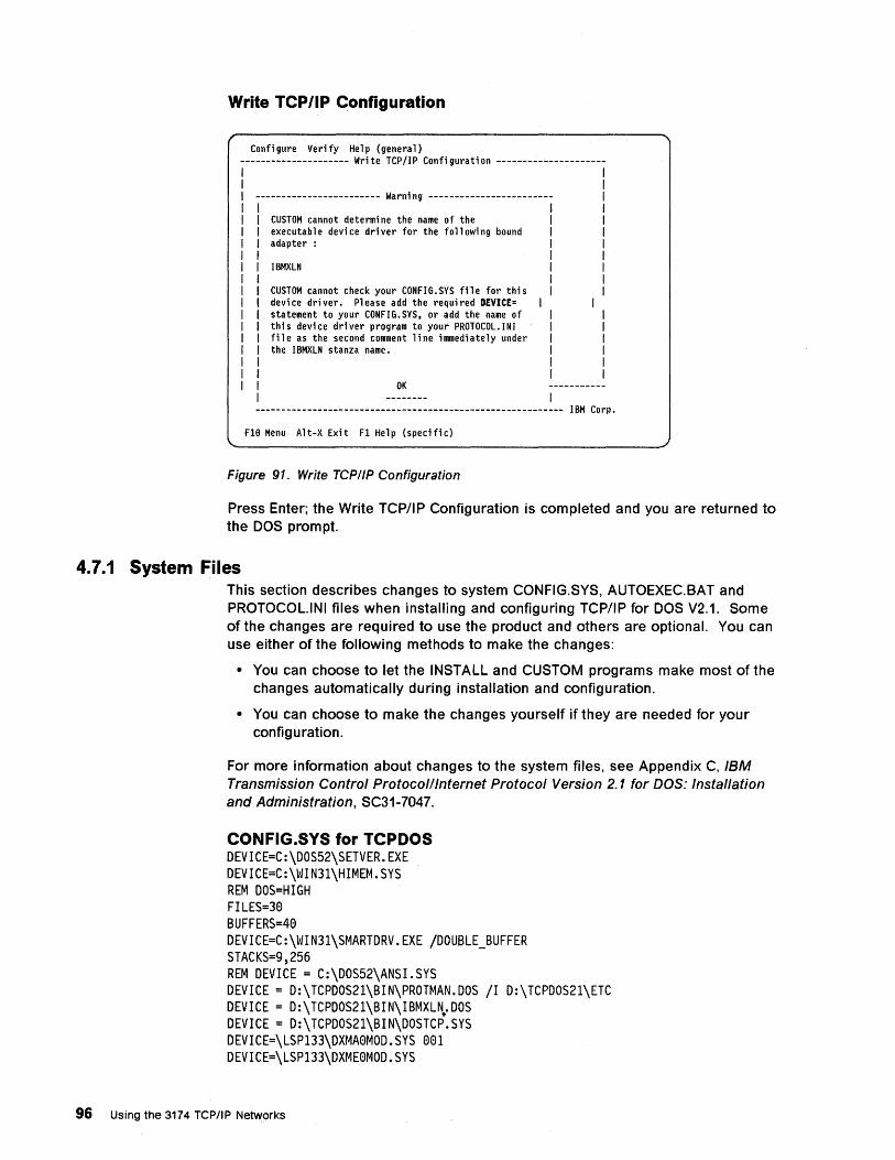
Write TCP/IP Configuration
Confi gure Verify Help (genera 1)
--------------------- Write TCP/IP Configuration --------------------I I
------------------------ Warni ng ----------------------- I
CUSTOM cannot determi ne the name of the executab 1 e devi ce dri ver for the fo 11 owi ng bound adapter:
IBMXLN
CUSTOM cannot check your CONFIG.SYS file for this devi ce dri ver. Pl ease add the requi red DEVICE= statement to your CONFIG.SYS. or add the name of this device driver program to your PROTOCOL.INI file as the second comment line immediately under the I BMXLN stanza name.
OK I
---------------------------------------------------------- IBM Corp.
FlB Menu A It-X Exi t Fl Help (specifi c)
Figure 91. Write TCP/IP Configuration
Press Enter; the Write TCP/IP Configuration is completed and you are returned to the DOS prompt.
4.7.1 System Files This section describes changes to system CONFIG.SYS, AUTOEXEC.BAT and PROTOCOL.INI files when installing and configuring TCP/IP for DOS V2.1. Some of the changes are required to use the product and others are optional. You can use either of the following methods to make the changes:
• You can choose to let the INSTALL and CUSTOM programs make most of the changes automatically during installation and configuration.
• You can choose to make the changes yourself if they are needed for your configuration.
For more information about changes to the system files, see Appendix C, IBM Transmission Control Protocol/Internet Protocol Version 2.1 for DOS: Installation and Administration, SC31-7047.
CONFIG.SYS for TCPDOS DEVICE=C:\DOS52\SETVER.EXE DEVICE=C:\WIN3l\HIMEM.SYS REM DOS=HIGH FILES=30 BUFFERS=40 DEVICE=C:\WIN3l\SMARTDRV.EXE IDOUBLE_BUFFER STACKS=9,256 REM DEVICE = C:\DOS52\ANSI.SYS DEVICE = D:\TCPDOS21\BIN\PROTMAN.DOS II D:\TCPDOS2l\ETC DEVICE = D:\TCPDOS2l\BIN\IBMXL~.DOS DEVICE = D:\TCPDOS2l\BIN\DOSTCP.SYS DEVICE=\LSPl33\DXMA0MOD.SYS 00l DEVICE=\LSPl33\DXME0MOD.SYS
96 Using the 3174 TCP/IP Networks
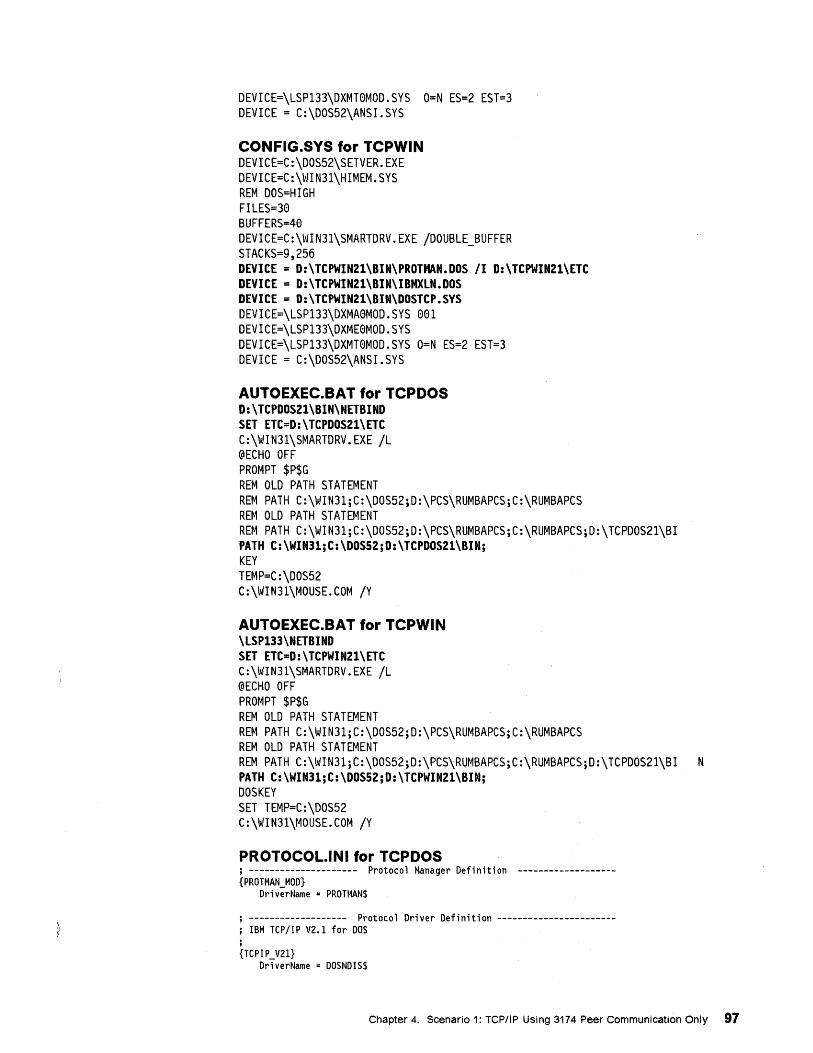
DEVICE=\LSP133\DXMT0MOD.SYS O=N ES=2 EST=3 DEVICE = C:\DOS52\ANS1.SYS
CONFIG.SYS for TCPWIN DEVICE=C:\DOS52\SETVER.EXE DEVICE=C:\WIN31\H1MEM.SYS REM DOS=H1GH F1LES=30 BUFFERS=40 DEV1CE=C:\WIN31\SMARTDRV.EXE IDOUBLE_BUFFER STACKS=9,256 DEVICE = D:\TCPWIN21\BIN\PROTMAN.DOS /1 D:\TCPWIN21\ETC DEVICE = D:\TCPWIN21\BIN\IBMXlN.DOS DEVICE = D:\TCPWIN21\BIN\DOSTCP.SYS DEV1CE=\LSP133\DXMA0MOD.SYS 001 DEVICE=\LSP133\DXME0MOD.SYS DEV1CE=\LSP133\DXMT0MOD.SYS O=N ES=2 EST=3 DEVICE = C:\DOS52\ANSI.SYS
AUTOEXEC.BAT for TCPDOS D:\TCPDOS21\BIN\NETBIND SET ETC=D:\TCPDOS21\ETC C:\WIN31\SMARTDRV.EXE IL @ECHO OFF PROMPT $P$G REM OLD PATH STATEMENT REM PATH C:\W1N31;C:\DOS52;D:\PCS\RUMBAPCS;C:\RUMBAPCS REM OLD PATH STATEMENT REM PATH C:\WIN31;C:\DOS52;D:\PCS\RUMBAPCS;C:\RUMBAPCS;D:\TCPDOS21\BI PATH C:\WIN31;C:\DOSS2;D:\TCPDOS21\BIN; KEY TEMP=C:\DOS52 C:\W1N31\MOUSE.COM IY
AUTOEXEC.BAT for TCPWIN \lSP133\NETBIND SET ETC=D:\TCPWIN21\ETC C:\W1N31\SMARTDRV.EXE IL @ECHO OFF PROMPT $P$G REM OLD PATH STATEMENT REM PATH C:\WIN31;C:\DOS52;D:\PCS\RUMBAPCS;C:\RUMBAPCS REM OLD PATH STATEMENT REM PATH C:\W1N31;C:\DOS52;D:\PCS\RUMBAPCS;C:\RUMBAPCS;D:\TCPDOS21\B1 N PATH C:\WIN31;C:\DOSS2;D:\TCPWIN21\BIN; DOS KEY SET TEMP=C:\DOS52 C:\WIN31\MOUSE.COM IY
PROTOCOL.lNI for TCPDOS ; --------------------- Protocol Manager Definition ------------------{PROTMAN MOD}
DriverName = PROTMAN$
; ------------------- Protocol Driver Definition ----------------------; IBM TCP/IP V2.1 for DOS ; {TCPIP V21}
DriverName = DOSNDIS$
Chapter 4. Scenario 1: TCP/IP Using 3174 Peer Communication Only 97
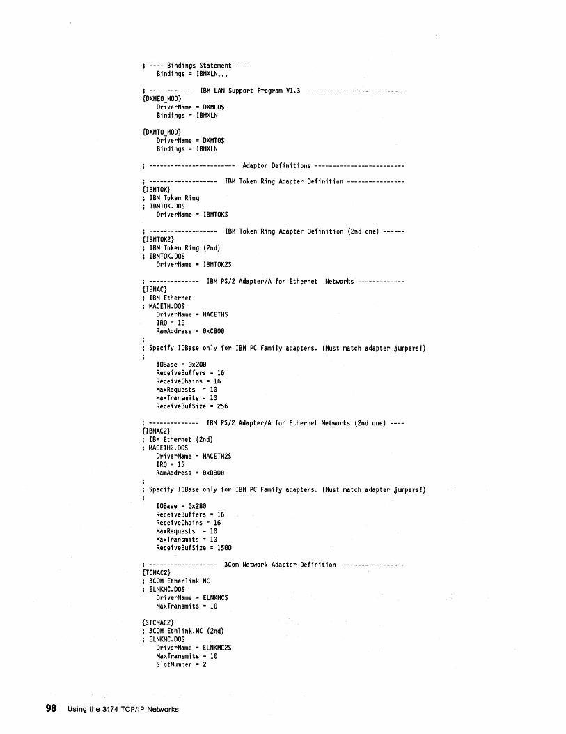
---- Bindings Statement ---Bindings = IBMXLN",
,------------ IBM LAN Support Program Vl.3 --------------------------{DXME8 MOD}
DriverName = DXME8$ Bindings = IBMXLN
{DXMT8 MOD} DriverName = DXMT8$ Bindings = IBMXLN
------------------------ Adaptor Definitions -------------------------
j ------------------- IBM Token Ring Adapter Definition ---------------{IBMTOK}
IBM Token Ring IBMTOK.DOS
DriverName = IBMTOK$
j ------------------- IBM Token Ring Adapter Definition (2nd one) -----{IBMTOK2}
IBM Token Ring (2nd) IBMTOK.DOS
DriverName = IBMTOK2$
j -------------- IBM PS/2 Adapter/A for Ethernet Networks ------------{IBMAC}
IBM Ethernet MACETH. DOS
DriverName = MACETH$ IRQ = 18 RamAddress = 8xCS88
Specify IOBase only for IBM PC Family adapters. (Must match adapter jumpers!)
IOBase = 8x288 ReceiveBuffers = 16 ReceiveChains = 16 MaxRequests = 18 MaxTransmits = 18 ReceiveBufSize = 256
j -------------- IBM PS/2 Adapter/A for Ethernet Networks (2nd one) ---{IBMAC2}
IBM Ethernet (2nd) MACETH2.DOS
DriverName =MACETH2$ IRQ = 15 RamAddress = 8xDS8e
Specify IOBase only for IBM PC Family adapters. (Must match adapter jumpers!)
IOBase = 8x2S8 ReceiveBuffers = 16 ReceiveChains = 16 MaxRequests = 18 MaxTransmits = 18 ReceiveBufSize = 158e
j ------------------- 3Com Network Adapter Definition ----------------{TCMAC2}
3COM Etherlink MC ELNKMC.DOS
DriverName = ELNKMC$ MaxTransmits = 18
{STCMAC2} 3COM Ethlink.MC (2nd) ELNKMC.DOS
DriverName • ELNKMC2$ MaxTransmits = 18 SlotNumber = 2
98 Using the 3174 TCPIIP Networks
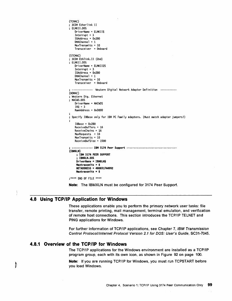
{TCMAC} j 3COM Etherlink II
ELNKII.DOS DriverName = ELNKII$ Interrupt = 3 IOAddress = 8x2S8 DMAChannel = 1 MaxTransmits = 18 Transceiver = Onboard
{STCMAC} j 3COM Ethlink.II (2nd)
ELNKI 1. DOS DriverName = ELNKII2$ Interrupt = 3 IOAddress = 8x2S8 DMAChannel = 1 MaxTransmits = 18 Transceiver = Onboard
j -------------- Western Digital Network Adapter Definition ----------{WOMAC} j Western Dig. Ethernet j MACWD.DOS
DriverName = MACWD$ IRQ = 3 RamAddress = 8xDS88
Specify IOBase only for IBM PC Family adapters. (Must match adapter jumpers!)
IOBase = 8x2S8 ReceiveBuffers = 16 ReceiveChains = 16 MaxRequests = 18 MaxTransmits = 18 ReceiveBufSize = 1588
; -------------- IBM 3174 Peer Support ----------------------------------{IBMXLN}
; IBM 3174 PEER SUPPORT ; IBMXLN. DOS Dr;verName = IBMXLN$ Maxtransmits = 6 NETADDRESS = 488831744992 Maxtransmits = 6
j**** END OF FILE ****
Note: The IBMXLN must be configured for3174 Peer Support.
4.8 Using TCP/IP Application for Windows
4.8.1
These applications enable you to perform the primary network user tasks: file transfer, remote printing, mail management, terminal emulation, and verification of remote host connections. This section introduces the TCPIIP TELNET and PING applications for Windows.
For further information of TCPIIP applications, see Chapter 7, IBM Transmission Control Protocol/Internet Protocol Version 2.1 for DOS: User's Guide, SC31-7045.
Overview of the TCP/IP for Windows The TCP/IP applications for the Windows environment are installed as a TCP/IP program group, each with its own icon, as shown in Figure 92 on page 100.
Note: If you are running TCP/IP for Windows, you must run TCPSTART before you load Windows.
Chapter 4. Scenario 1: TCPIIP Using 3174 Peer Communication Only 99
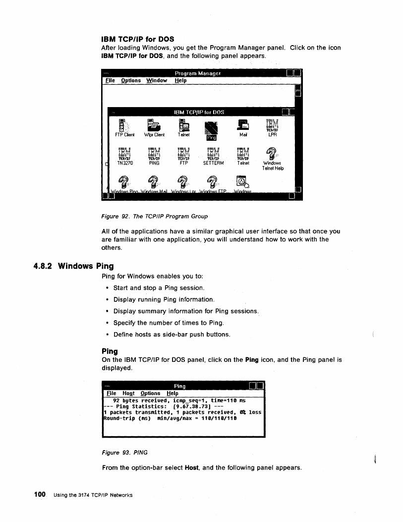
IBM TCP/IP for DOS After loading Windows, you get the Program Manager panel. Click on the icon IBM TCP/IP for DOS, and the following panel appears.
I ffint
SETTERM
Figure 92. The TCP/IP Program Group
!~ii
~::~ Telnet Windows
Telnet Help
All of the applications have a similar graphical user interface so that once you are familiar with one application, you will understand how to work with the others.
4.8.2 Windows Ping Ping for Windows enables you to:
• Start and stop a Ping session.
• Display running Ping information.
• Display summary information for Ping sessions.
• Specify the number of times to Ping.
• Define hosts as side-bar push buttons.
Ping On the IBM TCPIIP for DOS panel, click on the Ping icon, and the Ping panel is displayed.
-, Ping DO file Ho~t Qptions tlelp
92 bytes receiued, iCAp_seq=1, tiAe=110 AS --- Ping Statistics: [9.67.38.73] ---1 packets transAitted, 1 packets receiued, 0% loss Round-trip (AS) Ain/aug/Aax = 110/110/110
Figure 93. PING
From the option-bar select Host, and the following panel appears.
100 Using the 3174 TCPIIP Networks
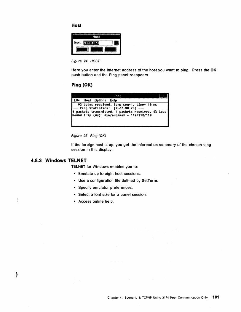
Host
Host
Figure 94. HOST
Here you enter the internet address of the host you want to ping. Press the OK push button and the Ping panel reappears.
Ping (OK)
- Ping DO Eile Ho~t .Qptions Help
92 bytes receiued, iCAp_seq=1, tiAe=110 AS --- Ping Statistics: [9.67.38.73] ---1 packets transAitted, 1 packets receiued, It loss Round-trip (AS) Ain/aug/Aax = 110/110/110
Figure 95. Ping (OK)
If the foreign host is up, you get the information summary of the chosen ping session in this display.
4.8.3 Windows TELNET TELNET for Windows enables you to:
• Emulate up to eight host sessions.
• Use a configuration file defined by SetTerm.
• Specify emulator preferences.
• Select a font size for a panel session.
• Access online help.
Chapter 4. Scenario 1: TCP/IP Using 3174 Peer Communication Only 101
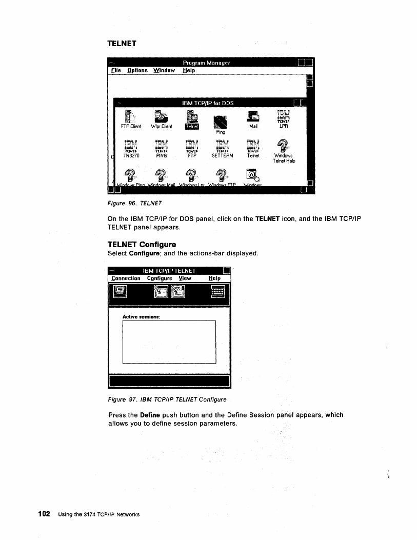
TELNET
Figure 96. TELNET
:.~.!~.:.
roil; SETTERM
t Windows Telnet Help
On the IBM TCP/IP for DOS panel, click on the TELNET icon, and the IBM TCP/IP TELNET panel appears.
TELNET Configure Select Configure; and the actions-bar displayed.
Active sessions:
Figure 97. IBM TCP/IP TELNET Configure
Press the Define push button and the Define Session panel appears, which allows you to define session parameters.
102 Using the 3174 TCP/IP Networks
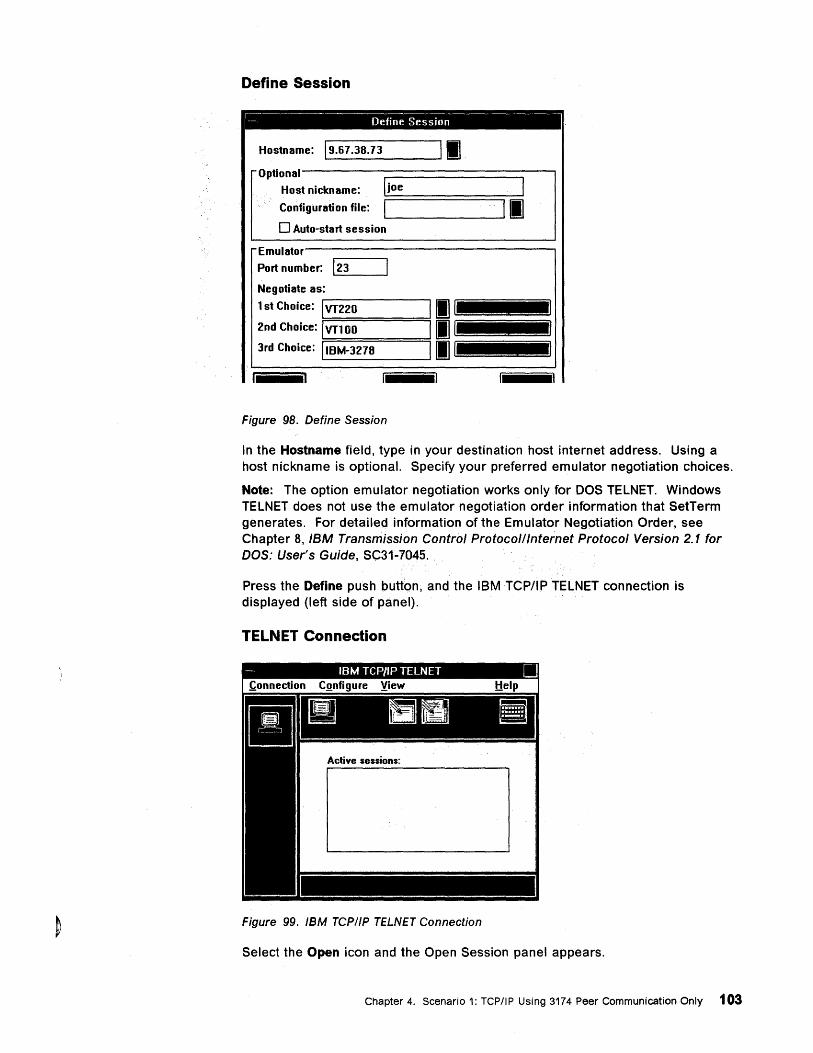
Define Session
---------------- Define Session
Hostname: 19.67.38.73 II Optional
I Host nickname: lioe
Configuration file: I II
o Auto-start session
Emulator
Port number: 123
Negotiate as:
1 st Choice: I VT220 II 2nd Choice: I VT100 II 3rd Choice: IIBM-3278 II
Figure 98. Define Session
In the Hostname field, type in your destination host internet address. Using a host nickname is optional. Specify your preferred emulator negotiation choices.
Note: The option emulator negotiation works only for DOS TELNET. Windows TELNET does not use the emulator negotiation order information that SetTerm generates. For detailed information of the Emulator Negotiation Order, see Chapter 8, IBM Transmission Control Protocolllnternet Protocol Version 2.1 for DOS: User's Guide, SC31-.7045.
Press the Define push button, and the IBM TCP/IP TELNET connection is displayed (left side of panel).
TELNET Connection
Active sessions:
Figure 99. IBM TCP/IP TELNET Connection
Select the Open icon and the Open Session panel appears.
Chapter 4. Scenario 1: TCP/IP Using 3174 Peer Communication Only 103
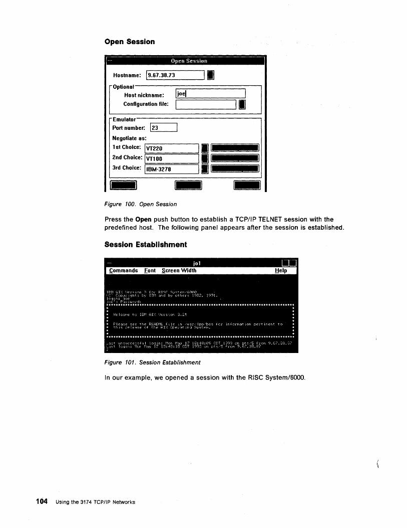
Open Session
- Open Session
Hostname: 19.67.38.73 II
Optional------;::::=======:::::::;~I
Host nickname: 1 joel I
Configuration file: 1 L-______ ---'11 Emulator-----------------,
Port number: L-12_3 __ .......
Negotiate as: 1 st Choice: r-lvr-2-2-0-----.
2nd Choice: Ivrl00 :========:
3rd Choice: L-11B_M_-_3_27_8 ___ -'
Figure 100. Open Session
Press the Open push button to establish a TCP/IP TELNET session with the predefined host. The following panel appears after the session is established.
Session Establishment
Figure 101. Session Establishment
In our example, we opened a session with the RISC System/6000.
104 Using the 3174 TCP/IP Networks
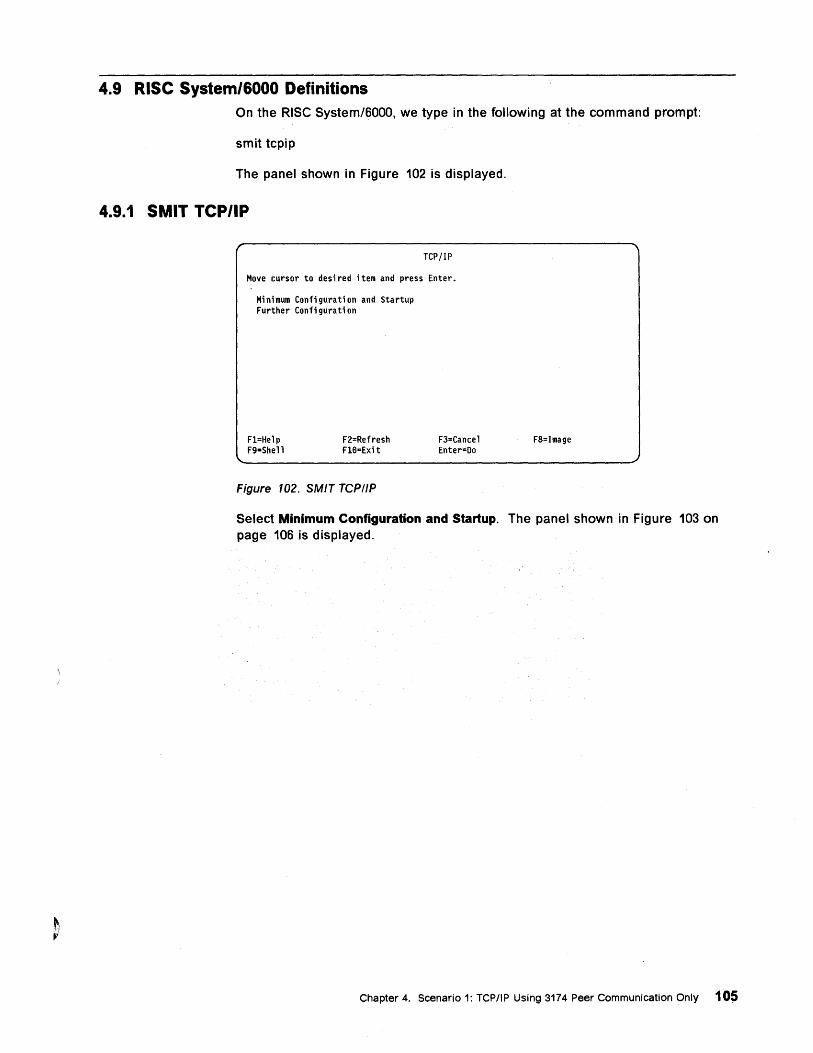
4.9 RISC System/6000 Definitions On the RiSe System/6000, we type in the following at the command prompt:
smit tcpip
The panel shown in Figure 102 is displayed.
4.9.1 SMIT TCP/IP
TCP/IP
Move cursor to desi red i tern and press Enter.
Minimum Configuration and Startup Further Configuration
Fl=Help F9=Shell
F2=Refresh Fl6=Exit
Figure 102. SMIT TCPIIP
F3=Cancel Enter=Oo
F8=Image
Select Minimum Configuration and Startup. The panel shown in Figure 103 on page 106 is displayed.
Chapter 4. Scenario 1: TCP/IP Using 3174 Peer Communication Only 105
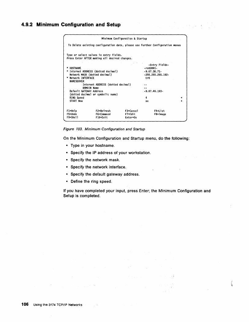
4.9.2 Minimum Configuration and Setup
Minimum Configuration & Startup
To Delete existing configuration data, please use Further Configuration menus
Type or select values in entry fields. Press Enter AFTER making all desired changes.
* HOSTNAME * Internet ADDRESS (dotted decimal)
Network MASK (dotted decimal) * Network INTERFACE
NAME SERVER Internet ADDRESS (dotted dec; ma l) DOMAIN Name
Default GATEWAY Address (dotted decimal or symbolic name) RING Speed START Now
F1=Help FS=Undo F9=Shell
F2=Refresh F6=Command FHl=Exi t
F3=Cancel F7=Edit Enter=Do
-Entry Fields--rs68881--9.67.38.71--2SS.2SS.2SS.192-trfl
-9.67.46.193-
4 no
F4=Li st F8=Image
Figure 103. Minimum Configuration and Startup
+ +
On the Minimum Configuration and Startup menu, do the following:
• Type in your hostname.
• Specify the IP address of your workstation.
• Specify the network mask.
• Specify the network interface.
• Specify the default gateway address.
• Define the ring speed.
If you have completed your input, press Enter; the Minimum Configuration and Setup is completed.
106 Using the 3174 TCP/IP Networks
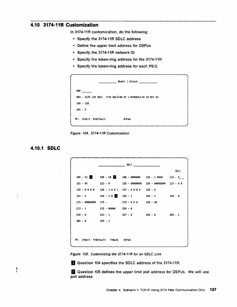
4.10 3174-11 R Customization
4.10.1 SDLC
In 3174-11R customization, do the following:
• Specify the 3174-11R SOLC address
• Define the upper limit address for OSPUs
• Specify the 3174-11R network 10
• Specify the token-ring address for the 3174-11R
• Specify the token-ring address for each PS/2.
____ Model/Attach ___ _
e98
e99 - 3174 11R SOLC ITSO RALEIGH BY J MINOERLEIN 19 MAY 93
1aa - 11R
1e1 - 2
PF: 3=Quit 4=Oefault 8=Fwd
Figure 104. 3174-11R Customization
SOLC
SOLC
1a4 - C1 D 1a5 - C8 a 1a8 - aaaaaaa 11e - 1 aaaa 116 - 2 - -121 - a1 123 - e 125 - aaaaaaae 126 - aaaeeeee 127 - e e
132 - a e a a 136 - 1 a e 1 137 - a e a e 138 - e
141 - A 15a - 1 e II 165 - 1 166 - A 168 - a
173 - aaaeeeee 175 - 179 - e e e 1ge - ae
213 - 1 215 - eaaaa 22a - e
31a - a 313 - 1 317 - a 318 - a 348 - 1
365 - a 37a - 1
PF: 3=Qui t 4=Oefaul t 7-Back 8=Fwd
Figure 105. Customizing the 3174-11R for an SDLC Link
D Question 104 specifies the SOLC address of the 3174-11R.
II Question 105 defines the upper limit poll address for OSPUs. We will use poll address:
Chapter 4. Scenario 1: TCPIIP Using 3174 Peer Communication Only 107
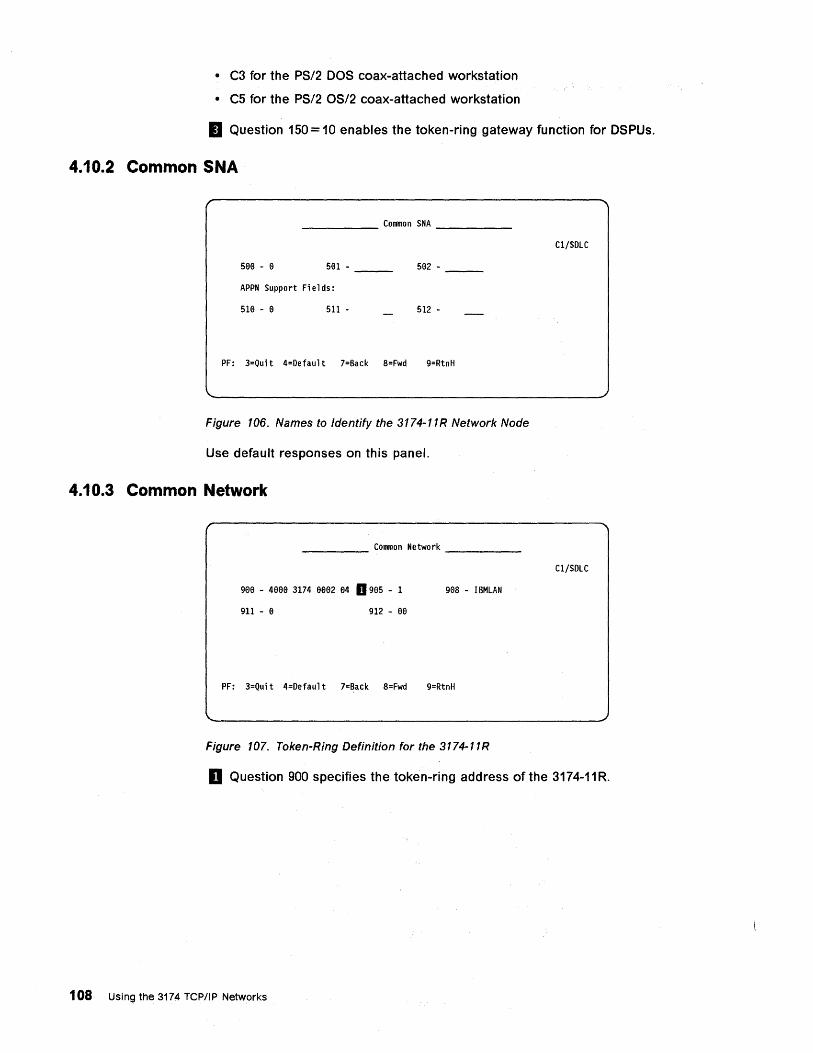
• C3 for the PS/2 DOS coax-attached workstation
• C5 for the PS/2 OS/2 coax-attached workstation
II Question 150 = 10 enables the token-ring gateway function for DSPUs.
4.10.2 Common SNA
_____ Common SNA ____ _
5aa - a 581 - 582 -
APPN Support Fi e 1 ds :
518 - a 511 - 512 -
PF: 3=Quit 4=Default 7=Back 8=Fwd 9=RtnH
Figure 106. Names to Identify the 3174-11R Network Node
Use default responses on this panel.
4.10.3 Common Network
____ Common Network ____ _
gea - 4aaa 3174 a882 84 D 985 - 1 908 - IBMLAN
911 - 8 912 - a8
PF: 3=Quit 4=Default 7=Back 8=Fwd 9=RtnH
Figure 107. Token-Ring Definition for the 3174-11R
C1/SDLC
C1/SDLC
II Question 900 specifies the token-ring address of the 3174-11 R.
108 Using the 3174 TCP/IP Networks
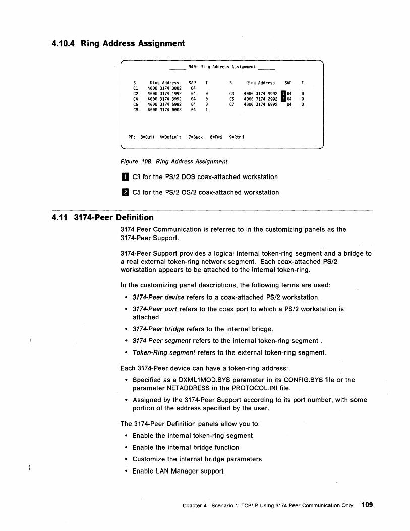
4.10.4 Ring Address Assignment
__ 948: Ri ng Address Assi gnment __
S Ri n9 Address SAP T S Ri n9 Address SAP Cl 4aa8 3174 8a62 64 C2 4686 3174 1992 84 8 C3 4aa8 3174 4992 B a4 C4 4886 3174 3992 84 8 C5 4688 3174 2992 84 C6 4a66 3174 5992 64 6 C7 4888 3174 6992 C8 4886 3174 6663 64 1
PF: 3=Quit 4=Default 7=Back 8=Fwd 9=RtnH
Figure 108. Ring Address Assignment
D C3 for the PS/2 DOS coax-attached workstation
D C5 for the PS/2 OS/2 coax-attached workstation
4.11 3174-Peer Definition
84
T
8 6 8
3174 Peer Communication is referred to in the customizing panels as the 3174-Peer Support.
3174-Peer Support provides a logical internal token-ring segment and a bridge to a real external token-ring network segment. Each coax-attached PS/2 workstation appears to be attached to the internal token-ring.
In the customizing panel descriptions, the following terms are used:
• 3174-Peer device refers to a coax-attached PS/2 workstation.
• 3174-Peer port refers to the coax port to which a PS/2 workstation is attached.
• 3174-Peer bridge refers to the internal bridge.
• 3174-Peer segment refers to the internal token-ring segment.
• Token-Ring segment refers to the external token-ring segment.
Each 3174-Peer device can have a token-ring address:
• Specified as a DXML 1MOD.SYS parameter in its CONFIG.SYS file or the parameter NETADDRESS in the PROTOCOL.INI file.
• Assigned by the 3174-Peer Support according to its port number, with some portion of the address specified by the user.
The 3174-Peer Definition panels allow you to:
• Enable the internal token-ring segment
• Enable the internal bridge function
• Customize the internal bridge parameters
• Enable LAN Manager support
Chapter 4. Scenario 1: TCP/IP Using 3174 Peer Communication Only 109
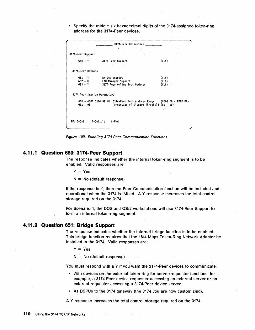
• Specify the middle six hexadecimal digits of the 3174-assigned token-ring add ress for the 3174-Peer devices.
___ 3174-Peer Defi ni ti on __ _
3174-Peer Support
65S - Y
3174-Peer Opti ons
651 - Y 652 - N 653 - y
3174-Peer Support
Br; dge Support LAN Manager Support 3174-Peer Onl ;ne Test Updates
3174-Peer Sta ti on Parameters
(Y,N)
(Y, N) (Y,N) (Y,N)
66S - 4SSS 3174 91 PN 3174-Peer Port Address Range (sssa sa - FFFF FF) 661 - S5 Percentage of Di scard Threshold (as - 99)
PF: 3=Qui t 4=Default 8=Fwd
Figure 109. Enabling 3174 Peer Communication Functions
4.11.1 Question 650: 3174-Peer Support The response indicates whether the internal tOken-ring segment is to be enabled. Valid responses are:
Y = Yes
N = No (default response)
If the response is Y, then the Peer Communication function will be included and operational when the 3174 is IMLed. A Y response increases the total control storage required on the 3174.
For Scenario 1, the DOS and OS/2· workstations will use 3174-Peer Support to form an internal token-ring segment.
4.11.2 Question 651: Bridge Support The response indicates whether the internal bridge function is to be enabled. This bridge function requires that the 16/4 Mbps Token-Ring Network Adapter be installed in the 3174. Valid responses are:
Y = Yes
N = No (default response)
You must respond with a Y if you want the 3174-Peer devices to communicate:
• With devices on the external token-ring for server/requester functions, for example, a 3174-Peer device requester accessing an external server or an external requester accessing a 3174-Peer device server.
• As DSPUs to the 3174 gateway (the 3174 you are now customizing).
A Y response increases the total control storage required on the 3174.
110 Using the 3174 TCPIIP Networks
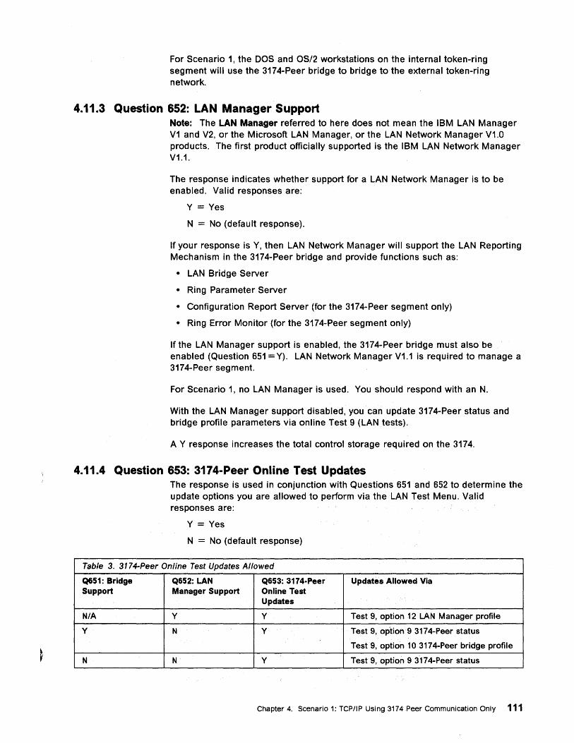
For Scenario 1, the DOS and OS/2 workstations on the internal token-ring segment will use the 3174-Peer bridge to bridge to the external token-ring network.
4.11.3 Question 652: LAN Manager Support Note: The LAN Manager referred to here does not mean the IBM LAN Manager V1 and V2, or the Microsoft LAN Manager, or the LAN Network Manager V1.0 products. The first product officially supported is the IBM LAN Network Manager V1.1.
The response indicates whether support for a LAN Network Manager is to be enabled. Valid responses are:
Y = Yes
N = No (default response).
If your response is Y, then LAN Network Manager will support the LAN Reporting Mechanism in the 3174-Peer bridge and provide functions such as:
• LAN Bridge Server
• Ring Parameter Server
• Configuration Report Server (for the 3174-Peer segment only)
• Ring Error Monitor (for the 3174-Peer segment only)
If the LAN Manager support is enabled, the 3174-Peer bridge must .also be enabled (Question 651 = Y). LAN Network Manager V1.1 is required to manage a 3174-Peer segment.
For Scenario 1, no LAN Manager is used. You should respond with an N.
With the LAN Manager support disabled, you can update 3174-Peer status and bridge profile parameters via online Test 9 (LAN tests).
A Y response increases the total control storage required on the 3174.
4.11.4 Question 653: 3174-Peer Online Test Updates The response is used in conjunction with Questions 651 and 652 to determine the update options you are allowed to perform via the LAN Test Menu. Valid responses are:
Y = Yes
N = No (default response)
Table 3. 3174-Peer Online Test Updates Allowed
Q651: Bridge Q652: LAN Q653: 3174·Peer Updates Allowed Via Support Manager Support Online Test
Updates
N/A y Y Test 9, option 12 LAN Manager profile
y N Y Test 9, option 9 3174-Peer status
Test 9, option 10 3174-Peer bridge profile
N N Y Test9, option 9 3174-Peer status
Chapter 4. Scenario 1: TCP/IP Using 3174 Peer Communication Only 111
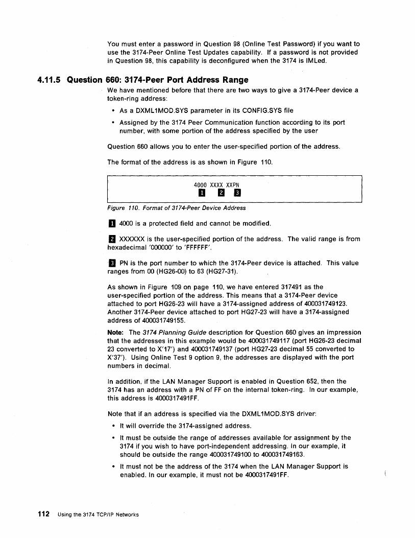
You must enter a password in Question 98 (Online Test Password) if you want to use the 3174-Peer Online Test Updates capability. If a password is not provided in Question 98, this capability is deconfigured when the 3174 is IMLed.
4.11.5 Question 660: 3174-Peer Port Address Range We have mentioned before that there are two ways to give a 3174-Peer device a token-ring address:
• As a DXML 1 MOD.SYS parameter in its CONFIG.SYS file
• Assigned by the 3174 Peer Communication function according to its port number, with some portion of the address specified by the user
Question 660 allows you to enter the user-specified portion of the address.
The format of the address is as shown in Figure 110.
4000 XXXX XXPN D B II
Figure 110. Format of 3174-Peer Device Address
D 4000 is a protected field and cannot be modified.
B XXXXXX is the user-specified portion of the address. The valid range is from hexadecimal '000000' to 'FFFFFF'.
II PN is the port number to which the 3174-Peer device is attached. This value ranges from 00 (HG26-00) to 63 (HG27-31).
As shown in Figure 109 on page 110, we have entered 317491 as the user-specified portion of the address. This means that a 3174-Peer device attached to port HG26-23 will have a 3174-assigned address of 400031749123. Another 3174-Peer device attached to port HG27-23 will have a 3174-assigned address of 400031749155.
Note: The 3174 Planning Guide description for Question 660 gives an impression that the addresses in this example would be 400031749117 (port HG26-23 decimal 23 converted to X'1?,) and 400031749137 (port HG27-23 decimal 55 converted to X'3?,). Using Online Test 9 option 9, the addresses are displayed with the port numbers in decimal.
In addition, if the LAN Manager Support is enabled in Question 652, then the 3174 has an address with a PN of FF on the internal token-ring. In our example, this address is 4000317491FF.
Note that if an address is specified via the DXML 1MOD.SYS driver:
• It will override the 3174-assigned address.
• It must be outside the range of addresses available for assignment by the 3174 if you wish to have port-independent addressing. In our example, it should be outside the range 400031749100 to 400031749163.
• It must not be the address of the 3174 when the LAN Manager Support is enabled. In our example, it must not be 4000317491FF.
112 Using the 3174 rePIJP Networks
If 3174-Peer Support and Bridge Support are both enabled, you should check that no other device uses any of the 3174-Peer Support addresses in Questions 106, 107, 900 and 940.
Recommendation: We recommend that you specify 3174-Peer device addresses via the DXML 1 MOD.SYS driver. This will give you addressing independent of the port numbers and allow 3174-Peer devices to be swapped from one port to another without problems.
4.11.6 Question 661: Percentage of Discard Threshold As a 3174-Peer device becomes congested, it cannot receive as many frames and starts to discard those it cannot receive. The more frames it discards within a given time interval, the more congested the device becomes.
Question 661 allows you to specify a threshold to use in deciding when a device has become congested. The valid range of response is 00 to 99. The default response is 05; this means that we consider a device to be congested if more than 5% of the frames are discarded in anyone-minute interval. If you specify ~O, it means that we consider a device to be congested if it discards any frame at all in anyone-minute interval.
4.11.7 3174-Peer Bridge Profile The 3174-Peer Bridge Profile panel allows you to specify parameters to be used by the internal bridge function. These parameters include:
• The internal bridge number
• The internal ring segment number
• The external token-ring network segment number
• The number of hops over which a broadcast frame can cross
• Whether frames will be forwarded by the bridge
• Setting threshold for bridge congestion
• How long to wait before logging a bridge congestion
• How long to wait before sending an alert about a congested bridge
Chapter 4. Scenario 1: TCP/IP Using 3174 Peer Communication Only 113
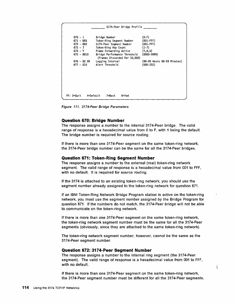
---.-__ 3174-Peer Bridge Profile __ _
678 - 1 671 - BB3 672 - 882 673 - 7 674 - Y 675 - 8818
676 - 82 88 677 - 818
Bridge Number Token-Ring Segment Number 3174-Peer Segment Number Token-Ring Hop Count Frame Forwarding Active Bridge Performance Threshold
(Frames Discarded Per 18,(88) Logging Interval Alert Threshold
PF: 3=Quit 4=Default 7=Back 8= Fwd
Figure 111. 3174-Peer Bridge Parameters
Question 670: Bridge Number
(8-F) (881-FFF) (001-FFF) (1-7) (Y,N,W) (8888-9999)
(88-99 Hours 88-59 Minutes) (888-255)
The response assigns a number to the internal 3174-Peer bridge. The valid range of response is a hexadecimal value from 0 to F, with 1 being the default. The bridge number is required for source routing.
If there is more than one 3174-Peer segment on the same token-ring network, the 3174-Peer bridge number can be the same for all the 3174-Peer bridges.
Question 671: Token-Ring Segment Number The response assigns a number to the external (real) token-ring network segment. The valid range of response is a hexadecimal value from 001 to FFF, with no default. It is required for source routing.
If the 3174 is attached to an eXisting token-ring network, you should use the segment number already assigned to the token-ring network for question 671.
If an IBM Token-Ring Network Bridge Program station is active on the token-ring network; you must use the segment number assigned by the Bridge Program for question 671. If the numbers do not match, the 3174-Peer bridge will not be able to communicate on the token-ring network.
If there is more than one 3174-Peer segment on the same token-ring network, the token-ring network segment number must be the same for all the 3174-Peer segments (obviously, since they are attached to the same token-ring network).
The token-ring network segment number, however, cannot be the same as the 3174-Peer segment number.
Question 672: 3174-Peer Segment Number The response assigns a number to the internal ring segment (the 3174-Peer segment). The valid range of response is a hexadecimal value from 001 to FFF, with no default.
If there is more than one 3174-Peer segment on the same token-ring network, the 3174-Peer segment number must be different for all the 3174-Peer segments.
114 Using the 3174 TCP/IP Networks
It must also be different from the token-ring network segment number. If the tOken-ring network is bridged to other token-ring networks, you must ensure that all 3174-Peer segment numbers are unique throughout the entire network.
Question 673: Token-Ring Hop Count The response specifies the maximum number of bridges that a broadcast frame can cross. The valid range of response is a from 1 to 7, with 7 as the default.
Note that the 3174-Peer bridge is counted as one hop when frames cross from the 3174-Peer segment to the external token-ring network or vice versa.
Question 674: Frame Forwarding Active The response indicates whether the 3174-Peer bridge is to forward frames it receives. Valid responses are:
Y = Yes (default response)
N=No
W=Wrap mode
Enter:
• Y if you want the 3174-Peer bridge to forward frames as well as process frames received from the tOken-ring network, or if a wrap plug is used on the Token-Ring Adapter in the 3174.
• N if you do not want the 3174-Peer bridge to forward frames received from the token-ring network. In fact, it will discard any frames it receives and stop incrementing the discard frame counters.
• W if a token-ring adapter cable is connected to the Token-Ring Adapter in the 3174 but not to the tOken-ring network (that is, not plugged into, for example, an 8230 Controlled Access Unit) and you want the adapter to open in wrap mode. Wrap mode allows 3174-Peer devices to access the 3174 token-ring gateway function for host communication without requiring the 3174 to be physically connected to a token-ring.
Note:
Before Configuration Support-C Release 3, you could put the 3174 into wrap mode by doing one of the following (depending on the microcode level):
Install a wrap plug (PN 6165899) instead of the Token-Ring Adapter cable at the 3174 Token-Ring Adapter port; respond to question 674 with a Y.
Install a Token-Ring Adapter cable at the 3174 Token-Ring Adapter port and apply patch TR 824501 (3174 Peer Communication Wrap Mode); respond to question 674 with a Y.
Note: Patch TR 824501 is only valid for the Peer Communications RPQ 8Q0718 (Configuration Support-B Release 4). This patch is not needed for Configuration Support-C Release 1 and later because Online Test /9,10 support for wrap mode was added.
Install a Token-Ring Adapter cable at the 3174 Token-Ring Adapter port; use Online Test /9,10 to set the Frame Forwarding Active response to W.
Chapter 4. Scenario 1: TCP/IP Using 3174 Peer Communication Only 115
With Configuration Support-C Release 3, you could put the 3174 into wrap mode by dOing one of the following:
Install a wrap plug (PN 6165899) instead of the Token-Ring Adapter cable at the 3174 Token-Ring Adapter port; respond to question 674 with a Y.
Install a Token-Ring Adapter cable at the 3174 Token-Ring Adapter port; respond to question 674 with a W (Wrap).
Install a Token-Ring Adapter cable at the 3174 Token-Ring Adapter port; use Online Test /9,10 to set the Frame Forwarding Active response to W.
Configuration Support-C Release 3 allows you to set the wrap mode through customization instead of using Online Test /9,10. The token-ring adapter is still required.
Question 675: Bridge Performance Threshold The response specifies the maximum percentage of information frames that may be discarded by the internal bridge within a one-minute interval before a count is incremented. The valid range is from 0000 to 9999; the number is in hundredths of a percent or the number of frames per 10,000. The default is 0010 and means that the discard counter will be incremented by one if 0.1 010 (10 hundredths of a percent) of the frames received within anyone-minute interval are discarded. It is the same as saying the discard counter will be incremented by one if 10 out of every 10,000 frames received within anyone-minute interval are discarded.
A separate count is maintained for frames received from the token-ring network and frames received from the 3174-Peer segment.
Question 676: Logging Interval When the internal bridge performance threshold is exceeded at the end of a one-minute interval, the bridge is congested. To measure how serious the congestion is, you can specify a time interval during which the congestion is monitored.
The monitoring begins at the end of the one-minute interval when the congestion occurred, counting that one-minute interval as the first minute of the monitoring interval. At the end of the monitoring interval, the Log Manager is invoked to record the number of minutes in that interval during which the bridge was congested. The number of minutes and a non-alertable status code are recorded in the event log. This information is time stamped.
Question 676 allows you to set the monitoring interval. The valid range of response is from 00 Hours 00 Minutes to 99 Hours 59 Minutes, with the default being 02 00 (every two hours). If 00 Hours 00 Minutes is specified, then no logging of the bridge congestion is invoked. If you specify any interval other than 0000, then logging begins only after bridge congestion has been detected.
Question 677: Alert Threshold Within the monitoring interval set by Question 676, you can set another threshold to raise an alert if the congestion is serious. Question 677 allows you to set this alert threshold. The valid range of response is from 000 to 255, with the default being 010 minutes.
116 Using the 3174 TCP/IP Networks
Using the default logging interval (0200) and default alert threshold (010) as an example, if bridge congestion is detected then monitoring begins. If bridge congestion total time is less than 10 minutes (the alert threshold), no alert is raised and logging is invoked at the end of two hours.
As soon as bridge congestion total time reaches 10 minutes (the alert threshold), an alert is raised, the Log Manager is immediately invoked to record a status code and the alert threshold in the event log and the logging interval is treated as if it has completed.
4.11.8 LAN Manager Profile The LAN Manager Profile panel allows you to specify a password for each reporting link. The following rules apply to the reporting link passwords:
• The passwords need not be unique.
• Each password must be six to eight characters in length.
• Each character must be in the range 0-9 and A-Z.
• No blanks preceding or imbedded in the password are allowed
• The default is all blanks (no password specified).
The following questions allow you to specify the passwords:
• Question 690: Reporting Link 0 Password
• Question 691: Reporting Link 1 Password
• Question 692: Reporting Link 2 Password
• Question 693: Reporting Link 3 Password
Chapter 4. Scenario 1: TCP/IP Using 3174 Peer Communication Only 117
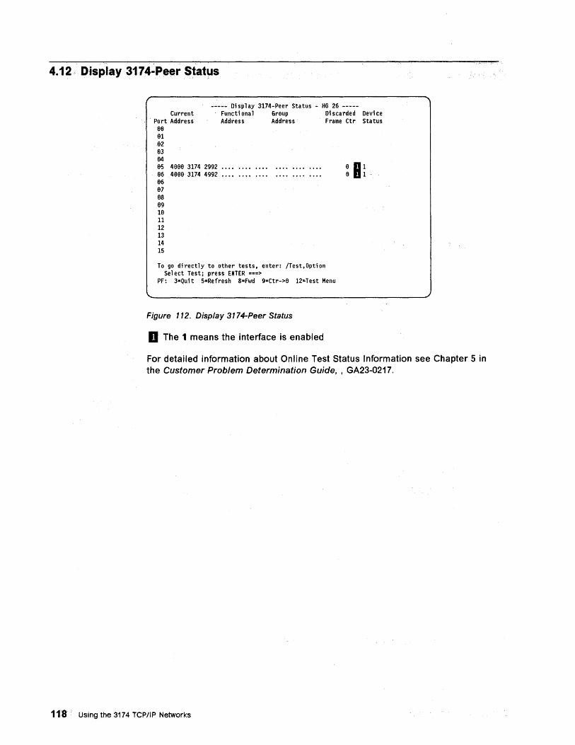
4.12· Display 3174-Peer StatlJs
----- Di sp lay 3174-Peer Status .:. HG 26 -----Current Functi ona 1 Group Di scarded Devi ce
Port Address 88
Address Address Frame Ctr Status
81 82 83 84 85 4888 3174 2992 •••• 86 4888 3174 4992 •••• 86 87 8S 89 H) 11 12 13 14 15
To go di rectly to other tests. enter: /Test. Opti on Se 1 ect Test; press ENTER ===>
PF: 3=Qui t 5=Refresh S=Fwd 9=Ctr->8 12=Test Menu
Figure 112. Display 3174-Peer Status
D The 1 means the interface is enabled
8 HI 8 1·
For detailed information about Online Test Status Information see Chapter 5 in the Customer Problem Determination Guide, , GA23-0217.
118 Using the 3174 TCP/IP Networks
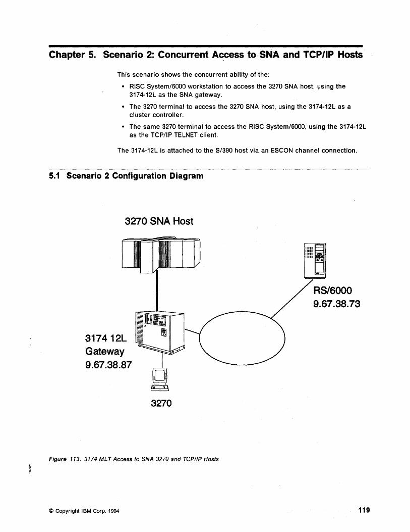
Chapter 5. Scenario 2: Concurrent Access to SNA and TCP/IP Hosts
This scenario shows the concurrent ability of the:
• RISC System/6000 workstation to access the 3270 SNA host, using the 3174-12L as the SNA gateway.
• The 3270 terminal to access the 3270 SNA host, using the 3174-12L as a cluster controller.
• The same 3270 terminal to access the RISC System/6000, using the 3174-12L as the TCP/IP TELNET client.
The 3174-12L is attached to the S/390 host via an ESCON channel connection.
5.1 Scenario 2 Configuration Diagram
3270 SNA Host
317412L Gateway 9.67.38.87
3270
Figure 113. 3174 MLT Access to SNA 3270 and TCP/IP Hosts
© Copyright IBM Corp. 1994
9.67.38.73
119
5.2 Scenario 2 Configuration Description The composite network has the following components:
• An S/390 host with VTAM* V4.1
• A 3174-12L Establishment Controller with:
- An ESCON connection
Token-ring address of 400031740004
• A RISC System/6000
- Token-ring address of 100054AF58CE
• 3270 terminal
120 Using the 3174 TCP/IP Networks
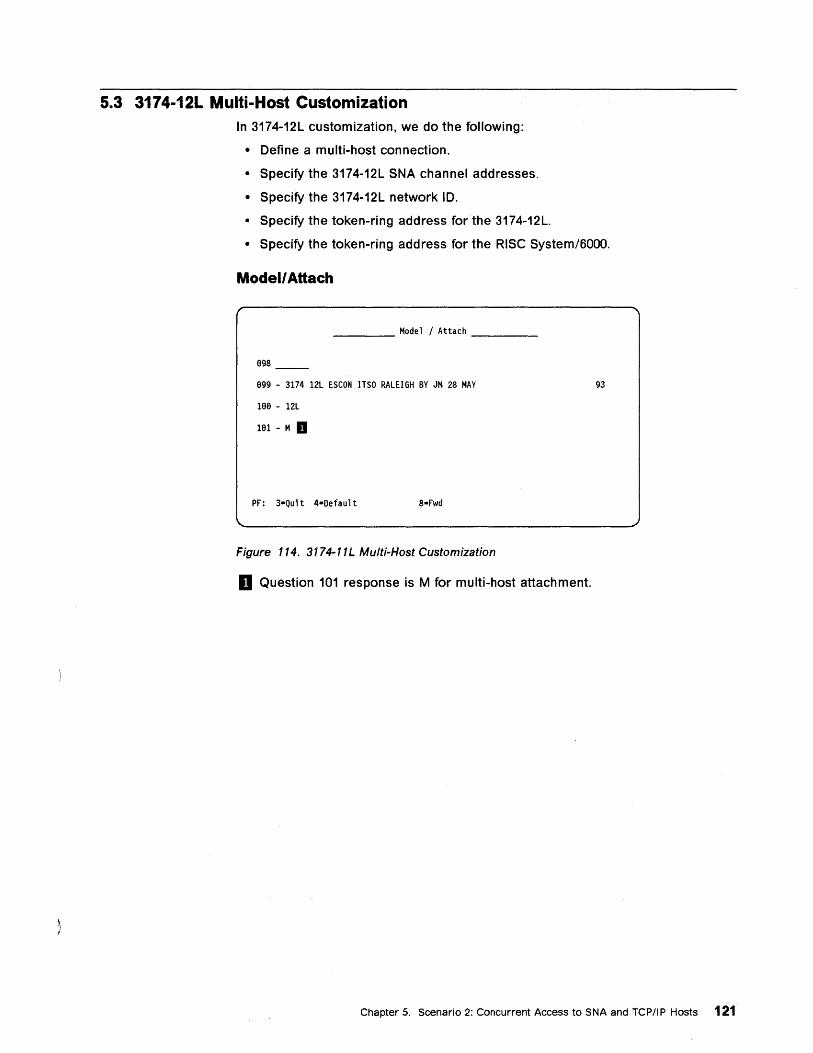
5.3 3174-12L Multi-Host Customization In 3174-12L customization, we do the following:
• Define a multi-host connection.
• Specify the 3174-12L SNA channel addresses.
• Specify the 3174-12L network 10.
• Specify the token-ring address for the 3174-12L.
• Specify the token-ring address for the RISe System/6000.
Modell Attach
____ Model/Attach ___ _
898
899 - 3174 12L ESCON ITSO RALEIGH BY JM 28 MAY
188 - 12L
181 - M II
PF: 3=Quit 4=Default 8=Fwd
Figure 114. 3174-11L Multi-Host Customization
D Question 101 response is M for multi-host attachment.
93
Chapter 5. Scenario 2: Concurrent Access to SNA and TCPIIP Hosts 121
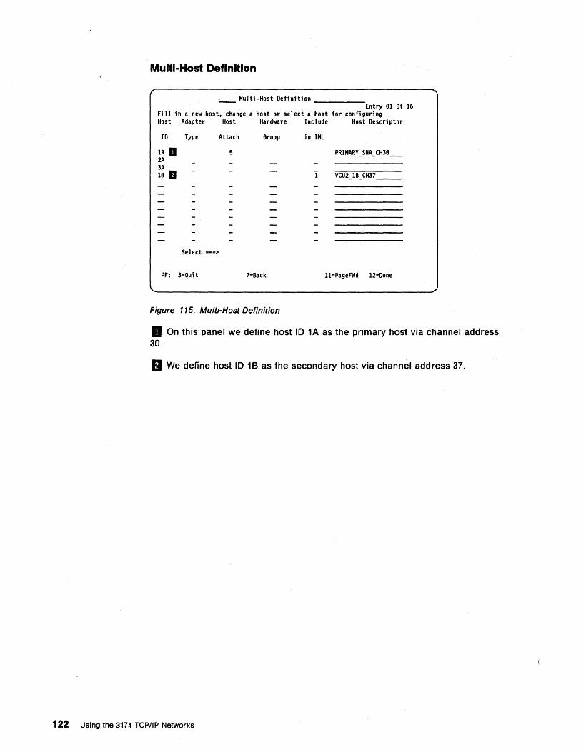
Multi-Host Definition
Multi-Host Definition ____ _ Entry 81 8f 16
Fill in a new host. change a host or select a host for configuring Host Adapter Host Hardware Include Host Descriptor
ID Type Attach Group in IMl
lA D 5 PRIMARY _ SNA_ CH38_ 2A 3A IB • 1 VCU2_1B_CH37 ___
Select ===>
PF: 3=Qui t 7=Back l1=PageFWd 12=Done
Figure 115. Multi-Host Definition
o On this panel we define host 10 1A as the primary host via channel address 30.
fJ We define host 10 18 as the secondary host via channel address 37.
122 Using the 3174 TCP/IP Networks
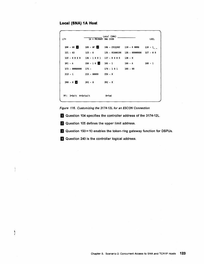
Local (SNA) 1 A Host
Local (SMA) LT- 1A = PRIMARY SMA CH38 LOCL
184 - 68 II 185 - 6F • 188 - 23CQ382 118 - 4 8888 116 - 1 - -121 - 83 123 - 8 125 - 81888188 126 - 88888888 127 - 8 8
132 - 8 8 8 8 136 - 1 8 8 1 137 - 8 8 8 8 138 - 8
141 - A 158 - 1 8 II 165 - 1 166 - A 168 - 1
173 - 88888888 175 - 179 - 1 8 1 198 - 88
213 - 1 215 - 88888 228 - 8
248 - 8 II 241 - 8 242 - 8
PF: 3=Quit 4=Oefault 8=Fwd
Figure 116. Customizing the 3174-12L for an ESCON Connection
D Question 104 specifies the controller address of the 3174-12L.
B Question 105 defines the upper limit address.
II Question 150= 10 enables the token-ring gateway function for DSPUs.
II Question 240 is the controller logical address.
Chapter 5. Scenario 2: Concurrent Access to SNA and TCPIIP Hosts 123
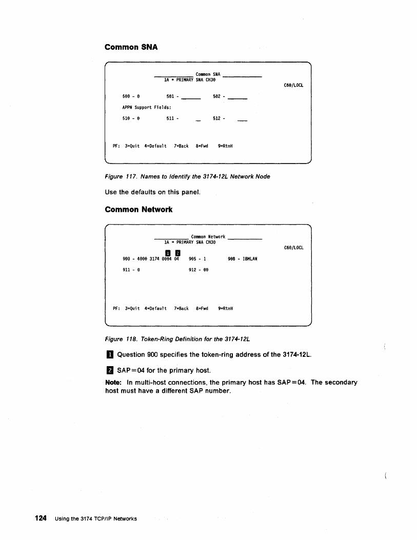
Common SNA
Common SNA ---::l:-:-A-=--::P~R'::":'IM~AR=Y SNA CH3e -----
C68/LOCL
se8 - 8 581 - 582 -
APPN Support Fi e 1 ds:
Sle - e 511 - 512 -
PF: 3=Quit 4=Default 7=Back S-Fwd 9=RtnH
Figure 117. Names to Identify the 3174-12L Network Node
Use the defaults on this panel.
Common Network
Common Network -"""I-A-=-P"""R"""'IM'"""ARY SNA CH3e -----
.D C68/LOCL
gee - 48ee 3174 8ee4 e4 geS - 1 98S - IBMLAN
911 - e 912 - aa
PF: 3=Quit 4=Default 7=Back S=Fwd 9=RtnH
Figure 118. Token-Ring Definition for the 3174-12L
D Question 900 specifies the token-ring address of the 3174-12L.
m SAP=04 for the primary host.
Note: In multi-host connections, the primary host has SAP=04. The secondary host must have a different SAP number.
124 Using the 3174 TCP/IP Networks
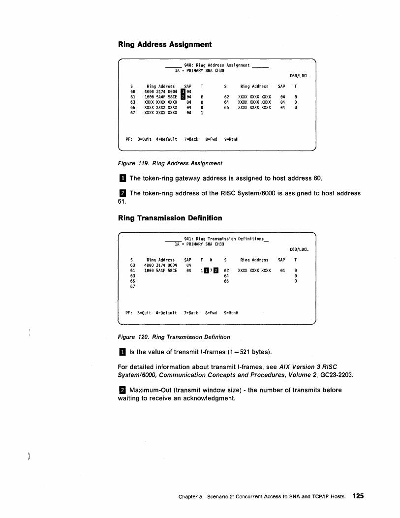
Ring Address Assignment
9413: Ring Address Assignment --lA-= PRIMARY SNA CH3a --
C6a/LOCL
S Ring Address SAP T S Ri ng Address SAP T 613 4131313 3174 1313134 H 134 61 1131313 5A4F 58CE 134 a 62 XXXX xxxx XXXX 134 a 63 xxx x XXXX xxx x 134 13 64 XXXX XXXX xxx x 134 13 65 xxx x XXXX xxx x 134 a 66 XXXX XXXX XXXX 134 a 67 XXXX xxx x XXXX 134 1
PF: 3=Quit 4=Oefault 7=Back 8=Fwd 9=RtnH
Figure 119. Ring Address Assignment
D The token-ring gateway address is assigned to host address BO.
a The token-ring address of the RISC System/BOOO is assigned to host address B1.
Ring Transmission Definition
941: Ri ng Transmi ssi on Oefi niti ons --lA-= PRIMARY SNA CH3B -
C6a/LOCL
S Ri ng Address SAP F W S Ring Address SAP T 613 4131313 3174 1313134 84 61 1aee 5A4F 58CE 134 1117& 62 xxx x XXXX XXXX a4 a 63 64 a 65 66 13 67
PF: 3=Quit 4=Oefault 7=Back 8=Fwd 9=RtnH
Figure 120. Ring Transmission Definition
D Is the value of transmit I-frames (1 = 521 bytes).
For detailed information about transmit I-frames, see AIX Version 3 RISC System/6000, Communication Concepts and Procedures, Volume 2, GC23-2203.
a Maximum-Out (transmit window size) - the number of transmits before waiting to receive an acknowledgment.
Chapter 5. Scenario 2: Concurrent Access to SNA and TCP/IP Hosts 125
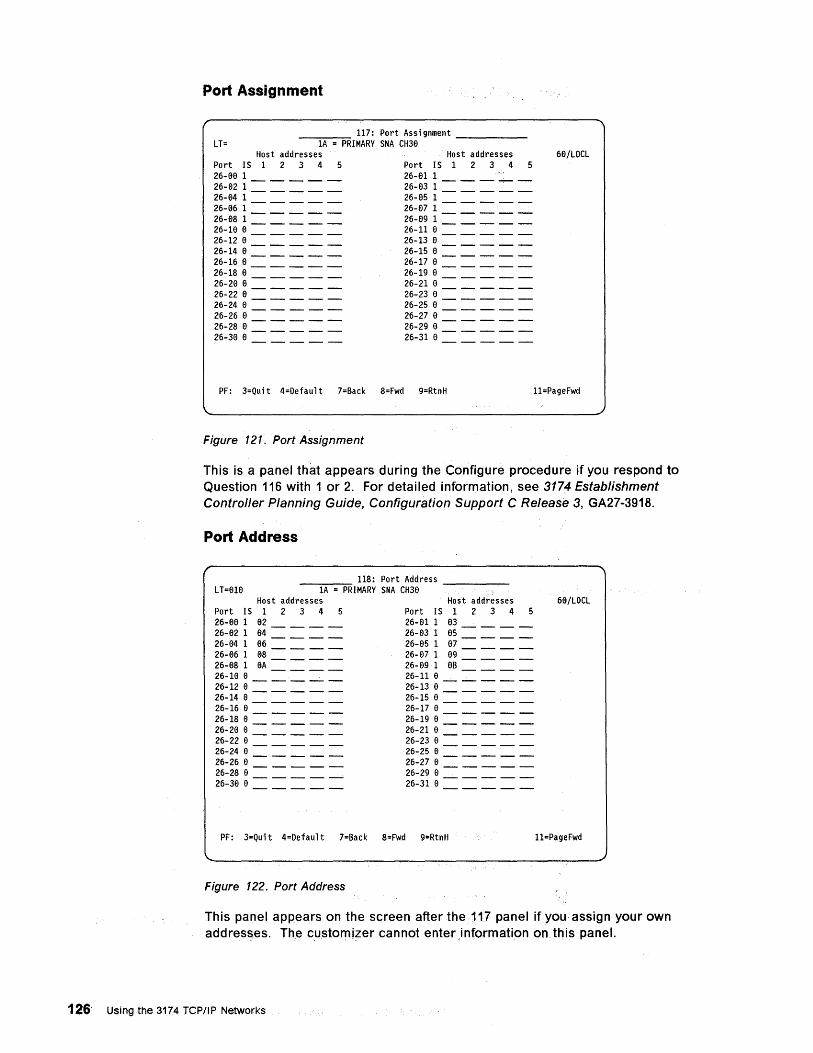
Port Assignment
LT= _-,----,= 117: Port Ass; gnment ____ _
1A = PRIMARY SNA CH30 Host addresses Host addresses 60/LOCL
Port IS 1 2 3 4 5 Port IS 1 2 3 4 5 26-00 1 ____ _ 26-02 1 ____ _
26-01 1
26~03 1 = = = = = 26-04 1 ____ _ 26-85 1 ____ _ 26-06 1 ____ _ 26-071 ____ _ 26-08 1 ____ _ 26-09 1 ____ _ 26-100 ____ _ 26-11 0 ____ _ 26-120 ____ _ 26-13 0 ____ _ 26-140 ____ _ 26-160 ____ _
26-15 0 ____ _ 26':17 0 ____ _
26-18 0 ____ _ 26-19 0 ____ _ 26-20 0 ____ _ 26-21 0 ____ _ 26-220 ____ _ 26-23 0 ____ _ 26-24 0 ____ _ 26-25 0 ____ _ 26-260 ____ _ 26-27 0 ____ _ 26-280 ____ _ 26-290 ____ _ 26-30 0 ____ _ 26-31 0 ____ _
PF: 3=Quit 4=Default 7=Back 8=Fwd 9=RtnH 11=PageFwd
Figure 121. Port Assignment
This is a panel that appears during the Configure procedure if you respond to Question 116 with 1 or 2. For detailed information, see 3174 Establishment Controller Planning Guide, Configuration Support C Release 3, GA27-3918.
Port Address
118: Port Address LT=010 --l-A -=-=P'"""RIMARY SNA CH30 -----
Host addresses Host addresses 60/LOCL Port IS 1 2 3 4 5 Port IS 1 2 3 4 5 26-08 1 82 ___ _ 26-01 1 03 ___ _ 26-82 1 84 ___ _ 26-03 1 05 ___ _ 26-04 1 86 ___ _ 26-05 1 07 ___ _ 26-86 1 88 ___ _ 26-87 1 09 ___ _ 26-88 1 8A ___ _ 26-89 1 8B ___ _ 26-10 0 ____ _ 26-11 0 ____ _ 26-12 0 ____ _ 26-13 0 ____ _ 26-14 0 ____ _ 26-15 0 ____ _ 26-168 ____ _ 26-17 0 ____ _ 26-18 8 ____ _ 26-19 8 ____ _ 26-20 8 ____ _ 26-21 0 ____ _ 26-22 8 ____ _ 26-23 0 ____ _ 26-24 8 ____ _ 26-25 0 ____ _ 26-26 8 ____ _ 26-27 0 ____ _ 26-288 ____ _ 26-29 0 ____ _ 26-300 ____ _ 26-31 8 ____ _
PF: 3=Qu; t 4=Default 7=Back 8=Fwd 9=RtnH l1=PageFwd
Figure 122. Port Address
This panel appears on the screen after the 117 panel if you assign your own addresses. The customizer cannot enterinformation on this panel.
126 Using the 3174 TCPIIPNetworks
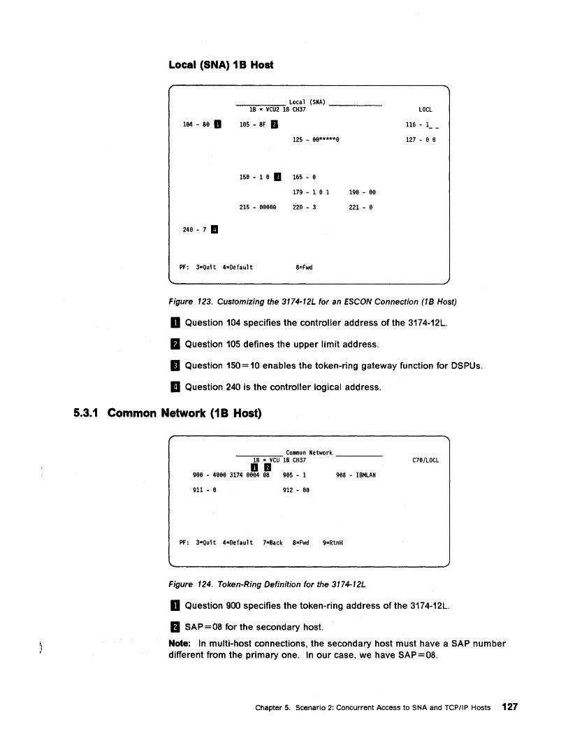
Local (SNA) 1 B Host
Local (SNA) -~l~B -.-:-V~CU=2~lB CH37 ---,----
184 - S8 .. 185 - SF •
125 - 88*****8
158 - 1 8. 165 - 8
179 - 1 8 1 198 - 8a
215 - 88888 228 - 3 221 - 8
248 - 7 II
PF: 3-Quit 4=Oefault S=Fwd
LOCL
116 - 1 __
127 - 8 8
Figure 123. Customizing the 3174-12L for an ESCON Connection (IB Host)
D Question 104 specifies the controller address of the 3174-12L.
a Question 105 defines the upper limit address.
11 Question 150= 10 enables the token-ring gateway function for DSPUs.
II Question 240 is the controller logical address.
5.3.1 Common Network (18 Host)
_~---:-~ Common Network ___ _ 1B .. VCU IB CH37 ... C78/LOCL
988 - 4888 3174 8884 8S 985 - 1 98S - IBMLAN
911 - 8 912 - 88
PF: 3-Quit 4=Oefault 7"Back S=Fwd 9=RtnH
Figure 124. Token-Ring Definition for the 3174-12L
D Question 900 specifies the token-ring address of the 3174-12L.
a SAP =08 for the secondary host.
Note: In multi-host connections, the secondary host must have a SAP number different from the primary one. In our case, we have SAP=08.
Chapter 5. Scenario 2: Concurrent Access to SNAand TCPIIP Hosts 127
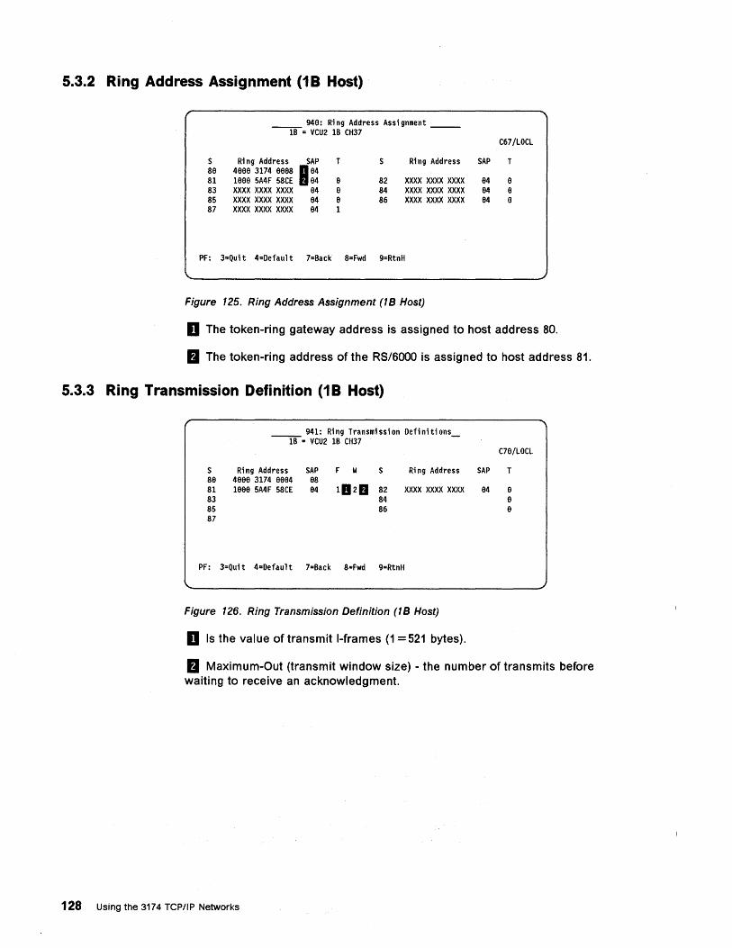
5.3.2 Ring Address Assignment (1 B Host)
__ 94a: R; ng Address Ass; gnment __ 1B = VCU2 1B CH37
C67/LOCL
S R; ng Address SAP T S R; ng Address SAP T 8a 4aaa 3174 aaa8 I a4 81 1aaa 5A4F 58CE a4 a 82 XXXX xxxx xxxx a4 a 83 XXXX xxxx xxxx a4 a 84 xxx x xxxx xxxx a4 a 85 xxx x xxxx xxxx a4 a 86 XXXX xxxx xxxx a4 a 87 XXXX xxxx xxx x a4 1
PF: 3=Quit 4=Default 7=Back 8"Fwd 9=RtnH
Figure 125. Ring Address Assignment (1 B Host)
D The token-ring gateway address is assigned to host address 80.
II The token-ring address of the RS/6000 is assigned to host address 81.
5.3.3 Ring Transmission Definition (1 B Host)
941: Ring Transmission Definitions --lB-= VCU2 1B CH37 -
C7a/LOCL
S Ri ng Address SAP F W S Ri ng Address SAP T 8a 4aaa 3174 aae4 a8 81 1aaa 5A4F 58CE a4 102. 82 XXXX XXXX XXXX a4 a 83 84 a 85 86 a 87
PF: 3=Quit 4=Default 7=Back 8=Fwd 9=RtnH
Figure 126. Ring Transmission Definition (1 B Host)
D Is the value of transmit I-frames (1 = 521 bytes).
II Maximum-Out (transmit window size) - the number of transmits before waiting to receive an acknowledgment.
128 Using the 3174 TCP/IP Networks
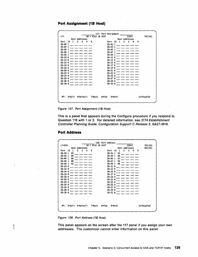
Port Assignment (1 B Host)
LT= _-,-__ 117: Port Assignment __ ::-:-:--:-
IB '" VCU2 IB CH37 116s:1 78/LOCL Host addresses Host addresses
Port IS 1 2 3 4 5 Port IS 1 2 3 4 5 26-88 1 ____ _ 26-811 ____ _ 26-82 1 ____ _ 26-831 ____ _ 26-84 1 ____ _ 26-851 ____ _ 26-86 1 ____ _ 26-871 ____ _ 26-881 ____ _ 26-69 1 ____ _ 26-18 8 ____ _ 26-11 8 ____ _ 26-12 8 ____ _ 26-13 6 ____ _ 26-14 8 ____ _ 26-15 8 ____ _ 26-16 8 ____ _ 26-178 ____ _ 26-18 8 ____ _ 26-19 8 ____ _ 26-28 8 ____ _ 26-21 8 ____ _ 26-228 ____ _ 26-236 ____ _ 26-24 8 ____ _ 26-256 ____ _ 26-26 8 ____ _ 26-27 8 ____ _ 26-28 8 ____ _ 26-29 6 ____ _ 26-388 ____ _ 26-31 6 ____ _
PF: 3=Quit 4=Oefault 7=Back 8=Fwd 9=RtnH l1=PageFwd
Figure 127. Port Assignment (1 B Host)
This is a panel that appears during the Configure procedure if you respond to Question 116 with 1 or 2. For detailed information, see 3174 Establishment Controller Planning Guide, Configuration Support C Release 3, GA27-3918.
Port Address
118: Port Address L T=616 --"I-B-=-V-CU2 IB CH37 ---1::-:1~6=-:-1
Host addresses Host addresses Port IS 1 2 3 4 5 Port IS 1 2 3 4 5 26-66 1 82 ___ _ 26-81 1 83 ___ _ 26-82 1 84 ___ _ 26-83 1 85 ___ _ 26-64 1 86 ___ _ 26-85 1 87 ___ _ 26-66 1 88 ___ _ 26-87 1 89 ___ _ 26-68 1 6A ___ _ 26-89 1 88 ___ _ 26-16 6 ____ _ 26-11 8 ____ _ 26-12 6 ____ _ 26-13 8 ____ _ 26-14 8 ____ _ 26-15 e ____ _ 26-16 6 ____ _ 26-17 e ____ _ 26-18 6 ____ _ 26-19 e ____ _ 26-28 8 ____ _ 26-21 8 ____ _ 26-226 ____ _ 26-238 ____ _ 26-24 8 ____ _ 26-25 8 ____ _ 26-26 8 ____ _ 26-278 ____ _ 26-28 8 ____ _ 26-29 e ____ _ 26-388 ____ _ 26-31 8 ____ _
PF: 3=Quit 4=Default 7=Back 8=Fwd 9=RtnH
Figure 128. Port Address (1 B Host)
78/LOCL 68/LOCL
l1=PageFwd
This panel appears on the screen after the 117 panel if you assign your own addresses. The customizer cannot enter information on this panel.
Chapter 5. Scenario 2: Concurrent Access to SNA and TCPIIP Hosts 129
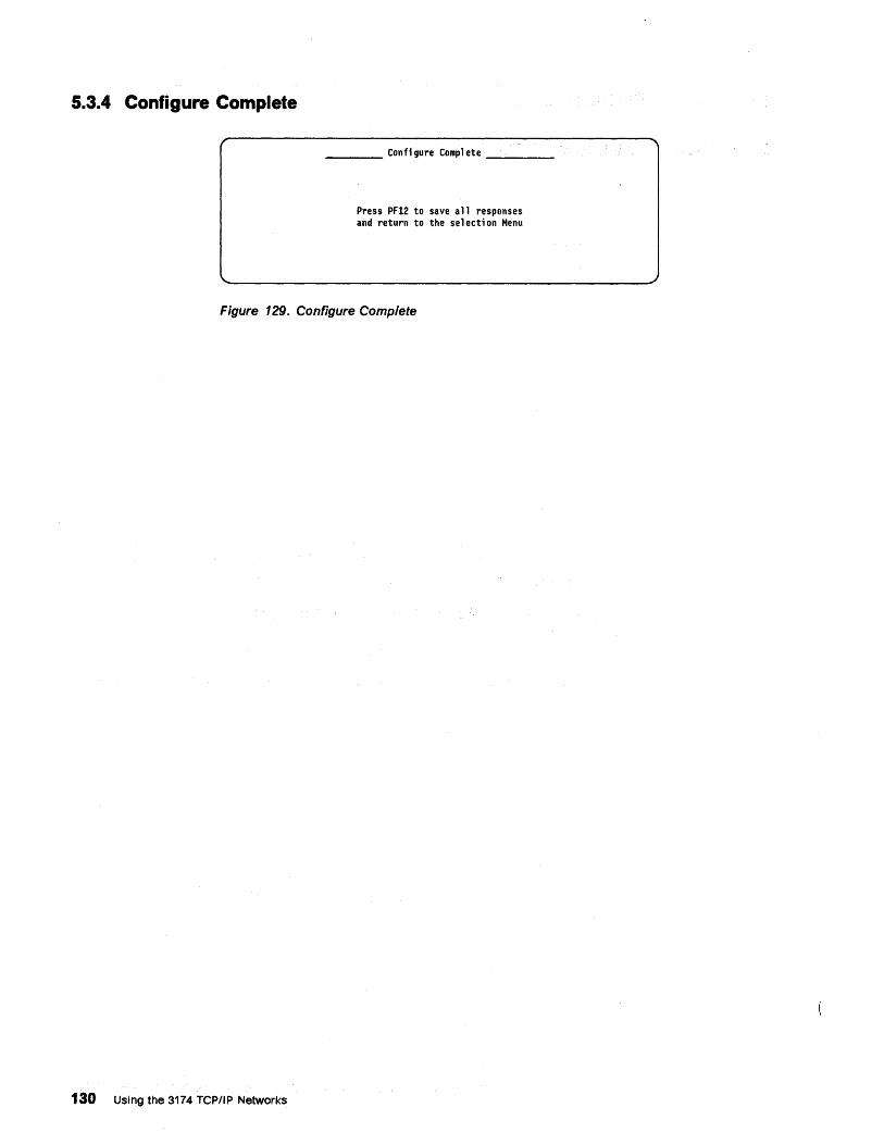
5.3.4 Configure Complete
____ Confi gure Comp1 ete ___ _
Press PF12 to save a 11 responses and return to the se 1 ecti on Menu
Figure 129. Configure Complete
130 Using the 3174 TCP/IP Networks
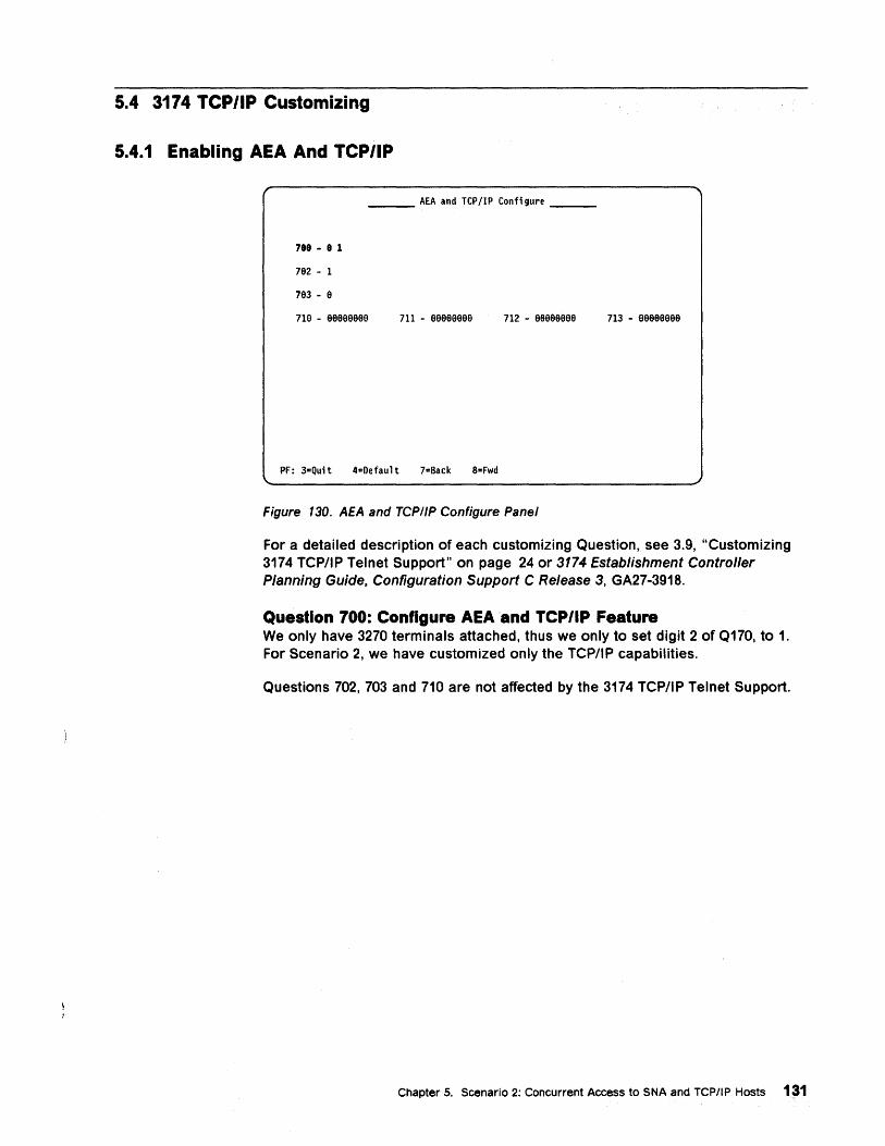
5.4 3174 YCP/IP Customizing
5.4.1 Enabling AEA And YCP/IP
___ AEA and TCP/IP Configure __ _
788 - 8 1
7e2 - 1
7e3 - e
71e - eeeeeeee 711 - eeeeeeee 712 - eeeeeeee 713 -eeeeeeee
PF: 3-=Quit 4-=Oefault 7=Back 8=Fwd
Figure 130. AEA and TCPI/P Configure Panel
For a detailed description of each customizing Question, see 3.9, "Customizing 3174 TCP/IP Telnet Support" on page 24 or 3174 Establishment Controller Planning Guide, Configuration Support C Release 3, GA27-3918.
Question 700: Configure AEA 'and TCP/IP Feature We only have 3270 terminals attached, thus we only to set digit 2 of Q170, to 1. For Scenario 2, we have customized only the TCP/IP capabilities.
Questions 702, 703 and 710 are not affected by the 3174 TCP/IP Telnet Support.
Chapter 5. Scenario 2: Concurrent Access to SNA and TCPIIP Hosts 1~1
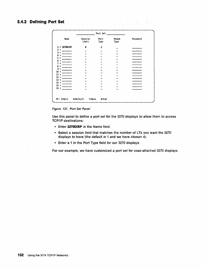
5.4.2 Defining Port Set
_____ Port Set ____ _
Name
1 = 3278DISP 2 = 3 = 4 = 5 = 6 = 7 = 8 = 9 =
18 = 11= 12 = 13 = 14 = 15 = 16 =
Sessi on limit
4
Port Type
1
PF: 3=Qui t 4=Default 7=Back 8=Fwd
Figure 131. Port Set Panel
Modem Type
Password
Use this panel to define a port set for the 3270 displays to allow them to access TCP/IP destinations:
• Enter 3270DISP in the Name field.
• Select a session limit that matches the number of L Ts you want the 3270 displays to have (the default is 1 and we have chosen 4).
• Enter a 1 in the Port Type field for our 3270 displays.
For our example, we have customized a port set for coax-attached 3270 displays.
1~2 Using the 3174 TCP/IP Networks
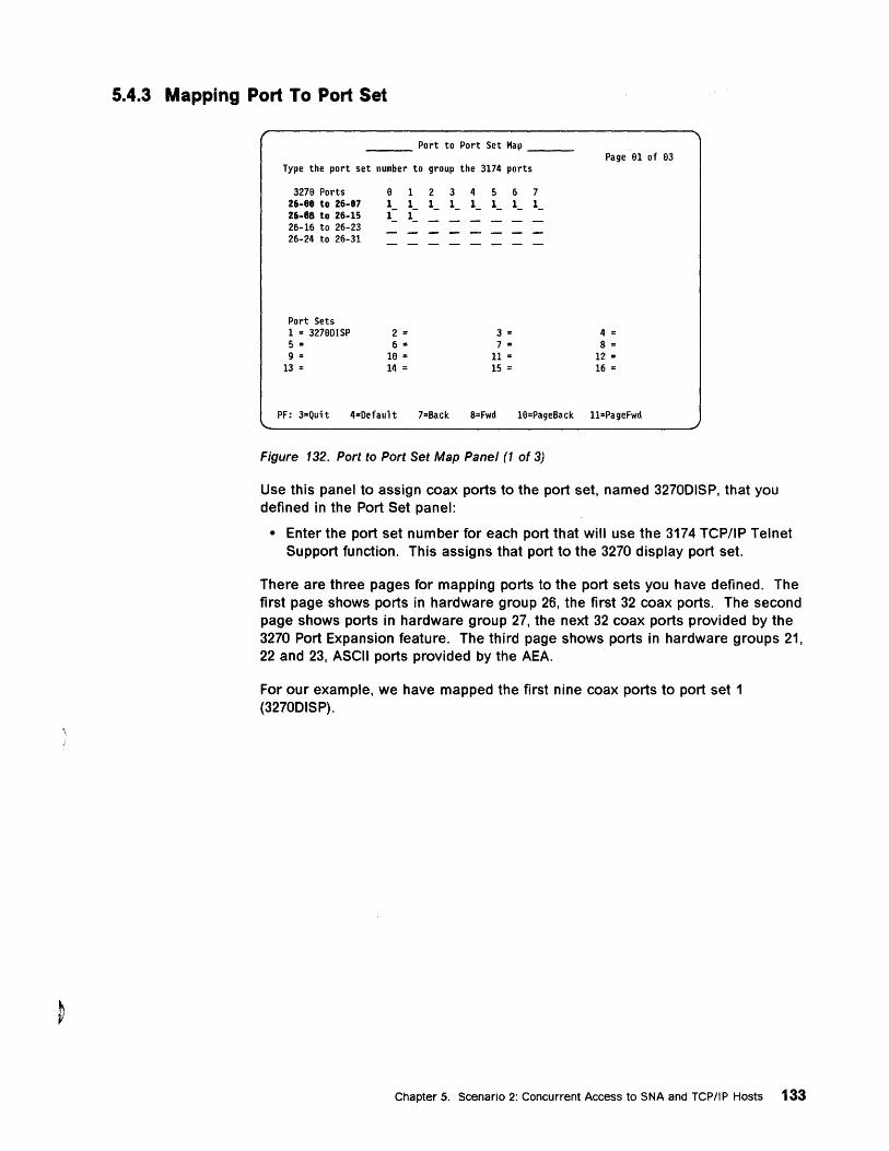
5.4.3 Mapping Port To Port Set
___ Port to Port Set Map __ _ Page 91 of 93
Type the port set number to group the 3174 ports
3279 Ports 9 1 2 3 4 5 6 7 26-88 to 26-87 1_ 1 1_ 1 - 1_ 1_ 1_ 1 -26-18 to 26-15 1 - ( 26-16 to 26-23 26-24 to 26-31
Port Sets 1 = 32790ISP 2 = 3 = 4 = 5 '" 6 II: 7 = 8 = 9 = 19 = 11= 12 =
13 = 14 = 15 = 16 =
PF: 3=Quit 4=Oefault 7=Back 8=Fwd 19=PageBack l1=PageFwd
Figure 132. Port to Port Set Map Panel (1 of 3)
Use this panel to assign coax ports to the port set, named 3270DISP, that you defined in the Port Set panel:
• Enter the port set number for each port that will use the 3174 TCPIIP Telnet Support function. This assigns that port to the 3270 display port set.
There are three pages for mapping ports to the port sets you have defined. The first page shows ports in hardware group 26, the first 32 coax ports. The second page shows ports in hardware group 27, the next 32 coax ports provided by the 3270 Port Expansion feature. The third page shows ports in hardware groups 21, 22 and 23, ASCII ports provided by the AEA.
For our example, we have mapped the first nine coax ports to port set 1 (3270DISP).
Chapter 5. Scenario 2: Concurrent Access to SNA and TCP/IP Hosts 133
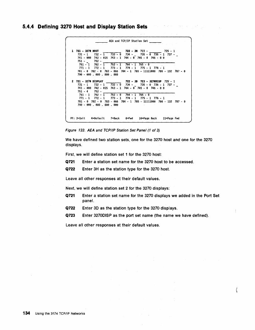
5.4.4 Defining 3270 Host and Display Station Sets
___ AEA and TCP/IP Station Set __ _
1 721 - 3278 HOST 722 - 3H 723 - 725 - 1 731 - 1 732 - 1 733 - a 734 - 735 -~ 1 737-741 - aea 742 - a15 743 - 1 744 - e- 745 - a 746 - a a 751 - 752 -
761 --1 762 - """1-"""76=3--~1--=7"""64"---1---"-76"""5--""'a------
771 - 1 772 - 1 773 - 1 774 - 1 775 - 1 776 - 1 781 - a 782 - a 783 - a66 784 - 1 785 - l1111aaa 786 - 132 787 - a 79a - aae • aae • aae • aae
2 721 - 3278 DISPLAY 722- 3D 723 - 3278DISP 725 - 1 731 - 1 732 - 1 733 - a 734 - 735 - a 736 - 1 737-741 - aaa 742 - a15 743 - 1 744 - a- 745 - a 746 - a a 751 - 4 752 -
761 - 1 762 - ..,...1-.."..76=3---a.,.-..".7..,...64,.----,-1---"-76..,,..5--....,a~-----
771 - 1 772 - 1 773 - 1 774 - 1 775 - 1 776 - 1 781 - a 782 - a 783 - a66 784 - 1 785 - l1111aaa 786 - 132 787 - a 79a - aaa • aaa • aaa • aaa
PF: 3=Qui t 4=Oefaul t 7=Back 8=Fwd la"Page Back l1"Page Fwd
Figure 133. AEA and TCP/IP Station Set Panel (1 of 3)
We have defined two station sets, one for the 3270 host and one for the 3270 displays.
First, we will define station set 1 for the 3270 host:
Q721 Enter a station set name for the 3270 host to be accessed.
Q722 Enter 3H as the station type for the 3270 host.
Leave all other responses at their default values.
Next, we will define station set 2 for the 3270 displays:
Q721 Enter a station set name for the 3270 displays we added in the Port Set panel.
Q722 Enter 3D as the station type for the 3270 displays.
Q723 Enter 32700lSP as the port set name (the name we have defined).
Leave all other responses at their default values.
134 Using the 3174 TCP/IP Networks
5.4.5 Defining TCP/IP Station Sets A station set for TCP/IP access defines a set of ASCII emulation characteristics and an optional host IP address. The 3174 TCP/IP Telnet Support supports the following ASCII terminal emulation:
• DEC VT100
• IBM 3101
• DG D210 (USA English only)
• DEC VT220, 7-bit control
• DEC VT220, 8-bit control
Each TCP/IP station set you define will be displayed on the host Connection Menu for the terminal user to select as a connection.
For each station set definition, you may specify an IP host address, or use the default response (all zeros), in Question 790. Your response is used as follows:
• If you specify an address, the 3174 does not automatically connect to that address when the station set is selected from the Connection Menu. The address is used if the user issues a PING or an OPEN command without specifying a destination.
• If you do not specify an address (default all zeros), then the user will need to specify the destination when issuing the PING or the OPEN command.
So, if your users at the 3270 coax terminals will use the 3174 TCP/IP Telnet Support to access only one TCP/IP host and that host supports DEC VT100 devices, then you only need to define one TCP/IP station set (the DEC VT100 station set). You will specify that host'slP address in Question 790 so that the users do not have to remember it. To access that host, the user selects the DEC VT100 station set from the Connection Menu, which puts the display into local mode, and then issues the OPEN command without specifying a destination.
If your users will access more than one host, you probably should define five TCP/IP station sets, one for each type of ASCII emulation supported. This allows the users to select the required station set from the Connection Menu. Again, if you specify an address in Question 790, it will be used when the user issues a PING or OPEN command without a destination. If you do not specify an address in Question 790 (default all zeros), then the user will need to specify the destination when issuing the PING or OPEN command.
For our example, we have defined only one station set for TCP/IP access.
Chapter 5. Scenario 2: Concurrent Access toSNA and TCP/IP Hosts 135
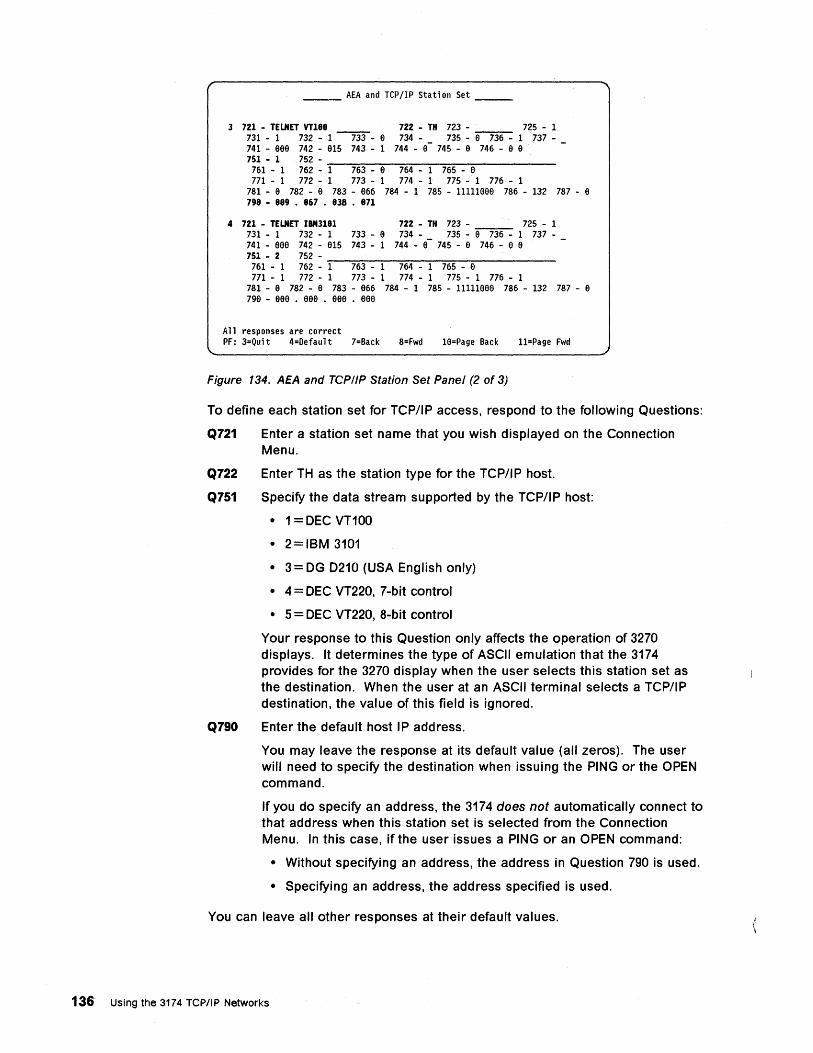
___ AEA and TCP/IP Station Set __ _
3 721 - TELNET VT188 722 - TH 723 - 725 - 1 731 - 1 732 -1 --m-- a 734 - 735 - a 736 - 1 737-741 - aaa 742 - a15 743 - 1 744 - a- 745 - a 746 - a a 751 - 1 752 -
761 - 1 762 - -=-1--=76~3~---::-a ---=7~64:'---~1~76~5---a:'-------
771 - 1 772 - 1 773 - 1 774 - 1 775 - 1 776 - 1 781 - a 782 - a 783 - a66 784 - 1 785 - 11111aaa 786 - 132 787 - a 798 - 889 • 867 • 838 • 871
4 721 - TELNET IBM3181 722 - TH 723 - 725 - 1 731 - 1 732 - 1 733 - a 734 - 735 -~ 1 737-741 - aaa 742 - a15 743 - 1 744 - a- 745 - a 746 - a a 751 - 2 752-
761 - 1 762 - -:-1-=76~3---1:'---=7-=-:64~---::-1-=-:76~5---:e:'-------
771 - 1 772 - 1 773 - 1 774 - 1 775 - 1 776 - 1 781 - a 782 - a 783 - a66 784 - 1 785 - l1111aae 786 - 132 787 - a 79a - aae • aaa . aae • eee
A 11 responses are correct PF: 3=Qui t 4=Default 7=Back 8=Fwd 1a=Page Back l1=Page Fwd
Figure 134. AEA and TCPIIP Station Set Panel (2 of 3)
To define each station set for TCP/IP access, respond to the following Questions:
Q721 Enter a station set name that you wish displayed on the Connection Menu.
Q722 Enter TH as the station type for the TCP/I P host.
Q751 Specify the data stream supported by the TCP/IP host:
• 1 = DEC VT100
• 2=IBM 3101
• 3 = DG 0210 (USA English only)
• 4 = DEC VT220, 7-bit control
• 5 = DEC VT220, 8-bit control
Your response to this Question only affects the operation of 3270 displays. It determines the type of ASCII emulation that the 3174 provides for the 3270 display when the user selects this station set as the destination. When the user at an ASCII terminal selects a TCP/IP destination, the value of this field is ignored.
Q790 Enter the default host IP address.
You may leave the response at its default value (all zeros). The user will need to specify the destination when issuing the PING or the OPEN command.
If you do specify an address, the 3174 does not automatically connect to that address when this station set is selected from the Connection Menu. In this case, if the user issues a PING or an OPEN command:
• Without specifying an address, the address in Question 790 is used.
• Specifying an address, the address specified is used.
You can leave all other responses at their default values.
136 Using the 3174 TCPIIP Networks
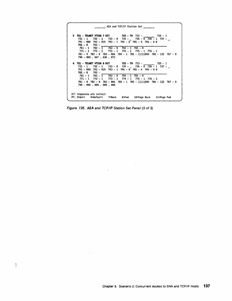
___ AEA and TCP/IP Station Set __ _
5 721 - TELNET VT228 7 lIT 731 - 1 732 - 1 733 - a 741 - aaa 742 - a15 743 - 1 751 - 4 752-
722 - TH 723 - 725 - 1 734 - 735 - a 736 - 1 737-
744 - 8- 745 - 8 746 - 8 8
761 - 1 762 - ':"1--:7=-:6":"3--~a ---:7:-:6~4--~1--=76"::":5:---~a------
771 - 1 772 - 1 773 - 1 774 - 1 775 - 1 776 - 1 781 - a 782 - a 783 - a66 784 - 1 785 - 11111a88 786 - 132 787 - 8 798 - 889 • 867 • 838 • 873
6 721 - TELNET VTZ28 8 lIT 731 - 1 732 - 1 733 - 8 741 - a88 742 - 815 743 - 1 751 - 5 752-
722 - TH 723 - 725 - 1 734 - 735 - a 736 - 1 737-
744 - a - 745 - e 746 - 8 a
761 - 1 762 - ':"1--:7=-:6":"3--~8 ---:7:-:6~4--~1--=76"::":5:---~8------
771 - 1 772 - 1 773 - 1 774 - 1 775 - 1 776 - 1 781 - 8 782 - a 783 - a66 784 - 1 785 - 11111888 786 - 132 787 - a 79a - aee • eea • aaa • aee
All responses are correct PF: 3-Qui t 4-Defaul t 7=Back 8=Fwd 1a=Page Back l1=Page Fwd
Figure 135. AEA and TCP/IP Station Set Panel (3 of 3)
Chapter 5. Scenario 2: Concurrent Access to SNA and TCPIIP Hosts 137
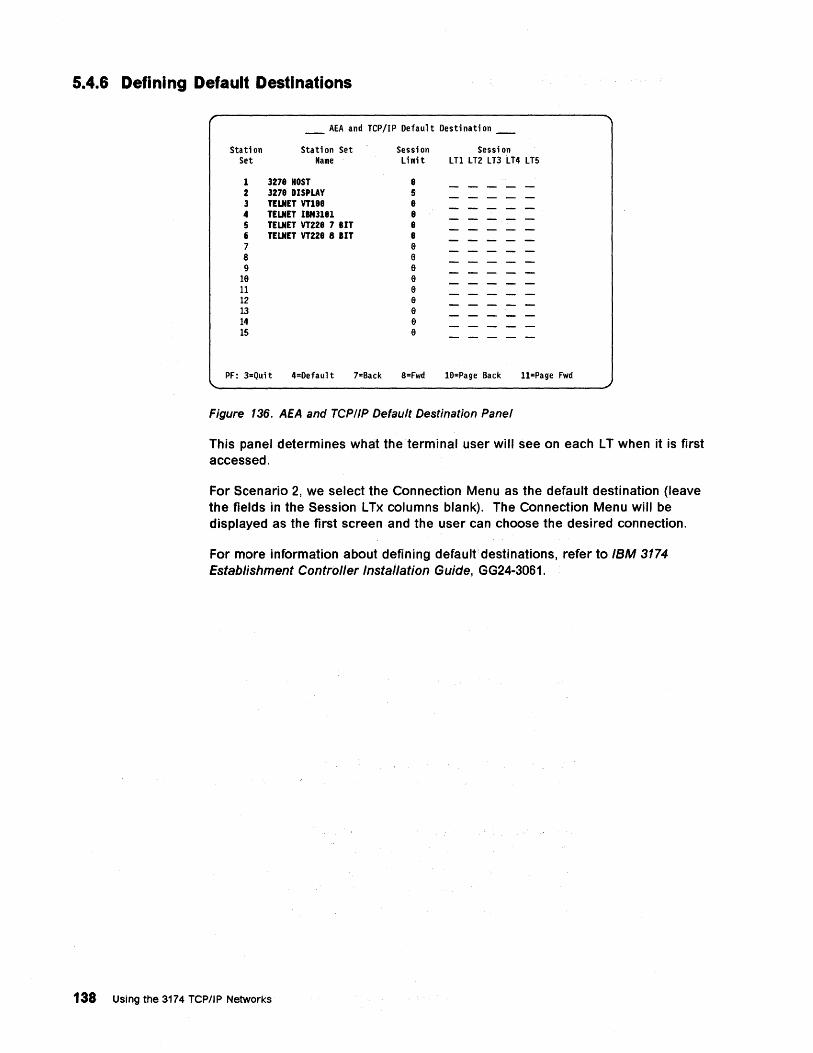
5.4.6 Defining Default Destinations
Station Set
_ AEA and TCP/IP Default Destination _
Stati on Set Name
Sessi on Sessi on Limit LTl LT2 LT3 LT4 LTS
1 3278 HOST 8 2 3278 DISPLAY 5 3 TELNET VT188 8 4 TELNET IIM3l81 8 5 TELNET VT228 7 BIT 8 6 TELNET VT228 8 BIT 8 7 8 8 8 9 8
18 8 11 8 ~ e ~ 8 14 8 ~ 8
PF: 3=Qui t 4=Defaul t 7"Back 8=Fwd 19=Page Back l1=Page Fwd
Figure 136. AEA and TCPIIP Default Destination Panel
This panel determines what the terminal user will see on each L T when it is first accessed.
For Scenario 2, we select the Connection Menu as the default destination (leave the fields in the Session L Tx columns blank). The Connection Menu will be displayed as the first screen and the user can choose the desired connection.
For more information about defining default'destinations, refer to IBM 3174 Establishment Controller Instailation Guide, GG24-3061.
138 Using the 3174 TCP/IP Networks
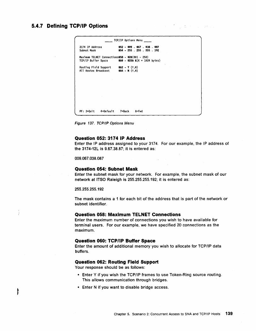
5.4.7 Defining TCP/IP Options
__ TCP/IP Options Menu __
3174 IP Address Subnet Mask
852 - 889 • 867 • 838 • 887 854 - 255 • 255 • 255 • 192
Maximum TELNET Connecti ons858 - 828(881 - 258) TCP/IP Buffer Space 868 - 8256 K(K = 1824 bytes)
Routi n9 Fi e 1 d Support All Routes Broadcast
862 - Y (Y,N) 864 - N (Y,N)
PF: 3=Qui t 4=Oefaul t 7=Back 8=Fwd
Figure 137. TCP/IP Options Menu
Question 052: 3174 IP Address Enter the IP address assigned to your 3174. For our example, the IP address of the 3174-12L is 9.67.38.87; it is entered as:
009.067.038.087
Question 054: Subnet Mask Enter the subnet mask for your network. For example, the subnet mask of our network at ITSO Raleigh is 255.255.255.192; it is entered as:
255.255.255.192
The mask contains a 1 for each bit of the address that is part of the network or subnet identifier.
Question 058: Maximum TELNET Connections Enter the maximum number of connections you wish to have available for terminal users. For our example, we have specified 20 connections as the maximum.
Question 060: TCP/IP Buffer Space Enter the amount of additional memory you wish to allocate for TCPflP data buffers.
Question 062: Routing Field Support Your response should be as follows:
• Enter Y if you wish the TCPflP frames to use Token-Ring source routing. This allows communication through bridges.
• Enter N if you want to disable bridge access.
Chapter 5. Scenario 2: Concurrent Access to SNA and TCP/IP Hosts 139
Question 064: All Routes Broadcast Your response should be as follows:
• Enter Y for All Routes Broadcast.
• Enter N for Single Route Broadcast.
Note: The response to Question 064 is meaningful only if Question 062=Y.
5.4.8 Defining rep/IP Routing Information Since the 3174 is in the same subnet as RS/6000 TCP/IP hosts, there is no routing information customized.
140 Using the 3174 TCP/IP Networks
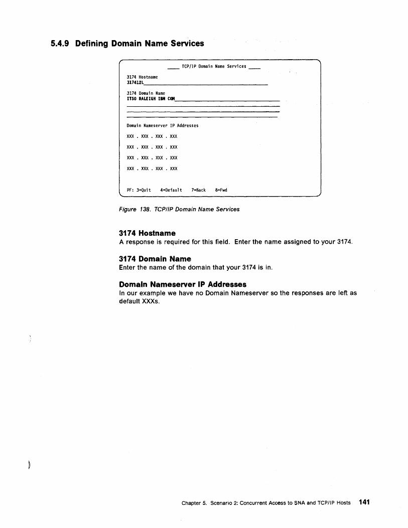
5.4.9 Defining Domain Name Services
__ TCP/IP Domain Name Services __
3174 Hostname 317412L~ __ -:-____________ _
3174 Domai n Name ITSO RALEIGH IBM COM, _______ -:-_____ _
Domain Nameserver IP Addresses
xxx . XXX • XXX . XXX
XXX • XXX • XXX . XXX
XXX . XXX • XXX • XXX
XXX • XXX • XXX . XXX
PF: 3=Qui t 4=Defaul t 7=Back 8=Fwd
Figure 138. TCP/IP Domain Name Services
3174 Hostname A response is required for this field. Enter the name assigned to your 3174.
3174 Domain Name Enter the name of the domain that your 3174 is in.
Domain Nameserver IP Addresses In our example we have no Domain Nameserver so the responses are left as default XXXs.
Chapter 5. Scenario 2: Concurrent Access to SNA and TCPIIP Hosts 141
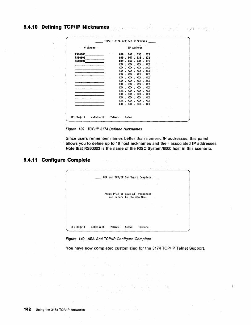
5.4.10 Defining TCP/IP Nicknames
__ TCP/IP 3174 Defined Nicknames __
Nickname
R$68883 ___ _ R$68882 ___ _ R$68881 ___ _
IP Address
889 • 867 • 838 • 873 8,9 • 867 • 838 • 872 889 • 867 • 838 • 871 XXX • XXX • XXX • XXX XXX • XXX • XXX • XXX XXX • XXX • XXX • XXX XXX • XXX • XXX • XXX XXX • XXX • XXX • XXX XXX • XXX • XXX • XXX XXX • XXX • XXX • XXX XXX • XXX • XXX • XXX XXX • XXX • XXX • XXX XXX • XXX • XXX • XXX XXX • XXX • XXX • XXX XXX • XXX • XXX • XXX XXX • XXX • XXX • XXX
PF: 3=Qui t 4=Defaul t 7=Back 8=Fwd
Figure 139. TCP/IP 3174 DefinedNicknames
Since users remember names better than numeric IP addresses, this panel allows you to define up to 16 host nicknames and their associated IP addresses. Note that RS60003 is the name of the RISC System/6000 host in this scenario.
5.4.11 Configure Complete
_ AEA and TCP/IP Configure Complete __
Press PF12. to save all responses and return to the AEA Menu
PF: 3=Quit 4=Default 7=Back 8=Fwd 12=Done
Figure 140. AEA And TCPIIP Configure Complete
You have now completed customizing for the 3174 TCP/IP Telnet Support.
142 Using the 3174 TCPIIP Networks
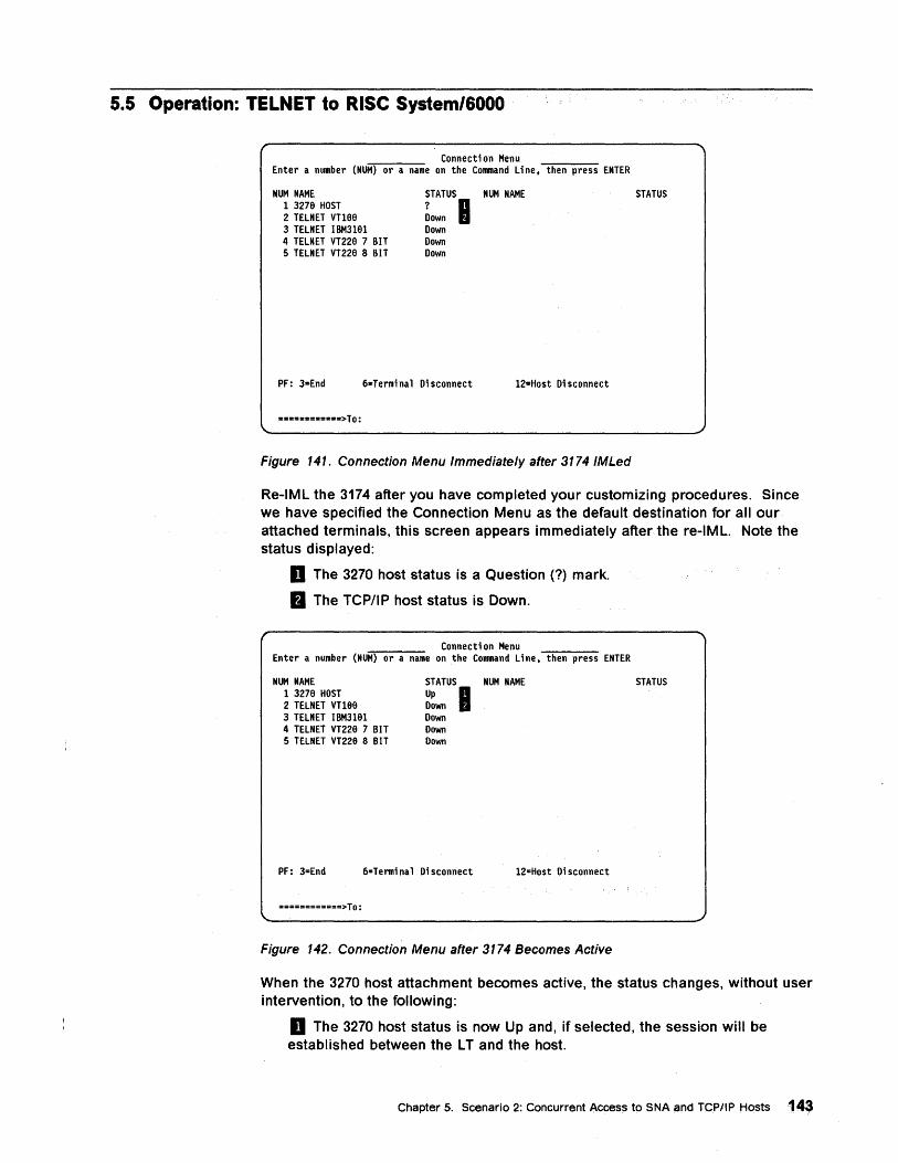
5.5 Operation: TELNET to RiSe System/6000
Connection Menu Enter a number (NUM) or a name on the Command Line, then press ENTER
NUM NAME STATUS NUM NAME STATUS 1 3276 HOST ? B 2 TELNET Vn66 Down 3 TELNET IBM3161 Down 4 TELNET VT226 7 BIT Down 5 TELNET VT226 8 BIT Down
PF: 3=End 6=Termi na 1 Di sconnect 12=Host Di sconnect
••• = •• =_ •••• > To:
Figure 141. Connection Menu Immediately after 3174 IMLed
Re-IML the 3174 after you have completed your customizing procedures. Since we have specified the Connection Menu as the default destination for all our attached terminals, this screen appears immediately after the re-IML. Note the status displayed:
D The 3270 host status is a Question (?) mark.
m The TCP/IP host status is Down.
Connecti on Menu Enter a number (NUM) or a name on the Command Line, then press ENTER
NUM NAME 1 3276 HOST 2 TELNET Vn66 3 TELNET IBM3161 4 TELNET VT226 7 BIT 5 TELNET VT220 8 BIT
STATUS NUM NAME
Up B Down Down Down Down
PF: 3=End 6=Termi na 1 Di sconnect 12=Host Disconnect
============> To:
Figure 142. Connection Menu after 3174 Becomes Active
STATUS
When the 3270 host attachment becomes active, the status changes, without user intervention, to the following:
D The 3270 host status is now Up and, if selected, the session will be established between the L T and the host.
Chapter 5. Scenario 2: Concurrent Access to SNA and TCP/IP Hosts 143
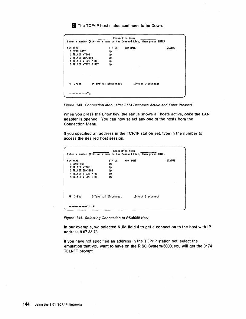
fJ The TCP/IP host status continues to be Down.
Connecti on Menu Enter a number (NUM) or a name on the Command Line. then press ENTER
NUM NAME 1 3279 HOST 2 TELNET Vne9 3 TELNET IBM3191 4 TELNET VT229 7 BIT 5 TELNET VT229 8 BIT
STATUS Up Up Up Up Up
PF: 3=End 6=Terminal Disconnect
============>To:
NUM NAME
12=Host Disconnect
STATUS
Figure 143. Connection Menu after 3174 Becomes Active and Enter Pressed
When you press the Enter key, the status shows all hosts active, once the LAN adapter is opened. You can now select anyone of the hosts from the Connection Menu.
If you specified an address in the TCP/IP station set, type in the number to access the desired host session.
Connecti on Menu Enter a number (NUM) or a name on the Command Li ne. then press ENTER
NUM NAME 1 3279 HOST 2 TELNET vn99 3 TELNET IBM3191 4 TELNET VT229 7 BIT 5 TELNET VT229 8 BIT
STATUS Up Up Up Up Up
PF: 3=End 6=Terminal Disconnect
============>To: 4
NUM NAME
12=Host Di sconnect
Figure 144. Selecting Connection to RS/6000 Host
STATUS
In our example, we selected NUM field 4 to get a connection to the host with IP address 9.67.38.73.
If you have not specified an address in the TCP/IP station set, select the emulation that you want to have on the RISC System/6000; you will get the 3174 TELNET prompt.
144 Using the 3174 TCP/IP Networks
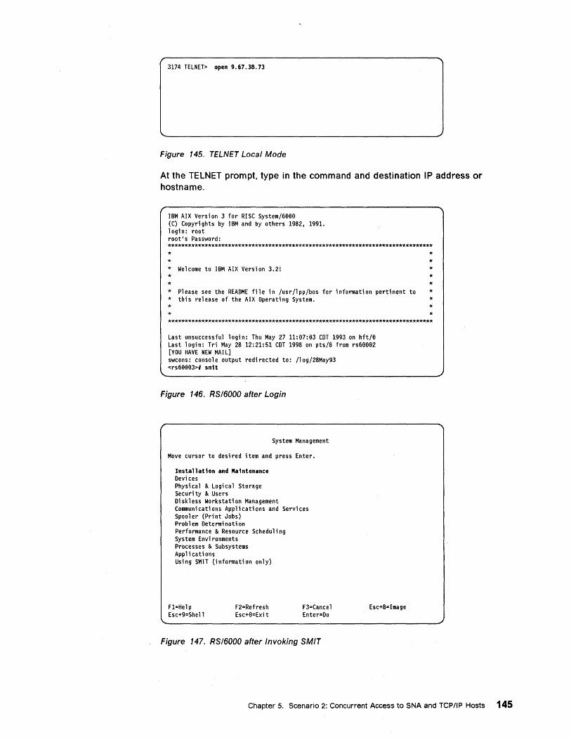
3174 TELNET> open 9.67.38.73
Figure 145. TELNET Local Mode
At the TELNET prompt, type in the command and destination IP address or hostname.
IBM AIX Version 3 for RISC System/6BB0 (C) Copyri ghts by IBM and by others 1982, 1991. login: root root's Password: ******************************************************************************* *
* Welcome to IBM AIX Version 3.21 * * * Pl ease see the README fil e in /usr /l pp/bos for i nformati on perti nent to * thi s release of the AIX Opera ti ng System. *
* * * * * * * * *
*******************************************************************************
Last unsuccessful login: Thu May 27 11:07:B3 COT 1993 on hft/B Last login: Tri May 28 12:21:51 COT 1998 on pts/8 from rs6eBB2 [YOU HAVE NEW MAIL] swcons: console output redirected to: /10g/28May93 <rs6BBB3># smit
Figure 146. RS/6000 after Login
System Management
Move cursor to desired item and press Enter.
Installation and Maintenance Devi ces Physi ca 1 & Logi ca 1 Storage Securi ty & Users Di skl ess Workstati on Management Communications Applications and Services Spooler (Print Jobs) Problem Determination Performance & Resource Schedul i ng System Envi ronments Processes & Subsystems Appl i cati ons Using SMIT (informati on only)
F1=Help Esc+9=She 11
F2=Refresh Esc+0=Exit
F3=Cancel Enter=Do
Figure 147. RS/6000 after Invoking SMIT
Esc+8=Image
Chapter 5. Scenario 2: Concurrent Access to SNA and TCP/IP Hosts 145
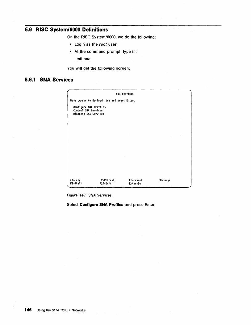
5.6 Rise System/6000 Definitions On the RiSe System/6000, we do the following:
• Login as the root user.
• At the command prompt, type in:
smit sna
You will get the following screen:
5.6.1 SNA Services
SNA Servi ces
Move cursor to des; red ; tem and press Enter.
Configure SMA Profiles Contro 1 SNA Serv; ces Diagnose SNA Servi ces
Fl=Help F9=Shell
F2=Refresh Fle=Ex; t
Figure 148. SNA Services
F3=Cancel Enter=Do
Select Configure SNA Profiles and press Enter.
146 Using the 3174 TCP/IP Networks
F8=Image
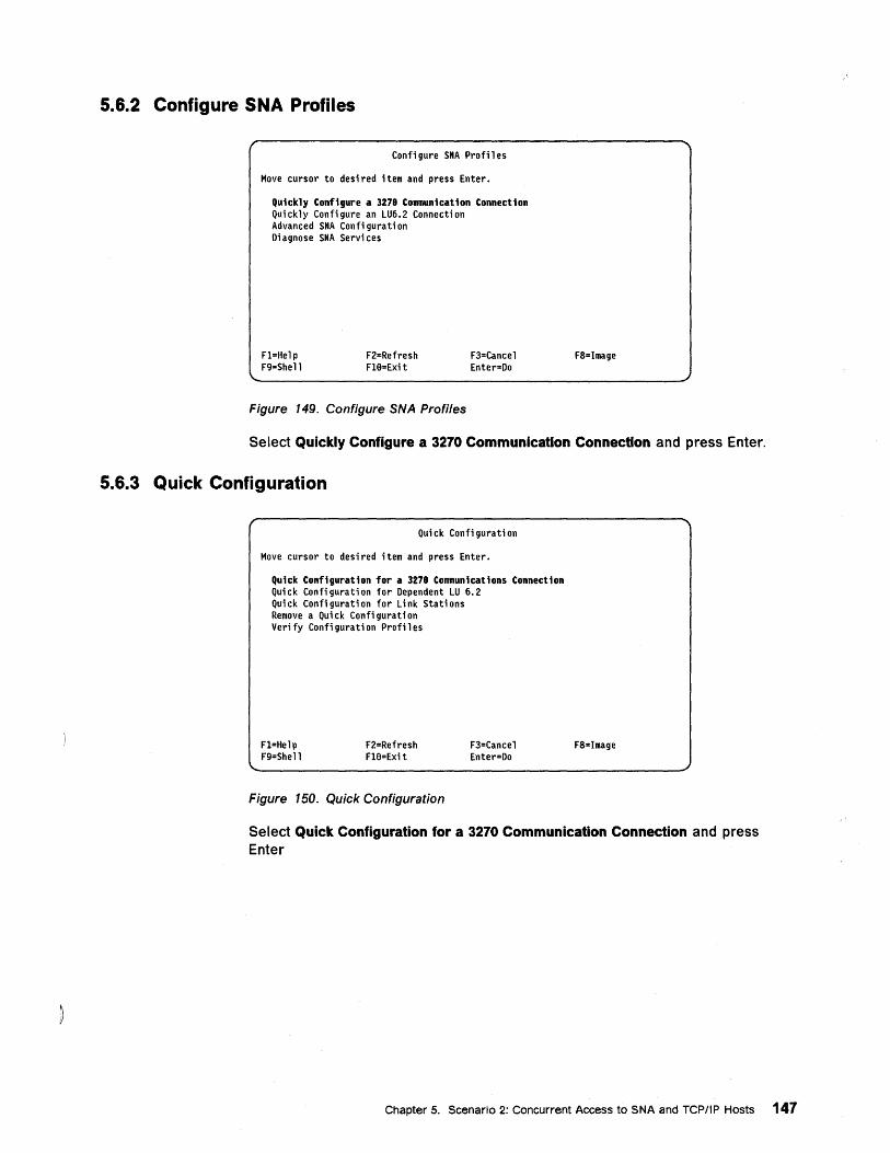
5.6.2 Configure SNA Profiles
Configure SNA Profiles
Move cursor to desi red item and press Enter.
Quickly Configure a 3278 Communication Connection Quickly Configure an LU6.2 Connection Advanced SNA Confi gura ti on Di agnose SNA Servi ces
Fl=Help F9=Shell
F2=Refresh Fl8=Exit
Figure 149. Configure SNA Profiles
F3=Cancel Enter=Do
F8=Image
Select Quickly Configure a 3270 Communication Connection and press Enter.
5.6.3 Quick Configuration
Quick Configuration
Move cursor to desired item and press Enter.
Quick Configuration for a 3278 Communications Connection Quick Configuration for Dependent LU 6.2 Quick Configuration for Link Stations Remove a Qui ck Confi gurati on Verify Configuration Profiles
Fl=Help F9=Shell
F2=Refresh Fl8=Exi t
Figure 150. Quick Configuration
F3=Cancel Enter=Do
F8=Image
Select Quick Configuration for a 3270 Communication Connection and press Enter
Chapter 5. Scenario 2: Concurrent Access to SNA and TCP/IP Hosts 147
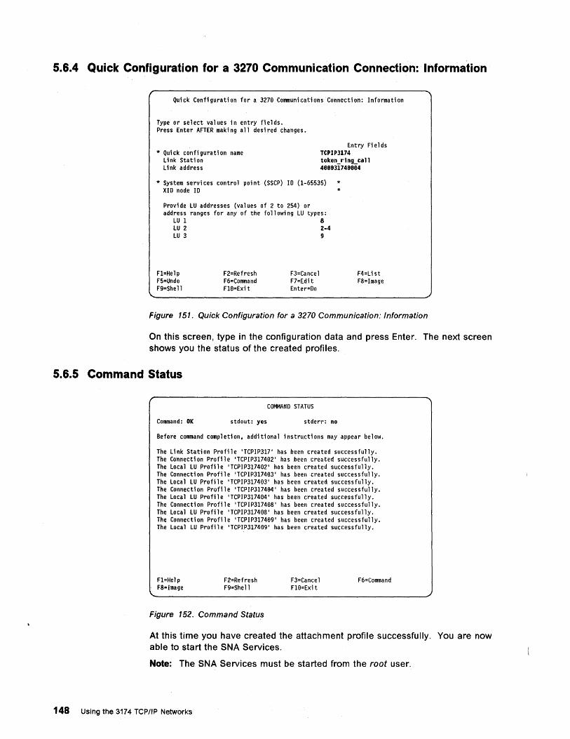
5.6.4 Quick Configuration for a 3270 Communication Connection: Information
Quick Configuration for a 3278 Communications Connection: Information
Type or select val ues in entry fi e 1 ds. Press Enter AFTER maki ng all desi red changes.
* Quick configuration name Link Station Li nk address
Entry Fields TCPIP3174 tokenJing_call 488831748884
* System services control point (SSCP) ID (1-65535) * XID node ID *
Provi de LU addresses (values of 2 to 254) or address ranges for any of the foll owi ng LU types:
LU 1 8 LU 2 2-4 LU 3 9
Fl=Help F5=Undo F9=Shell
F2=Refresh F6=Command Fl8=Exit
F3=Cancel F7=Edi t Enter=Do
F4=List F8=Image
Figure 151. Quick Configuration for a 3270 Communication: Information
On this screen, type in the configuration data and press Enter. The next screen shows you the status of the created profiles.
5.6.5 Command Status
COMMAND STATUS
Command: OK stdout: yes stderr: no
Before command completion, additional instructions may appear below.
The Link Station Profile 'TCPIP317' has been created successfully. The Connection Profile 'TCPIP317402' has been created successfully. The Local LU Profile 'TCPIP317482' has been created successfully. The Connection Profile 'TCPIP317403' has been created successfully. The Local LU Profile 'TCPIP317483' has been created successfully. The Connection Profile 'TCPIP317484, has been created successfully. The Local LU Profile 'TCPIP317484' has been created successfully. The Connection Profile 'TCPIP317408' has been created successfully. The Local LU Profile 'TCPIP317488' has been created successfully. The Connect; on Profi 1 e 'TCPI P317489, has been crea ted successfully. The Local LU Profile 'TCPIP317409' has been created successfully.
Fl=Help F8=Image
F2=Refresh F9=Shell
Figure 152. Command Status
F3=Cancel Fl0=Exi t
F6=Command
At this time you have created the attachment profile successfully. You are now able to start the SNA Services.
Note: The SNA Services must be started from the root user.
148 Using the 3174 TCPIIP Networks
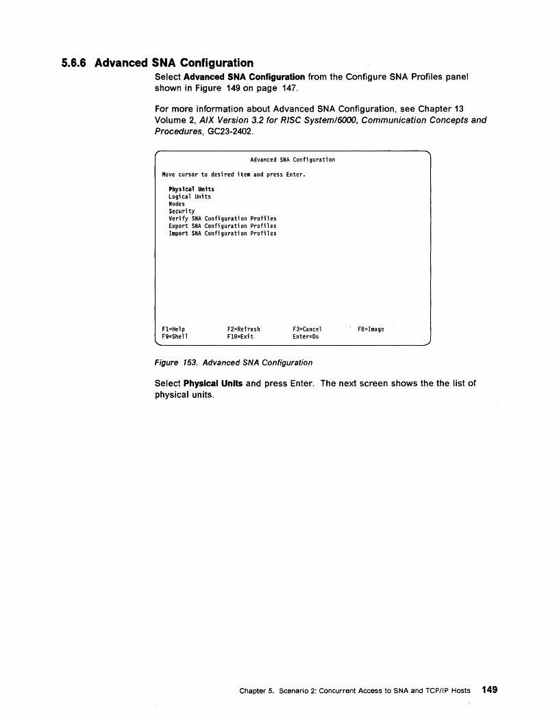
5.6.6 Advanced SNA Configuration Select Advanced SNA Configuration from the Configure SNA Profiles panel shown in Figure 149 on page 147.
For more information about Advanced SNA Configuration, see Chapter 13 Volume 2, AIX Version 3.2 for RISC System/6000, Communication Concepts and Procedures, GC23-2402.
Advanced SNA Conti gurati on
Move cursor to desi red item and press Enter.
Physical Units Logi ca 1 Uni ts Nodes Securi ty Verify SNA Configuration Profiles Export SNA Confi gurati on Profi 1 es Import SNA Configuration Profiles
Fl=Help F9=Shell
F2=Refresh Fl8=Exit
F3=Cancel Enter=Do
Figure 153. Advanced SNA Configuration
F8=Image
Select Physical Units and press Enter. The next screen shows the the list of physical units.
Chapter 5. Scenario 2: Concurrent Access to SNA and TCPIIP Hosts 149

5.6.7 Physical Units
Physi ca 1 Uni ts
Move cursor to desi red item and press Enter.
SDLC Standard Ethernet 8e2;3 Ethernet Token Ring X.25
Fl=Help F9=Shell
F2=Refresh Fle=Exit
Figure 154. Physical Units
F3=Cancel Enter=Do
Select Token Ring and press Enter.
5.6.8 Token-Ring
Token Ring
Move cursor to desi red item and press Enter.
Token Ring Attachment Token Ri ng Data Li nk Control
Fl=Help F9=Shell
F2=Refresh Fle-Exit
Figure 155. Token Ring
F3=Cancel Enter=Do
Select Token Ring Attachment and press Enter.
150 Using the 3174 TCP/IP Networks""
F8=Image
F8=Image
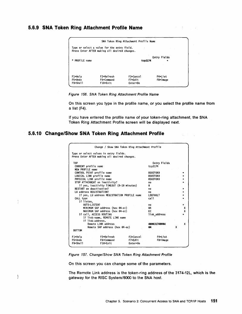
5.6.9 SNA Token Ring Attachment Profile Name
SNA Token Ri ng Attachment Profil e Name
Type or select a value for the entry field. Press Enter AFTER making all desired changes.
'" PROF! LE name
Fl=Help F5=Undo F9=Shell
F2=Refresh F6=Command Fl8=Exi t
F3=Cancel F7=Edit Enter=Oo
Entry Fi e 1 ds tcp3174 +
F4=Li st F8=Image
Figure 156. SNA Token Ring Attachment Profile Name
On this screen you type in the profile name, or you select the profile name from a list (F4).
If you have entered the profile name of your token-ring attachment, the SNA Token Ring Attachment Profile screen will be displayed next.
5.6.10 Change/Show SNA Token Ring Attachment Profile
Change / Show SNA Token Ri ng Attachment Profil e
Type or select values in entry fields. Press Enter AFTER maki ng all desi red changes.
TOP CURRENT profi 1 e name NEW PROFILE name CONTROL POINT profil e name LOGICAL LINK profile name PHYSICAL LINK profile name STOP ATTACHMENT on i nacti vi ty?
If yes, inactivity TIMEOUT (8-18 minutes) RESTART on deacti vati on? LU address REGISTRATION?
If yes, LU address REGISTRATION PROFILE name CALL type
If listen, AUTO-LISTEN? MINIMUM SAP address (hex 84-ec) MAXIMUM SAP address (hex 84-ec)
If call, ACCESS ROUTING If link-name, REMOTE LINK name If link-address,
Remote LI NK address Remote SAP address (hex 84-ec)
BOTTOM
Fl=Help F5=Undo F9=Shell
F2=Refresh F6=Command Fl8=Exit
F3=Cancel F7=Edit Enter=Oo
Entry Fi e 1 ds tcp3174
RS83TOK8 + RS83TOK8 + RS83TOK8 + no + 8 no + no + LOEFAULT + call +
no + 84 X EC X link_address +
488831748884 X 84 X
F4=L ist F8=Image
Figure 157. Change/Show SNA Token Ring Attachment Profile
On this screen you can change some of the parameters.
The Remote Link address is the token-ring address of the 3174-12.L, which is the gateway for the RiSe System/SOOO to the SNA host.
Chapter 5. Scenario 2: Concurrent Access to SNAand TCPIIPHosts 151
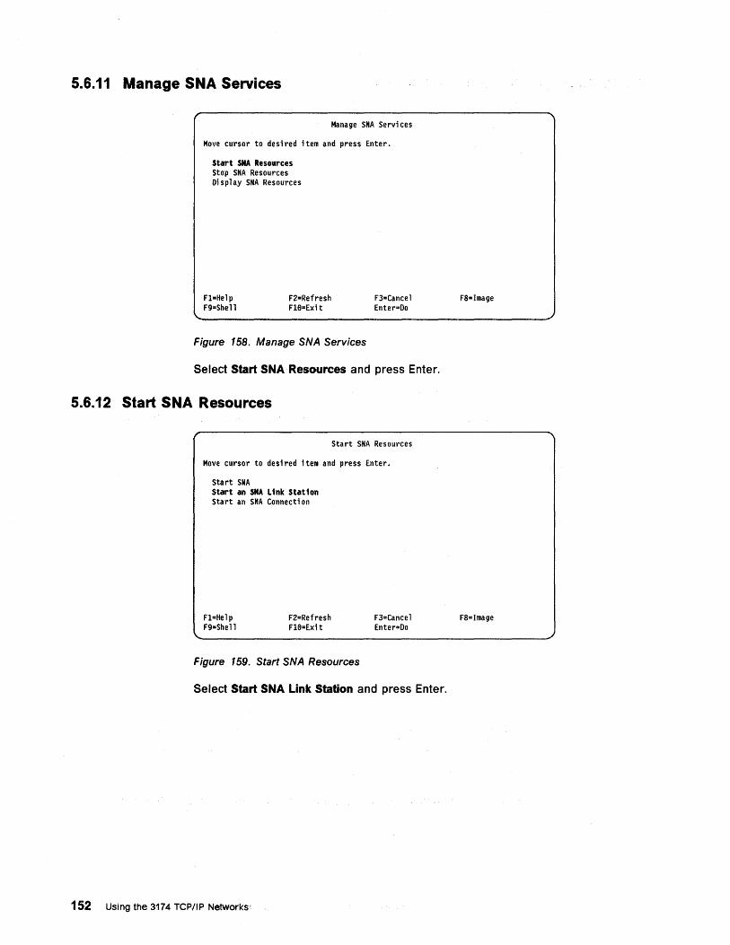
5.6.11 Manage SNA Services
Manage SNA Servi ces
Move cursor to desired item and press Enter.
Start SNA Resources Stop SNA Resources Display SNA Resources
Fl=Help F9=Shell
F2=Refresh Fl8=Exi t
Figure 158. Manage SNA Services
F3=Cancel Enter=Do
Select Start SNA Resources and press Enter.
5.6.12 Start SNA Resources
Start SNA Resources
Move cursor to desi red i tern and press Enter.
Start SNA Start an SNA Link Station Start an SNA Connecti on
Fl=Help F9 .. Shell
F2=Refresh Fl8=Exit
Figure 159. Start SNA Resources
F3=Cancel Enter=Do
Select Start SNA Link Station and press Enter.
152 Using the 3174 TCPIIP Networks'
F8=Image
F8=Image
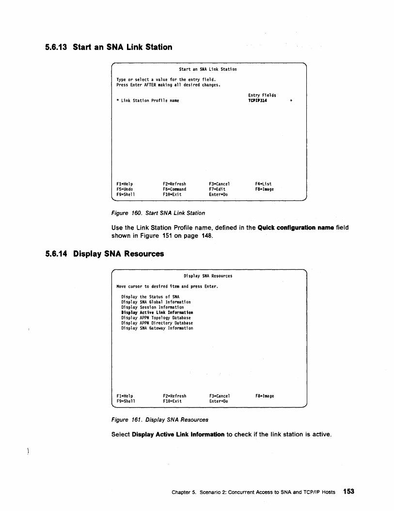
5.6.13 Start an SNA Link Station
Start an SNA link Station
Type or select a value for the entry field. Press Enter AFTER maki ng all desi red changes.
* Li nk Stati on Profi 1e name
Fl=Help F5=Undo F9=She11
F2=Refresh F6·Command Fle-Exi t
Figure 160. Start SNA Link Station
F3·Cancel F7"Edi t Enter-Do
Entry Fields TCPIP314
F4-Li st FScImage
+
Use the Link Station Profile name, defined in the Quick configuration name field shown in Figure 151 on page 148.
5.6.14 Display SNA Resources
Display SNA Resources
Move cursor to desired item and press Enter.
Display the Status of SNA Display SNA Global Information Display Session Information Display Active Link Information Display APPN Topology Database Display APPN Directory Database Display SNA Gateway Information
Fl=Help F9=She11
F2=Refresh Fle=Exit
Figure 161. Display SNA Resources
F3=Cancel Enter=Do
FS-Image
Select Display Active Link Information to check if the link station is active.
Chapter 5. Scenario 2: Concurrent Access to SNA and TCP/IP Hosts 153
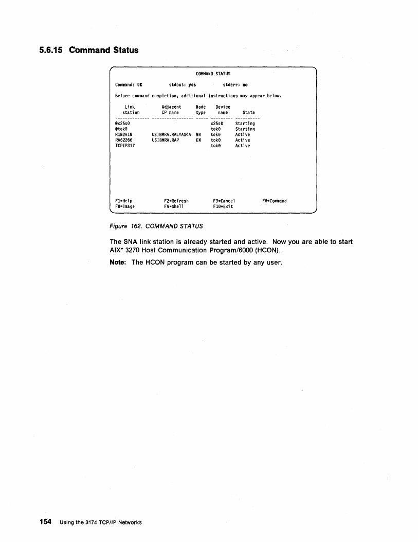
5.6.15 Command Status
COMMAND STATUS
Command: OK stdout: yes stderr: no
Before command completion. additional instructions may appear below.
Link station
@x25se @tok9 R1N2A1N RA62266 TCPIP317
Fl=Help F8=Image
Adjacent CP name
Node Devi ce type name
USIBMRA.RALYAS4A NN USIBMRA.RAP EN
F2=Refresh F9=Shell
x25se toke toke toke toke
F3=Cancel Fle=Exit
Figure 162. COMMAND STATUS
State
Starting Starting Acti ve Acti ve Active
F6=Command
The SNA link station is already started and active. Now you are able to start AIX* 3270 Host Communication Program/6000 (HCON).
Note: The HCON program can be started by any user.
154 Using the 3174 TCP/IP Networks
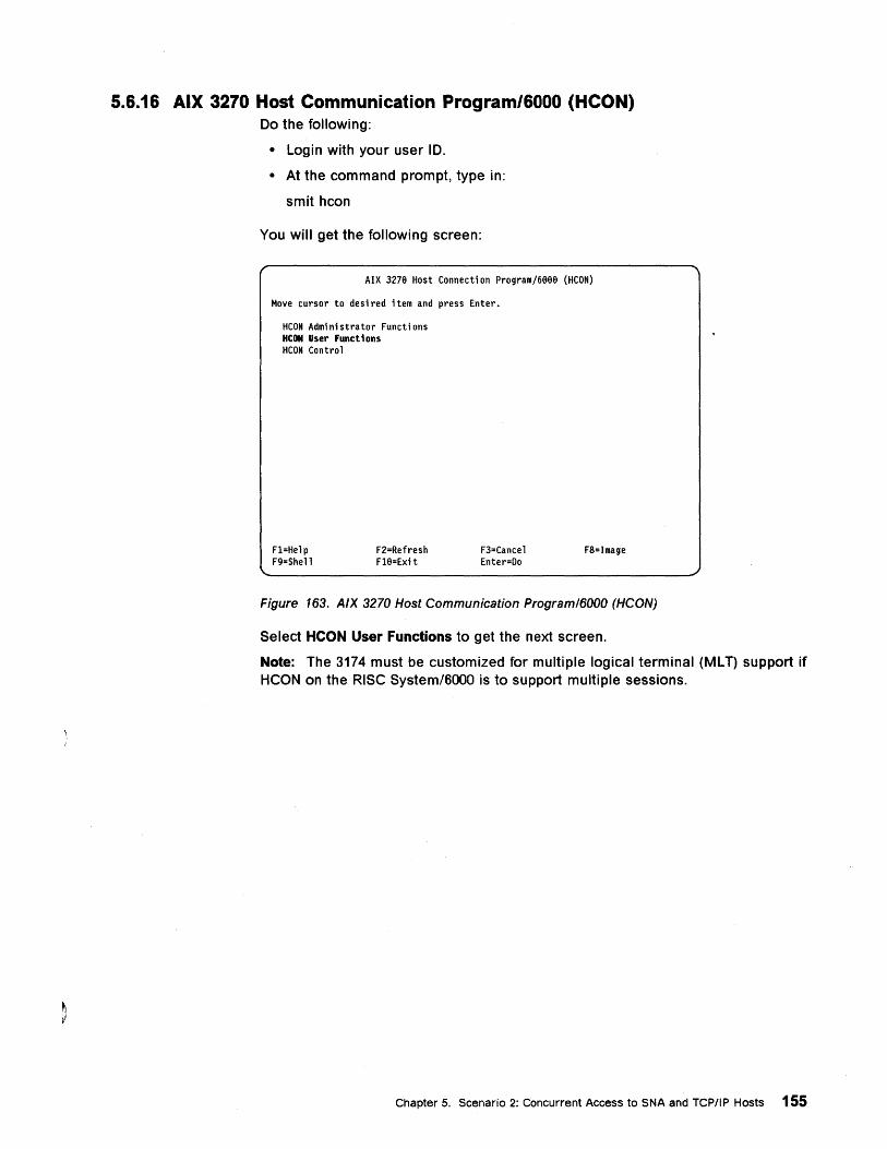
5.6.16 AIX 3270 Host Communication Program/6000 (HCON) Do the following:
• Login with your user 10.
• At the command prompt, type in:
smit hcon
You will get the following screen:
AIX 3278 Host Connect; on Program/6888 (HCON)
Move cursor to des; red ; tem and press Enter.
HCON Adm; n; strator Functi ons HCON User Funct 1 ons HCON Control
Fl=Help F9=Shell
F2=Refresh Fl8=Ex; t
F3=Cancel Enter=Do
F8=Image
Figure 163. A/X 3270 Host Communication Programl6000 (HCON)
Select HCON User Functions to get the next screen.
Note: The 3174 must be customized for multiple logical terminal (MLT) support if HCON on the RISC System/BOOO is to support multiple sessions.
Chapter 5. Scenario 2: Concurrent Access to SNA and TCP/IP Hosts 155
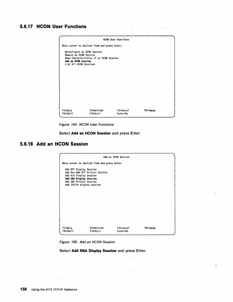
5.6.17 HCON User Functions
HCON User Functi ons
Move cursor to desired item and press Enter.
Reconfi gure an HCON Sessi on Remove an HCON Sessi on Show Characteristics of an HCON Session Add an HCON Sess i on list All HCON Sessions
Fl=Help F9=Shell
F2=Refresh Fl8=Exi t
Figure 164. HCON User Functions
F3=Cancel Enter=Do
Select Add an HCON Session and press Enter.
5.6.18 Add an HCON Session
Add an HCON Sessi on
Move cursor to desi red i tern and press Enter.
Add DFT Display Session Add Non-SNA DFT Pri nter Sessi on Add HIA Display Session Add SNA Display Session Add SNA Pri nter Sessi on Add TCP/IP display session
Fl=Help F9=Shell
F2=Refresh Fl8=Exit
Figure 165. Add an HCON Session
F3=Cancel Enter=Do
F8=Image
F8=Image
Select Add SNA Display Session and press Enter.
156 Using the 3174 TCP/IP Networks
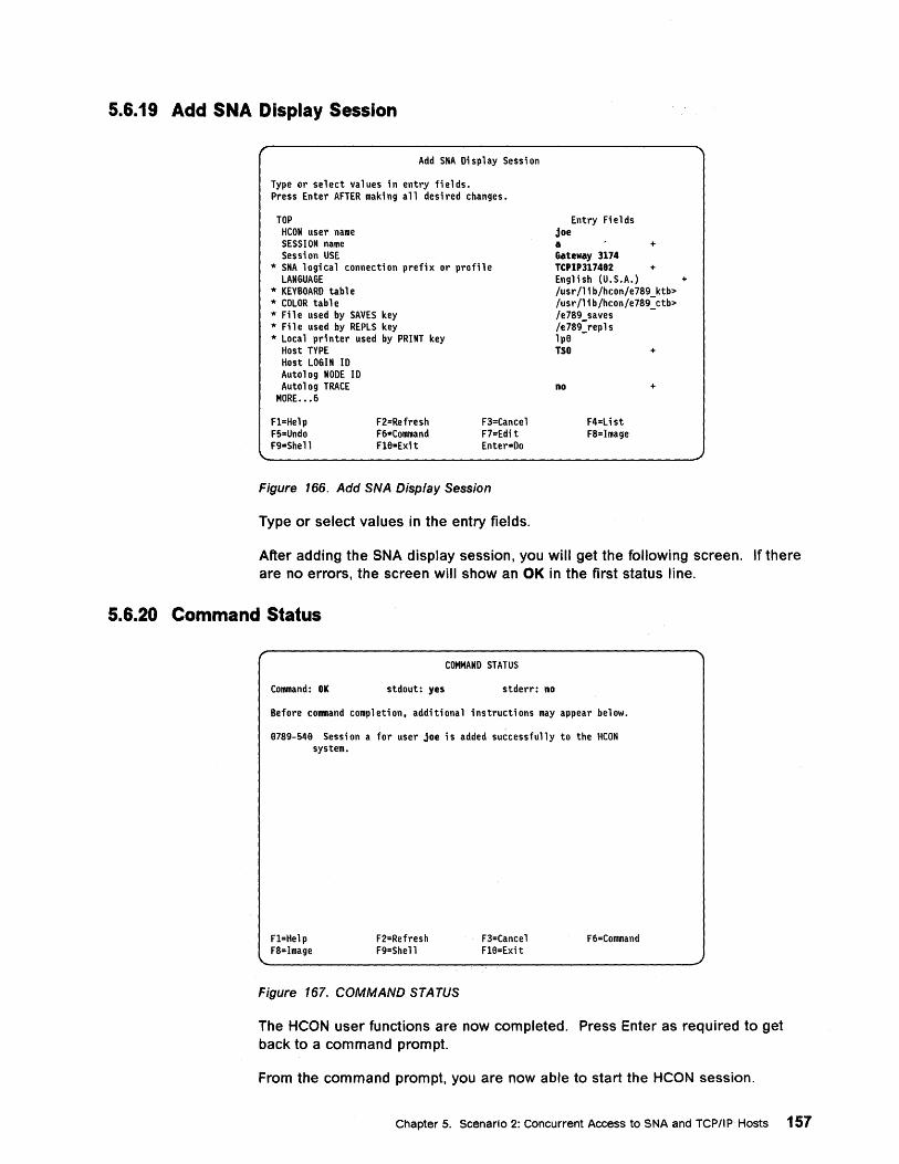
5.6.19 Add SNA Display Session
Add SNA Display Session
Type or select values in entry fields. Press Enter AFTER making all desired changes.
TOP HCON user name SESSION name Session USE
1< SNA logical connection prefix or profile LANGUAGE
1< KEYBOARD table 1< COLOR table 1< Fi 1 e used by SAVES key 1< Fi 1 e used by REPLS key 1< Local printer used by PRINT key
Host TYPE Host LOGIN 10 Autolog NODE 10 Autolog TRACE
MORE. •• 6
Fl=Help F5=Undo F9=Shell
F2=Refresh F6=Command Fl8=Exit
F3=Cancel F7=Edi t Enter=Do
Figure 166. Add SNA Display Session
Type or select values in the entry fields.
Entry Fi e 1 ds joe a + Gateway 3174 T('I'317482 + English (U.S.A.) /usr/lib/hcon/e789 ktb> /usr /1 i b/hcon/e789-ctb> /e789 saves -/e789-repls lp8 -TSO +
no
F4=Li st F8=Image
+
+
After adding the SNA display session, you will get the following screen. If there are no errors, the screen will show an OK in the first status line.
5.6.20 Command Status
COMMAND STATUS
Command: OK stdout: yes stderr: no
Before command completion, additional instructions may appear below.
8789-548 Session a for user joe is added successfully to the HCON system.
Fl=Help F8=lmage
F2=Refresh F9=Shell
Figure 167. COMMAND STATUS
F3=Cancel Fl6=Exit
F6=Command
The HCON user functions are now completed. Press Enter as required to get back to a command prompt.
From the command prompt, you are now able to start the HCON session.
Chapter 5. Scenario 2: Concurrent Access to SNA and TCP/IP Hosts 157
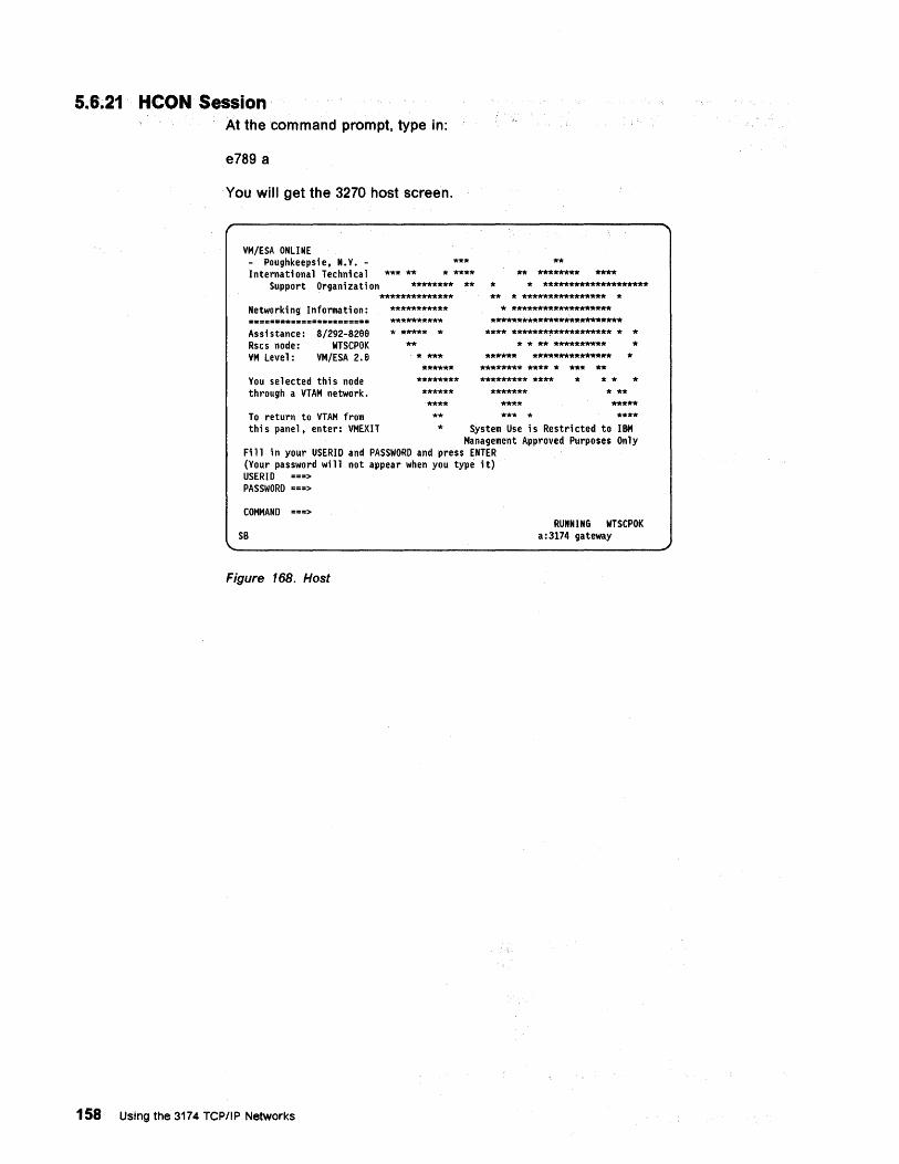
5.6.21 HCON Session
158
At the command prompt, type in:
e789 a
You will get the 3270 host screen.
VM/ESA ONLINE Poughkeepsie, N.V. -
International Technical Support Organization
Networki ng Informati on:
Assi stance: Rscs node: VM level:
8/292-8288 WTSCPOK
VM/ESA 2.a
Vou selected thi s node through a VTAM network.
*** ** ***
* **** ******** **
************** *********** ********** * ***** *
** * *** ******
******** ****** **** **
** ** ******** ****
* * ******************** ** * **************** *
* ******************* *************************
**** ******************* * * * * ** ********** *
****** *************** * ******** **** * *** ** ********* ****
******* **** *** *
* * * * * ** ***** **** To return to VTAM from
this panel, enter: VMEXIT * System Use is Restricted to IBM Management Approved Purposes Only
Fill in your USERID and PASSWORD and press ENTER (Vour password wi 11 not appear when you type it) USERID ===> PASSWORD ===>
COMMAND ===> RUNNING WTSCPOK
a:3174 gateway
Figure 168. Host
Using the 3174 TCPIIP Networks
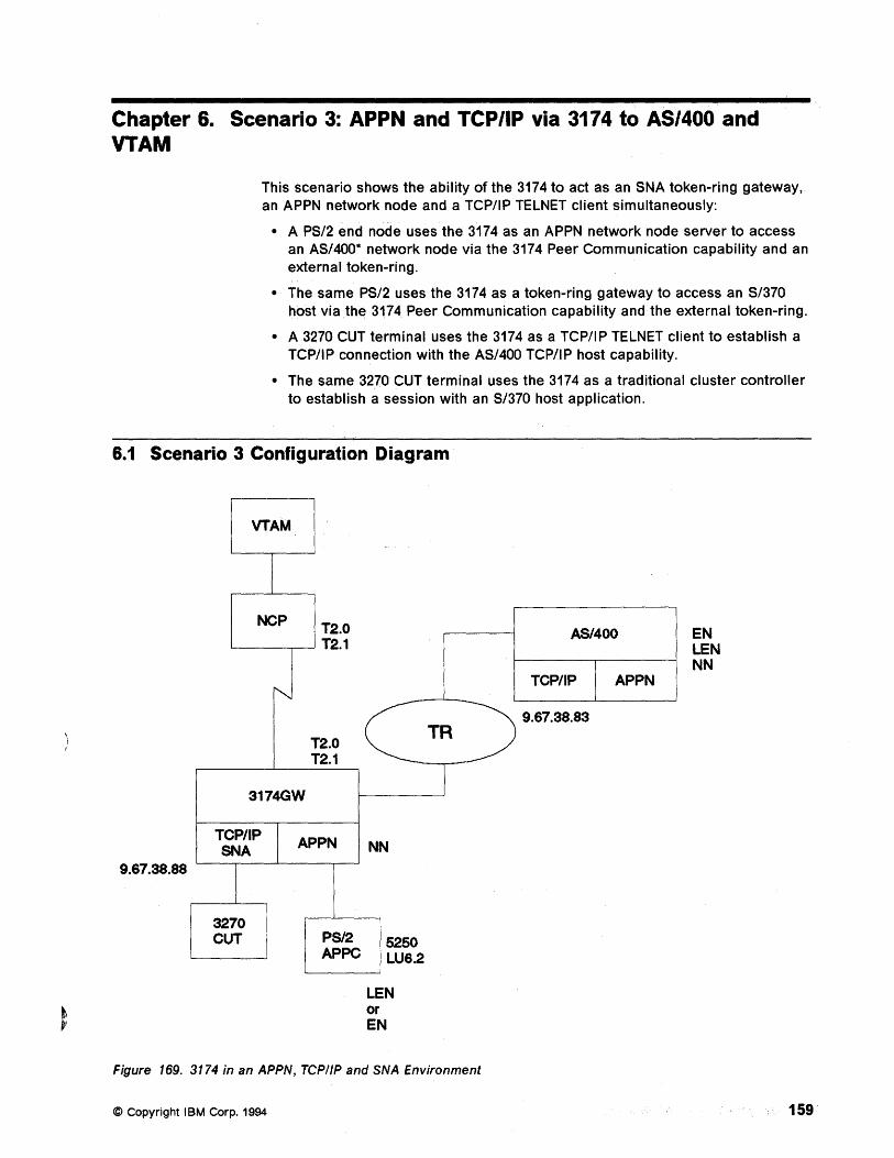
Chapter 6. Scenario 3: APPN and TCP/IP via 3174 to AS/400 and VTAM
This scenario shows the ability of the 3174 to act as an SNA token-ring gateway, an APPN network node and a TCP/IP TELNET client simultaneously:
• A PS/2 end node uses the 3174 as an APPN network node server to access an AS/400* network node via the 3174 Peer Communication capability and an external token-ring.
• The same PS/2 uses the 3174 as a token-ring gateway to access an S/370 host via th~ 3174 Peer Communication capability and the external token-ring.
• A 3270 CUT terminal uses the 3174 as a TCP/IP TELNET client to establish a TCP/IP connection with the AS/400 TCP/IP host capability.
• The same 3270 CUT terminal uses the 3174 as a traditional cluster controller to establish a session with an S/370 host application.
6.1 Scenario 3 Configuration Diagram
9.67.38.88
VTAM
NCP T2.0 '---_----.---' T2.1
3174GW
T2.0 T2.1
TCPIIP I APPN SNA
I 3270
NN
CUT PS/2 5250 APPC LU6.2
LEN or EN
TR
Figure 169. 3174 in an APPN, TCPIIP and SNA Environment
© Copyright IBM Corp. 1994
AS/400
TCP/IP I APPN
9.67.38.83
EN LEN NN
159
6.2 Scenario 3 Configuration Description Scenario 3 shows a PS/2 APPN end node (PS2COAX) coax-attached to a 3174-11R, which is SOLC-attached to an S/370 host and token-ring attached to an AS/400. It also shows a 3270 CUT terminal (CUTCOAX) attached to the same 3174-11 R.
The composite network has the following components:
• An S/370 host with VTAM V4.R1
• A 3745 with NCP V6.2, channel-attached to the S/370 host
• An AS/400 attached to the 3174-11R via a token-ring network
• A 3174-11R (CP31742), SOLC-attached to the 3745, as:
An APPN network node (NN) server for the PS/2 workstation
A token-ring gateway for the PS/2 workstation
A TCP/IP TELNET client for the 3270 CUT terminal
A cluster controller for the 3270 CUT terminal
With Peer Communication (LAN-Over-Coax) enabled.
• A PS/2 APPN end node (EN) (PS2COAX) with:
Communications Manager/2
5250 emulation to access the AS/400 host
3270 emulation to access the S/370 host
Token-ring address of 400031742992. I
• A 3270 CUT terminal (CUTCOAX):
With access to the AS/400 host as a VT100 terminal
With access to the S/370 host as a 3270 terminal
Note: This chapter does not describe the Communications Manager/2 configuration required to enable the PS/2 workstation to access the S/370 host using 3270 emulation.
160 Using the 3174 TCP/IP Networks
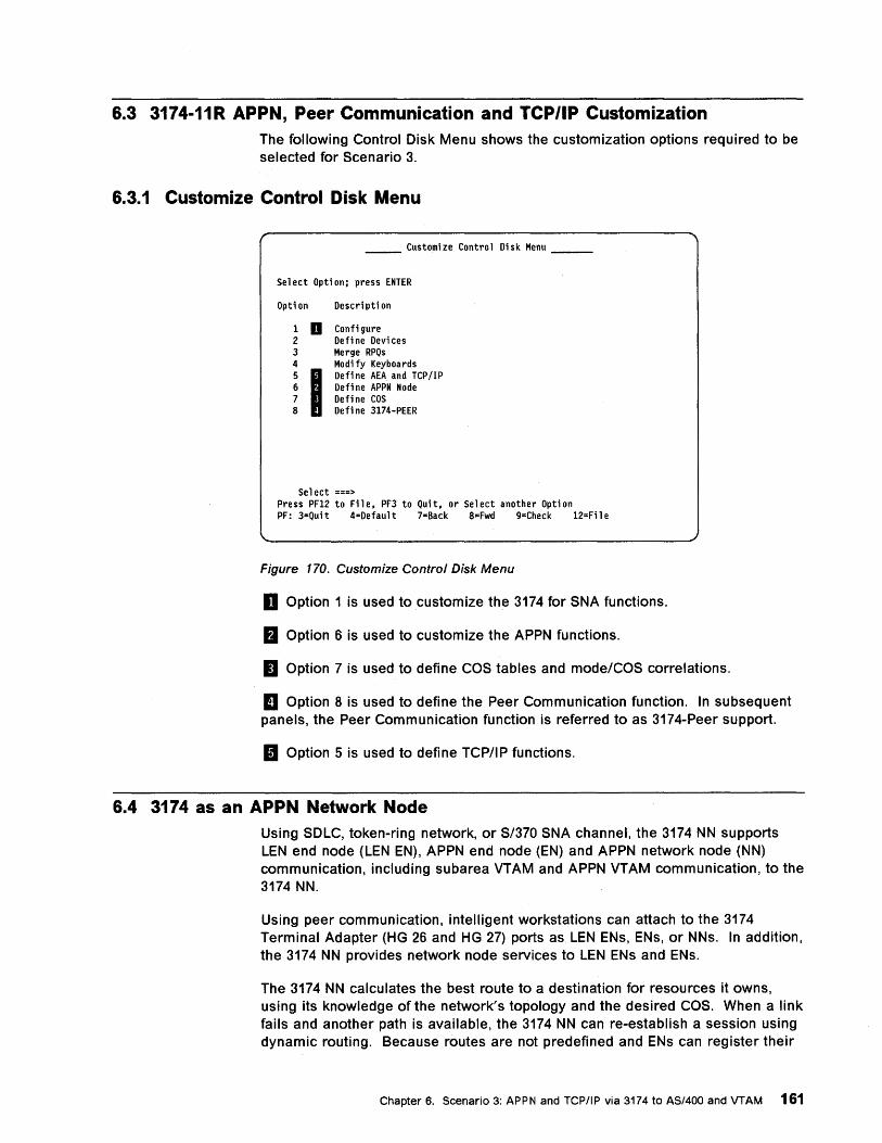
6.3 3174-11R APPN, Peer Communication and TCP/IP Customization The following Control Disk Menu shows the customization options required to be selected for Scenario 3.
6.3.1 Customize Control Disk Menu
Customize Control Disk Menu
Se 1 ect Opti on: press ENTER
Opti on Description
1 D Confi gure 2 Defi ne Devi ces 3 Merge RPQs 4 Modi fy Keyboards 5 I
Defi ne AEA. and TCP /1 P 6 Defi ne APPN Node 7 Define COS 8 Defi ne 3174-PEER
Sel ect ===> Press PF12 to File, PF3 to Quit, or Select another Option PF: 3=Qui t 4=Default 7=Back 8=Fwd 9=Check 12=Fil e
Figure 170. Customize Control Disk Menu
D Option 1 is used to customize the 3174 for SNA functions.
a Option 6 is used to customize the APPN functions.
II Option 7 is used to define COS tables and mode/COS correlations.
II Option 8 is used to define the Peer Communication function. In subsequent panels, the Peer Communication function is referred to as 3174-Peer support.
II Option 5 is used to define TCP/IP functions.
6.4 3174 as an APPN Network Node Using SOLC, token-ring network, or S/370 SNA channel, the 3174 NN supports LEN end node (LEN EN), APPN end node (EN) and APPN network node (NN) communication, including subarea VTAM and APPN VTAM communication, to the 3174 NN.
Using peer communication, intelligent workstations can attach to the 3174 Terminal Adapter (HG 26 and HG 27) ports as LEN ENs, ENs, or NNs. In addition, the 3174 NN provides network node services to LEN ENs and ENs.
The 3174 NN calculates the best route to a destination for resources it owns, using its knowledge of the network's topology and the desired COS. When a link fails and another path is available, the 3174 NN can re-establish a session using dynamic routing. Because routes are not predefined and ENs can register their
Chapter 6. Scenario 3: APPN and TCP/IP via 3174 to AS/400 and VTAM 161
resources with the 3174 NN, network system definition is minimal. Nodes can be added or deleted without recustomizing.
Because a 3174 NN allows LU 6.2 traffic to flow on a single link, multiple subchannel addresses or multidrop links are not needed for T2.1 traffic.
6.5 3174 APPN and Peer Communication Customization This chapter provides guidance on customizing the 3174 for APPN and Peer Communication functions. For a detailed description of each customizing question, refer to 3174 Establishment Controller Planning Guide Configuration Support-C Release 3, GA27-3918.
The following chapters in the planning guide are important:
• Chapter 11: Planning for Common SNA
• Chapter 12: Planning for APPN
• Chapter 13: Planning for 3174 Peer Communication
• Appendix A: Configuration Worksheets
Figure 171 on page 163 shows the flow sequence of panels when customizing the 3174 for APPN and Peer Communications.
162 Using the 3174 TCP/IP Networks
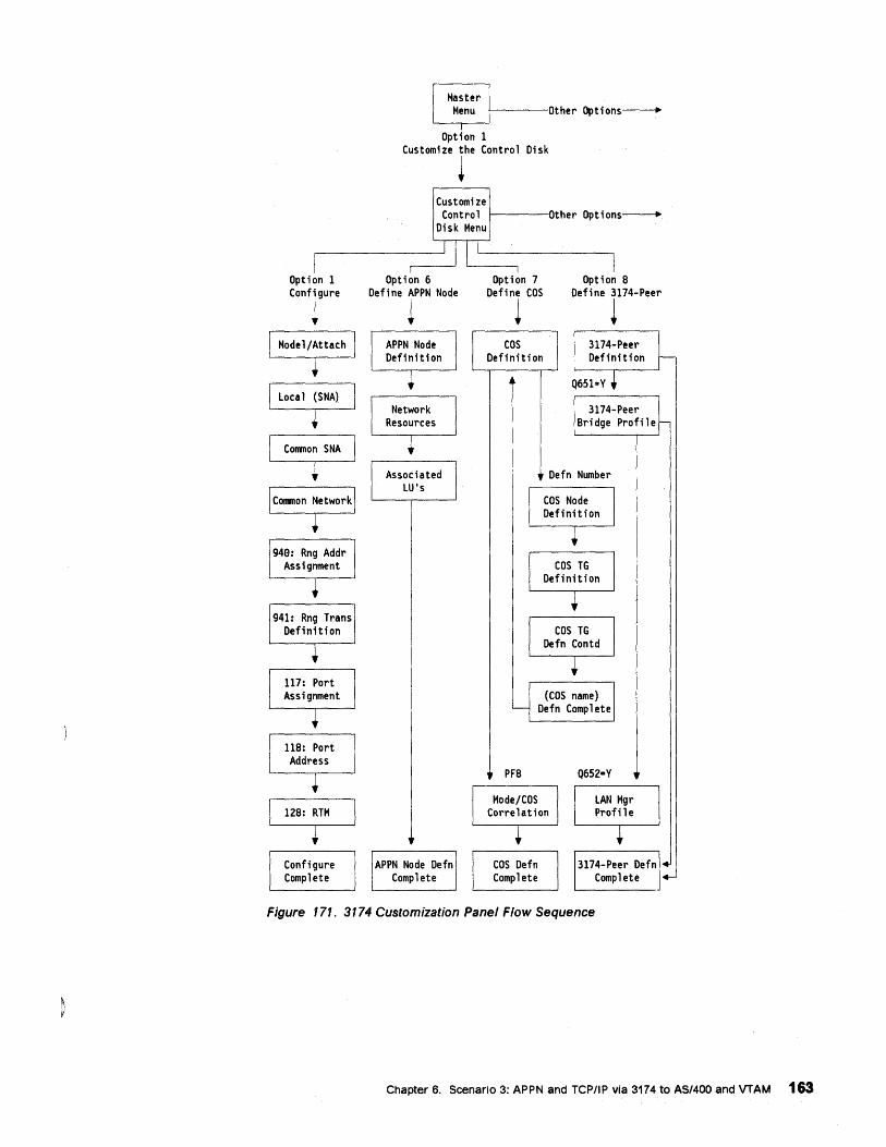
Option 1 Configure
~
Configure Complete
f-----Other Options----+
Option 1 Customize the Control Disk
~ Customize Control I-----Other Options----+
Disk Menu
~ 1<-1--'1 Option 6 Option 7
Define APPN Node Define COS
~ ~
APPN Node Defn Complete
PF8
I Option 8
Define 3174-Peer
~
Defn Number
Q652=Y
Figure 171. 3174 Customization Panel Flow Sequence
Chapter 6. Scenario 3: APPN and TCPIIP via 3174 to AS/400 and VTAM 163
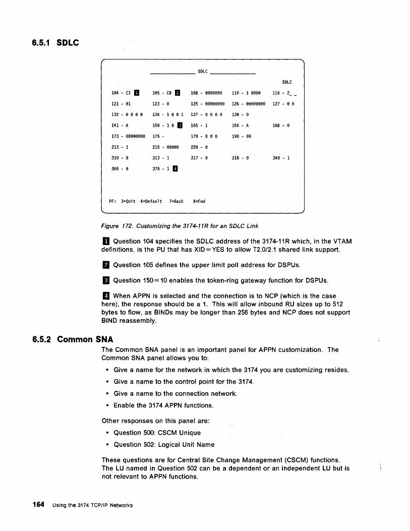
6.5.1 SDLC
SOLC
SOLC
1e4 - C1 D 1e5 - C8 fJ 1e8 - eeeeeee 11e - 1 eeee 116 - 2 __
121 - e1 123 - e 125 - eeeeeeee 126 - eeeeeeee 127 - e e
132 - a a a e 136 - 1 a a 1 137 - 8 e a a 138 - a
141 - A 15a - 1 a II 165 - 1 166 - A 168 - a
173 - aeeeeeee 175 - 179 - 8 a a 1ge - ee
213 - 1 215 - eeaee 22e - e
31e - e 313 - 1 317 - e 318 - e 348 - 1
365 - e 37e - 1 II
PF: 3=Quit 4=Oefault 7=Back 8=Fwd
Figure 172. Customizing the 3174-11R for an SDLC Link
D Question 104 specifies the SDLC address of the 3174-11 R which, in the VTAM definitions, is the PU that has XID = YES to allow T2.0/2.1 sh'ared link support.
B Question 105 defines the upper limit poll address for DSPUs.
II Question 150 = 10 enables the token-ring gateway function for DSPUs.
II When APPN is selected and the connection is to NCP (which is the case here), the response should be a 1. This will allow inbound RU sizes up to 512 bytes to flow, as BINDs may be longer than 256 bytes and NCP does not support BIND reassembly.
6.5.2 Common SNA The Common SNA panel is an important panel for APPN customization. The Common SNA panel allows you to:
• Give a name for the network in which the 3174 you are customizing resides.
• Give a name to the control point for the 3174.
• Give a name to the connection network.
• Enable the 3174 APPN functions.
Other responses on this panel are:
• Question 500: CSCM Unique
• Question 502: Logical Unit Name
These questions are for Central Site Change Management (CSCM) functions. The LU named in Question 502 can be a dependent or an independent LU but is not relevant to APPN functions.
164 Using the 3174 TCP/IP Networks
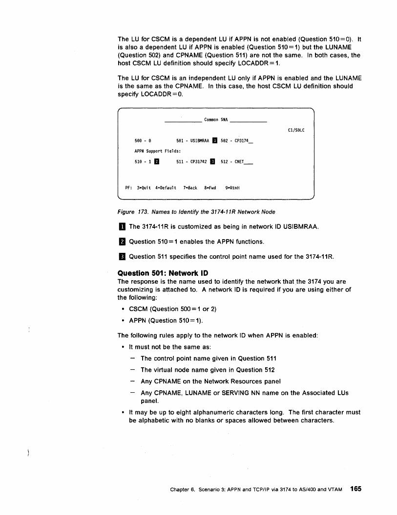
The LU for CSCM is a dependent LU if APPN is not enabled (Question 510=0). It is also a dependent LU if APPN is enabled (Question 510 = 1) but the LUNAME (Question 502) and CPNAME (Question 511) are not the same. In both cases, the host CSCM LU definition should specify LOCAOOR = 1.
The LU for CSCM is an independent LU only if APPN is enabled and the LUNAME is the same as the CPNAME. In this case, the host CSCM LU definition should specify LOCAOOR = O.
_____ Common SNA ____ _
Cl/SDLC
566 - 6 561 - USIBMRAA D 562 - CP3174_
APPN Support Fields:
516 - 1 fJ 511 - CP31742 II 512 - CNET_
PF: 3=Qui t 4=Defaul t 7=Back 8=Fwd 9=RtnH
Figure 173. Names to Identify the 3174-11R Network Node
D The 3174-11R is customized as being in network 10 USIBMRAA.
&I Question 510 = 1 enables the APPN functions.
II Question 511 specifies the control point name used for the 3174-11R.
Question 501: Network I D The response is the name used to identify the network that the 3174 you are customizing is attached to. A network 10 is required if you are using either of the following:
• CSCM (Question 500 = 1 or 2)
• APPN (Question 510 = 1).
The following rules apply to the network 10 when APPN is enabled:
• It must not be the same as:
The control point name given in Question 511
The virtual node name given in Question 512
Any CPNAME on the Network Resources panel
Any CPNAME, LUNAME or SERVING NN name on the Associated LUs panel.
• It may be up to eight alphanumeric characters long. The first character must be alphabetic with no blanks or spaces allowed between characters.
Chapter 6. Scenario 3: APPN and TCP/IP via 3174 to AS/400 and VTAM 165
Question 510: APPN Network· Controller The response indicates whether APPN functions in the 3174 are enabled. Valid responses are:
'.
o = APPN not enabled (default response)
1 = APPN enabled.
If you enabled the 3174 APPN functions '(Question 510 = 1), then:
. • The link type for a channel-attached'3174 must be able to carry both T2.0 and T2.1 traffic (Question 242 == 1)
• The network 10 (Question 501), the control point name (Question 511) and the virtual node name (Question 512) must be unique.
If you enabled the 3174 APPN functions and perform no further APPN customization, you will get a minimum APPN configuration using the IBM-supplied class of service definitions.
Question 511: APPN Control Point Name (CPNAME) The response is used as the control point name and identifies the 3174 network node to the network.
The following rules apply to the control point name:
• It is required when APPN is enabled.
• It must not be the same as:
The network 10 given in Question 501
The virtual node name given in Question 512
Any other resource names in the network.
• It may be up to eight alphanumeric characters long. The first character must be alphabetic with no blanks or spaces allowed between characters.
Question 512: APPN Virtual Node Name (VNODE) A connection network is used to minimize definitions for nodes connected to a shared-access transport facility such as a token-ring network. Physically, the connection network is the token-ring network to which the 3174 network node is attached.
Question 512 allows you to give a name to a connection network so that all nodes using the same connection network can pOint to the same name.
The connection network name is also referred to as:
• The virtual node name in the 3174
• The connection network control point name (CNNCPNAME) in the AS/400
• The connection network name in NS/2
It is used fully qualified by the network 10.
The following rules apply to the connection network (or virtual node) name:
• It is required when Question 510 = 1 (APPN enabled) even if a connection network is not used.
• It must not be the same as:
166 Using the 3174 TCP/IP Networks
The network JD given in Question 501
The control point name given in Question 511
Any CPNAME on the Network Resources panel
Any CPNAME, LUNAME or SERVING NN name.on the Associated LUs panel
Any other resource names in the network
• ,It may be up to eight alphanumeric characters long. The first character must be alphabetic with no blanks or spaces allowed between characters.
Chapter 6. Scenario 3: APPN and rCP/IP via 3174 to AS/400 and VTAM 167
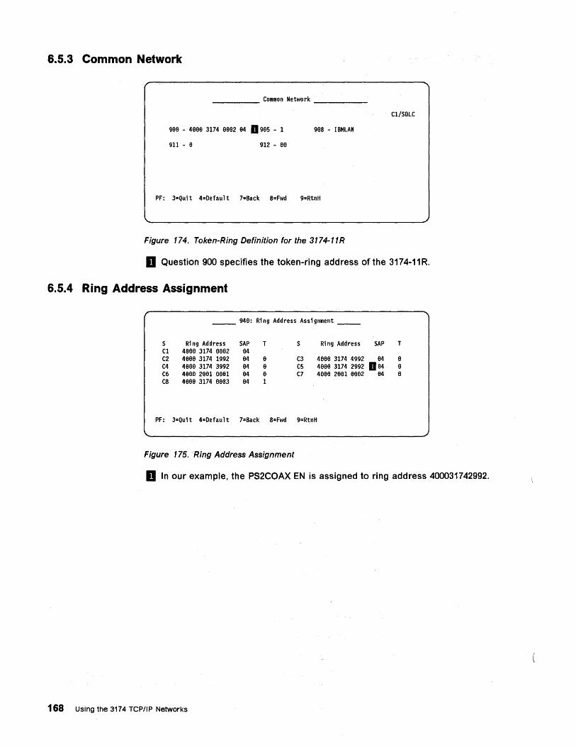
6.5.3 Common Network
_____ Common Network ____ _
C1/SDLC
9ae - 4aae 3174 aaa2 94 a 9a5 - 1 9as - IBMLAN
911 - a 912 - ae
PF: 3=Quit 4=Default 7=Back S=Fwd 9=RtnH
Figure 174. Token-Ring Definition for the 3174-11R
D Question 900 specifies the token-ring address of the 3174-11 R.
6.5.4 Ring Address Assignment
__ 94a: Ri ng Address Assi gnment __
S Ri ng Address SAP T S Ring Address SAP T C1 4aaa 3174 aaa2 e4 C2 4aaa 3174 1992 a4 a C3 4aae 3174 4992 a4 a C4 4aae 3174 3992 a4 a C5 4aee 3174 2992 a a4 a C6 4aaa 2aa1 aea1 84 8 C7 4888 28a1 aaa2 84 8 C8 4aaa 3174 eae3 a4 1
PF: 3=Quit 4=Default 7=Back 8=Fwd 9=RtnH
Figure 175. Ring Address Assignment
D In our example, the PS2COAX EN is assigned to ring address 400031742992.
168 Using the 3174 TCPIIP Networks
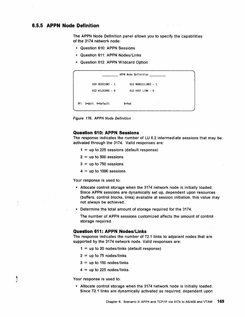
6.5.5 APPN Node Definition
The APPN Node Definition panel allows you to specify the capabilities of the 3174 network node:
• Question 610: APPN Sessions
• Question 611: APPN Nodes/Links
• Question 612: APPN Wildcard Option
___ APPN Node Defi niti on __ _
618 SESSIONS - 1 611 NODES/LINKS - 1
612 WILDCARD - 8 613 HOST LI NK - e
PF: 3=Quit 4=Defaul t 8=Fwd
Figure 176. APPN Node Definition
Question 610: APPN Sessions The response indicates the number of LU 6.2 intermediate sessions that may be activated through the 3174. Valid responses are:
1 = up to 225 sessions (default response)
2 = up to 500 sessions
3 = up to 750 sessions
4 = up to 1000 sessions
Your response is used to:
• Allocate control storage when the 3174 network node is initially loaded. Since APPN sessions are dynamically set up, dependent upon resources (buffers, control blocks, links) available at session initiation, this value may not always be achieved.
• Determine the total amount of storage required for the 3174.
The number of APPN sessions customized affects the amount of control storage required.
Question 611: APPN Nodes/Links The response indicates the number of T2.1 links to adjacent nodes that are supported by the 3174 network node. Valid responses are:
1 = up to 20 nodesllinks (default response)
2 = up to 75 nodes/links
3 = up to 150 nodes/links
4 = up to 225 nodes/links.
Your response is used to:
• Allocate control storage when the 3174 network node is initially loaded. Since T2.1 links are dynamically activated as required, dependent upon
Chapter 6. Scenario 3: APPN and TCPIIP via 3174 to AS/400 and VTAM 169
resources (control blocks and ports) available at link establishment, this value may not always be achieved.
• Determine the total amount of storage required for the 3174.
The number of nodes/links customized affects the amount of control storage required.
Question 612: APPN Wildcard Option The response indicates whether the 3174 network node you are customizing holds the wildcard connection to the host for the APPN network. Valid responses are:
o = No (default response)
1 = Yes
The wildcard option allows LUs to be dynamically located in a subarea network. The wildcard option permits sessions to be established from LUs in the APPN network to LUs in or through a subarea network.
For detailed information about the 3174 APPN wildcard, see IBM 3174 APPN Implementation Guide, GG24-3702.
Question 613: APPN Wildcard Host Link The response indicates which host link to this 3174 NN will be used for wildcard routing. Valid responses are:
1A = Host link 1A is used for wildcard routing (default response).
18 = Host link 18 is used for wildcard routing.
1C = Host link 1C is used for wildcard routing.
10 = Host link 10 is used for wildcard routing.
1E = Host link 1E is used for wildcard routing.
1F = Host link 1F is used for wildcard routing.
1G = Host link 1G is used for wildcard routing.
1H = Host link 1H is used for wildcard routing.
6.6 Network Resources Definition The Network Resources and Associated LUs panels allow you to define nodes in the APPN network to the 3174 network node you are customizing. You may use these panels to define:
• LEN nodes for which the 3174 is acting as a server
• LUs that are located in the LEN nodes served by the 3174
• Network nodes that are adjacent to the 3174
• Nodes that share a link for both T2.0 and T2.1 traffic, such as a 3174-13R that is used for both 3270 DSPU and APPN functions
• Addresses of nodes to which the 3174 NN will initiate a connection when it is IMLed
• Resources that are to be preloaded in the 3174 directory cache to reduce the number of broadcasts in the network
170 Using the 3174 TCP/IP Networks
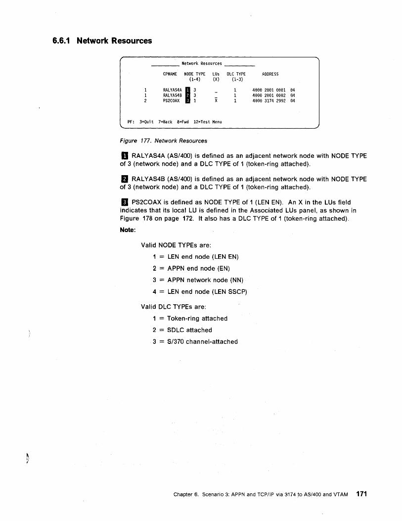
6.6.1 Network Resources
Network Resources
CPNAME NODE TYPE LUs DLC TYPE ADDRESS (1-4) (X) (1-3)
1 RALVAS.A I' 4eee 2ee1 eeel e4
1 RALYAS4B 3 4eee 2ee1 e002 04 2 PS2COAX 1 X 4000 3174 2992 04
PF: 3=Quit 7=Back 8=Fwd 12=Test Menu
Figure 177. Network Resources
o RALYAS4A (AS/400) is defined as an adjacent network node with NODE TYPE of 3 (network node) and a DLC TYPE of 1 (token-ring attached).
II RAL YAS4B (AS/400) is defined as an adjacent network node with NODE TYPE of 3 (network node) and a DLC TYPE of 1 (token-ring attached).
II PS2COAX is defined as NODE TYPE of 1 (LEN EN). An X in the LUs field indicates that its local LU is defined in the Associated LUs panel, as shown in Figure 178 on page 172. It also has a DLC TYPE of 1 (token-ring attached).
Note:
Valid NODE TYPEs are:
1 = LEN end node (LEN EN)
2 = APPN· end node (EN)
3 = APPN network node (NN)
4 = LEN end node (LEN SSCP)
Valid DLC TYPEs are:
1 = Token-ring attached
2 = SDLC attached
3 = S/370 chan nel-attached
Chapter 6. Scenario 3: APPN and TCP/IP via 3174 to AS/400 and VTAM 171
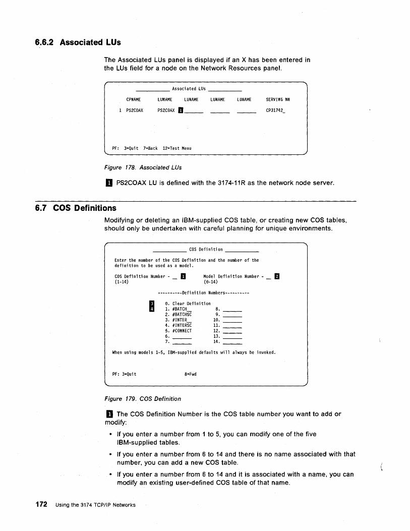
6.6.2 Associated LUs
The Associated LUs panel is displayed if an X has been entered in the LUs field for a node on the Network Resources panel.
_____ Associated LUs ____ _
CPNAME LUNAME LUNAME LUNAME LUNAME SERVING NN
1 PS2COAX PS2COAX D __ _ CP31742_
PF: 3=Qui t 7=Back 12=Test Menu
Figure 178. Associated LUs
D PS2COAX LU is defined with the 3174-11R as the network node server.
6.7 COS Definitions Modifying or deleting an 18M-supplied COS table, or creating new COS tables, should only be undertaken with careful planning for unique environments.
_____ cos Definition ____ _
Enter the number of the COS Defi niti on and the number of the defi ni ti on to be used as a model.
COS Defi ni ti on Number - _ D (1-14)
Mode 1 Defi ni ti on Number - _ B ( 8-14)
----------Defi ni ti on Numbers----------
B. Clear Definition 1. IBATCH 8. 2. IBATCHSC 9. 3. lINTER 18. 4. IINTERSC 11. 5. ICONNECT 12. 6. 13. 7. 14.
When using models 1-5, IBM-supplied defaults will always be invoked.
PF: 3=Quit 8=Fwd
Figure 179. COS Definition
D The COS Definition Number is the COS table number you want to add or modify:
• If you enter a number from 1 to 5, you can modify one of the five 18M-supplied tables.
• If you enter a number from 6 to 14 and there is no name associated with that number, you can add a new COS table.
• If you enter a number from 6 to 14 and it is associated with a name, you can modify an existing user-defined COS table of that name.
172 Using the 3174 TCP/IP Networks
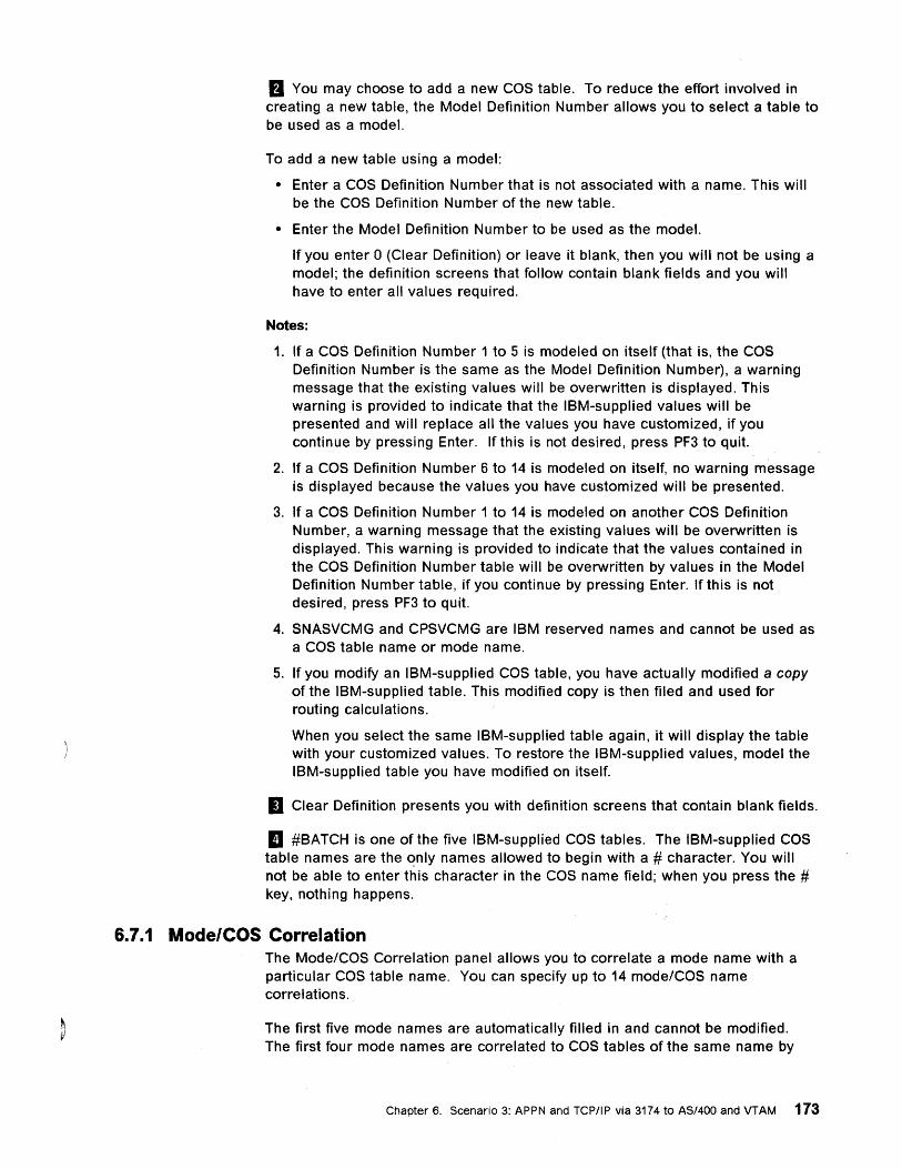
fJ You may choose to add a new COS table. To reduce the effort involved in creating a new table, the Model Definition Number allows you to select a table to be used as a model.
To add a new table using a model:
• Enter a COS Definition Number that is not associated with a name. This will be the COS Definition Number of the new table.
• Enter the Model Definition Number to be used as the model.
If you enter 0 (Clear Definition) or leave it blank, then you will not be using a model; the definition screens that follow contain blank fields and you will have to enter all values required.
Notes:
1. If a COS Definition Number 1 to 5 is modeled on itself (that is, the COS Definition Number is the same as the Model Definition Number), a warning message that the existing values will be overwritten is displayed. This warning is provided to indicate that the IBM-supplied values will be presented and will replace all the values you have customized, if you continue by pressing Enter. If this is not desired, press PF3 to quit.
2. If a COS Definition Number 6 to 14 is modeled on itself, no warning message is displayed because the values you have customized will be presented.
3. If a COS Definition Number 1 to 14 is modeled on another COS Definition Number, a warning message that the existing values will be overwritten is displayed. This warning is provided to indicate that the values contained in the COS Definition Number table will be overwritten by values in the Model Definition Number table, if you continue by pressing Enter. If this is not desired, press PF3 to quit.
4. SNASVCMG and CPSVCMG are IBM reserved names and cannot be used as a COS table name or mode name.
5. If you modify an IBM-supplied COS table, you have actually modified a copy of the IBM-supplied table. This modified copy is then filed and used for routing calculations.
When you select the same IBM-supplied table again, it will display the table with your customized values. To restore the IBM-supplied values, model the IBM-supplied table you have modified on itself.
II Clear Definition presents you with definition screens that contain blank fields.
II #BATCH is one of the five IBM-supplied COS tables. The IBM-supplied COS table names are the ~nly names allowed to begin with a # character. You will not be able to enter this character in the COS name field; when you press the # key, nothing happens.
6.7.1 Mode/COS Correlation The Mode/COS Correlation panel allows you to correlate a mode name with a particular COS table name. You can specify up to 14 mode/COS name correlations.
The first five mode names are automatically filled in and cannot be modified. The first four mode names are correlated to COS tables of the same name by
Chapter 6. Scenario 3: APPN and TCPIIP via 3174 to AS/400 and VTAM 173
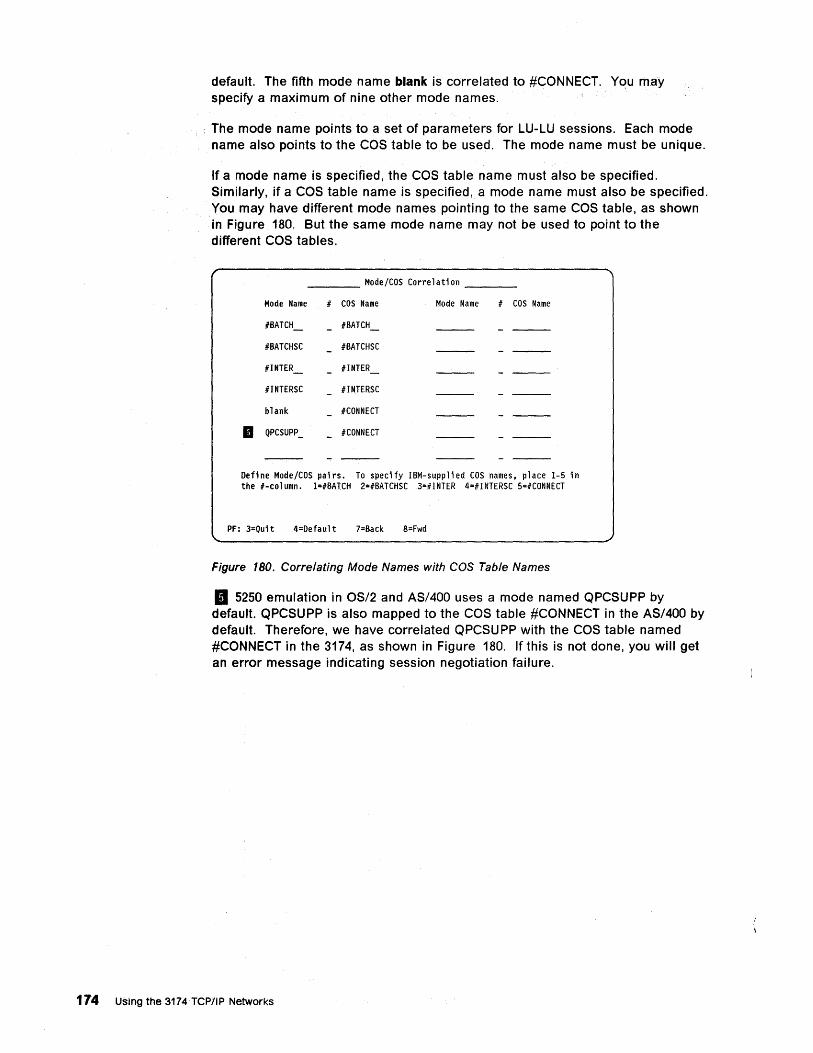
default. The fifth mode name blank is correlated to #CONNECT. You may specify a maximum of nine other mode names.
The mode name points to a set of parameters for LU-LU sessions. Each mode name also points to the COS table to be used. The mode name must be unique.
If a mode name is specified, the COS table name must also be specified. Similarly, if a COS table name is specified, a mode name must also be specified. You may have different mode names pointing to the same COS table, as shown in Figure 180. But the same mode name may not be used to point to the different COS tables.
Mode/COS Correlation
Mode Name # COS Name Mode Name # COS Name
IBATCH_ IBATCH - - ---IBATCHSC IBATCHSC - ---#INTER_ IINTER_ - ---#lNTERSC IINTERSC - ---blank ICONNECT - ---
• QPCSUPP _ ICONNECT - ---- --- - ---
Define Mode/COS pairs. To specify IBM-supplied COS names, place 1-5 in the I-column. l=#BATCH 2=IBATCHSC 3=#INTER 4=IINTERSC 5=#CONNECT
PF: 3=Qui t 4=Defaul t 7=Back 8=Fwd
Figure 180. Correlating Mode Names with COS Table Names
II 5250 emulation in OS/2 and AS/400 uses a mode named QPCSUPP by default. QPCSUPP is also mapped to the COS table #CONNECT in the AS/400 by default. Therefore, we have correlated QPCSU PP with the COS table named #CONNECT in the 3174, as shown in Figure 180. If this is not done, you will get an error message indicating session negotiation failure.
174 USing the 3174 TCP/IP Networks
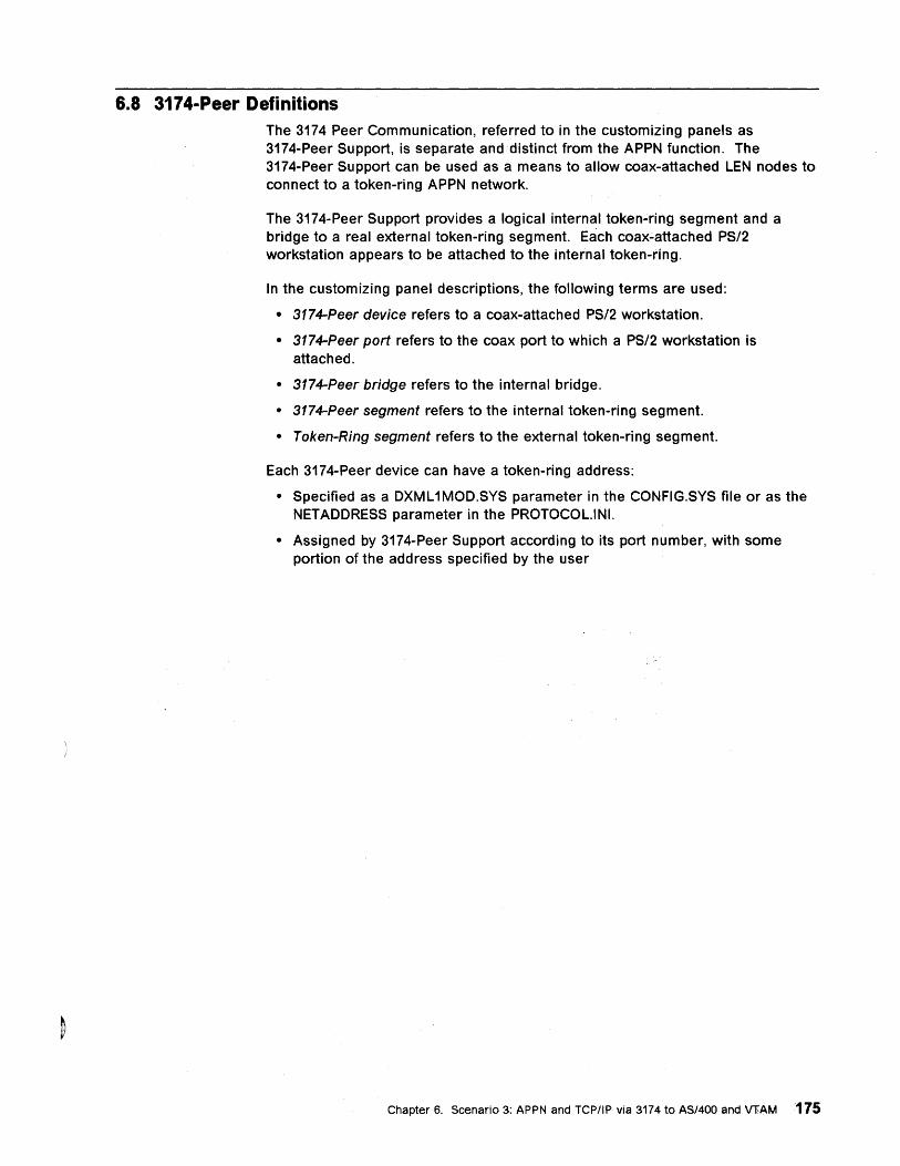
6.8 3174-Peer Definitions The 3174 Peer Communication, referred to in the customizing panels as 3174-Peer Support, is separate and distinct from the APPN function. The 3174-Peer Support can be used as a means to allow coax-attached LEN nodes to connect to a token-ring APPN network.
The 3174-Peer Support provides a logical internal token-ring segment and a bridge to a real external token-ring segment. Each coax.;.attached PS/2 workstation appears to be attached to the internal token-ring.
In the customizing panel descriptions, the following terms are used:
• 3174-Peer device refers to a coax-attached PS/2 workstation.
• 3174-Peer port refers to the coax port to which a PS/2 workstation is attached.
• 3174-Peer bridge refers to the internal bridge.
• 3174-Peer segment refers to the internal token-ring segment.
• Token-Ring segment refers to the external token-ring segment.
Each 3174-Peer device can have a token-ring address:
• Specified as a DXML 1MOD.SYS parameter in the CONFIG.SYS file or as the NETADDRESS parameter in the PROTOCOL.IN!.
• Assigned by 3174-Peer Support according to its port number, with some portion of the address specified by the user
Chapter 6. ScenariO 3: APPN and TCPIIP via 3174 to AS/400 and VFAM 175
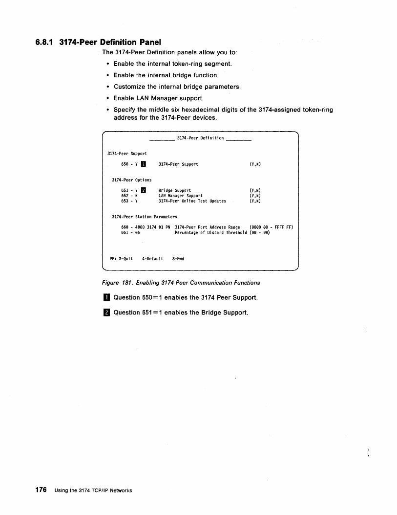
6.8.1 3174-Peer Definition Panel The 3174-Peer Definition panels allow you to:
• Enable the internal token-ring segment.
• Enable the internal bridge function.
• Customize the internal bridge parameters.
• Enable LAN Manager support.
• Specify the middle six hexadecimal digits of the 3174-assigned token-ring address for the 3174-Peer devices.
____ 3174-Peer Defi ni ti on ___ _
3174-Peer Support
658 - Y D
3174-Peer Opti ons
651 - Y D 652 - N 653 - Y
3174-Peer Support
Sri dge Support LAN Manager Support 3174-Peer On 1 i ne Test Updates
3174-Peer Stati on Parameters
(Y,N)
(Y,N) (Y, N) (Y, N)
668 - 4eee 3174 91 PN 3174-Peer Port Address Range (eeeS ee - FFFF FF) 661 - e5 Percentage of Discard Threshold (ee - 99)
PF: 3=Quit 4=Default 8=Fwd
Figure 181. Enabling 3174 Peer Communication Functions
D Question 650 = 1 enables the 3174 Peer Support.
rI Question 651 = 1 enables the Bridge Support.
176 Using the 3174 TCP/IP Networks
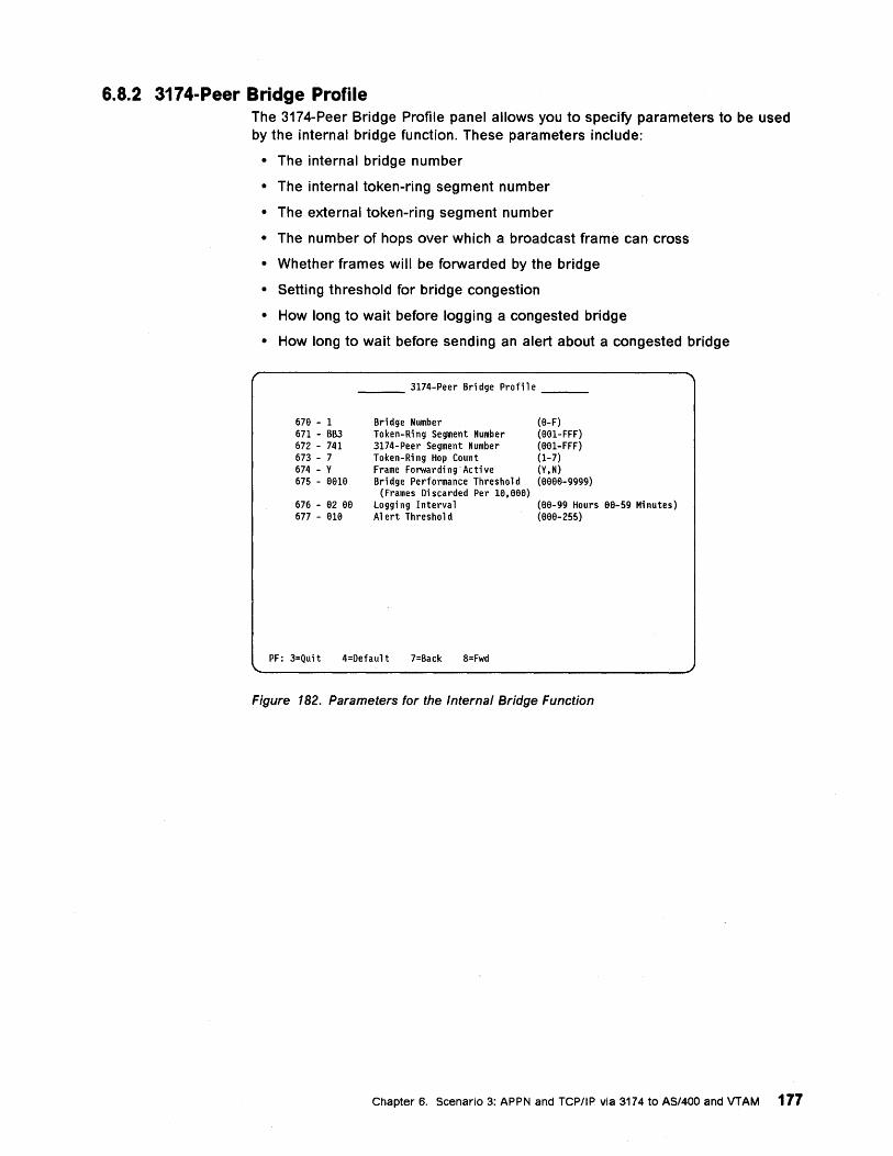
6.8.2 3174-Peer Bridge Profile The 3174-Peer Bridge Profile panel allows you to specify parameters to be used by the internal bridge function. These parameters include:
• The internal bridge number
• The internal token-ring segment number
• The external token-ring segment number
• The number of hops over which a broadcast frame can cross
• Whether frames will be forwarded by the bridge
• Setting threshold for bridge congestion
• How long to wait before logging a congested bridge
• How long to wait before sending an alert about a congested bridge
67e - 1 671 - BB3 672 - 741 673 - 7 674 - Y 675 - 6616
676 - 62 66 677 - 616
___ 3174-Peer Bri dge Profi 1 e __ _
Bridge Number Token-Ri ng Segment Number 3174-Peer Segment Number Token-Ri ng Hop Count Frame Forwarding"Active Sri dge Performance Threshold
(Frames Di scarded Per 16,66e) loggi ng I nterva 1 Alert Threshold
(6-F) (661-FFF) (961-FFF) (1-7) (Y,N) (6666-9999)
(66-99 Hours 66-59 Minutes) (666-255)
PF: 3=Quit 4=Default 7=Back 8=Fwd
Figure 182. Parameters for the Internal Bridge Function
Chapter 6. Scenario 3: APPN and TCP/IP via 3174 to AS/400 and VTAM 177
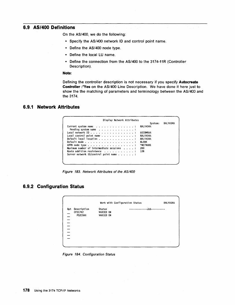
6.9 AS/400 Definitions On the AS/400, we do the following:
• Specify the AS/400 network 10 and control point name.
• Define the AS/400 node type.
• Define the local LU name.
• Define the connection from the AS/400 to the 3174-11 R (Controller Descri ption).
Note:
Defining the controller description is not necessary if you specify Autocreate Controller :*Yes on the AS/400 Line Description. We have done it here just to show the the matching of parameters and terminology between the AS/400 and the 3174.
6.9.1 Network Attributes
Current system name • • Pendi ng system name •
Local network ID •••• Loca 1 control poi nt name • Default local location •• Default mode • • • • • • •
Di sp 1 ay Network Attri butes
APPN node type • • • • • • • Maxi mum number of i ntermedi ate sessi ons Route addi ti on resi stance ••••• • Server network ID/control point name ••
Figure 183. Network Attributes of the AS/400
6.9.2 Configuration Status
System: RALYAS4A RALYAS4A
USIBMRAA RALYAS4A RALYAS4A BLANK *NETNODE 28e 128
Work wi th Confi gura ti on Status RALYAS4A
\.
Opt Descri pti on CP31742
PS2COAX
Status VARIED ON VARIED ON
Figure 184. Configuration Status
178 Using the 3174 TCPIIP Networks
-------------Job----------
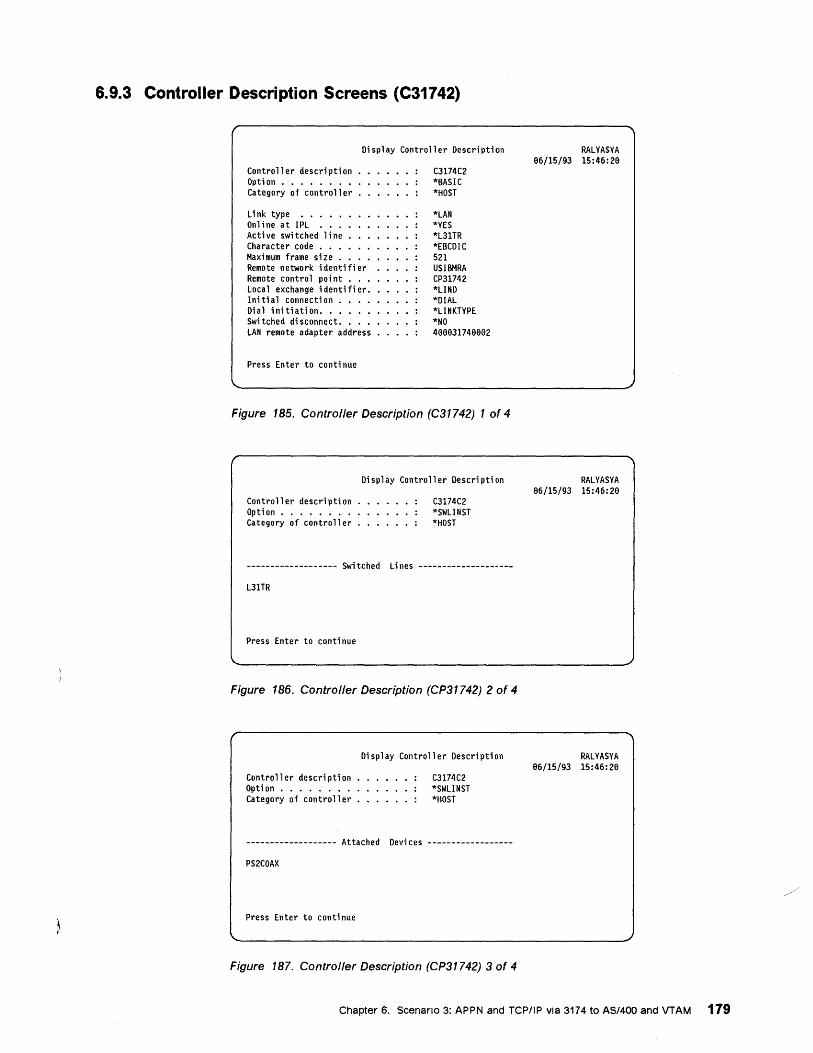
6.9.3 Controller Description Screens (C31742)
Display Controller Description
Controller description Opti on ••.••••• Category of controller
Link type ••••• Online at IPL ••• Acti ve swi tched 1 i ne Character code • • . Maximum frame size. Remote network i denti fi er Remote control poi nt • • • Local exchange identifier. Ini tial connecti on •••• Dial initiation .••••• Switched di sconnect. • • • LAN remote adapter address
Press Enter to continue
C3174C2 *BASIC *HOST
*LAN *YES *L3lTR *EBCDIC 521 USIBMRA CP31742 *LINO *DIAL *LINKTYPE *NO 499931749992
Figure 185. Controller Description (C31742) 1 of 4
Controller description Opti on • • • • • • . • Category of controller
Oi sp 1 ay Controller Oescri pti on
C3174C2 *SWLINST *HOST
------------------- Swi tched Li nes --------------------
L3lTR
Press Enter to conti nue
Figure 186. Controller Description (CP31742) 2 of 4
Contro 11 er descri pti on Opti on •••••.•• Category of controller
Oi sp 1 ay Controller Oescri pti on
C3174C2 *SWLINST *HOST
------------------- Attached Devices ------------------
PS2COAX
Press Enter to continue
Figure 187. Controller Description (CP31742) 3 of 4
RALYASYA 96/15/93 15:46:29
RALYASYA 96/15/93 15:46:29
RALYASYA 96/15/93 15:46:29
Chapter 6. Scenario 3: APPN and TCP/IP via 3174 to AS/400 and VTAM 179
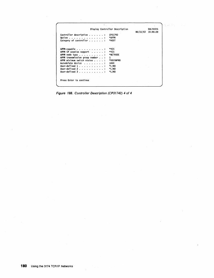
Oisp 1 ay Controller Oescri pti on
Contro 11 er descri pti on Opti on •••••••• Category of controller
APPN-capab 1 e • • • • • • • • • APPN CP sessi on support • • • APPN node type • • • • • • • • APPN transmi ssi on group number APPN minimum swi tch status Autode 1 ete devi ce User-defi ned 1 User-defi ned 2 User-defi ned 3
Press Enter to conti nue
CP31742 *APPN *HOST
*YES *YES *NETNOOE 1 *VRYONPND 1448 *LINO *LINO *LINO
Figure 188. Controller Description (CP31742) 4 of 4
180 Using the 3174 TCPIIP Networks
RALYASYA 66/15/93 15:46:20
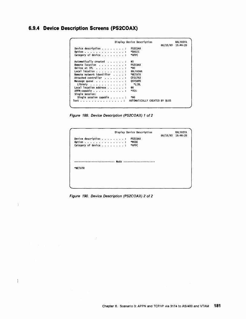
6.9.4 Device Description Screens (PS2COAX)
Devi ce descri pti on • Option ••••••• Category of devi ce •
Automatically created Remote location ••• Online at IPL •••• Local location •••• Remote network i denti fi er Attached controller • Message queue ••••
Library •••••• Loca 1 1 ocati on address APPN-capable ••••• Single session:
Single session capable
Di sp 1 ay Devi ce Descri pti on
PS2COAX *SASIC *APPC
NO PS2COAX *NO RALYAS4A *NETATR CP31742 QSYSOPR
*USL 88 *YES
*NO
RALYASYA 86/15/93 15:46:28
Text ••••••••••••••• : AUTOMATICALLY CREATED BY QLUS
Figure 189. Device Description (PS2COAX) 1 of 2
Devi ce descri pti on Opti on •••••• Category of devi ce
Display Device Description
PS2COAX *MODE *APPC
---------------------------- Mode ------------------ ----
*NETATR
Figure 190. Device Description (PS2COAX) 2 of 2
RALYASYA 86/15/93 15:46: 26
Chapter 6. Scenario 3: APPN and TCPIIP via 3174 to AS/400 and VTAM 181
6.10 Communications Manager/2 Definitions for 5250 Emulation On the PS/2, we run Communications Manager/2 and do the following:
• Communications Manager Installation/Setup
• Communication Setup
• Open Configuration
• Communication Manager Configuration Definition - 5250
• 5250 Emulation through Token-Ring
• Communication Setup Close
6.10.1 Communications Manager/2 Installation and Setup
n CMSETUP
- - - ....... -- ----- - - _ .. -- • ---- , --Communications Manager/2 Installation and Setup Version 1.0
(C) Copyright IBM Corp. 1988~ 1992. All rights reserved IBM is a registered trademark of
International Business Machines Corp.
Figure 191. Communications Managerl2 Installation and Setup
To initiate setup you wi" have to either click on the CMSETUP Icon if Communications Manager/2 is already installed, or enter cmsetup from the command prompt if this is the initial installation (see Communications Manager/2 Installation Guide for details).
182 Using the 3174 rep/lp Networks
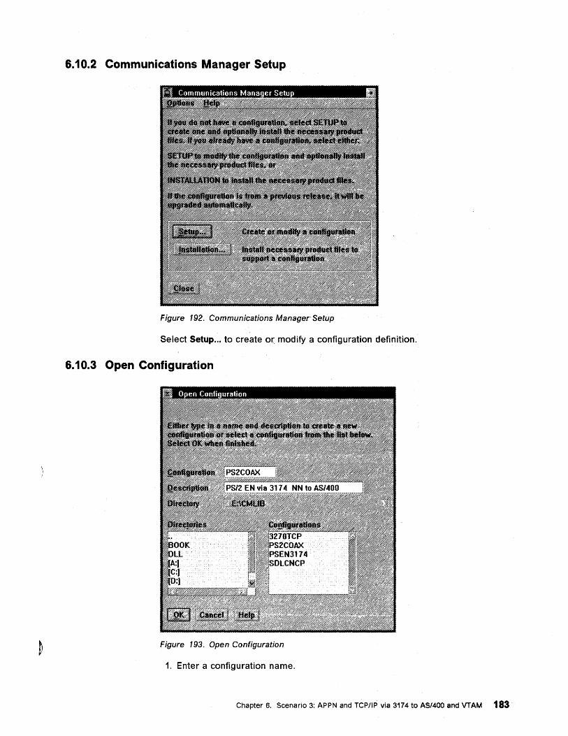
6.10.2 Communications Manager Setup
Figure 192. Communications Manager Setup
Select Setup ... to create or modify a configuration definition.
6.10.3 Open Configuration
Figure 193. Open Configuration
1. Enter a configuration name.
Chapter 6. Scenario 3: APPN and TCP/IP via 3174 to AS/400 and VTAM 183
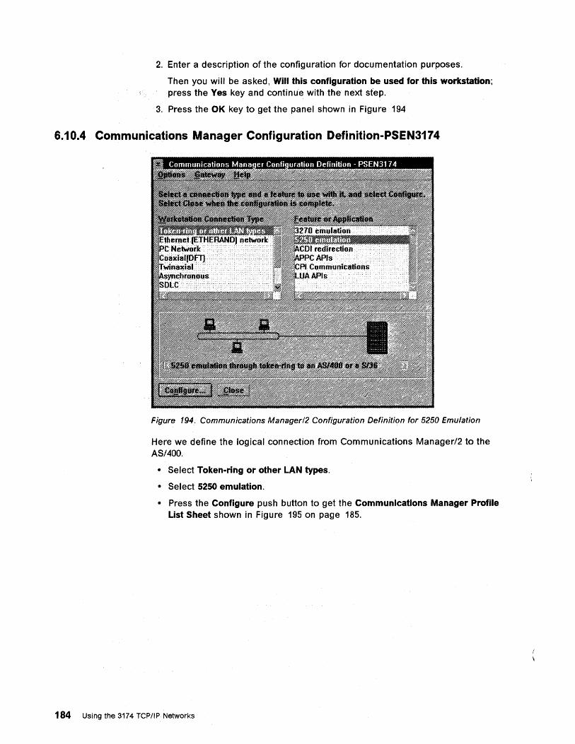
2. Enter a description of the configuration for documentation purposes.
Then you will be asked, Will this configuration be used for this workstation; press the Yes key and continue with the next step.
3. Press the OK key to get the panel shown in Figure 194
6.10.4 Communications Manager Configuration Definition-PSEN3174
Figure 194. Communications Managerl2 Configuration Definition for 5250 Emulation
Here we define the logical connection from Communications Manager/2 to the AS/400.
• Select Token-ring or other LAN types.
• Select 5250 emulation.
• Press the Configure push button to get the Communications Manager Profile List Sheet shown in Figure 195 on page 185.
184 Using the 3174 TCPIIPNetworks
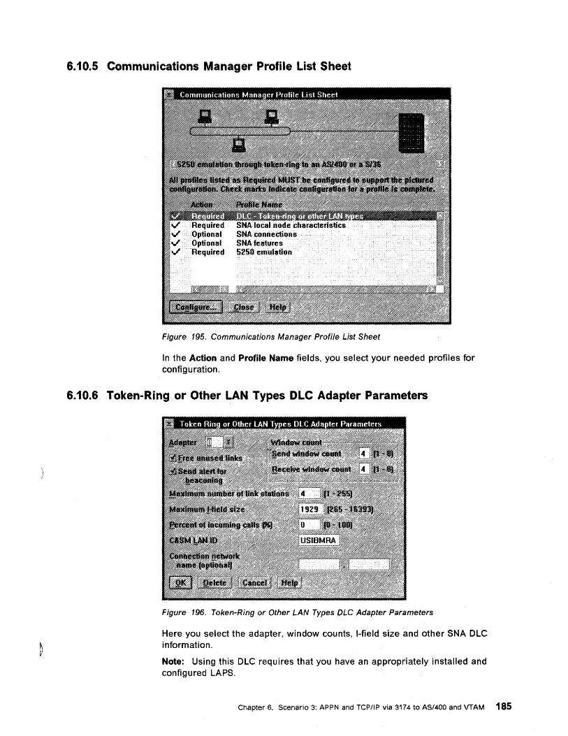
6.10.5 Communications Manager Profile List Sheet
Figure 195. Communications Manager Profile List Sheet
In the Action and Profile Name fields, you select your needed prOfiles for confi g u ration.
6.10.6 Token-Ring or Other LAN Types DLC Adapter Parameters
Figure 196. Token-Ring or Other LAN Types OLC Adapter Parameters
Here you select the adapter, window counts, I-field size and other SNA OLe information.
Note: Using this OLe requires that you have an appropriately installed and configured LAPS.
Chapter 6. Scenario 3: APPN and TCP/IP via 3174 to AS/400 and VTAM 185
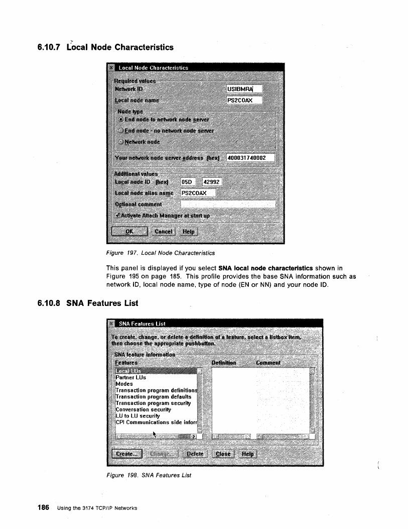
6.10.7 L'Ocal Node Characteristics
Figure 197. Local Node Characteristics
This panel is displayed if you select SNA local node characteristics shown in Figure 195 on page 185. This profile provides the base SNA information such as network 10, local node name, type of node (EN or NN) and your node 10.
6.10.8 SNA Features List
des action program definition
saction program defaults nsaction program security
1i0;)i~l:nm.lporsation security to lU security Communications side info
Figure 198. SNA Features List
186 Using the 3174 TCP/IP Networks
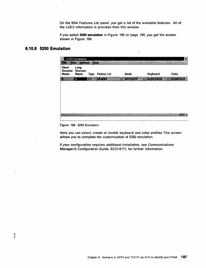
On the SNA Features List panel, you get a list of the available features. All of the LU6.2 information is provided from this window.
If you select 5250 emulation in Figure 195 on page 185, you get the screen shown in Figure 199.
6.10.9 5250 Emulation
r""" !o 5250 Emulation
I Short I Session I Name
Long Session Name Type Partner LU
Figure 199. 5250 Emulation
Mode Keyboard Color
Here you can select, create or modify keyboard and color profiles This screen allows you to complete the customization of 5250 emulation.
If your configuration requires additional installation, see Communications Managerl2 Configuration Guide, SC31-6171, for further information.
Chapter 6. Scenario 3: APPN and rep/IP via 3174 to AS/400 and VTAM 187
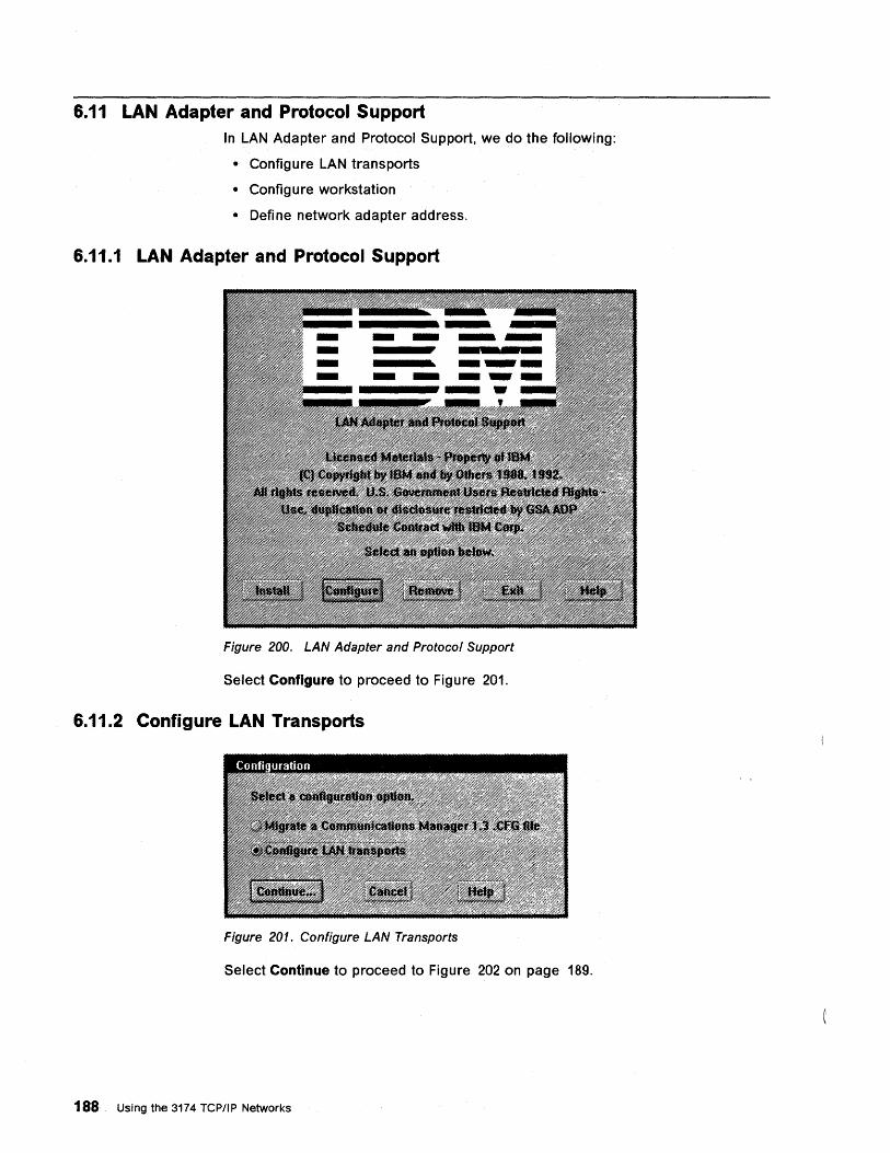
6.11 LAN Adapter and Protocol Support In LAN Adapter and Protocol Support, we do the following:
• Configure LAN transports
• Configure workstation
• Define network adapter address.
6.11.1 LAN Adapter and Protocol Support
Figure 200. LAN Adapter and Protocol Support
Select Configure to proceed to Figure 201.
6.11.2 Configure LAN Transports
Figure 201. Configure LAN Transports
Select Continue to proceed to Figure 202 on page 189.
188 Using the 3174 TCP/IP Networks
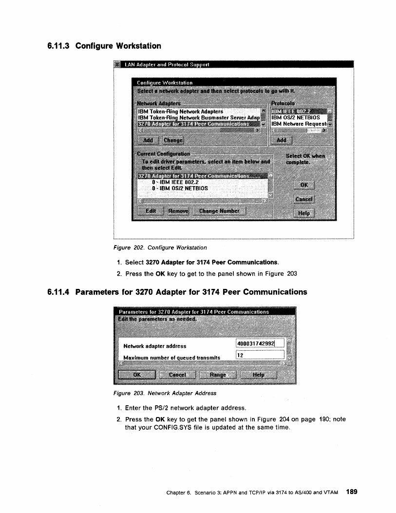
6.11.3 Configure Workstation
,~ LAN Ada ter and Protocol Su ort
I
I
I
I
" _____________________________________________ . ______ .--------------------------------------______ 1
Figure 202. Configure Workstation
1. Select 3270 Adapter for 3174 Peer Communications.
2. Press the OK key to get to the panel shown in Figure 203
6.11.4 Parameters for 3270 Adapter for 3174 Peer Communications
Figure 203. Network Adapter Address
1. Enter the PS/2 network adapter address.
2. Press the OK key to get the panel shown in Figure 204 on page 190; note that your CONFIG.SYS file is updated at the same time.
Chapter 6. Scenario 3: APPN and TCP/IP via 3174 to AS/400 and VTAM 189
6.11.5 LAN Adapter and Protocol Support
Figure 204. LAN Adapter and Protocol Support
Select Exit to end the LAN Adapter and Protocol Support process.
190 Using the 3174 TCP/IP Networks
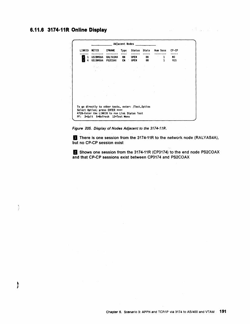
6.11.6 3174-11R Online Display
__ -'-__ Adjacent Nodes ____ _
LINKID NETID CPNAME Type Status State Num Sess CP-CP
USIBMRAA RALYAS4A USIBMRAA PS2COAX
NN EN
OPEN OPEN
8S 8S
To go directly to other tests, enter: ITest,Option Se 1 ect Opti on: press ENTER ••• > 4729-Enter the LINKIO to run Link Status Test PF: 3=Qui t S-Refresh 12-Test Menu
1 1
Figure 205. Display of Nodes Adjacent to the 3174-11R.
NO YES
D There is one session from the 3174-11R to the network node (RALYAS4A), but no CP-CP session exist
fJ Shows one session from the 3174-11R (CP3174) to the end node PS2COAX and that CP-CP sessions exist between CP3174 and PS2COAX
Chapter 6. Scenario 3: APPN and TCP/IP via 3174 to AS/400 and VTAM 191
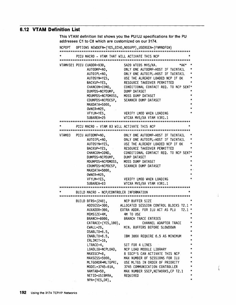
6.12 VTAM Definition List This VTAM definition list shows you the PU/LU specifications for the PU addresses C1 to C8 which are customized on our 3174.
NCPOPT OPTIONS NEWDEFN=(YES,ECHO,NOSUPP),USERGEN=(FNMNDFGN) *********************************************************************** * PCCU MACRO - VTAM THAT WILL ACTIVATE THIS NCP * *********************************************************************** VTAMV321 PCCU CUADDR=930,
AUTODMP=NO, AUTOIPL=NO, AUTOSYN=YES, BACKUP=YES, CHANCON=COND, DUMPDS=NCPDUMP, MDUMPDS=NCPDMOSS, CDUMPDS=NCPDCSP, MAXDATA=5000, OWNER=M25, VFYLM=YES, SUBAREA=25
SA20 WTCOS MVS/XA. *AK* * ONLY ONE AUTODMP-HOST IF TWINTAIL * ONLY ONE AUTOIPL-HOST IF TWINTAIL * USE THE ALREADY LOADED NCP IF OK * RESOURCE TAKEOVER PERMITTED * CONDITIONAL CONTACT REQ. TO NCP SENT* DUMP DATASET * MOSS DUMP DATASET * SCANNER DUMP DATASET *
VERIFY LMOD WHEN LOADING WTCXA MVS/XA VTAM V3Rl.l
* * *
*********************************************************************** * PCCU MACRO - VTAM 03 WILL ACTIVATE THIS NCP * *********************************************************************** VTAM03 PCCU AUTODMP=NO,
AUTOIPL=NO, AUTOSYN=YES, BACKUP=YES, CHANCON=COND, DUMPDS=NCPDUMP, MDUMPDS=NCPDMOSS, CDUMPDS=NCPDCSP, MAXDATA=5000, OWNER=M25, VFYLM=YES, SUBAREA=03
ONLY ONE AUTODMP-HOST IF TWINTAIL * ONLY ONE AUTOIPL-HOST IF TWINTAIL * USE THE ALREADY LOADED NCP IF OK * RESOURCE TAKEOVER PERMITTED * CONDITIONAL CONTACT REQ. TO NCP SENT* DUMP DATASET * MOSS DUMP DATASET * SCANNER DUMP DATASET *
VERIFY LMOD WHEN LOADING WTCXA MVS/XA VTAM V3Rl.1
* * *
*********************************************************************** * BUILD MACRO - NCP/CONTROLER INFORMATION * ***********************************************************************
BUILD BFRS=(240) , ADDSESS=300, AUXADDR=300, MEMSIZE=4M, BRANCH=8000, CATRACE=(YES, 100) , CWALL=26, DSABLTO=6.5, ENABLTO=6.5, ERLIMIT=16, LTRACE=4, LOADLIB=NCPLOAD, MAXSSCP=8, MAXSESS=5000, MLTGORDR=MLTGPRI, MODEL=3745-61A, NAMTAB=50, NETID=USIBMRA, NPA=(YES,DR),
192 Using the 3174 TCPIIP Networks
NCP BUFFER SIZE * ALLOCATED SESSION CONTROL BLOCKS T2.1 * EXTRA ADDR. FOR ILU ACT AS PLU T2.1 *
4M TO USE * BRANCH TRACE ENTRIES *
CHANNEL ADAPTER TRACE * MIN. BUFFERS BEFORE SLOWDOWN *
* IBM 386X REQUIRE 6.5 AS MINIMUM *
* SIT FOR 4 LINES * NCP LOAD MODULE LIBRARY * 8 SSCP'S CAN ACTIVATE THIS NCP * MAX NUMBER OF SESSIONS FOR ILU * USE MLTGS IN ORDER OF PRIORITY * 3745 COMMUNICATION CONTROLLER * MAX NUMBER SSCP,NETWORKS,CP T2.1 * REQUIRED *
*
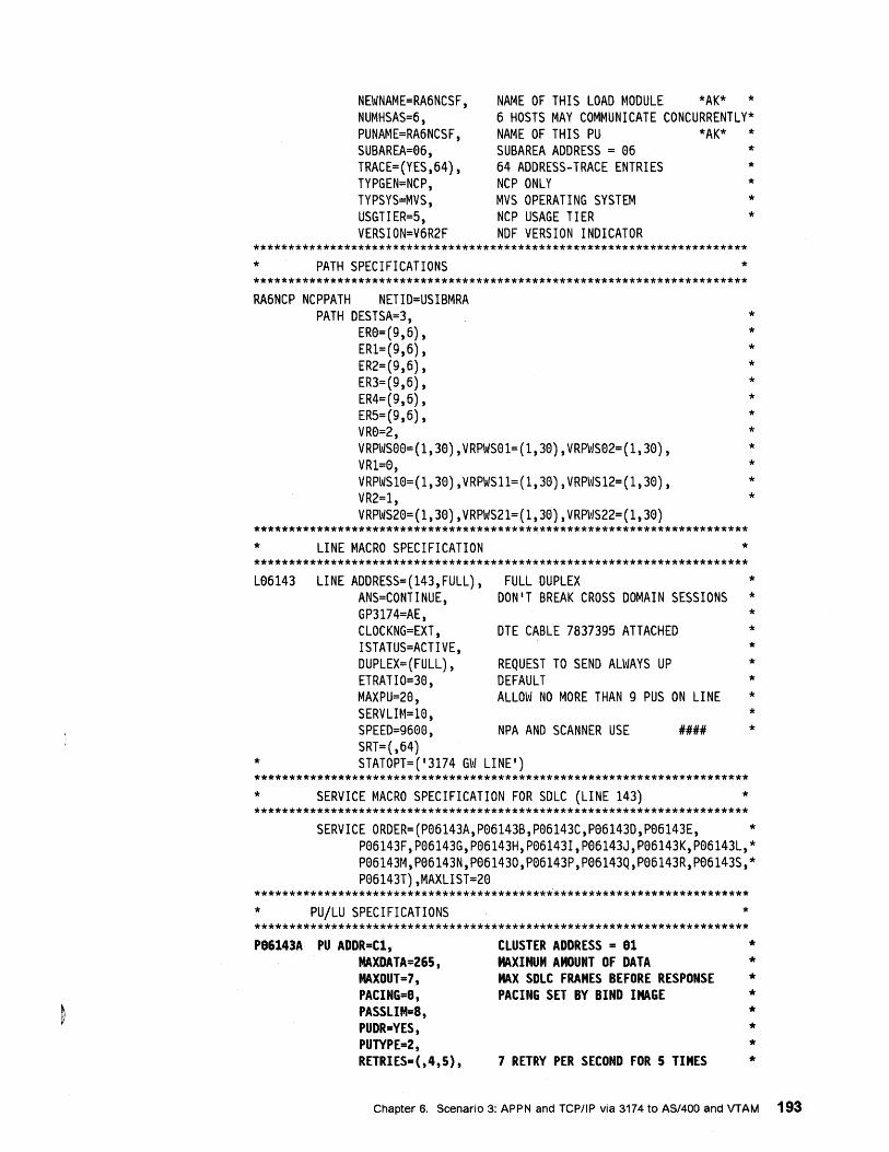
NEWNAME=RA6NCSF, NUMHSAS=6, PUNAME=RA6NCSF, SUBAREA=06, TRACE=(YES,64), TYPGEN=NCP, TYPSYS=MVS, USGTIER=5, VERSION=V6R2F
NAME OF THIS LOAD MODULE *AK* * 6 HOSTS MAY COMMUNICATE CONCURRENTLY* NAME OF THIS PU *AK* * SUBAREA ADDRESS = 06 * 64 ADDRESS-TRACE ENTRIES * NCP ONLY * MVS OPERATING SYSTEM * NCP USAGE TI ER * NDF VERSION INDICATOR
*********************************************************************** * PATH SPECIFICATIONS * *********************************************************************** RA6NCP NCPPATH NETID=USIBMRA
PATH DESTSA=3, ER0=(9,6), ER1=(9,6), ER2=(9,6), ER3=(9,6), ER4=(9,6), ER5=(9,6), VR0=2, VRPWS00=(l,30),VRPWS01=(l,30),VRPWS02=(l,30), VR1=0, VRPWS10=(1,30),VRPWS11=(l,30),VRPWS12=(l,30), VR2=1, VRPWS20=(l,30),VRPWS21=(l,30),VRPWS22=(l,30)
*********************************************************************** * LINE MACRO SPECIFICATION * *********************************************************************** L06143 LINE ADDRESS=(143,FULL), FULL DUPLEX
ANS=CONTINUE, DON'T BREAK CROSS DOMAIN SESSIONS GP3174=AE, CLOCKNG=EXT, DTE CABLE 7837395 ATTACHED ISTATUS=ACTIVE, DUPLEX=(FULL) , REQUEST TO SEND ALWAYS UP ETRATIO=30, DEFAULT MAXPU=20, ALLOW NO MORE THAN 9 PUS ON LINE SERVLIM=10, SPEED=9600, NPA AND SCANNER USE 11111111 SRT=(,64)
* STATOPT=('3174 GW LINE') *********************************************************************** * SERVICE MACRO SPECIFICATION FOR SDLC (LINE 143) * ***********************************************************************
* * * * * * * * * * * *
* * * * * * * * * *
SERVICE ORDER=(P06143A,P06143B,P06143C,P06143D,P06143E, * P06143F,P06143G,P06143H,P06143I,P06143J,P06143K,P06143L,* P06143M,P06143N,P061430,P06143P,P06143Q,P06143R,P06143S,* P06143T),MAXLIST=20
*********************************************************************** * PU/LU SPECIFICATIONS * *********************************************************************** P86143A PU ADDR=Cl,
MAXDATA=26S, MAXOUT=7, PACING=8, PASSLIM=8, PUDR=YES, PUTYPE=2, RETRIES=(,4,S),
CLUSTER ADDRESS = 81 MAXIMUM AMOUNT OF DATA MAX SDLC FRAMES BEFORE RESPONSE PACING SET BY BIND IMAGE
7 RETRY PER SECOND FOR 5 TIMES
* * * * * * * *
Chapter 6. Scenario 3: APPN and TCP/IP via 3174 to AS/400 and VTAM 193
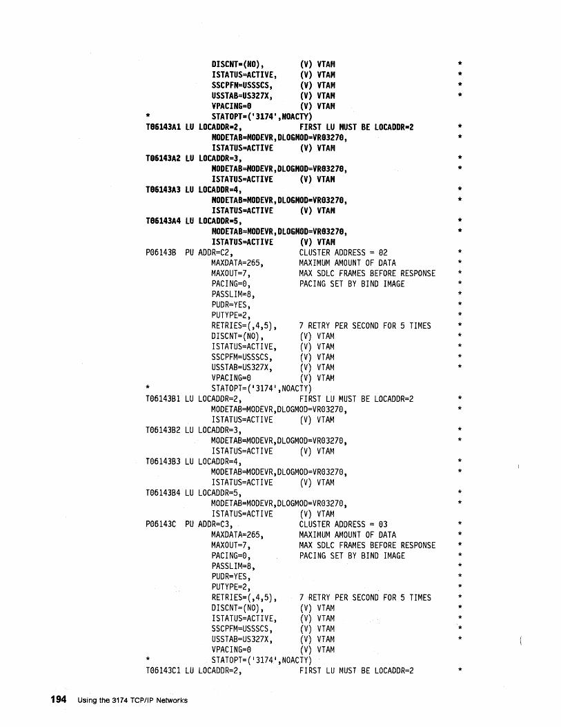
DISCNT=(NO) , (V) VTAM ISTATUS=ACTIVE, (V) VTAM SSCPFM=USSSCS, (V) VTAM USSTAB=US327X, (V) VTAM VPACING=8 (V) VTAM
* STATOPT=('3174',NOACTY) T86143Al lU lOCADDR=2, FIRST lU MUST BE lOCADDR=2
MODETAB=MODEVR,DlOGMOD=VR83278, ISTATUS=ACTIVE (V) VTAM
T86143A2 lU lOCADDR=3, MODETAB=MODEVR,DlOGMOD=VR83278, ISTATUS=ACTIVE (V) VTAM
T86143A3 lU lOCADDR=4, MODETAB=MODEVR,DlOGMOD=VR83278, ISTATUS=ACTIVE (V) VTAM
T86143A4 lU lOCADDR=5, MODETAB=MODEVR,DlOGMOD=VR83278, ISTATUS=ACTIVE (V) VTAM
P06143B PU ADDR=C2, CLUSTER ADDRESS = 02 MAXDATA=265, MAXIMUM AMOUNT OF DATA MAXOUT=7, MAX SDLC FRAMES BEFORE RESPONSE PACING=0, PACING SET BY BIND IMAGE PASSLIM=8, PUDR=YES, PUTYPE=2, RETRIES=(,4,5), 7 RETRY PER SECOND FOR 5 TIMES DISCNT=(NO) , (V) VTAM ISTATUS=ACTIVE, (V) VTAM SSCPFM=USSSCS, (V) VTAM USSTAB=US327X, (V) VTAM VPACING=0 (V) VTAM
* STATOPT=('3174 1 ,NOACTY) T06143Bl LU LOCADDR=2, FIRST LU MUST BE LOCADDR=2
MODETAB=MODEVR,DLOGMOD=VR03270, ISTATUS=ACTIVE (V) VTAM
T06143B2 LU LOCADDR=3, MODETAB=MODEVR,DLOGMOD=VR03270, ISTATUS=ACTIVE (V) VTAM
T06143B3 LU LOCADDR=4, MODETAB=MODEVR,DLOGMOD=VR03270, ISTATUS=ACTIVE (V) VTAM
T06143B4 LU LOCADDR=5, MODETAB=MODEVR,DLOGMOD=VR03270, ISTATUS=ACTIVE (V) VTAM
P06143C PU ADDR=C3, CLUSTER ADDRESS = 03 MAXDATA=265, MAXIMUM AMOUNT OF DATA MAXOUT=7, MAX SDLC FRAMES BEFORE RESPONSE PACING=0, PACING SET BY BIND IMAGE PASSLIM=8, PUDR=YES, PUTYPE=2, RETRIES=(,4,5), 7 RETRY PER SECOND FOR 5 TIMES DISCNT=(NO) , (V) VTAM ISTATUS=ACTIVE, (V) VTAM SSCPFM=USSSCS, (V) VTAM USSTAB=US327X, (V) VTAM VPACING=0 (V) VTAM
* STATOPT=('3174 1 ,NOACTY) T06143Cl LU LOCADDR=2, FIRST LU MUST BE LOCADDR=2
194 Using the 3174 TCPIIP Networks
* * * *
* *
* *
* *
* *
* * * * * * * * * * * *
* *
* *
* *
* *
* * * * * * * * *
*
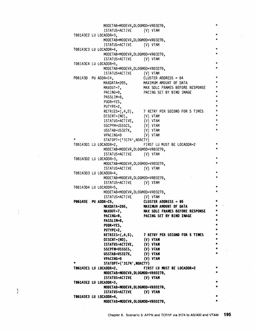
MODETAB=MODEVR,DLOGMOD=VR03270, ISTATUS=ACTIVE (V) VTAM
T06143C2 LU LOCADDR=3, MODETAB=MODEVR,DLOGMOD=VR03270, ISTATUS=ACTIVE (V) VTAM
T06143C3 LU LOCADDR=4, MODETAB=MODEVR,DLOGMOD=VR03270, ISTATUS=ACTIVE (V) VTAM
T06143C4 LU LOCADDR=5, MODETAB=MODEVR,DLOGMOD=VR03270, ISTATUS=ACTIVE (V) VTAM
P06143D PU ADDR=C4, CLUSTER ADDRESS = 04 MAXDATA=265, MAXIMUM AMOUNT OF DATA MAXOUT=7, MAX SDLC FRAMES BEFORE RESPONSE PACING=0, PACING SET BY BIND IMAGE PASSLIM=8, PUDR=YES, PUTYPE=2, RETRIES=(,4,5), 7 RETRY PER SECOND FOR 5 TIMES DISCNT=(NO) , (V) VTAM ISTATUS=ACTIVE, (V) VTAM SSCPFM=USSSCS, (V) VTAM USSTAB=US327X, (V) VTAM VPACING=0 (V) VTAM
* STATOPT=('3174 1 ,NOACTY) T06143D1 LU LOCADDR=2, FIRST LU MUST BE LOCADDR=2
MODETAB=MODEVR,DLOGMOD=VR03270, ISTATUS=ACTIVE (V) VTAM
T06143D2 LU LOCADDR=3, MODETAB=MODEVR,DLOGMOD=VR03270, ISTATUS=ACTIVE (V) VTAM
T06143D3 LU LOCADDR=4, MODETAB=MODEVR,DLOGMOD=VR03270, ISTATUS=ACTIVE (V) VTAM
T06143D4 LU LOCADDR=5, MODETAB=MODEVR,DLOGMOD=VR03270, ISTATUS=ACTIVE (V) VTAM
P86143E PU ADDR=CS, CLUSTER ADDRESS = 85 MAXDATA=265 , MAXIMUM AMOUNT OF DATA MAXOUT=7, MAX SDLC FRAMES BEFORE RESPONSE PACING=9, PACING SET BY BIND IMAGE PASSLIM=8, PUDR=YES, PUTYPE=2, RETRIES=(,4,5), 7 RETRY PER SECOND FOR 5 TIMES DISCNT=(NO) , (V) VTAM ISTATUS=ACTIVE, (V) VTAM SSCPFM=USSSCS, (V) VTAM USSTAB=US327X, (V) VTAM VPACING=9 (V) VTAM
* STATOPT=('3174',NOACTY) T86143El LU LOCADDR=2, FIRST LU MUST BE LOCADDR=2
MODETAB=MODEVR , DLOGMOD=VR93279 , ISTATUS=ACTIVE (V) VTAM
T86143E2 LU LOCADDR=3, MODETAB=MODEVR, DLOGMOD=VR93279 , ISTATUS=ACTIVE (V) VTAM
T86143E3 LU LOCADDR=4, MODETAB=MODEVR,DLOGMOD=VR93279,
*
* *
* *
* *
* * * * * * * * * * * *
* *
* *
* *
* *
* * . * * * * * * * * * *
* *
* *
* *
Chapter 6. Scenario 3: APPN and TCP/IP via 3174 to AS/400 and VTAM 195
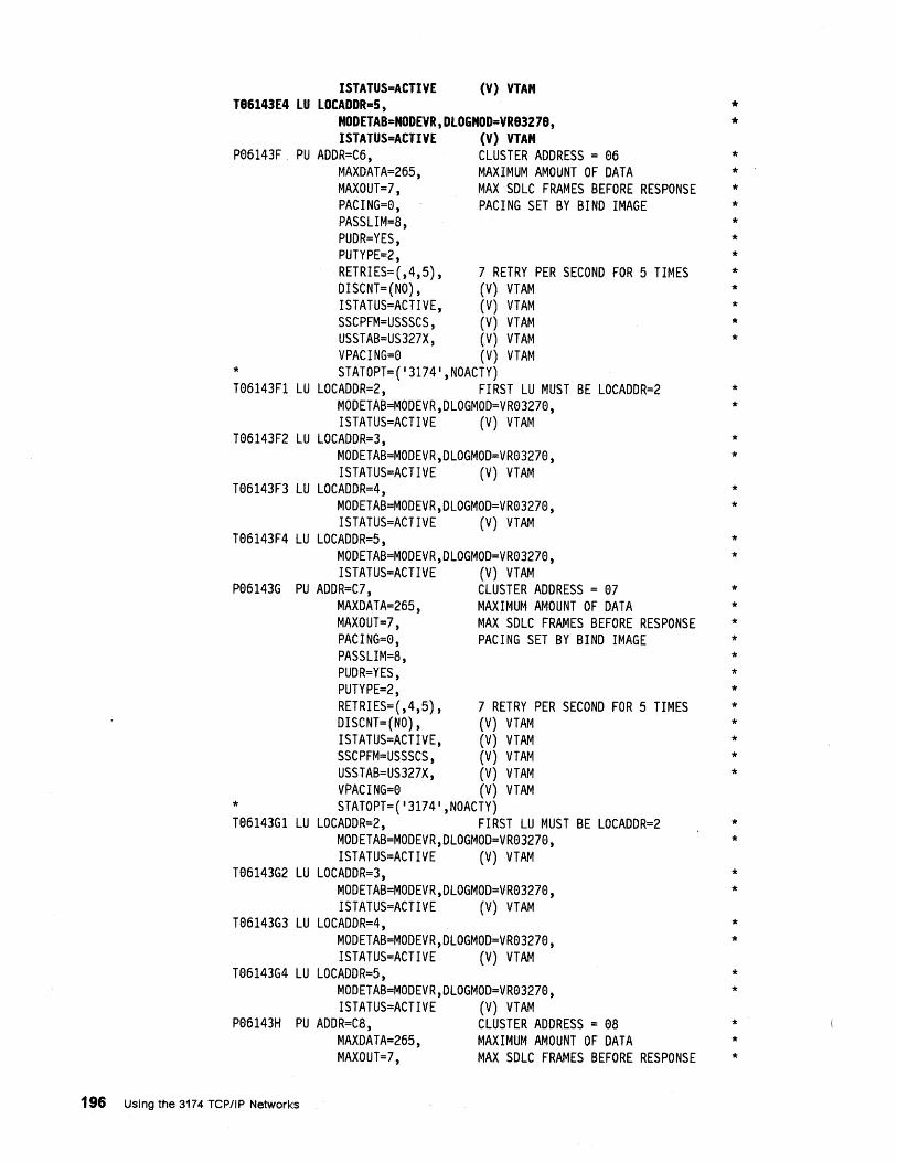
ISTATUS=ACTIVE (V) VTAM T86143E4 LU LOCADDR=S,
MODETAB=MODEVR,DLOGMOD=VR83278, ISTATUS=ACTIVE (V) VTAM
P06143F PU ADDR=C6, CLUSTER ADDRESS = 06 MAXDATA=265, MAXIMUM AMOUNT OF DATA MAXOUT=7, MAX SDLC FRAMES BEFORE RESPONSE PACING=0, PACING SET BY BIND IMAGE PASSLIM=8, PUDR=YES, PUTYPE=2, RETRIES=(,4,5), 7 RETRY PER SECOND FOR 5 TIMES DISCNT=(NO) , (V) VTAM ISTATUS=ACTIVE, (V) VTAM SSCPFM=USSSCS, (V) VTAM USSTAB=US327X, (V) VTAM VPACING=0 (V) VTAM
* STATOPT=('3174 1 ,NOACTY) T06143Fl LU LOCADDR=2, FIRST LU MUST BE LOCADDR=2
MODETAB=MODEVR,DLOGMOD=VR03270, ISTATUS=ACTIVE (V) VTAM
T06143F2 LU LOCADDR=3, MODETAB=MODEVR,DLOGMOD=VR03270, ISTATUS=ACTIVE (V) VTAM
T06143F3 LU LOCADDR=4, MODETAB=MODEVR,DLOGMOD=VR03270, ISTATUS=ACTIVE (V) VTAM
T06143F4 LU LOCADDR=5, MODETAB=MODEVR,DLOGMOD=VR03270, ISTATUS=ACTIVE (V) VTAM
P06143G PU ADDR=C7, CLUSTER ADDRESS = 07 MAXDATA=265, MAXIMUM AMOUNT OF DATA MAXOUT=7, MAX SDLC FRAMES BEFORE RESPONSE PACING=0, PACING SET BY BIND IMAGE PASSLIM=8, PUDR=YES, PUTYPE=2, RETRIES=(,4,5), 7 RETRY PER SECOND FOR 5 TIMES DISCNT=(NO) , (V) VTAM ISTATUS=ACTIVE, (V) VTAM SSCPFM=USSSCS, (V) VTAM USSTAB=US327X, (V) VTAM VPACING=0 (V) VTAM
* STATOPT=('3174 1 ,NOACTY) T06143Gl LU LOCADDR=2, FIRST LU MUST BE LOCADDR=2
MODETAB=MODEVR,DLOGMOD=VR03270, ISTATUS=ACTIVE (V) VTAM
T06143G2 LU LOCADDR=3, MODETAB=MODEVR,DLOGMOD=VR03270, ISTATUS=ACTIVE (V) VTAM
T06143G3 LU LOCADDR=4, MODETAB=MODEVR,DLOGMOD=VR03270, ISTATUS=ACTIVE (V) VTAM
T06143G4 LU LOCADDR=5, MODETAB=MODEVR,DLOGMOD=VR03270, ISTATUS=ACTIVE (V) VTAM
P06143H PU ADDR=C8, CLUSTER ADDRESS = 08 MAXDATA=265, MAXIMUM AMOUNT OF DATA MAXOUT=7, MAX SDLC FRAMES BEFORE RESPONSE
196 Using the 3174 TCPIIP Networks
* *
* * * * * * * * * * * *
* *
* *
* *
* *
* * * * * * * * * * * *
* *
* *
* *
* *
* * *
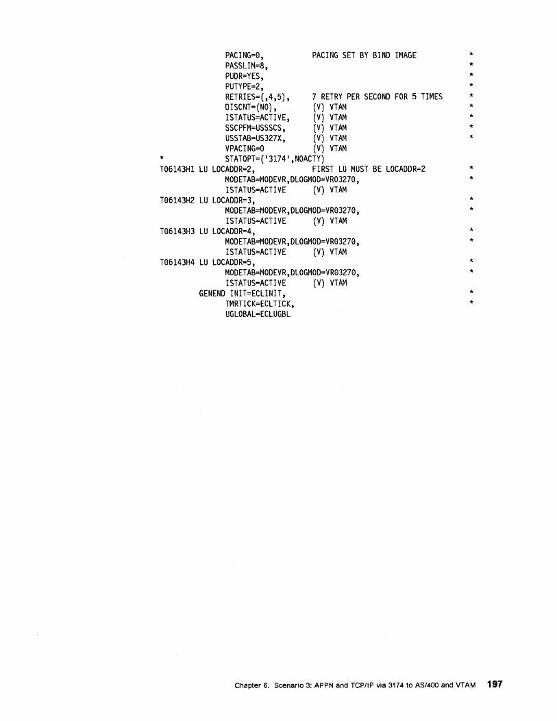
PACING=0, PACING SET BY BIND IMAGE PASSLIM=8, PUDR=YES, PUTYPE=2, RETRIES=(,4,5), 7 RETRY PER SECOND FOR 5 TIMES DISCNT=(NO) , (V) VTAM ISTATUS=ACTIVE, (V) VTAM SSCPFM=USSSCS, (V) VTAM USSTAB=US327X, (V) VTAM VPACING=0 (V) VTAM
* STATOPT=('3174 1 ,NOACTY) T06143Hl LU LOCADDR=2, FIRST LU MUST BE LOCADDR=2
MODETAB=MODEVR,DLOGMOD=VR03270, ISTATUS=ACTIVE (V) VTAM
T06143H2 LU LOCADDR=3, MODETAB=MODEVR,DLOGMOD=VR03270, ISTATUS=ACTIVE (V) VTAM
T06143H3 LU LOCADDR=4, MODETAB=MODEVR,DLOGMOD=VR03270, ISTATUS=ACTIVE (V) VTAM
T06143H4 LU LOCADDR=5, MODETAB=MODEVR,DLOGMOD=VR03270, ISTATUS=ACTIVE (V) VTAM
GENEND INIT=ECLINIT, TMRTICK=ECL TICK, UGLOBAL=ECLUGBL
* * * * * * * * *
* *
* *
* *
* *
* *
Chapter 6. Scenario 3: APPN and TCPIIP via 3174 to AS/400 and VTAM 197
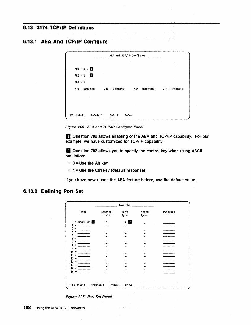
6.13 3174 TCP/IP Definitions
6.13.1 AEA And TCP/IP Configure
___ AEA and TCP/IP Configure __ _
7ge - 9 1 a 792 - 1 IJ 793 - 9
719 - 99999ge9 711 - 99999999
PF: 3=Quit 4z Default 7=Back 8-Fwd
712 - 99999999
Figure 206. AEA and TCP/IP Configure Panel
713 - 99999999
D Question 700 allows enabling of the AEA and TCP/IP capability. For our example, we have customized for TCP/IP capability.
II Question 702 allows you to specify the control key when using ASCII emulation:
• 0 = Use the Alt key
• 1 = Use the Ctrl key (default response)
If you have never used the AEA feature before, use the default value.
6.13.2 Defining Port Set
_____ Port Set ____ _
Name
1 = 3279DISP a 2 = 3 = 4 '" 5 = 6 = 7 :: 8 = 9 =
19 = 11= 12 = 13 = 14 = 15 = 16 =
Sessi on Limit
5
Port Type
llJ
PF: 3=Quit 4=Default 7=Back 8=Fwd
Figure 207. Port Set Panel
198 Using the 31.74 TCP/IP Networks
Modem Type
Password

DEnter 3210DISP in the Name field.
a Enter a 1 in the Port Type field for 3270 displays. This allows your 3270 display defined to port set 1 to access the TCPIIP destination.
Chapter 6. Scenario 3: APPN and TCP/IPvia 3174 to AS/400 and VTAM 199
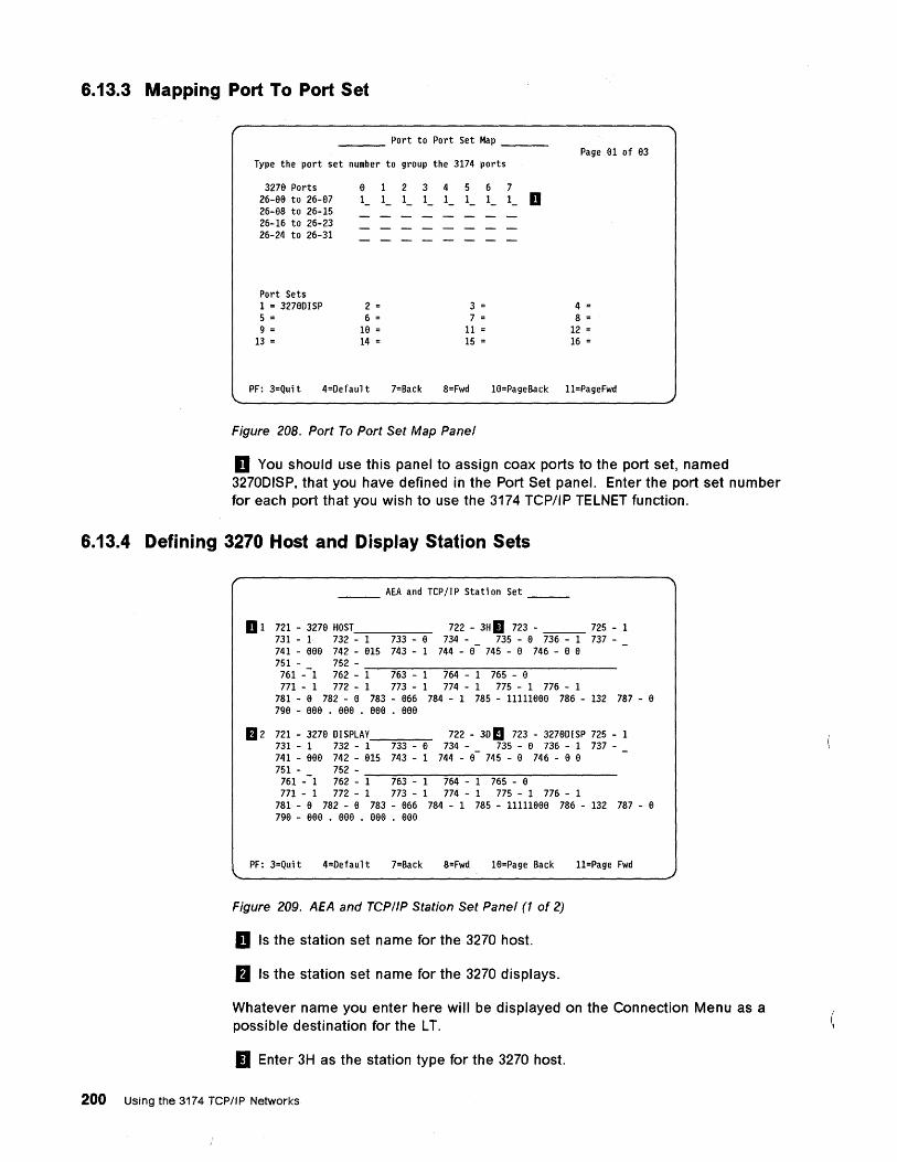
6.13.3 Mapping Port To Port Set
___ Port to Port Set Map __ _
Type the port set number to group the 3174 ports
327e Ports 26-ee to 26-137 26-138 to 26-15 26-16 to 26-23 26-24 to 26-31
Port Sets 1 = 327eDISP 5 = 9 =
13 =
e 1 -
2 = 6 =
1e = 14 =
1 2 1 1 - -
3 4 1 1 - -
5 1 -
3 = 7 =
11 = 15 =
6 1 -
7 1 - D
Page 131 of e3
4 = 8 =
12 = 16 =
PF: 3=Qui t 4=Defaul t 7=Back 8=Fwd 1e=PageBack l1=PageFwd
Figure 208. Port To Port Set Map Panel
D You should use this panel to assign coax ports to the port set, named 3270DISP, that you have defined in the Port Set panel. Enter the port set number for each port that you wish to use the 3174 TCPJIP TELNET function.
6.13.4 Defining 3270 Host and Display Station Sets
___ AEA and TCP/IP Station Set __ _
D 1 721 - 32713 HOST 722 - 3H II 723 - ___ 725 - 1 731 - 1 732 - 1 733 - a 734 - 735 - a 736 - 1 737-741 - eee 742 - e15 743 - 1 744 - 13- 745 - a 746 - a a 751 - 752 -761 --1 762 - ~1-=76=3---1~~7~64:-----:-1--=::76~5--:--a:-------
771 - 1 772 - 1 773 - 1 774 - 1 775 - 1 776 - 1 781 - a 782 - a 783 - 1366 784 - 1 785 - 11111131313 786 - 132 787 - e 7913 - eae . eea • eaa . eaa
fJ 2 721 - 327e DISPLAY 722 - 3D III 723 - 327eDISP 725 - 1 731 - 1 732 - 1 733 - a 734 - 735 - e 736 - 1 737-741 - eaa 742 - e15 743 - 1 744 - e- 745 - a 746 - a a 751 - 752 -
761 --1 762 - ~1-=76=3---1~~7~64:-----:-1--=::76~5---a:-------
771 - 1 772 - 1 773 - 1 774 - 1 775 - 1 776 - 1 781 - e 782 - a 783 - e66 784 - 1 785 - 11111131313 786 - 132 787 - a 7913 - eea . eea . eaa . eaa
PF: 3=Qui t 4=Defaul t 7=Back 8=Fwd 1fl=Page Back l1=Page Fwd
Figure 209. AEA and TCP/IP Station Set Panel (1 of 2)
D Is the station set name for the 3270 host.
fJ Is the station set name for the 3270 displays.
Whatever name you enter here will be displayed on the Connection Menu as a possible destination for the LT.
II Enter 3H as the station type for the 3270 host.
200 Using the 3174 TCP/IP Networks
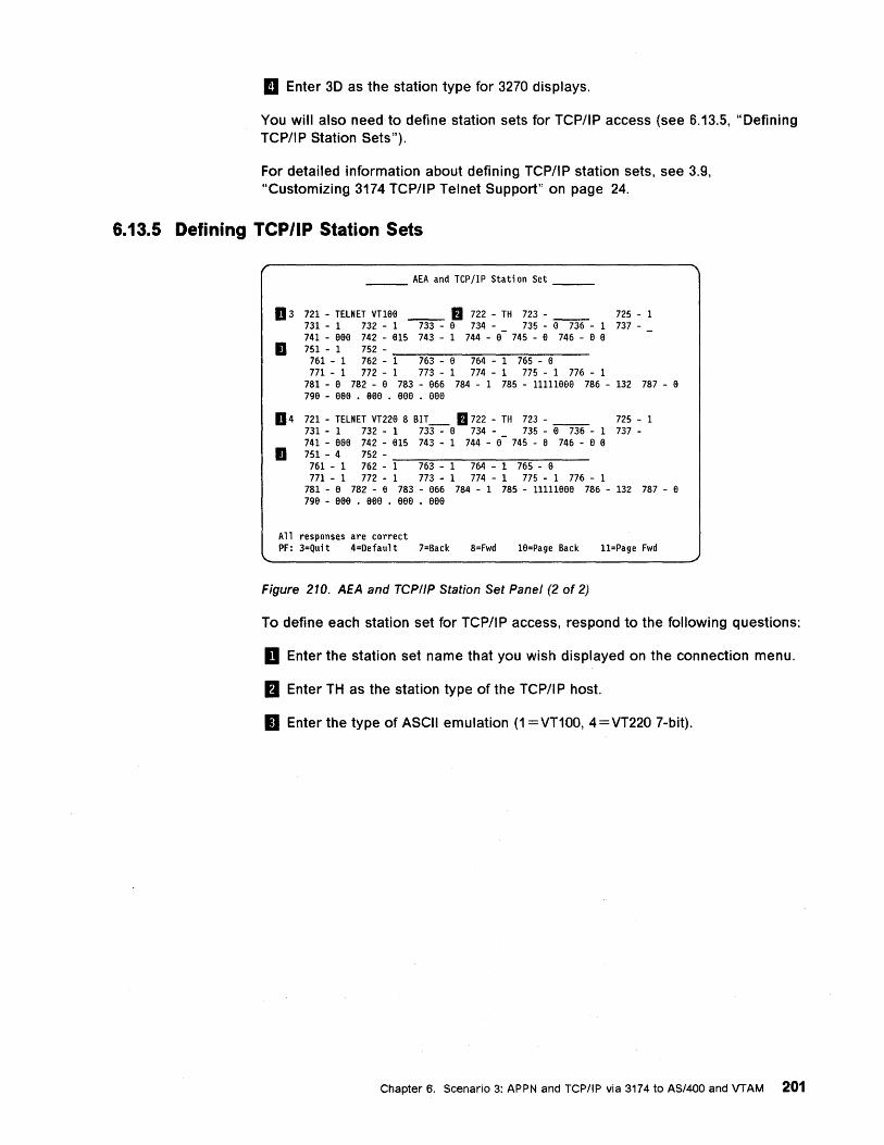
1:1 Enter 3D as the station type for 3270 displays.
You will also need to define station sets for TCP/IP access (see 6.13.5, "Defining TCP/IP Station Sets").
For detailed information about defining TCP/IP station sets, see 3.9, "Customizing 3174 TCP/IP Telnet Support" on page 24.
6.13.5 Defining TCP/IP Station Sets
___ AEA and TCP/IP Station Set __ _
D 3 721 - TELNET vnaa __ II 722 - TH 723 - __ 725 - 1 731 - 1 732 - 1 733 - a 734 - 735 - €I 736 - 1 737-741 - aaa 742 - a15 743 - 1 744 - a- 745 - a 746 - a a
• 751 - 1 752 -761 - 1 762 - '::"'1--=7':"':63:----~e----:7=-:6-:-4--"""":1~7:-:-65=---~a--771 - 1 772 - 1 773 - 1 774 - 1 775 - 1 776 - 1
781 - a 782 - a 783 - a66 784 - 1 785 - 11111aae 786 - 132 787 - a 79a - aaa • aaa • aaa • aae
D 4 721 - TELNET VT22a 8 BIT_ II 722 - TH 723 - __ 725 - 1 731 - 1 732 - 1 733 - a 734 - 735 - a 736 - 1 737-741 - aaa 742 - a15 743 - 1 744 - a- 745 - a 746 - a a
• 751 - 4 752-761 - 1 762 - ~1--=-76~3--~1-----'7:-:-64~--:1--::7':"':65=---~a--
771 - 1 772 - 1 773 - 1 774 - 1 775 - 1 776 - 1 781 - a 782 - a 783 - a66 784 - 1 785 - 11111aee 786 - 132 787 - a 79a - aaa • aae • eee • aee
All responses are correct PF: 3=Qui t 4=Defaul t 7=Back 8=Fwd 1a=Page Back l1=Page Fwd
Figure 210. AEA and TCPIIP Station Set Panel (2 of 2)
To define each station set for TCP/IP access, respond to the following questions:
D Enter the station set name that you wish displayed on the connection menu.
a Enter TH as the station type of the TCP/IP host.
II Enter the type of ASCII emulation (1 =VT100, 4=VT220 7-bit).
Chapter 6. Scenario 3: APPN and TCP/IP via 3174 to AS/400 and VTAM 201
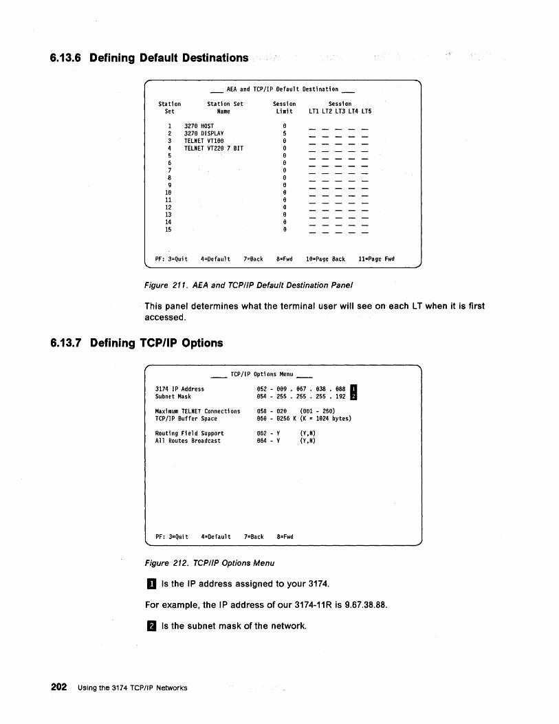
6.13.6 Defining Default Destinations
_ AEA and TCP/IP Default Destination _
Stati on Set
Stati on Set· Name
Session Session Limit LT1 LT2 LT3 LT4 LT5
1 3279 HOST 9 2 3279 DISPLAY 5 3 TELNET VT189 9 4 TELNET VT229 7 BIT 9 5 8 6 8 7 9 8 9 9 8
18 8 11 9 12 9 ~ 8 14 9 15 9
PF: 3=Qui t 4=Defaul t 7=Back 8=Fwd 18=Page Back 11=Page Fwd
Figure 211. AEA and TCP/IP Default Destination Panel
This panel determines what the terminal user will see on each L T when it is first accessed.
6.13.7 Defining TCP/IP Options
__ TCP/IP Options Menu __
3174 IP Address Subnet Mask
Maxi mum TELNET Connecti ons TCP/IP Buffer Space
Routi ng Fi e 1 d Support A 11 Routes Broadcast
952 - 889 • 867 • 838 • 988 I 854 - 255 • 255 • 255 • 192
858 - 82e (991 - 258) 96e - 8256 K (K '"' 1824 bytes)
862 - Y 964 - V
(V,N) (Y,N)
PF: 3=Quit 4=Default 7=Back 8=Fwd
Figure 212. TCP/IP Options Menu
D Is the IP address assigned to your 3174.
For example, the IP address of our 3174-11R is 9.67.38.88.
B Is the subnet mask of the network.
202 Using the 3174 TCP/IP Networks
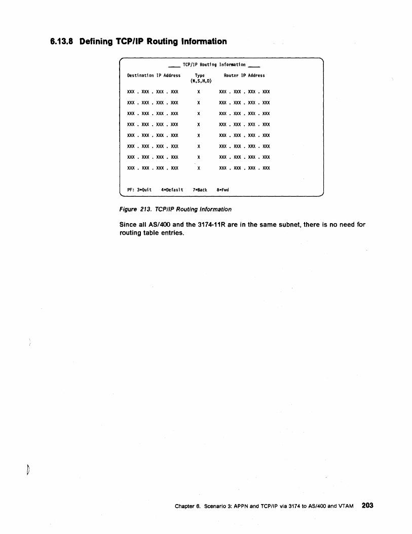
6.13.8 Defining TeP/lP Routing Information
__ TCP/IP Routing Information __
Destination IP Address Type Router IP Address (N.S.H.D)
XXX • XXX • XXX • XXX X XXX • XXX • XXX • XXX
XXX • XXX • XXX • XXX X XXX • XXX • XXX • XXX
XXX • XXX • XXX • XXX X XXX • XXX • XXX • XXX
XXX • XXX • XXX • XXX X XXX • XXX • XXX • XXX
XXX • XXX • XXX • XXX X XXX • XXX • XXX • XXX
XXX • XXX • XXX • XXX X XXX • XXX • XXX • XXX
XXX • XXX • XXX • XXX X XXX • XXX • XXX • XXX
XXX • XXX • XXX • XXX X XXX • XXX • XXX • XXX
PF: 3-Quit 4-Default 7-Back a-Fwd
Figure 213. TCPIIP Routing Information
Since all AS/400 and the 3174-11R are in the same subnet, there is no need for routing table entries.
Chapter 6. Scenario 3: APPN and TCP/IP via 3174 to AS/400 and VTAM 203
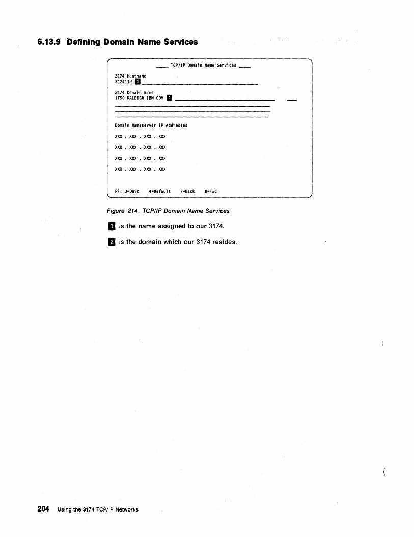
6.13.9 Defining Domain Name Services
__ TCP/IP Domain Name Services __
3174 Hostname 317411R D ______________ _
3174 Domain Name ITSO RALEIGH IBM COM. ________________ _
Domain Nameserver IP Addresses
xxx . XXX • XXX • XXX
XXX • XXX • XXX • XXX
XXX • XXX • XXX • XXX
XXX • XXX • XXX • XXX
PF: 3-Quit 4=Default 7=Back 8=Fwd
Figure 214. TCPIIP Domain Name Services
D Is the name assigned to our 3174.
fJ Is the domain which our 3174 resides.
204 Using the 3174 TCP/IP Networks
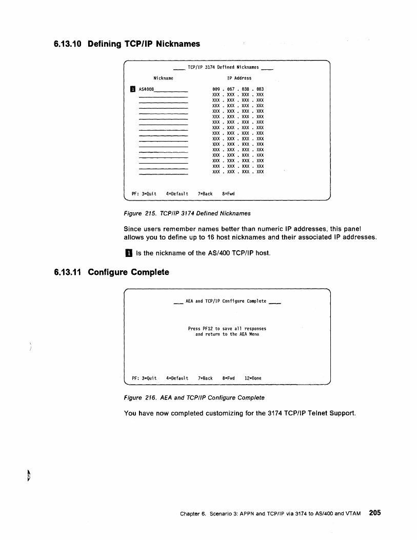
6.13.10 Defining TCP/IP Nicknames
__ TCP/IP 3174 Defined Nicknames __
Nickname IP Address
D AS4aeB ____ _ 999 • 967 • e38 • 983 XXX • XXX • XXX • XXX XXX • XXX • XXX • XXX XXX • XXX • XXX • XXX XXX • XXX • XXX • XXX XXX • XXX • XXX • XXX XXX • XXX • XXX • XXX XXX • XXX • XXX • XXX XXX • XXX • XXX • XXX XXX • XXX • XXX • XXX XXX • XXX • XXX • XXX XXX • XXX • XXX • XXX XXX • XXX • XXX • XXX XXX • XXX • XXX • XXX XXX • XXX • XXX • XXX XXX • XXX • XXX • XXX
PF: 3=Qui t 4=Defaul t 7=Back 8=Fwd
Figure 215. TCP/IP 3174 Defined Nicknames
Since users remember names better than numeric IP addresses, this panel allows you to define up to 16 host nicknames and their associated IP addresses.
D Is the nickname of the AS/400 TCP/IP host.
6.13.11 Configure Complete
_ AEA and TCP/IP Configure Complete __
Press PF12 to save all responses and return to the AEA Menu
PF: 3=Qui t 4=Default 7=Back 8=Fwd 12=Done
Figure 216. AEA and TCP/IP Configure Complete
You have now completed customizing for the 3174 TCP/IP Telnet Support.
Chapter 6. Scenario 3: APPN and TCP/IP via 3174 to AS/400 and VTAM 205
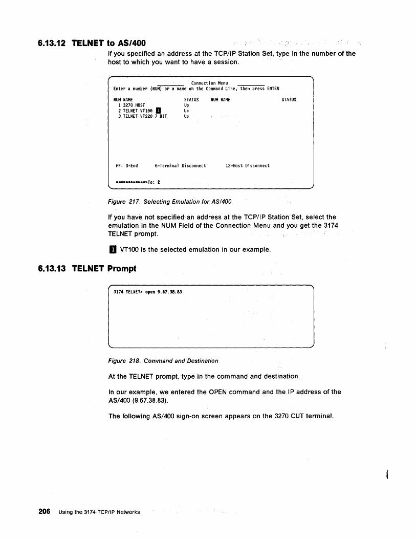
6.13.12 TELNET to AS/400 If you specified an address at the TCP/IP Station Set, type in the number of the host to which you want to have a session.
Connecti on Menu Enter a number (NUM) or a name on the Command Li ne. then press ENTER
NUM NAME 1 3279 HOST 2 TELNET VTl99 a 3 TELNET VT229 7 BIT
STATUS Up Up Up
PF: 3=End 6=Termi na 1 Di sconnect
• .. ·== .... =====>To: 2
NUM NAME
12=Host Disconnect
Figure 217. Selecting Emulation for ASI400
STATUS
If you have not specified an address at the TCP/IP Station Set, select the emulation in the NUM Field of the Connection Menu and you get the 3174 TELNET prompt.
D VT100 is the selected emulation in our example.
6.13.13 TELNET Prompt
3174 TELNET> open 9.67.38.83
Figure 218. Command and Destination
At the TELNET prompt,'type in the command and destination.
In our example, we entered the OPEN command and the IP address of the AS/400 (9.67.38.83).
The following AS/400 sign-on screen appears on the 3270 CUT terminal.
206 Using the 3174 TCP//P Networks
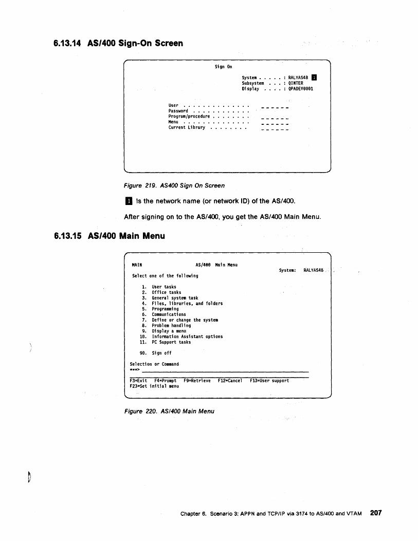
6.13.14 AS/400 Sign-On Screen
User ••••••• Password •••• Program/procedure Menu •••••••
Sign On
System •• Subsystem Display •
Current library ••••••••
Figure 219. AS400 Sign On Screen
RAlVAS48 D QINTER QPADEveeel
D Is the network name (or network 10) of the AS/400.
After signing on to the AS/400, you get the AS/400 Main Menu.
6.13.15 AS/400 Main Menu
MAIN AS/4ee Main Menu
Se 1 ect one of the fo 11 owi ng
1. User tasks 2. Office tasks 3. General system task 4. Files. libraries. and folders 5. Programming 6. Communi cati ons 7. Define or change the system 8. Problem handling 9. Display a menu
Ie. Informati on Assi stant opti ons 11. PC Support tasks
ge. Si gn off
Selection or Command •• =>
System: RAlVAS48
-----------------------------------------------F3=Exi t F4=Prompt F9=Retri eve F12-Cance 1 F13=User support F23=Set i ni ti a 1 menu
Figure 220. AS/400 Main Menu
Chapter 6. Scenario 3: APPN and TCPIIP vja3174 to AS/400 and VTAM207
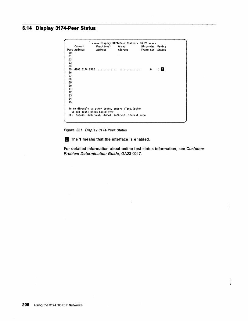
6.14 Display 3174-Peer Status
----- Display 3174-Peer Status - HG 26 -----Current Functional Group Discarded Device
Port Address 88
Address Address Frame Ctr Status
81 82 83 94 85 4888 3174 2992 •••• •••• •••• • ••• •••• • ••• 96 87 8S 89 18 11 12 13 14 15
To go di rectly to other tests. enter: /Test. Opti on Select Test; press ENTER ===>
PF: 3=Quit S=Refresh 8=Fwd 9=Ctr->8 12=Test Menu
Figure 221. Display 3174-Peer Status
D The 1 means that the interface is enabled.
8 1 II
For detailed information about online test status information, see Customer Problem Determination Guide, GA23-0217.
208 Using the 3174 TCP/IP Networks
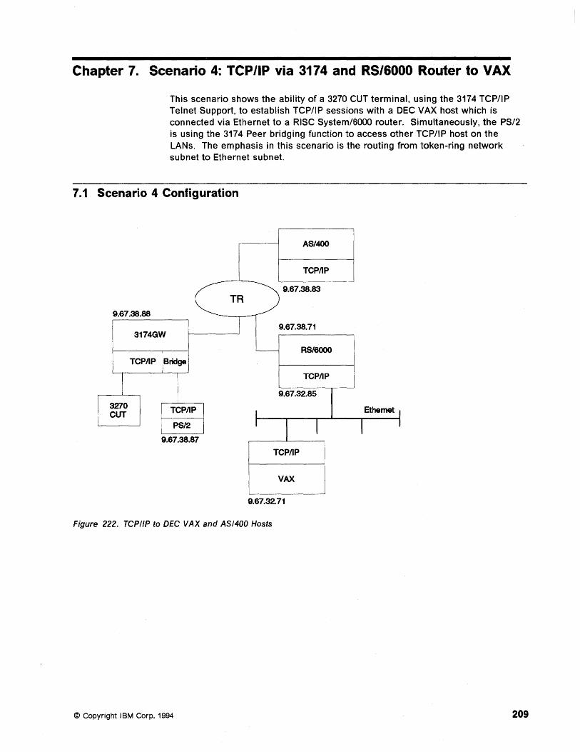
Chapter 7. Scenario 4: TCP/IP via 3174 and RS/6000 Router to VAX
This scenario shows the ability of a 3270 CUT terminal, using the 3174 TCP/IP Telnet Support, to establish TCP/IP sessions with a DEC VAX host which is connected via Ethernet to a RISC System/BOOO router. Simultaneously, the PS/2 is using the 3174 Peer bridging function to access other TCP/IP host on the LANs. The emphasis in this scenario is the routing from token-ring network subnet to Ethernet subnet.
7.1 Scenario 4 Configuration
9.67.38.88
I 3270 CUT
3174GW
TCPIIP Bridge
TCPIIP
PS/2
9.67.38.87
TR
AS/400
TCPIIP
9.67.38.83
9.67.38.71
- RS/6000
TCPIIP
9.67.32.85
I I I I
TCPIIP
VAX
9.67.32.71
Figure 222. TCPIIP to DEC VAX and AS/400 Hosts
© Copyright IBM Corp. 1994
Ethemet I
I I
209
7.2 Scenario 4 Description Scenario 4 shows a PS/2 workstation and a 3270 CUT Terminal coax-attached to the 3174-11R using the 3174 Peer Communication and 3174 TCP/IP Telnet Support, and the RISC System/6000 router to access a DEC VAX host via Ethernet.
The composite networ~ has the following components:
• A 3174-11R with:
3174 TCP/IP Telnet Support enabled
Peer Communication
• A PS/2 Communications Manager/2 (PS2COAX) with:
3270 emulation
Token-ring address (400031742992)
• A 3270 CUT terminal (CUTCOAX)
• The AS/400 host
• The RISC System/6000 attached to a token-ring on one side and an Ethernet LAN on the other side, acting as a router
• A DEC VAX host attached to the same Ethernet LAN as the RISC System/6000
210 Using the 3174 TCPIIP Networks
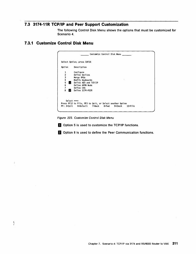
7.3 3174-11R TCP/IP and Peer Support Customization The following Control Disk Menu shows the options that must be customized for Scenario 4.
7.3.1 Customize Control Disk Menu
Customize Control Disk Menu
Select Option; press ENTER
Opti on Descri pti on
1 Configure 2 Def i ne Devi ces 3 Merge RPQs 4 Modi fy Keyboards 5 II Defi ne AEA and TCP lIP 6 Define APPN Node 7 Define COS 8 fJ Defi ne 3174-PEER
Sel ect ===> Press PF12 to File, PF3 to Quit, or Select another Option PF: 3=Quit 4=Default 7=Back 8=Fwd 9=Check 12=Fil e
Figure 223. Customize Control Disk Menu
II Option 5 is used to customize the TCP/IP functions.
fJ Option 8 is used to define the Peer Communication functions.
Chapter 7. Scenario 4: TCPIIP via 3174 and RS/6000 Router to VAX 211
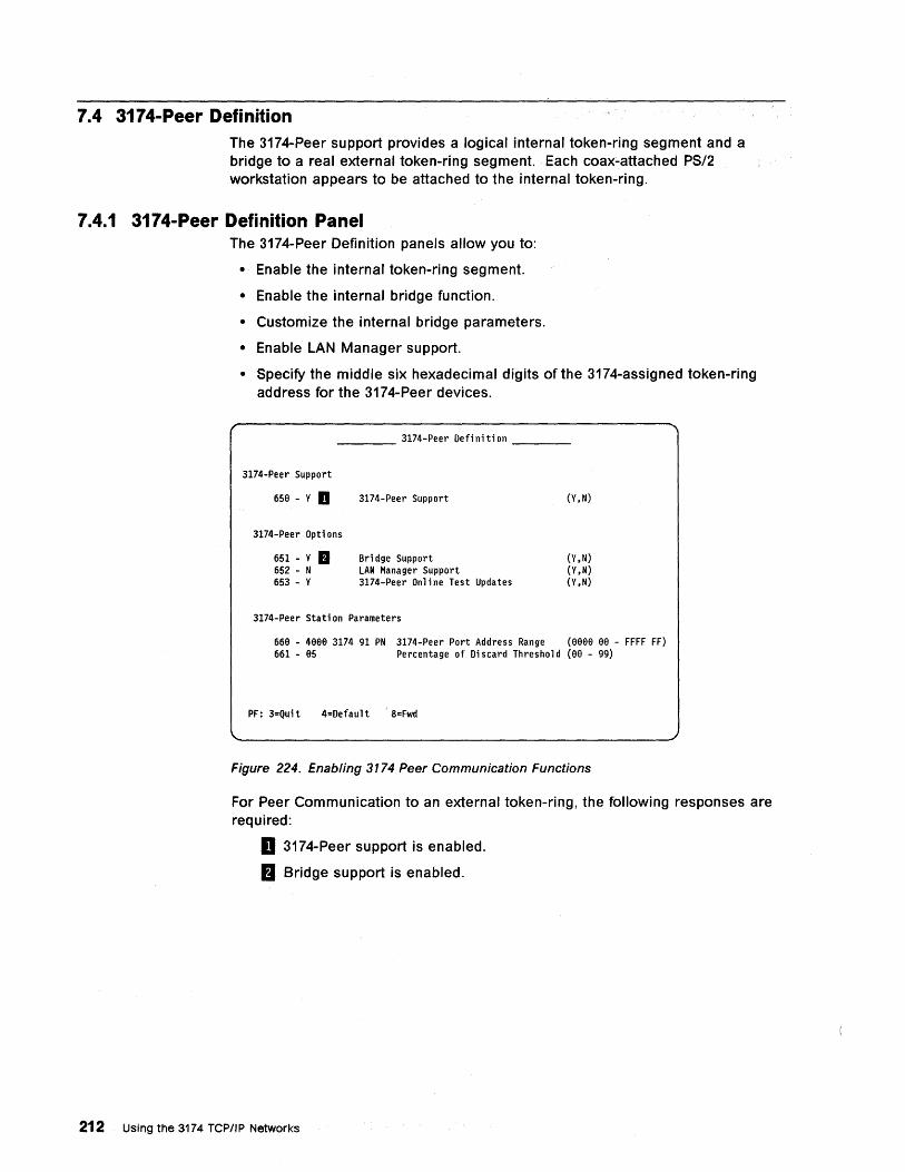
7.4 3174-Peer Definition The 3174-Peer support provides a logical internal token-ring segment and a bridge to a real external token-ring segment. Each coax~attached PS/2 workstation appears to be attached to the internal token-ring.
7.4.1 3174-Peer Definition Panel The 3174-Peer Definition panels allow you to:
• Enable the internal token-ring segment.
• Enable the internal bridge function.
• Customize the internal bridge parameters.
• Enable LAN Manager support.
• Specify the middle six hexadecimal digits of the 3174-assigned tOken-ring address for the 3174-Peer devices.
____ 3174-Peer Defi ni ti on ___ _
3174-Peer Support
65e - Y D
3174-Peer Opti ons
651 - Y fJ 652 - N 653 - Y
3174-Peer Support
Bridge Support LAN Manager Support 3174-Peer On 1 i ne Test Updates
3174-Peer Stati on Parameters
(Y,N)
(y, N) (Y,N) (Y,N)
66B - 4BBB 3174 91 PN 3174-Peer Port Address Range (BBBe BB - FFFF FF) 661 - B5 Percentage of Discard Threshold (BB - 99)
PF: 3=Qui t 4=Defaul t 8=Fwd
Figure 224. Enabling 3174 Peer Communication Functions
For Peer Communication to an external token-ring, the following responses are required:
D 3174-Peer support is enabled.
II Bridge support is enabled.
212 Using the 3174 TCPIIP Networks
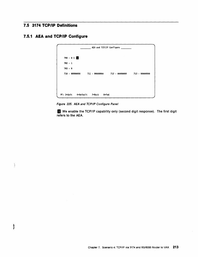
7.5 3174 TCP/IP Definitions
7.5.1 AEA and TCP/IP Configure
___ AEA and TCP/IP Configure __ _
799 - e 1 II 792 - 1
793 - 9
719 - 999999ge 711 - eeeeeege
PF: 3=Quit 4=Default 7=Back 8=Fwd
712 - eeeeeeee
Figure 225. AEA and TCP/IP Configure Panel
713 - eeeeeeee
II We enable the TCP/IP capability only (second digit response). The first digit refers to the AEA.
Chapter 7. Scenario 4: TCPIIP via 3174 and RS/6000 Router to VAX 213
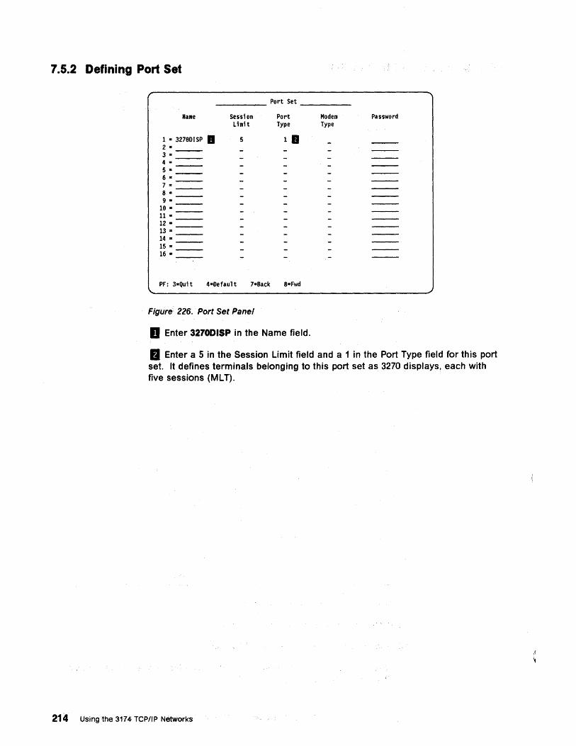
7.5.2 Defining Port Set
_____ Port Set ____ _
Name
1 .. 32790ISP a 2 .. 3 .. 4 = 5 .. 6 .. 7 .. 8 .. 9 ..
19 • n-12 :II:
13 .. 14 .. 15 .. 16 ..
Sessi on Limit
5
Port Type
1 •
PF: 3=Quit 4·0efault 7-Back 8-Fwd
Figure 226. Port Set Panel
II Enter 3270DISP in the Name field.
Modem Type
Password
fJ Enter a 5 in the Session Limit field and a 1 in the Port Type field for this port set. It defines terminals belonging to this port set as 3270 displays, each with five sessions (MLT).
214 Using the 3174 TCPII P Networks
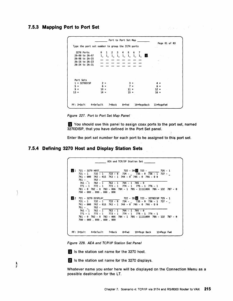
7.5.3 Mapping Port to Port Set
-,--__ Port to Port Set Map __ _ Page 61 of 63
Type the port set number to group the 3174 ports
327e Ports e 1 2 3 4 5 6 7 26-66 to 26-e7 1_ 1 - 1...; 1 - 1 - 1 - 1 - 1 - II; 26-68 to 26-15 26-16 to 26-23 26-24 to 26-31
Port Sets 1 = 3276DISP 2 = 3 = 4 = 5 = 6 = 7 = 8 .. 9 = 1a = 11= 12 ..
13 = 14 = 15 = 16 =
PF: 3=Quit 4=Default 7=Back 8=Fwd 16"'PageBack l1"PageFwd
Figure 227. Port to Port Set Map Panel·
D You should use this panel to assign coax ports to the port set. named 3270DISP. that you have defined in the Port Set panel.
Enter the port set number for each port to be assigned to this port set.
7 .5.4 Defining 3270 Host and Display Station Sets
___ AEA and TCPjIP Station Set __ _
D 1 721 - 327e HOST 722 - 3H 11 723 - ___ 725 - 1 731 - 1 732 - 1 733 - a 734 - 735 - e 736 - 1 737-741 - aee 742 - e15 743 - 1 744 - 6- 745 - a 746 - 6 6 751 - 752 -761 --1 762 - ~1--=-76=-=3----:-1 --=7":"":64:-"---:""1--=:76:':'5---:6:--------
771 - 1 772 - 1 773 - 1 774 - 1 775 - 1 776 - 1 781 - e 782 - a 783 - 666 784 - 1 785 - 1111166e 786 - 132 787 - e 796 - eee . aaa . aea • 6ee
112 721 - 327e DISPLAY 722 - 3011 723 - 327eDISP 725 - 1 731 - 1 732 - 1 733 - 6 734 - 735 - a 736 - 1 737-741 - aee 742 - 615 743 - 1 744 - a- 745 - 6 746 - a 6 751 - 752 -761 --1 762 - 7"1 --=-76=-=3----=-1 --:7:-:-64~-"":'1---=7':"':65:----::"a-----771 - 1 772 - 1 773 - 1 774 - 1 775 - 1 776 - 1
781 - a 782 - e 783 - e66 784 - 1 785 - 111116aa 786 - 132 787 - e 7ge - aee . 6ae . eea • eee
PF: 3=Qui t 4=Defaul t 7=Back 8=Fwd 1e=Page Back l1=Page Fwd
Figure 228. AEA and TCPI/P Station Set Panel
D Is the station set name for the 3270 host.
a Is the station set name for the 3270 displays.
Whatever name you enter here will be displayed on the Connection Menu as a possible destination for the LT.
Chapter 7. Scenario 4: TCPIIP via 3174 and RS/6000 Router to VAX 215'
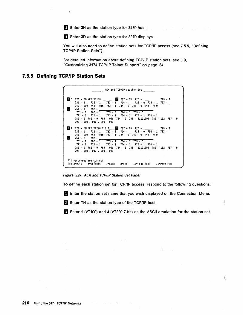
II Enter 3H as the station type for 3270 host.
II Enter 3D as the station type for 3270 displays.
You will also need to define station sets for TCP/IP access (see 7.5.5, "Defining TCP/IP Station Sets").
For detailed information about defining TCP/IP station sets, see 3.9, "Customizing 3174 TCP/IP Telnet Support" on page 24.
7.5.5 Defining TCP/IP Station Sets
___ AEA and TCP/IP Station Set __ _
D 3 721 - TELNET VT16a __ a 722 - TH 723 - __ 725 - 1 731 - 1 732 - 1 733 - a 734 - 735 - a 736 - 1 737-741 - eea 742 - a15 743 - 1 744 - a- 745 - a 746 - a a
11 751 - 1 752 -761 - 1 762 - -1-..".-76...".3---e-..".-76-.,..4---1----:-7--65---a--771 - 1 77Z - 1 773 - 1 774 - 1 775 - 1 776 - 1
781 - a 782 - e 783 - e66 784 - 1 785 - 11111eaa 786 - 132 787 - e 7ge - eee • eee • eee • eee
114 721 - TELNET VT22e 7 BIT_a 722 - TH 723 - __ 725 - 1 731 - 1 732 - 1 733 - e 734 - 735 - e 736 - 1 737-741 - aae 742 - e15 743 - 1 744 - a- 745 - e 746 - e a
11 751 - 2 752 -761 - 1 762 - -1-..".-76...".3---1-..".-76-.,..4---1----:-7-65---a--
771 - 1 772 - 1 773 - 1 774 - 1 775 - 1 776 - 1 781 - a 782 - e 783 - a66 784 - 1 785 - 11111aea 786 - 132 787 - a 79a - aea • aae • aea • aaa
All responses are correct PF: 3=Quit 4=Default 7=Back 8=Fwd 16=Page Back l1=Page Fwd
Figure 229. AEA and TCP//P Station Set Panel
To define each station set for TCP/IP access, respond to the following questions:
D Enter the station set name that you wish displayed on the Connection Menu.
fJ Enter TH as the station type of the TCP/I P host.
II Enter 1 (VT100) and 4 (VT220 7-bit) as the ASCII emulation for the station set.
216 Using the 3174 TCP/IP Networks
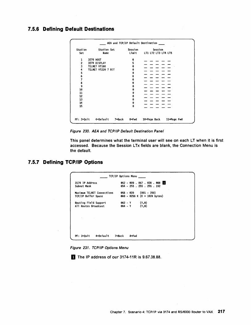
7.5.6 Defining Default Destinations
_ AEA and TCP/IP Default Destination _
Station Set
Stati on Set Name
1 3276 HOST 2 3276 DISPLAY 3 TELNET VT16e 4 TELNET VT22a 7 BIT 5 6 7 8 9
16 11 12 13 14 15
Sessi on Sessi on Limit LTl LT2 LT3 LT4 LT5
6 5 6 a a 6 e a 6 6 a 6 a 6 a
PF: 3=Qui t 4=Defaul t 7-Back 8=Fwd 16-Page Back ll-Page Fwd
Figure 230. AEA and TCP/IP Default Destination Panel
This panel determines what the terminal user will see on each LT when it is first accessed. Because the Session LTx fields are blank, the Connection Menu is the default.
7.5.7 Defining yep/IP Options
__ TCP/IP Options Menu __
3174 IP Address Subnet Mask
Maximum TELNET Connecti ons TCP/IP Buffer Space
Routi ng Fi e 1 d Support All Routes Broadcast
652 - 6a9 • 667 • 638 • 688 II e54 - 255 • 255 • 255 • 192
658 - a26 (e61 - 256) 666 - 6256 K (K • 1624 bytes)
662 - Y 664 - Y
(Y.N) (Y.N)
PF: 3=Quit 4=Default 7=Back 8=Fwd
Figure 231. TCP/IP Options Menu
D The IP address of our 3174-11R is 9.67.38.88.
Chapter 7. Scenario 4: TCP/IP via 3174 and RS/6000 Router to VAX 217
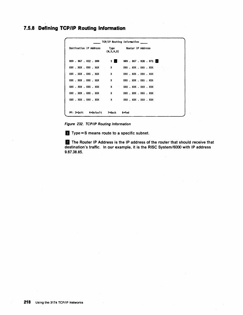
7.5.8 . Defining· TCP/IP Routing Information
__ TCP/IP Routing Info .... ation __
Destination IP Address Type Router IP Address (N,S,H,D)
889 • 867 • 832 • 988 Sa 889 • 867 • 838 • 871 •
XXX • xxx . xxx . xxx x xxx • xxx . xxx . xxx
xxx . xxx . xxx • xxx x xxx • xxx . xxx . xxx
xxx • xxx • xxx • xxx x xxx • xxx . xxx . xxx
xxx . xxx • xxx • xxx x xxx • xxx . xxx . xxx
xxx • xxx . xxx . xxx x xxx • xxx . xxx . xxx
xxx • xxx • xxx . xxx x xxx • xxx . xxx . xxx
PF: 3-Qui t 4-Defaul t 7-Back 8-Fwd
Figure 232. TCPIIP Routing Information
D Type = S means route to a specific subnet.
II The Router IP Address is the IP address of the router that should receive that destination's traffic. In our example, it is the RiSe System/600D with IP address 9.67.38.85.
218 Using the 3174 TCP/IP Networks
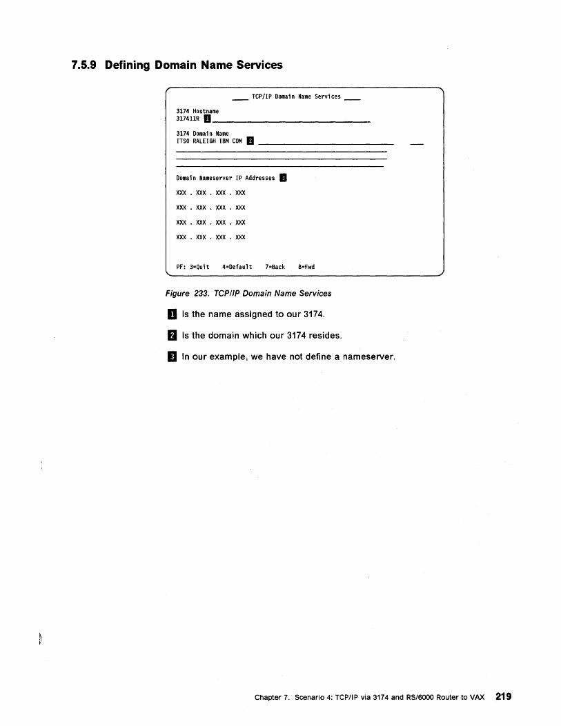
7.5.9 Defining Domain Name Services
__ TCP/IP Domain Name Services __
3174 Hostname 317411R D _______________ _ 3174 Domai n Name ITSO RALEIGH IBM COM tJ _____________ _
Doma in Nameserver I P Addresses II xxx . XXX • xxx . xxx xxx . xxx . xxx . xxx
xxx . xxx . xxx . xxx
xxx . xxx . xxx . xxx
PF: 3=Quit 4=Default 7=Back 8=Fwd
Figure 233. TCP//P Domain Name Services
D Is the name assigned to our 3174.
&I Is the domain which our 3174 resides.
II In our example, we have not define a nameserver.
Chapter 7. Scenario 4: TCPIIP via 3174 and RS/6000 Router to VAX 219
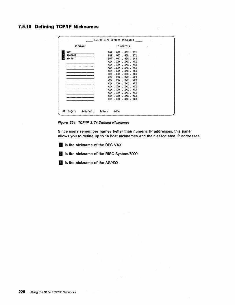
7.5.10 Defining TCP/IP Nicknames
rep lIP 3174 Defi ned Ni cknames
Nickname
I ~~~eeel ___ _ AS48e ____ _
IP Address
889 • 867 • 832 • 871 8eg • 867 • 838 • 871 899 • 967 • 838 • 883 XXX • xxx . xxx . XXX XXX . XXX • XXX • XXX XXX • XXX . XXX • XXX XXX • XXX • XXX • XXX XXX • XXX • XXX • XXX XXX • XXX • XXX • XXX XXX • XXX • XXX • XXX XXX • XXX • XXX . XXX XXX • XXX • XXX • XXX XXX • XXX . XXX • XXX XXX . XXX • XXX • XXX XXX • XXX • XXX • XXX XXX • XXX • XXX • XXX
PF: 3=Quit 4=Default 7=Back 8=Fwd
Figure 234. TCP/IP 3174 Defined Nicknames
Since users remember names better than numeric IP addresses, this panel allows you to define up to 16 host nicknames and their associated IP addresses.
D Is the nickname of the DEC VAX.
fJ Is the nickname of the RISC System/6000.
II Is the nickname of the AS/400.
220· Using the 3174 TCP/IP Networks
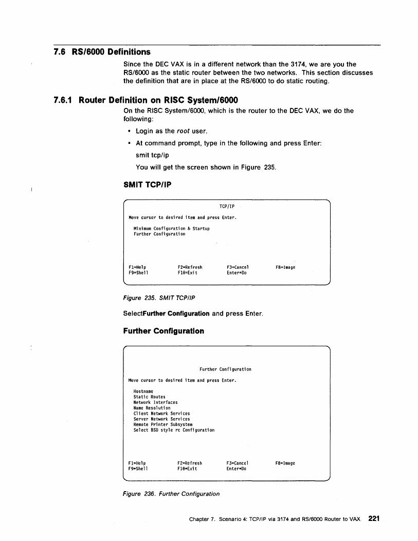
7.6 RS/6000 Definitions Since the DEC VAX is in a different network than the 3174, we are you the RS/BOOO as the static router between the two networks. This section discusses the definition that are in place at the RS/BOOO to do static routing.
7.6.1 Router Definition on RiSe System/6000 On the RISC System/BOOO, which is the router to the DEC VAX, we do the following:
• Login as the root user.
• At command prompt, type in the following and press Enter:
smit tcp/ip
You will get the screen shown in Figure 235.
SMIT TCP/IP
TCP/IP
Move cursor to desired item and press Enter.
Minimum Configuration & Startup Further Configuration
Fl=Help F9=Shell
F2=Refresh F18=Exi t
Figure 235. SMIT TCPI/P
F3=Cancel Enter=Do
SelectFurther Configuration and press Enter.
Further Configuration
Further Configuration
Move cursor to desired item and press Enter.
Hostname Stati c Routes Network Interfaces Name Resolution Cl i ent Network Servi ces Server Network Servi ces Remote Pri nter Subsystem Select BSD style rc Configuration
Fl=Help F9=Shell
F2=Refresh Fl8=Exi t
Figure 236. Further Configuration
F3=Cancel Enter=Do
F8=Image
F8=Image
Chapter 7. Scenario 4: TCP/IP via 3174 and RS/6000 Router to VAX 221
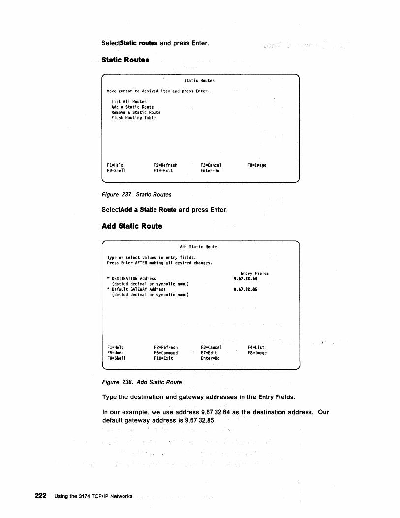
SelectStatlc routes and press Enter.
Static Routes
Stati c Routes
Move cursor to desi red item and press Enter.
List All Routes Add a Stati c Route Remove a Static Route Fl ush Routi ng Table
Fl=Help F9=Shell
F2=Refresh Fle-Exit
Figure 237. Static Routes
F3-Cancel Enter-Do
SelectAdd a Static Route and press Enter.
Add Static Route
Add Sta ti c Route
Type or select values in entry fields. Press Enter AFTER making all desired changes.
* DESTINATION Address (dotted dedmal or symbolic name)
* Default GATEWAY Address (dotted dedmal or symbolic name)
Fl=Help F5=Undo F9=Shell
F2=Refresh F6"Command Fle-Exit
Figure 238. Add Static Route
F3=Cancel F7-Edi t Enter=Do
Entry Fields 9.67.32.64
9.67.32.85
F4-Ust FS-IMage
Type the destination and gateway addresses in the Entry Fields.
In our example, we use address 9.67.32.64 as the destination address. Our default gateway address is 9.67.32.85.
222 Us.ing the 3174 TCP/IP Networks
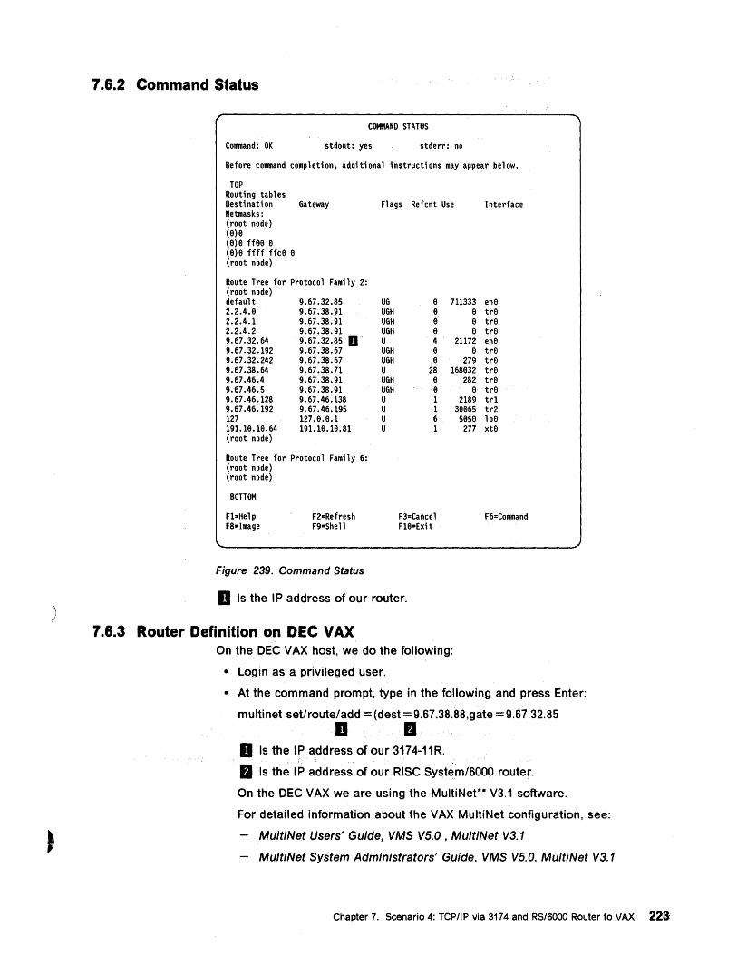
)
7.6.2 Command Status
COMMAND STATUS
Command: OK stdout: yes stderr: no
Before command completion, additional instructions may appear below.
TOP Routing tables Destination Gateway Netmasks: (root node) (8)8 (8)8 ff88 8 (8)8 ffff ffc8 8 (root node)
Route Tree for Protocol Family 2: (root node) defaul t 9.67.32.85 2.2.4.8 9.67.38.91 2.2.4.1 9.67.38.91 2.2.4.2 9.67.38.91 9.67.32.64 9.67.32.85 D 9.67.32.192 9.67.38.67 9.67.32.242 9.67.38.67 9.67.38.64 9.67.38.71 9.67.46.4 9.67.38.91 9.67.46.5 9.67.38.91 9.67.46.128 9.67.46.138 9.67.46.192 9.67.46.195 127 127.6.8.1 191.18.18.64 191.18.18.81 (root node)
Route Tree for Protocol Family 6: (root node) (root node)
BOTTOM
n=Help F8=Image
F2o:Refresh F9=Shell
Figure 239. Command Status
Fl ags Refcnt Use
UG UGH UGH UGH U UGH UGH U UGH UGH U U U U
8 8 8 8 4 8 8
28 6 8 1 1 6 1
F3=Cancel H8=Exit
711333 8 8 8
21172 8
279 168832
282 8
2189 38e6S 5856
277
D Is the IP address of our router.
7.6.3 Router Definition on DEC VAX On the DEC VAX host, we do the following:
• Login as a privileged user.
Interface
en8 tr6 tr6 tr6 ene tr6 tr8 tr6 tr6 tr8 tr1 tr2 106 xt6
F6=Command
• At the command prompt, type in the following and press Enter:
multinet set/route/add = (dest = 9.67.38.88,gate = 9.67.32.85
o fJ o Is the IP address of our 3174-11R.
fJ Is the IP address of our RISC Systeml6000 router.
On the DEC VAX we are using the MultiNet** V3.1 software.
For detailed information about the VAX MultiNet configuration, see:
MultiNet Users' Guide, VMS VS.O , MultiNet V3.1
MultiNet System Administrators' Guide, VMS VS.O, MultiNet V3.1
Chapter 7. Scenario 4: TCPIIP via 3174 and RS/6000 Router to VAX 223
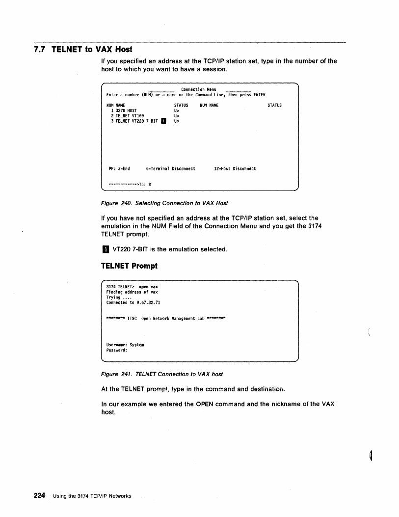
7.7 TELNET to VAX Host If you specified an address at the TCP/IP station set, type in the number of the host to which you want to have a session.
Connection Menu Enter a number (NUM) or a name on the Command line. then press ENTER
NUM NAME 1 3276 HOST 2 TELNET Vn6e 3 TELNET VT226 7 BIT II
STATUS Up Up Up
PF: 3=End 6=Termi na 1 Disconnect
============> To: 3
NUM NAME
12=Host Di sconnect
Figure 240. Selecting Connection to VAX Host
STATUS
If you have not specified an address at the TCP/IP station set, select the emulation in the NUM Field of the Connection Menu and you get the 3174 TELNET prompt.
D VT220 7-BIT is the emulation selected.
TELNET Prompt
3174 TELNET> open vax Finding address of vax Trying •••• Connected to 9.67.32.71
******** ITSC Open Network Management Lab ********
Username: System Password:
Figure 241. TELNET Connection to VAX host
At the TELNET prompt, type in the command and destination.
In our example we entered the OPEN command and the nickname of the VAX host.
224 Using the 3174 TCP/IP Networks
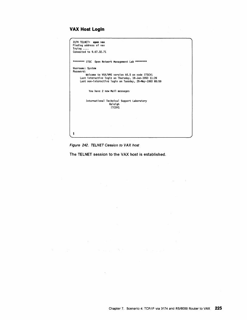
VAX Host Login
3174 TELNET> open vax Finding address of vax Trying •••• Connected to 9.67.32.71
******** ITSC Open Network Management Lab ********
Username: System Password:
Welcome to VAX/VMS version A5.5 on node ITSCVl Last interactive login on Thursday, 16-Jun-1993 11:39 Last non-interactive login on Tuesday, 25-May-1993 68:56
You have 2 new Mai 1 messages
$
Internati ona 1 Techni ca 1 Support Laboratory Raleigh
ITCSVI
Figure 242. TELNET Cession to VAX host
The TELNET session to the VAX host is established.
Chapter 7. Scenario 4: TCPIIP via 3174 and RS/6000 Router to VAX 225

226 Using the 3174 TCPIIP Networks
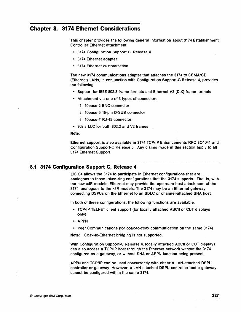
Chapter 8. 3174 Ethernet Considerations
This chapter provides the following general information about 3174 Establishment Controller Ethernet attachment:
• 3174 Configuration Support C, Release 4
• 3174 Ethernet adapter
• 3174 Ethernet customization
The new 3174 communications adapter that attaches the 3174 to CSMA/CO (Ethernet) LANs, in conjunction with Configuration Support-C Release 4, provides the following:
• Support for IEEE 802.3 frame formats and Ethernet V2 (OIX) frame formats
• Attachment via one of 3 types of connectors:
1. 10base-2 BNC connector
2. 10base-5 15-pin O-SUB connector
3. 10base-T RJ-45 connector
• 802.2 LLC for both 802.3 and V2 frames
Note:
Ethernet support is also available in 3174 TCP/IP Enhancements RPQ 8Q1041 and Configuration Support-C Release 5. Any claims made in this section apply to all 3174 Ethernet Support.
8.1 3174 Configuration Support C, Release 4 LlC C4 allows the 3174 to participate in Ethernet configurations that are analogous to those token-ring configurations that the 3174 supports. That is, with the new x4R models, Ethernet may provide the upstream host attachment of the 3174, analogous to the x3R models. The 3174 may be an Ethernet gateway, connecting OSPUs on the Ethernet to an SOLC or channel-attached SNA host.
In both of these configurations, the following functions are available:
• TCP/IP TELNET client support (for locally attached ASCII or CUT displays only)
• APPN
• Peer Communications (for coax-to-coax communication on the same 3174)
Note: Coax-to-Ethernet bridging is not supported.
With Configuration Support-C Release 4, locally attached ASCII or CUT displays can also access a TCP/IP host through the Ethernet network without the 3174 configured as a gateway, or without SNA or APPN function being present.
APPN and TCP/IP can be used concurrently with either a LAN-attached OSPU controller or gateway. However, a LAN-attached OSPU controller and a gateway cannot be configured within the same 3174.
© Copyright I BM Corp. 1994 227
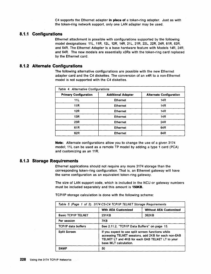
C4 supports the Ethernet adapter in place of a token-ring adapter. Just as with the token-ring network support, only one LAN adapter may be used.
8.1.1 Configurations Ethernet attachment is possible with configurations supported by the following model designations: 11 L, 11R, 12L, 12R, 14R, 21 L, 21R, 22L, 22R, 24R, 61R, 62R, and 64R. The Ethernet Adapter is a base hardware feature with Models 14R, 24R, and 64R. The new models are essentially x3Rs with the token-ring card replaced by the Ethernet card.
8.1.2 Alternate Configurations The following alternative configurations are possible with the new Ethernet adapter card and the C4 diskettes. The conversion of an x4R to a non-Ethernet model is not supported with the C4 diskettes.
Table 4. Alternative Configurations
Primary Configuration Additional Adapter Alternate Configuration
11 L Ethernet 14R
11 R Ethernet 14R
12R Ethernet 14R
13R Ethernet 14R
23R Ethernet 24R
61R Ethernet 64R
62R Ethernet 64R
Note: Alternate configurations allow you to change the use of a given 3174 model; 11 L can be used as a remote TP model by adding a type 1 card (PCA) and customizing as an 11 R.
8.1.3 Storage Requirements Ethernet applications should not require any more 3174 storage than the corresponding token-ring configuration. That is, an Ethernet gateway will have the same configuration as an equivalent token-ring gateway.
The size of LAN support code, which is included in the NCU or gateway numbers must be included separately and this amount is 150KB.
TCP/IP storage calculation is done with the following scheme:
Table 5 (Page 1 of 2). 3174 CS-C4 TCPI/P TELNET Storage Requirements
With AEA Customized Without AEA Customized
Basic TCPIIP TELNET 231KB 362KB
Per session 7KB
TCP/IP data buffers See 2.11.2, "TCP/IP Data Buffers" on page 15.
Split Screen If you expect to use split screen functions while accessing TELNET sessions, add 2KB for each non-EAB TELN ET L T and 4KB for each EAB TELN ET L T to your base MLT calculation.
SNMP 50
228 Using the 3174 TCP/IP Networks

Table 5 (Page 2 of 2). 3174 CS-C4 TCP/IP TELNET Storage Requirements
With AEA Customized I Without AEA Customized
No NCU, GW or APPN 150 installed
Chapter 8. 3174 Ethernet Considerations 229
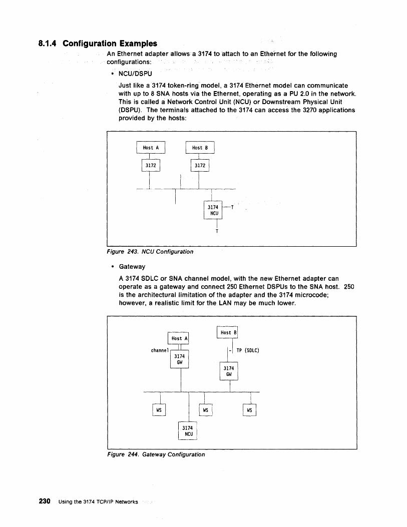
8.1.4 Configuration Examples An Ethernet adapter allows a 3174 to 'attach to an Ethernet for the following configurations:
• NCU/DSPU
Just like a 3174 token-ring model, a 3174 Ethernet model can communicate with up to 8 SNA hosts via the Ethernet, operating as a PU 2.0 in the network. This is called a Network Control Unit (NCU) or Downstream Physical Unit (DSPU). The terminals attached to the 3174 can access the 3270 applications provided by the hosts:
T
T
Figure 243. NCU,Configuration
• Gateway
A 3174 SDLC or SNA channel model, with the new Ethernet adapter can operate as a gateway and connect 250 Ethernet DSPUs to the SNA host. 250 is the architectural limitation of the adapter and the 3174 microcode; however, a realistic limit for the LAN may be much lower.
8 I-I TP (SOLe)
Figure 244. Gateway Configuration
230 Using the 3174 TCPIIP Networks
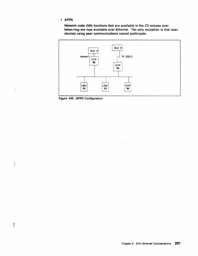
• APPN Network node (NN) functions that are available in the C3 release over token-ring are now available over Ethernet. The only exception is that coax devices using peer communications cannot participate.
8 I-I TP (SOLe)
Figure 245. APPN Configuration
Chapter 8. 3174 Ethernet Considerations 231
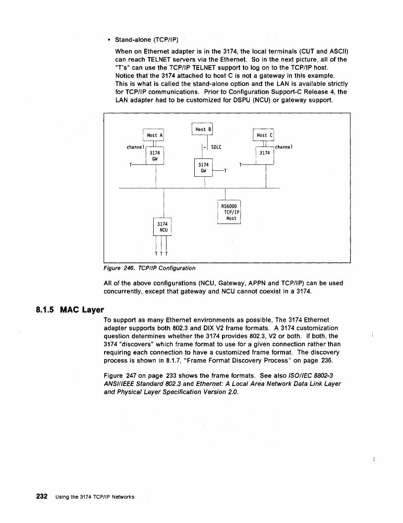
• Stand-alone (TCP/IP)
When on Ethernet adapter is in the 3174, the local terminals (CUT and ASCII) can reach TELNET servers via the Ethernet. So in the next picture, all of the "T's" can use the TCP/IP TELNET support to log on to the TCP/IP host. Notice that the 3174 attached to host C is not a gateway in this example. This is what is called the stand-alone option and the LAN is available strictly for TCP/IP communications. Prior to Configuration Support-C Release 4, the LAN adapter had to be customized for DSPU (NCU) or gateway support.
B I-I SOLC
T----'--r----'
T T T
RS6eee TCPjIP Host
T----'---,r----'
channe 1
Figure 246. TCP/IP Configuration
All of the above configurations (NCU, Gateway, APPN and TCP/IP) can be used concurrently, except that gateway and NCU cannot coexist in a 3174.
8.1.5 MAC Layer To support as many Ethernet environments as possible, The 3174 Ethernet adapter supports both 802.3 and DIX V2 frame formats. A 3174 customization question determines whether the 3174 provides 802.3, V2 or both. If both, the 3174 "discovers" which frame format to use for a given connection rather than requiring each connection to have a customized frame format. The discovery process is shown in 8.1.7, "Frame Format Discovery Process" on page 236.
Figure 247 on page 233 shows the frame formats. See also ISOllEe 8802-3 ANSI/IEEE Standard 802.3 and Ethernet: A Local Area Network Data Link Layer and Physical Layer Specification Version 2.0.
232 Using the 3174 TCP/IP Networks
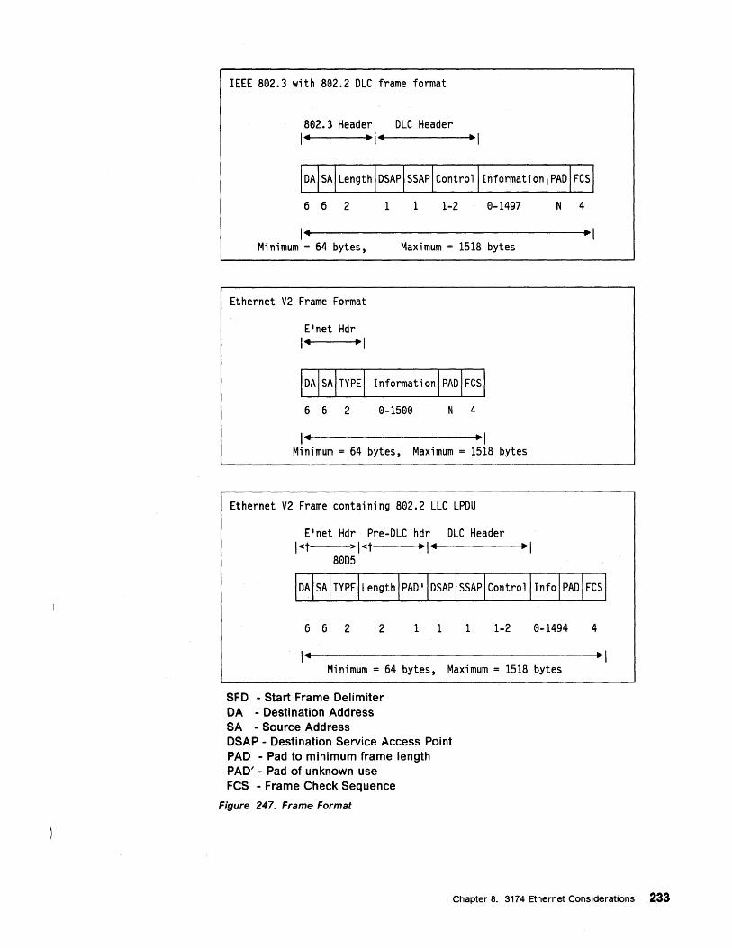
IEEE 802.3 with 802.2 OLC frame format
802.3 Header OLC Header 14 ~14 ~I
662 1 1 1-2 0-1497 N 4
~I Minimum = 64 bytes, Maximum = 1518 bytes
Ethernet V2 Frame Format
662 0-1500 N 4
14 ~ 1 Minimum = 64 bytes, Maximum = 1518 bytes
Ethernet V2 Frame containing 802.2 LLC LPOU
E'net Hdr Pre-OLC hdr DLC Header I<t >I<t ~14 ~I
8005
662 2 1 1 1 1-2 0-1494 4
14 ~I Minimum = 64 bytes, Maximum = 1518 bytes
SFD - Start Frame Delimiter DA - Destination Address SA - Source Address DSAP - Destination Service Access Point PAD - Pad to minimum frame length PAD' - Pad of unknown use FCS - Frame Check Sequence
Figure 247. Frame Format
Chapter 8. 3174 Ethernet Considerations 233
8.1.6 LLC Layer
Bit Order of Ethernet Addresses Even though the architectural definition of Ethernet and token-ring hardware addresses appear the same, there is a subtle difference: Ethernet defines the Individual/Group address bit as the least significant bit of the byte, while token-ring defines it as the most significant bit. The order of bit transmission is also different: Ethernet transmits the Least Significant Bit first, while token-ring transmits the Most Significant Bit first. The addresses are stored in 3174 memory in the usual IBM manner, most significant bit on the left, and are also described that way in text: 400031740000 would be a locally administered, individual address. Therefore, the bits of each byte of the address are reversed before transmitting on the Ethernet. This does not present a problem for TCP/IP connections, since ARP handles the address resolution For SNA over Ethernet, it is dependent upon how a particular connecting product is configured or implements addreSSing that determines how the addresses are customized at the 3174.
With 802.3 frames, C4 and the Ethernet adapter always use 802.2 Logical Link Control. The 802.2 LLC function is provided by microcode on the Ethernet adapter. C4 uses SAP AA for TCP/IP traffic, and SNA SAPs (multiples of 04) for NCU and gateway connections.
With V2 frames, SNA connections are provided by using the Ethernet type field 8005, and using "LLC over Ethernet". As above, SNA SAPs (multiples of 04) provide the NCU and gateway connections. The LLC function is provided by microcode on Ethernet adapter. For TCP/IP, no LLC function is used; rather, TCP/IP traffic is identified by the Ethernet type fields 0800 (IP) and 0806 (ARP).
Here is a high-level view of 3174 processing of a frame from the Ethernet, showing the difference between SNA and TCP/IP. The diagram shows that TCP/IP is not supported using 802.2 LLC-over-Ethernet on V2.
234 Using the 3174 TCPIIP Networks
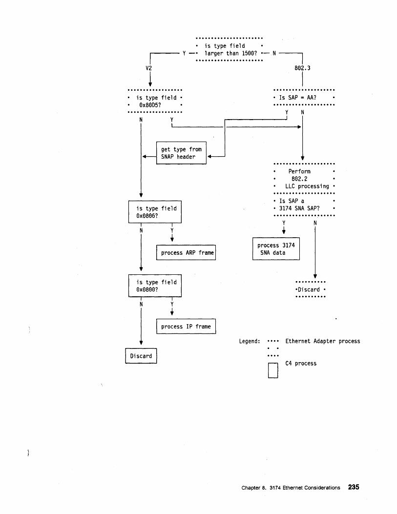
• is type field
,.----- y -: •• ~ ~::::. :~~~. ~:~~:.:- N ----"
V2 a02.3
! I • is type field •
0xa0D5?
N Y I
get type from '+- SNAP header
,
is type field 0x0a06?
I N
I Y t
i+---
I process ARP frame I
is type field 0x0a00?
I N
I Discard
I Y
t process IP frame
• Is SAP = AA?
y N I
~
,r · ......... · Perfo
· a02.
· LLC pr · ......... • Is SAP a
rm 2 ocessing •
• 3174 SNA SAP? .............. ~ ..... y N
t process 3174
SNA data
·Discard •
Legend: Ethernet Adapter process
D C4 process
Chapter 8. 3174 Ethernet Considerations 235
8.1.7 Frame Format Discovery Process The next sections describe how the 3174 determines the frame format (802.3 vs V2) to use, when the 3174 is customized to allow both frame formats.
TCP/IP For TCP/lP, the Address Resolution Protocol (ARP) is used to find the Ethernet address associated with an IP address. During ARP processing, the 3174 will also determine the frame format to use when sending datagrams to a particular IP address. The frame format associated with an IP address is only used for transmission; the 3174 accepts all received datagrams regardless of frame format.
The 3174 maintains an ARP table with entries for each remote host that it is talking to. Each entry contains the IP address of the host, the associated Ethernet physical address, the frame format to use, and some flags that show the state of the entry. When an entry is marked as complete, the physical address and frame format have been determined by ARP processing. This is done as follows:
1. If the 3174 wishes to send a datagram to IP address A.B, and no ARP table entry exists, the 3174 sends an ARP request to locate A.B. A table entry is created, but is not "complete". Since we are only discussing the "dynamic" case, the 3174 sends the ARP request in each format, sending the V2 format first. When a valid ARP response comes back, the 3174 marks the entry as complete, if it is not already complete, and assigns the frame format of the response to that entry, replacing the previous frame format. Any pending datagram is sent with that frame format. Therefore, if the remote host supports both frame formats, and answers both of the ARPs, the format of the second response would replace that of the first in the ARP entry.
2. When a remote TCP/IP host (X.Y) sends an ARP request containing the 3174's IP address, the 3174 creates an ARP table entry, if it does not already exist, and marks it complete. It also assigns the frame format of the request to the ARP entry and responds with that format. Therefore, if the requestor supports both frame formats, and sends ARPs in both formats, the 3174 would answer both requests; the format of the second request would be stored in the ARP entry.
Since TCP/IP operates in a "connectionless" environment, frames may be lost during ARP. If ARP processing does not complete, the datagram that caused the search is discarded. If this happens, the higher layers of the TCP/IP stack are responsible for recovering appropriately. For example, the 3174 PING function would not retry a frame if no response is received; rather, it would report the loss to the user. If a request to start a TELNET session is lost, the TCP layer times out and notifies the user, who can then attempt the session again.
236 Using the 3174 TCP/IP Networks
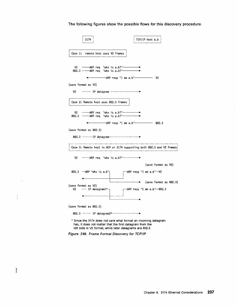
The following figures show the possible flows for this discovery procedure.
TCP/IP host a.b
Case 1: remote host uses V2 frames
V2 --ARP req "who is a.b?" • 802.3 --ARP req "who is a.b?" •
4 ARP resp "I am a.b" V2
(save format as V2)
V2 -- IP datagram -------.....
Case 2: Remote host uses 802.3 frames I
V2 --ARP req "who is a.b?" • 802.3 --ARP req "who is a.b?" •
4 ARP resp "I am a.b" 802.3
(save format as 802.3)
802.3 ---IP datagramm-----------..
Case 3: Remote host is NCP or 3174 supporting both 802.3 and V2 frames
V2 --ARP req "who is a.b?"----...
(save format as V2)
802.3 ~ARP 'who is a.b"1L--___ ,_A_R_p_r_e_sp .. "I am a.b"-V2
- • (save format as 802.3) (save format as V2)
V2 :- IP datagraml*l<-___ , __ AR_p_re_s_p •• "I am a.b'-S02.3
(save format as 802.3)
802.3 -- IP datagram2*-------+.
* Since the 3174 does not care what format an incoming datagram has, it does not matter that the first datagram from the left side is V2 format, while later datagrams are 802.3
Figure 248. Frame Format Discovery for TCPIIP
Chapter 8. 3174 Ethernet Considerations 237
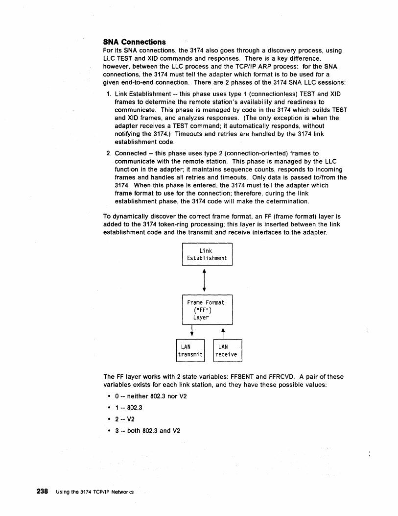
SNA Connections For its SNA connections, the 3174 also goes through a discovery process, using LLC TEST and XID commands and responses. There is a key difference, however, between the LLC process and the TCP/IP ARP process: for the SNA connections, the 3174 must tell the adapter which format is to be used for a given end-to-end connection. There are 2 phases of the 3174 SNA LLC sessions:
1. Link Establishment -- this phase uses type 1 (connectionless) TEST and XID frames to determine the remote station's availability and readiness to communicate. This phase is managed by code in the 3174 which builds TEST and XID frames, and analyzes responses. (The only exception is when the adapter receives a TEST command; it automatically responds, without notifying the 3174.) Timeouts and retries are handled by the 3174 link establishment code.
2. Connected -- this phase uses type 2 (connection-oriented) frames to communicate with the remote station. This phase is managed by the LLC function in the adapter; it maintains sequence counts, responds to incoming frames and handles all retries and timeouts. Only data is passed to/from the 3174. When this phase is entered, the 3174 must tell the adapter which frame format to use for the connection; therefore, during the link establishment phase, the 3174 code will make the determination.
To dynamically discover the correct frame format, an FF (frame format) layer is added to the 3174 token-ring processing; this layer is inserted between the link establishment code and the transmit and receive interfaces to the adapter.
Link Establishment
1 Frame Format
(IIFFII) Layer
LAN transmit
LAN receive
The FF layer works with 2 state variables: FFSENT and FFRCVD. A pair of these variables exists for each link station, and they have these possible values:
• 0 -- neither 802.3 nor V2
• 1 -- 802.3
• 2 -- V2
• 3 -- both 802.3 and V2
238 Using the 3174 TCPIIP Networks
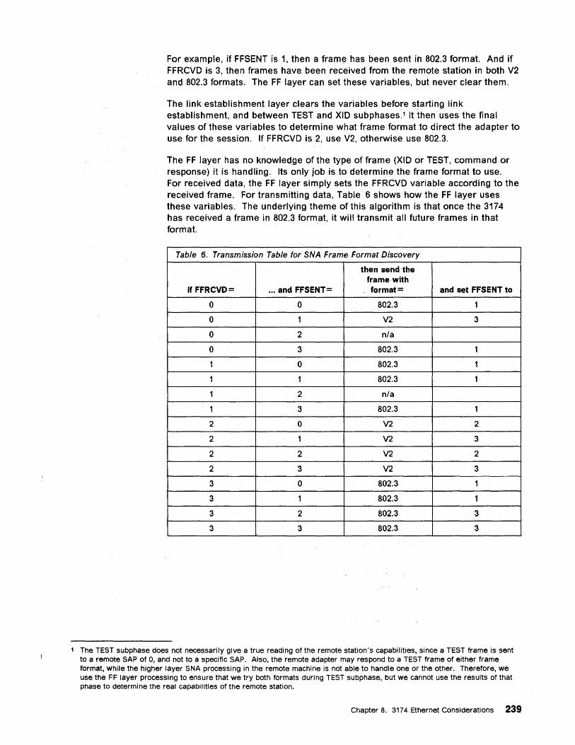
For example, if FFSENT is 1, then a frame· has been. sent in 802.3 format. And if FFRCVD is 3, then frames have. been received from the remote station in both V2 and 802.3 formats. The FFlayer can set these variables, but never clear them.
The link establishment layer clears the variables before starting link establishment, and between TEST and XID subphases.1 It then uses the final values of these variables to determine what frame format to direct the adapter to use for the session. If FFRCVD is 2, use V2, otherwise us:e 802.3.
The FF layer has no knowledge of the type of frame (XID or TEST, command or response) it is handling. Its only job is to determine the frame format to use. For received data, the FF layer simply sets the FFRCVD variable according to the received frame. For transmitting data,Table 6 shows how the FF layer uses these variables. The underlying theme of this algorithm is that once the 3174 has received a frame in 802.3 format, it will transmit all future frames in that format.
Table 6. Transmission Table for SNA Fr.ame Format Discovery
then send the frame with
if FFRCVD= ... and FFSENT= format = and set FFSENT to
0 0 802.3 1
0 1 V2 3
0 2 n/a
0 3 802.3 1
1 0 802.3 1
1 1 802.3 1
1 2 nfa
1 3 802.3 1
2 0 V2 2
2 1 V2 3
2 2 V2 2
2 3 V2 3
3 0 802.3 1
3 1 802.3 1
3 2 802.3 3
3 3 802.3 3
1 The TEST subphase does not necessarily give a true reading of the remote station's capabilities, since a TEST frame is sent to a remote SAP of 0, and not to a specific SAP. Also, the remote adapter may respond to a TEST frame of either frame format, while the higher layer SNA processing in the remote machine is not able to handle one or the other. Therefore, we use the FF layer processing to ensure that we try both formats during TEST subphase, but we cannot use the results of that phase to determine the real capabilities of the remote station.
Chapter 8. 3174 Ethernet Considerations 239
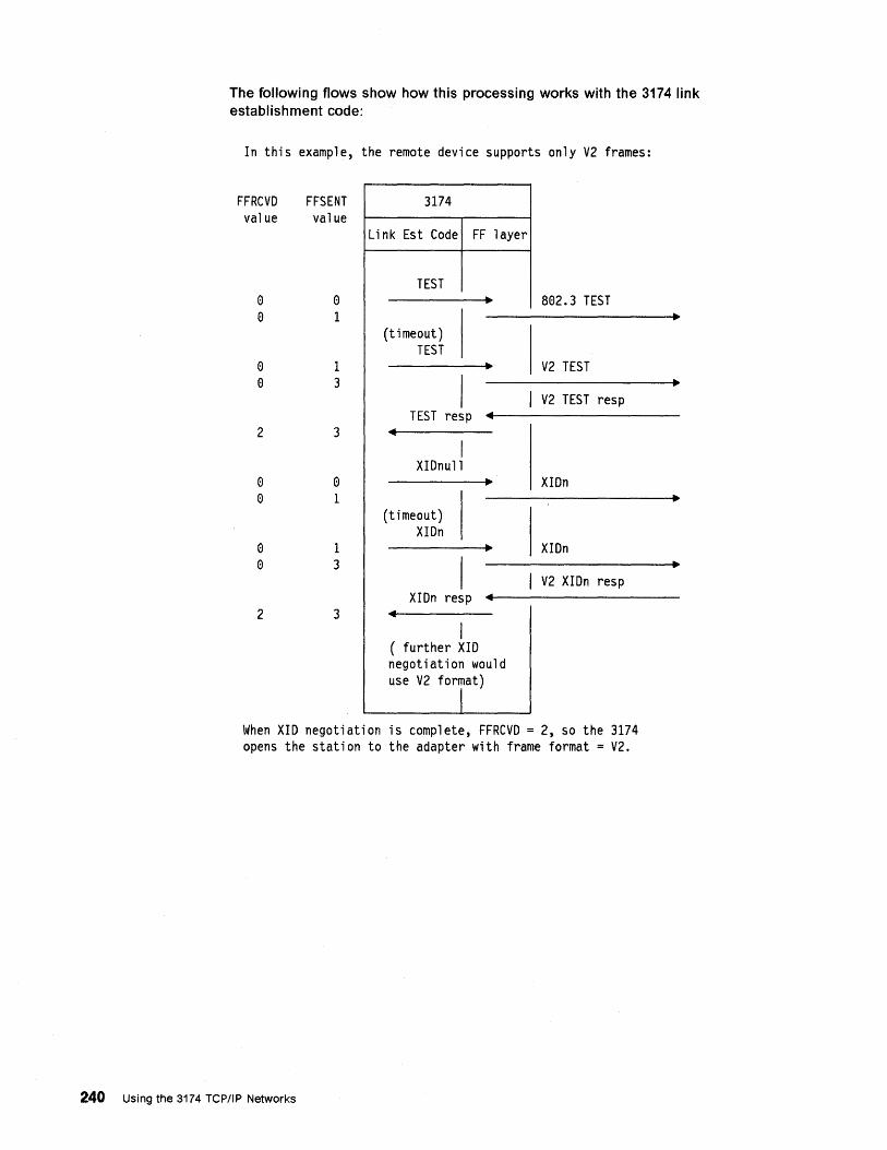
The following flows show how this processing works with the 3174 link establishment code:
In this example, the remote device supports only V2 frames:
FFRCVD value
e e
e e
2
e e
e e
2
FFSENT value
o 1
1 3
3
o 1
1 3
3
3174
Link Est Code FF layer
TEST • 802.3 TEST
(t i meout) TEST
• V2 TEST
I I V2 TEST resp TEST resp ..
.. I
XIDnull • XIDn
(timeout) XIDn
• XIDn
I I V2 XIDn resp XIDn resp ..
.. I
( further XID negotiation would use V2 format)
I When XID negotiation is complete, FFRCVD = 2, so the 3174 opens the station to the adapter with frame format = V2.
240 Using the 3174 TCP/IP Networks
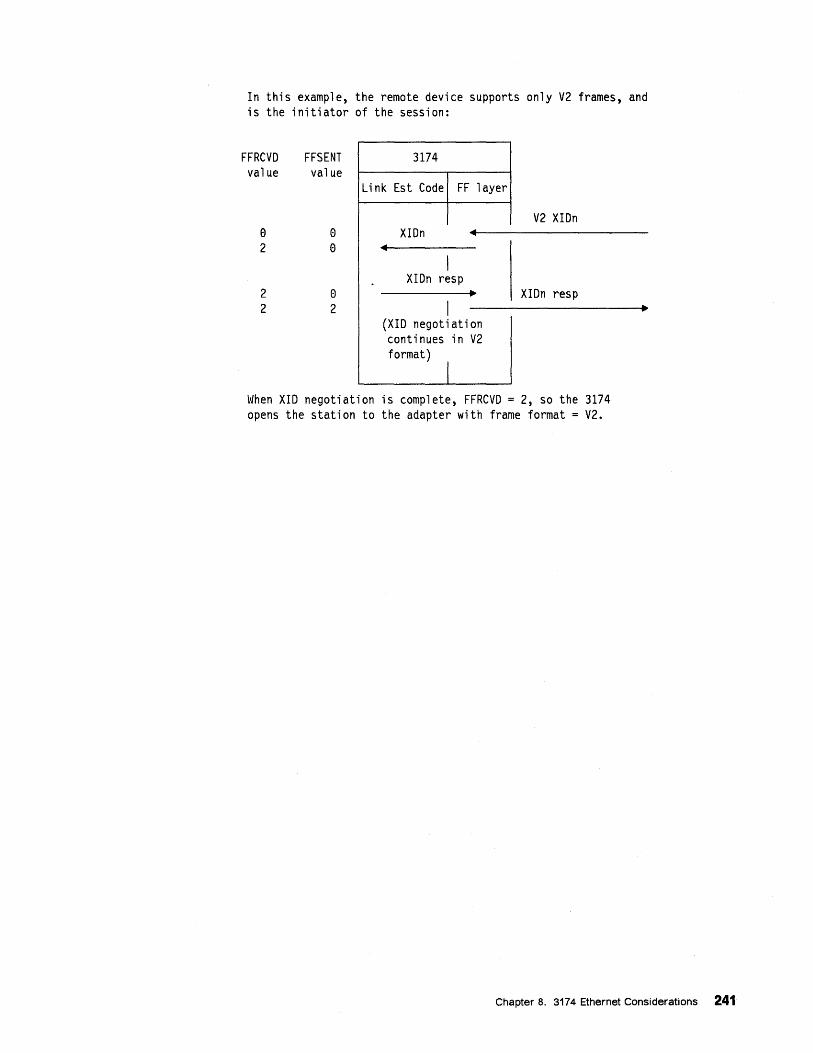
In this example, the remote device supports only V2 frames, and is the initiator of the session:
FFRCVD value
e 2
2 2
FFSENT value
e e
e 2
3174
Link Est Code FF layer
V2 XIDn XIDn 4
4
I XIDn resp .. XIDn resp
I (XID negotiation continues in V2 format)
I When XID negotiation is complete, FFRCVD = 2, so the 3174 opens the station to the adapter with frame format = V2.
Chapter 8. 3174 Ethernet Considerations 241
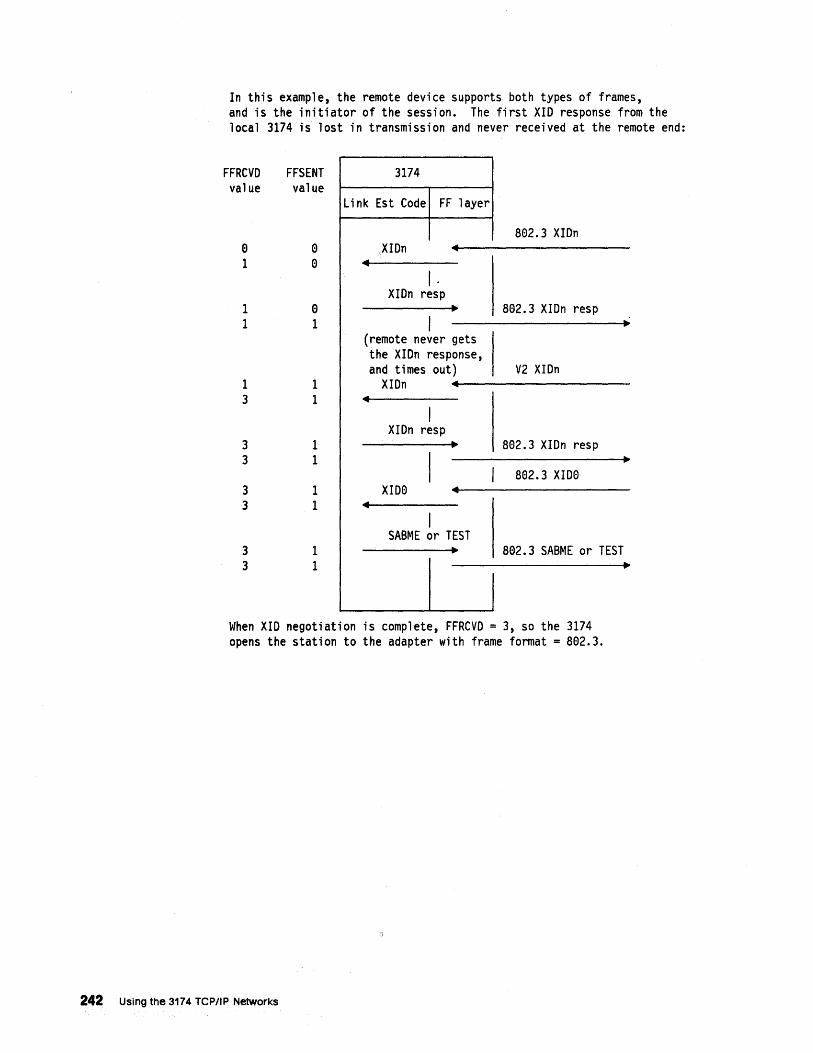
In this example, the remote device supports both types of frames, and is the initiator of the session. The first XID response from the local 3174 is lost in transmission and never received at the remote end:
FFRCVD value
FFSENT value
9 9 1 9
1 1
1 3
3 3
3 3
3 3
9 1
1 1
1 1
1 1
1 1
3174
Link Est Code FF layer
XIDn ~
~
I. XIDn resp
~
I (remote never gets the XIDn response, and times out)
XIDn ~
~
I XIDn resp
~
I XID0 ~
~
I SABME or TEST
~
I
I
802.3 XIDn
892.3 XIDn resp
V2 XIDn
802.3 XIDn resp
892.3 XIDe
802.3 SABME or TEST ~
When XID negotiation is complete, FFRCVD = 3, so the 3174 opens the station to the adapter with frame format = 802.3.
242 Using the 3174 TCP/IP Networks
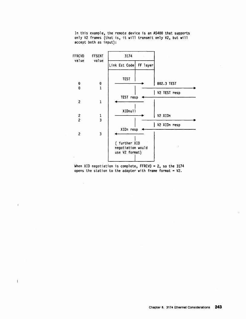
In this example, the remote device is an AS400 that supports only V2 frames (that is, it will transmit. only V2, but will accept both as input):
FFRCVO value
o o
FFSENT value
o 1
2 1
2 2
1 3
2 3
3174
Li nk Est Code FF layer
TEST • 802.3 TEST
I I V2 TEST resp TEST resp ...
... I
XIDnull • V2 XIDn
I I V2 XIDn resp XIOn resp ...
... I
( further XID negotiation would use V2 format)
J When XIO negotiation is complete, FFRCVO = 2, so the 3174 opens the station to the adapter with frame format = V2.
Chapter 8. 3174 Ethernet Considerations 243
8.2 3174 Ethernet Adapter
8.2.1 Capacity
The purpose of this adapter is to provide the 3174 with a high performance CSMA/CD and Ethernet Version 2.0 (DIX) communication facility via 16-bit MMIO transfers. This adapter performs the functions necessary to support one, and only one, CSMA/CD LAN when installed in the 3174.
Functional and operational highlights of the adapter are as follows:
• Interfaces the CSMA/CD logic to the SOOS-Bus (MMIO) using 8 or 16-bit transfers.
• Provides physical access to a CSMA/CD and Ethernet Version 2.0 (DIX) LAN via one of the following physical media:
10Base-2
10Base-S
10Base-T
• Supports universal addressing.
• Supports COlD (Card Detect and Identify facility).
• Provides the LLC (Logical Link Control) functions.
This adapter provides physical and logical attachment to a single 10Mbps CSMA/CD or Ethernet Version2.0 (DIX) LAN. LAN physical attachment is made via an RJ-4S connector (10base-T), coaxial connector (10base-2), or through an AUI and MAU attached to a 1S-pin D-shell (10base-S). The MAU and AUI are not provided with the adapter.
8.2.2 Configurations This adapter comes standard with no features which can be changed physically. There are no program pins or switches on the card that can be changed to alter any function of the adapter.
Cables for attaching the LAN to the adapter are not supplied with this adapter.
One BNC-T connector is supplied with the adapter. The T connector is supplied by IBM, and is included in the build group in USA.
Wrap plugs are supplied with the adapter, one for each physical interface. The wrap plugs are supplied by IBM, and are included in the build group in the USA.
8.2.3 CSMA/CD LAN Physical Interfaces The CSMA/CD adapter provides three physical interfaces to the LAN. Only one of these physical interfaces may be used at a time.
The supported physical interfaces are:
• 10Base-2 which uses a BNC connector
• 10Base-S which uses a 1S-pin D-SUB connector
• 10Base-T which uses an RJ-4S connector
244 Using the 3174 TCPIIP Networks
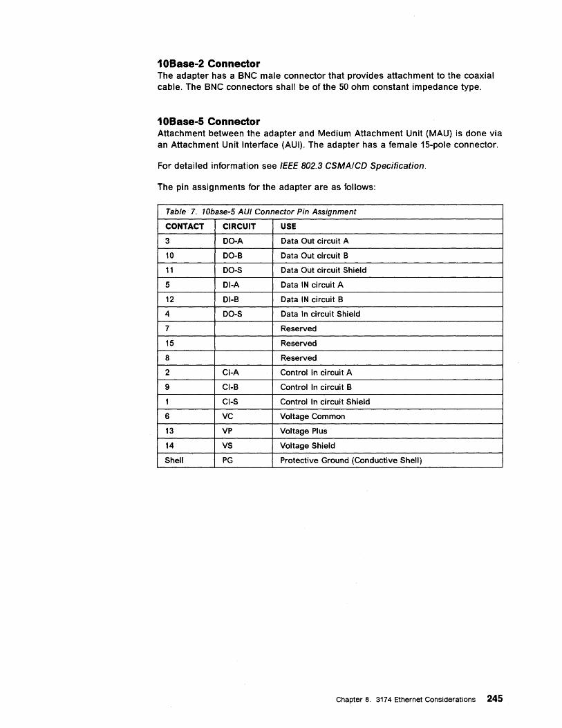
10Base-2 Connector The adapter has a BNC male connector that provides attachment to the coaxial cable. The BNC connectors shall be of the 50 ohm constant impedance type.
10Base-5 Connector Attachment between the adapter and Medium Attachment Unit (MAU) is done via an Attachment Unit Interface (AUI). The adapter has a female 15-pole connector.
For detailed information see IEEE 802.3 CSMAICD Specification.
The pin assignments for the adapter are as follows:
Table 7. 10base-5 AUf Connector Pin Assignment
CONTACT CIRCUIT USE
3 DO-A Data Out circuit A
10 DO-B Data Out circuit B
11 DO-S Data Out circuit Shield
5 DI-A Data IN circuit A
12 DI-B Data IN circuit B
4 DO-S Data In circuit Shield
7 Reserved
15 Reserved
8 Reserved
2 CI-A Control In circuit A
9 CI-B Control In circuit B
1 CI-S Control In circuit Shield
6 VC Voltage Common
13 VP Voltage Plus
14 VS Voltage Shield
Shell PG Protective Ground (Conductive Shell)
Chapter 8. 3174 Ethernet Considerations 245
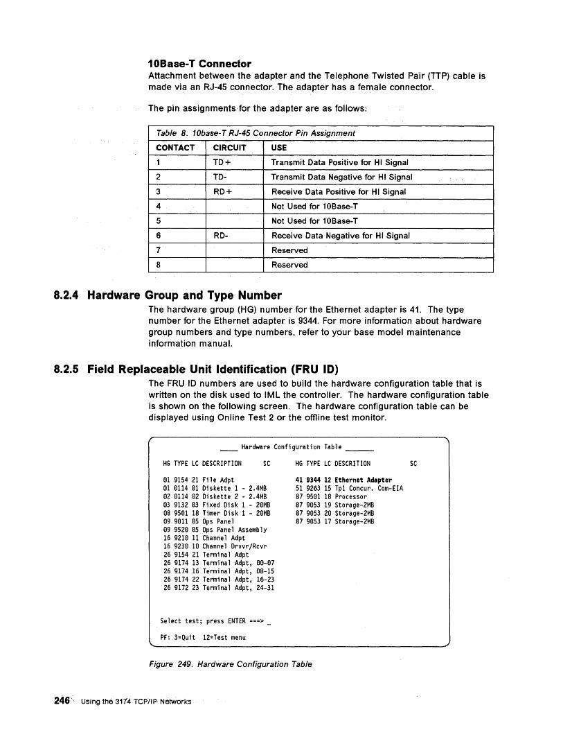
10Base-T Connector Attachment between the adapter and the Telephone Twisted Pair (TTP) cable is made via an RJ-4S connector. The adapter has a female connector.
The pin assignments for the adapter are as follows:
Table 8. 10base-T RJ-45 Connector Pin Assignment
CONTACT CIRCUIT USE
1 TD+ Transmit Data Positive for H I Signal
2 TD- Transmit Data Negative for H I Signal
3 RD+ Receive Data Positive for H I Signal
4 Not Used for 1 DBase-T
5 Not Used for 1DBase-T
6 RD- Receive Data Negative for H I Signal
7 Reserved
8 Reserved
8.2.4 Hardware Group and Type Number The hardware group (HG) number for the Ethernet adapter is 41. The type number for the Ethernet adapter is 9344. For more information about hardware group numbers and type numbers, refer to your base model maintenance information manual.
8.2.5 Field Replaceable Unit Identification (FRU ID) The FRU 10 numbers are used to build the hardware configuration table that is written on the disk used to IML the controller. The hardware configuration table is shown on the following screen. The hardware configuration table can be displayed using Online Test 2 or the offline test monitor.
__ Hardware Configuration Table __ _
HG TYPE LC DESCRIPTION SC
01 9154 21 File Adpt 01 0114 01 Diskette 1 - 2.4MB 02 0114 02 Diskette 2 - 2.4MB 03 9132 03 Fixed Disk 1 - 20MB 08 9501 18 Timer Disk 1 - 20MB 09 9011 05 Ops Panel 09 9520 05 Ops Panel Assembly 16 9210 11 Channel Adpt 16 9230 10 Channel Drvvr/Rcvr 26 9154 21 Terminal Adpt 26 9174 13 Terminal Adpt, 00-07 26 9174 16 Terminal Adpt, OB-15 26 9174 22 Terminal Adpt, 16-23 26 9172 23 Terminal Adpt, 24-31
Select test; press ENTER ===> _
PF: 3=Quit 12=Test menu
HG TYPE LC DESCRITION
41 9344 12 Ethernet Adapter 51 9263 15 Tp1 Concur. Com-EIA B7 9501 18 Processor 87 9053 19 Storage-2MB 87 9053 20 Storage-2MB 87 9053 17 Storage-2MB
Figure 249. Hardware Configuration Table
246, Using the 3174 TCP/IP NetWorks
SC
HG = Hardware Group TYPE = FRU Type number LC = FRU Location SC = Status code indicating an error on normal IML
Note: In the 3174, only those FRUs that are physically installed appear in this table.
For more information about FRU 10 numbers, Online Test 2, and the offline test monitor, refer to the base model maintenance information manual.
8.2.6 Status Codes For information about:
• Status codes that deal solely with Ethernet attachment, refer to Supplemental Customer Information of Configuration Support C Release 4 -Ethernet Attachment, GA27-3994.
• Status codes that apply to token-ring and Ethernet attachments, refer to 3174 Status Codes, GA27-3832.
• Event log, refer to the base model maintenance information manual.
Chapter 8. 3174 Ethernet Considerations 247
8.3 3174 Ethernet Customization Since Configuration Support-C Release 4 function is essentially the same as token-ring, most of the existing customization panels that are available in Configuration Support-C Release 3, apply to Configuration Support-C Release 4, with a few changes. For 3174 TCP/IP Telnet Support there is no need for an SNA host over the primary link. 3174 TCP/IP Telnet Support under Configuration Support-C Release 4, does not require that customize the 3174 as an APPN node, gateway or DSPU. To do this, the LAN specific type question have been isolated to two new panels -- one for token-ring and one for Ethernet. The token-ring panel has been disabled in base Configuration Support-C Release 4 microcode. This isolates the common LAN information from the panels that pertain to specific functions that use the LAN.
The following pages show you the difference between Configuration Support-C Release 3 and Configuration Support-C Release 4 customization panels.
If you are planning microcode customization for the first time, read Part 1 and Chapter 5 of the 3174 Establishment Controller Planning Guide. If you are experienced at planning microcode customization, you may want to skim those chapters.
8.4 Configuration Questions As you follow the procedure in the 3174 Planning Guide to answer the configuration questions and fill out the worksheets, use the information in this chapter for Ethernet-specific information. This information has been taken from the 3174 Ethernet Supplement. For worksheets and configuration questions not included in this section, refer to the worksheets and configuration questions in the 3174 Planning Guide.
248 Using the 3174 TCP/IP Networks·
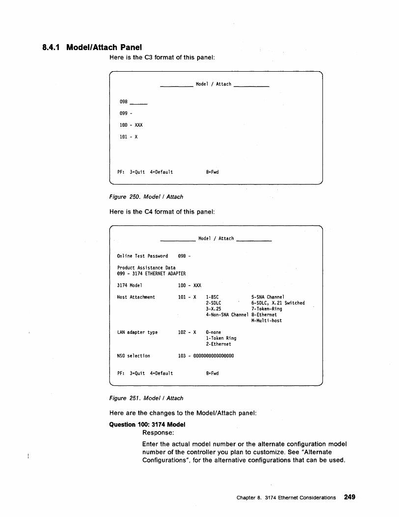
8.4.1 Modell Attach Panel Here is the C3 format of this panel:
____ Model/Attach ____ _
098
099 -
100 - XXX
101 - X
PF: 3=Quit 4=Default 8=Fwd
Figure 250. Model/Attach
Here is the C4 format of this panel:
_____ Model/Attach ____ _
Online Test Password 098 -
Product Assistance Data 099 - 3174 ETHERNET ADAPTER
3174 Model 100 - XXX
Host Attachment 101 - X 1-SSC 5-SNA Channel 2-SDLC 6-SDLC, X.21 Switched 3-X.25 7-Token-Ring 4-Non-SNA Channel 8-Ethernet
M-Multi-host
LAN adapter type 102 - X 0-none I-Token Ring 2-Ethernet
NSO selection 103 - 00eeeeeeeeeeeeee
PF: 3=Quit 4=Default 8= Fwd
Figure 251. Model/Attach
Here are the changes to the Modell Attach panel:
Question 100: 3174 Model Response:
Enter the actual model number or the alternate configuration model number of the controller you plan to customize. See "Alternate Configurations", for the alternative configurations that can be used.
Chapter 8. 3174 Ethernet Considerations 249
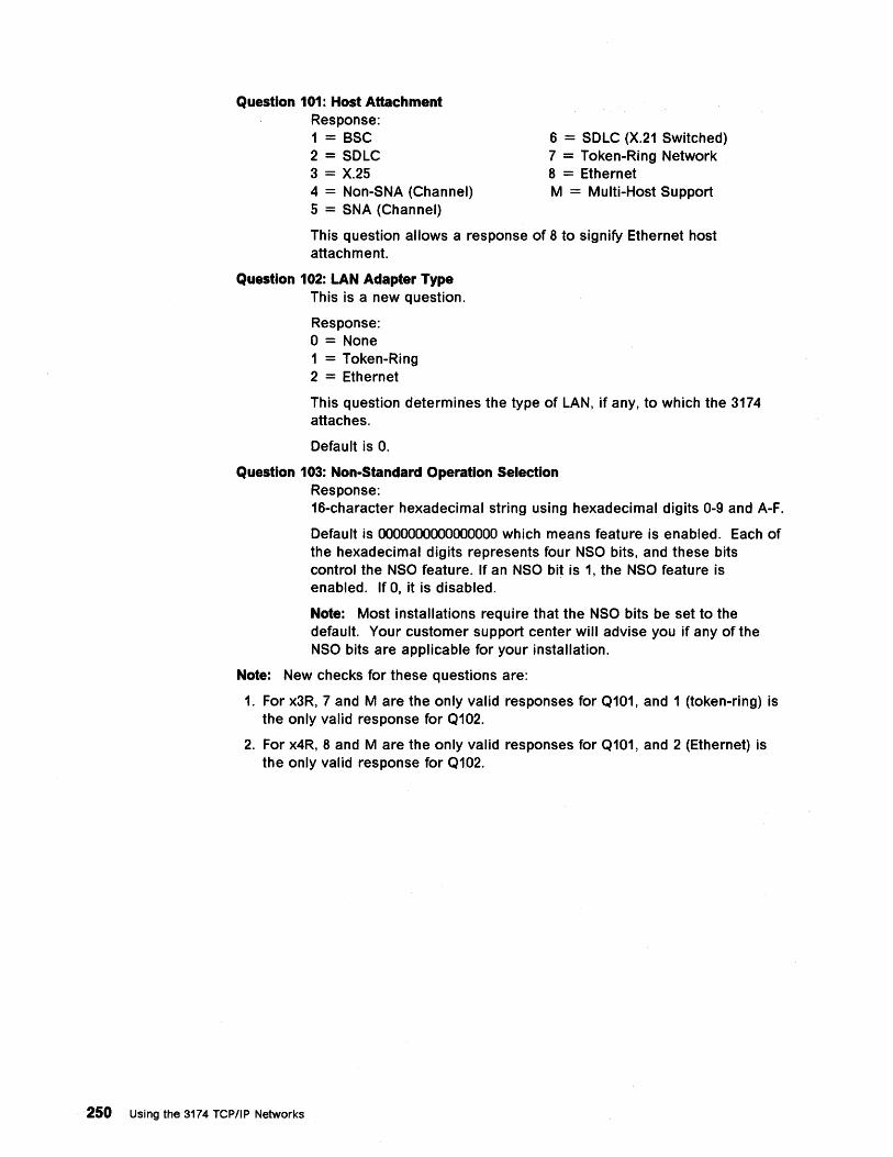
Question 101: Host Attachment Response: 1 = SSC 2 = SDLC 3 = X.25 4 = Non-SNA (Channel) 5 = SNA (Channel)
6 = SDLC (X.21 Switched) 7 = Token-Ring Network 8 = Ethernet M = Multi-Host Support
This question allows a response of 8 to signify Ethernet host attachment.
Question 102: LAN Adapter Type This is a new question.
Response: o = None 1 = Token-Ring 2 = Ethernet
This question determines the type of LAN, if any, to which the 3174 attaches.
Default is O.
Question 103: Non-Standard Operation Selection Response: 16-character hexadecimal string using hexadecimal digits 0-9 and A-F.
Default is 0000000000000000 which means feature is enabled. Each of the hexadecimal digits represents four NSO bits, and these bits control the NSO feature. If an NSO bit is 1, the NSO feature is enabled. If 0, it is disabled.
Note: Most installations require that the NSO bits be set to the default. Your customer support center will advise you if any of the NSO bits are applicable for your installation.
Note: New checks for these questions are:
1. For x3R, 7 and M are the only valid responses for Q101, and 1 (token-ring) is the only valid response for Q102.
2. For x4R, 8 and M are the only valid responses for Q101, and 2 (Ethernet) is the only valid response for Qt02.
250 Using the 3174 TCP/IP Networks
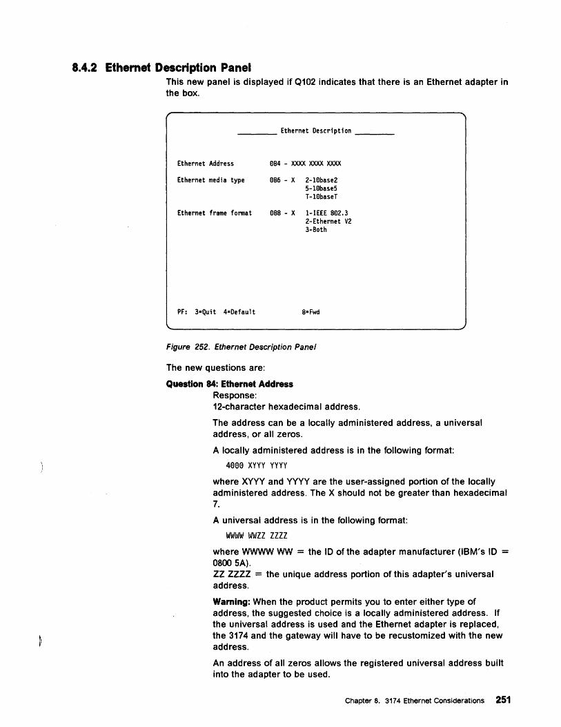
8.4.2 Ethemet Description Panel This new panel is displayed if Q102 indicates that there is an Ethernet adapter in the box.
____ Ethernet Description ___ _
Ethernet Address
Ethernet media type
eB4 - XXX>< XXX>< XXX><
eB6 - X 2-1ebase2 5-1ebase5 T-lebaseT
Ethernet frame format eBB - Xl-IEEE 8e2.3 2-Ethernet V2 3-Both
PF: 3-Qu;t 4=Default B=Fwd
Figure 252. Ethernet Description Panel
The new questions are:
Question 84: Ethernet Address Response: 12-character hexadecimal address.
The address can be a locally administered address, a universal address, or all zeros.
A locally administered address is in the following format:
4000 XYYY yyyy
where XYYY and YYYY are the user-assigned portion of the locally administered address. The X should not be greater than hexadecimal 7.
A universal address is in the following format:
WWWW WWZZ ZZZZ
where WWWW WW = the 10 of the adapter manufacturer (IBM's 10 = 0800 SA). ZZ ZZZZ = the unique address portion of this adapter's universal address.
Warning: When the product permits you to enter either type of address, the suggested choice is a locally administered address. If the universal address is used and the Ethernet adapter is replaced, the 3174 and the gateway will have to be recustomized with the new address.
An address of all zeros allows the registered universal address built into the adapter to be used.
Chapter 8. 3174 Ethernet Considerations 251
Note: LAN address must be customized using a canonical form of hexadecimal representation. For information about bit order in addresses and a guideline for address conversion, see Appendix A, "Address Bit Order for Ethernet Addresses" on page 359.
Question 86: Ethernet Media Type Response: 2 = 10base2 5 = 10base5 T = 10base-T
There is no default.
This shows the type of Ethernet media that the 3174 is attached to.
Question 88: Ethernet Frame Format Response:
252 Using the 3174 TCP/IP Networks
1 = IEEE 802.3 2 = Ethernet V2 3 = Both
The default is (3) both 802.3 and V2.
This question determines the frame format(s) that you want the 3174 to recognize.
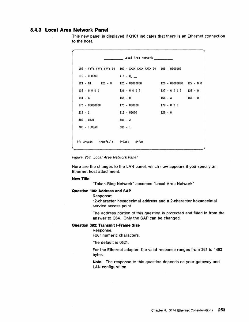
8.4.3 Local Area Network Panel This new panel is displayed if Q101 indicates that there is an Ethernet connection to the host.
____ Local Area Network ___ _
106 - yyyy YYYY YYYY 04 107 - XXXX XXXX XXXX 04 108 - 0000000
110 - 0 0000
121 - a1
132 - a a a 0
141 - 'A
173 - aaaaaaaa
213 - 1
382 - a521
385 - IBMLAN
123 - a
116 - I:t _
125 - aaaoaaaa
136 - a a a a
165 - a
175 - aaaaaa
215 - aaaaa
383 - 2
386 - 1
PF: 3=Quit 4=Default 7=Back 8= Fwd
Figure 253. Local Area Network Panel
126 - aaaaaaaa 127 - a a
137 - 0 a 0 a 138 - a
166 - A 168 - a
179 - a a a
22a - a
Here are the changes to the LAN panel, which now appears if you specify an Ethernet host attachment.
New Title "Token-Ring Network" becomes "Local Area Network"
Question 106: Address and SAP Response: 12-character hexadecimal address and a 2-character hexadecimal service access point.
The address portion of this question is protected and filled in from the answer to Q84. Only the SAP can be changed.
Question 382: Transmit I-Frame Size Response: Four numeric characters.
The default is 0521.
For the Ethernet adapter, the valid response ranges from 265 to 1493 bytes.
Note: The response to this question depends on your gateway and LAN configuration.
Chapter 8. 3174 Ethernet Considerations 253
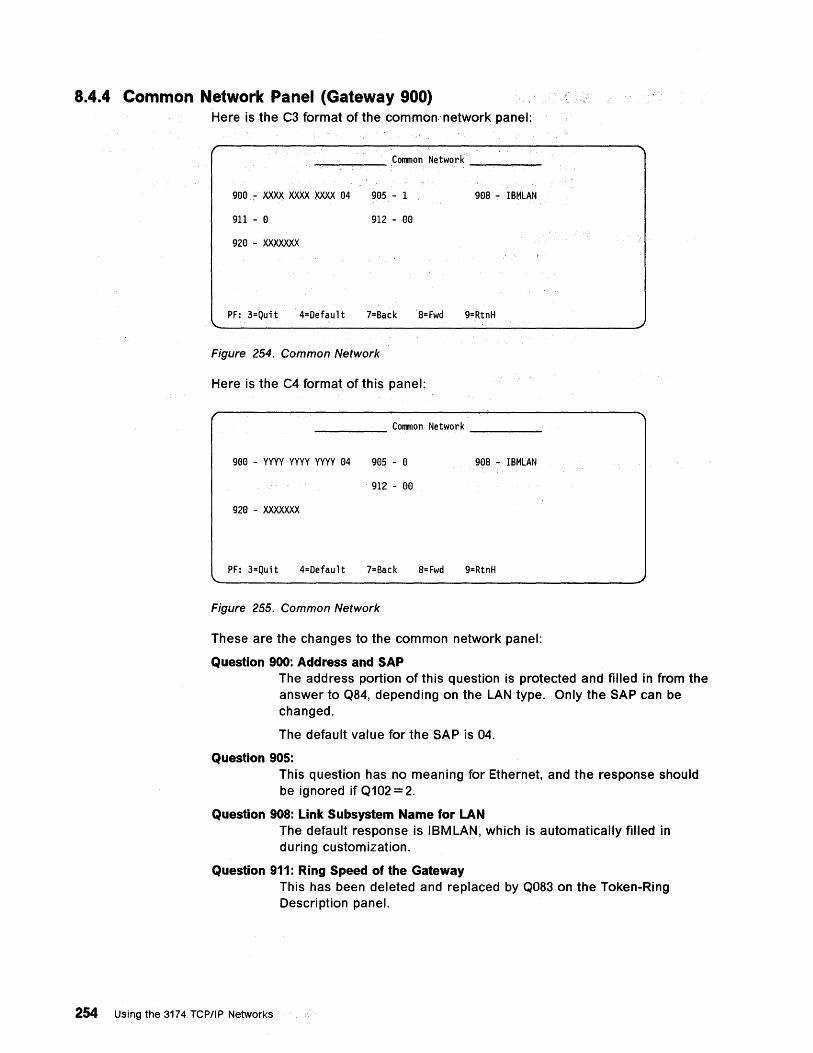
8.4.4 Common Network Panel (Gateway 900) Here is the C3 format of the common' network panel:
-,-__ -- COlTmon Network __ ---
908 - XXXX XXXX XXXX 84 985 - 1 9El8·~ IBMLAN
911 - 8 912 - 88
928 ... XXXXXXX
PF: 3=Quit 4=Default 7=Back8=Fwd 9=RtnH
Figure 254. Common Network
Here is the C4 format of this panel:
_____ COlTmon Network ........... ___ _
908 - vvvv VVVV VVVV 84 985 - 8 988 - IBMLAN
. 912 - 8El
928 - XXXXXXX
PF: 3=Quit 4=Default 7=Back 8=Fwd 9=RtnH
Figure 255. Common Network
These are the changes to the common network panel:
Question 900: Address and SAP The address portion of this question is protected and filled in from the answer to Q84, depending on the LAN type. Only the SAP can be changed.
The default value for the SAP is 04.
Question 905: This question has no meaning for Ethernet, and the response should be ignored if Q102 = 2.
Question 908: Link Subsystem Name for LAN The default response is IBM LAN, which is automatically filled in during customization.
Question 911: Ring Speed of the Gateway
254 Using the 3174 TCP/IP Networks
This has been deleted and replaced by Q083 on the Token-Ring Description panel.
8.4.5 Gateway 940 Panel The Gateway 940 panel has one change to support Ethernet adapters: The "T" column, which assigns a device type to each gateway DSPU, currently allows responses of 0 (workstation), 1 (3174) or 2 (8KB RU device). These responses are used to fill in an appropriate default frame size on the 941 panel. Since Ethernet has a max I-field size of 1493, the type 2 class of device is not applicable. So a response of 2 is not allowed for Ethernet.
8.4.6 Gateway 941 Panel The 941 panel has only one change. The Transmit I-frame size column gives the maximum I-frame size to use when transmitting to the station. (Actually, this should really be "I-field" of the I-frames.) Responses of 3 (2KB), 4 (4KB) and 5 (8KB) are not applicable for Ethernet adapters, because with Ethernet, we can only send up to 1493 bytes of data. Therefore, response 3 for an Ethernet configuration will mean 1493 bytes, and responses larger than 3 are not allowed.
8.4.7 yeP/IP Options Menu This menu appears in the AEA and TCP/IP utility. The last 2 questions on this panel are Routing Field Support and All Routes Broadcast; these 2 are not applicable for an Ethernet configuration, and the responses should be ignored.
8.4.8 End-User Productivity Panel The option on this panel titled "Token-Ring T1 Timer" is changed to "LAN T1 Timer".
Chapter 8. 3174 Ethernet Considerations 255
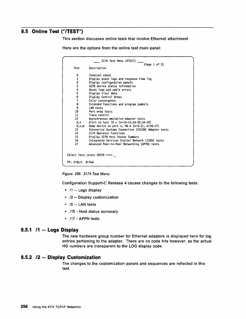
8.5 Online Test ("/TEST") This section discusses online tests that involve Ethernet attachment.
Here are the options from the online test main panel:
Test
9 1 2 3 4 5 6 7 8 9
19 11 12 A,n D,n,m
13 14 15 16 17
3174 Test Menu (XTEST) - -(Page 1 of 2)
Description
Terminal check Display event logs and response time log Display configuration panels 3279 device status information Res~t logs and cable errors Display vital data Display Control Areas Color convergence Extended functions and program symbols LAN tests Port wrap tests Trace control Asynchronous emulation adapter tests Alert to host 10 n (n=IA-IH,2A-2D,3A-3D) Dump device on port n, HG m (n=9-31, m=26-27) Enterprise Systems Connection (ESCON) Adapter tests 3174 Operator Functions Display 3279 Host Status Summary Integrated Services Digital Network (ISDN) tests Advanced Peer-to-Peer Networking (APPN) tests
Select Test; press ENTER ===>
PF: 3=Quit 8= Fwd
Figure 256. 3174 Test Menu
Configuration Support-C Release 4 causes changes to the following tests:
• 11 -- Logs display
• 12 -- Display customization
• 19 -- LAN tests
• 115 - Host status summary
• 117 - APPN tests
8.5.1 11 -- Logs Display The new hardware group number for Ethernet adapters is displayed here for log entries· pertaining to the adapter. There are no code hits however, as the actual HG numbers are transparent to the LOG display code.
8.5.2 12 -- Display Customization The changes to the customization panels and sequences are reflected in this test.
256 Using the 3174 TCPIIP Networks
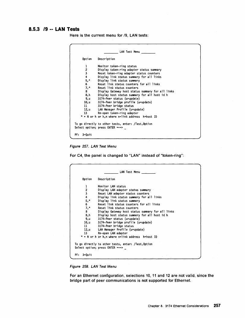
8.5.3 19 -- LAN Tests Here is the current menu for /9, LAN tests:
____ LAN Test Menu ___ _
Option Description
1 Monitor token-ring status 2 Display token-ring adapter status summary 3 Reset token-ring adapter status counters 4 Display link status summary for all links 5,* Display link status summary 6 Reset link status counters for all links 7,* Reset link status counters 8 Display Gateway host status summary for all links 8,h Display host status summary for all host id h 9,u 3174-Peer status (u=update)
10,u 3174-Peer bridge profile (u=update) 11 3174-Peer bridge status 12,u LAN Manager Profile (u=update) 13 Re-open token-ring adapter
* = N or h or h,n where n=link address h=host ID
To go directly to other tests, enter: jTest,Option Select option; press ENTER ===>
PF: 3=Quit
Figure 257. LAN Test Menu
For C4, the panel is changed to "LAN" instead of "token-ring":
____ LAN Test Menu ___ _
Option Description
1 Monitor LAN status 2 Display LAN adapter status summary 3 Reset LAN adapter status counters 4 Display link status summary for all links 5,* Display link status summary 6 Reset link status counters for all links 7,* Reset link status counters 8 Display Gateway host status summary for all links 8,h Display host status summary for all host id h 9,u 3174-Peer status (u=update)
10,u 3174-Peer bridge profile (u=update) 11 3174-Peer bridge status 12,u LAN Manager Profile (u=update) 13 Re-open LAN adapter
* = N or h or h,n where n=link address h=host ID
To go directly to other tests, enter: jTest,Option Select option; press ENTER ===> _
PF: 3=Quit
Figure 258. LAN Test Menu
For an Ethernet configuration, selections 10, 11 and 12 are not valid, since the bridge part of peer communications is not supported for Ethernet.
Chapter 8. 3174 Ethernet Considerations 257
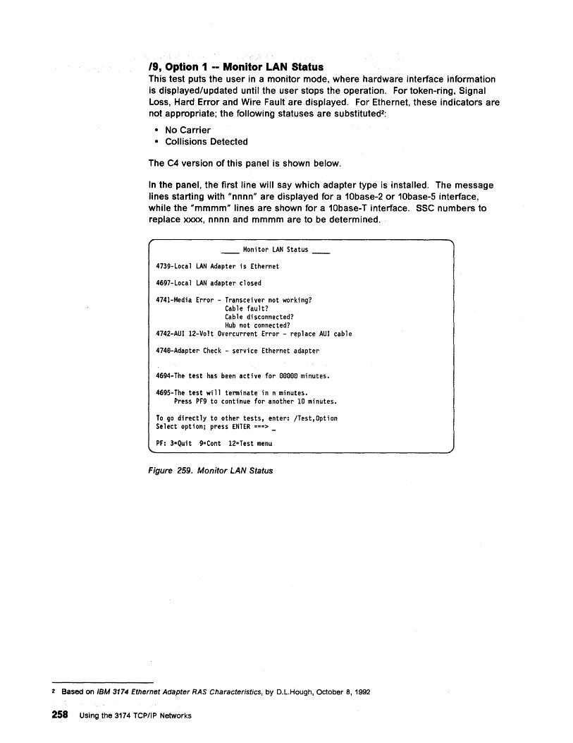
19, Option 1 -- Monitor LAN Status This test puts the user in a monitor mode, where hardware interface information is displayed/updated until the user stops the operation. For token-ring, Signal Loss, Hard Error and Wire Fault are displayed. For Ethernet, these indicators are not appropriate; the following statuses are substituted2:
• No Carrier • Collisions Detected
The C4 version of this panel is shown below.
In the panel, the first line will say which adapter type is installed. The message lines starting with "nnnn" are displayed for a 10base-2 or 10base-5 interface, while the "mmmm" lines are shown for a 10base-T interface. SSC numbers to replace XXXX, nnnn and mmmm are to be determined.
Monitor LAN Status
4739-Local LAN Adapter is Ethernet
4697-Local LAN adapter closed
4741-Media Error - Transceiver not working? Cable fault? Cable disconnected? Hub not connected?
4742-AUI 12-Volt Overcurrent Error - replace AUI cable
474a-Adapter Check - service Ethernet adapter
4694-The test has been active for aaeee minutes.
4695-The test will terminate in n minutes. Press PF9 to continue for another Ie minutes.
To go directly to other tests, enter: /Test,Option Select option; press ENTER ===> _
PF: 3=Quit 9=Cont 12=Test menu
Figure 259. Monitor LAN Status
2 Based on IBM 3174 Ethernet Adapter RAS Characteristics, by D.L.Hough, October 8, 1992
258 Using the 3174 TCPIIP Networks
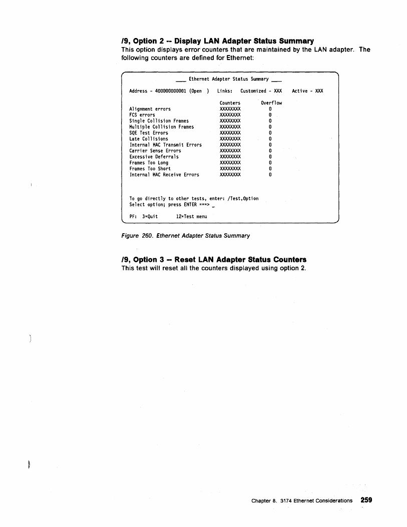
19, Option 2 -- Display LAN Adapter Status Summary This option displays error counters that are maintained by the LAN adapter. The following counters are defined for Ethernet:
____ Ethernet Adapter Status Summary ____
Address - 4eeeeeeeeeOl (Open) Links: Customized - XXX Active - XXX
Alignment errors FCS errors Single Collision Frames Multiple Collision Frames SQE Test Errors Late Collisions Internal MAC Transmit Errors Carrier Sense Errors Excessive Deferrals Frames Too Long Frames Too Short Internal MAC Receive Errors
Counters XXXXXXXX XXXXXXXX XXXXXXXX XXXXXXXX XXXXXXXX XXXXXXXX XXXXXXXX XXXXXXXX XXXXXXXX XXXXXXXX XXXXXXXX XXXXXXXX
To go directly to other tests, enter: /Test,Option Select option; press ENTER ===> _
PF: 3=Quit 12=Test menu
Figure 260. Ethernet Adapter Status Summary
Overflow e e e e e e e e e e e e
19, Option 3 - Reset LAN Adapter Status Counters This test will reset all the counters displayed using option 2.
Chapter 8. 3174 Ethernet Considerations 259
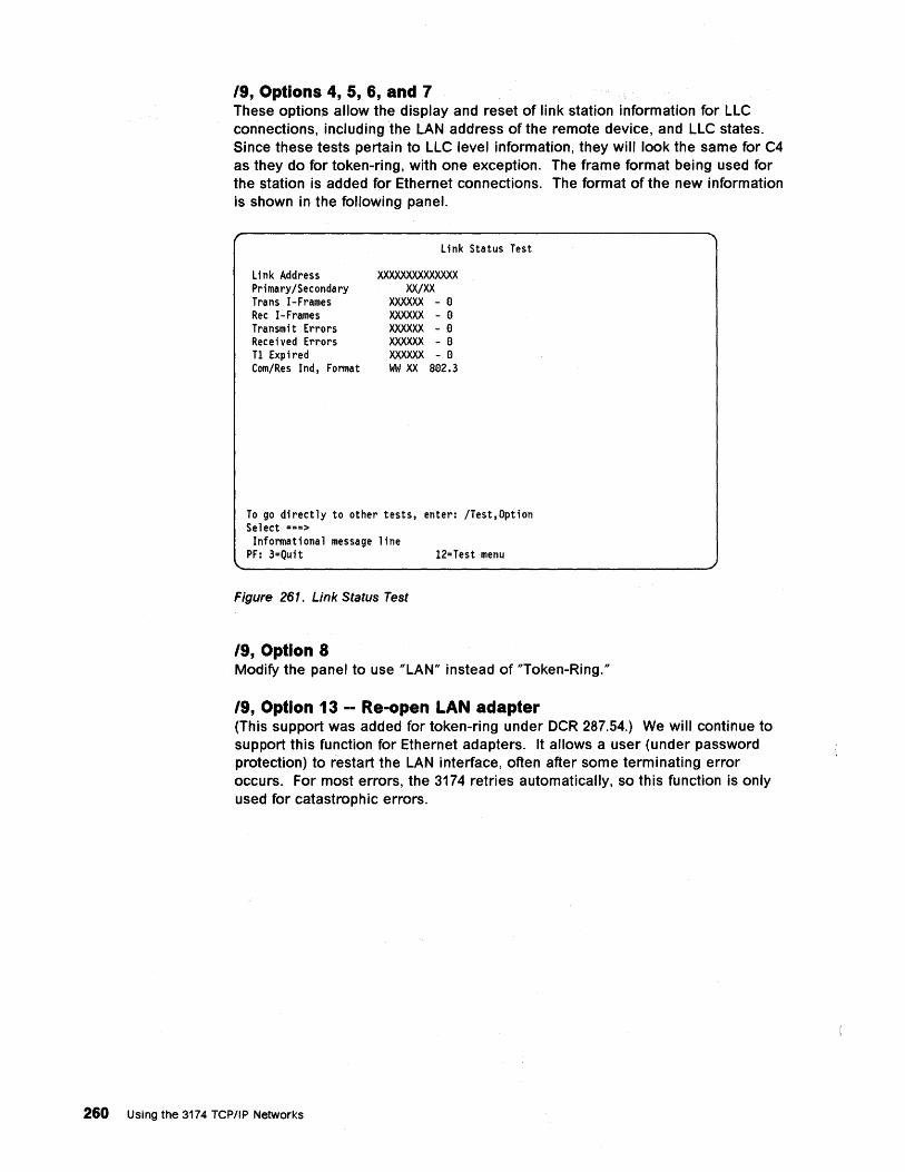
19, Options 4, 5, 6, and 7 These options allow the display and reset of link station information for LLC connections, including the LAN address of the remote device, and LLC states. Since these tests pertain to LLC level information, they will look the same for C4 as they do for token-ring, with one exception. The frame format being used for the station is added for Ethernet connections. The format of the new information is shown in the following panel.
li nk Address Primary/Secondary Trans I-Frames Rec I-Frames Transmit Errors Received Errors T1 Expired Com/Res Ind, Format
Link Status Test
xxxxxxxxxxxxxx XX/XX
XXXXXX - I:)
XXXXXX - I:)
XXXXXX - I:)
XXXXXX - I:)
XXXXXX - I:)
\oM XX 81:)2.3
To go directly to other tests, enter: /Test,Option Select ===>
Informational message line PF: 3=Quit 12=Testmenu
Figure 261. Link Status Test
19, Option 8 Modify the panel to use "LAN" instead of "Token-Ring."
19, Option 13 -- Re-open LAN adapter (This support was added for token-ring under OCR 287.54.) We will continue to support this function for Ethernet adapters. It allows a user (under password protection) to restart the LAN interface, often after some terminating error occurs. For most errors, the 3174 retries automatically, so this function is only used for catastrophic errors.
260 Using the 3174 TCPIIP Networks
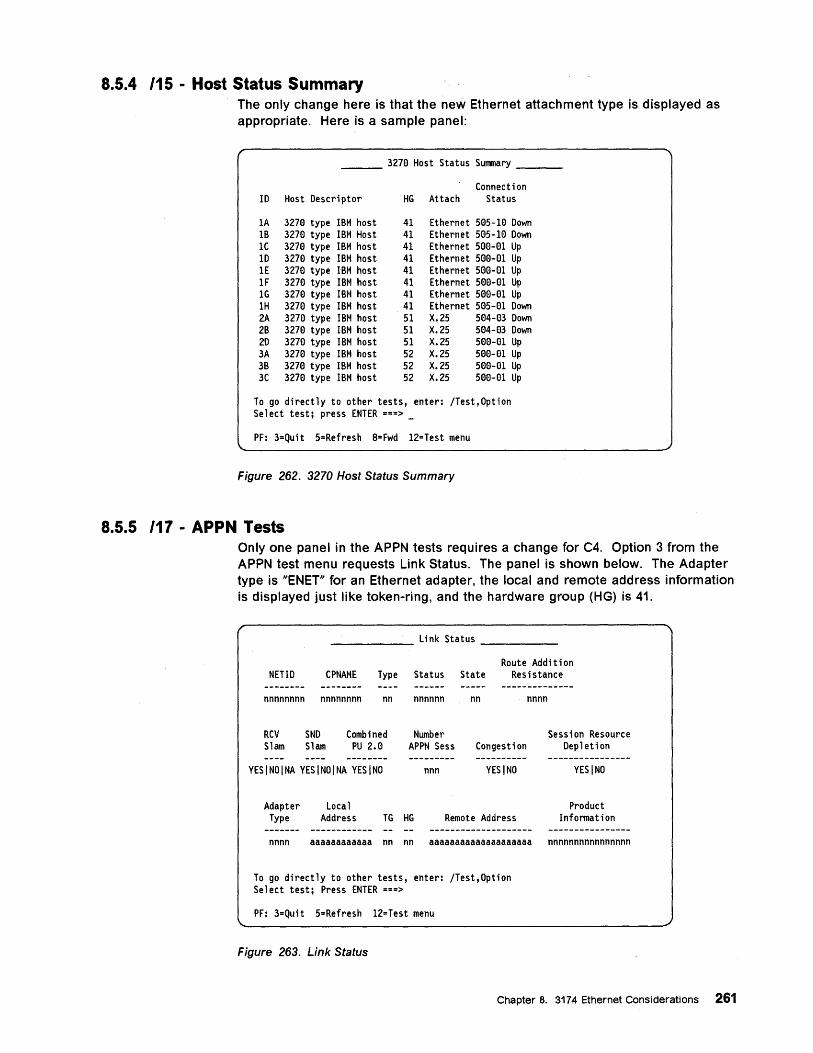
8.5.4 115 - Host Status Summary The only change here is that the new Ethernet attachment type is displayed as appropriate. Here is a sample panel:
3278 Host Status Sunmary
Connection 10 Host Descriptor HG Attach Status
lA 3278 type IBM host 41 Ethernet S8S-10 Down IB 3278 type IBM Host 41 Ethernet S8S-10 Down lC 3278 type IBM host 41 Ethernet S88-81 Up 10 3278 type IBM host 41 Ethernet S88-81 Up IE 3278 type IBM host 41 Ethernet S88-81 Up 1F 3278 type IBM host 41 Ethernet S88-81 Up IG 3278 type IBM host 41 Ethernet 588-81 Up IH 3278 type IBM host 41 Ethernet 585-81 Down 2A 3278 type IBM host 51 X.25 584-83 Down 2B 3278 type IBM host 51 X.25 584-83 Down 20 3278 type IBM host SI X.25 588-81 Up 3A 3278 type IBM host 52 X.25 S88-01 Up 3B 3278 type IBM host 52 X.25 588-81 Up 3C 3278 type IBM host S2 X.25 588-01 Up
To go directly to other tests, enter: /Test,Option Select test; press ENTER ===> _
PF: 3=Quit 5=Refresh 8= Fwd 12=Test menu
Figure 262. 3270 Host Status Summary
8.5.5 117 - APPN Tests Only one panel in the APPN tests requires a change for C4. Option 3 from the APPN test menu requests Link Status. The panel is shown below. The Adapter type is "ENET" for an Ethernet adapter, the local and remote address information is displayed just like token-ring, and the hardware group (HG) is 41.
______ Link Status ____ _
NETID CPNAME Type Status State Route Addition
Resistance
nnnnnnnn nnnnnnnn nn
RCV SND Combined Slam Slam PU 2.8
YESINOINA YESINOINA YESINO
Adapter Local
nnnnnn
Number APPN Sess
nnn
nn
Congestion
YESINO
Type Address TG HG Remote Address
nnnn
Session Resource Depletion
YESINO
Product Information
nnnn aaaaaaaaaaaa nn nn aaaaaaaaaaaaaaaaaaaa nnnnnnnnnnnnnnnn
To go directly to other tests, enter: /Test,Option Select test; Press ENTER ===>
PF: 3=Quit 5=Refresh 12=Test menu
Figure 263. Link Status
Chapter 8. 3174 Ethernet Considerations 261

262 Using the 3174 TCP/IP Networks
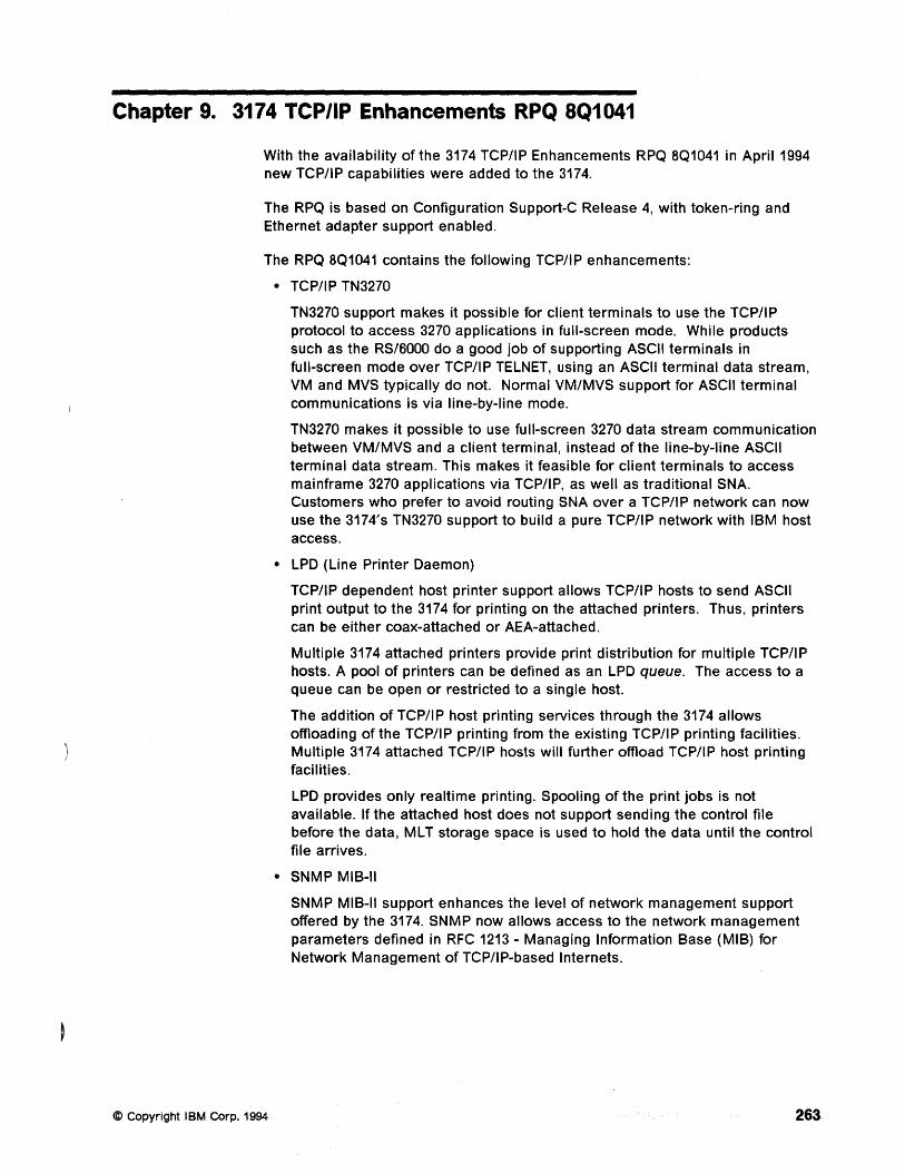
Chapter 9. 3174 TCP/IP Enhancements RPQ 8Q1041
With the availability of the 3174 TCP/IP Enhancements RPQ 8Q1041 in April 1994 new TCP/IP capabilities were added to the 3174.
The RPQ is based on Configuration Support-C Release 4, with token-ring and Ethernet adapter support enabled.
The RPQ 8Q1041 contains the following TCP/IP enhancements:
• TCP/IP TN3270
@ Copyright IBM Corp. 1994
TN3270 support makes it possible for client terminals to use the TCP/IP protocol to access 3270 applications in full-screen mode. While products such as the RS/6000 do a good job of supporting ASCII terminals in full-screen mode over TCP/IP TELNET, using an ASCII terminal data stream, VM and MVS typically do not. Normal VM/MVS support for ASCII terminal communications is via line-by-line mode.
TN3270 makes it possible to use full-screen 3270 data stream communication between VM/MVS and a client terminal, instead of the line-by-line ASCII terminal data stream. This makes it feasible for client terminals to access mainframe 3270 applications via TCP/IP, as well as traditional SNA. Customers who prefer to avoid routing SNA over a TCP/IP network can now use the 3174's TN3270 support to build a pure TCP/IP network with ISM host access.
• LPD (Line Printer Daemon)
TCP/IP dependent host printer support allows TCP/IP hosts to send ASCII print output to the 3174 for printing on the attached printers. Thus, printers can be either coax-attached or AEA-attached.
Multiple 3174 attached printers provide print distribution for multiple TCPIIP hosts. A pool of printers can be defined as an LPD queue. The access to a queue can be open or restricted to a single host.
The addition of TCPIIP host printing services through the 3174 allows offloading of the TCPIIP printing from the existing TCPIIP printing facilities. Multiple 3174 attached TCP/IP hosts will further offload TCP/IP host printing facilities.
LPD provides only realtime printing. Spooling of the print jobs is not available. If the attached host does not support sending the control file before the data, MLT storage space is used to hold the data until the control file arrives.
• SNMP MIS-II
SNMP MIS-II support enhances the level of network management support offered by the 3174. SNMP now allows access to the network management parameters defined in RFC 1213 - Managing Information Sase (MIS) for Network Management of TCP/IP-based Internets.
263
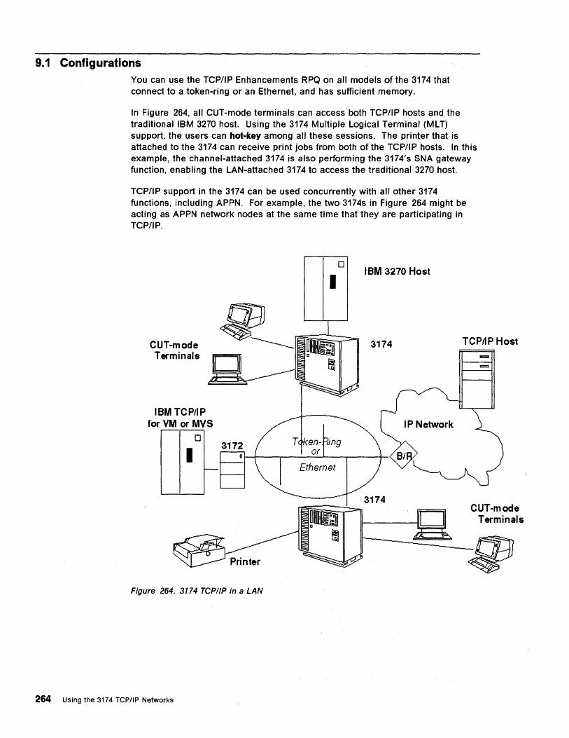
9.1 Configurations You can use the TCP/IP Enhancements RPQ on all models of the 3174 that connect to a token-ring or an Ethernet,and has sufficient memory.
In Figure 264, all CUT-mode terminals can access'both TCP/IP hosts and the traditional IBM 3270 host. Using the 3174 Multiple Logical Terminal (ML T) support, the users can hot-key among all these sessions. The printer that is attached to the 3174 can receive print jobs from both of the TCP/IP hosts. In this example, the channel-attached 3174 is also performing the 3174's SNA gateway function, enabling the LAN-attached 3174 to access the traditional 3270 host.
TCP/IP support in the 3174 can be used concurrently with all other 3174 functions, including APPN. For example, the two 3174s in Figure 264 might be acting as APPN network nodes at the same time that they are participating in TCP/IP.
CUT-mode Terminals
IBM TCP/IP for VM or MVS
o
I
Figure 264. 3174 TCP/IP in a LAN
264 Using the 3174 TCP/IP Networks
I
Ethernet
o IBM 3270 Host
3174 TCPIIP Host
g CUT-mode II-----D Terminals
~:9}
9.2 Devices
9.3 Hosts
The TCP/IP Enhancements RPQ allows all displays that attach to the controller, except DFTs, to operate in ASCII TELNET or TN3270 mode3 :
• Coax displays operating in CUT mode (CUTs, or the CUT side of a OFT-E)
ASCII TELNET These are supported as DEC VT100, DEC VT200, IBM 3101 or Dasher 0210 devices, using the ASCII emulation function of the 3174. (An AEA adapter is not required.)
The TCP/IP Enhancements RPQ supports these devices in 24X80 mode only; the 132-characters-per-line support for DEC VT220 made available in Configuration Support-C Release 2, is not available for the TCP/IP sessions.
TN3270 Full 3270 function is provided for these devices, including color support, models 2, 3, 4 and 5 screen sizes and Write Structured Fields. Local functions, such as copy session-to-session and split screen, are fully enabled while in a TN3270 session.
• ASCII displays that are attached via an AEA
ASCII TELNET The ASCII data stream is passed to the terminal with no manipulation by the 3174
TN3270 The 3174 performs 3270 emulation.
All printers that are directly attached to the 3174, either coax-attached or AEA-attached, can be used as LPD printers. HAP printers (printers attached to a port on a display) cannot be used for LPD. A printer that is being used for LPD cannot be used for 3270 host print sessions, nor can it be used for local copy printing.
The 3174 connects the above devices to any host or device attached to the network, that can communicate over TCPIIP networks using ASCII TELNET, TN3270 or LPD protocols. This includes IBM and non-IBM hosts. In particular, TN3270 support allows full-function display access to TCPIIP in mainframe IBM hosts (TCP/IP for VM or MVS) and to CICS/6000* workstations.
9.4 3174 Microcode and Packaging The TCP/IP Enhancements RPQ is a Control/Utility/Extension disk RPQ. This means you receive a complete set of 3174 diskettes with each order of the RPQ. It is based on Configuration Support~C Release 4 (CS-C4) Licensed Internal Code, with tOken-ring support enabled. The TCP/IP Enhancements RPQ provides all CS-C4 functions. DSL device, AEA, Peer Communications and APPN feature microcode has already been merged onto the Extension disk for you.
The TCPIIP Enhancements RPQ may not be compatible with other CS-C4 RPQs. Please contact your IBM marketing representative if you have questions about RPQ compatibility.
3 9.6," Protocols" on page 269 describes the difference between these 2 modes.
Chapter 9. 3174 TCPIIP Enhancements RPQ 8Q1041 265

The RPQ diskettes should not be used in configurations without TCP/IP.
266 Using the 3174 TCP/IP Networks
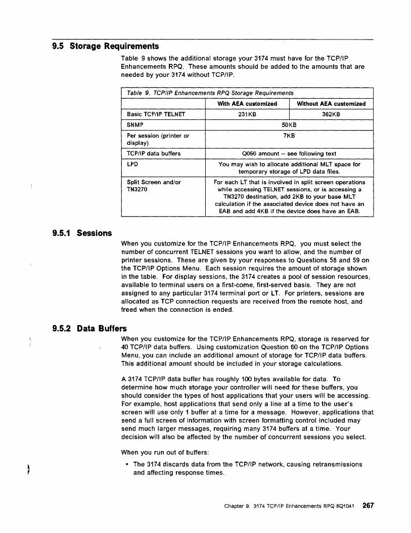
9.5 Storage Requirements
9.5.1 Sessions
Table 9 shows the additional storage your 3174 must have for the TCP/IP Enhancements RPQ. These amounts should be added to the amounts that are needed by your 3174 without TCP/IP.
Table 9. TCP//P Enhancements RPQ Storage Requirements
With AEA customized Without AEA customized
Basic TCP/IP TELNET 231KB 362KB
SNMP SOKB
Per session (printer or 7KB display)
TCP/IP data buffers Q060 amount -- see following text
LPD You may wish to allocate additional MLT space for temporary storage of LPD data files.
Split Screen and/or For each LT that is involved in split screen operations TN3270 while accessing TELNET sessions, or is accessing a
TN3270 destination, add 2KB to your base MLT calculation if the associated device does not have an
EAB and add 4KB if the device does have an EAB.
When you customize for the TCP/IP Enhancements RPQ, you must select the number of concurrent TELNET sessions you want to allow, and the number of printer sessions. These are given by your responses to Questions 58 and 59 on the TCP/IP Options Menu. Each session requires the amount of storage shown in the table. For display sessions, the 3174 creates a pool of session resources, available to terminal users on a first-come, first-served basis. They are not assigned to any particular 3174 terminal port or LT. For printers, sessions are allocated as TCP connection requests are received from the remote host, and freed when the connection is ended.
9.5.2 Data Buffers When you customize for the TCP/IP Enhancements RPQ, storage is reserved for 40 TCP/IP data buffers. Using customization Question 60 on the TCP/IP Options Menu, you can include an additional amount of storage for TCP/IP data buffers. This additional amount should be included in your storage calculations.
A 3174 TCP/IP data buffer has roughly 100 bytes available for data. To determine how much storage your controller will need for these buffers, you should consider the types of host applications that your users will be accessing. For example, host applications that send only a line at a time to the user's screen will use only 1 buffer at a time for a message. However, applications that send a full screen of information with screen formatting control included may send much larger messages, requiring many 3174 buffers at a time. Your decision will also be affected by the number of concurrent sessions you select.
When you run out of buffers:
• The 3174 discards data from the TCP/IP network, causing retransmissions and affecting response times.
Chapter 9. 3174 TCPIIP Enhancements RPQ 8Q1041 267

• Requests to establish host connections will be rejected, and the users must retry.
268 Using the 3174 TCP/IP Networks
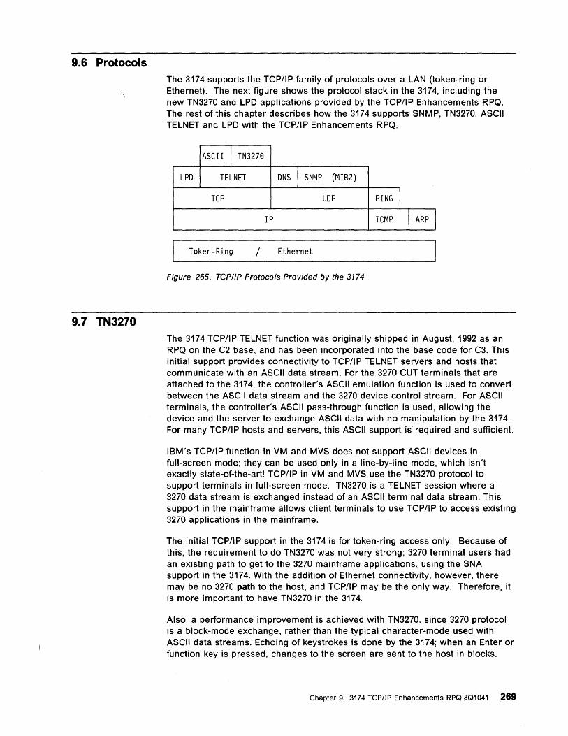
9.6 Protocols
9.7 TN3270
The 3174 supports the TCP/IP family of protocols over a LAN (token-ring or Ethernet). The next figure shows the protocol stack in the 3174, including the new TN3270 and LPD applications provided by the TCP/IP Enhancements RPQ. The rest of this chapter describes how the 3174 supports SNMP, TN3270, ASCII TELNET and LPD with the TCP/IP Enhancements RPQ.
ASCII I TN3270
LPD TELNET DNS I SNMP (MIB2)
TCP UDP PING I IP ICMP I ARP I
Token-Ring / Ethernet
Figure 265. TCP/IP Protocols Provided by the 3174
The 3174 TCP/IP TELNET function was originally shipped in August, 1992 as an RPQ on the C2 base, and has been incorporated into the base code for C3. This initial support provides connectivity to TCP/IP TELNET servers and hosts that communicate with an ASCII data stream. For the 3270 CUT terminals that are attached to the 3174, the controller's ASCII emulation function is used to convert between the ASCII data stream and the 3270 device control stream. For ASCII terminals, the controller's ASCII pass-through function is used, allowing the device and the server to exchange ASCII data with no manipulation by the 3174. For many TCP/IP hosts and servers, this ASCII support is required and sufficient.
IBM's TCP/IP function in VM and MVS does not support ASCII devices in full-screen mode; they can be used only in a line-by-line mode, which isn't exactly state-of-the-art! TCP/IP in VM and MVS use the TN3270 protocol to support terminals in full-screen mode. TN3270 is a TELNET session where a 3270 data stream is exchanged instead of an ASCII terminal data stream. This support in the mainframe allows client terminals to use TCP/IP to access existing 3270 applications in the mainframe.
The initial TCP/IP support in the 3174 is for token-ring access only. Because of this, the requirement to do TN3270 was not very strong; 3270 terminal users had an existing path to get to the 3270 mainframe applications, using the SNA support in the 3174. With the addition of Ethernet connectivity, however, there may be no 3270 path to the host, and TCP/IP may be the only way. Therefore, it is more important to have TN3270 in the 3174.
Also, a performance improvement is achieved with TN3270, since 3270 protocol is a block-mode exchange, rather than the typical character-mode used with ASCII data streams. Echoing of keystrokes is done by the 3174; when an Enter or function key is pressed, changes to the screen are sent to the host in blocks.
Chapter 9. 3174 TCPIIP Enhancements RPQ 8Q1041 269
9.7.1 Function
CICS/6000 is now available, allowing CICS applications to execute in an RS/6000. These applications typically support a 3270 data stream; they can be accessed via an ASCII data stream through TCP/IP TELNET, but this involves a conversion in the workstation from 3270 to the ASCII data stream. That is, they do the reverse of the 3174's ASCII emulation function. So with the existing 3174 TELNET support, a 3270 terminal's data stream is converted in the 3174 to ASCII, and then back to the 3270 in the RS/6000. By adding TN3270 in the 3174, we will eliminate the two conversions, and allow direct transfer of a 3270 data stream to a CICS/6000 platform.
From the perspective of the TELNET protocols, TN3270 support is most easily understood as another TELNET terminal type. In a typical TELNET session establishment sequence, the host or server initiates terminal type negotiation (see RFC 930), by asking the client for its terminal type. If the server does not support that type of terminal, the server asks again. The client can answer with another type, if it can provide more than one type, or it can answer with the same type. Once a client responds twice with the same type, that means it can't do any others.
The 3174 will handle this by adding a new host data stream type in the station sets for TCP/I P hosts. When a host with the new 3270 type is selected as the destination from a 3270 terminal, the 3174 will send the 3270 device type during terminal-type negotiation.
The 3174 doesn't know the exact device type that is attached to a coax port. However, the 3174 does learn certain attributes of the device, that can be mapped into the device types that TCP/IP for VM and MVS understands.
The 3174 maps color devices to 3279 and monochrome to 3278 The screen size determines the model attribute (2, 3, 4 or 5). And the presence of an EAB is represented by E at the end of the device name. So, the 3174 will return one of the following types for coax terminals:
• IBM-3278-2
• IBM-3278-3
• IBM-3278-4
• IBM-3278-5
• IBM-3278-2-E
• IBM-3278-3-E
• IBM-3278-4-E
• IBM-3278-5-E
• IBM-3279-2
• IBM-3279-3
• IBM-3279-2-E
• IBM-3279-3-E
For ASCII terminals, the station set type determines the model size that is emulated, and also whether color is supported. The TN3270 types that are returned for ASCII terminals are:
270 Using the 3174 TCP/IP Networks
• IBM-3278-4
- DEC VT100
• IBM-3278-5
IBM 3151 Model 31,41,51,61
IBM 3162
IBM-3279-2
- FTTERM
- IBM 3164
- Tektronix 4205
IBM-3278-2
- All others
If the host rejects the 3270 device type by asking for the terminal type a second time, the TCP session ends.
While in an active TN3270 session, the user cannot enter the 3174's local mode. The main uses of local mode during an active session are for manipulating ASCII terminal characteristics, so it is not needed during. 3270 mode. Between sessions, the 3174's local mode is the existing line-by-line interface: 3270 terminals will emulate VT100; ASCII terminals are in ASCII pass-through mode.
Since CICS/6000 TN3270 must be reached via a TCP port other than the well-known TELNET port, a customization option has been added to the station set definition. This new field allows the customer to specify which TCP port to use when doing an automatic host connection. (Automatic host connection is attempted if the I P address field in the station set is non-zero.) When not using automatic connections, the 3174 already allows the terminal user to select a TCP port number.
While in a TN3270 session, all the keyboard functions used during other 3270 sessions will work. That is, the restrictions that currently apply to TELNET sessions are removed:
• Copy session-to-session can be done with the TN3270 session as either the source or destination session
• Split screen functions can be done, even on ASCII TN3270 sessions
Chapter 9. 3174 TCP/IP Enhancements RPQ 8Q1041 271
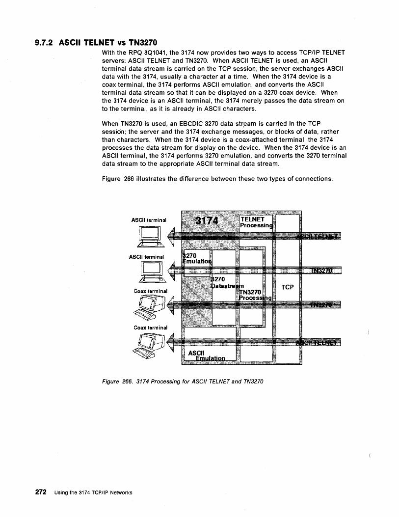
9.7.2 ASCII TELNET vs TN3270 With the RPQ 8Q1041, the 3174 now provides two ways to access TCP/IP TELNET servers: ASCII TELNET and TN3270. When ASCII TELNET is used, an ASCII terminal data stream is carried on the TCP session; the server exchanges ASCII data with the 3174, usually a character at a time. When the 3174 device is a coax terminal, the 3174 performs ASCII emUlation, and converts the ASCII terminal data stream so that it can be displayed on a 3270 coax device. When the 3174 device is an ASCII terminal, the 3174 merely passes the data stream on to the terminal, as it is already in ASCII characters.
When TN3270 is used, an EBCDIC 3270 data str,eam is carried in the TCP session; the server and the 3174 exchange messages, or blocks of data, rather than characters. When the 3174 device is a coax-attached terminal, the 3174 processes the data stream for display on the device. When the 3174 device is an ASCII terminal, the 3174 performs 3270 emUlation, and converts the 3270 terminal data stream to the appropriate ASCII terminal data stream.
Figure 266 illustrates the difference between these two types of connections.
ASCII terminal
ASCII terminal
Q Coax terminal
~ Coax terminal
Figure 266. 3174 Processing for ASCII TELNET and TN3270
272 Using the 3174 TCP/IP Networks
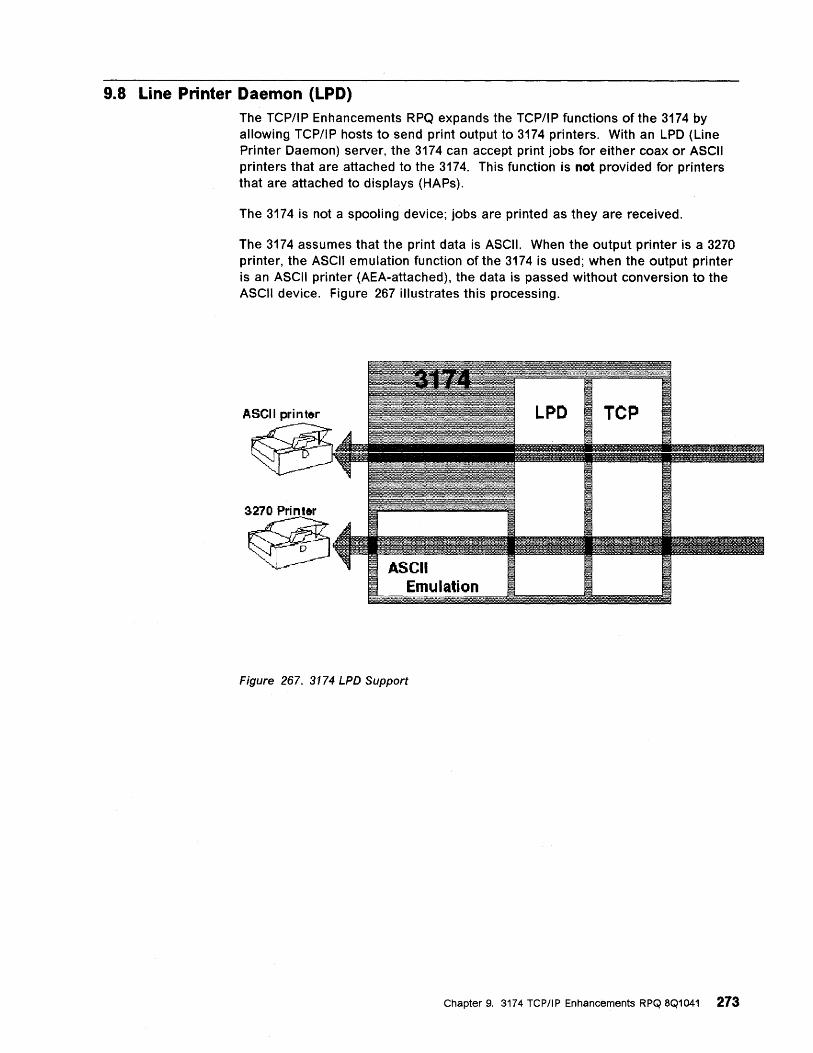
9.8 Line Printer Daemon (LPD) The TCP/IP Enhancements RPQ expands the TCP/IP functions of the 3174 by allowing TCP/IP hosts to send print output to 3174 printers. With an LPD (Line Printer Daemon) server, the 3174 can accept print jobs for either coax or ASCII printers that are attached to the 3174. This function is not provided for printers that are attached to displays (HAPs).
The 3174 is not a spooling device; jobs are printed as they are received.
The 3174 assumes that the print data is ASCII. When the output printer is a 3270 printer, the ASCII emulation function of the 3174 is used; when the output printer is an ASCII printer (AEA-attached), the data is passed without conversion to the ASCII device. Figure 267 illustrates this processing.
Emulation
Figure 267. 3174 LPD Support
Chapter 9. 3174 TCP/IP Enhancements RPQ 8Q1041 273
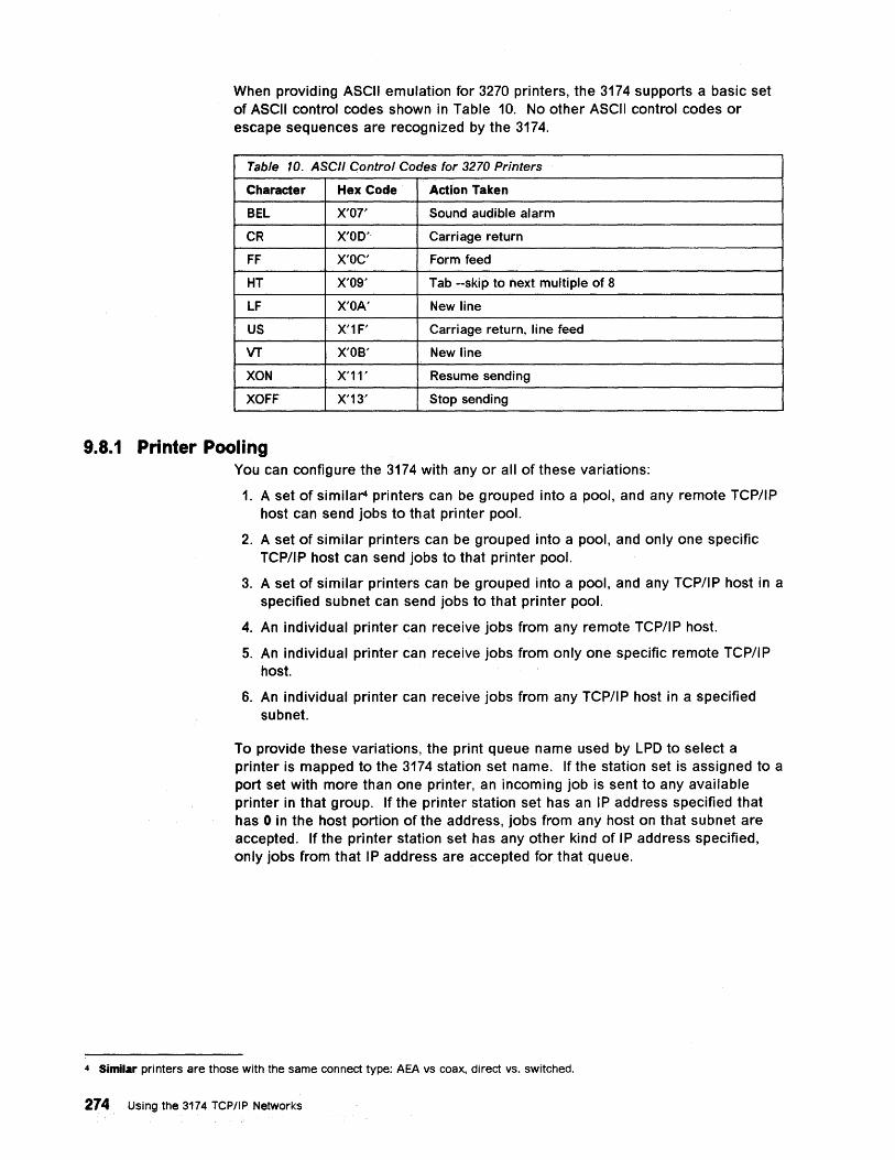
When providing ASCII emulation for 3270 printers, the 3174 supports a basic set of ASCII control codes shown in Table 10. No other ASCII control codes or escape sequences are recognized by the 3174.
Table 10. ASCII Contra/Codes for 3270 Printers
Character Hex Code Action Taken
BEL X'07' Sound audible alarm
CR X'OD' Carriage return
FF X'OC' Form feed
HT X'OS' Tab --skip to next multiple of 8
LF X'OA' New line
US X'1F' Carriage return, line feed
VT X'OB' New line
XON X'11' Resume sending
XOFF X'13' Stop sending
9.8.1 Printer Pooling You can configure the 3174 with any or all of these variations:
1. A set of similar4 printers can be grouped into a pool, and any remote TCP/IP host can send jobs to that printer pool.
2. A set of similar printers can be grouped into a pool, and only one specific TCP/IP host can send jobs to that printer pool.
3. A set of similar printers can be grouped into a pool, and any TCP/IP host in a specified subnet can send jobs to that printer pool.
4. An individual printer can receive jobs from any remote TCP/IP host.
5. An individual printer can receive jobs from only one specific remote TCP/IP host.
6. An individual printer can receive jobs from any TCP/IP host in a specified subnet.
To provide these variations, the print queue name used by LPD to select a printer is mapped to the 3174 station set name. If the station set is assigned to a port set with more than one printer, an incoming job is sent to any available printer in that group. If the printer station set has an IP address specified that has 0 in the host portion of the address, jobs from any host on that subnet are accepted. If the printer station set has any other kind of IP address specified, only jobs from that IP address are accepted for that queue.
4 Similar printers are those with the same connect type: AEA vs coax, direct vs. switched.
274 Using the 3174 TCP/IP Networks
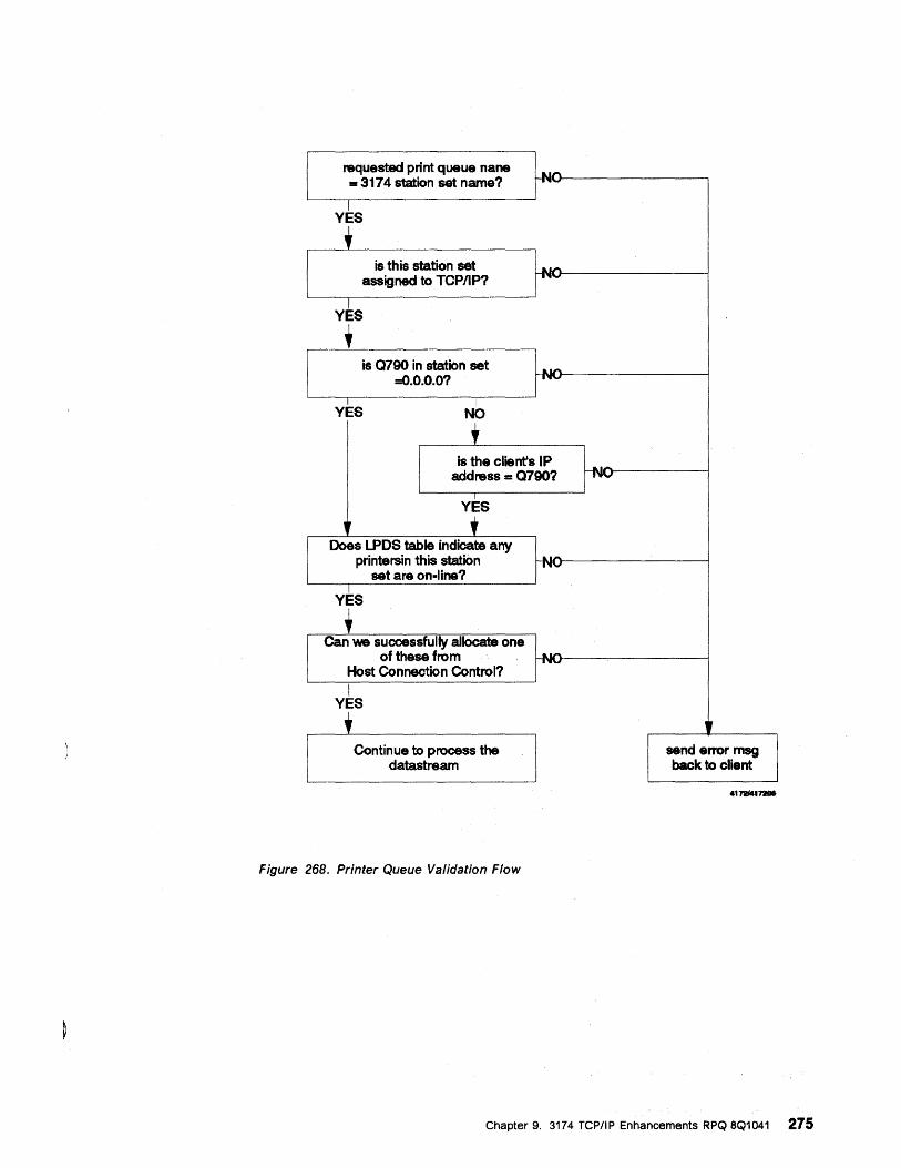
requested print queue nana = 3174 station set name? H-f\lN ... n.I_U----------,
Y~S , is this station set
assigned to TCPIIP? ~~----------~
Y~S , is Q790 in station set
=o.O.O.O?
YES I
NO , is the client's IP
address == Q7907
YES
J Does LPDS table indicate any
-NO
printersin this station H~I\IIV" .. r-----------I
set are on-lina?
YES , Can we successfully allocate one
of these from H-f'JN,~O(}----:---------! Host Connection Control? I
YES , Continue to process the
datastream
Figure 268. Printer Queue Validation Flow
'f send error msg back to client
Chapter 9. 3174 TCP/IP Enhancements RPQ 8Q1041 275
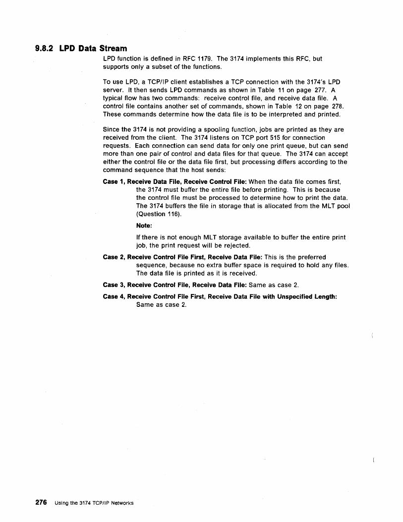
9.8.2 LPD Data Stream LPD function is defined in RFC 1179. The 3174 implements this RFC, but supports only a subset of the functions.
To use LPD, a TCP/IP client establishes a TCP connection with the 3174's LPD server. It then sends LPD commands as shown in Table 11 on page 277. A typical flow has two commands: receive control file, and receive data file. A control file contains another set of commands, shown in Table 12 on page 278. These commands determine how the data file is to be interpreted and printed.
Since the 3174 is not providing a spooling function, jobs are printed as they are received from the client. The 3174 listens on TCP port 515 for connection requests. Each connection can send data for only one print queue, but can send more than one pair of control and data files for that queue. The 3174 can accept either the control file or the data file first, but processing differs according to the command sequence that the host sends:
Case 1, Receive Data File, Receive Control File: When the data file comes first, the 31,74 must buffer the entire file before printing. This is because the control file must be processed to determine how to print the data. The 3174 buffers the file in storage that is allocated from the ML T pool (Question 116).
Note:
If there is not enough ML T storage available to buffer the entire print job, the print request will be rejected.
Case 2, Receive Control File First, Receive Data File: This is the preferred sequence, because no extra buffer space is required to hold any files. The data file is printed as it is received.
Case 3, Receive Control File, Receive Data File: Same as case 2.
Case 4, Receive Control File First, Receive Data File with Unspecified Length: Same as case 2.
276 Using the 3174 TCP/IP Networks
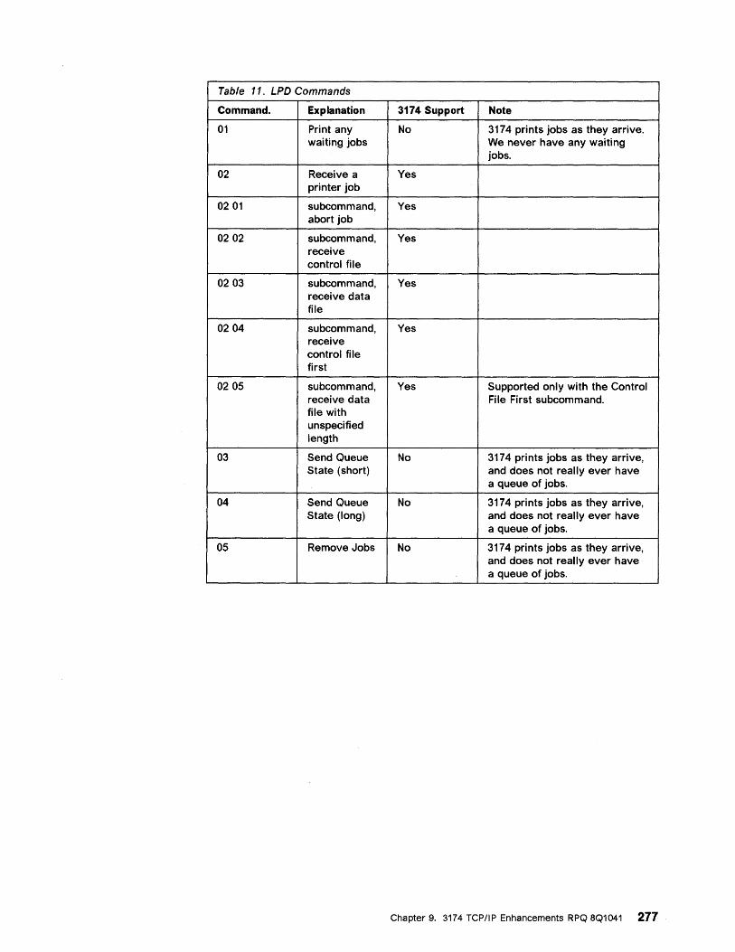
Table 11. LPD Commands
Command. Explanation 3174 Support Note
01 Print any No 3174 prints jobs as they arrive. waiting jobs We never have any waiting
jobs.
02 Receive a Yes printer job
0201 subcommand, Yes abort job
0202 subcommand, Yes receive control file
0203 subcommand, Yes receive data file
0204 subcommand, Yes receive control file first
0205 subcommand, Yes Supported only with the Control receive data File First subcommand. file with unspecified length
03 Send Queue No 3174 prints jobs as they arrive, State (short) and does not really ever have
a queue of jobs.
04 Send Queue No 3174 prints jobs as they arrive, State (long) and does not really ever have
a queue of jobs.
05 Remove Jobs No 3174 prints jobs as they arrive, and does not really ever have a queue of jobs.
Chapter 9. 3174 TCP/IP Enhancements RPQ 8Q1041 277
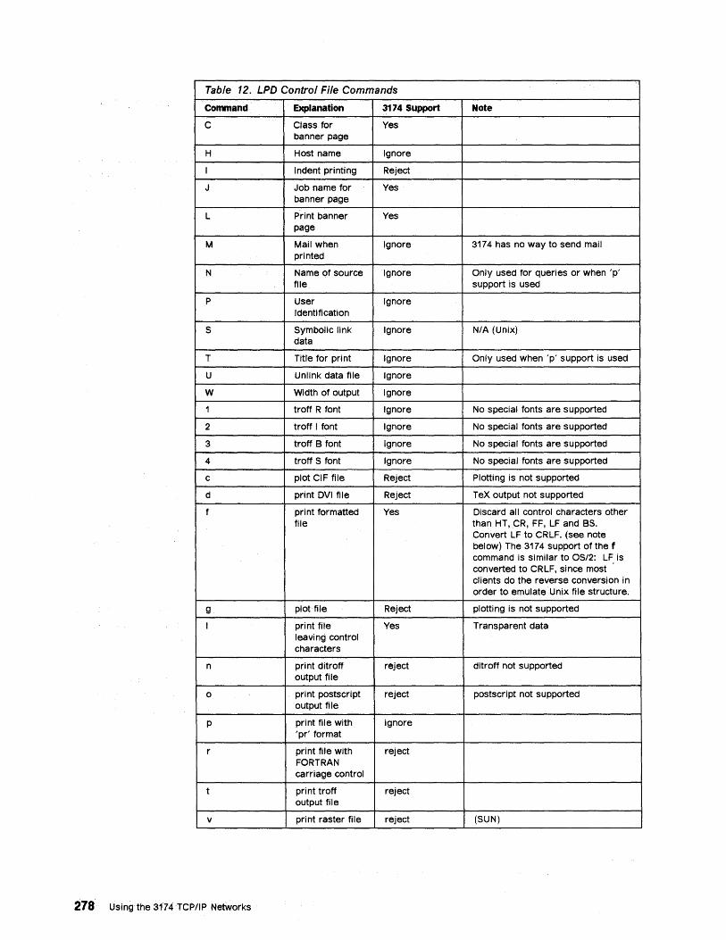
Table 12. LPD Control File Commands
Command Explanation 3174 Support Note
C Class for Yes banner page
H Host name Ignore
I Indent printing Reject
J Job name for Yes banner page
L Print banner Yes page
M Mail when Ignore 3174 has no way to send mail printed
N Name of source Ignore Only used for queries or when 'p' file support is used
P User Ignore Identification
S Symbolic link Ignore N/A (Unix) data
T Title for print Ignore Only used when 'p' support is used
U Unlink data file Ignore
W Width of output Ignore
1 troff R font Ignore No special fonts are supported
2 troff I font Ignore No special fonts are supported
3 troff B font Ignore No special fonts are supported
4 troff S font Ignore No special fonts are supported
c plot CIF file Reject Plotting is not supported
d print DVI file Reject TeX output not supported
f pri nt formatted Yes Discard all control characters other file than HT, CR, FF, LF and BS.
Convert LF to CRLF. (see note below) The 3174 support of the f command is similar to OS/2: LF is converted to CRLF, since most clients do the reverse conversion in order to emulate Unix file structure.
g plot file Reject plotting is not supported
I print file Yes Transparent data leaving control characters
n print ditroff reject ditroff not supported output file
0 print postscript reject postscript not supported output file
p pri nt fil e with ignore 'pr' format
r print file with reject FORTRAN carriage control
t print troff reject output file
v print raster file reject (SUN)
278' Using the 3174 TCPIIP Networks

9.8.3 Banner Page If the control file contains an L command to request a banner page, the 3174 sends this data to the printer, followed by a formfeed (FF)5:
(blank line) (blank line) ******************************************************************************* ******************************************************************************* ******************************************************************************* *** *** *** *** *** *** *** *** *** *** *** *** *** *** *** *** *** *** *** ***
Output from IBM 3174, printer_station_set_name
first_S8_bytes_of_the_job_name_xxxxxxxxxxxxxxxxxxx first_S8_bytes_of_the~job_name_xxxxxxxxxxxxxxxxxxx
first_S8_bytes_of_the_job_name_xxxxxxxxxxxxxxxxxxx
31_byte_class_xxxxxxxxxxxxxxxxxx 31_byte_class_xxxxxxxxxxxxxxxxxx 31_byte_class_xxxxxxxxxxxxxxxxxx
*** *** *** *** *** *** *** *** *** *** *** *** *** *** *** *** *** *** *** ***
******************************************************************************* ******************************************************************************* *******************************************************************************
first_SO_bytes_of_the...iobname is gotten from a J command in the control file. 31_byte_class is gotten from a C command in the control file. If no C command is used, the 3174's TCP/IP host name is inserted here.
9.8.4 Internal Queuing If the 3174 receives more print requests for a given queue than there are printers in that queue, the extra requests are queued internally until a printer becomes available. The host may break the TCP connection during this time, if it wants to.
If the 3174 receives more LPD connections than there are TCP/IP printer sessions allowed. The extra connections are queued internally until a session becomes available. The host may break the TCP connection during this time, if it wants to.
5 The 3174 assumes any previous print activity left the printer at the top of form
Chapter 9. 3174 TCP/IP Enhancements RPQ 8Q1041 279
9.8.5 Translation Support
9.9 MIB-II
When printing to a 3270 printer, ASCII emulat.ion requires translation of the characters from ASCII to internal code points. The type of translation is specified by Question 784 for each printer station set, and should match the character set of the sending host:
• ISM Code Page 850
• ISO 8859
• DEC NRC
• DEC MCS
Note: The printer queue name that you use at the sending host must be the same as the 3174 station set name. This name is case sensitive; since the 3174 station set name is always uppercase, you must use uppercase at the host when defining and selecting the queue.
The original 3174 TCP/IP SNMP support provided only MIS-I variables. The MIB-II support in the TCP/IP enhancements RPQ Q81041 expands the 3174's SNMP agent function to include MIB-II variables. The 3174 now supports the standard MIS defined by RFC 1231, the token-ring MIS from RFC 1231 and the Ethernet MIS from RFC 1398.
The 3174 agent responds to request for MIS variable information from SNMP clients elsewhere in the network. NetView/6000, for example, can operate as the SNMP client. The 3174 supports GET and GET_NEXT requests for the variables listed in Appendix B, "SNMP Variables" on page 363. The 3174 does not honor SET requests, nor does the 3174 generate TRAPs. The 3174 uses the community name public.
SNMP support requires additional storage. You may customize the 3174 to run with or without SNMP, as shown in Figure 269 on page 291.
There are some variables that the 3174 cannot support; we return NOSUCHNAME indications to the remote SNMP client when these variables are requested. For example, some Ethernet counters are not available from our adapter.
The rest of this section describes the new MIS-II variables.Appendix B, "SNMP Variables" on page 363 shows all the variables supported by the 3174 in ASN.1 numeric order.
• The System group (MIB-II 1)
sysContact (system 4) - DisplayString
The textual identification of the contact person for this managed node, together with information on how to contact this person. For 3174, this is the response to Q99.
sysName (system 5) - DisplayString
An administratively assigned name for this managed node. By convention, this is the node's fully-qualified domain name. For 3174, this is created from the information on the Domain Name Service customization panel.
280 Using the 3174 reP/IP Networks
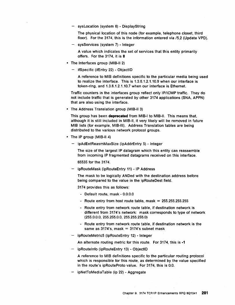
sysLocation (system 6) - DisplayString
The physical location of this node (for example, telephone closet, third floor). For the 3174, this is the information entered via 15,2 (Update VPD).
sysServices (system 7) - Integer
A value which indicates the set of services that this entity primarily offers. For the 3174, it is 8
• The Interfaces group (MIB-II 2)
if Specific (ifEntry 22) - ObjectlD
A reference to MIB definitions specific to the particular media being used to realize the interface. This is 1.3.6.1.2.1.10.9 when our interface is token-ring, and 1.3.6.1.2.1.10.7 when our interface is Ethernet.
Traffic counters in the interfaces group reflect only IP/ICMP traffic. They do not include traffic that is generated by other 3174 applications (SNA, APPN) that are also using the interface.
• The Address Translation group (MIB-II 3)
This group has been deprecated from MIB-I to MIB-II. This means that, although it is still included iri MIB-II, it very likely will be removed in future MIB lists (for example, MIB-III). Address Translation tables are being distributed to the various network protocol groups.
• The IP group (MIB-II 4)
ipAdEntReasmMaxSize (ipAddrEntry 5) - Integer
The size of the largest IP datagram which this entity can reassemble from incoming IP fragmented datagrams received on this interface.
65535 for the 3174.
ipRouteMask (ipRouteEntry 11) - IP Address
The mask to be logically ANDed with the destination address before being compared to the value in the ipRouteDest field.
3174 provides this as follows:
- Default route, mask - 0.0.0.0
- Route entry from host route table, mask = 255.255.255.255
- Route entry from network route table, if destination network is different from 3174's network: mask corresponds to type of network (255.0.0.0, 255.255.0.0, 255.255.255.0)
- Route entry from network route table, if destination network is the same as 3174's, mask = 3174's subnet mask
ipRouteMetric5 (ipRouteEntry 12) - Integer
An alternate routing metric for this route. For 3174, this is ·1
ipRoutelnfo (ipRouteEntry 13) - ObjectlD
A reference to MIB definitions specific to the particular routing protocol which is responsible for this route, as determined by the value specified in the route's ipRouteProto value. For 3174, this is 0.0.
ipNetToMediaTable (ip 22) - Aggregate
Chapter 9. 3174 TCPIIP Enhancements RPQ 8Q1041 281
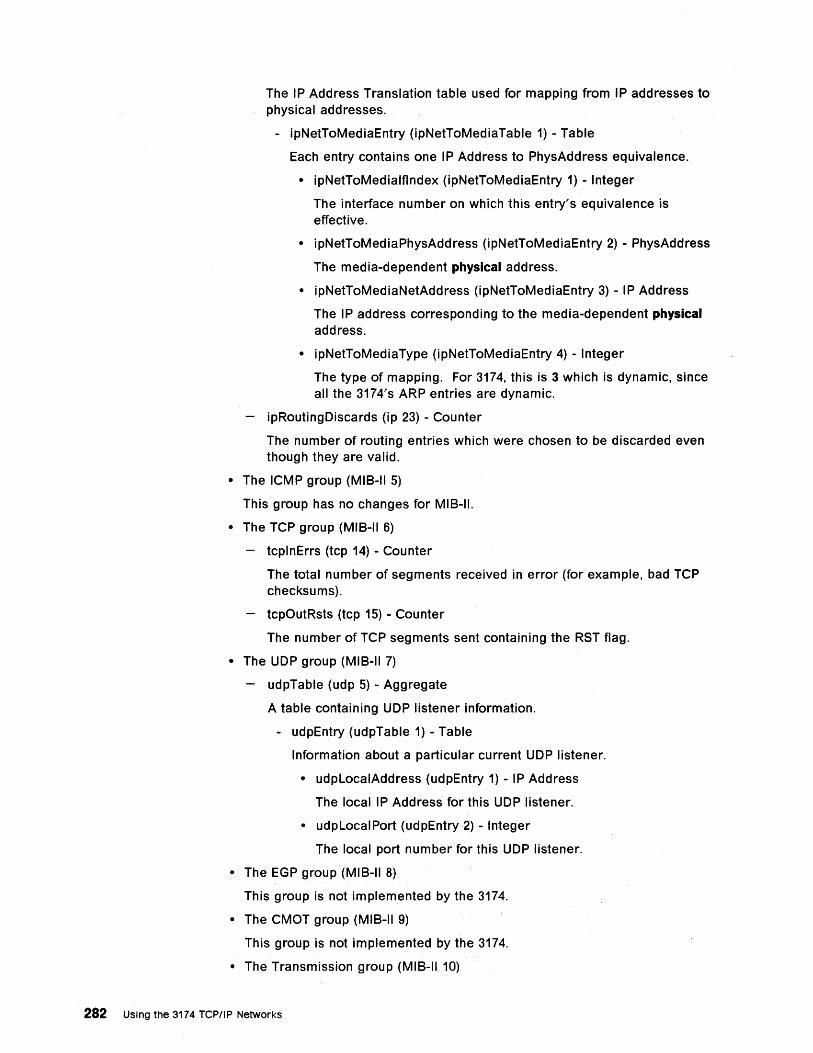
The IP Address Translation table used for mapping fromlP addresses to physical addresses.
- ipNetToMediaEntry (ipNetToMediaTable 1) - Table
Each entry contains one IP Address to PhysAddress equivalence.
• ipNetToMedialfindex (ipNetToMediaEntry 1) - Integer
The interface number on which this entry's equivalence is effective.
• ipNetToMediaPhysAddress (ipNetToMediaEntry 2) - PhysAddress
The media-dependent physical address.
• ipNetToMediaNetAddress (ipNetToMediaEntry 3) - IP Address
The IP address corresponding to the media-dependent physical address.
• ipNetToMediaType (ipNetToMediaEntry 4) - Integer
The type of mapping. For 3174, this is 3 which is dynamic, since all the 3174's ARP entries are dynamic.
ipRoutingDiscards (ip 23) - Counter
The number of routing entries which were chosen to be discarded even though they are valid.
• The ICMP group (MIS-II 5)
This group has no changes for MIS-II.
• The TCP group (MIS-II 6)
tcplnErrs (tcp 14) - Counter
The total number of segments received in error (for example, bad TCP checksums).
tcpOutRsts (tcp 15) - Counter
The number of TCP segments sent containing the RST flag.
• The UDP group (MIS-II 7)
udpTable (udp 5) - Aggregate
A table containing UDP listener information.
- udpEntry (udpTable 1) - Table
Information about a particular current UDP listener.
• udpLocalAddress (udpEntry 1) - IP Address
The local IP Address for this UDP listener.
• udpLocalPort (udpEntry2) - Integer
The local port number for this UDP listener.
• The EGP group (MIS-II 8)
This group is not implemented by the 3174.
• The CMOT group (MIS-II 9)
This group is not implemented by the 3174.
• The Transmission group (MIS-II 10)
282 Using the 3174 TCP/IP Networks
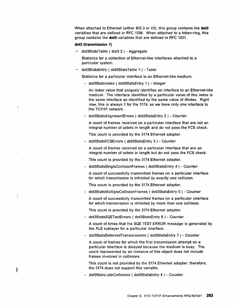
When attached to Ethernet (either 802.3 or V2), this group contains the dot3 variables that are defined in RFC 1398. When attached to a token-ring, this group contains the dots variables that are defined in RFC 1231.
dot3 (transmission 7)
dot3StatsTabie ( dot3 2 ) - Aggregate
Statistics for a collection of Ethernet-like interfaces attached to a particular system.
dot3StatsEntry ( dot3StatsTabie 1 ) - Table
Statistics for a particular interface to an Ethernet-like medium.
- dot3Statsindex ( dot3StatsEntry 1 ) - Integer
An index value that uniquely identifies an interface to an Ethernet-like medium. The interface identified by a particular value of this index is the same interface as identified by the same value of iflndex. Right now, this is always 1 for the 3174, as we have only one interface to the TCP/IP network.
- dot3StatsAlignmentErrors ( dot3StatsEntry 2 ) - Counter
A count of frames received on a particular interface that are not an integral number of octets in length and do not pass the FCS check.
This count is provided by the 3174 Ethernet adapter.
- dot3StatsFCSErrors ( dot3StatsEntry 3 ) - Counter
A count of frames received on a particular interface that are an integral number of octets in length but do not pass the FCS check.
This count is provided by the 3174 Ethernet adapter.
- dot3StatsSingieCoilisionFrames ( dot3StatsEntry 4 ) - Counter
A count of successfully transmitted frames on a particular interface for which transmission is inhibited by exactly one collision.
This count is provided by the 3174 Ethernet adapter.
- dot3StatsMuitipieCoilisionFrames ( dot3StatsEntry 5 ) - Counter
A count of successfully transmitted frames on a particular interface for which transmission is inhibited by more than one collision.
This count is provided by the 3174 Ethernet adapter.
- dot3StatsSQETestErrors ( dot3StatsEntry 6 ) - Counter
A count of times that the SQE TEST ERROR message is generated by the PLS sublayer for a particular interface.
- dot3StatsDeferredTransmissions ( dot3StatsEntry 7 ) - Counter
A count of frames for which the first transmission attempt on a particular interface is delayed because the medium is busy. The count represented by an instance of this object does not include frames involved in collisions.
This count is not provided by the 3174 Ethernet adapter; therefore, . the 3174 does not support this variable.
- dot3StatsLateCoilisions ( dot3StatsEntry 8 ) - Counter
Chapter 9. 3174 TCP/IP EnhancementsRPQ 8Q1041 283
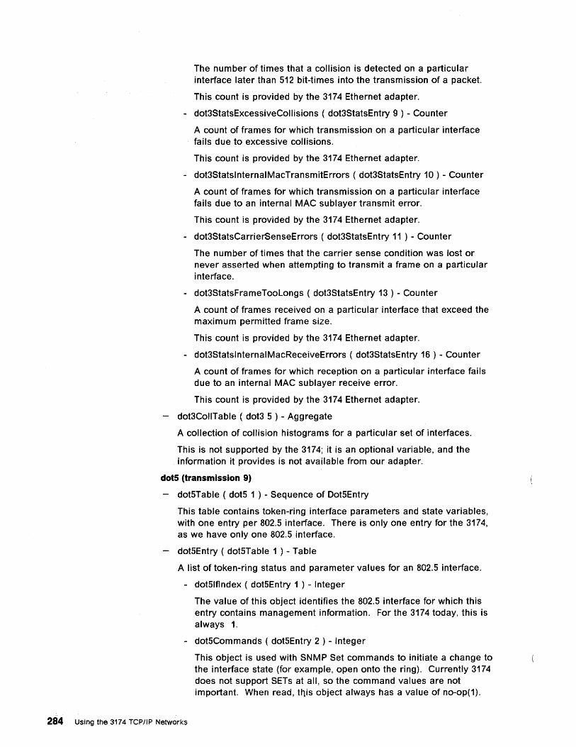
The number of times that a collision is detected on a particular interface later than S12 bit-times into the transmission of a packet.
This count is provided by the 3174 Ethernet adapter.
- dot3StatsExcessiveCoilisions ( dot3StatsEntry 9 ) - Counter
A count of frames for which transmission on a particular interface fails due to excessive collisions.
This count is provided by the 3174 Ethernet adapter.
- dot3StatsinternaiMacTransmitErrors ( dot3StatsEntry 10 ) - Counter
A count of frames for which transmission on a particular interface fails due to an internal MAC sublayer transmit error.
This count is provided by the 3174 Ethernet adapter.
- dot3StatsCarrierSenseErrors ( dot3StatsEntry 11 ) - Counter
The number of times that the carrier sense condition was lost or never asserted when attempting to transmit a frame on a particular interface.
- dot3StatsFrameTooLongs ( dot3StatsEntry 13 ) - Counter
A count of frames received on a particular interface that exceed the maximum permitted frame size.
This count is provided by the 3174 Ethernet adapter.
- dot3StatsinternaiMacReceiveErrors ( dot3StatsEntry 16 ) - Counter
A count of frames for which reception on a particular interface fails due to an internal MAC sublayer receive error.
This count is provided by the 3174 Ethernet adapter.
dot3CoilTabie ( dot3 S ) - Aggregate
A collection of collision histograms for a particular set of interfaces.
This is not supported by the 3174; it is an optional variable, and the information it provides is not available from our adapter.
dots (transmission 9)
dotSTable ( dotS 1 ) - Sequence of DotSEntry
This table contains token-ring interface parameters and state variables, with one entry per 802.S interface. There is only one entry for the 3174, as we have only one 802.S interface.
dotSEntry ( dotSTable 1 ) - Table
A list of tOken-ring status and parameter values for an 802.S interface.
- dotSlflndex ( dotSEntry 1 ) - Integer
The value of this object identifies the 802.S interface for which this entry contains management information. For the 3174 today, this is always 1.
- dotSCommands ( dotSEntry 2 ) - Integer
284 Using the 3174 TCP/IP Networks
This object is used with SNMP Set commands to initiate a change to the interface state (for example, open onto the ring). Currently 3174 does not support SETs at all, so the command values are not important. When read, this object always has a value of no-op(1).
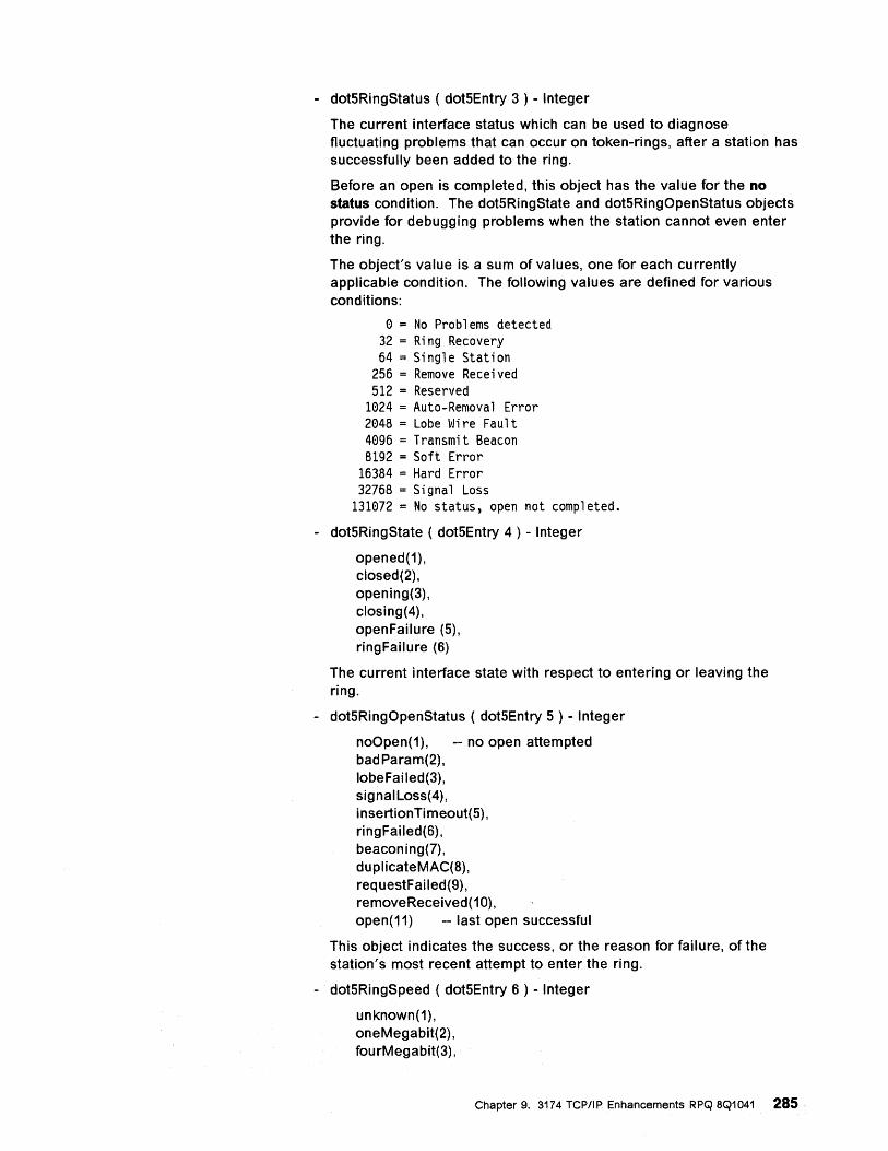
- dot5RingStatus ( dot5Entry 3 ) - Integer
The current interface status which can be used to diagnose fluctuating problems that can occur on token-rings, after a station has successfully been added to the ring.
Before an open is completed, this object has the value for the no status condition. The dot5RingState and dot5RingOpenStatus objects provide for debugging problems when the station cannot even enter the ring.
The object's value is a sum of values, one for each currently applicable condition. The following values are defined for various conditions:
o = No Problems detected 32 = Ring Recovery 64 = Single Station
256 = Remove Received 512 = Reserved
1024 = Auto-Removal Error 2048 = Lobe Wire Fault 4096 = Transmit Beacon 8192 = Soft Error
16384 = Hard Error 32768 = Signal Loss
131072 = No status, open not completed.
- dot5RingState ( dot5Entry 4 ) - Integer
opened(1), closed(2), opening(3), closing(4), openFailure (5), ringFailure (6)
The current interface state with respect to entering or leaving the ring.
- dot5RingOpenStatus ( dot5Entry 5 ) - Integer
noOpen(1), -- no open attempted badParam(2), lobeFailed(3), signaILoss(4), in se rtion Ti m eout( 5) , ringFailed(6), beaconing(7), duplicateMAC(8), requestFailed(9), re moveRece ived (10), open(11) -- last open successful
This object indicates the success, or the reason for failure, of the station's most recent attempt to enter the ring.
- dot5RingSpeed ( dot5Entry 6 ) - Integer
unknown(1), oneMegabit(2), fou rMegabit(3),
Chapter 9. 3174 TCP/IP Enhancements RPQ 8Q1041 285
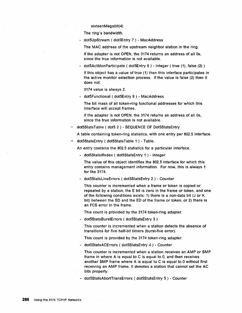
sixteenMegabit(4)
The ring's bandwidth.
- dotSUpStream ( dotSEntry 7 ) - MacAddress
The MAC address of the upstream neighbor station in the ring.
If the adapter is not OPEN, the 3174 returns an address of all Os, since the true information is not available.
- dotSActMonParticipate ( dotSEntry 8) - Integer ( true (1), false (2) )
If this object has a value of true (1) then this interface participates in the active monitor selection process. If the value is false (2) then it does not.
3174 value is always 2.
- dotSFunctional ( dotSEntry 9 ) - MacAddress
The bit mask of all tOken-ring functional addresses for which this interface will accept frames.
If the adapter is not OPEN, the 3174 returns an address of all Os, since the true information is not available.
dotSStatsTable ( dotS 2 ) - SEQUENCE OF OotSStatsEntry
A table containing token-ring statistics, with one entry per 802.S interface.
dotSStatsEntry ( dotSStatsTable 1 ) - Table.
An entry contains the 802.S statistics for a particular interface.
- dotSStatslflndex ( dotSStatsEntry 1 ) - Integer
The value of this object identifies the 802.S interface for which this entry contains management information. For now, this is always 1 for the 3174.
- dotSStatsLineErrors ( dotSStatsEntry 2 ) - Counter
This counter is incremented when a .frame or token is copied or repeated by a station, the E bit is zero in the frame or token, and one of the following conditions exists: 1) there is a non-data bit (J or K bit) between the SO and the EO of the frame or token, or 2) there is an FCS error in the frame.
This count is provided by the 3174 token-ring adapter.
- dotSStatsBurstErrors ( dotSStatsEntry 3 )
This counter is incremented when a station detects the absence of transitions for five half-bit timers (burst-five error).
This count is provided by the 3174 token-ring adapter.
- dotSStatsACErrors ( dotSStatsEntry 4 ) - Counter
This counter is incremented when a station receives an AMP or SMP frame in where A is equal to C is equal to 0, and then receives another SMP frame where A is equal to C is equal to 0 without first receiving an AMP frame. It denotes a station that cannot set the AC bits properly .
- dotSStatsAbortTransErrors ( dotSStatsEntry 5 ) - Counter
286 Using the 3174 TCPIIP Networks
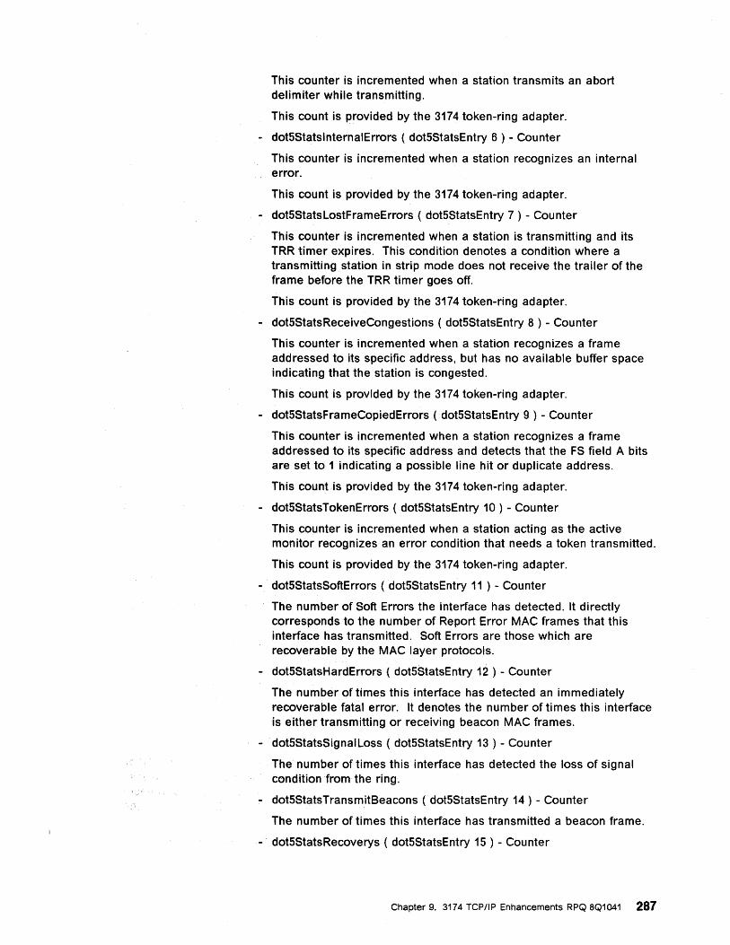
This counter is incremented when a station transmits an abort delimiter while transmitting.
This count is provided by the 3174 token-ring adapter.
- dot5StatsinternaiErrors ( dot5StatsEntry 6 ) - Counter
This counter is incremented when a station recognizes an internal error.
This count is provided by the 3174 token-ring adapter.
- dot5StatsLostFrameErrors ( dot5StatsEntry 7 ) - Counter
This counter is incremented when a station is transmitting and its TRR timer expires. This condition denotes a condition where a transmitting station in strip mode does not receive the trailer of the frame before the TRR timer goes off.
This count is provided by the 3174 token-ring adapter.
- dot5StatsReceiveCongestions ( dot5StatsEntry 8 ) - Counter
This counter is incremented when a station recognizes a frame addressed to its specific address, but has no available buffer space indicating that the station is congested.
This count is provided by the 3174 token-ring adapter.
- dot5StatsFrameCopiedErrors ( dot5StatsEntry 9 ) - Counter
This counter is incremented when a station recognizes a frame addressed to its specific address and detects that the FS field A bits are set to 1 indicating a possible line hit or duplicate address.
This count is provided by the 3174 token-ring adapter.
- dot5StatsTokenErrors ( dot5StatsEntry 10 ) - Counter
This counter is incremented when a station acting as the active monitor recognizes an error condition that needs a token transmitted.
This count is provided by the 3174 token-ring adapter.
- dot5StatsSoftErrors ( dot5StatsEntry 11 ) - Counter
The number of Soft Errors the interface has detected. It directly corresponds to the number of Report Error MAC frames that this interface has transmitted. Soft Errors are those which are recoverable by the MAC layer protocols.
- dot5StatsHardErrors ( dot5StatsEntry 12 ) - Counter
The number of times this interface has detected an immediately recoverable fatal error. It denotes the number of times this interface is either transmitting or receiving beacon MAC frames.
- dot5StatsSignaiLoss ( dot5StatsEntry 13 ) - Counter
The number of times this interface has detected the loss of signal condition from the ring.
- dot5StatsTransmitBeacons ( dot5StatsEntry 14 ) - Counter
The number of times this interface has transmitted a beacon frame.
- dot5StatsRecoverys ( dot5StatsEntry 15 ) - Counter
Chapter 9. 3174 TCP/IP Enhancements RPQ 8Q1041 287
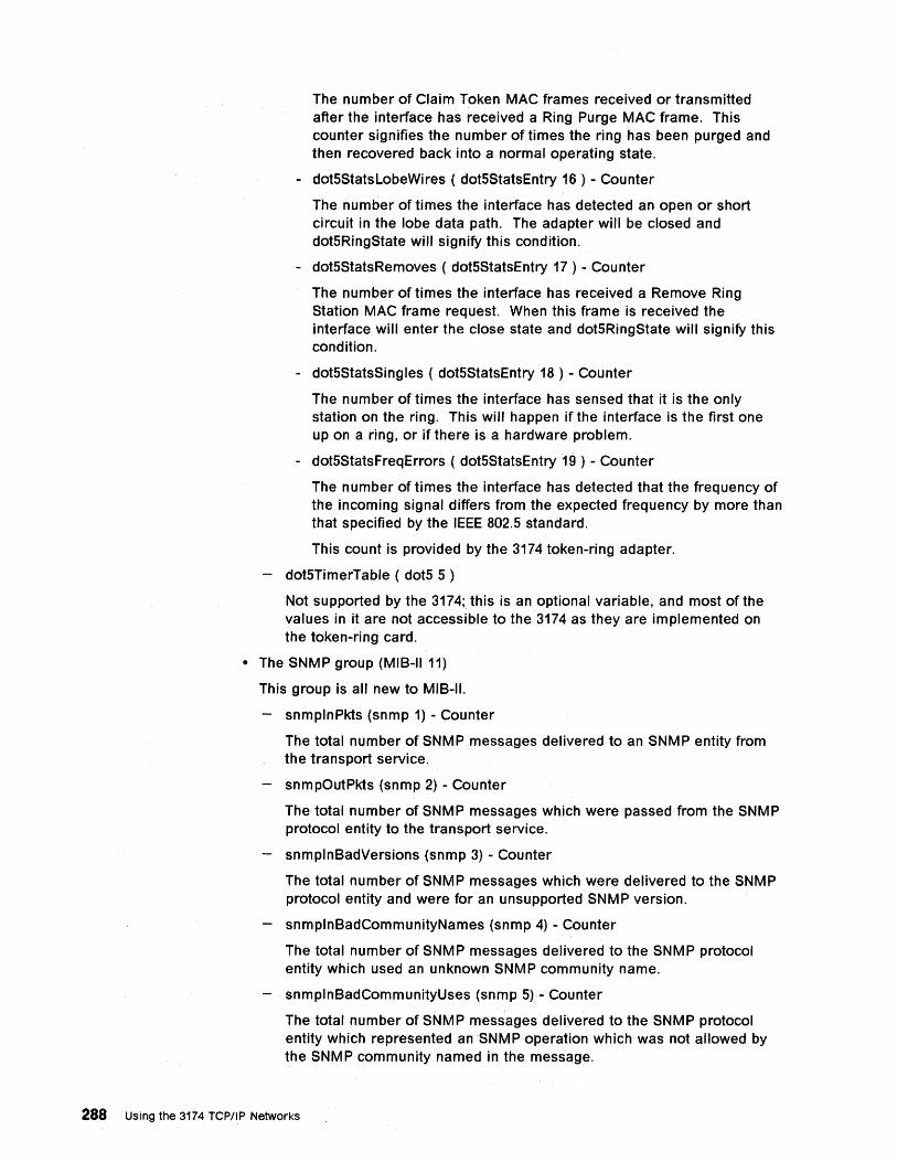
The number of Claim Token MAC frames received or transmitted after the interface has received a Ring Purge MAC frame. This counter signifies the number of times the ring has been purged and then recovered back into a normal operating state.
- dot5StatsLobeWires ( dot5StatsEntry 16 ) - Counter
The number of times the interface has detected an open or short circuit in the lobe data path. The adapter will be closed and dot5RingState will signify this condition.
- dot5StatsRemoves ( dot5StatsEntry 17 ) - Counter
The number of times the interface has received a Remove Ring Station MAC frame request. When this frame is received the interface will enter the close state and dot5RingState will signify this condition.
- dot5StatsSingies ( dot5StatsEntry 18 ) - Counter
The number of times the interface has sensed that it is the only station on the ring. This will happen if the interface is the first one up on a ring, or if there is a hardware problem.
- dot5StatsFreqErrors ( dot5StatsEntry 19 ) - Counter
The number of times the interface has detected that the frequency of the incoming signal differs from the expected frequency by more than that specified by the IEEE 802.5 standard.
This count is provided by the 3174 token-ring adapter.
dot5TimerTabie ( dot5 5 )
Not supported by the 3174; this is an optional variable, and most of the values in it are not accessible to the 3174 as they are implemented on the token-ring card.
• The SNMP group (MIS-II 11)
This group is all new to MIS-II.
snmplnPkts (snmp 1) - Counter
The total number of SNMP messages delivered to an SNMP entity from the transport service.
snmpOutPkts (snmp 2) - Counter
The total number of SNMP messages which were passed from the SNMP protocol entity to the transport service.
snmplnSadVersions (snmp 3) - Counter
The total number of SNMP messages which were delivered to the SNMP protocol entity and were foran unsupported SNMP version.
snmplnSadCommunityNames (snmp 4) - Counter
The total number of SNMP messages delivered to the SNMP protocol entity which used an unknown SNMP community name.
snmplnSadCommunityUses (snmp 5) - Counter
The total number of SNMP messages delivered to the SNMP protocol entity which represented an SNMPoperation which was not allowed by the SNMP community named in the message.
288 Using the 3174 TCPIIP Networks
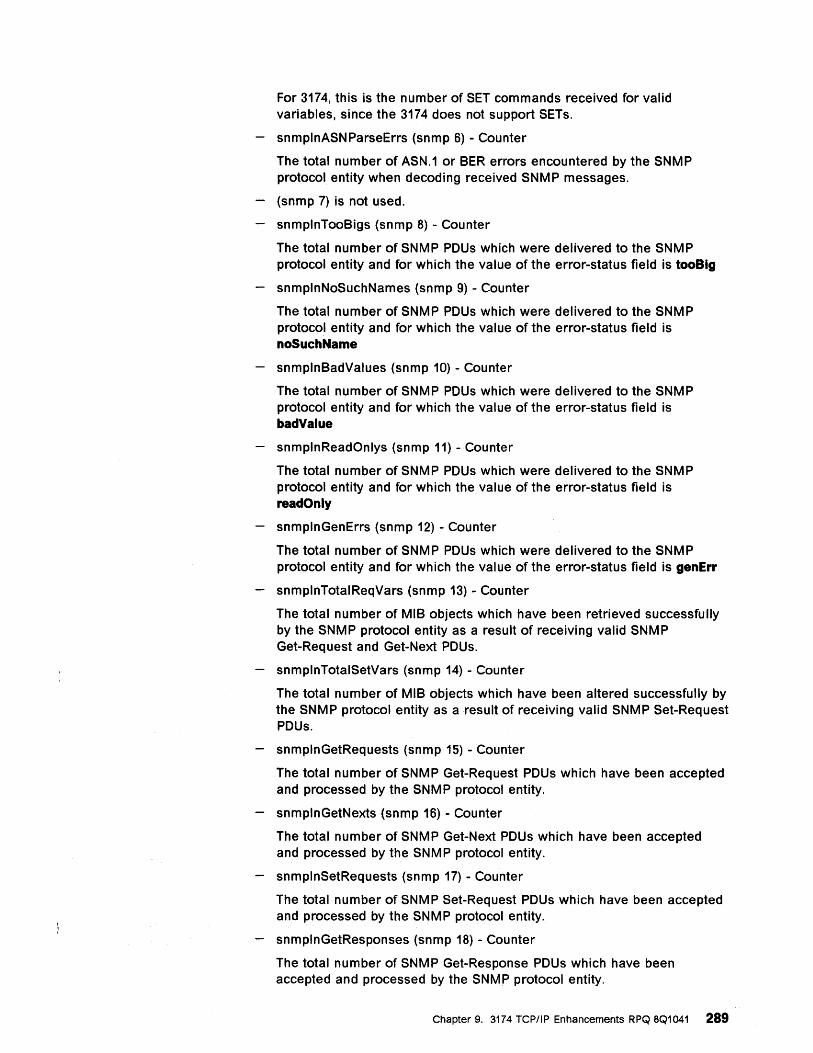
For 3174, this is the number of SET commands received for valid variables, since the 3174 does not support SETs.
snmplnASNParseErrs (snmp 6) - Counter
The total number of ASN.1 or BER errors encountered by the SNMP protocol entity when decoding received SNMP messages.
(snmp 7) is not used.
snmplnTooBigs (snmp 8) - Counter
The total number of SNMP PDUs which were delivered to the SNMP protocol entity and for which the value of the error-status field is tooBig
snmplnNoSuchNames (snmp 9) - Counter
The total number of SNMP PDUs which were delivered to the SNMP protocol entity and for which the value of the error-status field is noSuchName
snmplnBadValues (snmp 10) - Counter
The total number of SNMP PDUs which were delivered to the SNMP protocol entity and for which the value of the error-status field is badValue
snmplnReadOnlys (snmp 11) - Counter
The total number of SNMP PDUs which were delivered to the SNMP protocol entity and for which the value of the error-status field is readOnly
snmplnGenErrs (snmp 12) - Counter
The total number of SNMP PDUs which were delivered to the SNMP protocol entity and for which the value of the error-status field is genErr
snmplnTotalReqVars (snmp 13) - Counter
The total number of MIB objects which have been retrieved successfully by the SNMP protocol entity as a result of receiving valid SNMP Get-Request and Get-Next PDUs.
snmplnTotalSetVars (snmp 14) - Counter
The total number of MIB objects which have been altered successfully by the SNMP protocol entity as a result of receiving valid SNMP Set-Request PDUs.
snmplnGetRequests (snmp 15) - Counter
The total number of SNMP Get-Request PDUs which have been accepted and processed by the SNMP protocol entity.
snmplnGetNexts (snmp 16) - Counter
The total number of SNMP Get-Next PDUs which have been accepted and processed by the SNMP protocol entity.
snmplnSetRequests (snmp 17) - Counter
The total number of SNM P Set-Request PDUs which have been accepted and processed by the SNMP protocol entity.
snmplnGetResponses (snmp 18) - Counter
The total number of SNMP Get-Response PDUs which have been accepted and processed by the SNMP protocol entity.
Chapter 9. 3174 TCP/IP Enhancements RPQ 8Q1041 289
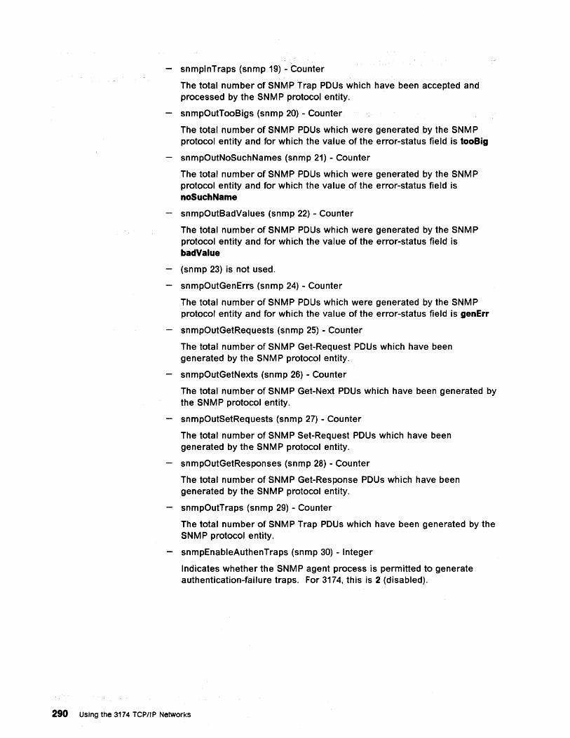
snmplnTraps (snmp 19) - Counter
The total number of SNMP Trap PDUs which have been accepted and processed by the SNMP protocol entity.
snmpOutTooBigs (snmp 20) - Counter
The total number of SNMP PDUs which were generated by the SNMP protocol entity and for which the value of the error-status field is tooBig
snmpOutNoSuchNames (snmp 21) - Counter
The total number of SNMP PDUs which were generated by the SNMP protocol entity and for which the value of the error-status field is noSuchName
snmpOutBadValues (snmp 22) - Counter
The total number of SNMP PDUs which were generated by the SNMP protocol entity and for which the value of the error-status field is badValue
(snmp 23) is not used.
snmpOutGenErrs (snmp 24) - Counter
The total number of SNMP PDUs which were generated by the SNMP protocol entity and for which the value of the error-status field is genErr
snmpOutGetRequests (snmp 25) - Counter
The total number of SNMP Get-Request PDUs which have been generated by the SNMP protocol entity.
snmpOutGetNexts (snmp 26) - Counter
The total number of SNMP Get-Next PDUs which have been generated by the SNMP protocol entity.
snmpOutSetRequests (snmp 27) - Counter
The total number of SNMP Set-Request PDUs which have been generated by the SNMP protocol entity.
snmpOutGetResponses (snmp 28) - Counter
The total number of SNMP Get-Response PDUs which have been generated by the SNMP protocol entity.
snmpOutTraps (snmp 29) - Counter
The total number of SNMP Trap PDUs which have been generated by the SNMP protocol entity.
snmpEnableAuthenTraps (snmp 30) - Integer
Indicates whether the SNMP agent process is permitted to generate authentication-failure traps. For 3174, this is 2 (disabled).
290 Using the 3174 TCPIIP Networks
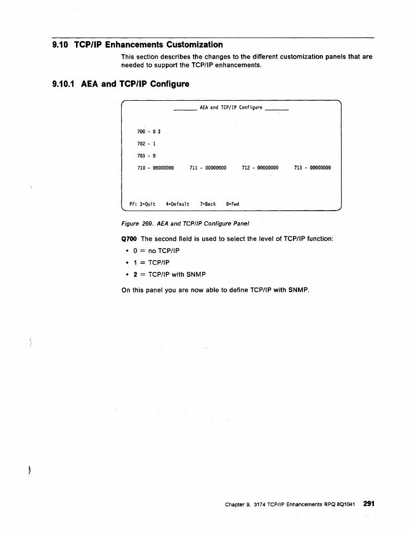
9.10 TCP/IP Enhancements Customization This section describes the changes to the different customization panels that are needed to support the TCPIIP enhancements.
9.10.1 AEA and TCP/IP Configure
___ AEA and TCP/lP Configure __ _
7ee - e 2
7e2 - 1
7e3 - e
710 - eeeeeeee 711 - eeeeeeee 712 - eeeeeeee 713 - eeeeeeee
PF: 3=Quit 4=Default 7=Back 8= Fwd
Figure 269. AEA and TCPIIP Configure Panel
Q700 The second field is used to select the level of TCP/IP function:
• 0 = no TCPIIP
• 1 = TCP/IP
• 2 = TCPIIP with SNMP
On this panel you are now able to define TCP/IP with SNMP.
Chapter 9. 3174 TCP/IP Enhancements RPQ 8Q1041 291
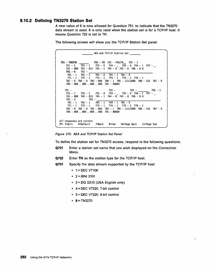
9.10.2 Defining TN3270 Station Set A new value of 6 is now allowed for Question 751, to indicate that the TN3270 data stream is used. 6 is only valid when the station set is for a TCP/IP host. It means Question 722 is set to TH.
The following screen will show you the TCP/IP Station Set panel.
___ AEA and TCPjIP Station Set __ _
721 - TN3278 722 - TH 723 - TN327e__ 725 - 1 731 - 1 ~1 733 - e 734 - _ 735 - e 736 - 1 737-741 - eee 742 - e15 743 - 1 744 - e 745 - e 746 - e e 751 - 6 752 -
761 - 1 762 - -::-1-~7-:-:63:---~e-7=-:6:-:-4---1:--:7~6-::-5 ----:e:-------771 - 1 772 - 1 773 - 1 774 - 1 775 - 1 776 - 1
781 - e 782 - e 783 - e66 784 - 1 785 - llllleee 786 - 132 787 - e 7ge - eee . eee . eee . eee 791 - eeeee
721 - 722 - 723 - 725 - 1 731 - 1 732 - 1 733 - e 734 - _ 735 - e 736 - 1 737-741 - eee 742 - e15 743 - 1 744 - e 745 - e 746 - e e 751 - 2 752 -
761 - 1 762 - 1 7~63:---~1-=-:76:-:-4---1:--:7~6-::-5 ----:e:---------771 - 1 772 - 1 773 - 1 774 - 1 775 - 1 776 - 1
781 - e 782 - e 783 - e66 784 - 1 785 - llllleee 786 - 132 787 - e 7ge - eee • eee • eee • eee 791 - eeeee
All responses are correct PF: 3=Quit 4=Default 7=Back 8= Fwd le=Page Back 11=Page Fwd
Figure 270. AEA and TCP/IP Station Set Panel
To define the station set for TN3270 access, respond to the following questions:
Q721 Enter a station set name that you wish displayed on the Connection Menu.
Q722 Enter TH as the station type for the TCP/IP host.
Q751 Specify the data stream supported by the TCP/IP host:
• 1 = DEC VT100
• 2=IBM 3101
• 3 = DG 0210 (USA English only)
• 4 = DEC VT220, 7-bit control
• 5 = DEC VT220, 8-bit control
• 6=TN3270
292 Using the 3174 TCPIIP Networks
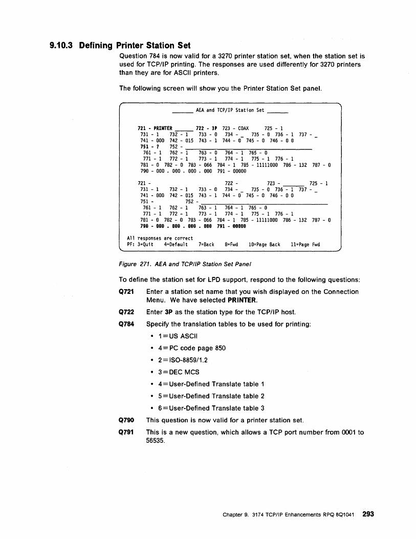
9.10.3 Defining Printer Station Set Question 784 is now valid for a 3270 printer station set, when the station set is used for TCP/IP printing. The responses are used differently for 3270 printers than they are for ASCII printers.
The following screen will show you the Printer Station Set panel.
___ AEA and TCP/IP Station Set __ _
721 - PRINTER ________ 722 - 3P 723 - COAX 725 - 1 731 - 1 732 - 1 733 - e 734 - _ 735 - e 736 - 1 737-741 - eee 742 - e15 743 - 1 744 - e 745 - e 746 - e e 751 -? 752 -
761 - 1 762 - -1-~7-63---e-7---6-4 ---1-7-6-5 ---e------771 - 1 772 - 1 773 - 1 774 - 1 775 - 1 776 - 1
781 - e 782 - e 783 - e66 784 - 1 785 - 11111eee 786 - 132 787 - e 7ge - eee • eee . eee . eee 791 - eeeee
721 - 722 - 723 - 725 - 1 731 - 1 732 - 1 733 - e 734 - _ 735 - e 736 - 1 737-741 - eee 742 - e15 743 - 1 744 - e 745 - e 746 - e e 751 - 752 - ______ ------------761 - 1 762 - 1 763 - 1 764 - 1 765 - e 771 - 1 772 - 1 773 - 1 774 - 1 775 - 1 776 - 1
781 - e 782 - e 783 - e66 784 - 1 785 - 11111eee 786 - 132 787 - e 7ge - eee • eee • eee • eee 791 - eeeee
All responses are correct PF: 3=Quit 4=Default 7=Back 8= Fwd 1e=Page Back 11=Page Fwd
Figure 271. AEA and TCPIIP Station Set Panel
To define the station set for LPD support, respond to the following questions:
Q721 Enter a station set name that you wish displayed on the Connection Menu. We have selected PRINTER.
Q722 Enter 3P as the station type for the TCP/I P host.
Q784 Specify the translation tables to be used for printing:
• 1 =US ASCII
• 4 = PC code page 850
• 2=ISO-8859/1.2
• 3=DEC MCS
• 4 = User-Defined Translate table 1
• 5 = User-Defined Translate table 2
• 6 = User-Defined Translate table 3
Q790 This question is now valid for a printer station set.
Q791 This is a new question, which allows a TCP port number from 0001 to 56535.
Chapter 9. 3174 TCP/IP Enhancements RPQ 8Q1041 293
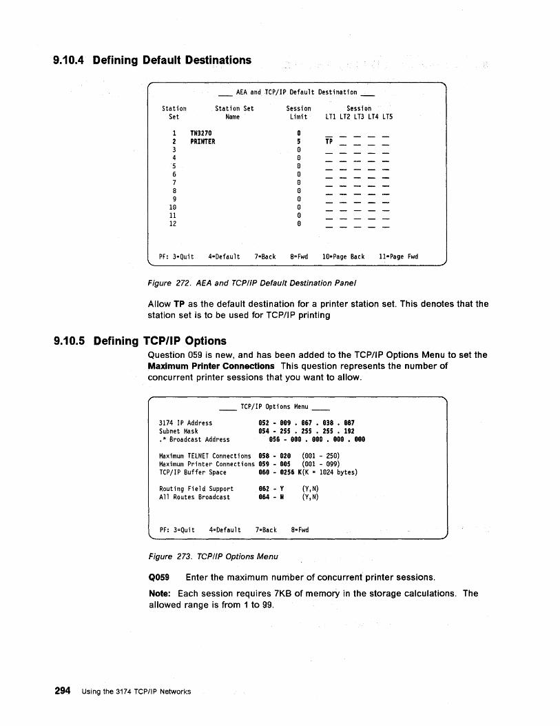
9.10.4 Defining Default Destinations
_ AEA and TCP/IP Default Destination _._.
Station Station Set Set Name
1 TN3279 2 PRINTER 3 4 5 6 7 8 9
HI 11 12
Session Session Limit LT1 LT2 LT3 LT4 LT5
8 5 TP o o o o o o o o o o
PF: 3=Quit 4=Default 7=Back 8=Fwd 10=Page Back 11=Page Fwd
Figure 272. AEA and TCP/IP Default Destination Panel
Allow TP as the default destination for a printer station set. This denotes that the station set is to be used for TCP/I P printing
9.10.5 Defining TCP/IP Options Question 059 is new, and has been added to the TCP/IP Options Menu to set the Maximum Printer Connections This question represents the number of concurrent printer sessions that you want to allow.
\,
__ TCP/IP Options Menu __
3174 IP Address Subnet Mask .* Broadcast Address
852 - 889 • 867 • 838 • 887 854 - 255 • 255 • 255 • 192
856 - 888 • 888 • 888 • 888
Maximum TELNET Connections 858 - 828 (001 - 250) Maximum Printer Connections 059 - 005 (001 - 099) TCP/IP Buffer Space 868 - 8256 K(K = 1024 bytes)
Routing Field Support All Routes Broadcast
862 - y 864 - N
(Y,N) (Y,N)
PF: 3=Quit 4=Default 7=Back 8= Fwd
Figure 273. TCP/IP Options Menu
Q059 Enter the maximum number of concurrent printer sessions.
Note: Each session requires 7KB of memory in the storage calculations. The allowed range is from 1 to 99.
294 Using the 3174 TCPIIP Networks
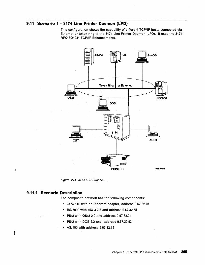
9.11 Scenario 1 - 3174 Line Printer Daemon (LPD) This configuration shows the capability of different TCP/IP hosts connected via Ethernet or token-ring to the 3174 Line Printer Daemon (LPD). It uses the 3174 RPQ 8Q1041 TCP/IP Enhancements.
HP
Token Ring or Ethemet
OS/2 RS6000
ASCII
PRINTER 417!1f417212
Figure 274. 3174 LPD Support
9.11.1 Scenario Description The composite network has the following components:
• 3174-11L with an Ethernet adapter, address 9.67.32.91
• RS/6000 with AIX 3.2.3 and address 9.67.32.85
• PS/2 with OS/2 2.0 and address 9.67.32.94
• PS/2 with DOS 5.2 and address 9.67.32.93
• AS/400 with address 9.67.32.95
Chapter 9. 3174 TCP/IP Enhancements RPQ 8Q1041 295
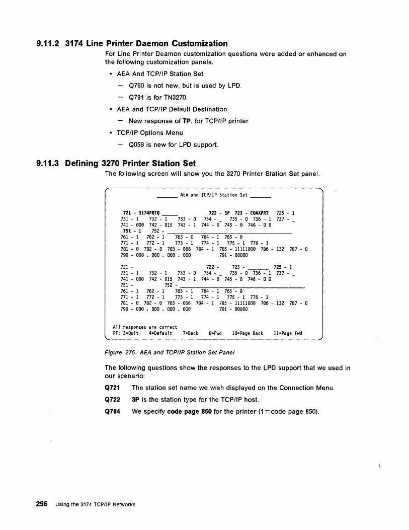
9.11.2 3174 Line Printer Daemon Customization For Line Printer Deamon customization questions were added or enhanced on the following customization panels.
• AEA And TCP/IP Station Set
Q790 is not new, but is used by LPD.
Q791 is for TN3270.
• AEA and TCP/IP Default Destination
- New response of TP, for TCP/IP printer
• TCP/IP Options Menu
- Q059 is new for LPD support.
9.11.3 Defining 3270 Printer Station Set The following screen will show you the 3270 Printer Station Set panel.
___ AEA and TCP/IP Station Set __ _
721 - 3174PRTQ 731 - 1 732 --1--733 - e 741 - eee 742 - e15 743 - 1
722 - 3P 723 - COAXPRT 725 - 1 734 - _ 735 - e 736 - 1 737-
744 - a 745 - e 746 - e e 751 - 1 752 - ____ --------------
761 - 1 762 - 1 763 - e 764 - 1 765 - e 771 - 1 772 - 1 773 - 1 774 - 1 775 - 1 776 - 1 781 - e 782 - e 783 - e66 784 - 1 785 - llllleee 786 - 132 787 - e 7ge - eee • aee • eee • eea 791 - eeeee
721 - 722 - 723 - 725 - 1 731 - 1 732 - 1 733 - e 734 - _ 735 - e 736 - 1 737-741 - eee 742 - e15 743 - 1 744 - e 745 - a 746 - a a 751 - 752 -761 - 1 762 - 1 76-:""3 ---:I~-=7::-:64:----:"'1---=76::-::5----:-a --------771 - 1 772 - 1 773 - 1 774 - 1 775 - 1 776 - 1 781 - e 782 - e 783 - e66 784 - 1 785 - llllleae 786 - 132 787 - e 79a - eae • eaa . aae . aee 791 - aeeee
All responses are correct PF: 3=Quit 4=Default 7=Back 8= Fwd le=Page Back 11=Page Fwd
Figure 275. AEA and TCPIIP Station Set Panel
The following questions show the responses to the LPD support that we used in our scenario:
Q721 The station set name we wish displayed on the Connection Menu.
Q722 3P is the station type for the TCP/IP host.
Q784 We specify code page 850 for the printer (1 = code page 850).
296 Using the 3174 TCP/IP Networks
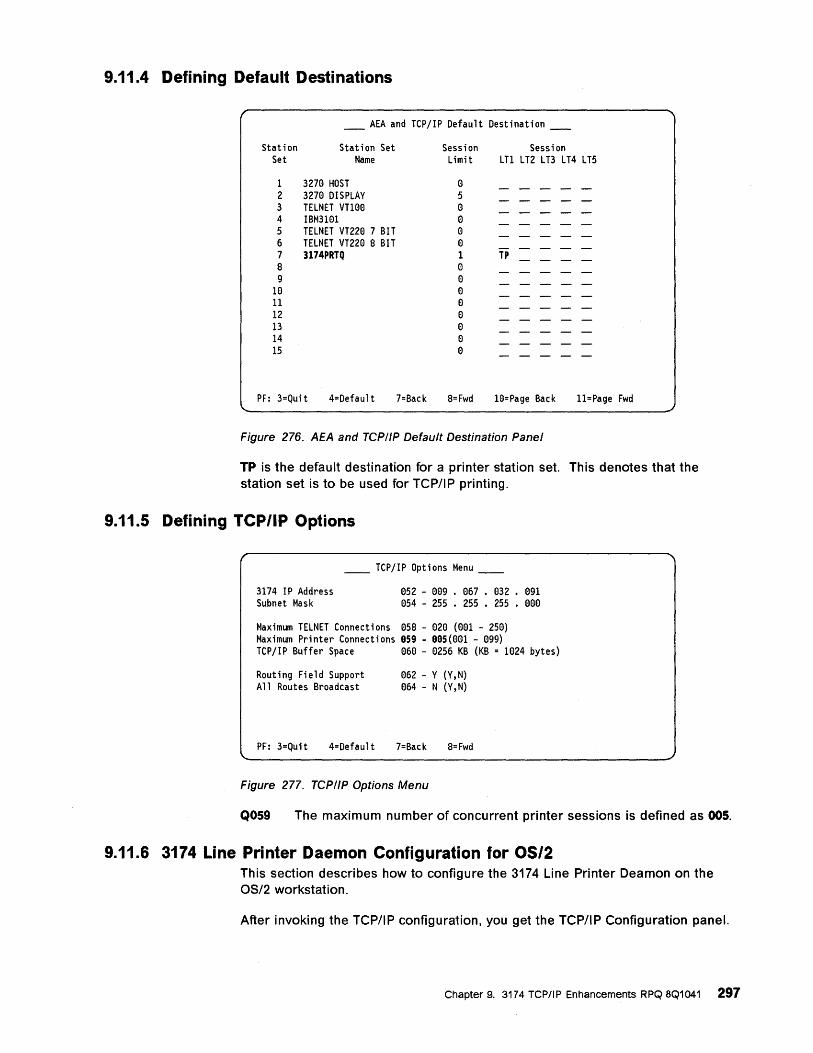
9.11.4 Defining Default Destinations
____ AEA and TCP/IP Default Destination ____
Station Station Set Set Name
1 3270 HOST 2 3270 DISPLAY 3 TELNET VT100 4 IBM3101 5 TELNET VT220 7 BIT 6 TELNET VT220 8 BIT 7 3174PRTQ 8 9
10 11 12 13 14 15
Session Session Limit LT1 LT2 LT3 LT4 LT5
o 5 o o o o 1 TP o o o o o o o o
PF: 3=Quit 4=Default 7=Back 8=Fwd 10=Page Back 11=Page Fwd
Figure 276. AEA and TCP/IP Default Destination Panel
TP is the default destination for a printer station set. This denotes that the station set is to be used for TCP/IP printing.
9.11.5 Defining TCP/IP Options
__ TCP/IP Options Menu __
3174 IP Address Subnet Mask
052 - 009 . 067 • 032 • 091 054 - 255 • 255 • 255 • 000
Maximum TELNET Connections 058 - 020 (001 - 250) Maximum Printer Connections 959 - 995(001 - (99) TCP/IP Buffer Space 060 - 0256 KB (KB = 1024 bytes)
Routing Field Support All Routes Broadcast
062 - Y (Y,N) 064 - N (Y,N)
PF: 3=Quit 4=Default 7=Back 8=Fwd
Figure 277. TCP/IP Options Menu
Q059 The maximum number of concurrent printer sessions is defined as 005.
9.11.6 3174 Line Printer Daemon Configuration for OS/2 This section describes how to configure the 3174 Line Printer Deamon on the OS/2 workstation.
After invoking the TCP/IP configuration, you get the TCP/IP Configuration panel.
Chapter 9. 3174 TCPIIP Enhancements RPQ 8Q1041 297
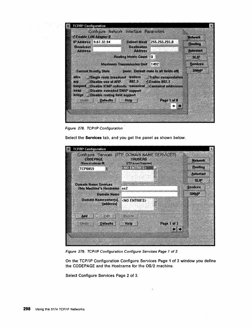
Figure 278. TCPIIP Configuration
Select the Services tab, and you get the panel as shown below.
Figure 279. TCPIIP Configuration Configure Services Page 1 of 3
On the TCP/IP Configuration Configure Services Page 1 of 3 window you define the CODEPAGE and the Hostname for the OS/2 machine.
Select Configure Services Page 2 of 3.
298 Using the 3174 TCP/IP Networks
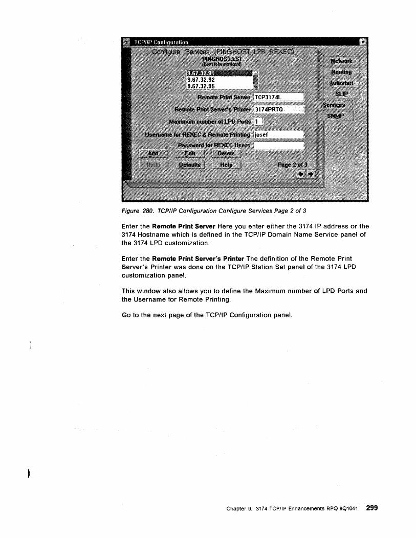
Figure 280. TCPIIP Configuration Configure Services Page 2 of 3
Enter the Remote Print Server Here you enter either the 3174 IP address or the 3174 Hostname which is defined in the TCP/IP Domain Name Service panel of the 3174 LPD customization.
Enter the Remote Print Server's Printer The definition of the Remote Print Server's Printer was done on the TCP/IP Station Set panel of the 3174 LPD customization panel.
This window also allows you to define the Maximum number of LPD Ports and the Username for Remote Printing.
Go to the next page of the TCP/IP Configuration panel.
Chapter 9. 3174 TCP/IP Enhancements RPQ 8Q1041 299
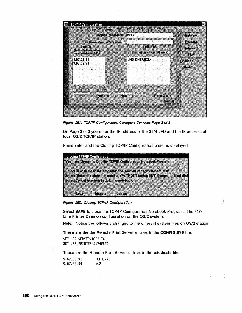
Figure 281. TCP//P Configuration Configure Services Page 3 of 3
On Page 3 of 3 you enter the IP address of the 3174 LPD and the IP address of local OS/2 TCP/IP station.
Press Enter and the Closing TCP/IP Configuration panel is displayed.
Figure 282. Closing TCPIIP Configuration
Select SAVE to close the TCP/IP Configuration Notebook Program. The 3174 Line Printer Daemon configuration on the OS/2 system.
Note: Notice the following changes to the different system files on OS/2 station.
These are the the Remote Print Server entries in the CONFIG.SYS file:
SET LPR SERVER=TCP3174L SET LPR_PRINTER=3174PRTQ
These are the Remote Print Server entries in the \etc\hosts file:
9.67.32.91 9.67.32.94
300 Using the 3174 TCP/IP Networks
TCP3174L os2
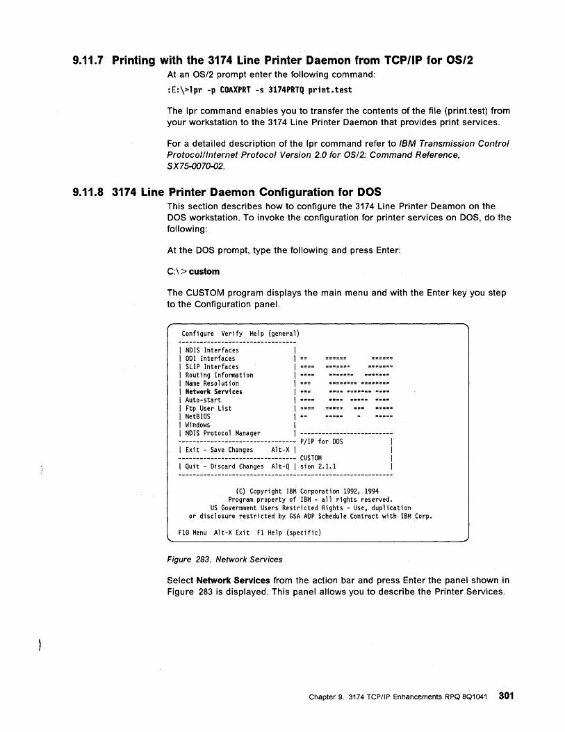
9.11.7 Printing with the 3174 Line Printer Daemon from TCP/IP for 0512 At an OS/2 prompt enter the following command:
:E:\>lpr -p COAXPRT -s 3174PRTQ print.test
The Ipr command enables you to transfer the contents of the file (print.test) from your workstation to the 3174 Line Printer Daemon that provides print services.
For a detailed description of the Ipr command refer to IBM Transmission Control Protocolllnternet Protocol Version 2.0 for OS/2: Command Reference, SX7S-0070-02.
9.11.8 3174 Line Printer Daemon Configuration for DOS This section describes how to configure the 3174 Line Printer Deamon on the DOS workstation. To invoke the configuration for printer services on DOS, do the following:
At the DOS prompt, type the following and press Enter:
C:\>custom
The CUSTOM program displays the main menu and with the Enter key you step to the Configuration panel.
Configure Verify Help (general)
I NDIS Interfaces I 001 Interfaces I SLIP Interfaces I Routing Information I Name Resolution ======== ======== I Network Services ==== ======= ==== I Auto-start I Ftp User Li st I NetBIOS I Windows I NDIS Protocol Manager ----------------------------------------------------------- PjlP for DOS I Exit - Save Changes Alt-X I --------------------------------- CUSTOM I Quit - Discard Changes Alt-Q I sion 2.1.1
(C) Copyright IBM Corporation 1992, 1994 Program property of IBM - all rights reserved.
US Government Users Restricted Rights - Use, duplication or disclosure restricted by GSA ADP Schedule Contract with IBM Corp.
FIe Menu Alt-X Exit Fl Help (specific)
Figure 283. Network Services
Select Network Services from the action bar and press Enter the panel shown in Figure 283 is displayed. This panel allows you to describe the Printer Services.
Chapter 9. 3174 TCP/IP Enhancements RPQ 8Q1041 '301
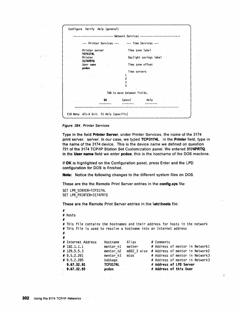
Configure Verify Help (general)
-------------------------- Network Services --------------------------
--- Printer Services ---
Printer server TCP3174L Printer 3174PRTQ User name pcdos
1 2 3 4
--- Time Services ---
Time zone label
Daylight savings label
Time zone offset
Time servers
TAB to move between fields.
OK Cancel Help
FIe Menu Alt-X Exit FI Help (specific)
Figure 284. Printer Services
Type in the field Printer Server, under Printer Services, the name of the 3174 print server. server. In our case, we typed TCP3174L. In the Printer field, type in the name of the 3174 device. This is the device name we defined on question 721 of the 3174 TCP/IP Station Set Customization panel. We entered 3174PRTQ. In the User name field we enter pcdos; this is the hostname of the DOS machine.
If OK is highlighted on the Configuration panel, press Enter and the LPO configuration for DOS is finished.
Note: Notice the following changes to the different system files on DOS.
These are the the Remote Print Server entries in the config.sys file:
SET LPR_SERVER=TCP3174L SET LPR_PRINTER=3174PRTQ
These are the Remote Print Server entries in the \etc\hosts file:
II II hosts II II This file contains the hostnames and their address for hosts in the network II This file is used to resolve a hostname into an Internet address II II II Internet Address II 192.1.1.1 II 129.5.5.3 II 9.5.2.201 II 9.5.2.205
9.67.32.91 9.67.32.93
302 Using the 3174 TCP/IP Networks
Hostname mentor n1 mentor n2 mentor n3 babbage TCP3174L pcdos
Alias II Comments mether II Address of mentor in Network1 mB02 3 wise II Address of mentor in Network2 mtok II Address of mentor in Network3
II Address of mentor in Network3 II Address of LPD Server II Address of this User
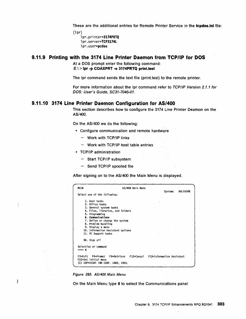
These are the additional entries for Remote Printer Service in the tcpdos.ini file:
(1 pr) 1pr.printer=3174PRTQ 1pr.server=TCP3174L 1pr.user=pcdos
9.11.9 Printing with the 3174 Line Printer Daemon from TCP/IP for DOS At a DOS prompt enter the following command: :E:\ > Ipr -p COAXPRT -s 3174PRTQ print.test
The Ipr command sends the text file (print.test) to the remote printer.
For more information about the Ipr command refer to TCP/IP Version 2.1.1 for DOS: User's Guide, SC31-7045-01.
9.11.10 3174 Line Printer Daemon Configuration for AS/400 This section describes how to configure the 3174 Line Printer Deamon on the AS/400.
On the AS/400 we do the following:
• Configure communication and remote hardware
Work with TCP/IP links
Work with TCP/I P host table entries
• TCP/IP administration
Start TCP/IP subsystem
Send TCP/IP spooled file
After signing on to the AS/400 the Main Menu is displayed.
MAIN AS/4BB Main Menu
Select one of the following:
1. User tasks 2. Office tasks 3. General system tasks 4. Files, libraries, and folders 5. Programming 6. Communications 7. Defi ne or change the system 8. Problem handling 9. Display a menu
18. Information Assistant options 11. PC Support tasks
98. Sign off
Sel ecti on or command ===> 6
System: RALYAS4B
F3=Exi t F4=Prompt F9=Retri eve F12=Cancel F13=Informati on Assistant F23=Set initial menu (C) COPYRIGHT IBM CORP. 1988, 1993.
Figure 285. ASI400 Main Menu
On the Main Menu type 6 to select the Communications panel
Chapter 9. 3174 TCPItP Enhancements RPQ8Q1041 303
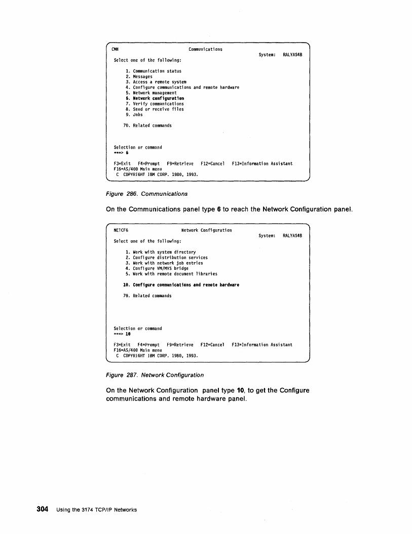
CMN Communi cati ons
Select one of the following:
1. Communicati on status 2. Messages 3. Access a remote system 4. Confi gure communi ca ti ons and remote ha rdwa re 5. Network management 6. Network configuration 7. Verify communications 8. Send or recei ve fil es 9. Jobs
78. Related commands
Sel ecti on or command ===> 6
System: RALYAS4B
F3=Exi t F4=Prompt F9=Retri eve F12=Cance 1 F13=Informati on Assi stant F16=AS/488 Mai n menu C COPYRIGHT IBM CORP. 1988, 1993.
Figure 286. Communications
On the Communications panel type 6 to reach the Network Configuration panel.
NETCFG Network Confi gurati on
Select one of the following:
1. Work with system di rectory 2. Configure distribution services 3. Work with network job entri es 4. Configure VM/MVS bridge 5. Work with remote document libraries
18. Configure communications and remote hardware
7B. Related commands
Se 1 ecti on or command ===> 18
System: RALYAS4B
F3=Exit F4=Prompt F9=Retrieve F12=Cancel F13=Information Assistant F16=AS/4BB Main menu C COPYRIGHT IBM CORP. 1988, 1993.
Figure 287. Network Configuration
On the Network Configuration panel type 10, to get the Configure communications and remote hardware panel.
304 Using the 3174 TCPIIP Networks
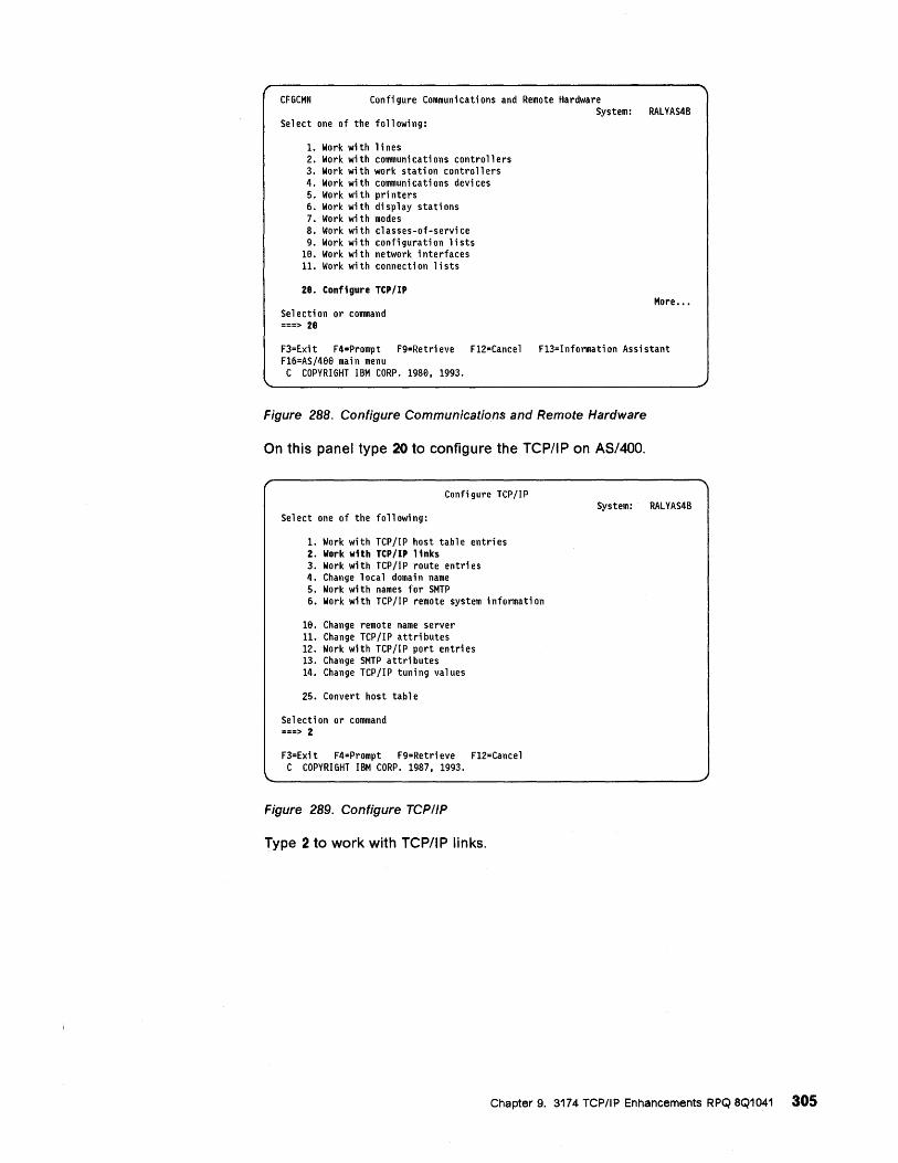
CFGCMN Confi gure Communi cati ons and Remote Hardware System: RALYAS4B
Select one of the following:
1. Work with lines 2. Work wi th communi ca ti ons contro 11 ers 3. Work with work station controllers 4. Work with communications devices 5. Work with printers 6. Work with display stations 7. Work with modes 8. Work with classes-of-service 9. Work with configuration lists
Ie. Work wi th network interfaces 11. Work with connection lists
28. Configure TCP/IP
Se 1 ecti on or command ===> 28
More •••
F3=Exit F4=Prompt F9=Retrieve F12=Cancel F13=Information Assistant FI6=AS/4ee main menu C COPYRIGHT IBM CORP. 1980. 1993.
Figure 288. Configure Communications and Remote Hardware
On this panel type 20 to configure the TCP/IP on AS/400.
Configure TCPIIP
Select one of the following:
1. Work with TCPjIP host table entries 2. Work with TCP/IP links 3. Work with TCPjIP route entries 4. Change local domain name 5. Work with names for SMTP 6. Work with TCP lIP remote system i nformati on
Ie. Change remote name server 11. Change TCPjIP attributes 12. Work with TCPjIP port entries 13. Change SMTP a ttri butes 14. Change TCPjIP tuning values
25. Convert host table
Se 1 ecti on or command ===> 2
F3=Exit F4=Prompt F9=Retrieve F12=Cancel C COPYRIGHT IBM CORP. 1987. 1993.
Figure 289. Configure TCPI/P
Type 2 to work with TCP/IP links.
System: RALYAS4B
Chapter 9. 3174 TCP/IP Enhancements RPQ 8Q1041 305
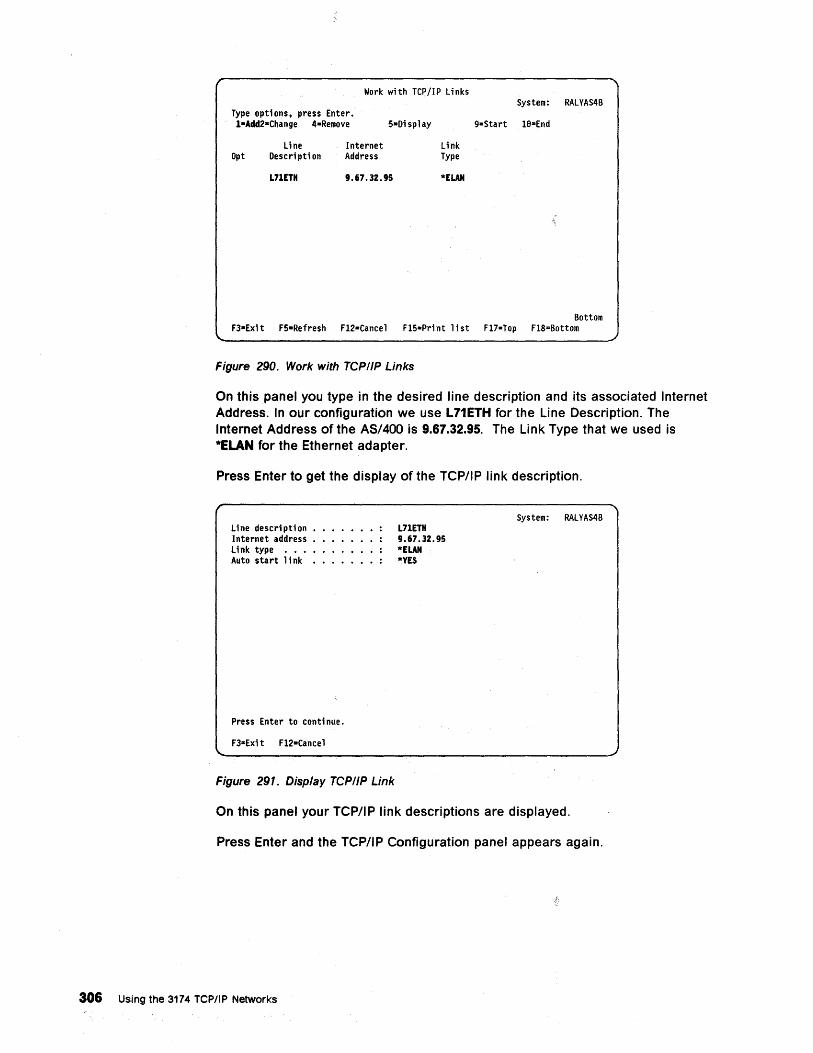
Work with TCP/IP Links
Type opti ons. press Enter. l-Add2-=Change 4-Remove
Opt line
Oescri pti on Internet Address
S=Oisplay
L71ETH 9.67.32.95
Link Type
*ELAN
System: RALYAS4B
9=Start le=End
Bottom F3a Exi t FS"Refresh Fl2=Cance 1 FlS=Pri nt 1 i st Fl7=Top Fl8=Bottom
Figure 290. Work with TCPIIP Links
On this panel you type in the desired line description and its associated Internet Address. In our configuration we use L71ETH for the Line Description. The Internet Address of the AS/400 is 9.67.32.95. The Link Type that we used is *ELAN for the Ethernet adapter.
Press Enter to get the display of the TCP/IP link description.
line description •• Internet address • link type •••• Auto start link •
Press Enter to conti nue.
F3"'Exi t Fl2"Cance 1
Figure 291. Display TCPIIP Link
L71ETH 9.67.32.95 *ELAN *YES
System: RALYAS4B
On this panel your TCP/IP link descriptions are displayed.
Press Enter and the TCP/IP Configuration panel appears again.
306 Using the 3174 TCP/IP Networks
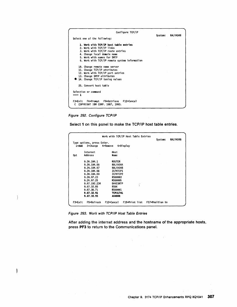
Configure TCP/IP
Select one of the following:
1. Work with TCP/IP host table entries 2. Work with TCP/IP links 3. Work with TCP/IP route entries 4. Change 1 oca 1 domai n name 5. Work with names for SHTP 6. Work with TCP/IP remote system information
16. Change remote name server 11. Change TCP /IP attri butes 12. Work with TCP/IP port entries 13. Change SHTP attri butes
• 14. Change TCP/IP tuning values
25. Convert host table
Se 1 ecti on or command =z=> 1
F3=Exit F4=Prompt F9=Retrieve F12=Cancel C COPYRIGHT IBH CORP. 1987. 1993.
Figure 292. Configure TCPIIP
System: RALYAS4B
Select 1 on this panel to make the TCP/IP host table entries.
Work with TCP/IP Host Table Entries System: RALYAS4B
Type options. press Enter. l=Add 2=Change 4=Remove 5=Display
Internet Host Opt Address Name
9.24.164.1 ROUTER 9.24.164.56 RALYAS4A 9.24.164.57 RALYAS4B 9.24.164.58 3174TCP1 9.24.164.59 3174TCP2 9.24.97.23 RS66663 9.24.97.25 RS66665 9.67.192.234 OAVESRTP 9.67.32.85 RS6K 9.67.38.71 RS66661 9.67.32.91 TCP3174L 9.67.3Z.95 AS4888
F3=Exit F5=Refresh F12=Cancel F15=Pri nt 1 ist F17=Posi ti on to
Figure 293. Work with TCPIIP Host Table Entries
After adding the internet address and the hostname of the appropriate hosts, press PF3 to return to the Communications panel.
Chapter 9. 3174 TCP/IP Enhancements RPQ 8Q1041 307
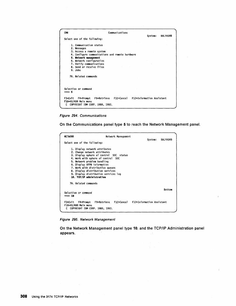
CMN Communications
Select one of the following:
1. Communication status 2. Messages 3. Access a remote system 4. Configure communications and remote hardware 5. Network management 6. Network confi gurati on 7. Veri fy communi cati ons 8. Send or receive files 9. Jobs
78. Related commands
Se 1 ecti on or command ===> 5
System: RALYAS4B
F3=Exit F4=Prompt F9=Retrieve F12=Cance1 F13=Information Assistant F16=AS/488 Main menu C COPYRIGHT IBM CORP. 1988, 1993.
Figure 294. Communications
On the Communications panel type 5 to reach the Network Management panel.
NETWORK Network Management
Select one of the following:
1. Display network attributes 2. Change network attri butes 3. Display sphere of control SOC status 4. Work with sphere of control SOC 5. Network problem handling 6. Display APPN information 7. Work wi th di stri buti on queues 8. Display distribution services 9. Display distribution services log 18. Tep/IP administration
78. Related commands
Se1 ecti on or command ===> 18
System: RALYAS4B
Bottom
F3=Exit F4=Prompt F9=Retrieve F12=Cance1 F13=Information Assistant F16=AS/488 Main menu C COPYRIGHT IBM CORP. 1988, 1993.
Figure 295. Network Management
On the Network Management panel type 10, and the TCP/IP Administration panel appears.
308 Using the 3174 TCP/IP Networks
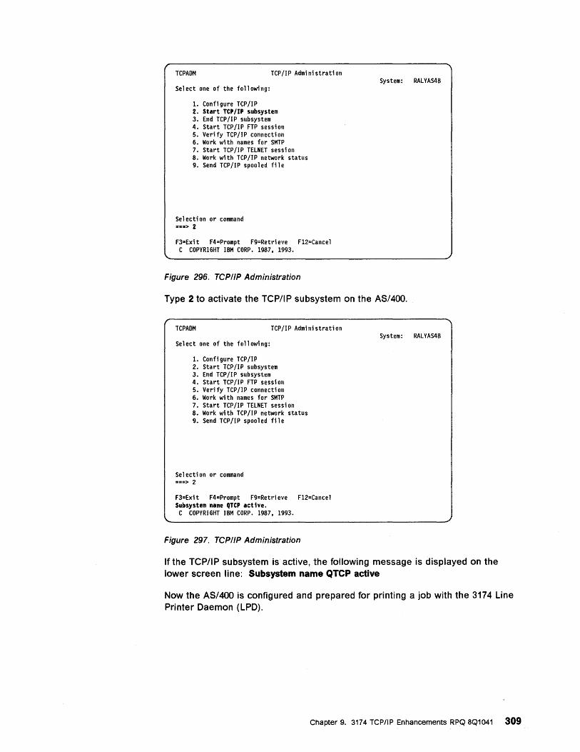
TCPAOM TCP/IP Administration
Select one of the following:
1. Configure TCP/IP 2. Start TCP/IP subsystem 3. End TCP/IP subsystem 4. Start TCP/IP FTP session 5. Verify TCP/IP connection 6. Work wi th names for SMTP 7. Start TCP /1 P TELNET sessi on 8. Work with TCP/IP network status 9. Send TCP/IP spooled file
Se 1 ecti on or command ===> 2
F3=Exit F4=Prompt F9=Retri eve F12=Cance 1 C COPYRIGHT IBM CORP. 1987, 1993.
Figure 296. TCP/IP Administration
System: RALYAS4B
Type 2 to activate the TCP/IP SUbsystem on the AS/400.
TCPAOM TCP/IP Administration
Select one of the following:
1. Configure TCP/IP 2. Start TCP/IP subsystem 3. End TCP/IP subsystem 4. Start TCP/IP FTP session 5. Verify TCP/IP connection 6. Work wi th names for SMTP 7. Start TCP/IP TELNET session 8. Work with TCP/IP network status 9. Send TCP/IP spooled file
Se 1 ecti on or command ===> 2
F3=Exit F4=Prompt F9=Retrieve Fl2=Cancel Subsystem name QTCP active.
C COPYRIGHT IBM CORP. 1987, 1993.
Figure 297. TCP/IP Administration
System: RALYAS4B
If the TCP/IP subsystem is active, the following message is displayed on the lower screen line: Subsystem name QTCP active
Now the AS/400 is configured and prepared for printing a job with the 3174 Line Printer Daemon (LPD).
Chapter 9. 3174 TCP/IP Enhancements RPQ 8Q1041 309
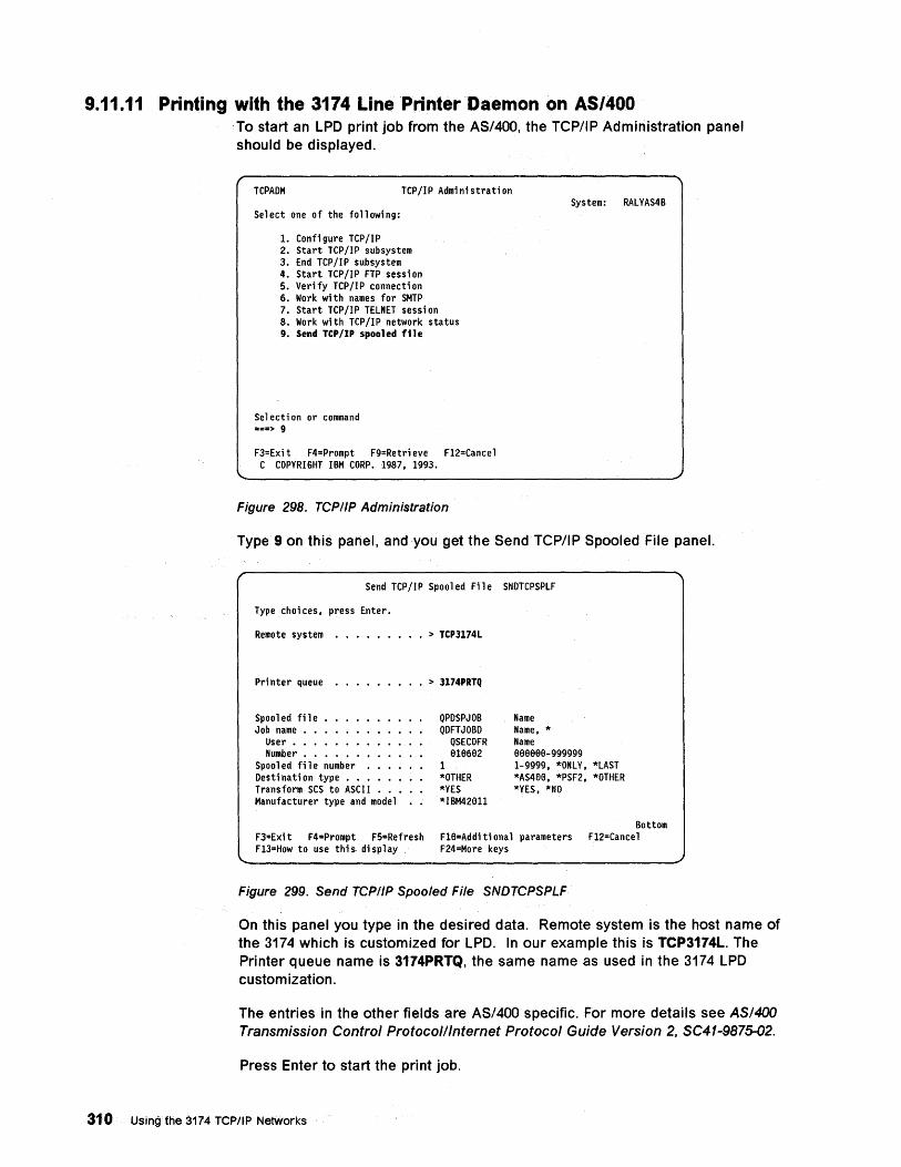
9.11.11 Printing with the 3174 LinePrinter Daemon on AS/400 To start an LPD print job from the AS/400, the TCP/IP Administration panel should be displayed.
TCPADM TCP/IP Administration
Select one of the following:
1. Configure TCP/IP 2. Start TCP/IP subsystem 3. End TCP/IP subsystem 4. Start TCP/IP FTP session 5. Verify TCP/IP connection 6. Work with names for SMTP 7. Start TCP/IP TELNET session 8. Work with TCP/IP network status 9. Send TCP/IP spooled file
Se 1 ecti on or command ===> 9
F3=Exit F4=Prompt F9=Retri eve Fl2=Cance 1 C COPYRIGHT IBM CORP. 1987, 1993.
Figure 298. TCP/IP Administration
System: RALYAS4B
Type 9 on this pahel, and you get the Send TCP/IP Spooled File panel.
Send TCP /1 P Spooled Fil e SNDTCPSPLF
Type choi ces, press Enter.
Remote system ••••••••• > TCP3174L
Pri nter queue
Spool ed fil e • Job name •••
User •••• Number. •• •
Spooled file number Destination type •• Transform SCS to ASCI I • Manufacturer type and model
• > 3174PRTQ
QPDSPJOB QDFTJOBD
QSECOFR 919692
1 *OTHER *YES *IBM42(H1
Name Name, * Name 999999-999999 1-9999, *ONLY, *LAST *AS499, *PSF2, *OTHER *YES, *NO
Bottom F3=Exi t F4=Prompt F5=Refresh Fl9=Additi ona 1 parameters Fl2=Cance 1 Fl3=How to use this di sp 1 ay F24=More keys
Figure 299. Send TCP/IP Spooled File SNDTCPSPLF
On this panel you type in the desired data. Remote system is the host name of the 3174 which is customized for LPD. In our example this is TCP3174L. The Printer queue name is 3174PRTQ, the same name as used in the 3174 LPD customization.
The entries in the other fields are AS/400 specific. For more details see AS/400 Transmission Control Protocol/Internet Protocol Guide Version 2. SC41-9875-02.
Press Enter to start the print job.
310 Using the 3174 TCP/IP Networks
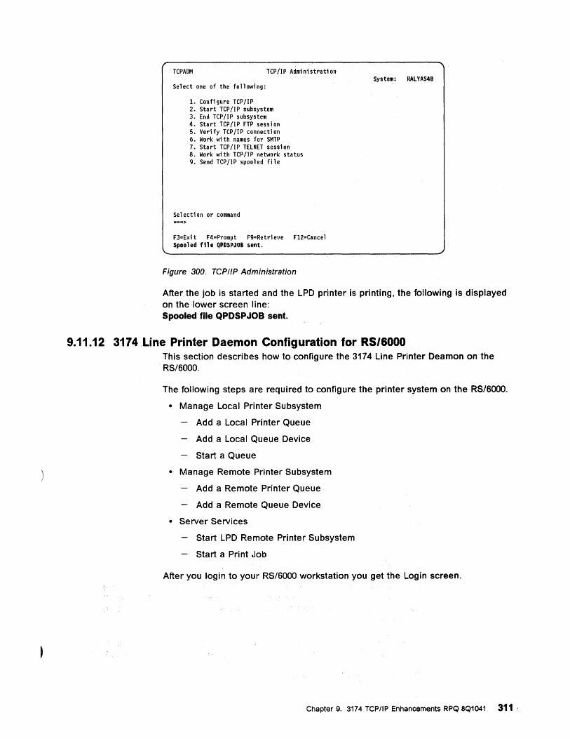
TCPAOM Ttp/IP Administration
Select one of the following:
1. Configure TCP/IP 2. Start TCP/IP subsystem 3. End TCP/IP subsystem 4. Start TCP/IP FTP session 5. Verify TCP /IP connecti on 6. Work with names for SMTP 7. Start TCP/IP TELNET session 8. Work with TCP/IP network status 9. Send TCP/IP spooled file
Selection or command ===>
F3=Exi t F4=Prompt F9=Retri eve F12=Cance 1 Spooled file QPDSPJOB sent.
Figure 300. TCP/IP Administration
System: RALVAS48
After the job is started and the LPD printer is printing, the following is displayed on the lower screen line: Spooled file QPDSPJOB sent.
9.11.12 3174 Line Printer Daemon Configuration for RS/6000 This section describes how to configure the 3174 Line Printer Deamon on the RS/6000.
The following steps are required to configure the printer system on the RS/6000.
• Manage Local Printer Subsystem
Add a Local Printer Queue
Add a Local Queue Device
Start a Queue
• Manage Remote Printer Subsystem
Add a Remote Printer Queue
Add a Remote Queue Device
• Server Services
Start LPD Remote Printer Subsystem
Start a Print Job
After you login to your RS/6000 workstation you get the Login screen.
Chapter 9. 3174 TCP/IP Enhancements RPQ 8Q1041 311
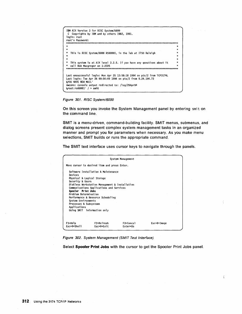
IBM AIX Versi on 3 for RISC System/6888 C Copyrights by IBM and by others 1982, 1991.
login: root root's Password: ******************************************************************************* * * * This is RISC System/6888 RS68881, in the lab at ITSO Raleigh * *
* * * * *
* This system is at AIX level 3.2.5. If you have any questions about it * * call Rob Macgregor on 1-2325 * *******************************************************************************
Last unsuccessful 1 ogi n: Mon Apr 25 13: 58: 18 1994 on pts/2 from TCP3174L Last login: Tue Apr 26 89:54:49 1994 on pts/2 from 9.24.184.73 ~YOU HAVE NEW MAIL' swcons: console output redi rected to: /10g/26Apr94 ~root:rs68881' / > smit
Figure 301. RiSe System/6000
On this screen you invoke the System Management panel by entering sm; t on the command line.
SMIT is a menu-driven, command-building facility. SMIT menus, submenus, and dialog screens present complex system management tasks in an organized manner and prompt you for parameters when necessary. As you make menu selections, SMIT builds or runs the appropriate command.
The SMIT text interface uses cursor keys to navigate through the panels.
System Management
Move cursor to desi red item and press Enter.
Software Installation & Maintenance Devi ces Physi ca 1 & Logi ca 1 Storage Sec uri ty & Users Diskless Workstation Management & Installation Communications Applications and Services Spooler Print Jobs Problem Determination Performance & Resource Schedu1 i ng System Envi ronments Processes & Subsystems Applications Using SMIT information only
F1=He1p Esc+9=She 11
F2=Refresh Esc+8=Exi t
F3=Cance1 Enter=Do
Esc+8=Image
Figure 302. System Management (SMIT Text Interface)
Select Spooler Print Jobs with the cursor to get the Spooler Print Jobs panel.
312 Using the 3174 TCP/IP Networks
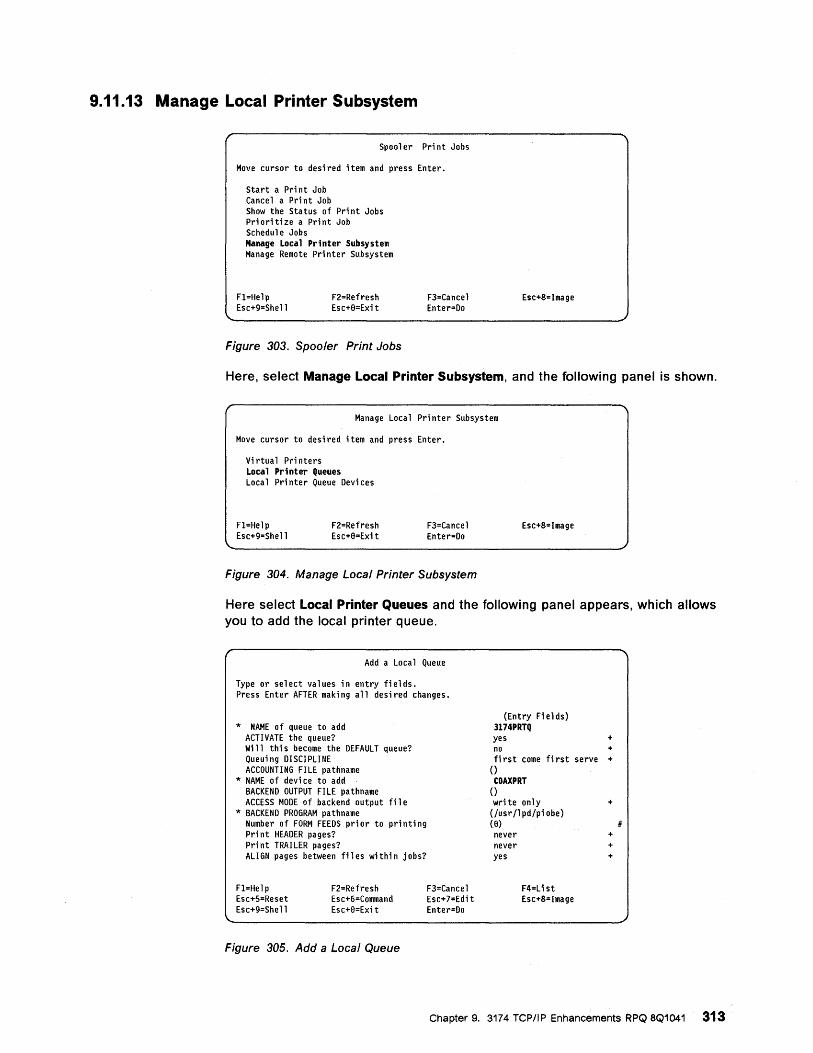
9.11.13 Manage Local Printer Subsystem
Spool er Pri nt Jobs
Move cursor to desi red item and press Enter.
Start a Pri nt Job Cance 1 a Pri nt Job Show the Status of Pri nt Jobs Pri oriti ze a Pri nt Job Schedul e Jobs Manage Local Printer Subsystem Manage Remote Printer Subsystem
Fl=Help Esc+9=Shell
F2=Refresh Esc+9=Exi t
Figure 303. Spooler Print Jobs
F3=Cancel Enter=Do
Esc+8=Image
Here, select Manage Local Printer Subsystem, and the following panel is shown.
Manage Local Printer Subsystem
Move cursor to desi red item and press Enter.
Virtual Printers Local Printer Queues Loca 1 Pri nter Queue Devi ces
F1=Help Esc+9=She 11
F2=Refresh Esc+9=Exi t
F3=Cancel Enter=Do
Figure 304. Manage Local Printer Subsystem
Esc+8=Image
Here select Local Printer Queues and the following panel appears, which allows you to add the local printer queue.
Add a Local Queue
Type or select values in entry fields. Press Enter AFTER making all desired changes.
* NAME of queue to add ACTIVATE the queue? Wi 11 thi s become the DEFAULT queue? Queuing DISCIPLINE ACCOUNTING FILE pathname
* NAME of device to add BACKEND OUTPUT FILE pathname ACCESS MODE of backend output file
* BACKEND PROGRAM pathname Number of FORM FEEDS prior to printing Print HEADER pages? Print TRAILER pages? ALIGN pages between files within jobs?
F1=He 1 P Esc+5=Reset Esc+9=She11
F2=Refresh Esc+6=Command Esc+9=Exi t
Figure 305. Add a Local Queue
F3=Cancel Esc+7=Edi t Enter=Do
(Entry Fields) 3174PRTQ yes + no + fi rst come fi rst serve +
() COAXPRT
() write only +
(fusr /1 pd/pi obe) (e) never never yes
F4=L i st Esc+8=Image
+ + +
I
Chapter 9. 3174 TCP/IP Enhancements RPQ 8Q1041 313
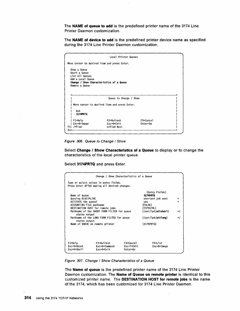
The NAME of queue to add is the predefined printer name of the 3174 Line Printer Daemon customization.
The NAME of device to add is the predefined printer device name as specified during the 3174 Line Printer Daemon customization.
Loca 1 Pri nter Queues
Move cursor to desired item and press Enter.
Stop a Queue Start a Queue Li st All Queues Add a Local Queue Change / Show Characteristics of a queue Remove a Queue
+--------------------------------------------------------------------------+ I Queue to Change / Show I I Move cursor to desi red i tern and press Enter. I I bsh I 3174PRTq I I F1=He 1 p F2=Refresh F3=Cance 1 I Esc+8=Image Esc+8=Exit Enter=Do
Fll /=Find n=Find Next Es+--------------------------------------------------------------------------+
Figure 306. Queue to Change / Show
Select Change I Show Characteristics of a Queue to display or to change the characteristics of the local printer queue.
Select 3174PRTQ and press Enter.
Change / Show Characteri sti cs of a Queue
Type or select values in entry fields. Press Enter AFTER making all desired changes.
Name of queue Queuing DISCIPLINE ACTIVATE the queue? ACCOUNTING FILE pathname DESTINATION HOST for remote jobs Pathname of the SHORT FORM FILTER for queue
status output Pathname of the LONG FORM FILTER for queue
status output Name of QUEUE on remote printer
F1=Help Esc+5=Reset Esc+9=She 11
F2=Refresh Esc+6=Command Esc+8=Exi t
F3=Cancel Esc+7=Edi t Enter=Do
(Entry Fields) 3174PRTq shortest job next yes
(FALSE) (TCP3174L) (fusr /1 pd/attshort)
(fusr /1 pd/attl ong)
(3174PRTQ)
F4=List Esc+8=Image
Figure 307. Change I Show Characteristics of a Queue
+ +
+/
+/
The Name of queue is the predefined printer name of the 3174 Line Printer Daemon customization. The Name of Queue on remote printer is identical to this customized printer name. The DESTINATION HOST for remote jobs is the name of the 3174, which has been customized for 3174 Line Printer Daemon.
314 Using the 3174 TCPIIP Networks
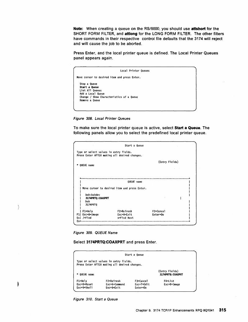
Note: When creating a queue on the RS/6000, you should use attshort for the SHORT FORM FILTER, and attlong for the LONG FORM FILTER. The other filters have commands in their respective control file defaults that the 3174 will reject and will cause the job to be aborted.
Press Enter, and the local printer queue is defined. The Local Printer Queues panel appears again.
Local Printer Queues
Move cursor to desi red item and press Enter.
Stop a Queue Start a Queue Li st All Queues Add a Loca 1 Queue Change / Show Characteri sti cs of a Queue Remove a Queue
Figure 308. Local Printer Queues
To make sure the local printer queue is active, select Start a Queue. The following panels allow you to select the predefined local printer queue.
Start a Queue
Type or select values in entry fields. Press Enter AFTER making all desired changes.
(Entry Fi el ds) * QUEUE name
+--------------------------------------------------------------------------+ I I
QUEUE name
I Move cursor to desi red item and press Enter. I I bsh: bshdev I 3174PRTQ: COAXPRT I bsh I 3174PRTQ I I Fl=Help
Fli Esc+8=Image Esl /=Find
F2=Refresh Esc+8=Exit n=Find Next
F3=Cancel Enter=Do
Es+--------------------------------------------------------------------------+
Figure 309. QUEUE Name
Select 3174PRTQ:COAXPRT and press Enter.
Start a Queue
Type or select values in entry fields. Press Enter AFTER maki ng all desi red changes.
* QUEUE name
Fl=Hel p Esc+5=Reset Esc+9=She 11
F2=Refresh Esc+6=Command Esc+8=Exi t
Figure 310. Start a Queue
F3=Cancel Esc+7=Edi t Enter=Do
(Entry Fields) 3174PRTQ: COAXPRT
F4=Li st Esc+8=Image
Chapter 9. 3174 TCP/IP Enhancements RPQ 8Q1041 315
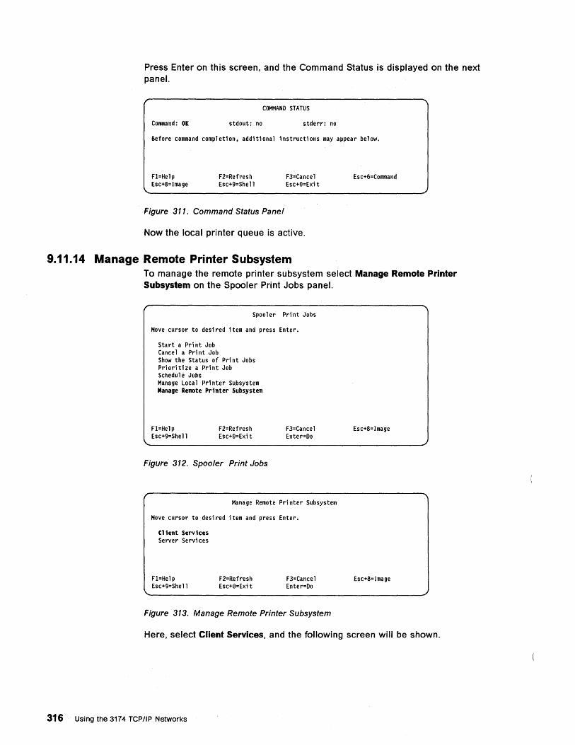
Press Enter on this screen, and the Command Status is displayed on the next panel.
COMMAND STATUS
Command: OK stdout: no stderr: no
Before command completion, additional instructions may appear below.
F1=Help Esc+8=Image
F2=Refresh Esc+9=She 11
Figure 311. Command Status Panel
F3=Cancel Esc+0=Exit
Now the local printer queue is active.
9.11.14 Manage Remote Printer Subsystem
Esc+6=Command
To manage the remote printer subsystem select Manage Remote Printer Subsystem on the Spooler Print Jobs panel.
Spooler Print Jobs
Move cursor to desi red item and press Enter.
Start a Print Job Cance 1 a Pri nt Job Show the Status of Pri nt Jobs Prioritize a Print Job Schedule Jobs Manage Local Printer Subsystem Manage Remote Printer Subsystem
F1=Hel p Esc+9=She 11
F2=Refresh Esc+0=Exi t
Figure 312. Spooler Print Jobs
F3=Cancel Enter=Do
Manage Remote Pri nter Subsystem
Move cursor to desired item and press Enter.
Client Services Server Servi ces
F1=Help Esc+9=She 11
F2=Refresh Esc+0=Exi t
F3=Cancel Enter=Do
Figure 313. Manage Remote Printer Subsystem
Esc+8=Image
Esc+8=Image
Here, select Client Services, and the following screen will be shown.
316 Using the 3174 TCP/IP Networks
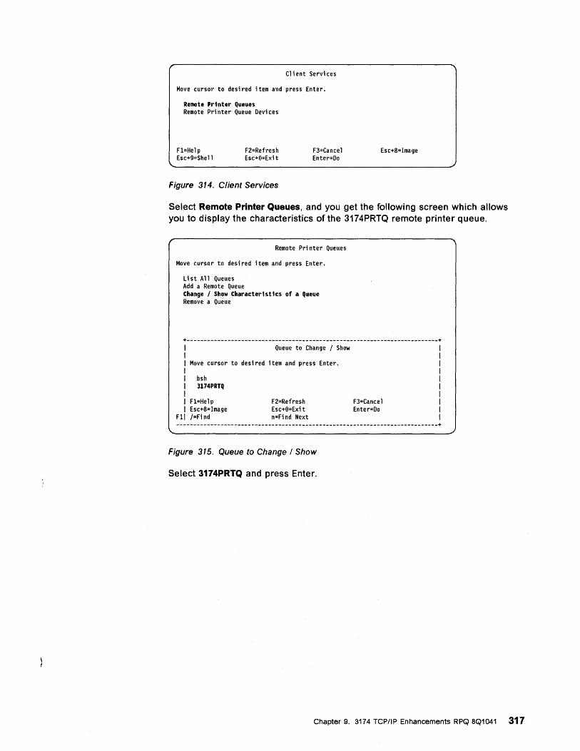
C1 i ent Servi ces
Move cursor to desi red i tern and press Enter.
Remote Printer Queues Remote Pri nter Queue Devi ces
F1=He1 p Esc+9=She 11
F2=Refresh Esc+9=Exi t
Figure 314. Client Services
F3=Cance1 Enter=Do
Esc+8=Image
Select Remote Printer Queues, and you get the following screen which allows you to display the characteristics of the 3174PRTQ remote printer queue.
Remote Printer Queues
Move cursor to desi red i tern and press Enter.
List All Queues Add a Remote Queue Change! Show Characteristics of a Queue Remove a Queue
+--------------------------------------------------------------------------+ I Queue to Change / Show I I Move cursor to desi red i tern and press Enter. I I bsh I 3174PRTQ I I F1=He 1 p F2=Refresh F3=Cance 1 I Esc+8=Image Esc+9=Exi t Enter=Do
Fli !=Find n=Find Next -----------------------------------------------------------------------------+
Figure 315. Queue to Change / Show
Select 3174PRTQ and press Enter.
Chapter 9. 3174 TCP/IP Enhancements RPQ 8Q1041 317
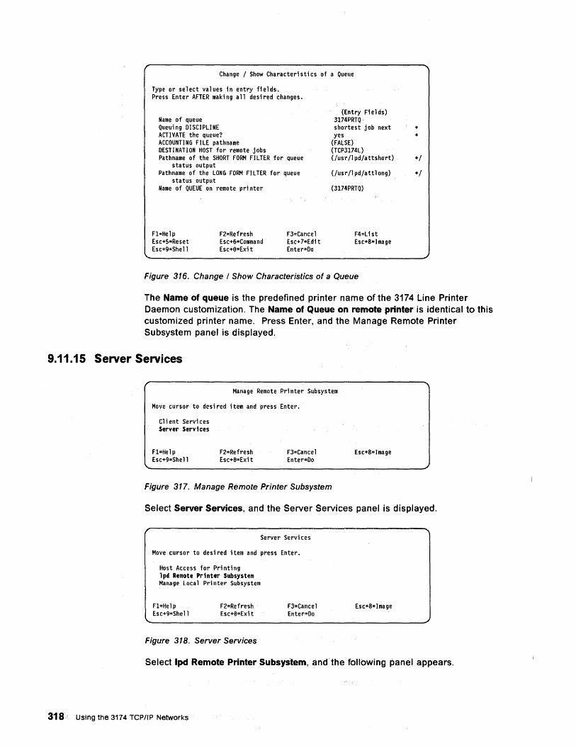
Change / Show Characteri sti cs of a Queue
Type or select values in entry fields. Press Enter AFTER maki ng all desi red changes.
Name of queue Queuing DISCIPLINE ACTIVATE the queue? ACCOUNTING FILE pathname DESTINATION HOST for remote jobs Pathname of the SHORT FORM FILTER for queue
status output Pathname of the LONG FORM FILTER for queue
status output Name of QUEUE on remote pri nter
F1=Help Esc+5=Reset Esc+9=She 11
F2=Refresh Esc+6=Command Esc+6=Exi t
F3=Cancel Esc+7=Edi t Enter=Do
(Entry Fields) 3174PRTQ· shortest job next yes
(FALSE) (TCP3174L) (Jusr /1 pd/attshort)
(Jusr/1 pd/att1 ong)
(3174PRTQ)
F4=Li st Esc+8=Image
Figure 316. Change / Show Characteristics of a Queue
+ +
+/
+/
The Name of queue is the predefined printer name of the 3174 Line Printer Daemon customization. The Name of Queue on remote printer is identical to this customized printer name. Press Enter, and the Manage Remote Printer Subsystem panel is displayed.
9.11.15 Server Services
Manage Remote Pri nter Subsystem
Move cursor to desi red item and press Enter.
Cl i ent Servi ces Server Services
F1=He1p Esc+9=She 11
F2=Refresh Esc+6=Exi t
F3=Cance1 Enter=Do
Figure 317. Manage Remote Printer Subsystem
Esc+8=Image
Select Server Services, and the Server Services panel is displayed.
Server Servi ces
Move cursor to desi red item and press Enter.
Host Access for Pri nti ng lpd Remote Printer Subsystem Manage Local Pri nter Subsystem
F1=Help Esc+9=She 11
F2=Refresh Esc+6=Exi t
Figure 318. Server Services
F3=Cance1 Enter=Do
Esc+8=Image
Select Ipd Remote Printer Subsystem, and the following panel appears.
318· Using the 3174 TCP/IP Networks
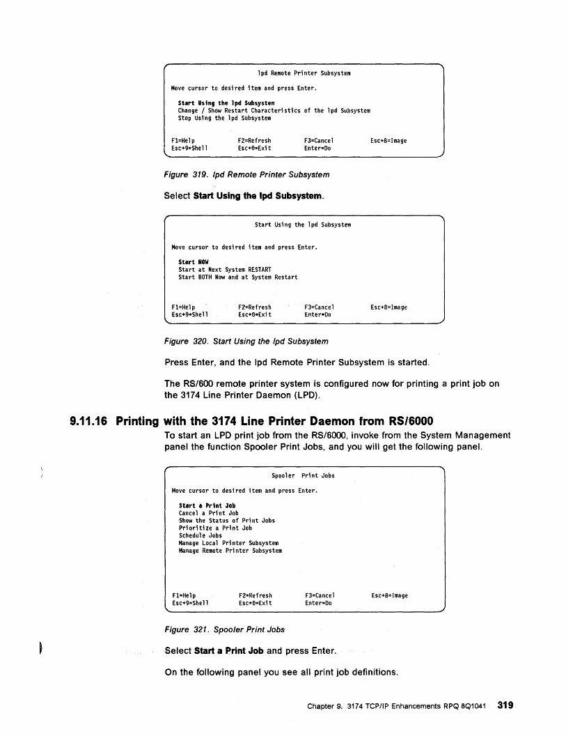
1 pd Remote Pri nter Subsystem
Move cursor to desi red item and press Enter.
Start Using the lpd Subsystem Change / Show Restart Character; sti cs of the 1 pd Subsystem Stop Using the lpd Subsystem
F1=He1p Esc+9=She 11
F2=Refresh Esc+6=Exit
F3=Cance1 Enter=Do
Figure 319. Ipd Remote Printer Subsystem
Select Start Using the Ipd Subsystem.
Start Usi ng the 1 pd Subsystem
Move cursor to desi red ; tem and press Enter.
Start NOW Start at Next System RESTART Start BOTH Now and at System Restart
F1=Help Esc+9=She11
F2=Refresh Esc+6=Exi t
F3=Cancel Enter=Do
Figure 320. Start Using the Ipd Subsystem
Esc+8=Image
Esc+8=Image
Press Enter, and the Ipd Remote Printer Subsystem is started.
The RS/SOO remote printer system is configured now for printing a print job on the 3174 Line Printer Daemon (LPD).
9.11.16 Printing with the 3174 Line Printer Daemon from RS/6000 To start an LPD print job from the RS/SOOO, invoke from the System Management panel the function Spooler Print Jobs, and you will get the following panel.
Spoo 1 er Pri nt Jobs
Move cursor to desi red item and press Enter.
Start a Print Job Cancel a Print Job Show the Status of Print Jobs Prioritize a Print Job Schedu1 e Jobs Manage Local Pri nter Subsystem Manage Remote Pri nter Subsystem
F1=Help Esc+9=She 11
F2=Refresh Esc+6=Exit
Figure 321. Spooler Print Jobs
F3=Cance1 Enter=Do
Select Start a Print Job and press Enter.
Esc+8=Image
On the following panel you see all print job definitions.
Chapter 9. 3174 TCP/IP Enhancements RPQ 8Q1041 319
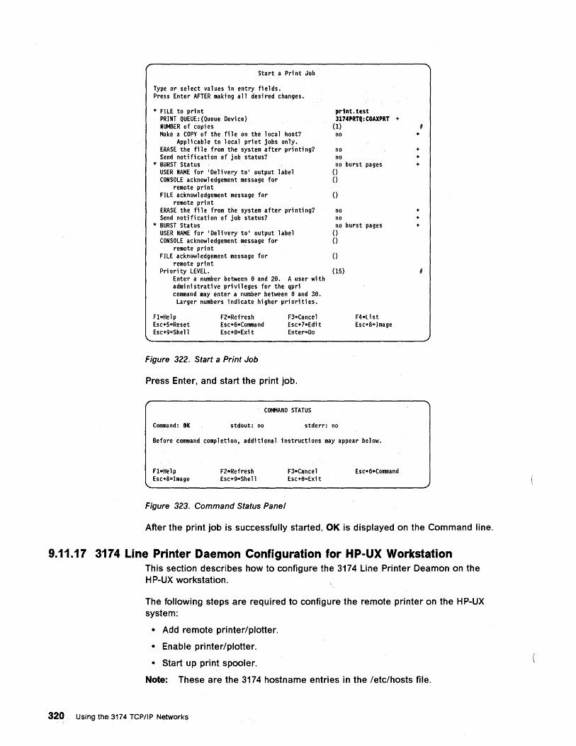
Sta rt a Pri nt Job
Type or select values in entry fields. Press Enter AFTER maki ng all desi red changes.
* FILE to print PRINT QUEUE:(Queue Device) NUMBER of copi es Make a COpy of the fi 1 e on the 1 oca 1 host?
Applicable to local print jobs only. ERASE the fil e from the system after pri nti ng? Send notification of job status?
* BURST Status USER NAME for 'Delivery to' output label CONSOLE acknowledgement message for
remote print FILE acknowl edgement message for
remote pri nt ERASE the fil e from the system after pri nti ng? Send notification of job status?
* BURST Status USER NAME for 'Delivery to' output label CONSOLE acknowledgement message for
remote pri nt FILE acknowledgement message for
remote print Pri ori ty LEVEL.
Enter a number between 9 and 29. A user with admi ni strati ve pri vil eges for the qpri command may enter a number between 9 and 39. Larger numbers indicate higher priorities.
F1=He 1 P Esc+5=Reset Esc+9=She 11
F2=Refresh Esc+6=Command Esc+9=Exi t
Figure 322. Start a Print Job
F3=Cancel Esc+7=Edi t Enter=Do
Press Enter, and start the print job.
COMMAND STATUS
print. test 3174PRTQ:COAXPRT +
(1) no
no no no burst pages o o o no no no burst pages o o o (15)
F4=Li st Esc+8=Image
Command: OK stdout: no stderr: no
Before command completion, additional instructions may appear below.
F1=Help Esc+8=Image
F2=Refresh Esc+9=She 11
Figure 323. Command Status Panel
F3=Cancel Esc+9=Exi t
Esc+6=Command
+
+ + +
+ + +
After the print job is successfully started, OK is displayed on the Command line.
9.11.17 3174 Line Printer Daemon Configuration for HP-UX Workstation This section describes how to configure the 3174 Line Printer Deamon on the HP-UX workstation.
The following steps are required to configure the remote printer on the HP-UX system:
• Add remote printer/plotter.
• Enable printer/plotter.
• Start up print spooler.
Note: These are the 3174 hostname entries in the /etc/hosts file.
320 Using the 3174 TCP/IP Networks
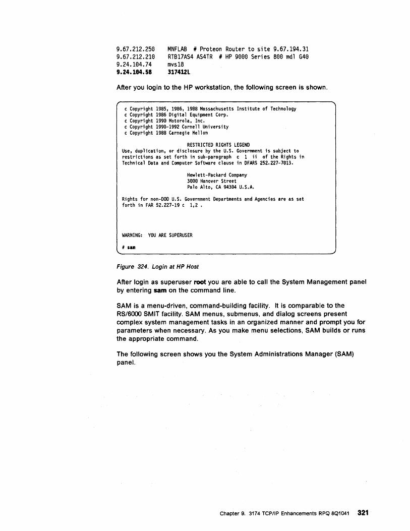
9.67.212.250 9.67.212.210 9.24.104.74 9.24.184.58
MNFLAB * Proteon Router to site 9.67.194.31 RTB17AS4 AS4TR * HP 9000 Series S00 mdl G40 mvs1S 317412L
After you login to the HP workstation, the following screen is shown.
c Copyright 1985, 1986, 1988 Massachusetts Institute of Technology c Copyright 1986 Digital Equipment Corp. c Copyright 1990 Motorola, Inc. c Copyright 1990-1992 Cornell University c Copyright 1988 Carnegie Mellon
RESTRICTED RIGHTS LEGEND Use, duplication, or disclosure by the U.S. Government is subject to restrictions as set forth in sub-paragraph c 1 ii of the Rights in Technical Data and Computer Software clause in DFARS 252.227-7013.
Hewlett-Packard Company 3000 Hanover Street Palo Alto, CA 94304 U.S.A.
Rights for non-DOD U.S. Government Departments and Agencies are as set forth in FAR 52.227-19 c 1,2.
WARNING: YOU ARE SUPERUSER
/I sam
Figure 324. Login at HP Host
After login as superuser root you are able to call the System Management panel by entering sam on the command line.
SAM is a menu-driven, command-building facility. It is comparable to the RS/6000 SMIT facility. SAM menus, submenus, and dialog screens present complex system management tasks in an organized manner and prompt you for parameters when necessary. As you make menu selections, SAM builds or runs the appropriate command.
The following screen shows you the System Administrations Manager (SAM) panel.
Chapter 9. 3174 TCP/IP Enhancements RPQ 8Q1041 321
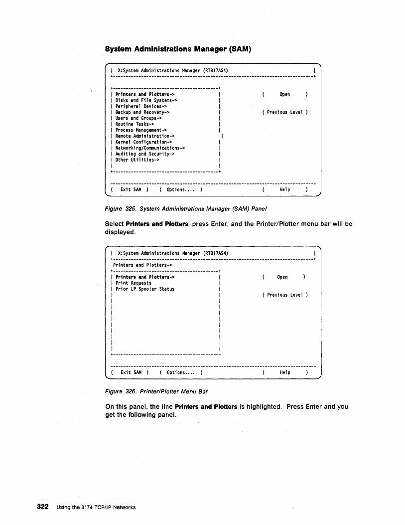
System Administrations Manager (SAM)
I X:System Administrations Manager (RTB17AS4) +------------------------------------------------------------------------------+
+-----------------------------------------+ Printers and Plotters-> I Open Disks and File Systems-> I Peri phera 1 Devi ces-> I Backup and Recovery-> I ( Previous Level Users and Groups-> I Routine Tasks-> I Process Hanagement-> I Remote Administration-> I Kernel Configuration-> I Networking/Communications-> I Auditing and Security-> I Other Utilities-> I
I +-----------------------------------------+
Exit SAM ) ( Options •..• ) Help
Figure 325. System Administrations Manager (SAM) Panel
Select Printers and Plotters, press Enter, and the Printer/Plotter menu bar will be displayed.
I X:System Administrations Manager (RTB17AS4) +------------------------------------------------------------------------------+ Printers and Plotters->
+-----------------------------------------+ Printers and Plotters-> Open Print Requests Prior LP Spooler Status
( Previous Level )
+-----------------------------------------+
Exit SAM ) ( Options •.•• ) Help
Figure 326. Printer/Plotter Menu Bar
On this panel, the line Printers and Plotters is highlighted. Press Enter and you get the following panel.
322 Using the 3174 TCP/IP Networks
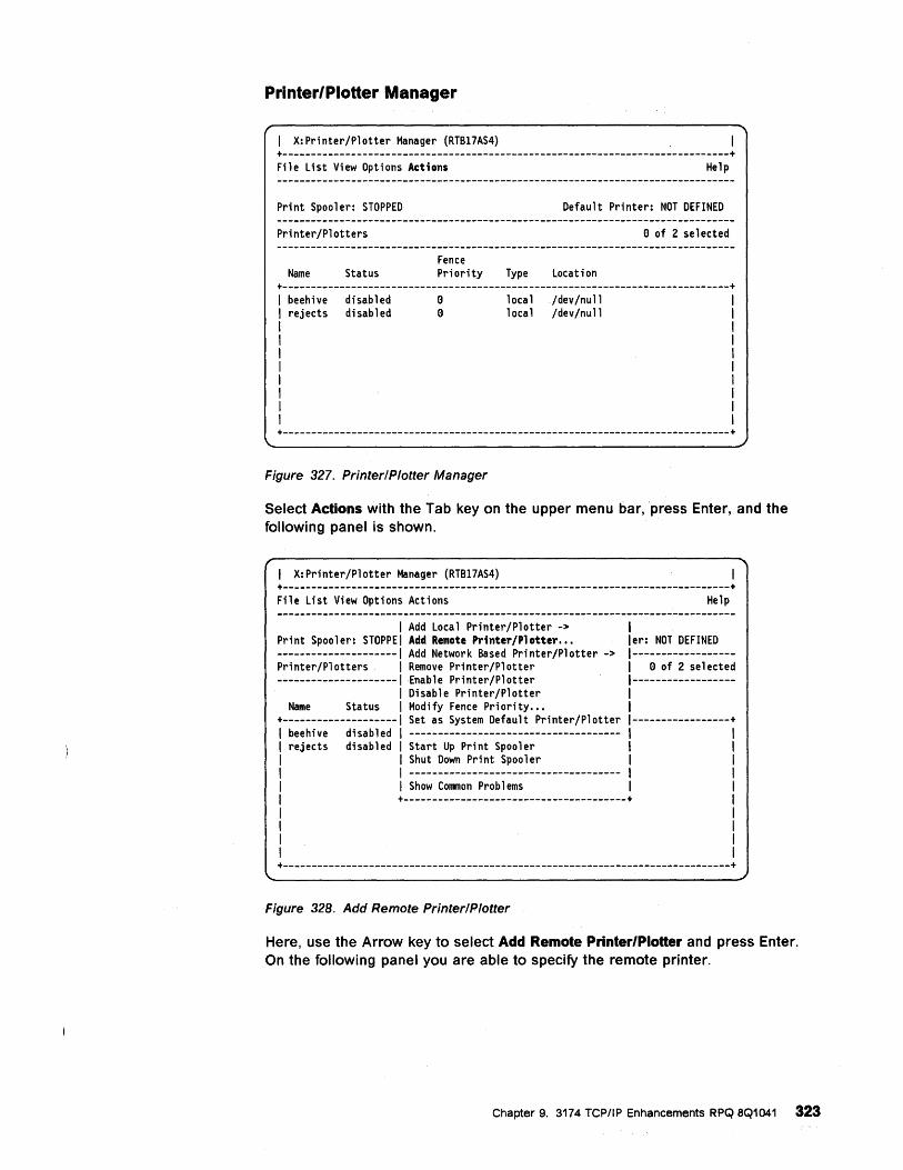
Printer/Plotter Manager
1 X:Printer/Plotter Manager (RTB17AS4) +------------------------------------------------------------------------------+ File List View Options Actions Help
Print Spooler: STOPPED Default Printer: NOT DEFINED
Printer/Plotters e of 2 selected
Fence Name Status Priority Type Location
+------------------------------------------------------------------------------+ 1 beehive disabled e local /dev/null 1 rejects disabled e local /dev/null 1
1 1
1
1
1
1
1
+------------------------------------------------------------------------------+
Figure 327. Printer/Plotter Manager
Select Actions with the Tab key on the upper menu bar, press Enter, and the following panel is shown.
1 X:Printer/Plotter Manager (RTB17AS4) +------------------------------------------------------------------------------+ File List View Options Actions Help
1 Add Local Printer/Plotter -> 1 Print Spooler: STOPPE Add Remote Printer/Plotter... ler: NOT DEFINED --------------------- Add Network Based Printer/Plotter -> 1------------------Printer/Plotters Remove Printer/Plotter 1 e of 2 selected ---------------------Enable Printer/Plotter 1------------------
Disable Printer/Plotter 1 Name Status Modify Fence Priority... 1
+-------------------- Set as System Default Printer/Plotter 1-----------------+ beehive disabled ------------------------------------- 1 I rejects disabled Start Up Print Spooler 1 1
Shut Down Pri nt Spoo 1 er 1 1 ------------------------------------- 1 I Show COl1lTlon Prob 1 ems 1 1
+---------------------------------------+ 1 1 1 I 1
+------------------------------------------------------------------------------+
Figure 328. Add Remote Printer/Plotter
Here, use the Arrow key to select Add Remote Printer/Plotter and press Enter. On the following panel you are able to specify the remote printer.
Chapter 9. 3174 TCP/IP Enhancements RPQ 8Q1041 323
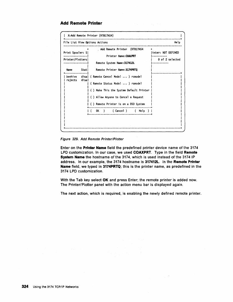
Add Remote Printer
.
X:Add Remote Printer (RTB17AS4) +------------------------------------------------------------------------------+ File List View Options Actions Help
+ Print Spooler: SI ----------------1 Printer/Plotters I ----------------1
I Name Stat I
+---------------1 beehive disal rejects disal
I I I I I I I
. Add Remote Printer (RTB17AS4 + linter: NOT DEFINED
Printer Name:COAXPRT 1----------I e of 2 selected
Remote System Name:317412L 1-----------I
Remote Printer Name:3174PRTQ I 1-------------------+
( Remote Cancel Model ••• ) remodel I I
( Remote Status Model ••• ) rsmodel I I
( ) Make This the System Default Printer I I
( ) Allow Anyone to Cancel a Request I I
( ) Remote Printer is on a BSD System I +------------------------------------------+ I (OK ( Cance 1 ) (He 1 p ) I +------------------------------------------+
+------------------------------------------------------------------------------+
Figure 329. Add Remote Printer/Plotter
Enter on the Printer Name field the predefined printer device name of the 3174 LPD customization. In our case, we used COAXPRT. Type in the field Remote System Name the hostname of the 3174, which is used instead of the 3174 IP address. In our example, the 3174 hostname is 317412L. In the Remote Printer Name field, we typed in 3174PRTQ; this is the printer name, as predefined in the 3174 LPD customization.
With the Tab key select OK and press Enter; the remote printer is added now. The Printer/Plotter panel with the action menu bar is displayed again.
The next action, which is required, is enabling the newly defined remote printer.
324 Using the 3174 TCPIIP Networks
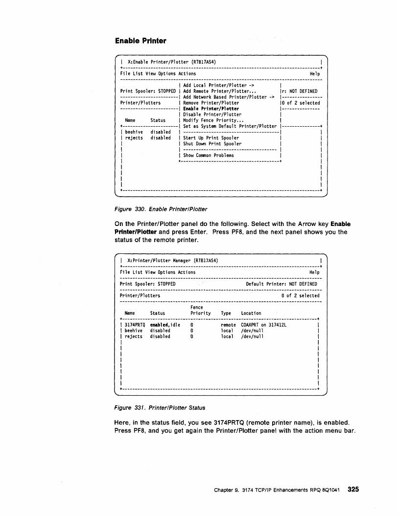
Enable Printer
I X:Enable Printer/Plotter (RTB17AS4) +------------------------------------------------------------------------------+ File List View Options Actions Help
I Add Local Printer/Plotter -> I Print Spooler: STOPPED I Add Remote Printer/Plotter... Ir: NOT DEFINED -----------------------1 Add Network Based Printer/Plotter -> 1----------------Printer/Plotters I Remove Printer/Plotter 10 of 2 selected -----------------------1 Enable Printer/Plotter 1---------------
I Disable Printer/Plotter I Name Status I Modify Fence Priority... I
+----------------------1 Set as System Default Printer/Plotter 1---------------+ I beehive disabled I --------------------------------------1 I rejects disabled I Start Up Print Spooler I I I Shut Down Pri nt Spoo 1 er I I I ------------------------------------- I I I Show Common Prob 1 ems I I +---------------------------------------+ I I I I +------------------------------------------------------------------------------+
Figure 330. Enable Printer/Plotter
On the Printer/Plotter panel do the following. Select with the Arrow key Enable Printer/Plotter and press Enter. Press PF8, and the next panel shows you the status of the remote printer.
I X:Printer/Plotter Manager (RTB17AS4) +------------------------------------------------------------------------------+ File List View Options Actions Help
Print Spoolet: STOPPED Default Printer: NOT DEFINED
Printer/Plotters o of 2 selected
Fence Name Status Priority Type Location
+-----------------------------------------------------------------------------+ 3174PRTQ enabled,idle 0 remote COAXPRT on 317412L beehi ve di sab 1 ed 0 local /dev /null rejects disabled 0 local /dev/null
Figure 331. Printer/Plotter Status
Here, in the status field, you see 3174PRTQ (remote printer name), is enabled. Press PF8, and you get again the Printer/Plotter panel with the action menu bar.
Chapter 9. 3174 TCP/IP Enhancements RPQ 8Q1041 325
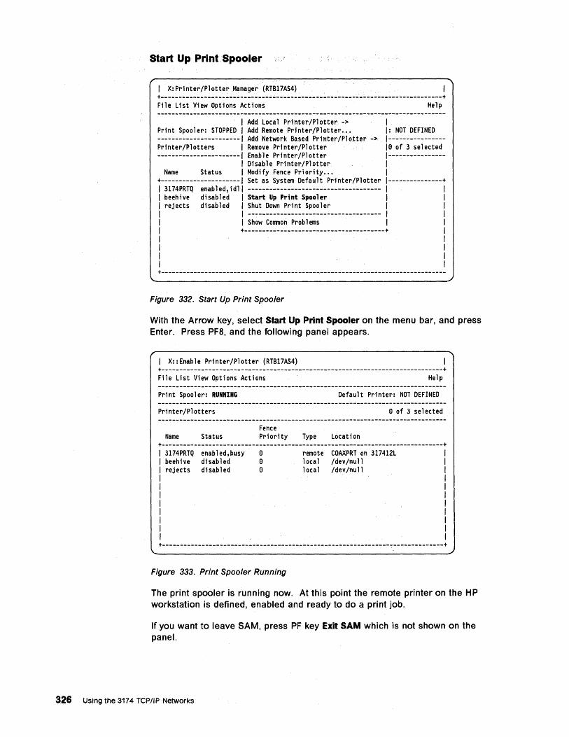
Start Up Print Spooler
1 X:Printer/Plotter Manager (RTB17AS4) +--------------------------~.----~------------------------~---------------------+ File List View Options Actions Help
1 Add Local Printer/Plotte~ -> 1 Print Spooler: STOPPED 1 Add Remote Printer/Plotter... I: NOT DEFINED -----------------------1 Add Network Based Printer/Plotter -> 1----------------Printer/Plotters 1 Remove Printer/Plotter 10 of 3 selected -----------------------1 Enable Printer/Plotter 1----------------
1 Disable Printer/Plotter 1 Name Status 1 Modify Fence Priority... 1
+----------------------1 Set as System Default Printer/Plotter 1---------------+ 1 3174PRTQ enabled,idll ------------------------------------- 1 1 1 beehive disabled 1 Start Up Pr;nt Spooler 1 1 1 rejects disabled 1 Shut Down Print Spooler 1 1 1 1 ------------------------------------- 1 1 1 1 Show COlllnon Prob 1 ems 1 1 1 +---------------------------------------+ 1 1 1 1 1 1 1 1 1 +-------------------------------------------------------------------------------
Figure 332. Start Up Print Spooler
With the Arrow key, select Start Up Print Spooler on the menu bar, and press Enter. Press PF8, and the following panel appears.
1 X::Enable Printer/Plotter (RTB17AS4) +------------------------------------------------------------------------------+ File List View Options Actions Help
Print Spooler: RUNNING Default Printer: NOT DEFINED
Printer/Plotters o of 3 selected
Fence Name Status Priority Type Location
+------------------------------------------------------------------------------+ 1 3174PRTQ enabled,busy 0 remote COAXPRT on 317412L 1 beehive disabled 0 local /dev/null 1 rejects disabled 0 local /dev/null 1
1 1
1
1
1
1
1 +------------------------------------------------------------------------------+
Figure 333. Print Spooler Running
The print spooler is running now. At this point the remote printer on the HP workstation is defined, enabled and ready to do a print job.
If you want to leave SAM, press PF key Exit SAM which is not shown on the panel.
326 Using the 3174 TCP/IPNetworks
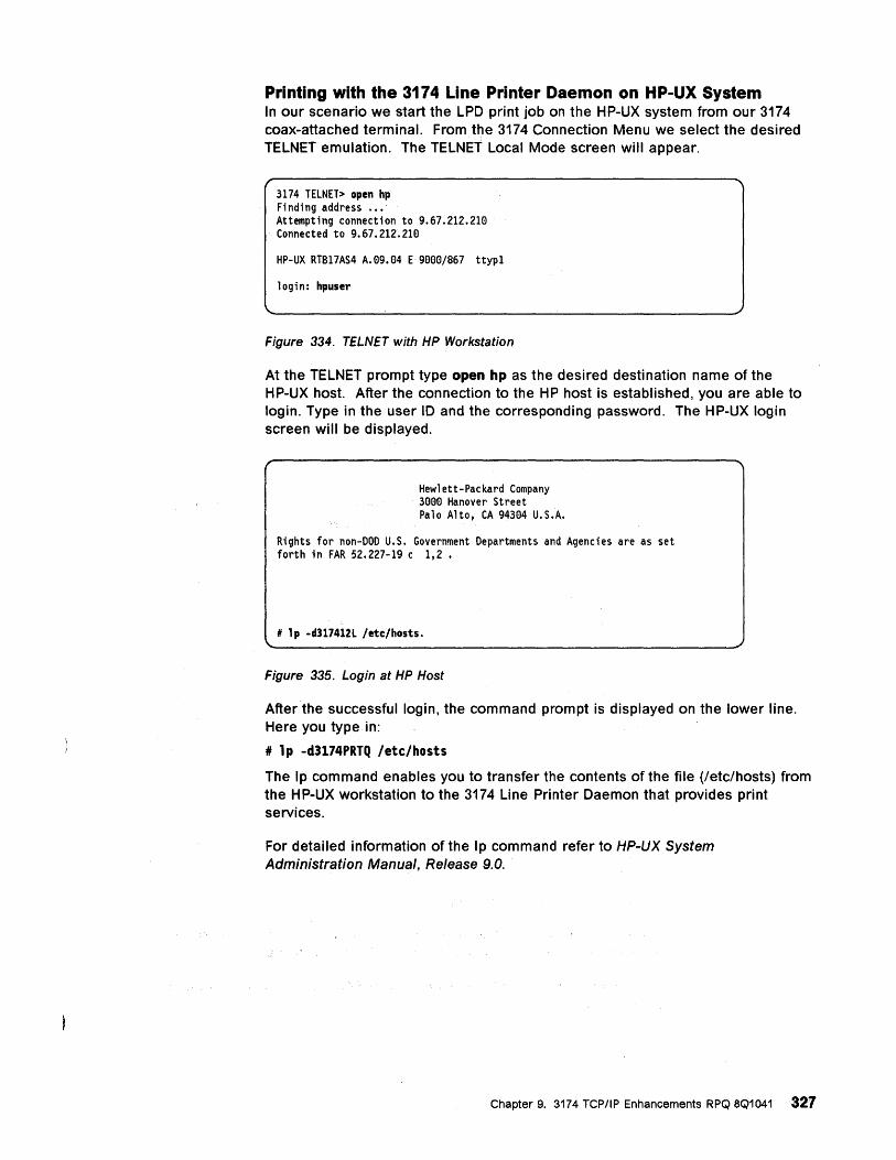
Printing with the 3174 Line Printer Daemon on HP-UX System In our scenario we start the LPD print job on the HP-UX system from our 3174 coax-attached terminal. From the 3174 Connection Menu we select the desired TELNET emulation. The TELNET Local Mode screen will appear.
3174 TELNET> open hp Finding address ••• Attempting connection to 9.67.212.210 Connected to 9.67.212.210
HP-UX RTB17AS4 A.09.04 E 9000/867 ttyp1
login: hpuser
Figure 334. TELNET with HP Workstation
At the TELNET prompt type open hp as the desired destination name of the HP-UX host. After the connection to the HP host is established, you are able to login. Type in the user ID and the corresponding password. The HP-UX login screen will be displayed.
Hewlett-Packard Company 3000 Hanover Street Palo Alto, CA 94304 U.S.A.
Rights for non-DOD U.S. Government Departments and Agencies are as set forth in FAR 52.227-19 c 1,2.
# lp -d317412L fetc/hosts.
Figure 335. Login at HP Host
After the successful login, the command prompt is displayed on the lower line. Here you type in:
# lp -d3174PRTQ letclhosts
The Ip command enables you to transfer the contents of the file (/etc/hosts) from the HP-UX workstation to the 3174 Line Printer Daemon that provides print services.
For detailed information of the Ip command refer to HP-UX System Administration Manual, Release 9.0.
Chapter 9. 3174 TCP/IP Enhancements RPQ 8Q1041 327
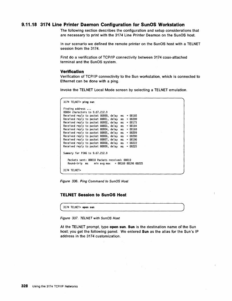
9.11.18 3174 Line Printer Daemon Configuration for SunOS Workstation The following section describes the configuration and setup considerations that are necessary to print with the 3174 Line Printer Deamon on the SunOS host.
In our scenario we defined the remote printer on the SunOS host with a TELNET session from the 3174.
First do a verification of TCP/IP connectivity between 3174 coax-attached terminal and the SunOS system.
Verification Verification of TCP/IP connectivity to the Sun workstation, which is connected to Ethernet can be done with a ping.
Invoke the TELNET Local Mode screen by selecting a TELNET emulation.
3174 TELNET> p;ng sun
Finding address ••• eee64 characters to 9.67.212.9 Received reply to packet eeeee, delay ms = ee18S Received reply to packet eeee1, delay ms = ee2e9 Received reply to packet eeee2, delay ms = ee173 Received reply to packet eeee3, delay ms = ee184 Received reply to packet eeee4, delay ms = ee169 Received reply to packet eeees, delay ms = ee2e9 Received reply to packet eeee6, delay ms = ee2ee Received reply to packet eeee7, delay ms = ee1ge Received reply to packet eeee8, delay ms = ee222 Received reply to packet eeee9, delay ms = ee22S
Summary for PING to 9.67.212.9
Packets sent: eeele Packets received: eeele Round-trip ms min avg max = ee169 ee196 ee22S
3174 TELNET>
Figure 336. Ping Command to SunOS Host
TELNET Session to SunOS Host
( 3174 TELNET> open sun ) "------------
Figure 337. TELNET with SunOS Host
At the TELNET prompt, type open sun. Sun is the destination name of the Sun host; you get the following panel. We entered Sun as the alias for the Sun's IP address in the 3174 customization.
328 Using the 3174 TCP/IP Networks
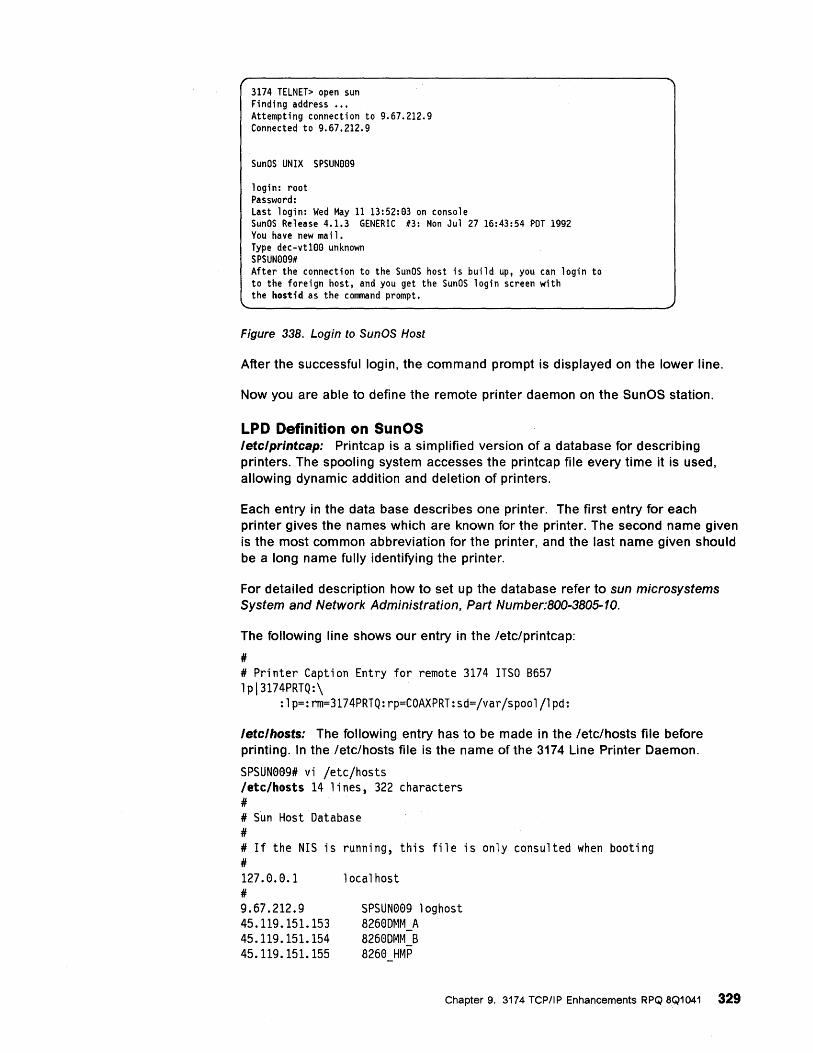
3174 TELNET> open sun Finding address ••• Attempting connection to 9.67.212.9 Connected to 9.67.212.9
SunOS UNIX SPSUN009
login: root Password: Last login: Wed May 11 13:52:03 on console SunOS Release 4.1.3 GENERIC #3: Mon Ju1 27 16:43:54 PDT 1992 You have new mail. Type dec-vt100 unknown SPSUN009# After the connection to the SunOS host is build up, you can login to to the foreign host, and you get the SunOS login screen with the host;d as the command prompt.
Figure 338. Login to SunOS Host
After the successful login, the command prompt is displayed on the lower line.
Now you are able to define the remote printer daemon on the SunOS station.
LPD Definition on SunOS /ete/printeap: Printcap is a simplified version of a database for describing printers. The spooling system accesses the printcap file every time it is used, allowing dynamic addition and deletion of printers.
Each entry in the data base describes one printer. The first entry for each printer gives the names which are known for the printer. The second name given is the most common abbreviation for the printer, and the last name given should be a long name fully identifying the printer.
For detailed description how to set up the database refer to sun microsystems System and Network Administration, Part Number:800-3805-10.
The following line shows our entry in the fetcfprintcap:
# # Printer Caption Entry for remote 3174 ITSO 8657 lpI3174PRTQ:\
:lp=:rm=3174PRTQ:rp=COAXPRT:sd=/var/spool/lpd:
Jete/hosts: The following entry has to be made in the fetefhosts file before printing. In the fetc/hosts file is the name of the 3174 Line Printer Daemon.
SPSUN009# vi /etc/hosts letclhosts 14 lines, 322 characters # # Sun Host Database # # If the N1S ;s running, this file is only consulted when booting # 127.0.0.1 # 9.67.212.9 45.119.151.153 45.119.151.154 45.119.151.155
local host
SPSUN009 loghost 8260DMM A 8260DMM B 8260 HMP
Chapter 9. 3174 TCP/IP Enhancements RPQ 8Q1041 329
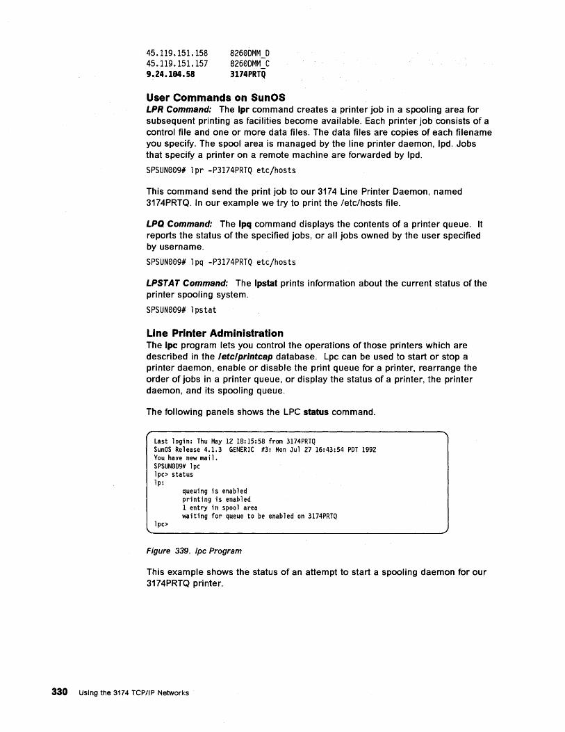
45.119.151.158 45.119.151.157 9.24.184.58
826eDMM D 826eDMM C 3174PRTQ
User Commands on SunOS LPR Command: The Ipr command creates a printer job in a spooling area for subsequent printing as facilities become available. Each printer job consists of a control file and one or more data files. The data files are copies of each filename you specify. The spool area is managed by the line printer daemon, Ipd. Jobs that specify a printer on a remote machine are forwarded by Ipd.
SPSUNee9# lpr -P3174PRTQ etc/hosts
This command send the print job to our 3174 Line Printer Daemon, named 3174PRTQ. In our example we try to print the /etc/hosts file.
LPQ Command: The Ipq command displays the contents of a printer queue. It reports the status of the specified jobs, or all jobs owned by the user specified by username.
SPSUNee9# lpq -P3174PRTQ etc/hosts
LPSTAT Command: The Ipstat prints information about the current status of the printer spooling system.
SPSUNee9# lpstat
Line Printer Administration The Ipc program lets you control the operations of those printers which are described in the letclprintcap database. Lpc can be used to start or stop a printer daemon, enable or disable the print queue for a printer, rearrange the order of jobs in a printer queue, or display the status of a printer, the printer daemon, and its spooling queue.
The following panels shows the LPC status command.
Last login: Thu May 12 18:15:58 from 3174PRTQ SunOS Release 4.1.3 GENERIC #3: Mon Ju1 27 16:43:54 PDT 1992 You have new mail. SPSUNee9# 1pc 1pc> status 1p:
1pc>
queuing is enabled printing is enabled 1 entry in spool area waiting for queue to be enabled on 3174PRTQ
Figure 339. fpc Program
This example shows the status of an attempt to start a spooling daemon for our 3174PRTQ printer.
330 Using the 3174 TCP/IP Networks
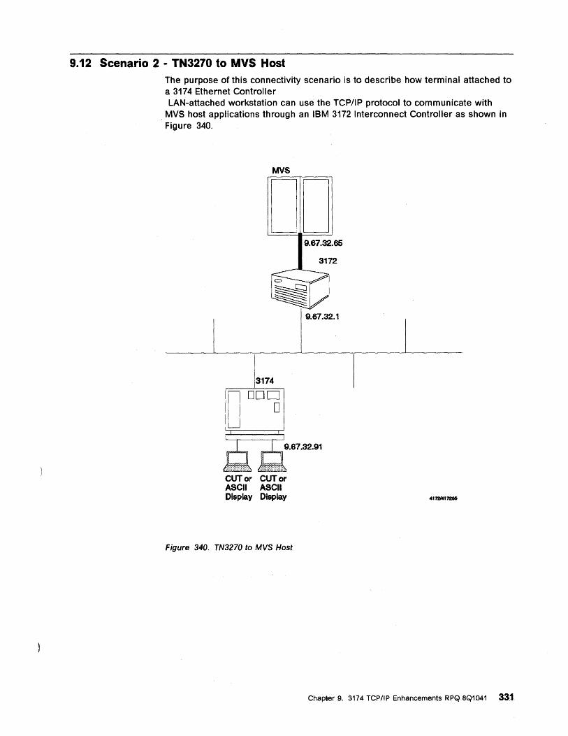
9.12 Scenario 2 - TN3270 to MVS Host The purpose of this connectivity scenario is to describe how terminal attached to a 3174 Ethernet Controller LAN-attached workstation can use the TCP/IP protocol to communicate with
MVS host applications through an IBM 3172 Interconnect Controller as shown in Figure 340.
MVS
DD
D 3174
DOD o
CUT or CUT or ASCII ASCII Display Display
Figure 340. TN3270 to MVS Host
9.67.32.65
3172
Chapter 9. 3174 TCP/IP Enhancements RPQ 8Q1041 331
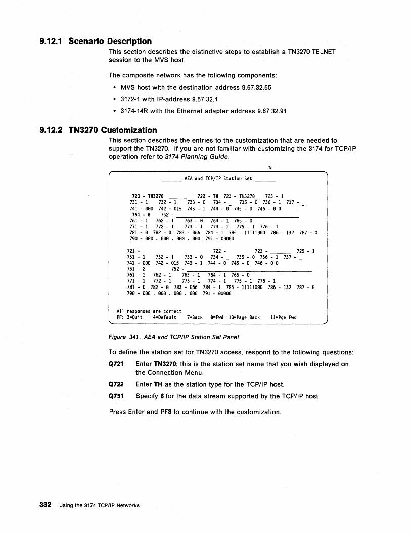
9.12.1 Scenario Description This section describes the distinctive steps to establish a TN3270 TELNET session to the MVS host.
The composite network has the following components:
• MVS host with the destination address 9.67.32.65
• 3172-1 with IP-address 9.67.32.1
• 3174-14R with the Ethernet adapter address 9.67.32.91
9.12.2 TN3270 Customization This section describes the entries to the customization that are needed to support the TN3270. If you are not familiar with customizing the 3174 for TCP/IP operation refer to 3174 Planning Guide.
___ AEA and TCPjIP Station Set __ _
721 - TN3270 722 - TH 723 - TN327e 725 - 1 731 - 1 732 -----1----733 - e 734 - 735 - e- 736 - 1 737-741 - eee 742 - e15 743 - 1 744 - e- 745 - e 746 - e e 751 - 6 752 -
761 - 1 762 - 1 -::':76':'"::'3---e=-, ~7~64:---~1-::-:76=5---e=-, ------771 - 1 772 - 1 773 - 1 774 - 1 775 - 1 776 - 1 781 - e 782 - e 783 - e66 784 - 1 785 - llllleee 786 - 132 787 - e 7ge - eee • eee • eee • eee 791 - eeeee
721 - 722 - 723 - 725 - 1 731 - 1 732 - 1 733 - e 734 - _ 735 - e 736 - 1 737-741 - eee 742 - e15 743 - 1 744 - e 745 - e 746 - e e 751 - 2 752 -761 - 1 762 - 1 76':""3 --~I:---~76':""4----:-1---::-76:-::5----:-e --------771 - 1 772 - 1 773 - 1 774 - 1 775 - 1 776 - 1 781 - e 782 - e 783 - e66 784 - 1 785 - l1111eee 786 - 132 787 - e 7ge - eee • eee • eee • eee 791 - eeeee
All responses are correct PF: 3=Quit 4=Default 7=Back 8=Fwd le=Page Back II=Pge Fwd
Figure 341. AEA and TCP/IP Station Set Panel
To define the station set for TN3270 access, respond to the following questions:
Q721 Enter TN3270; this is the station set name that you wish displayed on the Connection Menu.
Q722 Enter TH as the station type for the TCP/I P host.
Q751 Specify 6 for the data stream supported by the TCP/IP host.
Press Enter and PF8 to continue with the customization.
332 Using the 3174 TCPIIP NetworkS
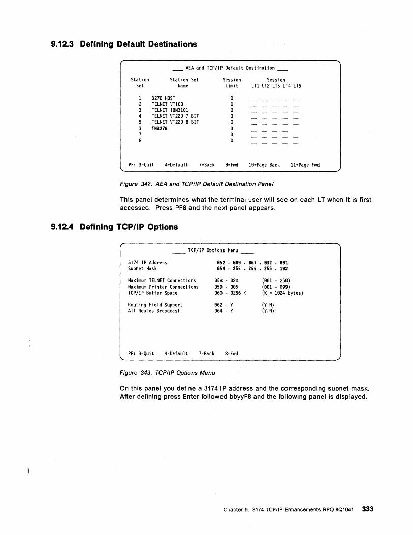
9.12.3 Defining Default Destinations
____ AEA and TCP/IP Default Destination ____
Station Station Set Session Session Set Name Limit LTl LT2 LT3 LT4 LT5
1 3270 HOST 0 2 TELNET VT100 0 3 TELNET IBM3lel 0 4 TELNET VT220 7 BIT 0 5 TELNET VT220 8 BIT 0 1 TN3270 0 7 0 8 0
PF: 3=Quit 4=Default 7=Back 8=Fwd l0=Page Back 11=Page Fwd
Figure 342. AEA and TCP/IP Default Destination Panel
This panel determines what the terminal user will see on each L T when it is first accessed. Press PFS and the next panel appears.
9.12.4 Defining TCP/IP Options
__ TCP/IP Options Menu __
3174 IP Address Subnet Mask
Maximum TELNET Connections Maximum Printer Connections TCP/IP Buffer Space
Routing Field Support All Routes Broadcast
052 - 009 • 067 • 032 • 091 054 - 255 • 255 • 255 • 192
058 - 020 059 - 005 060 - 0256 K
062 - Y 064 - Y
(001 - 250) (001 - 099) (K = 1I:l24 bytes)
(Y,N) (Y,N)
PF: 3=Quit 4=Default 7=Back 8=Fwd
Figure 343. TCP/IP Options Menu
On this panel you define a 3174 IP address and the corresponding subnet mask. After defining press Enter followed bbyyFS and the following panel is displayed.
Chapter 9. 3174 TCP/IP Enhancements RPQ 8Q1041 333
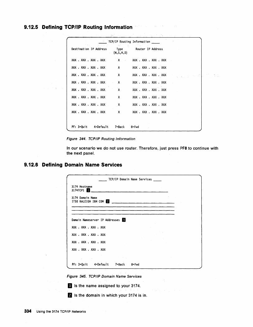
9.12.5 Defining TCP/IP Routing Information
__ . TCPjIP Routing Infonnation __
Destination IP Address Type Router IP Address (N,S,H,D)
XXX • XXX • XXX • XXX X XXX • XXX • XXX • XXX
XXX • XXX • XXX • XXX X XXX • XXX • XXX • XXX
XXX • XXX • XXX • XXX X XXX • XXX • XXX • XXX
XXX • XXX • XXX • XXX X XXX • XXX • XXX • XXX
XXX • XXX • XXX • XXX X XXX • XXX • XXX • XXX
XXX • XXX • XXX • XXX X XXX • XXX • XXX • XXX
XXX • XXX • XXX • XXX X XXX • XXX • XXX • XXX
XXX • XXX • XXX • XXX X XXX • XXX • XXX • XXX
PF: 3=Quit 4=Default 7=Back 8= Fwd
Figure 344. TCP/IP Routing Information
In our scenario we do not use router. Therefore, just press PF8 to continue with the next panel.
9.12.6 Defining Domain Name Services
__ TCPjIP Domain Name Services __
3174 Hostname 3174TCP1 D _______________ _
3174 Domain Name ITSe RALEIGH IBM COM fJ ____________ _
Domain Nameserver IP Addresses II XXX • XXX • XXX • XXX
XXX • XXX • XXX • XXX
XXX • XXX • XXX • XXX
XXX • XXX • XXX • XXX
PF: 3=Quit 4=Default 7=Back 8= Fwd
Figure 345. TCP/IP Domain Name Services
D Is the name assigned to your 3174.
II Is the domain in which your 3174 is in.
334 Using the 3174 TCPIIP Networks
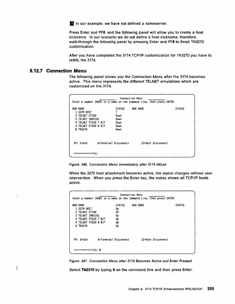
IJ In our example, we have not defined a nameserver.
Press Enter and PF8, and the followin~ panel will allow you to create a host nickname. In our scenario we do not define a host nickname; therefore, walk-through the following panel by pressing Enter and PF8 to finish TN3270 cu stom ization.
After you have completed the 3174 TCP/IP customization for TN3270 you have to relML the 3174.
9.12.7 Connection Menu The following panel shows you the Connection Menu after the 3174 becomes active. This menu represents the different TELNET emulations which are customized on the 3174.
Connection Menu Enter a number (NUM) or a name on the Command Line, then press ENTER
NUM NAME STATUS NUM NAME STATUS 1 327e HOST ? 2 TELNET vnee Down 3 TELNET IBM31el Down 4 TELNET VT22e 7 BIT Down 5 TELNET VT22e 8 BIT Down 6 TN327e Down
PF: 3=End 6=Terminal Disconnect 12=Host Disconnect
============>To:
Figure 346. Connection Menu Immediately after 3174 IMLed
When the 3270 host attachment becomes active, the status changes without user intervention. When you press the Enter key, the status shows all TCP/IP hosts active.
Connection Menu Enter a number (NUM) or a name on the Command Line, then press ENTER
NUM NAME 1 327e HOST 2 TELNET vnee 3 TELNET IBM31el 4 TELNET VT22e 7 BIT 5 TELNET VT22e 8 BIT 6 TN327e
STATUS Up UP Up Up Up Up
PF: 3=End 6=Terminal Disconnect
============>To: 6
NUM NAME
12=Host Disconnect
STATUS
Figure 347. Connection Menu after 3174 Becomes Active and Enter Pressed
Select TN2370 by typing 6 on the command line and then press Enter.
Chapter 9. 3174 TCP/IP Enhancements RPQ 8Q1041 335
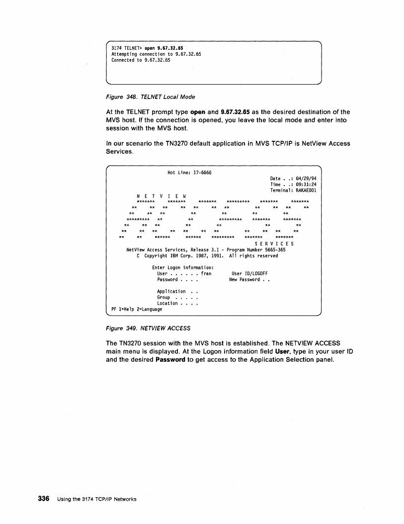
3174 TELNET> open 9.67.32.65 Attempting connection to 9.67.32.65 Connected to 9.67.32.65
Figure 348. TELNET Local Mode
At the TELNET prompt type open and 9.67.32.65 as the desired destination of the MVS host. If the connection is opened, you leave the local mode and enter into session with the MVS host.
In our scenario the TN3270 default application in MVS TCP/IP is NetView Access Services.
Hot Line: 17-6666 Date •• : 94/29/94 Time •. : 99:31:24 Terminal: RAKAE991
NET V lEW ******* ******* ******* ********* ******* *******
** **
** ** ** **
** ** ** **
** ** **
********* ** **
** **
** ** ** **
** ** **
** **
** *********
** *******
** *******
** ** ** ** ** ** ** **
** ****** ****** ********* ******* ******* S E R V ICE S
NetView Access Services, Release 3.1 - Program Number 5665-365 C Copyright IBM Corp. 1987, 1991. All rights reserved
Enter Logon information: User • • • • fran Password ••
Application Group . Location
PF l=Help 2=Language
Figure 349. NETVIEW ACCESS
User ID/LOGOFF New Password • •
**
**
The TN3270 session with the MVS host is established. The NETVIEW ACCESS main menu is displayed. At the Logon information field User, type in your user 10 and the desired Password to get access to the Application Selection panel.
336 Using the 3174 TCP/IP Networks
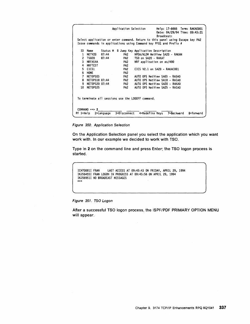
Application Selection Help: 17-6666 Term: RAKAE001 Date: 04/29/94 Time: 09:43:21 Broadcast:
Select application or enter command. Return to this panel using Escape key PA2 Issue commands in applications using Command key PF01 and Prefix #
10 Name Status M 1 NETV20 07:44 2 TS020 07:44 3 NRFAS4A 4 NRFTEST 5 CICS1 6 HONE 7 NETOPS03 8 NETOPS18 07:44 9 NETOPS20 07:44
10 NETOPS25
B Jump Key Application Description PA2 NPDA/NLDM NetView SA20 - RAKAN PA2 TSO on SA20 - RAKAT PA2 NRF application on as/400 PA2 PA2 PA2 PA2 PA2 PA2 PA2
CICS V2.1 on SA20 - RAKAC001
AUTO OPS NetView SA03 - RA3AO AUTO OPS NetView SA18 - RAIAO AUTO OPS NetView SA20 - RAKAO AUTO OPS NetView SA25 - RAIAO
To terminate all sessions use the LOGOFF command.
COMMAND ==> 2 ____ _ PF l=Help 2=Language 3=Disconnect 4=Redefine Keys 7=Backward 8=Forward
Figure 350. Application Selection
On the Application Selection panel you select the application which you want work with. In our example we decided to work with TSO.
Type in 2 on the command line and press Enter; the TSO logon process is started.
ICH70001I FRAN LAST ACCESS AT 99:45:43 ON FRIDAY, APRIL 29, 1994 IKJ56455I FRAN LOGON IN PROGRESS AT 99:45:56 ON APRIL 29, 1994 IKJ56951I NO BROADCAST MESSAGES ***
Figure 351. TSO Logon
After a successful TSO logon process, the ISPF/PDF PRIMARY OPTION MENU will appear.
Chapter 9. 3174 TCPIIP Enhancements RPQ 8Q1041 337
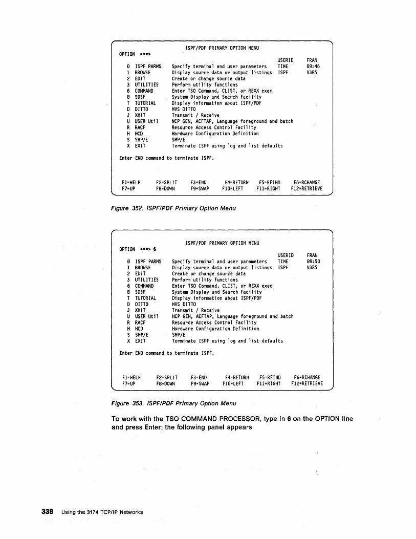
OPTION ===>
a ISPF PARMS I BROWSE 2 EDIT 3 UTILITIES 6 COMMAND a SDSF T TUTORIAL o DITTO J XMIT U USER Util R RACF H HCD S SMP/E X EXIT
ISPF/PDF PRIMARY OPTION MENU
Specify terminal and user parameters Display source data or output listings Create or change source data Perform utility functions Enter TSO Command, CLIST, or REXX exec System Display and Search Facility Display information about ISPF/PDF MVS DITTO Transmit / Receive
USERID TIME ISPF
NCP GEN, ACFTAP, Language foreground and batch Resource Access Control Facility Hardware Configuration Definition SMP/E Terminate ISPF using log and list defaults
Enter END command to terminate ISPF.
FRAN a9:46 V3R5
Fl=HELP F7=UP
F2=SPLIT Fa=DOWN
F3=END F9=SWAP
F4=RETURN F5=RFIND Fla=LEFT FII=RIGHT
F6=RCHANGE Fl2=RETRI EVE
Figure 352. ISPFIPDF Primary Option Menu
OPTION ===> 6
a ISPF PARMS I BROWSE 2 EDIT 3 UTILITIES 6 COMMAND a SDSF T TUTORIAL o DITTO J XMIT U USER Util R RACF H HCD S SMP/E X EXIT
ISPF/PDFPRIMARY OPTION MENU
Specify terminal and user parameters Display source data or output listings Create or change source data Perform utility functions Enter TSO Command, CLIST, or REXX exec System Display and Search Facility Display information about ISPF/PDF MVS DITTO Transmit / Receive
USERID TIME ISPF
NCP GEN, ACFTAP, Language foreground and batch Resource Access Control Facility Hardware Configuration Definition SMP/E Terminate ISPF using log and list defaults
Enter END command to terminate ISPF.
FRAN 99:59 V3R5
Fl=HELP F7=UP
F2=SPLIT Fa-DOWN
F3=END F9=SWAP
F4=RETURN F5=RFIND FIO=LEFT Fl1=RIGHT
F6=RCHANGE Fl2=RETRI EVE
Figure 353. ISPFIPDF Primary Option Menu
To work with the TSO COMMAND PROCESSOR, type in 6 on the OPTION line and press Enter; the following panel appears.
338 Using the 3174 TCP/IP Networks
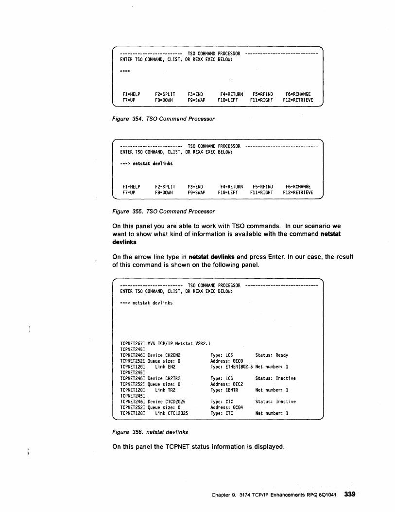
------------------------- TSO COMMAND PROCESSOR ----------------------------ENTER TSO COMMAND, CLIST, OR REXX EXEC BELOW:
===>
F1=HELP F7=UP
F2=SPLIT F8=DOWN
F3=END F9=SWAP
F4=RETURN F5=RFIND F6-RCHANGE F10=LEFT Fll=RIGHT F12-RETRIEVE
Figure 354. TSO Command Processor
------------------------- TSO COMMAND PROCESSOR ----------------------------ENTER TSO COMMAND, CLIST, OR REXX EXEC BELOW:
===> netstat devl;nks
F1=HELP F7=UP
F2=SPLIT F8=DOWN
F3=END F9=SWAP
F4=RETURN F5-RFIND F6=RCHANGE F10=LEFT Fll-RIGHT F12=RETRIEVE
Figure 355. TSO Command Processor
On this panel you are able to work with TSO commands. In our scenario we want to show what kind of information is available with the command netstat devlinks
On the arrow line type in netstat devlinks and press Enter. In our case, the result of this command is shown on the following panel.
------------------------- TSO COMMAND PROCESSOR ----------------------------ENTER TSO COMMAND, CLIST, OR REXX EXEC BELOW:
===> netstat devlinks
TCPNET267I MVS TCP/IP Netstat V2R2.1 TCPNET245I TCPNET246I Device CH2EN2 TCPNET252I Queue size: 0 TCPNET120I Link EN2 TCPNET245I TCPNET246I Device CH2TR2 TCPNET252I Queue size: 0 TCPNET120I Link TR2 TCPNET245I TCPNET246I Device CTCD2025 TCPNET252I Queue size: 0 TCPNET120I Link CTCL2025
Figure 356. netstat devlinks
Type: LCS Status: Ready Address: OECO Type: ETHERI802.3 Net number: 1
Type: LCS Address: OEC2 Type: IBMTR
Type: CTC Address: OC04 Type: CTC
Status: Inactive
Net number: 1
Status: Inactive
Net number: 1
On this panel the TCPNET status information is displayed.
Chapter 9. 3174 TCP/IP Enhancements RPQ 8Q1041 339·
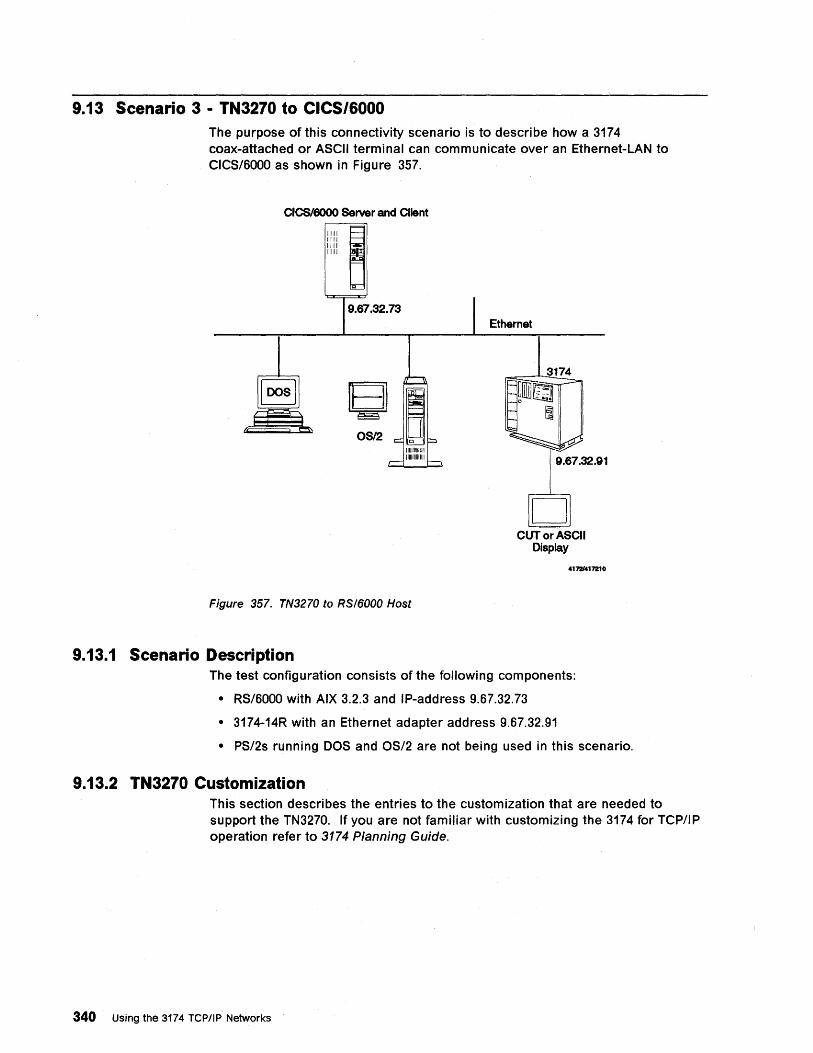
9.13 Scenario 3 - TN3270 to CICS/6000 The purpose of this connectivity scenario is to describe how a 3174 coax-attached or ASCII terminal can communicate over an Ethernet-LAN to CICS/6000 as shown in Figure 357.
CICSl6000 Server and Client
1111 ~ 1111 1111 1111
o
9.67.32.73
111111111111111 111111111111111
Figure 357. TN3270 to RSI6000 Host
9.13.1 Scenario Description
Ethernet
9.67.32.91
CUT or ASCII Display
41721417210
The test configuration consists of the following components:
• RS/6000 with AIX 3.2.3 and IP-address 9.67.32.73
• 3174-14R with an Ethernet adapter address 9.67.32.91
• PS/2s running DOS and OS/2 are not being used in this scenario.
9.13.2 TN3270 Customization This section describes the entries to the customization that are needed to support the TN3270. If you are not familiar with customizing the 3174 for TCP/IP operation refer to 3174 Planning Guide.
340 Using the 3174 TCPIIP Networks
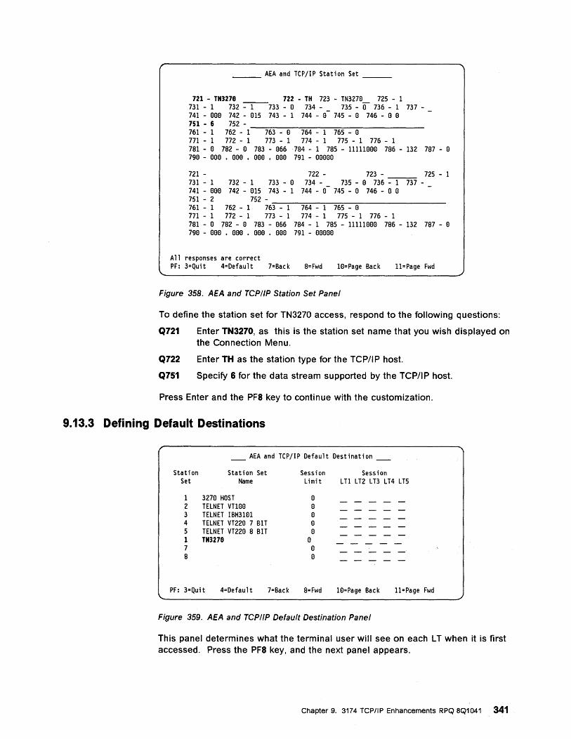
___ AEA and TCPjIP Station Set __ _
721 - TN3279 722 - TH 723 - TN327a 725 - 1 731 - 1 732 -----1----733 - a 734 - _ 735 - 01 736 - 1 737-741 - Bee 742 - a15 743 - 1 744 - a 745 - a 746 - a a 751 - 6 752 - _______________ ____ 761 - 1 762 - 1 763 - a 764 - 1 765 - a 771 - 1 772 - 1 773 - 1 774 - 1 775 - 1 776 - 1 781 - a 782 - a 783 - a66 784 - 1 785 - l1111aaa 786 - 132 787 - a 79a - aee • aee • eae • eaa 791 - aeeea
721 - 722 - 723 - 725 - 1 731 - 1 732 - 1 733 - a 734 - _ 735 - a 736 - 1 737-741 - aaa 742 - a15 743 - 1 744 - a 745 - a 746 - a a 751 - 2 752 - _______________ _ 761 - 1 762 - 1 763 - 1 764 - 1 765 - a 771 - 1 772 - 1 773 - 1 774 - 1 775 - 1 776 - 1 781 - a 782 - a 783 - a66 784 - 1 785 - l1111aaa 786 - 132 787 - a 79a - aaa • aaa . Bee . aaa 791 - aaaaa
All responses are correct PF: 3=Quit 4=Default 7=Back 8= Fwd la=Page Back II=Page Fwd
Figure 358. AEA and TCPIIP Station Set Panel
To define the station set for TN3270 access, respond to the following questions:
Q721 Enter TN3270, as this is the station set name that you wish displayed on the Connection Menu.
Q722 Enter TH as the station type for the TCP/I P host.
Q751 Specify 6 for the data stream supported by the TCP/I P host.
Press Enter and the PF8 key to continue with the customization.
9.13.3 Defining Default Destinations
____ AEA and TCPjIP Default Destination ____
Station Station Set Session Session Set Name Limit LTI LT2 LT3 LT4 LT5
1 327a HOST a 2 TELNET vnaa a 3 TELNET IBM31al a 4 TELNET VT22a 7 BIT a 5 TELNET VT22a 8 BIT a 1 TN3279 a 7 a 8 a
PF: 3=Qui t 4=Defaul t 7=Back 8=Fwd W=Page Back l1=Page Fwd
Figure 359. AEA and TCPIIP Default Destination Panel
This panel determines what the terminal user will see on each L T when it is first accessed. Press the PF8 key, and the next panel appears.
Chapter 9. 3174 TCP/IP Enhancements RPQ 8Q1041 341
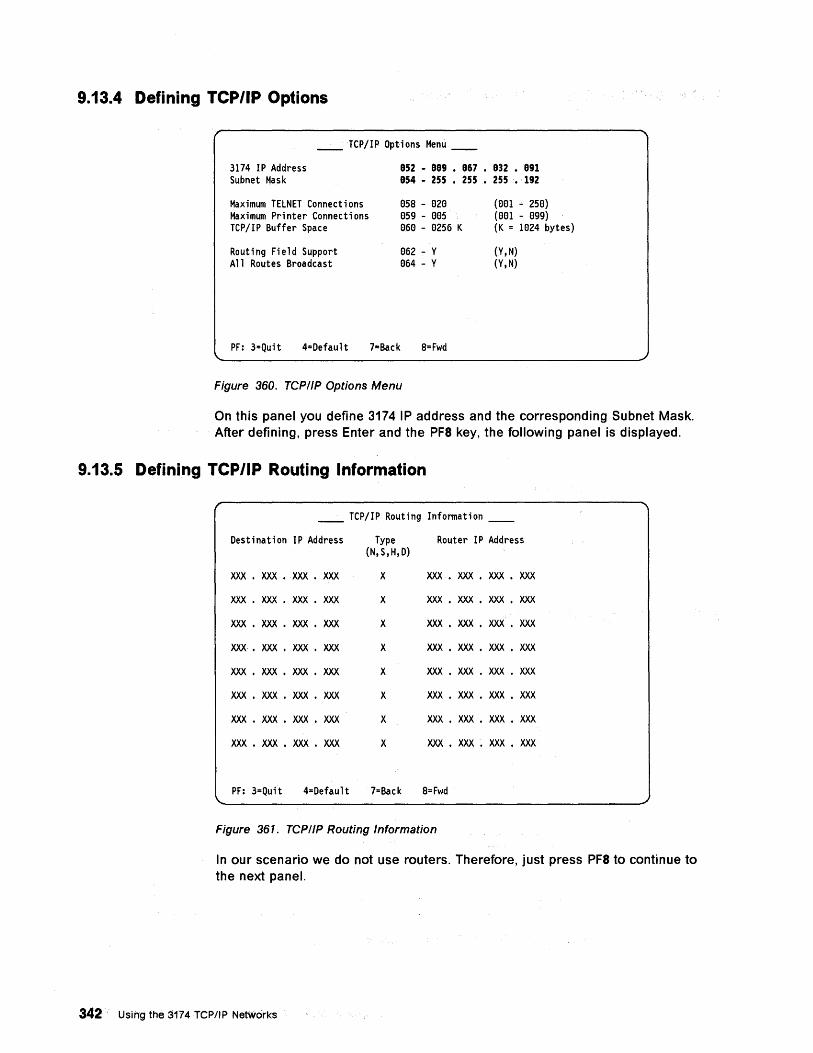
9.13.4 Defining TCP/IP Options
__ TCP/IP Options Menu __
3174 IP Address Subnet Mask
Maximum TELNET Connections Maximum Printer Connections TCP/IP Buffer Space
Routing Field Support All Routes Broadcast
852 - 889 • 867 • 832 • 891 854 - 255 • 255. 255. 192
GSS - G2G GS9 - GGS e6e - e2S6 K
G62 - Y G64 - Y
(eel - 25e) (eel - e99) (K = 1e24 bytes)
(Y,N) (Y,N)
PF: 3=Quit 4=Default 7=Back S=Fwd
Figure 360. TCPIIP Options Menu
On this panel you define 3174 IP address and the corresponding Subnet Mask. After defining, press Enter and the PF8 key, the following panel is displayed.
9.13.5 Defining TCP/IP Routing Information
__ TCP/IP Routing Information __
Destination IP Address Type Router IP Address (N,S,H,D)
XXX • XXX • XXX • XXX X XXX • XXX • XXX • XXX
XXX • XXX • XXX • XXX X XXX • XXX • XXX • XXX
XXX • XXX • XXX • XXX X XXX • XXX • XXX • XXX
XXX. XXX • XXX. XXX X XXX • XXX • XXX • XXX
XXX • XXX • XXX • XXX X XXX • XXX • XXX • XXX
XXX • XXX • XXX • XXX X XXX • XXX • XXX • XXX
XXX • XXX • XXX • XXX X XXX • XXX • XXX • XXX
XXX • XXX • XXX • XXX X XXX • XXX • XXX • XXX
PF: 3=Quit 4=Default 7=Back S=Fwd
Figure 361. TCPIIP Routing Information
In our scenario we do not use routers. Therefore, just press PF8 to continue to the next panel.
342 Using the 3174 TCPIIP Networks
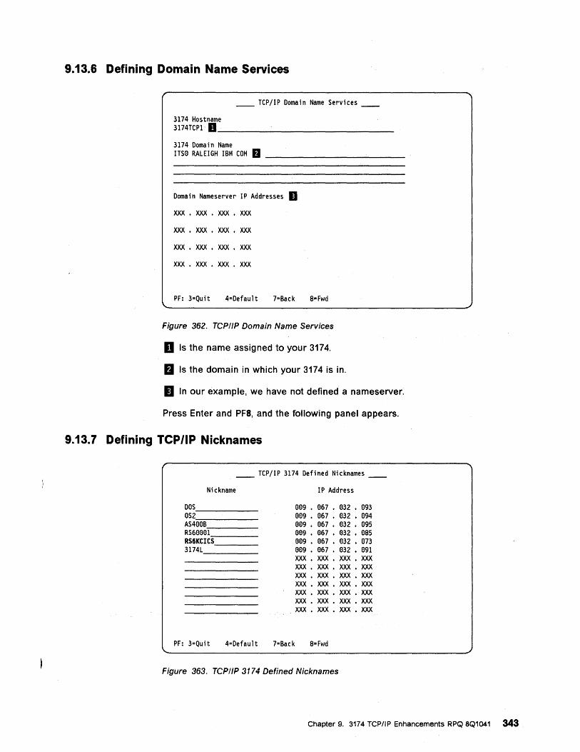
9.13.6 Defining Domain Name Services
__ TCPjlP Domain Name Services __
3174 Hostname 3174TCP1 D _______________ _
3174 Domain Name ITSe RALEIGH IBM COM fJ ____________ _
Doma i n Nameserver I P Addresses II xxx . XXX • XXX • XXX
xxx . XXX • XXX • XXX
XXX • XXX • xxx . xxx
XXX • XXX • XXX • XXX
PF: 3=Quit 4=Default 7=Back B=Fwd
Figure 362. TCPIIP Domain Name Services
D Is the name assigned to your 3174.
II Is the domain in which your 3174 is in.
a In our example, we have not defined a nameserver.
Press Enter and PF8, and the following panel appears.
9.13.7 Defining TCP/IP Nicknames
__ TCPjlP 3174 Defined Nicknames __
Nickname
DOS _____ _
OS2 AS4'-ee-· B-----
RS6eee1~ __ _ RS6KCICS, ___ _ 3174L, ____ _
IP Address
0e9 • e67 • 032 • e93 ee9 • e67 • e32 • e94 e09 • 067 • e32 • e95 ee9 • e67 • e32 • ess ee9 • e67 • e32 • e73 ee9 • e67 • e32 • e91 XXX • XXX • XXX • XXX XXX • XXX • XXX • XXX XXX. XXX • XXX • XXX XXX • XXX • XXX • XXX XXX • XXX • XXX • XXX XXX • XXX • XXX • XXX XXX • XXX • XXX • XXX
PF: 3=Quit 4=Default 7=Back S=Fwd
Figure 363. TCPIIP 3174 Defined Nicknames
Chapter 9. 3174 TCP/IP Enhancements RPQ 8Q1041 343
Since users remember names better than numericlP addresses, this panel allows you to define up to 16 host nicknames and their associated IP addresses. In our scenario we defined RS6KCICS as the nickname. After defining the nickname, press Enter and PF8.
After you have completed the 3174 TCP/IP customization for TN3270, yo have to relML the 3174.
9.13.8 CICS/6000 Overview CICS/6000 is the latest member of the CICS product family. It extends the distributed processing capabilities of CICS to the AIX environment. Like existing CICS products that run on the MVS, VSE, OS/2, and OS/400 platforms, CICS/6000 requires prerequisite products in order for it to function. In the case of CICS/6000 the prerequisite products are Distributed Computing Environment (DCE) and Encina. The name Encina is derived from Enterprise Computing in a New Age.
DCE is prerequisite to both CICS/6000 and Encina, because it provides a common infrastucture for distributed processing. CICS/6000 is the transaction monitor that enables transaction processing, resource management, and communication with other CICS family members.
For detailed information about the CICS/6000 environment refer to AIX CICS/60D0 Installation and Configuration: A Guide to Implementation, GG24-4091-OO.
9.13.9 CICS/6000 Environment Before you are able to communicate with TN3270 from a 3174 CUT or ASCII terminal to CICS/6000 be sure that the following steps have been taken on the CICS/6000 system:
• Install the CICS/6000 products.
• Configure a region.
• Create users.
• Customize the environment.
• Define a separate CICS/6000 client machine.
• Enable access from remote machines through a TCP/IP LAN.
For a detailed description about this procedures refer to Chapter 4 of AIX CICS/60D0 Installation and Configuration: A Guide to Implementation, GG24-4091-OO.
344 . Using the 3174 TCPIIP Networks
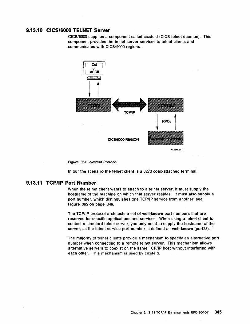
9.13.10 CICS/6000 TELNET Server CICS/6000 supplies a component called cicsteld (CICS telnet daemon). This component provides the telnet server services to telnet clients and communicates with CICS/6000 regions.
~ or ASCII
- •• ---CICS/6000 REGION
41721417211
Figure 364. cicsteld Protocol
In our the scenario the telnet client is a 3270 coax-attached terminal.
9.13.11 TCP/IP Port Number When the telnet client wants to attach to a telnet server, it must supply the hostname of the machine on which that server resides. It must also supply a port number, which distinguishes one TCPIIP service from another; see Figure 365 on page 346.
The TCP/IP protocol architects a set of well-known port numbers that are reserved for specific applications and services. When using a telnet client to contact a standard telnet server, you only need to supply the hostname of the server, as the telnet service port number is defined as well-known (port23).
The majority of telnet clients provide a mechanism to specify an alternative port number when connecting to a remote telnet server. This mechanism allows alternative servers to coexist on the same TCPIIP host without interfering with each other. This mechanism is used by cicsteld.
Chapter 9. 3174 TCPIIP Enhancements RPQ 8Q1041 345
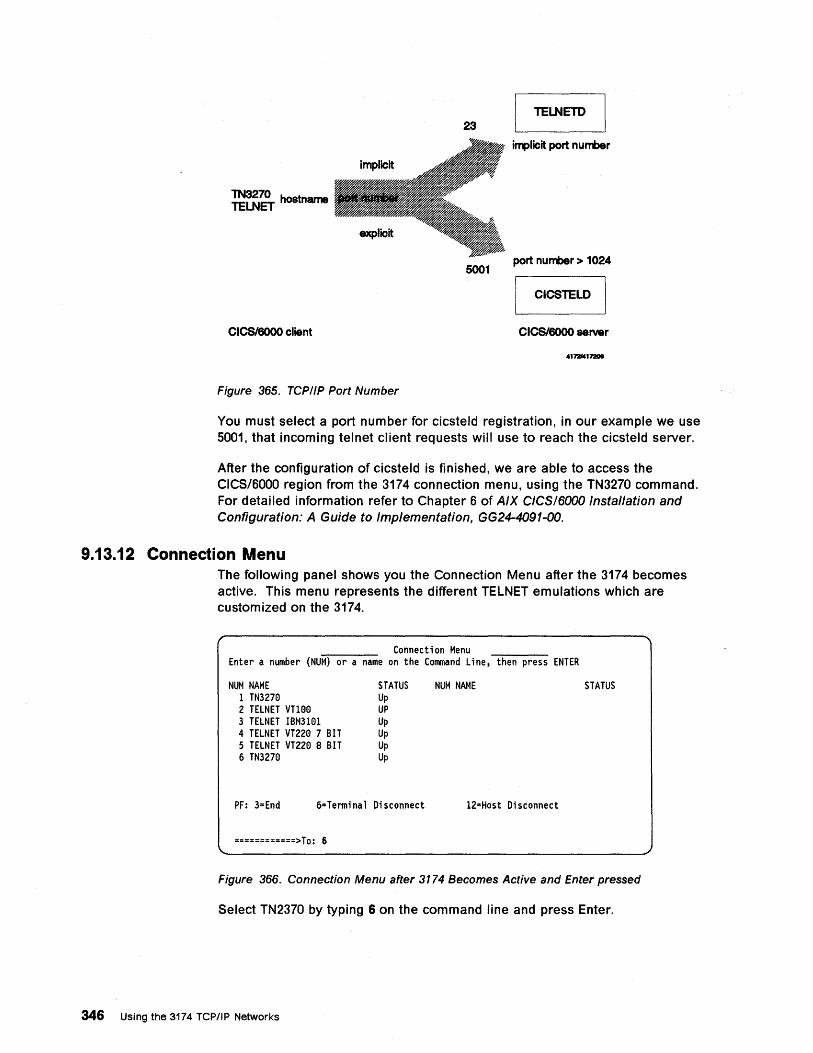
Thl3270 hostname TELNET
CICSI6000 client
Figure 365. TCPIIP Port Number
23
5001
TELNETD
i"1'licit port number
port number> 1024
CICSTELD I
CICS/6000 server
41721417200
You must select a port number for cicsteld registration, in our example we use 5001, that incoming telnet client requests will use to reach the cicsteld server.
After the configuration of cicsteld is finished, we are able to access the CICS/6000 region from the 3174 connection menu, using the TN3270 command. For detailed information refer to Chapter 6 of AIX CICSI6000 Installation and Configuration: A Guide to Implementation, GG24-4091-00.
9.13.12 Connection Menu The following panel shows you the Connection Menu after the 3174 becomes active. This menu represents the different TELNET emulations which are customized on the 3174.
Connection Menu Enter a number (NUM) or a name on the Command Line, then press ENTER
NUM NAME 1 TN3270 2 TELNET VTHl0 3 TELNET IBM3101 4 TELNET VT220 7 BIT 5 TELNET VT220 8 BIT 6 TN3270
STATUS Up UP Up Up Up Up
PF: 3=End 6=Terminal Disconnect
============>To: 6
NUM NAME
12=Host Disconnect
STATUS
Figure 366. Connection Menu after 3174 Becomes Active and Enter pressed
Select TN2370 by typing 6 on the command line and press Enter.
346 Using the 3174 TCP/IP Networks
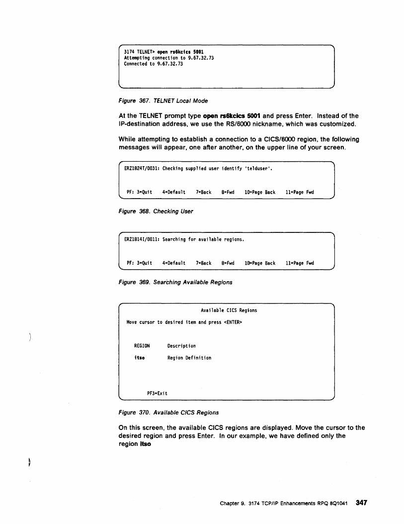
3174 TELNET> open rs6kcics 5881 Attempting connection to 9.67.32.73 Connected to 9.67.32.73
Figure 367. TELNET Local Mode
At the TELNET prompt type open rs6kclcs 5001 and press Enter. Instead of the IP-destination address, we use the RS/SOOO nickname, which was customized.
While attempting to establish a connection to a CICS/SOOO region, the following messages will appear, one after another, on the upper line of your screen.
ERZ1824T/ee3l: Checking supplied user identify 'telduser'.
PF: 3=Quit 4=Default 7-Back 8-Fwd lezpage Back ll-Page Fwd
Figure 368. Checking User
ERZ18l4I/eell: Searching for available regions.
PF: 3-Quit 4=Default 7-Back 8= Fwd le-Page Back ll-Page Fwd
Figure 369. Searching Available Regions
Available CICS Regions
Move cursor to desired item and press <ENTER>
REGION Description
itso Region Definition
PF3-Exit
Figure 370. Available CICS Regions
On this screen, the available CICS regions are displayed. Move the cursor to the desired region and press Enter. In our example, we have defined only the region Itso
Chapter 9. 3174 TCPIIP Enhancements RPQ 8Q1041 347
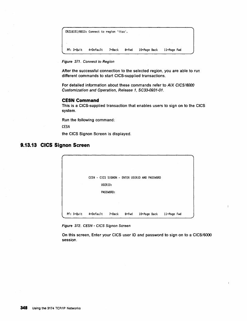
ERZ1815Ij0013: Connect to region 'itso'.
PF: 3=Quit 4=Default 7=Back 8= Fwd 10=Page Back 11=Page Fwd
Figure 371. Connect to Region
After the successful connection to the selected region, you are able to run different commands to start CICS-supplied transactions.
For detailed information about these commands refer to AIX CICSI6000 Customization and Operation, Release " SC33-0931-01.
CESN Command This is a CICS-supplied transaction that enables users to sign on to the CICS system.
Run the following command:
CESN
the CICS Signon Screen is displayed.
9.13.13 CICS Signon Screen
CESN - CICS SIGNON - ENTER USERID AND PASSWORD
USERID:
PASSWORD:
PF: 3=Quit 4=Default 7=Back 8=Fwd 10=Page Back 11=Page Fwd
Figure 372. CESN - CICS Signon Screen
On this screen, Enter your CICS user 10 and password to sign on to a CICS/6000 session.
348 Using the 3174 TCPIIP Networks
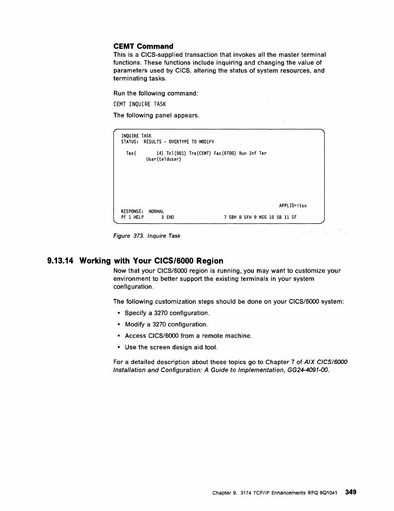
CEMT Command This is a CICS-supplied transaction that invokes all the master terminal functions. These functions include inquiring and changing the value of parameters used by CICS, altering the status of system resources, and terminating tasks.
Run the following command:
CEMT INQUIRE TASK
The following panel appears.
INQUIRE TASK STATUS: RESULTS - OVERTYPE TO MODIFY
Tas( 14) Tcl(eel) Tra(CEMT) Fac(RTee) Run Inf Ter User(telduser)
APPLID=; tso RESPONSE: NORMAL PF 1 HELP 3 END 7 SBH 8 SFH 9 MSG Ie SB 11 SF
Figure 373. Inquire Task
9.13.14 Working with Your CICS/6000 Region Now that your CICS/6000 region is running, you may want to customize your environment to better support the existing terminals in your system config u ration.
The following customization steps should be done on your CICS/6000 system:
• Specify a 3270 configuration.
• Modify a 3270 configuration.
• Access CICS/6000 from a remote machine.
• Use the screen design aid tool.
For a detailed description about these topics go to Chapter 7 of AIX CICSI6000 Installation and Configuration: A Guide to Implementation, GG24-4091-OO.
Chapter 9. 3174 TCP/lPEnhancements RPQ8Q1041 349

350. Using the 3174 TCPIIP Networks
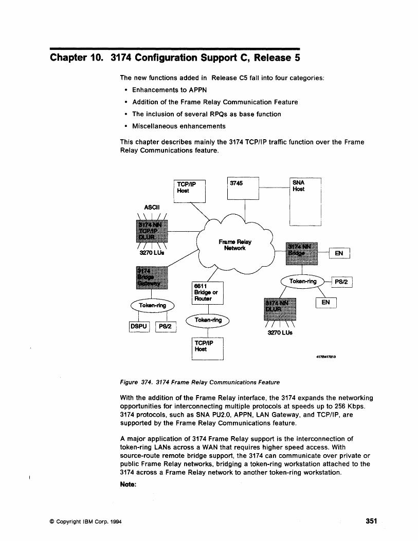
Chapter 10. 3174 Configuration Support C, Release 5
The new functions added in Release C5 fall into four categories:
• Enhancements to APPN
• Addition of the Frame Relay Communication Feature
• The inclusion of several RPQs as base function
• Miscellaneous enhancements
This chapter describes mainly the 3174 TCPIIP traffic function over the Frame Relay Communications feature.
TCPIIP Host
TCPIIP Host
3745
Frame Relay Network
SNA 1-----1 Host
Figure 374. 3174 Frame Relay Communications Feature
4172\0417213
With the addition of the Frame Relay interface, the 3174 expands the networking opportunities for interconnecting multiple protocols at speeds up to 256 Kbps. 3174 protocols, such as SNA PU2.0, APPN, LAN Gateway, and TCP/lP, are supported by the Frame Relay Communications feature.
A major application of 3174 Frame Relay support is the interconnection of token-ring LANs across a WAN that requires higher speed access. With source-route remote bridge support, the 3174 can communicate over private or public Frame Relay networks, bridging a token-ring workstation attached to the 3174 across a Frame Relay network to another token-ring workstation.
Note:
© Copyright IBM Corp. 1994 351
Frame relay remote bridge is not available in Configuration Support-C Release 5. The frame relay remote bridge function is planned for late 1994.
You can create hybrid networks where private and public networks are used (as available) with a single network interface. This will allow you to efficiently and economically expand your business network across town, or across country, while using higher communication speeds.
10.1 .Multiprotocol Frame Relay
10.2 DLCI
10.3 IP Support
The 3174 Frame Relay Communications feature, along with other IBM products, such as the 6611,3745,3172, RouteXpander/2, and AS/400, support RFC 1490 (updated 1294 RFC), a multiprotocol interconnect standard for Frame Relay. This standard establishes a format for transport across a Frame Relay network, so that any other device that meets this standard can read all traffic sent into the network.
The 3174 can support up to 250 Data Link Connection Identifiers (OLCls) with a single access to a private or public Frame Relay network. Multiple OLCls are allowed for each protocol type supported, as well as multiple protocols via one OLCI. The Local Management Interface (LMI), which provides status inquiries between the 3174 and the Frame Relay network, is supported for LMI Rev1, Annex 0, and CCITT formats.
The IP support of Frame Relay allows coax and ASCII terminal users to log on to TCP/IP hosts as TELNET clients over a WAN. The TELNET sessions can co-exist with eXisting 3270 or ASCII host sessions using the Multiple Logical Terminal function. Other basic protocols such as ICMP, UOP and SNMP, are also supported. For IP traffic, the 3174 uses InARP (Inverse ARP) when each OLCI becomes active to determine the remote device's IP address. The 3174 requires its remote partners to reply to InARP requests if they want to talk with the 3174 over Frame Relay.
10.4 Interoperability TCP/IP on the 3174 can use a Frame Relay network to a TCP/IP host or IP router, such as a 6611 or a 3745 using the Frame Relay Handler support in NCP.
10.5 Migration - Coexistence All functions in the previous C releases can coexist with the C5 functions. You can upgrade an existing 3174 to C5 and not lose any current function given you have installed the memory required to handle all the desired function.
Although C4 allowed Ethernet configurations, but not token-ring configurations, C5 allows either one to be configured.
352 Using the 3174 TCP/IP Networks
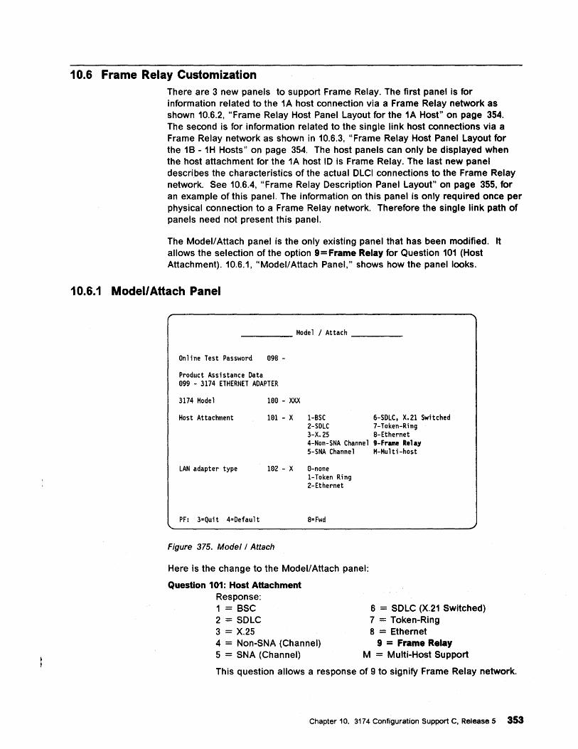
10.6 Frame Relay Customization There are 3 new panels to support Frame Relay. The first panel is for information related to the 1A host connection via a Frame Relay network as shown 10.6.2, "Frame Relay Host Panel Layout for the 1A Host" on page 354. The second is for information related to the single link host connections via a Frame Relay network as shown in 10.6.3, "Frame Relay Host Panel Layout for the 1 B-1 H Hosts" on page 354. The host panels can only be displayed when the host attachment for the 1A host 10 is Frame Relay. The last new panel describes the characteristics of the actual OLCI connections to the Frame Relay network. See 10.6.4, "Frame Relay Description Panel Layout" on page 355, for an example of this panel. The information on this panel is only required once per physical connection to a Frame Relay network. Therefore the single link path of panels need not present this panel.
The Modell Attach panel is the only existing panel that has been modified. It allows the selection of the option 9 = Frame Relay for Question 101 (Host Attachment). 10.6.1, "Modell Attach Panel," shows how the panel looks.
1 0.6.1 Modell Attach Panel
_____ Model I Attach ___ _
Online Test Password 898 -
Product Assistance Data 899 - 3174 ETHERNET ADAPTER
3174 Model 188 - XXX
Host Attachment 181 - X 1-BSC 6-SDLC, X.21 Switched 2-SDLC 7-Token-Ring 3-X.25 8-Ethernet 4-Non-SNA Channel 9-Frame Relay 5-SNA Channel M-Multi-host
LAN adapter type 182 - X 8-none
PF: 3=Quit 4=Default
Figure 375. Model/Attach
1-Token Ring 2-Ethernet
8= Fwd
Here is the change to the Modell Attach panel:
Question 101: Host Attachment Response: 1 = BSC 2 = SOLC 3 = X.25 4 = Non-SNA (Channel) 5 = SNA (Channel)
6 = SOLC (X.21 Switched) 7 = Token-Ring 8 .= Ethernet
9 = Frame Relay M = Multi-Host Support
This question allows a response of 9 to signify Frame Relay network.
Chapter 10. 3174 Configuration Support C, Release 5 353
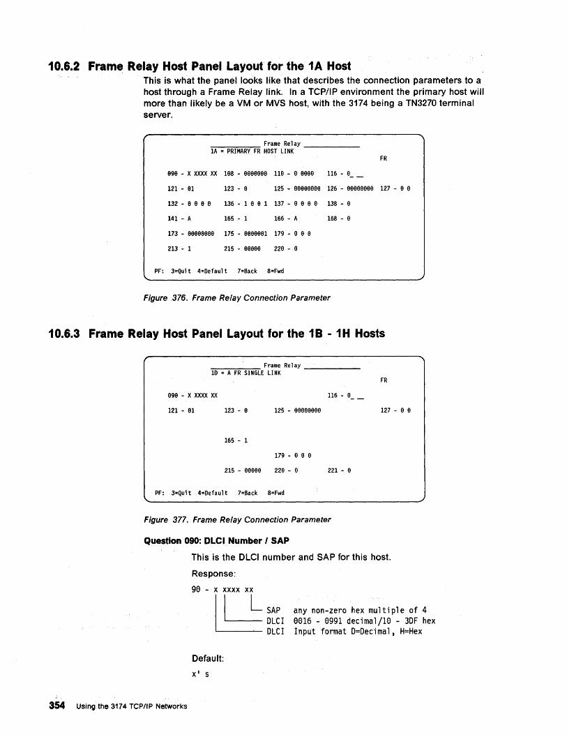
10.6.2 Frame Relay Host Panel Layout for the 1A Host This is what the panel looks like that describes the connection parameters to a host through a Frame Relay link. In a TCP/IP environment the primary host will more than likely be a VM or MVS host, with the 3174 being a TN3270 terminal server.
Frame Relay ""'lA-=-=PR""'IM"""'A=RY-F~R HOST LINK -----
FR
999 - X XXXX XX 1eS - eeeeeee 11e - e aaee 116 - e __
121 - a1 123 - e 125 - aaaeeeee 126 - aaeeeaee 127 - a e
132 - 9 a a a 136 - 1 a e 1 137 - e e e a 138 - e
141 - A 165 - 1 166 - A 168 - a
173 - 9ageaaee 175 - aaeeeel 179 - a e e
213 - 1 215 - aaeee 22a - a
PF: 3=Qui t 4=Default 7=Back S=Fwd
Figure 376. Frame Relay Connection Parameter
10.6.3 Frame Relay Host Panel Layout for the 1 B-1 H Hosts
Frame Relay =ID~=--:-A =FR~SI~NG~LE LINK -----
FR
999 - X XXXX XX
121 - 91 123 - e 125 - eaaeeeaa 127 - a e
165 - 1
179 - e e e
215 - aeaee 229 - 9 221 - 9
PF: 3=Quit 4=Default 7=Back 8=Fwd
Figure 377. Frame Relay Connection Parameter
Question 090: DLCI Number I SAP
This is the OlCI number and SAP for this host.
Response:
354 Using the 3174 TCPIIP Networks
90 - x xxxx xx
l1d=L SAP ~OLCI
OLCI
Default:
Xl S
any non-zero hex multiple of 4 0016 - 0991 decimal/10 - 30F hex Input format O=Oecimal, H=Hex
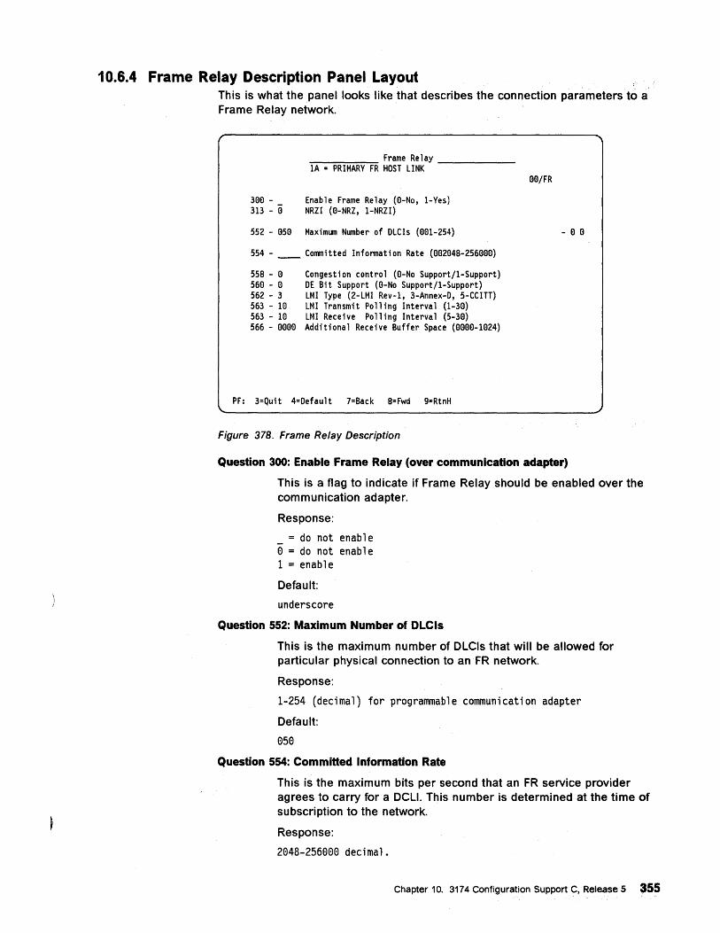
10.6.4 Frame Relay Description Panel Layout This is what the panel looks like that describes the connection parameters to a Frame Relay network.
300 -313 - a
~ _______ ~ ____ Frame Relay _____ _ 1A = PRIMARY FR HOST LINK
Enable Frame Relay (O-No, 1-Yes) NRZI (O-NRZ, 1-NRZI)
552 - 050 Maximum Number of DLCls (001-254)
554 - ____ Committed Information Rate (002048-256000)
558 - 0 560 - a 562 - 3 563 - 10 563 - 10 566 - 0000
Congestion control (a-No Support/1-Support) DE Bit Support (O-No Support/1-Support) LMI Type (2-LMI Rev-1, 3-Annex-O, 5-CCITT) LMI Transmit Polling Interval (1-30) LMI Recei ve Poll i ng Interval (5-30) Additional Receive Buffer Space (0000-1024)
PF: 3=Quit 4=Default 7=Back 8= Fwd 9=RtnH
Figure 378. Frame Relay Description
OO/FR
- 0 0
Question 300: Enable Frame Relay (over communication adapter)
This is a flag to indicate if Frame Relay should be enabled over the communication adapter.
Response:
= do not enable o = do not enable 1 = enable
Default:
underscore
Question 552: Maximum Number of OLCls
This is the maximum number of DLCls that will be allowed for particular physical connection to an FR network.
Response:
1-254 (decimal) for programmable communication adapter
Default:
050
Question 554: Committed Information Rate
This is the maximum bits per second that an FR service provider agrees to carry for a DCLI. This number is determined at the time of subscription to the network.
Response:
2048-256000 decimal.
Chapter 10. 3174 Configuration Support C, Release 5 355
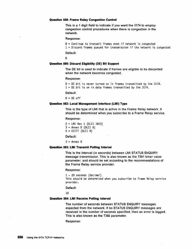
Question 558: Frame Relay Congestion Control
This is a 1 digit field to indicate if you want the 3174 to employ congestion control procedures when there is congestion in the network.
Response:
o = Continue to transmit frames even if network is congested 1 = Discard frames queued for transmission if the network is congested
Default:
o Question 560: Discard Eligibility (DE) Bit Support
The DE bit is used to indicate if frames are eligible to be discarded when the network becomes congested.
Response:
o = DE bit is never turned on in frames transmitted by the 3174. 1 = DE bit is on in data frames transmitted by the 3174.
Default:
o = DE off
Question 562: Local Management Interface (LMI) Type
This is the type of LMI that is active in the Frame Relay network. It should be determined when you subscribe to a Frame Relay service.
Response:
2 = LMI Rev 1 (OLCI 1023) 3 = Annex 0 (OLCI 0) 5 = CCITT (OLCI 0)
Default:
3 = Annex 0
Question 563: LMI Transmit Polling Interval
This is the interval (in seconds) between LMI STATUS ENQUIRY message transmission. This is also known as the T391 timer value parameter, and should be set according to the recommendations of the Frame Relay service provider.
Response:
1 - 29 seconds (decimal) This should be determined when you subscribe to Frame Relay service provider.
Default:
10
Question 564: LMI Receive Polling Interval
356 Using the 3174 TCPIIP Networks
The number of seconds between STATUS ENQUIRY messages expected from the network. If no STATUS ENQUIRY messages are received in the number of seconds specified, then an error is logged. This is also known as the T392 parameter.
Response:
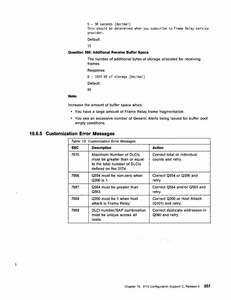
5 - 30 seconds (decimal) This should be determined when you subscribe to Frame Relay service provider.
Default:
15
Question 566: Additional Receive Buffer Space
Note:
The number of additional bytes of storage allocated for receiving frames.
Response:
o - 1024 KB of storage (decimal)
Default:
00
Increase the amount of buffer space when:
• You have a large amount of Frame Relay frame fragmentation.
• You see an excessive number of Generic Alerts being issued for buffer pool empty conditions.
10.6.5 Customization Error Messages
Table 13. Customization Error Messages
sse Description Action
7670 Maximum Number of OLCls Correct total or individual must be greater than or equal counts and retry. to the total number of OLCls defined on the 3174.
7666 Q5.54 must be non-zero when Correct Q554 or Q300 and Q300 is 1. retry:
7667 Q564 must be greater than Correct Q564 and/or Q563 and Q563. retry.
7668 Q300 must be 1 when host Correct Q300 or Host Attach attach is Frame Relay (Q101) and retry.
7669 OLCI number/SAP combination Correct duplicate addresses in must be unique across all Q090 and retry. hosts.
Chapter 10. 3174 Configuration Support C, Release 5 357

358 Using the 3174 TCP/IP Networks
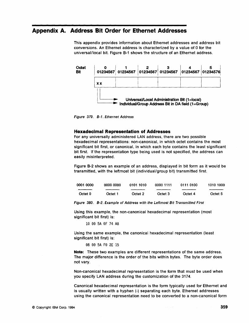
Appendix A. Address Bit Order for Ethernet Addresses
This appendix provides information about Ethernet addresses and address bit conversions. An Ethernet address is characterized by a value of 0 for the universal/local bit. Figure 8-1 shows the structure of an Ethernet address.
~et I 012~71 012~4567Io12ke71 012:..s67Io1~4567Io12i.s7~ Ixx
I L UniversallLoc:al Administration Bit (1 =Iocal) ----. IndMduaVGroup Address Bit in DA field (1=Group)
Figure 379. B-1. Ethernet Address
Hexadecimal Representation of Addresses For any universally administered LAN address, there are two possible hexadecimal representations: non-canonical, in which octet contains the most significant bit first, or canonical, in which each byte contains the least significant bit first. If the representation type being used is not specified, the address can easily misinterpreted.
Figure 8-2 shows an example of an address, displayed in bit form as it would be transmitted, with the leftmost bit (individual/group bit) transmitted first.
0001 0000 00000000 0101 1010 0000 1111 0111 0100 1010 1000
Octet 0 Octet 1 Octet 2 Octet 3 Octet 4 Octet 5
Figure 380. B-2. Example of Address with the Leftmost Bit Transmitted First
Using this example, the non-canonical hexadecimal representation (most significant bit first) is:
1e ee 5A eF 74 AS
Using the same example, the canonical hexadecimal representation (least significant bit first) is:
es ee 5A Fe 2£15
Note: These two examples are different representations of the same address. The major difference is the order of the bits within bytes. The byte order does not vary.
Non-canonical hexadecimal representation is the form that must be used when you specify LAN address during the customization of the 3174.
Canonical hexadecimal representation is the form typically used for Ethernet and is usually written with a hyphen (-) separating each byte. Ethernet addresses using the canonical representation need to be converted to a non-canonical form
© Copyright IBM Corp. 1994 359
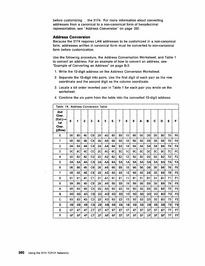
before customizing . the 31,74. For more information about converting addresses from a canonical to a non-canonical form of hexadecimal representation, see "Address Conversion" on page 360.
Address Conversion Because the 3174 requires LAN addresses to be customized in a non-canonical form, addresses written in canonical form must be converted to non-canonical form before customization.
Use the following procedure, the Address Conversation Worksheet, and Table 1 to convert an address. For an example of how to convert an address, see "Example of Converting an Address" on page B-3.
1. Write the 12-digit address on the Address Conversion Worksheet.
2. Separate the 12-digit into pairs. Use the first digit of each pair as the row coordinate and the second digit as the column coordinate.
3. Locate a bit order inverted pair in Table 1 for each pair you wrote on the worksheet.
4. Combine the six pairs from the table into the converted 12-digit address.
Table 14. Address Conversion Table
2nd Char. (Col.) ....
0 1 2 3 4 5 6 7 8 9 A B C 0 E 1st Char. !CRow)
0 00 80 40 CO 20 AO 60 EO 10 90 05 DO 30 BO 70
1 08 88 48 C8 28 A8 68 E8 18 98 58 08 38 B8 78
2 04 84 44 C4 24 A4 64 E4 14 94 54 04 34 B4 74
3 OC 8C 4C CC 2C AC 6C EC 1C 9C 5C DC 3C BC 7C
4 02 82 42 C2 22 A2 62 E2 12 92 52 02 32 B2 72
5 OA 8A 4A CA 2A AA 6A EA 1A 9A 5A OA 3A BA 7A
6 06 86 46 C6 26 A6 66 E6 16 96 56 06 36 B6 76
7 OE 8E 4E CE 2E AE 6E EE 1E 9E 5E DE 3E BE 7E
8 01 81 41 C1 21 A1 61 E1 11 91 51 01 31 B1 71
9 09 89 49 C9 29 A9 69 E9 19 99 59 09 39 B9 79
A 05 85 45 C5 25 A5 65 E5 15 95 55 05 35 B5 75
B 00 80 40 CD 20 AD 60 ED 10 90 50 OD 3D BO 70
C 03 83 43 C3 23 A3 63 E3 13 93 53 03 33 B3 73
0 OB 8B 4B CB 2B AB 6B EB 1B 9B 5B DB 3B BB 7B
E 07 87 47 C7 27 A7 67 E7 17 97 57 07 37 B7 77
F OF 8F 4F CF 2F AF 6F EF 1F 9F 5F OF 3F BF 7F
360 Using the 3174 TCP/IP Networks
F
FO
F8
F4
FC
F2
FA
F6
FE
F1
F9
F5
FO
F3
FB
F7
FF
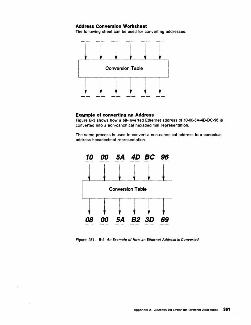
Address Conversion Worksheet The following sheet can be used for converting addresses.
, l' ,r l' l'
Conversion Table
,r ,r
Example of converting an Address Figure B-3 shows how a bit-inverted Ethernet address of 10-00-SA-40-8C-96 is converted into a non-canonical hexadecimal representation.
The same process is used to convert a non-canonical address to a canonical address hexadecimal representation.
10 00 SA 4D Be 96
" n u
" " " Conversion Table
" ,r If ~ " "
08 00 SA B2 3D 69
Figure 381. B-3. An Example of How an Ethernet Address is Converted
Appendix A. Address Bit Order for Ethernet Addresses 361

362 Using the 3174 TCPIIP Networks
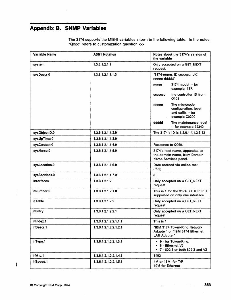
Appendix B. SNMP Variables
The 3174 supports the MIS-II variables shown in the following table. In the notes, "Qxxx" refers to customization question xxx.
Variable Name ASN1 Notation Notes about the 3174's version of the variable
system 1.3.6.1.2.1.1 Only accepted on a GET_NEXT request.
sysOescr.O 1.3.6.1.2.1.1.1.0 "'3174-mmm, 10 ccccccc, LlC nnnnn-ddddd'"
mmm 3174 model -- for example, 13R
ccccccc the controller 10 from Q108
nnnnn The microcode configuration, level and suffix -- for example C0300
ddddd The maintenance level -- for example 92340
sysObjectlO.O 1.3.6.1.2.1.1.2.0 The 3174's 10 is 1.3.6.1.4.1.2.6.13
sysUpTime.O 1.3.6.1.2.1.1.3.0
sysContact.O 1.3.6.1.2.1.1.4.0 Response to Q099.
sysName.O 1.3.6.1.2.1.1.5.0 3174' s host name, appended to the domain name, from Domain Name Services panel.
sysLocation.O 1.3.6.1.2.1.1.6.0 Data entered via online test, (/5,2)
sysServices.O 1.3.6.1.2.1.1.7.0 8
interfaces 1.3.6.1.2.1.2 Only accepted on a GET_NEXT request.
ifNumber.O 1.3.6.1.2.1.2.1.0 This is 1 for the 3174, as TCP/IP is supported on only one interface.
ifTable 1.3.6.1.2.1.2.2 Only accepted on a GET_NEXT request.
if Entry 1.3.6.1.2.1.2.2.1 Only accepted on a GET_NEXT request.
iflndex.1 1.3.6.1.2.1.2.2.1.1.1 This is 1.
ifOescr.1 1.3.6.1.2.1.2.2.1.2.1 "'IBM 3174 Token-Ring Network Adapter'" or "'IBM 3174 Ethernet LAN Adapter'"
ifType.1 1.3.6.1.2.1.2.2.1.3.1 · 9 - for Token/Ring,
· 6 - Ethernet V2
· 7 - 802.3 or both 802.3 and V2
ifMtu.1 1.3.6.1.2.1.2.2.1.4.1 1492
if Speed. 1 1.3.6.1.2.1.2.2.1.5.1 4M or 16M, for T/R 10M for Ethernet
© Copyright IBM Corp. 1994 363
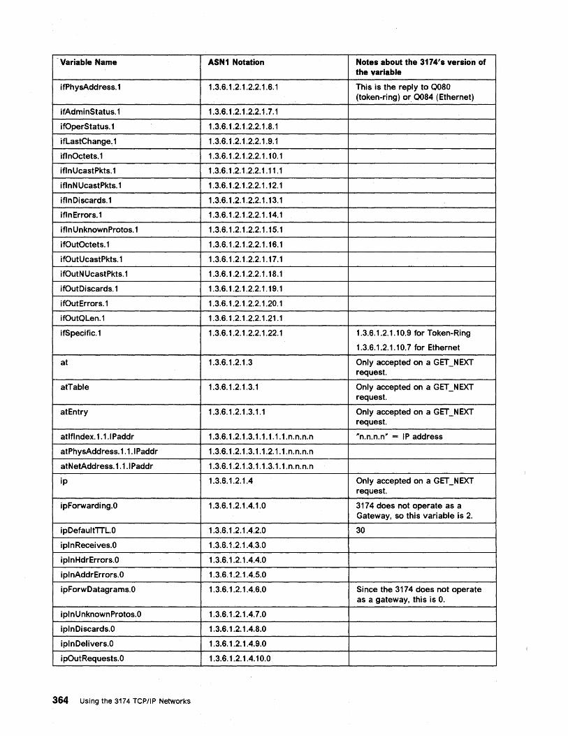
Variable Name ASN1 Notation Notes about the 3174'sversion of the variable
ifPhysAddress.1 1.3.6.1.2.1.2.2.1.6.1 This is the reply to 0080 (token-ring) or 0084 (Ethernet)
ifAdminStatus.1 1.3.6.1.2.1.2.2.1.7.1
ifOperStatus.1 1.3.6.1.2.1.2.2.1.8.1
ifLastChange~ 1 1.3.6.1.2.1.2.2.1.9.1
if I nOctets. 1 1.3.6.1.2.1.2.2.1.10.1
iflnUcastPkts.1 1.3.6.1.2.1.2.2.1.11.1
iflnNUcastPkts.1 1.3.6.1.2.1.2.2.1.12.1
iflnDiscards.1 1.3.6.1.2.1.2.2.1.13.1
iflnErrors.1 1.3.6.1.2.1.2.2.1.14.1
iflnUnknownProtos.1 1.3.6.1.2.1.2.2.1.15.1
ifOutOctets.1 1.3.6.1.2.1.2.2.1.16.1
ifOutUcastPkts.1 1.3.6.1.2.1.2.2.1.17.1
ifOutN UcastPkts.1 1.3.6.1.2.1.2.2.1.18.1
ifOutDiscards.1 1.3.6.1.2.1.2.2.1.19.1
ifOutErrors.1 1.3.6.1.2.1.2.2.1.20.1
ifOutQLen.1 1.3.6.1.2.1.2.2.1.21.1
if Specific. 1 1.3.6.1.2.1.2.2.1.22.1 1.3.6.1.2.1.10.9 for Token-Ring
1.3.6.1.2.1.10.7 for Ethernet
at 1.3.6.1.2.1.3 Only accepted on a GET_NEXT request.
atTable 1.3.6.1.2.1.3.1 Only accepted on a GET_NEXT request.
atEntry 1.3.6.1.2.1.3.1.1 Only accepted on a GET_NEXT request.
atlflndex. 1. 1.1 Paddr 1.3.6.1.2.1.3.1.1.1.1.1.n.n.n.n "'n.n.n.n'" - IP address
atPhysAddress. 1.1.1 Paddr 1.3.6.1.2.1.3.1.1.2.1.1.n.n.n.n
atNetAddress.1.1.1 Paddr 1.3.6.1.2.1.3.1.1.3.1.1.n.n.n.n
ip 1.3.6.1.2.1.4 Only accepted on a GET_NEXT request.
ipForwarding.O 1.3.6.1.2.1.4.1.0 3174 does not operate as a Gateway, so this variable is 2.
ipDefaultTTL.O 1.3.6.1.2.1.4.2.0 30
iplnReceives.O 1.3.6.1.2.1.4.3.0
iplnHdrErrors.O 1.3.6.1.2.1.4.4.0
iplnAddrErrors.O 1.3.6.1.2.1.4.5.0
ipForwDatagrams.O 1.3.6.1.2.1.4.6.0 Since the 3174 does not operate as a gateway, this is O.
i pin U nknownProtos.O 1.3.6.1.2.1.4.7.0
iplnDiscards.O 1.3.6.1.2.1.4.8.0
iplnDelivers.O 1.3.6.1.2.1.4.9.0
ipOutRequests.O 1.3.6.1.2.1.4.10.0
364 Using the 3174 TCP/IP Networks
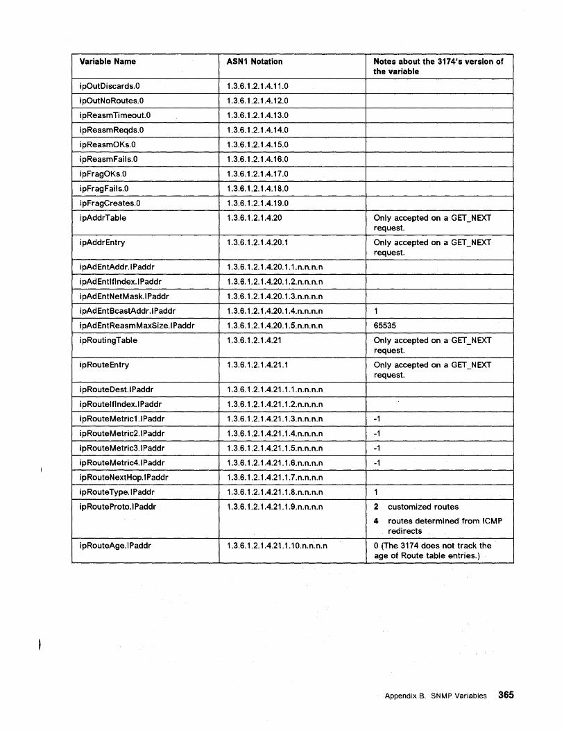
Variable Name ASN1 Notation Notes about the 3174's version of the variable
ipOutDiscards.O 1.3.6.1.2.1.4.11.0
ipOutNoRoutes.O 1.3.6.1.2.1.4.12.0
ipReasmTimeout.O 1.3.6.1.2.1.4.13.0
ipReasmReqds.O 1.3.6.1.2.1.4.14.0
ipReasmOKs.O 1.3.6.1.2.1.4.15.0
ipReasmFails.O 1.3.6.1.2.1.4.16.0
ipFragOKs.O 1.3.6.1.2.1.4.17.0
ipFragFails.O 1.3.6.1.2.1.4.18.0
ipFragCreates.O 1.3.6.1.2.1.4.19.0
ipAddrTable 1.3.6.1.2.1.4.20 Only accepted on a GET_NEXT request.
ipAddrEntry 1.3.6.1.2.1.4.20.1 Only accepted on a GET_NEXT request.
ipAdEntAddr.IPaddr 1.3.6.1.2.1.4.20.1.1.n.n.n.n
ipAdEntlflndex.IPaddr 1.3.6.1.2.1.4.20.1.2.n.n.n.n
ipAdEntNetMask.IPaddr 1.3.6.1.2.1.4.20.1.3.n.n.n.n
ipAdEntBcastAddr.IPaddr 1.3.6.1.2.1.4.20.1.4.n.n.n.n 1
ipAdEntReasmMaxSize.1 Paddr 1.3.6.1.2.1.4.20.1.5.n.n.n.n 65535
ipRoutingTable 1.3.6.1.2.1.4.21 Only accepted on a GET_NEXT request.
ipRouteEntry 1.3.6.1.2.1.4.21.1 Only accepted on a GET_NEXT request.
ipRouteDest.1 Paddr 1.3.6.1.2.1.4.21.1.1.n.n.n.n
ipRoutelflndex.IPaddr 1.3.6.1.2.1.4.21.1.2.n.n.n.n
ipRouteMetric1.1 Paddr 1.3.6.1.2.1.4.21.1.3.n.n.n.n -1
ipRouteMetric2.1 Paddr 1.3.6.1.2.1.4.21.1.4.n.n.n.n -1
ipRouteMetric3.1 Paddr 1.3.6.1.2.1.4.21.1.5.n.n.n.n -1
ipRouteMetric4.1 Paddr 1.3.6.1.2.1.4.21.1.6.n.n.n.n -1
ipRouteNextHop.1 Paddr 1.3.6.1.2.1.4.21.1.7.n.n.n.n
ipRouteType.1 Paddr 1.3.6.1.2.1.4.21.1.8.n.n.n.n 1
ipRouteProto.1 Paddr 1.3.6.1.2.1.4.21.1.9.n.n.n.n 2 customized routes
4 routes determined from ICMP redirects
ipRouteAge.1 Paddr 1.3.6.1.2.1.4.21.1.10.n.n.n.n o (The 3174 does not track the age of Route table entries.)
AppendixB. SNMP Variables 365
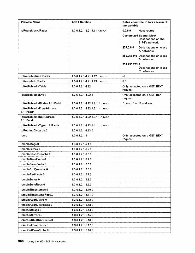
Variable Name ASN1 Notation Notes about the 3174's version of the variable
ipRouteMask.IPaddr 1.3.6.1.2.1.4.21.1.11.n.n.n.n 0.0.0.0 Host routes
Customized Subnet Mask Destinations on the 3174' s network
255.0.0.0 Destinations on class A networks
255.255.0.0 Destinations on class B networks
255.255.255.0 Destinations on class C networks
ipRouteMetricS.IPaddr 1.3.6.1.2.1.4.21.1.12.n.n.n.n -1
ipRoutelnfo.IPaddr 1.3.6.1.2.1.4.21.1.13.n.n.n.n 0.0
ipNetToMediaTable 1.3.6.1.2.1.4.22 Only accepted on a GET_NEXT request.
ipNetToMediaEntry 1.3.6.1.2.1.4.22.1 Only accepted on a GET_NEXT request.
ipNetToMedialflndex.1.1.IPaddr 1.3.6.1.2.1.4.22.1.1.1.1.n.n.n.n "n.n.n.n" = IP address
ipNetToMediaPhysAddress. 1.3.6.1.2.1.4.22.1.2.1.1.n.n.n.n 1.1.~Paddr
ipNetToMediaNetAddress. 1.3.6.1.2.1.4.22.1.3.1.1.n.n.n.n 1.1.IPaddr
ipNetToMediaType.1.1.IPaddr 1.3.6.1.2.1.4.22.1.4.1.1.n.n.n.n
i pRouting Di scards.O 1.3.6.1.2.1.4.23.0
icmp 1.3.6.1.2.1.S Only accepted on a GET_NEXT request.
icmplnMsgs.O 1.3.6.1.2.1.S.1.0
icmplnErrors.O 1.3.6.1.2.1.S.2.0
icmplnDestUnreachs.O 1.3.6.1.2.1.S.3.0
icmplnTimeExcds.O 1.3.6.1.2.1.S.4.0
icmplnParmProbs.O 1.3.6.1.2.1.S.S.0
icmplnSrcQuenchs.O 1.3.6.1.2.1.S.6.0
icmplnRedirects.O 1.3.6.1.2.1.S.7.0
icmplnEchos.O 1.3.6.1.2.1.S.8.0
icmplnEchoReps.O 1.3.6.1.2.1.S.9.0
icmplnTimestamps.O 1.3.6.1.2.1.S.10.0
icmplnTimestampReps.O 1.3.6.1.2.1.S.11.0
icmplnAddrMasks.O 1.3.6.1.2.1.S.12.0
icmplnAddrMaskReps.O 1.3.6.1.2.1.S.13.0
icmpOutMsgs.O 1.3.6.1.2.1.S.14.0
icmpOutErrors.O 1.3.6.1.2.1.S.1S.0
icmpOutDestUnreachs.O 1.3.6.1.2.1.S.16.0
icmpOutTimeExcds.O 1.3.6.1.2.1.S.17.0
icmpOutParmProbs.O 1.3.6.1.2.1.S.18.0
366 Using the 3174 TCP/IP Networks
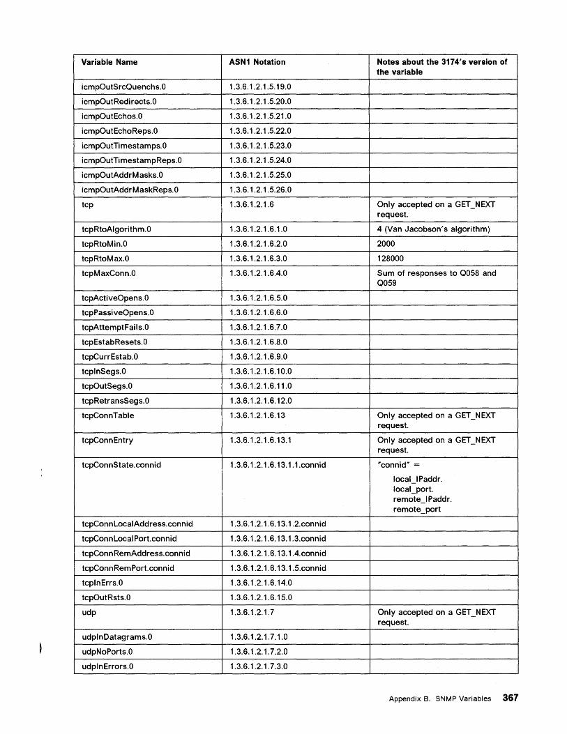
Variable Name ASN1 Notation Notes about the 3174's version of the variable
icmpOutSrcQuenchs.O 1.3.6.1.2.1.5.19.0
icmpOutRedirects.O 1.3.6.1.2.1.5.20.0
icmpOutEchos.O 1.3.6.1.2.1.5.21.0
icmpOutEchoReps.O 1.3.6.1.2.1.5.22.0
icmpOutTi mestamps. 0 1.3.6.1.2.1.5.23.0
icmpOutTimestampReps.O 1.3.6.1.2.1.5.24.0
icmpOutAddrM asks.O 1.3.6.1.2.1.5.25.0
icmpOutAddrMaskReps.O 1.3.6.1.2.1.5.26.0
tcp 1.3.6.1.2.1.6 Only accepted on a GET_NEXT request.
tcpRtoAlgorithm.O 1.3.6.1.2.1.6.1.0 4 (Van Jacobson's algorithm)
tcpRtoMin.O 1.3.6.1.2.1.6.2.0 2000
tcpRtoMax.O 1.3.6.1.2.1.6.3.0 128000
tcpMaxConn.O 1.3.6.1.2.1.6.4.0 Sum of responses to Q058 and Q059
tcpActiveOpens.O 1.3.6.1.2.1.6.5.0
tcpPassiveOpens.O 1.3.6.1.2.1.6.6.0
tcpAttemptFails.O 1.3.6.1.2.1.6.7.0
tcpEstabResets.O 1.3.6.1.2.1.6.8.0
tcpCurrEstab.O 1.3.6.1.2.1.6.9.0
tcplnSegs.O 1.3.6.1.2.1.6.10.0
tcpOutSegs.O 1.3.6.1.2.1.6.11.0
tcpRetransSegs.O 1.3.6.1.2.1.6.12.0
tcpConnTable 1.3.6.1.2.1.6.13 Only accepted on a GET_NEXT request.
tcpConnEntry 1.3.6.1.2.1.6.13.1 Only accepted on a GET_NEXT request.
tcpConnState.connid 1.3.6.1.2.1.6.13.1.1.connid "connid'" =
10cal_IPaddr. 10caLport. remote_IPaddr. remote_port
tcpConnLocalAddress.connid 1.3.6.1.2.1.6.13.1.2.connid
tcpConn Local Port.connid 1.3.6.1.2.1.6.13.1.3.connid
tcpConn RemAddress.connid 1.3.6.1.2.1.6.13.1.4.connid
tcpConnRemPort.connid 1.3.6.1.2.1.6.13.1.5.connid
tcplnErrs.O 1.3.6.1.2.1.6.14.0
tcpOutRsts.O 1.3.6.1.2.1.6.15.0
udp 1.3.6.1.2.1.7 Only accepted on a GET_NEXT request.
udplnDatagrams.O 1.3.6.1.2.1.7.1.0
udpNoPorts.O 1.3.6.1.2.1.7.2.0
udplnErrors.O 1.3.6.1.2.1.7.3.0
AppendixB. SNMP Variables 367
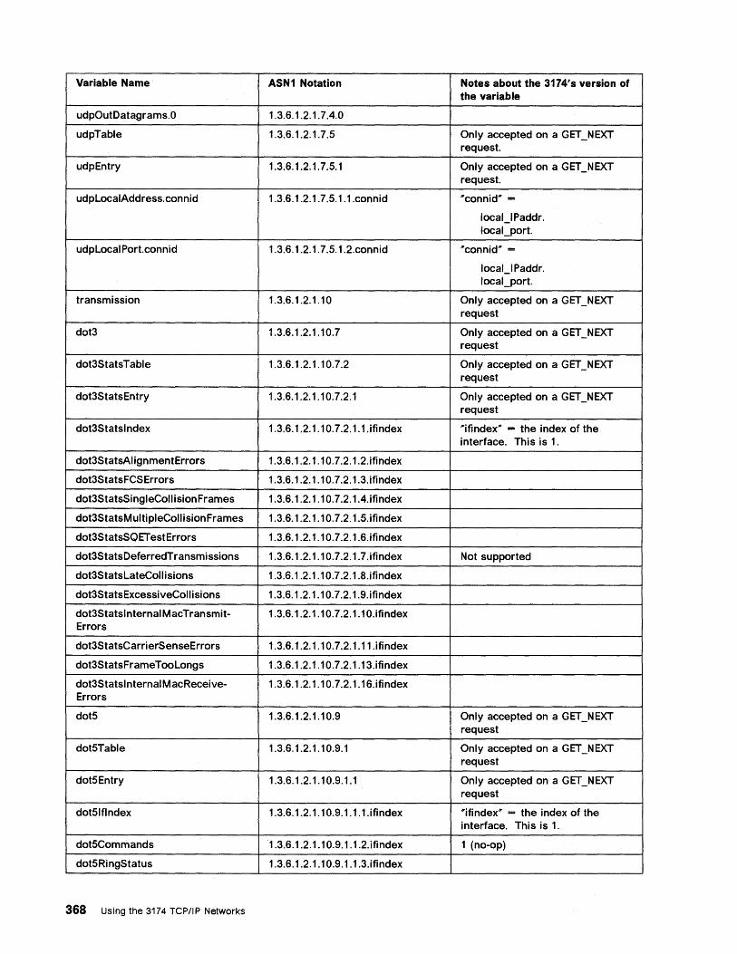
Variable Name ASN1 Notation Notes about the 3174's version of the variable
udpOutDatagrams.O 1.3.6.1.2.1.7.4.0
udpTable 1.3.6.1.2.1.7.S Only accepted on a GET_NEXT request.
udpEntry 1.3.6.1.2.1.7.S.1 Only accepted on a GET_NEXT request.
udpLocalAddress.connid 1.3.6.1.2.1.7.S.1.1.connid "'connid'" =
local_IPaddr. local_port.
udpLocal Port.connid 1.3.6.1.2.1.7.S.1.2.connid "'connid'" =
local_I Paddr. local_port.
transmission 1.3.6.1.2.1.10 Only accepted on a GET_NEXT request
dot3 1.3.6.1.2.1.10.7 Only accepted on a GET_NEXT request
dot3StatsTabie 1.3.6.1.2.1.10.7.2 Only accepted on a GET_NEXT request
dot3StatsEntry 1.3.6.1.2.1.10.7.2.1 Only accepted on a GET_NEXT request
dot3Statsindex 1.3.6.1.2.1.10.7.2.1.1.ifindex "'ifindex'" = the index of the interface. This is 1.
dot3StatsAI ignmentErrors 1.3.6.1.2.1.10.7.2.1.2.ifindex
dot3S tatsFCS Errors 1.3.6.1.2.1.10.7.2.1.3. ifindex
dot3StatsSingieCoilisionFrames 1.3.6.1.2.1.10.7.2.1.4.ifindex
dot3StatsMuitipieCoilisionFrames 1.3.6.1.2.1.10.7.2.1.S.ifindex
dot3StatsSQET est Errors 1.3.6.1.2.1.10.7.2.1.6.ifindex
dot3StatsDeferredTransmi ssions 1.3.6.1.2.1.10.7.2.1.7.ifindex Not supported
dot3StatsLateCoilisions 1.3.6.1.2.1.10.7.2.1.8.ifindex
dot3StatsExcessiveCoilisions 1.3.6.1.2.1.10.7.2.1.9.ifindex
dot3StatslnternalMacTransmit- 1.3.6.1.2.1.10.7.2.1.10.ifindex Errors
dot3StatsCarrierSenseErrors 1.3.6.1.2.1.10.7.2.1.11.ifindex
dot3StatsFrame Too Longs 1.3.6.1.2.1.10.7.2.1.13.ifindex
dot3Statsi nternal M acReceive- 1.3.6.1.2.1.10.7.2.1.16.ifindex Errors
dotS 1.3.6.1.2.1.10.9 Only accepted on a GET_NEXT request
dotSTable 1.3.6.1.2.1.10.9.1 Only accepted on a GET_NEXT request
dotSEntry 1.3.6.1.2.1.10.9.1.1 Only accepted on a GET_NEXT request
dotSlflndex 1.3.6.1.2.1.10.9.1.1.1.ifindex "'ifindex'" = the index of the interface. This is 1.
dotSCommands 1.3.6.1.2.1.10.9.1.1.2.ifindex 1 (no-op)
dotSRingStatus 1.3.6.1.2.1.10.9.1.1.3.ifindex
368 Using the 3174 TCP/IP Networks
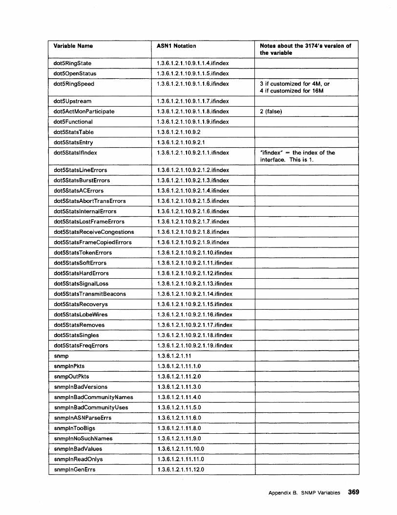
Variable Name ASN1 Notation Notes about the 3174's version of the variable
dot5Ri ngState 1.3.6.1.2.1.10.9.1.1.4.ifindex
dot50penStatus 1.3.6.1.2.1.10.9.1.1.5.ifindex
dot5RingSpeed 1.3.6.1.2.1.10.9.1.1.6.ifindex 3 if customized for 4M, or 4 if customized for 16M
dot5Upstream 1.3.6.1.2.1.10.9.1.1.7.ifindex
dot5ActMonParticipate 1.3.6.1.2.1.10.9.1.1.8.ifindex 2 (false)
dot5Functionai 1.3.6.1.2.1.10.9.1.1.9.ifindex
dot5StatsTabie 1.3.6.1.2.1.10.9.2
dot5S tats Entry 1.3.6.1.2.1.10.9.2.1
dot5Statslflndex 1.3.6.1.2.1.10.9.2.1.1.ifindex "'ifindex'" = the index of the interface. This is 1.
dot5StatsLi neErrors 1.3.6.1.2.1.10.9.2.1.2.ifindex
dot5StatsBurstErrors 1.3.6.1.2.1.10.9.2.1.3.ifindex
dot5S tatsAC Errors 1.3.6.1.2.1.1 0.9.2.1.4.ifi ndex
dot5StatsAbortTransErrors 1.3.6.1.2.1.10.9.2.1.5.ifindex
dot5Statsinternai Errors 1.3.6.1.2.1.10.9.2.1.6.ifindex
dot5StatsLostFrameErrors 1.3.6.1.2.1.10.9.2.1.7.ifindex
dot5StatsReceiveCongestions 1.3.6.1.2.1.10.9.2.1.8.ifindex
dot5StatsFrameCopiedErrors 1.3.6.1.2.1.10.9.2.1.9.ifindex
dot5Stats Token Errors 1.3.6.1.2.1.10.9.2.1.10.ifindex
dot5S tatsSoft Errors 1.3.6.1.2.1.10.9.2.1.11.ifindex
dot5S tatsH ard Errors 1.3.6.1.2.1.10.9.2.1.12.ifindex
dot5StatsSignai Loss 1.3.6.1.2.1.10.9.2.1.13.ifindex
dot5StatsTransmitBeacons 1.3.6.1.2.1.10.9.2.1.14.ifindex
dot5StatsRecoverys 1.3.6.1.2.1.10.9.2.1.15.ifindex
dot5StatsLobeWi res 1.3.6.1.2.1.10.9.2.1.16.ifindex
dot5StatsRemoves 1.3.6.1.2.1.10.9.2.1.17.ifindex
dot5StatsSingies 1.3.6.1.2.1.10.9.2.1.18.ifindex
dot5Stats F req Errors 1.3.6.1.2.1.10.9.2.1.19.ifindex
snmp 1.3.6.1.2.1.11
snmplnPkts 1.3.6.1.2.1.11.1.0
snmpOutPkts 1.3.6.1.2.1.11.2.0
snmplnBadVersions 1.3.6.1.2.1.11.3.0
snmplnBadCommunityNames 1.3.6.1.2.1.11.4.0
snmplnBadCommunityUses 1.3.6.1.2.1.11.5.0
snmpl nAS N Parse Errs 1.3.6.1.2.1.11.6.0
snmplnTooBigs 1.3.6.1.2.1.11.8.0
snmplnNoSuchNames 1.3.6.1 .2.1.11.9.0
snmpln BadValues 1.3.6.1.2.1.11.10.0
snmplnReadOnlys 1.3.6.1.2.1.11.11.0
snmplnGenErrs 1.3.6.1.2.1.11.12.0
Appendix B. SNMP Variables 369
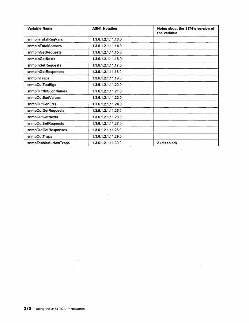
Variable Name ASN1 Notation Notes about the. 3174's version of the variable
snmpl nTotal ReqVars 1.3.6.1.2.1.11.13.0
snmplnTotalSetVars 1.3.6.1.2.1.11.14.0
snmplnGetRequests 1.3.6.1.2.1.11.15.0
snmpl nGetNexts 1.3.6.1.2.1.11.16.0
snmplnSetRequests 1.3.6.1.2.1.11.17.0
snmplnGetResponses 1.3.6.1.2.1.11.18.0
snmplnTraps 1.3.6.1.2.1.11.19.0
snmpOutTooBigs 1.3.6.1.2.1.11.20.0
snmpOutNoSuchNames 1.3.6.1.2.1.11.21.0
snmpOutBadValues 1.3.6.1.2.1.11.22.0
snmpOutGen Errs 1.3.6.1.2.1.11.24.0
snmpOutGetRequests 1.3.6.1.2.1.11.25.0
snmpOutGetNexts 1.3.6.1.2.1.11.26.0
snmpOutSetRequests 1.3.6.1.2.1.11.27.0
snmpOutGetResponses 1.3.6.1.2.1.11.28.0
snmpOutTraps 1.3.6.1.2.1.11.29.0
snmpEnableAuthen Traps 1.3.6.1.2.1.11.30.0 2 (disabled)
370 Using the 3174 TCP/IP Networks
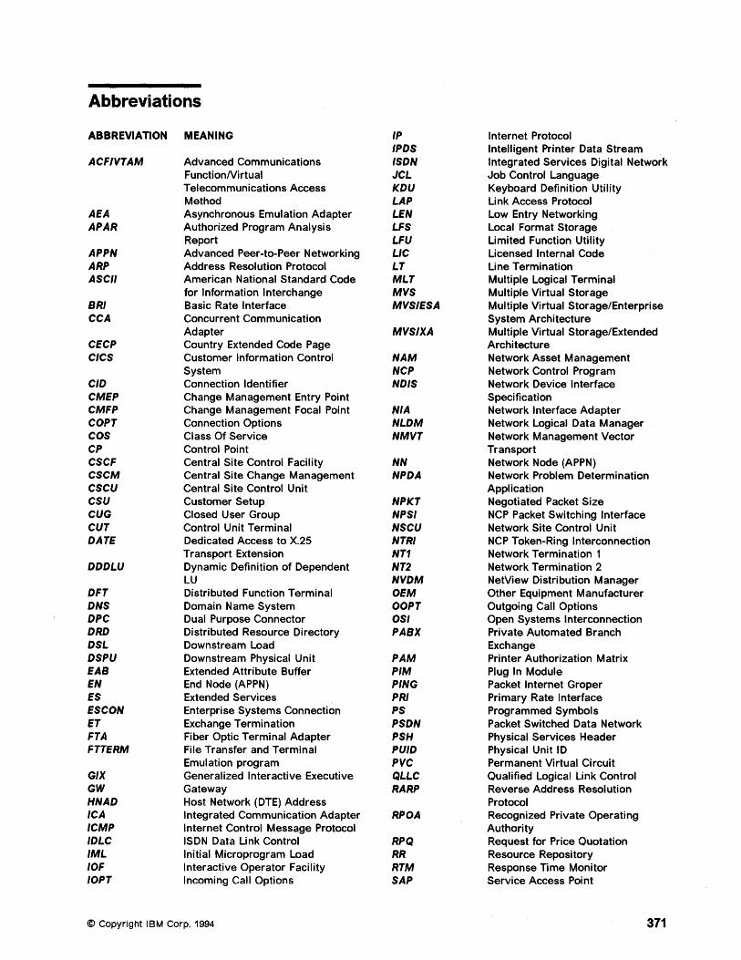
Abbreviations
ABBREVIATION MEANING IP Internet Protocol IPDS Intelligent Printer Data Stream
ACFIVTAM Advanced Communications ISDN Integrated Services Digital Network FunctionNirtual JCL Job Control Language Telecommunications Access KDU Keyboard Definition Utility Method LAP Link Access Protocol
AEA Asynchronous Emulation Adapter LEN Low Entry Networking APAR Authorized Program Analysis LFS Local Format Storage
Report LFU Limited Function Utility APPN Advanced Peer-to-Peer Networking L1C Licensed Internal Code ARP Address Resolution Protocol LT Line Termination ASCII American National Standard Code MLT Multiple Logical Terminal
for Information Interchange MVS Multiple Virtual Storage SRI Basic Rate Interface MVSIESA Multiple Virtual Storage/Enterprise CCA Concurrent Communication System Architecture
Adapter MVS/XA Multiple Virtual Storage/Extended CECP Country Extended Code Page Architecture CICS Customer Information Control NAM Network Asset Management
System NCP Network Control Program CID Connection Identifier ND/S Network Device Interface CMEP Change Management Entry Point Specification CMFP Change Management Focal Point filA Network Interface Adapter COPT Connection Options NLDM Network Logical Data Manager COS Class Of Service NMVT Network Management Vector CP Control Poi nt Transport CSCF Central Site Control Facility NN Network Node (APPN) CSCM Central Site Change Management NPDA Network Problem Determination CSCU Central Site Control Unit Application CSU Customer Setup NPKT Negotiated Packet Size CUG Closed User Group NPSI NCP Packet Switching Interface CUT Control Unit Terminal NSCU Network Site Control Unit DATE Dedicated Access to X.25 NTRI NCP Token-Ring Interconnection
Transport Extension NT1 Network Termination 1 DDDLU Dynamic Definition of Dependent NT2 Network Termination 2
LU NVDM NetView Distribution Manager DFT Distributed Function Terminal OEM Other Equipment Manufacturer DNS Domain Name System OOPT Outgoing Call Options DPC Dual Purpose Connector OSI Open Systems Interconnection DRD Distributed Resource Directory PASX Private Automated Branch DSL Downstream Load Exchange DSPU Downstream Physical Unit PAM Printer Authorization Matrix EAS Extended Attribute Buffer PIM Plug In Module EN End Node (APPN) PING Packet Internet Groper ES Extended Services PRI Primary Rate Interface ESCON Enterprise Systems Connection PS Programmed Symbols ET Exchange Termination PSDN Packet Switched Data Network FTA Fiber Optic Terminal Adapter PSH Physical Services Header FTTERM File Transfer and Terminal PUID Physical Unit 10
Emulation program PVC Permanent Virtual Circuit GIX Generalized Interactive Executive QLLC Qualified Logical Link Control GW Gateway RARP Reverse Address Resolution HNAD Host Network (DTE) Address Protocol ICA Integrated Communication Adapter RPOA Recognized Private Operating ICMP Internet Control Message Protocol Authority IDLC ISDN Data Link Control RPQ Request for Price Quotation IML Initial Microprogram Load RR Resource Repository lOF Interactive Operator Facility RTM Response Time Monitor lOPT Incoming Call Options SAP Service Access Point
© Copyright IBM Corp. 1994 371
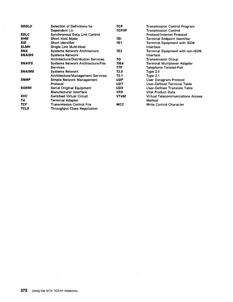
SDDLU Selection of Definitions for TCP Transmission Control Program Dependent LU TCPIIP Transmission Control
SDLC Synchronous Data Link Control Protocol/Internet Protocol SHM Short Hold Mode TEl Terminal Endpoint Identifier SID Short Identifier TE1 Terminal Equipment with ISDN SLMH Single Link Multi-Host Interface SNA Systems Network Architecture TE2 Terminal Equipment with non-ISDN SNAIDS Systems Network Interface
Architecture/Distribution Services TG Transmission Group SNAIFS Systems Network Architecture/File TMA Terminal Multiplexer Adapter
Services TTP Telephone Twisted-Pair SNAIMS Systems Network T2.0 Type 2.0
Architecture/M anagement Services T2.1 Type 2.1 SNMP Simple Network Management UDP User Datagram Protocol
Protocol UDT User-Defined Terminal Table SOEMI Serial Original Equipment UDX User-Defined Translate Table
Manufacturer Interface VPD Vital Product Data SVC Switched Virtual Circuit VTAM Virtual Telecommunications Access TA Terminal Adapter Method TCF Transmission Control File WCC Write Control Character TCLS Throughput Class Negotiation
372 Using the 3174 TCPIIP Networks
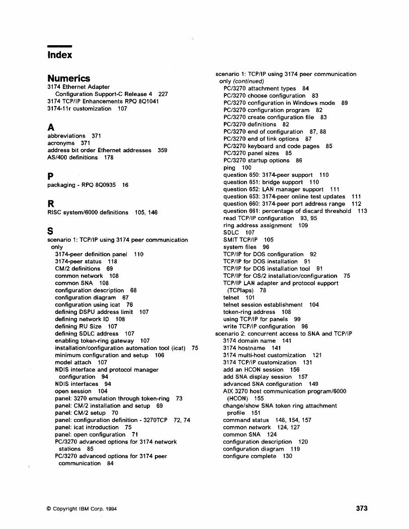
Index
Numerics 3174 Ethernet Adapter
Configuration Support-C Release 4 227 3174 TCP/IP Enhancements RPQ 8Q1041 3174-11 r customization 107
A abbreviations 371 acronyms 371 address bit order Ethernet addresses 359 AS/400 definitions 178
p packaging - RPQ 8Q0935 16
R RISC system/6000 definitions 105, 146
S scenario 1: TCP/IP using 3174 peer communication
only 3174-peer definition panel 110 3174-peer status 118 CM/2 definitions 69 common network 108 common S NA 108 configuration description 68 configuration diagram 67 configuration using icat 76 defining DSPU address limit 107 defining network 10 108 defining RU Size 107 defining SDLC address 107 enabling token-ring gateway 107 installation/configuration automation tool (icat) 75 minimum configuration and setup 106 model attach 107 NDIS interface and protocol manager
configuration 94 NDIS interfaces 94 open session 104 panel: 3270 emulation through token-ring 73 panel: CM/2 installation and setup 69 panel: CM/2 setup 70 panel: configuration definition - 3270TCP 72, 74 panel: icat introduction 75 panel: open configuration 71 PC/3270 advanced options for 3174 network
stations 85 PC/3270 advanced options for 3174 peer
communication 84
© Copyright I BM Corp. 1994
scenario 1: TCP/IP using 3174 peer communication only (continued)
PC/3270 attachment types 84 PC/3270 choose configuration 83 PC/3270 configuration in Windows mode 89 PC/3270 configuration program 82 PC/3270 create configuration file 83 PC/3270 definitions 82 PC/3270 end of configuration 87, 88 PC/3270 end of link options 87 PC/3270 keyboard and code pages 85 PC/3270 panel sizes 85 PC/3270 startup options 86 ping 100 question 650: 3174-peer support 110 question 651: bridge support 110 question 652: LAN manager support 111 question 653: 3174-peer online test updates 111 question 660: 3174-peer port address range 112 question 661: percentage of discard threshold 113 read TCP/IP configuration 93, 95 ring address assignment 109 SDLC 107 SMIT TCP/IP 105 system files 96 TCP/IP for DOS configuration 92 TCP/IP for DOS installation 91 TCP/IP for DOS installation tool 91 TCP/IP for OS/2 installation/configuration 75 TCP/IP LAN adapter and protocol support
(TCPlaps) 78 telnet 101 tel net session establishment 104 tOken-ring address 108 using TCP/IP for panels 99 write TCP/IP configuration 96
scenario 2: concurrent access to SNA and TCP/IP 3174 domain name 141 3174 hostname 141 3174 multi-host customization 121 3174 TCP/IP customization 131 add an HCON session 156 add SNA display session 157 advanced SNA configuration 149 AIX 3270 host communication program/6000
(HCON) 155 change/show SNA token ring attachment
profile 151 command status 148, 154, 157 common network 124, 127 common SNA 124 configuration description 120 configuration diagram 119 configure complete 130
373
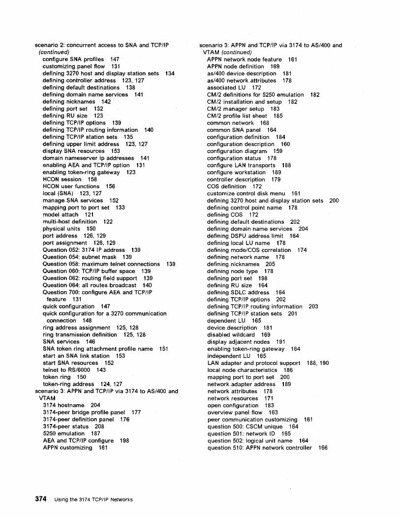
scenario 2: concurrent access to SNA and TCP/IP (continued)
configure SNA profiles 1~7
customizing panel flow 131 defining 3270 host and display station sets 134 defining controller address 123, 127 defining default destinations 138 defining domain name services 141 defining nicknames 142 defining port set 132 defining RU size 123 defining TCP/IP options 139 defining TCP/IP routing information 140 defining TCP/IP station sets 135 defining upper limit address 123, 127 display SNA resources 153 domain nameserver ip addresses 141 enabling AEA and TCP/IP option 131 enabling token-ring gateway 123 HCON session 158 HCON user functions 156 local (SNA) 123, 127 manage SNA services 152 mapping port to port set 133 model attach 121 multi-host definition 122 physical units 150 port address 126, 129 port assignment 126, 129 Question 052: 3174 I P address 139 Question 054: subnet mask 139 Question 058: maximum tel net connections 139 Question 060: TCP/IP buffer space 139 Question 062: routing field support 139 Question 064: all routes broadcast 140 Question 700: configure AEA and TCP/IP
feature 131 quick configuration 147 quick configuration for a 3270 communication
connection 148 ring address assignment 125, 128 ring transmission definition 125, 128 SNA services 146 SNA token ring attachment profile name 151 start an SNA link station 153 start SNA resources 152 tel net to RS/6000 143 token ring 150 token-ring address 124, 127
scenario 3: APPN and TCP/IP via 3174 to AS/400 and VTAM
3174 hostname 204 3174-peer bridge profile panel 177 3174-peer definition panel 176 3174-peer status 208 5250 emulation 187 AEA and TCP/IP configure 198 APPN customizing 161
374 Using the 3174 TCPIIP Networks
scenario 3: APPN and TCP/IP via 3174 to AS/400 and VTAM (continued)
APPN network node feature 161 APPN node definition 169 as/400 device description 181 as/400 network attributes 178 associated LU 172 CM/2 definitions for 5250 emulation 182 CM/2 installation and setup 182 CM/2 manager setup 183 CM/2 profile list sheet 185 common network 168 common SNA panel 164 configuration definition 184 configuration description 160 configuration diagram 159 configuration status 178 configure LAN transports 188 configure workstation 189 controller description 179 COS definition 172 customize control disk menu 161 defining 3270 host and display station sets 200 defining control point name 178 defining COS 172 defining default destinations 202 defining domain name services 204 defining OSPU address limit 164 defining local LU name 1.78 defining mode/COS correlation 174 defining network name 178 defining nicknames 205 defining node type 178 defining port set 198 defining RU size 164 defining SOLC address 164 defining TCP/IP options 202 defining TCP/I P routing information 203 defining TCP/IP station sets 201 dependent LU 165 device description 181 disabled wildcard 169 display adjacent nodes 191 enabling token-ring gateway 164 independent LU 165 LAN adapter and protocol support 188, 190 local node characteristics 186 mapping port to port set 200 network adapter address 189 network attributes 178 network resources 171 open configuration 183 overview panel flow 163 peer communication customizing 161 question 500: CSCM unique 164 question 501: network 10 165 question 502: logical unit name 164 question 510: APPN network controller 166
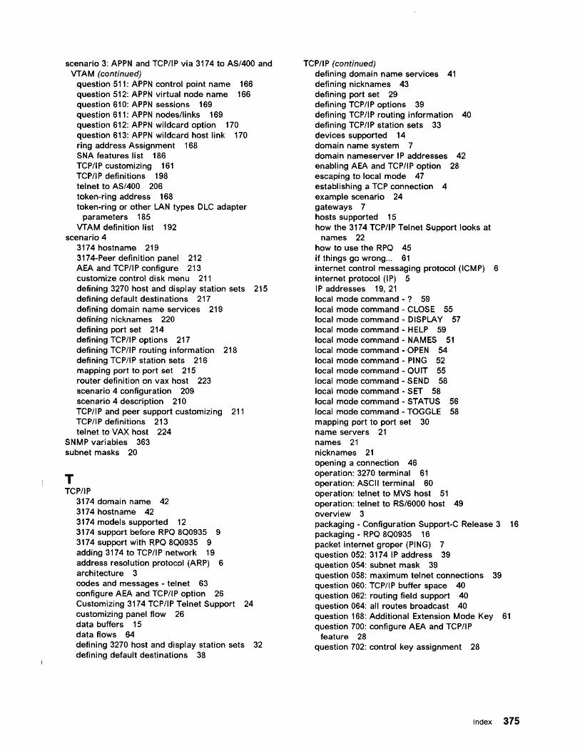
scenario 3: APPN and TCP/IP via 3174 to AS/400 and VTAM (continued)
question 511: APPN control point name 166 question 512: APPN virtual node name 166 question 610: APPN sessions 169 question 611: APPN nodes/links 169 question 612: APPN wildcard option 170 question 613: APPN wildcard host link 170 ring address Assignment 168 SNA features list 186 TCP/IP customizing 161 TCP/IP definitions 198 tel net to AS/400 206 token-ring address 168 token-ring or other LAN types DLC adapter
parameters 185 VTAM definition list 192
scenario 4 3174 hostname 219 3174-Peer definition panel 212 AEA and TCP/IP configure 213 customize control disk menu 211 defining 3270 host and display station sets 215 defining default destinations 217 defining domain name services 219 defining nicknames 220 defining port set 214 defining TCP/IP options 217 defining TCP/IP routing information 218 defining TCP/IP station sets 216 mapping port to port set 215 router definition on vax host 223 scenario 4 configuration 209 scenario 4 description 210 TCP/IP and peer support customizing 211 TCP/IP definitions 213 tel net to VAX host 224
SNMP variables 363 subnet masks 20
T TCP/IP
3174 domain name 42 3174 hostname 42 3174 models supported 12 3174 support before RPQ 8Q0935 9 3174 support with RPQ 8Q0935 9 adding 3174 to TCP/IP network 19 address resolution protocol (ARP) 6 architecture 3 codes and messages - tel net 63 configure AEA and TCP/IP option 26 Customizing 3174 TCP/IP Telnet Support 24 customizing panel flow 26 data buffers 15 data flows 64 defining 3270 host and display station sets 32 defining default destinations 38
TCP/IP (continued) defining domain name services 41 defining nicknames 43 defining port set 29 defining TCP/IP options 39 defining TCP/IP routing information 40 defining TCP/IP station sets 33 devices supported 14 domain name system 7 domain nameserver IP addresses 42 enabling AEA and TCP/IP option 28 escaping to local mode 47 establishing a TCP connection 4 example scenario 24 gateways 7 hosts supported 15 how the 3174 TCP/IP Telnet Support looks at
names 22 how to use the RPQ 45 if things go wrong... 61 internet control messaging protocol (ICMP) 6 internet protocol (IP) 5 I P addresses 19, 21 local mode command -? 59 local mode command - CLOSE 55 local mode command - DISPLAY 57 local mode command - HELP 59 local mode command - NAMES 51 local mode command - OPEN 54 local mode command - PING 52 local mode command - QU IT 55 local mode command - SEND 58 local mode command - SET 58 local mode command - STATUS 56 local mode command - TOGGLE 58 mapping port to port set 30 name servers 21 names 21 nicknames 21 opening a connection 46 operation: 3270 terminal 61 operation: ASCII terminal 60 operation: telnet to MVS host 51 operation: tel net to RS/6000 host 49 overview 3 packaging - Configuration Support-C Release 3 16 packaging - RPQ 8Q0935 16 packet internet groper (PING) 7 question 052: 3174 IP address 39 question 054: subnet mask 39 question 058: maximum tel net connections 39 question 060: TCP/IP buffer space 40 question 062: routing field support 40 question 064: all routes broadcast 40 question 168: Additional Extension Mode Key 61 question 700: configure AEA and TCP/IP
feature 28 question 702: control key assignment 28
Index 375
TCP/IP (continued) question 703: request M L T for AEA 29 questions 710 through 713: miscellaneous ASCII
options 29 returning to the connection menu 48 returning to the telnet session 48 routes 23 simple network management protocol (SNMP) 7 special considerations for 3270 emulation 61 special considerations for 3270 terminals 60 special considerations for ASCII terminals 59 storage requirements 15 subnet masks 20 support with Configuration Support-C Release
3 10 support with RPO 801041 10 supported configuration - DSPU 3174 13 supported configuration - gateway 3174 12 telnet 5 telnet session resources 48 tel net sessions 15 terminal operation 46 terminal types 59 token-ring considerations 44 transmission control protocol (TCP) 3 user datagram protocol (UDP) 6
376 Using the 3174 TCPIIP Networks

GG24-4172-00
Printed in the United States of America on recycled paper containing 10% recovered post-consumer fiber
-~------- ----- -- -. ---- - - ----~.--~--.~~- . -~
GG24-4172-00