TCP/IP for Dummies
81
1 TCP/IP for Dummies Jean-Yves Le Boudec ÉCOLE POLYTECHNIQUE FÉDÉRALE DE LAUSANNE
-
Upload
khangminh22 -
Category
Documents
-
view
9 -
download
0
Transcript of TCP/IP for Dummies

1
TCP/IP for DummiesJean-Yves Le Boudec
ÉCOLE POLYTECHNIQUE FÉDÉRALE DE LAUSANNE

2
This lecture may not be for youFirst take quiz 1 (given in class)
correct answer = +1wrong answer = -1no answer = 0
If you score 28 or more, this lecture is not for you; relax and come back when the review session is finished (see web site)If you score 23 or less, this lecture is for you
take the lecture plus the first two exercise sessionsbut do not take its title seriously, I once was a dummy, too
Else it is up to you to decide

3
Contents1. Overview of TCP/IP2. Layer 2, MAC addresses3. IP4. Transport5. Application

In this lecture we study computer networks.
We use a top-down approach, starting with applications. We present an overallpicture, which will enable you to understand the layered model of networking software. Then in the following chapters, we will study the various components (called “layers”), one by one.
What are computer networks used for ?
Computer networks allow people and machines to communicate, using a number of services. The slide shows a small subset of services.
4
1. OverviewNetwork Services
network services examples:distributed database, Web (3) , file transfer, remote login, email, news, talk, remote processing, resource sharing (file servers, printers, modems), network time, name service (2)……
user clicks:http://www.zurich.ibm.com/RZ.html
query www.zurich.ibm.com
answer www.zurich.ibm.comIP addr = 193.5.61.131
IP addr = 193.5.61.131GET activities.html
data (HTML page)
1
2
3
name server
Web server

A computer network is made of two distinct subsets of components
- distributed applications are programs running on interconnected computers; a web server, a remote login server, an e-mail exchanger are examples. This is the visible part of what people call “the Internet”. In this lecture we will study the simplest aspects of distributed applications. More sophisticated aspects are the object of lectures called “Distributed Systems” and “Information Systems”.
- the network infrastructure is the collection of systems which are required for the interconnection of computers running the distributed applications. It is the main focus of this lecture.
The network infrastructure problem has itself two aspects:
- distance: interconnect remote systems that are too far apart for a direct cable connection
- meshing: interconnect systems together; even in the case of systems close to each other, it is not possible in non-trivial cases to put cables from all systems to all systems (combinatorial explosion, cable salad management problems etc.).
The distance problem is solved by using a network, such as the telephone network with modems (see later). The meshing problem was originally solved easily because the terminals were not able to communicate with each other, but always has to go through a main computer. The mesh in such cases is reduced to a star network. Today this is solved by a complex set of bridges and routers.
5
Network InfrastructureA computer network is made of
distributed applicationsprovide services to users on other machines, or to other machinesexecute on computers
network infrastructuresupports transport of data between computers where distributed applications residein computers (Ethernet card, modem + software)+ in special network devices (bridges, routers, concentrators, switches)
focus of this lecture = network infrastructure

The objective of this and the following slides is to introduce the concept of layers. Like any complex computer system, a network is made of components. This decomposition is, to a large extent, stable: computer networking people have agreed on a reasonable way to divide the set of functions into what is called “layers”.
We use the term layer because the decomposition always assumes that different components can be ordered such that one component interfaces only with two adjacent components. We call “layers” the components.
We start with the simplest, and the oldest network example: it is a mainframe connected to terminals. In this case, there are mainly two functions
• physical layer: translates bits into electromagnetic waves;
• data link layer: translates frames into bits.
These two functions are implemented on cables or on radio links. The physical layer has to do with signal processing and coding; it is the object of the lecture called “Telecommunications”. The data link layer has to do with bits and bytes; we will study the data link layer in this lecture.
6
Physical Layer --Data Link Layer
point to pointcables
mainframecomputer
terminals
1
2
T1
T2
T3
“to T3: Hello”
“From T1: Hello”
physical transmission = Physical functionbits <-> electrical / optical signalstransmit individual bits over the cable: modulation, encoding, synchronization
frame transmission = Data Link functionbits <-> frames frame boundariesaddressingbit error detection: CRC
Modems, Ethernets

Modern networks have more than the physical and the data link layers. The network layer is a set of mechanisms that can be used to send packets from one computer to another in the world. There are two types of networks:
With packet switching, data packets can be carried together on the same link. They are differentiated by addressing information. Packet switching is the basis for all data networks today, including the Internet, public data networks such as Frame Relay or X.25, and even ATM. Packet switches have queues.
Circuit switching is the way telephone networks operate. A circuit emulates the physical signals of a direct end-to-end cable. When computers are connected by a circuit switched network, they establish a direct data link over the circuit. This is used today for modem access to a data network.
Modern circuit switches are based on byte multiplexing and are thus similar to packet switches, with the main difference that they perform non-statistical multiplexing (see later).
A network has intermediate systems (ISs): those are systems that send data to next ISs or to the destination. Using interconnected ISs saves cable and bandwidth. Intermediate systems are known under various terms depending on the context: routers (TCP/IP, AppleTalk,…), switches (X.25, Frame Relay, ATM, telephone), communication controllers (SNA), network nodes (APPN)
7
A Networknetwork layer
set of functions required to transport packets end-to-endexamples: IP, Appletalk, IPX
intermediate system forwards data not destined to itself
packet switch
1
4, 6a
T1
T2
T3
T4
2a1a 3a
5a 4a
2 3
srce=T2, dest=M2, “to T3: hello”
M1
M2

Physical, data link and network layers are sufficient to build a packet transport system between computers. However, this is not enough for the programmer.
When you write a low-level program that uses the network (as we will do in this lecture), you do not handle packets, but data. The primary goal of the transport layer is to provide the programmer with an interface to the network.
Second, the transport layer uses the concept of port. A port is an address that is used locally (on one machine) and identifies the source and the destination of the packet inside one machine. We will come back to the concept of ports later in this chapter.
The transport layer exists in two varieties: unreliable and reliable. The unreliable variety simply sends packets, and does not attempt to guarantee any delivery. The reliable variety, in contrast, makes sure that data does reach the destination, even if some packets may be lost from time to time.
8
Transport Layerwhy a transport layer?
transport layer = makes network services available to programsis end-to-end only, not in intermediate systems such as routersmay add additional functions to network services (reliability, ordering, congestion control, multiplexing)
in TCP/IP there are two main transport protocols (there is also RTP)UDP (User Datagram Protocol)
– unreliable– offers a datagram service to the application (unit of information is a message)
TCP (Transmisssion Control Protocol)– reliable– offers a stream service (unit of information is a byte)
application may use UDP or TCP depending on requirementsprogramming interface
socket API: a library of C functionssocket is similar to a file descriptor; controls a communication endpoint
– is associated with an IP address, a port number

9
Protocol, service and other fancy definitions
Peer entitiestwo (or more) instances of the same layer
Protocol and a PDU:the rules of the operation followed by peer entitiesthe data exchanged is called PDU (Protocol Data Unit)there is one protocol (or more) at every layer
Service and a SDUthe interface between a layer and the layer above - SAP (Service Access Point)the interface data is called a SDU (Service Data Unit)
Connectiona protocol is connection oriented if the peer entity must be synchronized before exchanging useful data (connection set up); otherwise it is connectionless.
A protocol is the formal definition of external behaviour for communicating entities. It defines:
- format of PDUs- rules of operation (PDU sent, data delivered, abort)
Examples of protocols are: TCP
UDP
IP
Ethernet
Protocols are connection oriented or connectionless. A connection exists if the communication requires some synchronization of all involved parties before communication can take place. The telephone system is connection oriented: before A can send some information to B, A has to call B (or vice versa) and say “hello”. The postal (mail) system is connectionless. If A wants to send some information to B, A can write a letter and mail it, even if B is not ready to read it.

10
Protocol Architecture
SAP
PDU PDU
protocol
Layer n-1
Layer n entity Layer n entity
SDU
serviceSAP
SDU
demultiplexing
Networking functions are structured as a layered model:
- layer n communicates with other layer n entities using layer n PDUs
- layer n uses the service of layer n-1 and offers a service to layer n+1.
- entities at the same layer are said peer entities
- operation rules between peer entities are called protocol
Layering of protocol entities is reflected by the term of a protocol stack.

Flow 2 illustrates the query/response protocol of the Domain Name System (DNS). The name resolver and the name server are two application programs, probably C programs making calls to the socket library. The programs use UDP, which is the non-reliable transport protocol in the TCP/IP stack.
Let us apply the terminology on this example.
“name resolver” uses the UDP service: it creates a request to send data to “name server”. “name server” is identified by its IP address (for example: 128.178.15.7). “name resolver” also knows that “name server” can be reached by means of port 53 (a well known convention used in the Internet). The SDU is the request, with the data. The transport-PDU is called a datagram. It contains the data, the address and the port numbers. It is identified by 2 in the figure.
UDP creates a request to IP to send data to the name server machine identified by the IP address 128.178.15.7. The network-PDU is called an IP packet. It contains the UDP datagram plus the IP addressing information (and some other information, see later).
IP creates a request to send a data frame over the modem. The modem card creates a data-link PDU, called a modem “frame”. The frame contains the IP packet, maybe compressed. Then the data link layer requests transmission of the frame; the physical layer SDU is a bit. The physical layer PDU is an electromagnetic signal.
At the routerthe data frame is received, understood as an IP packet
IP reads the IP destination address (128.178.15.7) and decides to forward it over its Ethernet interface
IP creates a request to send the data frame over the Ethernet. An Ethernet frame is created and sent to the name server machine
11
Example: name resolutionuser clicks:http://www.zurich.ibm.com/RZ.html
DNS query www.zurich.ibm.com
DNS answer www.zurich.ibm.comA 193.5.61.131
1
2
name resolvername resolver
TCPTCP UDPUDP
IP(network layer)
IP(network layer)
Data Link (modem, PPP)
Data Link (modem, PPP)
Physical(twisted pair)
Physical(twisted pair)
name servername server
TCPTCPUDPUDP
IPIP
Data Link (Ether)
Data Link (Ether)
Physical(thin Coax)
Physical(thin Coax)
IPIP
DL(modem)
DL(modem)
PHY(TP)
PHY(TP)
DL(Ether)
DL(Ether)
PHY(TC)
PHY(TC)
router R1
Host A Host BP1 P2

Here is a second example.
A web browser always uses TCP for communication with a web server.
The web browser starts by requesting from the transport layer the opening of a connection for reliable data transport. TCP opens a connection to the peer entity at the web server machine by starting a 3-way handshake. If the connection can successfully be opened, then data can flow between the web client and server. TCP monitors missing packets and retransmits them as appropriate.
The web browser and server can thus assume that they have a reliable data pipe between them transporting data in sequence and without errors, at least as long as the TCP layer does not close the connection.
TCP is connection oriented. What is shown is the connection setup phase. TCP uses IP, which is connectionless. UDP is connectionless.
An observer at P1 or P2 would see the beginning of the message between web clients and servers only in the third data frame.
12
An example with TCP
Web BrowserWeb Browser
UDPUDP TCPTCP
IP(network layer)
IP(network layer)
Data Link (modem, PPP)
Data Link (modem, PPP)
Physical(twisted pair)
Physical(twisted pair)
Web ServerWeb Server
UDPUDPTCPTCP
IPIP
Data Link (Ether)
Data Link (Ether)
Physical(thin Coax)
Physical(thin Coax)
IPIP
DL(modem)
DL(modem)
PHY(TP)
PHY(TP)
DL(Ether)
DL(Ether)
PHY(TC)
PHY(TC)
router R1
Host A Host BP1 P2
open connection to 193.5.61.131:80open (SYN)
connect (SYN ACK)
connect ack (ACK) send DATA (GET activities.html)
193.5.61.131
passive open80

We use the terms “client” and “server” in the following sense.
When two entities say A and B, want to communicate, there is a boostrap problem: how can you initialize both A and B such that the communication can take place. One solution is to manually start A, then B, but this defeats the purpose of networking. The only way we have found so far is to request that one of the two, say B, is started and immediately puts itself in a listening position. We say that B is a server. A system, such as A, which talks to B, is said to be a client.
Being a server or a client is relative to a given protocol. For example, consider the application level protocol called FTP (file transfer protocol). The FTP server is a machine that waits for other machines to send requests for logging in. When an FTP client has contacted an FTP server, then after an initial navigation phase, the FTP client has to wait for the FTP server to open a connection back to the client (try it !). In that interaction, the FTP client is a TCP server, namely, a machine which waits for some other machine to open a TCP connection.
In everyday’s life, most people use the term “server” to designate a machine whose main function is to be a server for some protocol: a name server, a file server, a news server ...
13
What is the Client-Server model?distributed applications use the client-server model
server = program that awaits data (requests) to be sent to it interprets a request and send a response
clients send data (requests) to serverswait for a response
user clicks:http://www.zurich.ibm.com/activities.html
query www.zurich.ibm.com
answer www.zurich.ibm.comIP addr = 193.5.61.131
IP addr = 193.5.61.131GET activities.html
data (HTML page)
1
2
3
name server
Web server
Internet

An architecture is a set of external behaviour specifications for a complete communication system. It describes protocols, but not how to implement them.
The OSI (Open Systems Interconnection) architecture defines protocols and service specifications.
It is an official standard, similar to the TCP/IP architecture, but is not much implemented. However, the OSI model is used most frequently to describe all systems, including TCP/IP
Architectures do not interoperate by themselves at the protocol level. For example, the OSI transport protocols are not compatible with TCP or UDP. Worse, there is no compatibility at the service level, so it is not possible to use layer n of one architecture and put it on top of layer n-1 of some other architectures. There are fortunately exceptions to this statement. Layer interfaces where service compatibility is often implemented are:
the data link layer
the transport layer.
For example, it is possible to use various protocol families over the same local area network (LAN).
The OSI presentation layer is in charge of hiding specific data representation formats. It defines ASN.1, an abstract, universal means for encoding all types of data structures. ASN.1 has also become part of the TCP/IP architecture, in the application layer.
The OSI session layer synchronizes events between end-systems, in order for example to support failure recovery. It is implemented in TCP/IP over a number of application layer protocols and TCP.
14
Application LayerApplication Layer
Presentation LayerPresentation Layer
OSI Architecture
Session LayerSession Layer
Transport LayerTransport Layer
Network LayerNetwork Layer
Data Link LayerData Link Layer
Physical LayerPhysical Layer 1
2
3
4
5
6
7
end to end layers
global layer
local layers

The TCP/IP Architecture, or the Internet Architecture is described by a collection of Internet standards, published in documents called RFCs (Requests For Comments), available for example from ftp://ftp.switch.ch/standard.
The picture shows all the layers of the Internet Architecture. There exists, inside every layer, a number of protocols that we will discover in this course.
There exist other architectures, each of them having a different set of layers and names for layers. There are:
proprietary architectures: SNA (IBM), Decnet (Digital), AppleTalk (Apple), XNS (Xerox), UUCP (Unix internal protocols), etc
the ITU architecture defines public networks for telephony, telex, fax, data networks (X.25, Frame Relay, mail and directory services) and ATM
the IEEE LAN architecture defines layers 1 and 2 for local area networks. We will see some details later.
Having several architectures is a nuisance; everything would be simpler if there would be only one. Today, the TCP/IP architecture has become dominant, so this is the only one we will study in detail. The ITU architecture (Frame Relay and ATM) does also play an important role and we will study it at the end of the course.
15
The TCP/IP Architecture
Application LayerApplication Layer
Transport LayerTransport Layer
Network LayerNetwork Layer
Data Link LayerData Link Layer
Physical LayerPhysical Layer
Network LayerNetwork Layer
Data Link LayerData Link Layer
Physical LayerPhysical Layer
Application LayerApplication Layer
Transport LayerTransport Layer
Network LayerNetwork Layer
Data Link LayerData Link Layer
Physical LayerPhysical Layer
Host(= end-system)
Router(= intermediate system)
Host(= end-system)
OSI layer Number
1
2
3
4
7-5

We see here some rudiments of transmission. The diagram shows some very primitive channel encoding methods. They are used on short distances, for example with Ethernet or Token Ring.
16
Physical Layerlayer 1 function is to transmit/receive a sequence of bits on electrical or optical systemBits are encoded as analog signal; here are examples different channel coding(Ethernet uses Manchester encoding)
NRZ
NRZI
Manchester
Differential Manchester
modulationadapt signal to fit a channel, eg. modems (telephone frequency band 300 - 3400 Hz)amplitude, frequency, phase modulation, or hybrid (amplitude and phase)
1 1 0 0 1 1 1 0 0 00

The bit rate of a channel is the number of bits per second. The bandwidth is the width of the frequency range that can be used for transmission over the channel. The bandwidth limits the maximal bit rate that can be obtained using a given channel.
In general, the information theory gives the maximum bit rate available under some modelling assumptions. The Shannon-Hartley laws gives the maximum bit rate, for a given bandwidth, assuming the channel is a white noise channel.
Many people confuse bandwidth and bit rate, but you should keep the distinction.
The bit rate and the number of bits to transmit determine the transmission time.
17
Bit RatesBit Rate of a transmission system = number of bits transmitted per time unit; improperly called “bandwidth” in some books and papersunits: b/s, kb/s = 1000 b/s, Mb/s = 10e+06 b/s, Gb/s=10e+09 b/sShannon-Hartley law: Cmax = B log2 ( 1 + S/N ), with B = bandwidth (Hz), S/N = signal to noise ratio (not expressed in dB)example: telephone circuit: B = 3 kHz, S/N = 30 dB, Cmax 30 kb/sPractical Bit Rates:
modem: 2.4 kb/s to 33.6 kb/s (56kb/s on reception over ISDN at server), 9.6 kb/s GSMADSL line: 124 kb/s to 2 Mb/sEthernet: 10 Mb/s, 100 Mb/s, 1Gb/sWireless LAN: 1 to 50 Mb/sATM: 2 Mb/s to 622 Mb/sOptical carriers: 155 Mb/s to 9.6 Gb/s
Transmission time = time to send x bits at a given bit rateExample: time to send 1 MB at 10 kb/s = ?

Multiplexing means putting several sources on the same link. The most common ways of multiplexing is by sharing time slots (temporal multiplexing) or frequency bands (frequency multiplexing). Temporal multiplexing is used in many telecommunication networks - in circuit switching each source is allocated with one time slot. When a source does not use the link during its slot, the available capacity is unused.
In statistical multiplexing data units are stamped with identifiers so that a source may send data at will.
On a packet switch, the bit rate of the output (4) is often less than the sum of the bit rates of all inputs (1 to 3). There is a queue at the output; if several packets arrive at the same time, then only one of them is transmitted whiles others have to wait. If nothing special is done, then once in a while, the queue may overflow and packets are lost. This happens everyday on the Internet. Special mechanisms, called congestion control, are required to avoid that packet losses happen too frequently. Congestion control is the object of the advanced lecture on networking.
In contrast, with circuit switching, the bit rate of the outgoing circuit (4 on the picture) is at least equal to the sum of the incoming circuits bit rates (1 to 3). There is no loss of data.
What is the value of statistical multiplexing ?
Well, economy. Most of the time, sources are not active, so circuit switching tends to waste bit rates.
18
Statistical and Non-statistical Multiplexing
Multiplexingseveral sources use the same link
Statistical Multiplexingthe bit rate is less than the sum of the incoming bit ratesmay produce packet loss; requires congestion control
1
3
T1
T2
T3
2 4

Propagation is the time taken by the front of a signal to reach the destination. It is independent of the bit rate.
Propagation of an electro magnetic signal is the speed (also called celerity) of light. It depends on the wavelength and the element in which the signal is propagating.
Acoustic waves move at ca. 300 m/s. What is the propagation time if we use an acoustic phone system between two cities which are 1000 km apart ?
19
PropagationPropagation between A and B = time for the head of signal to travel from A to B
si - ti = D (propagation delay)
D = d /c, where d = distance, c =signal celeritycopper: c= 2.3e+08 m/s; glass: c= 2e+08 m/s;Rule of thumb: 5 µs/km; example: earth round trip in fiber: D = 0.2 stime through circuits also adds to propagation delaysLausanne - Concarneau over acoustic channel. D = ???
t0 t1 tn
s0 s1 sn
A
B
time

Compute the values for these examples and try to find scenarios where they apply. Meditate the results.
20
ExamplesAt time 0, computer A sends a packet of size 1000 bytes to B; atwhat time is the packet received by B for each of the following cases ?
distance 20 km 20000 km 2 km 20 mbit rate 10 kb/s 1 Mb/s 10 Mb/s 1 Gb/s1-way propagation ?transmission ?reception time ?

21
ExamplesAt time 0, computer A sends a packet of size 1000 bytes to B; at what time is the packet received by B (c = 2e+08 m/s)?
distance 20 km 20000 km 2 km 20 mbit rate 10 kb/s 1 Mb/s 10 Mb/s 1 Gb/s1-way propagation 0.1 ms 100 ms 0.01 ms 0.1µstransmission 800 ms 8 ms 0.8 ms 8 µsreception time 800.1 ms 108 ms 0.81 ms 8.1 µs
GSM WAN WiFi LAN Gb-LAN

The throughput defines how much data can be moved by time unit. It is equal to the bit rate if there is no protocol (example 1). However, in most practical cases, the throughput is less than the bit rate for two reasons:
- protocol overhead: protocols like UDP use some bytes to transmit protocol information. This reduces the throughput. If you send one-byte messages with UDP, then for every byte you create an Ethernet packet of size 1 + 8 + 20 + 26 = 53 bytes, thus the maximum throughput you could ever get at the UDP service interface if you use a 64 kb/s channel would be 1.2 kb/s.
- protocol waiting times: some protocols may force you to wait for some event, as we show on the next page.
22
ThroughputThroughput (am thruput, f débit utile, g Durchsatz) for a transmission system or a communication flow =number of useful data bits / time unitunits: b/s, kb/s, Mb/sExample 1: PCM voice ( 8 kHz, 8 bits per sample -> 64 kb/s) throughput = 64 kb/sExample 2: Stop and Go protocol

This example is a simple protocol, often used, for repairing packet or message losses. The idea is simple
- identifiy all packets with some number or some other means
- when you send one packet, wait until you receive a confirmation
- after some time, if no confirmation arrives, consider that the packet has been lost and retransmit.
Compute the maximum throughput of this protocol, assuming the source has an infinite supply of packets to send, the destination generates the confirmation instantly, and the bit rate of the channel is constant.
23
Test Your UnderstandingPackets may be lost during transmission:bit errors due to channel imperfections, various noises.Computer A sends packets to B; B returns an acknowledgement packet immediately to confirm that B has received the packet;A waits for acknowledgement before sending a new packet; if no acknowledgement comes after a delay T1, then A retransmits
Question: What is the maximum throughput assuming that there are no losses ?notation:
packet length = L, constant (in bits);acknowledgement length = L’, constant channel bit rate = b; propagation delay = Dprocessing time is negligible

24
Solution (1)packet P1 sent
packet P1 acknowledged
T=L/b 2D T’=L’/b
cycle time = T + 2D + T’useful bits per cycle time = L
throughput = L / (T + 2D + T’)
= b / (1 + L’/L + 2Db/L)
A
B
time
overhead « bandwidth »-delay product

25
Solution (2)distance 20 km 20000 km 2 km 20 mbit rate 10 kb/s 1 Mb/s 10 Mb/s 1 Gb/spropagation 0.1ms 100 ms 0.01 ms 0.1µstransmission 800 ms 8 ms 0.8 ms 8 µsreception time 800.1 ms 108 ms 0.81 ms 8.1 µs
modem WAN LAN Hippibw delay product 2 bits 200 000 bits 200 bits 200 bitsthroughput = b × 99.98% 3.8% 97.56% 97.56%
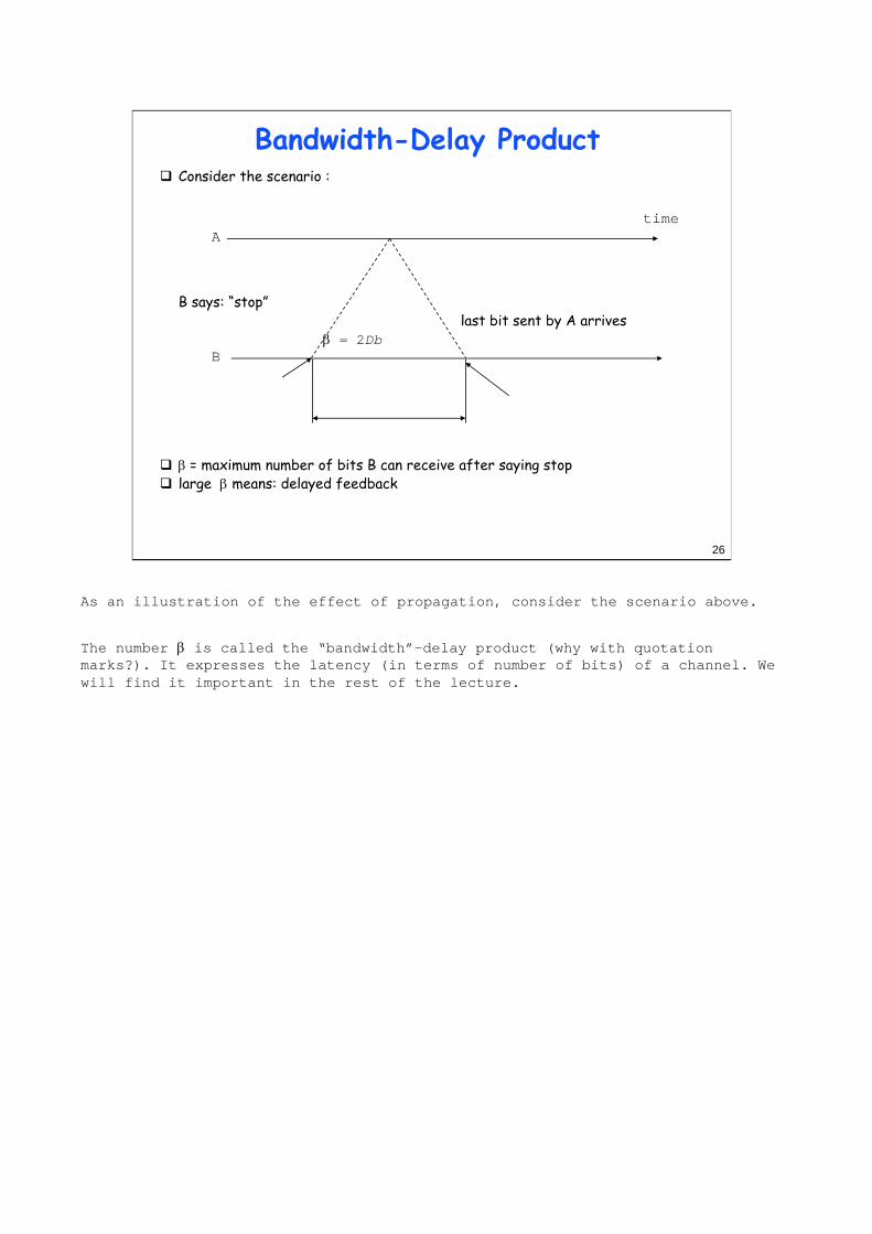
As an illustration of the effect of propagation, consider the scenario above.
The number β is called the “bandwidth”-delay product (why with quotation marks?). It expresses the latency (in terms of number of bits) of a channel. We will find it important in the rest of the lecture.
26
Bandwidth-Delay ProductConsider the scenario :
B says: “stop”last bit sent by A arrives
β = 2Db
β = maximum number of bits B can receive after saying stoplarge β means: delayed feedback
A
B
time

27
Facts to Remember (this section)Computer networks are organized using a layered modelThere is one layered model per architecture
ex. TCP/IP, Appletalk, Novell Netware, OSIbut the numbering is standard (1 to 7)
Layers 1 and 2 correspond to cables (or wireless channels)Layer 3 = network layer; has mainly intermediate systems, eg. routersLayer 4 = transport; is in end systems onlyUDP provide the simplest access to network servicesLayer 5-7 is the application layer (web, e-mail, etc)Concepts you should know
protocol, peer entities, PDU, servicetransmission time versus propagation timebandwidth delay product

28
2. Layer 2, MAC Addresses Local Area networks use mainly Ethernet and WLAN
see part II for detailsEthernet is originally a cable sharing protocolDesign goal: interconnect n systems without switch in-betweenRequires an Access Method: (Medium Access Control = MAC); for Ethernet. CSMA/CD
If you want to understand something in the world of local area networks, you should keep in mind the design requirements. Today, they are:
•(1) interconnect many pieces of equipment without complex cabling, inside a limited geographical area, and inside one organization
•(2a) be easy to manage, in particular, detect cable faults easily.
When Ethernet was first conceived, the requirements were a little bit different. The second requirement was replaced by:
•(2b) use one shared cable for the entire network.
Today most people would agree that this is not necessarily a good idea, because fault isolation is difficult on a shared cable. Originally, it was believed to be good because it would reduce the amount of cabling, and because traffic is bursty.
Burstiness means that, most of the time, sources are idle; once in a while, they send a large amount of traffic. The response time is better with a shared medium system than if you allocate a fixed share to all (see exercise).

The access method for Ethernet is Carrier Sense Multiple Access / Collision Detection (CSMA/CD). It works as follows
i = 1
while (i <= maxAttempts) do
listen until channel is idle
transmit and listen
wait until (end of transmission) or (collision detected)
if collision detected then
stop transmitting /* after 32 bits (“jam”)*/
else
wait for interframe delay
leave
wait random time
increment i
end do
29
CSMA / CD Time Diagram 1A senses idle channel, starts transmittingshortly before T, B senses idle channel, starts transmitting
BA0
T

30
CSMA / CD Time Diagram 2A senses collision, continues to transmit 32 bits (“jam”)B senses collision, continues to transmit 32 bits (”jam“)
BA0
T
t2

Collisions cannot be avoided because of propagation delays, but they are always resolved by the collision detection mechanisms.
Collisions are normal with Ethernet, though they tend to indicate a high load.
There is no packet loss due to collision: the sending station simply retransmits the packet if a collision occurs. The operating system is not aware of the collision, only the Ethernet adapter.
31
CSMA / CD Time Diagram 3A waits random time t1B waits random time t2B senses channel idle and transmitsA senses channel busy and defers to BA now waits until channel is idle
BA0
T
t2
t1

32
Ethernet at 10, 100 and 1000 Mb/sEthernet exists at 10 Mb/s, 100 Mb/s and 1 Gb/sslotSize is 512 bits at 10 Mb/s and 100 Mb/s
This means that the network size is 2 km at 10 Mb/s, and ____ at100 Mb/s
At 1 Gb/s, slotSize is 512 BytesThe network size is ca. the same as at 100 Mb/swhat does it implies?
See also network aspects: is there CSMA/CD in Gigabit Ethernet ?
This implies that the minimum packet size is larger. This can be achieved by
• grouping several small packets together
• otherwise, padding
Padding means that bit rate is wasted.

33
Ethernet / IEEE 802.3Ethernet = CSMA/CD with exponential backoff as shown in part Aoriginally over a coaxial cable10 Mb/s to 1 Gb/slocal area only (<= 0.2 to 2 kms)
Ethernet history1980 : Ethernet V1.0 (Digital, Intel, Xerox)1982 : Ethernet V2.01985 : IEEE 802.3 standardsmall differences in both specifications; adapters today support both1995 : IEEE 802.3 100Mb/s standard
DA
SA
Type
data
FCS
DA
SA
Length
data
FCS
pad
802.3 frame Ethernet V.2 frame
DA = destination addressSA = source address
SFD
preamble
SFD
preamble
1 B =10101011
7 B
6 B
6 B
2 B
<= 1500 B
4 B
SNAP
The preamble is used for the receivers to synchronize (01010101… terminated by 0). With Ethernet, transmission starts asynchronously (stations start independently), and between transmissions, the channel is idle.
SFD (start frame delimiter) is used to validate the beginning of a frame.
Destination length is used to indicate the total length before padding. Padding is required if the minimum frame size of 512 bits = 64 bytes is not reached. With the Ethernet proprietary (=non standard) format, this field is not present. It is up to the layer using Ethernet to know that frames have to be at least 512 bits, and perform the padding. Maximum size of data part is 1500 Bytes (limitation imposed by buffer size considerations in adapters).
The type field indicates the type of upper layer that uses the protocol (for example: IP or Appletalk). With 802.3, this field is absent; it is replaced by an intermediate layer, called LLC that provides mainly this multiplexing function. LLC is not needed with the non-standard Ethernet. Type values are larger than the maximum size so both formats can exist on the same network (even on the same station).
The FCS (frame check sequence) is a 32-bit cyclic redundancy check. It can detect all single, double, triple errors, all error bursts of length <= 32, most double bursts of length up to 17. The probability that a random collection of bit errors is undetected is 2e-10.
Ethernet works for a local area only. This is because the CSMA/CD protocol has poor utilization as the bandwidth-delay product becomes large compared to the frame sizes.
The first network of Apple (Appletalk) was CSMA/CA (collision avoidance) at 230.4 kb/s.

• Ethernet addresses are known as MAC addresses. Every Ethernet interface has its own MAC address, which is in fact the serial number of the adapter, put by the manufacturer.MAC addresses are 48 bit-long. The 1st address bit is the individual/group bit, used to differentiate normal addresses from group addresses. The second bit indicates whether the address is globally administered (the normal case, burnt-in) or locally administered. Group addresses are always locally administered.
• When A sends a data frame to B, A creates a MAC frame with source addr = A, dest addr = B. The frame is sent on the network and recognized by the destination.
• Some systems like DEC networks require that MAC addresses be configured by software; those are so-called locally administered MAC addresses. This is avoided whenever possible in order to simplify network management.
• Data on Ethernet is transmitted least significant bit of first octet first (a bug dictated by Intel processors). Canonical representation thus inverts the order of bits inside a byte(the first bit of the address is the least significant bit of the first byte); examples of addresses:
01:00:5e:02:a6:cf (a group address)08:00:20:71:0d:d4 (a SUN machine)00:00:c0:3f:6c:a4 (a PC )00:00:0c:02:78:36 (a CISCO router)FF:FF:FF:FF:FF:FF the broadcast address
34
AddressingMAC address: 48 bits (16 bits) = adapter namesender puts destination MAC address in the frameall stations read all frames; keep only if destination address matchesall 1 address (FF:FF:FF:FF:FF:FF) = broadcast
MAC address A08:00:20:71:0d:d4
B C D00:00:c0:3f:6c:a4
01:00:5e:02:a6:cf (group address)

Contrary to the original design requirement, Ethernet cabling is today mainly point to point.
Why do network managers prefer point to point cabling?
- because fault isolation is simpler- because configuration management is simpler
How is point to point cabling possible with a shared medium protocol?
- using repeaters (shown on the next slide)- or using bridges (called Ethernet Switches)
35
Ethernet CablingEthernet cabling is originally shared cableToday: mainly point to point UTP - twisted pairHow is that possible ?
repeatersbridges
Thick Coax
Thin Coax
UTP

36
RepeatersExtend network beyond cable length limitFunction of a simple, 2 port repeater:- repeat bits received on one port
to other port- if collision sensed on one port, repeat random bits on other portOne network with repeaters = onecollision domainEven with repeaters, network is limited
propagation time51.2µs slotTime includes repeatersat most 4 repeaters in one path
Repeaters perform only physical layer functions (bit repeaters)
Repeater
From ethernet.faq:
There are limitations on the number of repeaters and cable segments allowed between any two stations on the network. There are two different ways of looking at the same rules:
1. The Ethernet way: A remote repeater pair (with an intermediate point-to-point link) is counted as a single repeater (IEEE calls it two repeaters). You cannot put any stations on the point to point link (by definition!), and there can be two repeaters in the path between any pair of stations. This seems simpler to me than the IEEE terminology, and is equivalent.
2. The IEEE way: There may be no more than five (5) repeated segments, nor more than four (4) repeaters between any two Ethernet stations; and of the five cable segments, only three (3) may be populated. This is referred to as the "5-4-3" rule (5 segments, 4 repeaters, 3 populated segments).
From 3Com, for 10 Mb/s Ethernet:
The 100BASE-T standard defines two classes of repeaters, called Class I and Class II repeaters. A collision domain can include at most one Class I or two Class II repeaters. Key topology rules are as follows:
• Using two Class II repeaters, the maximum diameter of the collision domain is 205 meters (typically 100m + 5m + 100m). With just a single Class II repeater in the collision domain, the diameter can be extended to 309 meters using fiber (typically 100m UTP + 209m fiber downlink). With a single Class I repeater in the collision domain, the diameter can be extended to 261 meters using fiber (typically 100m UTP + 161m fiber downlink).
• Connecting from MAC to MAC (switch to switch, or end-station to switch) using half-duplex 100BASE-FX, a 412-meter fiber run is allowed.
• For very long distance runs, a nonstandard, full-duplex version of 100BASE-FX can be used to connect two devices over a 2-kilometer distance. The IEEE is currently working on a standard for full duplex, but at this time all full-duplex solutions are proprietary.

37
From Repeaters to HubsMultiport repeater (n ports)logically equivalent to:
- n simple repeaters - connected to one internal
Ethernet segment
Multi-port repeaters make it possible to use point-to-point segments (Ethernet in the box)Value of point to point cabling ?- ease of management- fault isolation
S1
S2
S3
to other hub
UTP segment
Multi-portRe-
peater
MultiportRepeater
Ethernet Hub
Repeaters are the first building block that made it possible to have point-to-point star based cabling.

A bridge is an intermediate system for the MAC layer. It receives MAC frames and forwards them further.
38
One word on Bridges
Bridges are intermediate systems, or switches, that forward MAC frames to destinations based on MAC addressesBridges perform connectionless data forwardingBridges separate collision domains
a bridged LAN maybe much larger than a repeated LANthere may be several frames transmitted in parallel in a bridged LAN
BridgeA
B
C
D
port 1
port 2
port 3Dest PortMAC Nbaddr
Dest PortMAC Nbaddr
A 1B 2C 3D 2
A 1B 2C 3D 2
Forwarding Table
Repeater

39
Repeaters and Bridges in OSI Model
Bridges are layer 2 intermediate systemsRepeaters are in layer 1intermediate systemsThere also exist layer 3 intermediate systems (IP routers) -> see next chapter
Transport
Network
Physical
ApplicationPresentation
Session
5 to 7
4
3
2
1
MAC
Physical Physical
MAC
Transport
Network
Physical
ApplicationPresentation
Session 5 to 7
4
3
2
1
MAC
L2 PDU(MAC Frame)
L2 PDU(MAC Frame)
End System Repeater Bridge End System
LLC LLC

40
Switched EthernetSwitched Ethernet = Bridge in the boxTotal bandwidth is not shared: parallel frame transmissionAn Ethernet Switch = Multiport Bridge is a connectionless data switchEthernet used as a point-to-point mechanism!
A
Bridge
B C D U
Bridge
V W X
1 2 3 4 5 1 2 3 4 5
Frame Switching Hub Frame Switching Hub
B1 B2

41
Full duplex EthernetA shared medium Ethernet cable is half duplexFull duplex Ethernet = a point to point cable, used in both directions
no access method, no CSMA/CD100 Mb/s and Gigabit Ethernet switches use full duplex links to avoid distance limitations and to guarantee bandwidth for stations

42
Congestion ControlA network of buffers require some form of congestion control
otherwise congestion collapse may occurKnown forms of congestion control are
reservations (ex: ATM)end-to-end (ex: TCP)hop by hop (ex: machine bus)
Ethernet concentrators use hop-by-hop flow control
STOP signal can be simulated by collisions on half duplex linkson full duplex links: PAUSE ( n ) frames, where n is the duration of required stopping time
P=0P0
P=1P=2P=3
STOP
P1P2P3
STOP
GO
P=5P=6P=7
P=4

43
Architecture versus Productsarchitecture = set of protocols and functions
defined by standards or proprietary specifications (SNA, Decnet, AppleTalk)examples:
MAC layer, Ethernet Physical LayerBridge, Repeater
Products = implementations of various architecture componentsexamples:
a concentrator that performs repeating, bridgingan adapter that performs MAC + PHY frame switching performed
store and forwardcut through
Bridging is a well defined architecture concept. Switching is a commercial name with different meanings depending on the context. In a LAN context, a switching Ethernet concentrator is simply a bridge.

44
Facts to Remember (this section)Computers communicate in a local area network using Ethernet and MAC addressesA MAC address is the serial number of the Ethernet adapter Original Ethernet is a shared medium: one collision domain per LANUsing bridging we can have several collision domains per LANAn Ethernet switch uses bridgingRepeaters are bit-forwarding devices inside one Ethernet segmentBridges are connectionless intermediate systems that separate Ethernet segments

45
3. IP
host
subnetwork

Forwarding tables in bridges contain the list of all the MAC addresses that are reachable in a LAN. It is not possible to aggregate MAC addresses because they are not structured in a way that would reflect the topology of the network.
The Internet Protocol solves this problem.
46
Why a network layer?MAC addresses and bridging are not sufficient
bridging does not scale well to large networksMAC have no topological structure
Solution: connectionless network layer (eg. Internet Protocol, IP):every host receives a network layer address (IP address)intermediate systems forward packets based on destination address

The connectionless network layer is similar to the postal system; every packet behaves like a postcard:
- the destination address is present in every packet,
- intermediate systems (called routers) use routing tables to forward packets,- changes in routing tables are not synchronized with end systems. This is why we say that this type of operation is connectionless.
Contrary to MAC addresses, network layer addresses have a topological (= geographical) structure. For example, all IP addresses of the form 128.178.x.x belong to EPFL. This enables aggregation of tables in routers. Routers in the Internet need only to know in which direction 128.178.x.x is; they do not need a list of all addresses in use at EPFL.
47
Connectionless Network LayerConnectionless network layer = no connection
router R1
router R2
router R4
Host A.H1
Host B.D.H2
2 1
2
21
1
to outputB.x 2A.x 0
to outputA.x 1B.D.x 2B.C.x 3
to outputA.x 1B.x 2
router R3
to outputA.x 1B.D.x 1B.C.x 0
13
Host B.C.H2
0 0

48
Network Example with IP Addresses 129.132
66.46
129.132.100.12
lrcsuns128.178.156.24
08:00:20:71:0D:D4
lrcpc3128.178.156.7
00:00:C0:B8:C2:8D
in-inr128.178.156.1
00:00:0C:02:78:36128.178.79.1
00:00:0C:17:32:96
ed2-in182.1
in-inj128.178.182.3
182.5
128.178.100.3
LRC
15.221
Anneau SIDI SUN
DI
ed0-swi15.13 128.178.100.12
128.178.84.1ed0-ext EPFL-Backbone
sic500cs128.178.84.130
Modem+ PPP
disun3128.178.79.9
08:00:20:20:46:2E
128.178.84.133
stisun115.7
128.178.47.5
128.178.47.3
Switch
ezci7-ethz-switch129.132.35.1
130.59.x.x
ed2-el
128.178.29.6408:00:07:01:a2:a5
LEMA
128.178.156.2308:00:07:01:a2:a5
ezci7-ethz-switch
KomsysETHZ-Backbone
129.132.100.27
lrcmac4
lrcmac4

answer: address is 128.178.156.24
prefix is 128.178.156.0
host part is 0.0.0.24
49
IP AddressesAn IP addreess is 32 bits, noted in dotted decimal notationAn IP address has a prefix and a host part: prefix:hostSubnet mask identifies the prefix by bitwise & operationExamples
subnet mask at EPFL = 255.255.255.0question: net:subnet and host parts of : lrcsuns.lrc.epfl.ch ?
IP addresses are associated (in a complicated way) with a network topology for fixed hosts
not true for mobile hosts

50
IP Address HierarchiesThe prefix of an IP address is itself structured in order to support aggregation
For example: 128.178.x.y represents an EPFL host128.178.156 / 24 represents the LRC subnet at EPFL128.178 / 16 represents EPFL
Used between routers by routing algorithmsThis way of doing is called classless and was first introduced in inter domain routing under the name of CIDR (classless interdomain routing)
Notation: 128.178.0.0/16 means : the prefix made of the 16 first bits of the stringIn the past, an old model was used: class based addresses, with networks of class A, B or C; now only the distinction between class D and non-class D is relevant.IP address changes when host moves to another subnet(ex: Ethernet split into 2); compare to bridging

At the origin, the prefix of an IP address was defined in a very rigid way. For class A addresses, the prefix was 8 bits. For class B, 16 bits. For class C, 24 bits. The interest of that scheme was that by simply analyzing the address you could find out what the prefix was.
It was soon recognized that this form was too rigid. Then subnets were added. It was no longer possible to recognize from the address alone where the subnet prefix ends and where the host identifier starts. For example, the host part at EPFL is 8 bits; it is 6 bits at ETHZ. Therefore, an additional information, called the subnet mask, is necessary.
Class C addresses were meant to be allocated one per network. Today, they are allocated in contiguous blocks.
51
IP Address Classes
Examples: 128.178.x.x = EPFL host; 129.132.x.x = ETHZ host9.x.x.x = IBM host 18.x.x.x = MIT host
Class Range
ABCDE
0.0.0.0 to 127.255.255.255128.0.0.0 to 191.255.255.255192.0.0.0 to 223.255.255.255224.0.0.0 to 239.255.255.255240.0.0.0 to 247.255.255.255
Class B addresses are close to exhausted; new addresses are taken from class C, allocated as continuous blocks
0 Net Id0 1 2 3… 8 16 24 31
10 Net Id
110 Net Id
1110 Multicast address
11110 Reserved
Subnet Id
Host Id
Host Id
class A
class B
class C
class D
class E
Host Id
Subnet Id

52
IP PrinciplesHomogeneous addressing
an IP address is unique across the whole network (= the world in general)IP address is the address of an interfacecommunication between IP hosts requires knowledge of IP addresses
Routers between subnetworks only:a subnetwork = a collection of systems with a common prefixinside a subnetwork: hosts communicate directly without routers
ARP used to find MAC addressbetween subnetworks: one or several routers are used
Terminology:host = end system; router = intermediate systemsubnetwork = one collection of hosts that can communicate directly withoutrouters

53
ARP Protocol
lrcsuns lrcpc1 lrcpc2 in-inr
128.178.156.2408:00:20:71:0D:D4
128.178.156.3100:00:C0:B3:D2:8D
128.178.156.100:00:0C:02:78:36
1128.178.156.0
1: lrcsuns has a packet to send to 128.178.156.31 (lrcpc1)
this address is on the same subnetlrcsuns sends an ARP request to all systems on the subnet (broadcast) target IP address = 128.178.156.31ARP request is received by all IP hosts on the local networkis not forwarded by routers

54
ARP Protocol
lrcsuns lrcpc1 lrcpc2 in-inr
128.178.156.2408:00:20:71:0D:D4
128.178.156.3100:00:C0:B3:D2:8D
128.178.156.100:00:0C:02:78:36
1
2
128.178.156.0
2: lrcpc1 has recognized its IP addresssends an ARP reply packet to the requesting hostwith its IP and MAC addresses

Systems learn from ARP-REQUESTs. At the end of flow 1, all systems have learnt the mapping IP <-> MAC addr for the source of the ARP-REQUEST, namely, they have updated the following entry in their ARP table:
IP addr: 128.178.156.24MAC addr: 08:00:20:71:0D:D4.
As a result, lrcpc1 will not send an ARP-REQUEST to communicate back with lrcsuns.
Gratuitous ARP consists in sending an ARP-REQUEST to self’s address. This is used at bootstrap to test the presence of a duplicate IP address. It is also used to force ARP cache entries to be changed after an address change (because systems learn from the ARP-REQUEST).
As flow 2 shows, the ARP-REPLY is not broadcast, but sent directly to the system that issued the request.
The “arp” command on Unix can be used to see or modify the ARP table.
55
ARP Protocol
lrcsuns lrcpc1 lrcpc2 in-inr
128.178.156.2408:00:20:71:0D:D4
128.178.156.3100:00:C0:B3:D2:8D
128.178.156.100:00:0C:02:78:36
1
2
128.178.156.0
3
3: lrcsuns reads ARP reply, stores in a cache and sends IP packet to lrcpc1

The solution is given in class.
56
Test Your UnderstandingWhat are the MAC and IP source and destination addresses at points 1 and 2 for packets sent by M1 to M3 (Mx= MAC address) ?What must the router do when it receives a packet to M2 for the first time?
Router
EthernetConcentrator
EthernetConcentrator
M1p.h1
M2p.h2
M3q.h1
M8q.1
M4q.h3
M9p.1
subnet p subnet q
1
2

57
The Internet ServicePacket sequence is not guaranteedRouting tables are updated asynchronouslyTemporary loops may exist
time to live field avoids that a packet loops for everat source : TTL = 64decremented at every routerupon expiration, packet is discarded

echo contains data part to be returned
destination unreachable = routing error or administrative error(sent if possible)
no message sent for buffer overflow
TTL exceeded not used on multicast address
address mask sent to router (broadcast address if not known)
source quench not used
timestamp have fields for: time sent time received time responded
sources computes transit delay ->real time (icmptime)
NTP (proctocol RFC 1305) has a precision of the order of 1ms.
Broadcast storms
message sent to broadcast Ethernet address with unicast IP address
all systems send a host unreachable or redirect (see exercise)
58
ICMP: Internet Control Message Protocolused by router or host to send error or control messages to other hosts or routerserror or control messages relate to layer 3 onlycarried in IP datagrams (protocol type = 1)
ICMP message typesecho request ( reply) -> used by pingdestination unreachable time exceeded (TTL = 0) -> used for traceroute responsesaddress mask request/replysource quenchredirect - router discoverytimestampsICMP messages never sent in response to
– ICMP error message - datagram sent or multicast or broadcast IP or layer 2 address - fragment other than first

The words switches and routers are normally used in many different ways. For us, a switch is an intermediate system for connection oriented network layers such as ATM or Frame Relay. For the commercial literature, it usually means a fast packet forwarder, usually implemented in hardware. In reality, routers can be implemented exactly in the same way and with the same performance as “switches”. The main difference is for multiprotocol routers that need to understand not just one network layer, but many. In such cases, only software implementations are available. In contrast, IP only routers are emerging with a performance similar to that of switches.
The “switching router” concept is an example of marketing exaggeration. It is a router function, placed in an Ethernet concentrator. Since the router is in the concentrator, it can know (for example by learning, or by configuration) the MAC address of directly attached systems. Thus, the ARP broadcasts are avoided.
59
Routers and BridgesRouters extend the scale limitations of bridgesBut bridges are “plug and play” and are simpler to manageIntelligent products combine advantages of both
example: “switching router” - knows the MAC addresses of directly attached hosts
Router
SwitchingRouter
SwitchingRouter
M1p.h1
M2p.h2
M3q.h1
M8q.1
M4q.h3
M9p.1
1
2
H1 H2

60
Facts to Remember (3)IP addresses are 32 bit numbersOne IP address per interfaceA unicast, non mobile IP address has a topological meaningRouters scale well because they can aggregate routesIP is connectionlessHosts on the Internet exchange packets with IP addresses

61
4. Transport Layer: UDP; TCP; ports; sockets
Reminder: transport layernetwork + data link + physical functions carry packets end-to-end;transport layer = makesetworks service available to programsis end to end only, not in routers
in TCP/IP there are two transport protocolsUDP (user datagram protocol)
– unreliable– offers a datagram service to the application (unit of information is a
message)TCP (transmisssion control protocol)
– reliable– offers a stream service (unit of information is a byte)
an application uses UDP or TCP, it is a designer’s choiceuse for example the socket API: a library of C functionssocket also means (IP address, port number)

The example shows a packet sent by the name resolver process at host A, to the name server process at host B. The UDP header contains the source and destination ports. The destination port number is used to contact the name server process at B; the source port is not used directly; it will be used in the response from B to A.
The UDP header also contains a checksum which verifies the UDP data plus the IP addresses and packet length. It is not performed by all systems.
62
UDP: User Datagram ProtocolUDP provides a means for user processes to use IP
adds only multiplexingUDP Port = multiplexing identifier on one end-systemport number assignment: well known or obtained from OS
Host IP addr=B
Host IP addr=B
Host IP addr=A
Host IP addr=A
IP SA=A DA=B prot=UDPsource port=1267destination port=53…data…
processsa
processra
UDP
processqa
processpa
TCP
IP
1267
processsbprocess
rb
UDP
processqb
processpb
TCP
IP
53
IP network
UDP Source Port UDP Dest Port UDP Message Length UDP Checksum
data
IP header
UDP datagramIP datagram

63
Port AssignmentMultiplexing based on source and destination numbers called port numbers
example. DNS query source port = _____, dest port = _____Some ports are statically defined (well-known ports)
– ex: DNS server port = 53Other ports are allocated on request from application program (ephemeral ports)
– ex: client port for DNS queriesApplication level protocol specifies use of ports
examples: assigned portsecho 7/UDPdiscard 9/UDPdomain 53/UDPtalk 517/UDPsnmp 161/UDPsnamp-trap 161/UDP

64
TCP : Transmission Control ProtocolProvides a reliable transport service
first a connection is opened between two hoststhen TCP guarantees that all data is delivered in sequence and without loss, unless the connection is brokenat the end the connection is closed
Uses port numbers like UDPex: TCP port 53 is also used for DNS
TCP connection is identified by:srce IP addr, srce port, dest IP addr, dest portTCP does not work with multicast IP addresses, UDP doesTCP uses connections, UDP is connectionless

65
Test Your UnderstandingConsider the UDP and TCP services
what does service mean here ?does UDP transfer the blocks of data delivered by the calling process as they were submitted ? Analyze: delineation, order, missing blocks. does TCP transfer the messages delivered by the calling process as they were submitted ? Analyze: delineation, order, missing blocks.
The answer is given in class

66
Client Server computingprocesses (for application programs) are associated (dynamically or statically) to port numbers
dest port used for presenting data to the corresponding program( = demultiplexing at destination) srce port stored by destination for responses
server programprogram that is ready to receive data at any time
– on a given port– associated with a process running at all times
client programprogram that sends data to a server program
– does not expect to receive data before taking an initiativeclient server computing
server programs started in advanceclient programs (on some other machines) talk to server programs
– new tasks / processes and/or ports created as result of interaction

67
Facts to remember (4)Applications use TCP or UDPTCP is connection oriented, reliable, byte oriented; is complex.UDP is connectionless; message oriented; just adds port numbers to IP packetsusually: port numbers are well known for servers

68
Application programs (ex. netscape) use a set of well defined application layer protocols (ex. HTTP) and formats (ex: HTML)A given Application Layer protocol uses TCP or UDP
Application layer runs on hostsdoes not involve routers
5. Application Layer: DNS; Web; Email
Web Client
Web Server
IP network(Internet, intranet)
HTTP
HTTP FTPTelnet
SMTP POP NNTP TFTPRealAudioRTP
TCP UDP

1. user creates mail with UA; UA triggers MTA to send it
2. MTA sends to destination or mail exchanger, using SMTP (simple mail transport protocol)
3. mail exchanger sends to destination MTA using SMTP
4. destination MTA delivers to user mailbox
5. user reads mailbox with UA
69
Example: Email
email address: identifier human userformat: user@domainNamedomainName is a nameaccording to DNS (real host or normally a virtual one)
electronic mail application elementsuser agent (UA) : mail, elm, Netscape, Eudora,...mail transfer agent (MTA): sendmail, Eudora,...
Typical scenario
UA MTA
mkksun34.mycorp.com
email to: [email protected]
MTAsicmail.epfl.ch
MTA UA
in
1
2
3
4
5
lrcsuns.epfl.ch

70
SMTP Session Exampleuse telnet <destMachine> <serverPort> to communicate manually with a serverexample
lrcsuns:/export/home1/leboudec$ telnet localhost 25Trying 127.0.0.1 ...Connected to localhost.Escape character is '^]'.220-lrcsuns.epfl.ch Sendmail/LRC ready at Mon, 23 Jun 1997 16:47:26 +0200220 ESMTP spoken hereHELO lrcmac45.epfl.ch250 lrcsuns.epfl.ch Hello localhost [127.0.0.1], pleased to meet youMAIL FROM: leConcombreMasque250 leConcombreMasque... Sender okRCPT TO: [email protected] [email protected]... Recipient okDATA354 Enter mail, end with "." on a line by itselfceci est un essaiiiii.250 QAA15185 Message accepted for deliveryQUIT221 lrcsuns.epfl.ch closing connectionConnection closed by foreign host.

71
The “End-to-end” Principle
Terminology Reviewlayer-n intermediate system (acts on data of protocol n for which it is nor source nor destination). Opposite is end-systemexamples: what are the names for MAC layer? IP layer?
The “end-to-end” principle says that the application layer should avoid intermediate systems, as much as possible
in contrast to SMS, Bitnet (IBM SNA) etc

72
World Wide Web (WWW)
three componentsfile transfer protocol: HTTP (hyper text transfer protocol)format for documents with links (“hyperdocuments”): HTML (hyper text markup language)URLs (universal resource locators)
1. user clicks:http://www.zurich.ibm.com/RZ.html
WebserverS2
2. transfer of oneor several documents
WebserverS1
3. user clicks on link in new document
4.transfer of one
or several documents

73
URLsidentify documents to be transferred and application layer protocol to use
examplesftp://lrcftp.epfl.ch/meinix.ps.gzhttp://lrcsuns.epfl.ch:12345news://comp.infosystems.www
protocolto beused
target hostpath for document on target host
http://www.zurich.ibm.com/RZ.html

FTP uses two TCP connections: one for exchanging commands, one for data. The second connection is setup by the FTP server. From a TCP point of view, the server in that case is the FTP client !
Many firewalls forbid or limit incoming TCP connections. An extension of FTP has been defined which avoids potential problems originating there.
74
File Transfer Protocol: FTPuses two TCP connections; ports 20 and 21 are reserved (“active mode”)
“passive-mode” FTP is a new version, does not use port 20
A: FTP client S: FTP server2112345 open TCP connection
PORT 12346
OK12346 20
open TCP connectionOK
<...>
A: FTP client S: FTP server2112345 open TCP connection
PASVOK 1515
12346 1515open TCP connection
OK<...>

75
HTTP
a simple request / response protocolA (client) B (server)open TCP connection
GET / HTTP/1.0
HTTP Status 200Server NCSA/1.4Date: Tue, 13 May, 1997 11:55:05 GMTContent-type: text/htmlContent-length: 280last-modified: Tue, 6 May, 1997 13:12:40 GMT<html><head> ... < rest of document>
close TCP connection

76
hoa.gif expires 2 May 1997 14.09:32last modified 2 May 1997 12.09:32
hoa.gif expires 2 May 1997 14.09:32last modified 2 May 1997 12.09:32
Web CachesIdea: keep frequently asked documents close to user
cache can reduce traffic due to responses or to requestssimilar system deployed by content distribution networks
lrcpc89 epfl cache www.bb.an
GET hoa.gifGET hoa.gif
OK Expires ...sskcZZJJ,k@pH,DKD"XÇáH\ ÅÊä9ã
OKsskcZZJJ,k@pH,DKD"XÇáH\ ÅÊä9ã
GET hoa.gifGET hoa.gif IF-MODIFIED-SINCE 2 May 1997 12.09:32
HEADOKsskcZZJJ,k@pH,DKD"XÇáH\ ÅÊä9ã
GET hoa.gif
OKsskcZZJJ,k@pH,DKD"XÇáH\ ÅÊä9ã
1
2
3

complete domain name = fully qualified domain name (FQDN)ends with a period (“.”)
trailing period usually hidden by user interface software
incomplete names are completed by local resolveradd period: www.zurich.ibm.com -> www.zurich.ibm.com.
or add local domain suffix: lrcsuns -> lrcsuns.epfl.ch.
77
Domain Name System: DNSObjective of DNS
support user friendly naming of resources: computers, printers, mailboxes,…hide IP address changes
Names and addresses“domain name”: high level identifier; ex: lrcsuns ssc.epfl.ch
used for machine (URL) or person names (email , IP telephony)

hierarchical name authority
- top level: Internic
- any organization can apply to become authority for a subdomain examples: SWITCH for ch. and li.
EPFL for epfl.ch.
- any authority can create subdomains and delegate recursively unilaterally
every authority is responsible for maintaining copies of their own database: for example, all names in epfl.ch are on both servers ltisun1 and ltisun2
78
Domain Name Tree
www
com
ibm
zurich
every node on the tree represents one or a set of resourcesevery node on the tree has a label(lrcsuns) and a domain name (lrcsuns.epfl.ch)domain name = sequence of labels, Š 64 bytes per label
– examples: www.zurich.ibm.com, lrcsuns.epfl.ch, ezinfo.ethz.ch, ee.ethz.ch– names have same syntax for subdomains or individual resources
arpa
in-addr
24
156
128
178
24.156.178.128.in-addr.arpa
generic domains
ch us za… …
epfl
lrcsuns ssc
gwen\.nedeleg
ethz
jachen\.carigiet
tik
ee
lrcsuns.epfl.ch
country domainstop leveldomains
2nd leveldomains
root
int
IP6
gov mil net org firm store web arts rec info nomedu

The picture shows an example of name resolution.
1. an application on lrcsuns requests a name resolution (find the IP address of www.zurich.ibm.com), a request is sent to the name server configured at lrcsuns
2. the epfl name server does not know the answer, but, as any name server, knows the IP address of root name servers.
3. a root name server knows the IP addresses of all level-2 domains. Thus, it informs lrcsuns of the IP address of the name servers responsible for the ibm.com domain
4. the epfl name server sends the same request now to the ibm name server
5 the ibm name server gives the IP address of www.zurich.ibm.com back to the epfl name server. The epfl name server keeps the address in its cache, this will be used if the same request comes again
6 the epfl name server gives the IP address of www.zurich.ibm.com back to lrcsuns. End of the resolution !
This process takes place for every address resolution. It is simplified if some of the addresses are in a cache.
The request sent by lrcsuns is recursive: lrcsuns will receive only the final answer. In contrast, the request sent by the epfl name server is iterative: it receives only partial answers which progress towards the solution.
All flows shown on this example use UDP.
79
lrcsunsresolver
stisun1nameserver
rootnameserver
watsonibm.com.
1 2
3
4
5
6
query, RD=yesquestion = “www.zurich.ibm.com. A”
1
query, RD=noquestion = “www.zurich.ibm.com. A”
2,4
answerquestion = “www.zurich.ibm.com. A”answer = ““autority= “ibm.com. NS watson.ibm.com.
NS ns.austin.ibm.com.NS ns.almaden.ibm.com.“
additional=“watson.ibm.com. A 192.35.232.34ns.austin.ibm.com. A 129.34.139.4ns.almaden.ibm.com A 198.4.83.134“
3
answerquestion = “www.zurich.ibm.com. A”answer = “www.zurich.ibm.com. A 193.5.61.131“
5,6
Example:Query
Processing

80
Test Your UnderstandingGive three examples of application layer intermediate systems. Why are they justified ?
email relay: justified by nomadic users or for ease of management
web proxies: reduce request rates on hot spot servers; may reduce bandwidth consumption
DNS server acting as proxy: reduces amounts of queries by caching

81
Facts to Remember (5)there are many TCP/IP application layer standards
protocol, data format, programsapplication layer runs on hosts, not routersapplication layer programs use clear text commandsDNS is a world wide distributed data base used for mapping names to IP addresses (and vice versa)