Improving Mobile IP Handover Latency on End-to-End TCP in ...
113
Improving Mobile IP Handover Latency on End-to-End TCP in UMTS/WCDMA Networks Chee Kong LAU A thesis submitted in fulfilment of the requirements for the degree of Master of Engineering (Research) in Electrical Engineering School of Electrical Engineering and Telecommunications The University of New South Wales March, 2006
-
Upload
khangminh22 -
Category
Documents
-
view
1 -
download
0
Transcript of Improving Mobile IP Handover Latency on End-to-End TCP in ...

Improving Mobile IP Handover Latency
on End-to-End TCP in
UMTS/WCDMA Networks
Chee Kong LAU
A thesis submitted in fulfilment
of the requirements for the degree of
Master of Engineering (Research) in Electrical Engineering
School of Electrical Engineering and Telecommunications
The University of New South Wales
March, 2006

CERTIFICATE OF ORIGINALITY
I hereby declare that this submission is my own work and to the best of my knowledge
it contains no materials previously published or written by another person, nor
material which to a substantial extent has been accepted for the award of any other
degree or diploma at UNSW or any other educational institution, except where due
acknowledgement is made in the thesis. Any contribution made to the research by
others, with whom I have worked at UNSW or elsewhere, is explicitly acknowledged
in the thesis.
I also declare that the intellectual content of this thesis is the product of my own work,
except to the extent that assistance from others in the project's design and conception
or in style, presentation and linguistic expression is acknowledged.
(Signed)_________________________________

i
Dedication
To:
My girl-friend (Jeslyn) for her love and caring, my parents for their endurance, and to
my friends and colleagues for their understanding; because while doing this thesis
project I did not manage to accompany them.
And
Lord Buddha for His great wisdom and compassion, and showing me the actual path
to liberation. For this, I take refuge in the Buddha, the Dharma, and the Sangha.

ii
Acknowledgement
There are too many people for their dedications and contributions to make this thesis
work a reality; without whom some of the contents of this thesis would not have been
realised. I would list down a few people and organisations, without order of
precedence and priority.
First of all, I would like to thank my supervisor, my mentor, and my advisor –
Professor Aruna Prased Seneviratne for his guiding touch in my uncertain research life.
I feel very glad to be guided by Aruna, a networking professor with pronounced
reputations and diverse field of experience both in research and academic. It has never
ceased to overwhelm me by Aruna’s clear and precise focus in research direction,
direct and sharp to the point comments and thoughtful advices. I am also grateful for
his assistance and support for allowing me to work for 1.5 years as a research student
at the Networking Pervasive Group, National ICT Australia. Thank you Aruna!
My heartfelt appreciation goes to a special senior friend – Binh Thai. Binh has
provided me numerous supports in research ideas during the initial phase of this thesis
work, and spiritual encouragement at all times. I always have some sense of
cheerfulness and calmness after a short discussion with Binh even during the ‘critical
stage’ of this thesis work. In particular, I am indebted to Binh for proof-reading my
thesis despite his tight schedule at work. His timely feedback and rational comments
has enabled me to think critically during the thesis write up process. Thank you very
much Binh!!
My special thanks go to my fellow colleagues at the MOBQOS (MOBile computing
and Quality-Of-Service Management) group UNSW. I would like to thank Robert
Hsieh for his personal description on the S-MIP framework, Prawit Chumchu for his
assistance and guidance during my ns learning stage, ZheGuang Zhou and Krit
Wongrujira for the technical assistance in Linux. I would also thank Tim Hu, Eranga
Perera and Stephen Herborn for their various supports and accompaniment during my
research journey. MOBQOS as facilitated by a fitting kitchen, coffee-making machine,

iii
self-regulation air-conditioning has created a conducive environment for me to
conduct this thesis work.
I am also grateful to UNSW for the financial support, covering both tuition fee and
living allowance. This thesis work is made possible under the UIPA (University
International Postgraduate Award) and the SEPA (Supplementary Engineering
Postgraduate Award) scholarships. The award funding has brought me to the world of
research and academic. ME/PhD has been an unforgettable and meaningful event in
my life experience, yet sorrowful and joyous along the path. It shapes me to think
more critically, to focus and concentrate more in mind (especially in writing), and to
reason events from different dimensions and perspectives.
Finally, I would like to thank every individual who has directly or indirectly helped
me to make this thesis work a reality, and accompanied me until the completion of this
research journey. I thank you all !!!

iv
Abstract
Due to terminal mobility and change of service area, efficient IP mobility support is an
important aspect in UMTS networks in order to provide mobile users negligible packet
loss rate and low handover latency, and thus some level of guaranteed quality-of-
service (QoS) to support real-time applications. 3G/UMTS has been specified and
implemented as an end-to-end mobile communications system. The underlying
WCDMA access systems manage radio access handover (layer 1) and provide link-
layer mobility (layer 2) in terms of connection setup and resource management. For
the UMTS nodes to have seamless connectivity with the Internet, the UMTS core
networks need to be able to support continuous and no network service session
handover (layer 3 and above). A long IP handover latency results in high packet loss
rate and severely degrades its end-to-end transport level performance. Network-layer
handover latency has therefore been regarded as one of the fundamental limitations in
IP-based UMTS networks. Therefore, it is crucial to provide efficient network-layer
mobility management in UMTS/WCDMA networks for seamless end-to-end TCP
connection with the global Internet.
Mobility of UMTS nodes necessitates extra functionalities such as user location
tracking, address registration and handover related mechanisms. The challenge to
provide seamless mobility in UMTS requires localised location management and
efficient IP handover management. Mobile IPv6 protocol offers a better mobility
support as the extended IPv6 features with mobility mechanism are integrated to the
mobile nodes. To mitigate the effect of lengthy IP handover latency, two well-known
handover reducing mechanisms based on Mobile IPv6 support have been proposed in
the literature. They are designed with hierarchical network management and address
pre-configuration mechanism. Hierarchical management aims to reduce the network
registration time, and fast-handover attempts to minimise the address resolution delay.
S-MIP (Seamless Mobile IP) integrates the key benefits of the above IP mobility
mechanisms coupled with local retransmission scheme to achieve packet lossless and
extremely low handover latency, operating in WLAN environments.

v
In this thesis, we explore the possible Mobile IP solutions and various IP handover
optimisation schemes in IPv6 to provide seamless mobility in UMTS with the global
Internet. It aims at developing an optimised handover scheme that encompasses the
packet lossless and extremely low handover latency scheme in S-MIP, and applying it
into the UMTS/WCDMA packet data domain. Therefore, the hybrid UMTS-SMIP
architecture is able to meet the requirements of delay sensitive real-time applications
requiring strict delay bound, packet lossless and low handover latency performance for
end-to-end TCP connection during a UMTS IP-based handover. The overall seamless
handover architecture in UMTS facilitates integrated, scalable and flexible global IP
handover solution enabling new services, assuring service quality and meeting the
user’s expectations in future all-IP UMTS deployment.
The viability of the seamless mobility scheme in UMTS is reflected through and
validated in our design model, network protocol implementation, and service
architecture. We illustrate the performance gained in QoS parameters, as a result of
converged UMTS-SMIP framework compared to other Mobile IPv6 variants. The
simulation results show such a viable and promising seamless handover scheme in
UMTS on IP handover latency reduction on its end-to-end TCP connection.
Keywords Mobile IPv6, Seamless Mobility, IP Handover, UMTS/WCDMA

vi
Table of Contents
Dedication.....................................................................................................................i Acknowledgement ...................................................................................................... ii Abstract ......................................................................................................................iv Table of Contents........................................................................................................vi List of Figures.......................................................................................................... viii List of Tables ..............................................................................................................ix Glossary .......................................................................................................................x Chapter 1 Introduction............................................................................................1
1.1 Background....................................................................................................1 1.2 Motivation......................................................................................................3
1.2.1 Challenge ...............................................................................................4 1.2.2 Objective................................................................................................6
1.3 Contribution...................................................................................................7 1.4 Thesis Organisation .......................................................................................8
Chapter 2 UMTS Packet Network........................................................................10
2.0 Introduction..................................................................................................10 2.1 UMTS Overview .........................................................................................10
2.1.1 Standardisation of 3G Systems............................................................10 2.1.2 UMTS Network ...................................................................................11 2.1.3 UMTS Services....................................................................................14
2.2 Wideband CDMA........................................................................................15 2.2.1 Technical Specifications......................................................................15 2.2.2 Access Method.....................................................................................16 2.2.3 WCDMA Characteristics.....................................................................16
2.3 UMTS Channels ..........................................................................................17 2.3.1 Logical Channels .................................................................................19 2.3.2 Transport Channels ..............................................................................19 2.3.3 Physical Channels ................................................................................20 2.3.4 Channel Mapping.................................................................................21
2.4 UMTS Architecture .....................................................................................22 2.4.1 User Equipment ...................................................................................23 2.4.2 Access Network ...................................................................................24 2.4.3 Core Network.......................................................................................25 2.4.4 Packet Network....................................................................................26 2.4.5 GPRS Tunnelling Protocol ..................................................................26 2.4.6 Mobility Function ................................................................................27 2.4.7 WCDMA Evolved ...............................................................................27
2.5 Summary......................................................................................................28

vii
Chapter 3 Mobility Management in UMTS .........................................................29 3.0 Introduction..................................................................................................29 3.1 Mobility Challenge ......................................................................................29
3.1.1 Location Management .........................................................................30 3.1.2 Background Principle: Mobile IP ........................................................31 3.1.3 Handover Management........................................................................32 3.1.4 Layer-2 Handover ................................................................................33
3.2 Mobile IPv6 Handover Schemes .................................................................35 3.2.1 Hierarchical Mobile IPv6 ....................................................................37 3.2.2 Fast Handover Mechanism ..................................................................38 3.2.3 S-MIP...................................................................................................40
3.3 Converged Network Architecture................................................................43 3.4 Summary......................................................................................................46
Chapter 4 Network Model ....................................................................................47
4.0 Network Simulation.....................................................................................47 4.1 The Network Simulator (ns) ........................................................................47
4.1.1 Wireless Nodes ....................................................................................50 4.1.2 Packet Formats.....................................................................................53 4.1.3 Mobile IP .............................................................................................54
4.2 UMTS/WCDMA Extensions.......................................................................56 4.2.1 UMTS Nodes .......................................................................................57 4.2.2 NOAH Agent .......................................................................................58 4.2.3 Handover Procedure ............................................................................59 4.2.4 TCP Simulations..................................................................................60
4.3 Modifications and Enhancements................................................................61 4.3.1 IP Mobility...........................................................................................61 4.3.2 Routing Module ...................................................................................63 4.3.3 Physical Layer .....................................................................................64 4.3.4 UMTS Mobile Nodes ..........................................................................65
4.4 Summary......................................................................................................66 Chapter 5 Performance Evaluation.......................................................................67
5.0 Simulation Objective ...................................................................................67 5.1 Network Topology.......................................................................................67 5.2 Simulation Parameters .................................................................................69 5.3 Results and Analysis....................................................................................70
5.3.1 Handover Results for Various MIPv6 Schemes ..................................70 5.3.2 Performance Matrix .............................................................................74 5.3.3 Signalling Cost Analysis......................................................................79
5.4 Summary......................................................................................................81 Chapter 6 Conclusions and Outlook.....................................................................82
6.1 Summary of Results.....................................................................................82 6.2 Future Work.................................................................................................84
Bibliography ..............................................................................................................87 Appendix I .................................................................................................................93 Appendix II ................................................................................................................95

viii
List of Figures
Figure 1.1 : 3G/UMTS subscribers in 2004....................................................................3 Figure 2.1: Hierarchical cell structure of UMTS..........................................................12 Figure 2.2: Data rates and mobility for UMTS.............................................................13 Figure 2.3: Spectrum allocation for UMTS..................................................................13 Figure 2.4: CDMA multiple access system ..................................................................16 Figure 2.5: Structure of UMTS access systems............................................................18 Figure 2.6:: Example of downlink DPCH frame structure ...........................................18 Figure 2.7: Mapping of transport channels to physical channels .................................22 Figure 2.8: UMTS network architecture.......................................................................23 Figure 3.1: Basic operation of Mobile IP .....................................................................32 Figure 3.2: Received signal strength indicator during a softer-handover.....................34 Figure 3.3: Mobility in UMTS networks......................................................................35 Figure 3.4: Traffic flows for MIPv4 and MIPv6. .........................................................36 Figure 3.5: Hierarchical Mobile IPv6 domain..............................................................37 Figure 3.6: The basic operation of FMIP......................................................................38 Figure 3.7: S-MIP architecture .....................................................................................41 Figure 3.8: S-MIP signalling protocol ..........................................................................42 Figure 3.9: Hierarchical mapping of UMTS and S-MIP ..............................................44 Figure 3.10: The converged seamless handover architecture in UMTS/WCDMA......45 Figure 4.1: Simplified user’s view of ns.......................................................................48 Figure 4.2: Structure of wireless nodes ........................................................................51 Figure 4.3: Handover process in Mobile IP..................................................................55 Figure 4.4: UMTS node structure.................................................................................57 Figure 4.5: Handover procedure in UMTS...................................................................60 Figure 4.6: Schematic diagram of the MAP node ........................................................65 Figure 4.7: Schematic diagram of the UE node............................................................66 Figure 5.1: Simulation network topology.....................................................................68 Figure 5.2: Handover result for combined HMIPv6 and FMIPv6 scheme...................71 Figure 5.3: Effect of FHMIPv6 handover on TCP from sender’s perspective .............72 Figure 5.4: Effect of FHMIPv6 handover on TCP from receiver’s perspective...........73 Figure 5.5: Effect of S-MIP seamless handover on TCP..............................................74 Figure 5.6: Handover performance for different MIPv6 schemes (UE moving at 1 m/s)
..............................................................................................................................75 Figure 5.7: Handover performance for UE moving at 2 m/s ........................................75 Figure 5.8 (a)–(d): Throughput comparisons on TCP connection................................78 Figure 5.9 (a)–(d): TCP congestion window (cwnd) over time....................................79 Figure 6.1: Schematic diagram for high-speed UE ......................................................86

ix
List of Tables
Table 2.1: UMTS tele-services .....................................................................................14 Table 2.2: UMTS logical channels ...............................................................................19 Table 2.3: UMTS transport channels............................................................................20 Table 2.4: UMTS physical channels.............................................................................21 Table 4.1: Trace file formats ........................................................................................53 Table 5.1: Simulation parameters .................................................................................69 Table 5.2: Performance matrix .....................................................................................77 Table 5.3: Signalling and architecture comparisons.....................................................80

x
Glossary
The following abbreviations have been used throughout this thesis document:
3G Third Generation
3GPP 3G Partnership Project
AAA Authentication, Authorisation, Accounting
AR Access Router
ATM Asynchronous Transfer Mode
BER Bit Error Rate
CoA Care of Address
CN Corresponding Node
DE Decision Engine
ETSI European Telecommunications Standards Institute
FA Foreign Agent
FDD Frequency Division Duplex
FDMA Frequency Division Multiple Access
FTP File Transfer Protocol
GGSN Gateway GPRS Support Node
GMSN Gateway MSN
GPRS General Packet Radio Service
GSM Global System for Mobile Communications
HA Home Agent
HLR Home Location Register
HSDPA High Speed Downlink Packet Access
HSUPA High Speed Uplink Packet Access
IETF Internet Engineering Task Force
IMS IP Multimedia Subsystem
IMT-2000 International Mobile Telephony 2000
IP Internet Protocol
IPv6 Internet Protocol version 6

xi
ISDN Integrated Services Digital Network
ITU International Telecommunications Union
kbps Kilo bits per second or kbits/s (kilo = thousand)
LAN Local Area Network
LL Link Layer
MAC Medium Access Control
MAP Mobility Anchor Point
Mbps Mega bits per second or Mbits/s (Mega = million)
MIPv6 Mobile Internet Protocol version 6
MN Mobile Node
MSC Mobile service Switching Centre
NodeB Base Station
QoS Quality of Service
RLC Radio Link Control
RNC Radio Network Controller
RRC Radio Resource Control
PDA Personal Digital Assistant
PDU Protocol Data Unit
PHY Physical Layer
PSTN Public Switched Telephone Network
SAP Service Access Point
SGSN Serving GPRS Support Node
TCP Transmission Control Protocol
TDD Time Division Duplex
TDMA Time Division Multiple Access
WCDMA Wideband Code Division Multiple Access
VLR Visitor Location Register
VoIP Voice over IP
UDP User Datagram Protocol
UE User Equipment
UMTS Universal Mobile Telecommunications System
UTRAN UMTS Terrestrial Radio Access Network
WLAN Wireless Local Area Network

Chapter 1 – Introduction 1
Chapter 1 Introduction
1.1 Background
Today, cellular network operators and service providers face complex challenges
to meet service level expectations, manage IP connectivity for advanced and
multimedia services, and be more responsive to user needs. Users are demanding
faster and more user-friendly multimedia services on the move. These services cover
a wide range of areas in their daily lives, ranging from traditional voice service, to
virtual banking, mobile office, video conferencing, and purely audio broadcasting to
watching streamed video. In addition, the users want to access these services at
anywhere, anytime, and be flexible enough to customise for each individual needs.
There are two major areas of technological innovation that will impact on future
mobile terminals to meet the ever-increasing demands from the users: First is IP
multimedia services, and Second is software radio technology. The impact of
microprocessors and nano-technology chips greatly enable the increased flexibility
and cost efficiency in radio equipments. Adaptive radio interface is designed to
optimise the performance in widely differing propagation conditions controlled by
software-based digital processing technology. These affordable and advanced mobile
terminals feature dramatically increased processing power and provide multimedia-
rich functionalities.
In the area of telecommunications, new trends are emerging: portable access,
seamless connectivity, network interoperability, broadband data and convergence of
services as well as technologies both in fixed and wireless mobile networks. The
traditional role of fixed-network telecommunications is being transformed to new
service dimensions of mobile networking. The balancing projected growth in demand
for mobile data services perceives commoditisation of bandwidth from the providers.
Mobile operators and cellular network providers are more steadily in tune with the

Chapter 1 – Introduction 2
needs of users of today. The ubiquity of broadband connectivity in mobile cellular
networks has risen the bar to meet the user expectations. Nowadays, notebook
computers and PDAs equipped with mobile data cards and wireless connectivity is a
ubiquitous sight in every hotel lobby and airport lounge. Mobile access to corporate
resources and multimedia services in fixed networks has enabled high data rate and
guaranteed quality of services.
Below are some statistical facts about mobile subscribers world-wide.
o In 2004, there were close to 5 million new mobile users a month, million a
month in Japan alone. The wireless access will likely to take-over fixed
access to global telecommunications early in the 21st century [28]. It is
envisaged that there will be more cell phone users in China than US
population in the next 10–20 years.
o There are over 1.2 billion GSM subscribers to over 600 networks in more
than 200 countries world-wide [28]. GSM is overwhelmingly the most
popular mobile technology globally.
o By the end of 2004, there were more than 16 million 3G/UMTS customers
subscribing to 60 networks based on WCDMA technology in 25 countries
[11]. A total of more than 125 licences were issued to a mixture of cellular
network operators and service providers.
The growth of new mobile users and high-demand for multimedia-rich
applications in large cellular customer base has called for a future global mobile
personal communications system. A true 3rd Generation (3G) mobile system is highly
envisaged that deals adequately with audio-visual multimedia communications yet
able to support the migration and evolution of current 2G customer base. 3G/UMTS
has been specified as an integrated solution for mobile voice and data with wide area
coverage. It provides significant increased network capacities and broadband
capabilities to support larger numbers of simultaneous voice and data users at higher
data rates. It could theoretically offer bit rates up to 384 kbps in high mobility
situations and rise as high as 2 Mbps in stationary/nomadic user environments [23].
Figure 1.1 shows the rapid growth of 3G/UMTS subscribers in 2004.

Chapter 1 – Introduction 3
Figure 1.11 : 3G/UMTS subscribers in 2004
The technological advances in electronics particularly in the digital processing
area and mobile wireless systems such as wideband radio access enable future
telecommunication enhancements. These enabling technologies will play an
instrumental role in positioning 3G/UMTS as a key enabler for true ‘mobile
broadband’. It offers data transmission rates comparable to most multimedia
applications provided by servers on fixed-line network environments of today.
3G/UMTS will offer enterprise and users all the benefits and ubiquitous features of
broadband connectivity while on the move. It provides a complete system that
supports Internet broadband, 3G mobile and seamless connectivity requiring high-
demand of converged network and multimedia services. 3G/UMTS has therefore been
regarded as one the key enablers for tomorrow’s ‘Portable Internet’ as envisaged by
the ITU [28].
1.2 Motivation
Currently, most multimedia services are provided by the global Internet network
targeting at broadband customers on the fixed networks. In the near future, multi-
mode and multi-band mobile terminals will be a common mechanism to link UMTS
systems to the IP networks. In order for these UMTS devices to get access to the
Internet media services and acquire full operational services, IP service platform is
required to run on top of the existing UMTS systems. Therefore, the overall UMTS 1 Figure is obtained from [28].

Chapter 1 – Introduction 4
mobile systems must be able to provide support for IP multimedia applications. When
multimedia services are provided in IP-mode via both wired and wireless access for
the UMTS terminals, Mobile Fixed Convergence (MFC) is realised as the future
UMTS-IP systems. It has been envisaged that MFC is the technological trend in
tomorrow’s telecommunications-networking arena.
Due to terminal mobility (device movement) and change of service area, IP
mobility support is an essential feature for the UMTS nodes. In order to provide
mobile users negligible packet loss rate and low handover latency and support some
level of guaranteed quality-of-service (QoS), efficient mobility support is thus an
important aspect in the UMTS networks. In addition to its radio access handover
(handover at layer 1 & 2) provided by the WCDMA access systems, the UMTS core
networks need to be able to support session handover (layer 3 and above) as well [20].
A long handover latency results in high packet loss rate and would severely degrade its
end-to-end transport level performance. Network-layer handover latency has therefore
been regarded as one of the fundamental limitations in IP-based UMTS networks.
Therefore, it is very crucial to provide efficient network-layer mobility management in
UMTS/WCDMA networks for continuous end-to-end TCP connection with the global
Internet. The IP handover solution must be seamless to ensure unnoticeable network
service disruption as perceived by the communication end-nodes. Furthermore, a
‘make-before-break’ mechanism is desired in UMTS whereby link connectivity is
established along the new path before the handover takes place.
1.2.1 Challenge
In UMTS networks, mobility of the terminal requires extra functionalities such
as user location tracking and registration, and handover related functions during
change of service coverage. It involves access point detection, connectivity
establishment and removal, user context transfer including authentication,
authorisation credentials and QoS information. The challenge to provide IP mobility
in UMTS/WCDMA networks is twofold: (1) Location management that requires
localised mobility management mechanism to reduce the frequency of location
updates; and (2) Handover management that reduces the network registration time

Chapter 1 – Introduction 5
when a mobile user changes it current point of attachment to another while engaging
in an active session.
Mobile IPv6 (MIPv6) protocol offers a better mobility support to provide node
mobility management for a diverse applications and UMTS devices on the global
Internet. The co-located care-of-address configuration brought by IPv6 stateless
address auto-configuration [53] has significantly improved the registration binding
latency for node mobility. Two well-known network-layer handover reducing
mechanisms based on mobility support in IPv6 have been proposed in the literature to
address the above mobility issues. Hierarchical handover [52] aims to reduce the
network registration time by using a hierarchical network management, while fast-
handover [39] attempts to reduce the address resolution delay through address pre-
configuration. S-MIP (Seamless Mobile IP) [35] synthesizes the key benefits in
Hierarchical Mobile IP approach, Fast-Handoff mechanism and mobile device
tracking techniques and is built in IPv6 framework. This seamless handover
architecture enables the minimisation of handover latency (to tens of milliseconds)
operating in indoor large open space WLAN environments.
3G/UMTS is specified and implemented as an end-to-end mobile
communications system. In particular, the underlying UMTS access networks support
link-layer mobility management in terms of connection setup and resource release.
The context argument is to look for possible Mobile IP solutions and optimisation
schemes in IPv6 to support seamless IP mobility in UMTS with the global Internet.
When the UMTS devices are IPv6 compatible, it is desirable to extend and synthesize
the key benefits of S-MIP into the UMTS packet networks for seamless end-to-end
TCP connections. The overall seamless handover architecture in UMTS must be able
to provide integrated, scalable and flexible IP handover solution enabling new services,
assuring service quality and meeting the user’s expectations.

Chapter 1 – Introduction 6
1.2.2 Objective
In this thesis, we explore the various mobility management schemes in IPv6 and
utilise them to provide seamless mobility in UMTS. It aims at developing an
optimised handover scheme that encompasses the packet lossless and extremely low
handover latency scheme in S-MIP, and applying it into the UMTS/WCDMA packet
data domain. This thesis work presents a seamless handover architecture in UMTS
packet networks. The optimised UMTS-SMIP architecture is able to achieve the
negligible packet loss rate and extremely low handover latency performance.
Therefore, the overall hybrid system is able to meet the requirements of delay-
sensitive real-time applications that require strict delay bound, packet lossless and QoS
guaranteed performance during a UMTS IP-based handover.
The seamless mobility architecture in UMTS has been designed with following
goals and assumptions:
o Scalable, Flexible, Reliable. The seamless handover scheme supports HSDPA
operation for high capacity traffic and future all-IP deployment in UMTS
networks. It facilitates a range of multimedia services in mixed complex UMTS
traffic and service provisioning platforms. By ensuring no network service
disruption, it meets the requirements of real-time applications on high-speed data
services.
o Rapid Integration and Service Activation. The architecture allows fast service
provisioning of seamless handover scheme on the existing UMTS core networks
with WCDMA access systems. It enables rapid deployment without the need to
purchase additional hardware or equipment as the service implementation is
entirely software-based. It also facilitates early service adoption and enables
more 3G multimedia services to the end users in UMTS.
o Service Quality Assurance. The seamless handover scheme delivers service-
level commitments for advanced services across wireline Internet, mobile UMTS
and converged networks. It provides centralised, network-wide on-demand
access of network performance to monitor network services and applications

Chapter 1 – Introduction 7
QoS to improve handover performance. By enhancing the delivered payload, it
prevents packet loss across the UMTS network layer.
o Optimisation and Converged Services. The portfolio of seamless handover
solution builds on existing Mobile IP methodology using IPv6 making UMTS
wireless networks more resilient and optimised for all-IP deployment. It allows
easy deployment of new converged and IMS-based services such as VoIP, IPTV,
multimedia and high-speed mobile data.
1.3 Contribution
The IP handover reducing scheme based on Mobile IPv6 protocols described in
this thesis is not fundamentally new by its own. However, this thesis identifies
another potential area to provide seamless Mobile IP mechanism for UMTS IP-based
networks during session handover based on seamless Mobile IP architecture described
in [35]. The simulation results show such a viable and promising seamless handover
scheme in UMTS on IP handover latency reduction on its end-to-end TCP connection.
In doing so, the work presented in this thesis leads to the following contributions:
1. Identification of IP mobility challenges and the various MIPv6 mobility
management variants in UMTS packet networks. We ascertain both location
and handover management as the two fundamental limitations in IP mobility.
We also segregate IP mobility support in UMTS networks into macro- and
micro-mobility mechanism.
2. Modelling, network protocol simulation and development in UMTS. We
describe a seamless handover framework in UMTS from service model.
Network signalling protocol for seamless mobility support is developed using
software-based network simulation. With this, we examine the viability of
our seamless handover design.

Chapter 1 – Introduction 8
3. Demonstration and comprehensive study the effect of S-MIP in UMTS. We
show how seamless connectivity in network services on end-to-end TCP
communications can be extended into UMTS networks. We illustrate the
performance gained, as a result of converged UMTS-SMIP architecture
compared to other MIPv6 schemes.
1.4 Thesis Organisation
The rest of this thesis is organised as follows:
Chapter 2 introduces UMTS systems and describes the background,
standardisation and creation of UMTS as the 3G communication systems. As it is
crucial to understand WCDMA air technologies as the UMTS access system, its
principles and characteristics using spread spectrum technology are presented. In
addition, we briefly describe the supported logical, physical and transport channels on
UMTS air interface. The network architecture in UMTS/WCDMA for packet data
mode operation is also presented.
The fundamental challenges for providing IP mobility in UMTS packet networks
in terms of location management and handover management are described in Chapter
3. The various proposed network-layer handover reducing mechanisms based on
mobility support in IPv6, namely Hierarchical Mobile IPv6, Fast Handover IPv6 and
S-MIP (Seamless Mobile IP) are presented. By capitalising the packet lossless
behaviour and extremely low handover latency performance, we develop and describe
a seamless handover architecture for UMTS using S-MIP framework.
The service model for seamless handover architecture in UMTS is built and
developed using ns – a network simulator, and is described in Chapter 4. This chapter
briefly describes the basic structure of ns and its supported modules for wireless, basic
Mobile IP(v4) and UMTS/WCDMA extensions. The various changes and
enhancements in the implementation work to extend S-MIP to the base UMTS
simulator is detailed in this chapter.

Chapter 1 – Introduction 9
The UMTS mobile extension to ns as described in Chapter 4 serves as the
implementation model to investigate the performance of S-MIP in UMTS/WCDMA
packet networks. Chapter 5 describes the handover simulation scenario in UMTS
network topology. The effect of S-MIP under UMTS environment on the IP handover
latency established on an end-to-end TCP session is analysed. We further evaluate the
various QoS performance measures such as effective data throughput, packet loss rate
and network signalling overhead in the simulation.
Finally, the concluding remarks and some suggestions for next phase of research
activities on this thesis project are provided in Chapter 6.
For the remaining of this thesis, unless explicitly stated, the term “UMTS” would
carry the ‘generic’ meaning of UMTS networks with WCDMA access system.

Chapter 2 – UMTS Packet Network 10
Chapter 2 UMTS Packet Network
2.0 Introduction
This Chapter describes the background, standardisation and creation of UMTS as
the 3rd Generation (3G) communication systems. It presents the principles and
characteristics of WCDMA using spread spectrum technology, the logical, physical
and transport channels on UMTS air interface, and finally the UMTS/WCDMA
network architecture in packet data mode.
2.1 UMTS Overview
UMTS (Universal Mobile Telecommunications System) is the vision for
European 3G mobile communications system. It is designed to continue the global
success of the European 2nd generation mobile communications system GSM (Global
System for Mobile Communication) which had, in December 1998, about 100 million
customers and 300 operators worldwide [11].
2.1.1 Standardisation of 3G Systems
There were different approaches for the global cellular 3G systems and its global
term has synonyms relative to regional settings and contexts. The European
Telecommunications Standards Institute (ETSI) [13] started the standardisation work
towards new 3G system known as UMTS perspective in 1990. However, in Japan and
US, 3G system comes from the International Telecommunications Union (ITU)
development project in 1993, carrying the name International Mobile Telephony 2000
(IMT-2000) [11]. Both of these bodies use the spread spectrum communications as
the access technologies. Following the system developments, six standard
development organisations (including China, United Nations, Korea and Australia)
joined their efforts in 1999 and formed Third Generation Partnership Project (3GPP)

Chapter 2 – UMTS Packet Network 11
to produce technical standards and specifications for future world-wide 3G Mobile
System [24]. The 3G partnership is structured into two projects: (1) 3GPP1 [1] aims at
global specifications for GSM network evolution to 3G, and (2) 3GPP2 [2] focuses on
technical development of cdma2000 (a member of IMT-2000 family) network
evolution to 3G. 3GPP1 has five main UMTS standardisation areas namely: Radio
Access, Core Networks, Terminals, Services and System Aspects.
The principles of UMTS started in spread spectrum communications which has it
origin in military applications to prevent eavesdropping and jamming of enemy
communications. The application is aimed to improve the time resolution of radar and
to establish a reliable yet secured communication link in military settings. By
harnessing the benefits of using the largest available bandwidth and noise-like
waveforms for communications, the principle technology of direct sequence spread
spectrum (DSSS) was introduced into UMTS in 1950’s [11]. Following the fast
development of digital signal processing in hardware in 1980’s, the first feasible and
commercial UMTS systems based on IS-95 standard (cdma2000 technology) [15]
went into operational trials in 1994.
2.1.2 UMTS Network
The history of UMTS can be traced back to 1980 when 2G cellular systems
started in Europe. UMTS mainly inherits its elements and functional principles
evolving from the present GSM core networks. Specifically, UMTS has strong “GSM
presence” from its network architecture point of view. It is intended to provide global
mobility with wide range of services including telephony, paging, messaging, Internet
and broadband mobile data. The specifications and requirements for UMTS system
are as follows [24]:
o The systems are to be fully specified and its network architecture is based on
GSM.
o The radio access must be able to provide “generic” wideband capacity.
o End-user services are independent from radio access technology platform and
network infrastructure.

Chapter 2 – UMTS Packet Network 12
The hierarchical cell structure of UMTS offers global radio coverage and world-
wide roaming. Figure 2.1 shows the hierarchical way in layers of varying coverage.
A higher layer covers a larger geographical area. While satellites covering the whole
planet sit in the highest layer, the lower layers form the UMTS terrestrial radio access
network (UTRAN). They are divided into macro-, micro- and pico-layers and each
layer is divided into cells. The lower the hierarchical level, the smaller the cells which
allow higher user-density. Therefore, macro-cells are used for wide-land coverage,
micro-cells are installed in high population density areas and pico-cells in “hot-spots”
such as airport terminals, railway stations and building offices.
Figure 2.12: Hierarchical cell structure of UMTS
The data transmission rate and speed of user is determined by the hierarchical
cell structure. In the macro-layer, a minimum of 144 kbps with maximum speed of
500 km/h is possible. In the micro-layer, 384 kbps with maximum speed of 120 km/h
is supported. The pico-layer offers up to 2 Mbps with a maximum speed of 10 km/h.
The maximum delay for running error intolerant real-time applications in UMTS
cellular networks shall be less than 150 ms for end-to-end guaranteed QoS
requirement. It is also possible to compromise the bit error rate (BER) and delay for
data rate and user speed limits. For instance, real-time applications with constant
delay (speech, video), the BER can be in the range between 10–7 and 10–3 for
maximum delay within 20–300 ms.
2 Figure is obtained from [24].

Chapter 2 – UMTS Packet Network 13
Figure 2.2 shows the data rates and mobility for UMTS in comparison with other
mobile communication networks such as Wireless Local Area Network (WLAN),
Mobile Broadband Systems (MBS), and Digital Enhanced Cordless
Telecommunications (DECT).
Figure 2.2: Data rates and mobility for UMTS
The spectrum allocated for UMTS is centred on the 2GHz frequencies, between
1900–2025 MHz (for uplink) and 2110–2200 MHz (for downlink) as shown in Figure
2.3. The sub-band on 2170–2200 MHz (downlink) has been reserved for Mobile
Satellite Service (MSS). The terrestrial use spectrum is further divided into two
modes of operation, namely the FDD (Frequency Division Duplex) and the TDD
(Time Division Duplex). FDD uses two equal bands for both uplink and downlink and
is assigned for macro- and micro-cells. TDD utilises different time-slots on the same
carrier and is used in pico-cell environments with low propagation delay.
Figure 2.3: Spectrum allocation for UMTS

Chapter 2 – UMTS Packet Network 14
2.1.3 UMTS Services
UMTS offers both user-services and bearer-services that provide capability for
information transfer between the access points. The characteristics of a bearer service
could be negotiated at session or connection establishment and re-negotiated
afterwards. Bearer services provide different data rate QoS parameters for maximum
transfer rate, latency, delay variation (jitter) and BER as explained in Section 2.1.2.
UMTS bearer services support the following four different QoS classes of traffic:
o Conversational class (voice, video telephony, video gaming)
o Streaming class (multimedia, video on demand, webcast)
o Interactive class (web browsing, network gaming, database access)
o Background class (email, short message services, downloading)
UMTS offers a broad range of services to its users. Speed, variety and user-
friendliness are the significant improvement on UMTS services compared to GSM
networks. For instance, a 1 Mbits video clip from the Internet would consume 1.5
mins in GSM with 9.6 kbps but it only takes half a second in UMTS with 2 Mbps.
ETSI defines the framework for the services and standardises the bit rate, BER and
delay time for UMTS bearer services. Table 2.1 shows the tele-services offered by
UMTS as perceived by the users.
Tele-services Examples
Information services www-browsing, online shopping, news.
Education Virtual schools, online library, training.
Entertainment Audio on demand, games, video clips.
Community services Emergency call, administration services.
Business services Mobile office, virtual workgroups.
Communications Video telephony, video conference.
Finance services Virtual banking, online billing.
Telematics Road transport logistics, remote control.
Special services Telemedicine, security monitoring.
Table 2.1: UMTS tele-services
Chapter 2 – UMTS Packet Network 15
2.2 Wideband CDMA
2.2.1 Technical Specifications
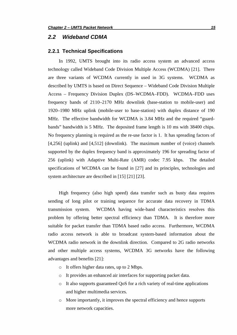
In 1992, UMTS brought into its radio access system an advanced access
technology called Wideband Code Division Multiple Access (WCDMA) [21]. There
are three variants of WCDMA currently in used in 3G systems. WCDMA as
described by UMTS is based on Direct Sequence – Wideband Code Division Multiple
Access – Frequency Division Duplex (DS–WCDMA–FDD). WCDMA–FDD uses
frequency bands of 2110–2170 MHz downlink (base-station to mobile-user) and
1920–1980 MHz uplink (mobile-user to base-station) with duplex distance of 190
MHz. The effective bandwidth for WCDMA is 3.84 MHz and the required “guard-
bands” bandwidth is 5 MHz. The deposited frame length is 10 ms with 38400 chips.
No frequency planning is required as the re-use factor is 1. It has spreading factors of
[4,256] (uplink) and [4,512] (downlink). The maximum number of (voice) channels
supported by the duplex frequency band is approximately 196 for spreading factor of
256 (uplink) with Adaptive Multi-Rate (AMR) codec 7.95 kbps. The detailed
specifications of WCDMA can be found in [27] and its principles, technologies and
system architecture are described in [15] [21] [23].
High frequency (also high speed) data transfer such as busty data requires
sending of long pilot or training sequence for accurate data recovery in TDMA
transmission system. WCDMA having wide-band characteristics resolves this
problem by offering better spectral efficiency than TDMA. It is therefore more
suitable for packet transfer than TDMA based radio access. Furthermore, WCDMA
radio access network is able to broadcast system-based information about the
WCDMA radio network in the downlink direction. Compared to 2G radio networks
and other multiple access systems, WCDMA 3G networks have the following
advantages and benefits [21]:
o It offers higher data rates, up to 2 Mbps.
o It provides an enhanced air interfaces for supporting packet data.
o It also supports guaranteed QoS for a rich variety of real-time applications
and higher multimedia services.
o More importantly, it improves the spectral efficiency and hence supports
more network capacities.

Chapter 2 – UMTS Packet Network 16
2.2.2 Access Method
The ‘soft capacity’ coming from its superior multiple access method is called the
Code Division Multiple Access (CDMA) and its system is shown in Figure 2.4. In
CDMA system, all users accessing the UMTS network share one radio frequency.
Each user is then given a set of spreading codes to distinguish them from each other by
the base-station. As more users are added to the WCDMA systems, the noise level as
seen by other users is increased and hence the link quality of other users is gradually
degraded over time. There is no absolute maximum number of simultaneous users as
imposed by number of available frequencies in FDMA or time-slots in TDMA systems.
Therefore, the quality of communications gradually degrades as more users and
UMTS devices are added to the WCDMA systems.
Figure 2.4: CDMA multiple access system
2.2.3 WCDMA Characteristics
All ultra high frequency (UHF) radio waves experience multiple propagation
paths which cause the received signal to fade over time [91]. The reflection, refraction
and fading phenomena are (1) specular reflection from ground known as Fresnell
diffraction, (2) fast variation in field strength due to reflecting bodies known as
Rayleigh fading, and (3) refraction from blocking object’s edges known as slow or
shadow fading [91]. The spread-spectrum property of WCDMA makes it benefit from
the natural reflections of the radio waves that cause severe fading dips in other systems
(i.e. narrow bandwidth). The interference due to reflected and direct path causes
distortion in the wide-band signal and has an averaging effect such that all the users

Chapter 2 – UMTS Packet Network 17
share the interference problem. Therefore, spread spectrum WCDMA is more
resistant to multipath effects and more tolerant of signal interference.
WCDMA has the characteristic known as the “near-far-problem”. The
interference of the users near the base-station may prevent the base-station from
‘hearing’ the users that are further away. The fast power control mechanism based on
signal-to-interference ratio (i.e. Eb/No) measurement is used to solve the near-far-
problem [23]. It allows the users to use minimal required transmission power while
communicating with the base-station. Therefore, it reduces the user’s battery from
draining too fast and hence increases the ‘talking’ air time. This signal-to-interference
ratio measurement is also used to trigger link-layer (layer 2) handover described in
Section 3.1.4.
WCDMA supports continuous connection with guaranteed QoS to the UMTS
networks during physical channels (layer 1 & 2) handover. Handover involves the
change of physical channels allocated to a call (or session) while maintaining this call.
At an overlapping cell region, the mobile sits in between two base-stations during the
time it moves between the cells. The mobile user is connected to two base-stations
simultaneously for a short duration of time. The intra-frequency handover is possible
since both the cells are using the same (single) radio frequency. This ‘make-before-
break’ mechanism is called softer handover. The softer-handover procedure is
entailed in Section 3.1.4.
2.3 UMTS Channels
Figure 2.5 shows the structure of the UMTS access systems. All entities are
controlled by the Radio Resource Control (RRC or layer 3) which provides a control
service access point (SAP) to higher layers. The layer 2 entities provide various radio
access bearers for transport of user data. All traffic including the RRC signalling is
forwarded through Radio Link Control (RLC) and Medium Access Control (MAC)
through transport channel to the physical layer (layer 1). The Physical Layer provides
higher layers reliable data transport services. It establishes, maintains, and terminates
physical radio connections of different requirements by the RRC. It also takes
measurements on radio link quality and reports those measurements to the RRC to

Chapter 2 – UMTS Packet Network 18
maintain the link connection. Various radio link parameters such as quality, signal
strength, and timing constraints are then set by the RRC. A general description of
3GPP physical layer, MAC, RLC and RRC protocol specifications can be found in [4]
[7] [8] [9].
Figure 2.5: Structure of UMTS access systems
The operation of the physical layer is one radio frame of 10 ms in duration. Each
radio frame is divided into 15 slots of 2560 chips. The amount of data carried by one
frame depends on the configuration of the particular physical channel. Figure 2.6
shows an example of downlink physical frame structure for DPCH. Transmit Power
Control (TPC) and Transport Format Combination Identifier (TFCI) belong to
DPCCH control channel and are used internally by the physical layer to maintain the
radio link operation.
Figure 2.63:: Example of downlink DPCH frame structure
3 Figure is obtained from [12].

Chapter 2 – UMTS Packet Network 19
2.3.1 Logical Channels
UMTS radio interface has logical channels which are mapped to the transport
channels. The logical to transport channel conversion occurs in Medium Access
Control (MAC) layer which is a lower sub-layer in Data Link Layer (layer 2). The
logical channels are listed in Table 2.2. The channel structure of UMTS system is not
symmetric. Some channels are only used in the uplink (UL) and some only in
downlink (DL) and some are for uni-directional (one-to-many). The 3GPP UMTS
radio interface protocol architecture is described in detail in [6].
Abbr Description Direction
BCCH Broadcast Control Channel DL
CCCH Common Control Channel DL/UL
CTCH Common Traffic Channel Uni-direction
DCCH Dedicated Control Channel DL/UL
DTCH Dedicated Traffic Channel DL/UL
PCCH Paging Control Channel DL
Table 2.2: UMTS logical channels
2.3.2 Transport Channels
In UMTS systems, the physical layer offers data transport services to the higher
layers. It ensures correct transport by utilising error correction coding and radio link
control according to QoS parameters that determine the required throughput, error rate
and delay. The transport channels provide data transport services to the higher layers.
They carry user data or higher layer maintenance data between the higher layer entities.
Table 2.3 depicts a short description of the transport channels.

Chapter 2 – UMTS Packet Network 20
Abbr Description Direction
BCH Broadcast Channel DL
CPCH Common Packet Channel DL
DCH Dedicated Channel DL/UL
DSCH Downlink Shared Channel DL
FACH Forward Access Channel DL
PCH Packet Channel UL
RACH Random Access Channel DL
Table 2.3: UMTS transport channels
2.3.3 Physical Channels
The physical channels are the physical radio link between the physical layers of
communicating entities such as users and base-station. There are two types of
physical channels in used in WCDMA systems, namely: (1) Data transport channels
that carry the transport channel data arriving from the higher layers, and (2) Control
channels are used for signalling between the physical layers of the users and UMTS
systems. The physical channels are briefly described in Table 2.4.
Abbr Description Direction
AICH Acquisition Indicator Channel DL
AP-AICH Access Preamble Acquisition
Indicator Channel
DL
CD/CAICH Collision-Detection/Channel-
Assignment Indicator Channel
DL
CPICH Common Pilot Channel DL
CSICH CPCH Status Indicator Channel DL

Chapter 2 – UMTS Packet Network 21
DPCCH Dedicated Physical Control Channel DL/UL
DPDCH Dedicated Physical Data Channel DL/UL
PCCPCH Primary Common Control Physical
Channel
DL
PCPCH Physical Common Packet Channel UL
PDSCH Physical Downlink Shared Channel DL
PICH Paging Indicator Channel DL
PRACH Physical Random Access Channel UL
SCCPCH Secondary Common Control Physical
Channel
DL
SCH Synchronisation Channel DL
Table 2.4: UMTS physical channels
2.3.4 Channel Mapping
Most of the transport channels are mapped onto the physical channels on a one-
to-one basis as shown in Figure 2.7. However, both PCH and FACH are carried by
the SCCPCH. The random access method is used for both RACH and CPCH
procedures for intermittent packet transmission and establishment of a persistent
channel. The dedicated channel communications are established in pair between the
base-station and UMTS users. The dedicated channel pair is DPxCH. The description
on mapping of transport channels onto physical channels can be found in [5].

Chapter 2 – UMTS Packet Network 22
Figure 2.74: Mapping of transport channels to physical channels
2.4 UMTS Architecture
From network conceptual model point of view, the entire UMTS network
architecture can be divided into three main subsystems. Figure 2.8 depicts a UMTS
network architecture with all the main subsystems forming a Public Land Mobile
Network (PLMN) interconnecting with other external networks such as another PLMN
via a Border Gateway (BG); a traditional Public Switched Telephone Network (PSTN)
via the voice-circuit backbone; and the Public Internet via the packet data backbone.
The circuit-switched and packet-switched domains interact and co-share the subsystem
elements. The three interacting main domains are divided based on the nature of
traffic, protocol structures, and network elements as follows:
o User Equipment (UE) Domain
o Access Network (AN) Domain
o Core Network (CN) Domain
o Packet-switched (PS) Domain
o Circuit-switched (CS) Domain
o Serving Network and Home Network Domain
4 Figure is obtained from [25].

Chapter 2 – UMTS Packet Network 23
Figure 2.8: UMTS network architecture
2.4.1 User Equipment
The terminal of the user known as UE develops the radio connection with
different software capabilities. The UE can be divided into two parts, namely (1)
Mobile Termination (MT) that performs the transmission and some related capabilities,
and (2) Terminal Equipment (TE) that contains the end-to-end applications.
Identification properties and user-service profiles reside in UMTS Subscriber Identity
Module (USIM) following the same physical characteristics of GSM SIM card. Rake
reception is used inside the UE to generate soft decisions and fed into the channel
decoder with appropriate power control.
There are a multitude of different types of UMTS terminals. To name a few,
these include multi-mode or multi-band hand-sets, notebook-like communicators,
UMTS-laptops with camera, speakers and microphone with in-build USIM card.
Several users can access one terminal simultaneously if more than one USIM card is
inserted. These UMTS mobile terminals can be operated in one of the three modes of
operation: PS/CS mode, PS mode and CS mode of operation.

Chapter 2 – UMTS Packet Network 24
2.4.2 Access Network
The subsystem controlling the wideband radio access is called UTRAN.
WCDMA is used as the UTRAN air interface technology. UTRAN having several
physical entities controls the radio resources of the access network, and provides the
UE access to the Core Network. It is divided into NodeB (also know as base-station)
and Radio Network Controller (RNC) as the two main controlling elements. The
Radio Network Subsystem (RNS) is made of one RNC and several NodeBs. The
NodeB has the same function as the Base Station in GSM systems. However, it is
more intelligent as it develops functions of combining and splitting to allow macro-
diversity. This allows the UE to change from one cell to an adjacent one without
losing its (link-layer) connection during the handover process [16]. RNC takes control
of the logical (radio link) resources of its UTRAN access points. It is also responsible
for handover decisions that need signalling to the UE. The UTRAN consists of
several RNSs and it represents an interface between the UE and the Core Network. It
stores all the capabilities of the radio connection and radio network parameters. It also
manages roaming and handover functions.
The functions of NodeB are [24]:
o Air Interface Transmission/Reception
o Modulation/Demodulation
o WCDMA Physical Channel Coding
o Micro Diversity
o Error Handling
o Closed Loop Power Control
The functions of RNC are [24]:
o Radio Resource Control
o Admission Control
o Channel Allocation
o Power Control Settings
o Handover Control
o Macro Diversity
o Ciphering

Chapter 2 – UMTS Packet Network 25
o Segmentation/Re-assembly
o Broadcast Signalling
o Open Loop Power Control
2.4.3 Core Network
The UMTS core network sits on a fixed network to provide support for different
capabilities and features of the system. It manages the location of the users and
provides a mechanism for transferring the signal (switching and transmission). The
UMTS CN consists of two parts namely the Serving Network and the Home Networks.
The Serving Network, where the local functions of the CN reside, gives connection
between the access network and the core itself. It is also responsible for call routing
and transport user data and information from source to destination. The Home
Network represents all the functions relating to fixed locations. It consists of a set of
registers such as HLR (Home Location Register), AuC (Authentication Centre) and
EIR (Equipment Identity Register) collectively known as AAA (Authentication,
Authorisation, Accounting), to maintain the static subscription and for security access
and authentication information. It contains the permanent user specific data and is
responsible for management of subscriber information. The USIM is related by
subscription to the home network.
There are two service domains in the core network, namely the legacy Circuit
Switched service domain (PSTN/ISDN) and the Packet Switched service domain (IP).
These two circuit- and packet-switched domains are needed for switching, routing and
subscriber control operations. They allow handling of switched data (up to 64 kbps)
and packet data (up to 2 Mbps). The circuit-switched network architecture for UMTS
is based on GSM network with General Packet Radio Service (GPRS). GPRS, often
known as 2.5G system, allows a higher circuit-switched data transfer by utilising the
unused TDMA channels in the GSM networks. The circuit-switched elements include
Mobile services Switching Centre (MSC), Visitor Location Register (VLR) and
Gateway MSC (GMSC). A complete description of UMTS network architecture and
its radio access technology can be found in [12] [16] [24].

Chapter 2 – UMTS Packet Network 26
2.4.4 Packet Network
The packet switched domain of the CN transports IP packets and provides packet
data services. The UMTS packet networks have two types of GPRS support elements,
namely the Serving GPRS Support Node (SGSN) and Gateway GPRS Support Node
(GGSN). The GGSN acts like a router that encapsulates the user data IP packets and
tunnels them to the corresponding SGSN. SGSN is central to the packet data network
operations for UMTS. It receives the connection setup request with QoS requirements.
It then instructs the RNC to set up the radio bearer in the UTRAN and establishes a
session connection between the GGSN and the RNC.
The data structure of both the SGSN and the GGSN contains the user’s session
information. When a UE needs to access the UMTS network, it must first attach and
activate a logical connection with the UMTS CN. The registration and attachment
operation allocates an association in the visiting SGSN and the GGSN serving the
access point. There are two tunnelling sessions [16]; one in between RNC and SGSN
and another one in between SGSN and GGSN. User data frames are encapsulated and
forwarded between RNC and GGSN, and transported over ATM networks. ATM
Adaptation Layer 5 (AAL5) is designed for packet delivery in UMTS core
transmission [26]. The mapping of user-IP and tunnelling session is recorded and
maintained at the corresponding SGSN.
2.4.5 GPRS Tunnelling Protocol
UMTS relies on a key network protocol – the GPRS Tunnelling Protocol (GTP)
for the delivery of the mobile data services. It transports TCP/IP and UDP/IP packets
from the public data networks and tunnels them with GTP messages throughout the
UMTS packet networks. The protocol is defined and used to route packets between
RNC, SGSN and GGSN within the same, or between different UMTS packet networks.
GTP is encapsulated within UDP in two separate protocols. The signalling protocol
creates logical connection and provides session management. GTP transfers user
payload using simple IP-based tunnelling protocol running over UDP. One tunnel is
established for each session connection (for each user in UMTS) and applied with
different QoS policies and requirements.

Chapter 2 – UMTS Packet Network 27
2.4.6 Mobility Function
It is necessary for the UMTS network to know the approximate location in order
to page a user. There are four areas of (link-layer) mobility function provided by the
UMTS CN [16]. Location Areas (related to CS services) and Routing Areas (related
to PS services) are used in the CN. UTRAN Registration Areas and Cell Areas are
used in the UTRAN. When the UE is in ‘idle’ mode, it initiates Location Update
towards the CN via location registration procedure. The CS mobility mechanisms
within the UE and the CN require optimal usage of the radio resource. The UTRAN
coordinates mobility management procedures that are logically assembled between the
CN and the UE. These include location management, authentication, temporary
identify management and equipment identity check.
Session mobility is provided entirely by packet switching in the UMTS CN.
While SGSN handles inter-RNC mobility, GGSN handles inter-SGSN mobility.
When the serving RNC of the mobile changes (still within the scope of the same
SGSN), it results in the re-direction of the GTP session between the SGSN and the
RNC. The session between the SGSN and GGSN is therefore remained unaffected.
When session mobility results in different point of GPRS attachment (i.e. across
different SGSN), both user-specific GTP sessions needs to be re-established.
2.4.7 WCDMA Evolved
3GPP Release 1 [3] was completed in 31 December 1999 and deployed in early
2001 in Japan. It consists of GSM GPRS Release 1999 with UMTS. Release 2000 [3]
includes Internet Protocol based networks and rolled out in 2002. It provides higher
bit rates, up to 2 Mbps. To meet the needs of higher bit rates and packet data for users,
UMTS includes other enhancements in the network. A new subsystem IMS (IP
Multimedia Subsystem) is added by 3GPP Release 5 [3] to provide the required
conversion functions to transport VoIP calls as IP packages and be routed to
traditional PSTN networks. It is based on IPv6 specifications and supports new
services and IETF’s SIP (Session Initiation Protocol). Release 5 also enhances
WCDMA Evolved access technology with HSDPA (High-Speed Downlink Packet
Access) [17] that could support data rates up to 10 Mbps on downlink direction.

Chapter 2 – UMTS Packet Network 28
2.5 Summary
This chapter has introduced the UMTS systems and described the principles of
WCDMA as its access technology. The UMTS packet networks support various
classes of packet data service with basic link-layer and session mobility functions.
When deployed and coupled with the global Internet in IPv6 environments in
particular, it represents a heterogenous network with different underlying access
technologies and network systems. The challenge to provide end-to-end IP mobility in
UMTS/WCDMA networks and the various mobility mechanisms is presented in the
next chapter.

Chapter 3 – Mobility Management in UMTS 29
Chapter 3 Mobility Management in UMTS
3.0 Introduction
This chapter describes the fundamental limitations in location and handover
management for providing IP mobility in UMTS packet networks. The various
proposed IP handover reducing schemes based on mobility support in IPv6, namely
Hierarchical Mobile IPv6, Fast Handover IPv6 and S-MIP (Seamless Mobile IP) are
presented. By capitalising the packet lossless behaviour and extremely low handover
latency performance, we design a seamless handover architecture for UMTS using S-
MIP architecture and describe the overall framework.
3.1 Mobility Challenge
The advancing technologies in electronics, networking and telecommunications,
coupled with demand for broadband mobile communications on the move have called
for mobility support to the internet nodes. As specified in the Internet Protocol (IP)
[49], every node on the network is identified by a unique IP address and hence its
points of attachment to the Internet. By inspecting the network portion of an address
and consistent routing table derived from different routing protocols, routers on the
Internet can successfully forward packets to any nodes on the Internet on a hop-by-hop
basis. When a mobile node (MN) changes its point of attachment (either due to the
movement of the user or the variation of signal strength which causes the device to
perform a switch of service area), this causes the MN to migrate from one network to
another. In order to remain “reachable” by other nodes on the Internet, the MN needs
to perform a reconfiguration of its IP settings that are suitable for the newly migrated
network.

Chapter 3 – Mobility Management in UMTS 30
Without appropriate mobility support, the session established between the MN
and other nodes before the migration cannot be maintained after the MN has migrated,
as the reconfiguration of IP address of the MN causes the session state information to
become invalid.
To provide mobile users uninterrupted end-to-end communication session with
some level of guaranteed Quality of Service (QoS), efficient mobility support is an
important aspect in any cellular and wireless networks. Particularly in UMTS
networks, in addition to radio access handover (handover at layer 1 & 2) provided by
WCDMA access systems, the UMTS core networks need to be able to support session
handover (layer 3 and above) [20]. Therefore, network-layer mobility support is a key
aspect for mobility management in UMTS/WCDMA networks for continuous end-to-
end IP connection with the global Internet. The following sections detail two
fundamental challenges for providing IP mobility in UMTS packet networks, namely
location management and handover management
3.1.1 Location Management
Due to change in point of attachment, the MN needs to periodically update its
location information with its home network. The Home Agent (HA) is the network
entity in MN’s home network and is responsible to maintain the current point of
attachment of all the MNs originating from its subnets. This location update is
referred to as idle mobility. Idle mobility is performed when the MN is not engaged in
any active sessions or with other network services. When the MN is far away from the
HA or the Corresponding Node (CN), it will take longer (i.e. more latency) to update
the HA of its current location, thus increasing the time of service interruption for the
MN. Idle mobility therefore requires localised location management mechanism to
reduce the frequency of location updates.

Chapter 3 – Mobility Management in UMTS 31
3.1.2 Background Principle: Mobile IP
Mobile IP – MIP (RFC 3344) [47], a standard solution provided by IETF [38]
Mobile IP Group, is designed to enable a node to move around the Internet, while
preserving its session continuity. MIP describes a simple yet global mobility solution
that provides host mobility management for a diverse array of applications and devices
on the Internet. In other words, it provides transparency to all transports and higher-
layer applications to the Internet. Its mobility mechanism in the IP routing
architecture is based on IPv4 protocol [47].
Host mobility in MIP is achieved by using two IP addresses: (1) a fixed home
address, and (2) a care-of-address (CoA) that changes at each new point of attachment.
The basic principle of MIP is to provide a local CoA to the MN while it is away from
the home network [43]. The mobile node has a permanent address (or home address)
assigned in the home network. The local CoA is provided by the visiting or foreign
network to which the MN is currently attached. Hence, MIP allows a MN to leave its
home network and continually to receive packets destined to its home address
irrespective of its current point of location in the Internet topology.
MIP requires the existence of a network entity know as the Home Agent (HA)
located at the home network. When the MN is away from its home network and
attaches to a foreign network, the MN obtains a CoA in the foreign network. The MN
sends a binding message to the HA enclosing the address binding of this CoA and its
home address. The HA then creates a binding cache in the address look-up routing
table and registers this address binding to resolve the routing problem during node
mobility. Any packet addressed to the MN (namely its home address) will be
forwarded by the HA to the MN’s CoA using IP-in-IP encapsulation or tunnelling [46].
The HA intercepts any IP packet addressed to the MN, encapsulates it with an extra IP
outer header and tunnels it to the MN’s CoA (with the original IP packet appears as
payload). The Foreign Agent (FA), a new MIP specific entity deployed in the foreign
network intercepts the packet, removes its outer IP header from tunnel and delivers it
to the MN. The MN responds to the received packet and sends its acknowledgement
back to the Corresponding Node (CN) using normal IP routing mechanism. The basic
operation of MIP is illustrated in Figure 3.1.

Chapter 3 – Mobility Management in UMTS 32
Figure 3.15: Basic operation of Mobile IP
Therefore, whenever the MN changes its current point of attachment, it obtains a
new CoA and performs update on the binding to the HA. The registration message
exchanges information between the MN, the FA, and the HA. It is sent periodically by
the MN to maintain its mobility binding at the HA. The registration procedure
requires two messages: namely the Registration Request (MN→FA→HA) and
Registration Reply (HA→FA→MN) [43]. MIPv4 requires two signalling messages
traversing MN–HA networks for a successful location or binding update performed.
The binding update involves additional network layer signalling overhead and lengthy
network registration time particularly if the MN if far away from the HA. The detailed
operation of Mobile IP and its mobile networking can be found in [43] [44] [45] [47].
3.1.3 Handover Management
Handover or handoff is another aspect of mobility associated with active data
sessions. When a user is engaged in an active connection such as a TCP transfer,
handover is triggered due to the movement of the MN from one base-station to another.
The UMTS network constantly monitors the MN’s radio conditions such as signal
strengths and capacity constraints and performs the handover decision. The handover
process results in moving the MN’s anchor point in the current network to another one
in the target network. The time taken for the MN to establish a network connection at
5 Figure obtained from [90].

Chapter 3 – Mobility Management in UMTS 33
the target base-station and finally switch over to the new radio connection is called
Layer-2 handover latency [16]. While Layer-3 (or IP) handover latency amounts to
time taken to update the binding with the HA and configure a new CoA at the target
network [20]. A long overall handover (Layer-2 & IP) latency is not suitable for
running real-time applications as there is a long breakage and noticeable gap in the
active TCP connection. The IP cellular-type handover support requires the breakage
and delay in an active connection to be less than 150 ms [20] for supporting any delay-
sensitive real-time applications such as VoIP and broadband multimedia services.
3.1.4 Layer-2 Handover
In wireless IP networks, the handover happens in a “passive-mode” as the MN
switches across different access routers [20]. Without any micro-mobility
management scheme, the MN first loses its network connection at the present access
router, it then establishes a new radio connection at the target access router. The MN
obtains the router information and a new CoA at the target access router, and performs
binding updates with the HA.
The link-layer mobility management in UMTS packet networks is facilitated by
its ‘softer handover’ support in the access network [16]. During an active session, the
MN provides periodic WCDMA signal strength measurements for neighbouring base-
stations to the current RNC. As the signal strength of the radio channel changes
rapidly due to fading and signal path loss as described in Section 2.2.3, the UMTS
RNC continuously monitors the MN’s radio conditions. Signal quality handover
occurs for the uplink direction when the received signal strength at current NodeB
falls below the received signal strength at the target NodeB. Figure 3.2 depicts the
received signal strength indicator (i.e. the Eb/No measurements) during a softer
handover.

Chapter 3 – Mobility Management in UMTS 34
Figure 3.2: Received signal strength indicator during a softer-handover
Based on the signal strengths and capacity constraints, the RNC makes the
decision to handover the MN to the target NodeB [12]. The current base-station
proactively signals the target base-station so that handover is performed. The target
base-station then establishes the necessary radio links and connections to intercept the
arrival of the MN. It also provides feedback information to the current or source base-
station for resource released. This softer-handover mechanism is ‘network-
determined’ [16] since the UMTS access network decides and instructs the MN to
perform a handover by providing signalling information to the target base-station.
A softer-handover occurs typically in 5–15% of time of connection [16]. During
this handover, the MN is in the coverage area of two overlapping service ranges
belonging to different base-stations. As facilitated by the RNC, the communication
between MN and NodeB takes place via two separate radio links from each base
station for a short duration. Therefore, an efficient network-layer handover scheme is
essential to smooth out the data transfer with no communication breakage or gap when
a softer-handover occurs in UMTS data networks. Figure 3.3 shows the overall
mobility challenges in UMTS data networks.

Chapter 3 – Mobility Management in UMTS 35
Figure 3.3: Mobility in UMTS networks
3.2 Mobile IPv6 Handover Schemes
Mobile IPv6 (MIPv6) protocol [48] offers a better mobility support as the
extended features from IPv6 [37] enables mobility mechanism to be integrated to the
IPv6 compatible mobile nodes. Fundamentally, its principle of operation is similar to
MIPv4 as described in Section 3.1.2, but the protocol capabilities and definitions have
been extended to enhance the support of IP mobility. In IPv4, a MN obtains a CoA
either from (1) the FA, or (2) using Dynamic Host Configuration Protocol (DHCP) [32]
– known as co-located CoA. In IPv6, the MN can form its own local CoA through
stateless address auto-configuration [53] by listening to the router advertisement
messages from the router serving that subnet through its neighbour discovery
procedure [42]. This stateless address auto-configuration capability and co-located
CoA enable the HA to tunnel and deliver packets directly to the MN. Therefore, a FA
is not required to support node mobility in IPv6 environments.

Chapter 3 – Mobility Management in UMTS 36
When the MN is IPv6 compatible, the registration process is greatly simplified
by directly communicating with the HA (bypassing the FA). Hence, MIPv6 could
significantly improve the CoA configuration and registration binding latency
performance for node mobility. The traffic flows of MIPv4 and MIPv6 are
summarised in Figure 3.4. The complete specifications of IPv6, the principles and
mobility support in MIPv6 can be found in [31] [37] [48] [51].
Figure 3.4: Traffic flows for MIPv4 and MIPv6.
Mobile IPv6 separates mobility into micro-mobility (within one domain or intra-
domain) and macro-mobility (between domains or inter-domain) [51]. To reduce the
frequency of location updates and support IP handover, a number of well-known
approaches based on micro- (or localised) and macro-mobility management
mechanisms in IPv6 have been proposed in the literature. Cellular-IP [29], Hawaii
[50], Regional Registration [40], Hierarchical Mobile IP [52] are Fast-Handover [39]
are some of these techniques.

Chapter 3 – Mobility Management in UMTS 37
3.2.1 Hierarchical Mobile IPv6
Hierarchical Mobile IPv6 (HMIPv6) reduces handover latency by using a
hierarchical network structure [52]. It minimises the location update signalling
messages with the external networks and hence reduces the (home) network
registration time with the HA. A Mobile Anchor Point (MAP), a special network
agent entity, is placed at the edge of the network to maintain a binding between itself
and the MN under its visiting and serving domain. It acts as a local home agent for the
MN. It intercepts all the packets addressed to the MN that it is serving and tunnels
them to the corresponding on-link CoA. When the MN moves within a single domain,
only one location (local binding) update to the MAP is required. Figure 3.5 shows the
HMIPv6 mobility domain.
Figure 3.5: Hierarchical Mobile IPv6 domain
When the MN changes its current address within a local MAP domain, it only
needs to register the new on-link address with the MAP since the global CoA does not
change. If the MN moves into a new MAP domain, it needs to acquire a regional
address (RCoA) and an on-link address (LCoA). The MN uses the new MAP’s
address as the RCoA, while the LCoA is formed using IPv6 stateless address auto-
configuration feature. The MN sends a regular MIPv6 binding update (BU) to the
MAP to bind the MN’s RCoA to its LCoA. MAP returns a binding acknowledgement
(BAck) to the MN indicating a successful binding and registration. The MN also

Chapter 3 – Mobility Management in UMTS 38
registers its new RCoA with the HA by sending another BU that specifies the binding
between its home address and its new RCoA.
3.2.2 Fast Handover Mechanism
In wireless IP network, the MN makes the decision to perform the handover and
inform the source router. The source router then determines the target router based on
information provided by the MN and requests the target router to provide a CoA.
When the MN loses the network connection at the source router, the packets destined
to the MN are tunnelled to the target router with the new CoA. The MN then accesses
the target router and is immediately able to configure the new CoA and receive those
delayed packets [20].
Fast Handover Mechanism (FMIP) works by reducing the lengthy address
resolution time when visiting a foreign network by using address pre-configuration
[39]. It involves setting up a routing path between the two access routers to enable the
MN to send and receive IP packets while it establishes a new network connection.
There are three phases in the protocol operation of FMIP: namely handover initiation,
tunnel establishment and packet forwarding. The basic operation of FMIP is
illustrated in Figure 3.6.
Figure 3.6: The basic operation of FMIP

Chapter 3 – Mobility Management in UMTS 39
FMIP introduces four additional message types between the access routers and
the MN, namely RtSolPt, PrRtAdv, HI and HAck. The protocol is initiated when the
MN receives an indication on Layer-2 trigger that determines the need to handover
based on link connectivity and radio connection. After the MN receives PrRtAdv
message with necessary network prefix information, the MN is able to formulate a
new CoA using IPv6 stateless auto-configuration. The MN sends F-BU to oAR to
associate its old CoA with nAR’s IP address to that the arriving packets at the oAR
can be tunnelled to the nAR. The HI message, sent by oAR to nAR serves two
purposes: (1) It establishes a bi-directional tunnel between the two ARs so that the MN
can continue to use its old CoA for its existing session; and (2) It also verifies the new
CoA if it can be used on the nAR link. When the MN receives F-BAck from oAR, it
confirms the usability of its new CoA on the nAR link and disconnects itself from the
oAR connection. This completes the tunnel establishment operation. The packet
forwarding phase starts when the MN connects itself to the nAR link. It sends the F-
NA message to the nAR to confirm its new CoA if F-BAck has not been received and it
also serves to announce its presence to the nAR. The nAR then sends NA-Ack to
indicate the acceptance use of the MN’s new CoA and starts delivering the flow of
packets to the MN.
Both the HMIPv6 and FMIPv6 mechanisms perform well in wireless IP
environments. They require the ARs to handle and make IP handover decisions
known as a network-initiated handover. An efficient handover procedure that reduces
both the network-layer registration time and address resolution time in IPv6 and
performs handover based on triggering from radio link layer is highly essential.

Chapter 3 – Mobility Management in UMTS 40
3.2.3 S-MIP
It has been shown in [34] that the combined HMIPv6 and FMIPv6 scheme
greatly reduces the overall handover latency to around 300–400 ms. This combined
handover mechanism offers a seamless handover procedure in WLAN environments.
However, it exhibits a packet loss behaviour exists at the IP layer which poses great
impact on packet-loss sensitive applications such as TCP connection streams.
Moreover, the ‘ping-pong’ movement effect has not been addressed adequately and
handled effectively with respect to handover delay. R. Hsieh in [35] proposed a
seamless handover architecture for Mobile IP in WLAN environment called S-MIP.
S-MIP is a seamless handover scheme that combines software-based mobile device
tracking techniques [93], HMIPv6 structure and FMIPv6 mechanism. The advantage
of S-MIP over the above combined HMIPv6 and FMIPv6 handover mechanism is that
it minimises the edge packet (between oAR and MN) and segment packet (within
MAP and ARs) losses so that the end nodes (both CN and MN) would perceive a
seamless connectivity with no packet losses. This hybrid handover scheme is
“mobile-initiated and network-determined” [30].
S-MIP introduces Synchronised-Packet-Simulcast (SPS) scheme that simulcasts
packets (s-packets) to the AR where the MN is currently attached to (oAR) and to the
target AR (nAR). MAP simulcasts s-packets as the forwarded packets (f-packets) are
most likely to be chronologically ‘older’ than the s-packets. Both the s- and f-packets
are necessary to minimise the packet re-ordering behaviour during handover. Figure
3.7 illustrates the network architecture of S-MIP. It builds on top of combined
HMIPv6 and FMIPv6 signalling scheme and introduces a Decision Engine (DE) entity
and the SPS scheme as an ‘intelligent handover’ mechanism. DE makes network-
layer handover decision for its network domain. It maintains a global view of the
connection state of any mobile devices in its network domain, and the movement
patterns of all these mobile devices. Effectively, the DE eliminates the mobile ‘ping-
pong’ movement effect by not allowing the MN to perform another seamless handover
before the current handover has been completed.

Chapter 3 – Mobility Management in UMTS 41
Internet
Macro Mobility
Micro Mobility
HA
MAP
DE
oAR
nAR2
nAR1
MN
CN
Figure 3.7: S-MIP architecture
Figure 3.8 shows the protocol operation of S-MIP. It defines six new signalling
messages in additional to the combined HMIPv6 and FMIPv6 handover scheme.
These six messages are CTS, CLS, HD, HN, Scast and Soff. If there is no additional
buffering capability being implemented into the AR agents, all the f-packets from oAR
to nAR will be discarded at the nAR if the MN is not present to receive those delayed
packets. The buffering mechanism of S-MIP works as follows: the nAR maintains
two distinct buffers namely the f-buffer and the s-buffer. The f-buffer contains
packets forwarded from the oAR (f-packets) while the s-buffer contains packets
marked with S-bit (s-packets). When the nAR receives F-NA message from the MN, it
starts delivering buffered packets to the MN. The nAR will first attempt to transmit
and empty the f-buffer before transmitting the s-buffer. Meanwhile, the oAR forwards
those packets to the nAR (f-packets) that are not marked with S-bit. The nAR sends
the Soff message to the MAP to terminate simulcast packet transmission after its f-
buffer has been emptied. MAP then performs the binding update by associating the
new LCoA of the MN with its RCoA. MAP subsequently forwards Soff message to
the DE signifying the completion of the overall handover process.

Chapter 3 – Mobility Management in UMTS 42
Figure 3.8: S-MIP signalling protocol
The S-MIP framework shows such a realisation of extremely low handover
latency and no packet loss scheme. It has been reported in [36] that the overall
handover latency as perceived by the CN is approximately 100 ms in WLAN
environment. The CN does not perceive any apparent packet loss and packet
retransmission behaviour in spite of handover performed by the MN. S-MIP also
performs exceedingly well with minimal network-layer handover signalling overhead.
It is however developed on indoor wireless LAN environments. This “generic”
seamless handover scheme could also be applied in large open-space cellular
environments such as UMTS/WCDMA networks to enable the minimisation of its
network-layer handover latency.

Chapter 3 – Mobility Management in UMTS 43
3.3 Converged Network Architecture
The challenge to provide seamless mobility in UMTS lies on different mobility
management and access network handover techniques employed between the
heterogeneous UMTS/WCDMA and global IP networks. Network-layer mobility in
UMTS nodes is provided by the well-known global and extended mobility solution –
Mobile IPv6 for end-to-end IP connectivity with the global Internet. At the link-layer,
mobility is restricted to the different access network technologies utilised in these
wireless networks. WLAN, traditionally designed for non-QoS performance, has an
asynchronous (or connection-less) signalling and Layer-2 handover protocols based on
contention-based 802.11 access technology [88]. WCDMA, a widely used radio
access technology in UMTS network has been designed to manage radio access related
handover (layer 1) in the base-stations (or NodeBs). Link-layer mobility (layer 2)
management functions in terms of connection setup and resource release are provided
by the RNC entity. The overall seamless handover architecture in UMTS requires
network integration and extra functionalities such as user location tracking, address
registration, and handover related functions during the change of service area. When
the UMTS devices are IPv6 compatible, it is therefore capable to extend and
synthesize the key benefits of S-MIP into UMTS/WCDMA packet network for
seamless end-to-end TCP connection.
In order to provide an efficient mobility IP scheme into the UMTS packet data
network, an optimised handover scheme that encompasses the packet lossless and
extremely low handover latency scheme has been developed by applying S-MIP into
the UMTS/WCDMA packet data domain. Thus, the overall hybrid UMTS-SMIP
network architecture is able to meet the requirements of delay-sensitive real-time
applications such as VoIP and streaming multimedia services that require strict delay-
bound, near packet losses and guaranteed QoS during a UMTS IP-based handover.
The optimised handover UMTS network architecture is designed to accomplish the
following objectives: extremely low handover latency; minimal network-layer
handover signalling overhead; highly available in large-scale; and reduced complexity
with a minimum set of resource required such as buffering mechanism. In essence, it
implies fast handover without loss of packet data in UMTS networks and unnoticeable
network service disruption as perceived by the communication end-nodes.

Chapter 3 – Mobility Management in UMTS 44
The UMTS/WCDMA network scenario for S-MIP corresponds to hybrid
architectures between the “pure” models of UMTS/WCDMA and S-MIP respectively.
The S-MIP model contains the following six node types: namely MN, AR, MAP, DE,
HA and CN. While the “traditional” UMTS/WCDMA model contains the following
six network elements: namely UE, NodeB, RNC, SGSN, GGSN and CN. From a
user-IP point of view, the network entity formed by NodeB-RNC-SGSN-GGSN
behaves as a “last hop link”. In particular, it means that micro-mobility is handled
entirely within the UMTS/WCDMA access and core networks and is completely
transparent to the IP-layer. The corresponding hierarchical mapping of
UMTS/WCDMA and S-MIP is illustrated in Figure 3.9. The red line denotes
“visibility” of user-IP and blue line denotes “link layer” visibility. The mapped
network scenario is S-MIP for GSN session continuity in UMTS/WCDMA. The user-
IP is visible up to GGSN and there is a direct 1-to-1 mapping between GGSN and the
corresponding AR. The HA has been placed at the same node layer of GGSN/AR.
From a session continuity point of view, the MAP sits in between the CN and
GGSN/AR. The functionality of the AP is distributed to the NodeB. Therefore, the
hybrid UMTS-SMIP model has seven network elements with the inclusion of
additional MAP network entity.
Figure 3.9: Hierarchical mapping of UMTS and S-MIP

Chapter 3 – Mobility Management in UMTS 45
The converged seamless handover architecture in UMTS/WCDMA packet data
network is depicted in Figure 3.10. The MAP entity is placed at the edge of the
UMTS packet core domain. It acts as a gateway that maintains a binding between
itself and the UE6 falls under its visiting domain. The functionality of MAP is twofold:
(1) It intercepts and tunnels all the packets addressing to the serving UE, and (2) It
also simulcasts packets (s-packets) to both current and new GGSNs7 to minimise the
segment packet loss during IP handover. A ‘loose-coupling’ network architecture is
assumed here whereby both the UMTS packet core domains are integrated via AAAL
entity [33]. The home agent functionality is provided by the HLR register in the home
network of the UE. Radio access handover (layer 1) and link-layer mobility (layer 2)
is managed and provided by WCDMA radio access systems namely NodeB and RNC
respectively. And UMTS IP mobility is facilitated by its packet-switched core
networks consisting of SGSN and GGSN and functional entities such as MAP and DE.
Figure 3.10: The converged seamless handover architecture in UMTS/WCDMA
6 For consistency, MN is used for mobile user in WLAN environments and UE in UMTS networks. 7 Similarly, GGSN is the access router in UMTS context.

Chapter 3 – Mobility Management in UMTS 46
The converged handover scheme introduces a new way to manage and support
data and IP mobility in UMTS/WCDMA packet networks so that the end nodes
(mainly the CN) would perceive a seamless connectivity during IP handover. The
objective of this thesis work is to investigate and analyse the various QoS performance
measures such as network-layer latency, packet loss rate and signalling overhead
during handover in UMTS/WCDMA networks using S-MIP signalling protocol.
Further to this project, it is also aimed to achieve a seamless handover architecture for
Mobile IP with extremely low IP handover latency and negligible packet loss rate in
UMTS/WCDMA data networks for its end-to-end TCP connection. Therefore, the
overall hybrid system is able to meet the requirements of delay-sensitive real-time
applications that require strict delay bound, packet lossless and QoS guaranteed
performance during a UMTS IP-based handover.
3.4 Summary
Network-layer handover latency is one of the fundamental limitations in
UMTS/WCDMA packet data networks. The development of network-layer handover
reducing mechanisms based on MIPv6 has paved the way to enable seamless
connectivity and guaranteed QoS performance. An optimised handover network
architecture is achieved by applying S-MIP service architecture into existing
UMTS/WCDMA network model. This hybrid UMTS-SMIP network architecture is
aimed to achieve extremely low latency and no packet loss during handover
performance. The service architecture is implemented using software modelling and is
detailed in the next Chapter. The various QoS performance measures in terms of
handover latency, packet loss and signalling overhead will be evaluated in the
simulation prototype.

Chapter 4 – Network Model 47
Chapter 4 Network Model
4.0 Network Simulation
From the service architecture presented in Chapter 3, we are going to build the
system in software prototype. The service model for seamless handover architecture
in UMTS packet networks is built and developed using a software simulation tool
called – “The Network Simulator” (ns). It is chosen as the simulator framework for
this thesis project due to the availability of its UMTS/WCDMA modules and open
architecture for protocol developments and enhancements. In particular, the S-MIP
architecture was built and tested in ns under WLAN environments. This chapter
briefly describes the basic structure of ns and its supported modules for wireless, basic
Mobile IP(v4) and UMTS/WCDMA extensions. We further illustrate various changes
and enhancements in the implementation work to extend S-MIP to the base UMTS
simulator in this chapter.
4.1 The Network Simulator (ns)
The Network Simulator (ns) [73] is a discrete event driven simulator for
computer networks and network protocols. It is widely used for simulating local and
wide area networks in networking research community as a large number of basic
network components are available. The development of more complex network
architectures can be facilitated by combining and building on top of these elements.
Currently, ns supports the following technologies and network protocols [59]:
o Point-to-point connections, LANs, wireless links, satellite links
o Router queuing mechanisms (DropTail, RED, CBQ, etc.)
o IP, Mobile IPv4
o Routing algorithms (Dijkstra etc)
o Multicasting (DVMRP, PIM, etc)

Chapter 4 – Network Model 48
o Transport Protocol (TCP, UDP, RTP/RTCP, SRM, etc.)
o QoS schemes (InterServ, DiffServ)
o Applications (Telnet, FTP, HTTP, etc.)
o Mathematic support (random number generation, integrals, etc.)
o Network emulation (i.e. interaction with “real” operating network node)
ns was originally developed in 1989 at UC Berkeley [70] as REAL network
simulator [67] for studying flow and congestion control schemes in packet-switched
data networks. In 1995, several universities and research groups such as UCB, LBNL,
ISI/USC, Sun, Xerox PARC etc jointly developed various modules in ns for
simulating variety of IP networks and network protocols. The ns project is now a part
of the VINT project [82] that develops tools for display of simulation results, analysis
and converters to integrate other network topology generators with ns.
Figure 4.1 illustrates a simplified user’s view of ns. It is an Object-oriented Tcl
(OTcl script) interpreter that has a simulation event scheduler and network component
object libraries, and network setup (plumbing) module libraries. An OTcl script is
written to setup and run a simulation network. It first invokes the Tcl interpreter for
basic network configuration and the program is run using various modules in the
simulator libraries. The simulator library initiates an event scheduler, sets up the
network topology using the network objects and plumbing functions. It also notifies
the traffic sources when to start and stop transmitting packets through the event
scheduler. A new network object can be constructed by making a compound object
from the object library and plumbing the data path through the object.
Figure 4.18: Simplified user’s view of ns
8 Figure is obtained from [54].

Chapter 4 – Network Model 49
The simulator framework uses a split-language programming approach. OTcl
[77], an object-oriented language of Tcl, is used for the control structure and
description of simulation scenarios. The event scheduling tasks and the dynamic
configuration of network components during the simulation are also written in OTcl.
The core processing unit of the simulator such as low-level event processing, packet
processing and forwarding etc is written in C++ language [55]. C++ is the object-
oriented version of C, a very low-level programming language for control and
structure. Therefore, using C++ in ns allows fast simulations for construction of large
scenarios. The compiled objects are made available to the OTcl interpreter through an
OTcl linkage. It creates a matching OTcl object for each of the C++ objects and
makes the control functions and the configurable variables specified by the C++
objects available to the corresponding OTcl object. The C++ and OTcl linkage and
duality gives flexibility to network configuration but it also adds complexity to the
simulator. Particularly, error debugging in both languages simultaneously is a difficult
task. To use and build the simulator, it is necessary to have knowledge and be
proficient in both OTcl and C++ programming languages [61] [78]. ns can be learned
from various tutorials, workshops, short courses and manual in [54] [56] [59] [62] [75]
[76] [85].
The network topology consists of network nodes connected by link with a certain
queuing model, delay and throughput. Agents are attached to the nodes to exchange
packets between them. Traffic sources such as applications use these agents to
communicate with traffic sinks at other nodes. There are several types of agent in ns.
A routing agent decides which link to forward a packet and a transport agent such as
TCP or UDP sends and receives IP packets. Scenarios are usually constructed and
written in the OTcl script by hand. When the simulation is finished, ns produces one
or more text-based output files containing detailed simulation data. The data can be
used for simulation analysis or visualised using a graphical simulation display tool
called the Network Animator (NAM) [72]. For accurate simulation analysis such as
calculating data throughput and network delay, these results can be graphically plotted
from ns output trace files using the plotting utilities such as GNUPlot [60] or XGraph
[86].

Chapter 4 – Network Model 50
4.1.1 Wireless Nodes
The original ns architecture only supports stationary (or fixed) nodes connected
by wired links. Wireless nodes and channels were added by the CMU Monash group
[57] focusing on the simulation of wireless ad-hoc networks. This wireless framework
allows a detailed modelling of wireless communications network stack such as Radio
Propagation Models, Antennas, Link Layer, Interface Queue, Address Resolution
Protocol (ARP) model, MAC Layer protocols (such as IEEE 802.11) and ad-hoc
routing protocols.
Special wireless nodes need to be constructed to compose the wireless networks.
These wireless nodes have added features in comparison to ordinary wired nodes.
They have information about their location in the topology, and can move in a linear
mode between locations at a constant speed. The concept of “links” does not exist in
wireless communications. The mobile nodes attach themselves to the same wireless
“channel” to send and receive packets between them. Packets sent over the wireless
channel are distributed (or broadcasted) to all the mobile nodes on the same channel.
The internal structure of wireless nodes is extended and depicted in Figure 4.2.
The wired nodes send packets through the link directly to the corresponding agent
which then processes the packets. However, packets at wireless nodes need to pass
through several additional layers for processing and filtering.

Chapter 4 – Network Model 51
255
0
LL
Wireless Channel
AddressClassifierclassifier_
entry_defaulttarget_
own IPaddress
Port Classifierdemux_
uptarget_
IFQ
MAC
PHY
target_
Antenna
Modulation Scheme
Propagation Model
Radio Propagation Model
channel_
Routing Agent ragent_
Traffic Source/Sink
uptarget_
downtarget_
downtarget_
downtarget_
uptarget_
propagation_
uptarget_
Incoming path
Outgoing path
ARParptable_
Figure 4.2: Structure of wireless nodes
All packets that are sent over the wireless channel are first handled by the
Physical Layer (PHY). The PHY layer uses a Radio Propagation Model (RPM) to
determine the signal strength of the received packet. A packet is marked the following
mode depending on its signal strength level:
o Not received – if signal strength is below detecting threshold.
o Received with errors – if signal strength falls short of received threshold.
o Received with no errors – if signal strength is above received threshold.

Chapter 4 – Network Model 52
The received packet is then handed over to the Medium Access Control (MAC)
layer. The MAC layer discards the packet that is marked “not received” (node could
not receive) and “received with errors” (received with bit errors) from the PHY layer.
The MAC layer hands the received packet up to the LL which resolves its IP address
via ARP module from the MAC header. The LL then forwards the packet to the
node_entry_ point. The address classifier (classifier_) acts as IP routing and
forwarding agent in ns. If the received packet is addressed for the mobile node, it is
handed over to the port classifier (demux_) and subsequently delivered to the traffic
agent (or sink agent). Otherwise, the non-matching packet is handed to the routing
agent (ragent_) by default. The ragent_ agent forwards the packet as per source route
and sends out the packet. The outgoing packet is handed down in the downlink
direction through an interface queue (IFQ), MAC layer and PHY layer and finally into
the wireless channel.
All wireless nodes have a routing agent (ragent_) attached to it. Since the
wireless extension has been designed focusing on mobile ad-hoc networks, ns
currently supports the following ad-hoc routing protocols:
o Destination Sequenced Distance Vector Routing (DSDV)
o Dynamic Source Routing (DSR)
o Ad-Hoc On Demand Distance Vector Routing (AODV)
o Temporally-Ordered Routing Algorithm (TORA)
A Base Station (BS) node shares the properties of a purely wireless node and
wired node. It is connected to wired link as well as wireless channel. It acts as a
bridge between the wired and wireless networks and is of paramount importance for
the simulation of Mobile IP.

Chapter 4 – Network Model 53
4.1.2 Packet Formats
The changes to ns for wireless networks have resulted in a different trace file
format for wireless traces. The trace file format comparison for both wired and
wireless communications is depicted in Table 4.1. Since packets are not sent directly
from source to destination, wireless trace uses source node ID only. When a packet is
sent, it is not known which node will receive the packet at the point of time since all
wireless nodes connected to the same wireless channel can potentially receive the
packet. For processing and filtering purpose, the wireless trace lines display some
additional information such as MAC and IP header fields, TCP/UDP header if the
packet is a TCP/UDP packet.
Table 4.1: Trace file formats
The pre-processing tools need to support both the trace file formats. Many trace
analysis tools for ns have been adjusted to work with both wireless and wired traces.
NAM supports the visualisation of wireless node movement and also displays packets
over the wireless channels. However, two separate trace extracting scripts need to be
written for plotting as script parsing in both wired and wireless traces is different. A
full description of wireless and NAM trace file formats can be found in [63].

Chapter 4 – Network Model 54
4.1.3 Mobile IP
The implementation of Mobile IP for ns supports both wired and wireless
networks. It is based on Sun Microsystem’s Mobile IP model [80] in IPv4 networks,
and includes the basic entities such as HA, MN and FA and the basic functionalities
such as agent discovery and registration. The BS advertises its presence by sending
beacon messages (Layer-2 signals) periodically. The MN stores the addresses of the
BS within its received service coverage and registers them in a list. When no beacon
message is received, the list entry expires itself and is removed. This triggers the MN
to perform a handover as it leaves the service range of the old FA. The MN then
chooses a base-station from the list as its new FA. When the list is empty, the MN
sends an Agent Solicitation Message. Any BS that receives this solicitation sends an
advertisement message to allow the MN to register with it.
The handover and registration process works as follows. The handover is
initiated by the MN when it sends the Registration Request message. The (new) BS
receives and forwards the request to the HA. The HA is required to perform two
functions here: (1) It updates the MN’s CoA in its address binding, and (2) It installs
an encapsulator (implemented as an agent in ns) to tunnel all future IP packets to the
MN via its new BS. The HA then sends back a Registration Reply message to the
(new) BS and in turn informs the MN. The handover process is successful here and
the MN registers this new CoA. The new BS acts as the MN’s new FA thereafter.
The handover duration (IP layer) is the time taken by the MN to send the Registration
Request till it registers the new CoA. The overall handover process is depicted in
Figure 4.3.

Chapter 4 – Network Model 55
Figure 4.39: Handover process in Mobile IP
This simple handover algorithm imposes two fundamental limitations. First, it
results in a packet dropout until the new connection is established even though the MN
could still communicate with its CN via the old BS. This happens because as the MN
receives a beacon message from a new BS, it sends a Registration Request and uses
this new BS as its new FA. Second, there is a possibly of a “ping-pong” effect. When
the MN is located in a service-overlapping area between BSs, it rebounds (i.e.
switches forth and back) between these BSs. When it occurs at high frequency, a
transport session will not be able to establish since the connection establishment
protocols will be lost and delayed during the change-over of CoA. It also generates a
large amount of unnecessary Mobile IP signalling packets since a handover to a new
BS generates a certain amount of control overhead.
The Mobile IP implementation in ns follows the original Mobile IP draft for IPv4.
However, reverse tunnelling [41] is used here where packets from the MN are always
routed to the HA then to the CN. All extensions and enhancements to Mobile IPv6 are
not implemented yet in ns.
9 Figure is obtained from [83].

Chapter 4 – Network Model 56
4.2 UMTS/WCDMA Extensions
The original ns simulator provides substantial support for simulation of TCP,
routing, and multicasting protocols over wired and wireless (both local and satellite)
networks. However, it does not support UMTS networks. A number of networking
research groups have studied UMTS protocols and functionalities and developed its
extensions to ns, which include:
o UMTS-TDD extensions to ns by Alfredo Todini and Francesco Vacirca [81],
o RNC, RLC/MAC modules for ns by Björn Knutsson and Anders Björsson [68],
o UTRAN/UMTS extensions for ns by Pablo Martin and Paula Ballester [71],
o HSDPA mode for ns by Sara Landström [69],
o Enhanced UMTS Radio Access Network Extensions (EURANE) for ns [58],
SEACORN project [79] for Ericsson Telecommunicatie B.V.
Most of the above-mentioned UMTS extensions to ns have been developed as
experimental platforms for simulating specific UMTS protocols and functionalities.
The UTRAN/UMTS extensions for ns have been chosen as the baseline for extending
in this thesis project, since they are capable of emulating UMTS systems including
UE/NodeB, UTRAN, UMTS core and packet data networks. This UMTS simulator
can also be modelled as all-IP networks whereby all the intra- and inter-
communications are based on IP protocols. With some extensions and modification
work, the whole UMTS network could be simulated by attaching agents and
applications on top of these UMTS nodes to obtain different network entities such as
RNC, SGSN, GGSN, VLR etc. This UMTS simulator works under ns version 2.1b9a-
gcc32 (all-in-one package) [74].

Chapter 4 – Network Model 57
4.2.1 UMTS Nodes
The base UMTS simulator is developed mainly to support UE and NodeB. It
could also simulate UMTS nodes, UTRAN layers and protocols and WCDMA radio
interfaces. It uses non ad-hoc communications, flat routing and dynamic updates.
Therefore, node mobility is not supported. The hierarchy of the object is as follows:
(1) UMTS nodes (UE and NodeB node) inherit from the Mobile Nodes in ns wireless
extensions, (2) MAC layer is implemented as new Connector object, (3) PHY, RLC
and LL are from LinkDelay due to its facility to emulate delays, (4) Non ad-hoc
routing agent for UMTS nodes inherits from Agent and is explained in Section 4.2.2,
(5) Two IFQ queues are implemented with DropTail as the base-class, and (6) Routing
module from ‘flat’ Classifier to handle packet routing in UMTS simulations. The
UMTS nodes use Wireless Nodes as the base class for construction. The main
modifications are the introduction of the PHY and RLC layers, replacement of the
routing agent and removal of the ARP module. The UMTS node structure is depicted
in Figure 4.4.
255
0
RRC
Wireless Channel
entry_
IFQ
MAC
PHY
Antenna
Modulation Scheme
Propagation Model
Radio Propagation Model
Routing Agent
Traffic Source/Sink
RLC
Figure 4.4: UMTS node structure

Chapter 4 – Network Model 58
The new layers handling UTRAN protocols have the following functionalities
[71]:
1. Radio Resource Control (RRC) Layer: Paging procedure, establishment,
maintenance and release of an RRC connection between UE and NodeB,
RRC connection mobility function (turn on/off procedure, Layer-2 handover
etc) and mapping into logical channel.
2. Interface Queue (IFQ): It acts as a part of the RLC. It is a queue of packets
that manages flow control functions and rate matching.
3. Radio Link Layer (RLC): Segmentation, reassembly and in-sequence
delivery of higher layer PDUs; Transparent, Unacknowledged and
Acknowledged mode transfer services.
4. Medium Access Control (MAC): Mapping between logical channels and
transport channel, and interference model.
5. Physical Layer: Mapping between transport channels and physical channels,
error detection and indication, uplink and downlink mux/demux and
spreading (WCDMA spreading and scrambling coding), measurement and
assignment of radio resources, power control, mux/demux of transport
channels (DPDCH, DPCCH), Cell Selection procedure, Paging procedure
and radio link handover related functions.
4.2.2 NOAH Agent
The ad-hoc routing agent comes with the Wireless Nodes communicating over
multiple wireless hops. In the simulation of UMTS scenarios, a UE could not use
other UEs as the intermediate “base-stations”, instead it can only communicate with its
NodeB. Hence, this ad-hoc routing produces unwanted and incorrect results in Mobile
IP scenarios. The Non-Ad-Hoc Routing Agent (NOAH) developed by J. Widmer in
[84] is installed as the routing module in the UMTS simulator. The UE only keeps a
list of other UE nodes that are within its service range, but it does not exchange
routing tables for multihop routing purpose. This is possible since the NOAH Agent

Chapter 4 – Network Model 59
does not generate any routing related traffic but it learns from the packets in which it
receives from the UE in range. This direct ‘UE-NodeB’ communication patterns work
well with Mobile IP. With Mobile IP, beacon messages (and also agent solicitations
from the UE) are broadcasted to all the UEs in its service range. The UE and NodeB
then initialise the list of UMTS nodes in range and establish a direct communication
between them so that nodes can exchange packets. Therefore, the NOAH node lists
can be initialised accordingly since Mobile IP agent discovery control messages are
always sent in a broadcasting mode.
4.2.3 Handover Procedure
The handover procedure is invoked when the UE changes its location from old
NodeB to new NodeB. The handover functions in UMTS are provided by both the
PHY layer (Layer-1 handover) and RRC layer (Layer-2 handover). The UE is
constantly taking measurements of the received power from the PHY layer (P-CCPCH
channel). When the received power falls under the threshold power, the PHY layer
has detected that the UE has moved away from the old NodeB and it sends a handover
message to the RRC layer.
The RRC handover functions involve two procedures, namely the Setup
Procedure and the Handover Procedure. The setup procedure is initiated by the UE to
register itself in the new NodeB. Figure 4.5 shows the exchange of link-layer
messages between the RRC entities of UE and new NodeB. The UE sends a
LL_SETUP message and transmits it through the air interface to the new NodeB.
When this message is received by the RRC layer in the new NodeB, it checks if
network resources are available to register the UE. The new NodeB responds to the
UE by sending a SETUP_REPLY message. The UE updates its internal registers and
enters into the connected mode of the new NodeB.

Chapter 4 – Network Model 60
Figure 4.5: Handover procedure in UMTS
At this stage, the UE is still connected to the old NodeB. The RLC layer at UE
performs a softer handover allowing the UE to receive from two NodeBs (old and new)
simultaneously for a short duration. After registering the UE, the new NodeB sends a
LL_HANDOVER message through the wired network to the old NodeB. The old
NodeB then de-registers the UE and releases all resources allocated to it. This
completes the link-layer handover procedure and it triggers high-layer handover (IP
layer and above) for the UE.
4.2.4 TCP Simulations
TCP protocol provides reliability to the application layer by constantly
evaluating the congestion status between the sender and the receiver [89]. Therefore,
the sending rate of the transport layer is adapted to network resources (i.e. available
bandwidth). In contrast, the UDP protocol does not evaluate the network available
resources and its sending pattern merely depends on the application layer. A UMTS
network needs to provide bandwidth on demand, as every UE sends data over the air
interface is allocated a fixed bandwidth for a certain duration. In the UMTS simulator,
bandwidth allocation is done on the Tcl script parameter at simulation setup. The
bandwidth required by the application flow needs to match the dedicated channel

Chapter 4 – Network Model 61
bandwidth computed by the RRC layer based on the spreading factor. Any mismatch
would lead to unexpected behaviour for TCP simulations in UMTS environments.
This is because TCP by means of its slow start and congestion avoidance mechanisms
would always try to reach the “upper bound” of the available resources. If the
computed spreading-factor opens a larger dedicated channel bandwidth, the
“experienced” TCP bandwidth is wider than declaring in the Tcl script.
The UMTS extension for ns only supports UDP simulations. Oliver Hynderick
and Sven Raes in [66] studied the performance of various TCP protocols over this
UMTS simulator. Extensive changes and modifications were made particularly on the
spreading-factor calculation and bandwidth allocation on DPDCH physical channel. It
facilitates an accurate and efficient simulation of TCP protocol in this UMTS
simulator.
4.3 Modifications and Enhancements
To develop the seamless handover architecture in this UMTS simulator, the
following changes and modifications have been carried out. Specifically, the features
of IPv6 mobility management, hierarchical routing module and the broadcast transport
and the physical channels have been extensively studied and extended to this UMTS
simulator. The following sections describe the protocols that have been implemented
to provide S-MIP for UMTS extension to ns.
4.3.1 IP Mobility
Due to the shortcoming of IP mobility support in UMTS nodes, substantial
changes and extensions to Mobile IP were carried out. First, the basic Mobile IPv4
functionalities are incorporated into NodeB and UE to support network-layer mobility
of UE throughout the network topology. The features included are registration agent,
encapsulator/decapsulator and binding update mechanism. Second, the handover
procedure described in Section 4.1.3 is further optimised to address the issues of
packet dropout and “ping-pong” effect. Priorities are assigned to base stations to
establish an order of preference. The UE performs a handover to the base stations
with the highest priority within range.

Chapter 4 – Network Model 62
The handover protocol is further optimised by taking the distance to base stations
into account. This reduces the frequency of handovers and ensures a timely handover
in order to prevent loss of connectivity. A boundary parameter b defines the near
range of the current base station. The UE performs a handover when it leaves the near
range (e.g. b = 2 means 80% of the total service range) of the current base station.
During the handover transition, the UE retains its reachability via the old CoA if the
old base station is still within its “hearing range”.
Third, the signalling protocols for hierarchical management, fast-handover
mechanism in MIPv6, simultaneous bindings and buffering mechanism in S-MIP are
incorporated into the UMTS mobile nodes. The seamless handover for UMTS
implementation is described as follows:
1. The binding cache and binding update mechanism are added to all wired and
UMTS nodes. Having equipped with the binding cache management, all nodes
satisfy the requirement of MIPv6 nodes. It is constructed using IPv6 extended
Destination Option [31] allowing the UE to bind its home address with the
CoA. The implementation is done on top of the existing registration, packet
encapsulation/decapsulation mechanism of the UMTS nodes.
2. For the HMIPv6 protocol suite, the MAP entity is implemented to allow
receiving of MAP binding updates from the UE. Only the registration agent is
implemented in the MAP at present. A simplified MAP discovery mechanism
is used to enable MAP’s RCoA discovery by the UE. The standard router
advertisement (beacon) message is also modified to include MAP
advertisement option.
3. For the FMIPv6 protocol suite, the UMTS extension to ns is modified to
emulate the ‘infrastructure mode’ instead of original ‘broadcast mode’. A new
and universal tunnelling mechanism is built to provide IP-in-IP encapsulation
for all nodes in the simulator. Furthermore, the seven additional protocol
messages as required by FMIPv6 are added to the Access Router agent, the
MAP and the UMTS mobile nodes.

Chapter 4 – Network Model 63
4. The Simultaneous Bindings protocol suite applies to the scenario where the UE
binds with the MAP entity. Only the operations required for the MAP binding
case are implemented here.
5. For the S-MIP protocol suite, the DE agent is implemented to gather the UE’s
position information and makes IP-layer handover decision based on
movement pattern tracking. The positioning is calculated using the ns Node
class’s getLoc() support [64]. This suffices for simulation modelling purpose
as it obtains the same position information as computed from the signal
strength value as described in Section 3.5.3. The support for simulcasting
(SPS) consisting of buffering mechanism and forwarding technique is also
included. Buffering capability is implemented into the Access Router agent
and the MAP to store and forward the f- and s-packets.
6. The Connection Monitor (CMon) entity as added into the default S-MIP
framework is removed as it is developed to ‘emulate’ the complete 802.11b
“ideal” channel change. For S-MIP operating in WLAN environments, when
the MN performs a Layer-2 handover to the new access network, CMon is set
to block any received packets during the Layer-2 handover period. However,
this Layer-2 channel switching mode has already been provided by the RLC
layer at UE as described in Section 4.2.3.
A brief description on implementing the combined HMIPv6 and FMIPv6 scheme
(i.e. HMIPv6) in ns under WLAN environments can be found in [65].
4.3.2 Routing Module
The base UMTS extension operates on flat addressing format and uses (single)
routing module to dynamically update its routing table in the event of change of
location for the UE. This routing module is not suitable to simulate network-layer
mobility in wireless UMTS scenarios. This is because the routing is done
automatically by the dynamic routing protocol instead of packet re-direction by the
mobility agents. Therefore, to handle IP mobility of the UE throughout the network
topology, the whole routing module in this UMTS extension has been replaced and is

Chapter 4 – Network Model 64
based on hierarchical routing format. This hierarchical addressing involves the
substitution of the Classifier module (IP routing module in ns) in all wired and UMTS
nodes by three new classifiers. The hierarchical routing also supports hierarchical
management in HMIPv6 implementation. A NOAH agent as described in Section
4.2.2 is installed in the NodeB to perform Layer-2 routing and forwarding of packets
to the UE within its service range. Therefore, the working of routing for mobile
UMTS scenarios is based on hierarchical structure of the addressing format.
4.3.3 Physical Layer
The Physical layer of the base UMTS simulator does not implement all the
Transport Channels and Physical Channels as per UTRAN/UMTS air interface
channel specifications described in Section 2.3. It offers information transfer services
to the MAC layer via the following four transport channels: DCH (Dedicated), PCH
(Paging), RACH (Random Access) and FACH (Forward Access). These transport
channels are being mapped to the following physical channels: DPDCH (Dedicated
Physical Data), DPCCH (Dedicated Physical Control), PICH (Paging Indication), P-
CCPCH (Primary Common Control), S-CCPCH (Secondary Common Control),
PRACH (Physical Random Access), SCH (Synchronisation) and AICH (Acquisition
Indicator). Most of these physical channels are deposited into 10 ms frames with 15
slots, 2560 chips/slot and a number of bits per slot depending on the spreading-factor
used. This frame corresponds to a 1.25 ms time slot size. Therefore, the physical
channel access interleave-delay is 1.25 ms.
The Mobile IP signalling messages such as the Router Advertisement messages
are carried in IP broadcast mode. This IP broadcast control message needs to be
deposited and carried by the Physical layer. Therefore, an additional UTRAN/UMTS
broadcast channel is developed and extended to the NodeB node. A new BCH
(Broadcast) transport channel is implemented at NodeB’s PHY layer and is mapped to
the MAC layer to support IP broadcasting. It is being mapped into the P-CCPCH
physical channel as provided by the base UMTS simulator for broadcasting functions
at the PHY layer.

Chapter 4 – Network Model 65
4.3.4 UMTS Mobile Nodes
A seamless handover framework for UMTS mobile extension to ns is achieved
with the above enhancements and changes to the base UMTS simulator. Figure 4.6
and Figure 4.7 depict the schematic diagrams for the MAP (wired) and the UE (UMTS
mobile node) nodes in ns.
Figure 4.6: Schematic diagram of the MAP node

Chapter 4 – Network Model 66
Registration Agentregagent_
255
0
RRC
Wireless Channel
HierarchicalClassifiers
classifier_(i)
entry_defaulttarget_
own IPaddress
Port Classifierdemux_
uptarget_
Tranport Agenteg.TCP
IFQ
RLC
MAC
PHY
target_
Antenna
Modulation Scheme
Propagation Model
Radio Propagation Modeldowntarget_
Routing Agentragent_
Figure 4.7: Schematic diagram of the UE node
4.4 Summary
Due to lack of IP mobility support in the base UTRAN/UMTS extension to ns, a
number of changes and modifications have been carried out. The IPv6 mobility
management protocols, hierarchical routing module and broadcast channel are the
main elements implemented to incorporate S-MIP framework to the UMTS simulator.
This new UMTS mobile extension module is validated by simulating a handover
scenario in UMTS network topology. The analysis of the simulation results is carried
out in the next chapter.

Chapter 5 – Performance Evaluation 67
Chapter 5 Performance Evaluation
5.0 Simulation Objective
The UMTS mobile extension to ns described in the previous chapter serves as
the implementation model to investigate the behaviour of UMTS packet networks
coupled with S-MIP model. The goal of the simulation is to examine the effect of
applying S-MIP framework in UMTS mobile networks on the IP handover latency
established on an end-to-end TCP communication session. In particular, the impact on
the delivered TCP user payload on packet loss and handover latency is of main focus.
The various QoS performance measures such as effective data throughput, packet
lossless behaviour and network signalling overhead are also evaluated in the
simulation.
5.1 Network Topology
Figure 5.1 shows the network topology used for the experiment. It follows the
typical network model that has been used extensively for Mobile IP performance
analysis [52]. The wired link characteristics, namely the bandwidth (M – megabits/s)
and delay (ms – milliseconds) are shown beside the link. The Radio Access Networks
(RANs) are set to be 70m apart between the oRAN and nRAN in free-space
environment ensuring adjacent and co-channel signal interference and radio path loss.
For simulation purposes, the RANs are parameterised with service coverage area of
40m to show minimum overlapping distance between them. Each RAN is connected
to its own UMTS Core Network (oCN & nCN) providing Access Router
functionalities. The link delay between MAP–N1 is set to be 50 ms to illustrate the
effect of MAP on IP handover latency.

Chapter 5 – Performance Evaluation 68
Figure 5.1: Simulation network topology
The popular TCP Tahao [89] using the ‘go back-n model that uses accumulative
positive acknowledgement with slow-start, congestion avoidance and fast re-
transmission’ mechanism has been used in the simulation studies. This TCP version is
the most common reference implementation for TCP as it is constrained to either
retransmit at most one dropped packet per round-trip time, or to retransmit packets that
might have already been successfully delivered. Hence, it serves as the lower-bound
limit for channel utilisation and link throughput for end-to-end connection. A full
description of TCP Tahao and the comparisons with other TCP implementations can
be found in [89].
A ns TCP source agent is attached to the CN and a ns TCP sink agent is attached
correspondingly at the UE. The UE is positioned near the oRAN and moves at a
constant speed of 1 m/s towards the nRAN after the simulation runs for 10s. The TCP
connection is established and a FTP (File Transfer Protocol) application session is
evoked at 5s after the simulation has started. The bulk FTP data traffic is sent from
the CN to the UE through the NodeB–UE air interface. All simulations have a
duration of 80s, thus allowing TCP to transfer data in its full window when handover
occurs. The 80s simulation period includes 5s of network initialisation, 5s of
stationary TCP transaction and followed by 70s of constant linear movement of the
UE from oRAN to nRAN in active TCP session.

Chapter 5 – Performance Evaluation 69
5.2 Simulation Parameters
The bearer characteristics and configurations for NodeB–UE air interface and
traffic pattern follow the model as specified in UMTS/WCDMS standards [12]. The
packet processing delay by the underlying UMTS/UTRAN networks is also modelled
in the simulation. Table 5.1 summarises the simulation parameters used for evaluating
above network topology.
Physical Layer:
o Block Error Rate (BLER) 0.03
o Transmission Power 858.72 µW
o Chip Rate 3.84 Mcps
o Frame Length 10 ms
o Max. Spreading Factor 256 (uplink), 512 (downlink)
RLC Layer:
o Processing Time (rlctime_) 50 ms
o Fragmentation Size (rlcfragsz_) 60 bytes
IFQ Layer:
o Queue Length (ifqlen_) 5000 bytes
LL Layer:
o Bandwidth (bandwidth_) 1.5 Mbps
o Delay (delay_) 100 ms
IP Layer:
o Registration Retransmission Timeout (reg_rtx_) 0.5 s
TCP Layer:
o Window Size (window_) 32
o Packet Size (packetSize_) 512 bytes
FTP/Application:
o Data Rate (rate_) 400.0 kbps
Table 5.1: Simulation parameters
The data rate of 400 kbps is chosen to test the theoretical upper bound data rate
for UMTS mobile user moving at outdoor high speed between two base-station service
areas. The Tcl simulation script is provided in Appendix II.

Chapter 5 – Performance Evaluation 70
5.3 Results and Analysis
A series of simulation experiments have been conducted in examining the
handover latency performance for various MIPv6 schemes. For performance
comparisons, only the IP handover latency is examined here where the UE is far away
from the HA and moves into a new UMTS access domain. The simulation results and
analysis are detailed in the following sections. The various QoS performance
measures with respect to IP handover latency, data throughput, packet loss and
signalling cost are also analysed and presented.
5.3.1 Handover Results for Various MIPv6 Schemes
Figure 5.2 shows the handover simulation result for the combined HMIPv6 and
FMIPv6 scheme in UMTS/WCDMA networks. The source-send curve shows the
CN’s TCP sending sequence number against time during handover. The breakage in
TCP sequence number on the curve indicates a network-layer disruption as perceived
by the sender. The TCP sender (i.e. CN) is interrupted by the handover mechanism
when the Layer-2 handover (~810 ms) occurs at approximately 45.05s and ends at
45.86s. This is immediately followed by the IP handover (~720 ms) and completed at
46.83s. The knee of the curve at around 45.86–46.11s shows packet loss at the IP
layer. The TCP retransmission is triggered at around 46.83s due to IP handover.

Chapter 5 – Performance Evaluation 71
5000
5050
5100
5150
5200
5250
5300
45 45.5 46 46.5 47 47.5 48
TCP
Sequ
ence
Num
ber
Time (sec)
Effect of Combined HMIPv6 and FMIPv6 Scheme on TCP
source_send
Packet loss
Layer-2 Handover
IP Handover
Figure 5.2: Handover result for combined HMIPv6 and FMIPv6 scheme
Figure 5.3 and Figure 5.4 illustrate the effect of MIPv6 handover on TCP for the
combined HMIPv6 and FMIPv6 scheme from the TCP sender’s and receiver’s
viewpoints respectively. In Figure 5.3, the upper curve is the source_send curve
corresponds to the CN’s TCP sending buffer while the bottom is source_recv curve
indicating CN’s TCP receiving buffer. In Figure 5.4, both the sink_recv and sink_send
curves are tied closely together and correspond to the UE’s TCP receiving and sending
buffers. As described in FMIPv6 handover procedure in Section 3.2.2, when the oCN
receives the BU from the UE, it forwards the packets destined to the UE’s on-link
address (or old CoA) to the UE’s new CoA. This happens at t=46.05s when the MAP
receives the BU from the UE and begins packet redirection from the CN to the nCN
instead of oCN. This results in an out-of-ordering packet behaviour during 46.05–
46.18s. Consequently, the UE starts transmitting duplicate acknowledgements
requesting for packet retransmission as seen on the ‘flat-plateau’ in the sink_send
curve.

Chapter 5 – Performance Evaluation 72
The received packets during 46.77–46.90s are the delayed packets forwarded by
the oCN to the nCN due to earlier packet requisition by the UE. Therefore, multiple
duplicate acknowledgements are sent by the UE. The TCP transaction returns to
normal operation at t=46.90s. The IP handover latency, defined as the time when the
UE attaches to the nRAN at Layer-2 until the disrupted communication session is
returned to its full operational state, is approximately 720 ms.
5000
5050
5100
5150
5200
5250
5300
45 45.5 46 46.5 47 47.5 48
TCP
Seq
uenc
e N
umbe
r
Time (sec)
Effect of HMIPv6+FMIPv6 on TCP for CN
source_sendsource_recv
Figure 5.3: Effect of FHMIPv6 handover on TCP from sender’s perspective

Chapter 5 – Performance Evaluation 73
5000
5050
5100
5150
5200
5250
5300
45 45.5 46 46.5 47 47.5 48
TCP
Seq
uenc
e N
umbe
r
Time (sec)
Effect of HMIPv6+FMIPv6 on TCP for UE
sink_recvsink_send
Figure 5.4: Effect of FHMIPv6 handover on TCP from receiver’s perspective
Figure 5.5 depicts the effect of S-MIP seamless handover on TCP in UMTS from
the communication end-hosts (i.e. CN & UE). The simulation results show that
seamless handover mechanism has eliminated the network-layer disruption in UMTS
as perceived by both the end-hosts. Despite the effect of UMTS Layer-2 handover
occurring at t=46.11s, it is observed that the TCP sender is essentially uninterrupted by
both the Layer-2 and network-layer handover mechanisms. Furthermore, no packet
loss (i.e. segment and edge-packet loss) has been observed at the IP layer. The TCP
re-transmission is triggered at t=46.65s due to IP handover. However, it does not
initiate the TCP congestion control mechanism due to the buffering mechanism
(double s- and f-buffers at nCN) employed in the S-MIP architecture. The IP
handover latency for UMTS in S-MIP is measured as approximately 285 ms.

Chapter 5 – Performance Evaluation 74
4950
5000
5050
5100
5150
5200
5250
5300
5350
45 45.5 46 46.5 47 47.5 48
TCP
Seq
uenc
e N
umbe
r
Time (sec)
Handover Performance for S-MIP in UMTS
source_sendsink_recv
sink_sendsource_recv
Figure 5.5: Effect of S-MIP seamless handover on TCP
5.3.2 Performance Matrix
Figure 5.6 shows handover performance on TCP for various MIPv6 schemes
applied in UMTS networks. In terms of handover delay performance, S-MIP
outperforms the combined HMIPv6 and FMIPv6, its standalone HMIPv6 and FMIPv6
architecture and the standard MIPv4 scheme. The moving speed of the mobile node
has imposed an impact on the IP handover latency performance. The handover
performance for all MIPv6 frameworks for UE moving at 2 m/s is depicted in Figure
5.7. The FMIPv6 scheme benefits from fast moving UE by showing lower handover
latency. The result agrees with FMIPv6 protocol mechanism as described in Section
3.2.2. As the UE moves faster towards the nRAN, it announces its presence faster to
the nRAN and subsequently receives the packet flow from the nCN quicker.

Chapter 5 – Performance Evaluation 75
5000
5100
5200
5300
5400
5500
5600
5700
5800
5900
45 46 47 48 49 50 51 52
TCP
Sequ
ence
Num
ber
Time (sec)
Handover Performance for Different Mobile IPv6 Schemes in UMTS
HMIPv6+FMIPv6S-MIP
FMIPv6HMIPv6
MIPv4
Figure 5.6: Handover performance for different MIPv6 schemes (UE moving at 1 m/s)
Figure 5.7: Handover performance for UE moving at 2 m/s

Chapter 5 – Performance Evaluation 76
A simple performance matrix in terms of IP handover latency, average data
throughput and packet lost cost is devised to examine the various MIPv6 simulation
architectures in UMTS networks. Table 5.2 summarises the performance of all the
simulated MIPv6 schemes. The table is sorted in the descending order of IP handover
latency. The average data throughput is defined as the total bytes of TCP packet
successfully transferred from CN to UE over the entire simulation duration. The
impact of handover latency, throughput and packet lost for UMTS in S-MIP shows
significant improvement over the various Mobile IPv6 schemes and standard Mobile
IPv4. It has been observed that the IP handover latency improves by ~60% compared
to the combined HMIPv6 + FMIPv6 scheme and ~90% to standard MIPv4. The
average data throughput increases by ~0.88% compared to combined HMIPv6 +
FMIPv6 and ~6.56% to MIPv4. Negligible edge- and segment-packet losses are
detected in this seamless handover scheme.
There is a direct proportional relationship between the handover latency and data
throughput. A shorter IP handover latency always gives rise to a higher average data
throughput as expected. However, the cost of packet loss does not relate to both
handover latency and throughput. A higher packet loss rate and packet re-
transmission during handover are observed in the FMIPv6 scheme. This is due to the
access router forwarding mechanism in fast-handover scheme (part of the handover
procedure as described in Section 3.2.2) leads to packet out of order problem which
subsequently triggers the TCP re-transmission. The combined HMIPv6 + FMIPv6
scheme inherits the packet forwarding scenario from the fast-handover scheme and
therefore exhibits such high cost of packet loss within its MAP domain. However,
negligible packet loss rate is observed in S-MIP for UMTS due to the excellent
doubling buffering mechanism and simulcasting process employed in the S-MIP
framework.

Chapter 5 – Performance Evaluation 77
Framework IP Handover Latency
(ms)
Average Data Throughput (kbytes/s)
Packet Loss Rate
MIPv4 3175 65.29 Low
FMIPv6 1850 67.08 High
HMIPv6 1725 68.05 Low
HMIPv6 + FMIPv6 720 68.97 High
S-MIP 285 69.58 Nil
Table 5.2: Performance matrix
Figure 5.8 (a)–(d) shows the comparisons of ‘instantaneous’ data throughput on
TCP connection to the UE for various MIPv6 handover schemes over the entire
simulation duration. The simple MIPv4 handover mechanism causes many triple
acknowledgements and TCP connection dropouts from 45–50s which severely impair
its TCP overall throughput. When packet loss is encountered during handover at t≈45s,
TCP reduces its ‘effective’ bandwidth, performs an exponential back-off, and does not
send packets for a few seconds. As part of TCP’s congestion control mechanism [92],
it is followed by re-transmission of the lost packet. As seen in Figure 5.8, bandwidth
reduction in S-MIP is negligible compared to various other MIPv6 handover schemes.
The sharp drop in TCP throughput is not due to packet loss but rather a slight loss of
connectivity due to IP handover for the seamless handover scheme. When packet loss
no longer occurs after the IP handover, TCP slowly increases its throughput rate
exponentially till it reaches it operating condition stabilising at 70 kbytes/s. The tiny
‘dents’ in the throughput are not caused by packet loss over UMTS/WCDMA air
interface but rather it reflects the typical ‘sawtooth-like’ TCP throughput. The
granularity used to evaluate the instantaneous throughput is set at 0.2s which is
sufficient to view the impact of network-layer handover on the overall TCP throughput.
One TCP packet size is set at 552 bytes with extra 40 bytes of header in the simulation.

Chapter 5 – Performance Evaluation 78
0 20 40 60 80
100
0 10 20 30 40 50 60 70 80
S-MIP
0 20 40 60 80
100
0 10 20 30 40 50 60 70 80
HMIPv6+FMIPv6
0 20 40 60 80
100
0 10 20 30 40 50 60 70 80
HMIPv6FMIPv6
0 20 40 60 80
100
0 10 20 30 40 50 60 70 80
MIPv4
Figure 5.8 (a)–(d): Throughput comparisons on TCP connection
In conjunction to the throughput comparisons, the TCP congestion window
(cwnd) for various MIPv6 schemes is illustrated in Figure 5.9 (a)–(d). The cwnd
values for S-MIP do not drop when handover occurs at around t=45s. However, the
congestion window drops significantly during handover for all other MIPv6
frameworks. During IP handover, there is a time-out and TCP closes its window size
to zero and transmits no packets. Consequently, the throughput becomes close to zero
as seen in Figure 5.8. When no congestion occurs (i.e. no more packet loss after the
handover), the TCP window size increases almost linearly until it reaches its
maximum value. The transient behaviour in throughput at simulation start illustrates
TCP operating in its slow-start phase.

Chapter 5 – Performance Evaluation 79
0
20
40
60
80
100
120
140
30 35 40 45 50 55 60 65 70
S-MIP
0
20
40
60
80
100
120
30 35 40 45 50 55 60 65 70
HMIPv6+FMIPv6
0
20
40
60
80
100
120
30 35 40 45 50 55 60 65 70
HMIPv6FMIPv6
0
20
40
60
80
100
120
30 35 40 45 50 55 60 65 70
MIPv4
Figure 5.9 (a)–(d): TCP congestion window (cwnd) over time
5.3.3 Signalling Cost Analysis
The primary overhead cost associated with seamless handover architecture is its
signalling messages. The signalling cost is derived from two sources. First, it is
associated with the setup cost of the seamless handover scheme which is identical to
the signalling overhead of the combined HMIPv6 and FMIPv6 scheme, packet
simulcasting and movement tracking messages. The integrated seamless handover
architecture in UMTS does not introduce any additional IP-layer signalling messages
between UE–xCN and internally between oCN–nCN. Therefore, the IP signalling cost
is identical to the original S-MIP framework. The second part of the signalling
requirement comes from the UMTS core networks. Four link-layer setup and
handover messages are required to complete the Layer-2 handover in UMTS as
described in Section 4.2.3. The inclusion of LL handover messages (by RRC layer)
shows great improvement on TCP connection during the transient behaviour at
connection setup and handover.

Chapter 5 – Performance Evaluation 80
We define signalling cost as the number of IP messages required for the UE to
send binding update to the HA and successfully configure its new CoA when it moves
between two service areas. Table 5.3 illustrates the differences in signalling overheads
and architecture complexity associated with various MIPv6 variants. It is sorted in the
ascending order of signalling messages. The low IP handover latency performance in
S-MIP comes at higher cost of signalling overheads and more complex network
architecture compared to other MIPv6 schemes. This is mainly due to the operational
requirement for the DE and SPS entities. It is difficult to quantify the number of
location tracking information required by DE for a successful handover. For quick
comparisons, we just assume one tracking information and one load message are sent
during handover. The location tracking signalling cost is higher in S-MIP when the
number of access routers under the same MAP domain is increased.
Framework Signalling Cost (No of messages)
Architecture Complexity
MIPv4 2 Very Low
HMIPv6 4 Low
FMIPv6 7 Medium
HMIPv6 + FMIPv6 11 High
S-MIP 15 Very High
Table 5.3: Signalling and architecture comparisons

Chapter 5 – Performance Evaluation 81
5.4 Summary
This chapter presents a comparative study regarding the impact of various QoS
performance measures on end-to-end TCP connection for various Mobile IP
framework variants, namely the standard MIPv4, standalone HMIPv6 and FMIPv6,
combined HMIPv6 + FMIPv6, and S-MIP. The performance matrix for evaluation
includes IP handover latency, average data throughput and packet loss rate. It is
shown through simulation studies that S-MIP is capable to reduce the IP handover
latency by 2.5 times compared to combined HMIPv6 + FMIPv6 and 11 folds when
compared to standard MIPv4. The average data throughput in S-MIP increases by
~0.88% compared to combined HMIPv6 + FMIPv6 and ~6.56% to MIPv4. Negligible
packet loss rate is detected in S-MIP for UMTS. However, this seamless handover
architecture in UMTS has yet to achieve the extremely low IP handover latency, i.e.
just a mere 100 ms approximately in WLAN environments as reported in [36]. Some
aspects of new design criteria based on UMTS underlying networks will be carried out
in the next phase of this research work and briefly explained in the next chapter.

Chapter 6 – Conclusions and Outlook 82
Chapter 6 Conclusions and Outlook
In this chapter, we summarise the key results of this thesis work and suggest
some areas in the next phase of this research work.
6.1 Summary of Results
This thesis evaluates the effect of S-MIP in UMTS/WCDMA networks on IP
handover latency performance improvement on end-to-end TCP communications. We
have described an overview of 3G/UMTS networks and WCDMA spread-spectrum
technology as its access system. The UMTS/WCDMA network architecture for
packet data mode of operation is presented in Chapter 2. We have identified various
mobility management schemes in IPv6 for end-to-end seamless connection in
UMTS/WCDMA packet networks. A seamless handover architecture for UMTS
based on S-MIP model is presented in Chapter 3. In Chapter 4, we described the
service modelling, protocol development and network enhancements in ns to extend S-
MIP architecture to the UMTS simulator. And finally, we examined the effect of S-
MIP under UMTS environments by simulating a handover scenario in UMTS network
topology in Chapter 5. Our simulation results show such a viable and promising
seamless handover scheme in UMTS on IP handover latency reduction on end-to-end
TCP connections.
Some of the key results and analysis of this thesis work are listed below:
o The IP handover latency for S-MIP in UMTS is measured to be approximately
285 ms.
o No breakage in TCP sequence number source-send is observed for S-MIP in
UMTS. Therefore, the communicating TCP sender does not perceive a
network-layer service disruption during a UMTS IP handover.

Chapter 6 – Conclusions and Outlook 83
o For IP handover latency performance measures, S-MIP shows a significant
improvement over various Mobile IPv6 schemes and standard Mobile IPv4. It
improves by ~60% (2.5 times reduction) compared to the combined HMIPv6
& FMIPv6 scheme; and ~90% (11 folds decrease) to standard Mobile IPv4.
o In terms of bit rate throughput performance measures, S-MIP shows an average
throughput increase by ~0.88% compared to combined HMIPv6 & FMIPv6;
and ~6.56% to Mobile IPv4.
o Negligible packet loss rate is detected for S-MIP in UMTS due to the excellent
doubling buffering mechanism and simulcasting process employed. Packet
out-of-ordering and delayed packet behaviours have not been observed. TCP
transaction is not triggered for re-transmission during IP handover in S-MIP.
o There is a direct proportional relationship between handover latency and
connection throughput. A shorter IP handover latency gives rise to a higher
average data throughput. However, the cost of packet loss does not relate to
both handover latency and throughput.
o The ‘instantaneous’ data throughput on the TCP connection does not show an
‘effective’ bandwidth reduction during IP handover. The drop in TCP
throughput for the seamless handover scheme is due to slight loss of
connectivity due to IP handover.
o The TCP congestion window for S-MIP is not affected when handover occurs.
During IP handover, TCP continues to transmit packets and does not close or
reduce its window size.
o The integrated S-MIP for UMTS does not introduce any additional IP-layer
signalling overheads externally with UE and internally between the access
networks. The IP signalling cost is identical to the original S-MIP framework.
In conclusion, a seamless handover architecture in UMTS networks on end-to-
end TCP connections has been achieved and validated in this thesis project. It has the
following QoS performance measures: low handover latency, improved average
throughput, no packet losses, and no additional network-layer signalling overheads
introduced. This seamless UMTS network architecture is therefore capable to meet
the requirements of delay-bound, near packet losses and guaranteed QoS performance
to support real-time applications during a UMTS IP-typed handover.

Chapter 6 – Conclusions and Outlook 84
In this thesis work, we have presented three main areas as our contributing
factors towards the novelty of research work. First, we addressed the IP mobility
challenges in UMTS/WCDMA packet networks and identified the various MIPv6
mobility management schemes for seamless mobility in UMTS. We modelled the
seamless handover framework in UMTS through service architecture and developed
the network signalling protocol using software prototype. Third, we validated the
viability of our seamless handover design in network simulations. We further
illustrated the performance gained in QoS parameters from the converged UMTS-
SMIP architecture compared to other MIPv6 schemes.
The simulation results are consistent with S-MIP operating in WLAN
environments. However, the seamless handover architecture in UMTS has yet to
achieve the extremely low IP handover latency, i.e. just a mere 100 ms approximately
in WLAN environments as reported in [36]. We believe this variation is contributed
by the following three sources: (1) Additional processing delay at RLC layer, (2)
Complex link-layer resource management and mobility (layer 2) management
structures, and (3) Different radio bearer characteristics in terms of delay, bandwidth
and bit error in WCDMA access systems. Some aspects of new design criteria based
on UMTS underlying networks will be carried out in the next phase of this research
work.
6.2 Future Work
This thesis work is in collaboration with Ericsson Networking Research at
Stockholm, Sweden [87]. It has formed and completed the first phase of Project C4
with Ericsson: “Applying S-MIP in WCDMA/HSDPA Evolved”. As part of UMTS
access networks, High-Speed Downlink Packet Access (HSDPA) [17] and High-Speed
Uplink Packet Access (HSUPA) (on-going 3GPP Release 6) [14] technologies will
further increase the effective throughput of WCDMA air interface. The WCDMA
Evolved system promises a theoretical downlink speed as high as 14.4 Mbps (and
correspondingly 5.8 Mbps uplink) [14]. This is comparable to data transmission speed
of today’s Ethernet-based networks in fixed-line environments. These enabling
technologies will truly position the technology roadmap for 3G/UMTS realising the

Chapter 6 – Conclusions and Outlook 85
real context of future mobile systems and services towards ‘Mobile Broadband and
Personal Internet’.
To provide seamless handover architecture in WCDMA/HSDPA Evolved, the
UMTS mobile extensions to ns developed in this thesis project serve as the core
UMTS service architecture and prototype model. We briefly outline some aspects of
modification and enhancement work required on systems and node configuration:
o Both the transport and physical channels need to be implemented and extended
to the UMTS simulator. The HS-DSCH (High-Speed Downlink Shared)
transport channel is mapped to the PDSCH (Physical Downlink Shared)
physical channel at the physical layer. Two control physical channels are
needed to support HS-DSCH, namely HS-SCCH (Shared Control) and HS-
DPCCH (Dedicated Physical Control). The downlink frame size is 2 ms TTI
corresponds to 3 slots size.
o A dual-MAC architecture could be implemented in the radio bearers to carry
both signalling messages and user payload. The basic MAC is used for DCH
(Dedicated Channel) while a new and more sophisticated MAC-hs is used to
support DSCH traffic.
o Flow control algorithm, flow priority buffering and credit allocation scheme
need to be implemented at NodeB MAC-hs to support different data flows
buffered separately by their flow and priority combination.
o At RLC layer, the implementation of AM-HS (Acknowledgment Mode for
DSCH) is required for both NodeB and UE. This enhanced AM provides flow
and priority packet status information and is used solely for DSCH.
o The DCH transport channel is used in uplink for HS-DSCH. However, a new
transport channel e-DCH (Uplink) is needed to support HSUPA operation.
Furthermore, the UMTS access networks could be mapped to all IP-based
networks following the requirements on 3GPP Release 5 on IP Multimedia Subsystem
[3]. S-MIP service model is applied to the NodeB for HSDPA enhanced with uplink
bearer. As the underlying WCDMA Evolved uses different access network, the link-
layer mobility management has also been changed. The network-layer handover
latency improvement on end-to-end TCP connection could be re-evaluated using this

Chapter 6 – Conclusions and Outlook 86
new bearer link in all UMTS IP-based networks. Figure 6.1 depicts the schematic
diagram in ns for UE node – UMTS high-speed mobile node.
Registration Agent
255
0
RRC/RLC
Wireless Channel
AddressClassifiers
defaulttarget_
own IPaddress
Port Classifier
uptarget_
Tranport Agent
target_
Routing Agent
MAC MAC-hs
defaulttarget_
PHY
Figure 6.1: Schematic diagram for high-speed UE

Bibliography 87
Bibliography
The referencing style used in this thesis adapts the Oxford system or the Documentary/
Note system for a bibliography or list of references. 10
e.g. Lau, C.K. ‘Improving Mobile IP Handover Latency on End-to-End TCP in
UMTS/WCDMA Networks’. In Proceedings of the 2005 ACM Conference on
Emerging Network Experiment and Technology, Toulouse, France, 24–27
October 2005.
The referencing format is organised numerically and chronologically sorted by
author’s surnames. For clarity and ease of readability, the list of references is sub-
divided into different sections identified by header titles.
3G, UMTS & WCDMA:
[1] 3GPP – Third Generation Partnership Project. http://www.3gpp.org
[2] 3GPP2 – Third Generation Partnership Project 2. http://www.3gpp2.org
[3] 3GPP Releases. http://www.3gpp.org/spec/releases.htm
[4] 3GPP TS 25.201: Physical Layer – General Description.
http://www.3gpp.org/spec/
[5] 3GPP TS 25.211: Physical Channels and Mapping of Transport Channels onto
Physical Channels. http://www.3gpp.org/spec/
[6] 3GPP TS 25.301: Radio Interface Protocol Architecture.
http://www.3gpp.org/spec/
[7] 3GPP TS 25.321: MAC Protocol Specification. http://www.3gpp.org/spec/
[8] 3GPP TS 25.322: RLC Protocol Specification. http://www.3gpp.org/spec/
[9] 3GPP TS 25.331: RRC Protocol Specification. http://www.3gpp.org/spec/
[10] 3GPP TS 29.060: GPRS Tunnelling Protocol (GTP). http://www.3gpp.org/spec/
10 Referencing: The Footnote/Bibliography System Prepared by David Coleman, Tracey-Lee Downey, Anne Philips, Dominic Fitzsimmons and Pam
Mort for The Learning Centre, The University of New South Wales, Australia.

Bibliography 88
[11] Altran Sdb. UMTS Overview Book. Consultores en Altas Tecnologia, 2001.
[12] Castro, J.P. The UMTS Networks and Radio Access Technology: Air Interface
Techniques for Future Mobile Systems. John Wiley & Sons, 2001.
[13] ETSI – European Telecommunications Standards Institute. http://www.etsi.org/
[14] Holma, H. HSDPA/HSUPA for UMTS: High Speed Radio Access for Mobile.
John Wiley & Sons, 2005.
[15] Holma, H. and Toskala, A. WCDMA for UMTS: Radio Access for Third
Generation Mobile Communications. 2nd Ed., John Wiley & Sons, 2002.
[16] Kaaranen, K., Ahtiainen, A., Laitinen, L., Naghian, S., and Niemi, V. UMTS
Networks: Architecture, Mobility and Services. John Wiley & Sons, 2001.
[17] Kolding, T.E. et al. ‘High Speed Downlink Packet Access: WCDMA Evolution’.
IEEE Vehicular Technology Society News, February 2003, pp. 4–10.
[18] Mandyam, G. and Lai, J. Third-Generation CDMA Systems for Enhanced Data
Services. Academic Press, 2002.
[19] Neubauer, T. Research Activities: UMTS.
http://www.nt.tuwien.ac.at/mobile/projects/UMTS/en/
[20] Patil, B. et al. IP in Wireless Networks. Prentice Hall, New Jersey, 2003.
[21] Pirttiaho, L. Introduction to 3G WCDMA Radio Communications System.
Version 1e, Nokia, 2001.
[22] Sanders, G. et al. GPRS Networks. John Wiley & Sons, 2003.
[23] Tachikawa, K. W-CDMA: Mobile Communications System. John Wiley & Sons,
2002.
[24] UMTS Overview. http://www.umtsworld.com/technology/overview.htm
[25] UMTS UTRAN Air Interface Channels.
http://www.umtsworld.com/technology/UMTSChannels.htm
[26] Walke, B., Seidenberg, P., and Althoff, M.P. UMTS: The Fundamentals. John
Wiley & Sons, 2003.
[27] WCDMA Specification. http://www.umtsworld.com/technology/wcdma.htm
[28] White Paper. ‘3G/UMTS – Towards Mobile Broadband and Personal Internet’.
The UMTS Forum, February 2005.

Bibliography 89
Mobility Management:
[29] Campbell, A., Gomez, J., Wan, C.Y., Kim, S., Turányi, Z., and Valkó A.,
‘Cellular IP’. Internet Draft, IETF, <draft-ietf-mobileip-cellularip-00.txt>,
December 1999.
[30] Chen, L.J., Sun. T., Cheung, B., Nguyen, D., and Gerla, M. ‘Universal Seamless
Handoff Architecture in Wireless Overlay Networks’. Technical Report CSD-
TR No. 040012, UCLA Computer Science Department, Los Angeles, USA.
[31] Deering, S. and Hinden, R. ‘Internet Protocol Version 6 (IPv6) Specification’.
RFC 2460, December 1998.
[32] Droms, R. ‘Dynamic Host Configuration Protocol’. RFC 1541, October 1993.
[33] Hiller, T. et al. ‘3G Wireless Data Provider Architecture Using Mobile IP and
AAA’. IETF, <draft-hiller-3Gwireless-00.txt>, March 1999.
[34] Hsieh, R. and Seneviratne, A. ‘Performance Analysis on Hierarchical Mobile
IPv6 with Fast-Handoff over TCP’. In Proceedings of GLOBECOM, Taipei,
Taiwan, 2002.
[35] Hsieh, R., Zhou, Z.G., and Seneviratne, A. ‘S-MIP: A Seamless Handoff
Architecture for Mobile IP’. In Proceedings of IEEE INFOCOM, vol. 3, March
2003, pp. 1774–1784.
[36] Hsieh, R. and Seneviratne, A. ‘A Comparison of Mechanisms for Improving
Mobile IP Handoff Latency for End-to-End TCP’. In Proceedings of
MobiCOM, San Diego, USA, September 2003.
[37] Huitema, C. IPv6 – The New Internet Protocol. 2nd Ed., Prentice Hall, 1998.
[38] IETF – The Internet Engineering Task Force http://www.ietf.org/
[39] Koodli, R. ‘Fast Handovers for Mobile IPv6’. Internet Draft, IETF, <draft-ietf-
mobileip-fast-mipv6-06.txt>, March 2003.
[40] Malinen, J.T. and Perkins, C.E. ‘Mobile IPv6 Regional Registrations’. Internet
Draft, <draft-malinen-mobileip-regreg6-00.txt>, July 2000.
[41] Montenegro, G. ‘Reverse Tunneling for Mobile IP’. RFC 3024, January 2001.
[42] Narten, T., Nordmark, E., and Simpson, W. ‘Neighbour Discovery for IP
Version 6 (IPv6)’. RFC 1970, August 1996.

Bibliography 90
[43] Perkins, C.E. Mobile IP: Design Principles and Practices. Addison Wesley,
1998.
[44] Perkins, C.E. ‘Mobile IP’. IEEE Communications Magazine, vol. 35, no. 5, May
1997, pp. 84–99.
[45] Perkins, C.E. ‘Mobile Networking Through Mobile IP’. IEEE Internet
Computing, vol. 2, no. 1, Jan–Feb 1998, pp. 58–69.
[46] Perkins, C. ‘IP Encapsulation within IP’. RFC 2003, October 1996.
[47] Perkins, C. ‘IP Mobility Support for IPv4’. RFC 3344, August 2002.
[48] Perkins, C.E. and Johnson, D.B. ‘Mobility Support in IPv6’. In Proceedings of
the 2nd Annual International Conference on Mobile Computing and
Networking (MobiCom’96), Rye, New York, USA, November 1996, pp. 27–37.
[49] Postel, J. ‘Internet Protocol’. RFC 0791, September 1981.
[50] Ramjee, R., Porta, T.L., Thuel, S., Varadhan, K., and Salgarelli, L. ‘IP Micro-
Mobility Support Using HAWAII’. Internet Draft, IETF, <draft-ietf-mobileip-
hawaii-00.txt>, June 1999.
[51] Soliman, H. Mobile IPv6: Mobility in a Wireless Internet. Addison Wesley, 2004.
[52] Soliman, H., Castelluccia, C., El-Malki, K., Bellier, L. ‘Hierarchical Mobile IPv6
Mobility Management (HMIPv6)’. Internet Draft, IETF, <draft-ietf-mobileip-
hmipv6-07.txt>, October 2002.
[53] Thomson, S. and Narten, T. ‘IPv6 Stateless Address Autoconfiguration’. RFC
2462, December 1998.
ns and Programming:
[54] Altman, E. ns Simulator Course for Beginners. http://www-
sop.inria.fr/mistral/personnel/Eitan.Altman/ns.htm
[55] C++ Class Hierarchy of ns. http://www.isi.edu/nsnam/nsdoc-classes/
[56] Chung, J. and Claypool, M. ns by Example. http://nile.wpi.edu/NS/
[57] CMU Monarch Project’s Wireless and Mobility Extensions to ns.
http://www.monarch.cs.cmu.edu/
[58] EURANE – Enhanced UMTS Extensions for ns. http://www.ti-wmc.nl/eurane/
[59] Fall, K. and Huang, P. UCB ns Workshop. http://www-aml.cs.umass.edu/~ns/
[60] GNUPlot. http://www.gnuplot.info/
[61] Goodman, A. Introduction to C and C++ Programming.
http://www.deakin.edu.au/~agoodman/ctutorial/

Bibliography 91
[62] Greis, M. ns Tutorial. http://www.isi.edu/nsnam/ns/tutorial/
[63] Griswold, R. ns-2 Trace Formats. http://k-lug.org/~griswold/NS2/ns2-trace-
formats.html
[64] Hingole, S. Network Simulator Cross Reference ns-2.1b9.
http://bottleneck.shacknet.nu/~shingole/lxr_ns2.1b9/http/source/
[65] Hsieh, R. HMIPv6 with Fast-Handover (fhmip) extension to ns.
http://mobqos.ee.unsw.edu.au/~robert/nstut.php
[66] Hynderick, O. and Raes, S. Improvements to ns UMTS Module.
http://www.info.fundp.ac.be/~lsc/Research/ns-2_UMTS/
[67] Keshav, S. REAL Network Simulator. http://www.cs.cornell.edu/skeshav/real/
[68] Knutsson, B. and Björsson, A. RNC, RLC/MAC Modules for ns
http://www.rt.isy.liu.se/~frida/nsmodules/
[69] Landström, S. ‘ns Model for Simulation of WCDMA and the HSDPA Mode’.
Technical Report, Luleå University of Technology, Sweden, 22 October 2003.
[70] MACH – The Berkeley Multimedia Research Centre. http://www-
mach.cs.berkeley.edu/
[71] Martin, P. and Ballester, P. UTRAN/UMTS Extensions for ns.
http://www.geocities.com/opahostil/
[72] NAM – Network Animator. http://www.isi.edu/nsnam/nam/
[73] ns – The Network Simulator. http://www.isi.edu/nsnam/ns/
[74] ns Distribution. http://www.isi.edu/nsnam/dist/
[75] ns Manual (formerly ns Notes and Documentation).
http://www.isi.edu/nsnam/ns/doc/
[76] ns Tutorial. http://www.isi.edu/nsnam/ns/ns-tutorial/
[77] OTcl – MIT Object Tcl. http://otcl-tclcl.sourceforge.net/otcl/
[78] OTcl Tutorial. http://www.openmash.org/developers/docs/otcl-
doc/doc/tutorial.html
[79] SEACORN Project. http://seacorn.pitinovacao.pt/
[80] Sun Microsystem Mobile IP Resources. http://playground.sun.com/mobile-ip/
[81] Todini, A. and Vacirca, F. UMTS-TDD Extensions to ns.
http://net.infocom.uniromal.it/downloads/umts.tgz

Bibliography 92
[82] VINT – Virtual InterNetwork Testbed. http://www.isi.edu/nsnam/vint/
[83] Widmer, J. Network Simulations for a Mobile Network Architecture for Vehicles.
http://www.icsi.berkeley.edu/~widmer/mnav/ns-extension
[84] Widmer, J. NOAH – NO Ad-Hoc Routing Agent for ns.
http://icapeople.epfl.ch/widmer/uwb/ns-2/noah
[85] Wood, L. Introducing ns. http://www.ee.surrey.ac.uk/Personal/L.Wood/ns/
[86] XGraph. http://www.isi.edu/nsnam/xgraph/
Others:
[87] Ericsson Research – Stockholm, Sweden http://www.e.kth.se/
[88] IEEE 802.11 Specifications. http://grouper.ieee.org/groups/802/11/main.html
[89] Fall, K. and Floyd, S. ‘Simulation-based Comparisons of Tahoe, Reno, and
SACK TCP’. Compute Communication Review, vol. 26, no. 3, pp. 5 – 21, July
1996.
[90] Murhammer, M.W. et al. TCP/IP Tutorial and Technical Overview. 6th Ed.,
International Technical Support Organization (IBM Corporation), October
1988.
[91] Rappaport, T.S. Wireless Communications: Principles and Practice. Prentice
Hall, 2000.
[92] Tanenbaum, A.S. Computer Networks. 4th Ed., Prentice Hall, 2003.
[93] Zhou, Z.G., Chen, R., Chumchu, P., and Seneviratne, A. ‘A Software Based
Indoor Relative Location Management System’. In Proceedings of Wireless
and Optical Communications, Canada, 20

Appendix I 93
Appendix I
Installation of the ns Extensions To be able to use the UMTS/WCDMA mobile extensions to ns presented in this thesis work, it is necessary to replace or modify some files of the ns base installation. The extensions were run with ns version 2.1b9a and tested under Debian Linux gcc version 3.3.3 (Knoppix 3.3 distribution Kernel 2.4.24-xfs). It might not work with other version of ns and Linux/gcc distribution. 1. ns-2.1b9a Base Installation
Create umts/ directory in the user home directory (e.g. /home/cklau/). Download the ns-2.1b9a with gcc32 all-in-one package at [74] and copy the
file to umts/ directory. Untar and unzip the ns-2.1b9a.
~/umts/ $tar –xzvf ns-allinone-2.1b9a-gcc32.tar.gz Install the ns-2.1b9a in the main ns directory (~/umts/ns-allinone-2.1b9a/).
~ns/ $./install Create work/ directory in the umts/ directory. Create symbolic link for ns and nam executables in the work/ directory.
~/umts/work/ $ln –s ~ns/ns-2.1b9a/ns ns_work ~/umts/work/ $ln –s ~ns/nam-1.0a11a/nam nam_work
Alternatively, one may set the variables in the PATH environment. ~/ $emacs .bashrc export NS_HOME=/home/cklau/work/ns-allinone-2.1b9a export PATH=$NS_HOME/bin:$NS_HOME/tcl8.3.2/unix:$NS_HOME/ tk8.3.2/unix:$PATH export LD_LIBRARY_PATH=$NS_HOME/tcl8.3.2/unix:$NS_HOME/tk8.3.2/ unix:$NS_HOME/otcl-1.0a8:$NS_HOME/lib:$LD_LIBRARY_PATH export TCL_LIBRARY=$NS_HOME/tcl8.3.2/library:$TCL_LIBRARY
2. UMTS/UTRAN Installation
Download the UMTS patch umts-modif-v1.0 at [66] and copy the file to ~ns/ns-2.1b9a/ directory.
Decompress the tarred and zipped extension archive. ~ns/ns-2.1b9a/ $tar –xzvf umts-modif-v1.0.tar.gz
Make clean, remove config.cache and Makefile. ~ns/ns-2.1b9a/ $make clean; rm config.cache; rm Makefile
Install the ns-umts-extensions. ~ns/ns-2.1b9a/ $./install
Run ./configure and make. ~ns/ns-2.1b9a/ $./configure; make

Appendix I 94
3. UMTS Mobile Extensions Installation Make clean, remove config.cache and Makefile.
~ns/ns-2.1b9a/ $make clean; rm config.cache; rm Makefile Copy classifier-hier.{h,cc}, classifier-umts.{h,cc} and
classifier-umts_hier.{h,cc} to ~ns/ns-2.1b9a/classifier/ directory. Copy mip.{h,cc}, mip-reg.cc and fasthandover.{h,cc} to ~ns/ns-
2.1b9a/mobile/ directory. Copy ll-nodeb.{h,cc}, ll-ue.{h,cc}, rlc-umts-nodeb.{h,cc}, rlc-
umts.{h,cc}, bsfc-queue.cc, fc-queue.cc, wired-flows.{h,cc}, mac-umts-nodeb.{h,cc}, phy-umts.{h,cc}, phy-umts-nodeb.{h,cc} and phy-timers.cc to ~ns/ns-2.1b9a/umts/ directory.
Copy ns-address.tcl, ns-default.tcl, ns-lib.tcl, ns-mip.tcl, ns-nodeb.tcl, ns-route.tcl, ns-rtmodule.tcl and ns-uenode.tcl to ~ns/ns-2.1b9a/tcl/lib/ directory.
Copy mobilenode.{h,cc} and ip.h to ~ns/ns-2.1b9a/common/ directory. Copy Makefile.in to ~ns/ns-2.1b9a/ directory. Run ./configure and make.
~ns/ns-2.1b9a/ $./configure; make 4. Scenario Simulation
Copy the simulation script umts-smip.tcl to umts/work/ directory. Run ./ns_work
~/umts/work/ $./ns_work umts-smip.tcl That’s it!!

Appendix II 95
Appendix II
Tcl Simulation Script ##################### # SCRIPT PARAMETERS # ##################### Phy/Umts set verbose_ 0 Phy/UmtsNodeB set verbose_ 0 Mac/Umts set verbose_ 0 Mac/UmtsNodeb set verbose_ 0 Rlc/Umts set rlcfragsz_ 60 Rlc/Umts set rlcverbose_ 0 Rlc/Umts set rlctime_ 50ms Rlc/UmtsNodeB set rlcfragsz_ 60 Rlc/UmtsNodeB set rlcverbose_ 0 Rlc/UmtsNodeB set rlctime_ 50ms Rlc/Umts set rlcverbose_ 0 Rlc/UmtsNodeB set rlcverbose_ 0 Queue/DropTail/BsFCQueue set verbose_ 0 Queue/DropTail/FCQueue set verbose_ 0 LL/UE set verbose_ 0 LL/Nodeb set verbose_ 0 LL/UE set ctimer_ 6.0 LL/Nodeb set ctimer_ 6.0 Phy/Umts set setbler_ 0 Phy/Umts set bler_ 0.03 Phy/UmtsNodeB set setbler_ 0 Phy/UmtsNodeB set bler_ 0.03 # change from 250m range to 100m (Diameter) range, or 50m radius Phy/WirelessPhy set Pt_ 8.5872e-4 set rng [new RNG] $rng seed 0 set tmp [new RandomVariable/Uniform] $tmp set min_ 65250 $tmp set max_ 65750 $tmp use-rng $rng $rng seed [expr int([$tmp value])] set opt(seed) [$rng seed] if {$opt(seed) > 0} { puts stderr "Seeding Random number generator with $opt(seed)\n" ns-random $opt(seed) }

Appendix II 96
# remove extra packet headers that take up too much space remove-packet-header LDP MPLS Snoop remove-packet-header Ping TFRC TFRC_ACK remove-packet-header Diffusion RAP IMEP remove-packet-header AODV SR TORA remove-packet-header HttpInval remove-packet-header MFTP SRMEXT SRM aSRM remove-packet-header mcastCtrl CtrMcast IVS remove-packet-header Resv UMP Flags ################### # SIMULATOR SETUP # ################### # create simulator instance set ns_ [new Simulator] # set hierarchical routing $ns_ node-config -addressType hierarchical AddrParams set domain_num_ 5 lappend cluster_num 2 1 1 2 2 AddrParams set cluster_num_ $cluster_num lappend eilastlevel 1 1 2 1 1 1 1 1 AddrParams set nodes_num_ $eilastlevel # create topography object set topo [new Topography] $ns_ use-newtrace set tracefd [open umts.tr w] $ns_ trace-all $tracefd set tracefd2 [open wired.tr w] set namtracefd [open umts.nam w] $ns_ namtrace-all-wireless $namtracefd 1000 1000 # define topology $topo load_flatgrid 1000 1000 # create God (1 for UE and 1 for BS, BS2 & HA) set god_ [create-god [expr 1+ 3]] # set chan according to new ns set chan1 [new Channel/WirelessChannel] ############## # NODE SETUP # ############## # Wired nodes --> CN, N1, MAP, SGSN # CN (node-addr: 0) set CN [$ns_ node 0.0.0] # MAP (node-addr: 1) set MAP [$ns_ node 2.0.0] # N1 (node-addr: 2) set N1 [$ns_ node 0.1.0]

Appendix II 97
# SGSN (node-addr: 3) set SGSN [$ns_ node 3.0.0] # SGSN2 (node-addr: 4) set SGSN2 [$ns_ node 4.0.0] # Wireless nodes --> BS, BS2, HA, UE puts stderr "Configuring HA node......." # configure for HA node $ns_ node-config -mobileIP ON \ -adhocRouting NOAH \ -llType LL/Nodeb \ -rlcType Rlc/UmtsNodeB \ -macType Mac/UmtsNodeb \ -ifqType Queue/DropTail/BsFCQueue \ -ifqLen 5000 \ -antType Antenna/OmniAntenna \ -propType Propagation/TwoRayGround \ -phyType Phy/WirelessPhy \ -topoInstance $topo \ -wiredRouting ON \ -agentTrace ON \ -routerTrace OFF \ -phyTrace ON \ -movementTrace OFF \ -channel $chan1 \ -umtsType NodeB \ -phyLayer Phy/UmtsNodeB \ -rxPower $power \ -txPower $power # HA (node-addr: 5) set HA [$ns_ node 1.0.0] [$HA set regagent_] priority 3 $HA random-motion 0 $HA configure-mip-flow ;# flow id: 1111 puts stderr "Configuring UE node......." # configure for UE node $ns_ node-config -wiredRouting OFF \ -adhocRouting NOAH \ -umtsType UE \ -llType LL/UE \ -rlcType Rlc/Umts \ -macType Mac/Umts \ -phyLayer Phy/Umts \ -ifqType Queue/DropTail/FCQueue \ -rxPower $power \ -txPower $power # UE (node-addr: 6) set UE [$ns_ node 1.0.1] set HAddr [AddrParams addr2id [$HA node-addr]] [$UE set regagent_] set home_agent_ $HAddr $UE configure-mip-flow ;# flow id: 1111

Appendix II 98
puts stderr "Configuring NodeB nodes......." # configure for NodeB nodes $ns_ node-config -wiredRouting ON \ -adhocRouting NOAH \ -umtsType NodeB \ -llType LL/Nodeb \ -rlcType Rlc/UmtsNodeB \ -macType Mac/UmtsNodeb \ -phyLayer Phy/UmtsNodeB \ -ifqType Queue/DropTail/BsFCQueue \ -rxPower $power \ -txPower $power # BS (node-addr: 7) set BS [$ns_ node 3.1.0 2.0.0] [$BS set regagent_] priority 3 $BS random-motion 0 $BS configure-mip-flow ;# flow id: 1111 # BS2 (node-addr: 8) set BS2 [$ns_ node 4.1.0 2.0.0] [$BS2 set regagent_] priority 4 $BS2 random-motion 0 $BS2 configure-mip-flow ;# flow id: 1111 ################# # NODE POSITION # ################# $CN set X_ 85.0 $CN set Y_ 5.0 $N1 set X_ 120.0 $N1 set Y_ 10.0 $HA set X_ 155.0 $HA set Y_ 5.0 $UE set X_ 85.0 $UE set Y_ 135.1 $MAP set X_ 120.0 $MAP set Y_ 15.0 $SGSN set X_ 85.0 $SGSN set Y_ 60.0 $BS set X_ 85.0 $BS set Y_ 135.0 $SGSN2 set X_ 155.0 $SGSN2 set Y_ 60.0 $BS2 set X_ 155.0 $BS2 set Y_ 135.0

Appendix II 99
############## # LINK SETUP # ############## $ns_ duplex-link $CN $N1 10Mb 2ms DropTail $ns_ duplex-link $HA $N1 10Mb 2ms DropTail $ns_ duplex-link $N1 $MAP 10Mb 50ms DropTail $ns_ duplex-link $MAP $SGSN 10Mb 2ms DropTail $ns_ duplex-link $SGSN $BS 10Mb 2ms DropTail $ns_ duplex-link $MAP $SGSN2 10Mb 2ms DropTail $ns_ duplex-link $SGSN2 $BS2 10Mb 2ms DropTail $ns_ trace-queue $CN $N1 $tracefd2 $ns_ trace-queue $N1 $CN $tracefd2 $ns_ duplex-link-op $N1 $CN orient left-down $ns_ duplex-link-op $N1 $HA orient right-down $ns_ duplex-link-op $MAP $N1 orient down $ns_ duplex-link-op $MAP $SGSN orient left-up $ns_ duplex-link-op $BS $SGSN orient down $ns_ duplex-link-op $MAP $SGSN2 orient right-up $ns_ duplex-link-op $BS2 $SGSN2 orient down ##################### # APPLICATION SETUP # ##################### # attach the MAP agent $ns_ attach-mapagent $MAP ;# Need to enable MAP_MODE in mip-reg.cc set tcp [new Agent/TCP] $ns_ attach-agent $CN $tcp $tcp set fid_ 2222 $tcp set window_ 32 $tcp set packetSize_ 512 $CN 2222 ftp rate_ 400.0k set sink [new Agent/TCPSink] $sink set fid_ 2222 $ns_ attach-agent $UE $sink $ns_ connect $tcp $sink $UE 2222 ftp rate_ 400.0k # setup smip buffer for BS nodes $ns_ smipbuffer 2222 $BS $ns_ smipbuffer 2222 $BS2 # trace all congestion window (cwnd) value for the TCP connection set cwndtrace [open win.cwnd w] $tcp trace cwnd_ $tcp attach $cwndtrace set ftp [new Application/FTP] $ftp attach-agent $tcp set stop 80 $ns_ at 5.0 "$ftp start" $ns_ at $stop.0 "$ftp stop"

Appendix II 100
############ # SCENARIO # ############ puts stderr "Trying to switch on UEs...." $UE ON $ns_ at 6.0 "$UE set X_ 85.0" $ns_ at 6.0 "$UE set Y_ 135.1" $ns_ at 10.0 "$UE setdest 155.0 135.1 1" # completion status for {set t 10} {$t < $stop} {incr t 10} { $ns_ at $t "puts stderr \"completed through $t/$stop secs...\"" } # define node initial position in nam $ns_ initial_node_pos $UE 8 $ns_ initial_node_pos $HA 8 $ns_ initial_node_pos $BS 8 $ns_ initial_node_pos $BS2 8 $ns_ set-animation-rate 100ms # tell all nodes when the simulation ends $ns_ at $stop.0 "$UE reset" $ns_ at $stop.0 "$HA reset" $ns_ at $stop.0 "$BS reset" $ns_ at $stop.0 "$BS2 reset" $ns_ at $stop.0001 "$ns_ nam-end-wireless $stop" $ns_ at $stop.0002 "finish" $ns_ at $stop.0003 "puts stderr \"Simulation finished\" ; $ns_ halt" proc finish {} { global ns_ tracefd tracefd2 namtracefd $ns_ flush-trace close $tracefd close $tracefd2 exec ./nam_work umts.nam & close $namtracefd exit 0 } puts stderr "Starting Simulation......" $ns_ run