usafatr-76-9 - DTIC
61
I.IIUII in Mil I II. Ml nun *~ .11.— ,.,- II.IUI.I.. .. .,..._.,,.!..... ,, II. I, USAFATR-76-9 • x THE EFFECT OF THRUST VECTORING ON AIRCRAFT MANEUVERING CO- CO i> a LT COL DUANE M. DAVIS MAJOR JERRY D. HINES DEPARTMENT OF AERONAUTICS USAF ACADEMY, COLORADO 80840 JUNE 1976 FINAL REPORT , ,o§^ ; cy % ^ ... v^ DEAN OF THE FACULTY UNITED STATES AIR FORCE ACADEMY „.»i-. UaiA.jm..,.,^».:»»^.^,» COLORADO 80840 »rMniH iiTFinn muäMmM*.
-
Upload
khangminh22 -
Category
Documents
-
view
3 -
download
0
Transcript of usafatr-76-9 - DTIC
I.IIUII in Mil I II. Ml nun *~ .11.— ,.,- II.IUI.I.. .. .,..._.,,.!..... ,, II. I,
USAFATR-76-9 • x
THE EFFECT OF THRUST VECTORING ON AIRCRAFT MANEUVERING
CO- CO i>
a
LT COL DUANE M. DAVIS
MAJOR JERRY D. HINES
DEPARTMENT OF AERONAUTICS
USAF ACADEMY, COLORADO 80840
JUNE 1976 FINAL REPORT
, ,o§^
; cy % ^ ... v^
DEAN OF THE FACULTY
UNITED STATES AIR FORCE ACADEMY
„.»i-. UaiA.jm..,.,^».:»»^.^,»
COLORADO 80840 »rMniH iiTFinn muäMmM*.

...
THIS DOCUMENT IS BEST QUALITY AVAILABLE. THE COPY
FURNISHED TO DTIC CONTAINED
A SIGNIFICANT NUMBER OF
PAGES WHICH DO NOT
REPRODUCE LEGIBLYo

UWim. »H«|.W^ip—w '"W»
hditorial Review by Major R.B. Donovan Department of English and Fini Arts
USAF Academy. Colorado 80^40
This research report is presented as a competent treatment of the subject, worthy of publication. The United States Air Force Academy vouches for the quality of the research, without necessarily endorsing the opinions and conclusions of the author.
This report has been cleared for open publication and/or public release by the appropriate Office of Information in accordance with AFR 190-17 and DODD 5230.9. There is no objection to unlimited distribution of this report to the public at large, or by DDC to the National Technical Information Service.
This research report has been reviewed and is approved for publication.
PHILII[/: ERDLE, Colonel, USAF Vice Dean of the Faculty
Additional copies of this document are available through the National Technical Information Service, U.S. Department of Commerce, 5285 Port Royal Road, Springfield, VA 22151.
riinfiiiinHtflMiliiiifaiffil^^ nu^i^f'- -;----|iiiiniW ftfrkjrjtii ■ft.,4ia,a.J&.:>.'jfcw

UMMMU»»—«BF~ -"7 !■■—^—— mzr- rrfyrarzrrzsE^" - tags
UNCLASSIFIED
ä
RU'ORT DOCUMfNTATION PAGE Kl- \\i !NS1 Kl'( I'll iNS MI I ' >kl ' , iMI I I I INC. M>RM
USAFA-TR-76-9J
i. ^i ».r. r J|I >N N 1 < "i AT AL ) . N MtlFR
he rffcct oi Thrust Vectoring on Aircraft nneuvering •
T>< ' ')F MI 1 i,m » prmop COVERFCI
Final_^j£jjÄtf Ott oct0aavi^9/i - AugasstfV
*- M ..1 mil, . v...j, Ci i^FfNTj" n
Lt CoyDuane M./Davis Major/jerry D./Hines
Ml » '. »Ill
Department of Aeronautics (DFAN) USAF Academy, CO 80840
| IP I U ;■ M i f. t; !| /. • I.
Air Force Aero Propulsion Laboratory Wright-Patterson AFB, OH 45433
Dean of the Faculty USAF Academy, CO 80840
Approved for public release; distribution unlimited
U lll'.TRI I« >tl '. 1 A ! 1 Ml »I I 1. I '/if I / -n (fl.p, k .•>., il ./I//, r. .,' Ir.ii. /. r-forf
IB i>UI 'l I ' Ml fl I »Hi Nil I I
*-•
thrust vector control air to air combat optimization maneuverability
A 3-dimensional minimum time turn optimal control problem was used as a framework for a preliminary investigation of the effects of thrust vectoring. Two basic configurations were used for aircraft in the study. They were the same except that one has the thrust vector fixed along the longitudinal axis, and the thrust vector for the other is free to move in the aircraft vertical plane. The effect of initial velocity, weight penalty and thrust-to-weight ratio were investigated. The results show a definite advantage for the thrust vectored aircraft for most of the conditions investigated and the possibility of an advantage for the others. .AiH

HE. ■!f»*vmm*™*!ZEr": ... ,J „Lmimi, .. ',■. .-mp. .n-iipw^ u.i.-,....»,i ^ i.^ ■'■■,■ JIII IUI....»!^^! luiii^Kwpw^^BPwwpww^swgwy»-^
-.-r-4 k UNCLASSIFIED 20. Therefore, more detailed analysis of the effect of thrust vectoring on combat maneuverability is justified.
>u,.-..::~r.i»-;,.i.. T- UNCLASSIFIED

■■sae—»-.=.Mi^iiw,i*ji. 'n i.^i^augBsagresn—Es-a- -» nagmna "*vat" r^^j.v"r
PREFACE
The work reported here was performed for the Air Force Aero Propulsion Laboratory, Wright-Patterson AFB, Ohio, and was accomplished by Lt Col Duane M. Davis and Major Jerry D. Hines primarily at the United States Air Force Academy, Colorado, between October 1971 and August 1973.
JtuVaj3n'iafaiM!^^,-J.a^a: «ii«Ä. , js^tmui^msuiUäMaiäuAää^iätiii Müh ..«--■i^-V^ m ifatfa^i. ■> t.»..^^^!!;,, . ^..^j- -■ j h_ -^->.-<ig-j| S^Pte*« «ä"»'-»' -t^Satfc«Jirrt.,k'rtü kdub'ii

tarns?4* Tacö r:3 WVWHEMIIillVB
CABLE OF CONTENTS
Preface
Table of Contents
List of Figures
last of Fables
Introduction
Theory
Aircraft Equations of Motion
Atmospheric Model
Computation of Gross Thrust
Computation of Ram Drag
Results and Discussion
Conclusions and Recommendations
List of References
.'age
1
2
3
5
6
7
13
14
lb
17
17
52
56
LY. v^..,^.- ,.^..^- ■., ..:.. ■■ i r in i litilriiiiüiififlti-iMtti-iitf iiiimini.Miii ■t*-rti~.-ji»/ii.\a1i**j!„uif'.M j»*>i, tmXiMSii *" " '——'—" -■-■ *! II—■■ | ||" !■ ■ .^.UJv,:.-.^_-^j.. iii-i-ii

»ST --„^'.l—BEiLl,..1 ' TITT^E■"—Tlflftf""—" "■-•'" «■» u.itjL.^^—.t.m.,u„ ■.
3
4
LIST OF FIGURES
Title Figure No
I State Space Coordinate System
■> Aircraft Coordinate System
(round Trace-Effect of Initial Velocity
Altitude Profile-Effect of Initial Velocity
5 Velocity Profile-Effect of Initial Velocity
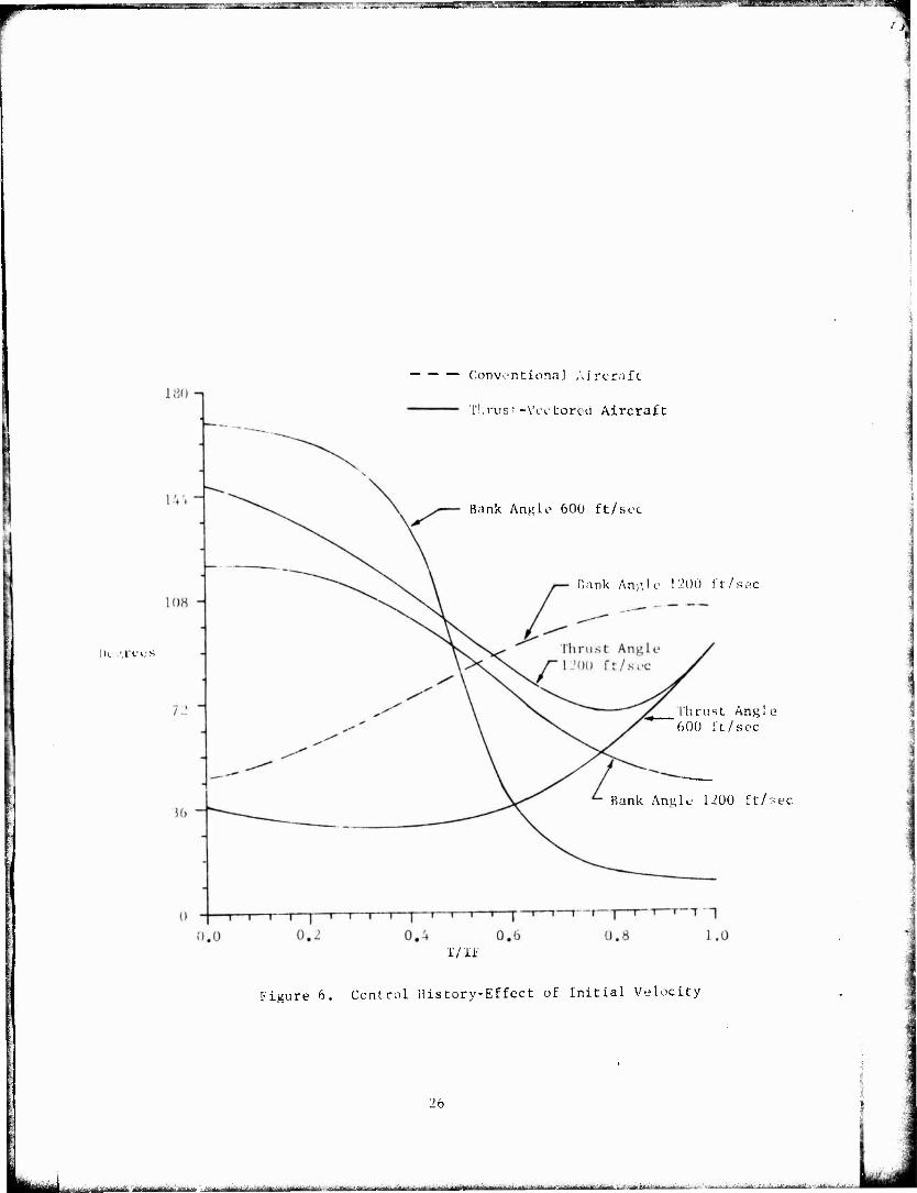
6 Control History-Effect of Initial Velocity
7 Ground Trace-Effect of Weight Penalty
(Vo = 600 ft/sec)
8 Altitude Profile-Effect of Weight Penalty
(Vo = 600 ft/sec)
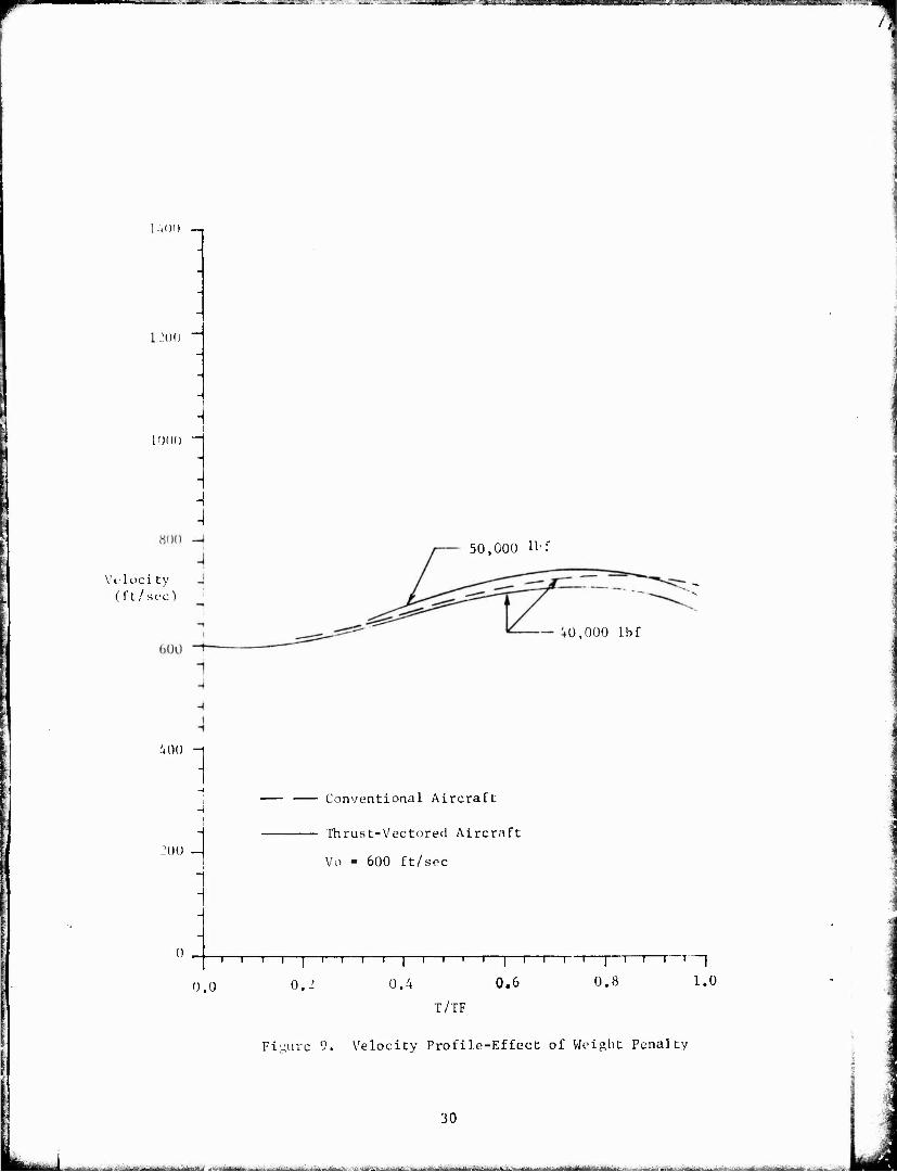
9 Velocity Profile-Effect of Weight Penalty
(Vo = 600 ft/sec)
10 Control History-Effect of Weight Penalty
(Vo = 600 ft/sec)
II Ground Trace-Effect of Weight Penalty
(Vo = 1200 ft/sec)
12 Altitude Profile-Effect of Weight Penalty (Vo - 1200 ft/sec)
13 Velocity Profile-Effect of Weight Penalty (Vo - 1200 ft/sec)
14 Control History-Effect of Weight Penalty (Vo - 1200 ft/sec)
15
16
17
Ground Trace-Effect of Thrust-to-Weight Ratio
(Vo = 600 ft/sec, T/W = 0.585)
Ground Trace-Effect of Thrust-to-Weight Ratio
(Vo - 600 ft/sec, T/W = 1.25)
Altitude Profile-Effect of Thrust-To-Weight Ratio
(Vo = 600 ft/sec)
Page
15
15
22
23
24
26
28
29
30
31
33
34
35
3b
38
39
40
.....:■ .^_-'._i-.^.^.i^.tjf^. f,-. .li»" ■ ■-aiW.-1i,4r,j^^w* ^vji^i&rfg^i.- - -1A.-.. tj..» J ■'■-■.■■■■ .-i.■.--- -.^ ,;/„lnT.A. itr- -=--"■-- -i~JJ-a~.< -:^-^- ^ -"-..m^^ >■*..i-:Ji*,»L,t:r-ijjii. ■-•*.*..-».M^^äif ■■ i--frM

^jgg^^ ■."'/■ ,yIM'" *■"— "^' "■' * tiStSBW -'agwssa,"-^w-jraft'flTTOEBiagggÄi-^siL L.- -)JW.- ;',_^M aas*»"^^ss-"**'
■igure .'.ü,
18
19
20
21
22
2 3
24
25
26
27
28
Title Page
Velocity Profile-Effect of Thrust-to-Weight Ratio 41 (Vo 600 ft/sec)
Control History-Effeet of Thrust-to-Weight Katio 42 (Vo = 600 ft/sec)
Ground 'race-Effect of Thrust-to-Weight Katio 43 (Vo 1200 ft/sec)
Altitude Profile-Effect of Thrust-to-Weight Ratio 44 (Vo = 1200 ft/sec)
Velocity Profile-Effect of Thrust-to-Weight Ratio 45 (Vo 1200 ft/sec)
Control History-Effect of Thrust-to-Weight Ratio 46 (Vo = 1200 ft/sec)
Flight Path Angle-Effect of Initial Velocity 50
Total Angular Rate-Effect of Initial Velocity 51
Turn Radius-Effect of Initial Velocity 5J
Turn Radius-Effect of Weight Penalty 54
Turn Radius-Effect of Thrust-to-Weight Ratio 55
*a»anittiJSfcifla'iV'ii yrr^: , HnaH.r '- ^.-■.,.,v;:_n .^-„.^^....m....^»^)^^, jfrjajjum .^sx^^mi..,-^ jajftaäitfcaüatti(iiflib4iaSM<mj

^B^mi^^^Km/^mmmamKBrnssK
['able No.
I
11
in
IV
VI
LIST ÜF TABLES
Title Page
Initial Conditions and Terminal Constraints 18
Terminal Conditions 1'}
Position at the End of 180 Turn for Thrust-Vectored 2] Aircraft-Effect of Initial Velocity
Position at the End of 180 Turn for Thrust-Vectored 27 Aircraft-Effect of Weight Penalty
Position at the End of 180 Turn for Thrust-Vectored 47 Aircrafc-Effecc of Thrust-to-Weight Ratio
Initial Excess llirust 4y
jäMHMhja ■ ■ ri&in.i-.-a^^J"--^--f"^^^^--^^;^'-- - i if. V .IIT Ü irfivfift'11'"""

-.__ . "T -77- '-■if,1J. :■ itWWawBt, 4m.«*■- -f
INTRODUCTION
I'he purpose of this investigation was to determine whether more complex and detailed studies oi the effects of thrust vectoring on air- to-air combat maneuverability were advisable. The minimum time turn was selected as the maneuver to study in order to keep the cost of the stud) down. Turning capability is very important in air-to-air combat, and since for given initial conditions, minimum radius is also obtained in a minimum time turn, it was possible to study two important aspects of the problem without a great deal of complexity.
A mathematical representation of an aircraft similar to the F-4K was created. This model was used in a first-order gradient optimiza- tion procedure. The output of the computer program was a trajectory for a minimum time turn for the selected initial conditions. In general, for each set of initial conditions two trajectories were produced, one for an aircraft without thrust vectoring capability and one for an aircraft with thrust vectoring capability. All cases were lor 180° of turn, lor most cases, the angle of turn and the flight path angle at the final time were the only constraints. However, in some cases Hugh speed weight penalty and high speed thrust ratio) it was necessary to also constrain the final altitude. These constraints were employed in an attempt to produce results which couli be used to judge whether the vectored or nonvectored thrust configuration had a combat advantage at the end of the 180 turn.
The effects of initial velocity, thrust-to-weight ratio and weight penalty were investigated. Even using the most simplified model of the air combat situation that could be expected to provide a reasonable basis for comparison, the. computer time required was high. Satisfactory convergence was difficult to obtain in the cases where the effect of thrust-to-weight ratio was investigated. In the weight penalty inves- tigation, weight was added to the thrust-vectored configuration until the weight was 112i"7 of the conventional aircraft. In general, varying the thrust to - ei,-,at ratio may be accomplished by changing either the we.vghL or the thrust. The purpose of the weight penalty study was to determine the amount of weight penalty, associated with mechanizing the thrust vectoring, that would nullify the advantage of thrust vectoring. Therefore, several thrust-vectored cases with increased weights were compared with the basic conventional aircraft case. The purpose of the thrust to weight ratio investigation was to identify the range of thrust to weight ratios where thrust vectoring provided the biggest payoff. Therefore, this study was conducted by investigating pairs of aircraft (one conventional and one thrust-vectored) at the same thrust to weight ratio.
We recognize the minimum time turn criteria for the optimization formulation is not the best criteria to compare combat capability. However, it was chosen so that an initial investigation could
i ;
^jayi^-IBa^^a^..-. AJ^.-.-.-.~klm«-'. LJ^:^-^ri^^.1.^|||^..11^;^JB.tLa^ijf| ^-üü-. :»** i^iiiiiti t *>■*'■■■■ ■*-'-■■■-■■ ■ iT ,;jlM,.'..-i' ■■i-...,-.-:-- | 'jjgfa
' -■■'--■■ ■ --i^;-: .---.-,...■,,_

••äk^Si mfVhtm.Jd^JmmA=JßdS^ "•
be conducted at an acceptable cost. The study sh. .vs that the thrust- vectored aircraft has a capability to maneuver in areas where the conventional aircraft does not. ihe trajectories of the thrast-vectored aircraft represent the bounds of this capability. Ln ehe combat situa- tion, the thrust-vectored aircraft would not be flown aiong a minimum tine turn trajectory in most cases. The difference between the conven- tional and thrust-vectored trajectories represents the additional capability for comb.it maneuver that gives the thrust-vectored aircralt an advantage in combat maneuver. The way that this capability is employed is'up to the individual pilot and depends upon the situation. In combat it is generally desirable to maintain as high an energy level as possible and the employment of thrust vectoring lowers the energy level of the aircraft. However, the objective of air combat is to ohoot down the other aircraft and if a sacrifice of energy level is necessary to achieve this objective, it is the correct thing to do. The reader should keep these points in mind as he evaluates the results of this studv.
niKORY
The program which computes the optimal trajectories uses a general first-order gradient algorithm for optimal control problems with known initial conditions and unknown final time. Ihe state equations and adjoint equations are integrated using a third-order modified Kuler integration scheme >_ '_• All partial derivatives needed by the program ar< computed using finite difference relations. Some double- precision computation is necessary to obtain accurate third-order partial derivatives. ihe state equations are the point mass equations of motion for Lne aircraft. Internally, the program uses a non- dimensional form of the equations. The program contains formulation for two types of aircraft. One is the conventional aircraft with the thrust vector fixed along the longitudinal axis. Ihe other is a thrust- vectored aircraft where the dirust can be directed throughout the aircraft's vertical plane.
The basic problem can be stated as follows:
i'or a dynamic system governed by first-order differential equations of the form
f(x,u,t) , a)
^■i'lrifr'Vr II «dMi,: -.^-..-i.- '■■- ■■:.-/^«-*-./.=---^--^-fcJ.^-.-i»l^-1-,.,■!!!-■ llif~li1lTh¥llBhrfiliir"li i iT i'-iÄ^iü/j.-.,, -■.-■■■ -■■-■■■ -,^-i-'^-■■■..;. ;-■■--•■■,;• ■.."■ ii-i..- . .

-"32SSS3CI~ "
determine the control history ti(t) and the final i ime which optimize:; a performance index of the form
ft 1 = 3 (xf,tf) + F(x,u,t)dt (2)
n these equations, / Is an n-component state vector, u is an m- component control vector , and t. is the independent variable time. Hie initial conditions at t,.
x(t ) = X o o (3)
are known. One or more terminal constraints are imposed on the solu- tion, rhe terminal constraints will be denoted by the -component vector
i(xf,tf) = 0 (M
where each component is a functional relationship which must be satis- fied at tf.
The necessary condition for an optimal solution is that the total variation in the performance index, 1, due to variations, 5u(t), Is •zero; i.e.,
dl = 0 (5)
where the constraints in equations (1), (3) and (4) are satisfied. Equations (1) and V) can be adjoined to equation (2) with the adjoint variables X(t) and Lagrange multipliers V to give
T ■--■ 3 + i/ V+ !' f [F(x,u,t) + Xr(t) [f(x,u,t)-xj}dt. (6)
Differentiation followed by integration by parts gives
**mmmmaimm m ■■,

■ .... J-wl .. . - r22BSr^*?TXBa^E3iFgEEm§3£32rE£ZJ±
dj (lA + „T «i£ + F +XT x] dtf
(.13 + yT 4*. ;r \. + x T 5x \ X X / f o o
,<-f -:— + X Ax + -s— ou dt , (7)
where the Hamiltonian !! is defined by
md
H F(x,u,t) + X ft) f(x,u,t)
Ox = dx - xdt
(8)
(9)
L'he adjoint variabLes can be chosen to satisfy the conditions
xr ÖH ' x
and
■-■ f
Ö x
X ' X
OF x,x
I'IO)
(11)
Uy imposing the additional condition on v that
G IV) •x4 + V1 ~ + F + X x - 0 (12)
the variation in the performance index reduces to
dl = i -r— 5u dt . ■^ 0 u
(13)
Since the variations in u(t) are arbitrary, a stationary value of 1 can exist only when
~- = 0 ; t : t - t, .1 ii o <
(14)
,..;...,.^iA;Yt.-^ji-'' -^ ...■-■ ; ■aii»;.,^.-.^ .-■..^■.-—■ .^; ■ ,^ ■,■■ -■■;>■■:-. ■., ■<„,A.-i--; .^--..v

In effect, the opeimiz.ntion problem has been transformed into a two-point boundary value problem with ?.n differential equations and mixed initial and terminal constraints where u(t) satisfies equation (14). The In differentia equations are given in equations (1) and (10).
and the initial and terminal constraints are given by equations ('S) and
(11).
The vector V is so far unspecified and must be found from the variation of the terminal constraints. In general, X(t) can be expressed as a linear function of V as
\(t) - p(t) *■ R(t)y, (15)
where the n-component vector p(t) and the n x & matrix Kit) are called influence functions and are defined by the differential equations
and
where
:• f\T / v P 1—) P -
/ x .\T (sty
(16 )
(17)
T = M cf (18)
and
<-f L X 119)
In terms of the influence functions terminal constraints are
the first-order variations in the
r.tf T Af dV - *dtr + ' R ~ 6u dt,
t 0
f20)
where
\f ft * . Ö * , Ö t ox
(21)
10
hggjEgaiatti^fllBiti ■..---■v,^-^^:-.^--^^^-«»*--^^ ■-■■^^■■^^^■^^^■irfi^|i;--al|iiil'l^% iria^tii^tWfiitiif iTii--ini--.ii i»4_£>fc*&.i- ■ .sKMÜ i . J, . juiuc -iV.-. ,-^jj; ■■;■... i-jM

Kquations (12) and (20; supply the inforniati m to determine the vector V and the final time t,.
Hie computational algorithm is as follows:
.v"tep (a). Using an initial estimate of the control history u(t), integrate the equations
*x = f(x,u,t) (1)
iorward to an estimated final time tf. The terminal con- straints (4) will not be satisfied.
Step fb). Compute the influence functions at each integration point along the trajectory by integrating the equations
*>. - mr, - m i6:
ana
R(t) -4fi » (17)
backward using the terminal conditions
Ö X (18)
and
{tf - ft x (19)
Step (c). Using an estimate of V, compute
A(t) - p(t) + R(t) V,
ö_H J F . T & f 5u= öu 5u '
(15)
(22)
f 11 _ £_F . T öfjE Ou 0u; Oif-
(23)
and
!1
I mini if I-•**-—Uli -TimüniilTiiir mi - ■■■ ■* JIB IHM ir min ' n ««Ml i m i Ma InllWifdihiiliinllllrt II I ■ i iMMltliHlnl 1 I i,. jaaiAfca ■,..^.im-~- ...

H ^ + A1 ~4 'U "U'
(24)
at each integration point along the trajectory. Simultan- eously, compute corrections 6u from the relation
— < —— ou + Ou —— ou = 0 U AX Ml
(25)
Step (d). With these values of öu(t) and an estimated correction to the final time, dtf, compute the predicted variation in the terminal constraints from the relation
•tf T Of c •IV (l\dtf) - V dtr + R — 6u dt 1 1 •' ou
o
(20)
Also, evaluate the transversality function
„ i ß T Ö 2 ^ 0>) = Tt + V T~z + H, (12)
Step (e). Vary the values of V and numerically compute ";dy Ö'dy
the partial derivatives -r-- and r-rrs . With these partial
derivatives, improve the estimate of y and dt, using the re l.ation
:.d>& yd* -+ dy\
- dV -1
* + dy
n (26)
Step (f). Iterate steps (c), (d), and (e) until
12
- w.fc«iaif*-t"-iinttir--i>.z:*«^^^ ■B'iiivr»--.» aw ^.toahiii ;.■■ wafe^ywiMa^^ia..^ .-.«A , ^-^.j^, ^n tt ,-rt iaril-^. -,:^ .^ . i ^yn^g^i. f,. .. ■MriMÜBBTiMltfii i iBfti .■vf.Mflm'-Yr-f.irfitf-'-«^»--^-

rMMBMi ■es «■■BPE^T"
mJ
di' (y,dtf) = - # (Xf,tf;
a (y) - o
(27)
(28)
are satisfied.
Step (g). When equations (27) and (28) have been satisfied, correct the estimates of u(t) and tr with
and
u'(t) = u(t) + f 6u(t)
t'f = tf + e dtf ,
(29)
(30)
where r is introduced to account for the nonlinearity of the problem. I'sinr the improved estimate of U(t) and t/-, repent the process starting with step (a) until some test for convergence is met. Some combination of the degree to which equations (4) and (14) are satisfied is usually used.
AIRCRAFT EQUATIONS OF MOTION
Assuming zero sideslip angle and no side forces, the point mass equations of motion for the aircraft are
dt V cosy cos o , (31)
dt V cosy sin C' , (32)
dt -V siny , (33)
m — = 1- cos u dt g 1
- I) - W siny - Dram , (34)
m\ , ay — - L cos -J + F„ sin a„, cos i> - W cosy dt g I (35)
mV cosy ~r- = L sin u + 1- sin 0u sin ? , at g J. (36)
13
**;i-^-ili»lillirW^^t-^ik^^: ^—1

" ' -T—^^imt.awititdkto.-'tx'Eag^s
CL fJV'S, (37)
whe re
a., -
i) (rn + KCT:') * o \':s,
flight path angle (positive up from the horizon) , heading angle , bank angle , angle of thrust vector measured from the velocity vector ("positive up).
(38)
[he original direction of the velocity vector is the positive X direction, and the heading angle is measured from the positive X axis. The positive direction for the z axis is down. See Figures 1 and 2.
ATMOSPHERIC MODEL
Assuming that temperature varies linearly with altitude according to the relation
where
T = T TSL h
SL 144000 '
T - temperature,
TgL " sea level temperature
h - altitude ,
(39)
and that air is a perfect gas, an expression for the pressure ratio can be found of the fot I
144000g
where
SL sLy
p - pressure ,
p_, - sea level pressure ,
R - the gas constant for air
14
■va-,,t.^i-.tvrt.-;^^^,,. =£*, -a.. -■■■■■■ "-■--vt-,'j^'iM'r'r«-iirr ^^.y^i^i,^,. V,;ktti^.^..^J..*^^^^,.,.;,^s,^.^2:^^±^^±*^ . jLuii—tf^i.: ,MIfe: :, ;^,.;.:. ii;,,*,;^.,

■WilTff-" '.IK'.'M:- ."SI -TT^» j.im.u.111,1... i,. i.i i <Pta»«»E»»Bya»1»ii^».»:mw,uii._.. ,"■.-■ muf •jsmfier^mr:fm"iw> #f*s*rti?.*:T^.
^urc I. sta-e Space Coordinate System
Z
v - vv,
Figure 2. Aircraft Coordinate Syst System
15
% «ui. a-ttt^^a ^..-^-.h^^^.-^^A^.^^.^.^^,- IT^-MM, ),„m ... t,^i.;,.^, = J,^,,,: ',■

E—mat -T^^T-a^wT;:' .-saga
In terms of the non-dimensional altitude z - -h/i' , the pressure and temperature ratios can be written as
T _ 'Snin T " 144000 Z (41)
when
K . - minimum radius for a level turn at sea level til in
a nd
JL . (JL\ PSL VrSl/
5.2094 (42)
The density ratio is given b\
Q- —C (P/PSL
)
(43)
COMPUiAT'lON OF GROSS THRUST
in general, the gross thrust is a function of Mach number, M, and altitude, h. At a given altitude, F may be approximated by
F :VF F •-■ F + -rrj» (M-M ) + • -T7T& (M-M„); , g go JM er 0M~ o7 ' (44)
where F _ and the partials are functions of altitude evaluated at M_. ... F
In turn, the F , "H?, anc^ -rrr* can be approximated as functions of go .-1 nM altitude using
cu + c12 (h-ho) + s c13 (h-h0) , (45)
Ji° c21 + c22 (h-ho) + t c23 (h-ho) , (46)
and
C_1 + C,- (h-h_) + v C„ (h-h )■ 51 51 o - Jj o (47)
16
"a^JU^M^-»-^^.^-^ ,".. *-J-,j- ■ :.;,. ^ _J

Sü^ETT: ~^~LLmtJaum&*^iäBR '.«BBEaaaBafi ^B^^.'..3egs-—aifa ——r.
Coefficients and engine data for the J79GE-17 engine with after- burner are given in DFAN i'K 73-4.
COMPUTATION OF KAM DRAG
(Tie ram drag is alpo a function of altitude and Math number or velocity. The ram drag can be approximated by the relation
- (Cr 1
ram "R1 V "R. + CD„ ) * P S. (48)
Crj , CD , and ram drag data for the J79GE-17 engine with afterburner JR 'R
are given in DFAN TR 73-4, along with a complete description of the computer program.
RESULTS AND DISCUSSION
Conditions. The effects of three parameters (initial velocity, weight penalty, thrust-to-weight ratio) were investigated. The initial conditions and terminal constraints which were not the same for all runs are given in Table I. Final conditions are given in Table II. All trajectories start at 20,000 ft, have a heading change of 180°, and end with the fligbL path angle equal to zero. Except where noted for the weight penalty investigation, the aircraft weight is 40,000 lbf, and for all cases it is constant throughout the turn. The wing area is 530 ft' , and the maximum load factor is 7.33 at all altitudes and air speeds. With the exception of the column in Table I labeled T/W at SL, all thrust-to-weight ratios are for the initial conditions of the run. It should be noted that the thrust varies with altitude and. therafore. the thrust to weig' *: ratio varies along the trajectory.
All runs were at maximum afterburner to maintain maximum energy for combat, although for the high speed conventional runs idle thrust would produce a tighter, faster turn. For all runs except 21 through 26, 38, 40, and 42, the final altitude was determined by the optimiza- tion process. For i"he runs mentioned the final altitude was constrained to be the same as that Jor the conventional aircraft run ^hat the results were to be compared with. This was necessary because the final altitude which resulted otherwise was so far below the final altitude for the conventional run that no conclusion about combat advantage could be made. The nature of the optimization algorithm is such that the final altitude does not have to be exactly equal to the constraint, but in every case it is close to the constraint.
17
llim.^ tifrft ■ daMHaSflitt ^v.AJ^.i^,r,rV,^.H vmx, iiLitiA A*J*ti*

CONVENTIONAL ] INITIAL 1 CONS TRAINED WEIGHT OR THRUST- | VELOCITY T./W T/W a- FINAL ALTITUDE PENALTY
RUN VECTORED | ft/aec •it SL ! 20,000 ft ft lbf
1 C 400 1.039 0.480 2 TV 400 1.039 0.480 3 C 600 1.069 0.585 4 TV 600 1.069 0.585 5 C 800 1.206 0.722 6 TV 800 1.206 0.722 7 C 1000 1.450 0.891 8 TV 1000 1.450 0.891 9 C 1200 1.801 1.092
10 TV 1200 1.801 1.092 11 C 1400 2.259 1.326 12 TV 1400 2.259 1.326 13 C 600 1.069 0.585 14 rv I 1.069 0.585 13 TV i 1.018 0.557 2000 16 TV i
! 0.972 0.532 4000 17 TV 0.930 0.508 6000 L8 TV 1 0.891 0.487 8000 19 TV 600 0.855 0.468 10000 20 C 1200 1.801 1.092 21 TV 1.801 1.092 24519 22 TV 1.715 1.040 2000 23 rv 1.637 0.990 4000 24 TV 1.566 0.950 6000 25 TV t 1.501 0.910 - ' 8000 26 TV 1200 1.441 0.870 24519 10000 27 C 600 1.069 0.585 28 TV 1.069 0.585 29 c: 1.371 0.750 30 TV 1.371 0.750 31 C 1.828 1.000 32 TV 1.828 1.000 33 C 2.285 1.250 34 TV 2.285 1.250 35 C ' < 2.742 1.500 36 TV 600 2.742 1.500 37 C 1200 1.801 1.092 38 TV 1.801 1.092 24519 39 C 2.061 1.250 40 TV 2.061 1.250 25637 41 C i t 2.473 1.500 42 TV 1200 2.473 1.500 26807
TABLE I. Init Lai Condition s and Terminal Cons traints
18
3^J~i*,~^.^.*„.^~ KätB&nAUia.. m MJKhistiLi*^**^*, ^t^M^^iS^giiä^ääefc^a

Z ll'W . iliJ-. .3UMH——^■b'dBiBBk. T
CONVENTIONAL OR THRUST- VECTORED
TIME FOR TURN (sec)
1 i NAL VALUES
RirN VELOCITY X 1 1 V ALTITUDE
1 C 15.58 652 -1049 1088 14534 2 TV 15.32 599 - 950 1047 14714 3 c: 13.32 714 - 529 1266 14394 4 TV 13.13 662 - 412 1221 14547 5 C 11.43 7d6 - 227 1486 14353 6 TV 11.27 738 - 108 1332 14450 7 C 11.91 820 530 6611 18077 8 TV 10.50 750 160 1724 14605 9 C 14.06 888 2299 8444 24519
10 TV 11.50 773 1298 5323 15818 11 c 15.13 824 3716 10476 23252 12 TV 12.65 792 2663 7929 18187 13 c 13.32 714 - 529 1266 14394 14 TV 13.13 662 - 412 1221 14547 15 TV 13.61 670 - 450 1080 14266 16 TV 14.10 681 - 501 1050 14003 17 TV 14.56 685 - 538 964 13747 18 TV 15.02 693 - 560 916 13479 19 TV 15.47 699 - 594 898 13223 20 C 14.06 888 2299 8444 24519 21 TV 13.16 69-9 1793 6310 24526 22 TV 13.48 701 1764 6601 24552 23 TV 13.88 703 1678 6918 24539 24 TV 14.25 704 1625 7208 24560 2 5 TV 14.75 704 1478 7533 24524 26 TV 15.16 700 1402 7801 24540 27 C 13.32 714 - 529 1266 14394 28 TV 13.13 662 - 412 1221 14547 29 C 12.76 752 - 489 1162 14454 30 TV 12.54 685 - 360 1122 14648 31 C 12.03 806 - 443 1125 14552 32 TV 11.78 715 - 298 1107 14818 33 C 11.76 890 - 714 1230 14563 34 TV 11.13 741 - 254 1057 14967 35 C 11.74 1008 -1225 1254 14411 36 TV 10.57 760 - 222 1012 15120 37 C 14.06 888 2299 8444 24519 38 TV 13.16 699 1793 6310 24526 39 C 14.22 897 2318 7940 25637 40 TV 13.2? 681 1831 5276 25637 41 C 14.27 951 2435 7609 26807 42 TV 13.15 687 1882 3734 26804
TABLE II. Terminal Conditions
19
Bife.a'.ii. ■.nm.T-rrrfi-Vi tflädfiBflBBifitofltf ■.,.■■- 8j - --^-r^j-f^ ,;*■.;-- i^\i£dte«*^^l£*ÜU^>fr^-»iil~^äe.^ :' --'.^-'-i-l ^«-: '■■"■ -■-■irrtiii'iiüiifl'fii *MBa---gJBli

Unis I through 12 represent the investigati .1 of the effects of initial velocity. Runs 13 through 26 are for the effect of weight penalty, and runs 27 through 42 are for the effect of thrust-to-weight ratio. Kuns 1.3 and 27 are the same as run number 3. Runs 20 and 37 art- the -ame as run number 9. Runs 14 and 28 ai-e the same as run number 4. Ihc data was repeated so that all of the data ov. a particular aspect of the investigation would be presented together and to make it easier to discuss the results. All velocities are given in it/sec. distances in feet, and time in seconds.
Initial Velocity. The greatest differences between the conven- tional and thrust-vectored aircraft were found for initial velocities above the corner velocity, which for the initial altitude of 20,000 ft was aixmt ''00 ft/sec. The corner velocity is the stall speed at maximum load factor' and for a level constant speed turn, it is the v. locity for a minimum time, minimum radius turn. lor all runs with an initial velocity below the corner velocity, the thrust-vectored aircraft ended up about 50 ft/sec slower, inside, above, and slightly in front ot the conventional aircraft with slant range, less than 190 ft (fable MI), i'h • slant range referred to in Table 111 i- the lino DI sight distance between the two aircraft. fhe thrust-vectored air- craft has the combat advantage, but the advantage is small. At first it might seem that i lie conventional aircraft has the advantage because it is behind the thrust-vectored aircraft. However, it is not possible lor the conventional aircraft to bring guns to bear on the thrust- vectored aircraft since it is turning at its maximum rate and is out- side of, below, and faster than the th ust-vectored aircr.iit and it is one to two degrees short of completing its turn. On the other hand, the thrust-vectored aircraft may climb and slow down slightly to end up behind the conventional aircraft and use its thrus*' vector capability to bring, guns to bear. One of the outcomes of tests an the Harrier aircraft such as those reported in References 1 and 2 was the demon- stration of the unique pointing capability that thrust vectoring provides.
lor speeds above uhe corner velocity it is more difficult to determine which aircraft has the advantage. Paths over the ground for runs 1 through 12 are plotted in Figure 3. Altitude is plotted in Figure 4 for runs 3, 4, 9, and 10 against time divided by final time (I'/VF). In figure 5, velocity is plotted against non-dimensional time for runs 3, 4, and 10. with this information, the reader may visiuili.'.e the trajectories and sequence of events in three dimensions. Consider runs 7 and 8 (initial velocity 1000 ft/sec) where the thrust- vectored aircraft is 4680 feet inside; 3550 feet below, and 99 ft/sec slower than the conventional aircraft, holding the final altitude of the thrust-vectored aircraft closer to that of the conventional air- craft will result in bringing the paths of the two aircraft over i:he ground closer together as well as in slowing down the thrust-vectored aircraft. This should allow the thrust-vectored aircraft to obtain a position where its guns can be brought to bear on the conventional aircraft.
20
L^aj-jJBfe*^- yfcaagiiiaiftaifiiaafciiaa ij-;"-' MBü ^■s^^i—^»..^.^^ Vl,*.*..i« ^W^^^„J^..^M^rw^fr^,1^ -.^ . ■■■■3".:-,:-^f,-Ji~ -,^a»'",„'ii itr-riift.T[Cl.-iH:i'.:

mt^maaam
f- w
- <; r/) 3?
*r" H "—' ■J
rJ
C~*
w V. p H (—* h-1 cj H
Ö < *<*- t-.
f.
-< >> .«-' c M
H r-l
m
tu
d M C-<
^-* H
O
U
S5 ta «
30 03
i— m a»
—-1 CO Ix vO r-~ 00 o X C CM o —4 0 c- NO
!•- CM •-* 00 o> en r-- r-.
o> O <r m 00 t-
m CM <}■ a ON r-.
00 <t co r- r- O m m O 00 O 1*» Cn r-> C^ vf m m in o O fH r-l 00 m r-~ -n IT* m <!■ r-l vO CM CO i-l .-I vt <t .^ <r <f o- CO <f
CM i-H m oo CM i-l
m r- <t i—i r-l CM «tf <t 00 en o ON
ao <f ~o CM CO m o CM m CM 1-1 CM o O CM C 1 *T en <•> r^ r- CO r- ON -^
"' —1 —-i .—1 —i o r-i r- m ON r-~
m o n CM r~ CO m o cr« CC O en ON m O —-I <t O ON NO in ON en NT) CO cr <r <t !-l o
—1 r-l
-3" CM r-l
NO CM
CO O r~ oo
ON o CO
00 c !~~ CO
o a ND 00 <}• 00
NO o <f oo
CM CM en en
en <-<
en i—i
r-. r-» CM CM
o o in in
o o m m
in in NO NO
m m
O O O O
u
o o o o NO NO
en <t
o o o o 00 CO
m vo
On r-l
u •> u
o o o o o o
rv oo
o o o o CM CM
ON o
o o o o
« u U r
•H <$ -a CJ u o *J V o
jj
CO
3 l-i
S u o
WJ
c u 3 H
o >-. no j-j ,-t •, i
*j IH 0 o r-l
a TJ ^ c
UJ r-l
Cfl CJ •r-l
rC ■U 1.1 •r-l
C t; w ej
U-l C 0 O •H u JJ U •H 4J tfl U-l O m Oi W
w rJ
L. 'M>»i.l. -|-~::^^^-.1^.!i^. ■■ lie r*"v""Tf -'i*
21
irriMteaBtte^ u j^umajo <~—ü-i^li i^ „iV j. I ,- jjjB

""ff^«.lW- ,-*-™>'T"^;
o o o J-J
u 0
O i* c O 30
c —i
c. c rv
0 o c *—- i-<
c 4-. u ^£ ^-. ii N—
O « i c fl D
ü
o -J c o •^ <f
»1
o c ci
O >- c ^ c tc r i
I:..
c o o
22
■«Mfafii-ftr-j*—aamiMMi^iMBaiMaayag ■"-tJ*Ma")"inytimiiaii ■

■ ■■'.'!'■ »»■ifWipu.J 'lim". -■" "^-.SJ.--"* mL77.'_' ' ■".' ' '^i:—' ".".I'M
50,000
!5,oon
20,000-H
A.';i.Uide CCD
15,000'
10,000'
r5,ooo H
600 ft/ c
Conventional Aircraft
Thrust-Vectored Aircraft
1 i 1 r—|—i 1 1 1 1 1—| 1 1 1 1—i 1—i 1 1 r — r
0.2 0.4 0.6 0.8
17 TF
Figure 4. Altitude Profile-Effect of Initial Ve1ocity
1.0
23
Igyjflgflgato ..,•,...,.i^aaaaaaaajfci^aaMiL'i^*»^.^^-^. ^-^nnmüS*■ ■ ttkwiaiäikvMajüBagiäästti aaüknJimiMi^ayiiftiiitt^tfihaiirittE^ fftflWtflft*llifrH^JVitfn"'-'' "' - ■ -■-•-- ■ ■^--■^^a&fe^jai^;

— —• — £L~ ~ •' _ ^ .sag» -Jt"-:'.jjAj"3Ma^'.:fcHa!g
'.DO -I
200
1000
800 -
Vt'l ocity (ft/sec)
bOO
4 00 -
200 -
0.0
600 ft/sec
Conventional Aircraft
Thru s t-V ec fc or öd Aircraft
-i—i—i—I—i—i—i—i—[—i—i—i—i—|—i—i—'—i—|—i—i i ' [
0.2 0.4 0.6 0.8 1.0 T/'.F
Figure 5. Velocity Profile-Effect of Initial Velocity
fc*^.iiÄ..^.^it::^i^i^-^i^^
24
i»D^^M«4i^, •^ü&^™«tek«*i^^

»K^-''-''." ..a- Lm&aiBEsa» ■ a ■-■«HMII]IUHMMM«I..IIM«I|«..II IUMUMJUI. -m^p
In all cases the optimal maneuver moved the oiocity toward the corner velocity (corner velocity varies with altitude). Above the corner velocity, the conventional aircraft climbs to lose speed while the thrust-vectored aircraft uses the angle o.f the thrust vector to lose speed and to tighten up the turn. In all ca^es the final angle for the thrust vector was about 90° (Figure 6). This was probably due to the requirement that the final flight path angle be zero. In Figure 6 the difference in the bank angle plots for the conventional aircraft at 600 ft/sec and tl"2 thrust-vectored aircraft could not be plotted. rhe optimal hank angle history for a conventional aircraft below the corner velocity agrees well with the procedure which is currently in use for making maximum rate 180° turns in the F-4.
The angle of attack for maximum Cj is about 22°. Therefore, a thrust angle of 36° indicates that the thrust line is 14° above the aircraft axis. Thrust angles for the runs below the corner velocity were small except for the last 307, of the run where only a few degrees of heading change is accomplished and the emphasis is on getting the flight path angle back to zero. For the high speed runs the thrust angle starts out at about 150° to reduce speed and tighten the turn. For the high speed runs the bank angle was considerably higher for the thrust-vectored aircraft, thus increasing turn rate. For the conven- tional aircraft the bank angle was low for the first part of the turn because of the need to gain altitude to lose air i>peed (Figure 6).
Weight Penalty. To determine the effect of the added weight which would be required to mechanize the thrust vectoring, runs were made for initial velocities of 600 ft/sec and 1200 ft/sec addiiv', increments of 2000 lbf of weight until the weight was 50,000 lbf. This represents a 257 increase in weight. <"onsidering the capability for aligning the aircraft: that exist:;; ir. the thrust-vectored aircraft, the thrust- vectored aircraft has a combat advantage even up to a 257 weight: penalty, I'he bank .ingle and thrust angle histories do not change much over the 10,000 lbf range of weights (Figure 10 and Figure 14). Table
1V shows the positions of all aircraft at the end of the turn for the 40,000 lbf thrust-vectored aircraft.
For the 600 ft/sec case, the thrust-vectored aircraft with a weight penalty of 2,000 to 10,000 pounds was behind, below, and within 1725 feet of the conventional aircraft (Figure 7, Figure 8, and Table TV). This is well within gun range for a 20 mm gun and the thrust-vectored aircraft is in a position to bring guns to bear. As the weight penalty was increased, the final velocity increased so that for a 6,000 pound penalty the final velocity of the thrust-vectored aircraft was within \ ft/sec of the conventional aircraft velocity (Table IV). There is no doubt that the thrust-vectored aircraft has the combat advantage. In reading Figures 8, 9, and 10, remember that the final time for each run plotted is different, so a value of T'/TF = 1 represents a different time for each run. See Fable IT for the final time for each run. Figure 10 shows that the bank angle and thrust angle vary only slightly from the 40,000 pound aircraft to the 50,000 oound aircraft.
«iiuäüi^auu'iua .:■=..-.. i.: j_™.,
»—^£^7""*^'! ; " ' "''*-'■ -■' ~ mi miimin mi ii ii *ff^^^" ■ '■' ""■ ■ ■■""■ -M^^—«nun miuimm
ii«. 'reu.s
Conven tionn] Ai re raft
'L'l.rusf -Vectored Aircraft
Bank Angle 600 ft/sec
Bank Angle 1200 ft/sec
hrust Angle 600 ft/sec
Bank Angle 1200 ft/~ec
17IJ?
igure 6. Control History-Effect of Initial Velocity
26
,.„ „.i.^* aÜ» .jrt^-^^-:,'..--,-^-- -^-.v. .■- ■ ~—.... .„- ,,.,--.J^, »-«»»■■ ,rs .i -^, jyjjfrjgj liap-mt ,j

iKll ^-mim-'f*-*^"^
H U >q C/ a x f/5 K
£ l—i u o 1— r^
u: •^ f U E| M KJ
n E—
►J
ä < ■rL.
r_ *
M
<: , c H t-< H C/l X O D.
~t
w ** < h^ f—1
|—1
; *
r^ O O o CM m m <r -o r~ o CM —i co o 3 -1- r-.
r-. CM o> i—i o CM in
r^ o o r^ f^ r*- c^
oo r- CM m a* O O o> <r t-~ <f m o \o (O ^ N O 00 N in -T <r st st co ro co
<t H a- n o> 'n öD vD ci r— en <f O r». IM NOO Ol O>00
CM r i co O co in O O •—i Is» CM CM to CI vt<f M CM vD 0>
I I
cn o ON oo oo oo r~» co r^ •>* r» r-~
or-
C
U
tJ >J
3 f-1 a c
'.., o vD : J 3 M «
g CO < 3 r-4 <- OS
o o o o o o o o o o o o o c c o o o o O o O O CM st >£> 00 o st ST <t sfr «* st in
i-i H h-i ^ h-t H
o
U N « O.
IT o r- CM r-» O CO O st CM 00 O <f H r» 4 o o> N N H H H
O ON r- CM O m ON
H 9> O N <t 'J >J Q\ vö N N t^ N S
vß CM CO O 00 O O vt iA in in st <f n <f st <t »* <t st st CM CM CM CM CM CM CM
.* O CM vo m st i-4 <t .-i o~> oo co a> CM co co in co >-* co m CO ^ vO iO Is 1^ f^"
,-( co in o CM vD <t co CT\ r» r-- oo O oo H N 0> H t^l \0 N CO i-i ■—I CM CM CM CM
r-- o r~~ co o m CM O oo r~~ r— t-~ vo \o
^D
co .-i
O O O O O O O o o o c o o o o o o o c o o O O CM -st >£> 00 O <f st st <f «* st m
C_> > > > > > > f- H H H H H
o o CM
o •> °
O i-l CM CO St 1-0 \£ CM CM CM OJ CM CM <N
U
CO
u 1-1
■H
-< •o u !x o •u o 01
«5 3 U
jr. M
01 c c l-l o
'•H
c u
H
O
0 CO
•a oi c a.
x; x;
4J s
«4-1 c o c
•H 4J 4J O •H 01
O M-l DJ tu
2 7
V'-a-iinfit/niitii i

■-^«WJ.4..«). -"»"^" ,■ '-'HW'HP ..■»»»»^■willllMLIl^llll I [. IJIM/lllli^UHIMI.l,.. l,l,TPWTT
4000 -H
orcn (,tc;
SouLh (ft)
iOOO-i
iooo H
inoo-^
o -J
30,000 lbf
-'.4,000 lbf
'.0,000 ibf o
1OO0
2000
Conventional Aircraft
Thrust-Vectored Aircraft
Position of 40-000 Lbf Conventionai Aircraft when the 40,000 lbf Thrust- Vectored AircrafL has Completed Turn
Vo - 000 ft/sec
liguLe 7. Ground Trace-Effect of Weight Penalty
28
.»^^^»..w.^yuami -■*•■■*- "■■-'■■—^ ... ytffrfjitfiffl^^pj^jji^^ ■■ - v jug -, i aüBg lai n^jgaag^jm^ i^ii'iMftrfi-ir YTfl -

* "^■"fWl—PWP^^I I UI ■ _IJ|P I ■HI! lll.l» '■■■■ WH i i.i i i
50,000 -i
-,,000 -
20,000
^Ltitute (Hi)
15,000 -
10,000-
- 40,000 lbf
50,000 lbf
5,000-
Conventional Aircraft
Thrust-Vectored Aircraft
Vn = 600 ft/sec
0.0
T 1—i 1—I 1—I r—i 1 1—|—1 1 1—I—I 1—i 1 r -l i i |
0.4 0.5 0.8 1.0
T/TF o.;
Fiit'ire 8. Altitude Profile-Effect of Weieht Penalty
29
. ^^...^^„j^i, - - ■>—-^-■■^--^-^■-■f -- —-- '.^-- - - ^-- - - -■■--=---- 'i i■■■Hi' win iir .■m^r\U\m\\r'^nmmmt^miiimmtmmmmmmm^
-trvr: T3E.:._ . -. W«M"tW"ll«'lL^M'^lA^a!*w^r*^
,1)0
1200
1000
Vulocity (ft/sec)
400
50,GOO H'f
0,000 lbf
200 —
Conventional Aircraft
Thrust-Vectored Aircraft
Vo = 600 ft/sec
0.0
T—i—i—i—|—i—i—i—i—|—i—i—i—i—|—i—i—i—i—|—i—i r— ^ |
0.2 0.4 0.6 0.8 1.0
T/TF
Figure 9. Velocity Profile-Effect oi" Weight Penalty
30
Wit.J AaijJM«»..^^-'-/^."-i ■ ..■-■■;- -:.-■...-; -. '. :--^-l^. .,^.,.'. ■ .,-. ,.---,i-; .; ^„-t .■.-„...». i.-,^--..-. .... ■■--■:■ „,,..-. ... -^i.-,..

Decrees
0.0
Thrust-Vectored Vo = 600 ft/sec
Bank Angle 50,000 lbf
Thrust Angle 50,000 lbf
hrust Angle Conventional Aircraft
I—r l | —T r— i—i—1—r-
0.2 0.4 0.6
T/TF
T 1 1 r
0.8
-T—r—1
1.0
Fi-urc 10. Control History-Effect of '„'eight Penalty
VI
~ -i'"titrfi iY'"in''iUhir •"' ■Sfc-gjr.ni---... <,; ■ ii-»-j"Tr-rtHw-p-'^"^'"-,M-: iiiWiiii^^aMiirr)i.-.i.."*'"A'-:''■"■*"■ '--■-■•■

- --.—^- -_— r. i i'ü.'?1.1)!! - si'i^.-juwaam^WMmcm ■HBESH
For the 120Ü ft/sec run, it was necessary t constrain Che final altitude Co be ehe altitude of the conventional a'reraft. Otherwise, there was too great a difference in the final altitudes to be able to determine which aircraft had an advantage (see Figure 4). I'or all weights, the thrust-vectored aircraft was inside and in front of the conventional aircraft. The thrust-vectored aircraft was slower and within 110 ft of the altitude of the conventional iircraft. Since the thnst-vectored aircraft is slower, a turn toward the conventional aircraft would tend to put the thrust-vectored aircraft behind the convention.il aircraft. With the computer program used, it was not possible to pursue this tactic to determine which aircrafc has Che advantage.
Table [V shows the posiCions of all aircraft at the end of the turn for the 40,000 lbf thrust-vectored aircraft. Since the altitude is almost the same for all aircraft, Figure 11 and Figure 12 give a very good picture of the relative position of each aircraft in space. Constraining the final altitude of the thrust-vectored aircraft resulted in almost no difference in the altitude profiles for the thrust-vectored aircraft of different weights. The difference in velocity between the conventional and the thrust-vactored aircraft makes it difficult to predict times and trajecCories for a turn into the conventional aircraft if the conventional aircraft continues the turn. Figure Hi shows that the velocity of the thrust-vectored air- craft does not change much with weight. However, the slant ranges (Table IV) are such that if the conventional aircraft tries to turn away from the thrust-vectored aircraft, the thr-ust-vectored aircraft will have the advantage. For 1200 ft/sec initial velocity (Figure 14), there is a slightly greater variation in bank angle with weight in comparison to the same variation at 600 ft/sec initial velocity (Figure 10).
The effect of weight penalty on the x direction position at 13.13 seconds for the low speed runs and 13.16 seconds for the high speed runs was to make it more positive. Since the low speed thrust-vectored aircraft was behind the conventional aircraft, the slant range was increased with weight penalty; and because for the high speed runs the thr'ist-vectored aircraft was in front, the slant range decreased with weight penalty. If the final altitude of the low speed runs had beer, constrained, increased weight would have produced wider turns, thus duplicating the effect of weight on the high speed runs (Figure 7 and Figure 11). Most of the effect of a constraint on the final altitude is on the y direction position since it tends to tip the plane of the turn up or down, rotating it about the x axis. There is very little effect on the x position, and the effect of increased weight on final x direction position (more negative) is the same for both speed regions.
32
■i^a^d^^;^^.*«^^ „utk^, äüema^a^faaa^aMüiMd müm&£ää atek Ai^^&tfiiJüiüitV. .1

«^■^»jHyt^jijiijj.i - - -Tgj-
-o-
3
o
o o
o s
n^r-T
3
c
i m ■ um,. Tür
33
„____.,...,. aiifijaf.'.,il. ^ite>., ■

-— ^■»■■■—-■—■-— - ' u- i ...■■■■■. ii -m-m ..u i.— vm w-i .... - —
JO,000 -i
3,000 H
.'0,000
[•),lHH)i
io,nooH
rj()()0
All Weights - With and Without Thrust Vectoring
v = 1200 ft/sec
1—i—i—i—|—i—i—i—i—|—i—i—i—i—|—i—r
0.0 0.2 0.4 0.6
T/TF
—I—.—r 1 1—r-
0.8 1.0
Figure 12. Altitude Profile-Effect of Weight Penalty
34
.... nm^ng—. ... -„..,..,.._, . •

4()U _
-'()()
10(10 -
Veloc- i t v ( £t/sec )
800 -
dOO -
200 ~
40,000 11'f
Conventional Aircraft
Thrust-Vectored Aircraft
V = 1200 ft/sec o
( —I—r—i—I 1 1—r—i—I ■ 1—"—' ' ' "~l r
o.O 0.2 0.4 0.6
T/TF
-i—i—|-—i—i—i—i 1
0.8 1.0
Fi.uirc 13. Velocity Profile-Effect of Weight Penalty
35

,'J.'-A?'.. -T-- v y—-—- — i', i,,^ _.,...maBmmiBntmmmaHmmnmnKmsai^mHBmammsmm
180 -,
1*4 -
10« -
()•' '>-<_H'S
36
• >• . :i ■ i >ii i ] i , t [ a 11 >a,ik ,... 1 v ^ , Ibf
O ■ n.-.w <■ io:,al Ai.cr.i.t iluiis. Angle, 40,000 lbf
* ; lir.i.si- . lictiii -I'll \iicrait Kank Mii^le, •'.', lbf
□ n.t'i.-a-Vt'ctnr,' : 'ircraft Thrust 'ü/lc, '+0,000 lbf
—I—I—I—I—|—I—I—I—I 1—I—I—I—I—|—I—I—I—I 1—I—I—I 1—|
o n. ' 0,4 0.6 0.8 1.0
T/'TF
Figure 14. Control II: stury-Ef f ect of Weight Penalty
36
^i^^^A^A^^i^^.«^ „,-i. -*;;■■■«?■. -^--/u^Jai^^L^.....^^^^ T'iii-ff.n-tf JUtiS Ü ^^■^Lfaäiii^^^^^lBK^jW. fc*.-*' ■-Mifcjit.VJa-:ii*-»,i.k..

„^^^^.T^^g-v.^.,, .„.w,,,t„-~^.^.w. ^.rwj,. ■j.ijMniaij.ffm.iwf*"." !■'■ -,-..m^as-w,'w. ..hvxm.vnjxLiw- ' - -üW: "*
Thrust-to-Woight. Several values of initi. ' thrust-to-weight ratios were investigated. These ranged from 0.385 to 1.5. The lower value was determined by basic aircraft data. For the case of 600 ft/sec initial velocity, the thrust-vectored aircraft was slower, above, inside, and in front of their conventional counterparts. As long as the turn was continued, the conventional aircraft could not point at the thrust-vectored aircraft. The slant range varied from 157 ft at 7w 0.585 up to 614 ft at I'/W = 1.5, and for the higher thrust-to-
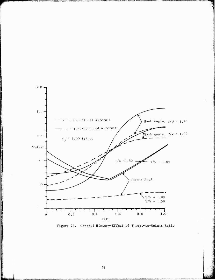
wuight ratios the major portion of the slant range was altitude. Being above and slower, the thrust-vectored aircraft probably has an advan- tage. The tracK over the. ground (Figure 15 and Figure 16) and the altitude (Figure 17) are not greatly affected by thrust-to-weight ratio in the low speed region. There is c noticable effect on the velocity profile ("Figure 18), but the conventional aircraft is more affected by thrust-to-weight ratio than the thrust-vectored aircraft. The effect is to increase the velocity difference between the conventional air- craft and the thrust-vectored aircraft as thrust-to-weight ratio increases. Figures l'-> -ind 23 show that the control histories are not changed greatly by thrust-to-weight ratio, although the effect is greatest on bank angle at initial velocities above the corner velocity. This is probably due to the effect of constraining the final altitude.
As with the weight penalty investigation, it was necessary to constrain the final altitude for the cases above the corner velocity. For an initial velocity of 1200 ft/sec, the thrust-vectored aircraft i-.'as slower, above., inside, and in front of their conventional counter- parts. The large slant ranges involved make an evaluation of advantage difficult. Ln Figure 20 the ground trace for the conventional aircraft with i'/W = 1.5 crosses inside of the trace for the conventional air- craft with 'i'/W - 1.09. This is due to the fact that with greater thrust, the first aircraft must climb higher faster to reduce velocity to the corner velocity (Figure 21). The same thing is true for the thrust-vectored aircraft. Thrust-to-weight ratio does not have much effect on the velocity profile of the thrust-vectored aircraft Lor the high speed region (Figure 22"). Since increased thrust-to-veight ratio increases the velocity for the conventional aircraft, it increases the velocity difference between the conventional and the thrust-vectored aircraft. The effect of thrust-to-weight ratio on the thrust angle was small. The effect on bank angle was significant (Figure 23). As thrust-tj-weight ratio was increased, the initial bank angle decreased and final bank angle increased, the initial bank angle, decreased and final bank angle increased for both the thrust-vectored and the conven- tional aircraft. The change was greatest for the thrust-vectored air- craft.
In both speed regions the effect of increasing thrust-to-weight ratio was to make, the x direction more positive, the y direction posi- tion smaller, and the slant range greater ("['able V). In the low speed region increasing thrust-to-weight ratio reduced the time for the turn and increased final velocity, but in the high speed region there was a negligible eflect on turn time and final velocity. For both regions the velocity difference between the conventional and the thrust- vectored aircraft increased with increasing thrust-to-weight ratio.
37 A''s- ■ ■,iti'il'a''Ä JtiTi nifri>" .-v^,.^.,,.^^..^^^.!;:, ...w.;.^.., 'i^^^^ÄiSrf^^; '.^ii.,,;:» :^ .. ^J^UJ^U^UiJtM

i ... Lig.ii ^T-^-r. . ij^t - i UJiy.l, -wmLLui.M- mi a -l'J« I l|. pl.l. «I»». J ■ | llnw^Py^a^jf^^f^pi——W^^T»^—*1WW|Wip>g^WW^^^'^"
4000
ortli (It)
3000 -
'000
1000
0 1
-1000
Convencional Aircraft
Thrust-Vectored Aircraft
Position of Conventional Aircraft when Thrust- Vectored Aircraft has Completed Turn
V0 = 600 ft/sec
T/W = 0.58r)
"I 1 1 1 T 1 1 1
1000 2000
East (ft)
'ixure 1';. Ground Trace-Effect of Thrust-to Weight Ratio
luu.^.:i. -.ij^BLiiiis-«
38
ii-iiu4i_ijifial:uln' E.ÜV.4I.-/XC'u ^i&i^^i^H^LÄ^.i^..ji.;*iiiÄVji.i,,•._.- ...-._w-..ii^..-_^i^-_1^^ :fi.^-..:Jü£mä^a.'^ajiM. AW.-3 ji.-O^A^-.' i -. Jfltc

wmammmKsmmnai
4000 -|
3000-
' 2000-1
North (ft)
1000-
0 -
South
•1000 T I 1 1 1 r
Ü 1000
— Convent Ion;) 1 Aircraft
Thrust-Vectored Aircraft
Position of Conventional Aircraft when Thrust- Vectored Aircraft has Completed Turn
V, 600 ft/sec
/K
1 1 1 2000
East (ft)
Figure 16, Ground Trace-Effect of Thrust-to-Weight Ratio
39
■■ «.-*.-.:.i*-~-±.^. -:._... , AAÜi^i-.-ili^^-L.^.Ä-*«^ ^jtmSStmUm iüHM^.. ■ fc^-rf,.-.»-^ -.^Ja^a . . ..■ *-,W- .i^.,;,,.■ Mi».-... JA-.*« --■ätniiiMii u^Witt^i ,

Ommmmr'.-m ISBYSE- ~: - ,"wy 7*'. -■• ■:^sn^sA^.'s^'raaaja]MiUMaj^ ■ii'i'
30,000
•5,000 -4
10,000 —I
5,000 H
Thrust-Vectored Aircraft T'W 0.585
Thrust-Voctored Aircraft l/W = U25
umv,lttion.il Aircraft T/W - 0.585
Conventional Aircraft T/W = 1.25
-1—r ■i | i I ' ' I ' "*
T/TF
I I I I ' ' ' I ' 0,6 0.8 1.0
El i., f e 17,
.liUwJ, "rofile-F.rEector^n.,-ro-Wei*rP.Ho
40
L..„k, ■ • ■ jrtiiin i ■" i n ii-.i!.-iii lifr^iar -V .11

». >' > mmwwpgmwiyw > ■ ■> »n*m 'ÜUH«« ■■ WIM' ■ .'»mwwpBgTC!iJPil' imp.'» ilUlfl^^^^W«
1,000 -i
800 H
600
Velocity (fl-./sec)
'4 00
?oo H
• Thrust-Vectored Aircraft T/W = 0.585
Thrust-Vectored Aircraft T/W = 1.25
Conventional Aircraft T/W = 0.585
Conven1". iona 1 Aircraft T/W = 1.25
0 —|—i—i—i—i—|—l—I—|—I—|—|—|—|—|—|—I—I—I—I—|—I—I—|—I—j
0 0.2 0.4 0.6 0.8 1.0
T/TF
Figure 18. Velocity Profile-Effect of Thrust-to-Weight Ratio,
41

E2-* i ' g ...... .nil ■ !!■■ IB «!»■'*'■■«"" -'■ ■■ ' '" ' !H' lUMllll»^
180
IV.
10*
Degrees
: - I) . >s >
O Thn'si--111
17 W
i /W
Convent ional Airc
UMWenlional aircraft
r- (1oo n/Kt'i
,, = o.r^
r/TF
iQ Cont Figure ly« ^u
uffp-t oi Thrus r0l History-Effect o
c-to-Weight Ratio
42

re s: u
F
o O o r-^
AJ
M •H
CJ p*;
o 1 o 0 o U o 1
to
o ' c o in
4-1 0
■-
u ■u C) ■Ji U-l
o a 1—1
o Hfc_
l~ o "J
GJ
3 OC
43
in "iii-i viniiriiimrr ilhilritfigtfiftMiBWiiiM -' —■!—-■».■■:.-■■ UgHB ..p.. ■■"- -•■■■■-•- ■ „Lii. *'s.^*

— ■ ■'• "■* ■■■—»«—»~
JO,000
15 ,000 —
»0,000
Altitude (ft)
13,000
10,000 —
3,000
V =- 1200 ft/sec
• Thru:, .-Vectored Aircraft, T/W = 1.09
ust-Vectored Aircraft, T/W -- 1.50
conventional Aircraft, T/W - 1.09
Conventional Aircraft, T/W - 1.50
I I I I | I I I I | I I I I | I I I I | '' I I 1
0.4 0.6 0.8 1.0
I/'IF
0..
■icTui-P 91. AlrifuHp Proriio-E^fecf nf Thnisf-to-WMgh': 3atIo
44
--■• -"—,..■....■.—.-■-■-ii—^.^.».^-.^,-^.- ■J,^.>..,^..^..,.„ ..,. .., ,. -.,. ijjjijagjijijiii^ja^i^^

rsPTHBffli -^■saroaMEFSTgs'. - -saras
1,400
1,200
L,000
800
Velocity (ft/sec)
600
400
200
Thrut.t-Vectorec] Aircraft, T/W = 1.09
O .hrust-Vectov \ircraft, T/W = 1.50
■ ' > 11 .■■ i ■ 11 L 1 i ,nal Aircraft, T/W - 1.09
D Conventiunal Aircraft, T/W - 1.50
o -A—i—i—i—i—|—i—i—i—i—|—i—i—i—i—|—i—i—i—i—|—i i i i |
Ü 0.2 0.4 0.6 0.8 1.0
T/TF
Figure 22. Velocity Profile-Effect of Thrust-to-Weight Ratio
45
. : ». .,_,.„,...' ..-«, ...ri.-i.j-: Jj^JavU.^ "iff ' I '"i"- III I r Unfifl "TV r"ltfrTilfü'iiM"«iil'il'i '-■"'■ •'«-■->-■-- ■■■--■;■'■ ■■■■ ■■ . v .^„..^j^.ia.-—^^^..tai^, j,: ^^ .^ja .-*.,_. ..- .:,..,,, .- .. ,-.....;■,■ ■J...u,i^wJiALi;J,.i.. :
;jMü.,y: ".•ir.T^Eiü":'" ■■■iigisiBg^ ._ ""gwig j.JH.'a.mii.ui.i-'i'-j,.w»i.»'~»y _. —
lfSO —i
r.. -
i .Mivi'iit ional Aircraft
Ihrust-Vcctored Aircraft
Bank Angl i?, T/W - 1 . 30
iank Anulc, T/W = 1.09 V - 1200 ft/s
Dt'urct'S
T—i—i—I—i—i—i—i—|—i—i—i—i—|—i—i—r—i—|—i—i—i—i—|
0.2 0.4 0.6 0.8 1.0
T/TF
Figure 23. Control History-Effect of Thrust-to-Weight Ratio
46
.:«■«*..«■..■! ., -;—.--.::. ■-..■■ -. ■ : -•--.;,.;.-..■ r... ■ ,. .. ■ . .-,.-=^..1i,i - üCi --■-■ 4.. a ■. ..;,...,!-■«;»•, ■ ,,- ,,.M»,-|,ii,- ,'w-i^- -: . .,-.„,-. . , ,.; ,... . ■■■.;-•-=■-\.rr'iAUMH^M»? UL<~I.< j.-..■■*. -:-T-. '.., ..■i,.-. -^- .,.. Ü. BA iwitaiii' Ifl llf'i' iMHlTi il fi

r
^-^»^^»»»«f^fliBfcM --:---=-;lf^l - - - ii-!^',-!.,^j1'-,V"'v irx'"^'*-Tt ■H^mass '—■EHBMBMBÄHHHSSET"
<d z
H I'- n CO
?« H
U C
5
P
►J
Ö M H
H o CM
OS o u
< l-l
OS
C] VO ro vf m in cr> 0 -X) O T-i CO 1—1 m CM CM <t vO
CN CM O
Is» CM in ü-i 00 m CM r-l r-^ 0 0 m C> r-l m r- r-l sO >n oc 0 —1 00 <!" vß vO r-i a. r-l O0 t^ 00 r^ ^D r^ x5 00 Is» 00 r^ CT- r- O vD ON O 0 ^0
00 r-~ CT> 00 r- 03 <t r- m 0 00 iD r-i r- in <t 0 <f m <r in i-i O ~£> in r-i vO CM 00 en (JN O cn in vt O m 00 v£> 0^ in r-4 <r m m KO vO 00
r-1 r-l -1- <t H r-l r-l i-l 1—I r-l CM CM
in in CM CN CM CM
<J r-i CO rg O r^ m r~- vO CM 5 0 m 0 00 <r O CM m CN CM O O m 0 r-l r-l <f t^ cn cn CN rj r-l r-t r-l r^ CM 0 CM O en cn 00 CM <f r>- r—1 f-H r-l r-l r-l r-l t—1 r-^ r-l r-l 00 vO r- in r^ cn
CM CM r^ O CO 00 O <t- 00 CM r-l cn CM r-l cn oj O r-l 0> v£> <t 0> cD m r» CM CO o-> r-l m c^ 00 <f <t CN cn CM CM r-l CM CM i—l
cn r-l CN cn
00 r-l cn
00 r-l
0\ O 0-. 0 00 O if) O *£> O r- 0 co 0 in 0 r-~ 00 r-- 00 r~- 00 r- 00 r- 00 vO 00 vO 00 vO 00
in in 00 00
in in
O o
\0 >£> r-l r-l
cn cn
o o
u ^•
OO rH r-l
u u > H
O O cD
o -> 9
u > H
O o CN
47
CM IM CM CM
U >
in in r-l r-l
cn ci
m m 0 0 c 0 0 0 O O CM CM O O O O 00 00 in in 0 0 in in O 0 ON CT> m m 0 0 m pn r-^ 1-» 0 0 CM CM m m O O CM CM in in
u
o o CN
r~- co o> 0 r-l (N cn <t in ID r- 00 0 0 r-l CM CM CM CM cn cn cn cn cn cn cn cn cn cn <f <!• -*
n. M CJ U
•rl
< -o 0) u 0 u 0 0) >
1 u in 3 rl
f rl O
4-1
tt O U •rl 'J -1 H rt
PS j O U « ■C r-l 00
•rl IH tu 0 £2
"1
-a 0 c JJ W 1
•u (u w
rr- a 1J rl
-C t- CJ
ca CM
c O 0
•rl U 4J O ■rl 0/ W M-l O m d, W
pa
H
iii£i:aftäfiMJjBfi^ -^^iv.^i; itfi,,-'—BfltSä iinifS^it ¥-jrn.ririirr- ÜI '•-••'■^^ -^-^^^te^?*frfiYif:i iitil - "--'•iiMatli-'.liatY^V : ihriwVMMt- 1 I

mmmsmss '-Wr- "~—•' • '-'■'■ ^~iML»MkmMLjmm^i.^sm^sm)L,...:-M^. <-mw » WJL
Figure 28 shows that for the conventional aircra: the turn ratlins lor the i'/W 1.5 aircraft is everywhere greater than lor the one with T/W - 1.09. However, lor the thrust-vectored aircraft, the additional thrust is used to slew the aircraft down and increase the turn rate. Thus (for a 600 ft/sec initial velocity), the radius of „urn for the
rcraft with a thrust-to-weight ratio of 1.5 is always less than the turn radius of the aircraft with a lower thrust-to-weight ratio. For a 1200 ft/sec initial velocity, the radius of turn is practically i n''ot)<->r)rlpnf- of thru«'.-to-',;oi"ht ia .
General. The initial value of excess thrust (gross thrust minus the sum of total aircraft dray and ram drag) is given in fable V . Engine data is );iven in Reference 4. The data goes up to Mach 1.0 and the Mach numbers for the runs ranged front 0.45 iov runs 1 and 2 up to 1.57 for runs 11 and 12. The gross thrust and ram drag figures for the runs with initial velocities of 1200 ft/sec and above may not be completely realisitc. However, Table VI shovs that the lowest values of excess thrust do occur in the transonic region as one would expect. Final valik run 11.
of excess thrust ranged from -6085 for run 2 to -48908 for
All turns were at Ci for the portion of the turn where the Hnax
velocity was less than the 'otul corner velocity and at maximum g load where the velocity was greater than the local corner velocity. Both the conventional ami the thrust-vectored aircraft were on the maximum performance boundary throughout the turn for all conditions.
Figure 24 shows that the flight path angle was almost symmetric about the mid time of the turn. This was probably due to the fact that the initial and final conditions on flight path angle wert: both zero. For the thrust-vectored aircraft the trends are as expected — the greater the initial velocity, the shallower the angle of descent. The trend for the conventional aircraft is also as expected except for the 1400 ft/sec i Htial velocity run which had a smaller flight path angle throughout the turn than the 1200 ft/sec initial velocity run. Total angular rate trends (Figure 25) were also as expected with the highest turn rates occurring for initial velocities closest to the corner velocity (800 and 1000 ft/sec) for both conventional and thrust- vectored aircraft. For the thrus -vectored aircraft the runs with initial velocities of 1200 ft/sec and 1400 ft/sec have a higher turn rate over the final portion of the turn where a return to zero flight path angle is the driving factor because with higher excess thrust they are able to maintain a velocity closer to the corner velocity. Over this portion of the turn, flight path angle is being changed signifi- cantly but the heading is only being changed 3 or 4 degrees. Since heading is not driving the optimization over this portion of the turn, turn rate drops off.
48
^.■■^^;...t.-».^.^^^...-,,^,^^Ji-rr-fcVii...| .,,,-: ,. ■WJiJ-äi..&. n^ iM, 7 *■•*-. ■-,-,. .,yim

^B&^-miMi&g^mawh,'±.^-:-> x^v-?&im!mBB&dm;-i.^--a:!!&r?~
RUN NUMBERS INITIAL EXCESS THRUST - lbf
1 and 2
3 and 4, 13 thru 19, 27 t>ru 36
5 and 6
7 and 8
9 and 10, 20 and 21, 37 thru 42
li and 12
23
24
25
26
5973
- 5199
-20934
-17179
- 919
11009
- 3335
- 6893
-10092
-13435
-16919
INITIAL VELOCITY ft/sec
400
600
800
1000
1200
1400
1200
1200
1200
1200
1200
TABLE VI. Initial Excess Thrust
49
,.>,.._: w, "i I-. ■■I-,-,-- --- IT,--, -■- if,-71 Mm i-- ^ii'iäWimiinihiifni'iwrfii' gBajajjaifa B^gaiag^iiMHttMi .-..., - - a^iL^^^A,^^ -.w;^-«^«*^^..*^

■wwi^'HW ~?~:3 -■w.u..ll.n JM—Ma^M^WWMBUlMIIJUI|l4MIM^WK!!^1IIMIHIL I~ '*™
90
hu H
in H
Flight Path Angle fdcg)
in H
•60 H
90
Convent l ona 1 Al re raft.
Tli rust -Vuct ored A i re raft
Both Aircraft
800 ft/sec
i—I—i—i—|—I—I— —| 1—I—I—I—I—|—I—i—i—i 1—i—I—i 1—|
0 0.L' 0.4 0.6 0.8 1.0
T/TF
Figure 24. Flight. Path Angle-Effect of Initial Velocity
50
'■= üaüda^jaMMti ima - ■>-•--■■ -i-n |; UM - a gj&üift ^jgfyigfcjjgag^a^iilBttfBiteftBiMiri ■'^"■'^M"A-li^- j«^jy>.j^^hto.Mfe^i^a^^*iv..J>-^^«j~ä,äi-fc-^^iitia^-Jj ^iä^^^-^vfc^^^^-jasAAaa

fcj-U-'JJW i i" _"•"■ ' T^S IHHFU
20
16
12
Turn Rate (de>»/sec)
• Conven Thrust
+ Conven £ Thrust: ♦ Conven
Thrust ■ COllVfcu
Thrust
o Conven
® i'hrus t ▲ Conven A Thrust
cional Aircraft 1400 ft/sec
-Vectored Aircraft 1400 ft/set' tional Aircraft. 1200 ft/sec
-Vectored Aircraft 1200 ft/sec
tional Aircraft 1000 ft/sec -Vectored Aircraft L000 ft/sec- tional Aircraft 800 ft/sec
-Vectored Aircraft: 800 fi /sec- tional Aircraft bOO ft /sec -Vectored Aircraft 600 ft/sec tional Aircraft 400 ft/sec -Vectored Aircraft 400 ft/sec
1—i—i—i—I—i—r
0 0.2
T—i—i—r ~l—l—r i—r i
0.4 0.6 0.8 1.0
T/TT
Figure 25. 'Total Angular Rate-Effect of Initial Velocity
■
51
jftäiJiÜütoMiriäibi a-^jir-.-«-::*--^^..,....^-,.^-^. dSJÜu ..^■■■^.^..-„■■W .^^.,^.: :,,,....- . ■ ,.^J^^^->J..,-^i^.^^h.-iJ,^^.,3i:i.^....,. .-.■■:..-....,..: -■ - ^.:„-..^^_

".-%.' >'i - '"^-^.:^~" .T^~ .,^.^,.-„ ..-.. ^^^^.^TM^j^ ^p nminimpunmiiiw ^^BM/U
iTie effect of initial velocity on turn radius was uniform and predictable (Figure 26). I'he effect of weight penalty on turn radius was also uniform and as expected (Figure 27). The effect of thrust-to- weight ratio on turn radius *;as small for initial velocities below the corner velocity and very small for initial velocities above the corner velocity (Figure 28). For the low speed runs the effect of thrust-to- weight ratio was as expected—increase in thrust-to-weight ratio rcsultr in a decrease in turn radius. For the high speed runs the effect was not uniform throughout the turn.
['his investigation, based on a minimum time turn, cannot consider many aspects of the advantages and disadvantages of thrust vectoring. Several advantage? are discussed in two articles by Brown- Discussions with an Air Force pilot who has flown the Harrier in simu- lated air-to-air combat brought out that there is a very significant capability to bring guns to bear with the thrust-vectored aiixraft in situations where the conventional aircraft could not do so. The advan- tages of in-flight thrust reversing are discussed by McCormick and Koepcke. The work by Humphreys et al should provide insight on the effects of varying thrust during the turn,
CONCLUSIONS AND RECOMMENDATIONS
For initial velocities below the corner velocity, there is a small but consistent advantage for the thrust-vectored aircraft for all thrust-to-weight ratios investigated and for weight penalties up to 257 of the conventional aircraft weight. The differences between the conventional and thrust-vectored aircraft are greatest for initial velocities above the corner velocity and increase wich velocity. Although il is difficult to determine which aircraft has the advantage in this velocity range, the results indicate that the thrust-vectored aircraft lias the advantage. A more detailed study is definitely justi- fied.
Within the framework of the minimum time turn problem, the effects for turns greater than 180° shpuld be investigated. i.'he effect of limitations on the thrust angle should also be investigated within this framework. Further work should be done in air-to-air combat simulators, The hank angle and thrust angle histories should be helpful to the pilots participating in the simulation and to pilots flying aircraft such as the Harrier.
52
^mmmäiM m - MMü—^*^>. .nki^rti-fm-wi'^n.^..-.- -i ■ ■ - - ,-,.*-^.^^^-^^,^.,^... -^-„~,,J;,J: . ■:....i^^^tiaiiit-iii^i^.-U^i,..;/,».^-,, ■■■_, .,.,:.: ,-...^^\^ _ , ■__-,.;..._. ;,-,,.:„> .-..

-JZZ J.-"':.'""T''"'-" .. T_Z^S:^ ' "" ::ia»Ki ............ _.- ^wJ'r^'°^^a^»-*trfW|WM».g^B^,??^E^,T^^^'
O
o o
o o o 'JO
o o o
o o o <r
o o o r-i
53
•t-4
u o f-i
>
4-1
a
<b 14-1
fn U4
F« UJ
H in
•H <t T) • m O OS
c VJ r> N
• >£)
CNJ CN • O U
(-J 3 Ml
■ -■■Ji.iriv.^,-^.--,V-.v ■■..„-...■-,. i-iijii^.iiil. -li^uil ^^i.-.'--.,---. ai. ■cfeattflÄiä£ -*-->-*>-:*--■-"-■-

TTZZ~-"?^ZZ, -^^wflpw^?^^ --'——"—v. J "■»" ■■'i^'—- »f jsapsp«wm»mwm^ ■gy^'- ■ "a^>.^'V"~IM'V»*aa.'*??
C Hi
P.
X- 00
u 3
i
T3 rd
c l-l 3 H
U
u-,
o o o c
o o o 30
o o o
o o o o o o CM
in 3
•H
s
54
Ü:.-:' ■: -Mi*n -■■OJtM—FM idhaoldwttniü » „ --.^„. ^lui.ül. -U

\mW"- ■■^■^ ■ ■»»■»» •- -■ .' 'mmmmmt-vtwst^miu, ■*- ma*Q&WT*w " '" '■ -1* ■■-.■'•''' ' ■■■■ -—"-
OS
Ml
tu IS I o
H
u V
oo eg
CD
3 00
o o o 00
o o o vO
o o o
o o o
3
os
55
i iiitiw^-- - ■—■■-■ MnfttrBifMr''"'

"--i-.-.'J'■■--'':,;,"■■..' -'.•^^™^-^="">"'l".l. IMI»^^^^^^gf'«F»<l»W^^ -^y-^
I.IST OF REFERENCES
1. Brown, David A., "Vectored-Thrust Maneuverability Explored," Aviation Week and Space Technology, December 13, 1971, pp. 36-39.
2. Brown, David A., "Thrust Vectoring to Aid Com'iat,'' Aviation Week and Space Technology, January 15, 1973, pp. 46-48.
3. Mines, Jerry D., "A Numerical Technique for Optimal Control Problems with Initial Conditions," Department of Aeronautics Technical Report DFAN TR 73-3, USAFA, June 1973.
4. Mines, Jerry D., and Davis, Duane M., "A Computer Program for Air- craft Optimal Control Problems," Department of Aeronautics Technical Report DFAN TR 73-4, USAFA, July 1973.
5. Humphreys, Robert P., Mennig, George P., Bolding, William A., and Helgeson, Larry A., "Optimal 3-Dimensional Minimum Time Turns for an Aircraft." The Journal of the Astronautical Sciences, Vol XX, No. 2, Sep-Oct 1972, pp. 88-112.
6. McCormick, R.L. , and Koepcke, W.W., "Capabilities of In-Flight "hrust Reversing on Tactical Aircraft," Air Force Flight Dynamics Laboratory Report AFFDL-TR-67-120, Wright-Patterson AFB, Ohio, October 1967.
7. Salvador!, M.C., and Baron, M.L., Numerical Methods in Engineering, Prentice-Hall, Inc., Englewood Cliffs, N.J., 1961.
56 i - j^aäMtfffliiiiflitoMyritefcfrfflMi^^ üB -J^^^v--^:--^v..^.t;.J,...-,^^.JJ,^i„L