An 4 3 9 6 6 5 - DTIC
55
UNCLASSIFIED An 4 3 9 6 6 5 DEFENSE DOCUMENTATION CENTER FOR SCIENTIFIC AND TECHNICAL INFORMATION CAMERON STATION, ALEXANDRIA, VIRGINIA UNCLASSIFIED
-
Upload
khangminh22 -
Category
Documents
-
view
6 -
download
0
Transcript of An 4 3 9 6 6 5 - DTIC

UNCLASSIFIED
An 4 3 9 6 6 5
DEFENSE DOCUMENTATION CENTER FOR
SCIENTIFIC AND TECHNICAL INFORMATION
CAMERON STATION, ALEXANDRIA, VIRGINIA
UNCLASSIFIED
NOTICE; When government or other dravings, speci- fications or other data are used for any purpose other than in connection with a definitely related government procurement operation, the U. S. Government thereby incurs no responsihllity, nor any obligation whatsoever; and the fact that the Govern- ment may have formulated, furnished, or in any way supplied the said drawings, specifications, or other data is not to be regarded by implication or other- wise as in any manner licensing the holder or any other person or corporation, or conveying any rights or permission to manufacture, use or sell any patented invention that may in any way be related thereto.

·•·
THIS DOCUMENT IS BEST QUALITY AVAILABLE. THE COPY
FURNISHED TO DTIC CONTAINED
A SIGNIFICANT NUMBER OF
PAGES WHICH DO NOT
REPRODUCE LEGIBLYo

(^14-
■'O
r i CO
'
^ DREXEL INSTITUTE OF TECHNOLOGY 77) PHILADELPHIA 4-, PENNSYLVANIA p
WT Report No. 125-5 ^
ATTENUATION OF THE STRONG PLANE SHOCK PRODUCED
IN A SOLID BY HYPERVELOCITY IMPACT
by
PEI CHI CHOU
HARBANS S. SIDHU
LAWRENCE J. ZAJAC
Prepared for
Ballistic Research Laboratories Aberdeen Proving Ground
under
%A Pebrwary, 1964
43 966 5

DIT Report No. 125-5
ATTENUATION OF THE STRONG PLANE SHOCK PRODUCED
IN A SOLID BY HYPERVELOCITY IMPACT
by
PEI CHI CHOU
HARBANS S. SIDHU
LAWRENCE J. ZAJAC
Prepared for
Ballistic Research Laboratories Aberdeen Proving Ground
under
Contract No. DA.36-034-ORD.3672 RD
February, 1964

/ ABSTRACT
V The attenuation of strong plane shocks in solids produced by hypervelocity
impact is studied, and two parametric equations are developed which describe
the path of the shock front in the x,t-plane. These parametric equations were
derived by considering the entropy change across the decaying shock and assuming
that the characteristic lines behind the shock are straight lines. The equation
of state is approximated by simple Hugoniot and isentrope equations. The same
problem is also solved graphically by a stepwise characteristic method. A
comparison of the graphical and analytical results shows that the simplifying
assumptions made for the analytical solution are valid for both weak and strong
shocks,

TABLE OF CONTENTS
Abstract
I. Introduction
II. Statement of the Problem
III. Basic Equations
1, Normal Shock Equations 2. Characteristic Equations
IV, Equation of State
V. Analytical Solutions .....
1. Assumptions 2. Initial conditions 3. Attenuation of the shock
a. "u+c= constant" Approach b_ "u=constant" Approach
4, Fowles' Solution
VI. Graphical Solutions
1. General Discussion 2. Detailed Procedure
VII. Comparison of Results
VIII, Notations ......
IX, Figures and Tables , .
X. References ......
XI■ Appendix
A. Discussion of Table I
PAGE
9 12
i 5
16
16 17
20
23-45
4 7
11

LIST OF FIGURES
Figure a Initial Shock Configuration 10
Figure 1 x.vs. t-Schematic Illustrating Collison of a ämfe» 2." and a target PLATü
Figure 2 Comparison of the fitted Equations (17) § (18) with 24 Tillotson's Data
Figure 3 Equation of State for Aluminum 2S
Figure 4 Regions in the physical plane used in the stepwise- 26 characteristics method
Figure 5 State plane 27
Figure 6a Position of shock front vs. time, showing comparison 28 of different methods for small time
Figure 6b Position of shock front vs. time showing comparison of 29 different methods for large time
Figure 7 Comparison of approximate analytical solutions 30
Figure 8 Schematic Illustrating the Relative Accuracy of the 31-32 u= constant assumption and(u+c)= constant assumption (for aluminum)
Figure 9 Constants used in the isentrope equation
9a A' vs. particle velocity 33
9b Y vs. particle velocity 34
9c P vs. particle velocity 35-36
LIST OF TABLES
Table 1. Equation of State Data (for aluminum) 37-/!2
Table 2. Partial List of State Properties 43
Table 3a Comparison of u, c, and u+c along a straight line in 44 the graphical solution, (for aluminum)
Table 3b Comparison of u, c, and u+c along a straight line in 45 the graphical solution, (for an ideal gas)
m
I, Introduction
In the theoretical study of hypervelocity impact, the hydrodynamic theory
is generally recognized to be applicable in the high pressure region. Based
1 2 upon this hydrodynamic theory, Walsh and Tillotson, and Bjork have obtained
numerical solutions by using finite-difference methods. Their results give
a most detailed history of the properties and motions of material particles.
However, the finite-difference methods have certain inherent deficiencies.
Namely, they are not convenient for engineering application because each impact
problem must be calculated separately on a computer with a large capacity. Also,
the accuracy of the finite-difference solution is questionable in certain
regions, such as regions immediately behind the shock front, since the peak
pressure is not precise, and in those regions where the density change is small.
Therefore, approximate analytic solutions are desirable not only for the afore-
mentioned reasons but also for later utilization, when the hydrodynamic theory
is eventually combined with the plastic or strength-dependent theories.
Rae has attempted an analytical solution based upon certain similarity
assumptions, but he has not been able to obtain satisfactory results for impact
problems. A few other investigators have recently tried to solve one-dimensional
4 impact problems. Herrmann, et al. have applied the finite-difference method
and the stepwise characteristic method to one-dimensional low speed impact
problems and have given a detailed comparison of the merits of these two numerical
methods. Fowles obtained an analytical expression for the decay of plane shocks
by using the characteristic method. However, he neglected the entropy change
across the shock front; therefore, his results are valid only for weak shocks
produced by low speed impacts.
In the present report, the strong plane shock produced by hypervelocity impact
is analyzed by two methods, both based on the principles of characteristics. In
the first method, certain simplifying assumptions are utilized, and two approximate
- 1 -

analytical solutions are obtained, In the second method, a graphical stepwise
characteristic apnroach is used. The results from there two methods demonstrate
very close agreement.
The equations of state of metals used in this analysis are those obtained
by Tillotson, In order to facilitate the application of the characteristic
method, a polynomial equation is fitted to the Hugoniot curve. Also, the
7 isentropes are approximated by an equation similar to the one used by Murnaghan.
II. Statement of the Problem
A one-dimensional plate of thickness "d", traveling at a hypervelocity,
orthogonally impacts a semi-infinite plate of the same material at (x , t ),
(figure i) Two shock waves are generated, one in the target and the other in
the projectile. The shock wave in the projectile reaches the free boundary at
(x , t 3, and a centered rarefaction wave reflects from this point. The head
of the rarefaction wave reaches the collision boundary at (x., t?) and overtakes
the shock front at (x.., t..)) from this point a continuous interaction between
the rarefaction wave and the shock front ensues
A solution to the problem involves a description of the state of the
material behind the shock and an equation for the path of the shock front in the
x-t plane. The solution to the above problem involves certain assumptions to
insure that the problem is amenable to the fundamental hydrodynamic theory
These assumptions are developed in the text
III Basic hquations
The method of characteristics in fluid mechanics and the governing equations
8 9 for a normal shock are well known ' In this section these basic equations are
summarized for later use.
1. Normal Shock Equations
The equations expressing the conservation of mass, momentum, and energy
across a shock are:
^"^ = f<(U - UKXW^ - xix) (2)
PyUy- P^Ux= j\(Ü- U^E^-Ex +-k(u.¥ - ^)j (3)
where U and u are the shock and particle velocities respectively, relative
to ground (lab. coordinates); P is pressure; p is density; and E is the specific
internal energy. Subscripts x and y refer to the states ahead of and behind the
shock front respectively. The equation of state of the material may be expressed
as
P = P(E,f) M)
If the condition ahead of the shock is known, then the quantities P , p , u , E
and U are related by the four equations, (1) to (4)„ Specification of any one
of these variables will determine the remaining quantities. Alternatively, if
the shock llugoniot equation
P - H if) (3) is known, then equations (1), (2), and (5) may be used to solve for any three
of the four variables P . p , u . and U, in terms of the remaining variable. In y y y
applying the method of characteristics, construction of a c,u-state plane, or a
P,u-state plane is necessary. The shock condition in the p,u-plane is represented
by a "shock polar", which is a curve of P vs. u , obtained from equations (1),
(2), and (5). If the relationship between c and P is known, a c,u-shock polar
can also be constructed.
- 3 -
2. Characteristic Equations
The characteristic equations for unsteady, one-dimensional, isentropic
flow are
dt" " U "^ C C6)
p dj= ± ^ <djLX = O (7)
where the upper and lower signs refer respectively to the C characteristics
(right traveling) and the C characteristics (left traveling), The sound
speed c is defined by
^ \3p/s • (8) For isentropic flow,
ae = -PdV . l9)
Substituting equation (9) into the general equation of state, equation (4), we
obtain the isentropic P,p-relation (or isentrope)
P - Ps (?) • (10)
Equations (8) and (10) may be substituted into equation (7) to yield the state
characteristic equation in the c,u-state plane, The state characteristics
combined with the physical characteristics, equation (6), are the basic
equations for the application of the method of characteristics.
It will be shown in the next section that the isentropes used in this
report have the form of equation (11),

+ p0 (11)
Equation (11) may be combined with (8) to yield
^TKf) =-f^-a^') Equation (7) thus reduces to
2L
or
^7Y" ^C "^ ^X\ " O (15)
U -t ^C - ii + 2-c-'
which are the equations for the state characteristics. In the c,u-plane,
these characteristics are straight lines with slopes + 2/ ( y - 1 )• In the
P,u-state plane the characteristics are
u i z.: f° ) ( p\r i-n) - covisT^MT Li3) i _ 1 \ A /
IV. Equation of State
For the present problem, the pressure in the solid material is of the
order of 1/10 to 10 megabars. Under a pressure of this magnitude, the strength
effect and the deviatoric components of stress can be neglected. One equation
relating three state properties is sufficient to describe the state of the
material. In other words, the material behaves like an ideal compressible fluid,
and the equation of state is similar to that used in hydrodynamics.

Under this hydrodynamic assumption, Tillotson obtained the following
equation of state which is accurate for a large pressure range, (equation (6)
ref. 9).
P = CL +
ton1 + 1 V A.^ -v B^1 iif<:
where P= the pressure in megabars
E= specific internal energy in megabars-cm^/g
V= 1/p specific volume in cm /g
n= p /p = V /V, where p is normal density^ and
y= n - 1
and a, b, A, B, E are constants dependent upon the metal. This equation is
serai-empirical in nature and represents a best-fit extrapolation between
Thomas-Fermi-Dirac data at high pressures (above 50 megabars) and shock wave
experimental data at low pressures„ This equation is accurate to approximately
5% of the Hugoniot pressure and 8% of the isentropi-, pressure.
Equation (16) is simple in form and is convenient for numerical calculation
of hypervelocity impact problems by the finite=difference methods. However,
it is not suitable to obtain an analytical solution to the present problem by
the characteristic method, A further simplification is incorporated by fitting
simple equations to the Hugoniot and isentropes of equation (16),
Table I contains data for aluminum which is calculated from the equation
of state, equation (16), and the normal shock conditions. (See Appendix A).
Two approaches have been used to fit the Hugoniot data in Table I, In the
first approach, the Hugoniot is represented by a curve of U vs. Z, where 1-
u+c. This curve is fitted by the following equation,
- 6

a U = a, + b.2 ■+• c,2 en)
where the constants a , b^ and c. are obtained by the method of least squares-
Figure 2b gives a comparison of equation (17) with the data in Table I. The
error is found to oe less than 0.6 % for a range of 1 to 10 megabars.
In the second approach, an equation relating U and u,
2. U = 0.2. + b£AJL + C2 AX (13)
is obtained by the method of least squares. Figure 2a compares equation
(18) with the data in Table I, The accuracy of this equation is within 2%
for a pressure of 1 to 10 megabars. Two different analytical solutions for
the shock path are developed in Section V,tf3, by using equations (17) and (18) ,
respectively.
For the isentropes, an equation similar to Murnaghan's is assumed,
P -A -)-l + Po ^ ton
From each point on the P-v liugoniot curve, an isentrope may be calculated
from equation (16), Equation (11) is fitted to those isentropes, and the
constants .V, y and P are determined; each of these constants assumes a o '
diffe.'ent value for every isentrope. Table I gives values of these constants
for aiuuinum The accuracy of equation ill) as compared to equation (16) is
very good as shown in figure 3.
Tn tnc present report, the liugoniot and isentrope equations are fitted
to data presented in Ref.. 6. Actually, llugoniots of the form of equation (17)
and (18) and isentropes of the form of equation (11) generally can be fitted
to other equations of state data, theoretical or experimental.
- 7

V, Analytical Solutions
ij Assumptions
Besides the assumptions of a hydrodynamic equation of state and an
adiabatic, non-viscous process, additional assumptions are required to obtain
an analytical solution for the decay of strong shocks, Fowles assumed that
the change of the entropy across the shock front is negligible, and thus
his solution is limited to weak shocks. For strong shocks9 however, the
entropy change across the shock is appreciable and cannot be neglected.
Behind a strong shock the characteristic lines, to be Pvact, are not
straight lines. However, the interactions between C and C characteristics
and between characteristics and contact lines are usually weak. In the present
analytical approach, we assume that the characteristic lines in the rare-
faction wave originating from point (x., t^, figure 1, remain straight.
Furthermore, either the particle velocity u, or the sum of particle velocity
and sound speed u + c, is assumed constant along any one of these characteristic
lines.
These assumptions are similar to those used in reference 10, which treats
the decay of plane strong shocks in an ideal gas. The assumption of characteristic
lines remaining straight has also been used by Al'tshuler; et al, in an
experimental technique to determine the sound velocity behind a strong shock.
Although the details are not given in their paper, they have also performed numerical
calculations to show that the error involved in their assumption of straight
characteristic lines is small.
If the values of u are assumed constant along characteristic lines behind
the shock front, the path of the shock can be determined from the exact shock
equations. For points directly behind the shock front, the sound speed calculated
from the exact shock equation is different from the sound speed on the same

straight characteristic line near point (x-.t.). In the region immediately
behind the shock front, therefore, this approach results in an inconsistency
in sound speed, and consequently in pressure. The sound speed and pressure
calculated from the shock equation are taken as the correct value behind the
shock, and a linear variation in properties between the shock front and the
rarefaction tail is assumed.
In the approach of u + c= constant, the values of u and c singly are
not assumed constant along the straight characteristic lines. The values of
c and u behind the shock front are determined by the shock conditions, while
a linear variation for these quantities is assumed between the shock and the
tail of the rarefaction wave.
2, Initial Conditions
According to equations (1) and (2), the shocks in the target and the
projectile, immediately after impact, are governed by the conditions
^uT= ^(uT - O")
Pe-P^f, (UTO J \
(19J
(20)
p0(Up-M0)-|\ (Up- *z)
Pe-Pc->(Up-0(
(.21)
PRO3 Ec-nut
M2. - ^Ao (22)
- 9 -

PROTE:CT\LE TA.RCkTELT
UP(<Ac^
Uc
BKCV<. SUP-FAJCE SHOCK.
L-J-^ M,
^
a iMTERFNCE SHöCI^
FIGURE a.
Initial Shock Configuration
where the subscripts refer to regions in figure aj and all velocities
are relative to the ground (positive toward the right). Solving equations (19)
to (22), we obtain the following relation
Uf - - ( \^ Mc (23)
This equation indicates that impact between similar materials yields shock
velocities (relative to the material ahead) in both the target and the projectile,
with equal magnitude but opposite signs0
Equation (23) may be substituted into equations (21) and (22) to yield
(24)
(25)
equations (20) and (25) gives
I AU = ? U,
(26J
10 -

Since U equals the magnitude of the shock velocity relative to the projectile,
the time required for the shock in the projectile to reach the free boundary
is
t-t = (27)
The absolute velocity of the shock in the projectile is U V V therefore
y. ,-^ = (1,- t0X-ut-v uo) . (28)
By combining equations (19), (20), (26), (27) and (28), and using the
geometry of the x^t-plane, we find that the head of the rarefaction wave
reaches the collision boundary at time t given by
ta-t, = i^d)/{^Ct) , (29)
The interaction between the rarefaction wave and the shock front in the
target starts at time t , which is given by
After simplification, equation (30) can be written as follows
+ _ t = ^ jjü: I ^0^
(30)
From (27) and (29), we obtain
- _&=! Vt^^-t.vu.-u» rk ^-^ ■ (32)
Substitution for (t.-t ) from (32) in (31) yields
L3 lo ui+<vutLace A 4- u tj (33)
. 11
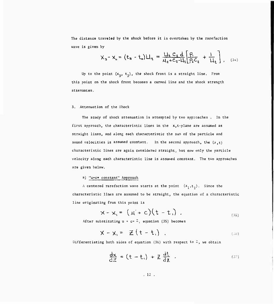
The distance traveled by the shock before it is overtaken by the rarefaction
wave is given by
Up to the point (x_, t,)s the shock front is a straight line. From
this point on the shock front becomes a curved line and the shock strength
attenuateso
3, Attenuation of the Shock
The study of shock attenuation is attempted by two approaches , In the
first approach, the characteristic lines in the Xjt^plane are assumed as
straight lines, and along each characteristic the sum of the particle and
sound velocities is assumed constant. In the second approach, the (x,t)
characteristic lines are again considered straight^ but now only the particle
velocity along each characteristic line is assumed constant. The two approaches
are given below.
a) "u+c= constant" Approach
A centered rarefaction wave starts at the point (x-.t.),. Since the
characteristic lines are assumed to be straightj the equation of a characteristic
line originating from this point is
After substituting u •*• c= " £ equation [35j becomes
X - y, = £ U - M . (-) Differentiating both sides of equation (36) with respect to Z( We obtain
12

Also, along the shock path
dx _ d* dt \ I ^t_
where U is the shock propagation velocity.
From equations (37) and (38) we see that
U 4 -(t-U -VH Jt
az. (33)
d£ di (39)
Substituting the expression for U in terms of Z, equation (17),into equation
(39), integrating and simplifying the resulting equation, we obtain
where
H2 p^J
c< - -^ m -1- -
(40)
>-4 A-a. Cb,-0 C, C,
and \
j3~QC
Equations (36) and (40) define the desired shock path in parametric form with
Z as the parameter and t , t,, and x. as constants, (figure 1), and Z is also
a constant which is equal to the sum of the particle velocity and the sound
velocity behind the shock immediately after impact.
b) "u= constant" Approach
Following the manner of the previous section, the equation of a characteristic
line starting from the point (x., t.) can be written as
- 13

X - X. = (M^cXt-tO (41J
Also, for a characteristic line, according to equation (14)
^ Y_l ^ )$.\ 142)
The constant y depends on the pressure behind the shock (see Appendix AJ „
Defining t as
we may rewrite equation (42) as
Thus, from equation (41),
differentiating both sides of equation (44) with respect to u, we obtain
dx Substituting equation (18) into equation (45) j, with U= -r-.- , we obtain
^t = j+J djjL t-t, 2. c^ ij(5 + e2.u >-clt (47)
14

where
^ = ae - -VH
us)
('9.1
Integrating both sides of equation (47), we obtain
- t(+(U-tV: ^^ -r /2 .
K-
(50) and (44) r
where u is the parameter.
'S" -M
Equations (50) and (44) represent the shock path in a parametric form,
(50)
4. Fowles' Solution
Fowles1 weak shock solution is given below for the purpose of comparison.
His equations for the path of the shock front are
Us-") =t^U^-t^ cs-0 -2u;o
^
cr ziUO
and
X(cr)= X. + C.icr + iXts-t,') (52)
(t>t:D where >'= a constant depending on the material (4.266 for aluminum),
U + c
and
CT -
<^o^
C,
cAVt,^
-1
H-l •
- 15 -

He used equation (11) with one set of constants as both the isentrope and
the llugoniot for calculating the initial conditions.
VI. Graphical Solutions
1, General Discussion
The graphical solution of the present problem is obtained by the
"field method" of stepwise characteristics. Although this method is time
consuming, it yields a very accurate solution which may be used as a basis
of comparison for the approximate analytical solutions.
The complete solution involves the determination of the path of the
shock front and a description of the physical properties of the material
behind the shock. This solution is achieved through the use of three planes,
the physical plane (c t(x-diagram of figure 4Jf the Psu-state plane (figure
5a) and the c^-state plane (figure 5b). A region of continuously varying
fluid properties in the physical plane is replaced by a number of finite regions
each having uniform fluid properties. These regions are divided by character-
istic or contact lines, across which the properties change. The complete
solution requires the use of shock polars and characteristics in the c,u and P.u
state planes.
In the present problem, only one shock polar is required. This shock polar
is plotted in both state planes from the data given in Table I. The origin of
the shock polar represents conditions in the target preceding impact, i.e.,
u= o, P= o and c= 5,275 km/sec.
Equation (14). in the following form, is used to plot the c8U'Characteristics
AA "T^ \ JU 4. -J^* H IM (14)
I,II
■ 16 -

where c,, and uH are the properties in the region immediately behind the shock,
In the c,u-state plane the characteristics are straight lines with slopes
equal to
dc 6JX
1,31
where Y is a constant for a particular isentrope which is found in Table I
with u , equal to u.
Equations 11, 12, and 14 are combined to yield the P,u-characteristics
v H *-\ K f. {*)( AT + V '- M«± r-\
2C Jl,T[
(IS.n)
H where u +^ is a constant and depends upon the properties of the region
Y-l
behind the shock. The constants A', y , p and cH may also be obtained from
Table I.
The P,u-state plane is required in the graphical solution because it
yields a simpler solution for the physical properties in the regions bounding
the contact lines. These regions have identical pressures and particle velocities
and therefore plot as a single point in this plane. The c,u-state plane yields
the required sound velocity to construct the physical (.c t-x) diagram.
2. Detailed Procedure
The graphical solution is obtained by constructing the complete flow field
in the physical and state planes. Figure 1 schematically illustrates the physical
plane. At the point of impact (x , t ) two shocks originate. The initial
position of the right traveling shock can be constructed with the slope c./LL.
The left traveling shock is constructed with the slot The slopes of the
physical characteristics are Riven b>
17 -

diet) _ c -1
1
where the upper sign refers to the I-characteristic (C or right-traveling
waves) and the lower sign refers to the II-characteristics (c or left*
traveling waves). Both the sound velocity c and particle velocity u represent
the average between their respective values on both sides of the characteristic
line.
The simple rarefaction wave centered at (c.t , x^ is arbitrarily divided
into six regions by assuming approximately equal increments of particle velocity
between adjacent regions. These waves are propagated with constant strength
until the head of the rarefaction wave overtakes the shock front. An interaction
between the waves and the shock front then follows. As the shock continues
with both decreased strength and velocity^ contact lines and reflected waves
are formed. A contact line4 which separates regions of unequal entropy, forms
because the fluid particles passing through shocks of unequal strength attain
different levels of entropy. A reflected wave is required in order to satisfy
the boundary conditions of equal pressure and equal particle velocity across
a contact line. All the regions bounded by the shock path and a pair of neighbor-
ing contact lines are at the same entropy level: therefore the coefficients A',
Y and P which are used in the characteristic equations are constant within
each of these regions. When crossing a contact line, new values for A', y and
P must be selected from Table I. o
The properties of regions 1 and 2 are determined by the initial conditions
of the problem. From the assumed particle velocities in regions 3 to 9P the
pressures and sound velocities can be determined by the method of characteristics.
Regions on both sides of a contact line have equal pressures and particle
velocities, (i.e., the pressure and particle velocity in regions 10 and 20 are
equal). Therefore the points 10' and 20' in the p-u state plane coincide. In the
- 18 -
CjU-planetfigure 58 point 10 lies directly above point 20^ Similarly, regions
21 and 30 plot as a single point in the P,u=state plane and lie at the
intersection of a I-characteristic through point 11 and a II-characteristic
through point 20,
For a complete and detailed discussion of the graphical method of solution,
the reader is referred to references 8p 9, and 100
As an example of the graphical method applied to the present problems
an impact velocity of 28,)2 km/sec was chosen. Figure 4 shows the physical
plane and Table II gives the physical properties in selected regions^
19
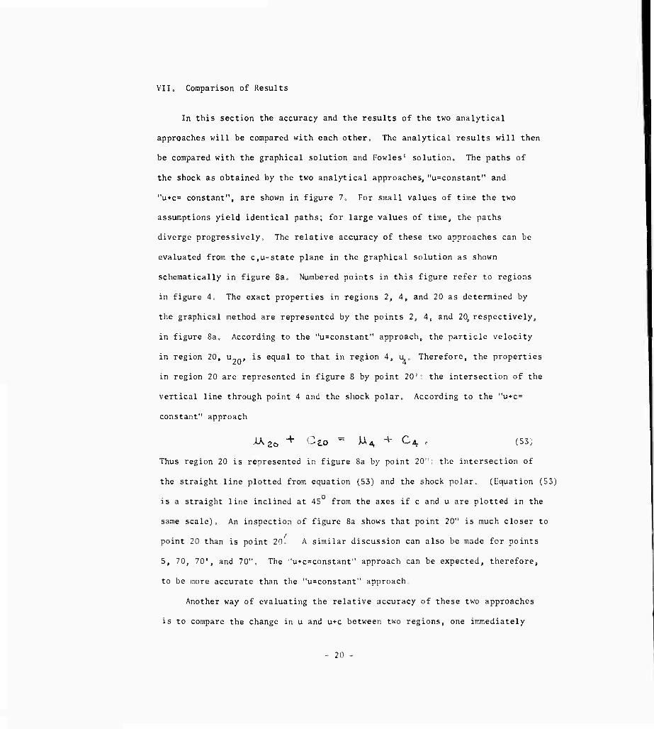
VII. Comparison of Results
In this section the accuracy and the results of the two analytical
approaches will be compared with each other. The analytical results will then
be compared with the graphical solution and Fowles0 solution. The paths of
the shock as obtained by the two analytical approaches, "u=constant" and
"u+c= constant", are shown in figure 7. For small values of time the two
assumptions yield identical paths; for large values of time, the paths
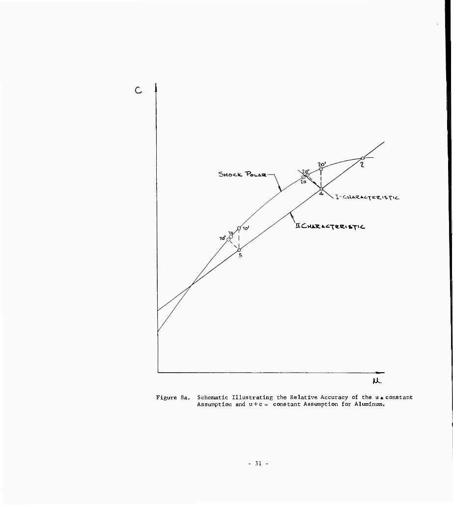
diverge progressively, The relative accuracy of these two approaches can be
evaluated from the c,u-state plane in the graphical solution as shown
schematically in figure 8a. Numbered points in this figure refer to regions
in figure 4. The exact properties in regions 2, 4, and 20 as determined by
the graphical method are represented by the points 2, 4, and 20s respectively,
in figure 8a. According to the "u=constant" approach, the particle velocity
in region 20, u , is equal to that in region 4, u Therefore, the properties
in region 20 are represented in figure 8 by point 20': the intersection of the
vertical line through point 4 and the shock polar. According to the "u+c=
constant" approach
^2ö + Cao " WA + C^ . (53,
Thus region 20 is represented in figure 8a by point 20 :: the intersection of
the straight line plotted from equation (53) and the shock polar. (Equation (53)
is a straight line inclined at 45 from the axes if c and u are plotted in the
same scale). An inspection of figure 8a shows that point 20" is much closer to
point 20 than is point 2o' A similar discussion can also be made for points
5, 70, 70', and 70", The ■'u*c=constanf' approach can be expected, therefore,
to be more accurate than the "u=constant ' approach
Another way of evaluating the relative accuracy of these two approaches
is to compare the change in u and u+c between two regions, one immediately
- 20 -

behind the shock and one in the simple wave region, such as regions 20 and 4
or regions 70 and 5, in figure 4. Table 3a shows the results of such a
comparison. Again, it can be seen that "u+c" changes less than "u", and
"u+c= constant" is a better approximation.
The discussion in the preceding paragraphs is true for aluminum. No
conclusion has been reached for metals in general. It is interesting to note
that calculations made for an ideal gas with a ratio of specific heat of 1.4
indicate an opposite trend. That is, the "usconstant" approach is more
accurate than the "u+c= constant" approach, as demonstrated by figure 8b and
Table 3b. Figure 8b is constructed in the same manner as figure 8a and with
the points similarly numbered. The major difference between the two is that
for the ideal gas, figure 8b, the shock polar is below the II-characteristic
line in the region of points 2, 4, and 5. Primarily due to this change in the
relative position of the shock polar and characteristic, the trend in the
accuracy of the two approaches is reversed. Table 3b is calculated in the
same manner as Table 3a. The equivalent impact velocity used for the ideal
gas is 1.22 km/sec, and the ratio of specific heat is taken as 1.4.
For weak shocks, the paths of the decaying shock obtained from all three
methods (analytical, graphical and Fowles') fall on one curve. For strong
shocks, the present analytical solution is in close agreement with the
graphical solution, whereas Fowles' solution deviates considerably from the
other two, as shown in figure 6t.
- 21 -
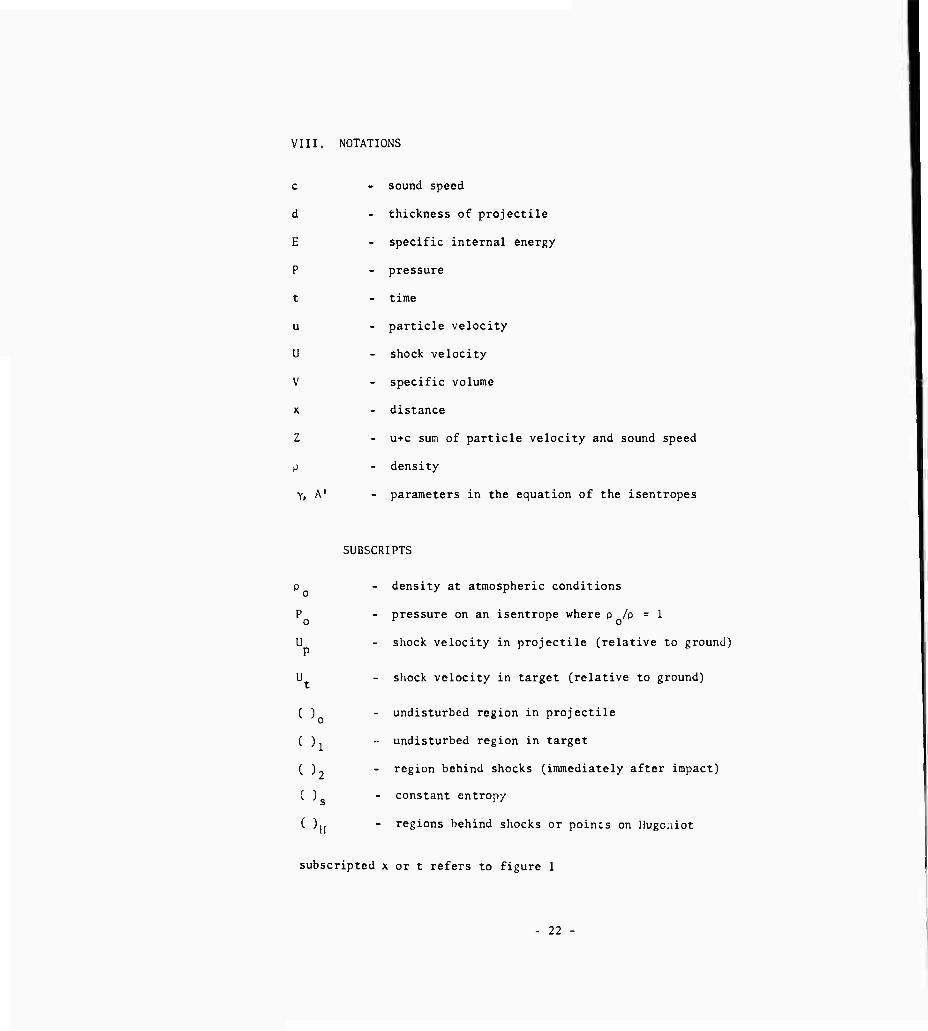
VIII. NOTATIONS
c - sound speed
d - thickness of projectile
E - specific internal energy
P - pressure
t - time
u - particle velocity
U - shock velocity
V - specific volume
x - distance
Z - u+c sum of particle velocity and sound speed
p - density
y, A' - parameters in the equation of the isentropes
SUBSCRIPTS
p - density at atmospheric conditions o
P - pressure on an isentrope where o /P = 1
U - shock velocity in projectile (relative to ground)
U - shock velocity in target (relative to ground)
( ) - undisturbed region in projectile
( ). - undisturbed region in target
( ) - region behind shocks (immediately after impact)
C ) - constant entropy s
( )[| - regions behind shocks or poincs on Hugc.iiot
subscripted x or t refers to figure 1
- 22 -

UJ u 2 <
Q
o
0)
>. £
o a a.
(U D Q
8 to
s
M 3 60
•I ME. (t)
23 -

8 \<o to ^
O^-tM^l «^ = .5wb4 > C^ .0016
0 4- 8 >1 lU lo U lg 31 % ^0
Figure 2. Comparison of the Fitted Equations with Tillotson's Data (a) U=<Xivt>2 iUL-v-C^. M3 (b) Ü- CX^b» Ä + <1, ^
24

JOO
Figure 3. Equation of State for Alumir
25

T3 O
0) ja m o
ü
HI
o
(0 o
a. n)
O i
a) to
•r-l
a a)
J2
M P
Ü
w
a,
a)
C o
M <U
u 3 M
»0 ^ G) •to N ^ in 10 CJ J - 26

R- dt\*K.ftu^v*.\Sf u,
l-<lv^«.Av^H^ » fcy I
I-GAfcÄA. c-Yevo *^v<-
C^
c
I- ^«kKA^av^v^
I- drt6Ä^.A,-^«.v^vY\^_
W u. Figure 5 - State Planes (Schematic) (a) P versus u State Plane (b) c versus u State Plane
- 27 -

•8
<u M <U
M-l
g
o o
X. to IM o
8
u 00
V««y>,_ ^.«-p
28

Y^ - V ^
- 29

5 i i
2/ \D a
Bl iJ U)
0 C
* o
II
0 3 o
r«^ •* -* 4J a 0)
0 4J o CQ H d " o
o
8 ii o
- + 3 o N-^
8 m —* C o -H
0 U 0 i
•r4
g 0 l-I
o. ex, < <■>
0 o r- en
4!
£ o o :>-. -J J2
■U
o g o U
1^ PM
^ o 8 5 to
M-l O
g •W 4J •H
O S 3 o
r^
g <U u 3 Ml •M
0 fc.
^v^. t^'p
30 -
c
1- c-vi.fc.e.».<^evj.*,i>\\<u
H d vu.Tt. A. ^T e. ä v ^T t.
ML
Figure 8a. Schematic Illustrating the Relative Accuracy of the us constant Assumption and u + c= constant Assumption for Aluminum.
- 31

Figure 8b. Schematic Illustrating the Relative Accuracy of the u = constant Assumption and u + c = constant. Assumption flor Ideal Gas.
32 -
I /
i 1 . i 1 o O LO
^9
5
o o ■x
CO
2 i
o co
~7' H
O 0 J
. A:
G —1
Ü 0 H n
r—1 tS 11 ■J >
u)
o u
1 " --
ci" O Ü
D
(O
o 5SJ
>^

i 1 —| ■
"a— i
< ] l !
i i i
\
NT — -—4
! _ ...: —
1
i i
-H - !
....1 V
- -— — —r- i
— —
vj/
. ..j.... \ : .. -T- — ■— — i
•—
. 1 ■ - -
j
^ — —j—
i ^
; ....p.. j
\
1
"T ._ — i
i .
. ■
0 0
--[- - ' 1 " 1 ~P . ■ 1
t\5 V'
']■ K ■ I
" r\ 1
...! ■4- i \
i | I \ ._]_._.
: L i — f .
s t i a
oÖ-O J
: ^
■—[— ' i" .!..
'. .;
v
1 \
•{ ■ -1 ■- I ■ \
: 4
4- .:.... .
>
\
......
\ i
n 1
-P 1 \
N
I — - _4__ —4—
■
|_
' i j ; ■
- - ■
1
) ( 5 V 5 1
.L-- t ^ J ^_L< ) i i |: :
! \< h.
! ... I ,. : 1 :; : :,
■ . i :.
1
^ -'34 : | 1 ■ !
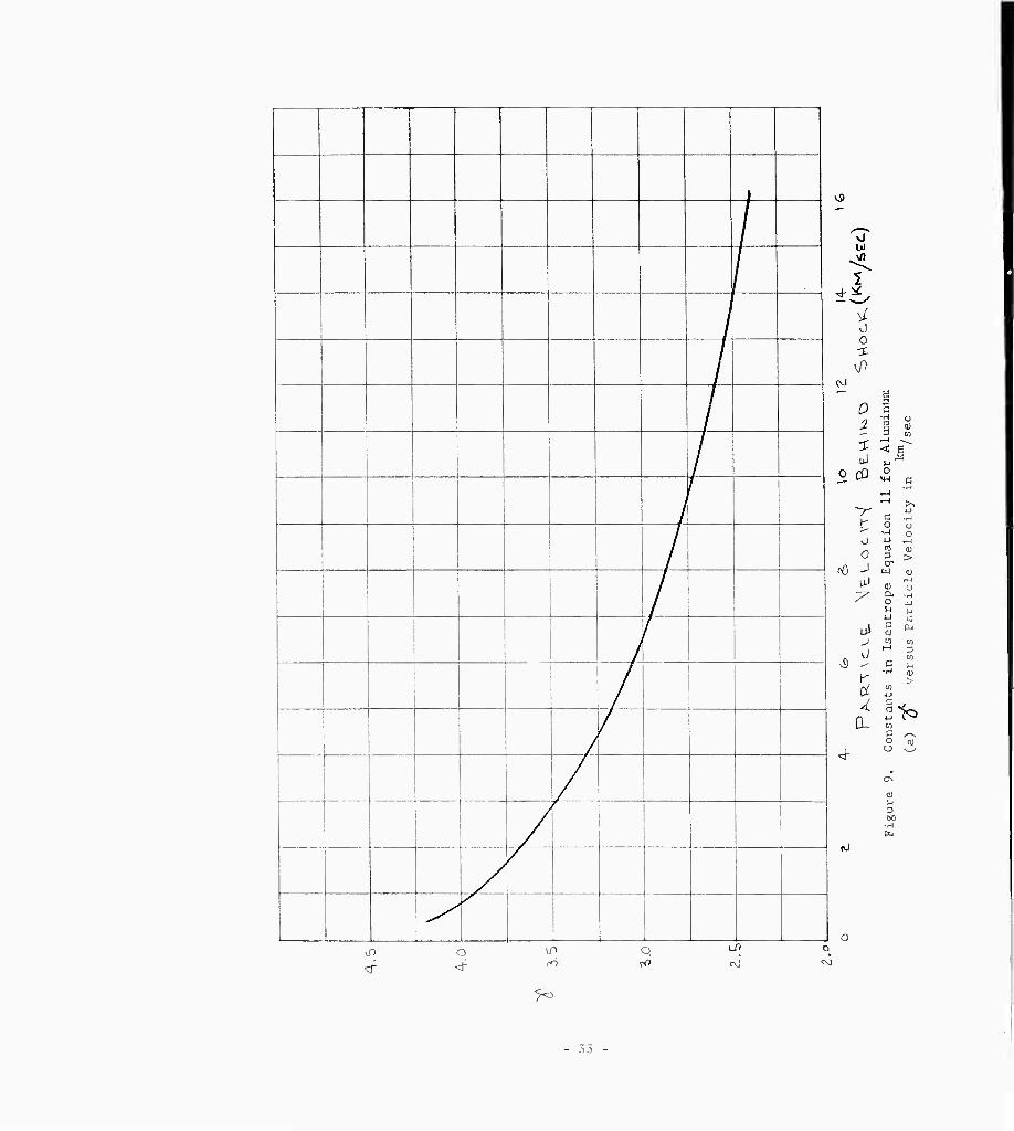
g O 3 <u rH w < *^ M 1 O
U-l c -H
.—1 ^H >>
4J c •r^ o O
■H o ^ --I al 0) 3 > tx W <u
f~^ d) u a. •rJ
o 4-1 M kl u M a CL, V to m
l-H 3 Ul
c M ■J-* (u
> <J> i-i c <■, n) ij CO
C /-N O PQ
U ^-^
, O
1) ^ 3 60

i- h;::h::PMi:|MMh:::|MM| MiJ^iiil Ktil >^i!ii MM,
.,n, 1 M ! i 1 ! M ! 11 I I i I M !-ll ! ! ! i h i ! : i ; : : ; : i i !;!!;• j_>r rMi iiiihiM
M M . I ii IT -i N-l \M I ' |:jJ: ii i^i ili; h M ; i i if i i i i li>'nT i.ii. iiii.iiii- ; : . j ; : : . f ; : ' ; : ; j
nnc -! Tl | 1 ' P ' [ ' if M '- i-i 1 Ni-i iii 1 1'ii i 1 ll lUm'-i 1= ̂ M^ fj [--|i:j:iJi:[jll.N i^
I i i 11 ii^i-i- i-1 ift|-! l-M j i-iJ'| i-i-i i i- l-i i i i i i yfTi i-i-i 11 i i-i i • i [f iiiiMiiiii f.r\<l H 1 r '■ i : ' ' ! 1 j- ! t | j 1 ■n-l] i:iir -i jit -i i i>h i i i 1 S l:K:i- ■ iii i-i l;Ti M^pppp |
Irr Hi H hiiv L1//'i • '1 i Hin HTTL h {4i;y..Pi|-:|r|4-f:|i:
nn 7 H ■ ■ 1 i I : 1 1 ; 1 | 1 1 1 i EmtjSit E rffnxrrrniT
i rafimjiliuffl M i FlM NTTTTrl '. ./^I 1 ■ I ' '' ■ i '■ ' ' l
"o H"irrrmTr iMIT: i I/MI 1 1 ITTTH lliui rrrrmTr i M iM 1 r r' ■ M i i i' ■ !'' ■
T I i^iriTi iTFrn |y\ i | J ' : ' i ■ ■ ! ' i M ' * j i i j i i •sm 1 J 1 1 1 L ' j] / I ! M | I I i 1 ' ; ' ' ■ ' ' ' ' M /-fAn P [ 1 : 1 .: : :. ; : 1 ; - t ' | i / i ' ■ ; ' : i i i ' i i i M • i !
■_. "1! i i hM; ! ri ii ! i ! 1 i / M M M ! ! ! M i M ; N ! 1 ! i ji j 1 I j 1 '^ ' 1 ' 1 noo, 11 M ji !! !M I! Mi i ;! [/ i i M i i i i M i i i i i i i 1 Pi-i.i j-jj i ! i J ! 1 !Mi i M M i | i M M
1- 1 M j 1 Mi i 1 l-L-l !-IJ-i ! lyp' -i I I ] ri t j t" -i 1 i"n~M""'i i tii N H l Üi-I ! i i i h i! i ,v,nR M ! : M M M-H H '- i ' / 1 ! j i -. ,. I 1 t ; ! . . i , . j j - . .. j j i , i , j | !.. i. 1 |
i 1 1 FFH n-i;l I i pi M FT n 1 rn M 1 Ii [■ l-i r ifi i:! i : i'' [- j [ 1 | H 1 ! M 1 1
nnn A hj-'l rl IH j" i' 1 ! 1 M 1 /!'
J IZL I- [' j | -{'{"' j 1 - 1 i i M M M 1 1
i 1--| i | M ! i | i i ii | ■ ■ ■ 1 ■ ■ i ■ 'ill ' t t t ' * t i 1 j j j j [ ■ j■ tj f • 1 t- j 1 - 1 1 j ■ | t 1 i t > t 1 ; ; j i | j j | i MM 000? M 1 j ■ 1 i: ■ ! ' t ' ' /h ' ! i -i::].!- |"l-i-"I \\ \ \ 1 |-4ij~:H.-|-i4zFt" ]■ j-i'-i I-t"f"H
.ml!; i i. KiTI M 11 T'trmTffl^mxf 1 liH-ili I 111 M ; s ' ' ' 1 ' / T i ; ' ' i "I "1 ''"''Mt "l""[~ 1 1 h 1 i 1 l M 1 1 1 1 rl llHiH-mlli .0S0 ? i I / 1 \ ! 1 # I ' ! i i 1 i 1 1 1 1 1 ! | | - - - | j I -1 ; i ; |
-Tf4i - M M i ' i rrr r-M 1 1 1 1 \ ' 1 1
1 ■ ■ f ; ■ \\/\\ ! ; : 1 j I i \ j ! r■ ■ ■ /r T ■ ■ i !i" r i" if lil t i i 1 1 i t r 1 1 i i t i t t t 1 1 r t i t t t
i ■ i /i 1 1 1 i ■ i --j-j -{- j 1 1 H M H |-t 1 i i Tl 1 r j | ! | i
I txr ijrr 11 i i II II MTli T Ii ! 1 1 ,0ini II!1! 1 1 M 1II 1 1 1 1 11 11 1 1 ■ rl i 1 rn t hi ii 111 rl rl i T i t Ii 1 11 ii
o • S l.O V5
^^acvc. (, ""l^zc) Figure 9. Constants in Isentropc Equation 11 for Aluminum
km , (c) P versus Particle Velocity in /sec
- 35
10
, q ; n -■;■-: :' MT': ! - [■ . , : .
R ;-i : i ; ; ■ Mi: Mi; \ \ \ \ \ \ \ ; ; : i^^-^
« ij i: 1:1- M i ;;- J i-.i i l-M i MMK M : : ^^
«; ^terMiMir :Mi- ; ..tr/J J_ . .ij-, -j . . _ i ; : :; ii..M-^^M ,><" ji:-- t-EM
."L ^T- —pn L 4 J0^ i
l^.i J-! i ! - i ! 1 i \-\ JU- d j .:..:! -..r- .■j.:. i IMJ^^ i-i- ; -" i - i-i-1-.. iMr-iv-j
- -I::!:. yLU iMr - ■;■-■. -j- - -■j "M: ^\\-\ \ t "J:M _ .-j- ■ - ■ ;. M-MjM M-I-j-i_. .1 i i^*1 . ,. i . . { x-i-.l. -j ,— -— -1 h-'--j
- =r - ; .:: : .: i r, : z p . .::: .. : : = -- .: j.: : a. ■j^f-i ! ■ - — Lri-' "'—" —
i— >^
^f:""t:-:--":"^-"11 ^i-.-K" , 9
•Q j^ ! ^ - - ■ >/| —
--- —M- - -- - —1
::+:::: :::::::^p ■ 1
09 vi i ! T! ri ! ! f/W | i ; i : MM M M - i 1 MM j ..M j MM MM j ! MM--:
PIS i !.: j j :! ; M i- / M i i i i ! ; M ; M i i i M MMi MvM I'M i MM MM I" bp; r,7 i f i !- M i/ M M IM: M 1 MM -rt'r -]-M..-|-. -i M -: M J j j-- i-.i ;:j MMMjr
0 6
:| \\ v\V\ I i/j: M i; MM i ili : i M - __J---:--TMMI ..i-i M ± -.Mh-. -!-MM 1 -------
S il: / ■ ■ ! M p -f~7--zXT'^-- '■ ---~- ------- 'I ] E=--
-~-: \ '\ ' =- - -j-l - := ■ :---- __- — .--J- - . - - . - ... .j .
y O i .,
it- m \ ; i M -[- i : • lJi M M M j : : M j i-j j | :v27;
n .1 ^ \ \ M! ;. MM M i j M. MM M;-M
: M ■/. 1 . ; ! ; :fH; i:; IEE^EEEEEE^EI: . j M
n ■? E! / EEEEEEEEEEE MEEEEI i :=E:M^EE-rE: M EEM.MMErE
iij/ =i^:=EEE^:M ! ij -M-iJM — - i i- - - - - j- - -
- MM ___ MM ; :_.. M ;MJ- : M - I M
Il ^A^^^i. _ ..-,.. - -. - - _ _ ..- _1_ . _. M — J 1 1
.0 l | 1.0 S.o S,o "1,6 "9.0 l\.o 13.o IS.0
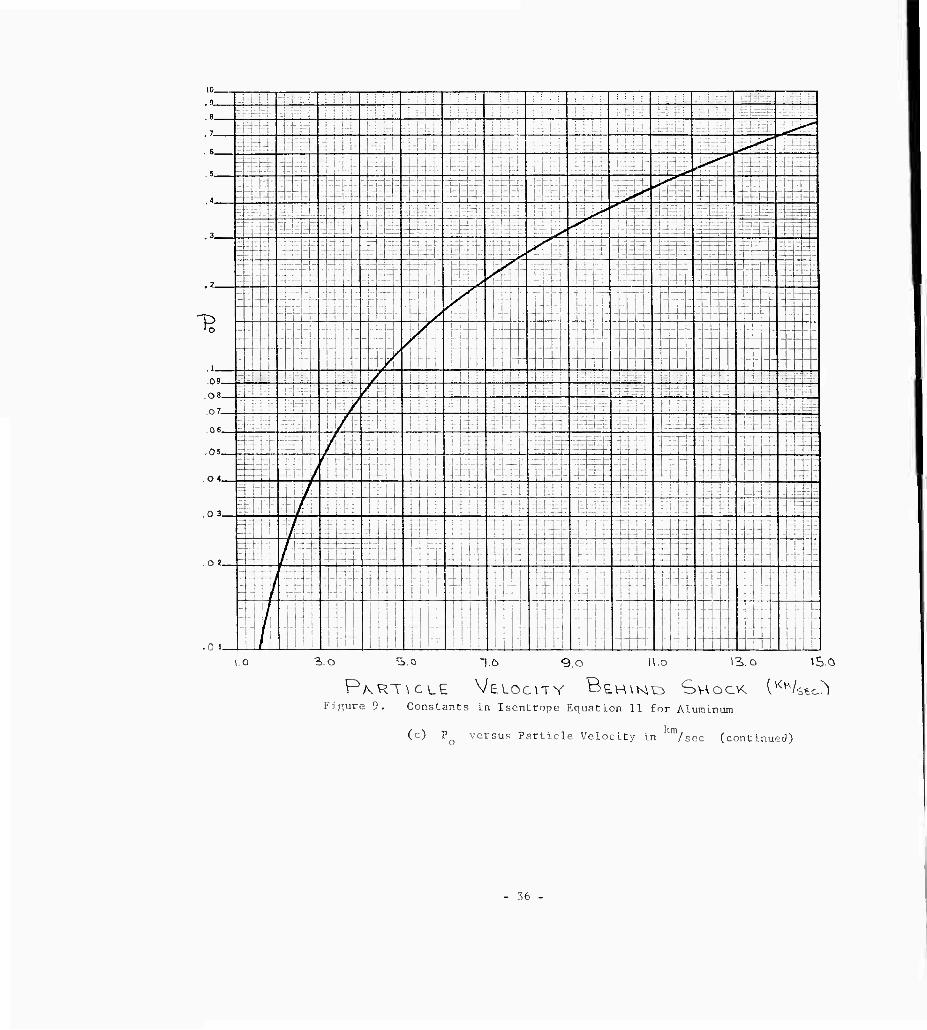
PKRT\CLE VELOC\TY B£H\K\O SHOCK I^^/SEC^) Figure 9. Constants in Isentrope Equation 11 £or Aluminum
(c) Po versus Particle Velocity in m/sec (continued)
36 -
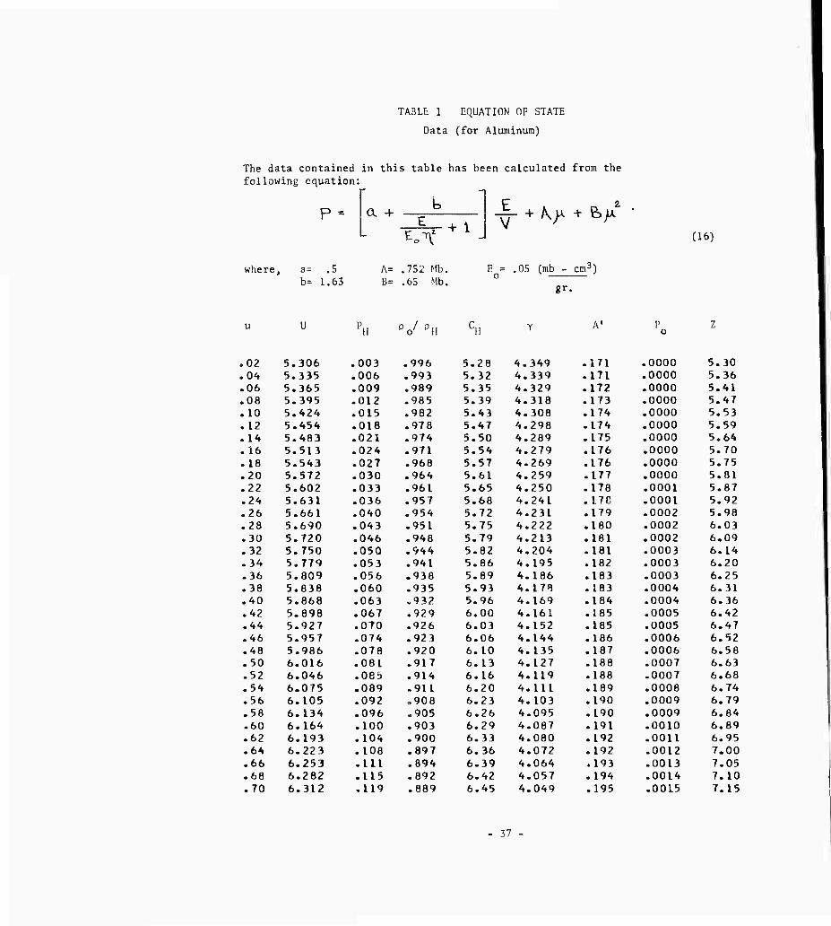
TABLE; 1 EQUATION OF STATE
Data (for Aluminum)
The data contained in this table has been calculated from the following equation:
- -
P- a + b
1 f+ ^ + e>/ (16)
where . a= .5 A= .752 Mb. E = .05 (mb - cm3) b= 1.63 B= .65 Mb.
0
«r
u u r H Oo/ Di! cu Y A' P
0 Z
,02 5.306 .003 .996 5.28 4.349 .171 .0000 5.30 .04 5.335 .006 .993 5.32 4.339 .171 .0000 5.36 .06 5.365 .009 .989 5.35 4.329 .172 .0000 5.41 .08 5.395 .012 .985 5.39 4.318 .173 .0000 5.4 7 .10 5.424 .( 315 .982 5.43 4.308 .174 .0000 5.53 .12 5.454 318 .978 5.47 4.293 .174 .0000 5.59 .14 5.483 .( 321 .974 5.50 4.289 .175 .0000 5.64 .16 5.513 324 .971 5.54 4.279 .176 .0000 5.70 .18 5.543 327 .968 5.57 4.269 .176 .0000 5.75 .20 5.572 D30 .964 5.61 4.259 .177 .0000 5.81 .22 5.602 333 .961 5.65 4.250 .178 .0001 5.87 .24 5.631 03b .957 5.68 4.241 .178 .0001 5.92 .26 5.661 340 .954 5.72 4.231 .179 .0002 5.98 .28 5.690 043 .951 5.75 4.222 .180 .0002 6.03 .30 5.720 046 .948 5.79 4.213 .181 .0002 6.09 .32 5.750 050 .944 5.82 4.204 .181 .0003 6.14 .34 5.779 053 .941 5.86 4.195 .182 .0003 6.20 .36 5.809 056 .938 5.89 4.186 .183 .0003 6.25 .38 5.838 060 .935 5.93 4.17B .183 .0004 6.31 .40 5.868 063 .932 5.96 4.169 .184 .0004 6.36 .42 5.898 067 .929 6.00 4.161 .185 .0005 6.42 .44 5.927 070 .926 6.03 4.152 .185 .0005 6-47 .46 5.957 074 .923 6.06 4.144 .186 .0006 6.52 .48 5.986 078 .920 6.10 4.135 .187 .0006 6.58 .50 6.016 081 .917 6.13 4.127 .188 .0007 6.63 .52 6.046 085 „914 6.16 4.119 .188 .0007 6.68 .54 6.075 089 .911 6.20 4.111 .189 .0008 6.74 .56 6.105 092 „908 6.23 4.103 .190 .0009 6.79 .58 6.134 096 „905 6.26 4.095 .190 .0009 6.84 .60 6.164 100 .903 6.29 4.087 .191 .0010 6.89 .62 6.193 104 .900 6.33 4.080 .192 .0011 6.95 .64 6.223 108 .897 6.36 4.072 .192 .0012 7.00 .66 6.253 1L1 .894 6.39 4.064 .193 .0013 7.05 .68 6.282 115 .892 6.42 4.057 .194 .0014 7.10 .70 6.312 119 .889 6.45 4.049 .195 .0015 7.15
37

TABLE 1, cont.
u U PH Po/ 0H CH Y A' P
0 Z
.72 6.341 .123 .886 6.49 4.042 .195 .0016 7.21
.7A 6.371 .127 .884 6.52 4.035 .196 .0017 7.26
.76 6.401 .131 .881 6.55 4.028 .197 .0018 7.31
.78 6.430 .135 .879 6.58 4.020 .197 .0019 7.36
.80 6.460 .140 .876 6.61 4.013 .198 .0020 7.41
.82 6.489 .144 .874 6.64 4.006 .199 .0021 7.46
.8^ 6.519 .148 .871 6.67 3.999 .199 .0022 7.51
.86 6.549 .152 .869 6.70 3.992 .200 .0024 7.56
.88 6.578 .156 .866 6.73 3.985 .201 .0025 7.61
.90 6.608 .161 .864 6.76 3.979 .202 .0026 7.66
.92 6.637 .165 .861 6.79 3.972 .202 .0028 7.71
.9A 6.667 .169 .859 6.82 3.965 .203 .0029 7.76
.96 6.696 .174 .857 6.85 3.959 .204 .0031 7.81
.98 6.726 .178 .854 6.88 3.952 .204 .0032 7.86 1.00 6.756 .182 .852 6.91 3.946 .205 .0034 7.91 1.02 6.785 .187 .850 6.94 3.939 .206 .0036 7.96 1.04 6.815 .191 .847 6.97 3.933 .206 .0037 8.01 1.05 6.848 .194 .847 7.00 3.931 .207 .0039 8.05 1.10 6.918 .205 .841 7.07 3.915 .209 .0043 8.17 1.15 6.988 .217 .835 7.14 3.899 .210 .0048 8.29 1.20 7.058 .229 .830 7.21 3.884 .212 .0053 8.41 1.25 7.127 .241 .825 7.28 3.869 .214 .0059 8.53 1.30 7.197 .253 .819 7.35 3.854 .216 .0065 8.65 i.35 7.267 .265 .814 7.42 3.840 .217 .0072 8.77 1.40 7.337 .277 .809 7,48 3.826 .219 .0078 8.88 1.45 7.407 .290 .804 7.55 3.812 .221 .0086 9.00 1.50 7.477 .303 .799 7.62 3.798 .223 .0093 9.12 1.55 7.547 .316 .795 7.68 3.785 .224 .0102 9.23 1.60 7.616 .329 .790 7.75 3.772 .226 .0110 9.35 1.65 7.686 .342 .785 7.81 3.759 .228 .0119 9.46 1.70 7.756 .356 .781 7.88 3.746 .230 .0129 9.58 1,75 7.826 .370 .776 7.94 3.734 .231 .0139 9.69 1.80 7.896 .384 .772 8.00 3.722 .233 .0150 9.80 1.85 7.966 .398 .768 8.06 3-710 .235 .0161 9.91 1.90 8.036 .412 .754 8.13 3.698 .237 .0173 10.03 1.95 8.105 .427 .759 8.19 3.686 .238 .0185 10.14 2.00 8.175 .441 .755 8.25 3.675 .240 .0198 10.25 2.05 8.245 .456 .751 8.31 3.664 .242 .0212 10.36 2.10 8.315 .471 .747 8.36 3.653 .241 .0208 10.46 2.15 8.385 .487 .744 8.42 3.642 .243 .0219 10.57 2.20 8.455 .502 .740 8.49 3.631 .245 .0230 10.69 2.25 8.525 .518 .736 8.55 3.621 .246 .0242 10.80 2.30 8.594 .534 .732 8.61 3.611 .248 .0254 10.91 2.35 8.664 .550 .729 8.67 3.601 .250 .0266 11.02 2.40 8.734 .566 .725 8.73 3.591 .252 .0279 11.13 2.45 8.804 .582 .722 8.79 3.581 .253 .0292 11.24 2.50 8.874 .599 .718 8.85 3.571 .255 .0305 11.35 2.55 8.944 .616 .715 8.90 3.562 .257 .0319 11.45 2.60 9.014 .633 .712 8.96 3.552 .259 .0333 11.56 2.65 9.084 .650 .708 9.02 3.543 .261 .0348 11.67 2.70 9.153 .667 .705 9.08 3.534 .262 .0363 11.78 2.75 9.223 .685 .702 9.14 3.525 .264 .0378 11.89 2.80 9.293 .703 .699 9.19 3.516 .266 .0394 11.99
- 38 -

TABLE 1, cont.
u U PH V PH CH Y A' P 0
Z
2-85 9-377 .722 .696 9.27 3.515 .268 .0416 12.12 2.90 9.441 .739 .693 9.32 3.505 .269 .0430 12.22 2.95 9-505 .757 -690 9.37 3.495 .271 .0444 12.32 3.00 9.569 .7 75 .686 9.42 3.485 -273 .0458 12.42 3.05 9.632 -793 .683 9.48 3.476 .275 .0473 12.53 3.10 9.696 .812 .680 9.53 3.46 7 .276 .0488 12.63 3.15 9.760 -830 .677 9-58 3.457 .278 .0502 12.73 3.20 9.824 .849 .674 9.63 3.-448 .280 .0518 12.83 3-25 9.888 .868 .671 9.68 3.439 .282 ,0533 12.93 3.30 9.951 .887 -668 9.73 'in430 ,283 ,0549 13.03 3.35 10.015 .906 -666 9.78 3.421 .285 .0565 13.13 3.40 10.079 .925 .663 9.83 3,413 .287 ,0581 13.23 3.45 10. 143 „945 .660 9.88 3.404 .289 .0598 13.33 3.50 10.20 7 .965 -657 9.93 3-396 ,291 .0614 13.43 3-55 10.270 -984 .654 9.98 3.387 .292 .0631 13.53 3.60 10-334 1.004 .652 10o03 3.379 .294 .0649 13.63 3-65 10.398 1.025 .649 10.08 3,371 -296 .0666 13.73 3.70 10.462 1.045 .646 10.13 3,363 -298 .0684 13.83 3.75 10.526 1,066 .644 10. 18 3,355 -299 .0702 13.93 3.80 10-589 1.086 ,641 10.23 3.347 -301 .0721 14.03 3.85 10-653 I. 107 .639 10-27 3,339 .303 .0739 14.12 3.90 10-717 1.129 -6 36 10.32 3,331 .305 .0758 14.22 3.95 10.781 1.150 .634 10.37 3.324 .306 .0778 14.32 4.00 10.845 1,171 .631 10.42 3.316 .308 .0797 14.42 4.05 10.908 1.193 .629 10.46 3.309 .310 .0817 14.51 4.10 10.972 1.215 .626 10.51 3,301 .312 .0837 14.61 4. 15 11.036 1.237 .624 10.56 3.294 ,314 .0857 14.71 4.20 11.100 1.259 .622 10.61 3.287 .315 .0878 14.81 4.25 11.164 1.281 -619 10.65 3.280 ,317 .0899 14.90 4.30 11-227 1.304 .617 10.70 3-272 .319 .0920 15.00 4.35 11.291 1.326 .615 10-74 3.265 .321 .0941 15.09 4.40 11.355 1,349 -613 10.79 3.258 .322 .0963 15.19 4.45 11.419 1.372 .610 10-84 3-251 .324 .0985 15.29 4.50 11-483 1-395 .608 10-88 3.245 ,326 .1008 15.38 4.55 11.546 lo4l8 -606 10-93 3.238 .328 .1030 15.48 4.60 11.610 1.442 .604 10.97 3-231 .329 ,1053 15.57 4-65 11.674 1.466 .602 11.02 3.224 .331 ,1076 15.67 4.70 11.738 1.490 .600 11.06 3,218 ,333 ,1100 15.76 4.75 11.802 1-514 .598 11.13 3.211 .339 .1096 15.88 4.80 11.865 1.538 .595 11.18 3-205 .341 .1115 15.98 4.85 11.929 1.562 .593 11.23 3. 198 ,342 .1135 16.08 4.90 11.993 1.587 -591 11.28 3-192 ,344 .1154 16.18 4.95 12.057 1.611 .589 1 1.34 3.186 .346 .1174 16.29 5.00 12.121 1,636 .587 IK 39 3.179 .348 .1194 16.39 5.05 12.184 1-661 .586 11,44 3. 173 .350 .1214 16.49 5.10 12.248 1.687 .584 11.49 3,167 »352 .1234 16.59 5.15 12,312 1-712 .582 11.54 3. 161 ,354 .1255 16.69 5.20 12.376 1-738 .580 11.59 3.155 .355 .1275 16.79 5.25 12.440 1.763 ,578 11.64 3, 149 .357 .1296 16.89 5.30 12.503 1.789 .576 11.69 3.143 .359 .1316 16.99 5.35 12.567 1.815 .574 11.74 3.137 .361 .1337 17.09 5.40 12.631 1.842 -572 11,79 3.131 .363 .1358 17.19 5.45 12.695 1.868 -571 11.84 3.125 .365 .1379 17.29
- 39 -
TABLE 1, cont,
u U PH Po/pH CH y A' P 0
Z
5-50 12.759 1.895 .569 11.89 3.119 .367 .1401 17.39 5.55 12.822 1.921 .567 11.94 3.114 .369 .1422 17.49 5.60 12.886 1.948 .565 11 = 99 3.108 .371 .1444 17.59 5.65 12-950 1.976 .564 12.04 3.102 .373 .1465 17.69 5.70 13.014 2.003 .562 12.09 3.097 .375 .1487 17.79 5.80 13.159 2.061 .559 12.09 3.085 .380 .1534 17-89 5.90 13.280 2.115 .556 12,17 3.074 .384 .1577 18.07 6.00 13-401 2.171 .552 12.25 3.064 .388 .1622 18.25 6el0 13.522 2.227 .549 12.34 3.053 .392 .1667 18.44 6.20 13.644 2.284 .546 12.42 3.043 .396 .1712 18.62 6.30 13.765 2.341 .542 12.50 3.033 .400 .1758 18.80 6.40 13.886 2.400 .539 12.58 3.023 .405 .1805 18.98 6.50 14.008 2.458 .536 12.67 3.013 .409 .1352 19.17 6.60 14.129 2.518 .533 12.75 3.003 .414 .1899 19.35 6.70 14.250 2.578 .530 12.83 2.993 .418 .1947 19.53 6.80 14.372 2«639 .527 12.91 2.984 .423 .1996 19.71 6.90 14.493 2.700 .524 12.99 2.974 .427 .2045 19.89 7.00 14.614 2.762 .521 13.07 2.965 .432 .2095 20.07 7.10 14.735 2.825 .518 13.15 2.956 .436 .2145 20.25 7.20 14.857 2.888 .515 13.23 2.947 .441 .2196 20.43 7.30 14.978 2.952 .513 13.30 2.938 .446 .2247 20.60 7.40 15-099 3.017 .510 13.38 2.929 .451 .2298 20.78 7.50 15-221 3.082 .507 13.46 2.920 .456 .2351 20.96 7.60 15-342 3.148 .505 13.54 2.911 .461 .2404 21.14 7.70 15-463 3.215 .502 13.62 2.903 .466 .2457 21.32 7.80 15-585 3.282 .500 13.69 2.894 .471 .2511 21.49 7.90 15-706 3.350 .497 13.77 2.886 .476 .2565 21.67 8.00 15-827 3.419 .495 13.85 2.878 .481 .2620 21.85 B.IO 15-948 3.488 .492 13.92 2.869 .486 .2675 22.02 8.20 16.070 3.558 .490 14.00 2.861 .491 .2731 22.20 8.30 16-191 3.628 .487 14.07 2.853 .496 .2788 22.37 B-AO 16.312 3.700 .485 14.15 2.845 .502 ,2845 22.55 8.50 16-434 3.772 .483 14.22 2.837 .507 .2902 22.72 8.60 16-555 3.844 .481 14.30 2.830 .512 .2960 22.90 8.70 16-676 3.917 .478 14.37 2.822 .518 .3019 23.07 8.80 16.798 3.991 .476 14.45 2.814 .523 .3078 23.25 8.90 16.919 4.066 .474 14.52 2.807 .529 .3137 23.42 9.00 17.040 4.141 .472 14.60 2.799 .534 .3198 23.60 9.10 17.161 4.217 .470 14.67 2.792 .540 .3258 23.77 9.20 17.283 4.293 .468 14.74 2.784 .546 .3319 23.94 9.30 17.404 4.370 .466 14.82 2.777 .552 .3381 24.12 9.40 17.525 4.448 .464 14.89 2.770 .557 .3443 24.29 9.50 17.647 4.526 .462 14.96 2.763 .563 .3506 24.46 9.60 17.768 4.605 .460 15.03 2.756 .569 .3569 24.63 9.70 17.889 4.685 .458 15.11 2.749 .575 .3633 24.81 9.80 18.011 4.766 .456 15.18 2.742 .581 .3697 24.98 9.90 18.132 4.847 .454 15.25 2.735 .587 .3762 25.15 10.00 18.253 4.928 .452 15.32 2.728 .593 .3828 25.32 10.10 18.374 5.011 .450 15.39 2.721 .599 .3894 25.49 10.20 18.496 5.094 .449 15.46 2.714 .605 .3960 25.66 10.30 18.617 5.177 .447 15.53 2.708 .612 .4027 25.83 10.40 18.738 5.262 .445 15.60 2.701 .618 .4094 26.00 10.50 18.860 5.347 .443 15.68 2.694 .624 .4162 26.18
40

TABLE 1, cont.
u U PH 0o/oH CH > A' P 0
Z
10.60 18,981 5.432 .442 15.75 2-688 .631 .4231 26.35 10-70 19.102 5.519 .440 15.82 2-681 .637 .4300 26.52 10.80 19.224 5.606 .438 15.89 2.675 .644 .4369 26.69 10.90 19.345 5.693 .437 15.95 2-669 .650 .4440 26.85 11.00 19-466 5.781 i435 16.02 t .662 .657 .4510 27.02 11.10 19-587 5-870 -433 16.09 2.656 -663 .4581 27.19 11.20 19-709 5.960 -432 16.16 2.650 -670 .4653 27.36 11.30 19.830 6-050 .430 16.23 2.644 .677 .4725 27.53 11.40 19.951 6-141 .429 16.30 2.638 .684 .4798 27.70 11.50 20.073 6-233 ,427 16.37 2.632 -690 .4871 27.87 11.60 20-194 6..325 -426 16.44 2.626 .697 .4945 28.04 11.70 20.315 6.418 .424 16.50 2.620 -704 .5019 28.20 11.80 20.437 6.511 .423 16.57 2.614 -711 .5094 28.37 11.90 20.558 6-605 .421 16.64 2.608 .718 .5169 28.54 12.00 20.679 6. TOO .420 16.71 2.602 -725 .5245 28.71 12.10 20.800 6.796 .418 16.77 2.596 .732 .5321 28.87 12.20 20.922 6-892 .417 16.84 2.590 .739 .5398 29.04 12.30 21.043 6-988 .415 16.91 2.585 .747 .5476 29.21 12.40 21.164 7-086 .414 16.97 2.579 .754 .5554 29.37 12.50 21.286 7-184 .413 17.04 2.573 .761 .5632 29.54 12.60 21.407 7-283 .411 17.11 2.568 .769 .5711 29.71 12.70 21.528 7-382 .410 17.17 2.562 .776 .5791 29.87 12.80 21.650 7-482 .409 17.24 2.557 .783 .5871 30.04 12.90 21.771 7-583 .407 17.31 2.551 .791 .5951 30.21 13-00 21.892 7-684 .406 17.37 2.546 .798 .6032 30.37 13.10 22.013 7.786 .405 17.44 2.540 .306 .6114 30.54 13-20 22-135 7.889 .404 17.50 2.535 .814 .6196 30.70 13.30 22.256 7.992 .402 17-57 2-530 .821 ,6279 30.87 13.40 22.377 8.096 .401 17-63 2.525 .829 .6362 31.03 13.50 22.499 8.201 .400 17.70 2.519 .837 .6446 31.20 13.60 22.620 8.306 .399 17.76 2-514 .845 .6530 31.36 13.70 22.741 8.412 .398 17.83 2.509 .853 .6615 31.53 13.80 22.863 3.519 .396 17.8° 2.504 .861 .6700 31.69 13.90 22.984 8.626 .395 17.96 2.499 .869 ,6786 31.86 14.00 23.105 8.734 .394 18.02 2.49 3 .877 ,6872 32.02 14.10 23.226 8.842 .393 18.08 2.488 .385 .6959 32.18 14.20 23.348 8.952 .392 18-15 2-483 .893 .7046 32.35 14-30 23.469 9.061 .391 18.21 2.478 .901 ,7134 32.51 14.40 23.590 9.172 .390 18.28 2.473 .909 .7223 32.68 14.50 23.712 9.283 .383 18.34 2.463 .918 .7311 32.84 14.60 23.833 9.395 .387 18.40 2.464 .926 .7401 33.00 14.70 23.954 9.507 .386 18.47 2.459 .934 .7491 33.17 14.80 24.076 9.621 .385 18.53 2.454 .943 .7581 33.33 14.90 24.197 9-734 .384 18.59 2.449 .951 .7673 33.49 15.00 24.318 9.849 .383 18.65 2-444 .960 .7764 33.65 15.10 24.439 9.964 .382 18.72 2-439 .968 .7856 33.82 15,20 24.561 10.080 .381 18.78 2.435 .977 .7949 33.98 15.30 24.682 10.196 .380 18.84 2-430 .986 ,8042 34.14 15.40 24.803 10.313 .379 18.90 2.425 .994 ,8136 34.30 15.50 24.925 10-431 .378 18.97 2.421 1.003 .8230 34.47 15.60 25.046 10.549 .377 19.03 2.416 1.012 .8324 34.63 15.70 25.167 10.668 .376 19,09 2.412 1.021 .8420 34.79 15.80 25.289 10.788 .375 19.15 2.407 1.030 .8515 34.95
-41-
TABLE 1, cont.
u U PH pc/ PH CH y A' P 0
Z
15.90 25.410 10.908 .374 19.21 2.402 1.039 .8612 35.11 16.00 25.531 11.029 .373 19.28 2.398 1.048 .8709 35.28 16.10 25.652 11.151 .372 19.34 2.393 1.057 .8806 35.44 16.20 25.774 11.273 .371 19.40 2.389 1.066 .8904 35.60 16.30 25.895 11.396 .371 19.46 2.384 1.075 .9002 35.76 16.^0 26.016 11.520 .370 19.52 2.380 1.084 .9101 35.92 16.50 26.138 11.644 .369 19.58 2.376 1.094 .9200 36.08 16.60 26.259 11.769 .368 19.64 2.371 1.103 .9300 36.24 16.70 26.380 11.895 .367 19.70 2.367 1.112 .9401 36.40 16.80 26.502 12.021 .366 19.76 2.363 1.122 .9502 36.56 16.90 26.623 12., 148 .365 19.82 2.358 1.131 .9603 36.72 17.00 26.744 12.276 .364 19.88 2.354 1.141 .9705 36.88 17.10 26.865 12.404 .363 19.94 2.350 1.150 .9808 37.04 17.20 26.987 12.533 .363 20.00 2.346 1.160 .9911 37.20 17.30 27.108 12.662 .362 20.06 2.341 1.169 1.0015 37.36 17.40 27.229 12.792 .361 20.12 2.337 1.179 1.0119 37.52 17.50 27.351 12.923 .360 20.18 2.333 1.189 1.0224 37.68 17.60 27.472 13.055 .359 20.24 2.329 1.199 1.0329 37.84
- 42 -

; 1 1
REGION j
km/sec km/sec i megabars
A c P ;
i 1 o 5.27 o i 2 ! 14.10 18.08 8.84 i
i 3 0 7.50 .30 i
i 4 12.50 16.88 6.96 i 5 11.00 15.16 5.52 ! 5 9.00 14.26 3.92 1 7 7-00 12.76 : 2.65 i o 5.00 11.27 1.64
9 2.50 9.A0 0.85
1 10 12.38 16.97 7.06
1 11 10.87 15.84 5.62 1 12 8.88 14.34 4.00 | 20 12.38 16.96 7.06
21 10.94 15.81 5.57 1 22 8.93 14.31 3.97
30 10.94 15.81 5.57 31 8.98 14.25 3.93
1 32 1 8.98 14.27 3.93 50 10.85 15.88 5,65
! 51 8.90 14.31 4.01 70 i 10.85 15.92 5.65 71 1 8-96 14.27 3.95 90 | 8.96 14.36 3.95
TABLE 2 - PARTIAL LIST OF STATE PROPERTIES
(Regions Correspond to Figure 4)
initial data;
impact velocity = 28.2 /sec.
u1 = o P = 5.275 kln/sec

a
r-. 0 -t- ^-' j ^ 0
•^*t + 6-2 ff^ 5~S CO O O
c i i O f- o •H U .-( o ro
a) 4- ~J ■ ' BO d a 0 I
n) + o ^
a 1 •r-l
0 5^ 6~5 Ö-S 0) m O 1 O ao O 1 O rn Cl ! <f B cd 1 m O ) u~l
X ü iH r—( o
i B~S i s~S
c o O ; O •H 5" o t-^ r^.
td
rTi CvJ 1 v£>
=( i i r—1
t
•s T3 C
4 r-. cs 03
•r-l o\ c^ <t
0 u-l r—(
Ul Ji ^ <u o
•w o •^'
1 u X ^—V I j M CD u CO u3 ! m «J
5\ | fO 'CO 1 CO
a. o ; CM ' O | GO M ^ -(
PJ 3. J
C /~\ . •H u 03 O SO £ <u c-j r^ tNl ■U 0 m ■H CJ 3 u-i <t 3 P> £ —; —( —1
r3 ^: « 3 N^
■U rH ^^ M C u « e
3 w m o o
0.-H • o m .-NJ ^H crs IJ g r—* .-H
PM ^ -3 ^. 2 X H ß i-l ! cu a
1 ^D -rJ O I O Ul rg O I rg
Q C o r- i ^
w ; Jxj m
^ •r-l Ü J3 i ! M o 3
CM ; a) x: co 2 O o
CrJ n -w
/—>. 1 XJ
en QJ a •z. > -rl o | C CO !J M . -H 3 O o CO i td | C 01 ,Q eä 0^-13
■HO.CS to e CU -H o
<!■ u-l ^D
n) u
•H
jr /-N a • to o tj (U 10 to
C 6 •H J
01 CM
a • -H CX3 ^-i og
4-J U-t
J2 O 00
•--1 >•. n) 4-1 iJ -H iJ o '0 O
I—1 CO 0) > oo
01 C -U C1 o o
r-i n) w n) a. KJ e pq ü -H
+ -=
c cd
o E 3
d --' o m d
•H O U -H Cd 4-J
D. 3 S -< o o O m
44

^0 !
_, ,
u ! ^ e-s 5*^ f-2
1 + o vO C^ 0) rH m O0 to ■% i * 1. 1 i
<t 1
i ü -r 1 d
1 i i ••~, gv« g-o 5^ 1 " O CO CNJ 00 I
^ 7 CM O") CS] i 1 GO *
1 §■ * ü *
m r-^ 1
xi O i i i
1 1 ä
1
i ■'-1 £~^ 0 ■ 5^2
1 « D =< ^O ro ~* i i—I >-D r^.
i 00 , . 1 ß ' < .—i ^H -< !
i " ^ 1 -O 1 s-*-
C ü •r4 ' 0) cv: LO
0
* i % Cl r^ •* ^ 0i . ■* <f ^ i
en ^^ cu .
TH JA 1 •u O /-s 1-1 0 O 01 J3 _, CU o n 00 CL tn J u} Csl ro
\ u ^ s 1 ""1 -d- ro |
Cu ^ ^^
CJ ^^ , ■H Ü J5 OJ , JJ to 1 00 O ro
3 <u U) g CO r^ LO <r <r <r
> S • i •o ca ^ a ?■ .J r, ^v
;-. —• U O ,1. 0) ^o o i <t
I Ci 3 ^ -1 r-i <r O •'-1 ^ | m ■d r^ i M « = Pu _i
1 ^-' ;
; t; ^r; 1
j Ä •" :
a) a i JD -H i VJ
d o i O o O i 1 O o ^ m CM r^ CN]
w ^ o XI —* \ ^ tO O 3
a> x: m 1 1 r1 a: to ^^ j i t5
CO 01 -H
1 z > M o C C3 u M •r-l 3 y)
u XI 1 -i LO vO | to C 0) 3
1 ai 0 ^-i m ; -H a 1 00 E o
i ai ■-< c j
i < zl <n —'
a) X X 4-J 4-J
•H c Ü
■~i 0 r-H
cu 9) p; >
■"< 7—f J_l
Ü -u " i- CL
3 ^
M Cd " C 0
W-y,
—< i-H »* cd
Q 'J T3 w ro •H
W + dl ^) 3 n)
5 ■0
H 3 O ro a CM
„ il (J
o o' rs •H
3 3 Ü
U-H ^ 0J o O m
en % d g o -H ^ CO 0
•H ü M U ■r-( r^j
cd x; • 0. O. r-l rr m O S-i <i-|
U 00 c
45

IX REFERENCES
1_ Walsh, J, M., and Tillotson, J. 11^ "Hydrodynamics of Hypervelocity Impact, General Atomic, GA-3827, January 22, 1963,
2, Bjork, Robert U, "Review of Physical Processes in Hypervelocity Impact and Penetration;," Proc, of the Sixth Symposiuin on Hypervelocity Impact^ Vol. II, Part I, August, 1963-
3, Rae, W, J,, and Kirchner, 11,P,, "Final Report on a Study of Meteoroid Impact Phenomena," Cornell Aeronautical Laboratory, Inc., Report No. RM-1655-M,4, February, 1963
4 iierrraar.n, itaiter, .vitner, Lmmett A , Percy, .lotm H. , nnd .lones, Anon il,, "Stress have Propagation and Snallation in Uniaxial Strain," ASO-TDR-ö?-,^»1. Air Force Systems Conmand, i.right Patterson Air Force Base, September, 1961
5 Fowles, C R,, "Attenuation of the Shock Wave Produced in a Solid by a Flying Plate," Journ. Applied Physics,, Vol 31, .No 4, pp 655-661, April, 1960.
0 lillotson, .1 II , "Metallic Equations of State for Hypervelocity Impact," General Atomic, GA-3216, July 18.- 1962
7 Murnaghan, I U , "Finite Deformation of an lilastic Solid (.John Wiley and sons, Inc., New York, 1951}
8. Gourar.t, P. , and Friedrichs, k U , "Supersonic Flow ana Shock Waves," interscicncc Publishers Ind, New York, ^J^R
9. Shapiro, Ascher 11-, "The Dynamics and Thermodynamics of Compressible Fluid Flow," Vol II , The Ronald Press Comnany, New Yorks 1954.
10, Chou, P. C., Karpp, Robert R , and Zajac. Lawrence J , 'Decay of Stronp Plane Shocks in an Ideal Gas," Drexel Institute of Technology Report No 160-3, January, 1964
11. Al'ts.'iuler, L. V,, Kormer, S, B , Brazhnik, M. I , Vladimirov, L A,, Speranskaya, M P , and Funtikov, A,, I , "The Isentropic Compressibility of Aluminum, Copper, Lead, and Iron at High Pressures.." Soviet Physics JETP, Vol II, No, 4, October, 1960
- 46

APPENDIX A--Discussicn of Table I
Equation of State Data
In this appendix, the equation of state computational procedure is
outlined. The basic equations involved are given in Sections III and IV,
Table I contains the equation of state data for aluminum calculated
from equation 16,
P = a b
EoTf + i -— -v- A p. -v ^ ̂ (16)
Values for the constants a, b, E , A and B, as determined in reference 6,
are listed in Table I. Combining equations (1), (2), (3), and (16) with
u = o, and dropping the subscript "y'\ we can obtain the shock Hugoniot
relation P= P.. (p). Data of this Hugoniot pressure-density relation are
listed in Table I under P., and p... The corresponding values for U and u n ri
are also given.
The isentrope is obtained by numerically integrating equation (I6) with
E= / - PdV. This data is not shown in Table I. (The data for a few
isentropes is tabulated in reference 6 for several metals). The values of
A1, Y , P are obtained by fitting equation (11) to each isentrope. These
values for each isentrope are shown in Table I on the same line with the
particular P and p corresponding to the intersection point of the isentrope
curve and the Hugoniot curve.
The sound velocity can be obtained either by numerically differentiating
the data from equations (16) and (9), or it can be obtained from equation (12)
The results from the latter equation (12) are shown in Table I,
In figures 9a to 9CJ the constants A',Y » and P for the isentropes are
also plotted as functions of the particle velocity immediately behind the
shock, (i.e., at the intersection of the isentropes and the Hugoniot).
47 -