USAF PRAM PROGRAM FINAL REPORT - Defense Technical ...
141
USAF PRAM PROGRAM FINAL REPORT U S A F PRAM PROGRAM OFFICE 1 PRAM PROJECT FINAL REPORT CARBON DIOXIDE PELLET BLASTING AUGMENTED XENON FLASHLAMP COATINGS REMOVAL DESIGN AND PROTOTYPE DEMONSTRATION PROJECT Warner Robins Air Logistics Center Office of the Chief Engineer WR-ALC/CN 19971119 085 30 March 1993 DISTRIBUTION LIMITATION STATEMENT: Unlimited Distribution Approved by: MICHAEL &. KOSTELM1K, Col Vice Commander Warner Robins Air Logistics Center sins Air Force Base, Georgia PRAM Project No: TAB Number: Project Officer: Office Symbol: Telephone No: 04491-01 5165 Mr Randall B. WR-ALC/CNC DSN 468-3284 Ivey DTIC QUALITY INSPECTED 5
-
Upload
khangminh22 -
Category
Documents
-
view
4 -
download
0
Transcript of USAF PRAM PROGRAM FINAL REPORT - Defense Technical ...
USAF PRAM PROGRAM
FINAL REPORT U S A F
PRAM PROGRAM OFFICE
1
PRAM PROJECT FINAL REPORT
CARBON DIOXIDE PELLET BLASTING AUGMENTED XENON FLASHLAMP COATINGS REMOVAL DESIGN AND PROTOTYPE DEMONSTRATION PROJECT
Warner Robins Air Logistics Center Office of the Chief Engineer
WR-ALC/CN
19971119 085 30 March 1993
DISTRIBUTION LIMITATION STATEMENT:
Unlimited Distribution
Approved by:
MICHAEL &. KOSTELM1K, Col Vice Commander
Warner Robins Air Logistics Center sins Air Force Base, Georgia
PRAM Project No: TAB Number: Project Officer: Office Symbol: Telephone No:
04491-01 5165 Mr Randall B. WR-ALC/CNC DSN 468-3284
Ivey
DTIC QUALITY INSPECTED 5
TABLE OF CONTENTS
Page
1. Executive Summary 1
2 Introduction 2
3. Technical Investigation 3
4. Lessons Learned 9
5. Implementation 9
6. Economic Summary . 10
7. Approval and Coordination 12
8 Appendices 13
9. Distribution List 14
1. EXECUTIVE SUMMARY
Air Force aircraft exterior coatings are removed every 4 to 8 years to facilitate various maintenance functions. One of the largest generators of hazardous waste in the Air Force has typically been the paint removal operations. Historically, the Air Force has used extremely harsh chemicals to remove the advanced coatings used on modern aircraft. Large volumes of hazardous waste (e.g., approximately 10,000 gallons for the F-15 aircraft) are produced with each aircraft that is stripped. In addition, the chemicals are not compatible with composite substrates.
In May 1990, WR-ALC began evaluating C02 pellet blasting to remove surface coatings. WR-ALC successfully improved the CCL pellet blasting process for application to aircraft metals. However, the process is too aggressive for application to composite substrates. In mid-1990, McDonnell Douglas Aerospace, Cold Jet, Inc., and Maxwell Laboratories, Inc., jointly developed the synergistic CO„ augmented xenon flashlamp approach. This involves the flashlamp technology to remove surface coatings while the CO? keeps the lamp clean, removes the resulting soot, and provides substrate cooling.
The Productivity, Reliability, Availability, and Maintainability (PRAM) project prototype C02 augmented flashlamp system developed under this program consists of a stripping head, a high voltage power supply/controller, a government furnished C02 pellet blasting system, and a contractor supplied effluent capture system.
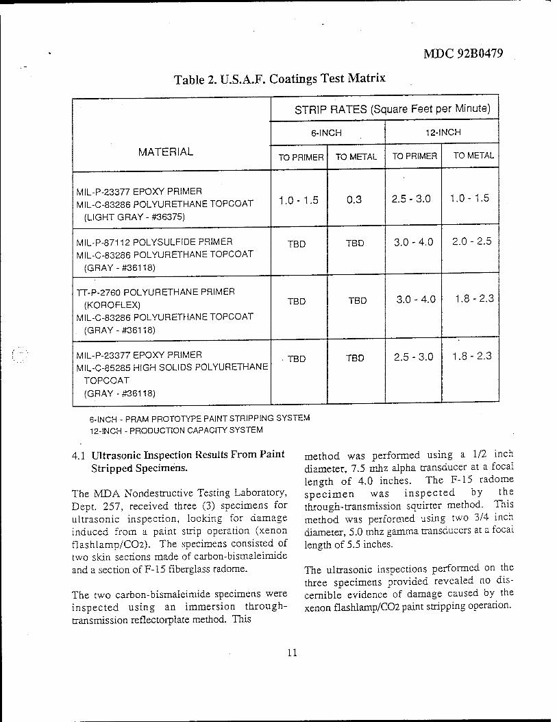
Test data was generated for both the PRAM funded 6-inch demonstration and validation prototype and a contractor funded 12-inch prototype production system. For the PRAM 6-inch demonstration/validation system, strip rates were 0.3 sq ft/min to remove 5 mils of coating to bare metal and 1.0 to 1.5 sq ft/min to remove 4 mils of coating, leaving the primer on metal or composite substrates. For the "next generation" contractor funded 12-inch flashlamp, strip rates were 1.0 to 2.5 sq ft/min to remove 5 mils of coating to bare metal and 2.5 to 4.0 sq ft/min to remove 4 mils of coating, leaving the primer on the metal or composite substrates. Test data generated to date have indicated that the C02 flashlamp process produces no changes in the properties of aircraft materials.
An $850K follow-on effort will install a production prototype system for stripping the composite areas of the F-15 aircraft. If the production system were to be implemented for complete stripping of a fighter-sized aircraft in an existing hangar, total implementation cost is estimated to be $5,236,000 including robot, flashlamp/C02 systems, ventilation, compressors, etc.
PRAM investment to date is $507K. The Navy also provided $350K for materials testing. An additional $850K investment is required for production proto- typing. The life-cycle savings of this process are estimated at $72M based on full implementation on an F-15-sized aircraft and compared to chemical depaint process over a 15-year estimated equipment life. Return on investment is estimated at 9.37 to 1.
Other benefits to be derived from the process include reduction in hazardous waste output, reduction in aircraft flow time, increased capability to strip composite materials, and the capability to strip all materials with less damage.

1
2. INTRODUCTION
The Air Force Corrosion Program Office, WR-ALC/CNC, is responsible for investigating new aircraft coatings removal processes that can reduce overall cost, hazardous waste production, and potential aircraft damage, while increasing worker and aircraft safety. McDonnell Douglas Aircraft Corporation briefed the PRAM organization on the merits of a C0? pellet blasting augmented xenon flashlamp system for aircraft coatings removal in Jan 91. While there are several new alternative coatings removal processes currently being evaluated by the Air Force, the C0? augmented flashlamp technology has the potential to eliminate or greatly reduce hazardous waste generated in coatings removal operations and to greatly reduce the cost of those operations. The process also has the potential to be all but benign to all aircraft materials. These beneficial characteristics have not been demonstrated by any other coatings removal technology to date. The level of damage possible with currently authorized coatings removal technologies (chemical depaint and plastic media blasting) has been evaluated as too high for application to some critical aircraft metals and composite materials. Composite materials, in particular, are lacking an acceptable, nondamaging coatings removal process. The CO~ augmented flashlamp technology has the potential to fill this technology void.
The Air Force Corrosion Program Office agreed to manage this initial effort to design, construct, and test a demonstration/validation prototype of the CO2 augmented flashlamp technology. Dr William F. White, Warner Robins Air Logistics Center's Chief Engineer, was the overall project director with Mr Randall B. Ivey as project engineer/program manager.
The project was accomplished in six phases: Phase 1, prototype design and construction; Phase 2, process optimization; Phase 3, effluent capture system concept development; Phase 4, optimization continuation/limited materials testing; Phase 5, prototype robotic interface; and Phase 6, WR-ALC demonstration.
The prototype system built under this project consists of an integrated stripping head, high voltage power supply/controller, and a WR-ALC supplied C0~ pellet blasting system. The C0? augmented flashlamp system is temporarily integrated to a robot in the F-15 Robotic Depaint Booth located in Bay 4, Building 137, Robins AFB GA. The contractor also developed and prototyped an effluent capture system using contractor funds. This capture system is currently on loan to WR-ALC and integrated with the C0? augmented flashlamp system.
The prototype system has demonstrated the capability to strip all aircraft coatings tested to date. The flashlamp vaporizes coatings by transferring energy to the coating surface via high intensity light. The amount of energy applied to the surface can be varied by changing the amount of power going to the lamp. The coatings removal rate is directly proportional to the amount of energy applied to the surface. The CO« pellets provide surface cooling and a cleaning action to remove the vaporization products. The stripping process is very controllable, allowing the user to remove various thicknesses of coating by changing the process parameters.
3. TECHNICAL INVESTIGATION
Statement of the Problem
Air Force aircraft exterior coatings are removed every 4 to 8 years to facilitate various maintenance functions. First, the top coat has a mechanical life expectancy in that range of time. The top coat suffers from environmental effects, flight wear, and from maintenance personnel accessing various aircraft hatches and panels. Second, Air Force aircraft are maintained to a high degree of professional appearance which is facilitated through numerous complete overcoatings of the aircraft. The additional layers of paint add weight to the aircraft and must be removed periodically. Third, complete coatings removal may be reguired to allow nondestructive inspection of the aircraft surface or to allow other types of maintenance activities to be performed on aircraft surfaces.
One of the largest generators of hazardous waste in the Air Force has tvpically been the paint removal operations. Historically, the Air Force has used extremely harsh chemicals to remove the advanced coatings used_on modern aircraft. The Air Force, in general, and the Warner Robins Air Logistics Center, in particular, have been striving toward the elimination of chemical paint stripping because of the high cost required to make this process conform to increasingly strict environmental and health requirements. Large volumes of hazardous waste (e.g., approximately 10,000 gallons for the F-15 aircraft) are produced with each aircraft that is stripped. Chemical strippers also have a methylene chloride base which the Occupational Safety and Health Administration (OSHA) has listed as a known carcinogen. OSHA has limited worker exposure to levels that are not achievable in an aircraft stripping environment. In addition, methylene chloride may soon be classified as a volatile organic compound (VOC), further restricting its use.
In the mid-1980s, plastic media blasting looked like a very promising solution toward reducing much of this problem. However, this process generates a sizable volume (e.g., approximately 3,000 pounds per F-15 aircraft) of dry hazardous waste. In addition, man-hour intensive operations to prevent/remove ingressed media are also required with plastic media blasting. Even with these drawbacks, plastic media represents a tremendous improvement over chemical paint stripping processes.
The chemical and plastic media blasting processes have a wide variety of application. However, the chemicals are not compatible with composite substrates, and plastic media is too abrasive for many composite applications. The C0o augmented flashlamp process was evaluated and selected as a candidate to reduce these environmental hazards and the cost of depaint operations and to provide an acceptable depaint process for both composites and metals.
Investigation and Findings
In 1987, a flashlamp depainting PRAM project for SM-ALC was completed. While the flashlamp alone is capable of removing surface coatings, this early system had some drawbacks that affected its application. These included lamp reliability, cumbersome and awkward handling, soot resulting from paint ablation, substrate heating, and the lack of a structural mechanical properties degradation evaluation.
In May 1990, WR-ALC began evaluating C02 pellet blasting to remove surface coatings. This program was designed to replace chemical and solid media blasting processes. WR-ALC successfully improved the C02 pellet blasting process for application to aircraft metals. However, the process is too aggressive for application to composite substrates. In mid-1990, McDonnell Douglas Aerospace, Cold Jet, Inc., and Maxwell Laboratories, Inc., jointly developed the synergistic CCL augmented xenon flashlamp approach. This involves the flashlamp technology to remove surface coatings, while the C09 keeps the lamp clean, removes the resulting soot, and provides substrate cooling. The C02 augmented flashlamp system was thought to be almost benign to the aircraft substrates because the system vaporizes the coatings from the surface. The potential environmental impact was also evaluated as low because the stripping process/material does not add to the waste stream, and the hazardous waste (the removed coating) is reduced in volume because it is vaporized. McDonnell Douglas developed a process comparison matrix (Figure 1) to compare various paint stripping processes and found that CO„ augmented flashlamp has a tremendous potential compared to other methods of coatings removal.
McDonnell Douglas Aircraft Corporation briefed the PRAM organization on the merits of a C02 pellet blast augmented xenon flashlamp system for aircraft coatings removal in Jan 91. The Air Force Corrosion Program Office agreed to manage this initial effort to design, construct, and test a demonstration/ validation prototype of the C02 augmented flashlamp technology. Dr William F. White, Warner Robins Air Logistics Center's Chief Engineer, was the overall project director with Mr Randall B. Ivey as project engineer/program manager. This activity led to the development of the first CO„ augmented flashlamp prototype.
Technical Approach
System Description
The PRAM project prototype C02 augmented flashlamp system developed under this program consists of a stripping head, a high voltage power supply/controller, a government furnished C02 pellet blasting system, and a contractor supplied effluent capture system.
The prototype stripping head consists of a flashlamp module that contains the 6-inch lamp, reflector, and water cooling system. The bracketry for mounting the 6-inch wide C02 nozzle, motion and proximity sensors, and the effluent capture shroud are attached to the flashlamp module, resulting in an integrated unit. Figure 2 shows the final installation of the system on the rear robot for the F-15 robotic depaint cell, Building 137, Robins AFB GA. A more detailed picture of the system is shown in Figure 3.
The high voltage power supply/controller provides the energy to operate the flashlamp. Computer control is provided for flashlamp energy levels and pulse rates. The deionized water cooling reservoir, pumps, and filters are also located within the cabinet seen in Figure 4.
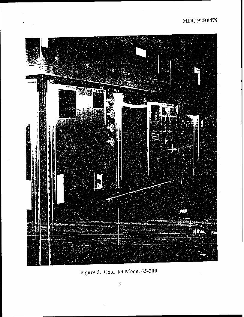
The C02 pellet blasting system, Cold Jet Model 65-200 (Figure 5), manufactures pellets from liquid C02 and provides a means of delivery and control to the nozzle of the stripping head.
1
Process Description
The pulsed light energy source consists of a quartz tube filled with xenon gas that, when electrically energized, emits a brilliant flash of broad spectrum light As the paint absorbs the photon energy, its temperature rapidly rises to the point at which a thin layer (approximately 1 mil per pulse) is_ablated and released from the surface. In normal stripping operations, the light is flashed four times each second. As the paint or coating is ablated, the residue is simultaneously removed from the surface by the low pressure (140 psi) CO. pellet stream.
CO. gas (source of the dry ice pellets) is a by-product of many other industrial processes. If left uncollected, the gas is vented to the atmosphere. The gas is collected, purified, and converted to a liquid state. The liquefied CO. is commercially available world wide. In this process, the Cold Jet equipment converts the liquid C02 into solid dry ice pellets and delivers them via a low pressure air stream to the nozzle. Upon impact, the pellets sublime to a gaseous state.
The synergism achieved with the C02 augmented flashlamp coatings removal process results in an excellent method for nondamaging coatings removal. As quickly as the pulsed light energy ablates the paint, the continuous flow of C0o pellets sweeps away the residue. The heating effect of the pulsed light energy is offset by the cooling effect of the C02 flow. During the stripping process, the continuous flow of C02 pellets also maintains the cleanliness of the flashlamp window, ensuring maximum transmission of photon energy to the surface. The CO. rich environment at the point of ablation also provides an atmosphere that will not support combustion.
Process Control
A major advantage of the CO. augmented flashlamp system coatings removal process over current and other developmental processes is the degree of control achievable. By varying operating parameters, such as- pulsed light energy density, pulse rate, stripping head rate of travel and stand-off, and CO. delivery pressure and nozzle angle, varying degrees of paint removal can be achieved. These include complete coatings removal (top coat and primer) to bare metal, removal of selected layers of topcoats (leaving the primer intact and undamaged), and chemically free cleaning of the surfaces using only the CO pellet stream. This selective stripping capability is in stark contrast to2all chemical and most liquid/solid media impingement processes which are limited to removing the entire finish system to the substrate. Selective stripping is particularly attractive for composite substrates, since leaving the primer precludes any subsequent damage. The increased use of composites in aircraft construction has introduced a unique set of problems relating to coatings removal. Many chemical strippers attack composite_resins as they destroy the paint and primer molecular bonds. Also, composites are^ particularly susceptible to damage from high velocity solid or liquid media. By using the control options available to remove only the topcoats and leave the primer intact, the CO. augmented flashlamp provides a capability which is impossible to attain with most other coatings removal processes.
Reliability and Maintainability
Manufacturers of the components that comprise the CCL augmented flashlamp system were selected partly for their attention to providing a high degree of system reliability and maintainability. McDonnell Douglas Aerospace (MDA), as prime contractor, Maxwell Laboratories, and-Cold Jet are familiar with and have designed and built their respective eguipment with high reliability and maintainability as a prime consideration.
Because of the prototype status of the flashlamp stripping head and power supply, no historical database exists. MDA is monitoring and collecting RSM data for further analysis. Predicted service life of the pulsed power system is 20,000 operating hours. Known consumables include the following:
Xenon lamps
- Lamp Life - 8 hours - Lamp Cost - $250-$300 each - Lamp Replacement Time - 15 minutes
The Cold Jet unit has been commercially available since 1990. Documented Reliability and Maintainability data include the following:
- Design Service Life - 10,000 Hours - Current Mean Time Between Failure - 1000 Hours - Current Mean Time To Repair - 4 Hours (one technician) - Scheduled Maintenance Interval - 500 Hours
(inspect, change filters, lubrication)
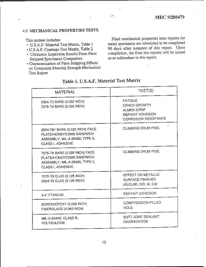
Materials Testing
Section 4.0, Mechanical Properties Tests, of the attached contractor's final report (Appendix 1) contains information on the test specimen, program test procedures, and test results to date. Additional test data for metal test specimen will be available by 30 Jun 93 and will be provided as an addendum to the final report. A review of the test data received to date shows that no damage is induced on the composite parts if the last layer of primer is left intact. Attempts to remove all primer will inevitably cause the removal of some resin. This resin loss leads to an average degradation in failure stress of 16.6 percent.
Strip Rates
Strip rate data is included in the mechanical test section (Table 2, page 11 of Appendix 1) of the final report. Data are presented for both the PRAM funded 6-inch demonstration/validation prototype and a contractor funded 12-inch prototype production system. For the PRAM 6-inch demonstration/ validation system, strip rates were 0.3 sq ft/min to remove 5 mils of coating to bare metal and 1.0 to 1.5 sq ft/min to remove 4 mils of coating, leaving the primer on metal or composite substrates.
For the "next generation" contractor funded 12-inch prototype production system, strip rates were 1.0 to 2.5 sq ft/min (depending on the type of paint) to remove 5 mils of coating to bare metal and 2.5 to 4.0 sq ft/min (depending
on the type of paint) to remove 4 mils of coating, leaving the primer on the metal or composite substrates.
Occupational Health
Section 5.0, Occupational Health Hazard Assessment Report, of the attached contractor's final report (Appendix 1) contains a detailed analysis of the effluent that is produced from C02 augmented flashlamp stripping operations Phase 3 of this project required the contractor to analyze the effluent and provide an initial design concept for an effluent capture system. The contractor went beyond the contract requirements and provided (at the contractor's expense) a prototype effluent capture system which proved capable of containing the effluent. While this prototype did not contain the recommended activated carbon absorption bed, it did show proof of concept This section of the report details the known requirements for an effluent capture system including the carbon absorption system. A complete prototype system, including the carbon absorption bed, would have to be evaluated to ensure complete hazard abatement.
Safety
Section 6, Safety, of the attached contractor's final report (Appendix 1) provides an analysis of worker safety related issues. Hearing and eye protection are required when operating the C02 augmented flashlamp system.
Process Evaluation
The prototype CO„ augmented flashlamp system was delivered to WR-ALC on 24 Sep 92 and integrated with the rear robot in F-15 Robot Depaint Cell, Bldg 137, Bay 4. Testing, evaluation, and demonstrations of the system are continuing as of the date of this report. The CO„ augmented flashlamp system has been shown to be an excellent tool for controllable paint removal The following results have been obtained through testing in a production environment.
Stand-off Distance. The prototype system has a relatively small focal point which requires that the stand-off distance be maintained to + 0.125 of an inch in order to achieve a uniform strip rate. The robots currently in use in the F-15 Robotic Depaint Cell cannot provide the required accuracy to provide a uniform strip of the surface. This problem can be solved by the application of an end-effector compliance device which will maintain the required stand-off distance with extreme accuracy. The contractor-funded production prototype system currently undergoing tests at Maxwell Labs has an expanded focal point envelope, somewhat reducing the problem. However, even this system would have improved quality and repeatability with the compliance device.
Coating Thickness. The C02 augmented flashlamp system can be adjusted to strip any thickness of paint by adjusting the power to the lamp, the frequency of flashing, and the head traversing rate. Typical measurements of an F-15 aircraft have found between 5 and 15 mils of paint on metal surfaces and between 12 and 25 mils of paint on composite substrates. The composites tend to have more paint build-up because there is no current production system to completely depaint these surfaces, whereas the metal surfaces are completely depamted every 4 to 6 years. The paint thickness on a given aircraft will
tend to vary from one area to the next by as much as 10 mils. The C02 augmented flashlamp has not been shown to be damaging to metal surfaces if they are "overprocessed." For this reason, the system can be set to run as if all metal surfaces have the greatest thickness of paint on them. With these parameters, the flashlamp would be needlessly slow over the areas of the plane that have thin coatings. Overprocessing of composites will cause a degradation in the material's mechanical properties. For this reason, composite stripping with the CCL augmented flashlamp system requires active control to prevent overprocessing. Higher productivity on metals and safety on composites can be achieved with the addition of a sensor to detect when the coatings are removed. This information will then be input into the robot and flashlamp control loops.
Conclusions and Recommendations
The CCu augmented xenon flashlamp system demonstrated under this program has been shown to be viable for aircraft coatings removal. Initial data from the materials characterization test show the process is nondamaging to both metals and composites if used correctly. The contractor funded prototype production flashlamp system has shown extremely high strip rates for both composites and metal substrates on a variety of Air Force coatings systems.
In order to fully utilize the capabilities of the C02 augmented flashlamp in a production environment, three accessories for the technology must be developed and integrated with the flashlamp system. These accessories are as follows:
a. Effluent capture system. The demonstration/validation prototype included a contractor funded, first generation effluent capture system which was not effective in removing the VOC component of the gases evolved during the stripping operations. An improved effluent capture system to eliminate the VOCs should be developed and integrated with the flashlamp technology.
b. Surface profile compliance system. The initial flashlamp tests have shown that the productivity and repeatability of the system is a function of the robot's ability to maintain consistent distances to the substrate being stripped. The robots currently used or being designed for aircraft depainting do not achieve the required accuracy. A surface profile compliance system should be developed to work in harmony with any robot as a part of the flashlamp system end effector. A compliance system will allow precise control of the flashlamp stand-off distance and allow for easier robot programming.
c. Substrate detection sensor. Tests with the demonstration/validation system on aircraft surfaces have shown that a substrate detection sensor is required to maximize productivity and prevent substrate damage. A colorimeter-based sensor should be designed to detect the substrate primer interface. Colorimeter-based sensor technology has been suggested as the best candidate technology, limiting risk and cost.
In addition, the demonstration/validation prototype system has shown strip rates of 1 square foot per minute on 5 mil thick paint. Operational aircraft composites have up to 25 mils of paint which will significantly reduce strip rate. The prime contractor has developed a follow-on prototype production system with a 300 percent improvement in strip rate. It is recommended that any production CO« augmented flashlamp incorporate the upgraded 12-inch system.
4. LESSONS LEARNED
DATA ITEMS FOR DELIVERY UNDER PROTOTYPE DEVELOPMENT EFFORTS
a. Upon review of the statement of work for this project, Data Item Management personnel had recommended delivery of level-three drawings of the entire system. This recommendation was based on the fact that a prototype system was being developed using Air Force funding. Level-three drawings and associated documentation are relatively expensive and were not funded for this program.
b. A more accurate statement of the demonstration/validation nature of the prototype was provided to Data Item Management personnel. The fact that this was a one-time project that was seen as an evolutionary step in the progress of the technology, that elements of the design were proprietary information predating the contract, and that there was no intent to buy future systems in this demonstration configuration allowed us to eliminate the reguirement for level-three drawings on 95 percent of the eguipment to be delivered.
c. A lesson learned was the need to ensure that all personnel in the contracting process are fully aware of the current and future intent of prototype development programs. In this case, the delivery of level-three drawings would have almost, doubled the cost of the contract. In addition, the Air Force would receive no additional benefit from the data initially identified for delivery.
5. IMPLEMENTATION
Follow-on implementation will require the development of the prototype production 12-inch system outlined in the Conclusions and Recommendations section of this final report. If funded, this first production system will be integrated with the rear robot of the Warner Robins F-15 Robotic Depaint Cell, Bay 4, Bldg 137. This first implementation will validate system use in a production environment and validate operational cost of using the system in a production environment. OC-ALC, SA-ALC, SM-ALC, OO-ALC, Navy, Army, commercial airlines, and airframe manufacturers have all shown extreme interest in potentially using this system. The F-15 System Program Office has continued its support for the system and would like to see the production prototype developed and installed in the F-15 Robotic Depaint Booth.
Approach
Implementation is not possible without the development and operational testing of the production prototype system. Funding has been requested through the Technology Transition Office to support the development, installation, and testing of the prototype production system. Future implementation of the system will be funded through 3080 funds.
Status
Awaiting funding status.

Validation of Savings
A detailed cost comparison matrix (Appendix 2) has been developed using^ engineering estimates of the production prototype system's performance in a production environment. These estimates are based on laboratory tests with a 12-inch Maxwell Laboratories' system on test panels coated with representative Air Force coating systems. The mathematical model includes performance degradation factors consistent with the transfer of depaint processes from the laboratory to production environment. Column DP of this matrix is a payback period (in years) for various processes when comparing the processes to the baseline of chemical depainting of aircraft. Total savings of the process can be derived by subtracting the cost of stripping using the flashlamp from the cost of stripping using chemical depaint. This matrix will be updated with actual production data after the installation of the prototype production system is installed.
Schedule
No schedule can be projected until funding is received to develop and install the prototype production system. The contractor has indicated that production systems can be available shortly after completion of that follow-on effort. The follow-on project to install the prototype production system is estimated to be a 9-month project once on contract. Implementation for other weapon systems is possible within 12 months of the completion of the prototype production system. No milestone chart is attached.
6. ECONOMIC SUMMARY
The initial $490,000 in PRAM funds was used to design, build, and test a demonstration and validation 6-inch prototype of the C02 augmented flashlamp system. An additional $17,091 was received from PRAM to provide local robotic engineering support. An additional $350,000 was provided by Naval Aviation Depot (NADEP) Jacksonville to fund a full materials characterization study. WR-ALC has provided support in terms of manpower, facilities, and equipment for this project. The funding breakout is as follows:
PRAM Project Cost: $507,091
a. Subcontract to Maxwell Labs and Cold Jet for flashlamp/C02 design and prototype $260,000
b. Prime Contractor, McDonnell Douglas for integration and project support 130,000
c. Test and Evaluation 70,000
d. Robot integration and demonstration 20,000
e. Travel 10,000
f. Robot integration support from MERC 17,091
PRAM investment to date = $507,091 Navy investment to date = $350,000 Additional investment required for production prototyping = $ 850,000
10
Total investment to bring technology to production maturity = sum of the three above = $1,707,091.
Based on the best available data, estimate life of the production capable system will be 15 years. The life-cycle savings of this process based on full implementation on an F-15-sized aircraft and compared to chemical depaint processes are as follows:
Implementation Cost. For the purpose of this report, the cost to implement a CCv, augmented flashlamp in an existing facility will be used. The implementa- tion cost will be based on one robot and flashlamp system which will be adeguate to handle the reguired flow (100 F-15s per year) of aircraft. The robot design/cost is similar to the Safari robot currently being used in the F-15 Robotic Paint Facility, Bay 5, Bldg 137, Robins AFB GA. The Safari robot manufacturer has indicated the weight of this system is within the design constraints of that robot. Please note that the implementation costs for this project could be reduced substantially (approximately $1,500,000) if the manipulators being designed under a separate Technology Transition Office (TTO) project were utilized. Total implementation cost is estimated to be $5,236,000 including robot, flashlamp/C09 systems, ventilation, compressors, etc. ^
Useful Life Savings (ULS) - The useful life savings of this eguipment is estimated over a 15-year period. The ULS for this project is calculated as the difference between current chemical stripping cost and robot assisted CO„ augmented flashlamp. ^
Cost to chemically depaint 100 F-15s per year = $5,606,025 (relative estimate) per appendix 2.
Cost to flashlamp depaint 100 F-15s per year = $808,735 (relative estimate) per appendix 2.
Cost savings per year = $5,606,025 - $808,735 = $4,797,690 per year.
Cost savings for useful life = $4,797,690 X 15 = $71,965,350.
Appendix 2 to this project plan contains the database which was used to compute the cost comparison. The information in the database was obtained from actual production information or test data, where available. Data that were not available were estimated based on knowledge of the processes.
Return on Investment (ROI)
$71,965,350 - ($1,707,091 + $5,236,000) ROI = = 9.37
($1,707,091 + $5,236,000)
Other benefits to be derived from the process include reduction in hazardous waste output, reduction in aircraft flow time, increased capability to strip composite materials, and the capability to strip all materials with less damage.
11

7. APPROVAL AND COORDINATION
OFFICE SYMBOL
SES
SIGNATURE DATE
CNC
CNC
CNT (PRAM)
CNT
CN
^H^ t>^
^^ksA
IJTM^??
Mwy 9)
*/fl< «Y 43 &
MM*«1s
/^C^^^T" 7 ^ 93
g^ix ^T
12

8. APPENDICES
Appendix 1 Contractor's Final Report
Appendix 2 Process and Implementation Cost Comparison Matrix
13
MDC 92B0479
Xenon Flashlamp and Carbon Dioxide Advanced Coatings Removal Prototype Development and Evaluation Program
David W. Breihan
McDonnell Douglas Corporation
1992
Department of The Air Force Warner Robins Air Logistics Center
Off
MDC 92B0479
Xenon Flashlamp and Carbon Dioxide Advanced Coatings Removal Prototype Development and Evaluation Program
Final Report
Prepared by
David W. Breihan
McDonnell Douglas Corporation P.O. Box 516 St. Louis, Missouri 63166-0516
December 1992
Contract F09603-90-G-0012-0029
Prepared for Department of The Air Force Warner Robins Air Logistics Center WR-ALC/CN Robins Air Force Base, Georgia 31098-5990

MDC 92B0479
Table of Contents
Subject Page No.
Abstract u
List of Figures U1
List of Tables • m
1.0 Introduction :•
9 2.0 Executive Summary
3.0 Technical Discussion 5
4.0 Mechanical Properties Tests 10
5.0 Occupational Health Hazard Assessment Report 16
6.0 Safety 23
7.0 Benefits 24
94 8.0 Conclusions ^
9.0 Recommendations/Implementation 24
Acknowledgements
Appendix A - Operating and Maintenance Manual (MDC92B0429-1)
MDC 92B0479
Abstract
Increasingly stringent environmental regulations controlling the use and
disposal of hazardous and toxic materials and increasing concerns over
personnel safety and aging airframe structural integrity in an era of rapidly
escalating costs are the issues which lead the McDonnell Douglas Corp.,
Cold Jet, Inc., and Maxwell Laboratories, Inc. team toward development of
an environmentally safe and operator friendly alternative to chemical', solid,
and liquid media paint stripping. A prototype development and evaluation
program was successfully completed for the United States Air Force
Producibility, Reliability, Availability, and Maintainability Office. The
McDonnell Douglas, Cold Jet, and Maxwell team has taken a holistic
approach to development of a paint removal technology which employs the r
synergy of pulsed light energy, low pressure dry ice particle stream, and
total effluent capture. This approach significantly reduces aircraft paint
stripping maintenance manhours and downtime, eliminates operating
personnel exposure to hazardous and toxic chemicals, and it causes no
damage to airframe structures. Of particular importance is the fact that the
synergism of pulsed light energy and low pressure dry ice particle stream
used for paint stripping is completely safe to composite subtrates when
correctly applied to those surfaces.
11
MDC92B0479
List of Figures
isure Page
No. Title No.
1. Investigation of Paint Strip Processes 3
2. WR-ALC Installation • 4
3. PRAM Stripping Head 6
4. High Voltage Power Supply
5. Cold Jet Model 65-200 8
6. Compression Specimen
13 7. Compression Fixture
8. Xenon Flashlamp/C02 Effluent Capture System 17
9. Effluent Capture Chamber (Before Exposure to Flashlamp) 18
10. Effluent Capture Chamber (After Exposure to Flashlamp) 19
List of Tables Table Päf
No. Title No.
1. U.S A.F. Material Test Matrix 10
2. U.S.A.F. Coatings Test Matrix 11
3. Mechanical Properties-Composite Test Matrix I2
4. Filled/Open Hole Compression Test Data 14
5. Open Hole Compression Summary
1 8 6. Stripped Paint Effluents
in
1.0 INTRODUCTION.
1.1 Objective - The Xenon Flashlamp and Carbon Dioxide
Advanced Coatings Removal Prototype Development and Evaluation Program was an engineering study to design, prototype, test, and demonstrate pulsed light energy/C02 aircraft coatings removal proof-of-concept. The process is designed to safely and economically remove aircraft coatings without the use of hazardous chemicals or potentially damaging impingement media. Additionally, a major goal was to significantly reduce the amount of hazardous waste generated by the aircraft paint stripping process.
The project was accomplished in six (6) phases: phase 1, prototype design and construction, phase 2, process optimization and effluent analysis, phase 3, effluent capture system concept development, phase 4, optimization continuation, phase 5, prototype robotic interface, and phase 6, WR-ALC demonstration.
1.2 Historical Background- In 1987 a flashlamp depainting PRAM project
for SM-ALC was completed. While the flashlamp alone is capable of removing surface coatings, this early system had some drawbacks that affected its application. These included lamp reliability, cumbersome and awkward handling, soot resulting from paint ablation, substrate heating, and the lack of a structural mechanical properties degradation evaluation.
In mid 1990 WR-ALC began evaluating C02 pellet blasting to remove surface coatings. This program was designed to replace chemical and solid media blasting processes which are extremely burdened with hazardous waste management and disposal costs. While CO2 pellet blasting removed coatings, the process was somewhat slower than expected and some questions regarding substrate damage resulting from CO2 pellet impingement arose.
MDC 92B0479
In mid 1990 McDonnell Douglas Aerospace, Cold Jet, Inc., and Maxwell Laboratories, Inc. jointly developed the concept that by using a synergistic approach, the flashlamp technology and CO2 pellet blasting could be used in concert to remove surface coatings, keep the lamp clean, remove the resulting soot, and provide substrate cooling. This activity led to the development of the first flashlamp/C02 advanced coatings removal prototype.
In April 1991 WR-ALC let the contract with McDonnell Douglas to develop and demonstrate a prototype system to be installed on a robot for F-15 composite parts paint stripping.
MDC 92B0479
2.0 EXECUTIVE SUMMARY.
2.1 Application - Increasingly stringent environmental
regulations (Clean Air Act 1990) controlling the use and disposal of hazardous and toxic materials; concerns over personnel health and safety; aging aircraft structural integrity; and the increasing use of composites are the issues which form the foundation for the development of an environmentally compliant alternative to aircraft paint stripping.
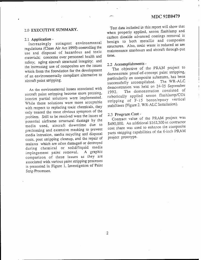
As the environmental issues associated with aircraft paint stripping become more pressing, interim partial solutions were implemented. While these solutions were more acceptable with respect to replacing toxic chemicals, they only treated the most obvious symptom of the problem. Still to be resolved were the issues of potential airframe structural damage by the media used, aircraft downtime due to precleaning and extensive masking to prevent media intrusion, media recycling and disposal costs, post stripping cleanup, and the repair of sealants which are often damaged or destroyed during chemical or solid/liquid media impingement paint removal. A graphic comparison of these issues as they are associated with various paint stripping processes is presented in Figure 1, Investigation of Paint Strip Processes.
Test data included in this report will show that when properly applied, xenon flashlamp and carbon dioxide advanced coatings removal is benign to both metallic and composite structures. Also, toxic waste is reduced as are maintenance manhours and aircraft through-put
time.
2.2 Accomplishments- The objective of the PRAM project to
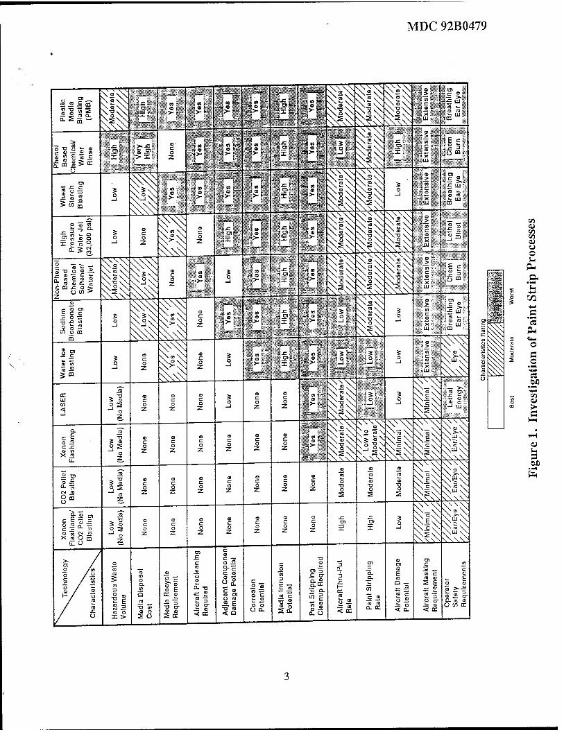
demonstrate proof-of-concept paint stripping, particularily on composite substrates, has been successfully accomplished. The WR-ALC demonstration was held on 24-25 September 1992. The demonstration consisted of robotically applied xenon flashlamp/CC-2 stripping of F-15 boron/epoxy vertical stabilizers (Figure 2. WR-ALC Installation).
2.3 Program Cost - Contract value of the PRAM project was
$490,000. An additional $ 162,300 M contractor cost 'share was used to enhance the composite parts stripping capabilities of the 6-inch PRAM project prototype.
MDC 92B0479
50 0)
V3 <U O o s*
CO ■M .g OH
o (3 ^o
*■*■*
Ä .2?
> d
u a OX)
MDC 92B0479
Figure 2. WR-ALC Installation
4

3.0 TECHNICAL DISCUSSION.
3.1 System Description - The PRAM Project prototype system consists
of a stripping head, high voltage power supply/controller, and a government furnished CO2 pellet blasting system.
3.1.1 Stripping Head - The prototype stripping head consists of a flashlamp module which contains the 6-inch lamp, reflector, and water cooling system. Bracketry for mounting provisions for the 6-inch wide CO2 nozzle, motion and proximity sensors and effluent capture shroud are attached to the flashlamp module resulting in an integrated unit, Figure 3. PRAM Stripping Head.
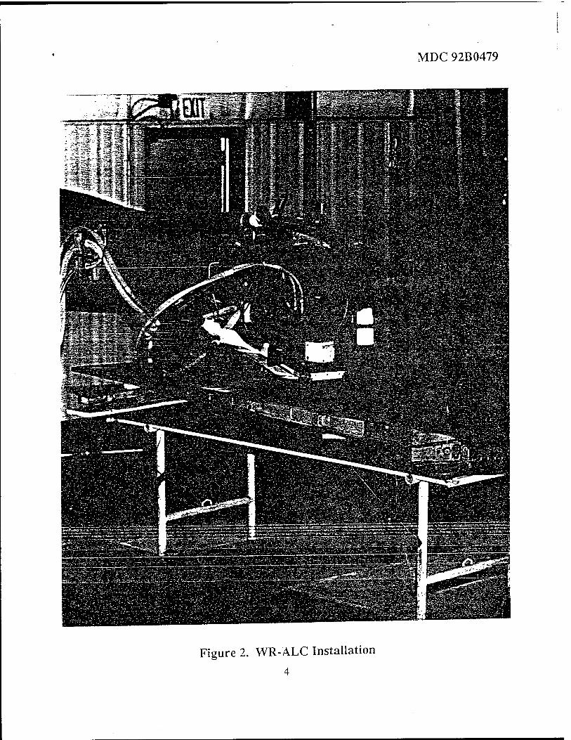
3.1.2 High Voltage Power Supply - The high voltage power supply provides the energy to operate the flashlamp. Computer control is provided for flashlamp energy levels and pulse rates. The deionized water cooling reservoir, pumps, and filters are also located within the cabinet, Figure 4. High Voltage Power Supply.
3.1.3 CO2 Pellet Blasting System (GFE) - The CO2 pellet blasting system, Cold Jet Model 65-200 (Figure 5.), manufactures pellets from liquid CO2 and provides a means of delivery and control to the nozzle of the stripping head.
3.2 Process Description - The pulsed light energy source consists of a
quartz tube filled with xenon gas which when electrically energized, emits a brilliant flash of light. As the paint absorbes the photon energy, its temperature rapidly rises to the point at which a thin layer (approximately 1 mil per pulse) is ablated and released from the surface. Rapid pulsing of the lamp results in an excellent paint removal rate with no damage to the substrate. As the paint coating is ablated, the residue is simultaneously removed from the surface by the low pressure CO2 particle stream.
MDC 92B0479
CO2 gas (source of the dry ice pellets) is a by-product of many other industrial processes. If left uncollected, the gas is vented to atmosphere. This gas is collected, purified, and converted to a liquid state. Liquid CO2 is then compressed into pellets and delivered to the painted surface in a low pressure air stream. Upon impact, the pellets sublime to a gaseous state.
The synergism achieved with the Xenon Flashlamp/C02 coatings removal process results in the perfect means to remove paint and clean the surface in one operation. As quickly as the pulsed light energy ablates the paint, the continous flow of CO2 pellets sweeps away the residue. The heating effect of pulsed light energy is offset by the cooling effect of the CO2 flow. During the stripping process, the continous flow of CO2 pellets also maintains the cleanliness of the flashlamp window ensuring maximum transmission of photon energy to the surface. The CO2 rich environment at the point of ablation also provides an atmosphere which will not support combustion.
3.3 Process Control - A major advantage of the Xenon
Flashlamp/C02 Coatings Removal Process over current and other developmental processes is the degree of control achievable. By varying operating parameters such as pulsed light energy density, stripping head rate of travel and standoff; and CO2 delivery pressure and nozzle angle, varying degrees of paint stripping can be achieved. These degrees of stripping include: complete finish system removal (top- coats and primer) to bare metal; removal of only selected layers of topcoats leaving the primer intact and undamaged; and chemical free cleaning of surfaces using only the CO2 pellet stream.

MDC 92B0479
Figure 3. PRAM Stripping Head
MDC 92B0479
Figure 4. High Voltage Power Supply
MDC 92B0479
Figure 5. Cold Jet Model 65-200

MDC 92B0479
This selective stripping capability is in stark contrast to all chemical and most liquid/solid media impingement processes which are limited to removing the entire finish system to substrate. Selective stripping is particularily attractive for composite substrates whereby leaving the primer precludes any subsequent damage.
The increased use of composites in aircraft construction has introduced a unique set of problems relating to paint stripping. Many chemical strippers attack composite resins as they destroy the paint/primer molecular bond. Also, composites are particularily susceptible to damage from high velocity solid or liquid media. By using the control option available to remove only topcoats and leave the primer intact, the Xenon Flashlamp/C02 Coatings Removal Process provides a capability which is impossible to attain with most other paint stripping processes.
3.4 Reliability & Maintainability - Manufacturers of the components which
comprise the Xenon Flashlamp/C02 system were selected partly for their attention to providing a high degree of system reliability and maintainability. McDonnell Douglas Aerospace (MDA), as prime contractor, and Maxwell Laboratories and Cold Jet are familiar with and have designed and built their respective equipment with high reliability and maintainability as a prime consideration.
3.4.1 Maxwell Labs Flashlamp System - Due to the prototype status of the stripping head and power supply, no current historical data base exists. MDA is monitoring and collecting R&M data for further analysis. Predicted service life of the pulsed power system is 20,000 operating hours. Known maintenance factors include:
• Lamp Cost - $250-$300 ea • Lamp Life - 8 hours ( 6-inch prototype) • Lamp Replacement Time - 15 minutes
3.4.2 Cold Jet Model 65-200 - The Cold Jet unit has been commercially available since 1990. Documented R & M data includes:
• Design Service Life -10,000 Hours • Current MTBF - 1,000 Hours • Current MTTR - 4 Hours (one technician) • Scheduled Maintenance Interval - 500 Hours
(Inspect, Change Filters, Lubrication)
MDC 92B0479
4.0 MECHANICAL PROPERTIES TESTS.
This section includes: • U.S.A.F. Material Test Matrix, Table 1 • U.S.A.F. Coatings Test Matrix, Table 2 • Ultrasonic Inspection Results From Paint
Stripped Specimens-Composites • Characterization of Paint Stripping Effects
on Composite Material Strength-Mechanical Test Report
Final mechanical properties tests reports for metal specimens are scheduled to be completed 90 days after issuance of this report. Upon completion, the final test reports will be issued as an addendum to this report.
Table 1. U.S.A.F. Material Test Matrix
MATERIAL
2024-T3 BARE (0.032 INCH) 7075-T6 BARE (0.032 INCH)
2024-T81 BARE (0.020 INCH) FACE PLATE/HONEYCOMB SANDWICH ASSEMBLY, MIL-A-25463, TYPE II, CLASS I, ADHESIVE
7075-T6 BARE (0.020 INCH) FACE PLATE/HONEYCOMB SANDWICH ASSEMBLY, MIL-A-25463, TYPE II,
CLASS l, ADHESIVE
7075-T6 CLAD (0.125 INCH) 2024-T3 CLAD (0.125 INCH)
6-4 TITANIUM
BORON/EPOXY (0.060 INCH) FIBERGLASS (0.060 INCH)
MIL-S-83430, CLASS B, POLYSULFIDE
TEST(S)
FATIGUE CRACK GROWTH
ALMEN STRIP REPAINT ADHESION CORROSION RESISTANCE
CLIMBING DRUM PEEL
CLIMBING DRUM PEEL
EFFECT ON METALLIC SURFACE FINISHES (ALCLAD, lVD, Al, Cd)
REPAINT ADHESION
COMPRESSION-FILLED
HOLE
BUTT JOINT SEALANT DEGRADATION
10
MDC 92B0479
Table 2. U.S.A.F. Coatings Test Matrix
MATERIAL
MIL-P-23377 EPOXY PRIMER MIL-C-83286 POLYURETHANE TOPCOAT
(LIGHT GRAY - #36375)
MIL-P-87112 POLYSULFIDE PRIMER MIL-C-83286 POLYURETHANE TOPCOAT
(GRAY-#36118)
TT-P-2760 POLYURETHANE PRIMER (KOROFLEX)
MIL-C-83286 POLYURETHANE TOPCOAT (GRAY-#36118)
MIL-P-23377 EPOXY PRIMER MIL-C-85285 HIGH SOLIDS POLYURETHANE
TOPCOAT (GRAY-#36118)
STRIP RATES (Square Feet per Minute)
6-INCH
TO PRIMER
1.0-1.5
TBD
TBD
■ TBD
TO METAL
0.3
TBD
TBD
TBD
12-INCH
TO PRIMER
2.5-3.0
3.0-4.0
3.0 - 4.0
2.5-3.0
TO METAL
1.0- 1.5
2.0-2.5
1.8-2.3
1.8-2.3
6-INCH - PRAM PROTOTYPE PAINT STRIPPING SYSTEM 12-INCH - PRODUCTION CAPACITY SYSTEM
4.1 Ultrasonic Inspection Results From Paint Stripped Specimens.
The MDA Nondestructive Testing Laboratory, Dept. 257, received three (3) specimens for ultrasonic inspection, looking for damage induced from a paint strip operation (xenon flashlamp/C02). The specimens consisted of two skin sections made of carbon-bismaleimide and a section of F-15 fiberglass radome.
The two carbon-bismaleimide specimens were inspected using an immersion through- transmission reflectorplate method. This
method was performed using a 1/2 inch diameter, 7.5 mhz alpha transducer at a focal length of 4.0 inches. The F-15 radome specimen was inspected by the through-transmission squirter method. This method was performed using two 3/4 inch diameter, 5.0 mhz gamma transducers at a focal length of 5.5 inches.
The ultrasonic inspections performed on the three specimens provided revealed no dis- cernible evidence of damage caused by the xenon flashlamp/C02 paint stripping operation.
11
MDC 92B0479
4.2 Characterization of Paint Stripping Effects on Composite Material Strength- Mechanical Test Report.
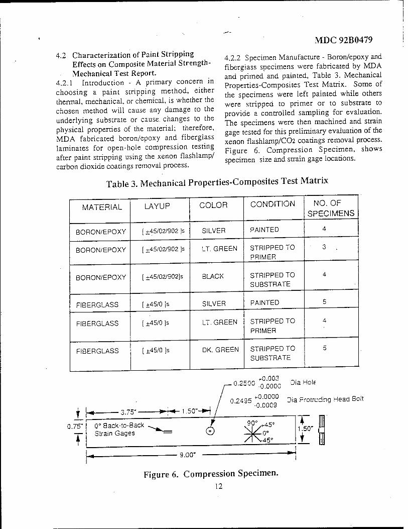
4.2.1 Introduction - A primary concern in choosing a paint stripping method, either thermal, mechanical, or chemical, is whether the chosen method will cause any damage to the underlying substrate or cause changes to the physical properties of the material; therefore, MDA fabricated boron/epoxy and fiberglass laminates for open-hole compression testing after paint stripping using the xenon flashlamp/ carbon dioxide coatings removal process.
4.2.2 Specimen Manufacture - Boron/epoxy and fiberglass specimens were fabricated by MDA and primed and painted, Table 3. Mechanical Properties-Composites Test Matrix. Some of the specimens were left painted while others were stripped to primer or to substrate to provide a controlled sampling for evaluation. The specimens were then machined and strain gage tested for this preliminary evaluation of the xenon flashlamp/C02 coatings removal process. Figure 6. Compression Specimen, shows specimen size and strain gage locations.
Table 3. Mechanical Properties-Composites Test Matrix
MATERIAL
BORON/EPOXY
BORON/EPOXY
BORON/EPOXY
FIBERGLASS
FIBERGLASS
FIBERGLASS
LAYUP
; ±45/02/902 ]s
[ +45/02/902 ]s
±45/02/902]s
h45/0 Is
±45/0 ]s
[ ±45/0 ]s
COLOR
SILVER
LT. GREEN
BLACK
SILVER
LT. GREEN
DK. GREEN
CONDITION
PAINTED
STRIPPED TO
PRIMER
STRIPPED TO SUBSTRATE
PAINTED
STRIPPED TO PRIMER
STRIPPED TO SUBSTRATE
NO. OF SPECIMENS
i 0.75"
T
3.75- -»!■« 1.50"-H
0° Back-to-Back Strain Gages
0.2500 :0°0°0°030 Dia Hoi,
0 2495 +0-0000 Dia Protruding Head Bolt -0.0009
90° ^45°
/l\-45°
9.00"
T i 1.50" ^
L I
Figure 6. Compression Specimen. 12
MDC 92B0479
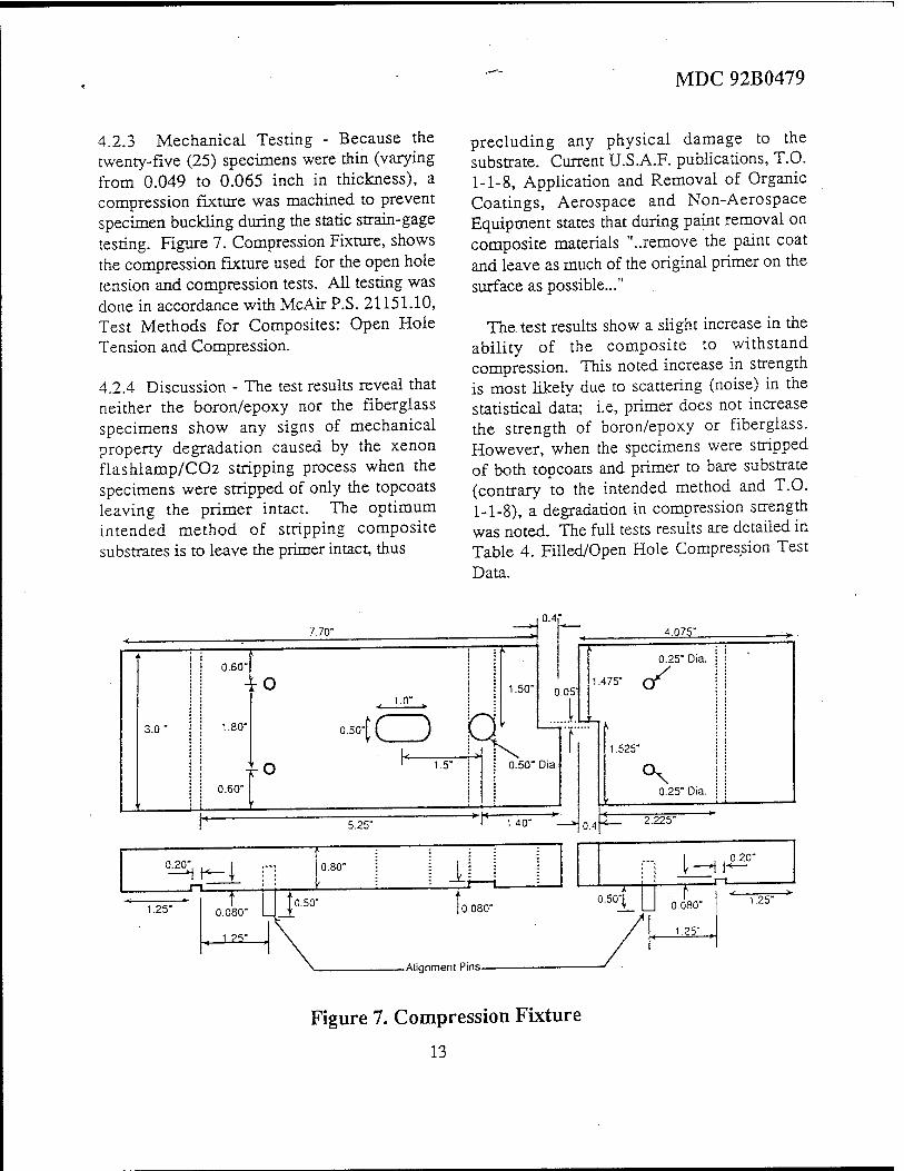
4.2.3 Mechanical Testing - Because the twenty-five (25) specimens were thin (varying from 0.049 to 0.065 inch in thickness), a compression fixture was machined to prevent specimen buckling during the static strain-gage testing. Figure 7. Compression Fixture, shows the compression fixture used for the open hole tension and compression tests. All testing was done in accordance with McAir P.S. 21151.10, Test Methods for Composites: Open Hole Tension and Compression.
4.2.4 Discussion - The test results reveal that neither the boron/epoxy nor the fiberglass specimens show any signs of mechanical property degradation caused by the xenon flashlamp/C02 stripping process when the specimens were stripped of only the topcoats leaving the primer intact. The optimum intended method of stripping composite substrates is to leave the primer intact, thus
precluding any physical damage to the substrate. Current U.S.A.F. publications, T.O. 1-1-8, Application and Removal of Organic Coatings, Aerospace and Non-Aerospace Equipment states that during paint removal on composite materials "..remove the paint coat and leave as much of the original primer on the surface as possible..."
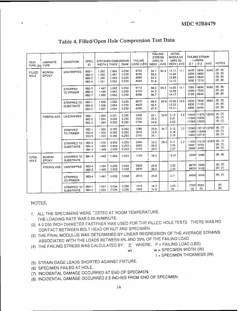
The test results show a slight increase in the ability of the composite to withstand compression. This noted increase in strength is most likely due to scattering (noise) in the statistical data; i.e, primer does not increase the strength of boron/epoxy or fiberglass. However, when the specimens were stripped of both topcoats and primer to bare substrate (contrary to the intended method and T.O. 1-1-8), a degradation in compression strength was noted. The full tests results are detailed in Table 4. Filled/Open Hole Compression Test Data.
| 1 0.60'
3.0"
-t-o
1.80*
0.60" }o
7.70"
1.0"
1.5"
1.50"
•"tCD R
5.25"
0.50" Dia
1.40"
°^K-{ :-: 0.80" j I ijj |
0.080" MJo.so" 10.080" 1.25"
< i?y >|
-Alignment Pins-
Figure 7. Compression Fixture
13
MDC 92B0479
Table 4. Filled/Open Hole Compression Test Data
TEST TYPE (2)
LAMINATE TYPE
CONDITION SPEC. ID
SPECIM WIDTH
ENDIMEt' THICK
JSIONS DIAM
FAILING LOAD (LBS)
FAIL STRE (KSI)
INDIV
NG ESS (4) AVG
INITtf MOOU
(MSI) INDIV
LUS (3) AVG
FAILING STRAIN (-ulN/IN)
G-1 G-2 AVG NOTES
FILLED HOLE
BORON/ EPOXY
UNSTRIPPED 882-1 8B2-2 8B2-3 882-4
1.502 1.502 1.496 1.501
0.062 0.061 0.063 0.062
0.250 0.250 0.250 0.250
8760 8550 8890 8540
94.1 93.3 94.3 91.8
93.4 14.11 14.28 13.89 14.12
14.1 6400 6290 6680 5890
6950 6800 6820 7210
6945 (6) (8) (6) (8) (6) (8) (6) (8)
STRIPPED TO PRIMER
8B2-5 882-6 8B2-7
1.497 1.499 1.502
0.062 0.062 0.062
0.250 0.250 0.250
9110 8760 8450
98.2 94.3 90.7
94.4 14.05 13.99 14.17
14.1 7080 6090 6160
6890 7330 6640
6953 (6) (8) (5) (8) (6) <S)
STRIPPED TO SU8STRATE
8B4-1 884-2 884-3
1.500 1.506 1.507
0.065 0.064 0.064
0.250 0.250 0.250
8670 8920 8480
88.9 92.5 87.9
89.8 13.39 13.53 13.51
13.5 6240 6530 6500
7030 7100 6460
6883 (6) (8) (6) (8)
(6) (8)
FIBERGLASS UNSTRIPPED 982-1 982-2 9B2-3
1.503 1.504 1.504
0.051 0.052 0.052
0.250 0.250 0.250
2450 2630 2720
33.1 33.5 34.8
33.8 3.15 3.21 3.22
3.2 11640 11290 11880
11570 12630 13020
12570 (6) (7)
(5) (7) (6) (7)
STRIPPED TO PRIMER
983-1 983-2 9B3-3
1.500 1.500 1.500
0.052 0.052 0.052
0.250 0.250 0.250
2780 2610 2740
35.6 33.5 35.1
34.7 3.12 3.18 3.18
3.2 12660 11880 12920
13710 11840 12710
12753 (6) (7) (6) (7) (6) (7)
STRIPPED TO SU8STRATE
984-3 9B4-4 984-5
1.502 1.499 1.499
0.054 0.054 0.049
0.250 0.250 0.250
2460 2020 2150
30.3 25.0 29.3
28.2 3.11 3.36 3.27
3.2 11930 8480 10090
11310 9490
.9700
10167 (6) (7)
(5) (7) (6) (7)
OPEN HOLE
BORON/ EPOXY
STRIPPED TO SUBSTRATE
884-4 1.485 0.064 0.250 7450 78.4 13.51 5330 5980 (6) (8)
FIBERGLASS UNSTRIPPED 982-4 9B2-5
1.504 1.503
0.052 0.052
0.250 0.250
2020 2070
25.8 26.5
3.33 3.33
8670 8620
8690 9100
(6) (7) (6) (7)
STRIPPED TO PRIMER
9B3-4 1.497 0.052 0.250 2010 25.8 3.11 8490 9040 (6) (7)
STRIPPED TO SUBSTRATE
984-1 984-2
1.501 1.504
0.054 0.054
0.250 0.250
1512 1200
18.7 14.8
3.03 (5)
7700 (5)
5580 (5)
(6) (6)
NOTES:
1. ALL THE SPECIMENS WERE TESTED AT ROOM TEMPERATURE.
THE LOADING RATE WAS 0.05 IN/MINUTE. ^ (2) A 0.250 INCH DIAMETER FASTENER WAS USED FOR THE FILLED HOLE TESTS. THERE WAS NO
CONTACT BETWEEN BOLT HEAD OR NUT AND SPECIMEN. (3) THE FINAL MODULUS WAS DETERMINED BY LINEAR REGRESSION OF THE AVERAGE STRAINS
ASSOCIATED WITH THE LOADS BETWEEN 6% AND 35% OF THE FAILING LOAD (4) THE FAILING STRESS WAS CALCULATED BY: P WHERE: P = FAILING LOAD (LBS) W wt w = SPECIMEN WIDTH (IN)
t = SPECIMEN THICKNESS (IN)
(5) STRAIN GAGE LEADS SHORTED AGAINST FIXTURE.
(6) SPECIMEN FAILED AT HOLE. (7) INCIDENTAL DAMAGE OCCURRED AT END OF SPECIMEN. (8) INCIDENTAL DAMAGE OCCURRED 2.5 INCHES FROM END OF SPECIMEN.
14

MDC 92B0479
Table 5. Open Hole Compression Summary
MATERIAL CONDITION AVERAGE FAILURE STRESS
(ksi)
DEGRADATION (IMPROVEMENT)
%
BORON/EPOXY UNSTRIPPED 93.4 ±1.6 —
STRIPPED TO PRIMER
94.4 ±3.8 (1.07)
STRIPPED TO SUBSTRATE
89.9 ±2.7 3.75
FIBERGLASS UNSTRIPPED 33.8 ±1.0 —
STRIPPED TO PRIMER
34.7 ±1.2 (2.66)
STRIPPED TO SUBSTRATE
28.2 ±3.2 16.57
4.2.5 Conclusion - The engineers who conducted the mechanical properties testing on these composites feel that the degradation observed on the fiberglass specimen stripped to substrate, Table 5. Open Hole Compression Summary, is due to a significant loss of resin at the outer surface. This observation is further strengthened by the fact that little or no degradation occurred to the fibergalss specimens when paint stripping of only topcoats, leaving the primer intact.
15
MDC 92B0479
5.0 OCCUPATIONAL HEALTH HAZARD ASSESSMENT REPORT.
5.1 Introduction.
In early December 1991, the McDonnell Douglas Aerospace (MDA) Analytical Chemical Laboratory (ACL) was requested to analyze the effluents resulting from the xenon flashlamp/C02 paint removal process and develop preliminary design parameters for an effluent capture and filtration system. This system is required for use in the collection and removal of dusts, fumes, vapors, and organic contaminants resulting from the operation of the xenon flashlamp/C02 paint removal process. A preliminary system was designed around an American Air Filter Model AR ARRESTAL Dust Collector series and the Invincible Airflow Systems Model 6000-7.5. Absorption and filtration media for collection of contaminants were identified and specified.
5.2 Health Hazard Evaluation.
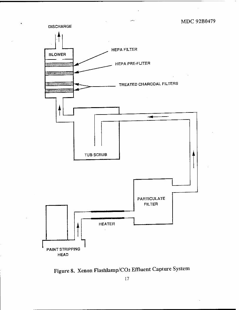
5.2.1 Evaluation Design - Particulates (such as dusts and fumes), vapors and organic constituents must be captured as close to the point of generation as possible for efficient removal. To fulfill this requirement a collection system (Figure 8) was designed exhibiting the following characteristics:
• Attaches to current stripping head/ collection box assembly
• Two 2.5 inch ducts are joined into one 4 inch flexible duct
• 400+ CFM volumetric flowrate • >3500 FPM duct velocity • >300 FPM face velocity • Blower system capable of approximately
60 inch W.G. • Heater capable of mamtaining inlet air temperature at 70 degrees F
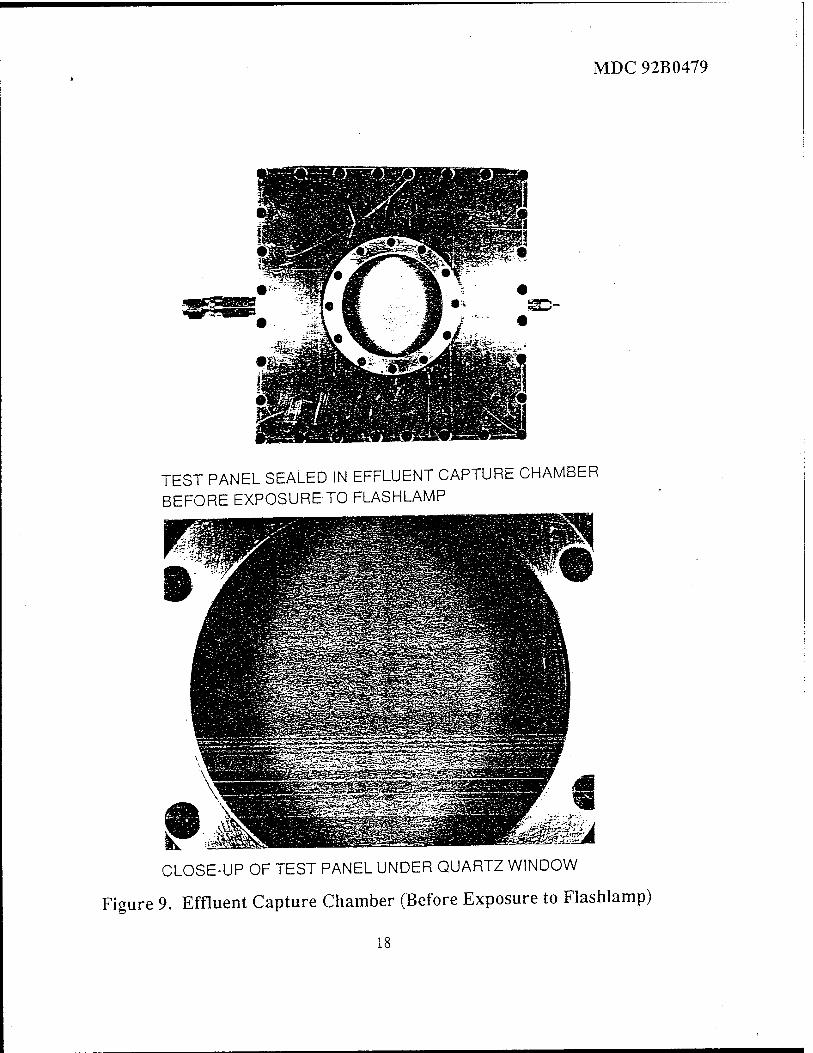
5.2.2 Description of the Evaluation Process - A prototype xenon flashlamp/C02 paint stripping system was constructed at Maxwell Laboratories, Inc., San Diego, CA. The prototype site was visited by MDA ACL employee Dale Scheer in October 1992. Samples of the effluent given off during the operation of the xenon flashlamp/C02 paint removal process where taken as described in paragraph 5.2.3 Methods. Preliminary analytical data indicated the particle size to be in the low micron range; therefore, a high flowrate and face velocity is required to capture the particulate matter. Concurrently, a high duct velocity is required to keep the captured particles moving. The American Air Filter ARRESTAL AR series and Invincible Airflow Systems Model 6000-7.5 comply with the listed requirements.
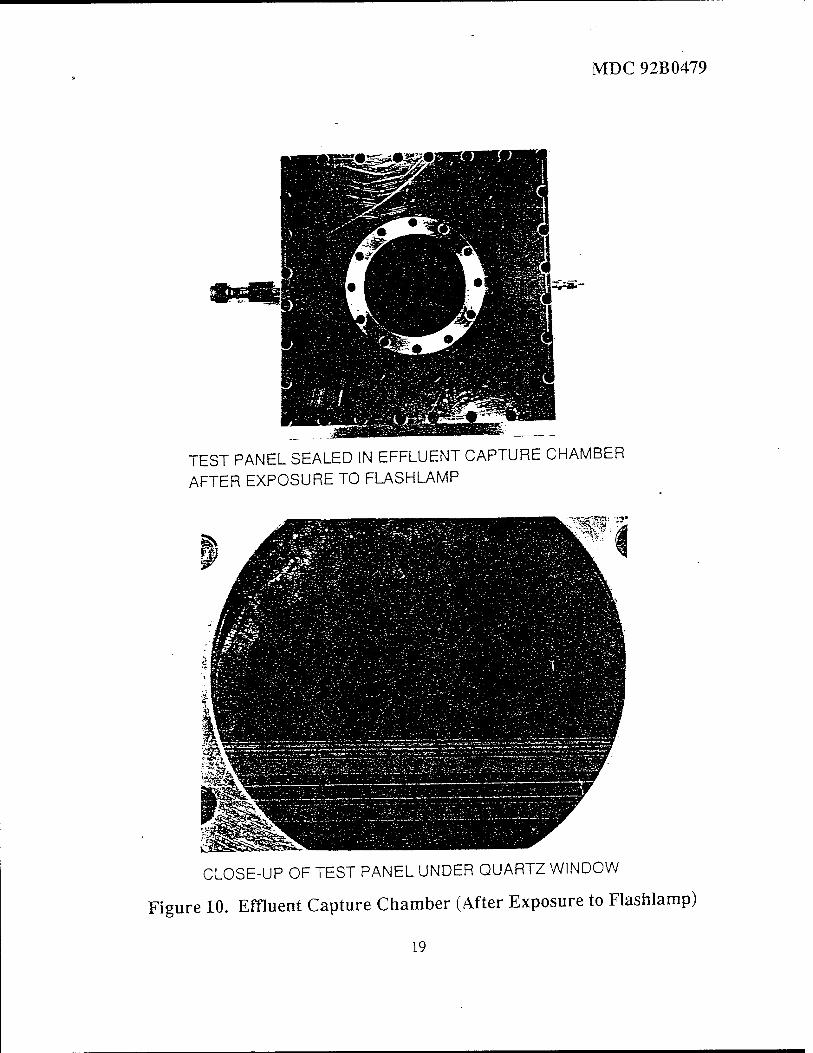
5.2.3 Methods - Two prepared aluminum panels were spray painted with F-15 topcoat and allowed to air dry. The panels were placed in a stainless steel chamber fitted with a 2 1/2 inch diameter quartz window. The chamber was assembled and seal integrity verified to two atmospheres pressure. Figure 9 is a photograph of the chamber prior to exposure. The panels were exposed to the xenon flashlamp through the quartz window. Figure 10 is a photograph of the chamber after exposure. All volatile materials were contained within the sealed chamber. The chamber was returned to the ACL for analysis. The chamber atmosphere was analyzed by capillary column gas chromatography/mass spectrometry (GM/MS) utilizing cryofocusing techniques. Compounds were identified by comparison of the mass spectral data to the Hewlett-Packard GC/MS on-board library.
16
MDC 92B0479 DISCHARGE
HEPA FILTER
HEPA PRE-FLITER
TREATED CHARCOAL FILTERS
~L PARTICULATE
FILTER
HEATER ~~L
PAINT STRIPPING HEAD
Figure 8. Xenon Flashlamp/CCh Effluent Capture System
17
MDC 92B0479
SD-
TEST PANEL SEALED IN EFFLUENT CAPTURE CHAMBER BEFORE EXPOSURE TO FLASHLAMP
CLOSE-UP OF TEST PANEL UNDER QUARTZ WINDOW
Figure 9. Effluent Capture Chamber (Before Exposure to Flashlamp)
18
MDC 92B0479
TEST PANEL SEALED IN EFFLUENT CAPTURE CHAMBER AFTER EXPOSURE TO FLASHLAMP
CLOSE-UP OF TEST PANEL UNDER QUARTZ WINDOW
Figure 10. Effluent Capture Chamber (After Exposure to Flashlamp)
19
5.3 Evaluation Results.
5.3.1 Environmental Sampling - Sample measurements where taken from the sealed chamber through the chamber's port. Off-gas compounds resulting from the xenon flashlamp testing are listed in Table 6. Stripped Paint Effluents.
5.3.2 Medical - The medium used in this operation is pelletized carbon dioxide. As solid carbon dioxide warms, it sublimes to the gas phase. For this reason, we have designed a gaseous CO2 monitor into the system which will effect a total system shut-down should the ambient CO2 level become unsafe by displacing the oxygen content of the ambient air. This device will also prohibit the system from restarting until the ambient CO2 levels fall below the unsafe threshold.
5.4. Conclusions.
The test objective of doing analysis and developing the preliminary design parameters for an effluent capture and filtration system used with the xenon flashlamp/C02 paint stripping process has been completed. The self-contained dust collector system identified in paragraph 5.2.1 meets the requirements of this capture system. American Air Filters (AAF) Model AR ARRESTAL and Invincible Airflow Systems Model 6000-7.5 units meet and/or exceed all the technical considerations listed. These systems are a compact and highly efficient dust collectors. They are relatively inexpensive, readily available and require little maintenance. These units provide a cleaning efficiency of 95% for paniculate matter greater than or equal to 1 micron in size. Thus, for every 100 pounds of 1 micron or larger particles delivered to the inlet, an ARRESTAL will remove 95 pounds. The dust collector will be equipped with a photomagnehelic interlock which will shut the
MDC92B0479
entire system down for cleaning when the pressure drop across the fabric exceeds a predetermined value. This unit will be equipped with an automatic shaker motor. Dusts are known for their static electric characteristics and the inherent potential danger; therefore, both the unit and the ducting will be static discharge protected. The effluent from the dust collection phase stage will then be directed to the chacoal filter stage.
Activated charcoal filter media is well known for its capability to remove organic components. Activated charcoal removes virtually all organics; i.e., its removal efficiency is greater than 99%. A charcoal unit, TUB SCRUB, manufactured by Cameron-Yakima Inc. has been identified as a possible source for activated charcoal filtration equipment. The TUB SCRUB unit is capable of handling the flows required for the paint stripping operation.
Research into the subject of a capture system revealed a company which manufactures advanced gas-phase air purification equipment. Extraction Systems Inc. manufactures a line of carbon filters under the trade name of DPCC ABSORBERS, These filters are constructed of carbon-impregnated pleated fiber filter media. In addition, this firm can supply a variety of carbon chemistries that are tailored for specific compound removal applications. They are able to chemically treat the charcoal in such a way that the filter exhibits enhanced specific compound collection. For example, some treated units will remove virtually 100% of compounds such as formaldehyde, ozone and/or acid gases. Other elements will remove virtually all incoming odors and hydrocarbons. The elements have a filtration area of 164 square meters and are 12 inches deep yet they exhibit little air flow resistance
20

MDC 92B0479
Table 6. Stripped Paint Effluents
OFF-GAS COMPOUNDS IDENTIFIED FROM XENON FLASHLAMP TESTS
2-methyi-1-propene
* acetaldehyde 1,3-butadiyne cyclopentadiene or
1.3-pentadiene
2-perrtene 2-propanone
* acetonitrile 1,3-cyclopentadiene
1-hexyne 2,5-dihydrofuran 1,4-hexadiene ethoxyethene 1-butanol 2,4-hexadiene 2-methly-1-propene
2,4-pentadione cyclopentanone
xylene ethynylbenzene cyclohexanone 1,1'-bicyclopropyl benzaldehyde 2-propenyibenzene 2-propynylbenzene 1,3-diethenylbenzene 1-methyl-1H-!ndene
* naphthalene
ethane acetylene cadmium
* 1,3-butadiene 1,3-buten-3-yne
ethanol 1-pentene isopropyl alcohol 2-methyl-1,3-butadiene 1,2-pentadiene 2-propenenitrile propylcyclopropanr or
methylcyclopentane 4-methylcyclopentene
nitromethane 1,1,1-trichloroethane
* benzene * 4-methyl-2-pentanone
toluene butyl acetate 5-hexen-1-ol 2-heptanone
* styrene 1,3-cyclopentanedione (l-methylethenyl)-benzene
benzonitrile 3-butenyibenzene .alpha.,.alpha.-dimethyl-benzenemethanol
1,3-dimethyl-cis-cyclopentane
1,2-dihydronaphthalene
1-propene ethene chromium
* Compounds listed as an Air Toxic per Clean Air Act Amendements of 1990.
21

(0.4" W.G.) at the design flowrate. These filter elements fit into standard holding frames which would facilitate the construction and maintenance of the filter stage.
It should be pointed out the Extraction Systems Inc. DPCC ABSORBERs were approved for use in the new National Archives facility. Prior to approval for use in the new facility, candidate filters were assessed for their effectiveness at removing specific pollutants. The specific pollutants were identified in Archives II, Degas Filters, Section 15881. Some of the specified pollutants are directly applicable to off-gas compounds resulting fron xenon flashlamp/C02 paint stripping. The subject testing was conducted by Battelle-Columbus under Battelle Contract 857-U-4580R, dated October 1991.
Final ultimate filtration will be achieved through the use of a HEPA pre-filter and a HEPA filter. These two filters will follow the carbon and treated carbon filter stage. The proposed HEPA pre-filter/filter combination has an efficiency of 99.97% for particulate matter in excess of 0.3 micron. The effluent from HEPA filtration is virtually free of particulate matter and/or fumes. HEPA filters are available from multiple sources. It is recommended that the final treated effluent be vented to outside air.
The filtration stages will also be configured with a photomagnehelic gauge. This unit will sense any pressure drop across the entire filter bed and shut the complete system down when a pre-determined pressure drop is reached. The pre-determined pressure drop indicates that the filter bed is "loaded" and cannot continue to adequately treat the waste air stream. The filtration system must then be serviced before the unit is allowed to be restarted.
MDC 92B0479
An alternate approach to the proposed filtration system is a thermal treatment. Thermal treatment can be accomplished by thermal or catalytic incineration. Initially, this approach is somewhat more expensive; however, it is more environmentally sound. Catalytic incineration (CI) would be the better choice since these units operate at lower temperatures. This translates to an immediate cost advantage due to reduced energy consumption. Actually, energy consumption may not be an issue because the influent to the proposed filtration system requires approximately 81,000 BTU/hr heat energy input prior to the particulate trap.
Typical volatile organic compound (VOC) destruction is 95 - 99% with approximately 75% heat recovery. CI not only achieves excellent VOC reduction but also yields other advantages such as less maintenance. C02 monitors and photomagnehelic interlocks will not be required with a CI unit. A significant advantage over the proposed filtration system is adaptability. The CI unit wiU easily adapt to the destruction of virtually any paint regardless of composition. With CI, filter media treatment and disposal is not an issue.
22

MDC 92B0479
6.0 SAFETY.
Safety requirements include noise and ultraviolet radiation protection. The noise levels result from air pressure produced by the Cold Jet unit and sonic shock resulting from the flashlamp pulse. Ultraviolet radiation is emitted from the flashlamp.
6.1 Noise Survey On The Cold Jet Cryogenic Cleaner.
6.1.1 An industrial hygiene survey was performed to determine noise levels while operating the Cold Jet unit. Samples were taken utilizing a Quest M-27 dosimeter. The instrument was calibrated before and after use.
6.1.2 The average noise level of the Cold Jet unit was 95 dBA on the A scale. Occupational Safety and Health Administration (OSHA) permissible exposure limit is 90 dBA on the A scale. Therefore, minimum hearing protection is required for personnel in the immediate operating area when the flashlamp/C02 system is running.
6.1.3 Sonic shock resulting from the flashlamp pulse is significantly lower than the Cold Jet unit noise. Therefore, the hearing protection used for the Cold Jet unit is adequate for sonic shock protection.
6.2 Ultraviolet Radiation Eye Protection.
6.2.1 WR-ALC/CNC requested that an evaluation of UV eye protection requirements relating to xenon flashlamp/C02 paint stripping operation be performed. Following are the results of that evaluation.
We evaluated the adequacy of the eye protection used by personnel in the robotics facility when the xenon flashlamp is operational. The two types of eye protection available for use axe welding goggles and UVEX Topsider 9142 safety glasses with side shields. The flashlamp will normally be operated using a boot (effluent capture/noise and light abatement shroud) over the unit which will shield the lamp from emitting direct light.
For the ultraviolet (UV) radiation hazards, the critical range of wavelengths for biological effects is from 200 to 320 nanometers (run), with 270 nm being the most critical wavelength. The output energy from the flashlamp is mainly UV when the unit is operated in the high current density mode. The safety glasses are rated by the manufacturer as screening 99.9% of the UV radiation with wavelengths below 385 nm. Both types of eye protection provide adequate protection at any distance. Personnel who are in the area when the flashlamp is in operation must wear the safety glasses.
The output energy from the flashlamp contains a significant infrared (IR) radiation health hazard when it is operated in low current density mode. However, the IR radiation is not a health concern because the workers cannot stare into the main beam and there is minute specular reflection (the IR energy is mostly absorbed by the target material).
To prevent the possiblity of eye strain (from excessive blinking) and to increase worker confidence in the goggles, it is recommended that shaded goggles be utilized.
23

MDC 92B0479
7.0 BENEFITS.
The analysis of current and emerging-paint stripping processes as depicted in Figure 1. Investigation of Paint Strip Processes, indicates that xenon fiashlamp/C02 advanced coatings removal offers an economical, safe, and environmentally compliant process ready to meet industry's needs.
Economically, the process provides high stripping rates, approximately 1 square foot per minute to primer on composites with the prototype and significantiy higher rates with the 12-inch production configuration system currently being used to complete metallic substrate testing. The system is designed to be self contained, including effluent capture, and does not require permanent facilities modifications. Concerns of safety to both airframe structures and operating personnel are of equal importance to MDA. The xenon flashlamp/C02 process meets these safety criteria. The xenon flashlamp/C02 process uses no residual solid or liquid media and does not fall into the high velocity impingment category. Environmental compliance is a major benefit of the xenon flashlamp/C02 process. By eliminating solid and liquid residual media, disposable hazardous waste is reduced by 99% resulting in significant waste disposal cost savings.
8.0 CONCLUSIONS.
Many emerging technologies are offered as the solution to the need for low cost, safe, environmentally compliant coatings removal. All the processes effectively strip paint and remove a variety of surface coatings; however, this is where the parallelism ends. Some are environmentally superior yet
present significant hazards for operating personnel and possess a high potential for inflicting structural damage. Others, while relatively benign, require substantial aircraft preparation and extensive post stripping clean-up. Each of the considerations described in Figure 1 ultimately affects the cost of technology implementation. The final selection, therefore, would seem to be based on making compromises among the various characteristics. Fortunately, one technology stands above the rest, scoring high in all categories: The Xenon Flashlamp/C02 Advanced Coatings Removal Process offers the greatest benefits in cost and performance along with superior environmental compliance.
9.0 RECOMMENDATIONS/ IMPLEMENTATION.
9.1 Recommendations.
Successful demonstration of the Xenon Flashlamp/C02 Advanced Coatings Removal Process as a viable paint stripping technology is but the first step toward environmental compliance and reduced costs associated with this facet of aircraft depot level maint- enance. Working toward the goal of a pro- duction scale paint stripping facility, the following activities are recommended:
• Fabricate and install the effluent capture system described in section 5.0.
• Develop/integrate process control sensor systems, i.e., color sensors to determine depth of coating removal; an Eddy Current Array to measure coating thick- ness on metal substrates; and an optical/ ultrasonic technique to determine coating thickness on non-conductive composite substrates.
24

MDC 92B0479
• Integrate the PRAM project prototype with a robot/radome transporter to strip F-15 radomes. Incorporate process control sensor systems to facilitate automated paint stripping.
• Develop a flashlamp stripping head motion device for large aircraft non-robotic process application.
9.2 Implementation.
The recommendations presented in para- graph 9.1 will be presented in the form of PRAM Project Idea Initial Submission Write- ups. Because the scope of follow-on activities is broad and the determination as to which effort(s) should receive highest priority is customer needs driven, the project idea writeups will be submitted first in draft menu form. Pending customer response, detailed long form PRAM project requests will be prepared for each specific program.
25

MDC 92B0479
Acknowledgements
Inputs and assistance in the preparation of this report have been provided by the following personnel.
Xenon Flashlamp and Carbon .Dioxide Advanced Coatings Removal Prototype Development and Evaluation Program Manager
Wayne N. Schmitz, Principal Technical Specialist McDonnel Douglas Corporation
Cold Jet Inc. Eugene Cooke HI, President
Maxwell Laboratories Inc. Edmond Chu, VP Technology and Product Development William Connelly, Engineer
Mechanical Properties Tests Rodney Chute, Lead Technician Steve Wanthal, Lead Engineer, Technology Thomas Wilson, Engineer, Technology
McDonnell Douglas Corporation
Occupational Health Hazard Assessment Report Dale Scheer, Lead Engineer Kenneth Lee, Lead Engineer Dee Burcham, Sr. Customer Service Rep
McDonnell Douglas Corporation
Safety Bonnie Lockhart, Sr. Industrial Hygienist
McDonnell Douglas Corporation Scott Walter, ILt, U.S.A.F., BSC
Base Radiation Officer, WR-ALC
26

MDC-92B0479-1
Appendix A PRAM Project Six Inch Xenon Flashlamp and Carbon Dioxide Advanced Coatings Removal Prototype
OPERATING AND MAINTENANCE MANUAL
© 1992 - McDonnell Douglas Corporation
McDonnell Douglas Corporation, Maxwell Laboratories Inc., and Cold Jet Inc. propnatary rights are included in the information disclosed herein. Recipient by accepting this document agrees that neither this document nor the information disclosed herein nor any part thereof shall be reproduced or transferred to other documents or used or disclosed to others for manufacturing or for any other purpose except as specifically authorized in writing jointly by McDonnell Douglas Corp., Maxwell Laboratories Inc., and Cold Jet Inc.
MCDONNELL DOUGLAS CORPORATION
P.O. BOX 516, ST. LOUIS, MISSOURI 63166 - TEL (314)-232-0232
MDC-92B0479-1
Table of Contents Page No.
List of Figures u
List of Tables u
1.0 INTRODUCTION ' l
2.0 GENERAL DESCRIPTION 2
3.0 INITIAL SYSTEM SETTINGS AND SETUP 2
4.0 SYSTEM OPERATION 6
5.0 TECHNICAL MAINTENANCE • | 5.2 Warranties , 5.3 Scheduled Maintenance ~ 5.4 Unscheduled Maintenance ' 5.5 Troubleshooting * 5.6 System Safety Interlocks
6.0 PARTS LISTS • ' 12
7.0 APPENDICES
Al PR AM Six Inch Flashhlast System Operation Manual (MLR-4047). A-l Maxwell Laboratories, Inc.
Balboa Division 8888 Balboa Avenue San Diego, California 92123-1506
A2. CCDS Power Supply. CCDS-8Q2-336 fMLR-3700) A-2 Maxwell Laboratories, Inc.
Balboa Division 8888 Balboa Avenue San Diego, California 92123-1506
A3. R-Pure Pressure Cartridge System. Series 583 Operation Manual/Pans List A-3 Bamstead/Thermolyne Corporation
2555 Kerper Boulevard P.O. Box 797 Dubuque, Iowa 52004-0797
A4. Cold Jet Model 65-200 Operators Manual A'4
Cold Jet, Inc. 455 Wards Comer Road Loveland, Ohio 45140

MDC-92B0479-1
List of Figures
T~ Page Figure °
No. Title N°-
1 U.S.A.F. PRAM Project Prototype Stripping Head - 4
List of Tables
Figure No. Title
Stripped Paint Effluents.
Page No.
3

MDC-92B0479-1
1.0 INTRODUCTION.
This manual contains functional descriptions, system operation instructions, and scheduled/ unscheduled maintenance requirements necessary to safely operate and maintain the PRAM Project 6-Inch Xenon Flashlamp and Carbon Dioxide Advanced Coating Removal Prototype System.
Detailed instructions for various subsystem components are provided in the respective manufacturer's manuals listed in the Appendices. Manufacturer's data will be referenced throughout this manual as applicable.
The basic configuration of the PRAM Project Xenon Flashlamp/C02 prototype consists of an end effector, high voltage power supply, and a customer supplied C02 pelletizer (Cold Jet Model 65-200). Effluent capture system requirements and equipment recommendations are included in the PRAM Project Final Report (MDC 92B0479).
The product description of the flashblast system, including xenon flashlamp, power supply, controller, and water cooling system is included in Appendix Al, Section 1 and Appendix A2, Section 1.
The product description of the Cold Jet Model 65-200 is included in Appendix A4, The Cold Jet System, page 3.
1.1 Warnings, Cautions, and Notes.
Items of special importance and critical information are identified in warnings, cautions, and notes throughout this manual and in the referenced commercial manuals. Warnings and cautions appear immediately before the step to which they apply. Notes may appear before or after the affected step.
WARNING
Warnings describe conditions or procedures that could result in injury or death if correct procedures are not followed.
CAUTION
Cautions describe conditions or procedures that could result in damage to or destruction of equipment if correct procedures are not followed. Equipment is defined as both the system components and the substrates to which the process is applied.
NOTE Notes describe or clarify conditions or procedures.
1.2 Occupational Safety and Health Administration (OSHA) Regulations.
Regulations that cover allowable noise level exposure are described in the Hearing Conservation Program. Refer to OSHA 29 CFR 1910.95. Samples taken of dB A levels for the Cold Jet unit averaged 95 dBA. Samples were taken without the noise abatement shroud installed.
There are no OSHA regulations that cover Ultraviolet (UV) light exposure. It is considered good industry practice to comply with the recognized limits established by other safety and health groups. The American Conference of Governmental Industrial Hygienist (ACGIH) has established exposure limits for UV radiation. Refer to the Ultraviolet Radiation Section in the ACGIH Threshold Limit Value Booklet.

MDC-92B0479-1
In the event the system is used without the effluent capture system, ensure that a suitable vacuum system is used to remove effluents away from operating personnel and that personnel in the immediate area use the appropriate breathing protection required by applicable local OSHA regulations. A listing of effluents is provided in Table 1. Stripped Paint Effluents. Refer to Table 1. and the appropriate OSHA Breathing Protection requirements relating to these effluents.
2.0 GENERAL DESCRIPTION.
The PRAM Project 6-Inch Xenon Flashlamp and Carbon Dioxide Coatings Removal Prototype consists of a stripping head, pulsed light energy power supply and controller, carbon dioxide pelletizer and delivery system, and the integration hardware necessary for safe operation.
The stripping head assembly, Figure 1. U.S.A.F. PRAM Project Prototype Stripping Head, consists of a reflector/housing, xenon flashlamp, deionized water cooling system, carbon dioxide pellet delivery nozzle, and motion/proximity safety sensing devices. Motion/proximity sensing is provided by switches and encoders which prevent inadvertent lamp pulsing. A detailed description of the motion/proximity system is included in Section 5.6 System Safety Interlocks.
The pulsed light energy power supply and controller cabinet includes all the electrical and electronic components which energize and control the flashlamp. The cabinet also contains the deionized water filtering, pumping, and heat exchangers.
The carbon dioxide pelletizer manufacturers C02 pellets from liquid carbon dioxide and delivers the pellets to the stripping head nozzle.
3.0 INITIAL SYSTEM SETTINGS AND SET-UP.
3.1 Safety - The system uses high voltage electrical current, pressurized air, and hydraulic actuation. Strict adherence to all Warnings, Cautions, and Notes in the commercial manuals is mandatory. Refer to paragraph 1.1 Warnings, Cautions, and Notes for descriptions. Refer to paragraph 1.2 OSHA Regulations for detailed worker safety personal protective equipment (PPE) requirements.
3.1.1 Flashblast System - Refer to Appendix Al, Section 2, Paragraph 2.1 Personnel Safety.
3.1.2 CCDS Power Supply- Refer to Appendix A2, Section 2, Paragraph 2.1 Personnel Safety.
3.1.3 B-Pure Pressure Cartridge System - Refer to Appendix A3, Page 2, Safety Information.
3.1.4 Cold Jet Model 65-200 - Refer to Appendix A4, Page 16, Safety Requirements for Operation.
3.2 System Set-Up - The Flashblast/CCDS system set-up procedures are outlined in Appendices Al, A2, and A3. The Cold Jet Model 65-200 set-up procedures are outlined in Appendix A4.
Prior to operating the system, a daily inspection must be performed on all system components as folllows:
3.2.1 Stripping Head.
Materials Required
Part Number TT-I-735, Grade B
Nomenclature Isopropyl Alcohol
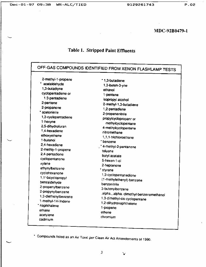
Dec-Ol-« 37 09:38 WR-ALC/TIED 9129261743 P.02
MDC-92B0479-1
Table 1. Stripped Paint Effluents
OFF-GAS COMPOUNDS IDENTIFIED FROM XENON FLASHLAMP TESTS
2-methyl-1 -propene •, ,3-butadiene * acetaldehyde 1,3-buten-3-yne
1,3-butadiyne etnan0| cyclopentadiene or ^ -pentene
1.3-pentadiene isopropyl alcohol 2-Pentene 2-methyl-1.3-butadiene 2-propanone 1.2-pentadiene
•acetonitrile 2-propenenrtrile 1 (3-cyclopentadiene propylcyctopropanr or 1"hexyne methylcyclopentane 2.5-d.hydrofuran 4-methylcyclopentene 1.4-hexad.ene nitromethane ethoxyethene 1,1,1-trichloroethane
s ■■ 1-bu,ano1 'benzene 2.4-hexadiene / 4-methyl-2-pentanone 2-methly-l-propene toluene 2,4-pentadione butyl acetate cyclopentanone 5-hexen-1-ol x*lene 2-heptanone ethynylbenzene .styrene
cyclohexanone 1,3-cyclopentanedione
K.V HC^r°Py (1-me.hy.ethenyl)-benzene benzaldehyde benzonitrile 2-propenylbenzene 3-butenylbenzene
^T^T™ a.pha.,.a.pha,dimethyl-benzenemethanol mt h1M ? TnS 1 ^dimethyl-cs-cyclopentane 1-methyl-lH-lndene . , ,ihu, ', r
• nani»kii~ 1 2-dihydronaphthalene naphthalene < nrm„^ i -propene ethane „<u elhene
. chromium cadmium
* Compounds listed as an Air Toxic per Clean Air Ac. Amendements of 1990.
3
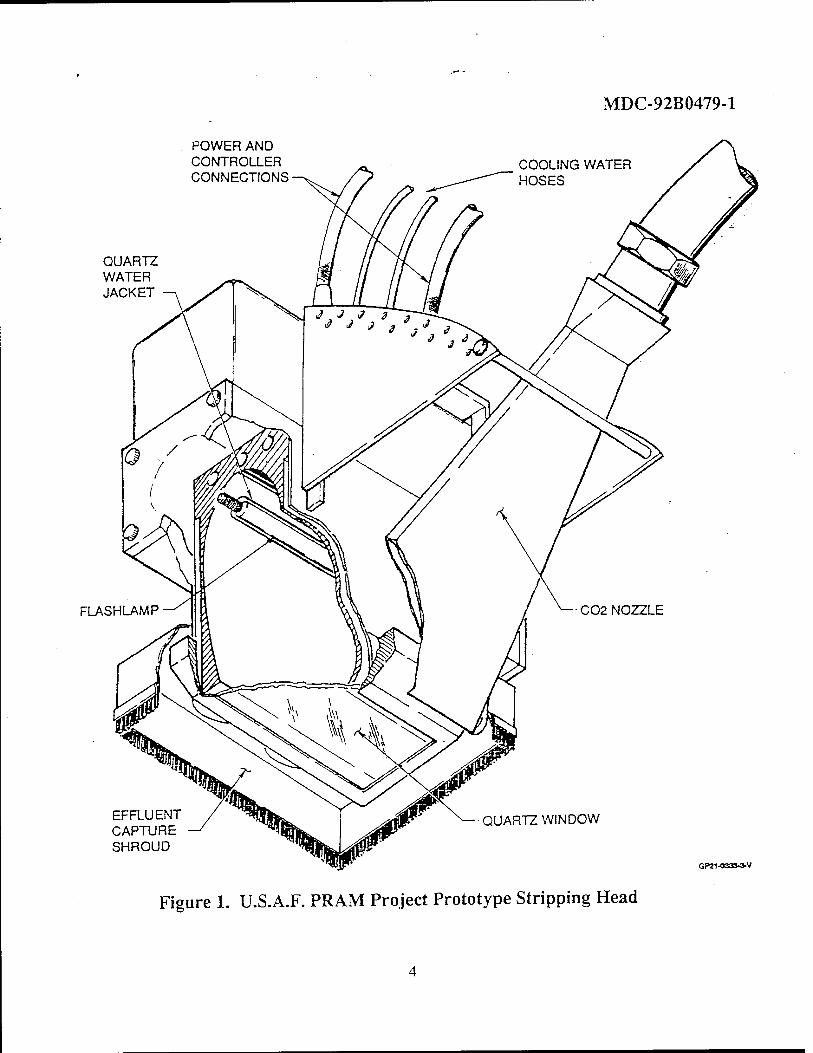
MDC-92B0479-1
POWER AND CONTROLLER CONNECTIONS
QUARTZ WATER JACKET
FLASHLAMP
EFFLUENT CAPTURE SHROUD
C02 NOZZLE
QUARTZ WINDOW
GP21-0333-3-V
Figure 1. U.S.A.F. PRAM Project Prototype Stripping Head
MDC-92B0479-1
WARNING
Make sure all electrical power is OFF before performing inspections.
a. Make sure electrical power is OFF.
WARNING
Isopropyl Alcohol is highly flammable and toxic. Do not use near open flame or sparks. Use only in well ventilated areas.
b. Using a clean cloth moistened with Isopropyl Alcohol, clean quartz window, Figure 1.
c. Visually inspect quartz window for cracks or crazing.
d. Visually inspect lamp for cracks, crazing or evidence of overheating.
e. Check all electrical connections for security.
f. Check water cooling lines for security and signs of leakage.
g. Check C02 delivery hose for security and signs of damage.
h. Inspect motion/proximity sensing device as follows:
1) Check encoder wheel for freedom of rotation.
2) Check limit switch and arm for freedom of movement.
3.2.2 CCDS Power Supply.
Materials Required
None
WARNING
Make sure all electrical power is OFF before performing inspections.
Refer to Appendix A2, Section 2, Safety before opening doors.
a. Make sure electrical power is OFF.
b. Visually inspect cabinet for any obvious physical damage.
c. Visually inspect water cooling reservoir for proper water level.
d. Visually inspect B-Pure Cartridge resistivity GO/NO-GO indicators. Refer to Appendix A3, Operation, page 7.
3.2.3 Cold Jet Model 65-22.
Materials Required
None
WARNING
Make sure all electrical power is OFF before opening any panels or doors.
a. Make sure electrical power is OFF.
b. Visually inspect unit for any obvious physical damage.
c. Visually inspect electrical and hydraulic connections for security.

MDC-92B0479-1
4.0 SYSTEM OPERATION.
4.1 Stripping Head - There are no operator requirements necessary for operation of the stripping head. The nozzle angle is pre-set for optimum stripping performance.
4.2 Cold Jet Model 65-200 - The unit requires at least 30 minutes to compress liquid C02 into pellets at initial start-up. Refer to Appendix A4, SET-UP PROCEDURES, page 21. Set C02 pressure at 140 PSI. Set C02 feed at 40%.
4.3 CCDS Power Supply - After the 65-200 READY light comes ON, refer to Appendix Al, Section 4. OPERATING PROCEDURE and Appendix A2, Section 3. OPERATING INSTRUCTIONS. Set CCDS voltage to 1,600 with a rep rate of 3 Hz.
4.4 Robotic Interface - Follow customer furnished operating instructions for set-up and operation of the robot. Standoff distance between quartz window and surface is programmed to maintain 1.0 inch standoff. Strip traverse rate is programmed at 2 ft/min. The number of passes is dependent on film thickness.
4.5 Flashlamp Life - Lower operating voltage will increase lamp life. Voltage parameters are 0 to 1850v @ 4 Hz. 1850v maximum is limited by capacitor discharge capacity. While small voltage changes result in a major change in lamp life, major voltage changes will affect strip rates.
5.0 TECHNICAL MAINTENANCE.
5.1 This section describes Scheduled and Unscheduled Maintenance, Troubleshooting Procedures, and System Safety Interlocks associated with the PRAM Project 6-Inch Prototype Advanced Coatings Removal Process.
5.2 Warranties - The 6-Inch Stripping head and CCDS Power Supply are covered under warranties set forth by Maxwell Laboratories, Inc. Refer to Appendix Al, Section 6 WARRANTY SUMMARY. The Cold Jet Model 65-200 is covered under warranties set forth by Cold Jet , Inc. Refer to Appendix A4, WARRANTY COMPLIANCE. The B-Pure Pressure Cartridge System is covered by the warranty set forth by Barnstead/ Thermolyne. Refer to Appendix A3, WARRANTY.
5.3 Scheduled Maintenance.
5.3.1 Stripping Head Assembly - Scheduled maintenance of the stripping head assembly consists of daily inspections as outlined in paragraph 3.0 of this manual and periodic replacement of the flashlamp.
5.3.1.1 Flashlamp Replacement. '
Materials Required
Part Number L7741 QFX413
Manufacturer ELC Technology Q-Arc Limited
NOTE
Flashlamp service life is predicted to be 8 operating hours.
a. Refer to LAMP REPLACEMENT PROCEDURE, Appendix Al, Section 5.
5.3.1.2 Lamp Pre-Conditioning - Lamp life may be increased by pre- conditioning the cathode prior to running the lamp at full power. Pre-Conditioning consists of running the lamp @ ~ lOOOv for 500 shots @ 4 pulses per second. After lamp replacement, pre-condition as follows:
a. Position stripping head such that the pulsed light energy output is at least 4 feet from any surrounding structure.
b. Disable motion/proximity sensor by disconnecting plug P6 on stripping head.
c. Connect wrap around jumper to plug P6.
d. Set voltage, number of shots, and pulse rate for pre-conditioning. Refer to Appendix Al, Section 4, paragraph 4.2.
e. Operate flashlamp. Refer to Appendix Al, Section 4, paragraph 4.3.
NOTE
Enable motion/proximity sensor upon completion of pre-conditioning.
f. Remove wrap around jumper from plug P6.
g. Reconnect cable from flashlamp controller to plug P6 on stripping head.
5.3.1.3 Quartz Window - No scheduled maintenance required. Refer to paragraph 5.4.1.1 for unscheduled maintenance.
5.3.1.4 Reflector - No scheduled maintenance required. Refer to paragraph 5.4.1.3 for unscheduled maintenance.
5.3.1.5 Proximity/Motion Sensor - No scheduled maintenance required. Refer to paragraph 5.6 System Safety Interlocks.
5.3.2 CCDS Power Supply - Scheduled maintenance of the CCDS Power Supply consists of daily inspections as outlined in paragraph 3.0 of this manual.
5.3.3 B-Pure Pressure Cartridge - Refer to Appendix A3, Maintenance and Servicing for scheduled maintenance procedures.
MDC-92B0479-1
5 3 4 Cold Jet Model 65-200 - Refer to Appendix A4, PREVENTATIVE MAINT- ENANCE, for 25 hour, 100 hour, and 500 hour scheduled inspection requirements.
5.4 Unscheduled Maintenance.
5.4.1 Stripping Head Assembly - Unsched- uled maintenance of the stripping head assembly consists of replacement of the quartz window, quartz water jacket, and reflector refurbishment.
5.4.1.1 Quartz Window - In the event the quartz window is damaged, crazed, or clouded, replace as follows:
Materials Required
Synthetic Fused Silica Window, dimensions 7.375 in X 3.0 in X 0.230-0.250 in thick, manufactured by Heraeus Amersil or Dunasil. Maxwell P/N 97525b 1. '
WARNING
Make sure all electrical power is OFF.
a. Make sure all electrical power is OFF.
b. Remove 20 screws (48), Maxwell drawing SK 97523, securing window clamp
(13).
c. Remove clamp (13), window (6), and O-ring (41).
d. Install O-ring (41), window (6), and clamp (13).
e. Install 20 screws (48) seeming window clamp (13).
5.4.1.2 Quartz Water Jacket - In the event the water jacket is damaged, crazed, or clouded, replace as follows:
MDC-92B0479-1
Materials Required
Quartz Water Jacket, dimensions 13mm ID, 15mm OD X 11.1 in long, manufactured by Heraeus Amersil. Maxwell P/N 97524b 1.
WARNING
Make sure all electrical power is OFF.
a. Make sure all electrical power is OFF.
b. Remove flashlamp, refer to LAMP REPLACEMENT PROCEDURE, Appendix Al, Section 5.
c. Disassemble stripping head as required, refer to Maxwell drawing SK 97523.
d. Install water jacket.
e. Reassemble stripping head.
f. Reinstall flashlamp.
5.4.1.3 Reflector - In the event the reflector surface becomes degraded with age or use, contact Maxwell Laboratories, Inc. for engineering disposition.
5.4.2 CCDS Power Supply - All unsched- uled maintenance requirements are outlined in the commercial manual. Refer to Appendix A2, Sections 3 and 4. System Safety Interlocks for the power supply are described in paragraph 5.6.
5.4.3 B-Pure Pressure Cartridge - All unscheduled maintenance requirements are oudined in the commercial manual. Refer to Appendix A3.
5.4.4 Cold Jet Model 65-200 - All unscheduled maintenance requirements are oudined in the commercial manual. Refer to Appendix A4.
5.5 Troubleshooting.
5.5.1 Stripping Head - Visually inspect for loose connections or obvious physical damage.
5.5.2 CCDS Power Supply - Refer to Appendix A2, Section 11, TROUBLE- SHOOTING GUIDE..
5 5 3 B-Pure Pressure Cartridge - Refer to Appendix A3, TROUBLESHOOTING GUIDE.
5.5.4 Cold Jet Model 65-200 - Refer to Appendix A4, TROUBLESHOOTING.
5.6 System Safety Interlocks.
5.6.1 Stripping Head- The motion sensor interface is a small electronic circuit mounted on the stripping head. The circuit interacts with the stripping head control-WR robot controller, flashlamp controller-and sensors at the head in order to provide safety time-outs for the operation of the flashlamp. This interface monitors the motion of the stripping head with a wheel and encoder assembly mounted along the centerline of the flashlamp axis. The wheel and encoder assembly are spring loaded with a proximity switch to indicate that the wheels have come in contact with the surface. The interface provides a "Flashlamp Request" signal from the WR robot controller. Based on the conditions at the strip head, the interface either asserts a "Flashlamp Command" signal or leaves the "Flashlamp Command" signal inactive, thereby inhibiting flashlamp operation. The operating conditions at the strip head are wholly determined by the encoders and proximity switch as follows:
MDC-92B0479-1
Flashlamp Request - Signal from robot controller indicating that the flashlamp should be turned on. When this signal is active, the interface will decide whether or not to turn on the flashlamp based on conditions at the strip head.
Flashlamp Command - Generated by the motion sensor interface in response to a "Flashlamp Request" if the proper operating conditions have been established. When this signal is active, the flashlamp will turn on.
Contact - Signal obtained from the strip head wheel assembly indicating that the wheels have contacted the surface (Proximity). Activation of this signal indicates contact has been made.
Motion - A conditioned signal from the encoders indicating that the strip head is moving. The amount of linear motion at the strip head that will activate this signal is jumper selectable at the motion sensor interface. When this signal is active, it indicates that motion is occuring.
NOTE
The motion direction is not detected. Motion in either fore or aft direction will permit flashlamp operation.
The following rules will be used to govern valid flashlamp operating conditions:
a) Flashlamp operation will only be per- mitted when "Flashlamp Request" signal is true.
b) The "Flashlamp Command" signal will be de-activated within 1 msec after "Flash- lamp Request" is removed.
d) If the "Flashlamp Request" is active, "Motion" is detected, and "Contact" is active, the "Flashlamp Command" will be active.
e) If "Flashlamp Request" becomes active while "Contact" is active, the "Flashlamp Command" will become asserted for a period of time (Tl) while no "Motion" is detected.
f) If the "Flashlamp Request" is active and "Contact" becomes active, the "Flashlamp Command" will be asserted for a period of. time (Tl) while "Motion" is active.
g) While the "Flashlamp Request" remains active and "Contact" is active, if "Motion" becomes inactive, the "Flashlamp Command" will be de-asserted after a period of time (T2).
h) If the "Flashlamp Request" _ is active, "Contact" is active, loss of "Motion" is detected and then becomes active, the "Flashlamp Command" will be re-asserted within 1 msec of the "Motion" signal.
i) If the "Flashlamp Request" is active, loss of "Motion" has been detected and "Contact" becomes inactive, the "Flashlamp Command" will be re-asserted.
NOTE
The "Motion" signal is a conditioned output from the encoder with select- able resolution. Motion less than the resolution will not be detected and not permit flashlamp operation. It is implicitly assumed "Motion" will not be active unless "Contact" is active.
MDC-92B0479-1
5.6.1.1 Safety Circuit Timing and Adjustment.
The safety circuit consists of the following: • 2" diameter wheels • 1000 pulses per rev incremental encoders • Encoder output at one foot per minute
{(1 ft/min)*(12 in/ft)*(1000 pulses/rev)}/ {(60 sec/min)*(27C in/rev)} = 31.8 Hz
a) Input RC filter eliminates high frequency noise and jitter - (0.1uF)*(15KQ)=1.5mS or -666 Hz. Maximum frequency passed (measured) was 435 or -6.8 ft/min.
b) Input one shot eliminates low frequency noise and jitter - 0.33*(2.2uF)*(50Kn) = 36.6 mS or 27.5 Hz. Note that 50 KQ is the maximum low frequency. This time has been pre-set to 30 mS.
c) Counter - Divides the pulses per revolu- tion from both encoders prior to motion pulse generation. This counter sets the amount of physical motion required to cause a motion pulse to be generated. This counter is jumper selectable and has been pre-set to divide the incoming encoder pulses by 16 (jumper Jll installed.
d) Normalizing one shot-Produces a positive 125fiS normalized pulse on the rising edge of each motion pulse. This pulse is not adjustable nor does it affect the timing of the safety circuit.
e) Stop time-out one-shot - Sets the time allowed from the rising edge of the last motion pulse until flash inhibit occurs. The maximum length of this time-out (measured) is 3.3 S; the minimum (measured) is 26 mS. The stop time-out has been pre-set to 0.5 S.
f) Start time-out one-shot - Sets the time allowed from the rising edge of the flash re- quest while surface contact is true until the rising edge of the first motion pulse. If motion
rising edge of the first motion pulse. If motion does not"occur within the start time-out period flash inhibit occurs. The maximum length of this time-out (measured) is 2.9 S; the min- imum (measured) is 25 mS. The start time-out has been pre-set to 2.9 S.
MINIMUM SPEED: The minimum speed target was one foot per minute. With both wheels in motion at one foot per minute, the combined output of the encoders is 63.6 Hz. The minimum (measured) frequency at which stop time-out did not occur was 40 Hz., or -0.628 ft/min.
MAXIMUM SPEED: The maximum speed target was eight feet per minute. With both wheels in motion at this rate, the combined output of the encoders is 509.3 Hz. Since the maximum passed frequency (measured) of the input RC filter is 345 Hz, the maximum speed is -6.83 ft/min.
5.6.2 CCDS Power Supply - The CCDS power supply has several safety interlocks incorpor- ated which will not allow the unit to operate until the interlock safety conditions are met. These interlocks include:
a) Water Flow Interlock
b) Water Level Interlock
c) Air Flow Interlock
d) Door Interlocks
e) Dump Interlocks
Upon system start-up, the "INTERLOCKS SATISFIED" light on the computer control panel will illuminate RED. Refer to Appendix Al, Section 4.3, OPERATION. If the "INTERLOCKS SATISFIED" light fails to iUuminate, "click" on the "RESET
10
MDC-92B0479-1
INTERLOCKS" button on the computer control screen. If the interlocks fail to reset, do the following:
5.6.2.1 Water Flow Interlock.
NOTE
The computer screen does not identify which interlock is not set.
a. Make sure hoses are not "kinked" or broken.
WARNING
WARNING
Make sure all electrical power is OFF and capacitors and inductors are DISCHARGED.
b. Make sure all electrical power is OFF and capacitors and inductors are DIS- CHARGED. Refer to Appendix Al, Section 2. SAFETY.
c. Make sure hose connections at strip head and pump assembly are secure.
d. Inspect cooling system inside CDDS power supply cabinet for correct valve positions and any obvious physical damage.
e. Refer to Appendix A3, TROUBLE- SHOOTING GUIDE for possible problems and solutions.
5.6.2.2 Water Level Interlock.
NOTE
The computer screen does not identify which interlock is not set.
a. Make sure hoses are not broken.
Make sure all electrical power is OFF and capacitors and inductors are DISCHARGED.
b. Make sure all electrical power is OFF and capacitors and inductors are DIS- CHARGED. Refer ' to Appendix Al, Section 2. SAFETY.
c. Make sure hose connections at strip head and pump assembly are secure.
d. Check for proper cooling water level in reservoir in CCDS power supply cabinet.
e. Refer to Appendix A3, TROUBLE- SHOOTING GUIDE for possible problems and solutions.
5.6.2.3 Air Flow Interlock.
NOTE
The computer screen does not identify which interlock is not set.
a. Check outside air flow exhaust areas for obstructions.
WARNING
Make sure all electrical power is OFF and capacitors and inductors are DISCHARGED.
b. Make sure all electrical power is OFF and capacitors and inductors are DIS- CHARGED. Refer to Appendix Al, Section 2. SAFETY.
c. Check cooling fan in CCDS power supply cabinet.
11
5.6.2.4 Door Interlocks.
Door interlocks are designed to prevent system operation if any doors other than the computer control door is open.
NOTE
The computer screen does not identify which interlock is not set.
a. Make sure doors are properly secured.
WARNING
Make sure all electrical power is OFF and capacitors and inductors are DISCHARGED.
b. Make sure all electrical power is OFF and capacitors and inductors are DIS- CHARGED. Refer to Appendix Al, Section 2. SAFETY.
c. Open doors and inspect interlock switches for obvious physical damage and connections for security.
5.6.2.4 Dump Interlock.
The dump interlock is designed to automatically discharge the capacitors and inductors upon system shutdown. Failure of this interlock will not be readily apparent during system operation. Whenever any maintenance is performed or the power supply cabinet doors are opened, the procedures outlined in Appendix Al, Section 2. SAFETY must be followed.
5.6.3 B-Pure Pressure Cartridge System.
There are no safety interlock requirements associated with the cartridge filter system.
MDC-92B0479-1
5.6.4 Cold Jet Model 65-200.
Safety circuits incorporated into the Cold Jet Model 65-200 unit include:
a) AUTOMATIC HYDRAULIC SYSTEM SAFETY SHUT-DOWNS. Refer to Appendix A4, page 43.
b) LIQUID INJECTION SYSTEM SHUT- DOWNS. Refer to Appendix A4, page 44.
c) MANUAL BLAST NOZZLE SYSTEM SHUT-DOWNS. Appendix A4, page 45.
6.0 PARTS LISTS.
6.1 Stripping Head - Parts list for the PRAM Project 6-Inch Stripping Head Assembly is included on the Maxwell drawing SK 97523.
6.1.1 Stripping Head Integration Hardware Parts integrating the C02 nozzle and sensor hardware to the stripping head are included on McDonnell Douglas drawing 91CST0500.
6.2 CCDS Power Supply - For parts associated with the CCDS power supply cabinet, contact Maxwell Laboratories, Inc. at (619)-576-7573.
6.3 B-Pure Pressure Cartridge System - Cartridges, filters, and a complete illustrated parts breakdown are included in Appendix A3.
6.4 Cold Jet Model 65-200 - Complete parts lists and illustrated parts breakdowns are included in Appendix A4.
12
MDC-92B0479-1
Appendix Al PRAM Six Inch Flashblast System Operation Manual (MLR-4047)
A-l

MLR-4047 SEPTEMBER 29,1992
OPERATION MANUAL FOR THE
PRAM PROJECT SIX INCH FLASHBLAST SYSTEM
Prepared by
Maxwell Laboratories, Inc. 8888 Balboa Avenue
San Diego, California 92123-1506
Table of Contents
1.0 GENERAL DESCRIPTION 1
2.0 SAFETY 2
2.1 Personnel Safety 2 3.0 INSTALLATION 5
3.1 AC Power Input 5 3.2 Lamp Module Cooling Water - 5 3.3 Remote Control Pendant 5 3.4 Cold Jet Interface 5
3.5 Lamp Module 5 4.0 OPERATING PROCEDURE 7
4.1 Power On and System Shutdown 7 4.2 Control Computer Screen 7 4.3 Operation '
5.0 LAMP REPLACEMENT PROCEDURE 10 5.1 Lamp Removal *-Q 5.2 Lamp Installation 1*
List of Illustrations
2.1 Discharge Locations 4 4.1 Computer Control Screen 9 5.1 6-Inch PRAM Prototype Flashlamp Removal and Installation 12

SECTION 1 GENERAL DESCRIPTION
The PRAM Project Six Inch Flashblast System (PRAM FS) is a laboratory prototype for use in conjunction with a Cold Jet. inc. C02 pellet blasting system. The intended use of the integrated system is for paint removal. The PRAM FS consists of a flashlamp (lamp) module, a water cooling system, a high-voltage power supply (Maxwell CCDS), a power conditioning section and computer control system. The power conditioning section is comprised of the main energy storage capacitor bank, a solid-state switch assembly and trigger, and the pulse shaping inductor. All of the components, with the exception of the lamp module are contained within the main enclosure.
The main enclosure is divided into two major compartments and three minor, rear compartments. The left hand major
compartment houses the controls, high-voltage power supply, lamp simmer power supply, and the AC power distribution. The right hand major compartment houses the power conditioning section and the AC power disconnect. The water cooling system is located in one of the minor, rear compartments.
The lamp module is located remotely, up to two hundred feet away. Connected to the lamp module is the main pulse cable, lamp module interlock cable (twisted pair with CPC connector), and a pair of cooling water lines (inlet/outlet). An additional, multiconductor cable is provided for interface to the McDonnell Douglas integration equipment.
Operation and maintenance manuals for the power supplies, the control computer, and the water cooling equipment are included in the Appendix.
SECTION 2 SAFETY
WARNING
THE HIGH VOLTAGE AND AC POWER USED IN THE PRAM FS MAY BE LETHAL. BEFORE WORKING WITH THIS EQUIPMENT OR COMPONENTS CONNECTED TO THE OUTPUT OF THE PRAM FS, MAKE SURE THE AC POWER TO THE PRAM FS IS OFF AND GROUND (DISCHARGE) ALL HIGH VOLTAGE CAPACITORS WITH THE APPROPRIATE GROUNDING DEVICE.
2.1 PERSONNEL SAFETY.
Maxwell Laboratories, Inc. (Maxwell) has made every effort to provide safety features to assure personnel safety in accordance with industry approved safety standards.
A high voltage grounding stick is supplied with the equipment. Figure 2.1 Discharge Locations shows the ground point and locations where a charge may exist within the enclosure.
2.1.1 Power Supply Enclosure Safetying-
WARNING
Failure to comply with the following procedure for safetying the high voltage power supply may result in injury of death.
Only qualified personnel are allowed to open the enclosure doors or panels.
WARNING
Make sure all electrical power is OFF before opening any doors or panels.
a. Make sure the MANUAL POWER SWITCH, Figure 2.1 Discharge Locations is OPEN.
b. Turn electrical power OFF at source.
WARNING
Do not bodily enter or touch any internal components within the main enclosure until grounding (DISCHARGE) procedure has been completed.
c. Open right hand door of main enclosure.
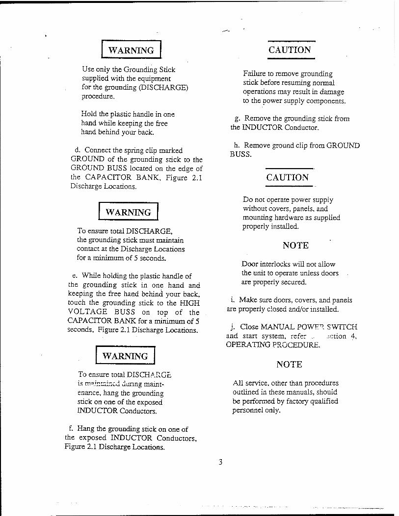
WARNING
Use only the Grounding Stick supplied with the equipment for the grounding (DISCHARGE) procedure.
Hold the plastic handle in one hand while keeping the free hand behind your back.
d. Connect the spring cüp marked GROUND of the grounding stick to the GROUND BUSS located on the edge of the CAPACITOR BANK, Figure 2.1 Discharge Locations.
WARNING
To ensure total DISCHARGE, the grounding stick must maintain contact at the Discharge Locations for a minimum of 5 seconds.
e. While holding the plastic handle of the grounding stick in one hand and keeping the free hand behind your back, touch the grounding stick to the HIGH VOLTAGE BUSS on top of the CAPACITOR BANK for a minimum of 5 seconds, Figure 2.1 Discharge Locations.
WARNING
To ensure total DISCHARGE is maintained during maint- enance, hang the grounding stick on one of the exposed INDUCTOR Conductors.
CAUTION
Failure to remove grounding stick before resuming normal operations may result in damage to the power supply components.
g. Remove the grounding stick from the INDUCTOR Conductor.
h. Remove ground clip from GROUND BUSS.
CAUTION
Do not operate power supply without covers, panels, and mounting hardware as supplied properly installed.
NOTE
Door interlocks will not allow the unit to operate unless doors are properly secured.
i. Make sure doors, covers, and panels are properly closed and/or installed.
j. Close MANUAL POWER SWITCH and start system, refer .. action 4, OPERATING PROCEDURE.
NOTE
All service, other than procedures outlined in these manuals, should be performed by factory qualified personnel only.
f. Hang the grounding stick on one of the exposed INDUCTOR Conductors, Figure 2.1 Discharge Locations.
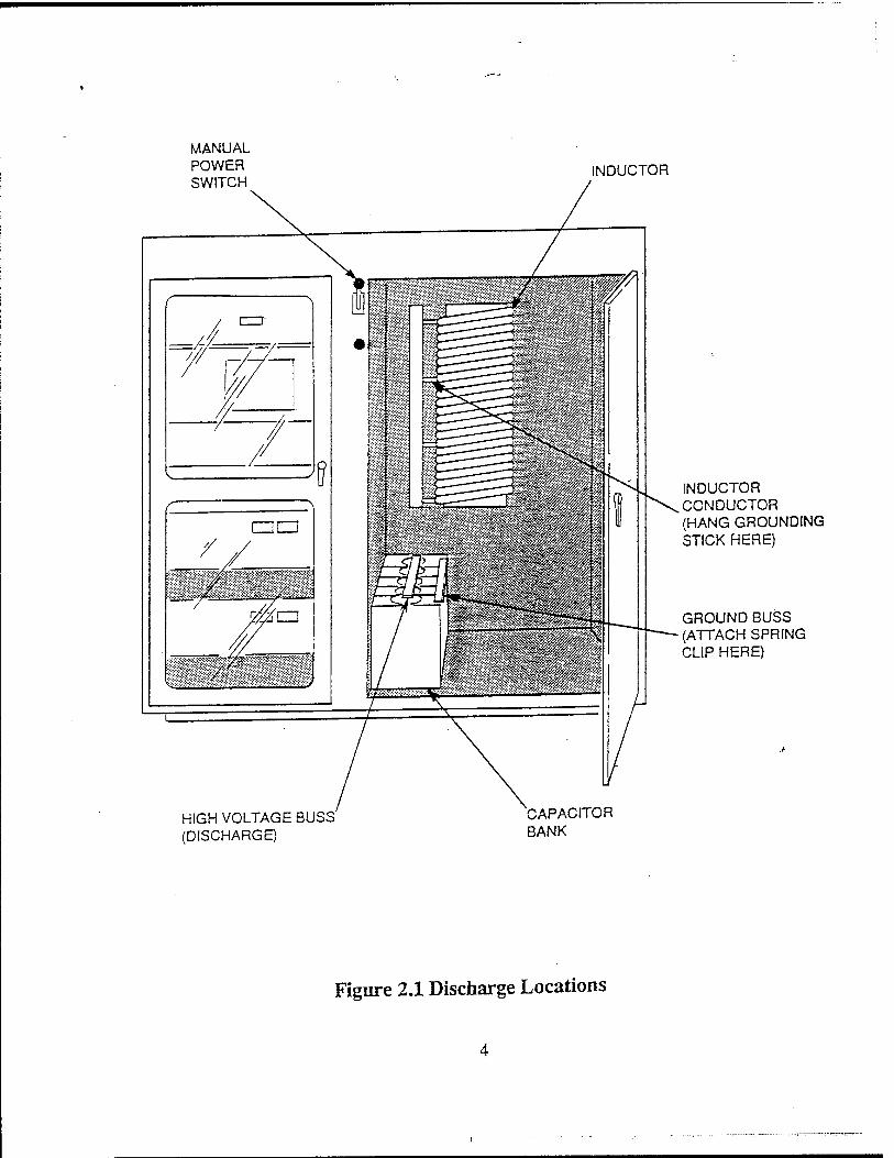
MANUAL POWER SWITCH
INDUCTOR
INDUCTOR CONDUCTOR (HANG GROUNDING STICK HERE)
GROUND BUSS (ATTACH SPRING CLIP HERE)
HIGH VOLTAGE BUSS (DISCHARGE)
CAPACITOR BANK
Figure 2.1 Discharge Locations
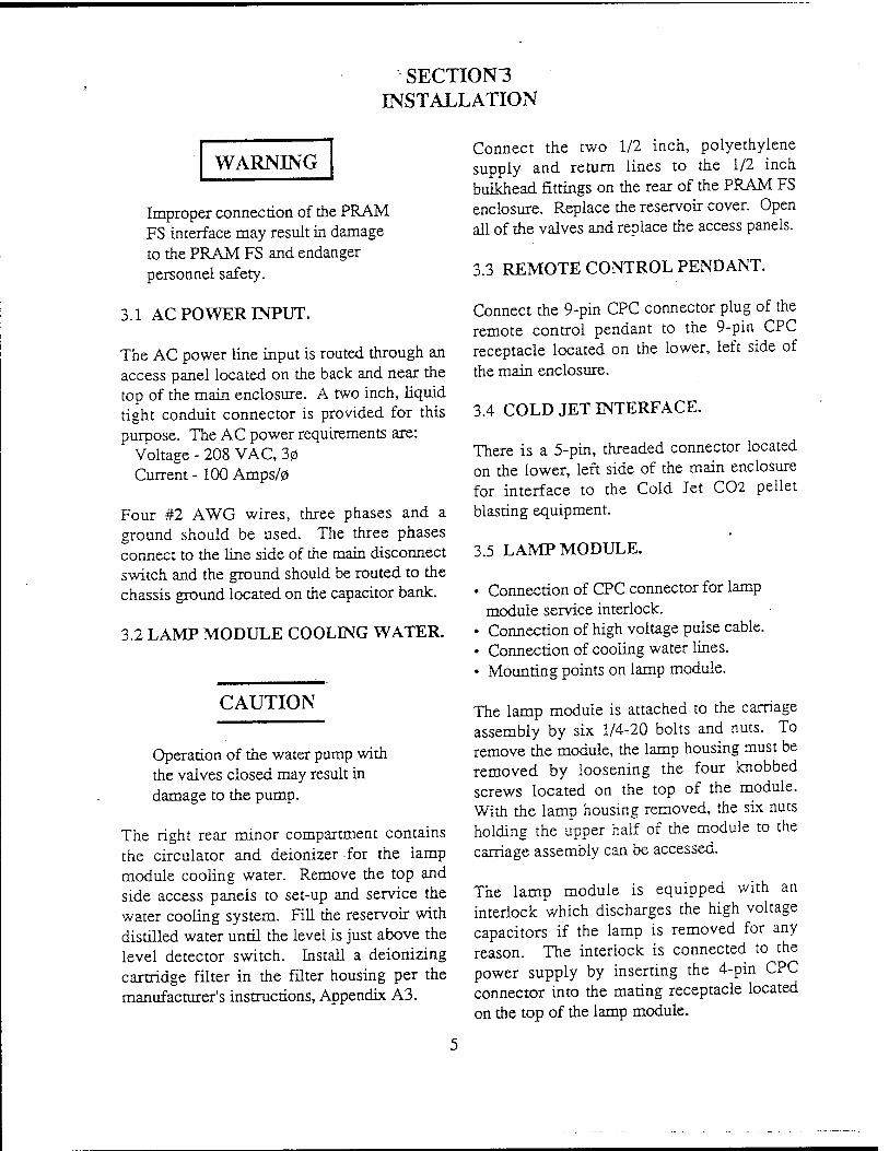
SECTI0N3 INSTALLATION
WARNING
Improper connection of the PRAM FS interface may result in damage to the PRAM FS and endanger personnel safety.
3.1 AC POWER INPUT.
The AC power line input is routed through an access panel located on the back and near the top of the main enclosure. A two inch, liquid tight conduit connector is provided for this purpose. The AC power requirements are:
Voltage - 208 VAC, 30 Current - 100 Amps/0
Four #2 AWG wires, three phases and a ground should be used. The three phases connect to the line side of the main disconnect switch and the ground should be routed to the chassis ground located on the capacitor bank.
3.2 LAMP MODULE COOLING WATER.
CAUTION
Operation of the water pump with the valves closed may result in damage to the pump.
The right rear minor compartment contains the circulator and deionizer for the lamp module cooling water. Remove the top and side access panels to set-up and service the water cooling system. Fill the reservoir with distilled water until the level is just above the level detector switch. Install a deionizing cartridge filter in the filter housing per the manufacturer's instructions, Appendix A3.
Connect the two 1/2 inch, polyethylene supply and return lines to the 1/2 inch bulkhead fittings on the rear of the PRAM FS enclosure. Replace the reservoir cover. Open all of the valves and replace the access panels.
3.3 REMOTE CONTROL PENDANT.
Connect the 9-pin CPC connector plug of the remote control pendant to the 9-pin CPC receptacle located on the lower, left side of the main enclosure.
3.4 COLD JET INTERFACE.
There is a 5-pin, threaded connector located on the lower, left side of the main enclosure for interface to the Cold Jet C02 pellet blasting equipment.
3.5 LAMP MODULE.
• Connection of CPC connector for lamp module service interlock.
• Connection of high voltage pulse cable. • Connection of cooling water lines. • Mounting points on lamp module.
The lamp module is attached to the carriage assembly by six 1/4-20 bolts and nuts. To remove the module, the lamp housing must be removed by loosening the four knobbed screws located on the top of the module. With the lamp housing removed, the six nuts holding the upper half of the module to the carriage assembly can be accessed.
The lamp module is equipped with an interlock which discharges the high voltage capacitors if the lamp is removed for any reason. The interlock is connected to the power supply by inserting the 4-pin CPC connector into the mating receptacle located on the top of the lamp module.
The lamp housing must also be removed in order to remove or re-attach the high voltage cable coming from the power supply cabinet. Four flathead screws in the ends of the module can then be removed allowing access to the high voltage cable connections. The cable lengths are such that the cable can only be hooked up with the proper polarity.
Water lines are removed from the module by depressing the outer ring of the quick disconnect fittings and pulling the fitting halves apart. To reassemble, the fittings must be pushed together until a "click" is heard.
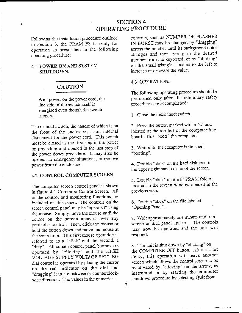
SECTION 4 OPERATING PROCUDURE
Following the installation procedure outlined in Section 3, the PRAM FS is ready for operation as prescribed in the following operating procedure:
4.1 POWER ON AND SYSTEM SHUTDOWN.
CAUTION
With power on the power cord, the line side of the switch itself is energized even though the switch is open.
The manual switch, the handle of which is on the front of the enclosure, is an internal disconnect for the power cord. This switch must be closed as the first step in the power up procedure and opened in the last step of the power down procedure. It may also be opened, in emergency situations, to remove power from the enclosure.
4.2 CONTROL COMPUTER SCREEN.
The computer screen control panel is shown in figure 4.1 Computer Control Screen. All of the control and monitoring functions are included on this panel. The controls on the screen control panel may be "operated" using the mouse. Simply move the mouse until the cursor on the screen appears over any particular control. Then, click the mouse or hold the button down and move the mouse at the same time. This first mouse operation is referred to as a "click" and the second, a "drag". All screen control panel buttons are operated by "clicking" and the HIGH VOLTAGE SUPPLY VOLTAGE SETTING dial control is operated by placing the cursor on the red indicator on the dial and "dragging" it in a clockwise or counterclock- wise direction. The values in the numerical
controls, such as NUMBER OF FLASHES IN BURST may be changed by "dragging" across the number until its background color changes and then typing in the desired number from the keyboard, or by "clicking" on the small triangles located to the left to increase or decrease the value.
4.3 OPERATION.
The following operating procedure should be performed only after all preliminary safety procedures are accomplished:.
1. Close the disconnect switch.
2. Press the button marked with a "<" and located at the top left of the computer key- board. This "boots" the computer.
3. Wait until the computer is finished "booting".
4. Double "click" on the hard disk icon in the upper right hand corner of the screen.
5. Double "click" on the 6" PRAM folder, located in the screen window opened in the previous step.
6. Double "click" on the file labeled "Opening Panel".
7. Wait approximately one minute until the screen control panel appears. The controls may now be operated and the unit will respond.
8. The unit is shut down by "clicking" on the COMPUTER OFF button. After a short delay, this operation will leave another screen which allows the control screen to be reactivated by "clicking" on the arrow, as instructed or by starting the computer shutdown procedure by selecting Quit from
the File Menu. If you elect to shut down the computer, wait a minute after selecting Quit until screen activity stops and then select Shut Down from the Special Menu. After a few seconds the computer will shut itself off.
OPERATION OF THE 6" PRAM UNIT FROM THE SCREEN CONTROL PANEL IS AS FOLLOWS:
1. "Click" the RESET INTERLOCKS button. This should cause the main contactor to close (audible click) and the INTERLOCKS SATISFIED and CONTACTOR indicators, below the RESET INTERLOCKS and COMPUTER OFF buttons, will change to a RED background after approximately 4 seconds. During this time the unit is turning on the cooling water and making sure flow is established.
2. "Click" the SIMMER SUPPLY ON button. After 4 seconds the SIMMER "OK" indicator light comes on indicating that the lamp is simmering. To stop simmering, "click" the SIMMER SUPPLY OFF button.
3. Select either BURST or CONTINUOUS by "clicking" on the white button marked as such in the LAMP CONTROL SETTINGS box.
4. Select the FLASH FREQUENCY values and NUMBER OF FLASHES IN BURST, if applicable.
5. "Click" RUN. After a 5 second delay, during which time the C02 is turned on, the flashing will commence and the RUNNING light will flash.
6. "Clicking" the STOP button causes the unit to stop flashing. After the flashing is stopped, another run can be made by repeating steps 4 and 5.
7. The RUN and STOP commands may also be made by pressing the appropriate buttons on the control pendant.
8. The EMERGENCY OFF button on the control pendant causes everything in the unit to shutdown, except for the computer and the disconnect switch. A second EMERGENCY OFF button is located on the front of the enclosure directly below the Disconnect Switch handle. Function of this button is the same as the control pendant button.

RESET INTERLOCKS
COMPUTER OFF
INTERLOCKS SATISFIED
CONTACTOR
•
ON
OFF
SIMMER -OK"
HIGH VOLTAGE SUPPLY VOLTAGE SETTING
1000
500
RUN
STOP
1 500
2000
LAMP CONTROL SETTINGS
SELECTED FLASH MODE
SET FLASH FREQUENCY
BURST 4.0
SET » FLASHES IN BURST
L=
MONITORS SIMMER SUPPLY
0 i Ivocrsl
jTf MI>'l"Tf
APPROX NUMBER OF FLASHES. COUNTER .
Figure 4.1 Computer Control Screen
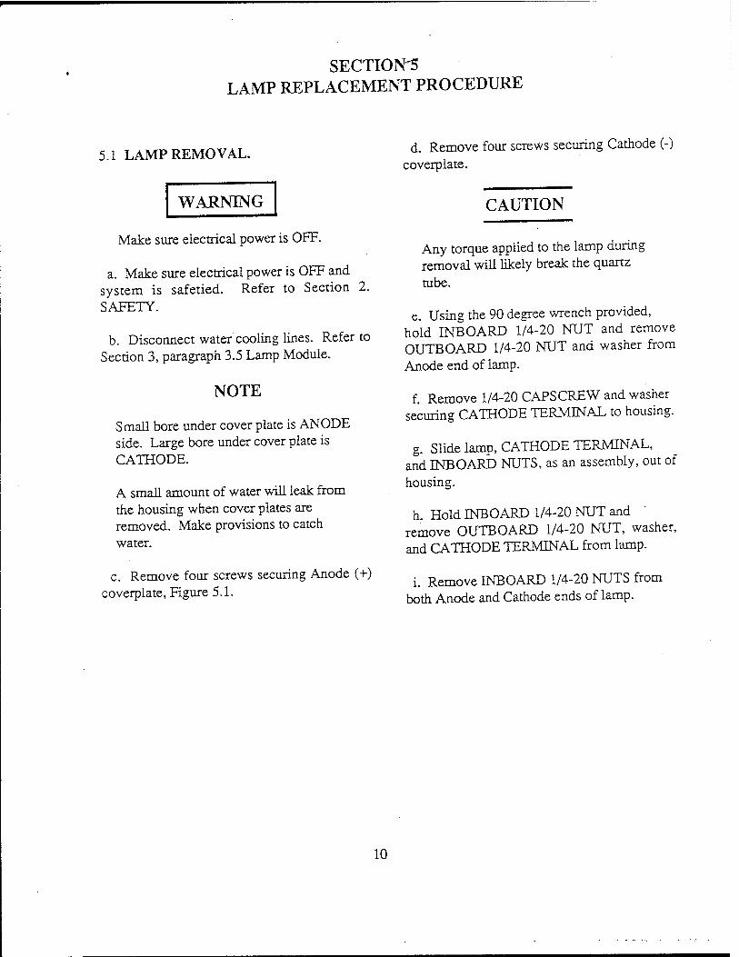
SECTION'S LAMP REPLACEMENT PROCEDURE
5.1 LAMP REMOVAL. d. Remove four screws securing Cathode (-)
coverplate.
WARNING
Make sure electrical power is OFF.
a. Make sure electrical power is OFF and system is safetied. Refer to Section 2. SAFETY.
b. Disconnect water cooling lines. Refer to Section 3, paragraph 3.5 Lamp Module.
NOTE
Small bore under cover plate is ANODE side. Large bore under cover plate is CATHODE.
A small amount of water will leak from the housing when cover plates are removed. Make provisions to catch water.
c. Remove four screws securing Anode (+) coverplate, Figure 5.1.
CAUTION
Any torque applied to the lamp during removal will likely break the quartz tube.
e. Using the 90 degree wrench provided, hold INBOARD 1/4-20 NUT and remove OUTBOARD 1/4-20 NUT and washer from Anode end of lamp.
f. Remove 1/4-20 CAPSCREW and washer securing CATHODE TERMINAL to housing.
g. Slide lamp, CATHODE TERMINAL, and INBOARD NUTS, as an assembly, out of housing.
h. Hold INBOARD 1/4-20 NUT and remove OUTBOARD 1/4-20 NUT, washer, and CATHODE TERMINAL from lamp.
i. Remove INBOARD 1/4-20 NUTS from both Anode and Cathode ends of lamp.
10
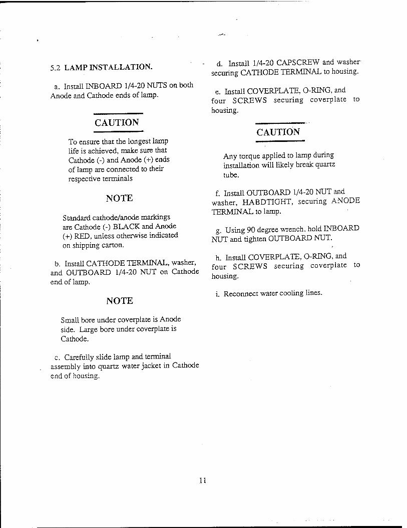
5.2 LAMP INSTALLATION.
a. Install INBOARD 1/4-20 NUTS on both Anode and Cathode ends of lamp.
CAUTION
To ensure that the longest lamp life is achieved, make sure that Cathode (-) and Anode (+) ends of lamp are connected to their respective terminals
NOTE
Standard cathode/anode markings are Cathode (-) BLACK and Anode (+) RED, unless otherwise indicated on shipping carton.
b. Install CATHODE TERMINAL, washer, and OUTBOARD 1/4-20 NUT on Cathode end of lamp.
NOTE
d. Install 1/4-20 CAPSCREW and washer securing CATHODE TERMINAL to housing.
e. Install COVERPLATE, O-RING, and four SCREWS securing coverplate to housing.
CAUTION
Any torque applied to lamp during installation will likely break quartz tube.
f. Install OUTBOARD 1/4-20 NUT and washer, HABDTIGHT, securing ANODE TERMINAL to lamp.
g. Using 90 degree wrench, hold INBOARD NUT and tighten OUTBOARD NUT.
h. Install COVERPLATE, O-RTNG, and four SCREWS securing coverplate housing.
i. Reconnect water cooling lines.
to
Small bore under coverplate is Anode side. Large bore under coverplate is Cathode.
c. Carefully slide lamp and terminal assembly into quartz water jacket in Cathode end of housing.
11
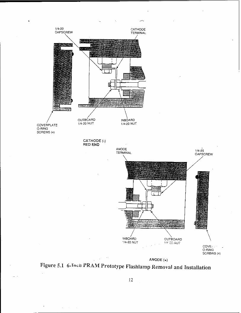
1/4-20 CAPSCREW
CATHODE TERMINAL
/
COVERPLATE O-RING SCREWS (4)
OUTBOARD 1/4-20 NUT
INBOARD 1/4-20 NUT
CATHODE (-) RED END
ANOOE TERMINAL
mOSSs
INBOARD 1/4-20 NUT
OUTBOARD 1/4-20 NUT
ANODE (+)
1/4-20 CAPSCREW
HP 1® L«si>S£
ärsfe
rag mm
COVE.-. ■ O-RING SCREWS (4)
Figure 5.1 6-Tncn PRAM Prototype Flashlamp Removal and Installation
12
MDC-92B0479-1
Appendix A2 CCDS Power Supply CCDS-802-336 (MLR-3700)
A-2

MLR-3700 December 1990
OPERATIONS AND MAINTENANCE MANUAL
FOR
CCDS POWER SUPPLY
Prepared by
Maxweil Laboratories, Inc. Balboa Division
8888 Balboa Avenue San Dieeo, California 92123-1506
Maxwell Laboratories, Inc., Copyright 1990
Table of Contents
1. GENERAL DESCRIPTION 1_1 2. SAFETY 2-1
2.1" Personnel Safety 2-1 3. OPERATING INSTRUCTIONS 3_1
3.1 Local Control 3_1 3.1.1 Control Power ON/OFF 3_1 3.1.2 Voltage Programming 2-1 3.1.3 HVON 3_! 3.1.4 HVOFF : 3_! 3.1.5 Voltage and Current Monitors 3-1
3.2 Remote Control ,... 2-1 3.2.1 Remote Control Enable 3_1 3.2.2 Voltage Programming 3-2 3.2.3 High Voltage ON/OFF 3_2 3.2.4 HV Inhibit 3_2 3.2.5 Voltage Reference 3_2 3.2.6 End of Charge 3_2 3.2.7 Voltage Monitor 3.3 3.2.8 Current Monitor 3.3 3.2.9 HV ON Indicator 3.3
3.3 External Interlock 3,3 3.4 AC Input Connections 3.3"
4. FUNCTIONAL DESCRIPTION 44 4.1 Input EMI Filter 4-1 4.2 Inrush Current Limit 4_1 4.3 Series Resonant Inverter 4_2 4.4 High Voltage Output Circuitry 4_2
5. SERVICE 5.J 6. WARRANTY SUMMARY 6_1 7. PARALLEL OPERATION 7.! 8. HIGH VOLTAGE OUTPUT CONNECTION g_l 9. MOUNTING 9_1 10. APPLICATION NOTES AND COMMENTS 10-1
10.1 Charging Large Capacitor Banks 10-1 10.2 Overvoltage/No Load Condition 10-1 10.3 Output Voltage Reversal 10-i 10.4 Special Applications 10-1
11. TROUBLESHOOTING GUBDE ! i_i
m
List of Illustrations
1-1. Model Number Nomenclature 1_2
2-1. Discharge Locations -° 3-1. CCDS High Voltage Power Supply Front Panel 3-4 3-2. CCDS High Voltage Power Supply Rear Panel 3-5 4-1. Powej Supply Block Diagram. 4-3
List of Tables
3-1. Remote Control Interface 3-6
IV
SECTIONi- GENERAL DESCRIPTION
The CCDS series is a high efficiency, capaci- tor charging power supply line that utilizes a high frequency series resonant inverter top- ology. All CCDS power supplies are designed to meet UL, CSA and ffiC safety standards. The supply is packaged in a 8.75 in. tall, 19 in. wide rack mount chassis and weighs approximately 55 pounds. The input power is 30, 208 VAC, with a neutral. The power supply is specifically designed for con- stant current capacitor charging. Output voltage regulation is maintained to better than 0.1 percent for load rep-rates up to 2kHz. The supply efficiency is greater than 90 percent, with a power factor of approximately 85 percent. Overcurrent protection is inherent in the series resonant topology and fast over- voltage protection (OVP) is incorporated to prevent power supply damage in the event of an open-circuit load connection. Overtemper- ature protection is provided to prevent potential power supply failure in excessive ambient environments. Inrush current limit is also included to prevent surges on the user power grid during initial power supply turn- on. In addition, the supply has an internal delay after discharge which inhibits the HV output for approximately 100 jis after the load capacitor is discharged to allow the high volt- age switch (e.g. thyratron) time to recover.
The power supply can be controlled either from the front panel local controls (instru- mented version) or via the rear panel remote
control interface. The local controls consist of control power ON/OFF, HV ON/OFF, out- put voltage programming, and digital voltage and current meters. The standard remote control interface includes HV ON/OFF, volt- age and current monitor analog outputs, TTL HV INHIBIT, TTL HV ON indicator, end-of- charge (EOC) signal, remote voltage pro- gramming and voltage reference for resistive voltage programming.
The standard units are available in instrum- ented or non-instrumented versions, the only difference being front panel controls and digital displays of the instrumented version. Either version is fully controllable via the 15-pin remote control connector on the rear of the supply. The standard power supply is forced air cooled via a fan mountedin the rear panel.
The CCDS-WXX-Y-Z series of high voltage power supplies consists of models with characteristics keyed to the model number as shown in Figure 1-1. The "W" in the model number indicates the output charging rate (e.g., a CCDS-5XX is capable of delivering 5,000 J/s). The XX in the model number indicates the maximum high voltage rating (e.g., a CCDS-W25 operates between 0 and 25,000 V). The "Y" in the model number indicates the polarity; P for positive or N for negative. The "Z" in the model number indicates the version; 1 for instrumented or 2 non-instrumented.
1-1
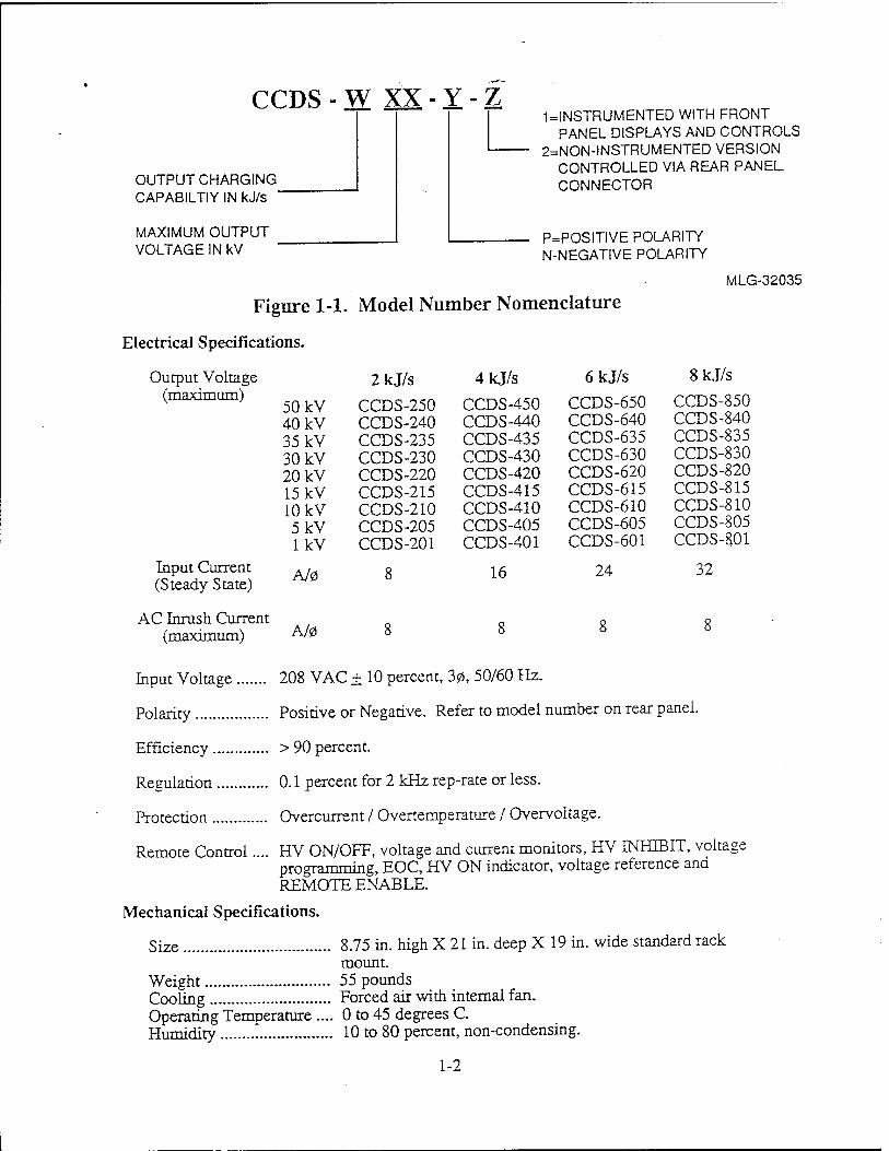
CCDS-W XX-Y-Z
OUTPUT CHARGING CAPABILTIY IN kJ/s '
MAXIMUM OUTPUT VOLTAGE IN kV
11NSTRUMENTED WITH FRONT PANEL DISPLAYS AND CONTROLS
2=NON-INSTRUMENTED VERSION CONTROLLED VIA REAR PANEL CONNECTOR
P=POSITIVE POLARITY N-NEGATIVE POLARITY
MLG-32035
Figure 1-1. Model Number Nomenclature
Electrical Specifications.
Output Voltage (maximum)
Input Cunrent (Steady State)
AC Inrush Current (maximum)
50 kV 40 kV 35 kV 30 kV 20 kV 15 kV 10 kV 5kV lkV
A/0
A/0
2kJ/s
CCDS-250 CCDS-240 CCDS-235 CCDS-230 CCDS-220 CCDS-215 CCDS-210 CCDS-205 CCDS-201
8
4kJ/s
CCDS-450 CCDS-440 CCDS-435 CCDS-430 CCDS-420 CCDS-415 CCDS-410 CCDS-405 CCDS-401
16
6kJ/s
-650 -640
CCDS- CCDS- CCDS-635 CCDS-630 CCDS-620 CCDS-615 CCDS-610 CCDS-605 CCDS-601
24
8kJ/s
CCDS-850 CCDS-840 CCDS-835 CCDS-830 CCDS-820 CCDS-815 CCDS-810 CCDS-805 CCDS-801
32
Input Voltage 208 VAC ± 10 percent, 30, 50/60 Hz.
Polarity Positive or Negative. Refer to model number on rear panel.
Efficiency > 90 percent.
Regulation 0.1 percent for 2 kHz rep-rate or less.
Protection Overcurrent / Overtemperature / Overvoltage.
Remote Control.... HV ON/OFF, voltage and current monitors, HV INHIBIT, voltage programming, EOC, HV ON indicator, voltage reference and REMOTE ENABLE.
Mechanical Specifications.
Size 8.75 in. high X 21 in. deep X 19 in. wide standard rack mount.
Weight 55 pounds Cooling Forced air with internal fan. Operating Temperature .... 0 to 45 degrees C. Humidity 10 to 80 percent, non-condensing.
1-2
SECTION 2 SAFETY
WARNING
THE HIGH VOLTAGE AND AC POWER USED IN THE PRAM FS MAY BE LETHAL. BEFORE WORKING WITH THIS EQUIPMENT OR COMPONENTS CONNECTED TO THE OUTPUT OF THE PRAM FS, MAKE SURE THE AC POWER TO THE PRAM FS IS OFF AND GROUND (DISCHARGE) ALL HIGH VOLTAGE CAPACITORS WITH THE APPROPRIATE GROUNDING DEVICE.
2.1 PERSONNEL SAFETY.
Maxwell Laboratories, Inc. (Maxwell) has made every effort to provide safety features to assure personnel safety in accordance with industry approved safety standards.
A high voltage grounding stick is supplied with the equipment. Figure 2.1 Discharge Locations shows the ground point and locations where a charge may exist within the enclosure.
2.1.1 Power S upply Enclosure S afetying-
WARNING
Failure to comply with the following procedure for safetying the high voltage power supply may result in injury of death.
Only qualified personnel are allowed to open the enclosure doors or panels.
WARNING
Make sure all electrical power is OFF before opening any doors or panels.
a. Make sure the MANUAL POWER SWITCH, Figure 2.1 Discharge Locations is OPEN.
b. Turn electrical power OFF at source.
WARNING
Do not bodily enter or touch any internal components within the main enclosure until grounding (DISCHARGE) procedure has been completed.
c. Open right hand door of main enclosure.
2-1
WARNING
Use only the Grounding Stick supplied with the equipment for the grounding (DIS CHARGE) procedure.
Hold the plastic handle in one hand while keeping the free hand behind your back.
d. Connect the spring cup marked GROUND of the grounding stick to the GROUND BUSS located on the edge of the CAPACITOR BANK, Figure 2.1 Discharge Locations.
WARNING
. To ensure total DIS CHARGE, the grounding stick must maintain contact at the Discharge Locations for a minimum of 5 seconds.
e. While holding the plastic handle of the grounding stick in one hand and keeping the free hand behind your back, touch the grounding stick to the HIGH VOLTAGE BUSS on top of the CAPACITOR BANK for a minimum of 5 seconds, Figure 2.1 Discharge Locations.
WARNING
To ensure total DISCHARGE is maintained during maint- enance, hang the grounding stick on one of the exposed INDUCTOR Conductors.
CAUTION
Failure to remove grounding stick before resuming normal operations may result in damage to the power supply components.
g. Remove the grounding stick from the INDUCTOR Conductor.
h. Remove ground clip from GROUND BUSS.
CAUTION
Do not operate power supply without covers, panels, and mounting hardware as supplied properly installed.
NOTE
Door interlocks will not allow the unit to operate unless doors are properly secured.
i. Make sure doors, covers, and panels are properly closed and/or installed.
j. Close MANUAL POWER SWITCH and start system, refer to Section 4, OPERATING PROCEDURE.
NOTE
All service, other than procedures outlined in these manuals, should be performed by factory qualified personnel only.
f. Hang the grounding stick on one of the exposed INDUCTOR Conductors, Figure 2.1 Discharge Locations.
2-2
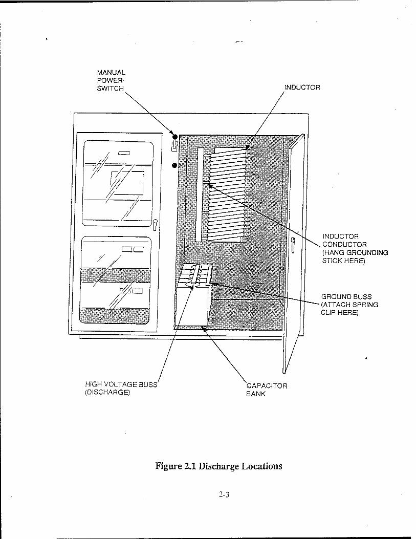
MANUAL POWER SWITCH INDUCTOR
INDUCTOR CONDUCTOR (HANG GROUNDING STICK HERE)
GROUND BUSS (ATTACH SPRING CUP HERE)
HIGH VOLTAGE BUSS (DISCHARGE)
CAPACITOR BANK
Figure 2.1 Discharge Locations
2-3
SECTIONS- OPERATING INSTRUCTIONS
Instrumented models can be locally controlled from the front panel of the high voltage power supply. All models, whether instrumented or non-instrumented, can be fully controlled re- motely via the remote control connector located on the rear panel of the unit
3.1 Local Control.
Local control of a fully instrumented power supply is achieved via the front panel controls shown in Figure 3-1. CCDS High Voltage Power Supply Front Panel. Unless the REMOTE CONTROL ENABLE is activated, the remote control functions of the power supply are always disabled to provide maximum operator and personnel safety.
3.1.1 Control Power ON/OFF
Push the Control Power switch to turn ON the power supply control power. Assuming the external interlock is satisfied and the power supply internal fault protection interlocks are satisfied, the power supply is ready to produce the high voltage output.
NOTE
Prior to activating the high voltage output, be sure the output of the supply is connected to the load capacitor and the desired output voltage level is set via the Voltage Programming knob.
3.1.2 Voltage Programming
Turn the Voltage Programming knob to the desired percentage of the rated output voltage.
3.1.3 HV ON.
To activate the high voltage output, push the HV ON switch.
3.1.4 HV OFF.
To deactivate the high voltage output, push the HV OFF switch.
3.1.5 Voltage and Current Monitors.
The output voltage and the average output current is displayed on the front panel of the instrumented units using 3.5 digit LCD displays.
3.2 Remote Control.
The standard user controls and monitor inter- faces for the power supply are' available through the remote control connector, J201, located on the rear panel as shown in Figure 3-2. CCDS High Voltage Power Supply Rear Panel. A summary of the remote control interface is shown in Table 3-1. Remote Control Interface. A detailed description of each function follows:
3.2.1 Remote Control Enable.
To use remote voltage programming and re- mote HV ON/OFF, the REMOTE CONTROL ENABLE, Pin 8 must be connected to GROUND, Pin 15. In instrumented versions, this will disable the front panel voltage programming control, thus preventing a remotely controlled unit from being accidentally misadjusted from the front panel. For maximum operator and personnel safety, the front panel HV OFF and voltage and current displays are operational, regardless of the status of the REMOTE CONTROL ENABLE Pin.
3-1
3.2.2 Voltage Programming.
The desired output voltage can be set by an external input on Pin 12 of the remote control connector. An external input of 0 to 10 V on Pin 12 programs the output voltage from 0 to 100 percent.
NOTE
Remote HV prograrnming requires activating the remote control enable by connecting Pins 8 and 15. This configuration will allow HV ON and HV OFF activation from both the front panel and remote controls.
3.2.3 High Voltage ON/OFF.
Remote HV ON requires a momentary contact closure between Pins 2 and 4.
NOTE
Remote HV ON operation requires activating the remote control enable by connecting Pins 8 and 15.
A momentary opening of Pins 1 and 3 activates the HV OFF.
NOTE
Pins 1 and 3 must be closed prior to the momentary closure of Pins 2 and 4 to turn the HV ON.
3.2.4 HV Inhibit.
A TTL compatible, HV INHIBIT input is provided to rapidly disable the inverter when the HV ON is in the activated state. This allows for a fast termination of a charging cycle or external logic controlled charging
periods. A TTL "1" state at Pin 7 inhibits the high voltage output, while a TTL "0" (or open connection) allows for normal output operation via the HV ON/OFF controls. The HV INHIBIT input pin is referenced to digital ground, Pin 15.
3.2.5 Voltage Reference.
A buffered precision +10 V reference output is provided on Pin 10 of the remote connector for use with the remote voltage programming input. The voltage reference is referenced to the analog ground, Pin 11.
3.2.6 End of Charge.
CAUTION
The maximum voltage to be applied to Pin 13 through a pull-up resistor is 24 VDC. The pull-up resistor should limit the current to less than 25 mA.
An open collector output is provided on Pin 13 that is in a TTL "0" state, i.e., the collector is low when the supply is in the charging mode. The collector goes open circuit (external pull-up is required for logic "1" state) when the preset charge voltage is reached and the supply switches to the "keep alive" mode. This signals the EOC and tells the remote user the load capacitor is charged to the programmed voltage and is awaiting discharge into the load. The collector will remain in the open state as long as the load capacitor voltage is at the programmed voltage level. This output is referenced to digital ground, Pin 15.
3-2

3.2.7 Voltage Monitor.
A 0 to 10 V output signal located on Pin. 5 of the remote control connector provides a linear analog monitor of the power supply output voltage corresponding to 0 to 100 percent of the rated output voltage. This output signal is referenced to analog ground, Pin 11.
3.2.8 Current Monitor.
An analog current monitor of the power supply's average output current is located on Pin 6 of the remote control connector. The current monitor voltage output is normally calibrated to 10 mV/mA. The analog current monitor output is referenced to analog groung, Pin 11.
3.2.9 HV ON Indicator.
Pin 14 of the remote control connector is a TTL HV ON indicator. The voltage on Pin 14 will be greater than 4 V when the power supply is in the HV ON state. It will be less than 0.6 V when the power supply is in the HV OFF state. Also, this signal can be used as a fault indicator since it will go to the HV OFF state if there is any unexpected fault in the supply.
3.3 External Interlock.
CAUTION
The voltage appearing on the external internal terminals is 24 VDC. Con- nections to these terminals must be done with isolated contacts to prevent potential damage to the power supply controls.
An external safety interlock option is provided by TB201 on the rear panel. Terminals 1 and 2 must be connected with isolated contacts to
allow the power suppy to be activated. When using multiple interlocks, it is recommended the isolated contacts of each be connected in series. This can be utilized as a safety switch to disable the power supply HV output in the event of an external fault condition. An open circuit between terminals 1 and 2 will inhibit the high voltage output under any condition.
3.4 AC Input Connections.
WARNING G This connection must be made to assure maximum personnel safety.
The 208 VAC, 30 power connections are made to TB1 located on the rear panel. The ground wire should be connected to the chassis ground screw terminal located under TB1.
WARNING
As with the majority of commercial power supplies and pieces of lab- oratory electronic equipment today, the input filter capacitors remain charged as long as the circuit breaker, CB1, is on and the unit is connected to the power line. This is independent of the position of the control power ON/OFF switch of an instrumented unit
The 30 input cable should be sized to handle the maximum input current stated in the electrical specifications section of this manual. The standard power supply is provided with an internal 30 circuit breaker, CB1, located on the rear panel.
Carefully read Section 5 prior to removing the top cover of the power supply.
3-3
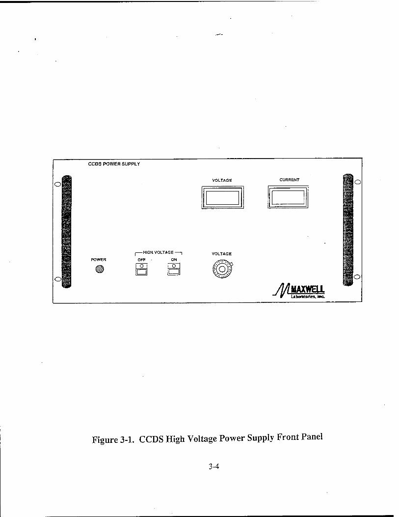
CCDS POWER SUPPLY
Of VOLTAGE CURRENT o
ol
I HIGH VOLTAGE —
OFF ON
O O m M
io
MAXWELL Laboratories, tac.
Figure 3-1. CCDS High Voltage Power Supply Front Panel
3-4
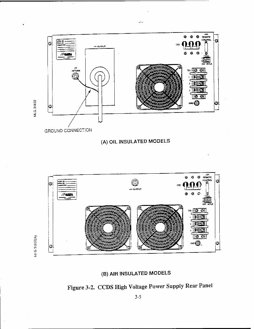
2
J3J1
BEMOTI
GROUND CONNECTION
(A) OIL INSULATED MODELS
© © © - W
THI @ @
gS S nggr "oof
o«COj 3
|®
'f'TWi'i
nV OUTPUT
8»
vilf ^<5^9»!W^^^
J201 REMOTE
©
JJ L
© © ©
'tWöTi
-j<oroj ©
(B) AIR INSULATED MODELS
Figure 3-2. CCDS High Voltage Power Supply Rear Panel
3-5

Table 3-1. Remote Control Interface
PIN NUMBER
2,4
1,3
13
14
10
12
5
6
7
8
11,15
9
DESCRIPTION
HV ON: Normally open, momentarily short to turn HV ON.
HV OFF: Normally closed, open to turn HV OFF.
EOC: Open collector output, open at EOC.
HV ON Indicator: TTL high indicates HV ON; HVPS okay.
+10V reference for resistive voltage prograinming (10mA max.)
Voltage Programming: 0 to 10 V for 0 to 100% output voltage.
Voltage Monitor 0 to +10 V for 0 to 100% output voltage.
Current Monitor: lOmV/mA for 0 to 100% output current typical.
HV Inhibit: TTL high inhibits HV output.
Remote Enable: Ground to enable remote control.
Ground for control signals.
Unused
3-6

SECTION 4 FUNCTIONAL DESCRIPTION
The Power Supply Block Diagram is shown in Figure 4-1. The AC input section includes a 30 circuit breaker, common/differential mode EMI filter, an inrush surge limit circuit, and the 30 line rectifier and filter capacitors. The switching power converter utilizes a series resonant "H" bridge topology which drives the primary of a multi-secondary high frequency step-up transformer. Multiple, full-wave bridge, high voltage rectifier circuits produce the rectified high voltage output. The control circuit utilizes a fixed frequency, quasi-pulse width modulated scheme to drive the power converter. All user controls are buffered and interface with the control circuit directly. The following is a detailed description of the functions of each element in the block diagram.
4.1 INPUT EMI FILTER.
The 30 input EMI filter attenuates both common mode (lines-to-chassis) and differential mode (line-to-line) high frequency noise. This includes conducted EMI, i.e., RF noise generated internally by the power supply inverter circuit and externally generated noise which may enter the power supply on the power lines. The filter is composed of a 30 balun inductor with "X" (line-to-line) and "Y" (line-to-ground) capacitors placed symmetrically on both sides of the inductor. The filter has a common mode attenuation of better than 40 dB at 1 MHz and above.
4.2 INRUSH CURRENT LIMIT.
WARNING
As with the majority of commercial power supplies and pieces of lab- oratory electronic equipment today, the input filter capacitors remain charged as long as the circuit breaker is on and the unit is connected to the power line. This is independent of the position of the control power ON/OFF switch.
The inrush current limit circuit prevents high inrush surge currents during the charging of the input capacitors when the circuit breaker is initally turned on. The input capacitors are initially charged through a thermistor which limits the inrush charging current to a maximum of 16 A. The thermistor-has a negative temperature coefficient. In the event of a short in the circuit after the thermistor, the thermistor resistance will drop to a sufficiently low value to cause the circuit breaker to trip. When the HV ON circuit is activated to start a charging cycle and the inverter turns on, an SCR fires that bypasses the inrush limiting thermistor, thus connecting the input capacitors directly to the input rectifiers during inverter operation.
Carefully read Section 5 prior to removing the power supply top cover.
4-1
4.3 SERIES RESONANT INVERTER.
The power converter utilized in the CCDS power supply is a series resonant "H" bridge topology operating in the 40 kHz range. This particular converter topology is ideal for high power, capacitor charging applications since it reflects a high source impedance to the output; consequently, this topology is inherently short circuit proof. The output characteristics of the inverter topology combined with the CCDS control topology result in a constant current (linear) charging profile.
The H-bridge switch elements are comprised of parallel power MOSFET transistors (FETs) or insulated gate bipolar transistor (IGBTs). The characteristics of these devices provide reliable high voltage, high current capability and easy device paralleling and control. When used as switches in a series resonant configuration as described above, the devices can be made to switch at zero current because of the sine wave property of the current in the LC circuit. As a consequence, the switching transistors have zero switching losses as compared to conventional pulse width modulated, quasi-square wave converter topologies.
4.4 HIGH VOLTAGE OUTPUT CIRCUITRY.
A multiple secondary high voltage transformer is used to step up the inverter voltage to the required output voltage. Multiple high voltage secondary windings are used to reduce the effects of parasitic resonances caused by secondary inductance and self-capacitance and to simplify the diode assemblies. Each winding is full-wave rectified by a high voltage diode bridge configuration. The rectifier circuits are then connected in series to sum the rectified voltage levels to the final output level.
The high voltage power transformer and entire high voltage output section (on 10 kV and higher supplies) is contained in a sealed, dielectric oil filled tank with oil-tight feedthroughs for all input/output lines. By paying careful attention to design stresses and using Maxwell's extensive capacitor impregnation knowledge base, oil insulation will assure maximum long term reliability of the high voltage section.
4-2
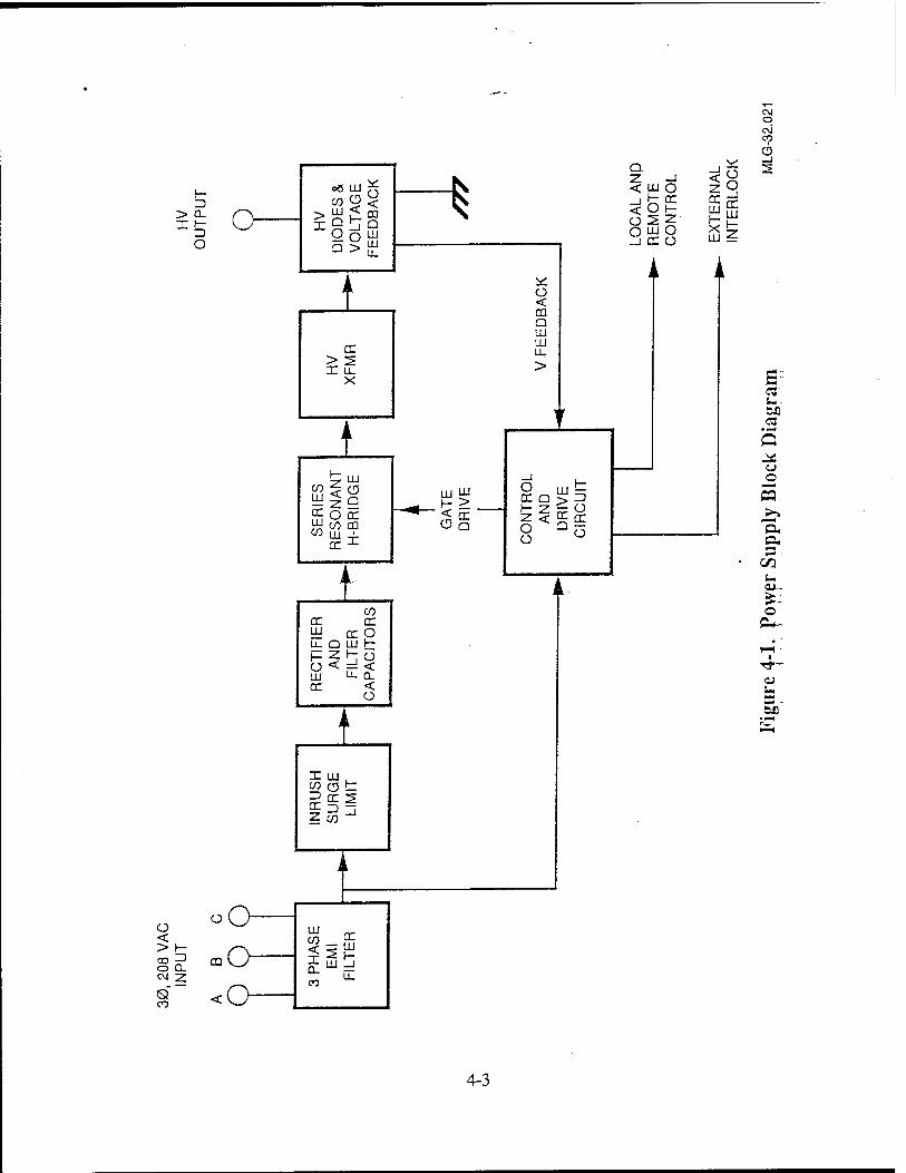
ü < > h- O 0- CM z Q
CO cc er LU cc o U_ Q LU h- t— z H- ü o < < 111 u_ a. er <
ü
I X III CO (T H- _) er s CE 3 . i Z CO
IM O C\J CD
CD
Q
<8 _i
Z -l < uj o zQ -l fcoc < O K-
.XTE
R
^JTE
RL
ü 2Z O UJ O llCCÜ LU :=
es- u CD C3
o
'S. o. 3
u. CU-
o 0^
3-
4-3
SECTION 5 SERVICE
WARNING
THE 208 VAC POWER IS PRESENT IN THE POWER SUPPLY WHEN THE CIRCUIT BREAKER IS CLOSED REGARDLESS OF THE STATUS OF THE FRONT PANEL CONTROL POWER ON/OFF SWITCH ON FULLY INSTRUMENTED MODELS. THIS VOLTAGE MAY BE LETHAL. BEFORE WORKING WITHIN THIS EQUIPMENT, TURN OFF THE MAIN 30 AC INPUT POWER AT THE CIRCUIT BREAKER, DISCONNECT THE AC POWER FROM THE SOURCE AND WAIT A MINIMUM OF FIVE (5) MINUTES FOR THE ENERGY STORED IN THE AC FILTER CAPACITORS TO DISSIPATE. UPON OPENING THE UNIT, DISCHARGE AND SECURELY GROUND THE FILTER CAPACITORS AT THE TERMINALS MARKED "INPUT" LOCATED IN THE CENTER OF THE INVERTER PCB.
CAUTION
THE MAKING OF ADJUSTMENTS TO A MODULE MUST BE DONE BY MAXWELL SINCE SEVERE DAMAGE MAY OCCUR DUE TO IMPROPER DAJUSTMENT. ANY WARRANTY SERVICE MUST BE PERFORMED BY OR UNDER THE DIRECT SUPERVISION OF FACTORY QUALIFIED PERSONNEL ONLY.
All servicing must be couducted or su- pervised by Maxwell service engineers. The power supply is modular and the modular sections can be removed for servicing or exchange under the direction of supervision of Maxwell service
engineers. It is, therefore, recommended that the product be returned to Maxwell for servicing, for both warranty and after warranty repair. Prior to shipping a power supply for service, call the Maxwell Sales Office at 1-800-854-1505 to obtain a "Returned Goods" number.
5-1

SECTION 6 WARRANTY SUMMARY
This product is sold by Maxwell under the warranty set forth in Maxwell's Standard Terms and Conditions of Sale.
The warranty is only extended to the buyers purchasing the product directly from Maxwell or a Maxwell distributor.
6-1

SECTION 7 PARALLEL OPERATION
The power supplies can be operated in parallel to increase the output charging current. This is done utilizing a master/ slave configuration in which the slave supplies are automatically controlled by the master supply which is interfaced to the user. The master/slave intercon- nections are done via the "Master/Slave Interconnect Cable Assembly" avail- able from Maxwell. Any supply in the system can be an instrumented or non- instrumented version. When operated in the master/slave configuration, the following are applicable:
1. The HV ONOFF, voltage program- ming, and voltage and current monitor functions should all be accessed from the master unit. For instrumented master units, this can be done locally or remotely.
2. An interlock opening in the master supply will shut down the entire system, however, an interlock opening in a slave supply will result in the shutdown of that supply only. Therefore, it is recommended to use the "external interlock" function of the master unit only.
7-1
SECTION 8 HIGH VOLTAGE OUTPUT CONNECTION
The high voltage output is accessed on the rear panel with the high voltage coaxial cable assembly. For maximum personnel safety, Maxwell recom- mends that the shield on the HV output cable assembly be connected to the HV
ground return stud located next to the HV output connector on the rear panel. Maxwell recommends the chassis of the power supply be securely grounded to the system ground in a low inductance manner.
8-1
SECTION 9 MOUNTING
The power supply is contained in a standard 19 inch wide X 8.75 inch tall rack mounted chassis. When mounting the supply in a rack mount cabinet, the power supply must be supported by chassis slides or support brackets in order to avoid excessive stress on the front panel. The power supply can be fitted with rolling chassis slides at the factory as an option.
Allow a minimum of three (3) inches of space at the rear of the supply for proper air flow and cooling.
CAUTION
The power supply is designed to operate in a horizontal position ONLY. Operating the supply in a vertical position can result in damage to the unit.
For applications requiring non- horizontal mounting, contact the Maxwell Sales Office at 1-800-854- 1505 for consultation with an applications engineer.
9-1

SECTION 10 APPLICATION NOTES AND COMMENTS
10.1 Charging Large Capacitor Banks.
Since the output of the CCDS power supply is a constant current, the full power capability of the supply can be realized only when set for maximum rated output voltage. In applica- tions where large parallel banks of capacitors with high leakage currents are charged then held for a period prior to discharge, the power supply may not be able to supply the leakage current and maintain the preset "keep alive" voltage once the capacitor bank is charged. The "keep alive" output current level can be internally adjusted to overcome this situation. Contact the Maxwell Sales Office at 1-800- 854-1505 for consultation with an applications engineer.
10.2 Overvoltage/No Load Condition.
The CCDS power supplies are designed to latch in the HV OFF state if the output voltage exceeds 110 percent of the maximum rated voltage level. The Overvoltage Protection (OVP) circuitry will protect the power supply in the event of an accidental open circuit output connection or no load condition. The user should make every effort to prevent this condition from occurring. If the supply latches in the HV OFF state, the HV indicator(s) will indicate the HV OFF state and the voltage monitor will read a constant voltage. These symptoms indirectly tell the user an overvoltage condition has occurred. In instrumented units, the power supply control power must be cycled ON/OFF to return the supply to an operational mode. In non-instrumented units, the main 30 power must be cycled ON/OFF to return the power supply to an operational mode.
10.3 Output Voltage Reversal.
CAUTION
Voltage reversal greater than 10 per- cent of the rated output voltage will cause damage to the power supply unless external protection circuitry is provided.
The CCDS-225 power supply is designed to operate with a maximum voltage reversal of 10 percent of the rated output voltage on a single-shot or fault basis. For applications in rep-rate power conditioning systems subject to repetitive voltage reversal, contact Maxwell application engineers at 1-800-854- 1505 for a recommended power supply protection circuit.
If the system being driven by the power supply is under-damped during the discharge period and voltage reversal is anticipated, the factory should be consulted so a proper external protection circuit design can be provided which will protect the power supply from damage.
10.4 Special Applications.
For special applications not outlined in this manual, please consult Maxwell at 1-800- 854-1505 for information and/or specific details regarding your needs.
10-1

SECTION 11 TROUBLESHOOTING GUIDE
PROBLEM
Power supply does not turn ON when front panel switch is activated.
POSSIBLE CAUSE
Rear panel breaker is not switched to ON position.
Front panel High Voltage ON Switch cannot be activated.
External rear panel interlock connection not made properly on TB201.
High voltage output is open circuited and over- voltage circuit has latched. Connect proper load and recycle front panel ON/OFF switch.
Power supply is wired for remote operation. Check J201 wiring on Pin 8.
High Voltage ON can be activated, but no output voltage is produced.
J201 Pin 7 is miswired.
High voltage output is shorted at load.
High Voltage ON cannot be activated by remote control via J201.
Pin 8 is not grounded.
High voltage output is open circuited. O.V.P. circuit has tripped.
J201 remote interface is wired improperly.
TB201 external interlock connection is not made.
For problems not covered in the Troubleshooting Guide, contact Maxwell Sales Office at 1-800-85--- :3.
11-1
MDC-92B0479-1
Appendix A3 B-Pure Pressure Cartridge System Series 583 Operation Manual/Parts List
$ -»
A-3
Barnstead|Thermoiyne Corporation
B-Pure Pressure Cartridge System
OPERATION MANUAL AND PARTS LIST
SERIES 583
p. ■:■ >■■
\<***£ ' '
M •A«fcixoi.:.;.'
Model # D4505 D4511 D4521 D4522 D4523 D4524
Voltage
120 240 100 120
Model« D4525 D5831 D5S32 D5833 D5834 D5839
Voltage 240 120 240 120 240
LT583X1 - 3/13&1 Serial Number:
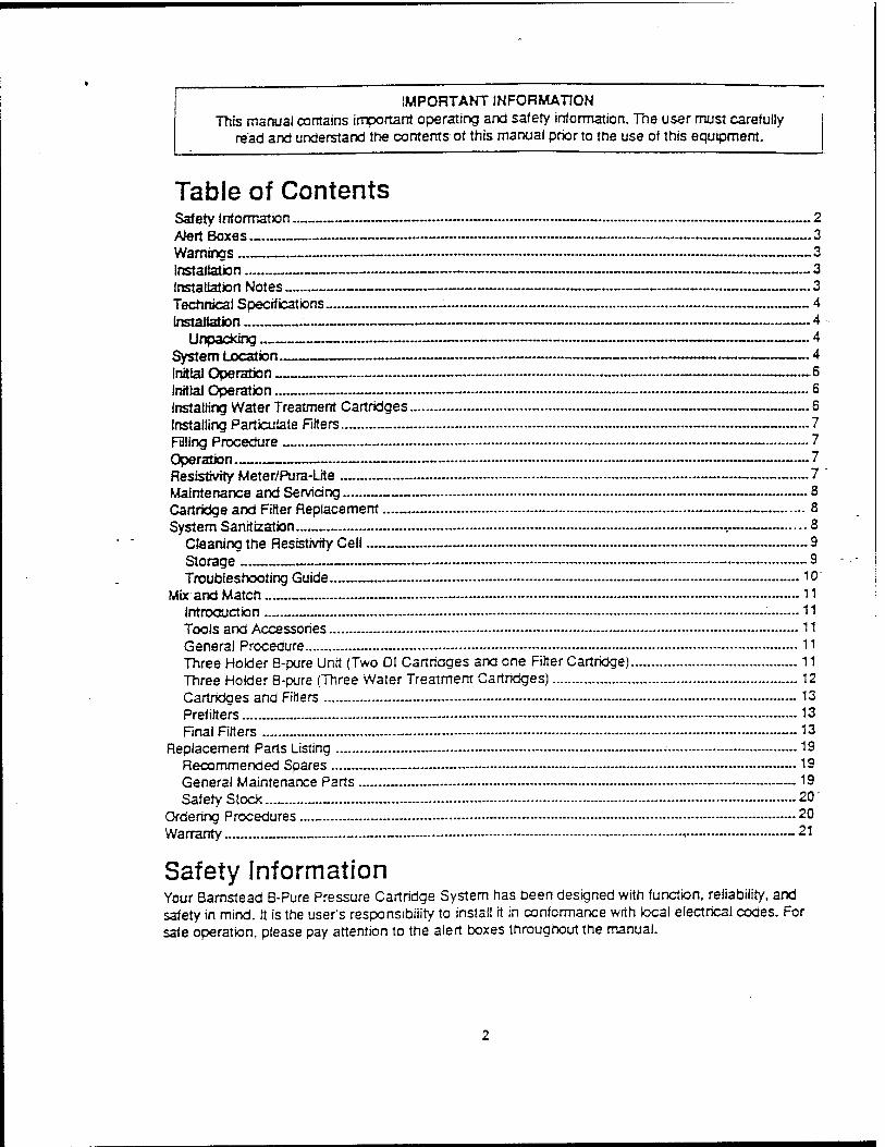
IMPORTANT INFORMATION This manual contains important operating and safety information. The user must carefully
read and understand the contents of this manual prior to the use of this equipment.
Table of Contents Safety Information - ~ 2 AJert Boxes — - 3 Warnings • 3 Installation 3 Installation Notes 3 Technical Specifications — - . 4 Instatlalion 4
Unpacking . • —• 4 System Location 4 Initial Operation 6 Initial Operation _ — — 6 Installing Water Treatment Cartridges ~ _ 6 Installing Particulate Filters _ _ 7 Rung Procedure 7 Operation 7 Resistivity Meter/Pura-Lite - - 7 ' Maintenance and Servicing 8 Cartridge and Filter Replacement — - - - 8 System Samtization— —-.. 8
Cleaning the Resistivity Cell — _ - - 9 Storage - 9 Troubleshooting Guide -— 10
Mix and Match - i1 Introduction _ - 11 Tools and Accessories 11 General Procedure 11 Three Holder B-pure Unit (Two DI Cartridges and one Filter Cartridge) 11 Three Holder B-pure (Three Water Treatment Cartridges) 12 Cartridges and Fitters - 13 Prefifters 13 Final Fitters -13
Replacement Parts Listing - - 19 Recommended Spares _ 19 General Maintenance Parts _ 19 Safety Stock _ 20
Ordering Procedures— 20 Warranty _ _ _ • -21
Safety Information Your Barnstead B-Pure Pressure Cartridge System has been designed with function, reliability, and safety in mind, tt is the user's responsibility to install it in conformance with local electrical codes. For safe operation, please pay attention to the alert boxes throughout the manual.
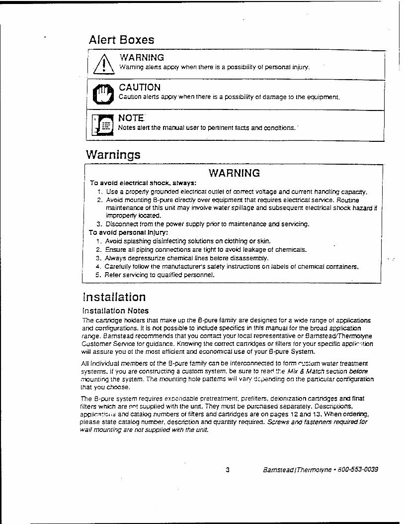
Alert Boxes WARNING
J \ Warning alerts apply when there is a possibility of personal injury.
CAUTION Caution alerts apply when there is a possibility of damage to the equipment.
NOTE — I Notes alert the manual user to pertinent facts and conditions.
Warnings
WARNING To avoid electrical shock, always:
1. Use a properly grounded electrical outlet of correct voltage and current handling capacity. 2. Avoid mounting B-pure directly over equipment that requires electrical service. Routine
maintenance of this unit may involve water spillage and subsequent electrical shock hazard if improperly located.
3. Disconnect from the power supply prior to maintenance and servicing. To avoid personal Injury:
1. Avoid splashing disinfecting solutions on clothing or skin. 2. Ensure all piping connections are tight to avoid leakage of chemicals. 3. Always depressurize chemical lines before disassembly. 4. Carefully follow the manufacturer's safety instructions on labels of chemical containers. 5. Refer servicing to qualified personnel.
Installation Installation Notes The cartridge holders that make up the B-pure family are designed for a wide range of applications and configurations. It is not possible to include specifics in this manual for the broad application range. Barnstead recommends that you contact your local representative or Bamstead/Thermotyne Customer Service for guidance. Knowing the correct cartridges or filters for your specific applic-ition will assure you of the most efficient and economical use of your B-pure System.
AJ! individual members of the B-pure family can be interconnected to form r-jsjom water treatment systems. If you are constructing a custom system, be sure to read the Mix & Match section before mounting the system. The mounting hole patterns wiil vary depending on the particular configuration that you choose.
The B-pure system requires expendable pretreatmerrt, prefifters, deionization cartridges and final filters which are n«! supplied with the unit. They must be purchased separately. Descriptions, applie^t-cns and catalog numbers of filters and cartridges are on pages 12 and 13. When ordering, please state catalog number, description and quantity required. Screws and fasteners required for wall mounting are not supplied with the unit.
BarnsteadIThermotyne • 800-553-0039

Technical Specifications Feedwater Requirements
Types Maximum pressure Temperature
Tap, RO, Dt, distilled 7 kg/cm2 (100 psig) maximum 4-*9°C(40-120°F)
installation Mounting Dimensbns, mm (in.)
Width Depth.' Height
Op. weight, kg (lbs) Plumbing Connections
Inlet Outlet
Wall mount, with bracket provided Dual B-pure 381 (15) 171.5(6 3A) 673 (25 V2) 12.7(28)
V2" NPTF V2- NPTF V4" NPTF S/16* 00 Hose barb
Single B-pure Half-size Holder 178(7) 178(7) 1715(6 8/4) 171.5(6 3/4) 591 (23 1/4) 368 (14 V2) 5.9(13) 5(11)
V2" NPTF" 1/2" NPTF V2" NPTF 1/2" NPTF-
0.1-18.3 megohm-cm (Temperature Compensated to 25°C/77°F) ±1.0 megohm-cm 0.1 constant
108-132 VAC, 47-63 Hz, 5 Watts 216-264 VAC, 47-63 Hz, 5 Watts
Resistivity Measurement Range
Accuracy Cell Electncai Requirements
120 VAC, 50/60 Hz 240 VAC, 50/60 Hz
Installation Unpacking Unpack the B-pure carefully. B-pure units come completely assembled. A spare head interconnector (15853) is~supplied as a loose part with the single B-pure (D4511) and the V2 B-Pure (D4505 and D5S39). Retain this item for possible later use in expansion.
System Location The B-pure should be mounted at a convenient height for routine operation. Adequate front access will be required for cartridge or filter exchange and reading of the resistivity meter, if used. The - following clearances are necessary:
• Left and right side clearance - AJI B-pure products, 4" minimum
• Ree space below canisters - All 8-pure products, 4" minimum
• Free Space Above Center ot Wall Bracket - All B-pure products without meter, 4" minimum - B-pure products with meter, 8" minimum

WARNING Do not mount B-Pure directly over eauipment that requires electrical service. Routine maintenance of this unrt may invorve water spiilage and subsequent electnca! shock hazard ff improperty located.
The recommended dimensions for mounting hardware to support your equipment are: • Body Diameter, V*" maximum • Head Diameter, Vs" maximum • Length, 1" typical
© CAUTION Wall and mounting hardware must be capable of supporting the full operational weights - as outlined in the technical characteristics section of this manual. Inadequate support or fasteners may result in damage to mounting surface and/or equipment. Use adequate hardware for the job. If you are unsure of the hardware, consult your building maintenance group or contractor..
Mounting and Utility Connections All B-pure installations require a user supplied shutoff valve in the incoming water service line. In some installations, it may be desirable to provide an outlet shutoff valve. A drawoff valve assembty is provided on the Dual Holders as a standard and may be ordered as an optional extra for other B-pure products. (See exploded view drawing for part numbers.)
_, NOTE E=:j If you are constructing a custom water treatment system using B-Pure components, read
the Mix and Match section of this manual before proceeding further.
Mount the B-Pure unrt using the following steps: 1. Remove the wall brackets from the unit by removing the two securing screws on the left and the
' right bottom portion of the brackets. Slide brackets downward to release. 2. Using the wall brackets as a template, mark the hole locations on the wail.
3. Drill holes in wall suitable for the selected fasteners . 4. Mount wall brackets and secure with fasteners. 5. Re-secure B-Pure on brackets and refasten securing screws. 6. Connect feedwater service to the left side of the head assembly using adapter provided. Use
Teflon* tape on threads to assure a leak-free connection.
O CAUTION Do not overtighten this connection — excessrve tightening wiil crack the adapter.
7. Make outlet connections as required by your specrfic application.
* Registered trademark of DuPont
BarnsteadlThermolyne • 800-553-0039

Initial Operation Initial Operation Various types of fitters and cartridges are used in B-pure systems; 10* nominal paniculate filters and cartridges are used in the hatf-size canisters and nominai 17" water treatment cartridges used in trie full size canisters.
installing Water Treatment Cartridges 1. Remove the cartridge from trie bag.. 2. Remove the canister from trie head by depressing the thumb lever and rotating the hana ring »A
turn to the left. 3. Check to ensure that trie small o-ring inside the head is in place. This is important because
water wiii bypass the cartridge if this o-ring is not in place. 4. Place cartridge(s) in canister with the targe opening down. 5. Wet canister o-ring before installation, install canister by depressing thumb lever and rotating V*
turn to the right, until the locking pin is in appropriate position (see figure 1).
© CAUTION Secure locking pin before operating. Locking pin on canister must be fully released into hole in head before system is operated.
Figure 1: Canister locking pin position
NOTE An extra set of head-tc-canister Orings are supplied. These can be used to replace any O-rings that may have been damaged or deformed in shipment.
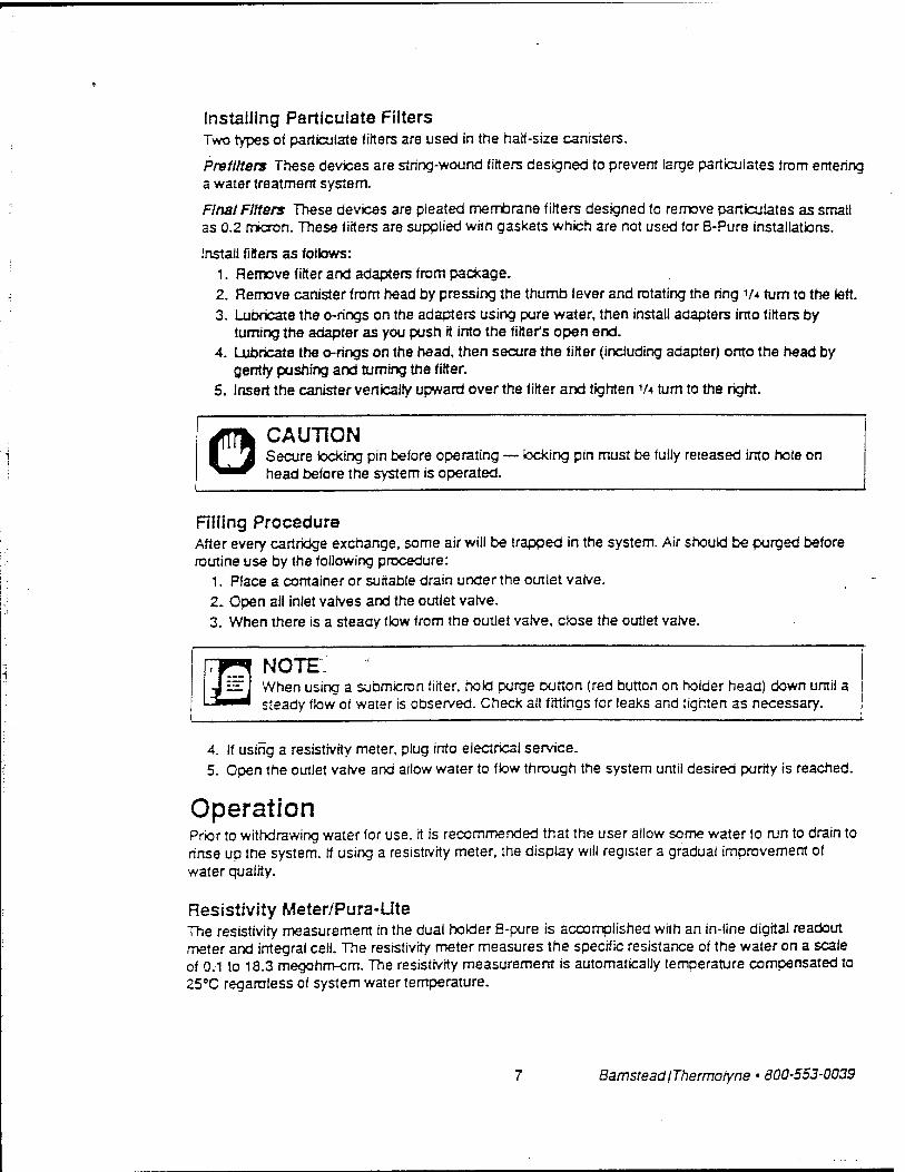
Installing Paniculate Filters Two types of paniculate fitters are used in the half-size canisters.
Prefllters These devices are string-wound fitters designed to prevent large particuiates from entering a water treatment system.
Final Filters These devices are pleated membrane fitters designed to remove particuiates as small as 0.2 mtcron. These fitters are supplied with gaskets which are not used for B-Pure installations.
Install fitters as follows: 1. Remove fitter and adapters from package. 2. Remove canister from head by pressing the thumb lever and rotating the ring v* turn to the left. 3. Lubricate the c-rings on the adapters using pure water, then install adapters into fitters by
turning the adapter as you push it into the fitter's open end. 4. Lubricate the o-rings on the head, then secure the fitter (including adapter) onto the head by
gently pushing and turning the fitter. 5. Insert the canister vertically upward over the fitter and tighten V* turn to the right.
© CAUTION Secure locking pin before operating — locking pin must be fuily released into hole on head before the system is operated.
Riling Procedure After every cartridge exchange, some air will be trapped in the system. Air should be purged before routine use by the following procedure:
1. Place a container or suitable drain under the outlet valve.
2. Open ail inlet varves and the outlet valve. 3. When there is a steady flow from the outlet valve, close the outlet valve.
NOTE: — J When using a submicron fitter, hold purge button (red button on holder head) down until a
steady flow of water is observed. Check all fittings for leaks and tighten as necessary.
4. If using a resistivity meter, plug into electrical service. 5. Open the outlet valve and allow water to flow through the system until desired purity is reached.
Operation Prior to withdrawing water for use, it is recommended that the user allow some water to run to drain to rinse up the system. If using a resistivity meter, the display will register a gradual improvement of water quality.
Resistivity Meter/Pura-Ute The resistivity measurement in the dual holder S-pure is accomplished with an in-line digital readout meter and integral cell. The resistivity meter measures the specific resistance of the water on a scale of 0.1 to 18.3 megohm-cm. The resistivity measurement is automatically temperature compensated to 25°C regardless of system water temperature.
BamsteadlThermotyne • 800-553-0039
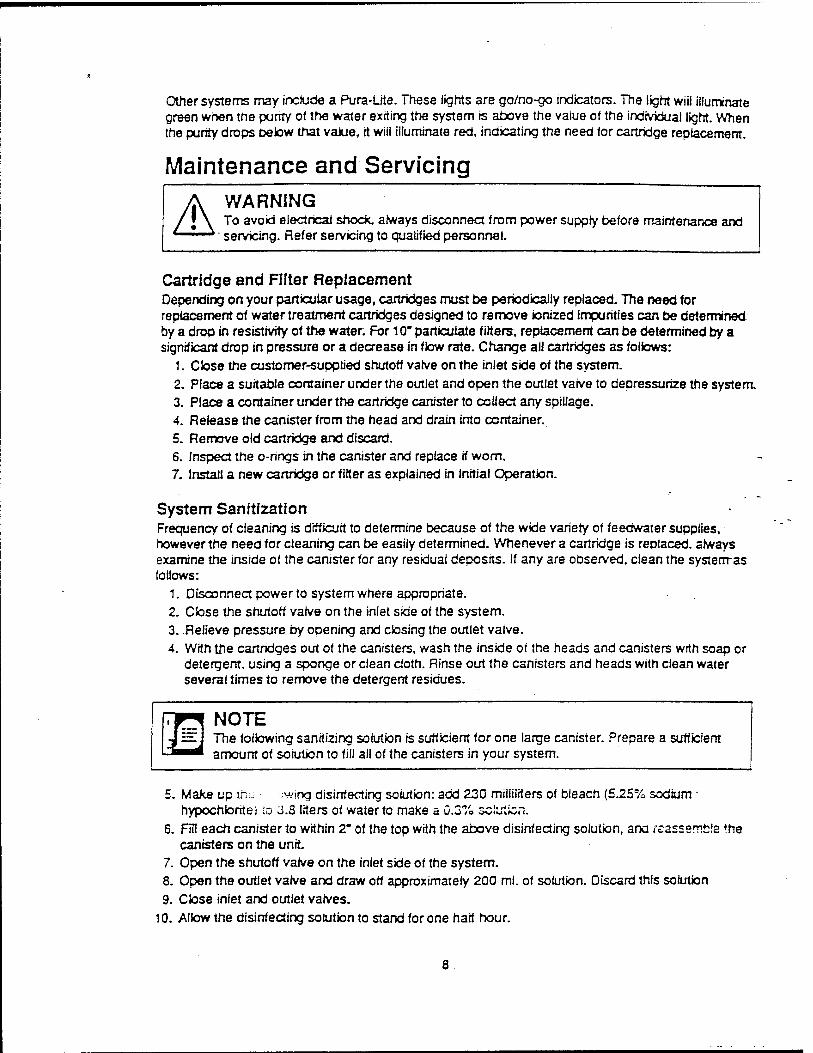
Other systems may include a Pura-Ute. These lights are go/no-go indicators. The light wiii illuminate green when the purity o< the water exiting the system is above the value of the individual light. When the purity drops betow that vaiue, it wiii illuminate red, indicating the need for cartridge replacement.
Maintenance and Servicing
A WARNING To avoid electrical shock, always disconnect from power supply before maintenance and servicing. Refer servicing to qualified personnel.
Cartridge and Filter Replacement Depending on your particular usage, cartridges must be periodically replaced. The need for replacement of water treatment cartridges designed to remove ionized impurities can be determined by a drop in resistivity of the water. For 10" paniculate filters, replacement can be determined by a significant drop in pressure or a decrease in flow rate. Change all cartridges as follows:
1. Close the customer-supplied shutoff valve on the iniet side of the system. 2. Place a suitable container under the outlet and open the outlet vaive to depressurize the system 3. Place a container under the cartridge canister to collect any spillage. 4. Release the canister from the head and drain into container. 5. Remove old cartridge and discard. 6. Inspect the o-rings in the canister and replace if worn. 7. Install a new cartridge or filter as explained in Initial Operation.
System Sanitfzation Frequency of cleaning is difficult to determine because of the wide variety of feedwater supplies, however the need for cleaning can be easily determined. Whenever a cartridge is replaced, always examine the inside of the canister for any residual deposits. If any are observed, clean the systemas follows:
1. Disconnect power to system where appropriate. 2. Close the shutoff valve on the inlet side of the system. 3. Relieve pressure by opening and closing the outlet valve. 4. With the cartridges out of the canisters, wash the inside of the heads and canisters with soap or
detergent, using a sponge or clean cloth. Rinse out the canisters and heads with clean water several times to remove the detergent residues.
NOTE i ==. j The following sanitizing solution is sufficient for one large canister. Prepare a sufficient
amount of solution to fill all of the canisters in your system.
5. Make up tm; ;wing disinfecting solution: add 230 millilrters of bleach (5.25% sodium - hypochJorite) to 3.3 liters of water to make a 0.3% sciuticn.
6. Fill each canister to within 2" of the top with the above disinfecting solution, ana reassemble the canisters on the unit
7. Open the shutoff valve on the inlet side of the system. 8. Open the outlet valve and draw off approximately 200 ml. of solution. Discard this solution 9. Close inlet and outlet valves.
10. Allow the disinfecting solution to stand for one half hour.
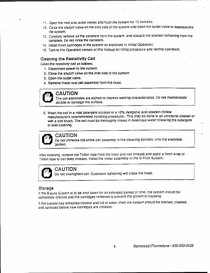
11. Open the inlet and outlet valves and flush the system tor 10 minutes. 12. Close the shutorf varve on the iniet side of the system and open the outlet varve to depressurize
the system. 13. Carefully remove all the canisters from the system, and discard the solution remaining from the
canisters. Do not rinsa the canisters. 14. Install fresh cartridges in the system as explained in Initial Operation. 15. Turn to the Operation section of this manual (or filling procedure and normal operation.
Cleaning the Resistivity Cell Clean the resistivity cell as follows:
1. Disconnect power to the system.
2. Close the shutorf valve on the inlet side of the system. 3. Open the outlet vatve. 4. Remove meter and call assembly from the head.
o CAUTION The cell electrodes are etched to improve wetting characteristics. Do not mechanically abrade or damage this surface.
5. Wash the cell in a mild detergent solution or a 10% inorganic acid solution (follow manufacturer's recommended handling procedure). This may be done in an ultrasonic cleaner or with a soft brush. The cell must be thoroughly rinsed in deionized water following the detergent or acid cleaning.
© CAUTION Do not immerse the entire cell assembly in the cleaning solution, only the electrode portion.
After cleaning, remove old Teflon tape from the head and cell threads and apply a fresh wrap of Teflon tape to cell body threads. Install the meter assembly in the B-Pure System.
Q CAUTION Do not overtighten cell. Excessive tightening will crack the head.
Storage If the B-pure System is to be shut down for an extended period of time, the system should be completely drained and the cartridges removed to prevent the growth of bacteria.
If the system has remained inactive and full of water, then the system should be drained, cleaned, and sanitized before new cartridges are installed.
BamsteadIThermotyne • 800-553-0039
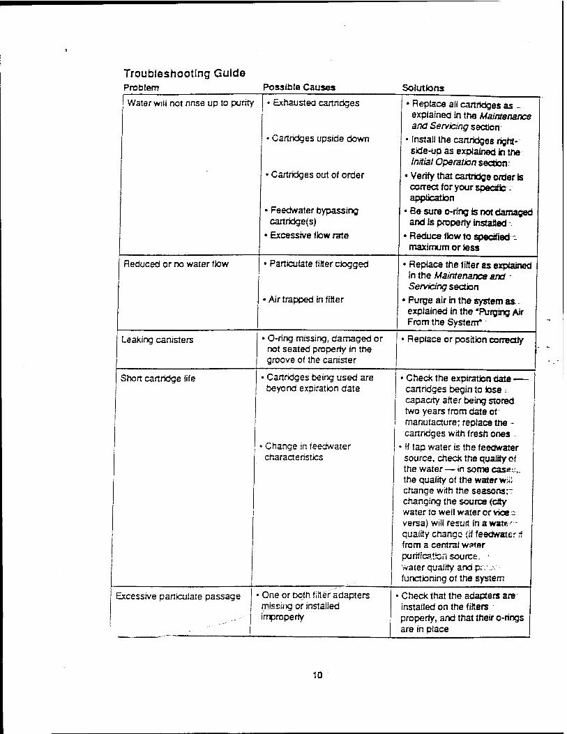
Troubleshooting Guide Problem Possible Causes Solutions
Water will not rinse up to purity Exhausted cartndges
Cartridges upside down
• Cartridges out of order
• Feedwater bypassing cartridge(s)
• Excessive flow rate
• Replace all cartridges as— explained in the Maintenance and Servicing section
• Install the cartridges right- side-up as explained in the Initial Operation section.
• Verify that cartridge order is correct for your specific :■ application
• Be sure o-ring is not damaged and is property installed -
• Reduce flow to specified - maximum or less
Reduced or no water flow Paniculate filter dogged
Air trapped in filter
• Replace the filter as explained in the Maintenance and - Servicing section
• Purge air in the system as explained in the "Purging Air From the System*
Leaking canisters
Short cartridge life
• O-ring missing, damaged or not seated property in the groove of the canister
Replace or position correctly
• Cartridges being used are beyond expiration date
■ Change in feedwater characteristics
• Check the expiration date — cartridges begin to iose ; capacity after being stored two years from date of manufacture; replace the - cartridges with fresh ones ..
■ If tap water is the feedwater source, check the quality of the water — in some cases,. the quality of the water wiii change with the seasons" changing the source (city water to well water or vices versa) wiii resurt in a water- quality change (if feedwater if from a central w?ter purification source, water quality and pr.\.. functioning of the system
Excessive paniculate passage • One or both-fitter adapters missing or installed improperly
• Check that the adapters are installed on the filters properly, and that their o-rings are in place
10
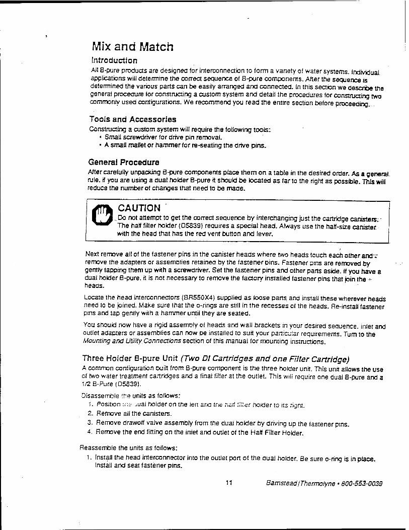
Mix and Match Introduction All B-ptire products are designed for interconnection to form a variety of water systems. Individual applications wiii determine the correct sequence of B-pure components. After the sequence is determined the various parts can be easily arranged and connected. In this section we describe the general procedure for constructing a custom system and detail the procedures for constructing two commonly used configurations- We recommend you read the entire section before proceeding.
Tools and Accessories Constructing a custom system will require the following tools;
• Small screwdriver for drive pin removal. • A small mallet or hammer for re-seating the drive pins.
General Procedure After carefully unpacking B-pure components place them on a table in the desired order. As a general rule, if you are using a dual holder B-pure it should be located as far to the right as possfole. This will reduce the number of changes that need to be made.
© CAUTION .^Do not attempt to get the correct sequence by interchanging just the cartridge canisters;: Trie half filter holder (D5S39) requires a special head. A/ways use the half-size canister with the head that has the red vent button and lever.
Next remove all of the fastener pins in the canister heads where two heads touch each other andv remove the adapters or assemblies retained by the fastener pins. Fastener pins are removed by gently tapping them up with a screwdriver. Set the fastener pins and other parts aside. If you have a dual holder B-pure, it is not necessary to remove the factory installed fastener pins that join the - heads.
Locate the head interconnectors (BR550X4) supplied as loose pans and install these wherever heads need to be joined. Make sure that the o-rings are stiil in the recesses of the heads. Re-install fastener pins and tap gently with a hammer until they are seated.
You should now have a rigid assembly of heads and wall brackets in your desired seauence. inlet and outlet adapters or assemblies can now be installed to suit your particular requirements. Turn to the Mounting and Utility Connections section of this manual for mounting instructions.
Three Holder B-pure Unit (Two DJ Cartridges and one Filter Cartridge) A common configuration built from B-pure component is the three holder unit. This unit allows the use of two water treatment cartridges and a final filter at the outlet. This will require one dual B-pure and a 1/2B-Pure(D5S39).
Disassemble the units as follows: "i. Position ir.a jual holder on the iert ana tne naif filter nolder to its rignt. 2. Remove all the canisters. 3. Remove drawoff valve assembly from the dual holder by driving up the fastener pins. 4. Remove the end fitting on the inlet and outlet of the Half Fitter Holder.
Reassemble the units as follows:
1. Install the head interconnector into the outlet port of the dual holder. Be sure o-ring is in place. Install and seat fastener pins.
11 BarnsteadIThermolyne • 800-553-0039
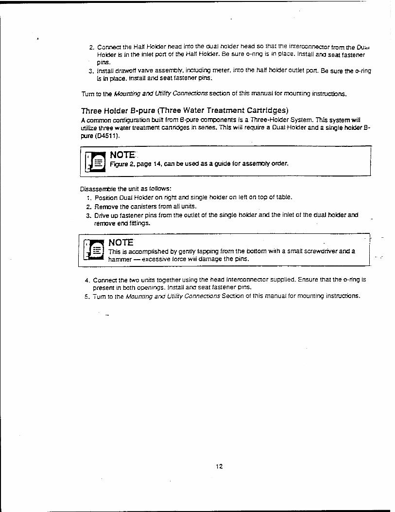
2. Connect the Half Holder head into the dual bolder head so that the interconnector from the Dua. Hober is in the inlet port of the Half Holder. Be sure o-ring is in place. Install and seat fastener pins.
3. Install drawoff varve assembly, including meter, into the half holder outlet port. Be sure the o-ring Is in place. Install and seat fastener pins.
Turn to the Mounting and Utility Connections section of this manual for mounting instructions.
Three Holder B-pure (Three Water Treatment Cartridges) A common configuration built from B-pure components is a Three-Holder System. This system will utilize three water treatment cartridges in series. This wiii require a Dual Holder and a single holder B- pure(D4511).
Disassemble the unit as follows: 1. Position Dual Holder on right and single holder on left on top of table. 2. Remove the canisters from all units. 3. Drive up fastener pins from the outlet of the single hoider and the inlet of the dual holder and
remove end fittings.
r* NOTE I i=I j This is accomplished by gentry tapping from the bottom with a small screwdriver and a ■■■■ hammer — excessive force wiii damage the pins.
4. Connect the two units together using the head interconnector supplied. Ensure that the o-ring is present in both openings. Install and seat fastener pins.
5. Turn to the Mounting and Utility Connections Section of this manual for mounting instructions.
12
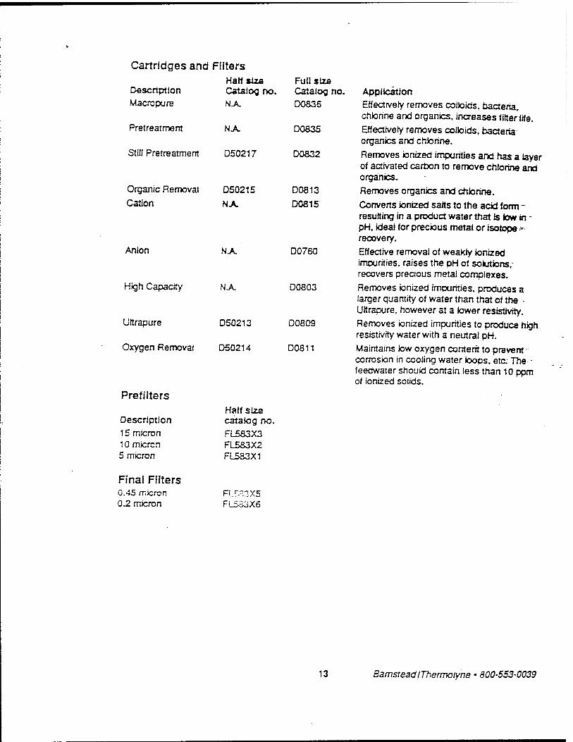
Cartridges and FfJters
Description Macro pure
Half siza Catalog no. NA
Full size Catalog no D0836
Pretreatment NA D0835
Still Pretreatment D50217 D0S32
Organic Removal
Cation D50215
NA D0813
D0S15
Anion NA D0760
High Capacity NA, D0803
Ultrapure D50213 D0809
Oxygen Removal D50214 D0811
Prefilters
Half size Description catalog no 15 micron FL583X3 10 micron FL583X2 5 micron FL5S3X1
Final Fflters 0.45 micron R_r.=!3X5 0.2 micron FlSä3X6
Application
Effectively removes colloids, bacteria, chlorine and organics, increases filter life.
Effectively removes colloids, bacteria organics and chlorine.
Removes ionized impurities and has a layer of activated carbon to remove chlorine and organics.
Removes organics and chlorine.
Converts ionized salts to the acid form - resulting in a product water trial is low in - pH, ideal for precious metai or isotope - recovery.
Effective removal of weakly ionized impurities, raises the pH of solutions,- recovers precious metal complexes.
Removes ionized impurities, produces a larger quantity of water than that of the - Ultrapure, however at a lower resistivity.
Removes ionized impurities to produce high resistivity water with a neutral pH.
Maintains low oxygen content to prevent -■■ corrosion in cooling water loops, etc. The - feedwater should contain less than 10 ppm of ionized solids.
13 BamsteadIThermolyne • 800-553-0039
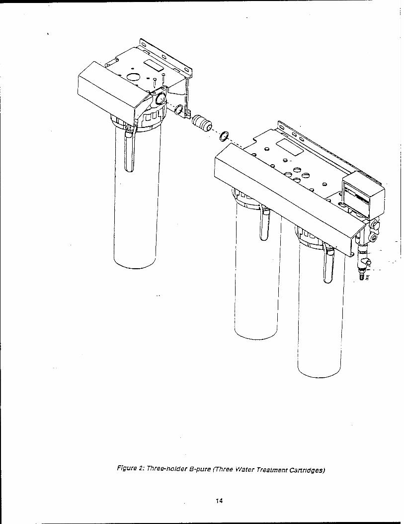
Figure 2: Three-holder B-pure (Three Water Treatment Cartridges)
14
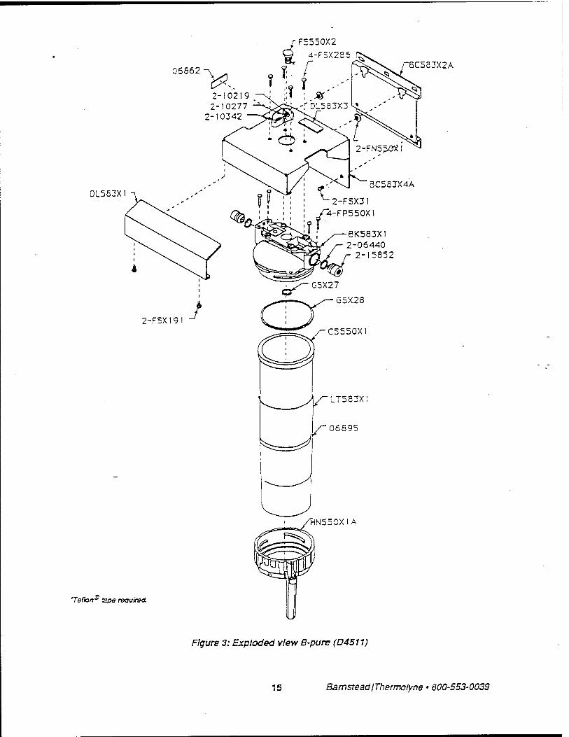
FS550X2
4-F5X285
06552
2-10219 2-10277
2-10342
D1583X
8C553X2A
2-F5X19! J
Teflon"5 apfl required.
■6K583X1 2-06440
2-15852
G5X27
V
"^=J
LT583X!
06595
"HN550X1A
Figure 3: Exploded view B-pure (D4511)
15 BamsteadjThermolyne • 600-553-0039
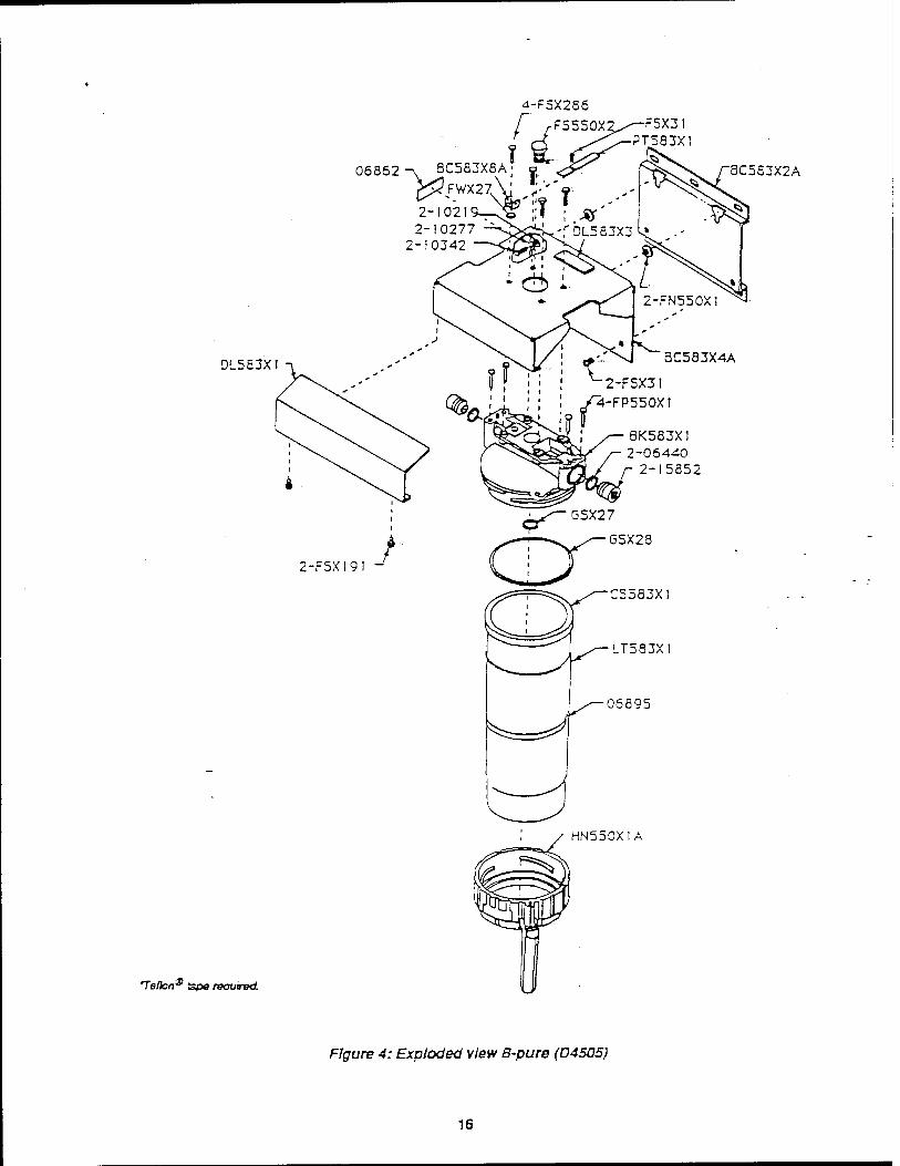
06862. ^v SC583X8A
f !
4-F5X286
FS550X
-i ÖLOÖJÄÖA' o ^
5X3! PT583X!
2-102 2-10277
2-10342 f01583X3
0L583X!
2-F5X19!
i
J
8C583X2A
2-FN550X
BC583X4A
2-FSX31
4-FP550X1
8K583X1 2-06440
2-15852
^-<~GSX27
^—'—-^ /—GSX28 dX ■C5583X!
Te/lon* tspo /BOUJTBOL
LT583X;
06895
HN550X1
Figure 4: Exploded view B-pure (D4505)
16
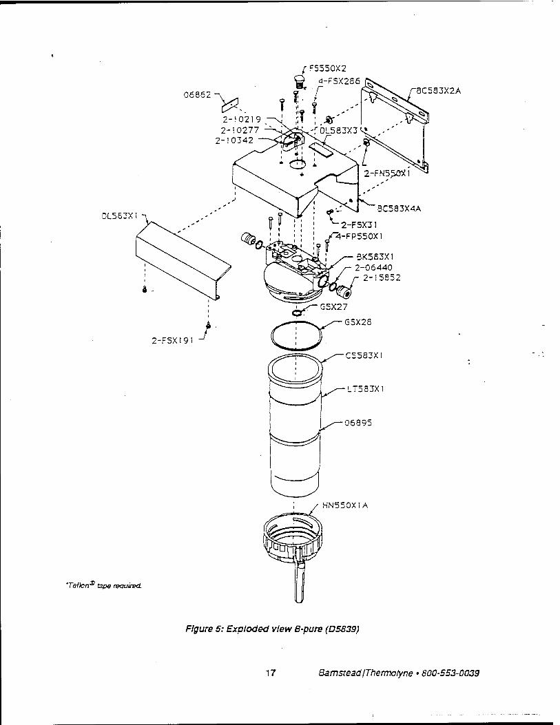
F5550X2
4-F5X286
06862
0L58JX!
'Teflon^ tape reouirsd.
8C583X2A
HN550X1A
Figure 5: Exploded view B-pure (D5839)
17 Bamstead/Thermotyne • 800-553-0039
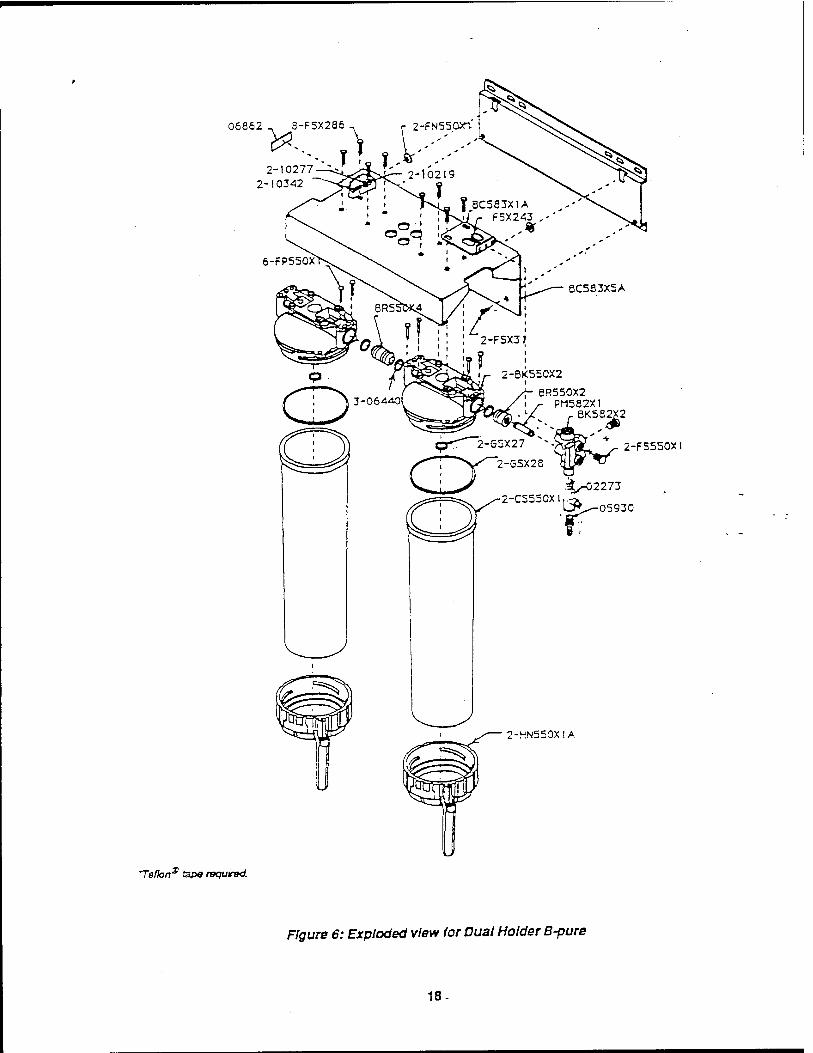
06862 _ 3-F5X286 2-FN550X1
-)_tn-37T :. _S *' 2-10277 2-10342
6-FP550X
Teflon* tape required.
8C5S3X5A
6R550X2 PM582X1
8K582X2 w 2-FS550X1
-■^-02273 2-CS5S0Xl,:Ä
UV^05930 r
2-HN550XIA
Figure 6: Exploded view for Dual Holder B-pure
18-

Replacement Parts Listing
A WARNING To avoid electrical shock, always disconnect from power supply before maintenance and servicing. Refer servicing to qualified personnel.
Recommended Spares Consumable parts are those required to support the day-to-day operation of this equipment. Bamstead |Thermotyne establishes two types of consumables:
• Those items that must periodically be replaced to maintain performance (filters, resin cartridges, etc.)
• Other items of limited life (indicator lights, fuses, etc.) that the user can expect to replace on a more or less random basis.
The replacement of consumable parts is discussed in the Maintenance and Sen/icing section of this manual to assist the user in accomplishing his own service.
Consumables List The onry consumables used in the B-Pure products are user selected. The following chart is provided for the user as a means of recording the cartridges, part numbers (catalog numbers), and their location in the system.
Location (left to right) Part#(Qty) Description
1 -
2
3 4 - | |
5- I I 6 I '- '' ' I
General Maintenance Parts General maintenance parts are defined as laboratory level repair parts which do not require great expertise or special tools for installation. Bamstead |Thermoiyne recommends that the user stock the general maintenance parts as an aid to ensuring the continued operation of this equipment.
Recommended Quantity Part* Description V2 B-Pure Single B-Pure Dual B-Pure GSX27 O-ring, cartridge head seal 1 1 2 GSX28 O-ring, large head seal 1 1 2 .. 06440 O-ring (between heads) 1 1 4 • FP550X1 Fastener pin 4 4 8 BR550X4 Head interconnector N.R. N.R. 1 15852 Connector (inlet/outlet) 1 1 1
19 BamsteadIThermotyne • 800-553-0039

Safety Stock For critical applications where performance with minimum downtime is required, Bamstead reoommends thai the user maintain a tocai stock ot those pans listed under 'General Maintenance' and 'Safety Stock.* In the event of component failure, the safety stock can be drawn upon by the user or Bamstead technicians, thereby, avoiding unnecessary delays in delivery of replacement parts.
Recommended Quantity Part# Description 1/2 B-Pure Single B-Pure Dual B-Pura BK550X2 Cartridge canister head N.R 1 2. BK583X2 Rfter canister head 1 N.R N.R. CS550X1 Full-size cartridge canister N.R 1 1 CS583X1 1/2-size filter canister 1 N.R NJ». D2770 Resistivity meter, 115 VAC N.R N.R 1 D2769 Resistivity meter, 230 VAC N.R N.R 1 HN550X1A Cartridge canister handle 1 1 -j
Ordering Procedures Please refer to the Spea:;=ation Plate for the complete model number, serial number, and series number when requesting service, replacement parts or in any correspondence concerning this unit.
All parts listed herein may be ordered from the Barnstead|Therrnotyne dealer from whom you purchased this unit or can be obtained promptly from the factory. When service or replacement parts are needed we ask that you check Tirst with your dealer. If the dealer cannot handle your request, then contact our Customer Service Department at 319-555-2241 or 800-553-0039.
Prior to returning any materials to Bamstead|Thermofyne Corp., please contact our Customer Service Department for a "Return Goods Authorization' number (RGA). Material returned without a RGA number wiil be refused. Minimum invoice: S25.
20

One Year Limited Warranty BarnstaadlThermotyne Corporation warrants this product to be free from detects in material and workmanship tor a period ot one year trom date of purchase.
This warranty applies onfy to detects in original parts or components, and does not apply to daims or alleged product failures resulting from unauthorized repairs, misuse, accidents or lack of proper maintenance, failure to follow Bamstead|Thermoryne's instructions for use or from ordinary wear and tear.
Warranty service may be obtained by returning any defective product to an authorized BamsteadlThermoryne dealer or to Bamstead|Thermoryne. Heating elements, because of their susceptibility to overheating and contamination, must be returned to our factory and if, upon inspection, it is concluded that faiiure is not due to excessive high temperature or contamination, warranty replacement will be provided.
BARNSTEADfTHERMOLYNFS SOLE OBLIGATION UNDER THIS WARRANTY SHALL BE TO REPAIR OR REPLACE ANY PRODUCTS WHICH IT DELIVERS AND ARE FOUND TO BE DEFECTIVE,
THERE ARE NO OTHER WARRANTIES, EXPRESSED OR IMPLIED, MADE IN CONNECTION WITH THE SALE OF THIS PRODUCT. BARNSTEADfTHERMOLYNE EXPRESSLY DISCLAIMS ANY IMPUED WARRANTY OF MERCHANTABILITY OR FITNESS FOR SPECIFIC USE.
Barnstead|Thermoiyne Corporation
2555 Kerper Boulevard • PO Box 797 Dubuque, Iowa 52004-0797, USA
Phone 319-556-2241 • 800-553-0039 Fax 319-556-0695 • Telex 2S4 767
21 BarnsteadIThermotyne • 800-553-0039
MDC-92B0479-1
Appendix A4 Cold Jet Model 65-200 Operators Manual
This manual is customer furnished data. The WR-ALC installation utilized a Cold Jet Model 65-200 government furnished unit. Use the manual supplied with the government furnished equipment for data refered to as Appendix A4.
A-4
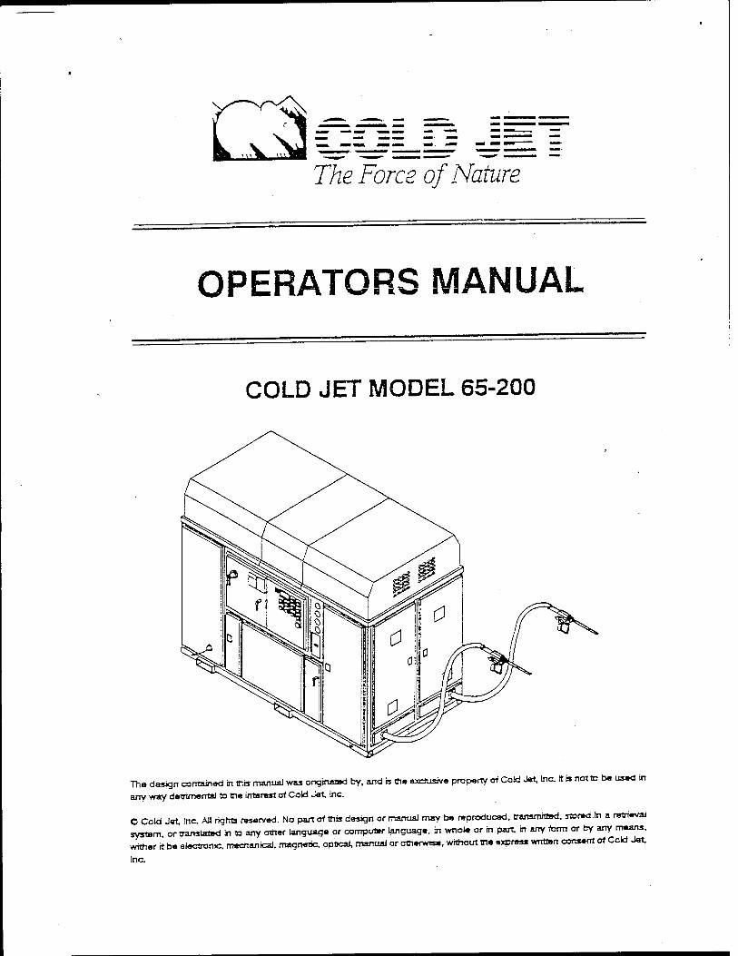
The Force of Nature
OPERATORS MANUAL
COLD JET MODEL 65-200
Tha design contained in this manual was originated by, and a the exclusive property of Cold Jet, Inc. it» not to ba used in
any way detrimental to tha interest of Cold Jat, Inc.
O Cold Jat Inc. AH rights reserved. No part of thfcr design or manual may ba reproducad. transmrttad. stored.in a retrieval
systam, or Translated in to any other language or computer language, in whole or in part, in any form or by any means,
wither it ba electronic, mechanical, magnetic, optical, manual or otherwise, without the express written consent of Cold Jat,
Inc.
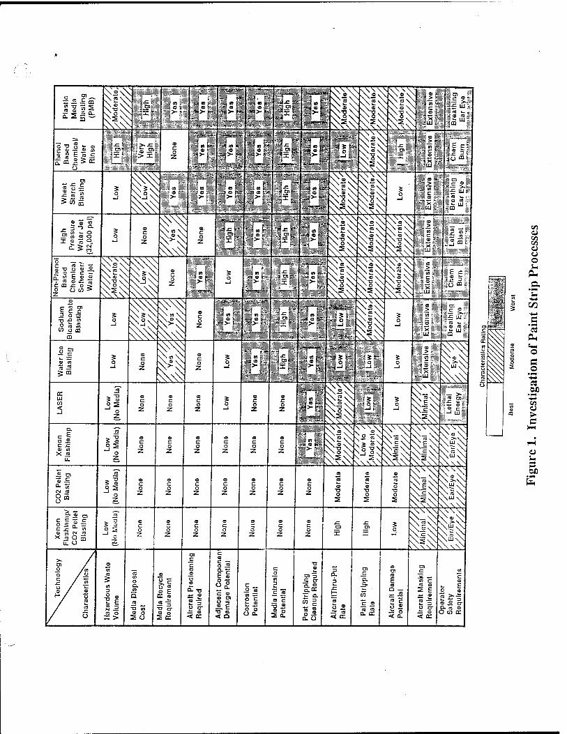
OJ V) V} U o o u
C/2
"3 OH
O (3
+^ en
> G
4) S_
OX)
fa
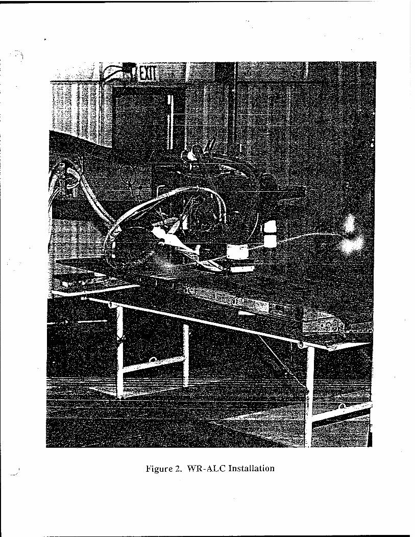
Figure 2. WR-ALC Installation
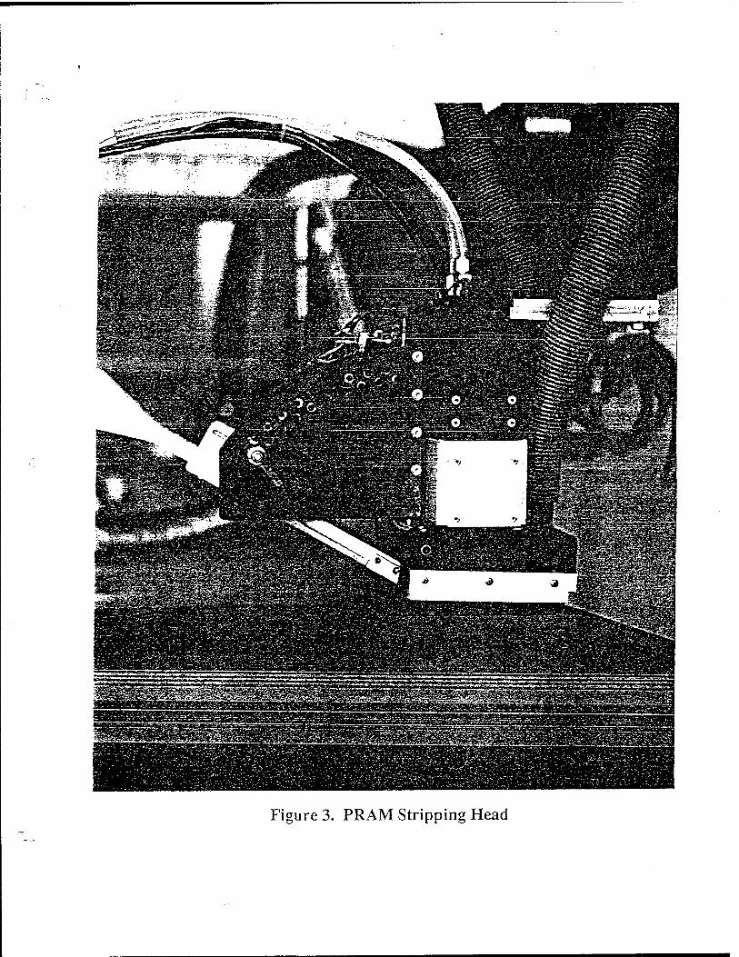
Figure 3. PRAM Stripping Head

Figure 4. High Voltage Power Supply
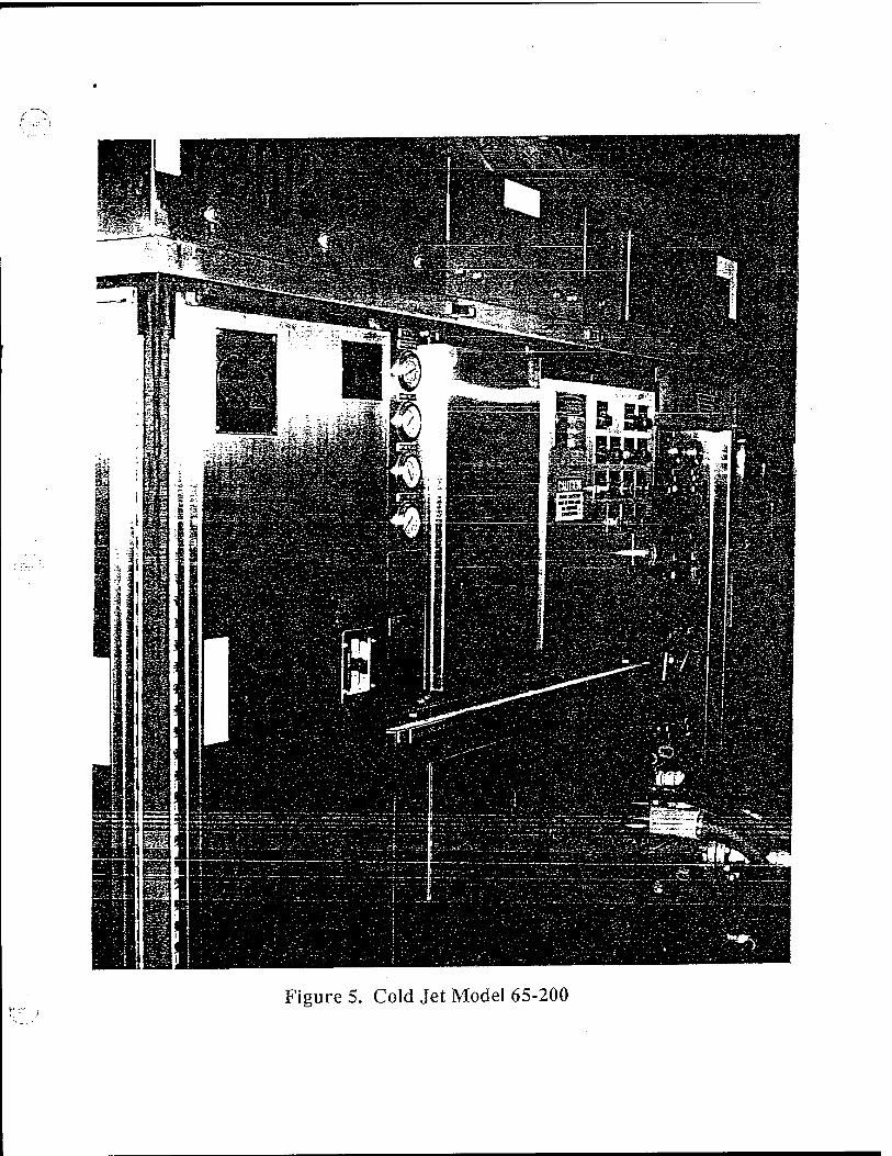
Figure 5. Cold Jet Model 65-200
i CD CD I CD CD > CD CD
> CD CD l CD CD ' CD CD
CD CD ■ CD CD = CD CD <
O O
UJ
o o _l o 2 I o UJ
0 z Q. a. a: h- </) I- Z < Q.
(3 Z
111 s UJ _l Q.
a: o u. _l UJ a o 2
a: < a 2 o Ü
tn O o
o a CD CD CD odd
CD CD CD CD CD CD odd
CD CD CD CD CD CD <^ Q di
< s
o o
5o
c\j oj t>j
000 000 to w d — n to
CD a CD CD
en co
CD en CD o CD CD CO CO
I CD «3 C loic lC
01 s
CD CD CD CD CD CD
I Istelg l_;.-,M|
CD CD CD CD CD CD
g CD do
(J-A/h 1
o o _J o z x o Hi I- o z a. £ f- UJ
H z < a.
UJ s 111 _l a. S
a: o
ui Q o s z o tE < a. O ü I- co O O
9 Si is H- a
: 3
) < < a
-< CD CD d > CD CD CD CD CD CD CD CD CD CD CD CD CD CD CD CD CD CO CD CD CD CD CD CD
c
CD CD <3 (- N ! o
c 5
ooc 3 CD CD CD CD CD CD CD CD CD CD CD CD CD CD CD CD CD CD CD CD CD CD CD CD CD CD CD CD CD CD z Z ^^. cv cxi CV W Cvi CNJ csi OJ CVJ w Cvi cvj cv cxi CVJ
M C c
Si 1- Q.
C 5 < CD CD CZ CD CD CD CD CD CD ■c: CD CD CD CD CD CD CD CD
CD CO CD CD CD CD CD CD CD CD CD CD
a
CD CD CD
5 a. <
-^ -< -«; CO CD CZ CD CD CD CD CD CD c: CD CD CD CD CD CD CD CD CD CD CD CD CD CD Jw —
LL z "z CD CD <Z odd odd c d d t^i <d <^i d d d CO CD CD aa a
CD CD CD d d d fCD <CD CD CD CD CD
"£ a L£* LTD uT Li" iT3 LiD CD CD CD CO CD CD CD CD CD CD CD CD CO CO CO CD CD CO CD CD ert
£ CO CO CO co co co co co CO QL
w C —i
go NJ
Is a: uj
o z
< t— < a
-< -< -< CD CD s CD CD § CD s CD CD CD CD s CD CD CD CD CD CO CD CD CD CD CD CD CD CD CD CD CD CO CD CO =C3
X CD CD CD CD CD CD CD CD CD CD CD CD CO CD CD CD CD CD CD CD CO CD CD CD CD CD CO CO
o z; z: "z: -*r ca s CO «o CO cv
CNJ CO CO — ^T d -*r -rr CO e\j C\j CO CNJ OJ CJ CO CO CO CO -<r CO
— o. z ■" o
a. o ** Q
5 Z3 _l
_j < a:
UJ
3
CO CD CD CD CD CD CD CD CD CD CD CD CD CD _, CD CD CD CD CD CD CD CD CD CD CD CD ir: CD r- C3 CD CD CD CD CD CD CD CD
d CD CO c: CD CD g° CD
CD CD CD CD CD CD «O CD CD CD
CD CD CD CD
CO CD CD
5 .fl 2 CL CD CD CD CD CD CD CD CD CD CD CD CO d .-< <=i CD CD CD CD CD CD CD CD CD CD CD
UJ -rr OJ CD CD CD CD CD CD CD cz CD CD CD C2 c; CD CD S "^ CD CD CD CD CD CD CD CD CD CD CD CD CD CD CD CD JJ c/a < < X
o CO cn CD CD
CM
CD CD CD
OJ
CD CD
cv CD
CM
CD CO
cv> er-J er
OJ OJ «~ OJ CD CO
CsJ CV CD CO
CNJ cx CD CO
CNJ CN? CD CO
CN? CN? CD CO
Cv? CN?
a. X x o
t i. o UJ a 5 n s UJ
i
> « -j CL
e/3 o _1
CL X
CD C3
CD CD
CD CD
CD CD
CD CD
CD CD
CD CD
CD CD
CD CD
CD CD
CD UT3
CD ■T3 CD
UT3 CD LTD
CD wO
CD CD CD UD
CD CD LO IT3
CD CD CD CD CD in
CD UD
CD CD iT3
CD in
CD in
CD in
CD in
CD in
CD CD
CD UO
CD in
L JJ CXi CNJ cO CD CD CD
CNJ CD CD CD U-3
CV r- r- r— r- r-' r- r~; ^.' r-^ r-' r-' r~' r-' r— r-' r~' r~^ r-' CN? CN? cv d CN?
CN? CN?
CN? CN?
Z r < o C i. X u. o 1 1 c l. o v» a 2 _1 3 o
a.
UJ i—
C3 CD CD CD CD CD CD CD CD CD CD CD
CD CD CO CD CD CD CD CD CD CD CD CD CD CD CO CD CO CD CO CD CD CO CD CD CD CD
CD CD CD
CD CD CD CD CD CD CD CD CD CD CD CD CD CD CD CD CD CD CD CO CD CD CD CD CD CD CD CD CD CD
3 t OL
2 Z3 CL C3 CD
CD CD <=D CD CD CD CD CD CD- d d
CD CO
d CD CD
d d CD CD d d d d d d d d d d d d d d d d d d d CD CO
d CD CO CO CD CD CD CD CD CD CD CO CO CO CO CD CD CD CD CO CO CD <CD CD CD CD CD CD CO CD CD CD CD
L. Ü </3 z X r- CO CO CO CO CO CO CD CO CO CO CO CO CO co ca CO CO CO CO_ CO CO CO CO CO CD CD CD CD C c L <
x < X
o o
Lf3 — r*-~ ~ en" cri " crj cn co" d d cd" CD CO CD" « CO CO CO co" CO CO* co" CO CO CO* co" CO* CD CD
c L o C/3
c 2 =3 —1 CL
UJ a. <
1— <. o
C3 CD CD CD CD CD CD CD CD CD CD CD CO CD CD CD CD CD CD CD CD CD CD CD CD CD CD CD CD CD CD CD CD CD CD CD EH e> 0 2
< X
u_ d> CD CD CD CD CD CD CD CD CD CO CD CD CD CD CD CD CD CD CD CD CD CD CD CD CD CD CD CD CD CD CD CD CD CN
U j O -^* CD OJ "«T* CO CO -~ CO CO -^ CO CO -^r d d "^* d d -rr d d "^* d d ■^r d d ""3- d d T d d TT d d
c c if L d
z CD
Gi HI
CM
G O C/S
Q H
U Q
J =3
o_ 2 <
cc
o < k-
C3 CD
CD CD
CD CD CD
CD
CD CD
CD CD CD
CD
CD CD
CD CD
CD CD
CD CD
CD CD CO
CD CD CD
CD CD
CD CD
CD CD
CD CD
CD CD CD CD
CD CD
CD CD
CD CD
CD CD
CD CD
CD CD
CO CD
CD CD
CD CD
«3 CO
CD CD
CD CD
CD CD
CD CD
CD CD
CD CD
J z < < a CO
cn
CD CO CO CD CD
CO CD CO
CD- CO
CD CD CO
d CD
d CO
d CO d
CO d CO
d CO
d CO
d CO
d CO
d d CO CO
d CO
d CO
d CO
d CO
d CO
d CO
d CO
d CO
d CO
d CO
d m d CD
d CO
d CD
d CO
d CO
a X X
D
a I—
IS _j <
UJ X
a UJ t—
CL
t- - z > H- CD CD
CD CD
CD CD
CD CD CD CD CD CD •CD CD «CD CD CO CD CD CD CD CD CD CD CD CD
CD CD
CO CO
CO CO
CD CO
CD CD
CO CD CO CD CD CD CD CD CD
(£ V J o o 5 o CD CD CD CD CD CD CO CD CD CD CD CD CD CD CD CD CD CD CD CD CD CD CD CD CO CD CD
U. Q
a . o 2 UJ
X o o
CD CD CD CD i^D UTD CD <jri ixri d iT) LCD d d d d d d O d d d d d d d d d d
| d d d d d d
a a
: z < en O
a UJ »— CL
X
CD CD CD CD CD CD CD CD CD CO CD CD CO CD CD CD CO CD CD CD CD CD CD CO
1
CD CD CD CD CD CD CD CD H - :z > O
CD CD CD CD CD CD CD CD CD CD CD CD CD CD CD CD CD CO CD CO CO CD CD d CD CD CD CD CD CD CD CD CD CD CD
O* v O
Si o
o 3 CD CD CD CD CD CD d d d d d d d CD CD d d d d d d d CD CD d d d d d d d d X UJ ce
CD CD CD CD CD CD CD CO CD CD CD CD CD CD CD CD CD CD d CO CD CD CD CD CD CD CD CD CD CD CD CD u. o CD CD C\2 OJ OJ CV ^H cv =M CsJ CM CVJ -^- CM =*J c^ T"_ :\? TT CO CO =o_ 3D CO CO
a CL
Z o o
cJ r-" r-" :\i r-" r~-" ^j" c-' r-" r-j r-" r-" CM" r-" c-" rvj r-* T - CVJ C>j" CM" ■%/ C\J CV cv?" -=r" _!"""
o < *— </> a. z —J CC
S UJ < UJ < i t
i_ z o»
o CL
CD CD CD =D .—■ _JICD CD CD CD CD CD CD C3 CD CD CD CD CD CD CD CO CD CD CD CD CD CD CD CD CD CD CD CD C-j £/" o LL < O S C? ^ CD|C= CD CD CD CD CD C3 CD CD CD CD Z3 CD CD CD CD CD CD CD CD CD CD CD CD CD CD CD CD ICD
CL X UJ IT
o C3 CD o 2D =3 ■^. cb 33 "«3* d d ,_. =D =D ™ d =D =b =D =D no d d =D ■^r
.:■-'. i O c i<->
z
Q. Z -J Q: ce UJ < Z3 i—
o «" UJ
a.
2:
O £
> o o < CD =D
CD CD
=D
C3
g CD =D
O CD E CD CD 2
CD CD
CD CD 3
CD CD
CD CD 3
CD CD 3 CD q=D CD
CD CD CD
CD CD CD
CD CD
CD CD CD
CD CD
CD CD
o CD
CD CD
CD CD
3 3
3 CD
CD CD
3 CD
< X UJ
z < < rD O => CD ^> = ZD CD- => CD- CD- => d 3 CD ^^ d CD CD CD- CD- CD CD- CD CD
30 CD =3
CD CD DO
3 3D
CD CD ZD
3 DO
o Ql X A <_>
ID
o
2 2 C/5
a UJ >— =3
=D =D =D CD o CD CD cs CD Z3 CD CD
EH
H- o ^5 ■v < O) C ■\J CD c %I CD CD CD CD CD CD => c CD CD CD CD CD CD CD CD CD CD CD CD 3 CD 3 3 3 3
IE t/5 CL X
O 3D o < o O o O O ^> CD ^t CD CD CD t CD CD =D CD CD =3 CD CD Z> CD CD 3 3 CD 3 3 3 3
LÜ =D O
P. C o O DD
1
=5 < o O '
CD < -O .O
CD OJ CD CD CD CD CD < =j d d CD CD Z2 CD d < CD C3 CD CD CD CD CD 3 3 CD
a_ = o o —" "NJ C -J —' C M* C •n —i e >i c -3 —" t ■v" -3
<H CM ■n "* IT) XJ -» D Ä D H ■N ■n •& n a ■*- o Tl o l-t •W ■n •* r> J3 -» 33 01 Q rH ■N m •<* n J3 — 33 Tt o r-< ■N ■o <f ft D -• 33 m O r-t ■N ■o <f
-H H -i H rH H l-i H -1 N ■M N N N ■N ->4 N "^ CN ■n m ■n m m ■n ■n ■*) ■n ■n *r «31 ■=* -31 <• •f ■d1 tf i* -* n .n rt n r>
CD CD ( ™ CD ,
CD CD , -*r CD t
CD CD c CD CD CD CD :
> CD g
UJ
o o _1 o z x o 111 h- o z a. a ctL h-
I- z < 0.
H z UJ S. UJ -I a 2 €C O a. _1 UJ □ o s z o (ft a: < a. 5 O Ü H- i/i O o
CV (DJ l CD CD ■
D o
CD CD t CD CD < CD CD <
<
s
z LU
o 1— > 1— LL 1— s O o
LU U.1 O u. u o
U.
LU
o CD CD CD O cTD CDJCD CD
CD CD
CO CO
Op CD
o a a
O 5
s;
CD C3
CD CD
CO uTJ
CD CD CD — CIO
CD CD
CD CD CO CO CD CD
CO CO CO CO CO CO
CO CO CD CD
CD CD ' CD CD ' CD CD - CD CD i CV OJ I
CD CD CD CD CD CD
CD CD i CD CD « do i
</5 UJ
O o _1 o Z I Ü LU I-
O z a. a. ce i- </i
Z < a.
z i- z Ul s HI _l a.
O u. _I HI a o 2 z o <2 a: <
O o i- f> o u
< z a. a.
CO
z O t—
2 UJ a. o
a. 2 CO
o CL Z < s
Q UJ t—
a.
o o
CD CD
CD CO CCl' c\J
CD CD CD CD CD cd
CD CD CD CD CO
CVJ?
CD CD CD CD CD
CD CD CD CD CD UD
CD CD CD CD CD CD" CO
CD uCD OJ CO
CD "? co CO
CD CD uO r- co en
CO CO oi
CD CD CD CD UD, Oj' OJ
CD CD CD CD
CO CO CO CO uD CD" OJ
CD CO
CO
CD' IT3
CD CO CO OJ
o
CO en
uO co_ OJ
_.
r-
OJ OJ CD r-"
cn
-«5* CD_
CO CO
CD
OJ'
co oj UD CO CO"
UO CD CO co"
UO CO
uo co_
CO CO
5
CO CO CO CO CO CO"
en o~3
UO
CO
en co"
cri CO
CO OJ UO CD
oi
CO CO
UO in
CO eri CD
CD CD CD CD CD CD" CD
CD CD CD UO OJ_
CD CD CD CD uo_ oj" OJ
CD CD CD CD CD UO*
CD CD eb UO OJ_
CD CO CD CD uo_ OJ* OJ
<
O Z a. a. 2 h- CO
z o r-
OJ a. O
a: t— CO
cc
a. o z < 3
UJ i—
£ O O
3E
C3
CD CD CD CD
CD CD CD CD CD
CD CD CD
CO CO CO CO
CD CD CD LO OJ
CD CD CD CD iT3
CD co
CO
CO
UD OJ CO UD
CD cri
CD CD UD
CO
CD CD CD
CO OJ OJ
CO
CD
OJ
CO
en CO uO CO CD
CO uo z—'
CD CO CD
CO OJ
CO CD UO
CO CO CD
CO
OJ OJ
CO CO CD CO
cri CO
en CO CO CO
OJ cri OJ
en r~ UD CO
CO UO
CO
CD UO CO
en UO
OJ CO
CO CO CO CO
CD UO r-' CO
CD CD UO r- co
CO CO CO CO
CD UO r—' CO
CD CD ub c- CO
s CD z a. a_
CO
z O i—
s UJ a. O
3= o _J u_ a. a; CO
cc z LU s >—
O UJ y— ra
O o
CiJ CD CD CD
CD CD e\i
CD CD CD CD
CO CO CD
OJ
CO
CD CD WD OJ
OJ CD CO
-<3" CD CO OJ
CO
oS CO cri
uO OJ
CO
uO OJ
CO
OJ uO CO OJ
co OJ
CO oi WD
r- CO OJ
OJ uO CO UD
OJ UO CO UO
OJ UO oi OJ
uO
CO
UO
OJ
co
CD CO CO
OJ cri OJ
en CO OJ CO
en r~ uo CO
en CD uo CO
co en
CO
CO CD UO
CO CO
CD UO oi CO
CO CO C£2
CO r-
OJ
CO CO cd
CO CO CO
uO en CO CO
3 <
z a. a. CXL 1— CO
z O
S UJ a. O
o UJ _J UJ
i— o O o
a UJ }— ID CL
O O
-a:
z: ■ZL
in
uT3
UD CO
CD
en
uO
tiO
CO
VjO
CD
CO
en CD r-"
CO CO
en CO CO en OJ
uT3 CO
CO
co CO CO CD
CO OJ
OJ~
CO CO CO CO
OJ OJ UO
ch
CD en
CO CO CO CO CO
UO
OJ CD
en OJ
CD
CO*
CO CO CO CD
CD UO
OJ
en en CO CO
UO en oi CD
UO CD
OJ CO uO
OJ
CO CO CO CO OJ
eo CO
CO
en
UO en CO CO
C-; CO
en
> <
CD z o_ Q-
i— CO
z o (— s UJ □_ o
>• t—
o a: h- o UJ _J UJ
to O o
< <
-a:
z; CD CD
CD CD
r-- CD CD
CD CD
CD CD
CD CD
CD CD
CD CD
CD CD
r- CD CD
r- CD CD
CD CD
V- CD CD
CD CD
CD CD
CD CD
CD CD
r- CD CD
CD CD
CD CD
CD CD
CD CD
CD CD
CD CD
CD CD
r— CD CD
r- CD CD
r— <=D CD
CD CD
CD CD
CD CD
P- CD CD
CD CD
CD z a. a. 0£ F- CO
z o >—
UJ Q. o
CO
t— <: 3 o _j
2
< o 1—
Q UJ H- =3 O- X o o
zi
-=c en CO CD CO
CO r- CD OJ
OJ*
OJ LTD
CO
OJ cn CO CD CO
CO r^ CD OJ
OJ~
OJ CO
OJ
OJ OJ CO OJ OJ"
uO
CO iT5
•JO CO CO
CO co
UD cri uO CO co'
Cn CD cri
c~- OJ CO
CO UD CD en uD
OJ CO
OD
CO CO CO CO CD cri OJ
OJ CO
en uO uo"
CO CO CO CO
CO" OJ
OJ r- CO r- co_ OJ* UO
CO
?^ «O
CO
CO r—■ co"
OJ en OJ OJ iO
p-
co UO
CO
CO
CO CO"
en oi CO CO OJ
OJ CO
CO CO
OJ CO
OJ r- CO
CO CO'
CO CO CO CO CO OJ
en
CO uo
en cn CO CD en OJ
co
CO
CO UO
en cn CO CD en OJ'
O z a. a. 2 ^_ CO
Z o
s UJ a. O
a UJ
C£ UJ 3= >— o
5 o z 55 i— < S o _J
< < z: - 3=
CD CD r-
CD CD
r-'
CD CD CD CD CD
r~^"
CD
UO
CD
UO
CD
UO
CD
UO
CD
UO
CD
UO
CD CD CD CO
CD CD CD CO
CD CD CD CO
CD
uo
CD
UO
CD
uo
CD
UO
CD
UO
CD
UO
CD
eb en
o z a. a. 2 CO
z O
s LU CL o
< a. X o o
■2T
O z in >— < 5 o —i
a UJ (— O- s o
-< z:
-<; ^1
co r- CO oS
co co cri
r- co cri
CO cri OJ OJ OJ
i^3 en o-> CO
L£D en era CO
en cri CO
LO en cri CO
en cri CO
uO en cri CO
en cri CO
en cri CO
en cri CO
CO oj UO
CO oj UO
CO OJ UO
CO OJ UO
CO
CD
CO
CD
CD CD CD
CD CD CD
CD CD CD
CD CD O
CD
CD
CD
CD
CD CD CD
CD
CD
s o z a. 2 t— CO
o
s UJ CL o
UJ
3 o a. UJ CO
o
o z ce UJ a.
Q UJ F- 31 a.
o o 2i z: z:
cn
OJ
cn
OJ
cn
OJ
cn ■JO OJ
cn uO OJ
cx> OD OJ
OJ CO CO
OJ CO CO
OJ CO CO
CO CO en
CO CO en
CD CO en
CO CO en
CO CO en
CO CO en
CO CO en
OJ CO
3D
OJ CO
CO CD CD CD CD
en OJ CD
en OJ CD
CD CD CD
CD CD CD
CD CD CD CD CD CD CD eb eb
CD z a. a. cr t— CO
z o t—
s UJ a_ O
UJ a: CO CO UJ a: a. a: <
c/5 CL
< »V- < =i
-
CD
CO
CD
CO
CD
CO
CD
CO
CD
CO
CD
CO
CD CD CD
CD CD CD -T3"
CD CD CD
CD r-
co
CD CD
CO
CD
co
CD C-
CO
CD r-
CD
CO
CD
CO
CD
CO
CD CD CD CO
CD CD CD CO
CD CD CD CD
CD CD CD CO
CD CD CD CO
CD CD CD CO
CD CD CD CO
CD CD CD CO
CD CD CD CO
CD CD CD CO
CD CD CD CO
CD CD CD CO
CD CD CD CO
CD CD eb CO
CD CD CD CO
CD Z Q_ a. oc F- CO
z o s—
UJ Q. O
UJ
=3 _J o > <
o Z z
t
< < SI - ZZL
CD
CD § CD OJ
CD CD CD OJ OJ
CD CD CD OJ OJ
CD CD CD OJ OJ
CD CD CD OJ OJ
CD
CD OJ
CD CD CD
OJ
CD CD CD OJ OJ
CD CD
CD CO
CD CD CD CD CO
CD CD CD CD CO
CD CD CD CD CO
CD CD CD CD CO
CD CD CD CD CO
CD CD CD CD CO
CD CD
5 UD
CD CD CD CD CO
CD CD CD CD
CD CD CD CD CO
CD CD CD CD CO
CD
CD CD CO
CD CD
CD CO
CD CD CD CD CO
CD CD CD
CD CD
CD CD CD
CD CD^
CD CD
CD CD
CD CD CD -
o
CD z a. 2 CO
z O
UJ o_ O
o CO
a )— z < a.
t— CO O o t— o 1—
a UJ >— a.
o o
CD CD CD CD
CD CD CD CD CD_
CD CD CD CD CD
CD CO
CO
CD CD OJ CO
CD CD
OJ
CD CO
CO
CD CD OJ CO
CD CD
OJ
CD CO
CO
CD CD
CO
CD CD
OJ CO
CD CO
CO
CD CD OJ CO
CD CD
OJ
CD CO
CO
CD CD
OJ CO
CD CD
OJ CO
CD CD ^J
CD CD
CJ CO
CD
CO
CD CD
OJ CO
CD CD
OJ CO
CD CO
CO
CD CD OJ CO
CD CD
OJ CO
CD CO
CO
CD CD OJ CO
CD CD
OJ CO
CD CO
CO
CD CD OJ CO
CD CD
OJ CO
CD CO
CO
CD CD OJ CO
CD CD
OJ CO
§
CD z a. CL
2 »— CO
z O t—
s UJ a. O
o a. CO
O
z < CL
1— CO o o
< < a
CD CD
CD CD OJ
CD CD cv
OJ CD
OJ CD
OJ CD
OJ CD
r- OJ CD
OJ CD
OJ CD
OJ CD
OJ CD
OJ CD
OJ CD
OJ CD
OJ CD
OJ CD
OJ CD
OJ CD
OJ CD
OJ CD
OJ CD
OJ CD
OJ CD
OJ CD
OJ CD
OJ CD
OJ CD
OJ CD CD
r- OJ CD
OJ CD
OJ OJ CD
OJ eb
r- OJ eb
r-i CN m ■o- urj UD r- CO cn o CN rH m i-i
■^ m CO rH
en *-* O ■H in U3 CN CN
CO (N CN
O m
t-i CN n ro
en o t-t CN in U3 CD cn o in in
CN in m in tn
< o
> CD CD > CD CD i CD CD
l CD CD » CD CO
UJ
(5 O _l O 2 I O LU H
o
pq
3
o ö
» CD CD ' CD CD • cd co
0. Q-
< 0.
z H Z Hi 5 UJ _l a s a: o
UJ a O
z o
< a. o o t- c/) o o
I CD CD ) CD CD ■ cd trD
CD CD <
Cvi CJ C
, CD CD I CD CD ; CD OJ
0)
tu
o 3= O
CD CD CD CD CO CD
< 36
< 3
< 3
3 o 4=3 ?
2
' CO .
■131
03 < IE 3
2 55 . ■ s- ' i CO <
in w o o _l o z I o w h- o z 0. a
<
z m 5 uu _i a.
a: o u. _i Hi Q O s z o a) a: < a. 5 O o i- </7 O Ü
s
S: o CO u. O _i <
2
CD CD CD CD CD CD
o o o
CD CD CD CD CD CD
Ü odd
HE
CD CD CD CD C-i CD CO CO
CD CD CD CD CD CD
CD CD CD CD CD CD
CD CDiCD
s o
' ^c- co ■ c-3 CO
> o
s ■ CO CO ■ co <n ■ cv c-o
10 LU
O o _l o z ü UJ 1- C3 z a. a: </)
> O
s UJ > O i
< CXL UJ
5 o '
«■" S s
nm —' wo- '
< a. O z i- z UJ s LU _1 DL
a: o
a o
o CO
Lt < a. S o o i- to o o
<
< o _J <
«5
o
UJ
C/3
o 3
Ä <
o <o <o CD C3 CD iH c-j c-ö
o o o CD ez> cz> odd

V) UJ
o O _i o z x o UJ H
o z a. a.
H Z < 0.
Z UJ 5 UJ _l 0.
O
a o z O
a: < a.
O o H (/) o O
z LU £ UJ _J a.
t— co a o
a.
<
o m o a:
Cfl
O O
o UJ H- ZD CL
s o o
C3 CD CD
CD
CD CD
CD
CD CD
CD
CD CD
CD
CD CD
CD
CD CD
CD CD CD
CD" CD
CD CD
CD CD CD
CD" uO
co"
CD CD
CD CD CD
CD" CD CD
CD"
CD CD
CD
CD CD
CD
CD CD
CD
CD CD
CD
CD CD
CD
CD CD
CD
CD CD
CD CD e=> CD* CV CO
CD CD
CD CD CD
CD* CV CO
CD CD
CD CD CD
CD"
CO
CD CD
CD CD CD
CD" CD CD
co"
CD CD
CD CD CD
CD* CD CD
in"
CD CD
CD CD CD
CD* CD CD
CD*
CD CD
CD CD CD
CD* CV CO
CD CD
CD CD CD
CD CV CO
CD CD
CD CD CD_
CD" CO
CD CD
CD CD CD
CD* CD <n
CD CD
CD CD CD
CD* CD CD
in"
CD CD
CD CD CD
CD* CD CD
iri
CD CD
CD CD CD
CD" CD ■n
CD CD
CD CD CD
CD" CD CD
in"
CD CD
CD CD CD
CD* CD uO
C-"
CD CD
CD
CD CD
CD
CD CD
CD
CD CD
CD
CD CD
CD
CD CD
CD
a
1— z LU £ UJ —i a. £
t— GO o o
z o v-
3 Z LU >
o o
a LU h- =3 a.
O o
CD CD
CD CD CD
CD" CD
CD CD
CD CD CD
CD" CD en
CD CD
CD CD CD
CD* CD CO
CD CD
CD CD CD
CD" CD cv
CD CD
CD CD CD_
CD* CD en
CD CD
CD CD CD
CD" CD co_
CD CD
CD CD CD
CD* CD CV2
CD CD
CD CD CD
CD* CD cn
CD CD
CD CD CD
CD* CD
CD CD
CD
CD CD
CD
CD CD
CD
CD CD
CD
CD CD
CD
CD CD
CD
CD CD
CD
CD CD
CD
CD CD
CD
CD CD
CD
CD CD
CD
CD CD
CD
CD CD
CD
CD CD
CD
CD CD
CD
CD CD
CD
CD CD
CD
CD CD
CD
CD CD
CD
CD CD
CD
CD CD
CD
CD CD
CD
CD" CD
CD
CD CD
CD
o
j— Z UJ £ UJ _l CL £
>— GO
o o
>■ cc LU > o O UJ cc:
C/3
O O w >* 00
a LU t— ID
£ O Ü
CD O CD
CD CD
CD CD CD
CD" CD
CD CD
CD CD CD
LO CVf CD
CD CD
CD CD CD
CD" LT3 CD
CD CD
CD CD CD
CD" CD
CD CD
CD CD CD
uO Cv? CD
CV
CD CD
CD CD CD
CD" LTJ CD_
CD CD
CD CD CD
CD" CD CV
CD CD
CD CD CD
IO CV CD
CV
CD CD
CD CD CD
CD* uO CD_
CD CD
CD CD CD_
CD* CD
CD CD
CD CD CD
CD" uO
CD CD
CD CD CD_
CD* CD cn
CD CD
CD CD CD
CD" CD
CD CD
CD CD CD
CD" UD
CD CD
CD CD CD
CD* CD CTt
CD CD
CD CD <~o CD* CD
CD CD
CD CD CD
CD' uO
CD CD
CD CD CD
CD* CD cn
CD CD
CD CD CD
co" CO
CD CD
CD CD CD_
co" CO
CD CD
CD CD CD
CD CD
CD CD CD
CO
CD CD
CD CD CD
CO" CO
CD CD
CD CD CD
CO" CO
CD CD
CD CD CD
CD* in
CD CD
CD CD CD
CD" CD CO
CD CD
CD CD CD_
CD* uO
CD CD
CD
CD CD
CD
CD CD
CD
CD CD
CD
CD CD
CD
CD CD
CD
Z UJ £ UJ _J a-
00
O o
a_ £ O O
< o
J—
o o
o LU
ID a.
O O
C3 o CD
CD CD
CD
g CD
CD CD
CD CD CD
CD*
CD
CD CD CD
CD' CO
CD CD
CD CD CD
CD' CD CVJ
CD CD
CD CD CD_
CD*
CD CD
CD CD CD
CD* CO
CD CD
CD CD CD_
CD* CO
CD CD
CD CD CD
CD* cn
CD CD
CD CD CD
CD" CO
CD CD
CD CD CD_
CD* CO CO
CD CD
CD CD CD_
LO r- CO
CD CD
CD CD CD
CD* CD uO
CD CD
CD CD CD
CD* CD CD
CD CD
CD CD CD
CD"
CV
CD CD
CD CD CD
CD* in CV
CD CD
CD CD CD
CD* CD UJO
CD CD
CD CD CD
CD" IT3
CJ
CD CD
CD CD CD
CD" in CV
CD CD
CD CD CD
CD* CD in
CD CD
CD CD CD_
CD* CD CV
CD CD
CD CD CD
CD" CD CV
1 CD CD
CD* CD CO
CD CD
CD CD CD
CD* CD
CD CD
CD CD CD
CD" CD CV
CD CD
CD CD CD
CD" CD CV
CD CD
CD
CD CD
CD
CD CD
CD
CD CD
CD CD CD_
CD* CV
CD CD
CD CD CD
CD" CV
CD CD
CD CD CD
CD* CV
CD CD
CD CD CD
CD" cv
CD CD
CD CD CD
CD* CV
CD CD
CD CD CD
CD" cv
M Q
UJ £ UJ -J CL
£
GO
o o
CL
£ O
< < O CD CD
CD CD
CD CD CD
CD" cv
CD CD
CD CD CD
CD' C\)
CD CD
CD CD CD
CD" cv
CD CD
CD CD CD
CD"
CD CD
CD CD CD
CD"
CD CD
d CD CD
CD OJ
CD CD
CD CD CD
CD* CO
CD CD
CD CD CD
CD* CO
CD CD
CD CD CD
CD" CO
CD CD
CD CD CD
LT)
CD CD
CD CD CD_
uT5
CD
CD CD CD
uT3
CD CD
CD CD CD
LTD CV
CD CD
CD CD CD
UO CV
CD CD
CD CD CD
UD CV
CD CD
CD CD CD
in CV
CD CD
CD CD CD
in" CV
CD CD
CD CD CD
uO" CV
CD CD
CD CD CD
CD' CD
CD CD
CD CD CD_
CD' CD
CD CD
CD CD CD
CD" CD
CD CD
CD CD CD
CD* CD
CD CD
CD CD CD
CD"
CD
CD CD
CD CD CD
CD* CD
CD CD
CD
CD CD
CD
CD CD
CD
CD CD
CD CD CD
CD' cv
CD CD
CD CD CD
CD" cv
CD CD
CD CD CD
CD' cv
CD CD
CD CD CD
CD" cv
CD CD
CD CD CD
CD" CV
CD CD
CD CD CD
CD' CV
a
Z UJ £ UJ _J a. £
CO
o o
V3 a: O c/> CO UJ
cr a. £ O
a LU CC
< < a
O CD CD CD CD
C*J
CD CD
CD CD
CD
CD CD
CNJ
CD CD
CO
CD CD
CO
CD CD
CO
CD CD
CO
CD CD
CV
CD CD
CO
CD CD
CD CD
CO
CD CD
CV
CD CD
CV
CD CD
CD CD
CV
CD CD
CV
CD CD
CD CD
cvi
CD CD
CV
CD CD
CO
CD CD
CD CD
CV
CD CD
CD CD
CD
CD CD
CD
CD CD
CD
CD CD
CD CD
CD CD
CD CD
CD CD
CD CD
z UJ £ UJ _1 CL £
co o o
CL
cc \— i/3
_J < )— O 1—
r— en O o t— z
a UJ (— Z3 CL, 3= O O
C3
CD CD CD
C-3
CD CD
CD CD CD
UT3
CD CD
CD
CD
CD CD
CD CD CD
CD" CO cv
CD CD
CD CD CD
CD" CO
CD CD
CD CD CD
CD" CD
CD CD
CD CD CD
CD" CO
CD CD
CD CD
CD"
CD CD
CD CD CD
CD" C\J
CD CD
CD CD CD
CD"
CD CD
CD CD CD
CD' CV CD_
CD CD
CD CD CD
CD"
CD
CV*
CD CD
CD CD CD
uO" cn
CD CD
CD CD CD
CD" CO CD
CD CD
CD
CD
CD* CV
CV
CD CD
CD CD CD
CD" CO
CD CD
CD CD CD
CD* CO
CD CD
CD CD CD
CD" CO q
CD CD
CD CD CD
CD* CO in
CD CD
CD CD CD
CD" CO uO
CD CD
CD CD CD
CD" CO CD
CD CD
CD CD CO
CD" CD
co"
CD CD
CD CD CD_
CD' CD CD
CO
CD CD
CD CD CD
CD* CD in
CD CD
CD CD CD
CD' CD in
CD CD
CD CD CD
CD" CD CD_
co'
CD CD
CD CD CD
CD* CD CD
CO*
CD CD
CD CD CD_
CD in
CD CD
CD CD CD
CD* CD CD_
CD CD
CD CD CD
CD' CD in
CD CD
CD CD- CD
CD* CO
CD CD
CD CD CD
i_o" CO
CD CD
CD CD CD
CD" CO CO
CD CD
CD CD CD
in" CO
CD CD
CD CD CD
CD CO
CD CD
CD CD CD
CD" CO CO
I— Z UJ £ UJ _I
£
GO
o o
1— z
< <
CD CD
CD CD CD
C-3
CD CD
CD CD CD
cri
CD CD
CD CD CD
C-3
CD CD
CD CD CD
CD"
CD CD
CD CD CD
CD"
CD CD
CD CD CD_
CD"
CD CD
CD CD CD_
CD*
CD CD
CD CD CD
CD"
CD CD
CD CD CD_
CD*
CD CD
CD CD Q
•J-3* CO
CD CD
CD CD CD
ulO CO
CD CD
CD CD CD_
UD CO
CD CD
CD CD CD
■LTS CO CV
CD CD
CD CD CD
•-n CO CV
CD CD
g CD
ifi CO CV
CD CD
CD CD CD
uO* CO CV
CD CD
CD CD CD
■_o" CO CV
CD CD
CD CD CD
LO* CO CV
CD CD
CD CD CD
iT3 CO CV
CD CD
CD CD CD
in" CO CV
CD CD
CD CD CD
uri CO CV
CD CD
CD CD CD
CD* CD in
CD CD
CD CD CD
CD' CD in
CD CD
CD CD CD
CD* CD in
CD CD
CD CD CD
CD* CD in
CD CD
CD CD CD
CD* CD ■n
CD CD
CD CD CD
g in
CD CD
CD CD CD
CD" CD in
CD CD
CD CD CD
CD* CD in
CD CD
CD CD CD
CD CD in
CD CD
CD CD CD
uri
CD CD
CD CD CD
iT3
CD CD
CD CD CD_
in'
CD CD
CD CD CD_
in
CD CD
CD CD CD
in
CD CD
CD CD CD
iri
1— Z UJ £ UJ _J a. £
GO
O o
O Z
CL CL
s
a a UJ cc cn t— z Z3
<: t— < a
9=
-<
CSI
CD
CD CD
CD CD
CD CD
r—
CD CD
CD CD
CO
CD CD
CD C\2
CD CD
CD CD
CO
CD CD
CO
CD CD
CO
CD CD
CV
CD CD
CV
CD CD
CO
CD CD
CD CD
CO
CD CD
CV
CD CD
CV
CD CD
CD CD
CV
CD CD
CV
CD CD
CD CD
CV
CD CD
CV
CD CD
CO
CD CD
CD CD
CV
CD CD
CV
CD CD
CD CD
CV
CD
CO
CD CD
CD CD
CO
CD CD
CO
CD CD
CO
CD CD
CD CD
CO
a a
—I _J
UJ > O
>- on < 3e 3E :D oo
o o
o I—
cc < UJ >- cc LU Q_
a UJ i— ID a. •s o o
CD CD
cv CD
CO
CO
iT3
CD CD
CD r~
co" OJ
CD CD
CO
CD
CD' CO CO
uT3
CO C7J
ÖJ
co" iO CO
cv
cri CD uO
cri
uD cn cri CD r- co" CD CO
•jri
CO en
r~
CNi CO
CM
r~
en P-" CO en CV
uO CD
oS uO
uD r- cv
CD
CO
CO
cn"
CD
CO
CO
CV CV
CO*
cn CO'
cri CD CO
uO CD Cn
ULO
CO
CO
CV
cn IT- CO
CO*
CD Cn
r-' CD_
CD
CD CO
CD cn CO
CV* CO CO
r-*
>T3
CD uO CO
C~-'
CO_
CO JT- uO
uri cn CO
CV
CO
CV en ijq
CV uO
co"
CO CO
r- r- cn CV r— -n
CD CO
in
r—"
CV
CV*
CD CO
CO in
in" cn
CO*
in
CD
cv" CV cn
CD CV
cri CD CD
CD
cn CO
CO CD CO
CD"
in
■n CO
cri cv CD
co" CD cn
CV CV
CO CO
co'
CD_
CO
CO •n in co
cv -ST
CO cv CD_
CO
cv r- c6
cv co' CO
in
cv in ca
CO
cn
co CO r- cv co" in CO
cv
CO CO
CO r- in
CD" in CD
cv
cv
•-n
cv cn cv"
CO CO
CD CO r~ in CO in
cv"
CO
CV r- CO
co" CO co cv"
CV
CD CD 1—
z~i
r— CO*
a a
_j _j
UJ > o
< 2 =E ID GO
1—
s o OS
<
CC < UJ >- cc LU a.
< <
CD CD
CD CD
CD
CD uT3
CD
CD uT3
CD CD
CD CD
CD CD CD CD
CD CD
CZ1 CD
CD
CD
CD ■-rD
CD CD
CD CD
CD ^> CD
CD CD
CD
CD CD
CD CD
CD CD
CD uT3
CD CD
CD uO
CD CD
CD
CD CD
CD uO
CD CD
iTJ
CD CD
CD
CD CD
in
CD CD
CD uO
CD CD
CD CD
CD CD
in
CD CD
CD in
CD CD
CD CD
CD CD
CD
CD CD
CD >n
CD
3 CD
CD CD
CD
CD
CD CD
CD CD
CD CD
CD i_o
CD CD
CD in
CD CD
CD CD
CD CD
CD
CD
CD
CO a
_J
s UJ > o
>• cc < X ID CO
LU
a cn i—
o o
a UJ
a. £ O O
C\J
cri cri
CO in
«D
cn CO
en CD cn
CO CO CO
CO
uO CD
uO cd
CO if)
CO
CD en CO
CO r- cri cd
cn CD
CO
CV CO
uri
CV cn CO
CO CO
r-'
CO cn
CO CO
CO
CO ifO
cv
CO CO
CV in
Cn CO
CV
in CO cn
in
CD CV
CO
in
ci
CO
CO
CO in
in cv CO
CO
CV cn uri
CO
< a
_J
_l
s UJ
o
>- cc <: X
ID 0*3
U) o o _l < 1— O t—
U_
o cc ■<
cc UJ CL
a LU
ID CL £ O O
CD
ca"
CD
c-i
cv" CO
CO CJ
CD CD CO_
r-'
LO OJ
cri CO CO
ca" cv
LT3
CD
CD"
CD cy
CO
CO* CD
iT5 r—_
CV
CO*
en cd
r— oV LT3
CD CV
cri CD in
<uO CO
CO
CO C?l
CD* CO
uO
CV CO
co"
cn
CO
CO*
CO cn CV cn r-- co" CO
CO CO
CD CV CD
CO* CO
CV CO
CV
r-* uO
in
CO r-
cO*
•UD
cn
iT3 CO
Cn
CD"
r- cri CV
in
CD
cri
CO
*si CD cn cri CO
CV CD
CV CV CV
cri
CO
CD CV CD
cv' CV
CD
CO
CV
CD* CO
CD CO
CD CO CD
cri
CO CV
cri CO
CV
CO CV
r^ cri cv
CO cv CD
cO_
r- cn
CO
co" CV
in CD
r-' CO r- co CO
r-
cv CO in
co" cv
co in
CD_
in cv CD CO
co" UD
CO
r-' in CO
in* cv
in
CO CO
co" UD
CD CD
cv
- CM m *f in yD r- a: en o CM rH
m r-t
in i-4 rH tH
CD o ■H
CN
CN
CN
m CN CN
in CN
U3 CM
CD
CN CM
o m
rH m
(N m m
■* in n
U3 (O
CO cn m
o CM -3-
n in ID -cf
CD CJ> o m
rH
m CM in
n in
T"~?"
m UJ
o o _J o z x o HI I- (3 z a. Q: h- </) H z < a. O z i- z W s Ul _1 a.
a: o
Hi □ o
o
< s o o I- m O o
Q
o < >- < Q_
CO a: < UJ >-
Q UJ y- =3 a. 2 O o
-<c
3i
-<C CO
CD
CO CX?
CO CO
cri uO
CD UD
in
oS
CO CX)
CD
in CO
iri
cn CD
CD iTJ cv
iO
CD
CX? CO
r-' CO CD
CX?
CO CX?
CD
CD cn
CD
ex? CO CD
CD
CO CX?
c-6
ex? CM
aD
CX?
CD
CO cv CVf
CO CO
CD
CD
cxi cO
CO
CD
CO
cx>
CD
cxi
co" CD
CD CD
CD
CO
CD
CD
CD CD
CO
CD
O Q UJ
_j a. 2
C/3
O O
O r—
1— 3C UJ
UJ _J a.
t— CO
O o
Q UJ
O o
CD CD
CD CD CD_
co"
CD CD
CD CD CD
uO'
CD CD
CD CD CD_
CX2
CD CD
CD CD CD
CD" Cxi iTD
CD CD
CD CD CD
uo' CO CO
CD CD
CD CD CD_
CD"
CO
in
CD CD
CD CD CD_
CD* CX? CD_
CXJ
CD CD
CD CD CD
uO* --O CXJ
CO'
CD CD
CD CD CD_
CD" CO CO
i_o'
CD CD
CD CD CD
CD" CD CO
CD CD
CD CD CD
uO" CX> CX?
CO
CD CD
CD CD CD
CD"
uO
co"
CD CD
CD CD CD
CD' r- cx?
CD CD
CD CD CD
CD"
CD
ex?"
CD CD
CD CD CO
CD"
CX? CD_
CD CD
CD CD CD
CD" CD
CD CD
CD CD CD
CD" aD in
CD CD
CD CD CD
CD" CD
co'
3 CD CD CD
CD" CO CO
CO
CD CD
CD CD CD
CD' CO CX?
CO*
CD CD
CD CD CD_
CD' =o
CX?"
CD CD
CD CD CD_
UD LO
CO"
CD CD
CD CD CD_
O LO aO
CO"
CD CD
CD CD CD_
CO CO
CD CD
CD CD CD
co"
co"
CD CD
CD CD CD
CO CO ex?
CO"
CD CD
CD CD CD
co' CO CX(
CO"
CD CD
CD CD CD
CD' ITD
ex/"
CD CD
CD CD CD
CD" CD cro
CO*
CD CD
CD CD CD_
CD* uO
OD*
CD CO
CD CD CD
CD" CD CXJ
CD CD
CD CD CD_
uf3 O
CD CD
CD CD CD
CD" CO CO
CD CD
CD CD CD
CD CD
CD CD CD
CD" CD CXI
CD CD
CD CD CD_
CO
a
1—
LLt
X UJ _J Q-
en O o
CO o o a: LU =C h- o
o UJ Q_ CO
< < a
CD CD
CD
CD CD
CD
CD CD
CD
CD CD
CD
CD CD
CD
CD CD
CD
CD CD
CD
CD CD
CD
CD CD
CD
CD CD
CD
CD CD
CD
CD CD
CD
CD CD
CD
CD CD
CD
CD CD
CD
CD CD
CD
CD CD
CD
CD CD
CD
CD CD
CD
CD CD
CD
CD CD
CD
CD CD
CD
CD CD
CD
CD CD
CD
CD CD
CD
CD CD
CD
CD CD
CD
CD CD
CO
CD CD
CD
CD CD
CD
CD CD
CD
CD CD
CD
CD CD
CD
CD CD
CD
CD CD
CD
CD CD
CD
rH CN m TJ- m ID r* CD cn o x-k CN iH
<D co <-i
cn o CN CN
CN CN
m -cf CN
in CN CN CN
CD CN
cn CN
O m
rH m
CN m
in m
UJ m
CO O 'S?
CN 1*
■^ m -** KO CD cn O in in
CN m
m in m
PRAM PROGRAM OFFICE FINAL REPORT DISTRIBUTION LIST
AEDC/XR 100 KINDLE DR, SUITE A214 ARNOLD AFB TN 37389-1214
HQ AFRES/LGMMB 155 2ND ST ROBINS AFB GA 31098-6001
SA-ALC/CN 485 QUENTIN ROOSEVELT, SUITE 4 KELLY AFB TX 78241-6425
OC-ALC/TIETP BLDG 3001, POST 2AF 66A TINKER AFB OK 73145-5990
NAVAL AVIONICS CENTER ÄTTN: MR GARCIA BRANCH 453, 6000 E 21ST ST INDIANAPOLIS IN 46219-2189
GENTILE STATION ATTN: JDMAG/MAT 108 HAMILTON ST GENTILE AFS OH 45444-5370
RL/RAC ATTN: WILLIAM H. 201 MILL ST ROME NY 13440
CROWELL SM-ALC/CN-1 ATTN: MR "TAG" TAGUBA 3237 PEACEKEEPER WY, SUITE 13 MCCLELLAN AFB CA 95652-1058
WR-ALC/CNT 215 PAGE RD, SUITE 232 ROBINS AFB GA 31098-1662
HQ AMC/XRATE 402 SCOTT DR, RM 132 SCOTT AFB IL 62225-5363
ACC/DRL 204 DODD BLVD, SUITE 226 LANGLY AFB VA 23665-2777
OO-ALC/TIETE 5751 F AVENUE HILL AFB UT 84056-5713
SECRETARY OF THE NAVY CPS, RM348 2211 JEFFERSON DAVIS HIGHWAY ARLINGTON VA 22202
ASC/SMT (3 COPIES) BLDG 22, 2690 C ST, SUITE 5 WRIGHT-PATTERSON AFB OH 45433-7412