NEW LIMITATION CHANGE TO - Defense Technical ...
98
UNCLASSIFIED AD NUMBER ADB078887 NEW LIMITATION CHANGE TO Approved for public release, distribution unlimited FROM Distribution authorized to U.S. Gov't. agencies only; Test and Evaluation; Sep 1983. Other requests shall be referred to Commander, U.S. Army Medical Research and Development Command, Attn: SGRD-RMS], Fort Detrick, Frederick, MD 21701. AUTHORITY USAMRDC/MCMR-R MI-S [70-1y] ltr, 6 Aug 1996 THIS PAGE IS UNCLASSIFIED
-
Upload
khangminh22 -
Category
Documents
-
view
1 -
download
0
Transcript of NEW LIMITATION CHANGE TO - Defense Technical ...

UNCLASSIFIED
AD NUMBER
ADB078887
NEW LIMITATION CHANGE
TOApproved for public release, distributionunlimited
FROMDistribution authorized to U.S. Gov't.agencies only; Test and Evaluation; Sep1983. Other requests shall be referred toCommander, U.S. Army Medical Research andDevelopment Command, Attn: SGRD-RMS], FortDetrick, Frederick, MD 21701.
AUTHORITY
USAMRDC/MCMR-R MI-S [70-1y] ltr, 6 Aug1996
THIS PAGE IS UNCLASSIFIED

00/
- -0- -0*~~

UnclassifiedSECURITY CLASSIPICAfION OF THIS PAGC (Whn Do* C,,,w.4
REKR DMMNTAION AGEREAD INSTRUCTIONSREPOT DCUMNTAiONPAG BEOfRE COMPLETING FORM0 NUMOEN2. GVT ACCESSION NO.2 ReCIPICUTS CATALOG NUMOeaR
14 -A674P ;-FR4. TITLE (end S.dU. L TYPE OF RgPORT & PCFmOO covgeno
Noninvasive Heart Rate monitor Final Report, Phase I -
6. PENPImNGORG. amEIPORT NUMBER___________________________________RCA-PRRL 83-CR-13
7. AuTnontsJ I. CONTRACr 00R GRANT NUW*Cft.)
Daniel D. Nawhinney DNI-3c31
S. P~roassoORGNIZAIONNAM9ANDAO010SO PROGRAM ELEMENT. PROJECT. TASX
3. PRC A P 4 L b r t o G Aie A IsN M E ~ G~ A R E A & W O R K U N IT N U W IS ERS
RCAvl LaoatoRises rh 6.37.5l.A 3M46375tD993.002
11. CON TROLLING OFFICE N AMC MAO ADORESI 12. RE1PORT GATEComsande r August 1983US Army Medical Research and IS. NUUeE* OFP 04KS
Por gt h .FrP Prigir Mnf I7f17n1400OOITGRING AGKJICY HNAK & AOORESSII &VIS~aw ft C,.A5dmto 0Mw.) IS. SECURITV CLASS. (oE iN. maeft)
UNCLASSIFIED
15ft Ot AM~PICATIOWDOWWGRAOING
14. DisTREuTion sTATEMNCT (od We* fl.eov)Distribution limited to U.S. Govt. agencies only; Test and Evaluation;September 1983. Other requests for this document inist be referred to theCommander, US Army Medical Research and Development Couzzand (ATTN: SGRD-RMS)Fort Detrick, Frederick, Maryland 21701
17. OIETRIGUT11OU STATEMENT (*4 We6bPW -w *3 InMd .It WHNWIM AMINOw3
I& SUPPLEMENTARYV NOTES A9-W
AIS. KCY WORDS (Canam. an ,. d" it4 II wooe.p ad IiEEr 6F AAm
Heart Raet Monitor; Doppler Detector; Microwave Radar; cw Radar:Moninvasive Monitor
3,AOS"&UCr ek~m oM0 06 It anwef~ 40 #00100 OF baome~/ 'Research effort was directed at validating the concept of using a handheld,
battery operated, cv microwave radar, operating at 2.45 GHs, for use as a heartrate monitor under chemically contaminated battlefield conditions. Verifica-tiojn'of radar measurements under laboratory conditions uas made by l.iterature
* ~references and laboratory demonstrations. A breadboard system was desilm"e andIevaluated with relatively good reoults for pr"-ie, stationary natients, buterratic pea ma e probably caused by reflections from antenna side leakage, ..was observed durinc transport in a tracked vehicle outfitted as an ambulance.
Do 10vo n g to geoETSUnclassifiedSaajinv CLP1OCA?10W Go THIN 'ae r .e. L..Wand
UnclassifiedSgCUI",Y CL.ASIFICATION OF THIS PAGMN111 DMA Earse.,
20. Abstract (cont'd.)
Some circuit modifications and improved shielding are recomended for Phase IIprototype models.,
V
1I
UnclassifiedSCumvTY CLASSI•ICATION OF rHIS PAQg(VW% O*ft JLt•Vd)
"'- - m N•m • mm ,4-

iN
AD
NONINVASIVE HEART RATE MONITORFinal Report, Phase I
Daniel D. Mawhinney
August 1983
Suppoted by
U. S. ARMY MEDICAL RESEARCH AND DEVELOPMENT COMMANDFort Detrick, Frederick, Maryland 21701
Contract No. DAMD17-83-C-3018
j RCA Laboratories "Princeton, New Jersey 08540
4-3
Distribution limiterl to U.S. Govt. agencies only: Test and Evaluation; August 1983. Otherrequests for this document must be referred to the Commander, US Army Medical Researchand Development Command (ATTN: SGRD-RMS) Fort Detrick, Frederick, Maryland 21701
The findings in this report wa not to be construed a an official Depertment of the Armyposition unless so designatd by other authorized documents.
r- ..i'

t
SUMMARY
This report describes research effort aimed at validating the concept of a
Noninvasive Heart Rate Monitor (NIHRlM) suitable for field use when both the
person being monitored and the person using the instrument are wearing protec-
tive garments.
The principle employed by the NIRRM is the change in the phase of reflec-
tion of a weak microwave signal as it is directed towards the moving chest
wall. Preparatory to the construction of a breadboard evaluation unit, tests
have been conducted on (1) the preferred frequency of the interrogating signal,
(2) the type of antenna providing the best compromise between size and direc-
tivity, (3) the nature of the received signal, (4) the shape of the reflected
signal after detection, and (5) suitable logic and display circuitry. These
tests are described in the report.
The breadboard unit is a small (1.6 cm x 0.9 cm x 0.75 cm) box having a
flat antenna on one face (the face placed against the fully-clothed patient)
and the digital readout on the opposite face. Alhhough some insufficient
suppression of extraneous motion was discerned during testing in an M113
tracked vehicle at Aberdeen Proving Grounds, it is nevertheless considered that
the design of the various components of the instrument as well as its overall
operation warrant continuation of the program, involving the final design and
fabrication of 24 evaluation models. It is recommended that the fabrication
ard evaluation of one additional prototype unit be included in Phase II of this
effort.

FOREWORD
This final report was prepared at RCA Laboratories, Princeton, New Jersey
under Contract No. DMID17-83-C-3018 for the U.S. Army Medical Research and
Development Command at Fort Detrick, Frederick, Maryland. The report describes
the design and development research for a Noninvasive Heart Rate Monitor
(NIHRM) to be used in chemically contaminated areas waere both the patient and
aidman must be completely covered by protective clothing.The work on Phase I was performed from Dec. 1, I'8$-through July 31, 1983
at the RCA Laboratories Microwave Technology Center, wh-ic•-h-directed by Dr.
Fred Sterzer. The program was supervised by Markus Nowogrodzki, Head of the
Microwave Subsystems Group. The design, development and evaluation work was
performed by Daniel D. Mawhinney, Member of the Technical Staff, and Henry F.
Milgazo, Senior Technical Associate. Guidance and support was provided by
Robert W. Paglione, Member of the Technical Staff.
The author gratefully acknowledges the assistance and support of Carl
Thayer, Technical Contract Monitor, especially for his counsel on potential
field problems and for his cooperation and assistance in arranging, and parti-
cipating in, the field tests at the Aberdeen Proving Grounds.
For the protection of human subjects, the investigators have adhered to
policies of applicable Federal Law 45CFR46. (See Appendix F.)
Citations of commercial organizations and trade names in this report do
not constitute an official Department of the Army endorsement or approval of
the products or services of these organizations.
4
4

N
TABLE OF CONTENTS
Section Page
SUMMARY ............................................................... i
FOREWORD .............................................................. iii
I. INTRODUCTION ..................................................... 1
II. TECHNICAL DISCUSSION ............................................. 3
A. Program Objectives ............................................ 3
B. Design Approach ............................................... 5
C. Signal Investigations ......................................... 11
D. Antenna Design ................................................ 14
E. Microwave Subsystem ........................................... 17
F. Digital Processor Circuit ..................................... 21
G. DC Power Requirements ......................................... 26
H. Calibrator .................................................... 28
I. Breadboard Evaluation Unit .................................... 30
J. Demonstration of Breadboard Evaluation Unit ................... 33
III. DEVELOPMENTAL PROTOTYPE MODELS .................................... 35
IV. CONCLUSIONS ...................................................... 37
V. RECOMMENDATIONS .................................................. 39
APPENDICES
A. Calculation of Heart Rate From Interval Counts ................ A-i
B. Microwave Patch Antenna Calculations .......................... B-I
C. Monitor Antenna VSWR Plots .................................... C-i
D. Balanced Mixer Positional Dependency Tests .................... D-IE. Radar Sensitivity Measurements ................................. E-i
F. FDA Compliance ................................................ F-i
v

QN
LIST OF ILLUSTRATIONS
Figure Page
1. Noninvasive heart rate monitor block diagram ..................... 8
2. Flat, printed patch antennas operating at different
microwave frequencies ............................................ 12
3. Block diagram of equipment used for sensitivity vs
frequency tests ................................................... 13
4. Experimental setup for preliminary measurements of signal
reflections from chest wall ...................................... 13
5. VSWR plot, beam from patch antenna directed into chest
through combat and chemical coats over left pocket flap .......... 16
6. Microstrip patch antenna, bistatic version ........................ 17
7. Oscillator breadboard circuits ................................... 18
8. Dielectric resonators ............................................ 19
9. Ring hybrij on test fixture ...................................... 20
10. Mixer diode on test fixture ...................................... 21
11. Combined microwave system ........................................ 22
12. Digital processor bl.ck diagram .................................. 23
13. Comparator - threshold detector operation ......................... 24
14. Reduction of spurious counts by use of standard length
output pulse ..................................................... 25
15. Battery voltage configuration .................................... 27
16. Tentative battery pack layout .................................... 29
17. Breadboard evaluation unit ....................................... 31
18. Breadboard evaluation unit in carrying case ...................... 31
19. Breadboard evaluation unit on top of calibrator reading
120 BPM .......................................................... 32
20. Microwave system and analog amplifier from breadboard
evaluation model ................................................. 32
21. Digital processor and display from breadboard evaluation
model ............................................................ 33
22. Commercial version of proposed carrying case ..................... 36
v-

S÷ -
I. INTRODUCTION
There is a need for a miniaturized, lightweight, portable Noninvasive Heart
Rate Monitor suitable for use in chemically contaminated areas on patients
wearing protective clothing. The overall objective of this program is to
develop and produce a small quantity of such heart rate monitoring devices for
evaluation and use under various hostile ambient field conditions.
The specific objective of Phase I was to determine the validity of the
concept and design approach proposed for these prototype developmental Nonin-
vasive Heart Rate Monitors (NIHRM).
The concept selected for this research effort employs the motion detection
capability of a microwave frequency cw Doppler radar system similar to those in
widespread use for traffic control, intrusion alarms, and, even, automatic door
openers. A number of years ago, RCA Laboratories built and demonstrated a
noncontacting microwave respiration monitor for apnea warning purposes; the
presence of a signal component related to the beating of the heart was observed
and recorded. Various references in the literature concern either microwave
Doppler systems used for monitoring cardiac and arterial actions or other
microwave measurements, such as torso attenuation or water content of the
lungs, being affected by heart motion.
Cbservation of Doppler signal waveforms generated by cardiac action on
instruments in an engineering or medical laboratory, while necessary to the
conception of the basic approach, is not sufficient to validate the concept or,
the approach for use under the conditions and constraints of this military
application. This report presents the details of experiments, measurements,
and proposed designs which, it is believed, provide a sound argument for the
approach as well as a positive assessment of the practicality of a microwave
Doppler Noninvasive Heart Rate Monitor for use under chemically hostile battle-
field conditions.
To accomplish this Phase I objective, it was necessary to examine and
solve a number of specific problems and to make a number of design tradeoffs
before the final design approach could be presented. Included among these
-* problems and design choices were:
1. Selection of the monitor's specific microwave frequency, which
invclv-d a tradeoff between size and rf penetration of the
protective garments and the tissue.

2. Extraction of the heart-beat-generated signal from among similar
Doppler signals produced by respiration and other c~est and
monitor motions and vibrations.
3. Minimization of the spatial sensitivity of the monitor placement
on the patient without degrading accuracy.
4. Sensitivity and dynamic range of the microwave receiver in the
presence of wide variations in signal level.
5. Determination of calibration methods and self-test features to be
incorporated in the monitor.
6. Consideration of microwave oscillator, signal amplifier logic,
and display designs within the battery power constraints of the
objective specifications.
7. Packaging for mechanical and chemical environments encountered
in field use.
8. Human engineering conditions related to the handling, operation, and:
reading of the instrument under field conditions by an aidman wearing
chemical protective clothing.
9. Reliability, availability, and maintainability capabilities consis-
tent with similar proven medical instruments.
In addition to these tasks, although not actually required by the contract
for Phase I, an advanced breadboard evaluation model was fabricated (with the
concurrence of the Technical Monitor) for evaluation in an M113 tracked ambu-
lance.
Discussions of the topics listed above are presented in the body of this
report. Various laboratory measurements and tests on breadboard circuits,
evaluation of remaining design problems, and performance results obtained with
the advanced breadboard evaluation model clearly demonstrate the viability of
the proposed approach and the desirability of proceeding with Phase II of the
program -- the fabrication of 24 developmental prototype Noninvasive Heart Rate
Monitors for advanced evaluation.
2

II. TECHNICAL DISUCSSION
A. PROGRAM OBJECTIVES
The fundamental objective of the program is to develop and fabricate a
small number of Naninvasive Heart Rate Monitors for military use in high noise,
chemically contaminated areas where both patient and aidman are completely
covered by inviolable protective clothing. To meet this overall objective, it
is necessary to design a small, lightweight, mechanically rugged, sealed,
battery operated instrument that quickly displays a8 accurate reading of the
patient's heart rate.
The objective of the Phase I research was to verify that the selected
concept and the chosen design approach would lead to the fabrication of Non-
invasive Heart Rate Monitors capable of meeting the functional objectives
during Phase II. The purpose of this Final Report is to describe the design
apprcach and provide sufficient related data to show that the concept and
approach are valid. A more comprehensive definition of the program objectives
and the scope of work is contained in the following extract from the contract:
PHASE I
The contractor shall conduct an exploratory developmental
program to determine validity of the concept and approach. Essential
to validation is use with chemical protective overgarments while in
a high noise/vibration environment. Accurate display of heart rate
is essential. The contractor shall design and develop a prototype
monitoring device which will meet the following characteristics
and operational requirments:
4 a. The system,.as currently envisioned, shall consist of
modular electronic circuitry necessary to read the heart rate of a
patient in a chemical and/or conventional field environment and to
digitally display this data to the operator. The sensing elements
of the system and/or the signal processing electronics shall be de-
signed to discriminate against spurious responses caused by back-
ground noise, patient movement, and other perturbances. The sensors
shall be noninvas..ve and shall be capable of being affixed to a
patient such as not to require holding in place by the operator. The
patient sign to be dealt with by this development shall be heart rate.
3

b. The device shall provide vital signs readout from patients
inclosed in protective dress or protective patient wrap without
violating the integrity of the protective covering. The protective
clothing is a laminated nylon tricot knit (MIL-C-43858) covered by
a 5 oz cotton twill.
c. The device must be operable by personnel wearing field
protective equipment.
d. The device shall be operable in a chemically contaminated
environment without becoming contaminated internally.
e. Maximum use should be made of chemical resistant materials
and/or chemical agent paint for ease of decontaimation ef the
external surfaces of propused equipment, component, and containers.
f. The device shall be capable of operating for six (6) hours
continuously on internal rechargeable batteries.
g. The device shall be capable of providing information on con-
ventional casualties to avoid duplication of equipment.
h. The device shall be rugged, durable, and of a compact size
(i.e., the size of a package of cigarettes), lightweight, and sim-
plistic so that a technician can move, operate, and routinely main-
tain the system.
i. The device shall be designed for ease of operator/organiza-
tional asintenance and require minimal repair parts support.
j. The device must accommodate storage in, and transit through,
climatic categories Hot (Al) thLough Severe Cold (C3) inclusive, as
described in AR 70-38 (1 Aug 79). The device shall be suited for use
in categories Hot and Basic climatic design.
k. The device shall operate in a high noise and vibration
environment, such as a helicopter or an M113 tracked ambulance.
1. Reliability, Availability and Maintainability (RAN).
Comercial state-of-the-art technology shallbe used to develop life
expectancy, reliability, availability, and maintainability charac-
teristics in the device. Adherence to vital signs monitoring
equipment standards should help develop RAM values for this device.
Minimum requirements are that RAM characteristics be consistent
with commercial performance proven acceptable through use by
4

medical operators. AAMI standard for electronic and automated
sphygmomanometers shall be used as the commercial standard.
m. The device shall be constructed of materials which will
not cause safety or health hazards to patient or using personnel.
All component materials shall have been declared safe for use
by The Surgeon General.
n. The device shall he easily unpackaged and require little
or no assembly.
o. The device shall be packed in a reusable container. Con-
tainer must be dust proof, rain proof, and protect components frcm
vibration, drop, and transit shock in accordance with HIL-STD-810c.
p. The device shall conform to portability standards expressed
in MIL-STD-1472 when containerized.
The contractor shall submit a final report validating the concept
and approach not later than six (6) months from the effective date of
this contract. This shall constitute the end of Phase I. The govern-
ment has allowed 45 days for review and approval of the Phase I Final
Report.
PHASE II
1. Funding for Phase II shall be contingent upon apiroval of
the Phase I Report by the Government. Upon initiation of Phase II,
the contractor shall have six months to provide 24 Developmental
Prototype Heart Rate Devices with containers and accessory items
listed in Section F. Deliveries or Performance.
2. The contractor shall bear primary responsibility for the
conduct of the research and shall exercise judgment towards attaining
the stated research objectives withiu the limits of this contract's
terms and conditions. Written approval of the Contracting Officer
shall be obtained prior to change of the methodology or experiment,
stated objectives of the research effort, or the phenomenon or
phenomena under study.
B. DESIGN APPROACH
There are several types of instruments that can be used outside of medical
or engineering laboratories for measuring hezrt beat rate. These instruments
5

may have sensors which detect any one of several heart-beat-pr.&uced effects,
including sound, motion, pressure, IR reflectance or electrical currents which
can be converted into a readable display with simple circuitry. Those based on
sound, either direct or electronically-aided auscultation, are generally not
useful in high noise areas and are reduced in effectiven."s by protective
covering. Electrical pickups are also not usable without skin contact. Motion
detection by interferometer techniques using laser or other light sources and
photo-plethys.,.ography methods with LED and IR pickups are rendered completely
useless by layers of opaque clothing and protective covering.
Longer wavelength electromagnetic energy in the rf regions of the spectrum,
can penetrate most nonmetallic materials and, particularly at microwave fre-
quencies, can be used to sense the presence, position, and movement of material.
boundaries that reflect even a small amount of the emitted energy. This
ability to sense and process signals -- which results from coqaring time,
amplitude, frequency, and phase differences between transmitted and reflected
signals -- is the essential element of radar technology. Continuous wave (cw)
microwave radar is widely used in diverse .,pplications such as traffic control,
intrusion alarms, speed measurement, and automatic door openers. A detailed
explanation of the operation and application of cw microwave radar and the
related Doppler frequency shift phenomenon can be found in many radar texts and
handbooks [1,21.
Basically, the operation of cw microwave radar can be understood by
considering the consequence of combining, or mixing, a sample of the transmitted
"signal with the miniscule amount of signal reflected back from some object,
commonly referred to as the target. Depending upon the phase relations between
the sample and the reflected signals. the result will be usually a minute
increase or decrease in the detectable signal level at this point. Except in
4 specialized interferometer type measurement apparatus where it my be used to
determine position, this fixed offset level is barely discernible and not
especially useful.
If, however, the target is in motion relative to the transmitter, then the
small offset level changes and a small time-varying component i& added to the
mixed signal. It is this <ernating signal tuat is processed in most simplecw microwave radars.
For speedometers or traffic control radars, the frequency of the alter-
nating signal, the Doppler frequency, is proportional to relative speed and is
6

processed to display miles per hour. For motion detectors, such as automatic
door openers, ,.he presence of an alternating signal is sufficient to trigger
the desired response.
For measuring the periodicity of some form of regular reciprocating
motion, the waveform obtained from the detected wixer output can be filtered
and viewed on an oscillograph or processed and counted against a known timebase
to compute revolutions per minute (RPM) or, as in the area of interest of this
project, beats per minute (BPN).
Several years ago, while working on a cw microwave radar type respiration
monitor for apnea detection and alarm, scientists at RCA Laboratories obrerved
and recorded waveforms with signals that were obviously the result of motions
synchronized with, and probably directly caused by, the beating of the heart.
Detectable signals at the heart rate were observed on an oscillograph at
distances as far as 2 meters, using an X-band (10 Giz) radar. Detailed de-
scriptions of the cw microwave radar and the resulting waveforms were presented
in the previously supplied RCA proposal for a "Noninvasive Heart Rate Monitor"
[31.There are a number of articles in the literature concerning the detection
of cardiac action or related motions which substantiate the premise that cv
microwave radar is a viable measuremect technique. J. Lin, et al., report the
use of microwaves to measure chest wall motion in response to left-ventricle
activity to record apexcardiograms without the possible distortions caused by
the pressure of a microphone pickup taped to the chest [4]. S. Stuchly, et
al., have demonstrated the use of microwave Doppler radar to monitor the
movement of arterial walls and have presented recorded waveforms obtained from
viewing four major arteries from which the pulse rate could be clearly deter-
mined [5].
Others in using or evaluating cv microwave techniques for medical measure-
ment or diagnostic purposes, such as the measurement of microwave attenuation
in the human torso [61, electromagnetic wave effects on biological materials
and systems [71, mapping of internal organs [81, or Jiagnosis of pulmonary
edema [91, have reported observations of cardiac position and motion which
affected their measurements.
Although it is clearly substantiated .!rom the above examples that the
heart rate can be detected using cw microwave radar in the laboratory, no
evidence has been presented that such a technique, or the necessary apparatus,
7I

can be transferred to the chemically contaminated battlefield and still con-
tinue to provide accurate information.
The major effort of Phase I has been directed at arriving at a design
approach having this capability by performing various experiments and analyses
to verify the validity of the selected concept. As part of this work, a
advanced breadboard evaluation model was fabricated and tested. Although a
number of construction details will be completely different and there will be
other circuit design modifications made to the proposed developmental prototype
models, the basic block diag::am of the evaluation model (Figure 1) is repre-
sentative of the proposed approach.
L
I - I
/
Ls
• A microwave oscillator, operating at 2450 P1Hz, provides the output signal
for coupling to the patient through a low profile antenna structure. A sample
of this oscillator output is also applied to the local oscillator input 'of a .
balanced mixer to which the reflected signal is coupled through the directional •'•--
a ! I I I I I
'CM rRes"

action of a ferrite circulator. The summed output of the two diodes in the
balanced mixer is amplified in a low noise, instrumentation type, operational
amplifier and filtered so as to enhance the type of signal typically generated
by the motions produced by cardiac action.
Following additional amplification, the signal is split and used to drive
a special comparator - threshold detector which further differentiates the
heart beat type waveform from those produced by respiration or slow patient
movements, and which automatically corrects the threshold level to compensate
in part for amplitude variations expected from different patients and positions.
The output of the threshold detector is further processed and used to
strobe a reading to the LED display and to reset a binary counter which has
been counting clock pulses derived from a crystal controlled reference. The
count is converted to beats per minute -- using a look-up table memory element
and diaplayed. An LED flasher and piezoelectric sounder provide visual and
audible marks at each beat to help in operating the monitor.
The problems requiring solution to transfer the proposed approach from the
laboratory to the field concern patient movement and respiration, surrounding
motion, high ambient noise levels, battery power and size constraints, posi-
tional sensitivity and patient variability, chemical contamination, and rugged-
ness. More details of the proposed design and the means of solving these
problems is presented in the following sections describing specific design
features.
In summary form, our proposed approaches to these problems are:
Patient motion - The NOHRM will be held against the patient firmly --
but not oppressively -- by the aidman or held in place by a supplied
adhesive foam pad or strap. It is relative motion that the radar
detects; by reducing the sensitivity of the system to other body
motion as much as practical, absolute patient movement will have
little effect unless it is very pronounced and sudden.
Respiration -- The signal output from normal respiration is more
sinusoidal in nature than that of the pulse-like heart best. Filter-
ing and simple processing can separate the signals nnd exclude respira-
tion from the heart rate determination. Unusual respiration -- irregu-
larity, gasping, apnea recovery, etc. -- will probably affect the
accuracy of an unaveraged short term reading, but the monitor would
read, and might alert the aidman by, the irregularity of the rate.
9

Surrounding motion - The design of our breadboard evaluation unit did
not take surrounding motion into sufficient consideration. The pre-
sumed solution was simply that contact of the antenna with the patient
(through the protective coverings) would prevent anything else from
being "seen" by the radar. This proved to be wrong because the antenna
is separated from the patient's lossi skin and tissue by the protec-
tive clothing and by a thickness of plastic coveriug the antenna face.
There was considerable sideward leakage from the antenna-patient inter-
face as well as some leakage from the monitor itself which was not
adequately shielded.
Proposed corrections include encasing the NIIRM in a metal housingwith a frame of microwave absorptive material to attenuate leakage.
This is a technique we have used previou.ly to reduce sidelobeson a locomotive radar speed sensor with good results. Pads of
microwave absorptive material will also be provided to cover the
monitor, except for the display, in areas where extreme externalrelative aotion will be encountered, such as during transport.
Changes in the processor, discussed elsewhere, will also limit
the blocking effect caused by the large signals which can be
generated by motion inside a metal vehicle.
High noise levels -- Although sound does not affect the cw microwave
radar or the accuracy of the reading, vibrations associated with
high levels of sound and noise will cause relative motion between
the NIHRf and other objects. The improved shielding and leakage
suppression discussed above will isolate the monitor adequately in
most foreseeable instances.
Battery power -- An analysis of the battery requirements are in-
cluded in a later section. A rechargeable battery pack of reason-
able size and weight can meet the operational requirement of the
application.
Positional sensitivity and patient variability -- Positional sensitivizy,
which results in a wide range of signal characteristics and level, was
of considerable concern, and the attention directed to it resulted in
the design of a special threshold detector that automatically adapts
to the input level and to a decision to use a balanced mixer rather
than the simple self-mixing technique usually employed in simple cw
microwave radars.
10
• • . ' i i , , i i i l l l l l l I JI

Chemical contamination and ruggedness -- The developmental prototype
models will be compact units built into metal cases and sealed so
that vapors will not normally get inside the cases, but reasonable
and prudent procedures must be followed after any exposure to dan-
gerous chemical agents. The NIHRfl will need nonmetallic plastic
windows for the display and for the microwave antenna. These will
be gasket sealed to the metal case. If the gasket area is damaged,
the possibility of chemical agents being inside the case must be
presumed. Decontamination procedures within the storage tempera-
ture range limits will not damage the units with intact seals.
The plastic window will be a clear, extremely rugged polycarbonate
generally unaffected by greases, oils and acids. Further guidance
in the area of material selection will be solicited for the proto-
type model design prior to fabrication.
C. SIGNAL INVESTIGATIONS
Considerable effort was directed at determining the optimum microwave
frequency for the NIHRM. The properties of radio frequency waves, particulary
at microwave frequencies, are such that the penetration of muscle, skin, and
tissues decreases as the frequency rises. Specific data given by C. Johnson
and A. Guy [71 show that for frequencies from 0.1 to 10 GHz the penetration
varies from 6.7 to 0.34 cm for tissue with high water content and from 6.1 to
3.4 cm with low water content. For the best operation of the NIHRN, there
should be sufficient penetration to reach the heart itself, since pressure
against the chest through the coverings will suppress movement of the chest
wall relative to the monitor; however, there must not be so much transmission
that significant microwave energy completely penetrates the torso, allowing
external motions to produce extraneous signals.
A second factor in frequency selection is the size of the antenna or
coupling structure. For comparable performance, as the frequency is increased,
the antenna dimensions can be reduced. Size reductions can be made by using
high dielectric materials for the antenna, but for a first order tradeoff, it
is desirable to operate at a higher frequency for antenna size minimization,
In general, deep penetration by the microwave energy and reduction in size of
the monitor are contradictory objectives when selecting the operating frequency.
11

To provide experimental results to assist in the selection of the operating
frequency, a series of microstrip patch antan-nas were designed and fabricated
for operation at frequencies from 2 to 12 Glz, and tests were conducted at five
frequencies in this range. Figure 2 shows this group of nominally flat an-
tennas. Input impedance measurements were made on each of these antennas,
Figure 2. Flat, printed patch antennas operating atdifferent microwave frequencies.
using the RCA Microwave Technology Center Phase Locked Automatic Network An-
alyzer (PLANA) with the antennas looking into a free space absorber and then
pressed against the operlhtor's chest. Those antennas designed for the lower
frequencies -- 2 through 8 G•z -- were generally well matched to the chest
near the design frequency; the 10 and 12 GHz antennas were less well matched,
4 but usable for evaluation tests. In each case, a test arrangement was assem-
bled using various oscillators, mixers and circulators connected as shown
in Figure 3. Some of these components and the antennas can be seen in the
photograph of the test station (Figure 4) used for the sensitivity tests.
Sensitivity variation resulted from the use of different mixers and probably
accounts for the poor returns measured at 4 GHz where the mixer was at the end
of its rated baud. In all other cases, the results were of the same general
magnitude.
A description of the tests and the recorded waveforms are presented in
Appendix E.
12I i I I

LOW FRQUNY
TO STORAGEOSCLLOSCOPE 'O~~TR COUPLEM E .J R'CULATOM
Figure 3. Block diagram of equipment used fo~r sensitivityvs frequency tests.
Figure 4. Experimental setup-or preliminary measurementsof signal reflections from chest wall.
13

The conclusions drawn from these measurements include:
1. Large amplitude variations could be expected from the radar
mixer as the antenna was moved away from the subject's chest.
2. The higher frequencies, which have shorter wavelengths,
showed more positional sensitivity than the lower frequencies.
3. Pressing the antenna against the chest wall reduced the signal,
indicating that most of the detected signal was from chest wall
motion.
4. The waveform was complex probably because it was the resultant
of -- at least -- composite movement of the chest wall, the
precordium, blood flow and heart motion.
5. The waveforms appeared to be somewhat less complex when the
antenna was pressed against the chest. Respiration signals
were also reduced with close contact.
The major conclusion was that for contact monitoring -- which is necessary
where we expect patient or carrier movement -- the lower frequency will provide
a stronger signal, but not so much stronger that higher frequencies cannot be
used. The relatively good results we had at 2150 MHz led us to select an
operating frequency of 2450 MHz -- an FCC allocated and widely used frequency
for medical and industrial applications.
D. ANTENNA DESIGN
The purpose of the antenna is to couple the transmitter output into the
patient's torso in the vicinity of the heart and to receive reflections related
to the heart movement. Since the use of microwave energy on humans for diagnos-
tics or treatment requires an efficient coupling structure, especially at high
power levels, considerable work has been directed to the design of microwave
applicators [10,11,12,131.
Often materials with high dielectric coefficients are used to reduce thesize of the applicator and to better match the impedance of the human body. Toprovide information for the applicator design, measurements have been reported
on the transmission a'sd reflection characteristics of muscle, tissue and skin
under various conditions over the radio and microwave frequency spectrum [7].
Normal microwave antenna design assumes radiation into free space with or
without special boundary conditions. The NIHRM antenna falls somewhere between
14

an applicator and an antenna since it will be spaced away from direct chest
contact by an unknown number of layers of clothing, probably wrinkled and
bunched so as to contain air gaps, and a protective plastic window as a part of
the sealed case of the monitor. Physically, the antenna should have a flat
profile and be lightweight.
Considering the good performance of the 2150 MHz microstrip patch antenna
during the signal investigation tests, the decision was made to use a similar
design, but with a higher dielectric material and designed to operate at 2450
• Hz. The earlier test models had been made using a flexible copperclad PFTE-
based microwave circuiL board with a 2.3 dielectric constant, but the bread-
board evaluation model antenna was made from a similar microwave circuit board
having a composite substrate material resulting in a dielectric constant of
approximately 10.
All of the mic. ostrip patch antennas were designed using a simple prcgram
based on design formulas given by Bahl and Bhartia [14]. The program and the
runoffs which give the patch dimensions for various frequencies are presented
in Appendix B.
Using the PLANA test facility, the input impedance characteristics of the
high dielectric microstrip patch antenna were measured with the antenna face
pressed against the chest wall of the subject through various combinations of
the supplied military clothing. Test data printouts and a plot of the input
VSWR (Voltage Standing Wave Ratio) were obtained for all of the test conditions.
VSWR is one means of expressing impedance match which relates the incident and
reflected signals. A VSWR of 1.0 represents a perfect match (no reflection)
and higher values indicate a poorer match. For example, a VSWR of 3.0 means
that approximately 25% of the incident power is reflected. It does not neces-
sarily follow that the remaining 75% is coupled into the subject since there
are antenna and leakage losses to be considered, but, in general, the lower the
VSWR the better the coupling. An example of the test results is shown in
Figure 5. The best match is at about 2500 MHz when the antenna is held over
the left pocket flap of the chemical protective coat worn over the combat coat
and the other clothing of the test subject. It was intended to do some tuning
to improve the match after the antenna was mounted in the evaluation model
housing to further reduce the VSWR at the operating frequency.
Appendix C consists of a number of similar VSWR plots for the various
combinations of clothing and other conditions. There is some variation but not
15

N
MM ONTKI6A EPSILAW -10 6.74 X 1.01: X O.OSO:3s66 P4 yN.. 9: MON., 1"3INTO C)OCST TO6U C0935T AND CI4CI COOTS OWEN LFT Pocity rLAIP
20 0 1 ... .... ............. ............ .............. ............... ............. ......... Z ... ..... i...........
.Rp. 6.660 RP2. 0, 8.e00.660 -----
20660.0 210.4 226.66 230.06 24".00 2S6.6 2600.66 2b6S.0 266.06 2966.8.3 360.66
FREQ-MHZ
Figure 5. VSWR plot, beam from patch antenna directed intochest through combat and chemical coats over leftpocket flap.
an unreasonable amount, except for direct skin contact where the match is verypoor. This condition will not occur in practice because a plastic window will
be used to cover the antenna and seal the monitor housing.
Figure 6 shows a bistatic antenna structure using two microstrip patches
instead of the single patch actually used. It would be advantageous if abistatic antenna, which uses one patch for transmitting and one for receiving,could be used to eliminate the bulky ferrite circulator. Tests made with this
antenna were not positive, probably because the separation is too great for the
close pioximity of the target. Further testing with the antennas angled inward
towards each other is probably warranted and will be done prior to the designfinalization in Phase II.
In summary, the antenna structure will be either a single or dual micro-strip patch antenna made on a high dielectric substrate. The overall physical
size will be in the order of 100 = long x 60 mm wide x 2 = thick. The
radiating, or coupling, patch will be about 18 x 25 - -- an area of about 450sq mm. To remain within the safe electromagnetic wave energy limit of 10 mW/sq
cm, the radiated power should be kept below 45 mW.
16
' . . | i I , I ii I-I I I. I~

Figure 6. Microstrip patch antenna, bistatic version.
It is considered that this antenna design is well suited to the appli-
cation because of its small size, flat profile, lightweight, and tolerance of
variations of the protective garments.
E. MICROWAVE SUBSYSTEM
The microwave subsystem consists of an oscillator, a ferrite, a circulator,
and a balanced mixer which, respectively, generate the microwave signal,
separate the output and received signals, and extract the Doppler signal from
the microwave frequency components. The oscillator and mixer have been espe-
cially designed for use in the NIHRM. The circulator is a purchased component.
At 2450 MHz, many bipolar and field effect devices could be used for the
oscillator device. The Hewlett-Packard HXTR-4101 was selected since it is
particularly characterized for oscillator use at frequencies as high as 4.3
* GHz. A microstrip configuration using the microwave circuit board material
having a dielectric constant of 10 was selected because of its relatively small
size. The circuit consists of several transmission line elements connected to
the transistor which function as the resonant circuit (base), feedback (emitter),
and output matching (collector). Lumped element chokes and capacitors provide
the isolation and bypassing for the dc connections to the batteries. Bias is
provided by a large series emitter resistor connected to a negative voltage
since the base is dc grounded and the collector supply voltage is in the order
of +7.2 vdc.
17
-
L

The oscillator circuit was first built using the microwave board material
with the 2.3 dielectric constant and then scaled to the higher dielectric
material. Figure 7 shows both breadboard designs, which have comparable
performance, and provides a direct size comparison. The heavy metal plate is
for the test facility only aad not included in the final design.
Figure 7. Oscillator breadboard circuits.
Measured separate from the antenna and mixer, the oscillator provides an
output power of 4 to 24 mW at approzimately 2450 MHz with the current set
between 6 and 15 mA. The oscillator will be somewhat decoupled frsa the load
for stabilization in actual use and the output split so that about one-half of
the oscillator output will provide local oscillator drive for the mixer diodes.
Assuming conservatively that the antenna mismatch and loss will be low enough
to permit transmission of 75% of the split oscillator power to be radiated,
ahout 24 mW of oscillator power will result in a radiated power level of 9 mW,
which is 20% of the maximum safe limit of 45 mW deterwined in the antenna
design section. The oscillator current can be held to 15 mA maximum to assure
that the maximum safe level will never be exceeded nor even approached.
Tests were made to determine if adding a dielectric resonator to stabilize
the frequency was warranted. Since perf-rmance without the resonator was
18

satisfactory and the dielectric resonators (Figure 8) proved to be quite bulky,
they will not be incorporated into the oscillator design.
Figure 8. Dielectric resonators.
Operation under input conditions of about 7.5 vdc and 15 mA is well under
the manufacturer recommended operating conditions of 15 vdc and 30 mA [15].
It is proposed that the above described orcillator design be included in
the developmental prototype models. The design employs readily available
microwave components; the transistor operates well within its maximum ratings;
efficiency, including bias resistor and decoupling losses, is reasonable; and
the physical size is quite small and compatible with the remainder of the
microwave circuit.
The balanced mixer configuration was chosen to reduce positional depen-
dency, which was found troublesome wL~n simple mixing techniques were used. In
the balanced mixer, the phase relationships of the two diodes are offset by
about 90 degrees so that both outputs cannot go through a null phase or a low
sensitivity phase at the same relative position of the transmitter and target.
A simple ring hybrid was designed for the mixer and was also used as a
power splitter. The test hybrid ring is shown in Figure 9 mounted on a test
fixture. Spacings are arranged so that an input at either of the two in-line
19

Figure 9. Ring hybrid on test fixture.
connectors will be evenly divided between the opposite port and the closer
off-line port, and the farther off-line port will be isolated. The phane
shifts required for balanced mixer operatioa are provided by this circuit which
was also built on the material board with the higher dielectric constant.
A breadboard of the balanced mixer was fabricated using a pair of encapsu-
lated, commercially available Schottky-diodes recommended for mixer applications
as high as 10 GHz. To determine the matching circuit required, a diode was
nounted on the test fixture (Figure 10) and measured on PLANA. The results
were transferred to a microwave CAD program, COSKS, and a simple transmission
line matching section designed, using the same dielectric constant material as
for the ring.
To evaluate the balanced mixer and determine that it would reduce the
positional dependency of the system, a simple test arrangement was put together
in which the radar system -- constructed of the breadboard oscillator, antenna
and mixer -- was positioned on a moveable jackstand above the rim of a rotating
/ dielectric wheel with a small metal strip at one spot. This simulated a
reciprocating target, and the output of both mixers was observed at different
rositions. At no point lid thL sum of the mixer output drop to zero although
/ individual nulls were apparent. The details of these observations are contained
in Appndix D.
-<20
\.
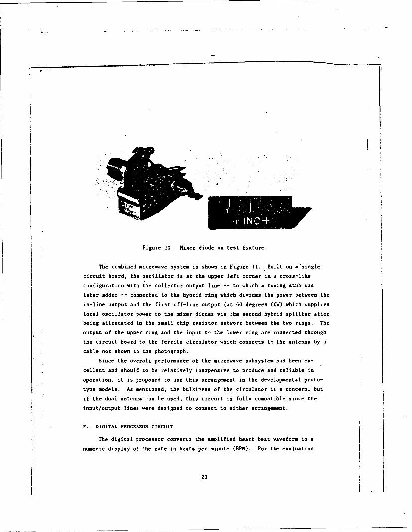
Figure 10. Mixer diode on test fixture.
The combined microwave system is shown in Figure 11. Built on a'single
circuit board, the oscillator is at the upper left corner in a cross-like
configuration with the collector output line -- to which a tuning stub was
later added -- connected to the hybrid ring which divides the power between the
in-line output and the first off-line output (at 60 degrees CCW) which supplies
local oscillator power to the mixer diodes via the second hybrid splitter after
being attenuated in the small chip resistor network between the two rings. The
output of the upper ring and the input to the lower ring are connected through
the circuit board to the ferrite circulator which connects to the antenna by a
cable not shown in the photograph.
Since the overall performance of the microwave subsystem has been ex-
cellent and should to be relatively inexpensive to produce and reliable in
operation, it is proposed to use this arrangement in the developmental proto-
type models. As mentioned, the bulkiress of the circulator is a concern, but
if the dual antenna can be used, this circuit is fully compatible since the
input/output lines were designed to connect to either arrangement.
F. DIGITAL PROCESSOR CIRCUIT
The digital processor converts the amplified heart beat waveform to a
numeric display of the rate in beats per minute (BPM). For the evaluation
21

i|I
Figure 11. Combined microwave system.
model, after a simple circuit which displayed BPN from 15 second interval
counts was built and determined to be too slow, a somewhat more involved
circuit was used which measured the interval between three successive beats and
used a look-up PROM to determine the BPH rate for the LED display.
This method pL'vides a reading in about 2 to 4 seconds for heart beat
rates from 90 to 45 BPM and is updated at the same rate. Although the processor
circuit that we suggest be used for the prototype developmental units has some
important changes, the evaluation model circuit (Figure 12) will be described
first and then the proposed changes discussed.
The output of the signal amplifier is a pair of nominally equal signals
from two unity gain operational amplifiers intended to isolate the sensitive
analog amplifier circuits from the pulsating digital processor. These two
signals are modified by separate peak detector networks with different charge
and discharge rates and the resulting signals applied to the differential
inputs of a comparator operational amplifier.
The reason for using two channels with different effective time constants
is to separate slower and more sinusoidal signals produced by respiration and
22
[

FLASHE
Figure 12. Digital processor block diagram.
subject movement from the pulse type of signal produced by the action of the
heart. The reason for the peak detector or peak holding circuit is to provide
an automatic threshold level control which adapts itself to the average level
of the incoming signal.
With reference to Figure 13, the operation of the comparator - threshold
detector is:
Channel A signal input develops the threshold level for the comparator
through the peak storage network consisting of RI, DI, CI, and R3, where R3 is
much larger than Ri. The corresponding network of Channel B consists of R2,
D2, C2, and R3, but the values differ in that C2 is smaller than C1 by a factor
I of 10, providing a smaller charging and discharging time for the B signal. RI
and R2 are equal, but R4 is less than R3 so that the A signal, the threshold
1 ~level, is attenuated less and overrides the B signal for slowly changing
signals.
* Since the peak voltage developed by the A channel signal is stored in C3i and allowed to discharge much more slowly than the B channel signal, the
! threshold level tends to follow the peak input signal, but with enough decay in1* the normal interval between heart beats to allow the next fast pulse through asSa beat. The action of the differential amplifier is to produce a positive
ouptwhen the signal overrides the floating threshold.
#2623
L4

A
AMPLFIER
Figure 13. Comparator - threshold detector operation.
This comparator - threshold detector circuit differentiates quite well
between the heart beat and respiration signals, but it has one shortcoming
which should be corrected in the prototype models. Very large signals from
sudden subject or monitor movements tend to drive the threshold level far above
that produced by normal signals, blocking one or more subsequent beats. In a
counting system measuring the interval for three heart beats to occur, missing
one beat will cause the monitor to read low by a significant amount, 45 instead
of 60 BPM, for instance. (The comparator - threshold detector proposed for the
prototype developmental units will have two additional features -- (1) signal
levels significantly greater than the average level will be recognized by a
two-level comparator and not considered as valid heart beat signals, and (2)
the threshold level will be averaged over a longer period and not be allowed to
increase significantly because of sporadic large amplitude signals.)
The output of the comparator - threshold detector is sharpened in a pair
of CMOS inverters and used to trigger a monostable multivibrator to produce a
standard pulse of a;Žout 200 ms. This pulse length limits the rate measurement
to 1/200 ms or 300 BPM, which is beyond the readout limit but, at the same
time, should prevent double counts from heartbeat waveforms with multiple
peaks, such as that shown in Figure 14.
The standard pulse is divided by three and used to reset the clock counter
and strobe the display output. The clock signal used is 32 Hz, derived from a
1 32,768 Hz crystal. The relation between the number of clock pulses counted in
24

WAVEFOO75 a
AMOV WAVFPORM l1 ~1SMANOEN[D ANOsQUktmo
Figure 14. Reduction of spurious counts by use ofstandard length output pulse.
the interval datermined Iy the spacing of heart beats has an inverse relation
to the BPM quantity. The relation can be calculated from the expression:
BPM = 60*K*Fc/N
where K = The heart beat pulse divisor
N = The number of counts in K beats
Fc= The counter input clock frequency
A simple computer program (Appendix A) was written and run to show the
relation between BPM and N for several values of selected clock rate and heart
beat divisors. As stated, a divisor of 3 and a clock rate of 32 Hz were
4 selected for the evaluation model because BPM values from 23 to 199 would
produce counts of 250 to 28, which fall within an 8-bit data capability and
have tolerable resolutions varying from +/- 1 BPM at 23 to +/- 5 BPM at 199.
The remainder of the digital processor consists of a PROM into which is
loaded the N to BPM look-up table obtained from the program runoff (shown in
part in Appendix A) and the LED display and associated drivers. In addition to
the BPM display, an LED flasher and a piezoelectric sounder driven from the
standard multivibrator pulse were included in the evaluation unit. Both the
visual and audible indications are intended to match the heart beat on a one
for one basis and provide help in positioning the monitor for a regular and
25
meaningful count as well as indicating the regularity of the heart beat without
the need for monitoring the display.
For the prototype models, the same general type of circuit is suggested
with some basic modifications. To reduce the effect of a missing beat or
extraneous input pulse, the output should be averaged over more than 3 pulses.
To do this without requiring a longer wait for the first reading and updates,
it is suggested that the count data be stored in 8-bit parallel shift registers
And added together with logic circuitry to eliminate any unreasonable counts
and adjust the average accordingly. A lower accuracy reading would be available
after just 2 or 3 beats but the accuracy would automatically improve as the
averaging time increased. Depending upon the room available for shift register
chips, from 6 to 10 interval counts would be added to obtain the long: term
average.
G. DC POWER REQUIREMENTS
The NIHRM is required to operate from rechargeable batteries for at least
6 hours before recharging. Of the four basic sections of the NIHRM, namely the
microwave oscillator, the signal amplifier, the digital processor, and the LED
display, only the oscillator and the display consume significant power and they
have been used to determine the battery requirements.
The bipolar transistor, grounded-base oscillator designed for the evalua-
tion model operates over a moderately wide voltage range with the current set
by an emitter resistor in series with a single 3.6 vdc lithium battery. With
two more of the same type of lithium batteries used for the collector supply
(7.2 vdc), the current was usually set between 10 and 15 MA. Battery current
drain was much greater for the three 7-segment LED numerical irdicators used in
the evaluation unit. Operated from a centertap grounded pair of the same 3.6
vdc lithium batteries, the total driver and display current rose as high as 250
mA, depending upon the number of segments driven.
For the prototype model NIHRI, it is essential that size and weight be
4 considered in the battery selection process as well as duration of operation
between recharging cycles. Of the several types of rechargeable batteries
available, the selection of sealed nickel cadmium cells appears to be most
consistent with the reliability, availability, and maintainability (RAM)requirements of the program as well as with the power needs of the NIHRM.
Nickel-cadmium batteries are in widespread commercial use in diverse tools and
26

instruments, operate in any position, have almost constant output voltage over
life at differing discharge rates, function over a wide range of ambient
temperatures (typically -40 to +60 degrees C), and can be run through hundreds
of charge/discharge cycles with little degradation.
Cylindrical cells are widely used and are relatively inexpensive and
available. Typical ratings for the commonly used AAA (10.5 m D X 44.5 mm L)
and AA (14.5 m- D X 50.0 = L) sizes are capacities of 180 and 500 mA, respec-
tively, with corresponding weights of 10 and 24 grams. Using the nominal C/10
discharge rate for computation, the output voltage of these cells would be
expected to drop from 1.2 to 1.0 vdc in 10 hours at discharge current. of 18
and 50 mA, respectively. Approximately 14 hours would be required to recharge
a fully discharged cell at this same C/10 rate although more rapid charging
rates can be tolerated if temperature limits are controlled.
For the prototype NIORM, it is recommended that a battery pack consisting
of 7 AMA and 4 AA cells wired as shown in Figure 15 be used. For the oscilla-
tor, the same +7.2 vdc will be available at a C/10 discharge rate of 18 mA, but
the emitter bias battery will be changed to -1.2 vdc, reducing the unnecessarily
large voltage drop in the emitter resistor. The collector and emitter current
drains, which are about the same and no more than 15 mA, will be supplied by
the 7 AAA cells comfortably for the required 6 hours of operation.
+72V OSCILLATOR COLLECTOR
.. V AMPLIFIER POSITIVE
OSCILLATOR BASE a COMMON
2 OSCILLATOR EMITTER a AMPLIFIER NEGATIVE
DIGITAL POSITIVE
* DIGITAL COM•ON
- V DIGITAL NEGATIVE
Figure; 15. Battery voltage configuration.
To reduce the heavy current drain of the LED display, a higher efficiency
solid state mumeric indicator, such as the HP 5082-7433, will be employed in
27

the prototype NIHRU. Although characterized as having excellent readability at
0.25 mA per segment -- which would require a current total of 4.0 mA for the
worst-case 16 segments to display "188" -- the numeric indicators will be run
at a significantly greater average current, tentatively 2.5 mA per segment, for
better daylight readability. Under the same maximum display current load of a"188" reading, the total current would be 40 mA; however, since the number ofsegments activated at any instant will usually be less than 16, the total
average current is estimated at 30 mA.
Current requirements for the remaining digital circuitry, LED flasher, and
a piezoelectric sounder will be no more than 5 mA. The resulting total display
and digital processing circuit current drain is estimated at 35 mA, which is
comfortably below the C/10 discharge rate of 50 mA for the AA nickel cadmium
cell and which should provide for more than 10 hours of operation under ideal
conditions until the output voltage drops from 1.2 to 1.0 vdc for each cell.
Since there is some cell degradation after each charge/recharge cycle,
leakage loss, and efficiency reduction at ambient temperature extremes, some
margin beyond the 6 hour limit is required. A tentative layout of the battery
pack as a part of the digital processor/display sub-module is shown in Figure
16. It is estimated that the overall dimensions of the sub-module will be in
the order of 140 mm X 90 mn X 32 mm with a probable battery weight of 160
grams. It is considered that the size and weight of this battery configuration
is a reasonable tradeoff for operational margin.
H. CALIBRATOR
During the testing of various comi-onents and assemblies, it was incon-
venient to use a subject at all times. At first, a slowly driven dielectric
rod rotating in and out of the antenna field was used, but the displacement was
magnitudes greater than the heart beat movement. Later, we used piezoelectric
sounders as the moving target. These devices, which are widely used as beepers
or alarms, emit an audible tone at a specific frequency. The ones we used
operate at low dc voltages and produce tones at about 3000 Hz. There is only a
miniscule movement of the diaphragm -- less motion than the heart undergoes
during beating.
28

DISPLAY I CONTROL AREA
COOIG ITAL CIRCUIT BOARD AREA
- - 1 SMEAL DISPI.AY
WINDOW
WAAA~
AA ~ i AA!
Il SEALED-' RECHARGING
00 00TERMINALS
90 DI I2.i
Figure 16. Tentative battery pack layout.
By driving the piezoelectric sounder with 0.1 sec. pulses at an adjustable
rate comparable to the heart rate, an output signal waveform much like one from
monitoring the heart was obtained. The sounder was used extensively to evalu-
ate and optimize the operation of various circuits during the later stages of
the program.
Additionally, the use of the piezoelectric sounder as a calibrator was
tested and will be incorporated in the developmenLal prototype design, as it
was in the breadboard evaluation model. A crystal controlled oscillator -
using the same crystal and type of circuitry as is used in many digital watches
4 -- driving a CMOS divider and multivibrator was designed to provide 0.1 sec
pulses at 0.5 sec intervals for the piezoelectric sounder. This is equivalent
to a heart rate of 120 BPM.
The sounder and circuit will be built into the carrying case and can be
usdfo checking the accuracy of the NIHRII quickly and conveniently. An
on-off switch will be provided and the sound will be quite muted by the con-
fines of the case.
29 -
, ;:-q

The calibrator will draw very little current and will operata from a
two-cell rechargeable battery which will be automatically charged along with
the monitor battery pack.
This simple calibrator is recommended for use because of its inherent
accuracy, minimal cost, compactness, and compliance with the program objectives.
I. BREADBOARD EVALUATION UNIT
The evaluation unit, which was assembled from the separate breadboard
circuits described earlier in this report, is physically quite different from
the proposed developmental prototype models, but it is a relatively good elec-
tronic and microwave equivalent. Therefore, the evaluations made related to
the basic performance can be reasonably extrapolated to the proposed models.
Those electronic deficiencies which remain, such as the lack of averaging and
blocking by large signals, will be corrected.
The leakage problem -- the reason for erratic and unusable performance in
the tracked vehicle -- must be solved mainly by the physical design which will
be completely different than that of the breadboard model.
The breadboard evaluation model (Figure 17) was assembled within two
standard bakelite instrument boxes mounted back to back, and is about 160 mm x
90 mm x 75 mm in size -- a volume almost twice that which the developmental
prototype units will have. The microwave signal is coupled through the plastic
wall -- bakelite is not a particularly good microwave material -- with the
antenna located about opposite the display window. Three LED numerical indica-
tors are mounted behind the window alongside of which is a simple LED that
flashes for each detected heartbeat. In synchronism with the flash, a piezo-
electric sounder inside the box is pulsed and can be heard for a short distance.
The on-off switch, which must be recessed and sealed in the final model, is
also shown.
The breadboard evaluation model was transportad in the carrying case shown
in Figure 18. To the left of the monitor is the area under which the calibrator
is mounted. To check the operation of the NIHR11, it may be placed on top of
this surface, as shown in Figure 19, and it should read 120 BPE'. With front*1 and back covers of the breadboard evaluation model removed, the microwave
system and analog amplifier can be seen in Figure 20 while the digital proces-
sor and display are shown in Figure 21.
30
I I- I I I I I I I I l I I I I l

Figure 17. Breadboard evaluation unit.
Figure 18. Breadboard evaluation unit in carrying case.
31

Figure 19. Breadboard evaluation unit on top a! calibratorreading 120 BPM.
4
Figure 20. Microwave system and analog amplifier frombreadboard evaluation model.
32
- ., I

Figure 21. Digital processor and display from breadboardevaluation model.
Basically, the unit is easy to use. One turns it and the calibrator on,
waits a few seconds for the internal transients to settle, and places it on the
calibrator to verify that it is functioning. Then one picks it up and holds it
against the patient's chest, firmly but not oppresively, in the vicinity of the
heart. It is helpful to watch the LED flasher and, if possible, listen to the
sounder to see if a regular beat is being obtained. If so, a new reading
should appear after every third beat. Moving the monitor will cause extraneous
readings so it is best to move it in increments and wait a few seconds at each
new position if it is necessary to search for a stronger (more regular) signal.
The developmental prototype models will be about the same in terms of ease
of operation. Instructions will be printed in the carrying case.
J. DEMONSTRATION OF BREADBOARD EVALUATION MODEL
To test the advanced breadboard evaluation model under field conditions,
the Technical Monitor arranged for a test run ii an M113 tracked vehicle which
was rigged for a litter. The testing was performed on 22 July 1983 at Aberdeen
Proving Grounds.
33

/
The following results were obtained:
1. With the subject (patient) lying in the litter while it was stationary
on the floor of the garage, accurate and consistent readings were obtained.
The NIHRflH breadboard model, which is quite oversized, was held in place with
two-sided cushioned tape.
2. With the subject lying in the litter while mounted in the H113,
reasonably consistent and probably accurate readings were obtained about 80% of
the time with the motor idling and the vehicle not moving.
3. In the same position, with the vehicle in motion over smooth or rough
roads, the readings were too erratic to determine the heart rate or even make a
life/death determination.
It is believed, as has been mentioned earlier in this report, the erratic
readings were mainly produced by strong reflections -- of signals leaking from
the antenna side -- from the metal walls of the vehicle. It will be necessary
to improve the shielding and reduce the antenna microwave leakage before
fabrication of the developmental prototype models.
The basic operation of the breadboard model under stationary conditions
was quite promising. Although there are several distinct iprovements to be
made to the follow-on models, the breadboard model has demonstrated that the
following major objectives can be met with certainty:
1. A handheld cw microwave radar can detect the heart beat rate.
2. Normal respiration is not a major concern.
3. Battery power is sufficient to drive the entire monitor.
4. The radar can be fully contained with no exposed radiating or
coupling structures.
5. The heart beat can be discerned through the protective clothing.
6. An accurate calibrator can be included.
7. With proper mixer design, position of placement affects the signal
strength but is not so critical as to be a major problem as originally
suspected. /
34
kv.
4 4

III. DEVELOPMENTAL PROTOTYPE MODELS
The basic concept, design approach, and proposed microwave and processor
circuits of the developmental prototype models have been described'in various
sections of this report. Where these have differed from the breadboard evalua-
tion model, the reasons and proposed changes have been described. Therefore,
in this section, only a summary of the proposed design is given.
The proposed developmental prototype models will use the cv microwave
radar approach to detect the heart motion. A bipolar transistor oscillator
operating at 2150 MHz and biased to limit the antenna output power to less than
9 mW will be fabricated on a microwave circuit board along with a ring hybrid
balanced mixer. Either a single printed microstrip petch antenna and a ferrite
circulator or, less likely, a bistatic printed antenna without a circulator
will be used to separate transmitted and received signals.
An anaJig circuit comprised of two amplifier stages with filtering to
optimizx the response to the heart beat waveform and a pair of output isolation
amplifiers will be built on a conventional printed circuit board. The two
output signals will be processed by a comparator-threshold detector to further
select heartbeat type signals and automatically compensate for signal amplitude
variations. A modification will be made to prevent large extraneous signals
from blocking the proper counting response by using a dual-level comparator.
Pulses from the comparator will be used to flash an LED and a sound beeper, but
mainly to reset a crystal clock counter and strobe readings into the display.
A count averaging shift register will be added to lessen the effect of occa-
sional bad counts. An LED display behind a filter and a transparent window
will provide the required readout.
The unit will be encased and sealed. The case will be metal, probably
anodized aluminum, with transparent plastic windows over the display and the
antenna patch. Gaskets will be used to seal the windows. The unit will be
4 about 140 mm x 90 = x 50 m- and the weight, about 750 gms.
The carrying case will be similar to that shown in Figure 22. It will be
metal and will hold the monitor in a recessed section under which will be the
calibrator and the recharging circuits. Provisions for recharging from ac or
dc sources will be provided.
35

Figure 22. Comuercial version of proposed carrying case.
361

IV. CONCLUSIONS
The background material, circuit descriptions, measurement data, and
general comments provided in this report have been directed at presenting
sufficient information to permit a judgment to be made of the proposed approach
as a valid concept for a battlefield Noninvasive Heart Rate Monitor. The
proposed approach is a small, handheld, battery operated, cw microwave radar
that senses the movements associated with cardiac action through layers of
protective clothing and displays the heart rate directly in beats per minute.
From this information and a general impression derived from performing the
tests and using the breadboard evaluation model, RCA Laboratories has concluded
that the basic proposed design approach is valid and reasonable. Deficiencies
were found during the program and most have been corrected. Remaining problems
are significant and must be resolved. However, promising solutions have been
proposed.
From the presented evaluation and design data and the projected develop-
mental prototype model performance, RCA Laboratories believes that the following
conclusions are essentially valid answers to the contract objectives of Phase
I:
a. A modular electronic assembly capable of detecting and measuring
heart beat in chemically contaminated field conditions can be
designed and built to the required standards.
b. The use of cw microwave radar makes it feasible to measure the
heart rate through chemical protective coverings and clothing.
c. The equipment will be simple to use and can be operated by
personnel wearing protective clothing. The only controls are
on-off switches for the monitor and the calibrator.
d. The device can be completely sealed and, unless physically
damaged, should not become internally contaminated.
e. External surfaces will be treated metal or small windows of
rugged transparent polycarbonate plastic sealed with recessedgaskets. The on-off switch will be recessed and sealed and
there will be two sealed feed-throughs for charging.
37
S' 'e-an--.-lm•

The carrying case will also be sealed in the section which
contains the calibrator and recharger. Obvious care must be
taken in opening the case after use in a contaminated enviroment.
f. Calculations and current measurements indicate that the monitor will
operate for more than 6 hours befoie recharging.
g. The NIHRM will function as well, if not better, under conventional
casualty situations as when used with victims in protective clothing
since it is not critically dependent upon the protective clothing.
h. The proposed device will be simple, rugged and easy to use.
i. Repair and parts support details have not been adequately analyzed,
but the nonmicrowave circuitry will be of a basic printed circuit
nature with less than I00 reasonably standard and available com-
ponents. The microwave circuitry should be quite reliable and even
repairable with specialized test equipment.
j. Environmental testing has not been done but all components will have
the required temperature range capabilities.
k. Operation in high noise and vibration areas has not been proven. It
is believed that the shielding proposed for the developmental proto-
type models will provide this capability sufficiently to ascertain
existence of a vital sign and a display of the average heart rate
with occasional errors from extreme movements.
I. Reliability, Availability and Maintainability details have not been
adequately detailed. Additional work will be done to quantify these
items. Generally, however, the proposed device will be comparable to
similar commercial devices but more rugged.
m. Material lists will be provided for safety and health analysis but
no problem is expected from the inert substances which will be used.
n. Unpacking will be simple, requiring only unlatching and opening the
cover of the carrying case.
o. The container will conform to the environmental and ruggedness re-
quirements.
p. The device will meet the portability requirements when containerized.
38

V. RECOMMENDATIONS
Based on the conclusions presented in Section IV, it is recommended that
fabrication of the developmental prototype models be authorized as Phase II of
the Noninvasive Heart Rate Monitor Program.
It is further recommended that additional time be allocated in Phase II to
allow for the fabrication and evaluation of one prototype model prior to design
finalization. This model is expected to perform in the M113 tracked vehicle
environment, but verification would be desirable and could be obtained if the
time devoted to Phase II of the program were extended by 60 days to cover
fabrication of the verification model.
/

REFERENCES
1. Skolnik, M.I.: "Introduction to Radar Systems", McGraw-Hill Book Company,
New York, 1962.
2. Skolnik, M.I.: "Radar Handbook", McGraw-Hill Book Company, New York, 1970.
3. RCA Proposal: "Proposal for a Noninvasive Heart-Rate Monitor", PP82-120;
RCA Laboratories, Princeton, NJ; June, 1982.
4. J. Lin, et al.: "Microwave Apexcardiography", IEEE Trans. MTT, Vol. 27,
No. 6; June, 1979.
5. S.S. Stuchly, et al.: "Monitoring of Arterial Wall Movement by Microwave
Doppler Radar," Proc. 1978 Symposium on Electromagmetic Fields in Bio-
logical Systems - Ottawa, Canada: June, 1978.
6. I. Yamaura: "Measurements of 1.8-2.7 GHz Microwave Attenuation in the
Human Torso," IEEE Trans. MT=, Vol. 25, No. 8; August, 1977.
7. C.C. Johnson and A.W. Guy: "Nonionizing Electromagnetic Wave Effects in
Biological Materials and Systems," Proc. IEEE, Vol. 60, No. 6, June, 1972.
8. I. Yamaura: "Napping of Microwave Power Transmitted Through the Human
Thorax," Proc. IEEE, Vol. 67, No. 8; August, 1979.9. P.C. Pedersen: "An Investigation of the Use of Microwave Radiation for
Pulmonary Diagnostics," IEEE Trans. Biomad Engr.; Sept. 1976.
10. F. Sterzer, et al.: "Microwave Apparatus for the Treatment of Cancer,"
Microwave Journal, 23 39-40, 1980.
11. R. Paglione, et al.: Microwave Applicators for Localized Hyperthermia
Treatment of Malignent Tumors,"IEEE-MTTS International Sympsium, May
26-30, 1980, Wasshington, D.C.
12. J. Lin: "A New Class of Microwave Therapeutic Applicators," Radio Science,
Vol. 17, No. 55; Sept-Oct 1982.
13. M. Iskander and C. Durney: "An Electromagnetic Energy Coupler for Medical
Applications," Proc. IEEE, Vol. 67, No. 10: Oct. 1979.
14. 1. Bahl and P. 8hartia: "Microstrip Antennas," Aertech House, Dedham, MA.
1980.
15. "A 4.3 GHz Oscillator Using the HX7R-2101 Bipolar Transistor", Hewlett
Packard Applicator Note 975, Dec., 1979.
4049I
I
• " i !I I I

APPENDICES
.4
4--1

APPENDIX A
CALCULATION or HEART RATE FROm INTERVAL COUNTS
This appendix pres-.nts the computer program and runoff used to compute the
prom look-up table to convert clock counts over heart beat intervals to beats
per minute for the BCD display. The clock rate and number of heart beats over
which the measurements are made are variables which may be selected to provide
different resolutions.
FT*, 7 7PP, OG'.AI1 rEATS
C <&30726.1356>C 1*rAT 1.TIE VS COUI:T OF CLOCI PULSES
, C
C FC-cLOCK" Fi,£•,Uc.;CY l.; :ZC 73-,:A!:T rATE L:; :;L1T - .
C i=h-.:T r,,i: 'ULSE I;:?UTý DV , iTO AVF2AGi 0 r:,ý . .
C 1;-t ;UI:LE• Ci 1,(tV.7Z;'
!:I,.I'r•(I,'("i 1:,I: CLOCi" F. .,,• .(.:v,!Ar (,*)zC
, ( " r 7::.: :i:." .... T '.AI'. D 'IoV I c' IT k ,' (" CC 1:t TS i; /.TS F:F !:, -"..
100 FCL:.AT (3X,13,4(4X,14))
ro iA-ILE (:;.LT.256)
LP::2- 2 * FC'60/::LPI:3=3*FC*G6LPl:4-4*F C*6 ci/:;1,100) 7, l , zP:2 , AP::3 , B- * .4
1=;N +I
STC7
F.EIO $
A-I
S-- --m

Sin rSMPEM CO~CK FREQUONCY !A' Az
i<-1 THE rHEART 3sEAT '?TE I'%O0UJNTS BEATS PER MINJTE
1~- 2 kK MG 28
961; 962 G 3 192,4841; L44! ý :
6 321, 6( 2G) I,7 -'7,j S4,, 3) 'l, 7
6 24C 4:3(, 7*(,' 9 IC
U 16G 32C .4 G 6C1 47 -19S 4c ?I'
14 33 27 L S41,
16 126 2 4 31 4:!7 1'-I 22 '0c J16 106 2111S 21 4 2I-19 0i) 1l Iý 2 1) ý, 4 ij426 96 19- 33E
211' 17.,23 !3 2 "-
24 G6 1 2W.r2(
26 7, : 9
2' 6 2 eS 2729 16G ':2 Liý
36 64 12S 191
A-2f -

COUNTS BEATS PER MINUTEN K-1 K-2 K-3 K-423 58 116 17a 23234 56 112 165 22S35 34 109 "GA 2.936 51 106 i6G 21337 S! 103 r55 2-738 SC 101 151 202
39 49 98 147 19646 46 96 144 i9641 46 93 !40 13742 45 91 13; 18,2 .43 44 39 133 17244 42 87 13C 17445 42 8S 17046 41 82 .2S 16647 40 31 2246 4C 8C 12C i6C49 39 7 117 !36Sc 3.3 76 115 153.51 37 75 t12 0SO52 36 72 11c 14?33 36 72 108 ý4454 35 71 106 E 425S 34 89 104 13956 34 68 102 '37S7 33 87 101 134Ss 32 66 95 13259 32 S5 37 1306C 32 64 96 l2661 31 34 12562 '3 61 92G3 30 30 3! t2f64 3C 6c 93 12Cs29 :9 38 ? '866 2c 56 37 11657 28 -337 8) .14G6 26 56 84 11269 27 35 3 3 ,t7 27 54 82 10971 -7 Z4 .31 t0272 26 53 3C 10673 26 52 78 ,OS74 25 51 07 10375 25 31 ?6 !0276 25 S 715 10177 24 49 .7 976 24 4$ 73 9679 24 42, -37
A-3

COUNTS BEATS PER MINUTEN K-I K-2 K-3 K=4
8C 24 4s 7Z 9681 23 47 71 9482 23 46 7C 9,83 23 aZ6 ,9 3284 22 45 66 9,85 2 4
86 22" 44 66 8S87 22 44 36 3886 21 43 65 8789 21 43 54 *390 21 42 64 PC31 2! 42 .3392 20 41 62 S3393 20 41 S? 3294 2G 4C 61 8195 20 0 60 309 6 2 G 4 G 6 G 0:197 19 9 39 7796 19 3r 5S 7E.39 ;9 38 53 77
100 19 31 57 76,lO. 19 38 57 76102 18 37 56 74103 i8 37 75 7S104 18 36 55 72105 19 36 54 73105 18 36 54 7-
107 17 35 S3 73108 17 5? 71109 17 3S 52 7')110 17 34 52 6G1l? 17 3i .31 33112 1? 34 51 66.113 16 33 50 67114 16 33 5c 611s !6 33 30 56116 16 33 4S 66117 16 32 43 )116 16 3 4C 6c119 16 328 s4120 16 32 4c 64121 IS 31 47 .3122 1S 31 47 62I 123 1S 31 46124 15 3G 46 6125 1S 306126 15 30 45127 15 30 45 30126 15 30 45 c 6124 H 29 453 4
A-4
. . L .. .. . .-,

COUNTS BEATS PER MINUTEN K-I K12 K-C K-
130 14 25 44 55131 1/ 29 4; 3813Z 14 2S 43 S6133 14 28 43 37134 14 26 42 5?135 14 28 42 36136 14 2b 42 56137 ;4 28 42 56130 13 2? 41 54136 13 27 41 5S139 13 27 41 s5141 13 27 40 54142 13 27 40 54143 13 22 40 32144 13 26 40 53
145 13 26 39 S2i46 13 26 -)g 5-147 !3 2I 39 S2146 12 25 36 s5149 !2 25 '3 51150 12 2$ 38 5'15s 12 25 3e 30153 12 25 37 50
154 12 24 37 43135 12 24 37 19156 i- 24 36 4137 12 24 34 "815i 12 24 3C 46159 12 24 36 43160 12 24 36 4b!61 11 23 35162 11 23 3$ 4?153 TI 23 35 '4164 11 23 3$ 46155 11 2- 34 4166 11 23 34 4C167 iT 22 3" 45166 11 2 34 4,69 II 22 xi 4517G 11 22 3, c171 II 2 3v172 11 22 33 44173 11 22 33 44174 11 22 33 44175 !0 21 43176 10 21 3 41t77 10 2 2176 1l 21 32 4;179 T0 21 3 4-2
.,.-A-5
-I-

COUNTS BEATS PER MINUTEN K-i K-2 K-1 K-4
18c i1 21 32 42181 10 2! 31 42182 10 21 31 42.183 10 2u184 10 2C 31 41185 10 20 3! 41186 10 20 30 41
1:37 to 20 o0186 1c 20 3c 40189 10 20 30 40190 IC 20 3G 4r,191 10 20 30 40
192 10 2G 31" 4c,
193 9 !9 29 39194 3 19 2 3$195 9 19 29 39196 9 19 2H 39197 9 19 29 38196 9 1 29 35139 9 19 2L200 9 is 26 36201 9 19 23 38202 $ 19 2•. 3203 3 t8 28 37204 9 16 26 37205 9 i8 ?q 37
206 S 16 27207 9 18 27 37206 9 1s 27 36209 3 !3 27 36210 ' 16 2? 3621! 9 !8 27 362127 16 2? 36213 9 ;8 27 36214 6 1? 26 3$215 17 2C 35216 s 17 26 ?5,217 8 17 25 35211 6 17 26 3S219 3 17 26 39
A-6

COUNTS BEATS PER MINUTEN K-1 K-2 K- K-4
22C 6 17 26 34221 8 17 26 34222 6 17 2i 34223 8 17 25 3M224 6 1? 2S 34224 8 17 25 34226 6 16 21 q227 8 25 33228 6 16 25 3C229 8 16 2523C 6 16 25 3231 8 16 24 33232 6 16 24 33233 8 16 24 32234 6 16 24 3K235 8 16 24 32236 6 16 24 3237 8 16 24 32238 6 16 24 32239 8 16 2424C 6 16 24241 7 !S 2' 3242 7 15 3?243 7 15244 7 15245 7 15 3246 7 15 31247 7 45 3 3t248 7 I5249 7 15 23 3025C 7 15 2251 7 15 22 30252 7 15 22252 7 I5 22 3C254 7 15 2G235 7 s5 22 SO
A-7

APPENDIX B
aICROSTRIP PATCH ANTENNA CALCULATIONS
This appendix presents the computer jrogram for calculating the
dimensions of eicsroatrp patch antennas and the runoffs for two differentsicrvave substrate materials.
RU PATANTYPE IN SUBSTRATE DIELECTRIC CONSTANT. TAICKNESS
10.0.0.127TYPE IN START, STOP, INCREM4ENT FREQUENCIES IN jHz
2.0,3.0.0.tFREQ. WIDTH LENGTH(GHZ) (IN) (IN)2.0 1.2.6 .932.1 1.20 .892.2 1.14 .842.3 1.09 .812.4 1.CS .772.5 1.01 .742.6 .97 .712.7 .93 .692.8 .90 .662.9 .87 .6A3.0 .84 .62
:RUPATANTYPE IN SUBSTRATE DIELECTRIC CONSTANT. THICKNESS
2.32,0.318TYPE IN START. STOP. INCREMENT FREQUENCIES IN (G;4z
1.0.12.0.1.0FREQ. A4IDTH LENGTA(GHZ) (IN) (IN)
1.G 4.58 3.8K2.0 2.29 !.P73.C 1.53 1.224.0 1.15 .39S.C .92 .7C6.0 .76 .567.C .65 .4?8.0 .37 .409.C .S1 .34
10.0 .46 .3011.C .42 .2612.0 .38 .23
B-1
- 4- -

LI.aPATANVPATAN T-00004 IS ON CR00004 USING 00006 BL<S R-0000
0001 FTN770002 PROGRAM PArANTJ003 C MICROSTRIP PATCH ANTENNA DESIGN CALCULATION00G4 C FROM "MICROSTRIP ANTENNAS". BAHL AND SHARTIA. AERTECH HOUSEO00S C PAGE 57; EQUATIONS 2.66 AND 2.67 AND OTHERS REFERENCED00C6 C0007 C FILENAME IS DDMPAT .... USUALLY CNANGE TO VPATANT FOR RTE-6 COMPIL00C8 C0009 REAL 4.4IN(20),C.FREQ.F(20).EREE.L.LIN(20ODELTAL.H0010 REAL FSTART,FSTOP.FINCR001! WRITE(t,!00)0012 100 FORMAT (3X,'TYPE IN SUBSTRATE DIELECTRIC CONSTANT. THICKNESS0013 READ (1.*) ERH0014 WRITE(1.200)jots 200 FORMAT (3X.'TYPE IN START. STOP. INCREMENT FREQUENCIES IN GH0016 READ (1.*) FSTART.FSTOP.FINCR0017 FREQ-FSTART-FINCR0018 I-C0019 C-3.OE1O0020 WRITE (1.400)0021 WRITE (1.500)0022 400 FORMAT5SX.'FREQ.'.4X.'WIDTH',SX.'LENGTH'r0023 SO0 FORMAT(SX,'(GHZ)-.4X.' !IN)'.SX.' (IN)')0024 DO WHILE (FREO.LT.FSTOP)0025 FREQ-FREQ+F .i;0026 I-I+l3027 ,REO-FRE*1.0E090028 W-(C/(2.*FREQ))*((ER+1.)/2.)**(-.S)3029 EE-((ER+1.)/2. )+(((ER-!.)/2.) (1.+(12.*H/W))..(-.S))0030 DELTAL- (O.412*H) (EE+O.-) * (W/H+0. 264))3031 DELTAL-DELTAL/I(EE-0.258).((W/H)+O.83)0032 L-((C/(2.*FREQ*(EE**°5n))-2.*DELTAL)0033 FREO-FREQ/I.OE090034 W-W/2.540035 L-L/2.540036 WRITE (l.300) FREQW.LJ037 END DO0038 STOP0039 300 F3RMAT(SX.F4.1,5X.FS.2,SX.FS.2)0040 END3041 ENDS
B-2

APPENDIX C
MONITOR VSWR PLOTS
This appendix presents the VSWR plots of the Noninvasive Heart Rate
Monitor's high dielectric aicrostrip patch antenna under various conditions
and clothing configurations.
I i
iC-iI ___ _____
--K

N
SSS
. ................................. .......... .............. ........... a36
cc a
............................. ..... .::............... ........ ......... a-n '00
-- 3
VON
,. .,...............................; ......................... ..(........ to .
* 2.
S •
w 3
so-
• . ........ ~~ ~~~......................... ..... ...... . .. . .. . . . . . . =.
3 0
* S.o oS
Q4
. .2 .
....0 N
Ic oN
cc 4
69 tn
..........
NMSS
C-2~

So
j.
0;0
a. aVN N
0 11 1
Ma U1....... .. .. . .. . . . . . . . . . . . . . .. . . . . . . . . . . . t
S"* a
ccUO.S
.. ~~~~ ~ ~ ~ .............. ...............
cc N0N c 0.
.. .. . .. .. . .. . . . . . . .. .. . . . .. . . . 0
a. 0 >. .. . . . . . . . . . ... ... . . . . . . . ... .. . ..-. .
cc. N 0
C-34

*- .. . . .
L..• ...... ................... *! ............. ..... !............... .'.j.
.. ... .......... ..
C4 ,
U(
Zw M
.. . . . . . ..
, ........... .. . . . ..... . ....... .
x 4) 41.o ........ .......... ........ . ................. .......... .
,W ... .. . . . . . .. .°. . . . ... . . . . .. . . .
0 C3 m =
z•
04I
I.I . . ........... I I I II.i..i
a U 0 (a
a...... ..........................................
uJ
. .. .. .. .. . . . . . . . ... . . . . . . . . . . . . . . . . . ... a
-C-

-- /1
tg,,
i\ !~~%A
"""•. ........ ....... . . . .............. .............. ...... .... , . •
•. ... . .;........ .... . ........... .... .............. ..............." " "- 'I , ..i 0
InIa
• w, ....... •................ 7 ....... ..• ..... ............. .. ;........... . d".• . . "S•e3 .... ... . .• - .I. *
L a 2, r :, 4 :s
.............. ; .... ......... ........ . . .....
a C3
e- iO Lo 0 4)•
01.. * : -
CmU . LL.
cc a
. ... t . ....... . . ..
>cmm
.. . . . .. . . . .. . . .. . . .. .. .. .. .... .. .. .. .
00 (
/ ........ 0
-m I I . . IJ.
to V V) .
NMSA N
C-5

Ci
.' . _ • ..S. . ... . .......... ................... . aQ
a w
"'-" ......... .... ........................ .. ..... ...0 . 0
0 0 IMD00
* C
........... I ..... .. ........... ....aNat
hi
• * * U
G.a LI I.
a W. I
01 IL.* ,.0 *0 .,.0° C
,. • ........... ................... .......... . .... ....... ......... _
aL
... ... . ............ ......... ........ .................. C;•
-u * S
-"C O D
0 LA.•0
.. .. .. .... ... . . . .. . . .. .. . .. .. . .. . .. . .. . .
.+ a ... ... ..... ..... .....
C-6 6
'. . . .................... . .. |
.. . . .. . . . . .. . . . . . ... . . . . .. . . . . .. . . . . .
S NS
C-

W ,÷
- IL............. . o................. ... ...
............. . .:....
3 1 ,- : * *
1.,W. ................. ............... . .................... .
a.. . N (U
... 0°
* * ~(U'-gO * S
. . . . • .....
S- N
. * . 0.0
........................... ...................................... ...... .... ~ L. '
JJ 0
Nc 0 ut7 " -
m (U
-u................. .............. ...... .....
Lai
* *0
. .. . . . . . . . . . . . . . . .. . . .

-rr
------ - ,-
............. .. ......................................
S . . .. . .. . . . . . :". .
t
S : .: *e I
-.: * / -5
a.
*. . 1................ .......•• ......../ ............. 0"•. o
. ... .o.... •.......... .. . o........ .o .......... .. ... .... o... ,........
S. ~ ...° .......... . ..... .....,... ... .......... .. o.. °... ...... u oo...
O.S.
4D
.. .. ... .... . ...... .. ........ .... ........ i -.tma *% .-
to
* (U
0 0
oil--
a . .. . . . .. . . ... . ... .. .. . . . .. . .. .. .. ..
10 m
ILII AII III II IIIIQ~
.... .... ... ... ...
NK 00
C--8

.. . .. . .. . . . . . . . . . . . .. . . . . . . . . . . . . .
aID* **i S
* .. . ........ .... . ... . . . . S,
* N
Ti .... .................. .............. r.............. :.............. • •" .* U
U . . . ,,
". .. . .. . . . . . .. . . . .. . . . . .. . . . . .............. i.. I8
SI 4 *
... ............ ............. .............. .............XI-D
41 Q0 .0
. ................. • ..... ............. .............. ... ............. Mýc 0
ago >
cc .0 (j
.. .. ... . .. .. . .. . . . . . . .. .. . ... . . . .. . . . .
* so
C-9

APPENDIX D
BALANCED MIXER POSITIONAL DEPENDENCY TEST
As mentioned in the text of this report, positional dependency was a
problem when simple mixing techniques were used for the cv microwave radar
sensitivity and frequency comparison tests. A balanced mixer consisting of two
Schottky mixer diodes and a ring hybrid, which offsets the two diodes by 908 in
phase, was designed for the Noninvasive Heart Rate Monitor. Prior to integrating
the balanced mixer into the monitor, a test was performed to demonstrate that
null readings would not occur at any spacing between the antenna and the
target.
The test arrangement shown in Figure D-1 was used. A small dielectric
shaft was set up under the antenna and the microwave system which had been
mounted on a moveable lab jack. Since the shaft was reasonably uniform, there
was no relative motion and no Doppler signal was generated. A small strip of
metal tape was positioned on the shaft at one point to provide a moving target
as the shaft was slowly rotated by a low RPI gearmotor.
The voltage output of each mixer diode was observed separately and as a
summed signal on a storage oscilloscope at several positions as the antenna was
elevated away from the rotating shaft. The oscillograph waveforms were proto-
graphed and are attached as Figures D-2 through D-1O.
As the spacing increases, the signal decreases as expected and this is not
a cause for concern. The problem is that the amplitude of either mixer signal
can go through a cull, as 6hown by Mixer 1 at St p 4 where the signal is
noticeably smaller than for either Step 3 or 5. The same tendency to go
through a null is shown by Mixer 2 at Step 7. The effect would be more pro-
nounced if the target motion were small and the step increments were finer. By
summing the two mixer voltages, some signal will be available at any spacing,
thereby removing much of the positional dependency of the cw microwave radar
design approach.
/
D-I "
I ",

BALANCED MIXER
POSITIONAL SENSITIVITY TEST
TEST SET-UP MIXERL
8 M TOSTORAGESI R OSCILLOSCOPE
HPATC ANTE NN.
METAL TAPE f' ~~ ~ ~ ~ ~ ~ ý L"J'" "'•A•JUSTABLE
/ ' " --.......- SPACING
MOTOR DIELECTRICSHAFT
Figure D-1
D-2

STEP No. 1RELATIVE POSITION 25 mm
MIXER I
MIXER 2
50Oms/DIV
10 mV/DIV
ADDED
Figure D-2.
D-3
........... ....
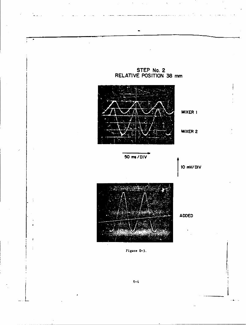
STEP No. 2RELATIVE POSITION 38 mm
MIXER I
MIXER 2
50 fns/Div
10 MV/DIV
ADDED
.........
Figure D-3.
0)-4

STEP No. 3RELATIVE POSITION 50 mm
MIXER 1
MIXER 2
50 ms/DIV
1O mV/DIV
S~ADDED
Figure D-4.
D-5
-. ., 'I IIIII

STEP No. 4RELATIVE POSITION 63 mm
MIXER 1
50MmX/DIV
501 mV/DIVV
ADDED
/Figure D-5.
D-6

STEP No. 5RELATIVE POSITION 75 mm
MIXER I
MIXER 2
50 ms/DIV
I 10 mV/DIV
1
ADDED4
Figure D-6.
D-7 i

STEP No. 6RELATI VE POSITION 88 mm
MIXER I
MIXER 2
50 ms/DIV
10 mV/ DIV
Figure D-7.
Dl-8

STEP No. 7RELATIVE POSITION 100 mm
MIXER I
MIXER 2
50 ms/DIV
10 mV/ DIV
ADDED
Figure D-8.
D-9

STEP No. 8RELATIVE POSITION 112 mm
MIXER I
MIXER 2
50 ms /Div Im/I
4 ADDED
Figure D-9.
D-10

STEP No. 9
RELATIVE POSITION 125 mm
MIXER I
MIXER 2
50 ms/DIV
t0 mV/DIV
ADDED
Figure D-10.

APPENDIX E
RADAR SENSITIVITY MEASUREMENTS
Using the test setup in Fig. E-la, various combinations of available
microwave components were assembled as cw microwave radar systems to perform
sensitivity measurements as a function of requency and relative position of the
antenna and test subject.
Mixer output waveforms under the various conditions were recorded on a
storage oscilloscope and the photographs are attached as Figures E-2 through
E-16. The waveforms in Figure E-2 were taken with the 2 Ghz antenna pressed
against the chests of two different subjects without the table and other
apparatus. All the other waveforms were taken on a single subject, wearing the
supplied combat coat marked with a locating grid, lying on the table as indicated
in Figure E-lb.
More distinct waveforms were obtained when the antenna was held against
the chest than when the subject and the antenna were separately supported by
the table and cart, but reference locations could not be maintained without
such an arrangment. In retrospect, testings with the radar mounted remote from
the subject, even when in contact, was not a good approach because there were
many sources of relative motion and vibration that introduced extraneous
signals; however it did serve to emphasize the need for direct contact of the
monitor on the patient in the field.
The various photographs are marked with the condition of the specific test
being performed. After reviewing the waveforms, the following general conclu-
sions were drawn:
1. There is more positional sensitivity at the higher frequencies
which should be expected since the wavelengths are shorter and
interference patterns will occur more closely.
2. Heavy wall pressure causes smaller signals, probably because
chest wall motion is suppressed.3. The waveforms are complex and vary widely, indicating that
the signal results from the composite of several different motions.
4. Mapping measurements at 8 GHz show variations in signal, but usable
signals are present over a wide area.
5. The signal processor must be able to handle a wide range of amplitude
and waveform variations.
E-1

TEST SET-UP FOR SENSITIVITY MEASUREMENTS
CIRCULATORO DIhECTIONAL M IXE STORAGE
COUPLER SCOPE
VARIGANU RU
(a)
MICROWAVEMICROSTRIP COMPONENTSCONEPATCH ONEANTDENA wI 1'F JClCANTN
w
(b)
Figure E-1.
E-2

2 - Hz PATCH ANTENNA AT2150 MHz
HELD AGAINSTCHEST OFSUBJECT DM
HELD AGAINSTCHEST OFSUBJECT HM
1.0 sec/DIV
Figure E-2.
E-3

2150 MHz SUBJECT DM -ANTENNA CENTERED OVER CHEST
I e /DIV
UGHT CONTACT
12 mm ABOVE CHEST
25 mm ABOVE CHEST
50 mm ABOVE CHEST
Figure E-3.
E-4

2150 MHz SUBJECT DM -
ANTENNA 25 mm LEFT OF CENTER
LIGHT CONTACT
HIM 12 mm ABOVE CHEST
25 mm ABOVE CHEST
Figure E-4.
E-5

2150 MHz SUBJECT DM-ANTENNA 50 mm LEFT OF CENTER
1.0 smc/DIV
ST.LIGHT CONTACT
Ais 12 mmABOVE CHEST
25 mm ABOVE CHEST
Figure E-5.
E-6
III ~ II- I I II I I I I I I I I " I I I I I I I I

2150 MHzTEST SET MOVED AWAY FROM INTERFERENCE
SUBJECT DM- ANTENNA 25 mm LEFT OF CENTER
MODERATE PRESSURE
LIGHT PRESSURE
CONTACT NO PRESSURE
P 12 mm ABOVE CHEST
Figure E-6.
E-7

4200 MHzSUBJEOT OM - CENTERED ON CHEST1.0 sec/DIV
HEAVY PRESSURE
MODERATE PRESSURE
UGHT PRESSURE
CONTACT NO PRESSURE
12 mmABOVE CHEST
Figure E-7.
E-8

6400 MHz SUBJECT DM -CENTERED OVER STERNUM
HEAVY PRESSURE
MODERATE PRES3URE
LIGHT PRESSURE
1.0 sec /DIV
Figure E-8.
E-9

6400 MHz (CONT.)
1.0 sc/ DIV
CONTACT NO PRESSURE
12 mm ABOVE CHEST
Figure E-9.
E-10

8000 MHzSUBJECT OM- CENTERED ON CHEST
1.0 sc/DIV
/, HEAVY PRESSURE
f, •i~j lfl•;•..• ( i(; rjrgj! 1LIGHT PRESSURE
iEll Eis-
It•t .JJMi 12 mm ABOVE CHESTiII~ff ThIHr.t I
Figure E-1O.
E-11

10 GHZSUBJECT OM- CENTERED ON CHEST
1.0 sec/DIV-
HEAVY PRESSURE
LIGHT PRESSURE
12 mm ABOVE CHEST
Figure E-11.
E-12

/.
!7
8000 MHzSENSITIVITY MAPPING
TEST
ANTENNA
REFERENCELOCATIONS
MEDIUMPRESSURE
Figure E-12.12w4
19 a
E-13
/ L.

8000 MHz MAPPING TESTSUBJECT DM- VARIOUS LOCATIONS
RELATIVE TO STERNUM
1.0 sec/DIV
POSITION 2MOP CENTER
POSITION 5CENTER
POSITION 8BOTTOM CENTER
Figure E-13.
E-14
4 , ----

8000 MHz MAPPING TEST
1.0 sec/DIV
POSITION 3TOP RIGHT
POSITION 6CENTER RIGHT
BOTTOM RIGHT
Figure E-14.
E- 15

8000 MHz MAPPING TEST
1.0 see/DIV
POSITION I
POSITION 4CENTER LEFT
POIIO
BOTTOM LEFT
Figure E-15.
E- 16

-- ------- -
APPENDIX F
FDA COMPLIANCE
This appendix presents a copy of RCA's application for investigational
* device exemption, submitted to the U.S. Food and Drug Adminstration, Bureau of
"Medical Devices on April 26, 1983.
F-i

p r
April 26, 1983
Joseph L. HackettBureau of Medical Devices, HFK-403 ....Food and Drug Administration8757 Georgia AvenueSilver Spring, MD 20910
Dear Mr. Hackett:
Under Contract No. DAVD17-83-C-3018 with the U.S. Army MedicalResearch and Development Command, RCA Laboratories is develovinga noninvasive heart rate monitor to be used with chemical protec-tive overgarments. Inasmuch as human subjects may be used intesting the monitor, we wish to be in compliance with 21 CFR, Part812 Investigational Device Exemption(IDE) Regulation.
We do not have an Institutional Review Board (IRB) at RCA Labora-tories and are unaware of the existence of an IRB in the ir.ediatearea. We are, therefore, submitting the following description ofthe proposed device and respectfully requesting your concurrencewith our opinion that it does not represent a significant riskdevice.
As presently envisaged, our device will be approxi--ately the size ofa package of cigarettes and will have a flat, printed-circuit an:ennaon one face (the face which will be placed against the chest of asubject wearing protective clothing, - not near the eyes or any otherheat-sensitive part of the body) and a digital readout on the oouositeface. M!ovements of the chest wall cause reflections of a weak micro-wave signal emitted by the antenna to contain components of the heart-beat rate which are converted by signal-processing circuitry into a"signal suitable for activating a digital heart rate readout. Uponactivation for a particular measurement, the device will averagereadings over not more than a 60-second time interval, then shutitself oft.
The frequency of operation of the device is 2.45 GHz and the trans-mitted power is 10 mW. The metalized "oatch" of the antexna hasdimensions of 1.83 cm x 2.54 cm (.72" x 1.0"), so tiaa its area is4.65 cm2. in the worst case, i.e. if we assume no beam spr2adingbetween the antenna and the body of the subject, the power densityduring the measurement will therefore be 10 mW / 4.65 cm2 2.15 mW/cm 2 (the attenuation suffered by :-.e signal in penetrating the pro-tective clothing is negligible).
My diret OiaJ Number is (609)-734 2712
F-2
K
' - " . , . - -•' . '

Mr. Joseph L. HackettPage 2April 26, 1983
T.i ANSI C95.1-1982 radio frequency protection guide for whole bodyexposure of human beings at a frequency of 2.45 GHz permits a maxi-mun exposure of 5 mW/sq cm. Considering that the maximum exposure,as calculated above, for a total of a few 60-second intervals only,on a limited area of the chest is less than one-half that perm'ittedby the ANSI standard for whole-body exposure, we conclude that the.instrument is not a significant risk ceevice within the meaning of21 CFR 812, and we request permission to perform preliminary experi-ments on personnel for the purpese of refining the design and forpackaging a prototype demonstration-model instrument as required byour contract.
Please notify us immediately it you require any additional informa-tion in connection with this reqvest.
Very truly yours,
Russell B. Chase
Yanager, Contracts
ajq
cc: Patricia M. McAllisterUSAHRDC
F-3