
MECHANICAL TREATMENT OF'ME$ALS - Defense Technical ...
65
RIA-77-U35 AM 19971017 312 AD SOVI ET PfiÖÜIfSTN tl*ERM O- MECHANICAL TREATMENT O F'ME$ALS^---"~~ •" " - :; /////< v ' f [\ /§ECHNICAL lk /^l LIBRARY MI MB WR^AZRIN U| |! MBTömS RESEARCH ok/ISION NovembeMW This document was^r^refeor the il s Afn| Forei|n%CiejiGe^n^^ennology Center of the US Army Materie>^i^^§rrt'-ancl Readines^l^rfia^.^if has been approved by the Foreign Science and t^cfiÄqt^:lS^^^^^§53epSrtment of Defense Scientific and Technical Intelligence Prögranrr— Approved for public release; distribution unlimited. DTIC QUALIFY INSPECTED 8 ARMY MATERIALS AND MECHANICS RESEARCH CENTER Watertown, Massachusetts 02172
-
Upload
khangminh22 -
Category
Documents
-
view
4 -
download
0
Transcript of MECHANICAL TREATMENT OF'ME$ALS - Defense Technical ...
RIA-77-U35
AM 19971017 312
AD
SOVI ET PfiÖÜIf STN tl*ERM O- MECHANICAL TREATMENT
O F'ME$ALS^---"~~ •" ■ ■ ■ " - :; /////< v' f [\ /§ECHNICAL
lk /^l LIBRARY
MI MB
WR^AZRIN U| |! MBTömS RESEARCH ok/ISION
NovembeMW
This document was^r^refeor the ilsAfn| Forei|n%CiejiGe^n^^ennology Center of the US Army Materie>^i^^§rrt'-ancl Readines^l^rfia^.^if has been approved by the Foreign Science and t^cfiÄqt^:lS^^^^^§53epSrtment of Defense Scientific and Technical Intelligence Prögranrr—
Approved for public release; distribution unlimited. DTIC QUALIFY INSPECTED 8
ARMY MATERIALS AND MECHANICS RESEARCH CENTER Watertown, Massachusetts 02172

The findings in this report are not to be construed as an official Department of the Army position, unless so designated by other authorized documents.
Mention of any trade names or manufacturers in this report shall not be construed as advertising nor as an official indorsement or approval of such products or companies by the United States Government.
DISPOSITION INSTRUCTIONS
Destroy this report when it is no longer needed. Do not return it to the originator.
UNCLASSIFIED SECURITY CLASSIFICATION OF THIS PAGE (When Data Entered)
REPORT DOCUMENTATION PAGE 1. REPORT NUMBER
AMMRC TR 76-36
2. GOVT ACCESSION NO.
4. TITLE (and Subtitle)
SOVIET PROGRESS IN THERMOMECHANICAL TREATMENT OF METALS
7. AUTHORfsJ
Morris Azrin
READ INSTRUCTIONS BEFORE COMPLETING FORM
3. RECIPIENT'S CATALOG NUMBER
5. TYPE OF REPORT ft PERIOD COVERED
Final Report 6. PERFORMING ORG. REPORT NUMBER
8. CONTRACT OR GRANT NUMBERfsJ
9. PERFORMING ORGANIZATION NAME AND ADDRESS
Army Materials and Mechanics Research Center Watertown, Massachusetts 02172 DRXMR-EM
10. PROGRAM ELEMENT. PROJECT, TASK AREA 4 WORK UNIT NUMBERS
WCMS Code: 381022.1
11. CONTROLLING OFFICE NAME AND ADDRESS
US Army Foreign Science and Technology Center 220 7th Street, N.E. Charlottesville, Virginia 22901
14. MONITORING AGENCY NAME a ADDRESSff/ different from Controlling Office)
12. REPORT DATE
November 1976 13. NUMBER OF PAGES
60 15. SECURITY CLASS, (of this report)
Unclassified 15«. DECLASSIFI CATION/DOWN GRADING
SCHEDULE
16. DISTRIBUTION STATEMENT (of this Report)
Approved for public release; distribution unlimited.
17. DISTRIBUTION STATEMENT (of the abstract entered in Block 20, if different from Report)
18. SUPPLEMENTARY NOTES
This document was prepared for the US Army Foreign Science and Technology Center of the US Army Materiel Development and Readiness Command. It has been approved by the Foreign Science and Technology Center under the Department of Defense Scientific and Technical Intelligence Program.
19. 'KEY WORDS (Continue on reverse side it necessary and identify by block number)
Thermomechanical treatment Aluminum-base alloys TRIP steels Ausforming Titanium-base alloys Precipitation hardening Steels Nickel-base alloys Plastic deformation
20. ABSTRACT (Continue on reverse side II necessary and Identify by block number;
(SEE REVERSE SIDE)
DD,JAT73l473 EDITION OF 1 NOV 65 IS OBSOLETE UNCLASSIFIED SECURITY CLASSIFICATION OF THIS PAGE (When Data Entered)
UNCLASSIFIED SECURITY CLASSIFICATION OF THIS PAGEflWmi Dal« Bnfrnd)
Block No. 20
ABSTRACT
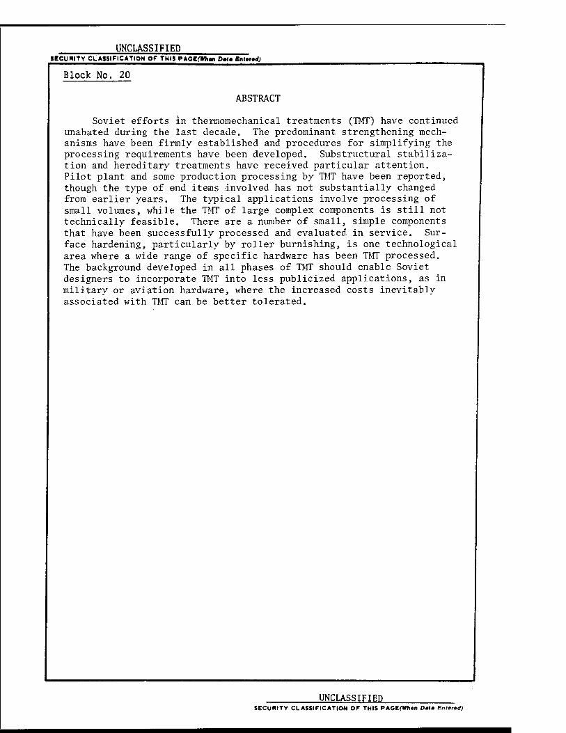
Soviet efforts in therraomechanical treatments (TMT) have continued unabated during the last decade. The predominant strengthening mech- anisms have been firmly established and procedures for simplifying the processing requirements have been developed. Substructural stabiliza- tion and hereditary treatments have received particular attention. Pilot plant and some production processing by TMT have been reported, though the type of end items involved has not substantially changed from earlier years. The typical applications involve processing of small volumes, while the TMT of large complex components is still not technically feasible. There are a number of small, simple components that have been successfully processed and evaluated in service. Sur- face hardening, particularly by roller burnishing, is one technological area where a wide range of specific hardware has been TMT processed. The background developed in all phases of TMT should enable Soviet designers to incorporate TMT into less publicized applications, as in military or aviation hardware, where the increased costs inevitably associated with TMT can be better tolerated.
UNCLASSIFIED SECURITY CLASSIFICATION OF THIS PAGEflWien Data Entcted)
PREFACE
This report presents the results of an extensive literature search to assess current efforts by the Eurasian Communist Countries in the thermomechanical treat- ment (TMT) of steels and alloys of aluminum, nickel, and titanium. Data for this report was obtained from scientific and technical literature dating from 1968 to April 1976.
Of the Eurasian Communist Countries, only in the Soviet Union and to a lesser extent in Czechoslovakia is there a strong commitment to the research, development, and utilization of TMT. The Soviet interest in this processing technique, like that of the US, dates back over two decades to the early work demonstrating a synergistic improvement in certain mechanical properties due to the combining of thermal and mechanical processing. US interest in TMT gradually waned after much research and development that, at times, culminated in service evaluation. The reason for this diminishing effort can be attributed to a number of factors: TMT and subsequent fabrication are difficult and costly to perform; new and improved steels were developed having improved properties after conventional heat treat- ment; and improvements in melting practice leading to improved properties have been developed. However, these seemingly formidable obstacles did not deter Soviet interest in TMT. Obviously, even without further significant technological advances there is the potential for critical applications in space, aviation, and military hardware where the increased strength-to-weight ratio can justify the use of TMT. Based on these considerations alone, there is ample motivation for a continued effort in TMT. A number of areas of application are discussed in this report to illustrate the hardware under consideration as well as to demonstrate how the results of the more fundamental studies were incorporated into pilot- plant evaluations. If the Soviets continue their present high level of research activities in TMT, further advances can lead to new types of applications of increased sophistication. Indications are that this is the case.
This document is designed to provide a valuable input to Department of Defense materials planners and research personnel concerned with development of advanced materials, materials theory, and processing technology.
This study was sponsored by the US Army Foreign Science and Technology Center, US Army Materiel Development and Readiness Command, with Mr. W. F. Marley, Jr., as technical monitor. Mr. Marley's assistance is gratefully acknowledged. The author would also like to thank Drs. E. B. Kula, G. B. Olson, and Mr. F. Hodi of AMMRC for their assistance during the preparation of this report.
111
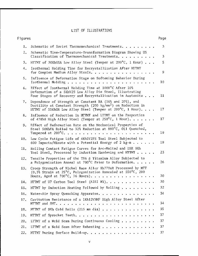
LIST OF ILLUSTRATIONS
Figures Page
1. Schematic of Soviet Thermomechanical Treatments 3
2. Schematic Time-Temperature-Transformation Diagram Showing US Classification of Thermomechanical Treatments 3
3. HTTMT of 30KhGSA Low Alloy Steel (Temper at 200°C, 1 Hour) ... 5
4. Isothermal Holding Time for Recrystallization After HTTMT for Complex Medium Alloy Steels 9
5. Influence of Deformation Stage on Softening Behavior During Isothermal Holding 10
6. Effect of Isothermal Holding Time at 1000°C After 10% Deformation of a 5KhV2S Low Alloy Die Steel, Illustrating Four Stages of Recovery and Recrystallization in Austenite ... 11
7. Dependence of Strength at Constant RA (16% and 20%), and Ductility at Constant Strength (200 kg/mm2) on Reduction in HTTMT of'55KhGR Low Alloy Steel (Temper at 200°C, 1 Hour). ... 17
8. Influence of Reduction in HTTMT and LTTMT on the Properties of 47Kh8 High Alloy Steel (Temper at 250°C, 1 Hour) 17
9. Effect of Deformation Rate on the Mechanical Properties of Steel 50KhFA Rolled to 32% Reduction at 880°C, Oil Quenched, Tempered at 200°C 19
10. Low Cycle Fatigue Life of 4Kh5V2FS Tool Steel Subjected to 600 Impacts/Minute with a Potential Energy of 2 kg-m 19
11. Rolling Contact Fatigue Curves for Arc-Melted and ESR 9Kh Tool Steel, Processed by Induction Hardening and HTTMT 23
12. Tensile Properties of the TS6 ß Titanium Alloy Subjected to a Polygonization Anneal at 700°C Prior to Deformation 26
13. Creep Strength of Nickel Base Alloy Kh77YuR Processed by MTT (0.3% Strain at 25°C, Polygonization Annealed at 550°C, 200 Hours, Aged at 700°C, 16 Hours) 30
14. HTTMT of U7 Carbon Tool Steel (AISI Wl) 30
15. HTTMT by Induction Heating Followed by Rolling 32
16. Water-Air Spray Quenching Apparatus 34
17. Cavitation Resistance of a lKhl2VNMF High Alloy Steel After HTTMT and SHT 34
18. HTTMT of 9Kh Cold Rolls (215 mm dia) 35
19. HTTMT of Sprocket Teeth 37
20. LTTMT of a Weld Seam During Continuous Cooling 37
21. LTTMT of a Weld Seam After Reheating 37
22. HTTMT During Surface Build-up 37
v
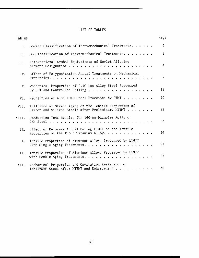
LIST OF TABLES
Tables Page
I. Soviet Classification of Thermomechanical Treatments 2
II. US Classification of Thermomechanical Treatments 2
III. International Svmbol Equivalents of Soviet Alloying Element Designation 4
IV. Effect of Polygonization Anneal Treatments on Mechanical Properties 7
V. Mechanical Properties of 0.1C Low Alloy Steel Processed by SHT and Controlled Rolling 18
VI. Properties of AISI 1040 Steel Processed by PTMT 20
VII. Influence of Strain Aging on the Tensile Properties of Carbon and Silicon Steels after Preliminary HTTMT 22
VIII. Production Test Results for 160-mm-Diameter Rolls of 9Kh Steel 23
IX. Effect of Recovery Anneal During LTMTT on the Tensile Properties of the TS6 ß Titanium Alloy 26
X. Tensile Properties of Aluminum Alloys Processed by LTMTT with Single Aging Treatments 27
XI. Tensile Properties of Aluminum Alloys Processed by LTMTT with Double Aging Treatments 27
XII. Mechanical Properties and Cavitation Resistance of !Khl2VNMF Steel after HTTMT and Rehardening 35
VI
SUMMARY
Soviet efforts in thermomechanical treatments (TMT) have continued unabated during the last decade» The predominant strengthening mechanisms have been firmly established and procedures for simplifying the processing requirements have been developed. Substructural stabilization and hereditary treatments have received particular attention. Pilot plant and some production processing by TMT have been reported, though the type of end items involved has not substantially changed from earlier years. The typical applications involve processing of small volumes, while the TMT of large complex components is still not technically feasible. There are a number of small, simple components that have been successfully processed and evalu- ated in service. Surface hardening, particularly by roller burnishing, is one technological area where a wide range of specific hardware has been TMT processed. The background developed in all phases of TMT should enable Soviet designers to incorporate TMT into less publicized applications, as in military or aviation hardware, where the increased costs inevitably associated with TMT can be better tolerated.
Vll
CONTENTS
Page
PREFACE iii
LIST OF ILLUSTRATIONS v
LIST OF TABLES vi
SUMMARY vii
Section I. INTRODUCTION 1
Section II. PHYSICAL METALLURGY OF THERMOMECHANICAL TREATMENTS
1. Strengthening Mechanisms 4 2. Characteristics of Deformed Austenite 7 3. Hereditary Effects 12 4. Crystal lographic Texture 13 5. Mechanisms in Precipitation-Hardenable Alloys 14
Section III. RESEARCH AND DEVELOPMENT OF THERMOMECHANICAL TREATMENT
1. Introduction 14 2. Thermomechanical Treatment of Steels
a. Low Temperature Thermomechanical Treatment (LTTMT). ... 15 b. High Temperature Thermomechanical Treatment (HTTMT) ... 16 c. Preliminary Thermomechanical Treatment (PTMT) 19 d. Mechanico-Thermal Treatment (MTT) 20 e. Combined Treatments 21 f. TMT of Electroslag Remelted Steels 22 g. TRIP Steels 23
3. Thermomechanical Treatment of Nonferrous Alloys
a. Titanium Alloys 25 b. Aluminum Alloys 26 c. Nickel-Base Alloys 28
Section IV. APPLICATIONS OF THERMOMECHANICAL TREATMENTS
1. Introduction 29 2. Tool Steels 30 3. Spring Steels 31 4. Bearing Steels 32 5. Rail Steels 33 6. Surface Hardening 34
Section V. FINAL COMMENTS
1. Conclusions 38 2. Forecast 39
BIBLIOGRAPHY 41
Section I.
INTRODUCTION
1. Thermomechanical treatment can be defined as the introduction of plastic deformation into an alloy heat treatment cycle such as to modify the normal micro- structural changes that occur, and thereby obtain improved properties. The im- proved property generally desired has been higher strength, which can often be obtained in combination with improved ductility, toughness, fatigue resistance, creep resistance, wear resistance, and crystallographic isotropy. These improve- ments are often accompanied by changes in hardenability, corrosion resistance, and retained austenite content.
2. Thermomechanical treatments have been under investigation since the mid 1950's. However, the predictions and hopes of commercial acceptance during the 1960's have not been achieved either in the United States or in the Soviet Union. This review will concentrate on Soviet developments since 1968.
3. The interest in thermomechanical treatments has led to a fair number of technical reports, reviews, and books on the subject. A brief listing of some of the more comprehensive publications illustrates the scope of the subject. G. Rassmann and P. Müller(l) of East Germany reported on the strengthening of ferrous alloys. L. Delaey(2) of West Germany discussed both ferrous and nonferrous alloys and concluded with some practical applications. Included in this review are a number of TTT (time-temperature-transformation) diagrams illustrating various thermomechanical treatments. Soviet reviews include M. Kh. Rabinovich and V. I. Yelagin(3) and M. Kh. Rabinovich(4) on aluminum alloys, D. A. Prokoshkin and I. I. Sidorin(5) on steels, M. Kh. Shorshorov et al.(6) on steel and titanium alloys, and E. L. Levin et al.(7) on surface hardening. The most comprehensive Soviet publication, a two volume monograph, is by M. L. Bernshteyn(8). US reviews include those by J. G. Dunleavy and J. W. Spretnak(9) and T. J. Koppenaal(10) on Soviet work, H. J. Henning(ll) on applications, E. B. Kula(12) and E. B. Kula and M. Azrin(13) on steels, and B. H. Kear et al.(14) on nickel-base alloys. British reviews on steels are by D. J. Latham(15) and M. J. May and D. J. Latham(16,17).
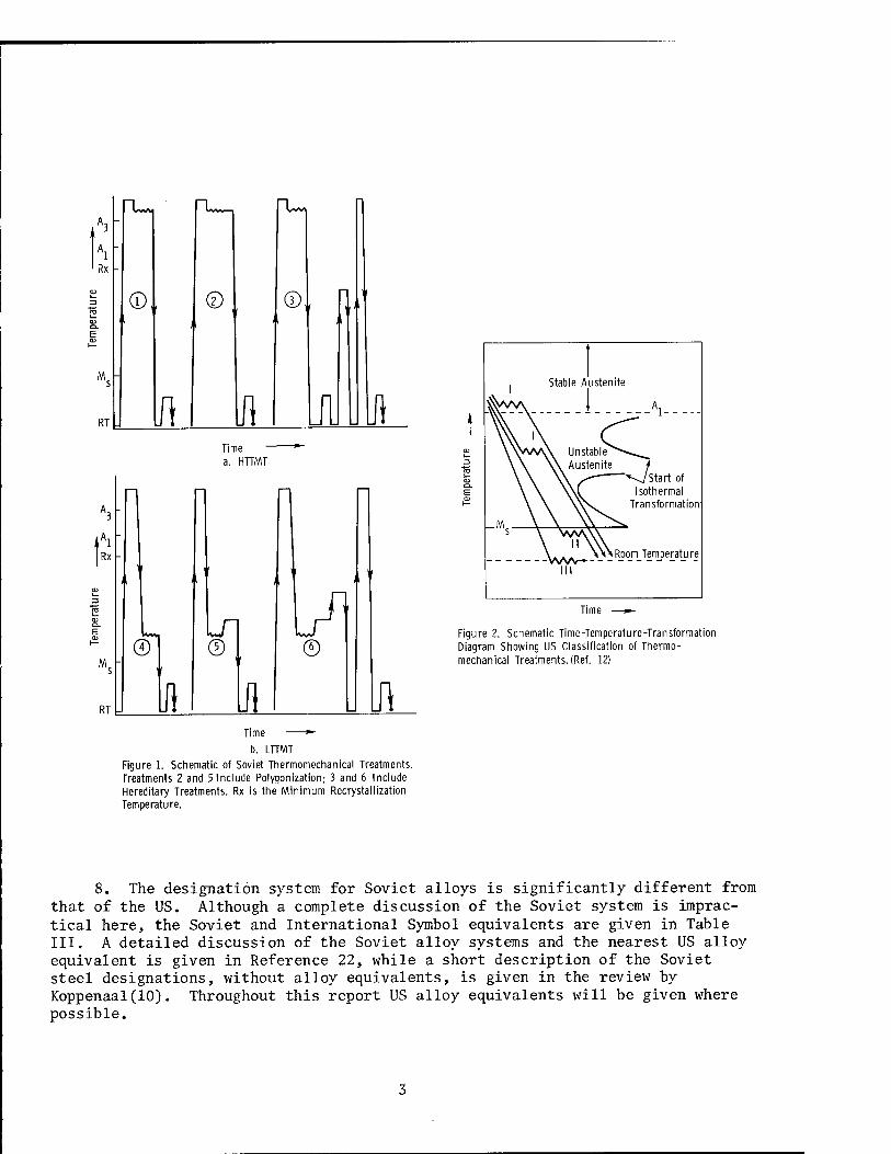
4. A number of types of thermomechanical treatments have been developed and assigned specific designations since the first work by E. M. H. Lips* and H. Van Zuilen(18) in 1954. There is only moderate consistency in the abbreviations applied to the various processes, although some classifications of treatments have been suggested(19,20). The thermomechanical treatments considered in this report are listed in Table I, along with the corresponding definitions and abbre- viations adopted in the Soviet literature. The basic processes of HTTMT and LTTMT are represented schematically in Figure 1.
5. It is of interest to compare this classification with the system devel- oped by S. V. Radcliffe and E. B. Kula(20) in the US that is based on the rela- tive sequence of deformation and phase transformation. Unlike the Soviet system, the temperature during deformation is not the primary consideration. For steels, the system is based on the three classes of deformation as listed in Table II and shown schematically in Figure 2. The common processing procedures easily fitted
LDTIC QUALITY INSPECTED S
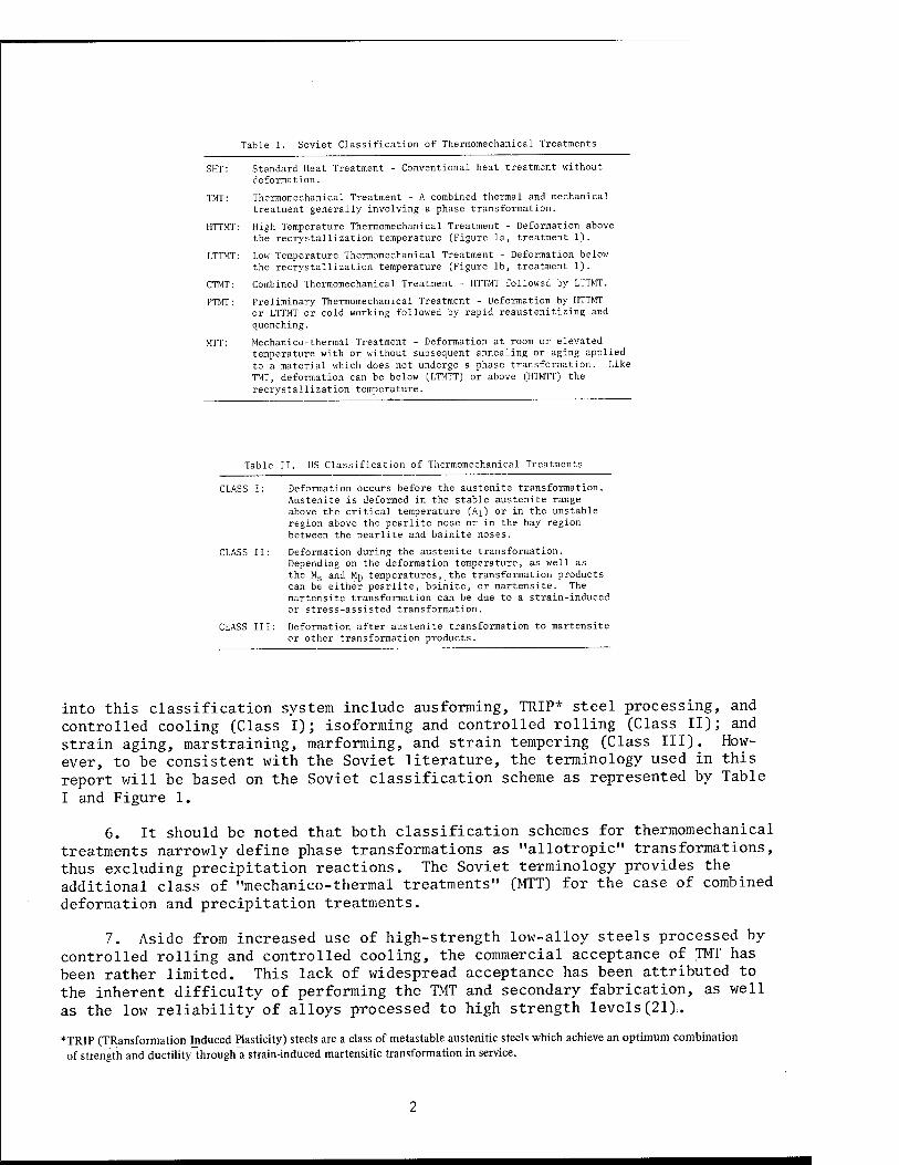
Table I. Soviet Classification of Thermomechanical Treatments
SHT: Standard Heat Treatment - Conventional heat treatment without deformation.
TMT: Thermomechanical Treatment - A combined thermal and mechanical treatment generally involving a phase transformation.
HTTMT: High Temperature Thermomechanical Treatment - Deformation above the recrystallization temperature (Figure la, treatment 1).
LTTMT: Low Temperature Thermomechanical Treatment - Deformation below the recrystallization temperature (Figure lb, treatment 1).
CTMT: Combined Thermomechanical Treatment - HTTMT followed by LTTMT.
PTMT: Preliminary Thermomechanical Treatment - Deformation by HTTMT or LTTMT or cold working followed by rapid reaustenitizing and quenching.
MTT: Mechanico-thermal Treatment - Deformation at room or elevated temperature with or without subsequent annealing or aging applied to a material which does not undergo a phase transformation. Like TMT, deformation can be below (LTMTT) or above (HTMTT) the recrystallization temperature.
Table II. US Classification of Thermomechanical Treatments
CLASS I: Deformation occurs before the austenite transformation. Austenite is deformed in the stable austenite range above the critical temperature (Aj) or in the unstable region above the pearlite nose or in the bay region between the pearlite and bainite noses.
CLASS II: Deformation during the austenite transformation. Depending on the deformation temperature, as well as the Ms and Mp temperatures, the transformation products can be either pearlite, bainite, or martensite. The martensite transformation can be due to a strain-induced or stress-assisted transformation.
CLASS III: Deformation after austenite transformation to martensite or other transformation products.
into this classification system include ausforming, TRIP* steel processing, and controlled cooling (Class I); isoforming and controlled rolling (Class II); and strain aging, marstraining, marforming, and strain tempering (Class III). How- ever, to be consistent with the Soviet literature, the terminology used in this report will be based on the Soviet classification scheme as represented by Table I and Figure 1.
6. It should be noted that both classification schemes for thermomechanical treatments narrowly define phase transformations as "allotropic" transformations, thus excluding precipitation reactions. The Soviet terminology provides the additional class of "mechanico-thermal treatments" (MTT) for the case of combined deformation and precipitation treatments.
7. Aside from increased use of high-strength low-alloy steels processed by controlled rolling and controlled cooling, the commercial acceptance of TMT has been rather limited. This lack of widespread acceptance has been attributed to the inherent difficulty of performing the TMT and secondary fabrication, as well as the low reliability of alloys processed to high strength levels(21).
TRIP (TRansformation Induced Plasticity) steels are a class of metastable austenitic steels which achieve an optimum combination of strength and ductility through a strain-induced martensitic transformation in service.
V Lvt/t -u- "U,
V Rx -
©. , © n "
M s
RT h ft Jill Time a. HnMT
V 1 '( " w H
■ \ i ; 3 O L- 3. L jn Ul
M. " © 1 ©
RT- ji Ifl \I\
Stable Austenite
Time —»-
Figure 2. Schematic Time-Temperature-Transformation Diagram Showing US Classification of Thermo- mechanical Treatments. (Ref. 12)
Time
b. LTTMT
Figure 1. Schematic of Soviet Thermomechanical Treatments. Treatments 2 and 5 Include Polygonization; 3 and 6 Include Hereditary Treatments. Rx is the Minimum Recrystallization Temperature.
8. The designation system for Soviet alloys is significantly different from that of the US. Although a complete discussion of the Soviet system is imprac- tical here, the Soviet and International Symbol equivalents are given in Table III. A detailed discussion of the Soviet alloy systems and the nearest US alloy equivalent is given in Reference 22, while a short description of the Soviet steel designations, without alloy equivalents, is given in the review by Koppenaal(10). Throughout this report US alloy equivalents will be given where possible.
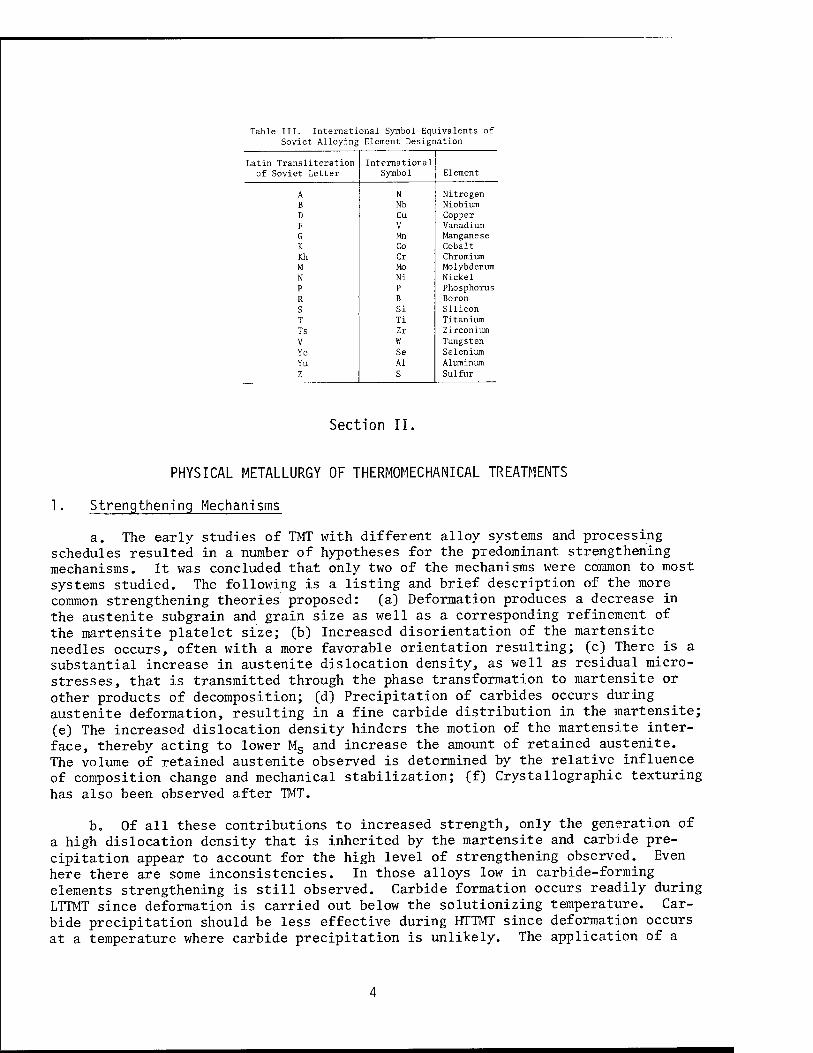
Table III. International Symbol Equivalents of Soviet Alloying Element Designation
Latin Transliteration International of Soviet Letter Symbol Element
A N Nitrogen B Nb Niobium D Cu Copper F V Vanadium G Mn Manganese K Co Cobalt Kh Cr Chromium M Mo Molybdenum N Ni Nickel P P Phosphorus R B Boron S Si Silicon T Ti Titanium Ts Zr Zirconium V W Tungsten Ye Se Selenium Yu Al Aluminum Z S Sulfur
Section II.
PHYSICAL METALLURGY OF THERMOMECHANICAL TREATMENTS
1 Strengthening Mechanisms
a. The early studies of TMT with different alloy systems and processing schedules resulted in a number of hypotheses for the predominant strengthening mechanisms. It was concluded that only two of the mechanisms were common to most systems studied. The following is a listing and brief description of the more common strengthening theories proposed: (a) Deformation produces a decrease in the austenite subgrain and grain size as well as a corresponding refinement of the martensite platelet size; (b) Increased disorientation of the martensite needles occurs, often with a more favorable orientation resulting; (c) There is a substantial increase in austenite dislocation density, as well as residual micro- stresses, that is transmitted through the phase transformation to martensite or other products of decomposition; (d) Precipitation of carbides occurs during austenite deformation, resulting in a fine carbide distribution in the martensite; (e) The increased dislocation density hinders the motion of the martensite inter- face, thereby acting to lower Ms and increase the amount of retained austenite. The volume of retained austenite observed is determined by the relative influence of composition change and mechanical stabilization; (f) Crystallographic texturing has also been observed after TMT.
b. Of all these contributions to increased strength, only the generation of a high dislocation density that is inherited by the martensite and carbide pre- cipitation appear to account for the high level of strengthening observed. Even here there are some inconsistencies. In those alloys low in carbide-forming elements strengthening is still observed. Carbide formation occurs readily during LTTMT since deformation is carried out below the solutionizing temperature. Car- bide precipitation should be less effective during HTTMT since deformation occurs at a temperature where carbide precipitation is unlikely. The application of a
compressive stress during deformation processing is claimed to be sufficient to decrease the solubility of carbon in austenite and permit carbide precipitation(23).
c. With the acceptance of the high defect structure and carbide precipitation as the major sources of strengthening, studies followed on how the processing variables influence the dislocation density and carbide precipitation, as well as the resulting strength and ductility levels. The recrystallization kinetics as influenced by alloying elements, the influence of recrystallization on structural details, polygonization, and polygonization treatments were also studied.
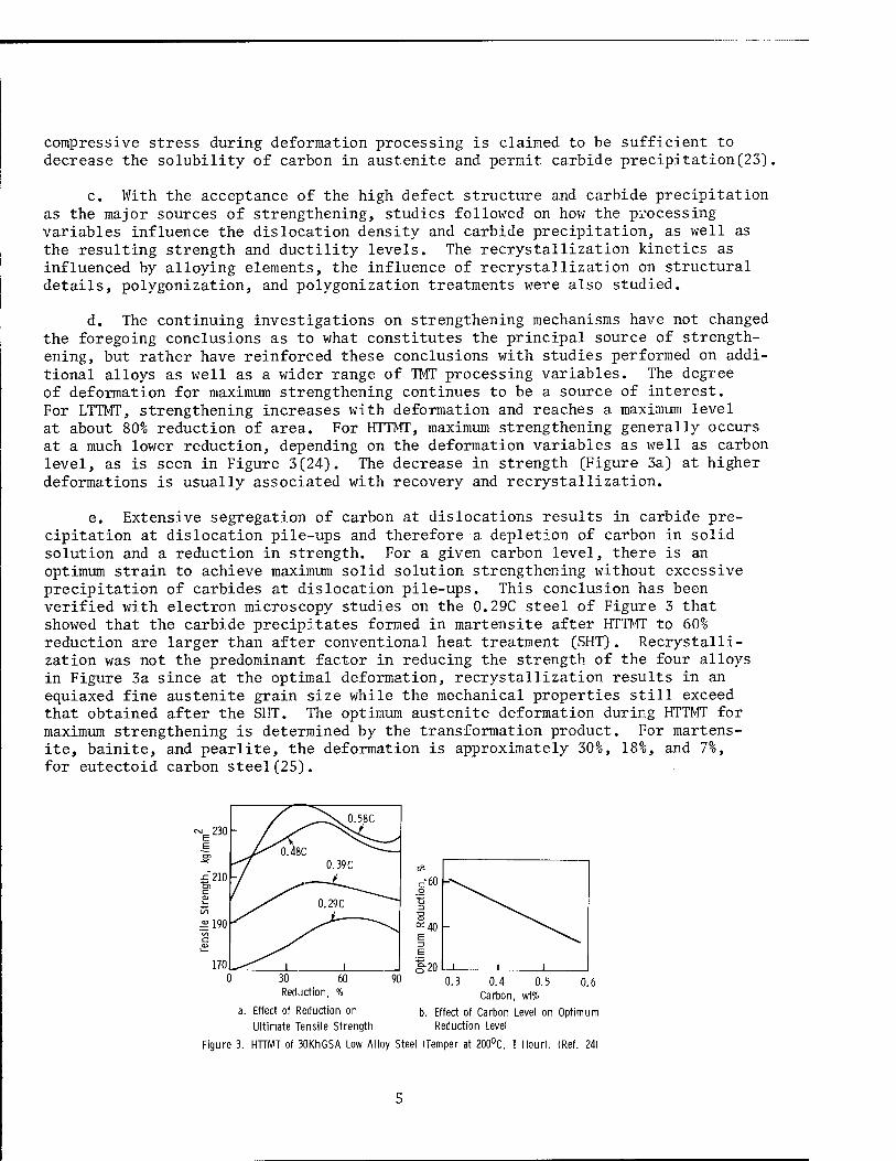
d. The continuing investigations on strengthening mechanisms have not changed the foregoing conclusions as to what constitutes the principal source of strength- ening, but rather have reinforced these conclusions with studies performed on addi- tional alloys as well as a wider range of TMT processing variables. The degree of deformation for maximum strengthening continues to be a source of interest. For LTTMT, strengthening increases with deformation and reaches a maximum level at about 80% reduction of area. For HTTMT, maximum strengthening generally occurs at a much lower reduction, depending on the deformation variables as well as carbon level, as is seen in Figure 3(24). The decrease in strength (Figure 3a) at higher deformations is usually associated with recovery and recrystallization.
e. Extensive segregation of carbon at dislocations results in carbide pre- cipitation at dislocation pile-ups and therefore a depletion of carbon in solid solution and a reduction in strength. For a given carbon level, there is an optimum strain to achieve maximum solid solution strengthening without excessive precipitation of carbides at dislocation pile-ups. This conclusion has been verified with electron microscopy studies on the 0.29C steel of Figure 3 that showed that the carbide precipitates formed in martensite after HTTMT to 60% reduction are larger than after conventional heat treatment (SHT). Recrystalli- zation was not the predominant factor in reducing the strength of the four alloys in Figure 3a since at the optimal deformation, recrystallization results in an equiaxed fine austenite grain size while the mechanical properties still exceed that obtained after the SHT. The optimum austenite deformation during HTTMT for maximum strengthening is determined by the transformation product. For martens- ite, bainite, and pearlite, the deformation is approximately 30%, 18%, and 7%, for eutectoid carbon steel (25).
^X0.58C ~£230 / s—
_E ^^0.48C
0.39C £210 CD
1_ 0.29C ^~"""
£1% ISI
C QJ
1—
170 -^^ i i 30 Reduction,
60
a. Effect of Reduction on
Ultimate Tensile Strength
90 0.4 Carbon, wt%
Effect of Carbon Level on Optimum Reduction Level
Figure 3. HTTMT of 30KhGSA Low Alloy Steel (Temper at 200°C, 1 Hour). (Ref. 24)
f. The recent studies on retained austenite are concerned with both the influence of TMT on the amount of retained austenite and its influence on strength. Rassmann and Müller(1) showed that strengthening during TMT is pri- marily associated with the austenite phase with the greatest strength increase at low levels of transformed martensite, and the smallest strength increase for 100% martensite. Although a number of studies have shown that large deformations of metastable austenite increase the retained austenite and small deformations pro- duce a decrease, the converse has also been observed on a high alloy steel(26). The influence of TMT on the distribution of carbon continues to be documented for a number of alloy systems. LTTMT produces a finer and more uniform distribution of carbides in secondary hardening steels compared to SHT(27). As a result, the strength and ductility increase, and the brittle fracture behavior of longitu- dinal samples changes from mainly intercrystalline (for SHT) to transcrystalline (for LTTMT). Similar improvements in carbide distribution are possible by in- creasing the quenching temperature during SHT, but at the expense of ductility due to the increased grain size. The carbon concentration in martensite is lower after TMT due to the usual carbide precipitation during deformation as well as the increased defect density that enhance carbon segregation in the austenite and auto-tempering of the martensite. The latter increases the volume fraction of the low tetragonality martensitic phase(28). Variations of the isoforming process on a low alloy steel showed that LTTMT during the austenite-to-pearlite transformation results in improved ductility and toughness due to the finer pearlite structure and the absence of coarse ferrite lamellae, compared to SHT or performing the LTTMT before or after the transformation(29). Ideally the initiation and comple- tion of transformation and deformation should coincide.
g. The importance of obtaining a stable polygonized substructure has been documented for a wide range of alloy systems(30-33). The substructure formed by the inheritance mechanism, whereby the work-hardened state formed during deforma- tion of the austenite phase is inherited by the martensite phase, does not always have sufficient thermal stability during higher temperature tempering. In addi- tion, at ultrahigh strengths, fracture toughness levels are inadequate for most applications. These problems have been partly alleviated by substructural strengthening through a polygonization anneal (Figure 1) treatment that forms a substructure that is often stable up to the recrystallization temperature range(6,34-36). Polygonization is a recovery process that occurs in stages. First relaxation occurs, characterized by migration and annihilation of point defects, without altering the grain boundaries, microstructure, or crystallo- graphic orientation. Polygonization then occurs with migration, annihilation and rearrangement of dislocations to create a substructure. This is followed by two stages of recrystallization: relaxation of microstresses during growth of the sub- grains by subboundary migration, and nucleation and growth of strain-free grains. The perfection of a polygonized structure depends in part on the stacking-fault energy. High stacking-fault energy materials, with their ease of cross-slip, have finer and more developed substructures. The thermal stability of the polygonized substructure is due to the lower energy of the elastic strain fields of the sub- boundaries and the interstitial atoms pinning them. Diffusion is then retarded, especially within the grains. The ease of slip through low-angle subboundaries improves the brittle crack resistance. MTT followed by aging of dispersion- hardened alloys can substantially increase the creep resistance as well as room and elevated temperature fatigue strength(37,38) due to the polygonized sub- structure that retards coalescence of the strengthening phases.
h. A stable polygonized structure can be obtained for HTTMT by polygoniza- tion during the hot deformation, i.e., dynamic polygonization, or during subse- quent isothermal holding or reheating, i.e., static polygonization. The benefits derived are impressive for LTTMT where the inclusion of a polygonization anneal of high-strength steels increased the reduction of area (RA) by 2.5 times and tensile strength (au) by 6 to 11 kg/mm
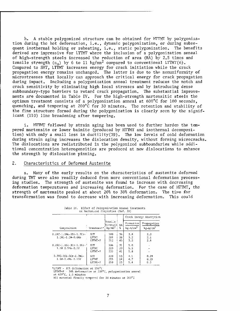
2 compared to conventional LTTMT(6). Compared to SHT, LTTMT increases energy for crack initiation while the crack propagation energy remains unchanged. The latter is due to the nonuniformity of microstresses that locally can approach the critical energy for crack propagation during impact. Including a polygonization anneal treatment reduces the notch and crack sensitivity by eliminating high local stresses and by introducing dense subboundary-type barriers to retard crack propagation. The substantial improve- ments are documented in Table IV. For the high-strength martensitic steels the optimum treatment consists of a polygonization anneal at 600°C for 100 seconds, quenching, and tempering at 200°C for 30 minutes. The retention and stability of the fine structure formed during the polygonization is clearly seen by the signif- icant (110) line broadening after tempering.
i. HTTMT followed by strain aging has been used to further harden the tem- pered martensite or lower bainite (produced by HTTMT and isothermal decomposi- tion) with only a small loss in ductility(39). The low levels of cold deformation during strain aging increases the dislocation density, without forming microcracks. The dislocations are redistributed in the polygonized subboundaries while addi- tional concentration heterogeneities are produced at new dislocations to enhance the strength by dislocation pinning.
2. Characteristics of Deformed Austenite
a„ Many of the early results on the characteristics of austenite deformed during TMT were also readily deduced from more conventional deformation process- ing studies. The strength of austenite was found to increase with decreasing deformation temperatures and increasing deformation. For the case of HTTMT, the strength of martensite peaked at about 20% to 30% deformation. The time for transformation was found to decrease with increasing deformation. This could
Table IV. Effect of Polygonization Anneal Treatments on Mechanical Pro perties (Ref . 35)
Tensile strength RA
Crack Energy Absorption
Formation Propagation
Composition Treatment* kg/mm2 % kg-m/cm2 kg^m/cm2
0.24C-l.lMn-lSi-1.7Cr- SHT 189 36 3.8 2.0 l.lNi-l.lW-0.6Mo LTTMT 204 38 3.2 2.1
LTTMT+P 212 45 3.5 2.8
0.26C-l.lSi-3Cr-l.lNi- SHT 196 31 5.0 _ 1.1W-0.5MO-0.1V LTTMT 219 29 5.5 -
LTTMT+P 220 41 5.8 - 0.38C-lSi-3Cr-1.2Ni- SHT 220 13 4.1 0.28
1.1W-0.4MO-0.15V LTTMT 255 14 4.7 0.29 LTTMT+P 250 23 5.4 0.5
*LTTMT - 30% deformation at 550 C LTTMT+P - 30% deformation at 550°C, polygonization anneal at 650°C, 1.5 minutes All material finally tempered for 30 minutes at 200°C
lead to hardenability problems in larger, more complex shaped components. Re- crystallization was found to be a serious problem during HTTMT. However, this influence could be partly controlled by alloying with Cr, Mo, Mn, Ni, Si, W, and V. A polygonized structure obtained during high temperature deformation or annealing produced a more stable austenitic structure. Deformation was found to refine the grain size, change grain shape, and produce certain crystallographic textures. The generation of defects during high temperature deformation was particularly beneficial in solutionizing and aging treatments. Deformation prior to aging produced a more uniform and finer dispersion. Precipitation and defor- mation were found to influence Ms and change the amount of retained austenite. Observations on deformed austenite continue to be made as a clearer explanation of the strengthening is sought.
b. Proper experimental techniques must be utilized to discern the structural features of deformed austenite. Although optical metallographic techniques can be used to observe the large subgrains (tens of microns) due to dynamic recrystal- lization, transmission electron microscopy must be used to observe the fine sub- boundary network of 1 to 3 microns developed within the larger subgrains during dynamic polygonization(40). These experimental techniques are necessary to establish the structural changes occurring during TMT and determine the optimum processing schedules. This was apparent from the slow strain-rate deformation during HTTMT of a ShKhl5SG ball bearing steel. With less than 40% deformation dynamic recovery processes predominate, while at higher deformations dynamic recrystallization is the controlling process(41).
c. The structural features in TRIP steels after LTTMT have been studied in detail by 0. P. Maksimova et al.(42). In this material, the martensite is formed not by quenching, but rather by a strain-induced transformation during secondary fabrication or in service. The structural characteristics of the deformed aus- tenite include distorted deformation twins, formation of subboundaries, precipi- tation of a carbide phase and a high defect density.
d. Holding or delay time between deformation and quenching is a source of major concern as attempts are made to optimize the TMT procedure for each alloy studied(43). For HTTMT of carbon steels dynamic polygonization can occur. For alloy steels some delay may be necessary for polygonization to form stable sub- boundaries, which are then inherited by the martensite during quenching. For low alloy steel 45KhNMFA it was found that after 30% deformation at 950°C, holding at 880°C for 1 to 10 minutes had little effect on tensile properties (44). However, at 5 minutes there was a maximum in the static torsion ductility. At this holding time, the substructure is stable and there are fine grains forming at the prior austenite boundaries indicating incipient recrystallization. The optimum prop- erties can also be obtained without any holding time by developing a substructure through dynamic polygonization(41). Close control of deformation time is required since the high dislocation density created during deformation may cause dynamic recrystallization to exceed dynamic polygonization.
e. M. L. Bernshtein et al.(45) found that for the low alloy 50KhGA steel (AISI 5147), a medium reduction (20% at 900°C) formed sufficient dislocations to develop a substructure (subboundaries) without forming excessive stress concen- trations at the grain boundaries. However, for 40% deformation, rapid recrys- tallization occurred in the region of the large-angle boundaries due to the
large stress peaks that accompanied the high dislocation density in this region. The mechanical properties in the former case are tensile strength (CTU) = 185 kg/mm2, RA = 15% to 20%, Charpy impact energy = 4 kg-m/cm2, compared to 0U = 150 to 160 kg/mm2, RA = 30% and Charpy impact energy = 3 to 4 kg-m/cm2.
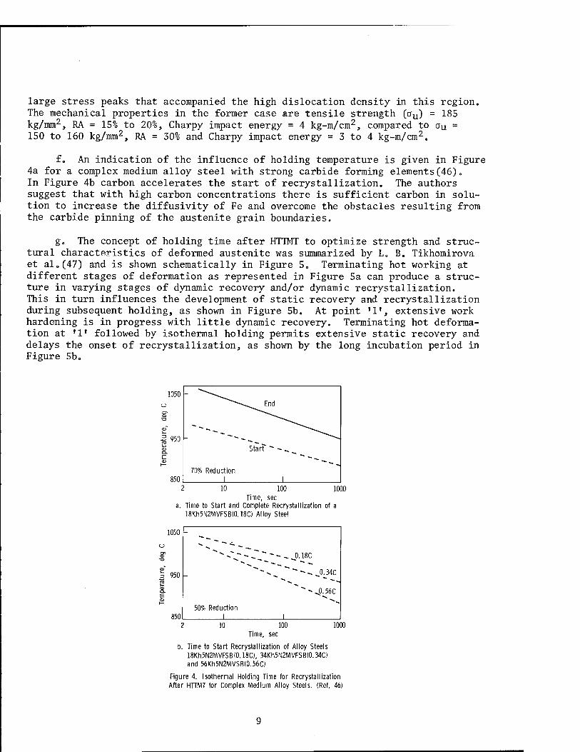
f. An indication of the influence of holding temperature is given in Figure 4a for a complex medium alloy steel with strong carbide forming elements(46)„ In Figure 4b carbon accelerates the start of recrystallization. The authors suggest that with high carbon concentrations there is sufficient carbon in solu- tion to increase the diffusivity of Fe and overcome the obstacles resulting from the carbide pinning of the austenite grain boundaries.
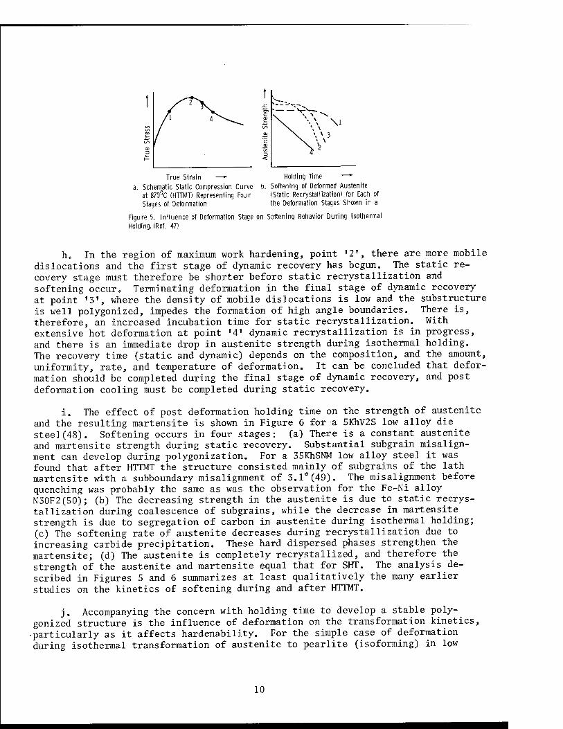
g„ The concept of holding time after HTTMT to optimize strength and struc- tural characteristics of deformed austenite was summarized by L„ B. Tikhomirova et al„(47) and is shown schematically in Figure 5. Terminating hot working at different stages of deformation as represented in Figure 5a can produce a struc- ture in varying stages of dynamic recovery and/or dynamic recrystallization. This in turn influences the development of static recovery and recrystallization during subsequent holding, as shown in Figure 5b. At point *1', extensive work hardening is in progress with little dynamic recovery. Terminating hot deforma- tion at '1' followed by isothermal holding permits extensive static recovery and delays the onset of recrystallization, as shown by the long incubation period in Figure 5b.
1050 - "-^^^ o ^^"^^^End
S1
TZ3 ^^^^^
-is 950 1„ QJ o. E CD }—
Starf
70% Reduction 850 1 1
2 10 100 1000 Time, sec
a. Time to Start and Complete Recrystallization of a 18Kh5N2MVFSB(0.18C) Alloy Steel
S1
1050
950
"* -V - - _- - - - J). 18C
•s. •»
"-4J.56C
50% Reduction 850 1 I
10 100 1000 Time, sec
b. Time to Start Recrystallization of Alloy Steels 18Kh5N2MVFSB(0.18C), 34Kh5N2MVFSB(0.34C> and 56Kh5N2MVSB(0.56C)
Figure 4. Isothermal Holding Time for Recrystallization After HTTMT for Complex Medium Alloy Steels. (Ref. 46)
True Strain — Holding Time —»
a. Schematic Static Compression Curve b. Softening of Deformed Austenite at 870°C (HTTMT) Representing Four (Static Recrystallization) for Each of Stages of Deformation the Deformation Stages Shown in a
Figure 5. Influence of Deformation Stage on Softening Behavior During Isothermal Holding. (Ref. 47)
h. In the region of maximum work hardening, point '2', there are more mobile dislocations and the first stage of dynamic recovery has begun. The static re- covery stage must therefore be shorter before static recrystallization and softening occur» Terminating deformation in the final stage of dynamic recovery at point '3', where the density of mobile dislocations is low and the substructure is well polygonized, impedes the formation of high angle boundaries. There is, therefore, an increased incubation time for static recrystallization. With extensive hot deformation at point '4' dynamic recrystallization is in progress, and there is an immediate drop in austenite strength during isothermal holding. The recovery time (static and dynamic) depends on the composition, and the amount, uniformity, rate, and temperature of deformation. It can be concluded that defor- mation should be completed during the final stage of dynamic recovery, and post deformation cooling must be completed during static recovery.
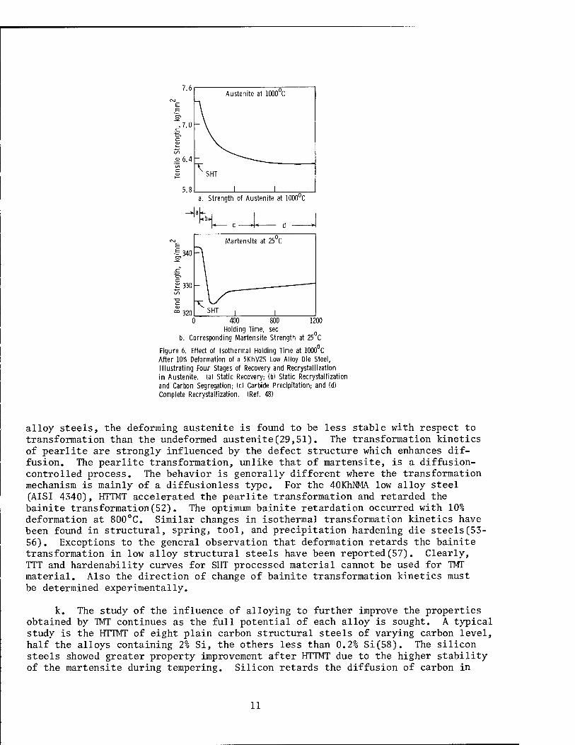
i. The effect of post deformation holding time on the strength of austenite and the resulting martensite is shown in Figure 6 for a 5KhV2S low alloy die steel(48). Softening occurs in four stages: (a) There is a constant austenite and martensite strength during static recovery. Substantial subgrain misalign- ment can develop during polygonization. For a 35KhSNM low alloy steel it was found that after HTTMT the structure consisted mainly of subgrains of the lath martensite with a subboundary misalignment of 3.1°(49). The misalignment before quenching was probably the same as was the observation for the Fe-Ni alloy N30F2(50); (b) The decreasing strength in the austenite is due to static recrys- tallization during coalescence of subgrains, while the decrease in martensite strength is due to segregation of carbon in austenite during isothermal holding; (c) The softening rate of austenite decreases during recrystallization due to increasing carbide precipitation. These hard dispersed phases strengthen the martensite; (d) The austenite is completely recrystallized, and therefore the strength of the austenite and martensite equal that for SHT. The analysis de- scribed in Figures 5 and 6 summarizes at least qualitatively the many earlier studies on the kinetics of softening during and after HTTMT.
j. Accompanying the concern with holding time to develop a stable poly- gonized structure is the influence of deformation on the transformation kinetics, •particularly as it affects hardenability. For the simple case of deformation during isothermal transformation of austenite to pearlite (isoforming) in low
10
a. Strength of Austenite at lOCXTC
400 800 1200 Holding Time, sec
b. Corresponding Martensite Strength at 25 C
Figure 6. Effect of Isothermal Holding Time at 1000 C After 10% Deformation of a 5KhV2S Low Alloy Die Steel, Illustrating Four Stages of Recovery and Recrystallization in Austenite. (a) Static Recovery; (b) Static Recrystallization and Carbon Segregation; (c) Carbide Precipitation; and (d) Complete Recrystallization. (Ref. 48)
alloy steels, the deforming austenite is found to be less stable with respect to transformation than the undeformed austenite(29,51). The transformation kinetics of pearlite are strongly influenced by the defect structure which enhances dif- fusion. The pearlite transformation, unlike that of martensite, is a diffusion- controlled process. The behavior is generally different where the transformation mechanism is mainly of a diffusionless type. For the 40KhNMA low alloy steel (AISI 4340), HTTMT accelerated the pearlite transformation and retarded the bainite transformation(52). The optimum bainite retardation occurred with 10% deformation at 800°C. Similar changes in isothermal transformation kinetics have been found in structural, spring, tool, and precipitation hardening die steels(53- 56). Exceptions to the general observation that deformation retards the bainite transformation in low alloy structural steels have been reported (57). Clearly, TTT and hardenability curves for SHT processed material cannot be used for TMT material. Also the direction of change of bainite transformation kinetics must be determined experimentally.
k. The study of the influence of alloying to further improve the properties obtained by TMT continues as the full potential of each alloy is sought. A typical study is the HTTMT of eight plain carbon structural steels of varying carbon level, half the alloys containing 2% Si, the others less than 0.2% Si(58). The silicon steels showed greater property improvement after HTTMT due to the higher stability of the martensite during tempering. Silicon retards the diffusion of carbon in
11
martensite, and therefore reduces the degree of auto-tempering of the martensite after both SHT and HTTMT(28). Auto-tempering during quenching usually results in a "two-phase" mixture of tetragonal and "cubic" (i.e„, low tetragonal) martensites* Increased stability of the tetragonal martensite permits the benefits derived by HTTMT to be retained at higher tempering temperatures.
1. The influence of grain refining continues to be studied. During HTTMT of plain carbon steel 50 (AISI 1050) a reduced grain size had no effect on strength but substantially improved the ductility(59). However, the finer grain size produced by either increasing the heating rate, decreasing the austenitizing time and temperature, or decreasing the deformation temperature accelerates auto- tempering by the two-phase mechanism(60).
3. Hereditary Effects
a. A major obstacle in the utilization of TMT is that the product is in the hard, heat-treated condition and not suitable for secondary fabrication. The Soviets have in some cases circumvented this problem by the use of hereditary treatments (Figure 1) in which the substructure formed during TMT is stable during subsequent rapid reaustenitizing. Therefore, a material hardened by TMT can be softened by a high temperature temper for the purpose of secondary processing (forming or machining) and then rehardened to restore the original TMT properties. Although early reports indicate a controversy existed over the applicability of hereditary treatments to certain spring steels (9), recent studies indicate that hereditary effects are possible, provided there is prior substructural stabilization.
b. Whereas the initial studies attributed the hereditary effects to the exis- tence of grain refinement, as well as crystallographic, dislocation, and precipi- tation texturing, the subsequent studies emphasize the need to stabilize the substructure prior to or during the high temperature temper. This was clearly demonstrated with a low alloy silicon spring steel alloyed with vanadium (60S2F)(28,61). The strong carbide forming tendency of vanadium sufficiently stabilized the substructure so that, after an intermediate double temper at 100°C and then 600°C, furnace heating could be used to reharden at 860°C. The first temper at 100°C results in carbide redistribution with a partial decomposition of martensite and further stabilization of the substructure formed during HTTMT. The second temper at 600°C reduces the hardness, annihilates the more mobile dislocations, and forms additional carbides that further stabilize the substruc- ture during subsequent rehardening. Rehardening does not eliminate the differ- ences in volume fraction of the low carbon cubic martensite and the degree of tetragonality of the high carbon martensite phase, compared to the SHT. Both observations are evidence that the characteristics of martensite generated during HTTMT are retained after rehardening, and this leads to no change in mechanical properties. HTTMT plus rehardening of low alloy steels produced no loss of fatigue strength relative to HTTMT without rehardening in 30KhGSA steel and only a slight loss with 40KhNMA steel (AISI 4340)(62), while for the high alloy stain- less steel lKhl2VNMF the erosion resistance is preserved along with a slight increase in impact strength(63). Rehardening was also possible after HTTMT with partial austenite decomposition of low alloy spring steel 50KhGA (AISI 5147)(64) and plain carbon steel 40 (AISI 1040)(65).
12
c. Hereditary treatments are similar for HTTMT and LTTMT. After HTTMT, the structure is relatively stable or can be made so by a polygonization anneal treat- ment. After LTTMT, however, a simple high temperature temper followed by rehard- ening will lead to significant softening due to the accelerating effect of cold work, during LTTMT, on recrystallization kinetics. The required stabilization, after LTTMT, was obtained by D« A. Prokoshkin et al.(66) on a medium alloy steel 40Kh5NSMF by a processing schedule consisting of:
solutionize at 1030°C, deform 60% at 530°C, polygonization anneal at 580°C for 10 minutes, quench, soften by tempering at 650°C, rapidly reheat to austenitizing temperature of 980°C, quench and temper.
The inclusion of a polygonization treatment increased the strength, without loss of ductility, due to the formation of a stable substructure and an impurity atmosphere around the dislocations.
d. The mechanism whereby hereditary treatments are successful is determined by how the martensite structure is transformed to austenite during reaustenitiz- ing(67). Only partial rehardening is possible if equiaxed grains are obtained by a nucleation and growth mechanism with movement of high-angle grain boundaries that eliminate the prior defect structure. The hereditary strengthening that does exist is attributed to the finer austenite grain size. Hereditary treatments are completely successful when transformation to austenite occurs by a reverse martensitic transformation that preserves the defect structure.
4. Crystal!oqraphic Texture
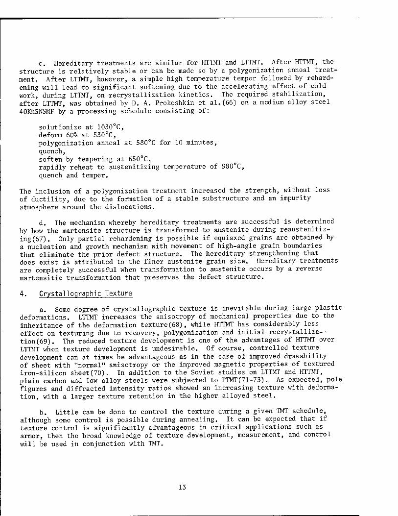
a. Some degree of crystallographic texture is inevitable during large plastic deformations. LTTMT increases the anisotropy of mechanical properties due to the inheritance of the deformation texture(68), while HTTMT has considerably less effect on texturing due to recovery, polygonization and initial recrystalliza-*- tion(69). The reduced texture development is one of the advantages of HTTMT over LTTMT when texture development is undesirable. Of course, controlled texture development can at times be advantageous as in the case of improved drawability of sheet with "normal" anisotropy or the improved magnetic properties of textured iron-silicon sheet(70). In addition to the Soviet studies on LTTMT and HTTMT, plain carbon and low alloy steels were subjected to PTMT(71-73). As expected, pole figures and diffracted intensity ratios showed an increasing texture with deforma- tion, with a larger texture retention in the higher alloyed steel.
b. Little can be done to control the texture during a given TMT schedule, although some control is possible during annealing. It can be expected that if texture control is significantly advantageous in critical applications such as armor, then the broad knowledge of texture development, measurement, and control will be used in conjunction with TMT„
13
5. Mechanisms in Precipitation-Hardenable Alloys
a. Soviet efforts toward understanding the role of MTT in precipitation hardening reactions, particularly in aluminum base alloys, have been recently reviewed by Rabinovich(4). A greater decrease in resistivity during aging after deformation as compared to aging without prior deformation clearly indicates the accelerating influence of deformation on the precipitation reaction. This accel- eration is attributed to two effects: a "static" or hereditary effect of prior deformation on subsequent precipitation, and a "dynamic" or direct effect asso- ciated with precipitation phenomena during the deformation. The static effect is attributed to an increased vacancy concentration, as a result of prior deformation, and heterogeneous nucleation on dislocations. The dynamic effect is attributed to enhanced diffusion from moving dislocations. The evidence suggests that this diffusion enhancement occurs not only within coarse slip bands but in the regions between them. These effects combine to give generally a finer, more homogeneous precipitation than aging without deformation(4,74-76).
b. In addition to affecting the distribution of precipitates, it is found that deformation can in some cases alter the type and morphology of the precipi- tates. Different metastable precipitate structures can be formed and coherency loss can be accelerated. Of particular importance in grain-boundary fracture- related problems such as stress corrosion is the tendency of MTT to inhibit grain-boundary precipitation relative to more homogeneous precipitation within the grains, to break up continuous boundary precipitates, and to reduce precipitate-free zones at the boundaries. This is of particular importance in high-strength aluminum alloys. MTT also increases fracture toughness in some alloys by producing a distorted or jagged grain-boundary structure which resists intergranular fracture, resulting in a change of fracture mode from intergranular to transgranular.
Section III.
RESEARCH AND DEVELOPMENT OF THERMOMECHANICAL TREATMENT
1. Introduction
a. Most Soviet research activities on TMT, as reported in the open litera- ture, are not directed at a specific application or end item. Instead, there appears to be a main concern with understanding the hardening mechanism or response to a particular TMT for the material under investigation. It is obvious that po- tential applications are what generate interest and provide research and develop- ment guidance to the broad Soviet effort on TMT. This has been true since the inception of Soviet research on TMT which had its origin in the study of temper brittleness of steel. Subsequent interest by both US and Soviet investigators has been extended to aluminum, copper, nickel, titanium, molybdenum, tantalum, tungsten, cobalt, and zirconium base systems. The Soviet activities, including the present, have been overwhelmingly concentrated on steels, reflecting the importance of that material in consumer, industrial, and military applications.
14

b. Recent research progress has attempted, with considerable success, to explain the optimum properties obtained in terms of processing variables and resulting microstructure. With these results, it can be expected that processing schedules will be designed more efficiently to accommodate the inherent limita- tions of thermomechanical processing.
c. The processing categories used here are somewhat arbitrary. The TMT of nonferrous alloys and MTT of steel could be combined under one heading. Broaden- ing our rather narrow definition of a phase transformation to include precipita- tion reactions would lead to additional changes in these categories. The terminology and definitions used here are, however, those generally accepted in the Soviet literature.
2. Thermomechanical Treatment of Steels
a. Low Temperature Thermomechanical Treatment (LTTMT)
(1) The limitations of thermomechanical processing are most often imposed by temperature control and required equipment capacity for deformation processing. Temperature control greatly complicates the TMT of most materials. An auxiliary furnace is often required to achieve the desired processing tempera- ture and to reheat the material between passes to limit the temperature varia- tion. Temperature monitoring equipment is necessary to determine the extent of temperature drop or, in some cases, temperature rise by adiabatic heating. The latter case would be particularly severe during extrusion where large reduction ratios are common and inadvertent isothermal decomposition is possible. It is also necessary to monitor time at deformation temperature to avoid the onset of decomposition. All these factors greatly increase the temperature control re- quirements over that generally available in production operations. Associated with the temperature and time problems is reproducibility of properties from specimen to specimen, between laboratory specimen and actual size components, as well as between individual pieces of a production run. The high deformation forces for large size components is a problem that has been dealt with only in- directly. In many cases the solution is not simply to fabricate machines with higher load capacity. The stresses generated must also be within the design requirements of the tooling material available. One solution to the high defor- mation forces has been the use of multiple passes instead of a single pass reduc- tion. It appears that nearly every deformation processing technique available has been used during TMT processing. These include rolling, wire drawing, forging, spin forming, extrusion, roller burnishing, torsion, swaging, and bending. Those processes involving a local deformation can more easily tolerate the higher loads during LTTMT.
(2) The trade-off between strength level and toughness has become a major concern in the use of TMT material. In the early years of development the emphasis was on achievement of maximum strength levels, with only modest improve- ments in toughness. Unfortunately, for most applications the design engineer and ultimate user, although welcoming the increased strength, could not tolerate the low toughness. More recently, the greater recognition of this problem has led to development of modest strength increases accompanied by adequate toughness levels. In terms of processing, the concern with toughness in addition to strength has
15
generated greater interest in HTTMT rather than LTTMT. Other factors have also contributed to the greater interest in HTTMT. LTTMT requires higher alloyed steels to ensure a deep bay region between the pearlite and bainite noses in the isothermal transformation diagram.
(3) The processing limitations noted here have resulted in relatively few studies or applications of LTTMT. When LTTMT is reported, the emphasis is usually on comparing LTTMT to other types of TMT(77-80). If high strength is the major goal, and the difficult processing and limited toughness can be tolerated, then LTTMT is often used. At the Azerbaidzhen Tube-Rolling Works, oil-well casing tubes of 20KhG2B low alloy steel were processed by deforming 4% tn 5% at 800°C to 850°C, cooling, and then transforming in the bainite region(81). While hot defor- mation prior to SHT resulted in ferrite, pearlite, bainite, martensite and 5% retained austenite, the LTTMT suppressed the pearlite transformation so that the transformation product was mainly bainite. The strength increased 50% and the ductility, toughness, and residual stress were acceptable. Another example is isoforming, the LTTMT during transformation to pearlite, of 27SG2M low alloy steel. The tensile and yield strengths increased slightly, while the elongation and Charpy impact energy increased 100% and 30%, respectively(29). The relatively low separating forces enable processing of this material on conventional rolling mills. Other common uses for LTTMT are discussed later in this report in the sections describing PTMT, MTT, combined treatments, surface hardening, and pro- cessing of TRIP steels, tool steels, and bearing steels.
b. High Temperature Thermomechanical Treatment (HTTMT)
(1) HTTMT, in contrast to LTTMT, can be performed on any steel of moderate hardenability. The deformation forces are significantly lower at the temperatures for HTTMT, and the 20% to 40% deformation required for optimum prop- erties is usually less than half that required for LTTMT. The need for an aux- iliary furnace to cool down to the deformation temperature is less critical since deformation is usually performed either at the austenitizing temperature or
slightly below.
(2) The large number of reports on HTTMT relative to LTTMT reflect the greater practicality of this process. Indications are that HTTMT is now widely used on a production scale, particularly for applications with rolled carbon or low alloy steels(82-84). Recent research on HTTMT includes detailed character- ization of the mechanical behavior, as well as a refinement of processing variables. For example, a calibration curve was developed based on several low alloy steels whereby the hardenability for HTTMT can be determined from available SHT data(57). HTTMT was found to increase the elastic limit(85,86) and decrease the shear modulus(87). HTTMT increases toughness, elongation, reduction of area, impact energy, and possibly strength (yield and tensile) while decreasing the transition temperature. Temper embrittlement (450°C to 600°C) is reduced by a change from intergranular (along prior austenite grain boundaries) to a ductile, fibrous fracture. The tensile strength rarely exceeds 300 kg/mm2 due to the onset of recrystallization.
(3) The low reduction during HTTMT (20% to 40%), to avoid recrystalliza- tion, refers not to the total reduction but the reduction after the onset of
16
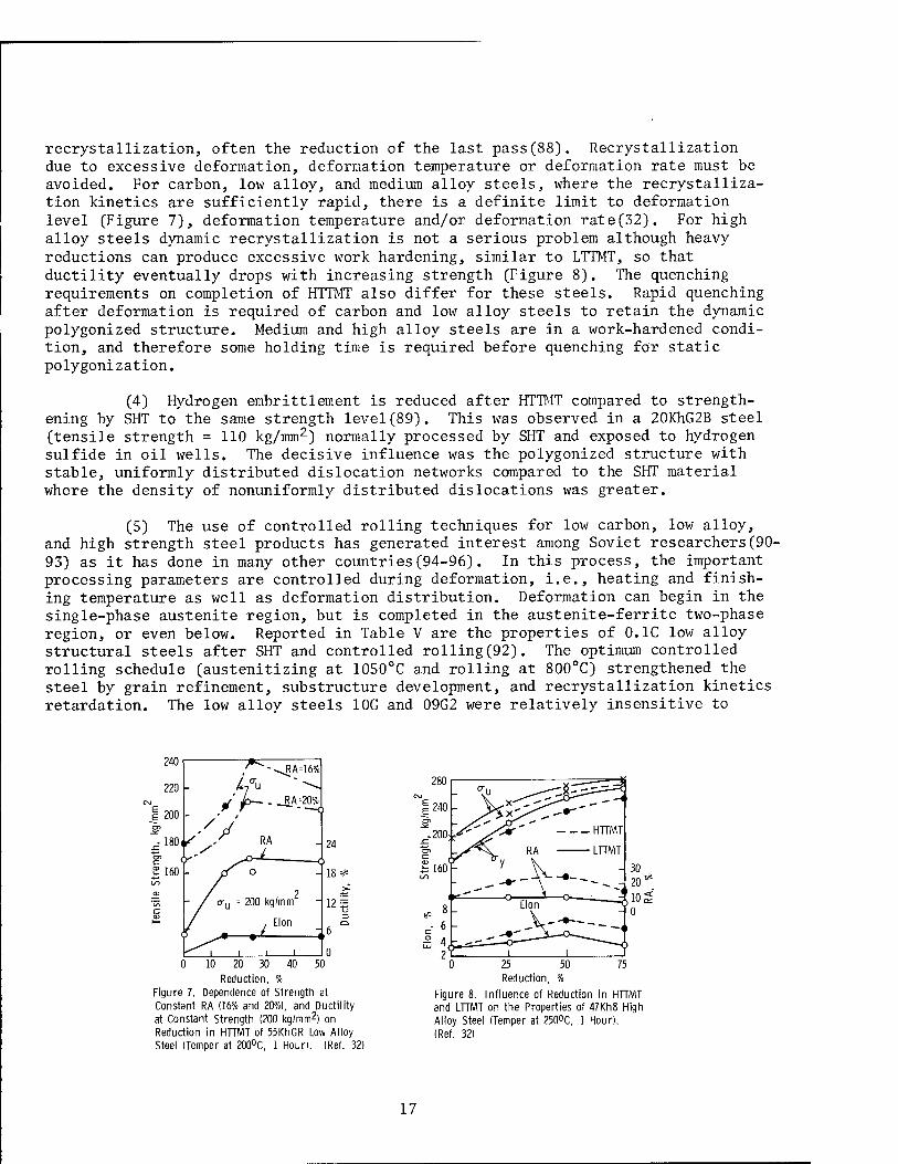
recrystallization, often the reduction of the last pass(88). Recrystallization due to excessive deformation, deformation temperature or deformation rate must be avoided. For carbon, low alloy, and medium alloy steels, where the recrystalliza- tion kinetics are sufficiently rapid, there is a definite limit to deformation level (Figure 7), deformation temperature and/or deformation rate(32). For high alloy steels dynamic recrystallization is not a serious problem although heavy reductions can produce excessive work hardening, similar to LTTMT, so that ductility eventually drops with increasing strength (Figure 8). The quenching requirements on completion of HTTMT also differ for these steels. Rapid quenching after deformation is required of carbon and low alloy steels to retain the dynamic polygonized structure. Medium and high alloy steels are in a work-hardened condi- tion, and therefore some holding time is required before quenching for static polygonization.
(4) Hydrogen embrittlement is reduced after HTTMT compared to strength- ening by SHT to the same strength level(89). This was observed in a 20KhG2B steel (tensile strength = 110 kg/mm2) normally processed by SHT and exposed to hydrogen sulfide in oil wells. The decisive influence was the polygonized structure with stable, uniformly distributed dislocation networks compared to the SHT material where the density of nonuniformly distributed dislocations was greater.
(5) The use of controlled rolling techniques for low carbon, low alloy, and high strength steel products has generated interest among Soviet researchers(90- 93) as it has done in many other countries(94-96). In this process, the important processing parameters are controlled during deformation, i.e., heating and finish- ing temperature as well as deformation distribution. Deformation can begin in the single-phase austenite region, but is completed in the austenite-ferrite two-phase region, or even below. Reported in Table V are the properties of 0.1C low alloy structural steels after SHT and controlled rolling(92). The optimum controlled rolling schedule (austenitizing at 1050°C and rolling at 800°C) strengthened the steel by grain refinement, substructure development, and recrystallization kinetics retardation. The low allov steels 10G and 09G2 were relatively insensitive to
10 20 30
Reduction, Figure 7. Dependence of Strength at Constant RA (16% and 20%), and Ductility at Constant Strength (200 kg/mm2) on Reduction in HTTMT of 55KhGR Low Alloy Steel (Temper at 200°C, 1 Hour). (Ref. 32)
25 Reduction, %
Figure 8. Influence of Reduction in HTTMT and LTTMT on the Properties of 47Kh8 High Alloy Steel (Temper at 250°C, 1 Hour). (Ref. 32)
17
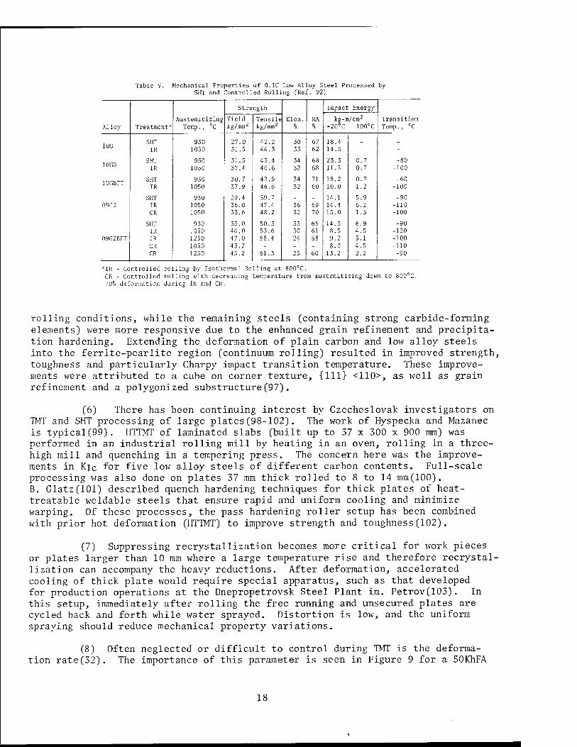
Table V. Mechanical Properties of 0.1C Low Alloy Steel Processed by SHT and Controlled Rolling (Ref. 92)
Austenitizing
Strength
Elon. RA
Impact Energy
Yield Tensile kg-m/cm2 Transition Alloy Treatment* Temp., °C kg/mm2 kg/mm2 % % +20°C -100°C Temp., °C
lOG SHT 930 27.0 42.2 30 67 18.4 _ _ IR 1050 31.5 44.3 33 62 14.5 - -
SHT 930 31.5 43.4 34 68 23.3 0.7 -80 IR 1050 37.4 46.6 32 68 11.5 0.7 -100
10GBFT SHT 930 30.7 42.9 34 71 18.2 0.7 -60 IR 1050 37.9 46.6 32 60 10.0 1.2 -100
SHT 930 29.4 39.7 - - 14.1 5.9 -90 09G2 IR 1050 36.0 47.4 36 69 14.4 6.2 -110
CR 1050 33.6 48.2 32 70 15.0 1.5 -100
SHT 930 35.0 50.3 33 65 14.3 6.9 -90 IR 1050 46.0 53.6 30 61 8.5 4.5 -120
09G2BFT IR 1250 47.0 58.4 24 58 9.2 5.1 -100 CR 1050 43.2 - - - 8.0 4.5 -110 CR 1250 45.2 61.3 25 60 13.2 2.2 -90
*IR - Controlled rolling by Isothermal Rolling at 800°C. CR - Controlled rolling with decreasing temperature from austenitizing down to 800°C. 70% deformation during IR and CR.
rolling conditions, while the remaining steels (containing strong carbide-forming elements) were more responsive due to the enhanced grain refinement and precipita- tion hardening. Extending the deformation of plain carbon and low alloy steels into the ferrite-pearlite region (continuum rolling) resulted in improved strength, toughness and particularly Charpy impact transition temperature. These improve- ments were attributed to a cube on corner texture, {111} <110>, as well as grain refinement and a polygonized substructure(97).
(6) There has been continuing interest by Czechoslovak investigators on TMT and SHT processing of large plates(98-102). The work of Hyspecka and Mazanec is typical(99). HTTMT of laminated slabs (built up to 37 x 300 x 900 mm) was performed in an industrial rolling mill by heating in an oven, rolling in a three- high mill and quenching in a tempering press. The concern here was the improve- ments in Kic for five low alloy steels of different carbon contents. Full-scale processing was also done on plates 37 mm thick rolled to 8 to 14 mm(100). B. Glatz(lOl) described quench hardening techniques for thick plates of heat- treatable weldable steels that ensure rapid and uniform cooling and minimize warping. Of these processes, the pass hardening roller setup has been combined with prior hot deformation (HTTMT) to improve strength and toughness(102).
(7) Suppressing recrystallization becomes more critical for work pieces or plates larger than 10 mm where a large temperature rise and therefore recrystal- lization can accompany the heavy reductions. After deformation, accelerated cooling of thick plate would require special apparatus, such as that developed for production operations at the Dnepropetrovsk Steel Plant im. Petrov(103). In this setup, immediately after rolling the free running and unsecured plates are cycled back and forth while water sprayed. Distortion is low, and the uniform spraying should reduce mechanical property variations.
(8) Often neglected or difficult to control during TMT is the deforma- tion rate(32). The importance of this parameter is seen in Figure 9 for a 50KhFA
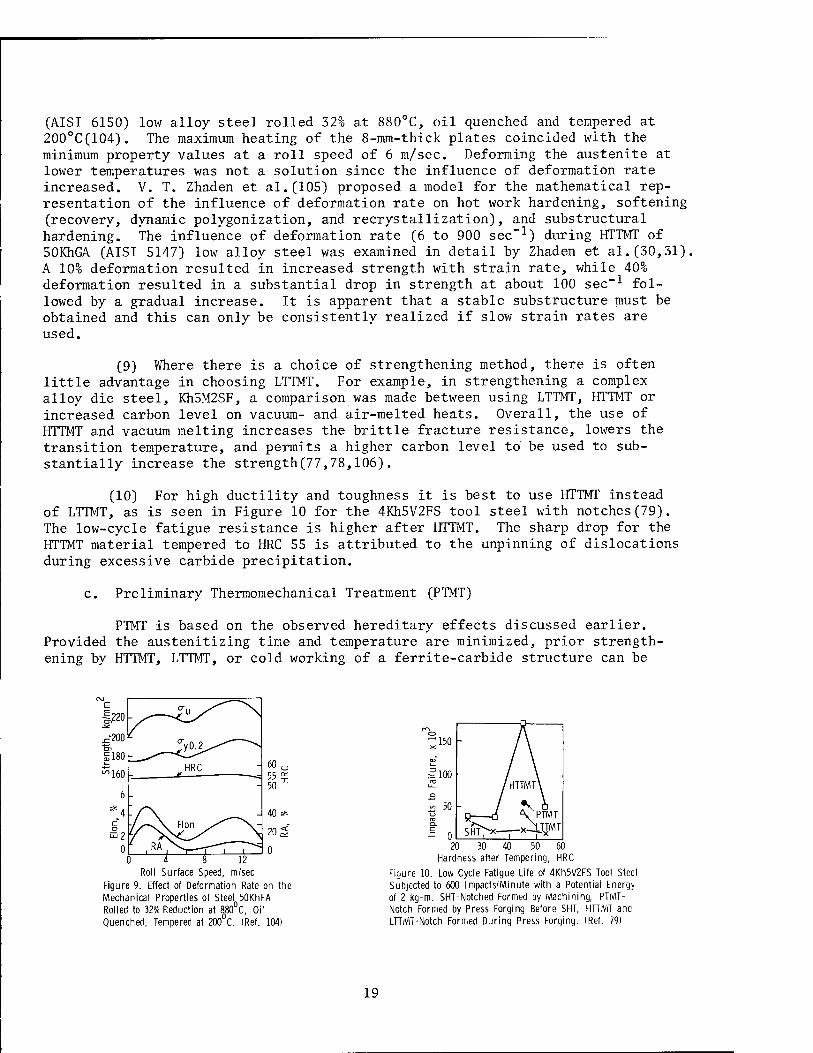
(AISI 6150) low alloy steel rolled 32% at 880°C, oil quenched and tempered at 200°C(104). The maximum heating of the 8-mm-thick plates coincided with the minimum property values at a roll speed of 6 m/sec. Deforming the austenite at lower temperatures was not a solution since the influence of deformation rate increased. V. T. Zhaden et al.(105) proposed a model for the mathematical rep- resentation of the influence of deformation rate on hot work hardening, softening (recovery, dynamic polygonization, and recrystallization), and substructural hardening. The influence of deformation rate (6 to 900 sec-1) during HTTMT of 50KhGA (AISI 5147) low alloy steel was examined in detail by Zhaden et al.(30,31). A 10% deformation resulted in increased strength with strain rate, while 40% deformation resulted in a substantial drop in strength at about 100 sec"1 fol- lowed by a gradual increase. It is apparent that a stable substructure must be obtained and this can only be consistently realized if slow strain rates are used.
(9) Where there is a choice of strengthening method, there is often little advantage in choosing LTTMT. For example, in strengthening a complex alloy die steel, Kh5M2SF, a comparison was made between using LTTMT, HTTMT or increased carbon level on vacuum- and air-melted heats. Overall, the use of HTTMT and vacuum melting increases the brittle fracture resistance, lowers the transition temperature, and permits a higher carbon level to be used to sub- stantially increase the strength(77,78,106).
(10) For high ductility and toughness it is best to use HTTMT instead of LTTMT, as is seen in Figure 10 for the 4Kh5V2FS tool steel with notches(79). The low-cycle fatigue resistance is higher after HTTMT. The sharp drop for the HTTMT material tempered to HRC 55 is attributed to the unpinning of dislocations during excessive carbide precipitation.
c. Preliminary Thermomechanical Treatment (PTMT)
PTMT is based on the observed hereditary effects discussed earlier. Provided the austenitizing time and temperature are minimized, prior strength- ening by HTTMT, LTTMT, or cold working of a ferrite-carbide structure can be
0 4 8 12 Roll Surface Speed, m/sec
Figure 9. Effect of Deformation Rate on the Mechanical Properties of Steel 50KhFA Rolled to 32% Reduction at 880 C, Oil Quenched, Tempered at 200 C. (Ref. 104)
20 30 40 50 60 Hardness after Tempering, HRC
Figure 10. Low Cycle Fatigue Life of 4Kh5V2FS Tool Steel Subjected to 600 Impacts/Minute with a Potential Energy of 2 kg-m. SHT-Notched Formed by Machining, PTMT- Notch Formed by Press Forging Before SHT, HTTMT and LTTMT-Notch Formed During Press Forging. (Ref. 79)
19
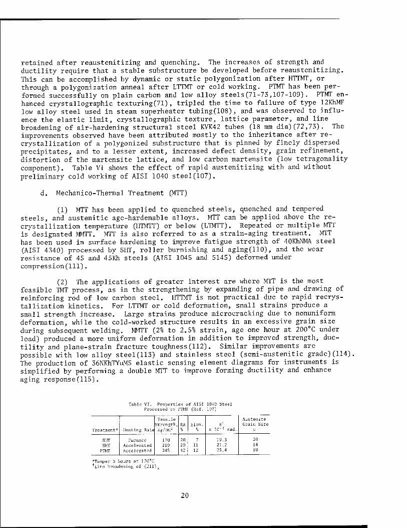
retained after reaustenitizing and quenching. The increases of strength and ductility require that a stable substructure be developed before reaustenitizing. This can be accomplished by dynamic or static polygonization after HTTMT, or through a polygonization anneal after LTTMT or cold working. PTMT has been per- formed successfully on plain carbon and low alloy steels(71-73,107-109). PTMT en- hanced crystallographic texturing(71), tripled the time to failure of type 12KhMF low alloy steel used in steam superheater tubing(108), and was observed to influ- ence the elastic limit, crystallographic texture, lattice parameter, and line broadening of air-hardening structural steel KVK42 tubes CIS mm dia)(72,73). The improvements observed have been attributed mostly to the inheritance after re- crystallization of a polygonized substructure that is pinned by finely dispersed precipitates, and to a lesser extent, increased defect density, grain refinement, distortion of the martensite lattice, and low carbon martensite (low tetragonality component). Table VI shows the effect of rapid austenitizing with and without
preliminary cold working of AISI 1040 steel(107).
d. Mechanico-Thermal Treatment (MTT)
(1) MTT has been applied to quenched steels, quenched and tempered steels, and austenitic age-hardenable alloys. MTT can be applied above the re- crystallization temperature (HTMTT) or below (LTMTT). Repeated or multiple MTT is'designated MMTT. MTT is also referred to as a strain-aging treatment. MTT has been used in surface hardening to improve fatigue strength of 40KhNMA steel (AISI 4340) processed by SHT, roller burnishing and aging(HO), and the wear resistance of 45 and 45Kh steels (AISI 1045 and 5145) deformed under compression(111).
(2) The applications of greater interest are where MTT is the most feasible TMT process, as in the strengthening by expanding of pipe and drawing of reinforcing rod of low carbon steel. HTTMT is not practical due to rapid recrys- tallization kinetics. For LTTMT or cold deformation, small strains produce a small strength increase. Large strains produce microcracking due to nonuniform deformation, while the cold-worked structure results in an excessive grain size during subsequent welding. MMTT (2% to 2.5% strain, age one hour at 200°C under load) produced a more uniform deformation in addition to improved strength, duc- tility and plane-strain fracture toughness(112). Similar improvements are possible with low alloy steel(113) and stainless steel (semi-austenitic grade)(114) The production of 36NKhTYuM5 elastic sensing element diagrams for instruments is simplified by performing a double MTT to improve forming ductility and enhance aging response(115).
Table VI. Properties c Processed by PTMT
f AISI (Ref.
1040 Steel 107)
Treatment* Heating Rate
Tensile Strength, kg/mm2
RA Elon. ß +
x 10"3 rad.
Austenite Grain Size
SHT SHT PTMT
Furnace Accelerated Accelerated
170 210 245
20 29 42
7 11 12
19.3 21.2 25.4
20 14 10
*Temper 3 hours at 170 C 'Line broadening of (211)a
20
(3) HTMTT of stabilized austenitic stainless steels improved the elevated temperature strength, creep resistance and fatigue strength(38,116,117). After HTMTT (311) line broadening was evidence of considerable substructure refinement and increased microdistortion of the crystal lattice, while the decreased lattice parameter was evidence of carbide precipitation(117). Elevated temperature prop- erties can also be increased by LTMTT (deformed at 575°C)(37).
e. Combined Treatments
(1) Combined thermomechanical treatment refers to the use of more than one TMT to obtain property improvements not possible with either treatment alone. The most popular of these treatments, at least during the early work on TMT, has been the sequence HTTMT followed by LTTMT. This process, referred to as CTMT, consists of deforming at a high temperature, cooling rapidly to the low defor- mation temperature, deforming, quenching, and tempering. The improvements are small, with nearly always increased elongation, ductility and toughness attrib- utable to HTTMT; the increased strength (yield and tensile) can be attributed to the LTTMT part of the processing. In addition to property improvements there is some easing of the deformation problem at low temperatures. The deformation processing equipment requirements are still severe, since it is the final strength of the processed material that mainly determines processing load requirements. Of more importance is the need for additional operations and temperature control that complicate any production setup. These factors must account for the relative absence of reported CTMT treatments since the late 1960's.
(2) A combined treatment that has attracted much interest is the use of strain aging (SA) of martensite after HTTMT(39,58,80,118-121) or after LTTMT(80). These treatments have been applied to plain carbon steels, tool steels, and low and medium alloy steels. Although LTTMT + SA has a higher strength than HTTMT + SA, it was found that for low alloy steel 18Kh2N4VA, HTTMT + SA had a better combination of properties (strength and ductility) at a SA deformation almost twice that for LTTMT + SA(80). Strain-aging treatments alone lead to very high strength levels for martensitic steels, but at reduced ductility and toughness(122). In addition, the deformation during preliminary processing and strain aging must be in the same direction for maximum strengthening. A variation of the foregoing procedures is, after HTTMT, to perform the strain-aging treatment in the martensitic transformation range (Ms-Mf)(118). For a 40KhSNMF low alloy steel there was an improved combination of strength and ductility, with less variation of mechanical properties.
(3) Table VII shows detailed processing schedules for a number of plain carbon and low alloy steels(120). The influence of the substructure produced during HTTMT persists after the SA treatments. For 20 (AISI 1020) and 20S2 steels with SA, the strength increases and the high ductility is retained if recrystal- lization during HTTMT does not occur. Recrystallization was not a factor for 20% and 40% hot deformation. SA of the 40 (AISI 1040) and 40S2 steels produces an increase in strength and slight decrease of ductility, without pronounced effects of recrystallization. The good combination of properties after HTTMT of the higher carbon steels, 60 and 60S2 (AISI 1060 and 9260), can be further improved by strain aging of the martensite. The increased rate of strain hardening of the higher carbon steels reduces the recommended level of martensite deformation. At
21

Table VII. Ir fluence of St rain Aging on the Tensile Properties of Carbon and c ilicon Steels after Preliminary HTTMT* (Ref. 120)
Cold Work,
SHT
HTTMT
20 % Deformation 4C % Deformation 6C % Deformation
°u , kg/nun^
a yo.2 Elon. RA °u
0 yo.2 Elon. RA °u ,
a yo.2 Elon. RA kg/mm2
0 yo-2
kg/mm Elon. RA
Steel kg/mm2 % % kg/mm kg/mm2 % % kg/mm2 kg/mm2 % % •6 *
20 0 100 84 6 17 132 116 6 46 138 112 5 38 120 104 6 27
3-4 112 102 4 16 136 126 5 45 143 130 4 24 128 108 5 25
5-6 120 115 3 17 138 131 4 43 144 132 4 25 131 110 3 22
9-10 124 120 1 18 139 125 4 37 147 133 4 25 138 132 2 14
15-16 128 124 1 17 142 121 3 27 148 130 3 24 146 130 2 14
21-22 132 127 1 15 144 120 3 18 150 124 3 26 157 129 1 13
20S2 0 109 79 6 12 126 96 13 24 126 100 12 44 106 86 8 18
3-4 120 105 3 17 129 101 10 26 136 118 8 23 127 115 6 19
5-6 126 118 3 18 133 111 7 21 - - - - 133 118 5 18
9-10 131 118 2 15 136 120 5 23 - - - 0 140 131 4 19
15-16 137 117 2 12 137 122 4 21 151 142 5 25 150 144 3 19
21-22 139 116 1 8 142 125 3 20 156 149 3 28 156 149 3 19
40 0 196 141 3 11 206 170 6 26 209 170 6 22 210 178 6.5 24
5-6 206 185 2 10 210 188 5 25 214 191 3 20 220 213 4 25
9-10 210 198 2 15 211 198 3 23 219 201 2 21 230 219 4 22
40S2 0 198 149 3 10 210 166 6.5 17 230 174 8 29 228 182 5 34
5-6 207 189 2 9 219 190 5 17 - - - - - - - " 9-10 209 196 2 10 226 209 4 16 - - - - 250 297 2 18
15-16 214 206 2 10 231 214 1.5 9 263 252 2 5 - ~ " 60 0 206 145 5.5 8 236 226 5 10 234 214 9 8 238 208 5 10
5-6 218 191 3 7 250 241 4 6 - - - - - - ~ 9-10 246 219 1.5 3.5 - - - - 267 241 2 5 263 242 1.5 6
60S2 0 218 162 4 14 240 197 6 27 241 220 7.5 35 258 223 8 40
3-4 230 221 3 11 256 248 5 12 251 244 5.5 19 267 259 5 22
7-8 241 232 2.5 8 263 253 4 10 259 250 3 19 275 263 2 9
9-10 253 237 2 4 268 257 3.5 9 270 257 3 16 - " ~ " 80 0 240 220 3 4 258 248 3 6 268 259 3 5 272 262 2 4
4-5 265 247 2 3 - - - - 281 277 - - 287 287 " " 80S2 0 243 208 2 6 253 230 3 7 261 243 4 9 268 259 2 3
3-4 250 243 1.5 3.5 - - - - 276 266 2 2 277 270
"Tempered at 200°C after SHT and HTTMT, age at 150°C for 1 hour Note: au = Tensile strength, ay0.2 = 0-2 percent offset yield strength
the highest carbon level (0.8C), tensile strengths often approached 300 kg/mm although with insignificant ductility. High martensite strain levels often caused microcracking, resulting in low strength levels. Strengthening during the strain aging part of the combined treatment was attributed to a conventional dislocation strain-hardening mechanism and carbide particle refinement. The latter has its origin in the increased density of nucleation sites for carbide precipitation. It is necessary to adjust the strain level high enough to adequately increase the dislocation density, but still avoid microcracking. During subsequent tempering the dislocations migrate to the polygonized subboundaries and carbon concentrates at the newly created dislocations due to the supersaturation of carbon in martensite.
f. TMT of Electroslag Remelted Steels
(1) Electroslag remelting (ESR) techniques have resulted in improved notch toughness, fatigue strength, ductility, anisotropy, surface finish, and service life due to increased purity and homogeneity(123,124). In addition, larger ingots and plates are available by ESR than by other refining methods. As expected, ESR material has been processed by TMT to obtain additional property improvements. Many of these studies have been concerned mainly with the effect
22
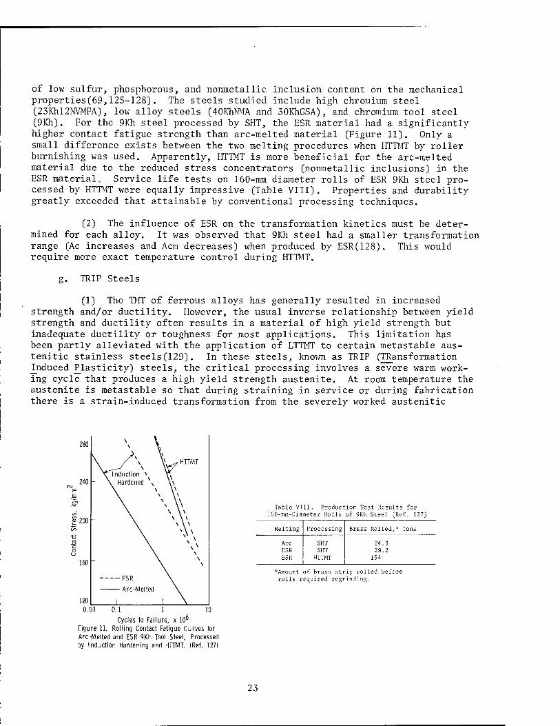
of low sulfur, phosphorous, and nonmetallic inclusion content on the mechanical properties(69,125-128). The steels studied include high chromium steel (23Khl2NVMFA), low alloy steels (40KhNMA and 30KhGSA), and chromium tool steel (9Kh). For the 9Kh steel processed by SHT, the ESR material had a significantly higher contact fatigue strength than arc-melted material (Figure 11). Only a small difference exists between the two melting procedures when HTTMT by roller burnishing was used. Apparently, HTTMT is more beneficial for the arc-melted material due to the reduced stress concentrators (nonmetallic inclusions) in the ESR material« Service life tests on 160-mm diameter rolls of ESR 9Kh steel pro- cessed by HTTMT were equally impressive (Table VIII). Properties and durability greatly exceeded that attainable by conventional processing techniques.
(2) The influence of ESR on the transformation kinetics must be deter- mined for each alloy. It was observed that 9Kh steel had a smaller transformation range (Ac increases and Acm decreases) when produced by ESR(128). This would require more exact temperature control during HTTMT.
g. TRIP Steels
(1) The TMT of ferrous alloys has generally resulted in increased strength and/or ductility. However, the usual inverse relationship between yield strength and ductility often results in a material of high yield strength but inadequate ductility or toughness for most applications. This limitation has been partly alleviated with the application of LTTMT to certain metastable aus- tenitic stainless steels(129). In these steels, known as TRIP (TRansformation Induced Plasticity) steels, the critical processing involves a severe warm work- ing cycle that produces a high yield strength austenite. At room temperature the austenite is metastable so that during straining in service or during fabrication there is a strain-induced transformation from the severely worked austenitic
280 \ 1
\ \\
\ / s \^f HTTMT \^— N
\ Induction N \\ 240 \ Hardened \
\ \ y \ \\ \ \ \ \ \ \
200 \ \ \ \ \ \
V. 160
ESR
120 1 i \ 0.03 10 0.1 1
Cycles to Failure, x 106
Figure 11. Rolling Contact Fatigue Curves for Arc-Melted and ESR 9Kh Tool Steel, Processed by Induction Hardening and HTTMT. (Ref. 127)
Table VIII. Product 160-mm-Diameter Rolls
ion Test Results for of 9Kh Steel (Ref. 127)
Melting Processing Brass Rolled,* Tons
Arc ESR ESR
SHT SHT
HTTMT
24.3 29.2
1S4
*Amount of brass strip rolled before rolls required regrinding.
23
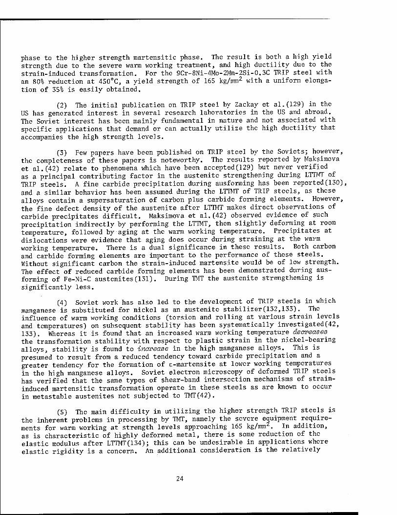
phase to the higher strength martensitic phase. The result is both a high yield strength due to the severe warm working treatment, and high ductility due to the strain-induced transformation. For the 9Cr-8Ni-4Mo-2Mn-2Si-0.3C TRIP steel with an 80% reduction at 450°C, a yield strength of 165 kg/mm2 with a uniform elonga- tion of 35% is easily obtained.
(2) The initial publication on TRIP steel by Zackay et al.(129) in the US has generated interest in several research laboratories in the US and abroad. The Soviet interest has been mainly fundamental in nature and not associated with specific applications that demand or can actually utilize the high ductility that accompanies the high strength levels.
(3) Few papers have been published on TRIP steel by the Soviets; however, the completeness of these papers is noteworthy. The results reported by Maksimova et al.(42) relate to phenomena which have been accepted(129) but never verified as a principal contributing factor in the austenite strengthening during LTTMT of TRIP steels. A fine carbide precipitation during ausforming has been reported(130), and a similar behavior has been assumed during the LTTMT of TRIP steels, as these alloys contain a supersaturation of carbon plus carbide forming elements. However, the fine defect density of the austenite after LTTMT makes direct observations of carbide precipitates difficult. Maksimova et al.(42) observed evidence of such precipitation indirectly by performing the LTTMT, then slightly deforming at room temperature, followed by aging at the warm working temperature. Precipitates at dislocations were evidence that aging does occur during straining at the warm working temperature. There is a dual significance in these results. Both carbon and carbide forming elements are important to the performance of these steels. Without significant carbon the strain-induced martensite would be of low strength. The effect of reduced carbide forming elements has been demonstrated during aus- forming of Fe-Ni-C austenites(131). During TMT the austenite strengthening is significantly less.
(4) Soviet work has also led to the development of TRIP steels in which manganese is substituted for nickel as an austenite stabilizer(132,133). The influence of warm working conditions (torsion and rolling at various strain levels and temperatures) on subsequent stability has been systematically investigated(42, 133). Whereas it is found that an increased warm working temperature deoveases^ the transformation stability with respect to plastic strain in the nickel-bearing alloys, stability is found to inovea.se in the high manganese alloys. This is presumed to result from a reduced tendency toward carbide precipitation and a greater tendency for the formation of e-martensite at lower working temperatures in the high manganese alloys. Soviet electron microscopy of deformed TRIP steels has verified that the same' types of shear-band intersection mechanisms of strain- induced martensitic transformation operate in these steels as are known to occur in metastable austenites not subjected to TMT(42).
(5) The main difficulty in utilizing the higher strength TRIP steels is the inherent problems in processing by TMT, namely the severe equipment require- ments for warm working at strength levels approaching 165 kg/mm2. In addition, as is characteristic of highly deformed metal, there is some reduction of the elastic modulus after LTTMT(134); this can be undesirable in applications where elastic rigidity is a concern. An additional consideration is the relatively
24
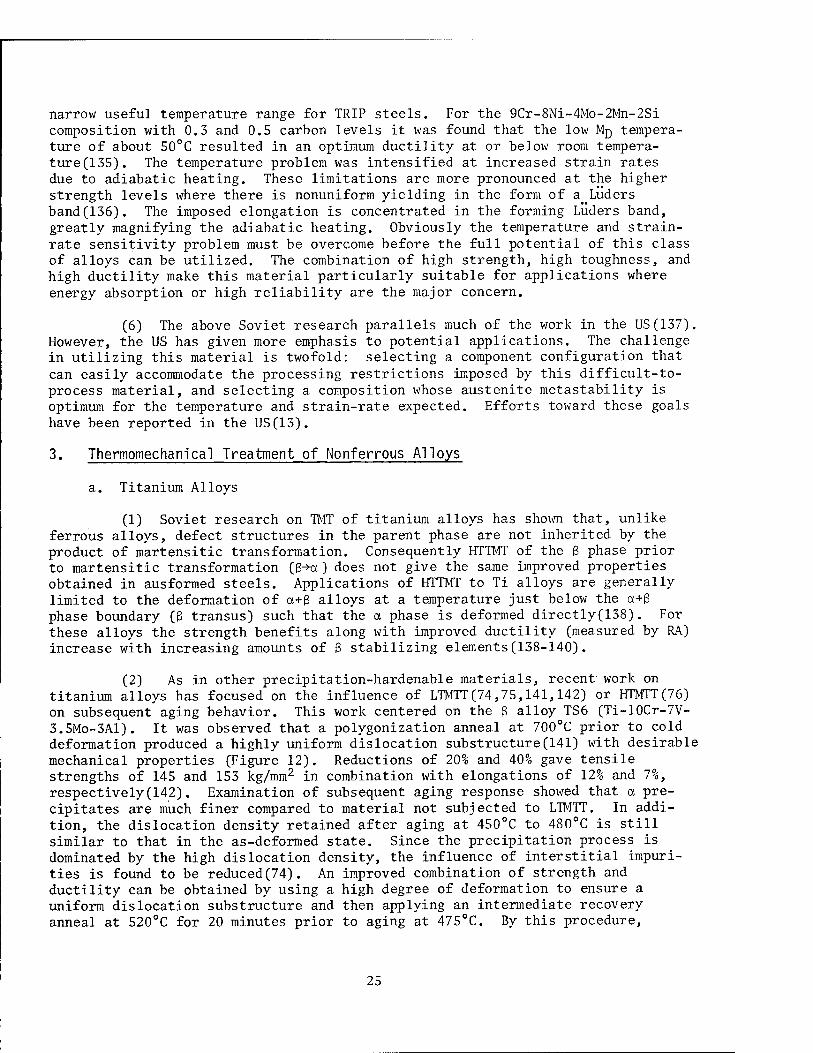
narrow useful temperature range for TRIP steels. For the 9Cr-8Ni-4Mo-2Mn-2Si composition with 0.3 and 0.5 carbon levels it was found that the low MQ tempera- ture of about 50°C resulted in an optimum ductility at or below room tempera- ture(135). The temperature problem was intensified at increased strain rates due to adiabatic heating. These limitations are more pronounced at the higher strength levels where there is nonuniform yielding in the form of a_LÜders band(136). The imposed elongation is concentrated in the forming Luders band, greatly magnifying the adiabatic heating. Obviously the temperature and strain- rate sensitivity problem must be overcome before the full potential of this class of alloys can be utilized. The combination of high strength, high toughness, and high ductility make this material particularly suitable for applications where energy absorption or high reliability are the major concern.
(6) The above Soviet research parallels much of the work in the US (137). However, the US has given more emphasis to potential applications. The challenge in utilizing this material is twofold: selecting a component configuration that can easily accommodate the processing restrictions imposed by this difficult-to- process material, and selecting a composition whose austenite metastability is optimum for the temperature and strain-rate expected. Efforts toward these goals have been reported in the US(13).
3. Thermomechanical Treatment of Nonferrous Alloys
a. Titanium Alloys
(1) Soviet research on TMT of titanium alloys has shown that, unlike ferrous alloys, defect structures in the parent phase are not inherited by the product of martensitic transformation. Consequently HTTMT of the ß phase prior to martensitic transformation (&-+a) does not give the same improved properties obtained in ausformed steels. Applications of HTTMT to Ti alloys are generally limited to the deformation of a+ß alloys at a temperature just below the a+ß phase boundary (ß transus) such that the a phase is deformed directly(138). For these alloys the strength benefits along with improved ductility (measured by RA) increase with increasing amounts of ß stabilizing elements(138-140).
(2) As in other precipitation-hardenable materials, recent work on titanium alloys has focused on the influence of LTMTT(74,75,141,142) or HTMTT(76) on subsequent aging behavior. This work centered on the ß alloy TS6 (Ti-10Cr-7V- 3.5Mo-3Al). It was observed that a polygonization anneal at 700°C prior to cold deformation produced a highly uniform dislocation substructure(141) with desirable mechanical properties (Figure 12). Reductions of 20% and 40% gave tensile strengths of 145 and 153 kg/mm2 in combination with elongations of 12% and 7%, respectively(142). Examination of subsequent aging response showed that a pre- cipitates are much finer compared to material not subjected to LTMTT. In addi- tion, the dislocation density retained after aging at 450°C to 480°C is still similar to that in the as-deformed state. Since the precipitation process is dominated by the high dislocation density, the influence of interstitial impuri- ties is found to be reduced(74). An improved combination of strength and ductility can be obtained by using a high degree of deformation to ensure a uniform dislocation substructure and then applying an intermediate recovery anneal at 520°C for 20 minutes prior to aging at 475°C. By this procedure,
25

ductility is doubled, with only a 15% decrease in strength relative to material processed without the recovery anneal (Table IX). US work on this same alloy has shown that a higher degree of cold deformation can result in a material with a tensile strength greater than 225 kg/mm2 and a reduction of area of 15%, although uniform elongation is minimal(143). Similar Soviet studies of the ß alloy VT15 and the a+ß alloy VT9 have shown that HTMTT prior to aging results in a poly- gonized substructure and an absence of large a precipitates at grain boundaries with a resultant increase in ductility(76). The time interval between deforma- tion and quenching is found to be of critical importance in determining both the volume fraction and dispersion of phases in this processing technique.
b. Aluminum Alloys
(1) Soviet work on the MTT of aluminum alloys has been reviewed recently by Rabinovich(4). Work has focussed largely on LTMTT consisting of a sequence of either solutionize, cold work, and age (s-cw-a) or a double aging treatment in the form of solutionize, age, cold work, and age (s-a-cw-a). The influence of the cold work operation is to greatly accelerate the kinetics of the subsequent aging reaction. This does not always lead to enhanced strength because properties characteristic of an overaged material may often result.
(2) Aluminum alloy systems which have been found to respond favorably to the s-cw-a sequence include Al-Cu-Mg, Al-Mg-Si, and Al-Mg-Zn. Results obtained on some of these alloys are summarized in Table X. A number of Soviet investiga- tors (144-146) have found a superior response to a sequence of the type s-a-cw-a in which an additional aging step precedes the cold work operation. For example, L. B. Ber et al.(144) obtained a 50% increase in strength in an Al-Mg-Si alloy similar to 6063 by this treatment. One advantage of this sequence appears to be an enhanced rate of work hardening during cold work after aging. Other alloy systems showing a favorable response to the s-a-cw-a sequence are Al-Zn-Mg(146), Al-Cu-Mg(4), and Al-Cu-Li(4). Results obtained for several alloys with this processing sequence are summarized in Table XI. Typically the strength increases
IbU
E 140 E
y/^1
en
f 120
CD \ \ —
! loo —. Elon
80 1 1 1
20 „
15|
10 £
0 10 20 30 40 Deformation at 20°C, %
Figure 12. Tensile Properties of the TS6 ß Titanium Alloy Subjected to a Polygonization Anneal at 700°C Prior to Deformation. (Ref. 142)
Table IX. Effect of Recovery Anneal During LTMTT on the Tensile Properties of the TS6 B Titanium Alloy (Ref. 75)
Strength
Treatment Tensile kg/mm2
Yield* kg/mm2
Elon.
Quench from 800°C + 35% deformation + recovery anneal 20 min at 520°C + aging 5 hr at 475°C
Quench from 800°C + 35% deformation + aging 5 hr at 475°C
128
152
120.7
145
7.8
4.25
*0.2 percent offset yield strength
26
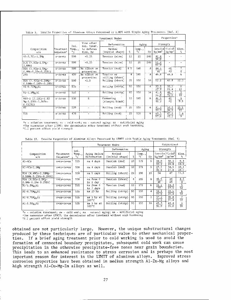
Table X. Tensile Properties of Aluminum Alloys Processed by LTMTT with S ingle Ag ing Treatments (Ref. 4)
Composition w/o
Treatment Sequence*
Treatment Modes Propertiest
Sol. Temp., °C
Time after sol. treat, to deforma- tion, hr
Deformation Aging Strength
Elon. Method (initial shape) %
Temp., °C Hr
Tensile kg/mm2
Yieldt kg/mm2
Al-3.7Cu-l.3Mg s+cw+na 500 <0.25 Tension (wire) 10 20 240 40.8 39.0
- -
D16 (4.5Cu-1.5Mg- 0.6Mn)
s+cw+na 500 <0.25 Tension Cwire) 10 20 240 52.8 51.2
- -
D16 (4.5Cu-1.5Mg- 0.8Mn-0.2Fe-0.25Si)
s+cw+aa 500 No effect on properties
Tension Cr°d) 4-5 185 8 48.5 46
48 43
7 8
24S s+cw+aa 499 No effect on properties
Tension or rolling (sheet)
4 185 8 46.8 44.9 6
D16 (4.49Cu-0.28Mg- 0.58Mn-0.28Fe-0.28Si)
s+cw+aa 500 <1.S Rolling (sheet) 25 150 10 52.2 45.8 12.0
Al-0.75Mg2Si s+cw+aa 535 - Rolling (strip) 90 150 4 33.2 22.5
32.1 21.4
6 12
Al-1.5Mg2Si s+cw+aa 535 - Rolling (strip) 90 150 16 41.8 35.9
40.7 25.6
5 10
AK4-1 C2.llCu-l.83 Mg-l.21Ni-l.36Fe- 0.032Ti)
s+cw+aa 530 8 Hammering (stamped blank)
10 185 6 49.5 46.3
41 41
8 9.5
AV s+cw+aa 520 - Rolling (rod) 20 150 6 41.3 32.5
34.0 26.0
15.5 22
V95 s+cw+aa 470 - Rolling (rod) 20 120 6 60.3 57.6
47.5 42.2
7.8 9
*s - solution treatment; cw - cold work; na - natural aging; aa - artificial aging tThe numerator after LTTMT; the denominator after treatment without work hardening to.2 percent offset yield strength
Table XI. Tensile Properties of Aluminum Alloys Processed by LTMTT with Double Ag Lng Treatments (Ref. 4)
Composition w/o
Treatment Sequence*
Treatment Modes Propertiest
Sol. Temp., °C
Aging Before Deformation
Deformation Aging Strength
Elon. Method (initial shape) %
Temp., °C Hr
Tensile kg/mm2
Yieldt kg/mm2
Al-4Cu s+na+cw+aa 525 na 4 days Tension (rod) 10 175 5 38.0 33.2
30.3 19.8
9.3 13.5
Al-4Cu-1.5Mg s+na+cw+aa 500 na 4 days Tension (rod) 10 175 5 47.1 40.9
38.5 27.8
10.1 19.7
D16 (4.49Cu-1.28Mg- 0.58Mn-0.23Fe-0.29Si)
s+na+cw+aa 500 na 5 days Rolling (sheet) 25 100 10 54 47 11.5
D16 (4.5Cu-1.5Mg- 0.9Mn-0.2Fe-0.25Si)
s+na+cw+aa 500 na from 0 to 1 day
Tension (sheet) 4 185 8 48.5 46
48 43
8.5 8
Al-1.5Mg2Si s+na+cw+aa 535 na from 6 to 7 days
Tension (rod) 10 170 6 31.1 27
28.3 17.S
5 14
Al-0.75Mg2Si s+na+cw+aa 535 na 20 hr Rolling (strip) 90 150 4 34.4 22.5
33.5 21.4
6 12
Al-0.75Mg2Si s+aa+cw+aa 535 aa 3 hr at 105°C
Rolling (strip) 90 150 2 37.2 22.5
35.8 21.4
7 12
Al-1.5Mg2Si s+aa+cw+aa 535 aa 3 hr at 105°C
Rolling (strip) 90 150 16 45.3 36.9
43.4 25.6
5 10
*s - solution treatment; cw - cold work; na tThe numerator after LTMTT; the denominator tO.2 percent offset yield strength
- natural aging; aa - artificial aging after treatment without work hardening
obtained are not particularly large. However, the unique substructural changes produced by these techniques are of particular value to other mechanical proper- ties» If a brief aging treatment prior to cold working is used to avoid the formation of connected boundary precipitates, subsequent cold work can cause precipitation in the otherwise precipitate-free zones near grain boundaries. This leads to an enhanced resistance to stress corrosion and is perhaps the most important reason for interest in the LTMTT of aluminum alloys. Improved stress corrosion properties have been obtained in medium strength Al-Zn-Mg alloys and high strength Al-Cu-Mg-Zn alloys as well.
27
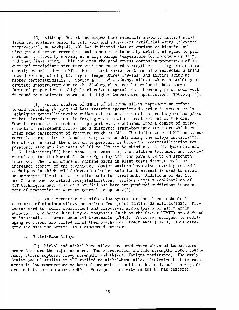
(3) Although Soviet techniques have generally involved natural aging (room temperature) prior to cold work and subsequent artificial aging (elevated temperature), US work(147,148) has indicated that an optimum combination of strength and stress corrosion resistance is obtained by artificial aging to peak hardness followed by working at a high enough temperature for homogeneous slip, and then final aging. This combines the good stress corrosion properties of an overaged precipitate structure with the enhanced strength of the high dislocation density associated with MTT. More recent Soviet work has also reflected a trend toward working at slightly higher temperatures(149-151) and initial aging at higher temperatures(152). Soviet LTMTT of Al-Cu-Mg- alloys, where a stable pre- cipitate substructure due to the A^CuMg phase can be produced, have shown improved properties at slightly elevated temperatures. However, prior cold work is found to accelerate overaging in higher temperature applications (T>0.5T^)(4).
(4) Soviet studies of HTMTT of aluminum alloys represent an effort toward combining shaping and heat treating operations in order to reduce costs. Techniques generally involve either extrusion with solution treating on the press or hot closed-impression die forging with solution treatment out of the die. Some improvements in mechanical properties are obtained from a degree of micro- structural refinement(3,153) and a distorted grain-boundary structure which can offer some enhancement of fracture toughness(4). The influence of HTMTT on stress corrosion properties is found to vary considerably among the alloys investigated. For alloys in which the solution temperature is below the recrystallization tem- perature, strength increases of 10% to 20% can be obtained. R. M. Ryabinina and L. N. Leshchiner(154) have shown that combining the solution treatment and forming operation, for the Soviet Al-Cu-Si-Mg alloy AK6, can give a 5% to 6% strength increase. The manufacture of machine parts in plant tests demonstrated the increased economy of the technique. Soviet workers have also investigated PMTT techniques in which cold deformation before solution treatment is used to retain an unrecrystallized structure after solution treatment. Additions of Mn, Cr, and Zr are used to retard recrystallization. Various complex combinations of MTT techniques have also been studied but have not produced sufficient improve- ment of properties to warrant general acceptance(4).
(5) An alternative classification system for the thermomechanical treatment of aluminum alloys has arisen from joint Italian-US efforts(155). Pro- cesses used to modify constituent and dispersoid morphologies or alter grain structure to enhance ductility or toughness (such as the Soviet HTMTT) are defined as intermediate thermomechanical treatments (ITMT). Processes designed to modify aging reactions are called final thermomechanical treatments (FTMT). This cate- gory includes the Soviet LTMTT discussed earlier.
c. Nickel-Base Alloys
(1) Nickel and nickel-base alloys are used where elevated temperature properties are the major concern. These properties include strength, notch tough- ness, stress rupture, creep strength, and thermal fatigue resistance. The early Soviet and US studies on MTT applied to nickel-base alloys indicated that improve- ments in low temperature mechanical properties could be obtained, but these gains are lost in service above 500°C. Subsequent activity in the US has centered
28
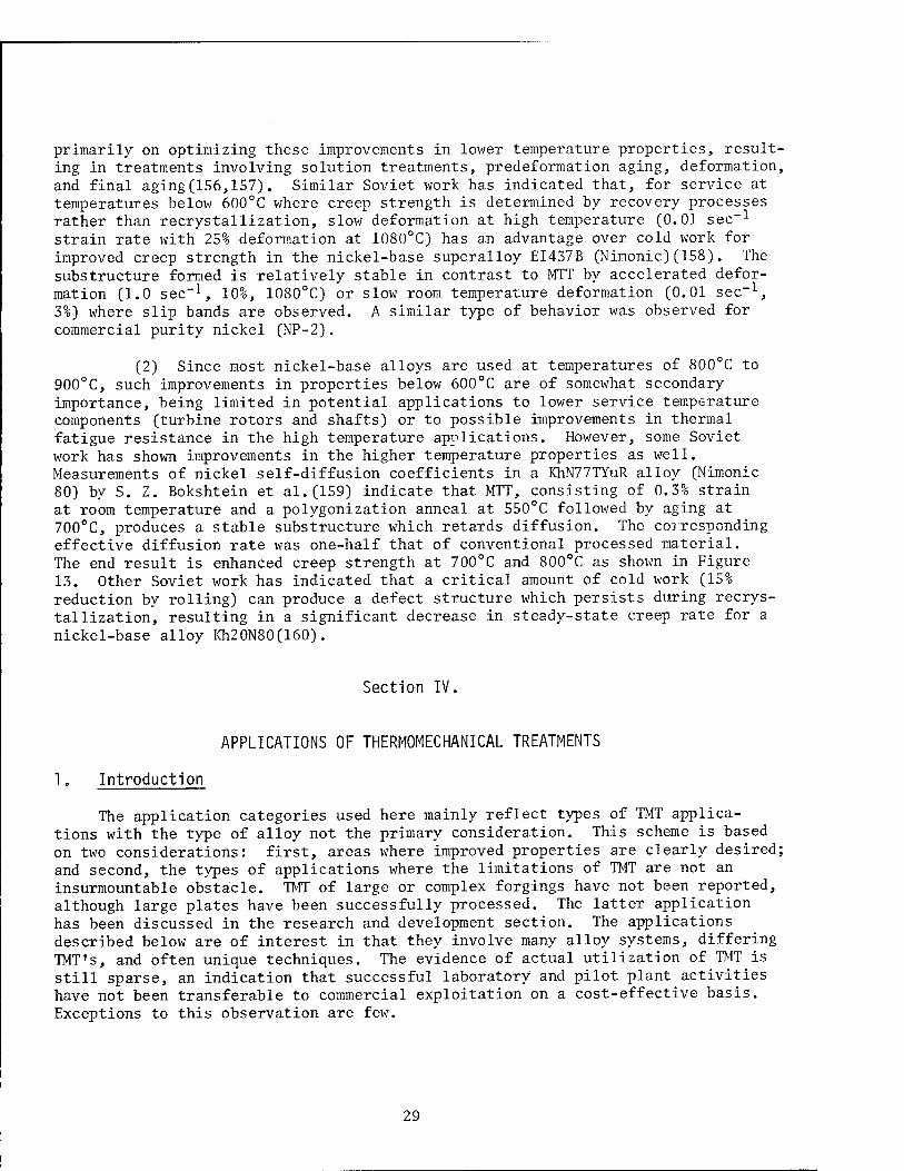
primarily on optimizing these improvements in lower temperature properties, result- ing in treatments involving solution treatments, predeformation aging, deformation, and final aging(156,157). Similar Soviet work has indicated that, for service at temperatures below 600°C where creep strength is determined by recovery processes rather than recrystallization, slow deformation at high temperature (0.01 sec"1
strain rate with 25% deformation at 1080°C) has an advantage over cold work for improved creep strength in the nickel-base superalloy EI437B (Nimonic)(158). The substructure formed is relatively stable in contrast to MTT by accelerated defor- mation (1.0 sec-1, 10%, 1080°C) or slow room temperature deformation (0.01 sec"1, 3%) where slip bands are observed. A similar type of behavior was observed for commercial purity nickel (NP-2).
(2) Since most nickel-base alloys are used at temperatures of 800°C to 900°C, such improvements in properties below 600°C are of somewhat secondary importance, being limited in potential applications to lower service temperature components (turbine rotors and shafts) or to possible improvements in thermal fatigue resistance in the high temperature applications. However, some Soviet work has shown improvements in the higher temperature properties as well. Measurements of nickel self-diffusion coefficients in a KhN77TYuR alloy (Nimonic 80) by S. Z. Bokshtein et al.(159) indicate that MTT, consisting of 0.3% strain at room temperature and a polygonization anneal at 550°C followed by aging at 700°C, produces a stable substructure which retards diffusion. The corresponding effective diffusion rate was one-half that of conventional processed material. The end result is enhanced creep strength at 700°C and 800°C as shown in Figure 13. Other Soviet work has indicated that a critical amount of cold work (15% reduction by rolling) can produce a defect structure which persists during recrys- tallization, resulting in a significant decrease in steady-state creep rate for a nickel-base alloy Kh20N80(160).
Section IV.
APPLICATIONS OF THERMOMECHANICAL TREATMENTS
1„ Introduction
The application categories used here mainly reflect types of TMT applica- tions with the type of alloy not the primary consideration. This scheme is based on two considerations: first, areas where improved properties are clearly desired; and second, the types of applications where the limitations of TMT are not an insurmountable obstacle. TMT of large or complex forgings have not been reported, although large plates have been successfully processed. The latter application has been discussed in the research and development section. The applications described below are of interest in that they involve many alloy systems, differing TMT's, and often unique techniques. The evidence of actual utilization of TMT is still sparse, an indication that successful laboratory and pilot plant activities have not been transferable to commercial exploitation on a cost-effective basis. Exceptions to this observation are few.
29
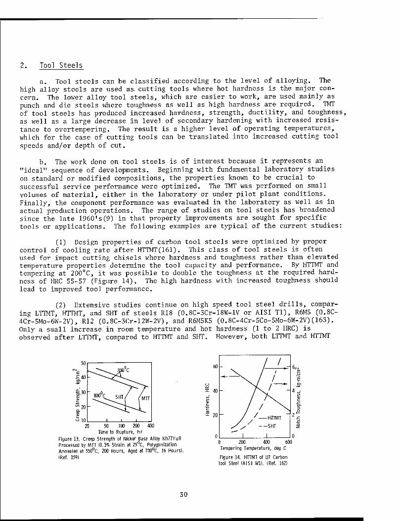
2. Tool Steels
a. Tool steels can be classified according to the level of alloying. The high alloy steels are used as cutting tools where hot hardness is the major con- cern. The lower alloy tool steels, which are easier to work, are used mainly as punch and die steels where toughness as well as high hardness are required. TMT of tool steels has produced increased hardness, strength, ductility, and toughness, as well as a large decrease in level of secondary hardening with increased resis- tance to overtempering. The result is a higher level of operating temperatures, which for the case of cutting tools can be translated into increased cutting tool
speeds and/or depth of cut.
b. The work done on tool steels is of interest because it represents an "ideal" sequence of developments. Beginning with fundamental laboratory studies on standard or modified compositions, the properties known to be crucial to successful service performance were optimized. The TMT was performed on small volumes of material, either in the laboratory or under pilot plant conditions. Finally, the component performance was evaluated in the laboratory as well as in actual production operations. The range of studies on tool steels has broadened since the late I960's(9) in that property improvements are sought for specific tools or applications. The following examples are typical of the current studies:
(1) Design properties of carbon tool steels were optimized by proper control of cooling rate after HTTMT(161). This class of tool steels is often used for impact cutting chisels where hardness and toughness rather than elevated temperature properties determine the tool capacity and performance. By HTTMT and tempering at 200°C, it was possible to double the toughness at the required hard- ness of HRC 55-57 (Figure 14). The high hardness with increased toughness should lead to improved tool performance.
(2) Extensive studies continue on high speed tool steel drills, compar- ing LTTMT, HTTMT, and SHT of steels R18 (0.8C-3Cr-18W-lV or AISI Tl), R6M5 (0.8C- 4Cr-5Mo-6W-2V), R12 (0.8C-3Cr-12W-2V), and R6M5K5 (0.8C-4Cr-5Co-5Mo-6W-2V)(163). Only a small increase in room temperature and hot hardness (1 to 2 HRC) is observed after LTTMT, compared to HTTMT and SHT. However, both LTTMT and HTTMT
" 10 20 50 100 200
Time to Rupture, hr
Figure 13. Creep Strength of Nickel Base Alloy Kh77YuR Processed by MTT (0.3% Strain at 25°C, Polygonization Annealed at 550°C, 200 Hours, Aged at 700°C, 16 Hours). (Ref. 159)
0 200 400 600 Tempering Temperature, deg C
Figure 14. HTTMT of U7 Carbon Tool Steel (AISI WD. (Ref. 162)
30
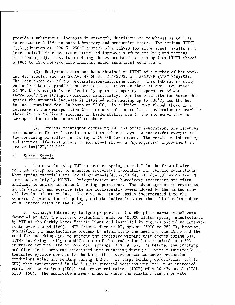
provide a substantial increase in strength, ductility and toughness as well as increased tool life in both laboratory and production tests. The optimum HTTMT
(25% reduction at 1000°C, 250°C temper) of a 5KhV2S low alloy steel results in a lower brittle fracture temperature and improved surface cracking and pitting resistance(164). Disk tube-cutting shears produced by this optimum HTTMT showed a 100% to 150% service life increase under industrial conditions.
(3) Background data has been obtained on HTTMT of a number of hot work- ing die steels, such as 5KhNV, 4Kh5MFS, 4Kh4M2VFS, and 3Kh2V8F (AISI N20)(53). The last three are of the precipitation-hardening grade. This laboratory study was undertaken to predict the service limitations on these alloys. For steel 5KhNV, the strength is retained only up to a tempering temperature of 450°C. Above 650°C the strength decreases drastically. For the precipitation-hardenable grades the strength increase is retained with heating up to 600°C, and the hot hardness retained for 150 hours at 550°C. In addition, even though there is a decrease in the decomposition time for unstable austenite transforming to pearlite, there is a significant increase in hardenability due to the increased time for decomposition to the intermediate phase.
(4) Process techniques combining TMT and other innovations are becoming more numerous for tool steels as well as other alloys. A successful example is the combining of roller burnishing with ESR techniques. The result of laboratory and service life evaluations on 9Kh steel showed a "synergistic" improvement in properties (127,128,165).
3. Spring Steels
a. The ease in using TMT to produce spring material in the form of wire, rod, and strip has led to numerous successful laboratory and service evaluations. Most spring materials are low alloy steels(45,54,61,64,121,166-168) which are TMT processed mainly by HTTMT. Polygonization and hereditary treatments are often included to enable subsequent forming operations. The advantages of improvements in performance and service life are occasionally overshadowed by the marked sim- plification of processing. Clearly, TMT can be easily incorporated into the commercial production of springs, and the indications are that this has been done on a limited basis in the USSR.
b. Although laboratory fatigue properties of a 65G plain carbon steel were improved by MTT, the service evaluations made on 40,000 clutch springs manufactured by MTT at the Gorkiy Motor Vehicle Plant and installed in engines showed no improve- ments over the SHT(169). MTT (stamp, form at RT, age at 230°C to 280°C), however, simplified the manufacturing process by eliminating the need for quenching and the need for quenching dies to prevent the excessive warping that occurs during SHT. HTTMT involving a slight modification of the production line resulted in a 30% increased service life of 55S2 coil springs (AISI 9255). As before, the cracking and dimensional problems associated with quenching during SHT were eliminated(61). Laminated ejector springs for hunting rifles were processed under production conditions using hot bending during HTTMT. The large bending deformation (30% to 35%) that concentrated in the highest stressed sections resulted in an increased resistance to fatigue (150%) and stress relaxation (100%) of a 50KhFA steel (AISI 6150)(168). The application seems unusual since the existing ban on private
31
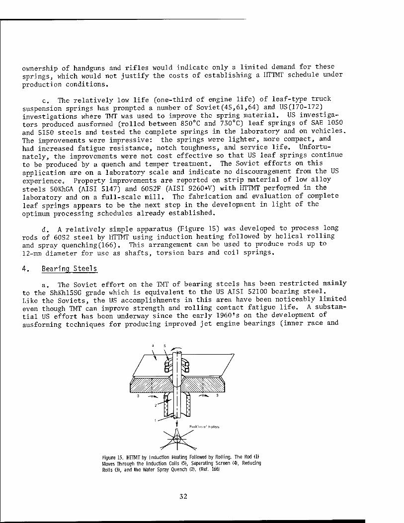
ownership of handguns and rifles would indicate only a limited demand for these springs, which would not justify the costs of establishing a HTTMT schedule under production conditions.
c. The relatively low life (one-third of engine life) of leaf-type truck suspension springs has prompted a number of Soviet(45,61,64) and US(170-172) investigations where TMT was used to improve the spring material. US investiga- tors produced ausformed (rolled between 850°C and 730°C) leaf springs of SAE 1050 and 5150 steels and tested the complete springs in the laboratory and on vehicles. The improvements were impressive: the springs were lighter, more compact, and had increased fatigue resistance, notch toughness, and service life. Unfortu- nately, the improvements were not cost effective so that US leaf springs continue to be produced by a quench and temper treatment. The Soviet efforts on this application are on a laboratory scale and indicate no discouragement from the US experience» Property improvements are reported on strip material of low alloy steels 50KhGA (AISI 5147) and 60S2F (AISI 9260+V) with HTTMT performed in the laboratory and on a full-scale mill. The fabrication and evaluation of complete leaf springs appears to be the next step in the development in light of the optimum processing schedules already established.
d. A relatively simple apparatus (Figure 15) was developed to process long rods of 60S2 steel by HTTMT using induction heating followed by helical rolling and spray quenching(166). This arrangement can be used to produce rods up to 12-mm diameter for use as shafts, torsion bars and coil springs.
4. Bearing Steels
a. The Soviet effort on the TMT of bearing steels has been restricted mainly to the ShKhl5SG grade which is equivalent to the US AISI 52100 bearing steel. Like the Soviets, the US accomplishments in this area have been noticeably limited even though TMT can improve strength and rolling contact fatigue life. A substan- tial US effort has been underway since the early 1960's on the development of ausforming techniques for producing improved jet engine bearings (inner race and
Figure 15. HTTMT by Induction Heating Followed by Rolling. The Rod (1) Moves Through the Induction Coils (5), Separating Screen (4), Reducing Rolls (3), and the Water Spray Quench (2). (Ref. 166)
32

balls) of M-50 tool steel(13,173,174). There was a laboratory life improvement of 3-1/2 to 9 times that of conventionally processed bearings, and the cost in- crease was estimated at 300%. Recent improvements in melting of M-50 steel, leading to increased cleanliness, have significantly increased bearing life with- out resorting to the difficult processing by TMT.
b. Soviet efforts on bearing steels appear to have followed a similar path. In the early and mid 1960's it was found that mechanical properties, service life and reliability of ShKhl5 and ShKhl5SG roller bearings improved after HTTMT(175, 176). Subsequent Soviet interest in these steels has been restricted to simple laboratory-type specimens for the study of the brittle-to-ductile transition, HTTMT processing variables, microstructural characteristics and properties(40,41, 177). Like the US, the Soviets undoubtedly have shifted their emphasis to improved material cleanliness to enhance bearing life. This trend has its exceptions as in the case of US work on large-diameter bearings operating at ultrahigh speeds where high hoop stresses are a potential source of race fracture.(13) LTTMT is being considered for this critical application to obtain the expected higher fracture toughness(178) at what may be an acceptable cost increase.
5. Rail Steels
a. The severe loading conditions imposed on railway rails can lead to failure due to high compression and bending stresses, impact, vibration, friction, and wear. In view of these requirements, rail heads and associated rolling stock are designed to have the largest possible transverse strength, toughness, and surface and volume to permit sufficient wear life before replacement. The potential for rail failure is greatly magnified by the low temperatures that are common in some regions of the USSR. Rails generally are made from plain carbon steel of 0.1 to 0.2Si, 0.6 to l.OMn, and 0.64 to 0.82C composition, having section sizes that weigh 100 to 200 kg/m, with the larger sizes having the higher carbon levels. It was only natural that TMT should be investigated for its potential to strengthen the rails and increase low temperature toughness.
b. Initial Soviet studies were on test specimens of high manganese austen- itic steel G13 (Hadfield steel) to enhance hardness and strength(179,180). HTTMT which strengthened the entire cross-section, was followed by LTTMT to further strengthen the rail-section head. The combined treatment increased the strength by 65%, but decreased the elongation and RA by 40% and 20%, respectively. M75 rail steel (AISI 1074) specimens were processed by HTTMT with and without a simul- taneous magnetic field(181). However, the effect of the magnetic field was not determined. Later investigations on plain carbon rail steel and low alloy struc- tural steel emphasized the effect of holding times and cooling rates on properties (43,182). Longitudinal cracks present after water quenching could be prevented by the slower cooling obtained with a sliding water-air sprayer mecha- nism, as shown in Figure 16(182). This specially designed laboratory apparatus permitted adjustment of the water-air flow parameters to obtain a cooling rate less than that for water quenching, but still sufficiently rapid to avoid recrys- tallization in a sample of 10 mm square cross-section.
c. These findings have led to the present stage of development in which short lengths (approximately 30 cm) of actual cross-sections are now being sub- jected to HTTMT, Processing of type AISI 1065 steel (R65 and R50 Soviet rail
33

steels) rail sections was performed at the Kuznetsk Metallurgical Combine on a semi-industrial mill with a four-roll finishing pass to deform the rail section head 14% to 21% (183-185). The rail head was cooled by a water-air mixture. The recommended HTTMT for R65 rails processed under industrial conditions is: aus- tenitize at 870°C to 940°C, roll at 780°C to 840°C in one finishing pass, water- air mixture cool for 75 to 100 sec (in the center of rail head), and air cool(184). This cooling rate refines the pearlitic structure compared to SHT (oil quench, 450°C temper). S. G. Nekrasov et al.(185) conclude that after HTTMT the strength properties of the rail head are similar to the SHT while the ductility and tough- ness levels are higher. Examination of the data(184,185), however, indicates that these improvements are not large.
d. The above method of processing full size cross-sections of railway rails has apparently achieved the goal of some increase in toughness without loss of strength and therefore appears ready for full production scale trials. Although HTTMT of full length rails may require additional development, it should be possible to use these procedures to process the much shorter frog sections used at rail crossings.
6. Surface Hardening
a. The potential benefits of increased surface hardness have resulted in a wide range of research, development, and pilot plant studies where TMT was used to harden the entire component, or more directly, harden only the surface region. The following examples illustrate the varied surface hardening applications:
(1) The surface improvements possible with HTTMT are shown in Figure 17 for a high alloy steel(63,186). In addition to a decrease in erosion rate there was an increase in strength, ductility, and impact strength. The improvements are maintained even after HTTMT with rehardening. This was demonstrated by tem- pering at 680°C for 50 min (HRC 32), rapidly reaustenitizing (5 min at 1050°C), followed by oil quenching. The results are shown in Table XII.
_JL2 ^.....Jx^ ̂ 7° "" °C11~ iÜÜv.v.r
Figure 16. Water-Air Spray Quenching Apparatus. The Moving Specimen is First Cooled by the Water Sprayer (1) Then the Air Sprayer (2). (Ref. 182)
22 / SHT '
/ /
cn / /
/
E
-•16 f"\ / k_ / CD _/ .
<L _ -~ ~ / ts>
3 10 ,. .c cn CD s HTTMT ./
4 -—■-■"i
200 500 800 Tempering Temperature, deg C
Figure 17. Cavitation Resistance of a lKhl2VNMF High Alloy Steel After HTTMT and SHT. (Ref. 63)
34
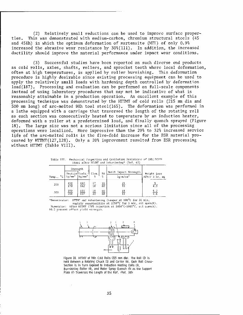
(2) Relatively small reductions can be used to improve surface proper- ties. This was demonstrated with medium-carbon, chromium structural steels (45 and 45Kh) in which the optimum deformation of martensite (MTT) of only 0.9% increased the abrasive wear resistance by 30%(111). In addition, the increased ductility should improve the material performance under impact wear conditions.
(3) Successful studies have been reported on such diverse end products as cold rolls, axles, shafts, rollers, and sprocket teeth where local deformation, often at high temperatures, is applied by roller burnishing. This deformation procedure is highly desirable since existing processing equipment can be used to apply the relatively small loads with hardening depth controlled by deformation load(187). Processing and evaluation can be performed on full-scale components instead of using laboratory procedures that may not be indicative of what is reasonably attainable in a production operation. An excellent example of this processing technique was demonstrated by the HTTMT of cold rolls (215 mm dia and 500 mm long) of arc-melted 9Kh tool steel(165). The deformation was performed in a lathe equipped with a carriage that traversed the length of the rotating roll as each section was consecutively heated to temperature by an induction heater, deformed with a roller at a predetermined load, and finally quench sprayed (Figure 18). The large size was not a serious limitation since all of the processing operations were localized. More impressive than the 20% to 32% increased service life of the arc-melted rolls is the five-fold increase for the ESR material pro- cessed by HTTMT(127,128). Only a 20% improvement resulted from ESR processing without HTTMT (Table VIII).
Table XII. Mechanical Properties and Cavitation Resistance of lKhl2VNMF Steel after HTTMT and Rehardening* (Ref. 63)
Strength
RA Notch Impact Strength
Yield i- Weight Loss After 3 hr, mg Temp. , ° C kg/mm2 kg/mm2 kg-m/cm2
169 160 17 55 21 5 170 162 18 60 16 4.3
1S9 155 18 60 18 5.2 164 157 20 68 14 4.6
*Denorainator: HTTMT and rehardening (temper at 680 C for 50 min, rapidly reaustenitize at 1050°C for 5 min, oil quench).
Numerator: After HTTMT (70% reduction at 1050°C-1000°C, oil quench). tO.2 percent offset yield strength.
3 4 5
Figure 18. HTTMT of 9Kh Cold Rolls (215 mm dia). The Roll (2) is held Between a Rotating Chuck (1) and Center (6). Each Roll Cross- Section is in Turn Exposed to Induction Heating Coils (3), Burnishing Roller (4), and Water Spray Quench (5) as the Support Plate (7) Traverses the Length of the Roll. (Ref. 165)
35
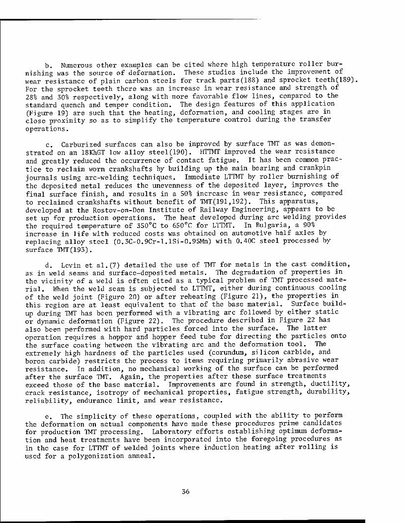
b. Numerous other examples can be cited where high temperature roller bur- nishing was the source of deformation. These studies include the improvement of wear resistance of plain carbon steels for track parts(188) and sprocket teeth(189) For the sprocket teeth there was an increase in wear resistance and strength of 28% and 30% respectively, along with more favorable flow lines, compared to the standard quench and temper condition. The design features of this application (Figure 19) are such that the heating, deformation, and cooling stages are in close proximity so as to simplify the temperature control during the transfer operations.
c. Carburized surfaces can also be improved by surface TMT as was demon- strated on an 18KhGT low alloy steel(190). HTTMT improved the wear resistance and greatly reduced the occurrence of contact fatigue. It has been common prac- tice to reclaim worn crankshafts by building up the main bearing and crankpin journals using arc-welding techniques. Immediate LTTMT by roller burnishing of the deposited metal reduces the unevenness of the deposited layer, improves the final surface finish, and results in a 50% increase in wear resistance, compared to reclaimed crankshafts without benefit of TMT(191,192). This apparatus, developed at the Rostov-on-Don Institute of Railway Engineering, appears to be set up for production operations. The heat developed during arc welding provides the required temperature of 350°C to 650°C for LTTMT. In Bulgaria, a 90% increase in life with reduced costs was obtained on automotive half axles by replacing alloy steel (0.3C-0.9Cr-l.lSi-0.95Mn) with 0.40C steel processed by surface TMT(193).
d. Levin et al.(7) detailed the use of TMT for metals in the cast condition, as in weld seams and surface-deposited metals. The degradation of properties in the vicinity of a weld is often cited as a typical problem of TMT processed mate- rial. When'the weld seam is subjected to LTTMT, either during continuous cooling of the weld joint (Figure 20) or after reheating (Figure 21), the properties in this region are at least equivalent to that of the base material. Surface build- up during TMT has been performed with a vibrating arc followed by either static or dynamic deformation (Figure 22). The procedure described in Figure 22 has also been performed with hard particles forced into the surface. The latter operation requires a hopper and hopper feed tube for directing the particles onto the surface coating between the vibrating arc and the deformation tool. The extremely high hardness of the particles used (corundum, silicon carbide, and boron carbide) restricts the process to items requiring primarily abrasive wear resistance. In addition, no mechanical working of the surface can be performed after the surface TMT. Again, the properties after these surface treatments exceed those of the base material. Improvements are found in strength, ductility, crack resistance, isotropy of mechanical properties, fatigue strength, durability, reliability, endurance limit, and wear resistance.
e. The simplicity of these operations, coupled with the ability to perform the deformation on actual components have made these procedures prime candidates for production TMT processing. Laboratory efforts establishing optimum deforma- tion and heat treatments have been incorporated into the foregoing procedures as in the case for LTTMT of welded joints where induction heating after rolling is used for a polygonization anneal.
36
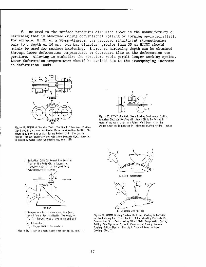
f. Related to the surface hardening discussed above is the nonuniformity of hardening that is observed during conventional rolling or forging operations(125). For example, HTTMT of a 50-mm-diameter bar produced significant strengthening only to a depth of 10 mm. For bar diameters greater than 35 mm HTTMT should mainly be used for surface hardening. Increased hardening depth can be obtained through lower deformation temperatures or decreased time at the deformation tem- perature. Alloying to stabilize the structure would permit longer working cycles. Lower deformation temperatures should be avoided due to the accompanying increase in deformation loads.
Figure 19. HTTMT of Sprocket Teeth. The Blank Enters from Position (la) Through the Induction Heater (2) to the Operating Position (lb) where it is Deformed by Burnishing Rollers (3,4). The Load is Applied Through Stationary and Adjustable Supports (5,6). Sprocket is Cooled by Water Spray Quenching (7). (Ref. 189)
Figure 20. LTTMT of a Weld Seam During Continuous Cooling. Tungsten Electrode Welding with Argon (1) is Performed in Front of the Rollers (2). The Raised Weld Seam (4) of the Welded Sheet (3) is Reduced in Thickness During Rolling. (Ref.7)
a. Induction Coils (1) Reheat the Seam in Front of the Rolls (2). If Necessary, Induction Coils (3) can be Used for a Polygonization Treatment.
-2 a. Static Deformation
3
Position
b. Temperature Distribution Along the Seam. Rx-minimum Recrystallization Temperature, Tj, T, - Temperatures at beginning and end
of Deformation, T - Polygonization Temperature
Figure 21. LTTMT of a Weld Seam After Reheating. (Ref.
b. Dynamic Deformation
Figure 22. HTTMT During Surface Build-up. Coating is Deposited on the Rotating Part (1) at the Arc of the Vibrating Electrode (2). Deformation (3) is Performed by Either Static Compression During Rolling (Top Figure) or Dynamic Compression During Hammer Forging (Bottom Figure). The Liquid Tube (4) Ensures Rapid Cooling. (Ref. 7)
37
Section V.
FINAL COMMENTS
1. Conclusions
a. The extensive and unabated study of TMT by Soviet investigators is clearly justified by the improvements in properties that have been documented. Limitations of TMT were readily identified during the early studies but have not deterred interest. Instead, extensive research was directed at overcoming spe- cific problems. This led to the recognition that immediate quenching after deformation is often undesirable. Also, hereditary treatments were developed to permit machining after BIT. Work is continuing on the strengthening mechanisms for the major alloy systems. This information is essential to the proper design of treatments for maximum substructural strengthening and stability. Pronounced variations in properties often encountered are mainly due to inadequate process- ing control.
b. Utilization of TMT is hindered in part by an inherent reluctance of de- signers and engineers to use ultrahigh strength steels of low toughness. This caution contributed to the shift in emphasis from earlier years, when high strength was the major goal, to the present concern for modest strength increases with adequate ductility and toughness. The result is greater use of HTTMT at the ex- pense of LTTMT.
c. The bulk of applications considered by the Soviets has not changed mark- edly in the last decade. The applications, with only few exceptions, have much in common in that the component or deforming volume is small and simple in shape. Little if any secondary fabrication is required. Processing and subsequent eval- uation can be performed under essentially pilot-plant conditions that are often simply an extension of the earlier laboratory effort. The benefits and savings from these applications should not be underestimated since they represent mass production items.
d. A major commitment to the use of TMT would entail investing heavily in facilities and equipment to process major components whose performance would be crucial to avoid costly or disastrous failure. TMT rails would fall in this cate- gory. After studying TMT of rail steels for over 10 years, only recently have short lengths (80 mm to 120 mm) of actual cross-sections been processed by TMT. Obviously there has been extreme caution associated with this critical application. It should be noted that TMT processing of rails is essentially a surface-hardening process applied to the rail head, the region of maximum wear and most probable failure. TMT of large sections of forgings still represents a relatively unex- plored area of TMT processing.
e. There is still sufficient cause, however, for some optimism in the future of thermomechanical treatments. Successful TMT efforts have shown potential for some serious applications. The Czechoslovak!ans are processing large plates of medium carbon steel. TRIP steel, with its high strength and ductility, has poten- tial for energy absorption applications. The various surface-hardening treatments
38
appear to be successful in terms of cost effectiveness. New applications of surface hardening by roller burnishing continue to be reported in the Soviet literature.
f. With every review of TMT there is some speculation on the future of this strengthening technique. In the earlier reviews one could justify additional re- search and development in light of the difficulty of processing. Clearly, better understanding of the hardening mechanisms was needed before concrete recommenda- tions could be made to circumvent the limitations to processing. Understanding of TMT has advanced considerably in the last decade, and this information is often crucial to successful TMT. The need for a stable substructure and how to obtain this is well established. The influence of deformation on hardenability has been documented for various alloys. Hereditary treatments can be performed after HTTMT or LTTMT. Current trends have favored the combining of TMT with other recent advances in materials processing as, for example, electroslag remelt- ing and texture control.
2. Forecast
a. The achievements in TMT should accelerate future progress where the actual end item or application is part of the study. Laboratory studies are necessary to determine thermomechanical processing parameters, but refinements to these processing parameters are logically made under production conditions. The Soviet experience in all aspects of TMT processing control is formidable in terms of providing background for a technology transfer from laboratory studies to specific end item exploitation. Interest in TMT is included in the Soviet five- year plans(194,195), and recommendations have been made to modify state standards governing fabricating and testing of tension specimens processed by TMT to high- strength low-ductility(196).
b. The experience of Soviet designers and production personnel is only reported in broad terms. Laboratory studies reported in conjunction with pilot plant or actual production operations as well as service evaluations do reveal the extensive Soviet interests and accomplishments in TMT. These efforts will enable the Soviets to rapidly expand their applications to the less publicized areas of defense, aviation, or space exploration. The acceptance of small im- provements, even at large costs, makes these areas prime candidates for the use of thermomechanical treatments.
39
BIBLIOGRAPHY
1. Rassmann, G. and P. Müller. Neue Hütte, Vol 17, No. 1, January 1972, pp 2-7 (Translation FSTC-HT-23-0002-74).
2. Delaey, L. Zeitschrift fuer Metallkunde, Vol 63, No. 9, September 1972, pp 531-541 (Translation FSTC-HT-23-229-74).
3. Rabinovich, M. Kh« and V, I. Yelagin. Soviet monograph - Metallurgy of Alloys of Lightweight Metals, Izdatel'stvo-Nauka, Moscow, 1970 (Translation FSTC-CW-01-03-73, pp 29-38).
4. Rabinovich, M. Kh. Thermomechanical Treatment of Aluminum Alloys, Moscow: Mashinostroyeniye, 1972, pp 1-161 (Translation FTD-MT- 24-834-73).
5. Prokoshkin, D. A. and I. I. Sidorin. Problems of Developing Machine- Building Technology, Izd-vo Mashinostroyeniye, Moscow, 1968, Chapter II, pp 33-66 (Translation FTD-MT-24-24-70, pp 1-57).
6. Shorshorov, M. Kh., L. K. Gordiyenko, and V. I. Antipov. The Thermoplastic Strengthening of Martensite Steels and Titanium Alloys, Izd vo Nauka, Moscow, 1971, pp 9-80 (Translation FTD-MT- 24-1778-72).
7. Levin, E. L., I. S. Sinyagovskiy, and G. S. Trofimov. Thermo- mechanical Hardening of Parts in the Surfacing Process, Moscow Kolos, 1974, pp 22-42 (Translation FSTC-HT-23-572-75).
8. Bernshteyn, M. L. Thermomechanical Treatment of Metals and Alloys, Vol I and II, Metallurgiya Publishing Office, Moscow, 1968 (Trans- lation FSTC-HT-23-788-70, Vol I, Chapters 3, 4, and 5).
9. Dunleavy, J. G. and J. W. Spretnak. Battelle Memorial Institute, Defense Metals Information Center, DMIC Memorandum No. 244, November 1969.
10. Koppenaal, T. J. American Society for Metals, Transactions Quar- terly, Vol 62, No. 1, March 1969, pp 24-37.
11. Henning, H. J. Battelle Memorial Institute, Defense Metals Infor- mation Center, DMIC Memorandum No. 251, November 1970.
12. Kula, E. B., in Strengthening Mechanisms - Metals and Ceramics, ed., J. J. Burke, N. L. Reed, and V. Weiss, Syracuse: Syracuse University Press, 1966, pp 83-121.
13. Kula, E. B. and M. Azrin, in Advances in Deformation Processing, ed., J. J. Burke and V. Weiss, Syracuse: Syracuse University Press (in press).
41
14. Kear, B. H., J. M. Oblak, and W. A. Owczarski. Journal of Metals, Vol 24, No. 6, June 1972, pp 25-32.
15. Latham, D. J. British Iron and Steel Research Association Report No. BISRA MG/A/39/69, 1969.
16. May, M. J. and D. J. Latham. Metal Treating, Vol 23, No. 5, October-November 1972, pp 3-13.
17. May, M. J. and D. J. Latham. Metal Treating, Vol 23, No. 6, December-January 1972-1973, pp 3-9.
18. Lips, E. M. H. and H. Van Zuilen. Metal Progress, Vol 66, No."2, August 1954, pp 103-104.
19. Savilov, E. S., A. P. Gulyaev, and A. G. Nikonov. Metal Science and Heat Treatment, No. 1, January 1968, pp 33-40.
20. Radcliffe, S. V. and E. B. Kula, in Fundamentals of Deformation Processing, ed., W. A. Backofen, el al., Syracuse: Syracuse University Press, 1964, pp 321-363.
21. Sklyarov, N. M. Mashinostroyeniye Avtomaticheskoye Upravleniye Mashinami i Sisteinami Mashin. Radiotekhnika, Elektronika i Elek- trosvyaz, Moscow Nauka, 1970, pp 191-204 [Translation PSTU-HT- 23-0455-75).
22„ Wahll, M. J. and R. F. Frontani. Handbook of Soviet Alloy Compo- sitions, Battelle Memorial Institute, Metals and Ceramics Infor- mation Center, Handbook No. MCIC-HB-05, February 1975.
23. Gulyaev, A. P. Metal Science and Heat Treatment, No. 11, November 1965, pp 709-717.
24. Pridantsev, M. V. and E. I. Ivantsova. Metal Science and Heat Treatment, No. 9, September 1970, pp 790-792.
25. Tushinskii, L. I. and L. B. Tikhomirova. Metal Science and Heat Treatment, Vol 14, No. 2, February 1972, pp 134-140.
26. Bashchenko, A. P. and N. D. Mel'nichenko. Metal Science and Heat Treatment, Vol 14, No. 2, February 1972, pp 131-133.
27. Bashchenko, A. P. and N. D. Mel'nichenko. Metal Science and Heat Treatment, No. 12, December 1969, pp 948-951.
28. Bernshtein, M. L., L. M. Kaputkina, and V. P. Kanev. Metal Science and Heat Treatment, No. 12, December 1969, pp 958-963.
29. Virakhovskii, Yu. G., Ya. B. Gurevich, and A. V. Krupin. Steel in the USSR, Vol 1, No. 8, August 1971, p 664.
42
30. Zhaden, V. T., M. L. Bernshtein, and V. T. Gubenke. Steel in the USSR, Vol 5, No. 1, January 1975, pp 46-48.
31. Zhaden, V. T., M. L. Bernshtein, and V. T. Gubenko. Steel in the USSR, Vol 5, No. 1, January 1975, pp 49-50.
32. Bernshtein, M. L. Steel in the USSR, Vol 2, No. 2, February 1972, pp 151-157.
33. Bernshteyn, M. L., et al. The Physics of Metals and Metallography, Vol 36, No. 2, 1973, pp 151-155.
34. Shorshorov, M. Kh. Metal Science Journal, Vol 7, No. 11, November 1973, pp 213-216.
35. Shorshorov, M. Kh. "The Microstructure and Design of Alloys," Proceedings of the Third International Conference on the Strength of Metals and Alloys, Cambridge, England, August 1973, Vol 2, pp 43-56.
36. Shorshorov, M. Kh. and L. K. Gordiyenko. Fizika i Khimiya Obrabotki Meterialov, No. 2, March-April, 1974, pp 13-20 (Translation AST-1840- 1-067-75).
37. Ivanova, V. S. and M. G. Veitsman. Metal Science and Heat Treatment, No. 8, August 1968, pp 625-626.
38. Lanskaya, K. A. and N. I. Kamenskaya. Metal Science and Heat Treat- ment, Vol 15, No. 6, June 1973, pp 451-453.
39. Tushinskii, L. I., L. B. Tikhomirova, and V. M. Muratov. Metal Science and Heat Treatment, No. 9, September 1970, pp 793-794.
40. Bernshtein, M. L. and N. A. Radzivilova. Metal Science and Heat Treatment, Vol 16, No. 7, July 1974, pp 562-568.
41. Bernshtein, M. L., A. V. Sakharova, and N. A. Radzivilova. Metal Science and Heat Treatment, Vol 16, No. 2, February 1974, pp 130-133.
42. Maksimova, 0. P., et al. The Physics of Metals and Metallography, Vol 34, No. 5, 1972, pp 165-176.
43. Rauzin, Ya. R., E. A. Shur, and P. N. Zonov. Metal Science and Heat Treatment, Vol 15, No. 9, September 1973, pp 729-731.
44. Astaf'eva, E. V., N. S. Maslova, and E. D. Tsypkina. Steel in the USSR, Vol 3, No. 10, October 1973, pp 875-876.
45. Bernshtein, M. L., V. T. Zhaden, and K. E. Khensger. Steel in the USSR, Vol 2, No. 11, November 1972, pp 916-918.
43
46. Bashchenko, A. P., et al. Metal Science and Heat Treatment, Vol 15, No. 8, August 1973, pp 658-662.
47. Tikhomirova, L. B., L. I. Tushinskii, and P. V. Redshed'ko. Steel in the USSR, Vol 5, No. 2, February 1975, pp 111-112.
48. Tushinskii, L. I., L. B. Tikhomirova, and P. V. Reshed'ko. Metal Science and Heat Treatment, Vol 16, No. 7, July 1974, pp 558-561.
49. Kozlova, A. G. and L. M. Utevskiy. The Physics of Metals and Metallography, Vol 37, No. 1, 1974, pp 213-215.
50. Vinnikov, L. Ya., M. N. Pankova, and L. M. Utevskiy. Problemy Metallovedenie i Fizika Metallov, Vol 1, Moscow, Izd. Metal- lurgiya, 1972, p 157.
51. Bernshtein, M. L., et al. Steel in the USSR, Vol 4, No. 3, March 1974, pp 251-253.
52. Khlestov, V. M., et al. Soviet Physics - Doklady, Vol 17, No. 12, June 1973, pp 1207-1209.
53. Smirnov, M. A., et al. Metal Science and Heat Treatment, Vol 15, No. 9, September 1973, pp 759-762.
54. Sokolov, K. N., et al. Metal Science and Heat Treatment, Vol 15, No. 1, January 1973, pp 12-17.
55. Shteinberg, M. M., et al. Steel in the USSR, Vol 3, No. 10, October 1973, pp 872-873.
56. Prokoshin, D. A., et al. Metal Science and Heat Treatment, No. 9, September 1970, pp 740-744.
57. Shur, E. A. and P. N. Zonov. Metal Science and Heat Treatment, Vol 16, No. 7, July 1974, pp 569-572.
58. Bernshtein, M. L. and K. G. Smolyakov. Steel in the USSR, Vol 1, No. 7, July 1971, pp 564-565.
59. Shavrin, 0. I., Yu. A. Mokrushin, and A. N. Il'ina. Metal Science and Heat Treatment, No. 3, March 1970, pp 246-247.
60. Bernshtein, M. L., et al. Steel in the USSR, Vol 3, No. 11, November 1973, pp 954-956.
61. Bernshtein, M. L., et al. Metal Science and Heat Treatment, No. 7, July 1968, pp 552-554.
62. Ermakov, V. V. Metal Science and Heat Treatment, Vol 14, No. 9, September 1972, pp 827-828.
44

63. Gavranek, V. V. and Z. K. Filippova. Metal Science and Heat Treat- ment, Vol 14, No. 2, February 1972, pp 128-130.
64. Zhaden, V. T., et al. Steel in the USSR, Vol 2, No. 3, March 1972, pp 219-220.
65. Bernshtein, M. L., V. A. Zaimovskii, and A. P. Matevos'yan. Metal Science and Heat Treatment, No. 9, September 1970, pp 745-747.
66. Prokoshkin, D. A., A. G. Vasil'eva, and B. A. Prusakov. Metal Science and Heat Treatment, No. 4, April 1968, pp 311-313.
67. Sadovskii, V. D., A. B. Bukhalov, and L. V. Smirnov. Metal Science and Heat Treatment, No. 12, December 1969, pp 937-944.
68. Prokshkin, D. A., A. G. Vasil'eva, and V. V. Akimov. Metal Science and Heat Treatment, No. 11, November 1965, pp 741-743.
69. Cherkasov, A. A., L. N. Kuz'minskaya, and M. L. Bernshtein. Metal Science and Heat Treatment, No. 9, September 1970, pp 748-751.
70. Larson, F. R. and A. Zarkades. Battelle Memorial Institute, Metals and Ceramics Information Center, Report No. MCIC-74-20, June 1974.
71. Bernshtein, M. L., et al. Steel in the USSR, Vol 2, No. 5, May 1972, pp 404-405.
72. Spektor, Ya. I., et al. Steel in the USSR, Vol 2, No. 11, November 1972, pp 911-913.
73. Spektor, Ya. I., E. N. Spektor, and M. N. Pankova. Steel in the USSR, Vol 3, No. 1, January 1973, pp 73-75.
74. Lerinman, R. M., et al. The Physics of Metals and Metallography, Vol 31, No. 3, 1971, pp 186-192.
75. Lerinman, R. M., et al. The Physics of Metals and Metallography, Vol 37, No. 3, 1974, pp 171-173.
76. Grenogina, T. L., et al. The Physics of Metals and Metallography, Vol 36, No. 6, 1973, pp 110-119.
77. Gulyaev, A. P. and A. M. Kim-Khenkina. Metal Science and Heat Treatment, No. 12, December 1969, pp 952-957.
78. Gulyaev, A. P. and A. M. Kim-Khenkina. Metal Science and Heat Treatment, No. 4, April 1969, pp 283-286.
79. Krishtal, M. A., I. P. Renne, and A. A. Kisurin. Metal Science and Heat Treatment, Vol 17, No. 1, January 1975, pp 34-36.
45
80. Starodubov, K. F. and A. N. Kasilov. Metal Science and Heat Treatment, Vol 16, No. 1, January 1974, pp 60-62.
81. Solomadina, E. A., et al. Steel in the USSR, Vol 2, No. 11, November 1972, pp 909-911.
82. Bernshteyn, M. L., et al. The Physics of Metals and Metallography, Vol 38, No. 2, 1974, pp 148-156.
83. Starodubov, K. F., A. N. Kasilov, and V. Ya. Maksimenko. Steel in the USSR, Vol 2, No. 10, October 1972, pp 840-842.
84. Grishkov, A. I. and F. L. Levin. Stal, No. 5, May 1971, p 457 (British Lending Library Translation M21107).
85. Lokshin, I. Kh. and M. L. Khenkin. Metal Science and Heat Treat- ment, No. 4, April 1969, pp 287-288.
86. Bernshtein, M. L., P. D. Odesskii, and G. B. Korneeva. Steel in the USSR, Vol 4, No. 1, January 1974, pp 78-80.
87. Verner, V. D., et al. Metal Science and Heat Treatment, Vol 14, No. 11, November 1972, pp 1006-1008.
88. Duckworth, W. E. Journal of Metals, Vol 18, No. 8, August 1966, pp 915-922.
89. Plavich, L. A., N. P. Zhuk, and M. L. Bernshtein. Soviet Materials Science, Vol 6, No. 3, May-June 1970, pp 303-307.
90. Shcherbakova, V. S., et al. Steel in the USSR, Vol 1, No. 6, June 1971, pp 471-475.
91. Sandier, N. I. and Sh. R. Dobruskina. Steel in the USSR, Vol 1, No. 1, January 1971, pp 70-73.
92. Gol'dshtein, M. I., et al. Steel in the USSR, Vol 4, No. 1, January 1974, pp 68-71.
93. Bernshtein, M. L., P. D. Odesskii, and G. B. Korneeva. Steel in the USSR, Vol 2, No. 11, November 1972, pp 914-916.
94. Sekine, H. and T. Maruyama. "The Microstructure and Design of Alloys," Proceedings of the Third International Conference on the Strength of Metals and Alloys, Cambridge, England, August 1973, Vol 1, Paper No. 18, pp 85-88.
95. Coleman, T., D. Dulieu, and A. Gouch. "The Microstructure and Design of Alloys," Proceedings of the Third International Conference on the Strength of Metals and Alloys, Cambridge, England, August 1973, Vol 1, Paper No. 15, pp 70-74.
46
96. Lauprecht, W. E., H. Imgrund, and B. Coldren. Stahl und Eisen, Vol 93, No. 22, October 1973, pp 1041-1053 (Translation BISITS No. 12398).
97. Melloy, G. F. and J. D. Dennison. "The Microstructure and Design of Alloys," Proceedings of the Third International Conference on the Strength of Metals and Alloys, Cambridge, England, August 1973, Vol 1, Paper No. 13, pp 60-64.
98. Hyspecka, L. and K. Mazanec. "The Microstructure and Design of Alloys," Proceedings of the Third International Conference on the Strength of Metals and Alloys, Cambridge, England, August 1973, Vol 1, Paper No. 77, pp 375-379.
99. Hyspecka, L. and K. Mazanec. Scientific Notes from Metallurgical Journal, Vol 68, No. 5, May 1971, pp 305-312 (Translation FTD-HC- 23-1001-72).
100. Hyspecka, L., et al. Hutnicke Listy, Vol 23, No. 4, April 1968, pp 261-265 (Translation FSTC-HT-23-0397-74).
101. Glatz, B. Hutnicke Listy, Vol 24, No. 6, June 1969, pp 413-420 (Translation FSTC-HT-23-0445-74).
102. Hyspecka, L. and K. Mazanec. "Physical Metallurgy of Thermome- chanical Treatment of Steels," Rozpravy Ceskoslovenske Akademie Ved, Rada Technickych Ved, Vol 78, No. 4, 1968.
103. Starodubov, K. F., et al. Steel in the USSR, Vol 2, No. 5, May 1972, pp 376-377.
104. Kopaleishvili, V. P. Metal Science and Heat Treatment, No. 8, August 1968, p 651.
105. Zhaden, V. T., et al. Steel in the USSR, Vol 5, No. 5, May 1975, pp 288-290.
106. Gulyaev, A. P. Metal Science and Heat Treatment, Vol 15, No. 10, October 1973, pp 912-915.
107. Blanter, M. E., M. I. Shklyarov, and M. S. Blanter. Metal Science and Heat Treatment, No. 9, September 1968, pp 715-716.
108. Bernshtein, M. L. and I. I. Mints. Metal Science and Heat Treatment, No. 12, December 1969, pp 945-947.
109. Bernshtein, M. L., T. N. Lipchin, and L. G. Chernukha. Steel in the USSR, Vol 1, No. 1, January 1971, pp 73-74.
110. Martsenko, K. N., et al. Metal Science and Heat Treatment, Vol 16, No. 4, April 1974, pp 328-331.
47
111. Bernshtein, M. L., V. G. Medvedev, and N. M. Serpik. Metal Science and Heat Treatment, Vol 15, No. 9, September 1973, pp 818-819.
112. Ogil'ko, A. K. Metal Science and Heat Treatment, No. 12, December 1970, pp 1016-1018.
113. Nagapetyan, V. L. and K. I. Shakhova. Metal Science and Heat Treatment, No. 3, March 1968, pp 237-239.
114. Mel'kumov, I. N., et al. Metal Science and Heat Treatment, Vol 13, No. 11, November 1971, pp 910-912.
115. Sokolov, V. P. Metal Science and Heat Treatment, Vol 15, No. 11, November 1973, pp 993-994.
116. Zoteev, V. S., et al. Metal Science and Heat Treatment, No. 2 February 1968, pp 157-159.
117. Shteinberg, M. M., et al. Metal Science and Heat Treatment, No. 3, March 1969, pp 217-219.
118. Shakhnazarov, Yu. V. Metal Science and Heat Treatment, No. 3, March 1968, pp 224-226.
119. Bernshteyn, M. L., et al. The Physics of Metals and Metallography, Vol 34, No. 3, 1972, pp 82-88.
120. Bernshtein, M. L. and K. G. Smolyakov. Steel in the USSR, Vol 2, No. 1, January 1972, pp 71-74.
121. Sorokivskii, I. S., et al. Soviet Materials Science, Vol 6, No. 6, November-December 1970, pp 663-666.
122. Shul'ga, B. N., et al. Soviet Materials Science, Vol 7, No. 2, March-April 1971, pp 248-250.
123. Tamarina, I. A., B. M. Ovsyannikov, and I. N. Golikov. Metal Science and Heat Treatment, Vol 16, No. 1, January 1974, pp 16-18.
124. Zheleznov, A. F., N. D. Zaporozhtseva, and E. M. Pribavkin. Steel in the USSR, Vol 5, No. 2, February 1975, pp 94-95.
125. Sheftel, N. I. Improvement of Quality and Variety of Rolled Metals, Metallurgiya, Moscow, 1973, pp 282-285 (FSTC internal translation by James McVay).
126. Shavrin, 0. I., et al. Metal Science and Heat Treatment, Vol 16, No. 2, February 1974, pp 139-141.
127. Belkin, M. Ya., V. A. Sologub, and E. A. Venzhega. Metal Science and Heat Treatment, No. 12, December 1969, pp 964-967.
48
128. Belkin, M. Ya., et al. Stal, No. 3, March 1971, pp 260-262 (Translation BISITS No. 9440).
129. Zackay, V. F., et al. American Society for Metals, Transactions Quarterly, Vol 60, No. 2, June 1967, pp 33-41.
130. Zackay, V. F. and E. R. Parker, in High-Strength Materials, ed., V. F. Zackay, New York: John Wiley, 1965, pp 130-154.
131. Phillips, R. and W. E. Duckworth, in High-Strength Materials, ed., V. F. Zackay, New York: John Wiley, 1965, pp 307-326.
132. Bogachev, I. N., T. D. Eysmondt, and A. V. Fugman. The Physics of Metals and Metallography, Vol 34, No. 5, 1972, pp 126-133.
133. Bogachev, I. N. and E. V. Savalei. Metal Science and Heat Treatment, Vol 16, No. 12, December 1974, pp 1043-1045.
134. Azrin, M., G. B. Olson, and R. A. Gagne, in Proceedings of the Fourth North American Metal Working Conference, ed., T. Altan, Dearborn: Society of Manufacturing Engineers, 1976, pp 25-28.
135. Virakhovskiy, Yu. G., et al. The Physics of Metals and Metal- lography, Vol 32, No. 2, 1971, pp 121-134.
136. Azrin, M., G. B. Olson, and R. A. Gagne. Materials Science and Engineering, Vol 23, No. 1, April 1976, pp 33-41.
137. Zackay, V. F., M. D. Bhandarkar, and E. R. Parker, in Advances in Deformation Processing, ed., J. J. Burke and V. Weiss, Syracuse: Syracuse University Press (in press).
138. Pavlov, I. M., A. Ye. Shiest, and Yu. F. Tarasevich. Plastic Deformation of High-Melting Metals and Special Alloys, Moscow: Nauka Publishing House, 1970, pp 91-111 (Translation FTD-HC-23- 1997-71).
139. Pavlov, I. M., A. E. Shelest, and Yu. F. Tarasevich. Titanium Alloys for Modern Technology, 1968 (Translation NASA F-596, pp 55-67).
140. Pavlov, I. M., A. Ye. Shelest, and Yu. F. Tarasevich. Plastic Deformation of Refractory Metals and Special Alloys, Izd-vo Nauka, Moscow, 1970, pp 111-125 (Translation FTD-MT-24-1608-71).
141. Lerinman, R. M. and G. V. Murzayeva. The Physics of Metals and Metallography, Vol 25, No. 5, 1968, pp 166-174.
142. Lerinman, R. M. and G. V. Murzayeva. The Physics of Metals and Metallography, Vol 27, No. 3, 1969, pp 137-142.
49
143. Avery, D. H. and N. W. Polan. Metallurgical Transactions, Vol 5, No. 5, May 1974, pp 1159-1162.
144. Ber, L. B., et al. The Physics of Metals and Metallography, Vol 36, No. 3, 1973, pp 120-126.
145. Shteinberg, M. M., et al. Metal Science and Heat Treatment, Vol 15, No. 8, August 1973, pp 665-667.
146. Romanova, R. R., N. N. Buynov, and V. G. Pushin. The Physics of Metals and Metallography, Vol 31, No. 5, 1971, pp 156-162.
147. Paton, N. E. and A. W. Sommer. "The Microstructure and Design of Alloys," Proceedings of the Third International Conference on the Strength of Metals and Alloys, Cambridge, England, August 1973, Vol 1, Paper No. 21, pp 101-108.
148. Thompson, D. S. and S. A. Levy. "The Microstructure and Design of Alloys," Proceedings of the Third International Conference on the Strength of Metals and Alloys, Cambridge, England, August 1973, Vol 1, Paper No. 24, pp 119-123.
149. Pavlov, V. A. and S. A. Frizen. The Physics of Metals and Metallography, Vol 28, No. 4, 1969, pp 170-174.
150. Kutaytseva, Ye. I., Z. G. Filippova, and S. A. Borovov. Metal- lovedeniya Splavov Legkikh Metallov, Izd-vo Nauka, Moscow, 1970, pp 29-33 (Translation FTD-75-C-002371).
151. Smirnov, M. A., et al. Metal Science and Heat Treatment, Vol 17, No. 1, January 1975, pp 52-55.
152. Romanova, R. R., et al. The Physics of Metals and Metallography, Vol 38, No. 2, 1974, pp 112-117.
153. Tvorogov, I. M. Metal Science and Heat Treatment, No. 8, August 1969, pp 640-642.
154. Ryabinina, R. M. and L. N. Leshchiner. Metal Science and Heat Treatment, No. 5, May 1970, pp 428-430.
155. DiRusso, E., et al. Metallurgical Transactions, Vol 4, No. 4, April 1973, pp 1133-1144.
156. Oblak, J. M. and W. A. Owczarski. Metallurgical Transactions, Vol 3, No. 3, March 1972, pp 617-626.
157. Mayers, M. A. and R. N. Orava. Metallurgical Transactions, Vol 7A, No. 2, February 1976, pp 179-190.
50

158. Surkov, Yu. P., F. N. Berseneva, and M. G. Gaydukov. The Physics of Metals and Metallography, Vol 37, No. 2, 1974, pp 144-150.
159. Bokshtein, S. Z., et al. Metal Science and Heat Treatment, No. 1, January 1969, pp 3-4.
160. Kharlanova, V. M., S. S. Gorelik, and G. S. Knizhnik. Metal Science and Heat Treatment, Vol 16, No. 1, January 1974, pp 85-87.
161. Tikhomirova, L. V. and A. P. Artem'ev. Steel in the USSR, Vol 3, No. 10, October 1973, pp 874-875.
162. Bayazitov, M. I. and A. A. Aliev. Metal Science and Heat Treatment, Vol 14, No. 3, March 1972, pp 257-258.
163. Lokshin, L. F., I. K. Kupalova, and V. B. Lenyashin. Metal Science and Heat Treatment, Vol 15, No. 9, September 1973, pp 763-766.
164. Tushinskii, L. I., L. V. Tikhomirova, and P. V. Reshed'ko. Steel in the USSR, Vol 2, No. 10, October 1972, pp 827-829.
165. Pimenov, V. M. Metal Science and Heat Treatment, Vol 15, No. 8, August 1973, pp 663-664.
166. Shavrin, 0. I. Metal Science and Heat Treatment, No. 12, December 1967, pp 930-931.
167. Nikolaeva, V. V. and A. S. Kovalenko. Metal Science and Heat Treatment, No. 3, March 1970, p 229.
168. Shavrin, 0. I. and L. M. Red'kin. Metal Science and Heat Treatment, Vol 16, No. 7, July 1974, pp 573-575.
169. Kotkis, M. A. and A. V. Skoblo. Metal Science and Heat Treatment, No. 2, February 1968, pp 133-136.
170. Clark, R. and J. J. Harwood. Metal Progress, Vol 89, No. 3, March 1966, pp 81-86.
171. Bock, R. A. and W. M. Justusson. Society of Automotive Engineers, Paper No. 680412, May 1968.
172. Bock, R. A. and W. M. Justusson. Metal Progress, Vol 94, No. 6, December 1968, pp 107-112.
173. Bamberger, E. N. American Society of Mechanical Engineers Trans- actions, Journal of Lubrication and Technology, Serial F, Vol 89, No. 1, January 1967, pp 63-75.
174. Bamberger, E. N. Air Force Materials Laboratory Contract Report No. AFML-TR-72-43, April 1972 (AD 894 156L).
51
175. Bernshtein, M. L., L. Demina, and K. E. Sofonova. Metal Science and Heat Treatment, No. 1, January 1962, pp 13-18.
176. Konter, L. Ya., et al. Transactions of the All-Union Scientific Research Institute of the Bearing Industry, Vol 40, No. 4, 1964, pp 12-24.
177. Romaniv, 0. N., et al. Soviet Materials Science, Vol 5, No. 4, July-August 1969, pp 323-327.
178. Schmatz, D. J. and V. F. Zackay. American Society for Metals, Transactions Quarterly, Vol 51, 1959, pp 476-494.
179. Grigorkin, V. I., et al. News of Higher Institutes of Learning, Ferrous Metallurgy, No. 4, April 1967, pp 110-115 (Translation JPRS 46592, October 3, 1968, pp 1-9).
180. Tushinskiy, L. I., et al. News of Higher Institutes of Learning, Ferrous Metallurgy, No. 12, December 1965, pp 114-115 (Translation JPRS 46592, October 3, 1968, pp 41-44).
181. Tushinskiy, L. I., et al. News of Higher Institutes of Learning, Ferrous Metallurgy, No. 6, June 1966, pp 137-140 (Translation JPRS 46592, October 3, 1968, pp 35-40).
182. Khait, D. M. and A. N. Savenko. Metal Science and Heat Treatment, No. 4, April 1968, pp 322-323.
183. Kobyzev, V. K., et al. Stal, Vol 1, No. 4, April 1971, pp 337-340 (Translation BISI 9547).
184. Nekrasov, S. G., N. A. Chelyshev, and V. I. Vorozhishchev. Steel in the USSR, Vol 2, No. 4, April 1972, pp 307-309.
185. Nekrasov, S. G., et al. Steel in the USSR, Vol 4, No. 10, October 1974, pp 829-831.
186. Gavranek, V. V. and Z. K. Filippova. Soviet Materials Science, Vol 7, No. 5, September-October 1971, pp 606-607.
187. Tsypkina, E. D., et al. Metal Science and Heat Treatment, Vol 16, No. 9, September 1974, pp 787-789.
188. Fridman, V. B., G. S. Slovokhochev, and M. L. Bernshtein. Metal Science and Heat Treatment, No. 11, November 1968, pp 924-926.
189. Shebanov, V. A. and V. F. Vasilenko. Metal Science and Heat Treatment, Vol 13, No. 11, November 1971, pp 966-967.
190. Yuzhakov, I. V. and V. P. Yudin. Metal Science and Heat Treatment, Vol 14, No. 2, February 1972, pp 183-184.
52
191. Boiko, N. I., et al. Welding Production, Vol 20, No. 4, April 1973, pp 30-34.
192. Boyko, N., et al. Avtomobi1'nyi Transport, No. 11, 1972, pp 34-36 (Translation FSTC-HT-23-285-75).
193. Banov, R. and A. Balashev. Metal Science and Heat Treatment, Vol 15, No. 10, October 1973, pp 896-898.
194. Golikov, I. N. Steel in the USSR, Vol 1, No. 7, July 1971, pp 497-499.
195. Kazanets, I. P. Steel in the USSR, Vol 2, No. 3, March 1972, pp 169-173.
196. Gulyayev, A. P., et al. Zavodskaya Laboratoriya, Vol 37, No. 8, 1971, pp 967-970 (Translation JPRS 55101, February 4, 1972).
53
DISTRIBUTION LIST
No. of Copies To
1 Office of the Director, Defense Research and Engineering, The Pentagon, Washington, D. C. 20301
12 Commander, Defense Documentation Center, Cameron Station, Building 5, 5010 Duke Street, Alexandria, Virginia 22314
Metals and Ceramics Information Center, Battelle Columbus Laboratories, 505 King Avenue, Columbus, Ohio 43201 ATTN: H. D. Horan
H. J. Henning J. G. Dunleavy T. Byer Dr. T. Altan
Chief of Research and Development, Department of the Army, Washington, D. C. 20310
2 ATTN: Physical and Engineering Sciences Division
Commander, Army Research Office, P. 0. Box 12211, Research Triangle Park, North Carolina 27709
1 ATTN: Information Processing Office 1 Dr. G. Mayer
Commander, U. S. Army Materiel Development and Readiness Command, 5001 Eisenhower Avenue, Alexandria, Virginia 22333
1 ATTN: DRCDE-L, Light Armor Coordination Office 1 DRCDE-TC 1 DRCDE-F 1 DRCSA-S, Dr. R. B. Dillaway, Chief Scientist
Commander, U. S. Army Electronics Command, Fort Monmouth, New Jersey 07703
1 ATTN: DRSEL-GG-DD 1 DRSEL-GG-DM 1 DRSEL-RD-I 1 DRSEL-WLM-DF
Commander, U. S. Army Missile Command, Redstone Arsenal, Alabama 35809
1 ATTN: Technical Library 1 DRSMI-RSM, Mr. E. J. Wheelahan 2 DRSMI-YDR
Commander, U. S. Army Armament Command, Rock Island, Illinois 61201
2 ATTN: Technical Library 1 DRSMR-RDI
Commander, U. S. Army Natick Research and Development Command, Natick, Massachusetts 01760
1 ATTN: DRXNM-ZSF
Commander, U. S. Army Satellite Communications Agency, Fort Monmouth, New Jersey 07703
1 ATTN: Technical Document Center
Commander, U. S. Army Tank-Automotive Research and Development Command, Warren, Michigan 48090
1 ATTN: DRDTA-R 2 DRDTA, Research Library Branch 1 DRDTA-NF
Commander, U. S. Army Mobility Equipment Research and Development Command, Fort Belvoir, Virginia 22060
1 ATTN: DRXFB-Y
Commander, U. S. Army Test and Evaluation Command, Aberdeen, Maryland 21005
1 ATTN: DRSTE-TO-F
Director, U. S. Army Ballistic Research Laboratories, Aberdeen Proving Ground, Maryland 21005
2 ATTN: DRXBR-XA-FI
Commander, U. S. Army Yuma Proving Ground, Yuma, Arizonia 85364
1 ATTN: STEYP-SE
No. of Copies To
Director, U. S. Army Air Mobility Research and Development Laboratory, Moffett Field, California 93035 ATTN: SAVDL-AS
Commander, U. S. Army Aviation Systems Command St. Louis, Missouri 63116 ATTN: DRSAV-ED
Commander, White Sands Missile Range, ATTN: STEWS-WS-VT
STEWS-TE-F
New Mexico 88002
1
Commander, Aberdeen Proving Ground, Maryland 21005 ATTN: STEAP-TL, Bldg. 305
Conmanuar, Dugway Proving Ground, Dugway, Utah 84022 ATTN: STEPD-FIO
Commander, Edgewood Arsenal, Aberdeen Proving Ground, Maryland 21010 ATTN: Mr. F. E. Thompson, Dir. of Eng. & Ind. Serv.,
Chem-Mun Br SAREA-FIO
Commander, Frankford Arsenal, Philadelphia, Pennsylvania Pennsylvania 19137
1 ATTN: SARFA-L300, Mr. J. Corrie 1 SARFA-FI 1 J. Waldman, Bldg. 149-2
Commander, Harry Dianond Laboratories, 2800 Powder Mill Road, Adel phi, Maryland 20783
1 ATTN: DRXDO-FIO
Commander, Picatinny Arsenal, Dover, New Jersey 07801 1 ATTN: SARPA-RT-S 1 SARPA-FIO
Commander, Redstone Scientific Information Center, U. S. Army Missile Command, Redstone Arsenal, Alabama 35809
4 ATTN: DRSMI-RBLD, Document Section
Commander, Watervliet Arsenal, Watervliet, New York 12189 1 ATTN: SARWV-RDT, Technical Information Services Office 1 SARWV-RT-FI
Commander, U. S. Army Foreign Science and Technology Center, 220 7th Street, N. E., Charlottesville, Virginia 22901
25 ATTN: DRXST-SD2 10 DRXST-SD
1 DRXST-IS3
Director, Eustis Directorate, U. S. Army Air Mobility Research and Development Laboratory, Fort Eustis, Virginia 23604
1 ATTN: Mr. J. Robinson, SAVDL-EU-SS
Librarian, U. S. Army Aviation School Library, Fort Rucker, Alabama 36360
1 ATTN: Building 5907
Naval Research Laboratory, Washington, D. C. 20375 1 ATTN: Dr. J. M. Krafft - Code 8430 2 Dr. G. R. Yoder - Code 6382 1 Code 2627
Chief of Naval Research, Arlington, Virginia 22217 1 ATTN: Code 471
Air Force Materials Laboratory, Wright-Patterson Air Force Base, Ohio 45433
2 ATTN: AFML/MXE/E. Morrissey 1 AFML/LC 1 AFML/LLP/D. M. Forney, Jr. 1 AFML/MBC/Mr. Stanley Schulman
National Aeronautics and Space Administration, Washington, D. C. 2C546
1 ATTN: Mr. B. G. Achhammer 1 Mr. G. C. Deutsch - Code RR-1 1 Code Wx
No. of Copies To
No. of Copies To
National Aeronautics and Space Administration, Marshall Space Flight Center, Huntsville, Alabama 35812
1 ATTN: R-P&VE-M, R. J. Schwinghamer 1 SJE-ME-MM, Mr. W. A. Wilson, Building 4720
1 Ship Research Committee, Maritime Transportation Research Board, National Research Council, 2101 Constitution Ave., N. W., Washington, D. C. 20418
1 Materials Sciences Corporation, Blue Bell Campus, Merion Towle Building, Blue Bell, Pennsylvania 19422
1 The Charles Stark Draper Laboratory, 68 Albany Street, Cambridge, Massachusetts 02139
1 Defense Advanced Research Project Agency, Architects Building, 1400 Wilson Boulevard, Arlington, Virginia 22209
1 Office of the Assistant to the Deputy Secretary of Defense, The Pentagon, Washington, D. C. 20301
1 Office of the Assistant Secretary of Defense, International Security Affairs, The Pentagon, Washington, D. C. 20301
2 Office of the Secretary of Defense, Director of Defense Research and Engineering, The Pentagon, Washington, D. C. 20301
2 Commander, Naval Intelligence Support Center, 4301 Suitland Road, Washington, D. C. 20390
2 Commander, Naval Sea Systems Command, SEA 09G31, Washington, D. C. 20362
1 Commander, Naval Ship Research and Development Center, Bethesda, Maryland 20084
1 Assistant Director for Intelligence Analyses and Net Assessments, Division of International Security Affairs, Room C—111, Energy Research and Development Administration, Washington, D. C. 20545
5 Department of State, Bureau of Intelligence and Research Communications Center, Room 6510, Washington, D. C. 20520
Director, NSA, Fort Meade, Maryland 20755 1 ATTN: C54/CDB
1 Communication Division - DIBA-127, Office of Administration Services, Domestic and International Business Administration, Room 3226, Department of Commerce, Washington, D. C. 20230
Commander, U. S. Naval Ordnance Laboratory, Silver Spring, Maryland 20910
1 ATTN: Code 730
1 Assistant Secretary of the Army, Research and Development, The Pentagon, Washington, D. C. 20310
Headquarters, Department of the Army, Washington, D. C. 20310 1 ATTN: DAMI-FIT 1 DAM I-TAR
1 FTD/PDID, Area B, Wright-Patterson Air Force Base, Ohio 45433
1 U. S. Army Intelligence Center, USAICE, Headquarters, USAREUR and Seventh Army, APO, New York 09403
Headquarters, U. S. Readiness Command, MACDILL Air Force Base, Florida 33608
1 ATTN: RCJ2
1 Commander, U. S. Naval Weapons Laboratory, Dahlgren, Virginia 22448
University of California, Materials Science and Engineering, 286 Hearst Mining Building, Berkeley, California 94720
1 ATTN: Prof. E. R. Parker 1 Prof. V. F. Zackay
Syracuse University, 4C9 Link Hall, Syracuse, New York, 13210 1 ATTN: Prof. V. Weiss 1 Prof. K. Shroder
Massachusetts Institute of Technology, Department of Materials Science and Engineering, 77 Massachusetts Avenue, Cambridge, Massachusetts 02139
1 ATTN: Prof. M. Cohen, Room 13-5046 1 Prof. R. Pelloux, Room 8-305 1 Prof. W. Owen, Room 8-307
1 Prof. H. I. Aaronson, Michigan Technological University, Houghton, Michigan 49931
1 G. F. Melloy, Homer Research Laboratories, Bethlehem Steel Corporation, Bethlehem, Pennsylvania 18016
1 Dr. N. E. Paton, Science Center, Rockwell International, Thousand Oaks, California 91360
1 G. A. Sargent, Metallurgical Engineering and Materials Science Department, University of Kentucky, Lexington, Kentucky 40506
1 D. S. Thompson, Metals Research Laboratory, Reynolds Metals Company, Richmond, Virginia
1 Dr. S. S. Sastri, Boston Research and Development Laboratory, The Gillette Company, Boston, Massachusetts
1 Prof. A. J. McEvily, Metallurgy Department, University of Connecticut, Stcrrs, Connecticut 06268
1 Prof. G. Krauss, Lehigh University, Bethlehem, Pennsylvania 18015
1 Prof. W. L. Haworth, Department of Chemical and Metallurgical Engineering, Wayne State University, Detroit, Michigan 48202
1 M. K. Koul, Steel Metallurgy, Foote Mineral Company, Exton, Pennsylvania 19341
1 J. T. Staley, Physical Metallurgy Division, Alcoa Laboratories, Alcoa Technical Center, Aluminum Company of America, Alcoa Center, Pennsylvania 15069
1 Prof. J. T. Berry, Georgia Institute of Technology, Atlanta, Georgia 30332
1 Dr. K. M. Kulkarni, ITT Research Institute, 10 West 35th Street, Chicago, Illinois 60616
1 Dr. S. Jain, Wyman-Gordon Company, 105 Madison Street, Worcester, Massachusetts 01601
1 Dr. W. H. Hu, United States Steel Corporation, Research Laboratory, 125 Jamison Lane, Monroeville, Pennsylvania 15146
1 Prof. S. D. Antolovich, Department of Materials Science and Metallurgical Engineering, University of Cincinnati, Cincinnati, Ohio 45221
1 D. J. Chandhok, Colt Industries, Crucible Materials Research Center, P. 0. Box 88, Pittsburgh, Pennsylvania 15230
1 Dr. V. A. Tipnis, Metcut Research Associates Inc., 3980 Rosslyn Drive, Cincinnati, Ohio 45209
1 Dr. S. V. Radcliffe, Resources for the Future, 1755 Massachusetts Avenue, N.W., Washington, D. C. 20036
1 Dr. H. J. Rack, Sandia Laboratories, Division 5535, P. 0. Box 5800, Albuquerque, New Mexico 87115
1 Prof. W. W. GerDerich, Department of Chemical Engineering and Material Sciences, 151 Chemical Engineering Building, University of Minnesota, Minneapolis, Minnesota 55455
1 Dr. A. Metcalfe, Solar, 2200 Pacific Highway, P. 0. Box 80966 San Diego, California 92138
No. of Copies To
No. of Copies To
Dr. S. A. Kulin, ManLabs, Inc., 21 Erie Street, Cambridge, Massachusetts 02139
Dr. W. A. Backofen, General Delivery, Lebonon, New Hampshire 03766
D. J. Schmatz, Scientific Research Staff, Metallurgy Department, Ford Motor Company, Dearborn, Michigan 48121
F. J. Gurney, Experimental Metals Processing, Westinghouse, AMC Branch USPO, Box 33609, Wright-Patterson Air Force Base, Ohio 45432
E. N. Bamberger, General Electric Company, GED, Mail Stop M82, Cincinnati, Ohio 45215
Dr. T. J. Koppenaal, Aeronutronic Division, Philco-Ford Corporation, Ford Road, Newport Beach, California 92663
J. R. Douglas, Westinghouse Electric, P. 0. Box N99, Winston-Sal em, North Carolina 27105
A. E. Leach/C-33, Bell Aerospace TEXTRON, P. 0. Box One, Buffalo, New York 14240
Prof. P. Rainey, Department of Technology, University of Houston, Houston, Texas 77004
Prof. W. F. Hosford, Jr., Department of Materials and Metallurgical Engineering, University of Michigan, Ann Arbor, Michigan 48104
Dr. P. S. Mathur, General Electric Company, River Works, 1100 Western Avenue, W. Lynn, Massachusetts 01903
Dr. L. Raymond, Aerospace Corporation, P. 0. Box 92957, Los Angeles, California 90009
Dr. S. M. Wolf, Division of Physical Research, U. S. Energy Research and Development Administration, Washington, D. C. 20545
Dr. D. Kalish, Western Electric, P. 0. Box 49404, Atlanta, Georgia 30329
Prof. J. W. Spretnak, Ohio State University, 116 West 19th Avenue, Columbus, Ohio 43210
Dr. J. F. Kahles, Machinability Data Center (MDC), 3980 Rosslyn Drive, Cincinnati, Ohio 45209
R. C. Braden, Mechanical Properties Data Center (MPDC), Belfour Stulen, Inc., 13919 W. Bay Shore Drive, Traverse City, Michigan 49684
Prof. J. C. Williams, Department of Metallurgy and Materials Science, Carnegie-Mellon University, Pittsburgh, Pennsylvania 15213
B. H. Kear, Materials Engineering and Research Laboratory, Pratt and Whitney Aircraft, Middletown, Connecticut 06457
Prof. D. H. Avery, Division of Engineering, Brown University, Providence, Rhode Island 02912
Director, Army Materials and Mechanics Research Center, Watertown, Massachusetts 02172 ATTN: DRXMR-PL
DRXMR-AG 3 DRXMR-XFI 1 Author
ftU.S. GOVERNMENT PRINTING OFFICE: 1 976-A-0703/82

rü
Cn I I 33 CJDi— (J
■i- ra CU -r- " C P > P _
in m !- +J.
H- roc s: s_ c o =J
O x: c cn
o ra s- co
P- CD -r- -p- O OJ s- JD cn l_ \— sz 1) QJ E "O O Cn3£: P
_> u. u> ;- -t- -r- X3 33 OJ i— .Ü h- 13 (DU ID Lr- P> C 4-> O CJ <U
Q-os- ro c ro cu s- ■a>)£z araairaDx:j34-'ai cu r— cu x> cu cu ■— r— CJ rax: p E tu cu c -r- cu ra cu cu c. 3 ro S_ X3 > E x: S- > -P X3 o
_Q .,- -r-COSfOCD P- ID 4- QJ OJ QJ L. OJ c , > u am- »CUT) c =3croaijD co c. c: o •
aj-czs- XJ cu cu ra XJ XJ cu tu tu E^ co cu OJ-Q vi OJ > en n h- "ö •>- co rs p > ro c r— cu to c tu c rar HI o co * tu +-- x: o
•r- > cu x: r > . w rou P P ra E h- u cu cu c o to c: c x: aj co s: .— .— cj-<-c.c.oi- O S--PI- >>r~- JD o -c a. OJ T- ID CJ CO "r- C r— fO T- s- CO c -p -p
E ^ OJ >>r— E co Q-'f- t— en ro -P cucocrE-cirotoro c E: -i- -r- a> > T- CD -P T- aj >•> s- h- co > -Q
c. ro en+-m- M_ ,— zs euro (DCCO i— £ CD CU
cns-'.-ra >i^ <u S-.Q C4J W+J CDr— 4- C. OJ P O •r- CO CO C i— CO QJ XJ 0J C3 co>)(iJ-Q''-racoi— *i— >, ra
s_ tu XJ o s- cu CJ ra +-> c 2 ra
I ra r—
ra c x: ra
cu
c C. o CD i CD r—
CJ <L c X) CO C J E ro
t- S- u cv 7*" N > CU u r-. <r <c o -a ra i— j OJ c\. t ) CO CJ
111 cu s- co to or r ■) s_ ro s:
cr o 1 CJ CO +-> rr to s: CJ P LU r--. <c •i- cu T 1 C CO 1— CC " ra 13 CO h- to
X3 x: *^" 1 CJ u < C_J r— cu ro L_ a: .a
ET CO (/) LU s: ro co co s: s: -p
XJ ro UJ c s: oc Li- CO ra CD O -P 3
o CO C rr r— <- 2 Q.. 2: O.T- ro o LU (U
•r- -p 1— > C£ * S- S- LlJ 1— a. ai cu <r ■— CL -P -P > JJ ro ro O CC o o
I— l/l 1- U J l/l U (1) I— CO > S- l_J — cncuroococo-r-uoraoro
c CJ p c_ QJCCJS-X:CO.PI— co -r- o •-- CL p u -C ZJ T- El PCi-X3 OOUC0>>a)CDr-|— CCUD-CDCCS-CU 13 Li- T- cux: j_o CL-PC ra-QE-^ E-POJdJ'r-LO CJ >,s ra P -p cn-c XI+J ra CU-P cu i— -a c c •■- rOCP UX>OXII-1.<UT3 CUOJ "a 3 i— c: rora C_S-CnCX3"0O dJr-ri3 U1T3
■p-Pcraoaj>1— >33 .— racu co-i- s->Cf— raocj3 -p
i— >, c: Q-i— ••— -i— x: -I— ■!— o ■ « ro ra -PM- o o P -PM-x:co-r- U C 'r 'i- O) >COCO-P i- «i— LOCU
■i- ra i— -p E c c rorau oo c c o-ro o-r- o co-c a. cu 1— •>- co ro •!— E N co «i— -i— -p Q-^T-Pco JCE'I-T- co-p «top ro ro uocoi— xJEracocorj) a cu-o -"-caiu-p-Pcci-if-T-^ E CU S-XJ ra-P-i- C E3-I- o o >— r— os-oro -i-1— cu cu c Q-.a E cm- -p-p ac c Q) ai w a«j S- COCTJCLOOTDCncUro-P cuajco rocrocLQ.S-cco -r- -cxreur—i— oj EErorora-o> ■Pl— s- ra a. .— oo-cs-x:cucu
13t. 4-roUU O.NC C Xl^-POO CUCU •!-•!-
•r- .OJ-PO -r X ID U Ü r- U CU U Ui— (1) CLCUr— ro-r-F— T- CO
COT3 O 3 -r- Q_>>r— D-4- S ro>— 4-J PraJ_t-D->,-PCLES- -OlO s-ocL-p -p E->~3roc30 oaj co ojotooo -i-CLcj 4-X3XJ-Q • (DT U OJ M- CnCXIP- • S-TDco-O ojprocoo-p cui— ■ajojeod)
CO ■<— CJij— (UJCCLOJCO praT? -p-c • i. ra u j Or- ra cu i— cu •ccncoroE'«- i— cu
■r- rxi (D3S-r-m>raajoi- ><DcotD-Poro S-0J>-PCJ 0-C3T- a+Jr cu4-Ci_ cus- <u — — CO-Pr- O ra-P >,0 O W (DTD
ro H ro c
O -C C Cn
CD I I 33 E s- c u ^ CHi— O * 1— OJ-i-T-O cu T « QJ T "D S. XI DlS-P JZ L 4-> > 4-> (D (D QJ E"00 CDS! -P ^ CO CU S-P-r-.C 13 CUi— -i^l—
13 ID XI lO C.,— -PC+JOU cu CLos- rocracus-
■o>iC c2.raQjra3JZ-Q+-)oj cu.— QJTDQJOJ.— i— (j rox: -PEcucus- -r-curacuQJS-2 ros_-Q> EX3S->-Px:o
X3 T- c o S ra (U aj E •■- ra M— 0) CU CU S- cu S- CU T3 P P E c > a cu 4- « <DTI c O S- QJ o ro S- co 13 C ro 0J XI CO S- c o • o ro 4-> P CU O r— CU .cr t- -o cu cu ro -a
i~ M- CU T3 CU QJ CU E X3 CO cu ♦i- T3 S- -M CO CU CU X) CU > Cr 13 1— -a •i- CO
.L: Z5 +J 33 -M > ra c h- <: co c CU C ra -c ra O co « cu -P X3 O
•I- > X3 >
c x:
co en CJ CU CU C O CO c
__._ r-.— CJ-r-S-S-O U S- -P P- >,r— xi ox: CL (U T- cj co -t- c i— ro T-
E =3 CU ^r— E co cuiocrE-Qroco ro >
QJ
ra c i- ra : ro QJ
C -P -P 'r-|— cn ro -p
■r^"'cU>>C_P::tÖ>Xl Cn-PM-M-,— ^j ojra
O i— XJ c -o ra - CJ C -P CO P CHi— C4_ S_
P- CO S- CJ 3 CO CJ —' en cu ra o co co -I—
C O -P S- QJ C COT- o ■<- CL4J u x:
■P C t- "O O O CJ CaJCLQJCCLOJ cu x: i_ o CL-P E +-> CU CU -i- co
QJ C- XJ O
>) ra
r~ *—> S_ CJ CXJ S_ f— <c < O TZ> ra i— in ^ o CU C\J CJ CO co o LU -r- cu ^1 L- IXJ CO
O S- ro E: CO s: o 1 CJ
CO +-> cc s: <x> E: ÜJ r-. <:
•r- CU n: t c to h- a: * ra =3 CO h- CO x: x: z _J u u HH <: CJ i— cu ro p- a: JD s: co CO LU E: ro
CO oo s; s: -P -a ro LU c s: oc LI_ CO ra CD O -M 333
CO c Q3 P- •— 5 D_ 2: O-'i- ra o LU cu
•r- -P p- E: s- s- LU P- Q- QJ QJ —> cc r— CL
„ :+-> ro CU-P aji— ID rocp ox3>oxis-s- OJCU X333J i— E3 roro 1. S- O) £3 XJ X> "
CO >, CU CU i— P- XJ S_ >— •!-
c ra xi E ■£= cu >, 2 ro -p
1 -p c ro o cu > r CO T- %- > c t
i— >, C Q-r— -r- ■ fö 4_> 4_ - -
X3 XJ CO T3i => 33j i— ro aj ro cj cj 13 -p
CJ c ■ QJ > CO ' p 4- x: co ■!-
. _1 -P S_ •!- CO c u ■i- ro i— +-J E c c rorau oo c c Q-ra o->- o cox: O-CUP-T-CO ro-i-ENco .,-.^+J CLET-PCO
X3 E 'I- •<- co-p «coi— roro CJOCOI— xiEracococn CJ OJXJ -«-C:CUU-P-PC4-4-T->, EOJ s-xj ra-p->- c c ■!- o o i— r— OS-Ora ••- i— (U CD C D-Xl E cm- -p+j CLcccucucoD-ro s- cocxJQ-ooxJcnQjra-P cuajco racraCLQ-S-cco *r- xx cur- (— aj EErarorax3> +-» I— t. fO O. ■— O O-C L£ ID ID
31_ If- ra U U CLNC C: X3335POCJ OJCU >r- T-
•r- .aj-po -i- x aj cj XJ -— u cu CJ Or— cu CLQJI— ra-^i— T- CO
COXJ O 13 '■- CL>)r— cm- 2 rar-+j S- D- >)-P CL E i-
S- CJ CL-P o cu CO QJ
ra ro o cu
4- XJ XJ XJ 4- C 33 C X3 J— Qj -p ro co o -p
L"
• S- XJ CO XJ CU i— • QJ QJ CO QJ CJli— CU X3 CL QJ CO
PraXJ -PX3 .C.rüCJ30r-ra aji— cu •CcncoraE*'- ■ - QJ
■r- x: XJ QJ Z3 S- r,** CO > ra cb o S- >Qjcoaj-Pora t-cu>-pcj o x: T- CL+j x3Qj4-ci_cus-aj c c oi-Pi— oro-P>>ootoroxJ''-T- .