UNIVERSITY OF CALIFORNIA, SAN DIEGO
38
UNIVERSITY OF CALIFORNIA, SAN DIEGO BERKELEY • DAVIS • IRVINE • LOS ANGELES o MERCED • RIVERSIDE o SAN DIEGO o SAN FRANCISCO OFFICE OF THE ASSIST ANT VICE CHANCELLOR CAMPUS ARCHITECT - FACILITIES DESIGN & CONSTRUCTION TEL : (858) 534- 2177 FAX: (858)534-4363 WWW.FDC.UCSD. EDU March 25, 2014 TO: ALL HOLDERS OF BIDDING DOCUMENTS MAIN HOSPITAL ROOFTOP S-19 REPLACEMENT UCSD MEDICAL CENTER- HILLCREST UNIVERSITY OF CALIFORNIA, SAN DIEGO Project No.: 4565/A4S-016/967755 Enclosed are the following: 1. Fire Detection and Alarm System Product Submittal SANTA BARBARA o SANTA CRUZ 9500 GILMAN DRIVE #0916 LA JOLLA, CALIFORNIA 92093-0916 2. Simplex Grinnell drawing FA-001 and FA-101 issued 2/10/14 NOTE: THE BID DATE REMAINS 2:00P.M., TUESDAY, APRIL 1, 2014. Sincerely, James R. Gillie Senior Director of Construction Services Facilities Design and Construction Enclosures
-
Upload
khangminh22 -
Category
Documents
-
view
9 -
download
0
Transcript of UNIVERSITY OF CALIFORNIA, SAN DIEGO
UNIVERSITY OF CALIFORNIA, SAN DIEGO
BERKELEY • DAVIS • IRVINE • LOS ANGELES o MERCED • RIVERSIDE o SAN DIEGO o SAN FRANCISCO
OFFICE OF THE ASSIST ANT VICE CHANCELLOR CAMPUS ARCHITECT - FACILITIES DESIGN & CONSTRUCTION TEL: (858) 534-2177 FAX: (858)534-4363 WWW.FDC.UCSD.EDU
March 25, 2014
TO: ALL HOLDERS OF BIDDING DOCUMENTS MAIN HOSPITAL ROOFTOP S-19 REPLACEMENT UCSD MEDICAL CENTER- HILLCREST UNIVERSITY OF CALIFORNIA, SAN DIEGO Project No.: 4565/A4S-016/967755
Enclosed are the following:
1. Fire Detection and Alarm System Product Submittal
SANTA BARBARA o SANTA CRUZ
9500 GILMAN DRIVE #0916 LA JOLLA, CALIFORNIA 92093-0916
2. Simplex Grinnell drawing FA-001 and FA-101 issued 2/10/14
NOTE: THE BID DATE REMAINS 2:00P.M., TUESDAY, APRIL 1, 2014.
Sincerely,
James R. Gillie Senior Director of Construction Services Facilities Design and Construction
Enclosures
MAIN HOSPITAL ROOFTOP S-19 REPLACEMENT UCSD MEDICAL CENTER- HILLCREST UNIVERSITY OF CALIFORNIA, SAN DIEGO
Project No.: 4565/A4S-016/967755
General:
ADDENDUM NO. ONE TO THE
CONSTRUCTION DOCUMENTS March 25, 2014
The following changes, additions, or deletions shall be made to the following documents; all other conditions shall remain the same.
1. Fire Detection and Alarm System Product Submittal
2. Simplex Grinnell drawing FA-001 and FA-101 issued 2/10/14
UCSD-FD&C Page 1 of 1
3/1
1/2
01
4 1
1:1
3:1
3 A
MT
HO
OK
480:408330-26
J. ROGUS
S. ETZEL
2/10/14
976229926
DRAWN BY:
CHECKED BY:
JOB #:
PROJECT #:
SIMPLEXGRINNELL ©
ISSUE DATE:
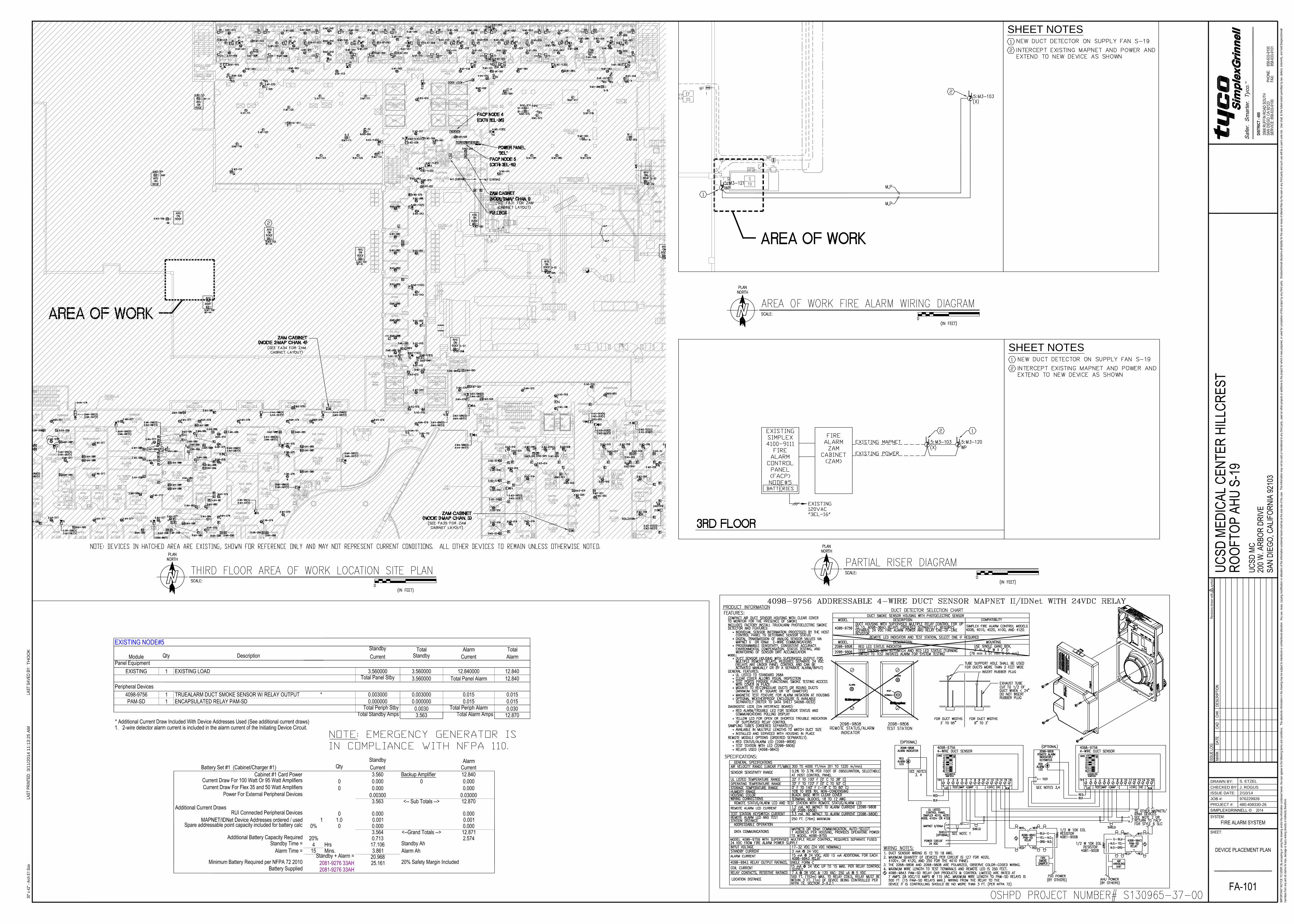
SHEET NOTES
SHEET NOTES
3/1
1/2
01
4 1
1:1
3:2
5 A
MT
HO
OK
480:408330-26
J. ROGUS
S. ETZEL
2/10/14
976229926
DRAWN BY:
CHECKED BY:
JOB #:
PROJECT #:
SIMPLEXGRINNELL ©
ISSUE DATE:
3/11/2014 REV.#: 0 PROJECT #: 480-408330-26 / 976229926
SimplexGrinnell LP 3568 Ruffin Road, South San Diego, CA 92123-2597 Tele: (858) 633-9100 Fax: (858) 633-9101 www.simplexgrinnell.com
FIRE DETECTION AND ALARM SYSTEM
PRODUCT SUBMITTAL
PROJECT: UCSD Medical Center Hillcrest
MCH 3RD
Floor Rooftop AHU S-19
200 West Arbor Drive
San Diego, California 92103
UCSD Project Number: MCH-4365
Facility ID: 12359
OSHPD ID: 106370782
ENGINEER: Donn C. Gilmore & Associates, Inc.
4051 E. La Palma Avenue, Suite A
Anaheim, California 92807
Telephone: 714-630-4291
Fire Alarm: SIMPLEXGRINNELL, LP
3568 Ruffin Road, South
San Diego, CA 92123-2597
Telephone: 858.633.9100
O.S.H.P.D. NUMBER: S130965-37-00

3/11/2014 REV.#: 0 PROJECT #: 480-408330-26 / 976229926
SimplexGrinnell LP 3568 Ruffin Road, South San Diego, CA 92123-2597 Tele: (858) 633-9100 Fax: (858) 633-9101 www.simplexgrinnell.com
UCSD Medical Center Hillcrest MCH 3RD Floor Rooftop AHU S-19
200 West Arbor Drive San Diego, California 92103
TAB # SYSTEM
1 FIRE ALARM PRODUCT DATA
2 APPENDIX
ITEM DESCRIPTION
A BUSINESS LICENSE
B WARRANTY
3/11/2014 REV.#: 0 PROJECT #: 480-408330-26 / 976229926
SimplexGrinnell LP 3568 Ruffin Road, South San Diego, CA 92123-2597 Tele: (858) 633-9100 Fax: (858) 633-9101 www.simplexgrinnell.com
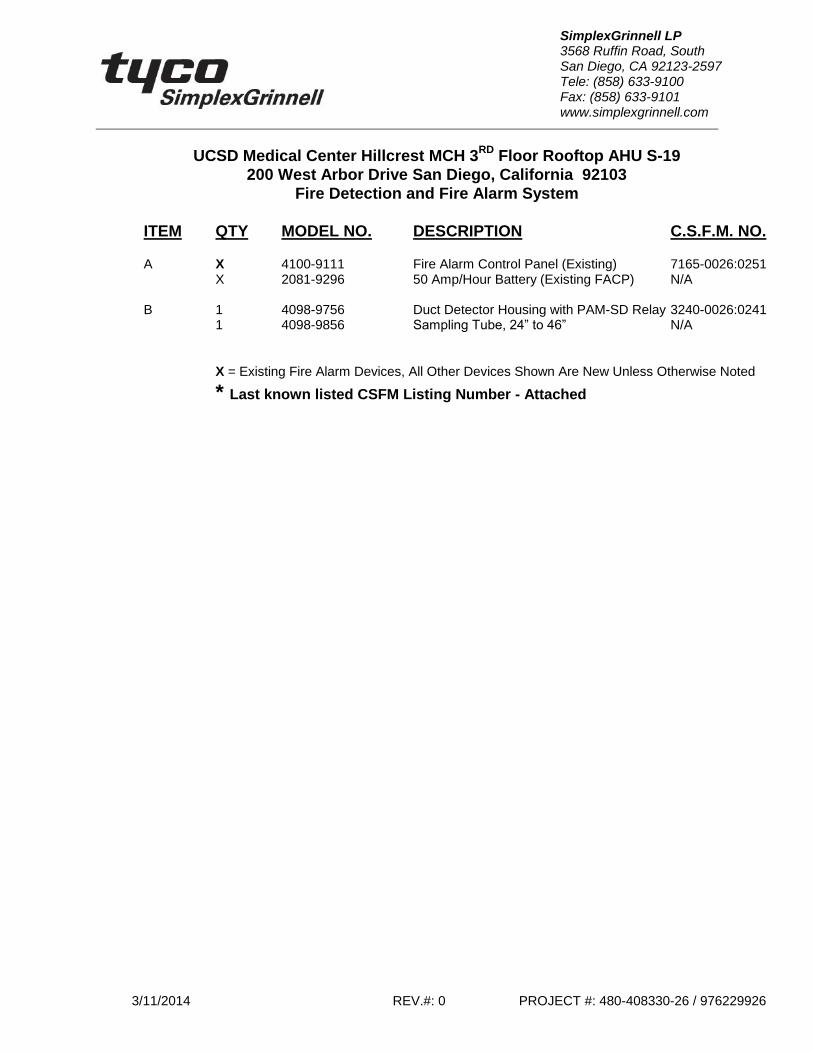
UCSD Medical Center Hillcrest MCH 3RD
Floor Rooftop AHU S-19
200 West Arbor Drive San Diego, California 92103
Fire Detection and Fire Alarm System
ITEM QTY MODEL NO. DESCRIPTION C.S.F.M. NO.
A X 4100-9111 Fire Alarm Control Panel (Existing) 7165-0026:0251 X 2081-9296 50 Amp/Hour Battery (Existing FACP) N/A B 1 4098-9756 Duct Detector Housing with PAM-SD Relay 3240-0026:0241 1 4098-9856 Sampling Tube, 24” to 46” N/A
X = Existing Fire Alarm Devices, All Other Devices Shown Are New Unless Otherwise Noted
* Last known listed CSFM Listing Number - Attached
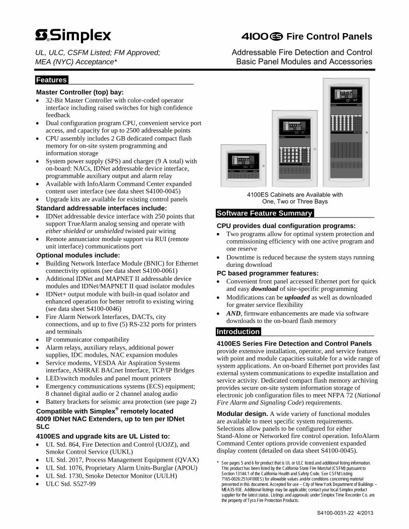
Features
Master Controller (top) bay: 32-Bit Master Controller with color-coded operator
interface including raised switches for high confidence feedback
Dual configuration program CPU, convenient service port access, and capacity for up to 2500 addressable points
CPU assembly includes 2 GB dedicated compact flash memory for on-site system programming and information storage
System power supply (SPS) and charger (9 A total) with on-board: NACs, IDNet addressable device interface, programmable auxiliary output and alarm relay
Available with InfoAlarm Command Center expanded content user interface (see data sheet S4100-0045)
Upgrade kits are available for existing control panels Standard addressable interfaces include: IDNet addressable device interface with 250 points that
support TrueAlarm analog sensing and operate with either shielded or unshielded twisted pair wiring
Remote annunciator module support via RUI (remote unit interface) communications port
Optional modules include: Building Network Interface Module (BNIC) for Ethernet
connectivity options (see data sheet S4100-0061) Additional IDNet and MAPNET II addressable device
modules and IDNet/MAPNET II quad isolator modules IDNet+ output module with built-in quad isolator and
enhanced operation for better retrofit to existing wiring (see data sheet S4100-0046)
Fire Alarm Network Interfaces, DACTs, city connections, and up to five (5) RS-232 ports for printers and terminals
IP communicator compatibility Alarm relays, auxiliary relays, additional power
supplies, IDC modules, NAC expansion modules Service modems, VESDA Air Aspiration Systems
interface, ASHRAE BACnet Interface, TCP/IP Bridges LED/switch modules and panel mount printers Emergency communications systems (ECS) equipment;
8 channel digital audio or 2 channel analog audio Battery brackets for seismic area protection (see page 2)
Compatible with Simplex® remotely located 4009 IDNet NAC Extenders, up to ten per IDNet SLC
4100ES and upgrade kits are UL Listed to: UL Std. 864, Fire Detection and Control (UOJZ), and
Smoke Control Service (UUKL) UL Std. 2017, Process Management Equipment (QVAX) UL Std. 1076, Proprietary Alarm Units-Burglar (APOU) UL Std. 1730, Smoke Detector Monitor (UULH) ULC Std. S527-99
Press ACK l ocated under fl ashin g indicator.Repeat operation unti l al l events are acknowledged.Local tone wil l silence.
A B C
AC Power
D E F G H I
J K L M N O P Q R
'SP ' ( ) , 0 :
S T U V W X Y Z /
ALARMSFire Alarm Priority 2 Alarm
SYSTEM WARNINGSSupervisory Trouble Ala rm Silenced
Emergency Operating Instructions
Alarm or Warning Condition
How to Acknowledge / View Events
How to Silence Building SignalsSystem ind icator flashing. Tone On. Press Alarm Silence.
How to Reset SystemPress System Reset.Press Ack to si lence tone device.
ZONE
1SI G
2A UX
3
FB
4IO
5I DNet
6
P
7A
8L
9
N ET ADDR
0 DE L
Enter C/Exit
Fire AlarmAck
Priority 2Ack
SupvAck
TroubleAck
AlarmSilence
SystemReset
EventTime
Enable On Arm
Disable OffDisarm Auto Lamp
Test
MoreInfo
Menu
Previous
Next
On
Off
Auto
On
Off
Auto
On
Off
Auto
On
Off
Auto
On
Off
Auto
On
Off
Auto
On
Off
Auto
On
Off
Auto
Press ACK located under flashing indicator.Repeat operation until all events are acknowledged.Lo cal to ne will silence.
A B C
AC Power
D E F G H I
J K L M N O P Q R
'SP' ( ) , 0 :
S T U V W X Y Z /
ALARMSFire Alarm Priority 2 Ala rm
SYSTEM WARNINGSSupervisory Trouble Alarm Silenced
Emergency Operating Instructions
Alarm or Warning Condition
How to Acknowledge / View Events
How to Silence Building SignalsSystem indicator flashing. Tone On. Press Alarm Silence.
How to Reset SystemPress System Reset.Press Ack to si lence tone device.
ZONE
1SI G
2A UX
3
FB
4IO
5I DNet
6
P
7A
8L
9
NET ADDR
0 DEL
Enter C/Exit
Fire AlarmAck
Priority 2Ack
SupvAck
TroubleAck
AlarmSilence
SystemReset
EventTime
Enable On Arm
Disable OffDisarm Auto Lamp
Test
MoreInfo
Menu
Previous
Next
4100ES Cabinets are Available with One, Two or Three Bays
Software Feature Summary
CPU provides dual configuration programs: Two programs allow for optimal system protection and
commissioning efficiency with one active program and one reserve
Downtime is reduced because the system stays running during download
PC based programmer features: Convenient front panel accessed Ethernet port for quick
and easy download of site-specific programming Modifications can be uploaded as well as downloaded
for greater service flexibility AND, firmware enhancements are made via software
downloads to the on-board flash memory
Introduction
4100ES Series Fire Detection and Control Panels provide extensive installation, operator, and service features with point and module capacities suitable for a wide range of system applications. An on-board Ethernet port provides fast external system communications to expedite installation and service activity. Dedicated compact flash memory archiving provides secure on-site system information storage of electronic job configuration files to meet NFPA 72 (National Fire Alarm and Signaling Code) requirements.
Modular design. A wide variety of functional modules are available to meet specific system requirements. Selections allow panels to be configured for either Stand-Alone or Networked fire control operation. InfoAlarm Command Center options provide convenient expanded display content (detailed on data sheet S4100-0045).
* See pages 5 and 6 for product that is UL or ULC listed and additional listing information. This product has been listed by the California State Fire Marshal (CSFM) pursuant to Section 13144.1 of the California Health and Safety Code. See CSFM Listing 7165-0026:251(4100ES) for allowable values and/or conditions concerning material presented in this document. Accepted for use – City of New York Department of Buildings – MEA35-93E. Additional listings may be applicable; contact your local Simplex product supplier for the latest status. Listings and approvals under Simplex Time Recorder Co. are the property of Tyco Fire Protection Products.
Fire Control Panels UL, ULC, CSFM Listed; FM Approved; Addressable Fire Detection and Control MEA (NYC) Acceptance* Basic Panel Modules and Accessories
S4100-0031-22 4/2013
jrogus
Text Box
EXISTING FACP

Module Bay Description
The Master Controller Bay (top) includes a standard multi-featured system power supply, the master controller board, and operator interface equipment.
The Expansion Bays include a Power Distribution Interface (PDI) for new 4” x 5” flat design option modules and also accommodate 4100-style modules.
The Battery Compartment (bottom) accepts two batteries, up to 50 Ah, to be mounted within the cabinet without interfering with module space.
The following illustration identifies bay locations using a three bay cabinet for reference.
PDI
4x5 Module
Expansion PowerSupply
(XPS)
4x5 Module
I/O Wiring
I/O Wiring
I/O Wiring
410
0 O
ptio
n
410
0 O
ptio
n
410
0 O
ptio
n
Slot 1 Slot 2 Slot 3 Slot 4 Slot 5 Slot 6 Slot 7 Slot 8
(Block E)
(Block F)
(Blocks G & H)
System Power Supply
(SPS)
IDNet NACs 1, 2 & 3
Aux PwrAux
Relay
Btry+-
Mas
ter
Con
trol
ler
Boa
rd
Slot 1 Slot 2 Slot 3 Slot 4 Slot 5 Slot 6 Slot 7 Slot 8
Slot 1
Slot 2
Slot 4
Slot 3
PDI
4x5 Module
Expansion PowerSupply
(XPS)
4x5 Module
I/O Wiring
I/O Wiring
I/O Wiring
4100
Opt
ion
4100
Opt
ion
4100
Opt
ion
Slot 1 Slot 2 Slot 3 Slot 4 Slot 5 Slot 6 Slot 7 Slot 8
(Block E)
(Block F)
(Blocks G & H)
Master Controller Bay
Expansion Bay 1
Battery Compartment
System power supplyMaster controller with dual slot motherboard
Expansion Bay 2
Typical bays with mixed module sizes
4100ES Module Bay Reference
Mechanical Description
Boxes can be close-nippled; each box provides convenient stud markers for drywall thickness and nail-hole knockouts for quicker mounting
Smooth box surfaces are provided for locally cutting conduit entrance holes exactly where required
Cabinet assembly design has been seismic tested and is certified to IBC and CBC standards as well as to ASCE 7-05 category D, requires 33 Ah or 50 Ah batteries with battery brackets as detailed on data sheet S2081-0019
Mechanical Description (Continued)
The latching dress panel (retainer) assembly easily lifts off for internal access
NACs are mounted directly on power supply assemblies providing minimized wiring loss, compact size, and readily accessible terminations
Packaging supports traditional 4100-style motherboard with daughter cards
Modules are power-limited (except as noted, such as relay modules)
The NEMA 1 box is ordered separately and available for early installation
Doors are available with tempered glass inserts or solid; boxes and doors are available in platinum or red
Boxes and door/retainer assemblies are ordered separately per system requirements; refer to data sheet S4100-0037 for details
Operator Interface Detail Reference
The following illustration identifies the primary functions of the operator interface.
Press ACK located under flashing indicator.Repeat operation until all events are acknowledged .Local tone will silence.
A B C
AC Power
D E F G H I
J K L M N O P Q R
'SP' ( ) , 0 :
S T U V W X Y Z /
ALARMSFire Alarm Priority 2 Alarm
SYSTEM WARNINGSSupervisory Trouble Alarm Silenced
Emergency Operating Instructions
Alarm or Warning Condition
How to Acknowledge / View Events
How to Silence Building SignalsSystem indicator flashing. Tone On. Press Alarm Silence.
How to Reset SystemPress System Reset.Press Ack to silence tone device.
ZONE
1SIG
2AUX
3
FB
4IO
5IDNet
6
P
7A
8L
9
NET ADDR
0 DEL
Enter C/Exit
Fire AlarmAck
Priority 2Ack
SupvAck
TroubleAck
AlarmSilence
SystemReset
EventTime
EnableOnArm
DisableOff
DisarmAuto
LampTest
MoreInfo
Menu
Previous
Next
Upload/Download Ethernet port access (under sliding cover)
Basic operator instructions are printed on the interface
mounting plate
Panel sounder
Operator interface panel is directly viewable and accessible (no access door)
Software Feature Summary
TrueAlarm individual analog sensing with front panel information and selection access
“Dirty” TrueAlarm sensor maintenance alerts, service and status reports including “almost dirty”
TrueAlarm magnet test indication appears as distinct “test abnormal” message on display when in test mode
TrueAlarm sensor peak value performance report “Install Mode” allows grouping of multiple troubles for
uninstalled modules and devices into a single trouble condition (typical with future phased expansion); with future equipment and devices grouped into a single trouble, operators can more clearly identify events from the commissioned and occupied areas
Module level ground fault searching assists installation and service by locating and isolating modules with grounded wiring
“Recurring Trouble Filtering” allows the panel to recognize, process, and log recurring intermittent troubles (such as external wiring ground faults), but only sends a single outbound system trouble to avoid nuisance communications
WALKTEST silent or audible system test performs an automatic self-resetting test cycle
2 S4100-0031-22 4/2013
Operator Interface
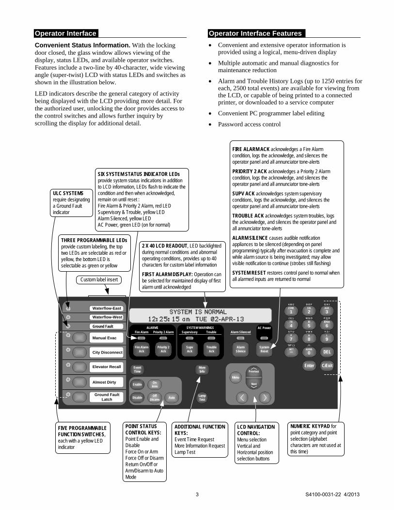
Convenient Status Information. With the locking door closed, the glass window allows viewing of the display, status LEDs, and available operator switches. Features include a two-line by 40-character, wide viewing angle (super-twist) LCD with status LEDs and switches as shown in the illustration below.
LED indicators describe the general category of activity being displayed with the LCD providing more detail. For the authorized user, unlocking the door provides access to the control switches and allows further inquiry by scrolling the display for additional detail.
Operator Interface Features
Convenient and extensive operator information is provided using a logical, menu-driven display
Multiple automatic and manual diagnostics for maintenance reduction
Alarm and Trouble History Logs (up to 1250 entries for each, 2500 total events) are available for viewing from the LCD, or capable of being printed to a connected printer, or downloaded to a service computer
Convenient PC programmer label editing
Password access control
A B C
AC Power
D E F G H I
J K L M N O P Q R
'SP' ( ) , 0 :
S T U V W X Y Z /
ALARMSFire Alarm Priority 2 Alarm
SYSTEM WARNINGSSupervisory Trouble Alarm Silenced
ZONE
1SIG
2AUX
3
FB
4IO
5IDNet
6
P
7A
8L
9
NET ADDR
0 DEL
Enter C/Exit
Fire AlarmAck
Priority 2Ack
SupvAck
TroubleAck
AlarmSilence
SystemReset
EventTime
EnableOn
Arm
DisableOff
DisarmAuto
LampTest
MoreInfo
Menu
Previous
Next
SIX SYSTEM STATUS INDICATOR LEDs provide system status indications in addition to LCD information, LEDs flash to indicate the condition and then when acknowledged, remain on until reset :Fire Alarm & Priority 2 Alarm, red LEDSupervisory & Trouble, yellow LEDAlarm Silenced, yellow LEDAC Power, green LED (on for normal)
FIVE PROGRAMMABLE FUNCTION SWITCHES, each with a yellow LED indicator
POINT STATUS CONTROL KEYS:Point Enable and DisableForce On or ArmForce Off or DisarmReturn On/Off or Arm/Disarm to Auto Mode
NUMERIC KEYPAD for point category and point selection (alphabet characters are not used at this time)
ADDITIONAL FUNCTION KEYS:Event Time RequestMore Information RequestLamp Test
Elevator Recall
City Disconnect
Manual Evac
Ground Fault
Waterflow-West
Waterflow-East
Custom label insert
LCD NAVIGATION CONTROL:Menu selectionVertical and Horizontal position selection buttons
FIRE ALARM ACK acknowledges a Fire Alarm condition, logs the acknowledge, and silences the operator panel and all annunciator tone-alerts
PRIORITY 2 ACK acknowledges a Priority 2 Alarm condition, logs the acknowledge, and silences the operator panel and all annunciator tone-alerts
SUPV ACK acknowledges system supervisory conditions, logs the acknowledge, and silences the operator panel and all annunciator tone-alerts
TROUBLE ACK acknowledges system troubles, logs the acknowledge, and silences the operator panel and all annunciator tone-alerts
ALARM SILENCE causes audible notification appliances to be silenced (depending on panel programming) typically after evacuation is complete and while alarm source is being investigated; may allow visible notification to continue (strobes still flashing)
SYSTEM RESET restores control panel to normal when all alarmed inputs are returned to normal
2 X 40 LCD READOUT, LED backlighted during normal conditions and abnormal operating conditions, provides up to 40 characters for custom label information
FIRST ALARM DISPLAY: Operation can be selected for maintained display of first alarm until acknowledged
THREE PROGRAMMABLE LEDs provide custom labeling, the top two LEDs are selectable as red or yellow, the bottom LED is selectable as green or yellow
ULC SYSTEMS require designating a Ground Fault indicator
Almost Dirty
Ground Fault Latch
3 S4100-0031-22 4/2013
Compatible Peripheral Devices
The 4100ES is compatible with an extensive list of remote peripheral devices including printers, CRT/keyboards (up to five total), and both conventional and addressable devices including TrueAlarm analog sensors.
Addressable Device Control
Overview. The 4100ES provides standard addressable device communications for IDNet compatible devices and accepts optional modules for communications with MAPNET II compatible devices. Using a two wire communications circuit, individual devices such as manual fire alarm stations, TrueAlarm sensors, conventional IDC zones, and sprinkler waterflow switches can be interfaced to the addressable controller to communicate their identity and status.
Addressability allows the location and condition of the connected device to be displayed on the operator interface LCD and on remote system annunciators. Additionally, control circuits (fans, dampers, etc.) may be individually controlled and monitored with addressable devices.
Addressable Operation. Each addressable device on the communication channel is continuously interrogated for status condition such as: normal, off-normal, alarm, supervisory, or trouble. Both Class B and Class A operation are available. Sophisticated poll and response communication techniques ensure supervision integrity and allow for "T-tapping" of the circuit for Class B operation. Devices with LEDs pulse the LED to indicate receipt of a communications poll and can be turned on steady from the panel.
IDNet Channel Capacity. The CPU bay system power supply (SPS) provides an IDNet signaling line circuit (SLC) that supports up to 250 addressable monitor and control points intermixed on the same pair of wires. Additional IDNet circuit modules are available for 64, 127, or 250 addressable devices.
IDNet/MAPNET II Communications wiring specifications. Distances are for shielded or unshielded wire. Shielded wire may provide protection from unexpected sources of interference.
Wiring Specifications
Size 18 AWG (0.82 mm2 )
Type Preferred Shielded twisted pair (STP)
Acceptable* Unshielded twisted pair (UTP)
Farthest Distance from Control Panel per Device load
126-250 Up to 2500 feet (762 m)
up to 125 Up to 4000 ft (1219 m)
Total Wire Length Allowed With “T” Taps for Class B Wiring Up to 10,000 ft (3 km); 0.58 µF
* Some applications may require shielded wiring. Review your system with your local Simplex product supplier.
TrueAlarm System Operation
Addressable device communications include operation of TrueAlarm smoke and temperature sensors. Smoke sensors transmit an output value based on their smoke chamber condition and the CPU maintains a current value, peak value, and an average value for each sensor. Status is determined by comparing the current sensor value to its average value. Tracking this average value as a continuously shifting reference point filters out environmental factors that cause shifts in sensitivity.
Programmable sensitivity of each sensor can be selected at the control panel for different levels of smoke obscuration (shown directly in percent) or for specific heat detection levels. To evaluate whether the sensitivity should be revised, the peak value is stored in memory and can be easily read and compared to the alarm threshold directly in percent.
CO sensor bases combine an electrolytic CO sensing module with a TrueAlarm analog sensor to provide a single multiple sensing assembly using one system address. The CO sensor can be enabled/disabled, used in LED/Switch modes and custom control, and can be made public for communication across a fire alarm Network. (refer to data sheet S4098-0041 for details)
TrueAlarm heat sensors can be selected for fixed temperature detection, with or without rate-of-rise detection. Utility temperature sensing is also available, typically to provide freeze warnings or alert to HVAC system problems. Readings can selected as either Fahrenheit or Celsius.
TrueSense Early Fire Detection. Multi-sensor 4098-9754 provides photoelectric and heat sensor data using a single 4100ES IDNet address. The panel evaluates smoke activity, heat activity, and their combination, to provide TrueSense early detection. For more details on this operation, refer to data sheet S4098-0024.
Diagnostics and Default Device Type
Sensor Status. TrueAlarm operation allows the control panel to automatically indicate when a sensor is almost dirty, dirty, and excessively dirty. The NFPA 72 requirement for a test of the sensitivity range of the sensors is fulfilled by the ability of TrueAlarm operation to maintain the sensitivity level of each sensor. CO Sensors track their 5 year active life status providing indicators to assist with service planning. Indicators occur at: 1 year, 6 months, and when end of life is reached.
Modular TrueAlarm sensors use the same base and different sensor types (smoke or heat sensor) and can be easily interchanged to meet specific location requirements. This allows intentional sensor substitution during building construction when conditions are temporarily dusty. Instead of covering smoke sensors (causing them to be disabled), heat sensors may be installed without reprogramming the control panel. The control panel will indicate an incorrect sensor type, but the heat sensor will operate at a default sensitivity to provide heat detection for building protection at that location.
4 S4100-0031-22 4/2013
CPU Bay Module Details
Master Controller and Motherboard: Mounts in Slot 4 of a two slot motherboard (Slots 3 and 4
of the Master Controller Bay) and provides one Style 4 or Style 7, RUI communications channel, available at Slot 4
RUI communications controls up to 31 devices per master controller (on one or multiple RUI channels); devices include: MINIPLEX transponders, 4603-9101 LCD Annunciators, 4602-9101 Status Command Units (SCU), 4602-9102 Remote Command Units (RCU), 4602 Series LED Annunciator Panels, and 4100 Series 24 I/O and LED/Switch modules
Up to four RUI channels are supported; use up to three 4100-1291 RUI expansion modules as required
Optional Service Modem 4100-6030 mounts onto the master controller board with its own on-board connections
Slot 3 of the motherboard is primarily for the 4100-6078 Network Interface Board with media modules, and secondarily for the 4100-6038 Dual RS-232 Board (4100-6038 is required for 2120 System connections)
System Power Supply: (see page 8 for more detail) Rating is 9 A total with “Special Application” appliances;
4 A total for “Regulated 24 DC” appliance power Outputs are power-limited, except for the battery charger Provides system power, battery charging, auxiliary power,
auxiliary relay, earth detection, on-board IDNet communications channel for 250 points, three on-board NACs, and provisions for either an optional City Connect Module or an optional Alarm Relay Module
IDNet SLC Output provides Class B or Class A communications for up to 250 addressable devices (as described on page 4)
System Power Supply (Continued): Three, 3 A On-Board NACs, conventional reverse
polarity operation; rated 3 A for Special Application appliances and 2 A for Regulated 24 DC power, with electronic control and overcurrent protection; selectable as Class B or Class A, and for synchronized strobe or SmartSync horn/strobe operation over two wires
NACs can be selected as auxiliary power outputs derated to 2 A for continuous duty; the total auxiliary power output per SPS is limited to 5 A
Battery Charger is dual rate, temperature compensated, and charges up to 50 Ah sealed lead-acid batteries mounted in the battery compartment (33 Ah for single bay cabinets); also is UL listed for charging up to 115 Ah batteries mounted in an external cabinet (see data sheet S2081-0012 for details)
Battery and Charger Monitoring includes battery charger status and low or depleted battery conditions; status information provided to the master controller includes analog values for: battery voltage, charger voltage and current, actual system voltage and current, and individual NAC currents
2 A Auxiliary Power Output is selectable for detector reset, door holder, or coded output operation
Auxiliary Relay is selectable as N.O. or N.C., rated 2 A @ 32 VDC, and is programmable as a trouble relay, either normally energized or normally de-energized, or as an auxiliary control
Optional City Connect Module (4100-6031, with disconnect switches, or 4100-6032, without disconnect switches) can be selected for conventional dual circuit city connections
Optional Alarm Relay Module (4100-6033) provides three Form C relays that are used for Alarm, Trouble, and Supervisory, rated 2 A resistive @ 32 VDC
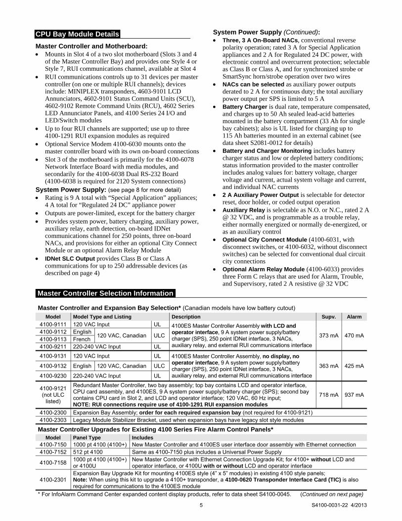
Master Controller and Expansion Bay Selection* (Canadian models have low battery cutout) Model Model Type and Listing Description Supv. Alarm
4100-9111 120 VAC Input UL 4100ES Master Controller Assembly with LCD and operator interface, 9 A system power supply/battery charger (SPS), 250 point IDNet interface, 3 NACs, auxiliary relay, and external RUI communications interface
373 mA 470 mA4100-9112 English
120 VAC, Canadian ULC 4100-9113 French 4100-9211 220-240 VAC Input UL
4100-9131 120 VAC Input UL 4100ES Master Controller Assembly, no display, no operator interface, 9 A system power supply/battery charger (SPS), 250 point IDNet interface, 3 NACs, auxiliary relay, and external RUI communications interface
363 mA 425 mA4100-9132 English 120 VAC, Canadian ULC
4100-9230 220-240 VAC Input UL
4100-9121 (not ULC
listed)
Redundant Master Controller, two bay assembly; top bay contains LCD and operator interface, CPU card assembly, and 4100ES, 9 A system power supply/battery charger (SPS); second bay contains CPU card in Slot 2, and LCD and operator interface; 120 VAC, 60 Hz input; NOTE: RUI connections require use of 4100-1291 RUI expansion modules
718 mA 937 mA
4100-2300 Expansion Bay Assembly; order for each required expansion bay (not required for 4100-9121) 4100-2303 Legacy Module Stabilizer Bracket, used when expansion bays have legacy slot style modules
Master Controller Upgrades for Existing 4100 Series Fire Alarm Control Panels* Model Panel Type Includes
4100-7150 1000 pt 4100 (4100+) New Master Controller and 4100ES user interface door assembly with Ethernet connection 4100-7152 512 pt 4100 Same as 4100-7150 plus includes a Universal Power Supply
4100-7158 1000 pt 4100 (4100+) or 4100U
New Master Controller with Ethernet Connection Upgrade Kit; for 4100+ without LCD and operator interface, or 4100U with or without LCD and operator interface
4100-2301 Expansion Bay Upgrade Kit for mounting 4100ES style (4” x 5” modules) in existing 4100 style panels; Note: When using this kit to upgrade a 4100+ transponder, a 4100-0620 Transponder Interface Card (TIC) is also required for communications to the 4100ES module
* For InfoAlarm Command Center expanded content display products, refer to data sheet S4100-0045. (Continued on next page)
5 S4100-0031-22 4/2013
Master Controller Selection Information
6 S4100-0031-22 4/2013
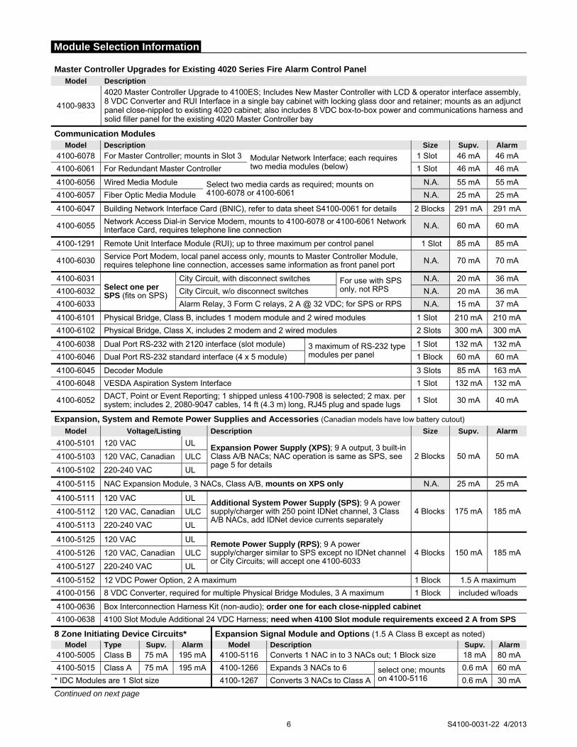
Master Controller Upgrades for Existing 4020 Series Fire Alarm Control Panel Model Description
4100-9833
4020 Master Controller Upgrade to 4100ES; Includes New Master Controller with LCD & operator interface assembly, 8 VDC Converter and RUI Interface in a single bay cabinet with locking glass door and retainer; mounts as an adjunct panel close-nippled to existing 4020 cabinet; also includes 8 VDC box-to-box power and communications harness and solid filler panel for the existing 4020 Master Controller bay
Communication Modules Model Description Size Supv. Alarm
4100-6078 For Master Controller; mounts in Slot 3 Modular Network Interface; each requires two media modules (below)
1 Slot 46 mA 46 mA
4100-6061 For Redundant Master Controller 1 Slot 46 mA 46 mA
4100-6056 Wired Media Module Select two media cards as required; mounts on 4100-6078 or 4100-6061
N.A. 55 mA 55 mA
4100-6057 Fiber Optic Media Module N.A. 25 mA 25 mA
4100-6047 Building Network Interface Card (BNIC), refer to data sheet S4100-0061 for details 2 Blocks 291 mA 291 mA
4100-6055 Network Access Dial-in Service Modem, mounts to 4100-6078 or 4100-6061 Network Interface Card, requires telephone line connection N.A. 60 mA 60 mA
4100-1291 Remote Unit Interface Module (RUI); up to three maximum per control panel 1 Slot 85 mA 85 mA
4100-6030 Service Port Modem, local panel access only, mounts to Master Controller Module, requires telephone line connection, accesses same information as front panel port N.A. 70 mA 70 mA
4100-6031 Select one per SPS (fits on SPS)
City Circuit, with disconnect switches For use with SPS only, not RPS
N.A. 20 mA 36 mA
4100-6032 City Circuit, w/o disconnect switches N.A. 20 mA 36 mA
4100-6033 Alarm Relay, 3 Form C relays, 2 A @ 32 VDC; for SPS or RPS N.A. 15 mA 37 mA
4100-6101 Physical Bridge, Class B, includes 1 modem module and 2 wired modules 1 Slot 210 mA 210 mA
4100-6102 Physical Bridge, Class X, includes 2 modem and 2 wired modules 2 Slots 300 mA 300 mA
4100-6038 Dual Port RS-232 with 2120 interface (slot module) 3 maximum of RS-232 type modules per panel
1 Slot 132 mA 132 mA
4100-6046 Dual Port RS-232 standard interface (4 x 5 module) 1 Block 60 mA 60 mA
4100-6045 Decoder Module 3 Slots 85 mA 163 mA
4100-6048 VESDA Aspiration System Interface 1 Slot 132 mA 132 mA
4100-6052 DACT, Point or Event Reporting; 1 shipped unless 4100-7908 is selected; 2 max. per system; includes 2, 2080-9047 cables, 14 ft (4.3 m) long, RJ45 plug and spade lugs 1 Slot 30 mA 40 mA
Expansion, System and Remote Power Supplies and Accessories (Canadian models have low battery cutout) Model Voltage/Listing Description Size Supv. Alarm
4100-5101 120 VAC UL Expansion Power Supply (XPS); 9 A output, 3 built-in Class A/B NACs; NAC operation is same as SPS, see page 5 for details
2 Blocks 50 mA 50 mA 4100-5103 120 VAC, Canadian ULC
4100-5102 220-240 VAC UL
4100-5115 NAC Expansion Module, 3 NACs, Class A/B, mounts on XPS only N.A. 25 mA 25 mA
4100-5111 120 VAC UL Additional System Power Supply (SPS); 9 A power supply/charger with 250 point IDNet channel, 3 Class A/B NACs, add IDNet device currents separately
4 Blocks 175 mA 185 mA 4100-5112 120 VAC, Canadian ULC
4100-5113 220-240 VAC UL
4100-5125 120 VAC UL Remote Power Supply (RPS); 9 A power supply/charger similar to SPS except no IDNet channel or City Circuits; will accept one 4100-6033
4 Blocks 150 mA 185 mA 4100-5126 120 VAC, Canadian ULC
4100-5127 220-240 VAC UL
4100-5152 12 VDC Power Option, 2 A maximum 1 Block 1.5 A maximum
4100-0156 8 VDC Converter, required for multiple Physical Bridge Modules, 3 A maximum 1 Block included w/loads
4100-0636 Box Interconnection Harness Kit (non-audio); order one for each close-nippled cabinet
4100-0638 4100 Slot Module Additional 24 VDC Harness; need when 4100 Slot module requirements exceed 2 A from SPS
8 Zone Initiating Device Circuits* Expansion Signal Module and Options (1.5 A Class B except as noted) Model Type Supv. Alarm Model Description Supv. Alarm
4100-5005 Class B 75 mA 195 mA 4100-5116 Converts 1 NAC in to 3 NACs out; 1 Block size 18 mA 80 mA
4100-5015 Class A 75 mA 195 mA 4100-1266 Expands 3 NACs to 6 select one; mounts on 4100-5116
0.6 mA 60 mA
* IDC Modules are 1 Slot size 4100-1267 Converts 3 NACs to Class A 0.6 mA 30 mA
Continued on next page
Module Selection Information

7 S4100-0031-22 4/2013
Miscellaneous Accessories Model Description
4100-1279 Single blank 2” display cover; 4100-2302 provides a single plate for a full bay
4100-9856* 4100ES Canadian French Appliqué Kit; Simplex, 4100ES, Controle Incendie
4100-9857* 4100ES English Appliqué Kit; Simplex, 4100ES, Fire Control
4100-9858* 4100ES InfoAlarm Remote Display English Appliqué Kit; Simplex, Operator Interface, 4100ES
4100-9859* 4100ES InfoAlarm Remote Display Canadian French Appliqué Kit; Simplex, Interface de l’operateur, 4100ES
4100-9835 Termination and Address Label Kit (for module marking); provides additional labels for field installed modules
4100-6029 Smoke Management Application Guide; required for UUKL listing
4100-6034 Tamper Switch, one per cabinet assembly if required; monitors solid door for panels with solid door; monitors the internal retainer panel for panels with glass door (not the glass door); has a built-in addressable IDNet IAM
2081-9031 Series resistor for WSO, IDCs (N.O. water flow and tamper on same circuit, wires after water flow and before tamper) 470 Ω, 1 W, encapsulated, two 18 AWG leads (0.82 mm2 ), 2-1/2” L x 1-3/8” W x 1” H (64 mm x 35 mm x 25 mm)
* Note: 4100ES English Appliqués are included with 4100ES Upgrade and Retrofit Kits for mounting 4100ES in 4100, 2120, 2001, and Autocall back boxes so that upgrades can be easily identified as 4100ES. 4100ES Appliqué Kits are available for applications such as to update Remote InfoAlarm Displays connected to a panel that was upgraded to 4100ES or for an existing 4100U when the New Master Controller is upgraded to 4100ES and only a software upgrade is required. When required, French appliqués are ordered separately.
Addressable Interface Modules (refer to location reference on pages 8 and 9) Model Description Supv. Alarm
4100-3101 IDNet Module, 250 point capacity With 250 IDNet devices, add 200 mA 250 mA
4100-3104 IDNet Module, 127 point capacity With 127 IDNet devices, add 102 mA 127 mA
4100-3105 IDNet Module, 64 point capacity With 64 IDNet devices, add 51 mA 64 mA
IDNet Modules, Specifications for each capacity; Module size = 1 Block
Module without devices 75 mA 115 mA
Loading per IDNet device 0.8 mA 1 mA
Model Description Supv. Alarm
4100-3102 MAPNET II Module, 127 point capacity, add devices separately; Module size = 2 Slots; Loading per MAPNET II device = 1.7 mA
Module without devices 255 mA 275 mA
Fully loaded module, total 471 mA 491 mA
4100-3103
Isolator Module for MAPNET II or IDNet; converts a single connected SLC into four isolated outputs selectable as Class A or Class B; up to two Isolator Modules can be connected to one SLC; Module size = 1 Slot; NOTE: Compatible with MAPNET II Remote Isolators only; for quad isolation with IDNet Remote Isolators, use 4100-3107 IDNet+ Module (see data sheet S4100-0046 for details)
50 mA 50 mA
Relay Modules; Nonpower-limited (for mounting in expansion bay only, refer to location reference on pages 8 and 9)
Model Description Resistive Ratings Inductive Ratings Size Supv. Alarm
4100-3202 4 DPDT w/feedback 10 A 250 VAC 10 A 250 VAC 2 Slots 15 mA 175 mA
4100-3204 4 DPDT w/feedback 2 A 30 VDC/VAC 1/2 A 30 VDC/120 VAC 1 Block 15 mA 60 mA
4100-3206 8 SPDT 3 A 30 VDC/120 VAC 1-1/2 A 30 VDC/120 VAC 1 Block 15 mA 190 mA
Current Calculation Notes: 1. To determine total supervisory current, add currents of modules in panel to base system value and all external loads powered
by panel power supplies. 2. To determine total alarm current, add currents of modules in panel to base system alarm current and add all panel NAC loads
and all external loads powered from panel power supplies.
Module Selection Information (Continued)
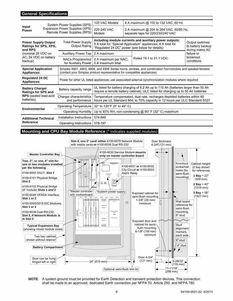
Input Power
System Power Supplies (SPS) Expansion Power Supplies (XPS)
Remote Power Supplies (RPS)
120 VAC Models 4 A maximum @ 102 to 132 VAC, 60 Hz
220-240 VAC Models
2 A maximum @ 204 to 264 VAC, 50/60 Hz; separate taps for 220/230/240 VAC
Power Supply Output Ratings for SPS, XPS, and RPS (nominal 28 VDC on AC; 24 VDC on battery backup)
Total Power Supply Output Rating
Including module currents and auxiliary power outputs; 9 A total for “Special Application” appliances; 4 A total for “Regulated 24 DC” power (see below for details)
Output switches to battery backup during mains AC failure or brownout conditions
Auxiliary Power Tap 2 A maximum Rated 19.1 to 31.1 VDC NACs Programmed
for Auxiliary Power 2 A maximum per NAC; 5 A maximum total
Special Application Appliances
Simplex 4901, 4903, 4904, and 4906 Series horns, strobes, and combination horn/strobes and speaker/strobes (contact your Simplex product representative for compatible appliances)
Regulated 24 DC Appliances
Power for other UL listed appliances; use associated external synchronization modules where required
Battery Charger Ratings for SPS and RPS (sealed lead-acid batteries)
Battery capacity range UL listed for battery charging of 6.2 Ah up to 115 Ah (batteries larger than 50 Ah require a remote battery cabinet); ULC listed for charging up to 50 Ah batteries
Charger characteristics and performance
Temperature compensated, dual rate, recharges depleted batteries within 48 hours per UL Standard 864; to 70% capacity in 12 hours per ULC Standard S527
Environmental Operating Temperature 32° to 120°F (0° to 49° C)
Operating Humidity Up to 93% RH, non-condensing @ 90° F (32° C) maximum
Additional Technical Reference
Installation Instructions 574-848
Operating Instructions 579-197
8 S4100-0031-22 4/2013
PDI
4x5 Module
Expansion PowerSupply
(XPS)
4x5 Module
I/O Wiring
I/O Wiring
I/O Wiring
410
0 O
ptio
n
410
0 O
ptio
n
410
0 O
ptio
n
Slot 1 Slot 2 Slot 3 Slot 4 Slot 5 Slot 6 Slot 7 Slot 8
(Block E)
(Block F)
(Blocks G & H)
System Power Supply
(SPS)
IDNet NACs 1, 2 & 3
Aux Pwr Aux Relay
Btry+-
City Circuit4100-60314100-6032
Alarm Relay4100-6033
Mas
ter
Co
ntr
olle
r B
oard
Slot 1 Slot 2 Slot 3 Slot 4 Slot 5 Slot 6 Slot 7 Slot 8
*System power supply*Master controller with motherboard
Optional semi-flush trim kit
4100-6031 or 4100-6032 City Circuit or 4100-6033Alarm Relay
4100-6030 Service Modem mounts only on master controller board
Slot 3, one 2" card: either 4100-6078 Network Module with media cards or 4100-6038 Dual RS-232
Slot 1
Slot 2
Slot 3
Cabinet height:(2 bay shown for reference)
1 Bay = 22"(559 mm)
2 Bay = 40"(1016 mm)
3 Bay = 56"(1427 mm)
Stud alignment markers, each side
Knockout screw/nail holes (for semi-flush mounting)
4" stud
6" stud
Two, 2", or one, 4" slot for one or two modules installed per the following:
4100-6052 DACT, Slot 1
4100-6101 Physical Bridge, Slot 2
4100-6102 Physical Bridge (4" module) Slots 1 and 2
4100-6048 VESDA Interface, Slot 1 or 2
4100-5005/5015 IDC Modules, Slot 1 or 2
4100-6038 Dual RS-232, Slot 2, if Network Module is in Slot 3
Master Controller Bay
Typical Expansion Bay(showing mixed module sizes)
Battery Compartment
Door can be hunghinged left or right
Wall board reference for semi-flush mounting, 6" stud
Two bay cabinet shown without retainer
11-11/16"(296 mm)
6-29/32"(175 mm)
Door thickness4-3/4"(121 mm)
Exposed cabinet forsemi-flush mounting
1-3/8" (35 mm)minimum
Exposed door and cabinet for semi-
flush mounting 6-1/8" (156 mm)
minimum
24" (610 mm)
Door 4-3/4"(121 mm)
General Specifications
Mounting and CPU Bay Module Reference (* indicates supplied modules)
NOTE: A system ground must be provided for Earth Detection and transient protection devices. This connection shall be made to an approved, dedicated Earth connection per NFPA 70, Article 250, and NFPA 780.
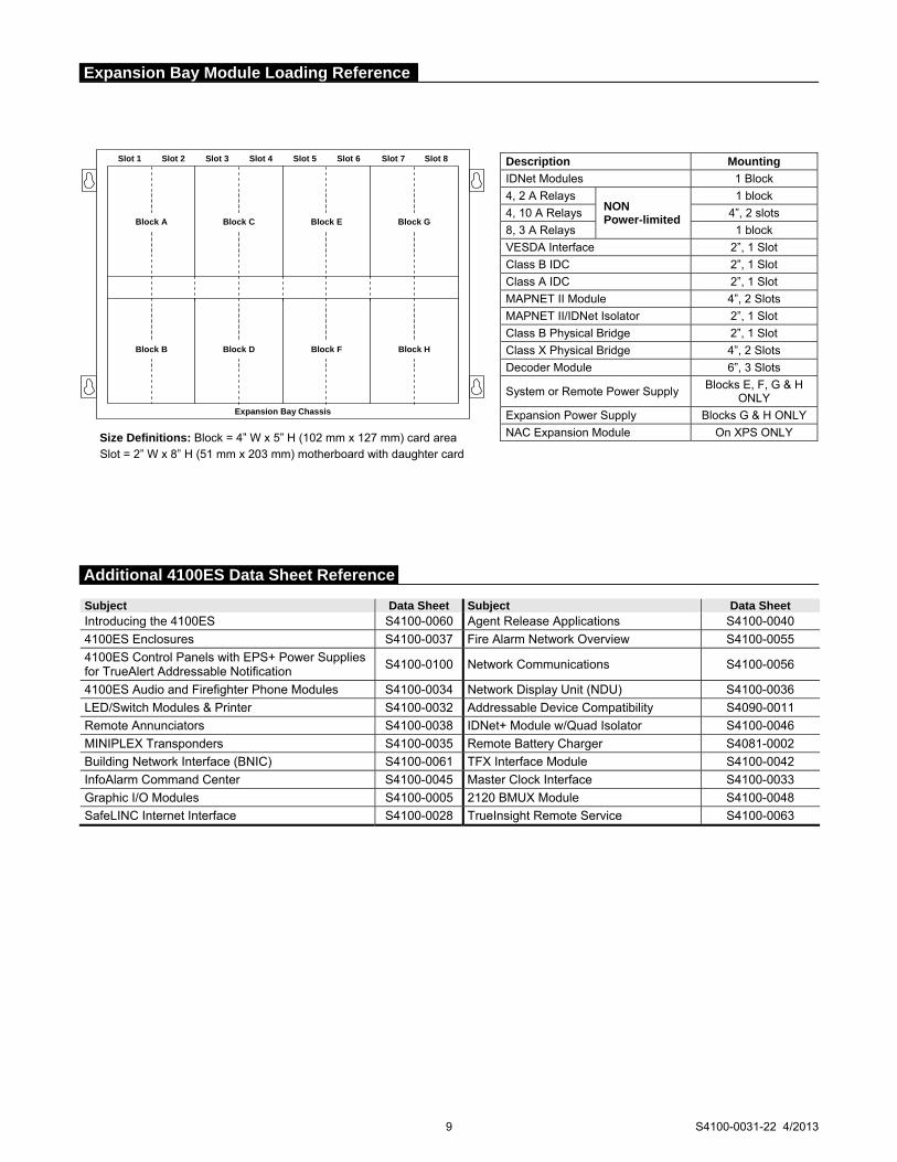
Slot 1 Slot 8Slot 7Slot 6Slot 5Slot 4Slot 3Slot 2
Expansion Bay Chassis
Block A
Block B
Block C
Block D
Block E
Block F
Block G
Block H
Size Definitions: Block = 4” W x 5” H (102 mm x 127 mm) card area Slot = 2” W x 8” H (51 mm x 203 mm) motherboard with daughter card
Subject Data Sheet Subject Data Sheet Introducing the 4100ES S4100-0060 Agent Release Applications S4100-0040
4100ES Enclosures S4100-0037 Fire Alarm Network Overview S4100-0055
4100ES Control Panels with EPS+ Power Supplies for TrueAlert Addressable Notification
S4100-0100 Network Communications S4100-0056
4100ES Audio and Firefighter Phone Modules S4100-0034 Network Display Unit (NDU) S4100-0036
LED/Switch Modules & Printer S4100-0032 Addressable Device Compatibility S4090-0011
Remote Annunciators S4100-0038 IDNet+ Module w/Quad Isolator S4100-0046
MINIPLEX Transponders S4100-0035 Remote Battery Charger S4081-0002
Building Network Interface (BNIC) S4100-0061 TFX Interface Module S4100-0042
InfoAlarm Command Center S4100-0045 Master Clock Interface S4100-0033
Graphic I/O Modules S4100-0005 2120 BMUX Module S4100-0048
SafeLINC Internet Interface S4100-0028 TrueInsight Remote Service S4100-0063
9 S4100-0031-22 4/2013
Expansion Bay Module Loading Reference
Description Mounting
IDNet Modules 1 Block
4, 2 A Relays NON Power-limited
1 block
4, 10 A Relays 4”, 2 slots
8, 3 A Relays 1 block
VESDA Interface 2”, 1 Slot
Class B IDC 2”, 1 Slot
Class A IDC 2”, 1 Slot
MAPNET II Module 4”, 2 Slots
MAPNET II/IDNet Isolator 2”, 1 Slot
Class B Physical Bridge 2”, 1 Slot
Class X Physical Bridge 4”, 2 Slots
Decoder Module 6”, 3 Slots
System or Remote Power Supply Blocks E, F, G & H
ONLY
Expansion Power Supply Blocks G & H ONLY
NAC Expansion Module On XPS ONLY
Additional 4100ES Data Sheet Reference

TYCO, SIMPLEX, and the product names listed in this material are marks and/or registered marks. Unauthorized use is strictly prohibited. Microsoft and Windows are trademarks of Microsoft Corporation. VESDA is a trademark of Xtralis Pty Ltd. NFPA 72 and National Fire Alarm Code are trademarks of the National Fire Protection Association (NFPA). ASHRAE and BACnet are trademarks of ASHRAE, American Society of Heating, Refrigeration, and Air Conditioning Engineers.
Tyco Fire Protection Products • Westminster, MA • 01441-0001 • USA S4100-0031-22 4/2013
www.simplexgrinnell.com © 2013 Tyco Fire Protection Products. All rights reserved. All specifications and other information shown were current as of document revision date and are subject to change without notice.
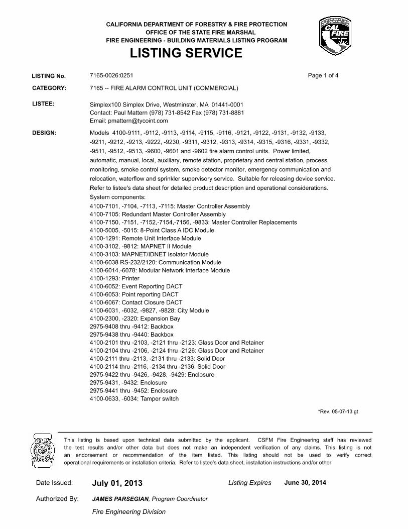
CALIFORNIA DEPARTMENT OF FORESTRY & FIRE PROTECTION
OFFICE OF THE STATE FIRE MARSHAL
FIRE ENGINEERING - BUILDING MATERIALS LISTING PROGRAM
LISTING SERVICE
LISTING No. 7165-0026:0251 Page 1 of 4
CATEGORY: 7165 -- FIRE ALARM CONTROL UNIT (COMMERCIAL)
LISTEE: Simplex100 Simplex Drive, Westminster, MA 01441-0001
Contact: Paul Mattern (978) 731-8542 Fax (978) 731-8881
Email: [email protected]
DESIGN: Models 4100-9111, -9112, -9113, -9114, -9115, -9116, -9121, -9122, -9131, -9132, -9133,
-9211, -9212, -9213, -9222, -9230, -9311, -9312, -9313, -9314, -9315, -9316, -9331, -9332,
-9511, -9512, -9513, -9600, -9601 and -9602 fire alarm control units. Power limited,
automatic, manual, local, auxiliary, remote station, proprietary and central station, process
monitoring, smoke control system, smoke detector monitor, emergency communication and
relocation, waterflow and sprinkler supervisory service. Suitable for releasing device service.
Refer to listee's data sheet for detailed product description and operational considerations.
System components:
4100-7101, -7104, -7113, -7115: Master Controller Assembly
4100-7105: Redundant Master Controller Assembly
4100-7150, -7151, -7152,-7154,-7156, -9833: Master Controller Replacements
4100-5005, -5015: 8-Point Class A IDC Module
4100-1291: Remote Unit Interface Module
4100-3102, -9812: MAPNET II Module
4100-3103: MAPNET/IDNET Isolator Module
4100-6038 RS-232/2120: Communication Module
4100-6014,-6078: Modular Network Interface Module
4100-1293: Printer
4100-6052: Event Reporting DACT
4100-6053: Point reporting DACT
4100-6067: Contact Closure DACT
4100-6031, -6032, -9827, -9828: City Module
4100-2300, -2320: Expansion Bay
2975-9408 thru -9412: Backbox
2975-9438 thru -9440: Backbox
4100-2101 thru -2103, -2121 thru -2123: Glass Door and Retainer
4100-2104 thru -2106, -2124 thru -2126: Glass Door and Retainer
4100-2111 thru -2113, -2131 thru -2133: Solid Door
4100-2114 thru -2116, -2134 thru -2136: Solid Door
2975-9422 thru -9426, -9428, -9429: Enclosure
2975-9431, -9432: Enclosure
2975-9441 thru -9452: Enclosure
4100-0633, -6034: Tamper switch
*Rev. 05-07-13 gt
July 01, 2013Date Issued: Listing Expires June 30, 2014
Authorized By:
Fire Engineering Division
This listing is based upon technical data submitted by the applicant. CSFM Fire Engineering staff has reviewed
the test results and/or other data but does not make an independent verification of any claims. This listing is not
an endorsement or recommendation of the item listed. This listing should not be used to verify correct
operational requirements or installation criteria. Refer to listee’s data sheet, installation instructions and/or other
JAMES PARSEGIAN, Program Coordinator
jrogus
Text Box
EXISTING FACP
jrogus
Rectangle
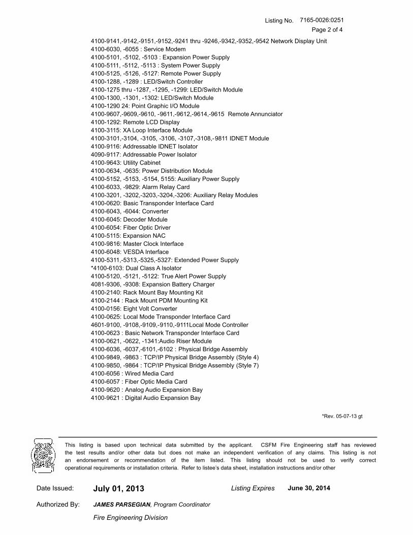
Listing No.
Page 2 of 4
7165-0026:0251
4100-9141,-9142,-9151,-9152,-9241 thru -9246,-9342,-9352,-9542 Network Display Unit
4100-6030, -6055 : Service Modem
4100-5101, -5102, -5103 : Expansion Power Supply
4100-5111, -5112, -5113 : System Power Supply
4100-5125, -5126, -5127: Remote Power Supply
4100-1288, -1289 : LED/Switch Controller
4100-1275 thru -1287, -1295, -1299: LED/Switch Module
4100-1300, -1301, -1302: LED/Switch Module
4100-1290 24: Point Graphic I/O Module
4100-9607,-9609,-9610, -9611,-9612,-9614,-9615 Remote Annunciator
4100-1292: Remote LCD Display
4100-3115: XA Loop Interface Module
4100-3101,-3104, -3105, -3106, -3107,-3108,-9811 IDNET Module
4100-9116: Addressable IDNET Isolator
4090-9117: Addressable Power Isolator
4100-9643: Utility Cabinet
4100-0634, -0635: Power Distribution Module
4100-5152, -5153, -5154, 5155: Auxiliary Power Supply
4100-6033, -9829: Alarm Relay Card
4100-3201, -3202,-3203,-3204,-3206: Auxiliary Relay Modules
4100-0620: Basic Transponder Interface Card
4100-6043, -6044: Converter
4100-6045: Decoder Module
4100-6054: Fiber Optic Driver
4100-5115: Expansion NAC
4100-9816: Master Clock Interface
4100-6048: VESDA Interface
4100-5311,-5313,-5325,-5327: Extended Power Supply
*4100-6103: Dual Class A Isolator
4100-5120, -5121, -5122: True Alert Power Supply
4081-9306, -9308: Expansion Battery Charger
4100-2140: Rack Mount Bay Mounting Kit
4100-2144 : Rack Mount PDM Mounting Kit
4100-0156: Eight Volt Converter
4100-0625: Local Mode Transponder Interface Card
4601-9100, -9108,-9109,-9110,-9111Local Mode Controller
4100-0623 : Basic Network Transponder Interface Card
4100-0621, -0622, -1341:Audio Riser Module
4100-6036, -6037,-6101,-6102 : Physical Bridge Assembly
4100-9849, -9863 : TCP/IP Physical Bridge Assembly (Style 4)
4100-9850, -9864 : TCP/IP Physical Bridge Assembly (Style 7)
4100-6056 : Wired Media Card
4100-6057 : Fiber Optic Media Card
4100-9620 : Analog Audio Expansion Bay
4100-9621 : Digital Audio Expansion Bay
*Rev. 05-07-13 gt
July 01, 2013Date Issued: Listing Expires June 30, 2014
Authorized By:
Fire Engineering Division
This listing is based upon technical data submitted by the applicant. CSFM Fire Engineering staff has reviewed
the test results and/or other data but does not make an independent verification of any claims. This listing is not
an endorsement or recommendation of the item listed. This listing should not be used to verify correct
operational requirements or installation criteria. Refer to listee’s data sheet, installation instructions and/or other
JAMES PARSEGIAN, Program Coordinator
Listing No.
Page 3 of 4
7165-0026:0251
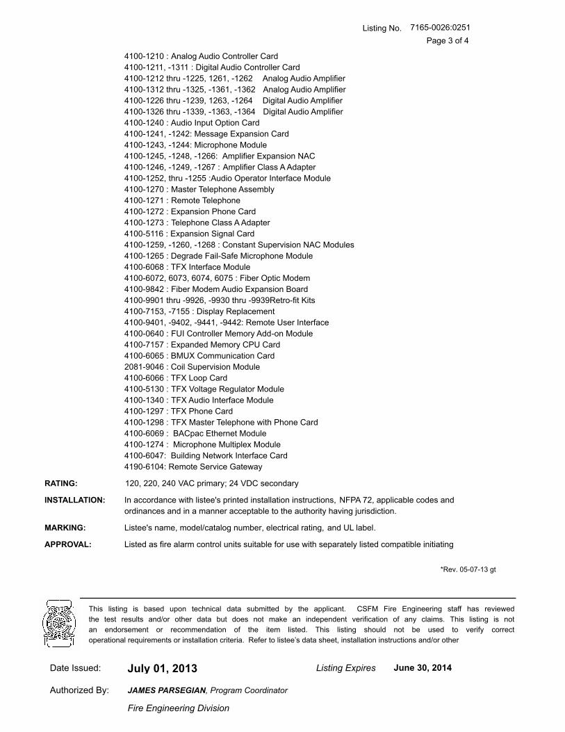
4100-1210 : Analog Audio Controller Card
4100-1211, -1311 : Digital Audio Controller Card
4100-1212 thru -1225, 1261, -1262 Analog Audio Amplifier
4100-1312 thru -1325, -1361, -1362 Analog Audio Amplifier
4100-1226 thru -1239, 1263, -1264 Digital Audio Amplifier
4100-1326 thru -1339, -1363, -1364 Digital Audio Amplifier
4100-1240 : Audio Input Option Card
4100-1241, -1242: Message Expansion Card
4100-1243, -1244: Microphone Module
4100-1245, -1248, -1266: Amplifier Expansion NAC
4100-1246, -1249, -1267 : Amplifier Class A Adapter
4100-1252, thru -1255 :Audio Operator Interface Module
4100-1270 : Master Telephone Assembly
4100-1271 : Remote Telephone
4100-1272 : Expansion Phone Card
4100-1273 : Telephone Class A Adapter
4100-5116 : Expansion Signal Card
4100-1259, -1260, -1268 : Constant Supervision NAC Modules
4100-1265 : Degrade Fail-Safe Microphone Module
4100-6068 : TFX Interface Module
4100-6072, 6073, 6074, 6075 : Fiber Optic Modem
4100-9842 : Fiber Modem Audio Expansion Board
4100-9901 thru -9926, -9930 thru -9939Retro-fit Kits
4100-7153, -7155 : Display Replacement
4100-9401, -9402, -9441, -9442: Remote User Interface
4100-0640 : FUI Controller Memory Add-on Module
4100-7157 : Expanded Memory CPU Card
4100-6065 : BMUX Communication Card
2081-9046 : Coil Supervision Module
4100-6066 : TFX Loop Card
4100-5130 : TFX Voltage Regulator Module
4100-1340 : TFX Audio Interface Module
4100-1297 : TFX Phone Card
4100-1298 : TFX Master Telephone with Phone Card
4100-6069 : BACpac Ethernet Module
4100-1274 : Microphone Multiplex Module
4100-6047: Building Network Interface Card
4190-6104: Remote Service Gateway
RATING: 120, 220, 240 VAC primary; 24 VDC secondary
INSTALLATION: In accordance with listee's printed installation instructions, NFPA 72, applicable codes and
ordinances and in a manner acceptable to the authority having jurisdiction.
MARKING: Listee's name, model/catalog number, electrical rating, and UL label.
APPROVAL: Listed as fire alarm control units suitable for use with separately listed compatible initiating
*Rev. 05-07-13 gt
July 01, 2013Date Issued: Listing Expires June 30, 2014
Authorized By:
Fire Engineering Division
This listing is based upon technical data submitted by the applicant. CSFM Fire Engineering staff has reviewed
the test results and/or other data but does not make an independent verification of any claims. This listing is not
an endorsement or recommendation of the item listed. This listing should not be used to verify correct
operational requirements or installation criteria. Refer to listee’s data sheet, installation instructions and/or other
JAMES PARSEGIAN, Program Coordinator
Listing No.
Page 4 of 4
7165-0026:0251
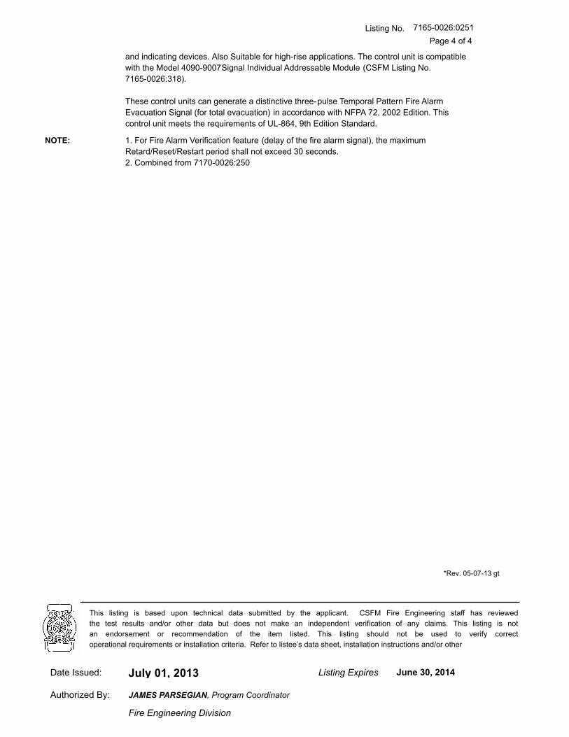
and indicating devices. Also Suitable for high-rise applications. The control unit is compatible
with the Model 4090-9007Signal Individual Addressable Module (CSFM Listing No.
7165-0026:318).
These control units can generate a distinctive three-pulse Temporal Pattern Fire Alarm
Evacuation Signal (for total evacuation) in accordance with NFPA 72, 2002 Edition. This
control unit meets the requirements of UL-864, 9th Edition Standard.
NOTE: 1. For Fire Alarm Verification feature (delay of the fire alarm signal), the maximum
Retard/Reset/Restart period shall not exceed 30 seconds.
2. Combined from 7170-0026:250
*Rev. 05-07-13 gt
July 01, 2013Date Issued: Listing Expires June 30, 2014
Authorized By:
Fire Engineering Division
This listing is based upon technical data submitted by the applicant. CSFM Fire Engineering staff has reviewed
the test results and/or other data but does not make an independent verification of any claims. This listing is not
an endorsement or recommendation of the item listed. This listing should not be used to verify correct
operational requirements or installation criteria. Refer to listee’s data sheet, installation instructions and/or other
JAMES PARSEGIAN, Program Coordinator

Features
Rechargeable, sealed lead-acid batteries:
Lead-calcium grid structure with immobilized electrolyte in absorbent separator
Low maintenance with no need to add water
Low self-discharge characteristics
One-piece, high impact polystyrene cell cover with high reliability dual seal construction
UL 924 recognized pressure relief valves Available in a variety of capacities:
Batteries for internal mounting range from 6.2 Ah up to 50 Ah, depending on control panel cabinet size
Larger batteries, up to 110 Ah, mount in external battery cabinets with models available with internal chargers
Battery cabinets with chargers:
Battery cabinets with charger communicate with their connected fire alarm control panel and are available for 4100ES/4010ES/4100U Series and 4010 Series panels
Description
Simplex® rechargeable sealed-lead acid batteries provide reliable and repeatable discharge and recharge characteristics for use in fire alarm and other systems applications. They are designed with immobilized electrolyte in an absorbent separator, allowing them to provide rated capacity on the first cycle.
Because of their sealed construction, packaging is allowed within the system electronics enclosure (see illustration on page 2). When this is applicable, the quantity of system cabinets and the battery wiring distances are both minimized. Where required, external battery cabinets can be close-nippled to the control panel to house larger batteries with battery chargers available in some battery cabinet sizes.
Battery Details
Charging. These batteries are intended to be used with compatible Simplex battery chargers.
Series Connections. These batteries are required to be connected in series to produce 24 V system voltage. Battery sets must be of identical voltage, model number, appearance, and approximately the same date of manufacture for proper operation.
Testing. Battery capacity testing is recommended to be performed by using a sealed lead-acid battery tester designed to withdraw a minimum of battery charge. The preferred tester applies a variety of amplitude and duration controlled test pulses that compares terminal voltage against those predicted for the specific battery size. (Testing is available through your local Simplex product supplier.)
Compatible Sealed Lead-Acid Batteries can be Installed Inside Fire Alarm Control Panel Cabinets
Remote Battery Cabinets are Available for Larger Battery Requirements
Battery Details (Continued)
Shipping. Sealed lead-acid batteries are shipped via ground or sea transportation only. They are not shipped via air.
Disposal. Battery chemicals and materials can be recycled. Refer to information shipped with the battery or on its case. Return to the battery manufacturer or to a similarly qualified battery processing facility for proper disposal.
* Refer to details on page 4 and to the referenced individual product data
sheets for agency listing status of battery cabinets and chargers. The batteries detailed in this document meet the requirements of UL, ULC, and Factory Mutual for use with respective equipment battery chargers as listed on page 3. Contact your local Simplex product supplier for proper battery selection per system requirements. Listings and approvals under Simplex Time Recorder Co. are the property of Tyco Fire Protection Products.
Fire Alarm Control Panel Accessories Listings* System Batteries, Sealed Lead-Acid; with Applications Reference for Battery Cabinets, and Battery Cabinets with Charger
S2081-0006-20 1/2012
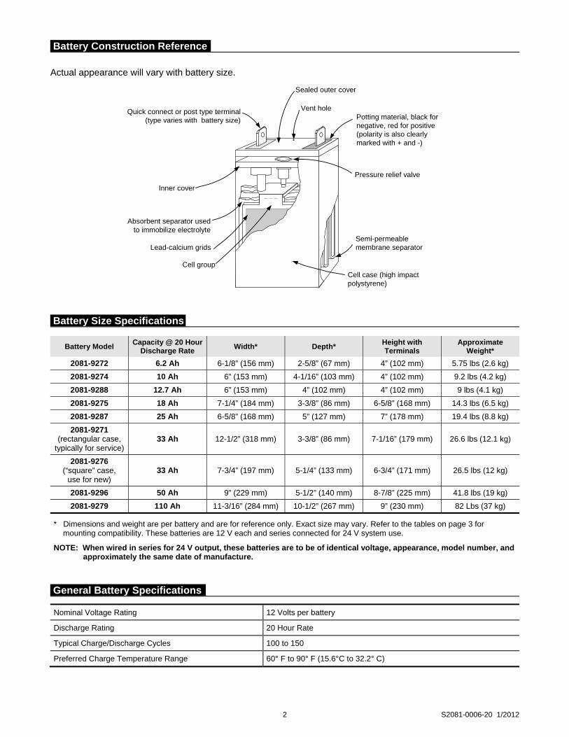
Actual appearance will vary with battery size.
2 S2081-0006-20 1/2012
Nominal Voltage Rating 12 Volts per battery
Discharge Rating 20 Hour Rate
Typical Charge/Discharge Cycles 100 to 150
Preferred Charge Temperature Range 60° F to 90° F (15.6°C to 32.2° C)
Quick connect or post type terminal(type varies with battery size)
Inner cover
Absorbent separator usedto immobilize electrolyte
Lead-calcium grids
Cell group
Cell case (high impactpolystyrene)
Sealed outer cover
Vent holePotting material, black fornegative, red for positive(polarity is also clearlymarked with + and -)
Pressure relief valve
Semi-permeablemembrane separator
Battery Model Capacity @ 20 Hour
Discharge Rate Width* Depth*
Height with Terminals
Approximate Weight*
2081-9272 6.2 Ah 6-1/8” (156 mm) 2-5/8” (67 mm) 4” (102 mm) 5.75 lbs (2.6 kg)
2081-9274 10 Ah 6” (153 mm) 4-1/16” (103 mm) 4” (102 mm) 9.2 lbs (4.2 kg)
2081-9288 12.7 Ah 6” (153 mm) 4” (102 mm) 4” (102 mm) 9 lbs (4.1 kg)
2081-9275 18 Ah 7-1/4” (184 mm) 3-3/8” (86 mm) 6-5/8” (168 mm) 14.3 lbs (6.5 kg)
2081-9287 25 Ah 6-5/8” (168 mm) 5” (127 mm) 7” (178 mm) 19.4 lbs (8.8 kg)
2081-9271 (rectangular case,
typically for service) 33 Ah 12-1/2” (318 mm) 3-3/8” (86 mm) 7-1/16” (179 mm) 26.6 lbs (12.1 kg)
2081-9276 (“square” case,
use for new) 33 Ah 7-3/4” (197 mm) 5-1/4” (133 mm) 6-3/4” (171 mm) 26.5 lbs (12 kg)
2081-9296 50 Ah 9” (229 mm) 5-1/2” (140 mm) 8-7/8” (225 mm) 41.8 lbs (19 kg)
2081-9279 110 Ah 11-3/16” (284 mm) 10-1/2” (267 mm) 9” (230 mm) 82 Lbs (37 kg)
* Dimensions and weight are per battery and are for reference only. Exact size may vary. Refer to the tables on page 3 for mounting compatibility. These batteries are 12 V each and series connected for 24 V system use.
NOTE: When wired in series for 24 V output, these batteries are to be of identical voltage, appearance, model number, and approximately the same date of manufacture.
Battery Construction Reference
Battery Size Specifications
General Battery Specifications
3 S2081-0006-20 1/2012
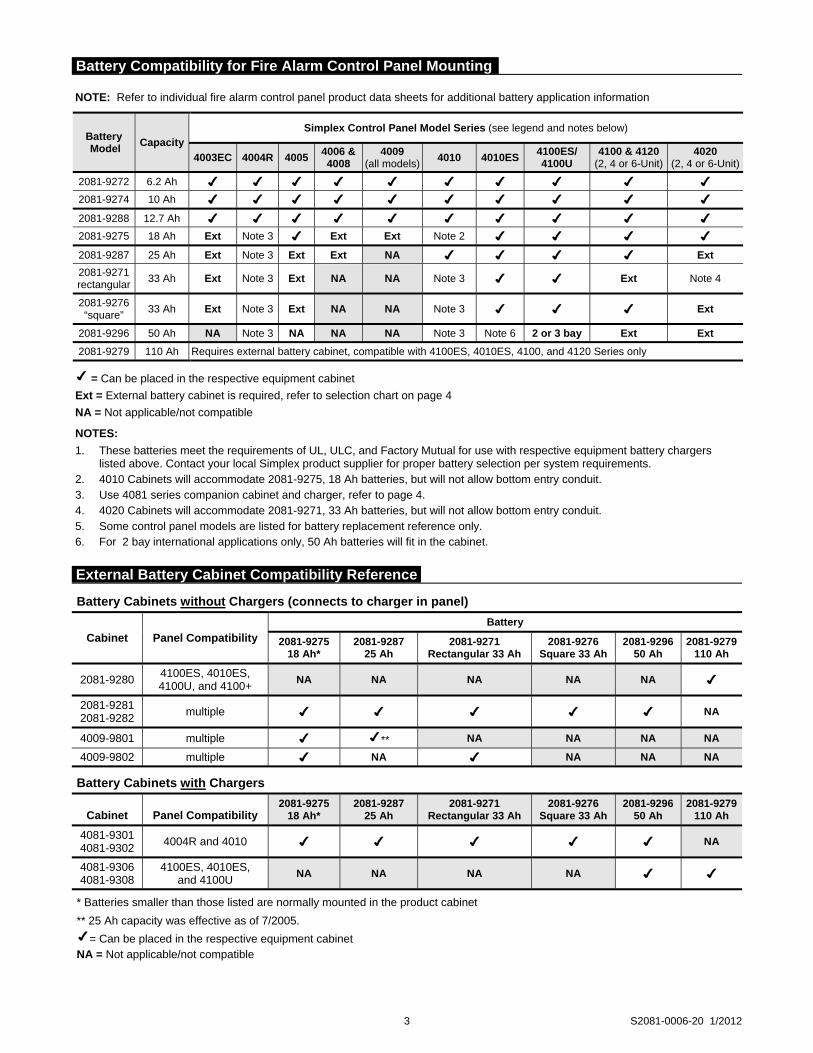
Battery Cabinets without Chargers (connects to charger in panel)
Cabinet Panel Compatibility
Battery
2081-927518 Ah*
2081-9287 25 Ah
2081-9271 Rectangular 33 Ah
2081-9276 Square 33 Ah
2081-929650 Ah
2081-9279110 Ah
2081-9280 4100ES, 4010ES, 4100U, and 4100+
NA NA NA NA NA
2081-9281 2081-9282
multiple NA
4009-9801 multiple ** NA NA NA NA
4009-9802 multiple NA NA NA NA
Battery Cabinets with Chargers
Cabinet Panel Compatibility 2081-9275
18 Ah* 2081-9287
25 Ah 2081-9271
Rectangular 33 Ah 2081-9276
Square 33 Ah 2081-9296
50 Ah 2081-9279
110 Ah
4081-9301 4081-9302
4004R and 4010 NA
4081-9306 4081-9308
4100ES, 4010ES, and 4100U
NA NA NA NA
* Batteries smaller than those listed are normally mounted in the product cabinet
** 25 Ah capacity was effective as of 7/2005.
= Can be placed in the respective equipment cabinet NA = Not applicable/not compatible
NOTE: Refer to individual fire alarm control panel product data sheets for additional battery application information
Battery Model
Capacity Simplex Control Panel Model Series (see legend and notes below)
4003EC 4004R 4005 4006 & 4008
4009 (all models)
4010 4010ES4100ES/ 4100U
4100 & 4120 (2, 4 or 6-Unit)
4020 (2, 4 or 6-Unit)
2081-9272 6.2 Ah
2081-9274 10 Ah
2081-9288 12.7 Ah
2081-9275 18 Ah Ext Note 3 Ext Ext Note 2
2081-9287 25 Ah Ext Note 3 Ext Ext NA Ext
2081-9271 rectangular
33 Ah Ext Note 3 Ext NA NA Note 3 Ext Note 4
2081-9276 “square”
33 Ah Ext Note 3 Ext NA NA Note 3 Ext
2081-9296 50 Ah NA Note 3 NA NA NA Note 3 Note 6 2 or 3 bay Ext Ext
2081-9279 110 Ah Requires external battery cabinet, compatible with 4100ES, 4010ES, 4100, and 4120 Series only
= Can be placed in the respective equipment cabinet
Ext = External battery cabinet is required, refer to selection chart on page 4
NA = Not applicable/not compatible
NOTES:
1. These batteries meet the requirements of UL, ULC, and Factory Mutual for use with respective equipment battery chargers listed above. Contact your local Simplex product supplier for proper battery selection per system requirements.
2. 4010 Cabinets will accommodate 2081-9275, 18 Ah batteries, but will not allow bottom entry conduit. 3. Use 4081 series companion cabinet and charger, refer to page 4. 4. 4020 Cabinets will accommodate 2081-9271, 33 Ah batteries, but will not allow bottom entry conduit. 5. Some control panel models are listed for battery replacement reference only. 6. For 2 bay international applications only, 50 Ah batteries will fit in the cabinet.
Battery Compatibility for Fire Alarm Control Panel Mounting
External Battery Cabinet Compatibility Reference
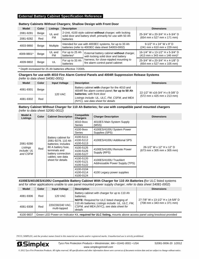
Battery Cabinets Without Chargers; Shallow Design with Front Door
Model Color Listings Description Dimensions
2081-9281 Beige UL and FM
2-Unit, 4100 style cabinet without charger; with locking solid door and battery shelf, primarily for use with 50 Ah batteries
25-3/4” W x 20-3/4” H x 6-3/4” D(654 mm x 527 mm x 171 mm) 2081-9282 Red
4003-9860 Beige Multiple Intended for use with 4003EC systems, for up to 33 Ah batteries (refer to 4003EC data sheet S4003-0002)
9-1/2” H x 24” W x 9” D (241 mm x 610 mm x 229 mm)
4009-9801* Beige UL and
FM For up to 25 Ah batteries*
External battery cabinet without charger, with locking solid door and battery harness; for close-nippled mounting to fire alarm control panel cabinet
16-1/4” W x 13-1/2” H x 5-3/4” D(413 mm x 343 mm x 146 mm)*
4009-9802 Beige UL For up to 33 Ah batteries
25-3/4” W x 20-3/4” H x 4-1/8” D (654 mm x 527 mm x 105 mm)
* Depth increased for 25 Ah batteries effective 7/2005.
Chargers for use with 4010 Fire Alarm Control Panels and 4004R Suppression Release Systems (refer to data sheet S4081-0001)
Model Color Input Voltage Description Dimensions
4081-9301 Beige
120 VAC
Battery cabinet with charger for the 4010 and 4004R fire alarm control panel; for up to 50 Ah batteries; with front door Listings include: UL, ULC, FM, CSFM, and MEA (NYC), see data sheet for details
22-1/2” W x16-3/4” H x 8-3/8” D (572 mm x 425 mm x 213 mm)
4081-9302 Red
Battery Cabinet Without Charger for 110 Ah Batteries; for use with compatible panel mounted chargers (refer to data sheet S2081-0012)
Model & Listings
Color Cabinet Description Compatible Chargers
Charger Description Dimensions
2081-9280 Listings
include: UL and CSFM
Red
Battery cabinet for 2081-9279, 110 Ah batteries; includes 80 A battery fuse, terminals and battery connection cables; see data sheet for details
4010-9xxx Series
4010ES Main System Supply (MSS)
26-1/2” W x 12” H x 12” D (673 mm x 305 mm x 305 mm)
4100-9xxx Series
4100ES/4100U System Power Supplies (SPS)
4100-5111 4100-5112 4100-5113
4100ES/4100U Additional SPS
4100-5125 4100-5126 4100-5127
4100ES/4100U Remote Power Supply (RPS)
4100-5120 4100-5121 4100-5122
4100ES/4100U TrueAlert Addressable Power Supply (TPS)
4100-0104 4100-0114 4100-0124
4100 Legacy power supplies
4100ES/4010ES/4100U Compatible Battery Cabinet With Charger for 110 Ah Batteries (for ULC listed systems and for other applications unable to use panel mounted power supply charger; refer to data sheet S4081-0002)
Model Color Input Voltage Description Dimensions
4081-9306 Red 120 VAC Battery cabinet with charger for up to 110 Ah batteries; NOTE: Required for ULC listed charging of 110 Ah batteries; Listings include: UL, ULC, FM, CSFM, and MEA (NYC), see data sheet for details
27-7/8” W x 13-1/2” H x 14-5/8” D(708 mm x 343 mm x 371 mm)
4081-9308 Red 220/230/240 VAC,
multi-tapped
4100-9837 Green LED Power-on Indicator Kit, required for ULC listing, mounts above access panel using knockout provided
Tyco Fire Protection Products • Westminster, MA • 01441-0001 • USA S2081-0006-20 1/2012
www.simplexgrinnell.com © 2012 Tyco Fire Protection Products. All rights reserved. All specifications and other information shown were current as of document revision date and are subject to change without notice.
TYCO, SIMPLEX, and the product names listed in this material are marks and/or registered marks. Unauthorized use is strictly prohibited.
External Battery Cabinet Specification Reference
Features
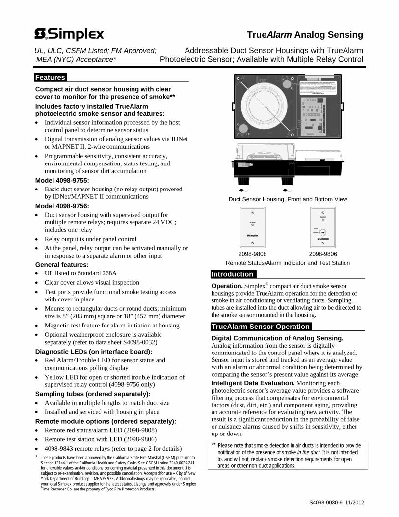
Compact air duct sensor housing with clear cover to monitor for the presence of smoke**
Includes factory installed TrueAlarm photoelectric smoke sensor and features: Individual sensor information processed by the host
control panel to determine sensor status
Digital transmission of analog sensor values via IDNet or MAPNET II, 2-wire communications
Programmable sensitivity, consistent accuracy, environmental compensation, status testing, and monitoring of sensor dirt accumulation
Model 4098-9755: Basic duct sensor housing (no relay output) powered
by IDNet/MAPNET II communications
Model 4098-9756: Duct sensor housing with supervised output for
multiple remote relays; requires separate 24 VDC; includes one relay
Relay output is under panel control
At the panel, relay output can be activated manually or in response to a separate alarm or other input
General features: UL listed to Standard 268A
Clear cover allows visual inspection
Test ports provide functional smoke testing access with cover in place
Mounts to rectangular ducts or round ducts; minimum size is 8” (203 mm) square or 18” (457 mm) diameter
Magnetic test feature for alarm initiation at housing
Optional weatherproof enclosure is available separately (refer to data sheet S4098-0032)
Diagnostic LEDs (on interface board): Red Alarm/Trouble LED for sensor status and
communications polling display
Yellow LED for open or shorted trouble indication of supervised relay control (4098-9756 only)
Sampling tubes (ordered separately): Available in multiple lengths to match duct size
Installed and serviced with housing in place
Remote module options (ordered separately): Remote red status/alarm LED (2098-9808)
Remote test station with LED (2098-9806)
4098-9843 remote relays (refer to page 2 for details) * These products have been approved by the California State Fire Marshal (CSFM) pursuant to
Section 13144.1 of the California Health and Safety Code. See CSFM Listing 3240-0026.241 for allowable values and/or conditions concerning material presented in this document. It is subject to re-examination, revision, and possible cancellation. Accepted for use – City of New York Department of Buildings – MEA35-93E. Additional listings may be applicable; contact your local Simplex product supplier for the latest status. Listings and approvals under Simplex Time Recorder Co. are the property of Tyco Fire Protection Products.
This device is a duct smoke housing. When provided with detector, it is designed to sample the air flowpassing by it in the air duct to determine whether it contains unacceptable levels of smoke. Theeffectiveness of a duct smoke detector is highly dependent upon: the design and operating conditions of theair handling system in which it is installed, variables such as smoke dilution and stratification over whicheven the best designed systems have no control, and proper placement and positioning of the duct smokedetector, which is often compromised for practical reasons. For the reasons stated above, the effectivenessof this duct smoke detector cannot be warranted or guaranteed. Under no circumstances should this ductsmoke detector be used or regarded to be a substitute for the building's Fire alarm and detection system towhich this device is attached as a secondary detection device.
DO NOT REMOVE THIS NOTICE!
Duct Sensor Housing, Front and Bottom View
ALARM
TEST
NORM
ALARM
2098-9808 2098-9806
Remote Status/Alarm Indicator and Test Station
Introduction
Operation. Simplex® compact air duct smoke sensor housings provide TrueAlarm operation for the detection of smoke in air conditioning or ventilating ducts. Sampling tubes are installed into the duct allowing air to be directed to the smoke sensor mounted in the housing.
TrueAlarm Sensor Operation
Digital Communication of Analog Sensing. Analog information from the sensor is digitally communicated to the control panel where it is analyzed. Sensor input is stored and tracked as an average value with an alarm or abnormal condition being determined by comparing the sensor’s present value against its average.
Intelligent Data Evaluation. Monitoring each photoelectric sensor’s average value provides a software filtering process that compensates for environmental factors (dust, dirt, etc.) and component aging, providing an accurate reference for evaluating new activity. The result is a significant reduction in the probability of false or nuisance alarms caused by shifts in sensitivity, either up or down.
** Please note that smoke detection in air ducts is intended to provide notification of the presence of smoke in the duct. It is not intended to, and will not, replace smoke detection requirements for open areas or other non-duct applications.
TrueAlarm Analog Sensing UL, ULC, CSFM Listed; FM Approved; Addressable Duct Sensor Housings with TrueAlarm MEA (NYC) Acceptance* Photoelectric Sensor; Available with Multiple Relay Control
S4098-0030-9 11/2012
jrogus
Rectangle

TrueAlarm Sensor Operation (Continued)
Control Panel Selection. Peak activity per sensor is stored to assist in evaluating specific locations. The alarm set point for each sensor is determined at the control panel, selectable as the individual application requires.
Sensor Status LED. Each sensor housing’s red status LED (located on the electrical interface board) pulses to indicate communications with the panel. If the control panel determines that a sensor is in alarm, or that it is dirty or has some other type of trouble, the details are annunciated at the control panel and that sensor housing’s status LED will be turned on steadily. During a system alarm, the control panel will control the LEDs such that an LED indicating a trouble will return to pulsing to help identify any alarmed sensors. (Remote Status/Alarm LEDs track the operation of the sensor housing LED.)
Photoelectric Sensing
TrueAlarm photoelectric sensors use a stable, pulsed infrared LED light source and a silicon photodiode receiver to provide consistent and accurate low power smoke sensing.
Photoelectric Sensing (Continued)
Typically duct sensor applications require less sensitive settings (such as 2.5% per foot obscuration) due to the ducts being a relative dirty environment. However, the standard seven levels of TrueAlarm sensor sensitivity are available for each individual sensor, ranging from 0.2% to 3.7% per foot of smoke obscuration. Sensitivity is selected and monitored at the fire alarm control panel.
Fire Alarm Control Panel Features
Individual smoke sensitivity selection Sensitivity monitoring that satisfies NFPA 72
sensitivity testing requirements Peak value logging allows accurate analysis for
sensitivity selection Automatic, once per minute individual sensor
calibration check verifies sensor integrity Automatic environmental compensation Smoke sensitivity is displayed in percent per foot Ability to display and print detailed sensor
information in plain English language Relays of model 4098-9756 are under panel control
for ON, OFF, or override
2 S4098-0030-9 11/2012
Duct Smoke Sensor Housing with Photoelectric Sensor* Model Description Compatibility
4098-9755 Basic Duct Sensor Housing; operating power is supplied by either IDNet or MAPNET II communications (no relay output)
Simplex fire alarm control panel models: 4100ES, 4010ES, 4008, 4010, 4100U, and legacy products 4020, 4100/4100+, and 4120. Also 2120 CDT if configured for MAPNET II, TrueAlarm operation
4098-9756 Duct Sensor Housing with supervised multiple relay output, requires separate 24 VDC fire alarm power and 4081-9008 end-of-line resistor harness; includes one 4098-9843 relay
Same as above except relay operation is not compatible with 2120 CDT; Relay output is for up to 15 total 4098-9843 Relays (additional relays are ordered separately)
Remote LED Indicator and Test Station, Select One if Required Model Description Compatibility Mounting
2098-9808 Red LED status indicator on single-gang stainless steel plate
4098-9755 4098-9756
Use single gang box, 3” H x 2” W x 2” D
(76 mm x 51 mm x 51 mm) 2098-9806 Test Station with keyswitch and red LED status indicator, on single-gang stainless steel plate; (turning switch to “TEST” initiates alarm for system testing)
Epoxy Encapsulated Remote Relay and End-of-Line Resistor Model Description Compatibility Location
4098-9843 Relay; single Form C (7 A @ 120 VAC); refer to pages 3 and 4 for additional relay information; one included with 4098-9756; wiring is 18 AWG (0.82 mm2 ) color coded wire leads
4098-9756 only; connect up to 15
Locate relays within 3 ft (1 m) of device being
controlled per NFPA 72
4081-9008 End-of-Line Resistor Harness; 10 k, 1/2 W; (ref. 733-894); required to supervise remote relay coil connection 4098-9756 At last relay location
* Each duct housing includes an internally mounted model 4098-9714 TrueAlarm photoelectric sensor and an exhaust tube. A correctly sized sampling tube (ordered per application) is required, refer to chart below.
Overall Duct Width Tube Required Suggested Cut Length
12” (305 mm) 4098-9854 1/2” (12.7 mm) longer than duct width
13” to 23” (330 mm to 584 mm) 4098-9855 1/2” (12.7 mm) longer than duct width
24” to 46” (610 mm to 1168 mm) 4098-9856 3 in” (76 mm) longer than duct width
46” to 71” (1168 mm to 1803 mm) 4098-9857 3 in” (76 mm) longer than duct width
71” to 95” (1803 mm to 2413 mm) 4098-9858 3 in” (76 mm) longer than duct width
Duct Sensor Selection Chart
Sampling Tube Selection Chart, Ordered Separately Per Duct Width, Select One
jrogus
Rectangle
jrogus
Rectangle

NOTE: Refer to Installation Instructions 574-776 for additional installation detail and maintenance information.
3 S4098-0030-9 11/2012
This device is a duct smoke housing. When provided with detector, it is designed to sample the air flow passing by it in the air duct to determine whether it contains unacceptable levels of smoke. The effectiveness of a duct smoke detector is highly dependent upon: the design and operating conditions of the air handling system in which it is installed, variables such as smoke dilution and stratification over which even the best designed systems have no control, and proper placement and positioning of the duct smoke detector, which is often compromised for practical reasons. For the reasons stated above, the effectiveness of this duct smoke detector cannot be warranted or guaranteed. Under no circumstances should this duct smoke detector be used or regarded to be a substitute for the building's Fire alarm and detection system to which this device is attached as a secondary detection device.
DO NOT REMOVE THIS NOTICE!
6-3/4"(171 mm )
11-3/8" (289 mm)
3-3/8"(86 mm)
Exhaust tube access hole
Captive fastening screws (4)
Metal plate with dual holes for 3/4" (19 mm) conduit, plug supplied for unused hole
Wiring terminals
Gaskets (supplied)
Conduit (by others)
Stationary baffle (built-in)
4098-9714 Smoke sensor, mounted in special interface base (supplied)
Magnetic test area
Test ports (2) provided for measuring airflow
and for aerosol injection
13/16" (21 mm)
Sampling tube, ordered separately per duct width
Exhaust tube (supplied)
NOTE: Orientation shown is for reference only, refer to General Location Notes and End View illustration below for alternate mounting reference.
Red sensor status LED
Transparent cover Gasketed sensor area
Sampling tube access hole
Duct wall
Front View
Bottom view
Yellow LED, relay control trouble indicator (4098-9756 only)
Side of duct
4098-9843 Remote Relay(7 A @ 120 VAC, for use with 4098-9756 only)
NOTE: Mount in separate electrical box within3 ft (1 m) of device being controlled perNFPA 72
AP&C-PAM SD
WHT BLUYEL
RED ORG
1-3/16"(30 mm)
1-1/2" (38 mm)
13/16" (21 mm)
Sampling tube, keyed for proper hole alignment with holes facing into airflow (template is provided for proper tube installation). (Housing is shown as position 2 per note 2 below.)
8" Square duct outline (minimum width)
18" Round duct outline (minimum diameter)
End View with Ducts and Tubes
General Location Notes:
1. Testing performed under the auspices of the Fire Detection Institute (FDI) recommended when sampling tubes are not located vertically, that they be positioned horizontally in the upper half of the duct to account for possible stratification.
2. Three duct side mounting options are available as shown below.Mount housing at 90° to airflow for all orientations. Arrows indicate allowed airflow directions.
Exhaust tube
Duct housing
Alternate location (if appropriate)
Square duct reference outline
This device is a duct smoke housing. When provided with detector, it is designed to sample the air flowpassing by it in the air duct to determine whether it contains unacceptable levels of smoke. Theeffectiveness of a duct smoke detector is highly dependent upon: the design and operating conditions of theair handling system in which it is installed, var iables such as smoke dilut ion and strat if ication over whicheven the best designed systems have no control, and proper placement and positioning of the duct smokedetector, which is often compromised for practical reasons. For the reasons stated above, the effectivenessof this duct smoke detector cannot be warranted or guaranteed. Under no circumstances should this ductsmoke detector be used or regarded to be a substitute for the building's Fire alarm and detection system towhich this device is attached as a secondary detection device.
DO NOT REMOVE THIS NOTICE!
This
dev
ice
is a
duct
sm
oke
hous
ing.
Whe
n pr
ovid
ed w
ith d
etec
tor,
it is
des
igne
d to
sam
ple
the
air f
low
pass
ing
by it
in th
e ai
r duc
t to
dete
rmin
e w
heth
er it
con
tain
s un
acce
ptab
le le
vels
of s
mok
e. T
heef
fect
iven
ess
of a
duc
t sm
oke
dete
ctor
is h
ighl
y de
pend
ent u
pon:
the
desi
gn a
nd o
pera
ting
cond
ition
s of
the
air h
andl
ing
syst
em in
whi
ch it
is in
stal
led,
var
iabl
es s
uch
as s
mok
e di
lutio
n an
d st
rati
ficat
ion
over
whi
chev
en th
e be
st d
esig
ned
syst
ems
have
no
cont
rol,
and
prop
er p
lace
men
t and
pos
ition
ing
of th
e du
ct s
mok
ede
tect
or, w
hich
is o
ften
com
prom
ised
for p
ract
ical
reas
ons.
For
the
reas
ons
stat
ed a
bove
, the
effe
ctiv
enes
sof
this
duc
t sm
oke
dete
ctor
can
not b
e w
arra
nted
or g
uara
ntee
d. U
nder
no
circ
umst
ance
s sh
ould
this
duc
tsm
oke
dete
ctor
be
used
or r
egar
ded
to b
e a
subs
titut
e fo
r th
e bu
ildin
g's
Fire
ala
rm a
nd d
etec
tion
syst
em to
whi
ch th
is d
evic
e is
atta
ched
as
a se
cond
ary
dete
ctio
n de
vice
.D
O N
OT
REM
OV
E TH
IS N
OTI
CE!
1 2 3
This device is a duct smoke housing. When provided with detector, it is designed to sample the air flowpassing by it in the air duct to determine whether it contains unacceptable levels of smoke. Theeffectiveness of a duct smoke detector is highly dependent upon: the design and operating conditions of the
air handling system in which it is installed, variables such as smoke dilution and stratificationover whicheven the best designed systems have no control, and proper placement and positioning of the duct smokedetector, which is often compromised for practical reasons. For the reasons stated above, the effectivenessof this duct smoke detector cannot be warranted or guaranteed. Under no circumstances should this ductsmoke detector be used or regarded to be a substitute for the building's Fire alarm and detection system to
which this device is attached as a secondary detection device.DO NOT REMOVE THIS NOTICE!
DO NOT MOUNT ON BOTTOM OF DUCT
Duct Sensor Housing Detail Reference
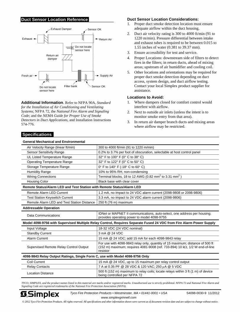
Duct Sensor Location Reference
Return Air
Supply Air
Return air damper
Filter bank
Fresh air
Do not locate sensor here
Sensor OK
Exhaust
Exhaust Damper
Sensor OKDo not locate sensor here
Additional Information. Refer to NFPA 90A, Standard for the Installation of Air Conditioning and Ventilating Systems; NFPA 72, the National Fire Alarm and Signaling Code; and the NEMA Guide for Proper Use of Smoke Detectors in Duct Applications, and Installation Instructions 574-776.
Duct Sensor Location Considerations: 1. Proper duct smoke detection location must ensure
adequate airflow within the duct housing. 2. Duct air velocity rating is 300 to 4000 ft/min (91 to
1220 m/min). Pressure differential between intake and exhaust tubes is required to be between 0.015 to 1.55 inches of water (0.381 to 39.37 mm).
3. Ensure accessibility for test and service. 4. Proper Locations: downstream side of filters to detect
fires in the filters; in return ducts, ahead of mixing areas; upstream of air humidifier and cooling coil.
5. Other locations and orientations may be required for proper duct smoke detection depending on duct access, system design, and duct airflow testing. Contact your local Simplex product supplier for assistance.
Locations to Avoid: 1. Where dampers closed for comfort control would
interfere with airflow. 2. Next to outside air inlets (unless the intent is to
monitor smoke entry from that area). 3. In return air damper branch ducts and mixing areas
where airflow may be restricted.
TYCO, SIMPLEX, and the product names listed in this material are marks and/or registered marks. Unauthorized use is strictly prohibited. NFPA 72 and National Fire Alarm and Signaling Code are registered trademarks of the National Fire Protection Association (NFPA).
General Mechanical and Environmental
Air Velocity Range (linear ft/min) 300 to 4000 ft/min (91 to 1220 m/min)
Sensor Sensitivity Range 0.2% to 3.7% per foot of obscuration, selectable at host control panel
UL Listed Temperature Range 32° F to 100° F (0° C to 38° C)
Operating Temperature Range 32° F to 122° F (0° C to 50° C)
Storage Temperature Range 0 F to 140 F (-18 C to 60 C)
Humidity Range 10% to 95% RH, non-condensing
Wiring Connections Terminal blocks, 18 to 12 AWG (0.82 mm2 to 3.31 mm2 )
Housing Color Black base with clear cover
Remote Status/Alarm LED and Test Station with Remote Status/Alarm LED
Remote Alarm LED Current 1.2 mA, no impact to 24 VDC alarm current (2098-9808 or 2098-9806)
Test Station Keyswitch Current 3.3 mA, no impact to 24 VDC alarm current (2098-9806)
Remote Alarm LED and Test Station Distance 250 ft (76 m) maximum
Addressable Operation
Data Communications IDNet or MAPNET II communications, auto-select, one address per housing; provides operating power to model 4098-9755
Model 4098-9756 with Supervised Multiple Relay Control, Requires Separate Fused 24 VDC from Fire Alarm Power Supply
Input Voltage 18-32 VDC (24 VDC nominal)
Standby Current 3 mA @ 24 VDC
Alarm Current 15 mA @ 24 VDC; add 15 mA for each 4098-9843 relay
Supervised Remote Relay Control Output For use with 4098-9843 relay only, quantity of 15 maximum; distance of 500 ft (152 m) maximum; requires 4081-9008 (ref. 733-894) 10 k, 1/2 W end-of-line resistor
4098-9843 Relay Output Ratings, Single Form C, use with Model 4098-9756 Only
Coil Current 15 mA @ 24 VDC, up to 15 maximum per relay control output
Relay Contacts 7 A at 0.35 PF @ 28 VDC & 120 VAC; 250 A @ 5 VDC
Location Distance 500 ft (152 m) maximum to relay coils; locate relays within 3 ft (1 m) of device being controlled per NFPA 72
Tyco Fire Protection Products • Westminster, MA • 01441-0001 • USA S4098-0030-9 11/2012
www.simplexgrinnell.com © 2012 Tyco Fire Protection Products. All rights reserved. All specifications and other information shown were current as of document revision date and are subject to change without notice.
Specifications

CALIFORNIA DEPARTMENT OF FORESTRY & FIRE PROTECTION
OFFICE OF THE STATE FIRE MARSHAL
FIRE ENGINEERING - BUILDING MATERIALS LISTING PROGRAM
LISTING SERVICE
LISTING No. 3240-0026:0241 Page 1 of 1
CATEGORY: 3240 -- DUCT SMOKE DETECTOR HOUSING/BASE
LISTEE: Simplex100 Simplex Drive, Westminster, MA 01441-0001
Contact: Paul Mattern (978) 731-8542 Fax (978) 731-8881
Email: [email protected]
DESIGN: Models 4098-9755, *4098-9755TSP, *4098-9755TTP, 4098-9756, *4098-9756TSP,
*4098-9756TTP, 4098-9685, 4098-9686, 4098-9687 and 4098-9688 photoelectric type air duct
smoke detector units and Model 4098-9841 relay (for Model 4098-9688 only). Unit consists
of a listed detector head, base, a sampling and an exhaust tube and an enclosure. Refer to
listee's data sheet for additional detailed product description and operational considerations.
RATING: Air Velocity: 300 - 4000 feet/min
INSTALLATION: In accordance with listee's printed installation instructions, applicable codes and ordinances,
and in a manner acceptable to the authority having jurisdiction.
MARKING: Listee's name, model number, electrical & air velocity rating, and UL label.
APPROVAL: Listed as duct smoke detector units for installation in HVAC systems when used with
separately listed compatible fire alarm control units. Refer to listee’s Installation Instruction
Manual for details.
NOTE:
*Rev. 11-06-03
July 01, 2013Date Issued: Listing Expires June 30, 2014
Authorized By:
Fire Engineering Division
This listing is based upon technical data submitted by the applicant. CSFM Fire Engineering staff has reviewed
the test results and/or other data but does not make an independent verification of any claims. This listing is not
an endorsement or recommendation of the item listed. This listing should not be used to verify correct
operational requirements or installation criteria. Refer to listee’s data sheet, installation instructions and/or other
JAMES PARSEGIAN, Program Coordinator
jrogus
Rectangle
jrogus
Rectangle
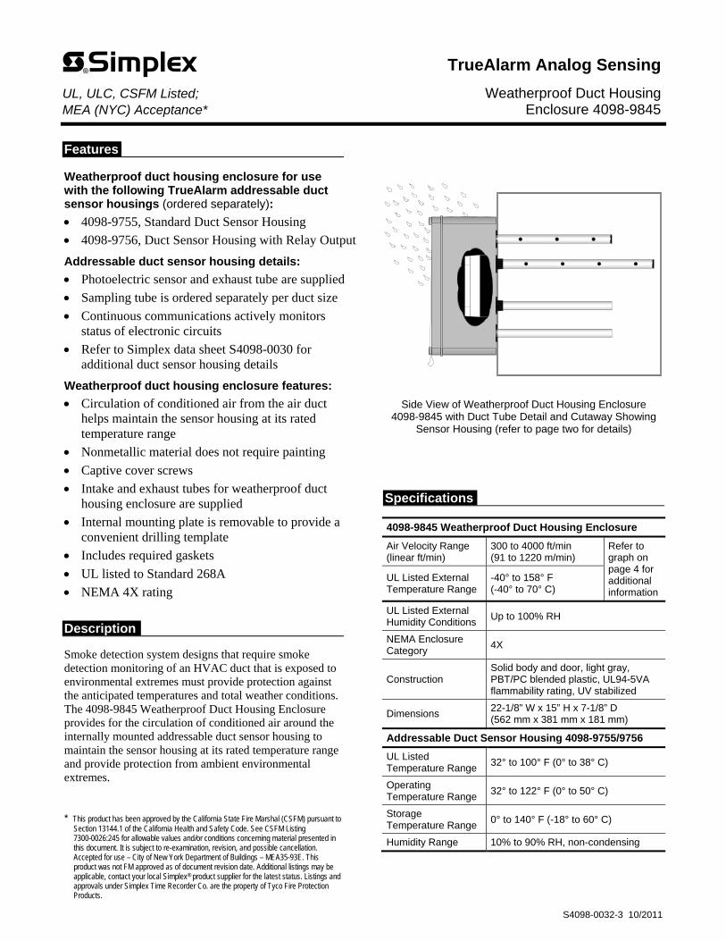
Features Weatherproof duct housing enclosure for use with the following TrueAlarm addressable duct sensor housings (ordered separately):
4098-9755, Standard Duct Sensor Housing
4098-9756, Duct Sensor Housing with Relay Output
Addressable duct sensor housing details:
Photoelectric sensor and exhaust tube are supplied
Sampling tube is ordered separately per duct size
Continuous communications actively monitors status of electronic circuits
Refer to Simplex data sheet S4098-0030 for additional duct sensor housing details
Weatherproof duct housing enclosure features:
Circulation of conditioned air from the air duct helps maintain the sensor housing at its rated temperature range
Nonmetallic material does not require painting
Captive cover screws
Intake and exhaust tubes for weatherproof duct housing enclosure are supplied
Internal mounting plate is removable to provide a convenient drilling template
Includes required gaskets
UL listed to Standard 268A
NEMA 4X rating
Description
Smoke detection system designs that require smoke detection monitoring of an HVAC duct that is exposed to environmental extremes must provide protection against the anticipated temperatures and total weather conditions. The 4098-9845 Weatherproof Duct Housing Enclosure provides for the circulation of conditioned air around the internally mounted addressable duct sensor housing to maintain the sensor housing at its rated temperature range and provide protection from ambient environmental extremes.
* This product has been approved by the California State Fire Marshal (CSFM) pursuant to
Section 13144.1 of the California Health and Safety Code. See CSFM Listing 7300-0026:245 for allowable values and/or conditions concerning material presented in this document. It is subject to re-examination, revision, and possible cancellation. Accepted for use – City of New York Department of Buildings – MEA35-93E. This product was not FM approved as of document revision date. Additional listings may be applicable, contact your local Simplex® product supplier for the latest status. Listings and approvals under Simplex Time Recorder Co. are the property of Tyco Fire Protection Products.
Side View of Weatherproof Duct Housing Enclosure 4098-9845 with Duct Tube Detail and Cutaway Showing
Sensor Housing (refer to page two for details)
Specifications
4098-9845 Weatherproof Duct Housing Enclosure
Air Velocity Range (linear ft/min)
300 to 4000 ft/min (91 to 1220 m/min)
Refer to graph on page 4 for additional information
UL Listed External Temperature Range
-40° to 158° F (-40° to 70° C)
UL Listed External Humidity Conditions
Up to 100% RH
NEMA Enclosure Category
4X
Construction Solid body and door, light gray, PBT/PC blended plastic, UL94-5VA flammability rating, UV stabilized
Dimensions 22-1/8” W x 15” H x 7-1/8” D (562 mm x 381 mm x 181 mm)
Addressable Duct Sensor Housing 4098-9755/9756
UL Listed Temperature Range
32° to 100° F (0° to 38° C)
Operating Temperature Range
32° to 122° F (0° to 50° C)
Storage Temperature Range
0° to 140° F (-18° to 60° C)
Humidity Range 10% to 90% RH, non-condensing
TrueAlarm Analog Sensing UL, ULC, CSFM Listed; Weatherproof Duct Housing MEA (NYC) Acceptance* Enclosure 4098-9845
S4098-0032-3 10/2011
jrogus
Rectangle
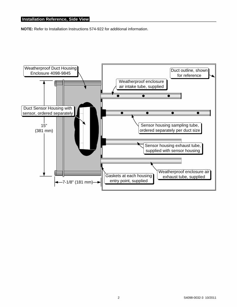
2 S4098-0032-3 10/2011
15"(381 mm)
Weatherproof enclosure air exhaust tube, supplied
Weatherproof enclosure air intake tube, supplied
Gaskets at each housing entry point, supplied
Duct outline, shown for reference
Weatherproof Duct Housing Enclosure 4098-9845
Duct Sensor Housing with sensor, ordered separately
Sensor housing sampling tube, ordered separately per duct size
Sensor housing exhaust tube, supplied with sensor housing
7-1/8" (181 mm)
Installation Reference, Side View NOTE: Refer to Installation Instructions 574-922 for additional information.
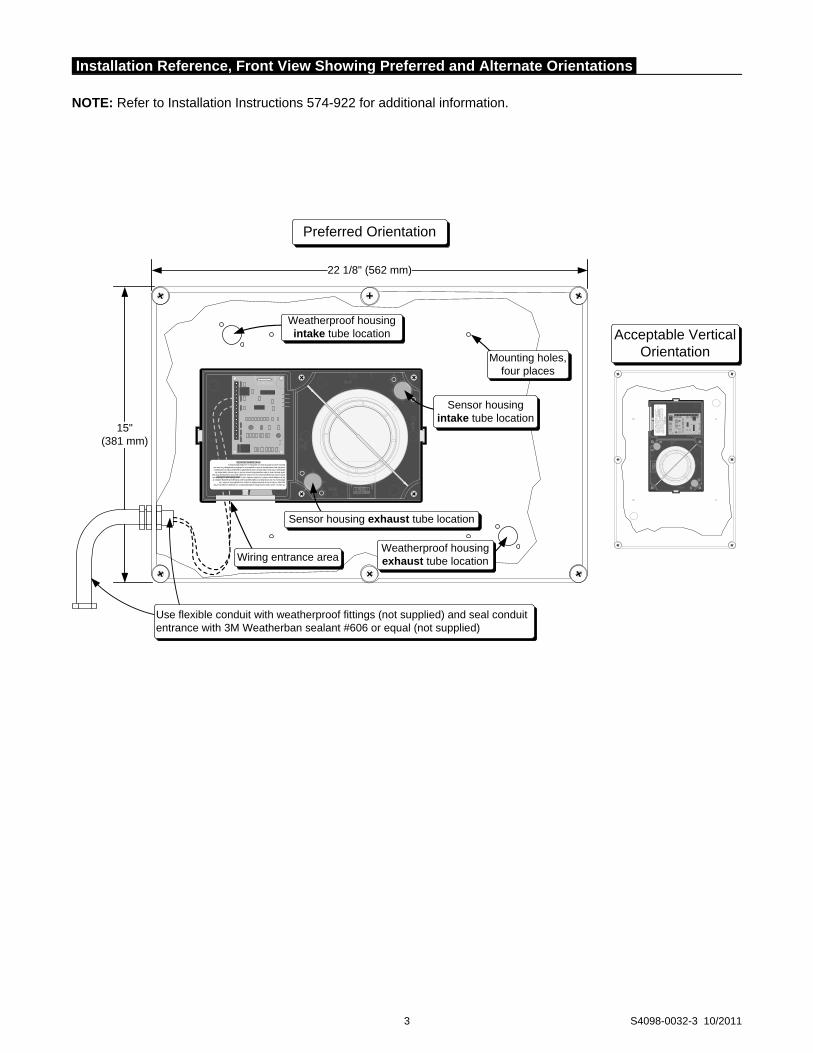
3 S4098-0032-3 10/2011
15"(381 mm)
Acceptable Vertical Orientation
22 1/8" (562 mm)
Preferred Orientation
Use flexible conduit with weatherproof fittings (not supplied) and seal conduit entrance with 3M Weatherban sealant #606 or equal (not supplied)
Sensor housing exhaust tube location
Weatherproof housing intake tube location
Sensor housing intake tube location
This device is a duct smoke housing. When provided with detector, it is designed to sample the air flow passing by it in the air duct to determine whether it contains unacceptable levels of smoke. The effectiveness of a duct smoke detector is highly dependent upon: the design and operating conditions of the air handling system in which it is installed, variables such as smoke dilution and stratificationover which even the best designed systems have no control, and proper placement and positioning of the duct smoke detector, which is often compromised for practical reasons. For the reasons stated above, the effectiveness of this duct smoke detector cannot be warranted or guaranteed. Under no circumstances should this duct smoke detector be used or regarded to be a substitute for the building's Fire alarm and detection system to which this device is attached as a secondary detection device.
DO NOT REMOVE THIS NOTICE!
Weatherproof housing exhaust tube locationWiring entrance area
Mounting holes, four places
This
dev
ice
is a
duc
t sm
oke
hous
ing.
Whe
n pr
ovid
ed w
ith d
etec
tor,
it is
des
igne
d to
sam
ple
the
air f
low
pass
ing
by it
in th
e ai
r duc
t to
dete
rmin
e w
heth
er it
con
tain
s un
acce
ptab
le le
vels
of s
mok
e. T
he
effe
ctiv
enes
s of
a d
uct s
mok
e de
tect
or is
hig
hly
depe
nden
t upo
n: th
e de
sign
and
ope
ratin
g co
nditi
ons
of th
e
air h
andl
ing
syst
em in
whi
ch it
is in
stal
led,
var
iabl
es s
uch
as
smok
e di
lutio
n an
d st
ratif
icat
ion
over
whi
ch
even
the
best
des
igne
d sy
stem
s ha
ve n
o co
ntro
l, an
d pr
oper
pla
cem
ent a
nd p
ositio
ning
of t
he d
uct s
mok
e
dete
ctor
, whi
ch is
ofte
n co
mpr
omis
ed fo
r pra
ctic
al re
ason
s. F
or th
e re
ason
s st
ated
abo
ve, t
he e
ffect
iven
ess
of th
is d
uct s
mok
e de
tect
or c
anno
t be
warra
nted
or g
uara
ntee
d. U
nder
no
circ
umst
ance
s sh
ould
this
duc
t
smok
e de
tect
or b
e us
ed o
r reg
arde
d to
be
a su
bstit
ute
for t
he b
uild
ing's
Fire
ala
rm a
nd d
etec
tion
syst
em to
whi
ch th
is d
evic
e is
atta
ched
as
a se
cond
ary
dete
ctio
n de
vice
.
DO N
OT
REM
OV
E TH
IS N
OTI
CE!
Installation Reference, Front View Showing Preferred and Alternate Orientations
NOTE: Refer to Installation Instructions 574-922 for additional information.
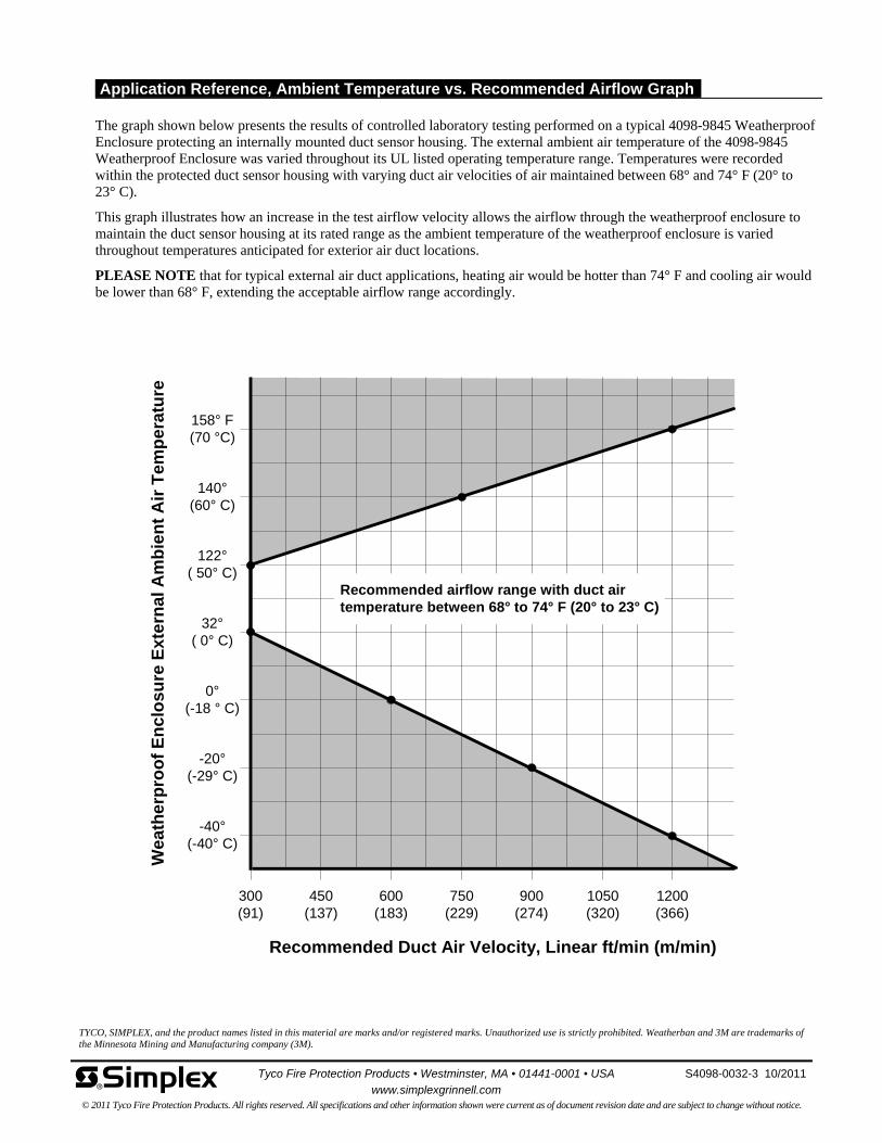
TYCO, SIMPLEX, and the product names listed in this material are marks and/or registered marks. Unauthorized use is strictly prohibited. Weatherban and 3M are trademarks of the Minnesota Mining and Manufacturing company (3M).
-40°(-40° C)
-20°(-29° C)
0°(-18 ° C)
32°( 0° C)
122°( 50° C)
140°(60° C)
158° F(70 °C)
Recommended Duct Air Velocity, Linear ft/min (m/min)
Wea
the
rpro
of
En
clo
su
re E
xte
rna
l Am
bie
nt
Air
Te
mp
era
ture
Recommended airflow range with duct airtemperature between 68° to 74° F (20° to 23° C)
300(91)
450(137)
600(183)
750(229)
900(274)
1050(320)
1200(366)
Tyco Fire Protection Products • Westminster, MA • 01441-0001 • USA S4098-0032-3 10/2011
www.simplexgrinnell.com © 2011 Tyco Fire Protection Products. All rights reserved. All specifications and other information shown were current as of document revision date and are subject to change without notice.
Application Reference, Ambient Temperature vs. Recommended Airflow Graph The graph shown below presents the results of controlled laboratory testing performed on a typical 4098-9845 Weatherproof Enclosure protecting an internally mounted duct sensor housing. The external ambient air temperature of the 4098-9845 Weatherproof Enclosure was varied throughout its UL listed operating temperature range. Temperatures were recorded within the protected duct sensor housing with varying duct air velocities of air maintained between 68° and 74° F (20° to 23° C).
This graph illustrates how an increase in the test airflow velocity allows the airflow through the weatherproof enclosure to maintain the duct sensor housing at its rated range as the ambient temperature of the weatherproof enclosure is varied throughout temperatures anticipated for exterior air duct locations.
PLEASE NOTE that for typical external air duct applications, heating air would be hotter than 74° F and cooling air would be lower than 68° F, extending the acceptable airflow range accordingly.
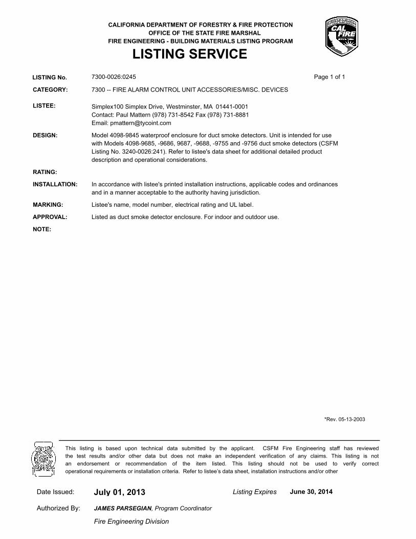
CALIFORNIA DEPARTMENT OF FORESTRY & FIRE PROTECTION
OFFICE OF THE STATE FIRE MARSHAL
FIRE ENGINEERING - BUILDING MATERIALS LISTING PROGRAM
LISTING SERVICE
LISTING No. 7300-0026:0245 Page 1 of 1
CATEGORY: 7300 -- FIRE ALARM CONTROL UNIT ACCESSORIES/MISC. DEVICES
LISTEE: Simplex100 Simplex Drive, Westminster, MA 01441-0001
Contact: Paul Mattern (978) 731-8542 Fax (978) 731-8881
Email: [email protected]
DESIGN: Model 4098-9845 waterproof enclosure for duct smoke detectors. Unit is intended for use
with Models 4098-9685, -9686, 9687, -9688, -9755 and -9756 duct smoke detectors (CSFM
Listing No. 3240-0026:241). Refer to listee's data sheet for additional detailed product
description and operational considerations.
RATING:
INSTALLATION: In accordance with listee's printed installation instructions, applicable codes and ordinances
and in a manner acceptable to the authority having jurisdiction.
MARKING: Listee's name, model number, electrical rating and UL label.
APPROVAL: Listed as duct smoke detector enclosure. For indoor and outdoor use.
NOTE:
*Rev. 05-13-2003
July 01, 2013Date Issued: Listing Expires June 30, 2014
Authorized By:
Fire Engineering Division
This listing is based upon technical data submitted by the applicant. CSFM Fire Engineering staff has reviewed
the test results and/or other data but does not make an independent verification of any claims. This listing is not
an endorsement or recommendation of the item listed. This listing should not be used to verify correct
operational requirements or installation criteria. Refer to listee’s data sheet, installation instructions and/or other
JAMES PARSEGIAN, Program Coordinator
jrogus
Rectangle
3/11/2014 REV.#: 0 PROJECT #: 480-408330-26 / 976229926
SimplexGrinnell LP 3568 Ruffin Road, South San Diego, CA 92123-2597 Tele: (858) 633-9100 Fax: (858) 633-9101 www.simplexgrinnell.com
APPENDIX
ITEM DESCRIPTION
A BUSINESS LICENSE
B WARRANTY
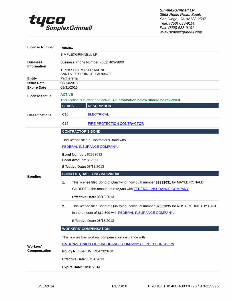
3/11/2014 REV.#: 0 PROJECT #: 480-408330-26 / 976229926
SimplexGrinnell LP 3568 Ruffin Road, South San Diego, CA 92123-2597 Tele: (858) 633-9100 Fax: (858) 633-9101 www.simplexgrinnell.com
License Number 986047
Business
Information
SIMPLEXGRINNELL LP Business Phone Number: (562) 405-3800 12728 SHOEMAKER AVENUE SANTA FE SPRINGS, CA 90670
Entity Partnership
Issue Date 08/14/2013
Expire Date 08/31/2015
License Status ACTIVE
This license is current and active. All information below should be reviewed.
Classifications
CLASS DESCRIPTION
C10 ELECTRICAL
C16 FIRE PROTECTION CONTRACTOR
Bonding
CONTRACTOR'S BOND
This license filed a Contractor's Bond with
FEDERAL INSURANCE COMPANY.
Bond Number: 82332032
Bond Amount: $12,500
Effective Date: 08/13/2013
BOND OF QUALIFYING INDIVIDUAL
1. This license filed Bond of Qualifying Individual number 82332031 for MAYLE RONALD
GILBERT in the amount of $12,500 with FEDERAL INSURANCE COMPANY.
Effective Date: 08/13/2013
2. This license filed Bond of Qualifying Individual number 82332035 for ROSTEN TIMOTHY PAUL
in the amount of $12,500 with FEDERAL INSURANCE COMPANY.
Effective Date: 08/13/2013
Workers'
Compensation
WORKERS' COMPENSATION
This license has workers compensation insurance with
NATIONAL UNION FIRE INSURANCE COMPANY OF PITTSBURGH, PA
Policy Number: WLRC47323484
Effective Date: 10/01/2013
Expire Date: 10/01/2014
3/11/2014 REV.#: 0 PROJECT #: 480-408330-26 / 976229926
SimplexGrinnell LP 3568 Ruffin Road, South San Diego, CA 92123-2597 Tele: (858) 633-9100 Fax: (858) 633-9101 www.simplexgrinnell.com
SIMPLEXGRINNELL WARRANTY
WARRANTY & DAMAGES: SimplexGrinnell hereby warranties for one (1) year from the date of beneficial use or eighteen (18) months from date of delivery to the purchaser to replace, or at its option, to repair any equipment or parts thereof which are found to be defective in material or workmanship. This warranty is made to the purchaser of this equipment and is in lieu of all other warranties, expressed or implied, including any implied warranty of merchantability of fitness for a particular purpose. SimplexGrinnell shall not be liable for any direct, incidental or consequential loss of damage to the purchaser or user of this equipment arising out of the failure of the equipment to operate in excess of the purchase price of said equipment. This warranty is solely limited to the equipment as provided by SimplexGrinnell in this submittal and excludes associated field wiring and/or any equipment to which the submitted equipment may be attached or connected.
WARRANTY SERVICE HOURS:
- 8:00AM TO 17:00PM, MONDAY THROUGH FRIDAY, EXCLUDING LOCALLY OBSERVED SIMPLEX HOLIDAYS.
- OFF HOURS RESPONSE IS AVAILABLE AT EXTRA COST