
UNIVERSITY OF CALIFORNIA, IRVINE Solid Oxide Fuel Cell ...
309
UNIVERSITY OF CALIFORNIA, IRVINE Solid Oxide Fuel Cell-Gas Turbine Hybrid Power Systems: Energy Analysis, Control Assessments, Fluid Dynamics Analysis and Dynamic Modeling for Stationary and Transportation Applications DISSERTATION submitted in partial satisfaction of the requirements for the degree of DOCTOR OF PHILOSOPHY in Mechanical and Aerospace Engineering by Mohammad Ali Azizi Dissertation Committee: Professor Jacob Brouwer, Chair Professor Scott Samuelsen Professor Ken Mease 2018
-
Upload
khangminh22 -
Category
Documents
-
view
2 -
download
0
Transcript of UNIVERSITY OF CALIFORNIA, IRVINE Solid Oxide Fuel Cell ...
UNIVERSITY OF CALIFORNIA,IRVINE
Solid Oxide Fuel Cell-Gas Turbine Hybrid Power Systems: Energy Analysis, ControlAssessments, Fluid Dynamics Analysis and Dynamic Modeling for Stationary and
Transportation Applications
DISSERTATION
submitted in partial satisfaction of the requirementsfor the degree of
DOCTOR OF PHILOSOPHY
in Mechanical and Aerospace Engineering
by
Mohammad Ali Azizi
Dissertation Committee:Professor Jacob Brouwer, Chair
Professor Scott SamuelsenProfessor Ken Mease
2018

© 2018 Mohammad Ali Azizi

DEDICATION
To
My parents
for their inspiration and encouraging me to follow my dreams
ii

TABLE OF CONTENTS
Page
LIST OF FIGURES vi
LIST OF TABLES xii
ACKNOWLEDGMENTS xiii
CURRICULUM VITAE xiv
ABSTRACT OF THE DISSERTATION xix
1 Introduction and Background 11.1 Introduction . . . . . . . . . . . . . . . . . . . . . . . . . . . . . . . . . . 1
1.1.1 Emergence of SOFC power plants . . . . . . . . . . . . . . . . . . 11.2 Goal and Objectives . . . . . . . . . . . . . . . . . . . . . . . . . . . . . . 4
1.2.1 Goal . . . . . . . . . . . . . . . . . . . . . . . . . . . . . . . . . . 41.2.2 Objectives . . . . . . . . . . . . . . . . . . . . . . . . . . . . . . . 4
2 Literature Review 62.1 SOFC-GT hybrid system background . . . . . . . . . . . . . . . . . . . . 6
2.1.1 Experimental evaluation of Integrated SOFC-GT hybrid systems . . 82.1.2 Experimental test facilities for hybrid systems . . . . . . . . . . . . 102.1.3 Gas turbine technology applications in SOFC-GT hybrid systems . 21
2.2 Hybrid SOFC-GT System Design Concepts . . . . . . . . . . . . . . . . . 212.2.1 Hybrid system configurations . . . . . . . . . . . . . . . . . . . . 232.2.2 Integration with various cycles . . . . . . . . . . . . . . . . . . . . 26
2.3 Models for SOFC-GT Hybrid Systems . . . . . . . . . . . . . . . . . . . . 292.3.1 Early hybrid SOFC-GT model development . . . . . . . . . . . . . 29
2.4 Motivation . . . . . . . . . . . . . . . . . . . . . . . . . . . . . . . . . . . 392.5 SOFC-GT dynamics model description . . . . . . . . . . . . . . . . . . . . 40
2.5.1 Fuel cell and stack models . . . . . . . . . . . . . . . . . . . . . . 402.5.2 Reformer models . . . . . . . . . . . . . . . . . . . . . . . . . . . 462.5.3 Combustor models . . . . . . . . . . . . . . . . . . . . . . . . . . 51
2.6 Steady-State Performance Reported . . . . . . . . . . . . . . . . . . . . . 53
iii
2.7 Component Modifications for Dynamic Hybrid System Operation . . . . . 572.8 Practical Issues Discussed in Hybrid SOFC/GT Literature . . . . . . . . . . 592.9 Hybrid System Transient Operation and Control . . . . . . . . . . . . . . . 60
2.9.1 Turbomachinery Controls . . . . . . . . . . . . . . . . . . . . . . 602.9.2 Off-design performance of hybrid system using fixed and variable
GT speed . . . . . . . . . . . . . . . . . . . . . . . . . . . . . . . 622.9.3 Control strategies for compressor surge . . . . . . . . . . . . . . . 782.9.4 Computational stall/surge analysis in hybrid SOFC-GT systems . . 832.9.5 Gas turbine and compressor models . . . . . . . . . . . . . . . . . 86
2.10 Optimal control and reliability analysis of stationary hybrid SOFC-GT pow-er generation system . . . . . . . . . . . . . . . . . . . . . . . . . . . . . 982.10.1 System control strategies . . . . . . . . . . . . . . . . . . . . . . . 99
2.11 Hybrid SOFC-GT System Optimization . . . . . . . . . . . . . . . . . . . 1112.12 Parametric Studies . . . . . . . . . . . . . . . . . . . . . . . . . . . . . . 116
2.12.1 Main parameters for SOFC-GT hybrid system simulation . . . . . . 1162.12.2 Exergy based analysis of hybrid systems . . . . . . . . . . . . . . . 1222.12.3 Operating pressure effects . . . . . . . . . . . . . . . . . . . . . . 124
2.13 CO2 capture, sequestration and emission reduction . . . . . . . . . . . . . 1262.14 Investigation of alternative fuels . . . . . . . . . . . . . . . . . . . . . . . 130
3 Computational fluid dynamic Analysis 1343.1 Motivation for using CFD to analyze surge . . . . . . . . . . . . . . . . . . 134
3.1.1 Mechanisms of Compressor Surge/Stall in hybrid SOFC-GT system 1383.1.2 Dynamic model integrated with CFD simulation . . . . . . . . . . 140
3.2 Plant description . . . . . . . . . . . . . . . . . . . . . . . . . . . . . . . 1413.2.1 Dynamic Hybrid System Model . . . . . . . . . . . . . . . . . . . 141
3.3 Transient Dynamic Simulation . . . . . . . . . . . . . . . . . . . . . . . . 1423.4 Turbomachinery Fluid Dynamics Simulation . . . . . . . . . . . . . . . . . 1433.5 Geometry Modeling . . . . . . . . . . . . . . . . . . . . . . . . . . . . . . 1473.6 Boundary Conditions . . . . . . . . . . . . . . . . . . . . . . . . . . . . . 1483.7 Fluid Dynamics Model . . . . . . . . . . . . . . . . . . . . . . . . . . . . 1483.8 Stall/Surge Results . . . . . . . . . . . . . . . . . . . . . . . . . . . . . . 1503.9 Stall/Surge analysis results . . . . . . . . . . . . . . . . . . . . . . . . . . 1613.10 220 kW Siemens-Westinghouse Power Plant . . . . . . . . . . . . . . . . . 162
3.10.1 Model Validation Efforts . . . . . . . . . . . . . . . . . . . . . . . 163
4 Hybrid SOFC-GT Locomotive System Design 1734.1 General System Modeling . . . . . . . . . . . . . . . . . . . . . . . . . . 1734.2 Hybrid SOFC-GT system for transportation application . . . . . . . . . . . 173
4.2.1 Motivation . . . . . . . . . . . . . . . . . . . . . . . . . . . . . . 1734.3 Scope . . . . . . . . . . . . . . . . . . . . . . . . . . . . . . . . . . . . . 174
4.3.1 Research Gap . . . . . . . . . . . . . . . . . . . . . . . . . . . . . 1744.3.2 Fuel Cell Locomotives . . . . . . . . . . . . . . . . . . . . . . . . 175
iv

4.3.3 Locomotive requirements . . . . . . . . . . . . . . . . . . . . . . 1804.3.4 Fueling Infrastructure for hybrid SOFC-GT locomotives . . . . . . 1814.3.5 Economic Considerations . . . . . . . . . . . . . . . . . . . . . . 1844.3.6 Modeling . . . . . . . . . . . . . . . . . . . . . . . . . . . . . . . 1884.3.7 Total Cost calculation . . . . . . . . . . . . . . . . . . . . . . . . 1934.3.8 Cost Model . . . . . . . . . . . . . . . . . . . . . . . . . . . . . . 1934.3.9 Development Stages . . . . . . . . . . . . . . . . . . . . . . . . . 1944.3.10 Cost Results . . . . . . . . . . . . . . . . . . . . . . . . . . . . . 1944.3.11 System Sizing and Evaluation of the First long-haul SOFC-GT system197
5 Modeling of Hybrid SOFC-GT system for locomotives 2045.1 Development of 500 kW small scale lab design . . . . . . . . . . . . . . . 204
6 Hybrid SOFC-GT Locomotive Dynamics and Control 2196.1 Dynamic Modeling of hybrid SOFC-GT system for locomotives . . . . . . 219
6.1.1 Objectives . . . . . . . . . . . . . . . . . . . . . . . . . . . . . . . 2206.1.2 Prototype Development . . . . . . . . . . . . . . . . . . . . . . . . 2226.1.3 System Optimization . . . . . . . . . . . . . . . . . . . . . . . . . 2246.1.4 System Modeling . . . . . . . . . . . . . . . . . . . . . . . . . . . 2286.1.5 Gas Turbine Dynamic Model . . . . . . . . . . . . . . . . . . . . . 229
6.2 Route Simulation . . . . . . . . . . . . . . . . . . . . . . . . . . . . . . . 2316.3 Parametric study for fuel cell power density . . . . . . . . . . . . . . . . . 237
7 Summary and Conclusions 2417.1 Summary . . . . . . . . . . . . . . . . . . . . . . . . . . . . . . . . . . . 2417.2 Conclusion . . . . . . . . . . . . . . . . . . . . . . . . . . . . . . . . . . 244
Bibliography 245
v

LIST OF FIGURES
Page
2.1 250 kW prototype of hybrid SOFC-MGT system [102] . . . . . . . . . . . 92.2 Long term operation test of the SOFC-MGT system [102] . . . . . . . . . . 102.3 Emulator test rigs: NETL, University of Genoa and DLR laboratories [103] 112.4 Block diagram of HyPer MPC control application [104] . . . . . . . . . . . 112.5 MIMO controller of hybrid SOFC-GT system [111] . . . . . . . . . . . . . 132.6 Prediction Type Kalman Filter (PTKF) [112] . . . . . . . . . . . . . . . . . 142.7 Simplified flow diagram of hybrid simulation facility at NETL [113] . . . . 142.8 Load based speed control strategy [116] . . . . . . . . . . . . . . . . . . . 152.9 The T100 power module modifications for the fuel cell coupling [120] . . . 162.10 Test rig plant layout: the blue box is related to the SOFC model [121] . . . 172.11 Hybrid cycle design [122] . . . . . . . . . . . . . . . . . . . . . . . . . . 182.12 Transient behavior of MGT with temperature variation at gas preheater [122] 192.13 Hybrid power plant test rig at DLR [122] . . . . . . . . . . . . . . . . . . . 202.14 Basic concept of a fuel cell-gas turbine hybrid system [129] . . . . . . . . . 222.15 Schematic of a direct hybrid gas turbine fuel cell topping cycle [30] . . . . 232.16 Schematic of an indirect gas turbine fuel cell bottoming cycle [30] . . . . . 242.17 Schematic of the SOFC-MGT-ORC cycle [141] . . . . . . . . . . . . . . . 272.18 Process concept of combined fermentation and gasification of sewage sludge
[148] . . . . . . . . . . . . . . . . . . . . . . . . . . . . . . . . . . . . . . 282.19 Schematic of a recuperated internal-reforming hybrid SOFC-GT system [64] 292.20 Plant layout [72] . . . . . . . . . . . . . . . . . . . . . . . . . . . . . . . 302.21 Pressurized 220 kW SOFC/Gas Turbine Hybrid [30] . . . . . . . . . . . . 332.22 Tubular SOFC stack design [30] . . . . . . . . . . . . . . . . . . . . . . . 342.23 Siemens Westinghouse substack basic building block tested at UC Irvine [158] 352.24 Siemens Westinghouse hybrid system [158] . . . . . . . . . . . . . . . . . 352.25 320 kWe PSOFC/GT power system [158] . . . . . . . . . . . . . . . . . . 362.26 Scheme of the SOFC group, mixer and sensible heat reformer [155] . . . . 372.27 The hybrid SOFC-GT power plant being developed at DLR [161] . . . . . 382.28 (a) Cell voltage at different temperatures and current densities. (b) 3-D view
of the cell voltage variation at different temperatures and current densities [64] 422.29 3-D view of SOFC voltage variation at different air inlet temperatures and
fuel flow rates [64] . . . . . . . . . . . . . . . . . . . . . . . . . . . . . . 45
vi

2.30 3-D view of stack power output variation at different air inlet temperaturesand fuel flow rates [64] . . . . . . . . . . . . . . . . . . . . . . . . . . . . 45
2.31 Shaft speed control strategy [190] . . . . . . . . . . . . . . . . . . . . . . 602.32 GT power output, model VS experiment data [30] . . . . . . . . . . . . . . 612.33 Partial load performance of SOFC-GT system with TIT and rotor speed as
parameters [198] . . . . . . . . . . . . . . . . . . . . . . . . . . . . . . . 662.34 Influence of ambient temperature without control system [199] . . . . . . . 672.35 Hybrid System Part Load Efficiency [199] . . . . . . . . . . . . . . . . . . 682.36 Fuel Cell Part Load Efficiency [199] . . . . . . . . . . . . . . . . . . . . . 682.37 Simplified layout of hybrid system (Personal Turbine and SOFC) [200] . . 692.38 Design and part-load performance of a hybrid system versus non-dimensional
power (fixed turbine speed control system) [200] . . . . . . . . . . . . . . 702.39 Hybrid system inefficiencies versus non-dimensional power (Variable tur-
bine speed control system) [200] . . . . . . . . . . . . . . . . . . . . . . . 712.40 Pressurized SOFC hybrid system [201] . . . . . . . . . . . . . . . . . . . . 722.41 Off-design performance of P-HS (constant speed)[201] . . . . . . . . . . . 732.42 Off-design performance of fuel cell stack in P-HS layout (constant speed)
[201] . . . . . . . . . . . . . . . . . . . . . . . . . . . . . . . . . . . . . . 732.43 Off-design performance of P-HS layout (Variable speed) [201] . . . . . . . 742.44 Off-design performance of fuel cell stack in P-HS layout (Variable speed)
[201] . . . . . . . . . . . . . . . . . . . . . . . . . . . . . . . . . . . . . . 742.45 SOFC-GT hybrid system with fixed speed GT and cathode bypass [175] . . 752.46 Temperature distribution in the SOFC module (a) air stream in the electro-
chemical reaction process (b) electrolyte and electrodes (c) fuel stream inthe electrochemical reaction process (d) fuel stream in the reforming process[202]. . . . . . . . . . . . . . . . . . . . . . . . . . . . . . . . . . . . . . 76
2.47 Two important temperatures of SOFC/GT hybrid system operating with VRS+ FC and HAB + FC modes: (a) cell temperature; (b) turbine inlet tempera-ture [203] . . . . . . . . . . . . . . . . . . . . . . . . . . . . . . . . . . . 77
2.48 Pressure losses between the recuperator and the combustor for three differentconditions: (i) direct line, (ii) volume zero, and, (iii) modular volume [205] 79
2.49 Temperature control system scheme (external loop) [206] . . . . . . . . . . 792.50 P-I feedback control loops for FC-GT control [181] . . . . . . . . . . . . . 802.51 Control overview for synchronous SOFC-GT topping cycle with inlet guide
vanes (IGV) and bypass [181] . . . . . . . . . . . . . . . . . . . . . . . . 802.52 Stepwise SOFC load change for a constant ratio of GT load to SOFC load
[208] . . . . . . . . . . . . . . . . . . . . . . . . . . . . . . . . . . . . . . 812.53 Simulated time profiles during a shut down test at valve positions αv=30 deg
standard configuration. (a) βp; (b) compressor flow rate; (c) turbine flow rate[211] . . . . . . . . . . . . . . . . . . . . . . . . . . . . . . . . . . . . . . 82
2.54 Dynamic simulation approach of gas turbine and compressor [30] . . . . . 882.55 Schematic of a compressor-fuel cell-combustor- gas turbine engine used in
[64] . . . . . . . . . . . . . . . . . . . . . . . . . . . . . . . . . . . . . . 90
vii

2.56 Turbomachinery Interpolation strategy [190] . . . . . . . . . . . . . . . . . 932.57 Dual spool compressor pressure profile during mild surge following a pres-
sure step dynamic perturbation [215] . . . . . . . . . . . . . . . . . . . . . 982.58 Cascade controller design [194] . . . . . . . . . . . . . . . . . . . . . . . 1002.59 Catalytic oxidizer control scheme [194] . . . . . . . . . . . . . . . . . . . 1002.60 A kilowatt per second 2.4-4.8 kW load increase with compensated fuel flow
combustor temperature control, current fuel cell power control and blowerpower buffering [221] . . . . . . . . . . . . . . . . . . . . . . . . . . . . . 102
2.61 SOFC-GT hybrid system integrated with autonomous power system [222] . 1022.62 PI control structure [222] . . . . . . . . . . . . . . . . . . . . . . . . . . . 1032.63 Load change, SOFC temperature and fuel utilization during simulation [222] 1042.64 Control inputs variation during simulation [222] . . . . . . . . . . . . . . . 1042.65 The proposed power tracking control strategy [225] . . . . . . . . . . . . . 1052.66 Control diagram of power tracking control [225] . . . . . . . . . . . . . . . 1052.67 Schematic of the closed-loop SOFC/GT plant with the IS-RG controller [227] 1062.68 SOFC-GT hybrid system [228] . . . . . . . . . . . . . . . . . . . . . . . . 1072.69 SOFC-GT control system [228] . . . . . . . . . . . . . . . . . . . . . . . . 1072.70 System emulator layout and interface to the fuel cell stack real-time model
[231] . . . . . . . . . . . . . . . . . . . . . . . . . . . . . . . . . . . . . . 1082.71 Flue gas temperature control loop in hybrid system [232] . . . . . . . . . . 1092.72 Hybrid cycle layout [189] . . . . . . . . . . . . . . . . . . . . . . . . . . . 1102.73 Control system of hybrid system [189] . . . . . . . . . . . . . . . . . . . . 1112.74 Hydrogen molar flow rate (a), SOFC voltage (b) and current (c) outputs (GT
load steps: 37-22.5-44 kW) [260] . . . . . . . . . . . . . . . . . . . . . . . 1152.75 Destroyed exergy rate of hybrid system components from Calise et al. [72] . 1222.76 Thermal/Mechanical/Electrical power generation/consumption by each com-
ponent from Calise et al. [72] . . . . . . . . . . . . . . . . . . . . . . . . . 1232.77 Exergy destructions per mole of methane consumed for the devices in the
integrated system for the illustrative example, where Vs=0.61 V [270] . . . 1242.78 System layout of the IGCC system with pre-combustion CO2 capture [296] 128
3.1 Surge chart . . . . . . . . . . . . . . . . . . . . . . . . . . . . . . . . . . 1353.2 Impeller corrosion . . . . . . . . . . . . . . . . . . . . . . . . . . . . . . . 1363.3 Compressor surge effect on blade corrosion . . . . . . . . . . . . . . . . . 1373.4 Types of surge . . . . . . . . . . . . . . . . . . . . . . . . . . . . . . . . . 1383.5 Surge mechanism due to the high turbine inlet (TIT) temperature . . . . . . 1393.6 Surge mechanism due to the system emergency shut-down . . . . . . . . . 1393.7 Hybrid SOFC-GT system power plant schematic [316] . . . . . . . . . . . 1423.8 1.7 MW Kawasaki multi-stage gas turbine [317] . . . . . . . . . . . . . . . 1433.9 1.7 MW Kawasaki gas turbine [317] . . . . . . . . . . . . . . . . . . . . . 1443.10 1.7 MW Kawasaki compressor geometry model . . . . . . . . . . . . . . . 1443.11 Applied Fluid Model-Multi Stage Compressor . . . . . . . . . . . . . . . . 1453.12 Mesh generated on the Splitter . . . . . . . . . . . . . . . . . . . . . . . . 146
viii

3.13 Mesh generated on the blade . . . . . . . . . . . . . . . . . . . . . . . . . 1463.14 Mesh generated on the diffuser . . . . . . . . . . . . . . . . . . . . . . . . 1473.15 Operating point of 4 MW hybrid SOFC-GT at steady state condition . . . . 1503.16 Velocity vector on the whole domain . . . . . . . . . . . . . . . . . . . . . 1513.17 Pressure distribution in the flow domain on the front and rear impellers of
the multi-stage compressor . . . . . . . . . . . . . . . . . . . . . . . . . . 1523.18 Pressure development in the diffuser . . . . . . . . . . . . . . . . . . . . . 1543.19 Pressure development on the front impeller’s shroud . . . . . . . . . . . . . 1553.20 Pressure development on the rear impeller’s shroud . . . . . . . . . . . . . 1563.21 Front Impeller inlet velocity/mass flow rate oscillation . . . . . . . . . . . 1573.22 Rear Impeller inlet velocity/mass flow rate oscillation . . . . . . . . . . . . 1573.23 Sustained mass flow rate after transient power demand change of the hybrid
SOFC-GT system . . . . . . . . . . . . . . . . . . . . . . . . . . . . . . . 1593.24 The front impeller velocity distribution from the leading edge (LE) to the
trailing edge (TE) . . . . . . . . . . . . . . . . . . . . . . . . . . . . . . . 1603.25 The rear Impeller velocity distribution from the LE to the TE . . . . . . . . 1603.26 Sustained mass flow rate after transient power demand change of the hybrid
SOFC-GT system . . . . . . . . . . . . . . . . . . . . . . . . . . . . . . . 1623.27 220 kW Siemens- Westinghouse power plant . . . . . . . . . . . . . . . . 1633.28 Compressor inlet temperature . . . . . . . . . . . . . . . . . . . . . . . . . 1643.29 Observed and simulated turbine inlet, GT1 and GT2 temperatures . . . . . 1643.30 Observed and simulated SOFC inlet and outlet temperatures . . . . . . . . 1653.31 Modified Siemens Westinghouse Power System . . . . . . . . . . . . . . . 1663.32 Modified Siemens Westinghouse Control Strategy . . . . . . . . . . . . . . 1673.33 Single Stage Compressor Schematic . . . . . . . . . . . . . . . . . . . . . 1683.34 C-65 (Capstone) operating parameters . . . . . . . . . . . . . . . . . . . . 1693.35 C-65 (Capstone) operating parameters . . . . . . . . . . . . . . . . . . . . 1693.36 C-65 impeller pressure results . . . . . . . . . . . . . . . . . . . . . . . . 1703.37 C-65 impeller Velocity Distribution . . . . . . . . . . . . . . . . . . . . . 1703.38 C-65 impeller otutlet velocity ditribution . . . . . . . . . . . . . . . . . . . 1713.39 C-65 blade Velocity Distribution . . . . . . . . . . . . . . . . . . . . . . . 1713.40 Pressure evolution in diffuser over time . . . . . . . . . . . . . . . . . . . 1723.41 C-65 Single Stage Stall/Sure Results . . . . . . . . . . . . . . . . . . . . . 172
4.1 Locations of CNG and LNG stations in the US . . . . . . . . . . . . . . . 1754.2 Japan Locomotive . . . . . . . . . . . . . . . . . . . . . . . . . . . . . . . 1764.3 North America BNSF Locomotive . . . . . . . . . . . . . . . . . . . . . . 1764.4 North America BNSF Locomotive . . . . . . . . . . . . . . . . . . . . . . 1774.5 Critical locomotive parameters . . . . . . . . . . . . . . . . . . . . . . . . 1774.6 Chinal PEMFC Locomotive . . . . . . . . . . . . . . . . . . . . . . . . . 1784.7 China Locomotive System Integration . . . . . . . . . . . . . . . . . . . . 1784.8 North America fuel cell locomotive system integration . . . . . . . . . . . 1794.9 North America fuel cell locomotive system integration schematic . . . . . . 179
ix

4.10 Locomotive Power Demand . . . . . . . . . . . . . . . . . . . . . . . . . 1804.11 Locomotive Power Demand generated by fuel cell, gas turbine and blower . 1804.12 Locomotive Efficiency . . . . . . . . . . . . . . . . . . . . . . . . . . . . 1814.13 Hydrogen Production from various resources, Source: NREL . . . . . . . . 1824.14 Hydrogen Production Potential . . . . . . . . . . . . . . . . . . . . . . . . 1824.15 Hydrogen Production Potential variation from various resources with Car-
load Traffic Density . . . . . . . . . . . . . . . . . . . . . . . . . . . . . . 1834.16 Hydrogen Production Potential for different states (alphabetical order) ver-
sus Carload density . . . . . . . . . . . . . . . . . . . . . . . . . . . . . . 1844.17 Material Cost . . . . . . . . . . . . . . . . . . . . . . . . . . . . . . . . . 1914.18 Total unit cost per year versus volume production per year . . . . . . . . . 1954.19 Total unit cost per year versus volume production per year . . . . . . . . . 1964.20 Cost calculated for different financial sections . . . . . . . . . . . . . . . . 1974.21 Hybrid SOFC-GT system to be used in long-haul locomotive . . . . . . . . 1984.22 Hybrid SOFC-GT system to be applied in long-haul locomotive engine . . . 2004.23 Fuel Cell Assembly to be used in long-haul locomotive . . . . . . . . . . . 2004.24 Heat Exchangers for Fuel Preheater . . . . . . . . . . . . . . . . . . . . . 2014.25 Heat Exchangers for Recuperator . . . . . . . . . . . . . . . . . . . . . . . 2024.26 Fuel Cell Stack to be used in long-haul locomotive . . . . . . . . . . . . . 2024.27 Reformer to be used in long-haul locomotive . . . . . . . . . . . . . . . . 203
5.1 Bloomenergy fuel cell to be used in a small scale prototype of hybrid SOFC-GT system . . . . . . . . . . . . . . . . . . . . . . . . . . . . . . . . . . . 205
5.2 Versa 400 kW Current Simulation . . . . . . . . . . . . . . . . . . . . . . 2055.3 Versa 400 kW Voltage Simulation . . . . . . . . . . . . . . . . . . . . . . 2065.4 Versa 400 kW Oxygen utilization Simulation . . . . . . . . . . . . . . . . 2065.5 200 kW capstone microturbine to be used in a small scale prototype of hybrid
SOFC-GT system . . . . . . . . . . . . . . . . . . . . . . . . . . . . . . . 2075.6 Pressure response for 500 kW small scale system . . . . . . . . . . . . . . 2085.7 Pressure distribution on impeller for 500 kW small scale system at T = 7, 000s2095.8 Velocity distribution on impeller for 500 kW small scale system at T = 7, 000s2095.9 Velocity development on the impeller blades, T = 7000(s) . . . . . . . . . 2105.10 Velocity vectors on the impeller inlet . . . . . . . . . . . . . . . . . . . . . 2115.11 Pressure reduction in the diffuser connected to the impeller outlet, T = 7000(s)2125.12 Impeller outlet velocity and flow rate increase, T = 7000(s) . . . . . . . . 2135.13 The velocity distribution over impellers at T=3000s . . . . . . . . . . . . . 2145.14 1st Impeller velocity distribution from LE to TE . . . . . . . . . . . . . . . 2155.15 Pressure variation at T = 3000(s) on diffuser . . . . . . . . . . . . . . . . 2165.16 Impeller outlet velocity reduction at time 3000 (s) . . . . . . . . . . . . . . 2175.17 Mass Flow Rate results at t=3000 (s), and t=7000 (s) . . . . . . . . . . . . 218
6.1 Bakersfield-Mojave Route, Source: Google Earth . . . . . . . . . . . . . . 2216.2 Power Duty Cycle of a 1 MW switcher locomotive . . . . . . . . . . . . . 223
x

6.3 Power Duty Cycle of a 3 MW switcher locomotive . . . . . . . . . . . . . 2236.4 Optimal Parametric Study of Fuel Cell Stack . . . . . . . . . . . . . . . . . 2256.5 Stack temperature difference with variation of power density and fuel uti-
lization . . . . . . . . . . . . . . . . . . . . . . . . . . . . . . . . . . . . 2266.6 voltage variation at different fuel utilizations and steam to carbon ratio . . . 2276.7 Stack temperature difference at different oxygen and fuel utilizations . . . . 2286.8 Prototype design of a 1 MW switcher locomotive . . . . . . . . . . . . . . 2326.9 Vehicle and Notching dynamic modeling . . . . . . . . . . . . . . . . . . . 2326.10 Notching algorithm . . . . . . . . . . . . . . . . . . . . . . . . . . . . . . 2346.11 Vehicle dynamics algorithm implementation . . . . . . . . . . . . . . . . . 2356.12 Notching dynamics over Bakersfield-Mojave Route . . . . . . . . . . . . . 2356.13 Power Dynamics over Bakersfield-Mojave Route . . . . . . . . . . . . . . 2366.14 Acceleration dynamics over Bakersfield-Mojave Route . . . . . . . . . . . 2366.15 Speed dynamics over Bakersfield-Mojave Route . . . . . . . . . . . . . . . 2366.16 Speed dynamics over Bakersfield-Mojave Route . . . . . . . . . . . . . . . 2376.17 Speed dynamics over Bakersfield-Mojave Route . . . . . . . . . . . . . . . 2376.18 Fuel cell power Density variation with fuel utilization and time . . . . . . . 2386.19 Fuel cell power Density variation with fuel utilization and cathode outlet
temperature . . . . . . . . . . . . . . . . . . . . . . . . . . . . . . . . . . 2396.20 Fuel Cell Power Density data over Bakersfield-Mojave route . . . . . . . . 2406.21 Interactive plot of fuel Cell Power Density data, and fuel cell efficiency over
Bakersfield-Mojave route . . . . . . . . . . . . . . . . . . . . . . . . . . . 240
xi
LIST OF TABLES
Page
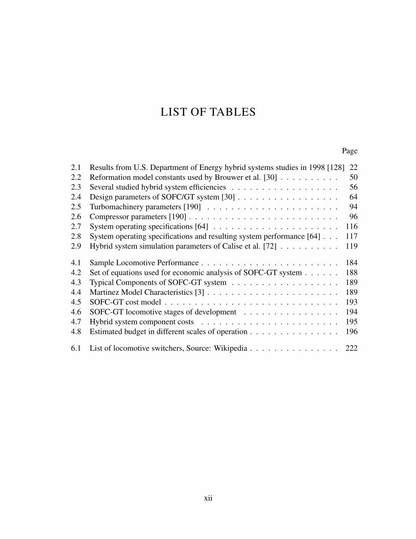
2.1 Results from U.S. Department of Energy hybrid systems studies in 1998 [128] 222.2 Reformation model constants used by Brouwer et al. [30] . . . . . . . . . . 502.3 Several studied hybrid system efficiencies . . . . . . . . . . . . . . . . . . 562.4 Design parameters of SOFC/GT system [30] . . . . . . . . . . . . . . . . . 642.5 Turbomachinery parameters [190] . . . . . . . . . . . . . . . . . . . . . . 942.6 Compressor parameters [190] . . . . . . . . . . . . . . . . . . . . . . . . . 962.7 System operating specifications [64] . . . . . . . . . . . . . . . . . . . . . 1162.8 System operating specifications and resulting system performance [64] . . . 1172.9 Hybrid system simulation parameters of Calise et al. [72] . . . . . . . . . . 119
4.1 Sample Locomotive Performance . . . . . . . . . . . . . . . . . . . . . . . 1844.2 Set of equations used for economic analysis of SOFC-GT system . . . . . . 1884.3 Typical Components of SOFC-GT system . . . . . . . . . . . . . . . . . . 1894.4 Martinez Model Characteristics [3] . . . . . . . . . . . . . . . . . . . . . . 1894.5 SOFC-GT cost model . . . . . . . . . . . . . . . . . . . . . . . . . . . . . 1934.6 SOFC-GT locomotive stages of development . . . . . . . . . . . . . . . . 1944.7 Hybrid system component costs . . . . . . . . . . . . . . . . . . . . . . . 1954.8 Estimated budget in different scales of operation . . . . . . . . . . . . . . . 196
6.1 List of locomotive switchers, Source: Wikipedia . . . . . . . . . . . . . . . 222
xii

ACKNOWLEDGMENTS
The author gratefully acknowledges the financial support of the Federal Railway Admin-istration under contract number 15-C-00024 and the contract management of Ms. MelissaShurland.
I would like to acknowledge my advisor Professor Jack Brouwer for his support and guid-ance throughout my M.S. and Ph.D, and for giving me the opportunity to work in thrivingenvironment.
I would also like to acknowledge Professor G. Scott Samuelsen for his valuable inputs andtechnical expertise, and criticism that encouraged me to do better.
I give many thanks to APEP students and staff who have supported me. You all have mademy experience here unforgettable. To my family, thanks for your unconditional support andlove.
xiii
CURRICULUM VITAE
Mohammad Ali Azizi
EDUCATION
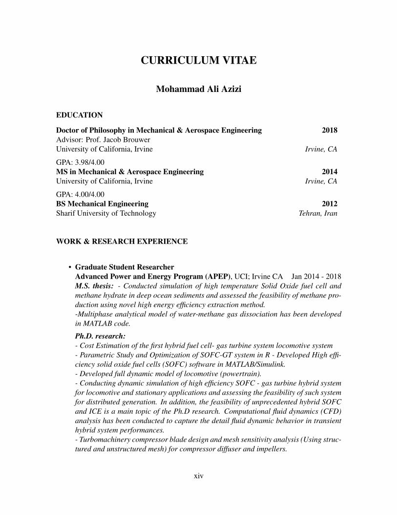
Doctor of Philosophy in Mechanical & Aerospace Engineering 2018Advisor: Prof. Jacob BrouwerUniversity of California, Irvine Irvine, CA
GPA: 3.98/4.00MS in Mechanical & Aerospace Engineering 2014University of California, Irvine Irvine, CA
GPA: 4.00/4.00BS Mechanical Engineering 2012Sharif University of Technology Tehran, Iran
WORK & RESEARCH EXPERIENCE
• Graduate Student ResearcherAdvanced Power and Energy Program (APEP), UCI; Irvine CA Jan 2014 - 2018M.S. thesis: - Conducted simulation of high temperature Solid Oxide fuel cell andmethane hydrate in deep ocean sediments and assessed the feasibility of methane pro-duction using novel high energy efficiency extraction method.-Multiphase analytical model of water-methane gas dissociation has been developedin MATLAB code.
Ph.D. research:- Cost Estimation of the first hybrid fuel cell- gas turbine system locomotive system- Parametric Study and Optimization of SOFC-GT system in R - Developed High effi-ciency solid oxide fuel cells (SOFC) software in MATLAB/Simulink.- Developed full dynamic model of locomotive (powertrain).- Conducting dynamic simulation of high efficiency SOFC - gas turbine hybrid systemfor locomotive and stationary applications and assessing the feasibility of such systemfor distributed generation. In addition, the feasibility of unprecedented hybrid SOFCand ICE is a main topic of the Ph.D research. Computational fluid dynamics (CFD)analysis has been conducted to capture the detail fluid dynamic behavior in transienthybrid system performances.- Turbomachinery compressor blade design and mesh sensitivity analysis (Using struc-tured and unstructured mesh) for compressor diffuser and impellers.
xiv
- Hybrid SOFC-GT locomotive system sizing using dynamic model tools of MAT-LAB/Simulink. Several heat exchangers have been sized used ASPEN software mod-ules (HTRI Xchanger Suite) .- Runnging dynamic model of locomotive hybrid system on an elevated path (Bakersfield-Mojave).- Developed powertrain system for hybid SOFC-GT locomotive system (LocomotiveNotching algorithm) in MATLAB/Simulink Platform.- Leading a hybrid fuel cell-gas turbine locomotive engine research group. Providingquarterly and annual reports for companies, agencies and organizations such as Fed-eral Rail Road Administration, U.S. Department of Energy, U.S. EPA, California AirResources Board, and South Coast Air Quality Management. District
• Reviewer of ASME Journal of Electrochemical Energy Conversion. 2017Work Experience: Reviewed a paper with a topic on Hybrid Solid Oxide Fuel Cell GasTurbine Control at ASME Journal written By National Energy Technology Laboratory(NETL)
• Controls Engineering InternBloom Energy; Sunnyvale CA Jul 2016 - Sep 2016Work Experience: Performed controls (PID) engineering on Bloom Energy Solid Ox-ide fuel cell systems, Real Time Data Analysis using statistical software (R) and ma-chine learning tools, Performed test measurements using Human Machine Interface(HMI), Developed control codes in MATLAB in interaction with main controller viaPython code and optimization of process design.
• Graduate Student ResearcherNational Fuel Cell Research Center (NFCRC), UCI; Irvine CA Jan 2014 - 2018
• Research AssistantMechanical & Aerospace Eng. Department, UCI; Irvine CA Jan 2013 - 2018
• InternTehran Oil Refining Company, Baghershahr, Iran Summer 2010
• ResearcherFinite element modeling of facial muscles, Sharif University of Technology, Tehran,Iran 2012
xv

• B.S thesis researchMicro robot localization using IMU and optic sensors (BS thesis), Sharif Universityof Technology, Tehran, Iran 2012Conducted research on micro robot localization under supervision of Prof. G.R. Vos-soughi. Our goal was to increase the localization accuracy by fusing IMU sensor andoptical sensors using Kalman Filtering.
• Research AssistantApplied Electronics Laboratory, Mechanical Engineering School, Sharif Universityof Technology, Tehran, Iran 2012Building Micro Robots using IMUs; Introductory knowledge of Kalman Filtering
• Research AssistantFluid Mechanics Laboratory, Mechanical Engineering School, Sharif University ofTechnology, Tehran, Iran 2008-2009Experimented on muddy fluids with high Reynold numbers
• Engineer AssistantTehran Wagon Manufacturing Company, Tehran, Iran Summer 2008
TEACHING EXPERIENCE
• Teaching Assistant, Mechanical & Aerospace Eng. Department, UCI; Irvine, CATwo times for Thermodynamics (MAE 115)Fluid Mechanics (MAE 130B)Thermal & Fluid Lab (MAE 107)Air Quality and Polution control (MAE 164)
xvi

JOURNAL PUBLICATIONS
• Azizi, Mohammad Ali, and Jacob Brouwer. ”Stall/surge dynamics of a multi-stage aircompressor in response to a load transient of a hybrid solid oxide fuel cell-gas turbinesystem”. Journal of Power Sources, Volume 365, 15 October 2017, Pages 408418(Citations:1)
• Azizi, Mohammad Ali, and Jacob Brouwer. ”Transient Analysis of 220 kW SolidOxide Fuel Cell-Gas Turbine Hybrid System Using Computational Fluid DynamicsResults.” ECS Transactions 71.1 (2016): 289-301. (Citations:2)
• Azizi, Mohammad Ali, Jacob Brouwer, and Derek Dunn-Rankin. ”Analytical inves-tigation of high temperature 1kW solid oxide fuel cell system feasibility in methanehydrate recovery and deep ocean power generation.” Applied Energy 179 (2016): 909-928. (Citations: 7)
• Azizi, Mohammad Ali, and Jacob Brouwer. ”Progress in solid oxide fuel cell-gas tur-bine hybrid power systems: System design and analysis, transient operation, controlsand optimization.” Applied Energy 215 (2018): 237-289.
CONFERENCE PUBLICATIONS
• M. Azizi, J. Brouwer. Mitigation of compressor stall/surge in a hybrid solid oxide fuelcell-gas turbine system , 4th International SYMPOSIUM on Solid Oxide Fuel Cells(SOFC): Materials, Science and Technology: System design and demonstrationJan22- 27, 2017; Daytona Beach, FL.
• M. Azizi, J. Brouwer. 4 MW locomotive hybrid solid oxide fuel cell-gas turbine sys-tem dynamic modeling using computational fluid dynamics results, ASME Power &Energy Conference. June 26- 30, 2016; Charlotte, NC.
• M. Azizi, J. Brouwer. Design and sizing of a 4 MW hybrid solid oxide fuel cell- gasturbine engine for long haul locomotive operation, ASME Power & Energy Confer-ence. June 26- 30, 2016; Charlotte, NC.
POSTER PRESENTATIONS
• M. Azizi, J. Brouwer. Transient Analysis of 220 kW Solid Oxide Fuel Cell-Gas Tur-bine Hybrid System Using Computational Fluid Dynamics Results, Fuel Cell Seminar& Energy Exposition. November 16 - 19, 2015; Los Angeles, CA.
xvii

MANUSCRIPTS UNDER PREPARATION
• M. Ali Azizi, J. Brouwer. Powertrain Performance of Solid Oxide Fuel Cell- GasTurbine Hybrid Engine in long-haul and Test scale locomotive, to be submitted toJournal of Power Sources, 2017.
• M. Ali Azizi, J. Brouwer. System sizing and feasibily analysis of long-haul SolidOxide Fuel Cell - Gas Turbine Hybrid Engine, to be submitted to Journal AppliedEnergy, 2017.
SOFTWARE
Technical: MATLAB/Simulink, ANSYS (CFX, FLUENT, TurboGrid, Mechanical), Solid-Works, COMSOL, OpenFOAM, Tecplot, R, Python, FORTRAN, Illustrator, TEX, LATEX, MSOffice; Familiar with: LabVIEW Languages: English, Persian.
REFERENCES
• Professor Jacob BrouwerEmail: [email protected]
• Professor Scott SmuelsenEmail: [email protected]
xviii
ABSTRACT OF THE DISSERTATION
Solid Oxide Fuel Cell-Gas Turbine Hybrid Power Systems: Energy Analysis, ControlAssessments, Fluid Dynamics Analysis and Dynamic Modeling for Stationary and
Transportation Applications
By
Mohammad Ali Azizi
Doctor of Philosophy in Mechanical and Aerospace Engineering
University of California, Irvine, 2018
Professor Jacob Brouwer, Chair
This research presents a system design and analysis, and transient control and optimization of
solid oxide fuel cell-gas turbine (SOFC-GT) hybrid systems. The main features of SOFC-GT
power systems include high efficiency, virtually zero emission of criteria pollutants, and low
acoustic signature compared to conventional power production technologies. Focus of this
dissertation is the investigation of control strategies and transient performance characteristics
of hybrid SOFC-GT systems, using computational fluid dynamics methods.
A novel control system is developed for a SOFC-GT system to follow dynamic power de-
mands associated with locomotives while keeping all of the components and system operat-
ing variables within acceptable limits of performance. The voltage variation is also greater
at lower fuel utilization. The stack temperature difference is highly dynamic at low fu-
el utilization. In addition, detailed analyses of potential SOFC-GT locomotive production
and operation costs in comparison to other low pollutant emitting alternatives is accom-
plished. SOFC-GT locomotives are projected to produce lower operating costs compared
to the catenary-electric alternative, and significantly lower operating costs compared to the
battery-electric alternative.
xix

A part of this research is devoted to a better understanding of turbulent unsteady flows in
gas turbine systems that is necessary to design and control compressors for hybrid fuel cell-
gas turbine (FC-GT) systems. In this study, compressor stall/surge analysis for a 4 MW
locomotive hybrid solid oxide fuel cell-gas turbine (SOFC-GT) engine is performed based on
a 1.7 MW multi-stage air compressor similar to available commercial compressors. Control
strategies are designed and evaluated to prevent the operation of hybrid SOFC-GT beyond
the stall/surge lines of the compressor. Computational fluid dynamics (CFD) tools are used
to provide a better understanding of flow distribution and instabilities near the stall/surge
line. Simulation results show the feasibility of using existing industrial compressors in the
hybrid SOFC-GT system operation. The results show that a 1.7 MW system compressor like
that of Kawasaki gas turbine is an appropriate choice among the industrial compressors to
be used in a 4 MW locomotive SOFC-GT with topping cycle design.
xx

CHAPTER 1
INTRODUCTION AND BACKGROUND
1.1 INTRODUCTION
Solid oxide fuel cells (SOFC) are electrochemical devices that convert chemical energy con-
tained in fuel directly into electricity through electrochemical reactions. The SOFC electro-
chemical reactions occur at relatively high temperatures compared to the other types of fuel
cells. The higher temperature operation allows for fuel flexibility. SOFCs can operate on
natural gas, hydrogen, biogasses, coal syngas and high temperature also lends itself well to
cogeneration schemes which can significantly increase the system efficiency.
1.1.1 EMERGENCE OF SOFC POWER PLANTS
SOFC power plants are a proven clean-tech alternative for electric utility power genera-
tion in residential, commercial and industrial applications. SOFCs lend themselves well
to stationary power and also to heavy duty transportation (e.g., locomotive) applications
[1, 2, 3, 4, 5, 6, 7, 8].
Features of SOFC power systems include production of less harmful chemical and acoustic
1

emissions at higher efficiencies compared to conventional power production technologies
[9, 10, 11, 12]. An electrolyte that is most typically made of yttria-stabilized zirconia (YSZ),
eliminates the need to manage the electrolyte evaporation and circulation associated with
other non-solid-state fuel cell types. As a result of high operating temperature and oxidizing
ion charge carrier (oxygen ion, O=), higher fuel flexibility is achievable compared to other
types of fuel cells. SOFCs are capable of converting carbon monoxide (CO) to electricity
via electrochemical reaction [13], while other types of fuel cells such as proton exchange
membrane fuel cells (PEMFC) are vulnerable to CO poisoning [14]. SOFC systems have
operated using various types of fuels such as carbon monoxide (CO), natural gas, hydrogen
(H2), propane (C3H8), landfill gas, diesel and JP-8 [15, 16, 17, 18]. Typically, the operating
temperature of SOFC is higher than other types of fuel cells such as PEMFC, alkaline fuel
cells (AFC), phosphoric acid fuel cells (PAFC), and molten carbonate fuel cells (MCFC)
[19, 20]. Higher operating temperature of SOFCs and the presence of nickel catalayst en-
able them to directly reform natural gas in the anode compartment. SOFC systems convert
reformed hydrogen and other gaseous fuel species (e.g., CO) usually produce by reforma-
tion of a hydrocarbon fuel through electrochemical reactions that produce electrical power
and high grade heat for use elsewhere in the system (e.g., reformation, preheating reactants)
and for combined heat and power (CHP) applications. The need for more costly materials
construction and insulation that can withstand the high temperature conditions is a disadvan-
tage. Nonetheless, fully integrated SOFC power generation systems have built and operated
as stationary power systems in multiple applications in the power production range of 1 kW
to 20 MW [21, 22].
Several designs of SOFC systems have been experimentally evaluated and demonstrated to-
date. The typical configurations of SOFC cells include tubular, planar and monolithic [23].
Each of these cell configurations has advantages and disadvantages regarding the thermal
shock resistance, manufacturability, power density and potential cost [24]. Among these, the
2

tubular SOFC design has been manufactured by Siemens Westinghouse Power Corporation,
Mitsubishi Heavy Industries, Rolls Royce and LG Fuel Cells Systems, Artex Energy, and
others [25, 26, 27, 28]. Monolithic SOFC cell designs have been primarily produced for
research and development purposes. By far the most popular type of cell configuration in
recent systems is the planar design used by most fuel cell system manufacturers including
Bloom Energy, Versa Power, FuelCell Energy, Ceres Power, SolidPower, and many others.
More than 100 companies are producing SOFC systems mostly in the U.S., Europe and
Japan. The most prominent manufacturer of SOFC systems in the U.S. is Bloom Energy.
The typical materials set used in SOFC cells and stacks is remarkably durable and robust
even over long periods of time operating at high temperature. For example, the tubular
SOFC design of Siemens Westinghouse Power Corporation has shown more than 85,000
hours of operation with low cell degradation and the planar SOFC design has shown power
densities up to 1000 (W
l) [29, 30]. The initial market for the fuel cells is currently limited to
areas with strict emission regulations, or where grid electric power is more expensive than
the on site power and heat production [31]. The current high capital cost of such fuel cell
systems is the main reason that SOFC technology has not become more widely deployed and
such capital costs are currently being reduced and also have a significant potential for being
reduced.
The SOFC-microturbine hybrid systems are also being considered in auxiliary power unit-
s (APU) in commercial airplanes to provide power to all electrical loads [32]. In recent
years, the application of SOFC systems has been expanded to deep ocean power generation
for methane hydrate recovery [33]. Aguiar et al. developed a High-altitude long-endurance
(HALE) hybrid system for UAVs [34]. The overall system efficiency was at 66.3% (LHV)
when operating on liquefied hydrogen for a three-stack system. Rajashekara et al., classified
hybrid systems into two major types: 1) A high temperature fuel cell combined with other
power generation systems such as reciprocating engine, and 2) The combination of fuel cell
3
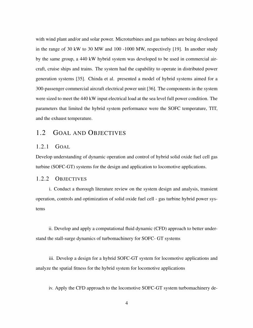
with wind plant and/or and solar power. Microturbines and gas turbines are being developed
in the range of 30 kW to 30 MW and 100 -1000 MW, respectively [19]. In another study
by the same group, a 440 kW hybrid system was developed to be used in commercial air-
craft, cruise ships and trains. The system had the capability to operate in distributed power
generation systems [35]. Chinda et al. presented a model of hybrid systems aimed for a
300-passenger commercial aircraft electrical power unit [36]. The components in the system
were sized to meet the 440 kW input electrical load at the sea level full power condition. The
parameters that limited the hybrid system performance were the SOFC temperature, TIT,
and the exhaust temperature.
1.2 GOAL AND OBJECTIVES
1.2.1 GOAL
Develop understanding of dynamic operation and control of hybrid solid oxide fuel cell gas
turbine (SOFC-GT) systems for the design and application to locomotive applications.
1.2.2 OBJECTIVES
i. Conduct a thorough literature review on the system design and analysis, transient
operation, controls and optimization of solid oxide fuel cell - gas turbine hybrid power sys-
tems
ii. Develop and apply a computational fluid dynamic (CFD) approach to better under-
stand the stall-surge dynamics of turbomachinery for SOFC- GT systems
iii. Develop a design for a hybrid SOFC-GT system for locomotive applications and
analyze the spatial fitness for the hybrid system for locomotive applications
iv. Apply the CFD approach to the locomotive SOFC-GT system turbomachinery de-
4

sign for analysis of stall-surge
v. Investigate the dynamic behavior and control strategies for locomotive application
of hybrid SOFC-GT technology
5

CHAPTER 2
LITERATURE REVIEW
2.1 SOFC-GT HYBRID SYSTEM BACKGROUND
Climate change, due to increasing greenhouse gas emissions and reduction in the availability
of fossil energy resources, have motivated the gas turbine industry to consider more en-
ergy efficient strategies with reduced emissions for stationary power plants. Hybrid fuel
cell-gas turbine (FC-GT) systems provide clean energy at high efficiency [37]. FC-GT hy-
brid power systems theoretically possess the highest efficiency and the cleanest emissions
of all fossil fueled power plants in any given size class [38]. Integrated hybrid systems
have the potential to operate at higher efficiency than a fuel cell or gas turbine alone. A
market study by Research Dynamics Corporation concluded that hybrid systems could com-
pete on electricity cost with other distributed generation (DG) technologies [30]. Technical
elements of various SOFC-GT hybrid systems have been published by the ASME Interna-
tional Gas Turbine Institute (IGTI) proceedings including several purposeful hybrid sessions
([39, 40, 41, 42, 43, 44, 45, 46]). SOFC-GT hybrid systems have been called one of the
most promising technologies to meet US DOE demands for high efficiency and low emis-
sions power generation [47]: 1) To achieve a higher electrical efficiency, 2) to minimize
6

environmental pollution, 3) to produce electricity at a competitive cost, and 4) to capture and
sequester CO2.
In recent years, many hybrid systems have been mentioned in several US patents [48, 49,
50, 51, 52, 53, 54, 55, 56, 57, 58]. The integration of an SOFC stack with a gas turbine
has been proven to be a promising concept, since SOFC-GT hybrid systems can achieve a
net electrical efficiency and a global efficiency close to 70% and 85%, respectively [59, 60,
61, 62, 63]. Many researchers have accomplished fundamental studies concerning SOFC-
GT hybrid systems [64, 65, 66, 67]. Some of them performed thermodynamic analyses
of hybrid systems [64, 65, 66, 68]. In addition, exergy analyses of hybrid systems were
performed by several authors [69, 70, 71, 72, 73, 74, 75, 76, 77, 78, 79]. In a study by Calise
et al., a maximum electrical efficiency of 65.4% was achieved at the full-load operation [70].
Analyses demonstrated that a combined SOFC-GT system could achieve fuel to electricity
conversion efficiencies at 65% to 74% for systems under 10 MW, and greater than 75% for
larger systems [30, 80, 81, 82, 83, 84]. As fuel cell technology advances, SOFC systems
could possibly tolerate higher pressures so that they could be integrated into even more
sophisticated hybrid systems with gas turbines characterized by higher pressure ratios and
higher turbine inlet temperature (TIT).
In 1999, Rolls Royce funded a study to produce a turbo-generator that was estimated to cost
approximately $400 per kW in full production [27, 30]. When coupled with fuel cells, the
turbine could produce 25% of the hybrid system power in the 1 MW to 5 MW class. As a
stand-alone device, the turbine could produce 1.5 MW of electric power in a simple cycle
mode. In a stand-alone mode, efficiency of the gas turbine system at this scale is approxi-
mately 33%. In addition to the stationary power applications of SOFC-GT hybrid systems,
they could be useful in supporting the auxiliary and propulsion power needed for the locomo-
tive and mobile applications, ships, aircraft and spacecraft [85, 3, 4, 86, 35, 87, 88, 89, 90].
Since SOFCs operate at high temperatures, hybrid systems are able to operate using various
7

types of fuels such as natural gas, coal, biomass and other fossil fuels [30, 91, 92, 93, 94].
Using simulation and experimental methods, it was demonstrated that an SOFC can achieve
a 50% net electrical efficiency [95]. Thermodynamic analyses have shown that integration of
SOFC into multi-kW and multi-MW gas turbine engines in order to achieve higher electrical
efficiencies is feasible [10, 96, 30]. The efficiencies of a gas turbine system, a high tem-
perature fuel cell system and a hybrid system have been reported to be approximately 35%,
50% and 70% respectively [97]. Additional analyses on hybrid systems have been performed
by the U.S. Department of Energy (DOE) with industry cooperation from FuelCell Energy,
General Electric (formerly Honeywell), and Siemens Power Corporation (formerly Siemens
Westinghouse) [98, 99, 29, 30, 84]. All of these analysis projects were accomplished for
hybrid system designs less than a MW class showing that efficiencies greater than 65% were
possible even in this small size class.
2.1.1 EXPERIMENTAL EVALUATION OF INTEGRATED SOFC-GT HYBRID
SYSTEMS
Experimental evaluation of hybrid FC-GT technologies has been supported by the U.S. DOE.
A hybrid system was integrated and tested in the 2004 timeframe that consisted of a 250 kW
fuel cell stack and a 30 kW Capstone MTG configured as an indirect bottoming cycle [2].
Experimental data of the Capstone GT C30 have also been used in an SOFC-GT hybrid
model [100]. The results of the simulation have been compared to the Capstone C30 for a
load step from 30 to 20 kW. In addition, FuelCell Energy designed a 40 MW DFC/T hybrid
system [98].
The Siemens Power Corporation 220 kWe PSOFC/MTG produced with Ingersoll-Rand was
a hybrid design that was tested at the National Fuel Cell Center (NFCRC) at the University
of California, Irvine [101] in the 1999-2003 timeframe. This system comprised the first hy-
brid SOFC-GT system ever constructed and tested, achieving a fuel-to-electrical conversion
8

efficiency of 53%. The test included pressurization of the fuel cell in order to provide a net
power of 220 kW from the hybrid system. Matching pressure ratios and mass flows were a-
mong the technical challenges of the hybrid systems. The test included pressurization of the
fuel cell in order to provide a net power of 220 kW from the hybrid system. Since the sys-
tem was comprised of an existing SOFC module that was integrated with an existing MTG,
matching air mass flows and balancing pressure and temperature distribution requirements
were among the technical challenges of the hybrid system.
Recently a prototype of 250 kW hybrid SOFC-MGT has been demonstrated by Mitsubishi
Heavy Industries in Tokyo Gas Senju Techno Station. The system was stable without voltage
degradation for 4100 hours. Fig. (2.1) shows the corresponding system [102].
Figure 2.1: 250 kW prototype of hybrid SOFC-MGT system [102]
Fig. (2.2) shows the operational plot of the corresponding hybrid SOFC-MGT system [102].
9
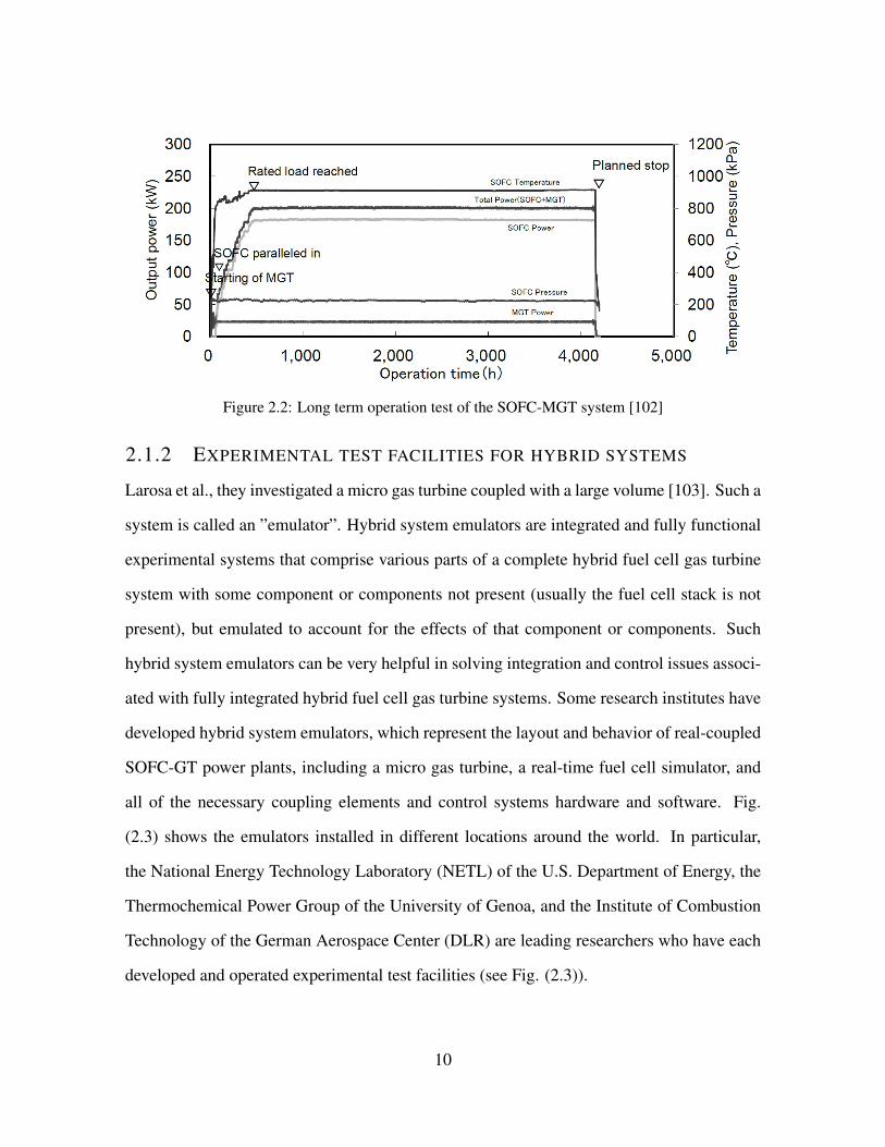
Figure 2.2: Long term operation test of the SOFC-MGT system [102]
2.1.2 EXPERIMENTAL TEST FACILITIES FOR HYBRID SYSTEMS
Larosa et al., they investigated a micro gas turbine coupled with a large volume [103]. Such a
system is called an ”emulator”. Hybrid system emulators are integrated and fully functional
experimental systems that comprise various parts of a complete hybrid fuel cell gas turbine
system with some component or components not present (usually the fuel cell stack is not
present), but emulated to account for the effects of that component or components. Such
hybrid system emulators can be very helpful in solving integration and control issues associ-
ated with fully integrated hybrid fuel cell gas turbine systems. Some research institutes have
developed hybrid system emulators, which represent the layout and behavior of real-coupled
SOFC-GT power plants, including a micro gas turbine, a real-time fuel cell simulator, and
all of the necessary coupling elements and control systems hardware and software. Fig.
(2.3) shows the emulators installed in different locations around the world. In particular,
the National Energy Technology Laboratory (NETL) of the U.S. Department of Energy, the
Thermochemical Power Group of the University of Genoa, and the Institute of Combustion
Technology of the German Aerospace Center (DLR) are leading researchers who have each
developed and operated experimental test facilities (see Fig. (2.3)).
10
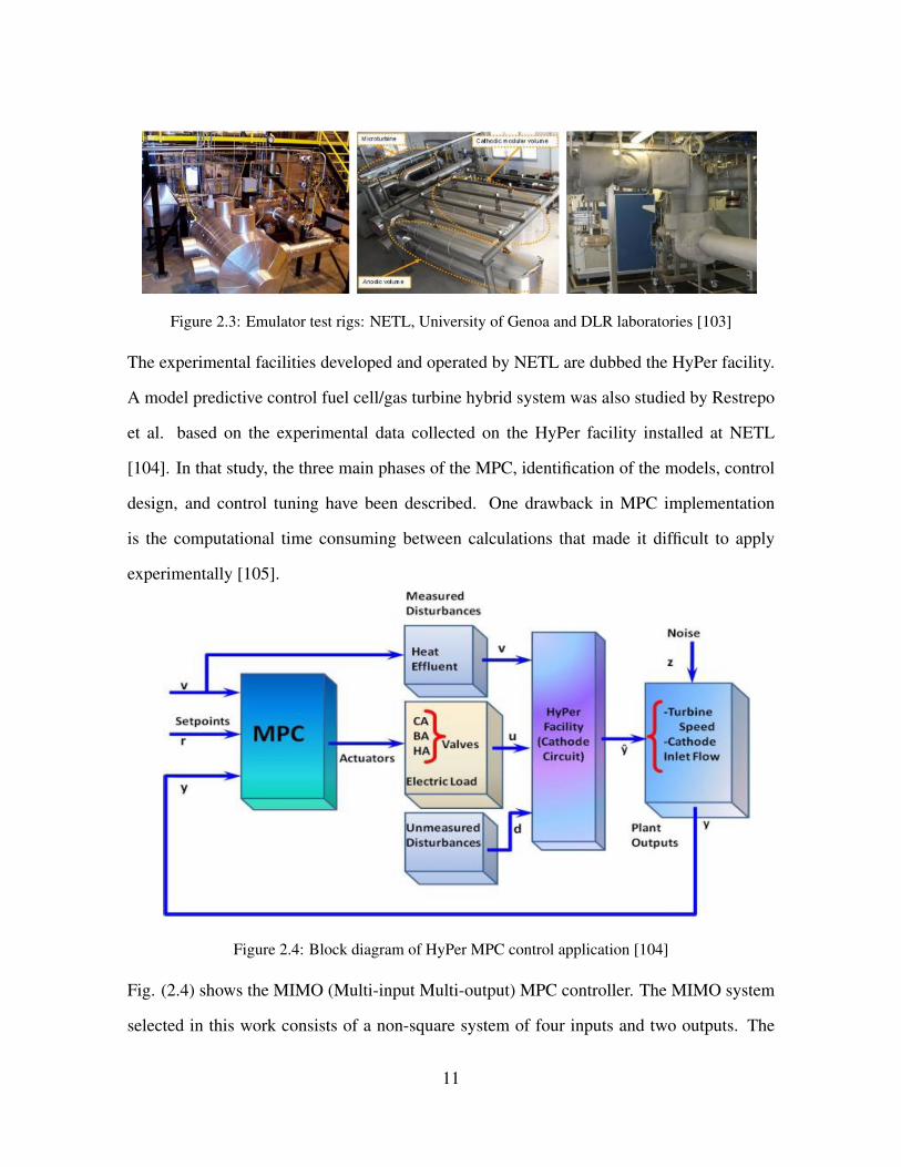
Figure 2.3: Emulator test rigs: NETL, University of Genoa and DLR laboratories [103]
The experimental facilities developed and operated by NETL are dubbed the HyPer facility.
A model predictive control fuel cell/gas turbine hybrid system was also studied by Restrepo
et al. based on the experimental data collected on the HyPer facility installed at NETL
[104]. In that study, the three main phases of the MPC, identification of the models, control
design, and control tuning have been described. One drawback in MPC implementation
is the computational time consuming between calculations that made it difficult to apply
experimentally [105].
Figure 2.4: Block diagram of HyPer MPC control application [104]
Fig. (2.4) shows the MIMO (Multi-input Multi-output) MPC controller. The MIMO system
selected in this work consists of a non-square system of four inputs and two outputs. The
11

manipulated variables or actuators, (u), in the facility were controlled by the three valves
CA, BA, HA, and the electric load. Y represents the output of the system which are turbine
speed, the cathode air mass flow and the cathode inlet temperature.
Harun et al. studied the impact of fuel composition transients on SOFC performance in a gas
turbine hybrid system [106]. In once study by Harun et al., both open loop and closed loop
transient responses of the fuel cell in a solid oxide fuel cell (SOFC) gas turbine (GT) hybrid
system to fuel composition changes were experimentally investigated using a cyber-physical
fuel cell system [107]. Zaccaria et al. developed a transfer function for SOFC-GT hybrid
systems control using cold air bypass [108]. Their tests were performed moving the cold air
valve from the nominal position of 40% with a step of 15% up and down while the system
was in open loop; without control on turbine speed or inlet temperature. Transfer functions
were developed for cathode mass flow, total pressure drop and surge margin. All the system
dynamics were approximated as First Order Plus Dead Time (FOPDT) transfer function.
In another study by Zaccaria et al., the gains of the PI controller were determined using
a pole placement method. The proportional and integral gains were found to be 0.5 and
0.0035. Control strategies were investigated in order to minimize the degradation effects
on the system performance [109]. The results showed that it was possible to maintain a
constant voltage while the fuel cell was degrading, reducing the degradation rate over time.
In a standalone fuel cell, in order to keep the power constant as the voltage degraded, the
current was increased which increased the degradation rate with time. In a hybrid system,
the total power output could be maintained constant increasing the turbine load; i.e. the
fuel flow to the system. PID controllers were implemented in order to keep the temperature
difference constant by manipulating the airflow, while the average temperature of the cell
was maintained constant by manipulating the fuel flow of the pre-heating combustor [110].
In one study by Zaccaria et al., a control strategy was implemented in order to keep constant
cathode inlet temperature during different operative conditions [109].
12

Emami et al. analyzed the performance of a 300 kW SOFC-GT pilot power plant simulator
using a set of robust PID controllers that satisfy time delay and gain uncertainties of the
hybrid system [111]. Fuel cell mass flow rate m and turbine speed ω were the controller
outputs. Fig. (2.5) shows the MIMO controller design for this study.
Figure 2.5: MIMO controller of hybrid SOFC-GT system [111]
In another study by the same group, operating points of the 300 kW system were estimated
using the Multiple Model Adaptive Estimation (MMAE) algorithm [112]. Fig. (2.6) shows
the Predictive type KF algorithm used in that study. The figure shows the discrete space-state
model followed by the discrete KF.
13

Figure 2.6: Prediction Type Kalman Filter (PTKF) [112]
Air flow control in the hybrid system was performed using the Hyper hardware simulation
facility at NETL [113]. Fig. (2.7) shows the plant flow diagram of this study.
Figure 2.7: Simplified flow diagram of hybrid simulation facility at NETL [113]
Thermal management of a hybrid SOFC-GT system was studied by Zhou et al. using the
same Hyper facility at NETL [114]. Responses of the physical subsystem and virtual sub-
system to various disturbances were studied. In addition, multi-objective neural network
14

controller of SOFC-GT hybrid system has been developed by Colby et al. of the same group
[115]. A computationally efficient plant simulator was developed based upon physical plant
data, that allows rapid fitness assignment. In a study by Harun et al., also of the same group,
dynamic performance of a SOFC-GT hybrid system in response to a sudden fuel composi-
tion change has been investigated experimentally for both open and closed loop operation
[116]. A load based speed control scheme was used in the closed loop test to maintain the
turbine speed at 40,500 rpm. Fig. (2.8) shows this control strategy.
Figure 2.8: Load based speed control strategy [116]
Tucker et al. provide details of their Hyper facility and results from cold flow testing ac-
complished in the facility that was constructed at the NETL [117]. They note that the Hyper
facility can experimentally analyze the transient performance dynamics of FC-GT systems
[117]. The SOFC-GT test facility was developed at the U.S. DOE NETL in Morgantown,
WV as part of the Hyper facility. In order to simulate the thermal output of the SOFC, a
natural gas burner controlled by a real-time fuel cell model to predict FC heat (and electric-
ity) production was used. The turbine inertia and viscous drags were determined during the
startup conditions for the turbomachinery. The turbine speed for the startup was not signifi-
cantly affected by the reduction in the amount of energy available to the turbine through the
system volume [117]. The facility uses hardware-in-the-loop to simulate the coupled SOFC
operation with gas turbine hardware. The SOFC operation was characterized over an exten-
sive range of operation including inert heating and cooling, standard on-design and extreme
off-design conditions. The average operating temperature and spatial gradient profile in the
simulated SOFC increased due to a step increase in the load [118]. Zhou et al., working
15

with the same NETL group, developed a transfer function to control the cathode airflow in
a hybrid SOFC-GT system [119]. The inputs of the hardware system where compressor in-
take and fuel flow. The fuel flow was controlled by a PID controller to maintain the turbine
speed at the nominal speed. An Atlas control system, manufactured by Woodward industrial
controls, was used to control a Swift valve (FV-432) that manipulated fuel flow to the system
combustor [113]. Turbine rotational speed was controlled using a PID controller demand for
the fuel valve using feedback from a optical speed instrument (ST-502). Other bypass valves
were also controlled by independent Atlas controllers.
The Thermochemical Power Group (TPG) built at the laboratory of the University of Genoa,
Italy, a new high temperature fuel cell - micro gas turbine physical emulator based on com-
mercial machine technology [120]. The focus of the study was on the critical phases of
start-up, shutdown and load changes. Fig. (2.9) shows the T100 power module modifica-
tions for the fuel cell coupling.
Figure 2.9: The T100 power module modifications for the fuel cell coupling [120]
Fig. (2.10) shows the test rig plant layout of the system built by the Thermochemical Power
Group (TPG) in their laboratory at the University of Genoa, Italy.
16

Figure 2.10: Test rig plant layout: the blue box is related to the SOFC model [121]
Hohloch et al. accomplished experimental analysis of a hybrid SOFC-GT system [122]. The
power plant operated at different MGT speeds and SOFC electrical power outputs leading
to different SOFC temperatures. Fig. (2.11) shows the hybrid cycle schematic. Fig. (2.12)
shows the transient behavior of MGT with temperature variation at the gas preheater. Fig.
(2.13) shows the test rig at the German Aerospace Center (DLR) where this study was ac-
complished.
17
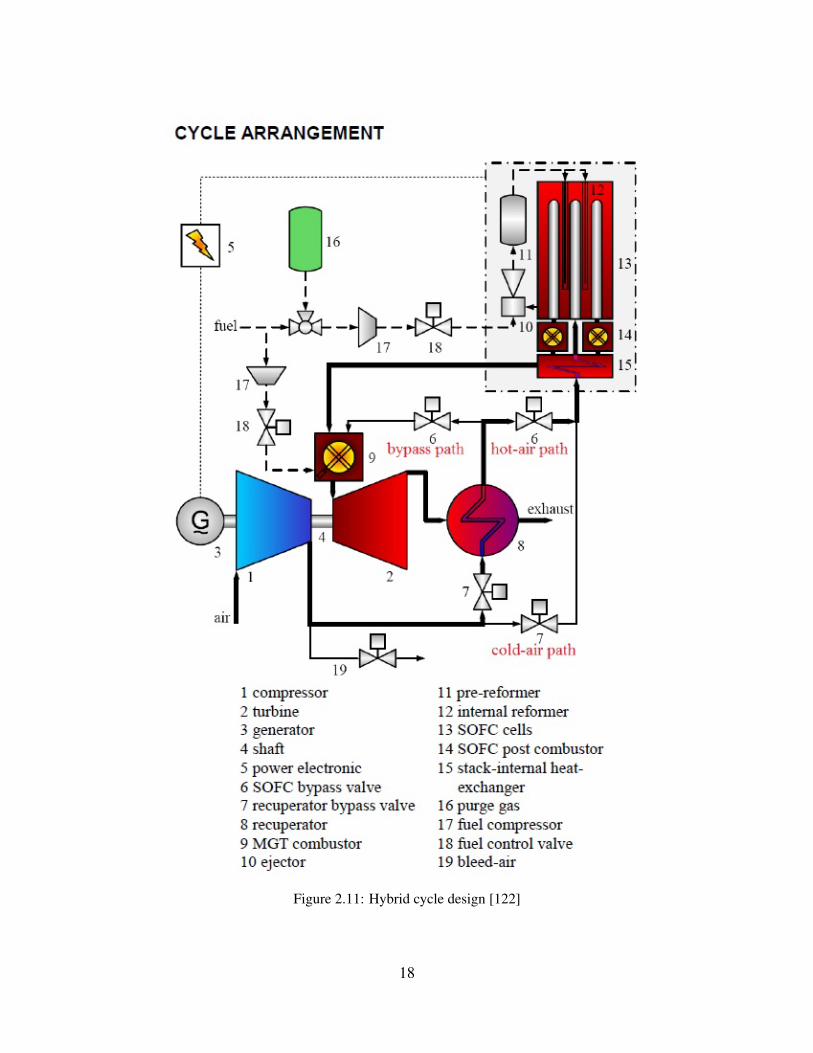
Figure 2.11: Hybrid cycle design [122]
18
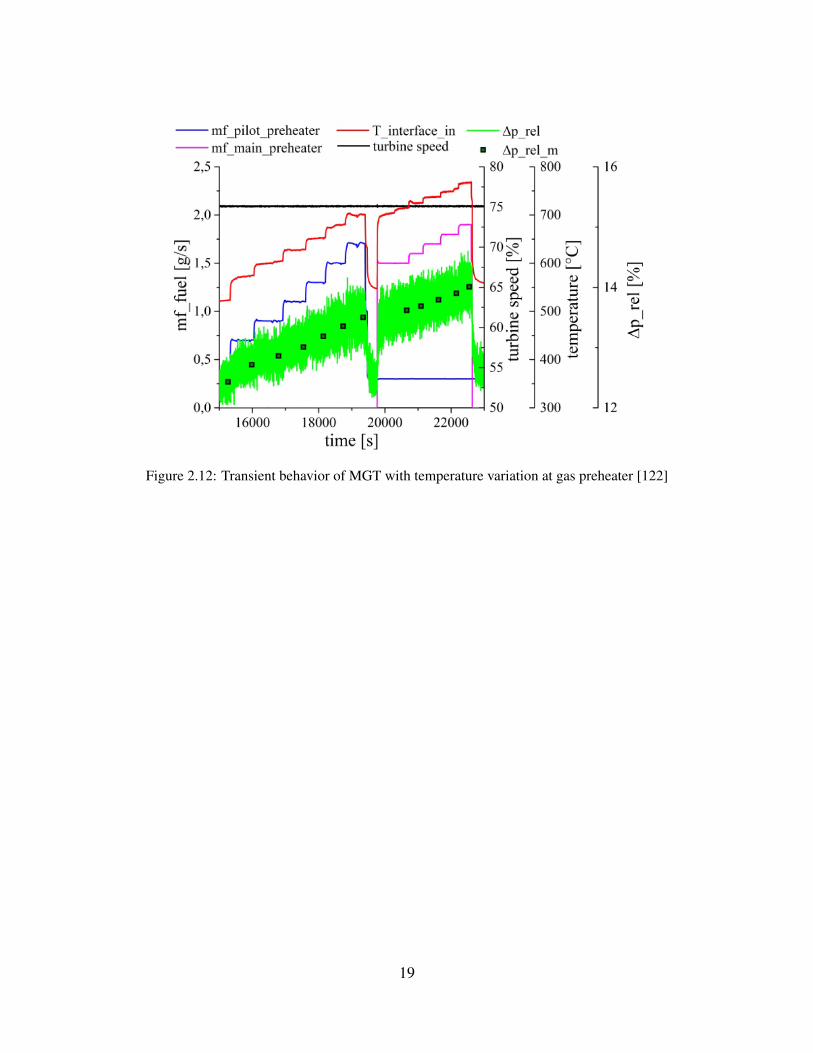
Figure 2.12: Transient behavior of MGT with temperature variation at gas preheater [122]
19

Figure 2.13: Hybrid power plant test rig at DLR [122]
Relative high pressure losses have been reported by researchers at DLR for transient op-
eration of the MGT in hybrid configurations. However, the relative pressure loss was not
reported as an indication of instability in the hybrid system. The absolute value of pressure
was reported to change with changing preheating temperature. Comparing simulation data
with measurement data from the DLR Turbec T100 test rig has led to extensions of the nu-
meric models, on the one hand, and to modifications of the test rig on the other [123]. Lai et
al. used two combustors in their experimental setup (Comb A and Comb B) to simulate the
high temperature exhaust gas of the SOFC and the condition of the sequential burner [124].
20

2.1.3 GAS TURBINE TECHNOLOGY APPLICATIONS IN SOFC-GT HY-
BRID SYSTEMS
Several conventional heat engines have been considered for integration with SOFCs, such as
the SOFC-GT hybrid cycle. These include gas turbines, steam turbines and reciprocating en-
gines [19]. The only engines that have been previously tested as an integrated hybrid system
with SOFC have been micro-gas turbine generators (MTG). The micro turbine generator has
showed promise when integrated with a high temperature SOFC. Among the features that
allow the integration of MTG and SOFC, the following were mentioned by Brouwer [30]:
1) the SOFC exhaust temperature and MTG turbine inlet temperature are well-matched; 2)
MTGs operate at relatively lower pressure ratios that makes the integration easier; 3) MTGs
often use recuperation in order to improve the system efficiency, which well-suits hybrid sys-
tem integration; 4) MTGs allow fuel cells to operate under higher pressures which improves
the cell performance; 5) The thermal energy contained in the SOFC exhaust is sufficient to
provide the necessary energy for the MTG components such as the compressor (for fuel cell
pressurization) and electric generator (produces additional electricity); and 6) The size of
current fuel cell systems match well with the current size of MTGs.
2.2 HYBRID SOFC-GT SYSTEM DESIGN CONCEPTS
In 1998, the U.S. DOE Office of Fossil Energy started five studies to evaluate variations of
the parameters on the FC-T hybrid concept. These studies included MCFCs, SOFCs, off-
the-shelf turbines and conceptual turbines [125, 126, 127, 81, 30]. Four of these cycles were
associated with hybrid systems in a power class of 20 MW. The fifth study evaluated them
under a MW class. The results of these studies are briefly shown in Table .(2.1). The SOFC-
GT hybrid systems concept was first patented in the mid 1970s. By 1998 more than ten
hybrid concepts were patented using different types of fuel cells, operating pressures, and
system configurations. The basic concept of an SOFC-GT hybrid system is demonstrated in
21
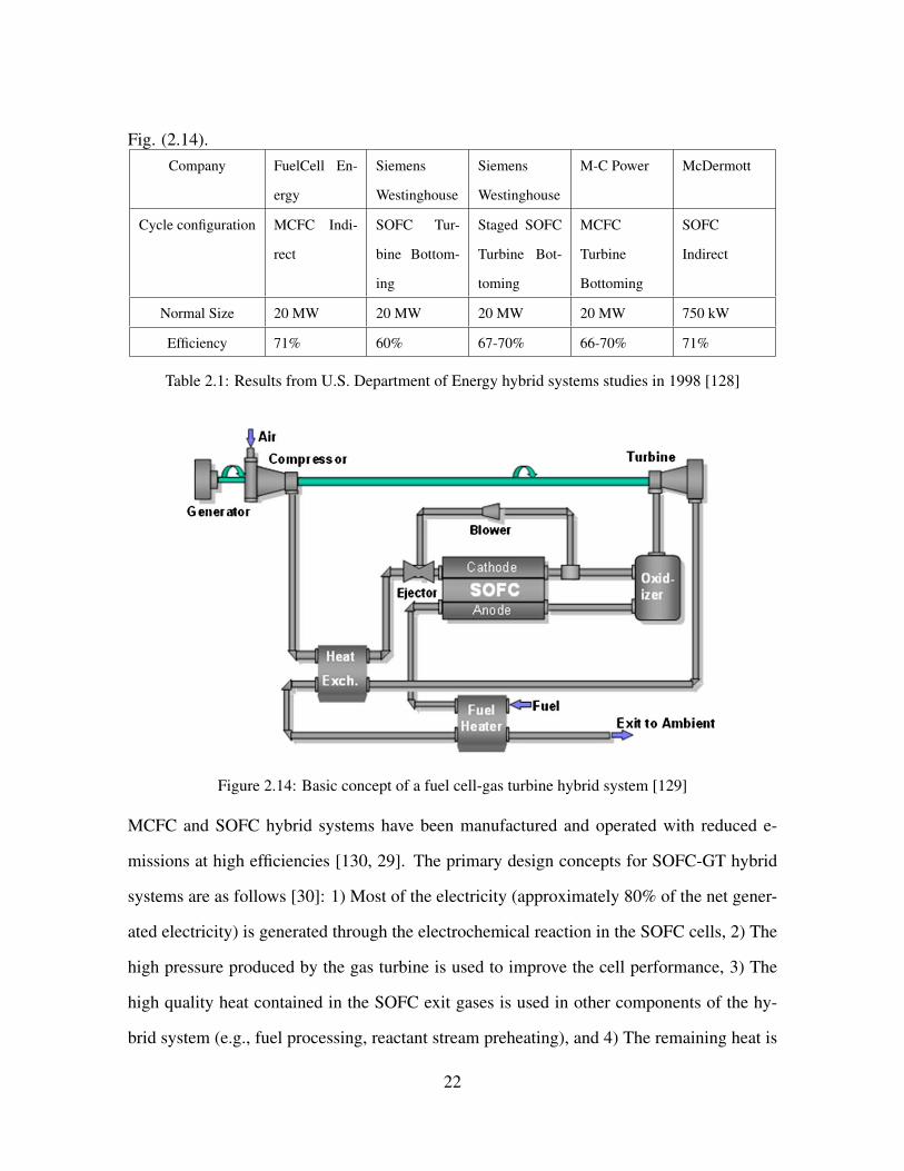
Fig. (2.14).Company FuelCell En-
ergy
Siemens
Westinghouse
Siemens
Westinghouse
M-C Power McDermott
Cycle configuration MCFC Indi-
rect
SOFC Tur-
bine Bottom-
ing
Staged SOFC
Turbine Bot-
toming
MCFC
Turbine
Bottoming
SOFC
Indirect
Normal Size 20 MW 20 MW 20 MW 20 MW 750 kW
Efficiency 71% 60% 67-70% 66-70% 71%
Table 2.1: Results from U.S. Department of Energy hybrid systems studies in 1998 [128]
Figure 2.14: Basic concept of a fuel cell-gas turbine hybrid system [129]
MCFC and SOFC hybrid systems have been manufactured and operated with reduced e-
missions at high efficiencies [130, 29]. The primary design concepts for SOFC-GT hybrid
systems are as follows [30]: 1) Most of the electricity (approximately 80% of the net gener-
ated electricity) is generated through the electrochemical reaction in the SOFC cells, 2) The
high pressure produced by the gas turbine is used to improve the cell performance, 3) The
high quality heat contained in the SOFC exit gases is used in other components of the hy-
brid system (e.g., fuel processing, reactant stream preheating), and 4) The remaining heat is
22
converted to compressor power and additional electricity (through a generator). McLarty et
al., studied both MCFC and SOFC technology for hybridization with micro-turbines and the
larger axial flow gas turbines at steady state [131]. Their study used off-design performance
maps produced from the detailed, spatially resolved component models. In the case of no
recirculation, the specific fuel cell heating and the specific combustion heating had to match.
In addition, the absolute flow rates of the turbine and the fuel cell had to match accurately
[131].
2.2.1 HYBRID SYSTEM CONFIGURATIONS
Hybrid system configurations are discussed by Buonomano et al. in detail [132] . In general,
two common configurations are used in the hybrid FC-GT systems based on the order of
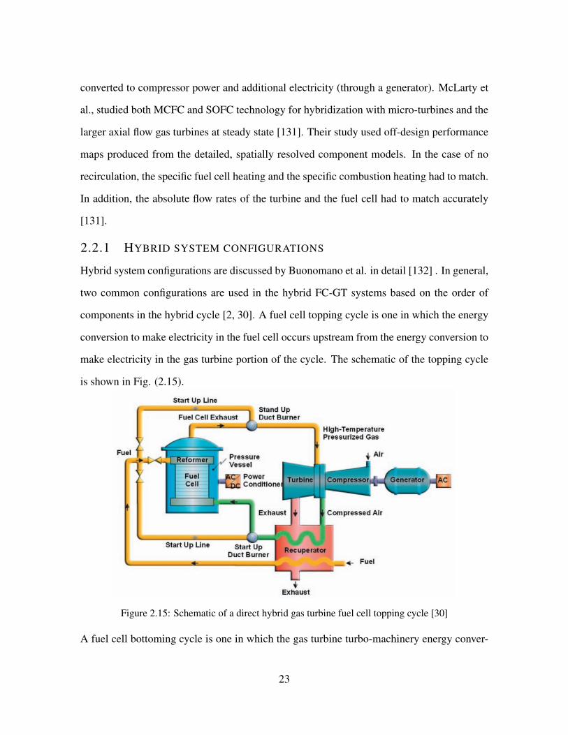
components in the hybrid cycle [2, 30]. A fuel cell topping cycle is one in which the energy
conversion to make electricity in the fuel cell occurs upstream from the energy conversion to
make electricity in the gas turbine portion of the cycle. The schematic of the topping cycle
is shown in Fig. (2.15).
Figure 2.15: Schematic of a direct hybrid gas turbine fuel cell topping cycle [30]
A fuel cell bottoming cycle is one in which the gas turbine turbo-machinery energy conver-
23
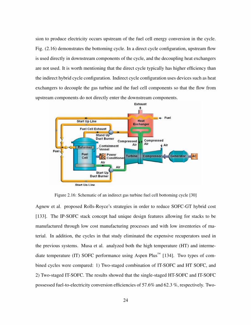
sion to produce electricity occurs upstream of the fuel cell energy conversion in the cycle.
Fig. (2.16) demonstrates the bottoming cycle. In a direct cycle configuration, upstream flow
is used directly in downstream components of the cycle, and the decoupling heat exchangers
are not used. It is worth mentioning that the direct cycle typically has higher efficiency than
the indirect hybrid cycle configuration. Indirect cycle configuration uses devices such as heat
exchangers to decouple the gas turbine and the fuel cell components so that the flow from
upstream components do not directly enter the downstream components.
Figure 2.16: Schematic of an indirect gas turbine fuel cell bottoming cycle [30]
Agnew et al. proposed Rolls-Royce’s strategies in order to reduce SOFC-GT hybrid cost
[133]. The IP-SOFC stack concept had unique design features allowing for stacks to be
manufactured through low cost manufacturing processes and with low inventories of ma-
terial. In addition, the cycles in that study eliminated the expensive recuperators used in
the previous systems. Musa et al. analyzed both the high temperature (HT) and interme-
diate temperature (IT) SOFC performance using Aspen Plus™ [134]. Two types of com-
bined cycles were compared: 1) Two-staged combination of IT-SOFC and HT SOFC, and
2) Two-staged IT-SOFC. The results showed that the single-staged HT-SOFC and IT-SOFC
possessed fuel-to-electricity conversion efficiencies of 57.6% and 62.3 %, respectively. Two-
24

staged IT-SOFC resulted in a 65.5% fuel-to-electricity conversion efficiency. However, by
optimizing the heat recovery and the gas turbine use, this efficiency could be increased to as
much as 68.3%. Lundberg et al. presented a conceptual design of 60% efficiency 20 MWe-
class PSOFC-ATS-GT HS that integrates Siemens Westinghouese pressurized SOFC and
Mercury 50 gas turbine [135]. The system installed cost was estimated $1170/kWe. While
operating on $3/MMBtu natural gas fuel, it’s cost of electricity (COE) was approximately
6% less than the COE of the less efficient and less expensive GT/ST combined cycle sys-
tem. Saisirirat has studied two different configurations of hybrid SOFC-GT systems [136].
The parameters that limited the cycle performance were found to be SOFC temperature, the
turbine inlet temperature and exhaust temperature. The first configuration has been chosen
based upon the idea that since combustor exhaust is at high temperature, even the low mass
flow rate will be enough to heat the fuel stream to a required temperature. The second con-
figuration is the proposed configuration and the only difference is that here both (fuel and
air) the streams are heated by the turbine exhaust. It was shown that configuration 2 had
lower steady state performance and configuration 1 gave the better.
Litzinger et al. discussed different configurations of the SOFC-GT hybrid systems [137].
An effective approach was used to fire the GT combustor at a reduced TIT with no change
in the GT air intake rate or the SOFC operating point. This reduced the system power
output; however, it increased the efficiency. In addition, adding the thermal-trim subsystems
increased the net system part-count, complexity and purchase cost from 5% to 15% relative
to the ideal-GT system cost. The study concluded that as the SOFC cost decreases, it is
preferred to use simpler GT systems and subsystems.
25

2.2.2 INTEGRATION WITH VARIOUS CYCLES
INTEGRATION WITH A RANKINE CYCLE
Yan et al. [138] presented an SOFC-GT system integrated with an organic Rankine cycle
(ORC) using liquefied natural gas (LNG). The overall electrical efficiency of the system was
found to be 67%. Increases in the fuel flow rate increased the net power output; however, the
overall electrical efficiency of the system decreased. The compressor pressure ratio increased
the overall efficiency. However, increases in the air flow and the S/C had a negative effect
on the hybrid system efficiency. Rokni studied a natural gas fed hybrid system in which the
SOFC was located on top of the steam turbine [139]. The remaining fuel from the SOFC
stacks was combusted in a burner, and the off-gases produced heat for the Rankine cycle.
The cycle electrical efficiency was found to be 67%. The SOFC cycle efficiency including
the autothermal (ATR) type of reformer was higher than the SOFC cycle with the catalytic
partial oxidation (CPO) pre-reformer. Interestingly, however, the hybrid plant efficiency
with the CPO reformer was greater than the hybrid plant with the ASR (adiabatic steam
reformer). Tuo et al. have conducted a comparative analysis of ORC using different working
fluids to recover waste heat from an SOFC-GT hybrid system [140]. The results showed that
the actual thermal efficiency of the ORC cycle depends upon the turbine inlet temperature,
exhaust gas temperature, and the fluid’s critical point temperature. Miyamoto et al. has
studied the SOFC triple combined cycle system, integrated with gas turbine (GT) and steam
turbine (ST) [102].
Ebrahimi et al., studied a combined SOFC, gas turbine and organic Rankine Cycle to produce
power at the 20 kW scale [141]. The overall efficiency was found to be over 65%. Fig. (2.17)
shows the corresponding power plant to this study.
26

Figure 2.17: Schematic of the SOFC-MGT-ORC cycle [141]
Among the six ORC working fluids, toluene, benzene, cyclohexane, cyclopentane, R123 and
R245fa, tolouene showed the best thermodynamic performance at favorable hybrid SOFC-
GT-organic Rankine cycle system size indicators [142]. Lv et al., studied the mathematical
modeling of IT-SOFC-GT hybrid system to study the effects of gasified biomass fuels on the
system load characteristics [143, 144]. Choi et al., studied triple power generation system of
SOFC-GT-ST [145]. Commercial available F-class and J-class gas turbines were considered
in that study. The efficiency of the triple power generation system was shown to be a weak
function of the gas turbine class. The efficiency of the F-class based system without carbon
capture was slightly over 70%.
INTEGRATION WITH GASIFICATION
Jia et al. suggested that an SOFC-GT hybrid system could be integrated with an energy
storage unit (e.g., battery) and a dual operating generator/motor G/M [146]. An integrated
biomass gasification system with an SOFC-MGT hybrid system has been investigated by
27

thermodynamic model [147]. Speidel et al., have studied the combination of fermentation
and gasification in which dried fermentation waste was converted in a gasifier [148]. Fig.
(2.18) shows the corresponding plant schematic of this process.
Figure 2.18: Process concept of combined fermentation and gasification of sewage sludge [148]
INTEGRATION WITH OTHER CYCLES
Integration of an atmospheric solid oxide fuel cell-gas turbine system with reverse osmosis
for distributed seawater desalination in a process facility was studied by Eveloy [149]. A
hybrid system was studied that included dual fuel cell cycles combined with a gas turbine
cycle. The SOFC in question operated at a pressure of 6-15 atms topped the turbine cycle and
was used to produce CO2 for a molten carbonate fuel cell cycle which bottomed the turbine
and was operated at atmospheric pressure [150]. Triple combined cycle was predicted to
have overall efficiency of more than 75% [151]. An indirect integration of a solid oxide fuel
cell, a gas turbine and a domestic water heater was proposed by Mahmoudi [152].
28

2.3 MODELS FOR SOFC-GT HYBRID SYSTEMS
2.3.1 EARLY HYBRID SOFC-GT MODEL DEVELOPMENT
Several different model layouts and configurations have been studied before. A review pa-
per by Buonomano [132] has summarized these layouts in detail. Choudhury reviewed the
applications of the SOFC technology for power generation [153]. This paper presents a
complementary review that focuses upon the transient dynamics and control strategies of
hybrid SOFC-GTs system. This section summarizes the previous typical layouts of hybrid
SOFC-GT systems.
An early hybrid SOFC-GT power generation system configuration is shown in Fig. (2.19)
[64]. The system included an SOFC stack, a combustor, a single spool gas turbine (GT) and
a free power turbine (PT), two compressors, two recuperators and an HRSG.
Figure 2.19: Schematic of a recuperated internal-reforming hybrid SOFC-GT system [64]
The mechanical work generated by the gas turbine was used to drive the air compressor.
Energy produced by the PT was used for the main application of power generation. During
the plant start-up, the electricity required for the air compressor came from the battery or the
29

electric grid. Thus, the power required for the air compressor was considered in calculation
of the real system efficiency. Since the range of fuel flow rate was small (up to 0.044kg
sfor
the 1.3 MW power plant), a constant fuel compressor efficiency was assumed. Because of
the synergistic considerations, the compressed fuel and air were pre-heated in the associated
heat exchangers before entering the IR-SOFC stack. Natural gas was internally reformed in
the anode compartment. Electrochemical reaction took place at the triple-phase boundary
(TPBs) of the anode and the cathode compartments. The high temperature effluent stream
of the IR-SOFC was sent to the combustor where the residual fuel (hydrogen, methane and
carbon monoxide) reacted with the excess air. The operating temperature of the SOFC was
simulated at 1000◦C, so the exit temperature of the combustor was estimated at 1200◦C. In
that study, a portion of the compressed air was channeled to the combustor in order to reduce
the combustor temperature. The produced gas expanded into the turbine to generate mechan-
ical power. The effluent stream of the turbine then was used to preheat the compressed air
and fuel through the heat exchangers.
Figure 2.20: Plant layout [72]
30

Chan et al., performed a study to reduce dependency on experimental data for the plant
performance prediction and to extend the code for possible part-load simulation in the future
[64]. In another study, Calise’s research group [72] studied a hybrid system in which the
SOFC stack was based on the tubular technology that was used by Siemens Westinghouse
in the 1970s [10]. The steam required for the internal reforming could have been provided
by the external heat exchanger (HRSG). Alternatively, it could be provided by recirculating
a part of the anode exit steam into the reformer [154, 155, 156, 99, 157]. In the Calise’s
study, however, the steam was produced in the HRSG by heating up the demineralized water
with thermal energy of the fuel heat exchanger exit stream. The gas-fuel heat exchanger
exit temperature (node 9) in Fig. (2.20) was high enough to be used for heating up the
demineralized water (node 11). The fuel that passed through the heat exchanger (node 17)
was mixed with the preheated water to be sent to the SOFC stack for the internal reforming.
The DC current generated by the fuel cell was converted to AC current with the appropriate
inverter. In the studied system [72], the exothermic electrochemical reaction produced large
amount of heat that was used to partially provide heat for the internal reformer, and heat up
the anode and the cathode streams. The exit temperature of the HRSG was high enough to
be used for co-generation and heat recovery. The assumptions that were applied in that study
were as follows: 1) One dimensional flow, 2) Steady state condition, 3) Thermodynamic
equilibrium, 4) Negligible kinetic and gravitational terms in the energy and exergy balance
equations. The first law and the exergy destruction plant efficiencies are defined in Eq. (4.13)
and Eq. (2.2):
ηIR−SOFC = VcellI×10−3
z|∆hH2|
(2.1)
31
ηex = VcellI×10−3
−(∆ExchA+∆ExchC+∆ExphA+∆ExphC )
(2.2)
Analyzing SOFC-GT hybrid system required several parameters to be evaluated iteratively.
The gas turbine exit operating conditions relied on the fuel cell inlet stream conditions and
those conditions relied on the GT outlet conditions [72]. These features made analyzing
the hybrid system more complicated. This complexity was solved by guessing the value of
the fuel cell outlet conditions (i.e. temperature and gas composition). The output of the
IR-SOFC system, depended on the operating temperature of the cell, the flow rates and the
compositions of the fuel, air and the steam, utilization factors and partial pressures. However,
in some cases the system didn’t converge [72]. In those cases, the gas turbine was not able
to supply enough energy to preheat the fuel and air and to vaporize the water. In that case,
system settings needed to be changed and the system was designed to increase the inlet
partial pressure of the GT. Alternatively, other changes could be made, including: 1) Water
vaporization using an external boiler, 2) Increasing the fuel flow rate and bypassing a portion
of the flow to the catalytic burner, 3) Changing the heat exchanger layout, and 4) Increasing
the current density or the fuel flow rate.
Siemens Power Corporation manufactured the first pressurized internal reforming IRSOFC-
GT hybrid system using a tubular SOFC stack design [30]. The system schematic is demon-
strated in Fig. (2.21). This system was tested and operated at the NFCRC at the UCI for over
2900 hours and produced up to 220 kW at fuel to electricity conversion efficiency of 53%.
Simulation and control models have been developed at the NFCRC in order to predict the
system response to the load demand. Dynamic and steady state data were gathered during
the system operation. Nominal fuel cell electricity production has been reported at 180 kWe
32

of the total power while 40 kWe for the gas turbine. Dynamic data from this study have
been gathered during the start up and shut down of the system. The purpose of the study
was to demonstrate the continuous operation of the hybrid system for 3000 hours of steady
state without evaluating the responses to the perturbations. The SOFC stack was pressur-
ized to 3 atm that resulted in an improved performance through a better electrode kinetics
and increased output (through the increased partial pressure of reactants). The stand-alone
SOFC stack produced 100 kWe at an atmospheric pressure, while it produced 180 kWe in
the hybrid configuration [158].
Figure 2.21: Pressurized 220 kW SOFC/Gas Turbine Hybrid [30]
Fig. (2.22) shows the tubular SOFC stack design used in that study. Note the air delivery
tubes anode off-gas recirculation by an ejector pump, tubular fuel cells, and combustion zone
of the stack design.
33

Figure 2.22: Tubular SOFC stack design [30]
The developed model at the NFCRC was based on the fundamental mass, momentum and
energy conservation principles and the detailed solution of the electrochemical and the chem-
ical reactions and heat transfer equations. The bulk model represented the performance of
the pressurized SOFC system. However, it was reported that a more detailed spatial model
was required to accurately simulate the hybrid system behavior.
Fig. (2.23) shows the Siemens Westinghouse substack system tested at the UC Irvine. Each
substack consisted of fuel ejector, ducting, fuel pre-reformer, and a zone above the stack
for combustion of the electrochemically unreacted fuel. The gas turbine, a recuperated two
shaft machine was supplied by Northern Research and Engineering Company (NREC). Fig.
(2.24) shows the integrated Siemens Westinghouse SOFC-gas turbine system.
34

Figure 2.23: Siemens Westinghouse substack basic building block tested at UC Irvine [158]
Figure 2.24: Siemens Westinghouse hybrid system [158]
The approximate overall dimensions of the system were 7.4 (m) in length, 2.8 (m) in depth,
3.9 (m) in height [158]. The stack consisted of two 576-cell sub-stacks and was of the design
used in the 100 kWe atmospheric pressure SOFC-CHP system. In order to adjust the stack
design for the pressurized system, no significant modifications were needed. The gas turbine
speed in that study was 70,000 rpm. The power turbine shaft speed was 44,000 rpm. The
SOFC generator was valved to permit the airflow around the cell stack (i.e., allow air to
bypass the stack for independent control of cathode mass flow and temperature, required
because the turbo machinery was not well matched to the SOFC flow requirements). The
35

gas turbine could be started by firing the gas turbine combustor before the SOFC during the
startup and air could be directed around the SOFC generator. The exhaust heat was available
when the turbine started in order to aid in heating up the SOFC. As the steady state condition
at the maximum efficiency was achieved, the fuel flow to the GT combustor and the air heater
was blocked.
Considering the commercial product design, the pressurized PSOFC/T hybrid cycle power
systems have competitive advantage due to their higher efficiency and potential for lower
installed cost and higher power density in the distributed generation market in the range
of 200 kWe to 10 MWe. In one study by Veyo et al., the AlliedSignal Parallon 75 turbo-
generator was used and the SOFC generator was sized to match the turbine. The results
were a power system concept that was rated at 300 kWe and efficiency of 57%. Another
study by Veyo et al. was conceptualization of the hybrid power system with the rating of
at least 1 MWe. Gas turbines are under development by Solar Turbines and NREC that
could be deployed in the system concept that resulted in the net AC efficiency of projected
60%. Higher power outputs and efficiencies were projected for the mature product SOFC
technology in future [158]. The schematic of the 300 kWe class hybrid power system if Veyo
et al. is shown in Fig. (2.25).
+
Figure 2.25: 320 kWe PSOFC/GT power system [158]
The Costamagna research group analyzed variable speed control and efficiency behavior at
36

part-load in depth [155]. The thermal efficiency of the 250/300 kWe hybrid system was high-
er than 60% at the design point and very high at part-load conditions. The SOFC schematic
of their study is shown in Fig. (2.26) as a bundle of tubular cells; however, no specific details
of tubular geometry were considered in the simulation.
Figure 2.26: Scheme of the SOFC group, mixer and sensible heat reformer [155]
In Fig. (2.26), M represents the mixer where the fuel and the recycled fuel were mixed and
ejected to the reformer and C represents the anode off-gas combustor. Their SOFC system
simulations accounted for all sub-modules of the overall plant model which required many
iterations before convergence. Campanari et al. [154], proposed predictive evaluations of
the SOFC behavior based on the interpolation of experimental data of measured reactor be-
havior under different operating conditions. Due to the high number of operating variables
(e.g., temperature, current density, reactant utilization, pressure, etc.), a complete experimen-
tal database of the SOFC system performance under the different operating conditions was
difficult to obtain and no data were available in the open literature at the time. In the Costam-
agna et al. analysis, some assumptions were made that simplified the simulation as follows:
1) All of the components were assumed to operate adiabatically in the SOFC stack group, 2)
The temperatures were assumed to be uniform in the SOFC group, 3) The cathodic flow con-
37

sisted of O2 and N2, 4) The anodic flow was composed of CH4, CO,CO2, H2, H2O, 5) The
reforming and shift reactions were assumed to be in equilibrium, and 6) The electrochemical
oxidation of CO was not considered in the simulation. However, it was known that this was
not the case in the transient analysis. Costamagna et al., used energy and mass balance in
the form of partial differential equations and integrated them numerically to obtain the pa-
rameters (i.e., distributions of the physical and chemical variables) [155]. Ghezel-Ayagh et
al. summarized the recent progress in the evolution of Direct FuelCell/Turbine® (DFC/T®)
[159]. The proof-of-concept tests on a sub-MW class DFC/T power plant were performed.
By integration of the microturbine with the fuel cell, higher efficiencies were achieved that
were associated with the additional power produced by the gas turbine and reduction in aux-
iliary power consumption by the air blower. In another study, Ghezel-Ayagh et al. mentioned
the key features of large-scale DFC/T systems including: electrical efficiencies of up to 75%
on natural gas and 60% on coal gas and reduced carbon dioxide release to the environment
[160]. In addition, the design of a 40 MW power plant together with a site plan was complet-
ed. The German Aerospace Center (DLR) also contributed significantly to the advancement
of hybrid SOFC/GT technology. This institute aims to build and operate a prototype hybrid
SOFC-GT power plant with an electrical power output of 30 kW [161].
Figure 2.27: The hybrid SOFC-GT power plant being developed at DLR [161]
Several researchers have studied natural gas fueled and methane fed integrated internal re-
forming solid oxide fuel cell-gas turbine (IRSOFC-GT) power generation systems [64, 73,
38

72, 162, 163]. Liese et al., compared internal reforming and external reforming in SOFC-GT
hybrid system [164]. Chan and Calise assumed that, the only participating fuel in the elec-
trochemical reaction was H2 [64, 72]. Another assumption was that unreacted gases were
fully oxidized in the combustor downstream of the SOFC stack. The main components of
the system in these studies were SOFC stack, downstream combustor, gas turbine, power tur-
bine, fuel compressor, air compressor and heat recovery steam generator (HRSG). The main
results of the study demonstrated that the system could achieve a net electrical efficiency
greater than 60% and the total system efficiency (counting the heat recovery for steam gen-
eration) of more than 80% [64]. The developed fuel cell model in that study was based on a
tubular natural gas-fed design. However, it could be customized to accept different types of
feedstock. Minh et al., studied direct electrochemical reaction of hydrocarbons in the SOFC
anode compartment [162]. They determined that the key challenge in the direct oxidation of
hydrocarbons at the Ni/YSZ anode is carbon deposition.
2.4 MOTIVATION
With reduction in fossil energy resources, increasing environmental pollution, greenhouse
gases, and as a result increased goal warming, gas turbine industry has focused on higher
efficiency. Hybrid fuel cell-gas turbine systems might enable US to provide clean energy at
high efficiency and reduced emissions of their stationary power plants.
39

2.5 SOFC-GT DYNAMICS MODEL DESCRIPTION
2.5.1 FUEL CELL AND STACK MODELS
The basic reversible potential of the fuel cell was calculated in the Chan et al. study from
Eq. (2.3) [64]:
Er = E◦ + ∆E = −∆G◦
2F+ RT
2Fln
pH2pO2
12
pH2O
(2.3)
From Eq. (2.3), it can be observed that in order to achieve the highest value of reversible
voltage, the partial pressures of the reactants (H2 and O2) should be high enough, while the
steam partial pressure should be as low as possible. This is the reason that fuel and oxidant
utilization can never reach 100% [11]. Three irreversible polarizations that reduce the cell
voltage in all types of fuel cells are as follows [30]: 1) Activation polarization (ηAct), 2)
Ohmic polarization (ηOhm), and 3) Concentration polarization (ηConc). Hence, the actual cell
potential is typically expressed in the form of Eq. (2.4) by subtracting all of the polarizations
from the reversible voltage:
E = Er − (ηAct + ηOhm + ηConc)
(2.4)
Where, the ηAct is derived from the Butler-Volmer equation and is expressed as a function of
40
exchange current density (i0) in the simplified form of Eq. (2.5):
ηAct = RuTαnF
ln( ii0
)
(2.5)
ηohm is expressed in the from of Eq. (2.6).
ηohm = iReff
(2.6)
Where Reff is the effective overall cell resistance and i is the current density. Moreover,
the model of the entire stack was made using the “unit cell” assumption that all cells act
in a similar fashion [66, 64]. Fig. (2.28) demonstrates the performance curve of the SOFC
produced by Chan et al. using these expressions [64].
41
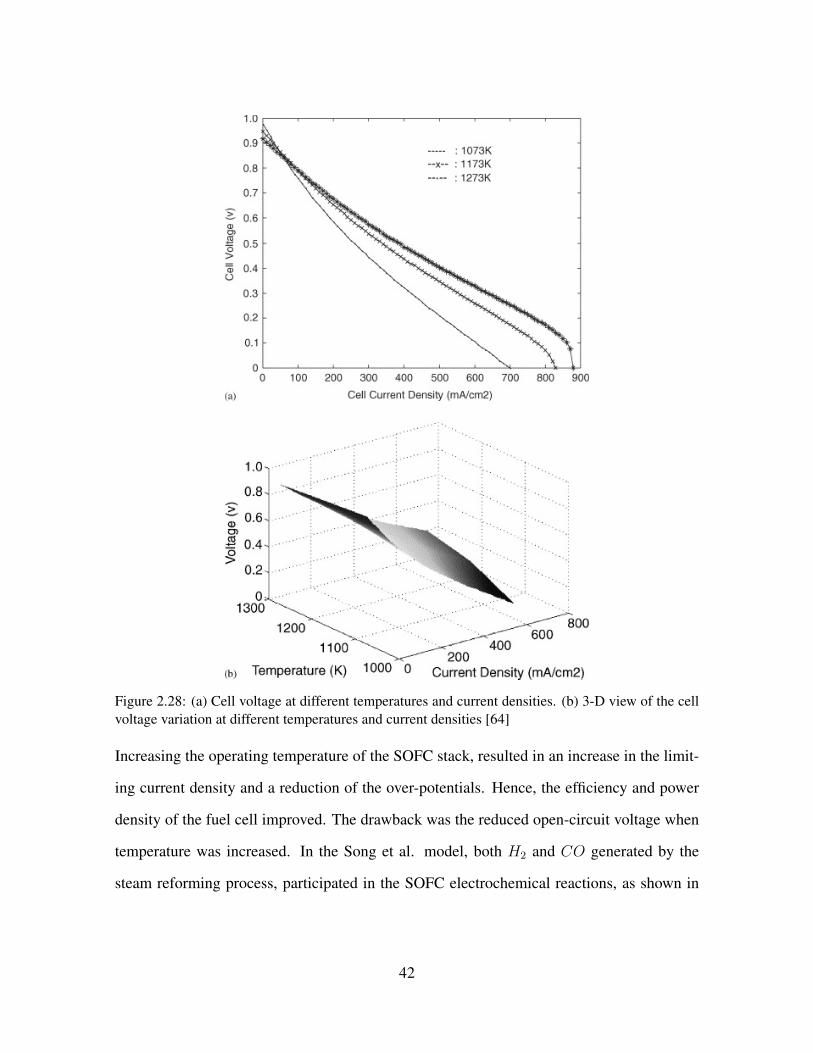
Figure 2.28: (a) Cell voltage at different temperatures and current densities. (b) 3-D view of the cellvoltage variation at different temperatures and current densities [64]
Increasing the operating temperature of the SOFC stack, resulted in an increase in the limit-
ing current density and a reduction of the over-potentials. Hence, the efficiency and power
density of the fuel cell improved. The drawback was the reduced open-circuit voltage when
temperature was increased. In the Song et al. model, both H2 and CO generated by the
steam reforming process, participated in the SOFC electrochemical reactions, as shown in
42
Eq. (2.7), Eq.(2.8) and Eq. (2.9) [165]:
12O2 + 2e− → O=
(2.7)
H2 +O= → H2O + 2e−
(2.8)
CO + 12O2 → CO2
(2.9)
A complete polarization model of a fuel cell is presented by Chan et al. [166]. In one
study, the combined anode and cathode activation polarization was modeled using Eq. (2.10),
which was described as due to the sluggish kinetics at the electro-catalytic sites because of
low temperature or lack of active sites [30]:
ηA = RuTαnF
ln( ii0
)
(2.10)
The exchange current density, i0 is associated with the catalytic activity at the interfaces of
43
the electrodes and the electrolyte. α represents the distribution of the intermediate species
at the TPB, and usually has a value between 0 and 1 (usually taken as 0.5). Concentration
polarization was modeled by Chan et al. as in Eq. (2.11):
ηC = −RuTnF
ln(1− iiL
)
(2.11)
The limiting current density, il, corresponds to the maximum current that fuel cell can pro-
duce to balance the maximum supply speed of reactants. A fuel cell usually operates at lower
current densities than the limiting current density. Several fuel cell parameters affect the cell
resistance including inherent electrolyte ionic conductivity, electrolyte thickness, electrode
and interconnect electronic conductivities and geometry of the electrolyte [30].
The Advanced Power Systems Analyses Tools (APSAT) modeling package is described in a
study by Yi et al. [167]. In that study, the performance of the developed tool for the analysis
of the tubular SOFC power systems was compared to the observed hybrid operation data.
The stack model that has been developed by the Chan research group consisted of four re-
actors that each could serve as heat sources or heat sinks to calculate the stack temperature
[64]: 1) Heat generated through the electrochemical reactions in the cells, 2) Heat consumed
by the internal reforming, 3) Heat transferred to the reactants, and 4) Heat loss to the sur-
roundings. Hence, the reaction heat was expressed in the form of Eq. (2.12):
Qrxn = i∑η + T∆S
(2.12)
44
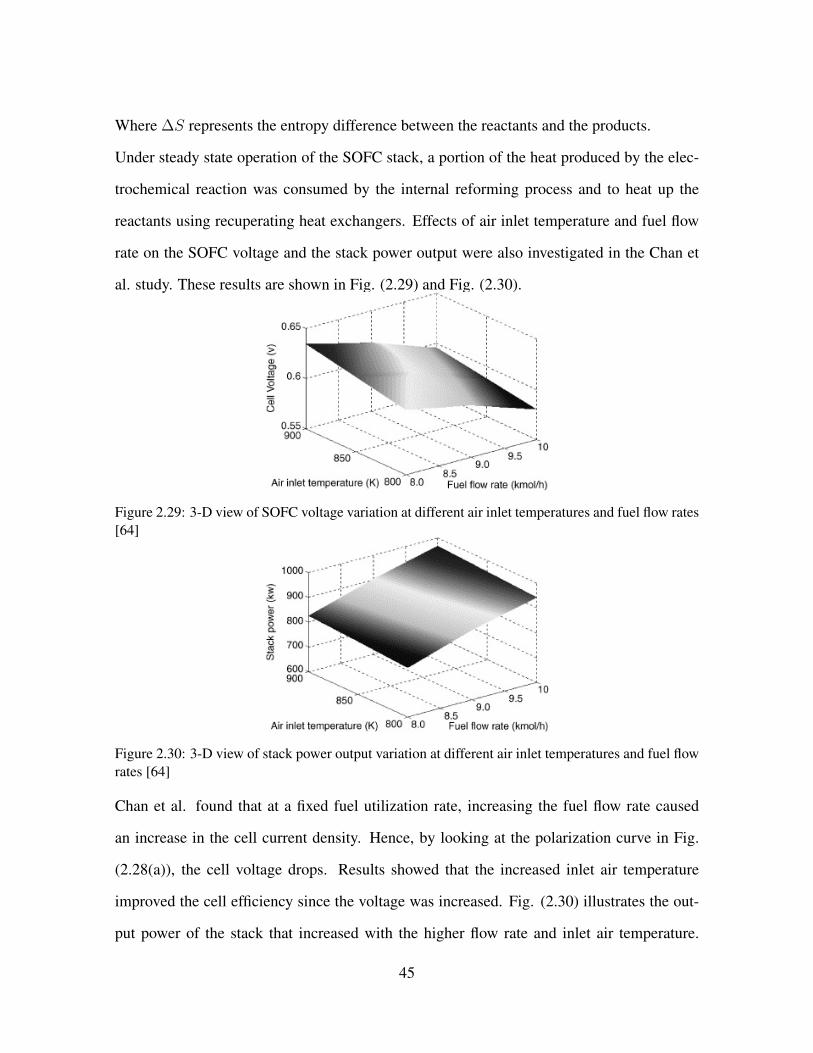
Where ∆S represents the entropy difference between the reactants and the products.
Under steady state operation of the SOFC stack, a portion of the heat produced by the elec-
trochemical reaction was consumed by the internal reforming process and to heat up the
reactants using recuperating heat exchangers. Effects of air inlet temperature and fuel flow
rate on the SOFC voltage and the stack power output were also investigated in the Chan et
al. study. These results are shown in Fig. (2.29) and Fig. (2.30).
Figure 2.29: 3-D view of SOFC voltage variation at different air inlet temperatures and fuel flow rates[64]
Figure 2.30: 3-D view of stack power output variation at different air inlet temperatures and fuel flowrates [64]
Chan et al. found that at a fixed fuel utilization rate, increasing the fuel flow rate caused
an increase in the cell current density. Hence, by looking at the polarization curve in Fig.
(2.28(a)), the cell voltage drops. Results showed that the increased inlet air temperature
improved the cell efficiency since the voltage was increased. Fig. (2.30) illustrates the out-
put power of the stack that increased with the higher flow rate and inlet air temperature.
45
Selimovic et al., suggested that by networking the fuel cell stacks, increased efficiency, im-
proved thermal balance, and higher total reactant utilization can be achieved. In such a
combination, the stacks were operating in series in the fuel flow direction. In one study, the
SOFC configuration using the multistage oxidation concept was analyzed. As a result, the
stack efficiency was increased due to smaller variation in the Nernst voltage across the cell
area [168].
2.5.2 REFORMER MODELS
For a natural gas fed hybrid SOFC-GT system, both internal or external reformers can be
used in the system. Due to expenses of providing additional cooling to the SOFC stack in
external reforming, an internal reformer has tended to be preferred over an external reformer
in the literature. For practical reasons of high temperature gradients when using only internal
reforming, many research groups have considered both external and internal reforming for
their hybrid SOFC/GT systems. Chan et al., have studied the internal reforming feasibility in
SOFC-GT hybrid systems [64]. The approach taken in that study, was vaporization of feed-
water by using the stack waste heat (HRSG), to produce the steam required for the reformer.
The reaction mechanisms of internal reforming are expressed in Eq. (2.13) to Eq. (2.15):
Reforming reaction: CH4 +H2O ↔ CO + 3H2
(2.13)
Shifting reaction: CO +H2O ↔ CO2 +H2
(2.14)
46

Electrochemical reaction: H2 + 12O2 → H2O
(2.15)
In the mentioned study, the equilibrium constants for the reforming and shifting reactions
depend upon the operating temperature and can be expressed by a polynomial form shown
in Eq. (2.16):
logKp = AT 4 +BT 3 + CT 2 +DT + E
(2.16)
The constants A, B, C, and D are listed in the work performed by Bossel [169]. Assuming
that the reforming and shifting reactions were always in equilibrium, the equilibrium con-
stants were calculated as a function of partial pressures of the reactants and the products as
expressed in Eq. (2.17) and Eq.(2.18):
Reforming: Kpr =p3H2
pCO
pCH4pH2O
(2.17)
Shifting: Kps =pH2
pCO2
pCOpH2O
(2.18)
47

Eq. (2.19) and Eq. (2.20) express the reforming and the shifting reaction net required heat
as a function of enthalpies of the reaction participants.
Qr = x(hCO + 3hH2 − hH2O − hCH4)
(2.19)
Qs = y(hCO2 + hH2 − hCO − hH2O)
(2.20)
Since both of the reforming and the shifting reactions are endothermic, the total heat trans-
fer from the stack was calculated by subtracting the reforming and shifting heat from the
generated heat in the electrochemical reaction as shown in Eq. (2.21):
Q = Qrxn −Qr −Qs
(2.21)
Where, Qrxn is the heat generated through the electrochemical reaction. Calise et al. used
the shift reaction equilibrium constant as follows [72]:
Kp,shift = exp(4594T− 4.35)
(2.22)
48
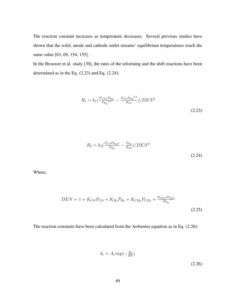
The reaction constant increases as temperature decreases. Several previous studies have
shown that the solid, anode and cathode outlet streams’ equilibrium temperatures reach the
same value [63, 69, 154, 155].
In the Brouwer et al. study [30], the rates of the reforming and the shift reactions have been
determined as in the Eq. (2.23) and Eq. (2.24):
R1 = k1(PCH4
PHOPH2
2.5 −PCOPH2
0.5
Kp1)/DEN2
(2.23)
R2 = k2(PCOPH2O
PH2− PO2
Kp2)/DEN2
(2.24)
Where,
DEN = 1 +KCOPCO +KH2PH2 +KCH4PCH4 +KH2O
PH2O
PH2
(2.25)
The reaction constants have been calculated from the Arrhenius equation as in Eq. (2.26):
ki = Ai exp(− EiRT
)
(2.26)
49
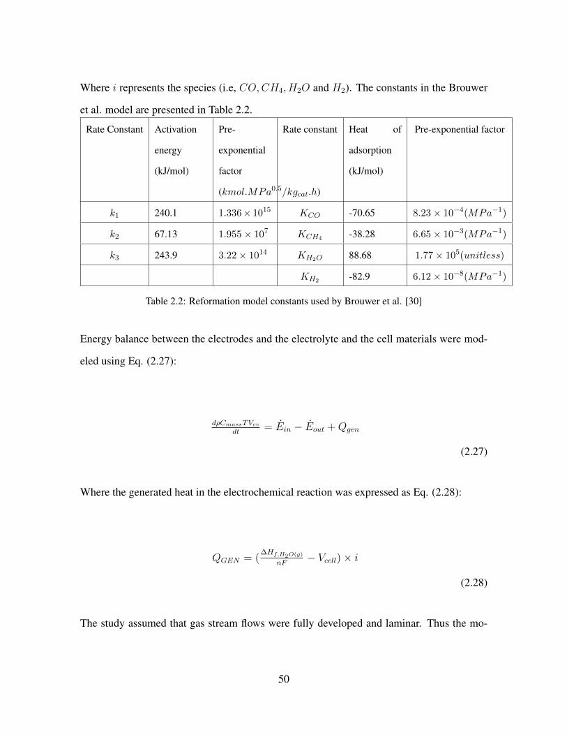
Where i represents the species (i.e, CO,CH4, H2O and H2). The constants in the Brouwer
et al. model are presented in Table 2.2.
Rate Constant Activation
energy
(kJ/mol)
Pre-
exponential
factor
(kmol.MPa0.5/kgcat.h)
Rate constant Heat of
adsorption
(kJ/mol)
Pre-exponential factor
k1 240.1 1.336× 10¹⁵ KCO -70.65 8.23× 10⁻⁴(MPa−1)
k2 67.13 1.955× 10⁷ KCH4 -38.28 6.65× 10⁻³(MPa−1)
k3 243.9 3.22× 10¹⁴ KH2O 88.68 1.77× 10⁵(unitless)
KH2 -82.9 6.12× 10⁻⁸(MPa−1)
Table 2.2: Reformation model constants used by Brouwer et al. [30]
Energy balance between the electrodes and the electrolyte and the cell materials were mod-
eled using Eq. (2.27):
dρCmassTVcvdt
= Ein − Eout +Qgen
(2.27)
Where the generated heat in the electrochemical reaction was expressed as Eq. (2.28):
QGEN = (∆Hf,H2O(g)
nF− Vcell)× i
(2.28)
The study assumed that gas stream flows were fully developed and laminar. Thus the mo-
50

mentum conservation equation that was used is in the form of Eq. (2.29):
∆P = f lDh
ρν3
2
(2.29)
Where ∆P is the pressure drop, f is the friction factor, L is the characteristic length, ρ
represents the density, ν is the average velocity and Dh is the hydraulic diameter. Chemical
kinetic representations of SMR (steam methane reformation) and WGS (water gas shift)
reactions have also been presented in another study by Campanari et al. [170]. Detailed
electrochemical models for either H2-only and H2 − CO oxidation were also presented in
that study.
2.5.3 COMBUSTOR MODELS
Chan et al., assumed that all the residual anode off-gas fuel constituents of the IR-SOFC
stack were fully oxidized in the combustor (i.e., CH4, CO and H2). Eq. (2.30) to Eq. (2.33)
show the chemical reactions proposed in that study [64]:
CH4 + 2O2 = CO2 + 2H2O + ∆Hrxn,H4
(2.30)
CO + 12O2 = CO2 + ∆Hrxn,CO
(2.31)
51

H2 + 12O2 = H2O + ∆Hrxn,H2
(2.32)
∑j Hp,j −
∑iHr,i = ∆Hrxn,CH4 + ∆Hrxn,CO + ∆Hrxn,H2
(2.33)
In order to determine the exit temperature of the combustor (Tp), Eq. (2.34) was used:
(∑
iHr,i + ∆Hrxn,CH4 + ∆Hrxn,CO + ∆Hrxn,H2)εeff =∑
j nj∫ TpTccp,jdT
(2.34)
Where, εeff is the combustion efficiency. The maximum possible heat exchanged from the
heat exchanger was calculated using Eq. (2.35):
Qmax = [min(nc × cp,c, nh × cp,h)]× (Th,i − Tc,i)
(2.35)
Where h and c represent the hot and the cold streams. So the net heat exchange was calcu-
52

lated from Eq. (2.36):
Q = εex ×Qmax
(2.36)
Calise et al., have modeled a catalytic burner [72]. In that study, gas-fuel and the gas-air heat
exchangers were simulated on a counter flow basis using the effectiveness number of transfer
units ε − NTU method. The impact of the heat exchanger on the SOFC-GT hybrid system
was investigated in another study by Magistri et al. [171]. Several configurations in terms of
the cycle layout were presented and the most promising configurations were identified. It was
suggested that the primary surface-type and some plate-fin-type recuperators could be used
in order to increase the compactness and minimize the capital cost of hybrid systems. The
high temperature heat exchangers, operated in the inlet temperature range of 750− 1100◦C
required the use of advanced materials such as nickel-based alloys, cobalt-based alloys and
ceramics. In addition, Magistri et al. indicated that the typically higher pressure drop in
ceramic heat exchangers can significantly reduce the efficiency of the cycle.
2.6 STEADY-STATE PERFORMANCE REPORTED
Efficiencies associated with several hybrid systems are shown in Table. (2.3). In general,
high operating pressure can significantly improve the system performance and efficiency.
Type Performer/year Stack
Pres-
sure
SOFC
Power
Net
Tur-
bine
Power
Total
Power
Electrical
Effi-
ciency
Total
Efficiency
SOFC/GT hy-
brid
Palsson et al., 2000
[59]
311 k-
W
173 k-
W
60% 86%
53

Atmospheric
SOFC
Veyo et al. 2002
[158]
1 atm +45% 75%
PSOFC/GT
hybrid
Veyo et al. 2002
[158]
Total
Pow-
er:MWe
class
59%
IRSOFC/GT
hybrid
Chab et al., 2003[66] 5 atm 1.3
MW
Power
Plant
437.8
kW
60.6% 80.5%
SOFC/µGT
hybrid
Uechi et al., 2004
[172, 173]
23.6 k-
W
6.4 k-
W
66.5%
IRSOFC/GT
hybrid
Song et al., 2005
[165]
176 k-
W
47 kW 57%
SOFC/GT hy-
brid
Rajashekara et al.,
2005[19]
3atm 441
kW
SOFC
161kW 68.6%
IRSOFC/GT
hybrid
Yi et al., 2005 [174] 50 bar 450
MW
SOFC
Power
177
MW
75.8%LHV
IRSOFC-GT Calise et al., 2006
[70]
1.47
MW
65.4%
SOFC/GT
(variable
speed)
Roberts et al., 2006
[175]
350 K-
W
66%
SOFC/GT
(fixed speed)
Roberts et al., 2006
[175]
350 K-
W
53%
54

IRSOFC/GT
hybrid
Bavarsad et al., 2007
[73]
3-7 at-
m
221.73
kW
SOFC
98 kW 53.34% 65.62%
SOFC/GT hy-
brid
Lim et al., 2008
[176]
3.5 at-
m
5 kW
SOFC-ST
(ASR)
Rokni, 2010 [139] 31.13
MW
9.21
MW
40.34
MW
67%
SOFC/GT Li et al,., 2010 [177] 10.1
bar
247.77
MW
63.38
MW
238.62
MW
61.5%
(HHV)
SOFC/GT Li et al., 2010 [177] 1.1 bar 229.91
MW
202.69
MW
52.2%
(HHV)
heat pipe in-
tegrated Gasi-
fierSOFCGT
Santhanam et al.,
2010 [178]
100 k-
W
72%
IT-SOFC
based IGFC
Romano et al., 2011
[179]
14 bar 330.9
MW
123.6
MW
493.4
MW
51.95%
LHV
IT-SOFC
based IGFC
Romano et al., 2011
[179]
23 bar 183.8
MW
246.3
MW
515.8
MW
54.29%
LHV
SOFC-GT-
ORC
Yan et al., 2013 [138] 3126
kW
1642
kW
67%
SOFC-
Stirling
hybrid system
Rokni, 2013 [180] order
of 10
kW
60%
SOFC/GT McLarty et al., 2014
[181]
>
65%
SOFC-GT
(fuelled with
gasified lig-
nocellulosic
biomass)
Caliandro, 2014
[182]
>
70%
55

SOFC-GT
(gassified
biomass
fueled)
Lv et al., 2014 [183] 144-
160
kW
50 −
55%
SOFC-GT Speidel et al., 2015
[148]
7.74
MW
3.96
MW
11.70
MW
54.2%
SOFC-MGT-
ORC
Ebrahimi et al., 2016
[141]
15.5 k-
W
1.25 k-
W
60.95% 65.77%
SOFC-GT Yi et al., 2016[151] 368.7
MW
98.3
MW
467
MW
72.8%
SOFC/GTCC Yi et al., 2016 [151] 367.8
MW
96.1
MW
486.4
MW
76%
SOFC/GT Facchinetti et al.,
2016 [184]
63%
SOFC-MGT Isfahani et al., 2016
[185]
51.5%
SOFCGT
(high tem-
perature heat
exchanger)
Saebea et al., 2017
[186]
388.28
kW
111.9
kW
100 k-
W
56.8%
SOFCGT
(cathode
exhaust gas
recirculation)
Saebea et al., 2017
[186]
388.27
kW
117.39
kW
62.48%
SOFC-blade
cooled gas
turbine
Choudhary et al.,
2017 [68]
73.46%
Table 2.3: Several studied hybrid system efficiencies
Veyo et al., showed that the pressurized SOFC-GT hybrid system had 10 efficiency points
56

advantage over the atmospheric hybrid system [158]. Fuel cells and gas turbines must main-
tain efficient operation and electricity production while protecting the equipment during the
perturbations that happen when the system is connected to the utility grid network. A cre-
ative control strategy is needed to ensure a flexible system with a robust dynamic operation.
Velumani et al. proposed a combined heat and power (CHP) SOFC-microturbine-absorption
chiller system for 230 kWe power demand of a building which acheived a thermal efficiency
of 70-75%, where the waste heat could be used for local heating and cooling [187]. The in-
stallation costs were reported in the range of 400 US$/kWe and 4000-5000 US $/kWe for the
microturbine and the SOFC, respectively. Barelli et al., have mentioned that the integrated
SOFC-GT efficiency can be significantly increased during load following operation [188].
The developed hybrid system model permitted 54.5% mean efficiency on a daily basis, with
short rapid dynamic response and wide part-load operating limits (down to 42.8% of nominal
system power).
2.7 COMPONENT MODIFICATIONS FOR DYNAMIC HYBRID
SYSTEM OPERATION
Many of the components desired for hybrid systems require significant advancement before
the systems are introduced as commercial products. In addition, the system integration and
control of a hybrid fuel cell-gas turbine system needs significant advancement for improving
their dynamic response. For example, compressors are sensitive to air density, so that the
compressor work demand increases as air temperature increases. Since the fuel cell oper-
ates at a fixed temperature, some researchers have found it challenging to maintain sufficient
compressor mass flow at high ambient temperature. If the gas turbine operates at a fixed
speed, then there are few options available to control the mass flow [30]. As a result, the
total power output of the system must often be sacrificed (by lowering the load demand),
so that the fuel cell could operate at a relatively fixed temperature. Understanding several
57

factors could help to improve the fuel cell performance in hybrid systems. These include
pressurized operation, effects of significant pressure differentials and pressure fluctuation-
s, integration with oxidizers for the increased thermal output to the heat engine, increased
fuel cell power density and material improvements for the increased current density, cost
reduction, electrode kinetics improvements and durability. The effects of decreasing the air
to fuel ratio compared to stand-alone fuel cell operation, so that the hybrid system is able
to operate at a higher combustor firing temperature are worthy of investigation. Research
that could contribute to the fuel flexibility of the fuel cell component in order to improve the
fuel cell tolerance to contaminants (especially those present in coal gasification products) is
important. Using a modulatable (0-100% load) combustor, which can withstand the constant
heat flux of the high temperature fuel cell effluent gases through the inactive combustor in
the steady state condition without cooling air, could improve the current state of the com-
bustor application in the hybrid systems. The integration of inverters, converters, and power
electronics with the hybrid power plant is also in need of understanding and advancement.
Using low cost and simplified inverters and understanding the effects of the inverter on the
power quality could contribute well to hybrid systems advancement.
It’s known that heat engines exhibit better performance at higher temperature and pressure in
stand-alone applications. However, integration with fuel cells requires specific modifications
such as lower temperature and lower pressure operation that may be better for overall hybrid
system performance. Hence heat engine modifications that may be preferred could have the
following features: 1) High performance under low quality heat input of the fuel cell (i.e.,
lower TIT (< 900◦C) in comparison to that typically delivered by a combustor (900◦C)), 2)
Ability to withstand the long duration of the fuel cell thermal cycling, 3) Ability to perform
under the low pressure ratios, 4) Ability to operate with the increased surge margin, and 5)
Improvement in compatibility with slow response time of the fuel cell.
58

2.8 PRACTICAL ISSUES DISCUSSED IN HYBRID SOFC/GT
LITERATURE
In general fuel crossover is a phenomenon that occurs when a specific amount of gaseous fu-
el diffuses from the anode compartment to the cathode compartment through the electrolyte
or seals without reacting electro-chemically. This is considered as an important factor in
the SOFC-GT hybrid systems performance degradation since sealing may be more diffi-
cult at higher pressure operation. Fuel crossover results in a direct reaction of the gaseous
fuel with the oxidant and produces heat that may lead to temperature gradients and degra-
dation. Electronic conduction through the electrolyte, which affects the cell net electrical
current density and efficiency is another mechanism of degraded performance expressed in
the literature that especially plagues certain types of electrolyte materials (e.g. ceria- and
bismuth-oxides). Pressurizing the cell increases the overall system efficiency. However, the
technical challenges associated with development of a robust SOFC cell and stack design
for operating under very high pressures is challenging and the development costs could be
significant. It is important to note that pressurization of an SOFC stack leads to reductions
in several polarization losses that result in increased efficiency for any given operating cur-
rent, which subsequently require less air flow for cooling and additional balance of plant
loss reductions that together increase overall efficiency. Yi et al. reported that increases in
operating pressure increase overall system efficiency. However, the technical challenges in
developing an SOFC with a very high operating pressure as well as the associated develop-
ment costs were reported to possibly be quite high. They concluded that there is a balance
between the development cost and the efficiency. In their work, the system efficiency was the
only factor considered [174]. Stiller suggested that specific incidents should be avoided for
a safe operation of the hybrid systems [189]. Some of these incidents have been reported as:
compressor surge or cell degradation due to thermal cycling or large temperature gradients,
59

carbon deposition and anode compartment blocking, and backflow of gas from the burner to
the anode compartment, exposing the anode to oxygen.
2.9 HYBRID SYSTEM TRANSIENT OPERATION AND CON-
TROL
2.9.1 TURBOMACHINERY CONTROLS
The turbomachinery used in hybrid SOFC-GT system can typically operate in two different
manners; fixed speed (synchronous) or variable speed (asynchronous) [190]. In the syn-
chronous mode the shaft is directly driving the electrical generator at some multiple of the
grid frequency. The advantage of this method is elimination of costly power conditioning
hardware and additional operating losses of the power conditioning equipment. For the syn-
chronous configurations the shaft speed of the turbomachinery in the hybrid system models
is typically controlled to a specified speed using a feedback loop with PI controller as shown
in Fig. (2.31).
Figure 2.31: Shaft speed control strategy [190]
Brouwer et al., acquired the experimental data of an SOFC-GT hybrid system during the
60

system start-up. During this period of operation, the hybrid system was slowly ramped up
in power to minimize the mechanical stresses from thermal dynamics of the fuel cell [30].
Fig. (2.32) demonstrates the control moves in their study, which included the SOFC load,
the recuperator, the SOFC bypass valve positions, and the fuel flow to the system. The
bypass valves were used to independently control the temperature and the mass flow rate
of the air entering the SOFC stack. The recuperator bypass was used to control the inlet
temperature of the air entering the stack, while the SOFC bypass was used to control the
air mass flow through the SOFC stack. In that study, the hybrid system utilized a dual shaft
turbine. The SOFC ramped up from 147 kW to 158 kW over a period of 100,000 seconds.
In the experiments, a sudden drop in the SOFC power was observed as the SOFC bypass
allowed more air to bypass the SOFC. At low load, the model couldn’t capture this sudden
drop, due to the uncertainties in the exact flow dynamics and the flow amounts altered by the
SOFC bypass valve. Also the first degrees of movement of the valve significantly changed
the amount of mass flow being bypassed. As more air bypassed the SOFC stack, the turbine
inlet temperature (TIT) was reduced which resulted in lower gas turbine power output [30].
Figure 2.32: GT power output, model VS experiment data [30]
61
The model of the Brouwer et al. followed the experimental data quite well, except at the
few load values where the SOFC bypass valve was being adjusted. The model demonstrated
that the turbine inlet temperature (TIT) was the most effective parameter for changing the
turbine power output. The model simulated the temperature at each point of the cycle and
they were fairly close. There was a 5% difference in the compressor mass flow, which caused
the model to predict lower temperatures. However, the model predicted higher temperature
because of the lack of accounting for the system heat loss. The only heat loss that has been
accounted for in the simulation was from combustor 1 and 2 where there was significant heat
loss [30].
Rastrepo et al. proposed a model predictive control strategy [105]. The constraint airflow
valves and the electric load were used in the simulation to control the constraint turbine speed
and the cathode airflow (CAF). Ferrari et al. studied a plant, comprising the coupling of a
tubular solid oxide fuel cell stack with a microturbine that was equipped with a bypass valve
able to connect the compressor outlet with the turbine inlet duct for rotational speed control
[191]. The main difficulty that Ferrari et al. found in implementing their control system
is the difference between the small mechanical inertia of the microturbine shaft compared
to the very large thermal capacitance of the fuel cell stack [192]. Jia et al. used GT shaft
speed control to stabilize the system [193]. In that study, a PI-type shaft speed controller,
was implemented to stabilize the hybrid system.
2.9.2 OFF-DESIGN PERFORMANCE OF HYBRID SYSTEM USING FIXED
AND VARIABLE GT SPEED
In a study by Roberts et al., transient performance and control analysis of atmospheric hybrid
systems with MCFCs were investigated [194]. Load perturbation was applied to evaluate the
system behavior. It was suggested that additional control strategies were required to study
the system behavior. The variation of the fuel utilization was the control method that was
62

studied in that paper. Variable speed of the GT was tested and showed that it could be a
promising control variable but limited to a system with lower power demand. For a larger
turn down in the system power, a bypass or an additional combustor was needed [195]. It
was shown that the variation of the GT speed was a required control method both for the
pressurized [30] and atmospheric [196] conditions in the part-load operation. The reason
was that the variation in the GT speed provided a better control over the compressor mass
flow. Brouwer et al. [30] developed a 1.15 MW pressurized SOFC-GT hybrid model. The
system was designed around the variable speed Capstone C200 MTG. The design parameters
of that system are presented in Table. (2.4).
63
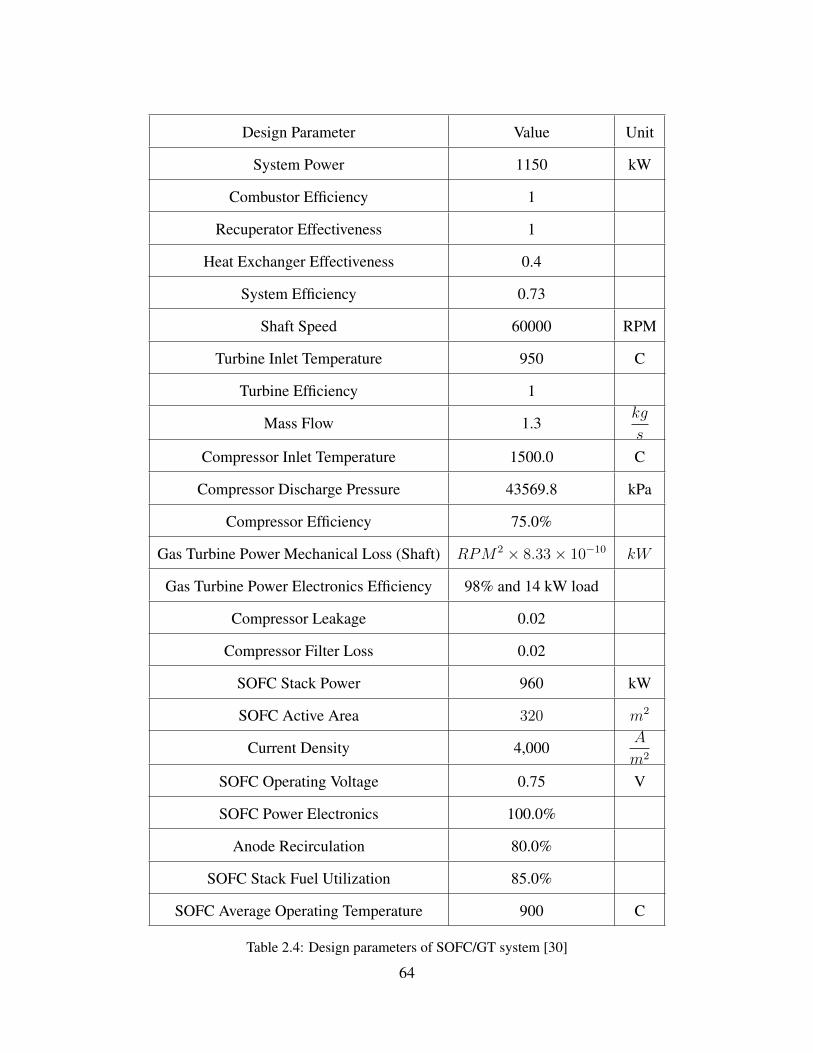
Design Parameter Value Unit
System Power 1150 kW
Combustor Efficiency 1
Recuperator Effectiveness 1
Heat Exchanger Effectiveness 0.4
System Efficiency 0.73
Shaft Speed 60000 RPM
Turbine Inlet Temperature 950 C
Turbine Efficiency 1
Mass Flow 1.3kg
s
Compressor Inlet Temperature 1500.0 C
Compressor Discharge Pressure 43569.8 kPa
Compressor Efficiency 75.0%
Gas Turbine Power Mechanical Loss (Shaft) RPM2 × 8.33× 10−10 kW
Gas Turbine Power Electronics Efficiency 98% and 14 kW load
Compressor Leakage 0.02
Compressor Filter Loss 0.02
SOFC Stack Power 960 kW
SOFC Active Area 320 m2
Current Density 4,000A
m2
SOFC Operating Voltage 0.75 V
SOFC Power Electronics 100.0%
Anode Recirculation 80.0%
SOFC Stack Fuel Utilization 85.0%
SOFC Average Operating Temperature 900 C
Table 2.4: Design parameters of SOFC/GT system [30]
64
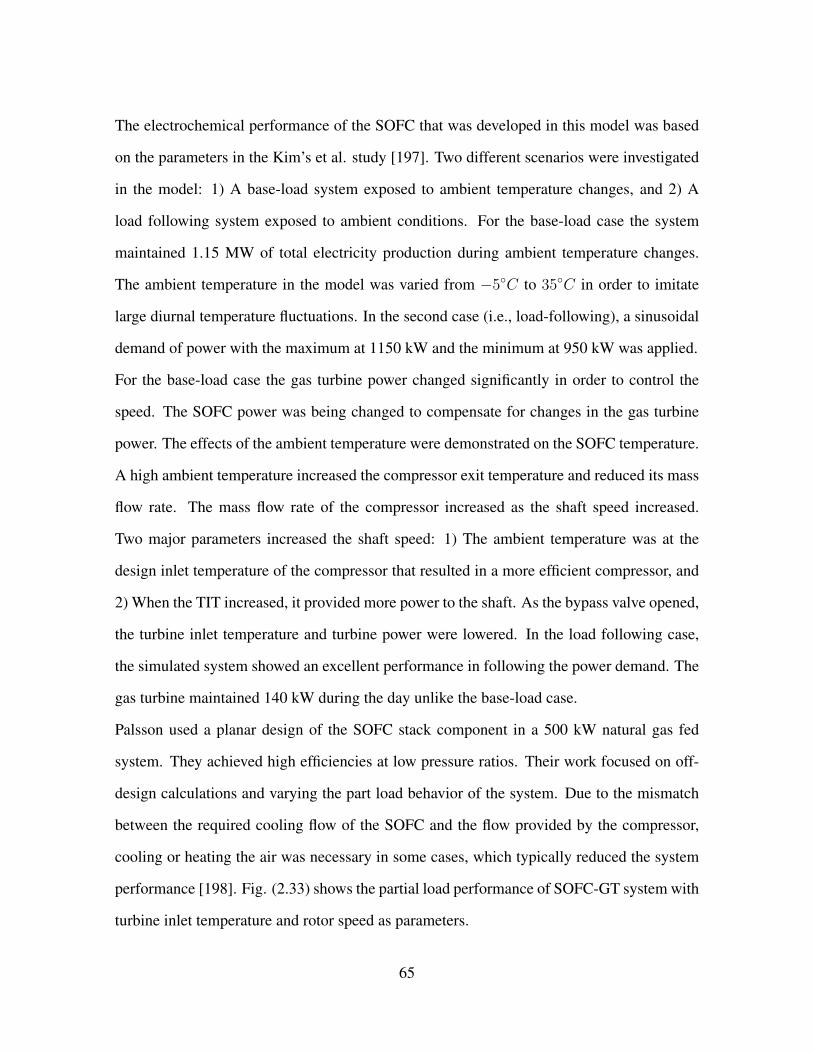
The electrochemical performance of the SOFC that was developed in this model was based
on the parameters in the Kim’s et al. study [197]. Two different scenarios were investigated
in the model: 1) A base-load system exposed to ambient temperature changes, and 2) A
load following system exposed to ambient conditions. For the base-load case the system
maintained 1.15 MW of total electricity production during ambient temperature changes.
The ambient temperature in the model was varied from −5◦C to 35◦C in order to imitate
large diurnal temperature fluctuations. In the second case (i.e., load-following), a sinusoidal
demand of power with the maximum at 1150 kW and the minimum at 950 kW was applied.
For the base-load case the gas turbine power changed significantly in order to control the
speed. The SOFC power was being changed to compensate for changes in the gas turbine
power. The effects of the ambient temperature were demonstrated on the SOFC temperature.
A high ambient temperature increased the compressor exit temperature and reduced its mass
flow rate. The mass flow rate of the compressor increased as the shaft speed increased.
Two major parameters increased the shaft speed: 1) The ambient temperature was at the
design inlet temperature of the compressor that resulted in a more efficient compressor, and
2) When the TIT increased, it provided more power to the shaft. As the bypass valve opened,
the turbine inlet temperature and turbine power were lowered. In the load following case,
the simulated system showed an excellent performance in following the power demand. The
gas turbine maintained 140 kW during the day unlike the base-load case.
Palsson used a planar design of the SOFC stack component in a 500 kW natural gas fed
system. They achieved high efficiencies at low pressure ratios. Their work focused on off-
design calculations and varying the part load behavior of the system. Due to the mismatch
between the required cooling flow of the SOFC and the flow provided by the compressor,
cooling or heating the air was necessary in some cases, which typically reduced the system
performance [198]. Fig. (2.33) shows the partial load performance of SOFC-GT system with
turbine inlet temperature and rotor speed as parameters.
65

Figure 2.33: Partial load performance of SOFC-GT system with TIT and rotor speed as parameters[198]
Magistri et al. defined the design point of the pressurized hybrid system based on Rolls-
Royce’s integrated planar solid oxide fuel cell (IP-SOFC) [199]. The hybrid system size
was about 2 MWe and the design point analysis was performed using two different IP-SOFC
models developed by the Thermochemical Power Group (TPG) at the University of Genoa:
1) A general model, where the transport and balance equations of the mass, energy and
electrical charges were solved in the lumped volume at constant temperature, 2) A detailed
model where all of the equations were solved using finite difference approach inside the
single cell. The ambient conditions effects on the IP-SOFC hybrid system performance were
investigated in that study. The part-load performance of the IP-SOFC hybrid system at a
fixed and variable turbine speed was analyzed. Fig. (2.34) shows the influence of ambient
temperature without control system. The operating temperature of the plant are strongly
affected by ambient conditions. The increase of 15◦C can result in the 4% increase in the
maximum temperature of the IP-SOFC.
66
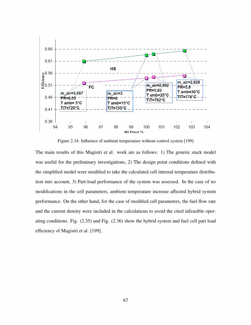
Figure 2.34: Influence of ambient temperature without control system [199]
The main results of this Magistri et al. work are as follows: 1) The generic stack model
was useful for the preliminary investigations, 2) The design point conditions defined with
the simplified model were modified to take the calculated cell internal temperature distribu-
tion into account, 3) Part-load performance of the system was assessed. In the case of no
modifications in the cell parameters, ambient temperature increase affected hybrid system
performance. On the other hand, for the case of modified cell parameters, the fuel flow rate
and the current density were included in the calculations to avoid the cited infeasible oper-
ating conditions. Fig. (2.35) and Fig. (2.36) show the hybrid system and fuel cell part load
efficiency of Magistri et al. [199].
67

Figure 2.35: Hybrid System Part Load Efficiency [199]
Figure 2.36: Fuel Cell Part Load Efficiency [199]
In another study from the same group (Magistri et al.), a hybrid system comprised of a 5 kW
microturbine coupled with a small size SOFC stack (31 kW) was analyzed [200]. The power
of the whole system was 36 kW depending upon the stack design parameters. A modular
code named ”HS-SOFC” was used to obtain the design and off-design performance of the
68
hybrid system. The hybrid system plant is shown in Fig. (2.37).
Figure 2.37: Simplified layout of hybrid system (Personal Turbine and SOFC) [200]
The system demonstrated potential efficiency at 56% at the design point. Two different speed
controls were used for the turbine’s rotational speed: 1) Fixed and 2) Variable. In the fixed
turbine speed control system analysis, the supplied power of the system was changed by
varying the fuel flow rate fed to the system. However, the fuel utilization of the fuel cell
stack was kept constant at 0.85. Fig. (2.38) shows the part-load performance of the hybrid
system at fixed turbine speed control system in the range of 55% load to full load. The
relative importance of component contributions have been reported as follows: the SOFC
and PT expander supply 31 kW and 17.3 kW, respectively, the air compressor consumes 9.7
kW, and the other losses account for 2.6 kW at the design point.
69
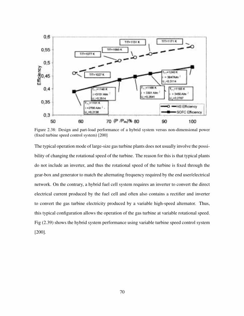
Figure 2.38: Design and part-load performance of a hybrid system versus non-dimensional power(fixed turbine speed control system) [200]
The typical operation mode of large-size gas turbine plants does not usually involve the possi-
bility of changing the rotational speed of the turbine. The reason for this is that typical plants
do not include an inverter, and thus the rotational speed of the turbine is fixed through the
gear-box and generator to match the alternating frequency required by the end user/electrical
network. On the contrary, a hybrid fuel cell system requires an inverter to convert the direct
electrical current produced by the fuel cell and often also contains a rectifier and inverter
to convert the gas turbine electricity produced by a variable high-speed alternator. Thus,
this typical configuration allows the operation of the gas turbine at variable rotational speed.
Fig (2.39) shows the hybrid system performance using variable turbine speed control system
[200].
70
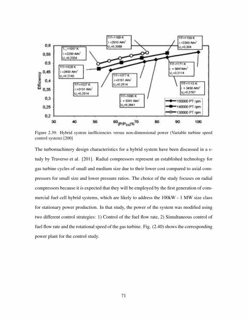
Figure 2.39: Hybrid system inefficiencies versus non-dimensional power (Variable turbine speedcontrol system) [200]
The turbomachinery design characteristics for a hybrid system have been discussed in a s-
tudy by Traverso et al. [201]. Radial compressors represent an established technology for
gas turbine cycles of small and medium size due to their lower cost compared to axial com-
pressors for small size and lower pressure ratios. The choice of the study focuses on radial
compressors because it is expected that they will be employed by the first generation of com-
mercial fuel cell hybrid systems, which are likely to address the 100kW - 1 MW size class
for stationary power production. In that study, the power of the system was modified using
two different control strategies: 1) Control of the fuel flow rate, 2) Simultaneous control of
fuel flow rate and the rotational speed of the gas turbine. Fig. (2.40) shows the corresponding
power plant for the control study.
71
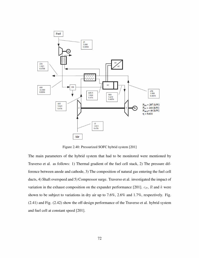
Figure 2.40: Pressurized SOFC hybrid system [201]
The main parameters of the hybrid system that had to be monitored were mentioned by
Traverso et al. as follows: 1) Thermal gradient of the fuel cell stack, 2) The pressure dif-
ference between anode and cathode, 3) The composition of natural gas entering the fuel cell
ducts, 4) Shaft overspeed and 5) Compressor surge. Traverso et al. investigated the impact of
variation in the exhaust composition on the expander performance [201]. cP , R and k were
shown to be subject to variations in dry air up to 7.6%, 2.6% and 1.7%, respectively. Fig.
(2.41) and Fig. (2.42) show the off-design performance of the Traverso et al. hybrid system
and fuel cell at constant speed [201].
72
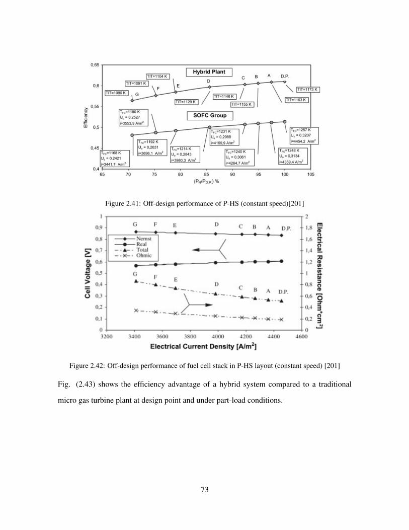
Figure 2.41: Off-design performance of P-HS (constant speed)[201]
Figure 2.42: Off-design performance of fuel cell stack in P-HS layout (constant speed) [201]
Fig. (2.43) shows the efficiency advantage of a hybrid system compared to a traditional
micro gas turbine plant at design point and under part-load conditions.
73

Figure 2.43: Off-design performance of P-HS layout (Variable speed) [201]
Fig. (2.44) shows the off-design performance of the SOFC in hybrid system determined by
Traverso et al. Note that as the fuel cell efficiency increases, the turbine rotational speed
decreases [201].
Figure 2.44: Off-design performance of fuel cell stack in P-HS layout (Variable speed) [201]
Roberts et al., used two similar control strategies, (i.e., fixed speed operation and variable
speed operation) [175]. The system efficiency they reported was greater than 66% for vari-
able speed operation compared to 53% efficiency for fixed speed operation. Fig. (2.45)
shows the plant at the gas turbine fixed speed operation.
74

Figure 2.45: SOFC-GT hybrid system with fixed speed GT and cathode bypass [175]
For the fixed speed operation additional actuators (cathode bypass or auxillary combustor)
were required in order to maintain the SOFC operating temperature. However, for the vari-
able speed operation, the additional actuators were not required [175]. Komatsu et al., used
the variable MGT rotational speed operation control for the part-load operation [202]. The
primary reason for the system performance degradation at part-load was due to the operating
temperature reduction of the SOFC component. The operating temperature reduction was
caused by the reduction in the fuel supply and the heat generated in the cells. The variable
MGT speed control required flexible airflow requirements that could lead to high system
efficiency. Fig. (2.46) shows the calculation results of temperature distribution in the SOFC
module at the design point. The horizontal axis is the normalized distance from 0 to 1. The
gas flow directions are the same as one of the segment length. This figure shows the temper-
ature distribution for performance analysis of the part-load operating condition of the hybrid
system.
75
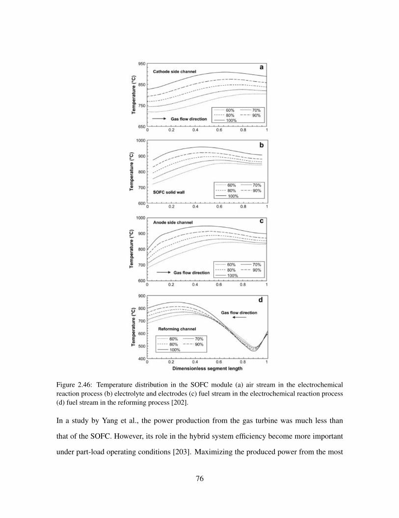
Figure 2.46: Temperature distribution in the SOFC module (a) air stream in the electrochemicalreaction process (b) electrolyte and electrodes (c) fuel stream in the electrochemical reaction process(d) fuel stream in the reforming process [202].
In a study by Yang et al., the power production from the gas turbine was much less than
that of the SOFC. However, its role in the hybrid system efficiency become more important
under part-load operating conditions [203]. Maximizing the produced power from the most
76

efficient component in the hybrid system (the SOFC) lead to the highest system efficiency.
Fig. (2.47) shows the two important temperatures of the Yang et al. SOFC-GT hybrid system
operating with VRS + FC (variable rotational speed with fuel control) and HAB + FC (hot
air bypass with fuel control) part-load control modes.
Figure 2.47: Two important temperatures of SOFC/GT hybrid system operating with VRS + FC andHAB + FC modes: (a) cell temperature; (b) turbine inlet temperature [203]
Controlling the air through a pressurized solid oxide fuel cell (SOFC) stack in a SOFC-
GT pressurized hybrid system was studied by Traverso et al.[204]. The results showed that
a variable speed microturbine was the best option for off-design operation of a SOFC-GT
hybrid system.
77

2.9.3 CONTROL STRATEGIES FOR COMPRESSOR SURGE
Ferrari et al., [205] designed and installed a high temperature fuel cell-micro gas turbine
physical emulator in the framework of the European Integrated Project (FELICITAS) at the
Thermochemical Power Group (TPG) located in Savona. The focus of the study was to min-
imize the viscous pressure loss in order to: 1) Reduce the pressure imbalance and dynamics
between the compressor and the expander, 2) Maintain an accurate measurement, and 3)
Have an effective plant efficiency. A modular high temperature volume was designed using
computational fluid dynamics (CFD) tools to achieve a high uniformity in the flow distribu-
tion inside the volume and to minimize the pressure losses. Their research showed that surge
occurred during the shutdown for a particular configuration. Fig. (2.48) shows the pres-
sure losses between the recuperator and the combustor for different conditions. The modular
volume line values, obtained at different loads with all the volume pipes connected to the
machine, were compared with the volume zero and direct line experimental data to show the
loss increase. However, the data obtained with the whole volume show that the objective of
minimizing the additional pressure losses has been completely reached.The tests operated at
volume zero configuration focusing the attention on a 75 kW load rejection. The preliminary
tests operated with modular volume connected with the machine. The paper showed tha the
surge happened during a shutdown at this configuration.
In another study by Ferrari et al., strategies to avoid surge or excessive stress during the
start-up and shutdown phases were proposed [206]. They concluded that a new control
study for managing the valve responsible for controling the inlet temperature ramp during
the hybrid system start-up and shutdown emulation was needed. Fig. (2.49) shows the
temperature control system scheme. The internal loop controls the valve pneumatic actuator
to reach the requested position. The difference between the command and the signal from the
valve position sensor is the input of a proportional integral (PI) controller optimized for an
overdamped valve reaction. The external loop controls the fuel cell cathode inlet temperature
78

to reach the temperature command value, which is the heating or cooling ramp.
Figure 2.48: Pressure losses between the recuperator and the combustor for three different conditions:(i) direct line, (ii) volume zero, and, (iii) modular volume [205]
Figure 2.49: Temperature control system scheme (external loop) [206]
In a study by Mclarty, controls were utilized to mitigate the spatial temperature variation and
the stall risk during the load following [181]. The results showed that using the combined
feed-forward, PI and cascade control strategy, 4:1 (SOFC) turn-down ratio could be achieved
and a 65% efficiency could be maintained throughout the operating regime. Fig. (2.50) and
Fig. (2.51) show the different control strategies used for the hybrid system.
79

Figure 2.50: P-I feedback control loops for FC-GT control [181]
Figure 2.51: Control overview for synchronous SOFC-GT topping cycle with inlet guide vanes (IGV)and bypass [181]
Azizi et al. studied the surge for a 1.7 MW gas turbine for a stationary hybrid SOFC-GT
80

system using computational fluid dynamics tools [207]. Hildebrandt and Assadi conducted a
the compressor sensitivity analysis associated with transient SOFC-GT hybrid system oper-
ation [208]. The reduced Moore and Greitzer model was used for the compressor modeling.
The results showed that transient part-load operation was sensitive to the characteristics of
the compressor speed-lines and the load change procedure. Fig. (2.52) shows the SOFC load
change for a constant ratio of GT load to SOFC load. In another study, Hildebrandt et al.
stated that at the shut-down with no control strategy, the slow thermal SOFC transients could
result in compressor surge [209].
Figure 2.52: Stepwise SOFC load change for a constant ratio of GT load to SOFC load [208]
The National Energy Technology Laboratory developed an experimental facility entitled the
Hyper Facility that is able to emulate hybrid power systems in the range of 300 kW to 900
kW. Tucker et al. were able to show that thermal management of the fuel cell improved
through controlling the cathode air flow during load transient operation. The increased pres-
81
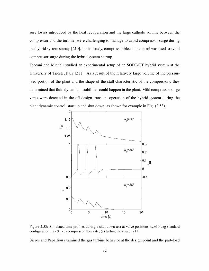
sure losses introduced by the heat recuperation and the large cathode volume between the
compressor and the turbine, were challenging to manage to avoid compressor surge during
the hybrid system startup [210]. In that study, compressor bleed air control was used to avoid
compressor surge during the hybrid system startup.
Taccani and Micheli studied an experimental setup of an SOFC-GT hybrid system at the
University of Trieste, Italy [211]. As a result of the relatively large volume of the pressur-
ized portion of the plant and the shape of the stall characteristic of the compressors, they
determined that fluid dynamic instabilities could happen in the plant. Mild compressor surge
vents were detected in the off-design transient operation of the hybrid system during the
plant dynamic control, start up and shut down, as shown for example in Fig. (2.53).
Figure 2.53: Simulated time profiles during a shut down test at valve positions αv=30 deg standardconfiguration. (a) βp; (b) compressor flow rate; (c) turbine flow rate [211]
Sieros and Papailiou examined the gas turbine behavior at the design point and the part-load
82

operation regimes of a hybrid SOFC-GT system [212]. They mentioned that the prediction
of surge was not reliable on the 1-D simulation basis (i.e., the actual surge margin might be
smaller than the predicted one of the 1-D simulation). They suggested using components
with variable geometries in their study.
2.9.4 COMPUTATIONAL STALL/SURGE ANALYSIS IN HYBRID SOFC-GT
SYSTEMS
Placing the fuel cell in the high pressure section between the compressor and turbine increas-
es the fuel cell efficiency by increasing the reactant partial pressures and lowering some po-
larization effects. The topping cycle design that is used for dynamic simulations in this study,
introduces the need for a pressure vessel of significant volume and increases the potential for
compressor stall/surge. Under steady-state conditions the compressor supplies a specific
mass flow rate of air at every combination of shaft speed and pressure ratio. These values are
typically normalized and compiled into tables or plotted in compressor maps. Compressor
performance in gas turbines is limited by two main lines that are typically plotted on com-
pressor maps: 1) a choke line at high air flow rate and, 2) a surge line at low air flow rate.
The surge limit depends upon the compressor design and system configuration and especial-
ly upon the pressure dynamics downstream of the compressor. The dynamics of compressor
surge/stall are significantly affected by introducing a fuel cell in the place of a combustor,
making it difficult to predict surge. Reaching the surge limit might reduce the compressor
performance temporarily or permanently and could introduce violent pressure and physical
perturbations during stall/surge operation that could damage fuel cell. Therefore, control
strategies are needed to keep the compressor performance in safe operating condition away
from surge line (often called the surge margin). At specific pressure ratios and shaft speeds
compressor surge occurs when reversal of flow direction is caused by excess back pressure
on the compressor. The series of operating points that result in a surge event are collectively
83
grouped into the surge line that is plotted on compressor maps [190]. Such surge events are
often followed by compressor stall and highly dynamic and stressful compressor conditions
that can cause a complete mechanical failure of th fuel cell, gas turbine and/or the entire
hybrid system. Researchers at the National Energy Technology Laboratory (NETL) have
showed the benefits of compressor bleed and cold air bypass for controlling the compressor
mass flow rate during transient behavior [38]. The HYPER hybrid system simulation facility
was able to emulate hybrid systems in the range of 300 kW to 900 kW. The thermal man-
agement of the fuel cell improved through controlling the cathode air flow during the load
transient operation. The increased pressure losses introduced by the heat recuperation and
the large cathode volume between the compressor and the turbine, were challenging during
the hybrid system startup [210]. In that study, the compressor bleed air was used to avoid
the compressor surge during the hybrid system startup. Ferrari et al. designed and installed
an SOFC-GT physical emulator in the framework of a European Integrated Project [205].
The focus of their study was to minimize the viscous pressure loss in order to: 1) Reduce
the unbalance between the compressor and the expander, 2) Maintain an accurate measure-
ment, and 3) Have an effective plant efficiency. A modular high temperature volume was
designed using computational fluid dynamics (CFD) tools to achieve a high uniformity in
the flow distribution inside the volume and to minimize the pressure losses. The paper con-
cluded that surge occurred during the shutdown for a particular configuration. In another
study, strategies to avoid surge or excessive stress during the start-up and shutdown phases
were proposed [206], which found that a new control strategy was required for managing the
valve responsible for volume inlet temperature ramp during the hybrid system start-up and
shutdown emulation. McLarty et al. studied the dynamic operation of an SOFC-GT topping
cycle and showed that the pressurized hybrid topping cycles exhibited increased stall/surge
characteristics particularly during off-design operation [131, 181]. In another study by M-
cLarty et al. controls were utilized to mitigate the spatial temperature variation and the stall
84
risk during load following [181]. The results showed that using the combined feed-forward,
PI and cascade control strategy, 4:1 (SOFC) turn-down ratio could be achieved and a 65%
efficiency could be maintained. Stiller et al. suggested that specific incidents should be
avoided for safe operation of hybrid systems [189]. Some of these incidents are: compressor
stall/surge or cell degradation due to thermal cracking or high temperatures, carbon depo-
sition and anode compartment blocking, and backflow of gas from the burner to the anode,
exposing the anode to oxygen. In that study, a new control strategy for managing the valve
was used to generate the requested inlet temperature ramp during the hybrid system start-up
and shutdown emulation. Roberts et al. have mentioned some important disturbances in the
hybrid carbonate fuel cell-gas turbine system due to the changes in the ambient temperature,
fuel flow variation induced by supply pressure disturbances, fuel composition variability,
and power demand fluctuations [194]. In that study, the predicted fuel cell operating tem-
perature, fuel utilization, fuel cell and GT power, shaft speed, compressor mass flow and
temperatures in the cycle were considered as the controlled response to the fuel cell volt-
age increase. Panne et al. demonstrated the steady state analysis of an SOFC-GT hybrid
cycle test rig [213]. The cycle could be evaluated without the risk of damaging the cell.
The effects of the ambient conditions or the pressure losses were investigated. The maxi-
mum compressor pressure ratio, the supplemental fuel mass flow and the SOFC air bypass
were the three different limitations in the choice of cycle configuration. The additional pres-
sure losses and piping had significant impact on the surge margin. Hilderbrandt studied the
compressor sensitivity analysis of the transient SOFC-GT-HS operation [208]. The reduced
Moore and Greitzer model was used for the compressor modeling, showing that the transient
part-load operation was sensitive to the characteristics of the compressor speed-lines and the
load change procedure. In another study, it was stated that at the shutdown with no control
strategy, the slow thermal SOFC transients could result in the compressor surge [209]. Stiller
studied a multi-loop control strategy for hybrid SOFC-GT system [189]. Fuel flow could be
85

controlled by controlling the fuel valve. Air flow could be controlled by controlling the shaft
speed, variable inlet guide vanes or variable compressor bleed. Their effects on the system
have been reported to be similar. In the mentioned study, shaft speed control was selected.
Power was controlled by manipulating the SOFC current, fuel utilization was controlled by
manipulating the fuel flow, air flow was controlled by manipulating the shaft speed and cell
temperature was controlled by adjustment of the air flow setpoint. Taccani et al. studied
an experimental setup of SOFC-GT-HS at University of Trieste, Italy [211]. As a result of
the relatively large volume of the pressurized portion of the plant and the shape of the stall
characteristic of the compressors investigated, the fluid dynamic instabilities were found to
occur in the plant. A surge could be detected in the off-design transient operation of the
hybrid system during the plant regulation, start-up and shutdown. Sieros et al. examined
the gas turbine behavior at the design point and the part-load operation regimes [212]. They
mentioned that the prediction of surge was not reliable on the 1-D basis (i.e., the actual surge
margin might be smaller than the predicted one). Using the components with variable ge-
ometries was suggested in that study. The literature suggests that two kinds of stall/surge are
common in industrial compressors, which are labeled as ”deep surge and mild surge. Deep
surge is the result of complete reversal of flow in the compressor impeller at a specific time.
This type of surge significantly reduces the compressor performance which could result in
the complete system failure. The other more common type of the compressor surge is mild
surge which is characterized by an oscillatory mass flow rate at the impeller inlet and outlet
caused by partial reversal of flow which causes reduced performance and efficiency of the
compressor. However, mild surge is not as severe as deep surge.
2.9.5 GAS TURBINE AND COMPRESSOR MODELS
Gas turbine systems are the most common technology for producing power around the world
today. Different types of turbo-machinery are operated today including those using water in a
hydroelectric plant, steam in nuclear and coal plants (and some gas plants using the Rankine
86

cycle), and air, such as those used in natural gas-fired combined cycle plants and jet-fueled
aircraft. Computer programs that calculate the performance of gas turbines typically need
a description of the turbine and compressor performance as a function of speed and mass
flow or pressure (usually provided in the form of maps) as an input. These maps are either
calculated or derived from a turbine rig test. The data from the turbine rig test usually are
not evenly distributed over the tested speed range and sometimes the distance between speed
lines is large. As a result, interpolation and extrapolation of the measured data is often
required [214].
For the gas turbine transient model developed by Brouwer et al., calculations were performed
at each time step [30]. Eq. (2.37) and (2.38) have been used to simulate the gas turbine
shaft speed dynamics given the dynamic turbine and the compressor powers (PT and PC),
rotational inertia J , and rotational speed ω as follows:
dωdt
= 1Jω
(PT1 − PC)
(2.37)
For hybrid systems that considered a the second turbine (i.e., power-only turbine without
compressor), the same equations have been used in order to calculate the temperatures and
the enthalpies. The second shaft had the generator load instead of the compressor load as
shown in Eq. (2.38):
dωdt
= 1Jω
(PT2 − PLoad)
(2.38)
87

In the study by Brouwer et al, the generator operated at 3600 RPM for 60 Hz AC electric-
ity production. Thus, the rotational speed of the turbine was adjusted and maintained by
controllers to a value as close as possible to 3600 RPM. A transient gas turbine model was
developed in their simulation of the hybrid Siemens Westinghouse pressurized system. The
dynamic expressions that account for gas compressibility and mass storage have been solved
in different diffuser volumes as shown in Fig. (2.54).
Figure 2.54: Dynamic simulation approach of gas turbine and compressor [30]
During the simulation, the generator load was applied to the turbine shaft. Their model was
flexible in importing the empirical data of any gas turbine operation. The semi-empirical
data that was used in their model was in the form of non-dimensional compressor and tur-
bine maps. These maps provided steady state mass flow, pressure ratio and efficiency as a
function of the rotational speed of the shaft. The first map plotted the pressure ratio versus
dimensionless mass flow at a fixed rotational speeds. The second map gave the normal-
ized isentropic efficiency versus dimensionless mass flow at a fixed rotational speed. The
non-dimensional mass flow in that study was defined as in Eq. (2.39):
Non-dimensionalized mass flow rate= mR√γRT01
D2P01
(2.39)
Where m is the fluid mass flow, R is the universal gas constant, γ is the ratio of the spe-
88
cific heats, T01 and P01 are the stagnation temperature and pressure at the inlet and D is a
characteristic length. Dimensionless rotor speed has been defined in the form of Eq. (2.40):
Dimensionless rotor speed = ND√γRT01
(2.40)
Where N is the rotational speed. For any inlet condition (T01, P01), discharge pressure and
speed, the mass flow rates were determined from the turbine and the compressor maps. An
iterative solution method was used until the pressure ratio guessed matched the ratio of the
discharge pressure to the inlet pressure. After finding the mass flow rate, the isentropic
efficiency of the turbine and the compressor was found from the second map. Knowing the
isentropic efficiency, the compressor and the turbine exit temperature were determined from
the isentropic efficiency relations. The exit temperatures were found from Eq. (2.41):
T02 = T01(1 + 1ηcomp
((P02
P01)γ−1γ − 1))
(2.41)
The specific heat was determined as a function of temperature for the gas mixture containing
the seven species. The compressor work was calculated as in Eq. (2.42):
Pc = mComp(h01 − h02)
(2.42)
89
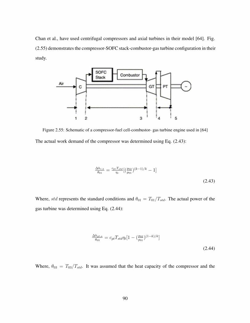
Chan et al., have used centrifugal compressors and axial turbines in their model [64]. Fig.
(2.55) demonstrates the compressor-SOFC stack-combustor-gas turbine configuration in their
study.
Figure 2.55: Schematic of a compressor-fuel cell-combustor- gas turbine engine used in [64]
The actual work demand of the compressor was determined using Eq. (2.43):
∆hc,aθ01
= cpcTstdηc
[(p02p01
)(k−1)/k − 1]
(2.43)
Where, std represents the standard conditions and θ01 = T01/Tstd. The actual power of the
gas turbine was determined using Eq. (2.44):
∆hgt,aθ03
= cptTstdηt[1− (p02p01
)(1−k)/k]
(2.44)
Where, θ03 = T03/Tstd. It was assumed that the heat capacity of the compressor and the
90
turbine are the same. The power output of the power turbine was in the form of Eq. (2.45):
∆hpt,aθ04
= cptTstdηpt[1− (p04p05
)(1−k)/k]
(2.45)
In the study by Chan et al. [64], typical compressor/turbine maps (DLR centrifugal com-
pressor and NASA-CR-174646 axial turbine) have been used in order to verify the operation
characteristics of the turbo-machines. In the described configuration, the speed of the com-
pressor was the same as the gas turbine speed. The simulation of a smaller or larger power
plant, only required the standard mass flow rate to be changed.
A compressor supplies a specific mass flow rate of air at every combination of shaft speed
and pressure ratio. These values are often normalized and compiled into tables or plotted
on maps. At specific pressure ratios and shaft speeds, compressor surge occurs. Compres-
sor surge is known as the reversal of flow direction due to the excess back pressure on the
compressor and could cause a complete failure of the gas turbine. The series of operating
points that result in the surge are collectively grouped into the surge line and added to the
compressor map plots. The shaft speed, the pressure ratio and the flow rate as plotted in
these maps are normalized using Eq. (2.46) to (2.48) [190]:
NRPM = RPM√TstagTdes
.RPMdes
(2.46)
91
NFlow = FlowF lowdes
.
√TstagTdesPinPdes
(2.47)
PR = PoutPin.PRdes
(2.48)
Where, the parameters were defined by McLarty using the Eq. (2.49) to Eq. (2.52):
Stagnation temperature: Tstag = Tin.(1 +M2(γ−12
))
(2.49)
Mach Number: M2 = RuγTinMV 2
in
(2.50)
Velocity: Vin = nRuTinAinPin
(2.51)
92
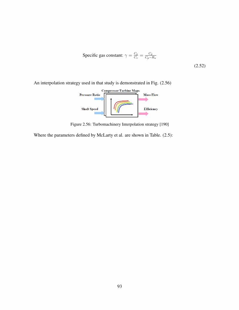
Specific gas constant: γ = CpCv
= CpCp−Ru
(2.52)
An interpolation strategy used in that study is demonstrated in Fig. (2.56)
Figure 2.56: Turbomachinery Interpolation strategy [190]
Where the parameters defined by McLarty et al. are shown in Table. (2.5):
93

Parameter Description
NRPM Normalized Shaft Speed
NFlow Normalized Flow Rate
RPM Actual Shaft Speed
RPMdes Design Shaft Speed
Flow Actual air flow rate
Flowdes Design Air Flow Rate
Tin,des,stag Inlet, Design or Stagnation Temp
Pin,out,des Inlet, Outlet or Design Pressure
PR Normalized Pressure Ratio
PRdes Design Pressure Ratio
M Molar Mass
Vin Inlet Velocity
n Actual Flow Rate
Ain Cross Sectional Area of Inlet
Table 2.5: Turbomachinery parameters [190]
The input parameters for the compressor were the ambient temperature, the species con-
centrations, the shaft speed and the inlet/exit pressures. For the compressor, two energy
conservation models were considered by McLarty [190]. The first was regarding the work-
ing fluid and the second included the compressor solid mass demonstrated in Eq. (2.53) and
(2.54).
dTgdt
= WC+(h.n)out+hcAsur(Ts−Tg)
Cp.PoutVRUTg
94
(2.53)
dTsdt
=hcAsur(Tg−Ts)+εσAsur(T 4
amb−T4s )
Cp.m
(2.54)
Where, the compressor work demand and the isentropic temperature were determined from
Eq. (2.55) and Eq. (2.56):
WC = nout.(hisen−hinηisen
)
(2.55)
Tisen = (PR.PRdes)γ−1γ
(2.56)
Table. (2.6) demonstrates the compressor parameters used in the study by McLarty [190].
95

Parameter description
WC Shaft Power
h inout
Flow Enthalpy
n inout
Flow Rate
hc Convection Coefficient
Asur Surface Area
Ts,g Solid and Gas Phase Temperature
Tg Air Flow Temperature Out
Tisen Isentropic Temperature
V Volume of Compressor
ε Emissivity of Metal
σ Boltzman Constant
m Mass of Compressor
Table 2.6: Compressor parameters [190]
Typically, a micro-turbine generator (MTG) is a relatively small gas turbine power generator
made of several components including: centrifugal compressor, inflow expander, combus-
tion chamber, recuperator, centrifugal turbine, electrical generator and natural gas compres-
sor. The simulation of such an MTG compressor module has been accomplished by McLarty
based on the experimental maps (efficiency and pressure ratio versus non-dimensional flow
rate) [190]. The input data of the compressor module were: the air inlet pressure and tem-
perature, rotational speeds and the first guess pressure ratio. Turbine modeling was similar
to the compressor modeling with different known initial conditions. The known parameters
for the turbine were the mass flow rate and the inlet temperature. The outlet pressure of the
turbine was known from the back calculation of the downstream components of the system.
96

Hence, the turbine inlet temperature, the shaft power produced, turbine outlet temperature
and the inlet pressure could be calculated. The inlet pressure of the turbine was calculated
iteratively. The inlet pressure was used to find the pressure ratio, and was applied to the
turbine map to find the mass flow rate which was iteratively solved to match the incoming
flow to maintain a constant pressure at any given time step. Axial and radial turbomachinery
can operate the compressor and turbine on a single shaft. In this case, the turbine and the
compressor are rotating at the same shaft speed. Typical electric generating turbomachinery
operates synchronously at some multiple of 60 Hz (50 Hz in Europe), or asynchronously,
requiring power conversion, inversion, and/or conditioning devices to prepare the electric-
ity for interconnection with the grid network. Knowledge of the turbomachinery moment
of inertia has been reported to be a significant factor for simulating high speed dynamics
[190]; determining how quickly it will spool up or down in rotational speed, and affecting
stall/surge behavior. The dynamic rotational speed operation of the shaft has been solved by
McLarty is in the form of Eq. (2.57):
dωdt
= Wt−wc−wgenωI0
(2.57)
Azizi et al., have studied the dynamics of a gas turbine in a hybrid SOFC/GT configuration
using computational fluid dynamics (CFD) results [215]. A pressure step corresponding to a
hybrid system dynamic perturbation was applied to the CFD model in order to examine the
potential surge response in the compressor. Fig. (2.57) shows the results of that study for a
dual spool centrifugal compressor analysis.
97

Figure 2.57: Dual spool compressor pressure profile during mild surge following a pressure stepdynamic perturbation [215]
2.10 OPTIMAL CONTROL AND RELIABILITY ANALYSIS OF
STATIONARY HYBRID SOFC-GT POWER GENERATION
SYSTEM
One main purpose of a SOFC-GT hybrid system implementation is for distributed power
generation applications. Therefore, this study investigates the possible extension of a SOFC-
GT hybrid system to multi-MW power cases. Based on commercially available gas turbines,
control strategies for SOFC-GT hybrid system are investigated for different stationary appli-
cations in distributed generation. Risk analysis of surge in hybrid SOFC-GT power system
is assessed while operating in transient pre-load and post-load mode. Possible cycle analyses
including different types of reformer (SMR and CPOX) and different cycle configurations
(anode recirculation included and without anode recirculation) are compared in this study.
The focus of this paper is reliability analysis of Hybrid SOFC-GT system while operating
in grid-connected mode. Optimal PID control algorithms have been developed in order to
predict the system behavior in sudden load demand changes. Possible integration of hybrid
98

SOFC-GT system with other components of distributed generation system (Chiller, thermal
storage, batteries, solar PVs and wind turbines) is discussed in this paper and the effect of
these components on the hybrid SOFC-GT system behavior, specifically regarding stall/surge
phenomenon is discussed. Several different cases such as base load, diurnal peaking, ener-
gy storage shift and load following have been studied in order to predict the hybrid system
behavior. High surge risk of gas turbine is associated in pre-load to post-load transition.
2.10.1 SYSTEM CONTROL STRATEGIES
Controlling SOFC-GT systems has several challenges that are quite thoroughly considered
and addressed in the literature. For example, control strategies have been proposed to min-
imize the transient SOFC temperature gradients during start-up and shut-down procedures,
follow rapid load (power demand) transients, compensate for load disturbances, control the
SOFC temperature during part-load and dynamic operation, independently control the air
flow and temperature entering the SOFC, manage power transients while controllers are in
conflict (e.g., power demand increases requiring higher air flow which reduces power output
from the turbo-machinery), maintain the turbine speed, handle and utilize the large thermal
mass of the SOFC, and address the power partitioning issue between the SOFC and GT.
Roberts et al., have mentioned some important disturbances in a hybrid carbonate fuel cell-
gas turbine system due to changes in ambient temperature, fuel flow variation induced by the
supply pressure disturbances, fuel composition variability, and power demand fluctuations
[194]. In that study, the predicted fuel cell operating temperature, fuel utilization, fuel cell
and GT power, shaft speed, compressor mass flow and temperatures in the cycle were con-
sidered the controlled responses to a fuel cell voltage increase perturbation (current decrease
perturbation). Fig. (2.58) and Fig. (2.59) show the cascade controller design and catalytic
oxidizer control scheme, respectively used by Roberts et al.
99

Figure 2.58: Cascade controller design [194]
Figure 2.59: Catalytic oxidizer control scheme [194]
Kemm et al. investigated the temperature limitations of SOFC in transient and steady state
operation of the hybrid system [216]. In order to minimize the transient SOFC temperature
gradients during start-up and the shut-down procedures, a stepwise heat-up and cool-down
procedure was proposed. The time needed for the hybrid system start-up and shut-down was
affected by the slow response characteristics of the SOFC that were limited by temperature
stress considerations. Mueller et al. presented a control design for a bottoming 275 kW
SOFC-GT hybrid system. Their dynamic model captured all the physics sufficient for the
dynamic simulation of the processes that affected the system with time scales greater than
100
10 ms [217]. In another study by the same group, it was demonstrated that the hybrid sys-
tem could be controlled to reach the transient capability greater than the Capstone 60 kW
recuperated gas turbine engine alone [218]. The characteristic voltage transient due to the
changes in the SOFC exit hydrogen concentration had a time scale that was shown to be on
the order of seconds and the characteristic temperature transient was on the order of hours
[219]. In another study by the same group, a control strategy was developed for rapid load
following of a hybrid SOFC-GT system [220]. The control strategies were analyzed in a
quasi-two-dimensional integrated dynamic system model that captured the physics of mass
convection, electrochemistry, chemical kinetics and heat transfer. The maximum instanta-
neous current increase that the SOFC could safely manage was quantified based upon several
parameters [221]. Fig. (2.60) shows the load increase with compensated fuel flow combustor
temperature control, current fuel cell power control and blower power buffering.
101

Figure 2.60: A kilowatt per second 2.4-4.8 kW load increase with compensated fuel flow combustortemperature control, current fuel cell power control and blower power buffering [221]Kandepu et al., developed control relevant models for an autonomous SOFC-GT-based pow-
er system [222]. Fig. (2.61) shows the corresponding power plant.
Figure 2.61: SOFC-GT hybrid system integrated with autonomous power system [222]
102

It was reported that a load change could affect the SOFC temperature that affects the SOFC
material durability. A control system was designed in order to compensate for the load
disturbances. Fig. (2.62) shows the PI control structure of the strategy proposed by Kadepu
et al.. Fuel Utilization (FU) and SOFC temperature were used as set points in that study.
In another study, Kandepu et al. included the important interactions between the SOFC-
GT hybrid system and the grid in their model. The study showed that the system could be
controlled using blow-off to control the SOFC temperature during the part-load operation,
although efficiency was reduced under these conditions [223].
Figure 2.62: PI control structure [222]
Fig. (2.63) and Fig. (2.64) shows the output and input of controller design.
103

Figure 2.63: Load change, SOFC temperature and fuel utilization during simulation [222]
Figure 2.64: Control inputs variation during simulation [222]
A multipurpose real-time (RT) model was developed for SOFC hybrid systems by Ghigliazza
104

et al. [224]. The developed model was compared to the experimental data from the start-
up heating phase of an SOFC hybrid system and the results were found to be satisfactory,
avoiding surge/stall events. Xu et al. proposed a power tracking control method to address
the power partitioning issue between the SOFC and GT [225]. The simulation results showed
that the method could control the load power distribution between the two generators. Fig.
(2.65) and Fig. (2.66) show the tracking control strategy used by Xu et al.
Figure 2.65: The proposed power tracking control strategy [225]
Figure 2.66: Control diagram of power tracking control [225]
105

Luecht et al. presented a dynamic model of the pressurized SOFC system that integrated
several control loops for fuel and air and power management [226]. The system must be able
to operate safely (that is, avoiding fuel starvation) while fuel utilization should be maintained
as high as possible to achieve high system efficiencies. When controlling the voltage of a
solid oxide fuel cell to achieve these conditions, it is important to keep the voltage above the
electrochemical nickel oxidation voltage in order to avoid irreversible anode degradation.
Tsourapas et al. mentioned the challenges in the transient load following due to the intricate
coupling dynamics of the SOFC and GT [227]. In that study, an IS-RG (Incremental step
reference governor) closed-loop reference governor controller was proposed to address the
challenges associated with the power shut-down during a sudden load change in the gener-
ator. Fig. (2.67) shows the schematic of the closed-loop SOFC/GT plant with the IS-RG
controller.
Figure 2.67: Schematic of the closed-loop SOFC/GT plant with the IS-RG controller [227]
In a recent study by Baudoin et al., a hybrid power system was controlled by single Three-
Level Neutral Point Clamped (3LNPC) inverter [228]. Digital R-S-T type controllers were
used to regulate the SOFC power in DC side of the inverter.
106

Figure 2.68: SOFC-GT hybrid system [228]
The control strategy was designed to manage the SOFC-GT by using only one converter
between the hybrid power system and the microgrid. Two main objectives of the study were:
1) The DC side controller had to regulate the SOFC power by offset and, 2) The AC side
controllers had to regulate the AC voltage and frequency through the duty cycles.
Figure 2.69: SOFC-GT control system [228]In another study by Vechiu et al., a control strategy was designed in order to allow managing
the power produced by two separate sources to meet the power demand [229]. In another
study by the same group (Camblong et al.), a control model was identified and a robust dig-
ital controller was designed using the Tracking and Regulation with Independent Objectives
method [230]. Larosa et al., used two model predictive control (MPC) systems instead of
a traditional PID control system [231]. Fuel cell power and cathode inlet temperature were
107
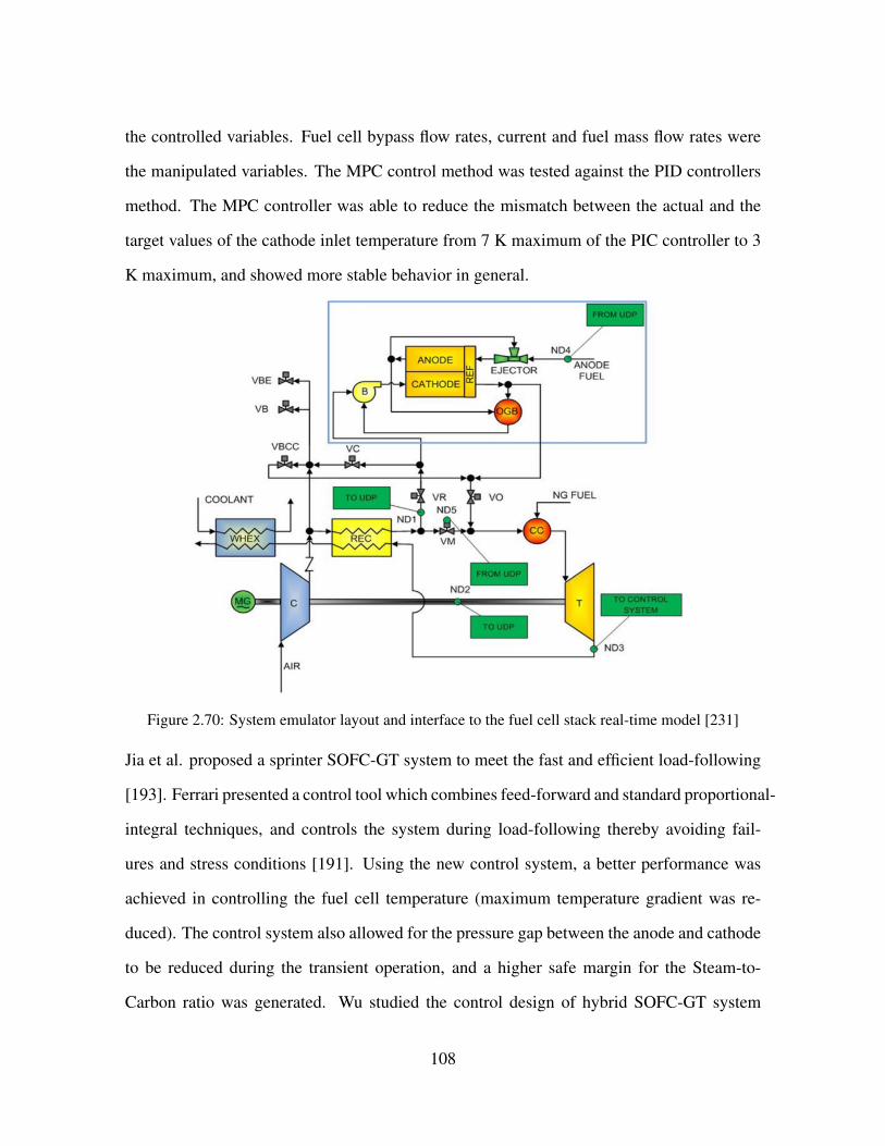
the controlled variables. Fuel cell bypass flow rates, current and fuel mass flow rates were
the manipulated variables. The MPC control method was tested against the PID controllers
method. The MPC controller was able to reduce the mismatch between the actual and the
target values of the cathode inlet temperature from 7 K maximum of the PIC controller to 3
K maximum, and showed more stable behavior in general.
Figure 2.70: System emulator layout and interface to the fuel cell stack real-time model [231]
Jia et al. proposed a sprinter SOFC-GT system to meet the fast and efficient load-following
[193]. Ferrari presented a control tool which combines feed-forward and standard proportional-
integral techniques, and controls the system during load-following thereby avoiding fail-
ures and stress conditions [191]. Using the new control system, a better performance was
achieved in controlling the fuel cell temperature (maximum temperature gradient was re-
duced). The control system also allowed for the pressure gap between the anode and cathode
to be reduced during the transient operation, and a higher safe margin for the Steam-to-
Carbon ratio was generated. Wu studied the control design of hybrid SOFC-GT system
108

combined with compressed-fuel processing unit (CFPU) [232]. Fig. (2.71) shows the flue
gas temperature control loop in the hybrid SOFC-GT system consisted of temperature trans-
mitter (TT), temperature controller (TC) and a heater that was added to control the flue gas
temperature by manipulating the external energy duty (QH).
Figure 2.71: Flue gas temperature control loop in hybrid system [232]
Milewski et al. determined the ranges of possible system operation conditions of the SOFC-
HS with part- and over-load operation, and adequate maps were given and described [233].
Effects of SOFC exhaust gas recirculation on hybrid system performance were studied by
Saebea et al. [234]. In another study, the inlet fuel composition effect on the hybrid sys-
tem performance was studied by Zabihian et al. [235]. The analysis of the operation of the
system when fueled with a wide range of fuel types demonstrated that the hybrid SOFCGT
cycle efficiency can be between 59% and 75%, depending on the inlet fuel type. Oh et al.
studied the power shutdown when the load was changed abruptly [236]. They studied the op-
erating parameters of the 5kW-Class SOFC-GT hybrid system in single-shaft and dual-shaft
gas turbine designs. Under the same load change condition, the responses to the load change
for the dual-shaft design were more robust against shutdown than the single-shaft design.
McLarty et al., compared their hybrid simulation results to dynamic experimental data and
109

showed a favorable agreement [237]. The predictions of the component temperatures, pres-
sures, voltage and system power showed 5◦C, 2 kPa, 2 mV, and 0.5% errors, respectively.
They found that a 15◦C ambient temperature perturbation caused a 30◦C variation in the
stack temperature.
Stiller et al. studied a multi-loop control strategy for a hybrid SOFC-GT system [189]. Fig.
(2.72) shows the corresponding power plant. Fuel flow is controlled by manipulating the
fuel valve. Air flow is controlled by manipulating generator power to affect the shaft speed,
or by manipulation of variable inlet guide vanes or variable compressor bleed. The effects
of each of these control strategies on the system performance is reported to be similar. In
the mentioned study, shaft speed control by generator power manipulation was selected as
preferred [189].
Figure 2.72: Hybrid cycle layout [189]
Control design objectives were mentioned by Stiller et al. as follows: 1) Safe operation
110

of the system: Avoiding incidents that can damage fuel cell or system such as compressor
surge. 2) Quick load following and high efficiency, 3) Long life-time of fuel cell, and 4)
Governing external influences such as compressor fouling or fuel cell degradation. Fig.
(2.73) shows the multi-loop control strategy used by Stiller et al.. Power was controlled by
manipulating SOFC current, Fuel utilization was controlled by manipulating the fuel flow,
air flow was controlled by manipulating the shaft speed and cell temperature was controlled
by adjustment of air flow setpoint.
Figure 2.73: Control system of hybrid system [189]
2.11 HYBRID SOFC-GT SYSTEM OPTIMIZATION
Several authors have accomplished studies on hybrid SOFC-GT optimization. Yi et al. stud-
ied a system consisting of an IR-SOFC and an inter-cooled gas turbine (ICGT) [174]. An
optimization strategy including the design of experiments (DOEx) was applied to the hybrid
system. The optimization results demonstrated that an electrical efficiency higher than 75%
was achieved when the system was designed to operate under 50 bara pressure and with
111
low percent excess air (55%) in the SOFC. Increase in the operating pressure increased the
overall system efficiency. Calise developed a thermodynamic model of the hybrid system
by introducing capital cost functions [238]. The synthesis/design (S/D) optimization of the
plant was accomplished based on the traditional single-level approach based on a genetic al-
gorithm. Their results showed that optimization of the stack as an isolated device should be
avoided, due to the significant inefficiencies in the turbomachinery and the balance of plant
(BOP). McLarty et al. used seven different design parameters for the design optimization
of sub MW and 100 MW systems with efficiencies more than 70% [239]. Their study con-
firmed that the systems that required less cathode recirculation and produced most of the net
power in the fuel cell, achieved higher efficiencies. In one study, the results showed that the
final optimal design of the plant leaded to an exergetic efficiency of 65.11% [240].
Several researchers performed thermo-economic optimization on the SOFC-GT hybrid sys-
tems [241, 242, 243, 244, 182, 245, 246, 247]. Auttssier et al. used the thermo-economic
multi-objective optimization approach to compute the integrated system performance, size
and cost [241]. The study had two optimization objectives: minimizing the specific cost
and maximizing the efficiency. The results proved systems could be created at costs from
2400$/kW at 44% efficiency to 6700$/kW at 70% efficiency. In addition, high system ef-
ficiencies could be obtained with low fuel utilization. Cheddie et al. studied the SOFC
indirectly coupled with a 10 MW power plant operating at 30% efficiency. The method of
Lagrange Multipliers in the thermo-economic was used to optimize the system performance.
The net power output of 18.9 MW at 48.5% efficiency was predicted [242]. Romano et al.
performed analyses of integrated gasification fuel cells plant in which a simple gas turbine
cycle operated in the hybrid cycle with a pressurized intermediate temperature SOFC, a coal
gasification, a syngas cleanup island and a bottoming steam cycle, in order to optimize the
heat recovery [179]. They calculated a net electric LHV efficiency in the range of 52%-54%.
The best solution was the 26% bypass of the fuel to the gas turbine, operating the SOFC at
112

23 bar, and 60% fuel utilization. This lead to the highest plant efficiency at 54.29%. In one
study, the turbine inlet temperature (TIT) was shown as the key parameter that limited the
efficiency of the hybrid power plant [248]. Increasing the number of the cells, increased the
TIT and the power generation efficiency of the hybrid cycle. At a fixed number of the cells,
the operating temperature of the SOFC needed to be increased in order to achieve a higher
electrical efficiency. Increasing the utilization factor improved the system performance. Ad-
ditionally, an increase in the S/C ratio decreased the efficiency and the TIT. Shirazi analyzed
the thermo-economic model of the IRSOFC-GT system. The genetic algorithm was used as
an optimization algorithm [243]. Multi-objective optimization was used in that study. The
exergy efficiency, total cost rate of the system and social cost of air pollution were consid-
ered as the objective functions. Exergy efficiency at the final optimal design point was at
66.06% for the objective function I, 57.64% for the objective function II, and at 65.60% for
the multi-objective optimization. Bakalis optimized the compressor and the turbine compo-
nents in the hybrid SOFC-GT system [249]. At full load operation the system achieved an
exergetic efficiency of 59.8% [250]. For the part load operation, two control strategies were
implemented by maintaining either the SOFC stack temperature or the turbine exit tempera-
ture constant [251]. Najafi studied the SOFC-GT system integrated with a multi stage flash
(MSF) desalination unit [244]. A Multi-objective genetic algorithm (MOGA) was used to
find the optimal design parameters of the plant. The exergy efficiency and the total cost
rate of the system were considered as the objective functions. The optimal design resulted
in 46.7% exergetic efficiency and a total cost of 3.76 million USD/year. The payback time
of the design was about 9 years. The results showed that the MSF desalination unit was
significantly irreversible with an exergy efficiency in the range of 3.05% to 3.61%.
Multi-objective optimization, optimal design analysis and Pareto optimization of a hybrid
system has been investigated in several other studies [252, 253, 254, 255]. Sharifzadeh et
al. developed an optimization framework that ensures process safety and simultaneously
113
optimizes energy-efficiency, quantified in economic terms [256].
Koyama et al. developed an internet-based modeling infrastructure called DOME (distribut-
ed object-based modeling environment) in order to create the integrated models from inde-
pendent simulation models for power production technologies [257]. DOME was used to
combine the SOFC-GT system with a power generation capacity and dispatch optimization
model. The study concluded that the SOFC micro-turbine hybrid system might reduce the
CO2 emissions in Japan by about 50% when a CO2 to cost ratio of 3000 ¥/t-C is adopted in
addition to the removal of the lower limits for LNG and Oil.
Thermodynamic, kinetic, geometric and cost models of the hybrid SOFC-GT-steam turbine
power plants were developed in the range of 1.5 MWe to 10 MWe [258]. A syngas-fed SOFC
and an irreversible GT optimization model was studied by Zhao et al. [259]. The developed
model was able to predict the performance characteristics of hybrid systems in the range of
2000 to 2500W
m2with efficiencies between 50% and 60%.
Barelli et al., developed a complete dynamic model of a the hybrid system in order to op-
timize the plant components [260]. The interactions between the system components were
analyzed during the transients and inertial effects of the gas turbine and the heat exchangers
on the fuel cell were considered. The study concluded that the SOFC transient behavior was
influenced by delays in the inputs (i.e. the cathode input air and the H2 flow rate). In addi-
tion, the SOFC current delivery was affected by a non-negligible delay in the case of the GT
load following. Fig. (2.74) shows the hydrogen molar flow rate, SOFC voltage and current
outputs during transient operation that Barelli et al. studied [260].
114

Figure 2.74: Hydrogen molar flow rate (a), SOFC voltage (b) and current (c) outputs (GT load steps:37-22.5-44 kW) [260]
Kanarit et al. optimized the SOFC-GT performance using total cost rate and system efficien-
cy as the objective functions [261]. Khani studied multi-objective optimization of a hybrid
SOFC-GT system using a genetic algorithm to determine the optimal design point in which
exergy efficiency was maximum [262]. Wu et al. showed that the IMC-based multi-loop
control scheme can efficiently regulate the total system power and control CO2 emissions
per kWh of electricity as well [263].
115

2.12 PARAMETRIC STUDIES
2.12.1 MAIN PARAMETERS FOR SOFC-GT HYBRID SYSTEM SIMULA-
TION
One of the most detailed parametric SOFC-GT hybrid systems analyses found in the litera-
ture is the study by Chan et al., which used the parameters shown in Table. (2.7) to simulate
a 1.3 MW IRSOFC-GT power plant with 40,000 tubular solid oxide fuel cells.
Reforming Shifting
Air pressure ratio 5
Fuel pressure ratio 4
Stack air flow rate (kmol/h) 120
Cooling air flow rate (kmol/h) 50
Fuel (NG) flow rate (kmol/h) 10
Fuel utilization 0.85
Table 2.7: System operating specifications [64]
The main results of their simulations are presented in Table. (2.8):
116

Cell voltage (V) 0.684
Cell current density (mA
cm2) 205
SOFC stack AC power output (kW) 1084
SOFC stack working temperature (K) 1197.5
Plant exit gas temperature (K) 410
Plant exit gas pressure (bar) 1.06
Air compressor power (kW) 232
Fuel compressor power (kW) 11
Turbine inlet flow temperature (K) 1221
Power turbine AC output (kW) 262.5
Heat rate recovery (kW) 529
Plant electrical efficiency (LHV) 61.9%
Total plant efficiency (LHV) 86.4%
Table 2.8: System operating specifications and resulting system performance [64]
The results of the Chan et al. study prove the advantage of integrating a gas turbine as the
bottoming cycle of an SOFC/GT hybrid to increase the net plant efficiency. The results
showed that a total power of 505.5 kW was generated from the turbines, from which about
45.9% (232 kW) was used to drive the air compressor and 2.2% (11 kW) that was used to
drive the fuel compressor. The net power output of the gas turbine was 263 kW (i.e., about
20% of the plant total electrical generation).
Calise et al. found that increasing the cell temperature would increase the operating voltage
of the cell and described it using their simulated polarization curves [72]. This result has
been achieved while keeping the other parameters constant (e.g. total pressure, hydrogen,
water and oxygen partial pressures). Also, the cell voltage increased by raising the cell
117
operating pressure, or by reducing the anode water molar fraction. Increasing the operating
pressure resulted in improved performance, even if more auxillary power was required for
the compressors. In order to simplify the model, limiting current density was assumed to
be constant. However, more detailed analyses by Chan et al., Costamagna et al., Tanaka et
al., and Bedringaas et al. showed that the limiting current density increased by raising the
operating temperature [64, 155, 264, 265, 266]. Their results showed that the activation loss
of the cathode was much more than the anode loss. The goal of one study was to find the most
irreversible components in the plant using second law of thermodynamics analyses [72]. In
addition, the model determined the temperature, pressure, enthalpy, entropy, exergy and the
gas compositions at each node of the cycle. The very high combustor exit temperature was
notable in the system operation. The simulations showed that combustor temperatures could
rise substantially using a low fuel utilization factor or a high working current density that
generates large amount of heat. Some of the major parameters are shown in Table (2.9):
118

Combustor efficiency 0.98
Inverter efficiency 0.95
Pump isentropic efficiency 0.80
Fuel compressor isentropic efficiency 0.80
Air compressor isentropic efficiency 0.80
Gas turbine isentropic efficiency 0.80
Limiting current density (mA/cm2) 900
Internal current density (mA/cm2) 2
Methane inlet molar flow rate (kmol/s) 0.0028
Water inlet molar flow rate (kmol/s) 0.0057
Oxygen inlet molar flow rate (kmol/s) 0.0070
Cell operating pressure (bar) 7
Environment pressure (bar) 1
Environment temperature (C) 25
Fuel utilization factor 0.85
Minimum steam-to-carbon ratio 2
Cell current density (mA/cm2) 100
Anode thickness (cm) 0.010
Electrolyte thickness (cm) 0.010
Cathode thickness (cm) 0.190
Interconnection thickness (cm) 0.004
γanode(mA/cm2) 2.13× 10⁷
γcathode(mA/cm2) 1.49× 10⁷
Table 2.9: Hybrid system simulation parameters of Calise et al. [72]
119

Because of the unreacted streams in the reformer and the significant amount of H2O pro-
duced in the anode compartment, the steam partial pressure was very high. The simulations
have shown that the low amount of CO that was produced in the reformer and not reacted
in the anode compartment was completely converted in the catalytic burner, and as a result
raised the combustor exit temperature.
Zhang et al. modeled the SOFC of a hybrid system based upon the Exponential Decay
Function and the Exponential Associate Function [267]. The model was developed using the
Aspen Custom Modeler simulation tool and the current density of the SOFC was considered
as a disturbance variable during the dynamic simulations. The simulation results showed
that the SOFC exit temperature was directly related to the current density. However, the
relation was inversed for the SOFC air inlet temperature and turbine inlet temperature. The
effects of the oxygen utilization, fuel utilization, operating temperature and efficiencies of
the gas turbine components on the system performance of the recuperative heat exchanger
(RHE) and the exhaust gas recirculated (EGR) cycles were determined [268]. The study
concluded that, increasing the fuel utilization or the oxygen utilization reduced the fuel cell
efficiency but improved the system efficiency for both of the RHE and EGR cycles. Tsuji
et al. introduced the concept of the Inter Cooled Multistage SOFC-GT hybrid system in
order to maximize the fuel heat input to the system [269]. The combination of the F-class
GT (TIT=1350◦C) and a 5-stage SOFC configuration was used and a 77% efficiency based
on the fuel LHV was achieved at a high pressure ratio. It was suggested that increasing the
number of the SOFC stages allowed the input of more fuel into the SOFC leading to the
increased system thermal efficiency.
In hybrid SOFC-GT systems, Calise et al. found that the air mass flow rate depends upon
the electrochemical rate of reaction, cell temperature control, and combustion reaction re-
quirements [72]. In that study, the lower air flow rate caused better performance mostly due
to the higher stack temperature (the lower cooling effect of the air flow. The fuel to air ratio
120

was an important factor, since operating in the unreasonable range could damage the cell
material due to the higher temperature. The capital cost of the SOFC stack depended upon
its operating temperature. The results showed that the plant irreversibilities could be reduced
by operating the system at higher fuel-to-air ratio, mainly due to the increase in the stack
temperature, which decreased the cell overpotentials. On the other hand, the higher SOFC
temperature meant higher heat flow of the HRSG and as a result, higher exergy destruction
in HRSG.
The study by Calise et al. proposed that the steam to carbon ration (S/C) had to be kept
at low levels in order to achieve higher electrical and net efficiencies. Higher S/C ratio
means more steam and more required heat that resulted in lower plant efficiency. Also,
electrical efficiency decreased as a result of the higher S/C, which produced higher produce
concentrations in the anode compartment. In a model presented by Ferrari et al. [192], a
part of the anodic exhaust gases were fed to the anode inlet in order to generate the right
temperature for the reforming reactions and avoid carbon deposition in the reformer and the
stack. They found that if the S/C ratio was reduced too much, carbon deposition would
damage both the reformer and the cell stack [192].
The purpose of most of the plant designs in the literature is to keep the fuel utilization factor
at as high a level as possible. The results of the work performed by Calise showed that
the higher fuel utilization caused higher efficiency and lower irreversibility destruction rate
[72]. The higher Uf resulted in lower chemical energy available for the burner, thereby
reducing the combustion irreversibilities. In general, the study concluded that increasing
fuel utilization increases the net and electrical efficiencies.
Yi et al. showed performed a system optimization analysis using Stat-Ease and showed that
the highest system efficiency can be achieved when the overall pressure ratio is high, excess
air is low, and the pressure ratio of the LPC is low [174].
121

2.12.2 EXERGY BASED ANALYSIS OF HYBRID SYSTEMS
Several researchers have accomplished exergy analyses of hybrid systems [72, 270, 271, 142,
69, 71, 70, 73, 75, 76, 78, 79]. Fig.(2.75) produced by Calise et al. is characteristic of the
analyses which demonstrate that the components that involved chemical and electrochemical
reactions, had the most irreversibility (exergy destruction) contributions to the plant (i.e., the
SOFC stack and the catalytic burner, or combustor).
Figure 2.75: Destroyed exergy rate of hybrid system components from Calise et al. [72]
Calise et al. reported that the ratio of the SOFC to the catalytic burner rate of exergy de-
struction (irreversibility) depended upon the fuel utilization factor since high fuel utilization
results in less fuel left over for the burner to combust [72]. On the other hand, lower fuel
utilization resulted in lower electrical power generation and overall lower first law efficien-
cy. Gas turbine exergy destructions were not significant in the Calise et al. study because
122

of the high isentropic efficiency assumed for the compressor and turbine. The SOFC stack
produced 985 kW of electrical power. The thermal, mechanical and electrical power gener-
ation/consumption details of the Calise et al. study are presented in Fig.(2.76).
Figure 2.76: Thermal/Mechanical/Electrical power generation/consumption by each component fromCalise et al. [72]
The electrical and the net efficiency of the system was calculated at 55% and 65% by Calise
et al. [72]. The stack performance was kept at a high level, as most of the power was
produced by the stack. The shape of the polarization curve in that study showed that in
order to achieve a high performance, it was necessary to keep the current density at a low
value even if that resulted in a greater cell cost due to the larger cell area required. At lower
current densities, a lower amount of heat was available, so that the cell exit temperature
was lowered, which caused lower cell voltage as well. Moreover, lower current density
caused a lower exergy destruction rate. Due to the small amount of mass flow rate in the
fuel compressor, the fuel-gas heat exchanger, and the pumps, the exergy destruction in these
types of components was typically found to be negligible. In another study, Dincer et al.,
studied exergetic performance of hybrid SOFC-GT system [270]. The energy and exergy
123
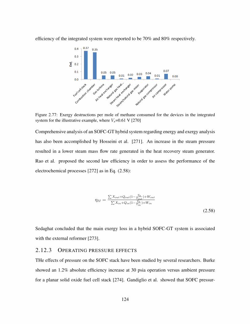
efficiency of the integrated system were reported to be 70% and 80% respectively.
Figure 2.77: Exergy destructions per mole of methane consumed for the devices in the integratedsystem for the illustrative example, where Vs=0.61 V [270]
Comprehensive analysis of an SOFC-GT hybrid system regarding energy and exergy analysis
has also been accomplished by Hosseini et al. [271]. An increase in the steam pressure
resulted in a lower steam mass flow rate generated in the heat recovery steam generator.
Rao et al. proposed the second law efficiency in order to assess the performance of the
electrochemical processes [272] as in Eq. (2.58):
ηII =∑Xout+Qout(1− T0
Tout)+Wout∑
Xin+Qin(1− T0Tin
)+Win
(2.58)
Sedaghat concluded that the main exergy loss in a hybrid SOFC-GT system is associated
with the external reformer [273].
2.12.3 OPERATING PRESSURE EFFECTS
THe effects of pressure on the SOFC stack have been studied by several researchers. Burke
showed an 1.2% absolute efficiency increase at 30 psia operation versus ambient pressure
for a planar solid oxide fuel cell stack [274]. Gandiglio et al. showed that SOFC pressur-
124

ization is beneficial to plant performance and should be considered by plant manufacturers
and SOFC technology developers in view of future ultra-efficient plants that convert NG
into electricity [275]. Hashimoto et al. showed that the power density of the cell was im-
proved by pressurization [276]. A study by Henke et al. showed that activation polarization
was reduced with increasing pressure as adsorption of reactants on the electrode surfaces
was enhanced supporting the charge transfer kinetics [277]. In another study, Henke et al.
showed that the activation and concentration overpotentials are reduced with increasing pres-
sure [278]. Results from another study by the same group showed that power density can be
increased significantly (an increase up to 100% was measured) at constant efficiency [279].
The behavior of pressurized solid oxide fuel cells using reformates as fuel was also examined
[280, 281].
Many researchers have modeled and tested the pressurized hybrid fuel cell and gas turbine
system [282, 48, 50, 49, 283, 101, 196, 284, 285, 286, 287, 288, 289, 290]. Calise et al. stud-
ied the operating pressure variation effect on the hybrid plant keeping the other parameters
constant. Increasing the pressure resulted in an increase in the system efficiency at a fixed
temperature (for both the net and the electrical efficiencies). It also reduced of the exergy
destructions. A higher operating pressure resulted in a higher cell voltage. Massardo et al.
demonstrated that their system efficiency was in the range of 65 - 70% for the atmospheric
cells and compared to the range of 74 - 76% for the pressurized cells [71]. A study by M-
cLarty et al. showed that higher system pressure improved the voltage and the efficiency, but
required sturdier components and axial flow geometry for the turbomachinery [239]. Singhal
et al. showed that the pressurized operation of the SOFC-GT power system achieved an effi-
ciency close to 70% which, resulted in the reduced fuel consumption and the reduced capital
cost per unit of the power output [291]. Panne et al. discussed the selection of the atmospher-
ic and the pressurized hybrid system based upon the Turbee T100 micro gas turbine and the
tubular SOFC stack [292]. They studied both pressurized and atmospheric hybrid system.
125

The pressurized cycle was preferred since the heat for the gas turbine had to be supplied
by an expensive high temperature heat exchanger that had a low effectiveness compared to
a standard heat exchanger. Improvement of the Nernst potential was another advantage of
the pressurized system that was mentioned in that study. The same group, demonstrated the
steady state analysis of an SOFC-GT hybrid cycle test rig [213]. The cycle could be evaluat-
ed without the risk of damaging the cell. The effect of ambient conditions and the pressure
losses throughout the cycle were investigated. The maximum compressor pressure ratio, the
supplemental fuel mass flow and the SOFC air bypass were the three different limitations in
the choice of cycle configuration. The additional pressure losses and piping of the hybrid
system had a significant impact on the surge margin.
Rao et al. analyzed the hybrid system as originally proposed by SureCellTM [293]. The
results of that analysis showed that the thermal efficiency of the cycle was relatively insensi-
tive to pressure ratio, increasing from 65.5% to 66.6% based on the fuel LHV as the pressure
ratio decreased from 15 to 6.5. In one study by Friedrich, results generally showed that the
pressure influence is stronger at low pressures up to 0.5 - 1 MPa and weakens towards high-
er pressures [294]. Results showed that pressure can strongly influence the power density
of SOFC. Henke et al. found that SOFC performance is strongly influenced by changes in
operating pressure. Depending upon the operating conditions, SOFC power density can be
strongly increased with increasing operating pressure [295].
2.13 CO2 CAPTURE, SEQUESTRATION AND EMISSION RE-
DUCTION
One of the applications of hybrid SOFC-GT systems described in the literature involves pow-
er generation with capture and sequestration for emissions reduction. In SOFC systems with
oxide ion conduction, fuel conversion takes place in the anode compartment to utimately
produce a stream of and water. CO2 can be separated from most of the water by simply
126

cooling the stream to produce concentrated CO2 for sequestration. This is in contrast to sys-
tems in which air and fuel are mixed (e.g., combustion) to produce a very dilute CO2 stream
(diluted mostly with nitrogen from the air), which separation process is energy intensive and
costly. As a result, SOFC technology offers the potential for reducing the capture penalty
in terms of efficiency and costs. Several researchers have conducted research on CO2 cap-
ture applications for SOFC-GT hybrid systems [296, 297, 298, 299, 300, 63, 156, 301, 185,
302, 303, 300, 145]. Park et al. integrated an SOFC and an oxy-fuel combustion technology
[296]. Fig. (2.78) shows the system layout of that study. The system was compromised
of an SOFC, gas turbine, oxy-combustion bottoming cycle, and the CO2 capture and com-
pression process. The steam expander inlet temperature and the condenser pressure in the
oxy-fuel combustion system were determined through parametric analysis. The integrated
system could be designed to have almost the same efficiency as the simple SOFC-GT system.
With the voltage at 0.752 V, temperature at 900◦C and the pressure at 8 bar for the operating
conditions of the SOFC , a system efficiency of 69.2% was predicted. The efficiency penalty
due to the CO2 capture and compression was 6.1%. An optimal condensing pressure exist-
ed, as the condensing pressure needed to be as low as possible. On the other hand, lowering
the condensing pressure increased the power consumption for the CO2 compression. The
optimal pressure was found to be 20 kPa.
127
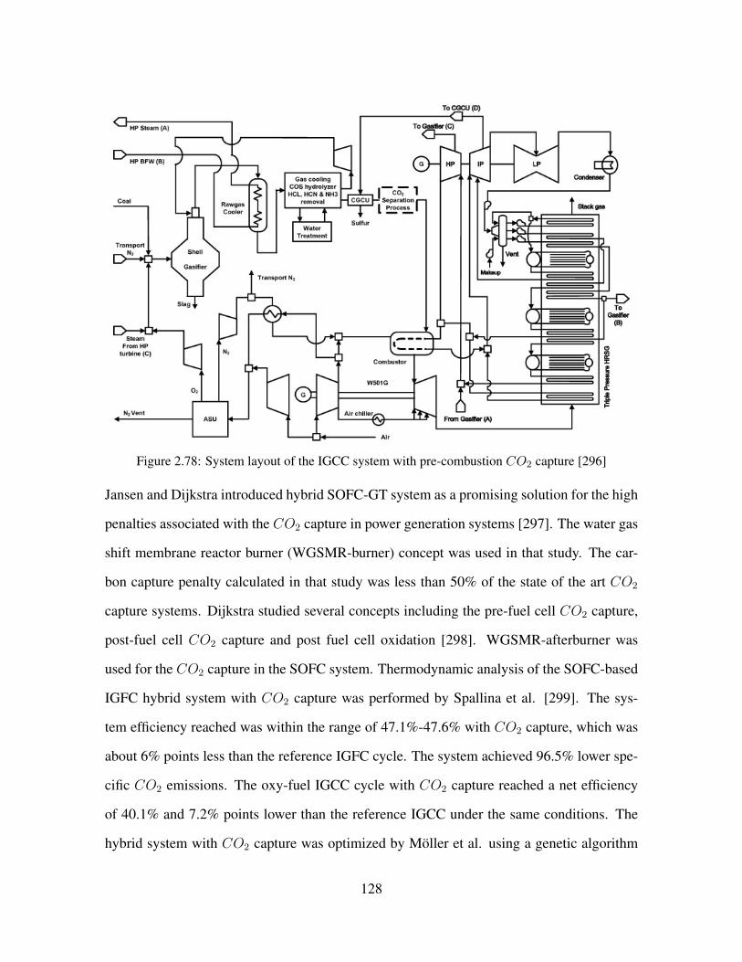
Figure 2.78: System layout of the IGCC system with pre-combustion CO2 capture [296]
Jansen and Dijkstra introduced hybrid SOFC-GT system as a promising solution for the high
penalties associated with the CO2 capture in power generation systems [297]. The water gas
shift membrane reactor burner (WGSMR-burner) concept was used in that study. The car-
bon capture penalty calculated in that study was less than 50% of the state of the art CO2
capture systems. Dijkstra studied several concepts including the pre-fuel cell CO2 capture,
post-fuel cell CO2 capture and post fuel cell oxidation [298]. WGSMR-afterburner was
used for the CO2 capture in the SOFC system. Thermodynamic analysis of the SOFC-based
IGFC hybrid system with CO2 capture was performed by Spallina et al. [299]. The sys-
tem efficiency reached was within the range of 47.1%-47.6% with CO2 capture, which was
about 6% points less than the reference IGFC cycle. The system achieved 96.5% lower spe-
cific CO2 emissions. The oxy-fuel IGCC cycle with CO2 capture reached a net efficiency
of 40.1% and 7.2% points lower than the reference IGCC under the same conditions. The
hybrid system with CO2 capture was optimized by Moller et al. using a genetic algorithm
128

[300]. An electrical efficiency of more than 60% was obtained with partCO2 capture. Inui et
al. studied the closed MHD/noble gas turbine cycle as a bottoming cycle as the temperature
of the combustion gas reached about 2300 K [63]. The total thermal efficiency of the system
using natural gas (methane) reached to 63.66% (HHV) or 70.64% (LHV). The efficiency was
high compared to others in the literature, since the system included CO2 recovery. The inlet
and outlet temperatures of the SOFC in that study were 1194 K and 1344 K, respectively.
The inlet temperature of the closed cycle MHD generator was at 2280 K. Campanari studied
CO2 separation in the SOFC-GT hybrid system, where CO2 was separated with absorption
systems or with adoption of a second SOFC module as an afterburner [156]. The system
achieved efficiency close to 70% with 90% CO2 removal, without having high TIT and NOx
emissions. The plant with unreacted fuel shift and absorption possessed a higher efficiency.
However, the double-SOFC configuration demonstrated best performances in the case that
the second SOFC produced positive power output. In another study, it was reported that
the SOFC-GT hybrid systems with CO2 capture decreased CO2 emission to 13.4% of the
traditional CO2 emission [304]. The Campanari group has studied SOFC power plants at
the 100 MW scale with CO2 capture. The theoretical LHV efficiencies with and without
CO2 capture exceeded 70% and 78% respectively [302, 303]. In another study, process sim-
ulation of an Intermediate-temperature (660− 730◦C) SOFC system has been accomplished
[305]. Hybrid SOFC-GT system with CO2 capture and a three-reactors chemical looping
for hydrogen generation (TRCL) from natural gas using three reactors was studied [185].
They found that efficiency could reach up to 51.4% on an LHV basis. An interesting concept
that includes CO2 capture has been presented by Li et al. [177], which integrates hydro-
gasification with an SOFC-GT hybrid system and steam bottoming cycle. They found that
high methane content from the hydro-gasifier together with recirculation of hydrogen to the
gasifier allowed the capture of CO2 with very little efficiency penalty. The overall efficiency
range for the CO2 capture systems that Li et al. found was more than 60%.
129
2.14 INVESTIGATION OF ALTERNATIVE FUELS
Several researchers have conducted hybrid system analysis using alternative fuels instead
of natural gas or methane [306, 78, 94, 307, 308, 93, 100, 183, 184, 309]. Santin et al.,
studied a 500 kW class SOFC-GT system fed by kerosene and methanol fuels [306]. The
WTEMP software developed by the University of Genoa was used for this purpose. Both
tubular and planar SOFC were studied with different temperature rise along the air path.
Compared to the methane-fueled case, the methanol-fueled systems demonstrated lower ef-
ficiencies (0.5-7 percentage points), but attractive economic performance (up to 0.5 years
reduction in payback period (PBP)). The Kerosene fueled systems demonstrated lower ef-
ficiencies (0.5-15% points) and poor economic performance (at least 3.4 years increase in
PBP). Fernandes et al. presented the results of the ”Well-to-Wing” efficiency analysis of a
liquid hydrogen produced by biomass gasification for aviation [78]. The system consisted of
a biomass gasification plant, a hydrogen liquefaction plant, and an SOFC-GT hybrid system.
The conventional hydrogen liquefaction process introduced a significant exergy destruction
that resulted in a lower overall efficiency.
The integration of fluidized bed steam gasification of biomass and an IRSOFC-gas turbine
hybrid cycle were studied using the IPSEpro software package [94]. The model of gasifica-
tion and gas conditioning section in that study was based upon data from the 8 MW plant
in Guessing/Austria. Electric efficiencies up to 43% were calculated for the combined heat
and power application. Kaneko et al. studied the transient behavior of a biomass gas fueled
SOFC-micro turbine system [307]. An unstable power output due to the fluctuation of the
gas composition in the fuel was observed when the system was fed biomass gas. A fuel
controller was used to follow the step change in the power demand from 32 to 35 kW, but
also stably maintained the system power output at 35 kW during fuel composition changes.
The SOFC and the MTG power contribution were 85% and 15%, respectively. The system
130

total efficiency was at 56.3% at the design point operating on methane. In addition, Kaneko
et al. designed a controller for the hybrid system that enabled it to rapidly follow the pow-
er demand while maintaining correct system temperatures. A PID controller was used to
manipulate the fuel flow rate to control the power output of the system.
Wongchanapai et al. studied a direct-biogas SOFC-micro gas turbine system to evaluate the
potential use of biogas as the main source of energy for a direct-biogas SOFC-MGT hybrid
CHP system [308]. The key parameters in that study were, the SOFC and reformer tem-
peratures, the fuel utilization factor, the turbine inlet temperature (TIT) and the compression
ratio. Steam was more preferable for the reforming agent of the SOFC regarding the mate-
rial limitations and the SOFC efficiency compared to the air-steam mixture fraction. How-
ever, adding a small amount of air enhanced the useful heat output and generated electricity
through the MTG without affecting the net system efficiency. Integrated biomass gasifier-
SOFC-GT systems have been studied by several authors [178, 310]. Maximum energy and
exergy efficiencies of the gasification-based system have been reported by Santhanam et al..
The energy and exergy efficiency for the SOFC-MGT cycle with biomass gasification were
reported as 58.3% and 69.6% as reported by Hosseini et al. [310]. Four different systems
based on SOFC-GT and biomass gasification were modeled in order to evaluate the influence
of the gasification, gas cleaning and the system scale on the overall system performance by
Toonssen et al. [93]. The results showed that a large scale system based upon the pressurized
direct air gasification and high temperature gas cleaning had the highest electrical exerget-
ic efficiency at 49.9%. The gasification technology had no significant effect on the system
overall performance. In addition, the large-scale systems had higher efficiencies than the
small-scale systems, due to larger exergy losses that were mainly associated with balance of
plant components. The effect of different biomass gases on the hybrid system performance
was studied by Lv et al. [183]. Electrical efficiency could reach up to over 50% with four
types of gasified biomass studied in that paper. The system efficiency for the system fueled
131
by wood chip gases was higher than the systems fueled by corn stalk gas, cotton wood gas
and grape seed gas. The speed of the gas turbine had a significant impact on the hybrid
performance such as the output power and efficiency. Hydrothermal gasification for the hy-
brid SOFC-GT cycle was studied by Facchinetti et al. [184]. The hydrothermal gasification
required heat at 673-773 K, while the SOFC contained excess heat in this high temperature
range due to the limited electrochemical fuel conversion. Thus, the integration of the two
technologies was technically feasible. Wet waste biomass conversion into electricity had a
first law efficiency of up to 63% while separating the biogenic carbon dioxide. An SOFC-
based hybrid system integrated with a coal gasification process was studied by Romano et al.
[311]. The proposed SOFC-based power system achieved the efficiency gain of 7 to 11 per-
centage points compared to the advanced IGCC based upon the state-of-the-art-technology.
Methanol and di-methyl-ether (DME) fuels were used in a SOFC-MGT hybrid system s-
tudied by Cocco et al. [309]. Since the reforming temperature of methanol and DME (200-
350◦C) was lower than that of natural gas (700-900◦C), the reformer could be located outside
of the stack, which resulted in improved exhaust heat recovery and a higher voltage produced
by the greater hydrogen partial pressure at the anode inlet for this case.
Martinez et al. compared the SOFC-GT freight locomotive fueled by natural gas and diesel
with on-board reformation [5]. Route-averaged fuel-to-wheels system efficiencies of 60%
and 52% were calculated for natural gas and diesel fuel, respectively. Compared to the state-
of-the-art locomotive technology, SOFC-GT operation could provide a 98% reduction in
NOx for both fuels, a 54% reduction in CO2 emissions for operation on natural gas and a
30% CO2 reduction for the operation on diesel fuel. Direct-alcohol SOFCs (e.g., methanol,
ethanol and propanol) and the effects of the fuel impurities were investigated by Sasaki et
al. [16]. Saebea et al. studied a SOFC-GT hybrid system supplied by ethanol fuel [312].
The recirculation of anode and cathode exhaust gas in the hybrid SOFC-GT system was
proposed to improve the heat management in the system. In order to control the turbine inlet
132
temperature, fuel and air were added to the combustor. In another study, they analyzed a
pressurized hybrid SOFC-GT system fed by ethanol with the recycle of a cathode exhaust
gas [313]. The highest system electrical efficiency was achieved in the range of 4-6 bar.
Rokni studied a 10 kW combined SOFC-Stirling engine power system for an average family
home [180]. The results of natural gas (NG), ammonia, di-methyl ether (DME), methanol
and ethanol operation were presented and analyzed in that study. Compared to the stand-
alone SOFC plant, the overall power production of the combined SOFC-Stirling cycle was
improved by 10%. The net system efficiency was at 60%. With a slight decrease in the
fuel utilization, the power produced from the bottoming cycle of the Stirling engine and the
overall plant efficiency were increased. Reducing the SOFC operating temperature decreased
the plant efficiency for all of the fuels except ammonia. The increase in the plant efficiency
fueled by natural gas was more significant than the other fuels; methanol, ethanol and DME.
In addition, the estimated cost of this type of hybrid system was 2060 $/kW.
Three coal-based SOFC-GT configurations were evaluated for the thermal management of
the main power block by Tucker et al. using steady state numerical simulations [314]. Con-
sistent syngas composition was assumed in each case. A 240 MW rated fuel cell module was
used in each of configurations. The recuperated cases were highly efficient and possessed
excellent potential for thermal management control strategies. This was because the recuper-
ation provided the means to increase the power contribution of the turbine while maintaining
high efficiency [315]. Saebea et al. analyzed a pressurized hybrid SOFC-GT system fed
by ethanol with the recycle of cathode exhaust gas [313]. The highest system electrical
efficiency was achieved in the 4-6 bar range.
133

CHAPTER 3
COMPUTATIONAL FLUID DYNAMIC ANAL-
YSIS
3.1 MOTIVATION FOR USING CFD TO ANALYZE SURGE
Using CFD to explore and understand compressor stall and surge could help to understand
the fluid behavior in the hybrid SOFC-GT system. Compressor performance in gas turbines
is limited by two main lines: 1) a choke line, 2) a surge line. Fig. (3.1) shows the typical
compressor map. The surge limit depends upon the compressor design and system configura-
tion and especially upon the pressure dynamics downstream of the compressor. Compressor
surge could result in impeller and blade corrosions as shown in Fig. (3.2) and Fig. (3.3).
134
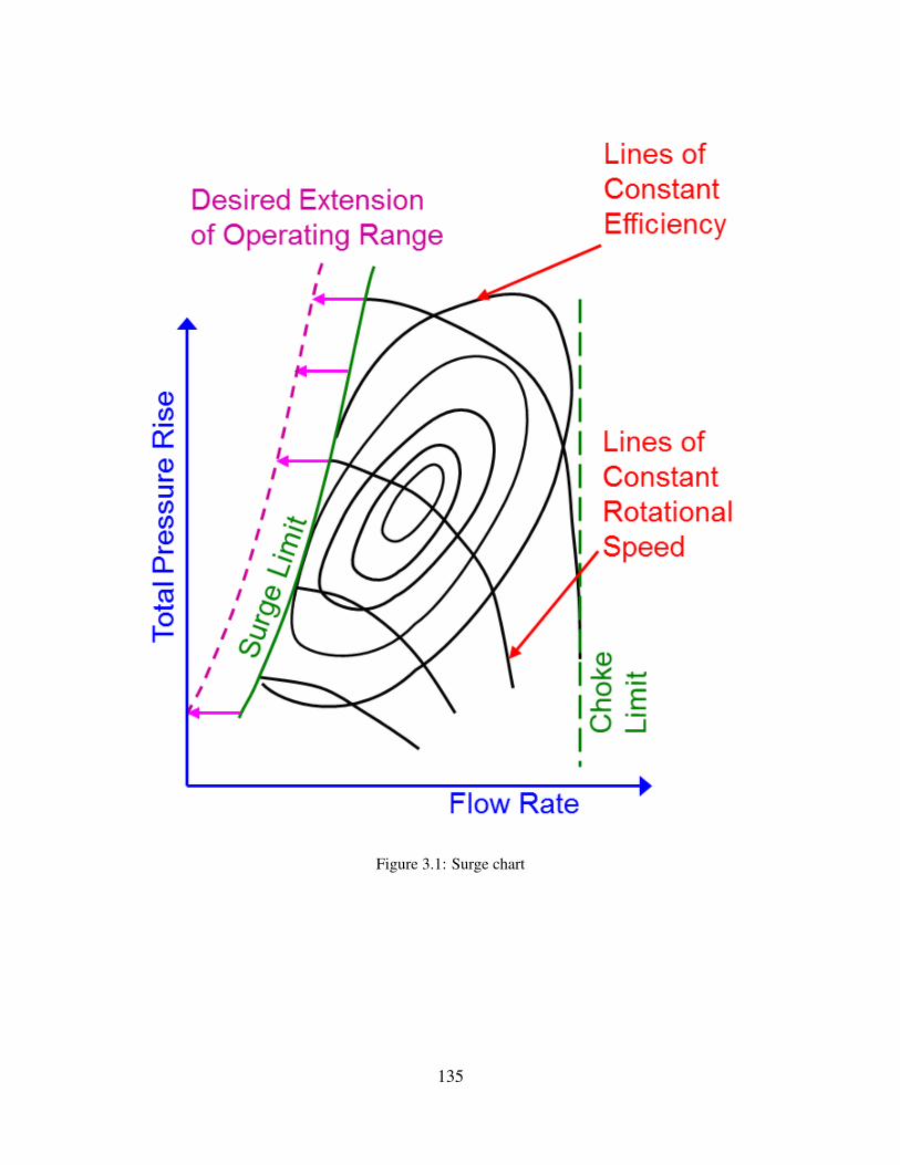
Figure 3.1: Surge chart
135

Figure 3.2: Impeller corrosion
136
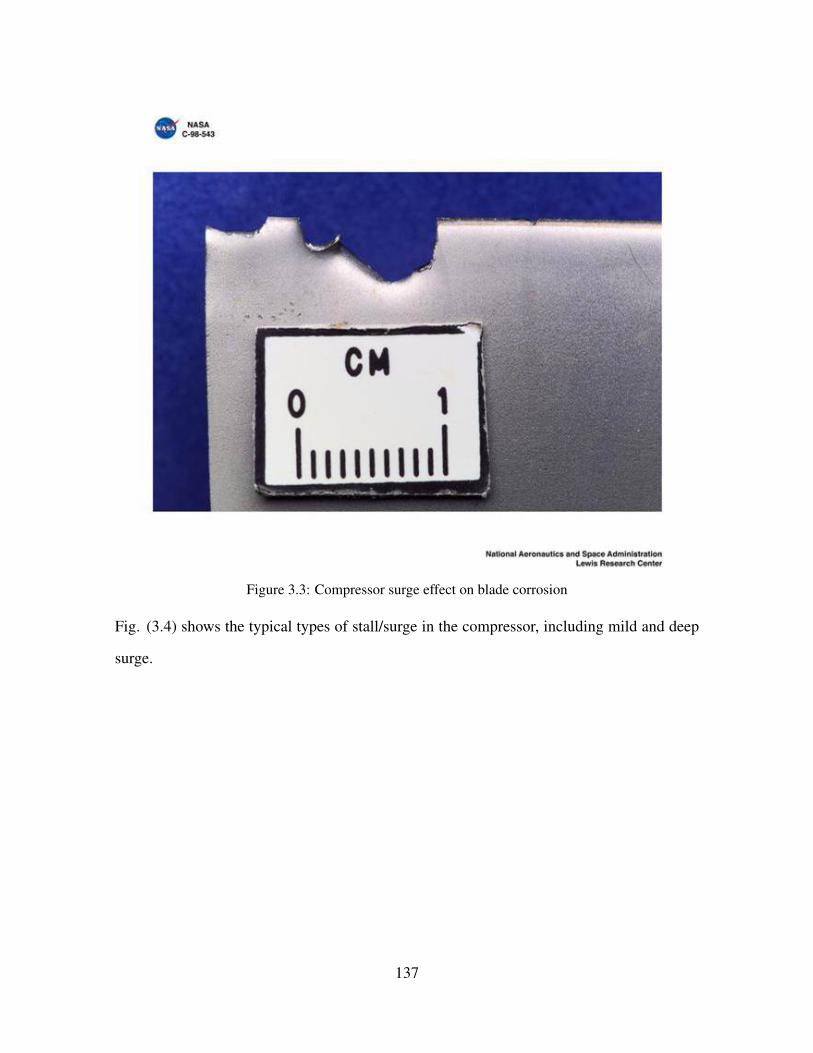
Figure 3.3: Compressor surge effect on blade corrosion
Fig. (3.4) shows the typical types of stall/surge in the compressor, including mild and deep
surge.
137

Figure 3.4: Types of surge
3.1.1 MECHANISMS OF COMPRESSOR SURGE/STALL IN HYBRID SOFC-
GT SYSTEM
There are two main mechanisms of compressor surge/stall in hybrid SOFC-GT systems that
has been previously studied by McLarty et al..
Surge due to the high turbine inlet temperature:
Fig. (3.5) shows the surge mechanism due to the high turbine inlet (TIT) temperature.
1) Turbine inlet temperature rises
2) The mass flow rate through turbine decreases due to the lower density of the hotter inlet
gases
3) Mass flow from the compressor persists causing a pressure buildup at the turbine inlet
138

4) Stall/Surge occurs. This is numerically simulated when the stall line is reached on the
compressor map.
5) Compressor mass flow rate and torsional load become negligible
6) Shaft speed increases suddenly while the pressure at the turbine inlet drops
Figure 3.5: Surge mechanism due to the high turbine inlet (TIT) temperature
Surge due to the system emergency shut-down:
Fig. (3.6) shows the surge mechanism due to the system emergency shut-down.
1) Fuel input to the combustor is cut off.
2) Turbine inlet temperature drops as does turbine power slowing rotational speed.
3) Shaft speed reduction occurs faster than the turbine can expel the mass stored in the sys-
tem to maintain surge margin.
4) Surge line is reached
Figure 3.6: Surge mechanism due to the system emergency shut-down
139
3.1.2 DYNAMIC MODEL INTEGRATED WITH CFD SIMULATION
This research addresses compressor stall/surge, one of the most significant challenges corre-
sponding to commercialization of hybrid solid oxide fuel cell-gas turbine (SOFC-GT) sys-
tems, using a novel approach. This study models a multi-stage compressor using computa-
tional fluid dynamics (CFD) tools and subjects the CFD computations to dynamic inlet and
outlet perturbations that result from a dynamic SOFC-GT system model. One of the main
causes of compressor stall/surge in hybrid SOFC-GT systems is turbine inlet temperature
rise due to the transient increase in power demand in a small period of time. As the power
demand rises from steady state to a specific higher power in a short time period, turbine inlet
temperature (TIT) increases so that the gas turbine can meet the power demand and ramp up
to meet the higher air flow required. Thus, the mass flow rate at the turbine inlet decreases
due to the lower density while the mass flow rate from the compressor keeps building up
pressure at the turbine inlet. As a result, reversal of flow in the impellers can occur, which is
recognized as deep surge. However, the mass flow rate from the compressor persists causing
a pressure buildup at the turbine inlet, increasing the local pressure. As a result of this pres-
sure build up in the compressor outlet, an oscillatory flow rate could occur in the impellers
that is recognized as mild surge.
Several researchers have addressed stall/surge in hybrid SOFC-GT systems and control meth-
ods have been developed in order to address stall/surge issue in the compressor. In one study,
Azizi has studied compressor surge in a 220 kW hybrid system [215]. A CFD model was
used in that study to address stall/surge in the single-stage centrifugal compressor. The fea-
sibility of the compressor integration in the hybrid system was determined in that study.
The overall approach of this research is based upon dynamics modeling of a hybrid SOFC-
GT system in MATLAB/Simulink software, in order to solve the dynamics of turbine inlet
pressure. The system-level dynamic modeling is followed by CFD modeling of a multi-
stage compressor of a 1.7 MW gas turbine system to capture the fluid dynamics proper-
140

ties throughout the compressor impellers during transient operation in order to determine
whether the compressor operation can feasibly avoid stall/surge in the hybrid SOFC-GT sys-
tem. Transient dynamic CFD results from simulation of the 1.7 MW gas turbine are analyzed
to determine whether these types of multi-stage centrifugal compressors could be used in fu-
ture SOFC-GT locomotive engines. This study: 1) verifies the previously developed control
methods for safe operation of radial compressors; 2) suggests that the control methods can be
applied to any type of centrifugal compressor of similar design, and 3) presents CFD results
for a specific compressor design that provide insights relevant to any industrial compressor
used in a hybrid SOFC-GT system.
3.2 PLANT DESCRIPTION
3.2.1 DYNAMIC HYBRID SYSTEM MODEL
Fig. (3.7) shows the model of a 4 MW hybrid power generation system that has been pre-
viously developed at the National Fuel Cell Research Center (NFCRC) at the University of
California, Irvine using MATLAB/Simulink tools. This model was used to show that such
systems, when properly designed and controlled, possess higher efficiency than previously
tested SOFC-GT systems in power generation applications. The model consists of a com-
pressor, a turbine, a blower, an SOFC, a combustor, three mixers and several bypass valves.
This model has been previously studied for different applications of SOFC-GT hybrid sys-
tems ([316, 131, 181, 237]). The model includes one fuel cell bypass and several heater
bypasses.
141
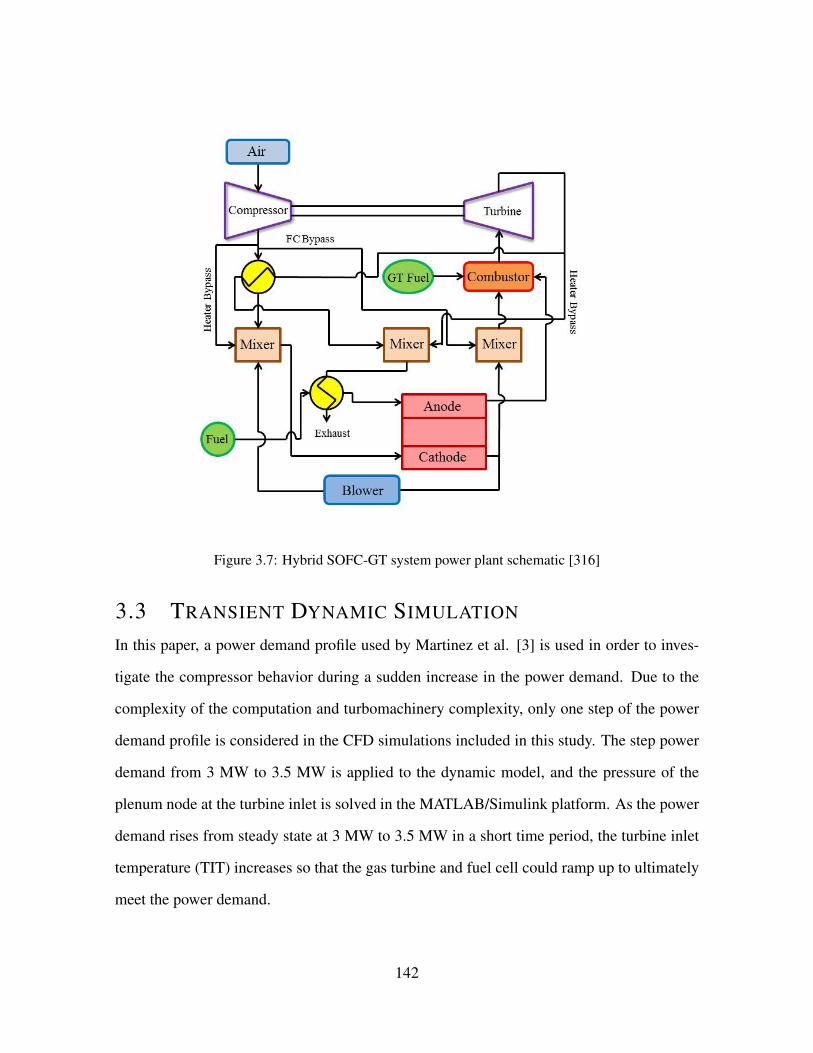
Figure 3.7: Hybrid SOFC-GT system power plant schematic [316]
3.3 TRANSIENT DYNAMIC SIMULATION
In this paper, a power demand profile used by Martinez et al. [3] is used in order to inves-
tigate the compressor behavior during a sudden increase in the power demand. Due to the
complexity of the computation and turbomachinery complexity, only one step of the power
demand profile is considered in the CFD simulations included in this study. The step power
demand from 3 MW to 3.5 MW is applied to the dynamic model, and the pressure of the
plenum node at the turbine inlet is solved in the MATLAB/Simulink platform. As the power
demand rises from steady state at 3 MW to 3.5 MW in a short time period, the turbine inlet
temperature (TIT) increases so that the gas turbine and fuel cell could ramp up to ultimately
meet the power demand.
142
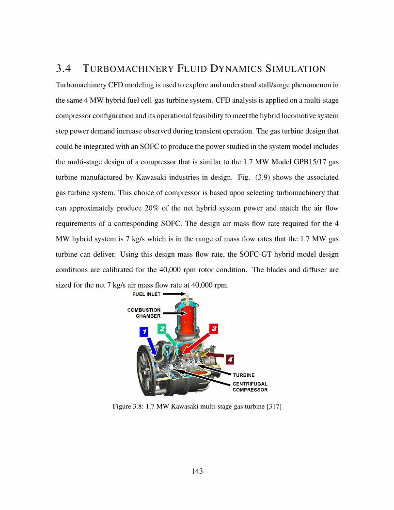
3.4 TURBOMACHINERY FLUID DYNAMICS SIMULATION
Turbomachinery CFD modeling is used to explore and understand stall/surge phenomenon in
the same 4 MW hybrid fuel cell-gas turbine system. CFD analysis is applied on a multi-stage
compressor configuration and its operational feasibility to meet the hybrid locomotive system
step power demand increase observed during transient operation. The gas turbine design that
could be integrated with an SOFC to produce the power studied in the system model includes
the multi-stage design of a compressor that is similar to the 1.7 MW Model GPB15/17 gas
turbine manufactured by Kawasaki industries in design. Fig. (3.9) shows the associated
gas turbine system. This choice of compressor is based upon selecting turbomachinery that
can approximately produce 20% of the net hybrid system power and match the air flow
requirements of a corresponding SOFC. The design air mass flow rate required for the 4
MW hybrid system is 7 kg/s which is in the range of mass flow rates that the 1.7 MW gas
turbine can deliver. Using this design mass flow rate, the SOFC-GT hybrid model design
conditions are calibrated for the 40,000 rpm rotor condition. The blades and diffuser are
sized for the net 7 kg/s air mass flow rate at 40,000 rpm.
Figure 3.8: 1.7 MW Kawasaki multi-stage gas turbine [317]
143
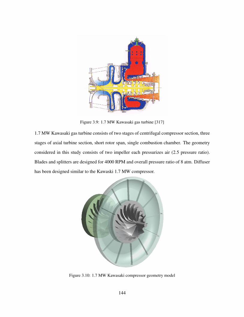
Figure 3.9: 1.7 MW Kawasaki gas turbine [317]
1.7 MW Kawasaki gas turbine consists of two stages of centrifugal compressor section, three
stages of axial turbine section, short rotor span, single combustion chamber. The geometry
considered in this study consists of two impeller each pressurizes air (2.5 pressure ratio).
Blades and splitters are designed for 4000 RPM and overall pressure ratio of 8 atm. Diffuser
has been designed similar to the Kawaski 1.7 MW compressor.
Figure 3.10: 1.7 MW Kawasaki compressor geometry model
144

Figure 3.11: Applied Fluid Model-Multi Stage Compressor
The fluid model is similar to 1.7 MW Kawasaki two stage compressor. The design conditions
are as follows: 1) 22,000 RPM rotational speed, 2) 7.8 overall pressure ratio, 3) 6-8 kg/s air
mass flow rate, 4) In order to reduce computational cost, periodic boundary condition is used.
Fig. (3.14) to Fig. (3.14) below shows the mesh generated on the fluid model. Structured
Mesh is used on the blades. Unstructured mesh is used on the diffuser.
145

Figure 3.12: Mesh generated on the Splitter
Figure 3.13: Mesh generated on the blade
146
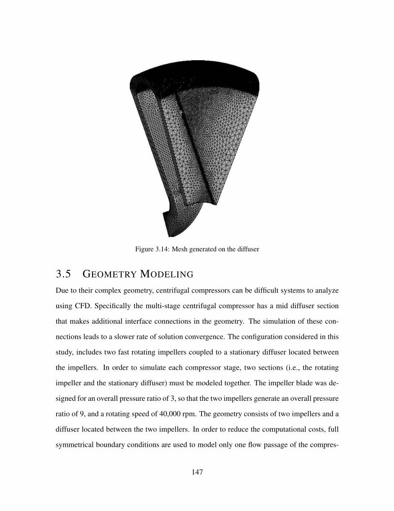
Figure 3.14: Mesh generated on the diffuser
3.5 GEOMETRY MODELING
Due to their complex geometry, centrifugal compressors can be difficult systems to analyze
using CFD. Specifically the multi-stage centrifugal compressor has a mid diffuser section
that makes additional interface connections in the geometry. The simulation of these con-
nections leads to a slower rate of solution convergence. The configuration considered in this
study, includes two fast rotating impellers coupled to a stationary diffuser located between
the impellers. In order to simulate each compressor stage, two sections (i.e., the rotating
impeller and the stationary diffuser) must be modeled together. The impeller blade was de-
signed for an overall pressure ratio of 3, so that the two impellers generate an overall pressure
ratio of 9, and a rotating speed of 40,000 rpm. The geometry consists of two impellers and a
diffuser located between the two impellers. In order to reduce the computational costs, full
symmetrical boundary conditions are used to model only one flow passage of the compres-
147
sor. Each of the rotating and stationary sections were meshed independently. The impellers
were meshed by the structured hexahedral method in ANSYS TurboGrid meshing software
[318], while the diffuser was meshed using unstructured tetrahedrals with boundary layer
refinements. The three separate mesh grids were connected by defining proper interfaces
between the rotor and diffuser sections.
3.6 BOUNDARY CONDITIONS
Stage averaging is used as a method of interface connection between the diffuser and im-
peller. In this method a circumferential averaging is applied at the interface between the
rotor and stator. In order to apply correct boundary conditions on the fluid domain, a sub-
sonic uniform air flow rate boundary condition with atmospheric pressure and temperature
is applied to the inlet. The turbulent intensity was set to 5%. The pressure dynamic perturba-
tion that resulted from step load change applied to the hybrid SOFC-GT system simulation,
is applied to the domain outlet. Since the diffuser domain is stationary and the impeller-
s are rotating, two interface boundaries are defined between the rotating impellers and the
stationary diffuser.
3.7 FLUID DYNAMICS MODEL
A Reynolds Averaged Navier-Stokes (RANS) based model of shear stress transport (SST),
k − ω, is used to close the system of equations that describe the turbulent flow that is sim-
ulated. Using the k − ω model instead of the k − ε model allows for better resolution of
boundary layers, especially under adverse pressure gradients. However, in the current study,
the SST model was more difficult to converge than the k − ε model. Nonetheless, the SST
model is known to better simulate wall bounded aerodynamic flows, e.g, airfoils, compres-
sors, turbines, and flows with separation due to adverse pressure gradients. In addition, the
SST closure model is used to reduce the boundary condition sensitivity. ANSYS CFX [318]
was chosen due to the proven ability to tackle complex turbomachinery problems faced in
148

the gas turbine industry. In order to obtain good convergence, first the solver converged to
the steady state solution. Following the stationary solution, the transient boundary condition
was applied to the model and the system was solved for each time step in the short period of
time that the system dynamics produced the pressure perturbation.
Shear Stress Transport Model:
∂(ρk)∂t
+∂(ρujk)
∂xj= P − β∗ρωk + ∂
∂xj[(µ+ σkµt)
∂k∂xj
]
(3.1)
∂(ρω)∂t
+∂(ρujω)
∂xj= γ
νtP − βρω2 + ∂
∂xj[(µ+ σωµt)
∂ω∂xj
] + 2(1− F1)ρσω2ω
∂k∂xj
∂ω∂xj
(3.2)
P = τij∂ui∂xj
(3.3)
τij = µt(2Sij − 23∂uk∂xk
δij)− 23ρkδij
(3.4)
149

3.8 STALL/SURGE RESULTS
Transient dynamic operation of hybrid fuel cell-gas turbine system while maintaining the
locomotive power requirement, is analyzed using computational and dynamics tools. Fig.
(3.15) demonstrates the operating point of the hybrid system near the stall/surge line at a
steady state condition. Control strategies were developed at NFCRC in order to prevent
system operation beyond the surge line, using only the compressor and turbine maps. Fig.
(3.15) demonstrates that the operating point is below the surge line and in the safe region.
The implemented control algorithms produced system operating dynamics that met the pow-
er demand dynamics without allowing the compressor to operate in a deep surge condition.
However, the fluid dynamics of a realistic industrial compressor performance must be inves-
tigated while operating in the hybrid system.
Figure 3.15: Operating point of 4 MW hybrid SOFC-GT at steady state condition
The dynamic pressure step perturbation due to the transient power demand variation in a
small time period is applied to the rear impeller outlet. This perturbation results in the
development of higher pressure in the diffuser and impellers as a function of rotor revolution
(time). The pressure development is shown in Fig. (3.17). The pressure in the diffuser
150

and the impellers increases over time during the transient CFD computation. High pressure
development takes time to reach the front impeller due to the stabilized flow in the middle
stationary diffuser located between the two rotating impellers. The pressure development
shown in Fig. (3.17) takes 25 rotor revolutions. The disrupted velocity vectors that are
formed on both impellers reduce the compression efficiency. Higher pressure on the rear
impeller follows the fuel cell pressure step increase, which over time (over a number of rotor
revolutions) results in higher pressure in the diffuser and the front impeller. Ongoing mass
flow rate through the front impeller and an increase in back pressure on the rear impeller
causes a pressure accumulation in the diffuser causing a secondary stall/surge in the front
impeller.
Fig. (3.16) shows that higher pressure at the 2nd Impeller outlet causes lower velocity in
the 2nd Impeller and consequently in the 1st Impeller. Due to the high pressure, temporary
instabilities in flow direction will occur at the 2nd impeller inlet.
Figure 3.16: Velocity vector on the whole domain
151
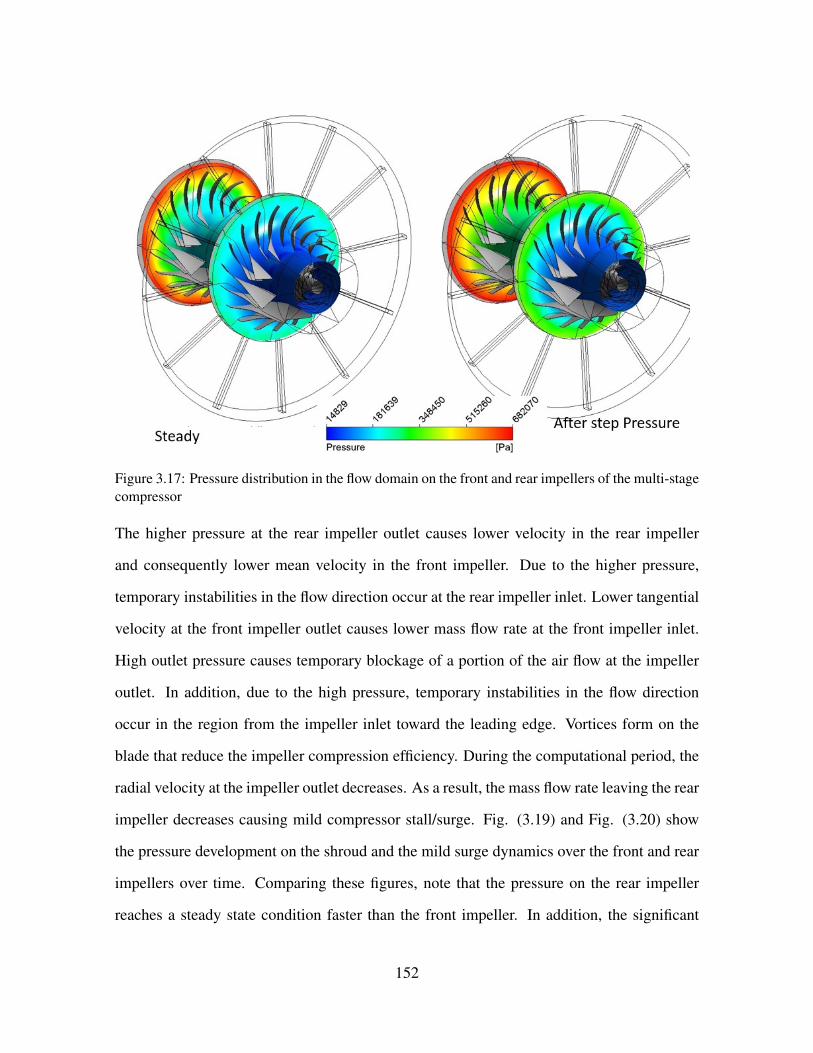
Figure 3.17: Pressure distribution in the flow domain on the front and rear impellers of the multi-stagecompressor
The higher pressure at the rear impeller outlet causes lower velocity in the rear impeller
and consequently lower mean velocity in the front impeller. Due to the higher pressure,
temporary instabilities in the flow direction occur at the rear impeller inlet. Lower tangential
velocity at the front impeller outlet causes lower mass flow rate at the front impeller inlet.
High outlet pressure causes temporary blockage of a portion of the air flow at the impeller
outlet. In addition, due to the high pressure, temporary instabilities in the flow direction
occur in the region from the impeller inlet toward the leading edge. Vortices form on the
blade that reduce the impeller compression efficiency. During the computational period, the
radial velocity at the impeller outlet decreases. As a result, the mass flow rate leaving the rear
impeller decreases causing mild compressor stall/surge. Fig. (3.19) and Fig. (3.20) show
the pressure development on the shroud and the mild surge dynamics over the front and rear
impellers over time. Comparing these figures, note that the pressure on the rear impeller
reaches a steady state condition faster than the front impeller. In addition, the significant
152

volume of the diffuser between the two impellers, delays the pressure increase in the front
impeller. Thus, whenever a fast transient power demand is required, the-mid diffuser delays
the initiation of stall/surge on the front impeller and lets the rear impeller return to the normal
operation before the second stall/surge event begins in the front impeller. Therefore, this
multi-stage configuration allows a time delay between the two stall/surge phenomena that
increases the stability of operation during this pressure perturbation dynamic. This results in
lower risk of system failure.
153

Figure 3.18: Pressure development in the diffuser
154

Figure 3.19: Pressure development on the front impeller’s shroud
155

Figure 3.20: Pressure development on the rear impeller’s shroud
Fig. (3.21) and Fig. (3.22) demonstrate the mass flow rate oscillation corresponding to the
mild surge on the front and rear impeller inlets, showing a sustained flow rate during the
hybrid SOFC-GT gas turbine transient operation, which produced pressure dynamic pertur-
bation that is applied as boundary condition to the CFD model. Following the pressure step
156

change, the system reaches a stead-state operation and mass flow rate continues throughout
the front and rear impellers without significant flow reversal.
Figure 3.21: Front Impeller inlet velocity/mass flow rate oscillation
Figure 3.22: Rear Impeller inlet velocity/mass flow rate oscillation
Fig. (3.23) shows the dynamics of stall/surge with higher resolution on the impeller outlet.
157

At steady state operation, the net mass flow rate is 7 kg/s which is equal to the design mass
flow rate of the scaled gas turbine (similar to Kawasaki gas turbine) simulated. As the dif-
fuser outlet pressure rises, the net mass flow rate decreases. However, the tangential velocity
increases. The outlet mass flow rate decreases to the point of steady mass flow rate at the
impeller outlet, which is the normal operating condition. Fig. (3.23) shows that at the 20th
rotor revolution, the net air mass flow rate converges to a steady state and retains its constant
value during the rest of this short period of hybrid SOFC-GT system operation. These re-
sults show that this type of industrial compressor can handle the type of transient pressure
perturbation that a hybrid system could introduce quite well. However, control algorithms
must be developed and applied subsequently in the system model to ramp the air flow rate
back up to the required flow rate.
Fig. (3.24) demonstrates that as the outlet pressure increases, the flow velocity on the rear
impeller gradually decreases at the trailing edge. The blue region shows some locations of
zero velocity that is developed from the trailing edge to the leading edge. This situation is
accompanied by the vortices that are formed along the blades and the splitters. Development
of control algorithms are necessary in order to prevent the local high velocity on the blades.
158

Figure 3.23: Sustained mass flow rate after transient power demand change of the hybrid SOFC-GTsystem
159

Figure 3.24: The front impeller velocity distribution from the leading edge (LE) to the trailing edge(TE)
Figure 3.25: The rear Impeller velocity distribution from the LE to the TE
160

3.9 STALL/SURGE ANALYSIS RESULTS
The mass flow rates are calculated at the inlet and outlet of the multi-stage compressor as
a function of the number rotor revolutions (time) as shown in Fig. (3.26). Note that, in the
multi-stage configuration there is a net and sustained positive mass flow rate through the
compressor outlet after the pressure applied and simulated to allow the compressor to re-
spond and return to a new steady state. Notice that the 32 rotor revolutions simulated in the
CFD simulation correspond to 0.05 seconds of hybrid system operation. After the compres-
sor relaxes from the applied pressure dynamic (as shown in Fig. (3.26)), the turbomachinery
will be ”spun-up” (primarily by increasing TIT) over time to deliver the new air flow rate
required by the hybrid system model. In the system model, this transient period lasts in or-
der of seconds. During this period the pressure dynamics could also be simulated, but, the
dynamics are relatively slow, indicating that CFD simulation of the compressor may not be
required.
161

Figure 3.26: Sustained mass flow rate after transient power demand change of the hybrid SOFC-GTsystem
3.10 220 KW SIEMENS-WESTINGHOUSE POWER PLANT
The Siemens Power Corporation hybrid design consisted of 100 kWe tubular SOFC and 75
kWe Ingersoll-RandMTG [101]. The system was tested at National Fuel Cell Center (NFCR-
C) at University of California, Irvine. Siemens-Westinghouse Power Corporation developed
the first hybrid system, which integrated a SOFC stack with the gas turbine engines. That
pressurized (3 atm) system generated 220 kW of electrical power at a net electrical efficiency
of 55%.
The dynamic interdependencies associated with the integration of the fuel cell and the gas
turbine are not completely understood and unexpected complications might occur during
the plant operation. The results of experimental study of SOFC-GT hybrid system at the
University of Trieste, Italy, demonstrate that as a result of the relatively large volume of the
162

pressurized portion of the plant and the shape of the stall characteristic of compressors, fluid
dynamic instabilities could happen in the plant [211]. Surge could be detected in off-design
transient operation of HS, during plant regulation, start up and shut down. In another study, It
has been mentioned that hybrid systems posses large volume of gas between air compressor
and turbine [30].
Figure 3.27: 220 kW Siemens- Westinghouse power plant
3.10.1 MODEL VALIDATION EFFORTS
Fig. (3.28) to Fig. (3.30) shows the open loop response to ambient temperature variation
during 60 hours operation at fixed current and air bypass previously studied at NFCRC.
Compressor inlet temperature, turbines inlet and outlet temperatures, and SOFC outlet tem-
perature show excellent agreement with the experiment measurements.
163

Figure 3.28: Compressor inlet temperature
Figure 3.29: Observed and simulated turbine inlet, GT1 and GT2 temperatures
164

Figure 3.30: Observed and simulated SOFC inlet and outlet temperatures
The Siemens-Westinghouse hybrid system has been modified due to the proven higher ef-
ficiency of the new system. The system has been developed at NFCRC at UC Irvine. The
control strategy for this hybrid system is demonstrated. Fig. (3.31) shows the modified
Siemens Westinghouse power system.
165

Figure 3.31: Modified Siemens Westinghouse Power System
Fig. (3.32) shows the control strategy for modified Siemens Westinghouse power system.
166

Figure 3.32: Modified Siemens Westinghouse Control Strategy
Conservation of mass and isentropic expression for speed of sound is shown in Eq. (3.5):
dppdt
=a2pVp
(mc − mt)
(3.5)
CFD models are applied to study single-stage and multi-stage compressors. Fig. (3.33)
shows the schematic of single-stage problem solved.
167

Figure 3.33: Single Stage Compressor Schematic
The CFD design is based on the Capstone C65 micro turbine generator. Secondary multi
stage compressor CFD design is based on Kawasaki 1.7 MW gas turbine. Surge Results
have been compared. Fig. (3.34)shows the operating parameters of Capstone micro-turbine.
168

Figure 3.34: C-65 (Capstone) operating parameters
Fig. (3.35) shows the capstone micro-turbine C-65 schematic.
Figure 3.35: C-65 (Capstone) operating parameters
Pressure step (jump) due to the sudden load variation has been applied to the diffuser outlet.
Development of high pressure based on rotor revolution is demonstrated. The pressure in the
diffuser and the impeller rises during the time Fig. (3.41).
169

Figure 3.36: C-65 impeller pressure results
Figure 3.37: C-65 impeller Velocity Distribution
Dynamic of surge is shown on the impeller outlet in Fig. (3.38). At the steady state operation,
the net mass flow rate is 0.5 kg/s. As the diffuser outlet pressure rises, the net mass flow rate
decreases. However, the tangential velocity increases. The outlet mass flow rate decreases
till the point of zero mass flow rate at the impeller outlet, which is called deep surge.
170

Figure 3.38: C-65 impeller otutlet velocity ditribution
High outlet pressure causes temporary blocking of the air flow in the impeller outlet. In addi-
tion, due to the high pressure, temporary instabilities in flow direction occur at the impeller
inlet to the leading edge. As a result, vortices form on the blade that reduce the impeller
compression efficiency.
Figure 3.39: C-65 blade Velocity Distribution
171

Figure 3.40: Pressure evolution in diffuser over time
Figure 3.41: C-65 Single Stage Stall/Sure Results
172

CHAPTER 4
HYBRID SOFC-GT LOCOMOTIVE SYSTEM
DESIGN
4.1 GENERAL SYSTEM MODELING
4.2 HYBRID SOFC-GT SYSTEM FOR TRANSPORTATION AP-
PLICATION
4.2.1 MOTIVATION
The current CNG and LNG stations are potential fueling stations for hybrid SOFC-GT lo-
comotive engines, giving some confidence that an initial deployment that uses natural gas
fuel is possible. Natural gas as a potential future fuel for all of their rail operations and has
also demonstrated the use of natural gas tenders and natural gas reciprocating (diesel cycle)
engines in rail operations.
173

4.3 SCOPE
This thesis covers computational fluid dynamic analysis of a stationary SOFC-GT system for
various system sizes, sizing of SOFC-GT engine prototype for locomotive engine and system
design and analysis of SOFC-GT system for locomotive system on a sample railroad route
from Bakersfield to Mojave. It also covers system integration and development for hybrid
SOFC-GT system in 1 MW switcher locomotive. The report addresses prototype system
development for this type of switchers. Also a test railroad route (Bakersfield-Mojave) has
been chosen in order to analyze the SOFC-GT performance on the route. Parametric studies
have been accomplished in order to find the optimal design of the system that can effectively
meet the power demand profile.
4.3.1 RESEARCH GAP
:
Zero emission commuter has been a target for many years in several transportation industries
including locomotives. The potential benefits of hybrid systems applications in transporta-
tion sector are:
1) Enhancement of transient power and tractive force
2) Regenerative braking
3) Reduction of capital cost
The effectiveness of these characteristics relies on the dynamics of duty cycle and the route.
These effects will be investigated in future efforts of our center on the path of development
of hybrid fuel cell gas turbine systems. Propulsion system design issues and operating con-
straints will determine the feasibility of applying hybrid fuel cell-gas turbine system in a
locomotive engine.
The current model of SOFC-Gas Turbine system works based on natural gas as the main
174

source of fueling. Hydrogen fueling has an advantage over natural gas as the hybrid system
produces lower CO2 and NOx emissions. However based on the number of current stations
installed for hydrogen and natural gas, the prototype system is designed for natural gas.
Fig. (4.1) shows the current compressed liquid and liquefied natural gas stations in the
US. The current CNG and LNG stations are potential fueling stations for hybrid SOFC-GT
locomotive engines, giving some confidence that an initial deployment that uses natural gas
fuel is possible. Natural gas as a potential future fuel for all of their rail operations and has
also demonstrated the use of natural gas tenders and natural gas reciprocating (diesel cycle)
engines in rail operations.
Figure 4.1: Locations of CNG and LNG stations in the US
4.3.2 FUEL CELL LOCOMOTIVES
To date, several rail vehicles use on-board hydrogen as a source of energy. Existing Fuel
Cell Locomotives are shown in Fig. (4.2) to Fig. (4.4).
175

Figure 4.2: Japan Locomotive
Figure 4.3: North America BNSF Locomotive
176

Figure 4.4: North America BNSF Locomotive
Critical Locomotive parameters are shown in Fig. (4.5).
Figure 4.5: Critical locomotive parameters
PEMFC operating Temperature is 80◦C. 23 kg compressed on board hydrogen is used.
Maximum operating pressure of the tank is 50 Mpa and 80 Mpa.
177
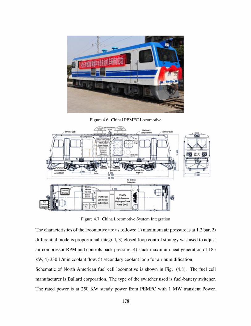
Figure 4.6: Chinal PEMFC Locomotive
Figure 4.7: China Locomotive System Integration
The characteristics of the locomotive are as follows: 1) maximum air pressure is at 1.2 bar, 2)
differential mode is proportional-integral, 3) closed-loop control strategy was used to adjust
air compressor RPM and controls back pressure, 4) stack maximum heat generation of 185
kW, 4) 330 L/min coolant flow, 5) secondary coolant loop for air humidification.
Schematic of North American fuel cell locomotive is shown in Fig. (4.8). The fuel cell
manufacturer is Ballard corporation. The type of the switcher used is fuel-battery switcher.
The rated power is at 250 KW steady power from PEMFC with 1 MW transient Power.
178

Carbon fiber aluminum cylinders are used in the system. The system is able to store 35 kg
of compressed hydrogen. Maximum air pressure is at 3 atm. Two stage air compression is
used. The first stage generates 2.7 atm pressure ratio. The second stage uses variable vane
to control the system back pressure and additional pressure boost.
Figure 4.8: North America fuel cell locomotive system integration
Figure 4.9: North America fuel cell locomotive system integration schematic
179
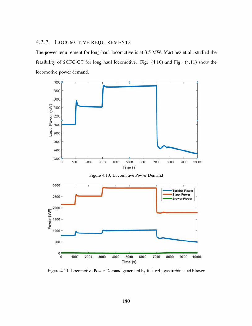
4.3.3 LOCOMOTIVE REQUIREMENTS
The power requirement for long-haul locomotive is at 3.5 MW. Martinez et al. studied the
feasibility of SOFC-GT for long haul locomotive. Fig. (4.10) and Fig. (4.11) show the
locomotive power demand.
Figure 4.10: Locomotive Power Demand
Figure 4.11: Locomotive Power Demand generated by fuel cell, gas turbine and blower
180

Figure 4.12: Locomotive Efficiency
4.3.4 FUELING INFRASTRUCTURE FOR HYBRID SOFC-GT LOCOMO-
TIVES
In this section, hydrogen fueling Infrastructure for railroad across the US has been developed
using data assimilation form National Renewable Energy Laboratory Resources. The poten-
tial of hydrogen production potential from various resources including (Coal,Geothemal,
Wind, Biomass) is shown in Fig. (4.13). General Mapping theme on a county level has been
used to compute the hydrogen production potential across US.
181

Figure 4.13: Hydrogen Production from various resources, Source: NREL
Fig. (4.16) shows the estimation of the quantity of low-carbon energy resources required to
meet hypothetical future demand levels.
Figure 4.14: Hydrogen Production Potential
Fig. (4.15) shows the estimation of the hydrogen production potential from various resources
required to meet hypothetical future demand levels versus carload traffic density.
182
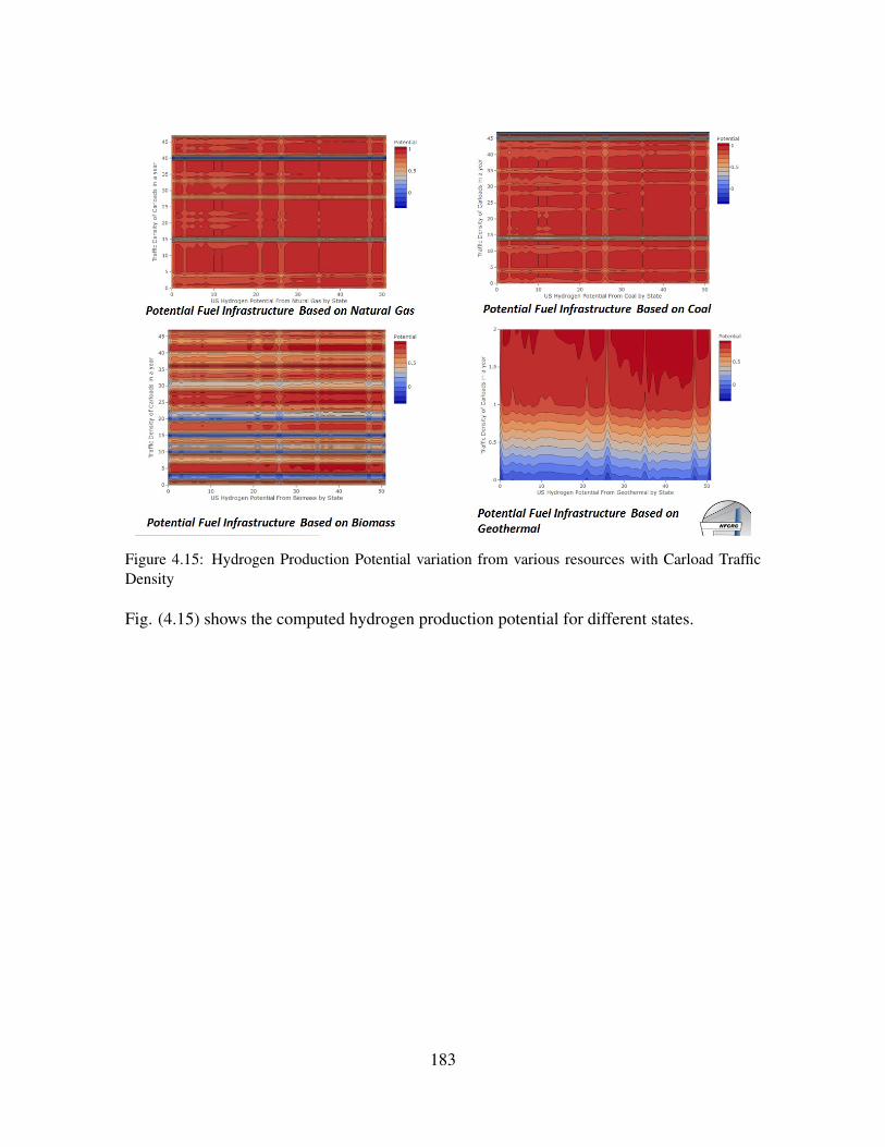
Figure 4.15: Hydrogen Production Potential variation from various resources with Carload TrafficDensity
Fig. (4.15) shows the computed hydrogen production potential for different states.
183

Figure 4.16: Hydrogen Production Potential for different states (alphabetical order) versus Carloaddensity
4.3.5 ECONOMIC CONSIDERATIONS
Table.(4.1) shows the sample locomotive performance.
Engine Horsepower 44000 HP
Starting tractive effort 183-190 lbs. force
Continuous tractive effort 157-166 lbs.force
Fuel efficiency 500 RTM**/gallon
Fuel tank capacity 5k gallons
Fuel tank range 800-1200 miles
Table 4.1: Sample Locomotive Performance
GE and EMD build 500-1200 locomotives annually for worldwide use. UP and BNSF com-
bined acquired 500 new locomotives annually for US. Transition towards a sustainable ener-
gy system requires the development and deployment of new and improved energy technolo-
184

gies. Efficiency has been improved by 50% since 1980 (1.8% /year) [319]. Evolution series
locomotives are the result of 10 years, $ 400 million investment by GE [320]. In 2005, at the
time of the GE Evolution series release, GE and other competitors were selling numerous
locomotives prices near $2 million [321]. Back in 2001, prices were from about $ 1,500,000
for DC units like the SD70 model to about $2,300,300 for an AC unit such as SD90MAC,
with the average price for a new locomotive at about $1,700,000 [322]. In 1948, the price
for 103 locomotives in the range of 1,000 to 6,000 hp was reported as $91.7-$106.1 per hp
with average of $102.42/hp. In 1970, for 173 locomotives ranging from 1,000 to 3,000 hp,
the price was reported as $92.5 to $150 per hp with the average of $116/hp. In 1979, the
Electro-Motive new unit model (SD-40-2), 3,000 hp cost was reported as $216.67/hp. In
1983, the Electro-Motive model SD-50, 3,500 hp cost was reported as $342.90/hp [322].
Elimination of high catenary-wire infrastructure costs by fuel-cell locomotives is the key to
economic viability of zero-emission, low-noise electric trains in the low population density
regions. The issues are related by the fact that about 97% of the energy for the transport sec-
tor (in the US) is based on oil, and more than 60% is imported. Because its primary energy
is based largely on combustion of fossil fuels, the transportation sector is one of the largest
sources of air pollution. A North American public-private project partnership has developed
a prototype fuel-cell-powered switch locomotive [323]. The fuel-cell-hybrid switch locomo-
tive for operation in the LA metro area combines the environmental advantages of an electric
locomotive with the lower infrastructure costs of a diesel-electric locomotive.
Fuel-cell stack hardware costs, on-board fuel storage, and fuel infrastructure continue to
be challenges for commercial implementation. Fuel cell locomotives are expected to be
more energy efficient than diesel locomotives, and because its fuel infrastructure will be
homologous to that of a diesel, it should have similar fuel infrastructure costs [324]. Capital
cost in some applications may be reduced. Based on an observed locomotive duty cycle, a
cost model shows that a hybrid power plant for a switcher may reduce capital cost [325].
185
Integrated hybrid systems have the potential to operate at higher energy efficiency than fuel
cell or gas turbine alone. A market study by Research Dynamics Corporation proposed
that hybrid systems could compete on the electricity cost with other distributed generation
technologies. The thermal efficiency of SOFC-GT can rise up to 70% comparing to the
current diesel locomotive efficiency 40%. The Tier 4 diesel electric locomotive cost has
been estimated to be 3$ million. Evolution series locomotive of the GE use 5% less fuel
during its lifetime or enough to power another evolution series for more than half a year.
Compared to previous GE transportation models, the evolution series locomotive reduces
emissions by more than 40%.
In 1999, Rolls Royce funded a study to produce a turbo-generator that costs approximately
$400 per kilowatt [27, 30]. It was shown that when coupled with fuel cell, the system pro-
duced 25% of the power from the turbine in the 1 MW to 5 MW class. As a stand-alone mode,
turbine would produce 1.5 MW of electric power in a simple cycle. In stand-alone mode,
the efficiency of turbine is approximately 33%. Pressurizing the fuel cell increases the over-
all system efficiency. However, the technical challenges associated with the development of
SOFC with a very high operating pressure and the development costs will be significant. Yi
et al. have studied the balance between the development cost and the efficiency [174]. The
turbomachinery used in power generation can operate in two configurations; Synchronous
ans Asynchronous. In synchronous mode the shaft is directly driving the electrical genera-
tor at some multiple of the grid frequency. The advantage of this method is elimination of
costly power conditioning hardware and additional losses of the power conditioning module.
Velumani et al. proposed a combined heat and power (CHP) SOFC/microturbine/absorption
chiller for 230 kWe demand building with thermal efficiency in the range of 70 to 75%,
where the waste heat can be used for local heating and cooling [187]. The installation costs
are reported to be in the range of 400 US$/kWe and 4000-5000 US$/kWe for the micro-
turbine and SOFC respectively. Agnew et al. presented Rolls-Royce strategies in order to
186
reduce the SOFC-GT hybrid costs [133]. An IP-SOFC stack concept has unique design
features, so that stacks can be manufactured through low cost manufacturing processes and
with low inventories of material. Lundberg et al. presented a conceptual design of 60%
efficiency 20 MWe-class PSOFC-ATS-GT HS that integrates Siemens Westinghouese pres-
surized SOFC and Mercury 50 gas turbine [243]. The system installed cost was estimated
at $1170/kWe. While operating on $3/MMBtu natural gas fuel, its cost of electricity (COE)
was approximately 6% less than COE of less efficient and less expensive GT/ST comcined
cycle system. Initial market of the fuel cells is discussed [31]. The cost of fuel cell sys-
tems has a significant potential for being further reduced. Several researchers developed
thermo-economic optimization of SOFC-GT hybrid systems [241, 242, 243, 244]. Auttssier
et al. used thermo-economic multi-objective optimization approach to compute the integrat-
ed system performances, size and cost [241]. Two objectives have been considered in this
study: minimizing of the specific cost and maximizing the efficiency. Their results prove the
existence of designs with costs from 2400$/kW for 44% efficiency to 6700$/kW for 70%
efficiency. In addition, high system efficiencies can be obtained with low fuel utilization in
their system. Cheddie et al. studied a SOFC indirectly coupled with 10MW power plant
with 30% efficiency. The method of Lagrange Multipliers in the thermo-economic has been
used to optimize the system performance. The net power output of 18.9MW at 48.5% effi-
ciency has been predicted. A breakeven per-unit energy cost of USD 4.54kWh( − 1) for the
hybrid system is predicted [242]. Najafi studied SOFC-GT system integrated with a multi
stage flash (MSF) desalination unit [243]. Muti-objective genetic algorithm (MOGA) has
been used to find the optimal design parameters of the plant. Exergy efficiency and total cost
rate of the system were considered as the objective functions. The optimal design resulted
in 46.7% exergetic efficiency and a total cost of 3.75 million USD/year. The payback time
of the design is reported to be 9 years. Results showed that MSF desalination unit is signif-
icantly irreversible with exergy efficiency from 3.05% to 3.61%. Thermodynamic, kinetic,
187

geometric and cost models of hybrid SOFC-GT-ST have been developed ranging in the size
of 1.5 MWe to 10 MWe [244]. It was reported that, higher operating pressure resulted in
higher cell voltage and as a result higher system efficiency. It was suggested that higher
compressor and turbine costs must be considered at higher operating pressures. Massardo
demonstrated that their proposed system efficiencies are high (65 - 70% for atmospheric cells
and 74 - 76% for pressurized cells) [71].
4.3.6 MODELING
For the turbo machinery the capital cost is provided by the formula presented by Calise et
al. [238]. Table. (4.2) shows the set of equations used for economic analysis of SOFC-GT
system.Gas Turbine Capital Cost CGT = (−98.328ln(PGT ) + 1318.5)PGT
Compressor Capital Cost Ccompressor = 91562× (Pcompressor
445)0.67
Heat Exchanger Capital Cost CHE = 11.6(mHE)0.95
Counter Flow Heat Exchanger Capital Cost CHEC = 130× AHE
0.093
Isentropic RelationT2T1
=P2
P1
(y−1)/y
Table 4.2: Set of equations used for economic analysis of SOFC-GT system
Where, mHE is the heat exchanger mass (kg). AHE is the surface area of the heat exchanger.
In order to find the heat exchanger surface area, we need to calculate the heat required to rise
the air temperature from compressor outlet temperature to the SOFC cathode inlet. Using
the isentropic relation and assuming the air is ideal gas.
In the Martinez et al. study [3] the hybrid system produced the net 3.5 MW (4693 hp)
power. We assume the SOFC and GT characteristics in the study can be used to provide a
cost projection that meets GE locomotive requirements (4400 hp). The particular turbine was
chosen that determined its power (1.2 MW) and size (9.02m2, 21.74m3) were well-matched
to the requirements of the hybrid system needed in this application. Two case studies have
188
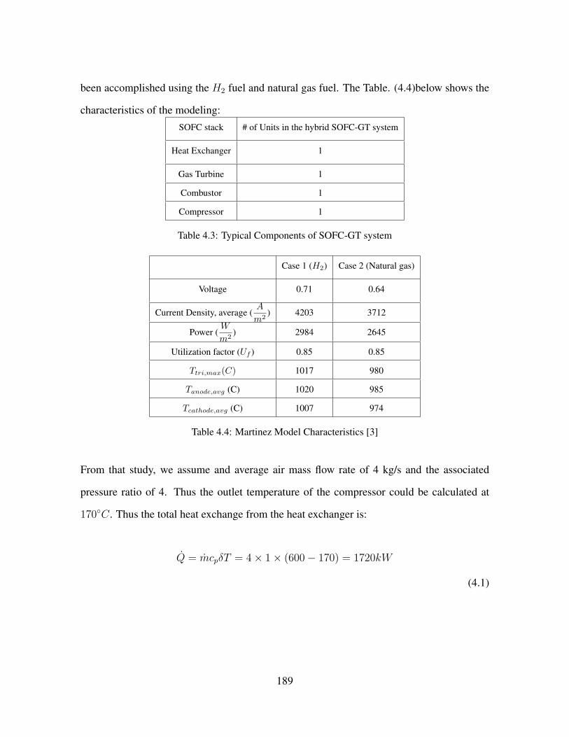
been accomplished using the H2 fuel and natural gas fuel. The Table. (4.4)below shows the
characteristics of the modeling:SOFC stack # of Units in the hybrid SOFC-GT system
Heat Exchanger 1
Gas Turbine 1
Combustor 1
Compressor 1
Table 4.3: Typical Components of SOFC-GT system
Case 1 (H2) Case 2 (Natural gas)
Voltage 0.71 0.64
Current Density, average (A
m2) 4203 3712
Power (W
m2) 2984 2645
Utilization factor (Uf ) 0.85 0.85
Ttri,max(C) 1017 980
Tanode,avg (C) 1020 985
Tcathode,avg (C) 1007 974
Table 4.4: Martinez Model Characteristics [3]
From that study, we assume and average air mass flow rate of 4 kg/s and the associated
pressure ratio of 4. Thus the outlet temperature of the compressor could be calculated at
170◦C. Thus the total heat exchange from the heat exchanger is:
Q = mcpδT = 4× 1× (600− 170) = 1720kW
(4.1)
189
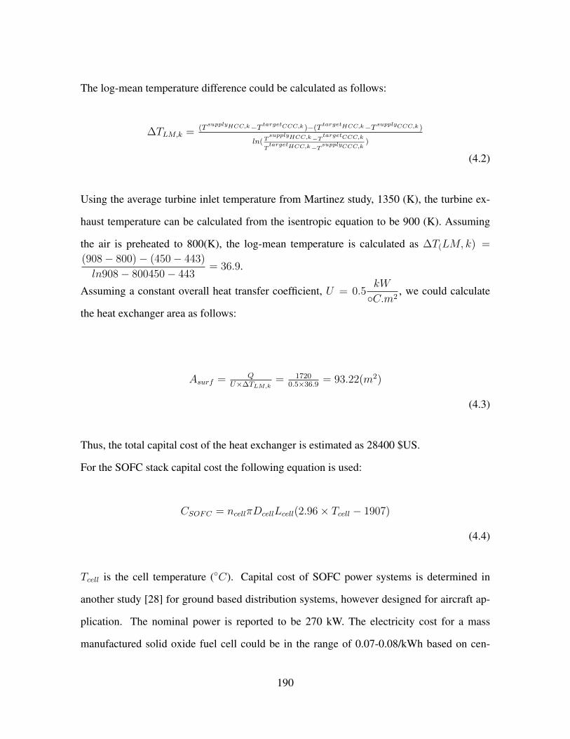
The log-mean temperature difference could be calculated as follows:
∆TLM,k = (TsupplyHCC,k−T targetCCC,k )−(T
targetHCC,k−T supplyCCC,k )
ln(TsupplyHCC,k−TtargetCCC,k
TtargetHCC,k−TsupplyCCC,k
)
(4.2)
Using the average turbine inlet temperature from Martinez study, 1350 (K), the turbine ex-
haust temperature can be calculated from the isentropic equation to be 900 (K). Assuming
the air is preheated to 800(K), the log-mean temperature is calculated as ∆T(LM, k) =
(908− 800)− (450− 443)
ln908− 800450− 443= 36.9.
Assuming a constant overall heat transfer coefficient, U = 0.5kW
◦C.m2, we could calculate
the heat exchanger area as follows:
Asurf = QU×∆TLM,k
= 17200.5×36.9
= 93.22(m2)
(4.3)
Thus, the total capital cost of the heat exchanger is estimated as 28400 $US.
For the SOFC stack capital cost the following equation is used:
CSOFC = ncellπDcellLcell(2.96× Tcell − 1907)
(4.4)
Tcell is the cell temperature (◦C). Capital cost of SOFC power systems is determined in
another study [28] for ground based distribution systems, however designed for aircraft ap-
plication. The nominal power is reported to be 270 kW. The electricity cost for a mass
manufactured solid oxide fuel cell could be in the range of 0.07-0.08/kWh based on cen-
190

tralized power production plants. The sputtering approach was investigated to examine the
decrease in costs associated with the process. It is reported that the process not only reduces
the material cost, but also increases the fuel cell power density by 50%. The increased pow-
er density reduces the number of repeat units required to makeup a 270 kW fuel cell stack.
Stack costs decreased by 33% at a mass production of 10,000 units per year. Material costs
contributed 55% of the total stack manufacturing costs.
Figure 4.17: Material Cost
191

In general the capital cost of SOFC manufacturing is reported to be from $500 to $700/kW.
In order to calculate the capital cost of SOFC based on the Calise et al. study, the active
cell area is needed. Motahar et al. studied tubular SOFC based SOFC-GT in a MW-class
[76]. Active area of the cell is assumed to be 834cm2. We use this active area in order
to find the capital cost of SOFC. Based on this study, the typical cell voltage for SOFC in
a MW-class SOFC-GT hybrid system is approximately 0.69(V) and the current density is
300mA/(cm2). Knowing the power produced by SOFC, active cell area, cell current density
and the cell voltage, we can calculate the number of the cells. Based on the work of Chan et
al. [30] study, the compressor power requirement is approximately one fifth of the produced
power by SOFC. We have used this assumption for the compressor power estimation. The
capital cost of the SOFC inverter is calculated as follows:
Cinverter = 100000× (Pcell500
)0.7
(4.5)
Where Pcell is the stack power production in kW. The SOFC pre-reformer capital cost is as
follows:
CPR = 130× (APR,fin
0.093)0.78 + 3240(VPR)0.4 + 21280.5× VPR
(4.6)
Where, VPR is the catalyst volume (m3), andAPR,fin is the finned exchange area (m2). Since
we dont know the exact number of catalysts, diameters and tube length, we refer to Arsalis
study for pre-reformer cost. The cost of the reformer does not vary significantly from 1.5
MW to 10 MW hybrid system. Thus we assume, the pre reformer cost would be 40,000$
US.
192

The capital cost of the auxiliary devices (catalytic combustor, mixer, etc.) can be calculated
a as a fixed percentage (15%) of the stack cost.
Caux,SOFC = 0.10× CSOFC
(4.7)
4.3.7 TOTAL COST CALCULATION
Assuming an overall 15 year lifetime is considered. The interest rate i is assumed to be
0.0929 [258]. Also, fmain is assumed to be 0.06. Similarly, the insurance fins and taxation
ftax are chosen as 0.2 and 0.54 percent.
4.3.8 COST MODEL
Table. (4.7) shows the SOFC-GT cost model for hybrid fuel cell gas turbine.Variable Variable Description Model Equation
1 Deprication cost ($/yr) Gdep =Cpur
ndep
2 Interest on outside capital cost ($/yr) Gint =Cpur
ndepi
3 Maintenance cost ($/yr) Gmai =Cpur
ndepfmai
4 Insurance cost ($/yr) Gins =Cpur
ndepfins
5 Taxation cost ($/yr) Gtax =Cpur
ndepftax
6 Capital cost ($/yr) Gcap = Gdep +Gint +Gmai +Gdep +Gtax
7 Operating cost ($/yr) Gope = cf × VfNh
7 Total cost ($/yr) Gtotal = Gcap +Gope
Table 4.5: SOFC-GT cost model
Based on Song et al. multi MW-class hybrid system study, the molar flow rate of the system
is estimated to be 0.2 kg/s or 1100 (Nm3)/hr. The price of natural gas is assumed to be
0.25 $/Nm3. In order to project the cost for volume production, the formula proposed by
193
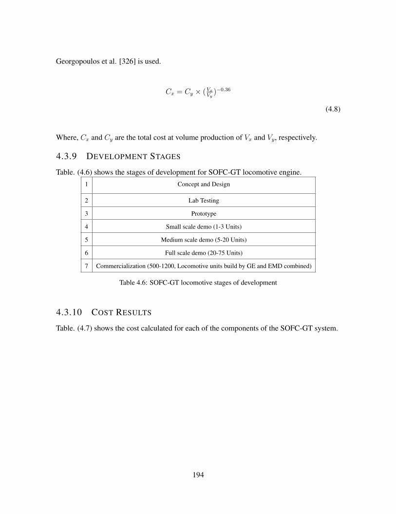
Georgopoulos et al. [326] is used.
Cx = Cy × (VxVy
)−0.36
(4.8)
Where, Cx and Cy are the total cost at volume production of Vx and Vy, respectively.
4.3.9 DEVELOPMENT STAGES
Table. (4.6) shows the stages of development for SOFC-GT locomotive engine.1 Concept and Design
2 Lab Testing
3 Prototype
4 Small scale demo (1-3 Units)
5 Medium scale demo (5-20 Units)
6 Full scale demo (20-75 Units)
7 Commercialization (500-1200, Locomotive units build by GE and EMD combined)
Table 4.6: SOFC-GT locomotive stages of development
4.3.10 COST RESULTS
Table. (4.7) shows the cost calculated for each of the components of the SOFC-GT system.
194

Stack cost ($) 1,424,350.98
Gas turbine cost ($) 745,660.55
Compressor ($) 106,807.07
Pre-reformer ($) 40,000
Heat Exchanger ($) 28,493.36
AC Inverter ($) 333,988.58
Auxiliary (Catalytic combustor, mixer, etc.) ($) 213,652.64
Total ($) 2,892,953
Table 4.7: Hybrid system component costs
Fig. (4.19) shows the annual locomotive cost (Total unit cost per year versus volume pro-
duction per year). Table. (6.1) shows the estimated budget in different scales of operation.
Figure 4.18: Total unit cost per year versus volume production per year
195

Stage of Locomotive Development Years Included Estimated Budget ($ US)
Concept/Design 1-2 Years 3,177,330.50 $
Lab Engine Testing 2-4 Units 745,990.0 $
Prototype and Demonstration Locomotive (1-5 units) 4 5 Years 3,573,100 $(1 unit) to
10,009,000.0 $ (5 units)
Pre-Production Locomotive Field Tests (20-75 units) 6 7 Years 24,305,000$ (25 units) to
56,635,000$ (75 units)
Commercial Production (500-1200 units annually) Compliance Date 22,231,000 $/yr (for 500 u-
nits/yr) to 38,931,000 $/yr
(for 1200 units/yr)
Table 4.8: Estimated budget in different scales of operation
The Fig. (4.19) and Fig. (4.20) shows the total cost for different components and different
financial aspects.
Figure 4.19: Total unit cost per year versus volume production per year
196

Figure 4.20: Cost calculated for different financial sections
4.3.11 SYSTEM SIZING AND EVALUATION OF THE FIRST LONG-HAUL
SOFC-GT SYSTEM
This section aims to provide an insight into the feasibility of hybrid fuel cell-gas turbine
regarding sizing constraints of hybrid solid oxide fuel cell-gas turbine (SOFC-GT) engine
for a 4 MW long-haul locomotive engine. The power plant designed for this system consists
of a 1.7 MW industrial gas turbine (similar to 1.7 MW Kawasaki gas turbine), a solid oxide
fuel cell, two main heat exchangers (fuel pre-heater, and air recuperator), an external diesel
reformer, a catalytic combustor and several mixers and valves. The system is designed to fit
into current long haul industrial locomotives. Fuel cell system and balance of plant (BOP)
is designed in order to provide sufficient fuel flow rate for steady operation of hybrid system
engine. Analysis shows that the SOFC module would generate about 80% of the net power
of the hybrid SOFC-GT system. Therefore, a 3 MW SOFC module is designed to be used
in the hybrid system. An analysis, results in a need for an approximately 1.5 MW gas tur-
bine in the hybrid engine in order to generate the required power at the full-load operation.
The closest commercial gas turbine, 1.7 MW Kawasaki multi-stage gas turbine, is chosen
197

to fulfill this operation. Two main heat exchangers of the system are the air preheater and
the fuel preheater. Due to the size constraints in the engine tank, fin and plate heat exchang-
ers are designed using available commercial heat exchanger design software (ASPEN). On
board steam methane reformer (SMR) has been sized and designed to provide enough hy-
drogen flow rate for the SOFC stack consumption. Optimized method will be discussed in
order to reduce the net size of hybrid SOFC-GT system. Analyses show that packing the
hybrid engine in a locomotive engine part will be possible. One of the significant challenges
(stall/surge) of this type of hybrid system will be discussed and control algorithms required
to tackle this challenge will be presented. At the end, possible industrial partners will be
introduced in order to build the first hybrid SOFC-GT engine at a test scale.
Fig. (4.21) shows the plant used for locomotive sizing.
Figure 4.21: Hybrid SOFC-GT system to be used in long-haul locomotive
Eq. (4.9) to Eq. (4.11) shows the equations used for system sizing of reformer.
Diesel Reformer:
C16H34 + 16H2O → 16CO + 33H2
(4.9)
198

Partial Oxidation:
C16H34 + 8O2 → 16CO + 17H2
(4.10)
ATR:
C16H34 + 16H2O + 8O2 → 16CO2 + 33H2
(4.11)
WhereC16H34 represents the paraffinic compounds at the highest concentration in low-sulfur
diesel fuel. Calculations for fuel cell sizing are as follows:
H2 = inF×N = 23.72mol
s= 5.67× 10³ nm3
hr
(4.12)
Based on cetane LHV, LHVcetane = 9.96MJ
mol.
LHVH2 = 243.5 kJmol
(4.13)
Fig. (4.22) and Fig. (4.23) show the fuel cell assembly for implementation in locomotive
fuel cell - gas turbine hybrid system.
199

Figure 4.22: Hybrid SOFC-GT system to be applied in long-haul locomotive engine
Figure 4.23: Fuel Cell Assembly to be used in long-haul locomotive
The sizing of the heat exchangers to be implemented in the long-haul locomotive are shown
in Fig. (4.24) and Fig. (4.25). System heat exchangers have been sized (Fuel preheater
200

and Recuperator heat exchangers in hybrid SOFC-GT system). Fin and plate heat exchanger
were designed in ASPEN simulation software.
Figure 4.24: Heat Exchangers for Fuel Preheater
201
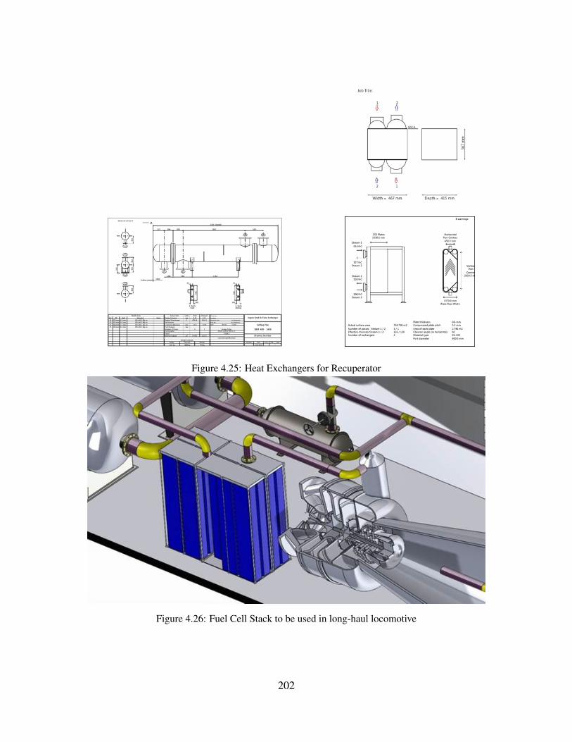
Figure 4.25: Heat Exchangers for Recuperator
Figure 4.26: Fuel Cell Stack to be used in long-haul locomotive
202

Figure 4.27: Reformer to be used in long-haul locomotive
203

CHAPTER 5
MODELING OF HYBRID SOFC-GT SYS-
TEM FOR LOCOMOTIVES
5.1 DEVELOPMENT OF 500 KW SMALL SCALE LAB DESIGN
Fig. (5.1) shows the bloom energy prototype of SOFC as the potential fuel cell design of
the locomotive. 400 kW Versa Power (Fuel Cell energy) is also another potential fuel cell
for small scale development of fuel cell - gas turbine system. Micro gas turbine selection
is based on the fact that 20% of the net power produced by gas turbine C-200 Capstone
micro-turbine. Fig. (5.5) shows the C-200 capstone microturbine system.
204

Figure 5.1: Bloomenergy fuel cell to be used in a small scale prototype of hybrid SOFC-GT system
Fig. (5.2) to Fig. (5.4) show the Versa Power 400 kW performance. At higher S/C, SOFC
produces more current.
Figure 5.2: Versa 400 kW Current Simulation
205

Figure 5.3: Versa 400 kW Voltage Simulation
Figure 5.4: Versa 400 kW Oxygen utilization Simulation
206

Figure 5.5: 200 kW capstone microturbine to be used in a small scale prototype of hybrid SOFC-GTsystem
Fig. (5.6) shows the pressure response to power demand profile for the 268 kW Bloom
energy SOFC system. This is the pressure dynamics response of our dynamic model to step
power demand change in 200 kW C-200 Capstone micro gas turbine.
207

Figure 5.6: Pressure response for 500 kW small scale system
Transient dynamic operation of hybrid SOFC-gas turbine system components has been in-
vestigated, while maintaining the 500 kW lab-scale locomotive power requirements, using
MATLAB/Simulink software. Simulation is accomplished in over time span of 10,000 (s).
Real industrial compressor performance has to be investigated while operating in a hybrid
system.
Fig. (5.7) shows the pressure distribution over C-200 single stage compressor Perturbation
results in the development of high pressure in Capstone C-200 impellers as a function of
rotor revolution. At time T = 7, 000(s) the rotor revolution is equal to 53 revs.
The results would validate the utilization of CFD tools in C-200 and lead to a better un-
derstanding of the flow phenomenon within the single-stage centrifugal compressor. Lower
pressure on impeller followed by pressure step decrease, results in lower pressure in the d-
iffuser and the first impeller. Ongoing mass flow rate through the impeller and reduction in
back pressure on the impeller causes a pressure reduction in the diffuser lowering the risk of
surge in the impeller.
208
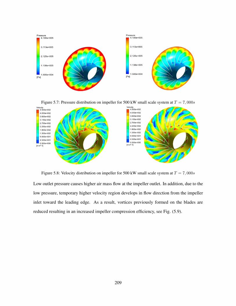
Figure 5.7: Pressure distribution on impeller for 500 kW small scale system at T = 7, 000s
Figure 5.8: Velocity distribution on impeller for 500 kW small scale system at T = 7, 000s
Low outlet pressure causes higher air mass flow at the impeller outlet. In addition, due to the
low pressure, temporary higher velocity region develops in flow direction from the impeller
inlet toward the leading edge. As a result, vortices previously formed on the blades are
reduced resulting in an increased impeller compression efficiency, see Fig. (5.9).
209

Figure 5.9: Velocity development on the impeller blades, T = 7000(s)
Fig. (5.10) shows the velocity vectors on the impeller inlet over time. Comparing these
figures, it could be seen that the net mass flow rate of air is consistent over time showing a
sustained flow rate during the sudden power demand reduction. In addition, high volume of
the diffuser plays a significant role stabilizing the flow at the impeller inlet. Thus, whenever
fast transient power demand is required, the diffuser delays the surge on the impeller and
reaches to the normal operation before the second surge begins.
210

Figure 5.10: Velocity vectors on the impeller inlet
Fig. (5.11) shows the pressure development throughout the diffuser over time. It could be
seen that the pressure reduces significantly due to the reduction in power demand reducing
the surge risk in the impeller. Stable flow in the diffuser plays an important role in reduction
of back pressure on the impeller and as a result keeps the air mass flow rate at a desirable
level of 1 kg/s.
211

Figure 5.11: Pressure reduction in the diffuser connected to the impeller outlet, T = 7000(s)
Fig. (5.12) demonstrates the mass flow rate oscillation corresponding to the mild surge on
the impellers outlet, showing a sustained flowrate in C-200 compressor during the hybrid
SOFC-GT gas turbine operation. During the time, the radial velocity at the impeller outlet
increases and as a result, the mass flow rate through the outlet increases reducing the surge
212

risk in the C-200.
Figure 5.12: Impeller outlet velocity and flow rate increase, T = 7000(s)
Fig. (5.13) shows the Velocity profile over the impeller at time=3000s, when the power
demand increases step wise to 200 kW. More critical case than the previous case as the
pressure increases due to power increase. The velocity is reduced, while the mass flow rate
is sustained at T=3,000 (s).
213

Figure 5.13: The velocity distribution over impellers at T=3000s
Fig. (5.14) shows the velocity region on the impeller blades. As the pressure increases, the
velocity decreases significantly on the trailing edge. However, after 20 rotor revolutions, the
velocity reaches to constant value and as a result a sustained mass flow rate. High vorticity
region that was formed at 5 rotor revolution, diminishes on the trailing edge after 20 rotor
revolutions.
214

Figure 5.14: 1st Impeller velocity distribution from LE to TE
As the pressure increases, the velocity decreases significantly on the trailing edge. However,
after 20 rotor revolutions, the velocity reaches to constant value and as a result a sustained
mass flow rate. High vorticity region that was formed at 5 rotor revolution diminishes.
Fig. (5.15) shows the pressure increase in the diffuser at T=3,000 (s).
215

Figure 5.15: Pressure variation at T = 3000(s) on diffuser
Fig. (5.16) demonstrates as the outlet pressure increases, the flow velocity on the impeller at
the trailing edge gradually decreases. This situation is accompanied by the vortices formed
along the blades and the splitters. Development of control algorithms are necessary in order
to prevent the local high velocity on the blades.
216

Figure 5.16: Impeller outlet velocity reduction at time 3000 (s)
In the single-stage configuration there is a net and sustained mass flow rate through the
compressor outlet after the pressure step is relaxed to a constant value. The calculated values
of mass flow rate at different parts of the single-stage C-200 compressor are shown in Fig.
(5.17) as a function of the rotor revolutions for two times of t=3000 s and t=7000 s. It could
be observed that, in the single-stage configuration there is a net and sustained mass flow rate
through the compressor outlet after the pressure step is relaxed to a constant value.
217
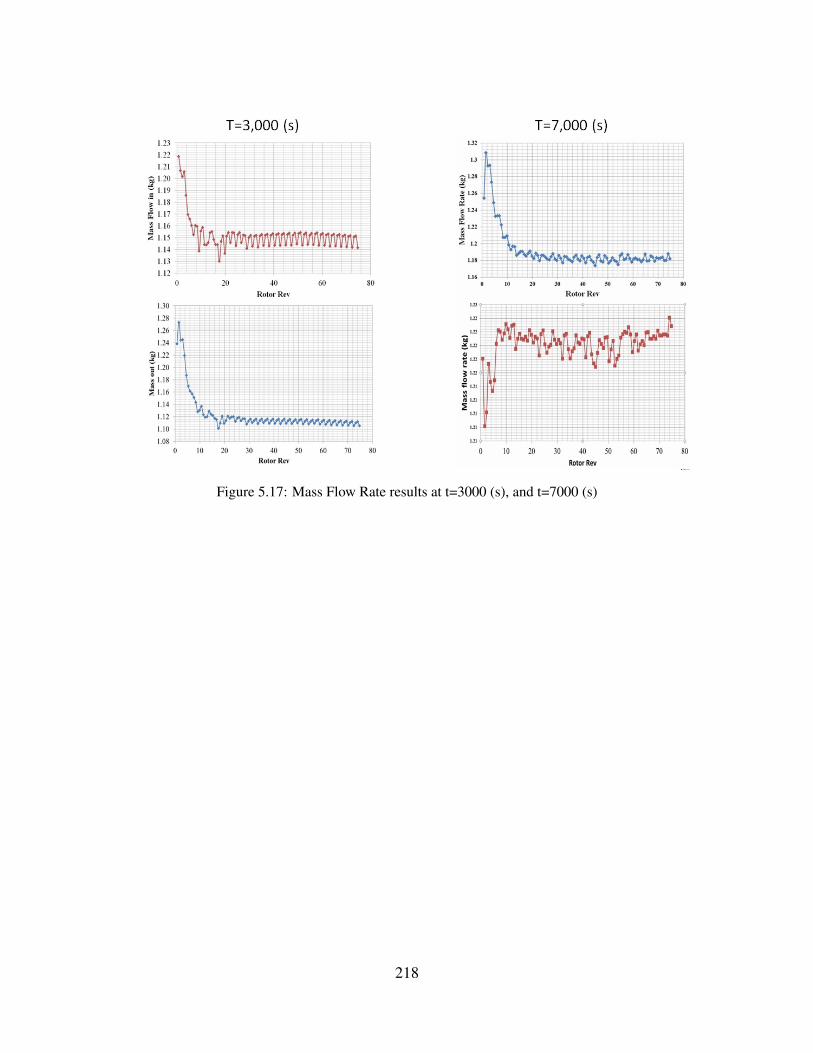
Figure 5.17: Mass Flow Rate results at t=3000 (s), and t=7000 (s)
218

CHAPTER 6
HYBRID SOFC-GT LOCOMOTIVE DYNAM-
ICS AND CONTROL
6.1 DYNAMIC MODELING OF HYBRID SOFC-GT SYSTEM
FOR LOCOMOTIVES
The National Fuel Cell Research Center (NFCRC) analyzed first prototype of the hybrid
SOFC-GT system on the route from Bakersfield to Mojave. The system is designed in MAT-
LAB/Simulink platform. The modeling process is divided into two sections of modeling the
switcher and modeling the switcher and modeling the long haul locomotive. The switcher
modeling is used in order to develop small 1 MW order prototype system. In the current
study, 8 notches have been modeled for the control system. System of the locomotive is
designed for a 1 MW switcher similar to EMD RS 1325. A single vehicle model is devel-
oped in MATLAB/Simulink platform. The total distance on the rail yard is calculated based
on double integration of traction force. The net force on locomotive is calculated based on
rolling resistance, air and axle resistance and the switcher weight. The system development
219

for the locomotive is based on two main components of vehicle dynamics and notch calcu-
lation. The notch system takes speed of the locomotive, grade of the route, acceleration and
traction/brake force as an input. Several assumptions have been made in implementation
of the notching algorithm: 1) The maximum desired train velocity was 60 miles per hour,
2) The minimum desired train velocity was 10 miles per hour, 3) The power notching pro-
gressed by one notch at a timestep (increasing or decreasing), (This decision is made by the
locomotive driver), 4) Notching does not alternate rapidly between the timesteps, 5) The sign
of the grade has an effect on the decision making.
6.1.1 OBJECTIVES
The objectives of the research accomplished herein are as follows:
- Development and analysis of small scale 1 MW SOFC-GT engine for switcher locomotive
and 3 MW SOFC-GT system for long-haul locomotive
- Testing the developed model on the Bakersfield to Mojave Railroad,
- Develop control algorithms in order to pass the switcher through the route,
- Finding the optimal design of the system that can be manufactured for the prototype,
- Conduct comparative the fuel economy testing of the developed model for Natural gas and
hydrogen fuels
- Establish final P&ID design of the hybrid SOFC-GT system that can be use in manufactur-
ing process.
The overall approach of this section is control system development for SOFC-GT hybrid
systems that are required to pass the 1 MW switcher locomotive through the Bakersfield-
Mojave Route. PID controllers are implemented to control the RPM, compressor inlet guide
vanes, fuel cell fuel flow rate and fuel cell power. Specific gains for these controllers are
specified in order to pass the switcher through the route. Due to highly dynamic nature of
the power duty cycle, the control systems are required in order to follow the power demand in
220

the short periods of times. The highly dynamic power cycle is due to the algorithm that keeps
the switcher at constant speed during the whole route. Other algorithms can be implemented
in order to produce less dynamic profile of the power duty cycle at which the controllers have
better performance in following the power demand.
This section covers system integration and development for hybrid SOFC-GT system in 1
MW switcher locomotive. The report addresses prototype system development for this type
of switchers. Also a test railroad route (Bakersfield-Mojave) has been chosen in order to
analyze the SOFC-GT performance on the route. Parametric studies have been accomplished
in order to find the optimal design of the system that can effectively meet the power demand
profile.
Fig. (6.1) shows the tested route for hybrid SOFC-GT Simulation.
Figure 6.1: Bakersfield-Mojave Route, Source: Google Earth
Table shows the list of switchers for hybrid SOFC-GT system modeling. The following
shows the total produced and the power output of the locomotives. The table shows the total
units of the switcher produced and the power output per kW.
221

Model Designation Build Year Total Produced Power Ouput
EMC pre SC 1935 2 600 hp (447 kW)
NW 1 1937-1939 27 900 hp (671 kW)
NW 2 1939-1949 1,145 1,000 hp (750 kW)
NW3 1939-1942 7 1,000 hp (750 kW)
TR 1940 3 2,000 hp (1,490 kW)
TR 1 1941 2 2,700hp (2,013 kW)
SW 7 1949-1951 489 1,200 hp (895 kW)
SW 8 1950-1954 815 1,200 hp (890 kW)
SW 9 1950-1953 815 1,200 hp (890 kW)
SW 600 1954-1962 15 600 hp (447 kW)
SW 900 1954-1969 371 900 hp (670 kW)
SW 1500 1966-1974 808 1,1500 hp (1,100 kW)
SW 1200 1954-1969 1,054 1,100 hp (890 kW)
Table 6.1: List of locomotive switchers, Source: Wikipedia
The modeling process is divided into two sections of modeling the switcher and modeling
the switcher and modeling the long haul locomotive. The switcher modeling is used in order
to develop small 1 MW order prototype system.
6.1.2 PROTOTYPE DEVELOPMENT
In order to develop the prototype, a full dynamic model of the locomotive system has been
developed in the MATLAB/Simulink platform. Locomotive traction and dynamic braking
have evolved over many years. In diesel locomotives, eight notches for the throttle control
emerged based on a three-valve fuel control. It should be noted that, more modern locomo-
tives have different numbers of notches and levels of dynamics braking. In the current study,
8 notches have been modeled for the control system. System of the locomotive is designed
for a 1 MW switcher similar to EMD RS 1325. A single vehicle model is developed in MAT-
LAB/Simulink platform. The total distance on the rail yard is calculated based on double
222
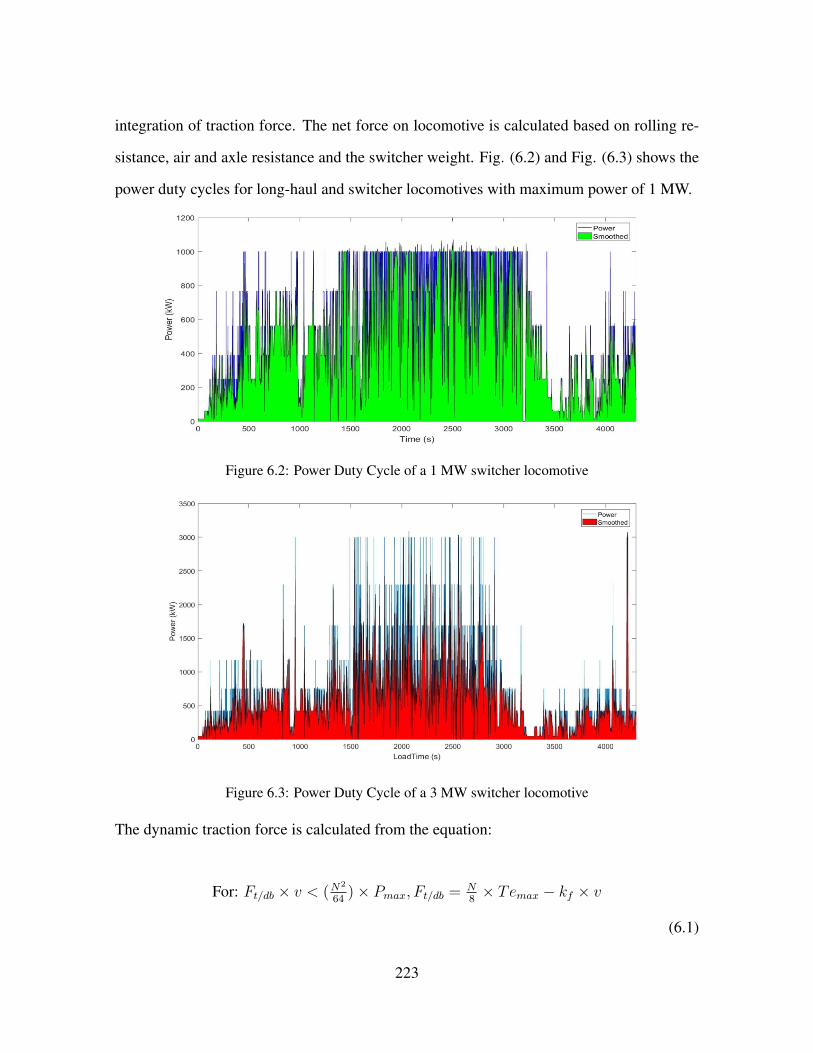
integration of traction force. The net force on locomotive is calculated based on rolling re-
sistance, air and axle resistance and the switcher weight. Fig. (6.2) and Fig. (6.3) shows the
power duty cycles for long-haul and switcher locomotives with maximum power of 1 MW.
Figure 6.2: Power Duty Cycle of a 1 MW switcher locomotive
Figure 6.3: Power Duty Cycle of a 3 MW switcher locomotive
The dynamic traction force is calculated from the equation:
For: Ft/db × v < (N2
64)× Pmax, Ft/db = N
8× Temax − kf × v
(6.1)
223

Else: Ft/db = (N2
64)× Pmax
v
(6.2)
Where N is the throttle setting in notches, 0-8; Pmax is the maximum locomotive traction
horsepower in watts; Temax is the maximum locomotive traction force, N and kf is the
torque reduction, N/(m/s).
A control system has been developed in this study. The system development for the locomo-
tive is based on two main components of vehicle dynamics and notch calculation. The notch
system takes speed of the locomotive, grade of the route, acceleration and traction/brake
force as an input. The notching algorithm Several assumptions have been made in imple-
mentation of the notching algorithm: 1) The maximum desired train velocity was 60 miles
per hour, 2) The minimum desired train velocity was 10 miles per hour, 3) The power notch-
ing progressed by one notch at a timestep (increasing or decreasing), (This decision is made
by the locomotive driver), 4) Notching does not alternate rapidly between the the timesteps,
5) The sign of the grade has an effect on the decision making.
Fig. (6.10) shows the algorithm implemented for the notching system. The algorithm is
developed by Martinez et al. [327].
6.1.3 SYSTEM OPTIMIZATION
In order to optimize the system, the research group has done parametric analysis on the fuel
cell design. We have changed the parameters of PEN average temperature, stack tempera-
ture difference, hydrogen and oxygen utilizations, voltage and current densities. In order to
optimize the system, the research group has done parametric analysis on the fuel cell design.
We have changed the parameters of PEN average temperature, stack temperature difference,
hydrogen and oxygen utilizations and voltage and current densities.
224
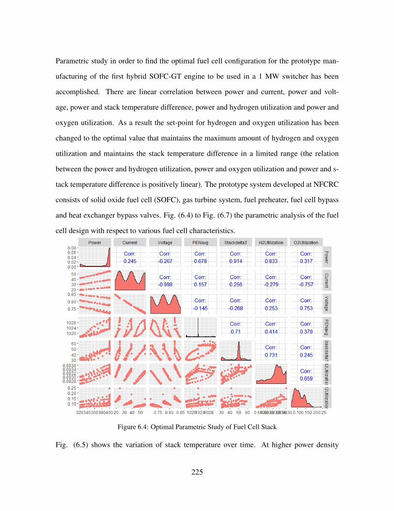
Parametric study in order to find the optimal fuel cell configuration for the prototype man-
ufacturing of the first hybrid SOFC-GT engine to be used in a 1 MW switcher has been
accomplished. There are linear correlation between power and current, power and volt-
age, power and stack temperature difference, power and hydrogen utilization and power and
oxygen utilization. As a result the set-point for hydrogen and oxygen utilization has been
changed to the optimal value that maintains the maximum amount of hydrogen and oxygen
utilization and maintains the stack temperature difference in a limited range (the relation
between the power and hydrogen utilization, power and oxygen utilization and power and s-
tack temperature difference is positively linear). The prototype system developed at NFCRC
consists of solid oxide fuel cell (SOFC), gas turbine system, fuel preheater, fuel cell bypass
and heat exchanger bypass valves. Fig. (6.4) to Fig. (6.7) the parametric analysis of the fuel
cell design with respect to various fuel cell characteristics.
Figure 6.4: Optimal Parametric Study of Fuel Cell Stack
Fig. (6.5) shows the variation of stack temperature over time. At higher power density
225
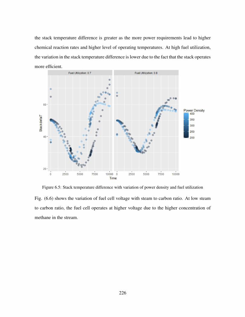
the stack temperature difference is greater as the more power requirements lead to higher
chemical reaction rates and higher level of operating temperatures. At high fuel utilization,
the variation in the stack temperature difference is lower due to the fact that the stack operates
more efficient.
Figure 6.5: Stack temperature difference with variation of power density and fuel utilization
Fig. (6.6) shows the variation of fuel cell voltage with steam to carbon ratio. At low steam
to carbon ratio, the fuel cell operates at higher voltage due to the higher concentration of
methane in the stream.
226

Figure 6.6: voltage variation at different fuel utilizations and steam to carbon ratio
Fig. (6.7) shows the stack temperature gradient at different levels of oxygen utilizations.
At lower fuel utilization, the stack temperature gradient is higher. The oscillation of stack
temperature difference is higher at low fuel utilization.
227

Figure 6.7: Stack temperature difference at different oxygen and fuel utilizations
6.1.4 SYSTEM MODELING
The prototype system developed at NFCRC consists of solid oxide fuel cell (SOFC), gas
turbine system, fuel preheater, fuel cell bypass and heat exchanger bypass valves.
The compressor module consists of compressor map that calculates flow rate and efficiency
of the compressor and gets the air flow rate, outlet pressure of the compressor and the ro-
tational speed of the compressor as an input. The model solves the energy balance of the
compressor. The system consists of fuel cell bypass.
Fuel cell mathematical modeling:
The mathematical modeling of the fuel cell stack has been developed in several studies by
McLarty et al.. The system is consisted of 3D model that resolves heat transfer and fluid
dynamics equations through in electrode and electrolyte layers. Eq. (6.3) to Eq. (6.4)
governs the temperature state of the solid portion of heat exchanger, and includes the heat
228

transfer from both fluids and the conductive heat transfer between adjacent segments.
QHT = hcAsurf (Tin+Tout
2− Tsolid)
(6.3)
dToutdt
=(h.n)in−out−hcAsur(
Tin+Tout2
−Tsolid)
CpVnodeC
(6.4)
The spatial discretization is generalized into n control volumes. The fuel cell modeling
includes 2-D spatial discretization of the heat exchanger.
6.1.5 GAS TURBINE DYNAMIC MODEL
A dynamic compressor and turbine model developed utilizing dynamic conversation equa-
tions and industry standard performance maps. The approach solves a dynamic torque bal-
ance equation for the shaft and includes mass storage for stall/surge analysis. The com-
pressor model inputs include inlet temperature, pressure, and species concentrations, shaft
speed, and an exhaust pressure. The flow rate supplied by the compressor and compression
efficiency are determined from the empirical correlations using turbine speed, pressure ratio,
and inlet temperature.
NRPM = RPM√
T0Tdes
.RPMdes
(6.5)
229
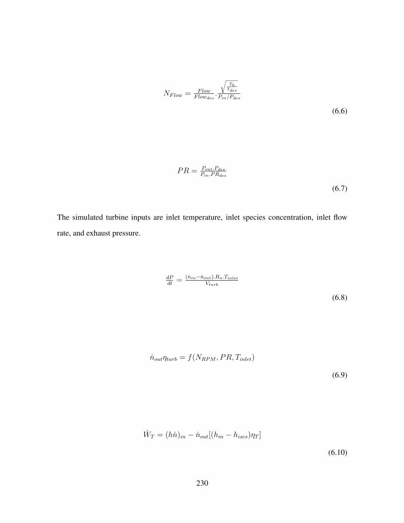
NFlow = FlowF lowdes
.
√T0Tdes
Pin/Pdes
(6.6)
PR = Pout.PdesPin.PRdes
(6.7)
The simulated turbine inputs are inlet temperature, inlet species concentration, inlet flow
rate, and exhaust pressure.
dPdt
= (nin−nout).Ru.TinletVturb
(6.8)
noutηturb = f(NRPM , PR, Tinlet)
(6.9)
WT = (hn)in − nout[(hin − hises)ηT ]
(6.10)
230

dTsdt
=hcA(Tf−Ts)+εσA(T 4
a−T 4s c)
cpm
(6.11)
dωdt
= (WT−WCWGEN )ωI0
(6.12)
I0 = ρLπr4
2
(6.13)
The recuperated gas turbine models have been calibrated regarding their efficiency and mass
flow rate versus power generation for C65 gas turbine. The off-design performance are
calibrated to test data at UC Irvine. The model has been compared to NETL facility to
validate the open loop control response to fuel valve step change.
6.2 ROUTE SIMULATION
The simulated route for the simulation is the railroad from Bakersfield to Mojave. The
elevation profile of the map has been obtained from Google API console. This route includes
the famous Tehachapi loop. Fig. (6.8) shows the prototype model design of 1 MW solid
oxide fuel cell - gas turbine system.
231

Figure 6.8: Prototype design of a 1 MW switcher locomotive
Fig. (6.9) shows the implementation of notching system.
Figure 6.9: Vehicle and Notching dynamic modeling
Notching Algorithm is as follows:
- The maximum desired train velocity was 60 miles per hour (26.82 meters per second).
232

- The power notching had to progress by one notch at a time, whether increasing or decreas-
ing notch. This decision could be made at every time step of the overall simulation
- The same restriction was placed on the notching for braking
- A power notch of both zero and one indicated 25% system power; however, notch
- A notch of zero on both power and braking indicated a coasting situation.
- The sign of the grade (whether uphill or downhill) could influence the decision-making
process.
- Acceleration influences the decision-making process
233
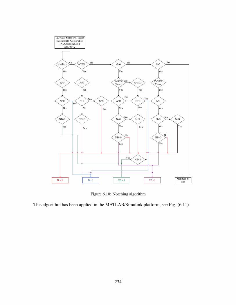
Figure 6.10: Notching algorithm
This algorithm has been applied in the MATLAB/Simulink platform, see Fig. (6.11).
234

Figure 6.11: Vehicle dynamics algorithm implementation
Fig. (6.11) shows the dynamics of locomotive notching over the Bakersfield-Mojave route.
Figure 6.12: Notching dynamics over Bakersfield-Mojave Route
Fig. (6.13) shows the dynamics power requirements over the Bakersfield-Mojave route.
235

Figure 6.13: Power Dynamics over Bakersfield-Mojave Route
Fig. (6.14) shows the acceleration profile over the Bakersfield-Mojave route.
Figure 6.14: Acceleration dynamics over Bakersfield-Mojave Route
Fig. (6.15) shows the dynamics of the speed that is controlled at 26 m/s.
Figure 6.15: Speed dynamics over Bakersfield-Mojave Route
The current model of SOFC-GT system does not respond to high dynamic power profile.
Due to high amount of computation in the system level of the MATLAB/Simulink platform, a
236
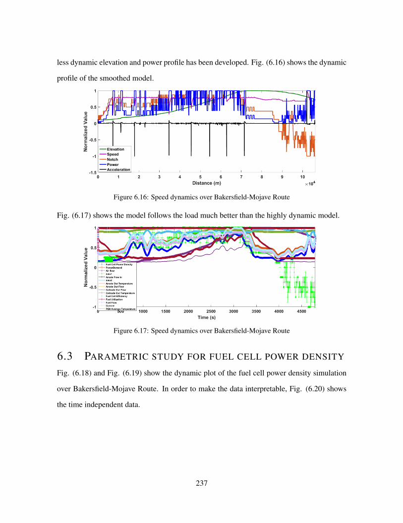
less dynamic elevation and power profile has been developed. Fig. (6.16) shows the dynamic
profile of the smoothed model.
Figure 6.16: Speed dynamics over Bakersfield-Mojave Route
Fig. (6.17) shows the model follows the load much better than the highly dynamic model.
Figure 6.17: Speed dynamics over Bakersfield-Mojave Route
6.3 PARAMETRIC STUDY FOR FUEL CELL POWER DENSITY
Fig. (6.18) and Fig. (6.19) show the dynamic plot of the fuel cell power density simulation
over Bakersfield-Mojave Route. In order to make the data interpretable, Fig. (6.20) shows
the time independent data.
237

Figure 6.18: Fuel cell power Density variation with fuel utilization and time
Fig. (6.19) shows the data of fuel cell power density based on air flow and fuel utilization
for Bakersfield-Mojave railroad path. The data is accumulated over time range of simula-
tion. In general, the data demonstrates strong independency of fuel cell operation from the
air flow. However there is strong correlation between the power density and the fuel utiliza-
tion. At higher load power, where locomotive requires maximum traction force, higher fuel
utilization is needed. The graph shows that the locomotive performance needs a high fuel
utilization from 0.75 to 0.8. An economic algorithms can be developed to reduce the amount
of fuel that is used in the locomotive.
238

Figure 6.19: Fuel cell power Density variation with fuel utilization and cathode outlet temperature
Fig. (6.20) and Fig. (6.21) show the parametric analysis for fuel cell power density over
fuel and oxygen utilization over the Bakersfield-Mojave route. The power profile is highly
dependent on the fuel and oxygen utilizations. The performance data is accumulated over
the time range of the simulation. Power profile is highly dependent on the fuel and oxygen
utilizations. The performance data is accumulated over the time range of the simulation.
Strong independency of fuel cell operation from the air flow rate is observed.
239

Figure 6.20: Fuel Cell Power Density data over Bakersfield-Mojave route
Figure 6.21: Interactive plot of fuel Cell Power Density data, and fuel cell efficiency over Bakersfield-Mojave route
240

CHAPTER 7
SUMMARY AND CONCLUSIONS
7.1 SUMMARY
This research presents a review of part-load and transient operation, dynamics, control and
optimization of hybrid solid oxide fuel cell - gas turbine (SOFC-GT) systems for various
system configurations. Different types of stall/surge control strategies have been discussed.
System optimization, CO2 capture and integration of hybrid SOFC-GT system with other
cycles are summarized. The main conclusions of this thesis are as follows:
- In this effort, compressor stall/surge is investigated, that could significantly affect hybrid
SOFC-GT system performance during sudden power demand perturbations. A multi-stage
compressor was designed with a configuration similar to that available in an industrial multi-
stage compressor (a similar design can be found in the 1.7 MW Kawasaki gas turbine model
GPB17). This type of compressor in a 4 MW hybrid SOFC-GT locomotive engine. The
transient operation of this type of industrial centrifugal compressor was analyzed using com-
putational fluid dynamics (CFD) tools, which provided insights regarding the flow distri-
bution in the compressor impellers during dynamic hybrid system operation. A transient
pressure boundary condition that resulted from a load perturbation applied in a hybrid sys-
241

tem dynamic simulation was applied to the CFD model of the compressor. The CFD model
resolved the compressor dynamics that occurred in response to the pressure perturbation near
the stall/surge limit line. The multi-stage compressor was shown to be robust to the pressure
dynamics investigated, making it suitable (able to handle pressure perturbation of interest
without going into deep stall/surge) for use in hybrid SOFC-GT stationary and locomotive
applications. The multi-stage compressor is able to keep the air flow rate positive over the
period of transient operation which prevents the flow from entering the severe deep surge
region, which could otherwise lead to the hybrid system failure.
- Various design and control concepts for dynamic operation of hybrid SOFC-GT systems
have been investigated and have demonstrated viable strategies for safe operation of the
system with turbomachinery that exhibits constant shaft speed or variable shaft speed. In
the case of variable turbine speed, as the speed of the turbine changes, additional control
algorithms are required for handling the pressure fluctuations in the stack, making sure that
they are not detrimental to stack operation or degradation.
- Considering the fact that few hybrid SOFC-GT systems have been built to-date, the litera-
ture regarding transient operation and control of such systems in remarkably rich. Extensive
numerical modeling studies suggest that such hybrid systems can be designed to be quite
controllable, robust to handling perturbations of various kinds, and even capable of high-
ly dynamic operation. However, various experimental results show that obstacles are still
present, suggesting that additional research and development of control strategies for tran-
sient operation may be required. Experimental investigation of transient hybrid operation is
especially recommended since only a very limited number of prototype systems have been
developed and evaluated to-date.
- The control of SOFC-GT systems has been studied extensively in the literature with model-
s. The main research gap for SOFC-GT system includes robust control systems development
that are demonstrated for dynamic operation of physical SOFC-GT systems. The studies
242

show that controlling these systems to meet the power demand is critical and challenging,
but possible with proper system design, control architecture, and control parameter selection.
This remains a significant need for developing control strategies that can forestall or elimi-
nate various degradation mechanisms, such as steep thermal gradients, fast electrical, flow, or
thermal transients, anode fuel starvation, thermal management of all components, compres-
sor stall and surge, etc. Additional challenges in hybrid SOFC-GT systems are associated
with compressors that are sensitive to air density, so that the compressor work demand in-
creases as air temperature increases. Since the fuel cell operates at a fixed temperature, some
researchers have found it challenging to maintain sufficient compressor mass flow at high
ambient temperature.
- The transient operation of industrial centrifugal compressor performance using computa-
tional fluid dynamics (CFD) tools was analyzed, which provided insights regarding the flow
distribution in the compressor impellers. In order to simulate the real world compressor op-
eration in the 500 kW test hybrid SOFC-GT system, a transient pressure boundary condition
that resulted from a previous hybrid system dynamic simulation was applied to the compres-
sor configurations. The pressure step change that resulted from the transient hybrid system
response to a load perturbation, corresponded to a sudden change of compressor dynamics
near the surge limit line. The single-stage compressor was shown to be robust to the pressure
dynamics and would be suitable for use in hybrid SOFC-GT applications. The single-stage
compressor is able to keep air flow over the period of transient operation while preventing
the flow entering the severe deep surge region, which could otherwise lead to hybrid system
failure.
- A MATLAB platform was developed for components of hybrid SOFC-GT system that
could capture the transient operation of a hybrid engine in a locomotive as a response to the
locomotive power requirements. Initial results of the fuel cell and gas turbine were obtained
from the MATLAB code.
243
- Finally, the feasibility of a hybrid SOFC-GT system was investigated regarding the system
sizing. The balance of plant and the main components of the system were sized through de-
tailed calculation and a general schematic of the system sizing was generated and compared
to the actual size of the GE dash 9 locomotive.
7.2 CONCLUSION
The main conclusions of this dissertation are as follows:
- Single-stage compressor, similar to the compressor used in the 200 kW Capstone micro gas
turbine (C-200) could be possibly used in 500 kW hybrid SOFC-GT locomotive test engine.
- A multi-stage compressor is shown to be robust to the pressure dynamics and suitable for
use in hybrid SOFC-GT applications.
- Single-stage compressor, similar to the compressor used in 200 kW Capstone micro gas
turbine (C-200) could be possibly used in 500 kW hybrid SOFC-GT locomotive test engine
- A multi-stage compressor is shown to be robust to the pressure dynamics and suitable for
use in hybrid SOFC-GT applications.
- A SOFC - GT can fit the dimensions of conventional long-haul diesel-electric locomotives.
- Compressor stall/surge, can significantly affect hybrid SOFC-GT system performance dur-
ing sudden power demand perturbations.
- A multi-stage compressor, similar to the compressor used in 1.7 MW Kawasaki (GPB17),
is amenable for use in 4 MW hybrid SOFC-GT system long-haul locomotive system.
- The multi-stage compressor maintains air flow over the period of transient operation and
thereby prevents the flow entering the severe deep surge region, which could otherwise lead
to hybrid system failure. Proper design of control systems that can maintain the compressor
mass flow rate can significantly reduce risk stall/surge in hybrid SOFC-GT system.
- Future control algorithms can reduced the delay time between the surge and reaching to the
design air mass flow rate.
244

BIBLIOGRAPHY
[1] Subhash C Singhal. Solid oxide fuel cells for stationary, mobile, and military appli-
cations. Solid State Ionics, 152:405–410, 2002.
[2] S Samuelsen and J Brouwer. Fuel cell/gas turbine hybrid. Encyclopedia of Electro-
chemical Power Sources, pages 124–134, 2009.
[3] Andrew S Martinez, Jacob Brouwer, and G Scott Samuelsen. Feasibility study for
sofc-gt hybrid locomotive power: Part i. development of a dynamic 3.5 mw sofc-gt
fortran model. Journal of Power Sources, 213:203–217, 2012.
[4] Andrew S Martinez, Jacob Brouwer, and G Scott Samuelsen. Feasibility study for
sofc-gt hybrid locomotive power part ii. system packaging and operating route simu-
lation. Journal of Power Sources, 213:358–374, 2012.
[5] Andrew S Martinez, Jacob Brouwer, and G Scott Samuelsen. Comparative analysis of
sofc–gt freight locomotive fueled by natural gas and diesel with onboard reformation.
Applied Energy, 148:421–438, 2015.
[6] L Barelli, G Bidini, and A Ottaviano. Part load operation of sofc/gt hybrid systems:
Stationary analysis. international journal of hydrogen energy, 37(21):16140–16150,
2012.
245

[7] Fuel cells for buildings and stationary applications roadmap. Energetics Incorporated,
2002.
[8] Ibrahim Dincer and C Ozgur Colpan. Introduction to stationary fuel cells. Solid oxide
fuel cells: from materials to system modeling. The Royal Society of Chemistry, pages
1–25, 2013.
[9] Thomas G Benjamin, Elias H Camara, and Leonard G Marianowski. Handbook of
fuel cell performance. Technical report, Institute of Gas Technology, Chicago, IL
(USA), 1980.
[10] James Larminie, Andrew Dicks, and Maurice S McDonald. Fuel cell systems ex-
plained, volume 2. Wiley New York, 2003.
[11] Fuel cell handbook. US Department of Energy, seventh edition, 2004.
[12] Gregor Hoogers. Fuel cell technology handbook. CRC press, 2014.
[13] Michael Homel, Turgut M Gur, Joon Ho Koh, and Anil V Virkar. Carbon monoxide-
fueled solid oxide fuel cell. Journal of Power Sources, 195(19):6367–6372, 2010.
[14] Qingfeng Li, Ronghuan He, Ji-An Gao, Jens Oluf Jensen, and Niels J Bjerrum. The
co poisoning effect in pemfcs operational at temperatures up to 200 c. Journal of the
Electrochemical Society, 150(12):A1599–A1605, 2003.
[15] J Staniforth and K Kendall. Cannock landfill gas powering a small tubular solid oxide
fuel cella case study. Journal of power sources, 86(1):401–403, 2000.
[16] K Sasaki, K Watanabe, K Shiosaki, K Susuki, and Y Teraoka. Multi-fuel capability
of solid oxide fuel cells. Journal of electroceramics, 13(1-3):669–675, 2004.
246

[17] A Lindermeir, S Kah, S Kavurucu, and M Muhlner. On-board diesel fuel processing
for an sofc–aputechnical challenges for catalysis and reactor design. Applied Catalysis
B: Environmental, 70(1):488–497, 2007.
[18] WA McPhee, L Bateman, M Koslowske, M Slaney, Z Uzep, J Bentley, and T Tao. Di-
rect jp-8 conversion using a liquid tin anode solid oxide fuel cell (lta-sofc) for military
applications. Journal of Fuel Cell Science and Technology, 8(4):041007, 2011.
[19] Kaushik Rajashekara. Hybrid fuel-cell strategies for clean power generation. Industry
Applications, IEEE Transactions on, 41(3):682–689, 2005.
[20] Ryan P O’Hayre, Suk-Won Cha, Whitney Colella, and Fritz B Prinz. Fuel cell funda-
mentals. John Wiley & Sons New York, 2006.
[21] Massimo Bertoldi, Olivier Bucheli, and Alberto Ravagni. Development, manufac-
turing and deployment of sofc-based products at solidpower. ECS Transactions,
68(1):117–123, 2015.
[22] KR Sridhar, James F McElroy, John E Finn, Fred Mitlitsky, and Matthias Gottman-
n. Co-production of hydrogen and electricity in a high temperature electrochemical
system, January 27 2009. US Patent 7,482,078.
[23] SPS Badwal and K Foger. Solid oxide electrolyte fuel cell review. Ceramics Interna-
tional, 22(3):257–265, 1996.
[24] Paola Costamagna, Azra Selimovic, Marco Del Borghi, and Gerry Agnew. Elec-
trochemical model of the integrated planar solid oxide fuel cell (ip-sofc). Chemical
Engineering Journal, 102(1):61–69, 2004.
[25] Raymond A George. Status of tubular sofc field unit demonstrations. Journal of
Power Sources, 86(1):134–139, 2000.
247

[26] YOSHINORI Kobayashi, YOSHIMASA Ando, Tatsuo Kabata, Masanori Nishiu-
ra, Kazuo Tomida, and Norihisa Matake. Extremely high-efficiency thermal power
system-solid oxide fuel cell (sofc) triple combined-cycle system. Mitsubishi Heavy
Industries Technical Review, 48(3):9–15, 2011.
[27] F JGARDNER Gardner, MJ Day, NP Brandon, MN Pashley, and M Cassidy. Sofc
technology development at rolls-royce. Journal of Power Sources, 86(1):122–129,
2000.
[28] http://www.atrexenergy.com/technology/about-atrex-tubular-sofc.
[29] Subhash Singhal. High-temperature solid oxide fuel cells: fundamentals, design and
applications: fundamentals, design and applications. Elsevier, 2003.
[30] Jack Brouwer. Hybrid gas turbine fuel cell systems. 2006.
[31] GA Richards, MM McMillian, RS Gemmen, Wl A Rogers, and SR Cully. Issues
for low-emission, fuel-flexible power systems. Progress in Energy and Combustion
Science, 27(2):141–169, 2001.
[32] David L Daggett, Stephan Eelman, and Gustav Kristiansson. Fuel cell apu for com-
mercial aircraft. In AIAA/ICAS International Air and Space Symposium and Exposi-
tion, OH, July, 2003.
[33] Mohammad Ali Azizi, Jacob Brouwer, and Derek Dunn-Rankin. Analytical inves-
tigation of high temperature 1kw solid oxide fuel cell system feasibility in methane
hydrate recovery and deep ocean power generation. Applied Energy, 179:909–928,
2016.
248

[34] P Aguiar, DJL Brett, and NP Brandon. Solid oxide fuel cell/gas turbine hybrid system
analysis for high-altitude long-endurance unmanned aerial vehicles. international
journal of hydrogen energy, 33(23):7214–7223, 2008.
[35] Kaushik Rajashekara, James Grieve, and David Daggett. Hybrid fuel cell power in
aircraft. Industry Applications Magazine, IEEE, 14(4):54–60, 2008.
[36] Penyarat Chinda and Pascal Brault. The hybrid solid oxide fuel cell (sofc) and gas
turbine (gt) systems steady state modeling. international journal of hydrogen energy,
37(11):9237–9248, 2012.
[37] Xiongwen Zhang, SH Chan, Guojun Li, HK Ho, Jun Li, and Zhenping Feng. A
review of integration strategies for solid oxide fuel cells. Journal of Power Sources,
195(3):685–702, 2010.
[38] Wolfgang Winkler, Pedro Nehter, Mark C Williams, David Tucker, and Randy Gem-
men. General fuel cell hybrid synergies and hybrid system testing status. Journal of
Power Sources, 159(1):656–666, 2006.
[39] Abbie Layne, S Samuelsen, M Williams, and Patricia Hoffman. Developmental status
of hybrids. ASME Paper, 1999.
[40] John D Leeper. The hybrid cycle: integration of a fuel cell with a gas turbine. In
ASME 1999 International Gas Turbine and Aeroengine Congress and Exhibition,
pages V002T02A067–V002T02A067. American Society of Mechanical Engineers,
1999.
[41] Sy A Ali and Robert R Moritz. the hybrid cycle: Integration of turbomachinery with
a fuel cell. ASME Paper, (99-GT):361, 1999.
249
[42] Eric A Liese, Randall S Gemmen, Faryar Jabbari, and Jacob Brouwer. Technical
development issues and dynamic modeling of gas turbine and fuel cell hybrid systems.
ASME Paper, (99-GT):360, 1999.
[43] Anthony J Leo, Hossein Ghezel-Ayagh, and Robert Sanderson. Ultra high efficien-
cy hybrid direct fuel cell/turbine power plant. In ASME Turbo Expo 2000: Power
for Land, Sea, and Air, pages V002T02A066–V002T02A066. American Society of
Mechanical Engineers, 2000.
[44] AD Rao and GS Samuelsen. Analysis strategies for tubular sofc based hybrid systems.
In ASME Turbo Expo 2000: Power for Land, Sea, and Air, pages V002T02A067–
V002T02A067. American Society of Mechanical Engineers, 2000.
[45] Sy A Ali and Robert R Moritz. A turbogenerator for fuel cell/gas turbine hybrid
power plant. In ASME Turbo Expo 2001: Power for Land, Sea, and Air, pages
V002T02A066–V002T02A066. American Society of Mechanical Engineers, 2001.
[46] Richard Dennis, Scott Samuelsen, Mark Williams, Norm Holcombe, and Abbie
Layne. The national energy technology laboratorys hybrid power systems program.
In ASME Turbo Expo 2002: Power for Land, Sea, and Air, pages 817–822. American
Society of Mechanical Engineers, 2002.
[47] AD Rao, GS Samuelsen, FL Robson, and RA Geisbrecht. Power plant system config-
urations for the 21st century. In ASME Turbo Expo 2002: Power for Land, Sea, and
Air, pages 831–844. American Society of Mechanical Engineers, 2002.
[48] David P Bloomfield and Michael B Landau. Pressurized fuel cell power plant with
steam flow through the cells, August 10 1976. US Patent 3,973,993.
[49] David P Bloomfield. Pressurized fuel cell power plant with single reactant gas stream,
August 24 1976. US Patent 3,976,507.
250

[50] Michael B Landau. Pressurized fuel cell power plant with air bypass, August 24 1976.
US Patent 3,976,506.
[51] Paolo Pietrogrande and Francesco Giacobbe. Compressed air, hydrogen, fuel cell,
May 24 1994. US Patent 5,314,761.
[52] Rudolf Hendriks and Hendrik J Ankersmit. Installation for generating electrical ener-
gy, June 14 1994. US Patent 5,319,925.
[53] William F Domeracki, Wayne L Lundberg, Thomas E Dowdy, and JoAnn M Linder.
Integrated gas turbine solid oxide fuel cell system, May 9 1995. US Patent 5,413,879.
[54] Paul L Micheli, Mark C Williams, and Edward L Parsons. Indirect-fired gas turbine
bottomed with fuel cell, September 12 1995. US Patent 5,449,568.
[55] Hiroshi Shingai and Hideo Nishigaki. Fuel cell/gas turbine combined power genera-
tion system and method for operating the same, January 9 1996. US Patent 5,482,791.
[56] Michael S Hsu and Ethan D Hoag. Power generator including an electrochemical con-
verter; thermodynamics, thermoelectricity, December 2 1997. US Patent 5,693,201.
[57] William R Wolfe, Owen S Taylor, Theodore R Vasilow, Arthur L Wolfe, Joseph F
Pierre, and John W Wiss. Fuel cell powered propulsion system, October 21 1997. US
Patent 5,678,647.
[58] Mark J Skowronski. Power generation system utilizing turbine and fuel cell, Septem-
ber 22 1998. US Patent 5,811,201.
[59] Jens Palsson, Azra Selimovic, and Lars Sjunnesson. Combined solid oxide fuel cell
and gas turbine systems for efficient power and heat generation. Journal of power
sources, 86(1):442–448, 2000.
251

[60] Jens Palsson, Azra Selimovic, and Peter Hendriksen. Intermediate temperature sofc in
gas turbine cycles. In ASME Turbo Expo 2001: Power for Land, Sea, and Air, pages
V002T04A002–V002T04A002. American Society of Mechanical Engineers, 2001.
[61] Shinji Kimijima and Nobuhide Kasagi. Performance evaluation of gas turbine-fuel
cell hybrid micro generation system. In ASME Turbo Expo 2002: Power for Land,
Sea, and Air, pages 351–360. American Society of Mechanical Engineers, 2002.
[62] Bong-Hyang Bae, Jeong L Sohn, and Sung Tack Ro. Thermodynamic modeling and
performance analysis of a power generation system based on the solid oxide fuel cell.
In ASME 2003 1st International Conference on Fuel Cell Science, Engineering and
Technology, pages 307–314. American Society of Mechanical Engineers, 2003.
[63] Y Inui, S Yanagisawa, and T Ishida. Proposal of high performance sofc combined
power generation system with carbon dioxide recovery. Energy conversion and man-
agement, 44(4):597–609, 2003.
[64] SH Chan, HK Ho, and Y Tian. Multi-level modeling of sofc–gas turbine hybrid
system. International Journal of Hydrogen Energy, 28(8):889–900, 2003.
[65] SH Chan, HK Ho, and Y Tian. Modelling of simple hybrid solid oxide fuel cell and
gas turbine power plant. Journal of Power Sources, 109(1):111–120, 2002.
[66] SH Chan, HK Ho, and Y Tian. Modelling for part-load operation of solid oxide
fuel cell–gas turbine hybrid power plant. Journal of Power Sources, 114(2):213–227,
2003.
[67] Adrian Bejan and Michael J Moran. Thermal design and optimization. John Wiley &
Sons, 1996.
252

[68] Tushar Choudhary et al. Thermodynamic assessment of advanced sofc-blade cooled
gas turbine hybrid cycle. International Journal of Hydrogen Energy, 42(15):10248–
10263, 2017.
[69] SH Chan, CF Low, and OL Ding. Energy and exergy analysis of simple solid-oxide
fuel-cell power systems. Journal of Power Sources, 103(2):188–200, 2002.
[70] F Calise, A Palombo, and L Vanoli. Design and partial load exergy analysis of hybrid
sofc–gt power plant. Journal of Power Sources, 158(1):225–244, 2006.
[71] Aristide F Massardo and Loredana Magistri. Internal reforming solid oxide fuel cell
gas turbine combined cycles (irsofc-gt): Part bexergy and thermoeconomic analyses.
In ASME Turbo Expo 2001: Power for Land, Sea, and Air, pages V002T04A015–
V002T04A015. American Society of Mechanical Engineers, 2001.
[72] F Calise, M Dentice dAccadia, A Palombo, and L Vanoli. Simulation and exergy anal-
ysis of a hybrid solid oxide fuel cell (sofc)–gas turbine system. Energy, 31(15):3278–
3299, 2006.
[73] Pegah Ghanbari Bavarsad. Energy and exergy analysis of internal reforming solid
oxide fuel cell–gas turbine hybrid system. International Journal of Hydrogen Energy,
32(17):4591–4599, 2007.
[74] Y Haseli, I Dincer, and GF Naterer. Thermodynamic modeling of a gas turbine cycle
combined with a solid oxide fuel cell. International Journal of Hydrogen Energy,
33(20):5811–5822, 2008.
[75] Y Haseli, I Dincer, and GF Naterer. Thermodynamic analysis of a combined gas
turbine power system with a solid oxide fuel cell through exergy. Thermochimica
Acta, 480(1):1–9, 2008.
253
[76] Sadegh Motahar and Ali Akbar Alemrajabi. Exergy based performance analysis of a
solid oxide fuel cell and steam injected gas turbine hybrid power system. international
journal of hydrogen energy, 34(5):2396–2407, 2009.
[77] Fahad A Al-Sulaiman, Ibrahim Dincer, and Feridun Hamdullahpur. Exergy analysis
of an integrated solid oxide fuel cell and organic rankine cycle for cooling, heating
and power production. Journal of power sources, 195(8):2346–2354, 2010.
[78] A Fernandes, T Woudstra, and PV Aravind. System simulation and exergy analysis on
the use of biomass-derived liquid-hydrogen for sofc/gt powered aircraft. International
Journal of Hydrogen Energy, 40(13):4683–4697, 2015.
[79] Anastassios Stamatis, Christina Vinni, Diamantis Bakalis, Fotini Tzorbatzoglou, and
Panagiotis Tsiakaras. Exergy analysis of an intermediate temperature solid oxide fuel
cell-gas turbine hybrid system fed with ethanol. Energies, 5(11):4268–4287, 2012.
[80] David J White. Hybrid gas turbine and fuel cell systems in perspective review. ASME
paper, (99-GT):419, 1999.
[81] Stephen E Veyo and Wayne L Lundberg. Solid oxide fuel cell power system cycles.
ASME paper, (99-GT):356, 1999.
[82] Ashok Domalpalli Rao and GS Samuelsen. A thermodynamic analysis of tubular sofc
based hybrid systems. In ASME Turbo Expo 2001: Power for Land, Sea, and Air,
pages V002T02A065–V002T02A065. American Society of Mechanical Engineers,
2001.
[83] George T Lee and Frederick A Sudhoff. Fuel cell/gas turbine system performance
studies. Technical report, USDOE Morgantown Energy Technology Center, WV (U-
nited States), 1996.
254
[84] SC Singhal. Advances in solid oxide fuel cell technology. Solid state ionics,
135(1):305–313, 2000.
[85] Ruixian Fang, Wei Jiang, Jamil Khan, and Roger Dougal. System-level thermal mod-
eling and co-simulation with hybrid power system for future all electric ship. In Elec-
tric Ship Technologies Symposium, 2009. ESTS 2009. IEEE, pages 547–553. IEEE,
2009.
[86] Kaushik Rajashekara, James Grieve, and David Daggett. Solid oxide fuel cell/gas tur-
bine hybrid apu system for aerospace applications. In Industry Applications Confer-
ence, 2006. 41st IAS Annual Meeting. Conference Record of the 2006 IEEE, volume 5,
pages 2185–2192. IEEE, 2006.
[87] Robert Tornabene, Xiao-yen Wang, Christopher J Steffen, and Joshua E Freeh. De-
velopment of parametric mass and volume models for an aerospace sofc/gas turbine
hybrid system. In ASME Turbo Expo 2005: Power for Land, Sea, and Air, pages
135–144. American Society of Mechanical Engineers, 2005.
[88] Christopher J Steffen, Joshua E Freeh, and Louis M Larosiliere. Solid oxide fuel
cell/gas turbine hybrid cycle technology for auxiliary aerospace power. In ASME
Turbo Expo 2005: Power for Land, Sea, and Air, pages 253–260. American Society
of Mechanical Engineers, 2005.
[89] Joshua E Freeh, Christopher J Steffen, and Louis M Larosiliere. Off-design perfor-
mance analysis of a solid-oxide fuel cell/gas turbine hybrid for auxiliary aerospace
power. In ASME 2005 3rd International Conference on Fuel Cell Science, Engi-
neering and Technology, pages 265–272. American Society of Mechanical Engineers,
2005.
255

[90] Wolfgang Winkler and Hagen Lorenz. Design studies of mobile applications with
sofc–heat engine modules. Journal of power sources, 106(1):338–343, 2002.
[91] Pilar Lisbona and Luis M Romeo. Enhanced coal gasification heated by unmixed
combustion integrated with an hybrid system of sofc/gt. International Journal of
Hydrogen Energy, 33(20):5755–5764, 2008.
[92] Prapan Kuchonthara, Sankar Bhattacharya, and Atsushi Tsutsumi. Combination of
thermochemical recuperative coal gasification cycle and fuel cell for power genera-
tion. Fuel, 84(7):1019–1021, 2005.
[93] Richard Toonssen, Stefano Sollai, PV Aravind, Nico Woudstra, and Adrian HM
Verkooijen. Alternative system designs of biomass gasification sofc/gt hybrid sys-
tems. International journal of hydrogen energy, 36(16):10414–10425, 2011.
[94] Tobias Proell, Reinhard Rauch, Christian Aichernig, and Hermann Hofbauer. Cou-
pling of biomass steam gasification and an sofc-gas turbine hybrid system for highly
efficient electricity generation. In ASME Turbo Expo 2004: Power for Land, Sea, and
Air, pages 103–112. American Society of Mechanical Engineers, 2004.
[95] A Boudghene Stambouli and E Traversa. Solid oxide fuel cells (sofcs): a review of
an environmentally clean and efficient source of energy. Renewable and Sustainable
Energy Reviews, 6(5):433–455, 2002.
[96] AF Massardo and F Lubelli. Internal reforming solid oxide fuel cell-gas turbine com-
bined cycles (irsofc-gt): Part acell model and cycle thermodynamic analysis. In
ASME 1998 International Gas Turbine and Aeroengine Congress and Exhibition,
pages V003T08A028–V003T08A028. American Society of Mechanical Engineers,
1998.
256
[97] JH Hirschenhofer, DB Stauffer, RR Engleman, and MG Klett. Fuel cell handbook.
1998.
[98] Mark C Williams, Joseph P Strakey, and Subhash C Singhal. Us distributed generation
fuel cell program. Journal of Power Sources, 131(1):79–85, 2004.
[99] Stefano Campanari. Full load and part-load performance prediction for integrated
sofc and microturbine systems. Journal of Engineering for Gas Turbines and Power,
122(2):239–246, 2000.
[100] Sylvain Baudoini, Ionel Vechiu, Haritza Camblong, Jean-Michel Vinassa, Linda
Barelli, and Stephane Kreckelbergh. Analysis and validation of a biogas hybrid sofc/gt
emulator. In Intelligent Energy Systems (IWIES), 2014 IEEE International Workshop
on, pages 93–98. IEEE, 2014.
[101] Stephen E Veyo, Shailesh D Vora, Kavin P Litzinger, and Wayne L Lundberg. Status
of pressurized sofc/gas turbine power system development at siemens westinghouse.
In ASME Turbo Expo 2002: Power for Land, Sea, and Air, pages 823–829. American
Society of Mechanical Engineers, 2002.
[102] Koji Miyamoto, Masahiro Mihara, Hiroyuki Oozawa, Kenichi Hiwatashi, Kazuo
Tomida, Masanori Nishiura, Hiroshi Kishizawa, Ryutaro Mori, and Yoshinori
Kobayashi. Recent progress of sofc combined cycle system with segmented-in-series
tubular type cell stack at mhps. ECS Transactions, 68(1):51–58, 2015.
[103] Luca Larosa, Alberto Traverso, and Aristide F Massardo. Dynamic analysis of a recu-
perated mgt cycle for fuel cell hybrid systems. In ASME Turbo Expo 2016: Turboma-
chinery Technical Conference and Exposition, pages V003T06A015–V003T06A015.
American Society of Mechanical Engineers, 2016.
257

[104] Bernardo Restrepo, Larry E Banta, and David Tucker. Simulation of model predic-
tive control for a fuel cell/gas turbine power system based on experimental data and
the recursive identification method. In ASME 2016 14th International Conference
on Fuel Cell Science, Engineering and Technology collocated with the ASME 2016
Power Conference and the ASME 2016 10th International Conference on Energy Sus-
tainability, pages V001T04A004–V001T04A004. American Society of Mechanical
Engineers, 2016.
[105] Bernardo Restrepo, David Tucker, and Larry E Banta. Recursive system identification
and simulation of model predictive control based on experimental data to control the
cathode side parameters of the hybrid fuel cell/gas turbine. Journal of Electrochemical
Energy Conversion and Storage, 14(3):031004, 2017.
[106] Nor Farida Harun, David Tucker, and Thomas A Adams. Impact of fuel composi-
tion transients on sofc performance in gas turbine hybrid systems. Applied Energy,
164:446–461, 2016.
[107] Nor Farida Harun, David Tucker, and Thomas A Adams II. Technical challenges
in operating an sofc in fuel flexible gas turbine hybrid systems: Coupling effects of
cathode air mass flow. Applied Energy, 190:852–867, 2017.
[108] V Zaccaria, D Tucker, and A Traverso. Transfer function development for sofc/gt
hybrid systems control using cold air bypass. Applied Energy, 165:695–706, 2016.
[109] Valentina Zaccaria, Zachary Branum, and David Tucker. Fuel cell temperature control
with a precombustor in sofc gas turbine hybrids during load changes. Journal of
Electrochemical Energy Conversion and Storage, 14(3):031006, 2017.
[110] V Zaccaria, D Tucker, and A Traverso. Operating strategies to minimize degradation
in fuel cell gas turbine hybrids. Applied Energy, 2016.
258

[111] Tooran Emami, Alex Tsai, and David Tucker. Robust pid controller design of a solid
oxide fuel cell gas turbine. In ASME 2016 14th International Conference on Fuel Cell
Science, Engineering and Technology collocated with the ASME 2016 Power Confer-
ence and the ASME 2016 10th International Conference on Energy Sustainability,
pages V001T03A003–V001T03A003. American Society of Mechanical Engineers,
2016.
[112] Alex Tsai, David Tucker, and Tooran Emami. Multiple model adaptive estimation of
a hybrid solid oxide fuel cell gas turbine power plant simulator. In ASME 2016 14th
International Conference on Fuel Cell Science, Engineering and Technology collo-
cated with the ASME 2016 Power Conference and the ASME 2016 10th International
Conference on Energy Sustainability, pages V001T03A004–V001T03A004. Ameri-
can Society of Mechanical Engineers, 2016.
[113] David Tucker, Larry Lawson, and Randall Gemmen. Characterization of air flow
management and control in a fuel cell turbine hybrid power system using hardware
simulation. In ASME 2005 Power Conference, pages 959–967. American Society of
Mechanical Engineers, 2005.
[114] Nana Zhou, Chen Yang, and David Tucker. Evaluation of compressor bleed air
transients in a fuel cell gas turbine hybrid system using hardware simulation. In
ASME Turbo Expo 2015: Turbine Technical Conference and Exposition, pages
V003T06A021–V003T06A021. American Society of Mechanical Engineers, 2015.
[115] Mitchell Colby, Logan Yliniemi, Paolo Pezzini, David Tucker, Kenneth Mark Bry-
den, and Kagan Tumer. Multiobjective neuroevolutionary control for a fuel cell tur-
bine hybrid energy system. In Proceedings of the 2016 on Genetic and Evolutionary
Computation Conference, pages 877–884. ACM, 2016.
259

[116] Nor Farida Harun, David Tucker, and Thomas A Adams. Open loop and closed loop
performance of solid oxide fuel cell turbine hybrid systems during fuel composition
changes. In ASME Turbo Expo 2015: Turbine Technical Conference and Exposition,
pages V003T06A023–V003T06A023. American Society of Mechanical Engineers,
2015.
[117] David Tucker, Larry Lawson, and Randy Gemmen. Preliminary results of a cold flow
test in a fuel cell gas turbine hybrid simulation facility. In ASME Turbo Expo 2003,
collocated with the 2003 International Joint Power Generation Conference, pages
281–287. American Society of Mechanical Engineers, 2003.
[118] Dimitri Hughes, William J Wepfer, Kevin Davies, J Christopher Ford, Comas Haynes,
and David Tucker. A real-time spatial sofc model for hardware-based simulation of
hybrid systems. In ASME 2011 9th International Conference on Fuel Cell Science,
Engineering and Technology collocated with ASME 2011 5th International Confer-
ence on Energy Sustainability, pages 409–428. American Society of Mechanical En-
gineers, 2011.
[119] Nana Zhou, Chen Yang, David Tucker, Paolo Pezzini, and Alberto Traverso. Transfer
function development for control of cathode airflow transients in fuel cell gas turbine
hybrid systems. International Journal of Hydrogen Energy, 40(4):1967–1979, 2015.
[120] Matteo Pascenti, Mario L Ferrari, Loredana Magistri, and Aristide F Massardo. Micro
gas turbine based test rig for hybrid system emulation. ASME Paper No. GT2007-
27075, 2007.
[121] F Caratozzolo, ML Ferrari, A Traverso, and AF Massardo. Emulator rig for sofc
hybrid systems: Temperature and power control with a real-time software. Fuel Cells,
13(6):1123–1130, 2013.
260

[122] Martina Hohloch, Andreas Huber, and Manfred Aigner. Experimental investigation
of a sofc/mgt hybrid power plant test rig: Impact and characterization of a fuel cell
emulator. In ASME Turbo Expo 2016: Turbomachinery Technical Conference and
Exposition, pages V003T06A018–V003T06A018. American Society of Mechanical
Engineers, 2016.
[123] Martin Henke, Nikolai Klempp, Martina Hohloch, Thomas Monz, and Manfred Aign-
er. Validation of a t100 micro gas turbine steady-state simulation tool. ASME Paper
No. GT2015-42090, 2015.
[124] Wei-Hsiang Lai, Chi-An Hsiao, Chien-Hsiung Lee, Yau-Pin Chyou, and Yu-Ching
Tsai. Experimental simulation on the integration of solid oxide fuel cell and micro-
turbine generation system. Journal of power sources, 171(1):130–139, 2007.
[125] Abbie Layne, Scott Samuelsen, Mark Williams, and Patricia Hoffman. Hybrid heat
engines: the power generation systems of the future. In ASME Turbo Expo 2000: Pow-
er for Land, Sea, and Air, pages V002T02A063–V002T02A063. American Society
of Mechanical Engineers, 2000.
[126] Abbie Layne, Scott Samuelsen, Mark Williams, and Norman Holcombe. Hybrid fu-
el cell heat engines: recent efforts. In ASME Turbo Expo 2001: Power for Land,
Sea, and Air, pages V002T02A067–V002T02A067. American Society of Mechanical
Engineers, 2001.
[127] Wayne L Lundberg, Stephen E Veyo, and Mark D Moeckel. A high-efficiency sofc
hybrid power system using the mercury 50 ats gas turbine. In ASME Turbo Expo
2001: Power for Land, Sea, and Air, pages V002T02A064–V002T02A064. American
Society of Mechanical Engineers, 2001.
261
[128] R. Dennis. Hybrid fuel cell systems, 2003. International Colloquium on Environmen-
tally, Preferred Advanced Generation.
[129] Brian Tarroja, Fabian Mueller, Jim Maclay, and Jacob Brouwer. Parametric thermo-
dynamic analysis of a solid oxide fuel cell gas turbine system design space. Journal
of Engineering for Gas Turbines and Power, 132(7):072301, 2010.
[130] Osamu Azegami. Mcfc/mgt hybrid generation system. Target, 60:70, 2006.
[131] Dustin McLarty, Jack Brouwer, and Scott Samuelsen. Fuel cell–gas turbine hybrid
system design part i: Steady state performance. Journal of Power Sources, 257:412–
420, 2014.
[132] Annamaria Buonomano, Francesco Calise, Massimo Dentice dAccadia, Adolfo
Palombo, and Maria Vicidomini. Hybrid solid oxide fuel cells–gas turbine system-
s for combined heat and power: A review. Applied Energy, 156:32–85, 2015.
[133] Gerry D Agnew, Robert R Moritz, Colin Berns, Alan Spangler, O Tarnowski, and
Michele Bozzolo. A unique solution to low cost sofc hybrid power plant. In ASME
Turbo Expo 2003, collocated with the 2003 International Joint Power Generation
Conference, pages 657–664. American Society of Mechanical Engineers, 2003.
[134] Abdullatif Musa and Michel De Paepe. Performance of combined internally re-
formed intermediate/high temperature sofc cycle compared to internally reformed
two-staged intermediate temperature sofc cycle. international journal of hydrogen
energy, 33(17):4665–4672, 2008.
[135] WL Lundberg, SE Veyo, and MD Moeckel. A high-efficiency solid oxide fuel cell
hybrid power system using the mercury 50 advanced turbine systems gas turbine.
Journal of Engineering for Gas Turbines and Power, 125(1):51–58, 2003.
262

[136] Penyarat Saisirirat. The solid oxide fuel cell (sofc) and gas turbine (gt) hybrid system
numerical model. Energy Procedia, 79:845–850, 2015.
[137] Kevin P Litzinger, Stephen E Veyo, Larry A Shockling, and Wayne L Lundberg. Com-
parative evaluation of sofc/gas turbine hybrid system options. In ASME Turbo Expo
2005: Power for Land, Sea, and Air, pages 669–676. American Society of Mechanical
Engineers, 2005.
[138] Zhequan Yan, Pan Zhao, Jiangfeng Wang, and Yiping Dai. Thermodynamic analysis
of an sofc–gt–orc integrated power system with liquefied natural gas as heat sink.
International Journal of Hydrogen Energy, 38(8):3352–3363, 2013.
[139] Masoud Rokni. Thermodynamic analysis of an integrated solid oxide fuel cell cycle
with a rankine cycle. Energy conversion and management, 51(12):2724–2732, 2010.
[140] Hanfei Tuo. Energy and exergy-based working fluid selection for organic rankine
cycle recovering waste heat from high temperature solid oxide fuel cell and gas turbine
hybrid systems. International Journal of Energy Research, 37(14):1831–1841, 2013.
[141] Masood Ebrahimi and Iraj Moradpoor. Combined solid oxide fuel cell, micro-gas
turbine and organic rankine cycle for power generation (sofc–mgt–orc). Energy Con-
version and Management, 116:120–133, 2016.
[142] Valerie Eveloy, Wirinya Karunkeyoon, Peter Rodgers, and Ali Al Alili. Energy, ex-
ergy and economic analysis of an integrated solid oxide fuel cell–gas turbine–organic
rankine power generation system. International Journal of Hydrogen Energy, 2016.
[143] Xiaojing Lv, Chaohao Lu, Yuzhang Wang, and Yiwu Weng. Effect of operating pa-
rameters on a hybrid system of intermediate-temperature solid oxide fuel cell and gas
turbine. Energy, 91:10–19, 2015.
263

[144] Xiaojing Lv, Chenghong Gu, Xing Liu, and Yiwu Weng. Effect of gasified biomass
fuel on load characteristics of an intermediate-temperature solid oxide fuel cell and
gas turbine hybrid system. International Journal of Hydrogen Energy, 41(22):9563–
9576, 2016.
[145] Ju Hwan Choi, Ji Ho Ahn, and Tong Seop Kim. Performance of a triple power gener-
ation cycle combining gas/steam turbine combined cycle and solid oxide fuel cell and
the influence of carbon capture. Applied Thermal Engineering, 71(1):301–309, 2014.
[146] Zhenzhong Jia, Jing Sun, So-Ryeok Oh, Herb Dobbs, and Joel King. Control of the
dual mode operation of generator/motor in sofc/gt-based apu for extended dynamic
capabilities. Journal of Power Sources, 235:172–180, 2013.
[147] Junxi Jia, Abuliti Abudula, Liming Wei, Baozhi Sun, and Yue Shi. Effect of operating
parameters on performance of an integrated biomass gasifier, solid oxide fuel cells
and micro gas turbine system. Biomass and Bioenergy, 75:35–45, 2015.
[148] Michael Speidel, Gerard Kraaij, and Antje Worner. A new process concept for highly
efficient conversion of sewage sludge by combined fermentation and gasification and
power generation in a hybrid system consisting of a sofc and a gas turbine. Energy
Conversion and Management, 98:259–267, 2015.
[149] Valerie Eveloy, Peter Rodgers, and Linyue Qiu. Integration of an atmospheric solid
oxide fuel cell-gas turbine system with reverse osmosis for distributed seawater de-
salination in a process facility. Energy Conversion and Management, 126:944–959,
2016.
[150] Paul L Micheli, Mark C Williams, and Frederick A Sudhoff. Indirect-fired gas turbine
dual fuel cell power cycle, July 30 1996. US Patent 5,541,014.
264

[151] Ji Hye Yi, Joo Hwan Choi, and Tong Seop Kim. Comparative evaluation of viable
options for combining a gas turbine and a solid oxide fuel cell for high performance.
Applied Thermal Engineering, 100:840–848, 2016.
[152] SMS Mahmoudi and Leyla Khani. Thermodynamic and exergoeconomic assessments
of a new solid oxide fuel cell-gas turbine cogeneration system. Energy Conversion
and Management, 123:324–337, 2016.
[153] Arnab Choudhury, H Chandra, and A Arora. Application of solid oxide fuel cell tech-
nology for power generationa review. Renewable and Sustainable Energy Reviews,
20:430–442, 2013.
[154] S Campanari. Power plants based on solid oxide fuel cells combined with gas turbine
cycles. PhD thesis, Ph. D. thesis, Politecnico di Milano, Milano, 1998.
[155] P Costamagna, L Magistri, and AF Massardo. Design and part-load performance of a
hybrid system based on a solid oxide fuel cell reactor and a micro gas turbine. Journal
of Power Sources, 96(2):352–368, 2001.
[156] Stefano Campanari. Carbon dioxide separation from high temperature fuel cell power
plants. Journal of Power Sources, 112(1):273–289, 2002.
[157] Stefano Campanari. Thermodynamic model and parametric analysis of a tubular sofc
module. Journal of power sources, 92(1):26–34, 2001.
[158] Stephen E Veyo, Larry A Shockling, Jeffrey T Dederer, James E Gillett, and Wayne L
Lundberg. Tubular solid oxide fuel cell/gas turbine hybrid cycle power systemsstatus.
In ASME Turbo Expo 2000: Power for Land, Sea, and Air, pages V002T02A064–
V002T02A064. American Society of Mechanical Engineers, 2000.
265

[159] Hossein Ghezel-Ayagh, Joseph M Daly, and Zhao-Hui Wang. Advances in direct fuel
cell/gas turbine power plants. In ASME Turbo Expo 2003, collocated with the 2003
International Joint Power Generation Conference, pages 625–629. American Society
of Mechanical Engineers, 2003.
[160] Hossein Ghezel-Ayagh, Jim Walzak, Dilip Patel, Joseph Daly, Hans Maru, Robert
Sanderson, and William Livingood. State of direct fuel cell/turbine systems develop-
ment. Journal of power sources, 152:219–225, 2005.
[161] Moritz Henke, Mike Steilen, Christian Schnegelberger, Marc Riedel, Martina
Hohloch, Sandro Bucheler, Melanie Herbst, Andreas Huber, Josef Kallo, and K An-
dreas Friedrich. Construction of a 30kw sofc gas turbine hybrid power plant. ECS
Transactions, 68(1):85–88, 2015.
[162] Nguyen Q Minh. Solid oxide fuel cell technologyfeatures and applications. Solid
State Ionics, 174(1):271–277, 2004.
[163] Tae Won Song, Jeong Lak Sohn, Tong Seop Kim, and Sung Tack Ro. Performance
characteristics of a mw-class sofc/gt hybrid system based on a commercially available
gas turbine. Journal of Power Sources, 158(1):361–367, 2006.
[164] Eric A Liese and Randall S Gemmen. Performance comparison of internal reforming
against external reforming in a solid oxide fuel cell, gas turbine hybrid system. Journal
of engineering for gas turbines and power, 127(1):86–90, 2005.
[165] Tae Won Song, Jeong Lak Sohn, Jae Hwan Kim, Tong Seop Kim, Sung Tack Ro,
and Kenjiro Suzuki. Performance analysis of a tubular solid oxide fuel cell/micro gas
turbine hybrid power system based on a quasi-two dimensional model. Journal of
Power Sources, 142(1):30–42, 2005.
266

[166] SH Chan, KA Khor, and ZT Xia. A complete polarization model of a solid oxide fuel
cell and its sensitivity to the change of cell component thickness. Journal of Power
Sources, 93(1):130–140, 2001.
[167] Yaofan Yi, Thomas P Smith, Jacob Brouwer, Ashok D Rao, and G Scot-
t SAMUELSEN. Simulation of a 220 kw hybrid sofc gas turbine system and data com-
parison. In Proceedings-Electrochemical Society, pages 1442–1454. Electrochemical
Society, 2003.
[168] Azra Selimovic and Jens Palsson. Networked solid oxide fuel cell stacks combined
with a gas turbine cycle. Journal of Power Sources, 106(1):76–82, 2002.
[169] Ulf G Bossel. Final report on sofc data facts and figures. Swiss Federal Office of
Energy, Berne, 1992.
[170] V Spallina, L Mastropasqua, P Iora, MC Romano, and S Campanari. Assessment
of finite volume modeling approaches for intermediate temperature solid oxide fuel
cells working with co-rich syngas fuels. International Journal of Hydrogen Energy,
40(43):15012–15031, 2015.
[171] L Magistri, A Traverso, AF Massardo, and RK Shah. Heat exchangers for fuel cell and
hybrid system applications. Journal of fuel cell science and technology, 3(2):111–118,
2006.
[172] Shinji Kimijima and Nobuhide Kasagi. Cycle analysis of gas turbine–fuel cell cycle
hybrid micro generation system. 2004.
[173] Hideyuki Uechi, Shinji Kimijima, and Nobuhide Kasagi. Cycle analysis of gas
turbine-fuel cell hybrid micro generation system. ASME Paper No. JPGC2001/PWR-
19171, 2001.
267
[174] Yaofan Yi, Ashok D Rao, Jacob Brouwer, and G Scott Samuelsen. Analysis and
optimization of a solid oxide fuel cell and intercooled gas turbine (sofc–icgt) hybrid
cycle. Journal of Power Sources, 132(1):77–85, 2004.
[175] Rory Roberts, Jack Brouwer, Faryar Jabbari, Tobias Junker, and Hossein Ghezel-
Ayagh. Control design of an atmospheric solid oxide fuel cell/gas turbine hybrid
system: Variable versus fixed speed gas turbine operation. Journal of Power sources,
161(1):484–491, 2006.
[176] Tak-Hyoung Lim, Rak-Hyun Song, Dong-Ryul Shin, Jung-Il Yang, Heon Jung,
IC Vinke, and Soo-Seok Yang. Operating characteristics of a 5kw class anode-
supported planar sofc stack for a fuel cell/gas turbine hybrid system. International
Journal of Hydrogen Energy, 33(3):1076–1083, 2008.
[177] LI Mu, Ashok D Rao, Jacob Brouwer, and G Scott Samuelsen. Design of highly
efficient coal-based integrated gasification fuel cell power plants. Journal of Power
Sources, 195(17):5707–5718, 2010.
[178] S Santhanam, C Schilt, B Turker, T Woudstra, and PV Aravind. Thermodynamic
modeling and evaluation of high efficiency heat pipe integrated biomass gasifier–solid
oxide fuel cells–gas turbine systems. Energy, 109:751–764, 2016.
[179] Matteo C Romano, Stefano Campanari, Vincenzo Spallina, and Giovanni Lozza.
Thermodynamic analysis and optimization of it-sofc-based integrated coal gasifica-
tion fuel cell power plants. Journal of Fuel Cell Science and Technology, 8(4):041002,
2011.
[180] Masoud Rokni. Thermodynamic analysis of sofc (solid oxide fuel cell)–stirling hybrid
plants using alternative fuels. Energy, 61:87–97, 2013.
268
[181] Dustin McLarty, Jack Brouwer, and Scott Samuelsen. Fuel cell–gas turbine hybrid
system design part ii: dynamics and control. Journal of Power Sources, 254:126–136,
2014.
[182] Priscilla Caliandro, Laurence Tock, Adriano V Ensinas, and Francois Marechal.
Thermo-economic optimization of a solid oxide fuel cell–gas turbine system fuelled
with gasified lignocellulosic biomass. Energy Conversion and Management, 85:764–
773, 2014.
[183] Xiaojing Lv, Xiaoru Geng, and Yiwu Weng. Thermodynamic analysis of solid oxide
fuel cell and gas turbine hybrid system fueled with gasified biomass. ele, 2:2, 2014.
[184] Emanuele Facchinetti, Martin Gassner, Matilde DAmelio, Francois Marechal, and
Daniel Favrat. Process integration and optimization of a solid oxide fuel cell–gas
turbine hybrid cycle fueled with hydrothermally gasified waste biomass. Energy,
41(1):408–419, 2012.
[185] Seyed Navid Roohani Isfahani and Ahmad Sedaghat. A hybrid micro gas turbine and
solid state fuel cell power plant with hydrogen production and co 2 capture. Interna-
tional Journal of Hydrogen Energy, 41(22):9490–9499, 2016.
[186] Dang Saebea, Loredana Magistri, Aristide Massardo, and Amornchai Arporn-
wichanop. Cycle analysis of solid oxide fuel cell-gas turbine hybrid systems inte-
grated ethanol steam reformer: Energy management. Energy, 127:743–755, 2017.
[187] S Velumani, Carlo Enrique Guzman, Ricardo Peniche, and Ramon Vega. Proposal of
a hybrid chp system: Sofc/microturbine/absorption chiller. International Journal of
Energy Research, 34(12):1088–1095, 2010.
[188] L Barelli, G Bidini, and A Ottaviano. Integration of sofc/gt hybrid systems in micro-
grids. Energy, 2016.
269

[189] Christoph Stiller, Bjørn Thorud, Olav Bolland, Rambabu Kandepu, and Lars Imsland.
Control strategy for a solid oxide fuel cell and gas turbine hybrid system. Journal of
power sources, 158(1):303–315, 2006.
[190] Dustin Fogle McLarty. Fuel cell gas turbine hybrid design, control, and performance.
University of California, Irvine, 2010.
[191] Mario L Ferrari. Advanced control approach for hybrid systems based on solid oxide
fuel cells. Applied Energy, 145:364–373, 2015.
[192] Mario L Ferrari. Solid oxide fuel cell hybrid system: control strategy for stand-alone
configurations. Journal of Power Sources, 196(5):2682–2690, 2011.
[193] Zhenzhong Jia, Jing Sun, Herb Dobbs, and Joel King. Feasibility study of solid oxide
fuel cell engines integrated with sprinter gas turbines: Modeling, design and control.
Journal of Power Sources, 275:111–125, 2015.
[194] Rory A Roberts, Jack Brouwer, Eric Liese, and Randall S Gemmen. Development of
controls for dynamic operation of carbonate fuel cell-gas turbine hybrid systems. In
ASME Turbo Expo 2005: Power for Land, Sea, and Air, pages 325–331. American
Society of Mechanical Engineers, 2005.
[195] Rory Andrew Roberts. A dynamic fuel cell-gas turbine hybrid simulation methodology
to establish control strategies and an improved balance of plant. 2005.
[196] RA Roberts and Jack Brouwer. Dynamic simulation of a pressurized 220kw solid ox-
ide fuel-cell–gas-turbine hybrid system: Modeled performance compared to measured
results. Journal of fuel cell science and technology, 3(1):18–25, 2006.
270

[197] Jai-Woh Kim, Anil V Virkar, Kuan-Zong Fung, Karun Mehta, and Subhash C Sing-
hal. Polarization effects in intermediate temperature, anode-supported solid oxide fuel
cells. Journal of the Electrochemical Society, 146(1):69–78, 1999.
[198] Jens Palsson and Azra Selimovic. Design and off-design predictions of a combined
sofc and gas turbine system. In ASME Turbo Expo 2001: Power for Land, Sea, and
Air, pages V002T04A014–V002T04A014. American Society of Mechanical Engi-
neers, 2001.
[199] Loredana Magistri, Michele Bozzolo, Olivier Tarnowski, Gerry Agnew, and Aristide F
Massardo. Design and off-design analysis of a mw hybrid system based on rolls-
royce integrated planar sofc. In ASME Turbo Expo 2003, collocated with the 2003
International Joint Power Generation Conference, pages 173–180. American Society
of Mechanical Engineers, 2003.
[200] L Magistri, P Costamagna, AF Massardo, C Rodgers, and CF McDonald. A hybrid
system based on a personal turbine (5 kw) and a solid oxide fuel cell stack: a flexi-
ble and high efficiency energy concept for the distributed power market. Journal of
engineering for gas turbines and power, 124(4):850–857, 2002.
[201] A Traverso, L Magistri, and AF Massardo. Turbomachinery for the air management
and energy recovery in fuel cell gas turbine hybrid systems. Energy, 35(2):764–777,
2010.
[202] Y Komatsu, S Kimijima, and JS Szmyd. Performance analysis for the part-load oper-
ation of a solid oxide fuel cell–micro gas turbine hybrid system. Energy, 35(2):982–
988, 2010.
271

[203] Jin Sik Yang, Jeong L Sohn, and Sung Tack Ro. Performance characteristics of part-
load operations of a solid oxide fuel cell/gas turbine hybrid system using air-bypass
valves. Journal of Power Sources, 175(1):296–302, 2008.
[204] Alberto Traverso, Aristide Massardo, Rory A Roberts, Jack Brouwer, and Scot-
t Samuelsen. Gas turbine assessment for air management of pressurized sofc/gt hybrid
systems. Journal of fuel cell science and technology, 4(4):373–383, 2007.
[205] Mario L Ferrari, Matteo Pascenti, Roberto Bertone, and Loredana Magistri. Hybrid
simulation facility based on commercial 100 kwe micro gas turbine. Journal of Fuel
Cell Science and Technology, 6(3):031008, 2009.
[206] Mario L Ferrari, Matteo Pascenti, Loredana Magistri, and Aristide F Massardo. Hy-
brid system test rig: start-up and shutdown physical emulation. Journal of Fuel Cell
Science and Technology, 7(2):021005, 2010.
[207] Mohammad Ali Azizi and Jacob Brouwer. Stall/surge dynamics of a multi-stage air
compressor in response to a load transient of a hybrid solid oxide fuel cell-gas turbine
system. Journal of Power Sources, 365:408–418, 2017.
[208] Andre Hildebrandt and Mohsen Assadi. Sensitivity analysis of transient compressor
operation behaviour in sofc-gt hybrid systems. In ASME Turbo Expo 2005: Power
for Land, Sea, and Air, pages 315–323. American Society of Mechanical Engineers,
2005.
[209] Andre Hildebrandt, Magnus Genrup, and Mohsen Assadi. Steady-state and transient
compressor surge behavior within a sofc-gt-hybrid system. In ASME Turbo Expo
2004: Power for Land, Sea, and Air, pages 541–550. American Society of Mechanical
Engineers, 2004.
272
[210] David Tucker, Larry Lawson, Randy Gemmen, and Richard Dennis. Evaluation of
hybrid fuel cell turbine system startup with compressor bleed. In ASME Turbo Expo
2005: Power for Land, Sea, and Air, pages 333–341. American Society of Mechanical
Engineers, 2005.
[211] Rodolfo Taccani and Diego Micheli. Experimental test facility for the analysis of tran-
sient behavior of high temperature fuel cell/gas turbine hybrid power plants. Journal
of fuel cell science and technology, 3(3):234–241, 2006.
[212] G Sieros and KD Papailiou. Gas turbine components optimised for use in hybrid
sofc-gt systems. In Proceedings of 7th European conference on turbomachinery fluid
dynamics and thermodynamics. Athens, Greece. Citeseer
, 2007.
[213] Tobias Panne, Axel Widenhorn, and Manfred Aigner. Steady state analysis of a sofc/gt
hybrid power plant test rig. In ASME Turbo Expo 2008: Power for Land, Sea, and
Air, pages 463–472. American Society of Mechanical Engineers, 2008.
[214] http://www.gasturb.de/turbine-maps.html.
[215] Mohammad Ali Azizi and Jacob Brouwer. Transient analysis of 220 kw solid oxide
fuel cell-gas turbine hybrid system using computational fluid dynamics results. ECS
Transactions, 71(1):289–301, 2016.
[216] Miriam Kemm, Andre Hildebrandt, and Mohsen Assadi. Operation and performance
limitations for solid oxide fuel cells and gas turbines in a hybrid system. In ASME
Turbo Expo 2004: Power for Land, Sea, and Air, pages 551–557. American Society
of Mechanical Engineers, 2004.
[217] Fabian Mueller, Faryar Jabbari, Jacob Brouwer, Rory Roberts, Tobias Junker, and
Hossein Ghezel-Ayagh. Control design for a bottoming solid oxide fuel cell gas tur-
273
bine hybrid system. Journal of Fuel Cell Science and Technology, 4(3):221–230,
2007.
[218] Fabian Mueller, Robert Gaynor, Allie E Auld, Jacob Brouwer, Faryar Jabbari, and
G Scott Samuelsen. Synergistic integration of a gas turbine and solid oxide fuel cell
for improved transient capability. Journal of Power Sources, 176(1):229–239, 2008.
[219] Fabian Mueller, Jacob Brouwer, Faryar Jabbari, and Scott Samuelsen. Dynamic sim-
ulation of an integrated solid oxide fuel cell system including current-based fuel flow
control. Journal of Fuel Cell Science and Technology, 3(2):144–154, 2006.
[220] Fabian Mueller, Faryar Jabbari, Robert Gaynor, and Jacob Brouwer. Novel solid ox-
ide fuel cell system controller for rapid load following. Journal of Power Sources,
172(1):308–323, 2007.
[221] Fabian Mueller, Faryar Jabbari, and Jacob Brouwer. On the intrinsic transient ca-
pability and limitations of solid oxide fuel cell systems. Journal of Power Sources,
187(2):452–460, 2009.
[222] Rambabu Kandepu, Lars Imsland, Bjarne A Foss, Christoph Stiller, Bjørn Thorud, and
Olav Bolland. Modeling and control of a sofc-gt-based autonomous power system.
Energy, 32(4):406–417, 2007.
[223] Rambabu Kandepu, Bjarne A Foss, and Lars Imsland. Integrated modeling and control
of a load-connected sofc-gt autonomous power system. In Proceedings of the 2006
American Control Conference Minneapolis, Minnesota. Citeseer, 2006.
[224] Francesco Ghigliazza, Alberto Traverso, Aristide F Massardo, John Wingate, and
Mario Ferrari. Generic real-time modeling of solid oxide fuel cell hybrid systems.
Journal of fuel cell science and technology, 6(2):021312, 2009.
274

[225] Ming Xu, Chuanyun Wang, Yang Qiu, Bing Lu, Fred C Lee, and George Kopasakis.
Control and simulation for hybrid solid oxide fuel cell power systems. In Applied
Power Electronics Conference and Exposition, 2006. APEC’06. Twenty-First Annual
IEEE, pages 7–pp. IEEE, 2006.
[226] Florian Leucht, Wolfgang G Bessler, Josef Kallo, K Andreas Friedrich, and H Muller-
Steinhagen. Fuel cell system modeling for solid oxide fuel cell/gas turbine hybrid
power plants, part i: Modeling and simulation framework. Journal of Power Sources,
196(3):1205–1215, 2011.
[227] Vasilis Tsourapas, Jing Sun, and Anna Stefanopoulou. Incremental step reference
governor for load conditioning of hybrid fuel cell and gas turbine power plants. Con-
trol Systems Technology, IEEE Transactions on, 17(4):756–767, 2009.
[228] Sylvain Baudoin, Ionel Vechiu, Haritza Camblong, Jean-Michel Vinassa, and Linda
Barelli. Sizing and control of a solid oxide fuel cell/gas microturbine hybrid pow-
er system using a unique inverter for rural microgrid integration. Applied Energy,
176:272–281, 2016.
[229] Ionel Vechiu, Sylvain Baudoin, Haritza Camblong, Jean-Michel Vinassa, and
Stephane Kreckelbergh. Control of a solid oxide fuel cell/gas microturbine hybrid
system using a multilevel convertor. In Power Electronics and Applications (EPE’15
ECCE-Europe), 2015 17th European Conference on, pages 1–8. IEEE, 2015.
[230] Haritza Camblong, Sylvain Baudoin, Ionel Vechiu, and Aitor Etxeberria. Design of a
sofc/gt/scs hybrid power system to supply a rural isolated microgrid. Energy Conver-
sion and Management, 117:12–20, 2016.
275
[231] Luca Larosa, Alberto Traverso, Mario L Ferrari, and Valentina Zaccaria. Pressurized
sofc hybrid systems: control system study and experimental verification. Journal of
Engineering for Gas Turbines and Power, 137(3):031602, 2015.
[232] Wei Wu, Shin-An Chen, and Ying-Chuan Chiu. Design and control of an sofc/gt
hybrid power generation system with low carbon emissions. Industrial & Engineering
Chemistry Research, 55(5):1281–1291, 2016.
[233] Jarosław Milewski, Andrzej Miller, and Jacek Sałacinski. Off-design analysis of sofc
hybrid system. International Journal of Hydrogen Energy, 32(6):687–698, 2007.
[234] Dang Saebea, Suthida Authayanun, Yaneeporn Patcharavorachot, and Amornchai Ar-
pornwichanop. Effects of sofc exhaust gas recirculation on performance of solid ox-
ide fuel cell-gas turbine hybrid system utilizing renewable fuels. ECS Transactions,
68(1):301–313, 2015.
[235] Farshid Zabihian and Alan S Fung. Performance analysis of hybrid solid oxide fuel
cell and gas turbine cycle: application of alternative fuels. Energy Conversion and
Management, 76:571–580, 2013.
[236] So-Ryeok Oh and Jing Sun. Optimization and load-following characteristics of 5kw-
class tubular solid oxide fuel cell/gas turbine hybrid systems. In American Control
Conference (ACC), 2010, pages 417–422. IEEE, 2010.
[237] Dustin McLarty, Yusuke Kuniba, Jack Brouwer, and Scott Samuelsen. Experimental
and theoretical evidence for control requirements in solid oxide fuel cell gas turbine
hybrid systems. Journal of Power Sources, 209:195–203, 2012.
[238] F Calise, M Dentice dAccadia, L Vanoli, and Michael R von Spakovsky. Full load
synthesis/design optimization of a hybrid sofc–gt power plant. Energy, 32(4):446–
458, 2007.
276
[239] Dustin McLarty, Scott Samuelsen, and Jack Brouwer. Hybrid fuel cell gas turbine
system design and optimization for sofc. In ASME 2010 8th International Conference
on Fuel Cell Science, Engineering and Technology, pages 269–282. American Society
of Mechanical Engineers, 2010.
[240] Mehdi Aminyavari, Alireza Haghighat Mamaghani, Ali Shirazi, Behzad Najafi, and
Fabio Rinaldi. Exergetic, economic, and environmental evaluations and multi-
objective optimization of an internal-reforming sofc-gas turbine cycle coupled with
a rankine cycle. Applied Thermal Engineering, 108:833–846, 2016.
[241] Nordahl Autissier, Francesca Palazzi, Francois Marechal, Jan Van herle, and Daniel
Favrat. Thermo-economic optimization of a solid oxide fuel cell, gas turbine hybrid
system. Journal of fuel cell science and technology, 4(2):123–129, 2007.
[242] Denver F Cheddie. Thermo-economic optimization of an indirectly coupled solid
oxide fuel cell/gas turbine hybrid power plant. International journal of hydrogen
energy, 36(2):1702–1709, 2011.
[243] Ali Shirazi, Mehdi Aminyavari, Behzad Najafi, Fabio Rinaldi, and Majid Razaghi.
Thermal–economic–environmental analysis and multi-objective optimization of an
internal-reforming solid oxide fuel cell–gas turbine hybrid system. international jour-
nal of hydrogen energy, 37(24):19111–19124, 2012.
[244] Behzad Najafi, Ali Shirazi, Mehdi Aminyavari, Fabio Rinaldi, and Robert A Taylor.
Exergetic, economic and environmental analyses and multi-objective optimization of
an sofc-gas turbine hybrid cycle coupled with an msf desalination system. Desalina-
tion, 334(1):46–59, 2014.
[245] Adriano Viana Ensinas, Priscilla Caliandro, Laurence Tock, and Francois Marechal.
Thermo-economic optimization of a solid oxide fuel cell-gas turbine system fuelled
277

with gasified lignocellulosic biomass. In ECOS 2013, number EPFL-CONF-187612,
2013.
[246] Andrea Mazzucco and Masoud Rokni. Thermo-economic analysis of a solid oxide
fuel cell and steam injected gas turbine plant integrated with woodchips gasification.
Energy, 76:114–129, 2014.
[247] Jamasb Pirkandi, Mostafa Mahmoodi, and Mohammad Ommian. An optimal config-
uration for a solid oxide fuel cell-gas turbine (sofc-gt) hybrid system based on thermo-
economic modelling. Journal of Cleaner Production, 144:375–386, 2017.
[248] Liqiang Duan, Binbin He, and Yongping Yang. Parameter optimization study on sofc-
mgt hybrid power system. International Journal of Energy Research, 35(8):721–732,
2011.
[249] Diamantis P Bakalis and Anastassios G Stamatis. Optimization methodology of tur-
bomachines for hybrid sofc–gt applications. Energy, 70:86–94, 2014.
[250] Diamantis P Bakalis and Anastassios G Stamatis. Full and part load exergetic analysis
of a hybrid micro gas turbine fuel cell system based on existing components. Energy
Conversion and management, 64:213–221, 2012.
[251] Diamantis P Bakalis and Anastassios G Stamatis. Incorporating available micro gas
turbines and fuel cell: Matching considerations and performance evaluation. Applied
Energy, 103:607–617, 2013.
[252] Sepehr Sanaye and Arash Katebi. 4e analysis and multi objective optimization of a
micro gas turbine and solid oxide fuel cell hybrid combined heat and power system.
Journal of Power Sources, 247:294–306, 2014.
278

[253] Mehdi Mehrpooya, Sepide Akbarpour, Ali Vatani, and Marc A Rosen. Modeling and
optimum design of hybrid solid oxide fuel cell-gas turbine power plants. International
Journal of Hydrogen Energy, 39(36):21196–21214, 2014.
[254] Mehdi Borji, Kazem Atashkari, Saba Ghorbani, and Nader Nariman-Zadeh. Paramet-
ric analysis and pareto optimization of an integrated autothermal biomass gasification,
solid oxide fuel cell and micro gas turbine chp system. International Journal of Hy-
drogen Energy, 40(41):14202–14223, 2015.
[255] Xiao-Juan Wu and Xin-Jian Zhu. Optimization of a solid oxide fuel cell and micro
gas turbine hybrid system. International Journal of Energy Research, 37(3):242–249,
2013.
[256] Mahdi Sharifzadeh, Mojtaba Meghdari, and Davood Rashtchian. Multi-objective de-
sign and operation of solid oxide fuel cell (sofc) triple combined-cycle power gener-
ation systems: Integrating energy efficiency and operational safety. Applied Energy,
185:345–361, 2017.
[257] Michihisa Koyama, Steven Kraines, Kanako Tanaka, David Wallace, Koichi Yama-
da, and Hiroshi Komiyama. Integrated model framework for the evaluation of an
sofc/gt system as a centralized power source. International journal of energy research,
28(1):13–30, 2004.
[258] Alexandros Arsalis. Thermoeconomic modeling and parametric study of hybrid sofc–
gas turbine–steam turbine power plants ranging from 1.5 to 10mwe. Journal of Power
Sources, 181(2):313–326, 2008.
[259] Yingru Zhao, Jhuma Sadhukhan, Andrea Lanzini, Nigel Brandon, and Nilay Shah.
Optimal integration strategies for a syngas fuelled sofc and gas turbine hybrid. Journal
of Power Sources, 196(22):9516–9527, 2011.
279

[260] L Barelli, G Bidini, and A Ottaviano. Part load operation of a sofc/gt hybrid system:
Dynamic analysis. Applied Energy, 110:173–189, 2013.
[261] Setthawut Kanarit, Wirinya Karunkeyoon, Ali Al-Alili, Valerie Eveloy, and Peter
Rodgers. Optimization of a solid oxide fuel cell and gas turbine hybrid system. In
ASME 2015 13th International Conference on Fuel Cell Science, Engineering and
Technology collocated with the ASME 2015 Power Conference, the ASME 2015 9th
International Conference on Energy Sustainability, and the ASME 2015 Nuclear Fo-
rum, pages V001T05A002–V001T05A002. American Society of Mechanical Engi-
neers, 2015.
[262] Leyla Khani, Ali Saberi Mehr, Mortaza Yari, and SMS Mahmoudi. Multi-objective
optimization of an indirectly integrated solid oxide fuel cell-gas turbine cogeneration
system. International Journal of Hydrogen Energy, 2016.
[263] Wei Wu, Shin-An Chen, Jenn-Jiang Hwang, and Fu-Teng Hsu. Optimization and
control of a stand-alone hybrid solid oxide fuel cells/gas turbine system coupled with
dry reforming of methane. Journal of Process Control, 54:90–100, 2017.
[264] SH Chan and HM Wang. Thermodynamic analysis of natural-gas fuel processing
for fuel cell applications. International Journal of Hydrogen Energy, 25(5):441–449,
2000.
[265] K Tanaka, C Wen, and K Yamada. Design and evaluation of combined cycle system
with solid oxide fuel cell and gas turbine. Fuel, 79(12):1493–1507, 2000.
[266] Kai W Bedringas, Ivar S Ertesvag, Stale Byggstøyl, and Bjørn F Magnussen. Exergy
analysis of solid-oxide fuel-cell (sofc) systems. Energy, 22(4):403–412, 1997.
280

[267] Xiongwen Zhang, Jun Li, Guojun Li, and Zhenping Feng. Dynamic modeling of a
hybrid system of the solid oxide fuel cell and recuperative gas turbine. Journal of
Power Sources, 163(1):523–531, 2006.
[268] Xiongwen Zhang, Jun Li, Guojun Li, and Zhenping Feng. Cycle analysis of an inte-
grated solid oxide fuel cell and recuperative gas turbine with an air reheating system.
Journal of power sources, 164(2):752–760, 2007.
[269] Tadashi Tsuji, Noboru Yanai, Kentaro Fujii, Hitoshi Miyamoto, Masaharu Watabe,
Tatsuo Ishiguro, Yuichi Ohtani, and Hideyuki Uechi. Multi-stage solid oxide fuel
cell–gas turbine combined cycle hybrid power plant system. In ASME Turbo Expo
2003, collocated with the 2003 International Joint Power Generation Conference,
pages 249–253. American Society of Mechanical Engineers, 2003.
[270] Ibrahim Dincer, Marc A Rosen, and Calin Zamfirescu. Exergetic performance anal-
ysis of a gas turbine cycle integrated with solid oxide fuel cells. Journal of Energy
Resources Technology, 131(3):032001, 2009.
[271] Mehdi Hosseini, Ibrahim Dincer, Pouria Ahmadi, Hasan Barzegar Avval, and Masoud
Ziaasharhagh. Thermodynamic modelling of an integrated solid oxide fuel cell and
micro gas turbine system for desalination purposes. International Journal of Energy
Research, 37(5):426–434, 2013.
[272] Ashok Rao, James Maclay, and Scott Samuelsen. Efficiency of electrochemical sys-
tems. Journal of power sources, 134(2):181–184, 2004.
[273] Ahmad Sedaghat, Ahmad Tahmasebi, Rasool Kalbasi, and Mahdi Moghimi Zand.
Performance assessment of a hybrid fuel cell and micro gas turbine power system.
Energy Equipment and Systems, 1(1):59–74, 2013.
281

[274] A Alan Burke, Louis G Carreiro, and John R Izzo. Pressurized testing of a planar
solid oxide fuel cell stack. International Journal of Hydrogen Energy, 38(31):13774–
13780, 2013.
[275] Marta Gandiglio, Andrea Lanzini, Pierluigi Leone, Massimo Santarelli, and Romano
Borchiellini. Thermoeconomic analysis of large solid oxide fuel cell plants: Atmo-
spheric vs. pressurized performance. Energy, 55:142–155, 2013.
[276] S Hashimoto, H Nishino, Y Liu, K Asano, M Mori, Y Funahashi, and Y Fujishiro.
Effects of pressurization on cell performance of a microtubular sofc with sc-doped zir-
conia electrolyte. Journal of the Electrochemical Society, 155(6):B587–B591, 2008.
[277] Moritz Henke. Pressurised solid oxide fuel cells: from electrode electrochemistry to
hybrid power plant system integration. 2015.
[278] Moritz Henke, Caroline Willich, Christina Westner, Florian Leucht, Josef Kallo, Wolf-
gang G Bessler, and K Andreas Friedrich. A validated multi-scale model of a sofc
stack at elevated pressure. Fuel Cells, 13(5):773–780, 2013.
[279] Moritz Henke, Caroline Willich, Christina Westner, Florian Leucht, Robert Leibinger,
Josef Kallo, and K Andreas Friedrich. Effect of pressure variation on power density
and efficiency of solid oxide fuel cells. Electrochimica Acta, 66:158–163, 2012.
[280] Stephanie Seidler, Moritz Henke, Josef Kallo, Wolfgang G Bessler, Uwe Maier, and
K Andreas Friedrich. Pressurized solid oxide fuel cells: Experimental studies and
modeling. Journal of Power Sources, 196(17):7195–7202, 2011.
[281] Caroline Willich, Christina Westner, Moritz Henke, Florian Leucht, Josef Kallo, and
K Andreas Friedrich. Pressurized solid oxide fuel cells with reformate as fuel. Journal
of The Electrochemical Society, 159(11):F711–F716, 2012.
282

[282] L Magistri, A Traverso, F Cerutti, M Bozzolo, P Costamagna, and AF Massardo.
Modelling of pressurised hybrid systems based on integrated planar solid oxide fuel
cell (ip-sofc) technology. Fuel Cells, 5(1):80–96, 2005.
[283] Sy A Ali and Robert Moritz. A prototype for the first commercial pressurized fu-
el cell system. In ASME Turbo Expo 2000: Power for Land, Sea, and Air, pages
V002T02A065–V002T02A065. American Society of Mechanical Engineers, 2000.
[284] SK Park and TS Kim. Comparison between pressurized design and ambient pressure
design of hybrid solid oxide fuel cell–gas turbine systems. Journal of Power Sources,
163(1):490–499, 2006.
[285] SK Park, KS Oh, and TS Kim. Analysis of the design of a pressurized sofc hybrid
system using a fixed gas turbine design. Journal of Power Sources, 170(1):130–139,
2007.
[286] Christian Wachter, Reinhart Lunderstadt, and Franz Joos. Dynamic model of a pres-
surized sofc/gas turbine hybrid power plant for the development of control concepts.
Journal of Fuel Cell Science and Technology, 3(3):271–279, 2006.
[287] A Franzoni, L Magistri, A Traverso, and AF Massardo. Thermoeconomic analysis of
pressurized hybrid sofc systems with co 2 separation. Energy, 33(2):311–320, 2008.
[288] WJ Yang, SK Park, TS Kim, JH Kim, JL Sohn, and ST Ro. Design performance
analysis of pressurized solid oxide fuel cell/gas turbine hybrid systems considering
temperature constraints. Journal of power sources, 160(1):462–473, 2006.
[289] Winston Burbank, Dennis Witmer, and Frank Holcomb. Model of a novel pressurized
solid oxide fuel cell gas turbine hybrid engine. Journal of Power Sources, 193(2):656–
664, 2009.
283

[290] Raymond A George, Stephen E Veyo, and Jeffrey T Dederer. Single module pressur-
ized fuel cell turbine generator system, July 3 2001. US Patent 6,255,010.
[291] SC Singhal. Science and technology of solid-oxide fuel cells. MRS bulletin,
25(03):16–21, 2000.
[292] Tobias Panne, Axel Widenhorn, Jan Boyde, Denis Matha, Vitali Abel, and Manfred
Aigner. Thermodynamic process analyses of sofc/gt hybrid cycles. In 5th Internation-
al Energy Conversion Engineering Conference and Exhibit (IECEC), St. Louis, MO,
June, pages 25–27, 2007.
[293] AD Rao and GS Samuelsen. Analysis strategies for tubular solid oxide fuel cell based
hybrid systems. Journal of engineering for gas turbines and power, 124(3):503–509,
2002.
[294] K Friedrich. Operational aspects for direct coupling of gas turbine and solid oxide
fuel cells. In ECS Conference on Electrochemical Energy Conversion & Storage with
SOFC-XIV (July 26-31, 2015). Ecs, 2015.
[295] Moritz Henke, Caroline Willich, Mike Steilen, Christian Schnegelberger, Josef Kallo,
and K Andreas Friedrich. Operational aspects for direct coupling of gas turbine and
solid oxide fuel cells. ECS Transactions, 68(1):79–84, 2015.
[296] Sung Ku Park, Tong Seop Kim, Jeong L Sohn, and Young Duk Lee. An integrated
power generation system combining solid oxide fuel cell and oxy-fuel combustion for
high performance and co 2 capture. Applied Energy, 88(4):1187–1196, 2011.
[297] D Jansen and JW Dijkstra. Co2 capture in sofc-gt systems. In Second Annual Con-
ference on Carbon Sequestration, Alexandria, Virginia USA, May, pages 5–7, 2003.
284

[298] JW Dijkstra and D Jansen. Novel concepts for co 2 capture. Energy, 29(9):1249–1257,
2004.
[299] Vincenzo Spallina, Matteo C Romano, Stefano Campanari, and Giovanni Lozza. A
sofc-based integrated gasification fuel cell cycle with co2 capture. Journal of Engi-
neering for Gas Turbines and Power, 133(7):071706, 2011.
[300] B Fredriksson Moller, Jaime Arriagada, Mohsen Assadi, and I Potts. Optimisation
of an sofc/gt system with co 2-capture. Journal of Power Sources, 131(1):320–326,
2004.
[301] Ji Ho Ahn, Sung Ku Park, and Tong Seop Kim. Influence of gas turbine specifica-
tion and integration option on the performance of integrated gasification solid oxide
fuel cell/gas turbine systems with co2 capture. Journal of Mechanical Science and
Technology, 27(9):2845–2856, 2013.
[302] Stefano Campanari, Luca Mastropasqua, Matteo Gazzani, Paolo Chiesa, and Mat-
teo C Romano. Predicting the ultimate potential of natural gas sofc power cycles with
co 2 capture–part a: Methodology and reference cases. Journal of Power Sources,
324:598–614, 2016.
[303] Stefano Campanari, Luca Mastropasqua, Matteo Gazzani, Paolo Chiesa, and Matteo C
Romano. Predicting the ultimate potential of natural gas sofc power cycles with co 2
capture–part b: Applications. Journal of Power Sources, 325:194–208, 2016.
[304] Jung-Ho Wee. Contribution of fuel cell systems to co 2 emission reduction in their
application fields. Renewable and Sustainable Energy Reviews, 14(2):735–744, 2010.
[305] Luca Mastropasqua, Stefano Campanari, Paolo Iora, and Matteo Carmelo Romano.
Simulation of intermediate-temperature sofc for 60%+ efficiency distributed genera-
tion. In ASME 2015 13th International Conference on Fuel Cell Science, Engineering
285

and Technology collocated with the ASME 2015 Power Conference, the ASME 2015
9th International Conference on Energy Sustainability, and the ASME 2015 Nuclear
Forum, pages V001T05A003–V001T05A003. American Society of Mechanical En-
gineers, 2015.
[306] Marco Santin, Alberto Traverso, and Loredana Magistri. Liquid fuel utilization in
sofc hybrid systems. Applied Energy, 86(10):2204–2212, 2009.
[307] T Kaneko, J Brouwer, and GS Samuelsen. Power and temperature control of fluctu-
ating biomass gas fueled solid oxide fuel cell and micro gas turbine hybrid system.
Journal of Power Sources, 160(1):316–325, 2006.
[308] Suranat Wongchanapai, Hiroshi Iwai, Motohiro Saito, and Hideo Yoshida. Perfor-
mance evaluation of a direct-biogas solid oxide fuel cell-micro gas turbine (sofc-mgt)
hybrid combined heat and power (chp) system. Journal of Power Sources, 223:9–17,
2013.
[309] D Cocco and V Tola. Externally reformed solid oxide fuel cell–micro-gas turbine
(sofc–mgt) hybrid systems fueled by methanol and di-methyl-ether (dme). Energy,
34(12):2124–2130, 2009.
[310] Mehdi Hosseini, Marc A Rosen, and Ibrahim Dincer. Thermodynamic analysis of a
cycle intergrating a solid-oxide fuel cell and micro gas turbine with biomass gasifica-
tion. In Progress in Sustainable Energy Technologies: Generating Renewable Energy,
pages 181–195. Springer, 2014.
[311] Matteo C Romano, Stefano Campanari, Vincenzo Spallina, and Giovanni Lozza.
Sofc-based hybrid cycle integrated with a coal gasification plant. In ASME Turbo
Expo 2009: Power for Land, Sea, and Air, pages 197–206. American Society of Me-
chanical Engineers, 2009.
286

[312] Dang Saebea, Suthida Authayanun, Yaneeporn Patcharavorachot, and Amornchai Ar-
pornwichanop. Effect of anode–cathode exhaust gas recirculation on energy recuper-
ation in a solid oxide fuel cell-gas turbine hybrid power system. Energy, 94:218–232,
2016.
[313] Dang Saebea, Yaneeporn Patcharavorachot, Suttichai Assabumrungrat, and Amorn-
chai Arpornwichanop. Analysis of a pressurized solid oxide fuel cell–gas turbine hy-
brid power system with cathode gas recirculation. International Journal of Hydrogen
Energy, 38(11):4748–4759, 2013.
[314] David Tucker, John VanOsdol, Eric Liese, Larry Lawson, Stephen Zitney, Randall
Gemmen, J Christopher Ford, and Comas Haynes. Evaluation of methods for ther-
mal management in a coal-based sofc turbine hybrid through numerical simulation.
Journal of Fuel Cell Science and Technology, 9(4):041004, 2012.
[315] David Tucker, Maria Abreu-Sepulveda, and Nor Farida Harun. Sofc lifetime assess-
ment in gas turbine hybrid power systems. Journal of Fuel Cell Science and Technol-
ogy, 11(5):051008, 2014.
[316] Dustin Fogle McLarty. Thermodynamic Modeling and Dispatch of Distributed Energy
Technologies including Fuel Cell–Gas Turbine Hybrids. 2013.
[317] Kawasaki gas turbines-americas gas turbines power generation technology & appli-
cations, Kawasaki Gas Turbines.
[318] Ansys cfx software packege, ansys inc., version 16.1.
[319] Arb freight locomotive advanced technology assessment, 2014.
[320] Evolution series locomotive.
287

[321] Tim Smith. Pricing strategy: Setting price levels, managing price discounts and
establishing price structures. Nelson Education, 2011.
[322] http://www.trainorders.com/discussion/read.php?1,1402247. accessed: 2015-06-12.
[323] Kris S Hess, Arnold R Miller, Timothy L Erickson, and James L Dippo. Demonstra-
tion of a hydrogen fuel-cell locomotive. In Proceedings of Locomotive Maintenance
Officers Association Conference. Chicago: American Public Transportation Associa-
tion, pages 1–6, 2008.
[324] AR Miller, KS Hess, DL Barnes, and TL Erickson. System design of a large fuel cell
hybrid locomotive. Journal of Power Sources, 173(2):935–942, 2007.
[325] Arnold R Miller, John Peters, Brian E Smith, and Omourtag A Velev. Analysis of fuel
cell hybrid locomotives. Journal of Power Sources, 157(2):855–861, 2006.
[326] Nikolaos Georgopoulos. Application of a decomposition strategy to the optimal syn-
thesis/design and operation of a fuel cell based total energy system. PhD thesis, Vir-
ginia Tech, 2002.
[327] Andrew Scott Martinez. Simulation of Dynamic Operation and Coke-Based Degra-
dation for SOFC-GT-Powered Medium and Long Haul Locomotives. University of
California, Irvine, 2011.
288