UNIVERSITE DU QUÉBEC A CHICOUTIMI MÉMOIRE ...
219
UNIVERSITE DU QUÉBEC A CHICOUTIMI MÉMOIRE PRÉSENTÉ À L'UNIVERSITÉ DU QUÉBEC À CHICOUTIMI COMME EXIGENCE PARTIELLE DE LA MAÎTRISE EN INGÉNIERIE PAR HU CHEN L'EFFET DU TAUX DE REFROIDISSEMENT, MODIFICATION AU STRONTIUM, TRAITEMENT THERMIQUE DU LIQUIDE ET LA MISE EN SOLUTION SUR LES CARACTÉRISTIQUES DES PARTICULES DU SILICIUM EUTECTIQUE ET LES PROPRIÉTÉS DE TRACTION DE L'ALLIAGE A356 AVRIL 2005
-
Upload
khangminh22 -
Category
Documents
-
view
1 -
download
0
Transcript of UNIVERSITE DU QUÉBEC A CHICOUTIMI MÉMOIRE ...

UNIVERSITE DU QUÉBEC A CHICOUTIMI
MÉMOIRE PRÉSENTÉ ÀL'UNIVERSITÉ DU QUÉBEC À CHICOUTIMI
COMME EXIGENCE PARTIELLEDE LA MAÎTRISE EN INGÉNIERIE
PARHU CHEN
L'EFFET DU TAUX DE REFROIDISSEMENT, MODIFICATION AU
STRONTIUM, TRAITEMENT THERMIQUE DU LIQUIDE ET LA MISE EN
SOLUTION SUR LES CARACTÉRISTIQUES DES PARTICULES DU SILICIUM
EUTECTIQUE ET LES PROPRIÉTÉS DE TRACTION DE L'ALLIAGE A356
AVRIL 2005

bibliothèquePaul-Emile-Bouletj
UIUQAC
Mise en garde/Advice
Afin de rendre accessible au plusgrand nombre le résultat destravaux de recherche menés par sesétudiants gradués et dans l'esprit desrègles qui régissent le dépôt et ladiffusion des mémoires et thèsesproduits dans cette Institution,l'Université du Québec àChicoutimi (UQAC) est fière derendre accessible une versioncomplète et gratuite de cette �uvre.
Motivated by a desire to make theresults of its graduate students'research accessible to all, and inaccordance with the rulesgoverning the acceptation anddiffusion of dissertations andtheses in this Institution, theUniversité du Québec àChicoutimi (UQAC) is proud tomake a complete version of thiswork available at no cost to thereader.
L'auteur conserve néanmoins lapropriété du droit d'auteur quiprotège ce mémoire ou cette thèse.Ni le mémoire ou la thèse ni desextraits substantiels de ceux-ci nepeuvent être imprimés ou autrementreproduits sans son autorisation.
The author retains ownership of thecopyright of this dissertation orthesis. Neither the dissertation orthesis, nor substantial extracts fromit, may be printed or otherwisereproduced without the author'spermission.

UNIVERSITE DU QUEBEC A CHICOUTIMI
MEMOIRE PRESENTE AL'UNIVERSITÉ DU QUÉBEC À CHICOUTIMI
COMME EXIGENCE PARTIELLEDE LA MAÎTRISE EN INGÉNIERIE
BYHU CHEN
EFFECT OF COOLING RATE, STRONTIUM MODIFICATION,
MELT THERMAL TREATMENT AND SOLUTION HEAT TREATMENT ON
THE EUTECTIC SILICON PARTICLE CHARACTERISTICS AND TENSILE
PROPERTIES OF A356 ALLOY
APRIL 2005

I l l
(Dedicated to my parents

RESUME
En tant qu'une des familles principales des alliages d'aluminium, les alliages Al-Si offrentune excellente coulabilité, une bonne résistance à la corrosion et des bonnes propriétésphysiques et mécaniques. L'alliage A356.2 commercialement populaire, appartenant ausystème Al-Si-Mg, a d'excellentes caractéristiques de coulée, soudabilité, étanchéité depression et résistance à la corrosion. L'alliage est généralement soumis à un traitementthermique (traitement T6) pour fournir de diverses combinaisons des propriétés de tractionet physiques qui sont attrayantes pour plusieurs d'applications en industrie de l'automobileet de l'aérospatiale telles que des blocs de moteur, des têtes de cylindre et des roues. De telscomposants critiques exigent que les pièces coulées présentent des propriétés conformes derésistance et de ductilité dans tout le matériel solidifié.
Il est bien connu que la morphologie des particules eutectiques de silicium dans les alliagesAl-Si soit un facteur principal qui détermine les propriétés mécaniques de ces alliages.Dans les conditions de tel que coulé, la microstructure d'alliage contient des particulesfragiles et aciculaires de silicium sous forme de plaquettes avec des côtés pointus auxextrémités. D'un point de vue mécanique, la présence de telles particules sous formeplaquettes dégradera les propriétés mécaniques parce que des efforts inhérents serontcentralisés sur les côtés et les extrémités pointus, ce qui entraîne une rupture rapide. D'autrepart, si les particules eutectiques de silicium sont obtenues sous une forme fine et fibreuse(silicium fibreux), une telle morphologie contribue aux meilleures propriétés de tractionavec des valeurs légèrement plus élevées de résistance à la traction finale et à des valeurs deductilité considérablement plus grandes.
En plus de la taille et de la forme des particules eutectiques de silicium, la taille de grain etle DAS (espacement de bras de dendrite) sont également importants pour les propriétés del'alliage. Le DAS est déterminé par le taux de refroidissement. En effet, des taux derefroidissement plus élevés mènent à une taille de grain plus fine et à une plus petite valeurde DAS qui améliorent les propriétés. Tandis qu'un taux de refroidissement élevé peutégalement produire des particules eutectiques de silicium plus fines, leur morphologie,cependant, demeure la même (c.-à-d. aciculaire).
La modification ou le changement de la morphologie de particules de silicium d'une formeaciculaire à une forme fibreuse est habituellement provoquée en ajoutant un modificateurau métal liquide. Pour cet effet, le strontium est généralement utilisé sous forme d'alliagemère d'Al-10%Sr. Le rôle du strontium est d'affecter principalement la nucléation et lacroissance de la phase de silicium en développant un habillage efficace d'impureté devant la

11
croissance de silicium présent dans l'alliage solidifié. Par la suite, cet habillage d'impuretéproduit des particules fines de silicium qui contiennent une forte densité.
Les particules fines de silicium peuvent également être produites en utilisant d'autresmoyens, par exemple un taux de refroidissement élevé, traitement de mise en solution ouun traitement thermique du liquide. Un taux de refroidissement élevé a commeconséquence un degré élevé de surfusion décalant le point Al-Si eutectique de l'alliage àune plus basse température. Le taux de refroidissement élevé mène à la formation desparticules plus fines de silicium comparées à un taux de refroidissement bas.
Autres moyens pour obtenir des particules fines de silicium est l'utilisation du traitementthermique du liquide, ou le processus de MTT. Dans ce cas-ci, l'utilisation de basses et dehautes températures pour l'alliage produit une structure fine de silicium. L'effet demodification est réalisé par des noyaux résultant de la dégénération de grands amasd'atomes et quelques solides réfractaires dans la basse température quand l'alliage estchauffé à hautes températures. Dans ce processus aucune addition d'élément n'est exigée.C'est une technique relativement récente qui semble être une alternative prometteuse à lamodification au strontium Sr, car elle n'exige aucune addition d'élément, de ce faitramenant le risque de porosité accrue normalement liée à l'addition du strontium au métalliquide.
L'utilisation de la surchauffe du métal liquide s'avère également un moyen pour produirel'amélioration de la structure eutectique de silicium. Dans ce cas-ci, aussi, la températureélevée de la fonte aide à la dégénération des amas d'atomes, fournissant plus de noyauxpour la formation de dendrite d'à-Al fournissant un affinage de la microstructure.
Dans les alliages d'aluminium traitables thermiquement, les propriétés mécaniques sontaugmentées par l'utilisation des traitements thermiques. Ces derniers qui sont appliqués surles alliages A356 se composent de trois étapes : un traitement thermique de mise ensolution (à 540 °C) pendant un temps indiqué, une trempe (dans l'eau chaude), suivie d'unvieillissement artificiel à 155 °C. La partie de traitement de mise en solution du processusaffecte directement les particules de silicium et, dépendant d'un temps optimum detraitement, produit des particules sphéroïdisées de silicium. Des temps plus grands detraitement de mise en solution peuvent mener à des particules aciculaires de silicium.
Ainsi, n'importe quel facteur qui peut affecter la morphologie des particules eutectiques desilicium aura un effet sur les propriétés mécaniques des alliages Al-Si. Le but du travailactuel est d'étudier de divers moyens d'obtenir une structure eutectique fine de siliciumdans l'alliage A356.2 et d'améliorer de ce fait les propriétés mécaniques de celui-ci. Les

Ill
effets du taux de refroidissement, la modification au Sr, le traitement thermique de mise ensolution et le traitement thermique du métal liquide sur les caractéristiques des particules desilicium de l'alliage A356.2 (Al-7%Si-0.4%Mg) ont été étudiés. Les paramètres desparticules mesurés étaient la surface moyenne, la longueur moyenne, le rapport de larondeur et le rapport longueur/largeur en utilisant l'analyse d'image et la microscopieoptique. Basé sur les résultats obtenus à partir des caractéristiques microstructurales, despropriétés de traction (la limite ultime, la limite élastique et l'allongement à la rupture) deséchantillons choisis ont été examinées au moyen d'une presse INSTRON universelle pourdéterminer l'effet de ces facteurs sur les propriétés mécaniques.
Les résultats ont prouvé que les alliages qui ont subi une modification au strontium Sraccompagnée d'une surchauffe et qui ont subi le processus de modification MTTfournissent très bien des particules eutectiques fines de silicium, le processus de Sr-MTTdonne de meilleurs résultats de modification.
La taille et la morphologie des particules eutectiques de silicium sont affectées par leprocédé de modification utilisé. Les alliages SrM, SH et SrMTT coulés montrent desparticules fibreuses de silicium bien modifiées, tandis que les alliages MTT qui montrentdes particules de silicium, bien que raffinées dans une certaine mesure, maintiennenttoujours leur morphologie aciculaire.
Le taux de refroidissement affecte la dimension particulaire du silicium eutectique puisqueun taux de refroidissement plus élevé produit des particules plus fines de silicium.Cependant, dans la marge des taux de refroidissement fournis par les extrémités froides dumoule utilisé dans ce travail, le taux de refroidissement n'affecte pas la morphologie desparticules de silicium.
Pendant le traitement thermique de mise en solution à 540 °C, les particules eutectiques desilicium subissent une fragmentation, une sphéroïdisation, et grossissement affectant lamorphologie des particules de silicium. Le processus de sphéroïdisation est déterminé parla taille et la morphologie des particules de silicium dans les conditions tels que coulés. Lesalliages subissant une modification au Sr, une surchauffe et un processus de SrMTT avecleurs particules de silicium raffinées ont besoin moins de temps de traitement de mise ensolution pour le processus de sphéroïdisation que les alliages non modifiés et alliages MTT.
Une analyse des essais de traction pour les diverses coulées de l'alliage A356.2 (NM, SRM,MTT SH et SrMTT) dans la condition tel que coulé montre que le taux de refroidissementet le procédé de modification n'avez aucune influence sur la limite élastique. La limiteultime (UTS) peut être améliorée par SrM, SH, et un traitement de SrMTT. Le processus de

IV
MTT n'a aucune influence apparente sur l'UTS. Le traitement de SrM et de SrMTT peuventconsidérablement améliorer le pourcentage de l'élongation à la rupture de l'alliage A356.Les processus SH et de MTT montrent aucune amélioration significative dans lepourcentage de l'élongation. Un pourcentage d'allongement plus élevé peut être produit àun taux de refroidissement plus élevé.
L'effet du traitement thermique de mise en solution sur les propriétés de traction desdiverses coulées de l'alliage A356.2 peut être résumé comme suit. La limite élastique desdiverses coulées de l'alliage A356.2 est sensiblement améliorée après le traitementthermique de mise en solution de 8 h dû à la précipitation de Mg2Si. La limite élastiquedemeure plus ou moins la même avec un accroissement plus ultérieur à un temps detraitement à 80 h. La limite ultime UTS est également considérablement améliorée dans les8 premières heures du traitement thermique de mise en solution et reste alors au mêmeniveau avec le temps augmentant jusqu'à 80h. L'amélioration est attribuée à la précipitationde Mg2Si, à la dissolution du silicium dans la matrice d'aluminium et au changement de lamorphologie de particules de silicium (sphéroïdisation). La ductilité des alliages A356.2qui ont subi le processus de NM, SH, et MTT peut être améliorée considérablement avec letraitement thermique de mise en solution (par exemple de ~ 6% dans l'alliage non modifiéet dans la condition de tel que coulé à ~ 10% après un traitement de mise en solution de 80heures). Cependant, les alliages qui ont subi le processus SrM et SrMTT ne montrentaucune amélioration remarquable.

ABSTRACT
As one of the major families of aluminium alloys, Al-Si alloys offer excellentcastability, good corrosion resistance, as well as a wide range of physical and mechanicalproperties. The commercially popular A356.2 alloy, belonging to the Al-Si-Mg system, hasexcellent casting characteristics, weldability, pressure tightness and corrosion resistance.The alloy is generally heat-treated (T6 treatment) to provide various combinations of tensileand physical properties that are attractive for several aircraft and automobile applicationssuch as engine blocks, cylinderheads and wheels. Such critical components require that thecasting parts exhibit consistent strength-ductility properties throughout the casting.
It is well known that the morphology of the eutectic silicon particles in Al-Si alloysis a key factor which determines the mechanical properties of these alloys, hi the as-castcondition, the alloy microstructure contains brittle, acicular silicon particles in the form ofplates with sharp sides and ends. From a mechanical point of view, the presence of suchplate-like particles will degrade the mechanical properties because inherent stresses will becentralized on the sharp sides and ends and induce fracture more rapidly. On the otherhand, if the eutectic silicon particles are obtained in a fine, fibrous form (fibrous silicon),such a morphology contributes to much better tensile properties with somewhat highervalues of ultimate tensile strength and greatly increased values of ductility.
In addition to the size and shape of the eutectic silicon particles, grain size and DAS(dendrite arm spacing) is also important for alloy properties. The DAS is determined bycooling rate. Higher cooling rates lead to a finer grain size and a smaller value of DASwhich improve the properties. While a high cooling rate can also produce finer eutecticsilicon particles, their morphology, however, remains the same (i.e. acicular).
The 'modification' or change in the silicon particle morphology from acicular tofibrous is usually brought about by adding a 'modifier' to the alloy melt, for whichstrontium is commonly employed in the form of Al-10%Sr master alloy. The role ofstrontium is to primarily affect the nucleation and growth of the silicon phase bydeveloping an effective impurity buildup in front of silicon growth fronts present in thesolidifying alloy. Eventually, this impurity buildup produces the fine silicon particles whichcontain a high density of twins.

VI
Fine silicon particles can also be produced using other means, e.g. a high coolingrate, solution heat treatment or melt thermal treatment. A high cooling rate results in a highdegree of undercooling, which results in shifting the Al-Si eutectic point of the alloy to alower temperature. The high cooling rate leads to the formation of finer silicon particlescompared to a low cooling rate.
Another means of obtaining fine silicon particles is through the use of melt thermaltreatment, or the MTT process, hi this case, the mixing of low and high temperature meltsof the alloy produce a fine silicon structure. The modification effect is achieved by nucleiresulting from the degeneration of big atom clusters and some refractory solids in the lowtemperature melt when it is heated by the high temperature melt, hi this process no elementaddition is required. This is a relatively recent technique that appears to be a promisingalternative to Sr modification, as it requires no element addition, thus reducing the risk ofincreased porosity normally associated with the addition of strontium to the alloy melt.
The use of melt superheat is also found to produce refinement of the eutectic Sistructure, hi this case, also, the high melt temperature assists in the degeneration of atomclusters, providing more nuclei for oAl dendrite formation, and a resulting refinement ofthe microstructure.
In heat-treatable aluminum alloys, the mechanical properties are enhanced by theuse of heat treatments. Heat treatment of A356 alloys consists of three steps: solution heattreatment (at 540°C) for a specified time, quenching (in warm water), followed by artificial155°C aging. The solution treatment part of the process directly affects the silicon particlesand, depending upon an optimum treatment time, produces spheroidized silicon particles.Larger solution treatment times lead to coarsening of the Si particles.
Thus, any factor that can affect the morphology of the eutectic silicon particles willhave an effect on the mechanical properties of Al-Si alloys. The aim of the present workwas to investigate various means of obtaining a fine eutectic silicn structure in A356.2 alloyand thereby improve the alloy mechnical properties. The effects of cooling rate, Srmodification, solution heat treatment and melt thermal treatment on the silicon particlecharacteristics of A356.2 (Al-7%Si-0.4%Mg) alloy were studied. The particlecharacteristics measured were the average particle area, average particle length, averageparticle roundness and average particle aspect ratio, using image analysis and opticalmicroscopy. Based on the results obtained from the microstructural characteristics, tensileproperties (yield strength, ultimate tensile strength and percentage elongation) of selectedsamples were tested, using an Instron Universal MT machine, to determine the effect ofthese factors on the mechanical properties.
The results showed that Sr modification, superheat, and Sr-modification-MTTprocessed castings provide fine eutectic Si particles, the SrMTT process giving the bestmodification results .

Vil
Both size and morphology of the eutectic silicon particles are affected by themodification process used. The SrM, SH and SrMTT castings show well modified fibrousSi particles, whereas the MTT casting exhibits Si particles that, although refined to a certainextent, still retain their acicular morphology.
Cooling rate affects the eutectic Si particle size in that a higher cooling rateproduces finer Si particles. However, within the range of cooling rates provided by the end-chill mold used in this work, the cooling rate does not affect the morphology of the Siparticles.
During solution heat treatment at 540°C, the eutectic Si particles undergofragmentation, spheroidization, and coarsening, affecting the Si particle morphology. Thespheroidization process is determined by the size and morphology of the Si particles in theas-cast condition. The Sr-modified, superheat and SrMTT processed castings with theirrefined Si partcles require much less solution treatment time for the spheroidization processto take place that do the non-modified (NM) and MTT castings.
An analysis of the tensile test data for the various A356.2 alloy castings (NM, SRM,SH MTT and SrMTT) in the as-cast condition shows that both cooling rate andmodification process have no influence on the yield strength. UTS can be improved bySrM, SH, and SrMTT treatment. The MTT process has no apparent influence on the UTS.Both SrM and SrMTT treatment can greatly improve the percentage elongation of A356alloy castings. SH and MTT processes do not show any significant improvement in thepercentage elongation. Higher percentage elongation can be produced at higher coolingrate.
The effect of solution heat treatment on the tensile properties of the various A356.2alloy castings can be summed up as follows. The yield strength of the various A356.2 alloycastings is significantly improved after 8 h solution heat treatment due to the precipitationof Mg2Si. The yield strength remains more or less the same with further increase in solutiontreatment time to 80 h. The UTS is also greatly improved within the first 8 h of solutionheat treatment and then remains at the same level as solution time increases up to 80h. Theimprovement is attributed to Mg2Si precipitation, dissolution of Si within the Al-matrix,and change in the Si particle morphology (spheroidization). The ductility of the NM, SH,and MTT processed A356.2 alloy castings can be improved considerably with solution heattreatment (e.g. from ~6% in the non-modified casting in the as-cast condition to -10% after80 h solution treatment). However, that of the SrM and SrMTT processed castings showsno remarkable improvement.

ACKNOWLEDGEMENTS
I am glad to finally have the opportunity to convey my gratefulness to all those who
were involved, directly or indirectly, in making this work a success. It is my great pleasure
to express my sincere thanks to my supervisors, Professors F. H. Samuel and A.M. Samuel,
for their invaluable guidance and help during the different stages of my work.
Financial assistance (in the form of scholarships) and in-kind support received from
the Natural Sciences and Engineering Research Council of Canada (NSERC), General
Motors Powertrain Group (U.S.A.), Corporativo Nemak (Mexico), the Fondation de
l'Université du Québec à Chicoutimi (FUQAC), and the Centre québécois de recherche et
développement de l'aluminium (CQRDA) is gratefully acknowledged.
I would like to express my appreciation to several colleagues, particularly Alain
Bérubé and Mathieu Paradis, for their help and for creating an enjoyable working
atmosphere.
Finally, I would like to record my deep gratitude to the members of my family,
especially my parents. Without their encouragement and support, I would not have been
able to fulfill my goal of completing my Master's degree successfully.

TABLE OF CONTENTS
ABSTRACT V
ACKNOWLEDGEMENTS VIII
TABLE OF CONTENTS IX
LIST OF TABLES XII
LIST OF FIGURES XIII
CHAPTER 1 INTRODUCTION 1
1.1 OBJECTIVES 5
CHAPTER 2 LITERATURE REVIEW 6
2.1 ALUMINUM-SILICON CASTING ALLOYS 72.2 A356 TYPE AL-SI-MG ALLOYS 132.3 SOLIDIFICATION OF A356 ALLOY 14
2.3.1 Formation of a- Al Dendrite Network 152.3.2 Formation of the Al-Si Eutectic 182.3.3 Mg2Si Precipitation 19
2.4 MODIFICATION OF AL-SI ALLOYS 202.4.1 Mechanism of Eutectic Silicon Modification 22
2.5 METHODS OF EUTECTIC SILICON MODIFICATION 252.5.1 Quench Modification 252.5.2 Chemical Modification 272.5.3 Melt Thermal Treatment 322.5.4 Melt Superheat 35
2.6 OTHER FACTORS AFFECTING EUTECTIC SILICON MODIFICAION 362.6.1 Chemical Composition 372.6.2 Solidification Rate 382.6.3 Undermodication and Overmodification 402.6.4 Porosity 41
2.7 EFFECT OF HEAT TREATMENT ON EUTECTIC SILICON PARTICLES ...442.7.1 Role of Solution Heat Treatment 442.7.2 Role of Quenching 47

2.7.3 Role of Aging 482.8 TENSILE PROPERTIES 51
2.8.1 Effect of Eutectic Si Particle Size and Morphology 532.8.2 Effect of Cooling Rate 552.8.3 Effect of Strontium Modification 562.8.4 Effect of Superheat and MTT Processes 572.8.5 Effect of Solution Heat Treatment 592.8.6 Quality Index 62
CHAPTER 3 EXPERIMENTAL PROCEDURE 64
THE A356.2 ALUMINUM CASTING ALLOY USED IN THE PRESENT STUDYWAS RECEIVED IN THE FORM OF 12.5 KG INGOTS. TABLE 3.1 LISTSTHE CHEMICAL COMPOSITION OF THE AS-RECEIVED INGOTS 65
3.1 MELT TREATMENT PROCEDURES 653.2 CASTING PROCEDURES 67
3.2.1 Melt Thermal Treatment (MTT) Process 683.2.2 Preparation of Castings Corresponding to Various Melt Treatments 693.2.3 Sectioning of End-Chill Castings for Sample Preparation 71
3.3 SOLUTION HEAT TREATMENT 733.4 METALLOGRAPHY 743.5 TENSILE TESTING 76
CHAPTER 4 AS-CAST MICROSTRUCTURE 79
4.1 INTRODUCTION 804.2 QUALITATIVE ASPECTS OF THE EUTECTIC SI PARTICLE
CHARACTERISTICS IN THE AS-CAST CONDITION 814.2.1 Effect of Cooling Rate 814.2.2 Comparison of Modification Methods in Relation to Cooling Rate 90
A3 QUANTITATIVE ASPECTS OF THE EUTECTIC SI PARTICLECHARACTERISTICS IN THE AS-CAST CONDITION 92
4.3.1 Effect of Cooling Rate and Modification Method 924.3.2 Comparison of Modification Methods 101
CHAPTER 5 EFFECT OF SOLUTION HEAT TREATMENT 103
ON EUTECTIC SI PARTICLE CHARACTERISTICS 1045.1 INTRODUCTION 1045.2 QUALITATIVE ASPECTS OF THE EFFECT OF SOLUTION HEAT
TREATMENT ON THE EUTECTIC SI PARTICLE CHARACTERISTICS.. 1065.3 QUANTITATIVE ASPECTS OF THE EFFECT OF SOLUTION HEAT
TREATMENT ON THE EUTECTIC SI PARTICLE CHARACTERISTICS.. 1145.5.7 Effect on Eutectic Si Particle Size 1145.3.2 Effect on Eutectic Si Particle Shape 126
CHAPTER 6 TENSILE PROPERTIES 133

XI
6.1 INTRODUCTION 1346.2 AS-CAST TENSILE PROPERTIES 1366.3 TENSILE PROPERTIES AFTER HEAT TREATMENT 141
6.3.1 Quality Index 150
CHAPTER 7 CONCLUSIONS 154
REFERENCES 160

LIST OF TABLES
CHAPTERTableTableTableTableTableTableTable
TableTableTableTableTableTableTableTable
Table
Table
2.12.22.32.42.52.62.7
2.82.93.13.23.33.44.14.2
4.3
4.4
Solubility of various elements in binary aluminum alloys 2 9Classification of aluminum casting alloys 11Characteristics of aluminum-silicon casting alloys 12Chemical composition of A356.2 alloy 13Properties of possible modifiers27 28Compositions of master alloys listed in Figure 2.11.36 31Silicon particle size analysis for the effect of solidification rate onmodification.5 39Effect of cooling rate on tensile properties of 55Effect of superheat treatment on tensile properties of A3 5 6 alloy.42 57Chemical composition of as-received A356.2 ingot 65Details of the various A356.2 end-chill castings prepared 69Chemical composition of various types of melts 70SDAS values obtained at various levels of the end-chill casting 72Casting codes for the different A356.2 alloy castings produced 81Eutectic Si particle characteristics of different casting samples obtainedin the as-cast condition 95Change in Si particle size achieved for different casting types incomparison to the non-modified casting 102Change in Si particle shape achieved for different casting types incomparison to the non-modified casting 102

LIST OF FIGURES
CHAPTER 2Figure 2.1 Part of the Al-Si phase diagram showing composition ranges of various
Al-Si alloy types 10Figure 2.2 Cooling curve of A356 alloy14 15Figure 2.3 Morphology and size of a-Al dendrites observed in A356.2 alloy under 16Figure 2.4 Dendrite cell size as a function of cooling rate.11'12'13'15'16 17Figure 2.5 Optical microstructure showing precipitation of Mg2Si particles in an
Al-Si-Mg alloy at low cooling rate 19Figure 2.6 Optical micrographs showing the eutectic Si morphology in as-cast A356
alloy samples in: (a) unmodified, and (b) 200ppm Sr-modified condition 21Figure 2.7 SEM images of: (a) eutectic Si flakes; (b) eutectic Si fibres.26 22Figure 2.8 (a) Schematic model of eutectic Si flakes with twin configuration
shaded,26 23Figure 2.9 Schematic of twin planes and resultant grooves at the solid-liquid
interface during the growth of an unmodified Si particles 24Figure 2.10 Undercoolings (a) and interparticle spacings (b) for unmodified (o,«)
and quench modified (�, ±) Al-Si eutectic plotted as function of growthvelocity for different temperature gradients: (�,�) 122°C cm ~l, (O,A)76°Ccm"1.30 26
Figure 2.11 Effect of holding time on degree of modification achieved in a 150ppmSr-modified A356 alloy using different Al-Sr master alloys.36 31
Figure 2.12 Effect of MTT on eutectic Si in A356.2 alloy, as cast: (a) without MTTtreatment; (b) MTT treated (2kg LTM at 600°C mixed with 4kg HTM at900°C), cast at 720°C 33
Figure 2.13 Solidification structure of A356: (a) unstirred LTM, 600°C; (b) stirredLTM, 600°C; and (c) final structure by mixing HTM (850°C) into stirredLTM (600°C).41 34
Figure 2.14 Microstructures of eutectic Si in A356.2 alloy, obtained from melts: 36Figure 2.15 Effect of phosphorus on modification in A356 alloy.36 38Figure 2.16 Undermodified eutectic Si particles in A3 5 6 alloy modified with 200
ppm Sr, as-cast condition 40Figure 2.17 Internal structure of Si particles in Al-Si alloy overmodified by
200ppmNa.46 41Figure 2.18 Gas content vs. holding temperature.35 42Figure 2.19 Porosity observed in reduced pressure castings of Al-10%Si alloys in: 43

XIV
Figure 2.20 Equilibrium solubility of Mg and Si in solid aluminum when both Mg2Siand Si are present.7 45
Figure 2.21 Microstructures showing eutectic Si particles observe in A356.2 alloysamples solution heat treated at 540°C. Unmodified alloy: (a) as-cast; (b)2 h; (c) 8 h, and Sr-modified alloy: (d) as-cast; (e) 2 h; (f) 8 h.7 46
Figure 2.22 Proposed TTT curve for A356 alloy with 0.3%Mg: A) Onset of Mg2Siprecipitation; B) Curve of maximum hardness.7 50
Figure 2.23 Effect of natural aging on T6 hardness (Rockwell F) of A356.8 50Figure 2.24 The engineering stress-strain curve.60 52Figure 2.25 The distribution of all (solid lines) and cracked (dashed lines) Si particles
as a function of (a) particle size and (b) particle aspect ratio (shape) forthe non-modified A357 alloy at two levels of applied strain, Cf.62 54
Figure 2.26 Influence of solidification rate and Sr level on the tensile properties ofeutectic Al-Si alloy.64 56
Figure 2.27 Effect of MTT process on tensile properties of Al-Si alloys: 58Figure 2.28 Effect of holding time on UTS of A356 alloy treated by MTT process.41 59Figure 2.29 Effect of solution heat treatment temperature and time on tensile
properties of A356 alloy.69 60Figure 2.30 Effect of aging temperature and time on tensile properties of A356 alloy
solution heat treated at 540°C for 9 hr and quenched at 15°C beforeaging.70 61
Figure 2.31 Relationship between UTS, El, YS and Q for an Al-7%Si-Mg alloy.28 63Figure 3.1 Furnaces used for preparing melts at (a) 750°C, and 66Figure 3.2 The end-chilled mold used to prepare the castings in the present study: 67Figure 3.3 Schematic diagram of the end-chill casting (all dimensions are in mm) 72Figure 3.4 Sectioning of specimen blank for preparation of samples for solution
heat treatment and metallography 73Figure 3.5 (a) PRONTOPRESS-2 mounting machine; 74Figure 3.6 (a) Prepared sample for microstructural analysis; (b) Optical microscope
and image analyzer system used for microstrutural analysis 75Figure 3.7 (a) Blank sectioning scheme for preparing tensile test specimens; 77Figure 3.8 Instron Universal Mechanical Testing machine 78Figure 4.1 Optical micrographs showing the eutectic Si particle characteristics
observed in as-cast samples of the NM (non-modified) A356.2 alloycasting: (a) level 1, DAS 37 /mi; (b) level 2, DAS 62 /mi; (c) level 3,DAS 78/mi 82
Figure 4.2 Optical micrographs showing the eutectic Si particle characteristicsobserved in as-cast samples of the SrM (200 ppm Sr-modified) A356.2alloy casting: (a) level 1, DAS 37 /mi; (b) level 2, DAS 62 jU.ni; (c) level3, DAS 78/mi 83
Figure 4.3 Optical micrographs showing the eutectic Si particle characteristicsobserved in as-cast samples of the SH (superheated) A356.2 alloycasting: 84

XV
Figure 4.4 Optical micrographs showing the eutectic Si particle characteristicsobserved in as-cast samples of the MTT processed A356.2 alloy casting: 85
Figure 4.5 Optical micrographs showing the eutectic Si particle characteristicsobserved in as-cast samples of the SrMTT (100 ppm Sr-modified + MTTprocessed) A356.2 alloy casting: (a) level 1, DAS 37 fim; (b) level 2,DAS 62/«n; 86
Figure 4.6 Optical micrographs corresponding to two fields of observation in theMTT casting-level 1 sample, showing (a) well-refined, and (b)inhomogeneously refined eutectic Si regions 89
Figure 4.7 Comparison of modification in different A356.2 alloy samples obtainedfrom: (a, b) NM, (c, d) SrM, (e, f) SH, (g, h) MTT, and (i, j) SrMTTcastings in the as-cast condition, and corresponding to levels 1 and 3 ineach case 91
Figure 4.8 Average Si particle area obtained for as-cast samples taken fromdifferent A356.2 alloy castings/levels, showing the effect of (a) coolingrate (casting level/DAS), and (b) modification process (casting type) 97
Figure 4.9 Average Si particle length obtained for as-cast samples taken fromdifferent A356.2 alloy castings/levels, showing the effect of (a) coolingrate (casting level/DAS), and (b) modification process (casting type) 98
Figure 4.10 Average Si particle roundness obtained for as-cast samples taken fromdifferent A356.2 alloy castings/levels, showing the effect of (a) coolingrate (casting level/DAS), and (b) modification process (casting type) 99
Figure 4.11 Average Si particle aspect ratio obtained for as-cast samples taken fromdifferent A356.2 alloy castings/levels, showing the effect of (a) coolingrate (casting level/DAS), and (b) modification process (casting type) 100
Figure 5.1 Effect of solution heat treatment on the eutectic Si particle characteristicsobserved in the non-modified A356.2 alloy NM casting-level 1 samplesin (a) the as-cast condition; (b), (c), (d) after solution heat treatment at540°C for (b) 8 h, (c) 40 h, and (d) 80 h 107
Figure 5.2 Effect of solution heat treatment on the eutectic Si particle characteristicsobserved in the Sr-modified A356.2 alloy SrM casting-level 1 samples in(a) the as-cast condition; (b), (c), (d) after solution heat treatment at540°C for (b) 8 h, (c) 40 h, and (d) 80 h 108
Figure 5.3 Effect of solution heat treatment on the eutectic Si particle characteristicsobserved in the melt superheat-treated A356.2 alloy SH casting-level 1samples in (a) the as-cast condition; (b), (c), (d) after solution heattreatment at 540°C for (b) 8 h, (c) 40 h, and (d) 80 h 109
Figure 5.4 Effect of solution heat treatment on the eutectic Si particle characteristicsobserved in the MTT processed A356.2 alloy MTT casting-level 1samples in (a) the as-cast condition; (b), (c), (d) after solution heattreatment at 540°C for (b) 8 h, (c) 40 h, and (d) 80 h 110
Figure 5.5 Effect of solution heat treatment on the eutectic Si particle characteristicsobserved in the Sr-modified MTT processed A356.2 alloy SrMTT

XVI
casting-level 1 samples in (a) the as-cast condition; (b), (c), (d) aftersolution heat treatment at 540°C for (b) 8 h, (c) 40 h, and (d) 80 h 111
Figure 5.6 Schematic representation of the three stages of eutectic Si particledevelopment during solution heat treatment in: (a) non-modified, and(b) Sr-modified A356.2 alloys 115
Figure 5.7 Effect of solution heat treatment on the average Si particle area obtainedin the different A356.2 alloy casting samples: (a) NM, (b) SrM, (c) SH,(d) MTT, and (e) SrMTT castings 120
Figure 5.8 Effect of solution heat treatment on the average Si particle lengthobtained in the different A356.2 alloy casting samples: (a) NM, (b) SrM,(c) SH, (d) MTT, and (e) SrMTT castings 125
Figure 5.9 Effect of solution heat treatment on the average Si particle roundnessobtained in the different A356.2 alloy casting samples: (a) NM, (b) SrM,(c) SH, (d) MTT, and (e) SrMTT castings 129
Figure 5.10 Effect of solution heat treatment on the average Si particle aspect ratioobtained in the different A356.2 alloy casting samples: (a) NM, (b) SrM,(c) SH, (d) MTT, and (e) SrMTT castings 132
Figure 6.1 Yield strength of samples obtained from different A356.2 alloy castings- as-cast condition 137
Figure 6.2 Ultimate tensile strength of samples obtained from different A356.2alloy castings - as-cast condition 138
Figure 6.3 Percentage elongation of samples obtained from different A356.2 alloycastings - as-cast condition 140
Figure 6.4 Effect of solution heat treatment on the yield strength of heat-treatedsamples obtained from various A356.2 alloy castings at: (a) 37 jum, (b)62 /mi, and (c) 78 /mi DAS levels 143
Figure 6.5 Effect of solution heat treatment on the ultimate tensile strength of heat-treated samples obtained from various A356.2 alloy castings at: (a) 37/mi, (b) 62 /mi, and (c) 78 fim DAS levels 146
Figure 6.6 Effect of solution heat treatment on percentage elongation of heat-treatedsamples obtained from various A356.2 alloy castings at: (a) 37 /mi, (b)62 /mi, and (c) 78 /mi DAS levels 149
Figure 6.7 Effect of solution heat treatment on quality index of heat-treated samplesobtained from various A356.2 alloy castings at: (a) 37 /im, (b) 62 /mi,and (c) 78 /mi DAS levels 153

CHAPTER 1
INTRODUCTION

CHAPITRE 1
INTRODUCTION
As one of the major families of aluminium alloys, Al-Si alloys offer excellent
castability, good corrosion resistance, as well as a wide range of physical and mechanical
properties. In addition, Al-Si alloys are also characterized by their low specific gravity, low
melting point, and negligible gas solubility with the exception of hydrogen which has
considerable solubility in molten aluminum at high temperature.
The commercially popular A356.2 alloy, belonging to the Al-Si-Mg system, has
excellent casting characteristics, weldability, pressure tightness and corrosion resistance.
The alloy is generally heat-treated (T6 treatment) to provide various combinations of
tensile and physical properties that are attractive for several aircraft and automobile
applications such as engine blocks, cylinderheads and wheels. Such critical components
require that the casting parts exhibit consistent strength-ductility properties throughout the
casting.
It is well known that the morphology of the eutectic silicon particles in Al-Si alloys
is a key factor which determines the mechanical properties of these alloys. In the as-cast
condition, the alloy microstructure contains brittle, acicular silicon particles in the form of
plates with sharp sides and ends. From a mechanical point of view, the presence of such
plate-like particles will degrade the mechanical properties (e.g., the tensile and impact

properties) because inherent stresses will be centralized on the sharp sides and ends and
induce fracture more rapidly. On the other hand, if the eutectic silicon particles are obtained
in a fine, fibrous form (fibrous silicon), such a morphology contributes to much better
tensile properties with somewhat higher values of ultimate tensile strength and greatly
increased values of ductility. The 'modification' or change in the silicon particle
morphology from acicular to fibrous is usually brought about by adding a 'modifier' to the
alloy melt, for which strontium is commonly employed in the form of Al-10%Sr master
alloy. The role of strontium is to primarily affect the nucleation and growth of the silicon
phase by developing an effective impurity buildup in front of silicon growth fronts present
in the solidifying alloy. Eventually this impurity buildup produces the fine silicon particles
which contain a high density of twins.
Fine silicon particles can also be produced using other means, e.g. a high cooling
rate, solution heat treatment or melt thermal treatment. A high cooling rate results in a high
degree of undercooling, which results in shifting the Al-Si eutectic point of the alloy to a
lower temperature. The high cooling rate leads to the formation of finer silicon particles
compared to a low cooling rate.
Another means of obtaining fine silicon particles is through the use of melt thermal
treatment, or the MTT process. In this case, the mixing of low and high temperature melts
of the alloy produces a fine silicon structure. The modification effect is achieved by nuclei
degenerated from the big atom clusters and some refractory solids in the low temperature
melt when it is heated by the high temperature melt. In this process no element addition is
required.

In heat-treatable alloys, the mechanical properties are enhanced by the use of heat
treatments. Heat treatment of A3 56 alloys consists of three steps: solution heat treatment (at
540°C) for a specified time, quenching (in warm water), followed by artificial aging (at
150°C). The solution treatment part of the process directly affects the silicon particles and,
depending upon an optimum treatment time, produces spheroidized silicon particles. Larger
solution treatment times lead to coarsening of the Si particles.
Basically speaking, any factor that can affect the morphology of the eutectic silicon
particles will have an effect on the mechanical properties of Al-Si alloys. The aim of the
present work was to study the effect of various combinations of the above four factors i.e.,
cooling rate, Sr modification, solution heat treatment and MTT on the silicon particle
characteristics of A356.2 (Al-7%Si-0.4%Mg) alloy, the particle characteristics measured
being the average particle area, average particle length, average particle roundness and
average particle aspect ratio. Based on the results obtained from the microstructural
characteristics, tensile properties (yield strength, ultimate tensile strength and percentage
elongation) of selected samples were tested to determine the effect of these four factors on
the mechanical properties.

1.1 OBJECTIVES
The present research work was undertaken to investigate various means of obtaining
a fine eutectic silicon structure in A356.2 alloy and thereby improve the alloy mechanical
properties. The main objectives of the study were as follows:
i) Investigate the effects of cooling rate, strontium modification, melt thermal
treatment (MTT process) and solution heat treatment on the eutectic silicon
particle characteristics in A356.2 alloy;
ii) Study the effect of the above parameters on the alloy tensile properties (yield
strength, ultimate tensile strength and percentage elongation);
iii) To date, there are very limited studies reporting on the effect of the MTT
process on the modification of eutectic silicon particles in A356 alloys. The
data collected in this study will help to bridge the existing gap in the
literature in this area.

CHAPTER 2
LITERATURE REVIEW

CHAPTER 2
LITERATURE REVIEW
2.1 ALUMINUM-SILICON CASTING ALLOYS
Aluminum casting alloys with silicon as a major alloying element are an important
class of alloys, widely employed due to their superior casting characteristics compared to
other aluminum alloys, as well as their high corrosion resistance, low thermal expansion
coefficient, weldability, and elevated mechanical properties. Today, Al-Si alloys are used
extensively in the automobile industry for engine components including blocks, cylinder
heads, pistons, intake manifolds and brackets, and are replacing cast iron components
because of their light weight. 1>2
One of the main features of Al-Si alloys is their excellent castability. This refers to
the high fluidity of the molten alloy and its ability to flow into and fill the areas of a mold
before it becomes too solid to flow any further. This feature of high fluidity is characterized
by one thermal property of Al-Si alloys: the heat of fusion. It is known that aluminum has a
high heat of fusion, i.e., a lot of heat must be absorbed by the mold and its surroundings in
the course of solidifying aluminum (more, in fact, than any other of the commonly-cast
metals). However, the heat of fusion of silicon is even higher, and several times greater

8
than that of aluminum {cf. 55.55 kJ mol"1 with 10.79 kJ mol"1 for Al). In this case, alloying
silicon into aluminum significantly increases the heat that must be removed from the Al-Si
alloy melt for it to solidify. The more heat that must be removed, the longer the time it will
take, and the further the alloy can flow, i.e., the higher its fluidity. Although the fluidity of
Al-Si alloys can be increased by increasing the Si content, however, when the Al-Si alloys
contain 18-20% or more silicon, the formation of primary silicon crystals in the melt may
mechanically impede the flow. That is why the silicon content of most Al-Si alloys is
controlled to within 18%, with only a few exceptions {e.g., 392 and 393 alloys).l
With the addition of certain elements to Al-Si alloys, a wide range of physical and
mechanical properties including high corrosion resistance, good weldability, low
shrinkage/thermal expansion, and high tensile properties can be achieved in different Al-Si
alloys. However, not every element can be an alloying element of aluminum, as it must
have a considerable solubility in aluminum, especially in the solid state.
Table 2.1 shows the solubility of various elements in aluminum, hi practice, only a
few elements with sufficient solid solubility such as silicon, zinc, magnesium, and copper
can be used as alloying additions.
In Al-Si alloys with silicon contents of 11-13%, an Al-Si eutectic can be formed
during solidification. Such alloys are named as Al-Si eutectic alloys {e.g., 336 and 413
alloys). The two other groups of Al-Si alloys are the Al-Si hypoeutectic alloys with silicon
content between 5 and 10% {e.g., 319 and 356 alloys) and Al-Si hypereutectic alloys with
silicon content between 14 and 20% {e.g., 390 and 393 alloys), as shown in Figure 2.1.

Table 2.1 Solubility of various elements in binary aluminum alloys
T*mp«ratur«(a) Liquid solubility Solid solubilityEl«m*nt *C °F wt% at .% wt% at .%
Ag 570 1060 72.0 60.9 55.6 23.8Au 640 1180 5 0.7 O.36 0.049B 660 1220 0.022 0.054 <O.OO1 <0.002Be 645 1190 0.87 2.56 0.063 O.188Bi 660(b) 122<Xb) 3.4 0.45 <0.1 <0.01Ca 62O 1150 7.6 5.25 <0.1 <0.05Cd 65O(b) I200<b) 6.7 1.69 O.47 O.llCo 660 1220 1.0 O.46 <O.O2 <0.01Cr 660(c) 122O(c) 0.41 0.21 0.77 0.40Cu 550 1020 33.15 17.39 5.67 2.48Fe 655 1210 1.87 0.91 0.052 0.025Ga 30 80 98.9 97.2 20.0 8.82Gd 640 1180 11.5 2.18 <0.1 <0.01Ge 425 800 53.0 29.5 6.0 2.30Hf 660(c) 122O(c) 0.49 0.074 1.22 0.186In 640 1180 17.5 4.65 O.17 0.04Li 600 1110 9.9 3O.0 4.0 13.9Mg 450 840 35.0 37.34 14.9 16.26Mn 660 1220 1.95 0.97 1.82 O.9OMo 660(c) 1220(c) 0.1 0.03 0.25 0.056Na 660(b) 1220(b) 0.18 0.21 <0.003 <0.003Nb 660(c) l220(c) 0.01 0.003 0.22 0.064Ni 640 118O 6.12 2.91 O.O5 0.023Pb 660 1220 1.52 O.2O 0.1S 0.02Pd 615 1140 24.2 7.5 <O.l <O.O2Rh 660 1220 1.09 . 0.29 <0.1 <0.02Ru 660 1220 0.69 0.185 <0.1 <0.02Sb 660 1220 1.1 0.25 <0.1 <0.02Sc 660 1220 0.52 0.31 0.38 0.Ï3Si 580 1080 12.6 12.16 1.65 1.59Sn 230 450 99.5 97.83 <0.0l <0.002Sr 655 1210Th 635 1180 25.0 3.73 <0.1 <0.01Ti 665(c) 123O(c) 0.15 0.084 1.00 0.57Tm 645 1190 10.0 1.74 <O. 1 <:O.O1U 640 1180 13.0 1.67 <O.l <O.O1V 665(c) 123O(c) 0.25 0.133 0.6 0.32Y 645 119O 7.7 2.47 <0.1 <0.03Zn 380 720 95.0 88.7 82.8 66.4Zr 660(c) 1220(c) 0.11 0.033 0.28 0.085
(a) Eutectic reactions unless designated otherwise, (b) Monotectic reaction, (c) Peritectic reaction.

10
7OO
5 0
6 O O -
Figure 2.1 Part of the Al-Si phase diagram showing composition ranges of variousAl-Si alloy types.3
From Figure 2.1 it can be seen that the solidification process of Al-Si hypoeutectic
alloys includes:
1) Formation of the a-aluminum dendrite network;
2) The aluminum-silicon eutectic reaction to produce the Al-Si eutectic; and
Precipitation of secondary eutectic phases, such as Mg2Si and A^Cu also takes
place depending on whether the alloy contains magnesium and copper, e.g., such as in the
case of Al-Si-Mg, Al-Si-Cu, and Al-Si-Cu-Mg alloys.
According to the three-digit designation system of the Aluminum Association,4 Al-
Si base alloys belong to the 3XX and 4XX series of aluminum casting alloys, as shown in
Table 2.2 below.

11
Table 2.2 Classification of aluminum casting alloys
Series
1XX
2XX
3XX
4XX
5XX
6XX
7XX
8XX
9XX
Alloy family
99.0% min AI
Al-Cu
Al-Si-Mg, Al-Si-Cu, Al-Si-Cu-Mg
Al-Si
Al-Mg
Unused
Al-Zn
Al-Sn
Unused
In Al-Si alloys, Mg and Cu are the two most important alloying additions. Within
Al-Si alloys, Al-Si-Mg, Al-Si-Cu, and Al-Si-Cu-Mg are the three major alloy systems in
the 3XX series, for which A356.2, A319.2, and B319.2 are typical examples. The main
function of Mg and Cu is to aid in Mg2Si and AI2CU precipitation, which can improve the
alloy mechanical properties upon heat treatment.
At the same time, because of the presence of some impurity elements such as Fe and
Mn, some intermetallic phases also precipitate during solidification. The iron intermetallics
Al5FeSi and a-Ali5(Mn,Fe)3Si2 are two phases often seen in Al-Si alloys. The (3-Al5FeSi
phase tends to form thin platelets which appear as needles in cross-section. These platelets
are very hard and brittle and have a relatively low bond strength with the matrix.5 The P-

12
iron phase also increases porosity by blocking feeding channels between solidifying a-Al
dendrites.
Among Al-Si alloys, hypoeutectic alloys such as 319 (Al-6.5%Si-3%Cu) and 356
(Al-7%Si-0.3Mg) offer good castability and corrosion resistance, while 380 alloy (Al-
8.5%Si-3.5%Cu) is popularly used in die casting for the silicon provides good casting
properties and the alloy can be strengthened by adding small amounts of Cu, Mg or Ni.
Eutectic alloys such as 413, 443 and 444 alloys provide high corrosion resistance, good
weldability and low specific gravity. Hypereutectic alloys such as 390 alloy which contain
high silicon levels have outstanding wear resistance, a lower thermal expansion coefficient,
and very good casting characteristics.
Table 2.3 shows the characteristics of some major Al-Si alloys, where the
characteristics are rated on a scale of 1 to 5, from best to worst.
Alloy
319.0332.0355.0A356.0A357.0380390413.0443.0
Table
CastingMethod
S,PP
S,PS,PS,PDDDP
2.3 Characteristics
ResistanceTo Tearing
211112211
PressureTightness
221111221
of aluminum-silicon casting alloys
Flui-dity
211112212
ShrinkageTendency
22111---1
CorrosionResistance
333225222
Machin-ability
343333445
Weld-ability
222224241
S: sand casting; P: permanent mold casting; D: high pressure die castingRating: 1 Best, 5 Worst

13
2.2 A356 TYPE Al-Si-Mg ALLOYS
The Al-Si-Mg alloy system has excellent casting characteristics, weldability, pressure
tightness, and corrosion resistance. With heat treatment, Al-Si-Mg alloys can provide a
wide range of physical and mechanical properties. The heat treatment includes the
processes of solution heat treatment, quenching, and natural or artificial aging. Such alloys
are commonly used in automobile components such as engine blocks and wheels. 2
Among Al-Si-Mg alloys, A356.2 alloy is a commercially popular alloy, used for its
excellent mechanical properties and high strength-to-weight ratio. Its chemical composition
is given in Table 2.4.
Table 2.4 Chemical composition of A356.2 alloy
AA DesignationA356.2
Si%6.5-7.5
Mg%0.30-0.45
Fe%0.13-0.25
Cu%0.10
Mn%0.05
Zn%0.05
The excellent mechanical properties of A356.2 alloy can be attributed to the effects
of Si and Mg after heat treatment of the alloy. Solution heat treatment at 540°C followed by
quenching and natural or artificial aging allows for the formation of interdendritic non-
equilibrium precipitates of Mg2Si and changes in the Si particle characteristics.7'8 m
general, A356.2 alloy contains 0.3 to 0.45% Mg which can induce age hardening through
the precipitation of Mg2Si. The higher the Mg content, the more the age hardening that can
be achieved. However, when the Mg content exceeds 0.7%, no further hardening is
observed. Increase in Mg content up to 0.7% has been reported to result in higher yield
strength or lower ductility and fracture toughness.9

14
The Si particle characteristics, especially the morphology, also influence the
mechanical properties, where a change from an acicular to a fibrous morphology improves
the properties, in particular, the ductility. In this regard, the molten metal processing (melt
treatment) and casting techniques, and the type of heat treatment used are the different
factors by which the form and size of the silicon particles can be controlled.7'10
2.3 SOLIDIFICATION OF A356 ALLOY
Although stable equilibrium solidification seldom exists in a practical casting
process, the study of equilibrium systems is still very valuable because it constitutes a
limiting condition from which actual solidification conditions can be estimated.10 hi a real
casting process, the extent of deviation from equilibrium conditions has a significant effect
on the actual microstructure observed.
Solidification of hypoeutectic Al-Si alloys can be characterized by a short
nucleation event, the subsequent growth of equiaxed dendrites until they impinge onto each
other at the dendrite coherency point, the growth and coarsening of secondary dendrite
arms, and a final eutectic precipitation in the case of a binary alloy. In the case of A356
(Al-Si-Mg) alloy, precipitation of a secondary eutectic Mg2Si phase takes place in the final
stages of solidification, following the Al-Si eutectic reaction.

15
TCO
620 -
600 -
sao -
560 -
MO .
S30 .
MO -
460 -
Al-Si eutectic plateau
Ai-MgaSi-Si eutectic
dT/dtCC/S)- vo
- 0 5
0.0
- � o s
100 150 200 250
Solidification Time (s)300 350
.14Figure 2.2 Cooling curve of A356 alloy
Figure 2.2 shows the cooling curve and its first derivative (dT/dt) obtained from the
thermal analysis of A3 5 6 alloy. The cooling curve indicates the precipitation sequence in
A356 alloy at different stages of solidification process, viz., formation of the a-Al dendrite
network, followed by the Al-Si eutectic reaction and the precipitation of Mg2Si towards the
end of solidification. The dT/dt curve delineates the peaks corresponding to each reaction.
2.3.1 Formation of a - Al Dendrite Network
During solidification, precipitation of the a-Al phase from the liquid melt takes
place in the form of dendrites. With subsequent growth, these dendrites impinge onto each
other at the dendrite coherency point, followed by the growth and coarsening of secondary

16
dendrite arms. Figure 2.3 provides examples of the dendrites observed in A356 alloy
samples obtained under high and low cooling rate conditions.
£ f V f JT1 I 60 mic t
Figure 2.3 Morphology and size of a-Al dendrites observed in A356.2 alloy under
(a) high cooling rate, and (b) low cooling rate conditions.
The secondary dendrite arm spacings (SDAS) is popularly used to indicate the size
of the a-Al dendrites and hence provide an estimation of the fineness of the microstructure.
Many studies11'12'13'15'16 have pointed out that the SDAS is basically controlled by the
cooling rate, since the cooling rate dictates the speed at which mass diffusion occurs.14 It
takes time for the Al atoms to diffuse to the dendrites from the liquid. Thus, the higher the
cooling rate, the less time it will take for the Al atoms to diffuse, and the smaller will be the
SDAS, as shown in Figure 2.4.
The following equation is commonly used to describe the effect of cooling rate on
the size of the a-Al dendrites:15'16

17
X=BR a
where X is the dendrite cell dimension, B and a are constants, and R = dT/dt is the average
cooling rate during solidification of the primary a-Al dendrite cells. This equation is
supported by several published experimental results, some of which are plotted in
Figure 2.4.11'12'13'15'16
TOO
18a
GrangarantfTIno __
atal.
JaquetandHab
Hamad and Elliot
100.01
Spear and Gardner
0.1 10 100solidification rate 'C/aec
Figure 2.4 Dendrite cell size as a function of cooling rate.11'12'13'15'16
The fineness of the microstructure is also determined by the grain size. A grain
refers to a family of a-Al dendrites which originate from the same nucleus. While a high
cooling rate reduces the dendrite arm spacing, it also refines the grain size. This effect is
called chilling grain refinement. Grain refinement can also be achieved by the addition of
certain elements such as Ti and B into the melt. This is known as chemical grain
refinement, hi this process, the grain refiner is added to the melt in the form of a master
alloy or flux, to provide an enhanced number of nuclei for the nucleation of new

18
crystals. In the present study, grain refinement of the A356.2 alloy employed was carried
out using Al-5%Ti-l%B master alloy.
The SDAS is an important parameter that controls the alloy tensile properties. The
smaller the dendrite cell size, the higher the tensile properties. A high cooling rate which
results in a small dendrite arm spacing can improve the tensile properties of A356 alloy.
Similarly, small grain sizes achieved with the addition of grain refiner will also improve the
tensile properties.
2.3.2 Formation of the Al-Si Eutectic
During solidification of A356 alloy, as the melt temperature drops down to 577.6°C,
which is widely accepted as Al-Si eutectic temperature,17 the Al-Si eutectic reaction takes
place, as shown in Figure 2.1 and Figure 2.2. The eutectic reaction occurs at 577.6'C, at a
Si level of- 12%.
A356 alloy liquid -^ Aleut + Sieut
During the eutectic reaction, the liquid alloy is completely transformed to nearly
pure Si and Al in solid solution. The solid solution of Al can contain up to 1.5 wt.% Si at
the eutectic temperature. However, the solubility of silicon in aluminum decreases with
temperature, e.g., to 0.05 wt.% at 300°C.18 The Al-Si eutectic nucleates on the primary
aluminum dendrites and grows into the interdendritic regions during the reaction. From the
Al-Si binary phase diagram, it can be estimated that A3 5 6 (Al-7%Si-0.4%) alloy contains
approximately 50% Al-Si eutectic.

19
2.3.3 Mg2Si Precipitation
Towards the end of solidification, the Mg2Si will precipitate from the supersaturated
solid solution of Mg and Si in aluminum. The final characteristics of the Mg2Si is
determined by the cooling rate. Mg2Si precipitated at low cooling rates will be present as
coarse incoherent non-hardening particles, as shown in Figure 2.5. On the other hand, at
high cooling rates, Mg and Si atoms can be frozen in solid solution to form a supersaturated
solid solution (SSS) of Mg and Si in aluminum. Mg and Si atoms in the SSS state are ready
to be heat treated for age hardening, which will be elaborated in section 2.7.1.
et-Al matrix \ îacicular Si particles
10
Figure 2.5 Optical microstructure showing precipitation of Mg2Si particlesin an Al-Si-Mg alloy at low cooling rate.

20
2.4 MODIFICATION OF Al-Si ALLOYS
From the time (1921) that Pacz19 discovered that Al-Si alloys containing 5 to 15%Si
could be treated with alkali fluoride (viz., sodium fluoride) to improve their ductility and
machinability, the study of modification has attracted many researchers.20'21'27 Early studies
dealt primarily with the use of sodium (Na) as the modifying agent.
In the 1970s, Hess and Blackmun22 reported on the potential of strontium (Sr) as a
better and more reliable alternative for modification purposes. This was the starting point of
the numerous investigations that followed through the next two decades on the effect of Sr
as a modifier of Al-Si alloys in terms of both the enhancement in mechanical properties
obtained, as well as the increased porosity observed in the Sr-modified alloys.
Today, modification is one of the melt treatments commonly carried out for Al-Si
alloys where, through the addition of a 'modifier', the eutectic silicon morphology is
changed from its brittle, acicular plate-like form to a fibrous form that improves the alloy
properties.
Several elements are known to cause eutectic silicon modification. Group LA and
Group ILA elements of the Periodic Table, rare earth elements (e.g., La, Ce), As, Sb, Se and
Cd have all been reported to exert a modification effect.23>26>27 However, only Na, Sr and
Sb have been used in general. Among them, antimony (Sb), due to its toxic effects, is not
used in North America. Due to its low boiling point, the 'fading' or poor retention of
sodium in the melt once added, leaves Sr as the modifier of choice in present-day foundry
operations.

21
The amount of each modifier element needed depends on the alloy composition, with
a higher silicon content requiring a larger addition of the modifier. Sodium is generally
used in the range of 0.005 to 0.01wt%. Strontium is used in the amount of- 0.02 wt% to
modify hypoeutectic alloys such as A356 (with 7%Si), while up to 0.04 wt% may be
needed for eutectic alloys such as 413 containing about 12 wt%Si.
Figure 2.6 shows how, with the addition of Sr-modifier to the melt, the unmodified
acicular eutectic Si plates become modified into fine particles, exhibiting a fibrous
morphology.
Figure 2.6 Optical micrographs showing the eutectic Si morphology in as-cast A3 5 6alloy samples in: (a) unmodified, and (b) 200ppm Sr-modified condition.
As can be seen, in the unmodified state (a), the eutectic Si particles are present in the
form of acicular flakes with a low density. By density is meant the number of Si particles
observed per unit area or field. However, with the addition of 200 ppm Sr, these flakes are
modified and refined into well-distributed fine fibres with a high density (b). This is
demonstrated more clearly by the SEM images of Figure 2.7.

22
(a) (b)
Figure 2.7 SEM images of: (a) eutectic Si flakes; (b) eutectic Si fibres.26
Apart from the use of modifiers (viz., chemical modification), the eutectic silicon can
also be modified through solution heat treatment or the use of high cooling rates (i.e.,
quench modification). As full modification is difficult to achieve by increasing the
solidification rate of the casting alone, Al-Si alloys are generally modified chemically,
using modifying agents.
Superheating the Al-Si alloy melt is also known to refine the eutectic silicon.42 More
recently, the melt thermal treatment (MTT) process has been reported as a promising
alternative method of modification of Al-Si alloys, by Japanese and Chinese
researchers.24'38'39'41'42
2.4.1 Mechanism of Eutectic Silicon Modification
With respect to the Al-Si eutectic reaction, the silicon phase plays a critical role in the
modification process. In the unmodified state, the silicon particles assume a flake-like
morphology when they grow at solidification rates of 5-100 jums'1, and at temperature
gradients of the solid-liquid interface of 50 -150°Ccm"'.25 The shape of the silicon particles

23
(or flakes) can be described in terms of the facets on the close-packed {111} faces of the
diamond cubic structure, generally combined with a few twins on the same planes.
Transmission electron microscopic examination also shows that silicon flakes have < 211 >
preferred growth direction. These aspects are shown in the schematic diagram of
Figure 2.8 (a),26 while Figure 2.8 (b) shows how twinning occurs in a crystal.27
[2Ï1]
(a) (b)26Figure 2.8 (a) Schematic model of eutectic Si flakes with twin configuration shaded,
(b) Twinning in a crystal showing the continuity of the atom planes acrossthe twin plane.27
Crystallization of silicon takes place by the addition of atoms to form steps which
move across the solid-liquid interface. These steps originate at twins across the {111}
planes, as shown in Figure 2.9. By the means of a twin-plane reentrant (TPRE) growth
mechanism, the reentrant edge at the growth tip formed by the twin planes tends to retain
silicon atoms from the melt and promotes growth along the <112> direction. The modified
silicon, although imperfect crystallographically, is highly twined with a rough microfaceted

24
structure. This type of growth of the modified silicon allows free and easy branching to
occur, to form the fibrous structure. The twin spacing is typically around 0.4-1.0 pirn.
Both conventional and high resolution transmission electron microscopy (TEM and
HRTEM) studies on Al-Si alloys have shown that chemically modified eutectic Si contains
a much higher twin density than the unmodified eutectic.26
run
TWin dang
fun
Freezing Direction
Figure 2.9 Schematic of twin planes and resultant grooves at the solid-liquid interfaceduring the growth of an unmodified Si particles.
According to Shamsuzzoha et al.,29 modifying agents such as Sr or Na lead to an
impurity build up in front of the silicon growth front. It is this impurity buildup that affects
the growth of the eutectic Si particles during solidification by retarding the growth of the
faceted eutectic Si over the nonfaceted a-Al phase to give enough time for coupled eutectic
Si to grow. During the process of retarding eutectic Si growth, the impurity buildup induces
a TPRE-assisted zigzag growth mechanism to promote a high twin density in the eutectic Si
in Al-Si alloys treated by chemical modification.25

25
2.5 METHODS OF EUTECTIC SILICON MODIFICATION
In general, modification of Al-Si alloys can be classified into two types: quench
modification and chemical modification. In the former, no additional element is added to
the melt and the eutectic Si flakes are refined under high cooling rates (growth rates of
1 mm-s"1 or higher). In the case of chemical modification, with low level additions of
certain chemical elements, the eutectic Si flakes are modified into branched fibres, while
primary Si particles (polygonal in shape) assume more nearly spherical shapes. The
chemical element addition or "modifier" or "modifying agent" can be Na, Sr, Ca, Ba or
selected rare earth metals (La, Ce, Pr, Eu, Yb).23
Recently, the melt thermal treatment or MTT process has also been reported to
refine the Al-Si eutectic in Al-Si alloy. In this process, low and high temperature melts of
the alloy are mixed to produce refinement of the eutectic silicon. The use of melt superheat
is also known to refine the eutectic silicon particles.
2.5.1 Quench Modification
Under rapid cooling rates, eutectic silicon particles can be refined from the large
and coarse flakes formed under slow cooling conditions. This is referred to as quench
modification. The information obtained from TEM observations indicates that the twin
density in quench-modified fibres is very low, and some fibres even appeared to be twin
plane-free.27 Such investigations have revealed that quench modified fibres actually have
the same characteristics of flakes refined by a large undercooling. Thus, in the case when
the Al-Si eutectic is quench modified, flake to fibre morphology transition is not related to

26
a massive increase in the twin density in eutectic Si as is observed in the case of chemical
modification.
According to Khan et al.,30 the transition of the eutectic Si particle morphology
from flake to quench-modified fibrous is determined by the growth velocity, V, in that both
the undercooling and interparticle spacing are function of V. As Figure 2.10 shows, the
interparticle spacing decreases as the growth velocity increases,29 which means that any
factor that increases the growth velocity will produce a finer microstmcture. At the same
time, the increase in undercooling with increase in growth velocity helps in promoting the
transition of the Si particles from flake to quench-modified fibrous form.
10(a)
100
Growth velocity bun s"1)
1000 10 100(b) Growth velocity (jun s'1)
1000
Figure 2.10 Undercoolings (a) and interparticle spacings (b) for unmodified (o,«) andquench modified ( B , A ) Al-Si eutectic plotted as function of growth velocityfor different temperature gradients: (�,�) 122°C cm ~\ (o, A) 76°C cm"1.30

27
2.5.2 Chemical Modification
With the addition of a low concentration of a modifying agent to an Al-Si alloy
melt, the eutectic Si flakes can be modified into branched fibres which contain a high
density of twins. An effective modifying agent or modifier should be evaluated against the
following criteria:
� Size ratio of modifier atom to Si atom
� Melting point
� Vapour pressure
� Oxidation potential
The essential requirement for a modifier to induce twinning in eutectic Si crystals is
that the ratio of the modifier element atom size to that of the Si atom must be in the range
of 1.54 - 1.85. According to Lu and Hellawell27, the ideal value of this ratio is around
1.646. From this point of view, many elements can be used as modifiers, e.g., Ca and La, as
shown in Table 2.5. Actually, these elements have been reported to have a modification
effect on Al-Si alloys.23'27 However, sodium and strontium are the two most popularly used
commercial modifiers on account of some other important factors, as indicated in
Table 2.5.
A modifier with a low melting point can promote its rapid dissolution in the Al-Si
alloy melt which is usually held around 1000K. Thus, the dissolution of sodium with a
melting point of 37IK is much easier than that of strontium which melts at 1042K. Calcium
and lanthanum are even more difficult to dissolve even though their atom ratios (1.68 and
1.59) are closer to the ideal value than that of strontium (1.84).

28
Element
Ba
Sr
Eu
Ca
Yb
La
Na
Ce
Pr
Nd
AtomicRadius, r
(Â)
2.18
2.16
2.02
1.97
1.93
1.87
1.86
1.83
1.82
1.82
Table 2.5
r/rSi
1.85
1.84
1.72
1.68
1.65
1.59
1.58
1.56
1.55
1.55
Properties of possible modifiers
MeltingPoint(K)
998
1042
1095
1112
1097
1193
371
1071
1204
1283
Vapour Pressureat 1000K
(atm)
5 x 10"5
1 x 10"3
1.8 xlO"4
2.6 x 10"4
5.6 x 10"3
10"6
0.2
10-i6
io-13
lu"11
-AG oxide(kj mol"1 at
1000K)
482
480
500
509
500
487
367
497
524
452
^oxidation
20
15
-
400
1500
-
2.7 x 10"5
-
-
-
Vapor pressure also affects the choice of modifier. While a high vapour pressure is
helpful for dissolving the modifier into the melt more rapidly, it can also causes the element
to boil off and be lost from the melt, producing a 'fading' effect. Thus, sodium, which has
the highest vapour pressure (0.2 atm at 1000K), fades very easily compared to other
elements.
In addition to vapour pressure, oxidation potential is another important factor which
can lead to fading.23 The equilibrium constant KoXjdaticm in Table 2.5 represents the oxidation
tendency of the reaction,
x A12O3 + y Modifier -> 2x Al + 3 ModifierxOy

29
An element with a high value of K tends to be oxidized more easily than those with low K
values. Although Na is very easily oxidized when exposed to air, its oxidation tendency in
Al-Si alloy melts is very low. Other elements such as Ca and Yb have a high tendency for
oxidation in the melt and hence are not effective modifiers, hi comparison, the oxidation of
Sr is very slow and so does not affect its efficiency as a modifier.
Through a comparison of eutectic Si particle characteristics observed in 200 ppm
Sr-modified permanent and sand mold castings of A356 alloys, Paray and Gruzleski5
highlighted the importance of chemical modification in situations where the Si particles
cannot be refined by increasing the solidification rate (as in the case of sand castings).
Combining the above criteria, among all the elements shown in Table 2.5, only
sodium and strontium have been used as effective modifiers for commercial application.
31'32 A third element, antimony, is often used as a modifier in European foundries. Unlike
Na or Sr, Sb modifies the eutectic Si into a lamellar rather than a fibrous structure. The
modification is permanent and has less gas pick-up and porosity formation tendency.33
However, antimony does not work well at low cooling rates and is incompatible with other
modifiers. In addition, the recycling of metal containing Sb is very difficult. More
importantly, antimony is regarded as a health hazard and its commercial application is
banned by law in North America.
While sodium is capable of producing very fine eutectic Si fibres within a very
short time, there are several factors that limit its application. First of all, it is usually
available in the form of pure metal, stored in kerosene as it is very easily oxidized in air.
Thus, its addition to the melt is quite problematic, and its concentration in the melt very

30
hard to control. Secondly, due to its high vapour pressure, it fades very quickly, providing
only a short-term modification effect. Thirdly, it is sensitive to porosity and has adverse
effects in terms of oxidation and agressivity against mold coatings or electrical
resistances.33
Compared to sodium, while strontium does not have an immediate modification
effect and has a tendency to cause porosity (which is not preferable for the mechanical
properties), it has its own advantages. Due to its low vapor pressure and less tendency for
oxidation, the loss rate of strontium is distinctly lower than that of sodium. Thus strontium
can provide a very durable modification effect. Strontium-modified melts can be cast and
remelted and will still exhibit a modified structure when re-cast. Also, strontium is very
easy to store without any special requirements. It is available in the form of master alloys
which makes its addition to the melt very convenient. Strontium can be used in many types
of castings including sand mold and permanent mold casting.
In practical application, strontium is added to the Al-Si alloy melt in the form of
master alloys, Al-10%Sr and Al-16%Si-10%Sr being the two most commonly used master
alloys, as they are economical and very convenient to use, with excellent recovery and no
fuming.34
Master alloys may be obtained in various shapes, e.g., waffle form or rods. After the
master alloy is added to the melt, a certain holding time is required to achieve optimum
modification. For master alloy in waffle form, about 30 to 45 min are required, whereas in
the case of rods, only 15 to 20 min are sufficient to achieve maximum modification35

31
�
-
- o - - " '-� ' "" , . . . . - . H-�"".""
r 0
-
1 1 1 1
1
-0��
_ -B�
0
1 .
A356 + O
. O -
0
O15Sr
O Q_gj g]
''.'.'-0 0
G
G- H -
-O-
, i , , ,
masteralloy A
masteralloy B
masteralloy C, i
1O
time (minutes)
5O 1OO
Figure 2.11 Effect of holding time on degree of modification achieved in a 150ppmSr-modified A356 alloy using different Al-Sr master alloys.36
Chai and Bâckerud36 conducted a study on the effect of holding time on the degree
of modification achieved in 150 ppm Sr-modified A356 alloys using different Al-Sr master
alloys. The degree of modification is based on a rating of 1 to 6, covering unmodified,
75Î.
lamellar, undermodified, well-modified and overmodified structures. Figure 2.11 shows
the results of their study, while details of the master alloys used are given in Table 2.6.
Table 2.6 Compositions of master alloys listed in Figure 2.11.36
Masteralloys
ABC
Sr10.923.609.78
Composition (wt%)Fe
0.190.150.17
Si0.070.060.06
Alremainremainremain
Al4Sr*
Qtm)400*100130*1010*1
* Size of Al4Sr particles present in the master alloy
From Figure 2.11 it can be seen that about 10-20 min are required to achieve
maximum modification. According to Chai and Bàckerud,36 it is the size of the ALjSr

32
particles in the master alloy that affect the degree of modification. A master alloy with finer
ALtSr particles will produce a higher degree of modification within a few minutes, like the
C master alloy does. In the present work, the Al-10%Sr master alloy was employed to
modify the A356.2 alloy melts.
2.5.3 Melt Thermal Treatment
Melt Thermal Treatment (MTT), which was first reported by Valanbun in the
1960s,37 has received much attention from Japanese and Chinese researchers in recent
years.24'38'39'41'42 To a certain degree, it appears to be a promising alternative to chemical
modification in that it can reduce some of the negative influences of chemical modification
such as increased porosity. Microstructure analysis of MTT processed Al-Si alloy castings
show that the resulting microstructure is refined significantly, resulting in a considerable
increase in the tensile strength-to-elongation ratio.
In the MTT process, a low temperature melt (LTM) and a high temperature melt
(HTM) are mixed in preset weight proportions, stirred, and cast. When the temperature of
the LTM is just above the liquidus, the melt contains a lot of atom clusters and refractory
heterogeneous phases. The bonding force of these clusters is much lower than that of the
solid phases. The effects of heating with the addition of the HTM and stirring enable these
larger clusters to be easily broken into smaller ones which disperse in the melt uniformly,
acting as the nuclei. As the temperature of the clusters is higher than that of the solid phase,
the growing rate of these cluster nuclei will be slower than that of the solid phase, and the
secondary dendrites will also grow slowly, decreasing the dendrite arm spacing.

33
Essentially, the LTM contains the nuclei, while the HTM provides instant thermal energy
for nuclei multiplication.39'40
Figure 2.12 shows the microstructure of eutectic Si particles observed in A356.2
alloy without and after MTT processing. It can be seen that in the non-modified state, the
silicon particles are present in the form of coarse acicular flakes after solidification, as
shown in Figure 2.12 (a). After MTT processing, the Si flakes are refined into finer and
more fibrous particles, as shown in Figure 2.12 (b). However, so far little study has been
reported on the research of the twin plane content in the Si particles formed in MTT
processed Al-Si alloys.
(b)
Figure 2.12 Effect of MTT on eutectic Si in A356.2 alloy, as cast: (a) withoutMTT treatment; (b) MTT treated (2kg LTM at 600°C mixed with4kg HTM at 900°C), cast at 720'C.
There are three factors which are critical to the modification effect of the MTT
process: the LTM structure, the holding time from the time of mixing the HTM into the
LTM until casting, and the cooling rate of the mixed melt.41

34
The structure of the LTM determines the solidification structure of MTT-processed
alloys. If the primary a-Al phase of the LTM has a tree-like dendritic structure in the case
when the LTM is not stirred, the dendrite size will become smaller after the MTT process,
but the morphology of the dendrites will still remain tree-like, as shown in Figure 2.13(a).
On the other hand, if the dendritic structure of the LTM is broken into a rosette-like form
with stirring, as shown in Figure 2.13(b), the resulting solidification structure of the MTT
treated melt will also be in non-dendrite, rosette-like or spherical morphology, as shown in
Figure 2.13 (c).41
(c)
Figure 2.13 Solidification structure of A356: (a) unstirred LTM, 60CTC; (b) stirredLTM, 600°C; and (c) final structure by mixing HTM (850°C) into stirredLTM (600°C).41
There is a holding time between the mixing of the LTM and HTM melts and pouring.
During this period, the gas entrapped in the melt will escape, which can lower the gas
content in the solidified alloys and thus improve the soundness of the casting. However, on

35
the other hand, the effect of the MTT process fades as the holding time increases. The
combination of these two factors results in a critical holding time at which the tensile
properties can reach their peak values. The study by Wang et al.41 shows the critical time is
60 seconds (see section 2.8.4, Figure 2.28).
Cooling rate can also affect the refining effect of the MTT process. There is a cooling
rate range for which the MTT process can improve the tensile properties most effectively.
According to Wang et al. 41, this range lies between 0.6 and 8.5 Ks"1.
2.5.4 Melt Superheat
In addition to the MTT process, the effect of melt superheat on the eutectic Si
structure in A356.2 alloy was also studied in this work. When A356 alloy is heated to
temperatures above 800°C, the amount of clusters and crystalline particles in the melt
decrease to a very low level. If the A356 melt is solidified at a high cooling rate from the
superheated condition, the solidification structure will contain very fine Si particles, as
shown in Figure 2.14.
According to Jie et al.,42 if the heat treatment temperature is kept below 800°C, there
is no obvious effect on the refinement of the Si particles in A356 alloy. However, over
800°C, the Si particles are significantly refined. At melt temperatures of 900°C, the
refinement of the Si particles by superheat treatment is comparable to that obtained with
100 ppm Sr modification. Jie et al.42 have contributed this refinement effect of superheat to
the existence of Mg in the A356 alloy, as they did not find any such effect in Al-Si binary
alloys (i.e., containing no Mg).

36
(a)
Figure 2.14 Microstructures of eutectic Si in A356.2 alloy, obtained from melts:(a) at 750°C; (b) superheated at 900° C for 20 minutes.
2.6 OTHER FACTORS AFFECTING EUTECTIC SILICON MODIFICAION
In order to achieve optimum modification, a number of other factors must be taken
into consideration. Both the chemical composition of the alloy and the solidification rate
will determine the structure of the eutectic Si in the as-cast condition, i.e., in the non-
modified state. The original size of the Si particles will determine the amount of modifier
addition required to bring about proper modification. Obviously, coarser Si particles will
require a higher modifier level to achieve a well-modified eutectic structure. Improper
additions could result in undermodification or overmodification.

37
2.6.1 Chemical Composition
In the case of Al-Si-Mg alloys, Si and Mg are the main alloying elements. The Si
content will determine the amount of modifier required. Thus, for example, to achieve the
same degree of modification, an A413 alloy (with 12%Si) will require a higher addition of
modifier than will an A356 alloy containing 7%Si only.
In those Al-Si-Mg alloys containing a high level of Mg, such as A332 alloy
(1.0% Mg), Mg also has a slight refining or modification effect on the non-modified
acicular Si particles, resulting in an eutectic structure that is a mixture of fibrous, lamellar
and acicular particles. In A356 alloy, however, where the Mg content is only 0.4%, the Mg
does not affect the Si particles. Nevertheless, it does affect the modification process (using
Sr) as, due to the formation of the complex intermetallic compound Mg2SrAl4Si3, which
forms prior to the Al-Si eutectic, the modification effect of Sr is reduced, resulting in a
partially modified eutectic Si structure rather than a fully modified one.43
Phosphorus, an inevitable impurity in Al-Si alloys, can also reduce the effect of
modification by reacting with the modifier.44 When strontium is added to A3 5 6 alloy, the
reaction between the phosphorus and strontium is the main reason for the strontium fading
that results. As shown in Figure 2.15, phosphorus has little effect on the degree of
modification during the first 10 minutes after the addition of strontium to the melt.36
However, since the melt must be held for a period of time (normally more than 10 minutes)
to render the strontium effective, the effect of modification will be distinctly reduced. In
this case, with 50 ppm phosphorus present in an A356 alloy containing 150 ppm strontium,
the modification degree after 60 minutes holding time is reduced to 3 for the C master

38
alloy, and to as low as 2 with the A and B master alloy36 (see Table 2.6 for details of these
master alloys). This problem can be solved by increasing the Sr level of the melt.
8
7
.8 6
* 4
3 -
2
1
o-
\ s
Z 0
i
A35S+O.C
-o- - "
" _. ...-0-
)O5P + O.O15Sr
O
0
H S -
�O-
"'"o---..
masteralloy A
masteralloy B
masteralloy C
� I i
6 8 10time (minutes)
2 0 40 6O
Figure 2.15 Effect of phosphorus on modification in A356 alloy.36
2.6.2 Solidification Rate
As the alloy microstructure and its constituents, including the eutectic Si particles,
can be refined under rapid cooling rates, a high solidification rate will also enhance the
effect of chemical modification. On the other hand, a very slow solidification rate could
degrade the modification effect even in the presence of a modifier level sufficient enough
to produce a fine fibrous eutectic Si structure. According to Pan et al.,45 with 200 ppm Sr, a
fully modified structure can be achieved in a casting at a high cooling rate (0.75°C/s), while
only partial modification is obtained with a low cooling rate (0.34°C/s).

39
Paray and Gruzleski5 quantified the effect of solidification rate on strontium
modification in A356 alloy, using permanent-mold and sand-mold castings, representative
of high and low solidification rates. Table 2.7 shows the Si particle parameters measured in
the two cases.
Table 2.7 Silicon particle size analysis for the effect of solidification rate onmodification.5
Parameter
Particles/mm2
Area (/mi2)Perimeter ( (/mi)
Average diameter ( /rai)Aspect ratio
Permanent-mold casting(modified by 200ppm Sr)
648660.24 ±0.212.19± 1.140.60 ± 0.261.74 ±0.51
Sand-mold casting(modified by 200ppm Sr)
481562.11 ±2.955.84 ±4.291.64 ±1.081.79 ±0.57
It can be seen that for the same level of strontium (200 ppm), the permanent mold
casting produces much finer particles than the sand mold casting. However, the aspect ratio
of the Si particles is not affected by the solidification rate, i.e., solidification rate does not
affect the Si particle shape as does Sr modification.
Based on various experimental results reported in the literature,35'46'47'48 it is
suggested that about 50-150 ppm Sr should be sufficient for relatively thin-section
permanent mold castings, but at least 150-300 ppm Sr is required to achieve full
modification in heavy sand mold castings that solidify at a low solidification rate.

40
2.6.3 Under modication and Over modification
In chemical modification, the use of improper amounts of the modifier can lead to
either undermodification or overmodification.
With an insufficient modifier addition, the eutectic Si will exhibit a mixture of
modified Si fibres and unmodified Si flakes, as shown in Figure 2.16.
Figure 2.16 Undermodified eutectic Si particles in A356 alloymodified with 200 ppm Sr, as-cast condition.
When a modifier level in excess of that required is used, changes in the eutectic Si
termed "overmodification" will occur, as shown in Figure 2.17. When Sr is used as the
modifying agent, the overmodified eutectic Si appears larger than that in fully modified
state. Overmodification can be caused by two phenomena: (a) the coarsening and joining of
refined Si particles, and (b) the formation of different kinds of intermetallic particles
containing strontium, such as Al4SrSi2, Al2SrSi2, and A^SrSi,45'46 which will deplete the

41
melt of the Sr needed to modify the Si particles in the regions where these intermetallics
occur.
Figure 2.17 Internal structure of Si particles in Al-Si alloyovermodified by 200ppm Na.46
Both undermodiRation and overmodification exert a deleterious effect on the
mechanical properties of Al-Si alloys. Thus a proper level of modifier is essential to
achieve the required enhancement in properties.
2.6.4 Porosity
Porosity is one of the main problems associated with the use of strontium as a
modifier. An increase in porosity is usually observed with the addition of strontium. As
hydrogen is the only gas which has a considerable solubility in aluminum in the liquid
state, the gas porosity observed in a casting is attributed to the hydrogen present in the melt.
Shrinkage porosity, on the other hand, results from the reduction in volume (shrinkage)
accompanying solidification. It has been suggested that the increase in porosity in Sr-
modified alloys may be attributed to an increase in the hydrogen level of the alloy melt

42
with the Sr addition.
Many studies have been carried out in this context. Hurley and Atkinson35 have
shown that the hydrogen level in Sr-modified A356 alloy does not increase until the
temperature of the melt exceeds 1375 K (1101.85°C), as shown in Figure 2.18. As the melt
temperature for most Al-Si alloys is kept below 1000°C, the increase in porosity is not
expected to be caused by the increase in hydrogen content.
According to Argo and Gruzleski,49 strontium addition results in the redistribution
of the porosity throughout the casting: an increase in the microshrinkage and a decrease in
the macroshrinkage (or piping), the total shrinkage remaining unchanged. The exact
reasons for this redistribution of microshrinkage are still not clear. Emadi and Gruzleski50
have proposed two possibilities: changes in interdendritic feeding or in the physical
properties of the liquid metal/alloy.
.40.
.35.
.30
.25
.20.
.OS
Aatttnt Condition»:
«2' fin D.M.
1
O - Al-UI SI-lOKr Ktffl»^ � A1-10Ï Sr «Ml
X - ««Ht»© - Met M»4if1«4
1300 13ZS 1390 137S 1400 1*25 1450
TEMPERATURE "t
Figure 2.18 Gas content vs. holding temperature.35

43
According to Bian et al.,51 strontium modification results in a change in the porosity
morphology. In unmodified Al-10%Si alloys, the porosity is present in long, fissured,
irregular form. With the addition of strontium, however, the porosity has a more rounded,
regular and smooth shape, as shown in Figure 2.19. They suggest that the change in the
morphology characteristics may be caused by the change in surface tension, inclusion
content, and eutectic solidification with the addition of strontium.
(b)
Figure 2.19 Porosity observed in reduced pressure castings of Al-10%Si alloys in:(a) unmodified, and (b) Sr-modified conditions.51
The problem of porosity in Sr-modified Al-Si alloys can easily offset the benefits
that modification brings to the mechanical properties, particularly with respect to the
ductility. Effective action should be taken to reduce the gas content, such as degassing after
strontium addition, redesigning the gating and riser of the mold, controlling the hydrogen
level in the liquid melt, and the use of chilling and directional solidification, hi addition,
new processing methods, such as hot isostatic pressing, are reported to be very efficient in
reducing the porosity problem in Sr-modified alloys.28

44
2.7 EFFECT OF HEAT TREATMENT ON EUTECTIC SILICON PARTICLES
The presence of Mg in A356 alloy renders it a heat-treatable alloy, viz., one whose
mechanical properties can be enhanced with the use of a suitable heat treatment. Any heat
treatment process involves three steps: (i) solution heat treatment, (ii) quenching, and (iii)
natural or artificial aging. The improvement in properties is brought about through the
precipitation of Mg2Si within the alloy matrix during the aging process.
2.7.1 Role of Solution Heat Treatment
The main purpose of solution heat treatment is to dissolve as much Mg and Si into
solid solution in the matrix, homogenize the casting, and change the morphology of the
eutectic Si particles.52
Figure 2.20 shows that the solubility of Mg and Si in the Al-rich a-phase decreases
with temperature. Therefore, in order to dissolve as much as Mg and Si into solid solution,
the temperature of solution heat treatment must be as close as possible to the eutectic
temperature. At the same time, this temperature should never exceed the melting point in
order to avoid any local melting at the grain boundaries which can irreversibly reduce the
mechanical properties. In most cases, for A3 5 6 and A3 5 7 alloys, the temperature of
solution heat treatment is controlled at 540 ± 5°C to achieve a solubility of about 0.6% Mg
in the solid solution.7
In the as-cast A3 5 6 alloy, the segregation of solute elements (Mg, Si) may affect the
mechanical properties. As the solubility of Si increases with temperature, the Si content
will be highest in the center of the a-Al dendrites which form first during the solidification

45
Temperature (F) v
570 660 750 840 930 1020 m o
0.0300 350 400 450 500
Temperature (C)550 600
Figure 2.20 Equilibrium solubility of Mg and Si in solid aluminum whenboth Mg2Si and Si are present.7
process. The Mg content, on the other hand, increases slightly from the center of the
dendrite to the edge. However, these segregations are not very strong and can be eliminated
within 30 min at 550°C, without any impact on modification.
During the solution heat treatment, the morphology of the eutectic Si particles
changes with increase in the solution treatment time. This change includes three stages:
fragmentation, spheroidization, and coarsening. Fragmentation occurs in the initial stages
of solution heat treatment, when the Si particles start necking and then break into
segments.53 Then the Si particles are gradually spheroidized to a more rounded shape.
Following spheroidization, with further solution treatment, the Si particles begin to increase
in size, i.e. they undergo coarsening.54 Both spheroidization and coarsening are driven by
surface energy, while the alloy system tries to reduce the surface area to a minimum.

46
It has been found that the change in morphology of the Si particles is more
dependent on the solution heat treatment temperature rather than the solution time.55 In
addition, the initial as-cast Si structure also has a great influence on the change in
morphology that can take place during solution heat treatment. Fine as-cast Si particles
need less solution treatment time to spheroidize,56 as shown in Figure 2.21. Highly
spheroidized eutectic Si particles are observed in the modified alloy after only 8 h solution
time, whereas in the unmodified alloy, the eutectic Si is still present mainly in flake
morphology. The higher spheroidization rate achieved in the modified eutectic Si particles
can be explained on the basis of the different interfacial instabilities in the two cases:
Compared to the unmodified Si particles, the modified eutectic Si particles are more
interfacially instable and tend to break down into fragments and then spheroidize.
(a)
>
Figure 2.21 Microstructures showing eutectic Si particles observe in A356.2 alloysamples solution heat treated at 540°C. Unmodified alloy: (a) as-cast;(b) 2 h; (c) 8 h, and Sr-modified alloy: (d) as-cast; (e) 2 h; (f) 8 h.7

47
On the other hand, the growth rate of unmodified eutectic Si particles during
solution heat treatment is higher than that of modified particles. Growth rates of
0.024 /zm3/h and 0.01 /mi3/h have been reported by Parker et al.51 and Meyer58 in the two
cases, respectively. In the unmodified case, the large diversity in the size and shape of Si
particles provides a greater driving force in the coarsening process.
2.7.2 Role of Quenching
Following solution heat treatment, the alloy is quenched; the purpose of quenching
is to form a supersaturated solid solution of MgaSi in the alloy at a low temperature. The
cooling rate must be very high to prevent any Mg2Si precipitation from the solid solution.
To obtain a high cooling rate, the quenching media must have sufficient volume and heat
extracting capacity. Water is the most common quenching media, and for very thin parts,
oil or air can also be employed. In addition, the quench interval is also critical, especially in
the temperature range where Mg2Si has the maximum precipitation rate. For A356 alloy,
between 250 to 400°C, Mg2Si can precipitate from the solid solution in 45 to 60 seconds,
which means the quench interval in this temperature range must be shorter than 45 seconds
to produce a fully solid solution.
However, the cooling rate cannot be too high as it will cause distortion of the
casting and induce residual stresses. In the case of water quenching, the temperature of
water is normally controlled between 25°C to 100°C to provide a proper cooling rate.

48
2.7.3 Role of Aging
After solution heat treatment and quenching, A3 5 6 alloy castings are aged, typically
at 155 to 175°C for 4 to 6 hours, for further enhancement of the mechanical properties
through the process of age or precipitation hardening. The purpose of aging is to precipitate
Mg2Si from the solid solution in the following sequence:
SS a phases GP zones �* jS'-* 0
where SS a phase refers to the supersaturated a-Al phase; GP zones or Guinier-Preston
zones, correspond to an early stage of the precipitates, characterized by an enrichment of
solute atoms (Mg, Si) on the lattice sites of the a-Al matrix;59 /3' has a composition of
Mg2Si but appears in the form of rods that are semi-coherent with the a-Al matrix; and /3 is
the final precipitate of Mg2Si in the form of platelets which are coherent with the aluminum
matrix at room temperature.
The whole aging process in A356 alloy begins with the decomposition of the SS a
phase with a clustering of silicon atoms. This clustering leads to the formation of needle-
shaped GP zones in the a-Al matrix, about 0.1 nm in diameter and 10 nm in length, and
oriented along <100>. As the aging time increases, the GP zones grow to form the rod-like
semi-coherent phase /3', with an f.c.c. structure and long axis parallel to the <100>
direction. With further increase in aging time, the equilibrium phase /3 (Mg2Si) forms, with
an f.c.c. structure, and a lattice parameter of the 0.639 nm. In addition, large Si particles are
also formed if the alloy contains excess silicon.
The precipitation rate of Mg2Si is dependent on the Si content. If the Si content is
higher than that stoichiometrically necessary for the formation of Mg2Si, the excess Si,

49
even in small amount, can result in a much higher precipitation rate. In A3 5 6 alloy, there is
about 1.35% excess Si, which can reduce the solid solubility of Mg2Si, but can also lead to
an increase in the solvus temperature at a given Mg2Si level. Therefore, at any given
temperature, a greater degree of supersaturation can be achieved and a finer dispersion of
precipitates will be obtained.8
In addition to Si, Mg and Ti are two other alloying elements in A356 alloy which can
influence the aging process. A higher Mg content can result in a greater supersaturation of
Mg in the a-Al matrix, leading to a higher tendency for Mg2Si precipitation. On the other
hand, with the aid of electron microprobe and TEM analysis, Apelian et al.,7 found that the
presence of Ti, in the form of needle-shaped TiAl3 in A356 alloy, delays the precipitation
ofMg2Si.
As a result of precipitation hardening, the mechanical properties of A356 alloy are
improved. The aging temperature and aging time are two primary variables used to control
the effect of precipitation hardening. Different hardening effects can be obtained with
different combinations of aging temperature and aging time, as shown in the Time-
Temperature-Transformation (TTT) curve of in Figure 2.22. According to the TTT curve, if
the aging temperature is 300°C, it takes only 10 s for Mg2Si to start precipitating, and after
less than 2 min the maximum hardness is achieved. However, if the aging temperature is
lowered down to 200°C, it takes about 2 min for the onset of Mg2Si precipitation, and
around 16-20 minutes to reach the peak hardness value. Generally speaking, it has been
observed that increasing the aging temperature by 10°C is equivalent to enhancing the
aging time by a factor of two.8

50
Tim* (hr)
0.001 0.01 0.1 1 10 100 1000
1000
10 100 10a 104 10s
Time (a)
10» 10 '
Figure 2.22 Proposed TTT curve for A356 alloy with 0.3%Mg: A) Onset ofMg2Si precipitation; B) Curve of maximum hardness.7
If A356 castings which have been solution heat treated and quenched are stored at
room temperature, the strength properties will be found to decrease. This decrease is
attributed to a phenomenon known as natural aging, in order to distinguish it from the
artificial aging process mentioned above. Figure 2.23 provides an example of how the
hardness varies with natural aging in Tô-treated A356 alloy.
.1 1 10
Natural Aging Time (hr)
100
Figure 2.23 Effect of natural aging on T6 hardness (Rockwell F) of A356.

51
Natural aging is not caused by Mg2Si precipitation since, according to the TTT curve,
over 1000 h are required at room temperature for Mg2Si to start precipitating, whereas the
phenomenon of natural aging can be observed only after 10 h, as shown in Figure 2.23.
Apelian et al.1 attribute natural aging to the interaction of vacancies and solute elements
that constitute the precipitating phase. However, the effect of natural aging can be
minimized by adding small amounts of Cu, Sn, In, or Cd into the castings or a short, high-
temperature treatment prior to artifical aging. Storing the casting at a low temperature can
also reduce the effect of natural aging on the strength properties.
2.8 TENSILE PROPERTIES
The tensile properties of an alloy are evaluated in terms of the yield strength (YS),
ultimate tensile strength (UTS), and percentage elongation (% El) or ductility.
The tensile properties of A3 5 6 alloy castings are controlled by the fineness of the
microstructure {i.e., the dendrite arm spacing), Mg2Si precipitation, and the eutectic Si
particle characteristics, as well as by the presence of other intermetallics, inclusions and
porosity in the casting. In view of the fact that all the parameters studied in this work, viz.,
cooling rate, Sr modification, superheat, MTT process, and solution heat treatment affect
the eutectic Si particle characteristics, the tensile properties will also be affected,
correspondingly, by these factors.
The tensile properties can be calculated from the engineering stress-strain curve
shown in Figure 2.24.60 The stress, or the average longitudinal stress, in the tensile
specimen is given by,

52
S = P / Ao
where S stands for stress, P is the longitudinal load on the specimen, and Ao is the original
cross-section area of the specimen.
The yield strength (YS) is the stress when the elongation of the specimen reaches
0.2% under load. The ultimate tensile strength (UTS), or tensile strength in short, is the
maximum stress the curve reaches during the tensile testing process. Percentage elongation
(%E1) is calculated by the equation,
%E1 = a I Lo
where a is the elongation measured and LQ is the original length of the specimen.
ige s
tres
Aver
t
-* Uniform strain >�
/offsetfl yieldIt strength Tfnh y stre,
/I
/ /III \
:�-^
siteigth
Fracturestress
Conventional strain e
Figure 2.24 The engineering stress-strain curve.60

53
2.8.1 Effect of Eutectic Si Particle Size and Morphology
The fracture mechanism during tensile testing takes place via three stages: particle
cracking, microcrack formation and growth, and local linkage of microcracks.61 When a
longitudinal load is applied to the specimen and plastic deformation occurs, the increasing
internal stress induces cracking the Si particles as also in the Fe-rich intermetallics. The
initial cracks in the eutectic Si particles form intraparticle microcracks which keeps
growing. As strain continues, more and more intraparticle cracks are formed. When the
volume fraction of cracked particles reaches a critical value, cracks in certain orientations
are linked up very rapidly, resulting in fracture. According to Wang et al.,62 fracture occurs
when the cracked particles reach approximately 45 % volume fraction (or 20 % number
fraction).
Wang et al.62 also studied the effect of Si particle size and shape on the tensile
properties of A357 alloy (Al-7%Si-0.55%Mg). As shown in Figure 2.25, for two applied
stains, �f, of 0.010 and 0.035, the cracking tends to occur in particles of larger sizes and
high aspect ratio. For example, at the strain �f = 0.035, all particles larger than 20 /mi have
cracked while none of those smaller than 4 /mi have cracked. This tendency does not
change with the applied strain. In other words, the larger, elongated particles are first to
crack, followed by the smaller and rounder ones.
Thus, through the use of various modification processes and solution heat treatment,
the eutectic Si particle characteristics of an alloy can be suitably altered so that it exhibits
improved tensile properties.

54
10000
1000 r
g 100
10Particle size
10000
1000
coO
100
10
9 035 .. toUI
- 0 OJS t.
10Particle aspect ratio
20
Figure 2.25 The distribution of all (solid lines) and cracked (dashed lines) Si particles asa function of (a) particle size and (b) particle aspect ratio (shape) for thenon-modified A357 alloy at two levels of applied strain, ef.62

55
2.8.2 Effect of Cooling Rate
As discussed in section 2.6.2, a high cooling rate can produce finer and fibrous
eutectic Si particles. Since a refinement of the eutectic Si structure can improve the tensile
properties (especially the ductility), A3 5 6 alloy castings obtained at high cooling rates will
exhibit higher tensile properties.
Table 2.8 shows the results of the study carried out by Paray and Gruzleski5 on the
effect of cooling rate on the tensile properties of A356 alloy. The cooling rate in
permanent-mold casting is much higher than that in sand-mold casting. It can be seen that
with the higher cooling rate, the YS and UTS of the permanent-mold casting are increased
about 10% and 40%, respectively. Also, the standard deviation values indicate that the
tensile properties are more homogeneous in the permanent-mold castings. The biggest
improvement appears in the ductility, where the percentage elongation increases to about
2.5 times that observed in the sand-mold casting. The improvement in properties is
attributed to the change in morphology of the eutectic Si particles achieved with the high
cooling rate.
Table 2.8 Effect of cooling rate on tensile properties ofunmodified A356 alloy, as-cast.5
Tensile PropertiesUTS (MPa)YS (MPa)
El%
Permanent-mold casting219±8109 ±1
6.2 ±1.6
Sand-mold casting157 ±1299 ±12
2.4 ±0.5

56
2.8.3 Effect of Strontium Modification
The effect of strontium modification on the tensile properties of A3 5 6 alloy has
been investigated by many researchers. Closset63 reported that the percentage elongation of
Sr-modified low pressure 413 alloy castings is greatly upgraded, while the tensile strength
is also improved, but to a lesser extent. Mahmoud and Toshiro64 compared the mechanical
properties of unmodified and Sr-modified Al-Si alloys cast in steel and graphite molds.
Their results, as depicted in Figure 2.26, also show that tensile properties, particularly
ductility, can be improved with strontium modification, i.e. by modifying the morphology
of the eutectic Si particles from acicular to fibrous.
3M
« g 2MV3 g
1M
� �Steel mould3 a Graphite mou
1�»
i� � '
tJ 4
m
,, �
-
�a- su
�Steel mould° Graphite mould
OJ)i OM osa
STRONTIUM CONTENT (maw %)
«.M «.«1 #.M � «
STRONTIUM CONTENT (mi«*)
Figure 2.26 Influence of solidification rate and Sr level on the tensile properties ofeutectic Al-Si alloy.64
Figure 2.26 shows the effect of various strontium modification level on tensile
properties under different solidification rate. It can be seen that with 200ppm strontium, YS
is slightly increased while UTS has a very remarkable improvement, and the percentage
elongation is increased from 8.03% in the unmodified alloy to 22.2% in the 240 ppm

57
strontium modified alloy, that is, by almost three times.64 In addition, the modification is
not affected significantly by the cooling rate (i.e. under either the high (steel mold) or low
(graphite mold) solidification rates).
In their studies of investment-mold A356 alloy castings, Closset and Fay65 also
found that even at low solidification rates, Sr modification worked well in improving the
mechanical properties.
2.8.4 Effect of Superheat and MTT Processes
Tensile properties of A356 alloy can also be improved by superheating the alloy
melt. Table 2.9 shows the results of the study carried out by Jie et al.42 on A356 alloys,
where it can be seen that the tensile properties increase with the melt superheat temperature
until they reach maximum strength (340 MPa UTS) and ductility (8.5%) at 845°C, after
which, the tensile properties begin to decline, as the melt superheat is increased to a higher
temperature.
Table 2.9 Effect of superheat treatment on tensile properties of A356 alloy.42
SuperheatTemperature
(°C)720810845945
Ultimate TensileStrength(MPa)305330340330
Yield Strength(MPa)
260280270275
PercentageElongation
(%E1)5.03.08.57.0
To date, there are very few studies in the literature that report on the effect of melt
thermal treatment (MTT) on the tensile properties of A356 alloy. The investigations by

58
Wang and coworkers39'41'42 are probably the only references to be found. Wang et al. 41
studied the effect of the MTT process on the mechanical properties of hypoeutectic A356
alloys, Figure 2.27, where, compared to the control sample (poured at 720°C without any
treatment), MTT processed alloys exhibit a slightly higher UTS but a remarkably increased
ductility, where A, B and C are A356 alloys containing, respectively, 3.2%Cu, 0.75%Fe,
and l%Mg levels compared to the base alloy (Al-7.1%Si-0.4%Mg-0.096%Fe-0.052%Cu).
control sample2»
200
s«°
J 100
so
0
1
11
^�control sample| 1 treated sample
j1ft
1A356
A356 Alloy A Alloy B Alloy C
(a) (b)
Figure 2.27 Effect of MTT process on tensile properties of Al-Si alloys:(a) UTS; (b) El%.41
Wang et al.41 also investigated the effect of holding time, viz. the time from mixing
the HTM into the LTM to pouring, on the tensile properties, as shown in Figure 2.28. It can
be seen that the UTS increases sharply in the first 20 seconds, gradually reaches its peak
value after a holding time of 60s, then drops down rapidly as the holding time is further
increased.

59
250
200
(0Q.
- 150
100
500 25 50 75 100 125 150
Holding time(s)
Figure 2.28 Effect of holding time on UTS of A3 5 6 alloy treated by MTT process.41
2.8.5 Effect of Solution Heat Treatment
The effect of solution heat treatment on the tensile properties of A356 alloy has
been investigated by many researchers.7'8'66'67'68'69 Their studies show that the tensile
properties of A3 5 6 alloy can be significantly improved after solution heat treatment,
followed by artificial aging. This improvement can be attributed to the changes in the
eutectic Si particle size and shape that occur during the solution heat treatment and the
precipitation of Mg2Si during artificial aging.
Temperature and time are the two main parameters of solution heat treatment.
Shivkumar et a/.67reported that increasing solution heat treatment temperature from 540°C
to 550°C can enhance the tensile properties of ASTM B 108 test bars of A356 alloy cast in
permanent mold. However, they also pointed out that the solution treatment temperature
should be controlled under 560°C since solution treatment at temperatures higher than
560°C will cause grain boundary melting and have a detrimental effect on the tensile

60
properties. An investigation of the effect of solution time on the tensile properties of Al-Si-
Mg/SiCp composite castings carried out by Samuel and Samuel showed that the effect of
solution treatment (at 520°C) on the tensile properties was observed during the first 4 h, and
thereafter little improvement was observed as the solution time continued to increase, even
when the solution temperature was increased from 520°C to 550°C.
Tsukuda et al.69 conducted an investigation on the effect of solution heat treatment
temperature and time on the tensile properties of A3 5 6 alloy. Their results are presented in
Figure 2.29. It can be seen that both UTS and %E1 improve with solution time at solution
temperatures of 520°C and 530°C, while the YS decreases somewhat with increase in
solution time. Peak properties are obtained at 540°C in 2 h solution time, but then show a
slight decrease as the solution time is extended. While the changes in UTS and YS are
relatively small from one solution temperature/time to the next, the percentage elongation
shows much greater variations in comparison. Overall, the best tensile properties are
obtained at 540°C/2 h.
� � 2 hr['"": 6 hrC2 12 hr
YS
UTS520C 530C
r
e
16 .
UJ
5«0C
Figure 2.29 Effect of solution heat treatment temperature and time on tensileproperties of A356 alloy.69

61
Following solution heat treatment and artificial aging, the tensile properties of A356
alloy can be greatly improved to desirable levels. This effect is attributed to the
precipitation of Mg2Si within the a-Al matrix. Tsukuda et al.70 studied the effect of
artificial aging temperature and time on the tensile properties of A356 alloy. Their results
are presented in Figure 2.30. It can be seen that increasing either aging temperature (from
120°C to 180°C or aging time (up to 12 h) increases the YS and UTS, but reduces the
ductility. Aging at 180°C/6h provides high strength, whereas aging at 140°C/4h gives a
high elongation. According to Shivkumar et a/.,8 with an increase in aging time, YS and
UTS reach a peak value after 10 h aging while %E1 reaches a minimum value. Further
increase in the aging time is found to reduce the YS and UTS, with a corresponding
increase in %E1.
42
38
34
30
£M 20
10
14 |
w
4 8 12Aging time (hr)
16
4 8 12 16Aging time (hr)
Aging Temperature (C)
o 120� 140D 160� 180
Figure 2.30 Effect of aging temperature and time on tensile properties of A356 alloysolution heat treated at 540°C for 9 hr and quenched at 15°C before aging.70

62
2.8.6 Quality Index
Drouzy et al.71 brought forth the concept of quality index, Q, in the mid of 1970s.
Instead of using ductility alone, the utilization of quality index, Q, is based on the
considerations of the relationships between UTS, YS and %E1. The quality index, Q, is
defined as
Q =UTS +klog%El
with an unit of MPa and k a coefficient (equal to 150 MPa for the Al-7%Si-Mg alloys).
Therefore, for A356.2 alloys studied in the present work, the quality index, Q, can be
defined as
Q (MPa) = UTS (MPa) + 150 (MPa) log %E1
The quality index, together with yield strength, YS, can be represented by two sets
of iso-lines (iso-YS and iso-Q) in a UTS-%E1 diagram. The effect of various casting and
heat-treatment variables on the quality index, Q, as well as on yield strength, YS, has been
summarized by Gruzleski and Closset, as shown in Figure 2.31. Some parameters (e.g.
Mg content and aging condition) have an influence on YS but not on Q. On the other hand,
soundness of the casting, modification process, cooling rate, and solution heat treatment
can affect the quality index, Q. Generally speaking, sounder, well-modified, and solution
heat-treated castings possess a higher quality index, Q.

63
Quench^agemg, Mg
35C4-V-'o n t e n l
Sound ness, modification
free/my fate,
treatment
3 0 0 -
«3CL
if)I�
250-
200
0.8 1 2 3 4 5 6 8 101214
Elongation )%>
Figure 2.31 Relationship between UTS, El, YS and Q for an Al-7%Si-Mg alloy.28

CHAPTER 3
EXPERIMENTAL PROCEDURE

65
CHAPTER 3
EXPERIMENTAL PROCEDURE
The A356.2 aluminum casting alloy used in the present study was received in the
form of 12.5 kg ingots. Table 3.1 lists the chemical composition of the as-received ingots.
Table 3.1
Ingot Type
A356.2
Si%
6.78
Chemical composition of as-received
Mg%
0.33
Fe%
0.11
Cu%
0.02
Mn%
0.04
Zn%
0.04
A356.2
Ti%
0.08
ingot.
Pb%
0.03
Al%
bal.
The A356.2 alloy ingots were cut into smaller pieces, cleaned, dried and melted in a
7-kg capacity SiC crucible, using an electrical resistance furnace. The melting temperature
was kept at 750°C ± 5°C.
3.1 MELT TREATMENT PROCEDURES
For preparing castings corresponding to various melt treatments and melt conditions,
6-kg charges of A3 56.2 alloy were melted in each case. The melts were grain refined, using
55 g of Al-5%Ti-l%B master alloy per 6 kg charge of metal. Degassing was carried out
using pure dry argon, injected into the melt by means of a graphite rotary degassing
impeller. The degassing time/speed were kept constant at 30 min/150 rpm.

66
For the preparation of Sr-modified castings, after degassing, the melt was modified
using Al-10%Sr master alloy, where 12 g of the master alloy were added (to the 6 kg
charge) to provide a Sr level of 200 ppm. The melt was stirred carefully and held for about
20 min to ensure proper dissolution of the strontium into the melt, followed by degassing
for another 10 min before pouring.
For the preparation of castings using superheated melts, the melt temperature was
increased to 900°C. The melt was held at this temperature for 20 min and then poured into
the mold. The preparation of the castings using the melt thermal treatment (MTT) process
will be described in section 3.2.1, separately.
Figure 3.1 shows the two furnaces that were employed for preparing melts at 750°C
and 900°C, respectively. Sampling for chemical analysis were taken from each of the melts
corresponding to the different casting types.
(a) (b)
Figure 3.1 Furnaces used for preparing melts at (a) 750"C, and(b) 900 °C (superheating and MTT process).

67
3.2 CASTING PROCEDURES
Castings were prepared using a rectangular end-chilled mold, as shown in Figure 3.2.
The four walls of the mold are made of refractory material, while the bottom consists of a
water-chilled copper base, to provide directional solidification. A schematic diagram of the
mold (64 x 127 x 254 mm) is shown in Figure 3.2(a), while Figure 3.2(b) shows the actual
mold configuration. This kind of mold is designed to provide a range of cooling rates along
the height of the casting above the chill end.
Mold WiUiMnfo FromBoard
CoWWittr
Figure 3.2 The end-chilled mold used to prepare the castings in the present study:(a) schematic diagram (all dimensions are in mm); and (b) actualmold configuration.

68
The mold was preheated at 225°C for at least 2-3 h to remove all moisture. The
molten metal was poured into the mold through ceramic foam filter discs fitted into the
riser to avoid oxides and inclusions from entering the mold. The water (that circulates in
the copper chill) was turned on as soon as the liquid metal had filled the mold to about
3 cm.
Such an arrangement produced ingot blocks with solidification rates that decreased
with increasing distance from the chill end, giving microstructures that exhibited secondary
dendrite arm spacings (SDAS) from 15 to 85 fim along the height of the cast block.
3.2.1 Melt Thermal Treatment (MTT) Process
For preparing castings using the MTT process, a 6-kg charge of A356.2 alloy was
melted at 750° (in the furnace corresponding to Figure 3.1 (a)), grain refined and degassed
using the same procedures described previously. Following this, 4 kg of the melt were
transferred to the other furnace (Figure 3.1(b)), already preheated to 750°C. The
temperature of the first furnace was then lowered to 600°C, while that of the second was
increased to 900°C. The corresponding low temperature melt (LTM) and high temperature
melt (HTM) were held at their respective temperatures for 20 min, followed by 15 min of
degassing. The HTM melt was then poured into the LTM melt, the mixture stirred
carefully, followed by pouring into the end-chilled mold.
For the preparation of Sr-modified grain-refined castings using the MTT process,
the same procedure was followed, except that the initial 6-kg melt was modified using 10 g
of Al-10% Sr master alloy to give a Sr level of 100 ppm, followed by degassing for another

69
10-15 min. After that 4 kg of the modified melt were transferred to the other furnace and
the same procedures followed of preparing the LTM and HTM melts, mixing them and then
pouring the melt into the end-chilled mold.
3.2.2 Preparation of Castings Corresponding to Various Melt Treatments
A number of castings were prepared corresponding to each one of the melt conditions
and treatments described in the previous section, to provide a sufficient number of castings
for carrying out solution heat treatment for times ranging from 2 h to 80 h, and the
corresponding metallography samples and tensile test specimens. Table 3.2 summarizes the
details corresponding to all the castings that were prepared. The chemical compositions of
the corresponding melts are given in Table 3.3, obtained from spectroscopic analysis.
Table 3.2 Details of the various A356.2 end-chill castings preparedfor the present work
CastingType
NM
SrM
SH
MTT
SrMTT
Melt Condition/Treatment
As-received (non-modified) + grain refined
Grain refined
+ Sr-modified
Grain refined +Superheated (900°C)
MTT process-treated
Non-modified
+ grain refined
LTM (600°C)
HTM (900°C)
MTT process-treated
Grain refined
+ Sr modified
LTM (600°C)
HTM (900°C)
Charge
6kg
6kg
6kg
6kg
(2kg)
(4kg)6kg
(2kg)
(4kg)
Additions toCharge
55gAl-5%Ti-l%B
55gAl-5%Ti-l%B12gAl-10%Sr
55gAl-5%Ti-l%B
55gAl-5%Ti-l%B
�55g Al-5% Ti-1% B
3gAl-10%Sr
Melt/PouringTemperature
750°C
750°C
900°C
670°C
670°C
No. ofCastingsPrepared
10
10
6
6
6

70
Table 3.3 Chemical composition of various types of melts.
Castingtype
NM
SrM
SH
MTT
SrMTT*
CastingNo.
123456123456123456123456
123456
Si%
5.996.996.586.546.396.00
6.176.266.516.606.056.336.446.176.056.256.636.47
6.236.036.155.896.357.66
7.107.126.647.046.986.91
Mg%
0.32190.38490.32250.35750.35710.3445
0.30390.30270.30690.21940.23960.23670.32370.28390.32140.29980.31720.3282
0.30850.32810.31770.32440.31300.2471
0.29620.32140.29920.32460.30690.3255
Sr%
< 0.00000.0002
< 0.00000.00010.0005
< 0.0000
0.02200.02040.02130.02020.02040.02030.00070.00020.00050.00020.00040.0002
0.00010.00020.00010.00020.00010.0012
0.00960.01180.01700.01610.01530.0126
T i %
0.17620.16940.16010.16900.18260.1709
0.13530.15050.16840.15320.15000.14740.01450.12730.15830.13580.14400.14010.14350.15600.13450.16140.14060.13910.20530.18780.24010.23610.22600.2099
A l %
bal.bal.bal.bal.bal.bal.
bal.bal.bal.bal.bal.bal.bal.bal.bal.bal.bal.bal.
bal.bal.bal.bal.bal.bal.
bal.bal.bal.bal.bal.bal.
*100 ppm Sr (and not 200 ppm Sr) was used for the SrMTT melt to determinewhether in using the MTT process, a lesser amount of Sr would suffice to obtaina well-modified eutectic structure

71
3.2.3 Sectioning of End-Chill Castings for Sample Preparation
The end-chill castings that were prepared corresponding to the various melt
treatments and processes were sectioned to obtain blanks that were subsequently sectioned
to provide samples for solution heat treatment, metallography and tensile testing.
Figure 3.3 shows a schematic diagram of an end-chill casting (all dimensions are in
mm). Three specimens blanks were sectioned from each of the prepared castings, at heights
of 10, 50 and 100 mm from the chill end, and corresponding to average secondary dendrite
arm spacings (SDAS) of 37, 62 and 78 [im, respectively, as shown in Table 3.4.
The SDAS values were determined by measuring the secondary dendrite arm
spacings from the corresponding metallography samples using an optical microscope-image
analyzer system. At least 40 measurements were made for each sample and the average
value taken to represent the SDAS value for the corresponding level, as shown in Table 3.4.
It is to be noted that, for the metallography and solution treatment samples, the blanks
were sectioned such that their surfaces corresponded exactly to the 10, 50 and 100 mm
levels. These were the surfaces that were subsequently polished for microstructural
examination. In the case of the tensile test specimens, the specimen blanks were sectioned
such that the centrelines of the blanks corresponded to the 10, 50 and 100 mm levels (as
shown in Figure 3.3), in order to be able to correctly compare the microstructures with the
tensile properties.

72
too-
Figure 3.3 Schematic diagram of the end-chill casting (all dimensions are in mm).
Each of the three specimen blanks obtained per casting were further sectioned into
21 parts and numbered, following the sequence shown in Figure 3.4.
Table 3.4 SDAS values obtained at various levels of the end-chill casting
Level #12
Distance From the Chill End (mm)1050100
SDAS (fim)376278

73
1
8
15
2
9
16
3
10
17
4
11
18
5
12
19
6
13
20
7
14
21
Figure 3.4 Sectioning of specimen blank for preparation of samples for solutionheat treatment and metallography.
3.3 SOLUTION HEAT TREATMENT
Two castings per casting type were used to obtain 42 samples for solution heat
treatment for each of the three levels of the casting. Following the sectioning scheme of
Figure 3.4, the first sample section (section 1) was kept aside as representing the as-cast
condition for that level/casting type. The remaining 40 samples were solution heat treated
at 540°C for times ranging from 2 h to 80 h in increasing intervals of 2 h, giving 40 solution
treatment conditions.
Thus, each of the three levels per casting type provided 2 as-cast samples and 40
solution heat treated samples, giving a total of 3 x 42 = 126 samples per casting type.
The solution heat treatment was carried out in a Blue M Electric furnace at 540°C,
with a temperature control of ± 5°C, for the 40 solution times. The samples were quenched
in warm water (60°C).

74
3.4 METALLOGRAPHY
The as-cast and solution heat treated samples (126 per casting type) were mounted in
bakélite and polished to a fine finish (1 jxm diamond suspension). Figure 3.5 shows the
mounting press and polishing machine that were employed for this purpose. An example of
a typical metallography sample is shown in Figure 3.6(a).
(a) PRONTOPRESS-2 mounting machine;(b) BUEHLER ECOMET 4 polishing machine.
The polished samples were examined using an Olympus BH-UMA optical
microscope. The secondary dendrite arm spacings (SDAS) and eutectic Si particle
characteristics were measured and quantified using a Leco 2001 image analyzer in
conjunction with the optical microscope, as shown in Figure 3.6(b).

75
Figure 3.6 (a) Prepared sample for microstructural analysis; (b) Optical microscope andimage analyzer system used for microstrutural analysis.
For the SDAS measurements, at least 40 measurements were made per sample, and
the average taken to represent the SDAS value for that sample.
The eutectic Si particle characteristics were examined for determining the particle
size and morphology corresponding to each casting type and solution heat treatment

76
condition. The average Si particle area, length, roundness and aspect ratio were measured,
where the area and length parameters estimated the size of the Si particles, while the
roundness and aspect ratio parameters provided an indication of the spheroidization
(roundness) of the Si particles.
For these measurements, 40 fields were examined for each sample, such that the
entire sample surface was traversed in a regular, systematic manner, and the Si particle
characteristics noted for each field. The measurements were carried out at 500 X
magnification for the non-modified (NM) castings, and at 1000 X for the other (viz., SrM,
SH, MTT and SrMTT) castings.
3.5 TENSILE TESTING
To prepare samples for tensile testing, specimen blanks were sectioned from each
casting at the three levels of 10, 50 and 100 mm above the chill end, such that the centre
line of each blank corresponded to these levels, as mentioned previously in section 3.2.3.
Each specimen blank was then sectioned into three, as shown in Figure 3.7(a), to
provide three rectangular bars. These bars were solution heat-treated at 540°C for 0(as-cast
condition), 8, 40 and 80 h, then machined to form the tensile test specimens, in keeping
with the dimensions shown in Figure 3.7(b). An example of the actual specimen is shown
in Figure 3.7(c). After machining, the tensile specimens were aged at 155°C for 5 h before
the tensile testing was carried out. Four specimens were tested corresponding to each
casing type/level/solution heat treatment condition.

77
60
125
(a)
= 7.58 <> = 8.95
.58 J JI
� * } 01.73
J
Tensile Test Specimen
(b)
Figure 3.7 (a) Blank sectioning scheme for preparing tensile test specimens;(b) Tensile test specimen dimensions (in mm);(c) Actual tensile test specimen.
The tensile testing was carried out using an Instron Universal Testing machine, as
shown in Figure 3.8. The tests were conducted at room temperature at a strain rate of
-42x KTm/s.

78
Figure 3.8 Instron Universal Mechanical Testing machine.

79
CHAPTER 4
AS-CAST MICROSTRUCTURE

80
CHAPTER 4
AS-CAST MICROSTRUCTURE
4.1 INTRODUCTION
Microstructures showing the eutectic Si particle characteristics obtained in the as-cast
condition for the various casting types produced are presented in this chapter. Optical
micrographs obtained from the three levels in each A356.2 alloy casting type (taken at
500 X magnification) reveal the changes in the eutectic Si particle characteristics with the
change in the dendrite arm spacing, viz., the effect of cooling rate on the former.
The Si particle characteristics were measured using a Leco 2001 image analyzer in
conjunction with the optical microscope that was used to obtain the optical micrographs.
Four parameters were measured: the average Si particle area, length, roundness and aspect
ratio. These provided an estimation of the changes in size (area/length) and morphology
(roundness/aspect ratio) of the Si particles, and hence that of the effectiveness of the
modification process corresponding to a specific casting type (i.e., Sr modification,
superheat, MTT and SrMTT processes).
As will be shown in the following sections, the Sr modification, superheat and
SrMTT processes produced a well-modified and fibrous eutectic Si morphology, whereas
the MTT process alone produced a moderate refinement in the Si particles but no change in
their morphology.

81
4.2 QUALITATIVE ASPECTS OF THE EUTECTIC Si PARTICLECHARACTERISTICS IN THE AS-CAST CONDITION
The optical micrographs taken from the various A356.2 alloy casting types are
presented in this section. To simplify the discussion, the five casting types studied will be
referred to by their casting codes as shown in Table 4.1.
Table 4.1 Casting codes for the different A356.2 alloy castings produced.
Casting CodeNMSrMSH
MTTSrMTT
Casting TypeNon-modified
200 ppm Sr-modified900°C Melt Superheat
Melt Thermal Treatment (MTT)MTT process +100 ppm Sr-modified*
* 100 ppm Sr (and not 200 ppm Sr) was used to determine whether in using the MTT process, a lesseramount of Sr would suffice to obtain a well modified eutectic structure
4.2.1 Effect of Cooling Rate
Figures 4.1 through 4.5 show the eutectic Si particle characteristics displayed by the
A356.2 alloy castings corresponding to the five casting types. Each figure displays the
microstructures obtained at levels 1, 2 and 3 of each casting, corresponding to DASs of
37 jum, 62 (im, and 78 fim, respectively.
As can be seen from Figure 4.1, the non-modified NM casting displays the typical
acicular Si particles. Some amount of refinement due to cooling rate is observed in
Figure 4.1 (a) compared to Figures 4.1(b) and (c). In effect, the dendrite arm spacings of
levels 2 and 3 are not that far apart and hence their microstructures would be more similar
than different, particularly when compared to that of level 1, with a dendrite arm spacing
almost half that of the others.

82
Figure 4.1 Optical micrographs showing the eutectic Si particle characteristics observedin as-cast samples of the NM (non-modified) A356.2 alloy casting: (a) level 1,DAS 37 fxm; (b) level 2, DAS 62 ^m; (c) level 3, DAS 78 /mi.

83
;> y. Zlzh� : y .*� OîX'A 4J&s'*r-
Figure 4.2 Optical micrographs showing the eutectic Si particle characteristics observedin as-cast samples of the SrM (200 ppm Sr-modified) A356.2 alloy casting:(a) level 1, DAS 37 \im; (b) level 2, DAS 62 /mi; (c) level 3, DAS 78 fan.

84
Figure 4.3 Optical micrographs showing the eutectic Si particle characteristics observedin as-cast samples of the SH (superheated) A356.2 alloy casting:(a) level 1, DAS 37 (im; (b) level 2, DAS 62 pm; (c) level 3, DAS 78 /mi.

85
mm,WSWK.
Figure 4.4 Optical micrographs showing the eutectic Si particle characteristics observedin as-cast samples of the MTT processed A356.2 alloy casting:(a) level 1, DAS 37 fim; (b) level 2, DAS 62 jxm; (c) level 3, DAS 78

86
' v . � � '
I*Ï F
�
o �* &8sn*v
Figure 4.5 Optical micrographs showing the eutectic Si particle characteristics observedin as-cast samples of the SrMTT (100 ppm Sr-modified + MTT processed)A356.2 alloy casting: (a) level 1, DAS 37 jim; (b) level 2, DAS 62 /Am;(c) level 3, DAS 78 fan.

87
Tolui and Hellawell72 and Hogan and Song73 have reported that the Si interparticle
spacing decreases with increase in cooling rate and vice versa. This is evidenced to some
extent in Figure 4.1.
With the introduction of 200 ppm Sr to the melt, the eutectic Si particles are
completely transformed from long, acicular plates to well-modified fibrous particles, as
shown in Figure 4.2. The very fine size of the particles results in a significant increase in
the Si particle density. The observation of a well-modified eutectic structure in A356.2
alloys with Sr addition is well reported in the literature (see, for example, Pan et al.45 and
Crosley and Mondolfo20).
hi Figures 4.2(a) and 4.2(c), while the eutectic Si regions are well modified, a certain
number of unmodified or partially modified Si particles are always observed situated close
to the a-Al dendrites. This phenomenon is a result of the distribution of Si concentration
within the a-Al dendrites. The areas close to the dendrites contain higher Si concentrations,
requiring more strontium to become fully modified. However, due to the high cooling rate
produced by the end-chill mold, there is less time for the strontium to be distributed to these
areas and thus there is not enough strontium available to fully modify the eutectic Si
particles, leaving them partially modified or unmodified.
Figure 4.3 shows that superheating of the melt has a remarkable refining effect on
the eutectic Si in A356.2 alloy. This effect can be attributed to the dissolution of atom
clusters present in the melt at the superheat temperature. According to Pople and Sidorov,74
if the superheat temperature is high enough for the atom clusters to dissolve fully in the
melt, the cooling rate should have no effect on the eutectic Si particle characteristics in the

88
microstructure. However, by comparing Figures 4.3(a), (b) and (c), it can be seen that the
size of the eutectic Si particles increases somewhat as the cooling rate decreases, so it can
be concluded that the 900°C melt superheat temperature used in the present study is not
high enough to achieve the same results. Therefore, in the present case, the microstructure
of the eutectic Si particles is determined by both the superheat temperature and the cooling
rate.75
Figures 4.4 and 4.5 compare the effects of melt thermal treatment (MTT) on the
microstructures of castings obtained from unmodified and Sr-modified A356.2 alloy melts,
respectively. Although the eutectic Si particles are refined in the MTT-processed casting of
the unmodified alloy, they still retain their acicular morphology, see Figure 4.4. This
observation was also reported by Wang et al.39 Combination of Sr-modification and the
MTT process results in very fine eutectic Si regions, where the acicular, larger-sized Si
particles that were observed at the edges of the a-Al dendrites in Figure 4.2 (for the
Sr-modified alloy) appear to have been minimized considerably in the SrMTT casting,
Figure 4.5.
In this regard, it ought to be mentioned that, in the MTT casting obtained from the
non-modified A356.2 alloy, the refining (or modifying) effect was not homogeneous over
the sample surface. As Figure 4.6 shows, the eutectic Si particles in (a) are comparatively
well refined, while those in (b) are a mix of refined and unrefined Si particles. Both
micrographs were taken from the MTT casting-level 1 sample, at a magnification of 500 X.
This irregularity in modification may be caused by the inhomogeneous transfer of
thermal energy when the LTM and HTM melts are mixed; on account of this, atom clusters

89
(a) (b)
Figure 4.6 Optical micrographs corresponding to two fields of observation in the MTTcasting-level 1 sample, showing (a) well-refined, and (b) inhomogeneouslyrefined eutectic Si regions.
that are not broken into smaller nuclei will eventually result in the formation of larger Si
particles upon solidification.
As mentioned previously, there appears to be very little literature that reports on the
MTT process in the context of the modification of Al-Si alloys. To the best of our
knowledge, the studies of Wang and coworkers39'41'42 are probably the only references to be
found. The present study extended the work of Wang et aï.39,41,42 to investigate the
combined effect of Sr addition and the MTT process on the modification effect in A356.2
alloy by modifying the alloy melt with 100 ppm Sr before subjecting it to the melt thermal
treatment process.
As Figure 4.5 clearly shows, the combination of Sr+MTT process produces the best
results as far as obtaining a well-modified eutectic is concerned. The uniformity of the
eutectic Si particle size throughout the eutectic regions is remarkable. Compared to the
200 ppm Sr-modified case (SrM casting, Figure 4.2), hardly any large Si particles are

90
observed at the periphery of the a-Al dendrites.
It is to be mentioned here that, for the SrMTT casting, only 100 ppm Sr was used, to
determine if a lesser amount of Sr than that usually employed for obtaining a well-modified
eutectic structure in Al-Si alloys would suffice to obtain the same level of modification
after the MTT process was carried out on the Sr-modified alloy melt. As will be shown in
Section 4.3, quantification of the eutectic Si particle characteristics (using image analysis)
showed that the SrMTT casting samples provided the smallest Si particle sizes, followed by
the SrM and then the SH (superheated melt) casting samples.
4.2.2 Comparison of Modification Methods in Relation to Cooling Rate
The level of modification observed in the different A356.2 alloy castings
corresponding to the non-modified (NM), Sr-modified (SrM), 900°C superheated melt
(SH), MTT processed (MTT), and Sr-modified-MTT processed (SrMTT) castings are
compared in Figure 4.7 for samples obtained from level 1 and level 3 of each casting,
corresponding to DAS values of 37 fim and 78 jum, respectively.
As can be seen, well-modified fibrous Si particles are produced with Sr-modification,
melt superheat and Sr-modification+MTT processes, the latter producing the finest
particles, while the use of the MTT process alone is seen to only refine the Si particles but
not change their acicular morphology. The effect of cooling rate is clearly apparent for the
MTT-processed casting samples (Figures 4.7(g) and 4.7(h)), and also evident to some
extent in the NM , SrM and SH casting samples. The extremely fine Si particles in the case
of the SrMTT casting render it difficult to distinguish the effect of cooling rate when
comparing Figures 4.7(i) and 4.7(j).

Level 1 (37 //m DAS) Level 3 (78 //m DAS)
ltd \
c £ik
�
- 4 : V � - � . / . � �
w V . V ' � ' ' » ' - - . . . : .� . ,
�d & M u n l - -
» � � � *fc«V
91
NM
SrM
SH
MTT
SrMTT
Figure 4.7 Comparison of modification in different A356.2 alloy samples obtainedfrom: (a, b) NM, (c, d) SrM, (e, f) SH, (g, h) MTT, and (i, j) SrMTT castingsin the as-cast condition, and corresponding to levels 1 and 3 in each case.

92
4.3 QUANTITATIVE ASPECTS OF THE EUTECTIC Si PARTICLECHARACTERISTICS IN THE AS-CAST CONDITION
A quantitative evaluation of the eutectic Si particle characteristics was carried out
using image analysis. As described in the experimental procedures in Chapter 3,
measurements of the silicon particle area, length, roundness and aspect ratio were taken
over 40 fields, in covering the sample surface area in a regular, systematic manner. From
these measurements, the average value and standard deviation (SD) were obtained in each
case. The results corresponding to the different casting types and levels are presented and
discussed in this section.
4.3.1 Effect of Cooling Rate and Modification Method
The effect of cooling rate on the Si particle characteristics in Al-Si alloys has been
investigated by many researchers.76'77'78'79 hi the present study, the A356.2 alloy melts
subjected to different modification methods were cast into end-chilled molds that provided
a range of cooling rates in the same casting, along the height of the casting block. Three
cooling rates were selected for study, at heights or levels of 10, 50 and 100 mm above the
chill end and corresponding to DAS values of 37, 62, 78 [im, respectively. As the A356.2
alloy melts were modified before being cast, in examining the effect of cooling rate, the
effects of the modification method used in each case would also be incorporated
automatically.
Table 4.2 summarizes the results of the eutectic Si particle characteristics obtained
for different samples in the as-cast condition. It can be seen that the cooling rate has a

93
moderate to significant influence on the Si particle size in that the particle size increases as
the cooling rate is decreased. The moderate effect is observed in the case of the non-
modified alloy casting, where a gradual increase in the average Si particle area and length
values are observed on going from level 1 to level 3. hi comparison, the other four
(modified) castings show a significant influence of the cooling rate, although this may not
be that evident in the case of the SrMTT casting samples compared to the MTT casting
samples, on account of the very fine particle sizes obtained in the former. Similar results
have been reported by Mancheva et al.11 who observed that the average Si particle area in
ry sy
AlSi7Mg castings improved from 0.9 pim to 0.4 fan when the cooling rate was increased
from 14.8 to 72.4 K/s.
While the cooling rate affects the Si particle size, Table 4.2 shows that the shape of
the Si particles is not affected by the change in cooling rate. Both the average roundness
and average aspect ratio values (and their standard deviations) remain more or less the
same from one level to the next. This is to be expected, since these parameters relate to the
morphology rather than the size of the Si particles, with roundness values close to 100 and
an aspect ratio of 1.0 representing completely spherical particles. As can be seen, the
acicular particles of the non-modified alloy display low roundness values (less than 50%)
and high aspect ratios (2.6 to 3.3), whereas the SrM, SH and SrMTT castings have much
higher roundness values (75-77%) and comparatively lower aspect ratios (-1.8). The
standard deviations obtained for these two parameters are also approximately similar for
the SrM, SH and SrMTT castings (-20 and ~0.7, respectively), indicating that these
parameters are influenced by the modification process rather than the cooling rate.

94
In contrast to the modified castings discussed above, the MTT casting samples
exhibit roundness and aspect ratio values that are comparable to, but somewhat lower than,
those obtained for the non-modified alloys, indicating that the Si particles, although refined,
still retain their acicular morphology. Also, the standard deviations observed for these two
parameters for the MTT and NM casting samples are higher (~28 and -1.35 to 1.7,
respectively), compared to those noted for the SrM, SH and SrMTT modified castings.
Similar results corresponding to the NM and SrM castings in the present work were
obtained by Paray and Gruzleski.,5 in their studies on non-modified and Sr-modified A356
alloys. Their experimental results showed that for A356 alloy castings cast in a permanent
mold, the average Si particle area was refined from 3.81 [im2 in the non-modified alloy
casting to 0.24 /xm2 in the 200 ppm Sr-modified alloy casting, and the average aspect ratio
improved from 2.17 to 1.74, correspondingly.
With respect to the average and standard deviation values listed in Table 4.2, it must
be noted that, due to the wide range of Si particle sizes observed - as can be seen from all
the microstructures presented in this chapter, it is expected that the standard deviation will
be of the order of or higher than the average value. The particle size distribution plotted by
the image analyzer system in the execution of "Feature" measurements (of individual Si
particles) provides a range of particle sizes, and the corresponding particle counts. It is
found that the maximum particle count generally corresponds to the particle size range
which includes or lies close to the average value calculated by the system. In other words,
the average values do reflect the overall modification effect obtained from casting type to
casting type.
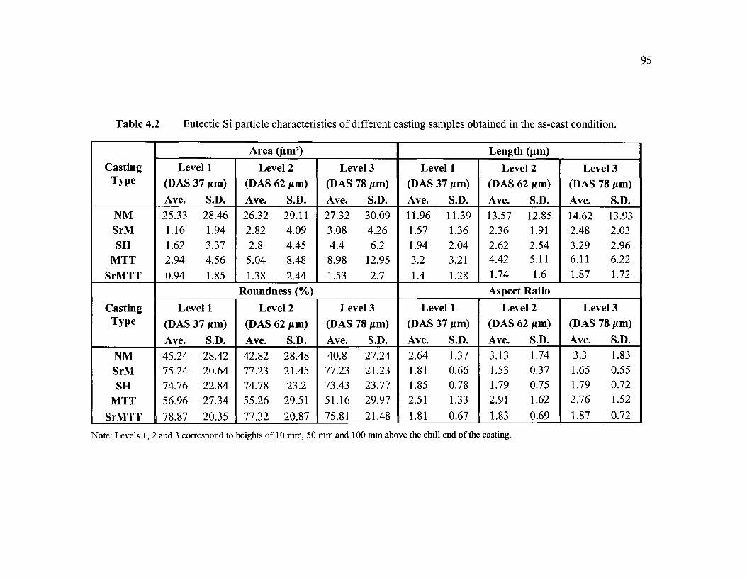
95
Table 4.2 Eutectic Si particle characteristics of different casting samples obtained in the as-cast condition.
CastingType
NMSrMSH
MTTSrMTT
CastingType
NMSrMSH
MTTSrMTT
Level 1(DAS
Ave.25.331.161.622.94
0.94
37 fan)
S.D.
28.461.943.374.56
1.85
Level 1(DAS
Ave.45.2475.2474.7656.96
78.87
37 fim)
S.D.28.4220.6422.8427.34
20.35
Area (|im2)
Level 2(DAS
Ave.26.322.822.85.041.38
62/iin)
S.D.29.114.094.458.482.44
Roundness (%)
Level 2(DAS
Ave.42.8277.2374.7855.26
77.32
62/tm)
S.D.28.4821.4523.229.51
20.87
Level 3(DAS
Ave.27.323.084.48.981.53
78 /un)
S.D.30.094.266.2
12.952.7
Level 3(DAS
Ave.40.877.2373.4351.16
75.81
IS urn)
S.D.27.2421.2323.7729.97
21.48
Level(DAS 37
Ave.11.961.571.943.21.4
Level(DAS 37
Ave.2.641.811.852.51
1.81
1
Mm)S.D.11.391.362.043.21
1.28
1
Urn)
S.D.1.370.660.781.33
0.67
Length (fini)
Level 2(DAS 62 urn)
Ave.13.572.362.624.421.74
Aspect
S.D.
12.851.912.545.111.6
Ratio
Level 2(DAS 62 urn)
Ave.3.131.531.792.91
1.83
S.D.1.740.370.751.62
0.69
Level(DAS 78Ave.14.622.483.296.111.87
Level(DAS 78
Ave.3.31.651.792.76
1.87
3Urn)
S.D.13.932.032.966.221.72
3
Mm)S.D.1.830.550.721.52
0.72
Note: Levels 1, 2 and 3 correspond to heights of 10 mm, 50 mm and 100 mm above the chill end of the casting.

96
The results of Table 4.2 have been presented in Figures 4.8 through 4.11 in the form
of histograms, which facilitates in distinguishing the effect of cooling rate (or dendrite arm
spacing), and that of the modification process on the Si particle characteristics.
In general, the Si particle area and length of the MTT casting appear to be the most
sensitive to the cooling rate, followed by the NM (non-modified) and SH (melt superheat-
treated) castings (Figures 4.8 and 4.9). In the SrM casting, an improvement due to cooling
rate is evidenced mainly at the cooling rate corresponding to the lowest DAS (37 fim). The
particle size remains constant at DAS levels of 62 /xm and above.
Compared to all these casting types, the SrMTT casting shows the best results in
that not only the Si particle sizes are the smallest among all castings, but these values
remain approximately constant over the range of cooling rates studied. This has a great
significance from the application point of view. Often, cast parts contain sections of
varying thickness, and in such cases, the use of an SrMTT processed Al-Si alloy melt in
casting would ensure a relatively uniform eutectic Si particle size throughout the casting
and, hence, guarantee its overall properties.
Again, with respect to the roundness parameter, the best results are obtained with
the SrMTT casting which displays consistently high roundness values, with a very small
influence due to cooling rate. The aspect ratios, however, are similar to those obtained for
the SH (superheated) and SrM (Sr-modified) castings. The moderate amount of refinement
in the Si particle morphology in the MTT casting compared to the non-modified (NM)
casting can also be observed from Figures 4.10 and 4.11.

97
LeveM (OAS37//m)Level2(DAS62//m)Level3(DAS78um}
WITT SrMTT
(a)
Leveli (DAS37//m) Level 2 (DAS 62/mi) Level 3
(b)
Figure 4.8 Average Si particle area obtained for as-cast samples taken from differentA356.2 alloy castings/levels, showing the effect of (a) cooling rate (castinglevel/DAS), and (b) modification process (casting type).

IS)
98
LeveM (DAS37//m)
Level2(QAS62fim)
Level3(DAS7§f/m)
NM SrM MTT
(a)
SrMTT
Level 1 (DAS 37//m) Level 2 (DAS 62jum) Level 3 (DAS 78/jm)
(b)
Figure 4.9 Average Si particle length obtained for as-cast samples taken from differentA356.2 alloy castings/levels, showing the effect of (a) cooling rate (castinglevel/DAS), and (b) modification process (casting type).

99
Levé M <DAS37f/m)Level2(DAS62jL;m)Level3(DAS7Bt/m)
NM SrM MTT SrMTT
(a)
Level 1 (DAS 37/mt) Level 2 (DAS 62pm)
(b)
Level 3 (DAS 78pm)
Figure 4.10 Average Si particle roundness obtained for as-cast samples taken fromdifferent A356.2 alloy castings/levels, showing the effect of (a) cooling rate(casting level/DAS), and (b) modification process (casting type).

100
LeveM (QAS37//m)Level2(nAS62fym)Levet3(DAS7Sf/m)
SrM SH
(a)
MTT SrMTT
Level 1 (DAS 37//m) Level 2 (DAS 62pm)
(b)
Level 3 (DAS 78/sm)
Figure 4.11 Average Si particle aspect ratio obtained for as-cast samples taken fromdifferent A356.2 alloy castings/levels, showing the effect of (a) cooling rate(casting level/DAS), and (b) modification process (casting type).

101
4.3.2 Comparison of Modification Methods
The various modification methods applied to A356.2 alloy in the present work were
used to determine which would produce a well-modified, fibrous eutectic structure, viz.
those that reduced the Si particle size and aspect ratio to a minimum and increased the
roundness to a maximum. Theoretically, spherical particles would have a roundness value
of -100% and an aspect ratio of 1.
To compare the efficiencies of the different modification methods, the Si particle
characteristics obtained for the SrM, SH, MTT and SrMTT casting samples were compared
with those obtained for the non-modified NM casting in terms of the percentage decrease
in the area and length parameters, the percentage increase in the roundness, and the
percentage decrease in the aspect ratio, as shown in Tables 4.3 and 4.4. The values in the
parentheses in the row for the NM casting in both tables represent the actual values
obtained for each parameter at the corresponding level. Those listed in the other rows
provide the percentage changes in the four parameters (area, length, roundness and aspect
ratio) observed in the other casting samples calculated in terms of the NM values in
parentheses. The actual values are given in Table 4.2.
In their study of the effect of Sr modification in A356.2 alloy, Paray and Gruzleski5
found that strontium affects not only the size and morphology of the eutectic Si particles,
but also the particle size and morphology distribution. Their conclusions, which correspond
to the NM and SrM castings in the present work, can also be extended to the SH, MTT and
SrMTT castings, as well, where the standard deviation obtained for each parameter
measured can be used to estimate the structural uniformity of the eutectic Si particles in

102
A356.2 alloy. More precisely, the narrower the standard deviation, the more homogeneous
the Si particle size and morphology distribution, in other words, the higher the degree of
modification achieved.
Table 4.3 Change in Si particle size achieved for different casting types incomparison to the non-modified casting
Casting Type
NMSrMSH
MTTSrMTT
Percentage Change in Si Particle Size% Decrease in Area (jim2)
Level 1(10mm)(25.33)95.4%93.6%88.4%
96.3%
Level 2(50mm)(26.32)89.3%89.4%80.9%
94.7%
Level 3(100mm)(27.32)88.7%83.9%67.1%
94.4%
% Decrease in Len
Level 1(10mm)(11.96)86.9%83.4%73.3%
88.1%
Level 2(50mm)(13.57)82.6%80.7%67.5%
87.2%
eth (um)
Level 3(100mm)(14.62)83.1%77.5%58.2%
87.2%
Note: levels 1, 2 and 3 correspond to DASs of 37, 62 and 78 jim, respectively
Table 4.4 Change in Si particle shape achieved for different casting types incomparison to the non-modified casting
Cast Type
NMSrMSH
MTTSrMTT
Percentage Change in Si Particle Shape% Increase in Roundness
Level 1(10mm)(45.24)66.31%65.25%25.91%74.34%
Level 2(50mm)(42.82)80.36%74.64%29.05%80.57%
Level 3(100mm)(40.80)89.29%79.98%25.39%85.81%
% Decrease in Aspect RatioLevel 1(10mm)(2.64)
31.44%29.92%4.92%31.44%
Level 2(50mm)(3.13)
51.12%42.81%7.03%
41.53%
Level 3(100mm)
(3.30)50.00%45.76%16.36%43.33%
Note: levels 1, 2 and 3 correspond to DASs of 37, 62 and 78 fim, respectively

CHAPTER 5
EFFECT OF SOLUTION HEAT TREATMENT
ON EUTECTIC Si PARTICLE CHARACTERISTICS

104
CHAPTER 5
EFFECT OF SOLUTION HEAT TREATMENT
ON EUTECTIC Si PARTICLE CHARACTERISTICS
5.1 INTRODUCTION
According to the results of investigations conducted by many researchers,7'80'81'82'83
the solution heat treatment of Al-Si-Mg alloys is carried out primarily for two reasons: the
first is to dissolve Mg and Si to the maximum extent in the aluminum matrix, and the
second is to alter the morphology of the eutectic Si particles from their acicular form in the
as-cast condition to a finer and more spheroidized form. Both effects can contribute
significantly in improving the mechanical properties of the alloy.
The change in the eutectic Si particle morphology takes place in three stages:
fragmentation, spheroidization, and coarsening. The solution treatment temperature and
time, and the original eutectic Si particle morphology in the as-cast condition are the main
factors that will control the effect of the solution heat treatment. Increasing the solution
temperature can expedite the process of fragmentation, spheroidization and coarsening,
keeping in mind that the temperature cannot be high enough to cause any microstructural
local melting of the alloy. For a given solution temperature, a sufficient solution time must

105
be applied to the alloy to reach a degree of spheroidization that is satisfactory. The original
as-cast eutectic Si morphology also plays a critical role. For instance, at a given solution
temperature, finer and rounder as-cast Si particles in a Sr-modified alloy can become highly
spheroidized compared to those in an unmodified alloy.
In the as-cast condition, Mg2Si is heterogeneously distributed within the oAl phase.
With solution heat treatment, the Mg2Si can be dissolved into the aluminum matrix, the
solubility being dependent on the solution temperature. Quenching thereafter can lock the
Si particles within the aluminum matrix to form a supersaturated solid solution. The
solution temperature is the key factor in this regard, and must be high enough so that the
Mg2Si can fully dissolve in solution.
In the present work, all the samples were solution heat treated at 540°C, for solution
times of 2 h to 80 h in increasing intervals of 2 h, for the NM and SrM casting samples, and
increasing intervals of 8 h for the SH, MTT and SrMTT casting samples, respectively. The
solution treated samples were then quenched in warm water (60°C). At 540°C, the
solubility of Mg is 0.6%; since the Mg content in A356.2 alloy is around 0.4%, Mg2Si can
be fully dissolved if treated at this temperature for a sufficient time. On the other hand, a
solution time span of 2-80 h can provide a wide range of conditions of the spheroidization
of the eutectic Si as well as various degrees of Mg2Si dissolution in the matrix.
The effect of solution heat treatment on the eutectic Si particle characteristics was
investigated by measuring the average particle area, length, roundness, and aspect ratio of
the corresponding solution heat-treated samples. In general, as the solution treatment time
increases, the average area, length, and roundness parameters should increase while the

106
average aspect ratio is expected to decrease, an aspect ratio of 1 corresponding to a
perfectly spherical particle. In addition, the effect of solution treatment on the eutectic Si
particle characteristics in the A356.2 alloy castings already modified prior to the solution
treatment (i.e., SrM, SH, MTT and SrMTT castings) was also investigated.
This chapter presents the results for the solution heat-treated samples corresponding
to the various A356.2 alloy casting types/levels and solution treatment times. As was done
in Chapter 4, both qualitative aspects (in the form of optical micrographs) and a
quantitative evaluation of the image analysis data obtained are presented and discussed in
the following sections.
5.2 QUALITATIVE ASPECTS OF THE EFFECT OF SOLUTION HEATTREATMENT ON THE EUTECTIC Si PARTICLE CHARACTERISTICS
The three stages of eutectic Si development during solution heat treatment, viz.,
fragmentation, spheroidization and coarsening, resulting in the samples obtained from the
various A356.2 alloy casting types are presented in Figures 5.1 through 5.5 for the NM,
SrM, SH, MTT and SrMTT castings, respectively. The four optical micrographs presented
in each figure were taken from the level 1 samples of the corresponding casting, as the
microstructures at this level (corresponding to the highest cooling rate, 37 jum DAS)
presented the best results in the as-cast condition (see Table 4.2 in Chapter 4). The as-cast
condition in each case is presented in the first micrograph (a) of each figure. The other
three micrographs ((b), (c) and (d)) correspond to solution treatment times of 8, 40 and

107
aizea si ^% \ % 4^» « y
'#...? *
Figure 5.1 Effect of solution heat treatment on the eutectic Si particle characteristics observed in the non-modifiedA356.2 alloy NM casting-level 1 samples in (a) the as-cast condition; (b), (c), (d) after solution heattreatment at 540°C for (b) 8 h, (c) 40 h, and (d) 80 h.

108
°*
*
*�< � � >
r* «
>'%
%� � *V
* *S30 un
� V
�
� V
�
£jfci
(b)
^
(d)
Figure 5.2 Effect of solution heat treatment on the eutectic Si particle characteristics observed in the Sr-modifiedA356.2 alloy SrM casting-level 1 samples in (a) the as-cast condition; (b), (c), (d) after solution heattreatment at S40°C for (b) 8 h, (c) 40 h, and (d) 80 h.

109
�
�
- * *
V
(b)
%Gfrarsened Si ^ «
# � i»% m* � # |3Ô~ÎS 0
(d)
Figure 5.3 Effect of solution heat treatment on the eutectic Si particle characteristics observed in the meltsuperheat-treated A356.2 alloy SH casting-level 1 samples in (a) the as-cast condition; (b), (c), (d) aftersolution heat treatment at 540°C for (b) 8 h, (c) 40 h, and (d) 80 h.

110
«
\
t
* *
«V
r
� �
1 1'
. ^ ^
r>
ni* '
�
ff p
*
/ /
(b)
1 �to
rt&ck
#
r
jm]
/
?
(d)
Rgure5.4 Effect of solution heat treatment on the eutectic Si particle characteristics observed in the MTTprocessed A356.2 alloy MTT casting-level 1 samples in (a) the as-cast condition; (b), (c), (d) aftersolution heat treatment at 540°C for (b) 8 h, (c) 40 h, and (d) 80 h.

I l l
v � �
i
«
* * # k
(b)
(c)
Figure 5.5 Effect of solution heat treatment on the eutectic Si particle characteristics observed in the Sr-modifîedMTT processed A356.2 alloy SrMTT casting-level 1 samples in (a) the as-cast condition; (b), (c), (d) aftersolution heat treatment at 540°C for (b) 8 h, (c) 40 h, and (d) 80 h.

112
80 h, that were selected as best representing the progress of the various stages of solution
treatment with time. These solution times were also used for solution heat treatment of the
tensile bars used for tensile testing.
The effect of solution treatment on the eutectic Si particles is most evident in the case
of the non-modified A356.2 alloy casting. As solution treatment at 540°C is commenced on
the as-cast sample, Figure 5.1 (a), with increasing solution time, the acicular Si particles are
seen to undergo "necking". Following this, such Si particles undergo fragmentation, as can
be seen in Figure 5.1 (b) for a sample which has been solution heat treated for 8 h. As the
solution time is increased further, the Si particles begin to spheroidize and then to coarsen,
as shown in Figure 5.1(c) and Figure 5.1(d), for solution times of 40 h and 80 h,
respectively.
Considering the various stages of the solution treatment as a whole, it can be seen
that the three stages of fragmentation, spheroidization and coarsening can occur together, as
well, in the same microstructure, depending upon the variety of Si particle sizes present in
the as-cast structure. Thus, while some longer particles may undergo fragmentation, other
smaller Si particles may become spheroidized, and those already spheroidized could start
coarsening, at any particular time during the solution treatment process.
When the alloys are modified before being solution heat treated, the spheroidization
process is accelerated, as shown in Figure 5.2 for the Sr-modified A356.2 alloy SrM
casting. Compare to the non-modified alloy, a high level of spheroidization is easily
achieved after only 8 h of solution treatment at 540°C, as shown in Figure 5.2(b). Further
solution treatment leads to the coarsening of the Si particles, as Figures 5.2(c) and 5.2(d)

113
demonstrate. Nevertheless, the overall size of the 'coarsened' Si particles is still much
smaller than that of the coarse particles in the non-modified alloy, Figure 5.1(d).
With the melt superheat-treated SH alloy casting, the results are similar to those
obtained for the Sr-modified casting. The slightly less degree to which the SH as-cast
sample is modified (Figure 5.3(a)), is reflected in the subsequent micrographs of
Figures 5.3(b), (c) and (d), when compared to those of Figure 5.2 for the same solution
times. In general, the Si particle sizes are somewhat larger in the SH casting samples.
In the case of the MTT processed casting, the particularities of the as-cast structure
(Figure 5.4(a)), which shows a moderate amount of refinement in comparison to the non-
modified alloy casting, lead to a corresponding improvement in the extent of
spheroidization achieved after 8 h solution treatment, Figure 5.4(b). Although
Figures 5.4(c) and 5.4(d) appear similar to those of Figures 5.1(c) and 5.1(d), due to the
initial refinement obtained in the as-cast structure of the MTT sample, the particle sizes in
Figures 5.4(c) and 5.4(d) are relatively smaller, overall.
Finally, the extremely well-modified eutectic structure in the as-cast SrMTT casting
sample (Figure 5.5(a)) leads to the attainment of a high degree of spheroidization after 8 h
solution treatment, comparable to that observed in the SrM casting sample. However, the
density of fine Si particles (i.e. number of Si particles per unit area) is greater and much
more homogeneously distributed than in the latter {cf. Figure 5.5(b) and Figure 5.2(b)).
Perhaps for this reason, the coarsening effects after 40 h solution time are more pronounced
in the SrMTT casting sample (Figure 5.5(c)) than in the SrM casting sample (Figure
5.2(c)). Figure 5.5(d) shows that, after 80 h of solution treatment, the remaining larger-

114
sized and non-spheroidized particles in the SrMTT casting (after 40 h solution treatment)
undergo fragmentation and spheroidization. In comparison, the larger-sized Si particles in
the Sr-modified casting still appear to be in the process of necking (and fragmentation)
after the same amount of solution treatment time (80 h).
In summary, therefore, these observations emphasize the fact that the original eutectic
Si structure contributes significantly to the efficiency of the solution heat treatment applied,
in terms of the solution time required to achieve optimum spheroidization of the Si
particles. Reduced solution treatment times would obviously add to the cost-effectiveness
of the production process.
5.3 QUANTITATIVE ASPECTS OF THE EFFECT OF SOLUTION HEATTREATMENT ON THE EUTECTIC Si PARTICLE CHARACTERISTICS
Quantification of the Si particle characteristics was carried out using image analysis.
The particle size and morphology were characterized in terms of the average particle area,
length, roundness and aspect ratio for the various A356.2 solution heat-treated casting
samples (at 540°C for different solution times). The results are presented in this section in
the form of x-y plots. The image analysis data is provided in Appendix 1.
5.3.1 Effect on Eutectic Si Particle Size
Depending upon the as-cast condition of the casting, and whether the A3 5 6.2 alloy
melt used to prepare the casting was Sr-modified or not, the development of the changes in
the eutectic Si particles brought about by the solution heat treatment applied would vary
from casting type to casting type.

115
Figure 5.6 shows a schematic representation of the three stages of eutectic Si particle
development, viz., fragmentation, spheroidization and coarsening with the progress of
QA
solution treatment, in non-modified and Sr-modified Al-Si alloys. As can be seen, in the
non-modified alloy, fragmentation must first occur before spheroidization and then
coarsening can take place, whereas in the modified alloy, the as-cast Si particles are already
relatively smaller in size and hence spheroidization commences shortly after the solution
treatment is underway. Obviously, with the progress of solution treatment time, the Si
particles will start to coarsen, exhibiting coarser particles compared to the unmodified alloy
after similar solution treatment times.
As - cast Fragmentation
(a)
As - cast
OSpheroidisation
(b)
0%
Spheroidisationand coarsening
oCoarsening
Figure 5.6 Schematic representation of the three stages of eutectic Si particledevelopment during solution heat treatment in: (a) non-modified, and(b) Sr-modified A356.2 alloys.84

116
Figure 5.7 shows the plots of average Si particle area values obtained for the different
casting types and levels over the range of solution treatment times studied from 0 h (as-cast
condition) through 80 h. The three curves corresponding to the samples taken from the
three levels of each casting are distinct from one another in the NM and MTT castings,
whereas those for the SrM, SH and SrMTT castings lie together. The potential advantage of
this observation in the latter cases is that the effect of Sr modification or superheat
overrides that of cooling rate, which has significance in the context of maintaining a
uniform eutectic structure in the thick and thin sections of a cast component.
In the non-modified casting, Figure 5.7(a), the as-cast particle size is in the order of
25 - 28 jLtm2. During the first four hours of solution treatment (at 540°C), the particle sizes
reduce, indicating the progress of fragmentation of the Si particles. The greatest amount of
fragmentation is observed at level 1 (DAS 37 urn). As the solution time progresses, the
particle sizes begin to increase somewhat, however, in a gradual manner, showing
increasing and decreasing values from one solution period to the next (in intervals of 2 h).
This range of solution times, from 8 to ~ 40 h, comprises both the spheroidization and the
coarsening stages that occur together. After 40 h, the particles coarsen, until at 80 h, they
attain particle sizes greater than their as-cast values, except for the level 1 sample which
attains its original size, negating the effect of fragmentation brought about by the solution
heat treatment.
In the SrM casting, Figure 5.7(b), all three levels exhibit almost similar particle sizes
over the entire range of solution treatment. In this case, the as-cast values are the lowest,
about 3 urn2 or less, and increase very gradually with increasing solution treatment time.

117
The spheroidization stage is expected to occur in the 24-60 h range, where the particle area
remains more or less constant at ~ 10 um2. The Si particles begin to coarsen thereafter.
However, even after coarsening, the particle sizes are still below 15 jam2. Virtually the
same results are obtained for the SH casting, Figure 5.7(c).
The increase in the particle size in the early stages of solution treatment (unlike the
decrease observed for the NM casting) is explained by the fact that there are no large
particles to undergo fragmentation, and so the spheroidization stage occurs directly. The
same is true for the other modified castings, i.e., the SH and SrMTT castings. In the case of
the MTT casting, Figure 5.7(d), however, distinct particle sizes are observed for the three
levels, and after about 56 h of solution treatment, the particles attain maximum coarsening
and display the same particle size of- 20-22 [im at DASs of 62 /an or more.
In terms of refinement achieved with the MTT process, only at level 1 is the cooling
rate high enough (DAS 37 jum) to achieve a particle size of-15 jum after 56 h solution
treatment, comparable to that achieved with the SH and SrMTT castings (Figures 5.7(c)
and 5.7(e), respectively). As Figure 5.7 shows, with respect to solution heat treatment, the
best result are obtained for the SrMTT casting, followed by the SrM and SH castings.
In their review of the fundamental aspect of heat treatment of cast Al-Si-Mg alloys,
Apelian et al.1 have analyzed the data from various studies reported in the literature. They
report that modification has a great influence on spheroidization. hi modified A356 alloy, a
high degree of spheroidization is observed after only 12 h of solution treatment, whereas in
the unmodified alloy, coarse acicular Si plates are still visible after the same amount of
solution treatment. According to Zhu et al.,53 during solution heat treatment, the Si particles

118
03
<
Average Si Particle Area - NM Casting
Solution Heat Treatment Time (hr)
(a)
Average Si Particle Area - SrM Casting
<
o
16 7224 32 40 41 M
Solution Heat Treatment Time {hr)
(b)
Figure 5.7 Effect of solution heat treatment on the average Si particle area obtained inthe different A356.2 alloy casting samples: (a) NM, (b) SrM, (c) SH,(d) MTT, and (e) SrMTT castings.

119
Average Si Particle Area - SH Casting
ora01
Solution Heat Treatment Time (hr)
(c)
Average Si Particle Area - MTT Casting
16 24 32 40 48 56
Solution Heat Treatment Time (hr)
(d)
Figure 5.7 Effect of solution heat treatment on the average Si particle area obtained inthe different A356.2 alloy casting samples: (a) NM> (b) SrM, (c) SH,(d) MTT, and (e) SrMTT castings.

120
40
35
30
25
Average Si Particle Area - SrMTT Casting
re
©
1�
eu
<
-Laval 1 (DAS37pm)
- Level 2 fQAS Rum I
16 2* 32 40 48 Se
Solution Heat Treatment Time (hr)
64 72
Figure 5.7 Effect of solution heat treatment on the average Si particle area obtained inthe different A356.2 alloy casting samples: (a) NM, (b) SrM, (c) SH>(d) MTT, and (e) SrMTT castings.
are first separated into segments at corners or at thin growth steps, but they still possess
their flake morphology. After that, these segments begin to spheroidize. Theoretical studies
have suggested that interfacial instabilities in the eutectic structure caused by the increase
in shape perturbations and consequent breaking of the eutectic Si particles during the heat
treatment do not take place that easily in the unmodified eutectic, and so the acicular
eutectic particles are resistant to spheroidization. In fibrous eutectic, however, the shape
perturbations are readily accepted and the particles are easily broken. As a result,
spheroidization occurs at a much faster rate in modified alloys than in non-modified alloys.

121
With respect to the various casting types studied in the present work, the data
presented in Appendix 1 may be analyzed as follows.
In the modified alloys, i.e., those with modified Si particles, spheroidization starts
with solution heat treatment followed by coarsening. The particle size increases in two
stages, where the growth occurs relatively fast in the first stage, then slows down in the
second stage. The duration of each stage of growth varies from casting type to casting type,
depending upon the modification method employed (i.e., SrM, SH, MTT or SrMTT).
As can be seen from the data provided in Appendix 1, the accelerated growth stages
vary from 28 h for SrM, to 32 h for SH, 8 h for MTT and 32 h for the SrMTT castings.
In the case of the unmodified NM casting also, once the fragmentation and
spheroidization stages have taken place, there are two stages of coarsening, the accelerated
coarsening, extending up to 12 h, as seen from the data in Appendix 1. It should be noted
that in this case, however, spheroidization could also be taking place at the same time as
coarsening, as the former takes place over the entire duration of the solution treatment, as
the optical micrographs of Figure 5.1 show. Also observed is the fact that the accelerated
growth periods for the NM and MTT castings are much shorter (10 h ± 2 h) than those
noted for the modified castings (30 h ± 2 h).
Apelian et al.1 have suggested that the large diversity of particle size and shape in the
unmodified alloy is expected to provide a greater driving force for coarsening in this case
than in the modified alloys. In addition, the small tips of the acicular needle (or plate)
shaped Si particles would favour growth at the corners, and increase their widths, viz.,

122
,85coarsen the particles. Rhines and Aballe have estimated the growth rate to be of the order
of 0.0225 jU,m3/hr in unmodified alloys compared to 0.014 jum3/hr in modified alloys.
Figure 5.8 compares the plots of the average Si particle lengths obtained for the
different A356.2 alloy casting types and levels at the various solution treatment times. The
plots are very similar to those of Figure 5.7 for the average Si particle area. As before, the
non-modified (NM) casting shows distinct particle sizes at the three levels (i.e., cooling
rates) where the particle lengths decrease in each case from their as-cast values up to 4 h
solution treatment, then begin to increase gradually, attaining more or less constant values
(within ± 1 fan) of 7, 8 and 9 fan for the levels 1, 2 and 3, respectively, over the 8 h-80 h
range of solution treatment time. The as-cast Si particle lengths range from ~12 /mi to
-15 fan.
The other variously modified castings display much smaller particle lengths in the
as-cast condition (~3 fan or less), with the MTT casting exhibiting slightly higher values
(~3 to 6 fim). After 56 h of solution treatment, the MTT casting samples corresponding to
levels 2 and 3 (i.e. at DASs >62 fan) show similar maximum particle lengths (~7/mi),
while the level 1 (37 /mi DAS) sample produces the best results in terms of refinement.
Before 56 h, the three levels exhibit distinct particle lengths as in the case of the non-
modified casting. The best results are obtained for the SrMTT casting which displays the
minimum values in area (-7.5 jum2) and length (2 /mi) in the as-cast condition, followed by
the SrM and SH castings.

123
14
ence>
_ia
Average Si Particle Length - NM Casting
Solution Heat Treatment Time (hr)
(a)
Average Si Particle Length - SrM Casting
24 Î2 40 48 56
Solution Heat Treatment Time (hr)
64 72 30
(b)
Figure 5.8 Effect of solution heat treatment on the average Si particle length obtainedin the different A3 5 6.2 alloy casting samples: (a) NM, (b) SrM, (c) SHf
(d) MTT, and (e) SrMTT castings.

124
Average Si Particle Length - SH Casting
Solution Heat Treatment Time (hr)
(c)
Average Si Particle Length - MTT Casting
72 80
Figure 5.8
24 32 40 43 56 64
Solution Heat Treatment Time (hr)
(d)
Effect of solution heat treatment on the average Si particle length obtainedin the different A356.2 alloy casting samples: (a) NM, (b) SrM, (c) SH,(d) MTT, and (e) SrMTT castings.

125
10
Figure 5.8
Average Si Particle Length - SrMTT Casting
-LevaII (DAS37ftfi;-Laval2 (DASE^m)-Laval3(DAS7tlpm)
54 7224 32 40 « 56
Solution Heat Treatment Time {hr)
(e)
Effect of solution heat treatment on the average Si particle length obtainedin the different A3 5 6.2 alloy casting samples: (a) NM, (b) SrM, (c) SH,(d) MTT, and (e) SrMTT castings.
After 80 hr solution heat treatment, the NM-level 1 and MTT casting samples
exhibit similar Si particle sizes (22-26 pirn2), while in the SrM, SH, and SrMTT castings,
the particle sizes are much smaller (12-15 /im2). Nonetheless, irrespective of the
modification method used, the Si particle sizes are significantly diminished compared to the
particle sizes obtained in the as-cast condition in the non-modified alloy (i.e., without
solution heat treatment). Also, as Figures 5.7 and 5.8 show, the effect of cooling rate on
particle size is not affected by the solution heat treatment time at 540°C solution
temperature.

126
5.3.2 Effect on Eutectic Si Particle Shape
Solution heat treatment can improve the shape of the eutectic Si particles during the
speroidization stage, when the particles become rounded, i.e., their roundness increases and
correspondingly, the aspect ratio decreases (and approaches the limit of 1 for spherical
particles). However, the spheroidization process takes place quite differently in the
unmodified and modified alloys.
Figure 5.9 displays the variations in the average Si particle roundness as a function of
solution treatment time at 540°C for the different A356.2 alloy casting types and levels.
As Figure 5.9(a) shows, the roundness of the Si particles in the non-modified alloy
casting shows a large improvement from ~ 40-45 % in the as-cast condition to
~ 60-68 % after only 2 h of solution treatment. The roundness increases gradually as the
solution time is prolonged, reaching a maximum at ~ 50 h and then remaining more or less
the same up to 80 h, at ~ 75-80 %. Of course, the level 1 samples show maximum
improvements, in each case.
Maximum roundness values (~85%) are obtained for the SrM casting samples, Figure
5.9(b), as also for the SH (Figure 5.9(c)) and SrMTT (Figure 5.9(e)) casting samples. In the
case of the SrM casting, all cooling rates exhibit the same roundness over the range of
solution treatment times, starting from an as-cast roundness of ~ 75-78 %. The SH and
SrMTT castings show some influence of cooling rate. As in the case of the NM casting, the
MTT casting also shows distinct roundness values for the three levels studied, although the
as-cast roundness values are higher (~ 51-56 %) compared to those obtained in the NM

55 so
O
cc3o
a;
50
127
Average Si Particle Roundness - NM Casting
Level 2 IDAS 62i/m)-LeveUiQAS7Sj/m)
24 32 40 48 56
Solution Heat Treatment Time (hr)
72 3S
(a)
Average Si Particle Roundness - SrM Casting
16 24 32 40 48 56
Solution Heat Treatment Time (hr)
64 72
(b)
Figure 5.9 Effect of solution heat treatment on the average Si particle roundnessobtained in the different A356.2 alloy casting samples: (a) NM, (b) SrM, (c)SH, (d) MTT, and (e) SrMTT castings.

128
Average Si Particle Roundness - SH Casting
4024 32 40 4a 56
Solution Heat Treatment Time {hr)
(c)
Average Si Particle Roundness - MTT Casting
-Level 1
Level! : CAS S2iriii;,-Level 3 (DAS 7Vm)
16 24 32 40 4* 6C
Solution Heat Treatment Time (hr)
(d)
Figure 5.9 Effect of solution heat treatment on the average Si particle roundnessobtained in the different A356.2 alloy casting samples: (a) NM, (b) SrM, (c)SH, (d) MTT, and (e) SrMTT castings.

129
Figure 5.9
Average Si Particle Roundness - SrMTT Casting
16 24 Ï2 40 48 56
Solution Heat Treatment Time (hr)
72
(e)
Effect of solution heat treatment on the average Si particle roundnessobtained in the different A356.2 alloy casting samples: (a) NM, (b) SrM, (c)SH, (d) MTT, and (e) SrMTT castings.
casting (~ 40-45 %). Again, the MTT casting-level 1 (37 /tun DAS) sample provides the
best roundness values.
Similar tendencies are reflected in the aspect ratio parameters exhibited by these
samples, as shown in Figure 5.10, only in this case, the aspect ratios start with a higher
value in the as-cast condition to decrease to an aspect ratio of 1 (corresponding to the
~100 % roundness) exhibited by perfectly spherical particles. Again, the lowest aspect
ratios are obtained for the SrM casting samples (< 1.5), Figure 5.10(b), where, after an
initial improvement after 2 h of solution treatment, the aspect ratio remains constant over
the range of solution times studied, and independent of the cooling rate or level. The SH

130
Average Si Particle Aspect Ratio - NM Casting
LeveM (CAS37//m]Level I.IDAS 32pm:.Level 3 IDAS 7^111 j !
24 32 40 +3 56
Solution Heat Treatment Time (hr)
W
(a)
Average Si Particle Aspect Ratio - SrM Casting3.5
O 3.0
IS
�3
< 1.5
�» L,evel 1 (CAS ilyTn)���Level 2 (ÛAS ttfim )' * " Level 3 (DAS T3>:n ;.
� i i 1 1 �
2.0
16 24 32 40 « 58
Solution Heat Treatment Time {hr)
(b)
Figure 5.10 Effect of solution heat treatment on the average Si particle aspect ratioobtained in the different A356.2 alloy casting samples: (a) NM, (b) SrM, (c)SH, (d) MTT, and (e) SrMTT castings.

131
Average Si Particle Aspect Ratio - SH Casting
24 32 40 48 56
Solution Heat Treatment Time (hr)
(c)
Average Si Particle Aspect Ratio - WITT Casting
1.0
» 24 32 40 48 «
Solution Heat Treatment Time (hr)
64 72
(d)
Figure 5.10 Effect of solution heat treatment on the average Si particle aspect ratioobtained in the different A356.2 alloy casting samples: (a) NM, (b) SrM, (c)SH, (d) MTT, and (e) SrMTT castings.

3.5
O 3d
re
Q.
en
<a 2.0
n
>
1.0
132
Average Si Particle Aspect Ratio - SrMTT Casting
16 24 32 40 48 56
Solution Heat Treatment Time (hr)
-L tv tM (CAS 37pm)Laval 2 (CAS 62pm)
64 72 30
(e)
Figure 5.10 Effect of solution heat treatment on the average Si particle aspect ratioobtained in the different A356.2 alloy casting samples: (a) NM, (b) SrM, (c)SH, (d) MTT, and (e) SrMTT castings.
and SrMTT castings follow next, where, with the exception of a few changes at ~ 40 h and
80 h solution times, the aspect ratio remains at - 1.5 for the SH casting and shows a bit
more discrepancy in the case of the SrMTT casting.
It can be concluded from these results that the original Si particle morphology is the
key factor which determines the time that the Si particles need for spheroidization. The
finer the Si particles, the less time it will take for them to be fully spheroidized.

CHAPTER 6
TENSILE PROPERTIES

134
CHAPTER 6
TENSILE PROPERTIES
6.1 INTRODUCTION
As one of the main groups of aluminum alloys used in automotive application, the
mechanical properties of Al-Si-Mg alloys have been investigated extensively.61'86'87
Among these, those relating to the tensile properties of A356 alloys have been
determined in terms of the secondary dendrite arm spacing (SDAS) or cooling rate,
eutectic Si particle characteristics, alloying element addition (Mg, Fe, and others), and
casting defects such as porosity and inclusions.9'61'62 In addition, the effects of
modification and solution heat treatment which, through their influence on the eutectic
Si particle characteristics, can also control the tensile properties of A3 56 alloy, have also
been studied by several workers.22'47'82'83
In the present work, we have focused on the effect of cooling rate, various
modification methods, and solution heat treatment on the characteristics of the eutectic
Si particles, observed in A356.2 alloys, with the aim of investigating how the changes
brought about by these various means will affect the tensile properties of the
corresponding castings.
This chapter presents the results of the tensile tests that were carried out for the
NM, SrM, SH, MTT and SrMTT end-chilled castings, on samples obtained at the three
levels (of 10, 50 and 100 mm above the chill end) to incorporate the effect of cooling

135
rate. The tensile properties (UTS, YS and %E1) were measured using an Instron
Universal Mechanical Testing machine, the details of the samples preparation and
testing procedures have been provided in Chapter 3, section 3.5.
In regard to the different parameters studied and their influence on the tensile
properties, a high cooling rate (or fine SDAS) is well known to enhance the tensile
properties, due to the overall refinement of the microstructure and its constituents,
including the Si particles, as well.
hi regard to the various modification methods used, those of Sr modification are
well known, according to Hafiz and Kobayashi,64 Sr modification has little effect on the
yield strength of A356 alloy, but can moderately improve the tensile strength. The main
impact of Sr modification is on the ductility, where the addition of 240 ppm Sr to A356
alloy melt scan improve the elongation from 8.03% to 22.2%.64
In comparison, there are few studies covering the effect of melt superheat and
even less on that of melt thermal treatment (MTT) on the tensile properties of A356
alloys. The results of Jie et al.,42 show that superheating an A356 alloy melt to 810°C
can improve the tensile properties, especially the ductility (from 5.0% to 8.5%). The
investigations of Wang et al.41 show that the MTT process greatly improves the
elongation, by almost 112%.
To the best of our knowledge, there is no report on the combined effect of Sr
modification and melt thermal treatment on the tensile properties of Al-Si alloys, and
A3 5 6 alloy, in particular. As has been shown in chapter 4, the SrMTT casting showed
the best results in that the eutectic Si particle characteristics were the finest produced

136
among all the casting types studied. It is to be expected, therefore, that the SrMTT
casting samples will exhibit the best tensile properties, as well.
The effect of solution heat treatment on the Si particle characteristics (and hence
on the tensile properties) of A356 alloy has also been investigated.82 In the present work,
the tensile test bars obtained from the various castings were solution treated at 540°C for
times ranging from 0 h (as-cast condition) to 80 h at intervals of 2 h for the
non-modified (NM) and Sr-modified (SrM) alloy castings. Based on the results obtained,
for the other castings, the test bars were solution treated at 540°C, again for times
ranging from 0 h (as-cast condition) to 80 h, but at intervals of 8 h. Following solution
treatment, all test bars were quenched in warm water and aged for 5 h at 155°C (standard
T6 treatment) before the tensile testing was carried out.
6.2 AS-CAST TENSILE PROPERTIES
The as-cast tensile properties of the various A3 5 6 alloy casting types were
determined. The results are plotted in Figures 6.1 to 6.3.

137
240
200
-��MM
->-SrM
- * - S H
-X-MTT
-*-SrMTT
nQ.S , 160 -
120-
DAS=37//m DAS=78//m
30 40 50 60 80 90
DAS
Figure 6.1 Yield strength of samples obtained from different A356.2 alloy castings -as-cast condition.
According to Shivkumar et al.,47 yield strength is essentially determined by the Mg
content and the aging condition rather than the eutectic Si particle characteristics or
cooling rate (in term of DAS). This is also evidenced by the experimental results of the
present work. As shown in Figure 6.1, under the same cooling rate, although various
modification methods produce a wide range of Si particles characteristics (as discussed
in Chapter 4 and 5), the yield strength of each casting type remains more or less the
same level to level. For instance, at the level 10mm from chilled end (DAS=37/im), the
yield strength of the NM, SrM, SH, MTT and SrMTT casting samples are 88, 96, 104,
99 and 94 MPa, respectively. In addition, for each casting type, the cooling rate does not
appear to affect the yield strength. For example, in the SrMTT casting samples, the yield

138
strengths obtained at the three levels (DAS=37, 62, 78/im) are 95, 96, 92MPa,
respectively, while the other A356 alloy casting types also show the same tendency.
320
20 90 100
Figure 6.2 Ultimate tensile strength of samples obtained from different A356.2 alloycastings - as-cast condition.
The UTS values obtained for the various casting types reveal that the SrM, SH and
SrMTT processes improve the UTS to a certain extent compared to the non-modified
(NM) condition, while the MTT processed casting appears to have no effect, as shown in
Figure 6.2. For instance, at DAS=62/mi, the UTS for NM, SrM, SH, MTT and SrMTT
samples are 148, 169, 168, 147 and 158 Mpa, respectively. This effect on UTS is related
to the improvement in the Si particle characteristics, especially with regard to the aspect
ratio. In SrM, SH and SrMTT-treated castings, the Si particles are modified from
acicular form to fibrous morphology while in NM or MTT-treated castings they still

139
appear as acicular flakes. However, it should be noted that the improvement is also
affected by the cooling rate. As Figure 6.2 shows, at the high cooling rate (DAS=37jum),
none of the modification methods show an obvious improvement in the UTS (182, 175,
162, 179MPa for the SrM, SH, MTT, and SrMTT treated castings respectively,
compared to 180MPa for the NM casting). At high cooling rates, the effect of cooling
rate (or DAS) dominates that produced by the different modification processes, as at fine
dendrite arm spacings, all microconstituents in the microstructure are refined and not
only the eutectic silicon, which is the case for the modified castings. However, the effect
of modification takes over as the cooling rate decreases, i.e., as the DAS attains larger
values. For example, in the SrM casting, the UTS decreases from 182 to 169 to 162 MPa
as the DAS increases from 37 to 78 /Am. Similarly, in the case of the SH casting, the
UTS is lowered from 175, through 168 to 159 MPa, respectively. This decrease in UTS
is related to the increase in the Si particle size and aspect ratio resulting from the
decrease in cooling rate.
The lower UTS value displayed by the MTT casting at 37 /an DAS could probably
be the result of the presence of porosity defect and/or inclusions present in the gage
length portion of the corresponding test bars.
Figure 6.3 shows the results for percentage elongation for the various casting types.
Both SrM and SrMTT processes improve the ductility considerably from ~ 6% in the
non-modified condition to ~ 12%, at 37 jum DAS. Comparing the plots for the NM and
SrM casting samples, the same level of improvement is obtained with Sr modification
(relative ot the non-modified case) at all cooling rates or DASs.

140
14
12
10
O
oLU
-+-NM- � -SrM
~*-SH
-M-MTT
-*-SrMTT
20 3Q 40 60 70 80 90 100
DAS
Figure 6.3 Percentage elongation of samples obtained from different A356.2 alloycastings - as-cast condition.
Although the SH and MTT processes do refine the Si particles, no significant
improvement in ductility is observed. In fact, the ductility is even lower than that of the
NM casting sample, at the high cooling rate, i.e., at DAS=37um by about 2 to 2.7%. The
ductility decreases very gradually with increase in dendrite arm spacing, from ~- 4% at
37 fim DAS to ~ 3% at 78 jxm DAS. These observations could be explained by the
degree of Si particle clustering observed in the respective microstructures. As was
shown in Chapter 4, the Si particle distribution was not homogeneous in these casting
samples, particularly at the high cooling rate, where the solidification time was not
sufficient to allow for a more even distribution of the Si particles. This general
characteristic of the MTT and SH samples would explain the low ductilities observed.

141
Compared to the NM casting sample, the longer solidification time at 78 jum DAS would
provide more time for distributing the Si particles more evenly in the casting, and result
in improving the ductility compared to the NM casting sample (~ 3% o f - 1.5% for
NM).
To summarize, the ductility of A356 alloys subjected to various modification
processes is determined by the dendrite arm spacing, the eutectic Si particle size and
aspect ratio, as well as by the presence of casting defects. The observations for the MTT
processed casting are in keeping with those of Wang61.
6.3 TENSILE PROPERTIES AFTER HEAT TREATMENT
For studying the effect of heat treatment, the tensile test bars were solution heat
treated at 540°C for selected times of 8, 40 and 80 h, to cover the range of solution times
studied. The samples were artificially aged at 155°C for 5 h (standard T6 temper) before
carrying out the test. The results are presented in Figures 6.4 through 6.6, where the
variations in YS, UTS and %E1 obtained at each cooling rate (or DAS level) have been
grouped together for the five casting types.
hi general, both YS and UTS are significantly improved after solution heat
treatment, hi regard to the elongation, while the ductilities of the NM, SH and MTT
castings are also improved, the case for the SrM and SrMTT castings is more
complicated in nature. As Figure 6.4 shows, for each A356.2 alloy casting type, the yield
strength is greatly improved after 8 h of solution heat treatment, compared to the as-cast
(0 h) condition. Maximum improvement is observed in the case of the NM casting,

142
240 -i
£L
120
30
20 30 40 50
S.H.T.Time(hr)
(a)
so 70 30 90
roa.£ 160 - -
Figure 6.4
60 70 8040 50
S.H.T. Time (hr)
(b)
Effect of solution heat treatment on the yield strength of heat-treatedsamples obtained from various A356.2 alloy castings at: (a) 37 /mi,(b) 62 (itm, and (c) 78 /im DAS levels.
90

143
Figure 6.4
60 70 SO 9040 50
S.H.T. Time (hr)
(c)
Effect of solution heat treatment on the yield strength of heat-treatedsamples obtained from various A356.2 alloy castings at: (a) 37 /im,(b) 62 fan, and (c) 78 jun DAS levels.
at the highest cooling rate, where the YS value jumps from ~ 85 MPa to - 235 MPa after
S h of solution treatment, the improvement in yield strength is attributed to the
precipitation of Mg2Si within the Al-matrix after aging. In most cases, the Mg2Si
precipitation is essentially completed within the first 8 h of solution treatment, and the
yield strength does not vary much thereafter, with further increase in solution treatment
time. Actually, according to Shivkumar et al.,47 the precipitation of Mg2Si finishes in the
first hour of solution treatment, once the samples have been solution heat treated,
cooling rate has very little effect on the yield strength.

144
The plots in Figure 6.4 show that for the SrM casting samples, the maximum
yield strength is achieved after 40 h of solution treatment, this may be explained by the
fact that the SrM casting from which the corresponding 40 h-solution treatment test bars
were obtained contained a higher level of Mg (0.309%) than did those for the 8 h and 80
h solution treatments (0.234% Mg and 0.239% Mg, respectively), hi comparing Figures
6.4(a), (b) and (c), it can be observed that, overall, the yield strength does not change
from one cooling rate to another for a specific modification process (i.e., casting type),
and under the same solution treatment conditions.
Figure 6.5 shows the UTS values obtained for the various A356.2 casting
samples after heat treatment. As can be seen, the UTS shows a tendency very similar to
that obtained for the yield strength in that a significant improvement is obtained after 8 h
solution heat treatment, then remains at the same level with further solution treatment.
As in the case of the yield strength, the maximum improvement in UTS is obtained for
the NM casting, from ~ 180 MPa in the as-cast condition to ~ 305 MPa after 8 h solution
treatment. Up to 40 h solution time, the UTS remains stable but drops to ~ 290 MPa
after 80 h of solution treatment. Cooling rate has a certain influence in that different
levels of improvement in UTS are obtained. In the case of the SrMTT casting, the UTS
improves gradually for the 78 /mi DAS samples from 162 MPa to 262 MPa until, after
80 h solution treatment, the UTS attains a value of 261 MPa, comparable to that
obtained at 62 //.m DAS.

145
20 30 40 50
S.H.T.Time(hr)
(a)
60
40 50
S.H.T. Time (hr)
60
70 ao
70
90
80 90
(b)
Figure 6.5 Effect of solution heat treatment on the ultimate tensile strength of heat-treated samples obtained from various A356.2 alloy castings at:(a) 37 jiim, (b) 62 [im, and (c) 78 fim DAS levels.

146
Figure 6.5
20 30 60 70 8040 50
S.H.T Time (hr)
(c)
Effect of solution heat treatment on the ultimate tensile strength of heat-treated samples obtained from various A356.2 alloy castings at:(a) 37 /mi, (b) 62 pan, and (c) 78 pun DAS levels.
90
According to Pan et ai*2 the improvement in UTS can be attributed three factors:
Mg2Si precipitation, dissolution of Si within the Al-matrix, and change in the Si particle
morphology. Among these, Mg2Si precipitation and change in Si particle morphology
favor an increase in the UTS, while dissolution of Si has a negative influence. The rapid
increase in UTS obtained for heat-treated samples solution treated for 8h is due to
maximum dissolution of Mg and Si (and, hence, precipitation of Mg2Si), and the
spheroidization of the Si particles. With further increase in solution treatment time (up to
80h), there is no further dissolution of Mg and Si (and hence no further Mg^Si
precipitation), while the positive effect of spheroidization is offset by the dissolution of

147
Si within the Al-matrix, thus maintaining the UTS around the same level, Figure 6.5.
Also, from a comparison of Figures 6.5(a), (b) and (c), it can be seen that the effect of
cooling rate on UTS is not affected by the solution treatment time, and that the tensile
strength of the various castings lie in the same range, within 10-20 MPa of each other,
for the three cooling rates studied. While the Si particle characteristics may vary from
one casting type to another, this difference does not affect the UTS after solution heat
treatment/aging, so long as the castings contain the same Mg level.
Figure 6.6 shows the effect of heat treatment on the ductility of the various A3 56.2
alloy casting samples at each of the three DAS levels. In general, the ductility is seen to
improve with solution heat treatment, as well as increase in solution time. The ductility
is controlled to a great extent by the changes in the Si particle morphology and size
brought about by the modification methods used, as well as the spheroidization due to
solution heat treatment. As discussed in Chapter 5, the development of the Si particle
characteristics during solution treatment varied from casting type to casting type
depending upon the modification process used and the particle characteristics in the
as-cast condition. Thus, the ductility for the NM casting samples is expected to
contribute to improve with increasing solution time, as the Si particle pass through the
stages of fragmentation and spheroidization, then remain constant or decrease somewhat
depending upon the amount of coarsening that has taken place after 80 h of solution
treatment.
Both the SrM and SrMTT samples display the highest percentage elongations in
the as-cast condition at the highest cooling rate (37 /an). The drop in ductility in the SrM

148
20 30 40 50
S.H.T. Time (hr)
(a)
so 70 SO 9Q
Figure 6.6
20 30 SO 70 80 9040 50
S.H.T. Time (hr)
(b)
Effect of solution heat treatment on percentage elongation of heat-treatedsamples obtained from various A356.2 alloy castings at: (a) 37 pxni
(b) 62 fim, and (c) 78 /Am DAS levels.

149
10 20 30 60
Figure 6.6
40 50
S.H.T. Time {hr}
(c)
Effect of solution heat treatment on percentage elongation of heat-treatedsamples obtained from various A356.2 alloy castings at: (a) 37 jim,(b) 62 jim, and (c) 78 fim DAS levels.
casting samples after 40 h of solution treatment is attributed to the increase in the Mg
content of the SrM casting from which these samples were prepared. As was observed in
the case of Figure 6.5(b), corresponding to the lowering of the ductility, the UTS
exhibited higher values of the same samples. The very fine eutectic Si structure achieved
in the SrMTT casting is responsible for the high ductility of- 12%, which is maintained
even at DAS of 62 /an. The drop in ductility with solution treatment is probably the
result of coarsening.
In general, in samples exhibiting low ductilities which is mostly the case at the
lowest cooling rate (78 /xm DAS), as for example in the MTT and SH castings, the
ductility improves progressively with prolonged solution treatment. This is also

150
observed to be the case of the SrMTT casting sample corresponding to the 78 jiim DAS
level.
To summarize, therefore, among the various modification methods used, the SrM
and SrMTT modification processes provide the highest ductilities for A356.2 alloy in the
as-cast condition and at the 37 jiim DAS level. Solution treatment is useful in increasing
the ductility of samples exhibiting low ductilities in the as-cast condition, irrespective of
the casting-type. The improvement is observed to increase as the solution time is
increased.
6.3.1 Quality Index
As described in Chapter 2, in section 2.8.5, the quality index, Q, defined as
Q = UTS + k logEl was introduced by Drouzy et al.71 as a means to better interpret
tensile test data. Rather than using ductility directly, they defined, instead, the quality
index Q, in terms of the ultimate tensile strength and percent elongation (El > 1%) and a
coefficient k, having a value of 150 MPa for the Al-7Si G06 alloy studied by them. This
alloy is equivalent in composition to A3 5 7 alloy without beryllium.
In view of the tensile properties of the different A356.2 alloy casting studied in the
present work, it would be interesting to see how the different factors, viz., cooling rate,
modification process, superheat and solution heat treatment would affect the 'quality' of
the alloy or casting, in terms of the quality index.
Accordingly, the Q values for the various samples were calculated based on the
equation:

151
Quality index = UTS (MPa) + 150 log (EL%)
with Q expressed in MPa units. The results are plotted in Figure 6.7 for the various
A356.2 alloy casting types, at each of the three DAS levels. As can be seen, a much
more consistent behavior is observed when the quality index is used as an indication of
the tensile properties than the individual properties themselves. Whatever the casting
type, the response to solution treatment follows the same bend. The 'quality' of the alloy
is significantly increased by about 100 to 125 MPa after 8 h solution treatment, at teach
DAS level. Obviously, the finer microstructures at the 37 /mi DAS level display a
somewhat superior quality. After 8 h, the Q values remain more or less steady with
further increase solution time up to 80 h.
From the application point of view, a compromise is often sought between the
strength and ductility requirements of a casting prepared for a specific application. The
Q plots of Figure 6.7, are a very convenient means to determine this. As can be seen,
the Sr and SrMTT castings display the best 'quality' overall, among all the casting types.
The lower 'quality' of the SH and MTT castings would probably be attributed to particle
clustering effects and inhomogeneous distribution of the Si particles in their
microstructures.

152
500
450
400
250
200
150
20 30 40 50
S.H.T Time (hr)
(a)
60 70 80 90
DAS
�»�NM
-«�SrM
�t-SH
-«-MTT
SrMTT
0 10 20 30 40 50 60 70 80 90
S.HT Time (hr)
(b)
Figure 6.7 Effect of solution heat treatment on quality index of heat-treated samplesobtained from various A3 56.2 alloy castings at: (a) 37[im, (b) 62fim, and(c) ISfxm DAS levels.

153
1500 10 20 30 40 50 60 70 80 90
S.H.T Time (hr)
(c)
Figure 6.7 Effect of solution heat treatment on quality index of heat-treated samplesobtained from various A356.2 alloy castings at: (a) 37 jam, (b) 62 jxm, and(c) 78 jim DAS levels.

CHAPTER 7
CONCLUSIONS

155
CHAPTER 7
CONCLUSIONS
A study of the effect of cooling rate, strontium modification, superheat treatment,
melt thermal treatment, and solution heat treatment on the characteristics of eutectic Si
particles in A356.2 alloy was carried out. The effect on the mechanical properties was also
investigated through a study of the tensile properties. Based on the results obtained from
the microstructural analysis and tensile testing, the following may be concluded:
1. The acicular eutectic silicon observed in non-modified A356.2 alloy can be
modified using various means such as Sr-modification, superheat, melt thermal
treatment (MTT) and a combination of Sr-modification and MTT. Strontium
modification, superheat and Sr-modified-MTT processed castings provide fine
eutectic Si particles, the SrMTT process giving the best modification results. The
MTT process alone provides a moderate amount of modification.
2. Compared to all casting types, the SrMTT casting shows the best results in that not
only the Si particle sizes are the smallest among all the castings, but these values
remain approximately constant over the ranges of cooling rates studied. This has
great significance from an application point of view, as cast parts often contain
sections of ranging thickness, and the use of an SrMTT processed Al-Si alloy melt

156
would ensure a relatively uniform eutectic Si particle size throughout the casting
and, hence, guarantee its overall properties.
3. Both size and morphology of the eutectic silicon particles are affected by the
modification process used. The SrM, SH and SrMTT castings show well modified
fibrous Si particles, whereas the MTT casting exhibits Si particles that, although
refined to a certain extent, still retain their acicular morphology.
4. Cooling rate affects the eutectic Si particle size in that a higher cooling rate
produces finer Si particles. However, within the range of cooling rates provided by
the end-chill mold used in this work, the cooling rate does not affect the
morphology of the Si particles.
5. During solution heat treatment at 540°C, the eutectic Si particles undergo
fragmentation, spheroidization, and coarsening, affecting the Si particle
morphology. The spheroidization process is determined by the size and
morphology of the Si particles in the as-cast condition. The Sr-modified, superheat
and SrMTT processed castings with their refined Si partcles require much less
solution treatment time for the spheroidization process to take place that do the
non-modified (NM) and MTT castings.
6. An analysis of the tensile test data for the various A356.2 alloy castings (NM,
SRM, SH MTT and SrMTT) in the as-cast condition shows that both cooling rate

157
and modification process have no influence on the yield strength. The tensile
strength can be improved by SrM, SH, and SrMTT treatment. The MTT process
has no apparent influence on the UTS. Both SrM and SrMTT treatment can greatly
improve the percentage elongation of A356 alloy castings. SH and MTT processes
do not show any significant improvement in the percentage elongation. Higher
percentage elongation can be produced at higher cooling rate.
7. The effect of solution heat treatment on the tensile properties of the various
A356.2 alloy castings can be summed up as follows.
i) The yield strength of the various A356.2 alloy castings is significantly
improved after 8 h solution heat treatment due to the precipitation of
Mg2Si. The yield strength remains more or less the same with further
increase in solution treatment time to 80 h.
ii) The UTS is also greatly improved within the first 8 h of solution heat
treatment and then remains at the same level as solution time increases
up to 80h. The improvement is attributed to Mg2Si precipitation,
dissolution of Si within the Al-matrix, and change in the Si particle
morphology (spheroidization).
iii) The ductility of the NM, SH, and MTT processed A356.2 alloy
castings can be improved considerably with solution heat treatment
(e.g. from -6% in the non-modified casting in the as-cast condition to

158
-10% after 80 h solution treatment). However, that of the SrM and
SrMTT processed castings shows no remarkable improvement.
The quality index shows that considering about the combination effect on UTS and
EL%, SrM and SrMTT processes can greatly improve the tensile properties of
A3 5 6 alloy compared to the NM process. On the other hand, although SH and
MTT processes can refine the eutectic Si particle, these two modification methods
do not show any remarkable improvement effect on the tensile properties of A356
alloy.
Recommendations for Future Work

159
Based on the results obtained in this study, it would be interesting to apply the MTT
process to alloys using very low quantities of strontium (in the range of 30-50 ppm),
to investigate the fundamental phenomena underlying the MTT modification
process.
It would be useful to expand the study of the mechanical properties to include
impact and fatigue properties as well.

REFERENCES
1. J.L. Jorstad, "Hypereutectic Al-Si Casting Alloys: 25 Years, What's Next?", SilverAnniversary Paper, AFS Transactions, Vol. 104, 1996, pp. 669-671.
2. John E. Hatch, Aluminum: Properties and Physical Metallurgy, American Society forMetals, Metals Park, Ohio, USA, 1984, p. 339.
3. L. Bâckerud, G. Chai and J. Tamminen, Solidification Characteristics of AluminumAlloys, Vol. 2: Foundry Alloys, AFS/Skanaluminium, Des Plaines, IL, USA, 1990,pp. 71 - 84.
4. A.M. Samuel and F.H. Samuel, "Modification of Iron Intermetallics by Magnesiumand Strontium in Al-Si Alloys", International Journal of Cast Metals Research,Vol. 10, 1997, pp. 147-157.
5. F. Paray and J.E. Gruzleski, "Factors to Consider in Modification", AFS Transactions,Vol. 102, 1994, pp. 833-842.
6. M. Lebyodkin, A. Deschamps and Y. Bréchet, "Influence of Second-PhaseMorphology on Mechanical and Fracture Properties of Al-Si Alloys", MaterialsScience and Engineering, Vols A234-236, 1997, pp. 481-484.
7. D. Apelian, S. Shivkumar and G. Sigworth, "Fundamental Aspects of Heat Treatmentof Cast Al-Si-Mg Alloys", AFS Transactions, Vol. 97, 1989, pp. 727-742.
8. S. Shivkumar, C. Keller and D. Apelian, "Aging Behavior in Cast Al-Si-Mg Alloys",AFS Transactions, Vol. 98, 1990, pp. 905-911.
9. Q.G. Wang and C.H. Câceres, "Mg Effects on the Eutectic Structure and TensileProperties of Al-Si-Mg Alloys", Materials Science Forum, Vol. 242, 1997,pp. 159-164.
10. H. Baker (Editor), ASM Handbook, Vol. 3: in Alloy Phase Diagrams, ASMInternational, Materials Park, Ohio, 1992, pp. 2-86.

161
11. C.H. Câceres, CJ. Davidson and J.R. Griffiths, "The deformation and fracturebehaviour of an Al-Si-Mg casting alloy", Materials Science and Engineering A,Vol. A197, 1995, pp. 171-179.
12. Q.S. Hamed and R. Elliot, "The dependence of secondary dendrite arm spacing onsolidification conditions-I. Untreated Al-7Si-0.4Mg alloys", Cast Metals, Vol. 6,1993, pp. 36-41.
13. D.A. Granger and E. Ting, Structure in directionally solidified aluminum foundryalloy A356, The Metallurgical Society, Cincinnati, Ohio, 1998.
14. R.E. Reed-Hill and R. Abbaschian, Physical Metallurgy Principles, PWS-KENTPublishing Co., Boston, 1992.
15. R.E. Spear and G.R. Gardner, "Dendrite cell size", AFS Transactions, Vol. 71, 1963,pp. 209-215.
16. J.C. Jaquet and W. Hotz, "Quantitative description of the microstructure of aluminumfoundry alloys", Cast Metals, Vol. 4, 1992, pp. 200-224.
17. J.R. Davis (Editor), Aluminum and aluminum alloys, ASM International, Ohio, 1993,p. 627.
18. Sumanth Shankar, Yancy W. Riddle and Makhlouf M. Makhlouf, "Nucleationmechanism of the eutectic phases in aluminum-silicon hypoeutectic alloys", ActaMaterialia, Vol. 52, 2004, pp. 4447-4460.
19. Aladar Pacz, United States Patent 1,387,900 (Aug. 16, 1921 ).
20. L.M. Hogan and M. Shamsuzzoha, "Crystallography of the Flake-Fiber Transition inthe Al-Si Eutectic", Materials Forum, Vol. 10, 1987, pp. 270-277.
21. P.E. Crosley and L.F. Mondolfo, "The Modification of Aluminum-Silicon Alloys",AFS Transactions, Vol. 74, 1966, pp. 53-64.
22. P.D. Hess and E.V. Blackmun, "Strontium as a Modifying Agent for HypoeutecticAluminum-Silicon Alloys", AFS Transactions, Vol. 84,, 1975, pp. 87-90.
23. J.E. Gruzleski, "The Art and Science of Modification: 25 Years of Progress", SilverAnniversary Paper, AFS Transactions, Vol. 100, 1992, pp. 673-683.

162
24. Tatsuya Ohmi, K Minoguchi, Masayuki Kudoh, Y Iton, K Matsuura, K Ishii,"Formation of Fine Primary Silicon Crystals by Mixing of Semi-Solid Slurry ofHypoeutectic Al-Si Alloy and Phosphorus-Added Hypereutectic Al-Si Alloy Melt",Journal of the Japan Institute of Metals, Vol. 58(3), 1994, pp. 324-329.
25. M. Shamsuzzoha, L.M. Hogan and J.T. Berry, "Growth Crystallography of EutecticPhases in Unmodified Aluminum Silicon Casting Alloys", AFS Transactions,Vol.100, 1992, pp. 2-3.
26. S.Z. Lu and A. Hellawell, "Modification and Refinement of Cast Al-Si Alloys", LightMetals 1995, J.E. Evans (Ed.), The Minerals, Metals and Material Society,Warrendale, PA, 1995, pp. 989-993.
27. S.Z. Lu and A. Hellawell, "The Mechanism of Silicon Modification in Aluminum-Silicon Alloys: Impurity Induced Twinning", Metallurgical Transactions A,Vol. 18A, 1987, pp. 1721-1733.
28. John E. Gruzleski and Bernard M. Closset, The Treatment of Liquid Aluminum-siliconAlloys, The American Foundrymen's Society Inc., Les Plaines, IL, p. 27.
29. M. Shamsuzzoha, L.M. Hogan and J.T. Berry, "Effects of Modifying Agents onCrystallography and Growth of Silicon Phase in Al-Si Casting Alloys", AFSTransactions, Vol. 101, 1993, pp. 999-1005.
30. S. Khan and R. Elliott, "Quench modification of aluminum-silicon eutectic alloys",Journal of Materials Science, Vol. 31, 1996, pp. 3731-3737.
31. C.B. Kim and R.W. Heine, "Fundamentals of Modification in the Aluminum-SiliconAlloys by Sodium", Journal of the Institute of Metals, Vol. 92, 1964, pp. 367-376.
32. W.T. Thiele and E. Dunkel, "On the Long-Term Modification of Aluminum-SiliconAlloys", Giesserei, Vol. 53, 1966, p. 768.
33. M. Garat, G. Laslaz, S. Jacob, P. Meyer, P.H. Guerin and R. Adam, "The State of theArt of the Use of Antimony Sodium and Strontium Modified Aluminum SiliconCasting Alloys", AFS Transactions, Vol. 100, 1992, pp. 92-146.
34. P.D. Hess and E.V. Blackmun, "Strontium as a Modifying Agent for HypoeutecticAluminum-Silicon Alloys", AFS Transactions, Vol. 84, 1975, pp. 87-90.
35. T.J. Hurley and R.G. Atkinson, "Effects of Modification Practice on Aluminum A-356Alloys", AFS Transactions, Vol. 93, 1985, pp. 291-296.

163
36. G. Chai and L. Bâckerud, "Some Factors Affecting the Modification of AluminumSilicon Alloys by Addition of Strontium Containing Master Alloys", AFSTransactions, Vol. 100, 1992, pp. 92-194.
37. G.F. Valanbun, Moscow, Mashgiz, 1965, p. 255.
38. T. Ohmi, M. Kudoh and K Ohsasa, "Effect of Casting Condition on Refinement ofPrimary Crystals in Hypereutectic Al-Si Alloy Ingots Produced by Duplex CastingProcess [J]", Journal of the Japan Institute of Metals, Vol. 56, 1992, pp. 1064-1071.
39. J. Wang, S. He, B. Sun, Y. Zhou, Q. Guo and M. Nishio, "A356 alloy refined by meltthermal treatment", International Journal of Cast Metals Research, Vol. 14, 2001,pp. 165-168.
40. M.C. Flemings, "Behavior of metal alloys in the semisolid state", MetallurgicalTransaction B, Vol. 22B, 1991, pp. 269-293.
41. Jun Wang, Shuxian He, Baode Sun, Ke Li, Da Shu and Yaohe Zhou, "Effects of meltthermal treatment on hypoeutectic Al-Si alloys", Materials Science and Engineering,A338, 2002, pp. 101-107.
42. Wangqi Jie, Zhongwei Chen, W. Reif and K. Muller, "Superheat Treatment of Al-7Si-0.55Mg Melt and Its Influences on the Solidification Structures and the MechanicalProperties", Metallurgical and Materials Transactions A, Vol. 34A, 2003,pp. 799-806.
43. A.T. Joenoes and J.E. Gruzleski, "Magnesium Effects on the Microstructure ofUnmodified and Modified Al-Si Alloys", Cast Metals, Vol. 4, 1991, pp. 62-71.
44. B. Gunther and H. Jurgens, "Influence of Minor Impurities on Mechanical Properties,Structure and Solidification Form of Eutectic and Near-EutecticAl-Si Casting Alloys",Giesserei, Vol. 67, 1980, pp. 8-13.
45. E.N. Pan, Y.C. Cherng, C.A. Li and H.S. Chiou, "Roles of Sr and Sb on SiliconModification of A356 Aluminum Alloys", AFS Transactions, Vol. 102, 1994,pp. 609-629.
46. G.K. Sigworth, "Theoretical and Practical Aspects of the Modification of Al-SiAlloy", AFS Transactions, Vol. 91, 1983, pp. 7-16.
47. S. Shivkumar, S. Ricci, Jr., B. Steenhoff, D. Apelian and G. Sigworth, "AnExperimental Study to Optimizze the Heat Treatment of A356 Alloy", AFSTransactions, Vol. 97, 1989, pp. 791-810.

164
48. S. Shivkumar, S. Ricci, Jr. and D. Apelian, "Influence of Solution Properties of A356Alloy", AFS Transactions, Vol. 98, 1990, pp. 913-920.
49. D. Argo and J.E. Gruzleski, "Porosity in Modified Al Alloy Castings", AFSTransactions, Vol. 96, 1988, pp. 65-74.
50. D. Emadi and J.E. Gruzleski, "The Effect of Na and Sr Modification on SurfaceTension and Volumetric Shrinkage of A356 Alloy and Their Influence on PorosityFormation", Metallurgical Transactions B, Vol. 24B, 1993, pp. 1-9.
51. Xiufang Bian, Zhonghua Zhang and Xiangfa Liu, "Effect of Strontium Modificationon Hydrogen Content and Porosity Shape of Al-Si Alloys", Materials Science Forum,Vol. 331-337, 2000, pp. 361-366.
52. J.F. Modolfo, Aluminum Alloys: Structure and Properties, Butterworth & Co.,Longdon, 1976.
53. P.Y. Zhu, Q.Y. Liu and T.X. Hou, "Spheroidization of Eutectic Silicon in Al-SiAlloys", AFS Transactions, Vol. 93, 1985, pp. 609-614.
54. C.W. Meyers, A. Saigal and J.T. Berry, "Fracture related properties of aluminumA357-T6 cast alloy and their interrelation with microstructure", AFS Transactions,Vol. 91, 1983, pp. 281-288.
55. J.W. Martin and R.D. Doherty, Stability of Microstructures in Metallic Systems,Cambridge University Press, Cambridge, U.K., 1982.
56. B. Closset, R.A.L. Drew and J.E. Gruzleski, "Eutectic Silicon Shape Control by InSitu Measurement of Resistivity", AFS Transactions, Vol. 94, 1986, pp. 9-16.
57. B.A. Parker, D.S. Saunders, and J.R. Griffiths, "The Quantitative-Evaluation of TheMicrostructure of A Strontium-Modified Al-Si-Mg Alloy Following ProlongedSlution Treatment", Metals Forum, Vol. 5(1), 1982, pp. 48-53.
58. C.W. Meyers, "Solution Heat Treatment Effects in A357 Alloys", AFS transactions,Vol. 93, 1985, pp. 741-750.
59. Frank Ernst, "Precipitation Hardening of Al-Si-Mg Alloys", Materials Laboratory III,EMSE-290, 2003, pp. 1-29.
60. G.E. Dieter, Jr., Mechanical Metallurgy, 2nd Edition, Metallurgy and MetallurgicalEngineering Series, McGraw-Hill, New York, 1976.

165
61. Q.G. Wang, "Microstructural Effects on the Tensile and Fracture Behavior ofAluminum Casting Alloys A356/357", Metallurgical and Materials Transactions A,Vol. 34A, 2003, pp. 2887-2899.
62. Q.G. Wang, C.H. Caceres and J.R. Griffiths, "Damage by Eutectic Particle Crackingin Aluminum Casting Alloys A356/357", Metallurgical and Materials TransactionsA, Vol. 34A, 2003, pp. 2901-2912.
63. B.M. Closset, "Modification and Quality of Low Pressure Aluminum Castings", AFSTransactions, Vol. 96, 1988, pp. 249-260.
64. Mahmoud F. Hafiz and Toshiro Kobayashi, "Mechanical Properties of Modified andNonmodified Eutectic Al-Si Alloys", Journal of Japan Institute of Light Metals,Vol. 44(1), 1994, pp. 28-34.
65. B. Closset and D. Fay, "Strontium Modification of Aluminum Investment CastingAlloys", AFS Transactions, Vol. 98, 1990, pp. 505-509.
66. C.W. Meyers, "Solution Heat Treatment Effect on ultimate Tensile Strength andUniform Elongation in A357 Aluminum Alloy", AFS Transactions, Vol. 94, 1986,pp. 511-518.
67. S. Shivkumar, S. Ricci, Jr., C. Keller and D. Apelian, "Effect of Solution TreatmentParameters on Tensile Properties of Cast Aluminum Alloys", Journal of HeatTreating, Vol. 8, 1990, pp. 63-70.
68. F.H. Samuel and A.M. Samuel, "Effect of Heat Treatment on the Microstructure,Tensile Properties, and Fracture Behavior of Permanent Mold Al-10 wt pet Si-0.6 wtpet Mg/SiC/10p Composite Castings", Metallurgical and Materials Transactions A,Vol. 25A, 1994, pp. 2247-2263.
69. M. Tsukuda, S. Koike, and M. Hurada, "The Heat Treatment of Al-7%-0.3%MgAlloy", Journal of the Japan Institute of Light Metals, Vol. 28 (1), 1978, pp. 8-14.
70. M. Tsukuda, S. Koike, and K. Asano, Journal of Japan Institute of Light Metals, Vol.28(11), 1978, pp. 531-540.
71. M. Drouzy, S. Jacob and M. Richard, Fonderie 355, 1976, p. 139.
72. B. Tolui and A. Hellawell, "Phase separation and undercooling in an Al-Si eutecticalloy - The influence of freezing rate and temperature gradient", Acta Metallurgical,Vol. 24, 1976, pp. 565-573.

166
73. L.M. Hogan and H. Song, "Interparticle spacings and undercoolings in Al-Si eutecticmicrostructures", Metallurgical Transactions A, Vol. 18A, 1970, pp. 235-237.
74. P.S. Popel and V.E. Sidorov, "Microheterogeneity of liquid metallic solutions and itsinfluence on the structure and properties of rapidly quenched alloys", MaterialsScience and Engineering A, Vols 226-228, 1997, pp. 237-244.
75. I. Brodova, D. Bashlykov, A. Manukhin, E. Rozhicyna, P. Popel and V. Manov,"Disperse structure forming in rapidly quenched Al-Hf alloy", Materials Science andEngineering A, Vols 304-306, 2001, pp. 544-547.
76. M.M. Tuttle, D.L. McLellan, "Silicon Particle Characteristics in Al-Si-Mg Castings",AFS Transactions, Vol. 90, 1982, pp. 13-23.
77. R. Lazarova-Mancheva, R. Kovacheva, G. Bachvarov and V. Manolov, "Influence ofthe Cooling Rate on the Geometric Parameters of Eutectic Silicon in AlSi7MgCastings", Prakische Metallographie, Vol. 39, 2002, pp. 28-35.
78. S. Lu and A. Hellawell, "Growth Mechanisms of Si and Al-Si Alloys", Journal ofCrysal Grwoth, Vol. 73, 1985, pp. 316-328.
79. L.M. Hogan and M. Shamsuzzoha, "Crystallography of the Flake-Fiber Transition inthe Al-Si Eutectic", Materials Forum, Vol. 10, 1987, pp. 270-277.
80. M.A. Moustafa, F.H. Samuel and H.W. Doty, "Effect of solution heat treatment andadditives on the microstructure of Al-Si (413.1) automotive alloys", Journal ofMaterials Science, Vol. 38, 2003, pp. 1-16.
81. HJ. Li, S. Shivkumar, XJ. Luo and D. Apelian, "Influence of modification on theSolution Heat-treatment Response of Cast Al-Si-Mg Alloys", Cast Metals, Vol. 1,1989, pp. 227-234.
82. E.N. Pan, J.F. Hu and C.C. Fan, "Solution-Treatment Conditions for Optimal TensileProperties in A357 Alloy", AFS Transactions, Vol. 104, 1996, pp. 1119-1132.
83. C.H. Caceres and Q.G. Wang, "Solidification Conditions, Heat Treatment and TensileDuctility of Al-7Si-0.4Mg Casting Alloys", AFS Transactions, Vol. 104, 1996, pp.1039-1043.
84. F. Paray and J.E. Gruzleski, "Microstructure-mechanical property relationships in a356 alloy. Part I: Microstructure", Cast Metals, Vol. 7, 1994, pp. 29-40.

167
85. F.N. Rhines and M. Aballe, Metallurgical Transactions A, Vol. 17A, 1986, pp. 2139-2152.
86. O. Vorren, J.E. Evensen, and T.B. Pedersen, "Microstructure and MechanicalProperties of AlSi(Mg) Casting Alloys", AFS Transactions, Vol. 92, 1984,pp. 459-466.
87. G.D. Scott, B.A. Cheney, and D.A. Granger, "Fracture Toughness and TensileProperties of Directionally Solidified Aluminum Foundry Alloys", Technology forPremium Quality Castings, E. Dunn and D.R. Durham (Ed.), The MetallurgicalSociety, 1986, pp. 123-151.

APPENDIX 1
Effect of Solution Heat Treatment on the Eutectic
Si Particle Characteristics Observed in Various
A356.2 Alloy Casting Types
Image Analysis Data

Silicon Particles Analysis (Non-modified)
Magnification:
No. of Fields:500 X
40
Field Area (|jm2) :
Total Area (|jm2) :226089.04328E+05
Updated:
2005-09-30
Level Sample ID a ^ m 2 ' Length (urn) Roundness (%) Aspect Ratio Total # Si ParticleAve. SD Ave. SD Ave. SD Ave. SD Features Density
Level 1(10mm)
Level 2(50mm)
level 3(100mm)
Level 1(10mm)
Level 2(50mm)
level 3(100mm)
Level 1(10mm)
Level 2(50mm)
level 3(100mm)
#1-0h
Distri-bution
#43- Oh
Distri-bution
#85-Oh
Distri-bution
#2-2h
Distri-bution
#44- 2h
Distri-bution
#86- 2h
Distri-bution
#3-4h
Distri-bution
#45-4h
Distri-bution
#87- 4h
Distri-bution
25,33 28,460Range Qty. Percent
0-6 1131 27,82%6-12 599 14,73%12-18 471 11,58%26,32 29,1100-6 1426 28,28%
6-12 684 13,57%12-18 532 10,55%
27,320 30,0900-6 1102 25,69%
6-12 641 14,95%12-16 447 10,42%
16,850 18,5200-6 1903 29,78%
6-12 1551 24,27%12-18 938 14,68%
17,790 20,3900-6 1643 30,69%
6-12 1157 21,61%12-18 805 15,04%
21,700 24,9400-6 1277 28,77%
6-12 826 18,61%12-18 552 12,44%9,067 11,2700-6 3121 54,99%
6-12 1270 22,37%12-18 540 9,51%
16,680 19,1900-6 1617 32,97%
6-12 1125 22,94%12-18 664 13,54%
20.640 23,6100-6 1390 30,79%
6-12 774 17,15%12-18 571 12,65%
11,960 11,390Range Qty. Percent
0-4 1021 25,11%4-8 911 22,41%8-12 690 16,97%
13,570 12,8500-4 1246 24,71%4-8 900 17,85%8-12 797 15,81%
14,620 13,9300-4 926 21,59%4-8 805 18,77%8-12 681 15,88%7,254 6,2150-4 2293 35,88%4-8 2075 32,47%8-12 1012 15,83%8,792 7,6450-4 1637 30,58%4-8 1540 28,76%8-12 939 17,54%
10,430 9,6400-4 1248 28,11%4-8 1112 25,05%8-12 731 16,47%5,765 4,7960-4 2676 47,15%4-8 1720 30,30%8-12 755 13,30%8,045 7,1330-4 1674 34,13%4-8 1445 29,46%8-12 814 16,60%
9,370 8,7810-4 1487 32,94%4-8 1116 24,72%8-12 717 15,88%
45,24 28,42Range Qty. Percent
12.8-16.8 273 6,71%16.8-20.8 264 6,49%8.92-12.8 262 6,44%
42,82 28,4812.8-16.8 401 7,95%16.8-20,8 388 7,70%20.8-24.7 355 7,04%
40,80 27,2412.8-16,8 371 8,65%8.92-12.8 346 8,07%16.8-20.8 327 7,62%
68,11 24,0396-100 672 10,51%
88.1-92,0 578 9,04%84.1-88.1 518 8,11%
58,95 25,9788.1-92,0 347 6,48%96.0-100 334 6,24%84,1-88,1 299 5,58%
55,22 27,1488.1-92.0 272 6,13%96.0-100 248 5,59%16,8-20.8 247 5,56%
62,98 24,0496.0-100 441 7,77%84.1-88.1 358 6,31%80,2-84.1 357 6,29%
62,82 25,2484.1-88.1 376 7,67%88.1-92.0 349 7,12%96.0-100 338 6,89%
60,58 26,3396.0-100 344 7.62%88,1-92.0 296 6,56%84,1-88.1 295 6,54%
2,642 1,365Range Qty. Percent
1.46-1.92 815 20,04%1,00-1,46 671 16,50%1.92-2.38 663 16,31%
3,127 1,7431,46-1.92 788 15,63%1.92-2.38 702 13,92%1.00-1.46 627 12,44%
3.303 1,8311.46-1.92 611 14:25%1.92-2,38 586 13,66%2,38-2.84 466 10,87%
2,187 1,0851.00-1.46 1768 27,66%1.46-1.92 1587 24,83%1.92-2.38 985 15,41%
2,752 1,5131,46-1.92 986 18,42%1.00-1.46 944 17,63%1.92-2.38 797 14,89%
2,890 1.6541.00-1.46 760 17,12%1.46-1.92 760 17,12%1,92-2,38 604 13,61%
2,646 1,4251.46-1.92 1090 19,20%1.00-1.46 1001 17,64%1.92-2.38 975 17,18%
2,560 1,4181,46-1.92 1036 21,12%1.00-1.46 983 20,04%1.92-2.38 796 16,23%
2,580 1,4441.00-1.46 948 21,00%1.46-1.92 901 19,96%1.92-2.38 698 15,46%
4066
5042
4289
6391
5354
4439
5676
4905
4514
4496
5575
4743
7067
5920
4909
6276
5424
4992

Level 1(10mm)
Level 2(50mm)
level 3(100mm)
Level 1(10mm)
Level 2(50mm)
level 3(100mm)
Level 1(10mm)
Level 2(50mm)
level 3(100mm)
Level 1(10mm)
Level 2(50mm)
level 3(100mm)
#4-6h
Distri-bution
#46-6h
Distri-bution
#88-6h
Distri-bution
#5-8h
Distri-bution
#47-8h
Distri-bution
#89- 8h
Distri-bution
#6- 10h
Distri-bution
#48- 10h
Distri-bution
#90- 10h
Distri-bution
#7-12h
Distri-bution
#49-12h
Distri-bution
#91-12h
Distri-bution
14,120 15,2500-6 1712 33,29%
6-12 1380 26,83%12-18 787 15,30%18,830 20,210
0-6 1134 25,59%6-12 1040 23,47%12-18 688 15,53%
21,420 23,3100-6 1197 26,77%6-12 860 19,24%12-18 612 13,69%16,010 17,040
0-6 1499 29,44%6-12 1255 24,65%12-18 814 15,99%19,290 20,650
0-6 1266 26,52%6-12 1008 21,11%12-18 695 14,56%
22,730 24,7900-6 1079 26,23%6-12 725 17,63%12-18 529 12,86%13,890 15,220
0-6 1584 34,04%6-12 1264 27,17%12-18 691 14,85%17,530 19,000
0-6 1294 27,89%6-12 1133 24,42%12-18 687 14,81%
24,270 24,8800-6 810 21,15%
6-12 731 19,09%12-18 529 13,81%17,340 17,3606-12 1160 25,41%0-6 1138 24,93%
12-18 736 16,12%23,160 22,9706-12 940 20,53%0-6 841 18,37%
12-18 750 16,38%27,790 29,290
0-6 983 25,14%6-12 491 12,56%12-18 420 10,74%
6,497 5,2040-4 1946 37,84%4-8 1860 36,17%8-12 750 14,58%8,693 7,2844-8 1388 31,32%0-4 1266 28,57%
8-12 788 17,78%9,546 8,6250-4 1305 29,19%4-8 1259 28,16%8-12 706 15,79%7,021 5,8034-8 1785 35,06%0-4 1783 35,02%
8-12 834 16,38%8,145 6,9224-8 1506 31,55%0-4 1477 30,94%8-12 844 17,68%9,409 8,7080-4 1238 30,10%4-8 1111 27,01%8-12 675 16,41%
6,798 5,3284-8 1652 35,50%0-4 1631 35,05%8-12 772 16,59%8,016 6,6484-8 1546 33,32%0-4 1425 30,71%8-12 792 17,07%
10,140 8,9844-8 1134 29,61%0-4 936 24,44%8-12 683 17,83%7,380 5,7424-8 1717 37,61%0-4 1386 30,36%
8-12 782 17,13%8,711 6,9744-8 1606 35,07%0-4 1114 24,33%8-12 866 18,91%
10,070 9,4030-4 1128 28,85%4-8 1014 25,93%8-12 662 16,93%
70,45 21,8688.1-92.0 449 8,73%84.1-88.1 464 9,02%92.0-96.0 452 8,79%
61,97 24,8588.1-92.0 352 7,94%84.1-88.1 299 6,75%92.0-96.0 265 5,98%
60,83 26,1888.1-92.0 312 6,98%96.0-100 308 6,89%84.1-88.1 297 6,64%
69,60 22,5688.1-92.0 506 9,94%96.0-100 458 9,00%84.1-88.1 436 8,56%
66,42 23,8488.1-92.0 399 8,36%84.1-88.1 384 8,04%96.0-100 365 7,65%
63,58 25,4988.1-92.0 331 8,05%96.0-100 323 7,85%88.1-92.0 297 7,22%
66,91 22,9088.1-92.0 397 8,53%92,0-96,0 351 7,54%80,2-84,1 335 7,20%
64,58 23,9088.1-92.0 390 8,41%84.1-88.1 340 7,33%80,2-84,1 314 6,77%
61,73 25,5888.1-92.0 293 7,65%96.0-100 257 6,71%84,1-88,1 242 6,32%
69,74 22,2688.1-92.0 433 9,49%84,1-88,1 395 8,65%80,2-84,1 377 8,26%
67,91 22,9584,1-88,1 423 9,24%88,1-92,0 403 8,80%92,0-96,0 335 7,32%
66,76 24,9096,0-100 395 10,10%88,1-92,0 360 9,21%84,1-88,1 283 7,24%
2,222 1,1161.00-1.46 1360 26,44%1.46-1.92 1259 24,48%1.92-2.38 843 16,39%
2,663 1,4531.46-1.92 870 19,63%1.00-1.46 831 18,75%1.92-2.38 671 15,14%
2,634 1,5201.00-1.46 970 21,70%1.46-1.92 875 19,57%1.92-2.38 647 14,47%
2,219 1,1221.00-1.46 1412 27,74%1.46-1.92 1184 23,26%1.92-2.38 821 16,13%
2,380 1,2811.00-1.46 1115 23,36%1.46-1.92 1088 22,79%1.92-2.38 752 15,75%
2,486 1,4351.00-1.46 962 23,39%1.46-1.92 906 22,03%1.92-2.38 623 15,15%
2,478 1,3201,46-1,92 998 21,45%1,00-1,46 974 20,93%1,92-2,38 801 17,21%
2,573 1,3901,46-1,92 976 21,03%1,00-1,46 913 19,68%1.92-2.38 734 15,82%
2,649 1,4871,46-1,92 782 20,42%1,00-1,46 761 19,87%1,92-2,38 576 15,04%
2,284 1,1931,00-1,46 1148 25,15%1,46-1,92 1133 24,82%1,92-2,38 767 16,80%
2,307 1,1941,46-1,92 1127 24,61%1,00-1,46 1090 23,80%1.92-2.38 752 16,42%
2,290 1,2581,00-1,46 1050 26,85%1,46-1,92 917 23,45%1,92-2,38 624 15,96%
5143
4431
4471
5091
4774
4113
4653
4640
3830
4565
4579
3910
5687
4900
4944
5630
5279
4548
5145
5131
4235
5048
5063
4324

,097
PCM"
,66
2,37
5,10
86,
712
17,0
9016
,130
§
#8-1
CO
425
3846
S3
67
CDCM
1141
,46
cio
,84%
o
oCMCD
�
cS
gsCMOCM
1616
op
4
gsCO
coco
1101
;
0-6
"i
S3co
mCM
980
CM
en
1,46
-,0
9%
o
COCOCO
, _
1-88
S
S3oco� < * �
CO
1319
0-4
g3COCD
(--
1074
;
6-12
S33*~
686
2,38
CMCD
62%
en
oCO
o
0-96
g
gsmCM(O
929
8-12
gsCD
I--
661
coi
CM
= §
Dis
but
, -
o
3Eo
,318
oStCM"
,70
CM
7,03
6,25
37,
932
18,3
9018
,470
£
#50-
ClCO
4310
S3enCMinCM
1090
1,92
1,46
-,9
0%
o
o
o
1-92
CO
co
gsCOmCM
1833
S3r-00^ -CN
1072
1.46
1.00
-93
%
en
ooCN
^_
1-88
S
gsoroox�
CJ
1374
32
gs
00
1244
:
6-12
gs
1168
:
0-6
tri-
Dis
CM
3E
IA
S3
47
CO
796
2.38
1.92
-:38
%
CO
COCO
o
0-96
g
S3
"oCM
881
8-12
800
814
COT�
1CN
3S3Q
,163
| 2,
274
1
,76
CM
I 68
,88
7,79
7I
9,57
126
,560
| 27
,630
£
#92-
co
486
cc
S3o
ooCM
1237
1,46
1,00
-,1
1%
en00
o
1-92
oooo
S3CM
COCO
1678
r
gS
COCM
1165
CMCD
1,46
-,0
9%
o
1-88
co
S3inCOCOCM
1028
32
gsCO
784
0-6
S3I.9
775
6-12
S3
oor�
809
2,38
CMCD
54%
en
oCM"3-
O
0-96
CM
en
S3
SCM
926
| 8-
12
S3
8r--
751
| 12
-18
S o
Dis
but
to f
1(10
),829
ooen
oo_
CM
4,90
5,46
3I
7,72
620
,890
| 23
,380
£
#9-
m299
4996
S347
1722
1,46
11,0
0-,3
1%
CO
incoCO
o
1-92
cooo
S3CDCOCM
2143
I 4-8
gSCM
CD
996
6-12
S3co00CM
1408
1,92
1,46
-,6
5%
CM
PiCO
o
0-96
CM
en
gso00T�CM
1089
0-4
gsCD
r-r--
889
0-6
S3cooCO
801
2,38
1,92
-:,0
3%
inin
^_
1-88
S
S3<oCOCJ)
992
| 8-
12
S3inCD�«a-
747
| 12
-18
.± c±5 O
Dis
but
, -
Ç3
E
),953
oooCM"
,88
CM
3,24
6,64
4|
8,64
524
,160
| 24
,860
16h
#51-
cn029
S3SoCO
1453
1,46
1,00
-,5
9%
CM
CO
rnin
o
1-92
CO00
S3COCDCDCO
1881
I 4-
8
gs
CO
772
12-1
8
?
S3
CM
1280
1,92
1,46
-,7
2%
o
inom
o
0-96
CMCD
gsoCOCD
933
0-4
g3coCMi n
719
6-12
gsoCDCO
796
2.38
1.92
-;83
%
en
CO
co
T_
1-88
S
S3CM
CD
626
[ 8-
12
S3ES� � a -
691
| 0-
6
£ o
Dis
but
CM
3
�gE09)
,432
atoCM"
?
co"
8,50
8|
10,4
2025
,990
| 27
,430
#93-
co
400
3620
gsCMtnoCM
743
,92
1,46
-31
%
co
oco
o
1-92
CO
co
S3CMCOCOCO
1217
4-8
S3
CD
693
I 6-
12
gs
CD*
703
CO
1 0
0-65
%
CM
.,_
1-88
co
S3
oCD"*~
689
8-12
S3�<3-
� < * �
512
0-6
tri-
Dis
"3® o
g3inCOCOr�
269
2,38
CMCD
57%
CD
00COCM
oCO
sCMCD
S3in
CO^~
657
0-4
gsCOCD
co
506
12-1
8
0
5n
),927
CD
8CM"
oo
CM
3,42
5,16
8|
7,04
418
,470
| 18
,900
18h
#10-
r-609
4609
S3
42
co
1448
1,46
1,00
-,3
7%CM
O
i n
o
1-92
cooo
gsCN�«a-
CM
� *
1955
I 4-8
gsCO
inCO
1087
;
I 6-
12
S3
fv.CM
1275
a.
1,46
-,1
5%o
CO
co
_
1-88
S
gs
"ooCM
1312
0-4
gsinCO
1007
;
0-6
tri-
Dis
3
"g
S3Sm
729
2,38
1
g
72%
en
oo�sr
o
0-96
CM
en
gstn
CO
758
8-12
gsCD
CO
760
12-1
8
04-»3a
,077
m
CM"
,22
CM
0,84
6,45
0I
8,27
522
,120
I 22
,830
#52-
CM
449
4062
S3SCOCM
1070
1,46
1,00
-,8
6%
o
� < * �
o
1-92
CO
oo
g3COcoCDCO
1611
I 4-
8
gsenen
804
I 6-
12
S3
67
>CM
1002
a
1,46
-81
%
CO
00inCO
^_
1-88
S
gs
COCM
941
0-4
gsSco
732
�
Dis
CM
3
�gE
I f )
S3
45
|�
709
2.38
1.92
-;69
%
CO
CO
inco
o0-
96
CMCD
S3r-
"*"
722
8-12
S3CD
I*-
697
12-1
8
o3a
,242
CD
coCM"
,22
CM
| 68
,27
7,54
0I
9,73
126
,020
| 28
,300
£00
#94-
cn
345
3128
S3enCO
COCM
741
1,46
1,00
-46
%
en
CD
CM
O
0-96
CMCD
gsCOCO
coCJ
1152
I 4-
8
gs00mr-
550
I 6-
12
S38COCM
721
1,92
1,46
-27
%
CD
CN
1-88S
gsCOCDCD
614
8-12
S3enCM
-a-
447
co
CM
tri-
Dis
co
±
^�
E
M 0
0m
S3CM
CO£29
2.38
1.92
-;14
%
CD
CD
CM
O
1-92
COCO
gsCMi n|s»
^ ~
548
0-4
S38CO
409
0-6
04-13a
),904
tn
2,0'
,64
5,09
4,74
0|
6,68
416
,930
| 17
,540
£OÏM
#11-
00
432
3914
S3inCMoCO
1184
,46
1,00
-,5
5%
� > -
CM
ID
O
1-92
oooo
S3coenm
1799
co
S3CO
m
1009
;
6-12
gsCO
oCOCM
1097
CMCD
1,46
-,8
8%
o
coCM�5T
t �
1-88
S
S3moofv.CM
1090
0-4
gsCO
:
998
0-6
gsCD
h-
673
2.38
CMCD
,78%
o
CMCM
O
0-96
g
S3CDi n
625
8-12
gs
oo
710
oo
CM
s
Dis
but
?3
Eo
,271
o�SCM"
,18
CM
Oto»
6,38
8I
8,10
520
,480
| 19
,780
#53-
423
3826
S3CNCMCM
298
1.92
1.46
-47
%
CO
CO
o
1-92
00co
gsinIV.
co
1406
I 4-
8
gST�
ooco
911
;
I 0-
6
S3oCMOCM
773
1.46
1.00
-95
%
r-.
SCO
^_
1-88
S
S3
esCOCM
1005
0-4
gS
CM
856
:6-
12
� c
Dis
CM
3
-gEIf)
656
2.38
1.92
-;42
%
lC
CN
2-84
o00
S3coCD| v .
^ ~
687
8-12
gsgm
609
12-1
8
0
5a
AU
o8CM"
,95
CM
| 63
,59
8,14
9I
9,79
724
,990
| 24
,810
i
#95-
in
408
3694
gs00CDCD
738
26"
1.46
-72
%
oo
CMCM
co
o
1-92
co00
S3ro
COCJ
1246
4-8
S3coCD
729
I 6-
12
gs
CD
706
.46
1.00
-50
%
iv.
CM
, _
1-88
S
S3
co_
CM
788
0-4
S3COCD
h-
664
0-6
tri-
Dis
«
"3E
oT-
S3CO
CO
618
sSCD
28%
CO
CMCOCM
2-84
§
g3CNinCO
684
8-12
S3CD� > * �
553
12-1
8
i
DU
t

Level 1(10mm)
Level 2(50mm)
level 3(100mm)
Level 1(10mm)
Level 2(50mm)
level 3(100mm)
Level 1(10mm)
Level 2(50mm)
level 3(100mm)
Level 1(10mm)
Level 2(50mm)
level 3(100mm)
#12-22h
Distri-bution
#54-22h
Distri-bution
#96- 22h
Distri-bution
#13-24h
Distri-bution
#55- 24h
Distri-bution
#97- 24h
Distri-bution
#14- 26h
Distri-bution
#56- 26h
Distri-bution
#98- 26h
Distri-bution
#15-28h
Distri-bution
#57- 28h
Distri-bution
#99- 28h
Distri-bution
17,150 17,3600-6 1265 27,45%
6-12 1004 21,79%12-18 790 17,14%
20,190 21,2300-6 1045 23,87%
6-12 885 20,21%12-18 708 16,17%
22,510 22,8600-6 848 21,24%
6-12 823 20,61%12-18 569 14,25%
21,580 20,4606-12 863 20,99%0-6 748 18,20%
12-18 704 17,12%21,130 21,370
0-6 1139 24,23%6-12 870 18,51%12-18 712 15,15%
25,980 25,9100-6 819 20,44%
6-12 606 15,12%12-18 563 14,05%17,740 17,630
0-6 1234 25,36%6-12 1131 23,24%12-18 751 15,43%
23,340 22,0906-12 799 18,99%0-6 735 17,47%
12-18 701 16,66%25,510 25,940
0-6 818 20,49%6-12 695 17,41%12-18 569 14,25%17,070 16,790
0-6 1245 25,20%6-12 1190 24,08%12-18 842 17,04%
22,870 21,7806-12 1021 21,64%12-18 761 16,13%0-6 744 15,77%
27,660 25,41012-18 700 16,52%6-12 677 15,98%0-6 578 13,64%
6,671 4,8424-8 1863 40,43%0-4 1466 31,81%
8-12 729 15,82%7,870 6,2574-8 1598 36,50%0-4 1207 27,57%
8-12 818 18,68%8,758 7,2084-8 1358 34,01%0-4 1011 25,32%8-12 744 18,63%7,686 5,5804-8 1713 41,67%0-4 990 24,08%8-12 790 19,22%7,890 6,3174-8 1731 36,82%0-4 1289 27,42%
8-12 831 17,68%9,271 7,6474-8 1319 32,92%0-4 934 23,31%8-12 761 18,99%
6,987 5,0964-8 1937 39,81%0-4 1451 29,82%
8-12 871 17,90%8,529 6,4894-8 1621 38,53%0-4 895 21,27%
8-12 850 20,20%9,548 8,2174-8 1323 33,14%0-4 942 23,60%8-12 699 17,51%6,652 4,7094-8 2065 41,79%0-4 1511 30,58%8-12 833 16,86%8,223 5,9704-8 1923 40,75%0-4 986 20,89%8-12 950 20,13%9,389 7,1654-8 1602 37,81%8-12 873 20,60%0-4 746 17,61%
73,66 19,4288,1-92,0 529 11,48%84,1-88,1 464 10,07%92.0-100 424 9,20%
69,31 21,8388,1-92,0 393 8,98%84,1-88,1 381 8,70%96.0-100 344 7,86%
66,67 22,9288.1-92.0 379 9,49%84,1-88,1 321 8,04%80.2-84.1 296 7,41%
72,75 19,8588,1-92,0 517 12,58%84,1-88,1 398 9,68%92.0-100 367 8,93%
70,27 21,8288,1-92,0 499 10,61%96.0-100 405 8,62%84.1-88.1 398 8,47%
67,81 22,8484.1-88.1 372 9,28%88.1-92.0 364 9,08%96.0-100 314 7,84%
71,72 19,3788,1-92,0 496 10,19%80.2-84.1 433 8,90%84.1-88.1 407 8,36%
68,94 21,6688,1-92,0 438 10,41%84.1-88.1 393 9,34%92.0-96.0 299 7,11%
66,07 23,5388.1-84.1 336 8,42%84.1-88.1 315 7,89%96.0-100 277 6,94%
74,19 18,5488,1-92,0 567 11,48%84.1-88.1 500 10,12%92.0-96.0 423 8,56%
71,19 20,0788,1-92,0 501 10,62%84.1-88.1 457 9,68%92.0-96.0 398 8,43%
69,64 21,5388.1-92.0 470 11,09%84.1-88.1 361 8,52%92.0-96.0 340 8,02%
2,080 0,9761,00-1,46 1300 28,21%1,46-1,92 1216 26,39%1.92-2.38 931 20,20%
2,314 1,2001.46-1.92 1099 25,10%1.00-1.46 1026 23,44%1.92-2.38 669 15,28%
2,416 1,2731.46-1.92 906 22,69%1.00-1.46 880 22,04%1.92-2.38 659 16,50%
2,112 0,9841,00-1,46 1148 27,93%1,46-1,92 1068 25,98%1.92-2.38 717 17,44%
2,197 1,0821.46-1.92 1221 25,97%1.00-1.46 1188 25,27%1.92-2.38 794 16,89%
2,333 1,1971,00-1,46 964 24,06%1,46-1,92 904 22,56%1.92-2.38 669 16,70%
2,169 1,0071.46-1.92 1291 26,53%1.00-1.46 1183 24,31%1.92-2.38 914 18,78%
2,266 1,1221.46-1.92 1034 24,58%1.00-1.46 1012 24,06%1.92-2.38 737 17,52%
2,431 1,2861.46-1.92 902 22,60%1.00-1.146 847 21,22%1.92-2.38 655 16,41%
2,063 0,9421.00-1.46 1358 27,48%1.46-1.92 1288 26,07%1.92-2.38 892 18,05%
2,226 1,0701.46-1.92 1182 25,05%1.00-1.46 1151 24,39%1.92-2.38 858 18,18%
2,299 1,1701.00-1.46 1055 24,90%1.46-1.92 963 22,73%1.92-2.38 727 17,16%
4608
4378
3993
4111
4701
4007
4866
4207
3992
4941
4719
4237
5095
4841
4415
4546
5198
4431
5381
4652
4414
5464
5218
4685

Level 1(10mm)
Level 2(50mm)
level 3(100mm)
Level 1(10mm)
Level 2(50mm)
level 3(100mm)
Level 1(10mm)
Level 2(50mm)
level 3(100mm)
Level 1(10mm)
Level 2(50mm)
level 3(100mm)
#16- 30h
Distri-bution
#58- 30h
Distri-bution
#100- 30h
Distri-bution
#17-32h
Distri-bution
#59- 32h
Distri-bution
#101- 32h
Distri-bution
#18-34h
Distri-bution
#60- 34h
Distri-bution
#102- 34h
Distri-bution
#19-36h
Distri-bution
#61- 36h
Distri-bution
#103- 36h
Distri-bution
24,450 22,6800-6 718 17,14%
6-12 695 16,59%12-18 675 16,11%
25,160 23,73012-18 795 16,77%0-6 777 16,39%
6-12 773 16,30%26,760 25,500
0-6 767 16,94%6-12 725 16,01%12-18 659 14,55%18,280 17,4506-12 1057 23,41%0-6 975 21,59%
12-18 884 19,57%23,390 22,3806-12 916 18,76%0-6 860 17,61%
12-18 817 16,73%23,360 25,7206-12 659 18,57%0-6 590 16,63%
12-18 524 14,77%16,500 16,900
0-6 1321 28,61%6-12 1095 23,71%12-18 724 15,68%19,160 20,980
0-6 1240 28,38%6-12 927 21,22%12-18 621 14,21%
23,280 23,7800-6 820 21,30%6-12 738 19,17%12-18 544 14,13%18,780 18,4806-12 1118 23,40%0-6 1058 22,14%
12-18 848 17,75%24,860 23,1406-12 888 18,78%12-18 756 15,99%0-6 738 15,61%
30,720 28,5800-6 584 16,05%
6-12 454 12,48%12-18 447 12,29%
7,943 5,7034-8 1715 40,94%0-4 916 21,87%8-12 864 20,63%8,539 6,4204-8 1870 39,43%8-12 1000 21,09%0-4 969 20,43%
9,246 7,3804-8 1573 34,74%0-4 975 21,53%8-12 874 19,30%7,032 4,9684-8 1927 42,67%0-4 1237 27,39%8-12 818 18,11%8,365 6,2454-8 1937 39,66%0-4 1044 21,38%8-12 976 19,98%9,929 7,9374-8 1205 33,96%0-4 685 19,31%8-12 683 19,25%
6,774 4,9624-8 1828 39,58%0-4 1468 31,79%
8-12 775 16,78%7,607 6,1564-8 1543 35,32%0-4 1339 30,65%8-12 746 17,07%9,073 7,6374-8 1271 33,01%0-4 944 24,52%8-12 755 19,61%7,084 5,0504-8 2087 43,68%0-4 1257 26,31%
8-12 852 17,83%7,618 6,5434-8 1862 39,38%8-12 964 20,39%0-4 957 20,24%
10,380 8,6274-8 1158 31,83%8-12 774 21,28%0-4 685 18,83%
74,18 19,2188,1-92,0 519 12,39%84.1-88.1 427 10,19%92.0-96.0 410 9,79%
71,43 20,7288.1-92.0 518 10,92%84.1-88.1 440 9,28%92.0-96.0 401 8,46%
69,64 21,5988.1-92.0 414 9,14%84.1-88.1 394 8,70%92.0-96.0 370 8,17%
72,26 18,9988,1-92,0 467 10,34%84.1-88.1 465 10,30%80,2-84,1 416 9,21%
69,27 20,8688,1-92,0 482 9,87%84.1-88.1 450 9,21%80,2-84,1 383 7,84%
63,83 23,1688.1-92.0 270 7,61%84.1-88.1 260 7,33%80,2-84,1 246 6,93%
70,87 19,9988,1-92,0 471 10,20%84.1-88.1 457 9,90%80,2-84,1 441 9,55%
68,79 21,2688,1-92,0 397 9,09%84.1-88.1 371 8,49%80,2-84,1 340 7,78%
66,11 22,6184,1-88,1 312 8,10%88,1-92,0 311 8,08%80,2-84,1 291 7,56%
72,62 18,9388,1-92,0 477 9,98%84.1-88.1 453 9,48%80,2-84,1 420 8,79%
70,50 20,9288,1-92,0 496 10,49%84.1-88.1 441 9,33%80,2-84,1 397 8,40%
67,12 23,0088.1-92.0 342 9,40%84.1-88.21 309 8,49%92.0-96.0 257 7,06%
2,009 0,8911.00-1.46 1293 30,87%1.46-1.92 1121 26,76%1.92-2.38 722 17,24%
2,156 1,0281.00-1.46 1270 26,78%1.46-1.92 1198 25,26%1.92-2.38 856 18,05%
2,266 1,1051.00-1.46 1133 25,02%1.46-1.92 1052 23,23%1.92-2.38 782 17,27%
2,111 0,9441.00-1.46 1193 26,42%1.46-1.92 1189 26,33%1.92-2.38 820 18,16%
2,232 1,0741,46-1,92 1222 25,02%1,00-1,42 1195 24,47%1.92-2.38 844 17,28%
2,567 1,3751.46-1.92 741 20,89%1.00-1.46 702 19,79%1.92-2.38 558 15,73%
2,198 1,0521.46-1.92 1230 26,63%1.00-1.46 1105 23,93%1.92-2.38 813 17,61%
2,331 1,1741,46-1,92 993 22,73%1,00-1,42 979 22,41%1.92-2.38 812 18,59%
2,460 1,3051.46-1.92 834 21,66%1.00-1.46 816 21,19%1.92-2.38 636 16,52%
2,099 0,9251.46-1.92 1284 26,87%1.00-1.46 1231 25,76%1.92-2.38 904 18,92%
2,203 1,0811.00-1.46 1197 25,32%1.46-1.92 1186 25,08%1.92-2.38 821 17,36%
2,324 1,2531.00-1.46 907 24,93%1.46-1.92 833 22,90%1.92-2.38 599 16,47%
4189
4742
4528
4516
4884
3548
4618
4369
3850
4778
4728
3638
4632
5244
5007
4994
5401
3923
5107
4831
4257
5283
5228
4023

co».
2,09
4
(
T�COm"
coCO-
t»-
coCOm
1 7,
340
19,8
2014
020
,#2
0-
oCM
in
enCO�<!�
ss
46
enCM
1275
.46
1.00
-'65
%
en
inCO
o
Y �
COCO
ssocoo
CO
en� * "
4-8
rMCM
1066
:
CO
°
S3
SinCM
6221
.92
1.46
-'
o
T �
00
°p
sssinCMcoCM
in
CM
0-4
s?inoo:
996
CM
CO
S3oocooCM
982
>.38
11.9
2-;
38%
CO
CM
seinO)CO"*"
CO
|
8-12
s=C3CM
628
co
?!
= §
Dis
but
T-
ve
5
?"iu
,159
oocoCM"
1,86
CM
a>orco
CO
a>CO
|
8,59
822
,810
660
£
#62-
o>
� *
eni*
c
ScoCM
901
.92
1
13%
cs>
545
o
enY �'88
s3<ni-cnco
o>
4-8
ssino
775
;
CM
co
Ô
-s
CM
830
$
1.00
-'97
%
o
00
°?
sS?encoCOCM
0-4
S3
cn
746
CO
o
S?
43
CO*~
621
2.38
38%
r--
>79
SCM
80,
*3~
N-001 �
|
4-12
S3CMI�m
594
-18
CM
tri- on
Dis
CM
> £
I
,261
CM
CM"
2,69
CM
CO00inCO
CMino>N.
| 9,
679
26,1
80
099
26,
00
oa-
oCOco
S3r�
COCM
853
.46
1.00
-56
%
CO
co
COCOr�
00
sCMco
CM
CM
00
ss� ^
661
CM
CO
S3mT �
CM
796
.92
1.46
-15
%
co
o
oCMOT�
88
S3CO
T�
CM
0-4
S3COCMI--
637
CD
°
S3
45
cc
607
CO
8!
07%
>61
COCM
S3CO
oCM
CO
|
8-12
S3en�«a-
co
498
-18
'Ri
Dis
but
CO
en�
o
1(10
),98
7
o
CM"
9,30
comCM
CMm
|
6,93
218
,660
100
18,
#21-
oooCMin
ini-r-
S3CMO
r--CM
0621
.46
1 1.
00-
,87%
o
C35
oCMa>T�
88
S3en00
coCO
f-IOco
4
S3
1296
-
«?o
uC
>
S3I.9
mCM
CO
.92
1.46
-76
%1
466
COCOY �
CO
S3oCMT�
CO
0-4
S°in
o
962
CM
CD
S3co�<TCO
880
COCO
a>
08%
CO
CDCO
COCM
S3in
T~
en
|
8-12
S3oCO
783
-18
. c
2 t) i
�p-
E
i
,126
CO.2'2
|
1,09
CM
l'-
en<i>
oenooCO
|
8,68
524
,090
350
40h
#63-
ooCMCO
CI
t
aoCO
S3O1
inCM
1100
.92
11.4
6-
cbCMcn
ino
oCM
COCO
S3CMOcoCO
I 4-
8
S3h-cooo
815
CO
o
S3
65
CMCM
989
.46
1.00
-09
%
en
s-cn
COCO
�
SS3CNID
CM
�M-
M
0-4
S3COenCD
739
CM
CD
S3cocn
783
1.92
-;
olC
523
T �
?CN
S3ocncn
cn
|
4-12
S3
CO
706
5
.± ck. Q
Dis
Ki
if
CM
>
�p-
ES2-
31
,241
coJÔCM"
2,29
CM
cnCOi--co
O>l"«.h-
I 9,
245
25,6
1050
0
I
#105
-
cnr�COt
oomco
S3
48
-CM
1067
.46
1.00
--06
%
en"
595
o
88.
S3cnCO
enm*~
I 4-
8
S3CO^-
O)
849
co
°
� >
S3
63
CMCM
986
.92
1.46
-'51
%
00
571
CO
°?
ss?cnoCOCN
inQ
0-4
S3
or--
744
21.
CD
S3CMCO
709
COCO
1.92
-;92
%
m
?CM
80.
S3T �
00
CM
|
8-12
s?COCN
029
co
uo
Dis
«
g"
1 (1
00m
al
I
J2
o>».
7,68
cnCO
J2co
I 6,
717
17,7
9066
0
cn
£CM
#22-
T
CO
�srCOr-m
S3
SCOc>
2093
.46
1.00
-',6
4%
m
CD
o
S3COcocn
CN
I 4-
8
S3CM
1211
:
CM
co
S3
ScnCN
1694
.92
1.46
-',2
8%CN
S
O
92.
S3inCMcnCM
in
m*~
2S3CO^-
cn
1114
CO
°
S3incn
950
COCO
CN
CO
*-
CMin
CO
°?
sS3ooint�
"*"
oo
|
8-12
S3COcor--
1025
?
�= s
Dis
but
>?"
),92
3
in
oCM"
3,25
CM
O)
CMI*»
ScnCO
| 9,
154
26,4
2017
0
CM
#64-
cnact� *
oCM
S3CM00OOCM
2221
.46
1.00
-'
CO
*-
CM
oCN
Y �
S3LO
co
coCO
I 4-
8
S?COCMin
648
CM
CO
S3COCMf.CM
1156
.92
1.46
-',6
1%
o
S
oo00
sS3� ^
00< �
CM
(DCM
8-12
S3COT �
tr
599
CM
S3CO
T~
753
'.38
1.92
-2,3
3%
o
COCO
o»6
sscnini�r~
CD
|
0-4
S3cnr--CM
541
18-2
4
F §
Dis
CM
ve
3
�£�Ejg_
i
),97
8
o
CM"
3,36
CM
S
CO
COCO
|
9,36
925
,180
330
30,
§5
V rt
cnCOc0
S3in
f�
CM
1083
.92
1.46
-',2
1%
*-
5j
o
SJ
S3cnon«
m~
I 4-
8
S3CMCO�<r
591
?!
n�3
§cnCM
1073
.46
1.00
-',6
8%
o
coCM
O
o92
.
S3
coCOCM
CN
8-12
S3coCOCM
513
CM
?
§T~~
702
>.38
1.92
-248
%
en
578
CO
T�
sS3CMco>T~
CO
|
0-4
S300
� « -
471
CM
CD
È o
Dis
but
CO ?b
1(10
)6
0,73
6
S
3,99
00
o>
~1Om
I 6,
457
18,4
0095
0
oo
£
co
CMco
sS3CMCOCO
2078
.46
1.00
-',3
0%
m
,-
o
S3o
co
COCM
I 4-
8
S3COcoco
1297
;
co
°1
S3cocnCM
2691
.92
1.46
-',4
4%
CM
CD
O
o
92.
S3CO
oCO
coCD*~
0-4
S3inoa>
1035
CM
CD
S3mmCO
899
COCO
CM
en
,26%
CM
0000^�
sS9in
CO
o
*
|
8-12
S3COo
925
co
CM
UO-111
Dis
>F
3
),87
8
P».
9,91
ocncoN.
CO
I 8,
295
25,5
4054
026
,
I$
mCICL� *
OO
S3o
co
1368
.46
1.00
-',2
5%
CM
O
en_
0000
S3LO
,-
m~
I 4-
8
S?cno
928
:
°
r-
S3
enCM
1279
.92
1.46
-',4
3%
o
S
co
SS3rr
mCM
enY �
0-4
-sSco
594
CN
CO
tri-
c
CM
ve
3
�p"
Em
S3,1co
709
8
55%
en
oCM
o
eno
92.
S3roCMoCN
o
s8-
12
S3ocoCM
541
co
CM
0
3
a
,070
|
2,15
4
13,
95
o>*r--
coT�
! 8,
693
24,7
4058
0
£
#107
-
cocor
ocoCM
S3CM
CM
1167
co
1.00
-1,7
7%
o
1.91
oCMenY _
88,
S3m>
co
?
S3enCM
867
;
CD
°
"!C
<o
Ç
S3omCN
1100
.92
1.46
-165
%
en
co
co00
84.
S3cnco>
CN
O
0-4
S3CM
630
CM
co
5 :
i"o
1(10
S3co00co
699
00co
1.92
-;63
%
en
CM
ocoeno
S3CM�5TOCM
8-12
S3r-co� *
615
co
?!
33

1,75
2
om00
16,8
9
o>CMCO
4,43
9|
6,4
7840
0
Is-
570
18,
46h
#24-
co
S
Is-mc
seincoinco
1767
co
0-1
o
?p
5972
3
oCMCJ)T -
0000
SvcoCO
2199
I 4-
8
S?rv
CM
T �
^ _
CO
°
i-
-«.
SoCO
1489
CMCJ)
� *
S?CD
CM
603
§g
ssecocoCJ)CM
1470
0-4
S3co
CN
CD
se'0
en
816
CMCNO)
asCMCO
� < -
576
1
CNCOO)
o
92
se_� * �
848
8-12
S?O)
Iv.
co
81.-
.J. C�- o
Dis
Levé
"?
(10m
ri
I
1,88
4
8CM
18,6
1
co
5,30
47,
473
490
oCM
880
CM
S.corr
#66-
oom
coCMm
S3inCMOCO
369
46
ySvoCJ)CM
584
o
92
T -
*3CMCOCM
1938
oo4
S3
8CO
CM
00
<?o
t
seCM00IV.CN
1259
Y
JPO)
o� > -
209
�_
88
r-
84
S?ococoCM
1077
0-0
S3cococo
CMco00
CN
co
Sven|v-t �
796
00coCNCMO)
v°�<rCN|
418
o
96
ôCM
?P
~|v-CD
892
CM
5serv00rv
Soo
-18
CM
Dis
buti
CM
Levé
?"
(50m
,074
CMIs-
CM
20,7
6
mcoT -
6,90
1|
8,
854
830
inCM
800
i
#108
-
co
c0îT
7)co
seincocoCM
1043
CMen
<7>
1.4
S3
1443
6
oCM
oooo
se�in
inco
1390
I 4-
8
CM^"Is-
289
CD
°
S?
CMCOCN
1027
461.
00-1
o
O)enCJ)
391
00
sSvmenY �
CM
859
0-4
S3cocom
co
co
-18
sec\
co
631
ooco
CMa>-
v°coroco
326
o
%oCMCJ)
seIs-cooCM
809
| 8
-12
vo�0-rv
|v-rvm
CN
CD
£ o
Dis
but
CO
leve
l
?t
),74
2
o00�^
17,5
173
f°
4,74
1|
6,
744
600
O)
560
'OZ
#25-
cSmm
omom
?P
encoooC)
1954
co
oo
se
4272
8
o
92
T -
00co
JP
oococo� *
2216
00
4
seo00
o
0-6
seorvCJ)CM
0091
CM
CO
1.4
se
78
co
696
o
o
seoooo|vCN
1408
0-4
secovioo
CMCO
CM
CO
seT �
CO
815
coco
(NICJ)
se
47
� > -
579
T _
00
scomco� " " "
936
| 8-
12
S?cocoCD
oinco
co
"F §
Dis
but
Leve
(10m
),86
2,9
618
,94
95
^
5,68
6|
8,2
5577
0
COCM
096
#67-
coCMIs-
trIs-CM
o
T�C)
1342
co
11.0
0-1
S?
01
co
999o
92
0000
S?ooT �
1760
co4
ssoo
|vcoco
co
t
>coenCM
1254
gCfS
86
o
464
co
senco
CM
914
8-12
S?CJ)co"S-
coCMco
CD
°
semIs-co
716
°?CMCJ)
S5
o
446
o
oCMCJ)
Sv�CJ
CJ)
821
|
0-4
S?oC)
co
CM
CO
"F. oCl
C
CM
Levé
but
-?
(50m
,060
mmCM
21,3
6
or-
7,50
3I
9,52
714
0
Cf>CM
290
#109
-
00co
oox�mco
mcoCM
1001
0-1
o
S?coo
380
oCMCJ)
cooo
sem-
3412
12I
4-8
S?coCNm
m
«?O
"ï
seCMO^>CM
845
CMO)
vo
<ôCJ>"
338
T �
�A
SseO)cooCM
735
8-12
secomco
CD
CM
CD
|vCDT~
889
oocoCMCMO)
v°
oo"
309
oCDCJ)
oCMCJ)
seO)coCJ)
682
|
0-4
s?mCMco
CD
"
oo
CM
. C
Dis
but
leve
l
?
(100
m
1,68
2,7
616
,60
oo
4,29
3I
6,24
111
0
oo
430
'81.SO
h#2
6-
3enin
Is-|v.com
seinCM
o
2164
CD
0-1
O
se83
m85
1
o
SJ
seT �
co
2318
I 4-
8
seCJ)om
a.
T �
CD
"i
seincoCJ)IM
9091
CMen
6-1
' * �
seCMCM00
711
o
o
secooCNo
1725
0-4
semCMo
S
CM
CD
seOin
808
ooco
<?CMen
S3
14
CM
653
SsecoooCO
905
| 8
-12
S3coT �
rv
_
CJ)
-18
CMt�
= §
Dis
Levé
?�E
3
1,84
919
,03
LO
5,70
3|
8,
115
ooCMCM
900
i
#68-
CDCMIs-
Is-rvCM
seCMCOCMCO
1395
co
0-1
o
S3
58
co
581
o
S)
seCMeno
1750
I 4-
8
S3rvT �
in
enCD
-18
CMr�
'i_i
CM
Levé
t
s?mcocoCM
1214
CMen
en
se
27
*-
482
o
o
sseCMCMCM
096
8-12
semT �
in
co
co
CD
h- = �
(50m
seootv^^
727
ooco
«VCNen
se
92
o
467
CO
Sse|v-COO)T~
098
|
0-4
secorv� « �
ocoCD
CM
CD
53
i
,06
CM
20,1
7CM
6,88
0|
9,1
44
099
enCM
560
50h
#110
-
5
CM
rv00
1� >
co
semoCJ)CM
1125
co
Ao
se
93
CM
500
o
�Aoooo
seCMrvco
1439
I 4-
8
seCMO
CM
m
CD
'ii
C
m
leve
l
seoCMCOCM
CO
CMCJ)
6-1
vooo
ai
382
T �
COco-
SS?
CMCM
864
8-12
seCDCO
CJ)co
-18
CM
seoCJ)rv
692
00co<?CNCJ>
vo
mai
362
o
%6CMCJ)
S3CJcorv
689
0-4
seorvCM
en
18-2
4bu
t
E"oo
1,72
0
s
18,0
7
%
4,54
0|
6,6
9330
0
CM
060
21,
#27-
mCM!n
IV.Is-
in
seCDCOCJ)co
2065
co
t
oo
seenco
771
oCMen
coco
secoCM
2181
I 4-
8
seininco
T �
coo
secocooco
1570
CM
S3
09
CM
929
o
96
ôCMen
seIs-O)00CM
1500
0-4
se00coCD
00
CM
CO
se
mr~
802
coco
seenen
o
699
_0000�A
00
seCOU)co
980
CM
5seincom
o
CO
-18
CM
'£ o
Dis
buti
,-
Levé
F
(10m
1,70
9
oo
19,4
6
8LO
6,18
0|
8,
113
400
coCM
720
#69-
smm
CJ)inoin
seooCDco
1821
co
1
oo
seO)
CN
632
oCNO)
88
semCMco
1648
I 4-
8
seocoCO
CJ)
coo
'i_l
CM
Levé
secocoY_co
0091
S
1,46
-1
S3en
566
o
seo
CM
1366
0-4
seCM
O
CMm
CM
co
seinCMco
822
00coCMCMCJ)
secoCMO
520
coco
co
T �
CM
1070
| 8
-12
seooCMO
OCMm
-18
CN
L C
�=�
(50m
3
,015
|s.
CM
20,5
8
coCMCN
7,43
3I
9,47
247
0
r«-CM
670
30,
i
#111
-
5^5f
h-COr
se_r�
rvCM
1127
CD
Oo
seSr� « -
465
oCM
T -
COco
seCMcoco
1352
I 4-
8
servCDco
00
co
9o
r
seoncoenCM
1073
ST
-PCNroen"
379
,_coopr�
84
secocoCM
953
8-12
seCMOCM
CJ)CO
-24
oo
tri-
semiv.rv
723
ooco
o
mmoo"
364
oco°P6CMen
secoCMen
784
0-4
sey�
coT -
CM
-18
CM
Dis
buti
co
leve
l
?|
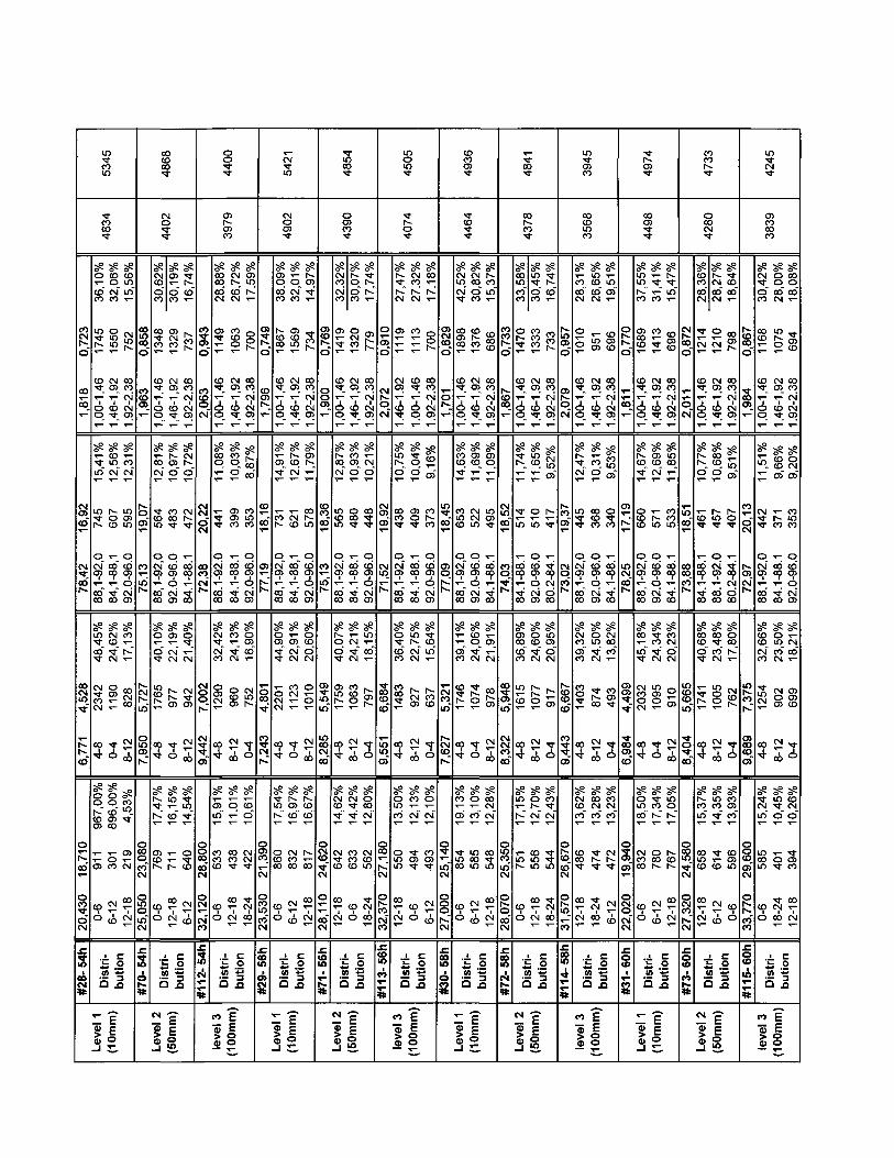
0,72
3
oo
16,9
2
00
4,52
86,
771
o
00
o"CN
i09
m
534
C0
seo
coco
1745
to
x�
1,00
-
se
in
745
oCMCDx -
0000
semon�«a-
2342
4-8
seO
o,
T �T �
CD
0-6
T
è
se(OoCMCO
0991
fMaix�
1,46
-
CM
607
0000x -
00
seCMCDxj-
CM
1190
0-4
seoCDCO
Y �
Oco
CM
se<omm
752
oncoCM
1.92
-
secôCM
595
otoen
6CMCD
seCO
"~
828
8-12
vo
CO
m
CD
CM
2-18
ï o
Dis
buti
Levé
F"
(10m
0,85
8
en
1,9
19,0
7
co
m
5,72
77,
950
ooocoCM
im"CM
s
#70-
coCiol
CM
440
S?CMCOOCO
1348
<ox�
1,00
-
s?côCM
564
o
92
x-
00C0
S?oo
1765
oo4
s?IV.
rv
enm
0-6
�c
sem<~>co
1329
CMCDY -
1,46
-
seeno
483
o
86
92
seenCNCM
977
0-4
sein
eo
r-
2-18
serv.fO
737
encoCM
1.92
-
ssCM
O
472
�_oooo
SseoT_CM
942
8-12
seSxfr
<->
S
CNT�
<o
: §
Dis
CM
(50m
32
0,94
3
tn
CM
20,2
2
ooCM
7,00
29,
442
8ou00CM
2,12
0
co
i
#112
-
o
440
CDenco
seonooooCM
1149
en"
1,00
-
se00
ox-
x�
O
Si00oo
seCM
CMCO
1290
|
4-8
se5>in
COnCD
0-6
seCM
eoCM
1063
CMCDx�
1,46
-
seCO
oo
399
00
�A-
sseCO
-<TCM
960
8-12
seox-
onm�«a-
2-18
seCDin
"*"
700
00
coCM
1.92
-
oo"
353
o
86CMen
seoO)on
752
|
0-4
setoo
CMCM�«a-
8-24
Ê o
Dis
but
co
leve
l
(lu
S
0,74
9
o>
18,1
6
ai
4,80
1I
7,24
3
oO)
CM
3,53
0
CM
#29-
542
CM
490
se8coco
1867
1,00
-
seCD�<a-
731
o
Sicoco
se
90
�«a-��a-
2201
4-8
S?
srv
0-6
sex�
oCNCO
1569
CMO)* { �
1,46
-
seCDCM
621
00
°p
sse
91
CMCM
1123
0-4
serveneo
CMC)00
CM
seO)>
� * ~
734
00
coCM
1.92
-
seenx-
578
o
8o
seoto
oCM
1010
| 8
-12
secotD
T �
00
2-18
�= i
Dis
but
Levé
- = �
(10m
0,76
9
8.
18,3
6
co
m
5,54
9|
8,
285
oCM
248,
110
CM
O
#71-
rmoo
o
439
seCMC)CMCO
1419
tn
x�
1,00
-
seooCM
565
o
Si0000
seoo
1759
4-8
seCMto
CM
S
2-18
�E
VC
CN
Levé
seooco
1320
CMenx-
1,46
-
seC)CDO
480
oox -
SseCM�«a-CM
1063
8-12
seCM
-s-� < * �
COcoeo
0-6
ser-i�"*~
779
cocoCM
1.92
-
seCMO
448
o
8oSi
semon
797
|
0-4
seo00CM
CN
S
8-24
S
but
1
0,91
02,
019
,92
52
x-
6,68
4|
9,5
51
ooo
2,37
0
co
i
#113
-
m
450
�«a-
407
se
|�CN
1119
CNO)<c�
1.46
-
semo
438
oCDx -
0000
seoeoco
1483
I 4-
8
seomco
oinin
2-18
seCMCOI�CM
1113
r�
1.00
-
v?
So
409
co
x -
Sse
75
CMCM
927
8-12
secoCM
�«a-CD
0-6
seon|V.
ooz
00
eoCM
1.92
-vPCD
en
373
o
8oCMCD
seSm
637
|
0-4
seoCM
COCD� < *
CM
J= o
Dis
but
co
leve
l
E"
(100
m
0,62
9
T_o
18,4
509
|v.
5,32
1I
7,62
7
o
»
257,
000
CM
#30-
tD
493
�Sr
446
seCMmCM
1898
eo
1,00
-secoto� *
653
oa\x -
0000
se
CDCJ
1746
I 4-
8
seC)
CD
m00
0-6
seCMOOoco
1376
CMCDx�
1,46
-
seentox-
229
o
8oCMen
setooCM
1074
0-4
seo
co
in00in
CM
secoin
686
onC)CM
1.92
-
8
495
0000x -
00
seenr�CM
978
8-12
se00CMCM
en�>a-in
2-18
f. §
Dis
but
x-
Leve
- = �
(10m
0,73
3I
1,86
18,5
2
coo
5,94
88,
322
U)
mCN
8,07
0
CN
i
#72-
484
co
437
seonincoco
1470
to� *
x�
1,00
-
se
x-
514
x�
00oox -
oo
ss8enco
1615
op4
semr-
m
0-6
sein*oco
1333
CMG)x�
1,46
-
seinCDx-
510
o
oSi
se8CM
1077
8-12
se
CM
tnmm
2-18
se|v
en
733
encoCM
1.92
-
vo
CM
en"
417
x-
�srooCMOoo
semenoCM
917
0-4
se
43
CM
xj.
4"U)
8-24
S o
Dis
but
CM
Levé
-p
(50m
0,95
72,
019
,37
CMOCO
6,66
7!
9,44
3
ofv
1,57
0
eo
#114
-
in
394
co
356
secoonCM
1010
tn
1,00
-
se
CM
445
o
Six-
seCMCOO)CO
1403
co4
seCMCDCO
enon"*
2-18
seincotnCM
951
CMenx�
1,46
-
secoo
368
o
eno
Si
seomCM
874
8-12
secoCMCO
rv
8-24
ssmCD
696
tncoCM
1.92
-
vPco
CD"
340
T �
x-
sseCMCOco
493
0-4
seCOCMCO
CN
CM
�= i
Dis
but
«o
leve
l
"Êoo
0,77
0
x�
1,8
17,1
9
mCNoo
4,49
9|
6,9
84
o
en
2,02
0
CM
i
#31-
r
497
oo
449
semin[s.
co
1689
46
X ( �
1,00
-
seeo�q-
660
o
Six-
se00
m20
32I
4-8
se8OO
CMCOco
0-6
sexj-
x�C)
1413
fNenx�
1,46
-
seCDCDCN
571
oOi
o
Si
seSCM
1095
0-4
se
rv
oonrv
CM
se
m
696
oncoCM
1.92
-
SSmcox-
533
T �
cox-
SsecoCMOCM
910
8-12
semorv
enrv
2-18
.J. CJ= O
Dis
but
x-
Leve
� = �
(10m
0,87
2
\�T�
2,0
18,5
1
0000
co
5,66
5|
8,4
04
00
et
7,32
0
CN
60h
#73-
co
473
o
428
se<nCOonCM
1214
enx�
1,00
-
serv.o
461
x-
sse00eoo
1741
co4
seftin
enmeo
2-18
seCMonCM
1210
CMCDx�
1,46
-
sscoCD
o
457
o
Six -
SSoocoCM
1005
8-12
semeo1-
x�to
CM
seSon
798
encoCM
1.92
-
v°
CTT
407
T_
sCM
8
se8rv
762
0-4
se8co
tnCDm
0-6
!£ o
Dis
but
CM
Levé
� = �
(50m
0,86
7
on
1,9
20,1
3
�CM
7,37
5|
9,
689
OcoCM
3,77
0
co
#115
-
L
r->
CD
383
seCM
Oco
1168
en�3-x�
1,00
-
se
x-
CM
OCMenx -
00oo
se8CMco
1254
oo4
seCMm
monm
0-6
"ij
co
leve
l
seooonCM
1075
fNCDx�
1,46
-
v°eoen
371
cooox -
00
se8roCM
902
8-12
se45
o
Y �
O
8-24
seenoon
694
oneoCM
1.92
-
v=
CD"
353
o
96
ôCMCD
seCMen
669
0-4
seeoCMo
CDCO
2-18
. c
ng"
(100
m
3

0,67
31
Tj
T17
,00
9,83
4,53
8|
6,
835
70
en"
2,08
0
CM
62h
#32-
rv.
506
4582
seCM
inCO
1994
461,
00-1
S3inCOCO
749
1
o
1-92
00co
S3
rvfrfr
2050
4-8
S3côoo
CM
8
0-6
S3enenCM
1373
36
1,46
-1
v?
3
671
1
o
0-96
CM
en
S3eneni nCM
1191
0-4
S3frfr
CO
i n
S
CM
00
677
11.9
2-2
S300
CMI 899
1-88
S
S3oenen
912
8-12
S3CN
mm
r
2-18
t O
Dis
r-
Ç3
(Ul
E
0,82
91,
930
17,8
25,
481
| 8
,166
06
co"CM
| 2
6,99
0
£N
CO
#74-
CM
458
frfrl.fr
S3eo
�CO
1290
46
iS3enoCM
Om
o
1-92
coco
S3enrv.CN
1772
4-8
S3Seo
COinm
2-18
'itS
CN
fi
S3
S8
1277
921,
46-1
S3CM
en
494
1
1-88
S
S3oi nCOCM
974
8-12
S3§}eo
rv
!n
CM
Srv
731
1.92
-2
>poonen
406
o
0-96
CM
en
S3i n
r�~
725
|
0-4
S3oenco
enm
0-6
but
(ui
E
£�
0,98
5
h -
I 2,09
19,6
51,
456,
714
|
9,45
07,
630
CM
1,49
0
CO
Nco
#116
-
r
431
3904
s?or-CM
1058
4611
.00-
1
S3oCO� » -
l-frfr
o
1-92
§
S3v .
coco
1433
4-8
S330CO
enCO
m
2-18
S3SCOCM
1036
921,
46-1
v 9
en
381
X �
1-88
S
S3Y " *
meoCM
918
8-12
S3oco
00oin
6-12
tri- nn
Dis
hut
CO
CD
s
?<->
(10
S3oencc
738
ooco
1.92
-2
v?
oo"
342
o
0-96
g
S3i n| v -
mT~
615
|
0-4
S3I.0
CM
enCO
0-6
0,63
8
S
17,1
7S0
.51
4,24
4|
6,
528
gen"
1,16
0
CM
#33-
I V
567
5134
S3coeoi n
2345
46I 1
,00-
1
S3
71
co
898
o
0-96
CM
en
S3rv,�«a-^ -
2283
4-8
S3en
CO
o
0-6
a
fi
S3eneooco
1560
921,
46-1
S3
78
m
810
o
1-92
00CO
S3CMCN
coCM
1449
0-4
S3coCMrv
rvcooo
2-18
S3
eoT~68
6
ooeo
1.92
-2
S3
75
x�
603
o
.0-1
0
S3CN
co
961
| 8
-12
S3rvcneo
rvoo
CM
en
uo
but
(Ul
E
0,77
6
i n
s
18,2
4
80'9-399'9
| 8
,218
5,30
0
CM
8,29
0
CM
64h
#75-
o
503
4549
S3coo
S
1548
461,
00-1
S3Seo
593
o
1-92
ooco
vS
sooco
1755
4-8
S3
eo
«a-� �
0-6
u
If
c
CM
çfi
S3Soeo
1402
921,
46-1
S3coCM
513
1-88
84
S3g-a-CN
1096
8-12
S3coenCM
on00m
2-18
S3éoen
744
381.
92-2
S3ooooo
495
o
0-96
CM
en
S3
gQCM
910
|
0-4
S3CM00CM
CO00in
8-24
§
but
£
0,90
8m
1,99
19,3
0
S«
6,97
6|
9,
630
o
on"CM
3,80
0
co
#117
-
en
404
3662
S3 S3co mO CMT - r-.eo CM
1138
998
C O Ç N
1.00
-1
1,46
-1
S3 S3T - enr - CMT- Ol
LL
ZZO
fr
O r-
1-92
1-88
co -<tco co
S3 S3T - enCM eoeo � *eo CM
1216
893
4-8
8-12
S3 S3'S- Oo oT T-
� * c o
£ §
0-6
2-18
v?
s� * ~
657
381.
92-2
v°CM
en
356
o
0-96
CM
en
S3CNCO
en
616
|
0-4
S3mcoo
eneo
8-24
Dis
but
«o ?� o
0,68
2
m
1,72
16,7
79,
844,
360
| 6,
625
o
ai
1,11
0
CM
#34-
r
534
4835
S3gT �
�M-
9303
461,
00-1
S3
Seo
814
1
o
1-92
ooco
S?onO)i n
2223
4-8
S3
o
CM
g
0-6
S3CMOeo
1462
921,
46-1
ssG)CN
691
1
o
0-96
CM
en
S3enC)
enCN
1276
0-4
S3incorv
encoco
CM
S3eor-.i nT~
762
381.
92-2
S3
S
563
11-
88
S
S3
enco
917
j 8
-1
2
S3
48
eo
en
2-18
S o
Dis
but
fi
(Ul
E
c.
m
491
4445
0,85
5
co
s.
18,4
75,
815
|
8,26
6
oPîi nCN
7,76
0
CM
M99
cô
S38y �
eo
-s -sSSen coCM v -
1400
1290
802
eo CM co�>*� en co
1,00
-11,
46-1
1.92
-2
ss gs ssM" ^ CM
CO T - O
^ NOoo CN min m � *
O T- O
1-92
1-88
0-96
oo ^r CMoo co en
S3 SS SSo rv enm �* eo|v. CM T -CO CM CM
1667
999
951
4-8
8-12
0-4
S? S3 S3m i- teo oo CD
rv co CM
eo � * CM00 T - CDrv. co m
Ô CM &
'È o
Dis
but
CM -g"
Ç E
0,92
2
m
2,04
19,8
13,
446,
876
|
8,99
9
oco
£}CN
9,37
0
CN
i
#118
-
r-
428
3877
S3
45
coCM
1103
461.
00-1
S3i n
frfrfr
o
1-92
coco
S3en
S
1325
4-8
S3CMCO
rv
cococo
0-6
�i
S3côCN
1078
921,
46-1
S3Ci
o
416
11-
88S
S3enenT�CM
398
8-12
S3co
co
en8
oo
S3689
1.92
-2
sP
Cs|en"
357
2-84
S3encoT�CN
838
|
0-4
S3
co
CM
UO
Dis
but
co
?s
(10
0,72
01,
8116
,34
8,99
4,50
5|
6,
897
o
o"CM
1,88
0
CM
#35-
542
4902
S3I V .
CO
1822
461,
00-1
S3enmm
764
1
o
1-92
cooo
S3CNOfrfr
2158
4-8
S3
en
en
0-6
S3m
oco
1478
CM
en
1,46
-1
S3enooCM
632
1
o
0-96
S3encomCM
1258
0-4
S3cSrv
h-
So
CM
S3co
en
820
ço
1.92
-2
S3
44
*-
561
1
_
1-88
S
S3oncooCM
999
8-12
S3coCD
CNen
2-18
È o
Dis
but
fi
FOT -
0,86
81,
960
17,9
35,
385,
633
8,34
1
o
I!-CM
7,83
0
CM
68h
#77-
en
458
4150
S3CM
enoC)
1283
461,
00-1
S3
SCN
528
1
o
1-92
coco
S3
menco
1642
4-8
S300^~
5
0-6
S3co
enCM
1209
CM
en
1.46
-1
S3
� > -
479
1
x�
1-88
S
S3
e�«a-CM
1010
8-12
S300
co
corv.
8-24
tri-
Dis
CM
çfi
£
S3eocoon
762
oocoCM
CM
en
S3moo
417
1
x�
2-84
8
S3co
on
765
0-4
S3CM
mco
eoin
2-18
§sa
0,97
82,
109
19,7
22,
197,
000
9,65
0
8CM
1,96
0
co
i
#119
-
427
3862
ss61.
CM
1050
co
1.00
-1
S3eo
453
1
o
1-92
§
S3rv
enco
1397
4-8
S3menCM
oom
2-18
S3
enCM
1018
CM
en
1,46
-1
S3oCMO
394
1
�_co00
00
S3o00eoCM
919
8-12
S3cocoCM
on
8-24
S3Sonx�
696
ooeo
1.92
-2
vO
eo
en"
350
o
0-96
CM
en
S3encoi nr�
594
0-4
S3encoT -
enm
0-6
S o
Dis
but
coes
(lU
ho

Level 1(10mm)
Level 2(50mm)
level 3(100mm)
Level 1(10mm)
Level 2(50mm)
level 3(100mm)
Level 1(10mm)
Level 2(50mm)
level 3(100mm)
Level 1(10mm)
Level 2(50mm)
level 3(100mm)
#36- 70h
Distri-bution
#78- 70h
Distri-bution
#120-70h
Distri-bution
#37- 72h
Distri-bution
#79- 72h
Distri-bution
#121-72h
Distri-bution
#38- 74h
Distri-bution
#80- 74h
Distri-bution
#122-74h
Distri-bution
#39- 76h
Distri-bution
#81- 76h
Distri-bution
#123- 76h
Distri-bution
26,500 23,3806-12 719 15,49%0-6 703 15,15%
12-18 647 13,94%30,640 26,30018-24 550 12,78%0-6 541 12,57%
12-18 535 12,43%33,850 28,53012-18 457 12,97%18-24 417 11,84%6-12 406 11,52%
24,570 22,1606-12 724 16,98%0-6 715 16,77%
12-18 637 14,94%28,860 25,20012-18 563 14,35%0-6 532 13,56%
6-12 517 13,18%30,960 26,44012-18 530 14,04%6-12 518 13,73%18-24 436 11,55%
25,550 22,3900-6 745 16,90%
6-12 642 14,56%12-18 610 13,84%
31,560 26,46012-18 551 12,45%18-24 539 12,18%0-6 518 11,70%
35,950 30,4500-6 439 12,00%
18-24 398 10,88%12-18 378 10,33%
23,150 20,8200-6 806 17,74%
6-12 798 17,56%12-18 724 15,93%
29,510 25,4706-12 578 13,61%0-6 560 13,18%
12-18 546 12,85%34,840 29,06018-24 430 12,01%12-18 425 11,87%0-6 392 10,95%
7,618 4,9764-8 1958 42,19%8-12 1024 22,06%0-4 1008 21,72%
8,641 5,8134-8 1733 40,26%8-12 1043 24,23%0-4 705 16,38%
9,948 7,1364-8 1270 36,05%8-12 866 24,58%0-4 480 13,62%
7,313 4,6684-8 1836 43,06%0-4 965 22,63%8-12 960 22,51%8,574 5,8224-8 1561 39,79%8-12 932 23,76%0-4 683 17,41%
9,363 6,5424-8 1429 37,86%8-12 929 24,62%0-4 558 14,79%
7,280 4,5944-8 1873 42,49%8-12 1043 23,66%0-4 993 22,53%
8,829 5,9144-8 1692 38,23%8-12 1156 26,12%0-4 708 16,00%
10,080 7,4024-8 1180 32,25%8-12 931 25,44%0-4 560 15,30%
6,992 4,5334-8 2020 44,45%0-4 1107 24,36%8-12 947 20,84%8,611 5,8424-8 1638 38,56%8-12 1102 25,94%0-4 725 17,07%
10,100 8,3754-8 1264 35,30%8-12 868 24,24%0-4 485 13,54%
78,58 17,4988.1-92.0 694 14,95%92.0-96.0 673 14,50%84.1-88.1 532 11,46%
75,80 18,1088.1-92.0 596 13,84%84.1-88.1 494 11,48%92.0-96.0 469 10,89%
72,05 19,7088,1-92,0 404 11,47%84.1-88.1 343 9,74%80.2-84.1 316 8,97%
78,76 16,6188.1-92.0 617 14,47%92.0-96.0 566 13,27%84.1-88.1 533 12,50%
74,96 18,4088.1-92.0 517 13,18%84.1-88.1 443 11,29%92.0-96.0 383 9,76%
72,25 19,2188,1-92,0 417 11,05%84.1-88.1 382 10,12%80.2-84.1 345 9,14%
79,25 16,8088.1-92.0 692 15,70%92.0-96.0 618 14,02%84.1-88.1 549 12,45%
75,23 18,1788.1-92.0 615 13,90%84.1-88.1 524 11,84%92.0-96.0 434 9,81%
72,47 19,6388,1-92,0 393 10,74%84.1-88.1 365 9,98%92.0-96.0 350 9,57%
79,81 16,8388.1-92.0 720 15,85%92.0-96.0 715 15,74%84.1-88.1 560 12,32%
74,58 17,6888.1-92.0 506 11,91%84.1-88.1 487 11,46%80.2-84.1 434 10,22%
71,90 19,5488,1-92,0 386 10,78%84.1-88.1 365 10,19%80.2-84.1 323 9,02%
1,749 0,6901,00-1,46 1896 40,85%1,46-1,92 1396 30,08%1.92-2.38 714 15,38%
1,877 0,7711,00-1,46 1432 33,26%1,46-1,92 1309 30,41%1.92-2.38 776 18,03%
2,106 0,9841.00-1.46 993 28,19%1,46-1,92 935 26,54%1.92-2.38 590 16,75%
1,789 0,7071,00-1,46 1590 37,29%1,46-1,92 1336 31,33%1.92-2.38 710 16,65%
1,976 0,8711,00-1,46 1201 30,61%1,46-1,92 1140 29,06%1.92-2.38 695 17,72%
2,095 0,9331.46-1.92 1031 27,32%1.00-1.46 1002 26,55%1.92-2.38 710 18,81%
1,713 0,6351,00-1,46 1830 41,52%1,46-1,92 1427 32,37%1.92-2.38 630 14,29%
1,855 0,7721,00-1,46 1541 34,82%1,46-1,92 1344 30,37%1.92-2.38 749 16,92%
2,036 0,9031,00-1,46 1045 28,56%1,46-1,92 1036 28,31%1.92-2.38 652 17,82%
1,705 0,6601,00-1,46 1986 43,71%1,46-1,92 1368 30,11%1.92-2.38 682 15,01%
1,944 0,8191.46-1.92 1303 30,67%1.00-1.46 1278 30,08%1.92-2.38 773 18,20%
2,076 0,9341.46-1.92 1010 28,20%1.00-1.46 956 26,70%1.92-2.38 664 18,54%
4641
4305
3523
4264
3923
3774
4408
4426
3659
4544
4248
3581
5132
4760
3896
4715
4338
4173
4874
4894
4046
5025
4697
3960

Level 1(10mm)
Level 2(50mm)
level 3(100mm)
Level 1(10mm)
Level 2(50mm)
level 3(100mm)
#40- 78h
Distri-bution
#82- 78h
Distri-bution
#124-78h
Distri-bution
#41-80h
Distri-bution
#83- 80h
Distri-bution
#125- 80h
Distri-bution
23,480 20,7506-12 857 17,31%0-6 840 16,97%
12-18 743 15,01%31,560 27,020
0-6 542 13,51%12-18 466 11,62%6-12 453 11,29%
36,030 30,3100-6 493 13,44%
18-24 386 10,52%24-30 354 9,65%26,000 22,850
0-6 654 15,65%6-12 621 14,86%12-18 607 14,53%
30,730 26,2300-6 558 13,60%
12-18 510 12,43%18-24 501 12,21%
38,110 30,36012-18 349 10,68%0-6 343 10,50%
18-24 321 9,83%
6,968 4,4334-8 2224 44,93%0-4 1188 24,00%8-12 1045 21,11%8,999 6,3174-8 1440 35,90%8-12 1070 26,68%0-4 677 16,88%
10,200 7,4224-8 1127 30,73%8-12 953 25,98%0-4 569 15,51%
7,432 4,8134-8 1769 42,33%8-12 1014 24,26%0-4 902 21,58%
8,666 5,6644-8 1564 38,11%8-12 1042 25,39%0-4 697 16,98%
10,160 6,9474-8 1085 33,21%8-12 860 26,32%0-4 418 12,79%
79,91 16,3388.1-92.0 804 16,24%92.0-96.0 741 14,97%84.1-88.1 642 12,97%
73,92 18,9388.1-92.0 474 11,82%84.1-88.1 431 10,75%92.0-96.0 378 9,42%
70,79 20,4288,1-92,0 374 10,20%84.1-88.1 370 10,09%76.2-80.2 303 8,26%
79,23 17,5088.1-92.0 699 16,73%92.0-96.0 598 14,31%84.1-88.1 540 12,92%
74,97 18,2888.1-92.0 504 12,28%84.1-88.1 459 11,18%92.0-96.0 435 10,60%
73,51 19,0288,1-92,0 416 12,73%84.1-88.1 348 10,65%92.0-96.0 322 9,86%
1,676 0,5981,00-1,46 2183 44,10%1,46-1,92 1535 31,01%1.92-2.38 719 14,53%
1,913 0,8081,00-1,46 1343 33,48%1,46-1,92 1151 28,70%1.92-2.38 686 17,10%
2,037 0,9271.46-1.92 1064 29,01%1.00-1.46 1020 27,81%1.92-2.38 684 18,65%
1,721 0,6701,00-1,46 1798 43,02%1,46-1,92 1283 30,70%1.92-2.38 588 14,07%
1,917 0,8251,00-1,46 1336 32,55%1,46-1,92 1201 29,26%1.92-2.38 735 17,91%
1,944 0,8231,00-1,46 1025 31,37%1,46-1,92 974 29,81%1.92-2.38 532 16,28%
4950
4011
3668
4179
4104
3267
5474
4435
4056
4621
4538
3613

Silicon Particles Analysis (Sr-modified)
Magnification:No. of Fields:
1000 X
40
Field Area (|jm2) :
Total Area (|jm2) :
5664
2.26572E+0S
Updated:
2005-09-30
Level Sample ID Area (um2) Length (urn) Roundness (%) Aspect Ratio Total # Si ParticleAve. SD Ave. SD Ave. SD Ave. SD Features Density
Level 1(10mm)
Level 2(SOmm)
level 3(100mm)
Level 1(10mm)
Level 2(50mm)
level 3(100mm)
Level 1(10mm)
Level 2(50mm)
level 3(100mm)
#S1-0h
Distri-bution
#S43- Oh
Distri-bution
#S85- Oh
Distri-bution
#S2- 2h
Distri-bution
#S44- 2h
Distri-bution
#S86- 2h
Distri-bution
#S3- 4h
Distri-bution
#S45- 4h
Distri-bution
#S87- 4h
Distri-bution
1,163 1,939Range Qty. Percent
0-2 22713 84,78%2-4 2647 9,88%4-6 752 2,81%
2,821 4,0910-3 12976 71,92%3-6 3112 17,25%6-9 987 5,47%
3,077 4,2600-3 12035 67,61%3-6 3447 19.36%6-9 1190 6,69%
3,875 4.3750-3 3864 54,83%3-6 1798 25,51%Q-9 706 10,02%
4,164 4,4660-3 3964 51,06%3-6 2100 27,05%6-9 882 11,36%
4,623 4,6850-3 3564 43,90%3-6 2522 31,07%6-9 1066 13,13%
4,127 4,9230-3 2753 54,84%3-6 1134 22,59%6-9 562 11,20%
4,969 5,6610-3 2855 44,69%3-6 1809 28,32%6-9 798 12,49%
5,088 5,9110-3 2774 45,15%3-6 1652 26,89%6-9 792 12,89%
1,568 1,363Range Qty. Percent0.5-1.0 8510 31,76%1.0-1.5 5280 19,71%0-0.5 3552 13,26%2.358 1,9051.2-1,8 4462 24,73%0.6-1.2 4007 22,21%1.8-2.4 2147 11,90%2,478 2,0271.2-1,6 3871 21,75%0.6-1.2 3554 19,97%1.8-2.4 2131 11,97%2,548 1,7941.2-1.8 1427 20,25%2.4-3.0 1145 16,25%0.6-1.2 1080 15,33%2,662 1,7681.2-1.8 1536 19,79%2.4-3.0 1337 17,22%1.8-2.4 1149 14,80%2,839 1,857
2.4-3.0 1602 19,73%1.2-1.8 1367 16,84%1.8-2.4 1217 14,99%2,588 1,8311.2-1.8 1022 20,36%0.6-1.2 769 15,32%2.4-3.0 720 14,34%2,885 1,929
2,4-3.0 1127 17,64%1.2-1.8 1057 16,55%1.6-2,4 874 13,68%2,975 2,050
2.4-3.0 1043 16,98%1.2-1.8 956 15,56%1.8-2,4 835 13,59%
75,24 20,64Range Qty. Percent
96.0-100 5279 19,70%80.2-84.1 2547 9,51%84.1-88.1 2384 8,90%
77.23 21,4596.0-100 3287 18,22%88.1-92.0 2407 13,34%92,0-96.0 2152 11,93%
77,23 21,2396.0-100 3449 19,38%88.1-92.0 2120 11,91%92,0-96.0 1941 10,90%
83,39 15,6588.1-92.0 1349 19,14%92,0-96.0 1227 17,41%96.0-100 1073 15,23%
85,35 13,9388.1-92.0 161*1 20.79%92.0-96.0 1572 20,25%96.0-100 1339 17,25%
85,52 13,9192.0-96.0 1945 23,96%88.1-92.0 1678 20,67%96.0-100 1246 15,35%
83,80 13,8384.1-88,1 983 19,58%92.0-96.0 766 15,26%96.0-100 739 14,72%
84,76 13,5388.1-92,0 1305 20,43%92.0-96.0 1273 19,93%84.1-88.1 907 14,20%
82,96 14.6788.1-92.0 1145 18,64%92,0-96.0 1060 17,25%84.1-88.1 848 13,80%
1,806 0.662Range Qty. Percent
1.96-2,12 4219 15,75%1.48-1.64 3741 13,96%1.00-1.16 3302 12,33%
1,527 0,3701.00-1.06 1608 8,91%1.48-1,54 1546 8,57%>1.30-1.36 1444 8,00%
1.654 0.5531.16-1.32 2769 15,56%1.00-1.16 2616 14,70%1.32-1.48 2612 14,67%
1.521 0,5021.16-1.32 1539 21.84%1.00-1.16 1390 19,72%1.32-1.48 1166 16,55%
1,491 0,4471.16-1.32 1803 23,23%1.00-1.16 1548 19,94%1.32-1.48 1314 16,93%
1,486 0,4471.16-1.32 1933 23.81%1.00-1.16 1669 20,56%1.32-1.48 1398 17,22%
1,505 0,4431.16-1.32 1119 22,29%1.00-1.16 925 18,43%1,32-1.48 891 17,75%
1,507 0,4531,16-1.32 1522 23,83%1.00-1.16 1170 18,32%1.32-1.48 1095 17,14%
1,568 0,5081.16-1.32 1306 21,26%1.32-1.48 1032 16,80%1.00-1.16 1013 16,49%
26791
18043
17801
7047
7763
8118
5020
6388
6144
147806
79635
78567
31103
34263
35830
22156
28194
27117

0,41
6,4
405,
71
ro00eoCO
1,93
8,8
0
928'
5,17
5 5
£co
*
ooCO
CM
enT
CDin
sem
CN
1359
eo
oa
seCOmcn
1100
oCMO>
oo00
seCOCNIs-
en
CO
CN� « -
seCMinI - .
oeo
CO
ci
seonoCM
1353
CM
6-1.
3
seo
cn
1073
oCOrooCMro
sem
M-
812
oCO
CM
sex�
CNCM
244
3-6
seo1^^~
956
co
co
seCO
f s .
� * "
964
oo
o
96
sex�
xfr
793
CM
6-1
o
sem
T�� * ~
660
enCD
�i i.2 Xa Ë
Leve
F"
(10m
0,41
4,4
414,
10
Ci
co00
2,02
1
?
,577
6,12
0 6
-6h
«o
mohmCM
M-CN00m
ser-
eoCM
1559
CMCO
eo
seco
oCN
1174
oCNro
0 00 0
se�xj-
CD
940
oeo
CM
seCNO0 0eo
>214
coo
seCDCMCM
1317
eo
0-1.
1
o
seco0 0
1084
ococnoCMen
seenom
879
00
CM
sex�
mCM
466
3-6
ser-CD1�T "
1029
oo
co
sex f
eo
783
en
1-8
00
se0 0
eo
808eoeo
6co
seoCMm
988
6-9
�à i�2 1O Ë
«M
Levé
?"
(50m
0,44
1,4
973,
40
C3O
3
2,07
8,4
435,
997
�
£«O
CO
oCDT
CM
CDr-mm
serooxfl-CM
1343
CMCO
x�
ci
seCM
OCN
1122
oCNro, 1ooco
secoCMCD
905
o
4-3
CM
se
coC)
>149
coci
serox�
ro
1070
eo
ci
secoenCD*~
947
oCDO>OCN
ro
seeo� < *
818
00
CM
secoeomCM
432
3-6
seo
CD
936
co
T
seacoCD^~
914
00op
00
seCDcoco
745
CD
0-3
co
semcox j -
838
6-9
� = i
c
to
leve
l
s
(100
ir
4
I
0,39
1,4
193,
21
cooin
1,99
7
8.
96S'<
6,06
3
e
£00
�ô
1
'01o<o
oCD
sex^-
CN
1140
CN
6-1.
31.
1
serocox�
CM
806
oCMCp
CO00
sex>x�
eo
673
co
CM
semx�
727
2
9-
s?m
coCM
886
CD
1.00
-1.1
seoo
roT~
823
ocoen6CMro
seCMCD
608
oco4CN
seM-0 0
CNCM
950
CD
CO
secrCN
*^71
8
co
1CN
co
seeomeoT~
563
oo
oeo
sex3-CM
CM
509
eocooco
secoroCMT~
540
6-9
� = ia2 * ;
i
Levé
(10m
0,40
4,4
542,
32
mcom
2,00
1
CO
,508
6,07
0
e
£00
h*
g
cotncoX
CM
00eocoxt
seh-comCN
1242
CM
6-1.
3
ser-CNCN
1100
oCNro
CO0 0
secoCD
789
oco
4CM
seooroeo
887
0-3
seco
C-5CM
�ro
eo
0-1.
1
o
semC )x�CN
1035
oCDrociCM�
secocol O
744
CO
seCMOx j .
CM
162
3-6
semc\00
883
co
CNm
seeoxfl-
x�
714
ooco
xfr00
semCM
608
CN
CO
� " "
secox�
mx�
732
6-9
F i.2 1
CM
Levé
s J:
-=-
(50m
0,48
4,5
194,
12
gS
2,24
6
00
,579
6,75
2
7B9
-8h
corrooCM
com
seco
CNCM
1082
CNCO
ci
sex j -
oCM
973
oCNro.ri.co00
seroom
717
oeo
CM
seeocoeoo
741
0-3
t
seroco
668
eo
cio
sex »CMOCN
962
oCDrooCN
ro
sex�
roco
661
CD
0-3
eo
seCMeoCN
106
3-6
secoo| s _
812
0 0
CMCO
seeoeo
649
oo1
ciCD
se
04
co
039
00
* -
se0 0
comT~
755
enci
"F i�2 1û ï
n
leve
l
�§�
(100
m
i
0,39
0,4
372,
51
eotnou
1,99
9,0
2:,3
225,
924
6
£O
m
c� >
eomroT
t nCN�srx j -
sex�
eoCN
1158
CMCO
ei
sem_
CM
953
oCMro
m00
seeomm
687
00
seC)co
918
coci
seCMCMCN
984
co
cio
sei�
ro
872
ocorooCMro
seCM
roeo
616
o
4-3
CM
sex *
x�CM
0963-
6
seroCMh-
765
m�<r
CN
co
secox f
* ~
654
oo
cieo
secoCM
548
S
seX3-CO
CN
546
roci
à i« 1Q ï
Leve
� = �
(10m
0,42
6,4
762,
63
Sm00
2,00
0
S
,356
5,78
9
�10
h
co
CM* rCOCNCN
OeoT
m
seooeoi nCM
1302
CMO
ci
seCDCNCM
1163
oCNro
1
88.
sex j -
CD
845
00
CM
secoC)CM
'173
coci
S?
roco
973
eo
cio
seoo
oCN
1035
oeorooCMro
seCMeom
786
oco
4CN
sex�
eoCM
187
3-6
sem^.~
900
0 0
CNCO
seCN
T ~
740
0 0
co
sex^-
CN
638
x j -
8-2
� > -
semcoeo*~
685
roeo
= ii ï
CM
Levé
�=�
(50m
0,47
0,5
073,
39
Smco
2,18
0
i
,071
6,52
4
710
h
ci
inmcoCMCN
t nCDom
seeoeocoCN
1183
CNeo
ei
1.1
setn
oCN
1051
oCNro
0 0co
seen
xfr
759
o
«?CM
secoCDeoco
857
eoci
"i
secoooCN
1016
eo
oo
seocooCN
8301
oeoO)OCMro
seCMO
710
eococico
se0 0eoeoCM
184
3-6
seCMCOCO
842
co
cilco
seoX;f-
* ~
714
ooeo
°'secoroCM
655
CM
3co
seeooeo
812
enCD
= i�2 1Q Ë
n
leve
l
f
(100
m
0,39
3,4
411,
91
o00mco
2,08
3
Enr�
,004
6,42
6
712
h
I OCM
r-
CD
o
seCNcomCM
1017
CMCO
ci
1.1
sem_
CN
865
oCNro,_coco
seCMCD
651
co
CM
se0 0
CM
694
eoo
'i
f
sem
CM
864
eo
oo
sex�
OCN
809
oeoO)oCMro
seeoco
537
ocp
CN
sero
oCM
823
3-6
= i
secoco0 0
736
0 0
co
seCNroeo
559
oo
oCD
seoroCN
518
�.
8-2
� « -
semmCN
504
roCD
5�2 1Q .a
Levé
� = �
(10m
0,38
8,4
291,
97
CMcoco
2,10
8
°.
,250
6,92
5
7
£(M
on
cococooCN
oCDx !
se1�eoCN
1232
CMeo
CD
secoeoCM
1097
oCMen, -0 0
eo
sex�
m
696
00
seeoCMeoc;
699
coo
T
secoCMCMCN
1024
CO
x�
O
o
seoCMCOCM
1069
ocomoCMro
seeox�
�«J-
651
o
4CN
serox�CM
012
3-6
seo
cn
880
co
CMCO
seeoroeo
643
x�
0 0
cp
00
seroCN
597
co
0-3
co
seocom"*"
705
roCD
à o« ^
CM
Levé
� p
(50m
0,44
7,4
552,
77
i s .
co
86,
2,18
2,2
677,
105
712
h
eorocoCMCM
I-0 0V
m
sem� > *
�M-CN
1268
CMCO
ci
seomCNCM
1167
oeorooCMro
seCMx *
740
CDCO
6co
se
eoeo
750
0-3
'i
secocoCM
1235
eo
cio
secoCN^_CM
1104
oCMro
0 00 0
seeoeo
706
oco
CM
seCMtn
CM
116
3-6
seT -
� * ~
889
0 0
co
seeooj s .
* ~
885
oo
oCD
seco
x -
593
co
CM
seotnco
856
6-9
; i(A �-
Q £
n
leve
l
�g-
(100
m

r-
435
S co om' CM' OO"CM CM x -
CM CO 0 0CO x - '
coCMoCD
o00
co m eni-- m x-xf co"CM CM x -
co m _co T- II
CM CD 00CO x - xfr
coS . .t- O CO
9
enCM
?
vP >Poo m _CM CO CDxr" CM"CM CM T -
ilCM CO COCO x -
00
m
enom
se^S?�sr o ooh- CD en
. O 00CM CM x -
399
CM�sr
�srCDco
se se ser- xr coCD CD -XT
CM CO C0co T - x r
coCMCDco
. sesein o eoCM CM x r
se
° oo co
CM eo oo00 T-
00mco
o
co
se se seCO CD OO C O *m CM ooCM CM x -
T- O T-co eo T-0 0 I - CO
eô c i CMx- O CO
CMcocoeo
mCMcoco
ssse seCD 00 T-cn en co
co en com i-. xr
co eo
CM co coco T- -sr
ooCM
se se seCM t - OT- m en
� * *~ ~ -en CM �° ° £
CM CD CO
S
se se seCD en mco CM co
CM co oxr oo co
CM CO COCO T - *
CO
CMCDml ' -
eni�
se ss seT - O CMCM co enco xr i--CM CM x -
^ o) n° CD r-
CM CD 0 0(O T- rf
453
eoenooco
vP -PO X-o �*
CM CO 0 0co x- xr
seseen m r-.cooio
o" co"CM CM
CM T - CMI- - CM
se s? sem oo ooen CD xr
ses? seoo co mco co en
sese _T- I"- T-0 0 CO
se s? sex - I-- I--CO CD r -
se se seoo en xren m T-
se se seo m eoeo CD r*.
se se sem CD coi- m o
S? S? SS
co SSsQ sQ sp5- S- S-xr xr CM
r- co
se se s?�xr x - COCM CD CO
sese seCO CD CO
eo 'co T - *CM CM x -
CO x - CDCM CM
i� mCM x - x -
S 3 CD OCl O)
I s - m < -
CM CO 00O> O) 00
O T- £co coG ) CO
-cix^
CM CD 0 0CD CD �
as sa
CM CD 0 0O ) O ) OOT� G T�
0 0 CM ^~00 O CO
85
°. °. oCM CD OOï Oî *T�± O' <=>.0 0 CM ÇO� en en
o o ocsi c o <=>CD CD * 7�Aqooo CM eooo en CD
m oo � *CM x - x -
O CM x -i~- i n � *
o a x -csi CO OO"CD CD 00x - Ô x -
CM x - -srCM CM x -
q x-CM CD 00CD O> 00
O x -
CM CD 00CM x -
xid. °P
se se sem CMO CD
sese se�sr -sr CMco "sr r��
sese _m x- i�O)T-N
s > ^p ^pO) S S� co c o
se sese�sr mco o CM
*«p ^p ^pS' S' 3 s
CO CDCD 00
sO sB ^CM CM x -CM CD i n
sese se�sr -M- oo00 I - O
se se -sen eo ê ;
°> o £se^gen en oo�sr" CM" x -"
s«se seo en cooo eo_ CM_co" x-" o "
$- 5- seCM CM O*_ co_ inCM" CM" O"
S
. CM Ox- O CMm m � *
i n o *x ^ CO CM"
co CD inx- CO Oco m m
co ooco x-
co m m
o CD oo<?<? .t O CMCM" CO" x-"
S
4 6 aCD O 00oo" co" x-"
O CMCM CO" x-"
oq CD eq
CM x j ; CDx - CM 0 0
O CD 00CO" CO X-"
4 O CMCM" CO" x-"
q CD oq00 00 x-'
q CMCM CO x-^
x- xr oCM CD CMxr co oo
q oq co00 x-^ 00
4 CM qCM x-^ 00
CD in r-eo oxr xj-S
o eo ooco" co x-"4 c i CM_CM" CO" x -"
xr ooo oo x-xr xr xr
cp q oqco oo xrq 4 CMco CM
se se seco co coCM 0 0 "
CMS O CO"
se se ser- eo ooin x- o
seseCM CM m
xr xt
se s? seCM en moo o oo
se se seco eo enCD I-- �
- 9 - 9 -S5- 5- o-O f - CDx- 00 00
se s? se1 ^ CM CDCD x - 0 0
se se seoo m x-
o osese se^ 1^. CDx - 0O CD
se se s?CD T ~ ^C0 LO CO
se se sem co eoco m r-
>O ^ «Q
5-5-5-xj en enxr o m
co CM x- o CM coCO CM T -
STTO
<9
m I--^. m o^ CD CD
2S 554
^ co in
àÂè
CD x- mCM CM x -
1 ^ CD CO2 m CM^ 0 0 CO
cp enco co
xr o CMco CM x -
, o CO 005 0 CD CM
co xr
CM CM COCO CM x -
i� eoeo coi-- m
S2
,5 en m
2ct2 C i CO CD
CD CD l OCM x - x -
« O I N� r-. CM^ [-. CD
op eo enci co eo
S: en x-2 oo ooJI i^ m
6 32
S om "-s
a iJ= .3
O Si
� ci: »a si a?
a siO SI
'S Ia si O SI
si
#S1 a si
5.1a si
3E o s si §
il © S 11 o Itô £

0,43
1I
1,43
4,3
5
cnCOeo0 0
m
2,3
CM
8,92
07,
097
£CMCM
CM
o00CD
CO
oCOCO
as
COCM
1003
CD� " -
1.00
-1
asg� > -
0 0CO
oo
oCD
4,86
%
CD
g
CM
CO
o
asCOCO
3
1690
'
0-3
asr-.CM
COCM
886
CM0 0
1.16
-1
as
91
CO
oCM
r-
oCM
opCO0 0
1,74
%
i--
COooo
ascn0 0
CD
643
3-6
asoco
613
CO
1.32
-1
as
41
m
r-.00to
o<oO )
oCN
1,61
%
CN
O
0 0
� *
CN
asCM0 0
� > -
450
6-9
� = iQ .o
, -
0)
2
"g"
(10
0,41
3
m
o
SCDCO
2,3
onCM_
9,05
57,
873
£CMCM
s
enooenT
fO0 0
asoco^.CM
1068
CMCO
1.16
-1
asCD
coen
oCMen
onco
1,63
%
g
CM
�c�
COO
ascoCO
0 0
1664
:
0-3
s?
0 0CM
1030
en
1.00
-1
asococo
COor>
o<ncooCMen
1,59
%
cn
o0 0
4CN
asmmr
756
3-6
asCMCO
746
co
1.32
-1
as
62
t ^
enl O
oo
oco
1,19
%
CMCOM-
CO00oco
as� *
CN
523
enci
"F §» VQ Si
CM
o
5
�g-EO
S)
0,45
4
p .
t o
cooo
mmtoCM"
o_
9,59
77,
375
£CMCM
<Ô
a-CD0 0CM
I--mco1O
asi ncomCM
1358
CD* ~
1.00
-1
asS
00co
ooocoU J
7,72
%
en
S
CM
cio
ascooco
2466
'
0-3
a?r-i�en
1059
CMco
1.16
-1
as
co
CN
en
oCMen.,�CO0 3
4,93
%
oo00
eoooo
ascococo
741
3-6
asesT �
m
810
oo� q -
CNCO
as
65
co
èo
o
96
oCMen
3,35
%
om
oco�4CM
^=
524
°Pco
� = ia! ^Q Si
na
(Ul
E
(101
0,43
5
P--
1,41
,95
^ .comoo
SiCM"
�*!
9,85
18,
724
24h
n
t
o00CD^
COococo
ascoT �
CDCM
997
CD*~
1.00
-1
asenen0 0
00CN
oCMo>
0 00 0
2,16
%
co
*
ocotCN
a?0 0
co
00en
coci
as0 0
ocoCM
877
CMCO
1.16
-1
as
44
r-
eoco
otot »oCNen
0,45
%
coenco
cocooco
astni�0 3
714
3-6
asr*-*3-^~
560
co
1.32
-1
ascoCM
CO
o
CO
oo
oCD
3,98
%
CM
CO
CMT �
cio
asotn* -
438
enci
�ft s.2 ?
,-o
3
�g-
E
(10
0,40
0
on
1,41
co
T_eomco
0 0
mCM"
,66
10,6
809,
695
24h
enooen
oco
asCMT �
^ -
CM
1039
CD* ~
1.00
-1
as
41
0 0
cocn
oCMenT_0 0co
0,08
%
co
CD
00O
CO
ascot ro
co
coo
t
asCD
0 0CM
1017
CMCO
1.16
-1
asSr-
co
oeocooCMen
S3
s
CNCM
CN
eoo
asenT �
^ "
611
3-6
ascoCD
i n
673
0 0
1.32
-1
asgtn
CM
CD
oo
oco
3,52
%
o
oco�4CM
asCMCM
526
enci
�ft s. 2 ^Q .a
CM
a�g-EO
S)
0,37
9
ooc»
,56
Seooo
CO
10,9
4012
,060
24h
t
SCOCM
mcom
as
* -O )' ^
1043
CNCO
1.16
-1
as
co
0 0en
ocnenoCMCO
3,19
%
coco
o0 0
CM
asgCM
673
0-3
ascol O
r-*~
942
co
* �
as
eo
mcnco
oCM
^L0 0co
3,01
%
a>CM
cocoo00
astoCO
624
3-6
a?CDOCM
646
oo
1.32
-1
� q -
on"
CN
tn�sr
oo
oeoU J
7,22
%
00co
0 0^ >
CM
� *
m"
518
6-9
�ft s.2 Sa si
eo
leve
l
(Ul
Eo
0,44
8
s
h*IOCM"
s.
10,3
108,
457
£<OCM
teoCMcoT
mcoCD
co
asco>
CM
896
CD� " -
1.00
-1as
24
co
co
oCNO>^_
0 00 0
3,60
%
om
CM
coo
as�«a-
coo
1505
'
00
o
asCM
CNCM
826
CMCO
1.16
-1sseo
en
8r--
oo
oco
0,45
%
tncoco
oco4CM
asoCMI O
560
3-6
asCM
CD-
594
co
1.32
-1
as
�sr
oCMI O
ocno>oCM
0,23
%
0 0
coooo
S3CMO
406
6-9
F i. 2 ^a s,
çJ5
E
(10
0,41
1
coCM
0 0
t o0 0
2,50
5
CM
10,1
909,
561
26h
i
co
s0 0
0 00 0
o�sr
asmI OCM
1043
co
1.00
-1
asCNCD
* -
0 00 0
oCNen
on0 0
1,23
%
entoM-
oco�<t
CN
ast �
1273
:
0-3
asmT -
mCM
1028
CMCO
1.16
-1
as
o
Inco
o<0
oCM
1,23
%
cotn
cocooco
a«T�CDCD
679
3-6
a?tnoi�T~"
697
0 0
1.32
-1
as!nm
co
oo'cieoU J
3,27
%
enco
CM
CD
O
as0 300CO
547
CpCD
�= i.2 ?O Si
CM
o
3
�g-EO
S)
0,45
9,4
1
^ _CO^ >
00
IOmCM"
CMtO_
9,43
48,
555
26h
i
CDCOOOCN
mmt
asenh-.CMCN
1037
CMOO
1.16
-1
asIOoen
co
o
goCMen
0,70
%
r�00�«a-
CM
eoo
a?mI O
t o
1617
:
0-3
asCMT �
CM
968
CD* ~
1.00
-1
S3
29
m
CD
CD
OCM
cp0 00 0
0,70
%
r-0 3
co0 0
oco
asCMCMCD
738
3-6
as
| s _
^ ~
780
co'S-
1.32
-1
as
85
>a-
coCD
ooi,oCD
0,59
%
CMC O�«a-
o0 0
4CM
S3CMmCM
570
enci
�= i. 2 ^G Si
eo
fȣ
(Ul
E
(10(
0,35
7
co
,48
aoin0 0
CM
coCM"
gen
10,3
6010
,370
28h
ut
otoCMCO
CMOOCO
aso0 3CM
841
CMCO
1.16
-1
asCNCD
enCD
oCNe>>
onco
2,59
%
0 0
0 0
oco4CM
asCMCO
m
760
;0-
3
as0 0r�
I OCN
756
eo*~
1.00
-1
as
65
t-.
o
m
oo»oco01
1,76
%
0 0
IOco
eococico
astncoen
596
3-6
asCMCO
f -^ -
629
oo
1.32
-1
as
46
CMI O
^ .
0 30 0
�a-0 0
3,79
%
enCM
^ .
CM
0 3
� " "
asCOCM
428
6-9
�= i.2 5O Si
3
�g-E
(10
0,38
0
co
1,40
,84
� > -
^ _
0 0
i n00
CM
IOCM"
s
11,4
8011
,510
28h
en91.
t
0 3OCMCO
S3coenCDCM
864
CM0 0
1.16
-1
as
44
0 0
CMtO
OCMen,L0 00 0
2,78
%o� « �
oco� * �
CM
as0 0
en
705
!0-
3
asCM
I OCN
806
co
1.00
-1
as
41
CM
en
r-
ocnenoCMen
1,28
%CN
CO
cocooco
ascn0 0
r-
574
3-6
�F i
asCDI�
567
co^>
1.32
-1
as
I O
cn
0 0
°p� q -0 3
3,82
%
t O
CO
CO
2-4
asCO
477
6-9
o si
CM
3
�g-EO
S)
0,46
4
CO00�w
,03
2-
cnco
84
SZ'2
S11
,850
10,2
5028
h
co
0 0coco
T
CO
mo
asoocoCM
946
CMCO
1.16
-1
asI O
en
coo>
oCM
^Lon0 0
2,14
%
CM
CM^�
ciO
asm
?r
1384
:
coci
C
asm0 0
CMCM
926
CD*~
1.00
-1
as
62
r>-
00* (Oco
10�a-
0co
CM
asco
580
3-6
asencom"^
636
co
1.32
-1
S3comr--
co
0
cncn0
CMen
3,86
%
enmco
CDco0co
S3
0 0
0
438
6-9
�= ii
O Si
co
�
(Ul
E0

o"
ensr
,60
coco00
comCM"
860
109,
839
MOC
CMi v
om
m�
0
asCM
eoCM
CMCDOU
CMCO
6-1
ascor -
co
oCMCO
oCMen
88.
,19%
CM0 0
co
oco�srCM
asCMCMCO
OO
* -
0-3
r0
asmen�srCM
CMi nco
co*~
0-1
o
asmCM
co
minm
ocoenco
92.
,37%
o
srmco
cocoo0 0
as
61
m*~
eocoi n
3-6
asT �
CO
gm
0 0
sr�
CMC )
as
sr
CMonsr
cooocoen
69%
en
coco
0 0
T�
CM
" ~
as
00
0 0T ~
sr�sr�sr
6-9
�t g
Dis
t
,-
3E
(10
33t
i n
o"
co
,41
T -
,75
CDCOmco
o
CM"
CNCO
640
o
10,2
30
MOC
8
mCMCD
CM0 0
c-1
co
asenCMcoCM
coeoen
eo� " - ;
1.00
-1
aseoooT�CM
moco
oCMen^.
88.
,81%
mcosr
oco
4CM
gen"CM
� � -
coo
as0 0
eomCM
men
CMeo
eo
asmen
mo| v
ocoeno
92.
,05%
o
I v
co
cocooco
asc»co
00CM
co
3-6
as0 0coco
cocoCO
co
CMco
asomT~
coIV.m
oo»ocoai
13%
%co
co
2-4
"*
asgCM
msrsr
enCD
.J. CH. O
Dis
t
CM
Q)
"Ê"E
(50
31
r-
o"
0 0
,61
m
co
s!oCM"
ro°i
030
10,4
80
MO
C-
S
0 0ooCDm
T
�
eo0 0
asmc»coCM
m
CMCO
eo
ascosrCMCM
� ^
0 0
oCMo>
88.
,91%
o
srenco
cococi00
as00cocoCM
00CM
* -
0-3
asenai
CM
srenr~
eo*~
00
aseo00O)� ^
SCD
OCOO)0
92.
,55%
0
co0 0
0
4-3
CM
asCM
enmr~
mIVm
3-6
asm�sr| v
""
00 0
co
0 0
sr
CM00
-s
seo�
F�
| v
00
0
9603
%
en
coCM
co
CMT �
ci0
ascoenCM� * " *
|vcosr
enei
.J. C>- o
Dis
t
(Ul
E
(10
:3j
0
0 "
CM
sr
,40
sr
I V
co"0 0
co0toCM"
m
200
CM
11,6
80>1
7-
*
mCMCD
co
| v
co000
asenI V
CDCM
co
co
co0
asCN0CM
sCD
0CM05^i
88.
,02%
CM
rv0 0
000srCM
as
mCM
00coh-
0-3asrvsrCDCM
^_
0 0
CMCO
6-1
r�
as0CD
ai*~
m0co
0
coenco
92.
,63%
0
0 0CMCO
CD
co0co
asencoT~
CMCMi n
3-6
ri-asCM
eo
co
m
cosr
CM00
asen
sr
cocosr
_0 0
1-8
84,
20%
m
sr0 0CM
0 0
2-4
sr
as0CD
CMT ~
389
6-9
Dis
tbuti
3E
(10
co
0 "
enco
,67
CO
mm00
o
CM"
iv.
730
0
10,9
90
MZC
559-
*
srCMCD
m
0� rmco
a?T �
COCM
eoaiai
CMp i
6-1
asI O
CMCM
enI V
0CMai
88.
,27%
� » -
en0
0
cosrCM
as
01
CM
Omco
00ci
asCM
srmCM
0
ai
co"~
00
asmen�
CM
rv
0
ene»t~^
92.
,19%
eoen0 0
co00eico
as
43
1�
* ~
I v
CD
3-6
ascorvCD
etm
0 0
CMCO
asensrsr
co
m
eo
1-8
S
97%
m
comco
0 0
srCMsr
as
67
co
6-9
�t g
Dis
tbuti
CM
OE
0 "
rv
sr
,27
0 0
cosr00
coi nCM"
sr
580
^
12,4
80
MZC
-
101
0 0
enCMm
mCD�0
asmT �
eoCM
co
o>
CM00
6-1
as0
srCMCM
eo|vI V
OCMen
88.
,77%
co0sr
eo0 0
00 0
as0000CM
Sco
0-3
r0
assr
srCM
CO
CD
f i ,
ascoen0CM
|vCMrv
0
coenco
92.
,65%
0
enco
0cos}-CM
asCM
mT~
CM1 »
3-6
ri-D
ist
�3a
(Ul
E0
asen| v
"
coCD
CO
CM1.
3
asenCM
mCD
^ _
0 0
co
84,
41%
CD
CO
C )
CMY�
CD
O
ascoCM
srT~
COen
enei
331
0
0 "
m
sr
,66
0CM
84,
»
CM"
CM0 0
700
0
9,93
434
h51
8-
*
co0
sr
CM
cococo
asU )
mCM
CMmco
CMCO
6-1
asCD
mcoCM
SCD
O
CMai
co00
,79%
CM
eoCM
OCO
4CM
asSco
5
eo0
"i
asi nsrmCM
0 0
co
eo
0-1
0
asmCM0 0
CO0CD
O
COai0
92.
,98%
0
CD
0-3
co
asSco
0CD
3-6
as0CDCD
" "
CO
mm
co
CM0 0
asCMaisr
iven
co
1-8
84,
63%
CD
CMCO
co~
CMT~
asS0 0� * ~
mm
6-9
: g
Dis
tbuti
, -
S E
(10
CM
0 "
m
,41
,24
m0meo
RI D
<M~
360
11,0
0034
h56
0-
*
CDCDCOCO
COO
00
asmcoCM
cocoen
CMCO
eo
1,1
as0CM
CMCM
COCM0 0
OCNai
88.
,30%
ensr
000si-CM
asmIVCDCM
CM
en
0-3
as0 0| v
srCM
O>
CD
0-1
0
as� r -CD
O )
CMI V
OCO
eneo
92.
,19%
t -
msr
coco0co
as
61
co*~
CD
CO
3-6
asco0 0| v
"
0 0
coeo
co�sr
1CMCO
asCM
m
com
T_co0 0
^L
84,
76%
0 0
i nCMco
CM^f
CD
CO
asCMenCM*�"
enrv
01ci
à g
Dis
t
CM
3E
(50
31
sr
O"
00
T �
,68
i n
mco
ai
CM"
i nCM_
590
CM
12,6
00-3
4h
S
meo1
s
S
r
tCNCO
ascomm"CM
CMCMCO
CNCO
ci
as§CMCM
en0| v
0CM
en88
.87
%
0 0
mcoCM
coco0co
as
mCM
COCMCO
CO
O
as00 0
coCM
mcoi v
eo
s - "
as0
on
enrvm
0
coen092
.74
%
0 0
0 0CM
OCO
srCM
asm000 0
� * "
enCMsr
3-6
asm0| V
0 0
m
0 0
t
CM0 0
ascosren
COCNm
onco
84,
62%
0 0
| vCM
0 0
CMsr
as
0
00mco
6-9
è g
Dis
t
«
«
(Ul
(100
m
3�)
0
0 "
| v
0 0
0
sr0 0
co0
CM"
CM
ien"
9,29
2
M9C
519-
enCM
co00
0CM0co
ascoCDCN
enen
CM0 0
co
assr0CM
co
eo
0CMai
88.
,52%
CM
0 0rvco
000srCM
aseoCM
00
en
0-3
as� r -
srCM
0OCN| v
CD
0-1
0
asm0 0
rv
CDCO
m
0
coenco
92.
,49%
CD00O0 0
as
61
0 0T ~
562
3-6
asCMO| v
srUl
cosr
�C NCO
asenco
enon
_coco
84,
,60%
0
0CMCO
srCMco� > -
asco
00T~
iv.<n�sr
CD
ci
�F 0i
3
nE
(10
z3T
0 "
r~
,87
CDT �
mco
S"CN
O>
420
0
10,1
40
£to
561-
*
comi n
en
mco
ascoCNCOCN
CNen
CMCO
eo
as�srmCMCM
i v
0
CM
en
§
,08%
CM
m
0eosj-CM
as
coCM
CN
en
co0
as0 0CDCMCM
0 0ai
eo
0-1
u
asm0CM
en0
0
coen0
92.
,62%
en
CD
0-3
co
asCMCO
00
CD
3-6
aseoI V
I V
mCMCO
eo
CMCO
ascoCMm~
com
r�
on0 0
84,
23%
0
0
«
co^-CM
' -
as0IVCOT ~
CM00
cr>co
�4 g
Dis
t
CM
�0
E
(50
3�}
en�T0 "
0| v
,71
CM
S
84,
CM"
ono_sr"
200
^:
10,9
50-3
6h
S
T
C�>m
| v00mco
asi v
msrCM
CDCOCO
CM00
6-1
asgT �
CN
SI V
0CMCD
88.
,25%
0 0CD0 0
OCO
si-CM
as
mCM
IVCD0 0
CO
O
asCDCM
CM
COi n
CD
f i ,
asUlen� Ï �
0CDCO
OCO
enco
92.
,22%
� * -
| v
enco
eoco0co
asmCMr~� " "
0
eo
3-6
Dis
t
co�3a
(Ul
OT"
aseo| V .
0 0CO
0 0
CNC )
asI V�sr
m~
547
,_0 00 0
^L
68%
0 0
Ci
CM
CO
0 0
ascoCM
CO
� * ~
CDCOsr
CD
ci
5� �
31

en
S?o"
o
1 1,
4513
,70
SS
8
2,5
CMCO
co
11,0
009,
358
£COc oC3N
LOT
147
00
coeo
S3�«a-(DLOCN
LOLO0 0
CMCO
1,16
-1
S3LO
enCD
565
oCM
enx�
onco
as
2,33
oco
CM
S3LOCM^fCO
1142
coci
S3CMIOCOCM
0 0rv
(O
1,00
-1
S3rvcnt
499
0 00 0
x�
I fco
S3coCM
CN
CO
CD
eoeieo
S3rvCDh-
589
3-6
tri-
S3«en
,-LO
CO
1.32
-1
S3I V
tCO
449
oo* � , �
oco
as
3,23
eo
CN
T -
CO
o
asI O
CN
419
enci
5.2 '-ga E
,-
o
"H"1UI
(10
CMIO�q.o"
Vf
1,47
13,3
8
T _
O
s
2,6
en
co
11,2
4010
,040
38h
CM
#S6
enec0!f
encococo
S3co
coCM
I.6
rv
CMC )
1,16
-1
S3
-en
654
oCM
CO
eo
S3
3,80
eo
oeo
CM
S3CM
CM
eo
1082
coci
CNCN
rvrv
<o
1,00
-1
asenI O
522
oeoenciCMen
S3
3,45
CMLOCO
CD
0-3
CO
S3ooen
549
3-6
S3
<o
LOLO
0 0
1.32
-1
S3
o�«f
473
_ _
cocor�
�a-0 0
v°
O)
eo
CM
r�
CO
O
sscoCMCM
412
enci
"F. g» *a £
CM
3gOS)
co
s?o
co
1,49
14,1
2
rv00
co00
CD
CM"
co
co
11,2
809,
948
)4-3
8h
8
CMCM
172
CMO
eneo
S3rvcoCMCN
eorv0 0
CMco
1.16
-1
S3onco
721
oCM
T -
CO
co
S3
0,28
Ofr
cocooeo
S3onencoco
1326
0-3
asS�CN
S0 0
coT~
1.00
-1
S3
coT f
570
oo
oCD
v 9,66'oenco
CM
CD
O
S3CD^~<r�
570
3-6
S3cocoCD
eneoCD
cot
1.32
-1
S3CN
t
551
__
eneo
0 0
v°
s
coco
oco-fr
CN
S3co^-T -
� * "
446
6-9
i g.2 1O E
co"ôi»
fE
(10(
209
o
eo
15,0
3
rv.co�^0 0
s
2,6
I Orv,enco
12,0
7011
,010
£
CM
131
CM
rvenCM
S377
coCM
IOIO0 0
CMCO
1,16
-1
S3
oen
999
oCN
T -
enco
S3
3,83
oco-fr
CM
S3coLO
rv^~
521
0-3
S300eoeoCN
corv
eo
1,00
-1
S3airvCD
499
__
coCO
T �
0 0
S3
1,51
CM
CO
CDCO
OCO
S3CM0 0
enT~
689
3-6
S3oCMeoT"~
, -
LO
0 0
1.32
-1
S3
LO
449
o
o*,oco
S3
1,47
CM
T -
eoo
S3o>
� * "
419
enei
�F gm *
T -
Ç5
i £
~-
E
(10
00encoo"
CM
1,42
12,8
2
CMLO
LO00
OOCslcoCM"
coen0 0
11,6
7010
,960
iCO
«o
coo
154
oen
T
co
S3
66
CMCM
en
CMC )
CD
S3rveo
654
oCM
T�enco
S3
3,43
eo
oeo4CM
S3o
C )
1082
coci
S3enoCMCM
rv
co
1,00
-1
S3enen
229oenenciCMen
S3
3,09
CMLO00
CD00
cico
ascorvLO
� * "
549
3-6
iri-
« ï
S3enrvLO
LO
CO�sf
1.32
-1
S3LOLO
CO
473
_ _
0 0
ouX -
^f0 0
v°OO
enCM00
CMx�
CD
O
S3t �
CO
T �
� * ~
412
6-9
5
a £
CM
O
3
"g"
OS)
CM
O
I O
12,9
1
coCMI OCO
OCM
2,6
gco^ � "
11,8
9012
,530
-40h
I O
5}
CDO
150
8«tco
S3
68
LOCM
S0 0
CMCO
1.16
-1
S3CM
721
;
oCM
enT -
0 0CO
as
1,79
Ofr
cocoo00
S3ooenco
1326
0-3
S3eoLOCM
co
co*~
1.00
-1
S3COrvCD
570
oo
o
S3Zfr't
oeneo
CMv -
CD
O
S3eoeo
570
3-6
S3
79
co^
en00CD
0 0
1.32
-1
S3CMCD
551
__
co0 0
0 0
S3
1,29
00eo
oco-fr
CM
S3CM
0 0
446
6-9
s g.2 1G E
co
o E
(10(
coo
o
m
12,9
8
coCN
0 0
9'2
min
co
11,0
109,
819
42h
CMCM
t
157
r-TLO
co
S3CM
^-CM
CMCOCO
CMCO
1,16
-1S3eneoen
711
oCM
x�
0 00 0
S3
1,70
0 0
oco,).CN
S3cocoCMCO
1175
0-3
S3
0 0CM
00CM0 0
COT ~
1,00
-1S3oCM
CD
579
CMenenoCMen
S3CD
enen00
cocooeo
S3o| V .
" ~
611
3-6
as
77
rv
LO
eoeo
eo� f
CM
eo
S3
eoLO
559
_ _
co0 0
^|T
CO
S3
0,60
enrveo
0 0Y�
CN
' "
S3CD
CMx�
453
6-9
�F, g.2 IQ E
o"g"
(10
?O
ro
r
13,0
4
I O
0 0
CM"
fOrv.co
10,9
609,
770
£CM
#S6
rv' i f
171
IS0 00 0
S3
79
>CM
eocoen
CMCO
1,16
-1
S3C )
oo
778
;
oCM
0 0
co
S3
1,09
co
cocooco
S3LO
CMCO
1265
0-3
S3
47
CNCM
00|v0 0
CO
1,00
-1
S3LO
CD
639
ocoo>oCN
en
S3
0,48
rvOfr
co
CM
� " -
S3
eneo
657
3-6
ss�o-
rv
CD
0 0' i f
1.32
-1
S3eneoI O
91.9
_ _
onOO
�<t0 0
S3
0,48
Ofr
oOO,J.
CN
S3oeoCM
478
6-9
= g.2 1O E
CM
ç EOS)
enCM
o
T -
13,6
0
eniv.
co0 0
LO
coCDCM"
OCMenco
11,3
5010
,620
£CM
CO
r-oCMeot�
CM
rvCD0 0
aseoOO
coCM
LO
0 0
CMOO
1.16
-1
S3orvo
760
;
oCMaiy�
0 00 0
S3
0,10
eo
oco, jCM
S3
^-
Ci
co
1118
0-3
S3ox�
CM
iven'"~
coT -
1.00
-1
S3O)CD
I O
576
oenaiciCN
en
v=
,72e
rvLO
co
cocoo00
S3oco' i f
536
3-6
� =
S3CMCD|v .
Zfr
CD
0 0
1.32
-1
S3rv.LO
^ >
535
_ _
on0 0
0 0
V »,69'
CMLO
eo
CMX�
coo
S3
eoCMT~
452
6-9
I 1o E
co"ôj
»
"g-Eo
rvIO
o
0 0
� * _
13,6
7
i ^rv� »0 0
00
oIOCM"
LO
CO
10,6
809,
190
£
COCM
ene1LOCD
I Orv0 0
S3
SCM
LOCMai
CMco
1,16
-1
SSC.3CO
O
781
;
oCN
onco
S32,
09
LO
CM
CO
o
S3coorvco
1390
coci
S3%eoCM
IV.rv0 0
eo
1,00
-1
S3CN
CD
635
o(OenoCN
en
S31,
43
enCM
oeo^.CM
S3
o(O
612
3-6
S3
76
coT~
enCMCD
OO^f
1.32
-1
S3rv.coI O
577
oo
oeo
S3
0,47
0 0enco
coT �
CM
' "
S3oLO
o
394
6-9
�F, g« 1Q E
T-
E
(10
co
o"
co
1,44
13,6
5
onCD
0 0
CM
2,6
cococo
11,4
5010
,410
iI O
#S6
CMCN
169
0 0eo
S3coLOCN
CD
en
CMco
1,16
-1
S3
oo
767
:
oCM
enT�enco
S3
1,03
co
oco4CM
aseo
T�co
1205
00
ci
ss|vencoCM
en
en
co
1,00
-1
S3coen0 0
727
o<oeneiCM
en
S3
3,82
LO
CO
0-3
co
S3LO
CO
619
3-6
asrv
co
oCNCD
on
1.32
-1
S3
co'*
560
oo
0-1
CD
v°
,18e
CMLO
eo
CM
<oo
S3enCM
CM
470
6-9
= ga l
O £
CM
«
3£OS)
00
s?o"
en
1,45
12,3
8
O)
s
coLO
CM"
coenco
11,0
3010
,710
o' i f
158
encoLO0 0
S3CMIO^ >
CM
OCO0 0
CMCO
1.16
-1
S3oCM
793
i
oCM
enx -
on0 0
S3
3,48
eo00
cococieo
S3eooenCM
1042
coo
"i(
S3CM
CMCM
rven'""'
eo
1.00
-1
S3
eorv
632
ocoenoCM
en
,92%
356
9
oco
CM
S3LOOLO
540
3-6
S3
rv
�<f
co
0 0
1.32
-1
S3enCDeo
491
oncox�
co
,17%
enCM
co
0 0
x�
CM
S3eo�3"
CM
446
6-9
= gS £
co
leve
l
�ç
E§

0,43
9
x -
XJ-_
,40
CO
s
CM
CM"
cnen
12,2
8011
,140
46h
8
JO
*
135
en
306
asCOoLOCN
769
CNCO
1,16
-1
S3eoLOoCM
COCD
oCNen�
on00
asCOCO
o
sro
oro
CM
asCOCNen
898
Î0-
3
asCMx j -
CM
743
CD
1,00
-1
asCNI�^~
enCNLO
OCOcnoCNen
asc-o
CN
00
CO
ooOCO
ssCOXJ-
LO
475
3-6
asgeo
493
CO
1.32
-1
asCO
T~
o
_
ooCO
x j -CO
s°enorn"
enr-.CM
CM
CDO
asooeo
399
16-
9
�= i
Dis
but
,-aa
�p-Eo
0,36
9
x -
,44
COXJ-
LO00
eo
CM"
ro
12,1
3011
,600
1à
CO( � >
143
LO
325
a?00coLOCN
COCO00
CMCO
1,16
-1
as� *
enCM
X *
r-
OCNenT �
on00
S3
43
x -
CM
CO
COCOoeo
RSoCOx j -
791
20-
3
S3CO00CN
775
CO
1,00
-1
S3onC3CM
LOCO
oCOenoCMen
S3
40
x -
co
oCO
4CM
RSCOCDco
543
13-
6
S3COo00*~
587
00� " �
1.32
-1
RSCM
LO
CM
en
_COCO
x�
x j -CO
-,°CM
en
ooCO
CO
2-4
" *
RSCNCM�sr
463
16-
9
�ft i
Dis
but
CM
3EOS)
0,38
1
1 -
2-
,67
x -
^_t »LOCO
Ri nCM"
COCO
11,6
8012
,500
#S10
8-46
h
rX
137
0031
0
RSoenCDCN
836
CMCO
1.16
-1
RSLOCOLOCM
g
oCMen
COCO
RSoenx -
oCO
coeooCO
RSoLOO
637
2
CO
o
SSCMx j -
COCM
728
CO-*"
1.00
-1
RSCMOCM
O
co
oeoo>oCMen
S3CMxj-
o
CMCO
OCO
4CM
RSLOCMLO
474
3-6
sscLOI"-�
544
0 0XJ-
1.32
-1
RS
coLO
i�00x j -
^ _
CO0 0
CO
S3COCM
O
CO
00
CO
TCMx j -
RSLO0000
415
enCO
�ft S
Dis
but
n"3£
fb
(10
0,47
9
LO
,53
CO� * �
CO
>lfDCM"
,66
12,3
0010
,200
48h
UJM
LOo
164
r
371
S3
eoLOCM
954
CD*~
1.00
-1
ssenenCO*~
g
no
CD
IRS"CO
x -
00COx j -
CD
ooo
S3COx j .
CD
CDLOCO
eoei
S3enx�00CM
862
CMCO
1.16
-1
S3COo00T~
CN
r-co
oCNen
0000
RS
41
x -
x j -CM
CM
COo
S3
COx j -
543
13-
6asorenx j -
555
COx j
1.32
-1
asLOLO
x j -
x -
LO
^_
COCO
xj-00
asCD
O
OO
o00
4CM
asLOCMO
381
6-9
� = i
Dis
but
"F"
o
0,41
3
x -
4
,36
r<s .
OlO00
CM
nff>CM
n
,90
11,5
8010
,680
Io
toit
oLO
144
*
327
asLOCOCN
898
CMCO_
I 1,
16-1
asCOox�
CM
OenCD
oCMenx�
88.
S3
91
x -
oOÎCO
oCO
CM
asCMenoo
947
;
CO
ci
asenx j .
COCM
769
eo
1,00
-1
RSCOenCO
LO
ocoenoCMen
S3
05
o
enCMCO
eoCO
ci00
RSCOoCO
369
3-6
RS
ooCO
536
CO
M.3
2-1
asx lCNLO*~
encn
x�00CO
CO
LOmon"
COenCM
CM
coo
asCO00x -
371
enCD
� o
Dis
but
CM
E!£.
0,42
8
o
CN
�CO
s
00intoCM"
IO
11,6
7011
,430
-48h
#S10
9
enLO
135
CN
307
asr-r*.x j -
CM
761
CMCO
1.16
-1
S3enx�
x�
CM
19CO
oCMen
COCO
asCDO
CDCNCO
OCO
4CM
S3LOIs-LO
791
2
CO
o
S3enCMx�CN
654
CD� ^
1.00
-1
S3
§CD*~
00
IO
o
goCNen
RSCOCO
o
enCO
CO
eooCO
S3enLOLO
479
3-6
RSCNenLO
489
CO
1.32
-1
S3
x�
CDT~
LO
en
T_ooCO
CO
Son
CM
x j -
LOCOx j -
S3COx j -
CM
382
1
enCO
s i
Dis
but
«
£
Ê"bo
0,39
2
x *
,49
COCOx j .00
LO
CM"
enCO
10,3
509,
869
50h
S
COCO
150
x j
341
RSCNCOCM
968
CMCO
1,16
-1sseni-~
CM
x j -
OCMO)
0000
S3COCO
CO
LOLOx j -
o00
4CM
S3o00CO
966
',0-
3
S3COCOCMCM
764
CO
1,00
-1asCOen~
enLOCD
oCOenoCMen
S3So
oCO
COCOo00
RSCNen
658
13-
6
asCOco
~
601
CO
1.32
-1
asCOox j -
r-
__0000
CO
S3
43
o
eo
CO
CMT~
RS
gCO
446
16-
9
�ft i
Dis
but
r -
3E
(10
0,38
7
� *
1,43
,16
i».ooS
?CM"
IOCO
9,94
79,
766
50h
eoeo
en00
160
t
363
S3eoC)eoCM
957
CNCO
1,16
-1
RSLOLO
CM
COCO
oCMenx�onCO
S3
48
CO
oen
oCO
4CM
S3
r*-i~~
1007
i
0-3
S3ooCMCNCM
808CO
1,00
-1
S3
r»03T~
oooco
oCOenoCNen
S3CM
x -
s
COCOoCO
S3eox j 1
en
706
13-
6
S3x j -
en
39900
1.32
-1
S3LOx j -x j -
^ ~
LOCNLO
T_
00CO
00
S3oeno
COenCO
00^~
CMT ~
S3ox�
CO
476
enCD
�= §
Dis
but
CM
»
Q)
-1
"fT
(50
0,42
4
CM
,56
o»-00
i n
CM"
<op.
10,3
2010
,480
-50h
o
i
CO
151
en
343
S3oCMCDCN
901
CMCO
1.16
-1
SSox j "
x�
CM
CD
OCMen
0000
S3eoCOx -
00o*
ooo4CM
S3LOCMx j -
834
:
CO
o
S3
CMoCM
695
eo� * - .
1.00
-1
S3
r*»
**~
sCO
o
goCNen
RSCOx -
cnCOCO
CD00oCO
S3eoi--CO
645
3-6
S3CMCOr-�
613
COXJ-
1.32
-1
S3
SLO'c~
LOCOLO
T_
00eo
CO
en"
ooCO
o
6-4
00
S3COLOCO
467
Opco
s i
Dis
but
«
£b
O
0,39
6
CO
xf_
,74
CT>
x j -
00
CO
CM"
mIO00_
10,4
409,
752
MZS
i
x;rCO
151
en
342
S3LOx j
CDCM
907
CMco_
1,16
-1
S3CNLO^~CM
00CO
OCMen
OOCO
RSCM
CO
oLOx j -
oCO
4CM
S3enx�
en
1001
Î
0-3
asCOI�CMCM
781
CD
1,00
-1
asenenT~
r-
eo
oCOo>oCNen
asoCNx -
x j -COCO
CO
CN
*~
asCNx j -
en
666
13-
6
,±±5
as
eo
573
CO� * .
1.32
-1
RSCMXT
en00
__
onoo
x j -CO
as00ox -
oCOCO
CO00oCO
aseoeo
472
1
enCO
Dis
but
3
�p-Eo
0,37
5,0
2
oooLOoo
ISCM"
LOen
10,6
8010
,300
52h
#S69
-
CN
154
0x;0
ssCMoCOCN
606
CNco_
1,16
-1
S3CMCOCM
CO
CO
oCMO)
onCO
S3
65
CM
CM
OOOx j .
CM
ss<r>UieoI
926
0-3
rD
RSLO
CMCM
774
CO
1,00
-1
S3LO
x�CM
OCOr-
oCOenciCMcn
RS
39
x -
COen00
cooo6CO
S3CMLOCO
647
13-
6
RSCOCDon
651
onx t
1.32
-1
S3enCOCO
468
_
0000, _
sS3CD
O
LOLOCO
CO
CM
S3CO
x j -
506
1
enCO
�= i
Dis
buti
CM
SJo
- i
� ~
EOS)
0,39
5
CO
,29
8enCO
eo
CM"
o
9,96
910
,290
-52h
i
CO
156
CO
354
S3x�enLOCN
918
CMCO
1.16
-1
RS§COCN
COCOCO
oCMen
on00
RS
CM
COCO
" *
COCOoCO
RSx j -
I:
998
0-3
RSCOCOCNCN
809
CO
1.00
-1
RSoLOCNCM
en
oeoenorMen
S3CO00x -
en
oCO
4CM
as§00
641
13-
6
as00
on
653
on
1.32
-1
S3oLOLOT~
enIO
__
0000^_x j -CO
RSSo
r-.00
00^_
CM
S3rox j -I
229
6-9
�= i
CO
"3£
buti
fO
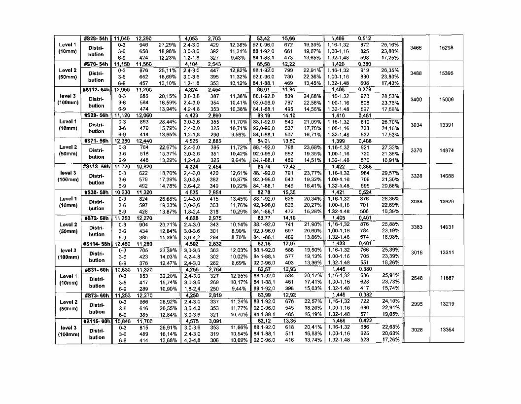
Level 1(10mm)
Level 2(50mm)
level 3(100mm)
Level 1(10mm)
Level 2(50mm)
level 3(100mm)
Level 1(10mm)
Level 2(50mm)
level 3(100mm)
Level 1(10mm)
Level 2(50mm)
level 3(100mm)
#S28- 54h
Distri-bution
#S70- 54h
Distri-bution
#S112-54h
Distri-bution
#S29- 56h
Distri-bution
#S71-56h
Distri-bution
#S113-56h
Distri-bution
#S30- 58h
Distri-bution
#S72- 58h
Distri-bution
#S114-58h
Distri-bution
#S31- 60h
Distri-bution
#S73- 60h
Distri-bution
#S115-60h
Distri-bution
11,040 12,2900-3 946 27,29%3-6 658 18,98%6-9 424 12,23%
11,150 11,5600-3 876 25,11%3-6 652 18,69%6-9 457 13,10%
12,050 11,2000-3 685 20,15%3-6 564 16,59%6-9 474 13,94%
11,120 12,0600-3 863 28,44%3-6 479 15,79%6-9 414 13,65%
12,380 12,4400-3 764 22,67%3-6 518 15,37%6-9 448 13,29%
11,720 10,8200-3 622 18,70%3-6 579 17,39%6-9 492 14,78%
10,630 11,3200-3 824 26,68%3-6 597 19,33%6-9 428 13,87%
11,253 12,2700-3 904 26,71%3-6 434 12,84%6-9 385 11,39%
12,460 11,2800-3 705 23,39%3-6 423 14,03%6-9 376 12,47%
10,630 11,3200-3 853 32,20%3-6 417 15,74%6-9 289 10,90%
11,253 12,2700-3 866 28,92%3-6 616 20,55%6-9 385 12,84%
10,840 11,7000-3 815 26,91%3-6 489 16,14%6-9 414 13,68%
4,053 2,7032,4-3,0 429 12,38%3,0-3,6 392 11,31%1,2-1,8 327 9,43%4,104 2,5432.4-3.0 447 12,82%3.0-3.6 395 11,32%1,2-1,8 353 10,12%4,324 2,4543,0-3,6 387 11,38%2,4-3,0 354 10,41%4,2-4,8 353 10,38%4,423 2,8603,0-3,6 355 11,70%2,4-3,0 325 10,71%1,2-1,8 290 9,56%4,525 2,8852.4-3.0 395 11,72%3.0-3.6 351 10,42%1,2-1,8 325 9,64%4,324 2,4542,4-3,0 420 12,61%3,0-3,6 362 10,87%3,6-4,2 340 10,22%4,535 2,9542,4-3,0 415 13,45%3,0-3,6 363 11,76%1,8-2,4 318 10,29%4,628 2,9752.4-3.0 343 10,14%3.0-3.6 301 8,90%3,6-4,2 294 8,70%4,592 2,8323,0-3,6 363 12,03%4,2-4,8 302 10,02%2,4-3,0 262 8,69%4,255 2,7642,4-3,0 327 12,35%3,0-3,6 269 10,17%1,8-2,4 250 9,44%4,250 2,8192,4-3,0 337 11,24%3,6-4,2 353 11,77%3,0-3,6 321 10,70%4,575 3,0913,0-3,6 353 11,66%2,4-3,0 319 10,54%4,2-4,8 306 10,09%
83,42 15,6692,0-96,0 672 19,39%88,1-92,0 661 19,07%84,1-88,1 473 13,65%
85,58 12,2288.1-92.0 799 22,91%92.0-96.0 780 22,36%84.1-88.1 469 13,45%
86,01 11,8488.1-92.0 839 24,68%92.0-96.0 767 22,56%84.1-88.1 495 14,56%
83,19 14,1088,1-92,0 640 21,09%92,0-96,0 537 17,70%84,1-88,1 507 16,71%
84,01 13,5088.1-92.0 798 23,68%92.0-96.0 652 19,35%84.1-88.1 489 14,51%
84,74 12,4288.1-92.0 791 23,77%92.0-96.0 643 19,32%84.1-88.1 546 16,41%
82,78 15,3588,1-92,0 628 20,34%92,0-96,0 626 20,27%84,1-88,1 472 15,28%
83,77 14,1988.1-92.0 741 21,90%92.0-96.0 697 20,60%84.1-88.1 469 13,86%
82,18 12,9788.1-92.0 588 19,50%84,1-88,1 577 19,13%92,0-96,0 403 13,36%
82,57 12,9388,1-92,0 534 20,17%84,1-88,1 461 17,41%88,1-92,0 398 15,03%
83,99 12,9288.1-92.0 676 22,57%92.0-96.0 545 18,20%84.1-88.1 485 16,19%
82,12 13,3588.1-92.0 618 20,41%84,1-88,1 511 16,88%92,0-96,0 416 13,74%
1,469 0,5121,16-1,32 872 25,16%1,00-1,16 825 23,80%1.32-1.48 598 17,25%
1,420 0,3801,16-1,32 919 26,35%1,00-1,16 830 23,80%1.32-1.48 608 17,43%
1,406 0,3781.16-1.32 970 28,53%1.00-1.16 808 23,76%1.32-1.48 597 17,56%
1,410 0,4611,16-1,32 810 26,70%1,00-1,16 733 24,16%1.32-1.48 532 17,53%
1,399 0,4081,16-1,32 921 27,33%1,00-1,16 720 21,36%1.32-1.48 570 16,91%
1,422 0,3881.16-1.32 984 29,57%1.00-1.16 709 21,30%1.32-1.48 695 20,88%
1,421 0,5241,16-1,32 876 28,36%1,00-1,16 701 22,69%1.32-1.48 506 16,39%
1,405 0,4011,16-1,32 876 25,88%1,00-1,16 784 23,19%1.32-1.48 574 16,98%
1,433 0,4011.16-1.32 766 25,39%1.00-1.16 705 23,39%1.32-1.48 551 18,26%
1,445 0,3801,16-1,32 686 25,91%1,00-1,16 628 23,73%1.32-1.48 417 15,74%
1,445 0,3821,16-1,32 722 24,10%1,00-1,16 686 22,91%1.32-1.48 571 19,05%
1,488 0,4221.16-1.32 686 22,65%1.00-1.16 625 20,63%1.32-1.48 523 17,26%
3466
3488
3400
3034
3370
3328
3088
3383
3016
2648
2995
3028
15298
15395
15006
13391
14874
14688
13629
14931
13311
11687
13219
13364

oCMCOCO
CO CO î fo � * enTf co" m"CM CM »-
co m enen o
^P ^o ^p5^ 5*. tf*� * r - T -
co m co
436
co
omCM
m en eooo M- CMm" CM" r-~CM CM * -
CM CO COCO i -
C»OCO
se se seCM oo enen eo co
co oo oo in ooCO M O
Oeom�M-
£
r- T- eno co
co T - co
CD O CMr- O CO
enomm
463
en N- in
CM CM CDCM CM
00 CO 00O�Sco r- m
CM CD 0000 T -
OMCMCO00
s? s? ser-- CM co
CM O
CM CO 0000 T - T t
00
co
se se sem eo om M- coin co eoCM CM T -
en x- mCM CD ^ -
CM co ooni-*
co
h-
3
e s s5* 3"* 3"*o co en* CM CMM - CM COCM CM » -
oo r- ooen CM cor- h- m
CM eo oo
g
00menCM
s? s? sesnioo CM m
coCM CM
CM r- en00 1 -co m
CM co con<-*
se se se0 0 CM � *~ co coeo CM r»CM CM * -
CM 00 COCM T - mco r- m
CM eo oooo T-_ M;
5 S CM
enCM
00CM
*-9 -«5 �-£5v $N 3^T - o a>�*- co o
Vp sp s^5s- 5s- 5s*CO I*** O00 CO 00
se se sem co coo r- �*
oo i~- enco r- eo
r- in r~cn M- r-oo" in
OO CM 00oo m CM
se se sei- t- OCO S t
��£ *£ *£
5 5s 5* C M i -CO I s - CM
se ses?r- co eo"tf CM CO
m co T-IO O) S f - oo eo
SS ^ è«00 ^ - TtT - CM CD
sO sQ sP
5^ 5N gsCM en CMCM en -
- . O OO) T- reo co m
,96
g g 2 CO 00CM O
m m,3
6 m T - � *O CM r-
q q oCM CD Oen en�A c i ô00 CM CDeo en en
o T- o
84
en en oo
5 Is' oo enS
co ooen cç
T- O r-CO CM
co en
CM CO" O
2 2 SCO CM ^
oo en oo
CM CO 00en en oo� r o - .cô CN" ^-"co o? oo
CN (£> 0000 0)00- 9 -00 C\i <�"oo en oo S
cS
00
°?
° ° en
o eo ooco" co" W
ci CMCM CO"
CM en £m CM g-o»
T T
^ s e ^m m enr- Tfr CM
CD 00 Oco" ^r" co
5^ 5^ >P
a.5.s
00 0000 03CO CM
o eo ooCO CO r-"
c i CM s
*H 00a ° co"
O CD COco" co ^ r
c i CM
^ 2? ^m en CMco m o_en en en
CD ^ - .�«a- c o T -co co co
-,- T °?on *
8
co en S«l10- eo
n ifl Nco m CM
o co ooco co T "� * O CM
gssse
2 en" oo"
o eo ooco" co" �*"4 e i CM
° en co"
O_ CO CM_CO CO ^
4 cieo
5^ 3s- Î 5
ScoS
CM 0000 CM
O CD 00co" co" T-"4 O CM
sp vP00 ^fIs- O
IDC»co" co" m"ci 4_ coco" CM"CM 0 0 T - CN CO � * CM CO T - CM CO CM oo eo CM CO T -
s? se ser o CMO CD O
m" CM"
sess[ ^ COco r�
^ i « o eeo CM mCM T -
^? ^? ^?Ô^ 6^ tf1T - CO CM
eo �>-
" 00 CM�«f m
� * ooen T- m
seseseCM CO TfO ^ - CO
se ses?T- m oo
co eo
se se seoo m enT- oo en
se se seCO Tt CDo �<- m
ss ss seo m eoeo i~- CM
se se seO 00 00r-~ CM enm co »-
N I - T
ÇN K ^f
6ÂZ
gsm CM eo
in 5
co enCO CD
oo CD aiO CO CD
00 fCM T -
« r- r-
° "* "*oo co eno co eo
*esoCO N CM
co CD enO CO CD
440
co CD aic i co CD
O I"- T-1^ O O
co CD enci co ci
s» sO CM COoo in co
enCD
S
s!.2 ^
8
Si =Q si
'5 ob i
S Ia si
S
#S1 O ^2 a È
.2 So £5 l5 l
S Ia si
Si5 |
g
ESO Si
$ ES o 5 13g
S £> oa o il o
o
« Eô £> oa o 5?.
ô £> oo o li o
oS £> oo o

eoCM
o
,433
13,9
2
COmo00
cncnIDCM
,253
010
CO
o
12,1
0
Luoz
i
oCO
110
cncnCM
IOoi nCM
' 0CMCO
<NCO
CO
asoLO
375
oCMenL
88.
,32%
CM
CO
o
4-3
CM
as
CO
CO
ei
aseneo
-CM
eo
eo
0-1,
1
u
as�<r^ .� � ~
360
oCM
cp
84,
,76%
o
cneoCM
COCO
cit o
a?
enr-
449
3-6
asT�
CM
oCO
00
2-1.
4
co
asCMCM
306
oCOenciCMen
08%
cn
CMCM
CM
6-4
CO
asCOCM
OCMCO
6-9
�= i
Dis
,-
s-p-E
33
CMO
o
,442
12,4
8
o
84
COmCM
,320
co
ooco"
70h
»
enLO
118
r00CDCM
aseor-CM
co
r»
CMCO
<i>
asCOC)X�
CM
574
oCMen^L
88.
,43%
CO
oCO
4CM
as
CM
CO
0-3
asCO
x�CM
COLO
to
eia
asr-LOCO
499
oCOcnci
92,
,23%
o
i n
CM
CO
0-3
CO
asSCD
OCO
3-6
as
-to
00
CMCO
asr--LO
422
T_
00CO^L
84,
78%
CO
toCOCM
CO
2-4
asCO
CM
CDCMCO
6-9
�= i
Dis
buti
CM
a
�p-£
2-
CM
oo
,435
11,5
3
oLOco
SCM
IOeo_
,300
co
o
14,1
1#S
120-
70h
CMi n
113
CNh-inCM
asLO^ -
[ ^
CM
t o
CM
6-1.
31.
1
asr-CMLOCM
650
oCM
cp
88.
,04%
COCM
O
4-3
CM
as
h-
0-3
ash-eoCMCM
COCOLO
CD
1.00
-1.1
asoo� , �
CM
540
oCDcpci
92,
,15%
o
CDCM
COCO
O
CO
asoot
00CO
3-6
�= I
ast r
00
tr
CO
CMCO
as
66
>
377
COCO
84,
91%
CO
LOLOCM
COv-z
� *
asr-.COCM
COCO
6-9
i
Dis
but
CO
a_o
(ui
fcr>o
COo
,423
12,6
6
cS.
co
soCM
,550
CO
13,3
60
MZZ
#S37
-
LO
112
SCM
asCOCOtoCM
COCOCO
CMCO
CO
aseoCM
549
oCMen
88.
,90%
o
CM
OCO
4CM
asD
T �
CM
CO
toLO
0-3asr--CMCM
r~-LO
to
cio
asCMcn
488
oCDenci
g
,86%
o
tor-CM
CD
0-3
to
§m
3-6
asCOt o
CO
03
Y
asCMOto
407
00CO
84,
42%
CO
CM
CO
2-4
� « *
aseoCM
CMCMCO
enei
�= i
Dis
but
,-
ve
0)
�p-£
o00COo
,446
12,6
5
o
00
oNCM
,41
,650
CM
12,6
6
MZZ
#S79
-
CMm
116
oeoCM
asCMOeoCN
^_
COeo
CM
6-1,
3
asCMO
CM
555
oCMCO
88.
,21%
COcnCM
oCO
4CM
as�CDCM
cnm
cpci
ascnCDCM
seo
ascnCOj ^ .T ~
459
oCOcpei
92,
,76%
o
�>3-
00CM
CDCO
ciCO
asCMOCD
COCM
3-6
astoCMCO
CMon
CO
2-1.
4
CO
as
eo
442
r_COCO
84,
86%
00
COCM
CO
2-4
asoCDCO
enLOCO
6-9
Dis
but
CM
ve
�p-E
a
So
,459
12,6
9
o00COco
c»SCM
oco_
,350
�«r
o00� * "
� CCM
r-
[M
cncn
i n�a-CMCM
ascoCO^-CM
COi nLO
CMCO
CO
aseoen�
CN
493
oCMen^i.
88.
67%
cn
CM
CO
2-4
asT�enr~
CM
r>M-
0-3
asLOoCMCM
LOen
CO
cio
asLOI�
CO
376
otoenci
92,
44%
en
CM
CM
oCO
4CM
as�CM
cnCO
3-6
asCMCMCO
eno
CO
CMCO
asCM
to
362
0000^L
84,
35%
en
oCM
CO
0-3
CO
asoCMCM
^ .
CM
6-9
i §
Dis
buti
«
(ui
r i
(10
coo
,444
13,0
8
COCOCM00
^
CMr-CM
LO
co_
,830
CM
O
12,3
774
h
»
LOCM
110
00CO
CM
aseoCOCOCM
CD
CM
6-1,
3asoCOT -CM
532
oCMen
88.
,85%
tocnCM
o
3CM
asCO
CO
cn
m
0-3
� :
a?to� < *
cn
COCO
to
oo
a?LOCDto
416
0000^L
84,
,01%
o
r>mCM
to
0-3
CO
as_T �
h-
COCM
3-6
asmtoCO
COeo�9"
cn
CMCO
a?cnoLO
377
CMCOeno
92,
29%
cn
CMCOCM
CO
CM
asCOCM
CMCO
cnCO
: §
Dis
buti
, -
§
�p.E
381
o
,425
12,0
2
COCO
86
coCOCOCM
,431
,890
CMT�
o
12,9
674
h
C3CO
oCM
121
CDT1*
t
CM
gcoCM
CMCOr-
CM
6-1,
3
a?cnCOCOCM
656
oCM
cpT �
88.
,82%
o
enCM
oCO
4CM
asLO^ -
cnCOLO
0-3
asLOOCOCM
COCOCO
eo
1,00
-1,1
ascnCOT�CM
587
oeoeno
92,
,42%
o
COCOCM
CDCO
eiCO
a?LOcni n
ooCO�«a-
3-6
as
cn
CO
CMC>
ascno>r~
387
_COCO
s
65%
en
LOeoCM
CN
6-4
CO
asLOCOCM
cnCOCO
6-9
�F g
Dis
CM
ve
�p-E2.
33
CO
cnCOo
,449
12,0
3
SCOoo
00
IOCM
o
,450
CM
o
13,2
1
SCMCM
l>CO
118
CM00toCM
ascnCMeoCM
mor--
CNCO
CD
asM-COCMCN
591
oCMcn!.
88.
,78%
o
cn00CM
O
4CM
asoLOcn
COCMLO
0-3
asLOOCM
Utm
<o~
eio
asr-C)to
439
T_
COCO^L84
,,1
0%
o
i ^CM
CD
0-3
CO
asCOrLO
CMCM� < *
3-6
tri-
asen� < ! �
cn
COcn�o-
00
t�
CMCO
asen
400
CMCDeno
92,
25%
cn
CO� > *
CM
CM
6-4
CO
aseoCO
361
enei
3
Dis
buti
«
£
£"h
451
o
,450
14,7
8
cnCM00
CM
COCM_
,840
CM
O
12,0
7
M9Z
n
CO
132
LOcncnCM
a?COCDi nCM
cncn
CMCO
CD
asCOociCM
600
oCMen^L
88.
,32%
o
cnoCO
o
4-3
CM
as�srCD
g
0-3
"i
asoCOCMCM
COCOCD
t o
OO
asCOcnm
478
COCO
84,
98%
en
cncnCM
co
0-3
CO
asCOC)m
ofO
3-6
asCO
*
CMCMLO
CO
CMCO
asCOCMLO
456
CM
eocno
92,
32%
cn
Ol
CM
CM
6-4
CO
ascnLOCM
r*-
co
cnCO
= §
Dis
buti
o�p-E
So
,442
13,9
1
COcoCO00
COCOCM
,37;
460
co
O
12,9
7
M9Z
#S81
-
CMCD
137
03
CO
astoLOLOCM
cnr-
CMCO
CO
ascneocn
614
oCMenL
88.
,17%
o
CO
CDCO
O
CO
asmo� « �
om
0-3
asCMOLOCM
OCO
(O
eio
ssCOoh-
531
ot oenci
92,
97%
en
CO
o
4-3
CM
asCOLO� » �
CO
in
3-6
Dis
CM
S2
-p.£
asocneo
CMm
CO
CMCO
asLOCOmT"
488
00CO^L
84,
85%
CO
eoCM
CM
6-4
CO
ascnCOCM
g
cnCO
333
437
o
,498
13,7
3
esCOCM00
^
00CM
,600
CM
O
12,3
1-7
6h
«CM
£
h-
137
00oCO
asCO
CMCM
CO
CM
6-1.
3
asS
545
oCMcn^.
88.
43%
CO
COcnCM
oCO
4CM
a?
eoi n
CD
' " �
CO
ei
"i
asoLOcn
eooCO
eo
eio
as
LO
480
00op
00
27%
en
ononCM
00
CM
asCOi n�9-
CO
in
3-6
asLO|�
to
sCO
2-1.
4
CO
asCO
CO
408
CM
O
92,
01%
en
o00CM
CDCO
ciCO
aseoLO
otoCO
cpCD
= §
Dis
CO
o>
st
(10
z33

Level 1(10mm)
Level 2(50mm)
level 3(100mm)
Level 1(10mm)
Level 2(50mm)
level 3(100mm)
#S40- 78h
Distri-bution
#S82- 78h
Distri-bution
#S124-78h
Distri-bution
#S41- 80h
Distri-bution
#S83- 80h
Distri-bution
#S125- 80h
Distri-bution
11,450 13,1400-3 928 30,13%3-6 487 15,81%6-9 372 12,08%
13,070 12,9700-3 636 22,08%3-6 452 15,69%6-9 377 13,09%
13,980 12,9900-3 539 18,66%3-6 425 14,71%6-9 344 11,91%
12,130 12,9600-3 715 24,19%3-6 521 17,63%6-9 396 13,40%
12,020 12,4900-3 817 25,59%3-6 494 15,47%6-9 403 12,62%
12,940 12,7200-3 608 20,99%3-6 444 15,33%6-9 371 12,81%
4,056 2,8372,4-3,0 339 11,01%3,0-3,6 314 10,19%4,2-4,8 270 8,77%4,459 2,6942,4-3,0 311 10,79%3,0-3,6 303 10,52%4,2-4,8 271 9,41%4,669 2,7133,0-3,6 302 10,45%2,4-3,0 292 10,11%4,2-4,8 267 9,24%4,274 2,724
2,4-3,0 362 12,25%3,0-3,6 321 10,86%3,6-4,2 249 8,42%4,251 2,7112,4-3,0 344 10,77%3,0-3,6 326 10,21%3,6-4,2 281 8,80%4,502 2,7132,4-3,0 309 10,67%3,0-3,6 295 10,18%4,2-4,8 271 9,35%
82,71 14,3388.1-92.0 588 19,09%84,1-88,1 464 15,06%96,0-100 396 12,86%
84,04 12,2488.1-92.0 606 21,03%92,0-96,0 501 17,39%84,1-88,1 462 16,04%
84,22 12,6388.1-92.0 689 23,85%92,0-96,0 518 17,93%84,1-88,1 436 15,09%
83,18 13,0788.1-92.0 587 19,86%84,1-88,1 479 16,20%92,0-96,0 453 15,32%
82,91 13,7988.1-92.0 627 19,64%92,0-96,0 478 14,97%84,1-88,1 454 14,22%
83,07 13,3888.1-92.0 644 22,23%84,1-88,1 461 15,91%92,0-96,0 429 14,81%
1,462 0,4281,16-1,32 765 24,84%1,00-1,16 670 21,75%1.32-1.48 517 16,79%
1,428 0,3911,16-1,32 746 25,89%1,00-1,16 645 22,39%1.32-1.48 569 19,75%
1,427 0,3891.16-1.32 779 26,96%1.00-1.16 676 23,40%1.32-1.48 490 16,96%
1,424 0,3821,16-1,32 813 27,50%1,00-1,16 671 22,70%1.32-1.48 509 17,22%
1,447 0,3961,16-1,32 829 25,96%1,00-1,16 683 21,39%1.32-1.48 549 17,19%
1,459 0,4181.16-1.32 721 24,89%1.00-1.16 622 21,47%1.32-1.48 547 18,88%
3080
2881
2889
2956
3193
2897
13594
12716
12751
13047
14093
12786

Silicon Particles Analysis (SuperHeat)
Magnification:
No. of Fields:
1000 X
40Field Area i\im2) :
Total Area (|im2)
5664
2.26572E+05
Updated:
2005-09-30
Level Samnle ID A r e a ^ m 2 ' Length {\im) Roundness (%} Aspect Ratio Total # Si ParticleAve. SD Ave. SD Ave. SD Ave. SD Features Density
Level 1(10mm)
Level 2(50mm)
level 3(100mm)
Level 1(10mm)
Level 2(50mm)
level 3(100mm)
Level 1(10mm)
Level 2(50mm)
level 3(100mm)
S1- 0 Oh
Distri-bution
S2-0 0h
Distri-bution
S3-0- Oh
Distri-bution
S1-1 8h
Distri-bution
S2-1 8h
Distri-bution
S3-1 8h
Distri-bution
S1-2 16h
Distri-bution
S2-2 16h
Distri-bution
S3-2 16 h
Distri-bution
1,619 3,369Range Qty. Percent0-3.2 16010 89,30%
3.2-6.4 1212 6,76%6.4-9,6 334 1,86%2,803 4,4470-3.2 11111 76,32%
3.2-6.4 2131 14,64%6.4-9.6 614 4,22%4,403 6,2020-3.2 6785 59,42%
3.2-6.4 2478 21,70%6.4-9.6 999 8,75%7,192 8,3130-3,2 1724 40,21%
3.2-6.4 882 20,57%6.4-9.6 600 13,99%7,711 8,4200-3.2 1721 35,53%
3.2-6,4 1072 22,13%6.4-9.6 703 14,51%7,833 8,4820-3.2 1614 33,29%
3.2-6,4 1117 23,04%6.4-9.6 778 16,05%8,605 9,5770-3.2 1238 35,25%
3.2-6.4 689 19,62%6.4-9.6 484 13,78%8,957 9,3740-3.2 1130 30,90%
3.2-6.4 725 19,82%6.4-9.6 559 15,29%9,455 9,5240-3.2 1061 26,74%
3.2-6.4 837 21,09%6.4-9.6 660 16,63%
1,942 2,040Range Qty. Percent0-1.2 8076 45,05%
1.2-2.4 5648 31,50%2.4-3.6 2148 11,98%2,623 2,5391.2-2.4 5677 39,00%0-1.2 3602 24,74%
2.4-3,6 2458 16,88%3.2S7 2.S55
1.2-2.4 4026 35,26%2,4-3.6 2305 20,19%0-1.2 1729 15,14%3,476 2,634
2.4-3.6 1036 24,16%1.2-2.4 1028 23,97%3.6-4.8 666 15,53%3,591 2,651
2.4-3.6 1224 25,27%1.2-2.4 1056 21,80%3.6-4.8 766 15,81%3,703 2,750
2,4-3.6 1341 27,66%1.2-2.4 1071 22,09%3,6-4,8 784 16,17%3,776 2,745
2.4-3.6 822 23,41%1,2-2,4 787 22,41%3.6-4.8 534 15,21%3,862 2,701
2.4-3.6 898 24,56%1.2-2.4 768 21,00%3.6-4.8 650 17,77%4,076 2,867
2.4-3.6 1005 25.33%3.6-4.8 765 19,28%1.2-2.4 717 18,07%
74,76 22,84Range Qty. Percent
96.0-100 3457 19,28%88,1-92,0 1825 10,18%84,1-88.1 1784 9,95%
74,78 23,2096.0-100 2319 15,93%88.1-92.0 1836 12,61%92,0-96.0 1620 11,13%
73,43 23,7796-100 1590 13,93%
88,1-92.0 1464 12,82%92.0-96.0 1409 12,34%
82,29 15,7188.1-92.0 762 17,77%92,0-96.0 707 16,49%96.0-100 578 13,48%
84,58 14.5392.0-96,0 992 20,48%88.1-92.0 965 19,92%96.0-100 773 15,96%
83,48 14,8288.1-92.0 981 20,24%92.0-96.0 922 19,02%84.1-88.1 623 12,85%
82,99 14.7188.1-92.0 657 18,71%92.0-96.0 582 16,57%84.1-88.1 496 14,12%
84,27 13,8588.1-92.0 756 20,67%92.0-96.0 747 20,43%84.1-88.1 480 13,13%
83,41 14,3288.1-92.0 776 19,56%92.0-96.0 720 18,15%84.1-88.1 577 14,54%
1.848 0,781Range Qty. Percent
1.00-1.36 5587 31,16%1.36-1,72 4167 23,24%1.72-2.08 3591 20,03%
1,787 0,7511.00-1,36 4988 34,26%1.36-1.72 3656 25,11%1,72-2.08 2445 16,79%
1.786 0,723.00-1.36 3709 32,48%.36-1.72 2964 25,96%.72-2.08 1929 16,89%1,573 0,678
.00-1.36 2044 47,67%
.36-1.72 1153 26,89%
.72-2.08 586 13,67%1,496 0,476
1.00-1.36 2452 50,62%1.36-1.72 1278 26,38%1.72-2.08 657 13,56%
1,496 0,4791.00-1.36 2489 51,34%1.36-1,72 1279 26,38%1.72-2,08 623 12,85%
1,516 0,526.00-1,36 1766 50,28%.36-1.72 925 26,34%.72-2.08 466 13,27%1,467 0,470
.00-1.36 1995 54,55%
.36-1.72 925 25,29%,72-2.08 426 11,65%1,503 0,503
1.00-1.36 1982 49,95%1,36-1.72 1097 27,65%1.72-2.08 530 13,36%
17928
14558
11418
4288
4844
4848
3512
3657
3968
79127
64253
50395
18926
21380
21397
15501
16141
17513

0,45
5
en
13,3
4
<ori-CM
2,85
6,2
21
»
10
o
o"
24h
1-3
«0
1069
9
ct
CM
S3coens?
1186
<o
1.00
-1
*sminCD
474
oCMenr�
oo00
ss
CM
551
co
4-3
CM
*3
COCM
653
CM
ss
coCM
697
ÇM
1.36
-1
S?CM
LO
381
ooco
S
S3fOco00
445
< « �
<?CM*~
sscoo>T~
o
2-6.
4
co
il
S3noco
315
g
1.72
-2
seininm
CO
o
o
en
S3<oco00
445
00
CO
co
ssooco� " "
mcoco
4-9.
6
co
Dis
but
, - �p-£
0,47
5
en
13,7
8
S«
2,96
9
03CM
O
8
110,
71
«�»(MCO
1288
8
oSiCM
ss sst^- CMe n T -cn oo� * CM
1459
821
CO CMco r*-
1.00
-11.
36-1
ss S3
O O3o m
co co00 COm -5T
O T-CM 00en oo
oo ^"
^ ^CO CMco ^rco oo
o ooCD COco in
C D � *CO CM
4 CMCM 1 -
ss sso mCD CMh* 00CM T -
CD CO
gs
3-3.
22-
6.4
co
ssmoCM
353
§
1.72
-2
S3coi n
464
o(OCDO
S)
S=CT>CDCD
496
co
6-4
CO
asO)�«a-CO
Sco
4-9.
6
CD
S P
Dis
but
CM - = �
CD g
0,52
313
,44
2,96
3
coCN
O
0,93
0
� * "
i
3-3
1409
7�*rG)
co
ss
r iLO
1611
CD
11.0
0-1
s*oo
641
;
oCMen
oo00
co
752
:
co
4-3
CM
mCM
�sr
oo
CM
S
V
C
co
?
S3i noi�CM
864
1.36
-1
ssencoCD
533
o
o
CD
s?
ooi ^
569
oo
6-4
co
S300coO)*~
CD
co
2-6.
4
CO
sscoCN^~
411
ooo
1.72
-2
00
453
0000
sssoom
505
�«J-
CM
ssoo
CM
4-9.
6
CO
; §2 � «
"Êt
(10
0,51
915
,23
m
3,11
1
o
co
2,65
0
� " -
1-4
CO
1020
4
CM
COCM
S3CM
CMm
1212
CD
1.00
-1
ssc>co
426
oCMCDr^-
COCO
S?CM�<rCJ)
449
co<?�<rCM
S3oomCM
ooi n
3-3.
2S3
r~-CM
632
CMh -
1.36
-1
S=>cocoM-
332
o
96
6CMCD
S3§oo
418
00
6-4
co
S?coLOm
0>LOCO
2-6.
4
co
S3
coCN
982
ooo
11.7
2-2
mco
313
r_oooo
S
S3T�"co
310
o9-8
encoCM^~
SCM
coen
co
i §aC
ve
_i
m
0,55
5
i n09'I. |
15,8
6
CM
3,46
2
s
oj >
co
2,44
2-4
V)
1169
6
oincoCM
se00O)
oi n
1351
<o
1.00
-1
se
395
oCMCJ)
00co
ssmmen
518
CD
4-3
CM
!£ooCM
� *
in[^_
CM
CM
735
CM
1.36
-1
s?r-co
364
0000
s
m
co
429
^.CMCM
*~
- ^
SmT~
ma-
2-6.
4
CO
comCM
co
coo
1.72
-2
S?CJcoo
287
ocoaio
S
sscoCD
m
415
oo
6-4
co
-S
CMT ~
r--CNco
4-9.
6
CD
È P
Dis
but
CM
ve
_i
£
s.
0,48
914
,92
m
3,19
4
m
oco
122,
030
*"
3-4
o>
1440
6
tCDCMCO
ss
oLO
1657
CD
1.00
-1
co
431
oCMCD
S
S3cocoo:
089
co<?CM
asmCDcoCM
ooo
CM
s
S?
coooCM
925
CM
1.36
-1
ssenCM
411
T _
ooco�A
S
S3coor
557
00
6-4
co
Sco
CO
m
2-6.
4
co
S?T �
CM
398
§
1.72
-2
ssmm� « -
377
ocoeno
S?mi n1 -
475
CM
^"
S3mCMCM� " "
o
' r
4-9.
6
co
s i
Dis
but
co ?oo
1,04
6
enco
18,0
3
co
c»
3,39
3
«
O
sco
2,25
01-
5
co
cc
ïg
CM00
CM
S?cooon
1049
co
1.00
-1ssco� t
325
oCNCJ)
CD
417
co
6-4
CO
S3CM^_CO
coCO
CMco
"i
>
ssi nCMi nCM
551
CM
1.36
-1
ss�<rco
294
oco�oCMCD
ssonCDco
364
asr-m
coco
2-6.
4
CO
ssCMCM
267
00o
1.72
-2
ssenCM
282
^_
00co
sssCM
308
oo
6-4
co
jgc>CDO"~
CMCOCM
4-9.
6
CO
E
31
0,55
1
m
i 1,
5114
,47
onCM
3,33
1
s
O
co-Zl
2,42
2-5
co
1100
3
coCD
CM
S3C)CD
1231
CD
I 1.0
0-1
sscocooo
457
oCM
�A00oo
ssCMcoo
514
:
co
S3CNmh -CM
686
1.36
-1
ssoo�<}�i n
386
oco96CMO)
S3
oco
400
co
CM
Sîrv.
^>CM
O
co
CM
S
co
ssmh-
mco-a-
2-6.
4
co
S?CMO)CO^~
co
00o
1.72
-2
S3
co
co
co
T_0000�A
sS3CMCO
357
CM
"~
S?CJ
oCM- ï~
Ooco
4-9.
6
CD
S o
Dis
but
CM
ve
3E
1,36
0!
1,76
22,0
0on
3,07
1
?
O
gCM
1,70
0
T "
3-5
co
1313
5
coCDCM
S3Q1
m
1368
co
I 1.0
0-1
SSCMLO
m
462
oCMO)r -COco
S3<o
o
600
;
co
4-3
CM
S3oQCO
menco
3-3.
2
�i
S3mc>coCM
695
CM
1.36
-1
ssoococo
407
ocoCJ)o
ssco
516
CMCMT ~
S3i n^>^~
coco
2-6.
4
co
S3O
co
389
00o
1.72
-2
ssocoCM
375
T _
oooo
sS3
coco
496
co
6-4
co
S3coQT ~
00
co
4-9.
6
co
onDi
sbu
t
co E"o
(10
0,45
9
o
14,3
8
onCDT -
3,51
5
s.
O
s
3,84
0
T~
1-6
co
9202
m
CM
S3cocoCD
1040
1.00
-1
S3
371
oCMo>
COco
ssi no>CD
416
co
4-3
CM
sscoCDcoCM
CD
m
3-3.
2
S3T �
onCM
586
CM
1.36
-1
S3
306
t �
00oo
sssen«a-m
323
co
6-4
CO
^ P
Sm� " "
coCMco
2-6.
4
co
S3mCM
co
277
§
1.72
-2
S3
8
292
ocoty>oCM
S3ooco
271
o
8-6
� > * �
S3co� *
r�
CDroCM
4-9.
6
co
F. §
Dis
T -
ve
�£�E
3�)
0,50
014
,89
mm
3,56
0
00CO.
oLCJ
3,56
48h
<oCM
co
1072
5
ocoCM
S3�
CD
1208
CD
1.00
-1
S3
S
414
oCM
T ^ -
CO
S3cocor~
421
co
4-3
CM
S3
coIM
COonco
3-3.
2
S3M"
ooCM
CD
CM
1.36
-1
S3ocom
379
T �
onoo
3
S3oO)�*r
362
00
6-4
co
S3
coT~
CMco
2-6.
4
co
S3CMCMCM
297
§
1.72
-2
S3l~.
286
86CD
S3
359
S3
o� � "
i ^
CM
4-9.
6
co
± o
Dis
CM
ve
- 1
£
3"I
0,46
21,
4913
,79
LOcoSI
3,50
2,8
8(
O
F:'
4,31
0
i
3-6
(0
1207
1
LOcoCM
ssocoom
1384
CD
1.00
-1
S3�<a-
00
496
oCMCD
0003
S3
mco
508
CD
4-3
CM
coCM
mLOco
3-3.
2
sscoO5COCM
738
CM
1.36
-1
S3mCMm
417
ocoCDo
sS3oCMCO
443
co
6-4
co
S3o>co
CJ)fnco
2-6.
4
CO
S3CDO
co
358
00o
1.72
-2
-S
8m
412
�_on00
00
S3oncoco
366
CJJCM
"~
S3jîT_~
CMCO
4-9.
6
co
tri- on
Dis
but
coÇD
O
g"
o

Level 1(10mm)
Level 2(50mm)
level 3(100mm)
Level 1(10mm)
Level 2(50mm)
level 3(100mm)
Level 1(10mm)
Level 2(50mm)
level 3(100mm)
Level 1(10mm)
Level 2(50mm)
level 3(100mm)
S1-7 56h
Distri-bution
S2-7 56h
Distri-bution
S3-7 56h
Distri-bution
S1-8 64h
Distri-bution
S2-8 64h
Distri-bution
S3-8 64h
Distri-bution
S1-9 72h
Distri-bution
S2-9 72h
Distri-bution
S3-9 72h
Distri-bution
S1-10 80h
Distri-bution
S2-10 80h
Distri-bution
S3-10 80h
Distri-bution
14,500 14,0900-3.2 387 21,62%
3.2-6.4 270 15,08%6.4-9.6 198 11,06%15,56 14,5300-3.2 341 17,64%
3.2-6.4 286 14,80%6.4-9.6 257 13,30%15,230 14,8500-3.2 403 20,09%
3.2-6.4 270 13,46%6.4-9.6 241 12,01%15,910 15,2400-3.2 317 17,62%
3.2-6.4 260 14,45%6.4-9.6 220 12,23%15,99 15,7100-3.2 445 22,41%
3.2-6.4 243 12,24%6.4-9.6 213 10,73%16,240 14,8200-3.2 350 16,09%
3.2-6.4 300 13,79%6.4-9.6 260 11,95%16,610 16,4400-3.2 364 20,24%
3.2-6.4 217 12,07%6.4-9.6 210 11,68%15,91 14,9500-3.2 338 17,15%
3.2-6.4 318 16,13%6.4-9.6 216 10,96%15,870 15,2800-3.2 352 17,80%
3.2-6.4 278 14,06%6.4-9.6 250 12,65%15,430 16,3000-3.2 443 25,79%
3.2-6.4 211 12,28%6.4-9.6 183 10,65%17,18 16,3700-3.2 344 19,58%
3.2-6.4 214 12,18%6.4-9.6 199 11,33%16,460 15,9800-3.2 435 21,11%
3.2-6.4 238 11,55%6.4-9.6 219 10,63%
5,030 3,4982.4-3.6 329 18,38%3.6-4.8 282 15,75%1.2-2.4 234 13,07%5,248 3,491
2.4-3.6 378 19,56%3.6-4.8 330 17,07%4.8-6.0 255 13,19%5,169 3,6323.6-4.8 355 17,70%2.4-3.6 348 17,35%4.8-6.0 258 12,86%5,195 3,385
2.4-3.6 343 19,07%3.6-4.8 305 16,95%4.8-6.0 266 14,79%5,176 3,692
2.4-3.6 325 16,36%3.6-4.8 284 14,30%1.2-2.4 242 12,19%5,245 3,235
3.6-4.8 382 17,56%2.4-3.6 378 17,38%4.8-6.0 321 14,76%5,314 3,759
2.4-3.6 299 16,63%3.6-4.8 278 15,46%4.8-6.0 229 12,74%5,298 3,490
2.4-3.6 381 19,33%3.6-4.8 304 15,42%6.0-7.2 263 13,34%5,246 3,598
2.4-3.6 384 19,42%3.6-4.8 345 17,45%4.8-6.0 269 13,61%4,998 3,5492.4-3.6 297 17,29%3.6-4.8 264 15,37%1.2-2.4 234 13,62%5,468 3,755
2.4-3.6 302 17,19%3.6-4.8 246 14,00%6.0-7.2 226 12,86%5,290 3,628
2.4-3.6 337 16,35%3.6-4.8 324 15,72%6.0-7.2 265 12,86%
79,94 14,8888.1-92.0 278 15,53%84.1-88.1 265 14,80%92.0-96.0 234 13,07%
79,97 14,1188.1-92.0 309 15,99%84.1-88.1 284 14,69%92.0-96.0 235 12,16%
80,37 15,7888.1-92.0 364 18,15%84.1-88.1 303 15,10%92.0-96.0 276 13,76%
82,34 13,4388.1-92.0 347 19,29%84.1-88.1 287 15,95%92.0-96.0 244 13,56%
83,31 13,5788.1-92.0 341 17,17%92.0-96.0 326 16,41%84.1-88.1 300 15,11%
83,75 11,8188.1-92.0 439 20,18%92.0-96.0 366 16,83%84.1-88.1 356 16,37%
80,05 14,9688.1-92.0 255 14,18%80.2-84.1 249 13,85%84.1-88.1 242 13,46%
80,80 14,0888.1-92.0 340 17,25%84.1-88.1 318 16,13%92.0-96.0 247 12,53%
82,76 12,6288.1-92.0 364 18,41%84.1-88.1 311 15,73%92.0-96.0 292 14,77%
77,70 19,3788.1-92.0 291 16,94%84.1-88.1 259 15,08%92.0-96.0 210 12,22%
81,77 13,6288.1-92.0 306 17,42%92.0-96.0 252 14,34%84.1-88.1 251 14,29%
81,31 15,3488.1-92.0 400 19,41%84.1-88.1 320 15,53%92.0-96.0 279 13,54%
1,523 0,5641.00-1.36 887 49,55%1.36-1.72 465 25,98%1.72-2.08 258 14,41%
1,496 0,4661.00-1.36 964 49,87%1.36-1.72 546 28,25%1.72-2.08 234 12,11%
1,598 0,8661.00-1.36 988 49,25%1.36-1.72 550 27,42%1.72-2.08 248 12,36%
1,489 0,4701.00-1.36 895 49,75%1.36-1.72 530 29,46%1.72-2.08 231 12,84%
1,502 0,4841.00-1.36 979 49,30%1.36-1.72 543 27,34%1.72-2.08 286 14,40%
1,471 0,4291.00-1.36 1117 51,36%1.36-1.72 616 28,32%1.72-2.08 264 12,14%
1,514 0,5521.00-1.36 921 51,22%1.36-1.72 466 25,92%1.72-2.08 243 13,52%
1,505 0,5371.00-1.36 997 50,58%1.36-1.72 540 27,40%1.72-2.08 253 12,84%
1,470 0,4461.00-1.36 1070 54,12%1.36-1.72 497 25,14%1.72-2.08 257 13,00%
1,692 1,2411.00-1.36 853 49,65%1.36-1.72 437 25,44%1.72-2.08 195 11,35%
1,468 0,4451.00-1.36 920 52,36%1.36-1.72 486 27,66%1.72-2.08 207 11,78%
1,584 0,8271.00-1.36 1004 48,71%1.36-1.72 584 28,34%1.72-2.08 261 12,66%
1790
1933
2006
1799
1986
2175
1798
1971
1977
1718
1757
2061
7900
8532
8854
7940
8765
9600
7936
8699
8726
7583
7755
9096

Silicon Particles Analysis (MTT)
Magnification:
No. of Fields:
1000 X
40
Field Area (pm2) :
Total Area (nm2)
5664
2.26572E+05
Updated:
2005-09-30
Level Sample ID
Level 1(10mm)
Level 2(50mm)
level 3(100 mm)
Level 1(10mm)
Level 2(SOmm)
level 3(100mm)
Level 1(10mm)
Level 2(50mm)
level 3(100mm)
Distri-bution
M2-0 Oh
Distri-bution
M3-0 Oh
Distri-bution
M1-1 8h
Distri-bution
M2-1 8h
Distri-bution
M3-1 8h
Distri-bution
M1-2 16h
Distri-bution
M2-2 16h
Distri-bution
M3-2 16h
Distri-bution
Area (prnz)Ave. SD
Range Qty. Percent0-3.2 5137 72,88%
3.2-6.4 1046 14,84%6.4-9.6 377 5,35%5.037 8,4770-3,2 3294 63,55%
3.2-6.4 668 12,89%6.4-9.6 388 7,49%8,980 12,9500-3.2 1644 47,39%
3.2-6.4 492 14,18%6.4-9.6 280 8,07%9,308 9,5920-3.2 860 27,84%
3.2-6.4 618 20,01%6.4-9.6 520 16,83%11,210 11,3300-3,2 649 24,59%
3.2-6.4 443 16,79%6.4-9.6 395 14,97%14,070 13,8300-3.2 509 21,82%
3.2-6.4 325 13,93%6.4-9.6 277 11,87%10,840 9,9950-3.2 548 22,15%
3.2-6.4 429 17,34%6.4-9.6 394 15,93%14,120 13,9300-3.2 518 22,73%
3.2-6.4 279 12,24%6.4-9.6 277 12,15%16,870 15,0400-3.2 314 16,46%
6.4-9.6 215 11,27%9.6-12.8 212 11,11%
Length (|jm)Ave. SD
Range Qty. Percent0-1.2 2090 29,65%
1.2-2.4 1704 24,17%2.4-3.6 1054 14,95%4,417 5,1100-1.2 1715 33,09%
1.2-2.4 852 16,44%2.4-3.6 578 11.15%6,109 6,2190-1.2 800 23,06%
1.2-2.4 478 13,78%2.4-3.6 378 10,90%4,491 3,482
2.4-3,6 645 20,88%3.6-4.8 571 18,48%0-1.2 446 14,44%5,543 4,3783,6-4.8 447 16,94%2.4-3.6 415 15,73%0-1.2 329 12,47%6,609 5,3282.4-3.0 324 13,89%3.6-4.8 299 12,82%0-1.2 271 11,62%4,788 3,203
2.4-3.6 491 19,85%3.6-4.8 483 19,52%4.8-6.0 341 13,78%5,910 4,518
2.4-3.6 329 14,44%3.6-4.8 310 13,60%4.8-6.0 293 12,86%7,076 5,307
3.6-4.8 263 13,78%4.8-6.0 219 11,48%6.0-7.2 214 11,22%
Roundness(%)Ave. SD
Range Qty. Perçant96.0-100 951 13,49%60.4-64.3 386 5,48%24.7-28.7 346 4.91%
55,26 29,5196.0-100 880 16,98%16.8-20.8 267 5,15%64.3-68.3 262 5,05%
51,16 29,9796.0-100 426 12,28%12,8-16,8 230 6,63%16.8-20.8 222 6,40%
76,05 18,9988.1-92.0 371 12,01%84.1-88.1 349 11,30%96.0-100 339 10,97%
65,93 22,7896.0-100 222 8,41%88.1-92.0 198 7,50%84.1-88.1 193 7,31%
63,92 23,1696.0-100 162 6,94%88.1-92.0 156 6,69%84.1-88.1 154 6,60%
76,68 17,2288.1-92.0 344 13,90%84.1-88.1 298 12,05%92.0-96.0 240 9,70%
71,48 20,1280,7-84.1 ?3C) 10,09%84.1-88.1 201 8,82%96.0-100 187 8,21%
67,54 21,9188.1-92,0 160 8,39%84.1-88.1 158 8,28%80.2-84.1 137 7,18%
Aspect RatioAve. SD
Range Qty. Percent1.72-2,08 1260 17,87%1.36-1.72 1123 15,93%1.00-1.36 1103 15,65%
2,907 1,6241.72-2.08 852 16,44%1.00-1.36 702 13,54%1.36-1.72 620 11,96%
2,760 1,5211.72-2.08 561 16,17%1.00-1.36 522 15,05%1.36-1.72 446 12,86%
1.8C8 0,7881.00-1,36 857 27,74%1.36-1.72 806 26,09%1.72-2.08 614 19,88%
2,307 1,1941.36-1.72 496 18,79%1.00-1.36 494 18,72%1.72-2.08 477 18,08%
2,430 1,2911.00-1.36 408 17.49%1.36-1.72 395 16,93%1.72-2.08 395 16,93%
1,814 0,7461.00-1.36 737 29.79%1.36-1.72 646 26,11%1.72-2.08 466 18,84%
2,021 0,8671.00-1.36 533 23,39%1.36-1.72 500 21,94%1.72-2.08 450 1975%
?.?33 1,1021.36-1.72 379 19,86%1.00-1.36 370 19,39%1.72-2.08 333 17,45%
Total #Features
7049
5183
3469
3089
2639
2333
2474
2279
1908
Si ParticleDensity
38889
22876
15311
13634
11648
10297
10919
10059
8421

90Z
o
ro
5,32
m^ -
0 0
mCDoco"
co
ox>
10
009
24h
M1-
3
oo
CN000 0CN
06
000 0
, -
1�
sT �
1.00
-,6
2%
S
oCM
0 0co
se0 0eno
0000t
co00
4CM
ss
OCM
en
3.2
S?T �
0 0CN
mco
CNp-T �
1.36
-,9
1%
o
0 0
°p
0 0
secop-0 0
oo00� < *
co
6-4
co
sscôco
CNenco
-6.4
0 0
tri-
sso>r-*~
en
cooCN
1.72
-,5
5%
ço
^f.coCN
O0 0
S30 0cooo
en
co
o
8-6
"*
S?mom
mco
-9.6
�srco
i
Dis
but
Leve
l 1
(10m
m)
00ennoo"
g
2,0
mmm"
S
� * � "
,47.
o0 0
o
1566
0
co"~
24h
M2-
3
menco
rcooCM
S?mco
CN
CD
en
toC)
1.00
-18
%
en
ES
coCN(-)0 0
S3
en
moco
o
8-6
ssCMCD
t:
mco
CM
coo
S3CNCM
roCM
co
"""
CMp-T �
1.36
-89
%
oo
co
oCMen
ooco
S?
CNCO
encoCM
CO
6-4
co
ssco
r\icoCM
12.8
CD
en
s?T -
m
encooo
0 0
oCM
1.72
-79
%
0 0
enp-
oo0 0
T t0 0
S?0 0
� > -
enooCM
CM
r-
oCD
S3
§o
toCM
-9.6
co
� = i
Dis
but
Leve
l 2(5
0mm
)
mS
menCM"
0,83
CM
r-coO)
0000
m"
o
co
670
0 0
i
M3-
3
CN
0 0
r-
enr-I
S?0 00 0
CNCN
Ê
CMp -
1.36
-50
%
en
enco
SCMOCO
seoco
eoCM
0 0
6-4
co
S?
47
eo
ro-nCN
3.2
S?coen
CM
en
co0 0
T�
oo
98%
r-
CM�NT
0 00 0
T -
^ j -0 0
S3mCM
CM
0 0
CM
O
8-6
S?enCM
o
oo0 0
�12.
8
eoen
S?am1�
co
0 0
oCN
CM
r-
98%
p -
CM
�<J-
OO',
oco
g*-
T_CM
CM
0-7
CD
en
Ci
-9.6
tri- on
Dis
but
leve
l 3(1
00m
m)
3o
r-
P-_
8,69
44
m
645
co"
CM
O
co
960
co
32h
M1-
4
m0 0
en
« �
I MCM
S3�sr
CDCO
o0 0
tooo
°-
,47%
p-m
oCNen
0 0co
S3oCNCD
COCD
0 0
6-4
CO
S3
CMCM
enm
0-3.
2
S?op-mCM
co
CNP-r -
i
,80%
CM
0 00 0
T -
^ .
0 0
S?enO 1
� f
co
o
8-6
ss0 0
CM
roCM
-9.6
MCO
se
co
�q-
0 0
oes
S3o
coeo
coCN
O0 0
seco
CMCMCO
CO
4-3
CM
ssco
-
omCM
12.8
CD
en
s i
Dis
but
Leve
l 1
(10m
m)
coroO
CMP-co_
8,97
co�*
%
� * "
co
o
m
740
£CMCO
M2-
4
CMCOr-en
moCMCM
S?to
enCM
co
eo
toCOT �
1.00
-,7
0%
CN
oo
.0-1
CD
seS*-
�M-CO
S
s?00enoco
0 0
CD
3.2
o
S?
co^-CM
m
CM
T �
1.36
-75
%
en
m
r0 0
CMoco
S3r-CN
CDeoCN
0 0
6-4
co
^>m
en"
SCM
-9.6
CD
O)
enCM
^
0 0
oCM
1.72
-71
%
en
0 00 0
^ >0 0
*5cocoo
mcoCM
O
8-6
� « �
. P
oo"
i nen*~
12.8
CDen
� = i
Dis
but
Leve
l 2(5
0mm
)0 0
S
2,2
0,15
CM
00CO
206
m
i
oX)
91-
170
en
£N
M3-
4
enCMCO
co
tco
S?r�coa>
eoCM
0 0OCN
1.72
-02
%
co
m
�M-CO
CM
oco
s?coM-
gCM
0 0
6-4
co
seoenCM
»
3.2
fly
r
SSCM0 0
en
r-
CM
eoC)
T �
1.00
-95
%
i�
� « �
coco
^>co
seoenCM
mco"~
o
8-6
�sr
ssco
-
coeox�
-9.6
NCO
tri-
S?roi^'r-
omCM
CM
1.36
-53
%
i*^
coo
CNeo
CM
CMI - .
seCMO* -
00
m
CM
0-7
co
semCMO
12.8
coen
3
Dis
but
leve
l 3(1
00m
m)
O00mo
roo
1,8
5,40
i nco0 0
157
oo"
s.
o
970
"
40h
M1-
5
0 0pen0 0
cooooCM
seoCMco
CM
mco
s
1.00
-,9
5%
S
oCMen
0 0co
seen
co
tor�co
co
4-3
CM
ssenCD
CM
3.2
o
se0 0CN
COCN
m
CM
1.36
-,5
9%
S
oo0 0
sseo
0 0
00coeo
0 0
6-4
oo
SSenenm� *�
mCMC )
-6.4
00
s?
^ip-
meo
cooCN
1.72
-,3
1%
o
r -
y t0 0
CNOeo
S?ncom
co
o
8-6
"*
-S
s?
14
enCM
.4-9
.6
eo
�= i
Dis
but
Leve
l 1
(10m
m)
Z28
o"
tneoenr-
7,46
COCM
,78
oCMm
310
0 0
i
M2-
5
coCMp
mcoeo
SST �
mCN
CM
r-
,19%
co00
coco
^<0 3
semom
CD
CN
0 0
6-4
eo
S3r-CNco
CM
3.2
"î
s?m0 0
coCM
gO
co0 0
g
,19%
co00
�«3-
0 0
CM
O0 0
S3
r-�<t
�"3-CM
O
8-6
S3CD
m
rn0 0
12.8
coen
s?mCD
0 0
gc>
0 0
oCM
1.72
-
S3
Sen
00
m
CN
O0 0
CN
eo
S30 0r-CM
gCM
CM
0-7
co
S3om-
ooco
-9.6
CO
'-. O
Dis
but
Lev
el 2
(50m
m)
oo
f:CN
9,00
o
en
00CM
m"
,63
oCM
co
780
oCN
40h
M3-
5
0 0poco
r-r-ooT
S3
oCN
0 0CN
CNh»
1.36
-73
%
en
0 0co
0 0
S3oor-co
en00
CM
0-7
co
S3meoCN
O
*�
3.2
O
S3menco
coCM
COCO
T �
1.00
-57
%
0 0
0 0
oCMen�J-0 00 0
S3mm� > -
enm
o
8-6
� *
S3
eno
m^~
12.8
coen
S3to0 0
p -T�
eo
CM
cooCM
1.72
-57
%
0 0
co
CMO0 0
CM
cor-
S3mm*-
enm
CO
6-4
co
S?eo
oo"
I NCM
-16.
0
CM
�= i
Dis
but
leve
l 3(1
00m
m)
COmfOo"
mCM
T -
5,89
T �
OCM
co
Smco
8
oeoCM
300
oo� * "
48h
M1-
6
T
C-�n
enooT
CM
S3CM0 0
CMCO
CMOp -
toco
1.00
-,6
2%
OZê
0 00 0
T -
co
S30 0
oCD
CO
eo
6-4
co
S?0 0
mCN
m
S
CNJ
CO
o
S3r-CM
enCM
coCMco
CN
T �
1.36
-,5
8%
enco
oCNen
co0 0
S3
CN
OCO
o
8-6
TJ'
S3
S
m�M-CN
12.8
toen
C )
0 0
oCN
1.72
-,5
0%
co
�a-0 0
CN
O0 0
S30 0CMCO
0000CM
CO
4-3
CN
S3
CM
T �
CN
-9.6
CD
� = i
Dis
but
Leve
l 1(1
0mm
)
850
o
mmo>_
00
ro"
roo0 0
B25
CO
o
1675
048
hM
2-6
enoenp
CMenp »^
S3to
�srCM
00coT f
eoCiT �
1.00
-,2
1%
co00
oncoT -
T l "CO
S3CMtoCO
CM
fO-1
.2
S3
SCMCM
T_
�<t
3.2
o
S3CMp -
OOCM
mCM
CMIs»T �
1.36
-,0
4%
oCO
^ >
eoCM
o0 0
S3om*-
eooCM
CM
0-7
CD
^>
P-"
O
CO
en
�srCD
S3
o
CM
p-p-CO
COOCM
1.72
-38
%
en
coeo
oo
oco
S3o
*-
enen
co
6-4
co
^ o
CO
P-"
mro
-6.4
co
�= i
Dis
but
Leve
l 2(5
0mm
)
mo"
CNCM
CN
9,62
X �
0 0
p
co
sm"
CM
ocoi * /
p-
320
en
£
M3-
6
oc �p-
coc�>c>
S3men_
CM
mcoco
CM
T �
1.36
-,2
2%
O
t �
on0 0
sS3en�sr� < -
a>
o8-
6
S0 0
mC )
CM
coo
S3
oCM
m000 0
co0 0r�
1.00
-90
%
0 0
0 0
CM
O0 0
CN
'O
S3oo0 0
o
oô""
0 06-
4
00
v o
CM
en"
om
12.8
CD
en
S3
r-
menCM
0 0
oCM
CN
78%
0 0
eo
^.0 0
CM
O0 0
S?t N0 0
O
o00
CM
Oeo
S3
oo"
p -co
.4-9
.6
CD
�= i
Dis
but
leve
l 3(1
00m
m)

0,62
0
op-
COCO
in"T �
éoCO
cocoCO
eoco_
o
,09
S
5,0
56h
p»
i
rcncnp-
1812
s?enen>
co
634
CDCO
oo
seoCOCO
241
88
f -
t00
seCOp-
m
mCO
o
8-6
� * �
53%
o
Î72
CMCO
o
s?�a-cnmCM
470
CM
enCO
seO)CD
CN
OCO
O
92
cnCO
semCO� *
enco
CO
4-3
CM
26%
* -
SPI
CO
S?CO
en
352
COoCNCMp-
seoCMT -
coo
84
CMO00
semCO� *
oCO
00
6-4
CO
09%
* -
o' '
co
4CD
� s i
is Jt
a s
Leve
l �?
(10m
i
3
0,80
4
COcn
CO
T�
in
,92"
oCO
9,5
*~
is
enmmCO
1486
s?oCOmCM
376
CMp-r�
enCO
seoeoo
CO
m
o
92
T -
onoo
seenCOCO
cncn
o
8-6
�sr
23%
p-
>56
CMCO
s?
oCMCM
327
cneo�oo
seCOCN
O
CM
m
00
CO
secnCM
oen
CM
eieo
S«mroen"
enCO
fN
CDcn
s«enCN
CM
301
COoCNCN
seCOCM
o
CM
m
SCM
o00
seCOen*-
COp-
00
6-4
CO
15%
cn"
CO
oCD
00
CM
t i�2 IQ J2
CM
Leve
l "p"
(50m
i
0,82
3
CNOCM
B,30
inCO
CM
T �
m
CMCM_
o
,95
oCM
56h
i
COi
S
1462
S?enCMCOCM
340
CMp-
1.36
-
*P
en"
CM
CM
§CM
en
seai� > -
mp-
o
8-6
60%
CO
CN
CMCOO
seCO^~T �
CM
314
CDCOT �
eip
j Pcn
oo"
o
CO
CM(-)CO
3?cn*-
00UJ
CM
0-7
CD
S?cn<n00
p -CM
CM
COcn
se<£COen
283
COoesCNp-
>°
oo"
CMCN
CO00T -
^ -
00
v=
p~en"
CO
�
6-4
CO
59%
P_"
oCD
CO
�*�
tri- on
uC. Si
«
leve
l
f
(100
m
0,54
8
S
4,04
2
CM
COCO
CO
,030
oCO
64h
op
cot
CMp -
1641
s?mop-co
809
CDCOT �
eio
Sm
g
oCM
enX -
0000
s?en
p-
CMO)
00
6-4
co
33%
co
00CD
CM
S
s?enT �
enCM
479
CMp-T �
en
£5M-
�sr
0000x -^-co
secom
CM
o
8-6
"*
68%
CM
00O
CO
4eo
s?
P+.� * �
291
on
CNCN
s?a>CN
oo
84
CMO00
ss00co� *
CD00
COco
4CM
19%
CM
00c
CM
CO
tri- on
V
c
,-
Levé
> tl s.
(10m
1
0,82
1
CO
7,77
mcoco
coCM
,88"
o
,91
o
oCM
64h
00M
CMCOco
1668
S?CM00p.CM
464
CM
enco
S?mp -
� < -
CD
en
00
T -
CO
S?m
CMp-ciCD
39%
MO
CMCOO
s?encomCM
423
encoT�oo
ssaip-o
oco
CM
00
secomCM
eno
o
8-6
"*
S?coenoo"
oCD
00
CM
s?
cocn
327
enoCMCN
S?ai
o
op.
CMO00CM
en
seeno
coco
00
6-4
co
semm
m
CM
eoen
t i
is jt
Q s
CM
Leve
l(5
0mi
i
0,86
2
Sen
B,64
CM
Sm
,144
o
,82
S
0,9
CM
i00
i
�
a-a-
co
1664
S?CMcocoCM
388
CMp-T�
enco
v=
00
en"
o
.0-1
0
co
seoco
coCM
65%
en
527
CMCO
n
S?00p-CMCM
379
cncoY�
no
en
en"
com
88
M-00
CM
CMP-.
cico
S?CM
CM
-!TCMS"1CN
en
s?CDnCM
343
00oCMCN
v°CO
00"
ÇN
84
CMO00
en
CMCD
2-8
r -
15%
P_"
CMen
cico
�= i
is Jt
a s
co
leve
l
f
(100
m
3
0,65
0coco
4,46
§o
359
eo
,32'
o
,22
o
m"r~
72h
cn
i
00eocop-
1674
S?CMCO(-)
�a-
675
cncoY�
Oo
secoen
Om
o
92
f -
on00
seh-
m
s
00
6-4
co
82%
00
m
CMcoA
s?co
P-CM
465
CMp-x�
enco
seS
MO
88
CO
seT �
m
00m
o
8-6
11%
*-
CDCO
CD
4CD
s?eooP^"*"
983
00oCNCM
secoCM
COO
84
CMO00
sep»
co
oco
CMp;-
O
CD
45%
o
mp-
"r1
CM
CO
= i
is
Q s
Leve
l "p"
(10m
i
3
3
1,03
2
oCM
7,73
CM
T -
i nCM� < » �
CO
O
,09
S
9,6
*~
K
T
OOmCD
1491
S?CM
mCM
379
CM
enco
S?91?
o
CMO
CM
enp.
seCMCM* *
CM*~
CM
cico
83%
m
coPI
CNCO
r>
s?enCOoCM
311
CDCO
oo
s"en
aï
ai
SCMO00
seoncoCM
en00
o
8-6
�«s-
seenmoo"
S
oeo
coCM
S?CMenen
297
ooCJ>CNCN
en"
00
T -
00
seo00
CD
00
6-4
co
secom00"
00CN
CMen
ciCD
�= i
is Jt
c
CM
Leve
l
3 J3
(50m
i
0,99
3
CMOCM
9,45
00
CM
m
m_
o
,82
S
9,1
£CMr-o>
i
eocoeo
1533
s?i ncocoCM
358
enmY�
Oo
S?aicoo
co
o
-10
oeo
S?enop»
CMCD
CMP-.
eiCD
02%
mPI
CMCO
o
seCMCMCM
341
oooCMCN
m
en"
81?
�«a-
CM
r>00
seCMmCM
CMen
o
8-6
"*
96%
o
00co
oco
co31.
secon
CM
327
CM
enco
co"
m00
§
00
S?m»-
p-
co
6-4
co
S?mrooo"
00CM
CMen
cico
to(2 tO J
«o
leve
l
f
(100
m
ml
3
0,59
5
îrco
4,21
CM
en
cococo
,69
o
6,7
T~
)80h
i
p-copr
1685
seenco00co
652
enC*)T �
O
se00
m
mm
oCM
T -
0000
S?coeor�
en
00
6-4
co
08%
CD
CMCO
seCMCOenCM
494
CMr-^_enco
S?CM00CN
CD
SCMO00
?sCien�*r
m
CDeo4CN
93%
o
CD
CO
s?m
260
00oCMCN
ss91?
CN
o
co
00
sscnoeo
oCM
o
8-6
�«j-
34%
� * -
en
� " *
CM
CO
to
is
c
Leve
mè
3 Si
� = �
(10m
i
0,76
7
r-
co
CM
CD
" *
,34-
o
,70
(n
CM
80h
M2-
c»cocoCD
1443
S?P-
T�CM
317
CMp-
enco
S?cocoo
61?
CM
76
CMCM
sscnp-
coT ~
CMp-ciCD
81%
o
g
CMCO
n
s?ro00x�CM
315
coco
oo
en"
co
84
CMO00
se00CM
00p-
O
8-6
M-
s?CM
en"
co
CMen
cico
. i
s?
«c�CM
309
onoCMCNp-
p-en"
, -
00
r00
sep-coo
S
.00CM
p-
s?CNinco"
coCM
oco
00
CM
5.2 ^Q J
CM
Leve
l �p"
(50m
i
0,75
4
CMen
7,38
o
co
o
O)
� *
,32
oCM
CM"CM
80h
T�
M3-
mmr-m
1304
S5
coi nCM
330
CMp-x�
enco
sep-cno
co
eoCMOCO
seen
enoo
CM
oco
26%
m
enen
CM
o
s?cncoCM
302
CDCOT �
oo
s9
en"
CM
72
CO
onco
seen00t -
mm
o8-
6
�«r
S?p-enoo"
co
oCD
ooCN
s?mCMoCM
264
00oCMCNp-
5°Soo"
co
o
92
on00
semcoo
meo
sep-enp-"
S
CMen
ciCD
t i
is jt
O 3
n
leve
l
f
(100
m

Silicon Particles Analysis (SrMTT)
Magnification:
No. of Fields:
1000 X
40
Field Area ((jm2) :
Total Area
5664
2.26572E+05
Updated:
2005-09-30
Level Sample ID Area {prnz} Length fom) Roundness (%) Aspect Ratio Total # Si ParticleAve. SD Ave. SD Ave. SD Ave. SD Features Density
Level 1{10mm)
Level 2(50mm)
level 3(100min)
Level 1(10mm)
Level 2(SDmm)
level 3(100mm)
Level 1(10mm)
Level 2(50mm)
level 3(100 mm)
M1-0 Oh
Distri-bution
M2-0 Oh
Distri-bution
M3-0 Oh
Distri-bution
M1-1 8h
Distri-bution
M2-1 8h
Distri-bution
M3-1 Bh
Distri-bution
M1-2 16h
Distri-bution
M2-2 16h
Distri-bution
M3-2 16h
Distri-bution
0,9392 1,846Range Qty. Percent0-3.0 24955 93,98%
3.0-6.0 1085 4,09%6.0-9.0 266 1,00%1,383 2,4380-3.0 21365 89,60%
3.0-6,0 1631 6,84%6.0-9.0 447 1,87%1,531 2,6960-3.0 18752 88,09%
3.0-6.0 1651 7,76%6.0-9.0 441 2,07%6,407 6,7350-3.2 2462 39,80%
3.2-6.4 1468 23,73%6.4-9.6 916 14,81%7,344 7,6070-3.2 2101 34,65%
3.2-6,4 1415 23,33%6.4-9.6 974 16,06%6,811 6,6830-3.2 2279 33,63%
3.2-6.4 1815 26,78%6.4-9.6 1114 16,44%8,516 9,4650-3.2 1355 35,69%
3.2-6.4 679 17,88%6.4-9.6 565 14,88%7,822 8,2300-3.2 1537 35,04%
3.2-6.4 934 21,29%6,4-9.6 658 15,00%8,446 8,9320-3.2 1244 31,44%
3,2-6.4 841 21,25%6.4-9.6 670 16,93%
1,399 1,280Range Qty. Percent0.6-1.2 11193 42,15%1.2-1.8 5096 19,19%0-0.6 4692 17,67%1,742 1,595
0.6-1.2 8711 36,53%1.2-1.8 5402 22,65%0-0.6 2735 11,47%1,865 1,719
0.6-1.2 7085 33,28%1.2-1.8 5002 23,50%0-0.6 2303 10,82%3,264 2,247
2.4-3.6 1678 27,13%1.2-2.4 1672 27,03%3.6-4.8 967 15,63%3,529 2,461
2.4-3.6 1746 28,79%1.2-2.4 1516 25,00%3.6-4.8 999 16,47%3,360 2,106
2.4-3.6 2109 31,12%1,2-2.4 1648 24,32%3.6-4.8 1173 17,31%3,644 2,652
2.4-3.6 878 23,12%1.2-2.4 757 19,94%3.6-4.8 661 17,41%3,579 2,396
2.4-3.6 1137 25,92%1.2-2.4 995 22,68%3.6-4.8 770 17,55%3.801 2,676
2.4-3.6 1052 26,59%1.2-2.4 813 20,55%3.6-4.8 759 19,18%
78,87 20,35Range Qty. Percent
96.0-100 7745 29,17%88.1-92,0 2226 8,38%84.1-88,1 2193 8,26%
77,32 20,8796.0-100 5518 23,14%88.1-92,0 2300 9,65%84.1-88.1 2180 9,14%
75,81 21,4896,0-100 4412 20,73%88.1-92,0 2045 9,61%84.1-88.1 1964 9,23%
84,21 15,8192.0-96,0 1437 23,23%88.1-92.0 1249 20,19%96.0-100 881 14,24%
85.-11 14,1192.0-96.0 1527 25,18%88.1-92.0 1310 21,60%96.0-100 844 13,92%
86.02 12,9492.0-96,0 1683 24,83%88.1-92.0 1503 22,18%96,0-100 920 13,58%
84,07 14,1388.1-92.0 795 20,94%92.0-96,0 663 17,46%96.0-100 517 13,62%
84,86 12,7988.1-92.0 975 22,22%92.0-96.0 867 19,76%84.1-88.1 619 14,11%
84,46 13,3088.1-92.0 829 20,95%92.0-96.0 799 20,19%84.1-88.1 609 15,39%
1,814 0,666Ranqe Qty. Percent
1.96-2.12 4798 18,07%1,48-1.64 3878 14,60%1.00-1.16 3685 13,88%
1,827 0,6921.96-2.12 3433 14,40%1.48-1.64 3429 14,38%1.00-1.16 2867 12,02%
1,873 0,7201.96-2.12 2978 13,99%1.48-1.64 2885 13,55%1.00-1.16 2400 11,27%
1,545 0,8141.00-1.36 3276 52,96%1.36-1.72 1595 25,78%1.72-2.08 702 11,35%
1,467 0,4711.00-1.36 3309 54,57%1.36-1.72 1618 26,68%1.72-2.08 628 10,36%
1,430 0,3961.00-1.36 3780 55,78%1.36-1.72 1838 27,12%1.72-2.08 719 10,61%
1,466 0,4551.00-1.36 2058 54,20%1.36-1.72 1000 26,34%1.72-2.08 444 11,69%
1,474 0.4211.00-1.36 2201 50,17%1.36-1.72 1287 29,34%1.72-2.08 538 12,26%
1,508 0,4861.00-1.36 1943 49,10%1.36-1.72 1141 28,83%1.72-2.08 488 12,33%
26554
23846
21288
6186
6064
6777
379/
4387
3957
146499
105247
93957
27303
26764
29911
16758
19362
17465

0,43
2
CO
12,7
046
S
2,64
8,0
1 :
oCM
o
10,1
5024
h !
i
en00eo
T
eoco
secoCCI
m
1763
<ncoY�
1.00
-
se
64
CM
709
2
oCMen
88.1
§CM
754
CD
4-3
CM
seY ~
0 0CM
Y�
OO0 0
0-3.
2
s?i n� *
eoCM
838
CM
x�
1.36
-
se
4367
1 'i
o
%
92.0
seS"
969
CM
seocn
eoenm
3.2-
6.4
semeno
343
cooCM
1.72
-
se
449
1
T_co00
84.1
099
co
6-4
co
seT �
i nT~
co�<t
6.4-
9.6
= §
Dis
buti
,_
Lev
el
"c"
(10m
r
0,43
4
m
12,4
4
CMenS
2,58
2,9
1!
en"
9,45
9
1
M2-
3
oeoenm
CD
coeo
semeoCMm
1893
coco
1.00
-
se
794
2
oCMen
88.1
se
47
CDCM
957
co
4-3
CM
seocoeoCM
M
0-3.
2
seoenCM
1049
CMr-x�
1.36
-
secocoo
737
'<
o
92.0
se
en
700
2-2
* -
seeoa>oCM
r-LOp-
3.2-
6.4
� = \
Dis
CM
Lev
el
� = .
1
se
404
00oCM
1.72
-
seenen� < *
542
1
_
0 00 0
84.1
seeoCMf .
624
CO
6-4
co
seen
m
og
6.4-
9.6
3
0,45
0
tn
12,7
0
gS
2,81
9
CO
"
o
o
10,0
0024
hM
3-3
00
eo
cce
seCOY �
1 0
1898
cocox�
1.00
-
ss10oco
844
2
oCNen
I 88.
1
seS� -CN
913
eo
4-3
CM
secom
CM
0-3.
2
8o
seCM
0 0CM
1034
CM
Y�
1.36
-
semo
753
:
oeoen
92.0
seSo>
697
^.
2-2
� * �
seCM
OCM
CM1 fi--
3.2-
6.4
seocLOY�
424
0 0
oes
1.72
-
se
00
m
549
Y _
0000
84.1
se
co
685
00
6-4
co
seenCM^>T~
CMCMI O
6.4-
9.6
�= s
Dis
but
«0
leve
l
�g-
(100
m
0,49
0
I O
1,4
13,7
8
cn
S
2,80
6,2
2
oo
11,2
9032
hM
1-4
o00enCM
SCM
seI O
omu>
1619
eocoY -
1.00
-
se
49
� > -
632
;
oCMen
88.1
seCM
mYJ-CM
721
CD
CO
4CM
sem
cnCM
en
0-3.
2
secor-CM
804
CM
1.36
-
se0 0
en
564
ocoen
92.0
se£:i�T ~
505
.«.CM
CM
* -
seCMCDen� * ~
I O
6.4-
9.6
= l
seLT
Y�
� ^
328
onoCN
1.72
-
secoen� *
440
^
0 00 0
84.1
seeor-CDT~
492
00
6-4
co
seCM0 0
CM"*"
r-co
9.6-
12.8
i
Dis
but
,-
Lev
el
"c"
(10m
r
0,42
8
m� *
12,8
4
coco
2,76
5,1
9
O00
T �
10,9
4032
hM
2-4
.-ooi f
en
CO
seCDCMm
1672
encox�
1.00
-
se
41
en
617
oCMen
88.1
se
25
coCM
739
eoco�4CM
se:n0 0
enCM
�o-
CO
CN
CO
o
seenocoCM
892
CM
Y -
1.36
-
secoCD
039ocoen
92.0
se
565
CM
CM
semCMcn
CM
CD
6.4-
9.6
seT -
CM
385
0 0
oCN
1.72
-
se
45
m
491
_coCO
84.1
seCM
enCD
538
00
6-4
co
seco0 0
CM
0 0C3
9.6-
12.8
�= s
Dis
but
CM
Lev
el(5
0mr
0,48
7
0 0
12,8
6
m� « �
coco
2,80
1
coCM_
OO
T �
11,0
4032
hM
3-4
enT
0 0
co
T�
coco
secoenr�
m
1627
coco
1.00
-
seCM1 -
664
2
oCMen
88.1
seCMCOY -
CM
677
coco
4CM
semcocnCM
mCMoo
CN
coo
seenco
CM
867
CM
Y�
1.36
-
se
r�
550
oeoen
92.0
se
46
co
578
00
6-4
CO
^oY �
CM[ ^
� * "
eneoLO
6.4-
9.6
-Ml
seenCDx�
366
0 0
oCM
I 1.7
2-
se00
mCD
519
^
0 00 0
84.1
se
CD
525
�<!�
2-2
T ~
sem
� *
CO
I f
9.6-
12.8
Dis
but
<o
leve
l
�g-
(100
m
0,84
1enio_
15,1
7
S
2,78
2
CM
o
C i
î=
11,1
6040
hM
1-5
C�
T
TT
^
->t
tCMIT)CM
m
1290
eocov -
1.00
-
seenoCD
406
oCMen
88.1
seCD
enoCM
529
coco
4CM
seoCNenCM
r--co
CM
coci
semocoCM
708
CMr-
1.36
-secomt
368
0000
84.1
seCM
CD*
422
00
6-4
eo
-egco
oo
3.2-
6.4
semY -
292
onoCM
1.72
-se
45
� ^
289
ocoen
92.0
cti
410
^.CM
CM
secoCDeo"*"
^f�sfe»)
6.4-
9.6
Dis
but
Leve
l "S1
(10m
r
0,39
2
co
13,1
4
on
coco
2,82
4,2
9'
o
CM
11,7
80
MO»
IO
00oen�C
0 0
enCDCM
seC)CDeom
1447
cnC)
1.00
-
seen
0 050
7
oCNen
88.1
seenCMCN
618
CDCO
4CM
seenocoCN
f.
r-
0-3.
2
seCM
0 0CM
775
CM
Y -
1.36
-
se
46
eo
444
Y _
eoco
84.1
semoi�^
460
00
6-4
co
seooco0 0
� * ~
cn�M-
3.2-
6.4
s?aiY ~
310
enoCM
1.72
-
-S
m
428
oeoen
92.0
seCO
co
444
�.CM
CM
' -
secoI O
CM
00COco
6.4-
9.6
�= s
Dis
but
CM
Lev
el
"c"
(50m
r
0,52
5
oIO_
13,8
4
co� *
So
3,05
9
o
euCM
12,0
90
MO»
M3-
5
LOCMCM
1-
CM
secn
Y -
m
1429
eoeoy �
1.00
-
se
99
en
555
1oCMen
88.1
semCMY�
CN
590
CD
4-3
CN
seo
coCN
COCO
0-3.
2
se0 0cocoCN
741
CMr-Y -
1.36
-
se
05
m
418
1__0 00 0
84.1
seQ!cov -
456
0 0
6-4
co
seCMCO
x�LO� *
3.2-
6.4
� =
s?omCM
347
cooCM
1.72
-
gm
417
1oCDen
92.0
-S
gm*^
417
CM
" -
secooCM
I fCOco
6.4-
9.6
Dis
buti
«o
leve
l
� ?
(100
m
0,35
6
o�«t
11,7
9
co� *
s2,
837
CMCO_
"
OCM
CM
12,2
70
f
M1-
6
0 0CMeno
CDr-CM
seCMCOenLO
1402
cocoX�
1.00
-
SCM
563
2
oCMen
88.1
seIOCM
CMCM
551
CD
4-3
CM
seoco
CM
f-
co
0-3.
2
seCMCMp*.CM
674
CMr-Y �
1.36
-
§o
515
:
ocno>
92.0
seCMI�
426
co
6-4
co
seoen
co
3.2-
6.4
�=
seencoY �
^ ^
383
cooCM
1.72
-
se
63
m
387
__co00
84.1
se40
co�
406
^.
CM
se�Mf
CN
ooOCO
6.4-
9.6
Dis
buti
Lev
el
"c"
(10m
r
0,82
61,
5416
,02
cnmèô
3,31
5
SIO_� * "
or -
CO
13,1
60
£eo
M2-
6
00CM
"~
COIOIOCN
secoenCMm
1353
encoY -
1.00
-
seSo
524
2
oCMen
88.1
se
07oCM
513
CD
4-3
CN
seenmcoCM
enr-eo
0-3.
2
seoenLOCM
662
CM
Y �
1.36
-
se
I O
393
1
ocn
92.0
seèôco
417
^.
CM
seCD
I O
enenco
3.2-
6.4
seencoY�
863
onoCM
1.72
-
segI O
385
1
_ _
onco
84.1
seLOCD
LO
"*~
400
co
6-4
co
seeooY �
� * ~
CMenCM
6.4-
9.6
�= s
Dis
buti
CM
Lev
el
"c"
(50m
r
0,67
4
I O
15,0
6
CMI O
oô
3,10
5
CM
eo
o
1313
,560
48h
M3-
6
CDr
I O
CD
CDCN
se
Y�
m
1345
eneoy �
1.00
-
se
76
en
517
1
oCMen
88.1
se
oCN
525
eo
4-3
CN
seeo
CM
encoeo
0-3.
2
� i
se[*�
CM
725
CM
,�
1.36
-
semen
391
1
ocncn
92.0
se
LO
403
0 06-
4
eo
seenLO
LO
r-o
3.2-
6.4
ser-.Y - .
^ ~
300
onoCM
1.72
-
secoIO^ i
381
1
_ _
coco
84.1
seèoco"*"
356
M-CN
CM
secoeny -
" * "
CM
CO
6.4-
9.6
Dis
buti
«
leve
l
-P
(100
m

0828
frOE6
EZ98
89fr6
2ZZ6
6fr6Z
£698
2fr26
1919
ei-66
191.01.
£91-6
9Z81.
801-2
9961.
Efrl-2
frl.22
1.081.
Zfr6l
fr602
9861.
9fr22
00£2
9Z02
%06'2l 2fr2 802-2Z1.%|.8'92 £09 2ZV9EI-%9E'29 286 9EHX1I.
frfr9'0 881?' i%Z9'14 9fr2 802-2ZI%82'92 fr9S 2ZV9EI.%£8'99 ZZ14 9EV00I-
9frfr'O 9frfr'l.%£!�'£ I 892 802-2ZI-%8Z'fr2 Z8fr 2ZV9EI.%|.9>9 EZOl. 9EM.-00I-
9l9'0 06VI%9Z'frl 9l£ 802-2ZI.%fr9'92 1-Z9 2ZV9EI-%fr9'09 £801- 9EV001-
299'0 OtS'l.%fr2'2l. IZ2 802-2Z1.%9E'fr2 6£9 2Z1.-9EI.%62'fr9 2021. 9EV001
ZE6'0 999'I%66'H. 91.2 802-2Z1.%09'92 t9fr ZLV-9ZI%08'99 £201 9EV00H
68£'O SZfr'l.%92'H. 61-2 802"2Z'l.%fr0'82 9fr9 2ZV9EH%92'£9 ZeOl 9£l-00t
98fr'O OlVl%I.V'OI. 81-2 802-2ZI-%9fr>2 21-9 2ZL-9EI-%89'L9 080 i 9CI.-001.
9£2'1. Z69'l"/oe 'Ol. Z02 802-2ZI-%9£'82 £99 2Z1.-9E1.%l.e'99 8601. 9E1--001.
OEfr'O 9£f'|.%Z2'£|. 862 802-2ZI-%Z0'Z2 809 2Z1.-9EI.%f9'29 081.1. 9EH-001.
OI-VO 99ft%£8'U 2Z2 802-2ZI%£8'62 989 2ZI-9EH%ZVlS £81.1. 9E1.-00I.
9EV0 £9fl.%S9'0l- 1-22 802-2ZI.%£l-'82 fr89 2ZI.-9EI.%92'99 IHI 9 £k00 t
OZfr'O iWl
%ï\.'S\. WZ 188-1>8%66'9l. 00£ 096-026%90'l2 96£ 026-188
6l.'£l 99'28%££'£l. 1.82 096-026%2fr'9l. 92£ l.'88-l'W%£8'8l- Z6£ 026-l-'88
26'2t 62'E8%9l'H 062 t"88-k"W%Zfr'Sl £0E 096-026%Z£'8l 19£ 026-188
Cfr'SI. 00'£8%90'H WE t'88-l.'W%60>t 20E 096-026%£2'61. 2l.fr 026-188
H'H tO'£8%69'2l L82 096-026%ll'n Z2E 188-1*8%l.9'8l 2l.fr 026-1.88
8Z'9l. £2'18%99'£l. frfr2 096-026%6fr'91. Z62 1.88-rfr8%fr0'61. £fr£ 026-1.88
62'2l l-6'28%6Z'frL 882 f88-l.>8%69'91. E2£ 096-026%|.6'22 9frfr 0Z6-l.'88
ZO'El 9£'C8%99'2t £92 0-96-026%96'frl. £l.£ l'88-l.fr8%16'9I. fr9£ 026-1.88
8Z'Zl. 69'8Z%92'9l E0£ 096-026%82'ZI. £fr£ t'88-l.'W%68'8l 9ZE 026-188
fr£'21. Z8'£8%9Z'9I. fr9£ 096-026%0E'9t 99E l.'88-t>8%2I.'O2 29fr 026-|-'88
|.8'2I. £l.'£8%9£'frt 0££ 096-026%6£'9t HZ l.'88-fW%l.9'6t 1-Sfr 026-1.88
frfr'2t 88'28%Zfr'9l- 2fr£ l.'88-l.'W%Z9'91. 9fr£ 096-026%28'l-2 £9fr 026-r88
96'ZU 28'£8
%Z2'£l- 6fr2 9£-fr2%ZO'frt fr92 09-8fr%£0'9l 282 8fr-9£
fr£Z'£ 2fr9'9%H'Zi ZZ2 09-8fr%U'n 01.E 8fr-9"£%60'9l- 81-E 9£-fr'2
99fr'e 61.6'fr%2fr'9l. £0£ 8fr-9£%80'9l. 91.E 21.-0%99'Zl. 9frE 9£-fr2
99�'£ 1.29'fr%££'fr|. Z0£ 9£-fr2%zfr'fri. <ne 21--0%£0'9l 22£ 8fr-9£
688'S teZ'9%96'ei- 60£ 21.-0%96'frL l£E 8fr-9£%2Z'91. 8fr£ 9£-fr2
99fr'£ 99/'fr%9S'ei. frfr2 09-8fr%U'9l WE 8fr-9"£%66'8l 2fr£ 9£-fr2
0Z2'£ 9£0'9%frS'frl. £82 09-8'fr%6S'9t £2E 8fr-9£%69'9I- 92E 9£-fr2
929'e 899'9%£2'2l. 992 fr2-2l.%£fr'9l. E2£ 8fr-9£%Efr'91- frfr£ 9£-t>2
8Z9'E 8frl'9%91'frl. 1.82 0'9-8fr%28'9|. HZ 8"fr-9£%28'9l HZ 9£-fr2
6Z2'£ Zl.0'9%U'H HZ 09-8fr%2Z'9|. £9£ 8fr-9£%66'Zl. frOfr 9£-fr2
99£'£ ZZ0'9%00'frl. 22£ fr2-2l%£fr'9l. 8Z£ 8fr-9£%60'6l. 6£fr 9£-fr2
06l-'£ 8ZZ'fr%8Z'£|. 982 fr'2-21-%9£'8t I-8E 8fr-9£%29'02 82fr 9£-fr2
92t'£ 6EZ'fr
%fr9'6 611 821. -96%62'Ot- £61. fr'9-2£%99'81- 09£ 2E-0
OW'Zt 0E9'8t%|.6'6 602 9'6-fr9%£9'H. Efr2 fr'9-2£%Z9'fr2 81-9 2£-0
0frl-'9t 09£'9l.%0£'H. 222 96-fr'9%ZZ'2l 1-92 fr'9-2£%£2'Z2 9E9 2£-0
OZfr'91. OEfr'frl%Z1.'OI. 81.2 fr'9-2£%9fr'0t fr22 96-fr'9%62'£2 66fr 2E-0
096'9l- 0fr8'9t%Z0'01- £22 96-fr9%5L'2t 692 fr'9-2£%£8'92 fr69 2£-0
099'9l 008'n%99'H- OU 96-fr9%££>!- 892 fr'9-2£%U'6l 99£ 2£-0
OS I.'SI OU'SI.%fr6'01. £1.2 9-6-fr9%26'H- 2E2 fr'9-2E%Z9'9l 90£ 2E-0
092'9t 096'Zl-%09'0|. 222 96-fr9%99'2L 992 fr9-2£%Z6'22 I8fr 2£-0
006'91. 080'9l%£2'01- £02 96-fr9%fr£'U 922 fr'9-2£%2£'22 Efrfr 2£-0
0ie'9l 088'9t%9Z'H- fr92 96-fr9%fr9'£l- frO£ fr'9-2£%£9'6l- tfrfr 2E-0
OOf H 0£2'9l.%eu'ei. 2oe 96-fr9%1.6'El. 02£ fr'9-2£%92'£2 9£9 2E"0
09t'n Ofrl'frl.%Z9'2l- 1.92 9"6-fr9%EZ'9|. Z££ fr"9-2£%l-6'02 frEfr 2£-0
Ofrfr'El OOZ'El
uoi)nq
-!J}S|a
M08 0L-CIM
uojinq
-Misia
M08 01--ZW
uojjnq
M08 0kH«
uo|)nq
-M»S!a
mi 6-cvuuojjnq
MZZ 6-ZW
uoj)nq
M2Z 6-l.W
uo|}nq
-IJlsia
4fr9 8-CW
uo|)nq
Mfr9 8-ZIAI
uojjnq
Mfr9 8-I.W
uoi)nq-!J»sia
M9S Z-£W
uoijnq-!J»s|a
M9S l-ZVi
uojjnq
M9S Z-l-W
(uiiuooi.)� I6A0I
(uiuiog)Z I9A91
(uiiuoi.)V I9A0T
(uiiuooi.)£ |6A3|
(IUUIOS)
Z |9Aan
(uiiuoi.)V IOA3T
(uiiuoot)£ I3A6I
(uiuios)Z I9A01
(uiiuoi.)I I9A0T
(UIUIOOI.)
e I0A3I
(uiiuos)Z I0A3-1
(luiuoi.)