
UNIVERSITE DE PROVENCE t? THESE
447
r*» 1 *». UNIVERSITE DE PROVENCE (ADC-MARSEILLE I) C. t? THESE soutenue le 15 avril 1993par Didier MOREAU pour obtenir L'HABILITATION A DIRIGER DES RECHERCHES UTILISATION D'ONDES DE PLASMA POUR CREER DANS LES TOKAMAKS LES CONDITIONS QUASI-STATIONNAIRES NECESSAIRES A LA FUSION CONTROLEE Composition du jury : MM. Abraham BERS Dominique ESCANDE Jean JACQUINOT Guy LA VAL Gérard LECLERT Roland STAMM Professeur au M.I.T. Cambridge, Massachusetts (U.S.A.) - Rapporteur Chef du Département de Recherches sur la Fusion Contrôlée CEA, Centre d'Etudes de Cadarache Directeur de Recherches au CNRS Associate Director, JET Joint Undertaking Abingdon, Oxfordshire (U.K.) Directeur de Recherches au CNRS Ecole Polytechnique, Palaiseau Directeur de Recherches au CNRS Université de Nancy I - Rapporteur Professeur à l'Université de Provence Aix-Marseille I • Rapporteur m » f J
-
Upload
khangminh22 -
Category
Documents
-
view
0 -
download
0
Transcript of UNIVERSITE DE PROVENCE t? THESE

r*» 1
*».
UNIVERSITE DE PROVENCE(ADC-MARSEILLE I) C.
t?
THESEsoutenue le 15 avril 1993 par
Didier MOREAU
pour obtenir
L'HABILITATION A DIRIGER DES RECHERCHES
UTILISATION D'ONDES DE PLASMA POUR CREER DANS LES
TOKAMAKS LES CONDITIONS QUASI-STATIONNAIRES
NECESSAIRES A LA FUSION CONTROLEE
Composition du jury :
MM. Abraham BERS
Dominique ESCANDE
Jean JACQUINOT
Guy LA VAL
Gérard LECLERT
Roland STAMM
Professeur au M.I.T.Cambridge, Massachusetts (U.S.A.) - RapporteurChef du Département de Recherches sur la Fusion ContrôléeCEA, Centre d'Etudes de CadaracheDirecteur de Recherches au CNRSAssociate Director, JET Joint UndertakingAbingdon, Oxfordshire (U.K.)Directeur de Recherches au CNRSEcole Polytechnique, PalaiseauDirecteur de Recherches au CNRSUniversité de Nancy I - RapporteurProfesseur à l'Université de ProvenceAix-Marseille I • Rapporteur
m
»
f
J

.-f
K-
i,'t ••
> / * » ' • > '*1 v • • ti * «
UNIVERSITE DE PROVENCE(AIX-MARSEILLE I)
THESEsoutenue le 15 avril 1993 par
Didier MOREAU
pour obtenir
L'HABILITATION A DIRIGER DES RECHERCHES
-I
UTILISATION D'ONDES DE PLASMA POUR CREER DANS LES
TOKAMAKS LES CONDITIONS QUASI-STATIONNAIRES
NECESSAIRES A LA FUSION CONTROLEE
•"
ii ,
N
Composition du jury :
MM. Abraham BERS
Dominique ESCANDE
Jean JACQUINOT
Guy LA VAL
Gérard LECLERT
Roland STAMM
Professeur au M.I.T.Cambridge, Massachusetts (U.S.A.) - RapporteurChef du Département de Recherches sur la Fusion ContrôléeCEA, Centre d'Etudes de CadaracheDirecteur de Recherches au CNRSAssociate Director, JET Joint UndertakingAbingdon, Oxfordshire (U.K.)Directeur de Recherches au CNRSEcole Polytechnique, PalaiseauDirecteur de Recherches au CNRSUniversité de Nancy I - RapporteurProfesseur à l'Université de ProvenceAix-Marseille I - Rapporteur

""J 'SL*
A MARION, JEREMŒ, JUDITH et DEBORAH
ff}
y
1^H-V1 v-^.
• t
)t«
K
* :A" '
« £a période de l'histoire de l'humanité dans laquelle nous entrons à présent, celle où
l'énergie atomique libérée par la fission permettra de faire face à une partie des besoins en
énergie du monde, pourra fort bien être considérée un jour comme la période primitive de
l'âge atomique. On sait que l'énergie atomique peut été produite également par fusion,
comme c 'est le cas dans la bombe H, et rien dans nos connaissances scientifiques de base ne
permet de conclure à l'impossibilité de produire cette énergie par le procédé thermonucléaire,
tout en restant maître de celui-ci. Les problèmes techniques à résoudre sont immenses mais
on ne doit pas perdre de vue qu'il n'y a pas encore quinze ans que l'énergie atomique a, pour
la première fois, été libérée par Fermi dans une pile atomique. Je me hasarde à prédire que
d'ici vingt ans on aura trouvé le moyen de libérer, en la maîtrisant, l'énergie de fusion
nucléaire. Cette découverte une fois faite, les problèmes que pose au monde la production
d'énergie auront vraiment été résolus à jamais, car le combustible nécessaire sera disponible
en quantité presque illimitée, puisque l'hydrogène est l'un des éléments des océans. »
Discours prononcé à la "Première Conférence Internationale des Nations Unies sur
l'Utilisation de l'Energie Atomique à des Fins Pacifiques" par H. BHABHA, Président de la
Conférence, Genève (1955).
T -I ; "
»'
C
:—.; j
« It is now clear to all that our original beliefs that the doors into the desired region of
ultra-high temperatures would open smoothly at the first powerful pressure exerted by the
creative energy of physicists, have proved as unfounded as the sinner's hope of entering
Paradise without passing through Purgatory. And yet there can be scarcely any doubt that
the problem of controlled fusion will eventually be solved. Only we do not know how long
we shall have to remain in Purgatory. »
LA. AKTSIMOVrrCH, "Controlled Nuclear Fusion Research, September 1961 : Review of
Experimental Results", address given at the concluding session of the first "Conference on
Plasma Physics and Controlled Nuclear Fusion Research", Salzburg (1961).
- Ui -

» ; '
J '
REMERCIEMENTS
II y a déjà bien longtemps qu'un séjour d'études de deux ans à l'Université de Princeton
me fit découvrir le "Princeton Plasma Physics Laboratory" et fit naître en moi un intérêt, depuis
sans cesse croissant, pour la physique des plasmas et les recherches sur la fusion contrôlée. Les
cours de H.P. FURTH, F.W. PERKINS, M.N. ROSENBLUTH et P.H. RUTHERFORD me
donnèrent les bases d'une science en plein essor, et je n'ai pas oublié non plus les
encouragements et les conseils de PAUL RUTHERFORD et de GUY LAVAL à qui je rendais visite
à 1' "Institute for Advanced Studies" pour décider de mon retour en France et discuter des
diverses possibilités qui m'y seraient offertes pour continuer dans cette voie.
La confiance et l'enthousiasme que me témoigna ERNESTO CANOBBIO au laboratoire de
l'Association EURATOM-CEA de Grenoble m'incitèrent à porter mon choix sur les ondes de
plasma dans les Tokamaks et leur utilisation pour le chauffage des plasmas de fusion. Je tiens à
le remercier tout particulièrement pour les orientations qu'il m'a suggérées ainsi d'ailleurs que
MARCO BRAMBILLA, CLAUDE GORMEZANO et TRONG KHOI NGUYEN qui m'ont fait
découvrir les subtilités théoriques et expérimentales de la physique des ondes dans les
Tokamaks. MM. T. CONSOLi et G. BRiFFOD dirigèrent successivement ce laboratoire. Je les
remercie pour les moyens qu'ils ont mis à ma disposition.
Je dois beaucoup à JEAN JACQUINOT pour m'avoir acceuilli de 1985 à 1988 au sein de
la "Radio-Frequency Division" du prestigieux "Joint European Torus" (JET) pour explorer les
potentialités de la génération de courant par l'onde rapide, puis pour participer à la définition du
projet de contrôle du profil de courant par les ondes hybrides dans JET. Je le remercie pour sa
confiance, son dynamisme et ses conseils. Que soient associés également PASCAL LALLIA,
DAVID START, puis CLAUDE GORMEZANO, et enfin JEAN-MARCEL RAX, SIEVE KNOWLTON
ET CHRISTIAN DAVID à l'agréable souvenir de cette période de grande émulation. La visite de
BURTON FRIED fut également enrichissante et je lui en suis reconnaissant
- jv -

K-i - "
•t
Jl
Puis vint l'expérience TORE SUPRA, le projet de l'Association EURATOM-CEA de
fabriquer un soleil au soleil de Provence, dans le premier grand Tokamak supraconducteur, et
l'espoir de faire peut-être de Cadarache le site de construction du futur grand Tokamak
international, ITER ("International Tokamak Experimental Reactor"). Je remercie ROBERT
AYMAR et JEAN TACHON de la confiance qu'ils ont mise en moi en me demandant d'animer ie
groupe de physique du chauffage et de la génération de courant par ondes hybrides dans TORE
SUPRA, ANDRE SAMAIN pour sa disponibilité, ses suggestions et remarques pertinentes, et
enfin LOUIS LAURENT et DOMINIQUE ESCANDE qui m'apportent leur aide et leur soutien depuis
qu'ils ont accepté de diriger respectivement le Service de Physique des Plasmas de Fusion et le
Département de Recherches sur la Fusion Contrôlée.
Une thèse est toujours le fruit du travail d'un grand nombre de personnes et les
publications rassemblées ici en témoignent. En plus des personnes déjà citées avec qui j'ai eu le
plaisir, tout au long de ces dernières années, de partager les joies mais aussi les difficultés et les
déceptions inhérentes à la recherche scientifique, je tiens à remercier chaleureusement
l'ensemble de mes collègues et amis pour leurs -contributions essentielles aux résultats
rassemblés ici. Je pense en particulier à XAVIER LlTAUDON, JOAO PEDRO BlZARRO et JOËL
CARRASCO dont j'ai eu le plaisir de diriger la thèse de Doctorat, à ALAIN BECOULET,
GIA TUONG HOANG, EMMANUEL JOFFRIN, YVES PEYSSON, JEAN-MARCEL RAX, BERNARD
SAOUTIC, à nos collaborateurs suisses, THIERRY DUDOK DE WlT et JEAN-M ARC MORET,
nord-américains, VLADIMIR FUCHS, ROBERT HARVEY, AMANDA HUBBARD et KENNETH
KUPFER, et enfin à l'ensemble de l'équipe TORE SUPRA sans laquelle les résultats
expérimentaux présentés ici n'auraient pas pu être obtenus. Que ceux que j'ai pu oublier
veuillent bien m'en excuser.
Les membres du jury m'ont fait un grand honneur en acceptant de porter un jugement
sur ces travaux : MM. ABRAHAM BERS que je remercie pour l'intérêt qu'il leur porte depuis
longtemps et pour les récentes collaborations franco-américaines qu'il a encouragées,
••<î
- v -

'T*
M .'V.,
GERARD LECLERT et ROLAND STAMM pour avoir accepté d'être rapporteurs, et enfin
DOMINIQUE ESCANDE, JEAN JACQUINOT et GUY LAVAL.
Je remercie également M. VINCENT-PAUL KAFTANDJIAN, actuellement président de
l'Université de Provence Aix-Marseille I, de m'avoir chargé de cours au sein de la formation
doctorale "Rayonnement et Plasmas". Ce contact précieux avec de jeunes chercheurs constitue
chaque année en effet une source de satisfaction et de motivation supplémentaires.
•4
DIDIER MOREAU
Cadarache,février 1993.
- V J -

• jT\
*• • -y» • • • - •«s
r*.
AVANT-PROPOS
L'ensemble des travaux rassemblés dans cette thèse a été effectué dans le cadre de
l'association entre !'EURATOM et le COMMISSARIAT A L'ENERGIE ATOMIQUE, dans un
contexte international exemplaire, particulièrement ouvert et stimulant. La lourdeur des
équipements mis en oeuvre pour développer la fusion contrôlée et l'importance des sommes
investies dans ce but par les pays industrialisés en sont à l'origine. Elles rendraient pour le
moins hasardeux et probablement stériles les efforts d'une équipe ou d'une nation isolée.
Le contenu de nos recherches se trouve détaillé dans les "tirés à part" des publications
auxquelles elles ont donné lieu. Ceux-ci constituent la plus grande partie des pages qui vont
suivre. La présentation s'en trouve quelque peu disparate, alternant les considérations
générales, les chapitres très synthétiques rédigés en français (introductions, résumés et
conclusions des divers travaux) et les résultats théoriques et expérimentaux proprement-dits,
publiés par nécessité en langue anglaise, et reproduits in extenso.
Après une introduction générale retraçant l'historique des recherches sur la fusion
thermonucléaire contrôlée en exposant les espoirs qu'elles suscitent à l'échelle planétaire, nous
avons choisi de structurer le coeur de ce document en quatre chapitres relativement
indépendants. Chacun d'entre eux contient une brève introduction où sont exposées les
motivations particulières à un thème de recherche, quelques courts paragraphes où les
problèmes physiques correspondants et les solutions que nous y avons apportées sont mis en
lumière, et une conclusion. Chaque chapitre est suivi d'une annexe contenant les publications
relatives à chaque paragraphe, dans lesquelles sont développés les raisonnements, calculs et
observations expérimentales résumés auparavant Une conclusion termine l'ensemble, replaçant
ces travaux dans leur contexte à long terme et traçant les perspectives futures d'un vaste
programme de recherches encore en pleine évolution. Les progrès constants, auxquels les
résultats rapportés dans ce mémoire auront modestement contribué, permettent effectivement
d'envisager l'avenir de ce programme avec optimisme malgré l'immense difficulté du problème.
-VH -
f
r

'i%r ~<-
*> **
4
4 U-.
TABLE DES MATIERES
REMERCIEMENTS
AVANTPROPOS
INTRODUCTION A LA FUSION CONTROLEE
1. Fusion et fission nucléaires
2. Considerations énergétiques et écologiques
3. La fusion thermonucléaire contrôlée et son impact sur l'environnement
4. Les Tokamaks et l'utilisation des ondes de plasma
5. Entretien des conditions de fusion en régime quasi-stationnaire
CHAPITREI. COUPLAGE DE L1ONDE HYBRIDE AU PLASMA
ET ANTENNES A MULTUONCTTONS
1.1. Introduction
1.2. Couplage de l'onde lente au voisinage de la fréquence hybride basse
dans les grands Tokamaks
1.3. Couplage de l'onde hybride dans le Tokamak WEGA
1.4. Chauffage des plasmas par ondes hybrides à l'aide d'une nouvelle antenne :
le "gril à multijonctions"
1.5. Couplage d'ondes lentes à la fréquence hybride inférieure dans JET
1.6. Couplage de l'onde hybride dans TORE SUPRA au moyen d'antennes à multijonctions
1.7. Conclusion
Annexe au chapitre I
CHAPITRE ïï. PROPAGATION STOCHASTIQUE DE LONDE HYBRIDE,
DIFFUSION SPECTRALE ET REPONSE DU PLASMA
II. 1. Introduction
II.2. Description variationnelle de la propagation et de l'absorption de l'onde hybride
- vùï -
•a
r
,••t
I.
1
W
*:••' t».11.3. Réponse non-locale de la densité de courant due à la diffusion spatiale
des électrons suprathermiques
11.4. Equation pilote des modes normaux et diffusion spectrale de l'énergie électromagnétique
n.5. Chaos électromagnétique et influence de la température sur l'efficacité
de génération de courant
II.6. Conclusion
Annexe au chapitre n
CHAPITRE m. LA GENERATION DE COURANT PAR L1ONDE
MAGNETOSONIQUE RAPIDE
111.1. Introduction
111.2. Potentialités de la génération de courant, électronique par l'onde rapide
111.3. Analyse hamiltonienne de la génération de courant par l'onde rapide
ni.4. Application aux Tokamaks DIII-D, JET et ITER
ni.S. Commentaire sur la génération de courant par conversion de mode
111.6. Conclusion
Annexe au chapitre Œ
CHAPITRE IV. EXPERIENCES RELATIVES A LA GENERATION DE COURANT
ET AU CONTROLE DE PROFIL DANS TORE SUPRA ET JET
IV. !.Introduction
IV.2. Génération non-inductive de courant dans TORE SUPRA et JET
FV.3. Contrôle du profil de courant et régime de performance améliorée
dans TORE SUPRA (LHEP)
IV.4. Absorption électronique de l'onde rapide par "TTMP" dans JET
IV. 5. Conclusion
Annexe au chapitre FV
CONCLUSION ET PERSPECTIVES
*„.,
- I X -
r

»•-* vi
INTRODUCTION A LA FUSION CONTROLEE
-' 1
1. Fusion et fission nucléairesIj| ; Le soleil, les étoiles en général, libèrent depuis des milliards d'années une immense
£ : quantité d'énergie convenue dans les noyaux atomiques des éléments qui les composent. La
; , simple équivalence entre masse et énergie, contenue dans la célèbre relation E = me2, a permis
de comprendre l'origine de ce phénomène universel. Dès les années 1930, alors que l'on entrait "., •
dans une période marquée par les succès de la physique moderne, Hans Bethe , mais aussi *
George Garni,. u d'autres encore, formulaient puis quantifiaient plus précisément le cycle des
'"" réactions de fusion nucléaire qui engendrent au coeur du Soleil une production d'énergie si
intense depuis si longtemps.
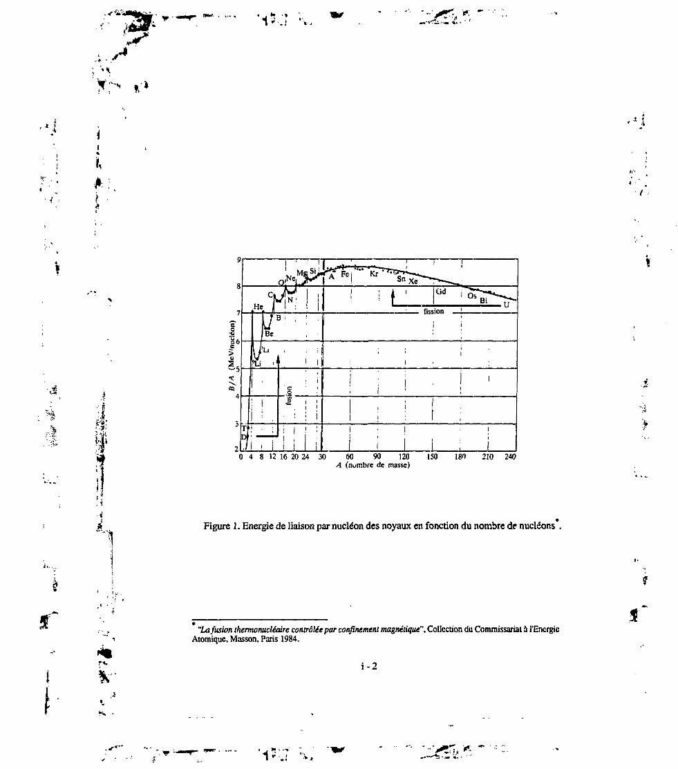
La niasse des noyaux lourds formés par fusion de noyaux plus légers étant inférieure à
la masse totale des éléments initialement en présence (figure 1), les produits de la réaction de
i fusion naissent avec une énergie cinétique bien supérieure à l'énergie moyenne des noyaux '!'
• g entrant en interaction. L'énergie ainsi libérée, quantitativement équivalente à ce "défaut de . ^
*j,~ masse", est dissipée par la suite dans le milieu stellaire. Il en résulte une température qui ; f.'•|i .' '•'»»
maintient l'astre en équilibre entre les forces de pression et les forces gravitationnelles, un
équilibre stable où la puissance fournie par la fusion des noyaux compense exactement la ;
puissance rayonnée dans l'espace interstellaire. C'est pourquoi le soleil brille et brillera encore'ï :
4 pendant plusieurs milliards d'années, jusqu'à épuisement de son combustible nucléaire.
1 Ainsi les astres nous éclairent et engendrent la vie organique parce qu'ils sont le siège de
j réactions de fusion nucléaire qui se traduisent par la transmutation de milliards de tonnes de j,
i matière par seconde, réalisant dans ce processus même la nucléosynthèse d'éléments tels que le g
, ' .'i ' carbone, l'oxygène, etc..., à partir de l'hydrogène et de l'hélium présents dans l'univers dès les' • ar~premières minutes qui suivirent le "Big Bang". y
H.A. Bethe, Physical Review, 55,434 (1939).
V
15,7 \,
..
Od
fission
2 LO 4 8 12 16 20 24 30 60 90 120 150 180 210 240
A (nombre de masse)
! ;. 1
•<
*Figure 1. Energie de liaison par nucléon des noyaux en fonction du nombre de nucléons
**. \-2
1.1
/ .•
"La fusion thermonucléaire contrôlée par confinement magnétique", Collection du Commissariat à l'EnergieAtomique, Masson, Paris 1984.
Jf'
A l'aube de la seconde guerre mondiale, il était déjà clairement admis que la fusion de
l'hydrogène ou de l'hélium représentait une source d'énergie gigantesque et universelle. Il i*'*]"
devenait terriblement tentant d'en acquérir la maîtrise en laboratoire et peut-être de fournir ainsi
à l'Humanité tout entière l'énergie nécessaire à son bien-être et à son développement à long i.
terme, pour des milliers voire des millions d'années, et ceci au moyen d'une source quasiment
inépuisable.
De terribles événements vinrent malheureusement modifier le cours de l'Histoire, et en
particulier celui de l'Histoire des Sciences, en donnant à la recherche scientifique des objectifs
beaucoup moins nobles et une finalité à beaucoup plus court terme : la mise au point de l'arme
atomique. Car les étoiles fabriquent aussi des éléments très lourds tels que l'uranium, lors de
processus moins fréquents mais néanmoins existants. Dans certaines circonstances, de tels i
noyaux se cassent et donnent naissance à des noyaux plus légers qui présentent également un |
"défaut de masse" par rapport au noyau initial (figure 1), libérant également une quantité
importante d'énergie. Ces réactions de fission nucléaire ont la particularité de se multiplier
de façon exponentielle, par un processus de réactions en chaîne, lorsqu'une masse suffisante de
matière fissile - dite masse critique - se trouve rassemblée. Bien qu'il ne se produise ~
pratiquement jamais de façon naturelle tant l'abondance des éléments fissiles dans l'univers est
faible, un tel phénomène est relativement facile à réaliser "en laboratoire" et la libération
;| explosive d'énergie qu'il engendre en a fait rapidement le principe d'une arme atomique
i 1 redoutable appelée bombe A. On peut évidemment regretter que la première prise de conscience
* globale, par l'homme, de l'énorme potentiel de l'énergie nucléaire se soit faite dans les
£ , circonstances affreuses de la seconde guerre mondiale, associant encore aujourd'hui dans !"'t
1J l'esprit de beaucoup la découverte de phénomènes aussi naturels et universels que l'énergie
I nucléaire ou la radioactivité à l'utilisation de la fission de l'atome sous sa forme la plus '"
i dévastatrice, à la seule fin de destruction massive.'• ' f
• La fusion n'a pas échappé aux désirs des hommes de l'utiliser dans le but de fabriquer jlf"
""' -, des armes toujours plus "performantes". Ainsi a t-on réalisé pour la première fois, en mai 1951,
r i-3

-;./•*v '
'1
f
ïI«
J,
& .A
6I''Ii
;n
1
Ia fusion thertnonuyléaire non-contrôlée de l'hydrogène au coeur d'une masse de
matière fissile elle-même en explosion, créant ainsi les conditions physiques nécessaires à
l'allumage des réactions de fusion, soit une température d'une centaine de millions de degrés.
La bombe H était née, capable de libérer en un éclair une quantité d'énergie encore bien plus
importante. L'effet dissuasif que la possession d'une telle arme pouvait exercer sur tout
agresseur potentiel devait bientôt devenir le principe même d'une stratégie militaire capable
d'assurer la paix entre les "grandes puissances".
Dans un même temps, la paix mondiale étant rétablie, les recherches sur les usages
pacifiques de l'énergie atomique s'intensifièrent, bien que leur rythme n'égala jamais celui de la
course à l'armement nucléaire qu'il fut convenu d'appeller la "guerre froide" et dans laquelle se
lancèrent les pays détenteurs de cette puissance. Le développement des piles atomiques - dans
lesquelles les réactions de fission se trouvent modérées par un assemblage sous-critique de
matière fissile et de matière absorbant les neutrons - conduit assez vite à la naissance de
centrales électriques nucléaires qui sont depuis devenues à la fois familières et terriblement
contestées. Les efforts pour réaliser la fusion nucléaire de façon contrôlée reprirent
également dans les années 1950, mais on se rendit compte très vite que la tâche serait longue et
difficile. Ces recherches furent alors libérées du secret militaire, des conférences internationales
furent organisées et les échanges entre physiciens de nombreux pays furent encouragés.
La fin de ce siècle approche et les progrès, considérables, ont été largement à la hauteur
des investissements. Il semble à peu près sûr que l'objectif scientifique - démonstration de la
faisabilité physique de la fusion contrôlée - sera atteint au début du siècle prochain dans une
machine internationale, ITER (International Tpkamak Experimental Reactor), actuellement en
cours de définition. Resteront un certain nombre de problèmes technologiques et de rentabilité
économique liés à la construction d'énormes centrales capables de délivrer un ou plusieurs
gigawatts au réseau électrique.
'•4
i-4
t
«
ï,
2. Considérations énergétiques et écologiques
II est bon de rappeler ici quelles sont les motivations profondes qui conduisent la plupart
des pays industrialisés à soutenir une telle entreprise avec autant de persévérance. Pour se
nourrir, se déplacer, mais aussi pour rendre son travail plus efficace, moins pénible et assurer la
survie et le confort de sa descendance, l'Homme a toujours été en quête de sources d'énergie
plus abondantes, depuis le développement des premières civilisations. Après la révolution
industrielle, le vingtième siècle a vu l'essor de civilisations occidentales riches, grandes
consommatrices d'énergie, et l'apparition d'un trop grand nombre de pays pauvres ou en voie
de développement, pour qui les besoins énergétiques sont énormes. Cependant, nous n'avons
pris conscience que très récemment, à l'échelle planétaire, à la fois des limites de nos
ressources énergétiques et des problèmes écologiques associés à l'exploitation
croissante des sources d'énergie fossiles à base de carbone et d'hydrocarbures (charbon, gaz,
pétrole) ou, seule alternative, à la mise en place d'une économie énergétique mondiale basée
principalement sur la fission nucléaire de l'uranium.
On estime environ à 1023 Joules les ressources énergétiques mondiales offertes par les
réserves connues et exploitables en combustibles fossiles, et la fission de l'uranium dans des
réacteurs surgénérateurs pourrait fournir à elle seule environ 10 fois plus, soit 1024 Joules*.
Ces chiffres sont à mettre en rapport avec la consommation énergétique mondiale actuelle qui
est de l'ordre de 4 x 10 Joules par an. Or, si un habitant des pays les plus riches consomme
en moyenne environ 100 fois ce qui suffirait à sa simple survie, ce facteur n'est que de 15 si
l'on prend la moyenne mondiale. On peut certainement souhaiter à la population entière
d'accéder à un niveau de vie moyen comparable à celui des pays occidentaux tout en limitant
simultanément l'expansion démographique de la planète, les deux phénomènes étant d'ailleurs
souvent directement liés. De toutes les façons, c'est à dire quelles que soient les incertitudes sur
r*.
cf. références dans "La fusion thermonucléaire contrôlée par confinement magnétique". Collection duCommissariat à l'Energie Atomique, Masson, Paris 1984, ou dans "Fusion Energy", R.A. Gross, John Wiley &Sons, Inc., New York, 1984.
i - 5
X*.r
•I
*\ :i
:î
T»,
les prévisions que l'on peut faire, les besoins énergétiques mondiaux atteindront quelques
1021 Joules par an dans le courant du vingt-et-unième siècle. Ne pas pouvoir les satisfaire serait
aller au devant de catastrophes à l'échelle de notre civilisation. Un calcul simple montre alors
que, faute de trouver de nouvelles sources d'énergie ou à moins de généraliser la construction
de réacteurs surgénérateurs, les réserves combustibles connues seraient, épuisées en moins de
cent ans, dans quelques générations seulement. De plus, le dégagement de gaz carbonique lié à
l'exploitation massive des réserves fossiles, et le réchauffement de la planète qui s'en suivrait,
conduiraient à une véritable catastrophe écologique.
Les seules solutions que la Science actuelle puisse apporter à ce problème sont l£S
surgénérateurs nucléaires, l'énergie solaire et la fusion contrôlée. Les énergies
renouvelables comme la biomasse, l'hydroélectricité, la géothermie, les vents, marées,
courants, doivent être utilisées mais elles apporteront une contribution probablement
insuffisante. Les problèmes de sûreté et la gestion des déchets radioactifs produits par la fission
nucléaire rendent peu souhaitable une généralisation des centrales nucléaires surgénératrices à
l'échelle de tous les pays, en particulier des pays en voie de développement. L'énergie solaire
n'est pas encore disponible à grande échelle car elle est d'un coût très élevé. Son potentiel est
pourtant considérable puisque le flux intercepté par la Terre est de 5,4 x 1024 Joules par an mais
elle nécessite une surface au sol gigantesque et il est difficilement envisageable d'en faire
l'unique source d'énergie dans les régions sans désert et à forte densité de population. Reste la
fusion nucléaire qui, hormis l'énergie solaire, est la seule source véritablement
inépuisable, la fusion du deuterium contenu dans l'eau d'un grand port pouvant suffire à elle
seule à la consommation annuelle mondiale d'énergie, et celle du deuterium contenu dans les
océans pouvant produire un total de 10 l Joules, soit de quoi subvenir aux besoins d'une
civilisation avanc1*'' pendant une durée comparable à la durée de vie du SoIeL !
La technologie mise en oeuvre dans un réacteur à fusion sera très élaborée. Il est donc à
redouter que le coût de l'électricité ainsi produite soit relativement élevé. En revanche, l'impact
sur l'environnement et les risques biologiques et écologiques d'une politique énergétique
i - 6
wI ; '

,«r
f,J :
i;
-.-*
ti
:"-"*
r*.
mondiale basée sur la fusion contrôlée seront sans commune mesure avec les dégâts causés de
façon continue par la combustion chimique des composés carbonés (effet de serre, pluies
acides...) ou de façon accidentelle par le dysfonctionnement d'un réacteur à fission, comme ce
fut le cas lors de l'accident de Tchernobyl (Union Soviétique) en avril 1986. L'ensemble des
mesures qui sont prises pour qu'un tel accident majeur "ne puisse pas se reproduire" sont d'un
coût sans cesse croissant, coût qu'il est même difficile d'évaluer tant il est lié à la notion de
probabilité à très long terme.
3. La fusion thermonucléaire contrôlée et son impact sur l'environnement
La fusion thermonucléaire contrôlée bénéficie d'atouts inestimables par l'absence de
phénomène de criticité (emballement de la réaction de fission) et la très faible quantité de
combustible présente dans le réacteur. Contrairement à la fission, il sera très difficile
d'entretenir la réaction dans une machine de taille raisonnable et la moindre anomalie tendra à
!'éteindre rapidement (accumulation des produits de fusion tels que l'hélium, ou d'impuretés
provenant des parois de l'enceinte à plasma). D'autre part les réactions de fusion ne produisent
pas de produits radioactifs de période longue et de haute toxicité comme le plutonium, et les
inconvénients liés au traitement, transport, et stockage d'importantes quantités de matières
radioactives et même à leur détournement dans un but terroriste sont inexistants.
La fusion contrôlée est considérée comme la plus sûre des méthodes actuellement
envisageables à long terme pour la génération d'électricité en quantité suffisante. Aucune
technologie, et en particulier aucune source d'énergie, n'est toutefois totalement exempte de
conséquences sur l'environnement et la sécurité des personnes, et elles nécessitent toutes une
recherche constante permettant d'en améliorer la sûreté. Dans une première génération de
réacteurs, la fusion sera basée sur la réaction
2D + 3T -> 4He (3,56 MeV) + 1H (14,03 MeV)
entre les deux isotopes lourds de l'hydrogène, le deuterium et le tritium. C'est la réaction la
moins difficile à mettre en oeuvre. Les dangers potentiels seront alors associés à la manipulation
i -7
•a?
u,,>.

-fsti'*:''*'-'
K> 1
r,
du tritium (isotope p" radioactif de période 12,36 ans), ainsi qu'à !'activation des structures du
réacteur par les flux neutroniques intenses. L'énergie stockée sous forme magnétique et la
possibilité d'incendie ou de détonation chimique dus à l'inflammabilité de l'hydrogène
entraîneront également certaines contraintes dans la conception d'un réacteur à fusion.
Pour évaluer objectivement l'ampleur que pourrait avoir une catastrophe extrême,
considérons l'éventualité d'un accident majeur détruisant complètement un réacteur et ses
diverses barrières de confinement. La totalité du tritium qu'il contient pourrait alors être relâchée
dans l'atmosphère. Cela constituerait bien entendu un accident non négligeable, concernant
peut-être jusqu'à une dizaine de kilogrammes de tritium car le réacteur produira lui-même son
tritium par transmutation de lithium,
6Li + ln -* 4He + 3T H- 4,78 MeV
7Li + 1H -» 4He + 3T + V - 2,47 MeV
et en brûlera de l'ordre d'un kilogramme par jour. La volatilité de ce gaz conduirait à
l'évacuation rapide de sa plus grande partie vers la haute atmosphère où il serait dilué et se
désintégrerait de façon inoffensive avec sa période de 12,36 ans. Les risques biologiques
proviendraient principalement de la formation d'eau tritiée (HTO ou T2O) et de son ingestion ou
inhalation par les organismes vivants. H faut remarquer cependant que notre organisme ne fixe
pratiquement pas le tritium et que celui-ci se trouve donc rapidement évacué par les moyens
naturels, avec un temps caractéristique de l'ordre de 12 jours. Les concentrations publiques
maximum permises par la réglementation internationale sont de 3 x 10"6 Curie par litre d'eau et
2 x 10"7 Curie par mètre-cube d'air. Sachant qu'un kilogramme de tritium fixé dans
l'environnement (soit quelques litres d'eau tritiée ou quelques mètre-cubes sous forme de
vapeur) représente 10 Curies, la diffusion de la vapeur d'eau tritiée toucherait une zone de
quelques dizaines de kilomètres de rayon avant que la concentration de tritium soit inférieure à
la concentration maximum permise par la réglementation citée plus haut. Par conséquent, même
l'accident le plus improbable aurait un impact localisé et de courte durée par rapport à celui
i -8
'•'*

:•'*'
1
•1';.T"-W
d'une catastrophe liée à la fission nucléaire. D'autre part, l'utilisation croissante des seuls
combustibles fossiles, le transport du pétrole dont les accidents sont fréquents, et certaines
industries chimiques, exercent aujourd'hui sur notre environnement une menace écologique
plus importante que ne le fera la fusion du deuterium et du tritium.
On peut aussi espérer que dans une deuxième génération de réacteurs à fusion, au bout
d'un temps qu'il est cependant difficile d'estimer, il deviendra possible de brûler du deuterium
pur, ou encore un mélange deutérium/hélium-3 s'il s'avère possible de recueillir à un coût
raisonnable l'hélium-3 présent par exemple sur la Lune. Les réactions de base seront alors
2D+ 2D • 3He (0,S2 MeV) + 'n (2,45 MeV)
et peut-être
2D + 2D -» 3T (1,01 MeV) + 1H (3,02 MeV)
2D + He -4 4He (3,71 MeV) + 1H (14,64 MeV).
Elles ont des sections efficaces dix à cent fois plus faibles que celle de la réaction D-T. La
température "d'ignition" c'est à dire d'allumage et d'auto-entretien de la réaction est donc plus
élevée, ceci nécessitant certainement des machines encore plus grandes et de plus haute
technologie que celles qui sont envisagées à l'heure actuelle. Le tritium ne serait plus alors
qu'un sous-produit de la deuxième réaction, lui-même partiellement brûlé par la réaction D-T.
Les études montrent que l'inventaire total en tritium dans un tel réacteur de deuxième génération
ne serait plus que de l'ordre de 1 gramme. Si l'on ajoute à cela qu'il permet d'éviter l'extraction
du lithium terrestre ou marin, on comprend l'attrait considérable que présenterait le cycle du
deuterium pur pour la fusion contrôlée. L'Humanité entrerait véritablement dans l'ère
thermonucléaire où l'abondance d'une énergie inépuisable et géographiquement bien disti.uuée
pourrait contribuer à l'essor de tous les peuples.
1C
è ; '
•4
i
i - 9

rj1I?::?"i «i
• 4à
4. Les Tokamaks et l'utilisation des ondes de plasma
L'état physique dans lequel se trouve un gaz complètement ionisé lorsqu'il est porté à
des températures extrêmes est appelé jtlasma, et est souvent qualifié de quatrième état de la
matière. Si les étoiles tiennent leur cohésion des forces gravitationnelles gigantesques
auxquelles elles sont soumises, les plasmas de laboratoire ne peuvent être confinés que sous
l'effet d'un champ magnétique très intense (confinement magnétique i ou, lors d'une
implosion, pendant une durée très brève (confinement inertieH.
En ce qui concerne la "fusion magnétique" qui semble la plus prometteuse et à laquelle
l'ensemble de cette thèse se rapporte, deux principaux types de machines toroïdales émergèrent
des recherches "classées secrètes" des années 1950, les Stellarators et les Tokamaks. Le
concept de Stellarator, imaginé par Lyman Spitzer, Jr. fut à l'Université de Princeton (USA) le
point de départ de "Project Matterhorn" (1951), tandis que l'ensemble du programme de
recherche américain était, peu après, coordonné sous le nom de "Project Sherwood" . Peu
après la déclassification des recherches sur la fusion contrôlée et la "Deuxième Conférence
Internationale des Nations Unies sur l'Utilisation de l'Energie Atomique à des Fins Pacifiques"
(Genève, 1958), les Soviétiques A.D. Sakharov et LE. Tamm publiaient les principes d'une
configuration magnétique toroïdale différente dans laquelle le plasma est traversé par un intense
courant électrique qui sert à la fois à le confiner et à le chauffer par effet Joule. Cette idée donna
naissance, dans les années 1960, à une série de machines construites dans le laboratoire de
l'Institut Kurtchatov de Moscou dirigé par L.A. Artsimovitch et baptisées "Tokamaks" (îojoid
= tore, kamera = chambre, magnit = aimant, fcatushka = bobine).
Le temps de confinement de l'énergie du plasma dans ces appareils fut bien supérieur à
celui observé dans les autres machines et leur succès fut vite assuré. Depuis, de nombreux
Tokamaks furent construits dans le monde et le plasma s'est avéré d'autant mieux coniiné que
«r
A.S. Bishop, "Project Sherwood, the U.S. Program in Controlled Fusion", Addison-Wesley, Reading, Ma.(USA), 1958.»#
A.D. Sakharov et I.E. Tamm, dans "Plasma Physics and the Problem of Thermonuclear Reactors",M.A. Leontovitch (Ed.), Vol. 1, Pergamon, New York (1959-1960).
i -10
l
•••' &. '•**.»

,Vl
. f ? ",fl
'1^J" ->*&•*•• • • • = : . •
f,
*
les machines étaient grandes, bien que les lois physiques y régissant le transport de la chaleur
ne soient toujours pas vraiment comprises. Plusieurs lois d'échelle empiriques ont été
proposées pour caractériser la dépendance du temps de confinement global de l'énergie, TE,
rapport de l'énergie thermique stockée dans le plasma à la puissance qui lui est fournie. Elles
sont en assez bon accord avec les résultats expérimentaux mais rendent les extrapolations à de
plus grandes machines toujours délicates.
La seule puissance dissipée par effet Joule conduit à un chauffage du plasma
généralement appelé chauffage ohmique. Celui-ci ne permit cependant pas d'obtenir des
températures suffisantes pour espérer observer dans les premiers Tokamaks suffisamment de
réactions thermonucléaires. On eut donc recours surtout à parti)- des années 1970 à ce que l'on a
appelé des moyens de chauffage "additionnels", qui devinrent cependant très vite les sources de
puissance dominantes car la résistivité du plasma décroît lorsque la température électronique
augmente. Ces méthodes de chauffage sont de trois types :
- la compression adiabatique du plasma,
- l'injection de faisceaux d'atomes neutres très énergétiques,
- l'utilisation d'ondes électromagnétiques capables de se propager dans les plasmas : les
ondes de plasma.
Les puissances mises en jeu dans le plus grand Tokamak construit jusqu'à présent, le
Tokamak JET (Joint European Torus), atteignent environ 21 et 22 Mégawatts pour ces deux
dernières méthodes respectivement, et 36 MW pour leur application simultanée. Ces chiffres
sont à comparer aux puissances de 1 à 2 MW fournies par le chauffage ohmique.
Les conditions physiques nécessaires à la fusion auto-entretenue d'un mélange de
deuterium et de tritium (D-T) concernent bien évidemment la température, T1, des ions du
plasma, qui doit être au moins de l'ordre de 10 à 20 keV (1 keV » 11,6 millions de degrés).
Mais ceci n'est pas forcément suffisant et un critère plus précis reliant Tj au produit, n^ïç, de la
K-
i •
fî. -'V*

•as
i
**>
--•%t
'1*.T vw
densité ionique et du temps de confinement de l'énergie a pu être énoncé grâce à des
considérations théoriques simples par J.D. Lawson dès 1957*. La figure 2 représente le produit
Hi-TE-T; obtenu dans un certain nombre de machines au cours des dernières décennies, en
fonction de T1, ainsi que les domaines opérationels correspondant à diverses valeurs
caractéristiques du rapport (Qjyr) de la puissance thermonucléaire que l'on obtiendrait dans un
mélange D-T à la puissance totale (ohmique et additionnelle) qu'il faut lui fournir de l'extérieur
pour maintenir sa température. L'étape Qm = 1, que l'on appelle "breakeven", correspond à un
bilan de puissance nul où l'énergie produite compense exactement l'énergie injectée dans le
plasma. "L'ignition" est obtenue lorsque Qp1- est infini, c'est à dire lorsque l'énergie cédée au
plasma par les particules a nées des réactions de fusion suffit à elle seule à auto-entretenir la
température du plasma, donc la combustion nucléaire, sans apport de puissance de l'extérieur.
Dans la plupart des Tokamaks les expériences sont effectuées dans des plasmas de
deuterium, d'hydrogène ou d'hélium car la manipulation du tritium même en faible quantité
requiert des précautions particulières. JET, et bientôt le Tokamak américain TFTR, auront un
programme dédié à l'étude de nlasmas D-T dans les conditions proches de celles d'un réacteur.20 3
A l'heure actuelle, la valeur record du triple produit nj.TE.Tj = 9 x 10 m" .s.keV a été obtenue
dans JET par injection de neutres dans un plasma de deuterium, ce qui conduisit à la production
de 4,3 x 10¹⁶ neutrons par seconde dans le régime dit des "ions chauds" (Tj » T6), avec
T1 = 19 keV et tE = 1,2 secondes. Des résultats similaires ont été obtenus à densité plus élevée
à l'aide du chauffage par onde? cyclotroniques ioniques, avec cette fois T1 = T6 « 10 keV.
Dans un plasma D-T ayant les mêmes caractéristiques, 11 MW de puissance de fusion seraient
produits pour une puissance injectée de 15 MW ce qui n'est plus très loin du "breakeven". La
première expérience D-T a été effectuée dans JET en novembre 1991 en introduisant 10% de
tritium dans un plasma de deuterium. Elle est également représentée dans le diagramme de la
figure 2, et permit d'obtenir une puissance de fusion maximum de 1,7 MW lors u'un puise de
puissance injectée de 2 secondes, libérant jusqu'à 6 x 101 neutrons par seconde et une énergie
de fusion de 2 Mégajoules. Le taux de production de neutrons mesuré pendant ce tir historique
J.D. Lawson, Proc. Phys. Soc. 70, part 1, n° 445 B, 6-10 (1957)
1-12
/ .•
n
•V
-

.t''
,** - f
<<2 :t •'i*vi ^* jt ^-;* .j^ ,,. r -TVr».'»|(r.)i| •
4
i
100
Hot Ion ModeRegionW,
19651 10
Central Ion Temperature T| (keV)
.'J
Figure 2. Produit nj-T^Tj obtenu dans les divers Tokamaks en fonction de la température ionique
P.H. Rebut, "Perspective on Nuclear Fusion", 'Third Conference on Clean Energy for Europe in Transition"Paris, 1992. Report JET-P(92)20.
i -13

JB.''i*;r\ «i
est poné en fonction du temps sur Ia figure 3.
11 12 _ , 4 13Time (s)
.. Ni i14
Figure 3. Mesures expérimentales (diode au silicium) et simulations (code TRANSP) du taux de
production total de neutrons (principalement de 14 MeV) pendant le tir 26148 (D-T) dans JET .
5. Entretien des conditions de fusion en régime ouasi-stationnaire
Les résultats récents qui sont mentionnés plus haut permettent de mesurer les progrès
considérables accomplis depuis la mise en oeuvre des moyens de chauffage additionnels.
Cependant, il faut noter que les meilleures performances sont toujours obtenues dans des
régimes où le confinement est "amélioré" par rapport aux lois de confinement empiriques
habituellement observées, et que ces régimes sont poui la plupart transitoires. D est donc capital
de développer dans les Tokamaks des moyens de contrôle de la décharge qui permettent
d'obtenir des régimes performants de façon continue, ou au moins quasi-stationnaire si, pour
The JET Team, Nuclear FUSKMI. 32 (1992) 187.
i-14
K1
t :
•$
t

r
r ,4** ' <r
I +*.
ï ^Çsiiï
les raisons qui vont suivre, on envisage un fonctionnement puisé du réacteur.
En effet, pendant longtemps le courant toroidal nécessaire au confinement d'un plasma
de Tokamak a été généré de façon purement inductive, suivant le principe d'un transformateur
dont l'anneau de plasma représente le circuit secondaire, le primaire étant constitué par des
bobinages externes fournissant au plasma la puissance nécessaire par dissipation ohmique de
l'énergie magnétique stockée initialement. Un schéma de principe est représenté ci-dessous
(figure 4) ainsi que des coupes artistiques des machines "OGRA" (de A&simovitch etGoloviri)
et "JET" (figures 5 et 6). La durée de la décharge est donc limitée par le flux magnétique
disponible dans le circuit primaire. Dans un réacteur, elle pourrait atteindre quelques milliers de
secondes.
.-'J
Ik
Sobinta criantchomp toroidal BT
Chomp produitpor le courant
{chcmp poloïdol)
Circuit mcgnâtiqu»
Figure 4. Schéma de principe du Tokamak
i-15
K, .„

I j . ' *
1'.; '>,
II
i
'' ^»*
a = Enroulement du primaire, b = Ecran de cuivre, c = Enroulement produisant le champ magnétique axial, d ••= Enveloppede Cuivre |20 mm) entourant la chambre il dècharRe. e = Chambre à dticharge en acier inoxydable (0,2 mm); diamètre de la
section de la chambre. 0.5 m. S. a. h = Ouvertures.section de la chambre, 0,5 m. S, g, h
Figure 5. Coupe du Tokamak "OGRA"*
•s
ft
MechanicalStructure
VacuumVessel
Toroidal _Field Coils
Outer PotoidalField Coils
lr.rvr Potoidal Field Coils(Primary Winding)
Figure 6. Coupe du Tokamak "JET"*
L.A. Artsimovitch, dans "Actes de la Deuxième Conférence Internationale des Nations Unies sur l'Utilisationde l'Energie Atomique à des Fins Pac'fiques", Genève (1958), Vol. 12, p. 6.
" JET Joint UndertaJdng, Progress Report 1991, Vol. 1, EUR 14434 EN, EUR-JET-PR9 (1992).
i - 16
1r . .i«9

ct
>-*,
'f
Une propriété universelle des Tokamaks inductifs est que, au bout d'un temps
* caractéristique de la diffusion résistive du courant, le profil radial de la densité de courant estj . <'•* directement lié, par la résistivité du plasma, au profil radial de sa température électronique, II est1 ii donc difficilement contrôlable et pourtant il joue un rôle prépondérant dans la stabilité MHD ! J
* . (magnéto-hydro-dynamique) du plasma, les phénomènes de transport et la turbulence. Il serait K- . ' ,'" • • i, r*.? donc essentiel de pouvoir découpler les profils de densité de courant et de température. . / "., jt '3 *' *•
,' ' A la fin des années 1970, alors que les moyens de chauffage par ondes se • ;
développaient, on démontrait qu'il était possible de générer le courant plasma par interaction ; ' :
dite "Landau quasi-linéaire" d'ondes à la fréquence "hvhride inférieure" avec une |
population d'électrons résonnants qui se trouvent accélérés unidirectionnellement dans le sens
^ de la vitesse de phase de l'onde. Ainsi naissait la perspective d'un réacteur du type Tokamak \
fonctionnant en continu mais aussi la possibilité de contrôler le profil de courant. La i
génération non-inductive de courant devint donc un des programmes de recherche
majeurs de nombreux laboratoires. Au milieu des années 1980, un programme de contrôle des
profils au moyen d'ondes de plasma dans JET était lancé, tandis que la France se dotait du plus . •f ' * .1
grand Tokamak à bobinages supraconducteurs, TORE SUPRA, dans le but d'étudier les -,
; |; décharges longues entretenues par des ondes à la fréquence hybride inférieure. •%.
I ^tj} L'ensemble des travaux rassemblés ici s'inscrit dans ces deux vastes programmes. Let |
11 contrôle des profils et en particulier le découplage entre les profils de température et de ^.
•' \ densité de courant par l'utilisation d'ondes de plasma en sont les buts à moyen terme. Cecii
1 devrait permettre d'améliorer les performances quasi-stationnaires des grands Tokamaks
| actuellement en exploitation, de façon à créer plus tard, dans des machines de taille encore
| , raisonnables telle que ITER, et avec une marge suffisante, les conditions nécessaires à la
: fusion. L'augmentation de Ia durée de la décharge par économie de flux magnétique, et si !»
1 î '. possible l'entretien continu de la décharge dans un réacteur "avancé" sont, à plus longJ
terme, des motivations supplémentaires sinon des buts ultimes. jf
*!'••>"V : -I
I «1 'Vi
i•*a
Cette thèse est divisée en quatre chapitres. Les deux premiers sont consacrés à
l'utilisation d'ondes couramment appelées "ondes hybrides", dont la fréquence est voisine
de la fréquence hybride inférieure dans le plasma. On a rassemblé ici des travaux concernant
spécifiquement le couplage des ondes au plasma (chapitre I), leur propagation et aussi la
réponse du plasma à l'absorption de ces ondes (chapitre II). Cette méthode de génération de
courant a de nombreux mérites et est jusqu'à présent la plus efficace. Elle a pourtant ses limites
et d'autres ondes peuvent en principe être utib'sées pour la génération non-inductive de courant.
C'est en particulier le cas de l'onde tnagnétosonique rapide dont le potentiel pour
contrôler la densité de courant au centre de la décharge, dans un réacteur ou dans un plasma très
chaud, est à priori plus grand. Une étude théorique en est faite au chapitre III. Le chapitre IV
sera consacré aux résultats expérimentaux. La génération de courant par les ondes hybrides a
donné lieu à de nombreuses expériences et les récents résultats que nous avons obtenu dans le
Tokamak TORE SUPRA sont très encourageants. Concernant l'onde rapide, des programmes
expérimentaux sont en cours, ou prévus, dans les tokamaks DIII-D (USA), JET, TORE
SUPRA, JT-60 (Japon) et seules quelques expériences préliminaires à des niveaux de
puissance modestes ont été effectuées. Dans une conclusion générale nous discuterons
finallement les propriétés respectives des deux méthodes dans la perspective de leur application
au réacteur et verrons dans quelle mesure elles peuvent se compléter. Nous esquisserons alors
les grandes lignes d'un programme de recherche visant à l'utilisation des ondes de plasma pour
le contrôle des Tokamaks, programme qui contribuera sûrement de façon essentielle à faire de la
fusion contrôlée l'énergie de demain.
K-
I r '
r*. i-18
*>
\
il'
*i
I
CHAPITRE I
COUPLAGE DE L'ONDE HYBRIDE AU PLASMA
ET ANTENNES A MULTIJONCTIONS
1.1. Introduction
Ce chapitre est entièrement dédié à l'étude des propriétés physiques des ondes hybrides
et à la conception d'antennes appropriées à leur utilisation dans les grands Tokamaks. La
résonance hybride inférieure, ou hybride basse, dans les plasmas de fusion «st de l'ordre du
gigahertz, ce qui rend possible la transmission de puissance par des guides d'ondes dont la
taille est petite par rapport au plasma. A ces fréquences, deux branches de propagation existent
dans le plasma. Elles sont appelées respectivement onde lente et onde rapide par référence
à leur vitesse de phase dans la direction perpendiculaire au champ magnétique d'équilibre
confinant le plasma. Leur polarisation est telle que la composante électrique de l'onde lente le
long de ce champ magnétique est plus grande que celle de l'onde rapide et que, par conséquent,
cette onde peut être fortement absorbée par interaction Landau avec les électrons du plasma. Par
une juxtaposition de guides d'ondes déphasés de façon adéquate, il est possible de sélectionner
le spectre en longueurs d'ondes du champ électromagnétique rayonné pour que l'interaction ait
lieu avec une population choisie d'électrons dans l'espace des vitesses. Ces électrons, en
résonance avec l'onde, tendront à acquérir une distribution de vitesse relativement uniforme par
diffusion quasi-linéaire, créant une queue de distribution non-thermique unidirectionnelle, à des
énergies de l'ordre de la centaine de keV. Le courant porté par cette population suprathermique
est une fonction de la puissance absorbée. Pour des puissances de quelques mégawatts dans
des machines de la taille de TORE SUPRA, JET ou JT-60, il peut atteindre une intensité
suffisante pour remplacer tout le courant inductif et confiner le plasma.
1-1
•<*
f
r

JjT ~*' '»e • "'
I
^
L'efficacité de la génération de courant telle qu'elle peut être définie par l'ingénieur,
c'est à dire en termes d'ampères par watts transmis par les générateurs, est évidemment liée en
partie à Ia qualité de l'antenne (polarisation de l'onde, finesse du spectre, bonne adaptation) qui
va coupler cette puissance au plasma. Le travail dont il est question au paragraphe 1.2 est à
l'origine de la conception d'antennes d'un type nouveau qui équipent maintenant les trois
grands Tokamaks cités plus haut ainsi que le Tokamak de Varennes (TdV) au Canada. Les
premières expériences qui ont permis, d'une part de vérifier la théorie du couplage proposée
(régimes de couplage, spectres rayonnes, coefficients de réflexion et d'intercouplage des guides
d'ondes), et d'autre part de qualifier le principe de ces antennes sont décrites dans les sections
1.3, IA et les annexes correspondantes. Les sections 1.5. et 1.6 concernent respectivement la
définition et l'optimisation d'une antenne de ce type pour JET et les expériences de couplage
menées sur TORE SUPRA à l'aide d'antennes semblables.
1.2. Couplage de l'onde lente au voisinage de la fréquence hvbride basse dans
les grands Tokamaks
Ce travail a fait l'objet d'un rapport non publié reproduit en annexe (A.I.2). La théorie
linéaire (2-D) du couplage y est faite pour des plasmas de densité relativement élevée devant
l'antenne et différents régimes de couplage sont distingués. Une théorie multipolaire des
réseaux de guides d'ondes appelés "grils" est ensuite développée et plusieurs structures haute
fréquence (HF) dérivées du principe du gril sont étudiées. Ces structures compactes nous ont
permis de concevoir de nouvelles antennes facilement extrapolables aux grands Tokamaks et
aux réacteurs à fusion, les "antennes à multijonctions". Nous en présentons ici la théorie
électromagnétique complète ainsi que les propriétés physiques concernant le couplage de la
puissance HF aux ondes de plasma.
Pour aider à la définition détaillée de telles antennes dans les situations pratiques, et
aussi pour interpréter les résultats obtenus en présence de plasma, nous avons développé un
gros programme de simulation numérique appelé SWAN ($Jow W_ave Antenna). Nous
1-2
t

•M_
• X*«•* - .r, VH,
X> t«
1
«
présentons également de nombreux résultats obtenus à partir de ce code de simulation sur des
calculateurs de grande capacité (CRAY).
Nous mettons en particulier en évidence un phénomène d'auto-adaptation qui permet
théoriquement de réaliser une bonne adaptation des antennes dans une large gamme de
paramètres du plasma de bord lorsqu'elles sont conçues pour exciter une onde progressive.
C'est le cas pour les applications à la génération de courant. Des coefficients de réflexion
inférieurs à 1% sont alors envisageables, ce qui permet de diminuer les pênes de puissance.
Une autre conséquence de cette propriété est que les taux d'ondes stationnaires (TOS) à la sortie
des générateurs (klystrons) restent faibles sans pour cela avoir recours à des circulateurs HF
pour les protéger. Ceci a constitué une économie importante dans la réalisation des lignes de
transmission pour TORE SUPRA.
Pour terminer, on décrit très brièvement les premières vérifications expérimentales de
principe effectuées sur le Tokamak PETULA-B à l'aide d'un "gril à multijonctions" excitant un
spectre symétrique. On donne enfin une méthode permettant d'obtenir pour la première fois une
bonne approximation des spectres expérimentaux réellement rayonnes par l'antenne, en utilisant
à la fois le code SWAN pour déterminer !'admittance de surface du plasma, et les mesures HF
effectuées en amont de l'antenne.
1.3. Couplage de l'onde hvbride dans le Tokamak WEGA
Nous avons ici utilisé les mesures HF effectuées sur le Tokamak WEGA lors
d'expériences utilisant une antenne conventionnelle du type "gril" (cf. annexe A.I.3), pour
valider la théorie du couplage proposée dans le travail précédent. Le modèle du plasma de bord
présent devant l'antenne consiste en un saut de densité arbitraire à l'interface antenne-plasma
suivi d'un gradient constant sur une distance au moins égale a quelques longueurs d'onde dans
la direction radiale, normale à l'ouverture des guides d'ondes, soit quelques centimètres.
Pour minimiser les conditions aux limites spécifiques du "gril" à quatre voies utilisé
dans WEGA, conditions qui ne sont pas prises en compte dans le modèle théorique, nous
1-3
•$-' .''1V
"
f
1n"r« • - . • • i •n
' '\
avons utilisé les données obtenues lorsque seules les deux voies centrales étaient alimentées en
puissance. La densité du plasma et son gradient ont été estimées à partir de mesures par sondes
de Langmuir. L'accord qualitatif entre l'expérience et la théorie est toujours bon. Un accord
quantitatif entre les mesures HF (amplitudes et phases des coefficients de réflexion et de
transmission dans les guides alimentés ou non) et les estimations théoriques est obtenu dans un
régime de densité de bord suffisamment élevé où le couplage dépend peu du gradient de la
densité (régime WKB). Ceci contraste avec les échecs des modèles précédents dans lesquels la
densité était supposée voisine de zéro (ou de la densité de coupure) à l'ouverture des guides
d'ondes. La validité du modèle à "saut de densité" est aussi démontrée par l'évolution des
phases des ondes réfléchies en fonction de la densité de bord. Ceci est particulièrement net pour
des expériences où la position du plasma oscillait dans un plan horizontal, entraînant une
modulation temporelle de cette densité.
1.4. Chauffage des plasmas par ondes hybrides à l'aide d'une nouvel le
antenne : le "gril à multijonctions"
Nous avons publié en 1985 les premiers essais d'une antenne à multijonction effectués
dans le Tokamak PETULA-B (annexe A.I.4). Dans cette antenne d'un type nouveau, fabriquée
dans le but de chauffer les ions du plasma, l'onde excitée avait un spectre symétrique et
rayonnait de façon oblique dans les deux directions opposées, ne générant donc aucun courant.i
La division de puissance était réalisée nour la première fois au moyen de multijonctions plan-E,
et le déphasage de 180° entre les ondes partielles ainsi engendrées, nécessaire à la propagation
de l'onde résultante dans le plasma, était induit par des réductions appropriées de la hauteur des
guides d'ondes secondaires.
Une comparaison détaillée des résultats obtenus avec ce nouveau coupleur et un "g.il"
conventionnel équivalent est faite en A.I.4. Les dépendances paramétriques des coefficients de
couplage sont voisines bien que la valeur du coefficient de réflexion global du nouveau
coupleur soit légèrement plus élevée. Ceci a été attribué à une différence de densité devant les
deux antennes, causée par leur situation respective dans la machine. La propriété d'auto-
1-4

f
X> f*
•*•"
'*%
4i
1
adaptation ne pouvait pas être vérifiée car elle n'existe que pour certains déphasages (60°, 90°)
correspondant à des spectres asymétriques. Les effets obtenus sur le plasma indiquent une
efficacité de chauffage, ne AT/PHF = 4,5 eV x 1019 m"3/kW, similaire dans les deux cas,
prouvant ainsi la validité du concept de ces nouvelles antennes. Par conséquent, en conclusion
de ce travail il est établi que les "multijonctions" pourront grandement simplifier la conception et
la construction des antennes à ondes hybrides pour les futurs grands Tokamaks, en particulier
avec un déphasage de 90° entre les voies secondaires pour les applications à la génération de
courant.
1.5. Couplage d'ondes lentes à la fréquence hvbride inférieure tjans .IET
Les propriétés physiques d'une antenne destinée au contrôle du profil de courant dans
JET et conçue sur le principe des grils à multijonctions ont été étudiées de façon très minutieuse
à l'aide du code SWAN dans un but d'optimisation (annexe A.I.5)*. Cette antenne est la plus
grande réalisée jusqu'à présent et se trouve actuellement en cours de montage, alors que des
éléments prototypes ont été testés pendant les campagnes expérimentales précédentes. Elle est
constituée par un réseau de 24 unités du type "multijonction" alimentées indépendamment par
24 klystrons pouvant délivrer un total de 12 Mégawatts à la fréquence de 3,7 GHz.
Dans l'étude présentée ici, l'importance de certains paramètres géométriques est
soulignée. L'optimisation qui en est faite a été prise en compte dans la définition et la fabrication
finales. Grâce à cette optimisation, l'amplitude des champs électriques dans les guides d'ondes
secondaires est minimisée pour une densité de plasma devant l'antenne d'environ 1018 m"3, et
le coefficient de réflexion global est inférieur à 1,5%. Les qualités de l'antenne pour la
génération de courant se mesurent aussi par sa directivité, souvent définie comme le rapport de
la puissance rayonnée dans la direction souhaitée (direction de dérive des électrons portant le
courant ohmique) à la puissance totale rayonnée. Nous avons défini pour les besoins de
l'optimisation une "directivité pondérée", mesure de l'efficacité théorique de la génération de
r».
*X. Litaudon, "Etude théorique et expérimentale du couplage de l'onde hybride dans TORE SUPKA et JET au
moyen d'antennes à multijonctions". Thèse de Doctorat, Université de Provence, Aix-Marseille 1,1990.
1-5

' f •'
r-, T
'H
ï,
A :
1-
:J
ffr " •
,'*,'
«1 ^t-.•W J . r~— -•—
courant basée sur le spectre rayonné et normalisée à l'efficacité qui correspondrait à un spectre
idéal, monochromatique à la longueur d'onde choisie. Pour le choix optimal des paramètres
géométriques, la "directivité pondérée" reste comprise entre 60% et 70% pour une large gamme
de dei. - autour de la densité optimale devant l'antenne. L'utilisation de guides passifs de
chaque côté de l'antenne, permet d'atténuer les effets de bord parasites. Finalement, l'effet du
champ magnétique sur le couplage de l'onde est étudié. Il devrait être négligeable pourvu que
l'intensité de ce champ sur l'axe magnétique du plasma soit supérieure à 1,5 Tesla.
1.6. Couplage de l'onde hybride dans TORE SUPRA au moven d'antennes à
multifonctions
Les expériences de génération de courant par ondes hybrides dans TORE SUPRA
utilisent un système basé sur deux coupleurs à multijonctions alimentés chacun par 8 klystrons
de 3,7 GHz/500 kW, soit une puissance installée de 8 MW. Comme pour JET, un réseau de 8
unités juxtaposées, soit 32 guides secondaires, compose chaque rangée horizontale des
antennes, ce qui permet d'exciter un spectre en nombres d'ondes très fin. Deux guides passifs
sont ajoutés de chaque côté des coupleurs pour diminuer les effets de bord.
De nombreuses expériences de couplage ont été réalisées dès 1990, au cours des
premières campagnes expérimentales, pour étudier les caractéristiques HF de ces antennes en
présence de plasma (annexe A.I.6). Les mesures des différents coefficients de transfert des
antennes ont montré un bon accord avec les valeurs prédites par la théorie et calculées à l'aide
du code SWAN. Des coefficients de réflexion globaux de quelques pour-cents ont été mesurés
pour des densités du plasma de bord allant de 0,3 x 10¹⁸ m"3 à 1,4 x 10¹⁸ m"3, pour des
distances entre l'antenne et la dernière surface magnétique du plasma allant de 2 à 5 centimètres,
et jusqu'à une densité de puissance injectée de 45 MW/m .
Lorsque le plasma est déplacé en direction du mur interne de la chambre toroïdale, le
coefficient de réflexion reste bas jusqu'à des distances antenne-plasma de l'ordre de
10 centimètres. Ceci constitue un résultat intéressant en vue du couplage à des plasmas très
1-6
fi-
i !
'
WJ*C "'
£••
1
performants où les flux de chaleur seront tels qu'ils ne permettront pas de placer les antennes à
quelques centimètres seulement en retrait des limiteurs qui déterminent la surface magnétique
externe du plasma.
Les mesures HF effectuées sur TORE SUPRA nous permettent maintenant de façon
routinière de reconstituer le spectre "expérimental" réellement rayonné par les antennes quand
tous leurs modules sont alimentés avec des amplitudes et des phases variables. La possibilité de
contrôler le spectre en déphasant les différents modules de -90° à +90° a été démontrée après
qu'une méthode originale ait été mise au point pour s'assurer de la stabilité des déphasages
respectifs entre les modules.
1.7. Conclusion
Comme nous le verrons dans le dernier chapitre de cette thèse, les performances des
coupleurs prototypes installés dans JET ont été comparables à celles des antennes utilisées dans
TORE SUPRA, même si l'efficacité de génération de courant a été bien supérieure. Cette
différence peut être attribuée en grande partie à la taille et à la géométrie respectives des
plasmas, à des phénomènes synergétiques entre les ondes hybrides et cyciotroniques ioniques
et à la température électronique moyenne des couches périphériques du plasma (cf. 11.5). Elle
ne semble pas due aux propriétés de couplage des antennes dont le fonctionnement a été
conforme à ce que l'on en attendait et relativement bien compris.
Ainsi, les antennes à multijonction ont-elles prouvé leur viabilité pour l'utilisation des
ondes hybrides dans les plus grands Tokamaks construits jusqu'à présent, et à des niveaux de
puissance satisfaisants. Des projets basés sur ce concept sont à l'étude pour une version
améliorée de TORE SUPRA qui permettrait de réaliser des décharges continues, ainsi que pour
ITER dont il sera sûrement souhaitable, dans une phase avancée, de contrôler le p/ofil de
courant et dont on envisage aussi, à plus long terme, le fonctionnement continu.
1-7

f I
**'•*>' :

ANNEXE AU CHAPITRE I
A.I.2. Couplage de l'Onde Lente au Voisinage de la Fréquence Hybride Basse dans les** Grands Tokamaks, D. MOREAU et T. K. NGUYEN, Rapport EUR-CEA-FC-1246, Centre
; d'Etudes Nucléaires de Grenoble, 1984.
A.I.3. Lower Hybrid Wave Coupling in the WEGA Tokamak, C. GORMEZANO and
D. MOREAU, Plasma Physics and Controlled Fusion 26 (1984) 553.
A.I.4. Lower-Hybrid Plasma Heating via a New Launcher : The Multijunction Grill,
C. GORMEZANO, P. BRIAND, G. BRIFFOD, G.T. HOANG, T. K. NGUYEN, D. MOREAU, ;
G. REY, Nuclear Fusion 25 (1985) 419.
A.I.5. Coupling of Slow Waves near the Lower Hybrid Frequency in JET, X. LiTAUDON,
! D. MOREAU, Nuclear Fusion 30 (1990) 471. '
;l. • V4(L V
>£'; A.I.6. Lower Hybrid Wave Coupling in TORE SUPRA through Multijunction Launchers, 1»
J x. LITAUDON, G. BERGER-BY, P. BIBET, J.R BIZARRO, JJ. CAPITAIN, J. CARRASCO,y
^ j M. GONICHE, G.T. HOANG, K. KUPFER, R. MAGNE, D. MOREAU, Y. PEYSSON,
Î ] J.M. RAX, G. REY, D. RIGAUD, G. TONON, Nuclear Fusion 32 (1992) 1883.. î
^ ' ,-T)
1-9

4*
.it
DRFC-SIG EU R-CEA-FC-1246
COUPLAGE DE L'ONDE LENTE AU VOISINAGE
DE LA FRÉQUENCE HYBRIDE BASSE
DANS LES GRANDS TOKAMAKS
D. MOREAU et T.K. NGUYEN
1983 • 1984
COUPLING OF SLOW WAVES NEAR THE
J j LOWER HYBRID FREQUENCY IN LARGE TOKAMAKS
ASSOCIATION EURATOM-CEA SUR LA FUSION
Département de Recherches sur la Fusion ContrôléeCentre d'Etudes Nucléaires
r î - w -

if•>'•
1 <-".'> "VI «I • I
TABLE DES MATIERES
Page
RESUME 1
INTRODUCTION 2
1. PROPAGATION LINEAIRE DES ONDES DE PLASMA DANS LE DOMAINE
DEL111HYBRIDEINFERIEURE" 5
1.1. Modèle mathématique et principalesapproximations .... 5
1.2. Admittance de surface du plasma vis-à-vis de l'onde
lente 7
1.3. Représentation analytique de la fonction ys(n//) •••• 10
1.4. Singularités de la fonction ys(n//) 11
1.5. Couplage au voisinage de la densité de coupure 13
1.6. Couplage à un plasma surdense - Régime WKF 14O
1.7. Dégénérescence des modes pour n,/=1 lorsqu'on néglige
les courants transverses 15
1.8. Influence des courants transverses sur les cscilla-
tions quasi-électrostatiques dans le domaine de la
fréquence hybride inférieure 16
1.9. Influence des courants transverses sur la propagation
du mode rapide 191.10.Influence des courants transverses sur Tadmittance
de surface pour un champ électrique d'excitation
horizontal (E =0) 21
1.11.Condition de rayonnement et détermination analytique
de y (n,,) pour n,, complexe 25
2. THEORIE MULTIPOLAIRE DU GRIL 30
2.1. Introduction... , 30
2.2. Champsélectromagnétiques aes guides - Puissance
complexe rayonnée 32
2.3. Champs électromagnétiques à l'interface guides -
Plasma de bord - Puissance complexe rayonnée 34
' t
' 5 "7" ;" 'T r -;-' Ai
Page
,j
,
2.4. Continuité du champ électrique tangentiel 352.5. Conservation de la puissance complexe 372.6. Bilc.n de puissance - Champs électriques tangentiels .. 402.7. Spectre des ondes planes d'indice n,, en z 41
3. EMPLOI DES GUIDES PASSIFS 43
3.1. Introduction 433.2. Matrice de transfert et tensions électriques 433.3. Champs électromagnétiques à l'embouchure des guides.. 463.4. Bilan de puissance et spectre en n,, des ondes planes
rayonnées vers 1e piasma 483.5. Exemples d'emploi des guides passifs 50
4. THEORIE DES MULTIJONCTIONS PLAN ••• E 51
4.1. Introduction 514.2. Matrice de transfert 514.3. Champs électromagnétiques dans les guides B34.4.Continuité du champ électrique tangentiel 584.5. Conservation de la puissance complexe 63
•
4.6. Déduction des éléments de la matrice de transfert ... 64
5. LES "GRILS" COMPACTS UTILISANT LES MULTIJONCTIONS PLAN E 68
5.1. Théorie des "grils multijonctions" (G.M.) 685.2. Propriété d1autoadaptation, champs électriques entre
le plan de jonction des guides et le plasma de bord 70
6. RESULTATS EXPERIMENTAUX SUR LE CHAUFFAGE DES IONS DU
TOKAMAK PETULA-B AVEC UN GRIL-MULTIJONCTION A ONDES
STATIONNAIRES - COMPARAISON AVEC LE GRIL CONVENTIONNEL
EQUIVALENT 80
6.1. Description du gril multi jonction 80
6.2. Mesures à faible niveau 80
6.3. Tests à puissance élevée 81
6.4. Couplage au plasma 81
*k-^
^.-<•
j
s
*""1
r*.
..î»
" " ' ^Pf '• irF «T< ' -^
,-•~rh . w'.ji, • • '
Page
6.5. Performances comparatives des G.M. et G.O. utilisés
pour le chauffage des ions 83
REFERENCES 85
FIGURES 88
*
* *
f"

.i»
1
•1'.? *'£_-
ABSTRACT
Î The linear (2-D) coupling theory of slow waves near the lower ' -j hybrid frequency is generalized for relatively high density plasmas^ facing the antenna and different coupling regimes are distinguished. ;* A multipolar theory of juxtaposed waveguide arrays (Grills) is then 'f ,L • developped and new r.f. structures derived from the principle of the ". t~.;» Grill are studied in order to make the extrapolation of this princi-
ple to large tokamaks and to reactors easier. These "compact structu-: res" allow the design of modular antennae, so called "E-plane multi-
junction antennae", and the electromagnetic theory of such "multi- tji
junctions" is presented. We have studied the physical properties of fthe slow wave antennae so obtained, as far as coupling the r.f. power
•x to plasma waves is concerned, with the aid of a computer code (S.W.A.N.)and we present many numerical results. In particular, we point out aninteresting "self-adaptation" phenomenon which should allow a good ;matching of "progressive wave multijunction antennae" (current drive)in a large range of edge plasma parameters. Reflection coefficientsless than 1 % could be considered with the potential consequence ofreducing a lot the cost of the r.f. power transmission lines. '4~
? > "
f.|. To conclude, we relate very briefly the "proof of principle" '*', ,>•. *%H; experiments performed on PETULA-B and we show "experimental spectra" .-'•?,I of radiated power which can be obtained from r.f. measurements through*f the SWAN code.* 1 i
.j»

v.., -1 «•-..' W
RESUME
, ** j' La théorie linéaire (2-D) du couplage au plasma d'ondes au voi-
i » sinage de la fréquence hybride inférieure est généralisée à des plasmas; A de densité relativement élevée devant l'antenne et différents régimes
• •1 ^ * . de couplage sont distingués. Une théorie multipolaire des réseaux de•' I guides d'ondes (Grils) est ensuite développée et de nouvelles structu-
res H. F. dérivées du principe du "Gril" sont étudiées de façon à faci-• ' liter l'extrapolation de ce principe aux grands tokamaks et aux réacteurs.
Ces "structures compactes" permettent de réaliser des antennes modulai-res dites "à multi jonctions plan-E" et la théorie électromagnétique de
* telles multi jonctions est présentée. Nous avons étudié les propriétésphysiques des antennes à ondes lentes ainsi obtenues» en ce qui concer-
" ne le couplage de la puissance H. F. aux ondes de plasma, grâce à un codenumérique connu sous le nom de S. W. A. N. (Slow Wave Antenna) et nousprésentons de nombreux résultats numériques. En particulier, nous met-tons en évidence un phénomène intéressant d1 "auto-adaptation" qui permetthéoriquement de réaliser une bonne adaptation des antennes à multi jonc-tions à ondes progressives (génération de courant) dans une large gamme
5 de paramètres du plasma de bord. Des coefficients de réflexion inférieurs>,à, | à 1 % sont envisageables ce qui entraîne une grande diminution du coût-$ '?$ des lignes de transmission de puissance. Pour conclure, on relate très4? i«Ji brièvement les vérifications expérimentales de principe effectuées sur
' PETULA-B et on donne des "spectres expérimentaux" de puissance rayonnée»! que le code S. W. A. N. permet de calculer à partir de mesures H. F.
-*

f
••• - • j *v "* *"1"«,' '"1^ I*
A i -
,i,. /
*'--«
I
2.
INTRODUCTION
Dans le but d'atteindre les températures nécessaires à la fusioncontrôlée, le chauffage des plasmas par des ondes de haute fréquenceà la résonance hybride inférieure (~ 1 GHz) fait depuis longtempsl'objet de nombreuses investigations théoriques /1/ et expérimentales/2/. Ces dernières n'ont permis d'étudier la physique de ce chauffage/3/ qu'après avoir résolu d'importants problèmes technologiques soulevéspar l'injection de plusieurs centaines de kilowatts (z 1 MW) H.F. dansun tokamak (vide, champ magnétique...) /4/, au moyen d'antennes dontles caractéristiques sont imposées par la physique des ondes plasma.
Plus récemment, stimulées par des résultats théoriques encoura-geants /5/, la plupart des expériences du type tokamak ont démontréqu'il est également possible, par l'application d'ondes H.F. dans lemême domaine de fréquence, d'entretenir ou même de générer le couranttoroidal en l'absence de champ électrique inductif /6/. Ceci permetd'envisager un fonctionnement quasi-continu des tokamaks et constitueun résultat très important pour leur avenir en tant que réacteursthermonucléaires potentiels /7/. Le domaine de la fréquence "hybrideinférieure" a ainsi acquis une dimension et un intérêt nouveaux quiont motivé le travail que nous présentons ici en vue de l'utilisationde telles ondes dans les grandes machines futures (T.S, N.E.T...).
Dans les machines de taille moyenne fonctionnant à l'heure actuelleon utilise pour le couplage de l'onde lente au voisinage de la fréquencehybride inférieure des réseaux de guides d'ondes juxtaposés appeléscommunément "Grils" /8/ dont la théorie a été développée initialementpar Brambilla /9/. Cette théorie, bien que linéaire, est en bon accordavec les observations expérimentales jusqu'à des densités de puissanceassez élevées /10-11/ ; au-delà, des phénomènes non-linéaires ont étéobservés expérimentalement /12/ et ur.e étude détaillée du couplage non-linéaire doit être faite (cf par exemple /13/).
K'
I
{ .-

-; - /! *-H
I , *l -yT"'.! rtl? '**'
Dans leur version conventionnelle les "grils" sont composés d'unnombre de guides d'ondes relativement faible (2 à 8) et chaque voieest alimentée individuellement en amplitude et en phase, donnant ainsiau système une souplesse maximum appréciable pour certaines études dephysique. Cependant, l'extrapolation de tels systèmes aux grands tokamaks,où des puissances mises en jeu seront supérieures à 10 MW, aboutit àla conception d'antennes dont le nombre de voies dépasse la centaine.Le coupleur lui-même et la ligne de transport de l'énergie H.F. délivréepar les générateurs deviennent alors d'une complexité et d'un encombre-ment excessif. Renoncer à utiliser toute la surface des queusots dispo-nibles et réduire le nombre de voies imposerait des contraintes peuréalistes sur les densités de puissance devant être véhiculées(> 5 kW/cm2). D'autre part, le coût d'un tel système devient rapidementdéfavorable comparativement à celui de systèmes de chauffage concurrents(chauffage cyclotronique ionique ou électronique, injection de neutres...)
.•I
Une simplification possible a été proposée récemment /14-15/. Elleconsiste à utiliser comme diviseur de puissance une jonction multivoiesplan E et à alimenter tous les guides d'ondes de dimension réduite parun seul guide, dit principal. Le déphasage entre les voies peut êtreréalisé par une réduction de la hauteur des guides sur une longueuradéquate.
Cette simplification apporte une grande réduction du coût dusystème et permet en outre d'utiliser toute la surface disponible desqueusots et d'abaisser ainsi la densité de puissance H.F. au-dessous duseuil d'apparition des phénomènes parasites : claquages, effet multi-pactorj décomposition paramétrique ou effets non linéaires. Il n'estd'ailleurs pas improbable que, comme les grils conventionnels avecfenêtres étanches en bout /16/, l'antenne proposée soit capable devéhiculer une densité de puissance plus grande que les grils conventionnelsentièrement sou? vide qui seuls, seront utilisables dans un réacteur.En effet, compte tenu de la compacité de cette antenne, la zone derésonance cyclotronique électronique -source possible de nombreux ennuis-peut se trouver soit dans le guide principal de grande section, soitderrière une fenêtre étanche du guide principal, dont la réalisation estsimple, c'est-à-dire dans la partie sous pression atmosphérique.
els 1
4.
Ce rapport sera divisé en six grandes parties. D'abord, on<~*l ,. exposera la théorie de la propagation des ondes appropriée aux fréquences
* considérées et on obtiendra les expressions de !'admittance de surface
Sj ! J du plasma dans différents cas d'intérêt physique. La deuxième partie„,. • N sera consacrée à la théorie électromagnétique du "gril" exposée à l'aide* \ F . d'une formulation multipolaire qui permettra directement le calcul
*V £ d'une antenne comportant en cascade des éléments tels que guides passifs,muUijonction plan E... Les 3° et 4° parties traiteront respectivement
: de chacun de ces éléments.
I Dans la 5° partie, on étudiera les propriétés physiques, en présence Jde plasma, des antennes compactes utilisant les multijonctions plan E. \
) Pour terminer, on donnera dans la 6° partie, les résultats desexpériences de chauffage des ions effectuées dans le tokamak PETULA B
. . à l'aide d'un "gril à multijonction" à ondes stationnaires (G.M.O.S.). iCes résultats seront comparés à ceux qui sont obtenus avec un "grilconventionnel" ayant les mêmes dimensions géométriques et dans lequel
I les voies adjacentes sont déphasées de II/':•' * -4

.'V*.
5.
1. PROPAGATION LINEAIRE DES ONDES DE PLASMA DANS LE DOMAINE DE L111HYBRIDE
INFERIEURE"1.1 Modèle mathématique et principales approximations
ce
%V
Les longueurs d'onde sont très petites par conséquent lorsquel'absorption au centre du plasma est suffisamment forte, l'excita-tion des ondes "hybrides" ou "plasma électroniques" lentes par des antennesextérieures pourra être étudiée comme un problème de rayonnement dansun milieu ?Tmi- infini. En particulier, on traitera le problème du coupla-ge antenne-plasma d'une façon totalement indépendante du problème del'absorption et de la thermal isation de l'énergie des ondes dans les cou-ches plus centrales du plasma.
La géométrie cartésienne (Oœyz) est ici tout I fait appropriée. Onsupposera que le plasma remplit le demi espace a > x et est parfaitementabsorbant dans la région éloignée de l'antenne. Son inhomogënëité peutêtre un ingrédient essentiel pour la physique du couplage ; elle seramodel i see par une stratification dans des plans parallèles à Oyz, legradient de densité Vn étant dirigé dans le sens Ole et la densité électro-nique n = n(;s ) étant supposée finie (modèle à "saut de densité", fig.[l] .
Une telle géométrie appliquée aux tokamaks fait apparaître unedeuxième direction privilégiée, orthogonale à Vn, qui est celle du champmagnétique B*. nécessaire au confinement du plasma. Si l'on néglige lecisaillement des lignes de force, généralement faible à la périphérie duplasma où elles sont presque horizontales, ce chamo mannétiaue intensepeut être supposé homogène est dirigé suivant Oz ; cette hypothèse simpli-ficatrice n'est d'ailleurs pas fondamentale pour les calculs qui vontsuivre.
Il reste à choisir un modèle concernant le plasma proprement dit.Les considérations qui nous ont fait séparer les problèmes de couplage etde dissipation des ondes nous conduisent tout naturellement à négligerles effets thermiques dans la région proche de l'antenne. Nous utiliseronsdonc le modèle de plasma froid, ou plus exactement "tempéré", tel quel'ont de-"™-* Allis, Buchsbaum et Bers /17/. Sa validité est assurée lorsquela vitesse thermique des électrons est beaucoup plus faible que les vitessesde phase des ondes, mais cependant plus grande que les vitesses moyennesacquises par les particules dans les champs électromagnétiques oscillants :
1/ th
'«£
'*

p
es
_*
iî'*r
jf-jj'
il
,1
'1
T*.'
6.
Ceci impose du même coup une limite supérieure au flux depuissance transporté par les ondes, limite qui fixe le domaine devalidité de la théorie décrite plus loin.
Si dans les inégalités 1/ celle de droite est satisfaite sansaucune difficulté, celle de gauche peut au contraire nous placer enposition marginale pour décrire le couplage dans les grands tokamakspar une théorie linéaire. En effet, les flux de puissance, S envi-2 x ,sages sont supérieurs à 1 KW/cm et la vitesse de groupe des ondesplasma électroniques qui sont excitées devant l'antenne -ou plutôtsa composante radiale v - est inférieure à la vitesse de la lumière
z "xdans le rapport 1/n dans les conditions optimales de couplage, n,,étant l'indice parallèle des ondes (cf. § 1. 6.). La densité d'éner-gie portée par les électrons dans leur mouvement oscillatoire lelong de BQ (à peu près la moitié de l'énergie de l'onde) peut êtreévaluée de façon grossière : Si m est la masse de l'électron et
2/ -2
*S 5S
* - £ - « — £- = 1,72 v
-7 Joule/cm3
ga;
Or la densité d'énergie thermique correspondant à une températurede 10 eV et une densité de 10" électrons/cm3 est du même ordre degrandeur (nmv?. = 1,6 x IQ-7 j/cm3).
Le régime non linéaire de couplage fait l'objet de théories quine sont pas toujours en accord avec les observations expérimentales/12/ . /13/ et il est encore trop tôt pour en donner une versionassez sûre. C'est donc dans le cadre de la théorie linéaire du couplageque nous nous proposons de déterminer les caractéristiques d'une antennecompacte et de les comparer à celles d'un "Gril" conventionnel.
Un dernier point concerne la bi-dimensionalité de la théorie. Onconsidère une superposition d'ondes harmoniques se propageant dans leplan défini par B et Vn, de la forme a(ar)ej' a)t"k//z . Les fronts d'ondesont donc parallèles à Oy et le problème est entièrement homogène parrapport à cette direction que l'o.i peut complètement ignorer. Dans laréalité les antennes auront une dimension poloTdale finie introduisantdes composantes de Fourier, k t O, dans cette direction /18/.Cependant,leslongueurs d'ondes associées seront de l'ordre de la longueur d'onde dansle vide, c'est-à-dire beaucoup plus grandes que dans les autres direc-tions ; ceci justifie la théorie 2-D.
,' *
»,-. .'
•<<'

Lorsqu'elles sont bien distinctes, les deux ondes "froides"qui peuvent se propager dans le domaine de fréquence que nous avons
4 I " choisi différent en particulier par leur polarisation. Nous voulons >.' * j f II évidemment favoriser l'excitation de l'onde plasma électrostatique
; * lente qui, dans ces conditions, est polarisée presque linéairement; '\ dans le plan Qxz. L'autre branche, dite rapide, a une polarisation ;
•' ." • j| elliptique dans un plan pratiquement perpendiculaire à B (Oa;y). Elle
• f~, jt correspond, dans des cas limites, à l'onde d'Alfvén haute fréquence• ou au mode "whistler" ionosphérique. L'antenne devra donc exciter des
champs électriques incidents dont la composante E est nulle, commec'est le cas des réseaux de guides d'ondes que l'on supposera de hauteur
„, infinie, ayant leur petit côté parallèle à B"*, et alimentés dans le mo- 'I i* de TEM fondamental (voir § 2). I
"* 1.2 Admittance de surface du plasma vis-à-vis de l'onde lente
; Pour déterminer l'efficacité théorique du couplage de la puissanceHF au plasma et les spectres excités, il est nécessaire de raccorder leschamps à l'intérieur des guides d'onde aux champs auto-cohérents dansle plasma. Cela peut être fait de façon simple quand on connaît l'admit-
5*, * tance de surface du plasma y5(n») en fonction de l'indice parallèle de \îri i chaque onde partielle (n,, = k,,/k où krt = oi/c est le nombre d'onde dansi? , J ff ff Q O H<4v fV le vide correspondant à la fréquence f = w/Zir du générateur). *
r. |,|j On écrit les équations de Maxwell dans le système MKS où Y = *'£Q/MO = •,:f:Z - 1 est 1'admittance du vide et on utilise la variable sans dimension
= k x. Pour des ondes harmoniques dont la dépendance temporelle etspatiale le long de B est eJ(
ut"k//z^, on obtient :
.. JZH Z ; - = JPY0E.° z ° z
3/
I E- = 1 T-JDE + n.,Z Hl ; H,, = - n-Y Eles ' , '.l <- 5ICS i •, t
t .
Le tenseur diélectrique est écrit avec les notations de Stix /19/
| S JD Ol
4/ î = -Q |-JD S Oi
i o o P!

3.
De ces équations, on tire facilement l'expression suivante pour!'admittance de surface réduite (£ = k0 0)
:
5/ ys(M = -i--£" Yo Ez
= 1
<" / - S)
JS dEz
Z'O
et l'on voit que cette expression ne fait intervenir que la composanteE du champ si s est diagonal (D(C ) = O) :
6/ ys(n;/) z
.'.I
'«£
Cette approximation est légitime lorsque la densité électroniquen = n(£ ) n'est pas excessivement élevée par rapport à la densité decoupure n de Tonde lente, une condition qui sera par ailleurs nécessai-re pour un bon couplage antenne-plasma. D'un point de vue physique celasignifie qu'on peut négliger les courants î * B*. par rapport aux courantsde déplacement dans le vide dans la direction normale à if, si la densitéest suffisamment faible. Le couplage est donc déterminé uniquement parles courants électroniques induits, parallèlement à ET (S = 1, D ~ O et
CO2
P = I —— où cj est la fréquence plasma électronique).U)2 "
Sur le plan mathématique, la principale conséquence de cette appro-ximation est de découpler les équations différentielles qui régissent lapropagation de l'onde lente et de l'onde rapide. On obtient aisément àl'aide de 3/ l'équation suivante, qui correspond à l'onde lente :
7/__l+ [X(C) - l](n/2 - I)E2 = O
où X(C) = Upe/w2 = n/n . De façon à pouvoir traiter analytiquement le cas
où la densité est voisine de la densité de coupure (X ~ 1) on devra faireune hypothèse sur le profil de densité devant l'antenne, au moins pendantquelques longueurs d'onde après lesquelles l'approximation WKB pourraêtre utilisée. Dans la pratique, un tel régime de couplage qu'on appellera"régime de la coupure" est assez rare car le plasma de bord est en général"surdense" ( 06U0)
?> ' )- Pour cette raison, on peut utiliser un modèlelinéaire pour le profil de densité dans presque tous les cas (fig. [O, cequi permet de mettre l'équation 7/ sous la forme de Stokes-Airy. On
'-•.,.
k

it*I,
J »» • -7" "i * > *V, ;/ *»i • '
supposera toujours X(C ) = X > 1 et l 'on pose :
dX8 / X =
OU
9/ — = —Ao no
dn
Xo • Xo
dX
+ I
9.
d'où l'on tire la constante diélectrique effective pour l'onde lente :
10/ (X - l)(n* - 1) =-2. (n* - I)(C - SQ)
avec1 -
Pour obtenir l'équation de Stokes, il suffit alors de faire le change-
ment de variable
1/3
(njï - I)X,,12/ n =
dans l'équation 7/ et il vient :
d2E.13/ Z _
1
qui admet les fonctions d'Airy Ai(n) et Bi(n) comme solutions. On défi-nira plus loin quelle racine il faut choisir dans l'équation 12/.
C'est en imposant la condition de rayonnement à l'infini que l'onpourra déterminer la solution exacte de 13/ qui permet d'obtenir !'admit-tance de surface 6/. Pour les valeurs réelles de n,,, choisissons parexemple, la racine réelle dans l'expression 12/. L'équation d'onde 7/montre que si X s I , les ondes d'indice n» inférieur à 1 sont évanescen-tes et la solution Bi(n) devra être écartée car elle diverge lorsqueç -!• +00. Qn obtient ainsi E a Ai(n) d'où :

'i*:;i :x.
14/ où
\= ni.
10.
O' ! O
t
Cette expression est purement imaginaire et la puissance transmisedans le plasma est donc nulle pour de tels indices qu'il faut éviterd'exciter à 1'antenne.
Le cas des ondes ralenties (r\J, > 1) est résolu en ne retenant quela solution de 13/ qui admet lorsque ç •>• + » (n -»• - °°) une solution'dutype WKB progressive dont la phase se propage vers les x décroissants,c'est-à-dire vers l'antenne, car on montre que c'est cette onde qui pro-page l'énergie vers les x croissants (v > O, cf § 1.11). La solutionretenue est donc Ey* Aï(n) - j BI(T) d'où :
15/ où
no = '
j AS(n0) - j Bl!n0)
(-; - u!/!
( n » - 1 ) nIl o
nc
1/3
AO
- j Bi
V
VIVA
h o_
1/3
«f »1
1.3 Représentation analytique de la fonction ys(n//)
Les expressions 14/ et 15/ supposent que l'on choisisse pour lecalcul de n et y les racines troisièmes réelles. En réalité, nous ver-rons qu'il est préférable pour le calcul numérique d'utiliser une expres-sion unique analytique dans le domaine complexe sauf pour n,, = :/!> = =1.Cette expression doit se réduire à "4/ ou 15/ lorsque n,, est réel.
Il faut pour cela définir des coupures dans le plan complexe àpartir des points de branchements n,/ = ^v-S- = ±1, et choisir les racinesappropriées qui ne sont plus toujours réelles sur l'axe réel mais varientde façon continue lorsque n,, varie sur un feuillet de Riemann.
Les composantes diagonales du tenseur diélectrique, en particulierici S, ont toujours une petite partie imaginaire correspondant à la dissi-pation, aussi faible soit elle. Avec nos conventions, son signe est

*» • •»I f •> «• J *Z> i*1•»..*, •
1 1 ,
négatif et la singularité ru = +1 (-1) doit être contournée dans ledemi plan supérieur (inférieur; de façon à respecter la condition derayonnement (causalité). Définissons donc les coupures comme le montrela fig. [2J et choisissons les représentations suivantes :
16/ <
n- - 1 •H n, - 1Hru -HII
JO+
je
< 2
L'expression générale de !'admittance de surface devient alors :
ys(n/7)Ai(nJ Jïï/6
17/ avec
"o •
2/3 > n-, complexe
A Taide de l'identité (cf. /20/)18/ Ai(z) - j Bi(z) = 2 e"JTr/3 Ai(z ej'2ïï/3)
il est facile de vérifier que l'expression 17/ de ys(ny/) est bien identique
à la solution causale représentée par 14/ et 15/ lorsque n,, est réel.
1.4 Singularitésde la fonction ys(n//)
Les singularités qui apparaissent aux points n» = ± (1 - jo) oud'une façon plus générale lorsque nj = S (cf eq. 6/) ne décrivent pascorrectement Vadmittance de surface du plasm- au voisinage de ces indi-ces. En effet, il n'est plus légitime ici de négliger Tonde rapide etd'utiliser l'équation 7/ car les deux ondes ne sont plus distinctes.D'ailleurs, dans la limite n', = S, on obtient à partir du système 3/ :
dE.19/
Jf'
4,•** 12,
y"
; '»<
X^ 1 si bien que les deux termes apparaissant dans l'expression généralede !'admittance (éq. 5/) se compensent exactement. L'approximation 6/ 3» ttombe donc également en défaut. ' .v
jLa solution générale du problème inhomogène d'ondes couplées qui
» se pose ici nécessite à priori une résolution numérique des équations :de propagation 3/ et elle dépend des profil s de densité électronique <••
* .. devant l'antenne /21/. Cependant moyennant quelques approximations et '
j- dans la limite WKB, ce problème a pu être traité anaïytiquement /9/.Ceci a montré que la conversion cnde lente-onde rapide en milieu inho-
; mogène a pour effet d'exciter des modes résonants qui se propagent ensurface. Dans le cas d'antennes ayant un grand nombre de guides d'ondes(»2) les composantes de Fourier correspondantes peuvent être minimisées ; \td'autre part, la dissipation collisionnelle dans le plasma de bord doitsuffire à atténuer de tels modes de cavité qui seront par conséquent nê-
•1;
gligés dans le cadre de ce travail. Quelques expériences effectuées àrelativement basse puissance semblent d'ailleurs confirmer la validitéde cette approximation /11/. ;
Néanmoins, nous évaluerons certains effets dus au couplage desdeux ondes froides à la "bouche" de l'antenne lorsque la densité n estsuffisamment élevée par rapport à la densité de coupure et que la propa- j,
I gation de Tonde lente est bien décrite par la limite homogène de la.Jj; théorie (Vn = O ; A ->• «>). Ainsi, nous obtiendrons dans cette limite une "%
i .>•
î-'îi (cf § 1.10).expression plus physique pour la fonction y (n,,) au voisinage de n?, = S
Les autres singularités de !'expression 17/ sont liées aux zéros*1 de la fonction d'Airy Ai(n_). Ceux-ci n'existent que pour des valeurs< * oJ| réelles négatives de n /20/. Or, pour les valeurs de n,, appartenant au'î feuillet c!e Riemann défini par 16/, les arguments 9+ et 3" ne peuvent* être simultanément égaux respectivement à - - et —-, excluant ainsi les*.. 2 2
valeurs réelles négatives de n .En conclusion, l'expression 17/ obtenue pour !'admittance de surface
du plasma pourra être utilisée dans tout le feuillet déterminé p - < : .En particulier, on pourra utiliser pour la commodité du calcul nun*, iquedes contours d'intégration ? du type de celui qui est représenté sur lafigure Z', chaque fois qu'on calculera des intégrales sur n,/, de - » à + ».
' f&

1.5 Couplage au voisinage de la densité de coupure
On définit un premier régime de couplage dit "régime de la «••*,{ ,J coupure" lorsque la densité électronique juste devant l'antenne esti de l'ordre de la densité de coupure correspondant à la fréquence i j
choisie (n > n ). C'est la situation qui a été la plus étudiée sur• ^ Q - C ' ^ r tf , , â~ . le plan théorique /9/ mais elle se prête malheureusement assez mal ,'..-, I*;« à une comparaison entre théorie et expérience car une bonne connais- ' f/ .£
sance du profil de densité et de son gradient est nécessaire. En effet,dans ce régime, le couplage est déterminé principalement par le gradient :de densité à la "bouche" de l'antenne et le profil exact de densité doit '•• ' être connu jusqu'à ce que la densité soit suffisante pour que l'approxi-mation WKB ait un sens, c'est-à-dire pour qu'il n'y ait plus de réfle-
" • xions partielles dues à 1'inhomogênéité du plasma.Les expressions obtenues précédemment ne sont extrapolables à ce
régime que dans la mesure où le profil de densité reste linéaire danstoute la région proche de l'antenne où cette approximation (WKB) nes'applique pas. Ceci exclut par exemple le cas de très forts gradientsdevant l'antenne (cf /10/) où là encore une résolution numérique del'équation d'onde est nécessaire pour une étude théorique du couplage /21/.
* Les estimations à la fois expérimentales et théoriques du transport dans '"'•• $1 G • 4.f le plasma de bord /22/ montrent cependant que les gradients sont compati- . v| J•J; blés avec le modèle de couplage décrit ici ce qui permet d'obtenir pourf;|J le "régime de la coupure" :
.1
i!« î 20 /
(n,) = 0.7 eJ7T/6
' >•:!'.
Ki
"// / w * / c " .—i— •• i • - - • ••1/3 , 2/3 4
-J ' °"< > ' ! ^
'] On voit donc que si la densité électronique devant l'antenne est , 1J
: de l'ordre do la densité de coupure, c'est-à-dire très faible (n = 1.24 "'.'•• \••- 10ia cm"3 pour une fréquence de 1 GHz), l'adaptation dépend essentielle- |
, . • ' ment du gradient de densité et du spectre en n,, des champs excités par-. * l'antenne. En outre, la puissance transmise au plasma par les modes *'*"
supérieurs indésirables excités par l'antenne (n.. élevé) est atténuée par•> , ' II '
.-L^ un facteur nr,^\f^ ilF*.

1
14.
x>
I,jf;
1.6 Couplage à un plasma surdense - Régime WKB
Dans les situations expérimentales les plus courantes, leplasma situé juste devant l'antenne est surdense, c'est-à-dire quesa densité est supérieure à la densité de coupure des "ondes hybri-des" (tu > eu ; n > n ). Cette éventualité n'est pas écartée dansps o cles théories initiales /23/ mais ses conséquences n'ont été étudiéesen détail que relativement récemment /24//10//11/.
On obtient une limite intéressante en particulier lorsqueno >> nc' "es ondes excitées ont alors, dans la direction du gradient,une longueur d'onde X bien plus petite que la distance caractéristi-que de variation de la densité (k X « A ). Dans une telle circons-tance, on peut utiliser l'approximation WKB dès la sortie du coupleur,ce qui est équivalent du point de vue mathématique à utiliser les dé-veloppements asymptotiques des fonctions d'Airy Ai(n ) quand |n | » 1.Dans ce régime, qu'on appellera le "régime WKB", !'admittance de sur-face 17/ prend la forme simple suivante :
21/
n » nO C
ys(n,) = Vnc
_"//; 1^
1/2
pourvu qu'on puisse encore utiliser les équations découplées pourdécrire la propagation des ondes (cf § 1.10).
La physique est ici plus simple que pour le "régime de la coupure".On observe en particulier que le gradient de densité ne joue plus aucunrôle puisque, ayant négligé l'onde rapide, aucune réflexion partielledes ondes n'a lieu dans le cadre de l'hypothèse WKB, c'est-à-dire au-delà de la discontinuité antenne-plasma. Les ondes se propagent librementcomme si le plasm était homogène de densité n(£) = n(£ ) = n . L'adap-tation se fait par un choix convenable de la densité n ou/et de laposition de la "bouche" du coupleur, ç , dans le plasma de bord dutokamak.
A la différence du régime précédent, !'admittance y est purementréelle, ce qui signifie que, suivant la valeur de son indice n,,, uneonde monochromatique se réfléchit partiellement à la surface du plasma

-.s K+
•ft 15.
avec un déphasage de 0° (y •' 1) ou de 180° (y > 1). Ceci correspond-5 J
respectivement à une réflexion du type circuit ouvert si la densitéest faible (n < nnn ) ou du type court-circuit si la densité est élevée(n > nj.n ). Dans le cadre de notre modèle, un couplage parfaitementadapté est donc théoriquement possible pour une onde monochromatique(coupleur à grand nombre de guides) si la densité à l'antenne satisfaitn /n = nr,»l. L'estimation 2/ a été faite dans cette hypothèse.
Les différences et la transition entre les deux régimes de coupla-ge qu'on vient de définir seront illustrées plus loin par des exemplesnumériques (§ 1.10, fig.[6] ).0n tire également de l'équation 21/ quela puissance rayonnée par les modes supérieurs de l'antenne décroît ennH1 au lieu de nH1*/3 à la coupure.
1.7 Dégénérescence des modes pour n| = 1 lorsqu'on néglige les courantstransverses
La théorie relativement simple exposée dans les paragraphes pré-cédents a pu être développée moyennant une hypothèse majeure qui estde négliger les courants induits dans la direction transverse du champmagnétique 8*. Ceci est justifié à basse densité, lorsque ces courants(polarisation et courants È * ÏÏ ) sont petits par rapport au courant dedéplacement, et peut être assimilé de façon équivalente à la limite
.£5a»où le champ B est très intense ce me P, a,) et les électrons
. .
sont astreints à des mouvements strictement parallèles aux lignes deforce. Les ions 'beaucoup plus lourds sont supposés inertes (w »
Un mode de propagation trivial existe dans cette limite (moderapide) si le champ électrique de l'onde est perpendiculaire à B puisqueles particules n'y jouent alors aucun rôle. Ce mode se propage donc
• / .•
4
comme dans le vide, à la vitesse de la lumière (u2 = kac n = n + n2 = 1),
II est purement électromagnétique 'et son champ électrique normal à la foisà B et k se trouve polarisé suivant Oy dans notre modèle. Quant aux ondeslentes qui nous intéressent (Ey = n) elles sont quasi électrostatiquessi nr.(~2 =
•> 1 et se réduisent alors aux usci Hâtions du plasma magnétisécos29, où •? est l'angle de propagation). Plus généralement, elles
peuvent avoir une composante électromagnétique et obéissent alors à la'relation de dispersion :
f
r*.

22/ rrcos''? - 1n- - 1
16.
si » 1 (cf éq. 7 / ) .
£j:
Si n2., = n2cos23 -<• 1, il est clair que l'indice perpendiculairedes deux ondes devient nul (n (- O) ; c'est la limite où la propagationest parallèle au champ magnétique. On vérifie facilement (3/) que sile champ électrique correspondant à la solution E = O satisfait aussi E 2 = O
[E «-dH /dç]. L'onde devient donc purement électromagnétique et identiqueà l'onde rapide. Cette dégénérescence s'explique par le fait que k et BQ
étant dans la même direction Oz, nos deux ondes définissent l'onde élec-tromagnétique elliptique (E t o, E1, ^ O) la plus générale se propageant
•* ^ yle long de BQ. Quant aux oscillations induites par un champ E2 elles sontalors purement électrostatiques et on sait qu'elles n'existent que si
OJ2 = ur (onde de Langmuir). Dans le cas général (u2 é ai2) E2(n/ / = ± 1) = Oet EJn,, = ± 1) = Z H (r\n = ± 1) est arbitraire ; l'admitance de sur-face y s (n /> = ± l)(ëq. 6/) est donc singulière dans la limite B^ - ».
Comme le champ magnétique est fini, la dégénérescence des deuxondes se produit pour des valeurs de n^ qui s'écartent de l'unité au furet à mesure que les courants transverses (E x Ej jouent un rôle de plus
en plus important, c'est-à-dire lorsque la densité électronique croît(D s O, S * I]. Dans un plasma inhomogène, chaque composante de Fourier(n ,, ) subit une conversion de mode quand elle rencontre la couche de den-sité correspondant à cette dégénérescence, ce qui rend les indices n2,,* 1inaccessibles à des densités très élevées. Les figures [3] et |4]montrentsur un exemple numérique (B = 4.5 Teslas, f = 3.7 GHz) l'évolution de
l'indice perpendiculaire des deux ondes et de leur polarisation projetéedans le plan Oyz (arctg iEy | / |Ez i ) . Les courbes sont paramétrées par n . . .
1.3 Influence des courants transverses sur les oscillationsquasi électrosta-tiques dans le domaine de la fréquence hybride inférieure
Au cours de leur prooagation dans les régions plus denses duplasma, les oscillations simples décrites au § 1.7 vont donc se modifierà cause des effets conjugués de la densité et du chaîne magnétique fini.
Les oscillations du plasma, qui doivent maintenir sa quasi -neutra-lité à forte densité, induisent des courants à divergence

, s*»-* -,/•• H'*•>
-, '*** < ***••;/ T,- • •'.jti • •
17.
nulle (TT.J =0). Au courant JL qui correspondait aux ondes de Langmuirmagnétisées viennent s'ajouter maintenant, par ordre d'importance dé-croissante les courants È * ïï électroniques, puis les courants depolarisation ioniques et électroniques ; les ions sont faiblement ma-gnétisés à ces fréquences et on peut négliger les courants È * ÏÏQ ioniques
23/ JExB, ;pol ^ExB.
Si on les normalise au courant de déplacement total, u>e0|I|, induitpar un champ oscillant quasi électrostatique E = tcose, E = Êsinô, on
Z 37
a oour ces divers courants les valeurs absolues suivantes :
"•J
24/
u>:s JEi sine (ce IL,
Jpol
oI
O]
sine (°= —, suivant Ox)
= -£!• sine («n, suivant Ox)U),
w.cose («n, suivant Oz)
et le courant de déplacement est en général du même ordre de grandeur quele courant de polarisation des électrons (u)2 /Si2. < 1).
PC Cc
Aux petits angles 9 et à relativement faible densité «ai2 « a2 ) les champs électrostatiques oscillants induisent des accumu-lations d'électrons suffisamment faibles pour être permises(3p/3t = - V. J * O) ; ce sont elles qui entretiennent les oscillations deLangmuir magnétisées où la quasi neutralité n'est pas respectée. La conti-nuité du flux de courant (7.J = O) peut cependant être restaurée grâce auconcept de courant de déplacement (JjeD * 3E/3t) :
25/ 7. (7 x fi) - O - k.(Jdep
Le courant È ••* B. peut ici être omis puisque k.Jo = O.
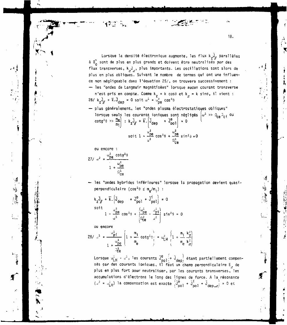
1
18.
I,ft
Lorsque la densité électronique augmente, les flux k JL parallèlesà Ef sont de plus en plus grands et doivent être neutralisés par desflux transverses, k^J>%, plus importants. Les oscillations sont alors de
Vu IAs
plus en plus obliques. Suivant le nombre de termes qui ont une influen-ce non négligeable dans l'équation 25/, on trouvera successivement :— les "ondes de Langmuir magnétisées" lorsque aucun courant transverse
n'est pris en compte. Comme k = k cosO et k^ = k sin6, il vient :26/ kzJ//+ÏÏ.Jdep . O soit ur .«^cos'e
— plus généralement, les "ondes plasma électrostatiques obliques"lorsque scotg29 »lorsque seuls les courants ioniques sont négligés L2 » ^ce^cl-
ou
me) . >. ~ , — f~ . "ïe 1 . ft [
soit 1 - -BE cos29 +
Jpol
co2
O
s in-e =0
t ••
27/
ou encore :
_ "pe cotg29
•"!'$
— les "ondes hybrides inférieures" lorsque la propagation devient quasi-perpendiculaire (cos29 s m /m-) :e -
• j dep
soit1 - -Ei
2U)
ou encore
28/
1 + •J.
SlV9 = O
m1 + — cotg2e> = 'jj.2LH , m k( e x_
,.-Jfc
' 4
i ~e ' - ILorsque ' H * ', 1SS courants Jp 0 1J
+ JdeD( étant partiellement compen-sés par des courants ioniques, il faut un champ perpendiculaire E-, deplus en plus fort pour neutraliser, par les courants transverses, lesaccumulations d'électrons le long des lignes de force. A la résonance
2 ) la compensation est exacte !i H + J1 1 + Jde ^i = O et

/».,•*l •
19.
Ia quasi neutralité est possible pour des oscillations purementperpendiculaires à B , et des champs électriques arbitrairemantgrands.
1.9 Influence des courants transverses sur la propagation du mode rapide
IJ%
Le mode purement électromagnétique décrit au § 1.7 se compliquelui aussi lorsque la densité électronique augmente, c'est-à-dire lorsqueles courants transverses deviennent non négligeables.
Une première modification se produit lorsque seuls les courantsÈ * EL électroniques prennent une part importante dans la propagation.C'est le mode "whistler" ionosphérique.. Les électrons ne sont plus atta-chés aux lignes de force mais induisent des courants transverses parrapport auxquels on peut négliger le courant de déplacement. Comme au§ 1.7, on considère un champ électrique I perpendiculaire à B , de sorteque Jy. = O, et l'on suppose, pour simplifier, que la propagation estparallèle à 8 (9 =0). Le champ est alors purement transversal (¥.£ = O)et une onde se propage si le courant induit est en "quadrature avance"avec le champ, comme c'est le cas pour le courant de déplacement, t —,
~e 3tdans le vide. Dans le cas du mode whistler, entretenu par J^r, ,ExB0ceci impose que le champ E tourne dans le même sens que les électrons(polarisation circulaire). L'indice n de l'onde s'obtient de façon tri-
-viale si l'on considère que le courantle courant de déplacement dans le rapport
* B est beaucoup plus grand que(cf êq. 24/). L'équation
des ondes, n * (n * T)
29/ n.?. *
pe' ce, permet d'obtenir n;- = W°dep soit
Quand la propagation est légèrement oblique, rien n'est changé pourla composante transversale (électromagnétique) E. du champ. Cependant, lechamp total reste pratiquement normal à B , ce qui implique, k étant dansle plan Oxz, = if I * E cosc
Oy donne alors n~ cosS ~oblique" : Jit£
L'équation des ondes projetée surM* I
qui généralise l'équation 29/ au "whistler
30/ oe

20.
. 1«'*'
Cette image simple tombe en défaut si la propagation est suffi-samment oblique. Les courants È x B induisent en effet une charged'espace (F J^ r O) qui est compensée par un courant le long des lignesde force (k//J// - O). Le champ parallèle E,, correspondant est en généraltrès faible. Lorsqu'il est trop important, l'équation 30/ n'est plusvraie. Le mode devient fortement électrostatique et peut dégénérer avecTonde plasma électrostatique décrite au § 1.8 en donnant lieu à une réfle-xion par conversion linéaire de mode si le plasma est inhomogène. Les den-sités plus élevées sont alors inaccessibles à Tonde.
Etudions maintenant l'influence des courants de polarisation. Sila fréquence ai est supérieure à la moyenne géométrique (SLJl^2* lecourant de polarisation est dominé par les électrons J'pol JpolII est donc en phase avec le courant de déplacement et participe égale-ment à la propagation lorsqu'on approche de la confluence des deux ondes.
Dans le cas contraire, ai2 < ^ce^c^ » le courant de polarisation estplutôt ionique et s'oppose au courant de déplacement qu'il peut compenserà une certaine densité (résonance hybride inférieure du mode lent). Adensité plus élevée, il le domine et le mode le plus lent n'existe plus.
La propagation de l'onde rapide peut devenir quasi-perpendiculaire à Bsans rencontrer la dégénérescence décrite plus haut. Les oscillationsdeviennent alors quasi-électrostatiques et sont entretenues par ce mouve-
ment compressionnel des ions. C'est alors lui qui compense la charge(k J £ O) induite par la comoosante E. caractéristique du mode rapide. La
«A* X J
composante E,, n'est plus nécessaire et Tonde reste tout à fait découpléedu mode électrostatique électronique lent, aussi élevée que soit la den-sité du plasma. Dans la direction transversale, Oy, le courant O élec-
z'tronique n'est pas nul et est lié à une composante magnétique Bparallèle à B~* qui induit une compression des lignes de champ.
Ce mode est donc un mode magnéto-acoustique et Tonde prend le nomà'"onde d'Alfvên de haute fréquence". Elle diffère de Tonde d'Alfvéncompressionnelle classique (w < Q^ par la direction du champ électriquequi est ici quasi-longitudinal (Ex > E ) plutôt que transversal (E ). Abasse fréquence (u « nci)en effet, les deux espèces (ioniques et electroniques) sont magnétisées et leur dérive È x ïï n'induit pas de séparationde charge.
Par contre, dans les deux cas, l'indice est voisin de l'indiced'Alfvén, n,. Pour Tonde d'Alfvén basse fréquence, on aurait
tr
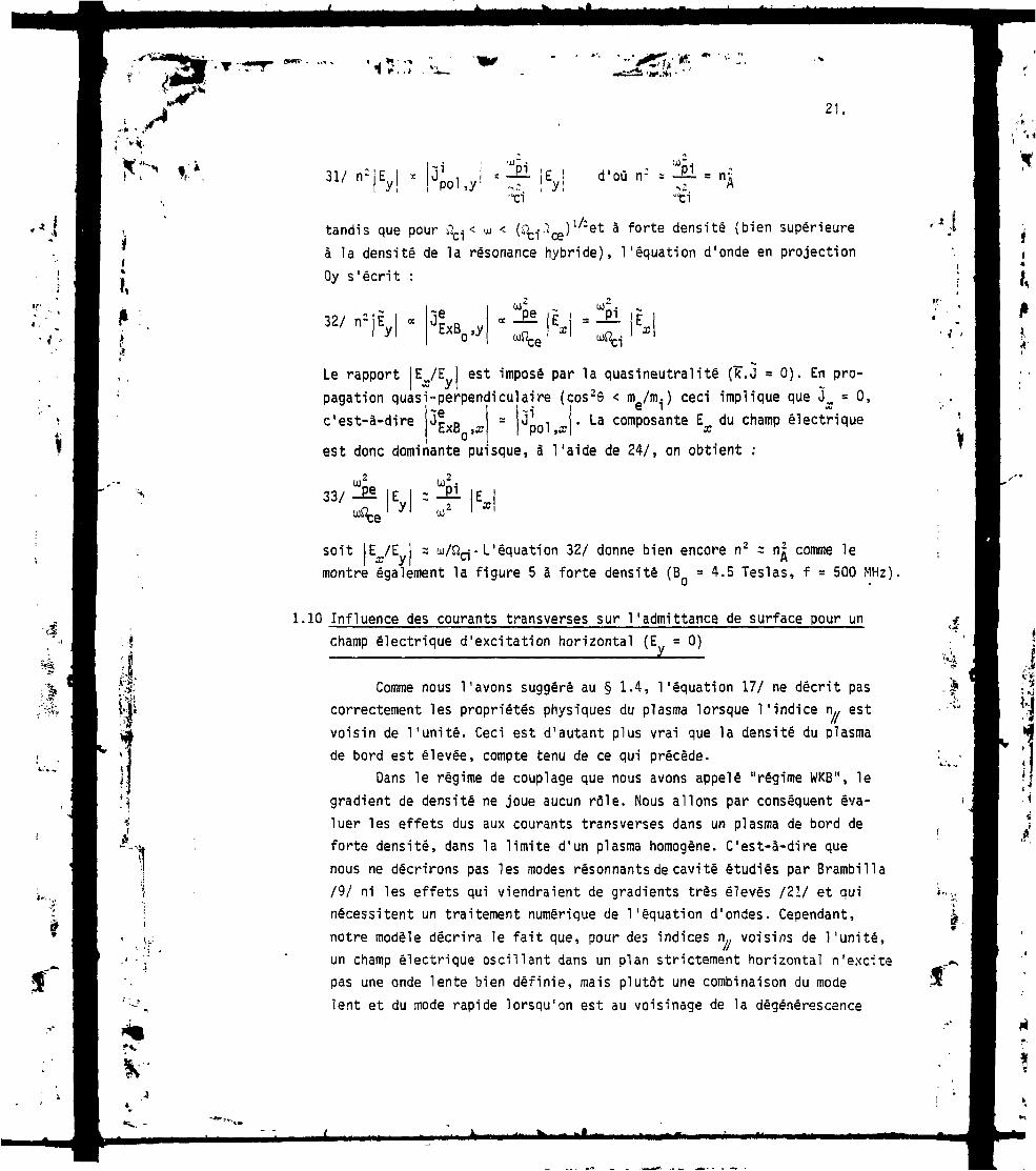
21 ,
Pi3"-Ey!' W-;?1 !SI"ci "ci
tandis que pour \L*< u < (SL^ œ) l^~ et à forte densité (b ien supérieureà la densité de la résonance hybride), l 'équat ion d'onde en projectionOy s'écrit :
32/ rr 'ExB0,y«pe
x
Le rapport E /E est imposé par la quasineutralité (TT.J = O). En pro-lique que J^ = O,champ électrique
pagation quasi-perpendiculaire (cos29 < me/m.. ) ceci implic'est-à-dire J*xB » J J01 . La composante Ex du ch
est donc dominante pu1 sque, à l'aide de 24/, on obtient :
OJ133/ -Pl E = -El
soit E /E = u/Sîçj. L'équation 32/ donne bien encore n2 s n| comme lemontre également la figure 5 à forte densité (B = 4.5 Teslas, f = 500 MHz),
i.
1.10 Influence des courants transverses sur !'admittance de surface pour unchamp électrique d'excitation horizontal (E = O)
Comme nous l'avons suggéré au § 1.4, l'équation 17/ ne décrit pascorrectement les propriétés physiques du plasma lorsque l'indice n estvoisin de l'unité. Ceci est d'autant plus vrai que la densité du plasmade bord est élevée, compte tenu de ce qui précède.
Dans le régime de couplage que nous avons appelé "régime WKB", legradient de densité ne joue aucun rôle. Nous allons par conséquent éva-luer les effets dus aux courants transverses dans un plasma de bord deforte densité, dans la limite d'un plasma homogène. C'est-à-dire quenous ne décrirons pas les modes résonnants de cavité étudiés par Brambilla/9/ ni les effets qui viendraient de gradients très élevés /21/ et quinécessitent un traitement numérique de l'équation d'ondes. Cependant,notre modèle décrira le fait que, pour des indices n,. voisins de l'unité,un champ électrique oscillant dans un plan strictement horizontal n'excitepas une onde lente bien définie, mais plutôt une combinaison du modelent et du mode rapide lorsqu'on est au voisinage de la dégénérescence
f
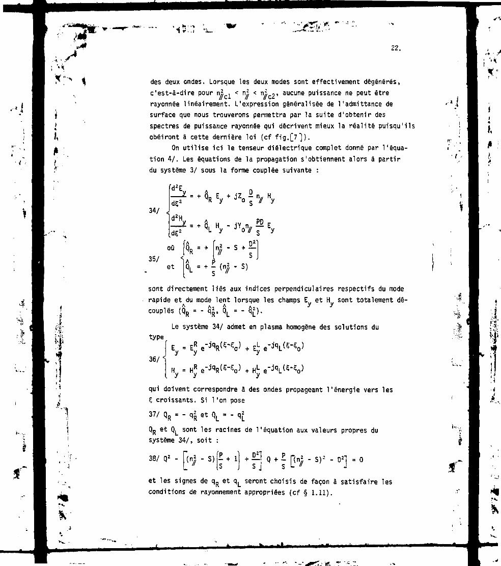
s*IF; '•*
*:- <
I*K
* -j ^V'*"*1I f i ,1
22.
des deux ondes. Lorsque les deux modes sont effectivement dégénérés,c'est-à-dire pour nj , < nr. < n« g» aucune puissance ne peut êtrerayonnée linéairement. L'expression généralisée de !'admittance desurface que nous trouverons permettra par la suite d'obtenir desspectres de puissance rayonnée qui décrivent mieux la réalité puisqu'ilsobéiront à cette dernière loi (cf fig.[7]).
On utilise ici le tenseur diélectrique complet donné par l'équa-tion 4/. Les équations de la propagation s'obtiennent alors à partirdu système 3/ sous la forme couplée suivante :
Td2E
34/ <d2H
"y ' ".>
où
35/ -IA. 6t [QL = +^//-
sont directement liés aux indices perpendiculaires respectifs du moderapide et du mode lent lorsque les champs E et H sont totalement dé-couplés (QR = - q
2,, QL = - $*).
Le système 34/ admet en plasma homogène des solutions du
Ey - EyR e-
type
36/
qui doivent correspondre à des ondes propageant l'énergie vers lesç croissants. Si l'on pose
37/ QR = - q| et Q1 = - q2
QR et QL sont les racines de l'équation aux valeurs propres dusystème 34/, soit :
38/Q2-^(n/2-S)jr+lj^JQ+r[(n
2-S)2-D2]=0
et les signes de qR et qL seront choisis de façon à satisfaire lesconditions de rayonnement appropriées (cf § 1.11).
.'ï
K-i

H . .-, ' ••«• > . t 1JL
'-* ' ,'s*23.
L'équation 38/, qui est la quartique de Booker si l'onremplace Q par -q-, a pour discriminant :
I4
^ On po:
i 40/ <
k
} . | ( ^ - s ) | i - - + r j + 4n / ?_
sera par Ia suiteI P"\ n2 A A
A = (n= - S ) 1 I - £ + — = QR - Q1o // ( si S R L
-2 an? pD2o = - 4n»
^ S2
0 •*•> i P l * " l 2 2 •"> **A8 = Ao ' r - l~-\ ["// ' >cl "// ' n//c2
2 I R LJ 2 Ij. / J g s _
de sorte que les racines Qo et Q, s'écrivent
Les points de confluence sont les racines de l'équation 39/et peuvent s'écrire explicitement
- s - °2(s * P) : 2D ""-PS(R - P)(L - TT
(S - P) 2
ou encore, dans l'hypothèse j2 » et n . «
43/ n
ce
Les polarisations respectives du node rapide et du mode lents'obtiennent à partir du système 34/ :
1 H»'L (Oo i ' QD) s Jn//PD44/ AD , =LJL- = L2± Ri_ = 1Jn1D (QRsL - Q1) S
et satisfont :
45/ - P
- • :V
i «...
é
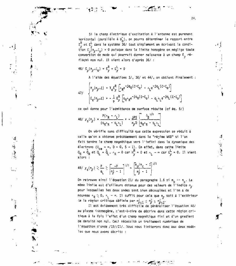
1 ''H
24.
Si Ie champ électrique d'excitation à l'antenne est purementhorizontal (parallèle à B*), on pourra déterminer le rapport entreR LE et E dans le système 36/ tout simplement en écrivant la condi-
tion E (n//»O = O puisque dans la limite homogène on néglige touteconversion de mode qui pourrait donner naissance à un champ E ré-fléchi non nul. Il vient alors d'après 36/ :
ai
à
46/ Ey(n/t50) - H- E = O
A l'aide des équations 3/, 36/ et 44/, on obtient finalement :
47/' ' Vy [v~JqR(5~<°) -
= -!ERP yce qui donne pour 1'admittance de surface réduite (cf éq. 5/)
48/ ys(n;/) =P(A - A
= -JfSr
Vu ~ VuOn vérifie sans difficulté que cette expression se réduit à
celle qu'on a obtenue précédemment dans le "régime WKB" si Ton
fait tendre le champ magnétique vers l'infini dans la dynamique des
électrons (J2-. -» °°, D •* O, S - I ) . En effet, dans cette limiteA ce A à IQ0 = QD et Qi = Qi > AD •*• O car H, = O et A. - » car E = O. Il vientK K L U K y L yalors :
On retrouve ainsi l'équation 21/ du paragraphe 1.6 si n » n . Lamême limite est d'ailleurs obtenue pour des valeurs de l'indice n«pour lesquelles les deux ondes sont bien découplées et l'on a denouveau A^ O, A^ - ». Il suffit pour cela que r\,. soit à l'extérieur-le la région critique définie par nj, . < nj. < n r2.
Il est évidemment très difficile de généraliser l'équation 48/au plasma inhomogène, c'est-à-dire de décrire dans cette région cri-tique à la fois l'effet d'un champ magnétique fini et d'un gradientde densité non nul. Ceci nécessité un traitement numérique del'équation d'onde /19//21/. Nous nous limiterons donc aux deux modè-les que nous avons décrits :
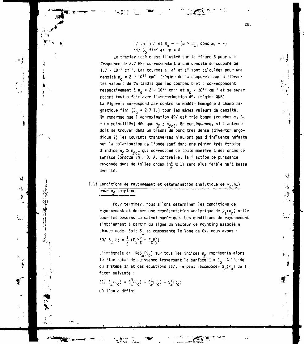
.'* • ,1
,,*.-,,T r ...»
'tf,
25.
•'.$-
SJ'i
i/ 7n fini et BQ - * (ii/ BQ fini et Tn = O.
.: donc m
Le premier modèle est illustré sur la figure 6 pour unefréquence de 3.7 GHz correspondant à une densité de coupure de1.7 * 1011 cm"3. Les courbes a, a' et a" sont calculées pour unedensité n = 2 •< 1011 cm"3 (régime de la coupure) pour différen-tes valeurs de 7n tandis que les courbes b et c correspondentrespectivement à n = 2 * 1012 cm"3 et n = 1013 cm"3 et se super-posent tout a fait avec l'approximation 49/ (régime WKB).La figure 7 correspond par contre au modèle homogène à champ ma-gnétique fini (B = 2.7 T.) pour les mêmes valeurs de densité.On remarque que l'approximation 49/ est très bonne (courbes a, 3,-, en pointillés) dès que n,, > n«co- En conséquence, si l'antennedoit se trouver dans un plasma de bord très dense (divertor ergo-dique ?) les courants transverses n'auront pas d'influence néfastesur la polarisation de l'onde sauf dans une région très étroite
correspond de toute manière à des ondes ded'indice n., % n „ -surface lorsque Vn * O. Au contraire, la fraction de puissancerayonnée dans de telles ondes (n % 1) sera plus faible qu'à bassedensité.
1.11 Conditions de rayonnement et détermination analytique de ys(n«)pour n,, complexe "
Pour terminer, nous allons déterminer les conditions derayonnement et donner une représentation analytique de ys(n//)
pour les besoins du calcul numérique. Les conditions de rayonnements'obtiennent à partir du signe du vecteur de Poynting associé àchaque mode. Soit S^ sa composante le long de Ox, nous avons :
50/ SJS) = -i (EyH - E2H*)
L'intégrale d" ReSJS ) sur tous les indices n., représente alorsle flux total de puissance traversant la surface ,-; = ;Q. A l'aidedu système 3/ et des équations 36/, on peut décomposer SJ-" ) de lafaçon suivante :
où 1'on a défini
•«$
•"à„>
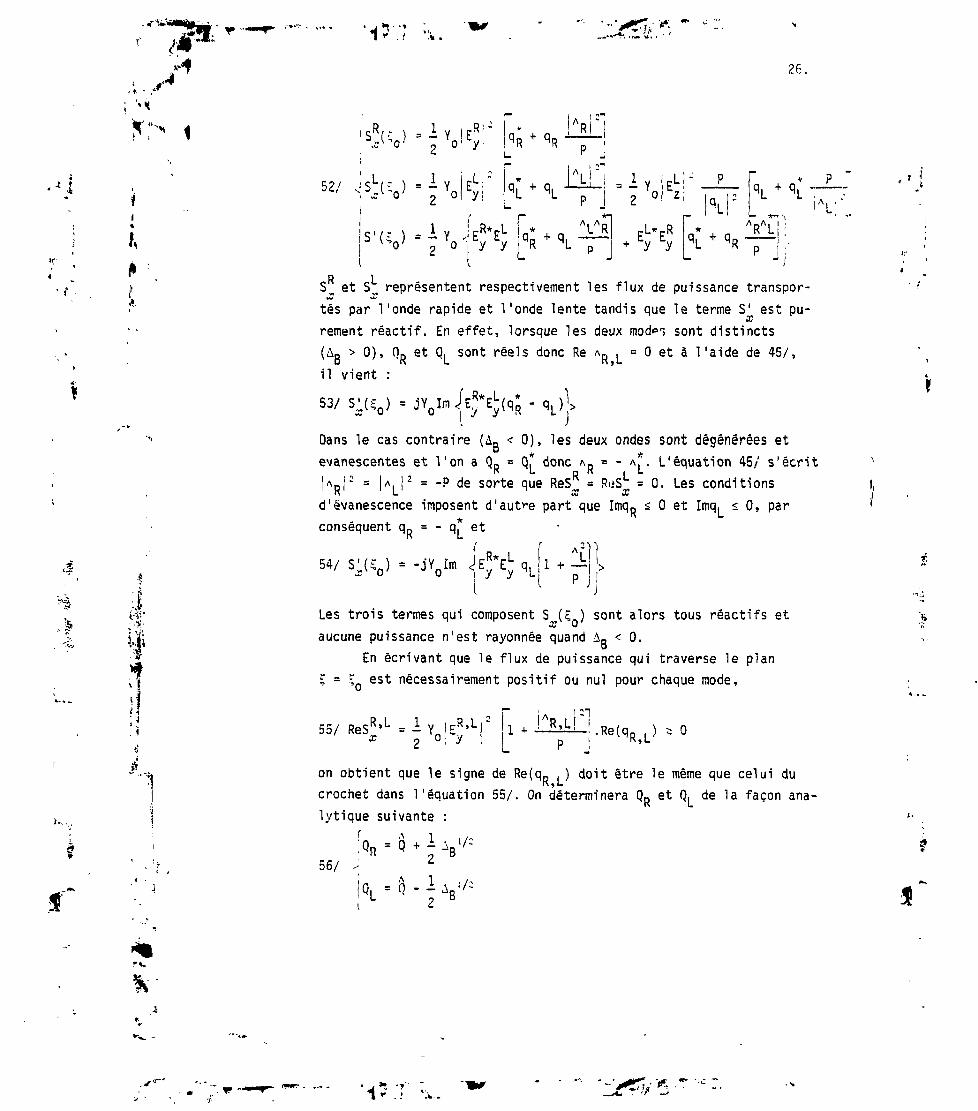
26.
i
il
,. y,
52/ = I2
-Iy
Q* + ! _RJ
_ R R p
"qJ + qLAlL.L L P
i_i
- = - Y.2 °
Ez ' -1- k *\ : L ^ ,- C* ± n VR] pL^R/ L0R + qi T j + Ey Ey
A ..A I I i
> + 'R— j :i - 0 TR LS^ et S^ représentent respectivement les flux de puissance transpor-tés par l'onde rapide et l'onde lente tandis que le terme S1 est pu-rement réactif. En effet, lorsque les deux mode~> sont distincts(A0 > O), O0 et O1 sont réels donc Re AD . = O et à l'aide de 45/,B K 'L K»L
il vient :
Dans le cas contraire (An < O), les deux ondes sont dégénérées etevanescentes et Von a Q0 = of donc An = - A*. L'équation 45/ s'écrit
R LAoi' = l A i I" = "p de sorte WQ ReS = R'iS = °- Les conditionsK L CC Xd' evanescence imposent d'autre part que ImqD s O et Imq, < O, par
* K Lconséquent q» = - q. et
Im
Les trois termes qui composent S (E, ) sont alors tous réactifs etaucune puissance n'est rayonnée quand AR < O.
En écrivant que le flux de puissance qui traverse le plan^ = ^ est nécessairement positif ou nul pour chaque mode,
55/ ReS"'u = - Yn Ex ~ Oi yR,L 2 ,0
on obtient que le signe de Re(q0 . ) doit être le même que celui duK,Lcrochet dans l'équation 55/. On déterminera QR et Q, de la façon ana-lytique suivante :
r \
56/
Q, = Q - -

-* • /
; v*où
27.
57/ A</: = ./=ej |-
et où l'on a posé
58/
<V n/cl,2> •
. ,+ avec -avec -
f
Les facteurs de polarisation AR et A. satisfont alors, d'après 40/et 44/ :
2 A A A1/2D Qn " QD û« " AR "
59/ ^
Q - Q
JBj:
ll
Corme nous nous limitons au cas du plasma "surdense" (P < O)les équations 55/ et 59/ montrent que les indices qR et q, sonttoujours de signe contraire quand ils sont purement réels. Commeû s'annule pour une valeur de n,, qui rend AB < O (ÛB = - 5
2) cettevaleur est comprise entre n., . et n,, « si bien 3ue lorsquepositif, c'est toujours qui est inférieur à 1 et
estj qui
est supérieur à 1. On a donc les conditions de rayonnement suivantesassociées aux représentations 56/, 57/ et 58/ et valables pour n,,réel :
- onde lente :si Q < O
60/
61/
fqL *
ImqL < O si QL > O ou ImQL * O
- onde rapide :
;qR > O si QR < O
ImqR < O si QR > O ou ImQR a O
Les coupures de l'onde rapide se produisent pour nr. = R = S + Oet nj. = L = S - D. Comme le produit des racines de 38/ est toujours
il

" " .<?J
128.
y»;i
positif quand AB < O (QRQL = QRQR)^ on a :
62/ L s n|cl < n < R
On devra donc définir des coupures correspondantes dans leplan complexe aux points n.. = ± /R" et n,, = ± /C pour déterminer defaçon univoque les variables complexes qR et q.. Les considérationsdes paragraphes 1.3 et 1.4 se généralisent ici et les contoursd'intégration devront contourner ces points de branchement comme lemontre la figure 8. On vérifie que les conditions de rayonnement60/ et 61/ sont toujours respectées lorsqu'on contourne les pointsde branchement de cette façon.
Pour préciser les déterminations de qR et qL lorsque n,, estcomplexe, nous allons supposer Re(n,,) > O -on utilisera pourRe(n,, < O) le fait que ys("//) est paire- et étudier le signe deIm(Q) et Im(Ai/2) lorsque n,, décrit les régions I (Re(n«) à O etIm(n,,) à O) et II (Re(n,,) > /IT et Im(n«) <. O) du plan complexe (cffig. 8). D'après 57/ et 58/, on a toujours :
63/O < arg /A>/2 \
I
TT < arg
=> ImA^/2 > O (région I)
'> < O => Imui/ss O (région II)
JlmQ
[imQ
flraQ
(ImQ
> O
< O
< O
z O
(région
(région
(région
(région
D
U)
I)
U)
Par contre pour Q, il faut distinguer deux cas (cf éq. 40/)
64/ si 1 + - > OS
65/ si 1 + - < OS
Par conséquent, si (P' 5 S, on peut affirmer que Im(QR) a lemême signe que Im(n,,) dans les régions I et II (cf ëq. 56/) tandisque si |P| > S, c'est le signe de Im(Q, ) qui est connu de façon
sûre et qui est nécessairement opposé à celui de Im(n,,).A l'aide des remarques précédentes et des conditions 60/ et
61/, on montre que l'on doit choisir dans les régions I et II les
déterminations de q. et qR suivantes :- si ip| < S :
66/ qR = (- QR)1/: avec -T < arg(qR) < O

«•v •
GPWrr . ,., „
_ji ^fU j., T1 '1 W-Ai- "
29.
67/ q. = (- Q. )1/=L L
- si IP,1 - S :
- %L '. arg(q ) •- - -o L o
et on déterminera la racine q,(qR) associée à 66/ (67/) à l'aidedu produit qRq, dont on sait donner une représentation continue :
68/q Rq L-(Q RQ L)l / a- -
1/2 J-e
où 1'on a posé
69/
Je;
(n,. ; /C) = ru ; /T eJ L
K-
• î ••
;l.•
i»
avec
70/" 2 < 9R'L <
_ 3ïï < 9-2 R>L
TT
2
Une dernière remarque concerne les singularités de Ta fonctiony (n,,). Elles ne peuvent se produire que lorsque qRAR = q^\L (cf éq.48/), c'est-à-dire nécessairement lorsque QRA^ = QLA^. A l'aide deséquations 56/ et 59/, on montre que cette condition n'est réaliséeque pour
71/ n = H n = ou nj - S t/~P/S
•4
Ces points satisfont L î nr, < R et on devra les contourner comme lemontre la figure 8 en contournant les points de branchement n,, = :

• j n ' V1 v-.-i
30.
- %: 2. THEORIE MULTIPOLAIRE DU "GRIL"
2. 1 Introduction .«I
On donne dans ce paragraphe une formulation compacte de la théoriedu "Gril" FIG [9]. Cette formulation est indispensable dans les caspratiques où soit que le "Gril" est lui-même couplé en amont avecd'autres circuits microondes (multijonction plan E uti 1 i see comme diviseurde puissance, déphaseurs, transformateurs d'impédances etc...), soit quedes guides dits passifs alimentés uniquement par 1 'intercouplage entreles guides sont utilisés pour affiner le spectre en n,, des ondes planesrayonnées vers le plasma /25/ FIG 00] ou encore dans le cas où le Grilest employé comme source pour exciter une ligne à structure corruguée
FIG [11]. Dans ce paragraphe l'ensemble "Gril" , plasmade bord et plasma principal est considéré comme un multipole HF à Nvoies, N étant le nombre total de guides du réseau ; le plasma principalconstitue la charge du multipôle, le plasma de bord, zone tampon entreles guides et la charge sert d'adaptation d'impédance ; ses caractéris-tiques (densité, gradient de densité) sont donc primordiales pour unebonne transmission de la puissance des guides vers le plasma principal.Le multipôle "Gril- plasma" est caractérisé par la matrice de transfert Sliant les vecteurs tensions électriques incidentes (V10 pour le modef ondamenta 1,
V1 I -
,'2
M"pour les modes supérieurs)
et les vecteurs tensions électriques réfléchies (sortant du multipôle)
V° pour le mode fondamental
'm
pour les modes supérieurs.
mChaque terme V ou V représente un vecteur à N dimensions N est lenombre de guide des "Grils".

'131.
Dans les cas pratiques où les ondes incidentes sont de modefondamental
72/
J i v v s u;, on a ta reianon simpie
V"ol
. v" .
=soo
R™
.v'° avec ?° =
' R 1 0 '
R20
DnoR
chaque terne S°° ou Rmo est une matrice carrée à N dimensions dontl'élément R™° représente la tension électrique de mode m du guide q dueà la tension électrique incidente de mode fondamental d'amplitude unitédu guide p. Pour simplifier on traite uniquement le cas des lames àfaces parallèles (k =0), le mode fondamental est donc le mode tran-verse électrique et magnétique (TEM) et les modes supérieurs des guidespeuvent être représentés par un ensemble complet et discret d'ondestransversesmagnétiques (TM) soit :
Mode fondamental TEM
73/ V0(X)
O O
Modes supérieurs (TM)
= H2 - O
avec VJx) = v'e"J'kox + v"ejkox
H = -*ft In(x) avec I (x) = Yrt(v'e~-1kox - v"ejkox)o o
- - — - z) I(xîkob
m = Ym(Vme
74/
Vm(x) = (Vme"J'kmx f
Hxm = O

.••* • ,!
'1*.732.
ym
b
k
-<î> (Zj JLw avec
constante de propagation dans le vide
admittance en propagation libre
largeur des guides du "Grill"
2 2 m 2 2
constante de propagation du mode TM d'ordre m : k = k *-
Yo '
= admittance d'onde mode TM d'ordre mk
m
et | cos(m = 1 2....«) sont les fonctions
caractérisant la variation des champs dans les sections transversalesà la direction cd1 orthogonal! téà la direction de propagation Ox. * et $ possèdent la propriété
dzsisi
m = nm ï n
de sorte que le flux de puissance complexe du mode m à travers lasurface de longueur unité en y et b en z perpendiculairement à ladirection de propagation Ox s'écrit :
75/ Pm ' Vx)
*• "1J*
2.2 Champs électromagnétiques des guides - Puissance complexe rayonnée
f***
En fonction des matrices de couplage S00 et Rno et du vecteurtension électrique incidente V °, les champs électromagnétiques dansles guides du "Gril " peuvent s'écrire sous forme de vecteurs à Ncoordonnées soient :

1 «"'•.! .'*-.»
, .y33.
76/ a/ E2(O1C) - [*0(I + S00) * $m(C)
T. R™0] . v'°
/~-w Y (?i . I I / /1 », \ \i I"», / T f*wW \ » / » \ 1 I/b/ Hy(0,Ç) = -Y0 l*0(I - S ) - *m(ç) . Ym .
O < C <
Le symbole T indique une transposition de matrice ou vecteur, I est lamatrice unité à N lignes et colonnes.
r*^*.(çî =Bl
~$ ( C ) I "^
((J9(C)I^
.V5)I.
•?*:
m
"41I0
O
O
OY_i.j'Q
O
O
O
O
O
O
T l
Y matrice diagonale d1admittances d'onde réduites (Nxn lignes,Nxn colonnes).La puissance complexe rayonnée vers le plasma par le réseau de guides etpar unité de longueur en y s'obtient en intégrant le produit-H+ .(0,C) . E_(0,C) (+ = matrice associée) entre O et 1 en y et entreo et b en Ç soit :
!
P = -/1dy /V(O5C) . E.(0,C)o o y z ou
77/ P = * (Y00+ - 0+ . Y™) V0 où
V est le vecteur tension électrique totale pour le mode fondamental,
V0 - (1 + S°°) v'°
Y00 est la matrice d 'admittance réduite pour le mode fondamental :
Y00 = (I - S00) . (I + S00)'1
'1S
moY matrice d'admittance d' intercouplage mode fondamental - modes supérieurs0R . (I + S )
00'1

1'"'
.-;. S
LIWWf - ».* , w •>., »'.v » »i •34.
Au second membre de la relation 77, le premier terme de la somme repré-sente la puissance rayonnée par le mode fondamental, le 2° terme lapuissance rayonnée par les modes supérieurs.
1»
?.,*•
2.3 Champs électromagnétiques à l'interface guide plasma de bord(région x = O+) - Puissance complexe rayonnée : FIG [9]
II reste à décrire dans cette région (x = O ) les champs électro-magnétiques et d'appliquer au plan de discontuinité les conditionshabituelles : continuité des champs électriques et magnétiques tangen-tiels. Comme le suggèrent R. SAFAVI NAINI et R.H. MACPHIE /26/ à laplace de la condition de continuité du champ magnétique tangentielnous employons la condition équivalente de conservation de la puissancecomplexe. Cette méthode permet de déduire les éléments S00 et Rmo de lamatrice de transfert du multipôle"Gril"- plasma par une algèbre matri-cielle simple.
Au-delà du plan d'ouverture du réseau de guides (x = O+), leschamps électromagnétiques peuvent être décrits comme la superpositiond'une infinité continue d'ondes planes d'indice de propagation nA
suivant la direction Ox et n,, suivant la direction Oz parallèle auchamp magnétique toroidal Ei du Tokamak. i
78/ a/ <
1 -KO .
- / M e"JI
A
/ Vjn// ko2 V(n,,"
. (s //
o (ns /'
d//
dn
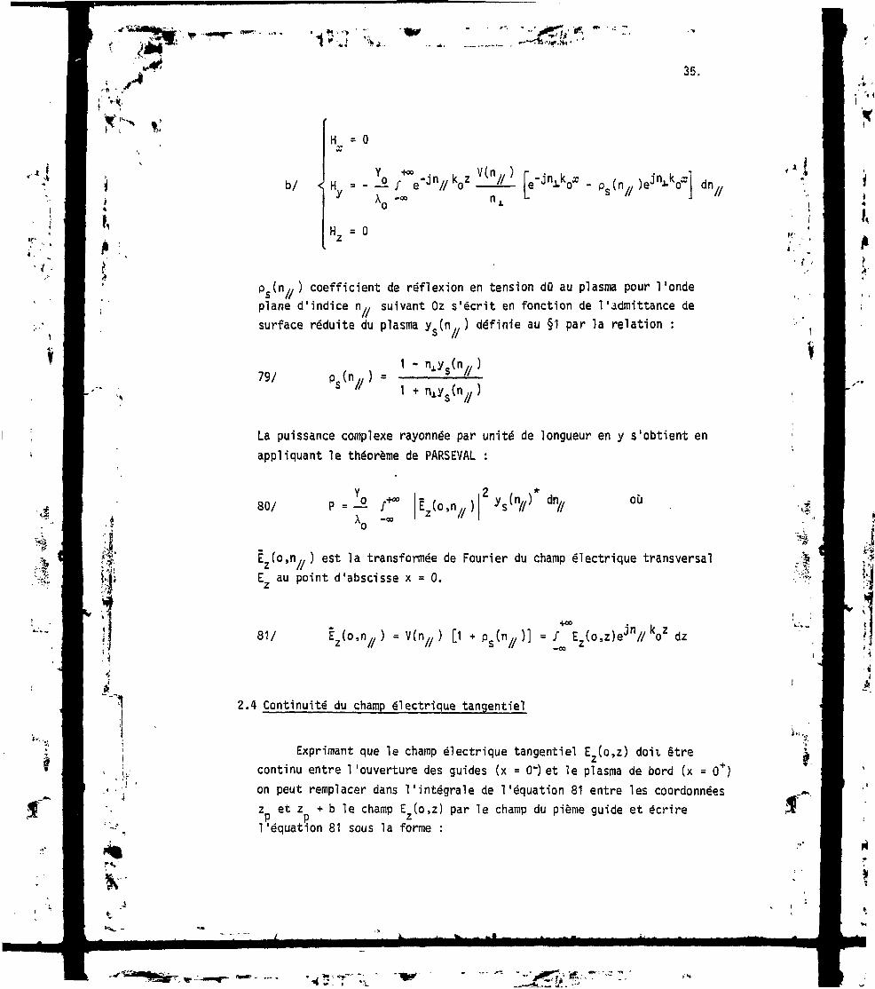
35.
b/
H = O
koz
H2 =
- p f n - ) e o * dn//
Ps(n//) coefficient de réflexion en tension dû au plasma pour l'ondeplane d'indice n,, suivant Oz s'écrit en fonction de !'admittance desurface réduite du plasma yg(n.. ) définie au §1 par la relation :
79/ p (n .. ) =S /X
La puissance complexe rayonnée par unité de longueur en y s'obtient enappliquant le théorème de PARSEVAL :
'.*80/ p.-a Ëz(o'n//)
dn// ou
.••*•iÊ (o,n,y) est la transformée de Fourier du champ électrique transversalE au point d'abscisse x = O.
81/ Êz(o,n;/) = [1 )] = /\(o,z)ejn//koz dz
a
2.4 Continuité du champ électrique tangentiel
Exprimant que le champ électrique tangentiel E (o,z) doit êtrecontinu entre 1'ouverture des guides (x = 0") et le plasma de bord (x = O*)on peut remplacer dans l'intégrale de l'équation 81 entre les coordonnéesz et z + b le champ E (o,z) par le champ du pième guide et écrirel'équation 81 sous la forme :
r

(SMK' . ... , !,I»'.-»' "1 «•-..' 'i,36.
tii
1
82/
N est le nombre de guides du réseau.Le champ électrique tangentiel est nul sur les parois des guides.Ë2(o,n,,) peut encore s'écrire en employant la relation 76a.
Ëz(o,n//) = e3'"// kozp . 00.(I +S
.V0 o < ç < b
ejn// O2P est un vecteur à N coordonnées soit :
83/ E2(o,n//) = ejn// ko2p
P = 12«...N+6Jn « . .V
avec z = coordonnée du pième guide
Les scalaires G0Cn^) et G(n(n//) sont définis de la façon suivante
84/ V/Jn,
85/
2 m 2 , 2
j(n// - ;"o
•4-

f,, &j "if-
37.
\i»K
où b est la largeur des guides du Gril. Dans l'équation 83 qui exprimela continuité du champ électrique tangentiel à l'interface Grill-plasma,la matrice G (n,,) est définie de la façon suivante :
86/ G2(n/;)I
n = 1 2 ..... «
I est la matrice unité à N lignes et colonnes.
•
Au second membre de ( 83 ) le 1er terme :
ej"// 1Vp • G0(n7/ ) V0
représente la contribution des champs de mode fondamental des guides ;le second terme ejn// kozp . Gm(n//r )
T . Y® . V0 celle des modes supé-rieurs des guides.
2.5 Conservation de la puissance complexe
Utilisant les équations SO et 83 on peut écrire la puissancerayonnée par les ondes planes (x = O+) vers le plasma sous la formed'une somme de deux termes :
1 ° - £ont£ijbati£n_d£S_c]iamp£ fejmxte f_ondame_ntaj_ des_ £uj_des

t t38.
la matrice hermi tique e est définie par
) . e'J VV
soit tout calcul fait :
.«1
87/ PF - V; .
Les matrices d1admittances réduites plasma sont définies de la façonsuivante :
88/ yno
,10
mo
no
avec y™ = — / ys(n/7 )Gm(n/7 )GQ(n/
= y,ornqp
.*-*I 2° -
PC = Y,XS o o U ".V
î** • K(V) d"//
soit tout calcul fait : I

TW;-r .,»».-,1*-.J "V.
I -H
39.
89/ o o •in y™)* Ymo V
mnl'élément y"" de la matrice d1admittance réduite modes supérieurs ys'écrit :
mn
90/3U/mn nm ?** ye(n//) (P,, )e":;n//k
Ecrivant que la puissance complexe est conservée et utilisant lesrelations 77, 87 et 89 ' on obtient le système d'équations permettantde déduire les éléments de la matrice de transfert du multipôle "Grill"-plasma à partir des admittances réduites y" soient :
91/
92/
y00 = y00 • y™.
-Ymo . Y . Ymo = Ymo . (yno * ymn . Y1"0)
93/
94/
>/oo
De ces relations, on déduit :
. (7
On remarque la symétrie de la matrice d 'admittance mode fondamental
Y . A l'aide des formules du § 2.2 on obtient finalement :
95/
96/
S00 = (I - Y00) . (I * Y00)'1
/V1 . 7° . (I +S 0 0 )
Dans la pratique la largeur des guides du réseau est telle queseul le mode fondamental est non evanescent et Y est imaginaire pur.
V m = 1 2.
2b
. &

{•*.i
,4"fH^
P- ,.., . , ». .» "1 «• .' .'k.
40.
2.6 Bilan de puissance champs électriques tangentiels
SIJ«
I,1° - Bilan de puissance
Puissance incidente mode fondamental :
,. N ,P = Y V V=Y T M V *Kio To vo ' vo Yo jl vop 'v op
Puissance réfléchie totale mode fondamental :
Puissance réactive tous modes confondus
re ' S
°°*. Y. • Rm°) . V
J
On remarque que le multipôle "GriT'-plasma" n'est pas de "bonnequalité" dans le sens conventionnel du terme : coefficients de réflexionintrinsèques et coefficients d1intercouplage des guides faibles. Siexpérimentalement on observe des puissances réfléchies faibles, celaest dû généralement à une combinaison "heureuse" o<»s champs électriquesréfléchis par le plasma avec leurs phases.
2° - Champs électriques à l'embouchure des guides - amplitude des ondesplanes d'indice n,. suivant Oz./y n r T
Les champs électriques à l'embouchure des guides sont donnés parla relation :
97/ E2Co,;) =r-x f/ \T / .
o m
»n .v'i ? ( ^o b m
^ ^*=' . /•—, mn » - 1 no+ y ) . y
.. /2 me,;) = I/ -cos
b bO < ç < b"

41.
Il est intéressant pour certains diagnostics comme la diffusioncohérente de connaître l'amplitude des ondes planes d'indice n,, donnéelle est donnée pour'une largeur de spectre An,, par la relation :
*:'
An,98/ .V° avec
V° - (I + S00) . V
1i!
Dans la pratique, on donne les puissances incidentes dans lesguides plutôt que les tensions électriques incidentes V » d'autre partles guides sont de hauteur finie et le mode fondamental TEM des lamesà faces parallèles devient le mode transverse électrique TE10 approxi-mativement on doit prendre pour amplitude de la tension électriqueïincidente V dans le guide p la valeur suivante :
op1op
où
2a
a est la hauteur des guides et P la puissance incidente dans Te pguide.
2.7 Spectre des ondes planes d'indice n,, en z
ième•H
il
Dans un plasma radialement inhomogène les ondes planes excitéespar l'antenne placée au bord ne peuvent pénétrer au centre et atteindrela couche de résonance que si leur indice n,, parallèle au champ magné-tique toroidal est supérieur à une valeur appelée l'indice parallèleaccessible (cf. §1 1-7 et 1-9). Les ondes dont l'indice n,, est inférieurà n,, accessible sont réfléchies vers les couches périphériques duplasma et n'ont auctm effet sur le chauffage. Il est donc important pour f
V
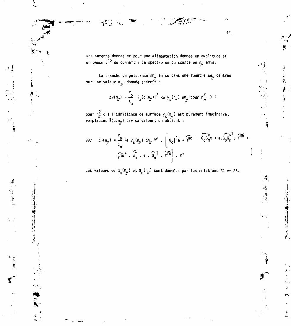
42.
une antenne donnée et pour une alimentation donnée en amplitude eten phase V ° de connaître le spectre en puissance en n,, émis.
La tranche de puissance An,, émise dans une fenêtre An,, centréesur une valeur n,, donnée s'écrit :
! a
.î•6
U-
= — [Ez(o,nj,) |2 Re ys(n;/) An pour n^ > 1
2pour n., < 1 1'admittance de surface ys(n//) est purement imaginaire,remplaçant Ë(o,n,J par sa valeur, on obtient :
99/ iGj'eJ. ' * r—*'
5 • GoGme + e 'GoGm • Ymo
Les valeurs de G0(n..) et Gm(n,,) sont données par les relations 84 et 85.

W" t.. »
43.
V3. EMPLOI DES GUIDES PASSIFS
3. 1 Introduction
On désigne par guides actifs (GA) ceux qui sont alimentés par lesgénérateurs ; les guides passifs (GP) sont généralement terminés soitpar des plans de court-circuit placés à une certaine distance du plasmade bord, soit par des charges adaptées. Les champs électriques des GPsont dus uniquement au couplage par l'intermédiaire du plasma de bordavec les guides (GA). L'emploi des résultats du paragraphe 2 permet dedéduire sans difficultés les principales propriétés du "Grill" à guides ac-tifs et passifs (G.A.P.)0n suppose que les impédances de charge et l'empla-cement des GP sont quelconques. Fig [12] .
K-
I
tt.
, i
3.2 Matrice de transfert et tensions électriques
On suppose comme au §2 que les tensions électriques incidentesaux G.A sont de mode fondamental pur (TEM des lames à faces parallèles).On divise la matrice de transfert du "Gril ", relation 72 en sousmatrices groupant ensemble les G.A. (indice a) et les G.P (indice b),soit :
Sous matrices S°° et Rmoaa aa couplage entre les G.A. pour le mode fonda-mental TEM et les modes supérieurs TM.
Sous matrices S?? et R P '• couplage entre G. P. pour le mode fondamen-tal TEM et les modes supérieurs TM.
I' '-y>;•"'•' Ji• J>;c*«
*
f
-Sous matrices S? S , R , R. couplage entre G. A. et G. P. et vice-versapour le mode fondamental TEM et les modes supérieurs TM. Entre S?° etS ° on a la relation évidente
.005ab
.005ba
ba
( T = matrice transposée).
I

44.
I' v*V-.
Entre les tensions électriques incidentes V,° et V, allant versa D »le plasma et les tensions électriques réfléchies par le plasma V et"nV on peut écrire la relation :
if .100/
" S00
-OOba
CnORaa
iCfnb. ba
çOO
^ba
cOObbb
«'HoRab
R?S.
V 1 Oa
l
b
I,
Les indices o et oo sont employés pour le mode fondamental TEM.Pour les G.P. on a d'autre part entre les tensions électriques incidentes
'o "oet réfléchies de mode fondamental V. et V. la relationo D
101/ - r vvb ! v b
:.
,%
où r est la matrice diagonale des coefficients de réflexion dus auximpédances de charge des G. P. Dans le cas où ces derniers sont terminéspar des plans de court-circuit situés à une distance L du plasma debord, on a :
102/ r, = -e~2jlabD
A
k est le nombre d'onde ; k = ~ dans le cas des lames à faces parallèles.Ao
Des relations 100 et 101 on peut déduire en fonction des tensionsélectriques incidentes de mode fondamental des G. A. et après un calculimmédiat :1°) Pour le mode fondamental et à l'embouchure des guides passifs :a/ Les tensions électriques incidentes (vers le plasma)
,03/ . r . » - s°° . . s°° .
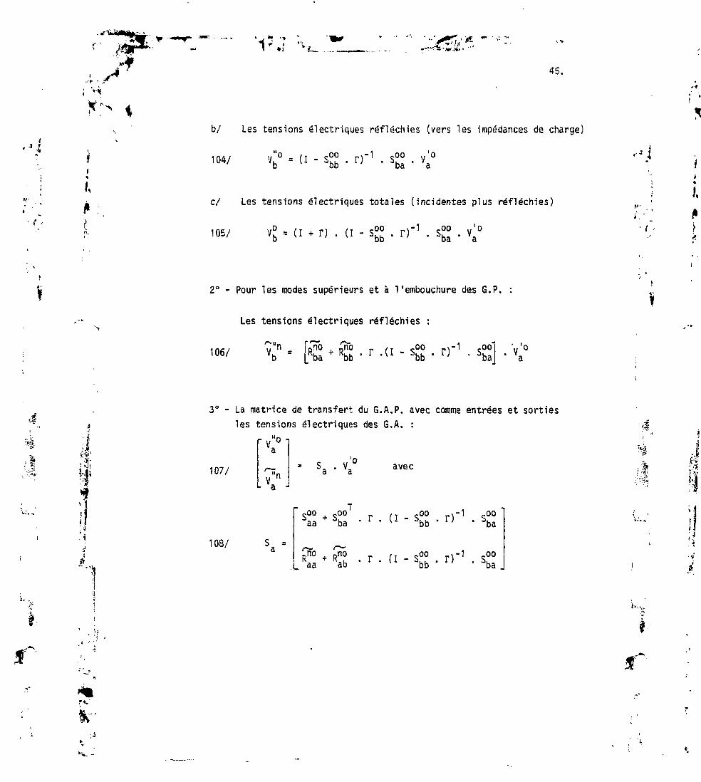
!••* ' ,J
*t "»
r i«; „--•ns n,.*,
45.
I,
b/ Les tensions électriques réfléchies (vers les impédances de charge)
104/ - (i - s00 rT1 s00 v'°-U ibb . i; . iba . va
c/ Les tensions électriques totales (incidentes plus réfléchies)
105/ = (I + -00 S00 v'°' 5ba ' a
2° - Pour les modes supérieurs et à l'embouchure des 6.P. :
106/
Les tensions électriques réfléchies :
v n - Rno + Rno r ( T - S 0 0vb - Rba + Rbfa ' r ' { l Sbb „ S!ooba:] • V
,1
3° - La matrice de transfert du G.A,P. avec comme entrées et sortiesles tensions électriques des 6.A. :
107/
"o i
• VV avec à'"
f
108/ S =a
00 + S00 r ri - s00a \à ' r ' u 5bb '00
Rno Rno fT -oo r1 oo.Raa ab ' T ' (I Sbb ' r) ' Sba ,

f/ww • * i « *
'15'.7 "-V.46.
3.3 Champs électromagnétiques à 1'embouchure des guides
<•*La notion de tension électrique bien connue des electromagnet!ci ens
n'est pas toujours très familière aux lecteurs non spécial is . Il estutile d'écrire pour cette raison les expressions complètes des champsà l'embouchure des guides du G.A.P. D'autre part, c'est à partir desexpressions des champs électriques et magnétiques qu'on calcule lapuissance rayonnée vers le plasma par le réseau de guides du 6.A.P. Dansle cas des lames à faces parallèles pour l'unité de longue. Hes guides
de largeur b on a l'expression bien connue :
109/ P = - /1 dy /b H*(0,ç) . E7(o,ç) dçy
où EZ et H représentent les champs totaux tout mode confondu ( lesymbole + désigne une matrice associée). Dans le cas du G. A. P. on a enfonction de V,0 tensions'électriques incidentes des G. A.a
r >vi~• r^
'I• 4à
1° - Pour les G.A.
a/ Champs électriques : E (oa
110/,0 = [ ( I + Sa ) + < * > ( < ; ) . R 3O a O fila a l <;°
b/ Champs magnétiques : H (o ,ç) = - Y n n ( I - S3 ) -a O O a a ma
2° - Pour les G.P.
T £=; ,—,-i i
««>•'«•".]•».
a/ Champs électriques : E b (o ,ç) = I ,.OO
•3ba
111/ . vmb a

47.
,••*
b/ Champs magnétiques :
. V.
avec les définitions suivantes :
- $ (ç)0 b m
/ 2 mirç= / - cos — m = 1 2...<» o < ç < b
On suppose que tous les guides du G.A.P. ont même largeur b
*2(ç) Ib
'"• v
I
f
f C, t
à
Ia et Ib sont des matrices unité dont le nombre de lignes et colonnesest égal respectivement aux nombres de G.A. et de G.P.
ma O
O
"Y
O
O
2/Y
1/YQ Ib O O O
Y2/v O O
b -

48.
*:- « Y ... Y sont respectivement les admittances d'onde du mode fondamentalo net du mode supérieur d'ordre n. Dans le cas des lames à faces parallèleson a :
= admittance du vide
2 2
Y =n avec
i
'!*é
Dans tous les cas pratiques, la largeur b des guides est telle quetous les modes supérieurs sont evanescents, leurs impédances d'ondesont capacitives et on peut écrire :
Yn ' J
2b
OO ^ ***enfin on définit S R, et R. de la façon suivante :d o t D
112/
113/
114/
.00 .005aa r. I
.00
£- _ Rno pnoKa " Kaa + Kab '
' - Rno + Rno rb " Rba + Rbb ' r
- S00 D'sbb 1;
- ss00bb '
'•' • «
.005ba
.00sba
3.4 Bilan de puissanc' et spectre en n/, des ondes planes rayonnées versle plasma.
Employant les expressions des champs électromagnétiques des G.A.et des G.P. données précédemment, on déduit le bilan de puissance duG.A.P., soit :

'?• _ •I ,.
• '"' **
if a/ Puissance incidente : P- = Ynv'° .v'° = Yn I |v'°|2la U a a u . CLi a
' »b •
'î b/ Puissance dissipée par les impédances de charge des G.P.
-*U P = Y v'0+ Y°* .( i - r* . D . Y° . v'°1 Ob o a ba ' b * ' ba * a
+ i ià : b/ Puissance réfléchie : PM » Y r tv'° .S* .S3 .v'° r '* • r a U a cl a d ' •
« .- " f*
' '--' ic/ Puissance réactive : P . = Y^Vo+. (S, -S. +R*.Y__.R,).Vça o a a a a m a a a
iOn peut définir un facteur de qualité Q qui à l'inverse de <•
cavités microondes sera égal au rapport de l'énergie transmise au plasma
sur l'énergie réactive P . Le "Gril " en tant que coupleur est d'autantCet (
meilleur que Q est élevé.
2° - £qur_l 6S-G1P
a/ Puissance transmise au plasma par les G. P.
Si les impédances de charge des G. P. sont des reactances pures, on i,..-(a r . r = I. et la puissance dissipée P«. est nulle. I

K
*V'V*' . - 1
50.
c/ Puissance réactive :
, 'o
Le spectre en n,, est donné par la relation 99 du §2.
J
*I,
(*. •
4
à
3.5 Exemples d'emploi des guides passifs
La Fig [10] montre le rule joué par les guides passifs dans leremodelage du spectre en n., des ondes planes émises vers le plasma :la figure [1Oa] montre celui d ' u n "gril" à deux guides déphasés de IT.
La figure [1Ob] montre celui du même "gril" auquel on a juxtaposé 4guides passifs à chaque extrémité. Les guides passifs sont terminéspar des plans de court circuit situés à une distance égale au quartde la longueur d'onde de l ' interface "Gn!"-plasma.
Une structure à base de guides actifs-passifs alternés a également
été étudiée et permet de former une onde lente stationnaire sans dépha-seurs (cf. référence /14/). On perd malgré tout beaucoup de surface enut i l isant autant de guides passifs.
f
r*.
Ir
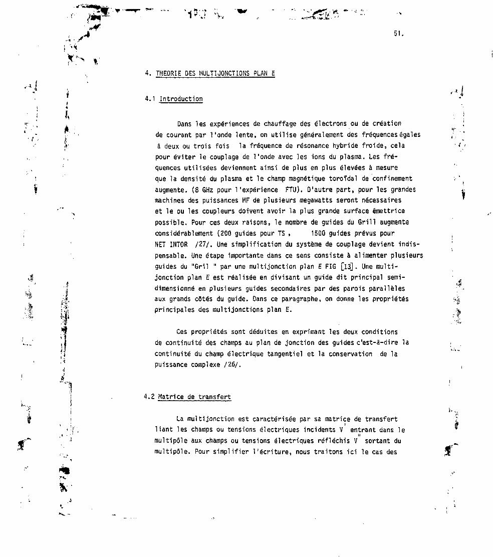
K*
51,
*. THEORIE DES MULTIJONCTIONS PLAN E
4.1 Introduction
Dans les expériences de chauffage des électrons ou de créationde courant par l'onde lente, on utilise généralement des fréquences égalesà deux ou trois fois la fréquence de résonance hybride froide, celapour éviter le couplage de Tonde avec les ions du plasma. Les fré-quences utilisées deviennent ainsi de plus en plus élevées à mesureque la densité du plasma et le champ magnétique toroïdal de confinement
augmente. (8 GHz pour l'expérience FTU). D'autre part, pour les grandesmachines des puissances HF de plusieurs mégawatts seront nécessaireset le ou les coupleurs doivent avoir la plus grande surface émettrice
possible. Pour ces deux raisons, le nombre de guides du Grill augmenteconsidérablement (200 guides pour TS , 1500 guides prévus pourNET INTOR /27/. Une simplification du système de couplage devient indis-
pensable. Une étape importante dans ce sens consiste à alimenter plusieursguides du "Gril " par une multijonction plan E FIG [13]. Une multi-jonction plan E est réalisée en divisant un guide dit principal semi-
dimensionné en plusieurs guides secondaires par des parois parallèlesaux grands côtés du guide. Dans ce paragraphe, on donne les propriétésprincipales des multijonctions plan E.
Ces propriétés sont déduites en exprimant les deux conditionsde continuité des champs au plan de jonction des guides c'est-à-dire la
continuité du champ électrique tangentiel et la conservation de lapuissance complexe /26/.
r*
4.2 Matrice de transfert
La multijonction est caractérisée par sa matrice de transfertiliant les champs ou tensions électriques incidents V entrant dans leMmult ipôle aux champs ou tensions électriques réfléchis V sortant dumul t ipô le . Pour s impl i f ie r l 'écriture, nous traitons ici le cas des
f
Jf'

•is:.752.
lames à faces parallèles, les champs incidents sont de mode TM pourles modes supérieurs et TEM pour le mode fondamental. La matrice detransfert est divisée en sous matrices en séparant le guide principaldes guides secondaires d'une part, et le mode fondamental des modessupérieurs d'autre part, soit :
115/
~\°"
O
7n
T ^- /— "oo po oo op
-oo (.00 -om çOnpo po
/— - /-*• {*** **,,mo -mo -mr cinmoo op oo op
cno XrîÔ cnm -fsj — _ ^ ^.— ^po po
\"'
1^mOr»y
K'
I
1O
O
Tm
,'o
V tensions électriques mode fondamental guide principal
"m vecteurs tensions électriques modes supérieurs guideprincipal
vecteurs tensions électriques mode fondamental guidessecondaires
n "nV V vecteurs tensions électriques modes supérieurs guidessecondaires.
L'élément S™" des matrices S est par définition l'amplitude dumode m du guide p induite par une tension électrique incidente d'ampli-tude unité de mode n du guide q. T indiqua une transposition de matriceou de vecteurs. On peut remarquer que toutes IBS sous-matrices S ne sontpas d'égale importance pour la compréhension du comportement de lamultijonction ; les éléments importants à connaître sont :
•o?
f
Jf
1/ Le scalaire s qui est le coefficient de réflexion en tensionvu du guide principal quand les guides secondaires sont fermés pardes charges adaptées (coefficient de réflexion intrinsèque).

53.
2/ Le vecteur S°j? qui indique pour le mode fondamental TEM laj • façon dont la puissance incidente au guide principal est partagée
-1* i entre les guides secondaires.i
; I 3/ La matrice S00 qui définit pour le mode fondamental les inter-f ,' * , couplages entre les guides secondaires. Ces intercouplages sont la'. ,- • '• cause des réflexions multiples entre le plasma de bord et le plan de
;* jonction.
. ' 4/ Le vecteur Sm° et la matrice S0T qui renseignent sur l'amplitude• des champs des modes supérieurs réfléchis vers le guide principal. »f Ces renseignements sont importants à connaître dans le cas où ce dernier \
est suffisamment surdimensionné pour qu'un nombre fini de modes supé-rieurs puissent s'y propager sans evanescence.
; Bien que la matrice de transfert complète puisse être déduite i: ' par la méthode de conservation de la puissance complexe, nous
attachons surtout de l'importance aux sous matrices précitées.
•f. $ ' $•^ J 4.3 Champs électromagnétiques dans les guides Vtl.
Les champs électromagnétiques dans les guides sont décrits par . -cun ensemble complet discret d'ondes TM
E = S $ (z) V V = V+ + V*z _ , . m m m m m ,m=o '
V* et V sont les tensions électriques des ondes se propageant respec-tivement dans les sens positif ou négatif de Taxe de propagation ox.î (z) est la fonction de mode d'ordre m :

'.t'1"J
54.
RlTTZ
<{> (z) = / JIl cos —r pour le mode d'ordre mro a,o a,b
* :
em = 1 pour m = O (TEM) e
m = 2 P°ur m = 1 2 3...~
Les fonctions de mode sont normalisées de telle manière que la puissancerayonnée par les champs d'un mode quelconque pour l'unité de longueuren y s'exprime simplement par :
p = v im m m
Ym est 1'admittance d'onde du mode d'ordre m :
m
(a,b)
/ mXo o/1- ( /
2a,b)
/ mXo/ (
2a,b
Y est 1'admittance du video
pour les modes non evanescents
pour les modes evanescents
a et b sont les largeurs du guide principal et des guides secondaires.Ces conventions adoptées, on peut écrire l'expression des champs E et Hdu guide principal et des guides secondaires en fonction des tensionsélectriques incidentes à la multijonction V et des éléments de lamatrice de transfert (éq. 115). On a :
V

SB.
v.
1° - Gui_de £nnci£aj_ ( indice a)
Mode fondamental
za oa s00)- s ° ° - s°"msoo;>> ' 5Oo • s°"l Tv 1
' sopj ' [v J
i
avec
,00)
1IU
ioo' LornHu = -Y $ (1 - Sgu);- Suu ;-S ;-Sya o oa |v oo" po ' oo '
Sr,.Soo;'
. [-S»,
0^ **,(2) est ^6 vecteur colonne des fonctions de modes.IUu
Yma est la matrice diagonale des admittances relativesd'onde des modes,niaT indique une transposition de vecteur ou matrice.
Finalement, en fonction des vecteurs"tensions électriques totales"(incidentes + réfléchies) et des sous matrices d1admittances réduitesles champs électromagnétiques du guide principal au plan de jonctions'écrivent :
it

56.
<<]
"i.
a/
116/
b/ Hya ' -Yo
avec
Vo =
~$oa
/-*$ma _
i " 1 yOO yOm
op oo
ytnO yfflO T
_oo op
yon -op
•?=z.Yop .
V° =
" $oa
$_ ma _
i
•
o Yma
•
r yOO yOO _yOm _yOn
oo "op QO "op
_m°°
yino yinr utnnop oo op
00
oo00 - C00
op - Spo' 0"1oo
'.:«
'*
8
:
1
op
î-j
oo op
•' W-
rvo
i>0
o,,n
2° - £uj/ie_s_se_C£ndcnres_ (indice b)
De manière similaire, les champs électromagnétiques des guidessecondaires au plan de jonction s'écrivent en fonction des vecteurster.wio.is électriques tctales et des sous matrices d'-.dmittances réduitessous forme de vecteurs colonnes.

1H?::: «i57.
a/ E.
ob ooPO
YnoTpo
onPO
P°
- C
£• ;117/
b/ ri- I O -
•
yOO yOO yOm yOH _
po " po
ylTo yTTo y% -^ns_ PO PO
avec
Yoo = soorpo ^po',/OO 00,Yuu = (I-SUU).(I+SUO) m
Ypo oo
*if «?ss - r ^ <?5Îvnm _ cnm / T . c n i r \Ypo ' spo- u+soo;
*ob = F' I
po = Sno.(I+S00J'1
Y7"5 = (T-S )
Ynh est la matrice diagonale d'admittanced'onde de modes.
':,?
'/•ll»
i....
•i •*lb I"<S>2b I
/nb1 .
^b =
"Ylb 1 °
V
O O
O
O
O "
Vavec Ynb=
2TT
= — et kn est la constante de propagation du mode d'ordre n.

58.
4.4 Continuité du champ électrique tangentiel
Le champ électrique tangentiel Ezest donné par Ia relation 116a,d'autre part, au plan de jonction des guides, il est égal au champE des guides secondaires (relation 117a) et nul sur les parois.
1Si on multiplie le champ E, par 4 = — et on intègre en z
de O à a, a étant la largeur du guide princip
So • i *oa Ez dz
en utilisant la relation 116a pour E2 on obtient sans difficulté :
118/ 8 O - ' 1 op oo H']On peut calculer la quantité S à partir de l'expression des
champs E des guides secondaires (relation 117a). Le champ E2 étantnul sur les parois séparant les guides secondaires, on a :
1
p=o zp
,ièmez est l'abscisse du p guide, b la largeur commune des guidessecondaires, N le nombre de guides secondaires, soit :
*"• v
I' 4
119/ 5O = - Ma L poT Om
Tpo
1 est le vecteur à N coordonnées toutes égales ? l'unité. Comparantles relations 118 et 119, comme le vecteur V est arbitraire, on obtientles 4 premières équations de continuité du champ E .

CTi*'**•
59.
i4
I 120/ <
a/
b/
C/
d/
1 =
yOO
OP
^N.
yOmOO
£
/S i .
= 4iT-A j= / — ia -
a __
oopo
om
"
Multiplions le champ E2 par le vecteur fonction de modes
m = 1 2....» et intégrons le produit en z de O à a.
mam
E2 dz
I
En remplaçant E, par sa valeur donnée par la relation 116 et tenantcompte de la propriété d1 orthonormalité des fonctions ,_
Q ITI
*an(z)1 si m = n
O si m t n
•«.I
i,, '-'VM
f-
on obtient une première expression pour le vecteur S .
121/ Sm =
O O
o I
oo op
yino ymo T ymnoo op op
I représente la matrice unité.
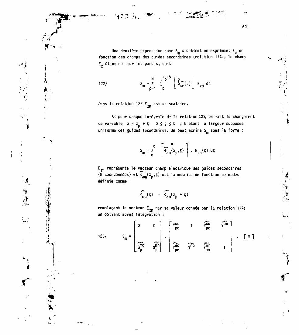
60.
Une deuxième expression pour S s'obtient en exprimant EZ enfonction des champs des guides secondaires (relation 117a, le champE étant nul sur les parois, soit
„••*•
122/
Dans la relation 122 E est un scalaire.
Si pour chaque intégrale de la relation 122, on fait le changementde variable z = z + ç 0 < ç < b ;b étant la largeur supposéeuniforme des guides secondaires. On peut écrire S sous la forme :
EZ_ représente le vecteur champ électrique des guides secondaires(N coordonnées) et $> (z >ç) est la matrice de fonction de modes
wlH P
définie comme :•*
remplaçant le vecteur E par sa valeur donnée par la relation 117aon obtient après intégration :
O O
123/ Sm =
yOOpo
«no Yno_ PO
PO
po
/>-> ~\/on]

61.
If
i :
Enfin les éléments scalaires des matrices et G™1 s'écrivent
124/
a//2e
Rmn _ / • nb _ / —F ab
m
si ?a
m 1
ira /m\2 _ /n \2a " F
•/ i\^~*JMïïi~(-1) SIn1-(Zp
_je _
b
b/mn
2a
mrr m ncos — z si - = - .
a p a b
1 pour n = O
2. pour n * O
a
*>• -..
'1
égalisant maintenant les équations 121 et 123, on obtient 4 équationsqui expriment avec les équations 120 la continuité du champ électriquetangentiel EZ au plan de jonction guide principal-guides secondaires.
125/
a/
b/
c/
d/
CYopaI
<**»mnop
• 6S0
= F0P
= 6J0's*~
•
yOO
' PO
+ s|n
Yp°ï +
r—yon
+ ?n . YP
. Y"°
Xmn ynmP ' PO
<P*X*«r
s_.
po
I désigne la matrice unité.

"35*"'*'•'*.*JS*
• , * • -v!»••«..'
"• "L/ev
V.
Utilisant les équations de continuité du champ tangential EZ(120 et 125) les champs électromagnétiques du guide principal(relations 116a et b) peuvent s'écrire sous la nouvelle forme :
a/ E Za
oa a -
°)
126/
/rmo von Pmnv(Gp . Y +Gp )
^f
Sf•?ya
oa
b 1T
â-
1 O
«
r YooOO
/,"( p°
. o v
^b1T YTm' a- 'Ypo -/|lT.Yon
Y = / — est Tadirittance d'onde dans le vide.
Yma rePrésente 1a niatrice diagonale des admittances relatives d'onde
m- = 1 2 .... oo
*«••...
è

, r
rt • j; '*i
E^» *>r 63.
Y - — = <ma »
/ 1 - (TJT-)mode m non evanescent
mode m evanescent
HIi
4.5 Conservation de la puissance complexe :
Pour déduire les 16 éléments de la matrice de transfert(relation 115) il faut compléter les 8 équations de continuité duchamp électrique (120 et 125) par 8 autres équations qui exprimentsoit la continuité du champ magnétique tangentiel, soit la conserva-tion de la puissance complexe /26/.
La puissance complexe rayonnée pour l'unité de longueur dans ladirection Oy s'écrit :
127/1 a
P = -/ dy / E H dz
En employant soit les expressions des champs du guide principal(relation 126), soit les expressions des champs des guides secondaires(relation 117). On obtient deux expressions équivalentes pour p :
a 1O
égalisant :
128/
[V]+ . [A] . [V] et p. = Yn [V]+ . [B] . [V] ou en
[Vj+ . [A - B] . [V] = O
"3

-•* ' /
"> « *
64.
Dans Ia relation 128 les vecteurs champs électriques sont arbi-traires on en déduit donc : 129/ A = B. A et B sont des fonctionsdes éléments de la matrice de transfert (relation 115) déduites desrelations 117, 526 et 127. Le calcul long et fastidieux n'offre pasd'intérêt.
4.6 Déduction des éléments de la matrice de transfert
Des équations déduites de la relation 129 et des équations decontinuité du champ électrique, on déduit les principaux résultatssuivants :
de_cou£la^e entre !ode_f£n_damejital_et
130/ /o , , m s » i"1 / °n T' ' "(Ynb + Gpq ' Yma) • Gpq ' Yma
"l
ti.f :
4
à
avec les définitions suivantes des termes du second membre
Ynb : la défini't''on est donnée au § 4.3.
fi.Yma
"VY i&a
Y I?a»
A
Yma(diagonale)
"YmaOOO
OYmaO
O
O
O^ •"
"*
O
O
OQ
** •«»
O """
O "
OO
* **vma
U)O)
O)
,~z
n colonnes
Yma est I'adm'it'tairicr relative pour le mode d'ordre m définie au § 4.3.I est la matrice unité d'ordre N, où N est le nombre de guidessecondaires.
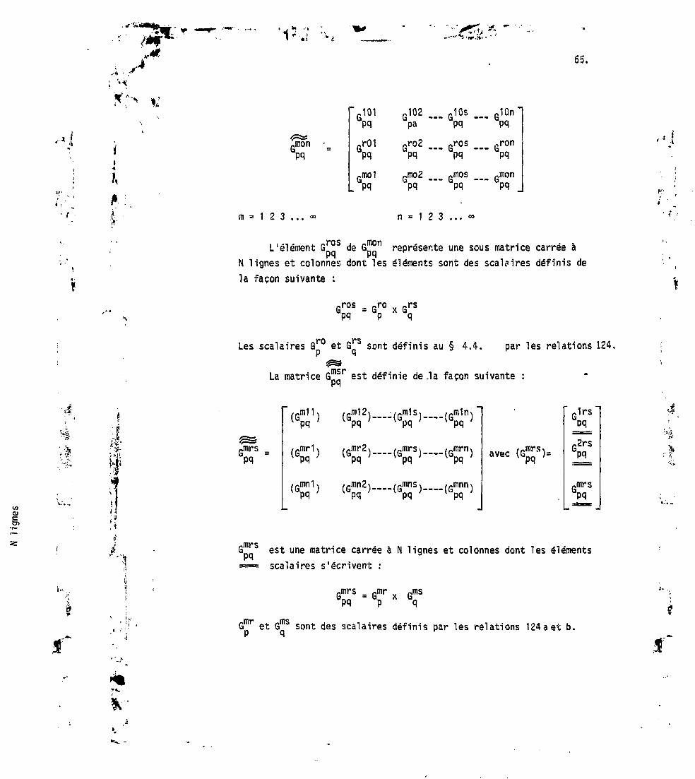
65.
^
i ^mon •_; P^:
"r101 J02Il U
pq pa
rr01 rro2pq pq
rmo1 rmo2(a 13
PQ PQ
A : ..?• m = 1 2 3 ... « n = 1
— G10S
pqrros
pqmospq
2 3 ... c
... G10n "pqfiron
pqrmon
™~"* IaPQ
D
L'élément G °s de G^n représente une sous matrice carrée àN lignes et colonnes dont les éléments sont des scalaires définis dela façon suivante :
ros
Les scalaires G£° et G^s sont définis au § 4.4. par les relations 124.
La matrice G est définie de .la façon suivante :
U)(U
Ol
fl
( ;, -î
/nrs
,m1s^apq '— »•(s
•{G!
pq
,mrn\3pq ;
^mnn>'pq '
avec
1rs
rmrsGpq
1
^DQ3 est une matr''ce carrée à N lignes et colonnes dont les éléments== scalaires s'écrivent :
-mrs -mr „ PmsGpq - GP X Gq
G"Jr et G 3 sont des scalaires définis par les relations 124 a et b.
r*.
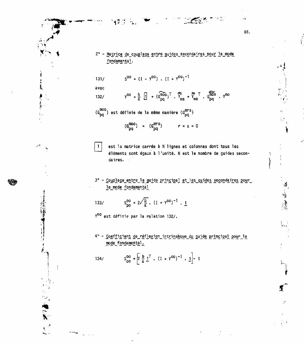
i*'•4 66.
2° - Ma_trj_« de_C£U£la_ge entrs £ujdes_S£condaj_res_p£ur ]e_m£de
fondamental.
131/ S00 = (I - Y00) . (I H- Y00)'
avec
132/ Y00 = - R + (G""5"0)1 . fa LJ pq ma
(G ) est définie de la même manière i
/rmoo\ /«rors\IG J = lu I rpq pq
? TYma
mon vno' Y
i,-
est la matrice carrée à N lignes et colonnes dont tous leséléments sont égaux à l'unité. N est le nombre de guides secon-daires.
r r, 1
3° - £ojjpjacje_en_t£e_l£ jj[ujcle
le mode fondamental
133/ S°° = 2/|". (I + Y00)'1 . 1pu a —
Y00 est définie par la relation 132/.
4° -
-,I1
4/I
mode fondamental .
134/ 1T . (I .Y00)'1 i - 1

67.
^0 " £°!ft'i.£''Jini £XjTêfle2i'i£n_c'S. rood,6!, £u£6£ifi_ur_s_dy. fiujKte £rj_n£ipaj_:
135/
*p et Gj" sont définis au §4 (relations 124 a et b).
6° -Jes modes iu£é£i£ujrs_du £U_ide £H.n£i£al_
136/ -moop
,,no'.Y"0) . (I + Yuo)
REMARQUE : Pour déduire les éléments de la matrice de transfert dela tnultijonction, on doit recourir au calcul numérique. Néanmoins,moyennant quelques hypothèses simplificatrices,on peut déduire analyti-quementses principales propriétés (voir §5).
. '.;*»
"....f

hrJi»'
68.
5. LES "GRILS" COMPACT UTILISANT LES MULTIJONCTIQNS PLAN E
5.1 Théorie des "Grils" multi jonctions (G. M.)
.j.
La multi jonction est employée comme diviseur de puissance pouralimenter plusieurs guides à la fois dans la direction toroTdaleFIG [14]. Le déphasage requis entre les guides peut être réalisé simple-ment en diminuant la hauteur des guides sur une longueur adéquate FIG[15]. Dans tous les cas pratiques, seul le mode fondamental peuvent sepropager sans evanescence dans les guides secondaires, d'autre part,iles champs électriques incidents V sont également de mode fondamental.On peut donc employer pour la multi jonction, la matrice de transfertsimplifiée déduite de la relation 115 modifiée par l'adjonction desdéphaseurs, soit :
137/
,"m
OO
<.ooPO
So_ OO
-OO
po
s""°0P .
Pour simplifier l'écriture, on a supprimé l'indice O (modefondamental) dans l'écriture des tensions électriques V ; l'indice Oen bas de V caractérise le guide principal de la multijonction. De la
mise en cascade du "Gril " et de la multijonction munie de déphaseurson déduit les propriétés suivantes du "Gril " compact :
Si Sn. est la matrice de transfert du "Gril " et V la tensionpx, oincidente au guide principal, on a en présence de plasma :
1° - Le coefficient de réflexion en mode fondamental du guide principal
138/ S00 SOOT°oo °o
t-

5 !I
69.
t«I,
- Les coefficients de réflexion de modes supérieurs du guideprincipal.
139/ -mo -1 oo
3° - La puissance réfléchie totale tout mode confondu du "Grill"multijonction.
140/ YJVo1 o1 'm "m*
Si le guide principal n'est pas surdimensionné p .p est imaginairepure et la puissance réfléchie se réduit au 1er terme de la somme dusecond membre de 140.
• a» J
Ui
1
4° - Le spectre en n,, des ondes planes émises vers le plasma est obtenuen remplaçant dans la relation 99 du §2 le vecteur V des champsélectriques totaux par :
141/ (I - S°°.S J'1 . S™ V.'PA' po o
Les résultats du calcul numérique montrent que le spectre en n,,des ondes planes émises vers le plasma est sensiblement le même quecelui d'un "Gril " conventionnel de mêmes dimensions géométriques etavec le même déphasage * entre guides adjacents FIG [16]. D'autre part,pour certaines valeurs de l'angle de déphasage $ entre guides, lapuissance réfléchie est très inférieure à celle du "Gril " conventionneléquivalent : c'est l'effet d1autoadaptation des Grils multijonction àondes progressives ($ t F). Cet effet peut être expliqué par Te faitque l'interface guides-plasma et le plan de jonction guides secondaires-guide principal sont des discontinuités de nature semblable et quepour certaines valeurs de .l'angle de déphasage entre guides il peut yavoir un effet de compensation entre ces deux discontinuités.
I
r*.'

'i ; W:
70.
5.2 Propriété d'autoadaptation, champs électriques entre le plan dejonction des guides et le plasma de bord
SI les parois séparant les guides secondaires sont d'épaisseur dtrès petite devant leur largeur, on peut en première approximationnégliger l'effet des modes supérieurs et déduire quelques propriétésimportantes des "Grils" multijonction sans recourir au calcul numérique.En effet, la matrice d'admittance réduite de mode fondamental (§ 4.6.relation 132) s'écrit simplement (sauf exception pour simplifier, ona supprimé 1'indice des modes).
142/S
Y = -x
et 143/ (I Y)"1 = I -X + N
où x = r- = rapport des largeurs du guide principal et des guidessecondaires, N est le nombre total de guides secondaires. De larelation 143, on déduit :
t ii
i!ià
ii•r' î
J
\° - Le_c£effj[cjtent_de_ léfljîxion Intrinsèque 4u_g]jide_principal_
x - N (N - 1) d
x + N 2a144/ oo
SQO est en valeur absolue égale au rapport de l'épaisseur totale desparois sur deux fois la largeur du guide principal. Comme on a toujoursd <« a dans les cas pratiques la multijonction vue du guide principalest adaptée.
2° ~ 2uldlsecondaires
145//T
spo = — = S -H x+N a
•4

71.
La puissance incidente au guide principal est distribuée égalementet en phase dans les guides secondaires dans le rapport - .
3° -
146/ S
soit
^-
« (I - Y) . (I + Y)"1 = I --itx + N
f b " (N - 1)d] bT 1 - 1 + 7 1 -
a l_ 2a J a
b f (N-DdI bi , 1 + . I M . -,.. ~
a |_ 2a J a
si D = a3 ' r "
Ci n ^ ci»1 H r M
D'autre part, on peut démontrer qu'en présence d'un plasma debord homogène dans la direction Oz, un réseau composé d'un grandnombre N de guides alimentés par des champs électriques d'égale ampli-tude et dont les phases suivent une progression arithmétique d'argu-ment $, FIG [ ], tous les guides sauf quelques uns se situant auxextrémités "voient" le même coefficient de réflexion p.
148/ p = p4
+ 2 Z t, cos n <t> (n entier)
*••-,.
p et tn sont les éléments de la matrice de transfert réseau-plasma.Généralement, on peut négliger les termes d1intercouplage tn pour n > 4.L'étude du comportement d'une multijonction à N voies secondaires(N » 1) avec déphaseurs fixes 4 en présence du plasma de bord symbolisépar le coefficient de réflexion p aboutit aux conclusions suivantes/15/.
Dans les guides secondaires Tonde va faire (n-1) allers etretours entre le plan de jonction et le plasma de bord FIG [18] tantque la relation :
-pf-

72.
2j(n-1)pcj> =
est satisfaite et aucune puissance ne sera réfléchie dans le guideprincipal.
tC'est le phénomène bien connu des multiréflexions entre deux
le ITWl
obstacles. Si $ est un sous multiple de n au n retour de 1'ondevers le plan de jonction, on a :
149/N
P-1
Le phénomène de multiréflexions s'arrête et l'onde va pénétrer dansle guide principal. La tension électrique totale à l'interface plasma
"î &IITPp guide de la multijonction s'écrit :
150/n m-1E ( n p J . (1 + pJe1
m=1 r=o r mJ(2m-1)p<î)
'••4
e/.
•*•• •..•ï1
,T> *
'à
P0 = 1 p sont les coefficients de reflexions vus par
les guides secondaires aux différents trajets aller de l'onde vers leplasma. Ces coefficients de réflexion ne sont pas identiques car ledéphasage entre guides est différent à chaque trajet aller de l'onde.Enfin, le coefficient de réflexion en tension vu du guide principals'écrit simplement.
151/n
= nî
Les multiréflexions diminuent la puissance réfléchie vers leguide principal donc vers le générateur ; c'est l'effet d1autoadaptationdes multijonctions ;elles font augmenter par contre le champ électriquedans les guides secondaires (relation 150). Appliquons ces résultats auxprincipaux cas pratiques d'utilisation des "Grils", dans les expériencesde chauffage et de génération de courant au voisinage de la fréquencehybride inférieure :
I

< X1.-* • P
fHW1N
173.
(G. M. O. S.)
Ces grils sont destinés au chauffage, soit des ions, soitdes électrons du plasma. Le déphasage entre guides adjacents est égalà II, en remplaçant dans la relation 149, <J> par n on a pour n = 1
Z
L'onde ne fait qu'un seul aller et retour comme dans un "grill" conven-tionnel ou chaque guide est alimenté indépendamment. Dans les deux cas,le champ électrique total dans les gui de s, normalisés au champ incidents'écrit :
P1)
•-4
2° - GrJ[Il muHjj£nction à £nfte£ £r£9ie£s™es_(G,.M.C[.£j à dé£h£sa_ge
N 9inDÏOn a Z e J PÏ = N pour n = 3 Tonde fait donc trois trajets
P-Ialler et trois trajets retour entre le plan de jonction des guides etle plasma de bord- Le déphasage entre guides adjacents estsuccessivement n/3 pour le 1er trajet, H pour le 2° trajet et -IE/3 pourle 3° trajet ; les coefficients de réflexion correspondants sont
,j soient d'après la relation 148
'•f
NI
f-
P1 * po * 2t " * ' P P2 = P0 - 2U1 - t3 - V
II en résulte que le spectre en puissance des ondes planesd'indice n émises vers le plasma central appelé souvent simplementspectre en n présente un lobe principal centré autour d'une valeurmaximum dépendant de la périodicité à - b+d des guides secondaires
S-V
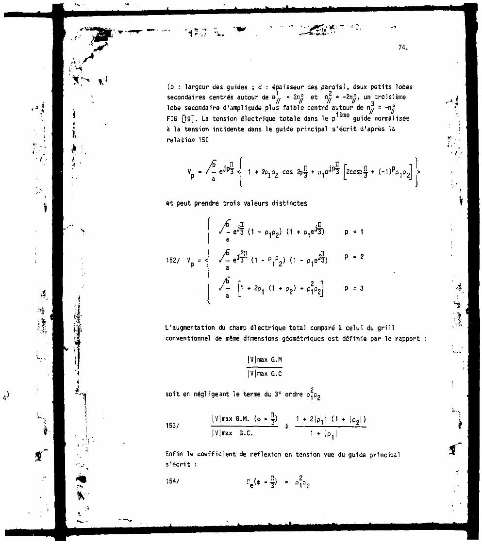
74.
Ii
fJt' •
(b : largeur des guides ; d : épaisseur des parois), deux petits lobes1 2secondaires centrés autour de n,/ = 2r\?, et n,, = "^n//> un troisième
lobe secondaire d'amplitude plus faible centré autour de nx/ = -n?ième "// 7/
FIG Qg]. La tension électrique totale dans le pIBllie guide normaliséeà la tension incidente dans le guide principal s'écrit d'après larelation 150
= /- ejpî <• 1 + 2O1 cos ~2cospj + (-I
K' .
i ; "
t '
et peut prendre trois valeurs distinctes
Ji .-n;J3 (1 - P1P2) (1 + P ,
/b" .2JI152/ V = < /-eJT~ (1 -
r- 1 + 2P1a L
>) + Pif
p = 1
p •P • 3
L'augmentation du champ électrique total comparé à celui du grill
conventionnel de même dimensions géométriques est définie par le rapport
(max G.M
!max G.C
soit en négligeant le terme du 3° ordre
153/|max G. M.
I max G.C.
|p|)
;1
Enfin le coefficient de réflexion en tension vue du guide principals'écrit :
154/ f) -
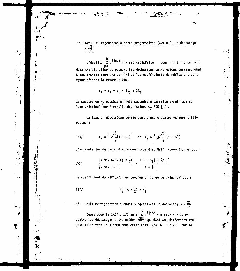
75.
*'N3° - Grill multijonction à ondes progressives (G.M.O.P.) à déphasage_
N= H est satisfaite pour n = 2 l 'onde faitL'égalité Z e
P=Ideux trajets aller et retour. Les déphasages entre guides correspondantà ces trajets sont n/2 et -H/2 et les coefficients de réflexions sontégaux d'après la relation 148:
P1 = P2 - P0 - Zt2 + 2t4
Le spectre en n» possède un lobe secondaire parasite symétrique aulobe principal sur l'échelle des indices n» FIG [2O].
La tension électrique totale peut prendre quatre valeurs diffé-rentes :
155/ et V = - j/- (1 - pj
fc>î«
*/:?»'
L'augmentation du champ électrique comparé au Gril conventionnel est
156/|max G.M. (* • ) 1 + + |P|
(Vjmax G. C. 1 +
Le coefficient de réflexion en tension vu du guide principal est :
157/
4° - cmtes
Comme pour le GMOP à n/3 on a Z e2jnp* = N pour n = 3. Parcontre les déphasages entre guides cBrrespondant aux différents tra-jets aller vers le plasma sont cette fois 2IÎ/3 O - 2ÏÏ/3. Pour le
t
Ik

76.
deuxième trajet aller tous les guides sont en phase et le coefficientde réflexion p dû au plasma est voisin de -1 :
= P - t - t + 2t - t = = PO + 2(t1 + t2 = t3 + t4) = -1
Au cours du deuxième trajet pratiquement aucune énergie n'estcédée au plasma .(|p2l ? D ce qui a pour conséquence d'augmenter lechamp électrique total dans les guides sans diminution du coefficientde réflexion T vu par le guide principal :
I .'
Ir6I = * P
Le spectre en n,, présente un lobe secondaire parasite autourde TL, - ~2 n/y . r\.l est l'indice maximum du lobe principal FIG [21]. Lesexpressions des tensions électriques totales sont similaires à cellesdes multijonctions à déphasage H/3. Le rapport du champ électriquemaximum du G.M 211/3 sur celui du gril conventionnel s'écrit :
!V|max G. M. (41 = 2II/3) 1 + 4|p,: à - LIVjmax G. C.
L'ensemble des résultats est résumé dans le tableau I.

-1
77.
TABLEAU I
Propriétés des "Grils" muitijonctions comparés au "Gril " conventionnel
' t
;•*
, 1
1
Déphasageentre guides
$
n
3
n
2
2ïï
3
n
•
PériodicitéA
\T1
™71
^T
1^N0
•*"//
1
?N°^ //
Déphasageentre guides
2° trajet
n
n
2
O
Déphasageentre guides
3° trajet
n
3
?n
3
Gril conventionnel (G. C.)
Tensionsélectriques
maximum
1+2|pt|. Up2I
1+2Ip1 I+P1 I *
1^)P1Kp1I2
UlP1
1 + 1P1
Coefficient deréflexion en
tension (guideprincipal)
Ip1!2. Ip2I
Ip1I2
* S p 1 I 2
Ip1I
IP1I
La dernière colonne du tableau traduit l'effet d1autoadaptationdes "Grils" multijonctions à ondes progressives. Si R est la puis-sance réfléchie du G.C. normalisée par la puissance incidente, celledes G.M. à déphasage n/2 et 2H/3 est Rz et celle du G.M. à déphasageïï/3 est approximativement en R3. La 5° colonne du tableau I montre
K- ..t ; '

78.
*' .
/I
Ii
$ • -
l'augmentation du champ électrique total due aux réflexions multiplesdans les guides des G.M. à ondes progressives. En réalité, cetteaugmentation n'est qu'apparente car pour un même système de trans-mission de puissance (générateurs, lignes, diviseurs verticaux), unmême spectre en n,, et la même puissance HF transmise au tore la surfaceemettrice de l'antenne à multijonctions est de 3 à 4 fois plus grandeque celle du G.C. et par conséquent le champ électrique total malgréles réflexions multiples est très inférieur à celui du G.C. Lesrésultats précédents sont confirmés par ceux donnés par le calculnumérique appliquant les théories complètes du "Gril" et de la multi-jonction comme le montrent les Fig. [19,20,21] : les spectres en n,,montrés sur ces figures sont ceux de trois grils multijonctions à on-des progressives (G.M.O.P.) ; le déphasage <j> entre guides adjacents sontsuccessivement n/3, n/2 et 2n/3. La périodicité A et le nombre total Ndes guides ont été choisis pour avoir pour les trois "Grils" un lobe prin-cipal de même largeur centré autour de la valeur i\°,, =2. La fréquenceest celle choisie pour l'expérience TORESUPRA: 3.7 GHz. La densitéélectronique à l'interface "gril"-plasma est prise égale 1013 cm"3et legradient de densité égal à Vn = 5 10lz.cnf ? On observe dans les troiscas que les lobes secondaires parasites se trouvent bien aux endroitsprévus par le raisonnement négligeant les modes supérieurs. Les Fig.[22, 23, 24] montrent l'évolution du coefficient de réflexion enpuissance R en fonction de la densité électronique à l'interfaceantenne-plasma ; les déphasages entre guides sont <(> = n/3 [22].<j> = n/2 [23J et $ = 21Ï/3 [24]. Les courbes a 3e rapportent aux G.C.et les courbes b aux G.M. On observe la diminution de R dû à l'effetd'autoadaptation. Le minimum présenté par les courbes(b) pour h entre
12 13 -310 et 10 cm est probablement dû à un effet de compensation entreles réflexions dans le guide principal des G.M. : reflexions dues auplasma d'une part et à l'épaisseur finie des parois séparant les guidessecondaires d'autre part. Les courbes de la Fig. (25 montrent l'évo-lution du coefficient de réflexion en puissance R e" fonction du nombrede modules pour les antennes définies de la façon suivante :
K' ..
i .
t ••
•4
r*.

*">• ' ''i*«*•-.' ..KiVTi •*...*. •
79,
Courbe aGril conventionnel déphasage
Courbe bAntenne composée de plusieurs multijonctions ou modules juxtaposéschaque multijonction comporte 4 guides secondaires avec déphasage$ = -L les parois sont supposées infiniment minces.
Courbe cMême antenne que la courbe b l'épaisseur des parois est finie.
Courbe dAntenne avec multijonctions à 5 voies secondaires déphasage$ = 72°, parois infiniment minces.
1
On observe une détérioration de l'effet d 'autoadaptation part d'
< 8).
l'effet d'extrémités (side effect) quand le nombre N de modules
En effet, la relation 148qui donne le coefficient de réflexioncommun vu par les guides en fonction des éléments de la matrice detransfert de l'interface gril -plasma n'est plus valable pour N < 8 etle recours au calcul numérique pour déduire les propriétés de l'antenne(G.M. ou G.C.) devient "îécessaire.
Enfin, pour les expériences de génération de courant utilisantles G.M. à ondes progressives, le choix du déphasage 4> = r- semble apremière vue la meilleur^. En effet, parmi les exemples cités
TT TT 2II\(41 = -Jr j y-), ce choix permet d'avoir la meilleure directivité et leminimum de puissance réfléchie. Malheureusement, dans le domaine defréquence utilisée (f = qq GHz) et pour des valeurs de njj >n// a c c lalargeur tes guides devient trop faible (colonne 2 - tableau I) et desphénomènes parasites peuvent apparaître (claquage, ionisation, mult i-pactor). Le choix de <j> = 5 semble de ce fait un compromis valable.

;j'.
*tT».
• j *• • "» ., W f*Z<lllT*.-.' V-, - .--"W-*,
80.
6.2 Mesures à faible niveau
Pour les mesures à faible niveau les guides secondaires sontfermés sur des charges adaptées, la HF est injectée ->ar le guide prin-cipal et on mesure la distribution de puissance dans les guides secon-daires en amplitude et en phase. Ces mesures sont faites en présence de
ri > 6. RESULTATS EXPERIMENTAUX SUR LE CHAUFFAGE DES IONS DU TOKAMAK
-, " PETULA B AVEC UN GRIL MULTIJQNCTION A ONDES STATIONNAIRES.
COMPARAISON AVEC LE GRIL CONVENTIONNEL EQUIVALENT JW.JiSf. ' •* j
\
\ - - j i* 6.1 Description du G.M.
[,, La fréquence de travail est de 1.3 GHz, le G.M. est réalisésimplement en divisant un guide standard rectangulaire WR 650 de
: section (8.25 x 16.5 cm2) en quatre guides secondaires de section -, •réduite (1.9 x 16.5 cma) à l'aide de trois parois métalliques d'épais- 4
seur 2 mm parallèles au grand côté du guide principal ; la périodicité *est ainsi de A = 2.1 cm. Fig. [26,]. Ces dimensions sont identiques àcelles d'un G.C. utilisé couramment sur PETULA B pour le chauffage des :> i
ions. Une étude comparative de leurs performances respectives est donc \possible. Avec un déphasage entre guides <j> = Ii théoriquement les deux"gril " doivent avoir un spectre en n^ composé de deux lobes principauxcentrés autour des valeurs n° = - 5.2. Dans le cas du G.M. ce déphasageest obtenu en réduisant la hauteur d'un guide secondaire sur deuxde 16.5 cm à 13.5 cm sur une longueur d'environ 60 cm. Cette section
" de guide réduite en hauteur est terminée aux extrémités par deux trans-:,{j formateurs plan H servant d'adaptateurs d'impédances Fig. [26]. Avant-*: application de la puissance HF l'antenne est nettoyée par des décharges
luminescentes sous atmosphère d'argon. Quatre boucles magnétiques placéessur le petit côté des guides secondaires à 8 cm de l'ouverture permettentla mesure des champs électriques totaux.
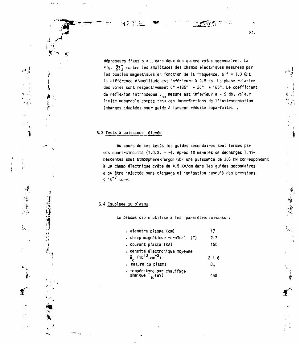
81
*déphaseurs fixes $ = n dans deux des quatre voies secondaires. La
i v Fig. §3] montre les amplitudes des champs électriques mesurées par* Jk i
* i( les boucles magnétiques en fonction de la fréquence, à f = 1.3 GHz•( i la différence d'amplitude est inférieure à 0.5 db. La phase relative? ^ des voies sont respectivement 0° +185° - 20° + 185°. Le coefficient
de réflexion intrinsèque S mesuré est inférieur à -19 db, valeur K- ..limite mesurable compte tenu des imperfections de l'instrumentation(charges adaptées pour guide à largeur réduite imparfaites) .
6.3 Tests à puissance élevée
Au cours de ces tests les guides secondaires sont fermés pardes court-circuits (T.O.S. = »). Après 10 minutes de décharges lumi-nescentes sous atmosphère d'argon/30/ une puissance de 300 kW correspondantà un champ électrique crête de 4.5 Kv/cm dans les guides secondaires
*'
a pu être injectée sans claquage ni ionisation jusqu'à des pressions
'•J< 10~3 torr.
6.4 Couplage au plasma
Le plasma cible utilisé a les paramètres suivants
. diamètre plasma (cm) 17
. champ magnétique toroidal (T) 2.7
. courant plasma (KA) 150
. densité électronique moyenneri (1013.cm~3) 2 * 6€
. nature du plasma 0«
. température par chauffageohmique T(eV) 450

82.
Mesure de la puissance réfléchie
La Fig. |8] montre l'évolution du coefficient de réflexion globalen puissance en fonction de la puissance HF injectée. Dans le cas du"Gril " multijonction c'est le coefficient de réflexion en puissance duguide principal. On observe :
1°/ que les courbes correspondantes au G.C. et G.P. ont mêmeallure ; le coefficient de réflexion R est légèrement supérieur dans lecas du G.M. Cela peut être partiellement expliqué par l'environnementnon identique des deux "Grils" bien qu'ils soient théoriquement à lamême distance du plasma.
2°/ une augmentation du coefficient R pour les deux :'Grils" enfonction de la puissance injectée due probablement à la modificationdes conditions de plasma de bord par la pression HF de radiation.
3°/ la puissance maximum injectable est plus petite pour le G.M.que pour le G.C. 250 kW et 350 kW). Cette différence peut être en partieexpliquée par les réflexions multiples dans le cas du G.M. entre leplasma et le plan de jonction et à l'augmentation des champs électriquesqui en résulte. En effet, dans le cas présent d'un G.P. à 4 voies leseffets d'extrémités jouent un rôle prépondérant et dissymétrisent lescoefficients de réflexion vus par les guides secondaires. Par ailleurs,en imposant au G.M. les mêmes dimensions que le G.C. déjà opérationnella réduction de hauteur dans les déphaseurs du G.M. (a1 = 13.5 cm)est trop importante d'où une deuxième cause possible de l'augmentationdes champs électriques dans ces sections. Cette deuxième cause peut êtresupprimée en augmentant la hauteur des guides du G.M. jusqu'à lalimite de l'apparition du mode TE20 (a ? X )
Champs électriques à 1 'interface antenne-plasma, spectre en n/,
Pour les deux "Grils" ces champs sont déduits des mesures indirectesdans le cas du G.C. on mesure les puissances incidente et réfléchie dechaque voie en amplitude et en phase à l'aide des coupleurs directifs
*"'•

83.
placés loin derrière l'ouverture de l'antenne, après différents élémentstnicroondes (coupures isolantes, transformateurs, fenêtres étanches...),on doit faire une correction d'amplitude et de phase pour tenir comptede ces éléments. Cette correction n'est pas toujours évidente s'il fauttenir compte des réflexions multiples entre le plasma et ces disconti-nuités même légères. Dans le cas du G.M., on ne dispose que des bouclesmagnétiques non directives qui mesurent seulement les champs électriquestotaux à 8 cm de l'interface, il faut utiliser la matrice de transfertde la multifonction et des mesures d'amplitudes et de phases obtenuespar les boucles. Cette procédure n'est légitime que s'il n'y a ni cla-quage, ni ionisation entre les boucles de mesures et le plan de jonctiondes guides. A partir des valeurs des champs à l'interface ainsi déduitespour les deux "Grils" (amplitudes |V | |VJ phases <j> et <j> ...) on peutremonter au spectre en N,, des ondes planes en utilisant la relation 99du § 2.7. Dans le cas présent, la densité électronique à l'inter-face est très grande comparée à la densité de coupure à 1.3 GHz ; ona pris pour 1'admittance de surface plasma la valeur donnée par larelation 21 § (1.6). On obtient ainsi des spectres en n,, qui serapprochent plus des spectres réellement rayonnes que les spectrespurement théoriques que Ton trouve couramment dans la littérature.La Fig. [29J montre quelques exemples de spectres obtenus d'aprèscette procédure : pour le G. M.-Fig. [29 a] et pour le G. C.
Fig. [29b] . La similitude de ces spectresexplique les performances identiques des deux "Grils" concernant lechauffage des ions.
6.5 Performances comparatives des G.M. et 6.C. utilisés pour le chauffagedes ions.
Les résultats de chauffage sont décrits ailleurs /29/, les prin-cipales conclusions sont les suivantes :
1°/ L'augmentation de la température ionique mesurée par l'échangede charge parallèle (au champ magnétique toroidal) et par flux de neu-trons dans le cas des plasmas de deuterium est comparable pour les deux"Grils" avec puissance transmise dans le tore égale dans les deux cas.

84.
2°/ Le rendement de chauffage n défini par le rapport
HFest également identique pour les deux "grils" et atteint sa valeurmaximum d'environ 4.5 eV 1013.cm"3/kW pour des densités centralesmoyennes de 5 à 6 1013.Cnf
3 Fig. [3O]. i -
1

•r* -
85.
t •'
1
REFERENCES
/1/ - T.H. STIX, Phys. Rev. Lett. 15, 878 (1965) ; A.D. PILIYA etV.I. FEDOROV, Zh. Eksp. Teor.Fiz. 57, 1198 (1969) [Sov. Phys.JETP 30, 653 (197O)] ; V.M. GLAGOLEV, Plasma Phys. 14, 301et 315 (1972) ; V.E. GOLANT, Zh. Tek. Fiz.41, 2492 (1971)[Sov. Phys. Tech. Phys. 16, 1980 (1972)] ; M. BRAMBILLA,Nucl. Fus. 14, 327 (1974) ; etc ...
/2/ - B.V. GALAKTIONOV, V.E. GOLANT, V.V. DJACHENKO et O.N. SCHERBININ,Proc. 4th Eur. Conf. on Cont. Fus. and Plasma Phys.Rome, 104 (1970)V.M. GLAGOLEV, N.A. KRIVOV et Y.V. SKOSYREV, dans "Plasma Physicsand Controlled Nuclear Fusion Research" (Proc. 4th Int. Conf.Madison, 1971) Vol.3, IAEA, Vienne, 559, (1971) ; JJ, CAPITAIN,G. ICHTCHENKO, P. LALLIA, D. MOULIN, T.K. NGUYEN, S.S.PESIC,Proc. 5th Eur. Conf. on Cont. Fus. and Plasma Phys., Grenoble,Vol. 1, 116 (1972) ; W. M. HOOKE et S. BERNABEI, Phys. Rev. Lett.28, 407 (1972).
/3/ - G. BRIFFCO, Equipes WEGA et PETULA, Proc. 4th Kiev Int. Conf. onPlasma Theory and 4th Int. Congress on Waves and Instabilitiesin Plasmas, Nagoya, p. 10 A-4, Vol. 2, 238 (1980) ;Pour une revue : M. PORKOLAB, IEEE Trans, on Plasma Science,Vol. P.S.12, 107 (1984).
/4/ - Par exemple : "Panel on Waveguide RF Antennas" dans "Heatingon ToroTdal Plasmas" (Proc. 3nd Joint Varenna-Grenoble Int.Symp.,Grenoble 1982), EUR 7979 EN, Vol. 3, 1129-1171 (1982).
/5/ - N.J. FISCH, Phys. Rev. Lett. 41, 873 (1978)C.F.F. KARNEY et N.J. FISCH, Phys. Fluids 22, 1817 (1979).
/6/ - W. HOOKE, Plasma Phys. 26, 133 (1984), (Proc. llth Eur. Conf.on Cont. Fus. and Plasma Phys., Aix la Chapelle, 1983).

f-H
I,
86.
/7/ - D.A. EHST1 C.D. BQLEY, K. EVANS Jr., J.JUNG, C.A. TRACHSEL et T.HINOJournal of Fusion Energy, 2, 83 (1982).
/8/ - P. LALLIA, dans "Radio Frequency Plasma Heating" (Proc. 2ndTop.Conf. Lubbock, 1974) p. C3.
/9/ - M. BRAMBILLA, Nucl. Fus. 16, 47 (1976) ;M. BRAMBILLA, Nucl. Fus. 19, 1343 (1979).
/10/ - C. GORMEZANO et D. MOREAU, Plasma Phys. and Cont. Fus., 26, 553(1984).
/11/ - D. MOREAU, C. GORMEZANO, G. MELIN et T.K. NGUYEN, dans"Radiation in Plasmas" (Rev. from 1983 College on Plasma Phys.,Trieste) Ed. B. Mc Namara, World Scientific, Vol.1, 331 (1984).
'4.
Iii
1
/12/ - L. DUPAS, P. GRELOT, F. PARLANCE et J. WEISSE, dans "Plasma Phys.and Cont. Nucl. Fus".(Proc. 8th Int. Conf., Bruxelles 1980)Vol.2, IAEA, Vienne, 489 (1981).
/13/ - M. BRAMBILLA, ibid. Vol.2, 483 ;A. FUKUYAMA, T. MORISHITA et Y. FURUTANI, Plasma Phys. 22, 565(1980) ;K. THEILHABER, Nucl. Fus. 22, 363 (1982) ;V.A. PETRZILKA, R. KLIMA et P. PAVLO, J. Plasma Phys., 30,2° part., 211 (1983).
/14/ - T.K. NGUYEN et D. MOREAU, dans "Fusion Technology 1982"(Proc. 12th Symp. JuIich), Vol.2, 1381 (1982).
/15/ - D. MOREAU et T.K. NGUYEN, Proc. 1984 Int. Conf. on Plasma Phys.,Lausanne, Cont. Paper P17-1, Vol 1, 216 (1984).
/16/ - K. ANDREANI, P. PAPITTO et M. SASSI, dans "Fusion Technology1982" (Proc. 12th Symp. Julien), Vol.2, 1249 (1982) ; ALCATOR-CGroup, dans "Heating in ToroTdal Plasmas" (Proc.Snd Joint VarennaGrenoble Int. Symp., Grenoble 1982), EUR 7979 EN, Vol.2, 469 (1982).

•-* • .=
,It#PW* f i OTT.•»'/* : ••*•-<*<• ••
87.
/17/ - W.P. ALLIS, S.J. BUCHSBAUM et A.BERS, Waves in AnisotropicPlasmas, M.I.T. Press, Cambridge, (1963).
/18/ - A. BERS et K. THEILHABER, Nucl. Fus. 23, 41 (1983).
/19/ - T.H. STIX, Theory of Plasma Waves, Mc Graw HiII, New York, (1962).
/20/ - M. ABRAMOWITZ et I.A. STEGUN, Handbook of Mathematical Functions,National Bureau of Standards, 10° edition (1972), p. 446.
/21/ - M. FICHET et I. FIDONE, Nucl. Fus. 21, 83 (1981).
/22/ - G. ICHTCHENKO, Rapport EUR.CEA.FC 1041.
/23/ - M. BRAMBILLA, Nucl. Fus. 18, 493 (1978).
/24/ - O. STEVENS, M. ONO, R. HORTON et J.R. WILSON, Nucl. Fus. 21,1259 (1981).
/25/ - O.N. SHCHERBININ, J.J. SCHUSS, Nuclear fusion, Vol.19, n° 12 (1979).
/26/ - REZA SAFAVI NAINI, KOBERT H.MACPHIE, IEEE Transactions on microwavetheory and techniques, VoI.MTT 29, n° 4, April 1981.
•
/27/ - J.G. WEGROVE, G. TONON, Net Intor Report 1983.
/28/ - T.K. NGUYEN, G. REY, D. MOREAU, PETULA et RF Group, Proc. of13th Symp. on Fus. Tech. Vol. 1, 663 (1984).
/29/ - C. GORMEZANO, P. BRIAND, G. BRIFFOD, G.T. HOANG, T.K. NGUYEN,D. MOREAU, G. REY Nuclear Fusion, Vol.25, n° 4 (1985).
/30/ - G. REY, P. BRIAND, C. DAVID, G. LAMBOLEY, D.M)ULIN, G. TONON.Proc. of 12th Symp. on Fus. Tech. Vol.2, 1311 (1982).
•4«I
%fit
;•*,'

**3pfc~'T•*^'.«•**• 1
Densité t
Plasma de bord
J Bouche du coupleur
\ i\I:
:!FIG. [1]
T*,'

'
(co) («=)
( T )
FIG. [2]
(J
f
Jt"

»• <y -
1
U
LO

• -Is»1* 9.fH *
t l
1
*
-

1
- -'I. -•I
"4
j ;
1
;.-*
(JLl
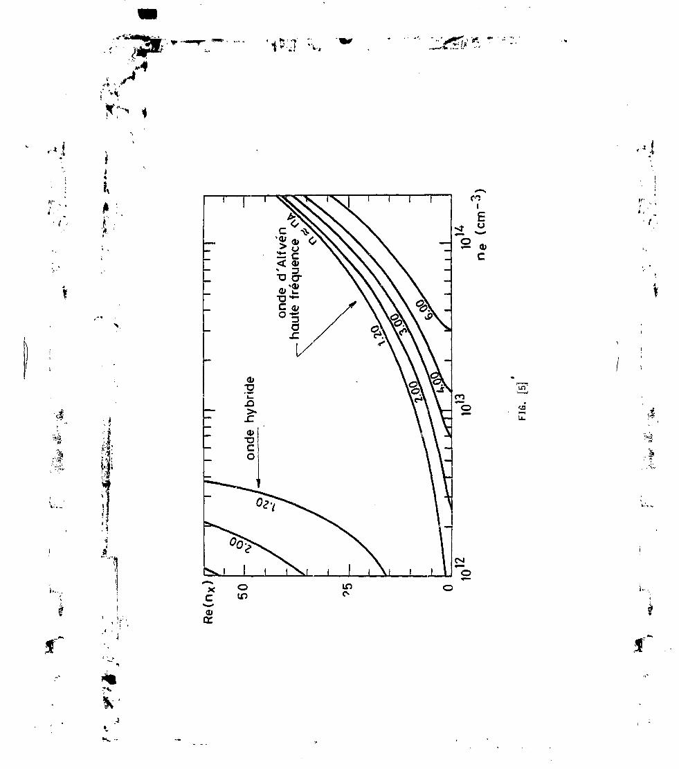
1
,-* ' ,
K-I . '
Il
*' •'* !
OUD
(UCT
If)
Lf)
Î-.
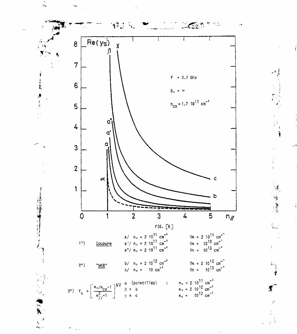
i***r .,,„ ' -J ?T ">1 <" ' "Il » i * «
IJ
Jr*''
>.
«
3 _
2 _
1 _
1°) Coupure
FIG. [6]
a/ n0 = 2 IQ11 cm"3
a ' / n0 = 2 10 cm"a"/ n0 = 2 1011 cm"3
Vn = 2 1011 cm""1? -"Vn = 10 cm11 -"Vn = 1010 cm
2°) "WKB" b/ n0 = 2 1012 cm"3
_3c/ n0 - 10 cm
1? -"Vn = 2 10'c cmVn = 1013 cm"
n°/nco-1
n 1
_ 1 / 9 a (pointillés)" 3 s b
Y = C
11 -3
2 10n cmn0
no = 2 1O -" cm
nc
_3
1013 cm"

"V
'1$;;7 'x- -rzïi'*-
'A'.
f. •)
n = 1.7 1011 cm"3
1a/b/c/
et/
3/
Y/
n0 = 2 1011 cm"3
n0 = 2 1012
n0 = 1013 cm"3
n0 = 2 1011 cm"3
n0 = 2 1C12 cm"3
17 3n0 = 10 ° cm
FIG. [7]
Vn = O
Hypothèse Y s-1/2
t

• j *" '• '» '
.1
(00)
( T )
Région I
R//C1 n//C2r i
i :• <»i
1
i
i
i !
!
r™ *•"•i ;ri
Ph
»ki
» il
i
I
; I»
I
p
I
» I
»
:: i
i r*r <
;»>
Régionf»»
n/
Coupures
FIG.[8] "-V-

K
• j n ' -r1 r ; . j
• x A • • • •_«. • •• • T • • • • B0 • •
• • • • • • • ^ • •• • •• • •
• • • •
• • • •
• • •• • • O/////////// /
/
/
• • •
• • •
• • •• •
• • •
b
»
\V,
«
• PLASMA DE BORD •
Hp?^o
fpI/o v*n'P VP
0f /
o-
1FIG. [9j
f
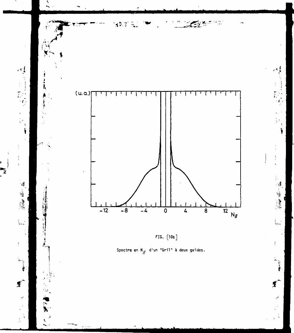
f«
*v -
(u.a.)
-12 -8
FIG. [1Oa]
Spectre en N,, d'un "Gril" à deux guides.

K*
r*
( U. d.)| I ' I
-12 -8 -4
I M 1 I 1 I 1 I 1 I
8
FIG. [1ObJ
12N/,
Spectre en N,, du même "gril" (fig. QOaj ) avec àchaque extrémité 4 guides passifs terminés par descourt-circuits placés à X0/4 de l'ouverture.
Uv
i-

«•v
• • • •
• • • • PLASMA DE BORD
VQ ' ' V b * • * '• • • • • • • • fc • • ^ • • • •
FIG.[11]
• • • • •
PLASMA DE BORD"4
«
1AlP lA
FIG..12]
"

1 -*
X-* -S
i Guides secondaires
T
'/
/
/
/
^b
»
7
MM
d
Ï\\\V
I
^t t tVB^\•»••• ••• •
^Î » <•« ••» M
I I III>**. M-. *.. -**
Vu V° u*no o V0
a
r
/
XX
XX
^•M
O+
• M g
0~
Guide principal
'<*
i• ";>*
^Jl.
FIG. [13]
*"'/

J
;• •*,t ' *
t:
• • • PLASMA DE BORD • • • •• • K • • • • • • • •
^^_^^^_ _^^^ .
/ /// / 6/sC
VsN
NX
//
^
^
^
m
If
/,^
d
0
/
/
//
D20 \
/m*
vpi"I)""
r
//
^/ x•••
•• MM W Ml
DN0
' t i
Vi V^
GUIDE PRINCIPAL
a
^
^/<y
/y
/,^
'///// /
FiG. [14]

* • • - - »
"'It'
(U
Ol
<u
<o
I:54;
VO
U
IM
ID
f

: ȕtMi
0.8
0.6
0.4
0.2
-3 -2 -1 1Q ) GRIL CONVENTIONNEL DEPHASAGE -~
( u. a.)
0.8 -
0.6 _
0.2
I I
Lobe secondaireparasite
J-3 -2 -1
b) GRlL MULTiJONCTiON DEPHASAGE2
"G. [16]
•'
«I
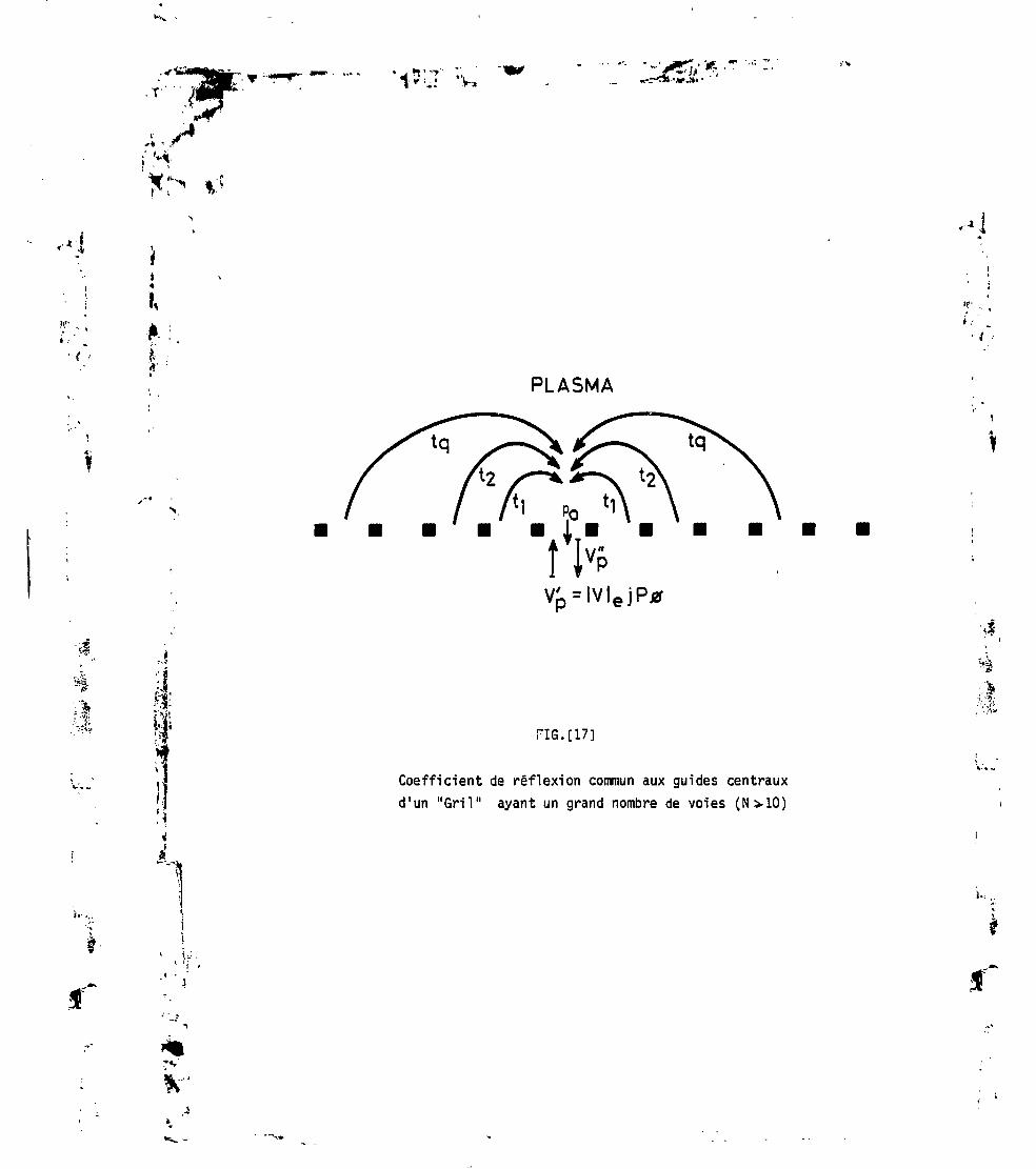
**I»
'15LT ;w
PLASMA
,'I
i.-
:J
i.
FI6.[17]
Coefficient de réflexion commun aux guides centrauxd'un "Gril" ayant un grand nombre de voies (N>10)

/ • ; LES RE FieXÎÛHS MULTIPLES te PLASMA ET /.£• PLAH
- • !
fl-
OES suioes
DDUCTION OU CHAMP ELECTRU1UE TBT-AL
i (S^) -,-IK- ..
GUi DE PRlKtJPAL;«**«« SUtDE SeCOHDAlRE J PLASMA DE BORP
1 v« Ji
N...\*fc* TftAJET
If
-
-Ji
* •

.f.À - /
{ •
'4
,1
.î"
*'*Ne = 1.OE* 13cm -3 VNe = 5.0E>12cm-4
Reflexion : 2.2%M | M in i H | . M I i . . p M ]-r i q i
1?r Trajet
, M . , . . , , , . . , . . . ,
U.A.
.7 -6 -5 -A -3 -2 -1 O 1 2 3 A 5 6 7SPECTRE DE PUISSANCE / PUISSANCE TRANSMISE
FIG.
Gril" multi jonction à 18 voies, déphasage $ = 60e
'••s
*"
r*.'

•v -r , ». .?T » ...»
J- i
w»
,.
Ne= 1.0E*13cm-3 VNe = 5.0E+12cm-4
Reflexion : 5.8%H Ij I I I I I I I M M I I I I I M 1 M 1 I | I I t ) I I | | I M • I I I | I I I | I M | I I I | I M ! I I
: U.A. i
1îr Trajet
2? Trajet -, _I
2î Trajet-,
-7 -6 -5 --4 -3 -2 -1 O 1 2 3 4 5 6 7
SPECTRE DE PUISSANCE / PUISSANCE TRANSMISE
FIG. [20]
"Gril" multijonction à 12 voies déphasage * = 90°
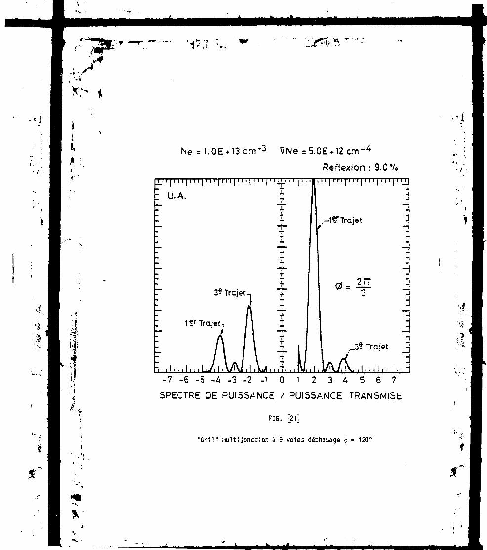
i
-s
£
Ne = 1.OE+ 13 cm'3 VNe = 5.OE* 12 cm-4
Reflexion : 9.0%I I I I I I I M I I I M I I ITF I I I M ' 1 ' I
: U.A.
1e/Trajet
3? Trajet
1îr Trajet-
'.I i l l Ml l l lL/ l l lY/ î \ i l l , \ jJ l . , l I M
I I i i n
2TT
3e. Trajet
/K, , 1 , , , ! M , I , ,- 7 - 6 - 5 - 4 - 3 - 2 - 1 0 1 2 3 4 5 6 7
SPECTRE DE PUISSANCE / PUISSANCE TRANSMISE
FIG. [21]
"Gril" multijonction à 9 voies déphasage $ = 120°
.«i
K- ..

-TTY:T <- • -I
R%
10
10r1
A0 =60
1011 1012FIG. [221
dB
-10
-20
-30
1013Ne-
Coefficient de réflexion en puissanceComparaison entre G.C.(a) et G.M.(b)
V

;•' '*i
'xS
• jni-yT «?;~i
-i
! '
i,
R%
10
10-1A0 = 90°
1012FIG.[23]
dB
-10
-20
-30
Ne-cm~31013
Coefficient de réflexion en puissanceComparaison entre G.C.(a) et G.M. (b)

i
v.*'
1
R0A
10
-20
-30
FIG.124]
Coefficient de réflexion en puissanceComparaison entre G.C.(a) et G.M. (b)
1J*.,4a
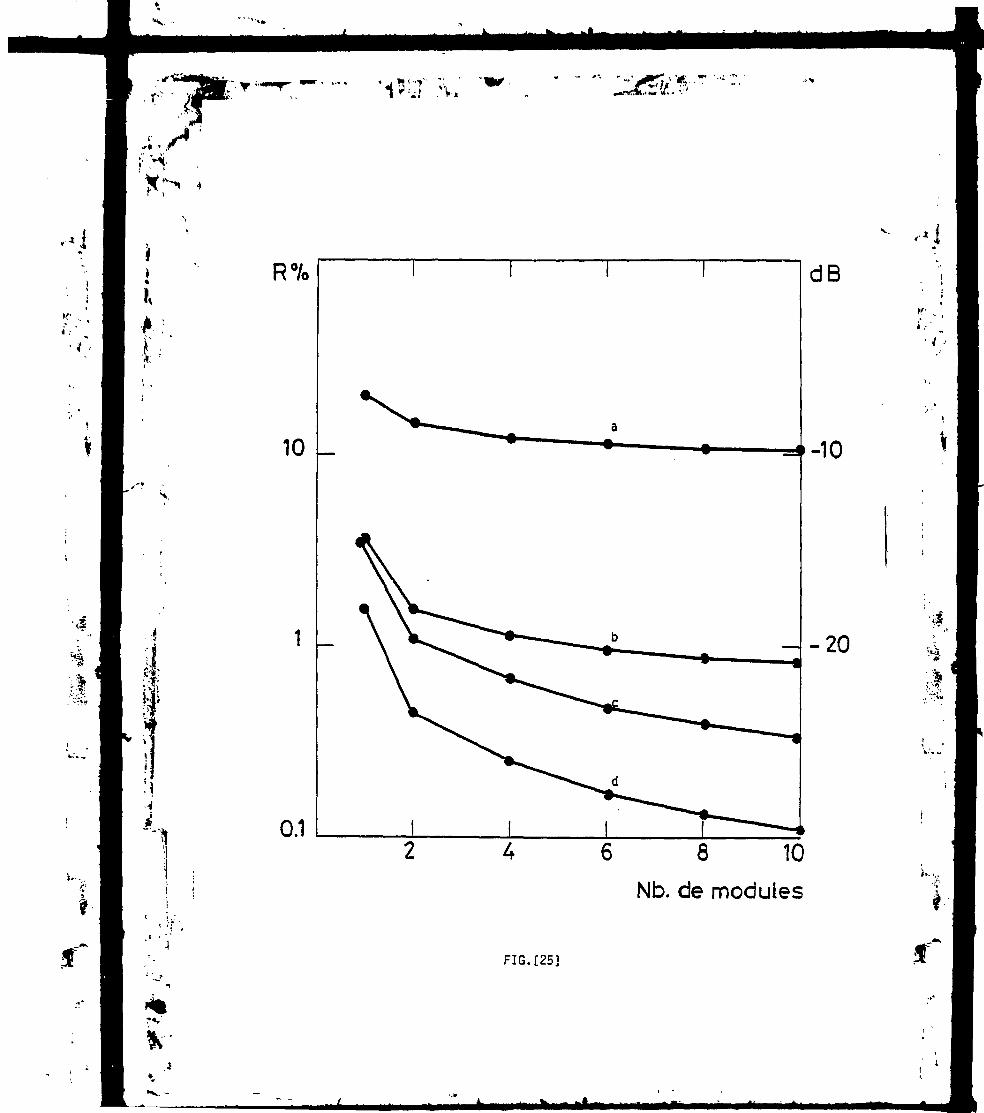
*"V -
r-•* » ,<
1 -j *V -»V-J 'V,
Ii
§
R%
10 -
1 _
0.1
dB
-10
-20
6 8 10
Nb. de modules
FIG.[25]
I-

"=¥
CM
0
on
UJ I—a LU
"3 C(O
L t
U

F *
-t25o -isso
FIG. [27]
Répartition des champs électriques en amplitude dans lesvoies secondaires
* Les courbes en trait plein conceinent les voies 2 et 4 muniesde déphaseur différentiel A<i> = IT
*"•..i»

I
en1-1
coCM

Gril multljonction
P = 25kW
P = 107kW
-6 -4 -2
Grit conventionnelPHF=250kW;
P ( N//)(u.a)
/ .•
-10 -8 -6 -4 -2
FIG. [29b]

,-•*
'•-'•;'•~'^
*•• -..Ss.
I-
*• : - I
D
Da
DD
a»
o :U. (J
O)O)L_ I/)? c-C O
O) ?
(U
DDO JS O .2
HJL! U- UJ Lu
• • D O
— o _t3'C'-S •- c0S 0.2,
DD
8
CSI

Plasma Physics and Controlled Fusion, Vol. 26. No. ). pp. 553 Io JM. 1984Pnnicd in Great Britain.
074I-3335/84Î3.00 + .001984 Inslimtc of Physics and Pergamon Press Ltd.
ji4
î,
LOWER HYBRID WAVE COUPLING IN THE WEGATOKAMAK
C. GORMEZANO and D. MOREAUAssociation Euratom-CEA, Département de Recherches sur la Fusion Contrôlée, Service IGn, Centre
d'Etudes Nucléaires, 85 X, 38041 Grenoble Cedex, France
(Received 25 May 1983; and in revised form 11 October 1983)
Abstract—The experimental data of the h.f. coupling measurements of the 4 waveguide grill of the WegaTokamak have been compared with a linear coupling theory using a step density model. In order tominimize specific boundary effects which are not taken into account in the theory, we have made use ofdata obtained when only the central waveguides are fed. The plasma density and its gradient at the mouthof the grill are estimated from probe measurements made with plasma conditions similar to those of theexperimental coupling data. The qualitative agreement is always very good and a quantitative agreementis obtained in a relatively high density regime. The validity of the step density model is supported by thedensity dependence of the phases of the reflected signals.
1. INTRODUCTIONA GOOD understanding of the lower hybrid wave coupling in Tokamak plasmas isnow becoming of great importance since large r.f. powers are foreseen in futureexperiments. The launching of these waves by means of phased waveguide arraysor "grills" will be effective only if a good matching of the antenna can be obtained.Such a matching depends upon the plasma parameters in the vicinity of the antenna.
A linear coupling theory of Lower Hybrid Waves has been developed by BRAMBILLA(1976) and is presently in a rather advanced stage. But there are some difficulties inapplying directly the output of this theory to experimental data. More recentestimations have been made in the case of an overdense plasma (o)pe > co) in frontof the coupler (BRAMBILLA, 1978) which is rather usual in experiments. The effect ofan arbitrary electron density at the grill mouth has been investigated and indicatesthat linear coupling depends strongly upon the edge density and not only upon itsgradient (STEVENS et ai, 1981).- In this paper we study the coupling properties of a four waveguide grill used inthe Wega HI experiment (GORMEZANO et al, 1982) i.e. we relate the output of a linearcoupling theory (MOREAU and N'GUYEN, 1984) with experimental data which includethe h.f. characteristics of the grill and the parameters of the plasma in front of thegrill. The theory used here is a two dimensional linear theory which assumes infinitelyhigh parallel plate waveguides and takes into account high order evanescent modes.By making use of multipole theory it can be formulated in compact matrix form (seeMOREAU et ai, 1983 for an outline) suitable for numerical computation.
The density profile in front of the grill has the shape which is sketched in Fig. 1and consists of a density step, /I0, at the grill mouth which is followed by a lineardensity gradient, Vn, such that:
n = ng + Vn-x and n, nCUIKrff.
The density gradient is supposed to be linear during several wavelengths in the
553
;»ai.
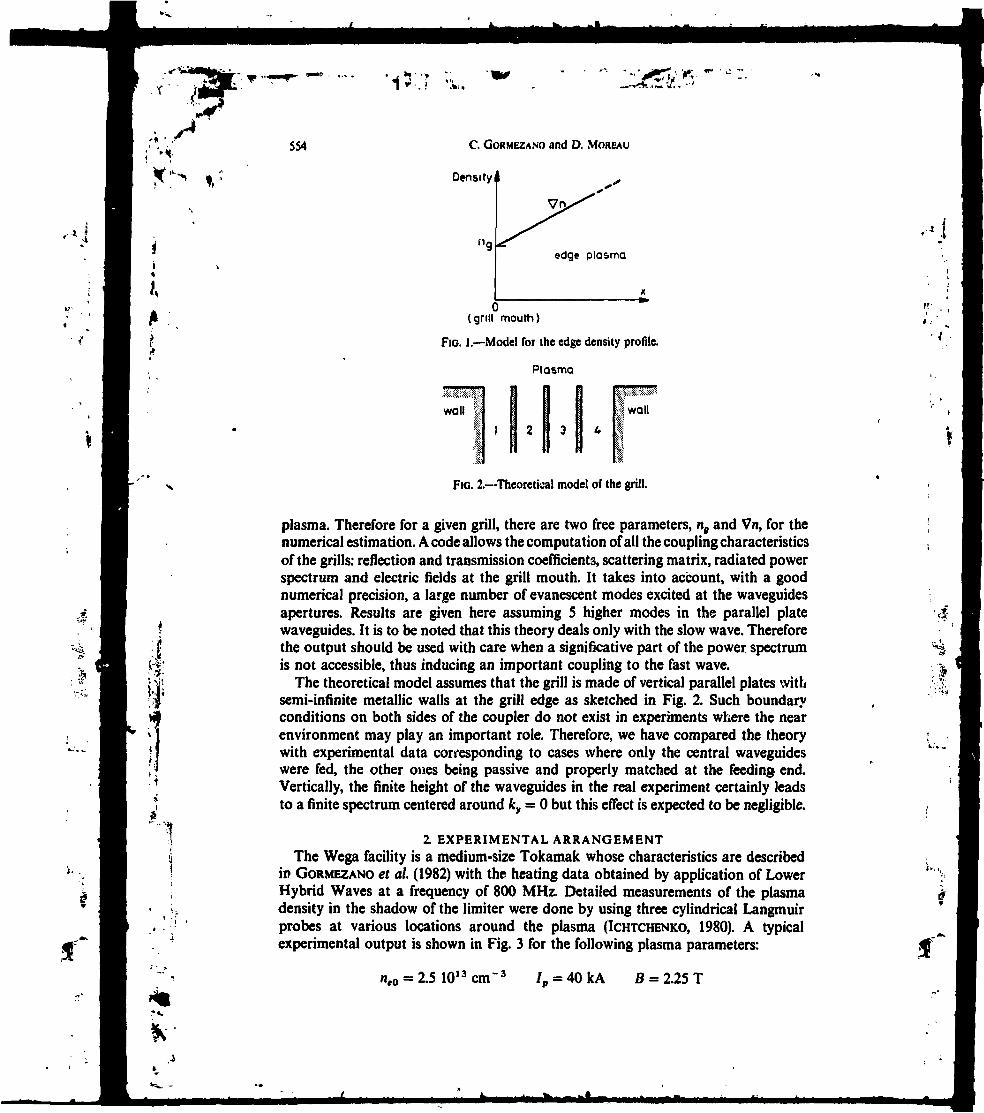
1
554 C. GORMEZANO and D. MOREAU
Density
(grill mouth)
FIG. 1.—Model for the edge density profile.
Plasma
; WOlIwall «
FIG. 2.—Theoretical model of the grill.
plasma. Therefore for a given grill, there are two free parameters, na and Vn, for thenumerical estimation. A code allows the computation of all the coupling characteristicsof the grills: reflection and transmission coefficients, scattering matrix, radiated powerspectrum and electric fields at the grill mouth. It takes into account, with a goodnumerical precision, a large number of evanescent modes excited at the waveguidesapertures. Results are given here assuming 5 higher modes in the parallel platewaveguides. It is to be noted that this theory deals only with the slow wave. Thereforethe output should be used with care when a significative part of the power spectrumis not accessible, thus inducing an important coupling to the fast wave.
The theoretical model assumes that the grill is made of vertical parallel plates withsemi-infinite metallic walls at the grill edge as sketched in Fig. 2. Such boundaryconditions on both sides of the coupler do not exist in experiments where the nearenvironment may play an important role. Therefore, we have compared the theorywith experimental data corresponding to cases where only the central waveguideswere fed, the other ones being passive and properly matched at the feeding* end.Vertically, the finite height of the waveguides in the real experiment certainly leadsto a finite spectrum centered around ky = O but this effect is expected to be negligible.
2. EXPERIMENTAL ARRANGEMENT
The Wega facility is a medium-size Tokamak whose characteristics are describedin GORMEZANO et al. (1982) with the heating data obtained by application of LowerHybrid Waves at a frequency of 800 MHz. Detailed measurements of the plasmadensity in the shadow of the limiter were done by using three cylindrical Langmuirprobes at various locations around the plasma (!CHTCHENKO, 1980). A typicalexperimental output is shown in Fig. 3 for the following plasma parameters:
= 2.5 1O13Cm'3 = 40kA B = 2.25 T
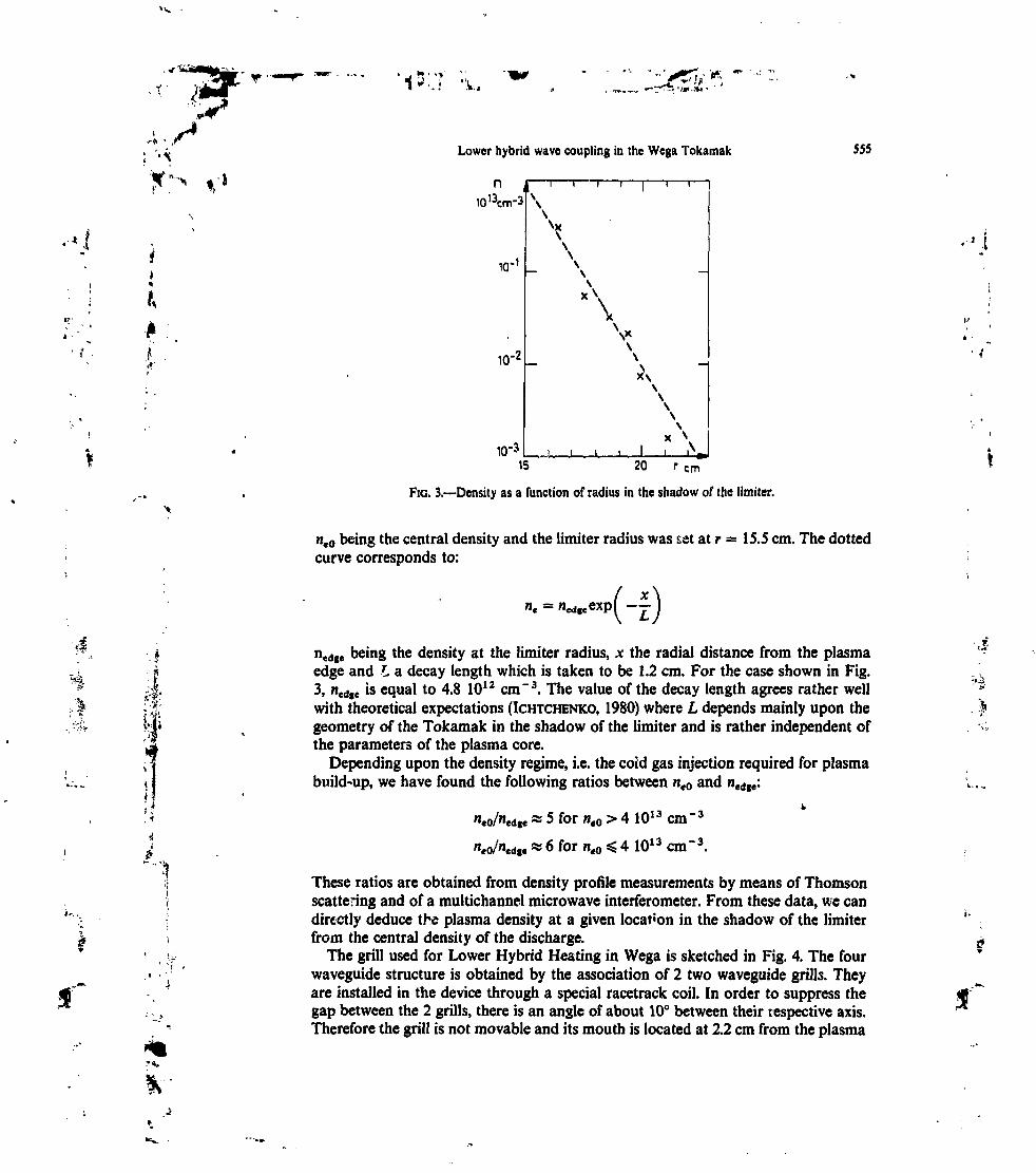
•W " " «:,1"',,' k.
À. /Lower hybrid wave coupling in the Wega Tokamak
IQ13Cm-S1
555
10-'
lu'2
I I I 1 I I 1 T I
\
\
x\
V\
1 . I
x\
I15 20 r cm
FIG. 3.—Density as a function or radius in the shadow of the limiter.
•a.
neQ being the central density and the limiter radius was s«t at r = 15.5 cm. The dottedcurve corresponds to:
nedfe being the density at the limiter radius, x the radial distance from the plasmaedge and L a decay length which is taken to be 1.2 cm. For the case shown in Fig.3, ned|e is equal to 4.8 1012 cm~3. The value of the decay length agrees rather wellwith theoretical expectations (!CHTCHENKO, 1980) where L depends mainly upon thegeometry of the Tokamak in the shadow of the limiter and is rather independent ofthe parameters of the plasma core.
Depending upon the density regime, i.e. the coid gas injection required for plasmabuild-up, we have found the following ratios between nt0 and ncd(e:
"*0/wed|e * 5 for «e0 > 4 1013 CHl
«eo/"edi« « 6 for ne0 4 1013 cm"3.
-3
-3
These ratios are obtained from density profile measurements by means of Thomsonscattering and of a multichannel microwave interferometer. From these data, we candirectly deduce the plasma density at a given location in the shadow of the limiterfrom the central density of the discharge.
The grill used for Lower Hybrid Heating in Wega is sketched in Fig. 4. The fourwaveguide structure is obtained by the association of 2 two waveguide grills. Theyare installed in the device through a special racetrack coil. In order to suppress thegap between the 2 grills, there is an angle of about 10° between their respective axis.Therefore the grill is not movable and its mouth is located at 2.2 cm from the plasma

'•
'# ' ;
J'
J *•> •» ",,,I"',.' *. *•
556 C. GORMEZANO and D. MOREAU
Glow discharge electrode
Electrical contort finger stocKs
I Bent reduced width waveguide
X Impedance transformer
m Vacuum window
UZ Transition waveguide
FIC. 4.—Sketch of the grill used in the Wega Tokamak.
10'/.
5V,
Spectral PowerDensity
-18 -12 -6 6 12 18N//
FIG. 5. — Spectral power density radiated into the plasma when the two central waveguides*are fed.
edge. The density ng in front of the grill is therefore varied by changing the centraldensity, ne0/ng being equal to 30 for ne0 < 4 1013 cm" 3 and to 36 for ne0 > 4 1013 cm" 3.
The power spectrum which is radiated into the plasma at x = O when the twocentral waveguides are fed with a phasing of n is shown in Fig. S. It is relativelyindependent of the plasma paiameters, well centered around N\\ =6, and is verysimilar to the spectrum obtained from the same theory when the whole grill is fed(GoRMEZANO et ai, 1982).
Reflection and transmission coefficients are measured by means of correlators andof crystal detectors located in the pressurized part of the waveguides close to thevacuum windows. The transmission coefficient is defined to be the ratio between thereflected r.f. power in one passive waveguide and the incident power in the adjacent
»,
'*
f

•yçï/w-'
Lower hybrid wave coupling in the Wega Tokamak 557
active waveguide. R. F. wave amplitudes are cross checked between the output of thecorrelators and of the crystal detectors. The absolute value of the phase shift ischecked by introducing a well known h.f. element in the circuit. The h.f. characteristicsof the grill were measured prior to the installation on the Tokamak, showing thatthe grill system does not introduce intrinsic reflection.
3. E X P E R I M E N T A L DATAUnexpectedly the experiments have shown a dissymmetry between reflection and
transmission coefficients of the different waveguides. On average on about 50 shots,we have:
Such a discrepancy can be explained by:— a dissymmetry in the neighbourhood of the grill;— a dissymmetry in the r.f. power;— a dissymmetry in the respective phases.
The last two dissymmetries can occur owing to the fact that the waveguides arefed by independent klystrons whose power and phases have to be adjusted in a
R2 ( PZ I PS =1. U14» =150*
«3 (PZ/ Pa = I. à n?R3(P2/P3*1.25,ÛM>aTT)
3'
FIC. 6.—Reflection coefficients vs density at the grill mouth; open circles are for experimentaldata; solid and dashed lines are for theoretical estimates.
ft 26.-3-E

C. GORMEZANO and D. MOREAU
f
î I I I^^r- T1 (P2 / P3 = I. A^-- H )
*"
10 15 Jr-T6
*****«,
+10 15
ne 10 "cm-3
FIG. 7.—Transmission coefficients vs density at the grill mouth; open circles are forexperimental data; solid and dashed lines are for theoretical estimates.
''' •-i .. "
-120_
-18015
ne101'cm-3
FIG. 8.—Phases of the reflected power vs density at the grill mouth; open circles and trianglesare for experimental data; solid and dashed lines are for theoretical estimates.
**'• Vr'"1
I-

-rtl
i" H
'**>
Lower hybrid wave coupling in the Wega Tokamak 559
lengthy process. In fact, the différence in r.f. incident power was not exceeding 25%but the phase shift between the two central waveguides was not exactly n but wasranging between 140° and 160°.
Experimental data for the reflection and transmission coefficients and the phasesof the reflection coefficients are shown in Figs. 6-8 in the case where the two centralwaveguides were fed with about 70 k W of r.f. power each. The dotted curves correspondto theoretical simulations with the following assumptions:
A0 = 71
= n= 150°.
(a) P2 = P3
(b) P2 = 1.25 P3
(c) P2 = P3
THe best fit seems to be obtained with case (c), the largest discrepancy beingobserved in one of the transmitted signals. This discrepancy can be due to the environ-ment of the grill mouth. Specifically the behaviour of the phase of the reflected poweragrees very well with theoretical estimations where a phasing of 150° is assumed.
Indeed, in case (c) the theoretical ratios between R2 and R3 and between T1 andT4. can vary respectively from 2.2 and 0.5 in the low density range to 1.3 and 0.7 inthe high density range. Such dissymmetries are close to the experimental observations.But the major change concerns the behaviour of the phase of the reflected wave. Inthe low density range, the phases vary in the opposite direction when the densityincreases. This is due to the fact that the reflected wave is determined by the complexsum of two waves with a phase shift of n when they almost cancel each other.Therefore, a minor change of that phase shift may induce a change of sign in thevariation of the complex phase of the reflected wave. A dissymmetry in the incidentr.f. power does not entail such changes in the behaviour of phases.
4. MODULATION OF THE EDGE DENSITYThe density at the grill mouth is not a measured density but is estimated. Therefore,
there is always a doubt upon the exact value of that density. We can alleviate someof the subsequent uncertainty by making use of certain plasma conditions where thedistance, xg, between the plasma edge and the grill mouth was modulated.
The plasma equilibrium in Wega was obtained by means of a feed-back amplifierwhich can oscillate if the amplifying factor is too high. This oscillation entails a verysmall oscillation Ax of the position of the plasma center. Since the plasma radius islimited by rail limiters located respectively above and below the plasma^the wholeplasma then oscillates in the horizontal position as shown by the multichannel micro-wave interferometer. The variation Ax of the plasma position is shown in Figs. 9 and10 together with the various r.f. signals for a given set of plasma parameters. Thedensity in front of the grill mouth increases when Ax increases, i.e. when the plasmamoves outwards. There is a very good synchronism between the variation of Ax andof the r.f signals. When Ax increases, R2, R3 and 3 increase while T1, T4, (J)2, ^1, 4decrease. This is in agreement with the conclusions we! get from the case where theplasma was at a fixed position and assuming that A$ was equal to 150°.
If we assume that:
" H)

'560
• J ?î ' 'VVv.' '•k-..
C. GORMEZANO and D. MOREAU
T1V. ;
Ole
FIG. 9.—Time variation of the reflection and transmission coefficients and of the plasmaposition (for n,0 =
3-2 10'3 cm~3).
C
1
we have:
Ax L'
Therefore the variation of the reflection coefficients can be written as:
An,LAJt,nt Ax~ (l = 2, 3).
Similar formulae can be obtained for the variation of the transmission coefficientsand of the phases.
ARf and Ax are deduced from the experimental data. If we assume that L - 1.2 cm,we can deduce ng if wo know ARJAn1 or vice versa. From Fig. 6, it appears thatARj/An8 does not depend upon the exact value of the density, at least in the highdensity range. Moreover this gradient is rather independent of the exact phasingbetween waveguides. Around ng - 1012 cm~3, ARJAn9 is equal to 1.1 (%, 10n cm~3).
We have reported in Table 1 the experimental data. Assuming the above value ofARJAn9, we obtain approximately the same density in front of each waveguide ofthe grill: 0.85 <«,<!.! (1012 cm" 3). Moreover such a value gives a ratio of nt0/nt = 32which is very close to the value we have taken in the preceding paragraph.
Jf'
V

•i^r
Lower hybrid wave coupling in the Wega Tokamak
TABLE 1
561
Waveguide n°
Afl,An%)
Ax (cm)
nf (10l2cm-3)
Waveguide w°
A4» (deg.)
A0/A'n, experiment (deg./10n cm'3)A4»/Ant theory (deg./10n cm'3)
1
-0.25
0.30.85
TABLE 2
2
2.9
0.31
1-3
-0.5
-0.4
3 4
2.3 -0.25
0.3 0.3
0.9 1.1
2 3
-6 8
-U 1.3
-1.8 2
4-6
-1
-0.8
Assuming nf = 1012 cm"3, we can deduce from the experimental values of thephases shown in Table 2, the phase gradient A0(/An0:
»/*•,) = -^- C - 1.1 3- •»).
We have indicated in Table 2 the theoretical values as deduced from Fig. 8 for» 150°. The agreement is rather good even though the accuracy of the measure-
ment of A&/AX is rather poor.
5. DISCUSSIONEarlier attempts of interpreting the experimental data from Wega with a linear
coupling theory, with the assumption that the plasma density at the waveguideapertures was equal to the cut-off density, have been reported (Et SHAER et ai, 1982).It turned out, however, that the main parameter which determined the coupling wasthe density facing the grill rather than its gradient in the edge plasma. It was thereforepointed out that such a theory should take into account, as a parameter, this specificdensity value which is relatively high with respect to the cut-off density.
We have shown above that this is indeed true, namely that Wega experiments wereperformed in the high density coupling regime in which the density gradient playslittle role (STEVENS et al., 1981; MOREAU et al., 1983). By assuming the existence of aso-called "density step" in front of the coupler, we have found a much better agreementbetween linear theory and experimental data, without invoicing large density gradients( « 1013 cm"4 over a few millimeters) as was done previously, e.g. (SCHUSS et al, 1981).
In order to show better evidence of the relevance of the "density step model" forinterpreting the Wega coupling data we shall now make two remarks:
(1) The first one concerns the consistency of the theory which was not respectedin previous interpretations when assuming that coupling was determined by a highgradient sheath between the antenna and the edge plasma. Namely, the analytictheory which was used requires that WKB approximation holds at the matchingregion where the gradient changes, i.e. for a density of about 1012 cm"3. In Wega,when two waveguides were fed, the average parallel index excited by the grill was< K H > %6 as shown on Fig. 5 and this corresponds to a perpendicular wavelength
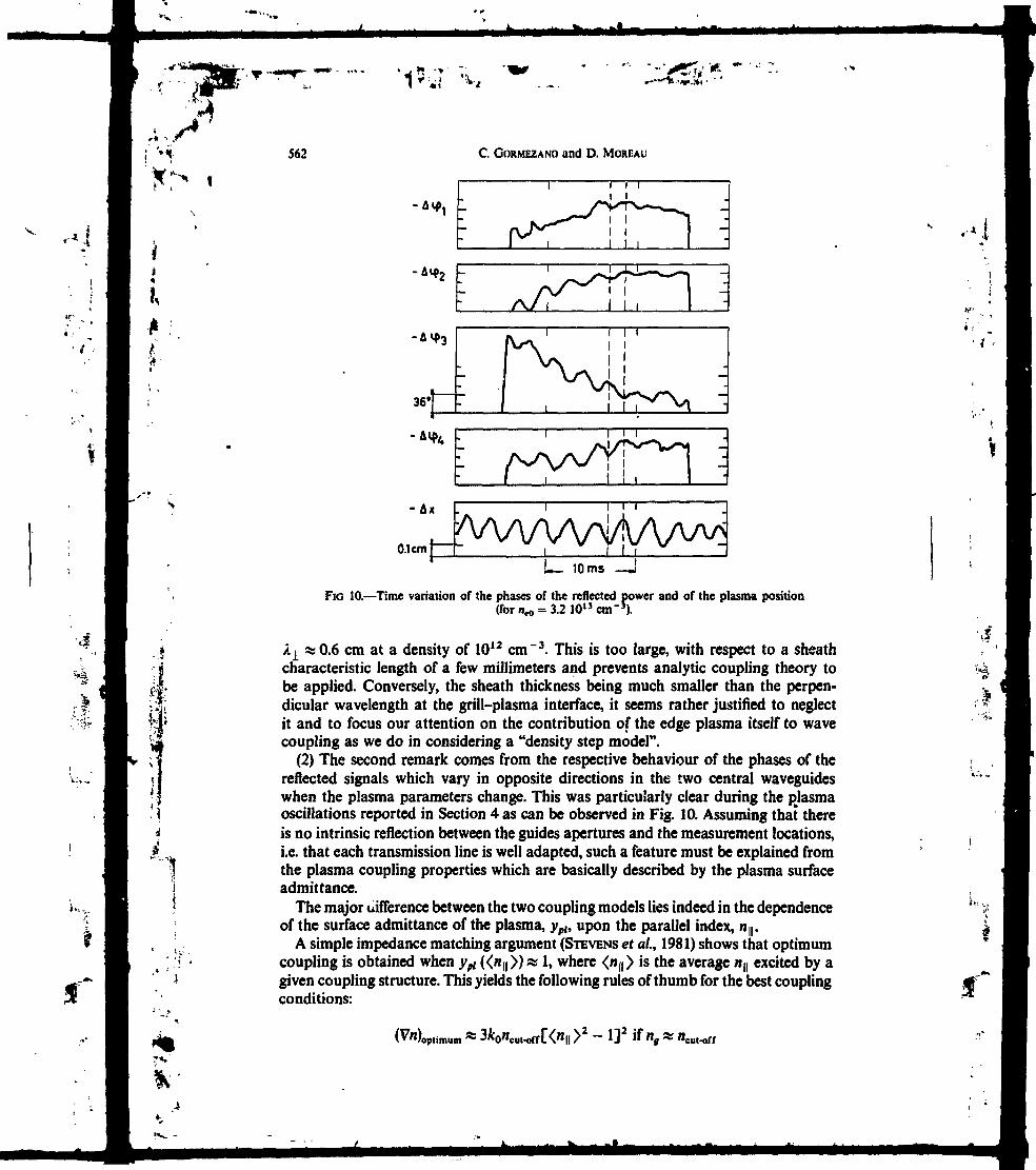
1 •.-—Tt '*•..»<
ti
1
562 C. GORMEZANO and D. MOREAU
-AVf 4
- A x
0.1cm I — }-L- 10ms
FIC 10. — Time variation of the phases of the reflected power and of the plasma position(for it*, = 3.2 1O13CTi-3).
A1 «0.6 cm at a density of 1012 cm"3. This is too large, with respect to a sheathcharacteristic length of a few millimeters and prevents analytic coupling theory tobe applied. Conversely, the sheath thickness being much smaller than the perpen-dicular wavelength at the grill-plasma interface, it seems rather justified to neglectit and to focus our attention on the contribution of the edge plasma itself to wavecoupling as we do in considering a "density step model".
(2) The second remark comes from the respective behaviour of the phases of thereflected signals which vary in opposite directions in the two central waveguideswhen the plasma parameters change. This was particularly clear during the plasmaoscillations reported in Section 4 as can be observed in Fig. 10. Assuming that thereis no intrinsic reflection between the guides apertures and the measurement locations,i.e. that each transmission line is well adapted, such a feature must be explained fromthe plasma coupling properties which are basically described by the plasma surfaceadmittance.
The major difference between the two coupling models lies indeed in the dependenceof the surface admittance of the plasma, yph upon the parallel index, n,,.
A simple impedance matching argument (STEVENS et al., 1981) shows that optimumcoupling is obtained when ypt ««u» » 1, where </i|(> is the average nn excited by agiven coupling structure. This yields the following rules of thumb for the best couplingconditions:
| >2 - I]2 if «, * «
U,,

xSLower hybrid wave coupling in the Wega Tokamak 563
or
«opiimum * "cut-ofK*1!! >2 »f «» "cui-off-
In Wega, we have: <HH > * 6.4,/0 = 800 MHz, nCM.off s 8.109 cm " 3 yielding optimumvalues Vn = 6.1012 cm~4 if we assume the cut-off model or ng « 3.1O11 cm"3 if weassume the density step model. Therefore, plots of the reflection coefficients versusthe appropriate parameter (Vn or ng) show similar behaviour in both models, namelya minimum of reflection around a particular value of the parameters. For this reasonit was possible to interpret the experimental data with the assumption of relativelyhigh density gradients at cut-off (EL SHAER et ai, 1982; SCHUSS et ai, 1981).
In contrast, the phases of the reflection coefficients may show quite differentbehaviours according to the assumed plasma surface admittance.
In the "overdense" limit, ypl is real positive and independent of the density gradientin the edge plasma. This indicates that there is no partial reflection in the plasmaitself but the reflection is produced very locally at the grill-plasma discontinuity. Thephase shift due to reflection is then either 0° (open circuit) when ypt > I i.e.Mg/Hcut-oir < n\ of 180° (short circuit type) when ng/nm^w>n\. The transition betweenthese two values occurs at a density where nt/ncat.o!fv <njj > and corresponds to aminimum of reflection due to a compensation between the different n(| valuescomposing the reflected Fourier wave spectrum. Therefore, as pointed out in Section3 (Fig. 8), the phases of the reflected signals in the transition region can be verysensitive upon the exact phases of the incident waves in each waveguide (OM 50° vs
!n the model where ng = nCM^K, ypl is complex with argument n/6. The reflectionis now an addition of partial reflections which take place in the whole gradient regionuntil the density is high enough. As a result, the reflection coefficient p (HH) does notswitch abruptly from real positive to real negative when n(| decreases. Instead, itsnegative argument varies very smoothly and all Fourier components are reflectedwith about the same negative phase shift, giving roughly the same shape to thereflected wave and to the incident wave. This reflected wave in turn decomposes itselfinto the different waveguides with about the same phase distribution as the incidentwave. In any case the relative phase of the reflected signals in the fed waveguidescannot be shifted by n as observed experimentally due to a small variation in thephasing of the incident waves. t
This feature which sounds rather subtle has been checked numerically. It is indeedfound that a small change of the phases in the fed waveguides (OMSO0 instead ofOM 80°) can lead to such a different behaviour in the phases of the reflected signalsonly if nt «cuM(r, i.e. in the case of coupling to an "overdense" plasma (MOREAUet al, 1983).
6. CONCLUSIONSThe theoretical model we have used to study the behaviour of the experimental
data of the Wega grill as a function of the density in front of the grill mouth isobviously simplified as compared to the real situation: finite poloidal extent of bothplasma and antenna, partial coupling of the wave to the fast wave. There are alsosome specific featues of the Wega grill which have not been taken into account: 2 x 2

*.r -w
564 C. GORMEZANO and D. MOREAU
waveguides, rounded edges, exact boundary conditions. Moreover, the exact valueof the plasma density and its gradient at the grill mouth were not measured butestimated from ad hoc relations between the edge density and the central density ofthe plasma discharge.
Nevertheless we have found excellent qualitative agreement between a linearcoupling theory, which is now rather elaborated, and the experimental observations.We also have strong indications of the relevance of the "density step model" fordescribing lower hybrid wave coupling. The quantitative agreement is also good,although there seem to be some discrepancies which may be related to the uncertaintyin the density estimates.
Anyway we want to emphasize that coupling measurements should be made withgreat care in the transition zone between high density and low density regimes ( ~ afew 10n cm~3). Edge plasma density measurements should also be available for thephysics of lower hybrid wave coupling to be fully understood.
Finally, it is to be noted that the experiments presented here were performed withabout 70 kW incident r.f. power in each waveguide so that agreement with theory isa proof, or at least a strong presumption, that there was no breakdown in thewaveguides. Furthermore, we can state that nonlinear effects were not too importantat this power level (1.4 kW cm~2), as far as coupling is concerned, although theymay have modified the plasma density in front of the antenna due to ponderomotiveeffects.
„••»
Acknowledgements—It is a pleasure to acknowledge T. K. N'GuYEN whose help was essential for settingup the theoretical simulation. The whole Wega team is also warmly acknowledged, especially G. W.PACKER who has made the plasma available and G. ICHTCHENKO and H. D. PACKER for the installationand the interpretation of the h.f. measurements and of the edge density diagnostic.
REFERENCESBRAMBILLA M. (1976) Nucl. Fusion 16,47.BRAMBILLA M. (1978) Nucl. Fusion 18,493.EL SHAER M. et ai (1982) In Proceedings of the 3rd Joint Varenna-Grenoble International Symposium on
Heating in Toroidal Plasmas, Grenoble, Vol. II, p. 571.GORMEZANO C. et al. (1982) In Proceedings of the 3rd Joint Varenna-Grenoble International Symposium on
Heating in Toroidal Plasmas, Grenoble, Vol. II, p. 439.ICHTCHENKO G. (1980), Report EUR-CEA-FC 1041.MOREAU D. and N'GUYEN T. K. (1984) Report EUR-CEA-FC in print.MOREAU D. et al. (1983) Spring College on Radiation in Plasmas, Trieste, Italy; Report EUR-CEA-FC 1199.SCHUSS J. J. et al. (1981) Nucl. Fusion 21,427.STEVENS J. et al. (1981) Nucl. Fusion 21,12S9.

•1
LOWER-HYBRID PLASMA HEATING VIA A NEW LAUNCHERTHE MULTIJUNCTION GRILL
C. GORMEZANO1 P. BRlAND, G. BRIFFOD, G.T. HOANG1-T.K.N'GUYEN, D. MOREAU, G. RAYAssociation EURATOM-CEA1Département de recherches sur la fusion contrôlée,Centre d'études nucléaires de Grenoble,Service d'ionique générale,Grenoble, France
ABSTRACT. A MW multifunction iriU-typt launcher lui b««n teited on thé Petula-B tokunak. In thisnew launcher, thé RF power il divided by meant of an E-plane junction, and the phaat between eachresultant wave U obtained by a suitable reduction in the height of the waveguide*. Data obtained onPetuIa-B indicate that both the heating efficiency (4.5 eV X 10" cm** -kW) and the parametric depen-dences of the reflection coefficient an very similar to those of a conventional frill. Therefore, such amultijunction grill may greatly simplify the construction of grills considered for UM in future large-scaletokamaks.
K-I ; '
;l.
•«ft1
1. INTRODUCTION
The phased waveguide array (i.e. the grill) [1 ] isthe most promising antenna for launching lowerhybrid waves to heat toroidal plasmas and to drivecurrent. Such systems have already proven to beeffective in present tokamaks [2-4]. In the conven-tional grill, the appropriate N| spectrum is launchedinto the plasma by a set of juxtaposed waveguides,each waveguide being phased independently. To date,RF powers in the megawatt range have been launchedby means of grills containing up to eight waveguidesin. a row [4] and up to a network of 4 X 4 waveguides[S]. Multimegawatt experiments are now being con-sidered for future large devices, such as JT-60 [6],TS [7] and FTU [8]. Since the transmitted powerdensity ranges from 2 kVY-cm*2 at f = 1.3 GHz to6-IO kW-cnf2 at f = 4.6 GHz [9], the launchersconsidered for the future will need to contain hundredsof waveguides, leading to very cumbersome RF systems.In order to alleviate the constraints of such launchers,it has been proposed [10] to use a new type of grill,the multijunction grill. In this concept, an E-planejunction is used as a power divider, and phase shiftersare inserted in the reduced sections in order to shapethe phasing therein, allowing the proper Nj sfectrumto be launched.
In order to assess the validity of this concept, acomparison has been made in the Petula-B tokamak(R = 72 cm, a = 16-18 cm, Ip < 200 kA, BT a 2.8 T,
NUCUAK rONOK. VtLIt. N»4<IMS)
f = 1.3 GHz) between a multijunction grill and a four-waveguide grill. Owing to the fact that the ion heatingmode with lower hybrid waves is more sensitive to theshape of the spectrum of the launched wave than thecurrent-drive regime [11], this comparison has beenperformed for the ion heating regime, i.e. with aphasing of * between adjacent waveguides.
2. DESCRIPTIONOFTHEMULTIJUNCTIONGRILL
As shown in Fig.l, a multijunction grill is obtainedby dividing the main waveguide, in the evacuated areaof the grill, into a given number (N) of secondary wave-guides by means of metallic walls that are parallel tothe main waveguide wall. The ir-phasing in the multi-junction antenna is made by geometrically increasingthe wavelength in the corresponding waveguides. This
.S1S:
mamWQWQUfOt
I1 1 » I3
* l . I
v[»T.T-
*lp»T«.T
E
Jp ptavno
Pj PQ
FIG. 1. Conceptual drtwing of» multifunction pitt.
419

t. < -y -, r . - i 1I
GORMEZANO tt al.
H pion* ironstornwr H pkmt iianstarnwr
FIG.2. Section of a secondary waveguide where a phasingof TT u made Ia - 13.5 cm, b = 14.$ cm, C = 16.5 cm).
is done by reducing the height of the waveguides, asshown in Fig.2. Step transformers at each end of thereduced-height sections allow a good matching to beobtained.
The output of a two-dimensional numerical studyof the theory of a multijunction grill [12] can besummarized as follows:
(a) The RF power is equally divided betweensecondary waveguides and is approximatelyequal to (b/b0 ) PRF, where b0 is the main wave-guide width, b is the secondary waveguide width,and PRF is the incident power in the mainwaveguide.
(b) The total reflection coefficient R is small and isgiven by
R3 | (N- l )e /2b 0 ] J
where e is the thickness of the wall.
(c) The wave reflections between the grill mouth andthe E-junction plane allow a self-adaptation whenthe travelling waves are. excited with an adequatephasing between the secondary waveguides. Thislast property cannot be verified with the O, TT, O, itmultijunction grill used in Petula-B.
The total reflection coefficient of the multijuncliongrill is plotted in Fig.3 as a function of the RF power,for plasma conditions which are optimized for ionheating. The respective behaviour of the reflectioncoefficient is very similar for both grills, with themultijunction grill tending to have slightly highervalues. Part of this discrepancy may be due to a dif-ference in the plasma density at the grill mouth sincethe multijunction grill is located closer to the limiterthan the conventional grill. Both grills are, however,at the same radius (4 cm from the plasma edge). Whenthe radial position of the multijunction grill is varied,the reflection coefficient decreases when the grill iscloser to the plasma, as also observed for the conven-tional grill [14). The distance of 4 cm is a compromisebetween impurity production and power couplingefficiency. In the ion heating regime, metallic impuri-ties are produced by fast ions located on large-radiusbanana orbits which may strike the grill mouth if thegrill is too close to the plasma edge.
An RF power of up to 250 kW has been launchedinto the torus via the multijunction grill and an RFpower of 350 kW has been launched via the conven-tional grill. For higher RF power, RF breakdownoccurs. For the multijunction grill, this breakdown islikely to be located in the reduced-height sections ofthe secondary waveguides where higher E-fields exist:this is due to
- the fact that the cut-off wavelength is very close tothe vacuum wavelength (such an effect can bereduced by using a higher height both in the tapersection and in the standard section)
- the reduced area of the taper section, which furtherenhances the HF-fields.
.-I
A 1.4 m long grill has been fabricated by dividing astandard waveguide into four secondary waveguides.The vertical walls of the 1 m long reduced-heightsections are 2 mm thick, allowing the geometricalperiodicity of the antenna (2.1 cm) to be identicalwith that of the conventional grill, which has its N|spectrum centred at Nj = 5.2 for a phasing of it. Thetotal area of the grill mouth facing the plasma is140cm*.
Low-level RF tests have shown a slight difference(less than 0.5 Ib) between the RF powers injected intoeach of the secondary waveguides and a resultingphasing of O0,+185°, -20°, +185° [13]. RF condi-tioning is obtained via low-pressure argon glowdischarges.
420
Rt1M
20
zoo 300 iOO
FlC.3. Total reflection coefficient vertus incident RF powerfor the multifunction frill and the conventional trill(lf = JSO kA.Hf = 5.5 X ;013 cm'3l.
NUCLEAR FUSION. VoLlS. No.4 (IMS)
Ir

5ft'*1
-•* -, :
' 4
TMtVl
O I «i-ino
FlG. 4. Time behaviour of the bulk ion temperature obtainedfrom parallel charge-exchange analysis and time behaviour ofthe neutron yield (lf = ISS M,n, = S.8X I0a cm'*. O1plasma, multifunction frill/.
Furthermore, the intercoupling between differentwaveguides, due to an asymmetry in the plasma environ-ment at the grill mouth, results in an enhanced electricfield in one secondary waveguide. From HF loop data,E-fields of up to 4.6 kV-cm"1 have been estimated inthe reduced-height section.
3. HEATINGRESULTS
Heating of the bulk ion population with the multi-junction grill has been studied using the same plasmatarget as for the conventional grill. For the multi-junction grill, the time behaviour of the bulk iontemperature obtained from parallel charge-exchangeanalysis and the time behaviour of the neutron yieldare as outlined in Fig.4. The ion temperature rises from4SO eV to 630 eV within IS ms and then stays constantfor 30 ms, up to the end of the RF pulse. The decaytime, 7 ms, is comparable to the ion energy confinementtime.
The power and density dependences for the twogrills are compared in Figs 5 and 6. The dependencesobtained are very similar. From these data, it may beconcluded that the ion heating efficiency, which is inthe range of 4.5 eV X 10" cm"3 -kW, is comparablefor the multijunction grill and the conventional grill.It may also be concluded that the launched spectra arevery similar, since the density dependence of the ionheating is very sensitive to the shape of the spectrumof the launched wave [U].
NUCUCAIt FUSION. VoLU, N«.4 <1*M)
MULTlJUNCTlON GRILL
The parallel spectrum or the wave launched by agrill is usually estimated by computing the theoreticalamplitudes and phases of (he incident H-fields. Wehave tried to better estimate this spectrum by takinginto account the experimental amplitudes and phasesof the HF electric field at the grill mouth. Thesevalues are deduced from measurements at HF probeslocated 8 cm from the grill mouth, assuming that theHF field propagation is not modified by parasiticplasma effects into the waveguide. Following grilltheory [ 1 ], the fraction of the power emitted betweenN| and N| + ANi is given by:
, N N N
IZ 1 ^ + Z Z 'Vpl IV«I(COS(P " q) N|k°*
f q
(D
where Yp](N|) is the edge-plasma surface admittance[IS], k0 is the free-space wavenumber, and I Vp l ,I VqI, p and I4 are the amplitudes and phases of thetotal electric voltages at the p-th and q-th waveguideapertures, respectively. The Petula edge-plasmaelectron density, no, measured by microwave inter-ferometry [16], is much larger than the edge-plasma
*T, (tV)
100.
no
• IWU CMqi MMn(Ia <nm niwnn nut
t •
FIG.S. Bulk ion heating at a function of the transmitted power,for the multijunction grin and the conventional grill (Dt pUuma,/p = 14OkA. S.S<nt<S.8X 10a cm'3).
421

-^.:.>
(
i,
' «1 * ' 'T" ~'i,
V«{ <*t
GORMEZANO tt «I.
AT, UV)
SOO
I I I
aa a
• nuKIJgnnltn grl .
F/C. 5. fluffc fon heatint at « /unction of tht lint-overatedensity, for the multifunction grill and tht conventional pill(Dt platma. /p = 740 kA, P»F = 250 kWj.
cut-off density, nco, allowing the following approxi-mation for the plasma surface admittance (IS]:
(2)
where Y0 = V6O/Mo is the free-space wave admittance.This approximation is valid when the plasma surfaceadmittance is not too high, i.e. when N| £ 2.
From relations (1) and (2) and using the experi-mentally estimated values of I Vp), I Vql, <fp and ^4,the N| spectra calculated for the multijunction grilland for the conventional grill are as shown in Fig. 7;the spectral power density is normalized to the totalpower integrated for N| values lying between theaccessibility and infinity. When comparing the spectraof the conventional grill and the multijunction grill,it can be noted that for the multijunction grill thereis more power on the positive side of the spectrumthan on the negative side, owing to differences in theelectric field amplitudes. However, the N| powerdensity integrated between N, = 4 and N1 = 7, whereoptimum coupling to the ion population is expectedto occur, is comparable for the three cases shown inFig.7, namely 39% for the conventional grill, and 28%and 30% for the multijunction grill (P = 25 kW andP = I l O kW). More detailed measurements are stillrequired in order to assess the modifications of thespectrum with different RF powers and plasmaparameters.
It has been shown [11,17] that the maximum valueof the wave index can be deduced from the startingenergy of the perpendicular fast-ion tail created by
422
the HF field, The perpendicular charge-exchangespectrum obtained with the multijunction grill isshown in Fig.8, with a value of 1.9 keV for the startingenergy of the fast-ion tail. The upper value of theperpendicular index of the wave at the linear turningpoint is given by: -•I
A?'*(3)
According to the usual wave propagation equation, thecorresponding maximum value of the N j spectrum isgiven by:
1/2(4)
(keV, GHz, T)
with
ions
Using the corresponding plasma parameters of Petula-B,Nim«x =70° and N|max= 8.3 are obtained. This valueis in good agreement with the estimated maximumvalue of the launched N( spectra shown in Fig.7.
FIG. 7. Computed Nt tptctn for two vtluu <,., tht transmittedpower of the multijunction frill, ttkint into account experi-mental metturtmtnti of the E-fleld.
Convention* pill (P = ISO kW). multifunctionpill ff - 25 kWI, multifunction FOKf=IlO JtW).
NUCLEAR FUSION. VatJS. Mo.4 (IMS)
•c
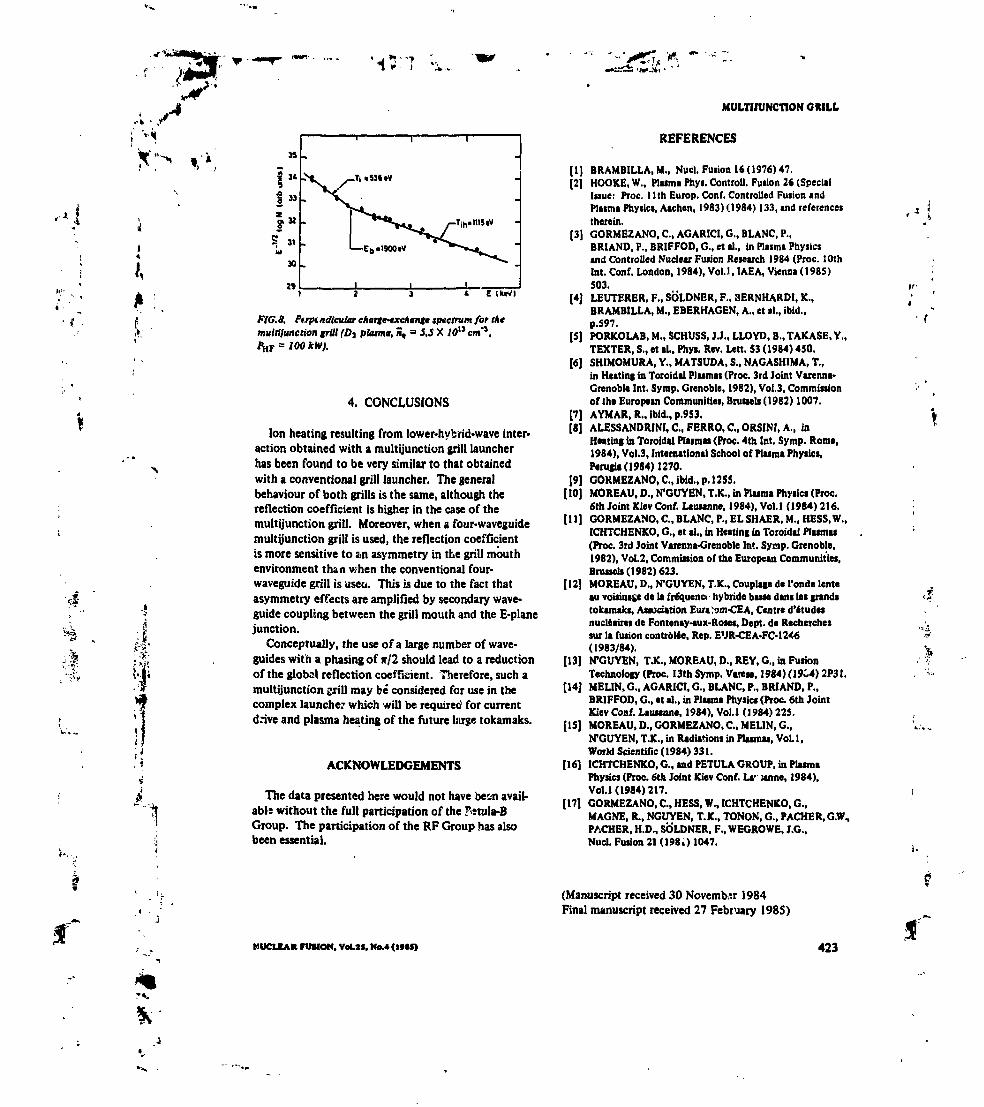
' " .ï-I
, -4
.*•..-,«•'. i
ai
1
it•»;
•4-
Î "1»Î»
S 3«w
M
29
Tih.ms«v
E (Un1I
FIG.S. Pirpiadicular charfe-txchantt spectrum for themultifunction frill (Dt plaima, n, = J.5 X JO11 cm'*,
4. CONCLUSIONS
Ion heating resulting from lower-hybrid-wave inter-action obtained with a multifunction grill launcherhas been found to be very similar to that obtainedwith a conventional grill launcher. The generalbehaviour of both grills is the same, although thereflection coefficient is higher in the case of themultijunction grill. Moreover, when a four-waveguidemultijunction grill is used, the reflection coefficientis more sensitive to an asymmetry in the grill mouthenvironment than when the conventional four-waveguide grill is useu. This is due to the fact thatasymmetry effects are amplified by secondary wave-guide coupling between the grill mouth and the E-planejunction.
Conceptually, the use of a large number of wave-guides with a phasing of */2 should lead to a reductionof the global reflection coefficient. Therefore, such amultijunction grill may be' considered for use in thecomplex launcher which will be required for currentdrive and plasma heating of the future large tokamaks.
ACKNOWLEDGEMENTS
The data presented here would not have been avaitable without the full participation of the fîtula-BGroup. The participation of the RP Group has alsobeen essential.
MULTIIUNCTION GMLL
REFERENCES
[1] BRAMBILLA1M., Nucl. Fuiion 16(1976)47.(2] HOOKE, W., Plumi Phyi. Controll. Fuiion 26 (Special
Isjue: PTOC, 11th Euiop. Conf. Controlled Fusion «ndPlumi Physic*, Aachen, 1983) (1984) 133, and referencestherein.
(3) GORMEZANO, C., AGARICI, G., BLANC, P.,BRIAND, P., BRIFFOD, G., et al., in Plasma Physicsand Controlled Nuclear Fusion Research 1984 (Proc. 10thInt. Conf. London, 1984), Vol.1, IAEA, Vienna (1985)503.
(4) LEUTEXER, F., SOLDNER, F., 3ERNHARDI, K.,BRAMBILLA, M., EBERHAGEN, A., et al., ibid.,p.597.
[S] PORKOLAB, M., SCHUSS, J.J., LLOYD, B., TAKASE. Y.,TEXTER, S., et al., Phyi. Rev. Lett. SJ (1984) 450.
[6] SHIMOMURA, Y., MATSUDA, S., NAGASHIMA, T.,in Heating in Toroidal Plasmas (Proc. 3rd Joint Varenna-Grenoble Int. Symp. Grenoble, 1982), Vol.3, Commissionof tht European Communities, Brussels (1982) 1007.
[7] AYMAR, R., ibid., p.953.[8] ALESSANDRINI, C., FERRO, C, ORSINI, A., in
Heating in Toroidal Plasmas (Proc. 4th Int. Symp. Rome,1984), Vol.3, International School of Plasma Physics,Perugia (1984) 1270.
[9] GOKMEZANO, C, ibid., p. 1255.( 10] MOREAU, D., N1GUYEN, T.K., in Plasm* Physics (Proc.
6th Joint Kiev Conf. Lausanne, 1984), Vol.1 (1984) 216.[11] GORMEZANO, C, BLANC, P., EL SHAER, M., HESS, W.,
ICHTCHENKO, G., et al., in Heating in Toroidal Plasmas(Proc. 3rd Joint Varenna-Grenoble Int. Symp. Grenoble,1982), Vol.2, Commission of the European Communities,Bruneli (1982) 623.
[12] MOREAU, D., N'GUYEN, T.K., Couplage de l'onde lenteau voisinage de la fréquence hybride basse dans les grand*tokamaks, Association Eur*:om-CEA, Centre d'étude*nucléaires de Fontenay-aux-Roses, Dept. de Recherchessur la fusion contrôlée, Rep. EUR-CEA-FC-12*6(1983/84).
[13] N1GUYEN, TX, MOREAU, D., REY, G., in FusionTechnology (Proc. 13th Symp. Van**, 1984)(19C4) 2P3I.
[14] MELIN, G., AGARICI, G., BLANC, P., BRIAND, P.,BRIFFOD, G., et al., in Plasma Physics (Proc. 6th JointKiev Conf. Lausanne, 1984), Vol.l (1984) 225.
[15] MOREAU, D., GORMEZANO, C., MELIN, G.,N'GUYEN, T.K., in Radiations in Plasmas, Vol.l,World Scientific ( 1984) 331.
[ 16] ICHTCHENKO, G., and PETULA GROUP, in PlasmaPhysics (Proc. 6th Joint Kiev Conf. La- itnne, 1984),VoU (1984) 217.
[17] GORMEZANO, C., HESS, W., ICHTCHENKO, G.,MAGNE, R., NGUYEN, T. K., TONOK, G., PACKER, G.W.,FACHER, H.D., SOLDNER, F., WEGROWE, J.G.,Nucl. Fusion 21 (1980 1047.
' t
NUCLEAR FUSION. VoLlS. Ho.4 (IMf)
(Manuscript received 30 November 1984Final manuscript received 27 February 198S)
423

1 '•< COUPLING OF SLOW WAVESNEAR THE LOWER HYBRID FREQUENCY IN JET
X. UTAUDON*. D. MOREAU**JET Joint Undertaking,Abingdon, Oxfordshire,United Kingdom
,'.i
ABSTRACT. The physical properties of the IET lower hybrid antenna hive been investigated numerically with •two-dimensional computer code bued on the linear couplinf theory. The antenna is made from an array of multijunctkwunits which divide the incident power along (he toroidal direction. The main properties of this new coupler areinvestigated and compared with tboae of toe conventional grills generally wed in previous tower hybrid experiments.In the light of this study, the general design of the multijunction antenna is presented; the importance of the geometricalparameters of the multijunction unit (e.g. choice of the location of the E-plane junctions, septum width betweenwaveguide*) is stressed. These parameters are «pîmbaH «nd their values are taken into account in launcher manu-facturing. With such an optimization, the electric field enhancement in each secondary waveguide is minimized for andeem» density at the launcher of atxnt 10" m"\ the power reflection coefflefeat It below 1.3% and the 'n(-wei|h«edantenna directivity' it expected to Ue between 60% and 70% in a large range of plasma densities around the optimumdensity. By using two shorted passive waveguide* on each side of the antenna, the edge effects are reduced. The effectof the accessibility limit on coupling is also inveetigaud.
J
Ui
1. INTRODUCTION
To interpret and predict the results of lower hybridcurrent drive (LHCD) experiments in present or futuretokamaks, one needs a complete description of threephysical processes: coupling from an external antenna(phased waveguide arrays), propagation of the launchedspectnun towards the absorption region, and efficiencyof the absorption process in terms of generated currentper absorbed power. The main objective of the LHCDexperiments in JET is to stabilize the internal disruptions(sawteeth oscillations) by controlling in a non-inductiveway the shape of the current profile [1> 2). For thispurpose, up to 10 MW of radiofrequency (RF) powerlaunched with an asymmetric parallel wavenumber (ni)power spectrum will be coupled to the JET plasma at afrequency of 3.7 GHz, which is well above the coldlower hybrid frequency.
For such experiments, great attention will be paid tothe radiated spectrum since it determines the major
* Present address: Dfpanemeat de recherche* sur la fusioncontrôlée, Association Eunton-CEA, Centre d'Aude*nucléaires de Cadanc* . F-UlOt Saint-Paul-lez-DuranceCedex, France.
•• Under assignment from Association Euratom-CEA, Centred'études nucléaire* de Cadanche, F-13108 Saiot-PtuMei-Duraace Cedex, France.
MlCLEAIl FUSION. VXJO, H..3 (It(O)
characteristics of the power deposition and the drivencurrent. Also, it has been shown that the efficiency ofthe process increases when the width of the n( spectrumis reduced [3]. Moreover, to avoid deleterious effects,such as ionization of neutral gas and RF breakdown inthe waveguides or non-linear effects induced at thegrill mouth (ponderomotive forces or parametric decayof the waves), the power density must be maintainedbelow 5 kW'cm"2. Both considerations require the useof a large number of waveguides to divide the incidentpower, in either the toroidal or the poloidal directions.When extrapolating the concept of the conventional grill(array of independent waveguides) to experiments ofthe size of JET, an antenna design of great complexityresults. For instance, a large number of vacuumwindows are required — a critical element in thetransmission lines. A proposed attractive simplifi-cation of the antenna is to use E-plane waveguidejunctions as power dividers in the toroidal direction incombination with fixed differential phase shifters. Suchcompact antennas have already been tested on PETULA[4] and, more recently, on TORE SUPRA [S] andJT-60 [6], and encouraging r suits have been reported.
The design of the JET lower hybrid wave launcherwas guided by theoretical coupling studies and numericalsimulations whenever their results were compatible withtechnical considerations. Our aim has been to keep the
471

'1^r .'*«•
UTAUDON Md MOREAU
Plasma currant
Upilrtam sida Oownitraim *Wa
Modufa Numbar S 7 « 5 4 3 2 1Prograasiva Phasing: TS* 66* 56* «M> 3M> 2N> N> O
-90* * Jl* « 90*1.38 <n, (part) «2.29
F/C. A Theoretical model of the JET antenna (top view).
••-i.
power reflected towards the RF sources (klystrons) aslow as possible (of the order of a few per cent) and atthe same time to maximize the power coupled to a well-defined travelling wave along the toroidal direction ofthe electron drift. On the basis of the 2-D linearcoupling theory and using the numerical code SWAN[7], which takes into account the microwave charac-teristics of the E-plane junctions, we have been able topredict the coupling properties of the antenna and tooptimize its design. The 2-D linear coupling theorywas checked previously and good agreement was foundwith the experimental results in past lower hybridexperiments performed with conventional grills [8-12].
General considerations regarding the definition ofthe E-plane multijunction units are given in Section 2.In Section 3, the geometrical parameters of the JETantenna are optimized and the importance of the loca-tions of the E-plane junctions is discussed. Section 4treats of the adjunction of two shorted passive wave-guides on each side of a toroidal row of the waveguideswhich is used to minimize the undesirable edge effects.In Section 5, the effect of accessibility limits on thecoupling at high density and low magnetic field isdiscussed and the range of edge plasma parametersand magnetic field at which the wave can be launchedis given. Section 6 gives conclusions.
2. E-PLANE MULTUUNCTION
A multijunction grill is obtained by dividing themain wavegukle into a given number N of secondarywaveguides. The phasing required to perform currentdrive experiments is obtained by geometrically increasingthe wavelength in the secondary waveguides, i.e. by
472
reducing their height. A drawback of such a systemis a loss of flexibility in the radiated spectrum since itoperates at a fixed phase shift (^0). To overcome thislimitation, the JET launcher consists of a set of eightjuxtaposed multijunction units along the toroidal direc-tion (Fig. 1). By changing the phase difference 6tf>between the single units, one can vary the parallelwave number at the peak value of the launched spectrumaccording to the following analytical relation [13]:
nlp-k =
where UM is the nominal wave number of each N-waveguide multijunction unit. In the case of JET,where nK » 1.84, N » 4 and 4o » 90°, ni can varybetween 1.4 and 2.3 if the phase difference &4> isallowed to vary between -90° and +90°. The smallnumber of waveguides in each multijunction unit (N » 4)allows a Urge variation of n(pMk. In the followingsections we calculate the parameters for the antenna sothat the required flexibility is obtained while preservingthe optimum behaviour of the antenna.
Considering only the fundamental mode in eachwaveguide and neglecting the edge effects, one canobtain some simple analytical results to describe themultijunction unit. The first assumption is well justifiedwhen the thickness of the walls (d) of the E-planejunctions is small compared with the internal width (b)of the secondary waveguides, i.e. when the transparencyof the multijunction is high. As an introduction to thegeneral design of the JET launcher, we first review themain properties of the multijunction grill [14].
IWCUM FUSION. VH.30. N..3 (I*N)

,«i
'1
2.1. Intrinsic properties of the multUuncttons
When the secondary waveguides are terminated byperfect loads, the intrinsic voltage reflection coeffi-cient s of the multifunction is directly related withthe geometrical transparency, t - Nb/a, of thejunction plane, where a is the internal width of themain waveguide. The coefficient is given by:
COVPUNG OF SLOW WAVES IN JET
Right and toftEspial» Junction»
i w/2
.0\*I2
\1*I2
Fir* E-pl«n« junction
FIG. 2. Schematic droving of one of the eifia juxtaposedmuhijunction units.
and can be made adequately small «0.1) by choosingthe width of the dividing walls as small as possible. Inany case, phase compensation between the reflectedfields at various discontinuities can be used to furtherreduce this intrinsic reflection. With this aim and alsofor achieving a more symmetrical power division, theJET multijunction unit utilizes a set of three E-planebijunctions (Fig. 2).
Simple considerations based on the geometricalsymmetry of the multijunction unit show that the sumof the waves reflected from the two walls of the secondbijunctions of length I1 is cancelled at the plane of thefirst junction when the difference Af - J2 - *i cor-responds to an electrical length of 90°. Consequently,only the reflection from the first E-plane junctionremains.
As far as the symmetry is concerned, the completeelectromagnetic calculations snow that because ofevanescent modes, parasitic effects such as unevenpower division would occur if the main waveguidewere divided into more that two secondary waveguidesin a single plane. In the JET launcher, the incidentfield from the main waveguide is equally divided inpower and phase among all the secondary waveguidesby using a series of bijunctions.
2.2. Self-adaptation property of the plasmaloaded multfytinction antenna
If we assume that the multijunction antenna facesthe plasma, then, as a consequence of a strong cross-coupling between the secondary waveguides, multiplereflections of the incident wave between the plasmaand the E-plane junctions can lake place. However,since the plasma load almost matches the antenna, thewave is strong/ atxnuated at each pass an4 no cavityresonarw can take place. It is precisely this goodintrinsic matching of the plasma to tower hybrid waveswhich makes the multijunction concept attractive. The
NUCLBA* FUKM. VtUO. N»J (HHI
wave is then reflected back into the main waveguideafter n forward passages through the phase shifters,provided that
NJJ exp(2jnp*o) - NP-I
The global voltage reflection coefficient is given by
r - J j oc»-)m-l
with PI, PI ... p. being the plasma voltage reflectioncoefficients corresponding to the different paths of thewave through the multijunction. This self-adaptationproperty of the muldjunction grill leads to a reductionof the reflected field in the main waveguide and maypermit operation without circulators [S], which are verycostly RF elements. This is obtained at the expense ofan increase of the total electric field in the secondarywaveguides, which requires particular attention in thelauncher design.
A thorough study [TJ has shown that, among thevarious choices for the phase difference between thesecondary waveguides ( 0), <fo * */2 is a goodcompromise. For example, the choice of <fc> » T/3would lead to a tower reflection coefficient and betterdirectivity, but, at the frequency used in JET and forUM « 2, a too small value for the internal width ofthe secondary waveguides would be required. Anotheradvantage of using an assembly of bijunctions is thatmultireflections are limited to the 90° phase shiftersof the secondary waveguides.
3. OPTIMIZATIONOF THE GEOMETRICAL PARAMETERS
OF THE JET ANTENNA
We now discuss the optimization of the multijunctionantenna on the basis of the 2-D linear theory; this
473
; ,*.. '-1Ay
r
f

• > ••"• j »»-. -
H « ? . . »
£r-
»-..
LITAUDON MMl MOREAU
3.Oi
2.0
1.0
™ 1cm
«4 « O n. - 1.MR-0.4% S00-67%
1st trip
2nd trip<n.-1.84)
0.0- 8 - 6 - 4 - 2 O 2 4 0 B
FlO. 3. Characteristic peaks of the radiated spectrum.
optimization can be achieved with a proper choice ofthe locations of the E-plane junctions [13, 15]. Beforegiving details of the optimization procedure, we describequantitatively the properties of die multireflections inthe E-plane dicontinuities and discuss the impact of thewall thickness of the secondary waveguides at the grillmouth.
3.1. Standing wave ratio in the multijuoction units
First, we study the electric fields in the E-planebijunctions because their amplitudes will determine then( power spectrum launched by the antenna and theymay turn out to be the main parameters for scalingthe power handling capability of die JET multi-junction launcher.
For a typical launched spectrum (Fig. 3), obtainedwith zero phase shift between the different multijunctionunits (o<t> = 0°), secondary peaks can be related to thetwo forward passages of the wave through the 90°differential phase shifters (Fig. 4) [14]. If one neglectsthe intrinsic reflection coefficient on the wall edges ofthe E-plane junctions and me parasitic effects ofevanescent modes, the incident field is equally distributedin the secondary waveguides and radiates a powerspectrum corresponding to a +90° progressive phaseshift of the incident field at me grill mouth (nw -1.84).After one passage of the reflected waves through thephase shifters, the progressive phase shift of the fieldat the waveguide apertures is -90°, and a wavetravelling in Ue opposite toroidal direction is excited
This simple picture has been checked using thecomplete numerical calculations from the SWAN code.
474
Figure 5 is a plot of the phase difference beween thereflected field and the incident field in the mainwaveguides versus the electrical length of the firstE-plane junction. As previously shown, the differencebetween the length of the first junction (f2) *nd thelengths of the second right and left junctions (t,) isconstant, namely +90*. We have calculated the phasesof the electric fields before the multijunction unit, afterthe correction of the small intrinsic reflection coefficientof the multijunction due to the finite thickness of thewalls. By linear variation of the phase with a slope of4f2 it is checked that the power is reflected towards themain transmission line after two forward passages of thewave in the reduced waveguides of the multijunctions.Regarding the plasma density, the phase of the reflectedfield shows a sharp transition from the low density tothe high density regime.
Since the reflected wave returns to the plasma whenit encounters the second E-plane junction dicontinui-ties, an advantage of the 90* multijunction is that a
O -5- « —»12VU /
(21
(3)
— " » *° \ \ \ /T
*/2.
IllO 1 Q
FIG. 4. Illustration of the multiple passage* of Ae waves throughthe E-plane junctions.
NUCLEAIt FUSION. V(IJO. Na.3 (IMO)f

"V •
'•<?'.
/•*
135 IW
4(0*8)
5. MOM difference between the reflected field aid dieincident field at the tip of the frstE-plane junction versus itselectrical ItHfOt. The différence between the length of the finijunction ami the length of the right (or left) junction is constant,i.e. 90*, and the intrinsic reflection of the multijunaion has beencorrected; nJVn, - I an. i* - 0». module 4.
global reflection coefficient of the order of the squareof the reflection coefficient of the conventional grill(T « p?) is obtained. However, in situations where thematching is poor, multireflections can cause a fieldenhancement in the secondary waveguides and adistortion of the nt power spectrum. The ratio of toemaximum electric field in the secondary waveguides ofthe multijunction grill (MG) to the maximum electricfield in the waveguides of the equivalent conventionalgrill (CG) is given by the simple analytical relation:
2|p.|IV]-1CG +
In spite of Uw jood intrinsic matching properties of'grill* antennas for lower hybrid waves, such phenomenamay limit the power handling capability of the antennawhen the plasma density at the waveguide apertures is
COUPLING OF SLOW WAVES IN JET
far from its optimum value. Therefore, correct positioningof the launcher with respect to the edge plasma seemsto be necessary and, in JET, such a positioning will beachieved during the plasma pulses through feedbackcontrol.
3.2. Optimization of the various lengthsin the multijunctlon units
Because of the impact of the lengths of the multi-junctions, we have to give some quantitative criteriain order to optimize the design. The criteria that wehave used for performing this optimization are thedirectivity of the antenna, the global power reflectioncoefficient in the main waveguides and the maximumelectric field in the secondary waveguides of thebijunctions.
Regarding the directivity of the antenna, the powerdirectivity normally used to characterize conventionalgrills is not quite relevant by itself for a multijunctionlauncher. With poor matching conditions, multireflectionsproduce secondary peaks of n( which hardly contributeto the generated RF current. Moreover, the powercorresponding to high n( peaks wil! be absorbed by thebulk electrons via Landau damping and will eventuallyheat the plasma periphery. For these reasons, weprefer to define an 'nrweighted directivity* on thebasis of the theoretical current drive efficiency of thewaves:
[[" JJ^*.
NUCLEAK PUJ)ON, Vd.W. N>4 <I*M»
where R is the global power reflection coefficient,dP/dni is the power density in n( space normalized tothe total radiated power and n^ is the value of theparallel wave index at the peak of the power spectrum.With this definition, S0, » 1 would correspond to anantenna which radiates a pure monochromatic travellingwave with a preselected wave index along the equilibriummagnetic field, n( - n , and in ideal matching condi-tions (R « O). The ni-weighted directivity ô* à thereforea quantitative measure, based on current drive efficiency,of the quality of the launched spectrum with regard toa well-defined ideal .,ne.
Another important criterion, required for determiningthe trade-off between the spectrum flexibility and thepower handling capability (or total area) of the antenna,
475
«I
i
f
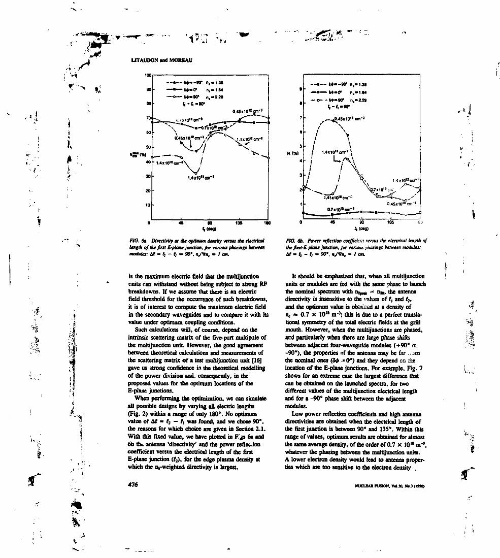
• .e• j * -> :; 'V*.' V*
>-* • .'
;' '**x ^
•j
]
UTAUDON «nd MORKAU
100
90
M
70
60
.-»—^m-9V n,-1.M
—•—W-O1 n.-1.M
—• c—— W— 90* n,—2.29
0.4SOO11JTn-'
* r ' ^
45 W 135 1W
FIC. 6a. Directivity at Ae optimum density versus tne electricallength of the first E-plane junction, for venous phasings betweenmodules: at - t, - t, - SD*. nJVn, m I cm.
is the maximum electric field that the multijunctionunits can withstand without being subject to strong RFbreakdowns. If we assume that there is an electricfield threshold for the occurrence of such breakdowns,it is of interest to compute the maximum electric fieldin the secondary waveguides and to compare it with itsvalue under optimum coupling conditions.
Such calculations will, of course, depend on theintrinsic scattering matrix of the five-port multipole ofthe multijunction unit. However, the good agreementbetween theoretical calculations and measurements ofthe scattering matrix of a test multijunction unit [161gave us strong confidence in the theoretical modellingof the power division and, consequently, in theproposed values for the optimum locations of theE-plane junctions.
When performing the optimization, we can simulateall possible designs by varying all electric lengths(Fig. 2) within a range of only 180e. No optimumvalue of Af » /2 - t, was found, and we chose 90°,the reasons for which choice are given in Section 2.1.With this fixed value, we have plotted in F s 6a and6b the, antenna 'directivity' and the power reflet Joncoefficient versus the electrical length of the firstE-plane junction (I2), for the edge plasma density atwhich the ni-weighled directivity is largest.
476
R(W)
— •-- W- -JO1 n,-1,3a— • — M-O* n.-1.«4— C--W-901 n.-2.29
<•-«,-•<>•
- .. .»..-.
/ \
" / r\/ • v
• I V v 3
/ / \\^•^ / V»
' 1.41X10" cm-= ^
• ', ~U~~ ,
1!> ^<^i-~ '—•*£,'
0.45» 10" on-'
' ~~° *"l45 90 135 160
FIC. 6b. Power inflection coefficient versus the eltarical length oflht ftrst-E plane junction, far various pltasings between modules:Af « t, - I1 - 90*. njvn. - / cm.
It should be emphasized that, when all multijuitctionunits or modules are fed with the same phase to launchthe nominal spectrum with n>rn), » n|0, the antennadirectivity is insensitive to the values of I, and I2,and die optimum value is obteksd at a density ofn. » 0.7 x 10'* or3; this is due to a perfect transla-tional symmetry of the total electric fields at the grillmouth. However, when the multijunctions are phased,and particularly when there are large phase shiftsbetween adjacent four-waveguide modules (+90° or-90°), the properties nf the antenna may be far .amthe nominal ones (fo -* 0°) and they depend CB dielocation of the E-plane junctions. For example, Fig. 7shows for an extreme case the largest difference thatcan be obtained on the launched spectra, for twodifferent values of the multijunction electrical lengthand for a -90° phase shift between the adjacentmodules.
Low power reflection coefficients and high antennadirectivities are obtained when the electrical length ofthe first junction is between 90° and 135°. Within thisrange of values, optimum results are obtained for almostthe same average density, of the order of 0.7 x 10" nr3,whatever the phasing between die multijunction units.A lower electron density would lead to antenna proper-ties which are too sensitive to the electron density
NUCUA* FUSION, Vri.30. N(J (IMO)
i.
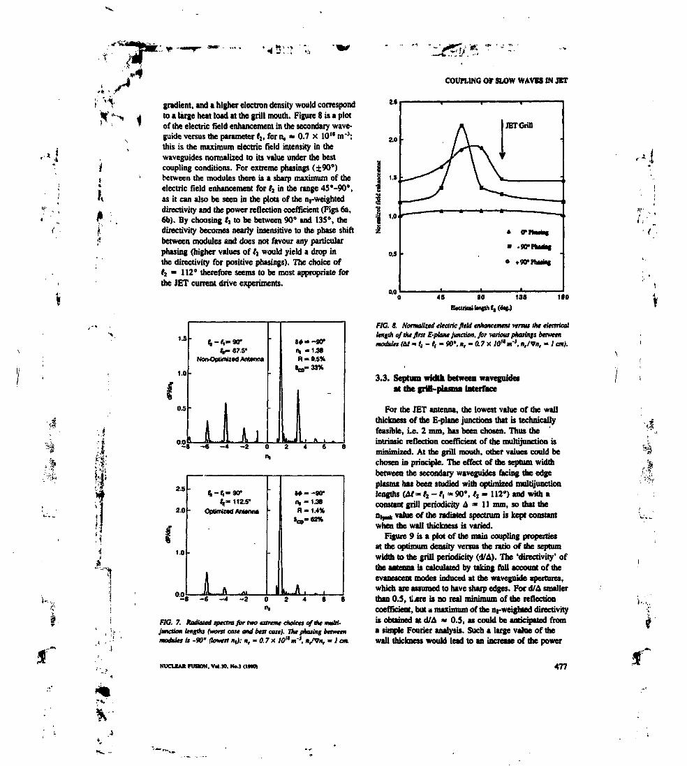
„ Jl
gradient, and a higher electron density would correspondto a large heat load at the grill mouth. Figure 8 is a plotof the electric field enhancement in the secondary wave-guide versus the parameter fj, for n, » 0.7 x 10'* nr1;this is the maximum electric field intensity in thewaveguides normalized to its value under the bestcoupling conditions. For extreme phasings (±90°)between the modules there is a sharp maximum of theelectric field enhancement for f2 in the range 45°-90°,as it can also be seen in the plots of the n,-weighteddirectivity and the power reflection coefficient (Figs 6a,6b). By choosing tt to be between 90° and 135°, thedirectivity becomes nearly insensitive to the phase shiftbetween modules and does not favour any particularphasing (higher values of J1 would yield a drop inthe directivity for positive phasings). The choice offj * 112* therefore seems to be most appropriate forthe JET current drive experiments.
1.5
1.0
0.5
0.0
67.5*
il JU-4 -2 6 B
2.5
2.0
1.0
4-$-90*tt_~ 112.5-
OptaflaiZtCf AlUaXHM
-
i A .
-
•
-
4+--9Û-IH -1.38R - 1.4%
J60- 62%
U-Jl . _ •°-8 - 6 - 4 - 2 0 2 4 6 8
IH
FlG. 7. Radiate* spectra f& two extreme choices of llie HmM-jmaioK length} (wont cast and tea cast). TV phasing betweenmodules is -90* (lowest n,): n, - ft 7 x /0"arJ. itJVn, - I cm.
NUCLBAK FUSION. V4.30. No.3 (IWO)
COUPLING OT SLOW WAVES IN JET
IiO
FlC, 8. Normalized electric JItU enhancement versus the electricallenfih of At first E-plane junction, for various phasinfs between
nm'j, i>,/Vn, - / cm).
3.3. Septum width between waveguidesat the grill-plasma interface
For the JET antenna, the lowest value of the wallthickness of the E-plane junctions that is technicallyfeasible, i.e. 2 mm, has been chosen. Thus theintrinsic reflection coefficient of the multijunction isminimized. At the grill mouth, other values could bechosen in principle. The effect of the septum widthbetween the secondary waveguides facing the edgeplasma has been studied with optimized multijunctionlengths (Af- /2 - f, - 90°, I2 » 112°) and with aconstant grill periodicity A * 11 mm, so that thenip* value of the radiated spectrum is kept constantwhen the wall thickness is varied.
Figure 9 is a plot of the main coupling propertiesat the optimum density versus the ratio of the septumwidth to the grill periodicity (d/A). The 'directivity' ofthe antenna is calculated by taking full account of theevanescent modes induced at the waveguide apertures,which are assumed to have sharp edges. For d/A smallerthan O.S. ti*re is no real minimum of the reflectioncoefficient, but * maximum of the ni-weighted directivityis obtained at d/A » 0.3, as could be anticipated froma simple Fourier analysis. Such a large value of thewall thickness would lead to an increase of the power
477
;•*,

, -t
•A
LlTAUDON Md MOREAU
*c* <*>
4 «H-t.»4 WO*O n|>>2.29 »««n, • 07no'*nf '
CTG. 9. Directivity and power inflection coefficient versus theratio of the wall thidotess d to the periodicity & of the grill(results obtained with the optimittd antenna).
density in the secondary waveguides and would limitthe power handling capability of the antenna, unless itstotal area would be increased accordingly. In the JETlauncher the wall thickness is 2 mm everywhere, fromthe E-plane junctions to the waveguide apertures facingthe plasma.
However, in NET and ITER or in a fusion reactor,the plasma facing edge of the antenna could consistof rather thick walls. For example, a 'grill'-shapedprotective shield, made of a thick layer of a low-Zmaterial similar to that covering the first wall of theplasma vessel, could be mounted at the termination ofthe main launcher and could possibly be replaced aftersignificant erosion.
In the last part of this section on the optimization ofthe geometrical parameters of the antenna we presentthree figures. Figure 10 is a plot of the power reflec-tion coefficient and the directivity versus the electrondensity at the grill mouth. We expect an ^-weighteddirectivity of the onter of 70% and an overall reflectioncoefficient below 1% when all modules are in phase,for electron densities of the order of 10" m"3 at thewaveguide apertures. The field enhancement (Fig. 11)is somewhat more sensitive to the electron density;nevertheless, its value a maintained below 1.3 at theoptimum density for the extreme (±90") phase differ-ences and is negligible (» 1.0) at the nominal phase
difference (£* - 0°) for a wide range of plasma edgedensities. Regarding the phasing of the various modules,Fig. 12 summarizes the results obtained for a ±50%variation of the density around the optimum density.Within these density and n( ranges, the global powerreflection coefficient is kept below 2.5%. Consequently,density variation across the antenna face could beaccommodated by the multijunction system, and anefficient coupling to various plasma configurations(limiter or divertor discharges) is expected.
4. EDGE EFFECTS
In our efforts to minimize the reflection coefficient,we generally consider its average value over eight
••4
«„(%)
«4-90*
0.3 0.5 2 3
FIG. 10. Directivity and power reflection coefficient versus theélectron density at the grill mouth (results obtained with theoptimized antenna).
478 NUCUAR FUSION. Vot.30. No.3 (IMQ)
r*,'

»<v -
I
'*,''
iif. i4
ft'
1 1W.
2.0
1.5
1.0
0.5
0.00.1 10
EdM pluma dmitty (101* m'1)
WC. ;;. Normalized electric JSeU enhancement versus tktelectron density at Oie grill momft (results obtained with Atoptimized antenna).
independent multijunctkras in a row. Because of thefinite number of waveguides, higher reflection coeffi-cients (Fig. 13) and field enhancements are expectedon each side of the antenna. For example, at the nominalphasing (6* » O*), the maximum electric field in theedge modules could be about 15% higher than that inthe central module. This effect can be reduced byshorted passive waveguides {17] mounted on each sideof the JET tower hybrid antenna. Furthermore, byusing passive waveguides, electrical problems on thesides of the launcher can be avoided, for examplearcing between side limiters and the adjacent activewaveguides due to high cross-coupled electric fields.For instants, die calculations for the JET launchershow that the electric field in the second passivewaveguide is at least 15 dB below the electric field inthe central secondary waveguides. Moreover, « vanishingparallel electric field in (and beyond) the last passivewaveguides enables a better comparison between theexperimental coupling results and the theoretical ones,since the theory assumes perfect metallic walls (i.e.jen electric field) on the elge of die launcher.
We use the SWAN code (T] for the optimization ofthe depth of the two shorted waveguides in an attemptto decrease the reflection hi the edge modules. For
NUCLBAB VUSK)N. VWJ* N*.l (MM
COUPLING OP SLOW WAVIS IN JET
this purpose, the depths of the puiive waveguides cmbe chosen so that the phase symmetry of the grill(progressive phase shift of the incident field betweenall waveguides of 90°) is maintained, for both activeand passive waveguides. The shorted waveguides will .reflect the electric field into the plasma with a 90°
ni1.4 1.8 1.8 2 2.2
ao
eo
40
20
n,-0.45x10"m-»n.-0.70xiO"m-«
DirtctMty
V
i\,, Rtftetlon CosfflelwN
V. A-90 -80 -30 O 30 W 90
K-i : '
FlG. 12, Directivity and corresponding power réfection coefficientversus phasing between modula.
WC. 13. Power refection coefficient of each muttijunction unitwithout a passive waveguide on both nets ofine anemUj.
479

*! '• -V
; H
If
t :
•J
N; 'J
^x '
1
UTAUOON Md MORBAU
5.0
4.0
3.0
R(H)
1.0,
0.0.
( a ( Oovwatraam nda
r OMaMd with argumanli MMd. on ptwM ahiK aymmatty
«*-
64 "90*
T*T45 90 135 1«0
EtoeHeal Untfh of «w PuUv* WavcguldM («tag.)
R(H)
r obtalnad with argumtntttaatdon plWM altlft synMTMty
0.0.45 90 135 IW
Etodrical Length of ttw Paaahw WiwguMaa (dag.)
FIG. 14. Power reflection coefficient in the edge modules venusthe electrical length of the adjacent passive waveguides, fordifferent phasing* between nodules (n. * 1.4 x 10" m'3.
n, * 7 CTI).
phase delay (or 90° phase advance) from the incidentfield of the adjacent downstream (upstream) waveguide,provided their electrical depth is approximately T/4(3w/4). These values are obtained by taking intoaccount only the cross-coupled electric field from thelast secondary active waveguide to the adjacent passivewaveguide and assuming that the phase angle of thecross-coupled coefficient of the active waveguide to thepassive waveguide is T.
480
The good agreement of the numerical result* withthe previous qualitative arguments based on the phaseshift symmetry of the grill is confirmed by the plots ofthe power reflection coefficient of the edge modulesversus the electrical length of the passive waveguides.We assumed that the two passive waveguides fixed onone side of the launcher have the same depth. We foundthat only one passive waveguide would be necessary toreduce the reflection coefficient in the adjacent module,but, for mechanical reasons (strengthening of theassembly) and for electrical reasons as mentionedpreviously, we used two shorted waveguides on eachside of the array.
The results have been obtained for different phasedifferences between multijunction units (Fig. 14) andfor different densities (Fig. IS). The minimum reflec-tivity in the edge modules exists at about 45° on thedownstream side and at 100°-120° on the upstreamside. These values have been taken into account inmanufacturing the launcher. With these optimizedvalues, the maximum electric field in the adjacentwaveguide is reduced by only 0.5 dB as comparedwith that of an antenna without passive waveguide.This weak effect of the passive waveguides on thereflectivity is apparent only on the downstream sideof the antenna, which has been expected because of thestrong directionality of the launched waves. We havealso numerically confirmed the idea that, for suchlarge arrays, the presence of passive waveguides doesnot change the shape of the radiated power spectrum.
5. FINITE MAGNETIC FIELD EFFECTS
For the edge plasma parameters, all previous calcu-lations of the coupling results of the JET launcher(ni-weighted directivity, global power reflection coeffi-cient versus electron density, etc.) were obtained withthe assumption of an electron density step (n«) followedby a constant electron density gradient (Vn,) and a veryhigh magnetic field intensity (B) at the grill mouth.Physically, the last assumption means that wave couplingis only determined by the electron current along thestraight magnetic field lines. At higher density ar J
lower magnetic field, the growing impact of the trans-verse currents, namely the E X B drift (proportional ton^B) and the electron polarization current (proportionalto iv/B2), slightly changes the plasma surface admittanceand therefore the coupling results. The aim of thefollowing study is to quantify the importance of thetransverse currents, and to extend the validity of theprevious calculations and optimization.
NUCLEAK FUSION. Vtl.30. N..3 CM»
;' '**
I,
1 •
•'I
Jf-I-
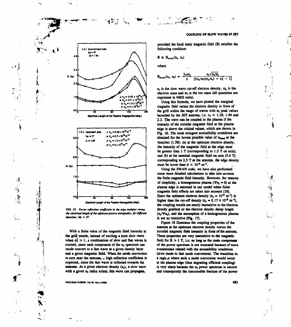
4.0
3.0
R(X)
1.M
0.0,
( I ) DowHwimsid»M-O*Nl-184
n,- 0,48« 1O1V"1
• n,- 0.7 it 1o"nf 'o n, —1.4 xicflnf'an.-3xlo"nf'
Î*T45 90 135 180
EItGWCtI Ltngth ol «it PMilvt Wtgtguktat (dtg.)
0.0 90 135
BtcMol LtngA ol tht PMtivt WtvtguidM (dtg.)
FKJ. 75. Power reflection coefficient in the edge modules vertusihf elearjcal length of aie adjacent passive waveguides, for differentdensities. S* - 0*.
With a finite value of the magnetic field intensity atthe grill mouth, instead of exciting a pure slow wavewhen of > 1, a combination of slow and nut waves isexcited, since each component of the n( spectrum canmode convert to a fast wave at a given density layerand a given magnetic field. When the mode conversionoc curs near the antenna, t. high reflection coefficient isexpected, since the fast wave is reflected towards theantenna. At a given electron density (nj, a slow wavewith a given n( index exists; this wave can propagate,
NUCLEAK FUSMN. VAM. H.J (IMO)
COUPLING OF SLOW WAVES IN JIT
provided the local static magnetic field (B) satisfies thefollowing condition:
B 2
where
, U1)2am,
+ nf - 1]
n, is the slow wave cut-off electron density, m, is theelectron mass and m, is the ion mass (all quantities areexpressed in MKS units).
Using this formula, we have plotted the marginalmagnetic field versus the electron density in front ofthe grill within the range of waves with n( peak valueslaunched by the JET antenna, i.e. n( » 1.38, 1.84 and2,3. The wave can be coupled to the plasma if theintensity of the toroidal magnetic field at the plasmaedge is above the critical values, which are shown inFig. 16. The most stringent accessibility conditions areobtained for the lowest possible value of n^ at thelauncher (1.38): (a) at the optimum electron density,the intensity of the magnetic field at the edge mustbe greater than 1 T (corresponding to 1.5 T on axis);and (b) at the nominal magnetic field on axis (3.4 T)corresponding to 2.5 T at the antenna, the edge densitymust be lower than 6 x 10" nr3.
Using the SWAN code, we have also performedsome more detailed calculations to take into accountthe finite magnetic field intensity. However, for reasonsof simplicity, a homogeneous plasma (Vn. » O) at theplasma edge is assumed in our model when finitemagnetic field effects are taken into account [1O].Since the optimum electron density (n, » 10" m'3) ishigher than the cut-off density (n. « 0.17 x 10" nr3),the coupling results are nearly insensitive to the electrondensity gradient or the electron density decay length(n^VnJ, and the assumption of a homogeneous plasmais not so restrictive (Fig. 17).
Figure 18 illustrates the coupling properties of theantenna at the optimum electron density versus thetoroidal magnetic field intensity in front of the antenna.These properties are very insensitive to the magneticfield for B > 1 T, i.e. as long as the main componentof die power spectrum is not truncated because of waveevanescence related with the accessibility conditions(slow mode to fast mode conversion). The transition toa régule where such a mode conversion would occurat the plasma edge (thus degrading efficient coupling)is very sharp because the n( power spectrum is narrowand consequently the inaccessible fraction of the power
481
»„,.

,'I\
*1*JÎ "-'s-.
LlTAUPON Md MORXAU
Ê£
'IK..
10» 10» 10'» 10»n» (m-»)
{ •
FlO. 16, Acceuibiliiy condition! a thé grill mouth, for varia» valu» of theparallel wave number. 7k* magnetic fitltt and tht tttaron dtteity art takenat the plasma edge.
if
1
near n( * 1 is small. For very high densities at thegrill mouth, the same phenomenon could occur whenthe magnetic field on axis is at its nominal value, i.e.3.4 T. However, in the expected range of edge plasmadensities (0.3 x 10" nr3 S a. s 3 x 10U nrj), thetwo theoretical models, for infinite magnetic fieldintensity/finite density gradient and finite magneticfield intensity/homogeneous plasma, give very similarresults (Fig. 19). Consequently, within the normalrange of operation of the LH launcher in JET,deleterious low magnetic field effects are not expectedto occur.
6. CONCLUSIONS
On the basis of the 2-D linear coupling theory andwith detailed numerical calculations (such as thoseprovided by our SWAN code), lower hybrid multi-junction antennas can be properly simulated andoptimally designed.
We have stressed the impact of the different lengthsof the multijunction unit- on the launched spectrum andwe have found the best locations of the E-plane junctionsfor the JET launcher. Accordingly, these locationshave been taken into account in manufacturing of thelauncher [18].
482
70
N
SO
40
UM
20
10
Diractivity
W-On.» 1.84
n.- 0.7 x 1O1V
ft (flection oMffictont
0.1 O.S 1
An4 (em)
'4
R(W)
10
FIG. 17. Directivity anepowtr reflection coefftiem venus Aetltctron density decay toifdh nJVn, at the (ritf IHDM*.
We have introduced an 'n(-weighted directivity',defined as the ratio of the expected RF driven current(e.g. neglecting effects due to the toroidal geometry) tothe current which would be driven if the total incidentRF power could be ideally launched at a preselected
NUCUUl IVBON. VMJ*. N..Î (IM*

so
70
«0
90
30
20
to
Otracttvity
W-On,-1.S4
PlMlM(Dt)
n. - . 7n,-0
V. JT.
f/G. 18, Dirtttivity and powtr rtfltctio* cotfflcitni vtniaAt toroidal mtgnttic fttU at Iht pill MMC*- ** - <>'•H, - 0.7 X 10"mm>. Vu, "O.
90
n
to
so
»e» (K) 40
W
so
10
1«-0 n.-t.M •
- 1cm 8-=B-8.ST
8
7
6
$
4 H(N)
3
2
1
0.3 O.S 1 2 3 • •n,<io» «r»)
WC. 79. DirtaMty ana ptnvtr rtftaio* cotffkitM vtraa tktebon* dntityfor two cot**: an i^Umegtneut flatum (*M aInnty atcay ling+of 1 cm) wM on wylmw mttiuHe feU. one
a fiitiu magnate ftU M tkt tdgt (2.ST).
COUPLING OV SLOW WAVU IN JCT
value (DiJ-4) of the parallel wave index. High orderevanescent modes excited at the waveguide apertureshave been taken into account in the calculations, whichentails a reduction of the spectrum directivity.
The most important result of the optimization is thefact that the maximum 'ni-weighted directivity' of thelauncher (above 60%) is nearly insensitive to the phasingbetween the single multijunction modules, while thereflection coefficient is very low (»1%). The largestflexibility of the spectrum will be obtained, however,at the expense of some power handling capability ofthe antenna, since for extreme phasing! the maximumelectric field in the narrowest waveguides can beincreased by about 30%.
Once properly optimized, the multijunction antennashould provide good coupling of lower hybrid waves ina large range of edge plasma densities. In particular, itshould be possible to accommodate a density variationof up to ±50% around the optimum edge density(n, » 10" nr3). The multijunction grill should thereforeallow the lower hybrid power to be coupled to a greatvariety of target plasmas obtained in JET, although itwill be difficult to have the whole surface of thelauncher lying on a surface of constant plasma density.
For the large active waveguide arrays used in JET(32 waveguides in each toroidal row), the fixed passivewaveguides on each side of the antenna have little effecton the launched spectrum, but they can slightly reducethe reflection coefficient in the edge modules if theirlength is correctly chosen. In any case, they preventhigh cross-coupled electric fields from appearing in theregions between the side limiters and the antenna edge.
In the operating range of edge electron densitiesand with a magnetic field intensity on axis greater than1.S T, the coupling properties of the JET antenna aremainly determined by the oscillating electron currentsexcited by the wave along the large magnetic field atthe grill mouth and, therefore, problems due to modeconversion just in front of the antenna are not expected.
ACKNOWLEDGEMENTS
It is a pleasure to thank Dn J. Jacquinot,C. Gormezano and A. Kaye for their helpful commentsand their interest in this work. Their hospitality duringour stay in the JET RF Division is greatly appreciated.
.'J
K'
4 . '
NUOMK PUMON. WAM. NO (IMM 483
•-<• •UTAUDON MHl MOREAU
REFERENCES |10|
(I] GORMEZANO, C.. MCQUINOT, J., REBUT. P.H..et al., in Fusion Technology (Proc. 14lh Symp. Avignon. ( I l l1986), Vol. I, Pergamon Press, Oxford (1987) 287.
(2] CORMEZANO. C., BOSlA, C., BRINKSCHULTE, H., |12]el »1., in Fuiioi, Engineering (Proc. 12th Symp. Monterey,CA. 1987). Vol. 1, IEEE, New York (1987) 38.
(31 STEVENS. J.E., SSLL, R.E., BERNABEI, S., et al.,Nucl. Fusion 28 (1988) 217. (13]
(4| GORMEZANO, C., BRIAND, P., BRIFFOD, 0., et tl..Nucl. Fusion 25 (I98S) 419.
[S] TONON, G.. GONICHE. M.. MOREAU. D.. et al.,Euratom-CEA Association Contributions to the 16(h (14]European Conference on Controlled Fusion and PlasmaPhysics. Rep. EUR-CEA-FC-1362, Centre d'étudesnucléaires de Cadarache, Stint-Paul-lez-Durtncc (1989).
(6] JT-60 TEAM, Plasma Phys. Control). Fusion 31 (1989) [IS)1597. [16]
PÎ MOREAU, D., NGUYEN, T.K., Couplage de ronde terneau voisinage de la fréquence hybride basse dam les grandstokamaks, Rep. EUR-CEA-FC-1246, Centre d'étudesnucléaires de Grenoble (1984).
[S] ENGLAND, A.C., ELDRIDGE, O.C., KNOWLTON, S.F., (17)PORKOLAB, M., WILSON, J.R., Nucl. Fusion 29 (1989)1327. (18)
(91 GORMEZANO, C.. MOREAU, D., Plasma Phys. 2C (1984)553.
MOREAU, D., GORMEZANO, C., MELIN, G,,NGUYEN, T.K., in Radiation in Plasmai (Proc. SpringCollege Trieste, 1983), Vol, I, World Scientific. Singapore(1984) 331.OHKUBO, K,, MATSUMOTO. K., Jpn I. Appl. Phys. 26(1987) 142.ZOUHAR, M., VIEN, T., LEUTERER, F., el tl..in Controlled Fusion and Plasma Healing (Proc. 13ih Eur.Conf. Schliersee, 1986), Vol. IOC, Part II. European PhysicalSociety (1986) 378.MOREAU, D., DAVID, C., GORMEZANO, C., el *!.,in Applications of Radiofrequency Power to Plasmas (Proc.7th Top. Conf. Kissimmee, FL, 1987), American Institute ofPhysics, New York (1987) 137.MOREAU, D., NGUYEN, T.K.. in Plasma Theory (Proc.6th Int. Conf. Lausanne, 1984). Vol. 1, Centre de recherchesen physique des plasmas, Ecole polytechnique de Lausanne(1984) 216.PREINHAELTER, J., Nucl. Fusion 29 (1989) 1729.PAIN, M., LENNHOLM, M.. JET, RF Division, personalcommunication, 1988; BIZARRO, J.P., PAIN, M.,A General Method for Measuring the Scattering Matrices ofN-port Systems, Rep. IET-R(89)11, JET Joint Undertaking,Abingdon, Oxfordshire (1989).MOTLEY, R.W., BERNABEl, S., HOOKE, W.M.,PAOLONI1 F.J., Nucl. Fusion 20 (1980) 1207.KAYE, A.S., BRINKSCHULTE1 H., EVANS, G., et al.,in Fusion Technology (Proc. 15th Symp. Utrecht, 1988),Vol. I, Pergamon Press, Oxford (1988) 449.
1
(Manuscript received 14 August 1989Final manuscript received 20 November 1989)
484 NUCLBAK FUSION. Vol.30. No. J (19W)

; x4
;' %is
*> it
ii
ii* :
'1 C-.It •
LOWER HYBRID WAVE COUPLING IN TORE SUPRATHROUGH MULTIJUNCTION LAUNCHERS
X. LITAUDON, G. BERGER-BY, P. BlBET, J.P. BIZARRO,J.J. CAPlTAIN, J. CARRASCO, M. GONICHE, G.T. HOANG,K. KUPFER, R. MAGNE, D. MOREAU, Y. PEYSSON,J.-M. RAX, G. REY, D. RIGAUD, G. TONONDépartement de recherches sur la fusion contrôlée,Association Eurttom-CEA,Centre d'études de Cadanche,Saint Paul-lez-Durance, France / -•
ABSTRACT. The TORE SUPRA lower hybrid current drive experiments (8 MW/3.7 GHz) UM large phasedwaveguide arrayi, four row» of 32 active waveguides and two passive waveguides for each of the two grills, to couplethe wave* to the plasma. These launchers an based on the 'multijunction' principle which allows them to be quitecompact and is therefore attractive for the design of efficient multi-megawatt antennas in NETiTTER. Extensive couplingmeasurement» have been performed in order to study the ndiofrequency (RF) characteristics of the plasma loadedantenna*. Measurements of the plasma scattering coefficients of the antennas show good agreement with those obtainedfrom the linear coupling theory (SWAN code). Global reflection coefficients of a few per cent have been measured ina large range of edge plasma densities (0.3 x IO" m"' s nH s 1.4 x 10" m°) or antenna positions (0.02-0.05 mfrom the plasma edge) and up to t maximum injected RF power density of 45 MW/mJ. When the plasma is pushedagainst the inner wall of the chamber, the reflection coefficient is found to remain low up to distances of the order of0.10 m. The coupling measurements allow us to deduce the 'experimental' power spectra radiated by the antennas whenall their modules are fed simultaneously with variable phases. Thus, the multijunction launcher is assessed as a viable
L for high power transmission with good coupling characteristics and spectrum control.
I
4
•
1. INTRODUCTION
Phased waveguide arrays are generally being usedfor launching lower hybrid (LH) waves in tokamakplasmas. When the concept of the conventional 'grill'[1] — an array of independent waveguides — is extra-polated to the present and the next generation of largescale tokamaks, an antenna of great complexity isobtained. The trend towards large waveguide arrays isa consequence of launching high radiorrequency (RF)powers (up to 10 MW in present experiments) whitemaintaining the power density at the plasma edge belowSO MW/m2 and keeping a narrow parallel wavenumber(k|) power spectrum. An attractive simplification consistsof using internal RF powei splitting: E-plane waveguidejunctions as power dividers in the toroidal directioncombined with fixed differential phase shifters [2-4]and an H-plane hybrid junction in the poloidal direc-tion. Such compact launchers, called 'multijunction'antennas, have been tested previously on PETULA [4]and more recently on JT-60 [S] and JET [6]. Two'multijunction' antennas have been designed and builtfor current drive (CD) experiments in TORE SUPRA.
Up to now, 5 MW of RF power launched at a frequencyof 3.7 GHz with an asymmetric parallel wavenumberpower spectrum have been coupled to the TORE SUPRAplasma [7-9].
In this paper we focus our attention on the couplingproperties of antennas [1O]. Since for the descriptionof the LH coupling physics some knowledge of thecoupler design is required, we devote Section 2 to ashort description of the LH system .installed in TORESUPRA. In Section 3 we give an overview of thetheory of compact antennas. We extend the conventional'grill' theory to include a more complex internal powersplitting. This theoretical framework will guide us inthe analysis of the LH coupling experiments performedin TORE SUPRA. Consequently, Section 4 is devotedto a detailed analysis of the LH coupling experiments,and a comparison with the linear theory is carried out.Our study also provides a check of the phase differencebetween adjacent waveguides, and we present thededuced experimental radiated power spectra. Wereport on the antenna performance obtained in a largerange of antenna positions,- plasma target and feedingconditions.
r*.
NUCLEM RJStON. Vd.32. No.ll <I*R) 1883
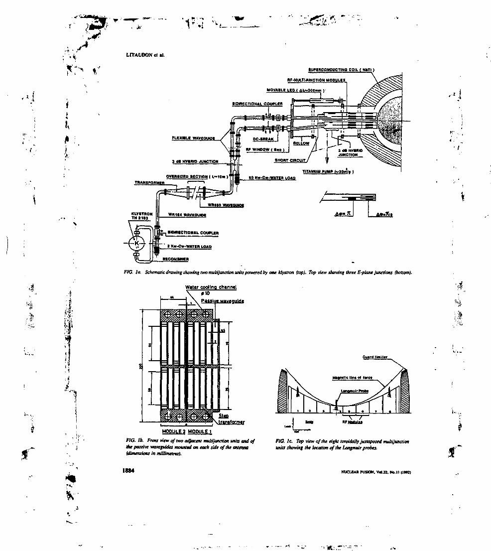
'1s:.l -^LHAUDON ct «I.
'•*,'•
ft» *. i
Ui
"
' 4
«WtBCOMDUCTINO COIU ( H>TI )
BF-MUlTMUNCTION MOOULg *
MOVABUt LtO I AL~300mm )•
!!DIRECTIONAL COUfLiR
» Kw-Cw-WATiB LOAD
NECOWBMtn
FIG. Ia. Schematic drawing showing two multijunaion units powered by one klystron (top). Top view showing three E-plane junctions (bottom).
W«Ur cooling channel«toPas«l « wavtguldf
Cu»rdltmil«r
v\tr«n«fofmtr
MODULE 2 MODULEI
FlO. Ib. Front view of two adjacent multijunction units and ofAe passive waveguides mounted on each side of the antenna(ttimensioiu in millimetres).
1884
FIC. Ic. Top view of the eight toroidalfy juxtaposed multijunctionunits showing the location of the Langmuir probes.
NUCUAIt FUSION. V«I.M, No. 11 <IW2)
T*,'

• J H1 * •
LH WAVE COUPUNG IN TORE SUPRA
2. DESCRlPTIONOFTHETORE SUPRA LH COUPLERS
The LH system installed on TORE SUPRA [11, 12]is based on O.S MW (cw) klystron amplifiers operatingat a frequency f = w/2» = 3.7 GHz. Each of the twomultijunction antennas is fed by 4 MW of RF powerdelivered by eight klystrons and is mounted on themachine through adjacent ports (the two antennas arereferred to as antenna No. 1 and antenna No. 2). Thepower is transmitted to the plasma through oversizedwaveguides over distances of 20 m (the measuredtransmission factor is 94%). As indicated in Fig. Ia,each transmission line is terminated by a 3 dB hybridjunction which divides the power delivered by eachklystron. This permits simultaneous feeding of anupper and a lower antenna module and protection ofthe klystron. The power in each module is dividedpoloidally through a vacuum 3 dB hybrid junction andtoroidally through a set of two E-plane junctions intofour reduced secondary waveguides. Two horizontalrows of eight juxtaposed multijunction units form eachantenna. Such a unit is represented schematically inFig. Ia.
The units are made of copper and zirconium, iso-lated by a small (1 mm) gap in order to reduce thestresses during plasma disruptions, and active highpressurized (30 bar) water cooling is provided. Finally,a passive waveguide is added on each side of eachhorizontal row of the 32 reduced active waveguides;this bas the effect of reducing the electric field betweenthe antenna and the limiter frame as well as the reflec-tion coefficients in the edge units. Both couplers havea toroidal periodicity of 1.05 cm (except for the smallgaps at every fourth waveguide), a septum thickness of0.2 cm and a total width of 38 cm (Fig. Ib). Built-inphase shifters result hi a 90° phasing between adjacentoutput waveguides of a given unit. Consequently, eachmultijunction unit radiates an HI spectrum centred atnipt* = 1-8 (HI = k|C/d> is the parallel index of refrac-tion of the waves). The large number of toroidally juxta-posed modules (Fig. Ic) gives a very narrow n( powerspectrum (FWHM An( « 0.2) and allows for spectrumflexibility by varying the phase between adjacent units(1.4 a nlp-k s 2.3). The low reflection coefficientstypical of the multijunction design allow the TORESUPRA LH system to operate routinely without anycirculator protecting the klystrons.
3. THEORY OF COMPACT ANTENNAS
3.1. Plasma scattering matrix
To compare LH wave coupling experiments withlinear theory, one can make use of the matrix formula-tion. In this formulation, incident and reflected fieldsare linked by scattering matrices which contain theintrinsic features of the plasma loaded 'grill', indepen-dently of the feeding conditions.
As far as compact antennas are concerned, the RFmeasurements are performed at the input of eachmodule, i.e. far from the plasma facing edge of theantenna. Therefore, it is necessary to measure and takeinto account the transfer matrix between the bidirectionalcouplers and the 'grill' aperture in order to obtain theplasma loaded scattering matrix which links, at the RFmeasurement plane, the incident fields with the fieldsreflected by the plasma.
Let V and V be the column vectors whose elementsrepresent respectively the complex incident and reflectedvoltages of the fundamental mode in the reduced secon-dary waveguides at the grill-plasma interface. Thedominant fields are related by the grill-plasma scatteringmatrix S, which, for a given array of secondary wave-guides, depends on the edge plasma parameters:
S1V (1)
NUCLEAK FUSION. Vot.33. Uf.U (MK)
For the sake of simplicity, we have neglected thehigher evanescent modes excited at the antennaaperture.
In the framework of the classical two-dimensionallinear coupling theory of the 'grill* [1] and using theSWAN code [13, 14], S1 is numerically calculated invarious edge plasma conditions. The plasma is describedin a Cartesian slab geometry (Oxyz) with a densityprofile in iront of the grill consisting of a density stepn., at the grill aperture» followed by a linear densitygradient Vn4 along the radial axis (Ox). The tokamakequilibrium magnetic field is assumed to be in thetoroidal direction (Oz). The secondary waveguides areassumed to be infinitely high in the poloidal direction(Oy), with perfectly conducting parallel plate walls.The small gaps between adjacent modules, which area specificity of the TORE SUPRA 'grill', have beenfully modelled.
The full antenna consists of a set of multijunctionmodules. Let V' and V* be the column vectors whoseelements represent respectively the complex incidentand reflected voltages of the fundamental mode at theinput plane of the power splitting modules. The dimen-sions of the radiating structure are chosen so that only
1885
K
I .

.* I
iMi
LITAUDON et «I.
the fundamental mode can propagate in the modules,so that far from the 'grill' aperture the evanescentmodes are completely negligible. The linear transferrelations between the incident and the reflected electricfields in the modules have been cast into the followingform:
fV" = S0V' + T1V"
y. _ Ty, + py.(2)
where S0, T and T are the scattering elements of thewhole launching structure. They take into account thegeometry and the RF characteristics of the modules:internal power splitting in the poloidal and toroidaldirection, and fixed differential phase shifters. Precisely,50 is the matrix of the intrinsic reflection coefficients,T is the transmission matrix of the incident field fromthe main waveguides to the secondary waveguides(T1 is the transposed matrix) and F is the couplingmatrix between all secondary waveguides. These lastelements are related by a power conservation law, but51 is not unitary, i.e. it does not conserve power, sincethe antenna radiates.
The transfer matrices S0, T, F have been measuredin the laboratory on a prototype module of the TORESUPRA antenna. The internal power splitting model hasbeen compared with the measurements. Further detailson the structure of the transfer matrices (symmetry,size), the measurement procedure and the experimentalresults have been reported previously [15, 16].
Combining Eqs (1) and (2) leads to the determina-tion of the plasma scattering matrix of the multijunc-tion antenna S, which related V? to V' directly at themeasurement plane:
(3)
As a consequence of strong cross-coupling betweenthe secondary waveguides through the matrix F, thematrix (1 - FS,)'1 in expression (3) characterizes themultiple reflections of the incident wave which takeplace between the plasma and the input plane of themultijunction modules. This point is well illustrated inRefs [3, 17-19], where it is shown that the multi-reflection process leads to self-adaptation of the multi-junction antenna, which reduces the reflected fields inthe main waveguide. One of the aims of this paper isto demonstrate experimentally that this property remainsvalid in quite a broad range of edge plasma parametersand distances between the launcher and the main plasma.
1886
V" = SV' with S = «0 HI- T1S1(I -FS1)-i T
3.2. Total electrk fields In thesecondary waveguides
Combining Eqs (1) and (2), the relation between theincident field at the input plane of the modules and thetotal electric voltage at the grill aperture, V = VH-V",is determined:
S1)(I-TS1J-1TV' (4)
Once again, we identify the matrix (1 - PS1)'' whichhas been linked to the multiple reflections of the inci-dent wave. In poor coupling conditions, this processincreases the total electric field at the grill-plasmainterface and also leads to a distortion of the radiatedspectra. However, since the wave is attenuated at eachpass, the plasma loaded multijunction antenna does notsuffer from any resonant cavity behaviour.
3.3. Radiated power spectra
For an understanding of the LH wave propagationbetween the wave source (the antenna) and the absorp-tion region, a quantity of interest is the Poynting vector.The Initial conditions of the propagation problem aredefined by the coupling analysis. The radiated power(per unit length along the poloidal direction Oy) at thewaveguide apertures (x = O plane) is calculated by theflux of the Poynting vector (P1) through this plane.Applying the Parseval-Plancherel relation to thePoynting vector, we obtain the spectral power density:
f*'p' = J -•>where
dP(n,) _dni
dP(n,)
Y0 - - Reft
(5)
E,(0,ni) and H1(O1Ui) are the Fourier transforms in zof the tangential electric and magnetic fields (nt is theparallel index), Ic0 is the free space wavenumber, Y0 isthe vacuum admittance, Re (y,(DI)) is the real part ofthe plasma surface admittance y,(ni), and dP(n t) isthe fraction of RF power radiated with a parallel indexwithin an interval dni around a given value of HI .
The expression of the spectral power density isrelated to the total electric field by the relation:
NUCLEAK FUSION. V«I.H. No. 11 <IM»

*;••< «•
I,
where
G0(n,)
Y° TT Rc(y,(n,))+ W(B1)V
(6)
,1/2
in.(b is the width of the waveguides) and W(D1) is ahermitian matrix defined by its generic elementWn(nt) = exp [iki (Zp - zjl (Zp is the position of theleft edge of the p-th waveguide). The plus refers to thetransposed conjugate matrix.
Expression (6) relates the distortion of the radiatedpower spectra to the perturbations of the electric fieldvoltage at the antenna aperture. Keeping relation (4) inmind, we conclude that the radiated spectra are sensitiveto the coupling conditions (density and density gradientat the antenna aperture) as well as to the design of theinternal power splitting units. For the LH experimentsin JET and TORE SUPRA the antenna design has beencarefully optimized [19].
In summary, we have defined all fundamental ele-ments for a complete computation of the coupling per-formance of the TORE SUPRA multijunction antennas,namely the plasma scattering matrix, the total electricfields in the secondary waveguides and the radiated D1
power spectrum. The main goal of this section was toexhibit the close link between all these antenna charac-teristics. For this purpose, the evanescent modes excitedat the antenna aperture have been neglected. However,for simulating the TORE SUPRA coupling experiments,full numerical calculations are performed, keeping upto two evanescent modes. In the next section, theexperimental coupling data obtained in TORE SUPRAare analysed in the light of the present theory.
4. LOWERHYBRIDCOUPLINGEXPERIMENTS
A detailed experimental study of the coupling of LHwaves to the TORE SUPRA plasma has been carriedout using the analysis of the available RF measurementsat the input of each unit. For each antenna (two rowsof eight modules) the incident and reflected voltages(amplitude and phase) are determined from the measure-ment performed by 16 bidirectional couplers; a 16 portmultiplexer is used to decrease the number of diodesand correlators. In the experiments the edge plasmadensity has been measured by Langmuir probes locatedon the equatorial plane of the launchers (Fig. Ic).
LH WAVE COUPLING IN TORE SUPRA
4.1. Plasma scattering matrix
In this section, only low power level experimentsare considered, namely those at a power level of 60 kWper klystron («0.5 MW per antenna or 3OkW permodule), corresponding to a power density at the plasmaedge of S MW/m2. At such a power level, deleteriouseffects due to RF breakdown in the waveguides and/orto a non-linear modification of the edge plasma densitybave not been observed. Consequently, comparison ofthe experimental data with linear coupling theory shouldbe relevant.
Instead of comparing the power reflection coefficientsin the individual modules for various phasing condi-tions, we have measured the plasma loaded scatteringmatrices S which, by definition, connect all the incidentand reflected fields. The scattering matrices contain theintrinsic features of the plasma loaded antenna, namelythose which are independent of the feeding conditions.Two systematic methods have been set up to measurethe unknown complex elements of the plasma scatteringmatrix (S) of the TORE SUPRA antennas.
The direct analysis consists of feeding sequentiallyeach klystron of a given toroidal row during a singleplasma shot. To obtain the complete plasma scatteringmatrix, the experiment was repeated eight times. Duringthe plasma shots the average plasma parameters werestationary and well reproducible. The required precisionof the electric field measurement restricted this methodto the determination of the diagonal coefficients S(i, i)and, in the best experimental conditions, the first off-diagonal coefficients S(i, i± 1), where i labels themodule which is powered.
The experimental amplitude and phase of the S(i, i)element are plotted in Fig. 2 for various grill positions,at a radius R^j1 with respect to the outboard limiter radiusRU-J-,. The antenna position is linked with the edgedensity at the antenna aperture. By assuming that, in theshadow of the limiter, the electron density decays expo-nentially with an e-folding decay length A- of 0.013 m(the density at the limiter is n* » 2.0 x 10" nr3) wecan compute a theoretical curve. The general shape ofthe curve is well reproduced, although the experimentalvalues are slightly higher than predicted. The scatteringcoefficient exhibits a broad optimum position when theantenna is located at approximately 0.01 m from thelimiter, which corresponds to an edge density of0.9 X 10" m'3. A precise determination of A- is notreally required since, in this density range, it was nume-rically checked that the coupling results are insensitiveto A,,, provided that A- is greater than 0.5 X 10'2 m[19]. As far as the phases are concerned, we can easily .$"
NUClEAII FUSMN. Vol.31. Ne. 11 (l*n> 1887

fI
,-i
w-, „., i , »• .»1 * • .'
UTAUDON tt •!.
•* 0.4
0.3
SW 0,2
0.1
•.0
S(M)EXp.
S(CATk.
IM
}135
45
// 5(2,2) Exp.
8(2,2) TV
• 1 2 3 4
•trill '
• 1 2 3
•jrlll ' R1lMlltr <*"'
F/G, 2. Meoiumf (mi and calculated (+) amplitudes and phases of dit scattering matrix elementvtnus distance between the grill and the limiter.
Upptr Upper modulM
Ï «
M.
S(U)
Î
sgi+2)1 2 3 4 S < T S
Ztt
IN
»
-Mt
r,
I • " • I S(MA
8(21+1,21+1)
• *
*~*"*1 2 3 4 5 « 7 S
f7G. J. Amplitude and arguments of AeS (i,j) elements versus module number i. The horizontal linesshow Ae results from Ae SWAN code with an edge density ofnn - 1.4 x 10" m~3.
*1
recognize the two different types of modules which differin their electrical length by construction. As predicted bythe calculations, the phases of the diagonal S(i, i) termsare nearly insensitive to the antenna position. This lackof dependence makes it impossible to correlate the phaseof the S(i, i) element with the edge plasma density oreven to separate the low density regime (where theedge density is close to the cut-off density) from theWKB regime. This result is in contrast with previousexperiments performed with a conventional grill where
the phase of the reflected fields in the individual wave-guides was found to vary significantly with edgedensity [2O].
The plasma scattering matrices have been determinedby another method, which will be developed in the lastpart of this section. In general terms, to determine theN*N elements of the plasma scattering matrix, whereN is the number of toroidal modules (eight in the caseof the TORE SUPRA antenna), it suffices to considerN independent arrangements of the incident electric field Jf
1888 NUCLEAR FUSION. Vd.)2. No.ll (IM2)

^s.
LH WAVE COUPLING FN TORE SUPRA
I
I*;i
phases, at fixed plasma conditions, and to measure thecorresponding complex reflected fields. For eachtoroidal row, one obtains a large linear system wherethe unknown terms are the complex coefficients of theN x N scattering matrix S. Further mathematical detailsfor this method are given in the Appendix.
Experimentally, the phase difference <5* between theincident fields in two adjacent modules was chosen totake eight distinct values, for instance S4> = 0°, ±60°,±90°, ±120°, 180°. The control command of theLH system permitted a change of the phasing conditionsduring plasma shots, which considerably simplified themethod. Moreover, as soon as the average plasmaparameters were stationary (average plasma density,plasma current and plasma position), we checked thatthe edge plasma density was kept constant during theLH pulse. The electron density measurement was per-formed with the Langmuir probe located on the electronside of the launcher. The accuracy of the method enabledus to determine up to the cro^s-coupling coefficientsbetween non-adjacent modules, i.e. S(i,i±2). In otherwords, we measured the plasma scattering elementswhose amplitudes are larger than 0.01.
Figure 3 is a plot of the amplitude and argument ofthe major scattering coefficients versus the module num-ber flower and upper modules are shown) when the edgedensity is well above the LH cut-off density, i.e.n,, » 1.4 x 101* nr3 (±20%). In this coupling regimeand for the multijunctipn antennas the global scatteringcoefficients are nearly insensitive to a slight electrondensity perturbation, which justifies the proposedmethod. From the analysis of this figure, we note thefollowing points:
(a) Excellent agreement is obtained between allmeasured scattering terms, including their phases, andthose deduced from linear coupling theory.
(b) As expected for such large waveguide arrays, thescattering coefficients of the central units do not dependon the module number. Furthermore, this experimentalresult proves that the edge density inhomogeneities inthe toroidal direction can be made negligible. In someexperimental situations the density inhomogeneities areclearly observed on such diagrams.
(c) The difference (due to design constraints)between the electrical lengths ol even and odd units isdisplayed on the phases of the diagonal elements S(i, i).
(d) The strong ordering between the diagonal andoff-diagonal elements (crow-coupling terms) of S isclearly illustrated, i.e. S(i±l,i)/S(i,i) » 0.3 andS(i±2,i)/S(i,i) * 0.08.
NUClCMt FUSION. V«UZ. N*.ll (l«*2)
(e) The symmetry of the scattering matrix(S(i + 1, i) - S(i, i + 1)), which is an implication ofthe field reciprocity theorem, is verified. The departurefrom symmetry (if any) enables us to estimate the rela-tive errors in the electric field measurements, whichare in the worst cases about ± 10% and ±20° on theamplitudes and phases, respectively.
1 2 3 4 5 < 7 >
FlG. 4 Effect of a phase measurement error on Ae arguments ofthe S (i,j) elements versus the module number i. ;s
itf
ft
I 2 3 « 5 < 7 •
FIC. 5. Effect of a otiose measurement error on the arguments ofthe S (i.j) elements versus the module number i.
1889
Jf'
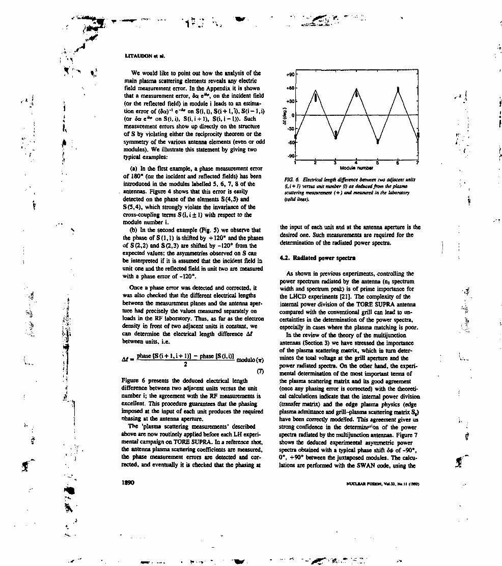
1
LITAUDON it Bl.
We would like to point out how the analysis of themain plasma scattering elements reveals any electricfield measurement error. In the Appendix it is shownthat a measurement error, da e*", on the incident Held(or the reflected field) in module i leads to an estima-tion error of («a)'1 e"** on S(i, i), S(i -I- 1,1), S(i - l.i)(or 6a e*» on S(i, i), S(i, i + 1), S(i, i - 1)). Suchmeasurement errors show up directly on the structureof S by violating either the reciprocity theorem or thesymmetry of the various antenna elements (even or oddmodules). We illustrate this statement by giving twotypical examples:
(a) In the first example, a phase measurement errorof 180° (on the incident and reflected fields) has beenintroduced in the modules labelled S, 6, 7, 8 of theantennas. Figure 4 shows that this error is easilydetected on the phase of the elements S (4, 5) and5(5,4), which strongly violate the invariance of thecross-coupling terms S(i, i ± 2) with respect to themodule number i.
(b) In the second example (Fig. S) we observe thatthe phase of S(1, 1) is shifted by + 120° and the phasesof S (2,2) and S (2, 3) are shifted by -120° from theexpected values; the asymmetries observed on S canbe interpreted if it is assumed that the incident field inunit one and the reflected field in unit two are measuredwith a phase error of -120°.
Once a phase error was detected and corrected, itwas also checked that the different electrical lengthsbetween the measurement planes and the antenna aper-ture had precisely the values measured separately onloads in the RF laboratory. Thus, as far as the electrondensity in front of two adjacent units is constant, wecan determine the electrical length difference atbetween units, i.e.
Af = Phase [SO+ Li+ Dl- Phase [S(i,i)l
(7)Figure 6 presents the deduced electrical lengthdifference between two adjacent units versus the unitnumber i; the agreement with the RF measurements isexcellent. This procedure guarantees that the phasingimposed at the input of each unit produces the requiredohasing at the antenna aperture.
The 'plasma scattering measurements' describedabove are now routinely applied before each LH experi-mental campaign on TORE SUPRA. In a reference shot,the antenna plasma scattering coefficients are measured,the phase measurement errors are detected and cor-rected, and eventually it is checked that the phasing at
1890
+90
+60
+30
i•30
•60-
-90
V1 2 3 4 5 6 7
Modub numtMr
FlC. 6. Electrical length difference between two adjacent units(i, i +1) versus unit number (i) at deduced from the plasmascattering measurement <+) and measured in the laboratory(solid lines).
the input of each unit and at the antenna aperture is thedesired one. Such measurements are required for thedetermination of the radiated power spectra.
4.2. Radiated power spectra
As shown in previous experiments, controlling thepower spectrum radiated by the antenna (DI spectrumwidth and spectrum peak) is of prime importance forthe LHCD experiments [21]. The complexity of theinternal power division of the TORE SUPRA antennacompared with the conventional grill can lead to un-certainties in the determination of the power spectra,especially in cases where the plasma matching is poor.
In the review of the theory of the multijunctionantennas (Section 3) we have stressed the importanceof the plasma scattering matrix, which in turn deter-mines the total voltage at the grill aperture and thepower radiated spectra. On the other hand, the experi-mental determination of the most important terms ofthe plasma scattering matrix and its good agreement(once any phasing error is corrected) with the theoreti-cal calculations indicate that the internal power division(transfer matrix) and the edge plasma physics (edgeplasma admittance and grill-plasma scattering matrix S1)have been correctly modelled. This agreement gives usstrong confidence in the detcrmin?':on of the powerspectra radiated by the multijunction antennas. Figure 7shows the deduced experimental asymmetric powerspectra obtained with a typical phase shift £4 of -90°,0°, +90° between the juxtaposed modules. The calcu-lations are performed with the SWAN code, using the
NUCLCAX FlMIOM. Vd.tt. N».ll (IWZ)
•"US.:

LH WAVE COUPLING IN TORE SUPRA
'*l
I
J-' f
4il
J
JJ
1
II1U
a ../v A ..
M •<>•_*.HuDMK • VC
i
n, p»tK- 1.4
1Il
I IJy Ii iMS ...A ,.A . u
I .L «* . +90-n,, PMK . 2.3
•
it
n,lndtx
WG. 7. Launched n^ power spectra for three characteristicphasing* (-90*. 0\ +90').
measured edge plasma density and incident fields ineach unit whose values have been checked by the'plasma scattering measurements'.
To characterize the power spectra, an 'n( weighteddirectivity' based on the theoretical current drive (CD)efficiency of the waves has been defined [19, 22]:
(8)dP
where R is the global power reflection coefficient,dP/dn( is tin power density in n§ space normalized tothe total radiated power, and n)pMk is the value of theparallel wave indtx at the peak of the power spectrum.The *ni weighted directivity* On, is a quantitativemeasure, based on the CD efficiency, of the quality ofthe launched spectrum with regard to an ideal spectrumS(DI — nip,*), i.e. a Dirac function centred at HI,**.The S* parameter is also a rough measure of the powerlaunched in the most efficient main lobe, independentlyof the parallel wave index at the peak of the powerspectrum (nip.*). We stress that the quality of thespectrum is defined at the antenna aperture, i.e. ignor-ing the propagation effects of the LH wave packet indie plasma core.
During CD experiments performed on TORE SUPRAit was observed that the pîiase dependences of the loopvoltage drop and of the non-thermal electron cyclotronemission showed a broad maximum around zero phasing(Fig. 8a) [T]. The variation of the high energy X-raysignals with the phase shows the same dependence(Fig. 8b) [23]. It appears that the plasma response of
0,4
0.3
10.1
• O • &V/Va Non-thermal ECE (».u.)
Q -135 -M -45 O 45 90 135PhM* (dm.)
FlC. Sa, Loop voltage drop (•) and non-thermal electroncyclotron émission (a) versus antenna phasing for lf « 1.6MA.n, * 3.8 X 10"m~' and PU, - 2.4 MW.
Lin» of (iflht 8SO KtV
loo mvISO IwV200 IwV
NomMRz«dcRr*ctivitypwim*wr 5c(j
•150 -100 -50 O 50 100 150Phm (d«g.)
FlG. Sb. X-ray émission along the central chord for fourphoton energies as a Junction of the phasing. Blade circles showthe 'n, weighted directivity' See (all data have been normalized tothe zero phasing value).
OJ
O.t
0.4
F*werdircctMt7
*-!35 •»• .4S • 45 M 13SPhase (deg.)
FlG. 9. Power directivity, j*" (dP/dn,)dnt ( U ) and'AI weighted directivity', ttt ft), versus antenna phasing.
NUCLEAK FUSION. Vd.32. No. 11 (WR) 1891
'.•i •W.."

; "*«••*, ».!
I,
't.
LITAUDON cl «I.
the CD assisted discharges is well correlated with theantenna performance (coupling, directivity, spectrum)parameters, which exhibit a similar behaviour whenmeasured by the 'nt weighted directivity' (Fig. 9).Figure 9 also shows that the fraction of power flowingalong the toroidal direction of the electron drift (thepower directivity) is practically insensitive to the phasingconditions, and its typical value is of the order of 70%.In fact, the power directivity generally used to charac-terize conventional grills does not quantify in an accurateway a possible distortion (in large phasing conditions)of the power spectra. The correlation between the'HI weighted directivity* and the CD performance ofthe LH waves justifies the design optimization of theantennas based on this parameter.
4.3. Power reflection coefficients
In this section we cl ".nine the experimental rangeof operation of the multijunction antennas and show
• coupler 1• coupler 2
*• O 2 4 6 8R^-RtMr(Cm)
FlG. 1Oa. Overall power reflection coefficient far antennaNo. 1 (+) and antenna No. 2 ( • ).
10'»
E
c*
10"
-An- 1.4cm
FlG. 1Ob. Edge electron density versus distance between the grilland the limiter (O* phasing) obtained by moving the antenna in theSOL. PU, * 1.0 MW (O.S MWper antenna).
1892
30
! 20
10
. • coupler 1• • coupler 2
* O 4 8 12 16R g*-"pu»» (cm)
FIG. lia. Overall power reflection coefficient for antennaNo. I (+) and antenna No. 2(9).
10'»
E10'»
• coupler 1• coupltr Z
10 12 14101
FIG. lib. Edge electron density venus distance between the grilland the limiter (O* phasing) obtained by moving the plasma columnaway from the antenna. Pm * 1.0 MW {0.5 UWper antenna).
that LH waves can indeed be coupled to a large varietyof target plasmas.
Two sets of coupling experiments were performed toobtain a complete scan of the overall power reflectionversus the antenna position or the edge plasma density.In the first type of experiment the launchers were movedin one single plasma shot and the whole scrape-off layer(SOL) was scanned, while in the second type ofexperiment the plasma column was moved away fromthe antennas. Both experiments were carried out at thesame power level of 0.5 MW per antenna.
Figure 1Oa is a plot of the overall power reflectioncoefficient (average over all modules) versus theantenna position relative to the external limiter whichis in contact with the plasma. The experimental datahave been obtained by moving the antennas during onesingle plasma shot and keeping a zero phasing betweenthe different units (frp * 0°). At the optimum positionthe power reflection is of the order of 3%. Thereflection coefficient is kept at its optimum value
NUCLEAR FUSION. VdJZ. Nfcll <IM2)
«!: -V

,-; - LH WAVE COUPLING IN TORE SUPRA
!<> i (below 4%) in a large range of antenna positions,namely 0.01 m s R1nH - R11nUn, S 0.05 m. In (hisexperiment, the electron density decay length is meas-ured to be 0.014 m (Fig. 1Ob). The global results areslightly different when the antenna is located at anoptimum position and the plasma column is movedaway from it. The range of AR = R,n,, - Rp|Bm,(Rpiumt is defined by the radius of the last closedmagnetic surface determined from magnetic measure-ments), where good coupling is maintained, is con-siderably extended to 0.01 m £ Ryu-R^im» â 0.10 m(Fig. 1 la). This result, obtained with a multijunctionlauncher, confirms the previous experiments performedon ASDEX with a conventional grill [24], Figure Hbshows the weak dependence of the edge electron den-sity on AR, which explains the different characteristiccurves obtained in the two experiments (Fig. 1Oa andFig. lia). As soon as AR fe 0.10 m, the reflectioncoefficients are higher in antenna No. 2 than in amennaNo. 1. The difference is explained by density inhomo-geneities across the poloidal section of the antennawhich are due to a slight poloidal tilt of the secondantenna. Close to the LH cut-off density, any densityinhoiiiogeneities affect strongly the coupling behaviourof some modules. Figure 12 is a synthesis o> the twoexperiments for one antenna (antenna No. 1); the samedependence of the reflection coefficient on the edgeplasma density is obtained, which indicates that thecritical parameter is indeed the edge electron density.Furthermore, the agreement of the theoretical calcula-tions with the experimental data is confirmed. We havechecked that the agreement obtained with the overallreflection coefficient is also valid for the individualunit.
At three characteristic antenna locations and at alow power level of 0.5 MW per antenna, a completescan of the phasing between modules has been made,-180" £ 5d> S +180° (Fig. 13). The TORE SUPRAantennas have been optimally designed to allow for aphase shift variation between -90° and +90° for highpower operation. This is experimentally confirmed bythe broad minimum of the reflection coefficients withinthis range of phasings. In this operating domain theaverage reflection coefficient varies between 2% and 5%when the measured density is between 1.4 x 10" m'3
and 0.3 x 10" rrr3. To summarize, it should beemphasized that the flexibility in n( (1.4 £ nt S 2.3)is obtained while preserving an optimum behaviour ofthe antenna in a large range of edge plasma densitiesor plasma targets.
To further illustrate the good coupling efficiencyof the multijunction antennas, in various situations
NUCUAIl FUSION. V«I.M. Nt.tl <I*»Z)
FIG. 12. Overall power reflection coefficient for antenna No. 1venus measured edge electron density obtained by moving theantenna (*) or the plasma coluitm (AJ. P111 = I.O MW(O.S MWper antenna). The fui tine is the theoretical overallpower reflection coefficient deduced from the SWAN code.
4$ »t Uf IH
(«*>
FIG. 13. Experimental and theoretical (full lines) average reflec-tion coefficients versus antenna phasing at three antenna locations:
* 0.07m. n,t - 0.3 x 10" m'3 (*);* 0.06 m. nn « 0.5 x ]0" m'3 (m);
The density used in the calculation is deduced from Langmtu'probe measurements. PLH * 1.0 MW (0.5 MWper antenna).
appropriate to next step machines (ITER), the analysishas been extended to the LH assisted current ramp-upexperiments in which coupling of the waves wasachieved with the same general quality (Fig. 14).
4.4. High power experiments
Since the technical aspects of the high power capa-bility of the LH system installed on TORE SUPRA
1893
r*.

>!*
. ,«*LITAUDON M «I.
1,5i —T
3
O.S
1P
PW
1.5
a5
0.5
J0
F/G. 14. Time evolution of the injected power, plasma current,edge density and global power reflection coefficient in LH assistedcurrent ramp-up experiments.
K-
i10 14 ta 22
10 14 IB 22
FIG. ISa. Time evolution of the injected power during the longpulse experiments and corresponding power reflection coefficientfor antenna No. 1.
I
.|.: 'f.-
I ^i. i
"•1
have been previously described [25], we report hereonly the coupling results. The good coupling potentialof the TORE SUPRA antennas observed at low trans-mitted power is confirmed at higher power levels, evenabove 300 kW per klystron (ISO kW per module). Inthese conditions, which are now routinely obtained,more than 1.5 MW is transmitted by each antenna.Figures 15a and ISb show the typical performanceobtained with antenna No. 1 during the high powerand long pulse discharges. Up to 2.0 MW of RF powerhas been coupled by one antenna during the 18 s longcurrent flat-top (Fig. ISa). The power reflection keepsits low value of less than 3% during the RF pulse. Thesame values of the power reflection coefficient aremeasured even at a higher power level (Fig. ISb), i.e.up to 3.3 MW (corresponding to an average powerdensity of 40 MW/m2) with one antenna.
At a power level of 1.5 MW per antenna, theexperiment of moving the antennas in the SOL duringthe plasma shots has been repeated. Figure 16 showscharacteristic curves for the two antennas. The operatingrange of the multijunction launcher is not affected byan increase in the power level. As in the low powerexperiment, the overall reflection coefficient is below
,.'$
4 5 6 7 B 9 1 0
9 10
FK7. ISb. Typical time evolutions of the injected power andcorresponding pcff.fr reflection coefficient for antenna No. 1.
J
1894 NUCLEA* FVSON. V«l.32. No. 11 (IfR)
*•**,
^
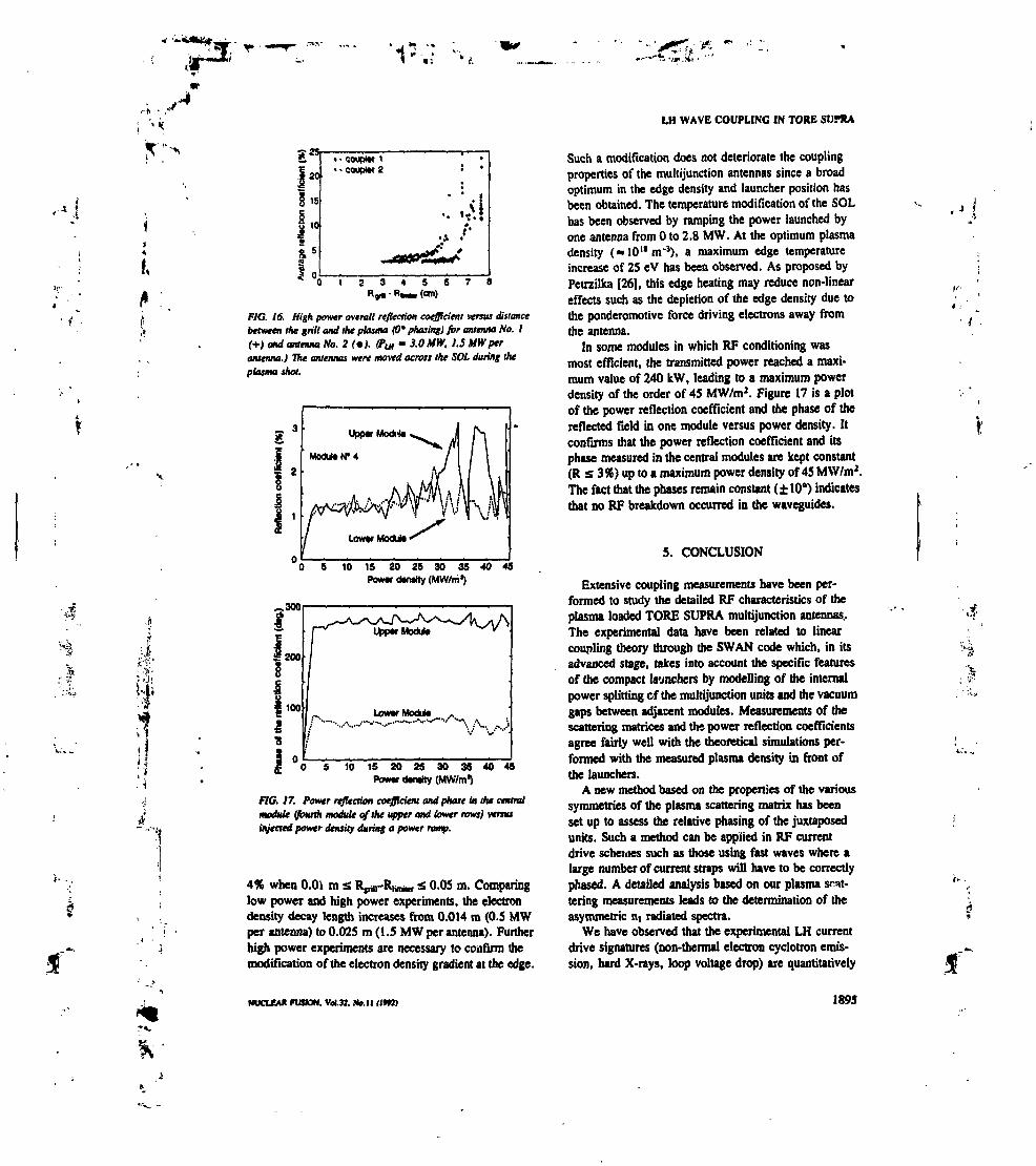
<!>'*•-,'ii •
LH WAVE COUPLING IN TORE SUPRA
j"f1»S 10
• coupMr 1•couptor 2
•A •
If
I
3 4
FW. 16. High power overall reflection coefficient versus distancebetween the grill ami the plasma (O* phasing) for antenna No. I(+) and antenna No. 2 (•). (Put - 3.0 MW, 1.5 MWptrantenna.) Tne antennas were moved across the SOL during theplasma shot.
E 3
1 2
, !
Upptr Modula
MoWtNM
O 5 10 15 20 25 30 35 40 45Poww dwafty (MVWm*)
-.30Or
O 5 10 15 20 25 30 35 40 45PDWW dtniity (MW/m1)
FlG. 17. Power reflection coefficient and phase in the centralmodule (fourth module of the upper and lower rows) versusinjected power density during a power ramp.
4% when 0.0» m a R^-RiMur £ 0.05 m. Comparinglow power and high power experiments, the electrondensity decay length increases from 0.014 m (0.5 MWper antenna) to 0.025 m (1.5 MW per antenna). Furtherhigh power experiments are necessary to coufirm themodification of the electron density gradient at the edge.
Such a modification does not deteriorate the couplingproperties of the multijunction antennas since a broadoptimum in the edge density and launcher position hasbeen obtained. The temperature modification of the SOLhas been observed by ramping the power launched byone antenna from O to 2.8 MW. At the optimum plasmadensity (-10"nr3), a maximum edge temperatureincrease of 25 eV has been observed. As proposed byPetrzilka [26], this edge heating may reduce non-lineareffects such as the depletion of the edge density due tothe ponderomotive force driving electrons away fromthe antenna.
In some modules in which RF conditioning wasmost efficient, the transmitted power reached a maxi-mum value of 240 kW, leading to a maximum powerdensity of the order of 45 MW/m2. Figure 17 is a plotof the power reflection coefficient and the phase of thereflected field in one module versus power density. Itconfirms that the power reflection coefficient and itsphase measured in the central modules are kept constant(R s 3%) up to a maximum power density of 45 MW/m2.The fact that the phases remain constant (± 10°) indicatesthat no RF breakdown occurred in the waveguides.
5. CONCLUSION
Extensive coupling measurements have been per-formed to study the detailed RF characteristics of theplasma loaded TORE SUPRA multijunction antennas..The experimental data have been related to linearcoupling theory through the SWAN code which, in itsadvanced stage, takes into account the specific featuresof the compact launchers by modelling of the internalpower splitting of the multijunction units and the vacuumgaps between adjacent modules. Measurements of thescattering matrices and the power reflection coefficientsagree fairly well with the theoretical simulations per-formed with the measured plasma density in front ofthe launchers.
A new method based on the properties of the varioussymmetries of the plasma scattering matrix has beenset up to assess the relative phasing of the juxtaposedunits. Such a method can be applied in RF currentdrive schemes such as those using fast waves where alarge number of current straps will have to be correctlyphased. A detailed analysis based on our plasma scat-tering measurements leads to the determination of theasymmetric n( radiated spectra.
We have observed that the experimental LH currentdrive signatures (non-thermal election cyclotron emis-sion, hard X-rays, loop voltage drop) are quantitatively
*.-..
NUCLCAIl FUSION. Vol.31. N*. 11 (1*R) 1895
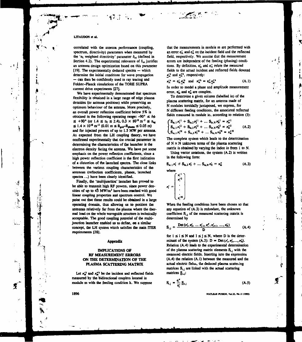
,-.. x LITAUDON et al.
Î,
correlated with the antenna performance (coupling,spectrum, directivity) parameters when measured bythe 'nt weighted directivity' parameter 5^ (defined inSection 4.2). The experimental relevance of 0« justifiesan antenna design optimization based on this parameter[19], The experimentally deduced spectra — whichdetermine the initial conditions for wave propagation— can then be confidently used in ray tracing andFokker-Planck simulations of the TORE SUPRAcurrent drive experiments [27],
We have experimentally demonstrated that spectrumflexibility is obtained in a large range of edge plasmadensities (or antenna positions) while preserving anoptimum behaviour of the antenna. More precisely,an overall power reflection coefficient below 5% isobtained in the following operating range: -90° a 50£ +90" (or 1.4 s ni s 2.4), 0.3 x 10 ll nr3 s n^s 1.4 x 10" nr1 (0.01 m s RpM-Rp1-. S 0,05 m)and for injected powers of up to 1.5 NfW per antenna.As expected from the LH coupling theory, we haveconfirmed experimentally that the crucial parameter indetermining the characteristics of the launcher is theelectron density facing the antenna. We have put someemphasis on the power reflection coefficients, since ahigh power reflection coefficient is the first indicationof a distortion of the launched spectra. The close linksbetween the various coupling characteristics of theantennas (reflection coefficients, phases, launchedspectra ...) have been clearly identified.
Finally, the 'multifunction' launcher has proved tobe able to transmit high RF powers, since power den-sities of up to 4$ MW/m2 have been reached with goodlinear coupling properties and spectrum control. Wepoint out that these results could be obtained in a largeoperating domain, thus allowing us to position theantennas relatively far from the plasma where the ther-mal load on the whole waveguide structure is technicallyacceptable. The good coupling potential of the multi-junction launcher enabled us to define, on a similarconcept, the LH system which satisfies the main ITERrequirements [28].
Appendix
IMPLICATIONS OFRF MEASUREMENT ERRORS
ON THE DETERMINATION OF THEPLASMA SCATTERING MATRIX
Let r£ and r^ be the incident and reflected fieldsmeasured by the bidirectional couplers located inmodule m with the feeding condition k. We suppose
that the measurements in module m are performed withan error e£, and e£ on the incident field and the reflectedfield, respectively. We assume that the measurementerrors are independent of the feeding (phasing) condi-tions. By definition, e^ and e£ relate the measuredfields to the actual incident and reflected fields denotedr£ and i£k, respectively:
i tf-eitf and •£" = e>»k (A.I)
In order to model a phase and amplitude measurementerror, e£, and e£ are complex.
To determine a given column (labelled io) of theplasma scattering matrix, for an antenna made ofN modules toroidally juxtaposed, we express, forN different feeding conditions, the associated reflectedfields measured in module io, according to relation (3):
ES r"
s0''/'
+ ...(A.2)
... 8*.*
The complete system which leads to the determinationof N x N unknown terms of the plasma scatteringmatrix is obtained by varying the index io from 1 to N.
Using vector notations, the system (A.2) is writtenin the following form:
S», 1*! +'
where
.! 1-2 + ... (A.3)
»'2
_'N
When the feeding conditions have been chosen so thatany equation of (A.3) is redundant, the unknowncoefficient S^ of the measured scattering matrix isdetermined by
(A.4)
for 1 S i S N and 1 s j S N, where D is the deter-minant of the system (A.3): D « Det(y;,y2,...,i-N).Relation (A.4) leads to the experimental determinationof the plasma scattering matrix elements S^ with themeasured electric fields. Inserting into the expression(A.4) the relation (A.I) between the measured and theactual electric field», the deduced plasma scatteiingmatrices S^ are linked with the actual scatteringmatrices S^:
O Î C /A *\Si.j * -; 2i.j (A.5)
•«I
1896 NUCLEAK FUSION, Vrt.32. No. 11 (IWl)

'«fi.
; v< LH WAVE COUPLING IN TORE S(JPRA
ff.
j
Relation (A.5) slates that a measurement error e,"occurring on the reflected field in module i leads toa multiplication by e"of all elements of the i-th lineof the experimental scattering matrix. Similarly, ameasurement error e,' in module j on the incident fieldleads to a multiplication by 1/e/ of the elements of thej-th column. These simple rules, together with the fieldreciprocity theorem, have been routinely used to qualifyour phase measurements and to analyse any detectederrors in such measurements.
REFERENCES
(I] BRAMBILLA, M., Nucl. Fusion 16 (1976) 47.(2] NGUYEN, T.K.. MOREAU, D,, in Fusion Technology
(Proc. 12th Symp. JQIich, 1982), Vol. 2. Pergamon Press,Oxford (1982) 1381.
[3] MOREAU, D.. NGUYEN, T.K.. in Pluma Theory (Proc.6th Int. Conf. Lausanne, 1984), Vol. >, Centre derecherches en physique des plasm», Ecole polytechnique,Lausanne (1984) 216.
[4] GORMEZANO, C., BRIAND, P., BRIFFOD, G., et al.,Nucl. Fusion 25 (198S) 419.
[S] KEDA, Y., IMAI, T., USHIGUSA, K., et al., Nucl.Fusion 2» (!989) 1815.
[6] GORMEZANO. C., BOSIA, G., BRUSATI, M., et al.,in Controlled Fusion and Plasma Physics (Proc. 18th Eur.Conf. Berlin, 1991), Vol. 15C, Pan m, European PhysicalSociety (1991) 393.
[7] MOREAU, D., TORE SUPRA Team, GORMEZANO, C.,Plasma Phys. 33 (1991) 1621.
{8] MOREAU, D., TORE SUPRA Team, Phys. Fluids B 4(1992) 216S.
[9] TONON. G., TORE SUPRA Team, in Fusion Technology(Proc. 14th Symp. San Diego, CA, 1991), IEEE, New York(1992), in press.
[10] UTAUDON. X.. BIBET, P.. GONICHE, M., et al., inControlled Fusion and Plasma Physics (Proc. 18th Eur.Conf. Berlin, 1991), Vol. ISC. Pan m, European PhysicalSociety (1991) 353.
[11] MAGNE, R., AYMAR, R., BERGER-BY, G., BIBET, P.,GONICHE, M., REY, G., TONON, G., in FusionTechnology (Proc. 15th Symp. Utrecht. 1988), Vol. 1.Pergamon Press, Oxford (1989) 524.
[12| REY, G., AYMAR, R., BERGER-BY, G,, et al., ibid.,p. 514.
113] MOREAU, D., NGUYEN, T.K., Couplage de fonde lenteau voisinage de la fréquence hybride basse dans les grandstokamaks, Rep, EUR-CEA-FC- 1246, Centre d'éludésnucléaires de Grenoble (1984).
[14) MOREAU. D., GORMEZANO, C., MELIN, G.,NGUYEN, T.K., in Radiation in Plasmas (Proc. SpringCollege Trieste, 1983). Vol. I. World Scientific, Singapore(1984) 331.
[15) BIBET, P., ACHARD, I., BERGER-BY, G., et al., inFusion Technology (Proc. ISUi Symp. Utrecht, 1989),Vol. I, Pergamon Press, Oxford (1989) 519.
[16] BIBET, P., ACHARD, J., BERGER-BY, G., el al.,Scattering Matrix of Tore Supra Lower Hybrid Antenna,Rep. EUR-CEA-FC-1390, Centre d'éludés de Cadarache,Saint Paul-Iez-Dunnce (1990).
(17) HURTAK, O., Plasma Phys. 32 (1990) 623.[18] PREINHAELTER, J., Nucl. Fusion 2» (1989) 1729.[19] UTAUDON, X., MOREAU, D., Nucl. Fusion 30 (1990)
471.[20] GORMEZANO, C., MOREAU, D,, Plasma Phys. 26 (1984)
553.[21] STEVENS, I.E., BELL, R.E., BERNABEI, S.. et al., Nucl.
Fusion 28 (1988) 217.[22] MOREAU, D., DAVID, C. GORMEZANO, C., et al., in
Application! of Radiofreqotncy Power to Plasmas (Proc. 7thTop. Conf. Kiuimee, Fl1 1987), American Institute ofPhysics. New York (1987) 137.
[23] PEYSSON, Y., BIZARRO, J.P., HOANG, G.T., et al., inControlled Fusion and Plasma Physics (Proc. 18th Eur.Conf. Berlin, 1991), Vol. 15C1 Part IV, European PhysicalSociety (1991) 345.
(24] LEUTERER, F., SÔLDNER, F., BRAMBILLA. M..MUNICH, M.. MONACO, F., ZOUHAR, M., PlasmaPhys. 33 (1990) 169.
[25] GONICHE, M.. REY, G.. BERGER-BY, G., et al., inRadiofrequency Heating and Current Drive of FusionDevices (Proc. Europhys. Top. Conf. Brussels, 1992),Vol. 16E, European Physical Society (1992) 69.
[26] PETRZILKA, V.A., Plasma Phys. 33 (1991) 365.[27] BIZARRO, I.P., HOANG, G.T., BERGER-BY, G., et al..
in Controlled Fusion and Plasma Physics (Proc. 18th Eur.Conf. Berlin, 1991), Vol. 15C, Part DI. European PhysicalSociety (1991) 357.
[28] TONON, G.. BIBET, P., BERGER-BY, G., et al., inFusion Technology (Proc. I6th Symp. London, 1990),Vol. 2. Elsevier, Amsterdam (1991) 1132.
if'
Ï :
(Manuscript received 13 January 1992Final manuscript received 29 June 1992)
NUCLEAR FUSION. Vot 32. No.lt (19*2) 1897

CHAPITRE II
PROPAGATION STOCHASTIQUE DE L'ONDE HYBRIDE,
DIFFUSION SPECTRALE ET REPONSE DU PLASMA
iILl. Introduction
La question de la propagation et de l'absorption résonnante des ondes hybrides dans les
plasmas de Tokamaks est évidemment essentielle pour leur utilisation efficace dans le but d'y
générer une partie du courant nécessaire au confinement du plasma, et plus particulièrement d'y
contrôler le profil radial de la densité de courant. Nous avons regroupé dans ce chapitre les
travaux qui se rapportent à cette question encore ouverte, car il faut bien reconnaître que nous
n'avons pas encore une description quantitative tout à fait satisfaisante de ces phénomènes.
Dès les premières expériences, les effets globaux observés sur le plasma furent assez
voisins des prédictions que l'on pouvait en faire même à partir de théories zéro-
dimensionnelles. Les difficultés survinrent lorsqu'il s'agit de décrire ou de simuler
numériquement de façon détaillée les caractéristiques spatiales et spectrales du dépôt de
puissance de l'onde dans les configurations géométrique et physique d'un plasma donné. Ce fut
d'abord le paradoxe du "gap" spectral qui engendra de nombreuses controverses dans les
années 1980 et auquel nous apporterons ici une réponse originale. Puis vint la question du
transport anormal des électrons et de ses conséquences sur l'efficacité de la génération de
courant et la non-localité de la réponse du courant à l'absorption de l'onde.
Enfin la mise au point de codes de simulation très lourds basés sur l'approximation de
l'optique géométrique a demandé de nombreuses années d'efforts, mais les incertitudes dans les
prédictions que fournissent ces outils néanmoins très utiles sont encore à l'origine de beaucoup
de discussions. Ces difficultés tiennent principalement à trois causes majeures. La première est
d'ordre expérimental car, si le couplage de l'onde est relativement "mesurable" (chapitre I), sa
I I -1

s*<rt < ,r
Jt^
ji
•*• •
propagation et l'évolution de son spectre dans un plasma de fusion sont terriblement difficiles à
diagnostiquer. Les vérifications expérimentales portent donc principalement sur la localisation
des électrons suprathermiques créés par l'onde, leur rayonnement, ainsi que sur les
conséquences indirectes de la génération de courant sur les paramètres locaux ou globaux de la
décharge (profil de la densité de courant totale, chauffage du plasma, mesures magnétiques,
cf. chapitre IV). Les deux autres causes sont théoriques et tiennent aux caractéristiques d'un
problème d'une part non-séparable - la propagation en géométrie toroïdale - et d'autre part
fortement non-linéaire, tant l'absorption de l'onde dépend de la distribution spatiale et
énergétique des électrons rapides qu'elle engendre.
Le plan de ce chapitre est le suivant. Un premier paragraphe (II.2) sera dédié à une
approche variationnelle de ce problème dans sa limite cylindrique. Ceci permettra de mettre en
évidence les principales caractéristiques physiques de la propagation et de l'interaction ondes-
particules dans le domaine de fréquence que nous considérons. Nous évaluerons ensuite (II.3)
les effets du transport anormal des électrons sur la génération de courant. Enfin nous étudierons
les conséquences de la non-séparabilité des équations de Maxwell et proposerons une théorie
permettant de décrire l'évolution spectrale de l'onde dans un Tokamak par un processus diffusif
(D.4). Certains phénomènes observés expérimentalement peuvent être facilement expliqués par
cette théorie. C'est le cas du "gap" spectral que nous évoquerons au paragraphe 11,4, et de
l'effet de la température du plasma sur l'efficacité de la génération de courant, que nous
traiterons pour terminer en section ÏÏ.5 avant de conclure en II.6.
II.2. Description variationnelle de la propagation et de l'absorption de l'onde
hvbride
L'approche variationnelle que nous avons développée (cf. *nnexe A.n.2) pour traiter
globalement les problèmes ondulatoires où la longueur d'onde est courte devant les dimensions
du système, n'a encore jamais été utilisée, à notre connaissance, pour décrire la propagation
d'ondes de plasma en milieu inhomogène. Elle est basée sur l'utilisation de fonctions d'essai
oscillantes qui sont des solutions locales du problème homogène et que nous appellerons
II-2
' '

*1*.T V.
"fonctions d'essai iconales". Son application est restreinte aux fréquences légèrement
supérieures à la fréquence hybride basse (ondes de Langmuir magnétisées et ondes "whistler")
de sorte que la résonance hybride proprement dite n'existe pas dans le plasma et que
l'interaction avec les ions est négligeable. Ce sont typiquement les fréquences que l'on utilise
pour la génération de courant
Les résultats présentés en A.n.2 ont été obtenus à l'aide d'un code de calcul numérique
(ELECTRE) où cette méthode est mise en oeuvre, dans un premier temps, pour des plasmas
cylindriques. Les profils de dépôt de puissance sont discutés et l'influence des principaux
paramètres du plasma et des ondes est étudiée. En particulier, l'influence du nombre d'onde
toroidal excité par l'antenne sur ces profils et sur l'accessibilité de l'onde au centre du plasma
est clairement observée. Le phénomène fa "whispering gallery", caractéristique de l'onde
hybride, ainsi que la forme et l'extension radiale du dépôt de puissance au voisinage des
caustiques correspondantes, sont également obtenus.
La généralisation de cette méthode à la géométrie toroïdale est en cours d'étude et
pourrait avoir un intérêt dans le cas d'un réacteur où l'absorption de l'onde sera relativement
forte au cours de son premier passage dans le plasma, c'est à dire avant la rencontre d'une
caustique. Il faut pour cela que l'indice parallèle de l'onde excitée par l'antenne soit grand et que
la température du plasma soit élevée. Quoi qu'il en soit ce programme nécessitera des
calculateurs très puissants. Il pourra être poursuivi dans un avenir relativement proche, avec
l'apparition d'une nouvelle génération d'ordinateurs.
Par contre, pour les expériences actuelles, c'est à dire dans des conditions de faible
absorption directe (nombres d'onde toroïdaux faibles), le calcul des champs électromagnétiques
et du dépôt de puissance en géométrie cylindrique permet de connaître la structure et \n taux
d'amortissement des modes normaux de la cavité cylindrique obtenue en "déroulant" le tore.
Nous verrons aux paragraphe n.4 l'utilisation qui peut en être faite.
•4
II-3

II.3. Réponse non-locale de la densité de courant due à la diffusion spatiale
des électrons suprathermiques
Nous considérons ici (cf. A.n.3) l'effet d'un transport anormal des électrons sur
l'efficacité de la génération de courant, et plus particulièrement ses conséquences sur le contrôle
du profil de courant. Le couplage entre une diffusion spatiale des électrons et leur diffusion
dans l'espace des vitesses donne naissance à une réponse non-locale du plasma lors d'une
excitation par absorption d'une onde HF. En généralisant le formalisme "adjoint" utilisé pour
l'étude de la réponse locale , il est possible d'en faire une analyse théorique dans le cas d'un
plasma homogène. On obtient alors sous forme explicite la fonction de Green non-locale
appropriée.
L'élargissement du profil de courant déposé et la diminution de l'efficacité globale de la
méthode sont discutés quantitativement en fonction des temps caractéristiques du ralentissement
collisionnel des électrons, T8, et de leur diffusion radiale, xd. Trois régimes sont distingués :
i) Si ts < Td, on donne l'expression de l'étendue radiale du dépôt de courant rapportée
au rayon de la colonne de plasma. Ce rapport est proportionnel à CVTj)1^2, mais le courant total
et par conséquent l'efficacité de génération de courant ne sont pas altérés par le transport.
ii) Si TS > Td, le courant non-inductif généré est distribué sur toute la section du plasma et
l'efficacité de la méthode est réduite d'un facteur proportionnel à ijid.
Ui) Si T, » rd, on donne l'expression du noyau non-local, X(r>r')» de l'intégrale
permettant de calculer le profil radial du courant généré connaissant celui de la puissance HF
absorbée ainsi que sa composition spectrale.
K- ..
i.. .-'•*»
' 4
JM. Rax, "Etudes sur la génération non-inductive de courant dans un plasma". Thèse de Doctorat, Universitéde Paris-Sud (Orsay), n° 3261,1987.
II-4
1V. &?•••
I.:
H.4, Equation pilote des modes normaux et diffusion spectrale de l'énergie
électromagnétique
Dans la limite cylindrique évoquée au paragraphe II.2, le champ électromagnétique peut
être analysé à l'aide de ses composantes de Fourier suivant les deux composantes angulaires,
toroïdales et poloïdales, chacune de ces composantes étant par ailleurs indépendante. Les
équations de Maxwell sont alors séparables. La géométrie toroïdale introduit un fort couplage
entre les harmoniques poloïdaux qui peut donner à la propagation de l'onde un caractère
irrégulier ou chaotique lorsque le rapport d'aspect du tore devient inférieur à un certain seuil de
stochasticité et que l'absorption de l'onde requiert de multiples passages à travers le plasma.
Nous appellerons ce phénomène le "chaos électromagnétique". Les Tokamaks ont un
rapport d'aspect voisin de 3, si bien que les deux conditions précédentes sont généralement
remplies au moins pour une partie du spectre rayonné par l'antenne. Il devient alors difficile de
décrire la propagation de façon déterministe car le tracé de rayons suivant les prescriptions de
l'optique géométrique est caractérisé par une grande instabilité aux petites variations des
paramètres ou des conditions initiales. La divergence exponentielle des rayons voisins rend
d'ailleurs le concept de front d'onde peu applicable dans de telles circonstances.
Nous donnons dans les annexes A.IIAa et A.IIAb les versions respectivement
abrégée et détaillée d'une théorie du "chaos électromagnétique" qui permet de décrire la
dynamique de l'onde comme un transfert irréversible d'énergie entre ses divers harmoniques
poloïdaux. Des couplages résonnants entre les "modes cylindriques", induits par la perturbation
toroïdale, en sont à l'origine et conduisent à la destruction des corrélations. On écrit alors une
équation pilote qui régit cette dynamique dans l'approximation des phases aléatoires. Une
méthode générale est ensuite proposée pour calculer de façon approchée les coefficients de
couplage et les probabilités de transition entre les modes normaux non perturbés, giàce à
certains résultats obtenus par le tracé de rayons.
Cette théorie permet de fournir une explication originale et certainement pertinente au
phénomène du "gap" spectral (A.IIAa). Un écart relativement grand existe en effet entre les
II-5
4 i '
•r;.«:, ":"î,x
f

-^ 'V.
1
vitesses de phase des ondes excitées par les antennes et les distributions de vitesse des électrons
dans les plasmas de Tokamaks. C'est ce que l'on appelle le "gap" spectral. Or on a toujours
observé une absorption très efficace de l'onde et les résultats obtenus par les expériences de
génération de courant ont été d'autant plus spectaculaires que les indices des ondes étaient
voisins de leur limite inférieure (cf. III. 1) et leur spectre fin, c'est à dire que cet écart était
grand. La diffusion spectrale de l'énergie électromagnétique est un mécanisme irréversible qui
permet à l'indice parallèle de l'onde de remplir de façon continue la fraction de l'espace des
phases qui lui est offerte jusqu'à ce que cet indice ait suffisamment augmenté pour que l'énergie
soit absorbée par effet Landau sur une population d'électrons résonnants.
ILS. Chaos électromagnétique et influence de la température sur l'efficacité de
génération de courant
Une autre conséquence de la propagation stochastique de l'onde hybride faiblement
amortis, et du remplissage du "gap" spectral par un processus diffusif est étudiée dans l'annexe
A.n.5. Elle est liée au fait que la largeur du spectre d'onde obtenu après diffusion dépend de la
température des électrons et que, par conséquent, le temps caractéristique pendant lequel cette
diffusion a lieu en dépend également. De nombreuses expériences (JT-60, JET) ont d'ailleurs
montré que l'efficacité de génération de courant des ondes hybrides dépendait fortement de la
température électronique moyenne du plasma.
Après avoir montré que la propagation des ondes hybrides dans TORE SUPRA et JT-60
était stochastique dans les domaines de paramètres ayant un intérêt, nous avons développé un
modèle qui permet d'expliquer l'effet de la température en prenant en compte l'absorption
parasite non-résonnante qui a lieu lorsque l'onde effectue de nombreux passages dans les
couches externes du plasma. L'accord entre les prédirions de ce modèle et les résultats
expérimentaux obtenus dans JT-60 est relativement satisfaisant. En particulier, la chute de
l'efficacité pour les températures faibles caractéristiques des petites machines est clairement
reproduite par le modèle.
U - 6
•"à

,.r"
I,
:•*.
II.6. Conclusion
Les recherches que nous avons résumées dans ce chapitre ont pour thème principal le
"chaos électromagnétique" pouvant naître de l'injection de puissance à la fréquence hybride
inférieure dans les Tokamaks, en particulier dans les conditions appropriées à la génération de
courant. Ces recherches se poursuivent encore actuellement et visent à donner de l'interaction
de ces ondes avec le plasma une compréhension plus fine et une description plus correcte que
celles dont on disposait au moment des premières investigations expérimentâtes. L'aspect
cinétique du problème est relativement bien compris et il est possible de calculer la réponse du
plasma par l'intermédiaire d'une fonction de Green appropriée en supposant connu le spectre de
puissance absorbée. La difficulté réside dans la détermination du spectre de la puissance
absorbée et de sa distribution radiale, dans une situation où l'onde rencontre plusieurs
caustiques ("whispering gallery", réflexions, conversions branche lente/branche rapide) et où sa
vitesse de propagation varie continuellement jusqu'à ce qu'elle satisfasse les conditions locales
de résonance avec une population électronique qui dépend elle-même fortement du profil
d'absorption de l'onde. D'autre part, la coexistence est fréquente, dans le spectre excité par une
antenne réelle, de composantes dont la propagation est stochastique et de composantes dont la
propagation est régulière ou l'absorption plus directe. Ceci rend difficilement crédible une
approche purement probabiliste appliquée à tout le spectre et dans tous les cas.
Malgré tout, les conséquences de l'aspect stochastique de la propagation et de son
caractère universel, par essence probabiliste, sont appréciées depuis peu à leur juste valeur, et
considérées avec sérieux dans des simulations cherchant à produire des profils de dépôt de
puissance relativement robustes et reproductives vis à vis des variations faibles de certains
paramètres. Comme nous l'avons montré en A.H4, les ingrédients essentiels (recouvrement de
résonances, probabilités de transition) d'une description statistique utilisant une base de modes
normaux peuvent être déduits de l'étude des trajectoires des rayons dans l'approximation de
l'optique géométrique. Un moyen pragmatique de la mettre en oeuvre est d'utiliser un code de
tracé de rayons et de découper le spectre excité par l'antenne de façon extrêmement fine. Cela
II-7
t
.t '1*3' ^,
' 4
revient à considérer un ensemble très dense de conditions initiales voisines pour remplir
uniformément de façon statistique tout le domaine de l'espace des phases accessible à l'onde .
C'est une méthode très coûteuse en temps de calcul. Elle a par contre l'avantage d'utiliser les
codes disponibles et ces codes permettent d'obtenir une solution auto-cohérente de l'interaction
quasi-linéaire entre l'onde et les particules (tracé de rayons + équation de Fokker-Planck) dans
les situations expérimentales réelles.
Dans certains cas typiques de TORE SUPRA, nous avons pu faire une comparaison
poussée entre les taux et profils d'absorption des modes cylindriques obtenus respectivement
par le code ELECTRE et par le tracé de rayons. Ceux-ci coïncident sauf pour quelques modes
extrêmes, à la frontière du domaine de propagation dans l'espace des phases, et pour lesquels la
longueur d'onde radiale devient trop grande et l'optique géométrique n'est pas du tout adaptée.
Une description diffusive de la dynamique de l'onde dans la limite semiclassique
continue peut aussi être faite à l'aide d'une équation d'onde cinétique équivalente à l'équation
pilote des modes normaux, en utilisant les taux et profils d'absorption de ces modes
cylindriques dont le calcul est rapide par l'une ou l'autre des deux méthodes mentionnées à
l'instant Cette étude donne des résultats encourageants (cf. A.II.6) II s'avère en particulier que
la valeur précise du coefficient de diffusion spectrale de l'énergie électromagnétique, Dondes(m),
très difficile à calculer, n'a pratiquement aucune influence sur le dépôt de* puissance de l'onde
résultant de son interaction quasi-linéaire auto-cohérente avec la fonction de distribution des
électrons, fe(v). Ceci nécessite que le coefficient de diffusion quasi-linéaire des particules,
Dparl(v), soit suffisamment grand, mais c'est toujours le cas pour l'onde hybride. Ce
phénomène est dû à une propriété d'auto-régulation du quasi-plateau de la fonction de
distribution des électrons dont la dérivée n'est pas tout à fait nulle mais s'ajuste au coefficient de
diffusion quasi-linéaire de façon à ce que le flux, Lp811Vv)Bf^v, soit fini e; donné. Or les
résonances ondes-particules établissent une correspondance entre la vitesse v et le nombre
r».
}.P. Bizarre, Thèse de Doctorat, Université de Provence, Aix-Marseille I, soutenance prévue en juin 1993.
I I -8

WWB'
-
g.*'
à
d'onde poloïdal m. A la résonance, Dpan(v) est proportionnel à la densité d'énergie
électromagnétique, U(m), dans l'espace des nombres d'onde poloïdaux, et inversement le taux
d'amortissement de l'onde, y(m), est proportionnel à dfjdv. On voit donc sans difficulté que le
produit v(m)U(m) est lui aussi fixé indépendamment de Dondes(m). Par contre U(m), et donc
y(m), en dépendent par l'équation :
à laquelle on doit ajouter les termes "source" appropriés pour m = O. Comme la réponse du
plasma (II. 3) est une fonctionnelle linéaire de la puissance absorbée, 2 7(111) U(m), et non pas
de la densité d'énergie, U(m), ce résultat est relativement intéressant car il permet d'évaluer le
profil de dépôt de puissance et de densité de courant générée sans avoir besoin de connaître le
coefficient de diffusion stochastique des ondes, D
Du point de vue de la physique fondamentale une question intéressante se pose
également. C'est de savoir dans quelles limites l'existence d'un chaos hamiltonien dans la
dynamique (de type classique) des rayons de l'optique géométrique suffit pour justifier
l'approximation des phases aléatoires dans une description modale discrète (de type quantique)
et ses conséquences sur l'irréversibilité du couplage des modes normaux discutée en 11.4.
Compte tenu de l'extrême densité des modes en présence aux fréquences élevées que nous
considérons, nous avons admis de façon intuitive que, si tel n'était pas le cas, l'existence d'un
faible bruit extrinsèque (fluctuations, turbulence) suffirait de toute façon à brouiller les phases et
à passer d'une évolution déterministe à un processus probabiliste avec production d'entropie.
Nous savons en effet que dans les problèmes hamiltoniens classiques de nature pourtant
déterministe, la fonction de distribution développe des structures aussi fines que l'on veut
lorsque la dynamique est stochastique, car l'espace des phases est continu et les trajectoires
divergent en conservant malgré tout les "aires" da»s cet espace. Un bruit aussi infinitésimal que
l'on veut suffit alors à brouiller ces structures fines et à justifier la diffusion quasi-linéaire,
irréversible.
I I -9
~*i

f

*,ANNEXE AU CHAPITRE II
A.II.2. Variational Description of Lower Hybrid Wave Propagation and Absorption in ' • *
Tokamaks, D. MOREAU, Y. PEYSSON, J. M. RAX, A. SAMAIN, J. C. DUMAS, Nuclear • * ' ^
Fusion 30 (1990) 97.
A.n.3. Non-Local Current Response in Wave Driven Tokamaks, J. M. RAX, D. MOREAU, tA
Nuclear Fusion 29 (1989) 1751. !
A.II.4.3. Lower Hybrid Wave Stochasticity in Tokamaks : A Universal Mechanism for
Bridging the N// Spectral Gap, D. MOREAU, J. M. RAX, A. SAMAIN, in Proceedings of the
15th EUT. Conf. on Contr. Fusion and Plasma Heating, Dubrovnik, 1988, Vol. IH, 995.
A.II.4.b. Normal Mode Master Equation for the Distribution of Lower Hybrid
Electromagnetic Energy in Tokamaks, D. MOREAU, J. M. RAX and A. SAMAIN, Plasma 4
Physics and Controlled Fusion 31 (1989) 1895. ^ I& &V i';;; '
A.IL5. Wave Chaos and the Dependence of LHCD Efficiency on Temperature, K. KUPFER, 'x i,(>*j S
> I D. MOREAU, Nuclear Fusion 32 (1992) 1845. ^
:j L,. ;}H A.II.6. Statistical Approach to LHCD Modeling using the Wave Kinetic Equation, ( J
v K. KUPFER, D. MOREAU, X. LITAUDON, Communication à la "10th Topical Conference un '
I Radio Frequency Power in Plasmas", Boston, Mass. (USA), 1-3 avril 1993. £. ;,

.4'
VARIATIONAL DESCRIPTIONOF LOWER HYBRID WAVE PROPAGATIONAND ABSORPTION IN FUSION PLASMAS
D. MOREAU, Y. PEYSSON, J.M. RAX, A. SAMAIN, J.C. DUMAS*CEA, Centre d'études nucléaires de Cadarache,Association Euratom-CEA sur la fusion contrôlée,Sunt-PauMez-Durance, France
- - I
ABSTRACT. A variational approach to a global solution of the lower hybrid wave propagation and absorption infusion plumas ii presented. It is restricted to current drive or electron heating applications (i.e. when no lower hybridresonance exists) and is based on the use of trial functions which are locally solutions of the homogeneous problemCeikonal trial (unctions'). Results in circular cylindrical geometry are presented for which radial power depositionprofiles have been calculated. The influence of the main plasma and wave parameters has been investigated, focusingon the effect of the toroidal wave number on the power deposition and also on the wave accessibility and the * whisperinggallery' phenomena. The radial extension and shape of the power deposition new the reflection layer of inaccessiblewavei (caustics) are displayed.
J
1. INTRODUCTION
A number of numerical codes have succeeded ingiving a full wave description of the electromagneticfield during additional heating in tokamaks for the ioncyclotron range of frequencies [1-6]. However, becauseof the much smaller wavelengths and therefore the largenumber of degrees of freedom of the wave field, thenumerical methods used in these codes cannot bedirectly extrapolated to the lower hybrid (LH) frequencyrange or to higher frequencies. Variational techniquesprovide an efficient scheme to describe in a globalmanner both the propagation and the absorption ofelectromagnetic waves in plasmas. We describe herea new method of giving a global wave description ofndiofrequency (RF)- fields in the LH frequency range,with the aim of studying current generation and profilecontrol via Landau absorption in tokamaks. So far, suchstudies have been carried out by using combined raytracing and Fokker-Planck numerical codes [T]; however,in some instances the geometrical optics fails to hold[8] and leads to large ndial and spectral uncertaintiesregarding the power absorption of LH waves. Hence,in these cases the profile of the RF driven current ishardly predictable. Such situations occur in particularwhen the LH rays suffer multiple reflections betweenthe low density cut-off layer at the plasma edge and
* CISI Ingénierie, Centre d'études nucléaires de Cadancbe,13106 Saint-Paul-lez-Durance Cedex. France.
NUClEA* FUSION. V«UO. NQ. I (MlO)
the 'whispering gallery' or 'accessibility' layer beforebeing significantly damped. For the highest phasevelocity part of the launched spectrum, such a multi-reflection process can lead to an 'electromagnetic chaos'for which again geometrical optics is not appropriate[9, 1O]. Instead, in this stochastic regime, the wavedynamics in real geometry can be described as a quasi-linear exchange of electromagnetic energy between alarge number of LH modes in the limiting separable(cylindrical) geometry.
A global, full wave analysis would therefore bemuch appreciated since LH waves are used to controlthe plasma current profile and to optimize varioushybrid (Ohmic + LH) tokamak operation scenarios inpresent generation machines, such as TORE-SUPRAand JET, and in future fusion reactor prototypes, suchas NET and TTER.
The variational scheme that we describe in this paperis restricted to the current drive or electron heatingapplications of LH waves, i.e. when the frequency issufficiently high that no lower hybrid resonance exists.The method is based upon the use of trial functionswhich are local solutions of the homogeneous problem;they will be referred to as 'eikonal trial functions'. Inthis frequency range, the cold dispersion relation supportstwo independent modes of propagation, the slow wave(cold electrostatic plasma wave) and the fast wave(whistler wave), which have well defined wave vectorsand polarizations in a homogeneous plasma layer. Then,over a scale length which can be larger man a wave-
97
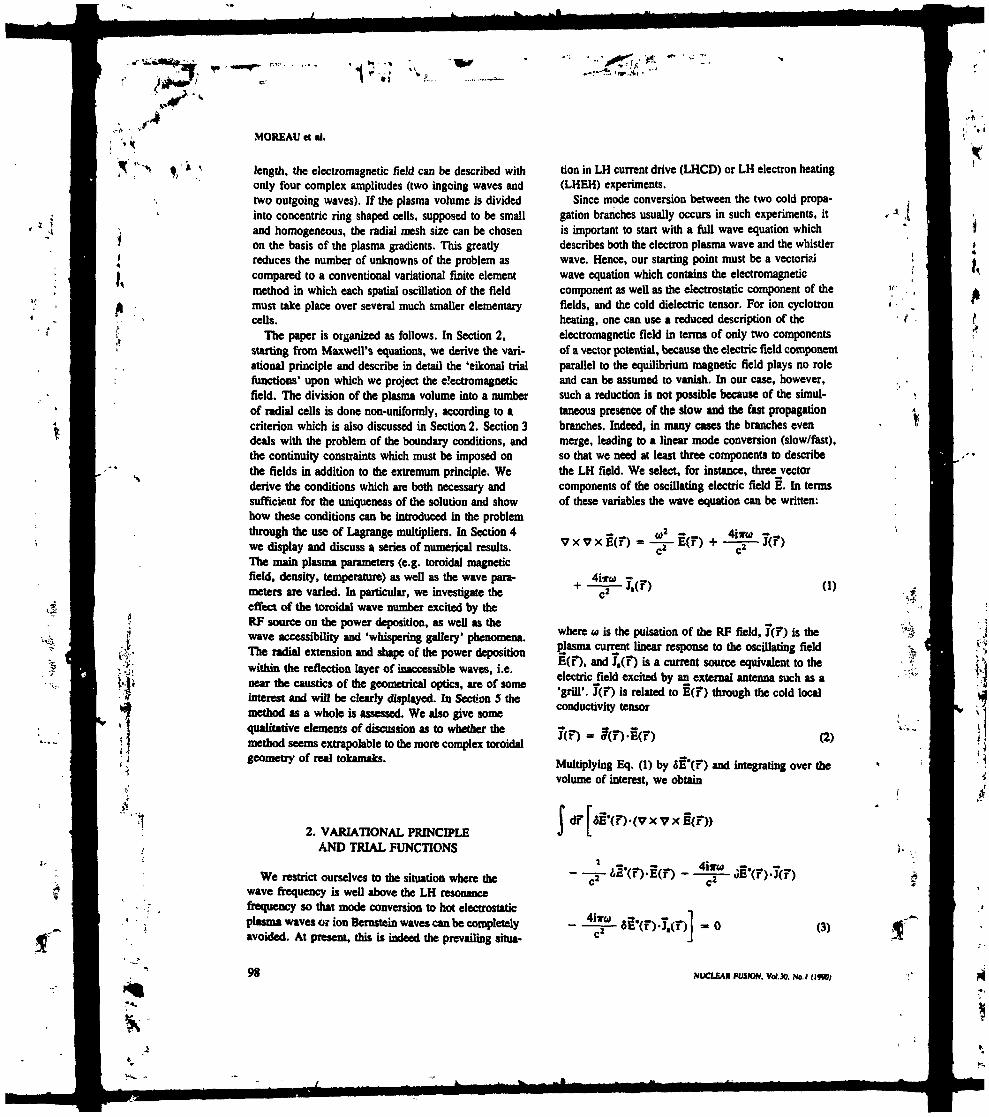
'1' *1
MOREAU Ct •!.
Ï v
1
length, the electromagnetic field can be described withonly four complex amplitudes (two ingoing waves andtwo outgoing waves). If the plasma volume is dividedinto concentric ring shaped cells, supposed to be smalland homogeneous, the radial mesh size can be chosenon the basis of the plasma gradients. This greatlyreduces the number of unknowns of the problem ascompared to a conventional variational finite elementmethod in which each spatial oscillation of the fieldmust take place over several much smaller elementarycells.
The paper is organized as follows. In Section 2,starting from Maxwell's equations, we derive the vari-ational principle and describe in detail the 'eikonal trialfunctions' upon which we project the electromagneticfield. The division of the plasma volume into a numberof radial cells is done non-uniformly, according to acriterion which is also discussed in Section 2. Section 3deals with the problem of the boundary conditions, andthe continuity constraints which must be imposed onthe fields in addition to the extremum principle. Wederive the conditions which are both necessary andsufficient for the uniqueness of the solution and showhow these conditions can be introduced in the problemthrough the use of Lagrange multipliers. In Section 4we display and discuss a series of numerical results.The main plasma parameters (e.g. toroidal magneticfield, density, temperature) as well as the wave para-meters are varied. In particular, we investigate theeffect of the toroidal wave number excited by theRF source on the power deposition, as well as thewave accessibility and 'whispering gallery' phenomena.The radial extension and shape of the power depositionwithin the reflection layer of inaccessible waves, i.e.near the caustics of the geometrical optics, are of someinterest and will be clearly displayed. In Section 5 themethod as a whole is assessed. We also give somequalitative elements of discussion as to whether themethod seems extrapolable to the more complex toroidalgeometry of real tokamaks.
2. VARIATIONAL PRINCIPLEAND TRIAL FUNCTIONS
We restrict ourselves to the situation where thewave frequency is well above the LH resonancefrequency so that mode conversion to hot electrostaticplasma waves or ion Bernstein waves can be completelyavoided. At present, this is indeed the prevailing situa-
tion in LH current drive (LHCD) or LH electron heating(LHEH) experiments.
Since mode conversion between the two cold propa-gation branches usually occurs in such experiments, itis important to start with a full wave equation whichdescribes both the electron plasma wave and the whistlerwave. Hence, our starting point must be a vectoriaiwave equation which contains the electromagneticcomponent as well as the electrostatic component of thefields, and the cold dielectric tensor. For ion cyclotronheating, one can use a reduced description of theelectromagnetic field in terms of only two componentsof a vector potential, because the electric field componentparallel to the equilibrium magnetic field plays no roleand can be assumed to vanish. In our case, however,such a reduction is not possible because of the simul-taneous presence of the slow and the fast propagationbranches. Indeed, in many cases the branches evenmerge, leading to a linear mode conversion (slow/fast),so that we need at least three components to describethe LH field. We select, for instance, threejvectorcomponents of the oscillating electric field E. In termsof these variables the wave equation can be written:
VXVxI(F) 4-2(F)*
(i)
where w is the pulsation of the RF field, T(F) is theplasma current linear response to the oscillating fieldE(F), and J1(F) is a current source equivalent to theelectric Jield excited by an external antenna such as a'grill*. T(F) is related to l(F) through the cold localconductivity tensor
J(F) = ?(F)-I(F) (2)
Multiplying Eq. (1) by fiI'(F) and integrating over thevolume of interest, we obtain
H51'(F)-(VXVxI(F))
--^-61'(F)-I(F)-
-J^L6I-(F)T1(F)] -O
- « I
(3)
98 NUCLEAR FUSKW. Vol.». No. I (ItK)

I,A,»
Now, using
*I'(F)-(Vx VxE(F)) = (V x E(F)HV xfil'(F))
+ V-I(VxE(F)) x ÔÊ*(F)J (4)
we find
f dF F(V x E(F)HV x oI'(F)) - - - ôI'(F)-Ê(F)
+ \ dan-[(V x E(F)) x OE-(F)J » O (5)Jc
Let us consider the following functional:
L(I, §') - f dF F(V X I(F))-(V X 1'(F))
E-(F)-R(F)-E(F)-
(6)
where R represents the cold dielectric tensor. SupposeE(F) is a solution of Maxwell's equations (1); then,varying §'(?) by SB'(?) entails a variation SL whichvanishes exactly according to Eq. (S), Jot all variations£E*(F) subject to the condition n x SE' - O on theboundary, which is assumed to be metallic. Conversely,if OL vanishes identically for any variation 5E"(F)subject to the boundary condition n x 5§* = O, ihenEq. (5) and hence Eq. (3) hold for any such SE'(T);therefore, E(F) must be a solution of our wave equa-tion (1) at every point inside the volume V, However,the stationarity of the variational form L(E, E') has tobe searched only among those vector fields whichsatisfy the boundary condition n x I « O becausesuch a condition is not necessarily a consequence ofL being stationary. This type of boundary conditioncan be called 'principal boundary condition* [11]and will play an important role in the following(see Section 3).
Our problem is therefore equivalent to finding thestationary point of the bilinear fbrm_L(Ê, Ë') withrespect to all possible variations of I*(F), subject tothe condition n x SE' * O on the boundary £ togetherwith the principal condition n x I » O on the same
IWCLEAIl FUSION. VdJO, No. I (IWO)
LH WAVE PROPAGATION AND ABSORPTION IN PLASMAS
boundary. In fact, provided some dissipation (eveninfinitesimal) is assumed to take place at every pointwithin the volume V [12], it can be shown that thefield inside the volume is uniquely determined whenevern x § is given at each point of the boundary. Inparticular, for a perfectly conducting boundary, thecondition
n x E = O on S (7)
is sufficient to ensure the uniqueness of the solution.Later on, we shall use cylindrical co-ordinates r,
9 and <t> = z/Ro (see Fig. 1), and perform a Fourieranalysis with respect to the poloidal angle O and thetoroidal angle <t> =* 2/R0 (R0 is the major radius of thetoroidal plasma and z is a linear co-ordinate which runsalong the axis of revolution in the cylindrical limit ofthe torus). It will be convenient to assume that thecurrent source T1(F) is always entirely inside the volumeof interest. This is the case in experiments where themouth of the multi-waveguide antenna has to bepositioned inside the plasma scrape-off layer, at alocation where the plasma density 1V1n-I exceeds thecut-off density D011^t [13] by
(8)
Here, Nt is thejvave index parallel to the equilibriummagnetic field B0 and u |HIMM is the plasma1 frequency(in rad-s'1) at the antenna.
Because of the small wavelengths involved in theproblem, performing a discretization of the variationalform on a scale length which is smaller than the wave-length would require a prohibitively long processingtime. As a consequence, we must use trial functionswhich can approximate the solution over severalwavelengths. We therefore divide the plasma volume
FlC. 1. Schematic view of ate tokomok plasma showing the systemof co-ordinates and Ae motional transform.
99f"
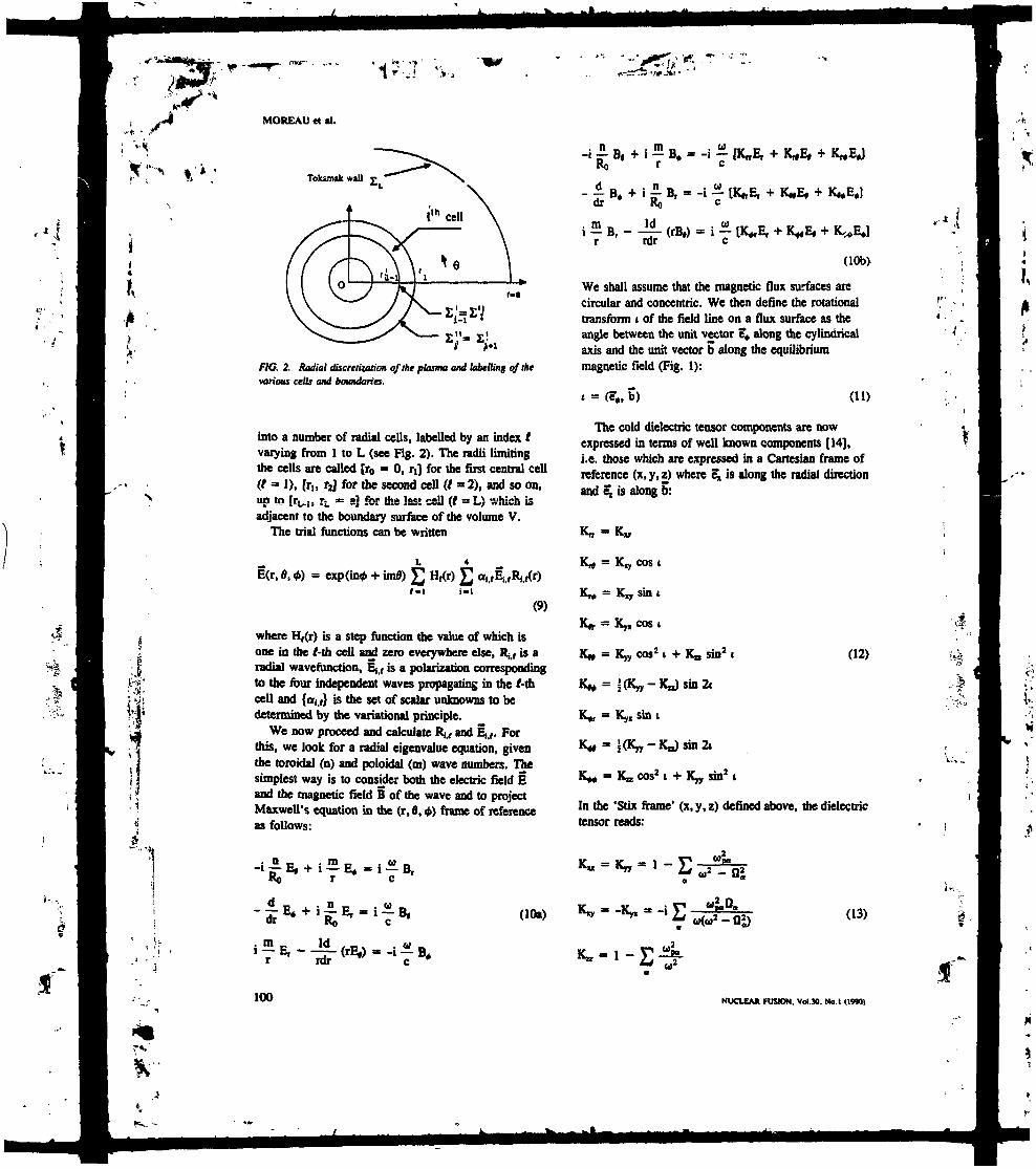
! VH-
-m*
MOREAU «t al.
Toksmak wall
FIG. 2. Radial discretization of the plasma and labelling of thevarioia cells and boundaries.
into a number of radial cells, labelled by an index tvarying from 1 to L (see Fig. 2). The radii limitingthe cells are called [r0 * O1 rj for the first central cell(t = 1), [r,, rj for the second cell (/ - 2), and so on,«p to [r^ij rL « a] for the last cell (t ^ L) which isadjacent to the boundary surface of the volume V.
The trial functions can be written
-i B, + i - B, » -i [KnE,KO r c
- B. + i B, = -i - [K11E, + K*E, +dr RO c
y B, - - . (rB,) - i ±
(10b>
We shall assume that the magnetic flux surfaces arecircular and concentric. We then define the rotationaltransform t of the field line on a flux surface as theangle between the unit vector e* along the cylindricalaxis and the unit vector b along the equilibriummagnetic field (Fig. 1):
ft, b) (U)
The cold dielectric tensor components are nowexpressed in terms of well known components [14],i.e. those which are expressed in a Cartesian frame ofreference (x, y, z) where SJ1 is along the radial directionand £ is along b:
, 1
4&
exp(in* + im») H,(r)
(9)
where H,(r) is a step function the value of which bone in the Mh cell and zero everywhere else, Rj,, is aradial waverunction, Ej1, is a polarization correspondingto the four independent waves propagating in the Mhcell and {<*{,,} is the set of scalar unknowns to bedetermined by the variational principle.
We now proceed and calculate Rj., and E1.,. Forthis, we look for a radial eigenvalue equation, giventhe toroidal (n) and poloidal (m) wave numbers. Thesimplest way is to consider both the electric field Eand the magnetic field B of the wave and to projectMaxwell's equation in the (r, O, <t>) frame of referenceas follows:
dr
1T1
100
Ro
Id
(10«)
= K cos
sin i
Kx, cos i
Ky, cos2 1 + K0 sin2 t
J(Ky5, -Kn) sin 2i
Ky1 sin i
(12)
K^ = Kn cos21 + Kyy sin2 i
In the 'Stix frame* (x, y, z) defined above, the dielectrictensor reads:
K11 - Kn « 1 - JJ J"•
03)
NUCLEAK FUSION. Vol.30. No. I (1990)
.4

LH WAVE PROPAGATION AND ABSORPTION IN PLASMAS
where the various frequencies appearing in Eqs (13)are the plasma frequencies Wp0 and the cyclotronfrequencies Q0, for each species a (ions and electrons)composing the plasma, and where we have used theconvention that R, is negative for the electrons.
To find 'eikonal trial functions1 which are appropriateto the cylindrical geometry, we remove the singularityat r * O by introducing a new radial variable J suchthat
r = a exp(f)
Thus, the singularity appears at £ » -co. This procedureis commonly used when one wishes to apply the WKBapproximation to radial equations [IS]. The advantageof this change of variables in our case is that eigen-runctions of the type exp(X£) become the simplemonomial functions r\ where X » a + i/3 is a complexnumber. These are indeed the simplest functions whichcan approximate both the analytic behaviour of the fieldsnear the singularity at t « O ('whispering gallery'effect) and the propagative nature of the wave awayfrom the magnetic axis.
Introducing also Ic0 » wfc, system (10) becomes:
-i ko a exptf) B, 4- i - - exp($) E,RO
The eigenrunctions exp(X£) or r* can be obtained fromthis system in the limit where we neglect the variationof r together with the variation of the plasma parameterswithin a cell. We .shall therefore divide the volume Vnon-uniformly into ring shaped radial cells whose widthis a given fraction, TJ, of the inhomogeneity scale lengthin the sense given above, i.e.
Max (15)
The 'eikonal trial function' can then be expressed as afunction of r as
£ H,(r) JJJ-I i-I
(16)
where, in each cell, the X1,, (i * 1, 4; t « 1, L) arethe eigenvalues associated with a 4 x 4 matrix (seesystem (14a)) which physically correspond to the slowand fast waves propagating both inward acd outward.Associated with each of these four values h a polariza-tion vector for the electric field E1,, which is nothingbut an eigenvector of system (14).
M"
I
- - « -E, + i It0 a exptf) B* + imE,3. PRINCIPAL BOUNDARY CONDITIONS,
NATURAL BOUNDARY CONDITIONS,LAGRANGE MULTIPLIERS
dB* an-jf- = i -=— exp($) B, + i kb a exp(f)df R0
x [K^E, + K11E, +
dB,-B, + imB, - i ko a exp($)
x [K^E, + K^E, +
with
(Ua)
+ rVB,
--£-«. -K-D]
NUCLEAK FUSION. Vol.30. No.l (l«m
(Wb)
Before performing the discretization of the varia-tional form, it is important to find those boundaryconditions or continuity conditions which must bespecified at the interfaces between the various cellsfor the problem to be well posed. These conditionswill become constraints on the variational principle.
Following Réf. [11], we must differentiate betweentwo kinds of conditions: principal boundary conditionswhich must be imposed (e.g. n x § » O on S), andnatural boundary conditions, i.e. those which will beautomatically satisfied once the stationarity of thefunctional L(I, E*) is found. For this purpose, welet V, be the volume associated with the f-th cell andVf the same volume when we intend to exclude itsboundaries. Let us also assume, without any loss ofgenerality, that the cum.-, scarce 7,(F) consists onlyof current sheets which circulate between one pair orseveral pairs of cells, for example the (L-l)-th and theL-th ones. From now on, we also distinguish betweenthe fields on each side of a cell border by labelling
101

MOREAU «t «I.
them with the index of the cells (e.g. E,(r,) differs inprinciple from E*f+l(r() because of the discontinuity at Tf).
As in Section 2, we multiply Eq. (1) by 5EJ(F) ineach cell, and integrate over the volume VJ (excludingits boundaries). After using Eg. (4), summing overall cells, and assuming that 6EJ(F) is continuous anddifferentiable in VJ, we obtain
c&'h
+ f dan,-[(Vx 1,(F)) x 8EJ(F)JJ O (17)
where Ef refers to the total boundary surface of the Mhcell, including its two sheets (Fig. 2):
(18)
The argument of the preceding section can now beextended and, after some algebra, we obtain the firstresult: If E(D is a solution of our problem, withn x 1 = O on E, then the functional
£(!,!•) E [( . df T(V x (VXEJ(D)
Conversely, if JC(E, E') it stationary for anyOEJ(F) satisfying Eqs (20) and (21), we have thefollowing results:
(a) At every point within the volume V1 of a cell,the Euler's equation
V X V X E ( F ) -
is satisfied,
^-J(F) = 0(22)
(b) When there is no current sheet source on ammon boundary between two cells (E" * EJ+ 1).en
commonthen
(23)n, x (V x E,) + Hl+1 x (V x 1,+j) « O
on E," - E/+,
The continuity^of^n x (V x I) it therefore a conse-quence of £(1, 1') being stationary and we need notimpose such a condition. However, acihizg preventsn x E from being discontinuous, and therefore wemust impose
n, x I, + nVn X EV,., - O on E," - E,V, (24)
(c) The same as in (b) applies when there is a currentsheet source JJ" on E1" = E('+lt except that
n, x (VXE,) + n,+I x (VXE,+,) - - TW
- - - EXD-
(19)
where JJ^(F) is a current sheet source on E", isstationary for all variations JEJ(F) satisfying theconstraint*stationaryconstraints
n, x si; + n,+, x «I;
nL x SEi * O
on E" « E;+I (25)
The set of constraints (24) must also be fulfilled in thiscase.
(d) Since there is no current source on the metallicboundary E of the volume V, and since 5 x $1* » Oon this surface, the yariational principle does not tellanything about n X E on E. We must therefore alsoimpose
+, « O on all E," - EJ+1 (20) n x E - O cm E (26)
on E£ » E (21)
The signs in Eq. (20) are consistent with the tact thatthe outward normals n, and n/+) to the t-\h cell andthe (/ + l)-th cell are opposing each other at r » rf.
102
We call the conditions that n x 1 vanish or becontinuous 'principal boundary conditions' (i.e. thosewhich must be imposed as constraints on the varia-tional principle). The conditions on n x (v x E) arenecessarily satisfied when the functional JC(1,1*) is
NUCLEA* FUSION. VoIJO. No.I (IfIO)

Ui
1
1
stationary and need not be specified as constraints;they are termed 'natural boundary conditions' [U].In the remaining part of this section, we shall derive amatrix representation of the variational principle underthe constraints specified above and obtain, its formalsolution. Such a matrix representation of the functionalJC(I, B') follows directly from the discretization of thevolume V into elementary volumes V, (t » 1, L) and isparticularly suitable for numerical analysis. It canobviously be written:
£(X,X') « X + -I -X-X + -S (27)
where X is the vector whose components are the alit's(see Eq. (9)) and the subscript + means the transposedcomplex conjugate (i.e. Hermitian adjoint for an operator).A is a bilinear form represented by a square matrix ofdimension 4L - 2, because two unphysical solutionsfor Xj,, in the central cell must be rejected since theywould lead to singularities at r » O. S is a vectorrepresenting the current source.
The matrix elements of A can be calculated in astraightforward manner owing to the simplicity of ourtrial functions. Moreover, the cells do not overlap andtherefore they are absolutely decoupled except throughthe constraints. Consequently, X is diagonal by blocksof dimension 4 x 4. If A(O is such an elementaryblock corresponding to the Mh cell, its elements aregiven by
•8 ( dfJv;
(28)
As nr as the elements of the source vector S areconcerned, they are given by
(29)
when the source has been explicited as
L-I _
exp(in« + imff) £ S(t - r,) J,f-i
NUOEAIl FUSION. Vol.». Np. I (IfN)
(30)
» •»..*, • • '
LH WAVE PROPAGATION AND ABSORPTION IN PLASMAS
with
Ji - Jf.« ?» + Jf,. * (31)
The constraints inherent in the principal boundaryconditions can be written as
é «it (VEii.)rL'L = O (32a)
(32b)i-i
4
(33a)i-l
i-i
i-l
This, again in matrix form, simply reads
1-X - O
(33b)
(34)
where § is a large rectangular matrix. We now wantto find a vector X which nukes the form (27^Jtationaryunder the constraint (34), for any variation £X* restrictedby the condition
' - O (35)
This can be best achieved by using the method ofLagrange multipliers, Le. by noting that such a vectorX will also make the following form stationary
JS1(X, X*. X) - X+-(X-X- S) + X+-I+-A (36)
where X a constant, under the same conditions(B-X « O and 8X+-I+ - O).
We then find that the best approximation of theelectric Jfcld I in the form given in Eq. (9) (Le thevector X) as well as UK t X of Lagrange multiplie-s(the vector A) is obtained by solving the followinglinear system of equations:
X-X + I+-A » S (37a)
103

.-*
; ViJ
X--
"•7«.'
'1
MOREAU M al.
lot (37b)
If uniqueness is assessed, i.e. if there is some dissipationat every point in the volume V (see Section 2), then
it, can be. shown that the matrix A is regular and thatB-A-'- 5* is also regular. Such a proof will be givenin the Appendix, and these two properties allow us toeliminate A and to write the solution formally
X = I-1-[S - §*-(§.5-'-i*)-'-(i-X-''S)J (38)
This solution of Maxwell's equations is the main resultof the paper and has been implemented in a numericalcode.
4. LOWER HYBRIDPOWER DEPOSITION PROFILES
IN MAXWELLIAN PLASMAS
We present in this section some radial depositionprofiles which were obtained numerically for Maxwellianplasmas. We assumed parabolic dependences for the ionand electron densities U1 (r) and n.(r), the electron tem-perature Te(r) and the safety factor q(r). To exciteprincipally the slow wave, we chose a current sourcewhich was purely in the azimuthal direction, as inthe LHCD experiments, and which was localized atr = 0.% m. The plasma between the antenna and themetallic wall was supposed to be homogeneous and itsdensity to be lower than the cut-off density, so that thewaves were evanescent in the last (L-Ui) cell whichextends from r = ru, = 0.% m t o r = rL = a = l m .Therefore (see Eq. (31)):
t, for all I (39a)
(39b)
where «tu refers to the Kronecker symbol.Both the collisions] absorption and the resonant
Landau damping of the waves are taken into accountby including the corresponding anti-hcnnitian compo-nent in the dielectric tensor. In each case we plot ahistogram whose area represents the total absorbedpower and is normalized to unity. The ordinale inthese plots is therefore the total power, absorbed in agiven cell (the imaginary pan of X,+-A'-X,) divided s
(ft - rr-i)/t. The subscript t here refers to vector andmatrix blocks of dimension 4 and to the f-th cell.
In a first set of calculations (Figs 3-7) we haveconsidered two different values of the discretization
104
S-
,*•
0.0
r/a
FlG. 3. Radial power deposition profits ft - 0.1) far varioustoroidal mode numbers n. Tht HWV* frequency is 3.7GHt, thepoloidal mode number is m « 10 and tilt plasma parametersan: Ke- 3m. a - I m, B,- 3.4 T. H1(O) - J x W" m'1,T1(O) - 5 keV, 1(0)-land q(a) - 3,
101U-0.05
0.4 OJ 0.1 1.0
r/a
FIG. 4. Radial power deposition profiles Jor n « 750 (single-patsabsorption) and for two different mesh sizes ft - 0.1 and * - 0.05).The other parameters are as in Fig. 3.
parameter, if - 0.1 and 7 = 0.05, corresponding to86 and 171 radial cells, respectively. In all these casesthe plasma parameters on axis are n,(0) » 5 x 10" m'3,T«(0) - 5 keV, q(0) - 1, and at the edge q(a) - 3.The toroidal magnetic intensity is B0 » 3.4 T, thefrequency is 3.7 GHz and the major and minor radii of
NUCLEAK FUSION, Vol.30. No.i (IWO)
',*
f.

K?
1
r«,
I .
n»o.i
01« 0.«
FlC. S. Radial power deposition profiles far n - 550 (single-passabsorption) and for different mtsh su.es ft - O. J and n - 0,05).Damping is weaker than in FIg. 3 and resonances appear for1-0.1. The other parameters are at in fig. J.
r/a
FlC. 6. Radial power deposition profiles from the plasma centre 10the half-radius. Jbr n - 450 (Ww* damping) and far two differentmesh sixes (n - 0.1 and 9 * 0.OS). Better convergence requiressmaller values oft. The other parameters an as in Fig. 3.
the tokamak a r e R o - S m i n d a - Im. The poloidalmode omnber is fixed at m * 10. The central cell hasa fixed radius of 1 mm; the outer cell, which extendsfrom the antenna layer to the edge, is also fixed.
Various toroidal mode numbers, ranging fromn - 450 to n » 850, have been selected in order to
NUCLEAK FUSION. Vol.30. Nb. I (IMO)
LH WAVE PROPAGATION AND ABSORPTION IN PLASMAS
show the influence of the parallel wave number on thepower deposition profiles (Fig. 3).
For such high values of the discretization parameter T;,the discontinuous character of the density profile showsup by giving rise to local resonances in some particularcells whose width matches the radial wavelength of the
I
0.05
FIC. 7. Enlargement of Tig. 6 fa-0.05) within S cm of the plasmacentre, showing the structure of the mode in Ae 'whispering gallery'layer.
20
•5 10fe
0.2 0.4 0.6 0.8 1.0
r/aFlC. 8. Xadiat paver deposition projtte ft - 0,07) when the waveencounters mode conversion and the damping is weak (n ~ 450,T,(0) -1 ken The magnetic fleld is Bt - 2 T. The other para-meters are as in FIg. 3.
1OS

I,
KV1.
II
• 4
a
MOREAU «t «I.
ISl
^ 10
<£ 5
8.0 0.2 0.4 0.6 0.8 1.0
r/a
CTG. 9. Same as Fig. 8, except thai B0 - 2.5 T. showingincreased penetration of the wave.
15
^- 10
J 5
0.0 0.2 0.4 0.6
r/a0.8 1.0
FIG. 10. Same as Fig. 9, except that 7 ~ 0.005, i.e. operabetter convergence of the numerical scheme.
field (Figs S, 6). These resonances occur in caseswhere the damping is weak and, since their ruysiralorigin lies in the width of the cells, it is possible toavoid them by going to a finer mesh.
Also in cases of weak absorption (n * 4SO), theBessel-like structure of the wave near the centre
106
appears clearly, as seen for example in Fig. 7, whichis an enlargement of Fig. 6 and corresponds to thecentral region, from r - O to r/a = 0.05.
We have obtained a second series of results byvarying the toroidal magnetic field in order to inves-tigate the penetration of the wave in cases where the
0.0 0.2 0.4 0.6 0.8 1.0
r/aFIG. 11. Same as Fig. 8, except that B9 - 2.75 T, i.e. for betteraccessibility conditions.
12
10
i5.0 0.2 0.4 0.6
r/a0.8 l.D
F!G. 12. Same at Fig. 8, except OtOtB0" 2.9 T, showing thestrong influence of the toroidal magnetic feU on accessibility.
NUCLEAK FUSION. Vol.30, No. I (19W)

LH WAVE PROPAGATION AND ABSORPTION IN PLASMAS
Pow
er (a
.u.)
> M
*>
0>
at m »100
11-0.05
l_ ^
clearlytoroidiof 3.7corresi
Figitoroida
30
^ 208.0 0.2 0.4 0.6 0.8 1.0 B
r/a *WG. 13. Kadial power deposition profit fa - 0.05) when Ae £wave encounters a 'whispering gallery' refection and the damping £ ,Qis weak (n * 4SO. T1(O)-UiV). TJu magnetic fleld is 8, - 3.4Tand Ae poloidal mode number is m «• /00. 77* other parametersare as in Fig. 3.
Pow
er (a
.u.)
> K
> .»
O
v O
O
C
:»0
WG. 14. Sathe 'whispen
central reg
m-200TJ «o.oi
P** ( ~~~~~**^iE^^
8
WGsotfiat
12
10
^ 8
0.2 0.4 0.6 0.8 1.0 "* 6
r/a §me as Fig. 13, with i - 0.01 and m - 200. so thai U* 4
ioo of the plasma is not accessible to the
2
A
display the accessibility regions for variousil magnetic field intensities. For a frequencyGHz and a major radius of 3 m, n * 450jonds roughly to a wave parallel index N( - 2.ires 8, 9, 1 1 and 12 have been obtained forJ magnetic intensities of 2 T, 2.5 T, 2.75 T and
m -500n-o.oi
O 0.2 0.4 0.6 0.8 1.r/a
. /5. Same as Fig. 13. with n- 0.01 and m - 500.1IOt the penetration of the wave to the central region islier decreased.
m -7SO
^
T1-O-O.
RF waves (Figs 8-12). We have selected here thesame election density as before and an election tem-perature of 1 keV at the plasma centre. The poloidalmode number is still m » 10, ami the toroidal modenumber is chosen to be low (n - 450) in order to '
NtXHfAK FUSION. Vol.». No.l (I«W)
0.2 0.4 0.6
r/aO.I i.o
WG. 16. Same as FIg. 13.wiA*- 0.01 and m « 730.7»e vavt parallel index is significantly upshift*! and Aembtorption is ttnnttr.
107
f .
fc

»• -1„"•,<*-.. ,*
Kt
MOHEAU H «I.
10
8
I 4
0,2 0.4 0.6
r/ao.s 1.0
FIC. 17. Stunt as Fig. 16, with v - 0,05 and m - /600.Dit strong NI upshift rtsuttt in single-pass absorption.Small collisional damping is also seen in the outer layersof tne plasma.
2.9 T, respectively, and for i; = 0.01. In addition, thecalculation corresponding to Fig. 9 (B0 =* 2.5 T) hasbeen duplicated with TJ » 0.005 in order to check theconvergence of the scheme; the result can be seen inFig. 10.
For these values of the wave parallel index and theelectron temperature, the damping of the wave at eachtransit from the edge cut-off to the mode conversionlayer is very small. Consequently, a LH normal mode,consisting of a combination of the slow and the fastpropagation branches, tends to build up in the plasmacavity. As expected, the penetration of the waveincreases rapidly when the toroidal magnetic fieldexceeds 2 T. The structure of the modes is also clearlydisplayed; of special interest here are the radial extensionand the shape of the power deposition within thereflection layer of inaccessible waves, i.e. near thecaustics of the geometrical optics.
Finally, a third set of calculations has been dedicatedto the study of the 'whispering gallery' phenomenon,by which the wave penetration to the plasma core isimpeded also for high poloidal mode numbers, simplybecause of the cy'indrical effects (Bessel-like structureof the modes). We hr/e used the ï. me plasma para-meters as those in the previous calculation, except thatwe bave chosen B0 - 3.4 T in order to avoid modeconversion to the rut branch. The toroidal wave numberis n =- 450, as before, but we have varied the poloidal
108
wave number from m • 100 to m - 1OUO. Becauseof the finite rotational transform i(r) (which is relatedto the safety factor profile q(r)), increasing m resultsin an increase of the total parallel index of the wave:
N,(r) = _£_[„WR0 L
(40)
and therefore the damping per pass becomes significantat high m numbers. The generation of modes with highm number [7-10], coupled to the finite rotational trans-form, causes the well known toroidal upshift of the LHspectrum. This is invoked to explain the spectacularresults of current drive experiments in situations wherethe phase velocity of the waves launched by the antennais much faster than the thermal velocities of the electrons.Therefore, by artificially increasing the poloidal wavenumber we can simulate the bridging of this LH spectralgap. Figures 13 (m » 100, q « 0.05), 14 (m - 200,ij * 0.01) and 15 (m - 500, ij - 0.01) show a normalmode structure because of a weak damping per pass,and the 'whispering gallery* layer is clearly pushedoutside when m is increased. Contrary to the previouscases, the modes consist of the slow branch only anddo not show the long wavelength beat structure whichcan be observed in Figs 8-12. In Fig. 16 (m « 750,j) = 0.01) the damping per pass is quite significant andthe wave amplitude* starts to decrease before it reachesthe radial reflection zone, because of power depletion.
In the extreme case (Fig. 17) where m * 1000, theNI upshift is such that the wave * completely absorbedin a single pass, at a radius r " C.25 m. Here, goodconvergence is obtained with a rather large mesh size(j) > 0.05) because the damping prevents any resonancefrom building up in the discrete cells.
5. CONCLUSION
The two conventional descriptions of RF fields intokamaks (finite element schemes and ray tracingcodes) fail to achieve a complete simulation of theLH wave dynamics in the plasma cavity. Finite elementmethods are restricted to low frequency waves (e.g.ion cyclotron waves) and geometrical optics is bestsuited for high frequency waves (e.g. electron cyclotronwaves). To overcome the difficulties associated withthe lower hybrid range of frequencies (caustics, modeconversion), we have developed an alternative schemeto solve Maxwell's equation and investigated the majorphysical processes involved in LHCD.
NVCLEAR FUSION. Vol.30. No. I (1*10)
._ «::"*". -if."it, • ' '
.-; - /
Our scheme is based upon 'eikonal trial fonctions'which contain the local information about the propaga-tion and absorption of the waves. This system has beenimplemented on a CRAY-XMP computer where eachrun took only a few seconds of CPU time.
The expected behaviour of LH waves is fairly wellreproduced and it is found that the convergence of thescheme with decreasing if is acceptable wl:«n the numberof radial cells in the plasma is around 80-100, exceptfor some particular radial locations where a resonantphenomenon may occur if the damping is too weak.These resonances are caused by a matching of the widthof a particular cell and the wavelength of a propagatingmode within this cell. They tend to disappear when themesh size is decreased, and reliable power depositionprofiles can be obtained in all cases by using about300-500 radial cells.
The method is at present restricted to cylindricalgeometry and therefore it does not permit a genuinestudy of phenomena such as the NI upshift due totoroidal effects, the effect of ellipticity and theShafranov shift.
However, it is anticipated that the resonances aredue to the perfect symmetry of the system with respectto the poloidal angle 0. Indeed, their occurrence isparticularly favoured by the fact that the radial wave-length of the modes are constant all the way aroundthe ring shaped cells. Ih toroidal geometry, the poloidalinhomogencity of the plasms should in principle removethese resonances by giving rise to strong toroidal couplingbetween a large number of poloidal modes. Thus, anextension of this method to more realistic tokamakequilibria seems f o be possible on a CRAY-2 computerand will be tackled in the near future. Such an extendedmethod should provide a welcome tool for studyingLH wave propagation and absorption in tokamakplasmas, especially since these waves are proposed tocontrol the plasma current profile in various tokamakoperation scenarios (Ohmic + LH) in present daymachines and in reactor prototypes of the nextgeneration.
Appendix
We want to show here that, provided the problem iswell posed, the matrix X a regular, i.e. X"1 exists,and that 5-X"1-S+] is also regular.
The k, y argument to prove this assertion is to formthe matrix [i(A - X+)] and to note that it is hermitian
NUClEAX FUSION. VoUO. No. I (1910)
LH WAVE PROPAGATION AND ABSORPTION IN PLASMAS
definite, even though A is neither hermitian nor anti-hermitian. This follows from
- a - P - PX * - A - X = I dF ( 7 X E ( D ) - ( V X E lJ L
- -^J-E-(D-R(F)-E(DIc J(A-I)
and
* "+ -X = \ dr I (VXE(D)-(Vxi'(D)
--^i-E-(D-R+(D-S(DJ (A-2)
which entail
J d? E-(D
w2 f
~*~}dF (A-3)
where i R* is the anti-bermitian part of the dielectrictensor.
This is simply the dissipated energy per unit time inthe volume V and is therefore assumed to be strictlypositive, except if E vanishes identically at every pointin the volume V. We note here that the solution wouldnot be uniquely determined if, at some point inside V,the real quantity I*(D 1R^(D-E(D were not positivealthough the M values were finite. _
Now it is straightforward to deduce that A is regular.Let us assume that A-Y - O for some vector Y. Then,necessarily^ Y+-X-Y - Y+-X+-Y - O, and, a fortiori,Y+-(X-X+) • Y » O, which entails that Y is identi-cally zero. Thus, X is regular and X'' exists.
As far as E-A'1-S+ is concerned, let us^againassume that, for some vector A0, [5-A"1 •§*]• A0 » O,and show that A0 is necessarily zero. From this assump-tion it follows that
-'-B+J-A0 - AJ-[I-(X"1)*-I+J-A0 O
(A-4)
109
M"
I

MOREAU tt al.
Inserting (A'1)*-A* -J (identity/in the first of theseexpressions, and using S-A'1 * Tin the secondexpression yields:
[AS- Î-1- S+-A0] = O (A-5)
(A-6)
, substracting 1So1S (A-S) and (A-6), and invokingefiniteness of (A - X+), we obtain [X'1 -I+ -A0]
Then.the definiteness= O, which in its turn entails
§*-AO = 0 (A-T)
since A is regular.The constraint matrix 8* is a large rectangular
matrix with (4L - 2) lines and 2L columns; therefore,when solved for A0, the homogeneous system (A-T)admits of no othersolutiqn than the trivial one, A0 » O.This proves that B-A'1-I+ is regular.
ACKNOWLEDGEMENTS
This work was performed under Article 14 ofthe statutes of the JET Joint Undertaking, ContractNo. JJ6/9012. The programming skills of C. Grondeinin transforming these calculations into a useful codeare warmly acknowledged.
REFERENCES
(U BECOUtCT, A., EDERY, D., GAMBIER, D.. PICQ, H.,SAMAIN, A., The Code ALCYON: 2-D NumericalModélisation of ICRF Wave» in Tokamaks, Int. Rep. 1254,Association Euratom-CEA sur la fusion contrôlée, Centred'éludés nucléaires de Cadanche, Saint-PauMez-Durance(1987).
[2] EDERY, D., PICQ, H., Comput. Phyi. Commun. 40(1986) 95.
[3] GAMBIER, D., SAMAIN, A., Nucl. Fusion 25 (1985) 283.(4] CHIU, S.C., MAU. T.K., Nucl. Fusion 23 (1983) 1613.[5] FUKUYAMA, A., NISHTYAMA, S., ITOH, K., et al.,
Nucl. Fusion 23 (1983) 1005.[6] McVEY, B., ICRF Antenna Coupling Theory for a
Cylindrically Stratified Plasma, Rep. MTIYPFC/ RR 84-12,Plasma Fusion Center, Maisachusetti Institute of Technology,Cambridge, MA (1984).
[7] BONOU, P.T., PORKOLAB, M., TAKASE, Y.,KNOWLTON, S.F., Nucl. Fusion 2* (1988) 991.
(8) BRAMBtLLA, M., CARDINAL!, A., Pluma Phys. 24(1982) 1187.
(9] MOREAU, D., RAX, JM., SAMAIN, A., in ControlledFusion and Plasma Heating (Proc. 15th Bur. Conf.Dubrovnik, 1988), Vol. 12B, Part 01, European PhysicalSociety (1988) 995.
[10] MOREAU, D., RAX, JM., SAMAIN, A., Plasma Phys.Contrail. Fusion 31 (1989) 1895.
[Ill MARCHUK, G.I., Methods of Numerical Mathematics,Springer-Verlag, Berlin (1978).
(12] HARRINGTON, R.F., Time-Harmonic ElectromagneticFields, McGraw-Hill, New York (1961).
[13] GORMEZANO, C., MOREAU, D., Plasma Phys. Contrail.Fusion 26 (1984) 553.
[14] STIX, T.H., The Theory of Plasma Waves, McGraw Hill,New York (1962).
[IS] MORSE. P.M., FESHBACH, H., Methods of TheoreticalPhysics, McGraw-Hill, New York (1953).
<*• J
I,
(Manuscript received 14 July 1989Final manuscript received 12 September 1989)
110 NUCLEAJl FUSION. Vol.30. No.l (1990)

(
'
NON-LOCAL CURRENT RESPONSEIN WAVE DRIVEN TOKAMAKS
J.M. RAX. D. MOREAUCEA, Centre d'études nucléaires de Cadarache,Association Euratom-CEA sur la fusion contrôlée,Saint-PauMez-Durance, France
ABSTRACT. The current response induced by supnlhennal Landau absorption in a (okwialc plum» it shown tobe non-local. The integral kernel describing this effect which is due to the coupling between spatial diffusion andvelocity diffusion is calculated. The consequences for the wave driven current profiles and the global current driveefficiency are presented. Extension to electron cyclotron absorption is briefly considered.
1. INTRODUCTION
The magnetohydrodynamic stability of tokamakdischarges is determined by their current and pressuregradients (1, 2]. It has been proposed to use shaping ofthe current profile by means of radiofrequency wavesfor achieving this stability. The use of the lowerhybrid (LH) wave and its Landau resonance withsuprathermal electrons is a promising method forprofile control scenarios [3-5].
Some LH profile effects have been reported [6, 7]and numerical codes have predicted localized off-axispower deposition [4, 8]. However, because of theanomalous diffusion of fast electrons, the key issue ofthe relation between the non-inductive suprathermalcurrent profile J(r) and the LH power deposition pro-file W.(r) is still an unsolved problem. The currentdistribution has been observed to be much broaderthan the predicted power deposition [8] and this hasbeen clearly indicated by the presence of suprathermalelectrons near the plasma centre (as found by X-raymeasurements), even when this is not accessible to thewave. Various phenomenological models can accountfor this non-trivial relation between J(r) and W.(r).Usually, for a given wave spectrum, a local equationof state (9, 10), J(r) = %(r)W.(r) (r is the radius ofthe nearly circular drift surface and qp is the localcurrent efficiency), describes the effects of the compe-tition between collision! relaxation and quasi-linearexcitation.
The characteristic kinetic time-scale associated withthe current response is the electron slowing-downtime rt. This suprathermal current is transported awayvia radial diffusion, which takes place on a time-scaleTt, the anomalous confinement time of fast electrons.
NUCtEAJl TlOKH. Vol.». No. 10 (IN*)
Other models use a global loss term [11], taking intoaccount the finite lifetime of the energetic electrons.The decrease of the current drive efficiency can bestudied with this model, but the current profile, whichis the key parameter of profile contre] experiments,cannot be obtained.
Decoupling of the radial dynamics from the momen-tum dynamics, or averaging of one of the processesover the dynamic variables of another one, is allowedonly if the momentum relaxation time rt is differentfrom the radial diffusion time rd.
When such a strong ordering exists, two situationscan be considered. Ih one case, r, > rd, the currentcarrying electrons are deconfined before having beensignificantly slowed down by the plasma bulk popula-tion, and this situation may be accounted for by a fastglobal loss term in the kinetic equation. In the reversecase, r, < rd> the suprathermal electrons are excitedand relax on almost the same drift surface, and in thiscase the current response can be described by a localequation.
It should be pointed out that if we consider theclassical collisional radial transport, we obtain therelation Vr, * O(a//»)2 (p is the Larmor radius of thefast electrons and a is the minor cross-section of theplasma). The radial dynamics is therefore decoupledfrom the momentum dynamics and does not signifi-cantly broaden the current profile and influence theefficiency. Here we consider the fast electron anomaloustransport, (Vr1) <* O(l) 4 O(a/p)2, which alwaysdominates the electron spatial dynamics of tokamakdischarges [8, 11,12). In present-day experiments,T, - [4r ht (A) IVe2C]-' £ Q(IO'1) s (n, is the electrondensity, r, is the classical electron radius and c is thevelocity of light); the radial diffusion is characterized
1751

.<f\
"1
RAX MHl MOREAU
by T11 » aVD a O(l) s (the anomalous radial diffusionD is of the order of O(l) mj/s). Even if the electronconfinement properties are improved by lower hybridcurrent drive (LHCD) [13], the thermal and supra-thermal spatial responses remain anomalous far abovethe expected collisional level. Present-day experimentsKi performed in an intermediate regime, and theradial and momentum dynamics are coupled becausethere is no strong ordering between r, and Td.
In this paper we show that, with such a weak order-ing, the plasma suprathermal response processes, suchas that of the current, are non-local in nature, and theefficiency becomes a non-local kernel »j(r,r'). relating,for a given spectrum, the absorbed power at r' to thecurrent at r:
J(D * J dr' »>(r,r') W.(r') (D
The physical picture underlying this formula is thefollowing. Because of the competition between colli-sional slowing-down and anomalous radial diffusion, afast electron excited by the LH waves at radius r' candrive a significant current at radius r, giving rise tonon-trivial profile control effects. Non-local (i.e.spatially dispersive) response is pertinent physically todescribe the suprathermal current dynamics and isobtained from the kinetic equations. Understanding ofsuch a spatially dispersive response is the key to aquantitative study of profile control scenarios.
The paper is organized as follows. In Section 2, wedescribe the model to b* studied and set up the equa-tion to be solved. Starting with an arbitrary powerdeposition profile, general expressions of the non-thermal part of the electron distribution function arederived and discussed. (The evaluation of W.(r'), forwhich ray tracing [8], full wave codes [14] or masterequations [15] can be used, is a special problem,which is not addressed here.) In Section 3, the currentresponse is investigated and the non-local efficiency iscalculated; both local profile modifications and globalefficiency are considered. Also, the current width andthe decrease of the efficiency are studied. In Section 4,the extension of our results to relativistic velocities andto electron cyclotron resonances is briefly considered.Conclusions are given in Section 5.
2. WAVEEXCITATIONAND PLASMA RESPONSE
We treat the problem of the dynamics of thesuprathermal electron distribution during LH current
generation in a cylindrical tokamak without any priorassumption on the ordering between the slowing-downtime r, and the anomalous radial diffusion time rd.
First, we give a kinetic equation which describesboth the momentum response and the spatial responseof the considered population. The notations are asfollows: p (O s p S oo) and M-I s /i £ 1) arethe momentum and pitch angle variables of the fastelectrons, and r (O £ r £ a) is the radial location oftheir guiding centre. The non-thermal part of the distri-bution, F,(p.fi, T, t), is averaged over the gyromotionand over the considered circular drift surface. Thedensity of the absorbed LH power is also averagedover the drift surface and is given as W1 (p, p, r, t).The Fokker-Planck equation describing the coupleddynamics of the collisional, quasi-linear and anomalousradial processes reads:
9 (i - 9
-B* H] "•'•"<••>- f 8*3 p'2 Rr' dp' dr' dp' dt' W.(p',p',r',t')
p' Rr
x «o*-,»') 5(t-t (2)
Rather than using the MKS system, we take r, as theunit of time, m,c as the unit of momentum, and a asthe unit of length; S is the Dine distribution and R isthe major radius of the tokamak.
Starting from the left, after the time derivative, wehave the electron-electron slowing-down operator, theelectron-ion pitch angle scattering operator and theradial anomalous diffusion operator. The right-handside describes the quasi-linear excitation of the popula-tion and considers this process as the classical limit ofan incoherent sum of quantum jumps Sc, 6ft associatedwith the absorption of one quantum of LH energy,W,(p, n, T, t) 8x3 p2 Rr dt dp dr dp. This is "'-nplV amore convenient and completely equivalent way towrite the quasi-linear operator [16, 17]; it is more con-venient because the responses are directly expressed interms of the absorbed power, and it is equivalentbecause W1 is proportional to U[£p(d/dp) +
1752 NUCLEAX FUSION. Vol.». N*.IO(IM»

.- - NON-UKIAL CURRENT RESPONSE IN TOKAMAKS
(F. + F0) (F0 is the equilibrium distribution and U isthe energy density of the LH wave). An integration byparts on the RHS of Eq. (2) gives the usual form ofthis quasi-linear relaxation: [<5p(d/5p) + &n(B/dn)] Ux (jptf/dp) + ontf/dn)] (F, + F0). We have takensquare density and anomalous diffusion profilesbetween r = O and r * a. (A parabolic profile or anelliptical drift surface can also be treated analyticallywith the help of Hermitian polynomials or Whittakerfunctions to separate the kinetic operator, but this com-plicates the analytical processing and does not providesignificant modifications and supplementary physicalinsight.) Furthermore, we have assumed that theanomalous flux dominates both the collisional fluxand the wave induced flux (the influence of the latter,which appears at a high LH level, is not relevantwith regard to profile contre] and is not investigatedhere (IS].
With the previous definition of the power density,the instantaneous total power absorbed by the plasmacolumn, WT, is given by
WT « f 8»3 p2 Rr dp dr dp W,(p, it, i, t) (3)
Taking advantage of the conservation of energy p2 andparallel momentum pp during the LH absorption, weobtain the elementary jumps:
op = — andP
(4)
It is convenient to introduce a Junction H, which isassociated with the momentum dependence of theanomalous diffusion and which will act as an effectivediffusivity:
H(jp,p') rJP u2 D(U) du (S)
The exact scaling of the anomalous diffusion D withthe fast electron momentum is an open issue, boththeoretically and experimentally. For the confinementof runaway electrons, which are actually slightly moreenergetic than suprathermal electrons from LH experi-ments, the result of experimental and theoretical studiesis D(p) » E(p)a, where E is the electron energy anda * -3 [8, 12]. Here, we use the urspecified relationD(P) without any loss of generality.
Equation (3) is a four-dimensional problem and so,rather than attempting a direct numerical solution,which is time consuming, we solve it analytically to
NUOJtM FUSION. V«t.». N».M (ItMI
extract the physical information relevant to profilecontrol. As it is a linear equation, we use the Green'sfunction technique to investigate the basic plasmaresponses and to point out the key parameters whichdrive the dynamics. We introduce the causal propaga-tor K of the LHS of Eq. (2), which is the solution of
_at p2 dp 2p3 '•<!-* 4-
rat
»',p,p',r,r',t,t')
P'r(6)
This equation has to be complemented by the appropri-ate causal and boundary conditions to ensure uniqueness:
where O is the Heaviside function, and
K(p,p',p,/*',l,r',t,t'> = 0
This propagator describes the dynamics of an electroncreated at (p',it',r', t'). By direct substitution it can bechecked that the solution of Eq. (2) is the followinglinear superposition of the different electron responses:
Fe(p,/t,r,t) = f fp'2 r' dp' dr' dp' df W.(p', /*', r', t')
+ *"'(7)
On the basis of an expansion on the eigenfunctions ofthe various operators, and after some lengthy algebra,we obtain the solution of Eq. (6) as follows:
K = fl(t-t') S -- - - t + j
x E E ^+ » «p <-k2H<p»p'»t k
( ytf+iKZ+iyi ./V1V i-ftr1)f) -SMS
(8)
1753f"

' XI
,-4RAX ami MOREAU
J0, J) and P, are the Bessel «nd Legendre (unctions,t are integers and k are the solutions of J0Oc) = O.The basic functions used to obtain K are given in theAppendix.
The propagator K displays intricate coupling betweenthe various processes, the Dirac function describes theusual slowing-down on the thermal electrons, whilethe Legendre polynomials describe the electron-ionpitch angle scattering and the Bessel functions theanomalous radial diffusion. The buildup of the steadystate profile can be inferred from K, in particular for agiven p' (i.e. a given wave parallel index N = (p/t)"1).Fine radial details of O(a/k) are removed by diffusionif k2H(p,p') > 1, i.e. they disappear on a time-scaleT, such that H((N'} - 3r)QM, N'') > k'*; for example,taking O to be constant gives the result r * a2/k2D.Rather than investigating this transient buildup of theprofile, which is of little interest, we address the mainproblem and calculate the steady state current distribu-tion associated with a given LH power depositionprofile.
To solve this problem, we consider the steady stateGreen's function C of the kinetic operator, which isthe solution of
-Î-Ap2 dp(Z + 1) d
2p3 dfi
_ PM1 r Al G(P p-r 3r drj '
(9)
This equation must be complemented by the approp-riate boundary conditions: G(p,p',p,p',r,r') = O.On the basis of the previous time-dependent study, thisGreen's function allows us to express the steady statenon-thermal part of the distribution function as follows:
F«(p,M,r)
*P'
j fp'2 r' dp' dr' dp' W.(p',p',r')
(10)
This steady state Green's function G can be calculatedby integrating the previous expression of K over thetime variable. It displays the structure of the current
profile when power deposition is localized in momentumspace as well as in real space. The profile stemmingfrom a broad deposition is simply a linear super-position (Eq. (1O)) of this elementary response G.The final expression of G is given by
G = 0(p'-p) £ E ?<2<+ 1J CXP <-k2H<P'P')>/ k *•
x /pY"*'*2*1"2 _Jo£r). Mj^. ?iW P^)J(J1)
Equation (10) and (11) are the central results of thispaper and will be used in the next section to study thecurrent profiles. It should be noted that most of thenon-thermal responses of the plasma (poloidal beta,cyclotron radiation, bremsstrahlung, self-inductance,etc.) can also be investigated with these equations.
3. CURRENTPROHLEAND EFFICIENCY
With Eqs (10) and (11), we can now calculate thecurrent density,
J(r) = q j 2x p3 p. dp dp Fe(p, p, r)
where q is the electron charge.The global efficiency ij is obtained with a space
integration over the whole plasma column:
rdr J(r)wWT
Up to this stage, we can easily recover the usual(local) Fisch efficiency by taking D » O and
(12)
-') S(r-r') «0*-l)/8ir3 p2 RrW,(p, M,r)
(this expression is due to the fact that most of thepower is absorbed near p - I [10, 17] and takes intoaccount the resonance condition of the fast electronswith the narrow spectrum of LH waves). The finalresult,
ilf - 4q N"2/2» R(Z + 5)
completely agrees with the usual one.Let us now consider D * O. As explained in
Section 1, a convenient and natural way to extend
.$>
1754 HUCLEAU FUSION. Vol.». No.lO(IN>)

1 'If.
NON-LOCAL CURRENT RESPONSE IN TOKAMAKS
1
the concept of efficiency is to introduce a non-localefficiency x-
JX1RX
J(D = q {8T3 p'2 Rr1 dp1 dr'
* W.(plM,r')x(p,*»,r,r')} (13)
The physical interpretation of qx is straightforward:When 1 W of LH power is deposited on the driftsurface r' with the index N *> p'1, qx(p, l,r,r') givesthe amount of amperes per square metre driven on thedrift surface r. On the basis of Eqs (10) and (11), weobtain
f lo(kr)
(14)
This non-local kernel, which is an original result, dis-plays the proposed type of dispersive response intro-duced in Eq. (I) if we restrict our study to a narrowwave packet with a parallel index, N = p'1. andassume i* = I , where most of the power is absorbed.Since the response to a broad spectrum is a sum overeach spectral component, we use the notation x(r,r')for this elementary, non-local response of a narrowwave packet.
The general formula (14) provides an efficient wayto compute the current profile on the basis of thepower deposition profile, which is the usual output ofthe ray tracing and full wave LH codes [8, 14, 15].Figure 1 displays this non-local response (up to afactor 2r:R) when the LH power is deposited atthe half-radius, x(r,a/2), with Z - 1, N » 2, andD(P) - 0.1, 1.0 and 10.0 (we have used 20 Besselfunctions to obtain good accuracy and the third curveis multiplied by a factor 10). We can identify tworegimes in this figure. When D is weak, the anomalousdiffusion induces a broadening of the current deposi-tion and there are no significant losses (except ifr' » a); in this regime, the current can be character-ized by its width, which can be defined as. follows:
1.0-
0.5-
FlC. 1. Normalized non-local response 2»2Rx « a function of thenormalized radius r/a, when the power if deposited at r'/a » 1/2,Vie wave index is N - 2. and Z - /, The radial diffusion D is0.1 on curve (I), 1-0 on curve (2), and 10.0 on curve (3); the lastcurve w multiplied by a factor 10.
In the other regime, when D increases, the profile isnearly proportional to J0(2.4r), and the relevant physi-cal information is the global efficiency i? as definedpreviously.
We now study these two quantities: the width of thecurrent distribution F associated with a narrow radialpower deposition (this makes it simple to calculate thecurrent width, up to a convolution with a broad depo-sition), and the ratio of the global efficiency ij to theFisch efficiency. These two quantities will reveal thebasic scaling of the local (T) and the global (q) effectsdue to the coupling between the radial dynamics andthe momentum dynamics, and will completely charac-terize the situation in the two complementary regimes.
The use of the current width is meaningful only ifthe fast electrons are relatively well confined, i.e. ifH(p',p) is small. Thus, to calculate F in this firstregime, we perform a multipolar expansion of thenon-local efficiency with respect to the expansionparameter Vr,/rd. The first term gives us the usualefficiency i\r and the second term describes thebroadening of the current distribution:
r, _ I dr T(T-I')1 X(r.r')
j dr T x(r,r')
NUCLEAR FUSION. Vlt.lt. Hf. IO (UfJf)
(15) X(r,r')1 S(r-r')
(Z -I- 5)
1755

1 W1
.»._*,
:
1
RAX Mid MOREAU
. L r .r dt or
(\
-ST fdp' (Xr*P Jo \ P
The first factor of this expansion gives T = O andcorresponds to the local Fisch efficiency (D = O),the second factor embodies the anomalous diffusioneffects since it involves the second derivative of aDirac distribution. The integration of Eq. (IS) givesfinally:
-^H J> -Taking a constant radial diffusion, D * a2/Td, todisplay the basic scaling and going back to MKSunits, we find the current width as a function of Z,N, T, and rd:
U = /*a "Vr1, 2(Z+ S)N3 (18)
i.e. T » at/V20fd, which, according to the previousdiscussion, is valid if r, < 20rd. If rd < O.OSr,, thenr » a, and the current profile is proportional toJo(2.4r), regardless of the power deposition. In thispoorly confined regime, use of the current width doesnot make sense and the relevant physical information iscontained in the efficiency ij. To calculate this quan-tity, we can restrict the sum over k in Eq. (14) to itsfirst term; then we find (with k - 2.40):
du u2 D(U)
(19)
The maximum efficiency is obtained when the poweris deposited on the magnetic axis, i.e. when the non-inductive current is created far from the boundarys: rface where the ultimate losses take place. If we taker' - O, D = i?ltt, as previously, and perform a 1/Dasymptotic expansion of the above sum over p', weobtain the scaling of the efficiency degradation due tothe finite electron lifetime:
1756
J. , rd
2k>J,(k) T,(20)
In this regime, the natural expansion parameter is notVr,/rd as previously, but it is rd/r,, and for typicalLH profile control parameters we find ij » 4»;Frd/r,;thus this approximation is valid if rd < 0.2Sr,. Tocompare this scaling with the result of Réf. [11], wemust take into account the time unit used there, namelyrL = 2(511/TPCeV])11 r,. With this change of the unit,the numerical order of magnitude of the efficiencyagrees with our results, the small discrepancy beingdue to the fact that a zero-dimensional model is usedin Réf. [H].
In summary, if rd > r,/20, then F < a is given byEq. (9) and ») » ij,, (provided the LH power is depositednear the plasma centre); if rd < r,/4, then T » a andij < ijF is given by Eq. (10). Thus, in the regimeO.OSr, < rd < 0.2Sr1, we have to use the full non-local response x(r.r') to obtain the current profile.Care must be taken when using the previous boundariesbetween the various regimes because they are associatedwith the peculiar scaling of D(p) * constant and theyare modified if D(p) is allowed to vary with p; theymust be considered as rough orders of magnitude.
4. CYCLOTRONRESONANCESAND RELATIVISTIC ELECTRONS
The non-local nature of the non-inductive current isnot restricted to the Landau resonance; the cyclotronresonance can also be considered in the present theo-retical framework. The conditions for extending theprevious results to the relativistic energies and to thecyclotron resonances are given below.
When the considered suprathennal electrons arerelativistic, the Green's function G can be obtainedanalytically [17, 19]:
Jo(kr)
. , XI(M-IXZ-M)M
.f<mxz+iy4X I ±-^- 1 exp (21)
NUCLEAK FUSION. VtLD. N*.10 (MW)

ta
V i
; "<
*where 7 is the relativistic energy, 7 » Vl + p2. VViththis modification, we have to use the function D(Y)and the associated factor H(Y,?') to couple the radialdynamics to the energy dynamics.
Similarly, the n-th harmonic electron cyclotronprofile control can be investigated if we consider thefollowing elementary jump rather than those inEq. (4):
dp = — and 6>P
(22)
where Y is the ratio of the cyclotron frequency to theinjected one.
A detailed investigation of the relativistic electroncyclotron profile control and particularly of theexpression of F will be done separately because, forsuch a perpendicular heating, trapping effects may beimportant and will have to be considered.
5. CONCLUSIONS
We have studied the problem of current generationwithout any prior assumption on the competitionbetween radial diffusion and momentum slowing-down.Three regimes have been considered:
T4 > T,: The current can be characterized by itsspatial extent T given by Eq. (17) for a momentumdependent diffusion; its basic scaling is given byEq. (18) for the case of a constant finite lifetime.
Td < r,: The non-inductive current occupies thewhole plasma column, and the relevant physical infor-mation is the global effective efficiency, given byEq. (19) for the general case and approximated byEq. (20) for a constant lifetime.
T4 » r,: A non-local response x(r,r'), given byEq. (14), is the only way to quantify the coupleddynamics.
This study is the iirst one to point out the occur-rence of a non-local response, and the associatedformalism appears to be a pertinent and efficientframework for assessing the potentialities of lowerhybrid profile control under realistic conditions andfor providing insight into the underlying physics.
NUCLEAK FUSION. Vol.». No. IO (MW)
NON-LOCAL CUUlENT RESPONSE IN TOKAMAKS
Appendix
The three basic representations of the Dirac functionwhich are used in the derivation of the propagator Kare presented here.
For the radial variable, the fact that the set ofBessel functions is a complete orthogonal basis enablesus to write:
S(r'-r)2r
k—k-0
W)
For the momentum and the pitch angle, we have thefollowing representations, which are generally used toseparate the kinetic operator:
f«o
exp (ikp3) exp (kp'3)1
ACKNOWLEDGEMENTS
Part of this work was accomplished while theauthors were at the Joint European Torus (JET)laboratory, and they wish to thank Dr. J. Jacquinotand Dr. C. Gormezano for their strong interest inthis work, and the RF division and profile controlgroup for their warm hospitality.
REFERENCES
[1] CLASSER, A.H.. FURTH, H.P.. RUTHERFORD, P.H.,Phys. Rev. Lett. 3« (1977) 234.
[2] HASTTE, R.J., SYKES, A., TURNER, M., WESSON, J.A.,Nucl. FuikMi 17 (1977) SlS.
(3] BRlFFOD1 O., GORMEZANO, C., PARLANCE, F..VAN HOUTTE, D., in Controlled Fusion and PlasmaHeMiOf (Pfoe. 13th Eur. Coof. Schlienee, 1986), Vol. 1OC,Part H, European Physical Society (1986) 453.
W KNOWLTON, S., CORMEZANO, C, MOREAU, D.,el al., in Controlled Fusion and Plasma Physics (Proc. UthEur. Conf. Madrid, 1987), Vol. UD, Part m, EuropeanPhysical Society (1987) 827.
1757
.*
1 '"7.
I,j
RAX Md MOREAU
(S] PORKOLAB. M., BONOU. P., CHEN, K,l., el il., in (13]Plasma Physics and Controlled Nuclear Fusion Research1988 (Proc. 12th Im. Conf. Nice, 1988), Vol. 1, IAEA, (14)Vienna (1989) 747.
[6] PARLANCE, F., VAN HOUTTE, D.. BOTTOUER-CURTET, H., et al., in Plasma Physics and ControlledNuclear Fusion Research 1986 (Proc. llth Im. Conf. [IS]Kyoïo. 1986), Vol. 1, IAEA. Vienna (I987) 525.
[7] McCORMICK. K,, SÔLDNER, F.X.. ECKHARTT, D.,e« al., Phys. Rev. Lett. 58 (1987) 491.
(S] BONOU. P.T., PORKOLAB, M.. TAKASE, Y., [16]KNOWLTON, S.F.. Nucl. Fusion » (1988) 991.
(9J FISCH. N.J.. Phys. Rev. Lett. 41 (1978) 873. [ITJ[10] KARNEY. C.F.F., FISCH, N.J., Phys. Fluids 28 (1985) [18]
116.(U] LCJCKHARDT, S.C., Nucl. Fusion 27 (1987) 1914. [19][12] MYNICK. H.E.. STRACHAN, I.D.. Phys. Fluids 24 (1981)
695.
STEVENS, J.E., BELL, R.E., BERNABEI, S., et al.,Nucl. Fusion 2l (1988) 217.MOREAU, D., PEYSSON, Y., RAX, J.M., SAMAlN. A..DUMAS, I.C., in Controlled Fusion and Pluma Physics(Proc. 16th Eur. Conf. Venice, 1989), Vol. 13B, Part m.European Physical Society (1989) 1169.MOREAU, D.. RAX, J.M., SAMAlN. A.. Normal modemaster equation for the distribution of lower hybrid electro-magnetic energy in lokamaks, to be published in PlasmaPhys. Control). Fusion.FISCH, N.J., BOOZER. A.H., Phys. Rev. Un. 45(1980) 720.XAX, J.M., Phys. Fluids 31 (1988) 1111.XlA, Mengfen, WU, Weimin, Plasma Phys. Contrail.Fusion 29 (1987) 621.FTSCH, N.J., Phys. Rev.. A 24 (1981) 3245.
H"
i • '
(Manuscript received 10 April 1989Final manuscript received 3 July 1989)
1758 NUCLEAR FUSION, V«l.2f. N.. IO (INI)

'15:r ;v,• »1 J
eunophysics
.*-
15th European Conference on
Controlled Fusionand Plasma Heating
Dubrovoik, May 16—20, 1988
Editors: S. Relié, J. Jacqulnot
Contributed PapersPart III
Published In
Series Editor:
European Physical Society
Dr. J. Heijn, Petten
Managing Editor: G. Thomas, Geneva
VOLUME12B
Part III

s*
"" }
995
LOWER HYBRID WAVE STOCHASTICITY IN TOKAMAKS:A UNIVERSAL MECHANISM FOR BRIDGING THE nil SPECTRAL GAP
O 8 Fl 65
D Moreau*, J M Rax», A Samain*
JET Joint Undertaking, Abingdon, Oxfordshire, 0X14 3EA, England
* From EUR-CEA Assoc, CEN Cadarache, 13108 St Paul lez Durance, France
SUi
Abstract
A global approach to the problem of LHCD is being attempted. Fortypical tokamak aspect ratios the propagation over long trajectories isstochastic and we describe the dynamics of the wave in the RPA.
Motivation for a Global Approach to LHCD
Up to now, combined ray-tracing and Fokker-Planck codes haveprovided a fairly good description of LHCD if the waves are followedafter one or a few reflections at the plasma edge and if the suprathermalelectrons are allowed to diffuse towards the plasma core before slowingdown . In fact, because the absorption is based on the resonant inter-action between the waves and the fast electrons the plasma is generallytransparent to the highest phase velocity waves which are launched. Thisis usually referred to as the problem of the LH spectral gap.
If the wave is decomposed on the usual exp(- jwt + jn<j> + jme)harmonic cylindrical basis, the local wave vector is given by:
k//(r) = (n (D
where q(r) is the cylindrical safety factor. Under the conditionnc » 1, where c is the inverse aspect ratio of the tokamak, ray-tracingpredicts a large increase in the poloidal mode number m which entails asignificant upshift of the wave vector kit. However there are somedrawbacks in using the geometrical optics for waves which are propagatingover multiple passes through the plasma column. Such an approach isunable to take into account the spreading of wavepackets and thereforeapplies only during a characteristic correlation time of the wave. Inour work we show how, due to toroidal effects, a stochastic instabilityappears , which leads to an exponential divergence of the rays and to thedestruction of the correlations. The long time dynamics of the waveenergy U(m) will be described as a random walk in m spaced Then thesolution of the associated master equation can predict the steady statedistribution U(m) and, via (1), the local and spectral power and currentdeposition which are the crucial parameters for profile concrolexperiments.

'i*;j •«If.
Resonant Toroidal Couplings
Our starting point is a modal analysis of the electric field E on acylindrical basis:
l,m,n (2)
KjiIA'
A
yà
—'•xik
i!
where l,m,n are the radial, poloidal and toroidal mode numbers related bythe unperturbed cylindrical dispersion relation D(u,l,min) - O. Fig 1shows such a dispersion curve (f - 3.7 GHz, n « const) for the electro-static branch and typical JET parameters. Toroidal effects inducecouplings between the (l,m,n) modes and Maxwell equations can be written:
t almn(t) = - J«io,n almn(t) ' 1'Ln
where V m n 's are matrix elements of the toroidal perturbation, ieproportional to eira"m ' . We are thus led to consider a system of coupledoscillators.
3000
2000
1000
f "3 XGHz
200 400 600
Fig 1 : Dispersion Curve Fig 2: Resonant Couplings
Because the perturbation is stationary, toroidal couplings will beresonant when they couple modes which lie on the unperturbed dispersioncurve, ie which correspond to the same eigenfrequency (uiimini =
uimn)This will occur when the vector (Al - 1-1', Am = m-m') is tangent to thedispersion curve, ie when the slope of the curve is rational:
)<o = Am = rational number
Fig 2 displays this set of resonances. We expect the dynamics ofsystem (3) to be dominated by the resonant couplings and we are thereforetempted to apply the random phase approximation and to write a masterequation for the wave energy U(m) a aIran *lmn with n - const and
dtIm1 P(m' + m) U(m')
m'P(m -» m') U(m) (5)

..' Wi
• J*-* - r: v«t
'V,'tK.
997
If the transitions took place in a continuum of states, the transi-tion probabilities P(m * m') would be proportional to Ivj7|jtni
So we
must find out how to compute the resonant matrix elements. A secondconceptual question also arises! under which conditions is the RPAjustified and what is the connection between P(m * m1) and VjI1JJfn, in theactual problem?
Wave Stochastic!ty and Criterion for RPA
To make progress concerning these questions, we go back to thestandard ray-traoing and express it in terrs of canonical action-anglevariables of the cylindrical geometry, using the hamiltonian character ofray equations. Poincaré surface of section plots in the (9,m) plane areshown in Figs 3, 4 and 5 for various increasing inverse aspect ratios.
130
120
100
200 300
Fig 3: r r surface of section(e - 0.015)
surface of section« 0.05)
In Fig 3, e is chosen sufficiently small (1.5 x 10~2) to exhibit theisland structure of phase space. The link between the ray and waveapproaches yields the following relationship between the island width andthe corresponding resonant matrix element:
Amisland * 4 AmcouplingIran
""res
1
(6)
where u£es contains second derivatives of the dispersion relation. Asuccessful check of this relation is shown in Fig 6 where we plotted theisland width vs t for various resonances and thus verified that V^T11InIis proportional to e lm~ra|. For large values of e, island overlappingleads to global stochasticity as shown in Fig U (e - 5 x 10~2) and inFig 5 (e » 0.3). In the stochastic regime, it can be argued that thecorrelations are sufficiently weak to justify the use of the RPA insystem(3), thus leading to (5). P(ID $ m') may then be deduced fromquasi-linear theory (p(m $ m'). Am|0 u . u,bounce. A.nfsland), whichmeans that the diffusion of m scales as:
P(m * l 'm'n ,I ^"island^coupling
(7)

1 ,--•<> • «...-*, •
998
; '•<• * <
To which exten*1- the onset of global stochastioity is sufficient forapplying the RPA on the "quantum" description of the mode eouplingsO) ia fundamental question which will be the subject of future work.
IJ
1500 -
Fig 5: rÏ?
200»<dtgi
surface of section= 0.3)
Fig 6s Island Width Versus e
•I. i
Conclusion
We propose a global stochasticdescription of lower hybrid wavepropagation and power deposi tlon intokamaks. When the absorption rateof each unperturbed mode is includedas a sink in system(5) a steadystate solution can be found in thepresence of a source at m = O.Fig 7 shows that the absorbed powerspectrum can be much broader andeven very distinct from the launchedspectrum when the so-called"spectral gap" has to be bridged bymeans of the stochastic diffusion.
References
o.a
0.2
SowciolL H. photons
LH. Sçnclrll gip
2.2
Fig 7: Thermal (...) andNon-thermal (—) absorption
1) P.Bonoli, 7th Topical conf. on Appl. of RF Power to Plasmas, Kissimmeep.85 (1987)
2) J.M.Wersinger, E.Ott and J.M.Finn, Phys. Fluids 21 (1978) 22633) S.V.Neudachin, V.V.Parall, G-V. Pereverzev, R.V.Shurygin, 12th Eur.
cc.if. on Cent. Fus. and Plasma Phys., Budapest, Part II p.212 (1985)
f

: ,
.,; - /Plasma Physics and Controlled Fusion, Vol. M, No. 12. pp. 1895 Io l«0. 1989 0741-33.15/8953.00+ .00 ! '• UPrimed m Great Britain. <" 19891OP Publishing Lid. and Pcrgamon Press pic ' .
field (BONOLI et al., 1988). Thus, when the so-called A^ "spectral gap" has been
I NORMAL MODE MASTER EQUATION FOR THEI, DISTRIBUTION OF LOWER HYBRID4 ELECTROMAGNETIC ENERGY IN TOKAMAKSr
£ D. MOREAU, J. M. RAX and A. SAMAINAssociation EURATOM-CEA, Département de Recherches sur Ia Fusion Contrôlée, Centre d'Etudes '
Nucléaires de Cadarache, 13108 Saint-Paul-lez-Durance Cedex, France: (Received 14 March 1989; and in revised form 1 June 1989) i
Abstract—The master equation for the poloidal spectrum of electromagnetic energy in a toroidal plasma '. is derived. This equation provides a theoretical framework for a global description of the propagation and 1
absorption of lower hybrid waves (or any weakly damped small wavelength mode) in present-day *Tokamaks. Resonant toroidal couplings between the unperturbed cylindrical modes are the basic processesinvolved in this description. They lead to the destruction of correlations above a stochasticity threshold
'v for the toroidal perturbation. A general method for computing the coupling coefficients is proposed andapplied under typical current generation conditions. This normal mode energy diffusion provides a simpletheory to address the so-called "spectral gap" problem.
I. INTRODUCTION !
UNTIL NOW combined ray. tracing and Fokker-Planck codes have been widely usedto describe the wave dynamics in Lower Hybrid Current Drive (LHCD) and profilecontrol (LHPC) experiments in Tokamaks. Generally the rays are followed after one .
g or several reflections at the plasma edge and, due to the toroidal effects, these multiple - , «ïj reflections result in an increase of the parallel refractive index of the wave (JV, = k\\c/<a), , ij
.;|. i.e. of the component of the wave vector which is parallel to the equilibrium magnetic ^ , -I,i à * * * H * v * • y, » »j |
H* bridged, the wave energy can eventually be absorbed by the suprathermal electrons -L MpJt according to the Landau resonance condition (<co = ktvt). ,JJ? Various mechanisms have been put forward to deal with the problem of the Lower ;f< I Hybrid (LH) spectral gap (Liu et al., 1982 ; CANOBBIO and CROCI, 1987 ; WEGROWE,î$ 1987; BARBATO era/., 1988;; NEUDATCHIN e/a/., 1985; PEREVERZEV, 1989;BARANOv' i et al, 1988), the simplest one, at least conceptually, being a toroidal upshift of JVn duei to multiple passes through the plasma column (BoNOLi et al., 1988). The theory which
^ 1 . w e shall develop here (MoREAU et al., 1988) can essentially be looked upon as the•! "canonical" way of describing this latter mechanism without paying attention to the "j
i details of each particular ray tracing, but rather by considering the wave dynamics as1 an irreversible quasi-linear exchange of energy between the various, properly labelled,
cyiindrical normal modes and studying the corresponding roaster equation.! In LHCD and LHPC experiments the plasma is nearly transparent to the highestf . phase velocity part of the launched spectrum, and during the multi-reflection process,
' " -* a stochastic divergence of the rays leading to wave-fronts with a fractal structurecan occur. Such a situation cannot be adequately described by geometrical optics(BRAMBILLA and CARDINALI, 1982), and in many cases a global, full wave analysis isclearly needed.
1895
"Jt
1896 D. MOREAU et al.;' H
I,
The first aim of this paper is to provide a framework for such an analysis for anyweakly damped small wavelength mode in Tokamaks: starting from a normal modedescription of the electromagnetic field, we discuss in which conditions the fielddynamics implies quasi-linear energy exchange between the modes. The crucial con-dition is an overlapping between resonantly coupled subsets of modes, similar to theoverlapping of the resonant trapped domains in phase space which allows applicationof the quasi-linear theory to the Hamiltonian ray dynamics. Our main conclusion isthat quasi-linear energy exchange between the normal modes, instead of geometricaloptics, applies when this overlapping criterion is satisfied.
In the case of lower hybrid waves in Tokamaks, we shall show that the toroidalcouplings between the cylindrical modes :
(1)
generate resonant subsets of "trapped" modes which overlap for typical Tokamakaspect ratios. Here, 0 and 6 are the toroidal and poloidal angles around the torus,and «, m and / the toroidal, poloidal and radial mode numbers, respectively, / beingrelated to the number of nodes of the mode in the radial direction. The vector e is theelectric field polarization of the mode. For a given toroidal mode number, in anaxisymmetric situation, resonance overlapping results in a diffusion of the wave energyin the (/, tri) plane. This diffusion is ultimately described by a master equation whichis derived from a quasi-linear treatment of the field equations.
Under such circumstances, the irreversible exchange of electromagnetic energybetween the various cylindrical modes leads to a large increase of the mode poloidalnumber m and therefore of the parallel wave number :
I
, *<
•"I
(2)
[R is the major radius and q(r) the safety factor], up to <o « Ar0 • vth where Landaudamping occurs.
The paper is organized as follows. In the next section, starting from Maxwell'sequations we derive the fundamental set of toroidally coupled mode equations whichgovern the evolution of the mode amplitudes in the plasma geometry o£a Tokamak.An original treatment of the lower hybrid wave propagation is then carried outthrough a physical analysis of this system of equations. The main idea is to distinguishbetween resonant and non-resonant couplings and between the corresponding "cir-culating" and "trapped" perturbed lower hybrid modes. Then, having identified theresonant perturbations, two kinds of resonances are considered, namely isolatedresonances and overlapping ones, and we show that in the latter situation the randomphase approximation (RPA) can be applied to the system for times which are longcompared to the correlation time of the mode amplitudes.
In Section 3, we shall give the rules for constructing a master equation which willdescribe the transfer of energy between the modes in terms of transition probabilitiesper unit time, under the fulfilment of the Chirikov criterion, i.e. the overlapping ofresonances. The steady state distribution of LH photons in mode number space can

1
Lower hybrid EM energy in Tokamuks 1897
Mi
l
1
*t'*,'
then be found by solving this master equation with a source of low m photons suppliedby the LH wave launcher and a sink given by the absorption rate of each mode. Theabsorption rate strongly depends on in through the Landau resonance condition withsuprathermal electrons and is strongest at large positive m (N11 upshift). Therefore thecompetition between the diffusion and absorption processes will ultimately determinethe extent of the m spectrum of the LH waves in the plasma. Correspondingly, throughthe use of equation (2) follows the Af1 spectral broadening generally invoked in theinterpretation of LHCD experiments.
Although the toroidal upshift process has already been studied within the frame-work of geometrical optics, the description and solution that we propose here havenot been developed previously in the field of r.f. plasma heating. Yet, the physicalpicture that we obtain is of quite a general nature. Formally, it is exactly for classicalelectromagnetism what the phenomenon of quantum stochasticity (ZASLAVSKY, 1981 ;BERMAN et al., 1987; ECKHARDT, 1988) is for quantum mechanics. Eigenmodes ofMaxwell's equations are analogs of eigenstates of Schrôdinger's equation, and theonset of an "electromagnetic chaos" which on its route leads to spectral broadeningis intrinsically due to the non-separability of the wave equation in the Tokamakgeometry, just as the non-separability of Schrôdinger's equation generates quantumchaos.
Section 4 is less formal and deals with the practical problem of calculating thetransition probabilities which appear in the master equation. Interestingly enough,these coefficients can be shown to be directly related to the width of the "classical"islands associated with the corresponding resonances, where the term classical refersto the approximate eikonal description of the full wave dynamics, in the same senseas classical mechanics is a geometrical optics approximation of wave mechanics inthe short wavelength limit. Thus we are able to estimate the transition probabilitiesbetween the modes from ray tracing. This is simple as compared to their full wavecomputation which would force us to carry out the exact calculation of the matrixelements of the toroidal perturbation in the normal mode basis.
Ray tracing is also used to calculate the dispersion curve of the unperturbedcylindrical modes in mode number space (/, m) and provides us (via Poincaré sections)with a systematical method to find the conditions under which the Chirikov criterionis satisfied for our system of coupled mode equations.
In Section 5, the master equation will be solved numerically under some approxi-mations relevant to present-day Tokamak LHCD and LHPC experiments. We shallinclude only the ingredients which are essential to the physics that we want to describe,namely the electrostatic branch of the LH waves in a strong helical magnetic field andthe dominant finite aspect ratio perturbation. The steady-state poloidal spectrum ofLH modes is calculated with a simple power absorption model and the resultingspectra are presented and briefly discussed. Numerical studies of the effects of theShafranov shift and ellipticity will be investigated in a future work.
Section 6 is our conclusion. The main goal of this paper is to present a new toolfor predicting and understanding LHCD experiments, to describe the underlyingphysics, and to show its potentiality. We also wish to stress the fact that this originalapproach, which combines a full wave description of the field with a ray calculationof the basic parameters, provides an accurate and natural description of a universaltoroidal mechanism to fill the lower hybrid JV1 "spectral gap".
t

'*
*"* '• -V-
1898 D. MOREAU et al.
2. RESONANT TOROIDAL C O U P L I N G S BETWEEN THE LOWER H Y B R I DC Y L I N D R I C A L MODES
Let us first consider the usual approximation of a Tokamak plasma consisting ofa periodic straight cylinder in which there exists a helical magnetic field and a radiallyinhomogeneous plasma with axial and azimuthal symmetries. The eigenvalue problemassociated with Maxwell's equations in this separable geometry and at a given fre-quency o) can be written (KAUFMAN and NAKAYAMA, 1970) :
V x V x E/mn(r, eo) ï K(r, co) • E/mn(r, co) = D,ma((u)Eimn(T, < (3)
with the appropriate boundary conditions n x E/mn = O on the vacuum vessel of theTokamak (K is the cold dielectric tensor). Introducing the eigenfunctions e""fl and e*10
to separate out the toroidal and poloidal degrees of freedom [cf. equation (I)] reducesthe problem to a one-dimensional boundary value problem for the polarization vectore/mnC*, o>) whose normalization will be specified later.
Strictly speaking, in addition to the toroidal, poloidal, and radial numbers (n, m, I)each mode should have another label to distinguish between various branches (slow,fast, TE, TM...) which could exist for a given triplet (n, m, I). However, we need notconsider this process which would lead to a concept of global mode conversioninduced by toroidal couplings.
Also, for the sake of simplicity, we shall drop the n index in the following becausewe consider only perturbations which preserve its invariance, e.g. we neglect the rippleof the magnetic field lines (axisymmetric torus). Assuming that the spectral problem[equation (3)] is solved, the eigenfrequencies of the cylindrical plasma cavity are thenthe discrete set {(o,m} solution of the dispersion equation :
= O. (4)
The cold plasma dielectric tensor K(r, o>) is Hermitian and therefore Dln(&) is real.Then, using the well known identity :
E'-(Vx Vx E) = (Vx E')-(Vx E) +V-[(Vx E) x El (5)
we readily obtain the orthogonality relation : k
.'1
II"
i
t •
- D,.m.(o>)} - dr E)Ur, to) ' E,m(r, QJ) = (6)
where the integral is restricted to the volume of the Tokamak chamber.for a finite subset of eigenvectors this subset can be orthogonalized separately. It canalso be proved that this orthogonal set of eigenfunctions of a Hermitian operator,(E2n(I*, co)}, is complete and therefore it forms a basis on which we can describe anyvector field E(r) in the Tokamak cavity.
Using this cylindrical eigenmode basis, we shall now analyse the structure of theelectromagnetic field excited by an antenna in the real toroidal Tokamak, with possibly
S

V •«s;,.
! ''i, Lower hybrid EM energy in Tokamaks 1899
non-circular cross-section, Shafranov shift and ellipticity. The field can be expandedas:
E(M) =l.m
(7)
In this paper we shall consider only one perturbation (e.g. the toroidal one which isproportional to the inverse aspect ratio & of the Tokamak) and call the associatedoperator V, within a factor which for convenience will appear later. To be more ex-plicit, let us briefly outline how to calculate the perturbation operator V associatedwith the toroidal departure from the cylindrical geometry.
Maxwell's equations involve two operators, the rotational (Vx) and the colddielectric tensor K, so that we can discriminate between two kinds of corrections tothe cylindrical equations : metric perturbations [V ,(s)] associated with the differencebetween the toroidal and the cylindrical V operators (VT x ) - (Vc x ), and dielectriccorrections [V2(e)J associated with the fact that the cylindrical dielectric tensorbecomes a function of the poloidal angle 6 through its dependence upon the toroidalmagnetic field.
If R is the major radius of the torus, a the minor one and s = a/R their ratio, themetric correction can be calculated on the basis of the difference between the cyl-indrical metric tensor Gc and the toroidal one Gr(e), and we haye :
tri .
/ .
i j
I
R2n + -
The detailed expression of (V x ) as a function of G can be found in MOON and SPENCER((97I) and with this result we can write:
V,(fi) = [(Vr x VT) - (V0 x Vc)].
In the same way, the fact that the toroidal magnetic field behaves as [1 + (r/a) e, cos'T1 allows a direct evaluation of the difference between the cylindrical dielectricinsor and the toroidal one :
•f
ca
The same considerations can be applied to the other perturbations, the role of E beingplayed by the Shafranov shift or the ellipticity.
Having explicited the perturbation operator V, the equation to be solved is then :

.,1900 O. MOREAU f/ al.
Vc x Vc x E(r) - K(F, to) • E(r) + - V • E(F) = (8)
where Ja is a current source excited by the antenna [note that V = Vi(e) + V2(e) hasthe dimension of <o]. Inserting the eigenfunction expansion (7) into equation (8), thenscalar multiplying with the conjugate of the (/,m) eigenfunction, integrating over thevolume and making use of the orthogonality relations (6), we obtain the system ofcoupled mode equations at a given frequency :
Dlm(a>)Nlm(o))alm(a))+\6no) .
(e,o))alm(o)) = -lortco
(9)
.'1
We have introduced the following matrix elements :
ÎT («,«) = J dFE*(F,
N1n(Oi) = J dr E/m(r, <o) - EJ, (r, o>), S,m(cw) = 1 J dr J.(r,a>) • Eft (r, CD). (10)
The infinite system (9) forms an exact set of coupled mode equations which iscompletely equivalent to Maxwell's equations. As far as the normalization JV isconcerned, it follows from equations (3), (S) and (10) that :
D1n(O))N1n(O)) = J dr I V x E£(F, o>) • V x E,m(r, co) - ^ E,* (r, co) • K(r, co) • E,m(r, co) .
(H)
Then, by varying CQ by a small amount we obtain :
J<*,, .\. d(— K(F, O)) JN1n(O)) 0^ = - dr E,* (r, co) C—j~ E4-(F, co),
IsU/ J VU/(12)
for we recognize in (11) the Lagrangian associated with equation (3), and thereforethe contribution which stems from the variation of the fields E6n vanishes. The modeenergy appears quite naturally in the RHS of equation (12) and we shall thereforenormalize the eijenfunctions E/m(r, <o) in such a way that they all correspond to unitenergy in the mode (/, m), i.e.
N1n(O))-1OTt(O
OCt)(13)
From equation (7) we see that a/OT • a/* represents the total amount of wave energy
*.*'1
* -Tf . I
• :
ï,
Lower hybrid EM energy in Tokamaks 190!
stored in the mode (/, m). Now, back to our coupled mode equation (9), we shallintroduce the expansion of the dispersion relation around cu = cu/m,
(14)
since, after the decay of the transients, we expect the field response to be dominatedby frequencies which are close to the eigenfrequency (o,m of the considered (/,m) mode(higher order terms in to describe the short time behaviour of the mode amplitude,/ < cu~ ', and the energy exchange will take place on a longer time scale / > cu~ ').Thus the final normalized coupled mode equations read :
((a~(ulm)atm = £ Ytt'(e,o))atm.(aj)+Stm(a>). (15)
The usual method to solve this system of equations would be to consider an expansionof V in powers of the inverse aspect ratio e or any other perturbation parameter, andto obtain the corresponding perturbation series for alm :
The problem with such an approach is that the series may fail to converge because ofthe presence of small real denominators. This will happen in particular if the amplitudeof the matrix element V'£' is of the order of the difference between two consecutiveeigenfrequencies and if no absorption takes place in the (l,m) mode.
As a matter of fact, due to the small wavelength of the LH waves as compared tothe size of the plasma, they generate a quasi-continuum with quite a large density ofeigenfrequencies. Consequently, we expect any stationary perturbation V to be res-onant in the vicinity of some couples of integers (/, m), (/', m') for which |eu/-m.—cu/OT| <\v&\-
Even in the non-resonant case the perturbation series would converge slowly(e » 0.3 in typical Tokamaks) and therefore we shall not pursue it further. Instead,to overcome the small denominator problem, let us switch to the time representation,Oim(t), of the system and address the problem of the response of the plasma cavity toa harmonic excitation driven by the antenna at tu = o>0, bearing in mind that thenatural e ordering is hidden by the resonances.
The response will be finite only when to » cu0 so that we can take V'£ (eo) %V™(a>o) * V'im since the matrix elements are continuous functions of a>. We arethus led from equation (IS) to the following long time (/ > cu"1)-evolution equa-tion for the mode amplitudes :
+ia>tmalm(t) = -i (16)
with Sin(I) = Sin e~*°0'. We can anticipate that the summation appearing in equation
f"

; '*•<•
*I r .
1902 D. MOREAU et al.
( \ 6) will be restricted to couples (/', m') which lie in the vicinity of the dispersion curve<a(l', m') = W0. This notion of vicinity depends on the perturbation and will be clarifiedlater.
To be more specific the dispersion curve corresponding to the electrostatic branchof a cylindrical Tokamak plasma is plotted on Fig. 1 in the (/,in) plane at 3.7 GHz.The general method used to compute this curve is based on the semi-classical quan-tization rules (KELLER, 1958; BERRY and MOUNT, 1972; PERCIVAL, 1977) and will bedetailed in Section 4.
An analytical check, which also gives the main scaling of the relation, can be madewhen the density profile is parabolic and the magnetic field axial and infinite. Theradial part of the potential eigenfunctions of this model is proportional to the Laguerrefunctions L" :
Vim (,2
with b - ) (a and R are the minor and major radii, n the toroidal number,and cup the plasma frequency on axis) and the dispersion relation is linear :
/+/M+^ = j£l---2 4/t \ct)0 COp
The dispersion curve obtained numerically indeed agrees exactly with this expressionwhen we consider this straight and strong magnetic field limit.
Let us now come back to the problem of identifying the resonances in the system ofcoupled equations (16) and quantify their influence in departing from the unperturbeddispersion curve. This is a key point in our study because the extent of the departure
3000
m
2000
1000
f-3.7GHz
200 400 600
FIG. 1.—Semi-classical dispersion curve for the cold electrostatic modes of a cylindricalplasma in a strong helical magnetic field, in the lower hybrid frequency range (/= 3.7 GHz).

I
i1.*(
• î•5i
»• '> • •<• • i
Lower hybrid EM energy in Tokamaks 1903
from the unperturbed dispersion will characterize the correlation time of the modeamplitudes subject to the system (16).
We focus our attention around particular points in (I, m) space for which the slopeof the tangent to the semi-classical continuous dispersion curve is rational :
co(L, M) =PQ
(17)
InM
where P/Q is an irreducible fraction. Near these resonant points (L, M; P, Q), theshift in eigenfrequency between the modes which lie along the tangent (cf. Fig. 2), i.e.for which :
(18)P(I-L) + Q(m-M) =
vanishes to first order and can be approximated by :
2 2t f . ^
, M)-2 f r(L, (19)
We expect strong resonant couplings between such modes, and hence, a break-up ofthe usual perturbation theory which would predict that the structure of the perturbedm mode is e""e( 1 + O(fi)). In order to find the structure of the new perturbed eigenmodeswhich, as we shall see, are trapped into a toroidal resonance, and to compare it withthe weakly modulated e'm9(l -r-O(e)) structure of a "circulating" mode, we parametrizethe resonant line with an integer v [cf. Fig. 2, equation (18)] :
m M-vP(20)
and isolate the slowly varying amplitudes :
at * const.
2. Q
l.Q-2
M M' m
FIG. 2.—Schematic representation of a magnified portion of the (/,m) plane showing theeigenmodes, the dispersion curve and two resonances.
f

#I
A
'1n^T«•. «
1904 D. MOREAU et al.
Then we introduce the phase representation b(<j)) of this one-dimensional (v) chain ofoscillators in order to understand the reorganization of the spectrum in this region :
2Tr,-ivf>0
Finally equation (16) is used to find the evolution of this non-trivial part [b(<j>)] ofthe resonant field. We obtain (ZASLAVSKY, 1981) :
.i.e.
(21)
^f
1
The source term is not considered here because it is not involved in the physics of theresonance. Sl stands for the bracket in equation (19) :
and can be viewed as the inverse of an effective mass. We have assumed that thecoupling to the nearest neighbours along the resonant line is dominant : the £ orderingbecomes an e? ordering along this line. In equation (21) V stands for:
y V ~
I)P ^ yL + (v-~ ' L + v
f-(V- I)P
Equation (21) is Schrôdinger's equation for a non-linear oscillator. It clearly displaysthe fact that the resonant linear couplings of the (7,/n) modes are in fact driven by anon-linear (in 0) dynamics in the (<f>,f) representation. This dynamics^of the modeamplitude in the neighbourhood of a resonance (JL, M;P,Q) justifies the terminologyused above ("trapped" and "circulating" mode) because part of the amplitude canbe localized in the bottom of the cos (P<f>) potential as a bound state of equation (21).
Whert the plasma is excited at co0, m, n fixed, the dispersion relation specifies /, andtwo situations may occur. If the (l,m) couple is resonant in the sense of equation (17)the structure r rthe mode is far from a harmonic wave e""e and according to equation(21) we obtain the spectrum of a Mathieu equation. If the (/, m) couple is non-resonantthe same kind of local analysis can be performed, but in the corresponding equation(2 1 ) the second derivative relative to 0 is preceded by a larger first derivative indicatinga drift in the <j> direction with a group velocity oc (dca/dm). Thus we recover theperturbed circulating mode oc e"1*.
For typical Tokamak aspect ratios the location of the resonant points is such that
',I
e.
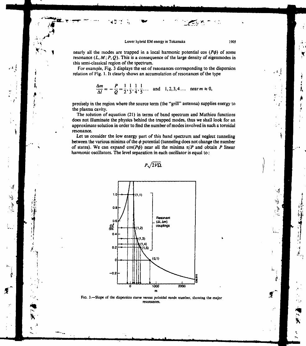
f,
Lower hybrid EM energy in Tokamaks 1905
nearly all the modes are trapped in a local harmonic potential cos (P<j>) of someresonance (L, M; P, Q). This is a consequence of the large density of eigenmodes inthis semi-classical region of the spectrum.
For example, Fig. 3 displays the set of resonances corresponding to the dispersionrelation of Fig. 1. It clearly shows an accumulation of resonances of the type
Am~ÂÏ
P
Q
1 I 1 I2'3 '4 'S '"
and 1,2,3,4... nearwaO,
precisely in the region where the source term (the "grill" antenna) supplies energy tothe plasma cavity.
The solution of equation (21) in terms of band spectrum and Mathieu functionsdoes not illuminate the physics behind the trapped modes, thus we shall look for anapproximate solution in order to find the number of modes involved in such a toroidalresonance.
Let us consider the low energy part of this band spectrum and neglect tunnelingbetween the various minima of the <j> potential (tunneling does not change the numberof states). We can expand cos(Jty) near all the minima Tt/? and obtain P linearharmonic oscillators. The level separation in each oscillator is equal to :
K-I
FIG. 3.—Slope of the dispersion curve versus poloidal mode number, showing the majorresonances.

1
•* •*
;.^4 '
X> V J
1906 D. MOREAU et al,
There are P oscillators, corresponding to the P minima of cos (P<j>) between O and2ft, and the number of modes trapped in a minimum of the isolated resonance is givenby the number of levels whose energy is less than the height of the potential, 4 V.Therefore we can conclude that in an isolated resonance the number of trapped modesis:
(22)
and thus we obtain a measure of the extent of the resonance zone near a resonantpoint (L, M; P, Q).
At this stage let us summarize our study of resonances. We have shown that thenatural ordering V£' = O(e""~m|) cannot be used directly. The nearest-neighbourcouplings (\m—m'\ = 1) resulting from an e expansion are not the leading terms ofthe coupled mode dynamics. The dominant contribution arises through resonantcouplings along the rational tangents to the dispersion curve and an ep ordering drivesthe dynamics among these modes. Near a resonant point of the type (L, M; P, Q)(\M-m\ < J(8y/£l)) the mode structure is completely reorganized and J(%V1CI)modes are trapped. Far from a resonance (\M— m\ >V/(8K/Q)) the cylindricaldynamics of the mode is only modified to first order in E and behaves approximatelyas e
3. MASTER EQUATION AND MODE ENERGY DYNAMICS IN THERANDOM PHASE APPROXIMATION
In order to understand the interaction of the various resonances, let us go back toequation (16) and consider the slow evolution of the mode amplitude cim defined asfollows :
This amplitude is solution of the integral equation :
/'.m1
The source term will be considered in the next section, and does not participate in thedynamics of the mode coupling. In order to calculate the energy flow between themode we assume that at /' = O the modes (/', m') have the amplitudes c,-m and thatthe (/, m) amplitude is zero. To first order in the perturbation, the short time evolutionis given h" :
c,m(t) = - .(<*>,•,„• -co/m)(23)
The small denominator <0i-m-—<o,m appears again, but now we know that the physicsbehind these resonances involves a complete reorganization of the spectrum in the

Lower hybrid EM energy in Tokamaks 1907
trapped region of the corresponding dispersion curve (BERMAN and ZASLAVSKY, 1977,1978).
Let us now suppose that the (/,/H) mode is trapped at least in two overlappingresonances (ZASLAVSKY and CHIRIKOV, 1972; CHIRIKOV, 1979; BERMAN et al., 1987)(L, A/; />, Q) and (L', M' ; P', Q'), i.e. that the following criterion is fulfilled :
(24)
In this case the (/, m) mode will be submitted to two contradictory influences : trappingin the cos (P$) potential and trapping in the cos (P'0) potential of equation (21).The system will be unable to satisfy these two tendencies and as a result, a decorrelationof the mode phases takes place, leading to a stochastic regime (CHIRIKOV, 1979). Aswe shall see in Section 4, this stochastic instability shows up on the ray trajectoriesin the eikonai limit, and induces an exponential divergence of neighbouring rays(WERSINGER et a/., 1978).
Our major argument in this paper is that the threshold for this divergence isobviously a threshold for the destruction of the phase correlations between the modes,and for the failure of the geometrical optics approximation because the radius ofcurvature of the equiphase surface blows up exponentially. Following ZASLAVSKY(1981), we assume that the destruction of these correlations allows us to derive akinetic equation for the mode amplitudes squares, e.g. by applying the RPA toequation (23), and leads to an irreversible exchange of energy between the coupledoscillators. However it can be conjectured that, as in the classical quasi-linear case,the ultimate justification of this irreversibility lies in the existence of some infinitesimalextrinsic noise (fluctuations, etc.) which triggers a finite entropy creation (RECHESTERand WHITE, 1980) whereas Maxwell's equations [or equation (16)] would not lead bythemselves to such an increase of the entropy. Although this point requires someclarification, it is not within the scope of this paper and we shall now proceed withthe derivation of the kinetic master equation for the energy density in mode numberspace.
In equation (23), c,m(t) appears as a sum of harmonic oscillations and the RPA isvalid over a time t longer than the correlation time, TC, between the individualoscillators. The correlation time of such a sum of e "***"" 0^' oscillations is given by :
Tcas27tmin|ca/m-a>,.ni.|
Therefore, assuming that resonant a jpl'ngs are efficient on'y within the width of theresonance, we obtain an approximate upper bound by considering that (/,m) and(/',m') belong to the edge of a resonance (\m'-m\ = ^/(BV/fï)), and then using thesecond-order Taylor expansion of ^u1n-(u,-m- [equation (19)] :
It(25)
1908 D. MOREAU et al.
-i » Let us now call t/,m = c,*, • c,m the energy content of the (/, m) mode and apply theRPA to equation (23) for t larger tnan TC. We obtain :
S'
*?
-.-»!
j I'm'
* This is the well-known Fermi golden rule for the transition between the LH states or1\ modes of the Tokamak plasma. It clearly displays the fact that only the resonant* couplings are involved in the t > TC dynamics. To obtain a transition probability we
• use the fact that we are considering a quasi-continuum of semi-classical states so that(V the sum over /' can be replaced by an integral over ca which involves the density of
states dw/dl. Taking advantage of the properties of the Dirac distribution, we obtain :
00)
a/In this expression we have dropped the / index because for any m the dispersionrelation [<o(l, m) % o>0], which now has a width <5<u « V, specifies the correspondingradial mode number.
This last equation can be interpreted as follows. For times t larger than TC thequantity
T(m'-
gives the transition probability of the energy per unit time between the mode m andthe resonantly coupled modes m'.
At this stage we can summarize the various ideas that we are developing by simplysaying that, when resonance overlapping occurs [equation (24)], the normal modedynamics of the electromagnetic energy can be modeled as an irreversible exchangeof energy between the cylindrical modes. The rate of this exchange is given by
\ T- ' [equation (26)] and we shall see in Section 4 that this condition for resonanceI overlapping is precisely that which allows us to apply the RPA on the ray equations"> and to use the quasi-linear diffusion picture to describe the ray motion^1 However, the description of a ray as a Brownian path in m space is questionable
and the normal mode approach is more appropriate because the random walk stepAm = v/> is not allowed to vanish as in the quasi-linear theory. In other words, themaster equation that we shall derive now will indeed have a Fokker-Planck limit, but
| this limit will not be valid near m = O because the step Am is comparable to m. Since' • • , ! the ' jw^r hybrid wave launchers radiate mostly in the low m region of the poloidal
jj spectrum, this is precisely the region of interest in the LH "spectral gap" problem and* - therefore we shall now carry on within the normal mode approach.
, ! ' Having shown that the energy flow of the LH field can be looked upon as an
f . J incoherent exchange of energy between the resonant coupled modes provided that theRPA ordering is fulfilled, we are now able to model the energy flux between thesemodes. Let us introduce a source (low m antenna) and a sink (high m Landau
V
.Jt-
Lower hybrid EM energy in Tokamaks 1909'
damping) and call W1n the power spectrum radiated by the antenna and to',,,, theimaginary part of the resonant frequency. In the weak damping limit
where Im [D] is the imaginary part of the dispersion relation due to the antihermitiancomponent of the dielectric tensor, —/K'. With the help of equations (3) and (13) weobtain (KAUFMAN, 1971):
JdrE?,,(r)-K'-E /m(r). (27)
The equation of evolution of the mode energy in the cylindrical Tokamak is simplya balance between the injection and absorption of r.f. power
,
dUm
and the latter is known to be very weak for the low m part of the spectrum. ,4In addition to these two processes we have shown in the previous section that the "
toroidal effects induce an energy transfer between the various modes. The energy flow :-xin the real Tokamak cavity is thus governed by the master equation : "1J
(28),i
The first term describes the gain due to the resonant coupling of the mode m, the ,*„,.I second one accounts for the losses due to the same process, and the other ones ]i represent the usual injection and absorption (the sink and the source). The kinetic ji equation (28) and the identity (26) are the main results of the paper, and are equivalent '• , 'i to Maxwell's equations when condition (24) is fulfilled. However, it must be noted ^
here that we assume the power source term Wn to be known as a function of m rather • !.'"• . than the current source S1n appearing in equation (16). In fact, these terms are related , '. :i.; to one another through a coupling impedance which we lost from the theory by
dropping the source term before the RPA treatment of equation (16).For our purposes, we are mainly concerned with the steady state m spectrum of
the wave in the Tokamak and this spectrum is the solution of the linear system :
Jf
:•*>'

'1*:?' ;L
1910 D. MOREAU et al.
Un,
U1m-f I(29)
where the matrix T has the following structure :
' m-» -*m
*m+ 1-«
Until now we have not given any prescription of the m lower and upper bounds (i.e.on the dimension of the previous linear system) :
»i0 ^ m M0.
In fact such bounds exist, m0 being physically related to the accessibility of the wave(AfH « 1) and M0 with either a cut-off or a strong Landau damping (Af8 % C/VT whereWT is the thermal velocity of the electronic population). We then wind up with a largesparse system which can only be processed numerically.
In the source-free region of the spectrum two regimes can be identified. If^(m -.m) > û/ the dynamics is diffusion dominated and Un, is nearly a flat function ofm ; in the reverse situation T(m•_„,, < co' the system is dominated by absorption andUn, decreases rapidly with m. The main problem now is to calculate r(ffl-_m) in aneffective way on the basis of equation (26), and to check if the Chirikov criterion isfulfilled. We shall answer these two questions in the next section.
4. LINK BETWEEN THE RAY HAMILTON EQUATIONS AND THENORMAL MODE MASTER EQUATION v
In this section we shall explain how to fill up the transition matrix and to checkcriterion (24) on the basis of a ray tracing calculation. Ray tracing has already shown(BoNOLi et al., 1988) a large increase of the poloidal number m during the transit ofthe rays through the plasma column, as a consequence of the toroidal effects, andthere is a correspondence between this classical m dynamics and the previous modeJiffdsion.
The first step to establish the link between the ray tracing equation and the modemaster equations is to calculate the dispersion relation co(/, m, n) with the help of thesemi-classical quantization rules (PERCIVAL, 1977; BERRY and MOUNT, 1972).
Let us introduce the Hamiltonian H(k,r) which describes the motion of rays in theunperturbed cylindrical plasma, and call the toroidal perturbation K(k,r). At fixed tothe unperturbed ray tracing:
»• •I «• • '(ft.
; H Lower hybrid EM energy in Tokumaks 1911
=
àt ~ ok ' d/ or
leaves m and n constant and gives a set of closed trajectories which can be labelledwith the third mode number / according to the following quantization rule :
fîUi
The integral is over one period of the closed orbit, r is the radius, kr the momentumconjugate to this variable and when /exists, o = (otmn. Using the terminology of semi-classical mechanics (PERCIVAL, 1977; BERRY and MOUNT, 1972), the Maslov index isequal to 2 because two caustics are encountered during one period, the first one nearthe outer cut-off and the other one near the center, at the "whispering gallery" layer(BRAMBILLA and CARDFNALI, 1982).
Launching a large number of rays at different m yields a dispersion curve like theone plotted in Fig. 1. It must be noted that the dispersion relation is nearly continuousbecause we are in a semi-classical continuum of states. Once this curve has beendrawn, we can differentiate it to obtain the location of the resonances (L, M; P, Q)in the (/, ni) plane. An example of this resonance identification is depicted in Fig. 3.
The second step is now to introduce the toroidal perturbation V. The perturbedray tracing :
dr d(H+ V) dk_ d(H+V)dt~ dit ' dt ~ " or
loses the regularity of the cylindrical dynamics (WERSINGER et al., 1978), m is nolonger constant and the best way to visualize this non-integrable behaviour is to studythe Poincarè section of a set of rays in the (m, 6) plane.
In the "classical" regime co(/, m, n) is the Hamiltonian of the unperturbed dynamicalsystem, so that equation (17) is nothing but the resonance condition under which thetopology of the classical rational K.A.M. tori is altered. This relation between themode resonance and the Hamiltonian dynamics is confirmed by the appearance ofislands in the Poincarè surface of section near the resonant value m « Af. Such' islandstructures in phase space are drawn schematically in Fig. 4, and particular Poincarèmaps obtained numerically for s = 0.015 are shown in Figs 5 and 6 in which thenumber of O points is equal to P (cf. Fig. 2).
This link between the modal and eikonal approaches can be further illuminated bynoting that the mode nur bers /, m are a set of action variables conjugated to twoangular variables Q\,02, such that the perturbed Hamiltonian reads :
(30)
A Taylor expansion around a resonance readily leads to the equation for the islandsand the expression for the island widths. We thus recover the expressions given in the
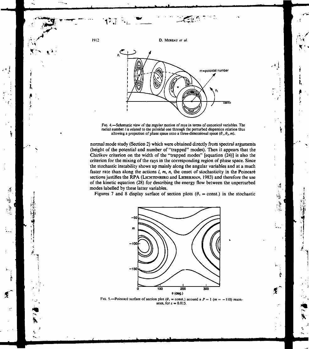
ï '7 '*:'
1912 D. MOREAU et al.
I*
m=poloidal number
FIG. 4.—Schematic view of the regular motion of rays in terms of canonical variables. Theradial number / is related to the poloidal one through the perturbed dispersion relation thus
allowing a projection of phase space onto a three-dimensional space (0|,0:,m).
normal mode study (Section 2) which were obtained directly from spectral arguments(height of the potential and number of "trapped" modes). Then it appears that theChirikov criterion on the width of the "trapped modes" [equation (24)] is also thecriterion for the mixing of the rays in the corresponding region of phase space. Sincethe stochastic instability shows up mainly along the angular variables and at a muchfaster rate than along the actions /, m, n, the onset of stochasticity in the Poincarésections justifies the RPA (LICHTENBERG and LIEBERMAN, 1983) and therefore the useof the kinetic equation (28) for describing the energy flow between the unperturbedmodes labelled by these latter variables.
Figures 1 and 8 display surface of section plots (0, = const.) in the stochastic
-so
m
-100
-150
100 2008(deg.)
FIO. 5.—Poincaré surface of section plot (0, = const.) around a Pance, for e = 0.015.
300
1 (m = -110) reson-

f ' if 1
Lower hybrid EM energy in Tokamaks 1913
FIG. 6,—Poincaré surface of section plot (0, = const.) around a P = 2 (m= 112) resonance,for E = 0.015.
I\]
%r*»
regime, for toroidal aspect ratios of 0.05 and 0.3. They show that for typical Tokamakaspect ratios the various toroidal resonances generally overlap and the subsequentstochastic propagation of the rays leads to the mixing of the phase fronts, thusallowing a statistical description (RPA).
Another interesting quantitative relation between the ray and modal approachescan be established if we consider the quasi-linear diffusion coefficients associatedeither with the random motion of the rays or with the energy transition between the
too
-100
-200
^W-•'•::• :<&*<*?&i=S-':;5V-m7&#'""""Vv. 4 „- - 1V J^?>\ v«»i,A*i <*-' j«,i*"^ "^>^i\l^^\
^v, «« ^H- ; -J „'
-; ^ , •• s-s <"*',, »'**-^u^: s •• ^v1SS
100 2008(deg.)
300
FIG. 7.—Poincaré surface of section plot (Bi = const.) showing the extent of the stochasticdomain for £ = O.OS.

«ij r- rf-
1914
I'/*
D. MOKEAU e( a/.
2000
FIO. 8.—Poincarc surface of section plot (0, = const.) showing the extent of the stochasticdomain for E = 0.3.
K- ,I :
«*'
normal modes. Formally, an effective diffusion coefficient, D^, can be derived bytaking the Fokker-Planck limit of our master equation. Considering that the timestep for the random walk process in m space is the inverse of the transition probabilityper unit time,
d<a
and the elementary step is Awcoup|ing = P, we obtain :
dco~dï
-\(31)
On the other hand, the correlation time must be shorter than the bounce time for theRPA to hold. According to equations (21) and (25) this can be written las:
PJ2VCK4Y
and implies
>1
i.e. that a large number of modes are involved in the non-linear resonance. This is incomplete agreement with our assumption of a large density of states (semi-classicallimit) and assesses the coherence of the various orderings.

., r» ^-.!*. • • '
Lower hybrid EM energy in Tokamaks 1915
Now we shall show that equation (31 ) possesses a counterpart in the "classical"Hamiltonian description. A quasi-linear diffusion coefficient can be derived by con-sidering a set of "classical" particles (photons) under the motion governed by theHamiltonian (30). This motion can be considered as time-dependent in a reducedphase space (TO, O1) by considering the 0 t angle as a time variable (LICHTENBERG andLIEBERMAN, 1983). The new Hamiltonian is then /(0,,02,w) and the equations ofmotion are :
d0, ~ Q1(32)
• Jf .
I
ti
va
"1
where Q( and Q2 are the unperturbed frequencies corresponding to the canonicalangles d, and O2 and
dm /do Y" ' » .d0| \dl / I11
(33)
Integrating this latter equation along the unperturbed trajectory given by equation(32) and averaging over the initial phases Q2 yields the quasi-linear diffusion coefficient.By recognizing that the unperturbed frequency Q, is nothing but 8<o/ol (the densityof states) we find, as expected, that this diffusion coefficient is the same as given inequation (31) obtained from the modal approach and the master equation.
To close this section, we shall finally address the following important question : isit possible to calculate the resonant matrix elements V1U^n+11 without the computationof the full wave mode structure?
Landau was the first to point out that in the semi-classical limit the non-resonantmatrix elements of a wave system can be calculated with the help of the trajectoriesof the corresponding classical Hamiltonian system (LANDAU and LIFCHITZ, 1981).His result is that the matrix elements of a perturbation operator are the Fouriertransforms of this perturbation along the trajectory.
Here we are interested in the resonant matrix elements. They can be calculatedfrom the width of the classical islands Amisiand before their destruction if we remarkthat, according to the correspondence principle, the distance between the upper andlower edges of a modal non-linear resonance in equation (22) is equal to the width ofthe corresponding "classical" island,
Am2island
TT 32
Since Awi5Und is available from the Poincaré surface of section plots and Si (as well asd(o(8l) from a differentiation of the dispersion curve, the transition probabilities Tcan be calculated without any full wave computation. This original technique extendsLandau's result to the resonant matrix elements.

\ H
11i;-.'. 1
1
,V,
1916 D. MOREAU et ai
We have plotted in Fig. 9 the island width versus the inverse aspect ratio £ forvarious resonances and verified that for a given (P, Q) resonance Amlsbnd scales as
/"2
in agreement with the previous relation (V'f'"m oc e |m~m ').
5. STEADY STATE SPECTRUM OF LOWER H Y B R I D WAVES INTOKAMAKS
To apply our theory to the problem of lower hybrid current drive in Tokamaks wehave been considering the simplest model which can be thought of, namely a stronglymagnetized toroidal plasma with a finite but constant rotational transform and aparabolic density profile. We limited ourselves to the cold electrostatic dispersionrelation for magnetized Langmuir waves, which are indeed the high field-low densityslow waves propagating in the lower hybrid frequency range, so that the electricpotential O is the solution of the scalar wave equation :
Am (Mind)
1000
Fto. 9.—Island width Am versus inverse aspect ratio for the major resonances. The cor-responding resonant elementary steps (A/= —Q and am = P) are given respectively inparentheses. Dotted lines are drawn beyond the onset of stochasticity in order to evaluate
the matrix elements of the resonant couplings for s = 0.3.

A-*
; v* Lower hybrid EM energy in Tokamuks 1917
= f V -
The inverse aspect ratio has been taken equal to 0.3 and, following the prescriptionof Section 4, it is straightforward to extrapolate the numerical value of the matrixelements V^n. from Fig. 9.
Then an estimation of the absorption rate of each unperturbed cylindrical modecan be obtained from Landau damping theory by assuming a parabolic temperatureprofile. A steady state solution [cf. equation (29)] can be found numerically for thedistribution of electromagnetic energy Un in poloidal mode number space, where wehave assumed that the source of photons (antenna spectrum) is localized at
-5 m 5,
and have followed the energy dynamics according to equation (29) in the range :
-250 ^m «S 250.
The result is shown in Fig. 10. The electron distribution function is supposed to beMaxwellian, thus simulating the beginning of the interaction of the waves with theplasma. For negative values of m (low JV9) there is no absorption and therefore theelectromagnetic energy accumulates in the plasma-filled cavity until fast suprathermalelectrons are created. On the contrary, on the positive side (high N]}) there is amonotonie decrease of Um due to stronger and stronger damping. The competitionbetween the diffusion process of the LH photons and their absorption at high N11
results in a steady state distribution like the one displayed in Fig. 10.
i.F?, 1
K
1
r*,'
V
FIG. 10.—Steady-state distribution of wave energy versus poloidal mode number for aMaxwellian plasma (parabolic temperature profile with a central temperature of 12 keV).
',.I

1918 D. MOREAU ct at.
On the contrary, considering an electron distribution function which contains ahigh energy tail and therefore simulates the steady state equilibrium between ihewaves and the particles, we obtain the Un, distribution shown in Fig. 11. Absorptionnow takes place on the whole spectrum and the distribution of electromagnetic energyis peaked around the source value of m, i.e. of JV11.
It is quite instructive to plot the steady state N11 spectrum of the absorbed power inboth cases since it governs the efficiency of the current generation. This is done in Fig.12 which clearly displays the fact that the absorbed spectrum can be much broaderthan the launched one. In extreme cases it can even be very distinct from it (dottedline), in particular at early times when the electron distribution is still nearly Max we! 1-ian, and more generally as long as the so-called LH "spectral gap" has to be bridgedby means of the stochastic diffusion.
6. CONCLUSIONIn this paper we have developed a new model to study the dynamics of the weakly
damped, small wavelength modes in toroidal plasmas and we have particularly focusedon the evolution of the low poloidal number modes in the lower hybrid frequencyrange.
For such modes and such geometries the usual eikonal approach cannot describethe long time dynamics of the energy and the transient build-up of modes due to themulti-reflections. Conversely, the present modal approach is well suited to the weaklydamped part of the LH spectrum, and when applied to a particular experiment (takinginto account the full toroidal configuration) it should enable one to obtain a betterunderstanding of the LH power deposition in regimes where ray tracing yields ratheruncertain results.
Ui
a—"""to
*T*,
200
FIG. 11.—Steady-state distribution of wave energy versus poloidal mode number for a non-thermal plasma in which 1 % of the electron distribution function is in a high energy tail
(400 keV). The bulk of the electron distribution is the same as in Fig. 10.
i,.,.1I
è
Jf

1 •v,
A -Lower hybrid EM energy in Tokumaks 1919
I*j
iT ^l
i-ls
( :
i.
r ;. 1
1
Source olL.H. photons
L.H. Spectral gap
Maxwellian,absorption
*».(_i t
1.4 2.0 2.2
Pic. 12.—Steady state Nt spectrum of the absorbed power in the case of a thermal plasma(dotted line) and of a non-thermal plasma (solid line). The hatched area represents the source
of power at -5 ^m ^ 5.
Moreover, it can be anticipated from our study that the optimum Nt spectrum toproduce the most efficient current drive should be peaked at the largest phase velocitiescompatible with the accessibility constraints. This stems from the fact that the finalbroadening of the spectrum is produced within the plasma itself and is limited to thesmallest amount which is required for sustaining the quasi-linear plateau. This isindeed what has been observed in most recent experiments (STEVEN7S et al., 1988 ; JT-60 TEAM, 1989) where the launched spectrum was narrow enough to assess theinfluence of the N11 index of the wave at the antenna on the efficiency of LHCD.
Finally, the main results of the paper can be summarized as follows. Above astochasticity threshold, Maxwell's equations :
V x V x E(r) - - [K(r, w) - /K'(r, co)] • E(r) = J,
ilead, in a toroidal plasma, to a steady state master equation for the flow of electro-magnetic energy U oc E • E* :
m'
The left-hand side of this equation accounts for a diffusion process which allows thelow m part of the LH spectrum to reach a region where Landau damping becomeseffective. The transition probabilities T can be calculated with the help of ray tracingexpressed in canonical variables. Future work will be devoted to the theoreticalstudy of the resonant couplings between the various branches of the electromagneticdispersion relation and to the investigation of the influence of the Shafranov shift and
'* I

-• • t:
'i
1920 D, MORCAU ?» a/,
of the ellipticity. In order to compare the semi-classical matrix elements with the exactfull wave ones, a variational full wave cylindrical code is also under development( MOREAU et al., 1989).
On the basis of a normal mode master equation we have studied the LH "spectralgap" problem and proposed a universal method to describe the toroidal upshiftmechanism which has been invoked repeatedly in the theoretical interpretation oflower hybrid current drive experiments.Acknowledgements—Part of this work was accomplished while two of the authors (D.M. and J.M.R.) wereat the Joint European Torus laboratory (JET) and we wish to acknowledge Dr J. JACQUINOT and Dr C.GORMEZANO for their strong interest in this work and the r.f. division and profile control group for theirwarm hospitality.
REFERENCESBARANOV Y. F., GUSAKOV E. Z. and PILIYA A. D. (1988) in Theory of Fusion Plasma (Proc. Joint Varenna-
Lausanne International Workshop, Chexbres, Switzerland) (edited by J. VACLAVIK, F. TROYON and E.SlNDONi), p. 707.
BARBATO E., CARDINALI A. and ROMANELLI F. (1988) in Controlled Fusion and Plasma Heating (Proc.\5th European Con/, Dubrovnik), Vol. 12B, part HI, p, 1011. European Physical Society.
BERMAN G. P., VLASOVA O. F. and IZRAILEV F. M. (1987) Sov. Phys. JETP 66,269.BERMAN G. P. and ZASLAVSKY G. M. (1977) Phys. Lett. 61A, 295.BERMAN G. P. and ZASLAVSKY G. M. (1978) Sov, Phys. DoM. 23,410.BERRY M. V. and MOUNT K. E. (1972) Rep. Prog. Phys. 35, 315.BONOLI P. T., PORKOLAB M., TAKASE Y. and KNOWLTON S. F. (1988) Nucl. Fusion 28,991.BRAMBILLA M. and CARDINALI A. (1982) Plasma Phys. 24, 1187.CANOBBIO E. and CROCI R. (1987) Z. Naturforsch. 42a, 1067.CHIRIKOV B. V. (1979) Phys. Rep. 52, 263.ECKHARDT B. (1988) Phys. Rep. 163, 205.JT-60 TEAM, presented by M. NAGAMI (1989) Plasma Phys. Contr. Fusion (Special Issue, Proc. 16//»
European COM/., Venice) 31, 1597.KAUFMAN A. N. (1971) Physics Fluids 14, 387.KAUFMAN A. N. and NAKAYAMA T. (1970) Physics Fluids 13,956.KELLER J. B. (1958) Annals of Physics 4,180.LANDAU L. D. and LIFCHITZ E. M. (1981) Course of Theoretical Physics, Vol. 3. Pergamon Press, Oxford.LICHTENBERC A. J. and LIEBERMAN M. A. (1983) Regular and Stochastic Motion. Springer, New York.Liu C. S., CHAN V. S., BHADRA D. K. and HARVEY R. W. (1982) Phys. Rev, Lett. 48,1479.MOON P. and SPENCER D. E. (1971) Field Theory Handbook. Springer, Berlin.MOREAU D., PEYSSON Y., RAX J. M., SAMAIN A. and DUMAS J. C. (1989) Report EUR-CEA-FC 1366.MOREAU D., RAX J. M. and SAMAIN A. (1988) in Controlled Fusion and Plasma Heating (Proc. 15th
European Co»/., Dubrovnik), Vol. 12B, Part III, p. 995. European Physical Society.NEUDATCHIN S. V., PARAIL V. V., PEREVERZEV G. V. and SHURYGIN R. V. (1985) in Controlled Fusion
and Plasma Physics (Proc. \2th European Con/, Budapest), Vol. 2, p. 212. European Physical Society.PERCIVAL I. C. (1977) Adv. chem. Phys. 36,1.PEREVERZEV G. V. (1989) to be published in Plasma Phys. Contr. Nuclear Fusion Res. $Proc. \1th Int.
Conf., Nice, 1988), paper E-IV-7-2. IAEA, Vienna.RECHESTER A. B. and WHITE R. B. (1980) Phys. Rev. Lett. 44,1586.STEVENS J. E. et al. (1988) Nucl. Fusion 28, 217.WEGROWE J. G. (1987) in Controlled Fusion and Plasma Physics (Proc. 14th European Conf., Madrid),
Vol. UD, Part III, p. 911. European Physical Society.WERSINGER J. M., Orr E. and FINN J. M. (1978) Physics Fluids 21,2263. ; .ZASLAVSKY G. M. (1981) Phys. Rep. 80, 157.ZASLAVSKY G. M. and CHIRIKOV B. V. (1972^ Sov. Phvs. Uspekhi 14, 549.
„••*

ï,
LETTERS
WAVE CHAOS AND THE DEPENDENCE OFLHCD EFFICIENCY ON TEMPERATURE
K. KUPFER, D. MOREAU (Association Euratom-CEAsur Ia fusion contrôlée, Centre d'études de Cadarache,Saint PauHez-Durance, France)
ABSTRACT. Weakly damped tower hybrid wave propagationis shown to be chaotic for parameter regimes typical of current drivein TORE SUPRA and JT-40. In these cases, the spectral gap is filledby wave energy that diffuses to higher parallel wavenumber k( in(he uochastic layer. Agreement between theoretical and experimentalscalings for the current drive efficiency is obtained by including non-resonant losses of wave energy due to collijioni and lossy reflectionsnear the plasma edge which reduce the efficiency at low temperature*when the spectnl gap is large.
1. INTRODUCTION
In many present day lower hybrid current drive(LHCD) experiments, large toroidal currents are drivenby waves launched at high parallel phase velocities,where there are initially far too few electrons to accountfor the observed current drive, i.e. there exists a 'spectralgap' between the launched waves and the thermal electronpopulation. Since it is well known that toroidal effectson the wave propagation can cause sufficient upshift inthe parallel wavenumber k( to fill the spectral gap [1],ray tracing codes are now standard tools for obtaininglower hybrid deposition profiles. However, it is notfully appreciated that lower hybrid ray trajectories in atokamak can be chaotic (even in the absence of densityfluctuations), as previously shown for the case of lowDI waves (n( = ck|/w) that undergo mode conversionbetween the slow (electrostatic) branch and the fast(electromagnetic) branch of the cold plasma dispersionrelation [2]. In fact, the chaotic dynamics is not restrictedto waves undergoing mode conversion, but it can occureven in the purely electrostatic limit, which is morerepresentative of the wave propagation in LHCD. Thisleads to a diffusion of the wave energy from low k(,where it is launched, to high k|, where it is absorbedby electron Landau damping {3]. Thus, the width ofthe diffu 3d vave spectrum and the characteristic diffu-sion time are both functions of electron temperature.Indeed, experiments (notably JT-60 [4] and morerecently JET [5]) show that the LHCD efficiency hasa strong dependence on the volume averaged electrontemperature.
We have developed a model for the temperaturedependence of LHCD efficiency which is linked withthe Tilling of the spectral gap in the presence of a para-sitic absorption process that drains RF power duringpropagation. In Section 2, we consider the issue ofchaotic ray dynamics for LHCD parameters typical ofTORE SUPRA and JT-60. In Section 3, we discuss theresults of coupled ray tracing/Fokker-Planck simulationsand formulate a simple model for the local current driveefficiency. The temperature dependence of the globalLHCD efficiency is discussed in Section 4 and ourconclusions are presented in Section 5.
2. RAY TRACING AND WAVE CHAOS
The ray equations are determined by the localdispersion relation and can be written in canonical form,where the canonically conjugate variables are (6, m) and(r, kr). Here, r is the minor radius, 9 is the poloidalangle, k, is the radial component of the wave vectorand m is the poloidal mode number. The equilibriumis considered to be axisymmetric, so the toroidal modenumber is conserved. We consider the cold plasmadispersion relation in the lower hybrid range of frequen-cies, as given in Réf. [1] (in all of the cases studied,thermal effects are negligible in determining the raytrajectories and need only be retained for calculatingthe electron Landau damping). Since all ray trajectoriesare confined inside the plasma by a cut-off layer at lowdensity, the system is periodic in both r and O, and wemay view the trajectories in an (m, 9) surface of section,defined as follows: each time an inward bound raypierces a given flux surface, the value of m is plottedversus 0 (mod 2*). Note that there is some subtletyinvolved in handling rays propagating on differentbranches of the dispersion relation. To avoid theappearance of intersecting ray trajectories in the surfaceof section, a different sheet of the (m,0) plane isdesignated for each branch of the cold plasma disper-sion relation (i.e. slow and fast). Furthermore, we mayview the surface of section in the (n(,0) plane, sincethere is a one to one mapping that relates each sheet ofthe (m, 0) plane to a corresponding sheet of the (RI, 0)plane. Each surface of section is composed for a giventoroidal mode number, representative of the launchedspectrum.
Surfaces of section for parameters typical of TORESUPRA and JT-60 are shown in Figs l(a) and l(b).Initial conditions with various poloidal mode numberswere taken on the slow wave branch near 9 * O. Thetoroidal mode number was chosen so that the initial
NUCLEAR FUSION. VMJ2, N*.W(IM2) 1845
S

«*;
LETTERS
• •* 1
* • \ .- '. Y , ' . ' V 1 X - . • ' • • . • • " . . . ; • • • • - V' *
' . . < v . " 4 • - , .V.V \ - ; . ' Y . y ' ' ' ' V i : > ' . ' . ' v - ' • ! * • ' • • . > • .
OJ 0.4 0.« 0,1 1 1.2 1.4 1.« I.I
43
4
M
J
2.1
2
IJ
(W
-V-. i". -...1J.... "V. ... . 'Wy..-'.-. -'.A-O--".? ï'.,:••••• ••••>!.*"
'•ii'"V.vo/.;.'. Jw...";,'.-.! .;•;.•••• » '
C-JHM.#&- : , . ; . - . - -
^' -T-;;;:'^.^."-^Vt';/,-'-KY-Cl
03 0.4 OS OJ U 1.4 1.« I.I
F/G. J. Surface of section (nt versus 9/2*) taken G syd-radiia forrays propagating on the slow wave branch of the disunion relation.TTu parameters are typical of (a) TORE SUPRA and (b) JT-M.Says were launched near 9*0 with veriaia initial poloidal modenumbers. TAc tc:^d~! mode number YMU chosen so thai m - Ocorresponds to n, » nu. vtiere nw - 1.8 for TOKE SUPKA and
"M
condition at m = O was launched with n( » RK, wherenu is near the peak of the actual (experimental) injectedspectrum. A thick stochastic layer surrounding nio(extending mostly in the direction n( 2 H10) is readilyvisible in both figures. The parameters for TORESUPRA [6] are: D40 = 4 x 10" cm'3,19 ^ 1.6 MA,B0 - 3.9 T, R0 » 240 cm, a - 80 cm, frf - 3.7 OHzand nw = 1.8. The parameters for JT-60 [4, T1 are:n.0 - 3 X 1013 cm"3, Ip - 1.5 MA, B0 = 4.5 T,R0 - 310cm, a » 70cm, f,f = 2 GHz and nu - 1.5.In each case, the ratio of the peak to volume averagedelectron density is 2 and the q profile is parabolic, withq =- 1 on axis. The ray tracing is done using the Bonoli-Englade code (I].
For a given toroidal mode number, the stochastic layeron any given flux surface r extends over the intervaln,(r) £ nt < nb(r), where nb(r) denotes the position ofa limiting KAM surface and n,(r) denotes a propagationlimit, i.e. the dispersion relation prohibits propagationfor n( < n,(r). It is worth mentioning that the propa-gation limit need not be established by mode conversionto the fast wave. This can easily be seen from theelectrostatic dispersion relation, C1 kî + «ikj = O,where kî » kj + (m/r)2 and k, « [n + m/q(r)]/Ro.Here, q(r) is the safety factor, n is the toroidal modenumber, and, for simplicity, one may consider ft/tj_« -b>£,(r)/<i>2. As m is decreased through negativevalues, k? eventually becomes negative across theentire plasma cross-section and the wave cannotpropagate. Thus, for a given toroidal mode number,there is a limit to the poloidal angular momentum thewave can carry; for negative m, this imposes a lowerlimit on n(. For fully electromagnetic propagation, bothpoloidal angular momentum and mode conversion canplay a role in establishing n,(r). For the above TORESUPRA parameters, the propagation limit is almostentirely due to poloidal angular momentum, whereas,for the JT-60 parameters, mode conversion to the fastwave plays an important role in limiting the spectrum.Mode converted rays appear on a second sheet of thesurface of section (not shown in Fig. 1), where theypropagate in a narrow stochastic layer with n( * n.(r).
Rays lauscJ>ed at nw (with m - O) can access higherDI in the stochastic layer, but cannot exceed the KAMsurface at nb(r). Since electron Landau damping on thetail of a Maxwellian distribution becomes strong whenthe wave phase velocity is less than (approximately) 4vc,the spectra] gap on a given flux surface can be filled,as long as nb(r) 2 c/4v,(r), where v, * VtT(TJTm1.For the case of TORE SUPRA in Fig. l(a), we see thatnb » 8 at mid-radius, so that the spectral gap can befilled, even at low electron temperatures (T12 0.5 keV).In contrast, for the case of JT-60 in Fig. l(b), nb » 4and the spectral gap can only be filled for T, K 2 keV.Note that our ray tracing calculations assume circularflux surfaces; non-circularity in the case of JT-60 islikely to increase the value of nb and needs to beconsidered.
An important property of a chaotic system is th_divergence of initially neighbouring trajectories inphase space. This divergence has a characteristic time-scale, which, in the case of lower hybrid wave propa-gation, must be compared with the time-scale forabsorption by electron Landau damping. If the dampingis weak enough, the chaotic dynamics has a strong effecton the spectral distribution of wave energy. For both ,'fi'
1846 NUCLEAK FUSION. Vol.32. No. 10 <I992)

• /
LETTERS . /,4
»j
i,
the case of TORE SUPRA with Te0 S 3 keV and thécase of JT-60 with Tc0 £ 6 keV, we find that anensemble of rays launched near the peak of the injectedspectrum (at low nu) can Till a large portion of thestochastic layer before it is absorbed. In this case, therays make many passes through the plasma, but donot establish a regular mode pattern, as they would inseparable geometry. Instead, wave energy fills theplasma, diffusing among a broad spectrum of randomlyphased poloidal harmonics [3]. Although there are manyquestions about the validity of geometric optics in themultipass situation, it is plausible that rough featuresof the wave energy transport and spectral broadeningcan be modelled by considering a large ensemble ofrays launched in the stochastic layer. However, therehas never been any comparison with full wave codesto substantiate this conjecture. In the opposite limit,when the damping is strong, rays remain in coherentbundles during the entire course of propagation.
3. A SIMPLE LHCD MODEL
The wave driven current density on a given fluxsurface can be calculated from the integral expression:
J,f(D4TeQWt wrr (3)
dv,G(v,, r)S(vlf r) (D
where S(V|, r) is the RF power density absorbed byelectron Landau damping at a given resonance, v, * w/k|,and G(VI, r) is the current dnve response function. ForLHCD, the appropriate response function [8] (ignoringthe effect of trapped electrons and taking the limitvj > vj) is
G(V,, r) » [e/m.r(r)]4vï/(5 (2)
where T(r) - *0vJ » n,e* lnA/(4Te$m,2) and V9 is the
thermal electron collision frequency. We consider theRF quasi-linear diffusion coefficient D(VI, r) to be finitein some range of resonant velocities, v, s v( s V2,where v, and V2 can be functions of r. Roughly speaking,v, is determined by electron Landau damping, whichlimits the diffusion of wave energy filling the spectralgap, and V2 is determined by the cold plasma disper-sion relation, which limits the minimum HI. Defining5 » D/PQV? and assuming 521, quasi-linear difru-sicu fkitens the electron distribution in the resonanceregion, so that S oc m,vfv, where v is the appropriatecollision*! momentum loss rate for fast electrons. Since» « vf3, combining the above equations leads to thefollowing expression for the current density:
NUCLEAK FUSION. Vol.}]. No, 10 (1992)
where Wrf is the RF power density absorbed by resonantelectrons on a given flux surface. Note that, for a givenabsorbed power, we have found that the current calcu-lated from Eq. (3) is in good agreement with previouslypublished results based on numerical solutions of thetwo-dimensional Fokker-Planck equation [9]. (In general,the two-dimensional numerical efficiency is found to belarger by a factor of 1.3 to 1.4, independent of Z1 andv2/v,.)
To calculate v, and vz and to check the assumptionthat D S 1, we have performed a coupled ray tracing/Fokker-Planck analysis. Using the simple (radially local)one-dimensional Fokker-Planck model [8] (ignoring bothfast electron transport and enhanced perpendicular electrontemperature), the electron Landau damping of a largeensemble of rays is calculated iteratively, until D(VI, r)and the electron distribution function are determinedself-consistently. Simulations were performed for TORESUPRA and JT-60 parameters, as given in Section 2, atvarious central electron temperatures from 2 to 9 keV.In the case of TORE SUPRA we considered waveslaunched with ni in the range 1.6 S nw £ 2.0, whilefor JT-60 we considered 1.2S S n)0 S 1.15, Varioustemperature profiles were assumed, with T1 (T.) inthe range 2 to 4, where (T.) is the volume averagedelectron temperature. The results of our analysis showthe following:
(i) v,(r) » ave(r), where a is a numerical factorfound to be between 3.5 and 4.0 on flux surfaceswhere there is significant power deposition;
(U) v2(r) « c/n»(r), where n,(r) is the low DI limitfor the minimum toroidal mode number in thelaunched spectrum (as discussed in Section 2);
(iii) 5 is of order unity or larger throughout theresonant region.
Results (i) and (iii) can be seen in Fig. 2, which showslevel contours of 6 with respect to tha normalized co-ordinates v,/v«(r) and r/a, for both TORE SUPRA andJT-60. The radial deposition profile for each case inFig. 2 is shown as a dashed curve, so one can see thatthe D * O contour indeed dips below V|/v, = 4 on fluxsurfaces where most of the RF power is absorbed. Also,D increases from zero to one quite rapidly (as shownby the proximity of the D * O and 6 » 1 contours)and then remains large throughout the resonant region,until V) exceeds v2(r) (not shown in Fig. 2).
Having performed simulations over a range of injectedpowers (from 0.5 to 5 MW), we were able to conclude
1847
f(.)'
7*.
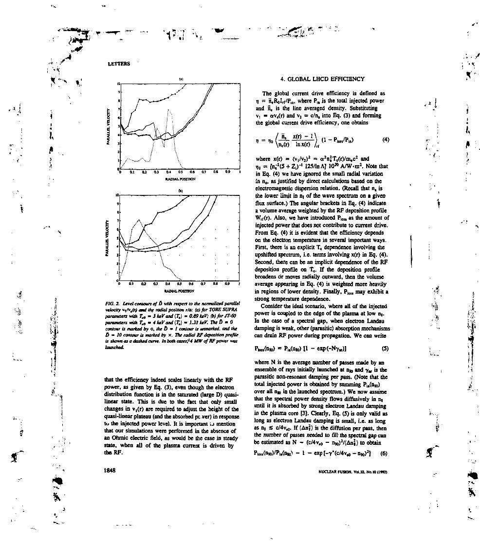
LETTERS
(i)
*:^.
.'&
i
i
0.1 U 0.] 0.4 0.1 0.« 0.7 0.1 0.»
KAOIAL rosmoN
(b)
O 0.1 U OJ 0.4 OJ 0.« 0.7 OJ 0.9 I
RADIAL rosmoN
FIC. 2. Level contours of O with respect to the normalized parallelvelocity v, Ar.frJ and the radial position r/a: (a) for TOKE SUPRAparameters with Ta - IkeVand(T,) * 0.89keV; Q)for JT-Wparameters with T* - 4 keV and (T,) - 1.33 IuV. The 5 - Ocontour is marked by o, the 6 * I contour is unmarked, and theU - IO contour is marked by X. The radial KF deposition profileis shown as a dashed curve. In both cases'.54 MW of KF power mulaunched.
that the efficiency indeed scales linearly with the RFpower, as given by Eq. (3), even though the electrondistribution function is in the saturated (large D) quasi-linear state. This is due to the fact that only smallchanges in v,(r) are required to adjust the height of thequasi-linear plateau (and the absorbed pc »er) hi responseto the injected power level. It is important U mentionthat our simulations were performed in the absence ofan Ohmic electric field, as would be the case in steadystate, when all of the plasma current is driven bythe RF.
1848
4. GLOBAL LHCD EFFICIENCY
The global current drive efficiency is defined asV = ntRoIrf/P,n, where P1n is the total injected powerand ne is the line averaged density. Substitutingv, = ave(r) and V2 = c/n, into Eq. (3) and formingthe global current drive efficiency, one obtains
/Ht x(r) - 1 \ „ D1} — In \ —TT —! TT / V1 ~ rta\ne(r) lnx(r) /„
(4)
where x(r) = (vt/v2)2 = a2njTe(r)/m,c2 and
Io = [n."2<5 + Z1)-' 125/lnA] 1020 A/W-m2. Note thatin Eq. (4) we have ignored the small radial variationin n., as justified by direct calculations based on theelectromagnetic dispersion relation. (Recall that n, isthe lower limit in DI of the wave spectrum on a givenflux surface.) The angular brackets in Eq. (4) indicatea volume average weighted by the RF deposition profileWrf(r). Also, we have introduced P1011 as the amount ofinjected power that does not contribute to current drive.From Eq. (4) it is evident that the efficiency dependson the electron temperature in several important ways.First, there is an explicit Te dependence involving theupshifted spectrum, i.e. terms involving x(r) in Eq. (4).Second, there can be an implicit dependence of the RFdeposition profile on T,. If the deposition profilebroadens or moves radially outward, then the volumeaverage appearing in Eq. (4) is weighted more heavilyin regions of lower density. Finally, P101, may exhibit astrong temperature dependence.
Consider the ideal scenario, where all of the injectedpower is coupled to the edge of the plasma at low HI.In the case of a spectral gap, when electron Landaudamping is weak, other (parasitic) absorption mechanismscan drain RF power during propagation. We can write
PiB(nw) [1 - (5)
where N is the average number of passes made by anensemble of rays initially launched at nn and yM is theparasitic non-resonant damping per pass. (Note that thetotal injected power is obtained by summing PL(UIO)over all nu in the launched spectrum.) We now assumethat the spectral power density flows diffusively in n(
until it is absorbed by strong electron Landau dampingin the plasma core [3]. Clearly, Eq. (S) is only valid aslong as electron Landau damping is small, i.e. as longas n( £ c/4v«o. If (AnJ) is the diffusion per pass, thenthe number of passes needed to fill the spectral gap canbe estimated as N - (c/4vrt - Ui0)V(AnI) to obtain
- 1 - exp[-T'(c/4v,o-nio)2] (6)
NUCLEAR FUSION. Vol.32. No. IO (1992)
„••*.
I-...
it4
K
*+'*.
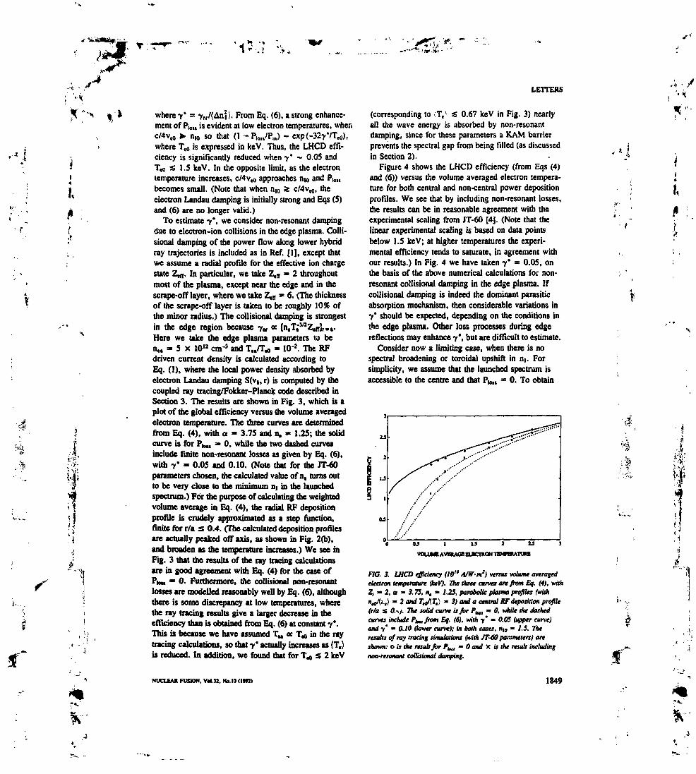
-«'*•.,«
LETlERS
f
where 7* = 7M/{Ani>. From Eq. (6), a strong enhance-ment of P1011 is evident at low electron temperatures, whenC/4V.O > nw so that (1 - P1011/?,,,) - exp(-327VT(0),where T10 is expressed in keV. Thus, the LHCD effi-ciency is significantly reduced when 7* - 0.05 andT.O s 1.5 keV. In the opposite limit, as the electrontemperature increases, c/4v,o approaches nw and P)01,becomes small. (Note that when n(0 % c/4vrt, theelectron Landau damping is initially strong and Eqs (S)and (6) are no longer valid.)
To estimate 7*, we consider non-resonant dampingdue to electron-ion collisions in the edge plasma. CoIH-sional damping of the power flow along lower hybridray trajectories is included as in Réf. [IJ, except thatwe assume a radial profile for the effective ion chargestate Zt1,. In particular, we take Z,ff = 2 throughoutmost of the plasma, except near the edge and in thescrape-off layer, where we take Z,a * 6, (The thicknessof the scrape-off layer is taken to be roughly 10% ofthe minor radius.) The collisional damping is strongestin the edge region because 7,, « [n,T;3/2Z,frJ,.,.Here we take the edge plasma parameters ta ben«. - 5 x 1012 cm'3 and T../Trt - 10'z. The RFdriven current density is calculated according toEq. (1), where the local power density absorbed byelectron Landau damping S(v(, r) is computed by thecoupled ray tracing/Fokker-Planck code described inSection 3. The results are shown in Fig. 3, which is aplot of the global efficiency versus the volume averagedelectron temperature. The three curves are determinedfrom Eq. (4), with a - 3.75 and n. * 1.25; the solidcurve is for P)01, « O, while the two dashed curvesinclude finite non-resonant losses as given by Eq. (6),with 7* - 0.05 and 0.10. (Note that for the JT-60parameters chosen, the calculated value of n, turns outto be very close to the minimum m in the launchedspectrum.) For the purpose of calculating the weightedvolume average in Eq. (4), the radial RF depositionprofile is crudely approximated as a step function,finite for r/a s 0.4. (The calculated deposition profilesare actually peaked off axis, as shown in Fig. 2(b),and broaden as the temperature increases.) We see inFig. 3 that the results of the ray tracing calculationsare in good agreement with Eq. (4) for the case ofPIOU • O. Furthermore, the collision! non-resonantlosses are modelled reasonably well by Eq. (6), althoughthere is some discrepancy at low temperatures, wherethe ray tracing results give a larger decrease Ui theefficiency than is obtained from Eq. (6) at constant 7*.This is because we have assumed TM « T10 in the raytracing calculations, so that 7* actually increases as (T.)is reduced. In addition, we found that for T-, S 2 keV
NUCLEAR FUSION. V4.32. No. 10 (I*R)
(corresponding to (T,\ •£ 0.67 keV in Fig. 3) nearlyall the wave energy is absorbed by non-resonantdamping, since for these parameters a KAM barrierprevents the spectral gap from being filled (as discussedin Section 2).
Figure 4 shows the LHCD efficiency (from Eqs (4)and (6)) versus the volume averaged electron tempera-ture for both central and non-central power depositionprofiles. We see that by including non-resonant losses,the results can be in reasonable agreement with theexperimental scaling from JT-60 [4]. (Note that thelinear experimental scaling is based on data pointsbelow 1.5 keV; at higher temperatures the experi-mental efficiency tends to saturate, in agreement withour results.) In Fig. 4 we have taken 7* = 0.05, onthe basis of the above numerical calculations for non-resonant collisional damping in the edge plasma. Ifcollisional damping is indeed the dominant parasiticabsorption mechanism, then considerable variations in7* should be expected, depending on the conditions inthe edge plasma. Other loss processes during edgereflections may enhance 7', but are difficult to estimate.
Consider now a limiting case, when there is nospectral broadening or toroidal upshift in n,. Forsimplicity, we assume that the launched spectrum isaccessible to the centre and that P101, = O. To obtain
l-J 2 W
IMHtATUH
FlC. 3. LHCD efficiency (M" A/W-m2) versus volume averagedelectron temperature QuV). The three curves are from Eq. (4), withZ1 - 2, a - 3. TS, R. - /.25, parabolic plasma profiles (with"loft'-t) m 2 and TrfKT,} » 3) and a central KF deposition profile(r/a s 0.-./. The solid curve is for P^0- O. while the dashedcurves include PI*, from Eq. (6), with y' - 0.05 (upper curve)and y' - 0.10 (lower curve); in both cases, nu - /.5. Theresults of ray tracing simulations (with JT-60 parameters) areshown: ois aie result for P^1, - O and X if the result includingnon-resonant collisional damping.
1849

*»•<• . "V • „•-•"!-...,. '
.1 . JT
Jf
LETTERS
OJ 1 IJ 2
VOLUM! AVDMW ELBCTXON TKMFERATVUB
FIC. 4. LHCD efficiency (H)" A/W-m3) versus volume averagedslraron temperature (keV). Tht solid curves are from Eq. (4) withPtm * O: the upper curve is for central KF deposition (r/a s 0.4)and the lower curve is for non-central deposition {0.3s r/a s 0.7).Vie dashed curves are also for the above two deposition profiles,but include P1^, from Eq. (6) with y' - 0.05. Vie straight line isJT-60 scaling, i» » 12{T,)/(S + Z4), determined from data pointswith (T,) s l.S keV f4J. The other parameters are the same as inFig. 3.
the appropriate current drive efficiency in this limit,Eq. (4) can still be used if we nuke the replacementsx. — (n,/n2)
z and n. — nt, where U1 and n2 denote theextent of the launched spectrum (n, s nn s n2). Thislimit is representative of current drive at high tempera-tures, when there is no spectral gap and single passabsorption is strong. With the parameters n, = 1.25,D2 = 1.75, Z1 = 2 and InA = 16, one finds that»j = (n«/n«}rf5.2 x 10" A/W-m2, which should becompared with the case of a spectral gap with multi-pass absorption, as plotted in Fig. 4. Although theglobal efficiency has no explicit temperature depen-dence in the high temperature limit, the effect ofincreasing (T.) will tend to push the RF depositionprofile outward to regions of lower density and higherlocal efficiency.
5. CONCLUSIONS
We have considered a model for LHCD where thespectral gap is filled by the diffusion of wave energydue to the chaotic nature of !owe. hybrid wave propa-gation in toroidal geometry. Wave energy launched inthe spectral gap (at low n() diffuses throughout the phasevelocity interval v,(r) & vt s v2(r), where v,(r) isdetermined by electron Landau damping and v2(r) isa propagation limit determined by the cold plasma
1850
dispersion relation. On flux surfaces where there issignificant RF power deposition, v,(r) » av,(r), wherea is found to be between 3.5 and 4.0. We find that thequasi-linear diffusion coefficient is large throughout theresonant region (including the gap), so that the spectrumof absorbed power is smoothly distributed between v,and v;, with a characteristic vj° scaling. This givesrise to a slow increase of the LHCD efficiency withvolume averaged electron temperature, as shown inFig. 4, which is in contrast to the linear experimentalscaling in the low temperature regime ((T.) a 1.5 keV).However, we have shown that the presence of a para-sitic non-resonant absorption process can give rise to
.a strong decay of the LHCD efficiency at low (T5),because the wave energy diffusion time for filling thespectral gap is longer (i.e. the number of passesincreases as (T,) is reduced). Agreement between ourmodel and the experimental temperature scaling of theLHCD efficiency can be obtained by adjusting the para-meter 7', defined as the ratio of the non-resonantdamping rate to the DI diffusion rate. Using conven-tional ray tracing/Fokker-Planck methods combinedwith collision»! wave absorption in the scrape-off layer,an effective value for 7* has been calculated, givingreasonable agreement with the experimental scaling(see Fig. 4).
As long as the quasi-linear diffusion coefficient islarge throughout the spectral gap, the LHCD efficiencyis not sensitive to the details of the mechanism involvedin the broadening of the lower hybrid spectrum. (For •example, one might also consider the scattering of lowerhybrid waves by density fluctuations, MHD modes, orthe toroidal field ripple.) Indeed, only the ratio of thenon-resonant damping rate to the ni diffusion rateappears as an essential parameter. On the other hand,if the quasi-linear diffusir * coefficient is too small toform a plateau in the electron distribution function,then the spectrum of the absorbed power will be moreconcentrated at lower phase velocities (near 4v() andthe efficiency (from Eq. (I)) will increase more stronglywith (T,). Therefore, the experimental data can also befitted by a model which takes P1011 * O and assumesthat the quasi-linear diffusion coefficient is small in thespectral gap, as in Réf. [4], although this is inconsistentwith the results of conventional ray tracing/Fokker-Planck codes. From an experimental point of view, itmay be possible to independently check the validity ofeither model by analysis of the hard X-ray emission,which depends on the slope of the electron distributionfunction, although it should be noted that radial electrondiffusion can significantly complicate this analysis, sincethe relation between the RF deposition profile and the
NUCLEAJl FUSION. Vol.JJ. No. IO (1M2)
X ' " »
'"* 1
a
1

1
I,
distribution of fast electrons becomes non-local [10],Finally, it is worth mentioning that poor electron con-finement can degrade the LHCD efficiency when theconfinement time of the fast electrons is shorter thantheir slowing down time [10-12]. However, such aneffect cannot account for the experimental scaling ofthe efficiency with respect to (T») on a given machine,since the confinement does not improve as (T,) increases.
ACKNOWLEDGEMENT
The authors would like to thank Prof. A. Bers formany helpful discussions during the development ofthis work.
REFERENCES
(I] BONOU, P.T., ENGLADE, R.C., Pby*. Fluids 20 (1986)2937.
(2] BONOLI, P.T., OTT. E.. Phyi. Fluids 25 (1982) 359.
LETTERS
[3| MOREAU, D., RAX. J.M., SAMAlN, A.. Plasma Phys.Control. Fusion 31 (1989) 1895.
[4] IMAl, T.. and JT-60 Train, in Plasma Physics andControlled Nuclear Fusion Research 1990 (Proc. 13th Int.Conf, Washington, DC, 1990), Vol. 1, IAEA, Vienna(1991) 645.
[S) GORMEZANO, C.. BRUSATI, M.. EKEDAHL. A..FROISSARD, P., MCQUINOT, J.. RIMINI, F.,in Fast Wave Current Drive in Reactor Scale Tokanuks(Proc. IAEA Tech. Comm. Mtg. Aries, 1991), Centred'études de Cadanche. Saint Paul-lez-Durance (1992) 244.
16] MOREAU. D., and TORE SUPRA Team, Phys. Fluids B 4(1992) 2165.
(7] IKEDA, Y., IMAI, T., USHIGUSA, K., et al., Nucl.Fusion 29 (1989) 1815.
[8] FISCH, N.J., Rev, Mod. Phys. 59 (1987) 175.[9] FUCHS, V., CAIRNS, R.A., SHOUCRI, M.M.,
HlZANlDlS, K., BERS, A.. Phys. FIuMs 21 (1985) 3619.[10] RAX, J.M., MOREAU, D., Nucl. Fusion » (1989) 1751.(11) LUCKHARDT, S.C., Nucl. Fusion 27 (1987) 1914.(121 O'BRIEN, M.R., COX, M.. McKENZIE, J.S., Noel, Fusion
31 (1991) 583.
(Manuscript received 22 June 1992Final manuscript received 24 August 1992)
J,
•4- ••I
SfJ.Vf
ilSI
' Î
1
.fNUCLEAR I1USION. Vol.32, No. IO (»92) 1851
,'*,' .

Preprint of a paper presented at the Tenth Topical Conference onRadio Frequency Power in Plasmas
April 1 • 3, 1993, Boston, MA
STATISTICAL APPROACH TO LHCD MODELINGUSING THE WAVE KINETIC EQUATION
K. KUPPER*General Atomics, San Diego, CA 92186-3784
D. MORBAU and X. LITAUOONAssociation EURATOM-CEA sur la Fusion Contrôlée
CE Cadaracbe, Saint Paul lez Durance, franco
ABSTRACT
Recent work has shown that for parameter regimes typical of many present daycurrent drive experiments, the orbits of the launched LH rays are chaotic (in theHamiltonian sense), so that wave energy diffuses through the stochastic layer and fillsthe spectral gap.1 We have analyzed this problem using a statistical approach, bysolving the wave iinetic equation for the coarse-grained spectral energy density. Aninteresting result is that the LH absorption profile is essentially independent of boththe total injected power and the level of wave stochastic diffusion.
THE WAVE KINETIC EQUATION
We consider the propagation of short wavelength lower-hybrid waves in a tokamak.The local spectral energy density of the rf field is denoted V(x,ktt), where x is theposition vector, k is the wavevector, and Udxdk is the energy in the six-dimensionalvolume element dxdk. For simplicity we assume there is no mode conversion to thefast wave, so that every point in the (x, fc) phase space is associated with a uniquepolarization vector. Also, the background plasma is assumed to be stationary. In thiscase, U obeys the wave kinetic equation (WKE)
,.t.
where 7 is the damping rate (electron Landau damping) and 5 is the rf source. Thequantities i and k are time derivatives of 9 and k along the ray trajectories inducedby the local dispersion relation D(Xt Ar, u) = O, where u> is the frequency of the waves.Upon inverting the dispersion relation to obtain v = 0(as,fe), the ray trajectories canbe written in Hamiltonian form,
& m & *± f
A detailed derivation and discussion of the WKE has been given by Réf. 2.Once the source function is specified, Eq. (1) can be solved by following incre-
ments of injected power along ray trajectories in phase space. Appropriate canonicalcoordinates in tokamak geometry are (*, k) -» (r, B1 fa kr, m, n), where m and n are thepoloidal and toroidal mode numbers. In the cylindrical approximation both 6 and 0 areignorable coordinates, so that m and n are conserved; m which case the ray trajectoriesare integrable and the solution of (1) can be written explicitly. We consider the point
r*
,1 m
s
*Oak Ridge Associated Universities Postdoctoral Program.
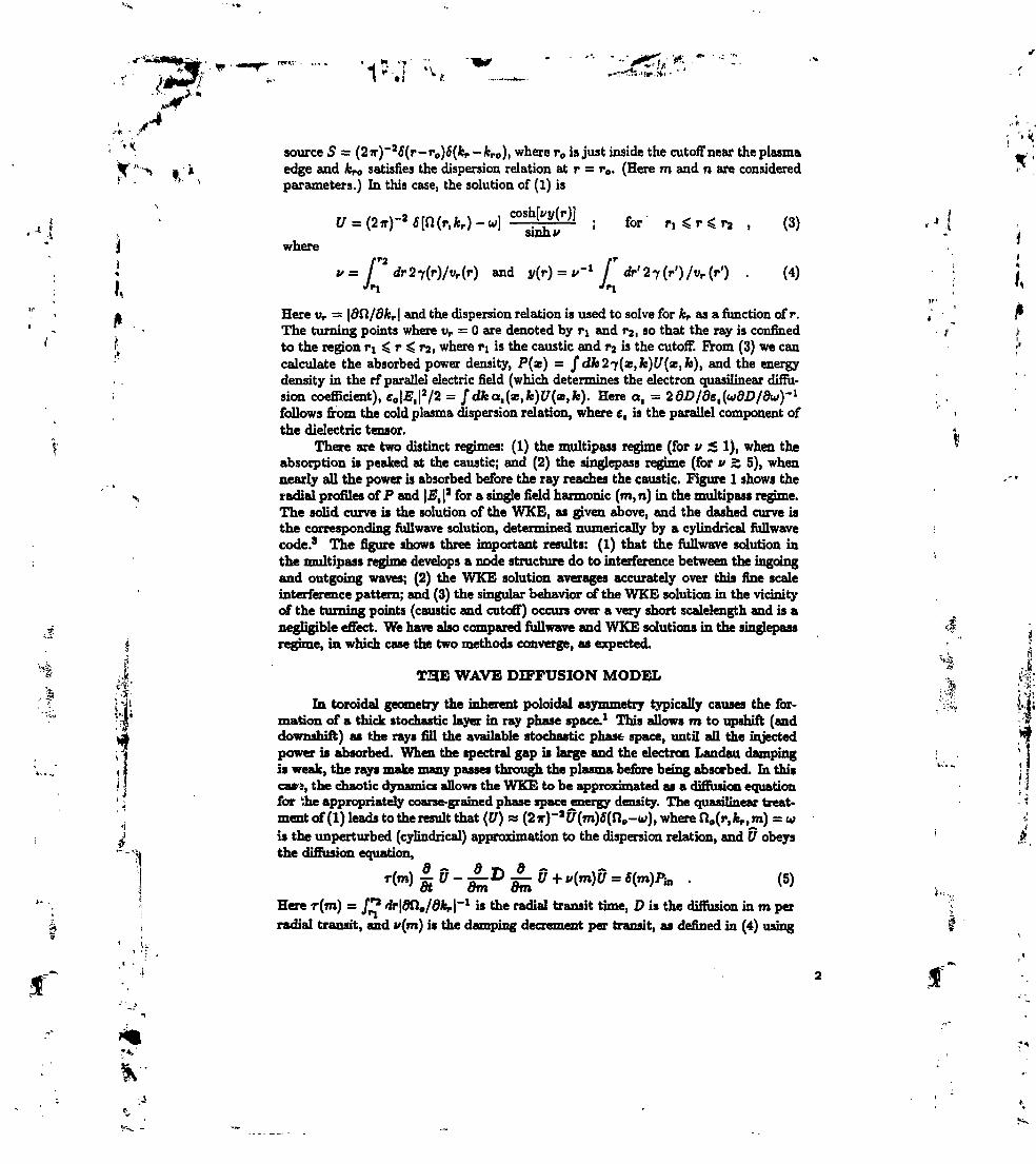
if
1 ) -* (myf l . . (5)
Here r(m) = JT* dr\dCla/dkr\~l is the radial transit tune, D is the diffusion in m perradial transit, and v(m) is the damping decrement per transit, as defined in (4) using
^-iSHSMfr , w ^_ », ,,• "< -^r- - • '"' -•rim,. • ~ ' T *• . I *V _..."*•,,_ a.. • '
l£*tJ!" i- I •: "* —*-• ' *"-*'^ Jkr^*^ ,*
/•*"*source 5 — (27r)~J(5(r-r0)5(fcr-fcPo), where r0 is just inside the cutoff near the plasma
"-^ I À edge and Av0 satisfies the dispersion relation at r = r0. (Here m and n are considered'*' ' parameters.) hi this case, the solution of (1) is
!i ; for ' ri < r < ra , (3)i|
jj where
^ v= I'* dr2i(r)/vf(r) and y(r) = V1 f dr'2f(r')/vr(r') . (4) ! {I Jr, Jfi ; M
* Here vr = |9n/ofcr| and the dispersion relation is used to solve for AV as a function of r. / rThe turning points where vr = O are denoted by TI and r2, so that the ray is confined 4 >
't to the region TI < r ^ r2l where ri is the caustic and r2 is the cutoff. Prom (3) we can '•*calculate the absorbed power density, P(X) — f dk2f(x,k)U(x,k), and the energy
. . density in the rf parallel electric field (which determines the electron quasilinear diffu-: sion coefficient), e0|£,|a/2 = /dfcoI(*,fc)^(x,fe). Here Q, = 2dD/de,(wdD/du)-1 ; .
follows from the cold plasma dispersion relation, where e, is the parallel component of <the dielectric tensor. i
There are two distinct regimes: (1) the multipass regime (for v £ 1), when the *absorption is peaked at the caustic; and (2) the singlepass regime (for v > 5), whennearly all the power is absorbed before the ray reaches the caustic. Figure 1 shows the
\ radial profiles of P and |J3, |a for a single field harmonic (m, n) hi the multipass regime.The solid curve is the solution of the WKE, as given above, and the dashed curve isthe corresponding fullwave solution, determined numerically by a cylindrical fullwave •code.3 The figure shows three important results: (1) that the fullwave solution inthe multipass regime develops a node structure do to interference between the ingoingand outgoing waves; (2) the WKE solution averages accurately over this fine scaleinterference pattern; and (3) the singular behavior of the WKE solution in the vicinityof the turning points (caustic and cutoff) occurs over a very short scalelength and is anegligible effect. We have also compared fullwave and WKE solutions in the singlepass 5!
I regime, in which case the two methods converge, as expected. •
J. THEWAVEDIFFUSIONMODEL * ftC*
• -J! In toroidal geometry the inherent poloidal asymmetry typically causes the for-•'!* mation of a thick stochastic layer in ray phase space.1 This allows m to upshift (and)j* downshift) as the rays fill the available stochastic phase space, until all the injected^ power is absorbed. When the spectral gap is large and the electron Landau dampingI 1 is weak, the rays make many passes through the plasma before being absorbed. Ih thisi J ca»i, the chaotic dynamics allows the WKE to be approximated as a diffusion equation• . for the appropriately coarse-grained phase space energy density. The quasilinear treat- • ^
'. ment of (1) leads to the result that (U) n (2*)-*U(m)6(no-u), where fl0(r, Av.ro) = w -jis the unperturbed (cylindrical) approximation to the dispersion relation, and U obeys ' *the diffusion equation,
:.i(.
.-WA
w v the unperturbed orbits. Also, Pin is the total injected power and we have idealized* . ** f the LH source as being a delta function spectrum in n and m, with n treated as a
parameter.Equation (5) is solved on the domain m. ^ m < m» with a reflecting boundary
condition (dU/dm = O) at ma and an absorbing boundary condition at m*. The lowerj boundary, as discussed in Réf. 1, corresponds to a propagation limit, since the dispersion; relation cannot be solved for real kr X m < ma, where ma can be calculated in the 'J cylindrical approximation. The upper boundary m» is somewhat Arbitrary because the ; «M electron Landau damping becomes very large at large m, so that U decays rapidly. It is ; ^. sufficient to chose m» large enough that the power flow across the boundary is negligible. ,,,. '* . Thus in steady-state (5) yields the conservation relation Pm = fdmv(m)U(m). , ' /I;' The effect of the chaotic dynamics on the evolution of the spectral energy density , f ~ ;;• enters (5) through the diffusion coefficient D. Although D can be a function of m, *
we have found that taking D to be a constant is an adequate approximation. Typical: values for D obtained from toroidal ray-tracing codes are in the approximate range
10s to IQ* (assuming a circular plasma cross-section and parameters typical of Tore . 'Supra and JT-60). Since the characteristic timescale for the divergence of neighboring ' .trajectories in the chaotic phase space must be much shorter than the time scale for *absorption, one finds that a rough criterion for the validity of the diffusion model is that *i/D must be smaller than the typical m upshift required for strong electron Landau
x damping. --•Because the damping decrement in (5) depends implicitly on the electron distri-
bution function, one must solve (5) together with the electron Fbkker-Planck equation,where the latter includes if driven quasilinear diffusion. We refer to this couplednonlinear system as the wave diffusion/Fokker-Planck system, or simply the WD/FP.The situation is entirely analogous to the usual coupled ray-tracing/Fokker-Planckapproach (BT/FP), except that in the BT/FP one seeks an exact solution of (1),which requires the use of a toroidal ray-tracing code to calculate the orbits of a largeensemble of rays for many radial transits. We have implemented numerical solutions of
i the WD/FP using a simple one-dimensional Fokker-Planck model at each radial grid >.fI point. A typical steady-state solution is shown in Fig. 2 for JT-60 like parameters with •;
: j- n«0 = 1.5 x 101' m~s, T90 = S keV, and a launched n, of 1.5. Good agreement is found s. . |l|' between the WD/FP and RT/FP, as long as the rays make many passes before being T ^J-{ajj; absorbed, in which case the effect of the chaotic dynamics is well described by (5). \ f •. &•'I' Numerical solutions of the WD/FP over a large range in the parameters D and ':- yj«ta P-O1 indicate the following simple scaling. Defining W(m) = vU/Pm as the normalized* J absorption per unit m, one finds that hi steady-state W is essentially independent of! I U do to strong quasilinear flattening of the electron tail, i.e., 7 a dft/0v, ac 1/17. It ; , ; I follows from (5) that U at Pin/D, so that quasilinear flattening occurs as long as Pm/Dt is larger than some critical value. For typical LHCD parameters Pin/D is 100 to 10004 times the critical value, so that the radial profiles of the absorbed power and the local$ , current drive efficiency are independent of substantial variations hi either D, or Pin. ,
ACKNOWLEDGMENTSî|1 This work was supported in «art by the EURATOM-CEA Association, in part J h .
> by an appointment to the U.S. Department of Energy Fusion Energy Postdoctoral ;. ! à.
fc.-5
*

Research Program administered by Oak Ridge Associated Universities, and in part byU.S. DOE Contract No. D&AC03-89ER51114.
REFERENCES
1. K. Kupfer and D. Moreau, Nucl. Fusion 32, 1845 (1992). ,1J 2. S.W. McDonald, Phys. Reports 158, 337 (1988).. 3. D. Moreau et a/., Nucl. Fusion 30,97 (1990). »i . i «
.jt figure Captions
FIG. 1. Radial profiles of the absorbed power (top) and parallel electric field en-ergy (bottom) hi the multipass regime (v < 1) for a single field harmonic(m = 100, n = 450) in cylindrical geometry. The solid curve is the WKE
\ solution from Eq. (3) and the dashed curve is the numerically determinedfullwave solution. Parameters are typical for LHCD on Tore Supra,
,-, .s
FIG. 2. Typical solution of the WD/FP. The rf energy density in the shadedregion is large enough to produce quasilinear flattening of the electrontail. [Here the parallel velocity is normalized to the local electron thermalvelocity {T«(r)/fn,}1''».] The profile of the absorbed rf power density issuperimposed.
>• iI*

- T
ABSORBEDPOWER
FIGURE
0.1 0.2 0.3 0.4 0.5 0.6 0.7
NORMALIZED RADIUS
0.8 0.9
•"* • .
r,
il
60
40
20
PARALLEL FIELD ENERGY
O 0.1 0.2 0.3 0.4 0.5 0.6 0.7 0.8 0.9 1
NORMALIZED RADIUS
FIGURE 2iV
9
8
j ^
6
5
4
3
2
i&
Q
-
,•x. *
** " . *
" * . " ^ . " * » "
:<'-
_
.
.,**
••'?••• * . * "
<•"
^ • •
• *
^«'
. " ] • •
g • *
t. .
I^AME kCj-
it mili\Il I iiV
i is
•
;JR
S
!
-•''•''•;.•>;!•• •!
'••
\<3fc
ifiiI i
j i l i i
* •.
*
:Hjl
,
a
rII"
f *.••
4I i::i :HH
• ! • ! * • ! ; • • » 1 1 '" * ! " * ! ' * •
. • * « f
•I 'i•
: IHl !
| | l" | rj i l '1
-
.^xABSORPTION PROFILE\
//
^x'' t
\'\
S
Vt
O 0.1 0.2,
0.3
^-•^
0.4=•
, t > t ,0.5 0.6 0.7 0.8 0.9 1
f
i:i4ij
NORMALIZED RADIUS
CHAPITRE III
LA GENERATION DE COURANT PAR L'ONDE
MAGNETOSONIQUE RAPIDE
•4
III.l. Introduction
II est apparu très vite, et les résultats expérimentaux l'ont confirmé, que la génération
non-inductive de courant serait d'autant plus efficace, en termes d'ampères par watt, que la
densité du plasma serait faible. La dépendance est inversement proportionnelle, et elle
s'applique quelles que soient les ondes utilisées car elle est due à la fréquence avec laquelle la
quantité de mouvement cédée aux électrons suprathermiques par l'onde est perdue par
collisions. Dans ce processus, la puissance HF est anallement thermalisée et participe donc à la
fois à la création du courant et au chauffage du plasma.
Cependant, dès les premières expériences utilisant les ondes hybrides inférieures et plus
exactement leur branche lente, on a observé une densité critique au delà de laquelle
l'efficacité chutait bien plus vite que la loi en ne~ ne le prévoyait. Ce phénomène est maintenant
bien compris. Il se produit lorsque, en augmentant la densité, la polarisation électrique de
l'onde acquiert une forte composante perpendiculaire au champ magnétique et une vitesse de
phase "perpendiculaire" suffisamment lente pour permettre une interaction résonnante avec la
population ionique du plasma (cf. A.I.2). Ce sont les prémices de la résonance hybride
proprement dite. L'absorption se faisant alors presque exclusivement par les ions, pratiquement
aucun courant n'est plus généré. Pour contourner cet obstacle, il a fallu augmenter la fréquence,
jusqu'à 3,7 GHz sur TORE SUPRA et JET par exemple (chapitre IV), car on a pu vérifier sur
de nombreuses machines que la densité critique était à peu près proportionnelle au carré de la
fréquence (nCiCrit- f 2ou fcrit~ ne1/2).
H I - I
**• V
».*!
I:
Sr

; H
>> i*Une deuxième limitation concerne la dépendance de l'efficacité de génération de courant
* par rapport à la vitesse de phase "parallèle" des ondes, v,.//, ou encore leur "indice parallèle", ' * I \i 2 2 '( n,/ - c/v,,,,,. Cette dépendance, proportionnelle à v^,/ ou n/, , devrait nous conduire à utiliser <* -. ! jI, un spectre d'ondes s'étendant jusqu'à la vitesse de la lumière (n// » 1), mais l'onde hybride ; ^
?' " ' J/I. ; n'est accessible à un plasma de densité donnée que si son indice parallèle est supérieur à une ' . ^
£ valeur critique, n//acc > 1, qui dépend de la fréquence de l'onde et des paramètres du plasma f5
• (densité, champ magnétique). Cette condition, dite d'accessibilité, est d'autant moins ' ,' '
; : contraignante que la fréquence est basse (en restant supérieure à la fréquence cyclotronique '" , :4 '
ionique, fci), que la densité est faible et que le champ magnétique est élevé. La fréquence f
minimum utilisable, déterminée par le phénomène de densité critique mentionné plus haut, se ^,,
N trouve toujours deux à trois fois supérieure à la fréquence hybride inférieure (f > fjpfcé2) et, '
par conséquent les indices inférieurs à n//acc » 2 ne peuvent accéder au centre d'un plasma ;
suffisamment dense, typique d'un Tokamak.
Finallement, la température du coeur d'un plasma thermonucléaire sera si élevée et
j l'amortissement Landau de l'onde lente si efficace que les ondes d'indice trop élevé >
'• J (n// > n//Landau) seront absorbées bien avant d'atteindre le centre du plasma. La conjugaison *
•'v'. des trois phénomènes de densité critique, accessibilité et absorption Landau réduit -f i i
considérablement la fenêtre utile d'indices parallèles (n//acc > n// > n//Landau) et de fréquences
(f > fcritX et rend difficile la pénétration de l'onde hybride dans les plasmas chauds et denses. V..,'
1 -iNous avons envisagé dès 1983 d'utiliser la branche rapide des ondes de fréquence ^
supérieure à fci, c'est à dire l'onde magnétosoiûque rapide, appelée encore onde d'Alfvén ' -*,
compressionelle de haute fréquence à cause de sa vitesse de propagation voisine de la vitesse
d'Alfvén (cf. A.12). Du point de vue de la propagation, sa vitesse de phase beaucoup plus " ;i?
rapide que celle de l'onde hybride permet en principe d'éviter toute résonance Landau avec les *
diverses populations ioniques, résonances qui seraient à l'origine d'un phénomène de densité ~~
*D. Moreau and C.M. S'mgh,"Plasma Waves for Electron Current Drive in Tokamaks", in Proc. of the IAEA
Tech. Committee Meeting on Non-Inductive Current Drive in Tokamaks, Culham (U.K.), 1983, Vol. II, 432.
m - 2

critique. Le critère d'accessibilité est le même pour l'onde lente et l'onde rapide puisqu'il
correspond à une réflexion par conversion linéaire de mode entre ces deux branches.
Cependant, l'absence de densité critique permet d'utiliser les basses fréquences (f » fci) et ainsi
de s'affranchir de la limite d'accessibilité (n//acc » 1).
¥.4
• L'ensemble de ces considérations très simples a fait naître l'espoir d'un possiblei •' contrôle de la densité de courant dans un réacteur par l'utilisation combinée d'ondes hybrides
; lentes (couches externes relativement "froides") et d'ondes magnétosoniques rapides dans la
: gamme de fréquence cyclotronique ionique (coeur du plasma chaud et dense). La question
traitée dans ce chapitre s'est donc posée dans les termes suivants : quelles sont les
. caractéristiques d'absorption de l'onde magnétosonique rapide par la population électronique du\
plasma, et quelle efficacité de génération de courant peut-on en attendre ?
III.2. Potentialités de la génération de courant électronique par l'onde rapide
Nous avons reproduit en annexe (Â.in.2.a) une communication présentée en 1986 à la
. ,,j jeme çonférence Européenne sur la Fusion Contrôlée et le Chauffage des Plasmas". U s'agit
| d'une des premières études quantitatives qui aient été faites en vue d'utiliser l'onde
• '|[ magnétosonique pour générer un courant. Ce travail met en évidence les propriétés
électromagnétiques de cette onde dans le régime d'intérêt en faisant ressortir les éléments qui
permettent d'évaluer l'interaction de l'onde avec la population électronique.
A la différence de l'onde hybride dont l'absorption est causée par l'effet Landau, la
résonance onde-particules est ici due à la combinaison de deux forces respectivement liées aux
composantes électrique (-eÊ7/) et magnétique de l'onde (-JiVB, Ji étant le moment magnétique
de l'électron). Lorsque l'une de ces deux forces domine, l'effet quadratique correspondant est
appelé respectivement "amortissement Landau" ou "pompage magnétique par temps
de transit" (en anglais, TTMP). L'action combinée des deux forces donne naissance à des
termes croisés supplémentaires et l'amplitude de l'interaction qui en résulte dépend de la vitesse
perpendiculaire des électrons résonnants, par l'intermédiaire de p.. Il existe en particulier, dans

Xr^ **
%r
l'espace des vitesses des électrons, une énergie perpendiculaire critique pour laquelle
^ . l'interaction est nulle. Les électrons ayant une énergie perpendiculaire inférieure à l'énergie
jj critique subissent principalement l'effet Landau tandis que ceux qui ont une énergie plus grande
« sont plutôt soumis au pompage magnétique.n
.Jt ; Nous avons déduit de cette étude des expressions relativement simples pour le
! ! coefficient de diffusion quasi-linéaire des particules et le taux d'absorption électronique de
l'onde, en fonction de Ia fréquence et des paramètres du plasma. Ces expressions ont été ;•.
; : introduites dans un code Fokker-Planck et les premiers calculs appliqués à JET (50 MHz) ont
montré que l'absorption de l'onde par les électrons pouvait être significative au centre de , i
décharges suffisamment chaudes et denses, c'est à dire pour des valeurs du paramètre pe local
"V (rapport de la pression électronique à la pression magnétique) atteignant 5 à 10% au centre. Un i
résultat très important est que cette absorption ne peut avoir lieu que si la vitesse de phase de j
- l'onde est voisine de la vitesse thermique des électrons. Même pour des densités de puissance '
très élevées, l'interaction reste pratiquement linéaire et ne donne pas lieu à la formation d'une
queue de distribution suprathermique. Ceci est dû au faible couplage entre l'onde et les -.3
r à électrons et ne permet pas de bénéficier au maximum d'un critère d'accessibilité à priori très ' Tt|
If' favorable. L'efficacité de génération de courant obtenue est malgré tout de l'ordre de 0,1 A/W v|
pour une densité ne = 6 x IQ19 m"3 et une température Te = 5 keV. Elle est pratiquement -~*
proportionnelle à la température électronique.
Dans une deuxième étude présentée à la conférence de Madrid en 1987 (A.in.2.b), nous
avons fait !'analyse d'un ensemble d'expériences déjà effectuées sur de "petites" machines pour
les situer par rapport aux deux régimes "Landau" et "TTMP" que nous avons mis en évidence, f
et pour voir dans quelle mesure leurs résultats étaient extrapolables au réacteur. Nous avons
identifié on paramètre sans dimension, '" ••
T. tj i
reliant la fréquence de l'onde, la densité du plasma et sa température, et montré que l'effet JS
Landau est dominant lorsque a < 1, tandis que pour a > 1 le TTMP devient important. La
1007
ii4
I,
a
dépendance paramétrique du taux d'absorption de l'onde par rapport au paramètre a s'inverse
lorsqu'on passe d'un régime à l'autre, et dans le régime TTMP où a > 1 celui-ci devient
proportionnel à pe. C'est d'ailleurs lé régime d'intérêt pour les grands Tokamaks et le réacteur
si l'on veut que l'onde pénètre au centre du plasma (fréquences de l'ordre de la fréquence
cyclotronique ionique ou même inférieures), alors que toutes les expériences initiales ont été
faites dans le régime "Landau" à cause de la trop faible valeur de la pression.
Nous avons pour finir quantifié les effets synergétiques qui pourraient naître de la
formation d'une composante électronique non-thermique par l'intermédiaire d'une autre onde
(hybride ou cyclotronique électronique), composante sur laquelle l'onde rapide viendrait
déposer sa puissance pour en accroître l'étendue énergétique. Les résultats d'un calcul
relativiste sont présentés en A.in.2.b. Ils montrent qu'une composante non-thermique dont la
pression locale correspondrait à Pe,non-«hennique "* 2,5% pourrait donner lieu à une absorption
substantielle de l'onde rapide.
IIî.3. Analyse hamiltnnienne de la génération de courant par l'onde rapide
L'analyse qui précède a été effectuée en plasma homogène infini dans le but d'explorer
les possibilités de génération de courant liées à l'utilisation de l'onde rapide, et de déterminer la
gamme de fréquence potentiellement utile. Pour faire une étude plus précise et plus
approfondie, et en particulier pour faire des prédictions directement appliquâmes aux Tokamaks
existants ou à venir, il faut avoir recours au calcul numérique. Nous avons donc entrepris
d'inclure les effets d'absorption directe de l'onde magnétosonique dans le code variationnel
ALCYON développé à l'origine pour étudier le chauffage cyclotronique ionique*. La
formulation hamiltonienne de l'interaction de l'onde avec la population électronique, étape
nécessaire pour l'objectif que nous nous sommes fixé, a été développée** et son implantation
7«."
I
D. Gambier, A. Samain, "Variational Theory of Ion Cyclotron Resonance Healing in Tokamak Plasmas",Nuclear Fusion 25 (1985) 283.A. Bécoulet, D. Edery. D. Gambier, H. Picq, A. Samain/T/te Code ALCYON. 2-D numerical modélisation ofKRF waves in Tokamaks", Rapport interne n° 1254, DRFC, Centre d'Etudes de Cadarache (1989).
A. Bécoutet, "Etude hamiltonienne de la réponse d'un plasma de Tokamak à l'onde de chauffage cyclotroniqueionique : chauffage minoritaire et génération de courant par l'onde rapide". Thèse de Doctorat, Université de Paris-Sud (Orsay), n° 1352,1990.
ffl-5
m
K:
1008

. ~r
numérique dans ALCYON a été accomplie en 1991. Nous en verrons quelques applications au
paragraphe III.4.
D'autre part, la faible interaction de l'onde avec les électrons et les nombres d'onde
toroïdaux relativement bas qu'il faut considérer ont des conséquences non triviales sur le
recouvrement des résonances et sur la validité d'une théorie quasi-linéaire. Ceci a fait l'objet
d'une étude présentée dans l'annexe A.ffl.3, où l'on a déterminé les régions de l'espace des
phases ou une telle théorie peut s'appliquer. Lorsque, grâce aux couplages toroïdaux et à un
phénomène analogue à celui décrit dans la section II.4, l'enrichissement du spectre poloïdal de
l'onde devient suffisant, et aussi lorsqu'on est loin de certaines surfaces magnétiques
singulières, alors les résonances se multiplient et la diffusion quasi-linéaire des particules peut
avoir lieu. La prise en compte des collisions montre alors que la formation d'un plateau en \//
sur la fonction de distribution n'est possible que pour les vitesses perpendiculaires élevées, là
où l'effet "TTMP" domine la friction collisionnelle. On confirme ainsi un résultat obtenu en
ÏÏI.2 suivant lequel l'interaction de l'onde magnétosonique avec les électrons est essentiellement
linéaire. A défaut d'augmenter l'efficacité de génération de courant, ce résultat a au moins
l'avantage qu'un calcul numérique du type ALCYON peut être effectué avec une bonne
approximation sur la base de fonctions de distribution maxwelliennes.
m.4. Application aux Tokamaks DIIT-D. .TET et ITER
L'annexe A.m.4.(a) reproduit un rapport issu de la collaboration entre l'Association
EURATOM-CEA (Département de Recherches sur la Fusion Contrôlée) et le gouvernement
américain (US Department of Energy) et en particulier le laboratoire de la General Atomics à
San Diego (Californie) où se trouve le Tokamak DHI-D. Nous présentons ici des simulations
obtenues à l'aide du code ALCYON, de l'expérience faite sur cette machine à la fréquence de
60 MHz. Deux "tirs" typiques de la campagne expérimentale de l'été 1991, effectués à des
champs magnétiques respectivement de 1 et 2 Teslas, ont été sélectionnés. Les champs
électromagnétiques dans le plasma sont représentés. Ils montrent bien l'enrichissement du
spectre poloïdal qui conduit à l'augrr es ration de l'indice parallèle et à l'absorption de l'onde. Ce
ra-6
*i
1009

y•*•
spectre est malgré tout borné et le phénomène d'enrichissement ne détruit pas la directivité de
l'onde. L'estimation de l'efficacité de génération de courant est faite sur la base de l'absorption
linéaire (cf. IH.3) et de la réponse du plasma décrite par la fonction de Green appropriée dans sa
limite locale (cf. 11.3). Les profils de densité de courant trouvés sont très piqués sur l'axe du
plasma. Dans le cas "1 Tesla/1,7 fceV" on obtient un courant non-inductif de 88 kA avec une
puissance de 1,7 MW couplée aux électrons. Dans l'autre (2 Teslas/3,4 keV), 47 kA sont
générés avec une puissance totale de 1,5 MW dont 44% sont absorbés par l'hydrogène
minoritaire au deuxième harmonique de sa fréquence cyclotronique. L'efficacité globale
(courant par unité de puissance multiplié par la densité et le grand rayon du plasma) est alors de
0,18 x 10¹⁹ Am-2W"1 si l'on ne prend en compte que la partie de la puissance effectivement
absorbée par les électrons.
Des simulations analogues ont été faites pour JET (tir 20297) à la fréquence deIQ 3
48 MHz, pour une température centrale de 3,9 keV, une densité centrale de 2,2 x 10 m" et
un courant total de 2 MA. Elles ont donné une efficacité maximum de 0,25 x 101 Am" W" et
des profils tout aussi piqués. Un courant non-inductif de l'ordre de 50 à 75 kA seulement aurait
pu être généré avec une puissance de 5 MW. On comprend donc qu'il ait été difficilement
observable.
Des extrapolations à ITER ont été présentées à une réunion internationale intitulée "Fast
Wave Current Drive in Reactor Scale Tokamaks", qui s'est tenue à Arles en septembre 1991,
sous les auspices de l'Agence Internationale de l'Energie Atomique. Elle montrent que l'on peut
en principe s'attendre à gagner un ordre de grandeur, principalement grâce à l'effet de
température, et obtenir des efficacités de l'ordre de 0,2 x 10²⁰ Am-2W"1 (cf. annexe A.ffl.4.b).
m.5. Commentaire sur la génération de courant par conversion de mode
Pour terminer, Ia possibilité de générer un courant par conversion de mode de l'onde
rapide près d'une résonance ion-ion a été également envisagée . Nous en avons fait une étude
J. Jacquinol,"//eonng and Current Drive Scenarios with ICRF", Rapport JET-P(85)12, JET Joint Undertaking,Abingdon(U.K.), 1985.
ffl-7
1010

I,
I
mW»i
,'I
"3^
préliminaire dans le cas de JET où les antennes sont situées du côté bas champ (annexe A.III.5)
et avons comparé deux scénarios basés sur l'hydrogène minoritaire et l'hélium-3 minoritaire,
respectivement. Nous montrons que la compétition entre les phénomènes de conversion de
mode et d'absorption cyclotronique entraîne une préférence pour l'hélium-3 car sa concentration
peut être choisie proche de son optimum pour l'absorption de type "Budden", sans pour autant
que les résonances hybride et cyclotronique soient trop voisines et que l'absorption
cyclotronique domine.
Malgré tout, dans les plasmas très chauds, la largeur Doppler de la résonance
cyclotronique est telle que ce scénario ne semble pas prometteur avec des antennes placées sur
la partie extérieure de la chambre torique d'un Tokamak.
III.6. Conclusion
La génération de courant par l'onde magnétosonique rapide est un sujet qui a donné lieu
à de nombreuses investigations théoriques et expérimentales depuis quelques années. La
conférence d'Arles patronnée par l'Agence Internationale de l'Energie Atomique nous a permis
de faire le point sur cette question. On en trouvera un résumé en annexe A.m.6.
La méthode n'est pas aussi attrayante qu'on aurait pu le penser au tout début. Il semble
en tout cas à peu près exclu de produire des électrons approchant Ia vitesse de la lumière par une
interaction quasi-linéaire. U faudra certainement s'en tenir à l'absorption linéaire de l'onde et à
l'efficacité réduite que cela entraîne (0,2 x 10²⁰ Am-2W"1)- Cependant il faut souligner que la
pénétration de l'onde au coeur d'un plasma thermonucléaire est possible à des densités et
températures aussi élevées que l'on veut. Ceci sera sans doute un atout considérable et même
unique pour l'utilisation de cette méthode dans un scénario de réacteur "avancé" où la majeure
partie du courant pourrait être engendrée par l'effet de "bootstrap". Une application a YIcR peut
aussi être envisagée à une fréquence inférieure à la fréquence cyclotronique du tritium, ou
encore comprise entre les harmoniques du tritium et du deuterium.
T •• '•i f " _?
f
in-8

~
Certains effets spectaculaires de synergie entre l'onde rapide et l'onde hybride ont été
observés expérimentalement (cf. chapitre IV) mais leur interprétation n'est pas triviale car ils ne
peuvent pas être simulés par la seule absorption de Ia première par la population électronique
suprathermique générée par la seconde. Il semble beaucoup plus probable qu'une partie de la
puissance portée par l'onde rapide et convertie en onde de Bernstein au voisinage de la
résonance ion-ion (cf. Iïï.5) soit absorbée très efficacement par la population suprathermique et
augmente ainsi la "température" des électrons rapides. Par contre l'absorption directe de l'onde
rapide par les électrons a bien été observée dans JET et Dffl-D, et dans cette dernière expérience
on a même pu mettre en évidence un effet de génération de courant.
m-9
U,".
K
y
"il
pi?ur
812 BECOULET et al.

ANNEXE AU CHAPITRE HI
' 4
IT
A.ffl.2.a. Fast Wave Electron Current Drive, D. MOREAU, J. JACQUINOT, P.P. LALLIA, in
Proceedings of the 13th Eur. Conf. on Contr. Fusion and Plasma Heating, Schliersee (RFA),
1986, Vol. H, 421.
A.HLl.b. Potentiality of Fast Wave Current Drive in Non-Maxwellian Plasmas,
D. MOREAU, M. O'BRIEN, M. COX, D. F. H. START, in Proceedings of the 14th Eur. Conf.
on Contr. Fusion and Plasma Phys., Madrid, 1987, Vol. ffi, 1007.
A.m.3. Analysis of Fast Wave Current Drive in Reactor Scale Tokamaks Through
Hamiltonian Theory, A. BECOULET, D. MOREAU, D. GAMBŒR, J. M. RAX, A. SAMAIN, in
"Plasma Physics and Controlled Nuclear Fusion Research 1990", Nuclear Fusion Supplement
1991, IAEA, Vienna (1991), Vol. 1,811.
AJIIAa. Variational Full Wave Calculation of Fast Wave Current Drive in DIII-D using the
ALCYON Code, A. BECOULET and D. MOREAU, Rapport GA-A20846, General Atomics,
San Diego (California), USA.
A.m.4.b. Analysis of Fast Wave Current Drive from the ALCYON Code, A. BECOULET,
D. MOREAU, G. GlRUZZI, B. SAOUTIC, J. CHINARDET, in "Fast Wave Current Drive in
Reactor Scale Tokamaks", Proceedings of the IAEA Technical Committee Meeting, Aries
(septembre 1991), p. 62.
A.III.5. Comments on ICRH Current Drive in JET, B. FRIED, T. HELLSTEN and
D. MOREAU, Plasma Physics and Controlled Fusion 31 (1989) 1785.
A.HI.6. Fast Wave Current Drive in Reactor Scale Tokamaks, D. MOREAU, Nuclear Fusion
32 (19S--?) 701.
m-ii
«?,'•*•• j«rji, - —'
IAEA-CN-53/E-m-lO 813

europhysicsconference
13 th European Conference on
Controlled Fusionand Plasma HeatingSchliersee/14-18 April 1986
I
|iI
Contributed Papers, Part IiEditors: G. Briffod, M. Kaufmann
Published by:
Series Editor:
European Physical Society
Prof. S. Methfessel. Bochum
Managing Editor: G. Thomas Geneva
Volume1OC
Part Il
814 BECOULET et al.

421
VJ
FAST WAVE ELECTRON CURRENT DRIVE
D. Moreau , J. Jacqulnot. P.P. LaIlla
JET Joint Undertaking.Abingdon, Oxon, OXU 3EA, UK
* From EUR-CEA Grenoble, France
Abstract
As a basis for investigating the possibility of controlling currentprofiles in JET we present a short analysis of transit time magneticpumping of electrons by fast magnetosonic waves above the ion cyclotronfrequency.
1. Introduction
The "profile consistency" observed to limit the performances of addi-tionally heated tokamak discharges stressed the interest of decouplingtheir temperature and current density profiles.
The fast magnetosonic wave has been considered as an attractivecandidate for non-inductive current drive /1-2/. Unlike the slow wave inthe lower hybrid frequency range, it has indeed the potentiality of beingefficient at high density and high temperature. Interaction with the bulkof the electron distribution in. the centre of the discharge, although notthe moat efficient, wojld provide the required absorption of the RF power.In particular the fast wave could be very well suited for driving areverse current in the central hot and dense plasma of large tokamaks,with the hope of suppressing "sawteeth relaxations" /3/.
A mode conversion current drive scheme near a two-ion hybridresonance (Bernstein wave current drive) has been proposed /1/. As analternative, we shall concentrate In this paper on direct electron currentdrive from the high frequency AIfvén wave itself. We shall draw somepreliminary conclusions with respect to wave absorption by the electrons,bearing in mind that other loss channels such as absorption from ions atharmonics of Qol or from high energy fusion products will have to beavoided or overcome.
2. Electrodynamics of the fast wave above the ion cyclotron frequency
We consider frequencies such that Q*ol < u2 < «ci fl and densities
higher than the lower hybrid resonance density (uzpi>> u*7. The wave hasboth electrostatic and electromagnetic components, le. È - - 1 || - V$,its electric fiald is mostly perpendicular to the equilibrium magneticfield 8Qand its magnetic field 8 parallel to 8O. Parallel currents existdue to a small parallel electric field but also to the bulk uVB forceexerted on the electron fluid. This force is the only thermal effecttaken into account. Solving Maxwell's equations within these assumptions,one obtains the following results:
IAEA-CN-S3/E.ID-10 SlS

;• '-•<422
a
- at densities Such that 01 »™ only the fast branch propagates andthere is no problem of accessibility up to a few harmonics of Q01;
- near cutoff the wave has all the characteristics of the righthanded circularly polarized whistler mode and then transforms itself into
nfl - <"pi/nci at almost
A Ay
the high frequency Alfven wave (HFAW), nperpendicular propagation
- if S0 is along Sz, i< in the Oxz plane and if o is the anglebetween ic and Sx we find the following polarization for the HFAW:
A - - jnA * 0030 Oci/u, Ax « Ay,coao ana Ex- -J ko nA $ cosa;
- the energy density carried by the wave is mostly in magnetic andion kinetic energy and can be expressed as
H = Hn, + H1 - 2Hn, - B|/p0 - 0.5 ne T6 Be|e4./Te « where B6 is theusual ratio of electron pressure to magnetic pressure.
3. Interaction of the fast wave with electrons : TTMP vs. LANDAU DAMPING
Both parallel (-eE// force) and perpendicular (-uV//B force) electricfields act upon the parallel velocity of the guiding centre of theelectrons. However, unlike ions in TTMP heating, electrons see oppositeforces and the interaction vanishes at some critical perpendicular energyHicrlf Becauae tne parallel electric field adjusts itself so as to givea zero net force on the bulk electron fluid (in the limit of zero electroninertia and uDi » u) we expect this critical energy to be near thethermal energy of the bulk electrons. TTMP diffusion will therefore bemost efficient on electron tails having perpendicular energies a few timesabove thermal.
Our detailed calculations show that the total force applied on theguiding centre is
J K e * n// L- [, -i-"ce me
!LEl cos'al-i
so that the critical energy defined above is indeed«icrit - <Hx> + "»* "1^1Di
where <Hj> is the average perpendicular energy or the electron fluid«H -T ). It is to be noted that at high density and low frequency(50 HHz) Hlerlt is indeed near T6 whereas at higher frequencies (800 MHz)it is much larger so that Landau damping is the dominant absorptionprocess (cf. Fig. tK
From the expression of the total force given above, it J,s straight-forward to obtain the quasilinear diffusion coefficient and thecorresponding damping rate. He assume a Gaussian distribution in k//space for the wave energy density and, after some algebra, we find that wecan approximate the diffusion coefficient by the following expression:
where n//Q is the peak parallel wavenumber and An// the half width of theand
the expr 33.' ongiven at the end of the precedent section.
In high température plasmas and at moderate resonant velocities the
were n//Q s te pea parallel wavenumber and An// the half wispectrum. The thermal velocity vfce is defined by T6 - mv*teJe*/Te|
7 is related to the average wave energy density H by the
f S
816 BECOULET et al.
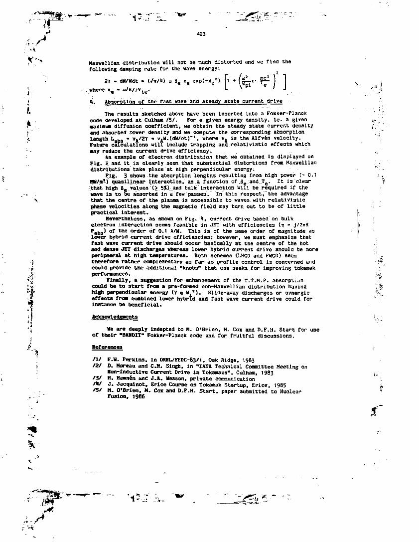
—=di,i
423
ii«
J.
Maxwellian distribution will not be much distorted and we find thefollowing damping rate for the wave energy:
dW/Wdt . B6 xe exp(-xe>) *
«here *e
«i. Absorption of thé fast wave and steady state current drive
The results sketched above have been inserted into a Fokker-Planckcode developed at Culham /5/. For a given energy density, le. a givenmaximum diffusion coefficient, we obtain the steady state current densityand absorbed sower density and we compute the corresponding absorptionlength L »„ - vA/2Y - v,W.(dW/dt)~
l, where vft is the AIfvén velocity.Future calculations will include trapping and relativistic effects which•ay reduce the current drive efficiency.
An example of electron distribution that we obtained is displayed onFig. 2 and it is clearly seen that substantial distortions from Maxwelliandistributions take place at high perpendicular energy.
Fig. 3 shows the absorption lengths resulting from high power (- 0.1HW/m1) quasilinear interaction, as .a function of .Se:and_Te. It is clearthat high Bgivalues r(>_5%V_and bulk interaction will be required if thewave is to be absorbed in a few passes. In this respect, the advantagethat the centre of the plasma is accessible to waves with relativisticphase velocities along the magnetic field may turn out to be of littlepractical interest.
nevertheless, as shown on Fig. 1, current drive based on bulkelectron interaction seems feasible in JET with efficiencies (n * j/2itRPabg) of the order of 0.1 A/W. This is of the same order of magnitude asloner hybrid current drive efficiencies; however, we must emphasize thatfast wave current drive should occur basically at the centre of the hotand dense JET discharges whereas lower hybrid current drive should be moreperipheral at high temperatures. Both schemes (LHCD and FWCD) seamtherefore rather complementary as far as profile control is concerned andcould provide the additional "knobs" that one seeks for improving tokamakperformances.
Finally, a suggestion for enhancement of the T.T.M.P. absorptioncould toe to start from a pre-formed non-Haxwellian distribution havinghigh perpendicular energy (Y a W.a). Slide-away discharges or synergiceffects from combined lower hybrid and fast wave current drive could forinstance be beneficial.
Acknowledgments
We are deeply Indepted to H. O'Brien, M. Cox and D.F.H. Start for useof their "BAHDIT" Fokker-Planck code and for fruitful discussions.
References
/1/ F.H. Perkins, in OHHL/FEDC-83/1, Oak Ridge, 1983/2/ D. Moreau and C.H. Singh, in "IAEA Technical Committee Meeting on
Von-Inductlve Current Drive in Tokamaks", Culham, 1983/3/ H. Hamnen ant! J.A. Wesson, private communication/*/ J. J ac qui not, Erlce Course on Tokamak Startup, Erice, 1985/5/ M. O'Brien. M. Cox and D.F.H. Start, paper submitted to Nuclear
Fusion, 1986
. -

424
Fig. 1 Quasilinear diffusioncoefficient versus perpendi-cular velocity at high (Landaudamping) and low frequency(T.T.H.P.)
Fig. 2 Electron distribution con-tours for B0» 2.2 T., f - 50 MHz,
5 keV, n. 1.8 x 10²⁰ m~'(fle - 7-5» in a Hz plasma. Thewave spectrum is Gaussian withn// - 2.9 and An// - 0.5
'S.
IFig. 3 Absorption length versusratio of peak resonant energy toelectron temperature (Ere3
/Te) for
B6 - 2.5Ï and 7.5J, and for T6 »5 KeV and 15 keV. Other parametersare BQ - 2.2 T., f « 50 MHz, in//" 0.5 and H, plasma
O I 2 3 4 S t
Fig. U Current driveefficiency versus Ere3/Te.Same cases as for Fig. 3i.e. 6e - 2.5* and 7.5Ïand T6 - 5 keV and 15 keV
' 13(£:.-
!
europhysicsconferenceabstracts
14 th European Conference on
Con t ro l l ed Fusionand Plasma Phys icsMadrid. 22 - 26 June 1987
Editors: F. Engelmann, J. L Alvarez Rivas
Contributed PapersPart
Published by: European Physical Society
Series Editor: Prof. S. Methfessel, Bochum
Managing Editor: G. Thomas, Geneva
VOLUME11 D
PART IIIS

.-J
1007
POTENTIALITY OF FAST WAVE CURRENTDRIVE IN NON-MAXWELLIAN PLASMAS
D. Moreau1, M.R. O'Brien2, M. Cox2, D.F.H. Start3
EUR-CEA, DRFC Cadarache, 13108 St Paul lez Durance, France'Presently attached to JET Joint Undertaking, Abingdon, 0X14 3EA, UK
2 EUR-UKAEA Association, Culham, Abingdon, Oxon, 0X14 3EA, UK3 JET Joint Undertaking, Abingdon, 0X14 3EA, UK
ABSTRACTAfter a short analysis of the available experimental data on pure
fast wave electron current drive we propose a theoretical scaling law forthe wave absorption through combined electron Landau damping and transittime magnetic pumping. We then present the result of a fully relativis-tic calculation which we apply to a bi-Maxwellian electron distributionfunction and conclude on the requirements to be fulfilled by theenergetic tail for obtaining significant damping in TORE-SUPRA.
INTRODUCTIONBecause of the limitations of Lower Hybrid Current Drive (LHCD) for
the reactor regime Fast Wave Current Drive (FWCD) has been the subject ofboth experimental and theoretical consideration. As far as wave propa-gation is concerned the fast wave has the ability of penetrating to theplasma centre at high temperatures and densities.
The current drive efficiency of waves in terms of current per unitabsorbed power is now well assessed both from Fisch-Karney theory andfrom the large experimental LHCD database. It is rather the absorptionefficiency of the electrons which becomes the important parameter inevaluating the merit of a FWCD scheme.
In this paper we shall first present a short analysis of presentFWCD experiments and define an absorption figure of merit for the directelectron damping of the fast wave which includes the combined effect ofelectron Landau damping (ELD) and transit time magnetic pumping (TTMP).Then we shall consider the effect of a non-thermal electron distributionfunction in producing an enhancement of the damping. In particular, weshall examine the range of parameters that would be required in a tokamaksuch as TORE-SUPRA for obtaining a significant tail absorption.
onSHORT ANALYSIS OF PRESENT F.W.C.D. EXPERIMENTS
Up to now only a few experiments have been reported or attemptedACT-I at 18 MHzi;, JIPP T-IIU at 40 MHz2)and 800 MHz3', JFT-2M at200 MHz*;, PLT at 800 MHz and provide a quite limited database.They can be classified in two sets:
i) Experiments in the lower hybrid frequency range encounter thedifficulty that the fast wave is launched in a very narrow n// windowbetween accessibility and cutoff. Coupling of the fast wave is thereforedifficult and the slow branch can be easily excited either at the antennaor by mode conversion after a small toroidal n// shift. The slow wave isvery efficiently absorbed and the current drive effect could be dominatedby the slow wave. This might explain why these experiments seem to face
K
I
1008
the same limitations as the usual LHCD experiments.ii)9Conversely, experiments using the High Frequency AIfvén Wave
(HFAW) 1^7 i.e. where u pi»ai are free of slow waves and have succeededin generating current at densities far exceeding the LHCD density limitscaling. However, they were still performed at very low densities andtemperatures so that the waves were damped on highly energetic electrontails through pure Landau damping rather than TTMP which would be signi-ficant or even dominant in reactor plasmas.
The main differences between these two frequency regimes are illus-trated on Figures 1 and 2 where we have plotted vs. density the parallelwavenumber for cutoff and accessibility in a deuterium plasma withBj. = 3.4 T. at frequencies of 800 MHz (i) and 50 MHz (ii) respectively.Also shown on Figures 3 and U are dispersion curves (kc/io vs. density)typical of the JIPP T-IIU experiments at 800 MHz3' (i) and «0 MHz2; (ii).
ABSORPTION FIGURE OF MERIT FOR FAST WAVE CURRENT DRIVEWe define an absorption figure of merit for FWCD as the ratio of the
maximum power damping decrement (2Yg{ ) to the angular frequency, in athermal plasma:
~" (D
This figure can thus be directly compared with a cavity quality factorand must be larger than some value determined by other absorptionmechanisms if a substantial part of the power is to be absorbed by theelectrons. Among various competitive mechanisms are the absorption ofthe walls of the tokamak chamber but principally the damping on neutralbeam injected fast ions and the damping on fusion products.
In order to estimate the damping rate" of the HFAW through thecombined action of ELD and TTMP a careful calculation of the electric andmagnetic fields which drive the fast wave has been done. An importantdimensionless parameter a appears which is a measure of the relativeimportance of the TTMP acceleration over the total parallel force on athermal electron. It is defined as
(2)
and is smaller than one when Landau damping dominates over TTMP. Otherindependent dimensionless parameters are <o/8ci and xg = w/ /2 k// vtewhich contain respectively the equilibrium magnetic field and theparallel phase velocity of the wave. Our absorption figure of merit canbe expressed in terms of these 3 quantities and reads:
p-S SxIO-1* X6 exp(-x|) <—
" ci(a + 1 (3)
It is to be noted that when a» 1 i.e. when TTMP dominates the damping isproportional to B6 through the product of a and or/fll*.
For the purpose of showing how various experiments scale accordingto this figure of merit we have plotted Q"1 versus c on Figure 5 fordifferent values of u/Qcl. From this plot we conclude that there is

- =::?-= •:»'- -
K
1009
indeed a large gap between present experiments based UpOQ1ELD (ot£<1) andthe reactor regime where TTMP will become dominant and Q6 S 10"'
ABSORPTION OF THE FAST WAVE ON A NON-THERMAL ELECTRON COMPONENTA conceptual scenario for enhancing the absorption could be to apply
the fast wave on a plasma in which a significant fraction of the elec-trons is non-thermal. Such an energetic component could for instance bepre-formed by Doppler shifted ECRH. This would have the advantage ofdirectly giving perpendicular energy to the electrons thus increasing theuv//B force due to the fast waves.
To investigate the effect of a non-thermal electron component wehave performed a fully relativistic calculation of the damping of fastwaves starting from the linearized relativistic drift equation5':
* £ _ _ eE / /-$£ v |B| . Wat // ZB /i i iThe calculation has been applied to a bi-Maxwellian equilibrium distri-bution function and, as an example, we consider a frequency of 120 MHzwhich will be available in TORE-SUPRA, ne = 6x10
1 y m~3, T = 5 keV, and areduced magnetic field of 2.25 T, so that w/flci =3.5. Plotted onFigure 6 is the absorption length Labs = vA/2Yabg (VA is the Alfvénspeed) vs. Eres/Tefor various temperatures of the electron tail (Eres isthe resonant energy of the electrons). It can be observed that at nighresonant energies, where the current drive efficiency is the largest,Labs can be of the order of 1 m or less only if the hot component tempe-rature is larger than 100 keV when we have assumed that it contains 156 ofthe bulk electrons.
CONCLUSIONOur theoretical study of the propagation and electron absorption of
the fast wave as well as a discussion of the present FWCD experimentsshow a number of conditions to be fulfilled if one is to consider such acurrent drive scheme in a large tokamak. The most favourable frequenciesseem to lie far below the lower hybrid frequency so as to push the LHlayer behind the antenna and to launch the high frequency Alfvén wave.
To reduce the cutoff layer at the antenna, coupling of the wave atlow n// could be attempted. Then only a very energetic non-thermalelectron component (local B6 tai-,a2.5S6) would be able to damp the wavealthough large toroidal n// upshifts may result in bulk absorption, amechanism which is invoked in LHCD experiments. Whether or not suchtails can be created by independent means remains to be demonstrated byFokker-Planck calculations and also by FWCD/ECRH synergistic experimentssuch as planned in JFT-2M for example. Finally the problem of minimizingthe ion damping requires further investigation.
REFERENCES
J. Corée et al., Phys. Rev. Lett. 55 (1985) 1669R. Ando et al., Nucl. Fus. 26 (1986) 1619K. Ohkubo et al., Phys. Rev. Lett. 56 (1986) 2010T. Yamamoto et al., Report JAERI-M 86-115 (1986)D.V. Sivukhin, in Reviews of Plasma Physics, Vol.1, M.A. Leontovitch

1010
II
Cutoff ni = R .
• • 'i"^1^-S^ ' \
Accessory ;-: M
MFig I Cutoff and Accessibility
for case (i)
NO SLOW WAVENO LH.R.
10" 10» 10"
Fig 2 Cutoff and Accessibilityfor case (ii)
i,-'
V
Fig 3 Refraction indexfor case (i)
ne (cm1)
Fig 4 Refraction indexfor case (ii)
m to' vf if i o wo
Fig 5 Absorption figure ofmerit vs. a
(m)
20
10
S
2
1
0.5
f Thermalf =120 MHz
T8 =5 keVne =6«ttBrn3
BT = 225 T= 1*
800k*
O 1O 20 30
Fig 6 Absorption lengthvs' Eres

T*K
Reprint from
PLASMA PHYSICSAND CONTROLLED
NUCLEAR FUSION RESEARCH1990
PROCEEDINGS OF THETHIRTEENTH INTERNATIONAL CONFERENCE ON PLASMA PHYSICS
AND CONTROLLED NUCLEAR FUSION RESEARCHHELD BY THE
INTERNATIONAL ATOMIC ENERGY AGENCYIN WASHINGTON, D.C.. 1-6 OCTOBER 1990
In three volumes
VOLUME 1
INTERNATIONAL ATOMIC ENERGY AGENCYVIENNA, 1991

IAEA-CN-53/E-III-IO
ANALYSIS OF FAST WAVE CURRENT DRIVEIN REACTOR SCALE TOKAMAKSTHROUGH HAMILTONIAN THEORY
A. BECOULET, D. MOREAU, DJ. GAMBIER, J.-M. RAX, A. SAMAINDépartement de recherches sur la fusion contrôlée,Association Euratom-CEA, CEN Cadarache,Saint-Paul-lez-Durance, France
Abstract
ANALYSIS OF FAST WAVE CURRENT DRIVE IN REACTOR SCALE TOKAMAKS THROUGHHAMILTONIAN THEORY.
The Hamiltonian formalism is used to analyse the direct resonant interaction between the fastmagnetosonic wave and passing electrons in a tokamak. The regions in phase space where quasi-lineardiffusion applies are deduced from a stochasticity criterion. A singular behaviour of rational-q surfacesis found, and the implications on the FWCD scenario in a reactor are discussed.
3;
f
1. INTRODUCTION
The fast magnetosonic wave, in the frequency range of up to a few «ci, is amajor candidate for driving non-inductive currents in reactor-like plasmas. Electronsinteract with the wave through a parallel electric force e5E(, leading to electronLandau damping (ELD), and through the transit time magnetic pumping (TTMP)force, JiVi(O1Bi). The interaction between the wave and the drift motion of theelectron becomes significant at very high parallel energy and will be neglected here.The fast wave does not suffer, as does the lower hybrid wave, from accessibilityconditions and will propagate in high density flat profile reactor plasmas. Fast wavedirect electron heating has recently been observed on JFT-2M [1] and JET [2], andseveral fast wave current drive (FWCD) experiments are planned (Dffl-D, JET,JT-60, TORE SUPRA), aiming at the implementation of an ICRF heating-currentdrive system on NET/TTER.
The efficiency of the proposed scenario depends on the coupling between waveand electrons. The existing theories a priori assume a quasi-linear damping in thevelocity space domain where resonant velocities exist. The quasi-linear theorydemands, however, a validation in terms of stochasticity and collisional effects. AHamiltonian approach to the interaction is, therefore, necessary in collisionlessregimes in order to determine the domains, self-consistently depending on fieldamplitude and spectrum, where trajectories become stochastic and quasi-lineardiffusion occurs.
8.
«r811
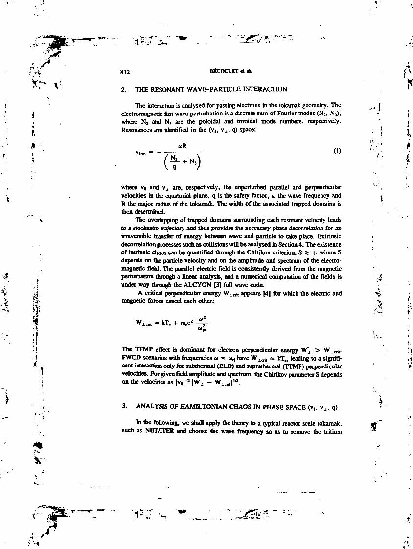
I,
f :
i -
812 BÉCOULET et al.
2. THE RESONANT WAVE-PARTICLE INTERACTION
The interaction is analysed for passing electrons in the tokamak geometry. Theelectromagnetic fast wave perturbation is a discrete sum of Fourier modes (N2, N3),where N2 and N3 are the poloidal and toroidal mode numbers, respectively.Resonances are identified in the (V1, v±, q) space:
(D
.¥'
i- •."*i; V
I,À
where v( and V1 are, respectively, the unperturbed parallel and perpendicularvelocities in the equatorial plane, q is the safety factor, u the wave frequency andR the major radius of the tokamak. The width of the associated trapped domains isthen determined.
The overlapping of trapped domains surrounding each resonant velocity leadsto a stochastic trajectory and thus provides the necessary phase decorreJation for anirreversible transfer of energy between wave and particle to take place. Extrinsicdecorrelation processes such as collisions will be analysed in Section 4. The existenceof intrinsic chaos can be quantified through the Chirikov criterion, S 2: 1, where Sdepends on the particle velocity and on the amplitude and spectrum of the electro-magnetic field. The parallel electric field is consistently derived from the magneticperturbation through a linear analysis, and a numerical computation of the fields isunder way through the ALCYON [3] full wave code.
A critical perpendicular energy Wicri, appears [4] for which the electric andmagnetic forces cancel each other:
kTea
The TTMP effect is dominant for electron perpendicular energy W"! > Wj.crit.FWCD scenarios with frequencies a * ua have WXCTit s, kTe, leading to a signifi-cant interaction only for subthermal (ELD) and suprathermal (TTMF) perpendicularvelocities. For given field amplitude and spectrum, the Chirikov parameter S dependson the velocities as |v,|-2 |WX - WAcrit|
1/2.
3. ANALYSIS OF HAMILTONIAN CHAOS IN PHASE SPACE (v,, Vx , q)
In the following, we shall apply the theory to a typical reactor scale tokamak,such as NET/ITER and choose the wave frequency so as to remove the tritium
;• v*

T- V" k"»œ.
lAEA-CN-53/E-III-lO 813
spectrum : BfB0 = 0.0002856
0.8
0.6
0.4
0.2
TTMP
ELD*.
(-10.-1)
(10,-3O)
(-10.-30)
HG. LS = I frontier in (vt/c, v±/c) space far q = 1.618 and a typical wave amplitude (polynomialfa are dimm and dotted circle actors show the thermal and light velocities). The wave spectrum (N2
varies from -IO to 10 and N} from -1 to -30) is also shown.
f?
.
fundamental cyclotron resonance from the plasma (R = 6 m, f = 19 MHz,He = 5 x I019 nr3, Te * 25 keV, B0 * 5 T).
Assuming that the safety factor q is constant along the unperturbed trajectory,Fig. 1 shows the S = 1 frontier in velocity space for a given field spectrum. Withinthe regions labelled TTMP and ELD, S is larger than 1, the perturbed trajectoriesare stochastic, and, therefore, quasi-linear diffusion applies. The spiky nature of thisfrontier is very sensitive to the q value, which directly acts upon the distance betweenconsecutive resonances (Eq. I)). In particular, rational q values lead to a degeneracy,reducing the effective number of resonances and, therefore, the extension of chaos.The effect is strongest near the integer-q surfaces.
To display this phenomenon over a significant plasma volume, we have, inFig. 2(a), represented a constant-vx cross-section of the phase space where the darkregions contain adiabatic trajectories and quasi-linear diffusion is restricted to thewhite domains. As expected, the vicinity of rational q values shows up in exhibitinglarge adiabatic 'diamond shaped* structures, which, in the absence of any extrinsicphenomenon, would prevent an electron from sitting on such a flux surface to reachhigh parallel velocities. However, outside these singular zones and for vx = 0.5 c,stochasticity is effective up to vt = 0.5 c. Increasing the perpendicular velocity(Fig. 2(b), vx = 0.7 c) pushes the adiabatic barrier to YI = 0.6 c, i.e. \ ~ c.
4. IMPUCATIONS ON THE KINETIC THEORY OF FWCD
With regard now to a kinetic analysis, the physical reality of the precedingrational-q structures, defining singular flux surfaces on which quasi-linear diffusion f

K
814 BÊCOULET et al.
.618
vj./c
FlG. 2. Adiabatic domains (dark) in (vt, q) space and corresponding D coefficients for q = /. 618. forv Jc = 0.5 (a and c) and Vj/c = 0.7 (b and d).
is prevented, must be questioned. In fact, extrinsic phenomena (e.g. collisions andradial diffusion) superimpose Markovian processes on the regular trajectoriesgenerating the 'dark* domains.
4.1. Effect of radial diffusion on rational-q structures
The anomalous radial diffusion, commonly observed during RF current driveexperiments, induces random steps in q space and will decorrelate the relative wave-electron phase when
where rq is the characteristic decorrelation time of an electron during its radialdiffusion and T^n the characteristic time for the same electron to complete its backand forth regular motion in the wave. We have
OHl-O 1 T q-PROFlLE

•- -1^JPw " -• --J^-*--••=-••-~-t~tâz.'lf^1 -
IAEA-CN-53/E-IIMO SlS
where Dr is the radial diffusion coefficient. On the other hand, the typical bouncetime in the wave reads:
2« J-a- |v\ - Vi011I
where DN is the N mode magnetic amplitude.Quantitatively, for the parameters in Fig. 2(a), rwlve = 1 fis and, on the
assumption of Dr « 2 m2/s, rq is smaller than T,«ïe for VI > 0.45 c for q = 1 andVI > 0.8 c for q = 2. The anomalous radial diffusion is not fast enough to wipe outthe 'diamond shaped' structures in the whole velocity range but generates chaos athigh parallel velocities, in the centre of the discharge.
4.2. Collisional regimes
Domains in velocity space where the collective motion can be described by aquasi-linear diffusion depend also on collisional considerations. Different regimes invelocity space exist, according to the Chirikov parameter S, and to the ratio,D = DqLTjio.injdB.n/v&e.na,, between the quasi-linear diffusion and the collisionaldiffusion coefficients; in particular:
— D > 1, over the region where S > 1: an effective plateau forms in the parallelvelocity distribution, die highest parallel velocity being determined by theintrinsic stochasticity frontier.
— D < 1, where S > 1: the collisional drag is strong, the distribution functionshews a small departure from the Maxwellian bulk, and damping is nearlylinear. „
WhDe increasing their parallel velocity, electrons move from an S > 1 highcollisionality region to an S < 1 low collisionality region. A high efficiency schemerequires an optimized spectrum in order to push the adiabatic barrier in the parallelvelocity beyond the D = 1 frontier. However, because of the relative weakness ofthe electron-wave interaction, this is only possible for high p^-pendicular velocities.Typically, in the conditions of Fig. 2(a), D is of the order of 1 (Fig. 2(c)) and reachesS for vx = 0.7 c (Fig. 2(d)). D remains much lower than one under the criticalperpendicular energy Wicfj,.

fr
816 BÉCOULET et al.
5. CONCLUSIONS AND PROSPECTS
Our theory shows that the extension of the quasi-linear diffusion is limited inparallel velocity because of the gaps between discrete resonances, especially forVj. = vicrj, and on integer-q flux surfaces. The absorption profile should, therefore,exhibit dips around the rational-q surfaces, and, interestingly enough, such a dip hasindeed been observed around the sawtooth inversion radius in the JET TTMP heatingexperiment [2]. In addition, when quasi-linear diffusion holds, the formation of aplateau in the electron distribution function, which would further increase theefficiency, seems possible at high V4., where TTMP dominates the collisional drag.
To ensure the destruction of adiabaticity, the distribution of the resonantvelocities is crucial. A natural enrichment of the poloidal spectrum is provided bytoroidal coupling along the multiple passes of the wave through the plasma [S], butsuch an uncontrolled broadening of the spectrum may lead to a loss of directivity.This will be studied when our theory will be applied in the ALCYON full wave code.
In conclusion, we may state that the following prescriptions seem to be relevanton optimizing the FWCD scheme: ;
— Controlled enrichment of the resonance pattern, by launching differentfrequency waves from different sets of antennas, with asymmetric, broadspectra. A frequency 'wobbulation', on a tune-scale shorter than the collisiontime, can also be envisaged.
—Application of FWCD hi synergy with ECRH, in order to take full advantageOfTTMPIo].
••I
ACKNOWLEDGEMENTS
The authors are grateful to J. Jacquinot and D. Start for stimulating discussions.This work was supported by Article 14, Contract No. JJO/9001 between JETand CEA.
1
REFERENCES
[1] UESUGI, Y., et al., Nucl. Fusion 30 (1990) 831.P] START, D.F.H., Nucl. Fusion 30 (1990) 2170.P] GAAfBIER, D.J., SAMAIN, A., Nucl. Fusion 25 (1985) 283.[4] MOREAU, D., JACQUINOT, J.. LALUA, P., in Controlled Fusion and Plasma Heating (Proc.
13th Eur. Conf. Schliersee. 1986), Vol. 1OC, Part H, European Physical Society (1986) 421.15] BHATNAGAR, V.P., et al., Ji Theory of Fusion Plasma- (Proc. Joint Varenna-Lausanne Int.
Workshop Varenna, 1990), to appear.[6] MOREAU, D., O'BRIEN, M.R., COX, M., START, D.F.H., in Controlled Fusion and Plasma
Physics (Proc. 14th Eur. Conf. Madrid. 1987), Vol. UD, Part IJI, European Physical Society(1987) 1007.
OHI-O 2 T q-PROFlLE

- - '-'jXTn*
JL. S
t*"M
~.f--^-
p
s_ï:
jt
GA-A20846UC-420
'' VARIATIONALt :
FULL WAVE CALCULATION OFFAST WAVE CURRENT DRIVE IN
DIII-D USING THE ALCYON CODE
byA. BECOULET* and D. MOREAU*
. Prepared underContract No. DE-AC03-89ER51114for the U.S. Department of Energy
•DepL de Recherches sur Ia Fusion Contrôlée Association EURATOM-CEA.
GENERAL ATOMICS PROJECT 3466DATEPUBLISHED: APRIL 1992
CEMERML MTOMiCS
$

'S,
I
'•4.,;
r-Hr - ;

ABSTRACT
l'-
Initial fast wave current drive simulations performed with the ALCYON* codefor the 60 MHz DIII-D experiment are presented. Two typical shots of the 1991summer campaign were selected with magnetic field intensities of 1 and 2 teslas re-spectively. The results for the wave electromagnetic fields in the plasma chamberare displayed. They exhibit a strong enrichment of the poloidal mode number m-spectrum which leads to the upshift of the parallel wavenumber, fc||, and to the waveabsorption. The m-spectruxn is bounded when the local poloidal wavenumber reachesthe Alfven wavenumber and the fc|| upshifts do not destroy the wave directionality.Linear estimations of the driven current are made. The current density profiles arefound to be peaked and we find that about 88 kA can be driven in the 1 tesla/1.7 keVcase with 1.7 MW coupled to the electrons. In the 2 tesla/3.4 keV case, 47 kA aredriven with a total power of 1.5 MW, 44% of which are absorbed on the hydrogenminority, through the second harmonic ion cyclotron resonance. The global efficiencyis then 0.18 x 10¹⁹ A Hi-2W"1 if one considers only the effective power going to theelectrons.
Mi
,1* The development of the ALCYON code is being supported by the JET Article 14 Contract
JJO/9001 betweea JBT mud EURATOM-CEA. Association
Ul

fit
1
%V"
0.50, ANTENNA POWER SPECTRUM

r *! ' TV
I «>• • -j
CONTENTS
ABSTRACT i»
1. INTRODUCTION 1
2. MHD EQUILIBRIUM 3
2.1. The 1 Tesla Case 32.2. The 2 Tesla C=ae 6
3. FAST WAVE FIELD COMPUTATION AND RESULTS FOR DIH-D . . 9
3.1. The 1 Tesla/1.7 keV Case 103.2. The2TesIa/3.4keVCase 143.3. Single-Pass Damping 14
4. WAVENUMBER SPECTRUM OF THE ABSORBED POWER 19
5. WAVE DRIVEN CURRENT AND CURRENT DRIVE EFFICIENCY . . 23
6. CONCLUSION 27
REFERENCES 29
ACKNOWLEDGMENTS 31
LIST OF FIGURES
Fig. 1. Profile of safety factor q for the Bt = 1 tesla case 5
Fig. 2. Plasma shape and mesh for Bt = 1 tesla case 5
Fig. 3. Profile of safety factor g for the Bt = 2 tesla case 7Fig. 4. Plasma shape and mesh for Bt = 2 tesla case 7
ABS(db). ALCYON. DiII-O 1 T. JV = 17

K
i
;5Ui -W.
LIST OF FIGURES (Continued)
Fig. 5. Spectrum of h|| obtained for equal currents in all antenna straps,with 7T/2 phasing between straps 9
Fig. 6. Power absorbed in the plasma as a function oftoroidal mode number 11
Fig. 7. Contours of |Brf| for the 1 tesla case 12
Fig. 8. |Brf I versus major radius for BT = 1 tesla case 12
Fig. 9. JBrf I versus poloidal mode number for toroidal mode JV = 17 . . . . 13
Fig. 10. Contours of amplitude of power in poloidal mode numbers between40 and -40, as a. function of minor radius, for N = 17and Bt = 1 tesla 13
Fig. 11. Contours of |Brf| for the 1 tesla case with the components withshort wavelength removed „ 15
Fig. 12. Contours of amplitude of power in poloidal mode numbers between40 and —40, aa a function of minor radius, for JV = 17 andBt = 1 tesla, with the components with shortwavelength removed 15
Fig. 13. For the Bt = 2 tesla case, the power absorbed by electronsthrough ELD and TTMP 16
Fig. 14. Contours of lBrf| in a poloidal cross section for the 2 tesla case . . . 16
Fig. 15. Power deposition as a function of minor radius for the2 testa, case 17
Fig. 16. Contours of |Brf| for the 2 tesla case, but wiih n, = 5 x 10¹⁰ m~3
and TC = 5 keV to enhance the damping 17
Fig. 17. Contours for the 2 tesla case, but with the dampingarbitrarily increased 18
Fig. 18. Launched spectrum and absorbed spectrum of ny for the 2 tesla caseat a minor radius r = 0.06 A •20
Vl
AtCYON. DIIl-O 1T. N = 17

J
*I,
"V
LIST OF FIGURES (Continued)
Fig. 19. Launched spectrum and absorbed spectrum of ny for the 2 tesla case
at a minor radius r = 0.59 A 20
Fig. 20. Launched spectrum and absorbed spectrum of n|| for the 2 tesla caseat a minor radius r = 0.06 A, but the spectrum of launched poweris shifted to lower ny 21
Fig. 21. Launched spectrum and absorbed spectrum of nj| for the 2 tesla caseat a minor radius r = 0.59 A, but the spectrum of launched poweris shifted to lower T»|| 21
Fig. 22. Radial profiles of power density, current density, local efficiencyof current drive, and integrated current, for the 2 tesla case . . . . 24
Fig. 23. Radial profiles of power density, current density, local efficiencyof current drive, and integrated current, for the 1 tesla case . . . . 25
VIl
a

•î'ï/
'*•
1
1. INTRODUCTION
In this report, we describe the main features of the ALCYON 2D-FuIl Wave code,and its application to the modeling of the first fast wave; current drive experiments in
DHI-D.
ALCYON contains the basic physics for the propagation and absorption of thefast magnetosonic wave in a toroidal axisymmetric geometry, starting from a consis-tent magnetohydrodynainic (MIiD) tokamak equilibrium. The wave fields are Fourieranalyzed along the toroidal and poloidal directions, the axisymmetry allowing a sepa-rate treatment for each toroidal harmonic number. The code is based on a variationalformulation of the Maxwdl-Vlasov equations, and on a full Hamiltonian description ofthe wave-particle interactions [1,2]. The functional form contains the physics relatedto the first and second harmonic ion cyclotron effects and the electron Landau anddamping (ELD) and transit time magnetic pumping (TTMP).
Satellite programs have been developed, which post-process the if fields com-puted by ALCYON. They allow :
1. To display the various components of the rf f.el^_
2. To compute the complete local quasUinear diffusion operator in velocityspace, on each flux surface. This operator can then be used in a Fokker-Planck code to evaluate the perturbed distribution function. A comparisonof the diffusion coefficient with the collisional drag validates the K"«"- ap-proximation (small perturbation of the Maxwellian distribution function),at least in the phase space domain where the electron-wave interaction isgoverned by ELD (vj. < 1
3. To estimate the wave driven current in this linear approximation, as wellas the power deposition and current density profiles, and to derive a globalcurrent drive efficiency.
The work which is reported here conusts of a quantitative simulation of twoDHI-D typical shots (#72715 & #73071), which essentially difler by their toroidal
• J Î Î - - T -T r -^i
abs(db), ALCYON. OHH) If1N = 17. ALFVEN FILTER

K
T:'*v"
magnetic field and temperature. For each of these cases, the computation of the
required MHD equilibrium has been made using data from the DIII-D/EFIT codeoutput. Then ALCYON has been run for all relevant toroidal mode numbers, givingon each flux surface the Fourier amplitudes of each field component (parallel mag-
netic field, perpendicular vector potential and scalar potential). Finally these datahave been processed through the above-mentioned programs in order to evaluate thecurrent drive effect in DIII-D.
In the following section we shall detail the plasma equilibria used in our study.Then, in Section 3, the ALCYON results concerning the wave propagation/absorptionand the field structure will be described and discussed with respect to the single passabsorption parameter. Section 4 deals with the wavenumber spectrum of the absorbed
power on a given flux surface and shows the modification of the launched spectrumand of its directivity as the wave propagates into the plasma. Section. 5 is devotedto the estimation of the driven current and of the fast wave current drive (FWCD)efficiency and it is followed by a short conclusion.
•'4'
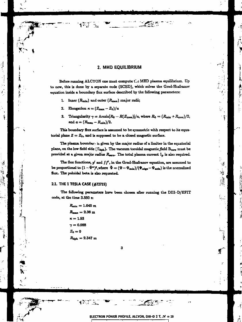
'-JiT-TI *!
%
r«>" .
2. MHD EQUILIBRIUM
Before running ALCYON one must compute tLa MHD plasma equilibrium. Upto now, this is done by a separate code (SCED), which solves the Grad-Shafranovequation inside a boundary flux surface described by the following parameters:
1. Inner (JZmin) and outer (.Rmax) major radii;
2. Elongation K = (Z111n — Z0)Ja
3. Triangularity 7 = ArCSm[JZ0 —
and a = (Rm*x -
where B0 = (Ram + JZmax)/2,
This boundary flux surface is assumed to be symmetric with respect to its equa-torial plane Z = Z0, and is supposed to be a closed magnetic surface.
The plasma boundary is given by the major radius of a limiter in the equatorialplane, on the low field side (fidph)- The vacuum toroidal magnetic Jield Bt010 must beprovided at a given major radius R^10. The total plasma current Ip is also required.
The flux functions, p' and //', in the Grad-Shafranov equation, are assumed tobe proportional to (l-$a)«,where $ = (*-*«d.)/(*«dge-*«d«) » the normalizedflux. The poloidal beta is also requested.
2.1. THE 1 TESLA CASE (#72715)
The following parameters have been chosen after running the DHI-D/EFITcode, at the time 3.550 s:
Jt,i. = 1.045 m
Raac = 2.36 m
ie =1.93
7 = 0.988
2.347 m
ELECTRON POWER PROFILE. ALCYON. DIIt-D 2 T. N = 20

A
Bt = -1.012 T
= 1.6955 m
IP = 500 kA
a = 0.94
g = 1.45
ft, = 0.38
giving the following values:
= 0.57%
A = 1-21
1.76 m
4(0) = 0.94
rt°> = 1
j(0) = 970 kA/m2.
The g-profile is shown in Fig. 1. The plasma shape and mesh are displayed inFig. 2.
The other plasma parameters and profiles have been chosen from fitting theejEDenmentotal data obtained from the DIH-D/ENERGY code and using the approxi-mation r/u «'>/*. They are the following:
n. = [(2.33 x 10") - (5.8 x 10»)] x (l - $l)" + 5.8 x 10¹⁸ m'»
Te = 1.677 x (1 - ^1)4-" keV
0.025 n,
TH = TD = 0.73 x (l - ^0-5)1 keV
4
*7*,' -
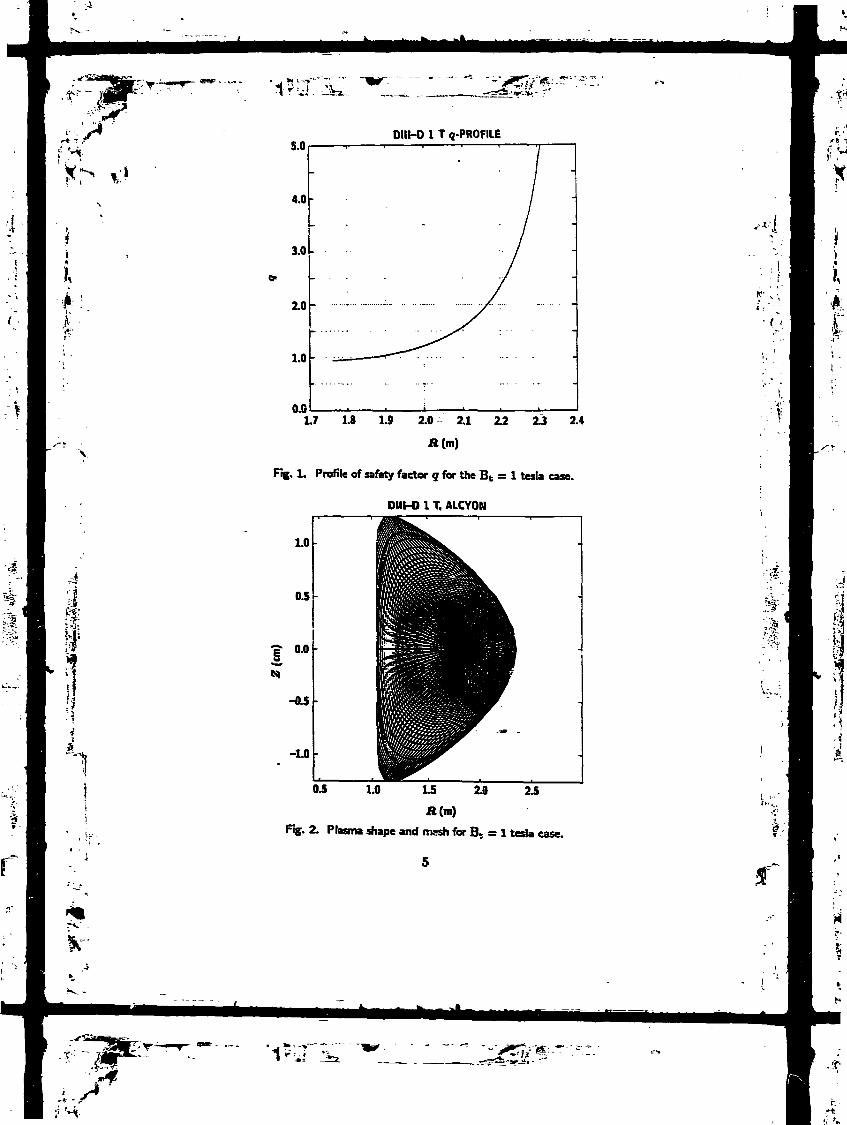
.vSSSS
,sr-f:m
1,
?**"
5.0
4.0
3.0
DIII-O 1 T «-PROFILE
1.0
0.0L7 1.8 1.9 2.0 2.1 2.2 2J 2.4
Fig. 1. Profile of safety factor g for the Bt = 1 tesla case.
OHI-D 1 T. ALCYON
0.0
-0.5
-1.0
1.0 L5 10 2.5
Jl (m)
Fig. 2. Plasma shape and mwh for Bt = 1 tesla case.
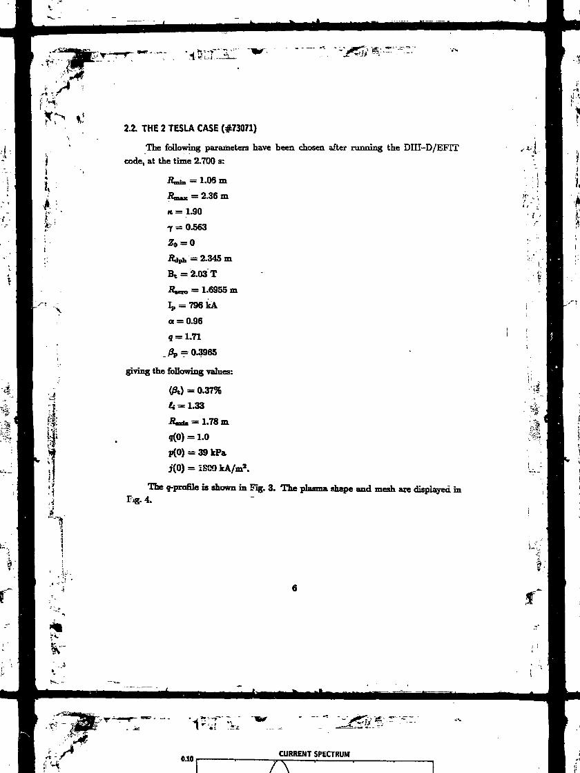
£;
2.2. THE 2 TESU CASE (#73071)
The following parameters have been chosen after running the DIII-D/EFITcode, at the time 2.700 s:
= 1.06 m
2.36 m
ic = 1.90
7 = 0.563
B1 = 2.03 T
JZUo = 1.6955 m
Ip = 796 kA
a = 0.96
g = 1.71
,£, = 0.3965
giving the following values:
(ft) = 0.37%
It = 1.33
JZ«ia = 1.78 m
5(0) = 1.0
p(0) = 39 kPa
j(0) = ISOO kA/m2.
The g-profile is shown in Big. 3. The plasma shape and mesh are displayed inFig. 4.
. >*
Ir
CURRENT SPECTRUM
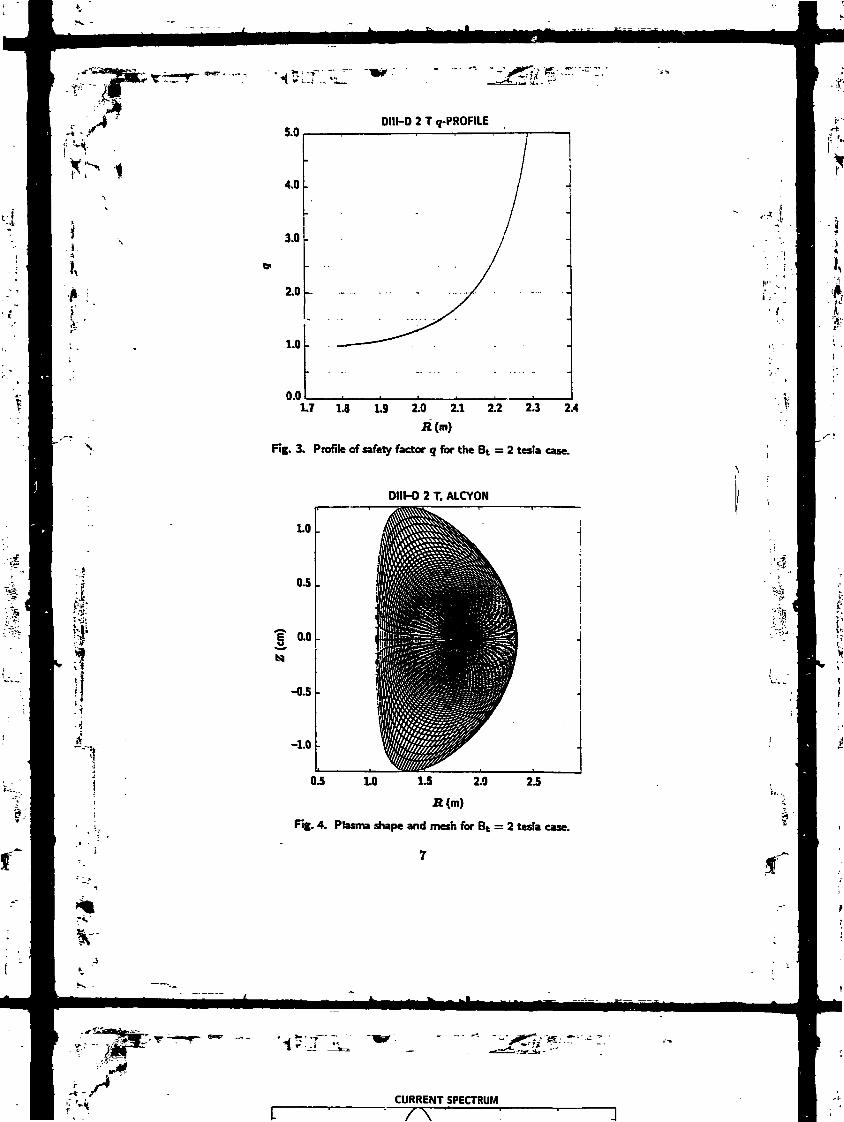
& Vi1
IISii
5.0DIII-D 2 T (j-PROFILE
4.0 -
3.0
2.0
1.0
0.01.7 1.8 1.9 2.0 2.1 2.2 2.3 2.4
Jt(B)
Fig. 3. Profile of safety factor q for the Bt = 2 tesla case.
DIII-O 2 T. ALCYON
LO
0.5
-0.5
-1.0
OJ 1.0 1.5 2.0 2.5
R (m)
Fig. 4. Plasma shape and mesh for Bt = 2 tesla
CURRENT SPECTRUM

The other plasma parameters and profiles have been chosen from fitting theexperimental data obtained from the DIII-D/ENERGY code and using the approxi-mation r/a sa i/*. They are the following:
ï, = [(3.5 x 10¹⁹) - (6.0 x 10")] x (1 - «")" + 6.0 X 10¹⁸ m~3
e = 3.4x(l-*°-ll)!l-2keV
= 0.025 TV
nD =
;|
M"4
TH = TD = 1.0 x (1 - f0-5)1 keV
8

• * -.-*«!
x>
K
3. FAST WAVE FIELD COMPUTATIONAND RESULTS FOR DIII-D
The 60 MHz wave is launched from an antenna situated at IZ = -R8Ot) in the vac-uum region between the plasma boundary (Adph) and the last (perfectly conducting)flux surface used in the calculation (.Kmnx)- We have taken fl^t = (JZdph + ^Zmax)/2and the antenna poloidal extension is ±0.35 radian. The antenna is fed hi a poloidalmonopole mode and the toroidal mode number spectrum of the antenna current iscreated by four equal currents in the four current straps (Fig. 5).
K•
3
I
,1• fI
0.12DlII-D ANTENNA CURRENT SPECTRUM
0.08
0.04
10 20 30
Fig- E- Spectrum of «-n obtained for equal currents in all antenna straps, with 7T/2 phasingbetween straps.
:i
à
- w-

Each ALCYON run is performed for a single toroidal mode number JV and we
have varied |JV| between 3 and 35. The corresponding parallel wavenumbers at the
antenna vary from ny = 1 (% = 1.25 m"1) to ri|| = 12 (k\\ = 15 m"1). In all these
runs the antenna current is taken to be the same (1000 A). The deposited toroidal
power spectrum is then the convolution between the absorbed power resulting from
these runs and the real current spectrum in the antenna [Fig. 6(a) for the 1T case and
Fig. 6(b) for the 2 T case]. Eighty-one poloidal mode numbers m between -40 and
+40 are used for the description of the fields. Thus, on each of the 75 flux surfaces,
the field is described by more than 5000 Fourier components each giving rise to a
•wave-particle resonance.
3.1. THE 1 TESLA/1.7 keV CASE (#72715)
Figures 7 (2-D contours) and 8 (equatorial section) display the modulus of the
wave magnetic field in a poloidal cross-section for N = 17. Because of the very weak
electron damping the wave tends to build up cavity modes through multiple passes,
while developing large poloidal m components. As a result, the wave pattern is rather
complicated and does not exhibit any ray structure.
The Fourier m-spectrum (JV = 17) of the wave magnetic field modulus is shown
in Fig. 9 for a central flux surface. In Fig. 10, level curves in the (r/a fa Vw,
m) space show the extension of this spectrum as a function of plasma radius. Quite
interestingly, the extension of the m-spectrum decreases towards the plasma center, in
agreement with an upper bound obtained where the equivalent poloidal wavenumber
(m/r) is of the order of the Alfvén wavenumber, U/CA.
Wave structures which have a wavelength much shorter than the Alfvén wave-
length are due either to some hot plasma wave (in which case they cannot be resolved
on the ALCYON mesh, size) or simply to the finite mesh itself. Ih any case the power
gokig into these short wavelength modes is generally small (except if there is a mode
conversion layer in the plasma) and they can be filtered out a posteriori, or damped a
10
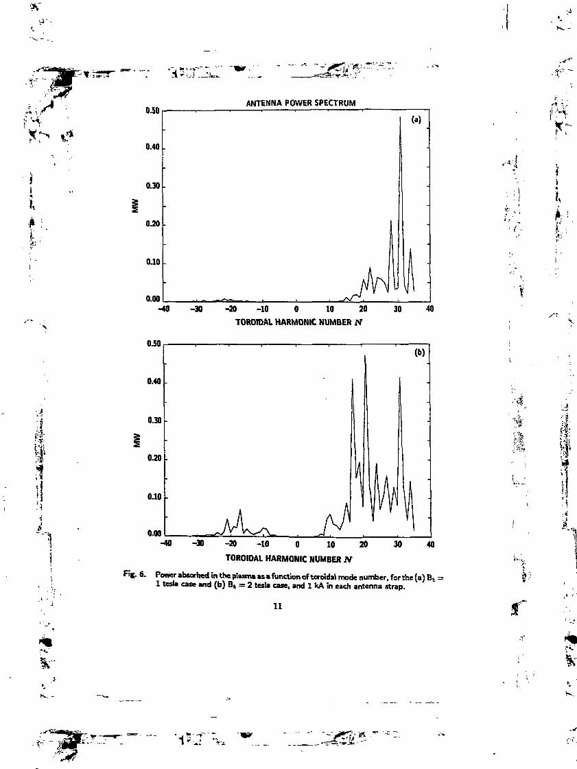
.1
0.50
0.40 .
0.30
070
0.10
0.00
0.50
0.40
0.30
0.10
0.00
ANTENNA POWER SPECTRUM
-40 -30 -20 -10 O 10 20
TOROIDAL HARMONIC NUhABER N
-40 -30 -20 -10 O 10 20
TOROIDAL HARMONIC NUMBER JV
(a)
30 40
30 40
. 6. Power absorbed in the plasma as a function of toroidal mode number, for the fa) Bt =1 teria case and (b) Bt = 2 testa case, and 1 kA in each antenna strap.
11
1j »';>•»
1•Ai

1.0
0.5
i 0.0
-0.5
-1.0
ABS(db), ALCYON, OHI-O 1 T. JV = 17
OJ 1,0 1.5 2.0 2£H (m)
Fig. 7. Contours of |Brf | for the 1 testa ease.
T •* 'Ï !
1.0 x 10-» ABS(«lb). ALCYON. DIIl-O 1T. JV = 17. eqjec.
OJ
0.6
0.4
LO U 1.4 L6 1.8 ZO 2.2 2.4
A
Rg- 8. |Brf| versus major radius for BT = 1 testa case.
12
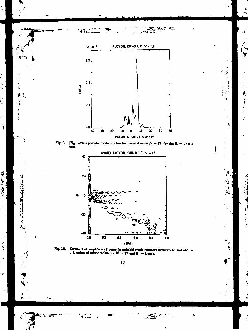
M
»
xio- AUCYON. DIII-O 1 T. N = 17
0.8
0.4
0.0 V .-40 -30 -20 -10 O 10 20 30 40
POLOIDAL MODE NUMBER
Fig. 9. |Brf| venus poloidal mode number for toroidal mode N = 17, for thé Bt = 1 tesla
abs(db). ALCYON. DIIH) 1T. JV = 17
E O
Rg. 10. Contours of amplitude of power in poloidal mode numbers between 40 and -40,a function of minor radius, for N = 17 and B1 = 1 tesla.
13
as
fc"

priori through an artificial damping term in the variational form. Figures 11 and 12
are the same as Figs. 7 and 10 after filtering out the small wavelength components.
À simple slab calculation based on a single pass through the plasma at constant
UH, and using the damping decrement given in Réf. [4], yields a power absorption
coefficient of the order of 0.07% for N = 11, and it reaches only 4.6% for N = 20.
Even though the damping length scales as the cubic p : wer of the inverse toroidal field,
the temperature is too small and therefore the fast wave experiences poor damping,
and thus strong poloidal enrichment.
II
3.2. THE 2 TESLA/3.4 keV CASE (#73071)
Ih this case, the single pass electron absorption coefficient just mentioned varies
between 0.7% (N = 11) and 32% (N = 20).
However, the second harmonic cyclotron resonance of the hydrogen lies in the
center of the plasma. Consistently with the experiments, we have assumed a 2.5%
minority hydrogen population hi a deuterium plasma. As a result, the electron ab-
sorption is dominant for large N, about equal to the hydrogen absorption for N = 18
where most of the power is bunched, and then smaller than the hydrogen absorption
for N < 18 (Fig. 13).
The wave field for this case is displayed hi Fig. 14 (N = 20) and the power
deposition profile in Fig. 15. The multi-pass character of the propagation is still clear
on Fig. 14.
33. SINGLE-PASS DAMPING
In order to simulate the propagation in a single pass absorption situation, we
have run the 2 tesla case while artificially increasing the absorption. This is done
either by choosing the central electron temperature and density to be 5 keV and
5 x 10¹⁸m~* respectively (Fig. 16), or simply by adding an artificial damping term
14
T*.'
I
1~: " "" " 'ig&f^_ _ --ï*âl..i _i, -

Kf
abs(db), ALCYON. DIII-O 1 T, N = 17. ALFVEN FILTER
1.0
0.5
.§, 0.0
-0.5
-1.0
0.5 1.0 1.5 2.0
H (m)
2.5
Fig. 11. Contours of |Brf| for the I tesla case with the components with short wavelengthremoved.
-40
Fg. 12. Contours of amplitude of power in poloidal mode numbers between 40 and -40, asa functwn of minor radius, for JV = 17 and B» = 1 tesla, with the components withshort wavelength removed.
-
15
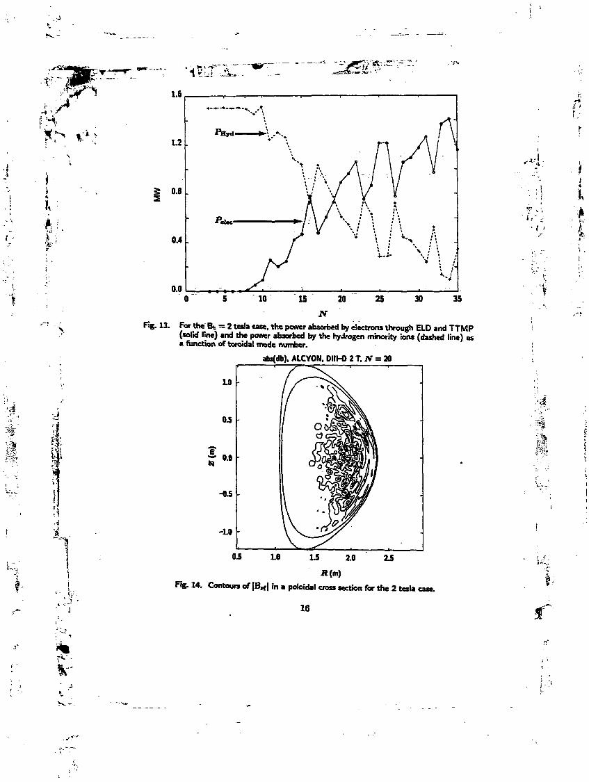
K
ti
\\:ià
0.8 .
0.4 .
0.0
Rg, 13. For the Bt = 2 tesla ease, the power absorbed by electrons through ELD and TTMP(solid line) and the power absorbed by the hydrogen minority ions (dashed line) asa function of toroidal mode number.
abs(db). ALCYON. DIIhO 2 T. ff = 20
-LO
OJ LO
Fig. 14. Contours of |Brf\ m » poloidal cross section for the 2 tesla case.
16
,
•ci;'
w

i
i
ELECTRON POWER PROFILE, ALCYON, DIII-D 2 T, N = 20
U
0.0)
Fig. IS. Power deposition as a function of minor radius for the 2 tesla case.
abs (db)
10
0.5
OJI
-LO
1.0 2.0 2.5
Fig. 16. Contours of jBrf| for the 2 tesla case, but with n, = 5 X 10™ m~3 and Te = 5 keVto enhance the damping.
17

.V
, ~~>31
ï" '-I'-
J
(anti-hennitian) to the ALCYON variational form (Fig. 17). The ray character of the
wave pattern is then clearly apparent and one can easily recognize the ray trajectory.
real (db). ALCYON, TV = 20. ARTIFICIAL DAMPING
1.0
0.5
£ 0.0
-0.5
-1.0
05 1.0 15 2.0 25at» (db). ALCYON. N = 20. ARTIFICIAL DAMPING
05
-05
-LO
05 1.0 15 2.0
H(m)
25
Fig. 17. Contours for the 2 testa case, but with the damping arbitrarily increased, of (a) |Brf|and (b) absorbed power.
18
%KlM

I-
4. WAVENUMBER SPECTRUM OF THE ABSORBED POWER
Ih order to display the n||-spectrum modifications due to both the N/R de-
pendence act! the poloidal component of the wave, we show on Figs. 18 and 19 the
absorbed power spectrum (electron channel) on a given flux surface corresponding
to r/a = 0.06 and r/a = 0.59 respectively, for the 2 tesla case. The upper curves
represent the launched spectrum, and the lower curves the absorbed spectrum. Near
the center of the plasma where tne broadening due to the m-spectrum is not too large,
one clearly sees the global upshift of the spectrum due to the JV/JZ dependence.
The current drive efficiency depends strongly upon the local absorbed power
spectrum and it is interesting to study how it varies when the launched spectrum is
shifted by changing the antenna phasing. This can help select the best compromise
between high efficiency (low ny) and good antenna coupling (high n\\). As an ex-
ample we see by comparing Figs. 20 and 21 with Figs. 18 and 19 that there is not
much interest Ui launching a lower ng spectrum (45 degree phasing) for this plasma
temperature, since the power is still absorbed in the same ng range, *-e. by electrons
in the same velocity range.
The coupling problem will be addressed in a future work by matching the plasma
surface impedance obtained from ALCYON to an antenna code [5] which contains the
exact geometry of the antenna and which shall yield a current spectrum consistent
with the full wave calculation. This consistent spectrum could then be used, rather
than the assumed one, for a better estimation of the power deposition and wave driven
current profiles.
19

>r-
î*K
T:'*•—.
0.10
k
CURRENT SPECTRUM
-20 -10 O 10PARALLEL INDEX
20
-30 -20 -10 O 10PARALLEL INDEX
20
30
1.0
OJ
on
ABSORBED POWER (A.U* I '
!
î JdJ. !.H. ...
). r = 0.03533 m. 9 = 1.03
•
30
Fig. 18. Launched spectrum and absorbed spectrum of nu for the 2 tesla case at a minorradius r = 0.06 A.
:•»
»'
0.10
0.OS
0.00-30
CURRENT SPECTRUM
7
-20 -10 O 10PARALLEL INDEX
20
ABSORBED POWER (A.U.). r = 0.03303 m. q = 1.865
20
30
30-10 O 10PARALLEL INDEX
Fig. 19. Launched spectrum and absorbed spectrum of nil for the 2 tesla case at aradius r = 0.59 A.
minor
.•a
20
A. Becoulet etaLI Analysis of Fast Wave Current Drive

Y. -HXr-
K> :| :
'"T-T
0.10
0.00-30
4.0
S 2.0X
0.0
CURRENT SPECTRUM
-20 -10 O 10PARALLEL INDEX
20
ABSORBED POWER (A.U.). r = 0.03533 m. q = 1.03
-30 -20 -10 O 10PARALLEL INDEX
20
30
30
Rg. 20. Launched spectrum and absorbed spectrum of rt|| for the 2 tesla case at a minorradius r = 0.06 A, but the spectrum of launched power is shifted to lower TIN.
1
;0.10
0.00-30
CURRENT SPECTRUM
-20 -10 O 10 20PARALLEL INDEX
ABSORBED POWER (A.U.). r = 0.03303 m. q = 1.865
20
30
30-10 O 10PARALLEL INDEX
Fig. 21. Launched spectrum and absorbed spectrum of n(| for the 2 tesla case, at a minorradius r = O.S9 A. but the jpectrum of launched power is shifted to lower ny.
21
A. Bécoula etaLl Analysis of Fast Wave Current Drive
I*

,11
5. WAVE DRIVEN CURRENT AND CURRENT DRIVE EFFICIENCY
«•* T ,
EH
The quasi-linear wave driven current can be calculated on each magnetic flux
surface using a Fokker-Planck code [6] and this will be done in a future work.
However, a comparison of the quasi-linear diffusion coefficient (obtained from
the ALCYON results) with the collisional drag operator shows that a strong deforma-
tion of the electron distribution function can occur only for perpendicular velocities
much higher than the thermal velocity (TTMP). When electron Landau damping is
dominant, as in DIH- D, one can assume in the first approximation that the wave-
particle interaction is linear. In this work, the driven current will then be estimated
by Ktu»arigi«g the Fokker-Planck equation and solving it by the adjoint method. An
analytical solution can be obtained for velocities larger than the thermal velocity, by
retaining only the collisional drag and the pitch angle scattering terms in the colli-
sional operator. Corrections due to trapping effects and other collisional terms have
opposite signs and will be neglected here. Therefore, for each (JV, m) resonance, the
driven current is obtained as an integral over perpendicular velocities, taking into
account the dependence of the quasi-linear diffusion operator, i.e. its vanishing at a
critical perpendicular velocity when ELD and TTMP cancel each other. The critical
velocity is taken to be v^t = (1 + 1/«)1/2 va^no. where a = (w^/w2) (T0Xm8C2) [T].
This approximate way of calculating the driven current provides useful estimates
without running a Fokker-Planck code and could be refined to include thermal effects
and trapping corrections [S].
The results are shown in Fig. 22 for fie 2 tesla case. The upper figures show
the radial profile of the power density going to the electrons and the radial profile
23
tI ,
•î
*»7*.'
A.Bécoulet et all sis Fast Wave Current Drive

f*
of the driven current density. The lower ones show the radial dependence of the
normalized efficiency in each plasma layer, ne R Alrf/APe, and the integrated driven
current which amounts to 47 kA for 0.85 MW absorbed by the electrons. The global
efficiency, n = n* JZIrf/Pe, is 0.18 X10¹⁸ Am-2W"1. The same calculation for the
1 tesla case (assuming the same antenna phasing) (Fig. 23) leads to 88 kA for 1.7 MW
coupled to the electrons, and a global efficiency 17 « 0.1 x 10¹⁸ Am-2W'1.
g
1
DEPOSITED POWER PROFILE
8
O0.0 0.2 0.4 0.6
*/• «,=LOCAL EFFICIENCY
0.04
0.02
0.000.0 0.2 0.4 0.6
CURRENT DENSITY PROFILE
I
0.0 02 0.4 0.6T/a
TOTAL CURRENT
47.23 kA= 0.8462 MW
0.0 0.2 0.4 0.6
Fig. 22. Radial profiles of power density, current density, local efficiency of current drive, andintegrated current, for the 2 tesla case.
24
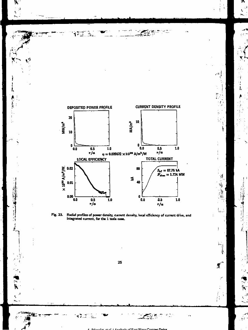
IÀ
§v î*f
il
DEPOSITED POWER PROFILE
"Ë5"
20
10
CURRENT DENSITY PROFILE
0.0 0.5 1.0 0.0 0.5*/" n = 0.009622 XlO20 A/ma/W r/°
1.0
LOCAL EFFICIENCY TOTAL CURRENT
80 = 87.76 kA= 1.724 MW
0.0 0.5r/a
1.0
Fig. 23. Radial profiles of power density, current density, local efficiency of current drive, andintegrated current, for the 1 tesla case.
1
%rv" -t e __ .
25
m-y*
^"••JT ^

.£.._..r... .. _i

6. CONCLUSION
Because of the weak election damping inherent to the fast magnetosonic wave,
full wave codes aie very useful for modeling fast wave current drive experiments.
FOI the two cases we have considered, we have shown that the field structure in
the plasma is indeed very different from a single pass structure, and in particular the
build up of high poloidal mode numbers leads to strong modifications in the absorbed
spectrum. The global directivity is not affected by this process but the current drive
efficiency depends on it. In particular we have shown that the local extension of
the poloidal mode number spectrum increases with minor radius and therefor= the
local j/p decreases slightly, from the plasma center to the edge, despite the density
decrease. Since the electron temperature plays a major role in the absorption, the
power deposition profiles are already peaked, and therefore the rf current profiles are
also very peaked.
Quantitatively, we find that about 88 kA can be driven in the 1 tesla/1.7 keV
case with 1.7 MW coupled to the electrons, i.e. with a global efficiency TJ « 0.1 x
10" Am-2W-1. Ih the 2 tesla/3.4 keV case, 47 kA can be driven with a total power
of 1.5 MW, 44% of which are absorbed on the hydrogen minority, through the second
harmonic ion cyclotron resonance. The global efficiency is then 0.18 X 10¹⁰ Am-2W-1
if one considers only the effective power going to the electrons, further experiments
at a higher electron temperature and with no second harmonic layer in the plasma
are needed and should produce larger driven currents with a better efficiency.
Our efficiency estimates have been obtained in the linear approximation, using
the high velocity limit of the collision operator (under-estimation) and neglecting
«
27
•1".
A n*i-nulat oral I Aiuihitic nfffattWavf furrfntDrive

'fJl
i«
K
trapping effects (over-estimation). À more accurate Fokker-Planck calculation will be
performed using the diffusion operator deduced from the same ALCYON results.
Another direction in which the calculation can be Improved co. :ems the antenna
current spectrum. In this report, we approximated this spectrum by assuming four
equal currents in the four current straps, with a perfect 90 degree phase shift. Later on,
the plasma surface impedance calculated from the ALCYON output will be inserted
into an antenna code which will compute the antenna current spectrum consistently.
28
A.BécouIet a al. I Analysis of Fast Wave Current Drive
,*'
.;F
'• X4rt T ?
fH
lfc '4?Ll"jâ
REFERENCES
[1] D.J. Gambier, A. Samain, Nucl. Fusion 25 (1985) 283.
[2] A. Bécoulet, J. Chinardet, D. Moreau, B. Saoutic, International Workshop on
Collective Acceleration in Collisionless Plasmas, I.E.S. Cargese, Corsica, France,
June 1991.
[3] A. Bécoulet, D. Edery, D. Gambier, H. Picq, A. Samain, CEA-DRFC/Note
interne #1254.
[4] S.C. Chiu, V.S. Chan, R. Harvey, M. Porkolab, Nucl. Fusion 29 (1989) 2175.
[5] P. Bannelier, Report EUR-CEA-FC 1316.
[6] G. Giruzri, Phys. Fluids 31 (1988) 3305.
[7] D. Moreau, J. Jacquinot, P. LaHia, in the Proceedings of the 13th European
Conference on Controlled Fusion and Plasma Heating, Schliersee (Germany)
1986.
[8] S.C. Chiu, private communication.
i
29
A. Bécoulet a al. I Analysis of Fast Wave Current Drive

A.Bécoulet adLIAnalysis of'FastWave CurrentDrive
'*
KACKNOWLEDGEMENTS
This work has been performed under a collaboration agreement between CEA
and U.S. DEPARTMENT OF ENERGY, while the authors were staying within the
DIII-D Team at General Atomics and in part by the U.S. Department of Energy
under Contract No. DE-AC03-89ER51114. They wish to thank the DIII-D rf group
for their warm hospitality and their help during the course of this work, as well as
K. Keith and N. Kirkpatrick for their technical support with the GA computers. The
JET RF Division is also greatly acknowledged for supporting the development of
ALCYON.
I
31
A, Bécoulet etaLl Analysis of Fast Wave Current Drive

»-.,
IV1
»*
Proceedingsof the
IAEA Technical Committee Meeting on
Fast Wave Current Drivein Reactor Scale Tokamaks
(Synergy and Complementarity with LHCD and ECRH)
ARLES (FRANCE) September 23 - 25,1991
Edited by D. Moreau, A. Bécoulet, Y. Peysson
Ni
*1
Association EURATOM-CEA sur Ia Fusion - Centre d'Etudes de Cadarache13108 St Paul lez Durance CEDEX - FRANCE
"4
Proceedings réalisés avec le soutien
du Ministère de la Recherche et de la TechnologieDélégation à l'Information Scientifique et Technique
1 rue Descartes, Paris (France)
J^?J?'*:~'-CT.
Pli.nu Phi-i^ jnd I .<n!n>IIal Fu-u-n. Vo! -I Nn Il.pp PS5 Io PU*. !«>•) 1)741 JJ35 S-) SJ IKI -

I,
ANALYSIS OF FAST WAVE CURRENT DRIVEFROM THE ALCYON CODE
A. Bécoulet. D. Moreau, G. Giruzri, B. Saoutic
Association EURATOM-CEA sur la Fusion ContrôléeCEN Cadarache, 13108 Saint-Paul-lez-Durance céda, FRANCE
J. Chinardet
GSi IngénierieCEN Cadarache, 13108 Saint-Paul-lez-Durance cédex, FRANCE
.
ABSTRACT.
Fast Wave Current Drive simulations have been performed with the 2-D full wave codeALCYON. These simulations include Ae computation of the RF field in a Tokamak geometry,for a given launched power spectrum, a linear estimation of the driven current profile using thisRF field, and the numerical derivation of the quasilinear diffusion operator for a completeFokkcr-Planck calculation. Results concerning the ITER, and the Dm-D Tokamaks arepresented and discussed.
1. INTRODUCTION.
The 2-D full wave code ALCYON [1][2] has been improved in order to include thedirect absorption of the fast wave on the electrons. This effect includes the parallel magneticfield ( transit time magnetic pumping (TTMP) ), as well as the parallel electric field ( electronLandau damping (ELD) ). ALCYON is then able to compute the fast magnetosonic wave field,in a Tokamak geometry, for a realistic launched spectrum, in all situations where thepredominant damping mechanism is ELD+TTMP, the first, the second ion cyclotron resonantH tJHg1 nr any combination of them.
In the cases of fast wave current drive (FWCD) studies, this field is then used for threedifferent analyses:
(a) an estimation of the intrinsic decorrelation provided by the wave-electron interaction.Together with the estimation of the extrinsic decorrelations, such as the collisions or a radialdiffusion effect, tins study validates the quasilinear analysis of die process.
(b) a derivation of the local qnasUinear diffusion operator, in the parallel-perpendicularvelocity space, for each magnetic flux surface. The comparison of this operator to the amplitudeof the coOisional drag directly gives information on the possibility of driving a plateau hi theelection distribution function. This local diffusion operator is also the input of a Fokker-Planckcode [3], in order to compute the realistic distribution function perturbation, and itscorresponding moments.
(c) a lincCT estimation of the driven current profiles from the deposited power, using thenon-relativistic expressions [4][5].
Such a set of simulations allows us to study and optimize the FWCD scenariosproposed for the next-step Tokamak, as well as for present-day experiments.
Kl-'iifr
r-63-
B. FRIED el al.

)!î
A. Bécoulet et al. I Analysis of Fast Wave Current Drive
3. COMPUTATION OF THE FAST WAVE FIELD.
2.1 Presentation of the ALCYON code.
ALCYON is based on the variational formulation of the linearized Maxwell-Vlasov setof equations [11. A functional form, L, depending on the vector A and scalar U potentials andon their complex conjugates is then derived. The radiated field (A(x,t), U(x,t)) is the oneMibjcr» cxtreirtalizes L with respect to all the variations of A*(x,t) and U*(x,t):
5A*(x,t)SL
5U*(x,t)
= 0
= 0.
(D
(2)
The Tokamak geometry is taken into account through a computed steady-state toroidalMBD equilibrium, working in the (\|f, d, (p)-coordinates, where V is the poloidal flux, •& theconjugated poloidal angle, and 9 the toroidal angle. The unperturbed trajectories of the particlesare described through a set of canonical action-angle variables (Jk=i^3, *k=i,2j)- The presentversion of ALCYON takes only passing electrons into account The wave-particle interaction iscomputed through an hamiltonian formalism, in the action-angle phase space. The linearizedinteraction hamiltonian is Fourier analyzed, and all the modes concerning the zeroth, first andsecond cyclotron harmonics are kept in the functional form L. The ALCYON code assumes thetowicjal antisymmetry of the plasma, allowing us to compute each toroidal harmonic number Nseparately. For this reason, the antenna is modelled as a single wire, located at a given toroidalangle Ip0, having any chosen poloidal location, poloidal width and current profile. Thereconstruction of the launched spectrum is discussed hereafter in 2.3. The extremalization isnumerically performed on a mesh in the 0|f> m)-space, where m is the poloidal harmonicnumber, through a finite-element method [2]. The outputs of the code are the field componentsis. functions of \p and m, for each toroidal mode number N. The mesh contains typically 75cells in the -direction, 81 poloidal harmonics (from -40 to 40), and a typical launchedspectrum requires toroidal mode numbers ranging from -357-25 to 25/35.
In the present version of ALCYON, the extremalization with respect to the scalarpotential U* (eq. (2)) has been performed analytically, leading to a relationship between thevector and the scalar potential. One can notice that this relationship is one of the polarizationequations for the fast magnetosonic wave. The remaining functional form is then rewrittencoherently using this relationship, and numerically extrcmalized.
2.2 Analysis for a single toroidal mode number.
A complete case has been run in order to simulate, in the ITER Tokamak, the lowfrequency FWCD scenario [6]. Tablel gives a summary of the chosen parameters, and Figl thety, ^)-mesh in a poloidal cross-section of the torus. Fig2 displa/s contours of constan:Ewdnlus of the parallel magnetic perturbation 6B//, in the configuration space, for N=IO. Ino*der to analyse this picture, one can display the same field in the (p, m) space (Fig3), where:
- (3). . . —„- ,«is
is the square toot of the normalized poloidal flux, and is very close to the normalized minor«•*"$. If we now consider the local (WKB) fast magnetosonic wave dispersion relation:
-64-
ICRH current drive in JET

r •or
A. Bêcoulet et al. I Analysa of Fast Wave Current Drive
j
1
k2=^ (4)
where CA is die Alfven velocity, one can rewrite k2 in terms of die radial wave number kr, diepoloidal wave number m/r and die parallel wave number k//. Expression (4) then leads to anupper bound for die poloidal wave number, mat can be rewritten as a condition on die poloidalmode number m:
(5)
This condition is also suown on HgS, and one can check that it is satisfied almost everywherein die plasma. This provides a bound to die broadening of die m-spectrum in die plasma core.
One can men notice on HgS that, due to dus particular relationship between m and r,whatever die poloidal enrichment of die wave can be in die middle of die plasma (essentiallydue to die low single-pass absorption), die directivity in die centre of die plasma remains veryclose to the launched directivity. The major loss of directivity is located typically around mid-radius, where die driven current is yet quasi-negligible (see below).
Two possible regions in die plasma can however exhibit discrepancies to die condition(S). The first one consists in die very last cells at the edge of die plasma. In this region diemesh is not accurate enough, in particular on die high field side of die plasma, to cope withphenomena such as Alfven resonances for example. The functional tries then to developstructures that reveal those phenomena, but me computed field cannot be die realistic one. Theresolution of such resonances would need a specific analysis [T]. The very centre of die plasmacan also exhibit "spurious" structures, due for example to a mode conversion [2]. Such abehaviour has also been detected in a simulation concerning die Dffl-D Tokamak, where asecond cyclotron harmonic layer was located exactly at die center of the plasma. In these casesagain, die computed field is not die realistic one, since die accuracy of die mesh is no moresufficient to describe it
Several possibilities exist to avoid these parasitic effects. The first one, a priori, is toinclude in ALCYON an artificial damping term, absorbing die field components whose high-order spatial derivatives are too large. The second one, a posteriori, consists in filtering diefield coherently wirn die condition (S), in order to keep only die fast wave component, which isthe only one correctly computed by die code. In all cases, diese two metiiods are equivalent,and do not affect deeply die fast wave structure. The reason is here dial those small structuiesare generated by me fast wave, but do not react back on it because of dieir thin structure. Theycan tiien either be damped or simply ignored without modifying strongly die fast wave itself.Moreover, one can numerically verify that, in die presence of thin structures in die very centreof die plasma, me generated current remains totally driven by die fast wave (Le. low-in)component, and not by these small wavelength components. In the following results, noartificial damping or filter has been used,
2.3 Construction of a complete case.
Due to die axisymmetry approximation, each toroidal mode number N can be computedseparately. In order to obtain die full toroidal spectrum of the radiated field, we use thefollowing procedure:
(a) each toroidal mode number N is computed, with die same excitation amplitude. OneUien obtains the plasma response (field and linear absorbed power per Ampere in dieantenna) for each N.
-65-
B. FRIED ci al
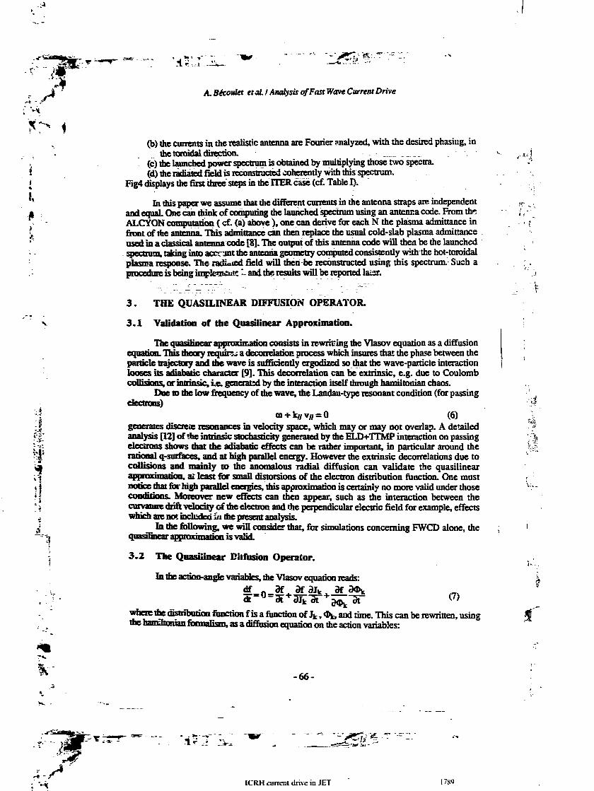
.-.4
\
i«
K
A. Béctwla et al. I Analysis of Fast Wave Current Drive
(b) the currents in the realistic antenna are Fourier analyzed, with the desired phasing, inthe toroidal direction.
(c) the launched power spectrum is obtained by multiplying those two spectra.(d) the radiated field is reconstructed coherently with this spectrum.
Fig4 displays the first three steps in the ITER case (cf. Table I).
In this paper we assume that the different currents in the antenna straps are independentand equal One can think of computing the launched spectrum using an antenna code. From theALCYON computation ( cf. (a) above ), one can derive for each N the plasma admittance infront of the antenna. This admittance can then replace the usual cold-slab plasma admittanceused in a classical antenna code [8]. The output of this antenna code will then be the launchedspectrum, taking into account the antenna geometry computed consistently with the hot-toroidalplasma response. The radiated field will then be reconstructed using this spectrum. Such aprocedure is being implements :. and the results will be reported laisr.
K'
i - '
3. THE QUASILINEAR DDTFUSION OPERATOR.
3.1 Validation of the Quasilinear Approximation.
The quasilinear approximation consists in rewriting the Vlasov equation as a diffusionéquation. This theory requirji a decorrelation process which insures that the phase between theparticle trajectory and the wave is sufficiently ergodized so that the wave-particle interactionlooses its adiahatic character [9]. This decorrelation can be extrinsic, e.g. due to Coulombcollisions, or intrinsic, Le. generated by the interaction itself through hamiltonian chaos.
Due to the low frequency of the wave, the Landau-type resonant condition (for passingelectrons)
ta + k// v// = O (6)generates discre* resonances in velocity space, which may or may not overlap. A detailedanalysis [12] of the intrinsic stochasticity generated by the ELD+TTMP interaction on passingélectrons shows mat the adiabatic effects can be rather important, in particular around therational q-smfaces. and at high parallel energy. However die extrinsic decorrelations due tocollisions and mainly to the anomalous radial diffusion can validate the quasilinear
, ai least for small distorsions of the electron distribution function. One mustnotice mat for high parallel energies, this approximation is certainly no more valid under thoseconditions. Moreover new effects can then appear, such as the interaction between thecurvature drift velocity of the electron and the perpendicular electric field for example, effectswinch are not included ai the present analysis.
Li die following, we will consider that, for simulations concerning FWCD alone, thequasi rmear approximation is valid.
3.2 The Qnasfiinear Diffusion Operator.
Li the action-angle variables, the Vlasov equation reads:df _ df
(7)
wherethe distribution function fis a function of Jk, &*, and time. This can be rewritten, usingthe hamOionian formalism, as a diffusion equation on the action variables:
•à
-66-
.;"'*
ICRH current drive in JET ITS')
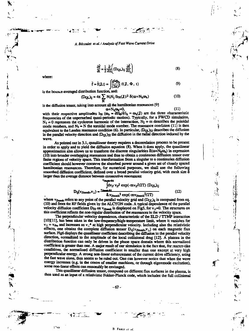
.Y"
r H. Bécoulet et al. I Analysis of Fast Wave Current Drive
F-
df3T
f = f(J.t) = 7.
where:
is the bounce-averaged distribution function, and::4jt£NiI«
Nis the diffusion tensor, taking into account all me harmltonian resonances [9]
(8)
(9)
(10)
(U)with their respective amplitudes HN (oik = dHo/dlk = o>k(J) are the three characteristicfrequencies of the unperturbed quasi-periodic motion). Typically, for a FWCD simulation,NI = O represents the cyclotron harmonic of me interaction, NI = m describes the poloidalmode numbers, and NS = N die toroidal mode number. The resonance condition (11) is thenequivalent to die Landau resonance condition (6). Ih particular, (DQL)SS describes the diffusionin me parallel velocity direction and (DQL)H *e diffusion in the radial direction induced by diewave.
As pointed out in 3.1, quasilinear theory requires a decorrelation process to be presentin order to apply and to yield me diffusion equation (8). When it does apply, the quasilinearapproximation also allows us to transform the discrete singularities 8(OH-NkPk) in expression(10) into broader overlapping resonances and mus to obtain a continuous diffusion tensor overfinite regions of velocity space. This transformation from a singular to a continuous diffusioncoefficient should however conserve me absorbed power around a given set of closely spacedhamiltonian resonances. Therefore, for numerical purposes, we shall use the followingsmoothed diffusion coefficient, defined over a broad parallel velocity grid, widi mesh size 5larger than the average distance between consecutive resonances:
dv// v//2 exp(-mv//V2T) (DQL)IJ
: (12)!exp(-mv/Anesh2/2T)
where v/faed, refers to any point of me parallel velocity grid and (DQL)IJ is computed from eq.(10) and from die RF fields given by the ALCYON code. A typical dependence of die parallelvelocity diffusion coefficient D^ on v//roeîh is displayed on FigS, for V1=O. The structures onthis coefficient reflects the non-regular distribution of me resonances in me velocity space.
The perpendicular velocity dependence, characteristic of the w.n / TTMP interaction[1O][Il], has been taken in me low-frequency/high-temperature limit, where it vanishes forVJ. - VAC and increases as vj.4 at high perpendicular velocity. Including also the relativisticeffects, one obtains die complete diffusion tensor Dij(v//mesh,vjJ on each magnetic fluxsurface. Hg6 displays the quasilinear coefficient describing the diffusion in die parallel velocitydirection, normalized to me amplitude of the local collisional drag [12]. A plateau hi diedistribution function can only be driven hi die phase space domain where this normalizedcoefficient is greater than one. A major result of our simulation is the fact mat, for reactcr-likeconditions, the normalized diffusion coefficient is smaller man one except at very highperpendicular energy. A strong non-linear enhancement of me current drive efficiency, usingthe fast wave alone, mus seems to be ruled out. One can however notice that when the waveenergy increases (e.g. in me centre of smaller machines, or through eigenmode excitation),some non-linear effects can reasonably be envisaged.
This quasilinear diffusion tensor, computed on different flux surfaces in the plasma, isthen used as an input of a relativistic Fokker-Planck code, which includes the full collisional
K
-67-
B. FRIED ct ul.

A. Bécoulet et al. I Analysis of Fast Wave Current Drive
effects (passing and trapped particles), and the radial diffusion effects. This part of thecomputation is described in a companion paper [3] at this conference. „••*
I
4. LINEAR ESTIMATION OF THE DRIVEN CURRENT.
A linear derivation of Ae driven current profile, and Ae current drive efficiency profilecan be made using Ae usual formulas [4][S] for Ae current density:
where:Dy// is proportional to 033
ne(r)e*lnA
for passing electrons only [4],
including Ae trapped electron effect [5].
Hg? displays, for the HER case described in Table I, the deposited power densityprofile p(r), the current density profile j(r), the local efficiency profile tfr) = ne(r)Roj(r)/p(r),and Ae integrated current. For this case, Ae launched spectrum is Ae one displayed on Fig4(c),and corresponds to SO MW launched by 24 ICRF-current straps [6] regularly phased. FigScompares Ae local efficiencies when Ae trapped electron effect is included, and gives Aecorresponding global linear efficiency, following:
ue Rp IFWCD' PFWCD
(computed with Ae line averaged density n«). As expected Ae trapped particles, which in thismodel are assumed to absorb power wiAout driving current, lower Ae global current driveefficiency, and peak its profile. One notices however a small enhancement of Ae localefficiency, in Ae centre of Ae plasma, Ie. in a region where Ae wave can detrap Ae electronsand Aen create a substantial amount of current wiA a somewhat small amount of power. TheFokker-Planck calculation [3] confirms this tendency, although mis effect is reduced.Moreover, our linear estimation does not include Ae exact collision term, but only its limit forhigh velocities. We Aus underestimate Ae current supported by electrons in Ae region aroundand under the Aermal velocity. Once again, Ae Fokker-Planck calculation [3] confirms Aat Aeefficiency is somewhat higher Aan Ae one given here. The current drive efficiency, in a typicalcase as Ae one given in Table I, can Aus be estimated [3] around 0.18 - 02 1020 A/W/m2.
The complete Fokker-Planck calculation also confirms Ae very small deformation of Aeelectron distribution function, Aus validating Ae linear estimation of the efficiency.
A similar complete case has been computed for Ae Dm-D Tokamak, for parametersclose BJ experimental data [13] (cf. Table H). In Ae same way, Ae linear efficiency, includingAe trapped particle effects, has been estimated to =» 0.01S 1020 A/W/m2.
-68-

. Bécoulet etaL I Anafysis of Fast Wave Current Drive
i
4J1SJi-.-1«
CONCLUSIONS.
Fast Wave Current Drive scenarios can now be studied using a 2-D, full wave, linearand self-consistent code for the computation of the radiated field, in the Tokamak geometry.This code contains the n// up- and down-shifts experienced by the wave, because of the toroidaleffects. By coupling ALCYON to a 3-D Fokker-Planck code, an estimation of the drivencurrent, and of the corresponding efficiency can be obtained, taking into account the globallaunched spectrum.
Several improvements to this set of codes are under process. The full-wave codeALCYON will be coupled to an antenna code, in order to handle more realistic spectra, and tooptimize the antenna designs. Absorption of the fast wave on plasmas with non thermalelectron distributions will allow us to study possible synergistic effects with other current driveschemes (Lower Hybrid Current Drive, Electron Cyclotron Current Drive). If strong non-lineareffects appear, iterations between the full wave and the Fokker-Planck code can also beenvisaged. Finally, the complete 3-D (Le. diffusion in velocity space, in the radial direction andcross-terms) diffusion tensor will be included in the Fokker-Planck simulation.
The present results concerning Fast Wave Current Drive scenarios for reactor-likeTokamaks yield a current drive efficiency of the order of 0.2 1020 A/W/m2. Even though thesescenarios have not been optimized, such an efficiency seems insufficient to drive the wholeplasma current (=• 20 MA) by the fast wave alone. However, a scenario where the fast wavedriven current plays the role of a seed current for the bootstrap effect [14] seems reasonable, inthe present state of the an.
ACKNOWLEDGEMENTS.
This work is supported by Article 14 Contract n° JJO / 9001 between JET andEURATOM / CEA Association. It is a pleasure to acknowledge A. Samain and DJ. Gambierfor their initial work on the ALCYON code. The authors are also grateful to the DIH-D RFphysicists, for their help in performing the simulations for this Tokamak.
REFERENCES.[I] GAMBIER, DJ., SAMAIN, A.. Nucl. Fus. 25 (1985) 283.C] BECOULET. A.. EDERY. D., GAMBIER, DJ.. PICQ., H., SAMAIN, A., The ALCYON Code,
DRFC, Internal report N° 1254.[3] GIRUZZI. G, BECOULET. A, MOREAU, D., SAOUTIC, B.. this conference.W FISCH, NJ.. BOOZER, AJl, Phys. Rev. Lett 45 (1980) 720.[5] GIRUZZI, G., NocL Fus.. 27 (1987) 1934.[61 ITER Group, Proc. of the 13* Int. Cant on Plasma Phys. and ContNucL Fus. Research, papers F-M
to F-3-19, Washington D.C., 1990.P] EVRARD. M.-P., VAN EESTER. D.. Proc. of the 9th APS Topical RF Conference, Charleston. USA
(1991).B] THEILABER, K, NucL Fus. 24 (1984) 1983.m BECOULET, A.. GAMBIER, DJ., SAMAIN. A., Phys. Fluids B 3 (1991) 137.[10] MOREAU. D., JACQUINOT, J., LALLIA. P., Proc. of the 13th Eur. Conf. on Com. Fusion and
Plasma Hearing, Schliersee (Germany) 1986.[II] BECOULET, A^ CHlNARDET, J.. MOREAU, D.. SAOUTIC. B., Proc. of the InL Workshop on
Collective Acceleration in Coflisunless Plasmas. Cargese (Corsica, FRANCE) 1991.[12] BECOULET, A., MOREAU, D.. GAMBIER. DJ.. RAX. J.-M.. SAMAIN, A., Proc. of the 13th Int.r,« tm
c^onHasnaPhvs.aiidCc^N«l.F!is.Research,VoL 1.pp811.WashingtonD.C., 1990.[13] PRATER,R, etaL. mis conference.[14] WEGROWE. L-G.. PARAIL. V, mis conference.
<••*!
-69-
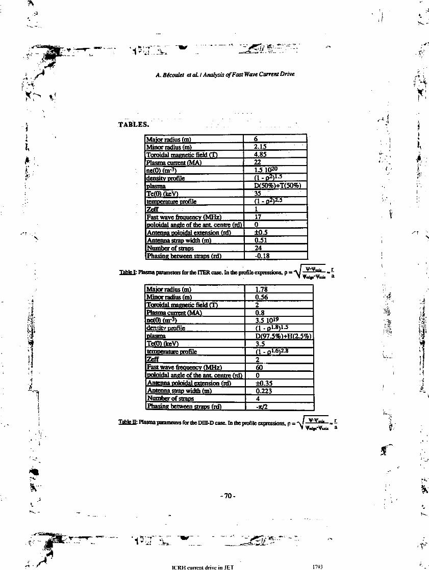
'-1*3
A. Bécoulet et ai I Analysis of Fast Wave Current Drive
Ij«
I,
TABLES.
til
1
Major radius (m)Minor radius (m)Toroidal magnetic field (T)Plasma current (MA)ne(0)(m-3)density mofileplasmaTe(O) (keV)
ZeffFast wave fieauencv (MHz)Doloufai ancle of ate ant. centre (id)Antenna pokwfai extension (id)Antenna strap width (m)Number of straosPhasing between straps (id)
62.154.85221.51020(1 - O2)1-5
D(50%)+T(50%)35-(1 . Dzyz.5117O±0.50.5124-0.18
Maior radius (m)Minor radius (m)Toroidal magnetic field (T)Plasma current (MA)nert» (m-3)densit? profilepiasm^Te(O) (keV)temperature profileZeffFast wave fieauencv (MHz)poloidal angle of the ant centre (id)Antenna poloidn! extension (id)Antenna strap width Cm)Number of soapsPhasine between straps (id)
1.780.562O 83.5 10"(1 . „1.8)1.5D(97 5%)+H(2 5%)3.5Q.0l.6)2.8260O±0 350.2234-ic/2
laizfen: Plasma parameters for the Dm-D case. In the profile expressions, p = -v/V
•is'
•A1
i,"
-70-
ICRH current drive in JET 1793

A. Bécoulet étal. I Analysis of Fast Wave Current Drive'4,
iSJ*
FIGURES.
3
2
1
-1
3
2
1
O
-1
-2
-3
-4-
10
. 0}-mesh for the TIER case C75 y-cells, 81 d-cdls).
2 4 6 8 10
R(m)
£le2; level-corves of the modulus of SB7/fiir N=IO (TTER case).
-71-
w ,.,i .-"'•{'
B FHIFII »>/ nl

A Bécoulet et al. I Analysis of Fast Wave Current Drive
ir/a
Egi same as F«g2, in the (p,m)-space (TTER case).
11« frontier conesponding to the equation (5) is superimposed.
5
f 5
1
1 4
»%r<" .
-72-
«*r*>Si^Jk-T1
IPRH i-niTpnt ririve in IFT
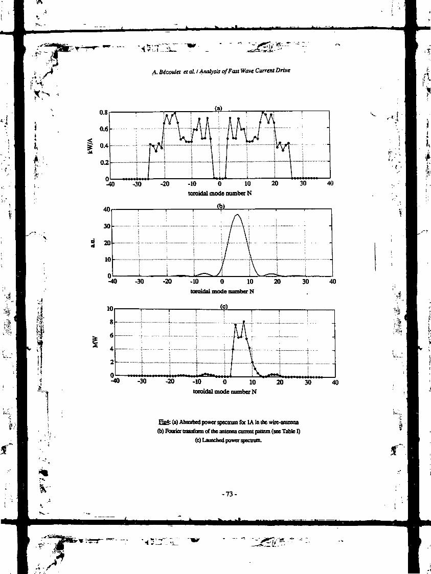
. •**•-•"
. Bécotdet et al. I Analysis of Fast Wave Current Drive
I
-40
40
30
20
10
10
8
6
4
2
-30 -20 -10 O 10
toroidal mode number N
Cb)
20
-40 -30 -20 -10 O 10toroidal mode number N
(c)
20
-40 -30 -20 -10 O 10
toroidal mode number N20
30
30
30
Bg4: (a) Absoibed power spectrum for IA in the wire-antenna(b) Fborier transfom of the antenna current pattern (see Table I)
(c) Launched power spectrum.
-73-
40
40
40
1S..
j./*

I
*. Bécoulet et ai / Analysis of Fast Wave Current Drive
-1 -0.8 -0.6 -0.4 -0.2 O 0.2
vpaiaUel/c
0.4 0.6 0.8
FigS: Parallel velocity dependence of the diffusion coefficient
(TIER case, p=0.15, q=0.945, V1=O).
Vj/C
Eefi: Complete diffusion coefficient in velocity space.
normalized to the collisiooal drag (TTER case), and limited to 0.1.-74-
I
1-J
CONFERENCES AND SYMFOSU

*l/#~^---'
Ï,
' 4
A. Bécouiet etaLI Analysis of Fast Wave Current Drive
2.S
2
luI 1
deposited power profile cunent density DrofUe
eta=0.2175e20 A/m2/Wlocal efficiency 2000
Ihf»l&19kA -
Pelec-30.02MW
fifl: FTER case, passing elecirons only, for SOMW (cf Table I):deposited power profile, ciment density profile. local efficiency profile, integrated current.
o.
r(m)BgS: local efficiency profile 0TER case, Table I)
(- -) : passing elections only (7 = 0.2210™ A/W/m1)C—) : including trapped election effect (7=0.161020 A/W/m2}.
-75-

. îl
M No 11. PP PS5 w 11741 .'JJJ S1S.MKI- '«IIOP Publishing Ltd. jnd Pergjmon Pres- pic
I,
COMMENTS ON ICRH CURRENT DRIVE IN JET
B. FRIED,* T. HELLSTEN and D. MoREAUtJET Joint Undertaking. Abingdon. Oxon OX14 3EA. U.K.
(Received'2S June 1988)
Abstract—To study current drive via the mode-converted slow wave during ICRH we assess for whichplasma compositions and wave numbers mode conversion from the magnetosonic wave to the slow wavecan dominate. We have used a simple slab model to investigate the competition between mode conversionand minority cyclotron absorption for a deuterium plasma with H* and 1He2* minority species in JET. A3He-* minority should be more appropriate for mode conversion current drive than H* because the 'He:~concentration can be chosen near its optimum for the "Budden absorption" without bringing the ionhybrid resonance and the cyclotron resonance so close that the minority absorption dominates.minority also allows operation at toroidal numbers which are characteristic of present JET antennae.
,-•ri
1
1. INTRODUCTIONCURRENT DRIVE associated with the ion-ion hybrid resonance constitutes one of theprincipal options for controlling or modifying the JET current profile, using facilitiesavailable now or within the next 3 years (JACQUINOT, 1985).
The concepts involved in this approach have been investigated in some detail byJacquinot, Brambilla, Perkins, and others, motivated by an interest in ICRF heating.The basic physical picture is straightforward for a slab model : a fast (magnetosonic)wave with cold plasma dispersion relation
= (fcxc/co)2 =2 = N- (1)
where R, L and S are, for the moment, the quantities defined by STDC (1962),propagates in from the low field side until it reaches a cutoff at L = JVJf. It is evanescentfrom there to the ion-ion hybrid resonance at S = N*, after which it again propagatestoward the high field side. This juxtaposition of a cutoff and a resonance constitutesthe classical Budden tunneling problem, whose solution (BUDDEN, 1961) gives thefraction R of the incident fast wave energy which is reflected at the cutoff and thefraction T which is transmitted past the resonance.
When the effects neglected in (1)—thermal velocities and finite electron inertia—are taken into account, NI is no longer singular and the fast wave couples to a slowwave or a short wavelength hot plasma wave. The energy fraction
= I-T-K, (2)
which is neither transmitted nor reflected in the cold plasma picture, is transferred tothis new wave and from there, by Landau or cyclotron damping, to the particles. This
* Permanent Address : Physics Department, UCLA, California, U.S. A.t Attached from EUR-CEA Association, DRFC Cadarache, France.
1785

"l
17Sf) B. FRIED ei ai.
can produce heating, with toroidully symmetric excitation, or current drive, with asuitably phased antenna system.
A quantitative (or even semi-quantitative) calculation of the resulting current driveis formidable, since it should include the problem of fast wave excitation by a realisticantenna system (producing a spectrum of N ). two-dimensional wave propagationand mode conversion, the effects of the poloidal field, etc.. as well as an analysis ofthe resultant changes in the electron distribution function (conventionally done interms of quasilinear diffusion produced by the r.f. field competing with Fokker-Planck diffusion). Large codes have recently been developed which can either treatthe quasilinear diffusion in velocity space or the wave propagation. However, it seemsuseful to have available also a simple way of surveying the many parameters involvedin actual experiments. It can be of help to experimentalists in choosing operatingpoints and is a necessary prerequisite to developing more sophisticated codes.
The simplest possible model is one in which we accept the Budden algorithm as anestimate of the absorption in the mode conversion process but note that, en route tothe mode conversion region, a wave incident from the low field side must pass theminority cyclotron resonance where it may also suffer some absorption. (We areassuming here a minority species whose cyclotron frequency is higher than that of themajority species.) When the objective is heating, this is generally helpful ; when theobjective is cunrent drive, via absorption of wave energy and/or momentum byelectrons, it is not. The strategy is then to maximize the absorption associated withmode conversion while minimizing the minority cyclotron absorption.
Both absorptions depend on the separation between the two resonances, which is,in turn, proportional to the minority ion concentration/2 = "minority/He- So far as theabsorption resulting from the mode conversion is concerned, there is an optimumvalue of this separation and hence of/2 : if the separation is too large, the incidentwave is totally reflected—if it is too small, it is completely transmitted. For a givenminority species, there is an optimum value, /opt, at which A is a. maximum.
To minimize the minority absorption, on the other hand, we would choose /2 aslarge as possible, since as /2 decreases, bringing the resonances closer together, theminority cyclotron absorption increases rapidly. We therefore need to find a "window"of /,, where it is large enough to keep the resonances well separated and hence theminority cyclotron absorption small, without being too far above 1. In addition, wenote that very small values of/2 may not be experimentally attainable.
On the basis of these elementary considerations, we find a significant differencebetween H+ and 3He2+ minority species in a deuterium plasma concerning theoverlap of the hybrid resonance by the Doppler-broadened cyclotron resonance. Ata given B field, the separation in frequency between the cyclotron resonance and theion-ion hybrid resonance is 4.5 times larger for 3He2+ than for H+. (For example,with typical JET parameters nD = 4 x 1013 cm" \ R = 3 m we have /opl = 0.73% forH+ and fapt = 3.3% for 3He2^.) In addition, due to the mass difference, the width ofthe minority resonance is larger for H+ than for 3He2+ (at given B, T and azimuthalwave number, n0), resulting in more minority cyclotron absorption. To reduce theoverlap may then require values of n^, smaller than can be achieved with the usualICRF antennae.
In the examples discussed below, we find that for 3He2+, experimentally inter-esting values of n* (up to 10 or 20) and of/2 (of order 5-10%) can be achieved with
CONFERENCES AND SYMPOSIA
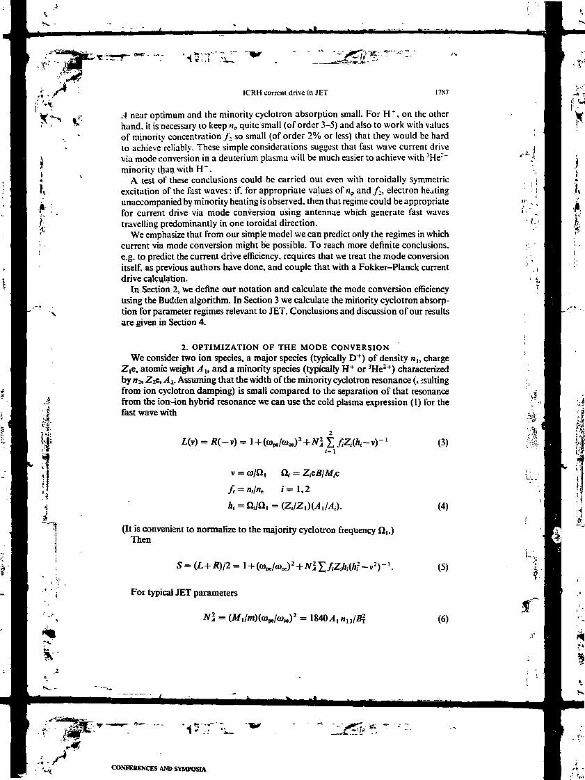
J,
ICRH current drive in JET 1787
.-1 near optimum and the minority cyclotron absorption small. For H4-, on the otherhand, it is necessary to keep H0 quite small (of order 3-5) and also to work with valuesof minority concentration /, so small (of order 2% or less) that they would be hardto achieve reliably. These simple considerations suggest that fast wave current drivevia mode conversion in a deuterium plasma will be much easier to achieve with 3He:"minority than with H".
A test of these conclusions could be carried out even with toroidally symmetricexcitation of the fast waves : if. for appropriate values of H4, and /;, electron heatingunaccompanied by minority heating is observed, then that regime could be appropriatefor current drive via mode conversion using antennae which generate fast wavestravelling predominantly in one toroidal direction.
We emphasize that from our simple model we can predict only the regimes in whichcurrent via mode conversion might be possible. To reach more definite conclusions.e.g. to predict the current drive efficiency, requires that we treat the mode conversionitself, as previous authors have done, and couple that with a Fokker-Planck currentdrive calculation.
In Section 2, we define our notation and calculate the mode conversion efficiencyusing the Budden algorithm. In Section 3 we calculate the minority cyclotron absorp-tion for parameter regimes relevant to JET. Conclusions and discussion of our resultsare given in Section 4.
2. OPTIMIZATION OF THE MODE CONVERSIONWe consider two ion species, a major species (typically D+) of density B1, charge
Z|C, atomic weight /I1, and a minority species (typically H+ or 3He2+) characterizedby B2, Z2e, A2. Assuming that the width of the minority cyclotron resonance (, suitingfrom ion cyclotron damping) is small compared to the separation of that resonancefrom the ion-ion hybrid resonance we can use the cold plasma expression (1) for thefast wave with
L(v) = R(-v) = X /,Z1(A1-V)- (3)
v = co/Q, Q, = Z.
/ = B,/Be i= l ,2
A1 = Q1VQ1 = (Z1VZ1)W1M,).
(It is convenient to normalize to the majority cyclotron frequency Q1.)Then
(4)
= (L+R)/2 = (5)
%r*,'
For typical JET parameters
= 18404 (6)

A
^ J/T;-
PSS B. FRIED ci al.
is of order 10' (where «,, is the density in units of 10" cm ' and #T is the field inTesla). whereas
N = (7)
is of order 1-10, n0 being the azimuthal mode number and /?m the major radius inmeters. It follows that N - « N$ so the location of the cutoff at L = N] can beapproximated by
with
L = O or v = VL =
h = h2 = O./Q, = Z2 2, f = /:Z2//,Z,.
(8)
(9)
Likewise, the location of the ion-ion hybrid resonance at S = N if can be approximatedby
(10)
In lowest order WKB approximation, the dispersion relation (1) for the fast wavecorresponds to a wave equation
a2E/ds2+NlE = O,
where s = eojc/c and Afx is a function of jc or s because
B = B0(
(U)
(12)
(We neglect density variation here since the scale length n\dn/dx\~ ' is typically longcompared to the separation of the ion-ion hybrid resonance from the minority cyclo-tron resonance.) Since NI vanishes at v = VL and is singular at v « vft, (11) has thestructure of Sudden's equation, conventionally written in the form
(13)
(14)
P2/ri2)E= O.
To establish the values of /J and 17 we approximate (1) by
Ni 3= RLjS= G(V-vj(v-V4)-
where vh and v^ are given by (8) and (10) and G is a slowly varying f-inrtion of vwhich reduces to G = ./VjZ1 if we assume / « 1 and set v = h in evaluating G.Comparing (13) and (14) we find
(15)
where Q0 = QI(-X = O). Although we do not need them, we note that
-t'
K-

1
f u =1/2 or n = (In2)/7c = 0.22. (21);.!?"Ci'Jî If the evanescent region between v* and VL through which the wave has to tunnel is•'4' too small, most of the energy incident from the low field side is transmitted and littleta is "absorbed" (Le. converted to a short wavelength mode). If the region is too large,
most of the energy is simply reflected (S.-* I, T^-Q) and again, little is absorbed.Thus, there is an optimum thickness, described by (21). Similar comments apply tohigh field side incidence.
It follows that for a given minority species (given value of A) there is an optimum
ICRH current drive in JET 1 "89
/J = -,V4(Z1)' ;»J S= (u>/c)(-V-}-R-RSinV11IiO). (16)
Accordinc to BCDDEN (1961), the energy reflection and transmission for a wave, * described by ( 13), incident from the right (s > O). are given by
i - x- /? = ( 1 — H): T= u
n u = exp (—m/), ( 17)
V - while a wave incident from the left surfers no reflection and has a transmissioni: ; coefficient
; - T1=U. (18)
The energy "absorbed" via mode coupling from a fast wave incident from the low ' ' • •field side is thus ';|
yt = l-,R-f=a(l-M). (19)\
If the transmitted wave energy is reflected from a boundary on the high field side and 'passes through the plasma again there will be an additional absorption :
i.e. a net doubling. Whether or not we take advantage of this additional factor of 2, ;the optimum absorption, A = 0.25, occurs at ''\ ^
. i ' C(f-
minority concentration given implicitly byi
ij = (ZI)1/2(/KJ0/c)(v£-vA) = 0.22. (22)
We can obtain an explicit expression forfopl if we assiimi / « 1 so that U
vL-vt^h(l+flh-f)-h(l+f{2h-fhl2)=f(h-l)2l2
and
1* ^x(Z1) "2CMVc)(A- i)2//2. (23) jf
Then

B. FRIEU
-j
4
,1>. Ii!
/,p, = 0.44(/j- 1) 2C.'/JQnIv4(Z, ) '
= 0.044, .(A -I)-(Ii, ,Z1) 1X
and the associated value of/; = H;,/I is given by
(24)
(25)
For the typical parameter values «,, = 4. Rn, = 3, Z, = 1, the optimum values for/and /; are shown in Table 1 . It is clear that under typical experimental conditions theminority concentration will be at cr above the optimum value for both 3He-"1" andH*. However, as we see from Fig. 1. which plots
A =exp(-m/)[ l— exp( —
vs 17, A is not too sensitive to ij, decreasing by only a factor of about 2.3 if
TABLE 1. — OPTIMUM MINORITY CONCENTRATIONSFOR R = 3 m, n = 4 x 10" cm"3 IN A DEUTERIUMPLASMA. HERE h is THE RATIO OF CYCLOTRONFREQUENCIES, /I = U^Q,; /; IS THE CON-CENTRATION OF THE MINORITY SPECIES; AND / =
Minority
3He-*2 0.73%
4/3 6.6%0.73%3.3%
££'
FIG. 1.—Budden "absorption" factor A = e~"[l -e^l vs 17.
" .4

-68-
.£•' ~ 1
Xr-
• j *• ' -y1 «"•:.-}
p[
ICRH current drive in JET
_ 0.66. Thus, even for a 5He concentration of 10%. the value of
1791
would still be 0.22. However, since/, can more easily be made nearer to its optimumvalue in the case of 3Hc than for H, the former should generally lead to better modeconversion efficiency.
As already noted, the wave incident from the low field side must pass the minoritycyclotron resonance (v = /i) before reaching the mode conversion region so we mustnow consider how much the wave is attenuated there by ion cyclotron damping.
3. ABSORPTION AT THE MINORITY CYCLOTRON RESONANCEWe estimate the wave absorption at the minority cyclotron resonance by calculating
the quantity
2 = l-exp( -2 A:2d-xj
where
Ar2 = Ini&r = ImN±co/c
(26)
(27)
Ii
.-§
and the integration in the component is over the region of x where fc, is non-negligible.In calculating N± we again use (1) but now with R, L and S modified to includekinetic effects arising from minority ion thermal motion along the magnetic field.Retaining only lowest order terms in txrci we have
S = £„ = +N\ {(1 -v2)- '
' -2//TJJ
R = (S+D)I2 L = (S-
g = fcaû2/n, a2 = (2T2/M2)
(28)
(29)
(30)
(31)
This procedure is justified if the ion-ion hybrid region (v = vj is sufficiently wellseparated from the minority resonance (v » /i). When this condition is violated, ourelementary model breaks down and a more sophisticated calculation is required.Calculations with a global wave code show that no mode-converted wave is emittedfrom the ion-ioa hybrid resonance if (Co-Q2)^11O2 % 1 at the resonance (HELLSTENet al., 1987). Anyhow, in that regime the ion cyclotron damping quickly becomesappreciable, so that case is not of interest for electron current drive via mode conver-sion. Instead, a net ion current can be obtained due to asymmetry of the wave fieldacross the cyclotron resonance (FiscH, 1981).
For typical JET parameters, we find that A2 is very small when the overlap of theminority and hybrid resonances is small, i.e. when /is large and/or g is small. A plot

-6 -
I
*£7,> #:<.*
B. FRIED i*/ <i/.
„, A-. vs .x, with the zero of A- chosen at the minority resonance has then a Gaussiancharacter, as shown in Fig. 2 where k2 is plotted against
i = it»-Sl2).k a2 = (uj k u 2 ) ( x R)(I + x R).
However when /'decreases OTg increases. A 2 increases and we get substantial overlap.as illustrated in Fia. 3. At this point, the model fails, but since A : is typically becomingsubstantial, this is~not a region of our interest. Typical values of f and A2 are shownin Tables 2 and 3 for H " and }He2' minorities in a deuterium plasma with « = 3 x IOm 3 7-, = 2 keV, Bn = 3 T and various values of M^. In cases where the overlap issmall, as in Fig. 4a. we get an estimate of A2 by truncating the integration over .v. asin Fig. 4b. The entry "overlap" indicates that the overlap is too large to allow thistruncation, i.e. that the model fails and A: is becoming large.
For 3He2-, we see that for n^^W the minority cyclotron absorption remains smallfor / near its optimum value. Even for U0 = 20 the absorption is less than 3% forj-/yopt _ 2.6, where the Budden factor A has only fallen off to 55% of its maximumvalue. For hydrogen, on the other hand, we are clearly restricted to small values of
.025
-4 Ot
FIG. Z—Piot of*, = ImJtx vs I = (io-aj/kta2 = (Wi^a1)(XlR)(I +x/R)'1 for H+ min-ority with nc = 3 x 10" cm'J, T1 = T2 = 2 keV, B0 = 3 T, frequency = 47 MHz, ns = 20and / = /i'2 ft = 0.2. There is no overlap of the hybrid and cyclotron minority resonances.
£f
I»t
0.1
FIG. 3.—Plot of A2 vs / for the same parameters as in Fig. 2 but with/ = 0.05. The resonancesoverlap so much as to invalidate the simple model used here.

-70-
^.
ICRH current drive in JET
TABLL 2.—MINORITY CYCLOTRON ABSORPTION A* (IN %) AS A I-TNCTIONOF/AND /I0 FOR 'He= * WITH ii = 3 x 10" cm- \ r: = 2 keV. Bn = 3 T AND
FREQLTNCY 31 MHZ CHOSEN TO MAKE «1 = ÏÎ; AT B = fl,,
0.20.10.10.10.10.10.050.050.050.050.030.030.03
20345
IO20345
10345
2.30.10.170.280.6
overlap0.20.30.54
overlap0.30.6
overlap
0.0910.0480.0480.0480.0480.0480.0240.0240.0240.0240.0150.0150.015
2.621.311.311.311.311.310.660.660.660.660.400.400.40
0.5470.9630.9630.9630.9630.9630.9280.9280.9280.9280.7330.7330.733
1793
J HK ;
I,
t- •'£•
TABLE 3.—MINORITY CYCLOTRON ABSORPTION A2 (IN %) AS A FUNCTIONOF/AND nt FOR H* MINORITY IN A DEUTERIUM PLASMA WITH n = 3 X 10¹³
cm"3, T2 = 2 keV, B0 = 3 T AND FREQUENCY 47 MHz CHOSEN TO MAKE01 = a2 AT B = B0
«* ///opt
0.10.10.10.10.050.050.050.050.050.020.020.020.02
351020345102034510
0.20.572.28.60.40.71.14.5
overlap1.11.82.9
overlap
0.0910.0910.0910.0910.0480.0480.0480.0480.0480.020.020.020.02
11.811.811.811.85.95.95.95.95.92.42.42.42.4
0.00110.00110.00110.001 10.06660.06660.06660.06660.06660.6160.6160.6160.616
i
n$; for /^ of order 10, there is no choice of/which keeps A2 small without causingexcessive reduction in A.
4 CONCLUSIONS AND DISCUSSION OF RESULTSA major problem for mode conversion current drive with low field side antennae
is to obtain significant mode conversion. For large minority concentrations thetunnelling through the evanescent layer is weak whereas for small concentrationsthe mode conversion surface is overlapped by the Doppler-broadened cyclotronresonance.
We have used a simple slab model to investigate the competition between modeconversion and minority cyclotron absorption for a deuterium plasma with H+ and^He2+ minority species, using typical current JET parameters. The Budden algo.ivimis used to estimate the fraction of incident wave energy mode converted to shortwavelength waves at the ion-ion hybrid resonance (this energy being considered as
Ju- ,
-cIr
fc" fr

B FRIED ei u/.
.080-
.040-
FIG. 4.—Plot of*, vs f for the same parameters as in Fig. 2 but with/ = O.OS. As shown in(a), there is some overlap, but setting k2 equal to zero for t to the left of the arrow in (a),we get a representation of k2 shown (on an expanded scale) in (b) from which we can obtain
a good approximation to A2.
.J-"
:ë>" "
f ••
"absorbed" in the Budden model). The classical ion cyclotron damping expression isintegrated over the minority resonance region to determine the direct absorption ofenergy by minority ions. Both absorption mechanisms can contribute to plasmaheating. The former method has the potential of creating an electron current throughLandau damping of the mode-converted wave whereas the latter can produce toncurrent To optimize current drive efficiency one should use either one process or theother but one should avoid having both occur simultaneously, thus driving oppositecurrents.
Our principal result is that a 3He2+ minority should be more appropriate for modeconversion current drive than H+, principally because the separation of the hybridand minority cyclotron resonances is 4.5 times greater for 3He2+ than for H+. Thisallows the 3He2+ concentration to be chosen near its optimum for the Budden"absorption" without bringing the two resonances so close that the minority cyclotrondamping dominates. It also allows operation at the higher /Z0 values (n$ ~ 10-20)characteristic of present JET antennae whereas for H+ rather small values (n$ ~ 3-5) are required.
To scale the results to higher minority temperatures one can use the fact that theDoppler width of the cyclotron resonance is proportional to n^v-JcoR. THUS to allowfor a higher température (higher »j) we have to reduce n$. In case of simultaneousminority heating a high energy ion .ail can be formed which enhances the Dopplerwidth of the cyclotron resonance and may prevent any mode conversion. However,this tail is strongly anisotropic and the increase of parallel energy which occurs via

5-T.-
ICRH current drive in JET l~ l>5 ,t '
pitch angle scattering is much smaller tha i the corresponding increase in perpendicular Wenergy. To reduce the overlap one can increase the minority concentration above the | 'optimum value £,p, at the expense of a weaker damping of the fast wave through modeconversion. , , |
I A serious calculation of current drive via mode conversion would require con-i "'• sideration of many effects .tad here: an actual calculation of the mode conversion.t effects of the poloidal fit. „> on the mode converted waves, consideration of wave
propagation from a realistic antenna system and analysis of the resultant change in£ electron distribution function. However, we believe that the elementary effects exam- >'£ ined here will remain an important part of a more comprehensive theory. '
R E F E R E N C E S, ' BUDDEN K. G. (1961) Radio Wares in the ionosphere. Cambridge University Press, Cambridge. U.K.
FLSCH N. J. (1981) /Vue/. Fusion 21, 15.HELLSIT-, T., APPERT K... VACLAVIK J. and VILLARD L. ( 1987) JET Joint Undertaking report JET-R(87)09.JACQUINOT J. (1985) Heating and current drive scenarios with ICRF. JET Joint Undertaking report JET-
P(85)12, presented at the Erice Course n Tokamak Startup, Erice, Sicily.STK T. H. (1962) Theon of Plasma Waves. McGraw-! ,. New York.
'($.
CONFERENCES AND SYMPOSIA
FAST WAVE CURRENT DRIVE IN REACTOR SCALE TOKAMAKS
Summary report on theIAEA Technical Committee Meetingon Fast Wave Current Drive in Reactor Scale Tokamaks(Synergy and Complementarity with LHCD and ECRH)held itAries, France,23-25 September 1991
D. MOREAUDépartement de recherches sur la fusion contrôlée,Association Euratom-CEA,Centre d'études de Cadarache,Saint-Paul-lez-Durance, France
S
1. INTRODUCTION
The IAEA Technical Committee Meeting on FastWave Current Drive in Reactor Scale Tokamaks washoisd by the Commissariat à l'énergie atomique(CEA), Département de recherches sur la fusioncontrôlée. Centre d'études de Cadarache, under theEuratom-CEA Association for fusion. About 60 partici-pants from 12 countries *nr*J*A the meeting, afterwhich men was a visit of the superconducting toka-mak TORE SUPRA. Participation at the meetingwas based on nomination of specialists by the IAEAMember States.*
«TlieS ntificProgn Ed of the followingmembers: A. Ben (Massachnsan Institue of Technology (MTI).Cambridge. USA). I. Jacqmnot (JET Mai UadanUng, CoDnm,UK). H. Koran (Japan Atomic Energy Research Imtitott, Nab.Japan). D. Mom (Assoduk» Enmom-CEA, Caaanche, France),V.V. Fnnl (Kmdmov Insnmte of Atonic Energy. Moscow,Kaon Federation), R. Prater (Gcnenl Atomics, San Diego,CA. USA), and JjG. Wegrowe QiET Team, Gardnng/Mûnchen.Germany). Tie IAEA was represented by V.V. Donchrate. TheLocal Organizing Committee •» compoted of A. Btoniet.Mn. M-C. Bennml (Secretary). O. Moteaa (Chainnu) andY. Ffeyason, Eantom-CEA aO.
MUCtEAK FUSDH. VAJZ. HO-4 (HU)
The purpose of the meeting was to discuss the physicsand efficiency of non-inductive current generation bymeans of fast waves, with emphasis on its relevance toreactor scale tokamaks, and to compare the availableexperimental results with theory and modelling. It wasto consider all reactor relevant aspects of fast wavecurrent drive (FWCD), i.e. technical, experimental,theoretical and computational, and all open questionsrelated to its potentiality for various uses in tokamaks.The meeting also considered the possible synergismsand complementarities between FWCD and otherschemes such as lower hybrid current drive (LHCD),electron cyclotron resonance heating (ECRH), neutralbeam current drive (NBCD), bootstrap current andhelicity injection. The following major areas werecovered: general current drive theory (non-inductive,bootstrap, helicity), computational studies including fullwave and ray tracing modelling, experimental results andf i ipects, wave coupling and antenna design, and reactorapplications.
The ten presentation sessions were chaired by:I. Tachon (Euratom-CEA, Cadarache), R. Prater,J.G. Wegrowe, L. Rucnko (Vekua Institute of Physicsand Technology, Sukhumi). D. Hoffman (ORNL),J.M. Noterdaeme (Euratom-IPP, Garching),V.V. Demchenko (IAEA), A. Bers (MTT), T. Watari(National Institute for Fusion Science, Nagoya) and
701

CONFERENCES AND SYMPOSIA
F. Santini (Euratom-ENEA, Frascati), and thediscussion/summary session was conducted byJ. Jacquinot (JET). The 32 papers presented aregiven in the reference list; nine of these paperswere invited ones.
2. THEORY AND MODELLINGOF RADIOFREQUENCY CURRENT DRIVE
2.1. Theory
The conference opened with an invited reviewof radiofrequency current drive (RFCD) theory byA. Bers (MTT) [I]. Progress in this field has beencontinuous during the 1980s, from the early simple1-D theory to the more sophisticated 2-D relativisticFokker-PIanck treatments and the inclusion of RFinduced transport. The kinetic formulation of RFCDwas extensively reviewed, considering the specificcases of lower hybrid (LH) waves, fast waves andmode converted ion Bernstein waves (JBW). Limitingforms of the current drive 'figure of merit1 or 'efficiency'were given. The importance of the high perpendiculartail temperatures (10 to SO times thermal) generatedduring RFCD through pitch angle scattering was stressed.Such 2-D effects were shown to significantly enhancethe current drive efficiency over I-D theory, typicallyby a actor of 2.5. At constant charge Z, this efficiencywas found to increase linearly with the perpendiculartail temperature. The bulk température dependence ofthe LHCD efficiency in relation to the spectral gapbetween the launched waves and the thermal electronpopulation was discussed. Finally, the damping of fastwaves on the suprathermal electrons created by LHwaves was shown to further increase the perpendiculartemperature of the tail. This effect could possibly leadto super-enhanced efficiencies, as seems to be observedin JET during simultaneous application of LH and ICRFwaves. Such synergetic scenarii are very attractive forefficient current drive in a reactor and require furtherwork.
R. Koch (Euratom-Etat Belge, Brussels) discussedAe various damping mecîianisnis in the frequency rangedof the fast waves [2]. His analysis was for arbitrarydistribution functions (general dielectric tensor) andincluded high harmonic cyclotron dampuv Parasiticabsorption by the a particles and by traces of hydrogenwas also studied. It was found mat the low frequencyFWCD scenarii, i.e. those for which the frequency iseverywhere smaller than the tritium cyclotron frequency,were the only promising ones for a reactor. A scenario
at 17 MHz was examined for ITER, yielding an absorp-tion probability in the 50% range. Using distributionfunctions with high energy suprathermal components, itwas shown that tails in the parallel direction such asthose created by LHCD would absorb only a negligiblefraction of the fcst wave power, whereas the tail absorp-tion would be much more significant in the case ofperpendicular tails, for example with ECRH or ECCD.It was recognized that these results may depend some-what on the oversimplified models used for the non-thermal components.
The importance of trapped particle effects onFWCD was studied by T. Hellsten (Royal Institute ofTechnology, Stockholm) [3] who concluded that suchdeleterious effects are minimized by using a highfrequency scheme (e.g. 200 MHz in ITER) and anoptimum toroidal phase velocity of about 2.8 (Te/mc) "
2.This produces peaked current profiles which would besuitable as seed current for the bootstrap current in atokamak driven by fast waves + bootstrap current.The FWCD efficiency for ITER-like parameters(Te(0) = 20 keV, n«(0) = 10M nr3) was found to beTo = Irfn«(0)R/Prf = 0.72 x 10a A-m^-W1, wherethe density is taken to be the central density.
2.2. Full wave modelling
Several full wave codes were presented at theconference. ALCYON is being developed by Euratom-CEA under a JET contract and was the subject of aninvited paper by A. Becoulet (Euratom-CEA) [4].This code is based on a variational formulation of theMaxwell-VIasov equations implemented in tokamakgeometry through a finite element method. It is a trulyfull wave code in the sense that is does not use thedielectric tensor (the plasma response is built in thevariational form) and therefore does not require anyansaiz such as k, — id/dx, at least in the Hermitianpart of the functional which describes the propagation.Absorption of the fast wave by electron Landau damping(ELD) and transit time magnetic pumping (TTMP) ">included as an anti-Hermitian perturbation by findingand inserting explicitly the linear polarization relation-ship which exists between the parallel electric field andthe perpendicular (2-D) vector potential components.Thus, ALCYON solves for these two wave componentsfrom which the complete field structure and the localquasi-linear diffusion operator in velocity space arethen deduced. So far, the perturbed anti-Hermitianfunctional is exact in the low frequency limit (u < U0Owhere the quasi-linear diffusion coefficients vanish forVj. = (Te/nie)"2. A linear estimate of the driven current
702 NUXEAK FUSION. VoUZ. No.4 (19R)

(i.e. assuming that the Maxwellian electron distributionis weakly perturbed) is made using a simplified analyticalresponse function including trapping effects. Results forITER. with frequency f = 17 MHz, a central tempera-ture Te(0) = 35 fceV and a density nw = 1.5 x 10²⁰ m'3.and with a realistic wave spectrum launched by 24 phasedcurrent straps and centred at a toroidal number nrt = 6(i.e. u/k,o = 2TfRo/n,o = 1.4 (T«(0)/ni«)"2 in the plasmacentre), yield an efficiency y - 0.2 X 10* A- or2 -W'1.Here, T is defined by the line averaged density ratherthan the central density as in Hellsten's paper [3]. Thepower deposition and current density profiles are foundto be peaked on axis.
In die paper presented by G. Giruzzi (Euralom-CEA)[5], numerical Fokker-PIanck calculations using thelocal diffusion tensor obtained from ALCYON werediscussed. These calculations confimud the validityof the linear approximation, namely that the fast waveinduced diffusion is too weak to drive by itself a highenergy tail in the electron distribution function. Theefficiency y » 0.2 x 10™ A-m^-W1 was indeedobtained from the full Fokker-Planck calculations andcould be improved up to 0.25 x Vf A-m^-W1
by optimizing the spectrum. This is higher than thesimplified (o>/k( > v^J analytical model had predictedbecause most of the power is indeed absorbed at phasevelocities that are not much higher than the thermalvelocity. The influence of magnetic turbulence wasdiscussed and, for realistic magnetic fluctuation levels,was shown to enhance somewhat the current driveefficiency by letting fast electrons diffuse away fromthe centre towards lower density regions, where theythermalize. Simulations of present FWCD experi-ments on Dffl-D were also performed with the coupledALCYON/Fokker-Planck codes, and synsrgism betweenFWCD and ECCD and between FWCD and the Ohmicelectric field was found to be negligible in the sensethat the driven currents were simply additive. The effi-ciency of FWCD was found to be the same as that ofECCD. namely y = 0.013 x MP A-m^-W'1 withoutturbulence and y = 0.018 x 10²⁰ A-nr2-W-' whiturbulence (6/B0 = 2 x 10-").
Another full wave code, PICES, developed atOak Ridge National Laboratory, was presented byE.F. Jaeger (ORNL) [6]. The wave equation is solvedin general flux co-ordinates, including s full (non-perturbative) solution for the parallel electric field.This code therefore calculates die poloidal modeexpansion of the three components of die wave electricfield. It does, however, use a dielectric tensor formuk-tion with an expansion to second order in Larmor radius,and a reduced order scheme in which Ic1 is calculated
CONFERENCES AND SYMPOSIA
as the appropriate (fast wave) solution of the local uni-form plasma dispersion relation, in the EI » O limit.The driven current density is then calculated with theKarney-Ehst response function fitted from numericalFokker-Planck calculations. Results were given forITER, for about the same parameters as in the paperby Becoulet et al. [4], but with a single toroidal modenumber. Jaeger stressed the effect of die k( upshift inreducing the FWCD efficiency, which is due mainly todie poloidal magnetic field component. An optimum effi-ciency, if = 0.36 x 10²⁰ A-nr2-W-', was found forn, = 3 and a central safety factor q0 = 2; it drops toy = 0.2 x 10²⁰ A-m-2-W-' for q0 = 1 (n, = 4). Fordie Dm-D experiments, die efficiency is predicted toscale roughly linearly with electron temperature and isin the range 7 = 0.1 x 10²⁰ A-m^-W'1 for T« = 8 keV,both at 60MHz (k,=5m-') and at 120 MHzQc, =7 nr1).This is higher than that predicted by ALCYON, but itis also obtained with only one (optimum) toroidalcomponent.
L.G. Eriksson (JET) [7] presented a study of diequasi-linear effects on die electron distribution function,made on the basis of die LION code (developed atCRPP Lausanne) coupled with a 1-D Fokker-Planckanalysis. In contrast to previous works, it was foundthat a plateau iu die electron distribution can be formed,leading to a saturation of die absorption hi die plasmacentre and therefore to a broadening of the RF currentprofile at high powers. However, upshifts in the k|spectrum due to poloidal mode numbers were notdiscussed, and it is possible mat die amounts ofpower assumed to be absorbed at high phase velocities,u/k, » 3 (Te/m.)"2, led to unrealisticaUy high RFelectric fields in die plasma cavity. This will have tobe clarified in Uw future.
2 J. Ray tradng/Fokker-Planck calculations
V.P. Bhatnagar (JET) [8] presented ray tracingsimulations of experiments which will be carried outduring die next extended programme in JET with dienew four-strap A2 antennas. The nw*i"""" directivityof the antennas is 0.88 for n, = 11, and a frequencyf of 35 MHz is chosen. As in paper [6], die drivencurrent is estimated from analytical fits to dieresponse functions, including trapping effects. As aresult, the current drive efficiency for T11(O) = 10 keV,n.(G, = j x 10" m-3 and ZW = i is (?) = (aJRlJP*=- 0.11 x 10» A-m-2-W-', where (n.) is the volumeaveraged density. Synergism between FWCD and LHCDwas also studied by assuming an.isotropic hot electroncomponent (200 keV) to simulate die experimentally
;• Vi;
>:
1il
Mi
£
NUCLEU FUSON. VdJZ. Ha.4 (IfB) 703

CONFERENCES AND SYMFOSU
observed LH driven suprathermal tails. For a hotelectron concentration of 0.5% and for lower toroidalmode numbers (n, = 2-4), for which a larger fraction ofthe spectrum resonates with fast electrons, it was foundthat the FWCD efficiency could be raised almost by afactor of two.
These results were not confirmed in the paper byM. Cox (Euratom-UKAEA, Cubant) [9] who discussed3-D Fokker-Planck calculations (V1, VA, r) performed withthe BANDIT 3-D code, with input diffusion coefficientsfrom LH wave and fast wave ray tracing data. Nosynergy between the two schemes was obtained, mainlybecause the power deposition zones were quite distinct.The same result was obtained even when radial transportof fast electrons was included. Nevertheless, the FWCDefficiency was quite good in high temperature, high betatarget plasmas, with yt reaching 0.49 X 10²⁰ A-m^-W1
for T0(O) = 26 keV and ne(0) = 1020 nr3, and with41% of the power being absorbed in the first pass.
R.W. Harvey (GA. San Diego, CA) [10] usedthe CQL3D Fokker-Planck quasi-linear code tostudy the various symbioses between fast waves,LH waves and EC waves. He presented a goodsimulation of the compound spectra LH experimentsperformed in ASDEX and showed that combined LHand EC waves could provide effective current profilecontrol. However, although synergy between FWCDand ECCD was shown to be possible in experimentalsituations, no such effect could be found in the rangeof reactor-like parameters. High FWCD efficienciesCy0 - 0.65 x iO20 A-rn^-W-1) were found fo- ITER-like plasmas with Te(0) = 35 keV and D1(O) = 1020 m'3.
Fmalry, K. Kupfer (Euratom-CEA) [11] presented aFokker-Planck formulation for RFCD including waveinduced radial transport. The model accounts for thecoupling between radial and velocity space dynamics intokamak geometry, and the resulting RF diffusion tensorcan be used in ray tracing calculations; it includes bothclassical and neoclassical contributions.
2.4. Helkity injection and ponderomotive effects
2.4.1. Helicity wove current drive
Helicity wave current drive iHWCD) refers to thecurrent which is driven by non-resonant forces, suchas the ponderomotive forces, under absorption of RFwaves. In this paper, J. Tataronis (University ofWisconsin, Madison) [12] gave an overall theoreticalpicture of these effects, bom through fluid theory and
! • theory, and presented results of the FASTWAChich contains such effects, as well as resonant
momentum transfer, bootstrap current and trappingeffects. Potential interest in HWCD is due to the factthat it does not have the adverse l/ne dependence, i.e.it becomes significant in high density plasmas withrespect to other resonant current drive schemes, andalso that it is not affected by trapped particle effects.The key quantity that governs the current produced bynon-resonant effects is the effective mean electric fieldin the fluid frame, ? = (V x b), where V and b arethe fluctuating plasma fluid velocity and magnetic field,respectively. This electric field, directed along theequilibrium magnetic field, B0, drives a parallel directcurrent in such a way that the total magnetic helicity,H = JjJ dVA-B, is basically conserved (A is the vectorpotential). Thus, during the wave damping process,part of the wave helicity converts to the helicity of theconfining magnetic field. The necessary conditions forthis phenomenon to take place are: (i) that the wave isnot linearly polarized, so that it carries net helicity,and (ii) that the wave is damped either because offinite resistivity and/or viscosity or because of plasmafluctuations.
Numerical results for the Phaedrus-T and Dm-DFWCD experiments indicate that the compressionalAlfvén wave polarization is such that the directionof the driven current is opposite to the direction ofthe other current components (Ohmic, conventionalmomentum transfer FWCD and bootstrap currents).In these particular cases, HWCD amounts to 20-25%of the total non-Ohmic current and will therefore bemarginally observable. However, this scheme has notbeen optimized with regard to the choice of the appro-priate wave and frequency.
The subject of HWCD was also considered byL. Ruchko (Vekua Institute of Physics and Technology,Sukhumi) who presented a paper by A.G. Elfimov et al.(Sukhumi) and co-workers at the M.V. Keldysh Instituteof Applied Mathematics of the Academy of Sciences,Moscow [13]. They find that the high frequency rangebetween the second and third tritium cyclotron harmonics(44 MHz < f < 66 MHz) is not suitable for FWCDin ITER because of strong damping of the ions. At afrequency of 17 MHz, the generation of high poloidalnumbers from toroidal coupling in weak absorptionsituations leads to a large spectral broade ang. It isproposed to use lower frequencies, for example12 MHz, for which HWCD is found to be in thesame direction as the resonantly driven current andto make a large contribution to the total current, whilebroadening its profile.
Xr
U
704 NVCtEAK FUSiON. Vol.32. No.4 (1992) >%TV
fcd_
^
2.4.2. Ponderamorive effects an fast wave coif ling
Finally, the effect of non-linear ponderomotiveforces on the coupling of the fast wave was discussedby V. Petrzilka (Institute of Plasma Physics, Prague)[141. In the LH frequency range, the fast wave couldbe excited by means of waveguide arrays; it was foundthat the ponderomotive forces lead to a growth of thedensity in front of the launcher array, even for powerdensities in the range of 3-4 kW/cm2. Contrary to thecase of the slow wave, where the density alwaysdecreases, in this case the non-linear effects couldbe used for better coupling of the fast wave.
2.5. Alternative RFCD schemes
2.5. /. Low phase velocity kinetic Aljven waves
A method for obtaining efficient current drive intokamaks using low phase velocity kinetic Alfvén waveswas proposed by S. Puri (Euratom-IPP, Garching) [IS].This method is based on the fact that canonical momen-tum absorbed by trapped electrons is not definitely lostfor current drive purposes. Rather, it is temporarilystored by these particles, which mus experience aninward pinch, and is eventually recovered throughcollisions, by passing bulk plasma electrons and ions,at a rate which is proportional to their respective colli-sion frequencies. The driving mechanism is thereforesimilar to the one which is responsible for the existenceof the bootstrap current, while die wave momentuminput provides a continuous inward pinch on thetrapped electrons. After this RF driven 'bootstrap-like'current was added to the conventional RF current dueto die power absorbed by the untrapped electrons.global current drive efficiencies {•») in the range of(1.5-3) x 1020 A-m^-W1 were found (using thevolume averaged density), which are much larger thanthose obtained with high phase velocity waves. Such ascheme could therefore be adequate for driving all thecurrent in a tokamak reactor.
2.5.2. Combined ion Bernstein and LH waves
M. Shoucri (Centre ranaHifn de fusion magaetique,Varennes) [161 described simulations of combined LHCDand IBW heating in the Princeton PBX tokamak. Thesimulations were performed with the Princeton TokamakSimulation Code (TSC). At present, die code permitsto study the effect of some model LH power depositionprofiles in self-consistent MHD equilibria coupled totokamak transport and circuit equations. It is also
"UCLEAt FUSION. VdJZ. N*4 (1950)
CONFERENCES AND SYMPOSIA
possible to study the MHD activity during the evolutionof the profile. The paper emphasizes the great impor-tance of the correct determination of the RF depositionprofiles and points to the need of coupling the TSC codeto a ray tracing/Fokker-Planck code in order to makeaccurate predictions regarding the accessibility to the'second stability regime'.
3. PRESENT EXPERIMENTS
As was unanimously shown in the theoretical worksummarized above, FWCD will be most efficient invery hot and dense plasmas such as those which are tobe produced in a fusion reactor. Therefore, the problemwith present day experiments is that they are notperformed in the most appropriate conditions. In somecases the driven current is expected to be marginallyobservable and, in any case, it is generally one orderof magnitude lower than what would be obtained inreactor grade plasmas. For these reasons, it was some-times easier to show experimental evidence of directELD/TTMP interaction between the fast wave and theelectrons in conditions where the launched spectrumhad no directivity (dipole phasing) and was intendedto resonate with the bulk thermal electrons, producingelectron heating rather than current drive. In other cases,it was attempted (monopole phasing, low k|) to havethe fast wave interact with a pre-formed LHCD driventail and thus to achieve enhanced current drive. Otherkinds of synergies were also discussed, such as combinedFWCD and ECRH or combined ICRH and neutral beaminjection (NBI). Finally, local ion minority current drivewas experimentally demonstrated and shown to havepotential applications in controlling sawtooth relaxationsand MHD activity (disruptions).
Recent fast wave heating and current drive experi-ments performed on IET, encompassing both directelectron absorption and ion minority current drive,were reviewed by D.F.H. Start (JET) [IT]. The minorityheating scheme was shown to yield either bulk electronheating or bulk ion heating, depending on the minorityion concentration and the plasma density. Thus, at highdensity (PEP + H-mode, Ue(O) = 7 x 10" nr3) andhigh hydrogen minority concentration (15%), the centralion and electron temperatures reached 10 keV. Thisresult is very encouraging, since this is an attractiveieacior relevant scenario for Leating bulk ions to ignitionin a high density plasma (TTER). Direct electron heatingby ELD + TTMP was also observed hi high betahydrogen plasmas (fle(0) = 1.5%) obtained with bothICRF and NBI heating. The particular absorption
705
K-
Ui
fc«
K~
.-; - /;' '-K
f .g"'.y .t-
.1u
CONFERENCES AND SYMFOSU
channel of the fast wave was assessed from RF powermodulation experiments. It produced centrally peakedpower deposition profiles, and the total fraction of powerdamped on the electrons accounted for 22% of the inputRF power, in agreement with full wave and ray tracingpredictions. Phasing of the ICRF antennas to launchtravelling waves has a dramatic effect on the sawteethwhen the cyclotron resonance layer is at the q = Isurface. Ion minority current drive theory indicatesthat +90° phasing produces a flattening of the currentdensity profile near q = 1, whereas -90° phasingproduces a steepening of this profile at the samelocation. The results were indeed qualitatively consistentwith these predictions: with positive phasing the monstersawtooth periods were extended; on the contrary, witha -90° phase shift between current straps the sawteethwere destabilized.
The bootstrap current contributed up to 70% of theplasma current in I MA H-mode plasmas with ICRFheating alone and with poloidal beta values of up to 2.The possible synergy between fast waves and LH waveshas been studied. Indeed, the current drive efficiencyand the fast electron tail temperature increase substan-tially when the fast wave antennas bave monopole phasingso thai their spectrum overlaps with the LH spectrum.This topic was the subject of a companion.paperpresented by C. Gonnezano (JET) [18] who quotedefficiencies as high as 0.4 x 10²⁰ A-nT2-W'', takinginto account the power coupled from the fast wave tothe fast electron tail. Thus, non-inductive currents ofup to l.S MA were produced in plasmas with volumeaveraged electron temperatures of 2.2 keV. The condi-tions for obtaining such synergistic effects are: (i) a largefast electron population is established in the inner halfof the plasma, (ii) the target plasma has peaked electrontemperature and density profiles, (Ui) the election densityremains low (n^ < 2.8 x 10" nr3), and (iv) the LHpower exceeds 1.5 MW.
The synergy between fast waves and LH waves wasalso accompanied by a strong increase in the centralelectron temperature. There were speculations mat thiscould be attributed to a local change in flic magneticshear, improving central energy confinement,
H. Kimura (JAERI) [19] reviewed FWCD studies inthe JAERI tokamaks JFT-2M and JT-60, and analysedthe FWCD capability on JT-60U. In JFT-2M the absorp-tion characteristics of die 2Of MFz fast wave are con-sistent with single-pass theoretical predictions for variousplasma parameters. It was shown that, during fast waveelectron heating y-WtH) in the dipote configuration,combined with ECRH, an appreciable amount of thesupratbermal electron tail energy came from the fast
wave. In JT-60, combined LHCD and FWEH experi-ments were performed at a fast wave frequency of131 MHz (2.5 fCH>- LHCD led to a significant increaseof fast wave absorption, with relatively low power(PLH'PFW = 0.3 - 0.6) for both monopole and dipoleconfigurations. However, hard X-ray emission generatedduring LHCD was only enhanced by the application ofthe fast wave when the latter was launched in themonopole configuration.
The JFT-2M results were presented in more detailby Y. Uesugi (Nagoya University, Nagoya) [20] andH. Kawashima (JAERI, Naka) [21]. Uesugi discussedin particular the large difference between the lowdensity regime at 200 MHz, in which current driveis observed to be due to the mode converted slow wave,and the high density regime, in which only the fastwave can propagate into the plasma and produce thedirect electron heating discussed above. Kawashimacompared the coupling characteristics of two four-loopantennas having peak parallel indices of 5 and 7.5,respectively, at 90° phasing. Loading was consistentwith theory, the higher n( antenna loading beingrelatively small. A tuning method was described whichallows power reflection coefficients of the order of 25%to be reached radier quickly, with phase deviationswithin 20%.
T. Watari (National Institute for Fusion Science,Nagoya) studied wave-particle interaction with fast andslow waves in JIPP T-IIU [22]. Direct electron heatingwas attempted at 130 MHz. Again, heating was onlyobserved for the (O, », O, *) phasing launching n( * 4.The toroidal magnetic field was 3 T to produce thehighest target electron temperature ( -1.5 keV). Abovea line averaged density of 2 x 10" nr3 the heatingdiscontinued owing to a large spectral gap between thebulk population and the wave phase velocities, and alsoowing to a lack of slide-away electrons. In this higherdensity regime, 130 MHz waves produced a synergisticion heating (third harmonic fCH) when they were appliedtogether with NBI or ICRH. This heating is attributedto third harmonic ion cyclotron damping on the highenergy ion tail and requires multiple passes of thewave through the plasma. IBWH was also discussedand was shown to produce efficient central ion heatingwhile keeping the Son tail energy in the 20 keV range(kj.Pi * 1). This is in contrast to conventional fastwave ion minority heating where ILJKUC instabilitiesand orbit effects may lead to saturation at high power/low minority concmtration [IT].
The first FWCD experiments in DIJI-D were reportedin an invited paper by R. Prater (GA, San Diego, CA)[23]. The long term goal of these experiments is to S
TGo NUCLEAK FUSION. Vol.32. No.4 (1992)

-; - /* '' '-tX"-> i produce & fully non-inductively driven high beta plasma
through a combination of FWCD/ECRH, ECCD andbootstrap current. The work is being carried out byseveral co-operating groups in the USA (ORNL, LLNL,MIT) and in other countries (CEA Cadarache, JAERIand Kurchatov Institute). This is the most advanced ofa series of forthcoming high grade FWCD projects(JET, JT-60, TORE SUPRA) which are aimed at areal experimental assessment of this scheme for ITERor future tokamak fusion reactors. The four-loop fastwave antenna installed in Dm-D was highly effectivein launching the fast wave and produced centrallypeaked electron heating (through 32 MHz dipolehydrogen minority heating) which compares well withneutral beam heating at the same power level. Directelectron heating through ELD/TTMP at 60 MHz wasquite efficient with a symmetric phasing (O1T1O1 T) ofthe antenna straps (HI *= II), provided the plasma targettemperature was at least 1 keV. The heating efficiencywas independent of the toroidal magnetic field, whichsuggests that multiple pass damping is effective andwhich rules out the possible second harmonic hydrogenresonance as the absorption channel. Strong centralelectron heating was observed even with no central ioncyclotron resonance, and the hydrogen fraction was low(-2%). At B7 = 1T, an ELMy H-mode was obtainedwith a record low power of about 750 kW, and the con-finement time increased by 60%. Experiments with T/2phasing of the current straps were performed with up to1.2 MW, showing a drop of the electron heating and theloop voltage. The driven current was inferred from acomparison of the loop voltage with predictions usingneoclassical resistivity and amounted to about 160 kA fori.I MW RF power in a 1 T discharge with a total currentof 400 IcA, a line averaged density nt = 0.7 x 10" nr3
and an electron temperature Te = 3 keV. This correspondsto an efficiency 7 * 0.02 x 1020 A-m^-W'1, which iscomparable to the ECCD efficiency obtained in Dm-Dat the same power level. In initial 2 T experiments, withlf = 750 IcA, n, = 3.2 x 10" nr3 and T1 = 2.2 keV, theRF current was estimated to be ISO kA, corresponding toT » 0.08 x 10™ A-m^-W1. Surprisingly, preliminaryanalyses showed that the driven current seems to beindependent of the antenna directionality, since aboutthe same amount of RF current was found when thephasing was changed to (O, -T/2, T, -3T/2). However,the increase in the central electron temperature and thesawtooth period did depend on tie directionality of thelaunched wave with respect to the plasma current.Further experiments wfll have to be performed in orderto elucidate these questions.
HUClEU FUSXXi. VtâJi. No.4 (I«2)
CONFERENCES AND SYMPOSIA
Synergism between ICRH and NPCD in TEXTORwas discussed by A. Messiaen (Euratom-Etat Belge,Brussels) [24]. It was shown that in the presence ofICRF hydrogen minority heating and with co-injectionof deuterium beams (1.8 MW), 70% of the total currentcould be non-inductively driven for n, < 2 x 10" nr3.This was obtained with an RF power of about two thirdsof the NBI power, whereas, with NBCD alone, only50% of the current could be driven. This increaseof the beam driven current is primarily due to theelectron heating, which leads to a longer slowingdown time of the beam ions. A non-negligible partof the RF power can also be absorbed by the beamthrough second harmonic cyclotron resonance andan increase of the perpendicular energy of the beam.Detailed comparisons with the results of the PrincetonTRANSP simulation code were made, showing fair agree-ment with the experiments. The experimental currentdrive efficiencies were 7 = 0.032 x 10²⁰ A-m^-W'1
and 7 = 0.052 X 10²⁰ A-m^-W for NBI alone andfor NBI + ICRH, respectively, when the NBI power wascorrected for charge exchange and shinethrough losses.If the bootstrap current is included in the driven current,these efficiencies become 7 = 0.041 x HPA-m^-W-1
and y = 0.066 x 1030 A-m^-W'1.Alfvén wave studies performed in the Vekua
Institute of Physics and Technology were presented byL. Ruchko (Sukhumi) [25], who reviewed the experi-mental work done over the years on the R-O device. Inthe local Alfvén resonance scenario, the fast Alfvénwave, which is excited at the plasma periphery belowthe ion cylotron frequency, is converted to a short wave-length kinetic Alfvén wave when the local resonance,a = k|CX, is met. Strong electron damping results ina zone of small radial extent, which leads to the possi-bility of controlling the power deposition near someparticular magnetic flux surfaces. Other schemes involveeither helical or global Alfvén resonances (GAR) whereeigenmodes of the plasma column are excited and wheredissipation through TTMP, and to a smaller extent ELD,occurs. When travelling waves are generated by theantenna, momentum transfer to electrons leads to theobservation of current drive in the absorption zone.The total current profile can thus be modified, and thiswas shown to affect the MHD stability of the plasmaas well as its energy and particle confinement. For theGAR scheme, theory shows that the non-resonantlydriven current from helicity conservation may be largerthan the momentum transfer driven current for phasevelocities higher than the thermal velocity [13]. Esti-mates have been made for the new TMR tokamak onwhich tiese studies will be pursued. Calculations for
707
S

« s* 'r* - f
K T^ V
\i*K
* -, /
t ;
i
CONFERENCES AND SYMPOSIA
ITER al thé 20 MA level yield a driven current whichis maximum at half-radius, while it reverses its sign in
the plasma centre.Finally, a short paper was presented by F. Soldner
(Euratom-IPP, Catching) [26], who summarized thecurrent profile control experiments with LHCDperformed on ASDEX during the last operating periodof this tokamak. The symbiosis between the low nt
current drive spectrum and the symmetric high n( onepermitted control of the total driven current profile.Broadening of the total current density profile wasachieved by superposing a high n( spectrum on anormal low m current drive spectrum, whereas peakingwas obtained by superposing a high ni spectrum on alow ri| spectrum with reversed current drive. Improve-ment of confinement was observed in the peaked profilecases.
4. REACTOR APPLICATIONS
4.1. Reactor scenarios including FWCD
D. A. Ehst (Argonne National Laboratory, Argonne,TL) studied steady state bootstrap equilibria with seedcurrents provided by tow frequency fast waves and withadditional outer current density driven by LH waves 127].Thus, the complementarity rather than the synergismbetween FWCD and LHCD is stressed and is provedto provide great flexibility in the desired current profileand safety factor on axis. The LH frequency is chosento be 5 GHz. Penetration is best for outboard launchand varies little when the launching position is movedto —1-3 m above or below the midpuuie. LHCD occursat parallel phase velocities in the range of 3.9-4.4 timesthe electron thermal velocity and in the region wherethe electron temperature is between 9 and 11 keV. Thislimits the wave penetration. The LHCD efficiency isreduced to about 70% of its ideal value because oftrapping effects- For fast waves, low frequencies arefavoured, but a tunable IS-SOMHz system is encouragedin order to allow ion and electron heating as well asFWCD. The calculations are made for f « 60 MHz andbased on ray tracing which produces central absorptionon the electrons. Studies with f •& 20 MHz wouldrequire multicîe pass damping and therefore should bemade with & full wave Cr-1C. However, the general con-clusions of the paper would be the same. Mutiple passdamping would also result in centrally peaked deposi-tion of the fast wave power. Using a self-consistentcomputer code (RIP) which provides flux surface equi-libria (Grad-Shafraoov) together with non-inductive
current density profiles (ray tracing), two specific ITERdesigns were considered which differ basically by theiraspect ratio. Il was found that the low aspect ratio(A = 2.8) ITER/CDA plasmas would have 60-70% oftheir total current carried by the bootstrap current andcould be almost fully driven (18 MA instead of 18.9 MA)by 15 MW FWCD and 75 MW LHCD, with varyingq profiles depending on the wave spectra. The total non-inductive current drive efficiency (including the bootstrap
contribution) reaches ?„ = °-79 x 1QM A-nr'-W-1.For higher aspect ratio (ITER/HARD, A = 4 option),an equilibrium driven only by FWCD was found, withI? = 9.8 MA and only 17.3 MW fast wave power.In this case, the bootstrap current fraction was 90%and 7B = 3-6* x 1020 A-m"2-W-'. The minimumpowers for equilibrium at Ip = 11.9 MA were 19.5 MWFWCD and 56.4 MW LHCD with 75% of bootstrapcurrent, q(0) = 7. and f( = 0.45. An appealing aspectof FWCD is the possibility to control q(V') and possiblyto achieve second stability in a reactor.
In a long, comprehensive paper by J.G. Wegrowe(NET) and V. Parail (Kurchatov Institute) [28] theoverall issues concerning heating and current drive ina next step device were discussed. The various rolesof non-inductive power in such a device (TTER) wereconsidered, namely heating to burn operating conditions,control of burn stability, current profile control, longpulse operation, steady state operation, current ramp-upassist and plasma preionization. Four possible methodswere envisaged, namely NBI, ion cyclotron waves,lower hybrid waves and electron cyclotron waves. Thepresent status as well as extrapolations to the next stepwere evaluated, with consideration of the concomitanttechnical developments required. In evaluating thepotential for plasma heating and burn control it wasrecognized that, so far, ICRH is the only heating methodthat was found to heat directly the reactive ions ratherthan the electrons [17] in high density reactor gradeplasmas; it would also provide efficient control of thefusion reactivity for burn control. NBI requires high beamenergy for central deposition. Regarding the current driveissue, the LHCD database is still unequalled, with thehighest efficiencies of 0.4 x 10" A-nv2-W-'. However,when extrapolating to a next step device, FWCD is foundto be quite attractive. Among the possible schemes, theelectron FWCD through TTMP/ELD is found Io bemost effective with a frequency below the ion cyclotronresonance and a broad antenna array for a well definedspectrum. This scheme does not have a density limit,and current drive efficiencies of 0.2 x I020 A-m'2-W~'are within reach. Current profile control with the ionminority scheme around q = 1 or q = 2 is promising.
1
708 NUCVEAK FUSION. VoI JJ. No 4 (IWJ)
^ 'iii

In the high bootstrap scenario, combined FWCD in thecentre and LHCD at the edge is also considered andshown to be a candidate for a steady state scenario forITER [27]. Regarding a revision of the HER heatingand current drive scenarios, which were proposed inthe ITER/CDA phase, it was stated that, in the mean-time, important progress has been achieved with ICRH,concerning the demonstration of the H-mode, TTMPabsorption, control of the ion minority current profile,observation of a strong synergism with LHCD, andalso understanding of the impurity generation and theprospect of working without a Faraday screen. Thus,ICRF waves in the range 15-80 MHz should be includedon the same footing as other methods until the finalselection is made in the mid-1990s. It is also speculatedthat improved heating and current drive scenarios, suchas those involving a high bootstrap current fraction, maymake it possible to achieve steady state operation atreasonable fusion amplification factors Q, for examplein plasmas of a high aspect ratio, high toroidal fieldtokamak into which LH waves would penetrate andwhere FWCD/LHCD synergism could be fully exploited.
H. Kimura (JAERI) presented a short paper [29]investigating the effect of eigenmodes of the fast waveon the current drive efficiency. The calculations wereperformed for ITER using a 1-D full wave code andtherefore do not contain the. effect of toroidal upshiftsin the poloidal wave numbers. It was claimed that boththe efficiency and the coupling resistance exhibit hugepeaks at the resonant frequencies of the plasma cavity.This is due to the fact that a single Fourier component ofthe full spectrum resonates and drives an the RF power.This single wave is precisely the one which correspondsto the peak of die main lobe, n, = 1.5, i.e. the mostefficient one. Off-resonant drive results in a mixture ofpoorly coupled and less efficient modes in the plasma,and a much smaller overall efficiency. Frequency feed-back is proposed for controlling this low n( resonantFWCD method which is found to yield high currentdrive efficiencies ft « 0.45 x HP A-nr'-W-1).
Finally. A. Longinov (Institute of Physics andTechnology, Khar'kov) [30] investigated a scheme forFTER with FWCD relying on mode conversion of ahigh frequency slow wave (-2 GHz LH wave) to arait wave at the plasma periphery. The fast wave mensuffers a significant n, upshift which leads to penetra-tion and damping (ELD) almost at half-radius. Th-penetration of the wave is thus unproved with respectto the case of aS GHz slow wave and wave couplingis easier (tower frequency). At the sane time, couplingof the slow wave (grill launchers) can be efficient atlow plasma, densities, whereas directly launching the
CONFERENCES AND SYMPOSIA
fast wave at frequencies around 1 GHz with n( largeenough to ensure penetration would be very inefficient(evanescence). Alpha panicle damping could be avoidedeven at 2 GHz because of the larger perpendicular phasevelocity of the high frequency Alfvén wave comparedto that of the LH wave.
4.2. FWCD antennas
Two papers dealt with the problems of antennadesign, matching and phasing: an invited paper byDJ. Hoffman (ORNL) together with groups fromORNL and GA (San Diego) [31], and a paperby G. Bosia and J. Jacquinot (IET) [32]. Hoffmanconsidered extensively the importance of the mutualinteraction between the current straps of the antennaarray, particularly for the asymmetric spectra requiredfor FWCD. The solutions for the DIU-D FWCD four-strap antenna were described and the effect of theside walls was discussed. The input power in eachstrap was shown to depend not only on phasing butalso on an important parameter, kQ, where k is theratio of the mutual inductance M of the straps to theirself-inductance L, and Q = «L/R (R being the strapcoupling resistance). To cope with high values of IcQ,which can even lead to power flowing backward in someparticular straps if kQ > 1, it was proposed to placemagnetic flux decouplers in series with the outer straps.In such devices there would be an additional flux linkagebetween particular straps, providing equal currents in allantenna elements. Considering the huge array antennasforeseen for future machines (TTER), the proposed'n-strap decoupler* would be an attractive compromisebetween simplicity acd the ability to control the spectrumduring the shot even if kQ is high.
G. Bosia made an interesting proposal for ITER-likemachin», namely to use toroidal periodic arrays ofnear-field coupled and individually powered currentstraps [32]. The idea is to design a slow-wave guidingstructure all around the torus, with part of the powercirculating between the individual straps, either insidethe torus along the structure or in external couplingand matching networks such as those described byHoffman. It was shown that such a toroidal structurewould support the propagation of a travelling wavearound the torus with tuning networks which can beadjusted in real time to cope with the changes in theplasma loading. The JET Al phased antenna arrays,used for the experiments reported in Réf. [17], as wellas the next phase A2 antenna array were described.These antennas already use the matching and tuningtechniques required for implementing the proposedscheme in ITER.
HUCLEAB FIBKW. VUS. Hb.4 (IfR) 709
1 -t
K
CONFERENCES AND SYMFOSU
5. DISCUSSION AND SUMMARY
J. Jacquinot (JET) chaired the final summarizingsession. The main results presented at the conferencein the four areas of power generation, theory, experi-ments and reactor aspects were reviewed.
Regarding phase controHed antenna arrays, it wasrecognized that great progress was made in the lastfew years, which now results in the ability of drivingequal currents in a number of closely spaced strapswith arbitrary phase shifts. It was stressed that theimportant quantities to be controlled are the currents,sometimes at the expense of unequal powers deliveredby each generator and/or at the expense of somecirculating power. The problem of impurities will haveto be investigated, and successful solutions involvingberyllium evaporation (JET) and boronizadon (DUI-D)have already been found. The JET 'golden rules' (tiltedangle. low-Z Faraday screen) were recalled. New ideasinvolving non-conducting materials as limiter frames arebeing studied and may provide some answers.
The main theoretical findings regarding the FWCDschemes are that k| upshifts are important owing to lowsingle-pass absorption. They have been confirmed by full-wave codes and mil be avoided by placing the antennasclose to the midplane and by optimizing the single-passdamping. Suprathcrmal tail formation is weak and mere-fore the interaction of the wave with electrons occursat velocities close to the thermal velocity, leading tosome limitation of the theoretical efficiency of thescheme. Still, normalized efficiencies ranging from0.2 x 1020 A-nr2-W-1 to 0.4 x 10²⁰ A-m^Whave been obtained. Eigenmode excitation wffl alwaysbe important and may require some tracking in orderto obtain higher efficiencies. Future work will have toconcentrate on the optimization of the k| spectrum, andwfll have to include terms that were often neglected,such as the torsional TTMP, the wave induced trans-port, the non-resonant current resulting from helicityinjection, and the bootstrap effect on the momentumabsorbed by trapped electrons. It was emphasized thatpenetration of the fist wave into the plasma core atany density and temperature made the scheme mostappropriate for reactor applications.
Regarding various synergjsms. it was generally foundfrom simulations that only weak effects between FWCDand LHCD shou1-* be expected because of the low fcstwave damping on fast electrons. FWCDyECRH andICRH/NBI synergies have been observed in presenttoy experiments, but they were found not to be usefulfor ITER-Uke plasmas. On the other Ha UH- a scenarioinvolving FWCD and a high bootstrap current fraction
looks very promising, with the possibility of profilecontrol from LHCD.
Experiments have demonstrated direct electrondamping of the fast wave (JFT-2M, JIPP T-OU, DIU-D,JET), showing that multipass damping is ensured. Also,minority ion current drive was successful in controlling'monster sawteeth' and is therefore a promising methodfor burn control, helium ash removal, improved confine-ment by negative shear and control of m = 2 modes.Significant FWCD (S 160 kA in a 400 kA discharge)has been observed in Dffl-D, although in a preliminaryfashion and with some unresolved questions regardingthe antenna phasing. Tn JET, a very interesting synergyhas been observed between the fast wave and LHCD,which led to a 1.5 MA, n* = 2.6 x 10" nr3,fully non-inductive discharge, with 2 MW LHCDand 3 MW FWCD in monopole phasing. Recordvalues of the normalized current drive efficiency,T = 0.4 X 10²⁰ A-nr'-W'1, were obtained. Thisis yet to be fully explained by theory (query: is theperpendicular temperature higher than expected?).Also, D.F.H. Start (JET) speculated that tail electronabsorption through mode conversion of the fast wavecould possibly occur near the H-D hybrid resonancein experiments in which there is a hydrogen cyclotronresonance between the inner wall and the plasma centre.
Finally, ITER scenarios- for.fast wave heating andFWCD have been discussed. A single system cancover the entire frequency range, which should be17MHz < f < 66MHz(or80MHz); 17MHzseemsto be the best frequency for current drive purposes.This scheme also looks promising in the high bootstrapcurrent regime. Other FWCD scenarios at f * 55 MHzcan also be envisaged. Minority ion current drive shouldbe added to the list of possible applications of the system(sawteeth and m = 2 control). Central ion heating toignition will be possible at any density, with the largeminority (>20%) (D)/T scheme at 33 MHz providingfuel ion heating. Central 3He minority heating andsecond harmonic tritium heating are possible atf = 44 MHz. Central hydrogen minority heating andsecond harmonic deuterium heating is also possible atf = 66 MHz. Such an ICRH/TTER system would basi-cally cover by itself the main heating and current driveneeds of a thermonuclear fusion reactor. The strongcomplementarity of other additional RF heating methods,such as LHCD and ECRH, for this basic heating andcurrent drive system should make it possible to satisfyall other reactor requirements and constraints (pre-kraization, current ramp-up, and profile and disruptioncontrol).
K
I
710 NUOEAR FUSION. VdJl. No.4 (IW)

Ii
ACKNOWLEDGEMENTS
A number of sponsors helped funding the meeting: theFrench Ministère de la recherche et de la technologie,the Secrétariat général de Ia défense nationale andThomson tubes électroniques. The author wishes toexpress his sincere gratitude to all of them on behalfof the Euratom-CEA Association.
The author also wishes to thank the [AEA for itssupport and all participants of the meeting for theenormous amount of work which has contributed tomaking it successful.
The participants thanked the Local OrganizingCommittee and in particular Mrs. M.C. Bertrand andMrs. S. Vassallo for their dedicated work in preparingthis meeting, and for their warm hospitality and helpwhich led to a very productive co-operation betweenphysicists of many countries.
PAPERS PRESENTED AT THE CONFERENCE
Ul BERS, A., RAM, A.K., Lower hybrid and fast Alfvén wavecurrent drive — Status of theory (invited paper).
Pl KOCH1R.. VAN EESTER. D.. Damping mechanisms in the
PJ
M
[Sl
m
CT
HELLSTEN. T., ERIKSSON, L.G.. An analysis of nappedpanicle effects on fist wave current profiles.BECOULET. A., MOREAU. D.. GIRUZZI, G-,SAOUTiC. B., CHDURDET. J.. Analysis of fast wavedurent drive from die ALCYON code (invited paper).GTRUZZI. G.. BECOULET, A.. MOREAU. D..SAOUTK. B.. FuD wave/FoHxr-Planck analysis offist wive current drive.JAEGER. EJ.. BATCHELOR. D.B.. Fun wave calculationof nst wave current drive in fofcamafcs including k| variations.ERKSSON. L.G.. HELLSTEN. T.. rJmMn» of ftawave current drive efficiencies and profiles with a globalwave cffliff
BHATNAGAR. V.P.. JACQUINOT. J.. START. D.F.H..Fast wave current drive eflkituuy calcularinm lor JETAZ-antemas.COX. M.. O'BRIEN. MJt.. WARRICK. CD.. 3D calcula-tion» of LHCD/FWCD svnergjsm including radial transporteffects,
HARVEY. R.W., CHIU, S.C.. McCOY. M.G..KERBEL. G-D.. SMTTH. GJL. MAU. TJC., 3D FoUtEf-Ftanck calculation of combined &a wave/lower hybrid and
t drive in tokamaks.mi112]
113]
KUPFER. K.. FottEr-Phnea: fbrmabana fat RF currentdrive mcmdDg wave driven radial transport.TATARONIS. J.A.. MOROZ. P.E.. Hefichy injection andfast wave current drive in tofcamab (invited paper).ELFJMOV. A.G., NEKRASOV. FJU., DMTTRIEVA, M.V..POTAPENKO, LF.. Plasm non-localiry effects on ioncyclotron absorption and current generation by fta waves.
CONFERENCES AND SYMPOSIA
[14] PETRZILKA. V.. On nonlinear changes of the reflectioncoefficient of the fast wave at lower hybrid frequencies due
to ponderomotive forces.[15) PURI, S., High efficiency toroidal current drive using low
phase velocity kinetic Alfvén waves.[16] SHOUCRI. M.. SHKAROFSKI. !.. JARDIN, S.,
HARVEY, R.. McCOY. M.. Combined lower hybrid currentdrive and ion Bernstein heating for PBX — A simulation withthe TSC code.
[17] START. D.F.H.. BHATNAGAR, V.P., BOSIA. G..BRUSATI, M.. BURES. M.. CAMPBELL, D.,CHALLIS, C., COTTRELL, C.A.. COX, M..EDWARDS, A., ERICKSSON, L.G., FROISSARD. P..GORMEZANO. C., COWERS, C., HUGONARD, S..MCQUINOT. J.. KUPSCHUS, P., GOTTARDI. N..O'BRIEN. M.R., PASINI. D.. PORCELLI, F., RIGHI. E..RIMINI, F., SADLER. G.. STORK. D., TANGA. A.,THOMSEN, K., TIBONE, F., TUBBING. B..VON HELLERMANN. M., Fast wave heating and currentdrive in JET: Present results and future plants (invited paper).
[18] GORMEZANO, C., BRUSATI, M.. EKEDAHL. A.,FROISSARD, P., JACQUINOT, J., RIMINI. F.,Synergistic effects between lower hybrid and fastmagnetosonic waves in JET.
[19] KIMURA, H., YAMAMOTO, T., FUJD, T..KAWASHIMA, H., TAMAI, H., SAIGUSA, M.,IMAI, T., HAMAMATSU, K., FUKUYAMA, A.,Studies on fast wave current drive hi the JAERI tokamaks(invited paper).
[20] UESUGI. Y.. YAMAMOTO, T., KAWASHIMA. H..Fist wive electron halting and current drive experimenton JFT-2M.
[21] KAWASHIMA, H., YAMAMOTO, T., PETTY, C.C.,UESUGI, Y.. SAIGUSA. M., KAZUMI, H.,YOSHIOKA. K.. Optimization of phased four-loopantenna for fast wave current drive in JFT-2M.
[22] WATARI, T., JIPP T-IIU Group, A study of wave particleinteractions in fast and slow waves on JIPP T-HU.
[23] PRATER, R.. MAYBERRY, MJ.. PETTY, C.C.,PINSKER. RJ.. PORKOLAB, M.. CHIU. S.C.,HARVEY, R.W., LUCE. T.C., BONOLI. P.,BATTY, F.W., GOULDING, R.H., HOFFMAN, DJ.,
JAMES, R.A., KAWASHIMA, H., BECOULET, A.,MOREAU, D.. TRUKHIN. V., Initial fast wave heating
(invited paper).[24] MESSIAEN, A.M., VAN EESTER. D., KOCH. R..
ONGENA, J., VAN WASSENHOVE, G.,WEYNANTS, R.R., CONRADS, H., DELVIGNE, T.,DURODIE, F., EUPJNGER. H., GAIGNEUX. M..GEISEN, B.. JADOUL, M., LEBEAU. D.. LENERS. R..LOCHTER, M.. SAUER, M.. TELESCA, G.,UHLEMANN, R., VANDENPLAS, P.E.,VAN NIEUWENKOVl-, R., VAN OOST, G.,WAIDMANN, G., Synergy between neutral beam c OTCM
drive and ICRH in TEXTOR.125} ELFIMOV, A.G., RUCHKO, L.F., Alfvtn method studies
for pusnWi heating and non-inductive current sustainment intoroidal systems — Research programme for the TMRtokamak.
<••* i
HUCUAK FUSHH. VdJI. Ife4 (IfR) 711

CONFERENCES AND SYMPOSIA
[261
P71
PSl
P91
SÔLDNER, F.X., BART(ROMO. R.. BERNABEI, S.. 130]HARVEY. R.W.. LEUTERER, P.. McCORMICK. K..Lower hybrid experiments in current profile control on [31]
ASDEX. .._ -.:".-.-.-EHST, D.A., Bootstrap and fast wave current drive Torlokamak reactors (invited paper). ":WEGROWE, J.G., PARAIL, V., Heating and current drivescenarios tor the next step device (invited paper). [321KIMURA, H., NAKAZATO. T-. FUKUYAMA. A..Analysis of fast wave current drive for ITER.
DYAKOV. V.E.. LONGINOV, A.V., Fast wave employmentfor current drive in ITER in the range a > ucl.HOFFMAN, D.I., GOULDING, R.H., RYAN, P.M.,BATCHELOR, D.B., JAEGER. E.F., BAITY, F.W.,MAYBERRY, M.J., PINSKER. R.I., PRATER, R.,PETTY, C.C., Design and matching problems associatedwith fast wave current drive antennas (invited paper).BOSIA, G., JACQUINOT. J., Phased antenna arrays forfast wave power generation — Initial results on JET.
"
ft
712
Ï
NtXlEAS FUSION. Vot.32. No.4 (19X2)
a

GrT
f
>
to-J
CHAPITRE IV
EXPERIENCES RELATIVES A LA GENERATION DE COURANT
ET AU CONTROLE DE PROFIL DANS TORE SUPRA ET JET
IV.l. Introduction
Les programmes scientifiques des Tokamaks JET et TORE SUPRA diffèrent dans leurs
objectifs. Dans le premier on étudie depuis déjà une dizaine d'années les plasmas performants
dont les caractéristiques physiques s'approchent de plus en plus des conditions de la fusion
(Oar > I)- Le but ultime de ces expériences est de préparer une dernière phase appelée "phase
tritium", prévue actuellement pour 1996, et pendant laquelle on étudiera essentiellement la
physique du chauffage du plasma par les particules a libérées par les réactions de fusion dans
un mélange de deuterium et de tritium en proportions égales. Les quelques expériences
préliminaires de tritium (PTE) réalisées fin 1991 avec 10% de tritium n'ont pas permis
l'entretien des conditions thermonucléaires de façon quasi-stationnaire (cf. Introduction
Générale, fig. 3). Les prochaines campagnes expérimentales seront donc entièrement dédiées à
cet objectif, d'une pan par la mise en oeuvre d'un concept de "divertor pompé" pour extraire
chaleur et particules pendant un temps de l'ordre de la dizaine de secondes, et d'autre part par
un contrôle actif des profils de densité de particules et de courant grâce aux systèmes haute-
fréquence (ondes hybrides et ondes magnétosoniques ou cyclotroniques ioniques) et aux
systèmes d'injection de neutres et de glaçons.
TORE SUPRA est plus jeune et de plus petite taille. Son objectif est de réaliser des
décharges relativement performantes mais surtout beaucoup plus longues (jusqu'à 1000
secondes comme ITER), grâce à des bobinages supraconducteurs et à la génération non-
inductive de courant L'étude de l'extraction de la chaleur et de la matière sur des temps très
longs (voire en régime continu) par des systèmes refroidis est en effet cruciale pour ITER et
IV-I
a
'i~:r

H
1
Ir
pour le réacteur futur. L'entretien des décharges en régime stationnaire et même continu est
évidemment l'objectif majeur qui est poursuivi. Dans ce but, de nombreuses études physiques
sont entreprises. Elles concernent la génération de courant et le contrôle des profils, le
chauffage et le confinement du plasma, sa stabilité MHD, l'interaction plasma-paroi, le
comportement des impuretés et le concept de "divertor ergodique".
Nous présenterons dans ce chapitre un certain nombre de résultats obtenus dans ces
deux machines à propos du chauffage et de la génération de courant par ondes. Le paragraphe
IV.2 sera consacré à une revue comparative des expériences de génération de courant par les
ondes hybrides, effectuées en 1990/1991 dans TORE SUPRA et JET. Cette synthèse a été
rédigée (annexe A.IV.2.a) en réponse à une invitation à la "18°™ Conférence Européenne sur la
Fusion Contrôlée et la Physique des Plasmas", qui s'est tenue à Berlin en juin 1991. Une autre
publication au journal "Physics of Fluids" est reproduite en annexe A.IV.2.b. Elle est
spécifique à TORE SUPRA, reprend les résultats de début 1991 et décrit de façon plus détaillée
les expériences effectuées pendant la campagne de l'été et de l'automne 1991, résultats que
nous avons été invités à exposer à la "33e""1 Conférence Annuelle de la Division de Physique
des Plasmas de la Société Américaine de Physique" à Tampa (Floride) en novembre 1991.
La section IV.3 traitera plus spécifiquement de résultats récents relatifs au contrôle du
profil de courant dans TORE SUPRA. Ils ont été présentés (annexe A.IV.3.a) en octobre 1992
à la "14°"* Conférence Internationale sur la Physique des Plasmas et les Recherches sur la
Fusion Nucléaire Contrôlée" organisée par l'Agence Internationale de l'Energie Atomique à
Wiirzburg (Allemagne). Enfin, nous terminerons ce chapitre par la première expérience de
chauffage direct des électrons par l'onde magnétosonique dans JET (section IV.4), avant de
conclure en IV.5.
IV.2. Génération non-indnctive «te courant dans TORE SUPRA et .IRT
Les publications reproduites en annexe (A.FV.2.a et A.IV.2.b) font la synthèse des
deux principales expériences de génération de courant menées en Europe en 1990/1991. Les
IV-2

antennes à multijonction ont rayonné jusqu'à des densités de puissance HF de 45 MW/m ,
avec des coefficients de réflexion inférieurs à 3% (cf. 1.6 et A.I.6). L'efficacité de génération de
courant a été environ de 0,2 x 10²⁰ Am-2W"1 dans TORE SUPRA avec l'onde hybride seule, à
une température électronique moyenne de 1,4 keV et dans des conditions où le champ électrique
ohmique était négligeable. En appliquant une puissance de 2,8 MW dans un plasma de densité
linéique moyenne n^ = 3 x 101 m", on a pu maintenir une décharge quasi-stationnaire pendant
22 secondes. L'utilisation de la puissance hybride pendant la phase de montée du courant a
permis de réduire la consommation résistive de flux magnétique avec une efficacité de
0,7 x 1O19Wb-IIf1TMJ, sans activité MHD.
Pour n^ = 1,5 x 10¹⁹ m"3 et jusqu'à un courant plasma de 1,6 MA, les dents de scie sont
supprimées et une oscillation MHD de type m=l apparaît La température centrale atteint alors
environ 8 keV pour une puissance de 3,6 MW. Dans des expériences combinant les chauffages
cyclotronique ionique et hybride, une puissance totale de 7,5 MW a pu être délivrée au plasma.
Le contenu énergétique global des électrons est en général en bon accord avec les prédictions de
la loi d'échelle de Rebut-Lallia-Watkins*.
Des expériences de modulation de la puissance hybride effectuées à n^ = 4 x 10¹⁹ m"3
ont montré que, malgré un dépôt de puissance hors de l'axe du plasma, celui-ci était le siège
d'un chauffage électronique apparaissant avec un retard. L'explication de ce phénomène n'a pas
pu être clairement identifiée. Elle réside dans une augmentation du confinement au centre du
plasma peut être liée à la modification du profil de courant ou à un transport anormal des
électrons suprathermiques créés par l'onde. De récentes expériences tendent à favoriser plutôt la
première de ces hypothèses.
Finalement, un résultat important a été l'injection répétitive de 28 micro-glaçons de
deuterium, à 600 m/s, dans une décharge entretenue partiellement par les ondes hybrides dans
TORE SUPRA. Ceci a permis d'augmenter la densité du plasma jusqu'à n£ = 4 x 10¹⁹ m"3, et
-PJL Rebut, PP. Lallia, MJ-. Waïkms.Tfte Critical Temperature Gradient Model of Plasma Transport :
Applications to JET and Future Tokamaks", dans "Plasma Physics and Controlled Nuclear Fusion Research",Ptoc. of thé 12* Int. Conférence, Nice, 1988 (IAEA Vienna. 1989), Vol. 2, p. 191.
IV-3

ii
I
de valider un scenario de "fueling" qui consiste à couper la puissance hybride pendant un temps
très court, 90 ms avant l'injection de chaque glaçon, de façon à permettre aux électrons
suprathermiques de se thermaliser et au glaçon de pénétrer.
La campagne expérimentale de fin 1990 sur JET n'a consacré que très peu de journées à
la génération de courant L'efficacité de génération de courant a atteint 0,4 x 10 Am" W" , ce
qui représente un record mondial, grâce à une température moyenne plus élevée que dans TORE
SUPRA (1,9 keV) et aussi à un effet de synergie entre l'onde hybride et l'onde rapide. Une
autre observation intéressante concerne l'effet de l'onde hybride sur la stabilisation des
disruptions internes ou "dents de scie", stabilisation obtenue en présence de chauffage
cyclotronique ionique. Il est démontré que l'effet de génération de courant entraîne un
allongement des périodes sans "dent de scie". Celles-ci ont pu être prolongées pendant une
durée de 2,9 secondes avec 4 MW de chauffage cyclotronique ionique et 1 MW de puissance
hybride. Un élargissement du profil de courant a été clairement observé et en est probablement
la cause.
TV.3, Contrôle du profil de courant et régime de performance améliorée dans
TORE SUPRA (LHEPl
En annexe ATV.3.a se trouve reproduite la synthèse des résultats de chauffage et de
génération de courant obtenus dans TORE SUPRA pendant la campagne expérimentale de
1992. L'accent a été mis sur les effets qui sont liés au contrôle de profil et peuvent être
potentiellement stationnaires. La durée maximum d'une décharge de 1 MA a pu être portée à 67
secondes grâce à la génération de courant par l'hybride qui a permis d'économiser l'équivalent
de 41 Webers. Ceci constitue une étape remarquable dans le programme de contrôle de
décharges très longues auquel ce Tokamak est dédié. Une étude de l'économie de flux pendant
Ia montée du courant a été également faite et une loi d'échelle reliant des quantités sans
dimension et basée sur des calculs à une dimension est proposée, et comparée avec les données
expérimentales.
IV-4
'•M

J'TT—
Le résultat le plus intéressant de cette campagne est sans doute la découverte d'un
régime de confinement global amélioré, à forte inductance interne, lorsque la totalité du courant • f *.-ï
j ' \, ou presque est engendrée de façon non-inductive. Ceci se produit pour un courant total
^ I = 0,8 MA, une densité h^ = 2 x 10¹⁹ m"3 et une puissance hybride de l'ordre de 3 MW. Le j
.Jl. | contenu énergétique global des électrons est alors supérieur de 40% aux prédictions déduites de tf -^ '
•|.: la loi de Rebut-Lallia-Watkins qui sert habituellement de référence, et l'augmentation de
l'inductance interne est liée à une augmentation du cisaillement magnétique dans la zone de i-,
;. confinement. Lorsque ce régime est atteint, il se produit au bout d'un temps de l'ordre d'une
seconde et au centre du plasma un phénomène supplémentaire étonnant. Sans que le profil de ',,
dépôt de puissance ait varié, la décharge entre soudainement dans une phase stationnaire où le- t . ••
N profil de température électronique se pique fortement jusqu'à ce que la température centrale j
atteigne 8 à 10 keV. Cette phase correspond à une réduction notoire de la diffusivité thermique ;
' au centre du plasma où les mesures de polarimétrie indiquent par ailleurs un profil de courant ;
très plat, voire légèrement creux (cf. A JV.S.b). Ces profils correspondent à une inversion du :
signe du cisaillement magnétique au centre de la décharge, inversion qui esta rapprocher de ce 1^
§r: qui se produit lors des phases transitoires dites "PEP" ("Pellet Enhanced Performance") _^
observées dans JET pendant l'injection de glaçons. La comparaison de ces deux expériences
Tg semble démontrer la forte influence du profil de cisaillement sur le transport de la chaleur et en
particulier l'effet bénéfique de son inversion au centre du plasma. Ce régime stationnaire
performant, résultant à la fois d'une augmentation du cisaillement dans la zone des gradients et
de sa diminution ou inversion au centre du plasma, a été baptisé "LHEP" ("Lower Hybrid
Ejilianced Performance"), n montre le bénéfice que l'on peut tirer d'un découplage total des
profils de température électronique et de densité de courant.
Enfin, un dernier effet bénéfique de la génération de courant même partielle par l'onde
hybride pourrait être de modifier le profil de courant de façon à réduire le volume interne à la
surface magnétique où q = 1, et à obtenir la stabilisation complète des disruptions internes en
"dents de scie" à l'aide de l'action combinée des ondes cyclotroniques ioniques ("pression
IV-5
?,ïr'f-

a
"•I
d'ions chauds") et hybrides (rayon q = 1). Les résultats observés sur TORE SUPRA à ne ~
3 x 10¹⁹ m"3 et Ip = 1,3 MA vont dans ce sens (A.IV.S.a) et confirment ceux de JET (IV.2).
IV.4. Absorption électronique de l'onde rapide par "TTMP" dans .TET
Dans Ia perspective de l'application de l'onde rapide à la génération de courant,
quelques expériences préliminaires ont été faites dans JET. En particulier, l'absorption directe
de l'onde magnétosonique par les électrons au centre d'un plasma d'hydrogène et à fort (3e a été
mise en évidence dans des conditions où le paramètre a (cf section UI.2) était de l'ordre de 3.
Cela signifie que l'on entrait dans le régime où, pour les électrons dont la vitesse
perpendiculaire est supérieure à la vitesse thermique, le pompage magnétique est responsable
d'une partie substantielle de l'interaction résonnante avec l'onde. Cette expérience est décrite
dans une lettre à "Nuclear Fusion" reproduite en annexe AIV A
Le profil du dépôt de puissance sur les électrons est très piqué sur l'axe du plasma et
s'étend jusqu'à la moitié du rayon du plasma. Environ 22% de ia puissance HF totale étaient '
dissipés par ce canal d'absorption. Le reste de la puissance était absorbé au deuxième
harmonique de la fréquence cyclotronique de l'hydrogène (f = 48 MHz), après que l'onde ait
traversé le coeur du plasma. Ce résultat global est en bon accord avec la théorie, bien que le
profil du dépôt de puissance semble plus large que ceux qu'elle prédit.
IV.5. Conclusion
L'ensemble des résultats expérimentaux obtenus dans ces dernières années montre les
potentialités qu'ont la génération de courant et le contrôle de profil pour l'obtention de régimes
performants et stationnâmes dans les Tokamaks. L'injection d'ondes hybrides et d'ondes
magnétosoniques rapides fait apparaître de nombreux phénomènes de synergie qu'il sera
intéressant d'exploiter pleinement. La possibilité de découpler complètement les profils de
température et de densité de courant pendant des temps longs a été démontrée. Ce découplage
peut effectivement conduire à une amélioration substantielle du confinement dans les
Tokamaks.
IV-6
Pf
i ,- "
Limer hvhrid currcnl drue
ANNEXE AU CHAPITRE IV
J ' ' ïtI1 AJV.2.a. Lower Hybrid Current Drive in TORE SUPRA and JET, D. MOREAU, !
Jt TORESUPRA TEAM and C. GORMEZANO, Plasma Physics and Controlled Fusion, /.-'
I 33 (1991) 1621. '
; AJV.2.b. Lower Hybrid Current Drive Experiments in TORE SUPRA, D. MOREAU and
THETORE SUPRA TEAM, Physics of Fluids B - Plasma Physics, 4 (1992) 2165.
AJV.3.8. RF Heating and Current Drive in TORE SUPRA, D. MOREAU, B. SAOUTIC,
'•" G. AGARICI, B. BEAUMONT, A. BECOULET, G. BERGER BY, P. BIBET, J.P. BIZARRO,
JJ. CAPITAIN, J. CARRASCO, T. DUDOK DE WIT, C. GIL, M. GONICHE, R. GUIRLET,
G. HASTE, G.T. HOANG, E. JOFFRIN, K. KUPFER, H. Kuus, J. LASALLE, X. LITAUDON,
M. MATTIOLI, AJ,. PECQUET, Y. PEYSSON, G. REY, J.L. SEGUI, G. TONON,
D. VAN HOUTTE, à paraître dans "Plasma Physics and Controlled Nuclear Fusion Research
I /992", Nuclear Fusion Supplement 1993, IAEA, Vienna (1993).e -.*j
:-»" •"
AJVJJ>. Lower Hybrid Enhanced Performance in TORE SUPRA, G.T. HOANG, ;
- D. MOREAU, E. JOFFRIN, X. LlTAUDON, Y. PEYSSON, TORE SUPRA TEAM, R.V. BUDNY,Tf' I S. KAYE, S.A. SABBAGH, V. FUCKS, Communication à la "IC?1 Topical Conference on Radio :
' i Frequency Power in Plasmas", Boston, Mass. (USA), 1-3 avril 1993.
s AJV.4. Electron Absorption of Fast Magnetosonic Waves by Transit Time Magnetic <
' Pumping in the JET Tokamak, D.F.H. START, D.V. BARTLETT, V.P. BHATNAGAR,
; DJ. CAMPBELL, C.D. CHALLIS. A.D. CHEETHAM, S. CORTI. A.w. EDWARDS, >.
L.G. ERIKSSON, RJ). GILL, N.A.O. GOTTARDI, T. HELLSTEN, JJ. JACOUINOT,
J-O1ROURKE, MJ. MAYBERRY, D. MOREAU, F.G. RIMINI, N.A. SALMON,
P. SMEULDERS, M. VONHELLERMANN, Nuclear Fusion 30 (1990) 2170. *
IV-7
3 " *• j m 3^ • - *•^ * - ? -A ^

T;t**v - ..- «
<-» - .='"' '"-H pp IlOl-lnVv 1"'Il
im tneat Hru.im
11-41-;•.-.? u| <; IHI - IK
KIP Puhlishinii 1 Hl anil IViiMimui PK-S* pk
.*»" -
^V^
LOWER HYBRID CURRENT DRIVE IN TORE SUPRA AND JET
D. MoreauTORE SUPRA Team1
Département de Recherches sur la Fusion ContrôléeCentre d'Etude de Cadarache, 13108 St Paul lez Durance, France
and
C. GormezanoJET Joint Undertaking, Abingdon, Oxfordshire, OX14 3EA, United Kingdom
il
ABSTRACT
Recent Lower Hybrid Current Drive (LHCD) experiments in TORE SUPRA and JET arereported. Large multijunction launchers have allowed the coupling of 5 MW to theplasma for several seconds with a maximum of 3.8 kw/cm2. Measurements of thescattering matrices of the antennae show good agreement with theory. The currentdrive efficiency in TORE SUPRA is about 0.2 X 10²⁰ AnT2/W with LH power alone andreaches 0.4 x 10²⁰ Am~2/W in JET thanks to a high volume-averaged electrontemperature (1.9 keV) _and also to a synergy between Lower Hybrid and FastMagnetosonic Waves. At ne - 1.5 x 10
19 m~3 in TORE SUPRA, sawteeth are suppressedand m - 1 MHD oscillations the frequency of which clearly depends on the amount ofLH power are observed on soft X-rays, and also on non-thermal ECE. In JET ICRHproduced sawtooth-free periods are extended by the application of LHCD (2.9 s. with4 MR ICRH) and current profile broadening has been clearly observed consistent withoff-axis fast_electron populations. LH power modulation experiments performed inTOEE SDPRA at ne - 4 x 10
19 m~3 show a delayed central electron heating despite theoff-axis creation of suprathermal electrons, thus ruling out the possibility of adirect heating through central wave absorption. A possible explanation in terms ofanomalous fast electron transport and classical slowing down would yield adiffusion coefficient of the order of 10 mz/s for the fast electrons. Otherinterpretations such as an anomalous heat pinch or a central confinementenhancement cannot be excluded. Finally, successful pellet fuelling of a partiallyLH driven plasma was obtained in TORE SUPRA, 28 successive pellets allowing thedensity to rise to ne - 4 x 10
19 m"3. This could be achieved by switching the LHpower off for 90 ms before each pellet injection, i.e. without modifyingsignificantly the current density profile.
KEYWORDS
Tokamaks, TORE SUPRA, JET, Current Drive, Lower Hybrid Wave, Fast Have, Synergy,Transit Time Magnetic Pumping, Sawtooth suppression. Anomalous transport. Pelletinjection.
1 - INTRODUCTION
Despi s 'heir differing pu-poses and scientific goals, the TORE SUPRA and JET LowerHybrid (LH) programs have been carried out under close collaboration. The longpulse 8 MH/3.7 GHz system installed on the TORE SUPRA superconducting tokamak isone of the main tools for obtaining quasi steady state discharges for periods muchlonger than the resistive time. This will allow the study of plasma heating,confinement, current drive and profile control, fuelling, impurity behaviour andplasma wall interaction, in conditions close to those required for a thermonuclearreactor and over relevant: time scales. The JET LH experiment is aimed morespecifically at controlling the current density profile and at stabilizing thedischarge with respect to MHD activity, e.g. by breaking the strong link whichexists through neoclassical resistivity between the ohmic current density and the
See appendix.
1621
IN
,-j
%
'£rj
(S
K--

"••.V,>«£.. .r
D MORL u <•/ u/.
electron temperature profile. It is thought that the confinement properties of theresulting steady, sawtooth-free plasma will be good enough to demonstrate thescientific feasibility of a tokamak fusion reactor.
TORE SUPRA resumed operation in January 1991 after a 3 month interruption and tr.ispaper will deal mainly with results of the recent experimental campaign wit.-i thefull LH capability at a toroidal field of 3.9 Teslas. As far as JET is cor.cerr.ed,only a short time was devoted during the autumn of 1990 to LH experiments while onethird of the total power capability was installed. Nevertheless the results ..: ichhave been obtained so far are highly encouraging.
In both experiments, LH studies have focussed on the following major subjects :i) Assessment of the multifunction (MJ) launcher as an efficient multi-megawattantenna with good coupling characteristics and spectrum control,ii) steady-state current drive capability and efficiency during current flat topat various magnetic fields, plasma currents, electron densities and temperatures,iii) electron heating and confinement, including power deposition profiles andsynergetic effects due to simultaneous Ion Cyclotron Resonant Heating (ICRH) andLower Hybrid Current Drive (LHCO),iv) profile control studies including the localization of fast electron tails andits consequences for the total current density and qiy profiles, as well as theeffect of LHCD on sawteeth stabilization ("monster sawteeth"),v) LH power modulation experiments bringing some new insight into the physics offast electrons and in particular their possible anomalous diffusion and theirimpact on heat deposition/transport and on MHD stability,vi) pellet fuelling of long pulse plasmas partially driven by LH waves, allowingsignificant primary flux savings to be made.
The main differences between the TORE SUPRA and JET LH experiments lie in theplasma target performances. TORE SUPRA is a circular cross-section tokamak (majorradius R « 2.4 m, minor radius a £ 0.8 m), routinely operated so far at a toroidalmagnetic field approaching 4 Teslas on axis. Up to now the maximum plasma currenthas been 1.9 MA and line-averaged density ne < 8 X 10
19 m*3. Ohmic plasmas have anelectron temperature around 3 keV on axis with ne - 2 x 10
19 m"3, Ip - 1.6 MA, andcontain around 0.32 MJ with a global energy confinement time TE - 200 ms. JET hasthe capability of being operated both in a material limiter or magnetic limiter(X points) configuration. The plasma is D-shaped with major radius 3 m and minorradius - 1 m with elongation K * 1.5. The magnetic field was 2.8 Teslas on axisduring LH experiments and the plasma current either 2 or 3 MA. Typical 3 MA ohmicdischarges contain 1.5 MJ with TE - 600 ms.
JET has the advantage of yielding relatively high volume-averaged electrontemperatures with combined ICRH (4.5 MW) and LHCD (1.6 MH). This has a directimpact on the I1HCD efficiency and is partly at the origin of quantitativedifferences between the current drive efficiencies in TORE SUPRA and JET, thusconfirming JT-60 results [Ushigusa et al. (1990); Imai et al. (1991)].
2 - DESCRIPTIOH OF THE JET AND TORE SUPRA LOWER HYBRID SYSTEMS
a) Common features
The lower hybrid systems installed on TORE SUPRA [Magne et al. (1988) ; Rey et al.(1988)], and later on JET [Gormezano et al. (1987); Pain et al. (1989)] are basedon 500 kH (cw) klystron amplifiers operating at a frequency of 3.7 GHz anddevelopped for TORE SUPRA. An upgraded version of the tubes which will deliver upto 700 kW is now being prepared (JET) . A total of 16 (8) such klystrons are nowinstalled on TORE SUPRA (JET) and in 1992 the full LH system on JET will host atotal of 24 klystrons (12 MW) . The power is transmitted to the plasma throughoversized waveguides over distances of 20 m and 40 m for TORE SUPRA and JETrespectively. Each transmission line is terminated by a 3 dB hybrid junction whichdivides the power delivered by each klystron. This allows the simultaneous feedingof an upper and a lower antenna module.
The RF power is coupled to the plasma via multijunction launchers made of a numberof units each having one standard waveguide input and 8 reduced waveguide outputsfacing the plasma. Spectrum flexibility is provided by varying the phase betweenadjacent units. Built-in phase shifters result in a 90° phasing between adjacentoutput waveguides of a given unit. Such a unit is represented schematically inFig. 1 and contains a vacuum hybrid junction and 3 E-olane junctions, the designsof which have been optimized taking into account the effect of the plasma load

LUU u r hvhnd current Jnvc
[Litaudon and Moreau (1990)]. A photograph of a. TORE SUPRA launcher as seen fromthe vacuum chamber is shown in Fig. 2. Up to now the maximum power density whichcan be transmitted through these antennae has reached about 3.8 kw/cm2 in TORESUPRA.
<P-90°i. 43°short circuit—| i—i \-
RF windows snort circuit— T ""
—ip-90'- 43'L,-Z22*
Fig. 1. Schematic drawing showing 2 multi junction units powered by oneklystron (top) . Top view showing 3 E-plane junctions (bottom) .
b) Minor ppmi
In TORE SUPRA, two horizontal rows of 8 juxtaposed MJ units form each antenna or"coupler" powered by B klystrons. Two couplers are mounted on the machine throughadjacent ports. The units are copper made, isolated by a small I mm gap in order toreduce the stresses during plasma disruptions and active water cooling is provided.Finally, a passive waveguide is added on each side of each horizontal row of 32reduced active waveguides and has the effect of reducing the electric field betweenthe antenna and the port, as well as the reflection coefficients in the edge units.Both couplers then have a toroidal periodicity of 1.05 cm (except for the smallgaps every 4 waveguides), a septum thickness of 0.2 cm and a total width of 38 cm.Foux horizontal coherent wave packets are thus launched by each coupler with anarrow n// spectrum (FHHM An// » 0.2) centered around n//peak » 1.8 when all theunits are powered in phase. The low reflection coefficients typical of themultijunction design has allowed the TORE SUPRA LH system to operate routinelywithout any circulator protecting the klystrons.
Fig. 2. Photograph of a TOR£ SUERA launcher taken from the vacuumchamber.
The JET launcher is composed at the moment of two modules (LOP and LOC), LOC beingmade of MJ units produced by CEA/Cadarache, with only 16 waveguides (4 units) in arow and 4 horizontal rows. The JET prototype launcher (LOP) has the same number ofwaveguides but is somewhat different from LOC in being made of stainless steel andinertially cooled. Ho gap is provided between the units which are welded together
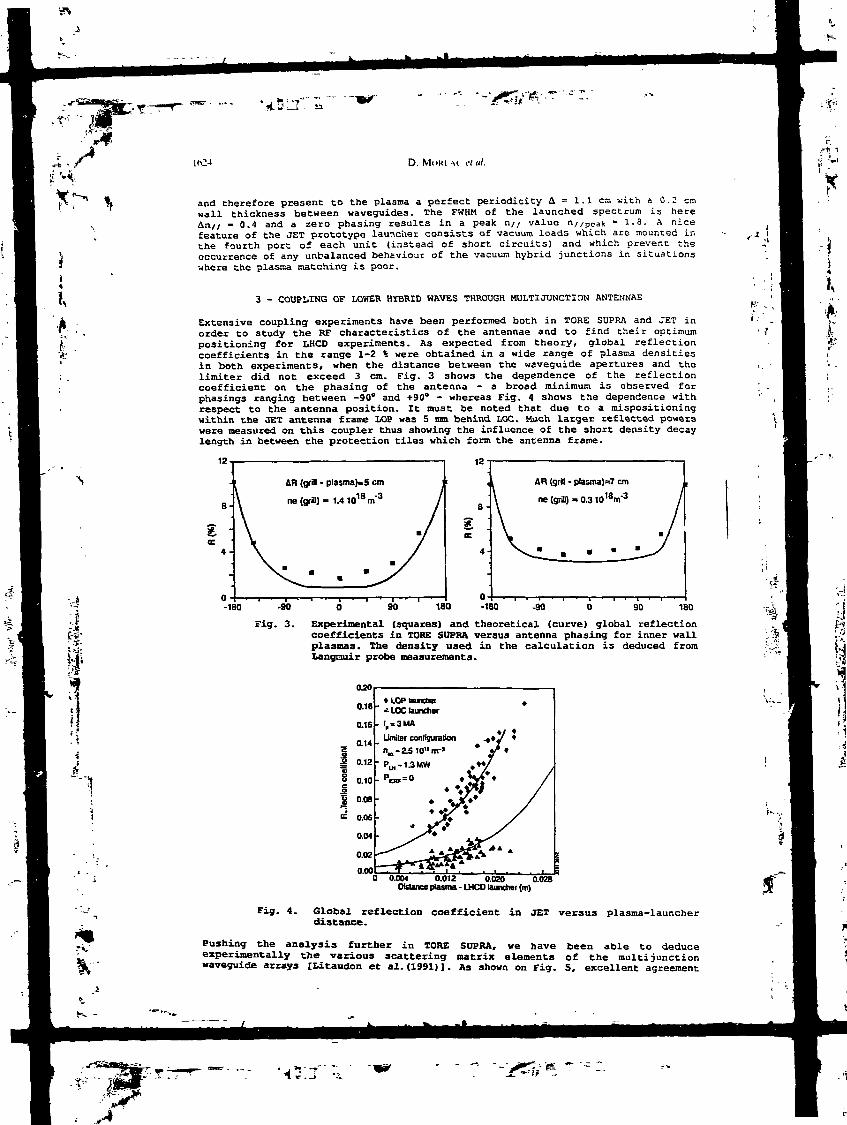
D. Ml)KE-M I1I II/.
and therefore present to the plasma a perfect periodicity A = 1.1 c»> with a 0.2 cmwall thickness between waveguides. The FWHM of the launched spectrum is hereAn// - 0.4 and a zero phasing results in a peak n// value n//poa!t »1.8. A nicefeature of the JET prototype launcher consists of vacuum loads which are mounted inthe fourth port of each unit (instead of short circuits) and which prevent theoccurrence of any unbalanced behaviour of the vacuum hybrid junctions in situationswhere the plasma matching is poor.
II.
3 - COUPLING OF LOWER HÏBRID WRVES THROUGH MULTIJUNCTION ANTENNAE
Extensive coupling experiments have been performed both in TORE SUPRA and JET inorder to study the RF characteristics of the antennae and to find their optimumpositioning for LHCD experiments. As expected from theory, global reflectioncoefficients in the range 1-2 % were obtained in a wide range of plasma densitiesin both experiments, when the distance between the waveguide apertures and thelimiter did not exceed 3 cm. Fig. 3 shows the dependence of the reflectioncoefficient on the phasing of the antenna - a broad minimum is observed forphasings ranging between -90° and +90° - whereas Fig. 4 shows the dependence withrespect to the antenna position. It must be noted that due to a mispositioningwithin the JET antenna frame LOP was 5 mm behind LOC. Much larger reflected powerswere measured on this coupler thus showing the influence of the short density decaylength in between Che protection tiles which form the antenna frame.
12
8-
4-
AR (grffl - plasma)*5 cm
ne (grin) = 1.41018m"3
12
8 -
AR (giffl - plasma)=? cm
-IBO -90
Fig. 3.
90 180 •180 -90 90 180
Experimental (squares) and theoretical (curve) global reflectioncoefficients in TORE SUPRA versus antenna phasing for inner wallplasmas. The density used in the calculation is deduced fromLangnuir probe measurements.
020
0.18
0.16
0'"°-'2
0.10
0.08
0.06
0.04
0.02
0.00
» LOP ttunctw* LOC launcher
I,=3 MA
0.012 0.020 0.028Distance (Hasina - LHCO launcher (m)
Ir
Fig. 4. Global reflection coefficient in JET versus plasma-launcherdistance.
Pushing the analysis further in TORE SDPRA, we have been able to deduceexperimentally the various scattering matrix elements of the multijunctionwaveguide arrays [Litaudon et al.(1991) ]. As shown on Fig. 5, excellent agreement
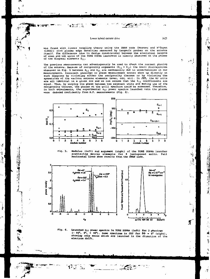
/ *••--•>"•
?H
K
i:
Lower hvhriil current drive IfOS
was found with linear coupling theory using the SWAN code [Moreau and N'Guyen(1984)] with plasma edge densities measured by Langmuir probes on the antennaitself. The difference (due to design constraints) between the electrical lengthsof even and odd units of the TORE SUPRA launchers is clearly observed on the phasesof the diagonal elements SjJ..
The previous measurements can advantageously be used to check the correct phasingof the antenna. Because of reciprocity arguments (Ssj - Sji) the small discrepanciesobserved on Fig. 5 between S^j and Sji are necessarily due to uncertainties in ourmeasurements. Incorrect phasings or phase measurement errors show up directly onsuch diagrams by violating either the reciprocity theorem or by violating thesymmetries of the various antenna elements (even, odd, etc). In JET, the MJ unitsare all identical in a given row and we can assume that the Su coefficients areequal. Thus, by varying the phase between two adjacent units and making use of thereciprocity theorem, the phases at the grill aperture could be assessed. Therefore,in both experiments, the experimental n// power spectra launched into the plasmawere deduced confidently from R.F. measurements (Fig. 6) .
200
02
0.1
0.0
• •
o • S(j+iH o i " B 5
» L 4>u+*
0 1 2 3 4 5 6 7 8module number
100
ÎI-100
-200
n - fg U ° 5 B
A
A * »
A
0 1 2 3 4 5 6 7 8module number
S.
Fig. 5. Modulus (left) and argument (right) of the TORE SUPRA launcherscattering matrix elements for 8 juxtaposed units. Fullhorizontal lines show results from the SHAN code.
'.V1 '(-
25
2
1.5
1
0.5
O
60ntpeak
&»",peak
•
" f t *i InIh!linII"
-o* to-1.8 (
— 90*J-1.4 jl
l'lIIiIl
il
. J
L_6«j njpea»
ji|
Il
I!iiii isLiLiL.
-+SO'-23
-2
1.0
Ne»1.10l2cm-3
16 waveguides
ft/ .U
00175 100 50 30 Eo(KeV)
Fig. 6. Launched n// power spectra in TORE SUPRA (left) for 3 phasings{- 90", 0", + 90°). Same spectrum in JET for St - 0° (right),showing only waves which are launched in the direction of theelectron drift.

ï,Jk
a)
LHin
D. MoKEAi' et al.
4 - CURRENT DRIVE EFFICIENCY
den*it-y gxperimgnliB in nhmieallv hear.ed TORE SUPRA plasmas
Current Drive signatures (non-thermal ECE and hard X-rays) were still observedTORE SUPRA at central densities approaching 1020 m"3 thus confirming the
potentiality of 3.7 GHz waves for high density LHCD. The most documented series ofexperiments has been conducted at ne - 4 * 10
19 m"3, in 1.6 MA/3.9 T heliumdischarges. At this density and at high power the residual OH electric field assistin driving the suprathermal current becomes small, and the steady state currentdrive efficiency can be found simply by making the ohmic resistivity correctionsdue to changes in electron temperature and Zetf [Bizarro, Hoang et al. (1991)].Fig. 7 displays an efficiency Y = neRIrf/Prf which varies from 3.5 X XO
19 AnT2XW atlow power to stabilize at Y « 2 X 10¹⁹ AnTVW for RF powers larger than 2 MW. Thebest performances correspond to an RF driven current Irf » 850 kA with Prj = 4 MWand a 57% loop voltage drop. The phase dependences of the loop voltage drop and ofthe non-thermal electron cyclotron emission (ECE) show a broad maximum around zerophasing (Fig. 8) . This can be correlated with the antenna performances (coupling,directivity, spectrum) which exhibit a similar behaviour when measured by theparameter Sea - <l/n2//>/ (l/nz//peak) defined in [Litaudon and Moreau (1990)].
4
1 2Q.
"isis
0.4
0.3
505
0.1
. ÛV/VQ Non thermal ECE (auu.)
Fig. 7.
1 2 3 4
P1F(MW)
Current drive efficiencyTORE SUPRA as a function
-135 -90 -45 O 45phase (deg.)
90 135
inof
LH power for Ip - 1.6 HA andn. - 3.8 x 10¹⁹ m"3.
Fig. 8. Loop voltage drop (blacktriangles) and non-thermalelectron-cyclotron emission(open squares) versus antennaphasing for Ip • 1.6 MA, n"e -3.8 x 10¹⁹ nr3 and PMI - 2.4 MW.
b) denalfrny RP
Early experiments in which the toroidal magnetic field was limited to B1 » 1.9tesla had been characterized by a rather low efficiency (Y - 1019 AnTz/W) for Ip =600 kA and ne - 1.5 x 10
19 m~3. This was attributed to the poor penetration of thewaves. At 3.9 Teslas, a zero loop voltage plasma was marginally obtained at a lineaveraged density ne - 2 x IQ
19 nT3 with 4.8 MW LH power. The time behaviour of•various signals during such a shot are shown in Fig. 9. At lower powers anddensities the effect of the residual electric field is generally important, asshown in fig. 10 where we have plotted the ratio of the power absorbed by thesupratbermal electrons from the ohmic field (PBi - Irf .Vloop) to the RF power whichis assumed to be absorbed by the resonant electrons (Pabs ~ 0-6 Prf due to spectrumdirectivity and losses). For H8 - 1.5 x 10
19 nT3, in agreement with theoreticalestimates (full curves) tKarney and Fisch (1986)1, up to 60-70% of the fastelectron energy comes from the ohmic field. This contributes substantially to thehigh apparent efficiency obtained at relatively low LH power (Fig.7). At higherpower, Pei/Pabs drops to about 10 % according to our estimate and therefore theefficiency becomes independent of the LH power.
O JET HiOh Tempgraf.urg/Hioh Efficiency Cnrnmfc Brim F.»perin«.nt3
Most probably because of a synergy between LHCD and ICRH but also because of ahigher electron temperature (volume-averaged <Te> - 1.9 keV) current drive
.'£

Lower hvhrii) current drive
efficiencies larger than 4 XlO19 AnT2XW were obser<-ed in .'ET [Gcrmezano et al.(1991).- Jacquinot et al. (1991)]. This result was obtained H- .> fi MW LH power in2.8 T/3 MA limiter discharges with additional ICF.'! (4 M.<i j... a D (H) plasma(Fig. 11). The loop voltage dropped by 50 % and aftu<- cor roo'.i ons due toresistivity changes one finds that about 1.2 MA were dri 'er. r> t- • waves. Theefficiency was rather independent of plasma current and phasing, i. cept at largephasings (n// = 2.4), where it was significantly reduced. Because of the hightemperatures routinely obtained in JET the residual loop voltage is quite low(< 0.25 V) and thus the OH assist on fast electrons is relatively unimportant as inthe high density TORE SUPRA discharges (P0a./Pabs - 10 %) .
.Jt. .
Fig. 9. RF driven TORE SUPRA discharge Fig. 10. Ratio of electric power gainedn° 6014_ (B1 - 3.9 T, Ip - by suprathermal electrons to1.6 MA, n, - 2 x io19 m"3 and PLH resonantly absorbed LH power- 4.8 HH). versus phase velocity
normalized to runaway velocity.A toroidal n// upshift n//ejf ="//peak x Rlauncher/R0 has beenassumed.
Considering that TORE SOPRA results were obtained in plasmas with <Te> < 1.4 keV,the comparison between the two experiments shows a stronger temperature scalingthan the one observed in JT-60 [Ushigusa et al. (1990); Imai et al. (1991)]. Thissupports the hypothesis of a LHCD/ICRH synergy in which about 1O1S of the ICRH powe.would be directly absorbed by resonant electrons through Landau damping and transietune magnetic pumping [Jacquinot et al. (1991)].
5 - ELECTRON HEATING AND CONFINEMENT
The temperature profile was strongly peaked when LH power was applied atIJ« - 1.5 x lO19 nr3 in TORE SUPRA. This is shown in Fig. 12 where a typical profilededuced from Thomson scattering measurements is displayed. Central temperatures ofthe order of 8 keV on axis were obtained in this density regime with 4 MW RF powerand the peaking factor, T«(0)/<Te>, increased from 2.2 to 3.

•y~.m>> si-t : r
s H>(> Ï
•il
Ii
*
UOS D. Mt)KLAl i'((l/.
0.5
0.1
X-poinl (Z,,=2Ip=SMA(!„,=•3x10"RV3
from Rsch(70% coupling)
10
—61
1
<Te>kaV
D OH+LH. OH
0.5 1.0
Fig. 11. Current drive efficiency inJET versus volume averagedelectron temperature withcombined LHCD and ICRH. Blackcircles are obtained if noICRF power is absorbed bysuprathermal electrons. Opencircles are for 10 % ICRFpower deposited on the fastelectrons.
Fig. 12. Electron temperature profilein TORE SUPRA (shot n° 5705)deduced from Thomsonscattering at centralelectron density neo = 2.2 x10¹⁹ nT3 with ohmic heating"alone (OH) and with 4 MH ofadditional LH power (OH-LH).
At central densities na(0) - 5 X 10¹⁹ m~3 in TORE SUPRA, the central electron
temperature was raised from 2 keV to 3 keV with an injected power of 4 MW and thetemperature increase scaled linearly with power. In these cases, the peaking factorwas approximately constant, indicating a broad power deposition profile through thefast electron channel [Pecguet et al. (1991)] in spite of a hollow hard x-rayprofile (S 7) [Feysson et al. (1991) 1 . This will be further discussed latertogether with modulation experiments. The global confinement time as deduced fromthe diamagnetic flux measurements is found to degrade slightly faster than theusual L-mode scaling and it is possible that the off-axis creation of fastelectrons and their radial transport are responsible for this.
Central electron heating has also been observed in JET in conditions where the fastelectron population was clearly produced off -axis (r 2 0.4 m) [Froissard et al.(1991)]. Hith LHCD alone, the confinement time also degrades faster than L-modeGoldston law [Goldston et al. (1984)], but with combined LHCD/ICRH in the "monstersawtooth regime" it is generally 10-15% highei. than this law would predict. Fromthe LIDAR Thomson scattering diagnostic [Salzmann et al. (1987) ] the centraltemperature was found to increase from 2.5 keV to 3.5 keV with LH alone and from6 keV with 3.5 MH of ICRH to 9 keV with the combination of LH (1.6 MW) and ICRH(4.5 MW, cf. Fig. 13). This result is quite interesting and a possible explanationthrough the synergistic absorption of the fast magnetosonic wave by fast LHproduced electrons [Jacquinot et al. (1991)] has been put forward. It would havedirect implications on future Fast Have Current Drive experiments.
6 - RAY-TRACING AND FOKKER-PLANCK SIMULATIONS
High density current drive experiments performed in TORE SUPRA were fairly wellsimulated by the HIT/varennes code [Bonoli and Englade (1986); Fuchs et al.(1989) ] . Typical outputs from such simulations are reproduced in [Bizarro, Hoang etal. (1991)]. in these simulations an anomalous diffusion of the suprathermal

Louer hvbrid current drive-
electrons and their perpendicular temperature were adjusted so that globalparameters agreed with the experimental ones. It must be noted that the simulatedrf current density profiles and rf absorption profiles are found to be extremelyhollow and peaked in the outer half of the discharge (r/a - 0.6). Low densitysimulations did not provide as good an agreement with the data but furthersimulations are in progress in which an approximate perpendicular temperature ofthe electron tail derived from kinetic theory will be computed and used in the 1-DFokker-Planck model to calculate the LH current drive. This should reduce theuncertainty in the modelling which is still very sensitive to some parameters(perpendicular temperature, edge temperature, poloidal launch angle ..). This isdue to the multipass absorption of the waves and is particularly important for D-shaped plasmas.
JET simulations using similar codes [Brusati et al. (1989); Rimini (1991)] show thesame trend, namely LH pot. - deposition in the outer part of the plasma for centraldensities larger than 3 x 10¹⁹ m"3. This off-axis deposition of the LH power isconsistent with hard X-ray measurements reported in the next section.
••{
7 - RADIAL AND SPECTRAL ANALYSIS OF THE FAST ELECTRON POPULATION
a) T.Q
Fast electron Bremsstrahlung measurements are performed in TORE SUPRA through5 lines of sight across the plasma [Peysson et al. (1991)]. In mixed OH-LH lowdensity discharges, consistent with the centrally peaked electron heating describedabove. X-ray emissivity is peaked at the center for photon energies up to 600 keV.Such energies are higher than accessibility conditions would allow, and thereforeexhibit the acceleration of the fast electrons by the residual ohmic electricfield. This is consistent with the apparently enhanced current drive efficiency dueto the OH-LH synergy when Pei/Pabs
is large (Fig. 10) .
b) Hiqh hase Bean in TORE SUPRA
At densities n - 4 x 10¹⁹ nT3, off-axis absorption of the lower hybrid waves can beinferred from the emissivity profile. X-ray spectra extend up to 300-350 keV with aslightly decreasing "photon temperature" when moving towards the edge of theplasma. As shown in Fig. 14 the line integrated emission profile is quite broad forenergies around 50-100 keV and becomes hollow above 150 keV. This is in agreementwith LH wave accessibility constraints since 150 keV electrons resonate withn// - 1.6 waves which should not exist inside r/a - 0.4 (Fig. 15) .
%ri."
Fig. 13. Electron temperature profilein JET (Ip - 3 MA, Jnadl - 5.5x 10¹⁹ m'2} for ICRH alone andcombined ICRB + LHCD.
12
1.0
0.8
0.6
0.4
02
0.0-1.0
Fig. 14.
SOkeV100 keV
150 keV
200 keV
-05 0.0<r/a>
0.5 1.0
Line integrated X-rayemission profile for 4 photonenergies in TORE SUPRA,normalized with respect tothe central chord emission.The central electron densityis 5 x ID19 m'3 and theantenna phasing is zero (shotn" 5144}.

l,Ài
D. MoKEAi' ei til.
A phase scan performed at the same density resulted in the curves displayed inFig. 16. The general bell-shaped behaviour of these data must be compared with thephase dependences of the loop voltage drop and non-thermal ECE (Fig. 8) and mayalso be mostly correlated with the "n//-weighted antenna directivity"8cd = <l/n
2//>/(l/n2//peak) • This parameter characterizes the theoretical currentdrive efficiency of à given spectrum in a homogeneous plasma slab (taking intoaccount the negative effect of parasitic lobes) as compared to an ideal spectrum5(n// - n// peak)- It is also a rough measure of the power launched in the mostefficient main lobe. Once corrections from this spectrum directivity have beenmade, the ef -Ct of varying n//peaic while changing the phasing of the antenna weaklyremains t" . -gh the slight asymmetry of the high energy curves which drop fasterfor neg?'- phases (accessibility) than for positive ones (Fig. 16), especially inthe ra O" < &$ < 90° i.e. where the spectrum is well defined.
C) pyperoy befew &n I.HPQ and TCRH i n .7ET
Similar observations were made in JET with the Fast Electron Bremsstrahlung (FEB)vertical camera through seven lines of sight [Froissard et al. (1991)1. The line-integrated emission profiles were always hollow and this feature was morepronounced at higher densities and higher X-ray energies. Simulations show thatsuch observations could only be explained if one assumes that the fast electronpopulation is mainly localized 50 cm away from the plasma center and almostvanishes in the central region.
With the simultaneous application of ZCRH (4.5 MH) and LHCD (1.6 MH) the fastelectron radial distribution was still hollow and the energy dependence of thesuprathermal tail was much flatter. Apparent "photon temperatures" up to BOO keVwere observed from X-rays as compared co 150 keV in the pure LHCD case [Jacquinotet al. (1991) ]. This indicates that the fast wave was significantly coupled to thefast electrons accelerated by the lower hybrid waves, thus explaining the improvedcurrent drive efficiency and electron heating also observed in the combined LHCD +ICRH scenario.
13
1.6
J 1.4
12
#5144B1 = 3.9 T
nJO)ai5.0 1O+19Bi-3
flat profile (peaking factor 2:0.5)
-UO -0.5 0.0<r/a>
1.0
0.0
•// 100 keV
'/ 150 kav200 keV
• Normalized directivity parameter 5Cd
-150 -100 -50 O 506» (deg.)
100 150
-.*
fc-
Fig. 15. Accessible n// refractive indexiersus radius for shot 5144 inTORE SUPRA.
a)
Fig. 16. TORE SUPRA X-ray emissionalong the central chord for 4photon energies as a functionof the phasing between the MJunits. Black, circles show thedirectivity parameter 8CD (alldata have been normalised tothe zero phasing value).
8 - CURRENT DENSITY PROFILE MODIFICATIONS AND SAWTOOTH BEHAVIOUR
ion of t:he infcertial induefcanng and a orofîlga
Consistent with the hollow X-ray profiles just discussed, the internal self-inductance was generally found to drop slightly in JET during the LH pulse, over atypical current diffusion time scale (8 sec) . Magnetic reconstruction codes
S'

Lower hvbrid current drive
(IDENTC) allow the evolution of the q profile to be deduced from magneticmeasurements. During combined LHCD and ICRH the central value of the safety factorchanges from 0.93 to 0.83 when the LH power is switched-off and replaced by thesame amount of ICRH power CGormezano et al. (1991)]. At the same time, an increaseof the q — 1 radius from 0.23 m to 0.22 m was observed on the soft X-ray sawtoothinversion radius due to the combined doubling of the ICRH power and LHCD switch-off(Fig. 17) . This current profile modification increased with density up toneo = 3 x IQ13 m"3 above which the LH power may have been insufficient.
Because of TORE SUPRA circular cross section, detailed analysis of the self-inductance variation was rather difficult. However by subtracting the diamagneticPj_ from the Shafranov equilibrium parameter (P// + Pi +Ii)/ 2 we could generally finda few percent decrease of 1 . Further studies will be devoted to this subject inthe near future using Faraday rotation to determine the current density profiles.
b) Saw£ec»t:h stabilisation and "monster sawtooth" gnhancempfifc by combined TCRH/LHCD
Whether related to current profile modifications (q > 1) or not, sawtoothstabilization by LH waves has been observed in most tokamaks at various frequencies[Van Houtte et al. (1984); Stevens et al. (1985); Farlange et al. (1986); Porkolabet al. (1986); Soldner et al. (1986); Ushigusa et al. (1990)...]. In TORE SUPRA,such a stabilization was obtained at low densities (ne = 1.5 x I0
19 m"3) at a powerlevel of 1.8 MW for I 1 MA and above 2 MW for I 1.6 MA. The sawtooth periodwas found to increase with power below the stabilization threshold (Fig. 18) .
100
3
f a_ i
o
> 61
120
1.15
1.10
1.05
fini — r^t
plasma inductance
0.Ot L
:SO
stabilization (Prf=1.8MW)
1 PrI(MW) 2
48 50 52 54 SB 58 60 62Time (S)
Fig. 17. Time evolution of the internalself—inductance and of the1 ~ 1 radius during combinedLHCD and ICRH in JET.
4.6
I4"2
3.34 4.1 4.2 4.3 4.4 4.5 4.6 4.7 4.8
US)
Fig. 18. Sawtooth period in TORE SUPRAversus LH power for ne = 1.5x 10" and ID 1 MA(top). Thermal ECE signal(central) during a modulationof the LH power between 2 MWand 2.9 MH at In 1.6 MA andsame density (bottom) .
With combined ICRH (4 HH) and LHCD {- 1.3 MW) in JET, "monster sawteeth" have beenmaintained for up to 2.9 seconds in a 2 MA discharge and 2.3 seconds at 3 MA[Gormezano et al. (1991) ]. m Fig. 19, a comparison between the duration of ICRHand ICRH/LHCD sawtooth-free periods clearly indicates that LHCD extends the lengthof such periods. The combined effect of ICRH produced fast ions and of thereduction of the q - 1 radius due to LHCD is thought to be responsible for thisprogress.

I,
^ f -»••/*
D. MOKI \i t'l al
9 - LH POWER MODULATION EXPERIMENTS AND FAST ELECTRON DYNAMICS
In order to study the power deposition of LH waves and possibly the dynamics of thesuprathermal electrons, a series of modulation experiments have been performed.Modelling of the quasi-linear electron ' response to the LH excitation under thecombined influence of slowing down and radial diffusion has been worked out throughthe Green's function technique and, as a theoretical guidance for interpreting theexperiments, we review here the main results.
a) nri diffusion
Following the general approach described in [Rax and Moreau (1989)), we consider,the Laplace transformed modulated response of the electron distribution function f(s, C, u, Ji), where C is the normalized radius (C - r/a), u the normalized velocity(u = v/c), and U = u///u = cos 8 the cosine of the pitch angle. It can be written interms o£ a Green's function Gg (|'r u1, Jl1; !;, u, fl) as :
f (s, Ç, u, (l) - J J J (1)
(T represents the modulated RF induced flux in velocity space and. for the sake ofsimplicity, we have neglected other source terms inducgd by the ohmic electricfield. IiL,ter£is of the absorbed power spectral density Wabs (u)du/ the flux C isgiven by CT = Wab»/u//-
Qtl the other hand the Green's function can be expressed on theLegendre polynomials basis PI(U) as :
I- (--1 + ( D + SKn J (ai- lij H (u'-u) (2)
where D is a radial diffusion coefficient for fast, electrons, Rn (C) and - kn areeigenf unctions and eigenvalues of the diffusion operator, K11n- is a couplingconstant (assumed to vanish for n' * n) due to the density gradient, and H is theHeaviside function. The frequency analysis can simply be obtained by setting s = join the previous expression. The time response to a step excitation
iiH W ££ S1n (u) nfe) (3)
can be derived from simple properties of Laplace transforms :
1 , . (i * »1 J(J + i| rdx' J-S-) E SiJx') exp L-
1
where x = u3/3. Also of interest is the time derivative of this response:
ifc.t-.d-
which directly exhibits the different physics characterizing slowing down - delayedresponse Sin{u
3/3 + t/Knn) - and diffusion - normal mode exponential attenuationexp {- t/Tnl. Remembering that Sin is the velocity derivative of the spectral powerdensity absorbed through resonant wave-particle interaction, one can gaininformation about the aaectral power deposition and radial diffusion from highfrequency modulation experiments, provided enough time resolution is available inthe fast electron diagnostics (hard X-rays, non-thermal ECE, microwavetransmission...).

[I, ï46
Lower hvhrid current drive Ko.'
b) Mnrjulatlon in TORE SUPRA
At densities nï = 4 x 10¹⁹ m~3 and 6 x 10¹⁹ m~3 where such experiments were performedto minimize the effect of the ohmic electric field, and for a modulated LH powertypically between 2 and 3 MW, a significant electron temperature modulation at thecenter was deduced from soft X-ray measurements [Pecquet et al. (1991)] or fromThomson scattering {Fig. 20) . This observation is in apparent contradiction withthe hollow high energy X-ray profiles discussed in § 7 and can be explained eitherin terms of heat transport, improved energy confinement in the plasma core, or fastelectron transport. Despite a global L-mode degradation, a confinement enhancementin the center cannot be excluded. In fact soft X-ray emission was modulated with a130 ms characteristic time for nCQ = 9 x 10
19 m~3 and a central temperature increaseof = 300 eV was measured, yielding an apparent power deposition of 50 kW/m3 which is25 % of the ohmic power density {P0h » 200 kW/m
3) . From the relative temperatureincrease in the center, one would obtain a 15-20% reduction in the centraltransport coefficient if one assumes that no LH power is absorbed in the center ofthe plasma. In view of the hollow RF current density profile which can be inferredfrom high energy x-rays, such an improvement of the central confinement could berelated to a change in the shear in the center, or even to a shear reversal as inthe JET Pellet Enhanced Phase ("PEP") [Kupschus et al. (1991); Smeulders et al.(1991) ] . However no measurement of the qy profiles is available yet to support thisassumption .
•g 3.0
"§la.0O)Z
g 1.0
S0.0
' a!CRH + LH(>)MW)" a ICRM only °
A
à
A A
1 * rf
4 à ^g a 3 o
: « g B OB|BO
Il
0.4 0.6 0.8 1.0
Fig- 19- Time duration of sawtooth-free Fig. 20. Electron temperature profileperiod in JET versus ICRH at various times during a highpower with (triangles) and density LH power modulationwithout LHCD (squares). experiment in_ TORE SUPRA
(shot 5981, HB - 6 x 10¹⁹ nT3,PLH - 2 MW (dark squares) andFIJI - 3 MB (open squares)).
On the other hand, a more detailed analysis of the time responses of the soft X-raysignals indicates that, apart from a global transport characterized by a 120 mstime constant, there exists a small delay in the central channel responses(Fig.21)• After some data processing we could obtain approximate z-transformedtransfer functions between the LH power excitation and the various responses.Assuming that the thermal responses are governed by indirect heating of the bulkelectrons by slowing down ones, one can separate the corresponding transferfunctions into .two factors. Th3 first one connects the RF power modulation to thene t source, OJMC, and the second one contains the global heat transportcharacterized by a longer time scale T0 - 120 ms. In terms cs the electrondistribution function one finds :
djldu u f (6)
which links Qo» to the slowing down and diffusion time scales discussed in theproceeding subsection. Considering different soft X-ray chords, we have plotted inFig. 22 the characteristic time for the appearance of the heat source (deduced froma phase vs. frequency analysis) as a function of minor radius for typicalmodulation experiments at n. - 4 x 10¹⁹ m'3, PLH - 1.9 to 2.9 MW with 0° and +90°phasings.

D. NU I
14
12
_ 'OO5
-§ 8mi e
4
2
+9(J deg. phasing(shot 6001)
-0.6 -0.4 -OJ2 O 0.2
radius (m)0.4 0.6
i
fig. 2l. Measured (dotted lines) and Fig. 22. Tim: delay for the appearancesimulated !full lines) of the heat source versusresponses to a UI power square radius during modulationmodulation (1.9 - 2.9 HH, 8* - experiments as depicted in+ 90") at n, - 4 X 10¹⁹ m'3. Fig. 21.Shown on this figure are thenon-thermal ECE (top)- softX-rays at r - 0.53 m (middle)and soft X-rays on axis(bottom). Simulated signalsare obtained from approximatetransfer function.
This tine, t$, is only a couple of milliseconds at half radius where most of thefast electrons are produced, indicating that the power absorption spectrum extendsto saallsr phase velocities than che launched spectrum and bridges the so-calledspectral gap (e.g. fHoreau, Rax and Samain (1989)])- Then Td clearly increases when"owing towards the center where it reaches 14 nig. Central heating cannot be due tolocally produced fast electrons since their slowing down time would be smaller incentral regions than in off-axis ones due to a higher density and to a smallerélectron energy (wave accessibility). A similar central heating has been observedîn DlXI-D during off-axis electros cyclotron heating (ECH). It is interpreted asbeing due to a non-diffusive heat transport [Petty et al. (1991) ] although theoirtgin of sach a heat pinch is not clear.
Tnsfcesd, central beat deposition could be caused by radial transport of fastelectrons (E > 150 ksV) produced at half-radius and reaching the center beforp theyhave co^^letely theznalized. The above characteristic times correspond to adiffusion coefficient D -{Ar)2/T<, of the order of 10 mz/s and, assuming that thisdiffusion is due to nagnetic turbulence acting en electrons having half the speedof light, yields a magnetic fluctuation level 5B/B0 » 1C"
4 [Mendonça (1991) ; Garbetec 3^- (19SO)J. This is therefore plausible, although it would imply magneticstochasticity up to the plasma center 'note that these experiments were allperfoned in sawtoothing discharges). Incidently, some shots "have been recentlyanalysed La JET in which pellets were injected during LHCO, and from the ECEresponse after the pellet injection a fast electron diffusion coefficient of thesa*e order of aagnitude was estimated [GondhaleJcar (19Ç1 ) ].
In 3cx*ary, it is still difficult to decide between anomalous fast electrontransport, anomalous heat pinch and confinement enhancement in the plasma centre toexplain the observed central heating. The short time constant for the appearance of
Ttx cortest drive

See appendix.1621
Lower hvbrid current drive IftXS
the heat source happens to be roughly the same as for the build up of the line-integrated non-thermal (i.e. non-localized) ECE observed from a Fabry-Perotinterferometer (11 ma). It is also consistent with the slowing down time of 250 keVelectrons. Qn the other hand, local shear modifications over distances of the orderof 10 cm may also take place on such a short time scale with the help ofsawtoothing, and significantly reduce heat transport in the central plasma.
•nodulacion in TORE SUPRA
At a density ne = 1.5 XlO19 m~3 where sawteeth were stabilized during the whole
modulation phase, and with the same modulation pattern as before (PLH = 1.9 to2.9 HW), a strong m = 1 MHD oscillation could be observed on soft X-rays(Fig. 23) . An oscillation at twice the frequency could also be seen on thetransmission of a 85 GHz RF beam through the plasma column and is attributed torefraction effects produced by the m = 1 island. While the RF power was modulated,it was clearly observed that the frequency of the mode was increasing with powerprovided that power steps were longer than 32 ma.
At the same time the oscillation was showing up more and more clearly on the non-thermal ECE. The oscillating part of this emission can be attributed to electronshaving energies in the range 170-230 keV if we assume they are localized within a20 cm radius from the center. Such energies are compatible with accessibility ofthe wave. It cannot be excluded that the strong m = 1 oscillation on the non-thermal ECE could be caused by a fast electron population inside the island,differing from the one existing outside or in the ergodic separatrix region. Acoherent RF current response to the m - 1 mode could modify the dispersion relationof the node and be responsible for the change in its structure/stability even inconditions where q on axis is less than one. Further experiments on this subjectwill be of great interest in order to check such hypotheses.
d - Hard X-ray responses in JET during LH power modulation
The rime response of hard X-ray emission has been studied in JET during experimentsin which the power was square modulated from O to 1.6 MW with a 500 ms period[Froissard et al. (1991)]. The most striking observation is related to the bigdifference between the rise times and the decay times of these signals and to theenergy dependence of these time constants. We can attribute this difference to thenon-linearity of the power absorption in relation to the filling of the velocitygap between the thermal population and the phase velocity of the launched waves,during the rise of the fast electron tail. The decay phases, instead, are governedby the slowing down of a fully developed energetic tail together with a suddenincrease of the accelerating ohmic electric field.
10 - PELLET FUELLING OF LONG PULSE LH DRIVEN PLASMAS
Attempts to combine repetitive pellet fuelling with LHCD have been made in TORESUPRA using a centrifugal pellet injector supplied by Oak Ridge NationalLaboratory, under an USDOE/Euratom CEA collaboration. As in other experiments[Sôldner et al. (1991)], pellet injection during a steady high power LH pulseresults in a poor penetration 'of the pellet, typically 20 cm, with only 20 % of thepellet content deposited into the plasma. However by switching the LH power off for90 ms before each pellet injection, i.e. leaving enough time for the fastestelectrons to thermalize, successful pellet fuelling was demonstrated during a 9 slong current flat t.'p in which pellets could penetrate up to half radius as inohmic discharges ana 50 to 80 % of the pellet content was deposited within theplasma. This was obtained by injecting 28 deuterium pellets into an helium plasmaand is displayed on Fig. 24.
The line averaged density was raised ap to na - 4 x 10¹⁹ m"3 without any gas
puffing, while Zeff dropped from 4.5 to about 2. The fast electron ECE signal wasdecreasing during the density rise, as expected. However the averaged loop voltagewas almost steady, as seen on the flux trace which slope yields 0.6 volt. A totalof 2.6 -volt. seconds were saved during this shot.
The possibility of using pellet injection in mixed OH-LH discharges thereforeexists and the time duration of the LH switch-off is short enough to prevent anycurrent density profile change. This scenario has to be optimized in order to reachlong steady plasmas in TORE SUPRA while keeping the potential advantages of pelletinjection like deep fuelling, density profile control, "PEP" mode confinement.
-2t
!•=-.- -

output waveguides of a given unit, sucn a unit is ceptBa««i.«i^ auuaimiu^Wa**^ »•.Fig. 1 and contains a vacuum hybrid junction and 3 E-plane junctions, the designsof which have been optimized taking into account the effect of the plasma load
'ft:
D. MuKkAi L-I al.
Central electron temperature
^^-ECE (a.u)
,1! I
W-
Fig- 23. m - 1 oscillations in TORE Fig. 24. Time evolution of variousSUPRA on soft X-rays (top), plasma parameters during TOREnon-thermal ECE (middle) and SUPRA shot n° 6035 withmicrowave transmission (bot- combined pellet fuelling andtorn) during power modulations LHCD.(PLH - 1.9 - 2.9 MW).
11 - CONCLUSION AND FUTURE PROSPECTS
Lower hybrid experiments conducted on TORE SUPRA and JET have shown a strongcentral temperature increase, even in conditions where the fast electron radialdistribution was hollow. This phenomenon can be due either to a central confinementimprovement during LHCD, to an anomalous heat pinch, or to a fast electronanomalous transport on a time scale which is comparable with the slowing down timescale (- 10-15 ms) . In the case of JET, the strongest electron heating in thecenter was~obtained with combined LHCD (1.6 MW) and ICRH (4.5 MW) and a synergy hasbeen observed between the two heating schemes showing that a significant part ofthe fast wave was absorbed on the LH-created suprathermal electrons, by Landaudamping and magnetic pumping.
Current profile broadening has been clearly observed consistent with off-axis fastelectrons. While sawteeth are stabilized by low density LHCD in TORE SUPRA, theduration of ICRH sawtooth-free periods in JET is extended when LHCD is \ es nt. Theeffect of the LH power on the m - 1 internal mode has been observed in TORE SUPRA,consisting of an increase of the frequency of the mode while m - 1 oscillationsappear more and more clearly on non-thermal electron cyclotron emission.
A3 far as current drive efficiency is concerned, values as high as 0.4 x 10²⁰ AnT2XWhave been reached, in JET thanks to an LHCD/ICRH synergy and to a high volume-averaged electron temperature <Te> - 1.9 kev. In TORE SUPRA, at lower temperaturesand wxth Lower Hybrid waves only, the efficiency is about 0.2 x 10²⁰ AnT2/w.
A total of 28 successive pellets have been injected in a partially LH drivendischarge in TORE SUPRA, thus allowing the density to rise to n« - 4 x 10¹⁹ m'3.Tnis could be achieved by switching off the LH power during 90 ms long periodsbefore each pellet injection, i.e. without modifying significantly the currentdensity profile. * = = j

waveguides but is somewhat different from LCX: in Deing maae OE seamless SCBBA anainertially cooled. No gap is provided between the unies which are welded together
'Xr- *Lower h\hrid current drive Ih.V
In the future, the synergy between LHCD and ICRH will be optimized by removing theion cyclotron resonance from the plasma so that more fast wave power is availableto electron damping. Profile effects will be studied more deeply, including aoossible shear reversal in the center which is thought to result in the centralconfinement improvement observed during the JET "PEP" mode. At the same time, longpulse scenarios will be tested in TORE SUPRA with LHCD, pellet injection and use ofthe ergodic divertor, with the aim of producing high performance plasmas for timesmuch longer than the various characteristic time scales of interest for a fusionreactor.
Acjcnowl edp-ements
It is a pleasure to acknowledge contributions from many colleagues in the TORESUPRA and JET Teams (and especially in the LH groups) for making these dataavailable, and fruitful collaborations with US/DOE and CCFM Varennes. We would liketo thank in particular G. Tonon and A. Kaye for the launcher and system designs, P.Bibet for the technical implementation of the power modulation on TORE SUPRA, theX-ray and ECE groups for their valuable measurements, and A. Géraud for the pelletdata. Large contributions from A. Hubbard, J.M. Horet, A.L. Pecquet and discussionswith J.T. Mendonca on the modulation experiments are also greatly appreciated, aswell as the dedicated work by B. Saoutic and B. de Gentile on the TORE SUPRA work-station software, allowing efficient data processing. He are also indebted to V.Fuchs and P. Bonoli who provided us with their simulation code. Simulation studieshave been performed under NET contract n° 90-251.
Apponrti -ir : The TORE SUPRA Team.
G. Agarici, E. Agostini, J.H. Ane, N. Auge, S. Balme, V. Basiuk, B. Bareyt,P. Bayetti, B. Beaumont, R. Becherer, A. Bécoulet, M. Benkadda, G. Berger-By,D. Bessette, Ph. Bibet, J.?. Bizarro, G. Bon-Mardion, P. Bcnnel, J.M. Bottereau,F. Bottiglioni, R. Brugnetti, J.L. Bruneau, X. Buravand, H. Capes, J.J. Capitain,Ph. Chappuis, D. Châtain, A. Chatelier, H. Chatelier, D. Ciazynski, J.J. Cordier,J.F. Coston, J.P. Coulon, B. Couturier, J.P. Crenn, C. Deck, B. De Gentile,R. Demarthe, C. De Kichelis, P. Deschamps, P. Devynck, L. Doceul, M. Dougnac,a.w. Drawin, M. Dubois, J.L. DuchSteau, L. Dupas, D. Edery, D. Elbèze, T. Evans1,T. Fall, J.L. Farjon, I. Fidone, M. Fois, C.A. Foster2, M. Fumelli, B. Gagey,X. Garbet, E. Gauthier, A. Géraud, F. Gervais3, Ph. Gendrih, C. Gil, G. Giruzzi,M. Goniche, R. Gravier, B. Gravil, H. Grégoire, D. Grésillon3, C. Grisolia,A. Grosman, D. Guilhem, B. Guillerminet, P. Hennequin3, F. Hennion, P. Hertout,H.R. Hess, H. Hesse, G.T. Hoang, L. Horton2, A. Hubbard4, T. Hutter, j. Idmtal,C. Jacquot, B. Jager, C. Javon, F. Jequier, E. Joffrin, J. Johner, J.Y. Journeaux,Ph. Joyer, H. Kuus, D. Lafon, J. Lasalle, L. Laurent, C. Laviron, G. Leclert5,P. Lecoustey, C. Leloup, P. Libeyre, K. Lipa, X. Litaudon, T. Loarer, Ph. Lotte,Ph. Hagaud, R. Hagne, G. Martin, A. Martinez, E.K. Maschke, M. Mattioli, G. Mayaux,P. Mioduszewski2, J. Misguich, P.Monier-Garbet, D. Moreau, J.P. Morera, J.M. Moret6,B. Moulin, D. Moulin, F. Mourgues-Millot, M. Moustier, F. Nguyen, J. Olivain,P. Ouvrier-Buffet, J. Pamela, A. Panzarella, F. Parlange, G. Pastor, R. Patris,M. Paume, A.L. Pecquet,- B. Pégourié, Y. Peysson, D. Piat, J.M. Picchiottino,J- Pierre, P. Platz, C. Portafaix, F. Poutchy, M. Prcu, A. Quemeneur3, J.M. Rax,G. Rey, Ph. Riband, D. Rigaud, L. Rodriguez, B. Rothan, J.P. Roubin, P. Roussel,S.K. Saha, F. Saraaille, A. Samain, B. Saoutic, J. Schlosser, A. Seigneur,J-L. Segui, T. Shepard2, K. Soler, H. Stirling2, J. Tachon, M. Talvard, G. Tonon,A. Torossian, A. True3, B. Turck, T. Uckan2, J.C. Vallet, D. Van Houtte, J. Weisse,X.L. Zou.
• v
1 General Atomics, San Diego, California, USA.* Oak Ridge National Laboratory, Oak Ridge, Tennessee, USA.3 PMI, Ecole polytechnique, Palaiseau, France* Centre Canadien de Fusion Magnétique, Varennes (Québec), Canada.» L.P.M.i. Université de Nancy I. Vandœuvre les Nancy, France.C.R.P.P., Ecole Polytechnique Fédérale de Lausanne, Lausanne, Switzerland.
twfe-^
waveguide arrays [Litaudon et al. (1991)]. As shown on Fig. S. excellent agreement
•"'«£:.T '' T.'
t
D. UF \i 01 at.
REFERENCES
Bizarro J-, Hoang G.T. et al., Proc. 18cn Eur. Conf. on Contr. Fusion and PlasmaPhys., Berlin (1991), Eur. Conf. Abs. Vol. 15£, part III, 357.
Bonoli P., Englade R.C., Phys. Fluids 22. (1986) 2937.Brusati M. et al., Proc. 18th Top. Conf. on Applications of Radio Frequency Power in
Plasmas, Irvine USA (1989).Froissard P. et al., Proc. 18th Eur. Conf. on Contr. Fus. and Plasma Phys., Berlin
(1991), Eur. Conf. Abs. Vol. 15C. part III, 389.Fuchs v. et al.. Nuclear Fusion 23. (1989) 1479.Garbet X., Mourgues F, Samain A., Plasma Phys. and Contr. Fusion, 22. (1990) 917.Goldston R. J. et al.. Plasma PAyS. and Contr. Fusion, 2& (1984) 87.Gondhalekar A., private communication (1991).Gormezano C. et al., Proc. 12th Symp. on Fusion Eng., Monterrey (1987), Vol. 1, 38.Gormezano C. et al., Proc. 18th Eur. Conf. on Contr. Fus. and Plasma Phys., Berlin
(1991), Eur. Conf. Abs. Vol. ISC, part III, 393.Imai T. et al., to appear in Proc. of the 13th Int. Conf. on Plasma Phys. and
Controlled Nucl. Fusion Research, Washington D.C. (1990).Jacquinot J., The JET Team, Invited paper at the 18th Eur. Conf. on Contr. Fusion
and Plasma Physics, Berlin( 1991), these proceedings.Karney C.F.F., Fisch N.J., Phys. Fluids 29 (1986) 180.Kupschus P. et al., Proc. 18th Eur. Conf. on Contr. Fusion and Plasma Phys., Berlin
(1991), Eur. Conf. Abs., Vol. ISC, part I, 1.Litaudon X-, Moreau D., Nuclear Fusion 30 (1990), 471.Litaudon X., et al., Proc. 18th Eur. Conf. on Contr. Fusion and Plasma Phys., Berlin
(1991), Eur. Conf. Abs. Vol. 15C, part III, 353.Magne R. et al., Proc 15th Symp. on Fusion Tech., Utrecht (1988), 524.Mendonça J.T., private communication (1991).Moreau D., N'Guyen T.K., Report EUR-CEA-FC-1246, Centre d'Etudes Nucléaires de
Grenoble (1984) .Moreau D., Rax J.M., Samain A., Plasma Phys. and Contr. Fusion, 31 (1989) 1895.Pain M. et al., Proc. 13th Syrup, on Fusion Eng., Knoxville (1989), Vol. 2, 1083.Parlange F. et al., Proc. IIth Int. Conf. on Plasma Physics and Contr. Nucl. Fusion
Research, Kyoto (1986), Vol. 1, p. 525.Pecquet A.L. et al., Proc. 18th Eur. Conf. on Contr. Fusion and Plasma Phys., Berlin
(1991), Eur. Conf. Abs., Vol. ISc. part III, 349.Petty C.C. et al.. Report GA-A20465, Proc. 18th Eur. Conf. on Contr. Fus. and Plasma
Physics, Berlin (1991), Eur. Conf. AbS-, Vol. 15C, part I, 2'1.Peysson Y. et al., Proc. 18th Eur. ConC. on Contr. Fusion and Plasma Phys., Berlin
(1991) Eur. Conf. Abs, Vol. ISC. part IV, 345.Porkolab M. et al., Proc. IIth Int. Conf. on Plasma Physics and Contr. Nucl. Fusion
Research, Kyoto (1986), Vol. 1, p. 509.Rax J.M., Moreau D., Nuclear Fusion 23. (1989) 1751.Rey G. et al.. Froc 15th Symp. on Fusion Tech., Utrecht (1988), 514.Rimini F., private communication (1991).Salzmann H. et al-. Nuclear Fusion 21 (1987) 1925.Smeulders P. et al., Proc. 18th Eur. Conf. on Contr. Fusion and Plasma Phys., Berlin
(1991), Eur. Conf. Abs., Vol. 15C, part II, 53.Sôldner F.X. et.al., Phys. Rev. Lett. 51 (1986) 1137.Sôldner F.X. et al.. Plasma Phys. and Contr. Fusion, 22. (1991) 405.Stevens J.E. et al., Proc. 12th Eur. Conf. on Contr. Fusion and Plasma Physics,
Budapest (1985), Eur. Conf. Abs., Vol. 5E. part III, 192.Ushigusa K., JT-60 Team, Plasma Phys. and Contr. Fus. 22. (1990), 753.Van Houtte D. et al.. Nuclear Fusion 2i (1984) 1485.
w-
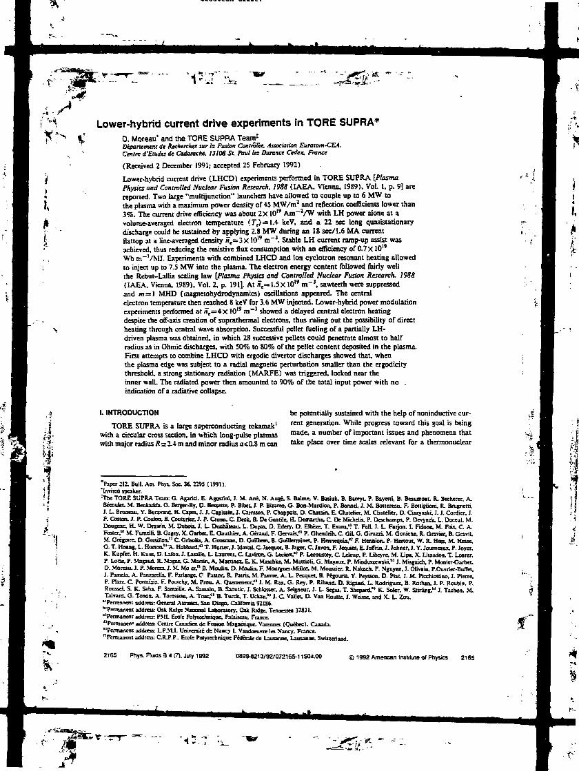
Lower-hybrid current drive experiments in TORE SUPRA*D. Moreau* and the TORE SUPRA Team1
Département de Recherches sur la Fusion Contrôlée, Association Euratom-CEA.Centre d'Etudes de Cadarache. 13108 St. Paul lez Durance Cedex. France
(Received 2 December 1991; accepted 25 February 1992)
Lower-hybrid current drive (LHCD) experiments performed in TORE SUPRA [PlasmaPhysics and Controlled Nuclear Fusion Research. 1988 (IAEA, Vienna, 1989), Vol. 1, p. 9] arereported. Two large "multijunction" launchers have allowed to couple up to 6 MW tothe plasma with a maximum power density of 45 MW/m2 and reflection coefficients lower than3%. The current drive efficiency was about 2x 10" Am~VW with LH power alone at avolume-averaged electron temperature 'Te) = 1.4 keV, and a 22 sec long quasistationarydischarge could be sustained by applying 2.8 MW during an 18 sec/1.6 MA currentflattop at a line-averaged density n,=3xlO" m~3. Stable LH current ramp-up assist wasachieved, thus reducing the resistive flux consumption with an efficiency of 0.7 X10"Wb m~'/MJ. Experiments with combined LHCD and ion cyclotron resonant heating allowedto inject up to 7.5 MW into the plasma. The electron energy content followed fairly wellthe Rebui-Lallia scaling law [Plasma Physics and Controlled Nuclear Fusion Research. 19SS(IAEA. Vienna. 1989), Vol. 2, p. 191]. At n,= 1.5x 10" m"3. sawteeth were suppressedand m= 1 MHD (laagnetohydrodynamics) oscillations appeared. The centralelectron temperature then reached 8 keV for 3.6 MW injected. Lower-hybrid power modulationexperiments performed at n,=4x 10¹⁹ m~3 showed a delayed central electron heatingdespite the off-axis creation of suprathermal electrons, thus ruling out the possibility of directheating through central wave absorption. Successful pellet fueling of a partially LH-driven plasma was obtained, in which 28 successive pellets could penetrate almost to halfradius as in Ohmic discharges, with 50% to 80% of the pellet content deposited in the plasma.First attempts to combine LHCD with ergodic divertor discharges showed that, whenthe plasma edge was subject to a radial magnetic perturbation smaller than the ergodicitythreshold, a strong stationary radiation (MARFE) was triggered, locked near theinner wall. The radiated power then amounted to 90% of the total input power with no .indication of a radiative collapse.
• (
if"
I. INTRODUCTION
TORE SUPRA is a large superconducting tokamak1
with a circular cross section, in which long-pulse plasmaswith major radius R=2.4 m and minor radius acO.8 m can
be potentially sustained with the help of noninductive cur-rent generation. While progress toward this goal is beingmade, a number of important issues and phenomena thattake place over time scales relevant for a thermonuclear
"Paper IE. BuIL Am. Pires. Soc. 36. 2Î93 ( 1991)."Invited speaker.:Tbe TORE SUPRA Team: G. Agariei. E. Agostini. J. M. Ane, N. Auge. S. Balaie. V. Bajiuk. B. Bareyt, P. Bayetti, B. Beaumont. R. Bechcrer. A.Becoulec. M. Benkadda. G. Bergcr-By. O- Bmrtrr, P. Bibet. 1. P. Btzarro. G. Bon-Mardion. P. Bonne], ]. M. Bonenau. ?. Boltiglioni. R. Brugnetti,J. L- Bruneau. Y. Bunvand. H. Capes. J. J. Capiuin. J. Carrasco. P. Chappuis. D. Châtain, E. Chatelicr. M. Chatelier. D. Ciazyiuki, J. J. Cordier, J.F. Cosjon. J. P. Couton. 3. Couturier. J. P. Cnnn. C Deck. B. De GCT tile, H. Demanhe. C De Michelis, P. Deschamps. P. Devynck, L. Doceul. M.Dougnac. H- W. Drawin. M. Dubois. J. I_ Duchaieau. L. Dupas. D. Edery. D. Elbeze. T. Evans,'! T. Fall. J. L. Farjon. I. Fidone. M. Fois, C. A.Foster."1 M. FumeUi. a Cagey. X. Girba» E. Gauthier. A. Gcraud. F. Gervais," P. Ghendrih. C GiU G. Giruzzi. M. Goniche. R. Gravier, B. Gravil.M. Grégoire. DL Gresfllon." C Grbolia. A. Grosman. D. Guilhem. a Guillerminet. P. Hennequin." F. Hennion. P. Hertout. W. R. Hes», M. Hesse.G- T. Hoang. L. Horton.1" A. Hubbard."1 T. Mutter. J. IdnuaL C Jacquot. a Jager. C Javon. F. Jequier. E JoSrin. J. Johner. J. Y. Journaux, P. Joyer,K. Kupfcr. H. Kuus. D. Lawn. J. Lasalle. L. Laurent. C Laviron, G. Leclert." P. Lecoustey. C Ldaup. P. Libeyre. M. Lip». X Liiaudon. T. Loarer.P. Lotte. P. Vtagaud. R. Nbgnc. G- Martin. A. Martinez. E. K. Maschke. M. Mattioli. G. Mayaux. P. Mioduszewski.hl J. Misguich, P. Monier-Garbet.D. Mordu. J. P. Morera. J. M. Mo «." R Moulin. O. Moulin. F. Mourgucs-Millot. M. Moustier. R. Nakach. F. Nguyen. J. Olivain. P.Ouvrier-Bunet.J. Pamela. A. Panzarella. F. Parlange. C Pastor, R. Pains. M. Paume. A. L. Pecquet. a Pégourié. Y. Peysson. D. Fiat. J. M. Picchiottino. J. Pierre.P- Piarz. C Ponauix. F. Pontchy. M. Prou. A. Quemeneur." i. M. Rax. G. Rey, P. Riband. D. Rigaud. L. Rodriguez. B. Rothan. J. P. Roubin. P.Roussel S- K. Sahx F. Samaille. A. Samain, a Saoutic. J. Schlosser. A. Seigneur. J. L. Segui. T. Shepatd."1 K. Soler. W. Stiriing." J. Tachon. M.Talvard. G. Tonon. A. TonKsian. A. True." B. Turck. T. Uckm.b> I. C Vallet. D. Van Houtte. J. Weisse, and X. L- Zou."PermaKent address; General Atomics. San Diego. California 92186."Permanent address: OaIt Ridge National Laboratory. Oak Ridge. Tennessee 37831.''Permanent address: PML Ecole Polytechnique. Palaiseau. France."Permanen1 address: Centre Onadim de Fusion Magnétique. Vareimes (Quebec). Canada."Permanent address: L.P.M.L Université de Nancy L Vandoeuvre les Nancy. France."Permanent address: C.R-P.P, Ecole Polytechnique Fédérale de Lausanne. Lausanne. Switzerland.
2165 Phys. Rums 3 4 (7). July 1992 08994213/92/072165-11S04.00 © 1992 Amencan Institute of Physics 2165

—__» r-~~-*~*-i ««..OU.K. «k a afinstyy uBiMetsn uiuu ana J.<_«n DUC 3J.3O Because Ot ahigher electron temperature (volume-averaged <Te> « 1.9 IceV) current drive
IJ
'* *'*?"" 7, "IE :-j _ i_
reactor will be studied.: These include energy confinement,healing and current drive, profile control, plasma fueling,power and panicle exhaust, plasma-wall interaction, andimpurity behavior. The role of an ergodic magnetic di-vertor on these various issues will also be assessed.
The long-pulse (quasicontinuous) 3.7 GHz/8 MWlower-hybrid (LH) system3 installed on the machine is oneof the main tools for obtaining such steady discharges and,during the 1991 experimental campaign, extensive high-power LH experiments have been carried out at a toroidalmagnetic field intensity B0=3.9 T on axis, a plasma cur-rent /,<1.6 MA, line-averaged densities ne<6x 10" m~},and with the full LH capability (two antennas powered by16 klystrons). Some of the early results from this periodhave been discussed already4 together with JET5 (JointEuropean Torus) results and will be briefly mentioned inthis paper for the sake of completeness.
The following topics will be covered. First, LH wavecoupling through multifunction launchers will be de-scribed. Then current drive efficiency and the synergy be-tween the Ohmic (OH) electric field and LH waves will bediscussed, together with long pulse operation and OH/LHcurrent ramp-up experiments. In Sec. IV, we shall reporton electron heating during lower-hybrid current drive(LHCD) and ion cyclotron resonant frequency (ICRF)heating experiments, and, in particular, on the confinementdegradation with additional power. Comparisons with con-finement scaling laws will be made. The following sectionwill deal with LH power modulation experiments, in whichwe observed sawtooth suppression at low density and someunexpected thermal plasma response in the plasma centerat higher density. Finally, we shall demonstrate the possi-bility of combining LHCD with repetitive pellet fuelingand show the effect of an ergodic divertor on LH-drivenplasmas.
II. COUPLING OF LOWER-HYBRID WAVES THROUGHMULTlJUNCTlON LAUNCHERS
The 3.7 GKz/8 MW lower-hybrid system installed onTORE SLTRA is made of 16 cw klystron amplifiers deliv-ering a maximum of 500 kW each. The power is transmit-ted to the launcher through oversized waveguides overabout 20 m with a measured transmission factor reaching94%. Transmission lines are terminated by a 3 dB hybridjunction, which divides the power delivered by each kly-stron and allows to power simultaneously an upper- and alower-antenna module.
The LH power is coupled to the plasma via two mul-tijunction launchers made of 16 nodules (eight juxtaposedin the upper row and eight in the lower row), and mountedon two adjacent ports of the machine. Each module con-"ats of two rows of four reduced-size waveguides whoseelectrical lengths are successively shifted by 90*. Spectrumflexibility is obtained by arbitrarily phasing the modulesand allows to launch a traveling wave whose peak refrac-tion index (n,) in the direction parallel to the static mag-netic field can be chosen between 1.4 ( —90* phasing) and2.3 ( -r90* phasing). In each antenna, the number of re-duced waveguides facing the plasma is 128 (32 in each
2166 Ptlys. Fliads 3. Vol. 4. No. 7. July 1992
row), and therefore the n(| spectrum is quite narrow (fullwidth at half-maximum &n||=:0.2). Up to now, a maxi-mum power of 6 MW has been coupled to the plasmaduring 4 sec and the power density through the waveguidesreached 45 MW/nr in some modules.
Coupling experiments have been performed in order tostudy the rf characteristics of the antennas and their optimum positioning. As expected from theory,6'7 global reflec-tion coefficients in the range l%-3% were obtained in awide range of plasma edge densities and a broad minimumwas observed for phase shifts between modules rangingfrom &£=—90* to 50= +90*. The various scattering ma-trix elements of the multijuncrion waveguide array havebeen measured experimentally (rf loops) together with theplasma density in front of the launchers (Langmuirprobes). Comparison with theoretical calculations showedfairly good agreement.4'8
In order to further assess the influence of the plasmadensity at the launcher aperture, two different sets of ex-periments have been performed. In the first one, thelaunchers have been pulled away from the limiter radiusduring the shot The global reflection coefficients are plot-ted in Figs. l(a) and l(b) as a function of the radialdistance between the grill and the limiter flux surface. Theelectron density decay length was found to be 1.5 cm,which is rather short. Yet reasonable coupling was ob-tained up to a distance of 5.5 cm, even at high power [Fig.1 (b)]. In another set of experiments, the plasma columnwas pushed away from the antenna against the inner wallof the chamber, and the density at the launcher was de-creasing much more slowly as a function of the distancebetween the grill and the last closed magnetic flux surface.Accordingly, the reflection coefficient was found to remainlow up to distances of the order of 10 cm [Fig. 1 (c)]. Thedata corresponding to coupler 1 in Figs. I (a) and l(c) areplotted as a function of the measured electron density atthe coupler aperture on Fig. 1 (d), and compared with thelinear theory prediction (SWAN code7}. In general, nearthe cutoff density where coupling is critical, poloidal asym-metries between the reflection coefficients in the upper andlower modules are observed. They are attributed to thesmall mismatch between the poloidal shape of the antennasand the magnetic flux surfaces and give rise to some dis-crepancies between the measured density (in the equatorialplane) and the average reflection coefficients. However,when the density at the waveguide apertures is at leastaround 3-4 X10¹⁷ m~3, i.e., roughly twice the cutoff den-sity, good coupling is achieved, and the linear theory de-scribes fairly well the observed reflected and cross-couplingsignals.*
111. LHCO EXPERIMENTS
A. Current drive efficiency
Current drive experiments have been conducted atline-averaged densities between 1.5 X10" and 6 X10¹⁹ m~3
with a clear signature from suprathermal electrons ( hard \rays and electron cyclotron emission) up to the highestdensities. The current drive density limit' was not observed
Mofeauera/. 2166
I

I- 16
•5i 12OU
IaU
àO
I403
1 n
» - coupler 1 $
« - coupler 2
4**•»
.•s»
^+àSÉSSlFf*^
SS
a so.s.STD3 20
JO
f 10ID
S1
J O
. - coupler 1• -couplera j. *:
^»
.•f
»
. i*» ** rt 4A 4
(«I2 4 6
Rgnl-Rfcniter (cm) (c| Rgri • Rplasma(cm)
* - coupler 1. - coupler 2
•?;r
2 3 4 5 6Rgn|-Rin«t«r(cm)
FIC. I. Refle nts during launcher and pUsnu dispL its. fa) Global reflection coefficients versus antenna-plasma distance duringlauncher displacement (shot TS7207. Pm=O-S MW in each coupler. U=CT). (b) Same as (a) during a high-prw pulse (shot TS7208.1.2 MW in eachcoupler. M=CT). Ic) Same as (a) during plasma displacement (shot TS72M, P1x = OJ MW in each coup: r. £' *<T). (d) Global reflection coefficientof coupler I vertus measured electron density at the waveguide apettuns Tor the cases (a) and (c). The full curve is the theoretical prediction.
Jmand therefore lies above n,=6x I019 m 3 (central densitylarger than 9X 10" m~}), as expected at a frequency of 3.7
At the lowest densities (n,= 1.5 X 10¹⁹ m~3) zero loopvoltage was observed in a 1.6 MA helium discharge duringa 3.2 MW/0.5 second LH pulse. With longer T.H pulsesduring which the electric field and current profile reachedequilibrium, the full current (/,= 1.6 MA) was marginallydriven (Rg. 2) with a total ,LH power ^=4.8 MW(n,=2x 10" m~3, 90% loop voltage drop). At higherdensity (rt,=4x 10W m"1) in a helium plasma, about halfof the plasma current was driven by the waves. In this case,taking into- account the change of resistivity due to changesin electron temperature and Z^, we could quantitativelyestimate the rf-diiven current to be of the order of 850 IcA,whfle the LH power vas 4 MW. The current drive effi-ciency in the high-density range was thus found to beY=S1R /,,-/Pu, = 2 X 10tt A m~VW at a volume-averaged electron temperature, (7"e)=;1.4 keV.
B. OH-LH synergism
At lower power, the apparent efficiency was higherbecause of the acceleration of the LH-driven fast-electron
i,1.24
1.20
1.16
1.12
_ Sn
4
6
> *
— 2
j^T^M^toop
plasma current
2
^-K.
•E E I U
0 2 4 6t(S>
8 10 12
FIG. 2. Time evolution of the main plasma parameters during rf-drivenshot TSfiOM (B0= 3.9 T. /,= t-6 MA. ï,=2x 10" m"'. Pu, = 4.8 MW,and «=.-45-).
S2167 Phys. Ruals B. Vd. 4. No. 7. July 1992 Moreau et al. 2167

(1989) 1. Typical outputs from such simulations are reproaucea in imzarro, noang ecal. (1991)]. In these simulations an anomalous diffusion of the suprathermal
FIC. 3. Ratio of electric power gained by suprathcmul electrons toresonandy absorbed LH power, versus phase velocity normalized to run-a»iy velocity. Full curves are deduced from theoretical calculations" forvarious ionic species CZ is the ion charge).
tail by the residual electric field. Defining I^ as the differ-ence between the total current and the Ohmic current car-ried by the bulk of the distribution, we could obtain yvalues up to 3.5 X10" A m~J/W for powers below 1 MW.This effect has been analyzed theoretically12 and can bequantified by a set of curves that depend only on the ioniccharge Z (Fig. 3). They represent the ratio of the powerabsorbed by the suprathermal electrons from the electricfield (Pd = /rf - K11101,) to the rf power absorbed by the res-onant electrons (P11J as a function of the resonant velocitynonntlaed to the runaway velocity.' We have assumedP1^ ~ O 6 /Vf. because of spectrum directivity and losses,and an effective n,, index UJdT=HiIPeJJtX(JlJnIi/*) toaccount for the upshift13 of the wave parallel index. Thuswe obtain the set of experimental points shown in Fig. 3 fortwo different plasma densities. These data are in relativelygood agreement with theory and show that, at the lowest rfpowers, fypjtawas as high as 70% for n,= 1.5 X10" m"1
and still around 50% for n,=4x 10¹⁹ m~3. This is consis-tent with- the enhanced efficiencies observed in the mixedOH-LH regime, although the enhancement factor, whichshould reach 1.7 and 1.5. respectively, can be slightlyhigher than that. This can be due to the fact that the elec-tric field extends the electron tail at higher velocities thanthe waves alone, thus reducing further its collisionality.
C. Long-pulse operation at high current
With a total primary flux swing of 15 Wb, 1.6 MAOhmic discharges were limited in duration to about 10 sec.We have been able to extend this duration to 22 sec byapplying 2.8 MW of LH power during an 18 sec longcurrent flattop. This is shown in Fig. 4 for a typical shotwhere the central electron density is n,o=4xlO" m~3
(« ,=3 x 10¹⁹ m"3), the central temperature Ta=3 keV,and Zrf ~ 2. Steady-state conditions were obtained withabout 35% of the total input power rad""fd away, and thedischarge was terminated after full consumption of the
2168 °hys. Ftads 3. VoL 4. No. 7. July 1992
«a
ï ï— 1.5§1.0—05ni -.•p 6
« 4S 2
„ 43
— 2
1. 1
|1.0-S0C
n
LH 'power
' ' oiasma current '
fine integrated density
visible Bremsstrahlunq
• -I "P ' I 'l 1 ' I 1 1 ' <
/ botometry
V loop voltage— i « i 1 1 1- — i " — -»—
_
-\
--~
1V"V
\t{S)
FIC. 4. Time evolution or the main plasma parameters during long-pulseoperation {shot TS6718, S,=3.9 T. /,= 1.6 MA, î,=3xlO" m"3.
available primary flux. With 1 MW applied for 2.5 secduring ramp-up and 3.5 MW for IS sec during flattop (i.e.,a total injected rf energy of 63 MJ), the resistive flux savedamounted to 10 Wb.
D. LH-OH current ramp-up and flux saving
Resistive flux saving during the current ramp-up phasehas been studied at various ramp-up rates and LHpowers.1* As for the steady-state current drive, the effi-ciency is higher at low rf powers because of the Ohmicelectri; field effect on suprathermal electrons. This isclearly seen in Fig. 5, where the resistive flux saved duringa current ramp from 0.7 up to 1.4 MA at a ratedlp/dt^QA MA/sec is plotted as a function of the normal-ized rf energy input, /O dt P\x/nf for various LH powers.During this phase, the line-averaged density varied typi-cally from J1=IO" to B,=2X 10¹⁹ m~3.
Defining a machine-size-independent efficiency for theresistive flux saving as
where x is the plasma elongation (K=!) and a its minorradius (j=0.8 m), we find |ra=0.7xl019 Wbrfl-'/MJfor PIM = 0-4 MW. Note that the plasma major radius doesnot enter in the definition of £n as both the flux consump-tion (for a given electric field) and the LH power (forgiven rfpowsr and current densities) scale linearly with R.The influence of the LH antenna phasing in modifying thecurrent profile can be seen in Fig. 6, where the internalinductance parameter /, is plotted versus time for 54= -90-, O*. and +9Qf, PU, = 0.7 MW and dl JdI=OAMA/sec.
,-•* !
Moreau et al. 2168
V

combined ICRH •!• LHCD.
Jo S,
2
?1.5
0.5
disruption(lacked mode) •
MHO
stabledomain
MHOdisruption
0.4 0.6d/dt (MA/s)
0.8
FIG. 7. MHO activity domain! in the {.it/diJP^ plane during OH andOH/LH current ramp-up (<W=<T).
FIG. 5. Difference between the resistive flax consumptions; during induc-tive (OH) entrent ramp-up and during combined LH/OH tamp-up atvinous LH pavas, venu time integral of Put/"»- The current wasincreased from 0.7 MA to U* MA at a rate of 0-4 MA/sec white », variedfrom 1 to 2x 10" m"3.
The application of LH power during low-density cur-rent ramp-up (n,= 1 to 2X10" m~}) produces a. peakingof the current profile with respect to the Ohmic ramp-upand this peaking remains frozen during the flattop phase.Moreover, the effect is more pronounced at the lowest par-allel wave numbers (negative phasings). This indicatesthat higher phase velocity waves are more centrally ab-sorbed than smaller phase velocity ones, probably becauseof the temperature profile dependence of the Landau reso-nance. The MHD (magnetohydrodynamics) stability do-main, which is shown in Fig. 7 and whose borders are onlyapproximately sketched, also confirms that the LH-
S 0.8
FIG. 6. Time evolution of the internal self-inductance during current.imp-up, «nth OBUUC drive alone and with 0.7 MW LHCD at threedifferent antenna phasnts ( -9OT. QT. and +9O1). The current was in-creased from 0.710 1.4 MA it a rate of 0.4 MA/sec while S, varied fromlK»2xIO"m-!.
2169 Phys. Fh*ds 3. VoL 4. No. 7. July 1992
generated current is more centrally deposited than the in-ductive Ohmic one. With enough LH power and at thesedensities, one can therefore ramp-up the plasma current ata rate that is larger than the one achieved with the induc-tive drive alone, while keeping the discharge MHD stable.
IV. ELECTRON HEATING AND CONFINEMENTSCALING
At low densities (n,= 1.5 X10¹⁹ m~3), a strong centralelectron heating was observed. The electron temperaturereached 8 keV on axis [Fig. 8(a)] during the application ofa 3.6 MW LH pulse that suppressed sawtooth relaxations.The peaking factor T,(Q)/(Te) increased from 2.2 in theOhmic phase to 3 in the LH one. Similar observations havebeen made in ASDEX11 after stabilization of sawteeth andm= IMHD modes."
At higher densities, n,(0)=;5xl019 m~3, the centraltemperature was raised typically from 2 to 3 keV with thesame amount of power, the central temperature increasescaled linearly with power and the peaking factor was ap-proximately constant. Finally, with the help of ICP.F hy-drogen minority heating in a deuterium plasma (2.2 MW,dipole phasing), the electron temperature profile was asshown in Fig. 8(b), with a central temperature above 4keV. The internal inductance parameter /, dropped from143 in the Ohmic phase to 1.18 in the LH phase andfurther decreased to 1.16 in the combined LH+ICRFphase, over a time constant that indicates a slight broad-ening of the current profile despite the strong central heat-ing. High-power operation of the ICRF antenna in themonopole configuration has not been satisfactory yet, andthe current drive synergism between lower hybrid a«4 fastwaves, which was observed in IET only with monopolephasing,17'" could not be detected either in TORE SUPRAin the dipole configuration.
A maximum total power (OH-f-LH+ICRF) of up to7.5 MW was injected into the plasma. The global confine-ment time deduced from diamagnetic measurements isplotted versus total power in Fig. 9(a) together with the
Moreauefa/. 2169

inductance was generally found to drop slightly in JET during the LH pulse, over atypical current diffusion time scale (8 sec). Magnetic reconstruction codes
0.5norrnaized radius
FIG. 8. Electron temperature profile measurements, (a) Electron tem-perature profile deduced from Thomson scattering at central electrondensity K10=Ux 10" m'1. with Ohmic heating alone and with 3.6 MWof additional LH power («=-«r, shot TSSTOS). (b) Same» (a) who»«=.«XIO" m-'rfb, « 4.2 MW, and with combined LHCD (4.2MW. 5*=CT) and ICRF healing (12 MW. drpofe phasing, shot TS6369).
ITER 89-P, L-mode scaling law." These data contain bothhelium (with negligible hydrogen content) and deuterium1.6 MA. discharges and three different densitiesCn11=UXlO19, 2.8X10", and 3.8x10" nT3). The en-ergy content of the fast-electron tail could be deduced fromthe response of the magnetic and diamagnetic signals tohigh-frequency modulations of the LH power, and wasfound to be at most 1% of the total plasma energy content.With additional ICRF power, the fast-ion contribution waslarger due to their longer slowing down time, but neverexceeded 10% of the total energy. The International Ther-monuclear Experimental Reactor (ITER)20 predictionswere calculated for an effective mass Jf rf = I. The interest-ing feature of the experimental data is a significant depen-dence of the global confinement tune upon the plasma den-sity, in a regime where the Ohmic power is still animportant component of the total input power. This can be
Z170 Phys. Rials 3. VoL 4, No. 7. July 1992
0,4
0.3
~ 0.2
0.1
IU)
0.5
J 0.4
§0.3
a-0.2
0.1
O
(b)
ITER 89 - P(M = 1. L mode)
Ptot(MW)
Ip = 1.6 MA :on=1.5x10'9m-3
- ofi=2.8x1o'9m-3
• n=2.8x10¹⁹rrr3(LH+ICRH)
- an=3.8x10t9rrr3
Ip = 1 MA :*n=i.5xi019rrï3 -ofi=2.2x10'9nT3
0.1 02. 0.3 0.4We, Rebut-Lallia (MJ)
0.5
FIG. 9. Global confinement scaling. (*) Global (diaoiagnetic) confine-ment time venus total input power for various densities (/,=1.6 MA),and comparison with the ITER 89-P (L-mode) scaling law (continuouscurves), (b) Thermal electron energy content (Thomson scattering) ver-sus Rebut-Lallia prediction,22 for various densities and plasma currents,and for input powers ranging from 0.8 to 7.J MW.
viewed as a reminiscence of the neo-Alcator Ohmic heatingscaling,11 but is not described correctly by the ITER scal-ing. Instead, we have compared the electron energy con-tent alone (obtained from interferometry and Thomsonscattering measurements) with the offset linear Rebut-Lallia scaling law:
with
ii/u
Ux lO-
in units of 10" m"3, teslas, MA, MW, MJ1 meters, andseconds. This comparison is made in Fig. 9(b) and onefinds the data in fair agreement with the prediction overthe whole density range, for /,= 1.6 MA and /„= I MA,and for total input powers ranging from 0.8 to 7.5 MW.
Moreauefa/. 2170
Ip(MA)
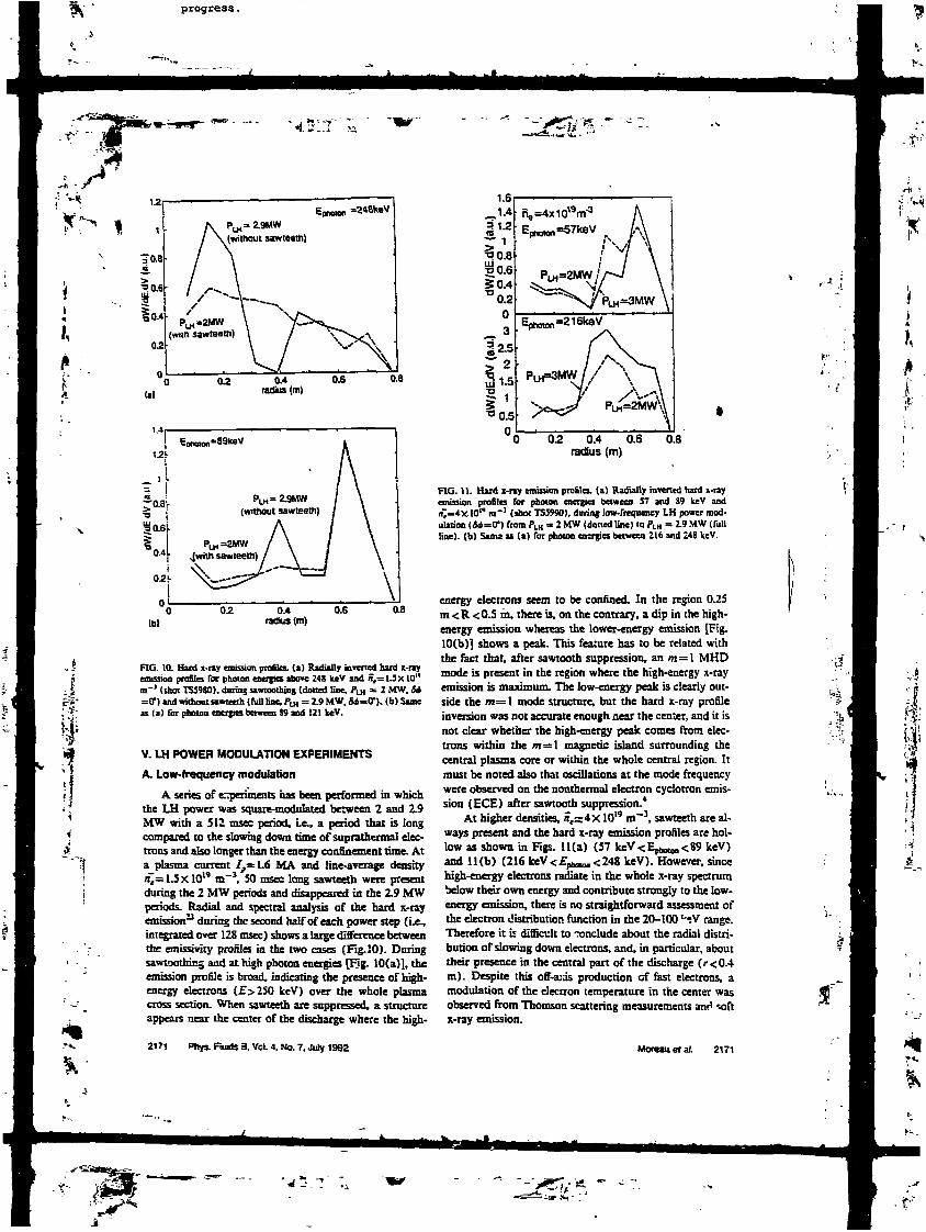
"*£•
(il0.4
radius (m)
i.4r
1.2".
(hi0.4
radius (m)0.6 0.8
FIG. IQ- Hard x-ny emission profila, (a) Radially inverted hard x-rayemission profiles for photon energies above Z48 keV and «,= 1.5 X10"m"' (shoe TSÎ980). during sawtoothing (dotted line. PIM = 2 MW, U=7) and without sawteeth (foil Hne. P1x = 19 MW. Sd=OT). (b) Samea la) for photon energies between 39 and 121 keV.
V. LH POWER MODULATION EXPERIMENTS
A. Low-frequency modulation
A series of experiments has been performed in whichthe LH power was square-modulated between 2 and 2.9MW with a 512 msec period, i.e., a period that is longcompared to the slowing down time of supiathermal elec-tions and also longer than the energy confinement time. Ata plasma current /,= 1.6 MA and line-average density/t~= 1.5 XlO19 m~J, 50 msec long sawteeth were presentdaring the 2 MW periods and disappeared in the 2.9 MWperiods. ^Radial and spectral analysis of the hard x-rayemission11 daring the second half of each power step (Le.,integrated over 123 msec) shows a large difference betweenthe emissiviry profiles in the two casre (Fig. 10). Duringsawtoothing aad at high photon energies [Bg. 10(a)], theemission profile is broad, indicating the presence of high-energy electrons (£>250 keV) over the whole plasmacross section. When sawteeth are suppressed, a structureappears near the center of the discharge where the high-
2171 Phys. Runts 3. VoL 4. No. 7, July 1992
1.6
1.4
«
50.4' 0.2
O3
S 1-5
"°0.5
ne=4x10¹⁹m'3
Eoh<Mon=216k8V
02 0.4 0.6radius (m)
0.8
FlG. U. Hard x-ny emission profiles, (a) Radially inverted hard x-rayemission profiles for photon énergies between 17 and 89 keV and/i~=4X.IO" m'1 (shot TS5990), during low-frequency LH power mod-ulation (M=OT) fromP1x = ZMW (dotiedline) toPLH = 2.9MW (fullline), (b) San: as (a) Tor photon energies between 216 and 248 keV.
energy electrons seem to be confined. In the region 0.25m<R<0.5 m, there is, on the contrary, a dip in the high-energy emission whereas the lower-energy emission [Fig.I0(b)] shows a peak. This feanire has to be related withthe fact that, after sawtooth suppression, an m= I MHDmode is present in the region where the high-energy x-rayemission is maximum. The low-energy peak is clearly out-side the m=l mode structure, but the hard x-ray profileinversion was not accurate enough near the center, and it isnot clear whether the high-energy peak comes from elec-trons within the m=\ magnetic island surrounding thecentral plasma core or within the whole central region. Itmust be noted also that oscillations at the mode frequencywere observed on the nonthermal electron cyclotron emis-sion (ECE) after sawtooth suppression.4
At higher densities, n,=4x 10" m"1, sawteeth are al-ways present and the hard x-ray emission profiles are hol-low as shown in Figs. ll(a) (57 keV<Ep6010n<89 keV)and 1Kb) (216 keV<£phaKln<248 keV). However, sincehigh-energy electrons radiate in the whole x-ray spectrumbelow their own energy and contribute strongly to the low-energy emission, there is no straightforward assessment ofthe electron distribution function in the 20-100 utV range.Therefore it is difficult to include about the radial distri-bution of slowing down electrons, and, in particular, abouttheir presence in the central part of the discharge (r<0.4m). Despite this off-axis production of fast electrons, amodulation of the electron temperature in the center wasobserved from Thomson scattering measurements and softx-ray emission.
MOT eau et al 2171

RG. 12. Time delay For the appearance of the heat source venus minorradius during high-frequency modulation experiments (n,=4x 10" m"1.PLH = 1-9 to 2.9 MW) with O- antenna phasing and -i-W phasing.
B. High-frequency modulation
In an attempt at determining the physical origin of thiscentral temperature increase, power modulation was ap-plied on a shorter time scale, i.e., of the order of the slow-ing down time of the fast electrons. It was then found thatthe apparent heat source was delayed in time with respectto the rf power when moving toward the center of thedischarge.4
This delay time reaches 14 msec at the plasma center(Fig. 12) and is comparable with the slowing.down time ofthe resonant electrons. From these experiments we con-clude that the central heating cannot be due to local ab-*orption of rf power. Rather, it can be due to some inwardheat transport1* or fast-electron transport, or alternatively,to an improvement of the confinement in the center of thedischarge. The modulation of the central heating rate isindeed small enough to be explained by a 20% reduction inthe local heat diffuâvity with a constant Ohmic heatingsource alone. Local changes in the magnetic shear couldpossibly explain a reduced heat transport, but they seemunlikely to take place on this very short ( 14 msec) timescale.
On the other hand, assuming that the heating is causedby anomaloub transport of fast electrons23 would yield alarge diffusion coefficient (D8n, = IO mVsec) or a largeconvection velocity (F0n, - 25 m/sec) for these particles.Magneticjurbulence theories2"7 with magnetic field fluc-tuations 3/B0 of the order of ICF4 would indeed supportsuch large diffusion coefficients of suprathermal electrons,and have been also proposed in JET as underlying theobserved nonthermal ECE decay after pellet injection inr ja LH-driven discharge.28
Vl. PELLET FUELING DURING LOWER-HYBRIDCURRENT DRIVE
Injecting pellets during steady high-power LH pulseresults in a poor pénétration of the pellets29-30 because ofthe presence of the suprathermal electron population.However, there is a large difference between the decay time
2172 Phys. Buds 8. VoL 4. No. 7. July 1992
40
I30
O)
I1a.o <ng> = £5 x 1O19ITT3
. <ne> = 2.0 x 10'9nr3
= 1.8 x 10¹⁹m'3
= 1.4 x 10'9rrr3
0O 20 40 60 80time deiay (ms)
100
FIG. 13. Pellet penetration length Tor various volume-averaged plasmadensities versus time delay between LH power switch off and pellet injec-tion. Pelleis are injected at a speed of 600 m/sec.
of this population, and the resistive time over whichchanges in the plasma current profile can take place. Tak-ing advantage of these distinct time scales, we have studiedthe possibility of using repetitive pellet injection in mixedOH-LH discharges by switching the LH power off duringa short time before each pellet injection and resuming LHoperation just after ( 10 msec) the pellet has been launched.
As shown in Fig. 13, the penetration depth of the 600m/sec pellets depends weakly on the delay time after rfswitch off, when this delay time is larger than 30 msec. Onthe contrary, it depends strongly upon the plasma targetdensity, possibly through a temperature profil.!; depen-dence. Then, with a 90 msec delay time, successful pelletfueling was demonstrated during a 9 sec long, helium dis-charge flattop, in which 28 deuterium pellets ware injected(Fig. 14). The pellets could penetrate into the plasmathrough a distance of 32 cm (i.e., almost to half-radius asin Ohmic discharges), and up to 50% to 80% of the pelletcontent were then deposited into the plasma, thus raisingthe line-averaged density to ne=4x 10" m~3, while Z^dropped from 4.5 to about 2. The average loop voltagededuced from the slope of the flux consumption curve onFig. 14 was almost constant at a value of 0.6 V during theLH pulse, despite the density increase. A total of 2.6 volt-seconrls were thus saved during this shot. This has not beenoptimized, but rough estimations show that it still repre-sents about half of what would have been saved if the samedensity rise had been obtained without the pellet injection,hence with continuous LH power. Figure 15 shows thetime evolution of the density profile after each pellet injec-tion. In agreement with Sec. IV, the global confinementtime increases by about 40% during the density rise, stillfollowing the Rebut-Lallia scaling.
VII. COMBINED LHCD AND ERGODIC DIVERTOROPERATION
TORE SUPRA is equipped with a set of six water-cooled ergodic divertor (ED) coils mounted inside the vac-
Moreau el aL 2172

Q 2 * S 8 10 12 14 16
-'J*'-.*(-
FIC. 14. Time évolution or thé main plasma parameter! during a 9 seclong repetitive deuterium pellet injection (23 pellets) in at LH-drivenhelium discharge (shot TS6035). The 2 MW LH power (M-QT) isswitched off 90 msec before each pellet injection and resumes IO msecalter the pellet has been fired.
uum vessel and producing either a set of magnetic islandsat the plasma edge or an crgodic boundary layer, depend-ing on the current /HJ circulating in the coils."'32
At large LH powers, a number of hot spots were gen-erally observed on the inner graphite wall of the plasmachamber. They were caused by a misalignment of this highfield side wall with respect to the toroidal field coils (up to6 mm), and this has now been corrected for the next ex-
E2 3°
1-
pelletinjection : t = O
RF on : t = +10mso : t = -4ms+ : t = +33msx : t = +71ms»: t = +108ms
O t 2 3 4 5 5 7 8 9 10
O 0.2 0.4 0.6 0.8 1normalized racfius
FIG. IS. Evolution of the demon density profile (deduced from Thom-son scattering) during combined LHCO and pellet fueling for the sameshot as in Fig. 1*.
2173 Phys. Hums 3. Vol. a. No. 7. July 1992
FIC. 16. Time evolution of some plasma parameters during combinedLHCD (P11I = 3.3 MW, M=OT) and ergodic divenor operation( Ifo= 18 kA) producing a MARFE and radiating 90?» of the inputpower (shot TS5674).
perimental campaign. At /ED=36 kA, i.e., just above theergodicity threshold, the number and magnitude of hotspots in the field of the camera were reduced, sometimes toOhmic levels, presumably because the ergcdic boundarylayer redistributes more uniformly the power load on theplasma-facing components.
At lower currents in the ED coils (/ED = 18 kA), i.e.,below the ergodicity threshold, and fer a safety factorqa=2.9, stationary MARFE's were triggered, which werelocked near the high field side wall on which the plasmawas bounded. These occurred for LH powers above 2 MW,were maintained during the whole combined LH+EDphase, and were triggered when pm=ira2<n,)//(I=0.12,i.e., below the usual MARFE limit. During such shots, theratio of the total radiated power to the input power in-creased from 30% in the OH phase, to 50% in the LHphase and then to about 90% throughout the LH+ED/MARFE phase, while the density kept increasing up to afactor 3 above its Ohmic value with no indication of aradiative collapse or density limit disruption (Fig. 16).3j
The line-averaged density rose *ypically from 2X10¹⁹ m~3
during the LH phase to 3 X10¹⁹ m~3 during the combinedLH+ED phase.
VIII. SUMMARY
A maximum of 6 MW of lower-hybrid power havebeen coupled in TORE SUPRA through two multifunctionlaunchers, i.e., at a power density level in the waveguidesthat is relevant for next-step fusion devices such as ITER.
Moreauera/. 2173
w
it«
K
\\
The currer-t drive efficiency was of the older of 2X10" Ant~Vw at volume-averaged temperatures not exceedingL4 keV. A rf-driven current of 850 kA was obtained at aline-averaged density n,=4x IQ19 m~\
Increasing the total injected power from the Ohmiclevel to 7.S MW (including some combined LH+ICRFshots), and with a plasma currert /p=1.6 MA, the globalconfinement time decreavs from 0.3 to 0.1 sec. It exhibitsa much larger density dependence than the ITER 89-Pscaling would predict, and is in better agreement with theoffset linear Rebut-Lallia scaline.
At densities it.=1.5 X10" m~3 and If= 1.6 MA, saw-teeth are stabilized with PLH >- MW. and m=l MHDactivity is observed. The central electron temperature thenreaches S keV witù P1x = 3.6 MW.
As far as long-pulse operation is concerned, a 22 seclong OH -}• LH quasistationary discharge has been achieved(/.,=1.6 MA, «e=3 x 10" m-3, PU, = 2.8 MW) in whichthe resistive flux saying due to LH waves amounts to 10Wb. The LH-rOH ramp-up experiments were character-ized.by a maximum resistive flux saving efficiency -_5ra=0.7xl019 WbUi-1XMI for PU, = 0.4 MW anddl/dt=0.4 MA/sec. A MHD-stable domain exists in the(Pu1, uET/<fr)plane indicating that, in the mixed LH/OHregime, current ramp-up rates can be made larger than inthe pure Ohmic one by driving enough noninductive cur-rent on axis.
A total of 28 successive pellets have been injected in apartially LH-driven discharge, thus allowing the density torise to ne=*X 10" m~3. This could be achieved by switch-ing off the rf power during 90 msec long periods beforeeach pellet injection, Le, without modifying significantlythe current density profite.
Finally, the application of a magnetic perturba Son inthe edge from ergodic divenor coils during LHCD trig-gered an inner-wall MARFE for. the whole LH+ED ~phase, during which the density rose up to three times itsOhmic vaine and the radiated power reached 90% of thetool input power without causing a plasroa disruption.
ACKNOWLEDGMENTS
The authors would like to thank the whole TORESUPRA tfchniral staff for making these data available.Collaboration agreemems bewrem the Euratom-CEA As-sociation and the ILS. Department of Energy on one handand the Centre Canadien de Fusion Magnétique on theother hand proved very fruitful in obtaining tfa-y? results.Stimulating »«cm«ar»« with S- Bernabei, P. Bonoli, R.Harvey, and V. Fochs through these agreements arewarmly acknowledged. The centrifugal pellet injector wassupplied fay the Oak Ridge National Laboratory.
'FfytprTORE SUPRA (presented Oj R. Aymar), in Kama Physicssarffrnmtffrrf-VVJm-Bain» g>mprir Prra— K.ip/J.h- YUh ItIKT-
saaonal Caaereacc. Nice. 19« (IAEA. Vienna. 1989). VoL 1. p. 9.-Equipe TORE SUPRA (presented by F. Pariange). at. Pbaraa PhyHaas^CamaaOeeXmcienTlTaam ROBTC*. Proceedings of the 13th Inter-Baâoca! Cxfexcncc. Wrianpir-, 1990 (IAEA. Vienna. 1991) VoL 1.P-StS.
217«
'Equipe TORE SUPRA (presented by G. Tonon), in Proceedings of thelEEEHthSymposium m Fusion Engineering, San Diego, 1991 (IEEE.New York, in press).
4D. Moreau. the TORE SUPRA Team, and C Garmczano, PlasmaPhys. Controlled Futon 33. 1621 ("/^ 1), and référença therein.
'The JET Team (presented by P. P. Rebut), in Plasma Physics andControlled Nuclear Fusion Research. Proceedings of the 13th Interna-tional Conference, Washington, 1990 (IAEA, Vienna, 1991), Vol. 1, p.27.
4D. Moreau and T- K. Nguyen, in Proceedings of Oie I984 InternationalConférence on Plasma Physics, Lausanne. 1984, Proceedings Contrib-uted Papers, edited by M. Q. Tran aid M. L. Sawley (Centre de Re-cherches en Physique des Plasmas, Ecole Polytechnique Fédérale deLausanne. Lausanne, Switzerland, 1984), Vol. I, p. 216.
7X. Liiaudon and O. Moreau, Nud. Fusion 30. 471 ( 1990).1X. Litaudon, G. Berger-By, P. Biber. J. P. Bizarra. J. J. Capitain. J.Carrasco, M. Goniche. G. T. Hoang. K. Kupfer, R- Magne, D. Moreau,Y. Peysson, J. M. Ru, G. Rey, O. Rigaud, and G. Tonon, submitted toNucLF\s>on.
'J. G. Wegrowe and G. Tonon. in Proceedings of the IAEA TechnicalCommittee Meeting on Non-Inductioc Current Drive in Tokamaks, ed-ited by D. E H. Stan (Culham Laboratory. Abingdon. England, 1983),VoL II, p. 3*3.
10M. J. Maybeny, M. Porkolab. K. I. Chen, A. S. Fisher. D. Griffin, R.D. Kaplan. S. C Luckhardt, J. Ramos, and R. Rohatgi, Phys. Rev.LeK. SS. 829 (1985). _ - -
"C Gormexano. G. T. Hcang, G. Agarici, H. Bottollier-Cunei, P. Bri-and. G. Brifiod, P. Chabert, M. Cément, C. David. A. Girard, M.Goniche. P. Grelot, W. Hess. M. Hesse, G. Ichichenko, A. Panzarella.F. Pariange. F. Ryter, G. Tonon, J. C Vallet, and D. Van Houtte, inProceedings of the 13th European Conference on Controlled Fusion andPlasma Heating. Schliersee (EPS. Geneva. 1986). Vol. 1OC. Part II, p.311.
12C F. F. Karney and N. 1. Fisch, Phys. Fluids 29. 180 ( 1986).11D- Moreau, 1. M. Rax. and A. Samain. Plasma Phys. Controlled Fusion
31. 1895 (1989)."D. Van Houtte, M. Talvard. E. Agosuni. C Gil. G. T. Hoang, P.
Lecoustey. F. Pariange, L. Rodriguez, and J. C. Vallet in Proceedings ofthe 18th European Conference on Controlled Fusion and Plasma Physics,Berlin (EPS, Geneva. Switzerland, 1991), Vol. 15C, Part I. p. 61.
"The ASDEX Team. Nud. Fusion 29, 1959 ( 1989).11F. X. Soldner. F. Leuterer. M. Bramoills. R. Bûchse. H. U. Fahrbach.
O. Genre, K. McCoimrck, M. Munich. H. D. Mumunn. K. H. Steuer,H. Zohm. M. Zouhar. R. Baniromo. R. Cesario, R. De Angelis. L.GabeUieri, V. Pericoli-Ridolfini. A. A. Tuctillo. S. Eonabei. T. K. Chu.H. Takahashi. R. W. Harvey. M. G. McCoy, and K. Ushigusa, inPlasma Physics and Controlled Nuclear Fusion Research, Proceedings ofthe 13th International Conférence. Washington, 1990 (IAEA, Vienna,19911. VoL 1. p. 613.
"The JET Team (presented by J. Jacquinot), Plasma Phys. ControlledFusion 33, 1657 (1991).
"C. Gonnezanb, M. Brasaa. A. Ekedahl. P- Froissard, J. Jacquinot, andF. Rimini, in Proceedings of-Ht IAEA Technical Committee Meeting onFast Wane Current Drioe in Reactor Scale Tokamaks. Aries, 1991. ed-ited by D. Moreau, A. Becoulet. and Y. Peysson (Département deRecherches sur Ia Fnskm Contrôlée, Association Euratom-CEA, Centred'Etudes de Cadanche, Saint Paul Id Durance, France, 1992).
"P. N. Yushmzaoï. T. Takizuka. K. S. Riedel. O. J. W. F. Kardaun. J.G.Cordey.S.M.Kaye.andD.E.Post.NueLFusion30.1999 (1990).
30K. Tfmahrrhi, in Plasma Physics and Controlled Nuclear Fusion Re-search, Proceedings of the 12th International Confernux. Nice, 1988(IAEA, Vienna. 1989), VoL 3. p. 215.
21R. Parker. M. Greenraid. S. Luckhardt. E. Mannar. M. Porkolab. andS- Wolfe, Nud. Fusion 25. 1127 (1985).
3P. H- Rebut, P. P. Lallia. and M. L, Watkins. in Plasma Physics andCaearotttd Nuclear Fusion Research, Proceedings of the 12th Interna-tional CouTerbice, Nice. 1988 (IAEA. Vien.A 1989). Vol. 2. p. 191.
23Y. Peysson. J. P. Bizano. G. T. Hoang, A. Hubbard. X. Litaudon. D.Morean. C Poiion-Pocheau. and J. M. Rax. in Proceedings of the 18thEuropean Conference on Controlled Fusion and Plasma Physics, Berlin(EPS, Genen. Switzerland. 1991), VoL 15C. Pan IV. p. 34S.
"T. C Luce. C C. Petty, and J. C M. de Haas. Phys. Rev. Lett. 68. 52(1992).
3J. M. Rax and D. Moreau, NucL Fusion 29. 1751 ( 1989).
Matesuetal. 2174
Pre rint of a per preswted M the Tenth Topical Conference on
ong 3 ea y p aamaa in v i e e iinjection like deep fuelling, density profile control. "PEP" mode confinement.
I
I*
KÀ
:°X. Garbet. F. Mourgues. ind A. Samain. Plasma Phys. Controlled Fu-rion32.917(|990).
:TP. H. Rebut and M. Hugon. Plasma Phys. Controlled Fusion 33. 1085(1991).
9A. Gondhaldiar. R. Mardn-SoUs. D. Bardett, M. Brusati. P. Fratssard,M. Hugon. P. Rimini, and C Tana, Bull. Am. Phys. Soc. 36. 2367(1991).
3F. X SôMner. V. Menens. R. Baniromo. H. S. Bosch. M. Komherr. R.Lang. F. Ltuterer. R- Loch. W. Sandmann. and K. Ushigusa. PlasmaPhys. Controlled Fusion 33,405 ( 1991 ).
10B. Pégourié ind Y. Peysym. in Protttdings of the /7(A Europtan Con-fmnee an Controlled Fusion and Plasma Healing, Amsterdam (EPS,Geneva. Switzerland. 1990). Vol. 14B. Pan III. p. 1227.
]IA. Grosman. M. H. Achard. P. Chappiw, J. J. Cordier. P. Deschamps,E. Gauthier, and M. Lip». J. Nucl. Mater. 142-1«. 162 ( 1989).
11A. Samain. T. Blenski. P. Ghendrih, and A, Grosman, Contrib. PlumaPhys. 30. 137 (1990).
"T. E. Evans. M. Caniche. C. De Michelis. D. Guilhem. W. Hess. M.MattioU. P. Monier-Garbet. J. C Vallet. and the LH Group. BuU. Am.Phys. Sac. 36, 2367 (1991).
!••'4
J£•-#•
I
. î
i
2175 Phys. Fluids B. VoL 4. Na 7. July 1992MoreauetaL 2175
fcThis could be achieved by switching off the LH power during 90 ms long periodsbefore each pellet injection, i.e. without modifying significantly the currentdensity profile.
INTERNATIONAL ATOMIC ENERGY AGENCY
FOURTEENTH INTERNATIONALTSONFERENCE ON PLASMAPHYSICS AND CONTROLLED NUCLEAR FUSION RESEARCH
Wurzburg, Germany, 30 September - 7 October 1992
KA
IAEA-CN-56/ E.2.1(C
RF HEATING AND CURRENT DRIVE IN TORE SUPRA
D. MOREAU, B. SAOUTTC, G. AGARICL B. BEAUMONT, A. BECOULET,
G. BERGER BY, P. BmET, J. P. BIZARRO. J. J. CAPITAIN, J. CARRASCO,
T. DUDOK DE WTT. C GIL, M. GONICHE, R. GUIRLET, G. HASTE1, G. T. HOANG,
E. JOFFRIN, K. KUPFER, H. KUUS, J. LASALLE, X. UTAUDON, M. MATTIOLI,
A. L. PECQUET, Y. PEYSSON, G. REY. J. L. SEGUI, G. TONON. D. VAN HOUTTE
!Il\
4
1
AssociatiooEURATOM-CEA
Département de Recherches sur la Fusion Contrôlée
Centre d'Etudes de Cadarache
13108 Saint-Paul-Lez-Durance Cedex, France
1 Oak Ridge National Laboratory, Oak Ridge, Tennessee, U. S A.
~ This a a preprint of a paper inundad for pretantation at a scientific mating. Bacauta of the provisional nature of ft*contant and since changes of subnanca or daua may hawe to be mad* bafora publication, ttw preprint is made available on theunderstanding that it will not be chad in tfw Kteratum or In any way b« reproducad in hi prasant form. The views expressed andthe statements made remain the ratporaibUity of the named authorfa); tha views do not nacaoarilv reflect thow of the govern-ment of the designating Membar Stata(s) or of tha designating organizationd). In partfeular, ntittitr On IAEA nor my otftarargtnUfDoa or body sponsoring Oilt mttting em bt hakt mpoiaiblm for my mmriil npmduad in Oik pnprint.

,It
-1- IAEA-CN-56/E-2-KC)
RF HEATING AND CURRENT DRIVE IN TORE SUPRA
D. MOREAU, B. SAOUUC, G. AGARIQ, B. BEAUMONT. A. BECOULET1
G. BERGER BY. P. BIBET, J. P. BIZARRO, I. L CAPITAIN, J. CARRASCO.
T. DUDOK DE WTT, C. GIL, M. GONICHE, R. GUIRLET, G. HASTE1, G. T. HOANG,
E. JOFFRIN, K. KUPFER, H. KUUS, J. LASALLE, X. LTTAUDON, M. MATTIOLI,
A. L. PECQUET, Y. PEYSSON, G. REY, J. L, SEGUI. G. TONON, D. VAN HOUTTE
Association EURATOM-CEADépartement de Recherches sur la Fusion Contrôlée
Centre d'Etudes de Cadarache13108 Saint-Paul-Lez-Durancc Cedex, France
<••* . ;
Abstract
RFHEATINGANDCIIItKENTDRIVEINTORESUFRA
Recent lower hybrid and ion cyclotron heating experiments are reported with emphasis onphenomena related to profile control and having stationary potentialities. Long pulse operation
(67 seconds, 1 MA) has been very successful, with an equivalent of 41 Wb saved. Flux
consumption during current ramp-up is investigated and a scaling based on 1-D theory is given
and compared with experimental results. The existence of a stationary, enhanced performance
regime (LHEP) with improved confinement and reduced magnetic shear inside a high temperaturegradient zone Cq0 -1.2, T,o - 8-10 keV) has been found, showing complete decoupling between
die election temperature and current density profiles. The beneficial effect of boron carbide coating
on the ICRH Faraday screens is assessed and the duration of sawtooth-free periods increased andreached 830 ms during combined ICRH/LH operation.
Oak Ridge National Labcramy. Oak Ridge, Tennessee. U.S.A.
-2- IAEA-CN-56/E-2-KC)
1. INTRODUCTION
An important paît of the physics program on TORE SUPRA [1] is devoted to the study of
RF heating and non-inductive current generation. The main motivations for this research are toinvestigate the confinement properties of - either full, or partly - driven plasmas and also toprovide the necessary flux savings for achieving long pulse operation. Profile control and, in
particular, decoupling of the electron temperature and current density profiles are ultimate goalswhose achievement may be necessary to ensure plasma stability in a reactor during the variousphases of the pulse (current ramp-up, plasma heating to ignition and high p, ramp-down and
transformer recharge), with respect to a variety of modes (sawteeth, tearing, ballooning, etc...).
Experimental results in this area are crucial for understanding tokamak scaling laws and selecting
between a number of reactor scenarios. The feasibility of a steady-state, large aspect ratio tokamakwith a large bootstrap component is also to be assessed in the long term, and in this respect the
TORE SUPRA superconducting tokamak is a unique operating facility.
Ih this paper, we shall report on the major results obtained along these lines, at 3.9 Testas,with both die lower hybrid (LH) and the Ion Cyclotron Resonance Heating (ICRH) systems.
2. LOWER HYBRID HEATING AND CURRENT PROFILE EFFECTS
2.1. Wave coupling, power handling and long pulse RF operation
A description of the LH system can be found in [2,3] together with an overview of pastexperiments, including some important results which will not be repeated here. A maximum RFpower of 6.5 MW at 3.7 GHz have been coupled through two multijunction launchers for
2 seconds, and the power density level in the waveguides reached 45 MW/m2 in some modules.In a series of coupling experiments in which the plasma was lying against die inner wall, the
launcher has been pushed away from the plasma boundary up to distances exceeding 10 cm. The
global reflection coefficient was a few percents and coupling was well described by theory [4].
During the longest plasma shot, die total injected LH energy reached a record value of170 MI during a 62 second LH pulse, at a power level of 2.8 MW corresponding to an averagedpower density of 17 MW/mi2.
2.2. LH driven quasi-stationary plasmas
The maximum current drive efficiency, y, was of the order of 2 x 10¹⁹ Am'2/W for a
total plasma current I9 = 1.6 MA and at volume-averaged temperatures not exceeding 1.4 keV.The OH-LH synergism was still significant, giving apparent efficiencies of 3.5 x 10¹⁹ Am"2/W
2165 Phys. Fluids 3 * (7), July 1992
*z\i *S.'«r »• - •
-3- IAEA-CN-56/E-2-KC)
below I MW. With H8 = 1.5 x 10¹⁹ nr3, lp = 1.6 MA and PLH = 4.8 MW, the plasma loopvoltage dropped by 90%. Sawteeth disappear with PLH » 2.9 MW but large m=l oscillations arepresent. At Ip = 0.8 MA and H6 = 2.2 x 10¹⁹ m'3, the loop voltage vanishes withPLH = 2.9 MW. giving y = 1.5 x 10¹⁹ Am'2/W.
Thanks to the LH primary flux saving (41 Wb), a 67 second long/1 MA quasi-stationaryinner wall discharge has been achieved, with a one minute flat-too and a central density of3.5 x 1019 nr3 [1-2]. The plasma was vertically swept (±4 mm) with a 16 s period in order tospread the heat load. About 0.8 MA was due to the presence of LH waves and "ray-tracing/adjoint" computations show mat ripple losses amount to less than 1% of the power. At aplasma current of 1.3 MA and a central density of 4.5 x 10¹⁹ nr3 the maximum pulse length was42 seconds.
2.3. Flux consumption scaling and profile control during current ramp-up
Transforming the usual current drive figure of merit, Y, into a figure of merit which ismachine-size-indcpcndent (C1C5) for the resistive flux economy, AiJtn,, leads to the definition [3] :
Ka ne
It is a measure of the current drive efficiency (equivalent to y) boosted by the effective loop voltage(V1J5) in the plasma. Thus, extrapolations and/or optimizations regarding surface flux consumptionare not straightforward on the basis OfCn* A more appropriate scaling can be found from Q-Dconsiderations and has been confirmed by 1-D numerical calculations (fig.1), taking into accountprofile effects, as well as time varying plasma boundaries. For a given current increment, AIp,around Ip, this scaling relates the surface flux consumption, AOn^ normalized to the inductiveflux, AO*=Leff Alp. to the LH power normalized to the power. P*. which steadily drives the fullcurrent It reads:
A4*
where TC, = (dL/Ipdt)"1 and Tn,=l^g/R^ the ratio of the effective inductance and resistance of
the plasma is profile dependent. The left hand side represents a normalized flux economy withrespect to the inductive flux, Le. with the convention that it is positive when the plasma is"overdriven" by the RF (P1 > P*. V^ < O), a situation which could occur in the current initiationphase, and where T tn, should be mmmaifA QOW ramp-up rate, low conductivity).
Experiments performed at various ramp-up rates with n^ between 1 and 2 x 10¹⁹ nr3
were always in the "unaerdriven" *egime (minimum. \U\^. Some shots are represented on fig.l.
é
Ij
%:*
-4- IA :N-56/E-2-l(C)
They were characterized by Çres = 0.25 x 10W Wb.nr VMJ above 1 MW, whereas Ci» variedbetween 0.5 and 1.5 x 10¹⁹ Wb.nr!/MJ for Pw < 0.5 MW [S]. The minimum achievable TIP was
limited by MHD stability, but a stable domain exists in the (PLH. dlp/dt) plane indicating that byusing an adequate amount of LH power (which increases with increasing ramp-up rate), thecurrent profile can be controlled, leading to a higher internal inductance Oi) than in the ohmic case.Highest phase velocities led to the maximum increase of I1, In another set of experiments,
imposing a constant voltage on the primary circuit and 2 MW LK power, the plasma current rose
freely to 2.1 MA at a rate of a 16 MA/s without MHD activity.
2.4. Profile decoupling and lower hybrid enhanced performance (LHEP)
At Ip = 0.8 MA and n, between 2 and 3 x 10¹⁹ nr3, fully and even overdriven
discharges (transformer recharge) are obtained either by applying the LH power (<• 3 MW) during
a current ramp-down phase [61 or directly on the flat-top (flg.2a). These discharges exhibit animproved global confinement (up to 40%) with respect to other discharges which generally followthe Rebut-Lallia scaling [7]. Small sawteeth disappear as soon as the LH power is applied. 1} is
larger than in the ohmic phase but the current density decreases on axis where the safety factor, q,varies from 1 to about 1.2 (jpolarimetry). so that there should be no m-1 mode. Then, about onesecond after a slight decrease of Ae central electron density (similar to die one observed in some
ECRH experiments), the discharge enters a stationary phase where the electron temperaturestrongly peaks within r/a < 0.4, and the central temperature, T60, rises to about 8-10 keV
(fig.2b). Central hard X-ray emission remains constant below 150 keV (LH accessibility) andslightly decreases at higher energies, so a sudden increase of die central power deposition isunlikely to occur. Within dus region, the density profile rises to become flat again, the electrontemperature gradient increases, and die normalized (ballooning) electron pressure gradient,a = (2(I0Rq2TB2) x (-dp/dr). reaches locally 0.2 or more depending on the local value of q.
Then, switch-off or partial breakdowns of the RF power generally lead to a minor disruption, T80
suddenly crashing to Us initial level while strong MHD activity appears.
From the analysis of the time variation of qg (q on axis) at the RF turn on, we know that
the LH current profile is flatter than die ohmic one at die center of the discharge, Le. that themagnetic shear is reduced. Simulating the effect of resistive diffusion on die time dependence ofqo loop voltage and Ij, it is possible to estimate the change in die current profile, relative to anassumed (consistent with q9 and I^ ohmic one (fig.3). We cannot conclude on the value of the
shear, bu» noting that die maximum bootstrap current density amounts to 10-15 % of the total
current density on axis and is localized near the maximum pressure gradient, we are led toconsider me possibility that die observed stationary lower hybrid enhanced performance (LHEP)is triggered by a small - perhaps negative as in die PEP phase of JET [8] - shear in die centralregion, thanks to die total decoupling of die temperature and current density profiles.

-5- IAEA-CN-56/E-2-KC)
3. ION CYCLOTRON RESONANCE HEATTNG
3.1. Effect of boron carbide on the antenna and heating performances
The ICRH system (35-80 MHz) is composed of three Resonant Double Loop antennas [9].
Originally, they wen equipped with carbon brazed tiles Faraday screens (FS). To allow long
pulse operation, new FS with cooled septum, tubes tilted along the magnetic field and boron
carbide coating have been developped and installed on two antennas. Four seconds, 3.6 MW
pulses are routinely coupled to the plasma with a single antenna, and even up to 4 MW have been
coupled, allowing to reach a record power density through die FS of 16 MW/m2. Thirty seconds,
steady-state RF pulses have teen obtained, the antenna thermal equilibrium being reached after 12
seconds. Up to 54 MI in a pulse have been delivered to the plasma.
Having both types of FS mounted on the machine has allowed a thorough comparison of
the two systems. The new design shows improved performance. The vacuum RF losses in the
antenna have been reduced by a factor of 4 and the plasma loading improved typically from 2 to2.5 n/m. However, the major benefit is a significant reduction of the total power radiated by the
plasma, both in monopole and dipole configurations. Data from UV spectroscopy, soft X-ray and
visible Bremsstralhung have been analysed using an impurity transport code [101. They clearly
show that both antennas produce the same amount of caibon which accounts completely for themeasured Z^ (< IJ). The different behaviours of the radiated power are only due to heavy
impurities. Their production remains quite negligible though and cannot account for the
disruptions observed during monopole operation with the old FS. It was found that disruptions
are due to thermal loading rather than RF induced impurity production. No such limitation has
been encountered with the new FS and the analysis of its behaviour after 5 months of operationdoes not show any significant erosion of mis 150 Um boron carbide coating.
3.2. ICRH "monster" sawteeth in ohmic and LH driven plasmas
When operating in the hydrogen minority heating scheme, dipole configuration, with the
resonance on the magnetic axis (± 6 cm), and with reduced-size inner wall target plasmas
(R=2^8 m, a=0.72 m), sawteeth-free periods [8] are observed. The range of plasma parametersin which stabilization occ-ns is H6 between 3 and 5 x 10¹⁹ or3, L, between 1.3 and 1.7 MA,
and the threshold power is 3 MW. As seen on other machines, the neutron yield and plasma
energy content continuously rises until the sawtooth collapse, although the central electron
t&upciature saturates. This results in a 15% increase of the confinement time.

. rimas a. VQI. i, no. /, JUty I
-
-6- IAEA-CN-56/E-2.1(C)
As in JET, an m=2/n=l mode grows after the collapse, preventing any new stabilizationuntil it disappears (fig.4a). A number of ripple-trapped fast ions are systematically lost at the endof the rising phase of the "monster" sawteeth but no MHD activity has been detected on magneticloops or soft X-rays during these losses. A possible explanation is that during the rise of thesawtooth, the expanding q=l surface enters the ripple-loss region so that hot ions originallyconfined within this flux surface are expelled from the plasma.
Another consequence of the continuous expansion of the q=l surface and concommitantdecrease of qo is the eventual occurence of the sawtooth collapse. Preliminary experiments using
LH current drive have been carried out to possibly prevent this evolution by partly decoupling thecurrent profile from the electron temperature. As shown on fig.4b, the duration of the sawtooth-free periods increases up to 830 ms with increasing LH power.
4. CONCLUSIONS
A number of interesting RF phenomena have been observed on TORE SUPRA concerningplasma heating, confinement and long pulse operation. Lower hybrid current profile control isthought to play an important role for primary flux saving and plasma stability during ramp-up.
The injection of LH power allows a strong decoupling between the central electrontemperature and the current density profile leading to enhanced performance and improvedconfinement in stationary plasmas. It may also be responsible for increasing the duration of ICRHsawteeth-free periods to 830 ms during combined ICRH/LH.
The use of tilled, boron carbide coated Faraday screens, with cooled septums, is highlybeneficial for me overall ICRH performance.
REFERENCES
[1] EQUIPE TORE SUPRA, this conference, paper IAEA-CN-SoTA-M.
[2] TONON, G., EQUIPE TORE SUPRA, Proc. Europhys. Top. Coitf. on Radiofrequency
Heating and Current Drive of Fusion Devices, Brussels, July 1992, to be published in PlasmaPays. Control. Fusion.
[3] MOREAU, D.. TORE SUPRA TEAM. Phys. Fluids B 4 (1992) 2165.
[4] LTTAUDON, X., et aL, Report EUR-CEA-FC-1443, to be published in NucL Fusion (1992).

2169 Phys- Ws B, vol. », wo, (
Figurel

•1\ -T
!l
1
10.80.60.40.2
O
1
0.5
O
1.5
1
0.5
O
3
2
1
O
8642O
0.2
0.1
0.2
0.1
Ip(MA)
325 keV (x 4)
X-ray power emission
(keV.MW)
Ii
<Io
8 10 12 14 16 18 20time (s)
Figure 2*

fc"
2i7t Phys- Ru"* a. vou «. NO. /, -juiy
i
4
3.5
3
2.5
2
ne(x!019m3) 10
8
6
4
Te (keV)
»:t=4t(OH)-t-:t = 6to:t=12»
if-,
O 0.2 0.4 0.6 0.8 1 'O 0.2 0.4 0.6 0.8 1
hi.-- «
0.2
0.15
0.1
0.05
O 0.2 0.4 0.6 0.8 1P
O 0.2 0.4 0.6 0.8 1P
Figure 2b
1

!«•:.-J --;W~
Figure 3a
OHMIC PHASE (t = 4 sec)
~— LH PHASE (t = 10 sec)
0.95
0.1 0.2 OJ 0.4 OJ 0.6 0.7 0.8 0.9
NORMALIZED MINOR RADIUS
Figure 3b
TIME (sec)

1î î
""1jï
Figure 4a
„. ota
I" .. Kï Qn- t ï . . . . •ïl.O 415 42.0 425
• Time (s)
QB
OjS
0-4
O2 -
OJO
Figure 4b
AA
M^
^^
t-I
A
— I— I— L. . I . . , . I . . , , I . , , , I . ,
0-0 OS 1.0 15 2.0. . ! . , . .
25 3.
--M

MA - /*
Preprint of a paper presented at the Tenth Topical Conference onRadio Frequency Power in Plasmas
April 1 - 3, 1993, Boston, MA
LOWER HYBRID ENHANCED PERFORMANCE IN TORE SUPRA
G.T. Hoang, D. Moreau, E. Joffiin, X. Litaudon, Y. Peyssonand Tore Supra TeamAssociation Euraiom-CEA-Dépanement de Recherches sur la Fusion ContrôléeCEN Cadarache, 13108 Saint Paul-lez-Durance, FRANCER.V. Budny, S. Kaye, S.A. Sabbagh*)Plasma Physics Laboratory. Princeton, New Jersey 08543, USA.V.FuchsCentre Canadien de Fusion Magnétique, Hydro-Québec, CANADA
ABSTRACT
The global energy confinement of the constant current discharges in ToreSupra is found to depend on the plasma density. Furthermore, the electron kineticenergy agrees with global Rebut-Lallia prediction1). Current ramp experimentsshowed an increase of the global energy confinement with increasing inductance (Ii)1X These results have been extended to the steady-state regime, in which the energyconfinement time during the 12s LH pulse exceeds the usual L-mode scalings by40%.
EXPEiOMENTAL RESULTS
Shot TS 9044
A series of experiments has been performed using LHCD in current rampdischarges at Ip=0.8MA, Oe(O)between 2.5 x 10¹⁹ m'3 and3 x 10l9m-3, and injected powers,PLH, ranging from 23 to 2.9MW(N//being varied from 1.4 to 2.2).The LH pulse is applied just beforedie plasma current is ramped downfrom 1.7MA to a 0.8MA plateau at arateof-lMA/s.
The time evolution of atypical current ramp discharge isshown in Rg-I. With a 2.7MW/12sLH power application (at N//= 2.2),die non-inductive current constitutesabout 99% of the total plasmacurrent (— 0.7MA), with a bootstrapcurrent, calculated by the TRANSPcode, of the order of 0.1MA. As soonas the LH power is applied, smallsawteeth are suppressed, and noMHD activity is* observed. Thesteady-star- value of Ii reaches 1.7instead of 1.4 obtained in the ohmiccase. It can be seen in Fig. 1 that thetime scale over which Ij varies, andthe relaxation time of the localcurrent density at die center of theplasma are not me same. Ii becomesconstant at t=9s (i.e. 3.6s
10 15titne(s)
FKi. 1: Main parameters of a current ramp discharge. MMA). loop voiugc, Vi(V). ctiunl density. n(OX10" af\
LH PO-O-. ILH (MWX rnanl ioducaoce. Ii. caunl cumnt density fiomTe. efaaim ml iaa kinetic

!I
ii
after the LH application), while the central current density, j(0), continues to decreaseslowly, and reaches a stationary value about 4s later (at t = 13s) due to a strongcentral electron heating. The global energy confinement time shows an enhancementof about 1.4 over both Rebut-Lallia and Goldston (with M = I) L-mode predictions.The density and temperature profiles reach an equilibrium during the LH pulse. Bulkelectrons are heated in the whole plasma volume, leading to an increase of the volumeaveraged temperature, <Te>. by a factor of two (Fig.2). Only a weak increase of theion temperature is observed (Fig.3); this can be explained by low collisionality due tolow density and high electron temperature. In the transient phase (between 5.4s and7s), the central electron temperature, T6(O), rises from 2keV to 6keV and reaches avalue of about 10 keV at the beginning of the constant-li phase. During this constant-Ii phase, the electron temperature profile reaches its peak within the magnetic surfacer/a < 0.3, with a peaking factor, Te(Oy<Te>, between 5 and 6 ( Figs 2 and 3).
.10 15time(s)
FIG.2: Volume-averaged electiontemperature and peaking factor profile(shotTS9044)
Figure 4 shows a constantcurrent, improved confinementdischarge. With the 3MW LH power(at N//=2.2) applied directly on theflat-top , Ii becomes larger than indie ohmic phase but the currentdecreases on the axis. The centralvalue of the safety factor, qv(0),computed by the equilibrium codeIDENTD «sing the polarimetne,interferometric and magneticmeasurements, increases from under1 to about 2 (Rg. 5). The LH currentprofile is found to be flatter than theohmic one in the central region.
During this improvedconfinement regime, the carbon(main impurity) reached a constant
FIG. 3: Electron and ion temperatureprofiles
0.1
B IB8 MTTZtime (s)
FIG. 4: Constant current improvedconfinement discharge (shot 9621)
level with a concentration that is four times higher than that in the corresponding ohmiccase. A comparison of the 'central' CVI radiance with the input carbon flux (from theemission of peripheral carbon lines) seems to indicate that the central impurity

aiganiution or body tpmuoring thl» mtu ngeta • ntpo
confinement time does not change. It is interesting to note the low fraction of radiatedpower, Prad/Ptot » 25%, which is down from 50% in the ohmic case.
CURRENT PROFILE AND TRANSPORT ANALYSIS
Current profile and local transport have been analysed for both high-1; transientand steady-state phases (shot 9044). Figures 5(a) and 5(b) show that there is still nochange in the magnetic shear in the central region during the transient phase (Ii « 2),while an increase is observed in the confinement region ( Fig. 5(b) ). At the sametime, the plasma pressure profile broadens ( Fig. 5(c) }. The magnetic shear thendecreases within the surface p < 0.3, and probably becomes negative when the steady-state current profile is reached ( t = 14.9s ). This local behaviour of the q-profile iscorrelated with the peaked pressure profile, as in the PEP phase of JET. We refer tothis as the "LHEP" ( Lower Hybrid Enhanced Performance ) regime. However, thisfurther improvement of the plasma performance does not generally modify thevolume integrated quantities such as the self-inductance and the total electron energycontent. It should be noted that the transition to the "LHEP" phase is not necessary forroutine high-lj confinement improvement in steady-state discharges.
a)
0.5r/a
15
2
1.5
1
OS
O
-0.5
b) OP(XlO4Pa) ShotTS9044
\L fe.feu:)..J8 10 12 14time(s)
0.5r/a
i o OSr/a
FIG. 5 Radial profiles of the safety factor ( qy ), magnetic shear ( s ), and measuredplasma pressure ( p ) during the high-li transient ( 1 ) and stationary ( 2 ) phases.The dashed curves are for a corresponding ohmic discharge ( 9037 ).
The electron and ion thermal diffusivities are compared to those in an L-modesawtooth suppressed LH discharge in Fig. 6. In the high-li transient phase, Xe is foundto be lower than the L-mode value for p £ 0.7. The mean value of Xe within theconfinement zone (0.4Sr/a<0.7 ) is 1.18 m2/s instead of 1.87 m2/s as in theL-mode sawtooth stàhîiimH case, and there is no net change in local ion transportThe enhancement of die global confinement in the confinement zone is correlatedwith the increase of Ij. Le. to the increase of the magnetic shear as shown on Fig.7. Onthis figure, the monster sawtooth discharges have been obtained with ICRH, wherethe q=l surface increases leading to the increase of the magnetic shear in the gradientzone. As can be seen, the behaviour of the energy confinement for both high-li andmonster sawtooth regimes are the same, i.e. decrease in xe in the confinement regiondue to the high value of magnetic shear.
For fu=s steady-state phase, tiv- decrease in & in the central region ( r/a < 0.3 )can be linked to the possibility of attaining the second ideal ballooning stability zone,where the magnetic shear is lower than the threshold limit 2X A rough estimate in the
:•4

•
,1
circular, large aspect ratio limit shows that the shear is less than this threshold valuefor r/a < 0.35. This value is consistent with the peaking of the pressure profileobserved inside the central region. A similar conclusion has also been mentioned inDffl-D experiment 3>. It should be noted that the switch-off or interruption of the RFpower generally leads to a collapse of the energy content. The central electrontemperature drops to the initial level, while strong MHD activity appears. Thisphenomena, which is also observed during the LH assisted current ramp-upexperiments, could be explained by the fact that the central magnetic shear rises, andtherefore, the central zone of the discharge enters to the unstable ballooning region.
ShotTS9044
Transient phase (&AÉÉ)Steady-stale t»i«i)L-mode (Shec loom
FIG. 6 Electron and ion thermal diffusivities for shot 9044 ( at times indicatedonFig.5 )
2JS
1
0.5
(Iboi 9044)
FIG. 7 Magnetic shear dependence ofelectron diffusivity, in the confinementZOne Oi is between 1.2 and 2, r/a = 0.5-0.7).
Circles: LHCD discharges( open: L-mode, full: improved c jnfinement regime)squares: Ion cyclotron resonant heating (ICRH)( open: L-mode, full: monster sawteeth)RFpower: 2.9 -3JMW
(XS LS
CONCLUSIONS
A stationary high-U, improved confinement regime has been routinelyachieved with LHCD. The confinement time during the 12s LH pulse is about 40%higher than the usual L-mode scalings. In the high-li regime, the electron diffusivityis found to decrease with the magnetic shear in the confinement zone. In addition,very strong electron heating in the center (=40keV) leads to a peaked pressure profilewhich is correlated with the low (or negative) shear.
*) Columbia Universily, Department of Applied Physics, New York 10027, USA.
D Hoang,G.T., et al., in Proceedings of the Joint ICCP-19th EPS, Innsbruck, 1992,VoL16C,pI-27.2> Mercier, C, Plasma Physics 21 (1979) 589.3> The Dm-D Team (presented by Simonen T.C.) in Proceedings of the 14thInternational Conference, WOrzburg, 1992.
I

K -
I,
i*
ELECTRON ABSORPTION OF FASTMAGNETOSOMC WAVES BY TRANSIT TEVIEMAGNETIC PIMPING IN JET
D.F.H. START, D.V. BARTLETT,V.P. BHAlNAGAR, D.J. CAMPBELL,C.D. CHALUS, A.D. CHEETHAM, S. CORTI,A.W. EDWARDS, L.-G. ERIKSSON, R.D. GILL,N.A.O. GOTTARDI, T. HELLSTEN*.JJ. IACQUINOT. J. O1ROURKE.MJ. MAYBERRY". D. MOREAU***,F.G. RIMINI. N.A. SALMON. P. SMEULDERS,M. von HELLERMANN (JET Joint Undertaking,Abïngdon. Oxfordshire, United Kingdom)
Permanent address: Royal Institue of Technology.S-10044 Stockholm. Sweden.Permanent address: General Atomics, San Diego. CA. USA.Permanent address: CEA. Centre d'études nucléaires
de rartararhr. Saint-Paul-Iez-Durance. France.
ABSTRACT. Direct electron damping of low frcquencj fastmagnetosonic waves has been observed in the centre of high betahydrogenic JET plasmas where transit time magnetic pumping is asignificant component in the electron-wave interaction mechanism.
The electron heating power profile was peaked on axis, extendedacross almost half the minor radius and accounted for 22±5S of
the total radiofrequency power coupled to the plasma. Afterpassing through the plasma core, the fast wave was absorbed byhydrogen ions at the second harmonic cyclotron resonance whichwas placed inboard of the magnetic axis and intersected theequatorial plane at one third of the minor radius.
Tokamak fusion reactors will almost certainlyrequire some form of non-inductive current drive.either for complete steady state operation or forcurrent profile control to maintain plasma stability.Direct electro-» damping of low frequency ( = 20 MHz)fast magnetosonic waves on suprathermal electronscould provide the most effective way of driving suchcurrents. Theoretical work by Fisch and Karney [I]first showed that such a scheme has an even greaterefficiency than lower hybrid current drive which, sofar, has achieved 2 MA of plasma current in JT-60 [2].
I
2170 NUCLEAR FUSION. Vol.30. No IO (IWO>
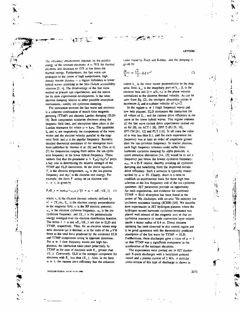
>'> ik,
f'i-
'1SlT
The otticwncy onnancemem Jcponcis on the parallelgnercy at" the resonant electrons; it is 70% for thermalelectrons and decreases to 15% at ten times thethermal energy. Furthermore, the fast wave canpropagate to the centre of high temperature, highJensity reactor plasmas — a region forbidden to lowerhybrid waves according to the Stix-Golant accessibilitycriterion [3. J-] . The disadvantage of the last wavemethod in present size experiments, and the reasonfor its slow experimental development, is the weakelectron damping relative to other possible absorptionmechanisms, notably ion cyclotron damping.
The interaction between the fast wave and electronsis a coherent combination of transit time magneticpumping (TTMP) and electron Landau damping (ELD)[5]. Both components accelerate electrons along themagnetic field lines, and absorption takes place at theLandau resonance for which u = ktv,. The quantitiesk, and v, are respectively the components of the wavevector and the electron velocity parallel to the mag-netic field, and u is the angular frequency. Recently.detailed theoretical treatments of the absorption havebeen published by Moreau et al. [6] and by Chiu et al.[7] for frequencies ranging from below the ion cyclo-tron frequency to the lower hybrid frequency. Theseauthors find that the parameter a = Tja^'iaj^a' playsa key role in determining the relative strength of theTTMP and ELD interactions. In the above equation.T; is the electron temperature. u!p, is the ion plasmafrequency and m=c: is the electron rest energy. Forexample, the tbrce F acting on an electron withv- > v. is given by
F1(Ej = + a - aE_ (U
where v= is the electron thermal velocity defined byv; = 2T_/m.. E^ is the electron energy perpendicularto the magnetic field, e is the RF electric potential.u;_c is the electron cyclotron frequency, Ujn is the ioncyclotron frequency, and <E_) is the perpendicularenergy averaged over me electron distribution ftmction.The terms 1 -r a and aE i/<E^_> are due to ELD andTTMP. respectively. Thus, for an electron whose mag-netic moment (^) is thermal, a is the ratio of the jtVBforce to the total force produced by the combined ELDand TTMP components acting in opposite directions.For a > I (low frequency waves and high bel »plasma), the interaction takes place principally byTTMP in the case of electrons with Ej. greater than< E _ > - Conversely. ELD is the stronger component forelectrons with E. less than (E-1). Also, in the limita s> 1. the current dme efficiency has the enhanced
LETTERS
value round by Fisch and Karney. and the damping is•liven bv
2k., C)
where k_ is the wave vector perpendicular to the mag-netic field, kj., is the imaginary part of k.. /3. is theelectron beta and £( = u/k^vj is the phase velocitynormalized to the electron thermal velocity. As can beseen from Eq. (2), the strongest absorption occurs atmaximum /3B and at a phase velocity of v/v/I.
In the regime a < 1 (high frequency waves andlow beta plasma), ELO dominates the interaction forall values of Ej., and the current drive efficiency is thesame as for lower hybrid waves. This regime containsall the fast wave current drive experiments carried outso far [6], on ACT-t [8], JIPP T-HU [9, 10],JFT-2M [11, 12] and PLT [13]. In all cases the valueof a was less than 0.1, and for each experiment thefrequency was at least an order of magnitude greaterthan the ion cyclotron frequency. In reactor plasmas,such high frequency schemes could suffer fromharmonic cyclotron damping by alpha particles, Amore attractive alternative [14, 15] would be to use afrequency just below the lowest cyclotron frequency,(jcT, in a D-T reactor, thereby avoiding all cyclotrondamping and benefitting from the improved currentdrive efficiency. Such a scenario is typically charac-terized by ct — 50. Clearly, there is a need toestablish an experimental basis for these high betaschemes at the low frequency end of the ion cyclotronspectrum. JET parameters provide an opportunityfor such experiments, and evidence for combinedTTMP •+• ELD absorption has been found in thecentre of 1He discharges with on-axis 3He minority ioncyclotron resonance heating (ICRH) [16]. We describehere experiments in JET hydrogen plasmas where thehydrogen second harmonic cyclotron resonance wasplaced well inboard of the magnetic axis so that nocyclotron resonance or mode conversion layer existedinside a minor radius of 0.4 m. Direct electrondamping has been observed in this central region andis in good agreement with the theoretically predictedabsorption of the fast wave by TTMP -f ELD.Furthermore, these discharges gave a value of a = 3so that TTMP was a significant component in theacceleration of the resonant electrons.
The experiments were carried out in JET double-null X-poini discharges with a beryllium getteredvessel and a plasma current of 2 MA. A poloiJalcross-section of this type of discharge is shown in
ii
NtCiEAU F131OS. Voi ;n). V, IO i I«OI 2171

1 2 3Major RacftJS (m)
F/G. /. Double-null X-poini configuration in JET. The2or,H resonance positions for B? = 1-34 Tand BT = 1.44 Tare shovat. together vith the operating range of the ECE
diagnostic.
Fig. 1. The last closed flux surface closely follows theRF antenna curvature, allowing optimal coupling to thefast wave. The hydrogen targe! plasma was heatedsimultaneously by both RF and neutral beam injection(NBI) for a period of 2 s. The NBI heating consistedof 4 MW of 80 keV deuterium atoms which produceda mixed hydrogen/deuterium plasma with the hydrogenconcentration typically 50% greater than the deuteriumdensity (i.e. nH/nD = 1.5). according to neutral particleanalyser measurements. Of the ions with Z > 1.carbon was the most abundant species. Visible brems-strahlung data gave Z^ = 3, which implies that thecarbon concentration was 5% of the electron densityand that nH -f- nD = 0.6 n^. The RF power waslaunched using the ICRH antennas and was squarewave modulated at 8 Hz between 3 MW and 9 MW.The frequency was 48 MHz and each antenna operatedwith dipole phasing. In this mode, the launched powerspectrum in Ic1 has a maximum at k| = 7 m'1. with afull width at half maximum Aki = 7 m"1.
For a central toroidal magnetic field (B7) in vacuumof 1.34 T the hydrogen second hznnonic reasonance inth_ p]£jma is calculated to be -t a najor radius of2.68 m when paramagnetic and diamagnetic effects aretaken into account. The position of this resonance layeris shown in Fig. 1. The flux surface i/-c which justtouches zhe resonance encloses a substantial centralplasma volume that is free from ion cyclotron and
mode conversion layers. In this situation, centraldamping of the fast wave can only occur through theTTMP/ELD process. Studies of the direc' electronheating in this region were carried out us.ag a multi-channel heterodyne electron cyclotron emission (ECE)radiometer [17] to observe the response of the electrontemperature to the RF power modulation. This instru-ment viewed the plasma horizontally along the mid-plane and was tuned to detect second harmonic E-moderadiation. The spatial resolution due to the receiverspot size was about 0.08 m. At B7 = 1.34 T. therange of operation covered the plasma core regionbetween major radii of 3.07 m and 3.32 m. Toincrease this range, data were also recorded atBT = 1.44 T, for which the u = 2ucll resonanceoccurs at 2.87 m and the ECE diagnostic scans fromR = 3.30 m to R = 3.58 m. In this case the resonance
intersects the flux surfaces covered by the ECE radio-meter so that mode conversion at the second harmonic,as well as TTMP + ELD, can contribute to theprompt electron heating signal. However, with dipoleantenna phasing the mode conversion component issmall and, according to full wave calculations with theISMENE code [18], it accounts for only 5% of thetotal power absorption.
Typical plasma parameters obtained at t = 51.8 sduring the combined heating are shown in Fig. 2. Theelectron density n, and the temperature profiles were
2 2 2 4 2 6 2 8 3 0 3 2 a* 3B38 40 42Major Radius (m)
F/G. 2. Typical profiles of electron temperature Tf. ion tem-perature T1 and electron density n,, recorded at t - 51.8 s.The uncertainties an their measurements are estimated tu he±5%.
'A'
:\
Ir
2172 NUCLEAR FUSION. VnI 30. No 10 (1

measured with the LIDAR Thomson scattering system[19]. The ion temperature T1 was deduced fromOoppler broadening of charge exchange recombinationradiation emitted by carbon impurity ions [2O]. Boththe T. and the T, profiles are strongly peaked, withon-axis values of 3.9 keV and 2.9 keV, respectively.The density profile is much broader and has a centralvalue of 2.2 x 10" nv3. Before the heating pulse, thecentral electron temperature was 1 keV. The volumeaveraged total beta for this discharge is V.4%, whichis approximately 30% of the Troyon limit for kink
modes [21].An estimate of the single-pass power absorption
in the central plasma enclosed by & can be madeusing Eq. (2) and the parameters of Fig. 2. Theaverage electron temperature inside & is 2.8 keV,giving an electron beta of 1.5%. The launched ki of^ m"' becomes 9 m~' in the plasma centre (sincekiR = constant) so that \ = 1.1. Taking kj. = u/VA,where VA is the Alfven velocity, we obtain 2kAi =0.22 m'1, which suggests that about 17% of theincident power will be absorbed on the first pass byTTMP + ELD inside a minor radius of 0.4 m.
The response of the on-axis electron temperature tothe RF power modulation can be seen in Fig. 3, whichshows the ECE radiometer signal together with the RFpower trace. The presence of direct electron dampingof the wave is revealed by the change in the slope (Te)
522
PlG- 3. Electron temperature response to modulated RFpan-er as measured \tith the central ECE channel. Notethe cnangf in the time derivative afTfat each RF powertransition, showing the presence of direct electron heating.
LETTERS
£0
140
••= 80
40
20
BT-l3T#20297BT «14T #20293
tt".30 32 34
Major Radius (m)3.6
FIG. 4. Electron healing paver density deduced from theECE measurements and plotted against the major radius forBr = 1.34 Toad B1-= 1.44 T. The RF transitions used forthis analysis are those shown in Fig. 3- The error bars onthe power density are rms deviations, whereas the error baron the position denotes the spatial resolution of the ECEdiagnostic.
of the sawtooth ramp at the time when the RF poweris switched up or switched down. The step in thepower per unit volume absorbed by the electrons isrelated to the discontinuity (ATe) in the temperatureslope through the expression AP. = (3/2KAT,.,provided the heat transport remains continuous duringthe RF power transition and An^ = O. There is nodetectable discontinuity in n^ and we can set an upperlimit of 0.01 MW/m3 on the error introduced byneglecting this component in the determination of thepower density.
Values of APC obtained from ATe are plottedagainst the major radius in Fig. 4. The solid pointsshow data for B7 = 1.34 T and the open pointsdata for B7 = 1.44 T. The centrally peaked powerdeposition is as expected from the similar form ofthe de profile, and the maximum power density is=0.11 MW/m3. When the data in Fig. 4 are fittedwith a Gaussian shape, we find that the total modu-lated power absorbed within &. is about 1.3 ± 0.3 MW.This corresponds to 22 ± 5% of the modulated inputpower, which is somewhat larger than the aboveestimate based on Eq. (2).
Further profile information is obtained from softX-ray measurements using the imaging cameras which
ï,
A
i .',\i
NlXLEAR FUSION. VoOO. No.lO .1990) 2173

«r
LETTERS
view the JET plasma from two orthogonal directions[221- The data are tomographically inverted to produceemissivity profiles, e(R), in the midptane such as thoseshown in Fig. 5. The change in slope, Ae. is clearlyseen in the plasma centre as the RF power is switcheddown at 52.12 s. A profile of Ae averaged overseveral RF power transitions is shown in Fig. 6 andconfirms the centrally peaked power deposition profilededuced from the ECE measurements. The error barsrepresent rms deviations. The maximum value of Aeappears to be slightly displaced (0.07 m) from themagnetic axis, although this is within the uncertaintiesof the tomographic and equilibrium calculations. Theprofile of Ae also shows subsidiary peaks outside thesawtooth inversion radius which could be due to eitherTTMP -i- ELD (see Fig. 8, for example) or electronheating by mode conversion in the vicinity of theoj = 2(JcH resonance.
The total power deposited in the plasma can becalculated from the modulated components of Wda andW^, the plasma energy measurements given by thediamagnetic loop and the Shafranov shift, respectively[23], These diagnostics have different sensitivities tothe parallel and perpendicular energies, such that thetotal energy content is given by
Wn 1/3 (W4, + 2 (3)
where the tilde denotes the modulated component. Forthe present experiments the global energy confinement
5. Tamograpnically reconstructed soft X-ray emissionprofiles in Oie median plane. Sawtooth crashes occur asI = S2.09s and i = 52.21 s. and the RF power à switcheddam at t = 52.12 s.
2174
FlC. 6. Discontinuity in the time derivative of the soft X-rayemisshity which is caused by the RF pwcr transition andwhich shows the electron heating to be peaked on axis. Thediscontinuiry was obtained/ram the median plane emistivityprofiles !see Fig. 5). The abscissa ^ is the magnetic fluxnormalized to unity at the boundary, lite labels HFS andLFS denote, respectively, the high jield side and the lowfield side of the magnetic axis.
time TE is 0.18 s, so that umTE = 9. where u>m is thefundamental angular frequency of the modulation. Inthis case the square wave amplitude of the absorbedpower can be obtained from P10, = 2.U111W10,/!. Thewave forms of W1 , and Wmhd are shown in Fig. 7 forthe experiments with B1- = 1.34 T. Both signals havea peak-to-peak variation of 0.14 MJ. which givesP™ = 4.4 MW compared with 5.8 MW of modulatedinput. Thus, 77 ± 10% of the coupled power isdeposited in the bulk plasma where the energy con-finement time exceeds «i1 by almost an order ofmagnitude. This result, in conjunction with the directelectron heating measurements, suggests that (a) mostof the power absorption takes place at the hydrogensecond harmonic resonance, and (b) a small amount ofpower is deposited in the plasma periphery where thesensitivity of the method is reduced by the poor energyconfinement in the edge region.
The power density profile for direct electrondamping is compared in Fig. 8 with theoretical profilesbased on ray tracing [24] and on a self-consistent treat-ment of power deposition and velocity distributionusing the PION code [25]. In addition to TTMP and
NUCLEAR FUSION. VoUO. No. IO (1990)
Ff .

W
'iKT
ELD, both models take account of second harmoniccyclotron absorption. The PION code also includesmode conversion, although the latter is negligible inthe present case wiih dipole antenna phasing. Thetheoretical direct electron heating profiles in Fig. Scorrespond to a modulated input power of 4.4 MW,which is the observed power deposited in the bulkplasma. The PION code predicts that 70 ± 5% of thepower is absorbed by the ions and 30 ± 5% by directelectron damping. Inside $c the predicted powerabsorbed by the electrons is 1.2 ± 0.2 MW, and thisis in good agreement with the measured value of1.3 ± 0.3 MW. Also, the calculated self-consistenthydrogen ion distribution function has at least 90%of the ions below the critical energy, and this isconsistent with the observed lack of velocity spaceanisotropy as shown by the equality of W1111 and W1n^;anisotropy begins to develop when the tail temperatureexceeds the critical energy (=25 keV in the presentcase) and ion-ion pitch angle scattering is reduced.However, the predicted profile is much more peakedthan the measured profile, with a predicted centralpower density of 0.3 MW/m3 compared with theobserved value of 0.11 MW/m3. However, it shouldbe noted that the PION code assumes an idealizedantenna current and does not take into account the gapin the central conductor on the equatorial plane whichdepletes the electric field near the magnetic axis. Theray tracing calculations predict that 38% of the inputpower is absorbed by electrons and 62% by ions. In
15 r-!
A *20297
(MJ) 13
12
ZO
K
(IvU)
PRF(MW)
IB -
8
6
*r
StB 513 520Tm6(S)
522 524
FlG- 7. Response of W^ and W^1 to RF pon-ermodulation.
LETTERS
300
Q2Minor Radius (m)
HC. 8. Comparison of the observed direct electron hearingpower density profite in minor radius with theoretical profilesfrom ray tracing and from PION code calculations
this case, the second harmonic damping was obtainedby using the average ion energy of 10 keV as given bythe Fokker-PIanck calculations. The electron heatingprofile is shown in Fig. g and has a maximum slightlyoff axis at a minor radius of 0.2 m. This effect is dueto the convergence of the rays towards a focus whichis 0.2 m on the high field side of the magnetic axis.The calculated power absorbed by the electrons inside&. is 1.2 MW, in agreement with both the experimentand the PION code calculations.
In summary, we have observed collisionless electrondamping of fast magnetosonic waves in the centre ofJET hydrogen discharges when there is no competingmode conversion or ion cyclotron absorption within aminor radius of 0.4 m. Outside this region, power wasabsorbed by the bulk ions at the 2ucH resonance. Theexperimental conditions of high beta plasmas and alow frequency wave ensured that TTMP was a signifi-cant component in the wave-electron interaction.The electron heating profile -was determined frommeasurements of the ECE and soft X-ray response toRF power modulation. The maximum power densityoccurred on axis, but the profile was less peaked thanthat predicted by either ray tracing or the PION codecalculations. The discrepancy is greatest in the lattercase and could be due to the simplified antenna
',t
f
W
NUCLEAR FUSION. VoUO. So-IO 119001 2175

fr" IrtK. -'
I
i
, 1
LETTERS
geometry assumed in the code: the model geometryproduces a more peaked RF electric field profile thanthat due to the real antenna. However, the total powerabsorbed by the electrons agrees well with theory.
ACKNOWLEDGEMENTS
It is a pleasure to thank all our colleagues in theJET team for assistance in this work. Particular thanksgo to the tokamak operating team and to the diagnosticgroups involved in the measurements reported here.
REFERENCES
III FISCH. NJ.. KARNEY. C.F.F., Phys. Fluids 24 (1981)17.
Ul SAGASHIMA. T.. and the JT-60 Team, in Applications ofRadiofrequency Power Io Plasmas (Proc. 7th Top. Conf.Kissimmee. FL. 1987). American Institute of Physics.New York (1987) 94.
[3] STIX. T.H.. The Theory of Plasma Waves. McGraw-Hill.New York (1962).
[4] GOLANT, V.E.. Sov. Phys. - Tech. Phys. 16 (1972)1980.
IS] STCC. T.H.. Nucl. Fusion IS (1975) 737.16) MOREAU. D-. O'BRIEN. MJt. COX. M..
START. D.F.H.. in Controlled Fusion and Plasma Physics(Proc. 14Ih Eur. Conf. Madrid. 1987). Vol. UD. Pan HI.European Physical Society (1987) 1007.
[7] CHIU. S.C.. CHAN. V.S., HARVEY, R.W..PORKOLAB. M.. Nucl. Fusion 29 (1989) 2175.
18] GOREE. J.. ONO. M.. COLESTOCK. P.. HORTON. R..McNFJLL, D.. PARK. H-. Phys. Rev. Lett. 56 (1985)1669.
[9] ANDO. R-, KAKO, E.. OGAWA, Y., WATARI. T..Nucl. Fusion 26 (1986) 1619.
[10] OHKUBO. K.. HAMADA. Y-. OGAWA, Y-. et al..Phys. Rev. Lett. 56 (1986) 2040.
[11] YAMAMOTO. T-, FUNAHASHI. A-, HOSHINO, K.,et al., in Plasma Physics and Controlled Nuclear FusionResearch 1986 (Proc. Um Int. Conf. Kyoto. 1986), Vol. 1,IAEA. Vienna (1987) 545.
2176
112] YAMAMOTO. T.. UESUGl. Y-. KAWASHlMA, H..et al.. Phys. Rev. Leu. 63 (1989) 1148.
]13] PlNSKER. R.I.. COLESTOCK. P.L.. BERNABEl. S..ei al., in Applications of Radiot'requenc} Power Io Plasmas(Proc. 7th Top. Conf. Kissimmee. FL. 1987). AmericanInsiiime of Physics, New York (1987) 175.
[14] JACQUINOT, J.. BHATNAGAR. V.P.. BURES. M..et al., "ICRF healing in reactor grade plasmas", paperpresented at 13th Im. Conf. on Plasma Physics andControlled Nuclear Fusion Research. Washington, DC.1-6 October 1990.
(IS] HELLSTEN. T. (Royal Institute of Technology. Stockholm»and MOREAU. D. (CEN, Cadarache). personal communica-tion. 1990.
(16) ERIKSSON. L.G., HELLSTEN. T.. Nucl. Fusion 29 (19891
875.[17] SALMON, N.A.. BARTLETT, D.V.. COSTLEY. A.E..
in Electron Cyclotron Emission and Electron CyclotronResonance Heating (Proc. 6th Int. Workshop Oxford. 19S71.Rep. CLM-ECR-1987. UKAEA. Culham Laboratory.Abingdon, Oxfordshire (1987).
[18] APPERT, K., HELLSTEN, T.. VACLAVIC, J..VILLARD, L., Comput. Phys. Commun. 40 (1986) 73.
[19] SALZMANN. H., HIRSCH, K.. NIELSEN. P.. et al..Nucl. Fusion 27 (1987) 1925.
[20] BOILEAU. A., von HELLERMANN. M.. HORTON. L.D..SPENCE. /.. SUMMERS. H.P., Plasma Phys. Contrail.Fusion 31 (1989) 779.
|21] SMEULDERS. P., ADAMS, J.M.. BALET. B., et al..in Controlled Fusion and Plasma Heating (Proc. 17th Eur.Conf. Amsterdam, 1990), Vol. 14B. Pan I. EuropeanPhysical Society (1990) 323.
122) EDWARDS, A.W.. FAHRBACH. H.-U.. GILL, R.D..et al.. Rev. Sci. Instrum. 57 (1986) 2142.
[23] CHRISTIANSEN, J.P., CORDEY. J.G.. MUIR, D.G..Nucl. Fusion 29 (1989) 1505.
[24] BHATNAGAR, V.P.. KOCH. R-. GEILFUS. P.. et al.,NucL Fusion 24 (1984) 955.
[25] ERIKSSON, L.G., HELLSTEN. T.. Self ConsistentCalculations of ICRH Power Deposition and VelocityDistribution. Rep. JET-p(89)65. JET Joim Undenaking.Abingdon, Oxfordshire (1989).
(Manuscript received 31 January 1990)Final manuscript received 21 May 1990)
^ TH
J,
i
NUCLEAR FUSION. VoIJO. No. 10 ItWO)
Ir
-s.--.
£,
!.\
CONCLUSION ET PERSPECTIVES
Depuis bientôt une quinzaine d'années, les recherches sur la fusion contrôlée sont
entrées dans une phase nouvelle avec l'avènement de la génération non-inductive de courant
dans les plasmas de Tokamaks. La possibilité de découpler les profils de densité de courant et
de température a des conséquences qui sont loin d'être triviales. Elle fournit en réalité un degré
de liberté supplémentaire pour contrôler les plasmas confinés dans une configuration qui sans
cela, bien qu'ayant de nombreux atouts, n'offre pas beaucoup de flexibilité tant les différents
paramètres physiques sont liés.
Le dernier "European Tokamak Programme Workshop" qui s'est tenu à Noordwijk
(Pays-Bas) du 16 au 18 décembre 1992 avait pour thème l'obtention de plasmas en régime
stationnaire, ce qui montre l'intérêt que la communauté scientifique porte actuellement à ce
problème. Parmi les divers sujets discutés, l'utilisation d'ondes de plasma pour parvenir à cet
objectif en contrôlant le profil de courant ou même pour entretenir un plasma continu a occupée
une place prépondérante. Une revue des récentes expériences de contrôle de profil effectuées
dans les Tokamaks américains Dm-D à San Diego et Ti1TK à Princeton, ainsi que dans JET et
TORE SUPRA, a montré que l'on pouvait en attendre des performances améliorées qui
devraient offrir à ITER et aux réacteurs futurs une marge de sécurité appréciable pour
l'obtention des conditions quasi-stationnaires nécessaires à la fusion contrôlée . Cependant, à
l'exception de TORE SUPRA, les moyens utilisés dans ces expériences (rampes de courant,
variation de la géométrie du plasma, injection de glaçon) n'en ont fait qu'un phénomène
transitoire. Les améliorations des performances se mesurent essentiellement par deux
paramètres : le facteur d'amélioration du confinement par rappor* aux lois de confinement
,thD. Moreau, "Current Profile Control in Long-Pulse Tokamaks", contribution invitée au "11 EuropeanTokamak Programme Workshop", Noordwijk, Pays-Bas (décembre 1992). Compte rendu à paraître dans "PlasmaPhysics and Controlled Fusion", 1993. Un ensemble de résultats détaillés des diverses expériences peut êtreobtenu dans "Plasma Physics and Controlled Nuclear Fusion Research 1992 ", Proc. of the 13th Int Conference,Wûrzburg, 1992 (IAEA Vienna, 1993).
C - I
fl(Sl

fc"HME(sec)
..t
usuelles, H, et le facteur de Trayon, PN, ou encore "P1 normalisé", qui représente le rapport
(pt, %) de la pression cinétique moyenne à la pression magnétique, normalisé au rapport,
IJaB1, du courant sur le rayon du plasma et l'intensité du champ magnétique (MA,m,T). Les
valeurs record obtenues dans DJU-D sont H = 3 par rapport à la loi ITER-89P (mode L) et
PN = 6. Dans TFTR elles sont H = 3,7 et PN = 5, tandis que dans JET, H = 4 et pN => 2,8.
D'autre part, dans DIII-D, !'elongation rapide de la décharge et l'injection de neutres ont permis
d'atteindre pt = 44% dans la partie centrale du plasma (pt moyen = 11%) et d'explorer un
"deuxième régime de stabilité" prévu par la théorie, grâce à un profil de cisaillement magnétique
inversé au centre du plasma comme dans le cas du régime PEP observé dans JET (cf. IV.3).
Les résultats de TORE SUPRA, bien que moins spectaculaires (H = 1,4), montrent qu'il
devrait être possible d'obtenir des performances similaires (produit HPN élevé) de façon
stationnaire. et également d'entrer dans la deuxième zone de stabilité lorsque toute la
puissance installée sera disponible.
Nous pouvons donc envisager dès à présent un réacteur de deuxième génération, dit
"réacteur avance", dans lequel le courant plasma pourrait être bien inférieur à ce qui est prévu
par exemple pour ITJbR, pour un triple produit H1-Tg-T; (cf. introduction) et des limites de
stabilité équivalents. Les lois de confinement empiriques monômiales comme ITER-89P ou la
loi de Goldston suggèrent que ce triple produit est proportionnel à H2Lj1A51 où A est le rapport
d'aspect (rapport du grand rayon au petit rayon, A = R/a) du plasma torique, et x et y sont de
l'ordre de 2. Une extrapolation au réacteur basée sur ces lois d'échelle montre donc qu'une
opération à faible courant nécessite un rapport d'aspect relativement élevé.
L'entretien continu d'une telle décharge, de façon purement non-inductive, semble
possible en faisant recirculer une partie de la puissance thermonucléaire produite (= 20%) dans
les systèmes de génération de courant pa- onrtes, à condition que la densité soit relativement
faible et que le courant de "bootstrap" néoclassique, I155, constitue une grande partie du courant
total (> 70%) . Dans certaines expériences réalisées à faible courant, des taux de "bootstrap"
M. Hkuchi, Nuclear Fusion 30 (1990) 265.
•'5Î
,.i
r C-2
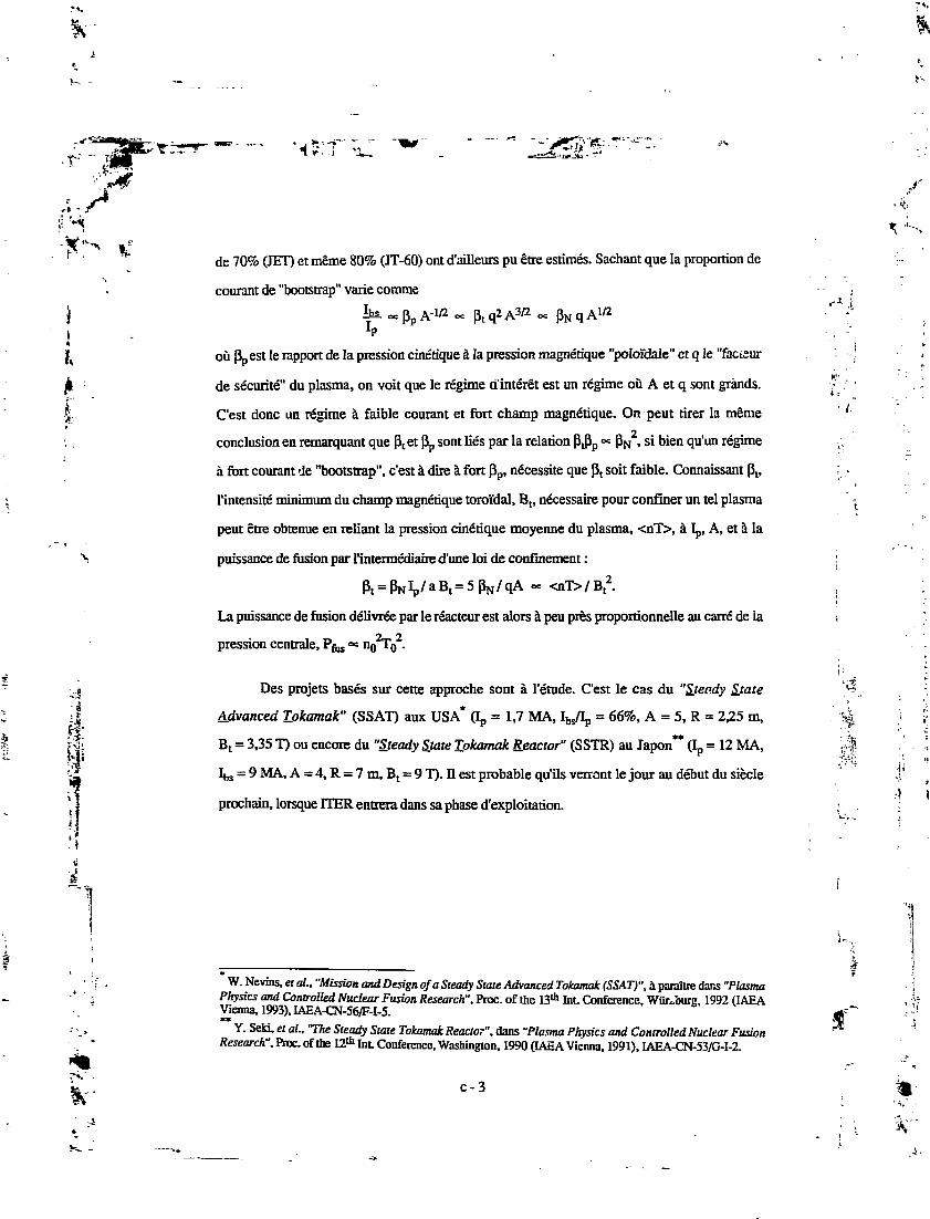
fc
14
I,
I
de 70% (JET) et même 80% (JT-60) ont d'ailleurs pu être estimes. Sachant que la proportion de
courant de "bootstrap" varie comme
Sa- O=PpA-1/2 -= ptq2A3/2 « pNqA1/2
1P
où ppest Ie rapport de la pression cinétique à la pression magnétique "poloïdale" et q le "factsur
de sécurité" du plasma, on voit que le régime d'intérêt est un régime où A et q sont grands.
C'est donc un régime à faible courant et fort champ magnétique. On peut tirer la même
conclusion en remarquant que pt et Pp sont liés par la relation P1Pp « PN2, si bien qu'un régime
à fort courant de "bootstrap", c'est à dire à fort pp, nécessite que ptsoit faible. Connaissant P1,
l'intensité minimum du champ magnétique toroidal, Bt, nécessaire pour confiner un tel plasma
peut être obtenue en reliant la pression cinétique moyenne du plasma, <nT>, à Ip, A, et à la
puissance de fusion par l'intermédiaire d'une loi de confinement :
P1 = PNIpMB1 = SpVqA - <nT>/Bt2.
La puissance de fusion délivrée par le réacteur est alors à peu près proportionnelle au carré de la
pression centrale, Pf133 °* H0HT0 .
Des projets basés sur cette approche sont à l'étude. C'est le cas du "Steady Sjate
Advanced Tokamak" (SSAT) aux USA* (Ip = 1,7 MA, Ibs/Ip = 66%, A = 5, R = 2,25 m,
B1 = 3,35 T) ou encore du "Steady State Tokamak Reactor" (SSTR) au Japon** (Ip = 12 MA,
Ibs = 9 MA, A = 4, R = 7 m, Bt = 9 T). Ji est probable qu'ils verront le jour au début du siècle
prochain, lorsque ITER entrera dans sa phase d'exploitation.
K- ,
i , - '
.«! I
r*»"fr
V
W. Nevins, et aL, "Mission and Design of a Steady State Advanced Tokamak (SSAT)", à paraître dans "PlasmaPhysics and Controlled Nuclear Fusion Research". PIQC. of the 13th Int Conference, WOrJniig, 1992 (IAEAVienna, 1993), IAEA-CN-56/F-I-5.**
Y. Seki, et aL, "The Steady State Tokamak Reactor", dans "Plasma Physics and Controlled Nuclear FusionResearch", Proc. of the 12* Int. Conference, Washington, 1990 (IAEA Vienna, 1991), IAEA-CN-53/G-I-2.
c-3
V"i.