Unit-II Instruction Set and Programs for Intel 8085
27
Unit-II Instruction Set and Programs for Intel 8085 • Following major topics have to covered in this unit • Addressing modes of Intel 8085 • Classification of Instructions of Intel 8085 • Machine and Assembly Languages • Basic assembly language programs of Intel 8085 Addressing Modes: • Each instruction requires certain data on which it has to operate • There are various techniques to specify data for instructions • These techniques are called addressing modes • The way of specifying data to be operated by an instruction is known as addressing modes • Intel 8085 uses the following addressing modes: • Direct addressing • Register addressing • Register Indirect addressing • Immediate addressing • Implicit addressing Direct Addressing: • In this mode of addressing the address of the operand (data) is given in the instruction itself • Example are: • STA 2500H: Store the content of the accumulator in the memory location 2500H • 32, 00, 25: The instruction is in coded form • LDA 26FFH: Load the content of the memory location 26FFH to the accumulator • 3A, FF, 26: The instruction is in coded form • IN 02: Read data from Port C • DB, 02: The instruction is in coded form Register Addressing: • In this mode of addressing the operand is in one of the general purpose registers • The opcode specifies the address of the register(s) in addition to the operation to be performed • Example are: • MOV A, B: Move the content of register B to register A • 78: The instruction is in coded form • ADD B: Add the content of register B to the content of register A [A] ← [A] + [B] • 80: The instruction is in coded form • SUB C: Subtract the content of register C from the content of register A [A] ← [A] – [C] • 91: The instruction is in coded form
-
Upload
khangminh22 -
Category
Documents
-
view
0 -
download
0
Transcript of Unit-II Instruction Set and Programs for Intel 8085

Unit-II Instruction Set and Programs for Intel 8085
• Following major topics have to covered in this unit
• Addressing modes of Intel 8085
• Classification of Instructions of Intel 8085
• Machine and Assembly Languages
• Basic assembly language programs of Intel 8085
Addressing Modes:
• Each instruction requires certain data on which it has to operate
• There are various techniques to specify data for instructions
• These techniques are called addressing modes
• The way of specifying data to be operated by an instruction is known as addressing modes
• Intel 8085 uses the following addressing modes:
• Direct addressing
• Register addressing
• Register Indirect addressing
• Immediate addressing
• Implicit addressing
Direct Addressing:
• In this mode of addressing the address of the operand (data) is given in the instruction itself
• Example are:
• STA 2500H: Store the content of the accumulator in the memory location 2500H
• 32, 00, 25: The instruction is in coded form
• LDA 26FFH: Load the content of the memory location 26FFH to the accumulator
• 3A, FF, 26: The instruction is in coded form
• IN 02: Read data from Port C
• DB, 02: The instruction is in coded form
Register Addressing:
• In this mode of addressing the operand is in one of the general purpose registers
• The opcode specifies the address of the register(s) in addition to the operation to be performed
• Example are:
• MOV A, B: Move the content of register B to register A
• 78: The instruction is in coded form
• ADD B: Add the content of register B to the content of register A [A] ← [A] + [B]
• 80: The instruction is in coded form
• SUB C: Subtract the content of register C from the content of register A [A] ← [A] – [C]
• 91: The instruction is in coded form

Register Indirect Addressing:
• In this mode of addressing the address of the operand is specified by a register pair
• Example are:
• MOV A, M: Move the content of the memory location, whose address is in H-L pair to the
accumulator
• 7E: The instruction is in coded form
• ADD M: Add the content of the memory location, whose address is in H-L pair, to the
content of the accumulator
• 86: The instruction is in coded form
• SUB M: Subtract the content of the memory location, whose address is in H-L pair, from the
content of the accumulator
• 96: The instruction is in coded form
Immediate Addressing:
• In this mode of addressing the operand (data) is specified within the instruction itself
• Example are:
• MVI A, 05: Move 05 in register A
• 3E, 05: The instruction is in coded form
• ADI 06: Add 06 to the content of the accumulator
• C6, 06: The instruction is in coded form
• LXI H, 2500: 2500 is 16-bit data which is given in the instruction itself to be loaded into H-L
pair
• 21, 00, 25: The instruction is in coded form
• SUI 06: Subtract 06 from the content of the accumulator
• D6, 06: The instruction is in coded form
Implicit Addressing:
• There are certain instructions which operate on the content of the accumulator
• Such instruction do not require the address of the operand
• Also, known as implied or inherent addressing mode
• Example are:
• CMA: complement the accumulator content
• he instruction is in co e form [A] ← [ A]
• RAL: Rotate accumulator left through carry
• 17: opcode [An+1] ← [An], [CS] ← [A7], [A0] ← [CS]
• RAR: Rotate accumulator right through carry
• 1F: The instruction is in coded form
[An] ← [An+1], [CS] ← [A0], [A7] ← [CS]

Instruction set of Intel 8085:
• Instruction is a command given to the computer to perform a specified operation on given
data
• The instruction set of a microprocessor is the collection of the instructions
• That the microprocessor is designed to execute
• These instructions have been classified into the following five groups
Classification of Intel 8085 Instructions:
• Data Transfer Group
• Arithmetic Group
• Logical Group
• Branch Control Group
• I/O and Machine Control Group

Data Transfer Group:
• Instructions which are used to transfer data in the following manner come under this group
• From one register to another register,
• From memory to register, or
• From register to memory
• Examples are: MOV, MVI, LXI, LDA, S A, etc….
• Data is transferred from the source to the destination without altering the content of the
source
S.
No
Instructions Meaning Flag Addressing
Modes
M/C
Cycle
T-
states
Description
1. MOV r1, r2 [r1]←[r ] none Register 1 4 Move the content of
one register to another
2. MOV r, M [r] ←[[H-L]] none Reg. Indirect 2 7 Move the content of
memory whose
address in H-L pair to
register
3. MOV M, r [[H-L]] ←[r] none Reg. Indirect 2 7 Move the content of
register to memory
whose address in H-L
pair
4. MVI r, data [r]← ata none Immediate 2 7 Move immediate data
to register r
5. MVI M, data [[H-L]] ← ata none Immediate/
Reg. Indirect
3 10 Move immediate data
to memory whose
address in H-L pair
6. LXI rp, data [r
p]← ata-16
[rH] ← 8-MSB
[rL]
← 8-LSB
none Immediate 3 10 Load register pair
immediate
7. LDA addr [A]← [a r] none Direct 4 13 Load accumulator
direct
8. STA addr [a r] ←[A] none Direct 4 13 Store accumulator
direct
9. LHLD addr [L]← [a r] [H]← [a r+1]
none Direct 5 16 Load H-L pair direct
10. SHLD addr [a r] ← [L] [a r+1] ← [H]
none Direct 5 16 Store H-L pair direct
11. LDA X rp [A]← [[r
p]] none Reg. Indirect 2 7 Load accumulator in-
direct
12. STAX rp [[r
p]] ←[A] none Reg. Indirect 2 7 Store accumulator in-
direct
13. XCHG [H-L]↔ [D-E] none Register 1 4 Exchange the content
of H-L with D-E
XCHG, LDAX rp and STAX rp
• Suppose before XCHG instruction
[H] = 35, [L] = 00 and [D] = 56, [E] = FF
• After XCHG instruction the result will be
[H] = 56, [L] = FF and [D] = 35, [E] = 00
• LDAX B will load the content of the memory location, whose address is in B-C pair to
accumulator

• Ex: LDAX B Suppose [B][C] = 2550H [B]=25 and [C] =50,
• Whatever the data stored at memory 2550H will load to accumulator
• STAX D will store the content of the accumulator in the memory location whose address is in
D-E pair
• Ex: STAX D Suppose [D][E] = 2655H [D]=26 and [E] =55 and Suppose [A] =FF
• FF will be stored at memory location 2655H
Arithmetic Group:
• Instructions of this group perform arithmetic operations such as
• Addition, subtraction
• Increment or decrement of the content of a register or memory
• Examples are: ADD, SUB, INR, DCR, DAD, etc….
• This group contains about 14 instructions
S.
No
Instructions Meaning Flag Addressing
Modes
M/C
Cycle
T-
states
Description
1. ADD r [A]←[A] + [r] all Register 1 4 Add register to
accumulator
2. ADD M [A]←[A] + [[H-
L]] all Reg. Indirect 2 7 Add memory whose
address in H-L pair to
accumulator
3. ADC r [A] ←[A] + [r]
+ [CS] all Register 1 4 Add register with
carry to accumulator
4. ADC M [A]← [A] + [[H-
L]] + [CS] all Reg. Indirect 2 7 Add memory whose
address in H-L pair
with carry to
accumulator
5. ADI data [A] ← [A]+ ata all Immediate 2 7 Add immediate data
to accumulator
6. ACI data [A]← [A] + data
+ [CS] all Immediate 2 7 Add with carry
immediate data to
accumulator
7. DAD rp [H-L]← [H-L] +
[rp]
CS Register 3 10 Add register pair to
H-L pair
8. SUB r [A] ←[A] – [r] all Register 1 4 Subtract register from
accumulator
9. SUB M [A] ← [A] –
[[H-L] all Reg. Indirect 2 7 Subtract memory
whose address in H-L
pair from accumulator
10. SBB r [A] ←[A] – [r] –
[CS] all Register 1 4 Subtract register from
accumulator with
borrow
11. SBB M [A] ← [A] –
[[H-L] – [CS] all Reg. Indirect 2 7 Subtract memory
whose address in H-L
pair from accumulator
with borrow
12. SUI data [A] ←[A] – data all Immediate 2 7 Subtract immediate
data from
accumulator
13. SBI data [A] ←[A] – data
– [CS] all Immediate 2 7 Subtract immediate
data from
accumulator with
borrow
14. INR r [r] ← [r] + 1 all
except
CS
Register 1 4 Increment register
content by 1
15. INR M [[H-L]] ←
[[H-L]] + 1
all
except
CS
Reg. Indirect 3 10 Increment memory
content by 1 whose
address in H-L pair
16. DCR r [r] ← [r] – 1 all
except
CS
Register 1 4 Decrement register
content by 1
17. DCR M [[H-L]] ←
[[H-L]] – 1
all
except
CS
Reg. Indirect 3 10 Decrement memory
content by 1 whose
address in H-L pair
18. INX rp [r
p] ←[r
p] + 1 none Register 1 6 Increment register
pair by 1
19. DCX rp [r
p] ←[r
p] – 1 none Register 1 6 Decrement register
pair by 1
20. DAA all Implicit 1 4 Decimal adjust
accumulator
DAA: Decimal Adjust Accumulator:
• DAA is use in the program after a ition instructions i.e. ADD, ADI, ADC etc…
• Result is placed in accumulator in hexadecimal
• The DAA instruction operates on result and gives the final result in decimal system
• It uses [CS] and [AC] for decimal adjustment
• 6 is added to 4 LSBs, if value lies A – F or [AC] = 1
• 6 is added to 4 MSBs, if value lies A – F or [CS] = 1
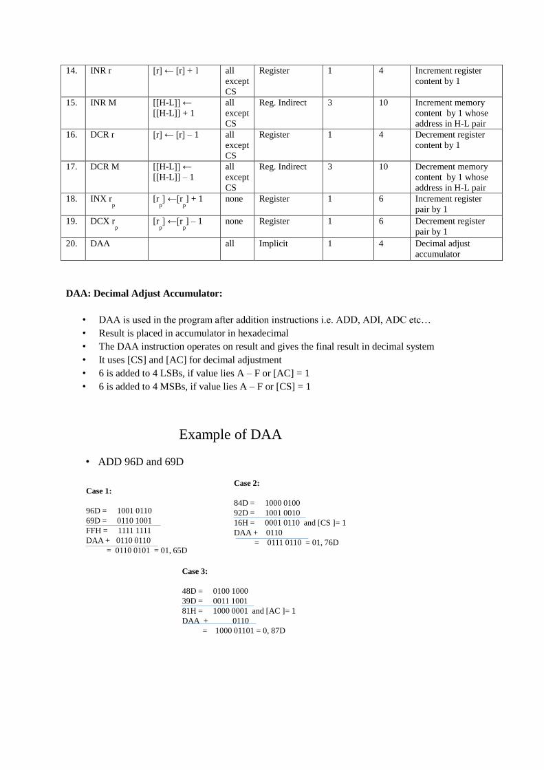
Example of DAA
• ADD 96D and 69D
Case 1:
96D = 1001 0110
69D = 0110 1001
FFH = 1111 1111
DAA + 0110 0110
= 0110 0101 = 01, 65D
Case 2:
84D = 1000 0100
92D = 1001 0010
16H = 0001 0110 and [CS ]= 1
DAA + 0110
= 0111 0110 = 01, 76D
Case 3:
48D = 0100 1000
39D = 0011 1001
81H = 1000 0001 and [AC ]= 1
DAA + 0110
= 1000 01101 = 0, 87D

Logical Group:
• Instructions of this group perform logical operations such as
• Logical AND, logical OR, Exclusive-OR
• Rotate or take complement of data in register or memory
• Examples are: ANA, ORA, XRA, CMP, RAR, etc…
• This group contains about 15 instructions
S.
No
Instructions Meaning Flag Addressing
Modes
M/C
Cycle
T-
states
Description
1. ANA r [A]←[A] ˄ [r] all,
CS=0, AC=1
Register 1 4 AND register with
accumulator
2. ANA M [A]←[A] ˄ [[H-
L]] all,
CS=0, AC=1
Reg. Indirect 2 7 AND memory whose
address in H-L pair
with accumulator
3. ANI data [A] ←[A] ˄ ata all,
CS=0, AC=1
Immediate 2 7 AND immediate data
with accumulator
4. ORA r [A]← [A] ˅ r all, CS=0,
AC=0
Register 1 4 OR register with
accumulator
5. ORA M [A] ← [A] ˅
[[H-L]] all, CS=0,
AC=0
Reg. Indirect 2 7 OR memory whose
address in H-L pair
with accumulator
6. ORI data [A]← [A] ˅ ata all, CS=0,
AC=0
Immediate 2 7 OR immediate data
with accumulator
7. XRA r [A]← [A] ˅ [r] all,
CS=0,
AC=0
Register 1 4 Exclusive –OR
register with
accumulator
8. XRA M [A] ←[A] ˅ [[H-
L]] all, CS=0,
AC=0
Reg. Indirect 2 7 Exclusive –OR
memory whose
address in H-L pair
with accumulator
9. XRI data [A] ← [A] ˅
data all, CS=0,
AC=0
Immediate 2 7 Exclusive –OR
immediate data with
accumulator
10. CMA [A] ← [ A] none Implicit 1 4 Complement the
accumulator
11. CMC [CS] ←[C S] CS Inherent 1 4 Complement the carry
status
12. STC [CS] ← 1 CS Inherent 1 4 Set Carry status
13. CMP r [A] – [r] all Register 1 4 Compare register with
accumulator, result
discarded
14. CMP M [A] – [[H-L]] all Reg. Indirect 2 7 Compare memory
whose address in H-L
pair with accumulator
15. CPI data [A] – data all Immediate 2 7 Compare immediate
data with accumulator
16. RLC [An+1]←[A
n],
[A0] ← [A
7],
[CS] ← [A7]
CS Implicit 1 4 Rotate accumulator
left

17. RRC [A
7] ← [A
0],
[CS] ← [A0] ,
[An]←[A
n + 1]
CS Implicit 1 4 Rotate accumulator
right
18. RAL [A
n+1]←[A
n],
[CS] ← [A7],
[A0] ← [CS]
CS Implicit 1 4 Rotate accumulator
left through carry
19. RAR [A
n]←[A
n + 1],
[CS] ← [A0],
[A7] ← [CS]
CS Implicit 1 4 Rotate accumulator
right through carry
RLC : Rotate Accumulator Left:
[An+1]←[An],
[A0] ← [A7],
[CS] ← [A7]
Diagram of RLC:
RRC : Rotate Accumulator Right:
[A7] ← [A0],
[CS] ← [A0] ,
[An]←[An + 1]
Diagram of RRC:
RAL : Rotate Accumulator Left through Carry:
[An+1]←[An],
[CS] ← [A7],
[A0] ← [CS]

Diagram of RAL:
RAR : Rotate Accumulator Right through Carry:
[An]←[An + 1],
[CS] ← [A0],
[A7] ← [CS]
Diagram of RAR:
Branch Control Group:
• This group includes the instructions for conditional and unconditional jump
• Subroutine call and return, and restart
• The instruction of this group change the normal sequence of the program
• Examples are: JMP, JC, CALL, CZ, RE , RS etc…
• This group contains about total 29 instructions, 9 instructions for each jump, call and return
S.
No
Instructions Meaning Flag Addressing
Modes
M/C
Cycle
T-
states
Description
1. JMP addr
(label) [PC]←label none Immediate 3 10 Unconditional jump:
jump to label
2. JZ addr
(label) [PC]←label Jump if Z = 1
none Immediate 2/3 7/10 Jump if the result is
zero
3. JNZ addr
(label) [PC]←label Jump if Z = 0
none Immediate 2/3 7/10 Jump if the result is
not zero
4 JC addr
(label) [PC]←label Jump if CS = 1
none Immediate 2/3 7/10 Jump if there is a
carry
5. JNC addr
(label) [PC]←label Jump if CS = 0
none Immediate 2/3 7/10 Jump if there is no
carry
6. JP addr
(label) [PC]←label Jump if S = 0
none Immediate 2/3 7/10 Jump if the result is
plus
7. JM addr
(label) [PC]←label Jump if S = 1
none Immediate 2/3 7/10 Jump if the result is
minus

8. JPE addr
(label) [PC]←label Jump if P = 1
none Immediate 2/3 7/10 Jump if even parity
9. JPO addr
(label) [PC]←label Jump if P = 0
none Immediate 2/3 7/10 Jump if odd parity
1. CALL addr
(label) [[SP] – 1]← [PCH], [[SP] – ]← [PCL], [SP] ←([SP] – 2), [PC]←label
none Immediate/
reg. indirect 5 18 Unconditional CALL:
call the subroutine by
label
2. CZ addr
(label) [[SP] – 1]← [PCH], [[SP] – ]← [PCL], [SP] ←([SP] – 2), [PC]←label
none Immediate/
reg. indirect 2/5 9/18 Call subroutine if the
result is zero, the zero
status Z = 1
3. CNZ addr
(label) [[SP] – 1]← [PCH], [[SP] – ]← [PCL], [SP] ←([SP] – 2), [PC]←label
none Immediate/
reg. indirect 2/5 9/18 Call subroutine if the
result is not zero, the
zero status Z = 0
4 CC addr
(label) [[SP] – 1]← [PCH], [[SP] – ]← [PCL], [SP] ←([SP] – 2), [PC]←label
none Immediate/
reg. indirect 2/5 9/18 Call subroutine if
there is carry, the
carry status CS = 1
5. CNC addr
(label) [[SP] – 1]← [PCH], [[SP] – ]← [PCL], [SP] ←([SP] – 2), [PC]←label
none Immediate/
reg. indirect 2/5 9/18 Call subroutine if
there is no carry, the
carry status CS = 0
6. CP addr
(label) [[SP] – 1]← [PCH], [[SP] – ]← [PCL], [SP] ←([SP] – 2), [PC]←label
none Immediate/
reg. indirect 2/5 9/18 Call subroutine if the
result is plus, the sign
status S= 0
7. CM addr
(label) [[SP] – 1]← [PCH], [[SP] – ]← [PCL], [SP] ←([SP] – 2), [PC]←label
none Immediate/
reg. indirect 2/5 9/18 Call subroutine if the
result is minus, the
sign status S= 1
8 CPE addr
(label) [[SP] – 1]← [PCH], [[SP] – ]← [PCL], [SP] ←([SP] – 2), [PC]←label
none Immediate/
reg. indirect 2/5 9/18 Call subroutine if
even parity, the parity
status P = 1
9. CPO addr
(label) [[SP] – 1]← [PCH], [[SP] – ]← [PCL], [SP] ←([SP] – 2), [PC]←label
none Immediate/
reg. indirect 2/5 9/18 Call subroutine if odd
parity, the parity
status P = 0
1. RET [PCL]← [[SP]], [PCH]← [[SP] + 1], [SP] ←([SP] + )
none reg. indirect 3 10 Unconditional return:
return from
subroutine
2. RZ addr
(label) [PCL]← [[SP]], [PCH]← [[SP] + 1], [SP] ←([SP] + )
none reg. indirect 1/3 6/12 Return from
subroutine if the
result is zero, the zero
status Z = 1
3. RNZ addr
(label) [PCL]← [[SP]], [PCH]← [[SP] + 1], [SP] ←([SP] + )
none reg. indirect 1/3 6/12 Return from
subroutine if the
result is not zero, the
zero status Z = 0
4 RC addr
(label) [PCL]← [[SP]], [PCH]← [[SP] + 1], [SP] ←([SP] + )
none reg. indirect 1/3 6/12 Return from
subroutine if there is
carry, the carry status
CS = 1
5. RNC addr
(label) [PCL]← [[SP]], [PCH]← [[SP] + 1], [SP] ←([SP] + )
none reg. indirect 1/3 6/12 Return from
subroutine if there is
no carry, the carry
status CS = 0

6. RP addr
(label) [PCL]← [[SP]], [PCH]← [[SP] + 1], [SP] ←([SP] + )
none reg. indirect 1/3 6/12 Return from
subroutine if the
result is plus, the sign
status S= 0
7. RM addr
(label) [PCL]← [[SP]], [PCH]← [[SP] + 1], [SP] ←([SP] + )
none reg. indirect 1/3 6/12 Return from
subroutine if the
result is minus, the
sign status S= 1
8 RPE addr
(label) [PCL]← [[SP]], [PCH]← [[SP] + 1], [SP] ←([SP] +
none reg. indirect 1/3 6/12 Return from
subroutine if even
parity, )the parity
status P=1
9. RPO addr
(label) [PCL]← [[SP]], [PCH]← [[SP] + 1], [SP] ←([SP] + )
none reg. indirect 1/3 6/12 Return from
subroutine if odd
parity, the parity
status P=0
1. RST n [[SP] –1]← [PCH], [[SP] – ]← [PCL], [SP] ← ([SP] – 2), [PC] ← 8 times n
none Reg. Indirect 3 12 Restart It is a one-word
CALL instruction
2. PCHL [PC] ← [H-L], [PCH] ← [H], [PCL] ← [L]
none Register 1 6 Jump to address
specified by H-L pair
The restart instruction as follows: RST 0, RST 1, RST 2, RST 3, RTS 4, RTS5, RST6 and RST 7
PCHL: The content of H-L pair are transferred to program counter
I/O and Machine Control Group:
• This group includes the instructions for input/ output ports
• Stacks and
• Machine control
• Examples are: IN, OU , PUSH, POP, HL , etc…
• This group contains about12 instructions, 2 for input/output, 4 for stacks and rest for machine
control
S.
No
Instructions Meaning Flag Addressing
Modes
M/C
Cycle
T-
states
Description
1. IN port-
address
[A]←[Port] none Direct 3 10 Input to accumulator
from I/O port
2. OUT port-
address
[Port]← [A] none Direct 3 10 Output from
accumulator to I/O
port
3. PUSH rp [[SP] – 1] ← [r
h]
[[SP] – ] ← [rl]
[SP] ← ([SP] –2)
none Register/
reg. Indirect
3 12 Push the content of
register pair to stack
4 PUSH PSW [[SP] – 1] ← [A]
[[SP] – ]← PSW
[SP] ← ([SP] –2)
none Register/
reg. Indirect
3 12 PUSH program status
word to the stack
5. POP rp [r
l] ← [[SP]]
[rh] ← [[SP] + 1]
[SP] ← ([SP] +2)
none Register/ reg. Indirect
3 10 Copy two bytes from
the top of the stack
into the specified
register
6. POP PSW PSW ← [[SP]] [A] ← [[SP] + 1
none Register/ reg. Indirect
3 10 Copy two bytes from
the top of the stack

[SP] ← ([SP] + ) into PSW and
Accumulator
7. HLT Program execution
is stopped none Implied 1 5 Halt
8. XTHL [L] ← [[SP]] [H] ← [[SP] + 1]
none Reg. Indirect 5 16 Exchange stack top
with H-L
9. SPHL [H-L] ← [SP] none Register 1 6 Move the contents of
H-L pair to stack
pointer
10. EI Interrupts are
enabled none Implied 1 4 Enable interrupts
11. DI Interrupts are
disabled none Implied 1 4 Disable interrupts
12. SIM none Implicit 1 4 Set Interrupt Masks
13. RIM none Implicit 1 4 Read Interrupt Mask
14. NOP none Implied 1 4 No operation
SIM & RIM instructions:
• When SIM instruction executed:
• Bit No. 0 – 5 of the accumulator are used in programming the restart interrupt masks
• Bits 6-7 of the accumulator are used in making serial output on SOD line
• When RIM instruction executed:
• The accumulator is loaded with pending interrupts,
• The restart interrupt masks and the contents of SID
Intel 8085 Instructions Classification Summary
S. No Group Instructions Examples Total
Instructions
1. Data Transfer MOV, MVI, LXI, LDA, STA, LHLD, SHLD,
LDAX, STAX, XCHG 10
2. Arithmetic ADD, ADC, ADI, ACI, DAD, SUB, SBB, SUI, SBI,
INR, DCR, INX, DCX, DAA 14
3. Logical ANA, ANI, ORA, ORI, XRA, XRI, CMA, CMC,
STC, CMP, CPI, RLC, RRC, RAL, RAR 15
4. Branch Control JMP, JZ, JNZ, JC, JNC, JP, JM, JPE, JPO, CALL,
CZ, CNZ, CC, CNC, CP, CM, CPE, CPO, RET, RZ,
RNZ, RC, RNC, RP, RM, RPE, RPO, RST, PCHL
29
5. I/O & Machine Control IN, OUT, PUSH, POP, HLT, XTHL, SPHL, EI, DI,
SIM, RIM, NOP 12

Machine Language:
• A computer uses binary digits for its operation and understands information composed of only
0s and 1s
• Hence, the instructions are coded and stored in the memory in the form of zeros and ones
• A program written in the form of 0s and 1s is called a machine language program
• In the machine language there is a specific binary code for each instruction
• For example, in Intel 8085 to add the contents of register A and register B, the binary code is
10000000
• To move the content of register B to register A the binary code is 01111000
Demerits of Machine Language Programs:
• A program written in machine codes ultimately becomes a set of binary numbers
• Demerits:
• It is very difficult for the programmer to write a program in machine codes, it is error prone
• It is very difficult to understand or debug a program
• Since each bit has to be entered individually the entry of the a program is very slow
• Programs are long
• Program writing is difficult and tiresome
• Chances of careless errors in writing program
Adding of two Numbers Program:
Machine Code Comments
0010 0001 Get the address of Ist number (21)
0000 0001 LSBs of 2501 (01)
0010 0101 MSBs of 2501 (25)
0111 1110 Move Ist number in accumulator (7E)
0010 0011 Increment the content of H-L pair (23)
1000 0110 Add IInd number to the Ist number (86)
0011 0010 Store sum at 2503 (32)
0000 0011 LSBs of 2503 (03)
0010 0101 MSBs of 2503 (25)
0111 0110 Stop Halt (76)
Input and Output for add Program:
Memory Address Data
Input:
0010 0101 0000 0001 0001 0101
0010 0101 0000 0010 0010 0000
Output:
0010 0101 0000 0011 0011 0101

Hexadecimal System:
• To facilitate programmer machine code can be written in hexadecimal system
• The program can easily be written in hexadecimal system compared to binary system
• The mistake can easily be detected
• The program written in hexadecimal system is converted into binary system
• All microprocessor kits have provision for such conversion
• The language in which a program writes a programs is called source language
• The language in which a computer works is called object or machine language
Adding two Numbers Program in Hex:
Hex Code Comments
21 Get the address of Ist number (21)
01 LSBs of 2501 (01)
25 MSBs of 2501 (25)
7E Move Ist number in accumulator (7E)
23 Increment the content of H-L pair (23)
86 Add 2
nd
number to the Ist number (86)
32 Store sum at 2503 (32)
03 LSBs of 2503 (03)
25 MSBs of 2503 (25)
76 Stop Halt (76)
Input: 2501 15
2502 20
2503 35 (Output)
Assembly Language:
• A programmer can easily write a program in alphanumeric symbols instead of 0s and 1s
• Meaningful and easily rememberable symbols are chosen for the purpose
• Examples are: ADD for addition, SUB for subtraction, CMP for comparison etc…, such
symbols called mnemonics
• A program written in mnemonics is known as assembly language program
• The writing of a program in assembly language is much easier and faster as compared to
machine language
• Both machine language and assembly language are microprocessor specific

Low Level Language:
• A microprocessor specific language is known as a low level language
• A program which translates an assembly language program into a machine language is called
an assembler
• A self-assembler or resident assembler is an assembler which runs on the microcomputer for
which
• It produces object code (or machine code)
• Mnemonics, operands, data of the program and starting address of for the program are fed to
computer
• The assembler converts the program into a machine language program before the execution of
the program
Adding two Numbers Program in Assembly:
Mnemonics Operands
LXI H, 2501H
MOV A, M
INX H
ADD M
STA 2503H
HLT
Input:
2501 49H
2502 56H
9FH (Output)
Adding two Numbers Program in kit
Memory Address Hex Code Mnemonics Operands
2000 21 LXI H, 2501H
2001 01
2002 25
2003 7E MOV A, M
2004 23 INX H
2005 86 ADD M
2006 32 STA 2503H
2007 03
2008 25
2009 76 HLT
DATA:
2501 49H
2502 56H
Result:
2501 9FH (Output)

Overview of Assembly Language:
Benefits:
• The programmer writes a program in mnemonics is easier to understand and faster to write
• An assembly language program is faster to produce result
Demerits:
• Programming is difficult and time consuming
• The assembly language is computer oriented
• Assembly language program is not portable
• Assembly language program is longer as compared to high level language
High Level Language:
• Instructions written in high-level languages are called statements rather than mnemonics
• In a HLL, statements more clearly resemble English and mathematics than mnemonics
• Examples of HLLs are OR RAN, COBOL, BASIC, PASCAL, C, C++, JAVA, etc….
Advantages of High Level Language:
• Instructions are very clear
• Writing of program is easier and faster
• HLLs are portable
• Easier documentation
• Standard syntax
• Independent of the structure of a computer
Disadvantages of High Level Language:
• Has to learn special rules for writing program
• Low speed
• Low efficiency of memory utilization: occupies the large part of the memory
• Extensive hardware and software supports required
• A compiler has to be provided to convert HLL program to Machine Language
STACK:
• During the execution of a program, it becomes necessary to save the contents of certain
registers
• Contents are named to certain memory locations by PUSH operation, registers used for other
operation
• Contents which were saved in memory are transferred back to registers by POP operation
• Memory locations for this purpose is set by the programmer in the beginning
• The set of memory locations kept for this purpose is called stack
• The last memory location of the occupied portion of the stack is called stack-top
• A special 16-bit register known as stack pointer holds the address of stack-top
• The stack pointer is initialized in the beginning of the program by LXI SP or SPHL
instruction

• Any area of RAM can be used as stack, data are stored in LIFO principle (last-in-first-out)
• Stack access is faster than memory access, the SP register holds the stack-top location
Stack before PUSH operation:
Stack after PUSH operation:
Stack before POP operation:
Stack after POP operation:

SUBROUTINES:
• While writing a program certain operations may occur several times and
• they are not available as individual instructions
• The program for such operation are repeated again and again in the main program
• Example of such operation is multiplication, sine, cosine, logarithm, etc. for Intel 8085
• The concept of subroutine is used to avoid the repetition of smaller programs
• The small program for a particular task is called subroutine
• Subroutines are written separately and stored in the memory
• They are called at various points of the main program by CALL instruction where they are
required
• The last instruction of the subroutine is RET
• After the completion of a subroutine, the main program begins from the instruction
• immediately following the CALL instruction
• There may be more than one subroutine in a program
• The technique of subroutine saves memory location
CALL-RETURN Structure of Subroutine:
MONITOR:
• A monitor is a program which resides in a ROM of PROM, carries out the following
functions:
• Initialization of the system
• Loading of programs into RAM
• Control of input & output devices
• Displaying of the contents of the internal CPU registers or memory location
• Modifying the contents of CPU registers or memory location
• Execution of the program which is in RAM or ROM

Monitor Program:
• In a microprocessor kit a monitor program controls its entire operation
• It contains subroutines for debugging programs like single step operation and
• program for inserting break point
• It also contains command like INSERT, DELETE, DELAY, RELOCATE etc.
• It controls CRT terminals, printer etc
• It helps user in entering and executing machine code program
• BIOS: Load the OS into RAM, and to control basic input/output operations
Intel8085: Basic Programs:
Ex1: Place 05 in register B
Mnemonics Operands Memory Address Machine Code Comments MVI B, 05 2000 H 06, 05 Get 05 in register B
HLT 2002 H 76 Stop
Ex2: Get 05 in register A; then move it to register B
Mnemonics Operands Memory Address Machine Code Comments MVI A, 05 2000 H 3E, 05 Get 05 in register A
MOV B, A 2002 H 47 Content of register A is
moved to register B
HLT 2003 H 76 Stop
Ex3: Load the content of memory location 3550H directly to accumulator, then transfer to
register B. The content of memory location 3550H is 05
Mnemonics Operands Memory Address Machine Code
LDA 3550H 2000 H 3A, 50, 35
MOV B, A 2003 H 47
HLT 2004 H 76
Ex4: Move the content of memory location 3550H to register C. The content of the memory
location 3550H is 08
Mnemonics Operands Memory Address Machine Code LXI H, 3550H 2000 H 21, 50, 35
MOV C, M 2003 H 4E
HLT 2004 H 76

Ex5: Place the content of the memory location FC50H in register B and that of FC51H in
register C. The content of FC50H and FC51H are 11H and 12H respectively
Mnemonics Operands Memory Address Machine Code
LXI H, FC50H 2500H 21, 50, FC
MOV B, M 2503H 46
INX H 2504H 23
MOV C, M 2505H 4E
HLT 2506H 76
The register B and C will contain 11H and 12H
DATA:
FC50 – 11H
FC51 – 12H
Ex6: Place 05 in the accumulator. Increment it by one and store the result in the memory
location 3600H
Mnemonics Operands Memory Address Machine Code MVI A, 05 2500 H 3E, 05
INR A 2502 H 3C
STA 3600 H 2503 H 32, 00, 36
HLT 2506 H 76
INR A increases the content of accumulator from 05 to 06
RESULT:
3600 H – 06 H
Addition of Two 8-bit Numbers: Sum 8-bit
Add 49 H and 56 H. Method#1
The 1st number 49 H is in the memory location 2501 H.
The 2nd
number 56 H is in the memory location 2502 H.
The result to be stored in the memory location 2503 H.
Mnemonics Operands Memory Address Machine Code LDA 2501 H 2000 H 3A, 01, 25
MOV B, A 2003 H 47
LDA 2502 H 2004 H 3A, 02, 25
ADD B 2007 H 80
STA 2503 H 2008 H 32, 03, 25
HLT 200B H 76
DATA
2501 – 49 H
2502 – 56 H
RESULT
2503 – 9F H

By Method#2
Mnemonics Operands Memory Address Machine Code LXI H, 2501 H 2000 H 21, 01, 25
MOV A, M 2003 H 7E
INX H 2004 H 23
ADD M 2005 H 86
STA 2503 H 2006 H 32, 03, 25
HLT 2009 H 76
Addition of Two 8-bit Numbers: Sum 16-bit
Add 98 H and 9A H. Method#1
The 1st number 98 H is in the memory location 2501 H.
The 2nd
number 9A H is in the memory location 2502 H.
The result to be stored in the memory location 2503 H & 2504 H.
Mnemonics Operands Memory Address Machine Code
MVI C, 00H 2000 H 0E, 00
LDA 2501 H 2002 H 3A, 01, 25
MOV B, A 2005 H 47
LDA 2502 H 2006 H 3A, 02, 25
ADD B 2009 H 80
JNC AHEAD 200A H D2, 0E, 20
INR C 200D H 0C
STA 2503 H 200E H 32, 03, 25
MOV A, C 2011 H 79
STA 2504 H 2012 H 32, 04, 25
HLT 2015 H 76
Method#2
Mnemonics Operands Memory Address Machine Code
MVI C, 00H 2000 H 0E, 00
LXI H, 2501 H 2002 H 21, 01, 25
MOV A, M 2005 H 7E
INX H 2006 H 23
ADD M 2007 H 86
JNC AHEAD 2008 H D2, 0C, 20
INR C 200B H 0C
STA 2503 H 200C H 32, 03, 25
MOV A, C 200F H 79
STA 2504 H 2010 H 32, 04, 25
HLT 2013 H 76
DATA
2501 – 49 H
2502 – 56 H
RESULT
2503 – 9F H
AHEAD:
DATA
2501 – 98 H
2502 – 9A H
Result
2503 – 32 H
2504 – 01 H
AHEAD:
DATA
2501 – 98 H
2502 – 9A H
Result
2503 – 32 H
2504 – 01 H

Decimal Addition of Two 8-bit Numbers:
Add 84 D and 75 D.
The 1st number 84 D is in the memory location 2501 H.
The 2nd
number 75 D is in the memory location 2502 H.
The result to be stored in the memory location 2503 H & 2504 H.
Mnemonics Operands Memory Address Machine Code
MVI C, 00H 2000 H 0E, 00
LXI H, 2501 H 2002 H 21, 01, 25
MOV A, M 2005 H 7E
INX H 2006 H 23
ADD M 2007 H 86
DAA 2008 H 27
JNC AHEAD 2009 H D2, 0D, 20
INR C 200C H 0C
AHEAD: STA 2503 H 200D H 32, 03, 25
MOV A, C 2010 H 79
STA 2504 H 2011 H 32, 04, 25
HLT 2014 H 76
Subtraction of Two 8-bit Numbers:
Subtract 32 H from 49 H. 49 H – 32 H Method#1
The 1st number 49 H is in the memory location 2501 H.
The 2nd
number 32 H is in the memory location 2502 H.
The result to be stored in the memory location 2503 H & 2504 H.
Mnemonics Operands Memory Address Machine Code
MVI C, 00H 2000 H 0E, 00 LDA 2501 H 2002 H 3A, 01, 25 MOV B, A 2005 H 47 LDA 2502 H 2006 H 3A, 02, 25 SUB B 2009 H 90 JNC AHEAD 200A H D2, 0E, 20 INR C 200D H 0C AHEAD: STA 2503 H 200E H 32, 03, 25 MOV C, A 2011 H 79 STA 2504 H 2012 H 32, 04, 25 HLT 2015 H 76
DATA
2501 – 49 H
2502 – 32 H
Result
2503 – 17 H
2504 – 00 H
DATA
2501 – 84 D
2502 – 75 D
Result
2503 – 59 D
2504 – 01

Method#2
Mnemonics Operands Memory Address Machine Code
MVI C, 00H 2000 H 0E, 00 LXI H, 2501 H 2002 H 21, 01, 25 MOV A, M 2005 H 7E INX H 2006 H 23 SUB M 2007 H 96 JNC AHEAD 2008 H D2, 0C, 20 INR C 200B H 0C AHEAD: STA 2503 H 200C H 32, 03, 25 MOV C, A 200F H 79 STA 2504 H 2010 H 32, 04, 25 HLT 2013 H 76
DATA
2501 – 32 H
2502 – 49 H
Result
2503 – F9 H
2504 – 01 H
Decimal Subtraction of Two 8-bit Numbers:
Subtract 38 D from 96 D. 96 – 38
The 1st number 96 D is in the memory location 2501 H.
The 2nd
number 32 D is in the memory location 2502 H.
The result to be stored in the memory location 2503 H.
In ecimal subtraction, the number which is to be subtracte is converte into 10’s complement
Mnemonics Operands Memory Address Machine Code LXI H, 2502 H 2000 H 21, 02, 25
MVI A, 99 H 2003 H 3E, 99
SUB M 2005 H 96
INR A 2006 H 3C
DCX H 2007 H 2B
ADD M 2008 H 86
DAA 2009 H 27
STA 2503 H 200A H 32, 03, 25
HLT 200D H 76
DATA
2501 – 96 D
2502 – 38 D
Result
2503 – 58 D

Find One’s complement of an 8-bit number
96 H = 1001 0110
One’s complement = 0110 1001 = (69 H)
The number is placed in the memory location 2501 H
The result is stored in the memory location 2502 H
Mnemonics Operands Memory Address Machine Code
LDA 2501 H 2000 H 3A, 01, 25
CMA 2003 H 2F
STA 2502 H 2004 H 32, 02, 25
HLT 2007 H 76
DATA
2501 – 96 H
Result
2502 – 69 H
Find Two’s complement of an 8-bit number:
96 H = 1001 0110
One’s complement = 0110 1001 = (69 H)
A 01 in 1’s complement, after a ition = 6A H
The number is placed in the memory location 2501 H
The result is stored in the memory location 2502 H
Mnemonics Operands Memory Address Machine Code
LDA 2501 H 2000 H 3A, 01, 25
CMA 2003 H 2F
INR A 2004 3C
STA 2502 H 2005 H 32, 02, 25
HLT 2008 H 76
Find One’s complement of a 16-bit number:
5485 H = 0101 0100 1000 0101
One’s complement = 1010 1011 0111 1010= (AB7A H)
The number is placed in the memory location 2501 H & 2502 H
The result is stored in the memory location 2503 H & 2504 H
Mnemonics Operands Memory Address Machine Code
LXI H, 2501 H 2000 H 21, 01, 25
MOV A, M 2003 H 7E
CMA 2004 H 2F
STA 2503 H 2005 H 32, 03, 25
INX H 2008 H 23
MOV A, M 2009 H 7E
CMA 200A H 2F
STA 2504 H 200B H 32, 04, 25
HLT 200E H 76
DATA
2501 – 96 H
Result
2502 – 6A H
DATA
2501 – 85 H
2502 – 54 H
Result
2503 – 7A H
2504 – AB H

Find Two’s complement of a 16-bit number:
A 01 in 1’s complement, after a ition = AB7B H
Mnemonics Operands Memory Address Machine Code LXI H, 2501 H 2000 H 21, 01, 25
MVI B, 00 H 2003 H 06, 00
MOV A, M 2005 H 7E
CMA 2006 H 2F
ADI 01 H 2007 H C6, 01
STA 2503 H 2009 H 32, 03, 25
JNC GO 200C H D2, 10, 20
INR B 200F H 04
INX H 2010 H 23
MOV A, M 2011 H 7E
CMA 2012 H 2F
ADD B 2013 H 80
STA 2504 H 2014 H 32, 04, 25
HLT 2017 H 76
Mask-off Least Significant 4-bits of an 8-bit number
Number = A6 H
= 1010 0110
Mask-off Least Significant 4-bits
Result = 1010 0000 = A0 H
The number is placed in the memory location 2501 H
The result is stored in the memory location 2502 H
Mnemonics Operands Memory Address Machine Code LDA 2501 H 2000 H 3A, 01, 25
ANI F0 H 2003 H E6, F0
STA 2502 H 2004 H 32, 02, 25
HLT 2007 H 76
Mask-off Most Significant 4-bits of an 8-bit number:
Number = A6 H
= 1010 0110
Mask-off Most Significant 4-bits
Result = 0000 0110 = 06 H
The number is placed in the memory location 2501 H
The result is stored in the memory location 2502 H
Mnemonics Operands Memory Address Machine Code LDA 2501 H 2000 H 3A, 01, 25
ANI 0F H 2003 H E6, 0F
STA 2502 H 2004 H 32, 02, 25
HLT 2007 H 76
GO:
DATA
2501 – 85 H
2502 – 54 H
Result
2503 – 7B H
2504 – AB H
DATA
2501 – A6 H
Result
2502 – A0 H
DATA
2501 – A6 H
Result
2502 – 06 H

Shift of an 8-bit number left by one bit:
Number = 65 H
= 0110 0101
Shift one bit left = 1100 1010 = CA H (Result)
The number is placed in the memory location 2501 H
The result is stored in the memory location 2502
0110 0101
0110 0101
1100 1010
Mnemonics Operands Memory Address Machine Code LDA 2501 H 2000 H 3A, 01, 25
ADD A 2003 H 87
STA 2502 H 2004 H 32, 02, 25
HLT 2007 H 76
Shift of an 8-bit number left by two bits:
Number = 65 H
= 0110 0101
Shift one bit left = 1100 1010 (1-bit left shift) = CA H
Shift again by one bit = 1001 0100 = 94 H
The number is placed in the memory location 2501 H
The result is stored in the memory location 2502 H
0110 0101
0110 0101
1100 1010
1100 1010
1001 0100
Mnemonics Operands Memory Address Machine Code
LDA 2501 H 2000 H 3A, 01, 25
ADD A 2003 H 87
ADD A 2004 H 87
STA 2502 H 2005 H 32, 02, 25
HLT 2008 H 76
DATA
2501 – 65 H
Result
2502 – 94 H
DATA
2501 – 65 H
Result
2502 – CA H

Assignment-II
1. Discuss various types of addressing modes of Intel 8085 with suitable examples. Give atleast
five examples for each
2. Classify 8085 instructions in various groups. Give atleast five examples of instructions for
each group
3. Write the advantages and disadvantages of machine language over assembly language
4. Write the roles of stacks, subroutines and monitor program in an assembly language program
5. Write a full description of the following instructions:
(i) ADC M, (ii) SUI data, (iii) XRA r, (iv) PUSH PSW, (v) LDAX D, (vi) POP B,
(vii) CPO addr(label), (viii) JNZ addr(label), (ix) RET (x) RAR
Program Assignment-II
1. Write an assembly language program for Intel 8085 to add two 16-bit numbers available at
memory locations 3401H, 3402H and 3403H, 3404H and store the result at memory location
3405H onward.
2. Write an assembly language program for Intel 8085 to subtract a 16-bit number stored at
memory locations 3501H & 3502H from a 16-bit number stored at memory location 3503H &
3504H and store the result at 3505H onward
3. Write an assembly language program to fin the ’s complement of an 8-bit number stored at
memory location 3600H and stores the complemented result at memory location 360AH.
4. Write an assembly language program for 8085 µp to subtract an 8-bit decimal number stored
at memory location 3500H from an 8-bit decimal number stored at memory location 3501H.
The program shall store the result and carry at memory locations 3502H onward
5. Write an assembly language program to fin the ’s complement of a 16-bit number stored at
memory locations 3601H & 3602H and stores the result at memory location 3603H & 3604H
The assignment should be completed by 20.10.2020