Core™ Processor Family Desktop, Intel
62
Reference Number: 324643-028 Notice: Products may contain design defects or errors known as errata which may cause the product to deviate from published specifications. Current characterized errata are available on request. 2nd Generation Intel ® Core™ Processor Family Desktop, Intel ® Pentium ® Processor Family Desktop, and Intel ® Celeron ® Processor Family Desktop Specification Update May 2013
-
Upload
khangminh22 -
Category
Documents
-
view
0 -
download
0
Transcript of Core™ Processor Family Desktop, Intel

Reference Number: 324643-028
Notice: Products may contain design defects or errors known as errata which may cause the product to deviate from published specifications. Current characterized errata are available on request.
2nd Generation Intel® Core™ Processor Family Desktop, Intel® Pentium® Processor Family Desktop, and Intel® Celeron® Processor Family Desktop Specification Update
May 2013
2 Specification Update
Legal Lines and DisclaimersINFORMATION IN THIS DOCUMENT IS PROVIDED IN CONNECTION WITH INTEL PRODUCTS. NO LICENSE, EXPRESS OR IMPLIED, BY ESTOPPEL OR OTHERWISE, TO ANY INTELLECTUAL PROPERTY RIGHTS IS GRANTED BY THIS DOCUMENT. EXCEPT AS PROVIDED IN INTEL'S TERMS AND CONDITIONS OF SALE FOR SUCH PRODUCTS, INTEL ASSUMES NO LIABILITY WHATSOEVER AND INTEL DISCLAIMS ANY EXPRESS OR IMPLIED WARRANTY, RELATING TO SALE AND/OR USE OF INTEL PRODUCTS INCLUDING LIABILITY OR WARRANTIES RELATING TO FITNESS FOR A PARTICULAR PURPOSE, MERCHANTABILITY, OR INFRINGEMENT OF ANY PATENT, COPYRIGHT OR OTHER INTELLECTUAL PROPERTY RIGHT.A “Mission Critical Application” is any application in which failure of the Intel Product could result, directly or indirectly, in personal injury or death. SHOULD YOU PURCHASE OR USE INTEL'S PRODUCTS FOR ANY SUCH MISSION CRITICAL APPLICATION, YOU SHALL INDEMNIFY AND HOLD INTEL AND ITS SUBSIDIARIES, SUBCONTRACTORS AND AFFILIATES, AND THE DIRECTORS, OFFICERS, AND EMPLOYEES OF EACH, HARMLESS AGAINST ALL CLAIMS COSTS, DAMAGES, AND EXPENSES AND REASONABLE ATTORNEYS' FEES ARISING OUT OF, DIRECTLY OR INDIRECTLY, ANY CLAIM OF PRODUCT LIABILITY, PERSONAL INJURY, OR DEATH ARISING IN ANY WAY OUT OF SUCH MISSION CRITICAL APPLICATION, WHETHER OR NOT INTEL OR ITS SUBCONTRACTOR WAS NEGLIGENT IN THE DESIGN, MANUFACTURE, OR WARNING OF THE INTEL PRODUCT OR ANY OF ITS PARTS.Intel may make changes to specifications and product descriptions at any time, without notice. Designers must not rely on the absence or characteristics of any features or instructions marked “reserved” or “undefined”. Intel reserves these for future definition and shall have no responsibility whatsoever for conflicts or incompatibilities arising from future changes to them. The information here is subject to change without notice. Do not finalize a design with this information.The products described in this document may contain design defects or errors known as errata which may cause the product to deviate from published specifications. Current characterized errata are available on request.Contact your local Intel sales office or your distributor to obtain the latest specifications and before placing your product order.Copies of documents which have an order number and are referenced in this document, or other Intel literature, may be obtained by calling 1-800-548-4725, or go to: http://www.intel.com/design/literature.htm Code Names are only for use by Intel to identify products, platforms, programs, services, etc. (“products”) in development by Intel that have not been made commercially available to the public, i.e., announced, launched or shipped. They are never to be used as “commercial” names for products. Also, they are not intended to function as trademarks.ΔIntel processor numbers are not a measure of performance. Processor numbers differentiate features within each processor family, not across different processor families. Go to: http://www.intel.com/products/processor_number/No computer system can provide absolute security under all conditions. Intel® Trusted Execution Technology (Intel® TXT) requires a computer with Intel® Virtualization Technology, an Intel TXT-enabled processor, chipset, BIOS, Authenticated Code Modules and an Intel TXT-compatible measured launched environment (MLE). Intel TXT also requires the system to contain a TPM v1.s. For more information, visit http://www.intel.com/technology/securityIntel® Virtualization Technology (Intel® VT) requires a computer system with an enabled Intel® processor, BIOS, and virtual machine monitor (VMM). Functionality, performance or other benefits will vary depending on hardware and software configurations. Software applications may not be compatible with all operating systems. Consult your PC manufacturer. For more information, visit http://www.intel.com/go/virtualization.Intel® Turbo Boost Technology requires a system with Intel® Turbo Boost Technology. Intel Turbo Boost Technology and Intel Turbo Boost Technology 2.0 are only available on select Intel® processors. Consult your system manufacturer. Performance varies depending on hardware, software, and system configuration. For more information, visit http://www.intel.com/go/turboIntel® Hyper-Threading Technology (Intel® HT Technology) is available on select Intel® Core™ processors. It requires an Intel® HT Technology enabled system. Consult your PC manufacturer. Performance will vary depending on the specific hardware and software used. Not available on Intel® Core™ i5-750. For more information including details on which processors support Intel® HT Technology, visit http://www.intel.com/info/hyperthreading.For Enhanced Intel SpeedStep® Technology, see the Processor Spec Finder at http://ark.intel.com/ or contact your Intel representative for more information.Intel® 64 architecture requires a system with a 64-bit enabled processor, chipset, BIOS and software. Performance will vary depending on the specific hardware and software you use. Consult your PC manufacturer for more information. For more information, visit http://www.intel.com/content/www/us/en/architecture-and-technology/microarchitecture/intel-64-architecture-general.html.Intel, Intel Core, Celeron, Pentium, Intel Xeon, Intel SpeedStep, and the Intel logo are trademarks or registered trademarks of Intel Corporation or its subsidiaries in the United States and other countries.*Other names and brands may be claimed as the property of others.Copyright © 2011–2013, Intel Corporation. All Rights Reserved.
Specification Update 3
Contents
Revision History ........................................................................................................5
Preface ......................................................................................................................7
Summary Tables of Changes......................................................................................9
Identification Information ....................................................................................... 15
Errata ...................................................................................................................... 19
Specification Changes.............................................................................................. 58
Specification Clarifications ...................................................................................... 59
Documentation Changes .......................................................................................... 60
§ §

4 Specification Update

Specification Update 5
Revision History
Revision Description Date
-001 Initial Release January 2011
-002 Added Erratum BJ78, BJ79 February 2011
-003 Added Erratum BJ80, BJ81 and BJ82 March 2011
-004 Added Erratum BJ83 April 2011
-005 Added Erratum BJ84, BJ85, BJ86, BJ87, BJ88 and BJ89 May 2011
-006Updated Processor Identification table to include the SKU information for- 2nd Generation Intel® Core™ i5-2310, i5-2405S and i3-2105 processors- Intel® Pentium® Processor G850, G840, G620 and G620T
May 2011
-007 Added Errata BJ90 to BJ94-008- July 2011
-008
Updated Processor Identification table to include the SKU information for- 2nd Generation Intel® Core™ i5-2320, i3-2125, i3-2130 and i3-2120T processors- Intel® Pentium® Processor G860, G630 and G630T- Intel® Celeron® Processor G540, G530, G530T, G440
September 2011
-009 Added Erratum BJ95 September 2011
-010 Updated Erratum BJ65 October 2011
-011Added Erratum BJ96Removed Erratum BJ73
November 2011
-013Skipped Revision -012Updated Erratum BJ65
November 2011
-014 Added G460 processor information November 2011
-015 Added Errata BJ98, BJ99 and BJ100 January 2012
-016 Added Errata BJ97, BJ101 - BJ104 March 2012
-017 Added Errata BJ105 - BJ106 April 2012
-018 Added Errata BJ107-BJ112 May 2012
-019Updated Processor Identification table to include the SKU information for- Intel® Pentium® Processor G870, G860T, G640T and G640- Intel® Celeron® Processor G550, and G540T
June 2012
-020Added Errata BJ113Updated Erratum BJ58
June 2012
-021 Added Errata BJ114 and BJ115 September 2012
-022Updated Processor Identification table to include the SKU information for- Intel® Pentium® Processor G645, G645T- Intel® Celeron® Processor G465, G550T and G550
October 2012
-023Updated Processor Identification table to include the SKU information for- i3-2100, i3-2100T, i3-2102, i3-2120Added Erratum BJ116
October 2012
-024 Added Errata BJ117-BJ120 December 2012
-025 Added Documentation Change BJ1 January 2013
-026 Added Erratum BJ121 March 2013
-027 Added Erratum BJ122 April 2013
-028Added SKUsAdded Errata BJ123-BJ125
May 2013

6 Specification Update
§ §
Specification Update 7
Preface
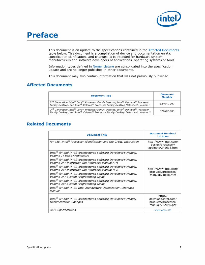
This document is an update to the specifications contained in the Affected Documents table below. This document is a compilation of device and documentation errata, specification clarifications and changes. It is intended for hardware system manufacturers and software developers of applications, operating systems or tools.
Information types defined in Nomenclature are consolidated into the specification update and are no longer published in other documents.
This document may also contain information that was not previously published.
Affected Documents
Related Documents
Document Title Document Number
2nd Generation Intel® Core™ Processor Family Desktop, Intel® Pentium® Processor Family Desktop, and Intel® Celeron® Processor Family Desktop Datasheet, Volume 1 324641-007
2nd Generation Intel® Core™ Processor Family Desktop, Intel® Pentium® Processor Family Desktop, and Intel® Celeron® Processor Family Desktop Datasheet, Volume 2 324642-003
Document Title Document Number/Location
AP-485, Intel® Processor Identification and the CPUID Instruction http://www.intel.com/design/processor/
applnots/241618.htm
Intel® 64 and IA-32 Architectures Software Developer’s Manual, Volume 1: Basic ArchitectureIntel® 64 and IA-32 Architectures Software Developer’s Manual, Volume 2A: Instruction Set Reference Manual A-MIntel® 64 and IA-32 Architectures Software Developer’s Manual, Volume 2B: Instruction Set Reference Manual N-ZIntel® 64 and IA-32 Architectures Software Developer’s Manual, Volume 3A: System Programming GuideIntel® 64 and IA-32 Architectures Software Developer’s Manual, Volume 3B: System Programming GuideIntel® 64 and IA-32 Intel Architecture Optimization Reference Manual
http://www.intel.com/products/processor/manuals/index.htm
Intel® 64 and IA-32 Architectures Software Developer’s Manual Documentation Changes
http://download.intel.com/products/processor/manual/252046.pdf
ACPI Specifications www.acpi.info

8 Specification Update
NomenclatureErrata are design defects or errors. These may cause the processor behavior to deviate from published specifications. Hardware and software designed to be used with any given stepping must assume that all errata documented for that stepping are present on all devices.
S-Spec Number is a five-digit code used to identify products. Products are differentiated by their unique characteristics such as, core speed, L2 cache size, package type, etc. as described in the processor identification information table. Read all notes associated with each S-Spec number.
Specification Changes are modifications to the current published specifications. These changes will be incorporated in any new release of the specification.
Specification Clarifications describe a specification in greater detail or further highlight a specification’s impact to a complex design situation. These clarifications will be incorporated in any new release of the specification.
Documentation Changes include typos, errors, or omissions from the current published specifications. These will be incorporated in any new release of the specification.
Note: Errata remain in the specification update throughout the product’s lifecycle, or until a particular stepping is no longer commercially available. Under these circumstances, errata removed from the specification update are archived and available upon request. Specification changes, specification clarifications and documentation changes are removed from the specification update when the appropriate changes are made to the appropriate product specification or user documentation (datasheets, manuals, etc.).
§ §

Specification Update 9
Summary Tables of Changes
The following tables indicate the errata, specification changes, specification clarifications, or documentation changes which apply to the processor. Intel may fix some of the errata in a future stepping of the component, and account for the other outstanding issues through documentation or specification changes as noted. These tables uses the following notations:
Codes Used in Summary Tables
Stepping
X: Errata exists in the stepping indicated. Specification Change or Clarification that applies to this stepping.
(No mark)
or (Blank box): This erratum is fixed in listed stepping or specification change does not apply to listed stepping.
Page
(Page): Page location of item in this document.
Status
Doc: Document change or update will be implemented.
Plan Fix: This erratum may be fixed in a future stepping of the product.
Fixed: This erratum has been previously fixed.
No Fix: There are no plans to fix this erratum.
Row
Change bar to left of a table row indicates this erratum is either new or modified from the previous version of the document.

10 Specification Update
Errata (Sheet 1 of 5)
NumberSteppings
Status ERRATAD-2 Q-0
BJ1 X X No FixAn Enabled Debug Breakpoint or Single Step Trap May Be Taken after MOV SS/POP SS Instruction if it is Followed by an Instruction That Signals a Floating Point Exception
BJ2 X X No Fix APIC Error “Received Illegal Vector” May be Lost
BJ3 X X No FixAn Uncorrectable Error Logged in IA32_CR_MC2_STATUS May also Result in a System Hang
BJ4 X X No Fix B0-B3 Bits in DR6 For Non-Enabled Breakpoints May be Incorrectly Set
BJ5 X X No FixChanging the Memory Type for an In-Use Page Translation May Lead to Memory-Ordering Violations
BJ6 X X No FixCode Segment Limit/Canonical Faults on RSM May be Serviced before Higher Priority Interrupts/Exceptions and May Push the Wrong Address Onto the Stack
BJ7 X X No FixCorruption of CS Segment Register During RSM While Transitioning From Real Mode to Protected Mode
BJ8 X X No FixDebug Exception Flags DR6.B0-B3 Flags May be Incorrect for Disabled Breakpoints
BJ9 X X No FixDR6.B0-B3 May Not Report All Breakpoints Matched When a MOV/POP SS is Followed by a Store or an MMX Instruction
BJ10 X X No FixEFLAGS Discrepancy on Page Faults and on EPT-Induced VM Exits after a Translation Change
BJ11 X X No Fix Fault on ENTER Instruction May Result in Unexpected Values on Stack Frame
BJ12 X X No Fix Faulting MMX Instruction May Incorrectly Update x87 FPU Tag Word
BJ13 X X No Fix FREEZE_WHILE_SMM Does Not Prevent Event From Pending PEBS During SMM
BJ14 X X No FixGeneral Protection Fault (#GP) for Instructions Greater than 15 Bytes May be Preempted
BJ15 X X No Fix#GP on Segment Selector Descriptor that Straddles Canonical Boundary May Not Provide Correct Exception Error Code
BJ16 X X No Fix IO_SMI Indication in SMRAM State Save Area May be Set Incorrectly
BJ17 X X No FixIRET under Certain Conditions May Cause an Unexpected Alignment Check Exception
BJ18 X X No Fix LER MSRs May Be Unreliable
BJ19 X X No FixLBR, BTS, BTM May Report a Wrong Address when an Exception/Interrupt Occurs in 64-bit Mode
BJ20 X X No FixMCi_Status Overflow Bit May Be Incorrectly Set on a Single Instance of a DTLB Error
BJ21 X X No Fix MONITOR or CLFLUSH on the Local XAPIC's Address Space Results in Hang
BJ22 X X No Fix MOV To/From Debug Registers Causes Debug Exception
BJ23 X X No Fix PEBS Record not Updated when in Probe Mode
BJ24 X X No FixPerformance Monitoring Event FP_MMX_TRANS_TO_MMX May Not Count Some Transitions
BJ25 X X No FixREP MOVS/STOS Executing with Fast Strings Enabled and Crossing Page Boundaries with Inconsistent Memory Types may use an Incorrect Data Size or Lead to Memory-Ordering Violations

Specification Update 11
BJ26 X X No FixReported Memory Type May Not Be Used to Access the VMCS and Referenced Data Structures
BJ27 X X No Fix Single Step Interrupts with Floating Point Exception Pending May Be Mishandled
BJ28 X X No Fix Storage of PEBS Record Delayed Following Execution of MOV SS or STI
BJ29 X X No Fix The Processor May Report a #TS Instead of a #GP Fault
BJ30 X X No Fix VM Exits Due to “NMI-Window Exiting” May Be Delayed by One Instruction
BJ31 X X No Fix Pending x87 FPU Exceptions (#MF) May be Signaled Earlier Than Expected
BJ32 X X No Fix Values for LBR/BTS/BTM Will be Incorrect after an Exit from SMM
BJ33 X X No Fix Unsupported PCIe* Upstream Access May Complete with an Incorrect Byte Count
BJ34 X X No FixMalformed PCIe* Transactions May be Treated as Unsupported Requests Instead of as Critical Errors
BJ35 X X No Fix PCIe* Root Port May Not Initiate Link Speed Change
BJ36 X X No FixIncorrect Address Computed For Last Byte of FXSAVE/FXRSTOR or XSAVE/XRSTOR Image Leads to Partial Memory Update
BJ37 X X No Fix Performance Monitor SSE Retired Instructions May Return Incorrect Values
BJ38 X X No FixFP Data Operand Pointer May Be Incorrectly Calculated After an FP Access Which Wraps a 4-Gbyte Boundary in Code That Uses 32-Bit Address Size in 64-bit Mode
BJ39 X X No FixFP Data Operand Pointer May Be Incorrectly Calculated After an FP Access Which Wraps a 64-Kbyte Boundary in 16-Bit Code
BJ40 X X No Fix Spurious Interrupts May be Generated From the Intel® VT-d Remap Engine
BJ41 X X No FixFault Not Reported When Setting Reserved Bits of Intel® VT-d Queued Invalidation Descriptors
BJ42 X X No FixVPHMINPOSUW Instruction in Vex Format Does Not Signal #UD When vex.vvvv !=1111b
BJ43 X X No FixLBR, BTM or BTS Records May have Incorrect Branch From Information After an EIST/T-state/S-state/C1E Transition or Adaptive Thermal Throttling
BJ44 X X No FixVMREAD/VMWRITE Instruction May Not Fail When Accessing an Unsupported Field in VMCS
BJ45 X X No Fix Clock Modulation Duty Cycle Cannot be Programmed to 6.25%
BJ46 X X No FixExecution of VAESIMC or VAESKEYGENASSIST With An Illegal Value for VEX.vvvv May Produce a #NM Exception
BJ47 X X No Fix Memory Aliasing of Code Pages May Cause Unpredictable System Behavior
BJ48 X X No FixPCI Express* Graphics Receiver Error Reported When Receiver With L0s Enabled and Link Retrain Performed
BJ49 X X No Fix Unexpected #UD on VZEROALL/VZEROUPPER
BJ50 X X No Fix Perfmon Event LD_BLOCKS.STORE_FORWARD May Overcount
BJ51 X X No FixConflict Between Processor Graphics Internal Message Cycles And Graphics Reads From Certain Physical Memory Ranges May Cause a System Hang
BJ52 X X No FixExecution of Opcode 9BH with the VEX Opcode Extension May Produce a #NM Exception
BJ53 X X No FixExecuting The GETSEC Instruction While Throttling May Result in a Processor Hang
Errata (Sheet 2 of 5)
NumberSteppings
Status ERRATAD-2 Q-0

12 Specification Update
BJ54 X X No FixA Write to the IA32_FIXED_CTR1 MSR May Result in Incorrect Value in Certain Conditions
BJ55 X X No FixInstruction Fetch May Cause Machine Check if Page Size and Memory Type Was Changed Without Invalidation
BJ56 X X No FixReception of Certain Malformed Transactions May Cause PCIe* Port to Hang Rather Than Reporting an Error
BJ57 X X No Fix PCIe* LTR Incorrectly Reported as Being Supported
BJ58 X X No Fix Performance-Counter Overflow Indication May Cause Undesired Behavior
BJ59 X X No FixXSAVE Executed During Paging-Structure Modification May Cause Unexpected Processor Behavior
BJ60 X X No Fix C-state Exit Latencies May be Higher Than Expected
BJ61 X X No FixMSR_Temperature_Target May Have an Incorrect Value in the Temperature Control Offset Field
BJ62 X X No FixIntel® VT-d Interrupt Remapping Will Not Report a Fault if Interrupt Index Exceeds FFFFH
BJ63 X X No Fix PCIe* Link Speed May Not Change From 5.0 GT/s to 2.5 GT/s
BJ64 X X No Fix L1 Data Cache Errors May be Logged With Level Set to 1 Instead of 0
BJ65 X X No FixAn Unexpected Page Fault or EPT Violation May Occur After Another Logical Processor Creates a Valid Translation for a Page
BJ66 X X No Fix TSC Deadline Not Armed While in APIC Legacy Mode
BJ67 X X No Fix PCIe* Upstream TCfgWr May Cause Unpredictable System Behavior
BJ68 X X No Fix Processor May Fail to Acknowledge a TLP Request
BJ69 X X No FixExecuting The GETSEC Instruction While Throttling May Result in a Processor Hang
BJ70 X X No Fix PerfMon Event LOAD_HIT_PRE.SW_PREFETCH May Overcount
BJ71 X X No FixExecution of FXSAVE or FXRSTOR With the VEX Prefix May Produce a #NM Exception
BJ72 X X No Fix Unexpected #UD on VPEXTRD/VPINSRD
BJ73 X X No Fix Erratum Removed
BJ74 X X No Fix Successive Fixed Counter Overflows May be Discarded
BJ75 X X No Fix#GP May be Signaled When Invalid VEX Prefix Precedes Conditional Branch Instructions
BJ76 X X No Fix A Read from The APIC-Timer CCR May Disarm The TSC_Deadline Counter
BJ77 X X No Fix An Unexpected PMI May Occur After Writing a Large Value to IA32_FIXED_CTR2
BJ78 X X No FixRDMSR From The APIC-Timer CCR May Disarm The APIC Timer in TSC Deadline Mode
BJ79 X X No Fix RC6 Entry Can be Blocked by Asynchronous Intel® VT-d Flows
BJ80 X X No FixRepeated PCIe* and/or DMI L1 Transitions During Package Power States May Cause a System Hang
BJ81 X X No Fix Execution of BIST During Cold RESET Will Result in a Machine Check Shutdown
BJ82 X X No FixPCI Express* Differential Peak-Peak Tx Voltage Swing May Violate the Specification
Errata (Sheet 3 of 5)
NumberSteppings
Status ERRATAD-2 Q-0

Specification Update 13
BJ83 X X No Fix PCIe* Presence Detect State May Not be Accurate After a Warm Reset
BJ84 X X No FixDisplay Corruption May be Seen After Graphics Voltage Rail (VCC_AXG) Power Up
BJ85 X X No FixPCMPESTRI, PCMPESTRM, VPCMPESTRI and VPCMPESTRM Always Operate with 32-bit Length Registers
BJ86 X X No FixVM Entries That Return From SMM Using VMLAUNCH May Not Update The Launch State of the VMCS
BJ87 X X No Fix Interrupt From Local APIC Timer May Not Be Detectable While Being Delivered
BJ88 X X No FixAn Unexpected Page Fault May Occur Following the Unmapping and Re-mapping of a Page
BJ89 X X No FixA PCIe* Device That Initially Transmits Minimal Posted Data Credits May Cause a System Hang
BJ90 X X No Fix Some Model Specific Branch Events May Overcount
BJ91 X X No FixSome Performance Monitoring Events in AnyThread Mode May Get Incorrect Count
BJ92 X X No Fix PDIR May Not Function Properly With FREEZE_PERFMON_ON_PMI
BJ93 X X No FixFor A Single Logical Processor Package, HTT May be Set to Zero Even Though The Package Reserves More Than One APIC ID
BJ94 X X No Fix LBR May Contain Incorrect Information When Using FREEZE_LBRS_ON_PMI
BJ95 X x No Fix A First Level Data Cache Parity Error May Result in Unexpected Behavior
BJ96 X X No Fix Intel® Trusted Execution Technology ACM Revocation
BJ97 X X Plan FixProgramming PDIR And an Additional Precise PerfMon Event May Cause Unexpected PMI or PEBS Events
BJ98 X X No Fix Performance Monitoring May Overcount Some Events During Debugging
BJ99 X X No Fix LTR Message is Not Treated as an Unsupported Request
BJ100 X X No FixUse of VMASKMOV to Access Memory Mapped I/O or Uncached Memory May Cause The Logical Processor to Hang
BJ101 X X No Fix PEBS May Unexpectedly Signal a PMI After The PEBS Buffer is Full
BJ102 X X No Fix XSAVEOPT May Fail to Save Some State after Transitions Into or Out of STM
BJ103 X X No FixPerformance Monitor Precise Instruction Retired Event May Present Wrong Indications
BJ104 X X No FixThe Value in IA32_MC3_ADDR MSR May Not be Accurate When MCACOD 0119H is Reported in IA32_MC3_Status
BJ105 X X No Fix MSR_PKG_Cx_RESIDENCY MSRs May Not be Accurate
BJ106 X No Fix Enabling/Disabling PEBS May Result in Unpredictable System Behavior
BJ107 X No FixExecution of VAESIMC or VAESKEYGENASSIST With An Illegal Value for VEX.vvvv May Produce a #NM Exception
BJ108 X No Fix Unexpected #UD on VZEROALL/VZEROUPPER
BJ109 X No Fix Successive Fixed Counter Overflows May be Discarded
BJ110 X X No FixExecution of FXSAVE or FXRSTOR With the VEX Prefix May Produce a #NM Exception
Errata (Sheet 4 of 5)
NumberSteppings
Status ERRATAD-2 Q-0

14 Specification Update
§ §
BJ111 X X No FixVM Exits Due to “NMI-Window Exiting” May Not Occur Following a VM Entry to the Shutdown State
BJ112 X X No FixExecution of INVVPID Outside 64-Bit Mode Cannot Invalidate Translations For 64-Bit Linear Addresses
BJ113 X X No Fix VEX.L is Not Ignored with VCVT*2SI Instructions
BJ114 X X No Fix MCI_ADDR May be Incorrect For Cache Parity Errors
BJ115 X X No FixInstruction Fetches Page-Table Walks May be Made Speculatively to Uncacheable Memory
BJ116 X X No Fix Reported Maximum Memory Frequency Capability May Be Higher Than Expected
BJ117 X X No FixThe Processor May Not Properly Execute Code Modified Using A Floating-Point Store
BJ118 X X No Fix Execution of GETSEC[SEXIT] May Cause a Debug Exception to be Lost
BJ119 X X No FixVM Exits Due to GETSEC May Save an Incorrect Value for “Blocking by STI” in the Context of Probe-Mode Redirection
BJ120 X X No FixSpecific Graphics Blitter Instructions May Result in Unpredictable Graphics Controller Behavior
BJ121 X X No Fix IA32_MC5_CTL2 is Not Cleared by a Warm Reset
BJ122 X X Plan Fix Performance Monitor Counters May Produce Incorrect Results
BJ123 X X No FixThe Corrected Error Count Overflow Bit in IA32_ MC0_STATUS is Not Updated After a UC Error is Logged
BJ124 X X No Fix Spurious Intel® VT-d Interrupts May Occur When the PFO Bit is Set
BJ125 X X No Fix Processor May Livelock During On Demand Clock Modulation
Errata (Sheet 5 of 5)
NumberSteppings
Status ERRATAD-2 Q-0
Specification ChangesNumber SPECIFICATION CHANGES
None for this revision of this specification update.
Specification ClarificationsNumber SPECIFICATION CLARIFICATIONS
None for this revision of this specification update.
Documentation ChangesNumber DOCUMENTATION CHANGES
BJ1 On-Demand Clock Modulation Feature Clarification

Specification Update 15
Identification Information
Component Identification using Programming InterfaceThe processor stepping can be identified by the following register contents.
Notes:1. The Extended Family, bits [27:20] are used in conjunction with the Family Code, specified in bits [11:8],
to indicate whether the processor belongs to the Intel386, Intel486, Pentium, Pentium Pro, Pentium 4, or Intel® Core™ processor family.
2. The Extended Model, bits [19:16] in conjunction with the Model Number, specified in bits [7:4], are used to identify the model of the processor within the processor’s family.
3. The Processor Type, specified in bits [13:12] indicates whether the processor is an original OEM processor, an OverDrive processor, or a dual processor (capable of being used in a dual processor system).
4. The Family Code corresponds to bits [11:8] of the EDX register after RESET, bits [11:8] of the EAX register after the CPUID instruction is executed with a 1 in the EAX register, and the generation field of the Device ID register accessible through Boundary Scan.
5. The Model Number corresponds to bits [7:4] of the EDX register after RESET, bits [7:4] of the EAX register after the CPUID instruction is executed with a 1 in the EAX register, and the model field of the Device ID register accessible through Boundary Scan.
6. The Stepping ID in bits [3:0] indicates the revision number of that model. See Table 1 for the processor stepping ID number in the CPUID information.
When EAX is initialized to a value of ‘1’, the CPUID instruction returns the Extended Family, Extended Model, Processor Type, Family Code, Model Number and Stepping ID value in the EAX register. Note that the EDX processor signature value after reset is equivalent to the processor signature output value in the EAX register.
Cache and TLB descriptor parameters are provided in the EAX, EBX, ECX and EDX registers after the CPUID instruction is executed with a 2 in the EAX register.
The processor can be identified by the following register contents.
Notes:1. The Vendor ID corresponds to bits 15:0 of the Vendor ID Register located at offset 00–01h in the PCI
function 0 configuration space.2. The Host Device ID corresponds to bits 15:0 of the Device ID Register located at Device 0 offset 02–03h
in the PCI function 0 configuration space.3. The Processor Graphics Device ID (DID2) corresponds to bits 15:0 of the Device ID Register located at
Device 2 offset 02–03h in the PCI function 0 configuration space.4. The Revision Number corresponds to bits 7:0 of the Revision ID Register located at offset 08h in the PCI
function 0 configuration space.
Reserved Extended Family1
Extended Model2 Reserved Processor
Type3Family Code4
Model Number5
Stepping ID6
31:28 27:20 19:16 15:14 13:12 11:8 7:4 3:0
00000000b 0010b 00b 0110 1010b xxxxb
Stepping Vendor ID1 Host Device ID2 Processor Graphics Device ID3 Revision ID4
D-2 8086h 0100hGT1: 0102hGT2: 0112h
GT2 (>1.3 GHz Turbo): 122h09h
Q-0 8086h 0100hGT1: 0102hGT2: 0112h
GT2 (>1.3 GHz Turbo): 122h09h

16 Specification Update
Component Marking InformationThe processor stepping can be identified by the following component markings.
Figure 1. Processor Production Top-side Markings (Example)
Table 1. Processor Identification (Sheet 1 of 3)
S-Spec Number
Processor Number Stepping Processor
Signature
Core Frequency (GHz) /
DDR3 (MHz) / Processor Graphics
Frequency
Max Intel® Turbo Boost Technology
2.0 Frequency (GHz)1
Shared L3 Cache Size (MB)
Notes
SR00C i7-2600K D-2 000206a7h 3.4 / 1333 / 850
4 core: 3.53 core: 3.62 core: 3.71 core: 3.8
8 2, 4, 6
SR00B i7-2600 D-2 000206a7h 3.4 / 1333 / 850
4 core: 3.53 core: 3.62 core: 3.71 core: 3.8
8 2, 3, 4, 5, 6
SR00E i7-2600S D-2 000206a7h 2.8 / 1333 / 850
4 core: 2.93 core: 3.32 core: 3.71 core: 3.8
8 2, 3, 4, 5, 6
SR0DG i7-2700K D-2 000206a7h 3.5 / 1333 / 850
4 core: N/A3 core: N/A2 core: N/A1 core: 3.9
8 2, 4, 6
SR008 i5-2500K D-2 000206a7h 3.3 / 1333 / 850
4 core: 3.43 core: 3.52 core: 3.61 core: 3.7
6 4, 6
SR00T i5-2500 D-2 000206a7h 3.3 / 1333 / 850
4 core: 3.43 core: 3.52 core: 3.61 core: 3.7
6 3, 4, 5, 6
LOT NO S/N
i ©'10 BRAND PROC#SLxxx SPEED[COO][FPO]
M
e4

Specification Update 17
SR009 i5-2500S D-2 000206a7h 2.7 / 1333 / 850
4 core: 2.83 core: 3.22 core: 3.61 core: 3.7
6 3, 4, 5, 6
SR00A i5-2500T D-2 000206a7h 2.3 / 1333 / 650
4 core: 2.43 core: 2.82 core: 3.21 core: 3.3
6 3, 4, 5, 6
SR00Q i5-2400 D-2 000206a7h 3.1 / 1333 / 850
4 core: 3.23 core: 3.32 core: 3.31 core: 3.4
6 3, 4, 5, 6
SR0BB i5-2405S D-2 000206a7h 2.5 / 1333 / 850
4 core: 2.63 core: 2.82 core: 3.21 core: 3.3
6 3, 4, 5, 6
SR00S i5-2400S D-2 000206a7h 2.5 / 1333 / 850
4 core: 2.63 core: 2.82 core: 3.21 core: 3.3
6 3, 4, 5, 6
SR02L i5-2320 D-2 000206a7h 3.0 / 1333 / 850
4 core: 3.13 core: 3.22 core: 3.21 core: 3.3
6 4,6
SR02K i5-2310 D-2 000206a7h 2.9 / 1333 / 850
4 core: 3.03 core: 3.12 core: 3.11 core: 3.2
6 4, 6
SR00D i5-2300 D-2 000206a7h 2.8 / 1333 / 850
4 core: 2.93 core: 3.02 core: 3.01 core: 3.1
6 4, 6
SR0G1 i5-2450P D-2 000206a7h 3.2 / 1333 / N/A
4 core: N/A3 core: N/A2 core: N/A1 core: 3.5
6 4, 6
SR0G2 i5-2380P D-2 000206a7h 3.1 / 1333 / N/A
4 core: N/A3 core: N/A2 core: N/A1 core: 3.4
6 4, 6
SR0QH i5-2550K D-2 000206a7h 3.4 / 1333 / N/A
4 core: N/A3 core: N/A2 core: N/A1 core: 3.8
6 4, 6
SR05C i3-2100 Q-0 000206a7h 3.1 / 1333 / 850 N/A 3 2, 4
SR05Z i3-2100T Q-0 000206a7h 2.5 / 1333 / 650 N/A 3 2, 4
SR05D i3-2102 Q-0 000206a7h 3.1 / 1333 / 850 N/A 3 2,4
SR0BA i3-2105 J-1 000206a7h 3.1 / 1333 / 850 N/A 3 2, 4
SR05W i3-2130 Q-0 000206a7h 3.4 / 1333 / 850 N/A 3 2, 4
SR0AY i3-2125 J-1 000206a7h 3.3 / 1333 / 850 N/A 3 2, 4
Table 1. Processor Identification (Sheet 2 of 3)
S-Spec Number
Processor Number Stepping Processor
Signature
Core Frequency (GHz) /
DDR3 (MHz) / Processor Graphics
Frequency
Max Intel® Turbo Boost Technology
2.0 Frequency (GHz)1
Shared L3 Cache Size (MB)
Notes

18 Specification Update
Notes:1. This column indicates maximum Intel® Turbo Boost Technology 2.0 frequency (GHz) for 4,3, 2 or 1
cores active respectively.2. Intel® Hyper-Threading Technology enabled.3. Intel® Trusted Execution Technology (Intel® TXT) enabled.4. Intel® Virtualization Technology for IA-32, Intel® 64 and Intel® Architecture (Intel® VT-x) enabled.5. Intel® Virtualization Technology for Directed I/O (Intel® VT-d) enabled.6. Intel® AES-NI enabled.
§ §
SR05Y i3-2120 Q-0 000206a7h 3.3 / 1333 / 850 N/A 3 2, 4
SR060 i3-2120T Q-0 000206a7h 2.6 /1333 / 650 N/A 3 4
SR057 G870 Q-0 000206a7h 3.1 / 1333 / 850 N/A 3 4
SR0MF G860T Q-0 000206a7h 2.6 / 1333 / 650 N/A 3 4
SR058 G860 Q-0 000206a7h 3.0 /1333 / 850 N/A 3 4
SR05Q G850 Q-0 000206a7h 2.9 / 1333 / 850 N/A 3 4
SR05P G840 Q-0 000206a7h 2.8 / 1333 / 850 N/A 3 4
SR059 G640 Q-0 000206a7h 2.8 / 1066 / 850 N/A 3 4
SR066 G640T Q-0 000206a7h 2.4 /1066 / 650 N/A 3 4
SR05S G630 Q-0 000206a7h 2.7 /1066 / 850 N/A 3 4
SR05U G630T Q-0 000206a7h 2.3 / 1066 / 650 N/A 3 4
SR05R G620 Q-0 000206a7h 2.6 / 1066 / 850 N/A 3 4
SR05T G620T Q-0 000206a7h 2.2 / 1066 / 650 N/A 3 4
SR0GR G460 Q-0 000206a7h 1.8 / 1066 / 650 N/A 1.5 4
SR0BY G440 Q-0 000206a7h 1.6 / 1066 / 650 N/A 1 4
SR061 G550 Q-0 000206a7h 2.6 / 1066 / 850 N/A 2 4
SR05L G540T Q-0 000206a7h 2.1 / 1066 / 650 N/A 2 4
SR05H G530 Q-0 000206a7h 2.4 / 1066 / 850 N/A 2 4
SR05K G530T Q-0 000206a7h 2.0 / 1066/ 650 N/A 2 4
SR05J G540 Q-0 000206a7h 2.5 /1066 / 850 N/A 2 4
SR0RS G645 Q-0 000206a7h 2.9 / 1066 / 850 N/A 3 4
SR0S0 G645T Q-0 000206a7h 2.5 / 1066 / 650 N/A 3 4
SR0S8 G465 Q-0 000206a7h 1.9 / 1066 / 650 N/A 1.5 4
SR05V G550T Q-0 000206a7h 2.2 / 1066 / 650 N/A 2 4
SR0RZ G555 Q-0 000206a7h 2.7 / 1066 / 850 N/A 2 4
SR05M G622 Q-0 000206a7h 2.6 / 1066 / 850 N/A 3 4
SR05N G632 Q-0 000206a7h 2.7 / 1066 / 850 N/A 3 4
SR059 G640 Q-0 000206a7h 2.8 / 1066 / 850 N/A 3 4
Table 1. Processor Identification (Sheet 3 of 3)
S-Spec Number
Processor Number Stepping Processor
Signature
Core Frequency (GHz) /
DDR3 (MHz) / Processor Graphics
Frequency
Max Intel® Turbo Boost Technology
2.0 Frequency (GHz)1
Shared L3 Cache Size (MB)
Notes

Specification Update 19
Errata
BJ1. An Enabled Debug Breakpoint or Single Step Trap May Be Taken after MOV SS/POP SS Instruction if it is Followed by an Instruction That Signals a Floating Point Exception
Problem: A MOV SS/POP SS instruction should inhibit all interrupts including debug breakpoints until after execution of the following instruction. This is intended to allow the sequential execution of MOV SS/POP SS and MOV [r/e]SP, [r/e]BP instructions without having an invalid stack during interrupt handling. However, an enabled debug breakpoint or single step trap may be taken after MOV SS/POP SS if this instruction is followed by an instruction that signals a floating point exception rather than a MOV [r/e]SP, [r/e]BP instruction. This results in a debug exception being signaled on an unexpected instruction boundary, since the MOV SS/POP SS and the following instruction should be executed atomically.
Implication: This can result in incorrect signaling of a debug exception and possibly a mismatched Stack Segment and Stack Pointer. If MOV SS/POP SS is not followed by a MOV [r/e]SP, [r/e]BP, there may be a mismatched Stack Segment and Stack Pointer on any exception. Intel has not observed this erratum with any commercially available software or system.
Workaround: As recommended in the IA32 Intel® Architecture Software Developer's Manual, the use of MOV SS/POP SS in conjunction with MOV [r/e]SP, [r/e]BP will avoid the failure since the MOV [r/e]SP, [r/e]BP will not generate a floating point exception. Developers of debug tools should be aware of the potential incorrect debug event signaling created by this erratum
Status: For the steppings affected, see the Summary Tables of Changes.
BJ2. APIC Error “Received Illegal Vector” May be LostProblem: APIC (Advanced Programmable Interrupt Controller) may not update the ESR (Error
Status Register) flag Received Illegal Vector bit [6] properly when an illegal vector error is received on the same internal clock that the ESR is being written (as part of the write-read ESR access flow). The corresponding error interrupt will also not be generated for this case.
Implication: Due to this erratum, an incoming illegal vector error may not be logged into ESR properly and may not generate an error interrupt.
Workaround: None identified.
Status: For the steppings affected, see the Summary Tables of Changes.
BJ3. An Uncorrectable Error Logged in IA32_CR_MC2_STATUS May also Result in a System Hang
Problem: Uncorrectable errors logged in IA32_CR_MC2_STATUS MSR (409H) may also result in a system hang causing an Internal Timer Error (MCACOD = 0x0400h) to be logged in another machine check bank (IA32_MCi_STATUS).
Implication: Uncorrectable errors logged in IA32_CR_MC2_STATUS can further cause a system hang and an Internal Timer Error to be logged.
Workaround: None identified.
Status: For the steppings affected, see the Summary Tables of Changes.

20 Specification Update
BJ4. B0-B3 Bits in DR6 For Non-Enabled Breakpoints May be Incorrectly SetProblem: Some of the B0-B3 bits (breakpoint conditions detect flags, bits [3:0]) in DR6 may be
incorrectly set for non-enabled breakpoints when the following sequence happens:
1. MOV or POP instruction to SS (Stack Segment) selector.
2. Next instruction is FP (Floating Point) that gets FP assist.
3. Another instruction after the FP instruction completes successfully.
4. A breakpoint occurs due to either a data breakpoint on the preceding instruction or a code breakpoint on the next instruction.
Due to this erratum a non-enabled breakpoint triggered on step 1 or step 2 may be reported in B0-B3 after the breakpoint occurs in step 4.
Implication: Due to this erratum, B0-B3 bits in DR6 may be incorrectly set for non-enabled breakpoints.
Workaround: Software should not execute a floating point instruction directly after a MOV SS or POP SS instruction.
Status: For the steppings affected, see the Summary Tables of Changes.
BJ5. Changing the Memory Type for an In-Use Page Translation May Lead to Memory-Ordering Violations
Problem: Under complex microarchitectural conditions, if software changes the memory type for data being actively used and shared by multiple threads without the use of semaphores or barriers, software may see load operations execute out of order.
Implication: Memory ordering may be violated. Intel has not observed this erratum with any commercially available software.
Workaround: Software should ensure pages are not being actively used before requesting their memory type be changed.
Status: For the steppings affected, see the Summary Tables of Changes.
BJ6. Code Segment Limit/Canonical Faults on RSM May be Serviced before Higher Priority Interrupts/Exceptions and May Push the Wrong Address Onto the Stack
Problem: Normally, when the processor encounters a Segment Limit or Canonical Fault due to code execution, a #GP (General Protection Exception) fault is generated after all higher priority Interrupts and exceptions are serviced. Due to this erratum, if RSM (Resume from System Management Mode) returns to execution flow that results in a Code Segment Limit or Canonical Fault, the #GP fault may be serviced before a higher priority Interrupt or Exception (e.g. NMI (Non-Maskable Interrupt), Debug break(#DB), Machine Check (#MC), etc.). If the RSM attempts to return to a non-canonical address, the address pushed onto the stack for this #GP fault may not match the non-canonical address that caused the fault.
Implication: Operating systems may observe a #GP fault being serviced before higher priority Interrupts and Exceptions. Intel has not observed this erratum on any commercially available software.
Workaround: None identified.
Status: For the steppings affected, see the Summary Tables of Changes.

Specification Update 21
BJ7. Corruption of CS Segment Register During RSM While Transitioning From Real Mode to Protected Mode
Problem: During the transition from real mode to protected mode, if an SMI (System Management Interrupt) occurs between the MOV to CR0 that sets PE (Protection Enable, bit 0) and the first far JMP, the subsequent RSM (Resume from System Management Mode) may cause the lower two bits of CS segment register to be corrupted.
Implication: The corruption of the bottom two bits of the CS segment register will have no impact unless software explicitly examines the CS segment register between enabling protected mode and the first far JMP. Intel® 64 and IA-32 Architectures Software Developer's Manual Volume 3A: System Programming Guide, Part 1, in the section titled “Switching to Protected Mode” recommends the far JMP immediately follows the write to CR0 to enable protected mode. Intel has not observed this erratum with any commercially available software.
Workaround: None identified.
Status: For the steppings affected, see the Summary Tables of Changes.
BJ8. Debug Exception Flags DR6.B0-B3 Flags May be Incorrect for Disabled Breakpoints
Problem: When a debug exception is signaled on a load that crosses cache lines with data forwarded from a store and whose corresponding breakpoint enable flags are disabled (DR7.G0-G3 and DR7.L0-L3), the DR6.B0-B3 flags may be incorrect.
Implication: The debug exception DR6.B0-B3 flags may be incorrect for the load if the corresponding breakpoint enable flag in DR7 is disabled.
Workaround: None identified.
Status: For the steppings affected, see the Summary Tables of Changes.
BJ9. DR6.B0-B3 May Not Report All Breakpoints Matched When a MOV/POP SS is Followed by a Store or an MMX Instruction
Problem: Normally, data breakpoints matches that occur on a MOV SS, r/m or POP SS will not cause a debug exception immediately after MOV/POP SS but will be delayed until the instruction boundary following the next instruction is reached. After the debug exception occurs, DR6.B0-B3 bits will contain information about data breakpoints matched during the MOV/POP SS as well as breakpoints detected by the following instruction. Due to this erratum, DR6.B0-B3 bits may not contain information about data breakpoints matched during the MOV/POP SS when the following instruction is either an MMX instruction that uses a memory addressing mode with an index or a store instruction.
Implication: When this erratum occurs, DR6 may not contain information about all breakpoints matched. This erratum will not be observed under the recommended usage of the MOV SS,r/m or POP SS instructions (i.e., following them only with an instruction that writes (E/R)SP).
Workaround: None identified.
Status: For the steppings affected, see the Summary Tables of Changes.

22 Specification Update
BJ10. EFLAGS Discrepancy on Page Faults and on EPT-Induced VM Exits after a Translation Change
Problem: This erratum is regarding the case where paging structures are modified to change a linear address from writable to non-writable without software performing an appropriate TLB invalidation. When a subsequent access to that address by a specific instruction (ADD, AND, BTC, BTR, BTS, CMPXCHG, DEC, INC, NEG, NOT, OR, ROL/ROR, SAL/SAR/SHL/SHR, SHLD, SHRD, SUB, XOR, and XADD) causes a page fault or an EPT-induced VM exit, the value saved for EFLAGS may incorrectly contain the arithmetic flag values that the EFLAGS register would have held had the instruction completed without fault or VM exit. For page faults, this can occur even if the fault causes a VM exit or if its delivery causes a nested fault.
Implication: None identified. Although the EFLAGS value saved by an affected event (a page fault or an EPT-induced VM exit) may contain incorrect arithmetic flag values, Intel has not identified software that is affected by this erratum. This erratum will have no further effects once the original instruction is restarted because the instruction will produce the same results as if it had initially completed without fault or VM exit.
Workaround: If the handler of the affected events inspects the arithmetic portion of the saved EFLAGS value, then system software should perform a synchronized paging structure modification and TLB invalidation.
Status: For the steppings affected, see the Summary Tables of Changes.
BJ11. Fault on ENTER Instruction May Result in Unexpected Values on Stack Frame
Problem: The ENTER instruction is used to create a procedure stack frame. Due to this erratum, if execution of the ENTER instruction results in a fault, the dynamic storage area of the resultant stack frame may contain unexpected values (i.e. residual stack data as a result of processing the fault).
Implication: Data in the created stack frame may be altered following a fault on the ENTER instruction. Please refer to “Procedure Calls For Block-Structured Languages” in IA-32 Intel® Architecture Software Developer's Manual, Vol. 1, Basic Architecture, for information on the usage of the ENTER instructions. This erratum is not expected to occur in ring 3. Faults are usually processed in ring 0 and stack switch occurs when transferring to ring 0. Intel has not observed this erratum on any commercially available software.
Workaround: None identified.
Status: For the steppings affected, see the Summary Tables of Changes.

Specification Update 23
BJ12. Faulting MMX Instruction May Incorrectly Update x87 FPU Tag WordProblem: Under a specific set of conditions, MMX stores (MOVD, MOVQ, MOVNTQ, MASKMOVQ)
which cause memory access faults (#GP, #SS, #PF, or #AC), may incorrectly update the x87 FPU tag word register.
This erratum will occur when the following additional conditions are also met: •The MMX store instruction must be the first MMX instruction to operate on x87 FPU state (i.e. the x87 FP tag word is not already set to 0x0000).
•For MOVD, MOVQ, MOVNTQ stores, the instruction must use an addressing mode that uses an index register (this condition does not apply to MASKMOVQ).
Implication: If the erratum conditions are met, the x87 FPU tag word register may be incorrectly set to a 0x0000 value when it should not have been modified.
Workaround: None identified
Status: For the steppings affected, see the Summary Tables of Changes.
BJ13. FREEZE_WHILE_SMM Does Not Prevent Event From Pending PEBS During SMM
Problem: In general, a PEBS record should be generated on the first count of the event after the counter has overflowed. However, IA32_DEBUGCTL_MSR.FREEZE_WHILE_SMM (MSR 1D9H, bit [14]) prevents performance counters from counting during SMM (System Management Mode). Due to this erratum, if:
1. A performance counter overflowed before an SMI.
2. A PEBS record has not yet been generated because another count of the event has not occurred.
3. The monitored event occurs during SMM then a PEBS record will be saved after the next RSM instruction.
When FREEZE_WHILE_SMM is set, a PEBS should not be generated until the event occurs outside of SMM.
Implication: A PEBS record may be saved after an RSM instruction due to the associated performance counter detecting the monitored event during SMM; even when FREEZE_WHILE_SMM is set.
Workaround: None identified.
Status: For the steppings affected, see the Summary Tables of Changes.
BJ14. General Protection Fault (#GP) for Instructions Greater than 15 Bytes May be Preempted
Problem: When the processor encounters an instruction that is greater than 15 bytes in length, a #GP is signaled when the instruction is decoded. Under some circumstances, the #GP fault may be preempted by another lower priority fault (e.g. Page Fault (#PF)). However, if the preempting lower priority faults are resolved by the operating system and the instruction retried, a #GP fault will occur.
Implication: Software may observe a lower-priority fault occurring before or in lieu of a #GP fault. Instructions of greater than 15 bytes in length can only occur if redundant prefixes are placed before the instruction.
Workaround: None identified.
Status: For the steppings affected, see the Summary Tables of Changes.

24 Specification Update
BJ15. #GP on Segment Selector Descriptor that Straddles Canonical Boundary May Not Provide Correct Exception Error Code
Problem: During a #GP (General Protection Exception), the processor pushes an error code on to the exception handler's stack. If the segment selector descriptor straddles the canonical boundary, the error code pushed onto the stack may be incorrect.
Implication: An incorrect error code may be pushed onto the stack. Intel has not observed this erratum with any commercially available software.
Workaround: None identified.
Status: For the steppings affected, see the Summary Tables of Changes.
BJ16. IO_SMI Indication in SMRAM State Save Area May be Set IncorrectlyProblem: The IO_SMI bit in SMRAM's location 7FA4H is set to “1” by the CPU to indicate a System
Management Interrupt (SMI) occurred as the result of executing an instruction that reads from an I/O port. Due to this erratum, the IO_SMI bit may be incorrectly set by:
•A non-I/O instruction
•SMI is pending while a lower priority event interrupts
•A REP I/O read
•A I/O read that redirects to MWAIT
Implication: SMM handlers may get false IO_SMI indication.Workaround: The SMM handler has to evaluate the saved context to determine if the SMI was
triggered by an instruction that read from an I/O port. The SMM handler must not restart an I/O instruction if the platform has not been configured to generate a synchronous SMI for the recorded I/O port address.
Status: For the steppings affected, see the Summary Tables of Changes.
BJ17. IRET under Certain Conditions May Cause an Unexpected Alignment Check Exception
Problem: In IA-32e mode, it is possible to get an Alignment Check Exception (#AC) on the IRET instruction even though alignment checks were disabled at the start of the IRET. This can only occur if the IRET instruction is returning from CPL3 code to CPL3 code. IRETs from CPL0/1/2 are not affected. This erratum can occur if the EFLAGS value on the stack has the AC flag set, and the interrupt handler's stack is misaligned. In IA-32e mode, RSP is aligned to a 16-byte boundary before pushing the stack frame.
Implication: In IA-32e mode, under the conditions given above, an IRET can get a #AC even if alignment checks are disabled at the start of the IRET. This erratum can only be observed with a software generated stack frame.
Workaround: Software should not generate misaligned stack frames for use with IRET.
Status: For the steppings affected, see the Summary Tables of Changes.
BJ18. LER MSRs May Be UnreliableProblem: Due to certain internal processor events, updates to the LER (Last Exception Record)
MSRs, MSR_LER_FROM_LIP (1DDH) and MSR_LER_TO_LIP (1DEH), may happen when no update was expected.
Implication: The values of the LER MSRs may be unreliable.Workaround: None identified.
Status: For the steppings affected, see the Summary Tables of Changes.

Specification Update 25
BJ19. LBR, BTS, BTM May Report a Wrong Address when an Exception/Interrupt Occurs in 64-bit Mode
Problem: An exception/interrupt event should be transparent to the LBR (Last Branch Record), BTS (Branch Trace Store) and BTM (Branch Trace Message) mechanisms. However, during a specific boundary condition where the exception/interrupt occurs right after the execution of an instruction at the lower canonical boundary (0x00007FFFFFFFFFFF) in 64-bit mode, the LBR return registers will save a wrong return address with bits 63 to 48 incorrectly sign extended to all 1's. Subsequent BTS and BTM operations which report the LBR will also be incorrect.
Implication: LBR, BTS and BTM may report incorrect information in the event of an exception/interrupt.
Workaround: None identified.
Status: For the steppings affected, see the Summary Tables of Changes.
BJ20. MCi_Status Overflow Bit May Be Incorrectly Set on a Single Instance of a DTLB Error
Problem: A single Data Translation Look Aside Buffer (DTLB) error can incorrectly set the Overflow (bit [62]) in the MCi_Status register. A DTLB error is indicated by MCA error code (bits [15:0]) appearing as binary value, 000x 0000 0001 0100, in the MCi_Status register.
Implication: Due to this erratum, the Overflow bit in the MCi_Status register may not be an accurate indication of multiple occurrences of DTLB errors. There is no other impact to normal processor functionality.
Workaround: None identified.
Status: For the steppings affected, see the Summary Tables of Changes.
BJ21. MONITOR or CLFLUSH on the Local XAPIC's Address Space Results in Hang
Problem: If the target linear address range for a MONITOR or CLFLUSH is mapped to the local xAPIC's address space, the processor will hang.
Implication: When this erratum occurs, the processor will hang. The local xAPIC's address space must be uncached. The MONITOR instruction only functions correctly if the specified linear address range is of the type write-back. CLFLUSH flushes data from the cache. Intel has not observed this erratum with any commercially available software.
Workaround: Do not execute MONITOR or CLFLUSH instructions on the local xAPIC address space.
Status: For the steppings affected, see the Summary Tables of Changes.

26 Specification Update
BJ22. MOV To/From Debug Registers Causes Debug ExceptionProblem: When in V86 mode, if a MOV instruction is executed to/from a debug registers, a
general-protection exception (#GP) should be generated. However, in the case when the general detect enable flag (GD) bit is set, the observed behavior is that a debug exception (#DB) is generated instead.
Implication: With debug-register protection enabled (i.e., the GD bit set), when attempting to execute a MOV on debug registers in V86 mode, a debug exception will be generated instead of the expected general-protection fault.
Workaround: In general, operating systems do not set the GD bit when they are in V86 mode. The GD bit is generally set and used by debuggers. The debug exception handler should check that the exception did not occur in V86 mode before continuing. If the exception did occur in V86 mode, the exception may be directed to the general-protection exception handler.
Status: For the steppings affected, see the Summary Tables of Changes.
BJ23. PEBS Record not Updated when in Probe ModeProblem: When a performance monitoring counter is configured for PEBS (Precise Event Based
Sampling), overflows of the counter can result in storage of a PEBS record in the PEBS buffer. Due to this erratum, if the overflow occurs during probe mode, it may be ignored and a new PEBS record may not be added to the PEBS buffer.
Implication: Due to this erratum, the PEBS buffer may not be updated by overflows that occur during probe mode.
Workaround: None identified.
Status: For the steppings affected, see the Summary Tables of Changes.
BJ24. Performance Monitoring Event FP_MMX_TRANS_TO_MMX May Not Count Some Transitions
Problem: Performance Monitor Event FP_MMX_TRANS_TO_MMX (Event CCH, Umask 01H) counts transitions from x87 Floating Point (FP) to MMX™ instructions. Due to this erratum, if only a small number of MMX instructions (including EMMS) are executed immediately after the last FP instruction, a FP to MMX transition may not be counted.
Implication: The count value for Performance Monitoring Event FP_MMX_TRANS_TO_MMX may be lower than expected. The degree of undercounting is dependent on the occurrences of the erratum condition while the counter is active. Intel has not observed this erratum with any commercially available software.
Workaround: None identified.
Status: For the steppings affected, see the Summary Tables of Changes.

Specification Update 27
BJ25. REP MOVS/STOS Executing with Fast Strings Enabled and Crossing Page Boundaries with Inconsistent Memory Types may use an Incorrect Data Size or Lead to Memory-Ordering Violations
Problem: Under certain conditions as described in the Software Developers Manual section “Out-of-Order Stores For String Operations in Pentium 4, Intel Xeon, and P6 Family Processors” the processor performs REP MOVS or REP STOS as fast strings. Due to this erratum fast string REP MOVS/REP STOS instructions that cross page boundaries from WB/WC memory types to UC/WP/WT memory types, may start using an incorrect data size or may observe memory ordering violations.
Implication: Upon crossing the page boundary the following may occur, dependent on the new page memory type:
• UC the data size of each write will now always be 8 bytes, as opposed to the original data size.
• WP the data size of each write will now always be 8 bytes, as opposed to the original data size and there may be a memory ordering violation.
• WT there may be a memory ordering violation.Workaround: Software should avoid crossing page boundaries from WB or WC memory type to UC,
WP or WT memory type within a single REP MOVS or REP STOS instruction that will execute with fast strings enabled.
Status: For the steppings affected, see the Summary Tables of Changes.
BJ26. Reported Memory Type May Not Be Used to Access the VMCS and Referenced Data Structures
Problem: Bits 53:50 of the IA32_VMX_BASIC MSR report the memory type that the processor uses to access the VMCS and data structures referenced by pointers in the VMCS. Due to this erratum, a VMX access to the VMCS or referenced data structures will instead use the memory type that the MTRRs (memory-type range registers) specify for the physical address of the access.
Implication: Bits 53:50 of the IA32_VMX_BASIC MSR report that the WB (write-back) memory type will be used but the processor may use a different memory type.
Workaround: Software should ensure that the VMCS and referenced data structures are located at physical addresses that are mapped to WB memory type by the MTRRs.
Status: For the steppings affected, see the Summary Tables of Changes.
BJ27. Single Step Interrupts with Floating Point Exception Pending May Be Mishandled
Problem: In certain circumstances, when a floating point exception (#MF) is pending during single-step execution, processing of the single-step debug exception (#DB) may be mishandled.
Implication: When this erratum occurs, #DB will be incorrectly handled as follows:
•#DB is signaled before the pending higher priority #MF (Interrupt 16).
•#DB is generated twice on the same instruction.Workaround: None identified.
Status: For the steppings affected, see the Summary Tables of Changes.

28 Specification Update
BJ28. Storage of PEBS Record Delayed Following Execution of MOV SS or STIProblem: When a performance monitoring counter is configured for PEBS (Precise Event Based
Sampling), overflow of the counter results in storage of a PEBS record in the PEBS buffer. The information in the PEBS record represents the state of the next instruction to be executed following the counter overflow. Due to this erratum, if the counter overflow occurs after execution of either MOV SS or STI, storage of the PEBS record is delayed by one instruction.
Implication: When this erratum occurs, software may observe storage of the PEBS record being delayed by one instruction following execution of MOV SS or STI. The state information in the PEBS record will also reflect the one instruction delay.
Workaround: None identified.
Status: For the steppings affected, see the Summary Tables of Changes.
BJ29. The Processor May Report a #TS Instead of a #GP FaultProblem: A jump to a busy TSS (Task-State Segment) may cause a #TS (invalid TSS exception)
instead of a #GP fault (general protection exception).
Implication: Operation systems that access a busy TSS may get invalid TSS fault instead of a #GP fault. Intel has not observed this erratum with any commercially available software.
Workaround: None identified.
Status: For the steppings affected, see the Summary Tables of Changes.
BJ30. VM Exits Due to “NMI-Window Exiting” May Be Delayed by One Instruction
Problem: If VM entry is executed with the “NMI-window exiting” VM-execution control set to 1, a VM exit with exit reason “NMI window” should occur before execution of any instruction if there is no virtual-NMI blocking, no blocking of events by MOV SS, and no blocking of events by STI. If VM entry is made with no virtual-NMI blocking but with blocking of events by either MOV SS or STI, such a VM exit should occur after execution of one instruction in VMX non-root operation. Due to this erratum, the VM exit may be delayed by one additional instruction.
Implication: VMM software using “NMI-window exiting” for NMI virtualization should generally be unaffected, as the erratum causes at most a one-instruction delay in the injection of a virtual NMI, which is virtually asynchronous. The erratum may affect VMMs relying on deterministic delivery of the affected VM exits.
Workaround: None identified.
Status: For the steppings affected, see the Summary Tables of Changes.
BJ31. Pending x87 FPU Exceptions (#MF) May be Signaled Earlier Than Expected
Problem: x87 instructions that trigger #MF normally service interrupts before the #MF. Due to this erratum, if an instruction that triggers #MF is executed while Enhanced Intel SpeedStep® Technology transitions, Intel® Turbo Boost Technology transitions, or Thermal Monitor events occur, the pending #MF may be signaled before pending interrupts are serviced.
Implication: Software may observe #MF being signaled before pending interrupts are serviced.Workaround: None identified.
Status: For the steppings affected, see the Summary Tables of Changes.

Specification Update 29
BJ32. Values for LBR/BTS/BTM Will be Incorrect after an Exit from SMMProblem: After a return from SMM (System Management Mode), the CPU will incorrectly update
the LBR (Last Branch Record) and the BTS (Branch Trace Store), hence rendering their data invalid. The corresponding data if sent out as a BTM on the system bus will also be incorrect. Note: This issue would only occur when one of the 3 above mentioned debug support facilities are used.
Implication: The value of the LBR, BTS, and BTM immediately after an RSM operation should not be used.
Workaround: None identified.
Status: For the steppings affected, see the Summary Tables of Changes.
BJ33. Unsupported PCIe* Upstream Access May Complete with an Incorrect Byte Count
Problem: PCIe* Upstream IO and Configuration accesses are not supported. If an IO or Configuration request is received upstream, the integrated PCIe controller will treat it as an unsupported request, the request will be dropped, and a completion will be sent with the UR (Unsupported Request) completion status. This completion, according to the PCIe specification, should indicate a byte count of 4. Due to this erratum, the byte count is set to the same byte count as the offending request.
Implication: The processor response to an unsupported PCIe access may not fully comply to the PCIe specification.
Workaround: PCIe agents should not issue unsupported accesses.
Status: For the steppings affected, see the Summary Tables of Changes.
BJ34. Malformed PCIe* Transactions May be Treated as Unsupported Requests Instead of as Critical Errors
Problem: PCIe MSG/MSG_D TLPs (Transaction Layer Packets) with incorrect Routing Code as well as the deprecated TCfgRD and TCfgWr types should be treated as malformed transactions leading to a critical error. Due to this erratum, the integrated PCIe controller's root ports may treat such messages as UR (Unsupported Requests).
Implication: Legacy malformed PCIe transactions may be treated as UR instead of as critical errors.Workaround: None identified.
Status: For the steppings affected, see the Summary Tables of Changes.

30 Specification Update
BJ35. PCIe* Root Port May Not Initiate Link Speed ChangeProblem: PCIe specification rev 2.0 requires the upstream component to maintain the PCIe link
at the target link speed or the highest speed supported by both components on the link, whichever is lower. PCIe root port will not initiate the link speed change without being triggered by the software. System BIOS will trigger the link speed change under normal boot scenarios. However, BIOS is not involved in some scenarios such as link disable/re-enable or secondary bus reset and therefore the speed change may not occur unless initiated by the downstream component. This erratum does not affect the ability of the downstream component to initiate a link speed change. All known 5.0Gb/s-capable PCIe downstream components have been observed to initiate the link speed change without relying on the root port to do so.
Implication: Due to this erratum, the PCIe root port may not initiate a link speed change during some hardware scenarios causing the PCIe link to operate at a lower than expected speed. Intel has not observed this erratum with any commercially available platform.
Workaround: None identified.
Status: For the steppings affected, see the Summary Tables of Changes.
BJ36. Incorrect Address Computed For Last Byte of FXSAVE/FXRSTOR or XSAVE/XRSTOR Image Leads to Partial Memory Update
Problem: A partial memory state save of the FXSAVE or XSAVE image or a partial memory state restore of the FXRSTOR or XRSTOR image may occur if a memory address exceeds the 64KB limit while the processor is operating in 16-bit mode or if a memory address exceeds the 4GB limit while the processor is operating in 32-bit mode.
Implication: FXSAVE/FXRSTOR or XSAVE/XRSTOR will incur a #GP fault due to the memory limit violation as expected but the memory state may be only partially saved or restored.
Workaround: Software should avoid memory accesses that wrap around the respective 16-bit and 32-bit mode memory limits.
Status: For the steppings affected, see the Summary Tables of Changes.
BJ37. Performance Monitor SSE Retired Instructions May Return Incorrect Values
Problem: Performance Monitoring counter SIMD_INST_RETIRED (Event: C7H) is used to track retired SSE instructions. Due to this erratum, the processor may also count other types of instructions resulting in higher than expected values.
Implication: Performance Monitoring counter SIMD_INST_RETIRED may report count higher than expected.
Workaround: None identified.
Status: For the steppings affected, see the Summary Tables of Changes.

Specification Update 31
BJ38. FP Data Operand Pointer May Be Incorrectly Calculated After an FP Access Which Wraps a 4-Gbyte Boundary in Code That Uses 32-Bit Address Size in 64-bit Mode
Problem: The FP (Floating Point) Data Operand Pointer is the effective address of the operand associated with the last non-control FP instruction executed by the processor. If an 80-bit FP access (load or store) uses a 32-bit address size in 64-bit mode and the memory access wraps a 4-Gbyte boundary and the FP environment is subsequently saved, the value contained in the FP Data Operand Pointer may be incorrect.
Implication: Due to this erratum, the FP Data Operand Pointer may be incorrect. Wrapping an 80-bit FP load around a 4-Gbyte boundary in this way is not a normal programming practice. Intel has not observed this erratum with any commercially available software.
Workaround: If the FP Data Operand Pointer is used in a 64-bit operating system which may run code accessing 32-bit addresses, care must be taken to ensure that no 80-bit FP accesses are wrapped around a 4-Gbyte boundary.
Status: For the steppings affected, see the Summary Tables of Changes.
BJ39. FP Data Operand Pointer May Be Incorrectly Calculated After an FP Access Which Wraps a 64-Kbyte Boundary in 16-Bit Code
Problem: The FP (Floating Point) Data Operand Pointer is the effective address of the operand associated with the last non-control FP instruction executed by the processor. If an 80-bit FP access (load or store) occurs in a 16-bit mode other than protected mode (in which case the access will produce a segment limit violation), the memory access wraps a 64-Kbyte boundary, and the FP environment is subsequently saved, the value contained in the FP Data Operand Pointer may be incorrect.
Implication: Due to this erratum, the FP Data Operand Pointer may be incorrect. Wrapping an 80-bit FP load around a segment boundary in this way is not a normal programming practice. Intel has not observed this erratum with any commercially available software.
Workaround: If the FP Data Operand Pointer is used in an operating system which may run 16-bit FP code, care must be taken to ensure that no 80-bit FP accesses are wrapped around a 64-Kbyte boundary.
Status: For the steppings affected, see the Summary Tables of Changes.
BJ40. Spurious Interrupts May be Generated From the Intel® VT-d Remap Engine
Problem: If software clears the F (Fault) bit 127 of the Fault Recording Register (FRCD_REG at offset 0x208 in Remap Engine BAR) by writing 1b through RW1C command (Read Write 1 to Clear) when the F bit is already clear then a spurious interrupt from Intel® VT-d (Intel® Virtualization Technology for Directed I/O) Remap Engine may be observed.
Implication: Due to this erratum, spurious interrupts will occur from the Intel VT-d Remap Engine following RW1C clearing F bit.
Workaround: None identified.
Status: For the steppings affected, see the Summary Tables of Changes.

32 Specification Update
BJ41. Fault Not Reported When Setting Reserved Bits of Intel® VT-d Queued Invalidation Descriptors
Problem: Reserved bits in the Queued Invalidation descriptors of Intel VT-d (Virtualization Technology for Directed I/O) are expected to be zero, meaning that software must program them as zero while the processor checks if they are not zero. Upon detection of a non-zero bit in a reserved field, an Intel VT-d fault should be recorded. Due to this erratum, the processor does not check reserved bit values for Queued Invalidation descriptors.
Implication: Due to this erratum, faults will not be reported when writing to reserved bits of Intel VT-d Queued Invalidation Descriptors.
Workaround: None identified
Status: For the steppings affected, see the Summary Tables of Changes.
BJ42. VPHMINPOSUW Instruction in Vex Format Does Not Signal #UD When vex.vvvv !=1111b
Problem: Processor does not signal #UD fault when executing the reserved instruction VPHMINPOSUW with vex.vvvv !=1111b.
Implication: Executing VPHMINPOSUW with vex.vvvv !=1111b results in the same behavior as executing with vex.vvvv=1111b.
Workaround: Software should not use VPHMINPOSUW with vex.vvvv !=1111b, in order to ensure future compatibility.
Status: For the steppings affected, see the Summary Tables of Changes.
BJ43. LBR, BTM or BTS Records May have Incorrect Branch From Information After an EIST/T-state/S-state/C1E Transition or Adaptive Thermal Throttling
Problem: The “From” address associated with the LBR (Last Branch Record), BTM (Branch Trace Message) or BTS (Branch Trace Store) may be incorrect for the first branch after a transition of:
• EIST (Enhanced Intel® SpeedStep Technology).
• T-state (Thermal Monitor states).
• S1-state (ACPI package sleep state).
• C1E (Enhanced C1 Low Power state).
• Adaptive Thermal Throttling.
Implication: When the LBRs, BTM or BTS are enabled, some records may have incorrect branch “From” addresses for the first branch after a transition of EIST, T-states, S-states, C1E, or Adaptive Thermal Throttling.
Workaround: None identified.
Status: For the steppings affected, see the Summary Tables of Changes.

Specification Update 33
BJ44. VMREAD/VMWRITE Instruction May Not Fail When Accessing an Unsupported Field in VMCS
Problem: The Intel® 64 and IA-32 Architectures Software Developer's Manual, Volume 2B states that execution of VMREAD or VMWRITE should fail if the value of the instruction's register source operand corresponds to an unsupported field in the VMCS (Virtual Machine Control Structure). The correct operation is that the logical processor will set the ZF (Zero Flag), write 0CH into the VM-instruction error field and for VMREAD leave the instruction's destination operand unmodified. Due to this erratum, the instruction may instead clear the ZF, leave the VM-instruction error field unmodified and for VMREAD modify the contents of its destination operand.
Implication: Accessing an unsupported field in VMCS will fail to properly report an error. In addition, VMREAD from an unsupported VMCS field may unexpectedly change its destination operand. Intel has not observed this erratum with any commercially available software.
Workaround: Software should avoid accessing unsupported fields in a VMCS.
Status: For the steppings affected, see the Summary Tables of Changes.
BJ45. Clock Modulation Duty Cycle Cannot be Programmed to 6.25%Problem: When programming field T_STATE_REQ of the IA32_CLOCK_MODULATION MSR (19AH)
bits [3:0] to '0001, the actual clock modulation duty cycle will be 12.5% instead of the expected 6.25% ratio.
Implication: Due to this erratum, it is not possible to program the clock modulation to a 6.25% duty cycle.
Workaround: None identified.
Status: For the steppings affected, see the Summary Tables of Changes.
BJ46. Execution of VAESIMC or VAESKEYGENASSIST With An Illegal Value for VEX.vvvv May Produce a #NM Exception
Problem: The VAESIMC and VAESKEYGENASSIST instructions should produce a #UD (Invalid-Opcode) exception if the value of the vvvv field in the VEX prefix is not 1111b. Due to this erratum, if CR0.TS is “1”, the processor may instead produce a #NM (Device-Not-Available) exception.
Implication: Due to this erratum, some undefined instruction encodings may produce a #NM instead of a #UD exception.
Workaround: Software should always set the vvvv field of the VEX prefix to 1111b for instances of the VAESIMC and VAESKEYGENASSIST instructions.
Status: For the steppings affected, see the Summary Tables of Changes.

34 Specification Update
BJ47. Memory Aliasing of Code Pages May Cause Unpredictable System Behavior
Problem: The type of memory aliasing contributing to this erratum is the case where two different logical processors have the same code page mapped with two different memory types. Specifically, if one code page is mapped by one logical processor as write-back and by another as uncachable and certain instruction fetch timing conditions occur, the system may experience unpredictable behavior.
Implication: If this erratum occurs, the system may have unpredictable behavior, including a system hang. The aliasing of memory regions, a condition necessary for this erratum to occur, is documented as being unsupported in the Intel 64 and IA-32 Intel® Architecture Software Developer's Manual, Volume 3A, in the section titled Programming the PAT. Intel has not observed this erratum with any commercially available software or system.
Workaround: Code pages should not be mapped with uncacheable and cacheable memory types at the same time.
Status: For the steppings affected, see the Summary Tables of Changes.
BJ48. PCI Express* Graphics Receiver Error Reported When Receiver With L0s Enabled and Link Retrain Performed
Problem: If the Processor PCI Express* root port is the receiver with L0s enabled and the root port itself initiates a transition to the recovery state via the retrain link configuration bit in the 'Link Control' register (Bus 0; Device 1; Functions 0, 1, 2 and Device 6; Function 0; Offset B0H; bit 5), then the root port may not mask the receiver or bad DLLP (Data Link Layer Packet) errors as expected. These correctable errors should only be considered valid during PCIe configuration and L0 but not L0s. This causes the processor to falsely report correctable errors in the 'Device Status' register (Bus 0; Device 1; Functions 0, 1, 2 and Device 6; Function 0; Offset AAH; bit 0) upon receiving the first FTS (Fast Training Sequence) when exiting Receiver L0s. Under normal conditions there is no reason for the Root Port to initiate a transition to Recovery. Note: This issue is only exposed when a recovery event is initiated by the processor.
Implication: The processor does not comply with the PCI Express 2.0 Specification. This does not impact functional compatibility or interoperability with other PCIe devices.
Workaround: None identified.
Status: For the steppings affected, see the Summary Tables of Changes.
BJ49. Unexpected #UD on VZEROALL/VZEROUPPERProblem: Execution of the VZEROALL or VZEROUPPER instructions in 64-bit mode with VEX.W set
to 1 may erroneously cause a #UD (invalid-opcode exception).
Implication: The affected instructions may produce unexpected invalid-opcode exceptions in 64-bit mode.
Workaround: Compilers should encode VEX.W = 0 for executions of the VZEROALL and VZEROUPPER instructions in 64-bit mode to ensure future compatibility.
Status: For the steppings affected, see the Summary Tables of Changes.

Specification Update 35
BJ50. Perfmon Event LD_BLOCKS.STORE_FORWARD May OvercountProblem: Perfmon LD_BLOCKS.STORE_FORWARD (event 3H, umask 01H) may overcount in the
cases of 4KB address aliasing and in some cases of blocked 32-byte AVX load operations. 4KB address aliasing happens when unrelated load and store that have different physical addresses appear to overlap due to partial address check done on the lower 12 bits of the address. In some cases, such memory aliasing can cause load execution to be significantly delayed. Blocked AVX load operations refer to 32-byte AVX loads that are blocked due to address conflict with an older store.
Implication: The perfmon event LD_BLOCKS.STORE_FORWARD may overcount for these cases.Workaround: None identified.
Status: For the steppings affected, see the Summary Tables of Changes.
BJ51. Conflict Between Processor Graphics Internal Message Cycles And Graphics Reads From Certain Physical Memory Ranges May Cause a System Hang
Problem: Processor Graphics internal message cycles occurring concurrently with a physical memory read by graphics from certain memory ranges may cause memory reads to be stalled resulting in a system hang. The following physical page (4K) addresses cannot be assigned to Processor Graphics: 00_2005_0xxx, 00_2013_0xxx, 00_2013_8xxx and 00_4000_4xxx.
Implication: Due to this erratum, accesses by the graphics engine to the defined memory ranges may cause memory reads to be stalled, resulting in a system hang.
Workaround: A BIOS code change has been identified and may be implemented as a workaround for this erratum.
Status: For the steppings affected, see the Summary Tables of Changes.
BJ52. Execution of Opcode 9BH with the VEX Opcode Extension May Produce a #NM Exception
Problem: Attempt to use opcode 9BH with a VEX opcode extension should produce a #UD (Invalid-Opcode) exception. Due to this erratum, if CR0.MP and CR0.TS are both 1, the processor may produce a #NM (Device-Not-Available) exception if one of the following conditions exists:
•66H, F2H, F3H or REX as a preceding prefix.
•An illegal map specified in the VEX.mmmmm field.
Implication: Due to this erratum, some undefined instruction encodings may produce a #NM instead of a #UD exception.
Workaround: Software should not use opcode 9BH with the VEX opcode extension.
Status: For the steppings affected, see the Summary Tables of Changes.

36 Specification Update
BJ53. Executing The GETSEC Instruction While Throttling May Result in a Processor Hang
Problem: If the processor throttles, due to either high temperature thermal conditions or due to an explicit operating system throttling request (TT1), while executing GETSEC[SENTER] or GETSEC[SEXIT] instructions, then under certain circumstances, the processor may hang. Intel has not been observed this erratum with any commercially available software.
Implication: Possible hang during execution of GETSEC instruction.Workaround: None identified.
Status: For the steppings affected, see the Summary Tables of Changes.
BJ54. A Write to the IA32_FIXED_CTR1 MSR May Result in Incorrect Value in Certain Conditions
Problem: Under specific internal conditions, if software tries to write the IA32_FIXED_CTR1 MSR (30AH) a value that has all bits [31:1] set while the counter was just about to overflow when the write is attempted (i.e. its value was 0xFFFF FFFF FFFF), then due to this erratum the new value in the MSR may be corrupted.
Implication: Due to this erratum, IA32_FIXED_CTR1 MSR may be written with a corrupted value. Workaround: Software may avoid this erratum by writing zeros to the IA32_FIXED_CTR1 MSR,
before the desired write operation.
Status: For the steppings affected, see the Summary Tables of Changes.
BJ55. Instruction Fetch May Cause Machine Check if Page Size and Memory Type Was Changed Without Invalidation
Problem: This erratum may cause a machine-check error (IA32_MCi_STATUS.MCACOD=0150H) on the fetch of an instruction that crosses a 4-KByte address boundary. It applies only if (1) the 4-KByte linear region on which the instruction begins is originally translated using a 4-KByte page with the WB memory type; (2) the paging structures are later modified so that linear region is translated using a large page (2-MByte, 4-MByte, or 1-GByte) with the UC memory type; and (3) the instruction fetch occurs after the paging-structure modification but before software invalidates any TLB entries for the linear region.
Implication: Due to this erratum, an unexpected machine check with error code 0150H may occur, possibly resulting in a shutdown. Intel has not observed this erratum with any commercially available software.
Workaround: Software should not write to a paging-structure entry in a way that would change, for any linear address, both the page size and the memory type. It can instead use the following algorithm: first clear the P flag in the relevant paging-structure entry (e.g., PDE); then invalidate any translations for the affected linear addresses; and then modify the relevant paging-structure entry to set the P flag and establish the new page size and memory type.
Status: For the steppings affected, see the Summary Tables of Changes.

Specification Update 37
BJ56. Reception of Certain Malformed Transactions May Cause PCIe* Port to Hang Rather Than Reporting an Error
Problem: If the processor receives an upstream malformed non posted packet for which the type field is IO, Configuration or the deprecated TCfgRd and the format is 4 DW header, then due to this erratum the integrated PCIe controller may hang instead of reporting the malformed packet error or issuing an unsupported request completion transaction.
Implication: Due to this erratum, the processor may hang without reporting errors when receiving a malformed PCIe transaction. Intel has not observed this erratum with any commercially available device.
Workaround: None identified. Upstream transaction initiators should avoid issuing unsupported requests with 4 DW header formats.
Status: For the steppings affected, see the Summary Tables of Changes.
BJ57. PCIe* LTR Incorrectly Reported as Being SupportedProblem: LTR (Latency Tolerance Reporting) is a new optional feature specified in PCIe rev. 2.1.
The processor reports LTR as supported in LTRS bit in DCAP2 register (bus 0; Device 1; Function 0; offset 0xc4), but this feature is not supported.
Implication: Due to this erratum, LTR is always reported as supported by the LTRS bit in the DCAP2 register.
Workaround: None the identified.
Status: For steppings affected, see the Summary Tables of Changes.
BJ58. Performance-Counter Overflow Indication May Cause Undesired Behavior
Problem: Under certain conditions (listed below) when a performance counter overflows, its overflow indication may remain set indefinitely. This erratum affects the general-purpose performance counters IA32_PMC{0-7} and the fixed-function performance counters IA32_FIXED_CTR{0-2}. The erratum may occur if any of the following conditions are applied concurrent to when an actual counter overflow condition is reached:1. Software disables the counter either globally through
the IA32_PERF_GLOBAL_CTRL MSR (38FH), or locally through the IA32_PERFEVTSEL{0-7} MSRs (186H-18DH), or the IA32_FIXED_CTR_CTRL MSR (38DH).
2. Software sets the IA32_DEBUGCTL MSR (1D9H) FREEZE_PERFMON_ON_PMI bit [12].
3. The processor attempts to disable the counters by updating the state of the IA32_PERF_GLOBAL_CTRL MSR (38FH) as part of transitions such as VM exit, VM entry, SMI, RSM, or processor C-state.
Implication: Due to this erratum, the corresponding overflow status bit in IA32_PERF_GLOBAL_STATUS MSR (38DH) for an affected counter may not get cleared when expected. If a corresponding counter is configured to issue a PMI (performance monitor interrupt), multiple PMIs may be signaled from the same overflow condition. Likewise, if a corresponding counter is configured in PEBS mode (applies to only the general purpose counters), multiple PEBS events may be signaled.
Workaround: None identified.
Status: For the steppings affected, see the Summary Tables of Changes.

38 Specification Update
BJ59. XSAVE Executed During Paging-Structure Modification May Cause Unexpected Processor Behavior
Problem: Execution of XSAVE may result in unexpected behavior if the XSAVE instruction writes to a page while another logical processor clears the dirty flag or the accessed flag in any paging-structure entry that maps that page.
Implication: This erratum may cause unpredictable system behavior. Intel has not observed this erratum with any commercially available software.
Workaround: It is possible for the BIOS to contain a workaround for this erratum.
Status: For the steppings affected, see the Summary Tables of Changes.
BJ60. C-state Exit Latencies May be Higher Than ExpectedProblem: Core C-state exit can be delayed if a P-state transition is requested before the pending
C-state exit request is completed. Under certain internal conditions the core C-state exit latencies may be over twice the value specified in the Intel® 64 and IA-32 Architectures Optimization Reference Manual.
Implication: While typical exit latencies are not impacted, the worst case core C-state exit latency may be over twice the value specified in the Intel® 64 and IA-32 Architectures Optimization Reference Manual and may lead to a delay in servicing interrupts. Intel has not observed any system failures due to this erratum.
Workaround: It is possible for the BIOS to contain a workaround for this erratum.
Status: For the steppings affected, see the Summary Tables of Changes.
BJ61. MSR_Temperature_Target May Have an Incorrect Value in the Temperature Control Offset Field
Problem: Under certain conditions the value in MSR_Temperature_Target (1A2H) bits [15:8] (Temperature Control Offset) may indicate a temperature up to 25 degrees higher than intended.
Implication: Due to this erratum, fan speed control algorithms that rely on this value may not function as expected
Workaround: It is possible for the BIOS to contain a workaround for this erratum.
Status: For the steppings affected, see the Summary Tables of Changes.

Specification Update 39
BJ62. Intel® VT-d Interrupt Remapping Will Not Report a Fault if Interrupt Index Exceeds FFFFH
Problem: With Intel VT-d (Virtualization Technology for Directed I/O) interrupt remapping, if subhandle valid (bit 3) is set in the address of an interrupt request, the interrupt index is computed as the sum of the interrupt request’s handle and subhandle. If the sum is greater than FFFFH (the maximum possible interrupt-remapping table size), a remapping fault with fault reason 21H should be reported. Due to this erratum, this condition is not reported as a fault. Instead, the low 16 bits of the sum are erroneously used as an interrupt index to access the interrupt-remapping table.
Implication: If the interrupt index of an interrupt request exceeds FFFFH, a remapping fault with fault reason 21H is not reported and, instead, the request uses the IRTE (interrupt-remapping table entry) indexed by the low 16 bits of the interrupt index.
Workaround: Software can use requestor-id verification to block the interrupts that would be delivered due to this erratum. Interrupts blocked in this way produce a remapping fault with fault reason 26H.
Status: For the steppings affected, see the Summary Tables of Changes.
BJ63. PCIe* Link Speed May Not Change From 5.0 GT/s to 2.5 GT/sProblem: If a PCI Express device changes its supported PCIe link speed from 5.0 GT/s to 2.5 GT/
s without initiating a speed change request and subsequently the L1 power management mode is entered, further retrains initiated by software will not change speed to 2.5 GT/s.
Implication: Intel has not observed any PCI Express device that changes supported link speed without actually initiating a speed change.
Workaround: None identified.
Status: For the steppings affected, see the Summary Tables of Changes.
BJ64. L1 Data Cache Errors May be Logged With Level Set to 1 Instead of 0Problem: When an L1 Data Cache error is logged in IA32_MCi_STATUS[15:0], which is the MCA
Error Code Field, with a cache error type of the format 0000 0001 RRRR TTLL, the LL field may be incorrectly encoded as 01 instead of 00.
Implication: An error in the L1 Data Cache may report the same LL value as the L2 Cache. Software should not assume that an LL value of 01 is the L2 Cache.
Workaround: None identified.
Status: For the steppings affected, see the Summary Tables of Changes.

40 Specification Update
BJ65. An Unexpected Page Fault or EPT Violation May Occur After Another Logical Processor Creates a Valid Translation for a Page
Problem: An unexpected page fault (#PF) or EPT violation may occur for a page under the following conditions:
•The paging structures initially specify no valid translation for the page.
•Software on one logical processor modifies the paging structures so that there is a valid translation for the page (e.g., by setting to 1 the present bit in one of the paging-structure entries used to translate the page).
•Software on another logical processor observes this modification (e.g., by accessing a linear address on the page or by reading the modified paging-structure entry and seeing value 1 for the present bit).
•Shortly thereafter, software on that other logical processor performs a store to a linear address on the page.
In this case, the store may cause a page fault or EPT violation that indicates that there is no translation for the page (e.g., with bit 0 clear in the page-fault error code, indicating that the fault was caused by a not-present page). Intel has not observed this erratum with any commercially available software.
Implication: An unexpected page fault may be reported. There are no other side effects due to this erratum.
Workaround: System software can be constructed to tolerate these unexpected page faults. See Section “Propagation of Paging-Structure Changes to Multiple Processors” of Volume 3A of IA-32 Intel® Architecture Software Developer’s Manual, for recommendations for software treatment of asynchronous paging-structure updates.
Status: For the steppings affected, see the Summary Tables of Changes.
BJ66. TSC Deadline Not Armed While in APIC Legacy ModeProblem: Under specific timing conditions, when in Legacy APIC Mode, writing to
IA32_TSC_DEADLINE MSR (6E0H) may fail to arm the TSC Deadline (Time Stamp Counter Deadline) event as expected. Exposure to this erratum is dependent on the proximity of TSC_Deadline MSR Write to a Timer CCR register read or to a write to the Timer LVT that enabled the TSC Deadline mode (writing 10 to bits [18:17] of Timer LVT).
Implication: Due to this erratum the expected timer event will either not be generated or will be generated at a wrong time. The TSC Deadline may fail until an LVT write to transition from “TSC Deadline mode” back to “Timer mode” occurs or until the next reset.
Workaround: It is possible for the BIOS to contain a workaround for this erratum.
Status: For the steppings affected, see the Summary Tables of Changes.
BJ67. PCIe* Upstream TCfgWr May Cause Unpredictable System Behavior Problem: TCfgWr (Trusted Configuration Writes) is a PCIe Base spec deprecated transaction type
which should be treated as a malformed packet. If a PCIe upstream TCfgWr request is received, then due to this erratum the request may not be managed as a Malformed Packet.
Implication: Upstream memory writes subsequent to a TCfgWr transaction may cause unpredictable system behavior. Intel has not observed any PCIe Device that sends such a TCfgWr request.
Workaround: PCIe end points should not initiate upstream TCfgWr requests.
Status: For the steppings affected, see the Summary Tables of Changes.
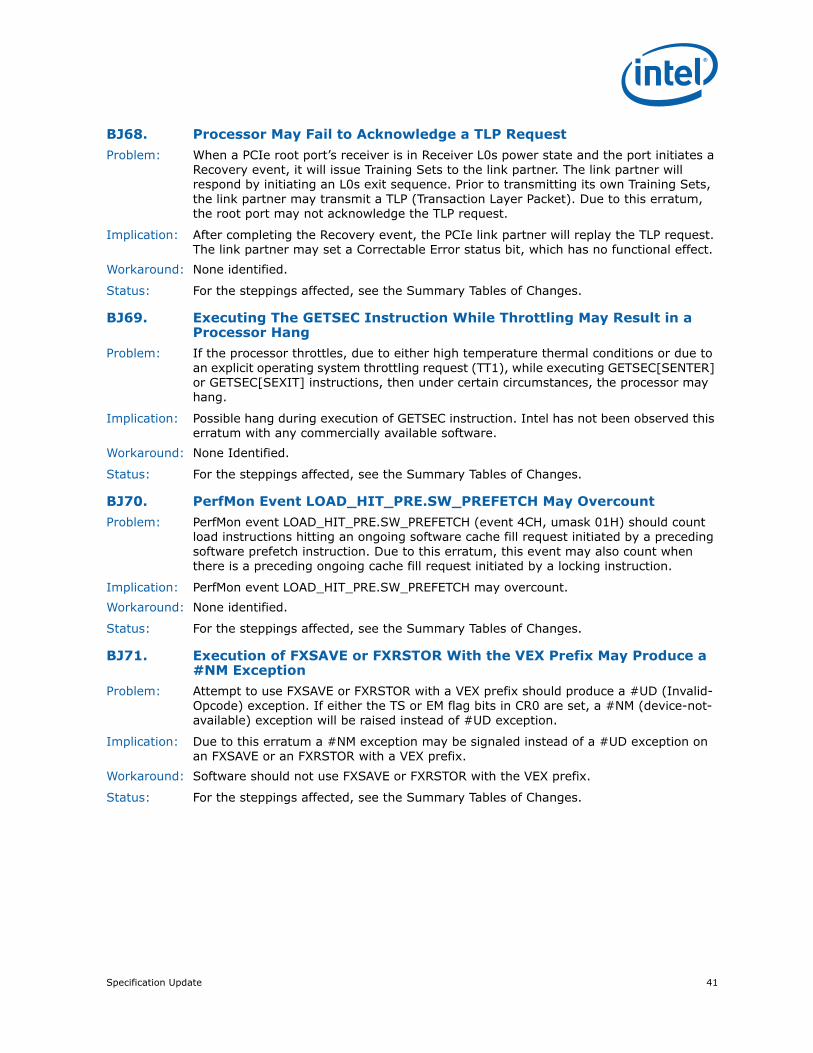
Specification Update 41
BJ68. Processor May Fail to Acknowledge a TLP RequestProblem: When a PCIe root port’s receiver is in Receiver L0s power state and the port initiates a
Recovery event, it will issue Training Sets to the link partner. The link partner will respond by initiating an L0s exit sequence. Prior to transmitting its own Training Sets, the link partner may transmit a TLP (Transaction Layer Packet). Due to this erratum, the root port may not acknowledge the TLP request.
Implication: After completing the Recovery event, the PCIe link partner will replay the TLP request. The link partner may set a Correctable Error status bit, which has no functional effect.
Workaround: None identified.
Status: For the steppings affected, see the Summary Tables of Changes.
BJ69. Executing The GETSEC Instruction While Throttling May Result in a Processor Hang
Problem: If the processor throttles, due to either high temperature thermal conditions or due to an explicit operating system throttling request (TT1), while executing GETSEC[SENTER] or GETSEC[SEXIT] instructions, then under certain circumstances, the processor may hang.
Implication: Possible hang during execution of GETSEC instruction. Intel has not been observed this erratum with any commercially available software.
Workaround: None Identified.
Status: For the steppings affected, see the Summary Tables of Changes.
BJ70. PerfMon Event LOAD_HIT_PRE.SW_PREFETCH May OvercountProblem: PerfMon event LOAD_HIT_PRE.SW_PREFETCH (event 4CH, umask 01H) should count
load instructions hitting an ongoing software cache fill request initiated by a preceding software prefetch instruction. Due to this erratum, this event may also count when there is a preceding ongoing cache fill request initiated by a locking instruction.
Implication: PerfMon event LOAD_HIT_PRE.SW_PREFETCH may overcount.Workaround: None identified.
Status: For the steppings affected, see the Summary Tables of Changes.
BJ71. Execution of FXSAVE or FXRSTOR With the VEX Prefix May Produce a #NM Exception
Problem: Attempt to use FXSAVE or FXRSTOR with a VEX prefix should produce a #UD (Invalid-Opcode) exception. If either the TS or EM flag bits in CR0 are set, a #NM (device-not-available) exception will be raised instead of #UD exception.
Implication: Due to this erratum a #NM exception may be signaled instead of a #UD exception on an FXSAVE or an FXRSTOR with a VEX prefix.
Workaround: Software should not use FXSAVE or FXRSTOR with the VEX prefix.
Status: For the steppings affected, see the Summary Tables of Changes.

42 Specification Update
BJ72. Unexpected #UD on VPEXTRD/VPINSRDProblem: Execution of the VPEXTRD or VPINSRD instructions outside of 64-bit mode with VEX.W
set to 1 may erroneously cause a #UD (invalid-opcode exception).
Implication: The affected instructions may produce unexpected invalid-opcode exceptions outside 64-bit mode.
Workaround: Software should encode VEX.W = 0 for executions of the VPEXTRD and VPINSRD instructions outside 64-bit mode.
Status: For the steppings affected, see the Summary Tables of Changes.
BJ73. Erratum Removed
BJ74. Successive Fixed Counter Overflows May be Discarded Problem: Under specific internal conditions, when using Freeze PerfMon on PMI feature (bit 12 in
IA32_DEBUGCTL.Freeze_PerfMon_on_PMI, MSR 1D9H), if two or more PerfMon Fixed Counters overflow very closely to each other, the overflow may be mishandled for some of them. This means that the counter’s overflow status bit (in MSR_PERF_GLOBAL_STATUS, MSR 38EH) may not be updated properly; additionally, PMI interrupt may be missed if software programs a counter in Sampling-Mode (PMI bit is set on counter configuration).
Implication: Successive Fixed Counter overflows may be discarded when Freeze PerfMon on PMI is used.
Workaround: Software can avoid this by:
•Avoid using Freeze PerfMon on PMI bit.
•Enable only one fixed counter at a time when using Freeze PerfMon on PMI.
Status: For the steppings affected, see the Summary Tables of Changes.
BJ75. #GP May be Signaled When Invalid VEX Prefix Precedes Conditional Branch Instructions
Problem: When a 2-byte opcode of a conditional branch (opcodes 0F8xH, for any value of x) instruction resides in 16-bit code-segment and is associated with invalid VEX prefix, it may sometimes signal a #GP fault (illegal instruction length > 15-bytes) instead of a #UD (illegal opcode) fault.
Implication: Due to this erratum, #GP fault instead of a #UD may be signaled on an illegal instruction.
Workaround: None identified.
Status: For the steppings affected, see the Summary Tables of Changes.
BJ76. A Read from The APIC-Timer CCR May Disarm The TSC_Deadline Counter
Problem: When in TSC Deadline mode with TSC_Deadline timer armed (IA32_TSC_DEADLINE<>0, MSR 6E0H), a read from the local APIC’s CCR (current count register) using RDMSR 0839H may disarm the TSC Deadline timer without generating an interrupt as specified in the APIC Timer LVT (Local Vector Table) entry.
Implication: Due to this erratum, unexpected disarming of the TSC_Deadline counter and possible loss of an interrupt may occur.
Workaround: It is possible for the BIOS to contain a workaround for this erratum.
Status: For the steppings affected, see the Summary Tables of Changes.
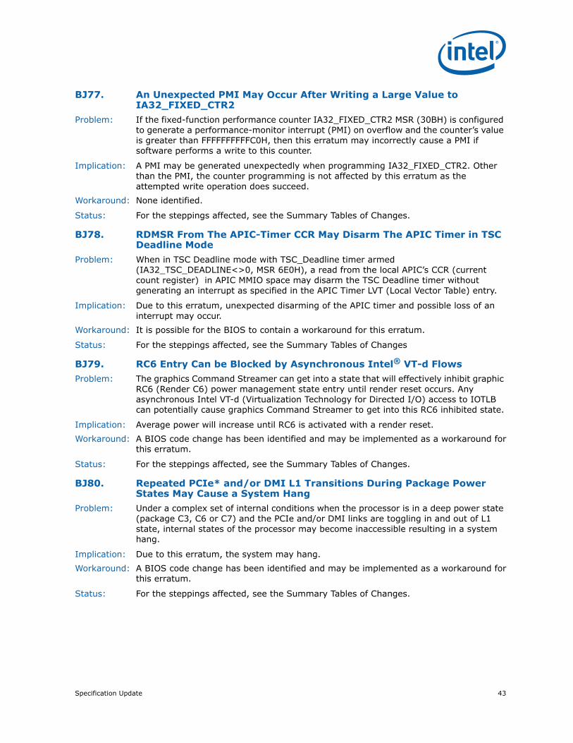
Specification Update 43
BJ77. An Unexpected PMI May Occur After Writing a Large Value to IA32_FIXED_CTR2
Problem: If the fixed-function performance counter IA32_FIXED_CTR2 MSR (30BH) is configured to generate a performance-monitor interrupt (PMI) on overflow and the counter’s value is greater than FFFFFFFFFFC0H, then this erratum may incorrectly cause a PMI if software performs a write to this counter.
Implication: A PMI may be generated unexpectedly when programming IA32_FIXED_CTR2. Other than the PMI, the counter programming is not affected by this erratum as the attempted write operation does succeed.
Workaround: None identified.
Status: For the steppings affected, see the Summary Tables of Changes.
BJ78. RDMSR From The APIC-Timer CCR May Disarm The APIC Timer in TSC Deadline Mode
Problem: When in TSC Deadline mode with TSC_Deadline timer armed (IA32_TSC_DEADLINE<>0, MSR 6E0H), a read from the local APIC’s CCR (current count register) in APIC MMIO space may disarm the TSC Deadline timer without generating an interrupt as specified in the APIC Timer LVT (Local Vector Table) entry.
Implication: Due to this erratum, unexpected disarming of the APIC timer and possible loss of an interrupt may occur.
Workaround: It is possible for the BIOS to contain a workaround for this erratum.
Status: For the steppings affected, see the Summary Tables of Changes
BJ79. RC6 Entry Can be Blocked by Asynchronous Intel® VT-d FlowsProblem: The graphics Command Streamer can get into a state that will effectively inhibit graphic
RC6 (Render C6) power management state entry until render reset occurs. Any asynchronous Intel VT-d (Virtualization Technology for Directed I/O) access to IOTLB can potentially cause graphics Command Streamer to get into this RC6 inhibited state.
Implication: Average power will increase until RC6 is activated with a render reset.Workaround: A BIOS code change has been identified and may be implemented as a workaround for
this erratum.
Status: For the steppings affected, see the Summary Tables of Changes.
BJ80. Repeated PCIe* and/or DMI L1 Transitions During Package Power States May Cause a System Hang
Problem: Under a complex set of internal conditions when the processor is in a deep power state (package C3, C6 or C7) and the PCIe and/or DMI links are toggling in and out of L1 state, internal states of the processor may become inaccessible resulting in a system hang.
Implication: Due to this erratum, the system may hang.Workaround: A BIOS code change has been identified and may be implemented as a workaround for
this erratum.
Status: For the steppings affected, see the Summary Tables of Changes.

44 Specification Update
BJ81. Execution of BIST During Cold RESET Will Result in a Machine Check Shutdown
Problem: If BIST (Built In Self-Test) is enabled and a Cold RESET follows, an unrecoverable machine check shutdown will occur.
Implication: Due to this erratum, BIST cannot be enabled.Workaround: None identified.
Status: For the steppings affected, see the Summary Tables of Changes.
BJ82. PCI Express* Differential Peak-Peak Tx Voltage Swing May Violate the Specification
Problem: Under certain conditions, including extreme voltage and temperature, the peak-peak voltage may be higher than the specification.
Implication: Violation of PCI Express Base Specification of the VTX--DIFF-PP voltage. No failures have been observed due to this erratum.
Workaround: None identified. Sugar Bay and Bromolow-WS
Status: For the steppings affected, see the Summary Tables of Changes.
BJ83. PCIe* Presence Detect State May Not be Accurate After a Warm ResetProblem: Under certain conditions, when there is no PCIe device present, the status of Presence
Detect State bit (SLOTSTS Device 1; Function 0,1,2; Offset BAH; bit [6] and/or Device 6; Function 0; Offset BAH; bit [6]) may not be accurate after a warm reset.
Implication: The Presence Detect State bit may incorrectly report a PCIe device is present even though no device is actually present, which may result in a system hang.
Workaround: A BIOS code change has been identified and may be implemented as a workaround for this erratum.
Status: For the steppings affected, see the Summary Tables of Changes.
BJ84. Display Corruption May be Seen After Graphics Voltage Rail (VCC_AXG) Power Up
Problem: Powering up the processor graphics logic in the cases of initial poweron or Sx resume state power up may cause a nondeterministic state in the processor graphics logic.
Implication: This erratum may cause improper 3D rendering and may result in display corruption.Workaround: A graphics driver workaround has been identified and may be implemented as a
workaround for this erratum.
Status: For the steppings affected, see the Summary Tables of Changes.

Specification Update 45
BJ85. PCMPESTRI, PCMPESTRM, VPCMPESTRI and VPCMPESTRM Always Operate with 32-bit Length Registers
Problem: In 64-bit mode, using REX.W=1 with PCMPESTRI and PCMPESTRM or VEX.W=1 with VPCMPESTRI and VPCMPESTRM should support a 64-bit length operation with RAX/RDX. Due to this erratum, the length registers are incorrectly interpreted as 32-bit values.
Implication: Due to this erratum, using REX.W=1 with PCMPESTRI and PCMPESTRM as well as VEX.W=1 with VPCMPESTRI and VPCMPESTRM do not result in promotion to 64-bit length registers.
Workaround: It is possible for the BIOS to contain a workaround for this erratum.
Status: For the steppings affected, see the Summary Tables of Changes.
BJ86. VM Entries That Return From SMM Using VMLAUNCH May Not Update The Launch State of the VMCS
Problem: Successful VM entries using the VMLAUNCH instruction should set the launch state of the VMCS to “launched”. Due to this erratum, such a VM entry may not update the launch state of the current VMCS if the VM entry is returning from SMM.
Implication: Subsequent VM entries using the VMRESUME instruction with this VMCS will fail. RFLAGS.ZF is set to 1 and the value 5 (indicating VMRESUME with non-launched VMCS) is stored in the VM-instruction error field. This erratum applies only if dual monitor treatment of SMI and SMM is active.
Workaround: It is possible for the BIOS to contain a workaround for this erratum.
Status: For the steppings affected, see the Summary Tables of Changes.
BJ87. Interrupt From Local APIC Timer May Not Be Detectable While Being Delivered
Problem: If the local-APIC timer’s CCR (current-count register) is 0, software should be able to determine whether a previously generated timer interrupt is being delivered by first reading the delivery-status bit in the LVT timer register and then reading the bit in the IRR (interrupt-request register) corresponding to the vector in the LVT timer register. If both values are read as 0, no timer interrupt should be in the process of being delivered. Due to this erratum, a timer interrupt may be delivered even if the CCR is 0 and the LVT and IRR bits are read as 0. This can occur only if the DCR (Divide Configuration Register) is greater than or equal to 4. The erratum does not occur if software writes zero to the Initial Count Register before reading the LVT and IRR bits.
Implication: Software that relies on reads of the LVT and IRR bits to determine whether a timer interrupt is being delivered may not operate properly.
Workaround: Software that uses the local-APIC timer must be prepared to handle the timer interrupts, even those that would not be expected based on reading CCR and the LVT and IRR bits; alternatively, software can avoid the problem by writing zero to the Initial Count Register before reading the LVT and IRR bits.
Status: For the steppings affected, see the Summary Tables of Changes.

46 Specification Update
BJ88. An Unexpected Page Fault May Occur Following the Unmapping and Re-mapping of a Page
Problem: An unexpected page fault (#PF) may occur for a page under the following conditions:
•The paging structures initially specify a valid translation for the page.
•Software modifies the paging structures so that there is no valid translation for the page (e.g., by clearing to 0 the present bit in one of the paging-structure entries used to translate the page).
•Software later modifies the paging structures so that the translation is again a valid translation for the page (e.g., by setting to 1 the bit that was cleared earlier).
•A subsequent instruction loads from a linear address on the page.
•Software did not invalidate TLB entries for the page between the first modification of the paging structures and the load from the linear address.
In this case, the load by the later instruction may cause a page fault that indicates that there is no translation for the page (e.g., with bit 0 clear in the page-fault error code, indicating that the fault was caused by a not-present page).
Implication: Software may see an unexpected page fault that indicates that there is no translation for the page. Intel has not observed this erratum with any commercially available software.
Workaround: None identified.
Status: For the steppings affected, see the Summary Tables of Changes.
BJ89. A PCIe* Device That Initially Transmits Minimal Posted Data Credits May Cause a System Hang
Problem: Under certain conditions, if a PCIe device that initially transmits posted data credits less than Max_Payload_Size/16 + 4 (16B/4DW is unit of data flow control) and is the target of a Peer-to-Peer write of Max_Payload_Size, the system may hang due to Posted Data credit starvation.
Implication: Under certain conditions, the processor may encounter a Posted Data credit starvation scenario and hang.
Workaround: A BIOS code change has been identified and may be implemented as a workaround for this erratum.
Status: For the steppings affected, see the Summary Tables of Changes.
BJ90. Some Model Specific Branch Events May OvercountProblem: Under certain internal conditions the following model specific performance monitoring
branch events may overcount:
•BR_INST_RETIRED.NOT_TAKEN
•BR_INST_RETIRED.NEAR_TAKEN
•BR_MISP_RETIRED.NOT_TAKEN
•BR_MISP_RETIRED.TAKEN
Implication: Due to this erratum the events may overcount.Workaround: None identified.
Status: For the steppings affected, see the Summary Tables of Changes.

Specification Update 47
BJ91. Some Performance Monitoring Events in AnyThread Mode May Get Incorrect Count
Problem: Performance monitoring AnyThread mode allows a given thread to monitor events as a result of any thread running on the same core. Due to this erratum, on systems with SMT enabled, counting any of the following performance monitoring events in AnyThread mode may get incorrect values:
•INST_RETIRED;
•OTHER_ASSISTS;
•UOPS_RETIRED;
•MACHINE_CLEARS;
•BR_INST_RETIRED;
•BR_MISP_RETIRED;
•SIMD_INST_RETIRED;
•FP_ASSIST;
•HW_INTERRUPTS;
•ROB_MISC_EVENTS;
•MEM_LOAD_RETIRED;
•MEM_LOAD_LLC_HIT_RETIRED;
•MEM_LOAD_LLC_MISS_RETIRED;
•MEM_LOAD_MISC_RETIRED;
Implication: Incorrect results when counting the above performance monitoring events in AnyThread mode with SMT on.
Workaround: In order to get a correct count for the above events, software may count the same event on both threads of the same physical core, and at post-processing stage sum-up the two values to get the core’s net value.
Status: For the steppings affected, see the Summary Tables of Changes.
BJ92. PDIR May Not Function Properly With FREEZE_PERFMON_ON_PMIProblem: When the PDIR (Precise Distribution for Instructions Retired) mechanism is activated
(INST_RETIRED.ALL (event C0H, umask value 00H) on Counter 1 programmed in PEBS mode) along with FREEZE_PERFMON_ON_PMI, bit 11, in the IA32_DEBUGCTL MSR (1D9h), the processor may behave in an undefined manner.
Implication: Due to this erratum when FREEZE_PERFMON_ON_PMI is programmed along with PDIR the processor behavior is undefined. This can result in any of but not limited to the following: incorrect PMI interrupts, incorrect PEBS events or invalid processor state.
Workaround: A software driver should not program FreezeOnPMI in conjunction with the PDIR mechanism.
Status: For the steppings affected, see the Summary Tables of Changes.

48 Specification Update
BJ93. For A Single Logical Processor Package, HTT May be Set to Zero Even Though The Package Reserves More Than One APIC ID
Problem: When maximum number of addressable IDs for logical processors in this physical package (CPUID.01H.EBX[23:16]) and maximum number of addressable IDs for processor cores in the physical package, (CPUID.04H.EAX[31:26]) indicate more than one reserved APIC ID, HTT(Multi-Threading, CPUID.01H.EDX[28]) should be set to One. However, due to this erratum, it may be set to Zero.
Implication: Software written expecting HTT to be Zero only when a single APIC ID is reserved for the package may not function correctly.
Workaround: It is possible for the BIOS to contain a workaround for this erratum.
Status: For the steppings affected, see the Summary Tables of Changes.
BJ94. LBR May Contain Incorrect Information When Using FREEZE_LBRS_ON_PMI
Problem: When FREEZE_LBRS_ON_PMI is enabled (bit 11 of IA32_DEBUGCTL MSR (1D9H) is set), and a taken branch retires at the same time that a PMI (Performance Monitor Interrupt) occurs, then under certain internal conditions the record at the top of the LBR stack may contain an incorrect “From” address.
Implication: When the LBRs are enabled with FREEZE_LRBS_ON_PMI, the “From” address at the top of the LBR stack may be incorrect.
Workaround: It is possible for the BIOS to contain a workaround for this erratum.
Status: For the steppings affected, see the Summary Tables of Changes.
BJ95. A First Level Data Cache Parity Error May Result in Unexpected Behavior
Problem: When a load occurs to a first level data cache line resulting in a parity error in close proximity to other software accesses to the same cache line and other locked accesses the processor may exhibit unexpected behavior.
Implication: Due to this erratum, unpredictable system behavior may occur. Intel has not observed this erratum with any commercially available system.
Workaround: None identified.
Status: For the steppings affected, see the Summary Tables of Changes.
BJ96. Intel® Trusted Execution Technology ACM RevocationProblem: SINIT ACM 2nd_gen_i5_i7_SINIT_1.9.BIN or earlier are revoked and will not launch
with new processor configuration information.
Implication: Due to this erratum, 2nd_gen_i5_i7_SINIT_1.9.BIN and earlier will be revoked.Workaround: It is possible for the BIOS to contain a workaround for this erratum. All Intel® TXT
enabled software must use SINIT ACM 2nd_gen_i5_i7_SINIT_1.9.BIN or later.
Status: For the steppings affected, see the Summary Tables of Changes.

Specification Update 49
BJ97. Programming PDIR And an Additional Precise PerfMon Event May Cause Unexpected PMI or PEBS Events
Problem: PDIR (Precise Distribution for Instructions Retired) mechanism is activated by programming INST_RETIRED.ALL (event C0H, umask value 00H) on Counter 1. When PDIR is activated in PEBS (Precise Event Based Sampling) mode with an additional precise PerfMon event, an incorrect PMI or PEBS event may occur.
Implication: Due to this erratum, when another PEBS event is programmed along with PDIR, an incorrect PMI or PEBS event may occur.
Workaround: Software should not program another PEBS event in conjunction with the PDIR mechanism.
Status: For the steppings affected, see the Summary Tables of Changes.
BJ98. Performance Monitoring May Overcount Some Events During Debugging
Problem: If the debug-control register (DR7) is configured so that some but not all of the breakpoints in the debug-address registers (DR0-DR3) are enabled and one or more of the following performance-monitoring counters are locally enabled (via IA32_CR_PERMON_EVNTSEL_CNTR{3:0}): BR_INST_RETIRED BR_MISP_RETIRED FP_ASSIST FP_ASSIST INST_RETIRED MACHINE_CLEARS MEM_LOAD_UOPS_LLC_HIT_RETIRED MEM_LOAD_UOPS_MISC_RETIRED.LLC_MISS MEM_LOAD_UOPS_RETIRED MEM_TRANS_RETIRED MEM_UOPS_RETIRED OTHER_ASSISTS ROB_MISC_EVENTS.LBR_INSERTS UOPS_RETIRED Any of the globally enabled (via IA32_CR_EMON_PERF_GLOBAL_CTRL) counters may overcount certain events when a disabled breakpoint condition is met
Implication: Performance-monitor counters may indicate a number greater than the number of events that occurred.
Workaround: Software can disable all breakpoints by clearing DR7. Alternatively, software can ensure that, for a breakpoint disabled in DR7, the corresponding debug-address register contains an address that prevents the breakpoint condition from being met (e.g., a non-canonical address).
Status: For the steppings affected, see the Summary Tables of Changes.
BJ99. LTR Message is Not Treated as an Unsupported RequestProblem: The PCIe* root port does not support LTR (Latency Tolerance Reporting) capability.
However, a received LTR message is not treated as a UR (Unsupported Request).
Implication: Due to this erratum, an LTR message does not generate a UR error.Workaround: None identified.
Status: For the steppings affected, see the Summary Tables of Changes.

50 Specification Update
BJ100. Use of VMASKMOV to Access Memory Mapped I/O or Uncached Memory May Cause The Logical Processor to Hang
Problem: Under a complex set of conditions, using VMASKMOV to reference memory mapped I/O or uncached memory may cause the logical processor to hang.
Implication: Due to this erratum, the logical processor may hang. Intel's Software Developers Manual states "VMASKMOV should not be used to access memory mapped I/O and un-cached memory as the access and the ordering of the individual loads or stores it does is implementation specific." Intel has not observed this erratum with any commercially available software.
Workaround: It is possible for the BIOS to contain a workaround for this erratum.
Status: For the steppings affected, see the Summary Tables of Changes.
BJ101. PEBS May Unexpectedly Signal a PMI After The PEBS Buffer is FullProblem: The Software Developer’s Manual states that no PMI should be generated when PEBS
index reaches PEBS Absolute Maximum. Due to this erratum a PMI may be generated even though the PEBS buffer is full.
Implication: PEBS may trigger a PMI even though the PEBS index has reached the PEBS Absolute Maximum.
Workaround: None identified.
Status: For the steppings affected, see the Summary Tables of Changes.
BJ102. XSAVEOPT May Fail to Save Some State after Transitions Into or Out of STM
Problem: The XSAVEOPT instruction may optimize performance by not saving state that has not been modified since the last execution of XRSTOR. This optimization should occur only if the executions of XSAVEOPT and XRSTOR are either both or neither in SMM (system-management mode). Due to this erratum, this optimization may be performed by the first execution of XSAVEOPT after a transition into or out of the STM (SMM-transfer monitor) if the most recent execution of XRSTOR occurred before that transition. For transitions into the STM, the erratum applies only to transitions using the VMCALL instruction. This erratum can occur only if the two executions are at the same privilege level, use the same linear address, and are either both or neither in VMX non-root operation. The erratum does not apply if software in SMM never uses XRSTOR or XSAVEOPT.
Implication: This erratum may lead to unpredictable system behavior.Workaround: STM software should execute the XRSTOR instruction with the value 0 in EDX:EAX after
each transition into the STM (after setting CR4.OSXSAVE) and before each transition out of the STM. Bytes 512 to 575 of the save area used by XRSTOR should be allocated in memory, but bytes 0 to 511 need not be. Bytes 512 to 535 should all be 0.
Status: For the steppings affected, see the Summary Tables of Changes.

Specification Update 51
BJ103. Performance Monitor Precise Instruction Retired Event May Present Wrong Indications
Problem: When the PDIR (Precise Distribution for Instructions Retired) mechanism is activated (INST_RETIRED.ALL (event C0H, umask value 00H) on Counter 1 programmed in PEBS mode), the processor may return wrong PEBS/PMI interrupts and/or incorrect counter values if the counter is reset with a SAV below 100 (Sample-After-Value is the counter reset value software programs in MSR IA32_PMC1[47:0] in order to control interrupt frequency).
Implication: Due to this erratum, when using low SAV values, the program may get incorrect PEBS or PMI interrupts and/or an invalid counter state.
Workaround: The sampling driver should avoid using SAV<100.
Status: For the steppings affected, see the Summary Tables of Changes.
BJ104. The Value in IA32_MC3_ADDR MSR May Not be Accurate When MCACOD 0119H is Reported in IA32_MC3_Status
Problem: Under certain conditions, when the The Machine Check Error Code (MCACOD) in the IA32_MC3_STATUS (MSR 040DH) register is 0119H, the value in IA32_MC3_ADDR MSR (40EH) may refer to the incoming MLC (Mid-Level Cache) cache line instead of the evicted cache line.
Implication: The address in IA32_MC3_ADDR MSR (40EH) may not be accurate for MLC cache read errors with MSCOD of 119H.
Workaround: None identified.
Status: For the steppings affected, see the Summary Tables of Changes.
BJ105. MSR_PKG_Cx_RESIDENCY MSRs May Not be AccurateProblem: If the processor is in a package C-state for an extended period of time (greater than 40
seconds) with no wake events, the value in the MSR_PKG_C{2,3,6,7}_RESIDENCY MSRs (60DH and 3F8H–3FAH) will not be accurate.
Implication: Utilities that report C-state residency times will report incorrect data in cases of long duration package C-states.
Workaround: None identified.
Status: For the steppings affected, see the Summary Tables of Changes.
BJ106. Enabling/Disabling PEBS May Result in Unpredictable System Behavior
Problem: Under certain conditions, enabling or disabling PEBS (Precise Event Based Sampling) via WRMSR to IA32_PEBS_ENABLE MSR may result in unpredictable system behavior near or coincident to this instruction.
Implication: Due to this erratum, unpredictable system behavior may result.Workaround: It is possible for the BIOS to contain a workaround for this erratum.
Status: For the steppings affected, see the Summary Tables of Changes.
52 Specification Update
BJ107. Execution of VAESIMC or VAESKEYGENASSIST With An Illegal Value for VEX.vvvv May Produce a #NM Exception
Problem: The VAESIMC and VAESKEYGENASSIST instructions should produce a #UD (Invalid-Opcode) exception if the value of the vvvv field in the VEX prefix is not 1111b. Due to this erratum, if CR0.TS is “1”, the processor may instead produce a #NM (Device-Not-Available) exception.
Implication: Due to this erratum, some undefined instruction encodings may produce a #NM instead of a #UD exception.
Workaround: Software should always set the vvvv field of the VEX prefix to 1111b for instances of the VAESIMC and VAESKEYGENASSIST instructions.
Status: For the steppings affected, see the Summary Tables of Changes.
BJ108. Unexpected #UD on VZEROALL/VZEROUPPERProblem: Execution of the VZEROALL or VZEROUPPER instructions in 64-bit mode with VEX.W set
to 1 may erroneously cause a #UD (invalid-opcode exception).
Implication: The affected instructions may produce unexpected invalid-opcode exceptions in 64-bit mode.
Workaround: Compilers should encode VEX.W = 0 for the VZEROALL and VZEROUPPER instructions.
Status: For the steppings affected, see the Summary Tables of Changes.
BJ109. Successive Fixed Counter Overflows May be DiscardedProblem: Under specific internal conditions, when using Freeze PerfMon on PMI feature (bit 12 in
IA32_DEBUGCTL.Freeze_PerfMon_on_PMI, MSR 1D9H), if two or more PerfMon Fixed Counters overflow very closely to each other, the overflow may be mishandled for some of them. This means that the counter’s overflow status bit (in MSR_PERF_GLOBAL_STATUS, MSR 38EH) may not be updated properly; additionally, PMI interrupt may be missed if software programs a counter in Sampling-Mode (PMI bit is set on counter configuration).
Implication: Successive Fixed Counter overflows may be discarded when Freeze PerfMon on PMI is used.
Workaround: Software can avoid this by:
•Avoid using Freeze PerfMon on PMI bit
•Enable only one fixed counter at a time when using Freeze PerfMon on PMI
Status: For the steppings affected, see the Summary Tables of Changes.
BJ110. Execution of FXSAVE or FXRSTOR With the VEX Prefix May Produce a #NM Exception
Problem: Attempt to use FXSAVE or FXRSTOR with a VEX prefix should produce a #UD (Invalid-Opcode) exception. If either the TS or EM flag bits in CR0 are set, a #NM (device-not-available) exception will be raised instead of #UD exception.
Implication: Due to this erratum a #NM exception may be signaled instead of a #UD exception on an FXSAVE or an FXRSTOR with a VEX prefix.
Workaround: Software should not use FXSAVE or FXRSTOR with the VEX prefix.
Status: For the steppings affected, see the Summary Tables of Changes.

Specification Update 53
BJ111. VM Exits Due to “NMI-Window Exiting” May Not Occur Following a VM Entry to the Shutdown State
Problem: If VM entry is made with the “virtual NMIs” and “NMI-window exiting”, VM-execution controls set to 1, and if there is no virtual-NMI blocking after VM entry, a VM exit with exit reason “NMI window” should occur immediately after VM entry unless the VM entry put the logical processor in the wait-for SIPI state. Due to this erratum, such VM exits do not occur if the VM entry put the processor in the shutdown state.
Implication: A VMM may fail to deliver a virtual NMI to a virtual machine in the shutdown state. Workaround: Before performing a VM entry to the shutdown state, software should check whether
the “virtual NMIs” and “NMI-window exiting” VM-execution controls are both 1. If they are, software should clear “NMI-window exiting” and inject an NMI as part of VM entry.
Status: For the steppings affected, see the Summary Tables of Changes.
BJ112. Execution of INVVPID Outside 64-Bit Mode Cannot Invalidate Translations For 64-Bit Linear Addresses
Problem: Executions of the INVVPID instruction outside 64-bit mode with the INVVPID type “individual-address invalidation” ignore bits 63:32 of the linear address in the INVVPID descriptor and invalidate translations for bits 31:0 of the linear address.
Implication: The INVVPID instruction may fail to invalidate translations for linear addresses that set bits in the range 63:32. Because this erratum applies only to executions outside 64-bit mode, it applies only to attempts by a 32-bit virtual-machine monitor (VMM) to invalidate translations for a 64-bit guest. Intel has not observed this erratum with any commercially available software.
Workaround: None identified.
Status: For the steppings affected, see the Summary Tables of Changes.
BJ113. VEX.L is Not Ignored with VCVT*2SI InstructionsProblem: The VEX.L bit should be ignored for the VCVTSS2SI, VCVTSD2SI, VCVTTSS2SI, and
VCVTTSD2SI instructions, however due to this erratum the VEX.L bit is not ignored and will cause a #UD.
Implication: Unexpected #UDs will be seen when the VEX.L bit is set to 1 with VCVTSS2SI, VCVTSD2SI, VCVTTSS2SI, and VCVTTSD2SI instructions.
Workaround: Software should ensure that the VEX.L bit is set to 0 for all scalar instructions.
Status: For the steppings affected, see the Summary Tables of Changes.
BJ114. MCI_ADDR May be Incorrect For Cache Parity ErrorsProblem: In cases when a WBINVD instruction evicts a line containing an address or data parity
error (MCACOD of 0x124, and MSCOD of 0x10), the address of this error should be logged in the MCi_ADDR register. Due to this erratum, the logged address may be incorrect, even though MCi_Status.ADDRV (bit 63) is set.
Implication: The address reported in MCi_ADDR may not be correct for cases of a parity error found during WBINVD execution.
Workaround: None identified.
Status: For the steppings affected, see the Summary Tables of Changes.

54 Specification Update
BJ115. Instruction Fetches Page-Table Walks May be Made Speculatively to Uncacheable Memory
Problem: Page-table walks on behalf of instruction fetches may be made speculatively to uncacheable (UC) memory.
Implication: If any paging structures are located at addresses in uncacheable memory that are used for memory-mapped I/O, such I/O operations may be invoked as a result of speculative execution that would never actually occur in the executed code path. Intel has not observed this erratum with any commercially available software.
Workaround: Software should avoid locating paging structures at addresses in uncacheable memory that are used for memory-mapped I/O
Status: For the steppings affected, see the Summary Tables of Changes.
BJ116. Reported Maximum Memory Frequency Capability May Be Higher Than Expected
Problem: The Intel® Pentium® Processor G645, Intel® Pentium® Processor G645T and Intel® Celeron® Processor G555 are specified for 1066 MT/s maximum DDR3 memory frequency, but report support for 1333 MT/s.The value in the DDR3 Maximum Frequency Capability (CAPID0_A - Capabilities A Register Device 0; Function 0; Offset E4–E7H; bits [2:0]) may indicate a higher than expected value of 110b, specifying that the memory controller will operate at a maximum of 1333 MT/s. The memory interface will operate as per the table below.
Implication: There may be a slight increase to power or thermal characteristics at the faster memory speed. At the faster memory speed the processor still functions correctly and within the published power and thermal specifications.
Workaround: None identified.
Status: For the steppings affected, see the Summary Tables of Changes.
BJ117. The Processor May Not Properly Execute Code Modified Using A Floating-Point Store
Problem: Under complex internal conditions, a floating-point store used to modify the next sequential instruction may result in the old instruction being executed instead of the new instruction.
Implication: Self- or cross-modifying code may not execute as expected. Intel has not observed this erratum with any commercially available software.
Workaround: None identified. Do not use floating-point stores to modify code.
Status: For the steppings affected, see the Summary Tables of Changes.
Processor Number
DDR3 DIMM Type
One DIMM/Channel Memory Frequency
Two DIMM/Channel Memory Frequency
G6451066 1066 MT/s 1066 MT/s
>=1333 1333 MT/s 1333 MT/s
G645T1066 1066 MT/s 1066 MT/s
>=1333 1333 MT/s 1333 MT/s
G5551066 1066 MT/s 1066 MT/s
>=1333 1333 MT/s 1066 MT/s

Specification Update 55
BJ118. Execution of GETSEC[SEXIT] May Cause a Debug Exception to be Lost
Problem: A debug exception occurring at the same time that GETSEC[SEXIT] is executed or when an SEXIT doorbell event is serviced may be lost.
Implication: Due to this erratum, there may be a loss of a debug exception when it happens concurrently with the execution of GETSEC[SEXIT]. Intel has not observed this erratum with any commercially available software.
Workaround: None identified.
Status: For the steppings affected, see the Summary Tables of Changes.
BJ119. VM Exits Due to GETSEC May Save an Incorrect Value for “Blocking by STI” in the Context of Probe-Mode Redirection
Problem: The GETSEC instruction causes a VM exit when executed in VMX non-root operation. Such a VM exit should set bit 0 in the Interruptability-state field in the virtual-machine control structure (VMCS) if the STI instruction was blocking interrupts at the time GETSEC commenced execution. Due to this erratum, a VM exit executed in VMX non-root operation may erroneously clear bit 0 if redirection to probe mode occurs on the GETSEC instruction.
Implication: After returning from probe mode, a virtual interrupt may be incorrectly delivered prior to GETSEC instruction. Intel has not observed this erratum with any commercially software.
Workaround: None identified.
Status: For the steppings affected, see the Summary Tables of Changes.
BJ120. Specific Graphics Blitter Instructions May Result in Unpredictable Graphics Controller Behavior
Problem: Specific source-copy blitter instructions in Intel® HD Graphics 2000 and 3000 Processor may result in unpredictable behavior when a blit source and destination overlap.
Implication: Due to this erratum, the processor may exhibit unpredictable graphics controller behavior. Intel has not observed this erratum with any commercially available software.
Workaround: None identified.
Status: For the steppings affected, see the Summary Tables of Changes.
BJ121. IA32_MC5_CTL2 is Not Cleared by a Warm ResetProblem: IA32_MC5_CTL2 MSR (285H) is documented to be cleared on any reset. Due to this
erratum this MSR is only cleared upon a cold reset.
Implication: The algorithm documented in Software Developer’s Manual, Volume 3, section titled “CMCI Initialization” or any other algorithm that counts the IA32_MC5_CTL2 MSR being cleared on reset will not function as expected after a warm reset
Workaround: None identified.
Status: For the steppings affected, see the Summary Tables of Changes.
BJ122. Performance Monitor Counters May Produce Incorrect ResultsProblem: When operating in hyper-threaded mode, a memory at-retirement performance
monitoring event (from the list below) may be dropped or may increment an enabled counter on the physical core’s other thread rather than the thread experiencing the event. The list of affected memory at-retirement events is as follows:
•MEM_UOP_RETIRED.LOADS

56 Specification Update
•MEM_UOP_RETIRED.STORES
•MEM_UOP_RETIRED.LOCK
•MEM_UOP_RETIRED.SPLIT
•MEM_UOP_RETIRED.STLB_MISS
•MEM_LOAD_UOPS_RETIRED.HIT_LFB
•MEM_LOAD_UOPS_RETIRED.L1_HIT
•MEM_LOAD_UOPS_RETIRED.L2_HIT
•MEM_LOAD_UOPS_RETIRED.LLC_HIT
•MEM_LOAD_UOPS_MISC_RETIRED.LLC_MISS
•MEM_LOAD_UOPS_LLC_HIT_RETIRED.XSNP_HIT
•MEM_LOAD_UOPS_LLC_HIT_RETIRED.XSNP_HITM
•MEM_LOAD_UOPS_LLC_HIT_RETIRED.XSNP_MISS
•MEM_LOAD_UOPS_LLC_HIT_RETIRED.XSNP_NONE
•MEM_LOAD_UOPS_RETIRED.LLC_MISS
•MEM_LOAD_UOPS_LLC_MISS_RETIRED.LOCAL_DRAM
•MEM_LOAD_UOPS_LLC_MISS_RETIRED.REMOTE_DRAM
•MEM_LOAD_UOPS_RETIRED.L2_MISS
Implication: Due to this erratum, certain performance monitoring event will produce unreliable results during hyper-threaded operation.
Workaround: None identified.
Status: For the steppings affected, see the Summary Tables of Changes.
BJ123. The Corrected Error Count Overflow Bit in IA32_ MC0_STATUS is Not Updated After a UC Error is Logged
Problem: When a UC (uncorrected) error is logged in the IA32_MC0_STATUS MSR (401H), corrected errors will continue to update the lower 14 bits (bits 51:38) of the Corrected Error Count. Due to this erratum, the sticky count overflow bit (bit 52) of the Corrected Error Count will not get updated after a UC error is logged.
Implication: The Corrected Error Count Overflow indication will be lost if the overflow occurs after an uncorrectable error has been logged.
Workaround: None identified.
Status: For the steppings affected, see the Summary Tables of Changes.
BJ124. Spurious Intel® VT-d Interrupts May Occur When the PFO Bit is SetProblem: When the PFO (Primary Fault Overflow) field (bit [0] in the VT-d FSTS [Fault Status]
register) is set to 1, further faults should not generate an interrupt. Due to this erratum, further interrupts may still occur.
Implication: Unexpected Invalidation Queue Error interrupts may occur. Intel has not observed this erratum with any commercially available software.
Workaround: Software should be written to handle spurious Intel® VT-d fault interrupts.
Status: For the steppings affected, see the Summary Tables of Changes.

Specification Update 57
BJ125. Processor May Livelock During On Demand Clock ModulationProblem: The processor may livelock when (1) a processor thread has enabled on demand clock
modulation via bit 4 of the IA32_CLOCK_MODULATION MSR (19AH) and the clock modulation duty cycle is set to 12.5% (02H in bits 3:0 of the same MSR), and (2) the other processor thread does not have on demand clock modulation enabled and that thread is executing a stream of instructions with the lock prefix that either split a cacheline or access UC memory.
Implication: Program execution may stall on both threads of the core subject to this erratum.Workaround: This erratum will not occur if clock modulation is enabled on all threads when using on
demand clock modulation or if the duty cycle programmed in the IA32_CLOCK_MODULATION MSR is 18.75% or higher.
Status: For the steppings affected, see the Summary Tables of Changes.
§ §

58 Specification Update
Specification Changes
The Specification Changes listed in this section apply to the following documents:• Intel® 64 and IA-32 Architectures Software Developer’s Manual, Volume 1: Basic
Architecture
• Intel® 64 and IA-32 Architectures Software Developer’s Manual, Volume 2A: Instruction Set Reference Manual A-M
• Intel® 64 and IA-32 Architectures Software Developer’s Manual, Volume 2B: Instruction Set Reference Manual N-Z
• Intel® 64 and IA-32 Architectures Software Developer’s Manual, Volume 3A: System Programming Guide
• Intel® 64 and IA-32 Architectures Software Developer’s Manual, Volume 3B: System Programming Guide
§ §

Specification Update 59
Specification Clarifications
The Specification Clarifications listed in this section may apply to the following documents:
• Intel® 64 and IA-32 Architectures Software Developer’s Manual, Volume 1: Basic Architecture
• Intel® 64 and IA-32 Architectures Software Developer’s Manual, Volume 2A: Instruction Set Reference Manual A-M
• Intel® 64 and IA-32 Architectures Software Developer’s Manual, Volume 2B: Instruction Set Reference Manual N-Z
• Intel® 64 and IA-32 Architectures Software Developer’s Manual, Volume 3A: System Programming Guide
• Intel® 64 and IA-32 Architectures Software Developer’s Manual, Volume 3B: System Programming Guide
There are no new Specification Changes in this Specification Update revision.
§ §

60 Specification Update
Documentation Changes
The Documentation Changes listed in this section apply to the following documents:• Intel® 64 and IA-32 Architectures Software Developer’s Manual, Volume 1:
Basic Architecture
• Intel® 64 and IA-32 Architectures Software Developer’s Manual, Volume 2A: Instruction Set Reference Manual A-M
• Intel® 64 and IA-32 Architectures Software Developer’s Manual, Volume 2B: Instruction Set Reference Manual N-Z
• Intel® 64 and IA-32 Architectures Software Developer’s Manual, Volume 3A: System Programming Guide
• Intel® 64 and IA-32 Architectures Software Developer’s Manual, Volume 3B: System Programming Guide
All Documentation Changes will be incorporated into a future version of the appropriate Processor documentation.
Note: Documentation changes for Intel® 64 and IA-32 Architecture Software Developer's Manual volumes 1, 2A, 2B, 3A, and 3B will be posted in a separate document, Intel® 64 and IA-32 Architecture Software Developer's Manual Documentation Changes. Follow the link below to become familiar with this file.
http://www.intel.com/products/processor/manuals/index.htm
BJ1. On-Demand Clock Modulation Feature ClarificationSoftware Controlled Clock Modulation section of the Intel® 64 and IA-32 Architectures Software Developer's Manual, Volume 3B: System Programming Guide will be modified to differentiate On-demand clock modulation feature on different processors. The clarification will state:
For Hyper-Threading Technology enabled processors, the IA32_CLOCK_MODULATION register is duplicated for each logical processor. In order for the On-demand clock modulation feature to work properly, the feature must be enabled on all the logical processors within a physical processor. If the programmed duty cycle is not identical for all the logical processors, the processor clock will modulate to the highest duty cycle programmed for processors if the CPUID DisplayFamily_DisplayModel signatures is listed in Table 14-2. For all other processors, if the programmed duty cycle is not identical for all logical processors in the same core, the processor will modulate at the lowest programmed duty cycle.
For multiple processor cores in a physical package, each core can modulate to a programmed duty cycle independently.
For the P6 family processors, on-demand clock modulation was implemented through the chipset, which controlled clock modulation through the processor’s STPCLK# pin.

Specification Update 61
Table 14-2. CPUID Signatures for Legacy Processors That Resolve to Higher Performance Setting of Conflicting Duty Cycle Requests
§ §
DisplayFamily_Display
Model
DisplayFamily_Display
Model
DisplayFamily_Display
Model
DisplayFamily_Display
Model 0F_xx 06_1C 06_1A 06_1E 06_1F 06_25 06_26 06_27 06_2C 06_2E 06_2F 06_35 06_36

62 Specification Update