
Unit II GENERALIZED MEDICAL INSTRUMENT SYSTEM The ...
15
Unit II GENERALIZED MEDICAL INSTRUMENT SYSTEM The primary purpose of any medical instrumentation system is to measure or determine the purpose of some physical quantity that assists the medical personnel to make better diagnosis and start treatment. Majority of the systems used are electrical or electronic in nature. The major difference between this system of medical instrumentation and conventional instrumentation systems is that the source of the signals is living tissue or energy applied to living tissue. Measurand The physical quantity or the condition that the system measure is called the measurand.The source is a human body that generates bio-potential signals. The accessibility of the measurand is important because it may be internal (blood pressure), it may be on the body surface (electrocardiogram potential), it may emanate from the body (infrared radiation), or it may be derived from a tissue sample (such as blood or a biopsy) that is removed from the body. Most medically important measurands can be grouped in the following categories: bio potential, pressure, flow, dimensions (imaging), displacement (velocity, acceleration, and force), impedance, temperature, and chemical concentrations. The measurand may be localized to a specific organ or anatomical structure. Sensor Transducer is defined as a device that converts one form of energy to another. A sensor converts a physical measurand to an electric output. The sensor should respond only to the form of energy present in the measurand. The sensor should interface with the living system. Many sensors have a primary sensing element such as a diaphragm, which converts pressure to displacement. A variable-conversion element, such as a strain gage, then converts displacement to an electric voltage. Sometimes the sensitivity of the sensor can be adjusted over a wide range by altering the primary sensing element. Many variable-conversion elements need external electric power to obtain a sensor output.
-
Upload
khangminh22 -
Category
Documents
-
view
4 -
download
0
Transcript of Unit II GENERALIZED MEDICAL INSTRUMENT SYSTEM The ...
Unit II
GENERALIZED MEDICAL INSTRUMENT SYSTEM
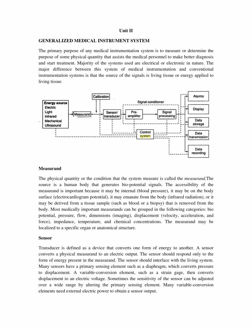
The primary purpose of any medical instrumentation system is to measure or determine the
purpose of some physical quantity that assists the medical personnel to make better diagnosis
and start treatment. Majority of the systems used are electrical or electronic in nature. The
major difference between this system of medical instrumentation and conventional
instrumentation systems is that the source of the signals is living tissue or energy applied to
living tissue.
Measurand
The physical quantity or the condition that the system measure is called the measurand.The
source is a human body that generates bio-potential signals. The accessibility of the
measurand is important because it may be internal (blood pressure), it may be on the body
surface (electrocardiogram potential), it may emanate from the body (infrared radiation), or it
may be derived from a tissue sample (such as blood or a biopsy) that is removed from the
body. Most medically important measurands can be grouped in the following categories: bio
potential, pressure, flow, dimensions (imaging), displacement (velocity, acceleration, and
force), impedance, temperature, and chemical concentrations. The measurand may be
localized to a specific organ or anatomical structure.
Sensor
Transducer is defined as a device that converts one form of energy to another. A sensor
converts a physical measurand to an electric output. The sensor should respond only to the
form of energy present in the measurand. The sensor should interface with the living system.
Many sensors have a primary sensing element such as a diaphragm, which converts pressure
to displacement. A variable-conversion element, such as a strain gage, then converts
displacement to an electric voltage. Sometimes the sensitivity of the sensor can be adjusted
over a wide range by altering the primary sensing element. Many variable-conversion
elements need external electric power to obtain a sensor output.
Signal Conditioning
Usually the sensor output cannot be directly coupled to the display device. Simple signal
conditioners may only amplify and filter the signal or merely match the impedance of the
sensor to the display. Often sensor outputs are converted to digital form and then processed
by specialized digital circuits or a microcomputer. For example, signal filtering may reduce
undesirable sensor signals. It may also average repetitive signals to reduce noise, or it may
convert information from the time domain to the frequency domain.
Output Display
The results of the measurement process must be displayed in a form that the human operator
can perceive. The best form for the display may be numerical or graphical, discrete or
continuous, permanent or temporary—depending onthe particular measurand and how the
operator will use the information. Although most displays rely on visual sense, some
information (Doppler ultrasonic signals-example) is best perceived by other senses (auditory
sense).
Auxiliary Elements
A calibration signal with the properties of the measurand should be applied to the sensor
input or as early in the signal-processing chain as possible. Many forms of control and
feedback may be required to elicit the measurand, to adjust the sensor and signal conditioner,
and to direct the flow of output for display, storage, or transmission. Control and feedback
may be automatic or manual. Data may be stored briefly to meet the requirements of signal
conditioning or to enable the operator to examine data that precede alarm conditions.
Alternatively, data may be stored before signal conditioning, so that different processing
schemes can be utilized. Conventional principles of communications can often be used to
transmit data to remote displays at nurses’ stations, medical centres, or medical data-
processing facilities.
In many measurement systems, some external stimulus is given to the patient and its effect is
measured. A good example is the recording of evoked response in EEG measurement.
Measurements can be classified as in vivo and in vitro. In vivo measurement is made on or
within the living organism itself, such as measurement of bool pressure in heart chambers. On
the hand, in vitro measurement is made outside the body, such as measurement of blood
glucose level in a blood sample drawn from the patient.
ELECTRODES
Bioelectric events have to be picked up from the surface of the body before they can be
calibrated or processed for further action. This is done by the electrodes. Electrodes transfer
ionic conduction into electronic conduction. The characteristics of a bio potential electrode
are normally non-linear and are a function of current density at their surface. The equivalent
circuit is shown in the fig.
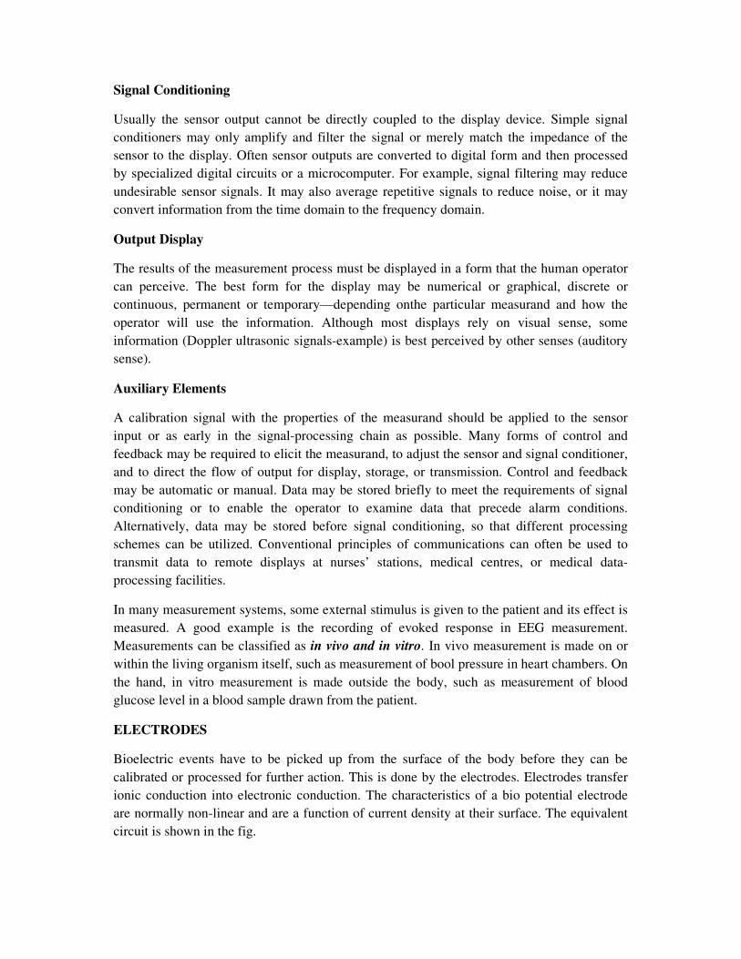
Equivalent circuit of bio potentialelectrode
Ehc – half-cell potential, Cd – electrode capacitance, Rd - leakage resistance, Rs – series
electrolyte and skin resistance.
The resistance Rd and Cd represent the impedance associated with the electrode-electrolyte
interface. Rs is the series resistance associated with interfacial effects and the resistance of the
electrode materials themselves. The potential developed at the electrode-electrolyte interface
or metal – electrode interface is called Half-cell Potential.The electrode is a metal and the
electrolyte is body fluids. The battery Ehc represents the half-cell potential. It is measured
with reference to hydrogen electrode placed in the electrolyte near that metallic electrode.
The half-cell potential developed can be expressed by the Nernst equation:
1 1
2 2
lnhc
C fRTE
nF C f
−=
Where R – gas constant, T – absolute temperature in Kelvin, F – faraday constant, n –
valency of ion, C1 and C2 – concentration of the selected ion on the 2 sides of the membrane
and f1 and f2 – activity co-efficient of the ion on the 2 sides of the membrane.
The impedance of the equivalent circuit is given by 1 2
d
s
d d
RZ R
j fC Rπ
= +
+
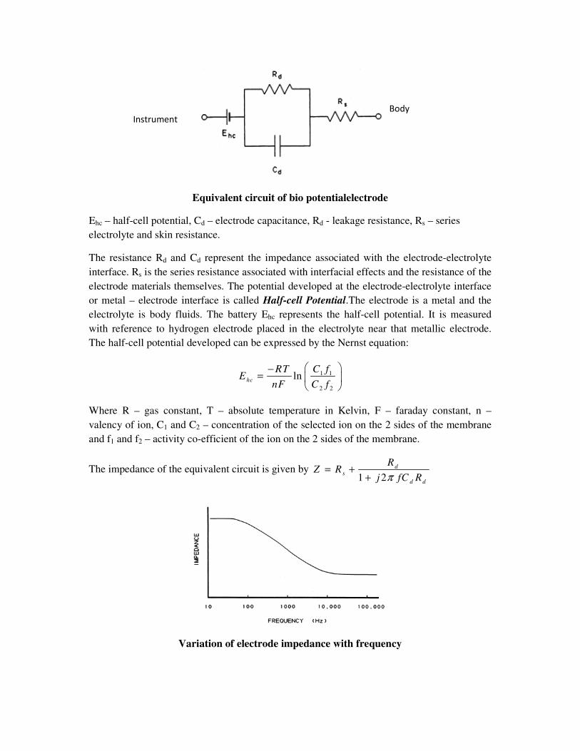
Variation of electrode impedance with frequency
Body
Instrument
At low frequencies the impedance is dominated by the series combination of Rs and Rd,
whereas at higher frequencies Cd bypasses the effect of Rd so that the impedance is now close
to Rs. Thus, by measuring the impedance of an electrode at high and low frequencies, it is
possible to determine the component values for the equivalent circuit for that electrode. When
a metal electrode comes in contact with an electrolyte (body fluid), the electrodes discharge
ions into the solution. Ions combine with the electrode and produce a charge gradient. The
spatial arrangement for the gradient is called Electrical Double Layer.
Perfectly Polarizable Electrodes
These are electrodes in which no actual charge crosses the electrode-electrolyte interface
when a current is applied. The current across theinterface is a displacement current and the
electrode behaves like acapacitor. Example: Ag/AgCl Electrode
Perfectly Non-Polarizable Electrode
These are electrodes where current passes freely across the electrode-electrolyte interface,
requiring no energy to make the transition. Theseelectrodes see no overpotentials. Example:
Platinum electrode
Stable gradient exist at the interface and if not, there may be variations causing noise voltages
called Artifact.
Generally conductivity of the skin is directly proportional to the moisture content in the skin.
Dry outer skin of the body is highly non-conductive. The skin has to be washed and rubbed to
remove some outer cells to establish electrical contact. The skin area has to coated with an
electrically conductive paste called “Electrode Paste”. The paste reduces the contact
impedance and artifacts. Saline solution is best suited as an electrode paste.
Purpose of Electrode Paste:It lowers the impedance between theelectrode and the skin and
also helps to stick the electrode to the skin. It reduces artifacts.
Electrode Material
The body fluids, electrode paste, and the metal / electrode can form a battery causing ions to
accumulate on the electrodes. Hence polarization occurs and causes some adverse effects. In
order to reduce this, the electrode material must be inert to body chemicals. By coating a
piece of pure silver with silver chloride, the silver-silver chloride electrode is developed. The
half-cell potential for this electrode is 2.5mV and effectively minimises the artifacts. It also
reduces the low frequency electrode-electrolyte impedance. Hence silver-silver chloride
electrodes are most commonly used in medical instrumentation.
PRACTICAL ELECTRODES FOR BIOMEDICAL MEASUREMENTS
Many different forms of electrodes have been developed for different types of biomedical
measurements. Three types are normally used in practice to measure bioelectric events.
1. Surface Electrodes: Used to measure ECG, EEG and EMG on the surface of the
skin.
2. Depth and Needle Electrodes: Used to penetrate the skin to record EEG from a local
region of the brain or EMG potentials from a specific group of muscles.
3. Micro Electrodes: Used to measure bioelectric potentials near a single cell.
SURFACE ELECTRODES
A small device that is attached to the skin to measure or cause electrical activity in the tissue
under it is called Surface Electrode. Surface electrodes may be used to look for problems with
muscles and nerves. Large area surface electrodes are used to sense ECG potentials and
smaller ones for EEG and EMG potentials. Commonly used body surface electrodes are
Metal plate electrodes, Suction electrodes, Floating electrodes,Flexible electrodes, Adhesive
tape electrodes and Multipoint Electrodes.
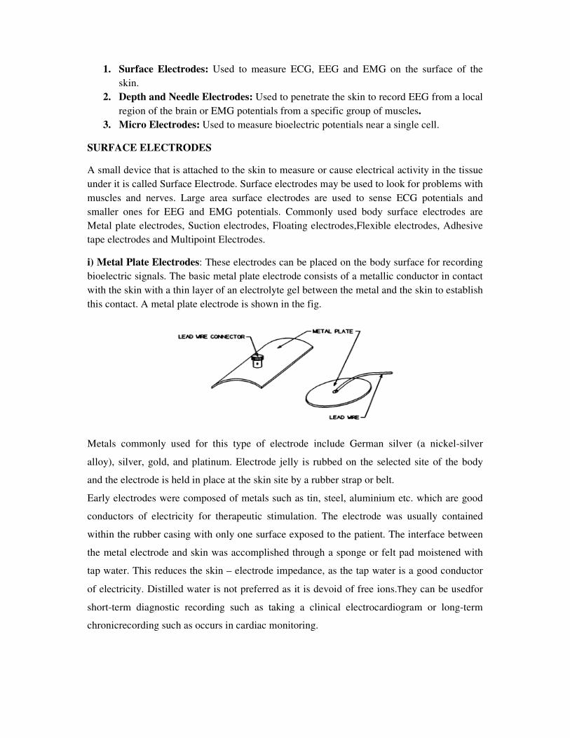
i) Metal Plate Electrodes: These electrodes can be placed on the body surface for recording
bioelectric signals. The basic metal plate electrode consists of a metallic conductor in contact
with the skin with a thin layer of an electrolyte gel between the metal and the skin to establish
this contact. A metal plate electrode is shown in the fig.
Metals commonly used for this type of electrode include German silver (a nickel-silver
alloy), silver, gold, and platinum. Electrode jelly is rubbed on the selected site of the body
and the electrode is held in place at the skin site by a rubber strap or belt.
Early electrodes were composed of metals such as tin, steel, aluminium etc. which are good
conductors of electricity for therapeutic stimulation. The electrode was usually contained
within the rubber casing with only one surface exposed to the patient. The interface between
the metal electrode and skin was accomplished through a sponge or felt pad moistened with
tap water. This reduces the skin – electrode impedance, as the tap water is a good conductor
of electricity. Distilled water is not preferred as it is devoid of free ions.They can be usedfor
short-term diagnostic recording such as taking a clinical electrocardiogram or long-term
chronicrecording such as occurs in cardiac monitoring.
Demerits of metal electrodes:
1. Metal plates may not be flexible enough to maintain adequate contact with certain
body parts.
2. Some may not be of comfort to the patients.
3. Size of the electrode makes it difficult to use for smaller treatment areas.
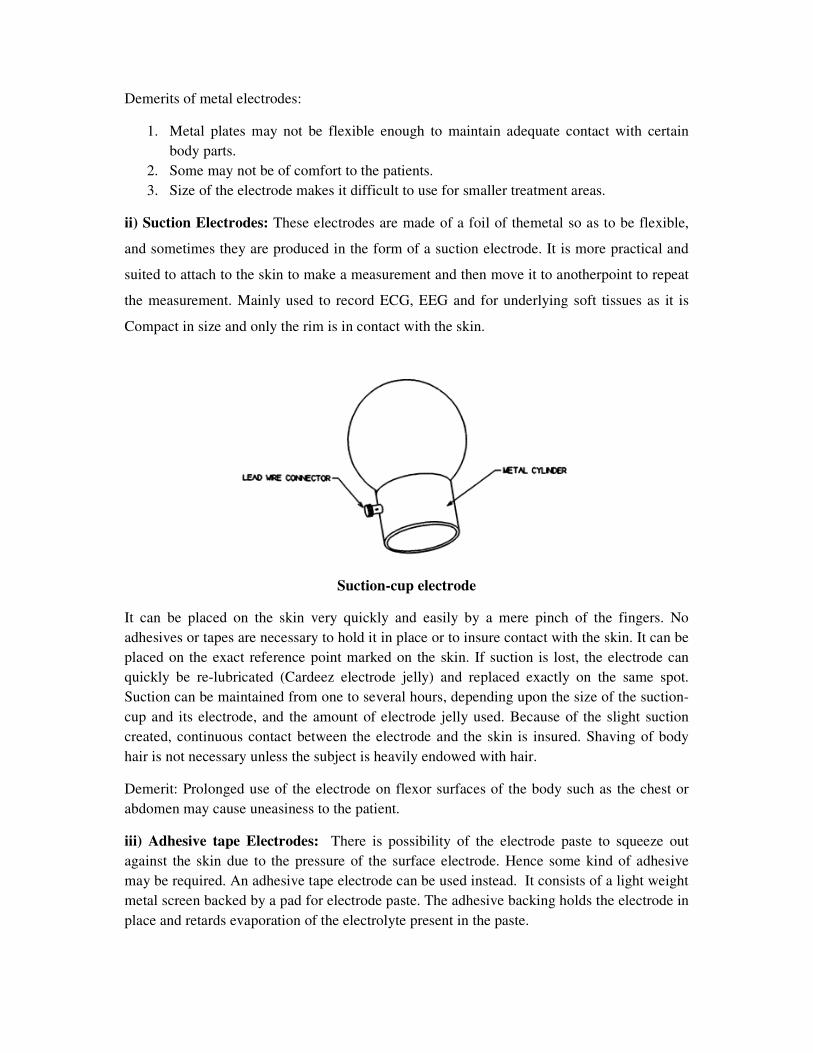
ii) Suction Electrodes: These electrodes are made of a foil of themetal so as to be flexible,
and sometimes they are produced in the form of a suction electrode. It is more practical and
suited to attach to the skin to make a measurement and then move it to anotherpoint to repeat
the measurement. Mainly used to record ECG, EEG and for underlying soft tissues as it is
Compact in size and only the rim is in contact with the skin.
Suction-cup electrode
It can be placed on the skin very quickly and easily by a mere pinch of the fingers. No
adhesives or tapes are necessary to hold it in place or to insure contact with the skin. It can be
placed on the exact reference point marked on the skin. If suction is lost, the electrode can
quickly be re-lubricated (Cardeez electrode jelly) and replaced exactly on the same spot.
Suction can be maintained from one to several hours, depending upon the size of the suction-
cup and its electrode, and the amount of electrode jelly used. Because of the slight suction
created, continuous contact between the electrode and the skin is insured. Shaving of body
hair is not necessary unless the subject is heavily endowed with hair.
Demerit: Prolonged use of the electrode on flexor surfaces of the body such as the chest or
abdomen may cause uneasiness to the patient.
iii) Adhesive tape Electrodes: There is possibility of the electrode paste to squeeze out
against the skin due to the pressure of the surface electrode. Hence some kind of adhesive
may be required. An adhesive tape electrode can be used instead. It consists of a light weight
metal screen backed by a pad for electrode paste. The adhesive backing holds the electrode in
place and retards evaporation of the electrolyte present in the paste.
iv) Multipoint Electrodes: These electrodes are commonly used for Bio-telemetry, patient
monitoring systems, ECG measurements and achieveseveral active, fine skin contacts.Low
resistance contact with the patient can be achieved under any ambience conditions. It requires
no preparation with jelly or paste. Noise voltage potentials can be minimized as the electrode-
skin movement can be reduced.
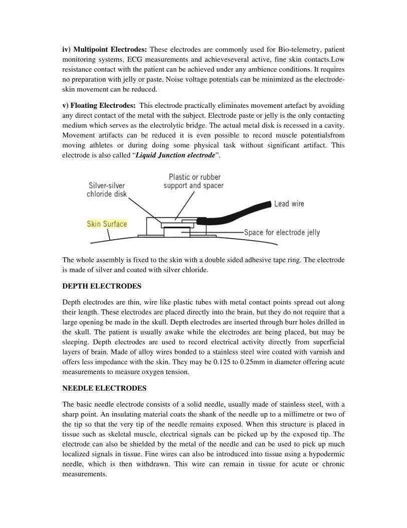
v) Floating Electrodes: This electrode practically eliminates movement artefact by avoiding
any direct contact of the metal with the subject. Electrode paste or jelly is the only contacting
medium which serves as the electrolytic bridge. The actual metal disk is recessed in a cavity.
Movement artifacts can be reduced it is even possible to record muscle potentialsfrom
moving athletes or during doing some physical task without significant artifact. This
electrode is also called “Liquid Junction electrode”.
The whole assembly is fixed to the skin with a double sided adhesive tape ring. The electrode
is made of silver and coated with silver chloride.
DEPTH ELECTRODES
Depth electrodes are thin, wire like plastic tubes with metal contact points spread out along
their length. These electrodes are placed directly into the brain, but they do not require that a
large opening be made in the skull. Depth electrodes are inserted through burr holes drilled in
the skull. The patient is usually awake while the electrodes are being placed, but may be
sleeping. Depth electrodes are used to record electrical activity directly from superficial
layers of brain. Made of alloy wires bonded to a stainless steel wire coated with varnish and
offers less impedance with the skin. They may be 0.125 to 0.25mm in diameter offering acute
measurements to measure oxygen tension.
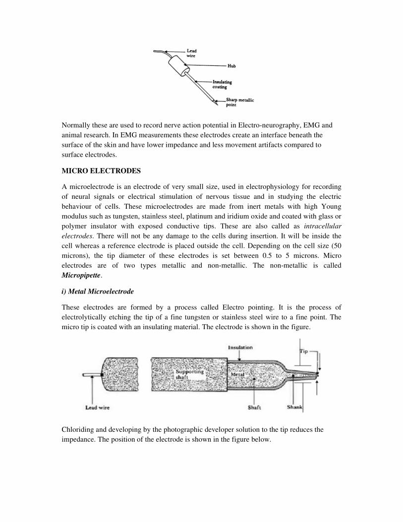
NEEDLE ELECTRODES
The basic needle electrode consists of a solid needle, usually made of stainless steel, with a
sharp point. An insulating material coats the shank of the needle up to a millimetre or two of
the tip so that the very tip of the needle remains exposed. When this structure is placed in
tissue such as skeletal muscle, electrical signals can be picked up by the exposed tip. The
electrode can also be shielded by the metal of the needle and can be used to pick up much
localized signals in tissue. Fine wires can also be introduced into tissue using a hypodermic
needle, which is then withdrawn. This wire can remain in tissue for acute or chronic
measurements.
Normally these are used to record nerve action potential in Electro-neurography, EMG and
animal research. In EMG measurements these electrodes create an interface beneath the
surface of the skin and have lower impedance and less movement artifacts compared to
surface electrodes.
MICRO ELECTRODES
A microelectrode is an electrode of very small size, used in electrophysiology for recording
of neural signals or electrical stimulation of nervous tissue and in studying the electric
behaviour of cells. These microelectrodes are made from inert metals with high Young
modulus such as tungsten, stainless steel, platinum and iridium oxide and coated with glass or
polymer insulator with exposed conductive tips. These are also called as intracellular
electrodes. There will not be any damage to the cells during insertion. It will be inside the
cell whereas a reference electrode is placed outside the cell. Depending on the cell size (50
microns), the tip diameter of these electrodes is set between 0.5 to 5 microns. Micro
electrodes are of two types metallic and non-metallic. The non-metallic is called
Micropipette.
i) Metal Microelectrode
These electrodes are formed by a process called Electro pointing. It is the process of
electrolytically etching the tip of a fine tungsten or stainless steel wire to a fine point. The
micro tip is coated with an insulating material. The electrode is shown in the figure.
Chloriding and developing by the photographic developer solution to the tip reduces the
impedance. The position of the electrode is shown in the figure below.
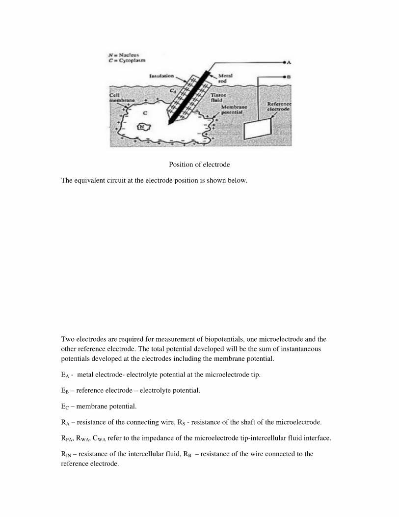
Position of electrode
The equivalent circuit at the electrode position is shown below.
Two electrodes are required for measurement of biopotentials, one microelectrode and the
other reference electrode. The total potential developed will be the sum of instantaneous
potentials developed at the electrodes including the membrane potential.
EA - metal electrode- electrolyte potential at the microelectrode tip.
EB – reference electrode – electrolyte potential.
EC – membrane potential.
RA – resistance of the connecting wire, RS - resistance of the shaft of the microelectrode.
RFA, RWA, CWA refer to the impedance of the microelectrode tip-intercellular fluid interface.
RIN – resistance of the intercellular fluid, RB – resistance of the wire connected to the
reference electrode.
RFB, RWB, CWB refer to the impedance of the reference electrode-extracellular fluid interface.
REX – resistance of the extracellular fluid. CD – distributed capacitance between the insulated
shaft of the microelectrode and the extracellular fluid. The capacitance between thetip of the
microelectrode and the intracellular fluid is negligible as the potential difference across it
remain constant. The impedance of the microelectrode tip is inversely proportional to the area
of the tip and frequency. When the electrode output is coupled with an amplifier, low
frequency components will be attenuated, if the input impedance of the amplifier is not high.
In that case, it will act as a high pass filter.
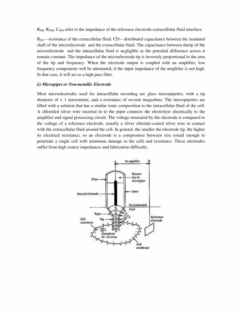
ii) Micropipet or Non-metallic Electrode
Most microelectrodes used for intracellular recording are glass micropipettes, with a tip
diameter of < 1 micrometre, and a resistance of several megaohms. The micropipettes are
filled with a solution that has a similar ionic composition to the intracellular fluid of the cell.
A chlorided silver wire inserted in to the pipet connects the electrolyte electrically to the
amplifier and signal processing circuit. The voltage measured by the electrode is compared to
the voltage of a reference electrode, usually a silver chloride-coated silver wire in contact
with the extracellular fluid around the cell. In general, the smaller the electrode tip, the higher
its electrical resistance, so an electrode is a compromise between size (small enough to
penetrate a single cell with minimum damage to the cell) and resistance. These electrodes
suffer from high source impedances and fabrication difficulty.
AMPLIFIERS
Bio-signals are recorded as potentials, voltages, and electrical field strengths generated by
nerves and muscles. The measurements involve voltages at very low levels, typically ranging
between 1 µV and 100 mV, with high source impedances and superimposed high level
interference signals and noise. The signals need to be amplified to make them compatible
with devices such as displays, recorders, or A/D converters for computerized equipment.
Amplifiers adequate to measure these signals have to satisfy very specific requirements. They
have to provide amplification selective to the physiological signal, reject superimposed noise
and interference signals, and guarantee protection from damages through voltage and current
surges for both patient and electronic equipment. Amplifiers featuring these specifications are
known as bio-potential amplifiers. The quality of bio-signal acquisition in a medical
instrument purely depends on medical preamplifier design.The design of physiological signal
amplifier or biomedical pre-amplifier has to satisfy the following requirement.
1. The voltage gain should be greater than 100 dB so that the signal be delivered
properly to drive the recorder.
2. Amplifier should have low frequency response from DC to the required frequency of
the particular bio-signal.
3. Gain and the response should be uniform throughout the bandwidth.
4. It must have large input impedance and low output impedance.
5. CMRR has to be large to eliminate 50 HZ interference from the mains.The amplifier
should provide the best possible separation of signal and interferences.
6. The measured signal should not be distorted and should not suffer from drift.
7. The amplifier has to offer protection of the patient from any hazard of electrical shock
8. The amplifier itself has to be protected against damages that might result from high
input voltagesas they occur during the application of defibrillators or electrosurgical
instrumentation.
PREAMPLFIERS
For biophysical measurements, the amplifiers include i) ac / dc universal amplifier with
neutralization, current injection, low leakage current, low dc drift etc. These are necessary to
make intracellular or extracellular measurements in case of ECG, EEG, EMG etc. ii) an ECG
amplifier with 12 lead selection and patient isolation iii) transducer amplifier suited for
bridge measurements on strain gauges etc for blood pressure measurements and in other
biophysical measurements like temperature etc.
Various amplifiers used are
1. Differential Amplifier: The main task of the differential amplifier is to reject the line
frequency interference that is electrostatically or magnetically coupled into the
subject. The desired bio potential appears as a voltage between the two input
terminals of the differential amplifier and is referred to as the differential signal. The
line frequency interference signal shows only very small differences in amplitude and
phase between the two measuring electrodes, causing approximately the same
potential at both inputs, and thus appears only between the inputs and ground and is
called the common mode signal. Strong rejection of the common mode signal is one
of the most important characteristics of a good bio potential amplifier. Most
amplifiers that are used to measure bioelectric signals are of differential type.
2. DC Amplifier: Generally of negative feedback type and suited for medium gain
applications. These suffer from low CMRR capability and are employed as pen drive
amplifiers in direct writing recorders.
3. Chopper Amplifier: Preferred to convert low level frequency signal to high level and
are available as mechanical and non-mechanical chopper amplifiers. These possess
excellent common mode rejection capability and very low drift with high sensitivity.
4. Isolation Amplifier:A form of differential amplifier that allow measurement of small
signals in the presence of a high common mode voltage by providing electrical
isolation and an electrical safety barrier. These amplifiers are also used for amplifying
low-level signals in multi-channel applications. They can also eliminate measurement
errors caused by ground loops.
Chopper Amplifier
Chopper amplifiers are basically DC amplifiers that operating on low-frequency signals.
These are extensively used in medical electronics to measure bio signals, as they are very
weak and needs to be amplified with high gain. A very high gain DC amplifier can be used to
support this with low drift and low offset. But the DC amplifiers exhibit a certain amount of
drift where the output will continuously shift even in the absence of input is zero or if it is
constant.A solution to the problem of drift is the use of Chopper Amplifier that employs a
chopper circuit to break up the slowly varying input signal into an alternating signal with an
amplitude proportional to the input direct current and with phase dependant on the polarity of
the original signal. The AC voltage is then amplified by an AC amplifier and rectified to get
back the amplified DC signal. This device serves to be a better device for signals of narrow
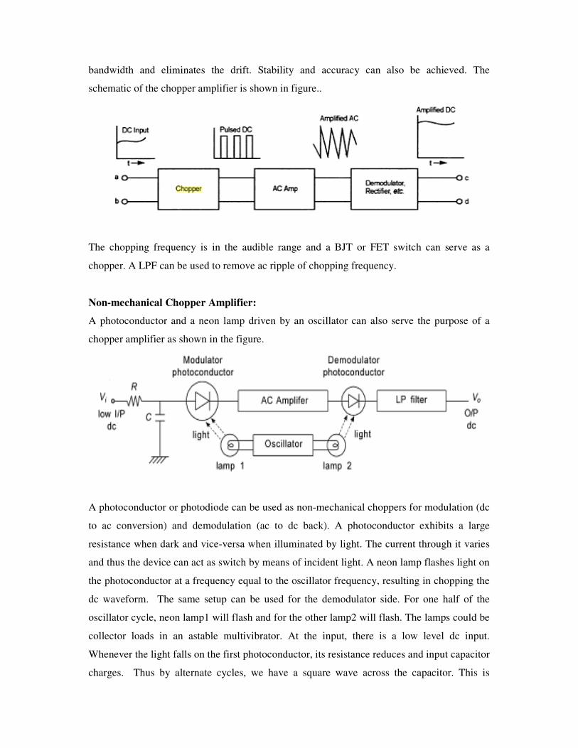
bandwidth and eliminates the drift. Stability and accuracy can also be achieved. The
schematic of the chopper amplifier is shown in figure..
The chopping frequency is in the audible range and a BJT or FET switch can serve as a
chopper. A LPF can be used to remove ac ripple of chopping frequency.
Non-mechanical Chopper Amplifier:
A photoconductor and a neon lamp driven by an oscillator can also serve the purpose of a
chopper amplifier as shown in the figure.
A photoconductor or photodiode can be used as non-mechanical choppers for modulation (dc
to ac conversion) and demodulation (ac to dc back). A photoconductor exhibits a large
resistance when dark and vice-versa when illuminated by light. The current through it varies
and thus the device can act as switch by means of incident light. A neon lamp flashes light on
the photoconductor at a frequency equal to the oscillator frequency, resulting in chopping the
dc waveform. The same setup can be used for the demodulator side. For one half of the
oscillator cycle, neon lamp1 will flash and for the other lamp2 will flash. The lamps could be
collector loads in an astable multivibrator. At the input, there is a low level dc input.
Whenever the light falls on the first photoconductor, its resistance reduces and input capacitor
charges. Thus by alternate cycles, we have a square wave across the capacitor. This is
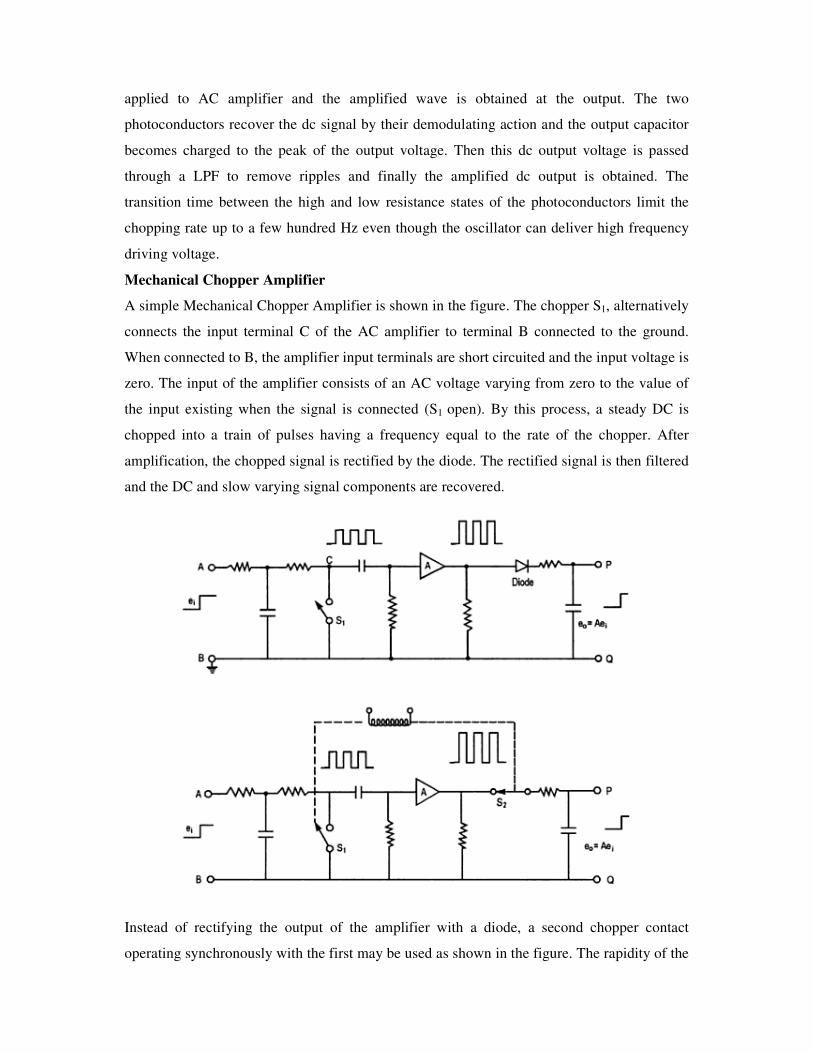
applied to AC amplifier and the amplified wave is obtained at the output. The two
photoconductors recover the dc signal by their demodulating action and the output capacitor
becomes charged to the peak of the output voltage. Then this dc output voltage is passed
through a LPF to remove ripples and finally the amplified dc output is obtained. The
transition time between the high and low resistance states of the photoconductors limit the
chopping rate up to a few hundred Hz even though the oscillator can deliver high frequency
driving voltage.
Mechanical Chopper Amplifier
A simple Mechanical Chopper Amplifier is shown in the figure. The chopper S1, alternatively
connects the input terminal C of the AC amplifier to terminal B connected to the ground.
When connected to B, the amplifier input terminals are short circuited and the input voltage is
zero. The input of the amplifier consists of an AC voltage varying from zero to the value of
the input existing when the signal is connected (S1 open). By this process, a steady DC is
chopped into a train of pulses having a frequency equal to the rate of the chopper. After
amplification, the chopped signal is rectified by the diode. The rectified signal is then filtered
and the DC and slow varying signal components are recovered.
Instead of rectifying the output of the amplifier with a diode, a second chopper contact
operating synchronously with the first may be used as shown in the figure. The rapidity of the
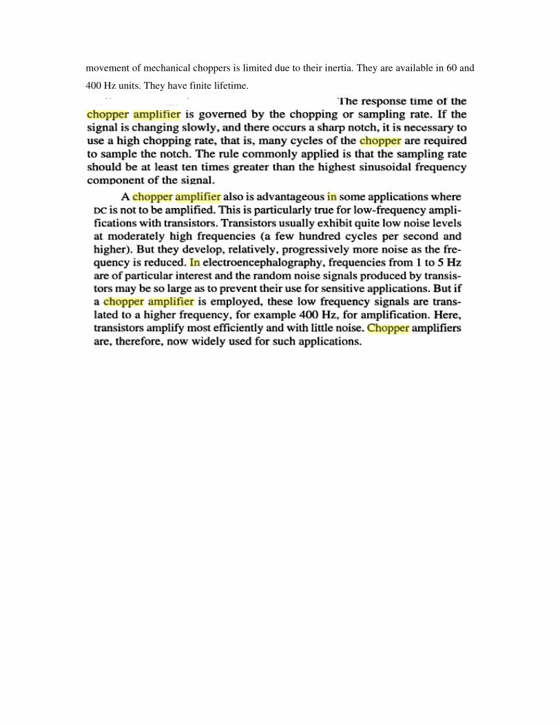
movement of mechanical choppers is limited due to their inertia. They are available in 60 and
400 Hz units. They have finite lifetime.